JP7331002B2 - Wound therapy system with wound volume estimation - Google Patents
Wound therapy system with wound volume estimation Download PDFInfo
- Publication number
- JP7331002B2 JP7331002B2 JP2020548904A JP2020548904A JP7331002B2 JP 7331002 B2 JP7331002 B2 JP 7331002B2 JP 2020548904 A JP2020548904 A JP 2020548904A JP 2020548904 A JP2020548904 A JP 2020548904A JP 7331002 B2 JP7331002 B2 JP 7331002B2
- Authority
- JP
- Japan
- Prior art keywords
- wound
- negative pressure
- therapy system
- pressure
- circuit
- Prior art date
- Legal status (The legal status is an assumption and is not a legal conclusion. Google has not performed a legal analysis and makes no representation as to the accuracy of the status listed.)
- Active
Links
- 206010052428 Wound Diseases 0.000 title claims description 440
- 208000027418 Wounds and injury Diseases 0.000 title claims description 440
- 238000002560 therapeutic procedure Methods 0.000 title claims description 159
- 239000012530 fluid Substances 0.000 claims description 153
- 230000004044 response Effects 0.000 claims description 125
- 238000012549 training Methods 0.000 claims description 124
- 238000000034 method Methods 0.000 claims description 91
- 238000010998 test method Methods 0.000 claims description 78
- 238000009530 blood pressure measurement Methods 0.000 claims description 26
- 238000010926 purge Methods 0.000 claims description 18
- 230000035876 healing Effects 0.000 claims description 14
- 238000005259 measurement Methods 0.000 claims description 12
- 238000012956 testing procedure Methods 0.000 claims description 11
- 238000013528 artificial neural network Methods 0.000 claims description 7
- 230000008569 process Effects 0.000 description 46
- 238000012360 testing method Methods 0.000 description 19
- 238000004891 communication Methods 0.000 description 13
- 230000006870 function Effects 0.000 description 12
- 238000009581 negative-pressure wound therapy Methods 0.000 description 10
- 238000010586 diagram Methods 0.000 description 9
- 238000003062 neural network model Methods 0.000 description 8
- 230000007423 decrease Effects 0.000 description 7
- 238000010801 machine learning Methods 0.000 description 7
- 238000012545 processing Methods 0.000 description 7
- 238000003860 storage Methods 0.000 description 7
- 210000000416 exudates and transudate Anatomy 0.000 description 6
- 238000012417 linear regression Methods 0.000 description 4
- 238000012986 modification Methods 0.000 description 4
- 230000004048 modification Effects 0.000 description 4
- 238000012544 monitoring process Methods 0.000 description 4
- 238000003825 pressing Methods 0.000 description 4
- 230000000638 stimulation Effects 0.000 description 4
- 230000001413 cellular effect Effects 0.000 description 3
- 230000036961 partial effect Effects 0.000 description 3
- 238000010276 construction Methods 0.000 description 2
- 238000003066 decision tree Methods 0.000 description 2
- 238000013135 deep learning Methods 0.000 description 2
- 238000001514 detection method Methods 0.000 description 2
- 230000000694 effects Effects 0.000 description 2
- 230000002068 genetic effect Effects 0.000 description 2
- 230000001939 inductive effect Effects 0.000 description 2
- 239000007788 liquid Substances 0.000 description 2
- 238000013178 mathematical model Methods 0.000 description 2
- 230000003287 optical effect Effects 0.000 description 2
- 238000013488 ordinary least square regression Methods 0.000 description 2
- 230000002787 reinforcement Effects 0.000 description 2
- 230000002441 reversible effect Effects 0.000 description 2
- 238000012706 support-vector machine Methods 0.000 description 2
- 230000029663 wound healing Effects 0.000 description 2
- 102000004506 Blood Proteins Human genes 0.000 description 1
- 108010017384 Blood Proteins Proteins 0.000 description 1
- 206010061218 Inflammation Diseases 0.000 description 1
- 230000004075 alteration Effects 0.000 description 1
- 238000003491 array Methods 0.000 description 1
- 230000001580 bacterial effect Effects 0.000 description 1
- 239000011324 bead Substances 0.000 description 1
- 230000003115 biocidal effect Effects 0.000 description 1
- 210000004369 blood Anatomy 0.000 description 1
- 239000008280 blood Substances 0.000 description 1
- 210000001772 blood platelet Anatomy 0.000 description 1
- 230000008859 change Effects 0.000 description 1
- 239000003086 colorant Substances 0.000 description 1
- 230000003247 decreasing effect Effects 0.000 description 1
- 238000013461 design Methods 0.000 description 1
- 239000003814 drug Substances 0.000 description 1
- 229940079593 drug Drugs 0.000 description 1
- 210000003743 erythrocyte Anatomy 0.000 description 1
- 230000002209 hydrophobic effect Effects 0.000 description 1
- 230000004054 inflammatory process Effects 0.000 description 1
- 238000003973 irrigation Methods 0.000 description 1
- 230000002262 irrigation Effects 0.000 description 1
- 230000003902 lesion Effects 0.000 description 1
- 210000000265 leukocyte Anatomy 0.000 description 1
- 230000000670 limiting effect Effects 0.000 description 1
- 239000000463 material Substances 0.000 description 1
- 239000002245 particle Substances 0.000 description 1
- 238000005086 pumping Methods 0.000 description 1
- 230000002829 reductive effect Effects 0.000 description 1
- 239000007787 solid Substances 0.000 description 1
- 238000006467 substitution reaction Methods 0.000 description 1
- 230000000699 topical effect Effects 0.000 description 1
- 239000011800 void material Substances 0.000 description 1
- XLYOFNOQVPJJNP-UHFFFAOYSA-N water Substances O XLYOFNOQVPJJNP-UHFFFAOYSA-N 0.000 description 1
Images


Classifications
-
- A—HUMAN NECESSITIES
- A61—MEDICAL OR VETERINARY SCIENCE; HYGIENE
- A61B—DIAGNOSIS; SURGERY; IDENTIFICATION
- A61B5/00—Measuring for diagnostic purposes; Identification of persons
- A61B5/103—Detecting, measuring or recording devices for testing the shape, pattern, colour, size or movement of the body or parts thereof, for diagnostic purposes
- A61B5/107—Measuring physical dimensions, e.g. size of the entire body or parts thereof
- A61B5/1073—Measuring volume, e.g. of limbs
-
- A—HUMAN NECESSITIES
- A61—MEDICAL OR VETERINARY SCIENCE; HYGIENE
- A61B—DIAGNOSIS; SURGERY; IDENTIFICATION
- A61B5/00—Measuring for diagnostic purposes; Identification of persons
- A61B5/103—Detecting, measuring or recording devices for testing the shape, pattern, colour, size or movement of the body or parts thereof, for diagnostic purposes
- A61B5/107—Measuring physical dimensions, e.g. size of the entire body or parts thereof
- A61B5/1076—Measuring physical dimensions, e.g. size of the entire body or parts thereof for measuring dimensions inside body cavities, e.g. using catheters
-
- A—HUMAN NECESSITIES
- A61—MEDICAL OR VETERINARY SCIENCE; HYGIENE
- A61B—DIAGNOSIS; SURGERY; IDENTIFICATION
- A61B5/00—Measuring for diagnostic purposes; Identification of persons
- A61B5/44—Detecting, measuring or recording for evaluating the integumentary system, e.g. skin, hair or nails
- A61B5/441—Skin evaluation, e.g. for skin disorder diagnosis
- A61B5/445—Evaluating skin irritation or skin trauma, e.g. rash, eczema, wound, bed sore
-
- A61F13/05—
-
- A—HUMAN NECESSITIES
- A61—MEDICAL OR VETERINARY SCIENCE; HYGIENE
- A61M—DEVICES FOR INTRODUCING MEDIA INTO, OR ONTO, THE BODY; DEVICES FOR TRANSDUCING BODY MEDIA OR FOR TAKING MEDIA FROM THE BODY; DEVICES FOR PRODUCING OR ENDING SLEEP OR STUPOR
- A61M1/00—Suction or pumping devices for medical purposes; Devices for carrying-off, for treatment of, or for carrying-over, body-liquids; Drainage systems
- A61M1/71—Suction drainage systems
- A61M1/73—Suction drainage systems comprising sensors or indicators for physical values
-
- A—HUMAN NECESSITIES
- A61—MEDICAL OR VETERINARY SCIENCE; HYGIENE
- A61M—DEVICES FOR INTRODUCING MEDIA INTO, OR ONTO, THE BODY; DEVICES FOR TRANSDUCING BODY MEDIA OR FOR TAKING MEDIA FROM THE BODY; DEVICES FOR PRODUCING OR ENDING SLEEP OR STUPOR
- A61M1/00—Suction or pumping devices for medical purposes; Devices for carrying-off, for treatment of, or for carrying-over, body-liquids; Drainage systems
- A61M1/71—Suction drainage systems
- A61M1/77—Suction-irrigation systems
-
- A—HUMAN NECESSITIES
- A61—MEDICAL OR VETERINARY SCIENCE; HYGIENE
- A61M—DEVICES FOR INTRODUCING MEDIA INTO, OR ONTO, THE BODY; DEVICES FOR TRANSDUCING BODY MEDIA OR FOR TAKING MEDIA FROM THE BODY; DEVICES FOR PRODUCING OR ENDING SLEEP OR STUPOR
- A61M1/00—Suction or pumping devices for medical purposes; Devices for carrying-off, for treatment of, or for carrying-over, body-liquids; Drainage systems
- A61M1/84—Drainage tubes; Aspiration tips
- A61M1/85—Drainage tubes; Aspiration tips with gas or fluid supply means, e.g. for supplying rinsing fluids or anticoagulants
-
- A—HUMAN NECESSITIES
- A61—MEDICAL OR VETERINARY SCIENCE; HYGIENE
- A61M—DEVICES FOR INTRODUCING MEDIA INTO, OR ONTO, THE BODY; DEVICES FOR TRANSDUCING BODY MEDIA OR FOR TAKING MEDIA FROM THE BODY; DEVICES FOR PRODUCING OR ENDING SLEEP OR STUPOR
- A61M1/00—Suction or pumping devices for medical purposes; Devices for carrying-off, for treatment of, or for carrying-over, body-liquids; Drainage systems
- A61M1/90—Negative pressure wound therapy devices, i.e. devices for applying suction to a wound to promote healing, e.g. including a vacuum dressing
- A61M1/92—Negative pressure wound therapy devices, i.e. devices for applying suction to a wound to promote healing, e.g. including a vacuum dressing with liquid supply means
-
- A—HUMAN NECESSITIES
- A61—MEDICAL OR VETERINARY SCIENCE; HYGIENE
- A61M—DEVICES FOR INTRODUCING MEDIA INTO, OR ONTO, THE BODY; DEVICES FOR TRANSDUCING BODY MEDIA OR FOR TAKING MEDIA FROM THE BODY; DEVICES FOR PRODUCING OR ENDING SLEEP OR STUPOR
- A61M1/00—Suction or pumping devices for medical purposes; Devices for carrying-off, for treatment of, or for carrying-over, body-liquids; Drainage systems
- A61M1/90—Negative pressure wound therapy devices, i.e. devices for applying suction to a wound to promote healing, e.g. including a vacuum dressing
- A61M1/96—Suction control thereof
- A61M1/962—Suction control thereof having pumping means on the suction site, e.g. miniature pump on dressing or dressing capable of exerting suction
-
- A—HUMAN NECESSITIES
- A61—MEDICAL OR VETERINARY SCIENCE; HYGIENE
- A61M—DEVICES FOR INTRODUCING MEDIA INTO, OR ONTO, THE BODY; DEVICES FOR TRANSDUCING BODY MEDIA OR FOR TAKING MEDIA FROM THE BODY; DEVICES FOR PRODUCING OR ENDING SLEEP OR STUPOR
- A61M1/00—Suction or pumping devices for medical purposes; Devices for carrying-off, for treatment of, or for carrying-over, body-liquids; Drainage systems
- A61M1/90—Negative pressure wound therapy devices, i.e. devices for applying suction to a wound to promote healing, e.g. including a vacuum dressing
- A61M1/96—Suction control thereof
- A61M1/964—Suction control thereof having venting means on or near the dressing
-
- A—HUMAN NECESSITIES
- A61—MEDICAL OR VETERINARY SCIENCE; HYGIENE
- A61M—DEVICES FOR INTRODUCING MEDIA INTO, OR ONTO, THE BODY; DEVICES FOR TRANSDUCING BODY MEDIA OR FOR TAKING MEDIA FROM THE BODY; DEVICES FOR PRODUCING OR ENDING SLEEP OR STUPOR
- A61M3/00—Medical syringes, e.g. enemata; Irrigators
- A61M3/02—Enemata; Irrigators
- A61M3/0204—Physical characteristics of the irrigation fluid, e.g. conductivity or turbidity
- A61M3/022—Volume; Flow rate
-
- A—HUMAN NECESSITIES
- A61—MEDICAL OR VETERINARY SCIENCE; HYGIENE
- A61M—DEVICES FOR INTRODUCING MEDIA INTO, OR ONTO, THE BODY; DEVICES FOR TRANSDUCING BODY MEDIA OR FOR TAKING MEDIA FROM THE BODY; DEVICES FOR PRODUCING OR ENDING SLEEP OR STUPOR
- A61M3/00—Medical syringes, e.g. enemata; Irrigators
- A61M3/02—Enemata; Irrigators
- A61M3/0233—Enemata; Irrigators characterised by liquid supply means, e.g. from pressurised reservoirs
- A61M3/0254—Enemata; Irrigators characterised by liquid supply means, e.g. from pressurised reservoirs the liquid being pumped
- A61M3/0258—Enemata; Irrigators characterised by liquid supply means, e.g. from pressurised reservoirs the liquid being pumped by means of electric pumps
-
- A—HUMAN NECESSITIES
- A61—MEDICAL OR VETERINARY SCIENCE; HYGIENE
- A61F—FILTERS IMPLANTABLE INTO BLOOD VESSELS; PROSTHESES; DEVICES PROVIDING PATENCY TO, OR PREVENTING COLLAPSING OF, TUBULAR STRUCTURES OF THE BODY, e.g. STENTS; ORTHOPAEDIC, NURSING OR CONTRACEPTIVE DEVICES; FOMENTATION; TREATMENT OR PROTECTION OF EYES OR EARS; BANDAGES, DRESSINGS OR ABSORBENT PADS; FIRST-AID KITS
- A61F13/00—Bandages or dressings; Absorbent pads
- A61F2013/00089—Wound bandages
- A61F2013/0017—Wound bandages possibility of applying fluid
- A61F2013/00174—Wound bandages possibility of applying fluid possibility of applying pressure
-
- A—HUMAN NECESSITIES
- A61—MEDICAL OR VETERINARY SCIENCE; HYGIENE
- A61F—FILTERS IMPLANTABLE INTO BLOOD VESSELS; PROSTHESES; DEVICES PROVIDING PATENCY TO, OR PREVENTING COLLAPSING OF, TUBULAR STRUCTURES OF THE BODY, e.g. STENTS; ORTHOPAEDIC, NURSING OR CONTRACEPTIVE DEVICES; FOMENTATION; TREATMENT OR PROTECTION OF EYES OR EARS; BANDAGES, DRESSINGS OR ABSORBENT PADS; FIRST-AID KITS
- A61F13/00—Bandages or dressings; Absorbent pads
- A61F13/15—Absorbent pads, e.g. sanitary towels, swabs or tampons for external or internal application to the body; Supporting or fastening means therefor; Tampon applicators
- A61F13/84—Accessories, not otherwise provided for, for absorbent pads
- A61F2013/8494—Accessories, not otherwise provided for, for absorbent pads including pumping devices
-
- A—HUMAN NECESSITIES
- A61—MEDICAL OR VETERINARY SCIENCE; HYGIENE
- A61M—DEVICES FOR INTRODUCING MEDIA INTO, OR ONTO, THE BODY; DEVICES FOR TRANSDUCING BODY MEDIA OR FOR TAKING MEDIA FROM THE BODY; DEVICES FOR PRODUCING OR ENDING SLEEP OR STUPOR
- A61M1/00—Suction or pumping devices for medical purposes; Devices for carrying-off, for treatment of, or for carrying-over, body-liquids; Drainage systems
- A61M1/71—Suction drainage systems
- A61M1/73—Suction drainage systems comprising sensors or indicators for physical values
- A61M1/732—Visual indicating means for vacuum pressure
-
- A—HUMAN NECESSITIES
- A61—MEDICAL OR VETERINARY SCIENCE; HYGIENE
- A61M—DEVICES FOR INTRODUCING MEDIA INTO, OR ONTO, THE BODY; DEVICES FOR TRANSDUCING BODY MEDIA OR FOR TAKING MEDIA FROM THE BODY; DEVICES FOR PRODUCING OR ENDING SLEEP OR STUPOR
- A61M1/00—Suction or pumping devices for medical purposes; Devices for carrying-off, for treatment of, or for carrying-over, body-liquids; Drainage systems
- A61M1/71—Suction drainage systems
- A61M1/74—Suction control
- A61M1/742—Suction control by changing the size of a vent
-
- A—HUMAN NECESSITIES
- A61—MEDICAL OR VETERINARY SCIENCE; HYGIENE
- A61M—DEVICES FOR INTRODUCING MEDIA INTO, OR ONTO, THE BODY; DEVICES FOR TRANSDUCING BODY MEDIA OR FOR TAKING MEDIA FROM THE BODY; DEVICES FOR PRODUCING OR ENDING SLEEP OR STUPOR
- A61M2205/00—General characteristics of the apparatus
- A61M2205/15—Detection of leaks
-
- A—HUMAN NECESSITIES
- A61—MEDICAL OR VETERINARY SCIENCE; HYGIENE
- A61M—DEVICES FOR INTRODUCING MEDIA INTO, OR ONTO, THE BODY; DEVICES FOR TRANSDUCING BODY MEDIA OR FOR TAKING MEDIA FROM THE BODY; DEVICES FOR PRODUCING OR ENDING SLEEP OR STUPOR
- A61M2205/00—General characteristics of the apparatus
- A61M2205/33—Controlling, regulating or measuring
- A61M2205/3331—Pressure; Flow
- A61M2205/3334—Measuring or controlling the flow rate
-
- A—HUMAN NECESSITIES
- A61—MEDICAL OR VETERINARY SCIENCE; HYGIENE
- A61M—DEVICES FOR INTRODUCING MEDIA INTO, OR ONTO, THE BODY; DEVICES FOR TRANSDUCING BODY MEDIA OR FOR TAKING MEDIA FROM THE BODY; DEVICES FOR PRODUCING OR ENDING SLEEP OR STUPOR
- A61M2205/00—General characteristics of the apparatus
- A61M2205/33—Controlling, regulating or measuring
- A61M2205/3331—Pressure; Flow
- A61M2205/3337—Controlling, regulating pressure or flow by means of a valve by-passing a pump
-
- A—HUMAN NECESSITIES
- A61—MEDICAL OR VETERINARY SCIENCE; HYGIENE
- A61M—DEVICES FOR INTRODUCING MEDIA INTO, OR ONTO, THE BODY; DEVICES FOR TRANSDUCING BODY MEDIA OR FOR TAKING MEDIA FROM THE BODY; DEVICES FOR PRODUCING OR ENDING SLEEP OR STUPOR
- A61M2205/00—General characteristics of the apparatus
- A61M2205/33—Controlling, regulating or measuring
- A61M2205/3331—Pressure; Flow
- A61M2205/3344—Measuring or controlling pressure at the body treatment site
-
- A—HUMAN NECESSITIES
- A61—MEDICAL OR VETERINARY SCIENCE; HYGIENE
- A61M—DEVICES FOR INTRODUCING MEDIA INTO, OR ONTO, THE BODY; DEVICES FOR TRANSDUCING BODY MEDIA OR FOR TAKING MEDIA FROM THE BODY; DEVICES FOR PRODUCING OR ENDING SLEEP OR STUPOR
- A61M2205/00—General characteristics of the apparatus
- A61M2205/33—Controlling, regulating or measuring
- A61M2205/3379—Masses, volumes, levels of fluids in reservoirs, flow rates
-
- A—HUMAN NECESSITIES
- A61—MEDICAL OR VETERINARY SCIENCE; HYGIENE
- A61M—DEVICES FOR INTRODUCING MEDIA INTO, OR ONTO, THE BODY; DEVICES FOR TRANSDUCING BODY MEDIA OR FOR TAKING MEDIA FROM THE BODY; DEVICES FOR PRODUCING OR ENDING SLEEP OR STUPOR
- A61M2205/00—General characteristics of the apparatus
- A61M2205/70—General characteristics of the apparatus with testing or calibration facilities
- A61M2205/702—General characteristics of the apparatus with testing or calibration facilities automatically during use
-
- A—HUMAN NECESSITIES
- A61—MEDICAL OR VETERINARY SCIENCE; HYGIENE
- A61M—DEVICES FOR INTRODUCING MEDIA INTO, OR ONTO, THE BODY; DEVICES FOR TRANSDUCING BODY MEDIA OR FOR TAKING MEDIA FROM THE BODY; DEVICES FOR PRODUCING OR ENDING SLEEP OR STUPOR
- A61M3/00—Medical syringes, e.g. enemata; Irrigators
- A61M3/02—Enemata; Irrigators
- A61M3/0202—Enemata; Irrigators with electronic control means or interfaces
-
- A—HUMAN NECESSITIES
- A61—MEDICAL OR VETERINARY SCIENCE; HYGIENE
- A61M—DEVICES FOR INTRODUCING MEDIA INTO, OR ONTO, THE BODY; DEVICES FOR TRANSDUCING BODY MEDIA OR FOR TAKING MEDIA FROM THE BODY; DEVICES FOR PRODUCING OR ENDING SLEEP OR STUPOR
- A61M35/00—Devices for applying media, e.g. remedies, on the human body
- A61M35/003—Portable hand-held applicators having means for dispensing or spreading integral media
- A61M35/006—Portable hand-held applicators having means for dispensing or spreading integral media using sponges, foams, absorbent pads or swabs as spreading means
-
- A—HUMAN NECESSITIES
- A61—MEDICAL OR VETERINARY SCIENCE; HYGIENE
- A61M—DEVICES FOR INTRODUCING MEDIA INTO, OR ONTO, THE BODY; DEVICES FOR TRANSDUCING BODY MEDIA OR FOR TAKING MEDIA FROM THE BODY; DEVICES FOR PRODUCING OR ENDING SLEEP OR STUPOR
- A61M35/00—Devices for applying media, e.g. remedies, on the human body
- A61M35/30—Gas therapy for therapeutic treatment of the skin
Description
関連出願の相互参照
本出願は、2018年3月29日に出願された米国仮特許出願第62/650,132号明細書、及び2019年1月31日に出願された米国仮特許出願第62/799,241号明細書に対する優先権の利益を主張するものであり、これらの特許文献の完全な開示の全体が各々、参照により本明細書に組み込まれる。
CROSS-REFERENCE TO RELATED APPLICATIONS This application is filed March 29, 2018, U.S. Provisional Application No. 62/650,132 and U.S. Provisional Application No. 62, filed January 31, 2019. No./799,241 patent application, the entire disclosure of each of which is incorporated herein by reference.
本開示は、概して、創傷療法システムに関し、より詳細には、創傷の容積を推定するように構成された創傷療法システムに関する。 FIELD OF THE DISCLOSURE The present disclosure relates generally to wound therapy systems, and more particularly to wound therapy systems configured to estimate wound volume.
陰圧創傷療法(NPWT)は、創傷治癒を促進するために創傷部位に陰圧を印加することを伴う創傷療法の一種である。いくつかの創傷治療システムは、必要な陰圧及び流れを生成するために、空気圧ポンプを使用して創傷に陰圧を印加する。NPWTでの創傷治癒の最近の進歩は、NPWTとの組み合わせで作用するように創傷に局所流体を適用することを含む。しかしながら、創傷に送達すべき滴下流体の適切な体積を決定することは困難である可能性がある。加えて、治癒の進行を経時的に正確に監視及び追跡することも困難である可能性がある。 Negative pressure wound therapy (NPWT) is a type of wound therapy that involves applying negative pressure to the wound site to promote wound healing. Some wound treatment systems use pneumatic pumps to apply negative pressure to the wound to create the necessary negative pressure and flow. Recent advances in wound healing with NPWT involve applying topical fluids to the wound to act in combination with the NPWT. However, determining the appropriate volume of drip fluid to deliver to the wound can be difficult. Additionally, it can be difficult to accurately monitor and track healing progress over time.
本開示の一実施態様は、創傷に陰圧を印加するように構成された陰圧回路と、陰圧回路に流体的に結合されたポンプであって、陰圧回路内の陰圧を制御するように動作可能なポンプと、陰圧回路内の又は創傷における陰圧を測定するように構成された圧力センサと、ポンプと圧力センサとに通信可能に結合された制御装置とを含む創傷療法システムである。制御装置は、陰圧回路に圧力刺激を印加することを含む圧力試験手順を実行し、圧力センサによって記録された圧力測定値を使用して圧力刺激に対する陰圧回路の動的圧力応答を観測し、且つ動的圧力応答に基づいて創傷の創傷容積を推定するように構成される。 One embodiment of the present disclosure includes a negative pressure circuit configured to apply negative pressure to a wound and a pump fluidly coupled to the negative pressure circuit to control the negative pressure in the negative pressure circuit. a pressure sensor configured to measure negative pressure in a negative pressure circuit or at a wound; and a controller communicatively coupled to the pump and the pressure sensor. is. The controller performs a pressure test procedure that includes applying a pressure stimulus to the negative pressure circuit and uses pressure measurements recorded by the pressure sensor to observe the dynamic pressure response of the negative pressure circuit to the pressure stimulus. and configured to estimate the wound volume of the wound based on the dynamic pressure response.
いくつかの実施形態では、陰圧回路は、創傷を取り囲む皮膚に封着可能な創傷ドレッシングを含む。いくつかの実施形態では、陰圧回路は、創傷への送達のための滴下流体を収容する滴下流体キャニスタ又は創傷から除去された流体を収容する除去流体キャニスタのうちの少なくとも1つを含む。いくつかの実施形態では、陰圧回路は、ポンプを創傷に流体的に接続する管を含む。 In some embodiments, the negative pressure circuit includes a wound dressing sealable to the skin surrounding the wound. In some embodiments, the negative pressure circuit includes at least one of a drip fluid canister containing drip fluid for delivery to the wound or a removal fluid canister containing fluid removed from the wound. In some embodiments, the negative pressure circuit includes tubing that fluidly connects the pump to the wound.
いくつかの実施形態では、陰圧回路は、創傷を取り囲む皮膚に封着可能な創傷ドレッシングと、創傷への送達のための滴下流体を収容する滴下流体キャニスタ又は創傷から除去された流体を収容する除去流体キャニスタのうちの少なくとも1つと、滴下流体キャニスタ又は除去流体キャニスタを創傷ドレッシングに流体的に接続する管とを含む。 In some embodiments, the negative pressure circuit contains a wound dressing sealable to the skin surrounding the wound and a dripping fluid canister containing dripping fluid for delivery to the wound or fluid removed from the wound. At least one of the removal fluid canisters and a tube fluidly connecting the dripping fluid canister or the removal fluid canister to the wound dressing.
いくつかの実施形態では、制御装置は、陰圧回路内に陰圧を確立するようにポンプを動作させるように構成される。いくつかの実施形態では、試験手順は、陰圧回路内に陰圧を確立するようにポンプを動作させることと、陰圧回路内に陰圧が確立された後に圧力刺激を印加することとを含む。 In some embodiments, the controller is configured to operate the pump to establish a negative pressure within the negative pressure circuit. In some embodiments, the test procedure comprises operating the pump to establish a negative pressure within the negative pressure circuit and applying a pressure stimulus after the negative pressure is established within the negative pressure circuit. include.
いくつかの実施形態では、システムは、陰圧回路に結合された弁であって、陰圧回路を制御可能に通気するように動作可能な弁を含む。いくつかの実施形態では、圧力刺激を印加することは、所定時間にわたって陰圧回路内への空気流を可能にするように弁を開放することと、所定時間の経過後に弁を閉鎖することとを含む。いくつかの実施形態では、圧力刺激を印加することは、弁を閉鎖した後に別の所定時間にわたって待機することと、陰圧が閾圧力値に達するまで開放ステップ、閉鎖ステップ、及び待機ステップを繰り返すこととをさらに含む。いくつかの実施形態では、圧力刺激を印加することは、陰圧回路への空気漏出を軽減するために弁が閉鎖されている間にポンプを動作させることをさらに含む。 In some embodiments, the system includes a valve coupled to the negative pressure circuit and operable to controllably vent the negative pressure circuit. In some embodiments, applying the pressure stimulus comprises opening a valve to allow airflow into the negative pressure circuit for a predetermined period of time and closing the valve after the predetermined period of time. including. In some embodiments, applying the pressure stimulus includes waiting another predetermined period of time after closing the valve and repeating the opening, closing, and waiting steps until the negative pressure reaches the threshold pressure value. further comprising: In some embodiments, applying pressure stimulation further comprises operating the pump while the valve is closed to mitigate air leakage into the negative pressure circuit.
いくつかの実施形態では、陰圧回路の動的圧力応答は、弁が開放される前の陰圧の測定値と弁が開放している間の陰圧の測定値との差として定義されるパージ深さパラメータによって特徴付けられる。 In some embodiments, the dynamic pressure response of a negative pressure circuit is defined as the difference between the measured negative pressure before the valve is opened and the measured negative pressure while the valve is open. Characterized by the purge depth parameter.
いくつかの実施形態では、陰圧回路の動的圧力応答は、弁が閉鎖された後の陰圧の測定値と弁が開放している間の陰圧の測定値との差として定義されるリバウンドパラメータによって特徴付けられる。 In some embodiments, the dynamic pressure response of a negative pressure circuit is defined as the difference between the negative pressure measurement after the valve is closed and the negative pressure measurement while the valve is open. Characterized by rebound parameters.
いくつかの実施形態では、陰圧回路の動的圧力応答は、弁が開放される前の陰圧の測定値と弁が閉鎖された後の陰圧の測定値との差として定義されるデルタパラメータによって特徴付けられる。 In some embodiments, the dynamic pressure response of a negative pressure circuit is delta defined as the difference between the measured negative pressure before the valve is opened and the measured negative pressure after the valve is closed. Characterized by parameters.
いくつかの実施形態では、陰圧回路の動的圧力応答は、弁が閉鎖されている間に陰圧が変化する速度として定義される漏出速度パラメータによって特徴付けられる。 In some embodiments, the dynamic pressure response of the negative pressure circuit is characterized by a leak rate parameter defined as the rate at which the negative pressure changes while the valve is closed.
いくつかの実施形態では、創傷療法システムは、陰圧回路に沿って位置するオリフィスであって、陰圧回路に空気が既知の速度で漏出することを可能にするように構成されたオリフィスを含む。 In some embodiments, the wound therapy system includes an orifice located along the negative pressure circuit configured to allow air to leak into the negative pressure circuit at a known rate. .
いくつかの実施形態では、圧力刺激を印加することは、陰圧回路内に所定の陰圧を達成するようにポンプを動作させることと、陰圧回路内で所定の陰圧に達したときにポンプを作動停止することとを含む。 In some embodiments, applying the pressure stimulus comprises operating the pump to achieve a predetermined negative pressure within the negative pressure circuit; and deactivating the pump.
いくつかの実施形態では、動的圧力応答に基づいて創傷容積を推定することは、動的圧力応答を特徴付ける1つ又は複数のパラメータについての値を決定することと、1つ又は複数のパラメータと創傷容積との関係を定義するモデルへの入力として1つ又は複数のパラメータの値を適用することとを含む。 In some embodiments, estimating wound volume based on the dynamic pressure response includes determining values for one or more parameters that characterize the dynamic pressure response; applying the values of one or more parameters as inputs to a model that defines the relationship to wound volume.
いくつかの実施形態では、1つ又は複数のパラメータと創傷容積との関係を定義するモデルは、多項式近似モデルである。いくつかの実施形態では、1つ又は複数のパラメータと創傷容積との関係を定義するモデルは、ニューラルネットワークである。 In some embodiments, the model defining the relationship between one or more parameters and wound volume is a polynomial fitting model. In some embodiments, the model defining the relationship between one or more parameters and wound volume is a neural network.
いくつかの実施形態では、制御装置は、既知の容積を有する訓練回路に圧力刺激を印加することを含む訓練手順を実行し、圧力センサによって記録された圧力測定値を使用して圧力刺激に対する訓練回路の動的圧力応答の観測し、且つ既知の容積を訓練回路の動的圧力応答と関連付けることによって、1つ又は複数のパラメータと創傷容積との関係を定義するモデルを生成するように構成される。 In some embodiments, the controller executes a training procedure that includes applying a pressure stimulus to a training circuit having a known volume and uses the pressure measurements recorded by the pressure sensor to train against the pressure stimulus. configured to generate a model defining the relationship between one or more parameters and wound volume by observing the dynamic pressure response of the circuit and relating known volumes to the dynamic pressure response of the training circuit. be.
いくつかの実施形態では、モデルを生成することは、複数の既知の容積に対して訓練手順を繰り返すことと、複数の既知の容積の各々について訓練回路の動的圧力応答を観測することと、複数の既知の容積と訓練回路の動的圧力応答との相関関係を生成することとをさらに含む。 In some embodiments, generating the model comprises repeating the training procedure for a plurality of known volumes, observing the dynamic pressure response of the training circuit for each of the plurality of known volumes; Generating a correlation between the plurality of known volumes and the dynamic pressure response of the training circuit.
いくつかの実施形態では、制御装置は、圧力試験手順を実行し、動的圧力応答を観測し、且つ創傷治療中に創傷容積を複数回推定するように構成される。制御装置は、創傷治療中の創傷容積の変化に基づいて治癒の進行を決定するように構成することができる。 In some embodiments, the controller is configured to perform pressure test procedures, observe dynamic pressure responses, and estimate wound volume multiple times during wound treatment. The controller can be configured to determine the progress of healing based on changes in wound volume during wound treatment.
いくつかの実施形態では、制御装置は、推定した創傷容積に基づいて創傷に送達すべき滴下流体の体積を決定するように構成される。制御装置は、その体積の滴下流体を創傷に送達するようにポンプを動作させるように構成することができる。 In some embodiments, the controller is configured to determine the volume of instillation fluid to be delivered to the wound based on the estimated wound volume. The controller may be configured to operate the pump to deliver the volume of drip fluid to the wound.
いくつかの実施形態では、制御装置は、推定した創傷容積に流体滴下係数を乗じることによって創傷に送達すべき滴下流体の体積を決定するように構成される。いくつかの実施形態では、流体滴下係数は、全創傷容積未満の創傷容積が滴下流体で満たされるように1未満である。いくつかの実施形態では、流体滴下係数は、約0.2~約0.8である。 In some embodiments, the controller is configured to determine the volume of drip fluid to be delivered to the wound by multiplying the estimated wound volume by a fluid drip factor. In some embodiments, the fluid drip coefficient is less than 1 such that less than the total wound volume is filled with drip fluid. In some embodiments, the fluid drip coefficient is from about 0.2 to about 0.8.
本開示の別の実施態様は、創傷の創傷容積を推定するための方法である。方法は、陰圧回路を使用して創傷に陰圧を印加することと、陰圧回路内の陰圧を制御するように、陰圧回路に流体的に結合されたポンプを動作させることと、陰圧回路内の又は創傷における陰圧を測定することと、陰圧回路に圧力刺激を印加することを含む圧力試験手順を実行することと、陰圧の測定値を使用して圧力刺激に対する陰圧回路の動的圧力応答を観測することと、動的圧力応答に基づいて創傷容積を推定することとを含む。 Another embodiment of the present disclosure is a method for estimating wound volume of a wound. The method includes applying negative pressure to a wound using a negative pressure circuit; operating a pump fluidly coupled to the negative pressure circuit to control the negative pressure in the negative pressure circuit; performing a pressure testing procedure that includes measuring negative pressure in a negative pressure circuit or at a wound; applying a pressure stimulus to the negative pressure circuit; Observing the dynamic pressure response of the pressure circuit and estimating the wound volume based on the dynamic pressure response.
いくつかの実施形態では、陰圧回路は、創傷を取り囲む皮膚に封着可能な創傷ドレッシングを含む。いくつかの実施形態では、陰圧回路は、創傷への送達のための滴下流体を収容する滴下流体キャニスタ又は創傷から除去された流体を収容する除去流体キャニスタのうちの少なくとも1つを含む。いくつかの実施形態では、陰圧回路は、ポンプを創傷に流体的に接続する管を含む。 In some embodiments, the negative pressure circuit includes a wound dressing sealable to the skin surrounding the wound. In some embodiments, the negative pressure circuit includes at least one of a drip fluid canister containing drip fluid for delivery to the wound or a removal fluid canister containing fluid removed from the wound. In some embodiments, the negative pressure circuit includes tubing that fluidly connects the pump to the wound.
いくつかの実施形態では、陰圧回路は、創傷を取り囲む皮膚に封着可能な創傷ドレッシングと、創傷への送達のための滴下流体を収容する滴下流体キャニスタ又は創傷から除去された流体を収容する除去流体キャニスタのうちの少なくとも1つと、滴下流体キャニスタ又は除去流体キャニスタを創傷ドレッシングに流体的に接続する管とを含む。 In some embodiments, the negative pressure circuit contains a wound dressing sealable to the skin surrounding the wound and a dripping fluid canister containing dripping fluid for delivery to the wound or fluid removed from the wound. At least one of the removal fluid canisters and a tube fluidly connecting the dripping fluid canister or the removal fluid canister to the wound dressing.
いくつかの実施形態では、方法は、陰圧回路内に陰圧を確立するようにポンプを動作させることを含む。いくつかの実施形態では、試験手順は、陰圧回路内に陰圧を確立するようにポンプを動作させることと、陰圧回路内に陰圧が確立された後に圧力刺激を印加することとを含む。 In some embodiments, the method includes operating a pump to establish a negative pressure within a negative pressure circuit. In some embodiments, the test procedure comprises operating the pump to establish a negative pressure within the negative pressure circuit and applying a pressure stimulus after the negative pressure is established within the negative pressure circuit. include.
いくつかの実施形態では、方法は、陰圧回路を制御可能に通気するように、陰圧回路に結合された弁を動作させることを含む。いくつかの実施形態では、圧力刺激を印加することは、所定時間にわたって陰圧回路内への空気流を可能にするように弁を開放することと、所定時間の経過後に弁を閉鎖することとを含む。 In some embodiments, the method includes operating a valve coupled to the negative pressure circuit to controllably vent the negative pressure circuit. In some embodiments, applying the pressure stimulus comprises opening a valve to allow airflow into the negative pressure circuit for a predetermined period of time and closing the valve after the predetermined period of time. including.
いくつかの実施形態では、圧力刺激を印加することは、弁を閉鎖した後に別の所定時間にわたって待機することと、陰圧が閾圧力値に達するまで開放ステップ、閉鎖ステップ、及び待機ステップを繰り返すこととをさらに含む。いくつかの実施形態では、圧力刺激を印加することは、陰圧回路への空気漏出を軽減するために弁が閉鎖されている間にポンプを動作させることをさらに含む。 In some embodiments, applying the pressure stimulus includes waiting another predetermined period of time after closing the valve and repeating the opening, closing, and waiting steps until the negative pressure reaches the threshold pressure value. further comprising: In some embodiments, applying pressure stimulation further comprises operating the pump while the valve is closed to mitigate air leakage into the negative pressure circuit.
いくつかの実施形態では、陰圧回路の動的圧力応答は、弁が開放される前の陰圧の測定値と弁が開放している間の陰圧の測定値との差として定義されるパージ深さパラメータによって特徴付けられる。 In some embodiments, the dynamic pressure response of a negative pressure circuit is defined as the difference between the measured negative pressure before the valve is opened and the measured negative pressure while the valve is open. Characterized by the purge depth parameter.
いくつかの実施形態では、陰圧回路の動的圧力応答は、弁が閉鎖された後の陰圧の測定値と弁が開放している間の陰圧の測定値との差として定義されるリバウンドパラメータによって特徴付けられる。 In some embodiments, the dynamic pressure response of a negative pressure circuit is defined as the difference between the negative pressure measurement after the valve is closed and the negative pressure measurement while the valve is open. Characterized by rebound parameters.
いくつかの実施形態では、陰圧回路の動的圧力応答は、弁が開放される前の陰圧の測定値と弁が閉鎖された後の陰圧の測定値との差として定義されるデルタパラメータによって特徴付けられる。 In some embodiments, the dynamic pressure response of a negative pressure circuit is delta defined as the difference between the measured negative pressure before the valve is opened and the measured negative pressure after the valve is closed. Characterized by parameters.
いくつかの実施形態では、陰圧回路の動的圧力応答は、弁が閉鎖されている間に陰圧が変化する速度として定義される漏出速度パラメータによって特徴付けられる。 In some embodiments, the dynamic pressure response of the negative pressure circuit is characterized by a leak rate parameter defined as the rate at which the negative pressure changes while the valve is closed.
いくつかの実施形態では、方法は、陰圧回路に沿って位置するオリフィスを介して陰圧回路に空気が既知の速度で漏出することを可能にすることを含む。 In some embodiments, the method includes allowing air to leak into the negative pressure circuit at a known rate through orifices located along the negative pressure circuit.
いくつかの実施形態では、圧力刺激を印加することは、陰圧回路内に所定の陰圧を達成するようにポンプを動作させることと、陰圧回路内で所定の陰圧に達したときにポンプを作動停止することとを含む。 In some embodiments, applying the pressure stimulus comprises operating the pump to achieve a predetermined negative pressure within the negative pressure circuit; and deactivating the pump.
いくつかの実施形態では、動的圧力応答に基づいて創傷容積を推定することは、動的圧力応答を特徴付ける1つ又は複数のパラメータについての値を決定することと、1つ又は複数のパラメータと創傷容積との関係を定義するモデルへの入力として1つ又は複数のパラメータの値を適用することとを含む。 In some embodiments, estimating wound volume based on the dynamic pressure response includes determining values for one or more parameters that characterize the dynamic pressure response; applying the values of one or more parameters as inputs to a model that defines the relationship to wound volume.
いくつかの実施形態では、1つ又は複数のパラメータと創傷容積との関係を定義するモデルは、多項式近似モデルである。いくつかの実施形態では、1つ又は複数のパラメータと創傷容積との関係を定義するモデルは、ニューラルネットワークである。 In some embodiments, the model defining the relationship between one or more parameters and wound volume is a polynomial fitting model. In some embodiments, the model defining the relationship between one or more parameters and wound volume is a neural network.
いくつかの実施形態では、方法は、既知の容積を有する訓練回路に圧力刺激を印加することを含む訓練手順を実行し、圧力センサによって記録された圧力測定値を使用して圧力刺激に対する訓練回路の動的圧力応答を観測し、且つ既知の容積を訓練回路の動的圧力応答と関連付けることによって、1つ又は複数のパラメータと創傷容積との関係を定義するモデルを生成することを含む。 In some embodiments, a method performs a training procedure that includes applying a pressure stimulus to a training circuit having a known volume, and using pressure measurements recorded by a pressure sensor to adjust the training circuit to the pressure stimulus. and creating a model that defines the relationship between one or more parameters and wound volume by observing the dynamic pressure response of and relating known volumes to the dynamic pressure response of the training circuit.
いくつかの実施形態では、モデルを生成することは、複数の既知の容積に対して訓練手順を繰り返すことと、複数の既知の容積の各々について訓練回路の動的圧力応答を観測することと、複数の既知の容積と訓練回路の動的圧力応答との相関関係を生成することとをさらに含む。 In some embodiments, generating the model comprises repeating the training procedure for a plurality of known volumes, observing the dynamic pressure response of the training circuit for each of the plurality of known volumes; Generating a correlation between the plurality of known volumes and the dynamic pressure response of the training circuit.
いくつかの実施形態では、方法は、圧力試験手順を実行し、動的圧力応答を観測し、且つ創傷治療中に創傷容積を複数回推定することを含む。方法は、創傷治療中の創傷容積の変化に基づいて治癒の進行を決定することを含み得る。 In some embodiments, the method includes performing a pressure test procedure, observing dynamic pressure responses, and estimating wound volume multiple times during wound treatment. The method may include determining the progress of healing based on changes in wound volume during wound treatment.
いくつかの実施形態では、方法は、推定した創傷容積に基づいて創傷に送達すべき滴下流体の体積を決定することと、その体積の滴下流体を創傷に送達するようにポンプを動作させることとを含む。 In some embodiments, the method comprises: determining a volume of instillation fluid to be delivered to the wound based on the estimated wound volume; and operating a pump to deliver that volume of instillation fluid to the wound. including.
いくつかの実施形態では、創傷に送達すべき滴下流体の体積を決定することは、推定した創傷容積に流体滴下係数を乗じることを含む。いくつかの実施形態では、流体滴下係数は、全創傷容積未満の創傷容積が滴下流体で満たされるように1未満である。いくつかの実施形態では、流体滴下係数は、約0.2~約0.8である。 In some embodiments, determining the volume of drip fluid to be delivered to the wound comprises multiplying the estimated wound volume by a fluid drip factor. In some embodiments, the fluid drip coefficient is less than 1 such that less than the total wound volume is filled with drip fluid. In some embodiments, the fluid drip coefficient is from about 0.2 to about 0.8.
本開示の別の実施態様は、創傷療法システムである。創傷療法システムは、創傷に陰圧を印加するように構成された陰圧回路と、創傷への送達のための滴下流体を収容するキャニスタと、滴下流体を創傷に送達するように動作可能なポンプと、陰圧回路内の又は創傷における陰圧を測定するように構成された圧力センサと、ポンプと圧力センサとに通信可能に結合された制御装置とを含む。制御装置は、創傷の創傷容積を推定するために圧力試験手順を実行し、推定した創傷容積に基づいて創傷に送達すべき滴下流体の体積を決定し、且つその体積の滴下流体を創傷に送達するようにポンプを動作させるように構成される。 Another embodiment of the present disclosure is a wound therapy system. The wound therapy system includes a negative pressure circuit configured to apply negative pressure to the wound, a canister containing a drip fluid for delivery to the wound, and a pump operable to deliver the drip fluid to the wound. , a pressure sensor configured to measure the negative pressure in the negative pressure circuit or at the wound, and a controller communicatively coupled to the pump and the pressure sensor. The controller performs a pressure test procedure to estimate the wound volume of the wound, determines a volume of instillation fluid to be delivered to the wound based on the estimated wound volume, and delivers that volume of instillation fluid to the wound. configured to operate the pump to
いくつかの実施形態では、制御装置は、推定した創傷容積に流体滴下係数を乗じることによって創傷に送達すべき滴下流体の体積を決定するように構成される。いくつかの実施形態では、流体滴下係数は、全創傷容積未満の創傷容積が滴下流体で満たされるように1未満である。いくつかの実施形態では、流体滴下係数は、約0.2~約0.8である。 In some embodiments, the controller is configured to determine the volume of drip fluid to be delivered to the wound by multiplying the estimated wound volume by a fluid drip factor. In some embodiments, the fluid drip coefficient is less than 1 such that less than the total wound volume is filled with drip fluid. In some embodiments, the fluid drip coefficient is from about 0.2 to about 0.8.
いくつかの実施形態では、陰圧回路は、創傷を取り囲む皮膚に封着可能な創傷ドレッシングを含む。いくつかの実施形態では、陰圧回路は、キャニスタを創傷ドレッシングに流体的に接続する管を含む。 In some embodiments, the negative pressure circuit includes a wound dressing sealable to the skin surrounding the wound. In some embodiments, the negative pressure circuit includes a tube that fluidly connects the canister to the wound dressing.
いくつかの実施形態では、制御装置は、陰圧回路内に陰圧を確立するようにポンプを動作させるように構成される。いくつかの実施形態では、圧力試験手順は、陰圧回路内に陰圧を確立するようにポンプを動作させることと、陰圧回路内に陰圧が確立された後に陰圧回路に圧力刺激を印加することとを含む。 In some embodiments, the controller is configured to operate the pump to establish a negative pressure within the negative pressure circuit. In some embodiments, the pressure test procedure comprises operating the pump to establish a negative pressure within the negative pressure circuit and applying pressure stimulation to the negative pressure circuit after the negative pressure is established within the negative pressure circuit. and applying.
いくつかの実施形態では、創傷療法システムは、陰圧回路に沿って位置するオリフィスであって、陰圧回路内に空気が既知の速度で漏出することを可能にするように構成されたオリフィスを含む。 In some embodiments, the wound therapy system includes an orifice located along the negative pressure circuit and configured to allow air to leak into the negative pressure circuit at a known rate. include.
いくつかの実施形態では、圧力試験手順は、陰圧回路内に所定の陰圧を達成するようにポンプを動作させることと、陰圧回路内で所定の陰圧に達したときに、ポンプを作動停止し、陰圧回路の動的圧力応答を観測することとを含む。 In some embodiments, the pressure test procedure comprises operating the pump to achieve a predetermined negative pressure within the negative pressure circuit and operating the pump when the predetermined negative pressure is reached within the negative pressure circuit. deactivating and observing the dynamic pressure response of the negative pressure circuit.
いくつかの実施形態では、システムは、陰圧回路に結合された弁であって、陰圧回路を制御可能に通気するように動作可能な弁を含む。いくつかの実施形態では、圧力試験手順は、所定時間にわたって陰圧回路内への空気流を可能にするように弁を開放することと、所定時間の経過後に弁を閉鎖することとを含む。 In some embodiments, the system includes a valve coupled to the negative pressure circuit and operable to controllably vent the negative pressure circuit. In some embodiments, the pressure test procedure includes opening a valve to allow airflow into the negative pressure circuit for a predetermined period of time and closing the valve after the predetermined period of time.
いくつかの実施形態では、圧力試験手順は、弁を閉鎖した後に別の所定時間にわたって待機することと、陰圧が閾圧力値に達するまで開放ステップ、閉鎖ステップ、及び待機ステップを繰り返すこととを含む。 In some embodiments, the pressure test procedure includes waiting another predetermined time period after closing the valve and repeating the opening, closing, and waiting steps until the negative pressure reaches the threshold pressure value. include.
いくつかの実施形態では、圧力試験手順は、陰圧回路に圧力刺激を印加することと、圧力センサによって記録された圧力測定値を使用して圧力刺激に対する陰圧回路の動的圧力応答を観測することと、動的圧力応答に基づいて創傷の創傷容積を推定することとを含む。いくつかの実施形態では、圧力試験手順は、陰圧回路への空気漏出を軽減するために弁が閉鎖されている間にポンプを動作させることを含む。 In some embodiments, a pressure testing procedure includes applying a pressure stimulus to a negative pressure circuit and using pressure measurements recorded by a pressure sensor to observe the dynamic pressure response of the negative pressure circuit to the pressure stimulus. and estimating the wound volume of the wound based on the dynamic pressure response. In some embodiments, the pressure test procedure includes operating the pump while the valve is closed to mitigate air leakage into the negative pressure circuit.
いくつかの実施形態では、陰圧回路の動的圧力応答は、弁が開放される前の陰圧の測定値と弁が開放している間の陰圧の測定値との差として定義されるパージ深さパラメータによって特徴付けられる。 In some embodiments, the dynamic pressure response of a negative pressure circuit is defined as the difference between the measured negative pressure before the valve is opened and the measured negative pressure while the valve is open. Characterized by the purge depth parameter.
いくつかの実施形態では、陰圧回路の動的圧力応答は、弁が閉鎖された後の陰圧の測定値と弁が開放している間の陰圧の測定値との差として定義されるリバウンドパラメータによって特徴付けられる。 In some embodiments, the dynamic pressure response of a negative pressure circuit is defined as the difference between the negative pressure measurement after the valve is closed and the negative pressure measurement while the valve is open. Characterized by rebound parameters.
いくつかの実施形態では、陰圧回路の動的圧力応答は、弁が開放される前の陰圧の測定値と弁が閉鎖された後の陰圧の測定値との差として定義されるデルタパラメータによって特徴付けられる。 In some embodiments, the dynamic pressure response of a negative pressure circuit is delta defined as the difference between the measured negative pressure before the valve is opened and the measured negative pressure after the valve is closed. Characterized by parameters.
いくつかの実施形態では、陰圧回路の動的圧力応答は、弁が閉鎖されている間に陰圧が変化する速度として定義される漏出速度パラメータによって特徴付けられる。 In some embodiments, the dynamic pressure response of the negative pressure circuit is characterized by a leak rate parameter defined as the rate at which the negative pressure changes while the valve is closed.
いくつかの実施形態では、動的圧力応答に基づいて創傷容積を推定することは、動的圧力応答を特徴付ける1つ又は複数のパラメータについての値を決定することと、1つ又は複数のパラメータと創傷容積との関係を定義するモデルへの入力として1つ又は複数のパラメータの値を適用することとを含む。 In some embodiments, estimating wound volume based on the dynamic pressure response includes determining values for one or more parameters that characterize the dynamic pressure response; applying the values of one or more parameters as inputs to a model that defines the relationship to wound volume.
いくつかの実施形態では、1つ又は複数のパラメータと創傷容積との関係を定義するモデルは、多項式近似モデルである。いくつかの実施形態では、1つ又は複数のパラメータと創傷容積との関係を定義するモデルは、ニューラルネットワークである。 In some embodiments, the model defining the relationship between one or more parameters and wound volume is a polynomial fitting model. In some embodiments, the model defining the relationship between one or more parameters and wound volume is a neural network.
いくつかの実施形態では、制御装置は、既知の容積を有する訓練回路に圧力刺激を印加することを含む訓練手順を実行し、圧力センサによって記録された圧力測定値を使用して圧力刺激に対する訓練回路の動的圧力応答を観測し、且つ既知の容積を訓練回路の動的圧力応答と関連付けることによって、1つ又は複数のパラメータと創傷容積との関係を定義するモデルを生成するように構成される。 In some embodiments, the controller executes a training procedure that includes applying a pressure stimulus to a training circuit having a known volume and uses the pressure measurements recorded by the pressure sensor to train against the pressure stimulus. configured to generate a model defining the relationship between one or more parameters and wound volume by observing the dynamic pressure response of the circuit and relating known volumes to the dynamic pressure response of the training circuit. be.
いくつかの実施形態では、モデルを生成することは、複数の既知の容積に対して訓練手順を繰り返すことと、複数の既知の容積の各々について訓練回路の動的圧力応答を観測することと、複数の既知の容積と訓練回路の動的圧力応答との相関関係を生成することとをさらに含む。 In some embodiments, generating the model comprises repeating the training procedure for a plurality of known volumes, observing the dynamic pressure response of the training circuit for each of the plurality of known volumes; Generating a correlation between the plurality of known volumes and the dynamic pressure response of the training circuit.
いくつかの実施形態では、制御装置は、創傷治療中に創傷容積を複数回推定するために圧力試験手順を実行し、且つ創傷治療中の創傷容積の変化に基づいて治癒の進行を決定するように構成される。 In some embodiments, the controller performs a pressure test procedure to estimate wound volume multiple times during wound treatment and to determine progress of healing based on changes in wound volume during wound treatment. configured to
当業者であれば、概要が単に例示的なものであり、限定的であるように意図されたものでは決してないことを認識するであろう。特許請求の範囲によってのみ定義される、本明細書で説明する装置及び/又はプロセスの他の態様、本発明の特徴、及び利点は、本明細書に記載され添付の図面と併せて解釈される詳細な説明で明らかになるであろう。 Those skilled in the art will appreciate that the summary is merely illustrative and is in no way intended to be limiting. Other aspects of the apparatus and/or processes, inventive features, and advantages described herein, as defined solely by the claims, are to be read in conjunction with the accompanying drawings. It will become clear in the detailed description.
概説
図を全体的に参照すると、種々の例示的な実施形態による、流体滴下及び除去を伴う創傷療法システム及びその構成要素が示されている。創傷療法システムは、療法装置と創傷ドレッシングとを含み得る。療法装置は、滴下流体キャニスタと、除去流体キャニスタと、弁と、空気圧ポンプと、滴下ポンプと、制御装置とを含み得る。創傷ドレッシングは、創傷を取り囲む患者の皮膚に適用することができる。療法装置は、創傷を陰圧に維持することによって滴下流体を創傷に送達して陰圧創傷療法(NPWT)を提供するように構成することができる。創傷療法装置の構成要素、創傷ドレッシング、及び/又は創傷は、陰圧回路を形成する。
Overview Referring generally to the figures, wound therapy systems with fluid dripping and removal and components thereof are shown in accordance with various exemplary embodiments. A wound therapy system may include a therapy device and a wound dressing. A therapy device may include a drip fluid canister, a removal fluid canister, a valve, a pneumatic pump, a drip pump, and a controller. Wound dressings can be applied to the patient's skin surrounding the wound. The therapy device can be configured to deliver instillation fluid to the wound by maintaining a negative pressure on the wound to provide negative pressure wound therapy (NPWT). The components of the wound therapy device, the wound dressing, and/or the wound form a negative pressure circuit.
制御装置は、空気圧ポンプ、滴下ポンプ、弁、及び/又は療法装置の他の制御可能な構成要素を動作させるように構成することができる。いくつかの実施形態では、制御装置は、陰圧回路に圧力刺激を印加することによって圧力試験手順を実施する。例えば、制御装置は、弁に閉鎖するように指示し、且つ陰圧回路内に陰圧を確立するように空気圧ポンプを動作させてもよい。陰圧が確立された時点で、制御装置は、空気圧ポンプを作動停止してもよい。制御装置は、所定時間にわたって弁を開放させ、次いで、所定時間の経過後に閉鎖させてもよい。いくつかの実施形態では、制御装置は、陰圧回路への空気漏出を軽減するために弁が閉鎖されている間に空気圧ポンプを動作させる。制御装置は、圧力センサによって記録された圧力測定値を使用して圧力刺激に対する陰圧回路の動的圧力応答を観測してもよい。動的圧力応答は、例えば、パージ深さパラメータ、リバウンドパラメータ、デルタパラメータ、及び漏出速度パラメータ(以下により詳細に説明する)を含む種々のパラメータによって特徴付けられてもよい。 The controller may be configured to operate pneumatic pumps, drip pumps, valves, and/or other controllable components of the therapy device. In some embodiments, the controller implements the pressure test procedure by applying a pressure stimulus to the negative pressure circuit. For example, the controller may direct the valve to close and operate the pneumatic pump to establish negative pressure in the negative pressure circuit. Once negative pressure is established, the controller may deactivate the pneumatic pump. The controller may cause the valve to open for a predetermined period of time and then close after a predetermined period of time. In some embodiments, the controller operates the pneumatic pump while the valve is closed to mitigate air leakage into the negative pressure circuit. The controller may use the pressure measurements recorded by the pressure sensor to observe the dynamic pressure response of the negative pressure circuit to pressure stimuli. A dynamic pressure response may be characterized by various parameters including, for example, a purge depth parameter, a rebound parameter, a delta parameter, and a leak rate parameter (discussed in more detail below).
制御装置は、観測した動的圧力応答に基づいて創傷の容積を推定することができる。例えば、制御装置は、観測したパラメータと陰圧回路の容積及び/又は創傷の容積との関係を定義する圧力モデルへの入力として、観測したパラメータを適用することができる。モデルは、多項式近似モデル、ニューラルネットワークモデル、又は観測したパラメータを陰圧回路の容積及び若しくは創傷の容積に関連付ける他の任意のモデルを含み得る。いくつかの実施形態では、圧力モデルは、療法装置の製造業者によって制御装置に記憶された既存のモデルである。他の実施形態では、制御装置は、訓練手順を実施することによってその場で圧力モデルを生成することができる。 The controller can estimate wound volume based on the observed dynamic pressure response. For example, the controller can apply the observed parameters as inputs to a pressure model that defines the relationship between the observed parameters and the volume of the negative pressure circuit and/or the volume of the wound. The model may include a polynomial approximation model, a neural network model, or any other model that relates observed parameters to negative pressure circuit volume and/or wound volume. In some embodiments, the pressure model is an existing model stored in the controller by the therapy device manufacturer. In other embodiments, the controller can generate the pressure model on the fly by performing a training procedure.
訓練手順は、既知の容積を有する訓練回路に療法装置が接続されることを除き、圧力試験手順と同じであってもよい。例えば、創傷ドレッシングは、創傷を取り囲む患者の皮膚にではなく、既知の容積を有する試験装置に適用することができる。制御装置は、種々の既知の容積を有する種々の訓練回路に圧力刺激を印加することができ、且つ各訓練回路の動的圧力応答を観測してもよい。既知の容積の各々は、圧力刺激に対して異なる動的圧力応答をもたらし得る。次いで、制御装置は、各訓練回路の既知の容積を対応する動的圧力応答と関連付けることができる。いくつかの実施形態では、制御装置は、訓練回路の動的圧力応答を使用して、動的圧力応答(例えば、パージ深さ、リバウンド、デルタ、漏出速度など)の観測したパラメータと訓練回路の容積との関係を定義する圧力モデルを生成する。次いで、圧力モデルは、先に説明したように、療法装置に記憶して、創傷の容積を推定するために使用することができる。 The training procedure may be the same as the pressure test procedure, except the therapy device is connected to a training circuit with a known volume. For example, a wound dressing may be applied to a test device of known volume rather than to the patient's skin surrounding the wound. The controller can apply pressure stimuli to different training circuits with different known volumes and may observe the dynamic pressure response of each training circuit. Each known volume can provide a different dynamic pressure response to a pressure stimulus. The controller can then associate the known volume of each training circuit with a corresponding dynamic pressure response. In some embodiments, the controller uses the dynamic pressure response of the training circuit to combine the observed parameters of the dynamic pressure response (e.g., purge depth, rebound, delta, leak rate, etc.) with the training circuit's Generate a pressure model that defines the relationship with volume. The pressure model can then be stored in the therapy device and used to estimate wound volume, as previously described.
いくつかの実施形態では、制御装置は、圧力試験手順を実行し、動的圧力応答を観測し、且つ創傷治療中に創傷容積を複数回推定するように構成される。次いで、制御装置は、創傷治療中の創傷容積の変化に基づいて治癒の進行を決定することができる。いくつかの実施形態では、制御装置は、推定した創傷容積に基づいて創傷に送達すべき滴下流体の体積を決定するように構成される。送達すべき滴下流体の体積は、創傷の容積の所定の割合(例えば、20%、50%、80%など)であってもよい。次いで、制御装置は、決定した体積の滴下流体を創傷に送達するように滴下ポンプを動作させることができる。創傷療法システムのこれら及び他の特徴について以下に詳細に説明する。 In some embodiments, the controller is configured to perform pressure test procedures, observe dynamic pressure responses, and estimate wound volume multiple times during wound treatment. The controller can then determine the progress of healing based on changes in wound volume during wound treatment. In some embodiments, the controller is configured to determine the volume of instillation fluid to be delivered to the wound based on the estimated wound volume. The volume of instillation fluid to be delivered may be a predetermined percentage of the wound volume (eg, 20%, 50%, 80%, etc.). The controller can then operate the drip pump to deliver the determined volume of drip fluid to the wound. These and other features of the wound therapy system are described in detail below.
創傷療法システム
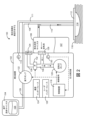
ここで図1~図4を参照すると、例示的な実施形態による、陰圧創傷療法(NPWT)システム100が示されている。NPWTシステム100は、管108及び110を介して創傷ドレッシング112に流体的に接続された療法装置102を含むように示されている。創傷ドレッシング112は、創傷114を取り囲む患者の皮膚116に接着又は封着されてもよい。NPWTシステム100と組み合わせて使用できる創傷ドレッシング112のいくつかの例が、2010年1月26日に付与された米国特許第7,651,484号明細書、2013年3月12日に付与された米国特許第8,394,081号明細書、及び2013年11月22日に出願された米国特許出願第14/087,418号明細書で詳細に説明されている。これらの特許及び特許出願の各々の開示全体は、参照により本明細書に組み込まれる。
Wound Therapy System Referring now to FIGS. 1-4, a negative pressure wound therapy (NPWT)
療法装置102は、創傷114における圧力を低下させることによって陰圧創傷療法を提供するように構成することができる。療法装置102は、創傷滲出液、空気、及び他の流体を創傷114から除去することによって、創傷114において(大気圧に対して)真空引きすることができる。創傷滲出液は、患者の循環系から病変又は炎症部位に滲み出る流体を含み得る。例えば、創傷滲出液は、水と、血液、血漿タンパク質、白血球、血小板、及び赤血球などの溶解溶質とを含み得る。創傷114から除去される他の流体は、創傷114に既に送達された滴下流体105を含み得る。滴下流体105は、例えば、洗浄流体、処方流体、薬剤流体、抗生物質流体、又は創傷治療中に創傷114に送達できる他の任意の種類の流体を含むことができる。滴下流体105は、滴下流体キャニスタ104内に保持され、滴下流体管108を介して創傷114に制御可能に分配されてもよい。いくつかの実施形態では、滴下流体キャニスタ104は、キャニスタ106が必要に応じて再び満たされ交換されることを可能にするために、療法装置102から取り外し可能である。
創傷114から除去された流体107は、除去流体管110を通過して、除去流体キャニスタ106内に収集される。除去流体キャニスタ106は、創傷滲出液と、創傷114から除去された他の流体107とを収集するように構成された療法装置102の構成要素であってもよい。いくつかの実施形態では、除去流体キャニスタ106は、キャニスタ106が必要に応じて空にされ交換されることを可能にするために、療法装置102から取り外し可能である。キャニスタ106の下部分は、創傷114から除去された創傷滲出液及び他の流体107で満たされてもよく、それに対して、キャニスタ106の上部分は、空気で満たされてもよい。療法装置102は、キャニスタ106から空気を吸い出すことによってキャニスタ106内を真空引きするように構成することができる。キャニスタ106内の減圧は、創傷ドレッシング112及び創傷114がキャニスタ106と同じ圧力に維持されるように、管110を介して創傷ドレッシング112及び創傷114に移すことができる。
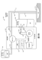
特に図2~図4を参照すると、例示的な実施形態による、療法装置102をより詳細に図示するブロック図が示されている。療法装置102は、空気圧ポンプ120と、滴下ポンプ122と、弁132と、フィルタ128と、制御装置118とを含むように示されている。空気圧ポンプ120は、(例えば、導管136を介して)除去流体キャニスタ106に流体的に結合することができ、且つキャニスタ106から空気を吸い出すことによってキャニスタ106内を真空引きするように構成することができる。いくつかの実施形態では、空気圧ポンプ120は、順方向と逆方向の両方向に動作するように構成される。例えば、空気圧ポンプ120は、キャニスタ106から空気を吸い出してキャニスタ106内の圧力を減少させるように順方向に動作することができる。空気圧ポンプ120は、キャニスタ106に空気を送り込んでキャニスタ106内の圧力を上昇させるように逆方向に動作することができる。空気圧ポンプ120は、以下により詳細に説明する、制御装置118によって制御することができる。
Referring specifically to FIGS. 2-4, block diagrams illustrating
同様に、滴下ポンプ122は、管109を介して滴下流体キャニスタ104に流体的に結合し、且つ管108を介して創傷ドレッシング112に流体的に結合することができる。滴下ポンプ122は、図4に示すように、管109及び管108を通して滴下流体105を送り出すことによって滴下流体105を創傷ドレッシング112及び創傷114に送達するように動作させることができる。滴下ポンプ122は、以下により詳細に説明する、制御装置118によって制御することができる。
Similarly,
フィルタ128は、キャニスタ106から吸い出された空気がフィルタ128を通過するように、除去流体キャニスタ106と空気圧ポンプ120との間に(例えば、導管136に沿って)位置決めすることができる。フィルタ128は、液体粒子又は固体粒子が導管136に入って空気圧ポンプ120に達するのを防止するように構成することができる。フィルタ128は、例えば、水性液体及び/又は油性液体が玉状になってフィルタ128の表面に付着するように疎水性及び/又は親油性である細菌フィルタを含み得る。空気圧ポンプ120は、フィルタ128前後の圧力降下があまり大きくならないようにフィルタ128を通る十分な空気流を提供するように(例えば、圧力降下が療法装置102から創傷114への陰圧の印加を実質的に妨げないように)構成することができる。
いくつかの実施形態では、療法装置102は、図3Aに示すように、陰圧回路を制御可能に通気するように弁132を動作させる。弁132は、導管136を介して空気圧ポンプ120とフィルタ128とに流体的に接続することができる。いくつかの実施形態では、弁132は、導管136と療法装置102の周囲の環境との間の空気流を制御するように構成される。例えば、弁132は、通気孔134及び導管138を介しての導管136内への空気流を可能にするために開放し、且つ通気孔134及び導管138を介しての導管136内への空気流を防止するために閉鎖することができる。弁132は、以下により詳細に説明する、制御装置118によって開閉することができる。弁132が閉鎖されたときに、空気圧ポンプ120は、図2に示すように、フィルタ128を第1の方向に通る空気流を生じさせることによって陰圧回路内を真空引きすることができる。陰圧回路は、陰圧創傷療法を実施するときに陰圧に維持できるシステム100の任意の構成要素(例えば、導管136、除去流体キャニスタ106、管110、創傷ドレッシング112、及び/又は創傷114)を含み得る。例えば、陰圧回路は、導管136、除去流体キャニスタ106、管110、創傷ドレッシング112、及び/又は創傷114を含み得る。弁132が開放しているときに、療法装置102の周囲の環境からの空気流は、通気孔134及び導管138を介して導管136に入り、陰圧回路内の空所を満たし得る。導管136からキャニスタ106及び陰圧回路内の他の容積内への空気流は、図3Aに示すように、フィルタ128を第1の方向とは反対の第2の方向に通過してもよい。
In some embodiments,
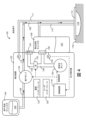
いくつかの実施形態では、療法装置102は、図3Bに示すように、オリフィス158を介して陰圧回路を通気する。オリフィス158は、導管136又は陰圧回路の他の任意の構成要素(例えば、除去流体キャニスタ106、管110、管111、創傷ドレッシング112など)における小さな開口部であってもよく、且つ陰圧回路に空気が既知の速度で漏出することを可能にしてもよい。いくつかの実施形態では、療法装置102は、弁132を動作させるのではなく、オリフィス158を介して陰圧回路を通気する。弁132は、オリフィス158が含まれる任意の実施形態では療法装置102から除外することができる。オリフィス158を介して陰圧回路に空気が漏出する速度は、オリフィス158の形状に応じて、実質的に一定であってもよく又は陰圧の関数として変化してもよい。オリフィス158からの漏出速度が可変である実施形態について、制御装置118は、陰圧と漏出速度との記憶された関係を使用して、陰圧の測定値に基づいてオリフィス158からの漏出速度を算出することができる。オリフィス158からの漏出速度が実質的に一定であるか可変であるかにかかわらず、オリフィス158を介しての陰圧回路への空気の漏出は、図5~図9を参照して説明したように、創傷114の容積を推定する際に使用される圧力減衰曲線を生成するために使用することができる。
In some embodiments,
いくつかの実施形態では、療法装置102は、様々なセンサを含む。例えば、療法装置102は、キャニスタ106内の圧力及び/又は創傷ドレッシング112又は創傷114における圧力を測定するように構成された圧力センサ130を含むように示されている。いくつかの実施形態では、療法装置102は、管111内の圧力を測定するように構成された圧力センサ113を含む。管111は、創傷ドレッシング112に接続されてもよく、且つ滴下流体105又は創傷滲出液を導くなどの二次機能なしに、創傷ドレッシング112又は創傷114における圧力を測定するためのみに使用されてもよい。種々の実施形態では、管108、110及び111は、療法装置102を創傷ドレッシング112に接続する単一の管内における物理的に別個の管又は別個の管腔であってもよい。よって、管110は、創傷ドレッシング112又は創傷114に陰圧を適用するように機能する陰圧管腔として説明されてもよく、それに対して、管111は、創傷ドレッシング112又は創傷114における圧力を感知するように構成された感知管腔として説明されてもよい。圧力センサ130及び113は、種々の実施形態において、療法装置102内に位置するか、管108、110及び111に沿った任意の位置に位置決めするか、又は創傷ドレッシング112に位置することができる。圧力センサ130及び/又は113によって記録された圧力測定値は、制御装置118に渡すことができる。制御装置118は、制御装置118(図5~図12を参照してより詳細に説明する)によって実施される種々の圧力試験動作及び制御動作への入力として圧力測定値を使用する。
In some embodiments,
制御装置118は、空気圧ポンプ120、滴下ポンプ122、弁132、及び/又は療法装置102の他の制御可能な構成要素を動作させるように構成することができる。いくつかの実施形態では、制御装置118は、陰圧回路に圧力刺激を印加することによって圧力試験手順を実施する。例えば、制御装置118は、弁132に閉鎖するように指示し、且つ陰圧回路内に陰圧を確立するように空気圧ポンプ120を動作させてもよい。陰圧が確立された時点で、制御装置118は、空気圧ポンプ120を作動停止してもよい。制御装置118は、所定時間にわたって弁132を開放させ、次いで、所定時間の経過後に閉鎖させてもよい。制御装置118は、圧力センサ130及び/又は113によって記録された圧力測定値を使用して圧力刺激に対する陰圧回路の動的圧力応答を観測してもよい。動的圧力応答は、例えば、パージ深さパラメータ、リバウンドパラメータ、デルタパラメータ、及び漏出速度パラメータ(図5を参照してより詳細に説明する)を含む様々なパラメータによって特徴付けられてもよい。
制御装置118は、観測した動的圧力応答に基づいて創傷114の容積を推定することができる。例えば、制御装置118は、観測したパラメータと陰圧回路の容積及び/又は創傷114の容積との関係を定義する圧力モデルへの入力として、観測したパラメータを適用することができる。モデルは、多項式近似モデル、ニューラルネットワークモデル、又は観測したパラメータを陰圧回路の容積及び若しくは創傷114の容積に関連付ける他の任意のモデルを含み得る。いくつかの実施形態では、圧力モデルは、療法装置102の製造業者によって制御装置118に記憶された既存のモデルである。他の実施形態では、制御装置118は、訓練手順を実施することによってその場で圧力モデルを生成することができる。
訓練手順は、既知の容積を有する訓練回路に療法装置102が接続されることを除き、圧力試験手順と同じであってもよい。例えば、創傷ドレッシング112は、創傷114を取り囲む患者の皮膚116にではなく、既知の容積を有する試験装置に適用することができる。制御装置118は、種々の既知の容積を有する種々の訓練回路に圧力刺激を印加することができ、且つ各訓練回路の動的圧力応答を観測してもよい。既知の容積の各々は、圧力刺激に対して異なる動的圧力応答をもたらし得る。次いで、制御装置118は、各訓練回路の既知の容積を対応する動的圧力応答と関連付けることができる。いくつかの実施形態では、制御装置118は、訓練回路の動的圧力応答を使用して、動的圧力応答(例えば、パージ深さ、リバウンド、デルタ、漏出速度など)の観測したパラメータと訓練回路の容積との関係を定義する圧力モデルを生成する。次いで、圧力モデルは、先に説明したように、制御装置118に記憶して、創傷114の容積を推定するために使用することができる。
The training procedure may be the same as the pressure test procedure, except the
いくつかの実施形態では、制御装置118は、圧力試験手順を実行し、動的圧力応答を観測し、且つ創傷治療中に創傷容積を複数回推定するように構成される。次いで、制御装置118は、創傷治療中の創傷容積の変化に基づいて治癒の進行を決定することができる。いくつかの実施形態では、制御装置118は、推定した創傷容積に基づいて創傷114に送達すべき滴下流体105の体積を決定するように構成される。送達すべき滴下流体105の体積は、創傷114の容積の所定の割合(例えば、20%、50%、80%など)であってもよい。次いで、制御装置118は、決定した体積の滴下流体105を創傷114に送達するように滴下ポンプ122を動作させることができる。制御装置118のこれら及び他の特徴について図5~図12を参照してより詳細に説明する。
In some embodiments,
いくつかの実施形態では、療法装置102は、ユーザインターフェース126を含む。ユーザインターフェース126は、1つ又は複数のボタン、ダイヤル、スライダ、キー、又はユーザからの入力を受け取るように構成された他の入力装置を含み得る。ユーザインターフェース126はまた、1つ若しくは複数の表示装置(例えば、LED、LCDディスプレイなど)、スピーカ、触覚フィードバック装置、又はユーザに情報を提供するように構成された他の出力装置を含み得る。いくつかの実施形態では、圧力センサ130及び/又は113によって記録された圧力測定値は、ユーザインターフェース126を介してユーザに提示される。ユーザインターフェース126はまた、制御装置118によって生成された警告を表示することもできる。例えば、制御装置118は、キャニスタ106が検出されない場合に「キャニスタなし」という警告を生成することができる。
In some embodiments,
いくつかの実施形態では、療法装置102は、データを送受信するように構成されたデータ通信インターフェース124(例えば、USBポート、無線送受信機など)を含む。通信インターフェース124は、外部システム又は装置とデータ通信を行うための有線又は無線通信インターフェース(例えば、ジャック、アンテナ、送信機、受信機、送受信機、ワイヤ端末など)を含み得る。種々の実施形態では、通信は、直接通信(例えば、ローカル有線又は無線通信)であってもよく、又は通信ネットワーク(例えば、WAN、インターネット、セルラーネットワークなど)を介した通信であってもよい。例えば、通信インターフェース124は、USBポート又はイーサネットに基づく通信リンク若しくはネットワークを介してデータを送受信するためのイーサネットカード及びポートを含むことができる。別の例では、通信インターフェース124は、無線通信ネットワーク又はセルラ若しくは携帯電話通信送受信機を介して通信するためのWi-Fi送受信機を含むことができる。
In some embodiments,
制御装置
ここで図5を参照すると、例示的な実施形態による、制御装置118をより詳細に図示するブロック図が示されている。制御装置118は、プロセッサ142とメモリ144とを含む処理回路140を含むように示されている。プロセッサ142は、汎用若しくは専用プロセッサ、特定用途向け集積回路(ASIC)、1つ若しくは複数のフィールドプログラマブルゲートアレイ(FPGA)、処理構成要素の群、又は他の好適な処理構成要素であってもよい。プロセッサ142は、メモリ144に記憶された又は他のコンピュータ可読媒体(例えば、CD-ROM、ネットワークストレージ、リモートサーバなど)から受信されたコンピュータコード又は命令を実行するように構成される。
Controller Referring now to FIG. 5, a block
メモリ144は、本開示で説明する種々のプロセスを完了及び/又は促進するためのデータ及び/又はコンピュータコードを記憶するための1つ又は複数の装置(例えば、メモリユニット、メモリ装置、記憶装置など)を含み得る。メモリ144は、ランダムアクセスメモリ(RAM)、読み取り専用メモリ(ROM)、ハードドライブ記憶装置、一時記憶装置、不揮発性メモリ、フラッシュメモリ、光メモリ、又はソフトウェアオブジェクト及び/若しくはコンピュータ命令を記憶するための他の任意の好適なメモリを含み得る。メモリ144は、データベース構成要素、オブジェクトコード構成要素、スクリプト構成要素、又は、種々の活動をサポートするための他の任意の種類の情報構造及び本開示で説明する情報構造を含み得る。メモリ144は、処理回路140を介してプロセッサ142に通信可能に接続されてもよく、且つ本明細書で説明する1つ又は複数のプロセスを(例えば、プロセッサ142によって)実行するためのコンピュータコードを含み得る。プロセッサ142が、メモリ144に記憶された命令を実行したときに、プロセッサ142は、概して、そのような活動を完了するように制御装置118(より詳細には処理回路140)を構成する。
制御装置118は、ポンプ制御装置146と弁制御装置150とを含むように示されている。ポンプ制御装置146は、制御信号を生成してポンプ120~122に提供することによってポンプ120~122を動作させるように構成することができる。ポンプ120~122に提供された制御信号は、ポンプ120~122を作動させるか、作動停止させるか、又はポンプ120~122に可変能力若しくは可変速度(例えば、半分の速度で動作する、最高速度で動作するなど)を達成させることができる。同様に、弁制御装置150は、制御信号を生成して弁132に提供することによって弁132を動作させるように構成することができる。弁132に提供される制御信号は、弁132を開放させるか、閉鎖させるか、又は弁132に指定の中間位置(例えば、1/3の開放、1/2の開放など)を達成させることができる。いくつかの実施形態では、ポンプ制御装置146及び弁制御装置150は、本明細書で説明するプロセスを実行するときに、ポンプ120~122及び弁132を動作させるために、制御装置118の他の構成要素(例えば、試験手順制御装置148、創傷容積推定器156など)によって使用される。
いくつかの実施形態では、ポンプ制御装置146は、除去流体キャニスタ106が存在するかどうかを検出するように構成されたキャニスタセンサからの入力を使用する。ポンプ制御装置146は、除去流体キャニスタ106が存在するときにのみ能動的空気圧ポンプ120を作動させるように構成することができる。例えば、ポンプ制御装置146は、キャニスタ106が存在するかどうかを確認することができ、且つキャニスタ106が存在するという判定に応答して空気圧ポンプ120を作動させることができる。しかしながら、キャニスタ106が存在しない場合、ポンプ制御装置146は、空気圧ポンプ120が作動するのを防止してもよい。同様に、ポンプ制御装置146は、滴下流体キャニスタ104が存在するときにのみ能動的滴下ポンプ122を作動させるように構成することができる。例えば、ポンプ制御装置146は、キャニスタ104が存在するかどうかを確認することができ、且つキャニスタ104が存在するという判定に応答して能動的滴下ポンプ122を作動させることができる。しかしながら、キャニスタ104が存在しない場合、ポンプ制御装置146は、滴下ポンプ122が作動するのを防止してもよい。
In some embodiments,
制御装置118は、圧力モニタ152を含むように示されている。圧力モニタ152は、圧力センサ130及び/又は113からのフィードバックを使用して除去流体キャニスタ106内の圧力及び/又は創傷ドレッシング112若しくは創傷114内の圧力を監視するように構成することができる。例えば、圧力センサ130及び/又は113は、圧力測定値を圧力モニタ152に提供してもよい。圧力モニタ152は、圧力測定値を使用して、キャニスタ106内の圧力及び/又は創傷ドレッシング112若しくは創傷114内の圧力をリアルタイムで決定することができる。圧力モニタ152は、モデル生成装置154、ポンプ制御装置146、試験手順制御装置148、及び/又は弁制御装置150に圧力値を、そのような構成要素によって実施されるプロセスを制御する入力として使用されるように、提供することができる。
ここで図5及び図6A~図6Cを参照すると、制御装置118は、試験手順制御装置148を含むように示されている。試験手順制御装置148は、動的圧力応答を引き起こし観測するために圧力試験手順を実行するように構成することができる。療法装置102が、創傷114を覆って患者の皮膚116に適用された創傷ドレッシング112に接続される場合、試験手順制御装置148は、導管136、除去流体キャニスタ106、管110、創傷ドレッシング112、及び/又は創傷114を含む陰圧回路(未知の容積を有し得る)の動的圧力応答を観測することができる。療法装置102が、既知の容積を有する訓練装置に適用された創傷ドレッシング112に接続される場合、試験手順制御装置148は、導管136、除去流体キャニスタ106、管110、創傷ドレッシング112、及び/又は訓練装置を含む訓練回路の動的圧力応答を観測することができる。
5 and 6A-6C,
特に図6Aを参照すると、例示的な実施形態による、試験手順制御装置148によって実施された受動的圧力試験手順を図示するグラフ200が示されている。試験手順制御装置148は、陰圧回路及び/又は訓練回路内に陰圧を確立するように空気圧ポンプ120を動作させるように構成することができる。陰圧は、療法装置102を取り囲む大気圧と陰圧回路及び/又は訓練回路内の圧力との差(すなわち、大気圧が陰圧回路及び/又は訓練回路内の圧力を超える量)として定義されてもよい。例えば、時間t0では、陰圧は、陰圧回路及び/又は訓練回路内の圧力が療法装置102の周囲の大気圧と等しいことを表す、P0(例えば、0mmHg)の値を有するように示されている。
Referring specifically to FIG. 6A, a
時間t0では、試験手順制御装置148は、陰圧回路及び/又は訓練回路内の陰圧を低下させるように空気圧ポンプ120の動作を開始する。陰圧は、時間t1において大気圧よりも低いP8mmHg(例えば、125mmHg)の陰圧値に達するまで低下し続ける。時間t1から時間t2の間に、試験手順制御装置148は、陰圧回路及び/又は訓練回路から空気を除去するように空気圧ポンプ120を必要に応じて動作させることによって陰圧をP8の値に維持する。次いで、試験手順制御装置148は、陰圧回路及び/又は訓練回路内に陰圧が確立された後に陰圧回路及び/又は訓練回路に圧力刺激を印加してもよい。
At time t0 ,
時間t2では、試験手順制御装置148は、空気圧ポンプ120を作動停止する。陰圧回路及び/又は訓練回路内の陰圧の大きさは、時間t2で始まり、弁132が閉鎖されている間の陰圧回路及び/又は訓練回路への空気の漏出に起因して減少し得る。弁132が閉鎖されている間に陰圧が減少する速度は、時間t2から時間t3の間の線202の傾きによって定められる。試験手順制御装置148は、時間t2から時間t3の間の線202の傾きを決定してもよく、且つこの傾きを漏出速度パラメータの値として記憶してもよい。漏出速度パラメータは、陰圧回路及び/又は訓練回路の動的圧力応答を特徴付けるパラメータの1つであってもよい。
At time t 2 ,
時間t3では、試験手順制御装置148は、陰圧回路及び/又は訓練回路に圧力刺激を印加する。圧力刺激を印加することは、陰圧回路及び/又は訓練回路を制御可能に通気するように弁132を動作させることを含み得る。例えば、試験手順制御装置148は、陰圧回路及び/又は訓練回路内への空気流を可能にするために、時間t3において弁132を開放させてもよい。試験手順制御装置148は、所定時間にわたって(すなわち、時間t3から時間t4まで)弁132を開放状態に保ってもよく、且つ所定時間の経過後に(すなわち、時間t4において)弁132を閉鎖してもよい。
At time t3 ,
時間t4では、試験手順制御装置148は、圧力刺激に対する陰圧回路及び/又は訓練回路の動的圧力応答を観測してもよい。動的圧力応答は、パージ深さパラメータ、リバウンドパラメータ、及びデルタパラメータを含むいくつかの追加のパラメータによって特徴付けられてもよい。パージ深さパラメータは、弁132が開放される前の陰圧P7の測定値と弁132が開放している間の陰圧P3の測定値との差(すなわち、パージ深さ=P7-P3)として定義されてもよい。リバウンドパラメータは、弁132が閉鎖された後の陰圧P6の測定値と弁132が開放している間の陰圧P3の測定値との差(すなわち、リバウンド=P6-P3)として定義されてもよい。デルタパラメータは、弁132が開放される前の陰圧P7の測定値と弁132が閉鎖された後の陰圧P6の測定値との差(すなわち、デルタ=P7-P6)として定義されてもよい。
At time t4 ,
いくつかの実施形態では、試験手順制御装置148は、弁132が閉鎖されたときに陰圧が閾値P1に達するまで圧力刺激をさらに1回又は複数回印加する。圧力刺激の各印加の間に、試験手順制御装置148は、別の所定時間にわたって(すなわち、時間t4から時間t5まで及び時間t6から時間t7まで)待機してもよい。例えば、試験手順制御装置148は、時間t4から時間t5までの所定時間にわたって待機してもよく、且つ時間t5において圧力刺激を再び印加してもよい。試験手順制御装置148は、陰圧回路及び/又は訓練回路内への空気流を可能にするために、時間t5において弁132を開放させてもよい。試験手順制御装置148は、所定時間にわたって(すなわち、時間t5から時間t6まで)弁132を開放状態に保ってもよく、且つ所定時間の経過後に(すなわち、時間t6において)弁132を閉鎖してもよい。時間t6では、試験手順制御装置148は、圧力刺激の2回目の印加に応答して、パージ深さパラメータ(すなわち、パージ深さ=P5-P1)、リバウンドパラメータ(すなわち、リバウンド=P4-P1)、及びデルタパラメータ(すなわち、デルタ=P5-P4)の値を記憶してもよい。このプロセスは、陰圧回路及び/又は訓練回路内の陰圧の値が時間t9において閾圧力値P1に達するまで繰り返すことができる。
In some embodiments,
特に図6Bを参照すると、例示的な実施形態による、試験手順制御装置148によって実施された能動的試験手順を図示するグラフ210が示されている。試験手順制御装置148は、陰圧回路及び/又は訓練回路内に陰圧を確立するように空気圧ポンプ120を動作させるように構成することができる。陰圧は、療法装置102を取り囲む大気圧と陰圧回路及び/又は訓練回路内の圧力との差(すなわち、大気圧が陰圧回路及び/又は訓練回路内の圧力を超える量)として定義されてもよい。例えば、時間t0では、陰圧は、陰圧回路及び/又は訓練回路内の圧力が療法装置102の周囲の大気圧と等しいことを表す、P0(例えば、0mmHg)の値を有するように示されている。
Referring specifically to FIG. 6B, a
図6Bに図示する能動的試験手順は、図6Aに図示する受動的試験手順と実質的に同様であってもよい。しかしながら、能動的試験手順では、制御装置148は、陰圧回路及び/又は訓練回路への高い空気漏出速度を補償するために、弁132が閉鎖されている間(例えば、時間t4からt5の間、時間t6からt7の間、及び時間t8からt9の間)の空気圧ポンプ120の短時間の制御された作動によって空気圧ポンプ120を動作させるように構成することができる。グラフ210では、線212は、陰圧回路及び/又は訓練回路内の圧力を時間の関数として表す。弁132が閉鎖されている間の陰圧回路及び/又は訓練回路への空気の実際の漏出速度は、線分216の傾きによって表され、それに対して、線214の傾きは、時間t4からt5の間の平均の又は補助を伴う漏出速度を表す。平均の又は補助を伴う漏出速度が

特に図6C~図6Dを参照すると、例示的な実施形態による、試験手順制御装置148によって実施された制御されない試験手順を図示するグラフ220及び230が示されている。図6A及び図6Bを参照して説明した受動的試験手順及び能動的試験手順とは異なり、制御されない試験手順は、弁132を利用せず、療法装置102が弁132の代わりにオリフィス158を含む実施形態のために実施することができる。グラフ220は、オリフィス158が陰圧回路及び/又は訓練回路に空気を可変の漏出速度で漏出させたときの制御されない試験手順を図示しており、それに対して、グラフ220は、オリフィス158が陰圧回路及び/又は訓練回路に空気を実質的に一定の漏出速度で漏出させたときの制御されない試験手順を図示している。
6C-6D,
両方の制御されない試験手順では、時間t0において、試験手順制御装置148は、陰圧回路及び/又は訓練回路内の圧力を低下させるように空気圧ポンプ120の動作を開始する。陰圧は、時間t1において大気圧よりも低いP2mmHg(例えば、125mmHg)の陰圧値に達するまで低下し続ける。
In both uncontrolled test procedures, at time t 0 ,
時間t1では、試験手順制御装置148は、空気圧ポンプ120を作動停止する。陰圧回路及び/又は訓練回路内の陰圧の大きさは、時間t1で始まり、オリフィス158を介しての陰圧回路及び/又は訓練回路への空気の漏出に起因して減少し得る。陰圧が減少する速度は、時間t1から時間t2の間の線222の傾きによって定められる。グラフ220では、t1からt2の間で時間が経過するにつれてゼロに近づく線222の傾きによって示すように、オリフィス158を介しての陰圧回路及び/又は訓練回路への空気の漏出が、時間t1付近でより速やかに、時間t2付近でよりゆっくりと生じる。グラフ230では、オリフィス158を介しての陰圧回路及び/又は訓練回路への空気の漏出が、略直線232で示すように、実質的に一定の速度で生じる。いずれのシナリオでも、試験手順制御装置148は、時間t1から時間t2の間の線222の傾きを1回又は複数回決定してもよく、且つこの傾きを漏出速度パラメータの値として記憶してもよい。代替的に、漏出速度パラメータは、陰圧がP2からP1まで低下するのに必要とされる時間として定義することができ、且つt2からt1を減算すること(すなわち、t2-t1)によって算出することができる。漏出速度パラメータは、陰圧回路及び/又は訓練回路の動的圧力応答を特徴付けるパラメータの1つであってもよい。
At time t 1 ,
試験手順制御装置148は、種々の実施形態において、受動的試験手順、能動的試験手順、及び/又は制御されない試験手順を実行するように構成することができる。受動的試験手順は、ほとんどの条件下で好適であり得、且つ試験手順制御装置148によって使用される主要な試験手順又はデフォルトの試験手順であってもよい。しかしながら、能動的試験手順は、漏出速度が高い場合に好適であり得、且つ実際の漏出速度が所定の漏出速度閾値を超えるという判定に応答して、試験手順制御装置148によって使用されてもよい。制御されない試験手順は、弁132がオリフィス158に置き換えられる実施形態に好適であり得る。
漏出速度は、様々な方法で決定することができる。いくつかの実施形態では、漏出速度は、陰圧回路内に所定の陰圧を達成するように空気圧ポンプ120を動作させて圧力減衰を経時的に測定することによって決定される。いくつかの実施形態では、漏出速度は、空気圧ポンプ120の効率又は空気圧ポンプ120によって消費される電力に基づいて決定される。例えば、ポンプ制御装置146は、先に説明したように、陰圧を設定値に維持するために又は所定の漏出速度閾値を超える速度で陰圧が低下するのを防止するために、空気圧ポンプ120の短時間の制御された作動を実施するように構成することができる。空気圧ポンプ120のこれらの短時間の制御された作動の数又は頻度は、漏出速度に依存し、漏出速度を決定するために使用することができる。同様に、これらの短時間の制御された作動を実施するために空気圧ポンプ120によって消費される電力は、漏出速度に依存し、漏出速度を決定するために使用することができる。例えば、制御装置118は、所与の期間内の空気圧ポンプ120の短時間の制御された作動の数を記録し、短時間の制御された作動の頻度若しくは間隔を測定し、空気圧ポンプ120の負荷サイクル(例えば、空気圧ポンプ120が動作している時間の割合)を測定し、又は短時間の制御された作動を実施するために空気圧ポンプ120によって消費された電力量を測定するように構成することができる。これらの測定基準のいずれかは、ポンプ効率を特徴付けてもよく、且つポンプ効率パラメータとして記憶することができる。制御装置118は、記憶された式又は所定の関係を使用して、漏出速度をポンプ効率の関数として算出することができる。
Leakage rate can be determined in a variety of ways. In some embodiments, the leak rate is determined by operating the
再び図5を参照すると、制御装置118は、モデル生成装置154を含むように示されている。モデル生成装置154は、動的圧力応答のパラメータと創傷114の容積との関係を定義するモデルを生成するように構成することができる。モデルを生成するために、モデル生成装置154は、いくつかの異なる既知の容積(例えば、50cc、100cc、200cc、300ccなど)を有するいくつかの異なる訓練回路について上で概説した圧力試験手順を試験手順制御装置148に実行させることができる。既知の容積を有する訓練回路において圧力試験手順が実施される場合、圧力試験手順は、訓練手順と呼ばれることがある。訓練手順の各実施は、既知の容積を有する訓練回路に圧力刺激を印加することと、圧力刺激に対する訓練回路の動的圧力応答を観測することと、既知の容積を訓練回路の動的圧力応答と関連付けることとを含み得る。
Referring again to FIG. 5,
いくつかの実施形態では、モデル生成装置154は、既知の容積毎に動的圧力応答(すなわち、漏出速度、パージ深さ、リバウンド、デルタなど)のパラメータの値を記録し、且つそれらの値を既知の容積と関連付ける。パラメータの値及び既知の容積は、モデルを構築するために使用できる1組の訓練データを形成する。パラメータの値は1組のモデル入力訓練データを形成し、それに対して、既知の容積は1組のモデル出力訓練データを形成する。モデル生成装置154は、様々なモデル生成技術のいずれかを使用して、パラメータの値を対応する容積に1組の訓練データとして関連付けるモデル(すなわち、数学的モデル)を構築することができる。
In some embodiments, the
いくつかの実施形態では、モデル生成装置154は、パラメータの値を対応する容積に関連付けるために多項式近似モデルを作成する。多項式近似モデルを生成するために、モデル生成装置154は、様々な回帰技術のいずれかを使用して多項式回帰などの曲線適合プロセスを実施することができる。モデル生成装置154によって使用できる回帰技術の例としては、最小二乗法、通常の最小二乗法、線形最小二乗法、部分最小二乗法、全最小二乗法、一般化最小二乗法、重み付け最小二乗法、非線形最小二乗法、非負最小二乗法、反復再重み付け最小二乗法、リッジ回帰、最小絶対偏差、ベイズ線形回帰、ベイズ多変量線形回帰などが挙げられる。
In some embodiments,
他の実施形態では、モデル生成装置154は、パラメータの値を対応する容積に関連付けるためにニューラルネットワークモデルを作成する。ニューラルネットワークモデルを生成するために、モデル生成装置154は、機械学習プロセスを実施することができる。モデル生成装置154によって使用できる機械学習技術の例としては、決定木学習、相関ルール学習、人工ニューラルネットワーク、深層学習、帰納論理プログラミング、サポートベクターマシン、クラスタリング、ベイジアンネットワーク、強化学習、表現学習、類似度及び計量学習、スパース辞書学習、遺伝的アルゴリズム、ルールベース機械学習などが挙げられる。
In another embodiment,
ここで図7Aを参照すると、例示的な実施形態による、いくつかの圧力減衰曲線252、254、256、及び258を図示するグラフ250が示されている。圧力減衰曲線252~258の各々は、既知の容積に対応し、陰圧回路及び/又は訓練回路内の圧力を対応する容積に対する時間の関数として表す。例えば、圧力減衰曲線252は300ccの容積に対応し、圧力減衰曲線254は200ccの容積に対応し、圧力減衰曲線256は100ccの容積に対応し、圧力減衰曲線258は50ccの容積に対応する。圧力減衰曲線252~258の各々は、上で説明したモデリング技術のいずれかを使用して、モデル生成装置154によって作成されてもよい。例えば、圧力減衰曲線252~258は、既知の容積毎に圧力試験手順を実行して既知の容積毎に圧力減衰を経時的にプロットすることによって作成することができる。
Referring now to FIG. 7A, a
いくつかの実施形態では、制御装置118は、創傷114の容積を推定するときに、圧力減衰曲線252~258を使用して、測定した圧力値を対応する容積に変換する。例えば、制御装置118は、陰圧回路の圧力を測定し、圧力が測定された時間を特定することができる。制御装置118は、圧力減衰曲線252~258の間を補間して、測定した圧力と時間の対に対応する補間圧力値を決定することができる。例えば、時間t1では、制御装置118は、P1の圧力値を観測してもよい。時間t1と圧力P1との組み合わせは、グラフ250内に点260を定める。点260は、圧力減衰曲線252と圧力減衰曲線254とのほぼ中間にある。制御装置118は、圧力減衰曲線252と254との間を補間して、陰圧回路の容積が、圧力減衰曲線252に対応する既知の容積と圧力減衰曲線254に対応する既知の容積とのほぼ中間の容積(約250cc)であると推定することができる。他の実施形態では、制御装置118は、圧力モデルへの入力として動的圧力応答の観測したパラメータを適用することによって、創傷114の容積を推定する。
In some embodiments,
ここで図7Bを参照すると、例示的な実施形態による、補助なしの圧力減衰曲線264と補助を伴う圧力減衰曲線262とを図示するグラフ260が示されている。グラフ260では、補助なしの圧力減衰曲線264と補助を伴う圧力減衰曲線262の両方は、同じ容積の陰圧回路及び/又は訓練回路に対応する。補助なしの圧力減衰曲線264は、図6Aに示す受動的試験手順の間(すなわち、高い漏出速度を補償するように空気圧ポンプ120を動作させていないとき)の圧力減衰を図示している。逆に、補助を伴う圧力減衰曲線262は、能動的試験手順の間の(すなわち、高い漏出速度を補償するように空気圧ポンプ120を動作させたときの)圧力減衰を図示している。図6Bを参照して述べたように、能動的試験手順の間に空気圧ポンプ120を動作させることによって圧力減衰が軽減され、それゆえ、補助なしの圧力減衰曲線264に対して補助を伴うより緩やかな圧力減衰曲線262が得られる。
Referring now to FIG. 7B, a
再び図5を参照すると、制御装置118は、創傷容積推定器156を含むように示されている。創傷容積推定器156は、圧力センサ130及び/又は113によって収集された圧力測定値に基づいて創傷114の容積を推定するように構成することができる。いくつかの実施形態では、創傷容積推定器156は、圧力試験手順を実施することによって創傷114の容積を推定する。圧力試験手順は、陰圧回路に圧力刺激を印加することと、圧力刺激に対する陰圧回路の動的圧力応答を観測することとを含み得る。上で説明したように、陰圧回路は、陰圧創傷療法を実施するときに陰圧に維持できるシステム100の任意の構成要素(例えば、導管136、除去流体キャニスタ106、管110、創傷ドレッシング112、及び/又は創傷114)を含み得る。
Referring again to FIG. 5,
圧力試験手順を実施するために、創傷容積推定器156は、弁132に閉鎖するように指示し、且つ陰圧回路内に陰圧を確立するように空気圧ポンプ120を動作させてもよい。陰圧が確立された時点で、創傷容積推定器156は、空気圧ポンプ120を作動停止してもよい。創傷容積推定器156は、所定時間にわたって弁132を開放させ、次いで、所定時間の経過後に閉鎖させてもよい。創傷容積推定器156は、圧力センサ130及び/又は113によって記録された圧力測定値を使用して圧力刺激に対する陰圧回路の動的圧力応答を観測してもよい。動的圧力応答は、先に説明したように、例えば、パージ深さパラメータ、リバウンドパラメータ、デルタパラメータ、及び漏出速度パラメータを含む様々なパラメータによって特徴付けられてもよい。
To perform the pressure test procedure, wound
創傷容積推定器156は、観測した動的圧力応答に基づいて創傷114の容積を推定することができる。例えば、創傷容積推定器156は、観測したパラメータと陰圧回路の容積及び/又は創傷114の容積との関係を定義する圧力モデルへの入力として、観測したパラメータを適用することができる。いくつかの実施形態では、圧力モデルは、モデル生成装置154によって(例えば、訓練回路を使用して収集された訓練データに基づいて訓練手順を実施することによって)作成されたモデルである。モデルは、多項式近似モデル、ニューラルネットワークモデル、又は観測したパラメータを陰圧回路の容積及び/若しくは創傷114の容積に関連付ける他の任意のモデルを含み得る。他の実施形態では、圧力モデルは、療法装置102の製造業者によってメモリ144に記憶された既存のモデルである。
いくつかの実施形態では、創傷容積推定器156は、圧力試験手順を実行し、動的圧力応答を観測し、且つ創傷治療中に創傷容積を複数回推定するように構成される。次いで、創傷容積推定器156は、創傷治療中の創傷容積の変化に基づいて治癒の進行を決定することができる。いくつかの実施形態では、創傷容積推定器156は、推定した創傷容積に基づいて創傷114に送達すべき滴下流体105の体積を決定するように構成される。送達すべき滴下流体105の体積は、創傷114の容積の所定の割合(例えば、20%、50%、80%など)であってもよい。次いで、創傷容積推定器156は、決定した体積の滴下流体105を創傷114に送達するように滴下ポンプ122を動作させることができる。
In some embodiments, wound
フロー図
ここで図8を参照すると、例示的な実施形態による、圧力モデルを生成するためのプロセス300のフローチャートが示されている。プロセス300は、訓練回路及び/又は陰圧回路の動的圧力応答を特徴付けるモデルを作成するために、療法装置102の1つ又は複数の構成要素によって実施することができる。例えば、プロセス300は、制御装置118、空気圧ポンプ120、弁132、並びに/又は圧力センサ130及び/若しくは113によって実施することができる。いくつかの実施形態では、プロセス300は、試験手順制御装置148とモデル生成装置154とによって実行される。
Flow Diagram Referring now to FIG. 8, a flowchart of a
プロセス300は、既知の容積を有する訓練回路に圧力刺激を印加すること(ステップ302)を含むように示されている。訓練回路は、療法装置102の1つ若しくは複数の構成要素(例えば、導管136、除去流体キャニスタ106など)及び/又はシステム100の他の構成要素(例えば、管110、創傷ドレッシング112)を含み得る。創傷治療条件下で、創傷ドレッシング112は通常、創傷114を取り囲む患者の皮膚116に適用される。しかしながら、訓練回路は、創傷114を既知の容積を有する訓練装置に置き換えてもよい。ステップ302は、弁132に閉鎖するように指示することと、訓練回路内に陰圧を確立するように空気圧ポンプ120を動作させることとを含み得る。陰圧が確立された時点で、空気圧ポンプ120が作動停止されてもよい。ステップ302は、所定時間にわたって弁132を開放させ、次いで、所定時間の経過後に弁132を閉鎖することを含み得る。
プロセス300は、圧力刺激に対する訓練回路の動的圧力応答を観測すること(ステップ304)と、訓練回路の既知の容積を動的圧力応答と関連付けること(ステップ306)とを含むように示されている。ステップ304は、圧力センサ130及び/又は113によって記録された圧力測定値を使用して訓練回路の圧力を経時的に監視することを含み得る。動的圧力応答は、先に説明したように、例えば、パージ深さパラメータ、リバウンドパラメータ、デルタパラメータ、及び漏出速度パラメータを含む様々なパラメータによって特徴付けられてもよい。ステップ306は、動的圧力応答のパラメータの値を入力訓練データとして記憶することと、訓練回路の既知の容積を入力訓練データに対応する出力訓練データとして記憶することとを含み得る。
プロセス300は、全ての容積が試験されたかどうかを判定すること(ステップ308)を含むように示されている。全ての容積が試験されているわけではない(つまり、ステップ308の結果が「いいえ」である)場合、療法装置102が接続されている訓練装置を、異なる既知の容積を有する異なる訓練装置に置き換えることができる。次いで、圧力刺激を印加して既知の容積毎に訓練回路の動的圧力応答を観測するために、圧力刺激を印加してステップ302~306を繰り返すことができる。動的圧力応答パラメータの各組は、入力訓練データとして記憶することができ、且つ各組及び対応する既知の容積は、出力訓練データとして記憶することができる。
全ての容積が試験された(つまり、ステップ308の結果が「はい」であった)時点で、プロセス300は、圧力モデルの生成(ステップ310)に進み得る。ステップ310は、様々なモデル生成技術のいずれかを使用して、動的圧力応答パラメータの値を対応する容積に1組の訓練データとして関連付けるモデル(すなわち、数学的モデル)を構築することを含み得る。
Once all volumes have been tested (ie, the result of
いくつかの実施形態では、ステップ310において生成されたモデルは、多項式近似モデルである。ステップ310は、様々な回帰技術のいずれかを使用して多項式回帰などの曲線適合プロセスを実施することを含み得る。ステップ310で使用できる回帰技術の例としては、最小二乗法、通常の最小二乗法、線形最小二乗法、部分最小二乗法、全最小二乗法、一般化最小二乗法、重み付け最小二乗法、非線形最小二乗法、非負最小二乗法、反復再重み付け最小二乗法、リッジ回帰、最小絶対偏差、ベイズ線形回帰、ベイズ多変量線形回帰などが挙げられる。
In some embodiments, the model generated in
いくつかの実施形態では、ステップ310において生成されたモデルは、ニューラルネットワークモデルである。ステップ310は、様々な機械学習技術のいずれかを使用して、動的圧力応答パラメータの値を対応する容積に1組の訓練データとして関連付けるニューラルネットワークモデルを生成することを含み得る。ステップ310で使用できる機械学習技術の例としては、決定木学習、相関ルール学習、人工ニューラルネットワーク、深層学習、帰納論理プログラミング、サポートベクターマシン、クラスタリング、ベイジアンネットワーク、強化学習、表現学習、類似度及び計量学習、スパース辞書学習、遺伝的アルゴリズム、ルールベース機械学習などが挙げられる。次いで、圧力モデルは、創傷114の容積を推定する際に使用されるように記憶することができる。
In some embodiments, the model generated in
ここで図9を参照すると、例示的な実施形態による、創傷の容積を推定するためのプロセス400のフローチャートが示されている。プロセス400は、創傷114の容積を推定するために、療法装置102の1つ又は複数の構成要素によって実施することができる。例えば、プロセス400は、制御装置118、空気圧ポンプ120、弁132、並びに/又は圧力センサ130及び/若しくは113によって実施することができる。いくつかの実施形態では、プロセス400は、試験手順制御装置148と創傷容積推定器156とによって実行される。
Referring now to FIG. 9, a flowchart of a
プロセス400は、未知の容積を有する陰圧回路に圧力刺激を印加すること(ステップ402)を含むように示されている。陰圧回路は、療法装置102の1つ若しくは複数の構成要素(例えば、導管136、除去流体キャニスタ106など)及び/又はシステム100の他の構成要素(例えば、管110、創傷ドレッシング112、創傷114)を含み得る。創傷治療条件下で、創傷ドレッシング112は、創傷114を取り囲む患者の皮膚116に適用されてもよい。よって、創傷114の容積は、陰圧回路の一部を形成する。ステップ402は、弁132に閉鎖するように指示することと、陰圧回路内に陰圧を確立するように空気圧ポンプ120を動作させることとを含み得る。陰圧が確立された時点で、空気圧ポンプ120が作動停止されてもよい。ステップ402は、所定時間にわたって弁132を開放させ、次いで、所定時間の経過後に弁132を閉鎖することを含み得る。いくつかの実施形態では、ステップ402は、図6A~図6Bを参照して説明したように、受動的試験手順及び/又は能動的試験手順を実行することを含む。
プロセス400は、圧力刺激に対する陰圧回路の動的圧力応答を観測すること(ステップ404)、動的圧力応答を特徴付けるパラメータについての値を決定すること(ステップ406)とを含むように示されている。ステップ404は、圧力センサ130及び/又は113によって記録された圧力測定値を使用して陰圧回路の圧力を経時的に監視することを含み得る。動的圧力応答は、先に説明したように、例えば、パージ深さパラメータ、リバウンドパラメータ、デルタパラメータ、及び漏出速度パラメータを含む様々なパラメータによって特徴付けられてもよい。ステップ406は、動的圧力応答のパラメータの値を記憶することを含み得る。
プロセス400は、創傷容積をパラメータの関数として定義する圧力応答モデルへの入力としてパラメータの値を適用すること(ステップ408)を含むように示されている。いくつかの実施形態では、圧力応答モデルは、プロセス300を実施することによって(例えば、訓練回路を使用して収集された訓練データを使用して回帰プロセス又は機械学習プロセスを実施することによって)作成されたモデルである。モデルは、多項式近似モデル、ニューラルネットワークモデル、又は観測したパラメータを陰圧回路の容積及び若しくは創傷114の容積に関連付ける他の任意のモデルを含み得る。
プロセス400は、モデルの出力に基づいて創傷の容積を推定すること(ステップ410)を含むように示されている。いくつかの実施形態では、圧力応答モデルの出力は、創傷114の推定容積である。よって、圧力応答モデルの出力は、推定した創傷容積として使用することができる。他の実施形態では、圧力応答モデルの出力は、陰圧回路の推定容積である。圧力応答モデルの出力が陰圧回路の推定容積である場合、ステップ410は、創傷114の推定容積を特定するために陰圧回路の他の構成要素の既知の容積を減算することを含み得る。例えば、ステップ410は、残りの唯一の容積が創傷114の容積となるように導管136、除去流体キャニスタ106、管110、及び/又は創傷ドレッシング112の既知の容積を減算することを含み得る。
いくつかの実施形態では、陰圧回路の一部を形成する除去流体キャニスタ106の容積は、キャニスタ106内の空気の体積に制限される。キャニスタ106内の空気の体積は、キャニスタ106内の除去流体107の液面に基づいて変化し得る。いくつかの実施形態では、除去流体キャニスタ106は、キャニスタ106内の除去流体107の液面を記録するように動作するセンサ(例えば、液面センサ、重量センサなど)を含む。次いで、除去流体107の観測した液面は、キャニスタ106内の空気の体積を推定するために使用することができる。他の実施形態では、キャニスタ106内の空気の体積は、デッドスペース検出プロセスを実行することによって推定することができる。キャニスタ106内の空気の体積を推定するために使用できるデッドスペース検出プロセスの例が、2017年10月26日に出願された米国仮特許出願第62/577,579号明細書で詳細に説明されており、この明細書の開示全体が参照により本明細書に組み込まれる。
In some embodiments, the volume of removal
ここで図10を参照すると、例示的な実施形態による、治癒の進行を経時的に監視するためのプロセス500のフローチャートが示されている。プロセス500は、創傷114の容積に基づいて治癒の進行を評価するために、療法装置102の1つ又は複数の構成要素によって実施することができる。例えば、プロセス500は、制御装置118、空気圧ポンプ120、弁132、並びに/又は圧力センサ130及び/若しくは113によって実施することができる。
Referring now to FIG. 10, a flowchart of a
プロセス500は、創傷治療中に創傷容積を複数回推定するために圧力試験手順を実行すること(ステップ502)を含むように示されている。ステップ502は、創傷治療中にプロセス400を複数回(例えば1日1回)実施することを含み得る。プロセス400が実施される度に、創傷114の容積が推定されてもよい。創傷容積の各推定値は、推定値が取得された時間と共に記憶することができる。時間と推定創傷容積の対は、療法装置102のメモリにデータ点として記憶することができ、且つ/又は(例えば、通信インターフェース124若しくはユーザインターフェース126を介して)療法装置102の出力としてユーザに提示することができる。いくつかの実施形態では、推定した創傷容積は、図11に示すように、時間の関数としてプロットすることができる。
プロセス500は、創傷治療中の創傷容積の変化に基づいて治癒の進行を決定すること(ステップ504)を含むように示されている。ステップ504は、創傷容積の変化を特定するために、創傷容積の現在の推定値を創傷容積の1つ又は複数の以前の推定値と比較することを含み得る。いくつかの実施形態では、ステップ504は、創傷114が治癒している速度を経時的な創傷容積の変化に基づいて決定することを含む。いくつかの実施形態では、ステップ504は、一連の創傷容積推定値に基づいて、創傷114が完全に治癒される時間を外挿又は予測することを含む。例えば、ステップ504は、ステップ502において取得された一連の創傷容積推定値に基づいて、推定した創傷容積がゼロ(又は別の閾値)に達する時間を予測することを含み得る。
ここで図11~図12を参照すると、例示的な実施形態による、創傷容積推定値の適用を図示するグラフ600及びフローチャート700が示されている。制御装置118は、推定した創傷容積を使用して創傷114に送達すべき滴下流体105の体積を算出することができる(ステップ702)。いくつかの実施形態では、制御装置118は、推定した創傷容積に流体滴下係数を乗じることによって創傷114に送達すべき滴下流体105の体積を算出する。流体滴下係数は、滴下流体105の算出した体積が創傷114の容積未満となるように1未満(すなわち、0から1の間)であってもよい。いくつかの実施形態では、流体滴下係数は、約0.2~約0.8である。しかしながら、流体滴下係数は、種々の代替的な実施形態において任意の値を有することができると考えられる。
11-12,
グラフ600では、線602は創傷114の推定容積を時間の関数として表し、それに対して、線604は創傷114に経時的に送達すべき滴下流体105の算出した体積を表す。時間t1では、創傷114の推定容積はV4である。時間t1での推定した創傷容積V4に流体滴下係数F(例えば、F=0.8)を乗じて、時間t1において創傷114に送達すべき滴下流体105 V3の体積を算出することができる(つまり、V4*F=V3)。創傷114が治癒するにつれて、創傷114の推定容積が減少して、時間t2においてV2の値に達する。時間t2での推定した創傷容積V2に流体滴下係数Fを乗じて、時間t2において創傷114に送達すべき滴下流体105 V1の体積を算出することができる(つまり、V2*F=V1)。
In
次いで、制御装置118は、算出した体積の滴下流体105を創傷114に送達するようにポンプを動作させることができる(ステップ704)。ステップ704は、滴下流体キャニスタ104から滴下流体105を引き出して管109及び108を介して滴下流体105を創傷114に送達するように滴下ポンプ122を動作させることを含むことができる。いくつかの実施形態では、算出した体積の滴下流体105はまた、空気圧ポンプ120の動作を制御するためにも使用される。例えば、制御装置118は、管110を介して創傷114からその体積の滴下流体105を除去するように空気圧ポンプ120を動作させることができる。空気圧ポンプ120が動作する時間量は、創傷114に送達された滴下流体105の体積の関数であってもよい。
創傷療法グラフ
ここで図13を参照すると、例示的な実施形態による、創傷療法プロセスのいくつかの段階を図示するグラフ800が示されている。図13に図示する創傷療法プロセスは、先に説明したように、療法装置102の1つ又は複数の構成要素によって実施することができる。線802は、創傷療法プロセスの各段階における陰圧回路内の陰圧を表す。
Wound Therapy Graph Referring now to FIG. 13, a
時間t0では、療法装置102が、時間t0からt1の間に生じる初期引き下げ段階804の間に陰圧回路内の陰圧を低下させるように空気圧ポンプ120の動作を開始する。時間t1では、陰圧回路内の陰圧が、大気圧よりも低い約125mmHgに達し、空気圧ポンプ120が作動停止される。
At time t 0 ,
時間t1からt2の間では、密封性確認段階806の間に圧力センサ130及び/又は113からの測定値を使用して陰圧回路内の陰圧が監視される。時間t1からt2の間の実質的な圧力の変化は、創傷ドレッシング112と患者の皮膚との間のシールが気密でないことを表し得、それに対して、時間t1からt2の間の実質的に一定の圧力は、創傷ドレッシング112が患者の皮膚に適切に封着されていることを表し得る。
Between times t 1 and t 2 , the negative pressure in the negative pressure circuit is monitored using measurements from
時間t2では、陰圧回路内の陰圧が大気圧よりも低い約200mmHgまで低下するまで、空気圧ポンプ120を作動させる。200mmHgの陰圧に達したときに、空気圧ポンプ120が作動停止され、創傷容積決定段階808が開始される。空気圧ポンプ120は、陰圧を約200mmHgに維持し且つ陰圧回路への空気の漏出を補償するように、段階808の間に間欠的に作動させてもよい。
At time t2 ,
時間t3では、空気圧ポンプ120が作動停止され、漏出決定段階810が開始する。時間t3からt4の間に、陰圧回路に空気が漏出する速度を決定するために、陰圧回路内の陰圧が監視される。時間t4では、約200mmHgに戻るように陰圧を低下させるように空気圧ポンプ120が再び作動される。空気圧ポンプ120は、陰圧を約200mmHgに維持し且つ陰圧回路への空気の漏出を補償するように、時間t4からt5の間に間欠的に作動させてもよい。
At time t3 ,
時間t5では、空気圧ポンプ120が作動停止され、創傷容積決定段階812が開始する。創傷容積決定段階812の間に、療法装置102は、図6A~図6Dを参照して説明した圧力試験手順の1つ又は複数を実施してもよい。グラフ200、210、220及び230に示す時間範囲は、完全にグラフ800における時間t5からt6の間に生じ得る。
At time t5 ,
時間t6では、空気圧ポンプ120が作動され、滴下段階814のための引き下げ中に陰圧が大気圧よりも低い約125mmHgまで低下する。時間t7において約125mmHgの陰圧に達したときに、空気圧ポンプ120が作動停止される。空気圧ポンプ120は、陰圧を約125mmHgに維持し且つ陰圧回路への空気の漏出を補償するように、時間t7からt8の間に間欠的に作動させてもよい。時間t7からt8の間に、滴下流体105は創傷114に送達されてもよい。
At time t 6 ,
例示的な実施形態の構成
種々の例示的な実施形態に示すようなシステム及び方法の構築及び配置は、例示的なものに過ぎない。少数の実施形態のみが本開示に詳述されているが、多くの修正(例えば、種々の要素のサイズ、寸法、構造、形状、及び比率、パラメータ値、取り付け配置、材料の使用量、色、向きなどにおける変更)が可能である。例えば、要素の位置を逆にするか又は別様に変更することができ、且つ別個の要素の性質又は数を改変又は変更することができる。よって、そのような全ての修正は、本開示の範囲内に含まれるように意図されている。任意の工程又は方法ステップの順番又は順序は、代替的な実施形態に従って変更又は再順序付けすることができる。本発明の範囲から逸脱することなく、他の置換、修正、変更、及び省略を、例示的な実施形態の設計、動作条件及び配置において行うことができる。
Construction of Exemplary Embodiments The construction and arrangement of systems and methods as shown in various exemplary embodiments are merely exemplary. Although only a few embodiments are detailed in this disclosure, many modifications (e.g., sizes, dimensions, structures, shapes and proportions of various elements, parameter values, mounting arrangements, material usage, colors, changes in orientation, etc.) are possible. For example, the positions of elements may be reversed or otherwise changed, and the nature or number of separate elements may be altered or changed. Accordingly, all such modifications are intended to be included within the scope of this disclosure. The order or sequence of any process or method steps may be altered or reordered according to alternative embodiments. Other substitutions, modifications, alterations, and omissions may be made in the design, operating conditions, and arrangement of the illustrative embodiments without departing from the scope of the invention.
本開示は、種々の動作を遂行するための方法、システム及び任意の機械可読媒体上のプログラム製品を考慮している。本開示の実施形態は、既存のコンピュータプロセッサを使用して、この若しくは別の目的のために組み込まれた、適切なシステムのための専用コンピュータプロセッサによって、又は、配線接続されたシステムによって実現することができる。本開示の範囲内の実施形態は、機械実行可能命令若しくはデータ構造を搬送するか又は記憶するための機械可読媒体を含むプログラム製品を含む。そのような機械可読媒体は、汎用若しくは専用コンピュータによって又はプロセッサを備えた他の機械によってアクセスできる任意の利用可能な媒体とすることができる。例として、そのような機械可読媒体は、RAM、ROM、EPROM、EEPROM、CD-ROM若しくは他の光ディスク記憶装置、磁気ディスク記憶装置若しくは他の磁気記憶装置、或いは、機械実行可能命令若しくはデータ構造の形態の所望のプログラムコードを搬送若しくは記憶するために使用でき且つ汎用若しくは専用コンピュータによって又はプロセッサを備えた他の機械によってアクセスできる他の任意の媒体を含むことができる。上記の組み合わせも機械可読媒体の範囲内に含まれる。機械実行可能命令は、例えば、汎用コンピュータ、専用コンピュータ、又は専用処理機に、ある特定の機能又は機能群を実行させる命令及びデータを含む。 The present disclosure contemplates methods, systems and program products on any machine-readable media for performing various operations. Embodiments of the present disclosure may be implemented using existing computer processors, by dedicated computer processors for appropriate systems incorporated for this or other purposes, or by hard-wired systems. can be done. Embodiments within the scope of the present disclosure include program products including machine-readable media for carrying or having machine-executable instructions or data structures stored thereon. Such machine-readable media can be any available media that can be accessed by a general purpose or special purpose computer or other machine with a processor. By way of example, such machine-readable media may include RAM, ROM, EPROM, EEPROM, CD-ROM or other optical disk storage devices, magnetic disk storage devices or other magnetic storage devices, or any other machine-executable instructions or data structure. It may include any other medium that can be used to carry or store desired program code in any form and that can be accessed by a general purpose or special purpose computer or other machine with a processor. Combinations of the above are also included within the scope of machine-readable media. Machine-executable instructions include, for example, instructions and data that cause a general purpose computer, special purpose computer, or special purpose processing machine to perform a certain function or group of functions.
図は方法ステップの特定の順序を示しているが、ステップの順序は、描かれている順序とは異なる場合がある。また、2つ以上のステップを同時に又は部分的に同時に実施することができる。そのような変更は、選択されたソフトウェアシステム及びハードウェアシステム並びに設計者の選択に依存する。そのような全ての変更は本開示の範囲内である。同様に、ソフトウェア実施態様は、種々の接続ステップ、処理ステップ、比較ステップ、及び決定ステップを実現するルールベース論理及び他の論理を用いた標準的なプログラミング技術で実現することができる。 Although the figures show a particular order of method steps, the order of the steps may differ from the order depicted. Also, two or more steps can be performed concurrently or with partial concurrence. Such changes will depend on the software and hardware systems chosen and the designer's choices. All such modifications are within the scope of this disclosure. Similarly, a software implementation can be implemented with standard programming techniques using rule-based and other logic to implement the various connecting, processing, comparing, and determining steps.
Claims (49)
創傷に陰圧を印加するように構成された陰圧回路と、
前記陰圧回路に流体的に結合されたポンプであって、前記陰圧回路内の前記陰圧を制御するように動作可能な前記ポンプと、
前記陰圧回路内の又は前記創傷における前記陰圧を測定するように構成された圧力センサと、
前記陰圧回路に結合された弁であって、前記陰圧回路を制御可能に通気するように動作可能な前記弁と、
前記ポンプと前記圧力センサとに通信可能に結合された制御装置であって、
前記陰圧回路に圧力刺激を印加することを含む圧力試験手順を実行し、前記圧力試験手順が:
所定時間にわたって前記陰圧回路内への空気流を可能にするように前記弁を開放すること;及び
前記所定時間の経過後に前記弁を閉鎖すること
を含み、
前記圧力センサによって記録された圧力測定値を使用して前記圧力刺激に対する前記陰圧回路の動的圧力応答を観測し、且つ
前記動的圧力応答に基づいて前記創傷の創傷容積を推定する
ように構成された前記制御装置と
を備えることを特徴とする創傷療法システム。 In a wound therapy system,
a negative pressure circuit configured to apply negative pressure to the wound;
a pump fluidly coupled to the negative pressure circuit, the pump operable to control the negative pressure within the negative pressure circuit;
a pressure sensor configured to measure the negative pressure within the negative pressure circuit or at the wound;
a valve coupled to the negative pressure circuit, the valve operable to controllably vent the negative pressure circuit;
A controller communicatively coupled to the pump and the pressure sensor, comprising:
performing a pressure testing procedure comprising applying a pressure stimulus to said negative pressure circuit, said pressure testing procedure comprising:
opening the valve to allow airflow into the negative pressure circuit for a predetermined period of time; and
Closing the valve after the predetermined time has elapsed
including
observing a dynamic pressure response of the negative pressure circuit to the pressure stimulus using pressure measurements recorded by the pressure sensor; and estimating a wound volume of the wound based on the dynamic pressure response. A wound therapy system, comprising: said controller configured.
前記創傷を取り囲む皮膚に封着可能な創傷ドレッシングと、
前記創傷への送達のための滴下流体を収容する滴下流体キャニスタ又は前記創傷から除去された流体を収容する除去流体キャニスタのうちの少なくとも1つと、
前記滴下流体キャニスタ又は前記除去流体キャニスタを前記創傷ドレッシングに流体的に接続する管と
を備えることを特徴とする創傷療法システム。 2. The wound therapy system of claim 1, wherein the negative pressure circuit comprises:
a wound dressing sealable to the skin surrounding the wound;
at least one of a drip fluid canister containing drip fluid for delivery to the wound or a removal fluid canister containing fluid removed from the wound;
a tube that fluidly connects the drip fluid canister or the removal fluid canister to the wound dressing.
前記陰圧回路内に前記陰圧を確立するように前記ポンプを動作させることと、
前記陰圧回路内に前記陰圧が確立された後に前記圧力刺激を印加することと
をさらに含むことを特徴とする創傷療法システム。 2. The wound therapy system of claim 1, wherein the pressure test procedure comprises:
operating the pump to establish the negative pressure in the negative pressure circuit;
applying the pressure stimulus after the negative pressure is established within the negative pressure circuit.
前記弁を閉鎖した後に別の所定時間にわたって待機することと、
前記陰圧が閾圧力値に達するまで、下記の:
所定時間にわたって前記陰圧回路内への空気流を可能にするように前記弁を開放すること;
前記所定時間の経過後に前記弁を閉鎖すること;及び
前記弁を閉鎖した後に別の所定時間にわたって待機すること
を繰り返すことと
をさらに含むことを特徴とする創傷療法システム。 2. The wound therapy system of claim 1 , wherein applying the pressure stimulus comprises:
waiting another predetermined period of time after closing the valve;
Until said negative pressure reaches a threshold pressure value , the following:
opening the valve to allow airflow into the negative pressure circuit for a predetermined period of time;
closing the valve after the predetermined time; and
waiting another predetermined time after closing the valve
and repeating.
前記陰圧回路内に所定の陰圧を達成するように前記ポンプを動作させることと、
前記陰圧回路内で前記所定の陰圧に達したときに前記ポンプを作動停止することと
を含むことを特徴とする創傷療法システム。 15. The wound therapy system of claim 14 , wherein applying the pressure stimulus comprises:
operating the pump to achieve a predetermined negative pressure within the negative pressure circuit;
and deactivating the pump when the predetermined negative pressure is reached in the negative pressure circuit.
前記動的圧力応答を特徴付ける1つ又は複数のパラメータについての値を決定することと、
前記1つ又は複数のパラメータと前記創傷容積との関係を定義するモデルへの入力として前記1つ又は複数のパラメータの前記値を適用することと
を含むことを特徴とする創傷療法システム。 The wound therapy system of claim 1, wherein estimating the wound volume based on the dynamic pressure response comprises:
determining values for one or more parameters that characterize the dynamic pressure response;
applying the values of the one or more parameters as inputs to a model that defines the relationship between the one or more parameters and the wound volume.
既知の容積を有する訓練回路に前記圧力刺激を印加することを含む訓練手順を実行し、
前記圧力センサによって記録された圧力測定値を使用して前記圧力刺激に対する前記訓練回路の動的圧力応答を観測し、且つ
前記既知の容積を前記訓練回路の前記動的圧力応答と関連付けること
によって、前記1つ又は複数のパラメータと前記創傷容積との前記関係を定義する前記モデルを生成するように構成される
ことを特徴とする創傷療法システム。 17. The wound therapy system of claim 16 , wherein the controller comprises:
performing a training procedure comprising applying the pressure stimulus to a training circuit having a known volume;
observing a dynamic pressure response of the training circuit to the pressure stimulus using pressure measurements recorded by the pressure sensor; and correlating the known volume with the dynamic pressure response of the training circuit; A wound therapy system configured to generate the model defining the relationship between the one or more parameters and the wound volume.
複数の既知の容積に対して前記訓練手順を繰り返すことと、
前記複数の既知の容積の各々について前記訓練回路の前記動的圧力応答を観測することと、
前記複数の既知の容積と前記訓練回路の前記動的圧力応答との相関関係を生成することと
をさらに含むことを特徴とする創傷療法システム。 20. The wound therapy system of claim 19 , wherein generating the model comprises:
repeating the training procedure for a plurality of known volumes;
observing the dynamic pressure response of the training circuit for each of the plurality of known volumes;
A wound therapy system, further comprising generating a correlation between said plurality of known volumes and said dynamic pressure response of said training circuit.
前記圧力試験手順を実行し、前記動的圧力応答を観測し、且つ創傷治療中に前記創傷容積を複数回推定し、並びに
創傷治療中の前記創傷容積の変化に基づいて治癒の進行を決定する
ように構成されることを特徴とする創傷療法システム。 2. The wound therapy system of claim 1, wherein the controller comprises:
performing the pressure test procedure, observing the dynamic pressure response, and estimating the wound volume multiple times during wound treatment, and determining progress of healing based on changes in the wound volume during wound treatment. A wound therapy system, characterized in that it is configured to:
前記推定した創傷容積に基づいて前記創傷に送達すべき滴下流体の体積を決定し、且つ
前記体積の滴下流体を前記創傷に送達するように前記ポンプを動作させる
ように構成されることを特徴とする創傷療法システム。 2. The wound therapy system of claim 1, wherein the controller comprises:
determining a volume of instillation fluid to be delivered to the wound based on the estimated wound volume; and operating the pump to deliver said volume of instillation fluid to the wound. wound therapy system.
創傷に陰圧を印加するように構成された陰圧回路と、
前記創傷への送達のための滴下流体を収容するキャニスタと、
前記滴下流体を前記創傷に送達するように動作可能なポンプと、
前記陰圧回路内の又は前記創傷における前記陰圧を測定するように構成された圧力センサと、
前記ポンプと前記圧力センサとに通信可能に結合された制御装置であって、
前記創傷の創傷容積を推定するために圧力試験手順を実行し、前記圧力試験手順が:
前記陰圧回路内に前記陰圧を確立するように前記ポンプを動作させること;及び
前記陰圧回路内に前記陰圧が確立された後に前記陰圧回路に圧力刺激を印加することを含み、
前記推定した創傷容積に基づいて前記創傷に送達すべき滴下流体の体積を決定し、且つ
前記体積の滴下流体を前記創傷に送達するように前記ポンプを動作させる
ように構成された前記制御装置と
を備えることを特徴とする創傷療法システム。 In a wound therapy system,
a negative pressure circuit configured to apply negative pressure to the wound;
a canister containing a dripping fluid for delivery to the wound;
a pump operable to deliver the instillation fluid to the wound;
a pressure sensor configured to measure the negative pressure within the negative pressure circuit or at the wound;
A controller communicatively coupled to the pump and the pressure sensor, comprising:
A pressure test procedure is performed to estimate the wound volume of said wound, said pressure test procedure:
operating the pump to establish the negative pressure in the negative pressure circuit; and
applying a pressure stimulus to the negative pressure circuit after the negative pressure is established within the negative pressure circuit;
determining a volume of instillation fluid to be delivered to the wound based on the estimated wound volume; and operating the pump to deliver said volume of instillation fluid to the wound. A wound therapy system comprising:
前記陰圧回路内に所定の陰圧を達成するように前記ポンプを動作させることと、
前記陰圧回路内で前記所定の陰圧に達したときに、前記ポンプを作動停止し、前記陰圧回路の動的圧力応答を観測することと
を含むことを特徴とする創傷療法システム。 34. The wound therapy system of claim 33 , wherein the pressure test procedure comprises:
operating the pump to achieve a predetermined negative pressure within the negative pressure circuit;
deactivating the pump and observing the dynamic pressure response of the negative pressure circuit when the predetermined negative pressure is reached in the negative pressure circuit.
所定時間にわたって前記陰圧回路内への空気流を可能にするように前記弁を開放することと、
前記所定時間の経過後に前記弁を閉鎖することと
を含むことを特徴とする創傷療法システム。 36. The wound therapy system of claim 35 , wherein the pressure test procedure comprises:
opening the valve to allow airflow into the negative pressure circuit for a predetermined time;
and closing the valve after the predetermined time period.
前記弁を閉鎖した後に別の所定時間にわたって待機することと、
前記陰圧が閾圧力値に達するまで、下記の:
所定時間にわたって前記陰圧回路内への空気流を可能にするように前記弁を開放すること;
前記所定時間の経過後に前記弁を閉鎖すること;及び
前記弁を閉鎖した後に別の所定時間にわたって待機すること
を繰り返すことと
を含むことを特徴とする創傷療法システム。 37. The wound therapy system of claim 36 , wherein the pressure test procedure comprises:
waiting another predetermined period of time after closing the valve;
Until said negative pressure reaches a threshold pressure value , the following:
opening the valve to allow airflow into the negative pressure circuit for a predetermined period of time;
closing the valve after the predetermined time; and
waiting another predetermined time after closing the valve
and repeating.
前記陰圧回路に圧力刺激を印加することと、
前記圧力センサによって記録された圧力測定値を使用して前記圧力刺激に対する前記陰圧回路の動的圧力応答を観測することと、
前記動的圧力応答に基づいて前記創傷の前記創傷容積を推定することと
を含むことを特徴とする創傷療法システム。 37. The wound therapy system of claim 36 , wherein the pressure test procedure comprises:
applying a pressure stimulus to the negative pressure circuit;
observing a dynamic pressure response of the negative pressure circuit to the pressure stimulus using pressure measurements recorded by the pressure sensor;
estimating the wound volume of the wound based on the dynamic pressure response.
前記動的圧力応答を特徴付ける1つ又は複数のパラメータについての値を決定することと、
前記1つ又は複数のパラメータと前記創傷容積との関係を定義するモデルへの入力として前記1つ又は複数のパラメータの前記値を適用することと
を含むことを特徴とする創傷療法システム。 40. The wound therapy system of claim 39 , wherein estimating the wound volume based on the dynamic pressure response comprises:
determining values for one or more parameters that characterize the dynamic pressure response;
applying the values of the one or more parameters as inputs to a model that defines the relationship between the one or more parameters and the wound volume.
既知の容積を有する訓練回路に前記圧力刺激を印加することを含む訓練手順を実行し、
前記圧力センサによって記録された圧力測定値を使用して前記圧力刺激に対する前記訓練回路の動的圧力応答を観測し、且つ
前記既知の容積を前記訓練回路の前記動的圧力応答と関連付けること
によって、前記1つ又は複数のパラメータと前記創傷容積との前記関係を定義する前記モデルを生成するように構成される
ことを特徴とする創傷療法システム。 45. The wound therapy system of claim 44 , wherein the controller comprises:
performing a training procedure comprising applying the pressure stimulus to a training circuit having a known volume;
observing a dynamic pressure response of the training circuit to the pressure stimulus using pressure measurements recorded by the pressure sensor; and correlating the known volume with the dynamic pressure response of the training circuit; A wound therapy system configured to generate the model defining the relationship between the one or more parameters and the wound volume.
複数の既知の容積に対して前記訓練手順を繰り返すことと、
前記複数の既知の容積の各々について前記訓練回路の前記動的圧力応答を観測することと、
前記複数の既知の容積と前記訓練回路の前記動的圧力応答との相関関係を生成することと
をさらに含むことを特徴とする創傷療法システム。 48. The wound therapy system of claim 47 , wherein generating the model comprises:
repeating the training procedure for a plurality of known volumes;
observing the dynamic pressure response of the training circuit for each of the plurality of known volumes;
A wound therapy system, further comprising generating a correlation between said plurality of known volumes and said dynamic pressure response of said training circuit.
創傷治療中に前記創傷容積を複数回推定するために前記圧力試験手順を実行し、且つ
創傷治療中の前記創傷容積の変化に基づいて治癒の進行を決定する
ように構成されることを特徴とする創傷療法システム。 27. The wound therapy system of claim 26 , wherein the controller comprises:
performing the pressure test procedure to estimate the wound volume multiple times during wound treatment; and determining progress of healing based on changes in the wound volume during wound treatment. wound therapy system.
Priority Applications (1)
| Application Number | Priority Date | Filing Date | Title |
|---|---|---|---|
| JP2023129910A JP2023162239A (en) | 2018-03-29 | 2023-08-09 | Wound therapy system with wound volume estimation |
Applications Claiming Priority (5)
| Application Number | Priority Date | Filing Date | Title |
|---|---|---|---|
| US201862650132P | 2018-03-29 | 2018-03-29 | |
| US62/650,132 | 2018-03-29 | ||
| US201962799241P | 2019-01-31 | 2019-01-31 | |
| US62/799,241 | 2019-01-31 | ||
| PCT/US2019/023904 WO2019190993A1 (en) | 2018-03-29 | 2019-03-25 | Wound therapy system with wound volume estimation |
Related Child Applications (1)
| Application Number | Title | Priority Date | Filing Date |
|---|---|---|---|
| JP2023129910A Division JP2023162239A (en) | 2018-03-29 | 2023-08-09 | Wound therapy system with wound volume estimation |
Publications (3)
| Publication Number | Publication Date |
|---|---|
| JP2021518175A JP2021518175A (en) | 2021-08-02 |
| JPWO2019190993A5 JPWO2019190993A5 (en) | 2022-03-29 |
| JP7331002B2 true JP7331002B2 (en) | 2023-08-22 |
Family
ID=66102237
Family Applications (2)
| Application Number | Title | Priority Date | Filing Date |
|---|---|---|---|
| JP2020548904A Active JP7331002B2 (en) | 2018-03-29 | 2019-03-25 | Wound therapy system with wound volume estimation |
| JP2023129910A Pending JP2023162239A (en) | 2018-03-29 | 2023-08-09 | Wound therapy system with wound volume estimation |
Family Applications After (1)
| Application Number | Title | Priority Date | Filing Date |
|---|---|---|---|
| JP2023129910A Pending JP2023162239A (en) | 2018-03-29 | 2023-08-09 | Wound therapy system with wound volume estimation |
Country Status (5)
| Country | Link |
|---|---|
| US (3) | US20210077671A1 (en) |
| EP (2) | EP3773777B1 (en) |
| JP (2) | JP7331002B2 (en) |
| CN (1) | CN111936177A (en) |
| WO (1) | WO2019190993A1 (en) |
Families Citing this family (23)
| Publication number | Priority date | Publication date | Assignee | Title |
|---|---|---|---|---|
| GB0808376D0 (en) | 2008-05-08 | 2008-06-18 | Bristol Myers Squibb Co | Wound dressing |
| GB0817796D0 (en) | 2008-09-29 | 2008-11-05 | Convatec Inc | wound dressing |
| GB201020236D0 (en) | 2010-11-30 | 2011-01-12 | Convatec Technologies Inc | A composition for detecting biofilms on viable tissues |
| CN103347561B (en) | 2010-12-08 | 2016-09-07 | 康沃特克科技公司 | For assessing the integrated system of wound exudate |
| EP2648794B1 (en) | 2010-12-08 | 2019-08-28 | ConvaTec Technologies Inc. | Wound exudate system accessory |
| GB201115182D0 (en) | 2011-09-02 | 2011-10-19 | Trio Healthcare Ltd | Skin contact material |
| GB2497406A (en) | 2011-11-29 | 2013-06-12 | Webtec Converting Llc | Dressing with a perforated binder layer |
| CN105008611A (en) | 2012-12-20 | 2015-10-28 | 康沃特克科技公司 | Processing of chemically modified cellulosic fibres |
| EP3936095A1 (en) | 2016-03-30 | 2022-01-12 | ConvaTec Technologies Inc. | Detecting microbial infections in wounds |
| CN109416355A (en) | 2016-03-30 | 2019-03-01 | 定性酶诊断有限责任两合公司 | Detect wound microbes infection |
| CA3030152A1 (en) | 2016-07-08 | 2018-01-11 | Convatec Technologies Inc. | Flexible negative pressure system |
| CN109640904A (en) | 2016-07-08 | 2019-04-16 | 康沃特克科技公司 | Fluid collection device |
| US11452808B2 (en) | 2016-07-08 | 2022-09-27 | Convatec Technologies Inc. | Fluid flow sensing |
| US20210077671A1 (en) * | 2018-03-29 | 2021-03-18 | Kci Licensing, Inc. | Wound therapy system with wound volume estimation |
| US11701264B2 (en) | 2018-06-27 | 2023-07-18 | Kci Licensing, Inc. | Wound therapy system with wound volume estimation using geometric approximation |
| US20210316060A1 (en) * | 2018-12-29 | 2021-10-14 | Tienan LIU | Medical drainage monitoring method, apparatus, and system based on image recognition |
| USD903093S1 (en) * | 2019-03-08 | 2020-11-24 | Kci Licensing, Inc. | Negative-pressure therapy device module |
| WO2020197552A1 (en) * | 2019-03-27 | 2020-10-01 | Kci Licensing, Inc. | Wound therapy system with wound volume estimation |
| US11426506B2 (en) | 2019-03-27 | 2022-08-30 | Kci Licensing, Inc. | Wound therapy system with wound volume estimation |
| US11331221B2 (en) | 2019-12-27 | 2022-05-17 | Convatec Limited | Negative pressure wound dressing |
| US11771819B2 (en) | 2019-12-27 | 2023-10-03 | Convatec Limited | Low profile filter devices suitable for use in negative pressure wound therapy systems |
| US20240009377A1 (en) * | 2020-01-29 | 2024-01-11 | Kci Licensing, Inc. | Wound therapy system with in-line orifice |
| GB202001212D0 (en) * | 2020-01-29 | 2020-03-11 | Smith & Nephew | Systems and methods for measuring and tracking wound volume |
Citations (4)
| Publication number | Priority date | Publication date | Assignee | Title |
|---|---|---|---|---|
| JP2011508614A (en) | 2007-12-06 | 2011-03-17 | スミス アンド ネフュー ピーエルシー | Apparatus and method for measuring wound volume |
| JP2014516713A (en) | 2011-05-27 | 2014-07-17 | ケーシーアイ ライセンシング インク | System and method for supplying fluid to a wound treatment dressing |
| US20150165182A1 (en) | 2013-12-18 | 2015-06-18 | Kci Licensing, Inc. | Autonomous fluid instillation system and method with tissue site pressure monitoring |
| JP2018506392A (en) | 2015-03-10 | 2018-03-08 | シージー バイオ カンパニー,リミテッド | Wound treatment method and apparatus |
Family Cites Families (160)
| Publication number | Priority date | Publication date | Assignee | Title |
|---|---|---|---|---|
| US1355846A (en) | 1920-02-06 | 1920-10-19 | David A Rannells | Medical appliance |
| US2547758A (en) | 1949-01-05 | 1951-04-03 | Wilmer B Keeling | Instrument for treating the male urethra |
| US2632443A (en) | 1949-04-18 | 1953-03-24 | Eleanor P Lesher | Surgical dressing |
| GB692578A (en) | 1949-09-13 | 1953-06-10 | Minnesota Mining & Mfg | Improvements in or relating to drape sheets for surgical use |
| US2682873A (en) | 1952-07-30 | 1954-07-06 | Johnson & Johnson | General purpose protective dressing |
| NL189176B (en) | 1956-07-13 | 1900-01-01 | Hisamitsu Pharmaceutical Co | PLASTER BASED ON A SYNTHETIC RUBBER. |
| US2969057A (en) | 1957-11-04 | 1961-01-24 | Brady Co W H | Nematodic swab |
| US3066672A (en) | 1960-09-27 | 1962-12-04 | Jr William H Crosby | Method and apparatus for serial sampling of intestinal juice |
| US3367332A (en) | 1965-08-27 | 1968-02-06 | Gen Electric | Product and process for establishing a sterile area of skin |
| US3520300A (en) | 1967-03-15 | 1970-07-14 | Amp Inc | Surgical sponge and suction device |
| US3568675A (en) | 1968-08-30 | 1971-03-09 | Clyde B Harvey | Fistula and penetrating wound dressing |
| US3682180A (en) | 1970-06-08 | 1972-08-08 | Coilform Co Inc | Drain clip for surgical drain |
| BE789293Q (en) | 1970-12-07 | 1973-01-15 | Parke Davis & Co | MEDICO-SURGICAL DRESSING FOR BURNS AND SIMILAR LESIONS |
| US3826254A (en) | 1973-02-26 | 1974-07-30 | Verco Ind | Needle or catheter retaining appliance |
| DE2527706A1 (en) | 1975-06-21 | 1976-12-30 | Hanfried Dr Med Weigand | DEVICE FOR THE INTRODUCTION OF CONTRAST AGENTS INTO AN ARTIFICIAL INTESTINAL OUTLET |
| DE2640413C3 (en) | 1976-09-08 | 1980-03-27 | Richard Wolf Gmbh, 7134 Knittlingen | Catheter monitor |
| NL7710909A (en) | 1976-10-08 | 1978-04-11 | Smith & Nephew | COMPOSITE STRAPS. |
| GB1562244A (en) | 1976-11-11 | 1980-03-05 | Lock P M | Wound dressing materials |
| US4080970A (en) | 1976-11-17 | 1978-03-28 | Miller Thomas J | Post-operative combination dressing and internal drain tube with external shield and tube connector |
| US4139004A (en) | 1977-02-17 | 1979-02-13 | Gonzalez Jr Harry | Bandage apparatus for treating burns |
| US4184510A (en) | 1977-03-15 | 1980-01-22 | Fibra-Sonics, Inc. | Valued device for controlling vacuum in surgery |
| US4165748A (en) | 1977-11-07 | 1979-08-28 | Johnson Melissa C | Catheter tube holder |
| US4245637A (en) | 1978-07-10 | 1981-01-20 | Nichols Robert L | Shutoff valve sleeve |
| SE414994B (en) | 1978-11-28 | 1980-09-01 | Landstingens Inkopscentral | VENKATETERFORBAND |
| GB2047543B (en) | 1978-12-06 | 1983-04-20 | Svedman Paul | Device for treating tissues for example skin |
| US4266545A (en) | 1979-04-06 | 1981-05-12 | Moss James P | Portable suction device for collecting fluids from a closed wound |
| US4284079A (en) | 1979-06-28 | 1981-08-18 | Adair Edwin Lloyd | Method for applying a male incontinence device |
| US4261363A (en) | 1979-11-09 | 1981-04-14 | C. R. Bard, Inc. | Retention clips for body fluid drains |
| US4569348A (en) | 1980-02-22 | 1986-02-11 | Velcro Usa Inc. | Catheter tube holder strap |
| ATE14835T1 (en) | 1980-03-11 | 1985-08-15 | Schmid Eduard | SKIN GRAFT PRESSURE BANDAGE. |
| US4297995A (en) | 1980-06-03 | 1981-11-03 | Key Pharmaceuticals, Inc. | Bandage containing attachment post |
| US4333468A (en) | 1980-08-18 | 1982-06-08 | Geist Robert W | Mesentery tube holder apparatus |
| US4465485A (en) | 1981-03-06 | 1984-08-14 | Becton, Dickinson And Company | Suction canister with unitary shut-off valve and filter features |
| US4392853A (en) | 1981-03-16 | 1983-07-12 | Rudolph Muto | Sterile assembly for protecting and fastening an indwelling device |
| US4373519A (en) | 1981-06-26 | 1983-02-15 | Minnesota Mining And Manufacturing Company | Composite wound dressing |
| US4392858A (en) | 1981-07-16 | 1983-07-12 | Sherwood Medical Company | Wound drainage device |
| US4419097A (en) | 1981-07-31 | 1983-12-06 | Rexar Industries, Inc. | Attachment for catheter tube |
| AU550575B2 (en) | 1981-08-07 | 1986-03-27 | Richard Christian Wright | Wound drainage device |
| SE429197B (en) | 1981-10-14 | 1983-08-22 | Frese Nielsen | SAR TREATMENT DEVICE |
| DE3146266A1 (en) | 1981-11-21 | 1983-06-01 | B. Braun Melsungen Ag, 3508 Melsungen | COMBINED DEVICE FOR A MEDICAL SUCTION DRAINAGE |
| US4551139A (en) | 1982-02-08 | 1985-11-05 | Marion Laboratories, Inc. | Method and apparatus for burn wound treatment |
| US4475909A (en) | 1982-05-06 | 1984-10-09 | Eisenberg Melvin I | Male urinary device and method for applying the device |
| EP0100148B1 (en) | 1982-07-06 | 1986-01-08 | Dow Corning Limited | Medical-surgical dressing and a process for the production thereof |
| NZ206837A (en) | 1983-01-27 | 1986-08-08 | Johnson & Johnson Prod Inc | Thin film adhesive dressing:backing material in three sections |
| US4548202A (en) | 1983-06-20 | 1985-10-22 | Ethicon, Inc. | Mesh tissue fasteners |
| US4540412A (en) | 1983-07-14 | 1985-09-10 | The Kendall Company | Device for moist heat therapy |
| US4543100A (en) | 1983-11-01 | 1985-09-24 | Brodsky Stuart A | Catheter and drain tube retainer |
| US4525374A (en) | 1984-02-27 | 1985-06-25 | Manresa, Inc. | Treating hydrophobic filters to render them hydrophilic |
| GB2157958A (en) | 1984-05-03 | 1985-11-06 | Ernest Edward Austen Bedding | Ball game net support |
| US4897081A (en) | 1984-05-25 | 1990-01-30 | Thermedics Inc. | Percutaneous access device |
| US5215522A (en) | 1984-07-23 | 1993-06-01 | Ballard Medical Products | Single use medical aspirating device and method |
| GB8419745D0 (en) | 1984-08-02 | 1984-09-05 | Smith & Nephew Ass | Wound dressing |
| US4872450A (en) | 1984-08-17 | 1989-10-10 | Austad Eric D | Wound dressing and method of forming same |
| US4826494A (en) | 1984-11-09 | 1989-05-02 | Stryker Corporation | Vacuum wound drainage system |
| US4655754A (en) | 1984-11-09 | 1987-04-07 | Stryker Corporation | Vacuum wound drainage system and lipids baffle therefor |
| US4605399A (en) | 1984-12-04 | 1986-08-12 | Complex, Inc. | Transdermal infusion device |
| US5037397A (en) | 1985-05-03 | 1991-08-06 | Medical Distributors, Inc. | Universal clamp |
| US4640688A (en) | 1985-08-23 | 1987-02-03 | Mentor Corporation | Urine collection catheter |
| US4710165A (en) | 1985-09-16 | 1987-12-01 | Mcneil Charles B | Wearable, variable rate suction/collection device |
| US4758220A (en) | 1985-09-26 | 1988-07-19 | Alcon Laboratories, Inc. | Surgical cassette proximity sensing and latching apparatus |
| US4733659A (en) | 1986-01-17 | 1988-03-29 | Seton Company | Foam bandage |
| EP0256060A1 (en) | 1986-01-31 | 1988-02-24 | OSMOND, Roger L. W. | Suction system for wound and gastro-intestinal drainage |
| US4838883A (en) | 1986-03-07 | 1989-06-13 | Nissho Corporation | Urine-collecting device |
| JPS62281965A (en) | 1986-05-29 | 1987-12-07 | テルモ株式会社 | Catheter and catheter fixing member |
| GB8621884D0 (en) | 1986-09-11 | 1986-10-15 | Bard Ltd | Catheter applicator |
| GB2195255B (en) | 1986-09-30 | 1991-05-01 | Vacutec Uk Limited | Apparatus for vacuum treatment of an epidermal surface |
| US4743232A (en) | 1986-10-06 | 1988-05-10 | The Clinipad Corporation | Package assembly for plastic film bandage |
| DE3634569A1 (en) | 1986-10-10 | 1988-04-21 | Sachse Hans E | CONDOM CATHETER, A URINE TUBE CATHETER FOR PREVENTING RISING INFECTIONS |
| JPS63135179A (en) | 1986-11-26 | 1988-06-07 | 立花 俊郎 | Subcataneous drug administration set |
| GB8628564D0 (en) | 1986-11-28 | 1987-01-07 | Smiths Industries Plc | Anti-foaming agent suction apparatus |
| GB8706116D0 (en) | 1987-03-14 | 1987-04-15 | Smith & Nephew Ass | Adhesive dressings |
| US4787888A (en) | 1987-06-01 | 1988-11-29 | University Of Connecticut | Disposable piezoelectric polymer bandage for percutaneous delivery of drugs and method for such percutaneous delivery (a) |
| US4863449A (en) | 1987-07-06 | 1989-09-05 | Hollister Incorporated | Adhesive-lined elastic condom cathether |
| US5176663A (en) | 1987-12-02 | 1993-01-05 | Pal Svedman | Dressing having pad with compressibility limiting elements |
| US4906240A (en) | 1988-02-01 | 1990-03-06 | Matrix Medica, Inc. | Adhesive-faced porous absorbent sheet and method of making same |
| US4985019A (en) | 1988-03-11 | 1991-01-15 | Michelson Gary K | X-ray marker |
| GB8812803D0 (en) | 1988-05-28 | 1988-06-29 | Smiths Industries Plc | Medico-surgical containers |
| US4919654A (en) | 1988-08-03 | 1990-04-24 | Kalt Medical Corporation | IV clamp with membrane |
| US5000741A (en) | 1988-08-22 | 1991-03-19 | Kalt Medical Corporation | Transparent tracheostomy tube dressing |
| US5059596A (en) | 1989-01-16 | 1991-10-22 | Roussel Uclaf | Azabicyclo compounds |
| GB8906100D0 (en) | 1989-03-16 | 1989-04-26 | Smith & Nephew | Laminates |
| US5527293A (en) | 1989-04-03 | 1996-06-18 | Kinetic Concepts, Inc. | Fastening system and method |
| US4969880A (en) | 1989-04-03 | 1990-11-13 | Zamierowski David S | Wound dressing and treatment method |
| US5261893A (en) | 1989-04-03 | 1993-11-16 | Zamierowski David S | Fastening system and method |
| US5100396A (en) | 1989-04-03 | 1992-03-31 | Zamierowski David S | Fluidic connection system and method |
| US5358494A (en) | 1989-07-11 | 1994-10-25 | Svedman Paul | Irrigation dressing |
| JP2719671B2 (en) | 1989-07-11 | 1998-02-25 | 日本ゼオン株式会社 | Wound dressing |
| US5232453A (en) | 1989-07-14 | 1993-08-03 | E. R. Squibb & Sons, Inc. | Catheter holder |
| GB2235877A (en) | 1989-09-18 | 1991-03-20 | Antonio Talluri | Closed wound suction apparatus |
| US5134994A (en) | 1990-02-12 | 1992-08-04 | Say Sam L | Field aspirator in a soft pack with externally mounted container |
| US5092858A (en) | 1990-03-20 | 1992-03-03 | Becton, Dickinson And Company | Liquid gelling agent distributor device |
| US5149331A (en) | 1991-05-03 | 1992-09-22 | Ariel Ferdman | Method and device for wound closure |
| US5278100A (en) | 1991-11-08 | 1994-01-11 | Micron Technology, Inc. | Chemical vapor deposition technique for depositing titanium silicide on semiconductor wafers |
| US5636643A (en) | 1991-11-14 | 1997-06-10 | Wake Forest University | Wound treatment employing reduced pressure |
| US5645081A (en) | 1991-11-14 | 1997-07-08 | Wake Forest University | Method of treating tissue damage and apparatus for same |
| US5279550A (en) | 1991-12-19 | 1994-01-18 | Gish Biomedical, Inc. | Orthopedic autotransfusion system |
| US5167613A (en) | 1992-03-23 | 1992-12-01 | The Kendall Company | Composite vented wound dressing |
| FR2690617B1 (en) | 1992-04-29 | 1994-06-24 | Cbh Textile | TRANSPARENT ADHESIVE DRESSING. |
| DE4306478A1 (en) | 1993-03-02 | 1994-09-08 | Wolfgang Dr Wagner | Drainage device, in particular pleural drainage device, and drainage method |
| US6241747B1 (en) | 1993-05-03 | 2001-06-05 | Quill Medical, Inc. | Barbed Bodily tissue connector |
| US5342376A (en) | 1993-05-03 | 1994-08-30 | Dermagraphics, Inc. | Inserting device for a barbed tissue connector |
| US5344415A (en) | 1993-06-15 | 1994-09-06 | Deroyal Industries, Inc. | Sterile system for dressing vascular access site |
| US5437651A (en) | 1993-09-01 | 1995-08-01 | Research Medical, Inc. | Medical suction apparatus |
| US5549584A (en) | 1994-02-14 | 1996-08-27 | The Kendall Company | Apparatus for removing fluid from a wound |
| US5607388A (en) | 1994-06-16 | 1997-03-04 | Hercules Incorporated | Multi-purpose wound dressing |
| US5556375A (en) | 1994-06-16 | 1996-09-17 | Hercules Incorporated | Wound dressing having a fenestrated base layer |
| US5664270A (en) | 1994-07-19 | 1997-09-09 | Kinetic Concepts, Inc. | Patient interface system |
| DE69505545T2 (en) | 1994-08-22 | 1999-03-11 | Kinetic Concepts Inc | WOUND DRAINAGE DEVICE |
| DE29504378U1 (en) | 1995-03-15 | 1995-09-14 | Mtg Medizinisch Tech Geraeteba | Electronically controlled low-vacuum pump for chest and wound drainage |
| GB9523253D0 (en) | 1995-11-14 | 1996-01-17 | Mediscus Prod Ltd | Portable wound treatment apparatus |
| US6135116A (en) | 1997-07-28 | 2000-10-24 | Kci Licensing, Inc. | Therapeutic method for treating ulcers |
| AU755496B2 (en) | 1997-09-12 | 2002-12-12 | Kci Licensing, Inc. | Surgical drape and suction head for wound treatment |
| GB9719520D0 (en) | 1997-09-12 | 1997-11-19 | Kci Medical Ltd | Surgical drape and suction heads for wound treatment |
| US6071267A (en) | 1998-02-06 | 2000-06-06 | Kinetic Concepts, Inc. | Medical patient fluid management interface system and method |
| US6488643B1 (en) | 1998-10-08 | 2002-12-03 | Kci Licensing, Inc. | Wound healing foot wrap |
| US6287316B1 (en) | 1999-03-26 | 2001-09-11 | Ethicon, Inc. | Knitted surgical mesh |
| US7799004B2 (en) | 2001-03-05 | 2010-09-21 | Kci Licensing, Inc. | Negative pressure wound treatment apparatus and infection identification system and method |
| US6856821B2 (en) | 2000-05-26 | 2005-02-15 | Kci Licensing, Inc. | System for combined transcutaneous blood gas monitoring and vacuum assisted wound closure |
| US6991643B2 (en) | 2000-12-20 | 2006-01-31 | Usgi Medical Inc. | Multi-barbed device for retaining tissue in apposition and methods of use |
| EP1257313B1 (en) | 2000-02-24 | 2004-05-12 | Venetec International, Inc. | Universal catheter anchoring system |
| US6540705B2 (en) | 2001-02-22 | 2003-04-01 | Core Products International, Inc. | Ankle brace providing upper and lower ankle adjustment |
| EP1406567B1 (en) * | 2001-07-12 | 2010-04-28 | KCI Medical Resources | Control of vacuum rate of change |
| US7625362B2 (en) * | 2003-09-16 | 2009-12-01 | Boehringer Technologies, L.P. | Apparatus and method for suction-assisted wound healing |
| US10413644B2 (en) * | 2004-04-27 | 2019-09-17 | Smith & Nephew Plc | Wound treatment apparatus and method |
| CA2635617C (en) | 2006-02-06 | 2011-11-08 | Kci Licensing, Inc. | Systems and methods for improved connection to wound dressings in conjunction with reduced pressure wound treatment systems |
| US7862339B2 (en) * | 2006-09-21 | 2011-01-04 | Tyco Healthcare Group Lp | Negative wound pressure therapy test system |
| EP2081618B1 (en) * | 2006-10-13 | 2016-01-06 | Bluesky Medical Group Inc. | Improved control circuit and apparatus for negative pressure wound treatment |
| GB0712757D0 (en) * | 2007-07-02 | 2007-08-08 | Smith & Nephew | Pressure control |
| US9408954B2 (en) * | 2007-07-02 | 2016-08-09 | Smith & Nephew Plc | Systems and methods for controlling operation of negative pressure wound therapy apparatus |
| ES2382595T3 (en) * | 2008-01-08 | 2012-06-11 | Bluesky Medical Group Inc. | Wound treatment through variable and sustained negative pressure and method to control it |
| US8307827B2 (en) * | 2008-03-10 | 2012-11-13 | University Of Florida Research Foundation, Inc. | Automated inspiratory muscle training for patients receiving mechanical ventilation |
| US7935858B2 (en) * | 2008-08-18 | 2011-05-03 | Daron Carl Praetzel | Tissue spacer for wound treatment employing reduced pressure and method and apparatus employing same |
| US11478190B2 (en) * | 2008-10-29 | 2022-10-25 | Flashback Technologies, Inc. | Noninvasive hydration monitoring |
| US11406269B2 (en) * | 2008-10-29 | 2022-08-09 | Flashback Technologies, Inc. | Rapid detection of bleeding following injury |
| AU2011210896B2 (en) | 2010-01-29 | 2014-03-13 | Kci Licensing, Inc | Wound treatment apparatuses and methods for controlled delivery of fluids to a wound |
| AU2011306735B2 (en) * | 2010-09-20 | 2015-05-14 | Smith & Nephew Plc | Negative pressure device |
| GB201015656D0 (en) * | 2010-09-20 | 2010-10-27 | Smith & Nephew | Pressure control apparatus |
| CN103347561B (en) * | 2010-12-08 | 2016-09-07 | 康沃特克科技公司 | For assessing the integrated system of wound exudate |
| CA2857971C (en) * | 2012-02-02 | 2022-08-02 | Kci Licensing, Inc. | Systems and methods for delivering fluid to a wound therapy dressing |
| EP2626049B1 (en) * | 2012-02-11 | 2018-07-25 | Paul Hartmann AG | Wound treatment device |
| KR101633497B1 (en) * | 2015-02-10 | 2016-06-24 | (주)시지바이오 | A method and apparatus for measuring volum of wound |
| US10328185B2 (en) * | 2015-04-06 | 2019-06-25 | Kci Licensing, Inc. | Apparatus, method, and system for controlling negative-pressure treatment |
| WO2016182861A1 (en) * | 2015-05-08 | 2016-11-17 | Kci Licensing, Inc. | Wound debridement by irrigation with ultrasonically activated microbubbles |
| CA2993653A1 (en) * | 2015-07-29 | 2017-02-02 | Innovative Therapies, Inc. | Wound therapy device pressure monitoring and control system |
| EP3187203B2 (en) * | 2015-12-30 | 2022-08-24 | Paul Hartmann AG | Methods and devices for controlling negative pressure at a wound site |
| JP2019508124A (en) * | 2016-02-12 | 2019-03-28 | スミス アンド ネフュー インコーポレイテッド | System and method for detecting operating conditions of decompression therapy |
| CA3041271A1 (en) * | 2016-10-19 | 2018-04-26 | Medtec Medical, Inc. | Electronic vacuum regulator device |
| US20190295718A1 (en) * | 2016-11-23 | 2019-09-26 | Mölnlycke Health Care Ab | Methods and systems for managing patient compliance |
| WO2018231878A1 (en) * | 2017-06-14 | 2018-12-20 | Smith & Nephew, Inc. | Fluid removal management and control of wound closure in wound therapy |
| US11395873B2 (en) * | 2017-06-14 | 2022-07-26 | Smith & Nephew, Inc. | Control of wound closure and fluid removal management in wound therapy |
| EP3661571A1 (en) * | 2017-07-27 | 2020-06-10 | KCI Licensing, Inc. | Wound therapy system with fluid instillation and removal |
| US20210077671A1 (en) * | 2018-03-29 | 2021-03-18 | Kci Licensing, Inc. | Wound therapy system with wound volume estimation |
| US11701264B2 (en) * | 2018-06-27 | 2023-07-18 | Kci Licensing, Inc. | Wound therapy system with wound volume estimation using geometric approximation |
| JP2021531909A (en) * | 2018-08-03 | 2021-11-25 | ケーシーアイ ライセンシング インコーポレイテッド | Wound therapy system for wound volume estimation |
| EP3840794B1 (en) * | 2018-08-21 | 2023-10-11 | 3M Innovative Properties Company | System for utilizing pressure decay to determine available fluid capacity in a negative pressure dressing |
| WO2020091831A1 (en) * | 2018-11-02 | 2020-05-07 | Kci Licensing, Inc. | Wound therapy tubeset system for wound volume estimation |
| CN113395985A (en) * | 2019-02-06 | 2021-09-14 | 凯希特许有限公司 | Wound treatment system with internal alternating orifices |
| US11426506B2 (en) * | 2019-03-27 | 2022-08-30 | Kci Licensing, Inc. | Wound therapy system with wound volume estimation |
| US11471573B2 (en) * | 2019-03-27 | 2022-10-18 | Kci Licensing, Inc. | Wound therapy system with wound volume estimation |
| GB202001212D0 (en) * | 2020-01-29 | 2020-03-11 | Smith & Nephew | Systems and methods for measuring and tracking wound volume |
-
2019
- 2019-03-25 US US16/982,415 patent/US20210077671A1/en not_active Abandoned
- 2019-03-25 CN CN201980023789.3A patent/CN111936177A/en active Pending
- 2019-03-25 WO PCT/US2019/023904 patent/WO2019190993A1/en active Application Filing
- 2019-03-25 EP EP19716660.6A patent/EP3773777B1/en active Active
- 2019-03-25 EP EP24151949.5A patent/EP4331481A3/en active Pending
- 2019-03-25 JP JP2020548904A patent/JP7331002B2/en active Active
- 2019-03-25 US US16/363,763 patent/US11141317B2/en active Active
-
2021
- 2021-09-09 US US17/470,679 patent/US20210401629A1/en active Pending
-
2023
- 2023-08-09 JP JP2023129910A patent/JP2023162239A/en active Pending
Patent Citations (4)
| Publication number | Priority date | Publication date | Assignee | Title |
|---|---|---|---|---|
| JP2011508614A (en) | 2007-12-06 | 2011-03-17 | スミス アンド ネフュー ピーエルシー | Apparatus and method for measuring wound volume |
| JP2014516713A (en) | 2011-05-27 | 2014-07-17 | ケーシーアイ ライセンシング インク | System and method for supplying fluid to a wound treatment dressing |
| US20150165182A1 (en) | 2013-12-18 | 2015-06-18 | Kci Licensing, Inc. | Autonomous fluid instillation system and method with tissue site pressure monitoring |
| JP2018506392A (en) | 2015-03-10 | 2018-03-08 | シージー バイオ カンパニー,リミテッド | Wound treatment method and apparatus |
Also Published As
| Publication number | Publication date |
|---|---|
| EP4331481A3 (en) | 2024-04-03 |
| JP2021518175A (en) | 2021-08-02 |
| EP3773777B1 (en) | 2024-01-17 |
| US11141317B2 (en) | 2021-10-12 |
| WO2019190993A1 (en) | 2019-10-03 |
| CN111936177A (en) | 2020-11-13 |
| JP2023162239A (en) | 2023-11-08 |
| US20210401629A1 (en) | 2021-12-30 |
| US20190298579A1 (en) | 2019-10-03 |
| US20210077671A1 (en) | 2021-03-18 |
| EP3773777A1 (en) | 2021-02-17 |
| EP4331481A2 (en) | 2024-03-06 |
Similar Documents
| Publication | Publication Date | Title |
|---|---|---|
| JP7331002B2 (en) | Wound therapy system with wound volume estimation | |
| US11253401B2 (en) | Wound therapy system with wound volume estimation | |
| US11701264B2 (en) | Wound therapy system with wound volume estimation using geometric approximation | |
| US11364334B2 (en) | System and method for utilizing pressure decay to determine available fluid capacity in a negative pressure dressing | |
| US11471573B2 (en) | Wound therapy system with wound volume estimation | |
| US20220362454A1 (en) | Wound therapy system with wound volume estimation | |
| US11744931B2 (en) | Wound therapy tubeset system for wound volume estimation | |
| US11318244B2 (en) | Negative pressure wound therapy device with automated filter purging | |
| JP7354279B2 (en) | Wound therapy system that estimates wound volume | |
| CN106255523A (en) | The method and device of pressure in use medical science pump control volume | |
| JP2022540272A (en) | Wound therapy system with wound volume estimation |
Legal Events
| Date | Code | Title | Description |
|---|---|---|---|
| A711 | Notification of change in applicant |
Free format text: JAPANESE INTERMEDIATE CODE: A711 Effective date: 20210218 |
|
| RD03 | Notification of appointment of power of attorney |
Free format text: JAPANESE INTERMEDIATE CODE: A7423 Effective date: 20211117 |
|
| A521 | Request for written amendment filed |
Free format text: JAPANESE INTERMEDIATE CODE: A523 Effective date: 20220318 |
|
| A621 | Written request for application examination |
Free format text: JAPANESE INTERMEDIATE CODE: A621 Effective date: 20220318 |
|
| A131 | Notification of reasons for refusal |
Free format text: JAPANESE INTERMEDIATE CODE: A131 Effective date: 20230131 |
|
| A977 | Report on retrieval |
Free format text: JAPANESE INTERMEDIATE CODE: A971007 Effective date: 20230131 |
|
| A521 | Request for written amendment filed |
Free format text: JAPANESE INTERMEDIATE CODE: A523 Effective date: 20230501 |
|
| TRDD | Decision of grant or rejection written | ||
| A01 | Written decision to grant a patent or to grant a registration (utility model) |
Free format text: JAPANESE INTERMEDIATE CODE: A01 Effective date: 20230711 |
|
| A61 | First payment of annual fees (during grant procedure) |
Free format text: JAPANESE INTERMEDIATE CODE: A61 Effective date: 20230809 |
|
| R150 | Certificate of patent or registration of utility model |
Ref document number: 7331002 Country of ref document: JP Free format text: JAPANESE INTERMEDIATE CODE: R150 |
|
| S111 | Request for change of ownership or part of ownership |
Free format text: JAPANESE INTERMEDIATE CODE: R313111 |