JP7330964B2 - Clips and clip assemblies - Google Patents
Clips and clip assemblies Download PDFInfo
- Publication number
- JP7330964B2 JP7330964B2 JP2020526592A JP2020526592A JP7330964B2 JP 7330964 B2 JP7330964 B2 JP 7330964B2 JP 2020526592 A JP2020526592 A JP 2020526592A JP 2020526592 A JP2020526592 A JP 2020526592A JP 7330964 B2 JP7330964 B2 JP 7330964B2
- Authority
- JP
- Japan
- Prior art keywords
- jaws
- clip
- engagement
- jaw
- endoscopic device
- Prior art date
- Legal status (The legal status is an assumption and is not a legal conclusion. Google has not performed a legal analysis and makes no representation as to the accuracy of the status listed.)
- Active
Links
Images


Classifications
-
- A—HUMAN NECESSITIES
- A61—MEDICAL OR VETERINARY SCIENCE; HYGIENE
- A61B—DIAGNOSIS; SURGERY; IDENTIFICATION
- A61B17/00—Surgical instruments, devices or methods, e.g. tourniquets
- A61B17/12—Surgical instruments, devices or methods, e.g. tourniquets for ligaturing or otherwise compressing tubular parts of the body, e.g. blood vessels, umbilical cord
- A61B17/122—Clamps or clips, e.g. for the umbilical cord
-
- A—HUMAN NECESSITIES
- A61—MEDICAL OR VETERINARY SCIENCE; HYGIENE
- A61B—DIAGNOSIS; SURGERY; IDENTIFICATION
- A61B17/00—Surgical instruments, devices or methods, e.g. tourniquets
- A61B17/12—Surgical instruments, devices or methods, e.g. tourniquets for ligaturing or otherwise compressing tubular parts of the body, e.g. blood vessels, umbilical cord
- A61B17/128—Surgical instruments, devices or methods, e.g. tourniquets for ligaturing or otherwise compressing tubular parts of the body, e.g. blood vessels, umbilical cord for applying or removing clamps or clips
- A61B17/1285—Surgical instruments, devices or methods, e.g. tourniquets for ligaturing or otherwise compressing tubular parts of the body, e.g. blood vessels, umbilical cord for applying or removing clamps or clips for minimally invasive surgery
-
- A—HUMAN NECESSITIES
- A61—MEDICAL OR VETERINARY SCIENCE; HYGIENE
- A61B—DIAGNOSIS; SURGERY; IDENTIFICATION
- A61B17/00—Surgical instruments, devices or methods, e.g. tourniquets
- A61B17/00234—Surgical instruments, devices or methods, e.g. tourniquets for minimally invasive surgery
-
- A—HUMAN NECESSITIES
- A61—MEDICAL OR VETERINARY SCIENCE; HYGIENE
- A61B—DIAGNOSIS; SURGERY; IDENTIFICATION
- A61B17/00—Surgical instruments, devices or methods, e.g. tourniquets
- A61B2017/00477—Coupling
-
- A—HUMAN NECESSITIES
- A61—MEDICAL OR VETERINARY SCIENCE; HYGIENE
- A61B—DIAGNOSIS; SURGERY; IDENTIFICATION
- A61B17/00—Surgical instruments, devices or methods, e.g. tourniquets
- A61B17/12—Surgical instruments, devices or methods, e.g. tourniquets for ligaturing or otherwise compressing tubular parts of the body, e.g. blood vessels, umbilical cord
- A61B2017/12004—Surgical instruments, devices or methods, e.g. tourniquets for ligaturing or otherwise compressing tubular parts of the body, e.g. blood vessels, umbilical cord for haemostasis, for prevention of bleeding
-
- A—HUMAN NECESSITIES
- A61—MEDICAL OR VETERINARY SCIENCE; HYGIENE
- A61B—DIAGNOSIS; SURGERY; IDENTIFICATION
- A61B17/00—Surgical instruments, devices or methods, e.g. tourniquets
- A61B17/12—Surgical instruments, devices or methods, e.g. tourniquets for ligaturing or otherwise compressing tubular parts of the body, e.g. blood vessels, umbilical cord
- A61B17/12022—Occluding by internal devices, e.g. balloons or releasable wires
- A61B2017/1205—Introduction devices
Description
本出願は、2017年11月15日に出願された米国仮特許出願第62/586,617号、及び2018年11月14日に出願された米国仮特許出願第62/767,353号の利益及び優先権を主張し、その開示内容全体は参照により本明細書に組み込まれる。 This application benefits from U.S. Provisional Patent Application No. 62/586,617, filed November 15, 2017, and U.S. Provisional Patent Application No. 62/767,353, filed November 14, 2018. and claim priority, the entire disclosure of which is incorporated herein by reference.
止血クリップは、組織、血管又は管を、クランプ又は閉鎖するために使用される。それらは、一般に、縫合又はステープル留めの代わりに、組織、血管または管の出血を制御するために使用される。
市販されている止血クリップは、ASTM F2503-13に従って「MR Conditional」とみなされており、MRI手技中にクリップの故障につながる可能性がある。
FDAガイダンス及びASTM F2503-13の下では、「MR Safe」とはすべてのMRI環境において既知の危険性がないことを意味する。MR Safeクリップは、MRIを受ける患者において安定しており、MRI環境において既知のハザードをもたらさないと考えられる。
Hemostatic clips are used to clamp or close tissue, vessels or ducts. They are commonly used in place of suturing or stapling to control bleeding in tissues, vessels or ducts.
Commercially available hemostatic clips are considered "MR Conditional" according to ASTM F2503-13 and can lead to clip failure during an MRI procedure.
Under FDA guidance and ASTM F2503-13, "MR Safe" means no known hazards in all MRI environments. MR Safe clips are stable in patients undergoing MRI and are believed to pose no known hazards in the MRI environment.
本出願は、その遠位端に把持部分と、その近位端に解放部分と、を備えるクリップを説明する。
クリップは、非導電性または非磁性材料で作られる。この装置の新規な態様は、クリップがMRI処置を受けている体内に存在する間に組織を把持し保持することができるという事実を中心とする。
市販されている他のクリップは、誘導された磁場の下で反応し、この反応(振動および/または温度上昇を含むことができる)は、クリップの保持能力を損なう可能性がある。
高エネルギー磁場の影響を受けない材料(プラスチック、ガラス、セラミック、非鉄金属など)を利用することで、この懸念を緩和する。
The present application describes a clip comprising a gripping portion at its distal end and a releasing portion at its proximal end.
Clips are made of non-conductive or non-magnetic material. A novel aspect of this device centers around the fact that the clips can grasp and hold tissue while in the body undergoing an MRI procedure.
Other commercially available clips react under an induced magnetic field, and this reaction (which can include vibration and/or temperature rise) can compromise the clip's ability to hold.
Utilizing materials that are immune to high-energy magnetic fields (plastics, glasses, ceramics, non-ferrous metals, etc.) mitigates this concern.
本出願はさらに、クリップと、ロック機構と、を備えるクリップアセンブリを説明する。
クリップは、その遠位端にある第1のアームと、その遠位端にある第2のアームと、その近位端にある解放部分と、を含む。
第1および第2のアームの少なくとも一方は、開位置と閉位置との間で移動可能である。各アームの遠位端は、係合部分を有する。クリップは、非導電性または非磁性材料で作られる。ロック機構は、第1および第2のアームを閉位置にロックするように構成される。
The present application further describes a clip assembly that includes a clip and a locking mechanism.
The clip includes a first arm at its distal end, a second arm at its distal end, and a release portion at its proximal end.
At least one of the first and second arms is movable between an open position and a closed position. The distal end of each arm has an engaging portion. Clips are made of non-conductive or non-magnetic material. A locking mechanism is configured to lock the first and second arms in the closed position.
本出願はさらに、クリップを患者に適用するための方法を説明する。
この方法は、1)クリップをその開放位置で露出させるステップと、2)係合部分を処置領域に整列させるようにドライバを調整するステップと、3)クリップを外側シース内に引き込んでクリップを閉じるステップと、4)カラーを移動させて保持機構を通過させるステップと、5)ドライバを伸ばしてプッシャチューブを後退させるステップと、6)ドライバをクリップから解放するステップと、を含む。
The present application further describes a method for applying clips to a patient.
The method includes the steps of 1) exposing the clip in its open position, 2) adjusting the driver to align the engaging portion with the treatment area, and 3) drawing the clip into the outer sheath to close the clip. 4) moving the collar past the retention mechanism; 5) extending the driver to retract the pusher tube; and 6) releasing the driver from the clip.
一般的な発明概念の特徴および利点は、添付図面を参照してなされる以下の詳細な説明から明らかになるのであろう。 Features and advantages of the general inventive concept will become apparent from the following detailed description, taken in conjunction with the accompanying drawings.
図1aは、本主題の例示的なクリップアセンブリ及び例示的な駆動アセンブリの正面図である。 1a is a front view of an exemplary clip assembly and an exemplary drive assembly of the present subject matter; FIG.
図1bは、図1に示す実施形態の断面図である。 FIG. 1b is a cross-sectional view of the embodiment shown in FIG.
図2は、クリップの実施形態の斜視図である。 Figure 2 is a perspective view of an embodiment of a clip;
図3は、クリップの別の実施形態の斜視図である。 Figure 3 is a perspective view of another embodiment of a clip;
図4は、クリップの別の実施形態の斜視図である。 Figure 4 is a perspective view of another embodiment of a clip;
図5は、クリップの別の実施形態の斜視図である。 Figure 5 is a perspective view of another embodiment of a clip;
図6aは、カラーの実施形態の斜視図である。 Figure 6a is a perspective view of an embodiment of a collar.
図6bは、図6aに示すカラーの左図である。 Figure 6b is a left view of the collar shown in Figure 6a.
図6cは、図6aに示すカラーの正面図である。 Figure 6c is a front view of the collar shown in Figure 6a.
図7a~図7cは、クリップおよびカラーがどのように動作するかの斜視図を示す。 Figures 7a-7c show perspective views of how the clip and collar work.
図8aは、図1に示すドライバの実施形態の斜視図である。 Figure 8a is a perspective view of the embodiment of the driver shown in Figure 1;
図8bは、図1に示すドライバおよびクリップアセンブリの正面図である。 8b is a front view of the driver and clip assembly shown in FIG. 1; FIG.
図9は、ドライバの別の実施形態の斜視図である。 FIG. 9 is a perspective view of another embodiment of a driver;
図10は、図9のドライバに対応するクリップの近位解放部分の拡大斜視図、拡大上面図および拡大正面図を示す。 10 shows enlarged perspective, enlarged top, and enlarged front views of the proximal release portion of the clip corresponding to the driver of FIG. 9;
図11は、ドライバの別の実施形態の斜視図である。 Figure 11 is a perspective view of another embodiment of a driver;
図12は、図11のドライバに対応する、クリップの別の近位解放部分の拡大斜視図、拡大上面図、および拡大正面図を示す。 12 shows enlarged perspective, enlarged top, and enlarged front views of another proximal release portion of the clip corresponding to the driver of FIG. 11;
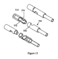
図13は、クリップの別の実施形態の解放部分およびドライバのコネクタの拡大斜視図である。 FIG. 13 is an enlarged perspective view of the release portion of another embodiment of the clip and connector of the driver;
図14は、本主題のクリップアセンブリおよび駆動アセンブリの別の実施形態の正面図を示す。 FIG. 14 shows a front view of another embodiment of the clip assembly and drive assembly of the present subject matter.
図15は、図14に示されているクリップアセンブリおよび駆動アセンブリの全閉位置での断面図を示している。 15 shows a cross-sectional view of the clip assembly and drive assembly shown in FIG. 14 in the fully closed position.
図16は、図14に示すカラーの種々の図を示す。 16 shows various views of the collar shown in FIG. 14. FIG.
図17a、図17bは、本主題の導入器の正面図を示す。 17a, 17b show front views of the introducer of the present subject matter.
図18は、開位置にある本主題のクリップアセンブリおよびその駆動アセンブリの別の実施形態の正面図を示す。 FIG. 18 shows a front view of another embodiment of the present subject clip assembly and its drive assembly in the open position.
図19は、開位置にある図18に示される実施形態の断面図を示す。 Figure 19 shows a cross-sectional view of the embodiment shown in Figure 18 in the open position.
図20は、閉位置における図18に示される実施形態の断面図を示す。 Figure 20 shows a cross-sectional view of the embodiment shown in Figure 18 in the closed position.
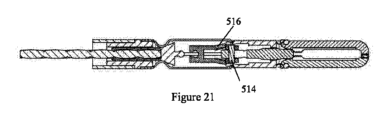
図21は、応力を加えた位置における図18に示された実施形態の断面図を示す。 Figure 21 shows a cross-sectional view of the embodiment shown in Figure 18 in a stressed position.
図22は、解放位置にある図18に示された実施形態の断面図を示す。 Figure 22 shows a cross-sectional view of the embodiment shown in Figure 18 in the released position.
図23は、図18に示すスイッチの正面図および上面図を示す。 23 shows front and top views of the switch shown in FIG. 18. FIG.
図24は、図18に示される解放部分の正面図および上面図を示す。 24 shows front and top views of the release portion shown in FIG. 18. FIG.
図25は、図18に示す結合器の様々な図を示す。 25 shows various views of the combiner shown in FIG. 18. FIG.
図26は、本主題のクリップアセンブリおよびその駆動アセンブリの実施形態の正面図である。 FIG. 26 is a front view of an embodiment of the present subject clip assembly and its drive assembly;
図27は、図26のクリップアセンブリおよびその駆動アセンブリの透明な正面図である。 27 is a transparent front view of the clip assembly of FIG. 26 and its drive assembly; FIG.
図28は、図26のクリップアセンブリおよびその駆動アセンブリの正面図であり、クリップアセンブリは開かれている。 28 is a front view of the clip assembly of FIG. 26 and its drive assembly, with the clip assembly open; FIG.
図29は、図26のクリップアセンブリおよびその駆動アセンブリの正面図であり、クリップアセンブリは、組織上にクリップ留めする。 FIG. 29 is a front view of the clip assembly of FIG. 26 and its drive assembly, the clip assembly clipping onto tissue;
図30は、図26のクリップアセンブリおよびその駆動アセンブリの正面図であり、ここで、クリップアセンブリは組織上にクリップを留め、そして駆動アセンブリはクリップアセンブリを係合解除するプロセスにある。 FIG. 30 is a front view of the clip assembly of FIG. 26 and its drive assembly wherein the clip assembly has secured the clip on tissue and the drive assembly is in the process of disengaging the clip assembly;
図31は、図26のクリップアセンブリおよびその駆動アセンブリの正面図であり、ここで、クリップアセンブリは組織上にクリップし、そして駆動アセンブリは、クリップアセンブリを係合解除する。 FIG. 31 is a front view of the clip assembly of FIG. 26 and its drive assembly, wherein the clip assembly clips onto tissue and the drive assembly disengages the clip assembly;
図32は、図31の斜視図である。 32 is a perspective view of FIG. 31. FIG.
図33は、係合解除アームの上面図および正面図を示す。 FIG. 33 shows top and front views of the disengagement arm.
図34は、解放位置にある別の実施形態の正面図/断面図を示す。 FIG. 34 shows a front/cross-sectional view of another embodiment in the released position.
図35aは、本主題のクリップアセンブリおよび駆動アセンブリの別の実施形態の正面図/断面図を示す。 FIG. 35a shows a front/cross-sectional view of another embodiment of the clip assembly and drive assembly of the present subject matter.
図35bは、応力を加えられた位置にある図35aに示される実施形態の正面図/断面図を示す。 Figure 35b shows a front/cross-sectional view of the embodiment shown in Figure 35a in a stressed position.
図35cは、解放された位置にある図35aに示される実施形態の正面図/断面図を示す。 Figure 35c shows a front/cross-sectional view of the embodiment shown in Figure 35a in the released position.
図36は、クリップアセンブリが閉じられている間のクリップアセンブリおよびその駆動アセンブリの別の実施形態の斜視図を示す。 FIG. 36 shows a perspective view of another embodiment of the clip assembly and its drive assembly while the clip assembly is closed;
図37は、クリップアセンブリが開いている間の、図36に示される実施形態の斜視図を示す。 Figure 37 shows a perspective view of the embodiment shown in Figure 36 while the clip assembly is open.
図38は、図36に示される実施形態の正面図/断面図を示す。 FIG. 38 shows a front/cross-sectional view of the embodiment shown in FIG.
図39は、図38に示す実施形態の一部の拡大図を示す。 FIG. 39 shows an enlarged view of part of the embodiment shown in FIG.
図40は、図36に示される実施形態の上面図を示す。 FIG. 40 shows a top view of the embodiment shown in FIG.
図41は、クリップアセンブリが開いている間の、図36に示される実施形態の別の斜視図を示す。 FIG. 41 shows another perspective view of the embodiment shown in FIG. 36 while the clip assembly is open;
図42は、図41に示す実施形態の一部の拡大図を示す。 FIG. 42 shows an enlarged view of part of the embodiment shown in FIG.
図43a~図43dは、係合の一実施形態の様々な図を示す。 Figures 43a-43d show various views of one embodiment of the engagement.
図44a~図44bは、係合の別の実施形態の様々な図を示す。 Figures 44a-44b show various views of another embodiment of the engagement.
図45a~図45cは、係合の別の実施形態の様々な図を示す。 Figures 45a-45c show various views of another embodiment of the engagement.
図46a~図46cは、係合の別の実施形態の様々な図を示す。 Figures 46a-46c show various views of another embodiment of the engagement.
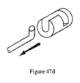
図47a~図47dは、係合の別の実施形態の様々な図を示す。 Figures 47a-47d show various views of another embodiment of the engagement.
図48a~図48cは、係合の別の実施形態の様々な図を示す。 Figures 48a-48c show various views of another embodiment of the engagement.
図49a~図49cは、係合の別の実施形態の様々な図を示す。 Figures 49a-49c show various views of another embodiment of the engagement.
図50a~図50bは、係合の別の実施形態の様々な図を示す。 Figures 50a-b show various views of another embodiment of the engagement.
図51a~図51bは、係合の別の実施形態の様々な図を示す。 Figures 51a-b show various views of another embodiment of the engagement.
図52a~図52bは、係合の別の実施形態の様々な図を示す。 Figures 52a-b show various views of another embodiment of the engagement.
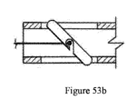
図53a~図53cは、係合の別の実施形態の様々な図を示す。 Figures 53a-c show various views of another embodiment of the engagement.
図54a~図54bは、係合の別の実施形態の様々な図を示す。 Figures 54a-54b show various views of another embodiment of the engagement.
図55a~図55bは、係合の別の実施形態の様々な図を示す。 Figures 55a-b show various views of another embodiment of the engagement.
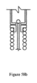
図56a~図56fは、係合の別の実施形態の様々な図を示す。 Figures 56a-56f show various views of another embodiment of the engagement.
図57a~図57bは、係合の別の実施形態の様々な図を示す。 Figures 57a-57b show various views of another embodiment of the engagement.
図58a~図58cは、係合の別の実施形態の様々な図を示す。 Figures 58a-c show various views of another embodiment of the engagement.
図59a~図59bは、係合の別の実施形態の様々な図を示す。 Figures 59a-b show various views of another embodiment of the engagement.
図60a~図60fは、係合の様々な実施形態を示す。 Figures 60a-60f show various embodiments of engagement.
図61は、係合の別の実施形態を示している。 FIG. 61 shows another embodiment of engagement.
図62は、係合の別の実施形態の断面図を示す。 FIG. 62 shows a cross-sectional view of another embodiment of the engagement.
図63は、係合の別の実施形態の斜視図を示す。 FIG. 63 shows a perspective view of another embodiment of engagement.
図64は、係合の別の実施形態の斜視図を示す。 FIG. 64 shows a perspective view of another embodiment of engagement.
図65は、係合の別の実施形態の斜視図を示す。 FIG. 65 shows a perspective view of another embodiment of engagement.
図66は、係合の別の実施形態の斜視図を示す。 FIG. 66 shows a perspective view of another embodiment of engagement.
図67は、係合の別の実施形態の様々な図を示す。 FIG. 67 shows various views of another embodiment of engagement.
図68は、係合の別の実施形態の様々な図を示す。 FIG. 68 shows various views of another embodiment of engagement.
図69は、係合の別の実施形態の斜視図を示す。 FIG. 69 shows a perspective view of another embodiment of engagement.
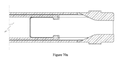
図70a~図70cは、図69に示される係合の種々の図を示す。 70a-70c show various views of the engagement shown in FIG.
図71a~図71cは、係合の別の実施形態の様々な図を示す。 Figures 71a-71c show various views of another embodiment of the engagement.
図72a~図72cは、図71a~図71cに示される、外側シースのない係合の様々な図を示す。 Figures 72a-72c show various views of the engagement without the outer sheath shown in Figures 71a-71c.
図73a~図73dは、係合の別の実施形態の様々な図を示す。 Figures 73a-73d show various views of another embodiment of the engagement.
図74a~図74dは、係合の別の実施形態の様々な図を示す。 Figures 74a-74d show various views of another embodiment of the engagement.
図75a~図75dは、係合の別の実施形態の様々な図を示す。 Figures 75a-75d show various views of another embodiment of the engagement.
図76a~図76bは係合の別の実施形態の様々な図を示す。 Figures 76a-76b show various views of another embodiment of the engagement.
図77a~図77cは、係合の別の実施形態の様々な図を示す。 Figures 77a-77c show various views of another embodiment of the engagement.
この詳細な説明は、一般的な発明概念による例示的な実施形態を単に説明するものであり、本発明の範囲または特許請求の範囲をいかなる形でも限定することを意図するものではない。
実際に、特許請求の範囲によって記載される本発明は、本明細書に記載される例示的な実施形態よりも広く、それによって制限されず、特許請求の範囲で使用される用語はそれらの完全な通常の意味を有する。
This detailed description merely describes exemplary embodiments according to the general inventive concept and is not intended to limit the scope of the invention or the claims in any way.
Indeed, the invention as defined by the claims is broader than, and is not limited to, the exemplary embodiments described herein, and the terms used in the claims are defined as their full has its usual meaning.
ここで、本発明の例示的な実施形態を時折参照して、一般的な発明概念を説明する。しかしながら、この一般的な発明概念は、異なる形態で具現化されてもよく、本明細書に記載された実施形態に限定されるものとして解釈されるべきではない。
むしろ、これらの実施形態は本開示が徹底的かつ完全であり、一般的な発明概念の範囲を当業者に完全に伝えるように提供される。
The general inventive concepts will now be described with occasional reference to exemplary embodiments of the invention. This general inventive concept may, however, be embodied in different forms and should not be construed as limited to the embodiments set forth herein.
rather, these embodiments are provided so that this disclosure will be thorough and complete, and will fully convey the scope of the general inventive concept to those skilled in the art.
別段の定義がない限り、本明細書で使用されるすべての技術用語および科学用語は、一般的な発明概念を包含する当業者によって一般に理解されるものと同じ意味を有する。この詳細な説明に記載される用語は、特定の実施形態を説明するためだけのものであり、一般的な発明概念を限定することを意図するものではない。
この詳細な説明および添付の特許請求の範囲で使用されるように、単数形「a」、「an」、および「the」は文脈が明らかに沿わないことを示さない限り、複数形も含むことが意図される。
Unless defined otherwise, all technical and scientific terms used herein have the same meaning as commonly understood by one of ordinary skill in the art, including general inventive concepts. The terminology used in this detailed description is for the purpose of describing particular embodiments only and is not intended to be limiting of the general inventive concept.
As used in this detailed description and the appended claims, the singular forms "a,""an," and "the" include the plural unless the context clearly dictates otherwise. is intended.
したがって、特に断らない限り、明細書および特許請求の範囲に記載された数値特性は、本発明の実施形態において得ようとする適切な特性に応じて変化し得る近似値である。
したがって、明細書および特許請求の範囲に記載された数値特性は明細書および特許請求の範囲に記載された数値特性が特に断らない限り、すべての例において「約」という用語によって修正されるものと理解されるべきである。
一般的な発明概念の広い範囲を示す数値範囲およびパラメータは近似値であるにもかかわらず、特定の実施例に示される数値は可能な限り正確に報告される。しかしながら、任意の数値は本質的に、それらのそれぞれの測定において見出される誤差から必然的に生じる特定の誤差を含む。
Accordingly, unless indicated to the contrary, the numerical properties set forth in the specification and claims are approximations that may vary depending on the appropriate properties sought to be obtained in embodiments of the present invention.
Accordingly, numerical properties set forth in the specification and claims are to be modified in all instances by the term "about," unless the numerical properties set forth in the specification and claims indicate otherwise. should be understood.
Notwithstanding that the numerical ranges and parameters setting forth the broad scope of the general inventive concept are approximations, the numerical values set forth in the specific examples are reported as precisely as possible. Any numerical value, however, inherently contains certain errors necessarily resulting from the errors found in their respective measurements.
当業者は、クリップを内視鏡的マーキングのための消化管への留置;約3cm未満の粘膜/粘膜下欠損、約2mm未満の出血性潰瘍、約2mm未満の動脈、直径約1.5cm未満のポリープ、結腸における憩室;病変切除後の遅発性出血のリスクを低下させるための予防的クリッピング;小腸壁に空腸栄養チューブを貼付するための固定;食道壁に完全に覆われた食道自己拡張型金属ステントを貼付するための固定;および保存的治療が可能な約20mm未満の管腔穿孔の補足的閉鎖方法として使用できることを合理的に理解すべきである。 Those skilled in the art are skilled in placement of clips into the gastrointestinal tract for endoscopic marking; mucosal/submucosal defects less than about 3 cm, bleeding ulcers less than about 2 mm, arteries less than about 2 mm, and diameters less than about 1.5 cm. polyps in the colon, diverticula in the colon; prophylactic clipping to reduce the risk of delayed bleeding after resection of the lesion; fixation to attach a jejunal feeding tube to the wall of the small bowel; It should be rationally understood that it can be used as a fixation for the application of type metal stents; and as a supplemental method of closing luminal perforations of less than about 20 mm that can be treated conservatively.
図1および図2に示すように、本主題は、クリップアセンブリおよびその駆動アセンブリを記載している。
クリップアセンブリは、クリップ10と、カラー20のようなロック機構と、駆動アセンブリ(カテーテルアセンブリ)30と、を備えている。
駆動アセンブリ30は、所望に応じてクリップアセンブリを操作および解放するように構成される。
As shown in FIGS. 1 and 2, the present subject matter describes a clip assembly and its drive assembly.
The clip assembly includes a
Drive
図2に示すように、例示的なクリップ10は、クリップ10の遠位端に把持部分12と、クリップ10の近位端に解放部分14と、を備える。
クリップの一実施形態では、把持部分12が第1のアーム50および第2のアーム60を備える。
いくつかの実施形態では、第1および第2のアーム50、60の一方は可動であるように構成され、他方のアームは静止している。
いくつかの実施形態では、第1および第2のアーム50、60の両方が可動であるように構成される。
いくつかの実施形態では第1および第2のアーム50、60の一方は弾性湾曲アームである。
いくつかの実施形態では、第1および第2のアーム50、60の両方が弾性湾曲アームである。アームの一部は、クリップの軸から外側に凸状である。言い換えれば、クリップはウィッシュボーン形状を有し、組織の周囲を迅速に閉鎖することができる。
湾曲アームは、組織を集めるための捕捉空間を形成する。当業者は、クリップ10が3つ以上のアーム、例えば3つのアームまたは4つのアームを備えてもよいことを合理的に理解すべきである。
いくつかの実施形態では、クリップは偶数のアームを有する。アームは平坦であってもよい。アームは非平面であってもよい。
いくつかの実施形態では、クリップ10が開放位置で少なくとも11mmの顎部開口部を有する。
いくつかの実施形態では、クリップ10が閉鎖位置で2.8mmチャネルを有するスコープに嵌合し、回転し、スコープを通って移動することができる。
As shown in FIG. 2, the
In one embodiment of the clip, gripping
In some embodiments, one of the first and
In some embodiments, both the first and
In some embodiments one of the first and
In some embodiments, both the first and
The curved arms form a capture space for collecting tissue. Those skilled in the art should reasonably appreciate that the
In some embodiments, the clip has an even number of arms. The arms may be flat. The arms may be non-planar.
In some embodiments,
In some embodiments, the
クリップの一実施形態では、第1のアーム50の遠位端54は、第1の係合部分56を含む。第2のアーム60の遠位端64は、第2の係合部分66を含む。
図7a~図7cを参照すると、クリップ10が閉鎖し始めると、第1および第2のアーム50、60の遠位端54、64は互いに向かって移動し、第1および第2の係合部分56、66は互いに係合し、これは、アームに対して予圧を与え、組織を把持する能力を増大させる。
クリップがその完全に閉じた位置にあるとき、アームはより良好な止血または他の所望の効果を達成するために、応力を受け続ける。一方、2つの係合部の近傍には、組織捕捉領域21が形成されている。
In one embodiment of the clip,
Referring to Figures 7a-7c, as the
When the clip is in its fully closed position, the arm remains under stress to achieve better hemostasis or other desired effect. On the other hand, a
図2に戻ると、いくつかの実施形態では、第1の係合部分56または第2の係合部分66がオフセット歯である。
いくつかの実施形態では、オフセット歯が遠位係合部分の幅がクリップのアームよりも広く、組織に対する優れた把持を可能にする輪郭を有する。これらの係合部分は、代替材料で作られ、アームに取り付けられてもよい。当業者は、第1および第2の係合部分56、66が複数のオフセット歯、または有効な止血効果を達成するために互いに安定して係合し得る他の公知の構造であり得ることを、合理的に理解すべきである。
クリップの代替実施形態では、第1および第2の係合部分が二重オフセット歯を備える。二重歯構造はオフセット歯が過度に重なり、閉鎖位置に固着することを防止する。
Returning to FIG. 2, in some embodiments, the first engaging
In some embodiments, the offset teeth are wider at the distal engaging portion than the arms of the clip and have a contour that allows for superior grip on tissue. These engaging portions may be made of alternative materials and attached to the arms. Those skilled in the art will appreciate that the first and second engaging
In an alternative embodiment of the clip, the first and second engaging portions comprise double offset teeth. The double tooth construction prevents the offset teeth from overlapping excessively and sticking in the closed position.
図2に示すクリップの実施形態では、少なくとも1つのアームが保持機構16を備える。
保持機構16は、第1のアーム50の遠位端54の近くに配置された保持フィン57を備える。
保持フィン57は、カラー20がクリップ10の近位端からクリップの遠位端に向かって移動することを可能にする。保持フィン57は、カラー20の幾何学的形状と結合することにより、カラー20が第1のアーム50の遠位端54から摺動して離れるのを防止し、クリップ10を閉位置に保ち、第1および第2の係合部分56、66が係合した状態に保つように、負の角度または他の幾何学的形状を含むことができる。
In the embodiment of the clip shown in FIG. 2, at least one arm is provided with retention features 16 .
Retaining
図3に示すクリップの別の実施形態では、保持機構116は、第1のアーム150の第1の遠位端154の近くに配置された第1の保持フィン157と、第2のアーム160の第2の遠位端164の近くに配置された第2の保持フィン167と、を含む。第1及び第2の保持フィン157、167は、上述した保持フィン57と同様の機能を有する。
In another embodiment of the clip shown in FIG. 3, the
図4に示すクリップの別の実施形態では、保持機構216は、保持フィン257と、遠位ストップ258と、保持フィン257と遠位ストップ258との間の凹部259と、を含む。
保持フィン257、遠位ストップ258、および凹部259は、第1のアーム250の遠位端254の近くに配置される。保持フィン257は、上述した保持フィン57と同様の機能を有する。凹部259の長さは、カラー20を受け入れるように構成されている。遠位ストップ258は、カラー20が第1および第2のアーム250、260の遠位端254、264から滑り出るのを防止する。
In another embodiment of the clip shown in FIG. 4 ,
Retaining
図5に示すクリップの別の実施形態では、保持機構316は、第1および第2の保持フィン357、367と、第1および第2の遠位停止部358、368と、第1の保持フィン357と第1の遠位停止部358との間の第1の凹部359と、第2の保持フィン367と第2の遠位停止部368との間の第2の凹部369と、を含む。
第1および第2の凹部359、369の長さは、カラー20を受け入れるように構成されている。第1および第2の保持フィン357、367は、上述の保持フィン57と同様の機能を有する。第1および第2の遠位停止部358、368は、上述の遠位停止部158と同様の機能を有する。
In another embodiment of the clip shown in FIG. 5, the
The lengths of first and
当業者は、上述の保持機構に加えて、他の公知の保持機構がカラーを固定するためにここで使用されてもよいことを合理的に理解すべきである。 Those skilled in the art should reasonably appreciate that other known retention mechanisms may be used herein to secure the collar in addition to the retention mechanisms described above.
図6a~図6cおよび図2のクリップ10の例示的な実施形態を参照すると、カラー20は、スリーブ22と、スリーブ22の中心にあるガイドチャンネル28と、を備える。
クリップ10のアーム50、60はカラー20がクリップ10のアーム50、60に沿って動くことができるように、ガイドチャンネル28を通過することができる。ガイドチャンネル28は、高さHと幅Wとを有している。
いくつかの実施形態ではガイドチャンネル28の高さHが閉位置におけるクリップ10の保持フィン57部分の高さH´に等しいか、またはそれよりわずかに高い。
いくつかの実施形態では、ガイドチャンネル28の幅Wがクリップ10の幅W´に等しいか、またはそれよりわずかに広い。ガイドチャンネル28は、カラー20が乗り越え、留まり保持フィン57によって保持されることを可能にするように構成されている。一方、保持されたカラー20は、第1および第2の係合部分56、66を強制的に閉じさせる。ガイドチャンネル28は、また、クリップ10がカラー20内で回転するのを防止するように構成される。一部の実施形態では、ガイドチャンネル28は長方形である。
ガイドチャンネルが、アームがガイドチャンネル内で移動可能である間にクリップがカラー内で回転するのを妨げる限り、ガイドチャンネルは他の形状であり得ることを当業者は合理的に理解すべきである。
6a-6c and the exemplary embodiment of
In some embodiments, the height H of the
In some embodiments, the width W of the
Those skilled in the art should reasonably understand that the guide channel may be of other shapes, so long as the guide channel prevents the clip from rotating within the collar while the arm is movable within the guide channel. .
カラー20は、スリーブ22の遠位端から延びる2つの支持アーム24、25をさらに備える。
支持アーム24、25はガイドチャンネル28と干渉しない。カラー20がクリップ10をロックし、保持フィン57によって保持されると、支持アーム24、25はアーム50、60の遠位端54、64に向かう。
いくつかの実施形態では、支持アーム24、25は、締め付け中にさらなる強度を提供するために、遠位端54、64までアーム50、60を覆うように構成される。しかしながら、いくつかの実施形態では、支持アーム24、25は支持アーム24、25が組織捕捉を妨害することを回避するように、第1および第2の係合部分56、66を越えて延在しない。
いくつかの実施形態では、支持アーム24、25は開口部26によって離間されている。
いくつかの実施形態では、支持アーム24、25は、クリップ10が閉じられたときにアーム50、60を覆うだけである。開口部26はクリップ10が完全に閉じられてロックされたときに、第1および第2の係合部分56、66によって捕捉された組織を受容するように構成される。開口部26及びアーム50、60間のギャップは、組織捕捉領域21(図7cに示す)を形成する。
いくつかの実施形態では、支持アーム24、25はアーム50、60が最大開放顎部を維持することができ、閉鎖するのが容易であるように、弾性であり、曲げることができる。
いくつかの実施形態では、支持アーム24、25は剛性である。
いくつかの実施形態では、スリーブ22がスリーブ22の近位端の外側に面取り部またはフィレット23を備える。面取りまたはフィレット23は、カラー20が保持フィンと連動するのを助ける。
In some embodiments, support
In some embodiments, support
In some embodiments, support
In some embodiments, the
In some embodiments, support
In some embodiments,
クリップアセンブリの代替実施形態では、アームの保持機構が保持フィンを備える。
カラーの支持アームは、支持アームの内面に配置されたスロットを備える。スロットは保持フィンをキャッチするように設定されている。いくつかの実施形態では、スロットはスルーホールである。
In an alternative embodiment of the clip assembly, the retention feature of the arm comprises retention fins.
The support arm of the collar includes a slot located on the inner surface of the support arm. The slots are set to catch the retaining fins. In some embodiments, the slots are through holes.
図1a~図1bに戻ると、本主題の一実施形態として、駆動アセンブリ30は、ドライバ31と、プッシャチューブ40と、外側シース42と、を備える。
プッシャチューブ40は、外側シース42内に配置されるように構成される。ドライバ31は、プッシャチューブ40内に配置されるように構成されている。外側シース42は、クリップ10及びカラー20を収容するように構成されている。プッシャチューブ40はクリップ10を収容するが、カラー20を収容できないように構成されている。
いくつかの実施形態では、外側シース42が結合されたコネクタ34および解放部分14がプッシャチューブ40によって覆われたときに、それらが分離されることを防止する。
いくつかの実施形態では、カラー20が連結されたコネクタ34および解放部分14がカラー20によって覆われたときに、それらが切り離されることを防止する。
Returning to FIGS. 1a-1b, in one embodiment of the present subject matter, drive
In some embodiments,
In some embodiments, the
クリップ10の駆動アセンブリ30及び解放部分14は、クリップ10を作動させるために協働する。外側シース42は、クリップ10が配置される前にクリップ10を収容するように構成される。外側シース42は、クリップ10の近位端に向かって移動し、クリップ10の把持部分12を外側シース42から解放するように構成される。その結果、把持部分12は開放状態になる。ドライバ31は、クリップ10が所望のように配置され得るように、クリップ10を移動または回転させるように構成される。クリップ10がその所望の位置にあるとき、ドライバ31は、外側シース42内に引っ込められ、クリップ10の把持部分12を閉じる。プッシャチューブ40は、クリップ10の遠位端に向かって移動するカラー20を押すように構成され、その結果、カラー20はクリップ10をロックする。
Drive
図8a及び図8bに示すように、ドライバ31は、近位端にケーブル32を備え、遠位端にコネクタ34を備える。
図9に示されるいくつかの実施形態では、駆動アセンブリ30がケーブル132とコネクタ134との間にワイヤ136をさらに備える。一実施形態によると、ワイヤ136の直径はコネクタ134が解放部分14内にロックされることを可能にするために、ケーブル132の直径よりも小さい。コネクタ34は、必要に応じて廃棄されるように、クリップ10に対する回転制御を持つように、解放部分14とインターフェースを構成する。
As shown in Figures 8a and 8b, the
In some embodiments shown in FIG. 9, drive
図2に戻ると、クリップ10の解放部分14は取り外し可能であり、駆動アセンブリ30のコネクタ34と結合される。
いくつかの実施形態では、解放部分14は、クリップ10の近位端から少なくとも1つの側部開口部を有する受容チャンバ70を備える。
いくつかの実施態様では、コネクタ34は、図8a及び図8bに示されるT字型円筒である。受容チャンバ70はT字状の形状のチャンバであり、T字状の形状のコネクタ34を受け入れることができる。
いくつかの実施形態では、コネクタ134が図9に示されるボールであり、受容チャンバ170は図10に示されるボール状の形状のチャンバであり、ボールコネクタ134を受容することができる。
いくつかの実施態様において、コネクタ234は図11に示される立方体であり、受け入れチャンバ270は図12に示される立方体状の形状チャンバであり、立方体コネクタ234を受け入れることができる。
Returning to FIG. 2,
In some embodiments,
In some embodiments,
In some embodiments,
In some embodiments,
図13に示されるようないくつかの実施態様において、コネクタ334および解放部分314は手ぶれコネクタなどのインターロックコネクタであり得るが、これに限定されない。解放部分314は、安定化アーム372およびタブ374を備える。コネクタ334はポケット336を含む。ポケット336は、安定化アーム上に載置され、タブ374と噛み合うことができる。ロックは、必要なときに解除することができる。
当業者は、コネクタ334および解放部分314の構成が交換可能であることを合理的に理解すべきである。
In some embodiments, such as shown in FIG. 13,
Those skilled in the art should reasonably appreciate that the configurations of
当業者は、ロック機構が上述の実施形態に加えて、他の既知の設計または構成であってもよいことを合理的に理解すべきである。 Those skilled in the art should reasonably appreciate that the locking mechanism may be of other known designs or configurations in addition to the embodiments described above.
図14~図16に示される駆動アセンブリの代替実施形態では、駆動アセンブリが結合器をさらに備える。
カプラは、外側シースの遠位端に配置される。結合器は、カラーに取り外し可能に結合するように構成される。カプラは、クリップアセンブリの回転可能性を維持しながら、複数の開閉サイクル中にカラーを保持するように構成される。
いくつかの実施形態では、カラーの近位端が溝を備える。カプラの遠位端は、溝に係合可能であるように構成された縁部を備える。縁部は、離れて広がることができる複数の花弁を含む。押し込みチューブが結合器内で前進されると、押し込みチューブは、カラーを強制的に結合器から外す。次に、駆動アセンブリを前進させて、クリップアセンブリの取り外しを補助することができる。
この実施形態では、クリップ10が係合部分56、66に係合するためにカラー20内に引き込まれ、前述の実施形態のように外側シース42を利用しない。
In an alternative embodiment of the drive assembly shown in Figures 14-16, the drive assembly further comprises a coupler.
A coupler is disposed at the distal end of the outer sheath. A coupler is configured to removably couple to the collar. The coupler is configured to retain the collar during multiple opening and closing cycles while maintaining rotatability of the clip assembly.
In some embodiments, the proximal end of the collar comprises grooves. The distal end of the coupler includes a rim configured to be engageable with the groove. The margin includes multiple petals that can spread apart. As the pusher tube is advanced within the coupler, it forces the collar off the coupler. The drive assembly can then be advanced to assist removal of the clip assembly.
In this embodiment,
当業者は、駆動アセンブリが上記の実施形態に加えて、他の公知の設計または構成であり得ることを合理的に理解すべきである。 Those skilled in the art should reasonably appreciate that the drive assembly may be of other known designs or configurations in addition to the embodiments described above.
図1aおよび図1bを参照すると、医療従事者がクリップアセンブリを患者に適用する場合、以下のステップを適用することができる:1)クリップをその開放位置で露出させる;2)係合部分を治療領域に整列させるようにドライバを調整する;3)クリップを外側シースまたはカラー内に後退させてクリップを閉鎖し、これにより、アームへ予圧を与え、組織を把持する能力を増大させる;4)カラーを移動させてカラーを、保持機構を通過させてクリップをその完全閉鎖位置で引っ張る;5)外側シースおよびプッシャチューブを引き戻す;6)クリップからドライバを解放する。 1a and 1b, when a medical practitioner applies the clip assembly to a patient, the following steps can be applied: 1) expose the clip in its open position; 2) treat the engagement portion; 3) retract the clip into the outer sheath or collar to close the clip, thereby preloading the arm and increasing its ability to grasp tissue; 4) the collar. 5) pull back the outer sheath and pusher tube; 6) release the driver from the clip.
図14および図15を参照すると、一実施形態では、医療従事者がクリップアセンブリを患者に適用する場合、以下のステップを適用することができる:1)開位置でクリップを露出させる;2)係合部分を治療領域に整列させるようにドライバを調整する;3)クリップがカラー内に引っ込んでクリップを閉じ、これにより、アームへの予荷重が可能になり、組織を把持する能力が増大する;4)プッシャチューブを押して、カラーをカプラから前進させ、クリップ上の保持フィンを通過させて、クリップを閉じてロックし、クリップをドライバから解放することができる。 14 and 15, in one embodiment, when a medical professional applies the clip assembly to a patient, the following steps can be applied: 1) expose the clip in the open position; 2) engage; Adjust the driver to align the mating portion with the treatment area; 3) The clip retracts into the collar to close the clip, allowing preloading of the arm and increasing its ability to grasp tissue; 4) The pusher tube can be pushed to advance the collar out of the coupler and past the retaining fins on the clip, locking it closed and releasing it from the driver.
本主題は、図17a~17bに示される導入器をさらに記載する。
導入器は、導入器の近位端に開口を有する内部チャンバと、導入器の遠位端に開口を有する。導入器の遠位端は、クリップアセンブリおよび駆動アセンブリの遠位端が通過することを可能にするように構成される。
導入器の近位端は、クリップアセンブリが通過するのを防止するように構成される。任意選択的に、導入器の近位端は、駆動アセンブリが通過するのを防止するように構成される。導入器は、輸送中および内視鏡上の生検弁を通しての導入中にクリップを保護するように構成される。導入器の遠位端は、生検弁に結合するように構成される。導入器の遠位端の最小長さLは約5mmである。クリップアセンブリは、生検弁を通って内視鏡作業チャネルに入るように構成される。
The present subject matter further describes the introducer shown in Figures 17a-17b.
The introducer has an internal chamber with an opening at the proximal end of the introducer and an opening at the distal end of the introducer. The distal end of the introducer is configured to allow the distal ends of the clip assembly and drive assembly to pass therethrough.
The proximal end of the introducer is configured to prevent passage of the clip assembly. Optionally, the proximal end of the introducer is configured to prevent passage of the drive assembly. The introducer is configured to protect the clip during transportation and introduction through the biopsy valve on the endoscope. A distal end of the introducer is configured to couple to a biopsy valve. The minimum length L of the distal end of the introducer is about 5 mm. The clip assembly is configured to pass through the biopsy valve and into the endoscope working channel.
内部チャンバは、近位端に隣接する内面400を備える。
いくつかの実施形態では、内部チャンバはポッド形状である。クリップは、内部チャンバ内で全開状態を維持するように構成される。内面400は、カテーテルアセンブリが近位端から遠位端に向かって前進することにつれて、クリップを圧潰させるように構成される。クリップが導入器の遠位端から作業チャネルから完全に露出されると、クリップは、その完全に開いた状態に戻るように構成される。クリップアセンブリが駆動アセンブリから取り外されると、駆動アセンブリを内視鏡から引き抜くことができる。クリップ10は生検チャネルを通って前進する間にスコープへの損傷を防止するために、非外傷性の幾何学的形状を有する可能性がある。
The inner chamber has an
In some embodiments, the internal chamber is pod-shaped. The clip is configured to remain fully open within the internal chamber. The
図18~19を参照すると、本主題は、クリップアセンブリおよびその駆動アセンブリの代替実施形態をさらに開示する。
クリップアセンブリは、ベース500と、一対の顎部502と、およびスイッチ504と、を備える。駆動アセンブリは、外側シース506と、カプラ508と、ドライバ510と、を備える。
18-19, the present subject matter further discloses alternative embodiments of clip assemblies and their drive assemblies.
The clip assembly comprises a
図18および図19は、開位置におけるクリップアセンブリおよびその駆動アセンブリを示す。
図20は、閉位置におけるクリップアセンブリ及びその駆動アセンブリを示す。
図21は、ストレス/ロック位置にあるクリップアセンブリとその駆動アセンブリを示す。
図22は、リリース/デタッチ位置にあるクリップアセンブリとその駆動アセンブリを示す。
クリップアセンブリは、駆動アセンブリによって開位置から閉位置へ、およびその逆に自由に移動することができる。クリップアセンブリは、応力/ロック位置に入ると、再び開くことができない。閉鎖位置はアームに対して予圧を与え、組織を把持する能力を増大させる。クリップが応力/ロック位置にあるとき、顎部はより良好な止血または他の所望の効果を達成するために、応力を受けたままである。
Figures 18 and 19 show the clip assembly and its drive assembly in the open position.
Figure 20 shows the clip assembly and its drive assembly in the closed position.
FIG. 21 shows the clip assembly and its drive assembly in the stress/lock position.
FIG. 22 shows the clip assembly and its drive assembly in the release/detached position.
The clip assembly is freely movable from the open position to the closed position and vice versa by the drive assembly. Once in the stress/lock position, the clip assembly cannot be reopened. The closed position preloads the arms and increases their ability to grasp tissue. When the clip is in the stressed/locked position, the jaws remain stressed to achieve better hemostasis or other desired effects.
ベース500は、顎部502およびスイッチ504を保持し、位置決めするように構成される。ベース500は、スイッチ504がベース500の遠位端から逃げることを防止するように構成される。ベース500は、2つの半体を含む。顎部502は組織を収集し、保持するように構成される。顎部502は、ベース500の遠位端に動作可能に接続するようにさらに構成される。スイッチ504の遠位部は、開位置と閉位置との間で顎部502を作動させるように構成される。スイッチ504の近位部分は、解放部分512を備える。解放部分512は、ドライバ510の遠位端と取り外し可能に連結するように構成される。解放部分とドライバとの間の接続の例示的な実施形態は、前の実施形態で論じたTバー接続である。
いくつかの実施形態では、解放部分512およびスイッチ504の遠位部分が別個の2つの部品であり、ピン514によって接続される。スイッチ504の遠位部分は、8の字形の穴を備える。8の字形の穴は、遠位部分と近位部分とを含む。ピン514が8の字形の穴の遠位部分に配置されると、クリップアセンブリを開位置と閉位置との間で移動させることができる。ピン514が8の字形の穴の近位部分に配置されると、クリップアセンブリはロックされ、最終的に解放され得る。
当業者は、8の字形の穴が必ずしも貫通穴ではなく、スロットであってもよいことを理解すべきである。
いくつかの実施形態では、8の字形の穴がスイッチ504の遠位部分の代わりに、解放部分512に配置される。
当業者は、機構が8の字形の穴でなくてもよく、同様の機能を達成する幾何学的形状であってもよいことを理解すべきである。
In some embodiments,
Those skilled in the art should understand that the figure 8 holes are not necessarily through holes and may be slots.
In some embodiments, a figure-eight hole is placed in
Those skilled in the art should understand that the feature need not be a figure-eight hole, but may be a geometric shape that accomplishes a similar function.
スイッチ504は、タブ516をさらに備える。
タブ516は、顎部が開位置と閉位置との間で移動する間、ベース内で移動可能であるように構成される。タブはさらに、ベースの外側に引っ張られ、スイッチ504がベース内に戻るのを防止して、応力が加わったときに顎部をロックするように構成されている。
Switch 504 further comprises
当業者であれば、解放部分512及びスイッチ504の先端部分は、ピン及び8の字形の穴をなくすことができるように一体に作ることができることを理解すべきである。
ある実施形態では、解放部分512とスイッチ504の遠位部分との間の接続部分が、クリップアセンブリが開放、閉鎖、ストレス/ロック、および解放位置を有することを可能にする8の字形の穴の同様の効果を達成するように、弾性材料で作られる。
Those skilled in the art should appreciate that the
In some embodiments, the connecting portion between the
カプラ508は、棘によって外側シース506と連結するように構成される。
当業者であれば、カプラ508と外側シース506とが一体であってもよいことを理解すべきである。カプラ508は、ベース500に取り外し可能に結合するように構成される。カプラ508はクリップアセンブリの回転可能性を維持しながら、複数の開閉サイクルの間、ベース500を保持するように構成される。
いくつかの実施形態では、ベース500の近位端が溝を備える。カプラ508の遠位端は、溝に係合可能であるように構成された縁部を備える。縁部は、離れて広がることができる複数の花弁を含む。
カプラ508は、ボトルネック520をさらに備える。ドライバ510はウェッジ522を含む。ウェッジ522はドライバ510が引き戻されてクリップアセンブリを駆動アセンブリから取り外そうとするときに、ボトルネック520を押すように構成される。ボトルネック520を押すことによって、ウェッジ522は、カプラ508の花弁を強制的に離す。その後、エッジと溝が外れる。したがって、クリップアセンブリは取り外される。
Those skilled in the art should appreciate that
In some embodiments, the proximal end of
図26~図33を参照すると、本主題は、クリップアセンブリおよびその駆動アセンブリの代替実施形態をさらに開示する。
クリップアセンブリは、第1の顎部602と、第2の顎部604と、第1のピボット606と、エラストマーバンド608と、を備える。
第1の顎部602は、第1のピボット606において第2の顎部604に枢動可能に連結されている。第1の顎部は、遠位アームおよび近位アームを備える。第2の顎部は、遠位アームおよび近位アームを備える。
第1および第2の顎部の両方は上記では移動顎部として記載されているが、当業者は第1の顎部が静止顎部であってもよいことを容易に理解すべきである。
26-33, the present subject matter further discloses alternative embodiments of clip assemblies and their drive assemblies.
Clip assembly includes
Although both the first and second jaws are described above as moving jaws, those skilled in the art should readily appreciate that the first jaw may be a stationary jaw.
エラストマーバンド608は、第1の顎部および第2の顎部の遠位アームを接続し、通常は閉じた第1の顎部および第2の顎部を可能にする。
いくつかの実施形態では、エラストマーバンドが第1の顎部の近位アームと第2の顎部の近位アームとの間を接続する。
いくつかの実施形態では、1つのエラストマーバンドが第1および第2の顎部の遠位アームの間を接続し、別のエラストマーバンドが第1および第2の顎部の近位アームの間を接続する。エラストマーバンドは、第1および第2の顎部の周りのリング、第1および第2の顎部の間のバンド、または第1および第2の顎部の間の任意の他の接続構造であってもよい。
いくつかの実施形態では、エラストマーバンドは排除され、ピボットは第1および第2の顎部が通常は閉じられるように、共通のエラストマー構造を備える。
An
In some embodiments, an elastomeric band connects between the proximal arm of the first jaw and the proximal arm of the second jaw.
In some embodiments, one elastomeric band connects between the distal arms of the first and second jaws and another elastomeric band connects between the proximal arms of the first and second jaws. Connecting. The elastomeric band may be a ring around the first and second jaws, a band between the first and second jaws, or any other connecting structure between the first and second jaws. may
In some embodiments, the elastomeric band is eliminated and the pivot comprises a common elastomeric structure such that the first and second jaws are normally closed.
第1および第2の顎部の各近位端は、レシーバ610を備える。
レシーバ610は、駆動アセンブリがクリップアセンブリを駆動して開閉できるように、駆動アセンブリを取り外し可能に受け入れるように構成される。
Each proximal end of the first and second jaws includes a
駆動アセンブリは、外側シース612と、フォーク614と、ドライバ616と、を備える。
フォーク614は、外側シース612内に配置される。フォーク614の遠位端は、外側シース612の遠位端から延びている。フォーク614の近位端は、ドライバ616に接続される。一実施形態では、フォーク614が第2のピボット628で外側シース612に旋回可能に接続される。
The drive assembly includes
フォーク614の2つの遠位端の各々は、係合部分618を備える。
係合部分618は、クリップアセンブリのレシーバ610と係合するように構成される。ドライバ616がその遠位方向に向かって押されると、フォーク614の遠位端が開放され、その結果、クリップアセンブリが開放される。ドライバ616がその近位方向に向かって引っ張られると、フォーク614の遠位端が閉じられ、その結果、クリップアセンブリが閉じられる。エラストマーバンドは、止血効果を達成するために閉鎖力を生成する。
いくつかの実施形態では、閉鎖力は約150~400gである。
Each of the two distal ends of
In some embodiments, the closing force is about 150-400g.
図34を参照すると、本主題は、クリップアセンブリおよびその駆動アセンブリの代替実施形態をさらに開示する。この実施形態では、フォークアセンブリ614内の単一のレバーアームがクリップアセンブリを開くために使用される。
第1のピボット606は、展開するまで外側シース612に接続される。展開後、第1のピボット606は、クリップアセンブリと共に残る。あるいは、クリップアセンブリが、リンクアームがクリップアセンブリに緩く取り付けられたままであることを可能にする、異なるピボット615でフォークから取り外されてもよい。
当業者は、フォーク(アセンブリ)が、駆動機構が遠位方向に前進するときに遠位端が開放される任意の公知の構造であり得ることを合理的に理解すべきである。
当業者は、フォークアセンブリ614および/またはレシーバ610からのクリップアセンブリの取り外しが、機械的取り外しなどの様々な方法によって、または顎部イントを切断するために電流を印加することによって達成され得ること、および取り外しがフォークアセンブリ614内の任意の連結点で達成され得ることを合理的に理解すべきである。
いくつかの実施形態では、ドライバ616は金属であり、フォークアセンブリ614はプラスチックである。ドライバ616は、電気的に加熱されてもよく、フォークアセンブリ614の少なくとも一部を溶融して、フォークアセンブリ614を取り外すことができる。
いくつかの実施形態では、外側シース612が機械的に破壊可能である。
いくつかの実施形態では、ピボット615が機械的に破壊可能である。
いくつかの実施形態では、ドライバ616が外側シース612に近い点で機械的に破壊可能である。
当業者は、上述の分離が本出願における他の実施形態に適用されてもよいことを理解すべきである。
Referring to FIG. 34, the present subject matter further discloses an alternate embodiment of the clip assembly and its drive assembly. In this embodiment, a single lever arm within
Those skilled in the art should reasonably appreciate that the fork (assembly) may be of any known structure that is open at the distal end when the drive mechanism is advanced distally.
Those skilled in the art will appreciate that removal of the clip assembly from
In some embodiments,
In some embodiments,
In some embodiments,
In some embodiments,
Those skilled in the art should understand that the above separation may apply to other embodiments in the present application.
いくつかの実施形態では、フォーク614が非対称アームを備える。
いくつかの実施形態では、フォーク614が異なる長さを有する遠位アームを備える。
いくつかの実施形態では、フォーク614が異なる長さを有する近位アームを備える。
In some embodiments,
In some embodiments,
In some embodiments,
フォーク614の係合部分618は、戻り止め620を含む。戻り止め620は、半球形または任意の他の適切な形状であってもよい。レシーバ610は、戻り止め620が係合するためのポケット624を備える。
いくつかの実施形態では、係合部分618が戻り止め620が圧縮され、レシーバ610から取り外されるのを助けるためのスロット622を備える。
いくつかの実施形態では、係合部分618がレシーバ610の取り外しを補助するための隆起626を備える。クリップアセンブリが組織をクリップ留めするとき、組織は、クリップアセンブリが完全に閉じられることを防止する。フォークがさらに閉じられると、バンプはポケット624の縁部を押圧し、係合解除を補助する。
In some embodiments, engaging
In some embodiments,
図35a、b及びcを参照すると、本主題は、クリップアセンブリおよびその駆動アセンブリの代替実施形態をさらに開示する。
クリップアセンブリは、クリップ710と、ロック機構720と、駆動アセンブリ(カテーテルアセンブリ)730と、解放部分714と、一対の顎部702と、を備える。
Referring to Figures 35a, b and c, the present subject matter further discloses alternative embodiments of the clip assembly and its drive assembly.
Clip assembly includes
図35aは、開位置にあるクリップアセンブリおよびその駆動アセンブリを示す。
図35bは、閉/応力/ロック位置にあるクリップアセンブリとその駆動アセンブリを示す。
図35cは、リリース/取り外し位置にあるクリップアセンブリとその駆動アセンブリを示している。クリップアセンブリは、駆動アセンブリによって開位置から閉位置へ、およびその逆に自由に移動することができる。クリップアセンブリは、応力/ロック位置に入ると、再び開くことができない。
Figure 35a shows the clip assembly and its drive assembly in the open position.
Figure 35b shows the clip assembly and its drive assembly in the closed/stressed/locked position.
Figure 35c shows the clip assembly and its drive assembly in the release/detach position. The clip assembly is freely movable from the open position to the closed position and vice versa by the drive assembly. Once in the stress/lock position, the clip assembly cannot be reopened.
クリップ710の解放部分714は、ドライバ731のコネクタ734と取り外し可能に連結される。
いくつかの実施形態では、解放部分714がクリップ710の近位端から少なくとも1つの側部開口部を有する受容チャンバ770を備える。
いくつかの実施態様では、コネクタ734はT字型シリンダであり、受容チャンバ770はT字型形状チャンバであり、T字型形状のコネクタを受け入れることができる。
いくつかの実施形態では、コネクタ734はボールであり、受容チャンバ770はボール状のチャンバであり、ボールコネクタ734を受け入れることができる。
いくつかの実施形態では、コネクタ734が示される立方体であり、受容チャンバ770は立方体様の形状のチャンバであり、立方体コネクタ734を受容することができる。
当業者は、コネクタ734および受容チャンバ770の形状が適切な接続および係合解除を可能にする任意の形状であり得ることを、合理的に理解すべきである。
In some embodiments,
In some implementations, the
In some embodiments,
In some embodiments,
Those skilled in the art should reasonably appreciate that the shape of
図35bを参照すると、顎部702は、ピボット728によって接続されている。
当業者は、ピボットが1つ以上のピボット点から構成されてもよく、別個の部品であってもよく、または顎部702内の特徴から構成されてもよいことを合理的に理解すべきである。ピボット728は、顎部702の閉鎖を可能にする任意の適切な材料から構成され得る。顎部702は、ピボット728を介して連結された1つ以上のピースから構成され得る。ピボット728は、アセンブリの動作に必要な付加的な構成要素を含んでもよい。
Referring to FIG. 35b,
Those skilled in the art should reasonably understand that the pivot may consist of one or more pivot points, may be a separate piece, or may consist of features within the
エラストマーバンド708は、顎部702の近位アームを接続し、正常に開いた位置決め顎部を可能にする。エラストマーバンドは、第1および第2の顎部の周りのリング、第1および第2の顎部の間のバンド、または第1および第2の顎部の間の任意の他の接続構造であってもよい。
いくつかの実施形態では、エラストマーバンドは排除され、ピボットは第1および第2の顎部が通常は開放されるように、共通のエラストマー構造を備える。
いくつかの実施形態では、エラストマーバンドは排除され、顎部は顎部の制御された開閉を可能にするロック機構に機械的に接続される。
In some embodiments, the elastomeric band is eliminated and the pivot comprises a common elastomeric structure such that the first and second jaws are normally open.
In some embodiments, the elastomeric band is eliminated and the jaws are mechanically connected to a locking mechanism that allows controlled opening and closing of the jaws.
閉じるとき、駆動アセンブリ730は、ロック機構720にクリップアセンブリ710の近位端を広げさせ、それによって、顎部702の把持部分712を合わせて、組織捕捉領域721を作り出す。これは、コネクタ734を解放部分714の受容チャンバ770から解放させるピボット728を介して達成される。この係合解除はクリップアセンブリ710がその加圧/ロック状態にあった後にコネクタ734が受容チャンバ770から解放されるように、分離機構から構成されてもよい。
いくつかの実施形態では、ロック機構720が外側部分上に保持ポケット729を備える。保持ポケット729は保持機構716の保持フィン757とインターロックし、これによりクリップ710を閉位置にロックする。
当業者は、ロック機構が顎部702の近位アームを広げるタスクを達成する、上記の実施形態に加えて、他の公知の設計または構成であり得ることを、合理的に理解すべきである。
When closed, drive assembly 730
In some embodiments,
Those skilled in the art should reasonably appreciate that, in addition to the above embodiment, the locking mechanism may be of other known designs or configurations that accomplish the task of spreading the proximal arms of
図35cを参照すると、クリップアセンブリ710が加圧/ロック位置にあると、駆動アセンブリ730はロック機構720から外れる。
Referring to FIG. 35c,
図36~図40を参照すると、本主題は、クリップアセンブリ800およびその駆動アセンブリ900の代替実施形態をさらに開示する。
クリップアセンブリ800は、第1の顎部802と、第2の顎部804と、ピボット806と、解放部分808と、ハウジング820と、を備える。
一実施形態では、第1の顎部802および第2の顎部804がピボット806に旋回可能に接続される。
当業者は、ピボット806が第1の顎部802、第2の顎部804、解放部分808、またはそれらの任意の組み合わせに、取り外し可能に取り付けられ得るか、またはそれらの一部であり得ることを理解するべきである。
ハウジング820は、内部チャネル822を備える。
第1の顎部802および第2の顎部804の両方の少なくとも一部は、内部チャネル822内に配置される。第1の顎部802および第2の顎部804は内部チャネル822と共に、完全閉鎖位置と完全開放位置との間で移動するように構成される。駆動アセンブリ900または駆動アセンブリ900のドライバがその遠位方向に向かって押されると、第1の顎部802および第2の顎部804が開く。駆動アセンブリ900または駆動アセンブリ900のドライバがその近位方向に向かって引っ張られると、第1の顎部802および第2の顎部804が閉じる。
第1および第2の顎部の両方は上記では移動顎部として記載されているが、当業者は第1の顎部が静止顎部であってもよいことを容易に理解すべきである。
当業者はまた、クリップアセンブリ800が3つ以上の顎部を備えてもよいことを理解すべきである。
36-40, the present subject matter further discloses an alternative embodiment of
In one embodiment,
Those skilled in the art will appreciate that
At least a portion of both
Although both the first and second jaws are described above as moving jaws, those skilled in the art should readily appreciate that the first jaw may be a stationary jaw.
Those skilled in the art should also appreciate that
いくつかの実施形態では、ハウジング820が遠位ストッパ824を備える。
遠位ストッパ824は内部チャネル822の遠位端836に、またはその近くに配置される。
いくつかの実施形態では、遠位ストッパ824がハウジング820を取り外し可能に通過するピンである。遠位ストッパ824は解放部分がその最も遠位の位置に移動するときに、第1の顎部802および第2の顎部804を完全に開放させるように構成される。遠位ストッパ824はまた、第1の顎部802および第2の顎部804がハウジング820から完全に脱落することを防止するように構成される。遠位ストッパ824はまた、第1の顎部802および第2の顎部804が、2つのアームを二等分する中心平面を横切ることを防止するように構成される。
In some embodiments,
In some embodiments,
いくつかの実施形態では、ハウジング820は、近位ストッパ826を備える。
近位ストッパ826は、内部チャネル822の近位端834またはその近くに配置される。
いくつかの実施形態では、近位ストッパ826が内部チャネル822に取り付けられたリングである。近位ストッパ826は、解放部分808がハウジング820から脱落するのを防止することができる。近位ストッパ826はTタグを取り外そうとするときに引っ張るために、顎部以外の梃の作用面を提供してもよい。応力は、このステップの位置に応じて、その近位ストッパと顎部のステップとの間でバランスをとることができる。
いくつかの実施形態では、全ての力が近位ストッパに作用することができる。
いくつかの実施形態では、全ての力が顎部に作用することができる。
いくつかの実施形態では、全ての力が近位ストッパと顎部との間で共有され得る。
In some embodiments,
In some embodiments,
In some embodiments, all forces can act on the proximal stop.
In some embodiments, all forces can act on the jaws.
In some embodiments, all forces can be shared between the proximal stop and the jaws.
解放部分808の少なくとも一部は、第1の顎部802および第2の顎部804の近位にある。
いくつかの実施形態では、解放部分808がピボット806に旋回可能に接続される。
いくつかの実施形態では、解放部分808がピボット806に固定される。
いくつかの実施形態では、解放部分808がいずれかのアームまたは両方のアームに固定される。
いくつかの実施形態では、第1の顎部802および第2の顎部804が解放部分808の少なくとも一部の各側に配置される。解放部分808は駆動アセンブリ900を取り外し可能に受け入れるように構成され、その結果、駆動アセンブリ900または駆動アセンブリ900のドライバはクリップアセンブリ800を開放または閉鎖するように駆動することができる。
At least a portion of
In some embodiments,
In some embodiments,
In some embodiments,
In some embodiments,
いくつかの実施形態では、部分的にまたは完全に閉じた位置で、第1の顎部802および第2の顎部804は止血力を得る。
いくつかの実施形態では、第1の顎部802および第2の顎部804が標的組織を噛む。第1および第2の顎部802、804の少なくとも一方と内部チャネル822との間の摩擦は第1および第2の顎部802、804を閉じたままにし、咬まれた組織に対する止血力を得る。
In some embodiments, in a partially or fully closed position,
In some embodiments,
図41~図42を参照すると、クリップアセンブリ800が開位置にあるとき、顎部は回転することができ、顎部が後退することを妨げる不整合または結合さえも引き起こす。
いくつかの実施形態では、ハウジング820が少なくとも1つの整列スロット828を備える。
いくつかの実施形態では、ハウジング820が2つの位置合わせスロットを備える。整列スロット828は第1の顎部802が非閉位置にあるとき、第1の顎部802の少なくとも一部分を受け取るように構成される。
いくつかの実施形態では、整列スロット828が第1の顎部802の整列リブ830を受容するように構成される。整列スロット828は、第1の顎部802が意図しない不整列または回転を防止する。
いくつかの実施形態では、ハウジング820が第1の顎部802および第2の顎部804の両方のための2つの整列スロット828を備える。
41-42, when the
In some embodiments,
In some embodiments,
In some embodiments,
In some embodiments,
図63~図68を参照すると、いくつかの実施形態では、整列スロット828が内部チャネル822に配置される。整列スロット828は、解放部分808の少なくとも一部を受け入れるように構成される。整列スロット828は、解放部分808が内部チャネル822内で回転するのを防止し、したがって、第1および第2の顎部が意図しない位置合わせ不良または回転するのを防止する。
いくつかの実施形態では、整列スロット828を有する内部チャネル822が整列リブ830を有する解放部分808を受容する。
いくつかの実施形態では、内部チャネル822および整列スロット828が一緒になって、解放部分808の対応する非円筒形状を受容する非円筒形状を形成する。
いくつかの実施態様では、整列スロット828は、ハウジング820上に配置され、解放部分808上にピン832を受け入れる。
いくつかの実施態様では、整列スロット828は、ハウジング820上に配置され、ピボット806を受け入れる。
当業者は、スロットがハウジングの外側から見える必要がなく、スロットが両側にある必要がなく、ピンが両側にある必要がなく、リブが両側にある必要がないことを理解すべきである。
Referring to FIGS. 63-68, in some
In some embodiments, an
In some embodiments,
In some implementations,
In some implementations, an
Those skilled in the art should understand that the slots need not be visible from the outside of the housing, the slots need not be on both sides, the pins need not be on both sides, and the ribs need not be on both sides.
当業者は解放部分808が対応する幾何学的形状を有する限り、ハウジング820(または内部チャネル822)の形状をシリンダ、立方体、ダイヤモンド、または他の適切な幾何学的形状とすることができることを理解すべきである。
Those skilled in the art will appreciate that housing 820 (or internal channel 822) can be cylindrical, cubic, diamond, or any other suitable geometric shape, so long as
駆動アセンブリ900は、外側シース902と、内側チューブ904と、ドライバ906と、を備える。
内側チューブ904は、外側シース902内に移動可能に配置される。ドライバ906は、内側チューブ904内に移動可能に配置される。ドライバ906は、解放部分808に取り外し可能に接続して、駆動係合を形成する。ドライバ906はクリップアセンブリ800を開放と閉鎖との間で制御するために、その遠位方向とその近位方向との間で移動するように構成される。
駆動係合のいくつかの実施形態では、所定の引っ張り力に応じて、ドライバ906は解放部分808から分離する。このような所定の引っ張り力は、クリップアセンブリ800を閉じさせ、止血効果を達成する力よりも大きい。
いくつかの実施形態では、外側シース902の遠位端908および内側チューブ904がハウジング820の近位端834とのハウジング係合を形成する。
当業者は、デバイスのいくつかの実施形態において、駆動およびハウジング係合のうちの1つのみが必要とされることを理解すべきである。
図39を参照すると、いくつかの実施形態では、遠位端908が外側シース902の他の部分から分離することなく、360度完全に回転するように構成される。
いくつかの実施形態では、2つの対向するレッジから構成されるインターロックリブおよびチャンネル構造は、遠位端部から外れないようにし、なおかつ円形の回転を可能にする。
In some embodiments of driving engagement,
In some embodiments,
Those skilled in the art should understand that in some embodiments of the device only one of drive and housing engagement is required.
Referring to FIG. 39, in some embodiments,
In some embodiments, an interlocking rib and channel structure consisting of two opposing ledges prevents disengagement from the distal end while still allowing circular rotation.
図62を参照すると、当業者は、駆動係合及び/又はハウジング係合が双方向制御可能な回転を提供することを理解すべきである。
双方向の制御可能な回転のためには、クリップアセンブリと駆動アセンブリとの間に、クリップアセンブリの長軸に対して垂直でない界面がなければならない。これは、平坦な表面および/または湾曲した表面の組み合わせであってもよい。これは、全回転係合面として知られている。
回転係合のいくつかの実施形態では、係合部分の各半分が中心平面(クリップアセンブリの長軸と一致する)のいずれかの側に位置する、少なくとも2つの対向する回転係合面を有する特徴、または一組の特徴を有し、2方向に制御可能な回転を有する必要がある。一方向回転の場合、1つの回転係合面のみが必要となる場合がある。係合された回転係合は、回転して係合解除するように構成される。
Referring to FIG. 62, those skilled in the art should appreciate that drive engagement and/or housing engagement provide bi-directional controllable rotation.
For bi-directional controllable rotation, there must be an interface between the clip assembly and the drive assembly that is not perpendicular to the long axis of the clip assembly. This may be a combination of flat and/or curved surfaces. This is known as a full rotation engagement surface.
In some embodiments of rotational engagement, each half of the engaging portion has at least two opposing rotational engagement surfaces located on either side of a central plane (coincident with the longitudinal axis of the clip assembly). It must have a feature, or set of features, and have controllable rotation in two directions. For unidirectional rotation, only one rotational engagement surface may be required. The engaged rotational engagement is configured to rotate to disengage.
当業者は、力を遠位および近位に並進させる(例えば、顎部を開閉し、クリップアセンブリを遠位または近位に移動させる)ために、駆動係合および/またはハウジング係合が、インターフェース面を提供しなければならないことを理解すべきである。
これらの界面は、アセンブリの長軸に平行ではない。これは、平坦な表面および/または湾曲した表面の組み合わせであってもよい。これは、全プッシュ/プル係合面として知られている。いくつかの係合では、係合部分の各半分が少なくとも2つの対向する全プッシュ/プル係合表面を有する特徴または特徴のセットを有さなければならない。係合された係合は並進的に移動し、係合解除するように構成される。
当業者は駆動係合及びハウジング係合の構造がしばしば、何らかの適応的な変更を伴う/伴わないで交換可能であることを容易に理解すべきである。
本出願に記載される係合は、駆動係合および/またはハウジング係合に使用されるものとして当業者によって理解されるべきである。
Those skilled in the art will appreciate that the drive engagement and/or housing engagement are coupled to the interface to translate the force distally and proximally (e.g., open and close the jaws and move the clip assembly distally or proximally). It should be understood that the surface must be provided.
These interfaces are not parallel to the long axis of the assembly. This may be a combination of flat and/or curved surfaces. This is known as a full push/pull engagement surface. For some engagements, each half of the engagement portion must have a feature or set of features with at least two opposing full push/pull engagement surfaces. The engaged engagement is configured to translate and disengage.
Those skilled in the art should readily appreciate that the structures of the drive engagement and housing engagement are often interchangeable, with or without some adaptive modification.
The engagements described in this application should be understood by those skilled in the art as being used for drive engagements and/or housing engagements.
図40、図44a~図44b、図46a~図46c、図47a~図47dを参照すると、いくつかの実施形態では、ドライバ906の遠位端908がタグ910を備える。
いくつかの実施形態では、タグ910はTタグである。
当業者であれば、タグ910は、Y、片側LまたはJベンド、アイレット、または他の適切な形状であってもよいことを理解すべきである。タグ910は、解放部分808に受け入れられて、駆動係合を形成する。タグ910は、通常の使用下で安定したプッシュ及びプル動作を促進する。いったん離脱が要求されると、2つのt字型ワイヤは半径方向内側に移動し、これにより、ワイヤは解放部分808から滑り出ることが可能になり、したがって、完全な離脱が達成される。タグ910は、回転制御にも役立つ。
40, 44a-44b, 46a-46c, 47a-47d, in some embodiments the
In some embodiments,
Those skilled in the art should appreciate that the
図59a~図59bを参照すると、いくつかの実施形態では、遠位端908と近位端834との間の係合がハンドシェイク係合である。遠位端908および近位端834はそれぞれ、ハンドシェイク半分を有する。遠位端908および近位端834が係合すると、内側チューブ904はハウジング820の近位端834内に延び、遠位端908および近位端834が係合解除されるのを防止する。内側チューブ904が近位端834から引き込まれると、係合された遠位端908と近位端834とを分離することができる。
59a-59b, in some embodiments, the engagement between
係合解除を可能にするために引っ込められる内側チューブ904は、遠位端908および近位端834が意図的に除去されるまで一緒に留まるような直径を有していなければならない。ハンドシェイク半体の両方の内径IDと内側チューブ904の外径ODとの組み合わせクリアランスはクリップアセンブリ800の長軸に対して垂直に測定したときに、総係合面の高さHよりも小さくなければならない。
図60a~図60f及び図61を参照すると、当業者は、全ての相互作用がクリップアセンブリ及び駆動アセンブリに対して対称な幾何学的形状を有してもよく、又は非対称であってもよいことを理解すべきである。
いずれかの側の全ての幾何学的形状は中心平面を横切って対称であってもよいし、非対称であってもよい。内側チューブを取り外すときに容易に離脱することを促進するための幾何学的形状は、後方角度、クリアランス、またはこの目的のための任意の他の適切な幾何学的形状の形態であってもよい。使用される幾何学的形状はクリップアセンブリおよび駆動アセンブリの外側から見えることも、見えないこともあり、外側材料内にあることもある。ハンドシェイクと内管の界面は、円筒形である必要はなく、整合形状である必要はない。
60a-60f and 61, those skilled in the art will appreciate that all interactions may have symmetrical geometries with respect to the clip assembly and drive assembly, or may be asymmetrical. should be understood.
All geometries on either side may be symmetrical or asymmetrical across the central plane. The geometry to facilitate easy disengagement when removing the inner tube may be in the form of a posterior angle, clearance, or any other suitable geometry for this purpose. . The geometry used may or may not be visible from the outside of the clip assembly and drive assembly, and may be within the outer material. The interface between the handshake and the inner tube need not be cylindrical and need not be a matching shape.
当業者は、クリップアセンブリと駆動アセンブリとの間の係合が上述の実施形態に限定されないことを理解すべきである。いくつかの他の例示的な実施形態は、以下の通りである。 Those skilled in the art should understand that the engagement between the clip assembly and drive assembly is not limited to the embodiments described above. Some other exemplary embodiments are as follows.
図43a~図43dを参照すると、係合の別の実施形態では、解放部分に巻かれた駆動ワイヤを備える。駆動ワイヤは、所定の力で引っ張られ、離脱するように真っ直ぐに引っ張られるように構成されている。 Referring to Figures 43a-43d, another embodiment of the engagement comprises a drive wire wrapped around the release portion. The drive wire is configured to be pulled with a predetermined force and pulled straight to disengage.
図45a~図45cを参照すると、係合の別の実施形態では、プルワイヤと、ボールを有する解放部分とを含む。外側シースの穴は、解放部分のボールを受容または解放するように構成される。ただし、穴にプルワイヤを挿入したままでは、リリース部のボールを解放することはできない。
別の実施形態では、穴は解放部分上にあり、ボールは駆動アセンブリに含まれる。当業者は、ボールが、引っ張りワイヤが取り外されることなく、穴を通して除去することができない他のいかなるより大きな幾何形状によっても置き換えることができることを理解すべきである。
Referring to Figures 45a-45c, another embodiment of engagement includes a pull wire and a release portion having a ball. A hole in the outer sheath is configured to receive or release the ball of the release portion. However, the ball in the release portion cannot be released while the pull wire is inserted into the hole.
In another embodiment, the hole is on the release portion and the ball is included in the drive assembly. Those skilled in the art should understand that the ball can be replaced by any other larger geometry that cannot be removed through the hole without the pull wire being removed.
図48a~図48cを参照すると、係合の別の実施形態では、ボール戻り止め接続である。 Referring to Figures 48a-48c, another embodiment of the engagement is a ball detent connection.
図49a~図49cを参照すると、係合の別の実施形態では、Lアームおよび内側チューブを備える。
Lアームは、クリップアセンブリのハウジングに取り外し可能に取り付けられる。内側チューブは遠位方向に動き、Lアームを押し、Lアームを強制的に内側に動かし、係合解除することができる。Lアームは、テーパ、摩擦、又はオーバーモールドによってハウジングに取り付けることができる。また、Lアームは、内側チューブがない場合に係合を維持する幾何学的形状で自由に浮いていてもよい。
Referring to Figures 49a-49c, another embodiment of engagement comprises an L-arm and an inner tube.
The L-arm is removably attached to the housing of the clip assembly. The inner tube can be moved distally to push the L-arms, forcing the L-arms to move medially and disengage. The L-arm can be attached to the housing by taper, friction, or overmolding. The L-arms may also float freely in a geometry that maintains engagement in the absence of the inner tube.
図50a~図50bを参照すると、係合の別の実施形態では、ハウジング820から外れるように半径方向内側に移動する軌道上を移動するクリップコネクタを備える。
Referring to FIGS. 50a-50b, another embodiment of engagement comprises clip connectors that move on tracks that move radially inward out of
図51a~図51bを参照すると、係合の別の実施形態では、ドライバと解放部分との間のネジ接続を含む。この接続を緩めるための所定の力は、装置を無効にする力よりも小さくなければならない。 Referring to Figures 51a-51b, another embodiment of engagement includes a threaded connection between the driver and the release portion. The predetermined force to loosen this connection must be less than the force to disable the device.
図52a~図52bを参照すると、係合の別の実施形態では、ハウジングが2つのスロットまたは穴を備える。
ドライバはドライバが時計回りに回転する場合にのみ、折りたたみ式の2つのプロジェクトで構成される。係合を維持するために、反時計回りに回転されると、インサートはスロット内に突出する。プロジェクトが時計回りに回転すると、プロジェクトがスロットから後退し、ドライバが外れるようになる。
Referring to Figures 52a-b, in another embodiment of engagement, the housing comprises two slots or holes.
The driver consists of two foldable projects only if the driver rotates clockwise. To maintain engagement, the insert protrudes into the slot when rotated counterclockwise. Rotating the project clockwise will retract the project from the slot allowing the driver to disengage.
図53a~図53cを参照すると、係合の別の実施形態では、スイッチバーが外側スリーブ上に配置されたスロット内で回転し、スイッチバーの中央の幾何学的形状からドライバを解放するように構成されている。 Referring to Figures 53a-53c, another embodiment of engagement is such that the switch bar rotates within a slot disposed on the outer sleeve, releasing the driver from the central geometry of the switch bar. It is configured.
図54a~図54bを参照すると、係合の別の実施形態では、ドライバはCリングを備え、解放部分は穴を備える。
係合すると、解放部の孔を通してCリングが挿入される。Cリングは、クリップアセンブリが脱落するまで引っ張られるように構成される。
Referring to Figures 54a-54b, in another embodiment of engagement, the driver comprises a C-ring and the release portion comprises a hole.
Once engaged, the C-ring is inserted through the hole in the release. The C-ring is configured to be pulled until the clip assembly falls off.
図55a~図55bを参照すると、係合の別の実施形態では、クリップアセンブリの解放部分が穴を備える。
内側のチューブは穴に挿入され、リリース部分を保持するために一定の吸引を使用する。吸引が停止されると、クリップアセンブリは係合解除される。
Referring to Figures 55a-b, in another embodiment of engagement, the release portion of the clip assembly comprises holes.
The inner tube is inserted into the hole and uses constant suction to hold the release part. When suction is stopped, the clip assembly disengages.
図56a~図56fを参照すると、係合の別の実施形態では、コッターピンがドライバおよび解放部分を繋ぐために使用される。コッターピンを取り外すことにより、クリップアセンブリは係合解除される。 Referring to Figures 56a-56f, in another embodiment of engagement, a cotter pin is used to connect the driver and release portion. Removing the cotter pin disengages the clip assembly.
図57a~図57bを参照すると、係合の別の実施形態では、解放部分が外側シースとオーバーフィットする。レバーは、解放部分を排出するために使用される。当業者であれば、レバーの代わりに、外側チューブまたはプッシングワイヤを使用して解放部分を排出することができることを理解するべきである。 Referring to Figures 57a-57b, in another embodiment of engagement, the release portion overfits the outer sheath. A lever is used to eject the release portion. Those skilled in the art should appreciate that an outer tube or pushing wire could be used to eject the release portion instead of the lever.
図58a~図58cを参照すると、係合の別の実施形態では、解放部分はソケットを含む。ドライバは、偏向可能なバルーンを含む。
バルーンは、ソケット内に挿入され、係合が維持されるように膨張される。ソケット内の膨張したバルーンは収縮して係合解除される。
当業者はまた、バルーンが収縮ではなく膨張が構成要素の解放を生じさせるように、または外側から特徴を把持するように構成され得ることを理解すべきである。
Referring to Figures 58a-58c, in another embodiment of engagement, the release portion comprises a socket. The driver includes a deflectable balloon.
The balloon is inserted into the socket and inflated so that engagement is maintained. The inflated balloon within the socket deflates and disengages.
Those skilled in the art should also appreciate that the balloon can be configured so that inflation, rather than deflation, causes component release, or to grip features from the outside.
図69および図70a~図70cを参照すると、係合の別別の実施形態では、少なくとも一つのアングルされたランプを含む。
ハウジングは、少なくとも1つの可撓性タブを含む。
外側シースは、保持スロットと、少なくとも1つの溝と、を備える。
柔軟なタブが固定スロットに収まり、ロックされる。溝は、外側シースの中心軸に実質的に沿っている。角度付けされたランプは、溝に沿って移動するように構成される。係合の解放が必要とされるとき、角度付きランプは、タブが保持スロットにもはや係合されない点まで、ロックタブを中心軸に向かって駆動する。その結果、係合は分離することができる。
Referring to Figures 69 and 70a-70c, another embodiment of the engagement includes at least one angled ramp.
The housing includes at least one flexible tab.
The outer sheath includes a retention slot and at least one groove.
A flexible tab fits into the fixed slot and locks. The groove is substantially along the central axis of the outer sheath. An angled ramp is configured to move along the groove. When disengagement is required, the angled ramp drives the locking tab toward the central axis to the point where the tab is no longer engaged in the retention slot. As a result, the engagement can be separated.
図71a~図71cおよび図72a~図72cを参照すると、係合の別の実施形態は互いに回転整合する2つのカム、つまり、カムを保持する保持バーを備える。
一実施形態では、保持バーが外側シースの一体部分であるレールである。保持バーは2つのカム間の位置合わせを維持し、それらが回転するのを防ぐ。2つのカムが(顎部を閉じてロックする方向に)遠位に引っ張られると、近位カムは保持バーを通過する位置に引っ張られ、近位カムが遠位カムに対して回転し、解放することを可能にする。カム角度は近位方向の力と関連して、回転を引き起こし、一旦、近位カムが十分に回転すると、ロックから解放される。
Referring to Figures 71a-71c and 72a-72c, another embodiment of the engagement comprises two cams in rotational alignment with each other, ie a retaining bar that retains the cams.
In one embodiment, the retaining bar is a rail that is an integral part of the outer sheath. A retaining bar maintains alignment between the two cams and prevents them from rotating. When the two cams are pulled distally (to close and lock the jaws), the proximal cam is pulled past the retaining bar and the proximal cam rotates relative to the distal cam, releasing. make it possible to The cam angle, in conjunction with the proximal force, causes rotation, and once the proximal cam has rotated sufficiently, the lock is released.
図73a~図73dを参照すると、係合の別の実施形態では、外側シースおよびハウジングがそれらを一緒に保持するアンダーカットを有する微細なカットで作製される。係合は、反転可能なワッシャを含む。ワッシャは荷重を受けて膨張し、外側シースの端部をハウジングから外れるように膨張させる。 Referring to Figures 73a-73d, in another embodiment of the engagement, the outer sheath and housing are made of fine cuts with undercuts that hold them together. The engagement includes a reversible washer. The washer expands under load and expands the end of the outer sheath out of the housing.
図74a~図74dを参照すると、係合の別の実施形態では、外側シースおよびハウジングが整合パターンを有する。界面端部は、平坦で柔軟なワッシャが2つの構成要素を互いに固定することを可能にする。駆動システムがワッシャを通して引っ張られると、コンポーネントは分離される。次いで、ワッシャは駆動アセンブリと共に保持される。 Referring to Figures 74a-74d, in another embodiment of engagement, the outer sheath and housing have matching patterns. The interface edge allows a flat flexible washer to secure the two components together. The components are separated when the drive system is pulled through the washer. The washer is then retained with the drive assembly.
図75a~図75dを参照すると、係合の別の実施形態では、ハウジングが少なくとも1つの挿入タブを備える。外側シースは、少なくとも1つの屈曲可能なアームを備える。
差し込みタブと曲げ可能なアームとは、互いに嵌合する。内側のチューブまたはドライバは、アームを曲げる方向に引っ張られ、タブを外す。これにより、今度は、ハウジングを外側シースから解放する。
Referring to Figures 75a-75d, in another embodiment of engagement, the housing comprises at least one insertion tab. The outer sheath has at least one bendable arm.
The bayonet tab and bendable arm mate with each other. The inner tube or driver is pulled in a direction that bends the arm, disengaging the tab. This in turn releases the housing from the outer sheath.
図77a~図77cを参照すると、係合の別の実施形態では、内側チューブ(またはドライバ)が2つの整列したボスを備える。整列したボスは、内側チューブがハウジングから引き出されて外側シースに入るまで、外側シースとハウジングとを一緒に接合する。この時点で、ハウジングは解放される。 Referring to Figures 77a-77c, in another embodiment of engagement, the inner tube (or driver) includes two aligned bosses. Aligned bosses join the outer sheath and housing together until the inner tube is pulled out of the housing and into the outer sheath. At this point the housing is released.
図76a~図76bを参照して、ロック機構を説明する。このロック機構は、クリップアセンブリを図76bに示す最終的な閉位置に保持するのに役立つ。すべてのアクションは軸方向および半径方向である。 The locking mechanism will now be described with reference to Figures 76a-76b. This locking mechanism helps retain the clip assembly in the final closed position shown in Figure 76b. All actions are axial and radial.
クリップアセンブリのいくつかの実施形態は「END EFFECTORS ACTUATION PLATFORM」という名称の、2017年11月15日に出願された米国仮出願第62/586,515号、および「AVULSION FORCEPS」という名称の、2017年11月15日に出願された米国仮出願第62/586,573号に開示されており、これらは、特に、および全体が参照により本明細書に組み込まれる。 Some embodiments of clip assemblies are disclosed in U.S. Provisional Application No. 62/586,515, filed Nov. 15, 2017, entitled "END EFFECTORS ACTUATION PLATFORM," and U.S. Provisional Application No. 2017, entitled "AVULSION FORCEPS." US Provisional Application No. 62/586,573, filed November 15, 2005, which are specifically and entirely incorporated herein by reference.
当業者はMRセーフであるために、上述のクリップアセンブリのいくつかの実施形態が、非導電性または非磁性材料から作製されることを合理的に理解すべきである。クリップアセンブリは、患者の体内に残される全ての構成要素を有する。 Those skilled in the art should reasonably understand that some embodiments of the clip assemblies described above are made from non-conductive or non-magnetic materials in order to be MR safe. The clip assembly has all the components that remain inside the patient.
当業者は、デバイスの少なくとも1つまたは複数の部分が医療用画像化技術で識別可能なように、放射線不透過性または放射線可視性材料で構築またはコーティングされてもよいことを合理的に理解すべきである。 Those skilled in the art will reasonably appreciate that at least one or more portions of the device may be constructed or coated with radiopaque or radiovisible materials so as to be discernible with medical imaging techniques. should.
当業者は、上記の設計が金属クリップまたは他の金属デバイスに容易に適用されることを合理的に理解すべきである。 Those skilled in the art should reasonably appreciate that the above designs are readily applied to metal clips or other metal devices.
一般的な発明概念の様々な発明の態様、概念、および特徴が、様々な例示的な実施形態の文脈で、本明細書で説明および例示されているが、これらの様々な態様、概念、および特徴は多くの代替的な実施形態において、個別に、またはそれらの様々な組合せおよびサブ組合せのいずれかで使用され得る。
本明細書において明確に除外されない限り、そのような組み合わせおよび部分的な組み合わせはすべて、一般的な発明概念の範囲内にあることが意図される。
さらに、本発明の様々な態様、概念、および特徴に関する様々な代替実施形態(代替材料、構造、構成、方法、回路、装置、および構成要素、形成、適合、および機能に関する代替など)を本明細書で説明することができるが、そのような説明は現在知られているか、または後に開発されるかにかかわらず、利用可能な代替実施形態の完全なまたは網羅的なリストであることを意図しない。
当業者は本発明の態様、概念、または特徴のうちの1つまたは複数を追加の実施形態に容易に採用し、そのような実施形態が本明細書で明示的に開示されていない場合であっても、一般的な本発明の概念の範囲内で使用することができる。
さらに、本発明のいくつかの特徴、概念、または態様が、好ましい配置または方法であるとして本明細書で説明され得るが、そのような説明は明示的にそのように述べられない限り、そのような特徴が必要または必要であることを示唆することを意図していない。
さらに、例示的または代表的な値および範囲は本開示の理解を助けるために含まれてもよいが、そのような値および範囲は限定的な意味で解釈されるべきではなく、そのように明示的に述べられた場合にのみ、臨界値または範囲であることが意図される。
さらに、様々な態様、特徴、および概念は本明細書では発明的であるか、または発明の一部を形成するものとして明確に識別され得るが、そのような識別は排他的であることを意図するものではなく、むしろ、そのようなものとして、または特定の発明の一部として明確に識別されることなく、本明細書で完全に説明される発明的態様、概念、および特徴が存在し得る。
例示的な方法またはプロセスの説明は、すべての場合に必要とされるものとしてすべてのステップを含むことに限定されず、また、ステップが提示される順序は明示的にそのように述べられない限り、必要または必要と解釈されるように提示される。
While various inventive aspects, concepts, and features of the general inventive concept have been described and illustrated herein in the context of various exemplary embodiments, these various aspects, concepts, and Features may be used either individually or in their various combinations and subcombinations in many alternative embodiments.
All such combinations and subcombinations are intended to be within the scope of the general inventive concept unless specifically excluded herein.
Moreover, various alternative embodiments of various aspects, concepts, and features of the present invention (such as alternative materials, structures, configurations, methods, circuits, devices, and components, formation, adaptation, and function alternatives) are described herein. However, such description is not intended to be an exhaustive or exhaustive list of alternative embodiments available, whether now known or later developed. .
One skilled in the art will readily adopt one or more of the aspects, concepts, or features of the present invention into additional embodiments, even if such embodiments are not expressly disclosed herein. can be used within the scope of the general inventive concept.
Moreover, while some feature, concept, or aspect of the invention may be described herein as being a preferred arrangement or method, such description is not intended to be such unless explicitly stated as such. It is not intended to imply that any particular feature is necessary or necessary.
Moreover, although exemplary or representative values and ranges may be included to aid in understanding the present disclosure, such values and ranges are not to be construed in a limiting sense and expressly Critical values or ranges are intended only where explicitly stated.
Moreover, although various aspects, features, and concepts may be expressly identified herein as inventive or forming part of the invention, such identification is intended to be exclusive. Rather, there may be inventive aspects, concepts, and features fully described herein without being clearly identified as such or as part of any particular invention. .
Descriptions of exemplary methods or processes are not limited to including all steps as required in all cases, nor is the order in which the steps are presented unless explicitly stated as such. , is presented as necessary or construed as necessary.
Claims (19)
前記クリップアセンブリは、第1の顎部と、第2の顎部と、内部チャネルを含むハウジングと、第1及び第2の顎部に接続する解放部分と、駆動アセンブリと、カラーと、を有し、
前記第1及び第2の顎部の少なくとも何れか一方には、保持フィンが設けられ、
前記ハウジングは、第1及び第2の顎部の少なくとも一部が前記内部チャネル内に配置され、第1及び第2の顎部は前記内部チャネルと共に、完全閉鎖位置と完全開放位置との間で選択的に移動し、
前記解放部分の少なくとも一部は、前記第1及び第2の顎部の近位に配置され、
前記カラーは、前記第1及び第2の顎部を完全閉鎖位置に維持するように、前記第1及び第2の顎部の近位端から前記第1及び第2の顎部の遠位端に向かって移動するように構成され、
前記保持フィンは、前記カラーが前記第1又は第2の顎部の遠位端から離れる方向に摺動するのを防止するように構成され、
前記駆動アセンブリは、外側シースと、前記外側シース内に移動可能に配置された内側チューブと、前記内側チューブ内に移動可能に配置され、近位端のケーブル及び遠位端のコネクタを備え、このコネクタが前記解放部分内に着脱可能に連結されるドライバと、を含み、
前記ドライバは、所定の引張り力によって、前記解放部分から壊れずに解放され、
前記ハウジングと前記外側シースとは、解放可能なハンドシェイク係合を形成し、
前記ハウジング内に延びる前記内側チューブは、前記ハンドシェイク係合が解除されることを防止する、内視鏡デバイス。 with clip assembly,
The clip assembly has a first jaw, a second jaw, a housing including an internal channel, a release portion connecting the first and second jaws, a drive assembly, and a collar. death,
at least one of the first and second jaws is provided with retaining fins;
The housing has at least a portion of the first and second jaws disposed within the interior channel, and the first and second jaws with the interior channel move between a fully closed position and a fully open position. move selectively
at least a portion of the release portion is positioned proximal to the first and second jaws;
The collar extends from proximal ends of the first and second jaws to distal ends of the first and second jaws to maintain the first and second jaws in a fully closed position. configured to move towards
the retaining fin is configured to prevent the collar from sliding away from the distal end of the first or second jaw;
the drive assembly comprising an outer sheath, an inner tube movably disposed within the outer sheath, and a cable at a proximal end and a connector at a distal end movably disposed within the inner tube; a driver having a connector removably coupled within the release portion ;
the driver is unbrokenly released from the release portion by a predetermined pulling force;
the housing and the outer sheath form a releasable handshake engagement;
An endoscopic device, wherein the inner tube extending into the housing prevents the handshake engagement from being disengaged.
前記遠位ストッパは、前記内部チャネルの遠位端に配置され、前記解放部分がその最遠位位置に移動すると、前記第1及び第2の顎部を完全に開くように構成する、請求項1に記載の内視鏡デバイス。 the clip assembly further comprises a distal stop;
4. The distal stop is disposed at a distal end of the inner channel and is configured to fully open the first and second jaws when the release portion is moved to its distal-most position. 2. The endoscopic device according to 1.
前記Tタグの2本のワイヤが、半径方向内向きに選択的に移動し、所定の力で引かれると、前記解放部分から滑り出す、請求項1に記載の内視鏡デバイス。 The driver is provided with a T-tag accommodated in the release portion,
2. The endoscopic device of claim 1, wherein the two wires of the T-tag selectively move radially inward and slide out of the release portion when pulled with a predetermined force.
前記整列スロットは、前記第1の顎部が非閉鎖位置にあるときに、前記第1の顎部の少なくとも一部を収容するように構成される、請求項1に記載の内視鏡デバイス。 the housing includes an alignment slot;
The endoscopic device of claim 1, wherein the alignment slot is configured to receive at least a portion of the first jaw when the first jaw is in the non-closed position.
前記クリップアセンブリは、第1の顎部と、第2の顎部と、駆動アセンブリと、カラーと、を有し、
前記第1及び第2の顎部は、完全閉鎖位置と完全開放位置との間で選択的に移動し、前記第1及び第2の顎部の少なくとも何れか一方には、保持フィンが設けられ、
前記カラーは、前記第1及び第2の顎部を完全閉鎖位置に維持するように、前記第1及び第2の顎部の近位端から前記第1及び第2の顎部の遠位端に向かって移動するように構成され、
前記保持フィンは、前記カラーが前記第1又は第2の顎部の遠位端から離れる方向に摺動するのを防止するように構成され、
前記駆動アセンブリの一部は、前記クリップアセンブリに取り外し可能に係合し、
前記クリップアセンブリは、非導電性または非磁性の材料で形成されている、内視鏡デバイス。
with clip assembly,
the clip assembly has a first jaw, a second jaw, a drive assembly and a collar ;
The first and second jaws are selectively movable between a fully closed position and a fully open position, and at least one of the first and second jaws are provided with retaining fins. ,
The collar extends from proximal ends of the first and second jaws to distal ends of the first and second jaws to maintain the first and second jaws in a fully closed position. configured to move towards
the retaining fin is configured to prevent the collar from sliding away from the distal end of the first or second jaw;
a portion of the drive assembly removably engages the clip assembly;
An endoscopic device , wherein said clip assembly is formed of a non- conductive or non-magnetic material.
Applications Claiming Priority (5)
| Application Number | Priority Date | Filing Date | Title |
|---|---|---|---|
| US201762586617P | 2017-11-15 | 2017-11-15 | |
| US62/586,617 | 2017-11-15 | ||
| US201862767353P | 2018-11-14 | 2018-11-14 | |
| US62/767,353 | 2018-11-14 | ||
| PCT/US2018/061321 WO2019099698A1 (en) | 2017-11-15 | 2018-11-15 | Clip and clip assembly |
Publications (3)
| Publication Number | Publication Date |
|---|---|
| JP2021502861A JP2021502861A (en) | 2021-02-04 |
| JP2021502861A5 JP2021502861A5 (en) | 2021-12-16 |
| JP7330964B2 true JP7330964B2 (en) | 2023-08-22 |
Family
ID=64572604
Family Applications (1)
| Application Number | Title | Priority Date | Filing Date |
|---|---|---|---|
| JP2020526592A Active JP7330964B2 (en) | 2017-11-15 | 2018-11-15 | Clips and clip assemblies |
Country Status (4)
| Country | Link |
|---|---|
| US (2) | US11751882B2 (en) |
| EP (1) | EP3709898B1 (en) |
| JP (1) | JP7330964B2 (en) |
| WO (1) | WO2019099698A1 (en) |
Families Citing this family (7)
| Publication number | Priority date | Publication date | Assignee | Title |
|---|---|---|---|---|
| US11413030B2 (en) * | 2018-11-08 | 2022-08-16 | William MONTROSS | Montross button |
| CN114668446A (en) * | 2018-12-28 | 2022-06-28 | 奥林巴斯株式会社 | Ligation device |
| US11622765B2 (en) * | 2019-01-03 | 2023-04-11 | Olympus Corporation | Clipping device for large defects, perforations and fistulas |
| CN110464410A (en) * | 2019-07-03 | 2019-11-19 | 安瑞医疗器械(杭州)有限公司 | The clamp apparatus and its clamping part that cooperation endoscope uses |
| WO2021156930A1 (en) * | 2020-02-04 | 2021-08-12 | オリンパス株式会社 | Applicator and ligation device |
| WO2022056223A1 (en) * | 2020-09-11 | 2022-03-17 | The Board Of Trustees Of The Leland Stanford Junior University | Devices and methods directed to sensing using synthetic materials |
| EP3984471A1 (en) * | 2020-10-16 | 2022-04-20 | Olympus Medical Systems Corp. | Bendable clip device |
Citations (4)
| Publication number | Priority date | Publication date | Assignee | Title |
|---|---|---|---|---|
| JP2008526376A (en) | 2005-01-11 | 2008-07-24 | ボストン サイエンティフィック サイムド, インコーポレイテッド | Multi-clip deployment device for hemostasis |
| JP2010511483A (en) | 2006-12-05 | 2010-04-15 | ウィルソン−クック・メディカル・インコーポレーテッド | Combination therapy hemostatic clip |
| JP2010525879A (en) | 2007-05-03 | 2010-07-29 | ボストン サイエンティフィック サイムド,インコーポレイテッド | Single-stage hemostatic clip device |
| WO2016185965A1 (en) | 2015-05-19 | 2016-11-24 | オリンパス株式会社 | Clip device |
Family Cites Families (14)
| Publication number | Priority date | Publication date | Assignee | Title |
|---|---|---|---|---|
| JP4472217B2 (en) * | 2000-10-16 | 2010-06-02 | オリンパス株式会社 | Biological tissue clip device |
| JP4097924B2 (en) * | 2001-02-05 | 2008-06-11 | オリンパス株式会社 | Biological tissue clip device |
| JP4059656B2 (en) * | 2001-03-07 | 2008-03-12 | オリンパス株式会社 | Biological tissue clip device |
| JP4827304B2 (en) | 2001-03-14 | 2011-11-30 | オリンパス株式会社 | Biological tissue clip device |
| US7727247B2 (en) * | 2002-08-21 | 2010-06-01 | Olympus Corporation | Living tissue ligation device |
| DE10334083A1 (en) * | 2003-07-26 | 2005-02-24 | Carl Stahl Gmbh | Method and device for endoscopic application of closing medical clips |
| JP4758173B2 (en) | 2004-12-24 | 2011-08-24 | オリンパス株式会社 | Ligation device |
| AU2007225266B2 (en) | 2006-03-10 | 2013-06-06 | Cook Medical Technologies Llc | A clip device and a protective cap for drawing the target tissue into it before the clip is deployed |
| EP2398548B1 (en) * | 2009-02-17 | 2017-04-19 | The Board Of Trustees Of The Leland | Closure device |
| JP5588711B2 (en) | 2010-03-30 | 2014-09-10 | 富士フイルム株式会社 | Ligation device |
| CN103124530B (en) * | 2010-09-22 | 2016-03-30 | 富士胶片株式会社 | Apparatus for ligating and the clip unit used in this apparatus for ligating |
| JP5343113B2 (en) * | 2011-09-15 | 2013-11-13 | 富士フイルム株式会社 | Clip unit and ligating apparatus using the same |
| EP2819595A1 (en) | 2012-02-28 | 2015-01-07 | Boston Scientific Scimed, Inc. | Clip applier |
| EP3305215A4 (en) * | 2015-05-27 | 2019-02-13 | Olympus Corporation | Device for endoscope |
-
2018
- 2018-11-15 WO PCT/US2018/061321 patent/WO2019099698A1/en unknown
- 2018-11-15 JP JP2020526592A patent/JP7330964B2/en active Active
- 2018-11-15 US US16/192,202 patent/US11751882B2/en active Active
- 2018-11-15 EP EP18812575.1A patent/EP3709898B1/en active Active
-
2023
- 2023-07-24 US US18/357,715 patent/US20230363764A1/en active Pending
Patent Citations (4)
| Publication number | Priority date | Publication date | Assignee | Title |
|---|---|---|---|---|
| JP2008526376A (en) | 2005-01-11 | 2008-07-24 | ボストン サイエンティフィック サイムド, インコーポレイテッド | Multi-clip deployment device for hemostasis |
| JP2010511483A (en) | 2006-12-05 | 2010-04-15 | ウィルソン−クック・メディカル・インコーポレーテッド | Combination therapy hemostatic clip |
| JP2010525879A (en) | 2007-05-03 | 2010-07-29 | ボストン サイエンティフィック サイムド,インコーポレイテッド | Single-stage hemostatic clip device |
| WO2016185965A1 (en) | 2015-05-19 | 2016-11-24 | オリンパス株式会社 | Clip device |
Also Published As
| Publication number | Publication date |
|---|---|
| US20230363764A1 (en) | 2023-11-16 |
| EP3709898A1 (en) | 2020-09-23 |
| US20190150929A1 (en) | 2019-05-23 |
| JP2021502861A (en) | 2021-02-04 |
| US11751882B2 (en) | 2023-09-12 |
| EP3709898B1 (en) | 2021-09-22 |
| WO2019099698A1 (en) | 2019-05-23 |
Similar Documents
| Publication | Publication Date | Title |
|---|---|---|
| JP7330964B2 (en) | Clips and clip assemblies | |
| AU2013226309B2 (en) | Omnidirectional closure clip | |
| JP7315638B2 (en) | Apparatus and method for retracting tissue | |
| US20220000485A1 (en) | Tissue clip devices, systems, and traction methods | |
| JP2023534025A (en) | Magnetically Attachable Tissue Clip for Endoscopic Submucosal Incision | |
| CN111526804A (en) | Dual support jaw design | |
| JP2023162219A (en) | Hemostatic clip shortening system | |
| JP2019520904A (en) | Remountable applicator for hemostatic clip | |
| US20200146686A1 (en) | Clip and clip assembly | |
| JP2022535011A (en) | tissue clipping device | |
| US20230263533A1 (en) | Clip, system, and clip deployment method | |
| US20230277193A1 (en) | Tissue closure method, clip device, and operation method of clip device | |
| WO2023037486A1 (en) | Fastening device, endoscope system, and suturing method | |
| KR20240005090A (en) | Collet Deployable Hemostatic Clip | |
| CN117396143A (en) | Repositionable endoscopic anastomosis clip |
Legal Events
| Date | Code | Title | Description |
|---|---|---|---|
| A521 | Request for written amendment filed |
Free format text: JAPANESE INTERMEDIATE CODE: A523 Effective date: 20211104 |
|
| A621 | Written request for application examination |
Free format text: JAPANESE INTERMEDIATE CODE: A621 Effective date: 20211104 |
|
| A977 | Report on retrieval |
Free format text: JAPANESE INTERMEDIATE CODE: A971007 Effective date: 20221129 |
|
| A131 | Notification of reasons for refusal |
Free format text: JAPANESE INTERMEDIATE CODE: A131 Effective date: 20221227 |
|
| A601 | Written request for extension of time |
Free format text: JAPANESE INTERMEDIATE CODE: A601 Effective date: 20230320 |
|
| A601 | Written request for extension of time |
Free format text: JAPANESE INTERMEDIATE CODE: A601 Effective date: 20230517 |
|
| A521 | Request for written amendment filed |
Free format text: JAPANESE INTERMEDIATE CODE: A523 Effective date: 20230627 |
|
| TRDD | Decision of grant or rejection written | ||
| A01 | Written decision to grant a patent or to grant a registration (utility model) |
Free format text: JAPANESE INTERMEDIATE CODE: A01 Effective date: 20230718 |
|
| A61 | First payment of annual fees (during grant procedure) |
Free format text: JAPANESE INTERMEDIATE CODE: A61 Effective date: 20230809 |
|
| R150 | Certificate of patent or registration of utility model |
Ref document number: 7330964 Country of ref document: JP Free format text: JAPANESE INTERMEDIATE CODE: R150 |