<第1実施形態>
1.遊技機の構造
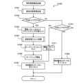
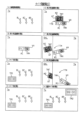
図1は、本発明の一実施形態としての遊技機1の正面図である。以下では、遊技機1の左右方向を、遊技機1に対面する遊技者から見た左右方向に一致させて説明する。また、遊技機1の前方向は、遊技機1から遊技者に向かう方向として説明し、遊技機1の後方向は、遊技者から遊技機1に向かう方向として説明する。
<First Embodiment>
1. Structure of Gaming Machine FIG. 1 is a front view of a gaming machine 1 as one embodiment of the present invention. In the following description, the left-right direction of the gaming machine 1 corresponds to the left-right direction viewed from the player facing the gaming machine 1 . Also, the front direction of the gaming machine 1 will be described as the direction from the gaming machine 1 to the player, and the rearward direction of the gaming machine 1 will be described as the direction from the player to the gaming machine 1 .
遊技機1は、遊技者の発射操作に基づいて遊技球を発射させ、特定の入賞装置に遊技球が入賞すると、その入賞に基づいて所定数の遊技球を遊技者に払い出すパチンコ遊技機である。遊技機1は、遊技機枠50と、遊技盤2とを備え、遊技機枠50の内側に遊技盤2が取り付けられている。遊技機枠50は、前枠(前枠部)53のほか、遊技機の外郭部を形成する外枠(基枠部)と、外枠の内側において遊技盤2が取り付けられる内枠と、を備えている。前枠(前枠部)53は、外枠および内枠の前方側に配置される縦長方形状のユニットであり、ハンドル60と、打球供給皿(上皿)61と、余剰球受皿(下皿)62と、演出ボタン63と、サブ表示画面64(右サブ表示画面64R、左サブ表示画面64L、および、上サブ表示画面64U)と、枠ランプ66(右枠ランプ66R、および、左枠ランプ66L)と、スピーカ67と、を備えている。前枠53の中央には開口部が形成されており、開口部を介して、遊技盤2の遊技領域3を視認することができる。
The game machine 1 is a pachinko game machine that shoots game balls based on a player's shooting operation, and pays out a predetermined number of game balls to the player based on the winning when the game balls win in a specific winning device. be. The game machine 1 includes a game machine frame 50 and a game board 2, and the game board 2 is attached inside the game machine frame 50.例文帳に追加The game machine frame 50 includes a front frame (front frame portion) 53, an outer frame (base frame portion) that forms the outer shell of the game machine, and an inner frame to which the game board 2 is attached inside the outer frame. I have. The front frame (front frame portion) 53 is a vertically rectangular unit arranged on the front side of the outer frame and the inner frame. ) 62, effect button 63, sub-display screen 64 (right sub-display screen 64R, left sub-display screen 64L, and upper sub-display screen 64U), frame lamp 66 (right frame lamp 66R, left frame lamp 66L) and a speaker 67. An opening is formed in the center of the front frame 53, and the game area 3 of the game board 2 can be viewed through the opening.
ハンドル60は、前枠53の右側の下端に配置され、回転角度に応じた発射強度で遊技球を発射させる。打球供給皿(上皿)61は、前枠53の下方に設けられ、遊技球を貯留する。余剰球受皿(下皿)62は、打球供給皿(上皿)61の下方に配置され、打球供給皿61に収容しきれない遊技球を貯留する。演出ボタン63は、打球供給皿(上皿)61の近傍に配置された操作部であり、遊技の進行に伴って実行される演出時などに遊技者によって操作(押圧)される。サブ表示画面64は、液晶表示装置の画面であり、右サブ表示画面64Rと、左サブ表示画面64Lと、上サブ表示画面64Uとを含んでいる。右サブ表示画面64Rは、前枠53の右側に設けられ、左サブ表示画面64Lは、前枠53の左側に設けられ、上サブ表示画面64Uは、前枠53の上側に設けられている。右サブ表示画面64Rと、左サブ表示画面64Lは、遊技盤2を介して対となる位置に配置されている。上サブ表示画面64Uは、遊技盤2の上方に配置されている。右サブ表示画面64Rと、左サブ表示画面64Lと、上サブ表示画面64Uは、前枠53の開口部を囲むように配置されている。サブ表示画面64は、液晶表示装置であってもよいし、有機EL表示装置、プラズマディスプレイ、プロジェクター、ドットマトリクスなどの他の画像表示装置であってもよい。枠ランプ66は、右枠ランプ66Rと、左枠ランプ66Lとを含んでおり、前枠53の上方に配置され、遊技中などに発光演出をおこなう。右枠ランプ66Rは、上サブ表示画面64Uと右サブ表示画面64Rとの間に配置された斜め線状の発光部である。左枠ランプ66Lは、上サブ表示画面64Uと左サブ表示画面64Lとの間に配置された斜め線状の発光部である。スピーカ67は、前枠53の左上方と右上方に配置され、遊技中などに音演出をおこなう。
The handle 60 is arranged at the lower end on the right side of the front frame 53, and shoots the game ball with a shooting intensity corresponding to the rotation angle. A batted ball supply tray (upper tray) 61 is provided below the front frame 53 and stores game balls. A surplus ball receiving tray (lower tray) 62 is arranged below the hit ball supply tray (upper tray) 61 and stores game balls that cannot be accommodated in the hit ball supply tray 61 . The production button 63 is an operation unit arranged near the batted ball supply tray (upper tray) 61, and is operated (pressed) by the player at the time of production performed as the game progresses. The sub-display screen 64 is a screen of a liquid crystal display device, and includes a right sub-display screen 64R, a left sub-display screen 64L, and an upper sub-display screen 64U. The right sub-display screen 64R is provided on the right side of the front frame 53, the left sub-display screen 64L is provided on the left side of the front frame 53, and the upper sub-display screen 64U is provided on the upper side of the front frame 53. The right sub-display screen 64R and the left sub-display screen 64L are arranged in pairs with the game board 2 interposed therebetween. The upper sub-display screen 64U is arranged above the game board 2 . The right sub-display screen 64R, the left sub-display screen 64L, and the upper sub-display screen 64U are arranged so as to surround the opening of the front frame 53. As shown in FIG. The sub display screen 64 may be a liquid crystal display device, or may be another image display device such as an organic EL display device, a plasma display, a projector, or a dot matrix. The frame lamp 66 includes a right frame lamp 66R and a left frame lamp 66L, is arranged above the front frame 53, and emits light during a game. The right frame lamp 66R is an oblique linear light-emitting portion arranged between the upper sub-display screen 64U and the right sub-display screen 64R. The left frame lamp 66L is an oblique linear light-emitting portion arranged between the upper sub-display screen 64U and the left sub-display screen 64L. The speakers 67 are arranged on the upper left and upper right sides of the front frame 53, and produce sound during a game or the like.
遊技盤2は、遊技領域3と、レール部材4と、盤ランプ5と、画像表示装置7と、センター装飾体10と、固定入賞装置(ヘソ)19と、普通可変入賞装置(電チュー)22と、ゲート(スルーチャッカー)28と、第1大入賞装置(第1アタッカー)31と、第2大入賞装置(第2アタッカー)36と、大入賞口開放始動口17と、一般入賞口27(普通入賞口27)と、一般入賞口29(普通入賞口29)、アウト口16と、表示器類40と、を備えている。
The game board 2 includes a game area 3, a rail member 4, a board lamp 5, an image display device 7, a center decoration 10, a fixed winning device (navel) 19, and a normal variable winning device (electric chew) 22. , a gate (through chucker) 28, a first big winning device (first attacker) 31, a second big winning device (second attacker) 36, a big winning opening opening start opening 17, and a general winning opening 27 ( A normal prize winning port 27), a general prize winning port 29 (ordinary winning prize port 29), an out port 16, and indicators 40 are provided.
遊技領域3は、ハンドル60の操作によって発射された遊技球が流下する領域であり、遊技球を誘導する複数の遊技釘が突設されている。レール部材4は、遊技領域3の左側端部に配置され、ハンドル60の操作によって発射された遊技球を遊技領域3の上方に向けて誘導する。盤ランプ5は、遊技領域3の背面側に配置され、遊技領域3の背面側から光を照射する。ここでは、盤ランプ5のうちの一部は、右枠ランプ66R、および、左枠ランプ66Lと接続され、形態や発光が連続するように構成されている。
The game area 3 is an area where the game ball shot by the operation of the handle 60 flows down, and a plurality of game nails for guiding the game ball are protruded. The rail member 4 is arranged at the left end of the game area 3 and guides the game ball shot by operating the handle 60 upwards of the game area 3 . The board lamp 5 is arranged on the back side of the game area 3 and emits light from the back side of the game area 3 . Here, some of the board lamps 5 are connected to the right frame lamp 66R and the left frame lamp 66L, and configured so that the form and light emission are continuous.
画像表示装置7は、遊技領域3の中央付近に設けられ、表示画面7aを備えている。画像表示装置7は、液晶表示装置であってもよいし、有機EL表示装置、プラズマディスプレイ、プロジェクター、ドットマトリクスなどの他の画像表示装置であってもよい。画像表示装置7の表示画面7aは、演出図柄(装飾図柄)8L、8C、8Rが可変表示(変動表示ともいう)される演出図柄表示領域と、保留画像9A、9Bが表示される保留画像表示領域と、保留消化画像9Cが表示される保留消化画像表示領域と、を有している。保留画像9A、9Bは、保留を表す画像であり、保留アイコン9A,9Bとも呼ぶ。保留消化画像9Cは、当該保留を表す画像であり、当該保留画像9C、または、当該保留アイコン9Cとも呼ぶ。第1保留アイコンと第2保留アイコンとを総称して、単に保留アイコンとも呼ぶ。
The image display device 7 is provided near the center of the game area 3 and has a display screen 7a. The image display device 7 may be a liquid crystal display device, or may be another image display device such as an organic EL display device, a plasma display, a projector, or a dot matrix. The display screen 7a of the image display device 7 includes a production pattern display area in which production patterns (decorative patterns) 8L, 8C, and 8R are variably displayed (also referred to as variable display), and a reserved image display in which reserved images 9A and 9B are displayed. and a pending digested image display region in which the pending digested image 9C is displayed. The pending images 9A and 9B are images representing pending and are also called pending icons 9A and 9B. The pending digest image 9C is an image representing the pending, and is also called the pending image 9C or the pending icon 9C. The first pending icon and the second pending icon are collectively referred to simply as pending icons.
演出図柄表示領域は、「左」「中」「右」の3つの図柄表示エリアを含んでいる。左の図柄表示エリアには左演出図柄(左装飾図柄)8Lが表示される。中の図柄表示エリアには中演出図柄(中装飾図柄)8Cが表示される。右の図柄表示エリアには右演出図柄(右装飾図柄)8Rが表示される。演出図柄8L、8C、8Rは、例えば「1」~「9」までの数字を表した複数の図柄によって構成されている。演出図柄8L、8C、8Rの変動表示は、後述する第1特別図柄および第2特別図柄の変動表示と同期している。画像表示装置7は、左、中、右の図柄表示エリアに表示する演出図柄の組み合わせによって、後述の第1特別図柄表示器41aおよび第2特別図柄表示器41bによって表示される第1特別図柄および第2特別図柄の可変表示の結果(大当たり抽選結果)を、遊技者にわかりやすく表示することができる。
The performance symbol display area includes three symbol display areas of "left", "middle" and "right". A left effect pattern (left decorative pattern) 8L is displayed in the left pattern display area. A medium effect pattern (middle decorative pattern) 8C is displayed in the middle pattern display area. A right effect pattern (right decorative pattern) 8R is displayed in the right pattern display area. The production patterns 8L, 8C, and 8R are composed of a plurality of patterns representing numbers "1" to "9", for example. The variable display of the effect symbols 8L, 8C, 8R is synchronized with the variable display of the first special symbol and the second special symbol which will be described later. The image display device 7 displays the first special symbol and the The result of variable display of the second special symbol (big hit lottery result) can be displayed in an easy-to-understand manner for the player.
例えば、大当たりに当選した場合には「777」などのゾロ目で演出図柄を停止表示する。はずれであった場合には「637」などのバラケ目で演出図柄を停止表示する。これにより、遊技者による遊技の進行状況の把握が容易となる。遊技者は、大当たり抽選結果を第1特別図柄表示器41aや第2特別図柄表示器41bのほか、画像表示装置7によって把握することができる。なお、図柄表示エリアの位置は固定的でなくてもよい。また、演出図柄の変動表示の態様としては、上下方向にスクロールする態様であってもよいしそれ以外の態様であってもよい。各抽選結果に応じてどのような演出図柄の組み合わせを停止表示するかは上記に限定されず任意に設定することができる。以後、演出図柄8L、8C、8Rを表示する演出を「演出図柄の変動演出」、「装飾図柄の変動演出」または、単に「変動演出」「変動表示」とも呼ぶ。なお、この装飾図柄の変動演出は、特別図柄が変動開始してから停止するまでの期間(特別図柄変動期間とも呼ぶ)における演出を1回の変動演出(1サイクルの変動演出)としてカウントする。従って、特別図柄が変動開始してから停止するまでの期間に、装飾図柄を仮停止させる場合があったとしても、当該仮停止の演出は、装飾図柄の変動演出に含まれる。
For example, when a jackpot is won, the production pattern is stopped and displayed with double numbers such as "777". In the case of a miss, the production pattern is stopped and displayed with a loose pattern such as "637". This makes it easier for the player to grasp the progress of the game. The player can grasp the jackpot lottery result by the image display device 7 in addition to the first special symbol display device 41a and the second special symbol display device 41b. The position of the pattern display area may not be fixed. Moreover, as a mode of the variable display of the effect symbols, a mode of scrolling in the vertical direction may be used, or a mode other than that may be used. It is not limited to the above, and can be arbitrarily set as to what combination of performance symbols to stop display according to each lottery result. Hereinafter, the effect of displaying the effect patterns 8L, 8C, 8R is also called "variation effect of effect pattern", "variation effect of decorative symbol", or simply "variation effect" or "variation display". In this decorative pattern variation performance, the performance in the period from when the special pattern starts to stop until it stops (also called a special symbol variation period) is counted as one variation performance (one cycle of variation performance). Therefore, even if there is a case in which the decorative symbols are temporarily stopped during the period from when the special symbols start to fluctuate until they stop, the performance of the temporary stop is included in the variable performance of the decorative symbols.
画像表示装置7は、演出図柄変動演出のほか、大当たり遊技(特別遊技の一例)に並行しておこなわれる大当たり演出や、客待ち用のデモ演出などを表示画面7aに表示することができる。演出図柄変動演出では、演出図柄のほか、背景画像やキャラクタ画像などの演出画像も表示されてもよい。また、画像表示装置7は、演出図柄に加え、特別図柄が変動中であることを示唆したり、特別図柄の抽選結果を示唆したりすることが可能な識別表示(第四図柄、図示省略)を、表示画面7aに表示してもよい。なお、識別表示(第四図柄)は、遊技領域3に設けられたLEDなどの発光器によって表示させてもよい。
The image display device 7 can display, on the display screen 7a, a big win performance performed in parallel with a big win game (an example of a special game), a demonstration performance for waiting for customers, etc., in addition to the performance symbol variation performance. In the production design variation production, production images such as a background image and a character image may be displayed in addition to the production design. In addition to the effect pattern, the image display device 7 also provides an identification display (fourth pattern, not shown) that can suggest that the special pattern is changing, or that the special pattern lottery result can be suggested. may be displayed on the display screen 7a. The identification display (fourth pattern) may be displayed by a light emitter such as an LED provided in the game area 3 .
保留画像表示領域は、後述の第1特図保留の記憶数に応じて保留画像9Aを表示する第1保留表示エリアと、後述の第2特図保留の記憶数に応じて保留画像9Bを表示する第2保留表示エリアとを含んでいる。保留画像9A、9Bの表示によって、後述の第1特図保留表示器43aに表示される第1特図保留の記憶数と、第2特図保留表示器43bに表示される第2特図保留の記憶数を、遊技者にわかりやすく表示することができる。保留消化画像表示領域は、保留消化画像9Cを表示する保留消化表示エリアを含んでいる。保留消化画像9Cは、表示画面7aまたは表示画面7bで現在変動中の演出図柄(演出図柄8L、8C、8R)に対応しており、保留消化画像9Cの表示によって、第1特図保留または第2特図保留が消化(後述の「特図保留の消化」)されることを、遊技者にわかりやすく表示することができる。
The reserved image display area is a first reserved display area that displays a reserved image 9A according to the number of memories of the first special figure reservation described later, and a reserved image 9B according to the number of memories of the second special figure reservation that will be described later. and a second reserved display area. By the display of the pending images 9A and 9B, the storage number of the first special figure suspension displayed on the first special figure suspension display 43a described later, and the second special figure suspension displayed on the second special figure suspension display 43b can be displayed in an easy-to-understand manner for the player. The pending digest image display area includes a pending digest display area that displays a pending digest image 9C. The pending digested image 9C corresponds to the production pattern (the production pattern 8L, 8C, 8R) currently fluctuating on the display screen 7a or the display screen 7b. 2 It is possible to display in an easy-to-understand manner for the player that the special figure reservation is digested ("extraction of special figure suspension" described later).
画像表示装置7の右上と左上には、可動式のいわゆるギミックである第1盤可動体14(第1可動役物14とも呼ぶ)が設けられている。第1可動役物14は、2つの長板状の発光部材が斜め下方向に移動可能に構成されている。第1可動役物14は、通常時は表示装置7の右上と左上の退避位置(図1)で静止しており、退避位置から斜め下方向に移動(進出)して表示画面7aの前方の進出位置で静止することができる。第1可動役物14は、進出位置で停止したとき画像表示装置7の一部を覆う。
A first board movable body 14 (also referred to as a first movable accessory 14), which is a movable so-called gimmick, is provided at the upper right and upper left of the image display device 7 . The first movable accessory 14 is configured such that two long plate-shaped light emitting members can move obliquely downward. The first movable accessory 14 is normally stationary at the upper right and upper left retracted positions (FIG. 1) of the display device 7, moves (advances) obliquely downward from the retracted position, and moves forward of the display screen 7a. It can rest in the advanced position. The first movable accessory 14 covers part of the image display device 7 when stopped at the advanced position.
センター装飾体10は、遊技領域3の中央付近であって、画像表示装置7の前方に配置されている。センター装飾体10には、可動式のいわゆるギミックである第2盤可動体15(第2可動役物15とも呼ぶ)が取り付けられている。センター装飾体10の下部には、ステージ部11が形成されている。ステージ部11は、ステージ部11の上面を転動する遊技球を後述の第1始動口20へと誘導可能な形状を有している。センター装飾体10の左下方には、ワープ部12が設けられている。ワープ部12は、遊技球が流入する入口部と遊技球が流出する出口部とを備え、入口部から流入した遊技球を出口部からステージ部11に流出させる。ステージ部11の下方には図示しない可動式のいわゆるギミックである第3盤可動体18(第3可動役物18とも呼ぶ)が取り付けられている。
The center decorative body 10 is arranged near the center of the game area 3 and in front of the image display device 7 . A second board movable body 15 (also referred to as a second movable accessory 15), which is a movable so-called gimmick, is attached to the center decorative body 10. - 特許庁A stage portion 11 is formed below the center decorative body 10 . The stage portion 11 has a shape capable of guiding a game ball rolling on the upper surface of the stage portion 11 to a first starting port 20 which will be described later. A warp portion 12 is provided on the lower left side of the center decorative body 10 . The warp part 12 has an entrance part into which the game balls flow in and an exit part from which the game balls flow out, and the game balls flowing in from the entrance part flow out to the stage part 11 from the exit part. A third board movable body 18 (also referred to as a third movable accessory 18), which is a movable so-called gimmick (not shown), is attached below the stage section 11 .
固定入賞装置(ヘソ)19は、遊技領域3における画像表示装置7の下方に配置され、遊技球の入球し易さが常に変わらない第1始動口(第1始動入賞口、第1入球口、固定始動口)20を備えている。第1始動口20への遊技球の入賞は、第1特別図柄の抽選(大当たり抽選)の契機となっている。言い換えれば、第1始動口20への遊技球の入賞は、大当たり乱数等の取得および大当たり判定等の契機となっている。
A fixed prize winning device (navel) 19 is arranged below the image display device 7 in the game area 3, and is a first start opening (first start winning opening, first ball entry opening) in which the ease with which a game ball enters is always unchanged. port, fixed starting port) 20. Winning of the game ball to the first starting port 20 triggers a first special symbol lottery (jackpot lottery). In other words, the winning of the game ball to the first starting port 20 is a trigger for the acquisition of the jackpot random number and the like and the jackpot determination and the like.
普通可変入賞装置(電チュー)22は、遊技領域3における第1始動口20の下方に配置され、第2始動口(第2始動入賞口、第2入球口、可変始動口)21を備えている。第2始動口21への遊技球の入賞は、第2特別図柄の抽選(小当たりおよび大当たり抽選)の契機となっている。電チュー22は、第2始動口21の前方に可動部材23を備えており、可動部材23の作動によって第2始動口21を開閉する。可動部材23は、電チューソレノイド24(図3)によって駆動される。第2始動口21は、可動部材23が開状態のとき遊技球が入球可能である。なお、電チュー22は、可動部材23が開状態のときの方が閉状態のときよりも第2始動口21への入球が容易であればよく、閉状態のときに第2始動口21への入球が可能であってもよい。
A normal variable winning device (electric chew) 22 is arranged below the first starting port 20 in the game area 3, and has a second starting port (second starting winning port, second ball entrance, variable starting port) 21. ing. The winning of the game ball into the second starting port 21 triggers the lottery of the second special symbol (small winning lottery and big winning lottery). The electric chew 22 has a movable member 23 in front of the second starting port 21 , and the second starting port 21 is opened and closed by the operation of the movable member 23 . The movable member 23 is driven by an electric tuning solenoid 24 (FIG. 3). A game ball can enter the second starting port 21 when the movable member 23 is in an open state. It is sufficient for the electric chew 22 that it is easier for the ball to enter the second starting port 21 when the movable member 23 is in the open state than when it is in the closed state. It may be possible to enter the ball into.
ゲート(スルーチャッカー)28は、遊技領域3における第1大入賞装置(第1アタッカー)31の上方に配置されており、遊技球が通過可能に構成されている。ゲート28への遊技球の通過は、電チュー22を開放するか否かを決定する普通図柄抽選の契機となっている。言い換えれば、ゲート28への遊技球の通過は、普通図柄乱数(当たり乱数)の取得および当たり判定等の契機となっている。
The gate (through chucker) 28 is arranged above the first big winning device (first attacker) 31 in the game area 3, and is configured to allow game balls to pass through. Passage of the game ball to the gate 28 triggers a normal symbol lottery for determining whether or not to open the electric chew 22.例文帳に追加In other words, the passage of the game ball to the gate 28 triggers acquisition of a normal symbol random number (hit random number), hit determination, and the like.
ここで、「特別図柄の大当たり抽選」とは、第1始動口20または第2始動口21に遊技球が入賞したときに、特別図柄判定用の大当たり乱数を取得し、この取得した大当たり乱数を予め定められた「大当たり」に対応する値と比較することにより、大当たりか否かを判定する処理をいう。この「大当たり」の抽選結果は即座に遊技者に報知されるわけではなく、後述の第1特別図柄表示器41aまたは第2特別図柄表示器41bにおいて特別図柄の変動表示がおこなわれ、所定の変動時間を経過したところで、抽選結果に対応する特別図柄が停止表示(確定表示)され、遊技者に抽選結果が報知される。画像表示装置7では、特別図柄の変動表示と同期して演出図柄を変動表示する図柄合わせゲームが行われ、この図柄合わせゲームによって、より効果的に大当りの抽選結果が遊技者に報知される。
Here, the ``special symbol jackpot lottery'' means that when a game ball wins in the first start port 20 or the second start port 21, a jackpot random number for special symbol determination is obtained, and the obtained jackpot random number is used. It refers to a process of determining whether or not a big win is made by comparing with a value corresponding to a predetermined "big win". The lottery result of this "jackpot" is not immediately notified to the player, but the variable display of special symbols is performed on the first special symbol display device 41a or the second special symbol display device 41b, which will be described later, and the predetermined variation is performed. When the time elapses, the special symbol corresponding to the lottery result is stopped and displayed (determined display), and the player is notified of the lottery result. In the image display device 7, a pattern matching game for variably displaying performance patterns is performed in synchronism with the variable display of the special patterns, and the result of the lottery of the big win is reported to the player more effectively by the pattern matching game.
また、「特別図柄の小当たり抽選」とは、第2始動口21に遊技球が入賞したときに、特別図柄判定用の小当たり乱数を取得し、この取得した小当たり乱数を予め定められた「小当たり」に対応する値と比較することにより、小当たりか否かを判定する処理をいう。この「小当たり」の抽選結果は即座に遊技者に報知されるわけではなく、後述の第2特別図柄表示器41bにおいて特別図柄の変動表示がおこなわれ、所定の変動時間を経過したところで、抽選結果に対応する特別図柄が停止表示(確定表示)され、遊技者に抽選結果が報知される。画像表示装置7では、特別図柄の変動表示と同期して演出図柄を変動表示する図柄合わせゲームが行われ、この図柄合わせゲームによって、より効果的に小当たりの抽選結果が遊技者に報知される。
In addition, the ``special symbol lottery'' means that when a game ball wins in the second start port 21, a small winning random number for special symbol determination is acquired, and the acquired small winning random number is set in advance. By comparing with the value corresponding to the "small hit", it refers to the process of determining whether or not it is a small hit. The lottery result of this "small hit" is not immediately notified to the player, but the variable display of the special symbols is performed on the second special symbol display device 41b described later, and a lottery is drawn after a predetermined variation time has elapsed. A special symbol corresponding to the result is stopped and displayed (determined display), and the player is notified of the lottery result. In the image display device 7, a pattern matching game is performed in which performance patterns are variably displayed in synchronism with the variable display of the special symbols, and by this pattern matching game, the lottery result of the small win is more effectively notified to the player. .
また、「普通図柄の抽選」とは、ゲート28を遊技球が通過したときに、普通図柄判定用の乱数を取得し、この取得した乱数を予め定められた「当り」に対応する値と比較することにより、当りか否かを判定する処理をいう。この普通図柄の抽選結果についても、ゲート28を遊技球が通過して即座に抽選結果が報知されるわけではなく、後述の普通図柄表示器42において普通図柄の変動表示がおこなわれ、所定の変動時間を経過したところで、抽選結果に対応する普通図柄が確定表示(点灯または消灯)され、遊技者に抽選結果が報知される。
In addition, the "lottery of normal symbols" means that when a game ball passes through the gate 28, a random number for normal symbol determination is obtained, and the obtained random number is compared with a value corresponding to a predetermined "hit". By doing so, it means the process of judging whether or not it is a hit. As for the lottery result of this normal pattern, the game ball passes through the gate 28 and the lottery result is not immediately reported, but the normal pattern is displayed in a normal pattern display device 42 to be described later, and a predetermined fluctuation is performed. When the time elapses, the normal symbol corresponding to the lottery result is fixedly displayed (lighted or extinguished), and the player is notified of the lottery result.
第1大入賞装置(第1アタッカー、第1特別可変入賞装置)31は、遊技領域3における第1始動口20の右上方に配置され、第1大入賞口(第1特別入賞口)30と、V領域39と、非V領域70と、V開閉部材71とを備えている。第1大入賞口30は、スイング式の開閉動作により遊技球の受け入れを許容または阻害する開閉部材(第1特別入賞口開閉部材)32を備えている。開閉部材32は、第1大入賞口ソレノイド33(図3)によって駆動される。第1大入賞口30は、開閉部材32が開状態のとき遊技球が入球可能となる。
The first big winning device (first attacker, first special variable winning device) 31 is arranged above the first starting port 20 in the game area 3, and the first big winning port (first special winning port) 30 and , a V region 39 , a non-V region 70 , and a V opening/closing member 71 . The first big winning hole 30 has an opening/closing member (first special winning hole opening/closing member) 32 that permits or inhibits reception of game balls by a swing-type opening/closing operation. The opening/closing member 32 is driven by a first grand prize winning solenoid 33 (FIG. 3). A game ball can enter the first big winning hole 30 when the opening/closing member 32 is in an open state.
第1大入賞装置31は内部に、V領域(特定領域)39と、V領域センサ39a(図3)と、非V領域(非特定領域)70と、非V領域センサ70a(図3)と、第1大入賞口センサ30a(図3)と、V開閉部材71と、V開閉部材ソレノイド73(図3)と、を備えている。V領域(特定領域)39および非V領域(非特定領域)70は、第1大入賞装置31の内部において、第1大入賞口30を通過した遊技球が通過可能な領域として構成されている。第1大入賞口センサ30aは、V領域39および非V領域70の上流に配置され、第1大入賞口30への遊技球の入賞を検知する。V領域センサ39aは、V領域39に配置され、V領域39への遊技球の通過を検知する。非V領域センサ70aは、非V領域70に配置され、非V領域70への遊技球の通過を検知する。V開閉部材71は、第1大入賞口30を通過した遊技球をV領域39または非V領域70のいずれかに振り分ける。V開閉部材ソレノイド73は、V開閉部材71を駆動する。V開閉部材71は、回転移動(遊技盤2に対して時計回りおよび反時計回り)するように構成され、V開閉部材ソレノイド73の通電時には、原点位置から反時計回りに回転して遊技球をV領域39に振り分ける第1の状態(回動状態)となり、V開閉部材ソレノイド73の非通電時には、原点に位置して遊技球を非V領域70に振り分ける第2の状態(停止状態)となる。なお、V開閉部材71は、回転移動に限らず、第1大入賞口30を通過した遊技球をV領域39または非V領域70のいずれかに振り分ける機能を有しておればよく、例えば、遊技盤2に対して左右方向に移動するように構成してもよい。すなわち、V開閉部材ソレノイド73の通電時には、遊技球をV領域39に振り分ける退避状態(第1の状態)となり、V開閉部材ソレノイド73の非通電時には、遊技球を非V領域70に振り分ける進出状態(第2の状態)となるように構成してもよい。なお、遊技機1では、V領域39への遊技球の通過が後述の高確率状態への移行の契機となっている。つまり、V領域39は、確変作動口となっている。一方、非V領域70は、確変作動口となっていない。本実施形態の第1大入賞装置31は、さらに、第1大入賞装置31から排出される遊技球数を計数する第1大入賞装置排出センサ(図示しない)を備えている。第1大入賞装置排出センサは、V領域39と非V領域70が下流で合流した地点に設けられており、V領域センサ39aまたは非V領域センサ70aを通過した遊技球数を計数する。
The first big prize winning device 31 has a V area (specific area) 39, a V area sensor 39a (FIG. 3), a non-V area (non-specific area) 70, and a non-V area sensor 70a (FIG. 3). , a first prize winning hole sensor 30a (FIG. 3), a V opening/closing member 71, and a V opening/closing member solenoid 73 (FIG. 3). The V area (specified area) 39 and the non-V area (non-specified area) 70 are configured as areas inside the first big winning device 31 through which game balls that have passed through the first big winning hole 30 can pass. . The first big winning hole sensor 30 a is arranged upstream of the V area 39 and the non-V area 70 and detects the winning of the game ball into the first big winning hole 30 . The V area sensor 39 a is arranged in the V area 39 and detects passage of a game ball to the V area 39 . The non-V area sensor 70 a is arranged in the non-V area 70 and detects passage of a game ball to the non-V area 70 . The V opening/closing member 71 distributes the game ball that has passed through the first big winning hole 30 to either the V area 39 or the non-V area 70 . The V opening/closing member solenoid 73 drives the V opening/closing member 71 . The V opening/closing member 71 is configured to rotate (clockwise and counterclockwise with respect to the game board 2), and when the V opening/closing member solenoid 73 is energized, it rotates counterclockwise from the origin position to release the game ball. A first state (rotating state) in which the ball is distributed to the V area 39 is entered, and a second state (stopped state) in which the game ball is positioned at the origin and distributed to the non-V area 70 is entered when the V opening/closing member solenoid 73 is not energized. . In addition, the V opening and closing member 71 is not limited to rotational movement, and may have a function of distributing the game ball that has passed through the first big winning hole 30 to either the V area 39 or the non-V area 70. For example, It may be configured to move in the horizontal direction with respect to the game board 2 . That is, when the V opening/closing member solenoid 73 is energized, it is in a retracted state (first state) in which game balls are distributed to the V area 39, and when the V opening/closing member solenoid 73 is not energized, it is in an advanced state in which game balls are distributed to the non-V area 70. (Second state). In the gaming machine 1, passage of the game ball to the V area 39 triggers a transition to a high probability state, which will be described later. That is, the V region 39 is a variable probability operating port. On the other hand, the non-V region 70 is not a variable probability operating port. The first big winning device 31 of this embodiment further includes a first big winning device discharge sensor (not shown) that counts the number of game balls discharged from the first big winning device 31 . The first big winning device discharge sensor is provided at a point where the V area 39 and the non-V area 70 merge downstream, and counts the number of game balls that have passed through the V area sensor 39a or the non-V area sensor 70a.
第2大入賞装置(第2アタッカー、小当りアタッカー、第2特別可変入賞装置)36は、遊技領域3における第1大入賞口30の右上方に配置され、第2大入賞口(第2特別入賞口)35を備えている。第2大入賞口35は、スイング式の開閉動作により遊技球の受け入れを阻害または許容する開閉部材(第2特別入賞口開閉部材、可動部材)37を備えている。開閉部材37は、第2大入賞口ソレノイド38(図3)によって駆動される。第2大入賞口35は、開閉部材37が開状態のとき遊技球が入球可能となる。この第2大入賞装置は、第2始動口21に遊技球が入賞して小当たり抽選で当選した場合に作動する、小当りアタッカーとなっている。
The second big winning device (second attacker, small winning attacker, second special variable winning device) 36 is arranged above the first big winning port 30 in the game area 3, and is the second big winning port (second special A winning opening) 35 is provided. The second big prize winning opening 35 has an opening/closing member (second special winning opening opening/closing member, movable member) 37 that inhibits or allows reception of game balls by a swing-type opening/closing operation. The opening/closing member 37 is driven by a second prize winning opening solenoid 38 (FIG. 3). A game ball can enter the second big winning hole 35 when the opening/closing member 37 is in an open state. This second big winning device is a small winning attacker that is activated when a game ball enters the second starting port 21 and wins a small winning lottery.
大入賞口開放始動口17は、遊技領域3における第1大入賞口30の上方に配置され、遊技球の通過時に、第1大入賞口30が開放される。
The large winning opening opening start opening 17 is arranged above the first large winning opening 30 in the game area 3, and the first large winning opening 30 is opened when the game ball passes.
一般入賞口27は、遊技領域3の下部に設けられている。アウト口16は、遊技領域3の下部に設けられており、いずれの入賞口にも入賞しなかった遊技球を遊技領域3の外へ排出する。表示器類40は、遊技盤2の右側中央付近に配置されている。表示器類40の詳細については後述する。一般入賞口29は、遊技領域3の右下部であって、第1大入賞口30の右側に隣接して配置されている。
The general winning opening 27 is provided in the lower part of the game area 3 . The out port 16 is provided in the lower part of the game area 3, and discharges out of the game area 3 game balls that have not won any prize winning openings. The display devices 40 are arranged near the center on the right side of the game board 2 . The details of the display devices 40 will be described later. The general winning opening 29 is arranged in the lower right part of the game area 3 and adjacent to the right side of the first big winning opening 30 .
遊技領域3には、左右方向の中央より左側の左遊技領域3Aと、右側の右遊技領域3Bとがある。左遊技領域3Aを遊技球が流下するように遊技球を発射する打ち方を「左打ち」と呼ぶ。一方、右遊技領域3Bを遊技球が流下するように遊技球を発射する打ち方を「右打ち」と呼ぶ。遊技機1では、左打ちにて第1始動口20への入賞を狙うことができる。一方、右打ちにてゲート28への通過、第2始動口21、第1大入賞口30、および、第2大入賞口35への入賞が狙うことができるように構成されている。
The game area 3 includes a left game area 3A on the left side of the center in the horizontal direction and a right game area 3B on the right side. A hitting method of shooting a game ball so that the game ball flows down the left game area 3A is called "left hitting". On the other hand, the hitting method of shooting the game ball so that the game ball flows down the right game area 3B is called "right hitting". In the game machine 1, it is possible to aim for a prize at the first start hole 20 by hitting to the left. On the other hand, it is configured so that it is possible to aim to pass through the gate 28 and to win the second starting hole 21, the first big winning hole 30, and the second big winning hole 35 by hitting to the right.
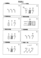
図2は、表示器類40の拡大図である。表示器類40は、第1特別図柄表示器41aと、第2特別図柄表示器41bと、普通図柄表示器42と、第1特図保留表示器43aと、第2特図保留表示器43bと、普図保留表示器44と、を含んでいる。第1特別図柄表示器41aは、第1特別図柄を可変表示する。第2特別図柄表示器41bは、第2特別図柄を可変表示する。普通図柄表示器42は、普通図柄を可変表示する。第1特図保留表示器43aは、第1特別図柄表示器41aの作動保留(第1特図保留)の記憶数を表示する。第2特図保留表示器43bは、第2特別図柄表示器41bの作動保留(第2特図保留)の記憶数を表示する。普図保留表示器44は、普通図柄表示器42の作動保留(普図保留)の記憶数を表示する。第1特別図柄の可変表示は、第1始動口20への遊技球の入賞を契機としておこなわれる。第2特別図柄の可変表示は、第2始動口21への遊技球の入賞を契機としておこなわれる。以下では、第1特別図柄および第2特別図柄を総称して「特別図柄」とも呼ぶ。また、第1特別図柄表示器41aおよび第2特別図柄表示器41bを総称して「特別図柄表示器41」とも呼ぶ。また、第1特図保留表示器43aおよび第2特図保留表示器43bを総称して「特図保留表示器43」とも呼ぶ。
FIG. 2 is an enlarged view of the indicators 40. As shown in FIG. The display devices 40 include a first special symbol display device 41a, a second special symbol display device 41b, a normal symbol display device 42, a first special symbol reservation display device 43a, and a second special symbol reservation display device 43b. , and a normal map holding display 44 . The first special symbol display 41a variably displays the first special symbol. The second special symbol display 41b variably displays the second special symbol. The normal symbol display 42 variably displays normal symbols. The 1st special figure reservation indicator 43a displays the number of memory of operation reservation (1st special figure reservation) of the 1st special design indicator 41a. The 2nd special figure reservation indicator 43b displays the number of memory of operation reservation (2nd special figure reservation) of the 2nd special design indicator 41b. The normal pattern holding display 44 displays the number of memory of operation holding (normal pattern holding) of the normal pattern display 42 . The variable display of the first special symbol is triggered by the winning of the game ball to the first starting port 20. - 特許庁The variable display of the second special symbol is performed with the winning of the game ball to the second starting port 21 as a trigger. Below, the 1st special design and the 2nd special design are named generically, and it is also called a "special design." Also, the first special symbol display device 41a and the second special symbol display device 41b are collectively referred to as "special symbol display device 41". Further, the first special figure reservation display 43a and the second special figure reservation display 43b are also collectively referred to as "special figure reservation display 43".
特別図柄表示器41は、特別図柄(識別情報)を可変表示(変動表示)した後、停止表示することによって第1始動口20または第2始動口21への入賞に基づく抽選(大当たり抽選)の結果を報知する。停止表示される特別図柄(停止図柄、可変表示の表示結果として導出表示される特別図柄)は、特別図柄抽選によって複数種類の特別図柄の中から選択された一つの特別図柄である。停止図柄が予め定めた大当たり停止態様の特別図柄(大当たり図柄)である場合には、停止表示された大当たり図柄の種類(当選した大当たりの種類)に応じた開放パターンにて第1大入賞口30または第2大入賞口35を開放させる特別遊技(大当たり遊技)がおこなわれる。なお、大当たり遊技における大入賞口(第1大入賞口30および第2大入賞口35)の開放パターンについては後述する。
The special symbol display device 41 variably displays (changes display) the special symbol (identification information), and then displays it in a stopped manner, so that a lottery (jackpot lottery) based on the winning of the first start port 20 or the second start port 21 is performed. Notify the results. A special symbol to be stopped and displayed (a stop symbol, a special symbol derived and displayed as a display result of variable display) is one special symbol selected from a plurality of types of special symbols by a special symbol lottery. When the stop pattern is a special pattern (jackpot pattern) of a predetermined jackpot stop mode, the first big prize opening 30 is opened in an opening pattern corresponding to the type of the stopped jackpot pattern (type of jackpot won). Alternatively, a special game (jackpot game) for opening the second big winning hole 35 is performed. The opening patterns of the big winning openings (the first big winning opening 30 and the second big winning opening 35) in the jackpot game will be described later.
特別図柄表示器41は、特別図柄(識別情報)を可変表示(変動表示)した後、停止表示することによって第2始動口21への入賞に基づく抽選(小当たり抽選)の結果を報知する。停止表示される特別図柄(停止図柄、可変表示の表示結果として導出表示される特別図柄)は、特別図柄抽選によって複数種類の特別図柄の中から選択された一つの特別図柄である。停止図柄が予め定めた小当たり停止態様の特別図柄(小当たり図柄)である場合には、所定の開放パターンにて第2大入賞口35を開放させる特別遊技(小当たり遊技)がおこなわれる。なお、小当たり遊技における第2大入賞口35の開放パターンについては後述する。
The special symbol display device 41 notifies the result of the lottery (small winning lottery) based on the winning to the second starting port 21 by displaying the special symbol (identification information) variably (variably displaying) and then stopping the display. A special symbol to be stopped and displayed (a stop symbol, a special symbol derived and displayed as a display result of variable display) is one special symbol selected from a plurality of types of special symbols by a special symbol lottery. When the stop pattern is a special pattern (small winning pattern) of a predetermined small winning stop mode, a special game (small winning game) is performed to open the second big winning hole 35 in a predetermined opening pattern. In addition, the opening pattern of the second big winning opening 35 in the small winning game will be described later.
特別図柄表示器41は、横並びに配された8個のLEDから構成されており、その点灯態様によって特別図柄当たり抽選の結果に応じた特別図柄を表示する。例えば、大当たり(後述の複数種類の大当たりのうちの一つ)に当選した場合には、「○○●●○○●●」(○:点灯、●:消灯)というように左から1,2,5,6番目にあるLEDが点灯した大当たり図柄を表示する。小当たりに当選した場合には、「○○●●●●●●」(○:点灯、●:消灯)というように左から1,2番目にあるLEDが点灯した小当たり図柄を表示する。ハズレである場合には、「●●●●●●●○」というように一番右にあるLEDのみが点灯したハズレ図柄を表示する。ハズレ図柄として全てのLEDを消灯させる態様を採用してもよい。特別図柄が停止表示される前には、所定の変動時間にわたって特別図柄の変動表示(可変表示)がなされる。変動表示の態様は、例えば、左から右へ光が繰り返し流れるように各LEDが点灯してもよい。変動表示の態様は、各LEDが停止表示(特定の態様での点灯表示)されていなければ、上記態様に限定されず、任意の点灯態様とすることができる。例えば、変動表示の態様は、全LEDが一斉に点滅してもよい。
The special symbol display device 41 is composed of eight LEDs arranged side by side, and displays a special symbol corresponding to the result of the special symbol winning lottery according to the lighting mode thereof. For example, if you win a jackpot (one of the multiple types of jackpots described later), you can say ``○○●●○○●●'' (○: lit, ●: unlit). , 5th and 6th LEDs light up to display the jackpot symbols. When a small prize is won, a small prize pattern in which the first and second LEDs from the left are lit is displayed, such as "○○●●●●●●" (○: lights up, ●: lights out). If the game is lost, a lost pattern is displayed in which only the rightmost LED lights up, such as "●●●●●●●○". A mode in which all the LEDs are extinguished may be adopted as the lost pattern. Before the special symbols are stopped and displayed, the special symbols are variably displayed (variably displayed) for a predetermined variation time. As for the aspect of the variable display, for example, each LED may light so that the light repeatedly flows from left to right. The mode of the variable display is not limited to the above mode, and any lighting mode can be used as long as each LED is not displayed in a stopped state (lighting display in a specific mode). For example, all LEDs may blink simultaneously in the variable display mode.
遊技機1では、第1始動口20または第2始動口21への遊技球の入賞(入球)があると、その入賞に対して取得した大当たり乱数等の各種乱数の値(数値情報)は、特図保留記憶領域85(図5)に一旦記憶される。具体的には、第1始動口20への入賞であれば、第1特図保留として第1特図保留記憶領域85a(図5)に記憶され、第2始動口21への入賞であれば、第2特図保留として第2特図保留記憶領域85b(図5)に記憶される。各々の特図保留記憶領域85に記憶可能な特図保留の数には上限があり、本実施形態における上限値は、第1特図保留記憶領域85a、第2特図保留記憶領域85bともにそれぞれ4個となっている。特図保留記憶領域85に記憶された特図保留は、その特図保留に基づく特別図柄の可変表示が可能となったときに消化される。「特図保留の消化」とは、その特図保留に対応する大当たり乱数等を判定して、その判定結果を示すための特別図柄の可変表示を実行することをいう。従って、遊技機1では、第1始動口20または第2始動口21への遊技球の入賞に基づく特別図柄の可変表示がその入賞後にすぐにおこなえない場合、すなわち、特別図柄の可変表示の実行中や特別遊技の実行中に入賞があった場合であっても、所定個数を上限として、その入賞に対する大当たり抽選の権利を留保することができる。特図保留の数は、特図保留表示器43に表示される。第1特図保留表示器43aと第2特図保留表示器43bは、例えばそれぞれ4個のLEDで構成されている。各特図保留表示器43は、特図保留の数だけLEDを点灯させることによって特図保留の数を表示する。
In the gaming machine 1, when a game ball enters the first start port 20 or the second start port 21 (enters a ball), the values (numerical information) of various random numbers such as jackpot random numbers acquired for the win are , It is temporarily stored in the special figure reservation storage area 85 (FIG. 5). Specifically, if it is a prize to the first start port 20, it is stored in the first special figure reservation storage area 85a (FIG. 5) as a first special figure reservation, and if it is a prize to the second start port 21 , is stored in the second special figure reservation storage area 85b (FIG. 5) as the second special figure reservation. There is an upper limit to the number of special figure reservations that can be stored in each special figure reservation storage area 85, and the upper limit value in this embodiment is the first special figure reservation storage area 85a and the second special figure reservation storage area 85b. There are four. The special figure reservation stored in the special figure reservation storage area 85 is consumed when the variable display of the special symbol based on the special figure reservation becomes possible. "Digestion of special figure reservation" means to determine a jackpot random number or the like corresponding to the special figure reservation and execute variable display of special symbols for showing the determination result. Therefore, in the gaming machine 1, when the variable display of the special symbols based on the winning of the game ball to the first start port 20 or the second start port 21 cannot be performed immediately after the winning, that is, the execution of the variable display of the special symbols. Even if a prize is won during execution of a special game, the right of a jackpot lottery for the prize can be reserved with a predetermined number as the upper limit. The number of special figure reservations is displayed on the special figure reservation indicator 43 . The 1st special figure reservation indicator 43a and the 2nd special figure reservation indicator 43b are each constituted by four LEDs, for example. Each special figure reservation indicator 43 displays the number of special figure reservations by turning on LEDs corresponding to the number of special figure reservations.
普通図柄の可変表示は、ゲート28への遊技球の通過を契機としておこなわれる。普通図柄表示器42は、普通図柄を可変表示(変動表示)した後、停止表示することによってゲート28への遊技球の通過に基づく普通図柄抽選の結果を報知する。停止表示される普通図柄(普図停止図柄、可変表示の表示結果として導出表示される普通図柄)は、普通図柄抽選によって複数種類の普通図柄の中から選択された一つの普通図柄である。普図停止図柄が予め定めた特定普通図柄(所定の停止態様の普通図柄すなわち普通当たり図柄)である場合には、現在の遊技状態に応じた開放パターンに第2始動口21を開放させる補助遊技が行われる。なお、第2始動口21の開放パターンについては後述する。
The variable display of normal symbols is performed when the game ball passes through the gate 28 as a trigger. The normal symbol display device 42 notifies the result of the normal symbol lottery based on the passage of the game ball to the gate 28 by displaying the normal symbols variably (variably displaying) and then stopping the display. A normal pattern to be stopped and displayed (a normal pattern stop pattern, a normal pattern derived and displayed as a display result of variable display) is one normal pattern selected from a plurality of types of normal patterns by a normal pattern lottery. When the normal pattern stop pattern is a predetermined specific normal pattern (a normal pattern of a predetermined stop mode, ie, a normal winning pattern), an auxiliary game that opens the second start port 21 in an opening pattern according to the current game state. is done. The opening pattern of the second starting port 21 will be described later.
普通図柄表示器42は、2個のLEDから構成されており、その点灯態様によって普通図柄抽選の結果に応じた普通図柄を表示するものである。例えば、抽選結果が当たりである場合には、「○○」(○:点灯、●:消灯)というように両LEDが点灯した普通当たり図柄を表示する。抽選結果がハズレである場合には、「●○」というように右のLEDのみが点灯した普通ハズレ図柄を表示する。普通ハズレ図柄として全てのLEDを消灯させる態様を採用してもよい。普通図柄が停止表示される前には、所定の変動時間にわたって普通図柄の変動表示がなされる。変動表示の態様は、例えば、両LEDが交互に点灯してもよい。変動表示の態様は、各LEDが停止表示(特定の態様での点灯表示)されていなければ、上記態様に限定されず、任意の点灯態様とすることができる。例えば、変動表示の態様は、全LEDが一斉に点滅してもよい。
The normal symbol display device 42 is composed of two LEDs, and displays a normal symbol according to the result of the normal symbol lottery according to the lighting mode thereof. For example, when the lottery result is a win, a normal win pattern with both LEDs lit up is displayed, such as "○○" (○: lights up, ●: lights out). When the lottery result is a loss, a normal losing pattern in which only the right LED lights up is displayed, such as "●○". A mode in which all the LEDs are extinguished may be employed as a normal losing pattern. Before the normal symbols are stop-displayed, the normal symbols are varied and displayed for a predetermined variation time. As for the aspect of the variable display, for example, both LEDs may alternately light up. The mode of the variable display is not limited to the above mode, and any lighting mode can be used as long as each LED is not displayed in a stopped state (lighting display in a specific mode). For example, all LEDs may blink simultaneously in the variable display mode.
遊技機1では、ゲート28への遊技球の通過があると、その通過に対して取得した普通図柄乱数(当たり乱数)の値は、普図保留記憶領域86(図5)に普図保留として一旦記憶される。普図保留記憶領域86に記憶可能な普図保留の数には上限があり、本形態における上限値は4個となっている。普図保留記憶領域86に記憶された普図保留は、その普図保留に基づく普通図柄の可変表示が可能となったときに消化される。普図保留の消化とは、その普図保留に対応する普通図柄乱数(当たり乱数)を判定して、その判定結果を示すための普通図柄の可変表示を実行することをいう。従って、遊技機1では、ゲート28への遊技球の通過に基づく普通図柄の可変表示がその通過後にすぐにおこなえない場合、すなわち、普通図柄の可変表示の実行中や補助遊技の実行中に入賞があった場合であっても、所定個数を上限として、その通過に対する普通図柄抽選の権利を留保することができる。普図保留の数は、普図保留表示器44に表示される。普図保留表示器44は、例えば、4個のLEDで構成されており、普図保留の数だけLEDを点灯させることによって普図保留の数を表示する。
In the gaming machine 1, when a game ball passes through the gate 28, the value of the normal symbol random number (hit random number) acquired for the passage is stored in the normal pattern reservation storage area 86 (FIG. 5) as a normal pattern reservation. memorized once. There is an upper limit to the number of normal pattern reservations that can be stored in the general pattern reservation storage area 86, and the upper limit value in this embodiment is four. The normal pattern reservation stored in the normal pattern reservation storage area 86 is terminated when the variable display of the normal pattern based on the normal pattern reservation becomes possible. The digestion of the normal pattern reservation means that the normal design random number (hit random number) corresponding to the normal pattern reservation is determined, and the normal design variable display is performed to show the determination result. Therefore, in the gaming machine 1, when the variable display of the normal symbols based on the passage of the game ball through the gate 28 cannot be performed immediately after the passage, that is, during the execution of the variable display of the normal symbols or during the execution of the auxiliary game, a prize is won. Even if there is, it is possible to reserve the right of the normal symbol lottery for the passage, with a predetermined number as the upper limit. The number of normal map reservations is displayed on the normal map reservation display 44 . The normal map hold indicator 44 is composed of, for example, four LEDs, and displays the number of normal map reserves by lighting the LEDs by the number of normal map reserves.
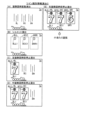
2.遊技機の電気的構成
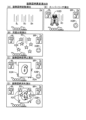
図3、図4に基づいて、遊技機1の電気的構成について説明する。図3は、遊技機1の主制御基板側の電気的な構成を示すブロック図である。図4は、遊技機1のサブ制御基板側の電気的な構成を示すブロック図である。遊技機1は、主制御基板80(図3)と、サブ制御基板90(図4)と、画像制御基板100(図4)と、ランプ制御基板107(図4)と、音声制御基板106(図4)と、払出制御基板110(図3)と、を備えている。主制御基板80は、大当たり抽選や遊技状態の移行などの遊技利益に関する制御をおこなう遊技制御基板であり、メイン制御部を構成する。サブ制御基板90は、遊技の進行に伴って実行する演出に関する制御をおこなう演出制御基板であり、画像制御基板100、ランプ制御基板107、音声制御基板106とともにサブ制御部を構成する。なお、サブ制御部は、少なくともサブ制御基板90を備えていれば構成可能である。
2. Electrical Configuration of Gaming Machine The electrical configuration of the gaming machine 1 will be described with reference to FIGS. 3 and 4. FIG. FIG. 3 is a block diagram showing the electrical configuration of the main control board side of the gaming machine 1. As shown in FIG. FIG. 4 is a block diagram showing the electrical configuration of the sub-control board side of the gaming machine 1. As shown in FIG. The gaming machine 1 includes a main control board 80 (FIG. 3), a sub control board 90 (FIG. 4), an image control board 100 (FIG. 4), a lamp control board 107 (FIG. 4), and an audio control board 106 ( 4) and a payout control board 110 (FIG. 3). The main control board 80 is a game control board that controls game profits such as jackpot lottery and game state transition, and constitutes a main control section. The sub-control board 90 is an effect control board that controls effects to be executed as the game progresses, and constitutes a sub-control section together with the image control board 100, the lamp control board 107, and the sound control board 106. It should be noted that the sub-control section can be configured as long as it includes at least the sub-control board 90 .
主制御基板80は、遊技制御用マイコン81と、入出力回路87と、を備えている。遊技制御用マイコン81は、主制御基板80に実装されているワンチップマイコンであり、プログラムに従って遊技機1の遊技の進行を制御する。遊技制御用マイコン81は、遊技の進行を制御するためのプログラムなどを記憶するメインROM83と、ワークメモリとして使用されるメインRAM84と、メインROM83に記憶されているプログラムを実行するメインCPU82と、を含んでいる。メインROM83に記憶されているデータの詳細、および、メインRAM84に設けられている記憶領域の詳細については後述する。メインROM83は外付けROMとして構成されていてもよい。遊技制御用マイコン81は、入出力回路(I/Oポート部)87を介して他の基板等とデータの送受信をおこなう。入出力回路87は、遊技制御用マイコン81に内蔵されていてもよい。
The main control board 80 includes a game control microcomputer 81 and an input/output circuit 87 . The game control microcomputer 81 is a one-chip microcomputer mounted on the main control board 80, and controls the progress of the game of the gaming machine 1 according to a program. The game control microcomputer 81 includes a main ROM 83 that stores programs for controlling the progress of the game, a main RAM 84 that is used as a work memory, and a main CPU 82 that executes the programs stored in the main ROM 83. contains. Details of the data stored in the main ROM 83 and details of the storage areas provided in the main RAM 84 will be described later. The main ROM 83 may be configured as an external ROM. The game control microcomputer 81 transmits and receives data to and from other boards and the like via an input/output circuit (I/O port section) 87 . The input/output circuit 87 may be built in the game control microcomputer 81 .
主制御基板80には、入出力回路87および中継基板88を介して各種センサやソレノイドが接続されている。主制御基板80は、各センサから出力された信号が入力するとともに、各ソレノイドに対して信号を出力する。中継基板88を介して接続されるセンサ類としては、大入賞口開放始動口センサ17a、第1始動口センサ20a、第2始動口センサ21a、ゲートセンサ28a、第1大入賞口センサ30a、第2大入賞口センサ35a、V領域センサ39a、非V領域センサ70a、および、普通入賞口センサ27a、29aが例示される。中継基板88を介して接続されるソレノイド類としては、電チューソレノイド24、第1大入賞口ソレノイド33、第2大入賞口ソレノイド38、および、V開閉部材ソレノイド73が例示される。大入賞口開放始動口センサ17aは、大入賞口開放始動口17の内部に設けられ、大入賞口開放始動口17に入球した遊技球を検出する。第1始動口センサ20aは、第1始動口20の内部に設けられ、第1始動口20に入賞した遊技球を検出する。第2始動口センサ21aは、第2始動口21の内部に設けられ、第2始動口21に入賞した遊技球を検出する。ゲートセンサ28aは、ゲート28の内部に設けられ、ゲート28を通過した遊技球を検出する。第1大入賞口センサ30aは、第1大入賞口30の内部に設けられ、第1大入賞口30に入賞した遊技球を検出する。第2大入賞口センサ35aは、第2大入賞口35の内部に設けられ、第2大入賞口35に入賞した遊技球を検出する。V領域センサ39aは、第1大入賞口30の内部のV領域39に設けられ、V領域39を通過した遊技球を検出する。非V領域センサ70aは、第1大入賞口30の内部の非V領域70に設けられ、非V領域70を通過した遊技球を検出する。普通入賞口センサ27aは、普通入賞口27の内部に設けられ、普通入賞口27に入賞した遊技球を検出する。普通入賞口センサ29aは、普通入賞口29の内部に通過した遊技球を検出する。電チューソレノイド24は、電チュー22の可動部材23を駆動する。第1大入賞口ソレノイド33は、第1大入賞装置31の開閉部材32を駆動する。第2大入賞口ソレノイド38は、第2大入賞装置36の開閉部材37を駆動する。V開閉部材ソレノイド73は、第1大入賞装置31のV開閉部材71を駆動する。
Various sensors and solenoids are connected to the main control board 80 via an input/output circuit 87 and a relay board 88 . The main control board 80 receives signals output from each sensor and outputs signals to each solenoid. Sensors connected via the relay board 88 include the large winning opening opening sensor 17a, the first starting opening sensor 20a, the second starting opening sensor 21a, the gate sensor 28a, the first large winning opening sensor 30a, the 2 major winning opening sensor 35a, V area sensor 39a, non-V area sensor 70a, and normal winning opening sensors 27a, 29a are illustrated. Examples of the solenoids connected via the relay board 88 include the electric tuning solenoid 24, the first big winning opening solenoid 33, the second big winning opening solenoid 38, and the V opening/closing member solenoid 73. The large winning opening opening starting opening sensor 17 a is provided inside the large winning opening opening starting opening 17 and detects a game ball entering the large winning opening opening starting opening 17 . The first starting hole sensor 20 a is provided inside the first starting hole 20 and detects a game ball that has entered the first starting hole 20 . The second starting hole sensor 21 a is provided inside the second starting hole 21 and detects a game ball that has entered the second starting hole 21 . The gate sensor 28 a is provided inside the gate 28 and detects a game ball that has passed through the gate 28 . The first big winning hole sensor 30 a is provided inside the first big winning hole 30 and detects a game ball that has won the first big winning hole 30 . The second big winning hole sensor 35 a is provided inside the second big winning hole 35 and detects a game ball that has won the second big winning hole 35 . The V area sensor 39 a is provided in the V area 39 inside the first big winning hole 30 and detects a game ball that has passed through the V area 39 . The non-V area sensor 70 a is provided in the non-V area 70 inside the first big winning hole 30 and detects a game ball that has passed through the non-V area 70 . The normal winning hole sensor 27 a is provided inside the normal winning hole 27 and detects a game ball that has entered the normal winning hole 27 . The normal winning opening sensor 29 a detects a game ball that has passed through the normal winning opening 29 . The electric chew solenoid 24 drives the movable member 23 of the electric chew 22 . The first big winning opening solenoid 33 drives the opening/closing member 32 of the first big winning device 31 . The second big prize opening solenoid 38 drives the opening/closing member 37 of the second big prize winning device 36 . The V opening/closing member solenoid 73 drives the V opening/closing member 71 of the first big winning device 31 .
主制御基板80には、入出力回路87を介して表示器類40が接続されている。遊技制御用マイコン81は、第1特別図柄表示器41a、第2特別図柄表示器41b、普通図柄表示器42、第1特図保留表示器43a、第2特図保留表示器43b、普図保留表示器44についての表示制御おこなう。
The display devices 40 are connected to the main control board 80 via an input/output circuit 87 . The game control microcomputer 81 includes a first special symbol display device 41a, a second special symbol display device 41b, a normal symbol display device 42, a first special symbol reservation display device 43a, a second special symbol reservation display device 43b, and a general pattern reservation. Display control for the display device 44 is performed.
主制御基板80には、入出力回路87を介して払出制御基板110が接続されている。主制御基板80は、払出制御基板110に各種コマンドを送信するとともに、払い出し監視のために払出制御基板110から信号を受信する。払出制御基板110には、賞球払出装置120と、貸球払出装置130と、カードユニット135と、が接続され、発射制御回路111を介して発射装置112が接続されている。賞球払出装置120は、賞球の払い出しをおこなう。払出制御基板110は、遊技制御用マイコン81からの信号に基づいて、賞球払出装置120の賞球モータ121を駆動して賞球の払い出しをおこなう。払い出される賞球は、計数のために賞球センサ122によって検知される。貸球払出装置130は、貸球の払い出しをおこなう。払出制御基板110は、遊技機1に接続されたカードユニット135からの信号に基づいて、貸球払出装置130の貸球モータ131を駆動して貸球の払い出しをおこなう。払い出される貸球は、計数のために貸球センサ132によって検知される。カードユニット135は、遊技機1に隣接して配置され、挿入されたプリペイドカードなどの情報に基づいて球貸に関する情報を出力する。発射装置112は、ハンドル60(図1)と、発射モータ113と、タッチスイッチ114と、発射ボリューム115と、を備えている。発射装置112は、遊技者によるハンドル60の操作があった場合に、タッチスイッチ114によってハンドル60の接触を検知し、発射ボリューム115によってハンドル60の回転量を検知する。そして、発射ボリューム115の検知信号の大きさに応じた強さで遊技球が発射されるように発射モータ113を駆動する。
A payout control board 110 is connected to the main control board 80 via an input/output circuit 87 . The main control board 80 transmits various commands to the payout control board 110 and receives signals from the payout control board 110 for payout monitoring. The payout control board 110 is connected with a prize ball payout device 120 , a rental ball payout device 130 and a card unit 135 , and is connected with a launcher 112 via a launch control circuit 111 . The prize ball payout device 120 pays out prize balls. The payout control board 110 drives the prize ball motor 121 of the prize ball payout device 120 based on the signal from the game control microcomputer 81 to pay out the prize balls. Prize balls to be dispensed are detected by a prize ball sensor 122 for counting. The rental ball dispensing device 130 discharges the rental balls. The payout control board 110 drives the rented ball motor 131 of the rented ball payout device 130 based on the signal from the card unit 135 connected to the gaming machine 1 to pay out the rented balls. The rented balls to be paid out are detected by a rented ball sensor 132 for counting. The card unit 135 is arranged adjacent to the gaming machine 1, and outputs information regarding ball lending based on information such as the inserted prepaid card. Firing device 112 includes handle 60 ( FIG. 1 ), firing motor 113 , touch switch 114 , and firing volume 115 . When the player operates the handle 60 , the shooting device 112 detects the contact of the handle 60 with the touch switch 114 and detects the amount of rotation of the handle 60 with the shooting volume 115 . Then, the shooting motor 113 is driven so that the game ball is shot with strength corresponding to the magnitude of the detection signal of the shooting volume 115 .
主制御基板80には、入出力回路87を介してサブ制御基板90(図4)が接続されている。主制御基板80は、サブ制御基板90に対して各種コマンドを送信する。主制御基板80とサブ制御基板90との接続は、主制御基板80からサブ制御基板90への信号の送信のみが可能な単方向通信接続となっている。すなわち、主制御基板80とサブ制御基板90との間には、通信方向規制手段としての図示しない単方向性回路(例えばダイオードを用いた回路)が介在している。
A sub control board 90 ( FIG. 4 ) is connected to the main control board 80 via an input/output circuit 87 . The main control board 80 transmits various commands to the sub control board 90 . The connection between the main control board 80 and the sub control board 90 is a unidirectional communication connection that allows only transmission of signals from the main control board 80 to the sub control board 90 . That is, between the main control board 80 and the sub-control board 90, a unidirectional circuit (for example, a circuit using a diode) (not shown) is interposed as communication direction control means.
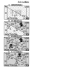
サブ制御基板90は、演出制御用マイコン91と、入出力回路95と、を備えている。演出制御用マイコン91は、サブ制御基板90に実装されているワンチップマイコンであり、プログラムに従って遊技機1の遊技の演出を制御する。演出制御用マイコン91は、遊技の進行に伴って演出を制御するためのプログラム等を記憶するサブROM93と、ワークメモリとして使用されるサブRAM94と、サブROM93に記憶されているプログラムを実行するサブCPU92と、を含んでいる。サブROM93に記憶されているデータの詳細、および、サブRAM94に設けられている記憶領域の詳細については後述する。サブROM93は外付けROMとして構成されていてもよい。演出制御用マイコン91は、入出力回路(I/Oポート部)95を介して他の基板等とデータの送受信をおこなう。入出力回路95は、演出制御用マイコン91に内蔵されていてもよい。サブ制御基板90には、入出力回路95を介して、画像制御基板100と、音声制御基板106と、ランプ制御基板107と、中継基板108と、が接続されている。
The sub-control board 90 includes a production control microcomputer 91 and an input/output circuit 95 . The effect control microcomputer 91 is a one-chip microcomputer mounted on the sub-control board 90, and controls the game effect of the game machine 1 according to a program. The effect control microcomputer 91 includes a sub ROM 93 that stores programs and the like for controlling effects as the game progresses, a sub RAM 94 that is used as a work memory, and a sub ROM 93 that executes the programs stored in the sub ROM 94. and a CPU 92 . Details of the data stored in the sub-ROM 93 and details of the storage areas provided in the sub-RAM 94 will be described later. The sub ROM 93 may be configured as an external ROM. The effect control microcomputer 91 transmits and receives data to and from other boards and the like via an input/output circuit (I/O port section) 95 . The input/output circuit 95 may be built in the effect control microcomputer 91 . An image control board 100 , an audio control board 106 , a lamp control board 107 and a relay board 108 are connected to the sub control board 90 via an input/output circuit 95 .
画像制御基板100は、画像制御用マイコン101と、入力回路105aと、出力回路105bとを備えている。画像制御用マイコン101は、画像制御基板100に実装されているワンチップマイコンであり、プログラムに従って画像表示装置7やサブ表示画面64の表示制御をおこなう。画像制御用マイコン101は、CPU102と、ROM103と、RAM104とを含んでいる。ROM103には、表示制御をおこなうためのプログラムのほか、画像表示装置7やサブ表示画面64に表示される静止画データや動画データ、具体的には、キャラクタ、アイテム、図形、文字、数字および記号等(演出図柄を含む)や背景画像等の画像データが格納されている。RAM104は、画像データを展開するためのメモリとして使用される。CPU102は、ROM103に記憶されているプログラムを実行する。演出制御用マイコン91は、主制御基板80から受信したコマンドに基づいて、画像制御用マイコン101に画像表示装置7やサブ表示画面64の表示制御をおこなわせる。画像制御用マイコン101は、演出制御用マイコン91からの指令に基づいてROM103から画像データを読み出し、読み出した画像データに基づいて表示制御をおこなう。
The image control board 100 includes an image control microcomputer 101, an input circuit 105a, and an output circuit 105b. The image control microcomputer 101 is a one-chip microcomputer mounted on the image control board 100, and performs display control of the image display device 7 and the sub display screen 64 according to a program. The image control microcomputer 101 includes a CPU 102 , a ROM 103 and a RAM 104 . In the ROM 103, in addition to programs for performing display control, still image data and moving image data displayed on the image display device 7 and the sub-display screen 64, specifically, characters, items, graphics, characters, numbers and symbols are stored. etc. (including production patterns) and image data such as background images are stored. A RAM 104 is used as a memory for developing image data. The CPU 102 executes programs stored in the ROM 103 . The effect control microcomputer 91 causes the image control microcomputer 101 to control the display of the image display device 7 and the sub display screen 64 based on the command received from the main control board 80 . The image control microcomputer 101 reads out image data from the ROM 103 based on a command from the effect control microcomputer 91, and performs display control based on the read image data.
音声制御基板106には、スピーカ67が接続されており、演出制御用マイコン91は、主制御基板80から受信したコマンドに基づいて、音声制御基板106を介してスピーカ67から音声、楽曲、効果音等を出力させる。スピーカ67から出力する音声等の音響データは、サブ制御基板90のサブROM93に格納されている。なお、音声制御基板106は、CPUを実装していてもよく、そのCPUにコマンドに基づく音声制御を実行させてもよい。さらに、音声制御基板106は、ROMを実装してもよく、そのROMに音響データを格納してもよい。また、スピーカ67を画像制御基板100に接続し、画像制御基板100のCPU102に音声制御を実行させてもよい。さらに、画像制御基板100のROM103に音響データを格納してもよい。
A speaker 67 is connected to the audio control board 106 , and based on commands received from the main control board 80 , the effect control microcomputer 91 outputs sounds, music, and sound effects from the speaker 67 via the audio control board 106 . and so on. Acoustic data such as voice output from the speaker 67 is stored in the sub ROM 93 of the sub control board 90 . Note that the audio control board 106 may have a CPU mounted thereon, and the CPU may execute audio control based on commands. Furthermore, the audio control board 106 may be implemented with a ROM, and the audio data may be stored in the ROM. Alternatively, the speaker 67 may be connected to the image control board 100 to cause the CPU 102 of the image control board 100 to perform voice control. Furthermore, the sound data may be stored in the ROM 103 of the image control board 100. FIG.
ランプ制御基板107には、枠ランプ66と、盤ランプ5と、第1可動役物14と、第2可動役物15と、第3可動役物18と、が接続されており、これらを制御する。演出制御用マイコン91は、主制御基板80から受信したコマンドに基づいて、ランプ制御基板107を介して枠ランプ66や盤ランプ5等のランプの点灯制御をおこなう。つまり、演出制御用マイコン91は、枠ランプ66や盤ランプ5等のランプの発光態様を決める発光パターンデータ(点灯/消灯や発光色等を決めるデータ、ランプデータともいう)を作成し、発光パターンデータに従って枠ランプ66や盤ランプ5などのランプの発光を制御する。発光パターンデータの作成にはサブ制御基板90のサブROM93に格納されているデータが用いられる。演出制御用マイコン91は、主制御基板80から受信したコマンドに基づいて、第1可動役物14、第2可動役物15、および、第3可動役物18を動作させる。演出制御用マイコン91は、第1可動役物14、第2可動役物15、および、第3可動役物18のそれぞれの動作態様を決める動作パターンデータ(駆動データ)を作成し、動作パターンデータに従って第1可動役物14、第2可動役物15、および、第3可動役物18の動作を制御する。動作パターンデータの作成にはサブROM93に格納されているデータを用いる。なお、ランプ制御基板107は、CPUを実装していてもよく、そのCPUにコマンドに基づくランプの点灯制御や可動役物14、15の動作制御を実行させてもよい。この場合、ランプ制御基板107はROMを実装してもよく、そのROMに発光パターンや動作パターンに関するデータを格納してもよい。
The frame lamp 66, the board lamp 5, the first movable accessory 14, the second movable accessory 15, and the third movable accessory 18 are connected to the lamp control board 107 to control them. do. The effect control microcomputer 91 performs lighting control of lamps such as the frame lamp 66 and the board lamp 5 via the lamp control board 107 based on the command received from the main control board 80 . In other words, the production control microcomputer 91 creates light emission pattern data (data for deciding on/off and emission color, also referred to as lamp data) that determines the light emission mode of the lamps such as the frame lamp 66 and the board lamp 5, and creates light emission patterns. Light emission of lamps such as the frame lamp 66 and the board lamp 5 is controlled according to the data. Data stored in the sub-ROM 93 of the sub-control board 90 is used to create the light emission pattern data. The effect control microcomputer 91 operates the first movable accessory 14, the second movable accessory 15, and the third movable accessory 18 based on the command received from the main control board 80. FIG. The performance control microcomputer 91 creates motion pattern data (driving data) for determining the motion mode of each of the first movable accessory 14, the second movable accessory 15, and the third movable accessory 18, and generates the motion pattern data. According to the above, the operation of the first movable accessory 14, the second movable accessory 15, and the third movable accessory 18 is controlled. Data stored in the sub ROM 93 is used to create the operation pattern data. Note that the lamp control board 107 may have a CPU mounted thereon, and the CPU may execute lighting control of the lamp and operation control of the movable accessories 14 and 15 based on commands. In this case, the lamp control board 107 may be mounted with a ROM, and the ROM may store data relating to light emission patterns and operation patterns.
中継基板108には、演出ボタン検出スイッチ63aと、セレクトボタン検出スイッチ68aと、が接続されている。演出ボタン検出スイッチ63aは、演出ボタン63(図1)が押下操作されたことを検出する。演出ボタン63が押下されると、演出ボタン検出スイッチ63aから、中継基板108を介してサブ制御基板90にスイッチ信号が出力される。セレクトボタン検出スイッチ68aは、セレクトボタン68が押下操作されたことを検出する。
A performance button detection switch 63a and a select button detection switch 68a are connected to the relay board 108 . The production button detection switch 63a detects that the production button 63 (FIG. 1) is pressed. When the effect button 63 is pressed, a switch signal is output from the effect button detection switch 63a to the sub-control board 90 via the relay board 108. The select button detection switch 68a detects that the select button 68 has been pressed.
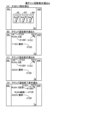
3.遊技機のデータ構成
図5、図6に基づいて、遊技機1のデータ構成について説明する。図5(A)は、メインROM83に記憶されているテーブルを説明するための図である。図5(B)は、メインRAM84に設けられている記憶領域を説明するための図である。図6(A)は、サブROM93に記憶されているテーブルを説明するための図である。図6(B)は、サブRAM94に設けられている記憶領域を説明するための図である。
3. Data Configuration of Gaming Machine The data configuration of the gaming machine 1 will be described with reference to FIGS. 5 and 6. FIG. FIG. 5A is a diagram for explaining a table stored in the main ROM 83. FIG. FIG. 5B is a diagram for explaining storage areas provided in the main RAM 84. As shown in FIG. FIG. 6A is a diagram for explaining the table stored in the sub ROM 93. As shown in FIG. FIG. 6B is a diagram for explaining storage areas provided in the sub-RAM 94. As shown in FIG.
メインROM83(図5(A))には、大当たり判定テーブルT1と、リーチ判定テーブルT2と、普通図柄当たり判定テーブルT3と、普通図柄変動パターン判定テーブルT4と、大当たり種別判定テーブルT5と、変動パターン判定テーブルT6と、電チュー開放パターン判定テーブルT7と、大入賞口開放パターン判定テーブルT8と、V開閉部材開放パターン判定テーブルT9と、小当たり判定テーブルT10と、が格納されている。これらの判定テーブルは、遊技制御用マイコン81が実行する主制御メイン処理(後述)において、遊技制御用マイコン81によって参照される。各判定テーブルの具体的な内容については後述する。
The main ROM 83 (FIG. 5(A)) contains a jackpot determination table T1, a reach determination table T2, a normal symbol hit determination table T3, a normal symbol variation pattern determination table T4, a jackpot type determination table T5, and a variation pattern. A judgment table T6, an electric chew opening pattern judgment table T7, a big winning opening pattern judgment table T8, a V opening/closing member opening pattern judgment table T9, and a small win judgment table T10 are stored. These determination tables are referred to by the game control microcomputer 81 in main control main processing (described later) executed by the game control microcomputer 81 . Specific contents of each determination table will be described later.
メインRAM84(図5(B))には、コマンドセット領域84aと、フラグセット領域84bと、カウンタセット領域84cと、特別動作ステータスセット領域84dと、特図保留記憶領域85と、普図保留記憶領域86とが設けられている。コマンドセット領域84aは、主制御メイン処理(後述)において、メイン制御部側からサブ制御部側に出力されるコマンドがセットされる領域(出力バッファ)であり、事前判定コマンド、保留球数コマンド、変動開始コマンド、変動停止コマンド、オープニングコマンド、ラウンド指定コマンド、エンディングコマンド、遊技状態指定コマンド、V通過コマンド、客待ち待機コマンドなどがセットされる。フラグセット領域84bは、主制御メイン処理(後述)において、遊技機の状態や遊技状態を示すフラグがセットされる領域であり、大当たりフラグ、大当たり終了フラグ、第1入賞フラグ、第2入賞フラグ、小当たりフラグ、Vフラグ、確変フラグ、時短フラグなどがセットされる。カウンタセット領域84cは、主制御メイン処理(後述)において使用されるカウンタがセットされる領域であり、乱数カウンタ、ラウンドカウンタ、確変カウンタ、時短カウンタなどがセットされる。特別動作ステータスセット領域84dは、後述する特別動作処理におけるステータスがセットされる領域である。特図保留記憶領域85は、第1特図保留が記憶される第1特図保留記憶領域85aと、第2特図保留が記憶される第2特図保留記憶領域85bとを含んでいる。第1特図保留記憶領域85aには、第1特図保留の1個目、2個目、3個目、4個目にそれぞれ対応する特別図柄当たり乱数等の乱数値群(保留情報)を記憶するための第1記憶領域、第2記憶領域、第3記憶領域、第4記憶領域が設けられている。第2特図保留記憶領域85bには、第2特図保留の1個目、2個目、3個目、4個目にそれぞれ対応する乱数値群(保留情報)を記憶するための第1記憶領域、第2記憶領域、第3記憶領域、第4記憶領域が設けられている。普図保留記憶領域86は、普図保留の1個目、2個目、3個目、4個目にそれぞれ対応する普通図柄乱数(あたり乱数)等の乱数値群(保留情報)を記憶するための第1記憶領域、第2記憶領域、第3記憶領域、第4記憶領域が設けられている。なお、メインRAM84には、上記の領域の他に、特図停止図柄データがセットされる当たり種別セットバッファや、可動役物14、15や枠可動体600を駆動させるための駆動データがセットされる駆動データバッファ等が設けられている。
The main RAM 84 (FIG. 5(B)) includes a command set area 84a, a flag set area 84b, a counter set area 84c, a special action status set area 84d, a special figure pending storage area 85, and a normal figure pending storage. A region 86 is provided. The command set area 84a is an area (output buffer) in which a command to be output from the main control unit side to the sub control unit side is set in the main control main processing (described later), and is a pre-determining command, a pending pitch command, A variation start command, a variation stop command, an opening command, a round designation command, an ending command, a game state designation command, a V passage command, a customer waiting command, etc. are set. The flag set area 84b is an area where flags indicating the state of the gaming machine and the game state are set in the main control main process (described later), and the jackpot flag, jackpot end flag, first prize flag, second prize flag, A small hit flag, a V flag, a variable probability flag, a time saving flag, etc. are set. The counter set area 84c is an area where counters used in the main control main process (described later) are set, and a random number counter, a round counter, a probability variable counter, a time saving counter and the like are set. The special action status set area 84d is an area in which a status is set for special action processing, which will be described later. The special figure reservation storage area 85 includes a first special figure reservation storage area 85a in which the first special figure reservation is stored and a second special figure reservation storage area 85b in which the second special figure reservation is stored. In the first special figure reservation storage area 85a, a random number group (reservation information) such as a random number per special symbol corresponding to the first, second, third, and fourth of the first special figure reservation A first storage area, a second storage area, a third storage area, and a fourth storage area are provided for storing. In the second special figure reservation storage area 85b, the first for storing the random number group (reservation information) corresponding to the first, second, third, and fourth of the second special figure reservation A storage area, a second storage area, a third storage area, and a fourth storage area are provided. The general pattern reservation storage area 86 stores a random number group (reservation information) such as normal pattern random numbers (per random numbers) corresponding to the 1st, 2nd, 3rd, and 4th general pattern reservations. A first storage area, a second storage area, a third storage area, and a fourth storage area are provided. In addition to the above areas, the main RAM 84 also contains a win type set buffer in which special figure stop symbol data is set, and drive data for driving the movable accessories 14 and 15 and the frame movable body 600. A drive data buffer and the like are provided.
サブROM93(図6(A))には、先読み演出パターン決定テーブルT51と、基幹演出パターン決定テーブルT52と、チャンスアップ演出パターン決定テーブルT53と、停止図柄パターン決定テーブルT54と、が格納されている。これらの決定テーブルは、演出制御用マイコン91が実行するサブ制御メイン処理(後述)において、演出制御用マイコン91によって参照される。各決定テーブルの具体的な内容については後述する。
The sub-ROM 93 (FIG. 6A) stores a look-ahead effect pattern determination table T51, a basic effect pattern determination table T52, a chance up effect pattern determination table T53, and a stop symbol pattern determination table T54. . These determination tables are referred to by the effect control microcomputer 91 in sub-control main processing (described later) executed by the effect control microcomputer 91 . Specific contents of each determination table will be described later.
サブRAM94(図6(B))には、コマンド記憶領域94aと、演出コマンドセット領域94bと、事前判定情報記憶領域94cと、カウンタセット領域94dと、が設けられている。コマンド記憶領域94aは、サブ制御メイン処理(後述)において、メイン制御部側から入力されたコマンドが記憶される領域(入力バッファ)であり、事前判定コマンド、保留球数コマンド、変動開始コマンド、変動停止コマンド、オープニングコマンド、ラウンド指定コマンド、エンディングコマンド、遊技状態指定コマンド、V通過コマンド、客待ち待機コマンドなどが格納される。演出コマンドセット領域94bは、サブ制御メイン処理(後述)において、サブ制御基板90から画像制御基板100、音声制御基板106、ランプ制御基板107、中継基板108に出力されるコマンドがセットされる領域(出力バッファ)であり、変動演出開始コマンド、変動終了前コマンド、変動演出終了コマンド、オープニング演出開始コマンド、ラウンド演出開始コマンド、エンディング演出開始コマンドなどがセットされる。事前判定情報記憶領域94cは、サブ制御メイン処理(後述)において、事前判定情報が記憶される。カウンタセット領域94dは、サブ制御メイン処理(後述)において使用されるカウンタがセットされる領域であり、乱数カウンタ、第1特図保留演出カウンタ、第2特図保留演出カウンタ、普図保留演出カウンタ、確変演出カウンタ、時短演出カウンタなどがセットされる。
The sub-RAM 94 (FIG. 6B) is provided with a command storage area 94a, an effect command set area 94b, a prior determination information storage area 94c, and a counter set area 94d. The command storage area 94a is an area (input buffer) in which commands input from the main control unit side are stored in the sub-control main process (described later), and is a pre-determination command, a pending ball number command, a variation start command, a variation A stop command, an opening command, a round designation command, an ending command, a game state designation command, a V passage command, a customer waiting command, etc. are stored. The effect command set area 94b is an area ( It is an output buffer), and a variable production start command, a command before the end of fluctuation, a variable production end command, an opening production start command, a round production start command, an ending production start command, etc. are set. The prior determination information storage area 94c stores prior determination information in a sub-control main process (described later). The counter set area 94d is an area where the counters used in the sub-control main process (described later) are set, such as a random number counter, a first special figure pending effect counter, a second special figure pending effect counter, a general figure pending effect counter. , Probability variation production counter, time saving production counter, etc. are set.
図7は、遊技機1において使用される各種の乱数を説明するための図である。図7(A)は、メイン制御部側の遊技制御用マイコン81が取得する乱数を示しており、図7(B)は、サブ制御部側の演出制御用マイコン91が取得する乱数を示している。遊技制御用マイコン81は、「大当たり乱数」と、「大当たり種別乱数」と、「リーチ乱数」と、「変動パターン乱数」と、「普通図柄乱数(当たり乱数)」と、「小当たり乱数」とを後述するタイミングにおいて取得するように構成されている。「大当たり乱数」は、大当たりか否かの抽選(大当たり判定)に用いられる乱数であり、0~65535までの範囲の値をとる。「大当たり種別乱数」は、当選した大当たりの種別の抽選(大当たり種別判定)に用いられる乱数であり、0~127までの範囲の値をとる。「リーチ乱数」は、大当たり判定がハズレである場合に、その結果を示す演出図柄変動演出においてリーチを発生させるか否かを決定するために用いられる乱数であり、0~127までの範囲の値をとる。リーチとは、複数の演出図柄(装飾図柄)のうち変動表示されている演出図柄が残り1つとなっている状態であって、変動表示されている演出図柄がどの図柄で停止表示されるか次第で大当たり当選を示す演出図柄の組み合わせとなる状態(例えば、「7↓7」の状態)のことである。なお、リーチ状態において停止表示されている演出図柄は、表示画面7a内で揺れているように表示されてもよい。「変動パターン乱数」は、変動時間を含む変動パターンを決定するために用いられる乱数であり、0~127までの範囲の値をとる。「普通図柄乱数(当たり乱数)」は、電チュー22を開放させる補助遊技をおこなうか否かの抽選(普通図柄抽選)に用いられる。普通図柄乱数は、0~255までの範囲の値をとる。「小当たり乱数」は、小当たりか否かの抽選(小当たり判定)に用いられる乱数であり、0~127までの範囲の値をとる。「大当たり乱数」、「大当たり種別乱数」、「リーチ乱数」、「変動パターン乱数」は、第1始動口20または第2始動口21への入球に基づいて取得される。「小当たり乱数」は、第2始動口21への入球に基づいて取得される。第1始動口20への入球に基づいて取得された乱数値群は第1特図保留記憶領域85aに記憶され、第2始動口21への入球に基づいて取得された乱数値群は第2特図保留記憶領域85bに記憶される。「普通図柄乱数(当たり乱数)」は、ゲート28の通過に基づいて取得される。取得された普通図柄乱数値は、普図保留記憶領域86に記憶される。
FIG. 7 is a diagram for explaining various random numbers used in the gaming machine 1. As shown in FIG. FIG. 7A shows random numbers acquired by the game control microcomputer 81 on the main control section side, and FIG. 7B shows random numbers acquired by the effect control microcomputer 91 on the sub control section side. there is The game control microcomputer 81 generates a "jackpot random number", a "jackpot type random number", a "reach random number", a "fluctuation pattern random number", a "normal symbol random number (hit random number)", and a "small hit random number". is acquired at a timing described later. The “jackpot random number” is a random number used for lottery (jackpot determination) to determine whether or not a jackpot will be won, and takes a value ranging from 0 to 65,535. The “jackpot type random number” is a random number used for the lottery (jackpot type determination) of the type of the winning jackpot, and takes a value in the range of 0-127. "Reach random number" is a random number used to determine whether or not to generate a reach in the effect symbol variation effect that indicates the result when the big hit determination is a loss, and is a value in the range of 0 to 127. take. Reach is a state in which only one of the plurality of production patterns (decorative patterns) that is variably displayed remains. It is a state (for example, the state of "7↓7") that is a combination of performance symbols indicating a jackpot winning. In addition, the effect symbol that is stopped and displayed in the ready-to-win state may be displayed as if it is shaking within the display screen 7a. “Variation pattern random number” is a random number used to determine a variation pattern including variation time, and takes a value in the range of 0-127. “Normal symbol random number (hit random number)” is used for a lottery (normal symbol lottery) for determining whether or not to perform an auxiliary game for opening the electric chew 22 . The normal symbol random number takes a value in the range of 0-255. The “small hit random number” is a random number used for a lottery (small hit determination) as to whether or not a small hit is made, and takes a value ranging from 0 to 127. The “jackpot random number”, the “jackpot type random number”, the “reach random number”, and the “fluctuation pattern random number” are obtained based on the ball entering the first start port 20 or the second start port 21 . A “small hit random number” is acquired based on the ball entering the second starting port 21 . The random value group obtained based on the ball entering the first starting port 20 is stored in the first special figure reservation storage area 85a, and the random value group obtained based on the ball entering the second starting port 21 is It is stored in the second special figure reservation storage area 85b. “Normal symbol random number (hit random number)” is acquired based on passing through the gate 28 . The acquired normal symbol random number value is stored in the normal symbol reservation storage area 86 .
演出制御用マイコン91は、「先読み演出乱数」と、「チャンスアップ乱数」と、を後述するタイミングにおいて取得するように構成されている。「先読み演出乱数」は、変動演出時の先読み演出を決定するために用いられる乱数であり、0~127までの範囲の値をとる。「チャンスアップ乱数」は、変動演出時のチャンスアップ演出を決定するために用いられる乱数であり、0~127までの範囲の値をとる。「先読み演出乱数」は、メイン制御部側からサブ制御部側に事前判定コマンドが出力されたことに基づいて取得される。取得された乱数値群はサブRAM94に記憶される。「チャンスアップ乱数」は、メイン制御部側からサブ制御部側に変動開始コマンドが出力されたことに基づいて取得される。取得された乱数値はサブRAM94に記憶される。
The effect control microcomputer 91 is configured to acquire a "read-ahead effect random number" and a "chance-up random number" at timings described later. ``Random number for look-ahead effect'' is a random number used for determining the look-ahead effect at the time of variable effect, and takes a value in the range of 0-127. The “chance-up random number” is a random number used for determining the chance-up effect during the variable effect, and takes a value in the range of 0-127. The "read-ahead effect random number" is acquired based on the output of a pre-determination command from the main control section to the sub-control section. The acquired random value group is stored in the sub-RAM 94 . The "chance-up random number" is acquired based on the output of a variation start command from the main control section to the sub-control section. The acquired random number value is stored in the sub-RAM 94 .
図8は、判定テーブルT1~T4、T10を説明するための図である。図8(A)には、大当たり判定テーブルT1を説明するための図が示され、図8(B)には、リーチ判定テーブルT2を説明するための図が示され、図8(C)には、普通図柄当たり判定テーブルT3を説明するための図が示され、図8(D)には、普通図柄変動パターン判定テーブルT4を説明するための図が示され、図8(E)には、小当たり判定テーブルT10を説明するための図が示されている。
FIG. 8 is a diagram for explaining the determination tables T1 to T4 and T10. FIG. 8A shows a diagram for explaining the jackpot determination table T1, FIG. 8B shows a diagram for explaining the reach determination table T2, and FIG. shows a diagram for explaining the normal symbol hit determination table T3, FIG. 8(D) shows a diagram for explaining the normal symbol variation pattern determination table T4, and FIG. 8(E) , a diagram for explaining the small hit determination table T10.
大当たり判定テーブルT1は、遊技制御用マイコン81が主制御メイン処理(後述)において、取得した大当たり乱数値(0~65535のいずれか)が「大当たり」に該当するか「ハズレ」に該当するかを判定するために参照されるテーブルである。図8(A)では、「通常確率状態」において、大当たり乱数値が「0~164」の場合には、「大当たり」と判定され(約確率1/397)、大当たり乱数値が「0~164以外の数値(165~65535)」の場合には、「ハズレ」と判定されることが示されている。また、「高確率状態」において、大当たり乱数値が「0~649」の場合には、「大当たり」と判定され(約確率1/101)、大当たり乱数値が「0~649以外の数値(650~65535)」の場合には、「ハズレ」と判定されることが示されている。「通常確率状態」および「高確率状態」の内容については後述する。
The jackpot determination table T1 determines whether the jackpot random number value (one of 0 to 65535) obtained by the game control microcomputer 81 in the main control main process (described later) corresponds to a "jackpot" or a "loss". It is a table referred to for determination. In FIG. 8 (A), in the "normal probability state", if the jackpot random value is "0 to 164", it is determined to be a "jackpot" (approximate probability 1/397), and the jackpot random value is "0 to 164 Numerical values other than (165 to 65535)” are determined to be “losing”. Also, in the "high probability state", if the jackpot random number is "0 to 649", it is determined to be a "jackpot" (approximate probability 1/101), and the jackpot random number is a number other than "0 to 649 (650 ~65535)” is determined to be “losing”. The contents of the "normal probability state" and the "high probability state" will be described later.
リーチ判定テーブルT2は、遊技制御用マイコン81が主制御メイン処理(後述)において、取得したリーチ乱数値(0~127のいずれか)が「リーチ有り」に該当するか「リーチ無し」に該当するかを判定するために参照されるテーブルである。なお、このリーチ判定テーブルT2は、上記の取得した大当たり乱数値が「大当たり」に該当している場合は参照されない。図8(B)では、「非時短状態」において、リーチ乱数値が「0~13」の場合には、「リーチ有り」と判定され、リーチ乱数値が「0~13以外の数値(14~127)」の場合には、「リーチ無し」と判定されることが示されている。また、「時短状態」において、リーチ乱数値が「0~5」の場合には、「リーチ有り」と判定され、リーチ乱数値が「0~5以外の数値(6~127)」の場合には、「リーチ無し」と判定されることが示されている。「時短状態」および「非時短状態」の内容については後述する。リーチ判定テーブルT2では、時短状態の方が非時短状態よりもハズレ時のリーチがかかりにくくなっている。これは、時短状態において変動時間の短いリーチ無しハズレがより多く選択されることで、特図保留の消化スピードを速めるためである。
In the reach determination table T2, the game control microcomputer 81 obtains a reach random number (any of 0 to 127) in the main control main process (described later) corresponds to "with reach" or "without reach". This table is referenced to determine whether It should be noted that this reach determination table T2 is not referred to when the obtained jackpot random number value corresponds to "jackpot". In FIG. 8 (B), in the "non-time saving state", if the reach random value is "0 to 13", it is determined to be "with reach", and the reach random value is a number other than "0 to 13 (14 to 127)” is determined to be “no reach”. Also, in the "time saving state", if the reach random number is "0 to 5", it is determined that there is reach, and if the reach random number is "a number other than 0 to 5 (6 to 127)" is determined to be "no reach". The contents of the "time saving state" and the "non-working time saving state" will be described later. In the reach determination table T2, the reach at the time of loss is less likely to be applied in the time saving state than in the non-working time saving state. This is to speed up the digestion speed of the special figure reservation by selecting more reach no loss with short fluctuation time in the time saving state.
普通図柄当たり判定テーブルT3は、遊技制御用マイコン81が主制御メイン処理(後述)において、取得した普通図柄乱数値(0~255のいずれか)が「当たり」に該当するか「ハズレ」に該当するかを判定するために参照されるテーブルである。図8(C)では、「非時短状態」において、普通図柄乱数値が「0~2」の場合には、「当たり」と判定され、普通図柄乱数値が「0~2以外の数値(3~255)」の場合には、「ハズレ」と判定されることが示されている。また、「時短状態」において、普通図柄乱数値が「0~254」の場合には、「当たり」と判定され、普通図柄乱数値が「0~254以外の数値(255)」の場合には、「ハズレ」と判定されることが示されている。
In the normal symbol hit determination table T3, the normal symbol random number value (any one of 0 to 255) acquired by the game control microcomputer 81 in the main control main process (described later) corresponds to "win" or "loss". This table is referenced to determine whether to In FIG. 8 (C), in the "non-time saving state", if the normal symbol random number is "0 to 2", it is determined to be "hit", and the normal symbol random number is a number other than "0 to 2 (3 ~ 255)” is determined to be “losing”. Also, in the "time saving state", if the normal symbol random number is "0 to 254", it is determined as "hit", and if the normal symbol random number is "a number other than 0 to 254 (255)" , is determined as “losing”.
普通図柄変動パターン判定テーブルT4は、遊技制御用マイコン81が主制御メイン処理(後述)において、遊技状態(非時短状態か時短状態か)に応じて、普通図柄の変動時間が何秒かを判定するために参照されるテーブルである。図8(D)では、「非時短状態」のとき、普通図柄の変動時間は「30秒」と判定され、「時短状態」のとき、普通図柄の変動時間が「1秒」と判定されることが示されている。
In the normal symbol variation pattern determination table T4, the game control microcomputer 81 determines how many seconds the normal symbol variation time is according to the game state (whether it is a non-time saving state or a time saving state) in the main control main process (described later). This table is referenced to In FIG. 8 (D), when the "non-time-saving state", the normal pattern variation time is determined to be "30 seconds", and when the "time-saving state", the normal pattern variation time is determined to be "1 second". is shown.
小当たり判定テーブルT10は、遊技制御用マイコン81が主制御メイン処理(後述)において、取得した小当たり乱数値(0~127のいずれか)が「小当たり」に該当するか「ハズレ」に該当するかを判定するために参照されるテーブルである。なお、この小当たり判定テーブルT10は、上記の取得した大当たり乱数値が「大当たり」に該当している場合は参照されない。図8(E)では、全状態において(遊技状態を問わず)、小当たり乱数値が「0~63」の場合には、「小当たり」と判定され(確率1/2)、小当たり乱数値が「0~63以外の数値(64~127)」の場合には、「ハズレ」と判定されることが示されている。なお、小当たり判定テーブルT10は、第2始動口21に遊技球が入賞したときに参照される(第1始動口20に遊技球が入賞したときは参照されない)テーブルである。また、小当たり判定テーブルT10は、「大当たり」と判定されたときは、参照されないテーブルである。
In the small hit determination table T10, the game control microcomputer 81 in the main control main process (described later), the small hit random value (any of 0 to 127) acquired corresponds to "small hit" or "losing". This table is referenced to determine whether to It should be noted that this small hit determination table T10 is not referred to when the obtained big hit random number value corresponds to "big hit". In FIG. 8 (E), in all states (regardless of the game state), if the small hit random value is "0 to 63", it is determined as "small hit" (probability 1/2), If the numerical value is "a numerical value (64 to 127) other than 0 to 63", it is determined to be "losing". It should be noted that the small hit determination table T10 is a table that is referred to when a game ball wins in the second start hole 21 (not referred to when a game ball wins in the first start hole 20). Also, the small win determination table T10 is a table that is not referred to when a "big win" is determined.
図9は、大当たり種別判定テーブルT5を説明するための図である。大当たり種別判定テーブルT5は、遊技制御用マイコン81が主制御メイン処理(後述)において、取得した大当たり種別乱数値(0~127のいずれか)に応じて、「大当たりの種別」と「特別図柄の種類」を判定するために参照されるテーブルである。図9では、第1特別図柄(特図1)の抽選において当選したとき、大当たり種別乱数値が「0~24」の場合には、大当たり種別が「16RV通過予定大当たり」と判定され、特図1の停止図柄(特図停止図柄)が「大当たり図柄1」と判定される。大当たり種別乱数値が「25~49」の場合には、大当たり種別が「16RV通過予定大当たり」と判定され、特図停止図柄が「大当たり図柄2」と判定される。大当たり種別乱数値が「50~55」の場合には、大当たり種別が「16R(実質15R)V通過予定大当たり」と判定され、特図停止図柄が「大当たり図柄3」と判定される。大当たり種別乱数値が「56~67」の場合には、大当たり種別が「16R(実質13R)V通過予定大当たり」と判定され、特図停止図柄が「大当たり図柄4」と判定される。大当たり種別乱数値が「68~127」の場合には、大当たり種別が「16R(実質13R)V非通過予定大当たり」と判定され、特図停止図柄が「大当たり図柄5」と判定される。一方、第2特別図柄(特図2)の抽選において当選したとき、大当たり種別乱数値が「0~40」の場合には、大当たり種別が「16RV通過予定大当たり」と判定され、特図2の停止図柄(特図停止図柄)が「大当たり図柄1」と判定される。大当たり種別乱数値が「41~82」の場合には、大当たり種別が「16RV通過予定大当たり」と判定され、特図2の停止図柄(特図停止図柄)が「大当たり図柄2」と判定される。大当たり種別乱数値が「83~127」の場合には、大当たり種別が「16R(実質13R)V非通過予定大当たり」と判定され、特図停止図柄が「大当たり図柄5」と判定される。なお、大当たり種別判定テーブルT5を参照することによって、特図停止図柄に対応する「特図停止図柄データ」、特別遊技の「オープニング(OP)コマンド」、「ラウンド指定コマンド」、「エンディング(ED)コマンド」も特定することができる。「16RV通過予定大当たり」、「16R(実質15R)V通過予定大当たり」、「16R(実質13R)V通過予定大当たり」および「16R(実質13R)V非通過予定大当たり」の具体的な内容については後述する。
FIG. 9 is a diagram for explaining the jackpot type determination table T5. The jackpot type determination table T5 is the game control microcomputer 81 in the main control main process (described later), according to the jackpot type random number value (any of 0 to 127) acquired, "jack type" and "special symbol It is a table referred to in order to determine "type". In FIG. 9, when winning in the lottery of the first special symbol (special figure 1), if the jackpot type random number is "0 to 24", the jackpot type is determined to be "16RV passage scheduled jackpot", and the special figure 1 stop design (special stop design) is determined as "jackpot design 1". When the jackpot type random number value is "25 to 49", the jackpot type is determined as "16RV passage scheduled jackpot", and the special figure stop design is determined as "jackpot design 2". When the jackpot type random number value is "50 to 55", the jackpot type is determined as "16R (actually 15R) V passage scheduled jackpot", and the special figure stop pattern is determined as "jackpot pattern 3". When the jackpot type random number value is "56 to 67", the jackpot type is determined as "16R (real 13R) V passage scheduled jackpot", and the special figure stop pattern is determined as "jackpot pattern 4". When the jackpot type random number value is "68 to 127", the jackpot type is determined as "16R (actually 13R) V non-passing scheduled jackpot", and the special figure stop symbol is determined as "jackpot symbol 5". On the other hand, when winning in the lottery of the second special symbol (special figure 2), if the jackpot type random number is "0 to 40", the jackpot type is determined to be "16RV passage scheduled jackpot", and the special figure 2 A stop symbol (a special figure stop symbol) is determined to be a "jackpot symbol 1". When the jackpot type random number is ``41 to 82'', the jackpot type is determined to be ``16RV passage scheduled jackpot'', and the stop pattern of special figure 2 (special figure stop pattern) is determined to be ``jackpot pattern 2''. . When the jackpot type random number value is "83 to 127", the jackpot type is determined as "16R (actually 13R) V non-passing scheduled jackpot", and the special figure stop symbol is determined as "jackpot symbol 5". By referring to the jackpot type determination table T5, "special figure stop symbol data" corresponding to the special figure stop symbol, special game "opening (OP) command", "round designation command", "ending (ED) command" can also be specified. For the specific contents of "16RV planned passage jackpot", "16R (real 15R) V planned passage jackpot", "16R (real 13R) V planned passage jackpot" and "16R (real 13R) V non-passage planned jackpot" will be described later.
図10は、非時短状態時の変動パターン判定テーブルT6を説明するための図である。図11は、時短状態時の変動パターン判定テーブルT6を説明するための図である。変動パターン判定テーブルT6は、遊技制御用マイコン81が主制御メイン処理(後述)において、取得した変動パターン乱数値(0~127)に応じて、変動パターンを判定するために参照されるテーブルである。
図10では、例えば、非時短状態において第1始動口20に入賞し、大当たり判定テーブルT1において「ハズレ」と判定され、リーチ判定テーブルT2において「リーチ有り」と判定され、保留球数が「1~2」であり、変動パターン乱数値が「0~60」の場合には、変動パターンが「P7」と判定されることが示されている。また、非時短状態において第2始動口21の保留を消化(非時短状態において第2始動口21への入賞は困難なため、時短状態(高確高ベース状態)が終了して通常状態(非時短状態、低確低ベース状態)になったとき、第2始動口21の保留を消化)し、大当たり判定テーブルT1において「大当たり」と判定され、大当たり種別判定テーブルT5において「16RV通過予定大当たり」、「大当たり図柄2(21H)」と判定され、変動パターン乱数値が「0~127」の場合には、変動パターンが「P22」と判定されることが示されている。また、非時短状態において第2始動口21の保留を消化し、小当たり判定テーブルT10において「小当たり」と判定され、変動パターン乱数値が「0~127」の場合には、変動パターンが「P34」と判定されることが示されている。
FIG. 10 is a diagram for explaining the variation pattern determination table T6 during the non-time saving state. FIG. 11 is a diagram for explaining the variation pattern determination table T6 during the time saving state. Variation pattern determination table T6 is a table referred to for determining a variation pattern according to the variation pattern random number value (0 to 127) acquired in main control main processing (described later) by the game control microcomputer 81. .
In FIG. 10, for example, the first start port 20 is won in a non-time saving state, it is determined to be "losing" in the big hit determination table T1, it is determined to be "with reach" in the reach determination table T2, and the number of retained balls is "1 ~ 2" and the variation pattern random number is "0 to 60", the variation pattern is determined to be "P7". Also, in a non-time-saving state, digest the hold of the second start-up port 21 (because it is difficult to win the second start-up port 21 in a non-time-saving state, the time-saving state (high probability high base state) ends and the normal state (non- When it becomes a time saving state, a low probability base state), the suspension of the second start port 21 is digested), it is determined as "jackpot" in the jackpot determination table T1, and "16RV passage schedule jackpot" in the jackpot type determination table T5. , “big hit pattern 2 (21H)”, and when the variation pattern random number is “0 to 127”, the variation pattern is determined to be “P22”. Also, in the non-time saving state, the second start port 21 is held, and it is determined as "small hit" in the small hit determination table T10. P34" is determined.
図11では、例えば、時短状態において第1始動口20に入賞し、大当たり判定テーブルT1において「ハズレ」と判定され、リーチ判定テーブルT2において「リーチ無し」と判定され、保留球数が「3~4」であり、変動パターン乱数値が「0~127」の場合には、変動パターンが「P56」と判定されることが示されている。また、時短状態において第2始動口21に入賞し、大当たり判定テーブルT1において「大当たり」と判定され、大当たり種別判定テーブルT5において「16RV通過予定大当たり」、「大当たり図柄2(21H)」と判定され、変動パターン乱数値が「0~127」の場合には、変動パターンが「P62」と判定されることが示されている。また、時短状態において第2始動口21に入賞し、小当たり判定テーブルT10において「小当たり」と判定され、変動パターン乱数値が「0~127」の場合には、変動パターンが「P74」と判定されることが示されている。
In FIG. 11, for example, the first start port 20 is won in the time saving state, it is determined as "losing" in the big hit determination table T1, it is determined as "no reach" in the reach determination table T2, and the number of held balls is "3 to 4” and the fluctuation pattern random number is “0 to 127”, the fluctuation pattern is determined to be “P56”. Also, in the time-saving state, the second start port 21 is won, and it is determined as "big hit" in the big hit determination table T1, and is determined as "16RV passage scheduled jackpot" and "big hit pattern 2 (21H)" in the big hit type determination table T5. , when the fluctuation pattern random number is "0 to 127", the fluctuation pattern is determined to be "P62". In addition, when the second start port 21 is won in the time saving state, it is determined as "small hit" in the small hit determination table T10, and the fluctuation pattern random number is "0 to 127", the fluctuation pattern is "P74". is shown to be determined.
図10,11に示されるように、変動パターンが決定されれば、変動時間も決定される。例えば、非時短状態において第2始動口21の保留を消化し、小当りと判定された場合、変動パターンが「P34」と判定され、変動時間は15000msecに決定される。また、時短状態において第2始動口21に入賞し、小当りと判定された場合、変動パターンが「P74」と判定され、変動時間は3000msecに決定される。なお、時短状態(高確高ベース状態)中は、次の大当たりになるまで後述する小当たりラッシュ(RUSH)期間中でもあり、つまり、小当たりラッシュ期間中では、第2始動口21に入賞したとき変動時間は3000msecで小当り確率が1/2なので、短時間で頻繁に小当りが発生する。そして、小当たりラッシュ期間中では、手持ちの遊技球を増加させながら大当たりを狙うことができる。また、リーチになる場合に、そのリーチがノーマルリーチとなるのかスーパーリーチ(SPリーチ)となるのかも決定される。スーパーリーチとは、ノーマルリーチよりもリーチ後の変動時間が長いリーチ演出である。ここでは、変動時間の異なる5種類のスーパーリーチ(SP1、SP2、SP3,SP4,SP5)が設定されている。SP1~3では、ノーマルリーチを経て発展的に実行される。SP1~5の違いは、例えば、疑似連の有無であってもよい。特にSP5は、後述する時短状態(高確高ベース状態)に発生する小当たりラッシュ(RUSH)期間中に、第2始動口21に入賞して疑似大当たり示唆演出がおこなわれる専用リーチの変動パターン(「P62」)となっている。なお、SP5は、時短状態(高確高ベース状態)が終了して通常状態(非時短状態、低確低ベース状態)になったときの、第2始動口21の保留消化中にも発生する場合があり、この場合にも疑似大当たり示唆演出がおこなわれ得る(変動パターン「P22」)。
As shown in FIGS. 10 and 11, once the variation pattern is determined, the variation time is also determined. For example, when the hold of the second starting port 21 is digested in the non-time saving state and it is determined as a small hit, the variation pattern is determined as "P34" and the variation time is determined as 15000 msec. In addition, when winning the second starting port 21 in the time saving state and it is determined as a small hit, the variation pattern is determined to be "P74" and the variation time is determined to be 3000 msec. In addition, during the time saving state (high probability high base state), it is also during the small hit rush (RUSH) period described later until the next big hit, that is, during the small hit rush period, when entering the second start port 21 Since the fluctuation time is 3000 msec and the small hit probability is 1/2, small hits occur frequently in a short time. During the small win rush period, the player can aim for a big win while increasing the number of game balls on hand. In addition, when it becomes reach, it is also determined whether the reach becomes normal reach or super reach (SP reach). Super reach is a reach production with a longer fluctuation time after reach than normal reach. Here, five types of super reach (SP1, SP2, SP3, SP4, SP5) with different fluctuation times are set. In SP1-3, it is executed progressively through normal reach. The difference between SP1 to SP5 may be, for example, the presence or absence of pseudo-reams. In particular, SP5 is a variation pattern of dedicated reach in which a pseudo-jackpot suggestion effect is performed by winning the second start port 21 during a small hit rush (RUSH) period that occurs in a time-saving state (high-probability high-base state) described later ( "P62"). In addition, SP5 occurs during the pending digestion of the second start port 21 when the time saving state (high probability high base state) ends and becomes normal state (non-time saving state, low probability low base state) In this case also, a pseudo-jackpot suggestive effect can be performed (fluctuation pattern “P22”).
図12は、電チュー開放パターン判定テーブルT7を説明するための図である。電チュー開放パターン判定テーブルT7は、遊技制御用マイコン81が主制御メイン処理(後述)において、遊技状態(非時短状態か時短状態か)に応じて、電チュー22の開放パターンを判定するために参照されるテーブルである。図12(A)では、「非時短状態」のとき、電チュー22の開放パターンは「開放パターン11」と判定され、「時短状態」のとき、開放パターンは「開放パターン12」と判定されることが示されている。図12(B)には、開放パターン11と開放パターン12の内容が示されている。開放パターン11では、開放回数1回、開放時間0.2秒の電チュー22の開放をおこなう。開放パターン12では、開放回数が3回、1回あたりの開放時間2.0秒、インターバル(開放間隔)1.0秒の電チュー22の開放をおこなう。ただし、この電チュー22の開放は、予め定められた数の遊技球の入賞(規定入賞数、最大10個)があった場合、開放時間が残っていても閉鎖される。
FIG. 12 is a diagram for explaining the electric tube opening pattern determination table T7. The electric chew opening pattern determination table T7 is used by the game control microcomputer 81 in the main control main process (described later) in order to determine the opening pattern of the electric chew 22 according to the game state (whether it is a non-time saving state or a time saving state). It is a referenced table. In FIG. 12(A), the open pattern of the electric tube 22 is determined as "open pattern 11" in the "non-time saving state", and the open pattern is determined as "open pattern 12" in the "time saving state". is shown. FIG. 12B shows the contents of open pattern 11 and open pattern 12 . In the opening pattern 11, the power tube 22 is opened once for 0.2 seconds. In the opening pattern 12, the electric tube 22 is opened three times, with an opening time of 2.0 seconds per time, and an interval (opening interval) of 1.0 second. However, the opening of the electric chew 22 is closed even if the opening time remains when a predetermined number of game balls have won a prize (prescribed number of winning prizes, maximum 10).
図13は、大入賞口開放パターン判定テーブルT8を説明するための図である。大入賞口開放パターン判定テーブルT8は、遊技制御用マイコン81が主制御メイン処理(後述)において、特図停止図柄データ(図9)に応じて、第1大入賞口30および第2大入賞口35の開放パターンを判定するために参照されるテーブルである。図13(A)では、大当たり遊技における大入賞口開放パターンとして、特図停止図柄データが「11H」、「12H」、「20H」、または、「21H」のとき、第1大入賞口30および第2大入賞口35の開放パターンは「開放パターン21」と判定され、特図停止図柄データが「14H」、「15H」、「22H」のとき、第1大入賞口30および第2大入賞口35の開放パターンは「開放パターン22」と判定され、特図停止図柄データが「13H」のとき、第1大入賞口30および第2大入賞口35の開放パターンは「開放パターン23」と判定されることが示されている。また、図13(A)では、小当たり遊技における大入賞口開放パターンとして、特図停止図柄データが「20H」のとき、第2大入賞口35の開放パターンは「開放パターン25」と判定され、特図停止図柄データが「21H」のとき、第2大入賞口35の開放パターンは「開放パターン26」と判定されることが示されている。
図13(B)には、大当たり遊技における大入賞口開放パターンとして、開放パターン21、開放パターン22および開放パターン23の内容が示されている。開放パターン21では1~13、15R目において、開放回数1回、開放時間29.5秒の第1大入賞口30の開放(ロング開放)をおこない、14、16R目において、開放回数1回、開放時間29.5秒の第2大入賞口35の開放(ロング開放)をおこなう。開放パターン22では1~13R目において、開放回数1回、開放時間29.5秒の第1大入賞口30の開放(ロング開放)をおこない、14、16R目において、開放回数1回、開放時間0.1秒の第2大入賞口35の開放(ショート開放)をおこない、15R目において、開放回数1回、開放時間0.1秒の第1大入賞口30の開放(ショート開放)をおこなう。開放パターン23では1~13、15R目において、開放回数1回、開放時間29.5秒の第1大入賞口30の開放(ロング開放)をおこない、14R目において、開放回数1回、開放時間0.1秒の第2大入賞口35の開放(ショート開放)をおこない、16R目において、開放回数1回、開放時間29.5秒の第2大入賞口35の開放(ロング開放)をおこなう。ただし、第1大入賞口30および第2大入賞口35の開放は、予め定められた数の遊技球の入賞(規定入賞数、最大9個)があった場合、開放時間が残っていても閉鎖される。
図13(C)には、小当たり遊技における大入賞口開放パターンとして、開放パターン25および開放パターン26の内容が示されている。開放パターン25では開放回数1回、開放時間1.0秒の第2大入賞口35の開放をおこなう。開放パターン26では開放回数5回、開放時間0.3秒の第2大入賞口35の開放をおこなう。つまり、小当たり遊技においては、第1大入賞口30は開放せず、第2大入賞口35のみが開放する。なお、開放パターン25は、特図2の大当たり図柄1(20H)により「16RV通過予定大当たり」したとき、当該大当たり遊技終了後の小当たりラッシュ期間中、および、当該小当たりラッシュ終了後の第2始動口21の保留を消化中におこなわれる。開放パターン26は、特図2の大当たり図柄2(21H)により「16RV通過予定大当たり」したとき、当該大当たり遊技終了後の小当たりラッシュ期間中、および、当該小当たりラッシュ終了後の第2始動口21の保留を消化中におこなわれる。すなわち、開放パターン26は、後述の疑似大当たり示唆演出がおこなわれる専用リーチ(SP5)の変動パターン(「P62」)を経由して大当たりになったときの、当該大当たり遊技後におこなわれる小当り遊技の開放パターンとなっている。言い換えれば、疑似大当たり示唆演出を経由して大当たりになったときと、疑似大当たり示唆演出を経由しないで大当たりになったときとで、小当たり遊技における大入賞口開放パターンが相違している。
FIG. 13 is a diagram for explaining the big winning opening opening pattern determination table T8. The game control microcomputer 81 uses the game control microcomputer 81 in the main control main process (described later) to determine the large winning opening opening pattern determination table T8 according to the special figure stop symbol data (FIG. 9). 35 is a table referenced to determine the T.35 opening pattern. In FIG. 13(A), when the special figure stop symbol data is "11H", "12H", "20H", or "21H", the first big winning opening 30 and The opening pattern of the second big winning opening 35 is determined to be "opening pattern 21", and when the special figure stop symbol data is "14H", "15H" and "22H", the first big winning opening 30 and the second big winning opening The opening pattern of the mouth 35 is determined as "opening pattern 22", and when the special figure stop symbol data is "13H", the opening pattern of the first big winning mouth 30 and the second big winning mouth 35 is "opening pattern 23". is shown to be determined. In addition, in FIG. 13A, when the special figure stop symbol data is "20H", the opening pattern of the second big winning opening 35 is determined as "opening pattern 25" as the big winning opening opening pattern in the small winning game. , When the special figure stop symbol data is "21H", the opening pattern of the second big winning opening 35 is determined to be "opening pattern 26".
FIG. 13(B) shows the contents of opening pattern 21, opening pattern 22 and opening pattern 23 as the big winning opening opening pattern in the jackpot game. In the opening pattern 21, in the 1st to 13th and 15th rounds, the number of times of opening is 1, and the opening time is 29.5 seconds (long opening). The opening (long opening) of the second big winning opening 35 with an opening time of 29.5 seconds is performed. In the opening pattern 22, in the 1st to 13th rounds, the number of openings is 1 and the opening time is 29.5 seconds (long opening). The second big prize winning opening 35 is opened for 0.1 seconds (short opening), and at the 15th R, the first big winning opening 30 is opened once for an opening time of 0.1 seconds (short opening). . In the opening pattern 23, in the 1st to 13th and 15th rounds, the number of openings is 1 and the opening time is 29.5 seconds (long opening). The second big prize winning port 35 is opened for 0.1 seconds (short opening), and at the 16th round, the second big prize winning port 35 is opened once for 29.5 seconds (long opening). . However, the opening of the first big winning hole 30 and the second big winning hole 35 is, if there is a predetermined number of game ball wins (regular winning number, maximum 9), even if the opening time remains Closed.
FIG. 13(C) shows the contents of open pattern 25 and open pattern 26 as the large winning opening open pattern in the small winning game. In the opening pattern 25, the second big prize winning opening 35 is opened once with an opening time of 1.0 second. In the opening pattern 26, the second big prize winning opening 35 is opened 5 times for an opening time of 0.3 seconds. That is, in the small winning game, the first big winning hole 30 is not opened, and only the second big winning hole 35 is opened. It should be noted that the opening pattern 25 is, when the "16RV passage scheduled jackpot" is achieved by the jackpot pattern 1 (20H) of the special figure 2, during the small hit rush period after the end of the big hit game, and the second after the end of the small hit rush. Reservation of the starting port 21 is performed during digestion. The opening pattern 26 is the second start port during the small winning rush period after the end of the big winning game and after the end of the small winning rush when the "16RV passage scheduled big win" is made by the big winning pattern 2 (21H) of the special figure 2. Twenty-one retentions are made during digestion. That is, the opening pattern 26 is a small winning game that is performed after the big winning game when the big winning is achieved via the fluctuation pattern ("P62") of the dedicated reach (SP5) in which the pseudo-big winning suggestion effect described later is performed. It has an open pattern. In other words, the big winning opening opening pattern in the small winning game is different between when the big win is achieved through the pseudo-big win suggestive performance and when the big win is achieved without the pseudo-big win suggestive performance.
図14は、V開閉部材開放パターン判定テーブルT9を説明するための図である。V開閉部材開放パターン判定テーブルT9は、遊技制御用マイコン81が主制御メイン処理(後述)において、特図停止図柄データ(図9)に応じて、V開閉部材71の開放パターンを判定するために参照されるテーブルである。図14(A)では、特図停止図柄データが「11H」、「12H」、「20H」、または、「21H」のとき、V開閉部材71の開放パターンは「開放パターン31」と判定され、特図停止図柄データが「13H」のとき、開放パターンは「開放パターン32」と判定され、特図停止図柄データが「14H」のとき、開放パターンは「開放パターン33」と判定され、特図停止図柄データが「15H」または「22H」のとき、開放パターンは「開放パターン34」と判定されることが示されている。図14(B)には、開放パターン31、開放パターン32、開放パターン33、および、開放パターン34の内容が示されている。開放パターン31では2、4、6、8R目において、第1大入賞口30に1個目の入賞があったとき開放時間0.1秒のV開閉部材71のショート開放をおこなう。10、12R目において、第1大入賞口30に1個目の入賞があったとき開放時間0.1秒のV開閉部材71のショート開放をおこない、2個目の入賞があったとき開放時間最大31.5秒のV開閉部材71のロング開放をおこなう。開放パターン32では2、4、6、12R目において、第1大入賞口30に1個目の入賞があったとき開放時間0.1秒のV開閉部材71のショート開放をおこなう。8、10R目において、第1大入賞口30に1個目の入賞があったとき開放時間0.1秒のV開閉部材71のショート開放をおこない、2個目の入賞があったとき開放時間最大31.5秒のV開閉部材71のロング開放をおこなう。開放パターン33では2、6R目において、第1大入賞口30に1個目の入賞があったとき開放時間0.1秒のV開閉部材71のショート開放をおこない、2個目の入賞があったとき開放時間最大31.5秒のV開閉部材71のロング開放をおこなう。4、8、10、12R目において、第1大入賞口30に1個目の入賞があったとき開放時間0.1秒のV開閉部材71のショート開放をおこなう。開放パターン34では2、4、6、8、10、12R目において、第1大入賞口30に1個目の入賞があったとき開放時間0.1秒のV開閉部材71のショート開放をおこなう。
FIG. 14 is a diagram for explaining the V opening/closing member opening pattern determination table T9. The V opening/closing member opening pattern determination table T9 is used by the game control microcomputer 81 to determine the opening pattern of the V opening/closing member 71 according to the special figure stop symbol data (FIG. 9) in the main control main process (described later). It is a referenced table. In FIG. 14A, when the special figure stop symbol data is "11H", "12H", "20H", or "21H", the opening pattern of the V opening/closing member 71 is determined as "opening pattern 31", When the special figure stop symbol data is "13H", the opening pattern is determined as "open pattern 32", and when the special figure stop symbol data is "14H", the opening pattern is determined as "open pattern 33", and the special figure It is shown that when the stop symbol data is "15H" or "22H", the opening pattern is determined to be "opening pattern 34". FIG. 14B shows the contents of open pattern 31, open pattern 32, open pattern 33, and open pattern . In the opening pattern 31, in the 2nd, 4th, 6th, and 8th rounds, when the first winning opening 30 receives the first prize, the V opening/closing member 71 is short-opened with an opening time of 0.1 second. In the 10th and 12th rounds, when the first prize is won in the first big prize opening 30, the V opening/closing member 71 is short-opened with an opening time of 0.1 second, and when the second prize is won, the opening time is reached. A long opening of the V opening/closing member 71 is performed for a maximum of 31.5 seconds. In the opening pattern 32, in the 2nd, 4th, 6th, and 12th R's, when the first prize is won in the first big prize opening 30, the V opening/closing member 71 is short-opened with an opening time of 0.1 second. In the 8th and 10th rounds, when the first prize is won in the first big prize opening 30, the V opening/closing member 71 is short-opened with an opening time of 0.1 second, and when the second prize is won, the opening time is A long opening of the V opening/closing member 71 is performed for a maximum of 31.5 seconds. In the opening pattern 33, in the 2nd and 6th rounds, when the first prize is won in the first big prize opening 30, the V opening/closing member 71 is short-opened with an opening time of 0.1 second, and when the second prize is won. The V opening/closing member 71 is opened for a long time with an opening time of maximum 31.5 seconds. In the 4th, 8th, 10th, and 12th rounds, when the first prize is won in the first big prize opening 30, the V opening/closing member 71 is short-opened with an opening time of 0.1 second. In the opening pattern 34, in the 2nd, 4th, 6th, 8th, 10th, and 12th rounds, when the first prize is won in the first big prize opening 30, the V opening/closing member 71 is short-opened with an opening time of 0.1 second. .
4.大当たり等の説明
遊技機1では、大当たり抽選(特別図柄抽選)の結果としての「大当たり」と「小当たり」と「ハズレ」がある。「大当たり」の場合には、特別図柄表示器41に「大当たり図柄」が停止表示される。「小当たり」の場合には、特別図柄表示器41に「小当たり図柄」が停止表示される。「ハズレ」のときには、特別図柄表示器41に「ハズレ図柄」が停止表示される。大当たりに当選すると、停止表示された特別図柄の種類(大当たりの種類)に応じた開放パターンにて、大入賞口(第1大入賞口30および第2大入賞口35)を開放させる「大当たり遊技」が実行される。大当たり遊技は、特別遊技の一例である。大当たり遊技は、複数回のラウンド遊技(単位開放遊技)と、初回のラウンド遊技が開始される前のオープニング(OP)と、最終回のラウンド遊技が終了した後のエンディング(ED)とを含んでいる。各ラウンド遊技は、オープニングの終了、または、前のラウンド遊技の終了によって開始し、次のラウンド遊技の開始によって終了する。ラウンド遊技間の大入賞口の閉鎖の時間(インターバル時間)は、その閉鎖前の開放ラウンド遊技に含まれる。小当たりに当選すると、後述の小当たりラッシュ発生の契機となった大当たりの種類に応じた開放パターンにて、大入賞口(第2大入賞口35)を開放させる「小当たり遊技」が実行される。
4. Explanation of Big Wins, etc. In the gaming machine 1, there are "big wins", "small wins" and "losses" as a result of a big win lottery (special symbol lottery). In the case of "big win", the special symbol display 41 stops displaying "big win". In the case of "small win", the special symbol display 41 stops displaying "small win symbol". In the case of "losing", the special symbol display 41 stops and displays "losing". When a jackpot is won, the jackpot game opens the jackpots (the first jackpot 30 and the second jackpot 35) in an opening pattern corresponding to the type of the special symbol that is stopped and displayed (the jackpot type). ” is executed. A jackpot game is an example of a special game. The jackpot game includes multiple round games (unit open games), an opening (OP) before the first round game starts, and an ending (ED) after the final round game ends. there is Each round begins with the end of the opening or the end of the previous round and ends with the beginning of the next round. The closing time (interval time) of the big winning opening between round games is included in the open round game before closing. When a small win is won, a "small win game" is executed to open a large winning hole (second big winning hole 35) in an opening pattern corresponding to the kind of big win that triggered the generation of a small winning rush, which will be described later. be.
大当たりには複数の種別がある。大当たりの種別については、図9に示すとおりである。ここでは、大当たりの種別としては、大きく分けて「V通過予定大当たり」と「V非通過予定大当たり」の2つある。
「V通過予定大当たり(確変大当たり)」は、その大当たり遊技中にV領域39への遊技球の通過が可能な開放パターン(V通過予定開放パターン)で開閉部材32、開閉部材37およびV開閉部材71を作動させる大当たりである。また、「V通過予定大当たり(確変大当たり)」は、当該大当たり遊技の終了後から次の大当たり遊技が開始されるまで、遊技状態が高確高ベース状態となり、その期間は第2始動口21に頻繁に入賞して小当りが発生する小当たりラッシュ期間となる。ここでは、特図停止図柄データが11H~14H,20H,21Hの大当たりが「V通過予定大当たり(確変大当たり)」に該当する。図13に示す開閉部材32および開閉部材37の開放パターンと、図14に示すV開閉部材71の開放パターンとの組み合わせが、(開放パターン21:開放パターン31)、(開放パターン22:開放パターン33)、または(開放パターン23:開放パターン32)のとき、その大当たり遊技中にV領域39への遊技球の通過が可能となる。
「V非通過予定大当たり(通常大当たり)」は、その大当たり遊技中にV領域39への遊技球の通過が不可能な開放パターン(V非通過予定開放パターン)で開閉部材32、開閉部材37およびV開閉部材71を作動させる大当たりである。なお、「V非通過予定大当たり(通常大当たり)」は、当該大当たり遊技の終了後は遊技状態が低確低ベース状態となり、その期間は第2始動口21への入賞が困難になり、したがって当該大当たり遊技終了後の小当たりラッシュ期間は発生しない。ここでは、特図停止図柄データが15H、22Hの大当たりが「V非通過予定大当たり」に該当する。図13に示す開閉部材32および開閉部材37の開放パターンと、図14に示すV開閉部材71の開放パターンとの組み合わせが(開放パターン22:開放パターン34)のとき、その大当たり遊技中にV領域39への遊技球の通過が不可能となる。
上記のように、開閉部材32および開閉部材37の開放パターン22は、V通過予定開放パターンとV非通過予定開放パターンとを兼ねている。
There are multiple types of jackpots. The types of jackpots are as shown in FIG. Here, the types of jackpots are roughly classified into two types, namely, "V-passing scheduled jackpot" and "V non-passing scheduled jackpot".
The "V passage scheduled jackpot (probable variable jackpot)" is an opening pattern (V passage scheduled opening pattern) that allows the game ball to pass through the V area 39 during the jackpot game. It is a jackpot that activates 71. In addition, the "V passage scheduled jackpot (probability variable jackpot)" is a high-probability base state after the end of the jackpot game until the next jackpot game is started, and during that period, the second start port 21 It will be a small hit rush period in which you will win frequently and small hits will occur. Here, special figure stop symbol data 11H ~ 14H, 20H, 21H jackpots correspond to "V passage scheduled jackpot (probability variable jackpot)". The combination of the opening pattern of the opening/closing member 32 and the opening/closing member 37 shown in FIG. 13 and the opening pattern of the V opening/closing member 71 shown in FIG. ), or (open pattern 23: open pattern 32), it is possible for the game ball to pass through the V area 39 during the jackpot game.
The "V non-passing scheduled jackpot (normal jackpot)" is an opening pattern (V non-passing scheduled opening pattern) in which the game ball cannot pass through the V area 39 during the jackpot game. It is a jackpot that activates the V opening/closing member 71 . In addition, the "V non-passing scheduled jackpot (normal jackpot)" will be in a low-probability base state after the jackpot game ends, and during that period it will be difficult to win a prize to the second start port 21. A small win rush period does not occur after the end of the big win game. Here, the jackpots with the special figure stop symbol data of 15H and 22H correspond to the "V non-passing scheduled jackpot". When the combination of the opening pattern of the opening/closing member 32 and the opening/closing member 37 shown in FIG. 13 and the opening pattern of the V opening/closing member 71 shown in FIG. Passage of the game ball to 39 becomes impossible.
As described above, the opening pattern 22 of the opening/closing member 32 and the opening/closing member 37 serves both as the V-passing planned opening pattern and the V-non-passing planned opening pattern.
「V通過予定大当たり」は、「16RV通過予定大当たり」と、「16R(実質13R)V通過予定大当たり」と、「16R(実質15R)V通過予定大当たり」と、を含んでいる。「16RV通過予定大当たり」は、実質的な総ラウンド数が16Rである。1Rから13Rまでと15Rは第1大入賞口30を1R当たり最大29.5秒にわたって開放する。14Rと16Rは第2大入賞口35を1R当たり最大29.5秒にわたって開放する(図13:開放パターン21)。10Rおよび12Rでは、V開閉部材71がロング開放され(図14:開放パターン31)、第1大入賞口30内のV領域39への通過が容易に可能である。
The "V passage scheduled jackpot" includes "16RV scheduled passage jackpot", "16R (actually 13R) V passage scheduled jackpot", and "16R (substantially 15R) V passage scheduled jackpot". The "16RV scheduled jackpot" has a substantial total number of rounds of 16R. From 1R to 13R and 15R, the first big prize opening 30 is opened for a maximum of 29.5 seconds per 1R. 14R and 16R open the 2nd prize-winning mouth 35 for 29.5 seconds at the maximum per 1R (FIG. 13: opening pattern 21). In 10R and 12R, the V opening/closing member 71 is long opened (FIG. 14: opening pattern 31), and passage to the V area 39 in the first big winning hole 30 is easily possible.
「16R(実質13R)V通過予定大当たり」は、総ラウンド数は16Rであるものの、実質的な総ラウンド数は13Rである。つまり、1Rから13Rまでは第1大入賞口30を1R当たり最大29.5秒にわたって開放するが、15Rでは第1大入賞口30を1R当たり0.1秒しか開放せず、また、14Rと16Rでも第2大入賞口35を1R当たり0.1秒しか開放しない(図13:開放パターン22)。従って、この「16R(実質13R)V通過予定大当たり」では14Rから16Rまでは、大入賞口の開放時間が極めて短く、賞球の見込めないラウンドとなっている。つまり、「16R(実質13R)V通過予定大当たり」は、実質13Rの大当たりとなっている。2Rおよび6Rでは、V開閉部材71がロング開放され(図14:開放パターン33)、第1大入賞口30内のV領域39への通過が容易に可能である。
"16R (substantially 13R) V expected passing jackpot" has a total number of rounds of 16R, but a substantial total number of rounds is 13R. In other words, from 1R to 13R, the first big prize opening 30 is opened for a maximum of 29.5 seconds per 1R, but in 15R, the first big prize opening 30 is opened only for 0.1 second per 1R, and 14R and 14R are open. Even in 16R, the second big winning opening 35 is opened only for 0.1 second per 1R (Fig. 13: opening pattern 22). Therefore, in this "16R (substantially 13R) V-passing scheduled jackpot", from 14R to 16R, the opening time of the big prize opening is extremely short, making it a round in which no prize balls can be expected. In other words, the "16R (substantially 13R) V passage scheduled jackpot" is a substantially 13R jackpot. In 2R and 6R, the V opening/closing member 71 is long opened ( FIG. 14 : opening pattern 33 ), and passage to the V area 39 in the first big winning hole 30 is easily possible.
「16R(実質15R)V通過予定大当たり」は、総ラウンド数は16Rであるものの、実質的な総ラウンド数は15Rである。つまり、1Rから13Rまでと15Rは第1大入賞口30を1R当たり最大29.5秒にわたって開放し、16Rでは第2大入賞口35を1R当たり最大29.5秒にわたって開放するが、14Rでは第2大入賞口35を1R当たり0.1秒しか開放しない(図13:開放パターン23)。従って、この「16R(実質15R)V通過予定大当たり」では14Rは、大入賞口の開放時間が極めて短く、賞球の見込めないラウンドとなっている。つまり、「16R(実質15R)V通過予定大当たり」は、実質15Rの大当たりとなっている。8Rおよび10Rでは、V開閉部材71がロング開放され(図14:開放パターン32)、第1大入賞口30内のV領域39への通過が容易に可能である。
"16R (substantially 15R) V expected passing jackpot" has a total number of rounds of 16R, but a substantial total number of rounds is 15R. In other words, from 1R to 13R and 15R, the first big prize opening 30 is opened for a maximum of 29.5 seconds per 1R. The second big winning opening 35 is opened only for 0.1 second per 1R (Fig. 13: opening pattern 23). Therefore, in this "16R (substantially 15R) V passage scheduled jackpot", 14R is a round in which the opening time of the big winning hole is extremely short and no prize balls can be expected. In other words, the "16R (substantially 15R) V passage scheduled jackpot" is a substantially 15R jackpot. In 8R and 10R, the V opening/closing member 71 is long opened ( FIG. 14 : opening pattern 32 ), and passage to the V area 39 in the first big winning hole 30 is easily possible.
「V非通過予定大当たり」は、総ラウンド数は16Rであるものの、実質的な総ラウンド数は13となる開放パターン22の「16R(実質13R)V非通過予定大当たり」である。つまり、1Rから13Rまでは第1大入賞口30を1R当たり最大29.5秒にわたって開放するが、15Rでは第1大入賞口30を1R当たり0.1秒しか開放せず、また、14Rと16Rでも第2大入賞口35を1R当たり0.1秒しか開放しない(図13:開放パターン22)。従って、この「16R(実質13R)V非通過予定大当たり」では14Rから16Rまでは、大入賞口の開放時間が極めて短く、賞球の見込めないラウンドとなっている。つまり、「16R(実質13R)V非通過予定大当たり」は実質13Rの大当たりとなっている。2R,4R,6R,8R,10Rおよび12Rでは、V開閉部材71は開放されるもののその開放はショート開放であり(図14:開放パターン34)、第1大入賞口30内のV領域39に遊技球が通過することはほぼ不可能となっている。
The "V non-passing scheduled jackpot" is a "16R (substantially 13R) V non-passing scheduled jackpot" of the open pattern 22 in which the total number of rounds is 16R, but the substantial total number of rounds is 13. In other words, from 1R to 13R, the first big prize opening 30 is opened for a maximum of 29.5 seconds per 1R, but in 15R, the first big prize opening 30 is opened only for 0.1 second per 1R, and 14R and 14R are open. Even in 16R, the second big prize winning opening 35 is opened only for 0.1 seconds per 1R (Fig. 13: opening pattern 22). Therefore, in this "16R (substantially 13R) V non-passing scheduled jackpot", from 14R to 16R, the opening time of the big prize opening is extremely short, making it a round in which prize balls cannot be expected. That is, the "16R (substantially 13R) V non-passing scheduled jackpot" is a substantially 13R jackpot. In 2R, 4R, 6R, 8R, 10R and 12R, although the V opening/closing member 71 is opened, the opening is short opening (Fig. It is almost impossible for a game ball to pass through.
また、図9に示すように、第1特別図柄(特図1)の抽選における大当たりの振分率は、V通過予定大当たり(小当たりラッシュ付き大当たり)が68/128(約53%)、V非通過予定大当たりが60/128(約47%)となっている。これに対して、第2特別図柄(特図2)の抽選における大当たりの振り分け率は、V通過予定大当たり(小当たりラッシュ付き大当たり)が83/128(約64.8%)、V非通過予定大当たりが45/128(約35.2%)となっている。このように遊技機1では、第1始動口20に遊技球が入賞して行われる大当たり抽選(第1特別図柄の抽選)よりも、第2始動口21に遊技球が入賞して行われる大当たり抽選(第2特別図柄の抽選)の方が、遊技者にとって有利となるように設定されている。
In addition, as shown in FIG. 9, the distribution rate of the jackpot in the lottery of the first special symbol (special pattern 1) is 68/128 (about 53%) for the V passing schedule jackpot (jackpot with a small hit rush), V The non-passing schedule jackpot is 60/128 (about 47%). On the other hand, the distribution rate of the jackpot in the lottery of the second special pattern (special figure 2) is 83/128 (about 64.8%) for the V-passing scheduled jackpot (jackpot with a small hit rush), and V non-passing schedule The jackpot is 45/128 (about 35.2%). As described above, in the gaming machine 1, the jackpot lottery (lottery of the first special symbol) is performed by winning a game ball in the first start port 20, and the jackpot is performed by winning a game ball in the second start port 21. The lottery (lottery for the second special symbol) is set to be more advantageous for the player.
5.遊技状態の説明
遊技機1の遊技状態について説明する。遊技制御用マイコン81は、特別図柄表示器41に表示する特別図柄および普通図柄表示器42に表示する普通図柄に対して、それぞれ、「確率変動制御」と「変動時間短縮制御」とを実行可能である。ここでは、遊技制御用マイコン81が特別図柄表示器41の特別図柄に対して確率変動制御している状態を「高確率状態(高確状態、確率変動状態、確変状態)」と呼び、確率変動制御していない状態を単に「通常確率状態(非高確率状態、低確率状態、通常状態)」と呼ぶ。遊技制御用マイコン81は、特別図柄の確率変動制御として、大当たりと判定される大当たり乱数値の数が通常確率状態よりも高確率状態の方が多い大当たり判定テーブル(図8(A))を用いた大当たり判定をおこなうことにより、高確率状態を実現する。従って、高確率状態は、通常確率状態よりも大当たりの確率が高くなる。つまり、遊技制御用マイコン81が特別図柄表示器41の特別図柄に対して確率変動制御を実行している場合には、確率変動制御を実行していない場合と比べて、特別図柄表示器41による特別図柄の可変表示の表示結果(停止図柄)が大当たり図柄となる確率が高くなる。
5. Explanation of Game State The game state of the gaming machine 1 will be explained. The game control microcomputer 81 can execute "probability variation control" and "variation time shortening control" for the special symbols displayed on the special symbol display device 41 and the normal symbols displayed on the normal symbol display device 42, respectively. is. Here, the state in which the game control microcomputer 81 is controlling the probability variation with respect to the special symbol of the special symbol display device 41 is called "high probability state (high probability state, probability variation state, probability variation state)", and the probability variation A non-controlled state is simply called a "normal probability state (non-high probability state, low probability state, normal state)". The game control microcomputer 81 uses a jackpot determination table (FIG. 8A) in which the number of jackpot random numbers determined to be jackpots is larger in the high probability state than in the normal probability state as the probability variation control of the special symbols. A high probability state is realized by performing a big hit determination. Therefore, in the high-probability state, the probability of winning a jackpot is higher than in the normal-probability state. That is, when the game control microcomputer 81 is executing the probability variation control for the special symbols of the special symbol display device 41, compared with the case where the probability variation control is not performed, the special symbol display device 41 The probability that the display result (stopped pattern) of the variable display of the special pattern becomes a jackpot pattern increases.
また、遊技制御用マイコン81が特別図柄表示器41の特別図柄に対して変動時間短縮制御している状態を「時短状態」といい、変動時間短縮制御していない状態を単に「非時短状態」という。時短状態は、特別図柄の変動時間(変動表示開始時から表示結果の導出表示時までの時間)が、非時短状態よりも短くなっている。遊技制御用マイコン81は、時短状態のときに、変動時間の短い変動パターンが選択されることが非時短状態よりも多くなるように定められた変動パターン判定テーブルT6(図10、図11)を用いた変動パターンの判定をおこなう。つまり、遊技制御用マイコン81が特別図柄表示器41の特別図柄に対して変動時間短縮制御を実行している場合には、変動時間短縮制御を実行していない場合と比べて、特別図柄の可変表示の変動時間として短い変動時間が選択されやすくなる。その結果、時短状態では、特図保留の消化のペースが速くなり、始動口への有効な入賞(特図保留として記憶され得る入賞)が発生しやすくなる。これにより、スムーズな遊技の進行のもとで大当たりを狙うことができる。なお、遊技制御用マイコン81は、特別図柄表示器41の特別図柄に対して、確率変動制御と変動時間短縮制御とを同時に実行することもあるし、片方のみ実行することもある。ただし、本例では、後述するように、確率変動制御と変動時間短縮制御とを同時に実行する実施形態が示される。
In addition, the state in which the game control microcomputer 81 performs variable time shortening control on the special symbols of the special symbol display 41 is referred to as a "time saving state", and the state in which the variable time shortening control is not performed is simply a "non-time saving state". It says. In the time saving state, the fluctuation time of the special symbol (the time from the start of the fluctuation display to the time of derivation display of the display result) is shorter than the non-time saving state. Game control microcomputer 81, when in the time-saving state, variation pattern determination table T6 (FIGS. 10 and 11) is determined so that the variation pattern with a short variation time is selected more often than in the non-time-saving state. The variation pattern used is determined. That is, when the game control microcomputer 81 is executing the variation time shortening control for the special symbols of the special symbol display device 41, the special symbols are variable compared to the case where the variation time shortening control is not performed. A short variation time is likely to be selected as the display variation time. As a result, in the time saving state, the pace of digestion of the special figure reservation becomes faster, and the effective winning of the starting opening (the winning that can be stored as the special figure reservation) is likely to occur. As a result, it is possible to aim for a big hit under the smooth progress of the game. Incidentally, the game control microcomputer 81 may simultaneously execute the probability fluctuation control and the fluctuation time shortening control for the special symbols of the special symbol display 41, or may execute only one of them. However, in this example, as will be described later, an embodiment is shown in which probability variation control and variation time shortening control are executed simultaneously.
遊技制御用マイコン81は、普通図柄表示器42の普通図柄に対する確率変動制御および変動時間短縮制御を、特別図柄表示器41の特別図柄に対する変動時間短縮制御に同期して実行する。すなわち、遊技制御用マイコン81は、普通図柄に対する確率変動制御および変動時間短縮制御を、時短状態の場合は実行し、非時短状態の場合には実行しない。遊技制御用マイコン81は、普通図柄の確率変動制御として、当たりと判定される普通図柄乱数値(当たり乱数値)の数が非時短状態よりも時短状態の方が多い普通図柄当たり判定テーブルT3(図8(C))を用いて、当たり判定(普通図柄の判定)をおこなう。従って、時短状態では、普通図柄通常確率状態よりも当たり確率が高くなる。つまり、遊技制御用マイコン81が普通図柄表示器42の普通図柄に対して確率変動制御を実行している場合には、確率変動制御を実行していない場合と比べて、普通図柄表示器42による普通図柄の可変表示の表示結果(停止図柄)が当たり図柄となる確率が高くなる。時短状態では、普通図柄の変動時間が非時短状態よりも短くなっている。ここでは、普通図柄の変動時間は非時短状態では30秒であるが、時短状態では1秒である(図8(D))。さらに時短状態では、補助遊技における電チュー22の開放時間が、非時短状態よりも長くなっている(図12)。すなわち、遊技制御用マイコン81は、電チュー22に対して開放時間延長制御を実行している。加えて、時短状態では、補助遊技における電チュー22の開放回数が非時短状態よりも多くなっている(図12)。すなわち、遊技制御用マイコン81は、電チュー22に対して開放回数増加制御を実行している。遊技制御用マイコン81が、普通図柄表示器42の普通図柄に対する確率変動制御と変動時間短縮制御、および、電チュー22に対する開放時間延長制御と開放回数増加制御とを実行している状況下では、これらの制御を実行していない場合と比べて、電チュー22が頻繁に開放され、第2始動口21へ遊技球が頻繁に入賞することとなる。その結果、発射球数に対する賞球数の割合であるベースが高くなる。従って、これらの制御が実行されている状態を「高ベース状態」といい、実行されていない状態を「低ベース状態」という。高ベース状態では、手持ちの遊技球を大きく減らすことなく大当たりを狙うことができる。なお、高ベース状態とは、いわゆる電サポ制御(電チュー22により第2始動口21への入賞をサポートする制御)が実行されている状態である。高ベース状態(電サポ制御状態)は、上記の全ての制御を実行するものでなくてもよい。すなわち、普通図柄表示器42の普通図柄に対する確率変動制御、普通図柄表示器42の普通図柄に対する変動時間短縮制御、電チュー22に対する開放時間延長制御、および、電チュー22に対する開放回数増加制御のうち一つ以上の制御を実行することによって、その制御が実行されていないときよりも電チュー22が開放され易くなっていればよい。また、高ベース状態(電サポ制御状態)は、時短状態に付随せずに独立して制御されるようにしてもよい。
The game control microcomputer 81 executes probability variation control and variation time shortening control for the normal symbols of the normal symbol display 42 in synchronization with variation time shortening control for the special symbols of the special symbol display 41 . That is, the game control microcomputer 81 normally executes the probability fluctuation control and the fluctuation time shortening control for the symbol in the case of the time saving state, and does not execute it in the case of the non-time saving state. The game control microcomputer 81, as the probability variation control of normal symbols, normal symbol hit determination table T3 ( Using FIG. 8 (C)), hit determination (normal symbol determination) is performed. Therefore, in the time saving state, the probability of winning is higher than in the normal symbol normal probability state. That is, when the game control microcomputer 81 is performing the probability variation control on the normal symbols of the normal symbol display device 42, compared with the case where the probability variation control is not performed, the normal symbol display device 42 The probability that the display result (stopped pattern) of the variable display of the normal pattern becomes a winning pattern increases. In the time saving state, the fluctuation time of the normal pattern is shorter than the non-working time saving state. Here, the variation time of the normal symbol is 30 seconds in the non-time saving state, but is 1 second in the time saving state (FIG. 8(D)). Furthermore, in the time saving state, the opening time of the electric chew 22 in the auxiliary game is longer than the non-time saving state (Fig. 12). That is, the game control microcomputer 81 is executing opening time extension control for the electric chew 22 . In addition, in the time-saving state, the number of times the electric chew 22 is opened in the auxiliary game is greater than in the non-time-saving state (FIG. 12). That is, the game control microcomputer 81 is executing the control for increasing the number of times of opening the electric chew 22 . game control microcomputer 81, the probability variation control and variation time shortening control for the normal symbol of the normal symbol display 42, and the opening time extension control and opening frequency increase control for the electric chew 22, Compared to the case where these controls are not executed, the electric chew 22 is opened more frequently, and the game balls enter the second starting hole 21 more frequently. As a result, the base, which is the ratio of the number of balls awarded to the number of balls fired, increases. Therefore, the state in which these controls are executed is called the "high base state", and the state in which they are not executed is called the "low base state". In the high base state, you can aim for a big hit without greatly reducing the number of game balls you have. Note that the high base state is a state in which so-called electric support control (control for supporting winning to the second starting port 21 by the electric chew 22) is being executed. The high base state (electric sapo control state) does not have to execute all of the above controls. That is, the probability variation control for the normal pattern of the normal symbol display device 42, the variation time shortening control for the normal symbol of the normal symbol display device 42, the opening time extension control for the electric chew 22, and the opening frequency increase control for the electric chew 22 By executing one or more controls, it is sufficient that the electric chew 22 is more likely to be opened than when the controls are not executed. Further, the high base state (electrical support control state) may be independently controlled without accompanying the time saving state.
遊技機1では、V通過予定大当たりへの当選による大当たり遊技後の遊技状態は、その大当たり遊技中にV領域39への通過がなされていれば、高確率状態かつ時短状態かつ高ベース状態である。この遊技状態を特に、「高確高ベース状態」、または、「高確時短状態」という。高確高ベース状態は、10000回の特別図柄の可変表示が実行されることにより終了する。すなわち、高確高ベース状態は、実質、次の大当たり(次回大当たり)に当選してその大当たり遊技が実行されることにより終了する。また、V非通過予定大当たりへの当選による大当たり遊技後の遊技状態は、その大当たり遊技中にV領域39の通過がなされていなければ(なされることはほぼない)、通常確率状態(非高確率状態すなわち低確率の状態)かつ非時短状態かつ低ベース状態(非電サポ制御状態)である。この遊技状態を特に、「低確低ベース状態」という。低確低ベース状態を「通常遊技状態」、または、「低確非時短状態(単に、非時短状態とも呼ぶ)」、と称することもある。遊技機1を初めて遊技する場合において電源投入後の遊技状態は、この低確低ベース状態である。また、本例では実施されないが、通常確率状態(非高確率状態すなわち低確率の状態)かつ時短状態かつ高ベース状態(電サポ制御状態)の遊技状態もあり、この遊技状態を特に、「低確高ベース状態」、「低確時短状態」という(高確率状態および高ベース状態のうち少なくとも一方の状態に制御されている状態を、「特定遊技状態」という)。また、特別遊技(大当たり遊技)の実行中の状態を「特別遊技状態(大当たり遊技状態)」と称することもある。
In the game machine 1, the game state after the jackpot game by winning the V passage scheduled jackpot is a high-probability state, a short-time state and a high-base state if the passage to the V area 39 is made during the jackpot game. . This game state is particularly referred to as a "high probability high base state" or a "high probability short working time state". The high-probability-high base state ends when the variable display of the special symbols is executed 10,000 times. That is, the high-probability-high base state is substantially ended by winning the next big win (next big win) and executing the big win game. In addition, the game state after the jackpot game by winning the V non-passing scheduled jackpot is normal probability state (non-high probability State (low probability state) and non-time saving state and low base state (non-electric support control state). This game state is particularly referred to as a "low probability low base state". The low-probability low base state may be referred to as "normal game state" or "low-probability non-time-saving state (simply referred to as non-time-saving state)". When the game machine 1 is played for the first time, the game state after the power is turned on is the low-probability-low base state. In addition, although not implemented in this example, there is also a game state of a normal probability state (non-high probability state, ie, low probability state), a short time state, and a high base state (electrical sapo control state). Probability high base state”, “low probability short working hours state” (the state that is controlled to at least one of the high probability state and high base state is referred to as “specific game state”). In addition, the state during execution of the special game (jackpot game) may be referred to as "special game state (jackpot game state)".
高確高ベース状態や低確高ベース状態といった高ベース状態では、右打ちによって右遊技領域3B(図1)へ遊技球を進入させた方が有利に遊技を進行させることができる。電サポ制御によって、低ベース状態と比べて電チュー22が開放されやすくなっており、第1始動口20への入賞よりも第2始動口21への入賞の方が容易となっているためである。このことから、高ベース状態では、普通図柄抽選の契機となるゲート28へ遊技球を通過させつつ、第2始動口21へ遊技球を入賞させるべく右打ちをおこなう。これにより左打ちをするよりも、多数の始動入賞(第2始動口21への入賞)を得ることができるとともに、頻繁に小当たりを発生させることができる。なお、遊技機1では、大当たり遊技中も右打ちにて遊技をおこなう。一方、低ベース状態では、左打ちによって左遊技領域3A(図1)へ遊技球を進入させた方が有利に遊技を進行させることができる。これは、電低ベース状態では、電サポ制御が実行されていないため、高ベース状態と比べて電チュー22が開放されにくくなっており、第2始動口21への入賞は困難となっているからであり、つまり、第2始動口21への入賞よりも第1始動口20への入賞の方が容易となっているからである。このことから、低ベース状態では、第1始動口20へ遊技球を入賞させるべく左打ちをおこなう。これにより右打ちするよりも、多数の始動入賞(第1始動口20への入賞)を得ることができる。
In high-base states such as high-probability-high base state and low-probability-high base state, it is possible to advance the game more advantageously by entering the game ball into the right game area 3B (FIG. 1) by hitting to the right. Due to the electric sapo control, it is easier to open the electric tube 22 than in the low base state, and it is easier to win the second start opening 21 than the first start opening 20. be. From this, in the high base state, while passing the game ball to the gate 28 that triggers the normal symbol lottery, the game ball is struck to the right to win the game ball to the second start port 21.例文帳に追加As a result, it is possible to obtain a larger number of starting prizes (winning prizes to the second starting port 21) than when hitting left, and to generate small hits frequently. In addition, in the gaming machine 1, the game is played by hitting to the right even during the jackpot game. On the other hand, in the low base state, it is possible to advance the game more advantageously by entering the game ball into the left game area 3A (FIG. 1) by hitting to the left. This is because in the low electric base state, the electric sapo control is not executed, so it is difficult to open the electric chew 22 compared to the high base state, and it is difficult to win the second starting port 21. This is because it is easier to win the first starting hole 20 than to win the second starting hole 21 . For this reason, in the low base state, left-handed hitting is performed in order to make the game ball enter the first start hole 20. - 特許庁This makes it possible to obtain a larger number of starting prizes (winning to the first starting port 20) than hitting to the right.
6.遊技制御用マイコン81の動作
図15~図34に基づいて主制御基板80(図3)に設けられた遊技制御用マイコン81の動作について説明する。遊技制御用マイコン81の動作説明にて登場するカウンタ、フラグ、ステータス、バッファ等はメインRAM84に設けられている。遊技制御用マイコン81は、当否判定手段(図23)、当否事前判定手段(図18、図19)に該当する。
6. Operation of Game Control Microcomputer 81 The operation of the game control microcomputer 81 provided on the main control board 80 (FIG. 3) will be described with reference to FIGS. Counters, flags, statuses, buffers, etc. appearing in the description of the operation of the game control microcomputer 81 are provided in the main RAM 84 . The game control microcomputer 81 corresponds to the success/failure determination means (FIG. 23) and the success/failure preliminary determination means (FIGS. 18 and 19).
[主制御メイン処理]
図15は、主制御メイン処理のフローチャートである。遊技制御用マイコン81は、遊技機1の電源がオンされると、メインROM83から主制御メイン処理を実行するためのプログラムを読み出す。主制御メイン処理では、遊技制御用マイコン81は、まず、初期設定をおこなう(ステップS001)。初期設定では、例えば、メインCPU82の設定、各種のフラグ、ステータスおよびカウンタなどのリセット等をおこなう。フラグの初期値は「0」つまり「OFF」であり、ステータスの初期値は「1」であり、カウンタの初期値は「0」である。なお、初期設定は、電源投入後に一度だけ実行され、それ以降は実行されない。
[Main control main processing]
FIG. 15 is a flowchart of main control main processing. When the game machine 1 is powered on, the game control microcomputer 81 reads a program for executing main control main processing from the main ROM 83 . In the main control main process, the game control microcomputer 81 first performs initial setting (step S001). In the initial setting, for example, setting of the main CPU 82, resetting of various flags, statuses, counters, and the like are performed. The initial value of the flag is "0" or "OFF", the initial value of the status is "1", and the initial value of the counter is "0". Note that the initial setting is performed only once after the power is turned on, and is not performed thereafter.
初期設定の後、遊技制御用マイコン81は、割り込み処理の割り込みを禁止し(ステップS002)、普通図柄・特別図柄主要乱数更新処理(ステップS003)をおこなう。この普通図柄・特別図柄主要乱数更新処理では、遊技制御用マイコン81は、図7(A)で示した種々の乱数カウンタ値(大当たり乱数値、大当たり種別乱数値、リーチ乱数値、変動パターン乱数値、普通図柄乱数値、小当たり乱数値)を1加算して更新する。各乱数カウンタ値は設定された上限値に達すると「0」に戻って再び加算される。なお、各乱数カウンタの初期値は「0」以外の値であってもよく、ランダムに変更されるものであってもよい。また、各乱数は、カウンタIC等からなる公知の乱数生成回路を利用して生成されるいわゆるハードウェア乱数であってもよい。
After the initial setting, the game control microcomputer 81 prohibits the interruption of the interruption process (step S002), and performs normal design/special design main random number update process (step S003). In this normal symbol/special symbol main random number update process, the game control microcomputer 81 controls various random number counter values (jackpot random number, jackpot type random number, reach random number, variation pattern random number) shown in FIG. , normal pattern random number, small hit random number) is updated by adding 1. When each random number counter value reaches the set upper limit value, it returns to "0" and is added again. The initial value of each random number counter may be a value other than "0", or may be changed randomly. Also, each random number may be a so-called hardware random number generated using a known random number generation circuit such as a counter IC.
普通図柄・特別図柄主要乱数更新処理の後、遊技制御用マイコン81は、割り込み処理の割り込みを許可する(ステップS004)。割り込み許可中は、メイン側タイマ割り込み処理(ステップS005)の実行が可能となる。メイン側タイマ割り込み処理は、所定の周期(例えば、4msec周期)でメインCPU82に繰り返し入力される割り込みパルスに基づいて実行される。すなわち、メイン側タイマ割り込み処理は、所定周期(例えば4msec周期)ごとに実行される。そして、メイン側タイマ割り込み処理が終了してから、次にメイン側タイマ割り込み処理が開始されるまでの間に、普通図柄・特別図柄主要乱数更新処理による各種カウンタ値の更新処理が繰り返し実行される。なお、割り込み禁止状態のときに、メインCPU82に割り込みパルスが入力された場合は、メイン側タイマ割り込み処理はすぐには開始されず、割り込み許可がされてから開始される。
After the normal symbol/special symbol main random number update process, the game control microcomputer 81 permits the interruption of the interruption process (step S004). While interrupts are enabled, it is possible to execute main-side timer interrupt processing (step S005). The main-side timer interrupt processing is executed based on interrupt pulses that are repeatedly input to the main CPU 82 at a predetermined cycle (for example, a 4 msec cycle). That is, the main-side timer interrupt processing is executed at predetermined intervals (for example, 4 msec intervals). Then, after the main side timer interrupt processing is finished, until the next main side timer interrupt processing is started, the update processing of various counter values by the normal symbol/special symbol main random number update processing is repeatedly executed. . If an interrupt pulse is input to the main CPU 82 while interrupts are disabled, the main-side timer interrupt processing is not started immediately, but is started after interrupts are enabled.
[メイン側タイマ割り込み処理]
図16は、メイン側タイマ割り込み処理(図15:ステップS005)のフローチャートである。メイン側タイマ割り込み処理では、遊技制御用マイコン81は、まず、乱数更新処理をおこなう(ステップS101)。具体的には、遊技制御用マイコン81は、図7(A)で示した種々の乱数カウンタ値を更新する。この乱数更新処理は、上述した主制御メイン処理(図15)でおこなう普通図柄・特別図柄主要乱数更新処理と同じである。すなわち、各種乱数カウンタ値の更新処理は、メイン側タイマ割り込み処理の実行期間と、それ以外の期間(メイン側タイマ割り込み処理の終了後、次のメイン側タイマ割り込み処理が開始されるまでの期間)との両方でおこなわれる。
[Main side timer interrupt processing]
FIG. 16 is a flowchart of main-side timer interrupt processing (FIG. 15: step S005). In the main timer interrupt process, the game control microcomputer 81 first performs random number update process (step S101). Specifically, the game control microcomputer 81 updates various random number counter values shown in FIG. 7(A). This random number update process is the same as the normal symbol/special symbol main random number update process performed in the main control main process (FIG. 15) described above. That is, the processing for updating the various random number counter values consists of the execution period of the main-side timer interrupt processing and the other period (the period from the end of the main-side timer interrupt processing to the start of the next main-side timer interrupt processing). and both.
乱数更新処理の後、遊技制御用マイコン81は、入力処理をおこなう(ステップS102)。入力処理では、遊技制御用マイコン81は、遊技機1に取り付けられている各種センサが検出した検出信号を読み込み、入賞口の種類に応じた賞球を払い出すための払い出しデータをメインRAM84の出力バッファにセットする。各種センサとは、例えば、第1始動口センサ20a、第2始動口センサ21a、第1大入賞口センサ30a、第2大入賞口センサ35a、普通入賞口センサ27a、普通入賞口センサ29a(図3)である。
After the random number update process, the game control microcomputer 81 performs an input process (step S102). In the input process, the game control microcomputer 81 reads detection signals detected by various sensors attached to the gaming machine 1, and outputs payout data for paying out prize balls according to the type of winning hole to the main RAM 84. set in the buffer. The various sensors include, for example, a first starting opening sensor 20a, a second starting opening sensor 21a, a first large winning opening sensor 30a, a second large winning opening sensor 35a, a normal winning opening sensor 27a, and a normal winning opening sensor 29a (Fig. 3).
入力処理の後、遊技制御用マイコン81は、始動口センサ検出処理(ステップS103)、普通動作処理(ステップS104)、特別動作処理(ステップS105)、V領域センサ検出処理(ステップS106)、保留球数処理(ステップS107)を順に実行する。これらの処理の詳細については後述する。保留球数処理の後、遊技制御用マイコン81は、出力処理をおこなう(ステップS108)。出力処理では、遊技制御用マイコン81は、上述の各処理においてメインRAM84のコマンドセット領域84aにセットしたコマンド等をサブ制御基板90に出力する。出力処理の後、遊技制御用マイコン81は、その他の処理をおこなう(ステップS109)。その他の処理では、例えば、後述の特図2保留球数に基づいて第2特図保留表示器43bをその数を示す表示態様に制御し、特図1保留球数に基づいて第1特図保留表示器43aをその数を示す表示態様に制御する。
After the input process, the game control microcomputer 81 performs a starting opening sensor detection process (step S103), a normal operation process (step S104), a special operation process (step S105), a V area sensor detection process (step S106), and a reserved ball. The number processing (step S107) is executed in order. Details of these processes will be described later. After the reserved ball number processing, the game control microcomputer 81 performs output processing (step S108). In the output process, the game control microcomputer 81 outputs to the sub-control board 90 the commands set in the command set area 84a of the main RAM 84 in each process described above. After the output process, the game control microcomputer 81 performs other processes (step S109). In other processing, for example, based on the number of special-figure 2 reserved balls to be described later, the second special-figure reservation display 43b is controlled to a display mode indicating the number, and the first special-figure based on the number of special-figure 1 reserved balls The pending indicator 43a is controlled to display the number.
[始動口センサ検出処理]
図17は、始動口センサ検出処理(図16:ステップS103)のフローチャートである。遊技制御用マイコン81は、まず、ゲート28に遊技球が通過したか否かの判定をおこなう(ステップS201)。この判定は、ゲートセンサ28aによって遊技球が検出されたか否かによっておこなわれる。ゲート28に遊技球が通過していない場合(ステップS201:NO)、処理はステップS205にスキップする。ゲート28に遊技球が通過した場合(ステップS201:YES)、遊技制御用マイコン81は、普通図柄保留球数が「4(上限値)」であるか否かの判定をおこなう(ステップS202)。普通図柄保留球数とは、普図保留の数であり、より具体的には、メインRAM84に設けられた普図保留の数をカウントするカウンタの値である。普通図柄保留球数が「4」であれば(ステップS202:YES)、処理はステップS205にスキップする。普通図柄保留球数が「3」以下の場合(ステップS202:NO)、普通図柄保留球数に「1」を加算した後(ステップS203)、普通図柄乱数取得処理をおこなう(ステップS204)。ここでは、遊技制御用マイコン81は、普通図柄乱数カウンタの値(図7:ラベル-TRND-Hの値)を取得し、取得した乱数値をメインRAM84の普図保留記憶領域86の第1~第4記憶領域うち、現在の普通図柄保留球数に応じた記憶領域に格納する。
[Starting port sensor detection process]
FIG. 17 is a flow chart of the starting opening sensor detection process (FIG. 16: step S103). The game control microcomputer 81 first determines whether or not the game ball has passed through the gate 28 (step S201). This determination is made depending on whether or not the game ball is detected by the gate sensor 28a. If the game ball has not passed through the gate 28 (step S201: NO), the process skips to step S205. When the game ball passes through the gate 28 (step S201: YES), the game control microcomputer 81 determines whether or not the number of normal symbol reserved balls is "4 (upper limit)" (step S202). The number of normal pattern reserved balls is the number of normal pattern reservations, more specifically, the value of a counter that counts the number of normal pattern reservations provided in the main RAM 84 . If the normal design reserved ball number is "4" (step S202: YES), the process skips to step S205. When the number of normal design reserved balls is "3" or less (step S202: NO), after adding "1" to the number of normal design reserved balls (step S203), normal design random number acquisition processing is performed (step S204). Here, the game control microcomputer 81 acquires the value of the normal symbol random number counter (FIG. 7: the value of the label-TRND-H), and stores the acquired random number in the first to normal symbol reservation storage areas 86 of the main RAM 84. Among the fourth storage areas, it is stored in a storage area corresponding to the current number of normal symbol reserved balls.
ステップS205では、遊技制御用マイコン81は、第2始動口21に遊技球が入賞したか否かの判定をおこなう。この判定は、第2始動口センサ21aによって遊技球が検出されたか否かによっておこなわれる。第2始動口21に遊技球が入賞していない場合(ステップS205:NO)、処理はステップS210にスキップする。遊技球が入賞した場合(ステップS205:YES)、遊技制御用マイコン81は、特図2保留球数が「4(上限値)」であるか否かの判定をおこなう(ステップS206)。特図2保留球数とは、第2特図保留の数であり、より具体的には、メインRAM84に設けられた第2特図保留の数をカウントするカウンタの値である。特図2保留球数が「4」であれば(ステップS206:YES)、処理はステップS210にスキップする。特図2保留球数が「3」以下の場合(ステップS206:NO)、特図2保留球数に「1」を加算した後(ステップS207)、特図2関係乱数取得処理をおこなう(ステップS208)。ここでは、大当たり乱数カウンタの値(図7:ラベル-TRND-Aの値)、大当たり種別乱数カウンタの値(図7:ラベル-TRND-ASの値)、リーチ乱数カウンタの値(図7:ラベル-TRND-RCの値)、変動パターン乱数カウンタの値(図7:ラベル-TRND-T1の値)、小当たり乱数カウンタの値(図7:ラベル-TRND-Kの値)を取得する。遊技制御用マイコン81は、取得した乱数値群を第2特図保留記憶領域85bの第1~第4記憶領域うち、現在の特図2保留球数に応じた記憶領域に格納する。遊技制御用マイコン81は、後述の特図2事前判定処理(図18)のために、取得した乱数値群を第2特図保留記憶領域85bとは異なるバッファ(事前判定用バッファ)にも一時的に記憶(保持)させる。特図2関係乱数取得処理の後、遊技制御用マイコン81は、特図2事前判定処理をおこなう(ステップS209)。特図2事前判定処理の詳細については後述する。
In step S205, the game control microcomputer 81 determines whether or not the game ball has entered the second starting port 21. FIG. This determination is made depending on whether or not the game ball is detected by the second starting opening sensor 21a. When the game ball has not won the second starting port 21 (step S205: NO), the process skips to step S210. When the game ball wins (step S205: YES), the game control microcomputer 81 determines whether or not the number of special figure 2 reserved balls is "4 (upper limit)" (step S206). The number of special figure 2 reservation balls is the number of second special figure reservations, and more specifically, the value of a counter that counts the number of second special figure reservations provided in the main RAM 84 . If the number of special figure 2 pending balls is "4" (step S206: YES), the process skips to step S210. If the number of special figure 2 reserved balls is "3" or less (step S206: NO), after adding "1" to the number of special figure 2 reserved balls (step S207), special figure 2 related random number acquisition processing is performed (step S208). Here, the value of the jackpot random number counter (Figure 7: label-TRND-A value), the value of the jackpot type random number counter (Figure 7: label-TRND-AS value), the reach random number counter value (Figure 7: label -TRND-RC value), variation pattern random number counter value (Figure 7: label -TRND-T1 value), small hit random number counter value (Figure 7: label -TRND-K value). The game control microcomputer 81 stores the obtained random value group in a storage area corresponding to the current special figure 2 reservation ball number among the first to fourth storage areas of the second special figure reservation storage area 85b. The game control microcomputer 81 temporarily stores the acquired random number group in a buffer (preliminary determination buffer) different from the second special figure reservation storage area 85b for the special figure 2 preliminary determination process (FIG. 18) described later. stored (retained). After the special figure 2 related random number acquisition process, the game control microcomputer 81 performs special figure 2 preliminary determination process (step S209). The details of the special figure 2 pre-determination process will be described later.
ステップS210では、遊技制御用マイコン81は、第1始動口20に遊技球が入賞したか否かの判定をおこなう。この判定は、第1始動口センサ20aによって遊技球が検出されたか否かによっておこなわれる。第1始動口20に遊技球が入賞していない場合(ステップS210:NO)、本処理を終了する。第1始動口20に遊技球が入賞した場合(ステップS210:YES)、遊技制御用マイコン81は、特図1保留球数が「4(上限値)」であるか否かの判定をおこなう(ステップS211)。特図1保留球数とは、第1特図保留の数であり、より具体的には、メインRAM84に設けられた第1特図保留の数をカウントするカウンタの値である。特図1保留球数が「4」であれば(ステップS211:YES)、本処理を終了する。特図1保留球数が「3」以下の場合(ステップS211:NO)、特図1保留球数に「1」を加算した後(ステップS212)、特図1関係乱数取得処理をおこなう(ステップS213)。ここでは、上述の特図2関係乱数取得処理(ステップS208)に準じて、大当たり乱数カウンタの値、大当たり種別乱数カウンタの値、リーチ乱数カウンタの値、変動パターン乱数カウンタの値を取得する。遊技制御用マイコン81は、取得した乱数値群を第1特図保留記憶領域85aの第1~第4記憶領域うち、現在の特図1保留球数に応じた記憶領域に格納する。遊技制御用マイコン81は、後述の特図1事前判定処理(図19)のために、取得した乱数値群を第1特図保留記憶領域85aとは異なるバッファ(事前判定用バッファ)にも一時的に記憶(保持)させる。特図1関係乱数取得処理の後、遊技制御用マイコン81は、特図1事前判定処理をおこなう(ステップS214)。特図1事前判定処理の詳細については後述する。
In step S210, the game control microcomputer 81 determines whether or not the game ball has entered the first start hole 20. FIG. This determination is made depending on whether or not the game ball is detected by the first starting opening sensor 20a. When the game ball has not won the first start hole 20 (step S210: NO), this process is terminated. When the game ball wins the first start port 20 (step S210: YES), the game control microcomputer 81 determines whether or not the number of special figure 1 reserved balls is "4 (upper limit)" ( step S211). The number of special figure 1 reserved balls is the number of the first special figure reservations, and more specifically, the value of the counter that counts the number of the first special figure reservations provided in the main RAM 84 . If the special figure 1 reserved ball number is "4" (step S211: YES), this process is terminated. If the number of special figure 1 reserved balls is "3" or less (step S211: NO), after adding "1" to the number of special figure 1 reserved balls (step S212), special figure 1 related random number acquisition processing is performed (step S213). Here, the value of the jackpot random number counter, the value of the jackpot type random number counter, the value of the reach random number counter, and the value of the variation pattern random number counter are obtained according to the special figure 2 related random number acquisition process (step S208) described above. The game control microcomputer 81 stores the obtained random number group in a storage area corresponding to the current special figure 1 reserved ball number among the first to fourth storage areas of the first special figure reserved storage area 85a. The game control microcomputer 81 temporarily stores the obtained random number group in a buffer (preliminary determination buffer) different from the first special figure reservation storage area 85a for the special figure 1 preliminary determination process (FIG. 19) described later. stored (retained). After the special figure 1 related random number acquisition process, the game control microcomputer 81 performs special figure 1 preliminary determination process (step S214). The details of the special figure 1 pre-determination process will be described later.
[特図2事前判定処理]
図18は、特図2事前判定処理(図17:ステップS209)のフローチャートである。遊技制御用マイコン81は、まず、確変フラグがONであるか否かの判定をおこなう(ステップS301)。確変フラグがOFFの場合(ステップS301:NO)、本処理を終える。すなわち、確変フラグがOFFの場合には、事前判定はおこなわれない。一方、確変フラグがONの場合、遊技制御用マイコン81は、大当たり判定テーブルT1(図8)のうちの高確率状態用テーブルを参照して大当たり事前判定をおこなう(ステップS302)。具体的には、遊技制御用マイコン81は、まず、特図2関係乱数取得処理(図17:ステップS208)によって事前判定用バッファに一時的に記憶されている判定値としての大当たり乱数値を取得する。次に、遊技制御用マイコン81は、参照する大当たり判定テーブルT1(図8)と大当たり乱数値とを用いて大当たりか否かの事前判定をおこなう。ここでは、高確率状態(確変フラグがON)であるため、遊技制御用マイコン81は、大当たり判定テーブルT1のうち、高確率状態用のテーブル(大当たり判定値が「0」~「649」)を参照して大当たりか否かを事前判定する。すなわち、大当たり乱数値が「0」~「649」のとき「大当たり」と事前判定し、それ以外の値のとき「ハズレ」と事前判定する。なお、本実施形態では、後述する大当たり判定処理(図23)で用いられる大当たり判定テーブルT1を用いて事前判定をおこなっているが、他の実施形態として、大当たり判定テーブルT1とは異なる事前判定用の大当たり判定テーブルを用いて事前判定をおこなってもよい。
[Special figure 2 pre-determination process]
FIG. 18 is a flowchart of the special figure 2 preliminary determination process (FIG. 17: step S209). The game control microcomputer 81 first determines whether or not the probability variation flag is ON (step S301). If the variable probability flag is OFF (step S301: NO), this process ends. That is, when the probability variation flag is OFF, the prior determination is not performed. On the other hand, when the variable probability flag is ON, the game control microcomputer 81 refers to the high-probability state table in the big-hit determination table T1 (FIG. 8) to perform the big-hit prior determination (step S302). Specifically, the game control microcomputer 81 first acquires a jackpot random value as a determination value temporarily stored in the preliminary determination buffer by special figure 2 related random number acquisition processing (FIG. 17: step S208) do. Next, the game control microcomputer 81 performs a prior determination of whether or not the game is a big hit by using the big hit determination table T1 (FIG. 8) to be referred to and the big hit random number value. Here, since it is in a high probability state (probability variation flag is ON), the game control microcomputer 81 selects a table for a high probability state (jackpot determination value is "0" to "649") out of the jackpot determination table T1. It is determined in advance whether or not it is a big hit by referring to it. That is, when the big hit random number is "0" to "649", it is pre-determined as "big hit", and when it is any other value, it is pre-determined as "losing". In addition, in this embodiment, the prior determination is performed using the jackpot determination table T1 used in the jackpot determination process (FIG. 23) to be described later. Pre-determination may be performed using the jackpot determination table.
大当たり事前判定の結果が「ハズレ」の場合(ステップS304:NO)、処理はステップS306にスキップする。一方、大当たり事前判定の結果が「大当たり」の場合(ステップS304:YES)、遊技制御用マイコン81は、大当たり種別事前判定をおこなう(ステップS305)。大当たり種別事前判定では、遊技制御用マイコン81は、まず、特図2関係乱数取得処理(図17:ステップS208)によって事前判定用バッファに一時的に記憶されている判定値としての大当たり種別乱数値を取得する。次に、遊技制御用マイコン81は、取得した大当たり種別乱数値と大当たり種別判定テーブルT5(図9)に基づいて、大当たり種別の事前判定をおこなう。ここでは、大当たり種別乱数値が「0」~「127」のいずれであっても「16RV通過予定大当たり」と事前判定する。なお、本実施形態では、後述する大当たり判定処理(図23)で用いられる大当たり種別判定テーブルT5を用いて事前判定をおこなっているが、他の実施形態として、大当たり種別判定テーブルT5とは異なる事前判定用の大当たり種別判定テーブルを用いて事前判定をおこなってもよい。
If the result of the jackpot preliminary determination is "losing" (step S304: NO), the process skips to step S306. On the other hand, when the result of the jackpot pre-determination is "jackpot" (step S304: YES), the game control microcomputer 81 performs the jackpot type pre-determination (step S305). In the jackpot type pre-determination, the game control microcomputer 81 is, first, a jackpot type random value as a determination value temporarily stored in the buffer for pre-determination by special figure 2 related random number acquisition processing (FIG. 17: step S208) to get Next, the game control microcomputer 81 performs prior determination of the jackpot type based on the obtained jackpot type random number value and the jackpot type determination table T5 (FIG. 9). Here, even if the jackpot type random value is any of "0" to "127", it is determined in advance as "16RV passage scheduled jackpot". It should be noted that, in the present embodiment, the prior determination is performed using the jackpot type determination table T5 used in the jackpot determination process (FIG. 23) to be described later, but as another embodiment, different from the jackpot type determination table T5 Prior determination may be performed using a jackpot type determination table for determination.
ステップS306では、遊技制御用マイコン81は、変動パターン事前判定をおこなう。具体的には、遊技制御用マイコン81は、まず、特図2関係乱数取得処理(図17:ステップS208)によって事前判定用バッファに一時的に記憶されている判定値としての変動パターン乱数値、および、リーチ乱数値を取得する。次に、ここでは、時短状態(時短フラグがON)であるため、遊技制御用マイコン81は、時短状態用の変動パターン判定テーブルT6(図11)を参照し、ステップS304の大当たり事前判定結果、リーチ乱数値から得られるリーチの有無事前判定結果、および、変動パターン乱数値から変動パターンを特定する。なお、図11の変動パターン判定テーブルT6では、保留球数の違いによって選択される変動パターンが異なる場合がある。ここでは、保留球数の違いによって選択される可能性のあるすべての変動パターンが選択されるものとする。例えば、大当たり事前判定結果、および、リーチ有無事前判定結果から、リーチ有りハズレが事前判定され、変動パターン乱数値が「60」の場合、遊技制御用マイコン81は、保留球数が「1~2」であれば選択される変動パターン「P64」と、保留球数が「3~4」であれば選択される変動パターン「P68」の2つを選択する。なお、本実施形態では、後述する変動パターン選択処理(図24、図25)で用いられる変動パターン判定テーブルT6を用いて事前判定をおこなっているが、他の実施形態として、変動パターン判定テーブルT6とは異なる事前判定用の変動パターン判定テーブルを用いて事前判定をおこなってもよい。
In step S306, the game control microcomputer 81 performs fluctuation pattern prior determination. Specifically, the game control microcomputer 81, first, variation pattern random number as a determination value temporarily stored in the pre-determination buffer by the special figure 2 related random number acquisition process (FIG. 17: step S208), And get the reach random value. Next, here, since the time saving state (the time saving flag is ON), the game control microcomputer 81 refers to the fluctuation pattern determination table T6 for the time saving state (FIG. 11), the jackpot prior determination result of step S304, Reach presence or absence pre-determined results obtained from the reach random number, and the fluctuation pattern is specified from the fluctuation pattern random number. In addition, in the variation pattern determination table T6 of FIG. 11, the variation pattern to be selected may differ depending on the number of held balls. Here, it is assumed that all variation patterns that can be selected depending on the difference in the number of held balls are selected. For example, from the jackpot pre-determination result and the reach presence/absence pre-determination result, it is pre-determined that there is a reach, and when the fluctuation pattern random number value is "60", the game control microcomputer 81 determines that the number of pending balls is "1-2 and the variation pattern "P68" which is selected when the number of held balls is "3 to 4". In this embodiment, the variation pattern determination table T6 used in the later-described variation pattern selection process (FIGS. 24 and 25) is used for preliminary determination, but as another embodiment, the variation pattern determination table T6 Pre-determination may be performed using a variation pattern determination table for pre-determination different from.
ステップS307では、遊技制御用マイコン81は、事前判定コマンドの作成をおこなう。事前判定コマンドには、大当たり事前判定結果、(大当たりの場合には大当たり種別事前判定結果)、および、変動パターン事前判定結果が含まれる。遊技制御用マイコン81は、作成した事前判定コマンドをメインRAM84のコマンドセット領域84aにセットして(ステップS308)、本処理を終える。
In step S307, the game control microcomputer 81 creates a pre-determination command. The pre-determination command includes a jackpot pre-determination result (a jackpot type pre-determination result in the case of a jackpot) and a variation pattern pre-determination result. The game control microcomputer 81 sets the created pre-determination command in the command set area 84a of the main RAM 84 (step S308), and ends this process.
[特図1事前判定処理]
図19は、特図1事前判定処理(図17:ステップS214)のフローチャートである。遊技制御用マイコン81は、まず、確変フラグがONであるか否かの判定をおこなう(ステップS401)。上述の特図2事前判定処理とは反対に、確変フラグがONの場合(ステップS401:YES)、本処理を終える。すなわち、確変フラグがONの場合には、事前判定はおこなわれない。一方、確変フラグがOFFの場合(ステップS401:NO)、遊技制御用マイコン81は、大当たり判定テーブルT1(図8)のうちの通常確率状態用のテーブルを参照して大当たり事前判定をおこなう(ステップS402)。具体的には、遊技制御用マイコン81は、まず、特図1関係乱数取得処理(図17:ステップS213)によって事前判定用バッファに一時的に記憶されている判定値としての大当たり乱数値を取得する。次に、ここでは、通常確率状態(確変フラグがOFF)であるため、遊技制御用マイコン81は、大当たり判定テーブルT1のうち、通常確率状態用のテーブル(大当たり判定値が「0」~「164」)に基づいて大当たりか否かを事前判定する。すなわち、大当たり乱数値が「0」~「164」のとき「大当たり」と事前判定し、それ以外の値のとき「ハズレ」と事前判定する。なお、大当たり事前判定は、大当たり判定テーブルT1とは異なる事前判定用の大当たり判定テーブルを用いてもよい。以降、ステップS404~S408の処理は、上述の特図2事前判定処理(図18)のステップS304~S308と同様であるため説明を省略する。
[Special figure 1 pre-determination process]
FIG. 19 is a flowchart of the special figure 1 preliminary determination process (FIG. 17: step S214). The game control microcomputer 81 first determines whether or not the probability variation flag is ON (step S401). Contrary to the special figure 2 pre-determining process described above, when the probability variation flag is ON (step S401: YES), this process is finished. That is, when the probability variation flag is ON, prior determination is not performed. On the other hand, when the probability variation flag is OFF (step S401: NO), the game control microcomputer 81 refers to the table for the normal probability state of the jackpot determination table T1 (FIG. 8) to perform the jackpot prior determination (step S402). Specifically, the game control microcomputer 81 first acquires a jackpot random value as a determination value temporarily stored in the preliminary determination buffer by special figure 1 related random number acquisition processing (FIG. 17: step S213) do. Next, here, since it is in the normal probability state (probability variable flag is OFF), the game control microcomputer 81 selects the normal probability state table (jackpot determination value is "0" to "164") out of the jackpot determination table T1. ”), it is determined in advance whether it is a big hit or not. That is, when the jackpot random number is "0" to "164", it is pre-determined as "big hit", and when it is any other value, it is pre-determined as "losing". Incidentally, for the jackpot preliminary determination, a jackpot determination table for preliminary determination that is different from the jackpot determination table T1 may be used. After that, the processing of steps S404 to S408 is the same as steps S304 to S308 of the above-described special figure 2 preliminary determination processing (FIG. 18), so the description is omitted.
[普通動作処理]
図20は、普通動作処理(図16:ステップS104)のフローチャートである。遊技制御用マイコン81は、まず、電チュー22が作動中か否かの判定をおこなう(ステップS501)。電チュー22が作動中の場合(ステップS501:YES)、処理はステップS520に移行する。電チュー22が作動中ではない場合(ステップS501:NO)、遊技制御用マイコン81は、普通図柄の変動中か否かの判定をおこなう(ステップS502)。普通図柄の変動中の場合(ステップS502:YES)、処理はステップS508にスキップする。普通図柄の変動中ではない場合(ステップS502:NO)、遊技制御用マイコン81は、普通図柄の保留球数が「0」か否かの判定をおこなう(ステップS503)。保留球数が「0」の場合(ステップS503:YES)、本処理を終了する。保留球数が1以上ある場合(ステップS503:NO)、普通図柄保留球数を1ディクリメントする(ステップS504)。従って、普通図柄の保留球数が「0」の状態でゲート28を遊技球が通過した場合、始動口センサ検出処理(図17)のステップS203において、一旦、普通図柄の保留球数が「1」になり、その後、本ステップS504において保留が消化され即座に普通図柄の保留球数が「0」になる。これは、特別図柄の保留球数についても同様である。すなわち、始動口センサ検出処理(図17)のステップS207およびステップS212において、一旦、特別図柄の保留数が「1」になり、その後、後述の特別図柄待機処理(図22)におけるステップS1404およびステップS1410において保留が消化され特別図柄の保留球数が「0」になる。次に、遊技制御用マイコン81は、普通図柄当たり判定テーブルT3(図8(C))を参照して当たり判定をおこなう(ステップS505)。具体的には、遊技制御用マイコン81は、まず、普図保留記憶領域86の第1記憶領域(普図保留の1個目に対応)に記憶されている判定値としての普通図柄乱数値(当たり乱数値)を読み出す。そして、普通図柄乱数値と、遊技状態(時短状態か否か)と、普通図柄当たり判定テーブルT3とを用いて当たりか否かを判定する。例えば、非時短状態において、普通図柄乱数値が「0」~「2」の場合には、「当たり」と判定され、普通図柄乱数値がそれ以外の場合には、「ハズレ」と判定される(図8(C)参照)。
[Normal operation processing]
FIG. 20 is a flowchart of normal operation processing (FIG. 16: step S104). The game control microcomputer 81 first determines whether or not the electric chew 22 is in operation (step S501). If the electric chew 22 is in operation (step S501: YES), the process proceeds to step S520. When the electric chew 22 is not in operation (step S501: NO), the game control microcomputer 81 determines whether or not the normal symbol is fluctuating (step S502). When the normal pattern is fluctuating (step S502: YES), the process skips to step S508. When the normal symbol is not fluctuating (step S502: NO), the game control microcomputer 81 determines whether or not the number of reserved balls of the normal symbol is "0" (step S503). If the number of pending balls is "0" (step S503: YES), this process is terminated. When the number of reserved balls is 1 or more (step S503: NO), the number of normal symbol reserved balls is decremented by 1 (step S504). Therefore, when the game ball passes through the gate 28 while the number of reserved balls of the normal symbol is "0", the number of reserved balls of the normal symbol is once set to "1" in step S203 of the starting opening sensor detection process (FIG. 17). ”, and then, in this step S504, the reservation is digested and immediately the number of reserved balls of the normal design becomes “0”. This is the same for the number of reserved balls of special symbols. That is, in step S207 and step S212 of the starting opening sensor detection process (FIG. 17), the number of reserved special symbols is once set to "1", and then step S1404 and step in the special symbol standby process (FIG. 22) to be described later. In S1410, the reservation is digested and the number of reserved balls of the special symbol becomes "0". Next, the game control microcomputer 81 performs a hit determination with reference to the normal symbol hit determination table T3 (FIG. 8C) (step S505). Specifically, the game control microcomputer 81 is, first, the normal pattern random number value ( random number). Then, the normal symbol random number value, the game state (whether or not the time saving state), and the normal symbol winning determination table T3 are used to determine whether or not the game is successful. For example, in the non-time-saving state, when the normal symbol random number is "0" to "2", it is determined as "hit", and when the normal symbol random number is other than that, it is determined as "losing". (See FIG. 8(C)).
次に、遊技制御用マイコン81は、普通図柄変動パターン判定テーブルT4(図8(D))を参照して変動パターンの選択をおこなう(ステップS506)。具体的には、遊技制御用マイコン81は、まず、遊技状態(時短状態か否か)の判定をおこない、遊技状態の判定結果と、普通図柄変動パターン判定テーブルT4とを用いて、普通図柄変動パターンとしての普通図柄の変動時間を選択する。ここでは、非時短状態のとき、普通図柄の変動時間は「30秒」と判定され、時短状態のとき、普通図柄の変動時間が「1秒」と判定される(図8(D)参照)。遊技制御用マイコン81は、選択した普通図柄変動パターンをセットすることで、普通図柄の変動表示を開始させる(ステップS507)。
Next, the game control microcomputer 81 selects a variation pattern with reference to the normal symbol variation pattern determination table T4 (FIG. 8(D)) (step S506). Specifically, the game control microcomputer 81 first determines the game state (whether or not it is a time saving state), and uses the determination result of the game state and the normal symbol variation pattern determination table T4 to determine the normal symbol variation. Select the fluctuation time of the normal design as a pattern. Here, in the non-time-saving state, the normal pattern variation time is determined to be "30 seconds", and in the time-saving state, the normal pattern variation time is determined to be "1 second" (see FIG. 8(D)). . The game control microcomputer 81 sets the selected normal symbol variation pattern, thereby starting the variable display of the normal symbol (step S507).
ステップS508では、遊技制御用マイコン81は、普通図柄の変動時間が経過して終了したか否かの判定をおこなう。普通図柄の変動時間とは、ステップS506で選択された変動時間である(図8(D)参照)。変動時間が終了していない場合(ステップS508:NO)、遊技制御用マイコン81は、本処理を終える。すなわち、普通図柄の変動表示が継続される。一方、変動時間が終了している場合(ステップS508:YES)、遊技制御用マイコン81は、変動表示を停止させ(ステップS509)、上述の当たり判定(ステップS505)において「ハズレ」の場合には(ステップS510:NO)、本処理を終える。一方、上述の当たり判定で「当たり」の場合には(ステップS510:YES)、遊技制御用マイコン81は、電チュー開放パターンのセットをおこなう(ステップS511)。電チュー22の開放パターンは、電チュー開放パターン判定テーブルT7(図12(A))を参照して選択される。具体的には、遊技制御用マイコン81は、遊技状態(時短状態か否か)の判定をおこない、遊技状態の判定結果と、電チュー開放パターン判定テーブルT7とを用いて電チュー22の開放パターンを選択する。ここでは、非時短状態のとき、「開放パターン11」が選択され、時短状態のとき、「開放パターン12」が選択される。開放パターンの選択後、遊技制御用マイコン81は、選択した開放パターンに従うように電チュー作動を開始させ(ステップS512)、本処理を終える。
In step S508, the game control microcomputer 81 determines whether or not the variation time of the normal symbols has passed and ended. The variable time in the normal design is the variable time selected in step S506 (see FIG. 8(D)). When the fluctuation time has not ended (step S508: NO), the game control microcomputer 81 ends this process. That is, the variable display of normal symbols is continued. On the other hand, if the variable time has ended (step S508: YES), the game control microcomputer 81 stops the variable display (step S509), (Step S510: NO), this processing ends. On the other hand, in the case of "hit" in the above hit determination (step S510: YES), the game control microcomputer 81 sets the electric chew opening pattern (step S511). The opening pattern of the electric chew 22 is selected with reference to the electric chew opening pattern determination table T7 (FIG. 12(A)). Specifically, the game control microcomputer 81 determines the game state (whether or not it is a time-saving state), and uses the determination result of the game state and the electric chew opening pattern determination table T7 to determine the opening pattern of the electric chew 22. to select. Here, "opening pattern 11" is selected in the non-time-saving state, and "opening pattern 12" is selected in the time-saving state. After selecting the opening pattern, the game control microcomputer 81 starts the electric chewing operation so as to follow the selected opening pattern (step S512), and ends this process.
上述のステップS501において、電チュー22が作動中の場合(ステップS501:YES)、遊技制御用マイコン81は、電チュー22の閉鎖条件が成立しているか否かの判定をおこなう(ステップS520)。ここでの閉鎖条件は、電チュー22への入賞個数が規定の最大入賞個数(例えば6個)に達したこと、または、電チュー22の作動時間が経過して電チュー22を閉鎖させる時間に至ったことのいずれかが満たされていることである。電チュー22の作動時間とは、ステップS511で選択された開放パターンに対応する作動時間である。電チュー22の閉鎖条件が成立していない場合(ステップS520:NO)、遊技制御用マイコン81は、本処理を終える。一方、電チュー22の閉鎖条件が成立している場合(ステップS520:YES)、遊技制御用マイコン81は、電チュー22を閉鎖(閉塞)してその作動を停止し(ステップS521)、本処理を終える。
In the above step S501, when the electric chew 22 is in operation (step S501: YES), the game control microcomputer 81 determines whether or not the condition for closing the electric chew 22 is satisfied (step S520). The closing condition here is that the number of winning prizes to the electric chew 22 reaches the specified maximum winning number (for example, 6), or the time to close the electric chew 22 after the operating time of the electric chew 22 has passed Either one of the things that has been reached is fulfilled. The operating time of the electric chew 22 is the operating time corresponding to the opening pattern selected in step S511. When the closing condition of the electric chew 22 is not satisfied (step S520: NO), the game control microcomputer 81 ends this process. On the other hand, when the closing condition of the electric chew 22 is satisfied (step S520: YES), the game control microcomputer 81 closes (blocks) the electric chew 22 and stops its operation (step S521), and this process finish.
[特別動作処理]
図21は、特別動作処理(図16:ステップS105)のフローチャートである。ここでは、特別図柄表示器41および大入賞装置(第1大入賞装置31および第2大入賞装置36)に関する処理を4つの段階に分け、各段階をそれぞれ「特別動作ステータス」の「1」、「2」、「3」、「4」と呼ぶ。遊技制御用マイコン81は、「特別動作ステータス」が「1」のとき(ステップS1301:YES)、特別図柄待機処理をおこなう(ステップS1302)。特別図柄待機処理では、大当たり判定、小当たり判定、変動パターン選択等が実行される。「特別動作ステータス」が「2」のときには(ステップS1301:NO、ステップS1303:YES)、特別図柄変動中処理をおこなう(ステップS1304)。特別図柄変動中処理では、変動時間経過後に変動停止コマンドの出力等が実行される。「特別動作ステータス」が「3」のときには(ステップS1301、S1303:NO、ステップS1305:YES)、特別図柄確定処理をおこなう(ステップS1306)。特別図柄確定処理では、大当たり時にオープニングコマンドの出力等が実行される。「特別動作ステータス」が「4」のときには(ステップS1301、S1303、S1305:NO)、特別電動役物処理をおこなう(ステップS1308)。特別電動役物処理では、大当たり遊技や小当たり遊技が実行される。上記の各処理の詳細については後述する。なお、特別動作ステータスは、初期設定では「1」である。
[Special action processing]
FIG. 21 is a flowchart of special operation processing (FIG. 16: step S105). Here, the processing relating to the special symbol display device 41 and the big winning device (the first big winning device 31 and the second big winning device 36) is divided into four stages, each of which has a "special action status" of "1", Call them "2", "3", and "4". When the "special action status" is "1" (step S1301: YES), the game control microcomputer 81 performs a special symbol standby process (step S1302). In the special symbol standby process, big hit determination, small hit determination, variation pattern selection and the like are executed. When the "special action status" is "2" (step S1301: NO, step S1303: YES), special symbol fluctuation processing is performed (step S1304). In the special symbol fluctuation process, the output of the fluctuation stop command and the like are executed after the fluctuation time has elapsed. When the "special action status" is "3" (steps S1301, S1303: NO, step S1305: YES), special symbol confirmation processing is performed (step S1306). In the special symbol confirmation process, the output of the opening command and the like are executed at the time of the big hit. When the "special action status" is "4" (steps S1301, S1303, S1305: NO), special electric accessory processing is performed (step S1308). In the special electric accessary product process, a big hit game or a small hit game is executed. Details of each of the above processes will be described later. Note that the special action status is "1" by default.
なお、特別動作処理は、第1特別図柄表示器41aに関する処理と、第2特別図柄表示器41bに関する処理とを独立させて第1特別図柄抽選と、第2特別図柄抽選とが並行して実行される同時変動が可能に構成されていてもよい。この場合、第1特別図柄表示器41aおよび大入賞装置(第1大入賞装置31および第2大入賞装置36)に関する処理を4つの段階に分け、各段階をそれぞれ「特図1動作ステータス」の「1」、「2」、「3」、「4」と呼ぶ。また、第2特別図柄表示器41bおよび大入賞装置に関する処理を4つの段階に分け、各段階をそれぞれ「特図2動作ステータス」の「1」、「2」、「3」、「4」と呼ぶ。「特図1動作ステータス」および「特図2動作ステータス」の初期設定は「1」である。遊技制御用マイコン81は、まず、「特図1動作ステータス」と「特図2動作ステータス」のいずれかが「4」であるか否かの判定をおこなう。「特図1動作ステータス」と「特図2動作ステータス」のいずれかが「4」のとき、特別電動役物処理をおこなう。特別電動役物処理では、大当たり遊技や小当たり遊技が実行される。具体的には、特図1動作ステータスが「4」のときには、特図1の大当たりによる大当たり遊技が実行される。特図2動作ステータスが「4」のときには、特図2の大当たりによる大当たり遊技または小当たり遊技が実行される。「特図1動作ステータス」と「特図2動作ステータス」のいずれも「4」ではない場合、遊技制御用マイコン81は、「特図1動作ステータス」が「1」か「2」か「3」かの判定をおこなう。「特図1動作ステータス」が「1」のとき、特図1待機処理をおこなう。特図1待機処理では、特図1の当たり判定や変動パターン選択等が実行される。「特図1動作ステータス」が「2」のとき、特図1変動中処理をおこなう。特図1変動中処理では、特図1の変動時間経過後に変動停止コマンドの出力等が実行される。「特図1動作ステータス」が「3」のとき、特図1確定処理をおこなう。特図1確定処理では、特図1抽選における大当たり時や小当たり時にオープニングコマンドの出力等が実行される。「特図1動作ステータス」が「1」か「2」か「3」かの判定をおこなった後、遊技制御用マイコン81は、「特図2動作ステータス」が「1」か「2」か「3」かの判定をおこなう。「特図2動作ステータス」が「1」のとき、特図2待機処理をおこなう。特図2待機処理では、特図2の当たり判定や変動パターン選択等が実行される。「特図2動作ステータス」が「2」のとき、特図2変動中処理をおこなう。特図2変動中処理では、特図2の変動時間経過後に変動停止コマンドの出力等が実行される。「特図2動作ステータス」が「3」のとき、特図2確定処理をおこなう。特図2確定処理では、特図2抽選における大当たり時や小当たり時にオープニングコマンドの出力等が実行される。上記のように、本実施形態の特別動作処理によれば、特図1の待機処理、変動中処理、確定処理と、特図2の待機処理、変動処理、確定処理とが並行して実行される。一方、大当たり遊技や小当たり遊技は、特図1および特図2の待機処理、変動処理、確定処理に優先して実行される。
In the special action process, the process related to the first special symbol display device 41a and the process related to the second special symbol display device 41b are made independent, and the first special symbol lottery and the second special symbol lottery are executed in parallel. may be configured to allow simultaneous variation of the In this case, the processing for the first special symbol display 41a and the big winning device (the first big winning device 31 and the second big winning device 36) is divided into four stages, each stage of the "special figure 1 operation status" Call them "1", "2", "3" and "4". In addition, the second special symbol display device 41b and the process related to the big winning device are divided into four stages, and each stage is "1", "2", "3", "4" of "special figure 2 operation status" respectively. call. The initial setting of "special figure 1 operation status" and "special figure 2 operation status" is "1". The game control microcomputer 81 first determines whether or not one of the "special figure 1 operation status" and the "special figure 2 operation status" is "4". When either "special figure 1 operation status" and "special figure 2 operation status" is "4", special electric accessary product processing is performed. In the special electric accessary product process, a big hit game or a small hit game is executed. Specifically, when the special figure 1 operation status is "4", the jackpot game by the special figure 1 jackpot is executed. When the special figure 2 operation status is "4", a big hit game or a small hit game by the special figure 2 big hit is executed. When neither the "special figure 1 operation status" nor the "special figure 2 operation status" is "4", the game control microcomputer 81 determines that the "special figure 1 operation status" is "1", "2", or "3". ” is determined. When the "special figure 1 operation status" is "1", the special figure 1 standby process is performed. In the special figure 1 standby process, hit determination of special figure 1, variation pattern selection, etc. are executed. When the "special figure 1 operation status" is "2", perform the special figure 1 changing process. In special figure 1 fluctuating process, the output of fluctuation stop command and the like are executed after the fluctuation time of special figure 1 has elapsed. When the "special figure 1 operation status" is "3", the special figure 1 determination process is performed. In the special figure 1 determination process, the output of the opening command etc. is executed at the time of the big hit or the small hit in the special figure 1 lottery. After determining whether the "special figure 1 operation status" is "1", "2" or "3", the game control microcomputer 81 determines whether the "special figure 2 operation status" is "1" or "2". A determination of "3" is made. When the "special figure 2 operation status" is "1", the special figure 2 standby process is performed. In the special figure 2 standby process, the hit determination of the special figure 2, variation pattern selection, etc. are executed. When the "special figure 2 operation status" is "2", perform the special figure 2 changing process. In special figure 2 fluctuating process, the output of the fluctuation stop command and the like are executed after the special figure 2 fluctuation time elapses. When the "special figure 2 operation status" is "3", the special figure 2 determination process is performed. In the special figure 2 determination process, the output of the opening command etc. is executed at the time of the big hit or the small hit in the special figure 2 lottery. As described above, according to the special operation process of the present embodiment, the standby process of the special figure 1, the process during fluctuation, the confirmation process and the standby process of the special figure 2, the fluctuation process, the confirmation process are executed in parallel be. On the other hand, the jackpot game and the small hit game are executed preferentially over the special figure 1 and special figure 2 standby processing, variation processing, and determination processing.
[特別図柄待機処理]
図22は、特別図柄待機処理(図21:ステップS1302)のフローチャートである。特別図柄待機処理では、遊技制御用マイコン81は、まず、特図2保留球数が「0」であるか否かの判定をおこなう(ステップS1400)。特図2保留球数が「0」である場合(ステップS1400:YES)、すなわち、第2特図保留記憶領域85bに、第2始動口21への入賞に起因して取得した乱数値群の記憶がない場合には、処理はステップS1407に移行する。特図2保留球数が「1」以上である場合(ステップS1400:NO)、遊技制御用マイコン81は、小当たり判定処理(ステップS1401)を実行する。小当たり判定処理では、遊技制御用マイコン81は、小当たり判定テーブルT10(図8)を参照して小当たり判定をおこなう。具体的には、遊技制御用マイコン81は、まず、第2特図保留記憶領域85bの第1記憶領域(第2特図保留の1個目に対応)に記憶されている小当たり乱数値を読み出し、この読み出した小当たり乱数値と小当たり判定テーブルT10とを用いて小当たりか否かを判定する。次に、遊技制御用マイコン81は、小当たり判定の結果が「小当たり」の場合、小当たりフラグをONにし、小当たり図柄に応じた特図停止図柄データをメインRAM84のバッファにセットして、本処理を終了する。次に、遊技制御用マイコン81は、大当たり判定処理(ステップS1402)、および、変動パターン選択処理(ステップS1403)を実行する。これらの処理の詳細については後述する。
[Special symbol standby process]
FIG. 22 is a flowchart of the special symbol standby process (FIG. 21: step S1302). In the special symbol standby process, the game control microcomputer 81 first determines whether or not the number of special figure 2 reserved balls is "0" (step S1400). If the number of special figure 2 reserved balls is "0" (step S1400: YES), that is, in the second special figure reservation storage area 85b, the random value group acquired due to the winning of the second start port 21 If not stored, the process moves to step S1407. When the number of special figure 2 reserved balls is "1" or more (step S1400: NO), the game control microcomputer 81 executes small hit determination processing (step S1401). In the small hit determination process, the game control microcomputer 81 performs the small hit determination with reference to the small hit determination table T10 (FIG. 8). Specifically, the game control microcomputer 81 first stores a small hit random value stored in the first storage area (corresponding to the first second special figure reservation) of the second special figure reservation storage area 85b. It is determined whether or not it is a small hit by reading out and using the read out small hit random value and the small hit determination table T10. Next, the game control microcomputer 81 turns ON the small winning flag when the result of the small winning determination is "small winning", and sets the special figure stop design data corresponding to the small winning design in the buffer of the main RAM 84. , the process ends. Next, the game control microcomputer 81 executes big hit determination processing (step S1402) and variation pattern selection processing (step S1403). Details of these processes will be described later.
変動パターン選択処理の後、特図2保留球数を1つディクリメントする(ステップS1404)。次に、遊技制御用マイコン81は、第2特図保留記憶領域85bの第1~第4記憶領域に格納されている保留情報(各種乱数値)の格納場所を現在の位置から読み出される側に1つシフトするとともに、第2特図保留記憶領域85bにおいて読み出される側から最も遠い場所に格納されている保留情報をクリアする(ステップS1405)。例えば、第1~第3記憶領域に保留情報が格納されている場合には、第3記憶領域に格納されている保留情報をクリアし、第1~第4記憶領域に保留情報が格納されている場合には、第4記憶領域に格納されている保留情報をクリアする。上記ステップによって、第2特図保留が保留された順に消化される。この場合、画像表示装置7の表示画面7aでは、第2特図保留記憶領域85bの第1記憶領域に対応する保留画像9B(4つの保留画像9Bのうち、一番左端の保留画像9B)が保留消化画像表示領域側にシフトし、保留消化画像9Cとして表示される。また、第2特図保留記憶領域85bの第2~第4記憶領域に対応する保留画像9B(4つの保留画像9Bのうち、左から2、3、4番目の保留画像9B)がそれぞれ左側に1つシフトする(図1)。これにより、遊技者は、第2特図保留が1つ消化されたことを認識することができる。次に、遊技制御用マイコン81は、特図2変動開始処理をおこなう(ステップS1406)。特図2変動開始処理では、変動開始コマンドをメインRAM84のコマンドセット領域84aにセットし、第2特別図柄の変動表示を開始させるとともに、変動時間タイマのセットをおこなう。変動時間タイマには、変動パターン選択処理で選択された変動パターンに応じて決定される変動時間がセットされる。また、遊技制御用マイコン81は、特別動作ステータスを「2」にセットする。なお、特図2変動開始処理でセットされる変動開始コマンド(特図2変動開始コマンド)には、小当たり判定処理(ステップS1401)でセットされた特図停止図柄データに関する情報や、大当たり判定処理(ステップS1402)でセットされた特図停止図柄データに関する情報や、変動パターン選択処理(ステップS1403)でセットされた変動パターンに関する情報(変動時間に関する情報を含む)が含まれている。
After the variation pattern selection process, the number of special figure 2 reserved balls is decremented by one (step S1404). Next, the game control microcomputer 81 moves the storage location of the pending information (various random values) stored in the first to fourth storage areas of the second special figure pending storage area 85b to the side read from the current position. While shifting by one, clear the pending information stored in the farthest place from the read side in the second special figure pending storage area 85b (step S1405). For example, when pending information is stored in the first to third storage areas, the pending information stored in the third storage area is cleared, and pending information is stored in the first to fourth storage areas. If so, clear the pending information stored in the fourth storage area. By the above steps, the second special figure reservation is digested in the order it was reserved. In this case, on the display screen 7a of the image display device 7, the reserved image 9B corresponding to the first storage area of the second special figure reserved storage area 85b (out of the four reserved images 9B, the leftmost reserved image 9B) is It shifts to the pending digested image display area side and is displayed as a pending digested image 9C. In addition, reserved images 9B corresponding to the second to fourth storage areas of the second special figure reserved storage area 85b (out of the four reserved images 9B, the second, third, and fourth reserved images 9B from the left) are on the left side Shift by one (Fig. 1). Thereby, the player can recognize that one second special figure reservation has been consumed. Next, the game control microcomputer 81 performs special figure 2 fluctuation start processing (step S1406). In the special figure 2 fluctuation start process, the fluctuation start command is set in the command set area 84a of the main RAM 84, the fluctuation display of the second special symbol is started, and the fluctuation time timer is set. The variable time timer is set with a variable time determined according to the variable pattern selected in the variable pattern selection process. In addition, the game control microcomputer 81 sets the special action status to "2". In addition, the variation start command (special figure 2 variation start command) set in the special figure 2 variation start process includes information about the special figure stop design data set in the small hit determination process (step S1401), and the big hit determination process (Step S1402) information on the special figure stop design data set in, information on the variation pattern set in the variation pattern selection process (step S1403) (including information on variation time) is included.
ステップS1401において、特図2保留球数が「0」の場合(ステップS1401:YES)、遊技制御用マイコン81は、特図1保留球数が「0」であるか否かの判定をおこなう(ステップS1407)。特図1保留球数が「0」である場合(ステップS1407:YES)、すなわち、第1特図保留記憶領域85aに、第1始動口20への入賞に起因して取得した乱数値群の記憶がない場合には、処理はステップS1413に移行する。特図1保留球数が「1」以上である場合(ステップS1407:NO)、遊技制御用マイコン81は、大当たり判定処理(ステップS1408)、および、変動パターン選択処理(ステップS1409)を実行する。これらの処理の詳細については後述する。変動パターン選択処理の後、特図1保留球数を1つディクリメントする(ステップS1410)。次に、遊技制御用マイコン81は、第1特図保留記憶領域85aの第1~第4記憶領域に格納されている各種乱数値の格納場所を現在の位置から読み出される側に1つシフトするとともに、第1特図保留記憶領域85aにおいて読み出される側から最も遠い場所に格納されている保留情報をクリアする(ステップS1411)。上記ステップによって、第1特図保留が保留された順に消化される。この場合、画像表示装置7の表示画面7aでは、第1特図保留記憶領域85aの第1記憶領域に対応する保留画像9A(4つの保留画像9Aのうち、一番右端の保留画像9A)が保留消化画像表示領域側にシフトし、保留消化画像9Cとして表示される。また、第1特図保留記憶領域85aの第2~第4記憶領域に対応する保留画像9A(4つの保留画像9Aのうち、左から2、3、4番目の保留画像9A)がそれぞれ右側に1つシフトする(図1)。これにより、遊技者は、第1特図保留が1つ消化されたことを認識することができる。次に、遊技制御用マイコン81は、特図1変動開始処理をおこなう(ステップS1412)。特図1変動開始処理では、変動開始コマンドをメインRAM84のコマンドセット領域84aにセットし、第1特別図柄の変動表示を開始させるとともに、変動時間タイマのセットをおこなう。変動時間タイマには、変動パターン選択処理で選択された変動パターンに応じて決定される変動時間がセットされる。また、遊技制御用マイコン81は、特別動作ステータスを「2」にセットする(ステップS1406)。なお、特図1変動開始処理でセットされる変動開始コマンド(特図1変動開始コマンド)には、大当たり判定処理(ステップS1408)でセットされた特図停止図柄データに関する情報や変動パターン選択処理(ステップS1409)でセットされた変動パターンに関する情報(変動時間に関する情報を含む)が含まれている。
In step S1401, when the number of special figure 2 reserved balls is "0" (step S1401: YES), the game control microcomputer 81 determines whether or not the number of special figure 1 reserved balls is "0" ( step S1407). If the number of special figure 1 reserved balls is "0" (step S1407: YES), that is, the random value group acquired due to the winning of the first start port 20 is stored in the first special figure reservation storage area 85a If not stored, the process moves to step S1413. When the special figure 1 reserved ball number is "1" or more (step S1407: NO), the game control microcomputer 81 executes a big hit determination process (step S1408) and a variation pattern selection process (step S1409). Details of these processes will be described later. After the variation pattern selection process, the number of special figure 1 reserved balls is decremented by one (step S1410). Next, the game control microcomputer 81 shifts the storage locations of various random numbers stored in the first to fourth storage areas of the first special figure reservation storage area 85a by one to the side read from the current position. Along with clearing the pending information stored in the farthest place from the read side in the first special figure pending storage area 85a (step S1411). By the above steps, the first special figure reservation is digested in the order it was reserved. In this case, on the display screen 7a of the image display device 7, the reserved image 9A (of the four reserved images 9A, the rightmost reserved image 9A) corresponding to the first storage area of the first special figure reserved storage area 85a It shifts to the pending digested image display area side and is displayed as a pending digested image 9C. In addition, the reserved image 9A corresponding to the second to fourth storage areas of the first special figure reserved storage area 85a (out of the four reserved images 9A, the 2nd, 3rd, and 4th reserved images 9A from the left) are on the right side Shift by one (Fig. 1). Thereby, the player can recognize that one first special figure reservation has been consumed. Next, the game control microcomputer 81 performs special figure 1 fluctuation start processing (step S1412). In the special figure 1 fluctuation start process, the fluctuation start command is set in the command set area 84a of the main RAM 84, the fluctuation display of the first special symbol is started, and the fluctuation time timer is set. The variable time timer is set with a variable time determined according to the variable pattern selected in the variable pattern selection process. In addition, the game control microcomputer 81 sets the special action status to "2" (step S1406). In addition, the variation start command (special figure 1 variation start command) set in the special figure 1 variation start process includes information on the special figure stop pattern data set in the big hit determination process (step S1408) and variation pattern selection process ( It contains information on the variation pattern (including information on variation time) set in step S1409).
ステップS1407において、特図1保留球数が「0」の場合(ステップS1407:YES)、遊技制御用マイコン81は、画像表示装置7の表示画面7aが待機画面か否かの判定をおこなう(ステップS1413)。待機画面とは、客待ち用のデモ画面のことである。遊技制御用マイコン81は、例えば、客待ち用のデモ画面表示フラグのON/OFFによって判定してもよい。待機画面である場合(ステップS1413:YES)、本処理を終了する。待機画面でない場合(ステップS1413:NO)、遊技制御用マイコン81は、所定の待機時間の経過をまって、待機場面を表示させるための客待ち待機コマンドをメインRAM84のコマンドセット領域84aにセットし(ステップS1414)、本処理を終える。上記のように、本実施形態の特別図柄待機処理によれば、第1特図保留に基づく特別図柄の変動表示は、第2特図保留が「0」の場合に限って実行される。すなわち、第2特図保留の消化は、第1特図保留の消化に優先して実行される。また、本実施形態の大当たり種別判定テーブルT5によれば、第2特図保留に基づく抽選の方が、第1特図保留に基づく抽選よりも遊技者にとって利益の大きい大当たり(V通過予定大当たり)に当選しやすくなっている。
In step S1407, if the number of special-figure 1 reserved balls is "0" (step S1407: YES), the game control microcomputer 81 determines whether the display screen 7a of the image display device 7 is a standby screen (step S1413). The standby screen is a demo screen for waiting for customers. The game control microcomputer 81 may determine, for example, by ON/OFF of a demonstration screen display flag for customer waiting. If the standby screen is displayed (step S1413: YES), the process ends. If it is not the standby screen (step S1413: NO), the game control microcomputer 81 waits for the lapse of the predetermined standby time, and sets the customer waiting standby command for displaying the standby scene in the command set area 84a of the main RAM 84. (Step S1414), this processing ends. As described above, according to the special symbol waiting process of the present embodiment, the variable display of the special symbol based on the first special symbol reservation is executed only when the second special symbol reservation is "0". That is, digestion of the second special figure reservation is executed with priority over digestion of the first special figure reservation. Further, according to the jackpot type determination table T5 of the present embodiment, the lottery based on the second special figure reservation is a jackpot (V passage scheduled jackpot) that is more profitable for the player than the lottery based on the first special figure reservation. It has become easier to be elected to
[大当たり判定処理]
図23は、大当たり判定処理(図22:ステップS1402、S1408)のフローチャートである。特図2の大当たり判定処理(ステップS1402)と特図1の大当たり判定処理(ステップS1408)は処理の流れが同様であるため、まとめて説明する。大当たり判定処理では、まず、遊技制御用マイコン81は、確変フラグがONであるか否かの判定をおこなう(ステップS1501)。確変フラグがONの場合(ステップS1501:YES)、大当たり判定テーブルT1(図8)のうちの高確率状態用テーブルを参照して大当たり判定をおこなう(ステップS1502)。具体的には、遊技制御用マイコン81は、まず、判定値としての大当たり乱数値の読み出しをおこなう。例えば、特図2の大当たり判定処理では、第2特図保留記憶領域85bの第1記憶領域(第2特図保留の1個目に対応)に記憶されている大当たり乱数値を読み出す。特図1の大当たり判定処理では、第1特図保留記憶領域85aの第1記憶領域(第1特図保留の1個目に対応)に記憶されている大当たり乱数値を読み出す。次に、遊技制御用マイコン81は、参照する大当たり判定テーブルT1と大当たり乱数値とを用いて大当たりか否かを判定する。ここでは、高確率状態(確変フラグがON)であるため、大当たり判定テーブルT1のうち、高確率状態用のテーブル(大当たり判定値が「0」~「649」)に基づいて大当たりか否かを判定する。
[Jackpot determination process]
FIG. 23 is a flowchart of the big hit determination process (FIG. 22: steps S1402 and S1408). Special Figure 2 big hit determination process (step S1402) and special figure 1 big hit determination process (step S1408) are similar in process flow, so they will be described collectively. In the jackpot determination process, first, the game control microcomputer 81 determines whether or not the probability variation flag is ON (step S1501). When the probability variation flag is ON (step S1501: YES), the high probability state table in the big hit determination table T1 (FIG. 8) is referred to and the big hit is determined (step S1502). Specifically, the game control microcomputer 81 first reads out a big hit random number value as a determination value. For example, in the special figure 2 jackpot determination process, the jackpot random value stored in the first storage area (corresponding to the first second special figure reservation) of the second special figure reservation storage area 85b is read. In the special figure 1 jackpot determination process, the jackpot random value stored in the first storage area (corresponding to the first first special figure reservation) of the first special figure reservation storage area 85a is read. Next, the game control microcomputer 81 determines whether or not it is a big hit by using the big hit determination table T1 and the big hit random number value to refer to. Here, since it is in a high probability state (probability variable flag is ON), whether or not it is a big hit based on the table for high probability state (jackpot determination value is "0" to "649") among the big hit determination tables T1 judge.
ステップS1501において、確変フラグがOFFの場合(ステップS1501:NO)、遊技制御用マイコン81は、大当たり判定テーブルT1(図8)のうちの通常確率状態用のテーブルを参照して大当たり判定をおこなう(ステップS1504)。具体的には、遊技制御用マイコン81は、まず、ステップS1502と同様の方法によって大当たり乱数値の読み出しをおこなう。次に、ここでは、通常確率状態(確変フラグがOFF)であるため、大当たり判定テーブルT1のうち、通常確率状態用のテーブル(大当たり判定値が「0」~「164」)に基づいて大当たりか否かを判定する。
In step S1501, when the probability variation flag is OFF (step S1501: NO), the game control microcomputer 81 refers to the table for the normal probability state of the big hit determination table T1 (FIG. 8) to make the big hit determination ( step S1504). Specifically, the game control microcomputer 81 first reads out the jackpot random number value by the same method as in step S1502. Next, here, since it is in the normal probability state (probability variable flag is OFF), it is a big hit based on the table for the normal probability state (jackpot judgment value is "0" to "164") among the big hit determination tables T1 determine whether or not
大当たり判定の結果が「大当たり」の場合(ステップS1503、S1505:YES)、遊技制御用マイコン81は、大当たりフラグをONにするとともに(ステップS1506)、大当たり種別の判定をおこなう(ステップS1507)。具体的には、遊技制御用マイコン81は、まず、判定値としての大当たり種別乱数値の読み出しをおこなう。例えば、特図2の大当たり判定処理では、第2特図保留記憶領域85bの第1記憶領域に記憶されている大当たり種別乱数値を読み出す。特図1の大当たり判定処理では、第1特図保留記憶領域85aの第1記憶領域に記憶されている大当たり種別乱数値を読み出す。次に、遊技制御用マイコン81は、読み出した大当たり種別乱数値と大当たり種別判定テーブルT5(図9)に基づいて、大当たり種別の判定をおこなう。大当たり種別の判定後、特定された大当たり種別に応じた特図停止図柄データ(図9)をメインRAM84に設けた大当たり種別バッファにセットして(ステップS1520)、本処理を終了する。一方、ステップS1503またはステップS1505において、大当たり判定の結果が「ハズレ」(小当たり判定の結果も「ハズレ」)の場合、ハズレ図柄に応じた特図停止図柄データ(01H)をメインRAM84に設けた大当たり種別バッファにセットして(ステップS1520)、本処理を終了する。
If the result of the jackpot determination is "jackpot" (steps S1503, S1505: YES), the game control microcomputer 81 turns on the jackpot flag (step S1506) and determines the jackpot type (step S1507). Specifically, the game control microcomputer 81 first reads out the jackpot type random number value as the determination value. For example, in the special figure 2 jackpot determination process, the jackpot type random value stored in the first storage area of the second special figure reservation storage area 85b is read. In the special figure 1 jackpot determination process, the jackpot type random value stored in the first storage area of the first special figure reservation storage area 85a is read. Next, the game control microcomputer 81 determines the jackpot type based on the read jackpot type random number value and the jackpot type determination table T5 (FIG. 9). After judging the jackpot type, the special figure stop symbol data (FIG. 9) corresponding to the specified jackpot type is set in the jackpot type buffer provided in the main RAM 84 (step S1520), and this process is finished. On the other hand, in step S1503 or step S1505, if the result of the big hit determination is "losing" (the result of the small hitting determination is also "losing"), the special figure stop design data (01H) corresponding to the losing design is provided in the main RAM84. It is set in the jackpot type buffer (step S1520), and the process ends.
[変動パターン選択処理]
図24および図25は、変動パターン選択処理(図22:ステップS1403、S1409)のフローチャートである。特図2の変動パターン選択処理(ステップS1403)と特図1の変動パターン選択処理(ステップS1409)は処理の流れが同様であるため、まとめて説明する。変動パターン選択処理では、まず、遊技制御用マイコン81は、遊技状態が時短状態であるか否かの判定をおこなう(ステップS1600)。時短状態であるか否かの判定は、時短フラグがONか否かによっておこなわれる。時短状態である場合(ステップS1600:YES)、処理はステップS1612に移行する。時短状態でない場合(ステップS1600:NO)、遊技制御用マイコン81は、大当たりフラグがONか否かの判定をおこなう(ステップS1602)。大当たりフラグがOFFの場合(ステップS1602:NO)、遊技制御用マイコン81は、小当たりフラグがONか否かの判定をおこなう(ステップS1610)。小当たりフラグがOFFの場合(ステップS1610:NO)、処理はステップS1607に移行する。小当たりフラグがONの場合(ステップS1610:YES)、遊技制御用マイコン81は、変動パターン判定テーブルT6(図10)のうち、非時短状態小当たり用のテーブルを参照して変動パターンの選択をおこなう(ステップS1611)。具体的には、遊技制御用マイコン81は、まず、第2特図保留記憶領域85bの第1記憶領域(第2特図保留の1個目に対応)に記憶されている変動パターン乱数値を読み出す。次に、遊技制御用マイコン81は、変動パターン判定テーブルT6と変動パターン乱数値とを用いて変動パターンを選択する。ここでは、非時短状態小当たり用のテーブルとして、図10に示す非時短状態用の変動パターン判定テーブルT6のうち、小当たりに該当する部分(変動パターンが「P34」の部分)が参照される(アドレスがセットされる)。読み出した変動パターン乱数値から、変動パターンとして「P34」が選択される。
[Variation pattern selection process]
24 and 25 are flowcharts of the variation pattern selection process (FIG. 22: steps S1403 and S1409). The variation pattern selection process of special figure 2 (step S1403) and the variation pattern selection process of special figure 1 (step S1409) are similar in process flow, so they will be collectively described. In the variation pattern selection process, first, the game control microcomputer 81 determines whether or not the game state is the time saving state (step S1600). Determination of whether or not it is in the time saving state is made depending on whether or not the time saving flag is ON. When it is a time saving state (step S1600: YES), a process transfers to step S1612. If it is not in the time saving state (step S1600: NO), the game control microcomputer 81 determines whether or not the jackpot flag is ON (step S1602). When the big hit flag is OFF (step S1602: NO), the game control microcomputer 81 determines whether or not the small hit flag is ON (step S1610). If the small hit flag is OFF (step S1610: NO), the process proceeds to step S1607. When the small hit flag is ON (step S1610: YES), the game control microcomputer 81 refers to the table for the non-time saving state small hit among the variation pattern determination table T6 (FIG. 10) to select the variation pattern. (step S1611). Specifically, the game control microcomputer 81, first, the variation pattern random value stored in the first storage area (corresponding to the first second special figure reservation) of the second special figure reservation storage area 85b read out. Next, the game control microcomputer 81 selects a variation pattern using the variation pattern determination table T6 and the variation pattern random number value. Here, as the table for the non-time-saving state small hit, of the variation pattern determination table T6 for the non-time-saving state shown in FIG. (Address is set). "P34" is selected as the variation pattern from the read variation pattern random number value.
大当たりフラグがONの場合(ステップS1602:YES)、遊技制御用マイコン81は、大当たり種別がV通過予定大当たりか否かの判定をおこなう(ステップS1604)、大当たり種別の判定は、メインRAM84にセットされている特図停止図柄データに基づいておこなわれる。
When the jackpot flag is ON (step S1602: YES), the game control microcomputer 81 determines whether or not the jackpot type is the V passage scheduled jackpot (step S1604). It is done based on the special figure stop design data.
大当たり種別がV通過予定大当たりの場合(ステップS1604:YES)、遊技制御用マイコン81は、変動パターン判定テーブルT6(図10)のうち、非時短状態V通過予定大当たり用のテーブルを参照して変動パターンの選択をおこなう(ステップS1605)。具体的には、遊技制御用マイコン81は、まず、判定値としての変動パターン乱数値の読み出しをおこなう。例えば、特図2の変動パターン選択処理では、第2特図保留記憶領域85bの第1記憶領域(第2特図保留の1個目に対応)に記憶されている変動パターン乱数値を読み出す。特図1の変動パターン選択処理では、第1特図保留記憶領域85aの第1記憶領域(第1特図保留の1個目に対応)に記憶されている変動パターン乱数値を読み出す。次に、遊技制御用マイコン81は、変動パターン判定テーブルT6と変動パターン乱数値とを用いて変動パターンを選択する。ここでは、非時短状態V通過予定大当たり用のテーブルとして、図10に示す非時短状態用の変動パターン判定テーブルT6のうち、V通過予定大当たりに該当する部分(特図1では変動パターンが「P1」~「P3」の部分、特図2では変動パターンが「P21」、「P22」の部分)が参照されるアドレスがセットされる)。読み出した変動パターン乱数値から、特図1では変動パターンとして「P1」~「P3」のいずれか、特図2では「P21」または「P22」が選択される。
If the jackpot type is the V passage scheduled jackpot (step S1604: YES), the game control microcomputer 81 changes by referring to the table for the non-time-saving state V passage scheduled jackpot among the variation pattern determination tables T6 (FIG. 10). A pattern is selected (step S1605). Specifically, the game control microcomputer 81 first reads a fluctuation pattern random number value as a determination value. For example, in the variation pattern selection process of special figure 2, the variation pattern random number value stored in the first storage area (corresponding to the first second special figure reservation) of the second special figure reservation storage area 85b is read. In the variation pattern selection process of the special figure 1, the variation pattern random number stored in the first storage area (corresponding to the first one of the first special figure reservation) of the first special figure reservation storage area 85a is read. Next, the game control microcomputer 81 selects a variation pattern using the variation pattern determination table T6 and the variation pattern random number value. Here, as a table for the non-time-saving state V passage scheduled jackpot, of the variation pattern determination table T6 for the non-time-saving state shown in FIG. ” ~ “P3” part, in special figure 2 the fluctuation pattern is “P21”, “P22” part) is set). From the read variation pattern random number, either "P1" ~ "P3" as the variation pattern in the special figure 1, "P21" or "P22" in the special figure 2 is selected.
大当たり種別がV非通過予定大当たりの場合(ステップS1604:NO)、遊技制御用マイコン81は、変動パターン判定テーブルT6(図10)のうち、非時短状態V非通過予定大当たり用のテーブルを参照して変動パターンの選択をおこなう(ステップS1606)。ここでは、非時短状態V非通過予定大当たり用のテーブルとして、図10に示す非時短状態用の変動パターン判定テーブルT6のうち、V非通過予定大当たりに該当する部分(特図1では変動パターンが「P4」~「P6」の部分、特図2では変動パターンが「P23」の部分)が参照されるアドレスがセットされる)。読み出した変動パターン乱数値から、特図1では変動パターンとして「P4」~「P6」のいずれか、特図2では「P23」が選択される。
When the jackpot type is the V non-passing scheduled jackpot (step S1604: NO), the game control microcomputer 81 refers to the table for the non-time-saving state V non-passing scheduled jackpot among the variation pattern determination tables T6 (FIG. 10). to select a variation pattern (step S1606). Here, as a table for the non-time-saving state V non-passing scheduled jackpot, the portion corresponding to the V non-passing scheduled jackpot of the variation pattern determination table T6 for the non-time-saving state shown in FIG. "P4" to "P6" part, the part where the variation pattern is "P23" in Special Figure 2) is set). From the read variation pattern random number, in the special figure 1 as the variation pattern either "P4" to "P6", in the special figure 2 "P23" is selected.
ステップS1610において、小当たりフラグがOFFの場合(ステップS1610:NO)、遊技制御用マイコン81は、リーチ乱数値がリーチ成立乱数値か否かの判定をおこなう(ステップS1607)。具体的には、遊技制御用マイコン81は、まず、判定値としてのリーチ乱数値の読み出しをおこなう。特図2の変動パターン選択処理では、第2特図保留記憶領域85bの第1記憶領域(第2特図保留の1個目に対応)に記憶されているリーチ乱数値を読み出す。特図1の変動パターン選択処理では、第1特図保留記憶領域85aの第1記憶領域(第1特図保留の1個目に対応)に記憶されているリーチ乱数値を読み出す。次に、遊技制御用マイコン81は、リーチ判定テーブルT2(図8(B))と、リーチ乱数値とを用いてリーチの有無を判定する。ここでは、非時短状態であるため、リーチ判定テーブルT2のうち、非時短状態用のテーブル(リーチ有り判定値(リーチ成立乱数値)が「0」~「13」の部分)に基づいてリーチの有無を判定する。
In step S1610, when the small hit flag is OFF (step S1610: NO), the game control microcomputer 81 determines whether or not the ready-to-win random number is a ready-to-win random number (step S1607). Specifically, the game control microcomputer 81 first reads out a reach random number as a determination value. In the variation pattern selection process of the special figure 2, the reach random number stored in the first storage area (corresponding to the first second special figure reservation) of the second special figure reservation storage area 85b is read. In the variation pattern selection process of the special figure 1, the reach random number stored in the first storage area (corresponding to the first one of the first special figure reservation) of the first special figure reservation storage area 85a is read. Next, the game control microcomputer 81 determines the presence or absence of the reach using the reach determination table T2 (FIG. 8(B)) and the reach random number. Here, because it is a non-time-saving state, of the reach determination table T2, the reach based on the table for the non-time-saving state (reach determination value (reach establishment random number) is "0" to "13" part) Determine presence/absence.
リーチ乱数値がリーチ成立乱数値である場合(ステップS1607:YES)、すなわち、リーチ有りハズレの場合には、遊技制御用マイコン81は、変動パターン判定テーブルT6(図10)のうち、非時短状態リーチ有りハズレ用のテーブルを参照して変動パターンの選択をおこなう(ステップS1608)。ここでは、非時短状態リーチ有りハズレ用のテーブルとして、図10に示す非時短状態用の変動パターン判定テーブルT6のうち、リーチ有りハズレに該当する部分(特図1では変動パターンが「P7」~「P14」の部分、特図2では変動パターンが「P24」~「P31」の部分)が参照される。特図1では、読み出した変動パターン乱数値と、現在の特図1保留球数(1~4)から、変動パターンとして「P7」~「P14」のいずれかが選択される。特図2では、読み出した変動パターン乱数値と、現在の特図2保留球数(1~4)から、変動パターンとして「P24」~「P31」のいずれかが選択される。保留球数によって選択される変動パターンが変わるため、保留球数に応じた短縮変動の機能が働くようになっている。すなわち、特図1および特図2のいずれにおいても、保留球数が「3」~「4」であるときは、保留球数が「1」~「2」であるときに比べて変動時間の短い変動パターンがより多く選択されるようになっている。これにより、保留球数が多いときに特図保留の消化スピードを速めることができる。
When the reach random number is the reach establishment random number (step S1607: YES), that is, in the case of reach with loss, the game control microcomputer 81 changes the variation pattern determination table T6 (FIG. 10) to a non-time saving state. A variation pattern is selected by referring to the table for loss with reach (step S1608). Here, as a table for loss with non-time-saving state reach, out of the variation pattern determination table T6 for non-time-saving state shown in FIG. The part of "P14", the part of the variation pattern "P24" to "P31" in the special figure 2) is referred to. In the special figure 1, one of "P7" to "P14" is selected as the variation pattern from the read variation pattern random number and the number of the current special figure 1 reserved balls (1 to 4). In the special figure 2, one of "P24" to "P31" is selected as the variation pattern from the read variation pattern random number and the current number of special figure 2 reserved balls (1 to 4). Since the selected variation pattern changes depending on the number of held balls, the function of shortening variation according to the number of held balls works. That is, in both special figures 1 and 2, when the number of reserved balls is "3" to "4", the fluctuation time is longer than when the number of reserved balls is "1" to "2". Short fluctuation patterns are more likely to be selected. As a result, when the number of retained balls is large, the digestion speed of special figure retention can be increased.
リーチ乱数値がリーチ成立乱数値ではない場合(ステップS1607:NO)、すなわち、リーチ無しハズレの場合には、遊技制御用マイコン81は、変動パターン判定テーブルT6(図10)のうち、非時短状態リーチ無しハズレ用のテーブルを参照して変動パターンの選択をおこなう(ステップS1609)。ここでは、非時短状態リーチ無しハズレ用のテーブルとして、図10に示す非時短状態用の変動パターン判定テーブルT6のうち、リーチ無しハズレに該当する部分(特図1では変動パターンが「P15」~「P16」の部分、特図2では変動パターンが「P32」~「P33」の部分)が参照される。特図1では、読み出した変動パターン乱数値と、現在の特図1保留球数(1~4)から、変動パターンとして「P15」、「P16」のいずれかが選択される。特図2では、読み出した変動パターン乱数値と、現在の特図2保留球数(1~4)から、変動パターンとして「P32」、「P33」のいずれかが選択される。ここでも、保留球数によって選択される変動パターンが変わるため、保留球数に応じた短縮変動の機能が働くようになっている。
When the reach random number is not the reach establishment random number (step S1607: NO), that is, in the case of no reach loss, the game control microcomputer 81 is in the non-time saving state in the variation pattern determination table T6 (FIG. 10). A variation pattern is selected by referring to the reach-less loss table (step S1609). Here, as a table for non-time-saving state reach-less loss, of the variation pattern determination table T6 for non-time-saving state shown in FIG. The part of "P16", the part of the variation pattern "P32" to "P33" in the special figure 2) is referred to. In the special figure 1, the fluctuation pattern random number value read out and the number of the current special figure 1 reserved balls (1 to 4) are selected as the variation pattern, either "P15" or "P16". In the special figure 2, the read variation pattern random number, from the current number of special figure 2 reserved balls (1 to 4), either "P32" or "P33" is selected as the variation pattern. Also here, since the variation pattern to be selected changes depending on the number of held balls, the function of shortening variation according to the number of held balls works.
ステップS1600において、遊技状態が時短状態であると判定した場合には、遊技制御用マイコン81は、大当たりフラグがONか否かの判定をおこなう(図25:ステップS1612)。以後、ステップS1614~S1621の処理は、以下の点を除いては上述のステップS1604~S1611の処理と同様であるため説明を省略する。ステップステップS1614~S1621の処理とステップS1604~S1611の処理との違いは、ステップS1615、S1616、S1618、S1619、S1621において、参照される変動パターン判定テーブルT6の部分が既述のステップS1605、S1606、S1608、S1609、S1611と異なる。具体的には、S1605、S1606、S1608、S1609、S1611では、非時短状態用の変動パターン判定テーブルT6(図10)が参照されるのに対して、ステップS1615、S1616、S1618、S1619、S1621では、時短状態用の変動パターン判定テーブルT6(図11)が参照される。例えば、ステップS1615の場合、すなわち、大当たり種別がV通過予定大当たりの場合、図11に示す時短状態用の変動パターン判定テーブルT6のうち、V通過予定大当たりに該当する部分(特図1では変動パターンが「P41」~「P43」の部分、特図2では変動パターンが「P61」または「P62」の部分)が参照される。読み出した変動パターン乱数値から、特図1では変動パターンとして「P41」~「P43」のいずれか、特図2では「P61」または「P62」が選択される。また、例えば、ステップS1616の場合、すなわち、大当たり種別がV非通過予定大当たりの場合、図11に示す時短状態用の変動パターン判定テーブルT6のうち、V非通過予定大当たりに該当する部分(特図1では変動パターンが「P44」~「P46」の部分、特図2では変動パターンが「P63」の部分)が参照される。読み出した変動パターン乱数値から、特図1では変動パターンとして「P44」~「P46」のいずれか、特図2では「P63」が選択される。また、例えば、ステップS1621の場合、すなわち小当たりの場合、図11に示す時短状態用の変動パターン判定テーブルT6のうち、小当たりに該当する部分(「P74」の部分)が参照される。読み出した変動パターン乱数値から、変動パターンとして「P74」が選択される。
In step S1600, when it is determined that the game state is the time saving state, the game control microcomputer 81 determines whether or not the jackpot flag is ON (FIG. 25: step S1612). After that, the processing of steps S1614 to S1621 is the same as the processing of steps S1604 to S1611 described above except for the following points, so the description thereof is omitted. The difference between the processing of steps S1614 to S1621 and the processing of steps S1604 to S1611 is that in steps S1615, S1616, S1618, S1619, and S1621, the part of the variation pattern determination table T6 referred to is steps S1605, S1606, It is different from S1608, S1609 and S1611. Specifically, in S1605, S1606, S1608, S1609, and S1611, the variation pattern determination table T6 for the non-time saving state (FIG. 10) is referred to, whereas in steps S1615, S1616, S1618, S1619, and S1621 , the variation pattern determination table T6 (FIG. 11) for the time saving state is referred to. For example, in the case of step S1615, that is, when the jackpot type is the V passing scheduled jackpot, the part corresponding to the V passing scheduled jackpot (in the special figure 1, the variation pattern determination table T6 for the time saving state shown in FIG. 11 is "P41" to "P43" part, and in special figure 2, the variation pattern is "P61" or "P62" part) is referred to. From the read variation pattern random number, either "P41" ~ "P43" as the variation pattern in the special figure 1, "P61" or "P62" in the special figure 2 is selected. Also, for example, in the case of step S1616, that is, when the jackpot type is the V non-passing scheduled jackpot, the portion corresponding to the V non-passing scheduled jackpot (special figure In 1, the variation pattern is “P44” to “P46”, and in the special figure 2, the variation pattern is “P63”). From the read variation pattern random number, either "P44" ~ "P46" as the variation pattern in the special figure 1, "P63" in the special figure 2 is selected. Further, for example, in the case of step S1621, that is, in the case of a small hit, the portion corresponding to the small hit ("P74" portion) of the variation pattern determination table T6 for the time saving state shown in FIG. 11 is referred to. "P74" is selected as the variation pattern from the read variation pattern random number value.
上記のように変動パターンの選択(ステップS1605、S1606、S1608、S1609、S1611、S1615、S1616、S1618、S1619、S1621)をおこなった後、遊技制御用マイコン81は、選択した変動パターンをセットして(ステップS1630)本処理を終える。セットされた変動パターンの情報は変動開始コマンドに含められて、出力処理(図16:ステップS108)においてサブ制御基板90に送信される。これにより特別図柄の変動表示が開始される。
After selecting the variation pattern as described above (steps S1605, S1606, S1608, S1609, S1611, S1615, S1616, S1618, S1619, S1621), the game control microcomputer 81 sets the selected variation pattern. (Step S1630) This processing ends. Information on the set variation pattern is included in the variation start command and transmitted to the sub-control board 90 in the output process ( FIG. 16 : step S108). As a result, the variable display of the special symbols is started.
[特別図柄変動中処理]
図26は、特別図柄変動中処理(図21:ステップS1304)のフローチャートである。遊技制御用マイコン81は、まず、特別図柄の変動時間が経過して終了したか否かの判定をおこなう(ステップS1701)。特別図柄の変動時間とは、上述の変動パターン選択処理(図24、図25)で選択された変動パターンに応じて決定される変動時間である。変動時間が終了していない場合(ステップS1701:NO)、本処理を終える。すなわち、特別図柄待機処理(図22)のステップS1406またはS1412において開始された特別図柄の変動表示が継続される。一方、変動時間が終了している場合(ステップS1701:YES)、変動停止コマンドをセットし(ステップS1702)、特別動作ステータスを「3」にセットする(ステップS1703)。また、遊技制御用マイコン81は、変動停止にともなうその他の処理をおこなう(ステップS1704)。例えば、遊技制御用マイコン81は、特別図柄の変動表示を、セットされている特図停止図柄データに応じた図柄で停止させる処理等をおこなう。その後、遊技制御用マイコン81は、本処理を終える。
[Processing during special symbol fluctuation]
FIG. 26 is a flow chart of the special symbol changing process (FIG. 21: step S1304). The game control microcomputer 81 first determines whether or not the special symbol variation time has elapsed (step S1701). The special symbol variation time is a variation time determined according to the variation pattern selected in the variation pattern selection process (FIGS. 24 and 25). If the variable time has not ended (step S1701: NO), this process ends. That is, the variable display of the special symbols started in step S1406 or S1412 of the special symbol standby process (FIG. 22) is continued. On the other hand, if the fluctuation time has ended (step S1701: YES), a fluctuation stop command is set (step S1702), and the special action status is set to "3" (step S1703). In addition, the game control microcomputer 81 performs other processing associated with the fluctuation stop (step S1704). For example, the game control microcomputer 81 performs a process of stopping the variable display of the special symbols with a symbol corresponding to the set special symbol stop symbol data. After that, the game control microcomputer 81 ends this process.
[特別図柄確定処理]
図27は、特別図柄確定処理(図21:ステップS1306)のフローチャートである。遊技制御用マイコン81は、まず、遊技状態管理処理をおこなう(ステップS1801)。遊技状態管理処理の内容について後述する。遊技状態管理処理の後、大当たりフラグがONであるか否かの判定をおこなう(ステップS1802)。大当たりフラグがOFFである場合(ステップS1802:NO)、遊技制御用マイコン81は、小当たりフラグがONであるか否かの判定をおこなう(ステップS1810)。小当たりフラグがOFFである場合(ステップS1810:NO)、遊技制御用マイコン81は、特別動作ステータスを「1」にセットして(ステップS1808)、本処理を終了する。これにより、大当たり遊技および小当たり遊技は開始されず、再度、特別図柄待機処理(図22)に移行し、次の保留に対する大当たり判定や小当たり判定等が実行される。
[Special symbol confirmation process]
FIG. 27 is a flowchart of the special symbol confirmation process (FIG. 21: step S1306). The game control microcomputer 81 first performs a game state management process (step S1801). The contents of the game state management process will be described later. After the game state management process, it is determined whether or not the jackpot flag is ON (step S1802). When the big hit flag is OFF (step S1802: NO), the game control microcomputer 81 determines whether or not the small hit flag is ON (step S1810). If the small hit flag is OFF (step S1810: NO), the game control microcomputer 81 sets the special action status to "1" (step S1808) and terminates this process. As a result, the big winning game and the small winning game are not started, and the process shifts to the special symbol waiting process (FIG. 22) again, and the big winning determination, the small winning determination, etc. for the next hold are executed.
大当たりフラグがONの場合(ステップS1802:YES)、遊技制御用マイコン81は、当選した大当たりの種別に応じた大入賞口およびV開閉部材の開放パターンのセットをおこなう(ステップS1803)。具体的には、遊技制御用マイコン81は、大入賞口開放パターン判定テーブルT8(図13)を参照して、特図停止図柄データから大入賞口の開放パターンを決定し、決定した開放パターンをセットする。例えば、特図停止図柄データが「11H」の場合には、大入賞口の開放パターンとして「開放パターン21」がセットされる。また、遊技制御用マイコン81は、V開閉部材開放パターン判定テーブルT9(図14)を参照して、特図停止図柄データからV開閉部材71の開放パターンを決定し、決定した開放パターンをセットする。例えば、特図停止図柄データが「11H」の場合には、V開閉部材71の開放パターンとして「開放パターン31」がセットされる。大入賞口およびV開閉部材の開放パターンのセットとあわせてラウンドカウンタの値を、当選した大当たりの種類に応じたラウンド数にセットする。ラウンドカウンタとは、大当たり遊技中に実行した単位開放遊技(ラウンド遊技)の回数をカウントするものである。ここでは、ラウンドカウンタには「16」がセットされる(図13(B))。
When the jackpot flag is ON (step S1802: YES), the game control microcomputer 81 sets the jackpot and the opening pattern of the V opening/closing member according to the type of jackpot won (step S1803). Specifically, the game control microcomputer 81 refers to the large winning opening opening pattern determination table T8 (FIG. 13), determines the opening pattern of the large winning opening from the special figure stop pattern data, and selects the determined opening pattern. set. For example, when the special figure stop symbol data is "11H", "opening pattern 21" is set as the opening pattern of the big winning opening. In addition, the game control microcomputer 81 refers to the V opening/closing member opening pattern determination table T9 (FIG. 14), determines the opening pattern of the V opening/closing member 71 from the special figure stop pattern data, and sets the determined opening pattern. . For example, when the special figure stop symbol data is "11H", "opening pattern 31" is set as the opening pattern of the V opening/closing member 71. The value of the round counter is set to the number of rounds according to the type of the winning jackpot, together with the set of the opening pattern of the big winning opening and the V opening/closing member. The round counter counts the number of unit open games (round games) executed during the jackpot game. Here, "16" is set in the round counter (FIG. 13(B)).
開放パターンのセット後、遊技制御用マイコン81は、遊技状態リセット処理をおこなう(ステップS1804)。遊技状態リセット処理とは、確変フラグや時短フラグをリセットする(OFFに戻す)ための処理であり、内容については後述する。遊技状態リセット処理の後、大当たり遊技を開始するために、大当たりのオープニングコマンドをセットし(ステップS1805)、オープニングを開始する(ステップS1806)。その後、特別動作ステータスを「4」にセットして(ステップS1807)、本処理を終える。
After setting the release pattern, the game control microcomputer 81 performs game state reset processing (step S1804). The game state reset process is a process for resetting (returning to OFF) the variable probability flag and the time saving flag, and the contents thereof will be described later. After the game state reset process, in order to start the jackpot game, a jackpot opening command is set (step S1805), and the opening is started (step S1806). After that, the special action status is set to "4" (step S1807), and this processing ends.
一方、小当たりフラグがONである場合(ステップS1810:YES)、遊技制御用マイコン81は、当選した小当たりラッシュ付き大当たりの種別に応じた大入賞口の開放パターンのセットをおこなう(ステップS1811)。具体的には、遊技制御用マイコン81は、大入賞口開放パターン判定テーブルT8(図13)を参照して、特図停止図柄データから大入賞口の開放パターンを決定し、決定した開放パターンをセットする。例えば、特図停止図柄データが「20H」の場合には、大入賞口の開放パターンとして「開放パターン25」がセットされる。開放パターンのセット後、遊技制御用マイコン81は、特別動作ステータスを「4」にセットして(ステップS1807)、本処理を終える。
On the other hand, when the small hit flag is ON (step S1810: YES), the game control microcomputer 81 sets the opening pattern of the big winning opening according to the type of the big win with the small hit rush (step S1811). . Specifically, the game control microcomputer 81 refers to the large winning opening opening pattern determination table T8 (FIG. 13), determines the opening pattern of the large winning opening from the special figure stop pattern data, and selects the determined opening pattern. set. For example, when the special figure stop symbol data is "20H", "opening pattern 25" is set as the opening pattern of the big winning opening. After setting the release pattern, the game control microcomputer 81 sets the special action status to "4" (step S1807), and ends this process.
[遊技状態管理処理]
図28は、遊技状態管理処理(図27:ステップS1801)のフローチャートである。遊技制御用マイコン81は、まず、確変フラグがONか否かの判定をおこなう(ステップS2001)。確変フラグがOFFの場合(ステップS2001:NO)、処理はステップS2005にスキップする。確変フラグがONの場合(ステップS2001:YES)、確変カウンタの値を1ディクリメントする(ステップS2002)。確変カウンタとは、高確率状態中に実行した特別図柄の変動回数をカウントするものである。ここでは、高確率状態への移行時に確変カウンタに「10000」がセットされる。遊技制御用マイコン81は、確変カウンタを1ディクリメントした結果、カウンタの値が「0」になったか否かの判定をおこなう(ステップS2003)。確変カウンタの値が「0」ではない場合(ステップS2003:NO)、処理はステップS2005にスキップする。確変カウンタの値が「0」の場合(ステップS2003:YES)、確変フラグをOFFに切り替える(ステップS2004)。なお、確変カウンタに「10000」がセットされた場合、実質確変カウンタの値が「0」になることはない。
[Game State Management Processing]
FIG. 28 is a flowchart of the gaming state management process (FIG. 27: step S1801). The game control microcomputer 81 first determines whether or not the probability variation flag is ON (step S2001). If the probability variation flag is OFF (step S2001: NO), the process skips to step S2005. When the probability variation flag is ON (step S2001: YES), the value of the probability variation counter is decremented by 1 (step S2002). The probability variation counter counts the number of variations of the special symbols executed during the high probability state. Here, "10000" is set to the variable probability counter at the time of transition to the high probability state. As a result of decrementing the variable probability counter by 1, the game control microcomputer 81 determines whether or not the value of the counter has become "0" (step S2003). When the value of the variable probability counter is not "0" (step S2003: NO), the process skips to step S2005. When the value of the variable probability counter is "0" (step S2003: YES), the variable probability flag is switched to OFF (step S2004). In addition, when "10000" is set to the variable probability counter, the value of the variable probability counter does not actually become "0".
ステップS2005では、遊技制御用マイコン81は、時短フラグがONか否かの判定をおこなう。時短フラグがOFFの場合(ステップS2005:NO)、処理はステップS2009にスキップする。時短フラグがONの場合(ステップS2005:YES)、時短カウンタの値を1ディクリメントする(ステップS2006)。時短カウンタとは、時短状態中に実行した特別図柄の変動回数をカウントするものである。ここでは、時短状態への移行時に時短カウンタに「10000」がセットされる。遊技制御用マイコン81は、時短カウンタを1ディクリメントした結果、カウンタの値が「0」になったか否かの判定をおこなう(ステップS2007)。時短カウンタの値が「0」ではない場合(ステップS2007:NO)、処理はステップS2009にスキップする。時短カウンタの値が「0」の場合(ステップS2007:YES)、時短フラグをOFFに切り替える(ステップS2008)。なお、時短カウンタに「10000」がセットされた場合、実質時短カウンタの値が「0」になることはない。
In step S2005, the game control microcomputer 81 determines whether or not the time saving flag is ON. When the time saving flag is OFF (step S2005: NO), the process skips to step S2009. When the time saving flag is ON (step S2005: YES), the value of the time saving counter is decremented by 1 (step S2006). The time-saving counter counts the number of variations of the special symbols executed during the time-saving state. Here, "10000" is set to the time-saving counter at the time of transition to the time-saving state. As a result of decrementing the time saving counter by 1, the game control microcomputer 81 determines whether or not the value of the counter has become "0" (step S2007). When the value of the time saving counter is not "0" (step S2007: NO), the process skips to step S2009. When the value of the time saving counter is "0" (step S2007: YES), the time saving flag is switched to OFF (step S2008). In addition, when "10000" is set to a time saving counter, the value of a real time saving counter will not become "0".
ステップS2009では、遊技制御用マイコン81は、遊技状態指定コマンドをメインRAM84のコマンドセット領域(出力バッファ)84aにセットして、本処理を終える。遊技状態指定コマンドには、今設定した現在の遊技状態に関する情報(確変状態か否か、確変カウンタ値、時短状態か否か、時短カウンタ値など)が含まれている。
In step S2009, the game control microcomputer 81 sets the game state designation command in the command set area (output buffer) 84a of the main RAM 84, and ends this process. The game state designation command includes information (probability variable state or not, probability variable counter value, time saving state or not, time saving counter value, etc.) on the current game state set just now.
[遊技状態リセット処理]
図29は、遊技状態リセット処理(図27:ステップS1804)のフローチャートである。遊技制御用マイコン81は、まず、確変フラグがONか否かの判定をおこなう(ステップS2101)。確変フラグがOFFの場合(ステップS2101:NO)、処理はステップS2103にスキップする。確変フラグがONの場合(ステップS2101:YES)、確変フラグをOFFに切り替える(ステップS2102)。ステップS2103において、遊技制御用マイコン81は、時短フラグがONか否かの判定をおこなう。時短フラグがOFFの場合(ステップS2103:NO)、本処理を終える。時短フラグがONの場合(ステップS2103:YES)、時短フラグをOFFに切り替える(ステップS2104)。つまり、大当たり遊技の実行中は、非高確率状態かつ非時短状態となる。遊技機1では、非時短状態時は常に低ベース状態となるため、大当たり遊技の実行中は低ベース状態となる。
[Game state reset processing]
FIG. 29 is a flowchart of game state reset processing (FIG. 27: step S1804). The game control microcomputer 81 first determines whether or not the probability variation flag is ON (step S2101). If the probability variation flag is OFF (step S2101: NO), the process skips to step S2103. When the probability variation flag is ON (step S2101: YES), the probability variation flag is switched to OFF (step S2102). In step S2103, the game control microcomputer 81 determines whether or not the time saving flag is ON. When the time saving flag is OFF (step S2103: NO), this process is finished. When the time saving flag is ON (step S2103: YES), the time saving flag is switched to OFF (step S2104). In other words, during execution of the jackpot game, it becomes a non-high probability state and a non-time saving state. In the gaming machine 1, since it is always in the low base state during the non-time-saving state, it is in the low base state during execution of the jackpot game.
[特別電動役物処理]
図30は、特別電動役物処理(図21:ステップS1308)のフローチャートである。遊技制御用マイコン81は、まず、大当たり終了フラグがONか否かの判定をおこなう(ステップS2200)。「大当たり終了フラグ」とは、実行中の大当たり遊技において、開放パターンに基づく大入賞装置(第1大入賞装置31および第2大入賞装置36)の開放がすべて終了したことを示すフラグである。大当たり終了フラグがONの場合(ステップS2200:YES)、処理はステップS2230に移行する。大当たり終了フラグがOFFの場合(ステップS2200:NO)、V開閉部材71を作動させるためのV開閉部材動作処理をおこなう(ステップS2201)。本実施形態のV開閉部材71は、第1大入賞口30に所定個数の遊技球が入賞した時に作動するように構成されており、V開閉部材動作処理では、V開閉部材開放パターンT9に応じて所定番目の遊技球の入賞時にV開閉部材71を所定期間開放させる。V開閉部材動作処理の詳細については後述する。V開閉部材動作処理の後、遊技制御用マイコン81は、大入賞口(第1大入賞口30および第2大入賞口35)が開放中か否かの判定をおこなう(ステップS2202)。開放中の場合(ステップS2202:YES)、処理はステップS2210に移行する。
[Special electric accessory processing]
FIG. 30 is a flowchart of the special electric accessory processing (FIG. 21: step S1308). The game control microcomputer 81 first determines whether or not the jackpot end flag is ON (step S2200). The “jackpot end flag” is a flag indicating that all the big winning devices (the first big winning device 31 and the second big winning device 36) based on the opening pattern have been opened in the jackpot game being executed. When the jackpot end flag is ON (step S2200: YES), the process proceeds to step S2230. When the jackpot end flag is OFF (step S2200: NO), V opening/closing member operation processing for operating the V opening/closing member 71 is performed (step S2201). The V opening/closing member 71 of the present embodiment is configured to operate when a predetermined number of game balls enter the first big winning hole 30. In the V opening/closing member operation process, The V opening/closing member 71 is opened for a predetermined period when a predetermined game ball wins. The details of the V opening/closing member operation processing will be described later. After the V opening/closing member operation process, the game control microcomputer 81 determines whether or not the big winning openings (the first big winning opening 30 and the second big winning opening 35) are open (step S2202). If it is open (step S2202: YES), the process proceeds to step S2210.
大入賞口が開放中ではない場合(ステップS2202:NO)、遊技制御用マイコン81は、大入賞口を開放するための条件が成立しているか否かの判定をおこなう(ステップS2203)。遊技制御用マイコン81は、大入賞口を開放するための条件としては、まず、大入賞口開放始動口17に入球があったか否かの判定をおこなう。大入賞口開放始動口17への入球が無い場合には条件を満たしていないと判定する。大入賞口開放始動口17への入球があった場合、さらに、遊技制御用マイコン81は、大入賞口を開放する時間(タイミング)か否かの判定をおこなう。大入賞口を開放する時間には、例えば、大当たりのオープニングの時間が経過して初回のラウンド遊技における開放開始の時期に至ったときや、開放後に一時的に閉鎖した大入賞口を再び開放させるまでのインターバル時間(閉鎖時間)が経過して、再度の開放開始の時期に至ったときが含まれる。上記の条件を満たしていない場合(ステップS2203:NO)、処理はステップS2220に移行する。
When the large winning opening is not open (step S2202: NO), the game control microcomputer 81 determines whether or not the conditions for opening the large winning opening are established (step S2203). The game control microcomputer 81 first determines whether or not a ball has entered the large winning opening opening start opening 17 as a condition for opening the large winning opening. If there is no entry into the special winning opening opening starting opening 17, it is determined that the conditions are not satisfied. When a ball enters the large winning opening opening start opening 17, the game control microcomputer 81 further determines whether or not it is time (timing) to open the large winning opening. The time to open the big prize gate is, for example, when the time for opening the jackpot has passed and it is time to start opening in the first round game, or when the big prize gate that was temporarily closed after opening is reopened. It includes the time when the interval time (closed time) has passed and it is time to start opening again. If the above conditions are not satisfied (step S2203: NO), the process proceeds to step S2220.
上記の条件を満たしている場合(ステップS2203:YES)、遊技制御用マイコン81は、大入賞口開放処理をおこなう(ステップS2207)。具体的には、遊技制御用マイコン81は、大当たりの種類に応じた開放パターン(図13)に従って大入賞口(第1大入賞口30または第2大入賞口35)を開放させる。大入賞口開放処理の後、遊技制御用マイコン81は、ラウンド指定コマンドのセットをおこなう(ステップS2208)。ラウンド指定コマンドには、実行中の大当たり遊技のラウンド数に関する情報が含まれており、遊技制御用マイコン81は、ラウンド指定コマンドをメインRAM84の出力バッファにセットする。なお、本実施形態では、1回のラウンド遊技中に複数回の大入賞口の開放がなされることがない。しかし、他の実施形態として、1回のラウンド遊技中に複数回の大入賞口の開放がなされる場合には、遊技制御用マイコン81は、大入賞口の開放が1回のラウンド中での初めての開放か否かを判定し、初めての開放の場合のみ、ラウンド指定コマンドをセットするようにしてもよい。ラウンド指定コマンドをセットした後、本処理を終える。
When the above conditions are satisfied (step S2203: YES), the game control microcomputer 81 performs a big winning opening opening process (step S2207). Specifically, the game control microcomputer 81 opens the big winning opening (the first big winning opening 30 or the second big winning opening 35) according to the opening pattern (FIG. 13) corresponding to the kind of big win. After the big winning opening opening process, the game control microcomputer 81 sets a round designation command (step S2208). The round designation command includes information about the number of rounds of the jackpot game being executed, and the game control microcomputer 81 sets the round designation command in the output buffer of the main RAM 84 . In addition, in this embodiment, the large winning opening is not opened a plurality of times during one round game. However, as another embodiment, when the large winning opening is opened a plurality of times during one round game, the game control microcomputer 81 determines that the opening of the large winning opening is in one round. It may be determined whether or not it is the first opening, and the round designation command may be set only in the case of the first opening. After setting the round designation command, this processing ends.
上述のステップS2202において、大入賞口の開放中の場合(ステップS2202:YES)、遊技制御用マイコン81は、大入賞口の閉鎖条件が成立しているか否かの判定をおこなう(ステップS2210)。ここでの閉鎖条件は、そのラウンド遊技における大入賞口への入賞個数が規定の最大入賞個数(例えば、1ラウンドあたり9個)に達したこと、または、大入賞口を閉鎖させる時間に至ったこと(すなわち、大入賞口を開放してから所定の開放時間(図13)が経過したこと)のいずれかが満たされていることである。そして、大入賞口の閉鎖条件が成立していなければ(ステップS2210:NO)、遊技制御用マイコン81は、本処理を終える。一方、大入賞口の閉鎖条件が成立している場合には(ステップS2210:YES)、遊技制御用マイコン81は、大入賞口を閉鎖(閉塞)する(ステップS2211)。
In the above-described step S2202, when the large winning opening is open (step S2202: YES), the game control microcomputer 81 determines whether or not the conditions for closing the large winning opening are satisfied (step S2210). The closing condition here is that the number of prizes won into the big prize gate in the round game has reached a prescribed maximum number of prizes (for example, 9 per round), or that the time has come to close the big prize gate. (that is, that a predetermined opening time (FIG. 13) has passed since the opening of the big winning opening) is satisfied. Then, if the condition for closing the big winning opening is not satisfied (step S2210: NO), the game control microcomputer 81 ends this process. On the other hand, when the conditions for closing the big winning opening are satisfied (step S2210: YES), the game control microcomputer 81 closes (blocks) the big winning opening (step S2211).
上述のステップS2203において、大入賞口を開放する時間(タイミング)ではない場合、遊技制御用マイコン81は、当該ラウンド遊技が終了しているか否かの判定をおこなう(ステップS2220)。ここでは1回のラウンドは、大入賞口が閉鎖してから所定の時間(ここでは2秒)経過後に終了する。上述のように、ラウンド遊技間の大入賞口の閉鎖の時間(インターバル時間)は、その閉鎖前の開放ラウンド遊技に含まれるためである。遊技制御用マイコン81は、大入賞口を閉鎖してから所定のインターバル時間が経過したか否かによって、当該ラウンド遊技が終了しているか否かの判定をおこなう。当該ラウンド遊技が終了していない場合(ステップS2220:NO)、遊技制御用マイコン81は本処理を終了する。
In step S2203 described above, if it is not time (timing) to open the big winning opening, the game control microcomputer 81 determines whether or not the round game has ended (step S2220). Here, one round ends after a predetermined time (here, two seconds) has passed since the big winning opening was closed. This is because, as described above, the closing time (interval time) of the big winning opening between round games is included in the open round game before closing. The game control microcomputer 81 determines whether or not the round game has ended depending on whether or not a predetermined interval time has passed since the big winning opening was closed. If the round game has not ended (step S2220: NO), the game control microcomputer 81 ends this process.
当該ラウンド遊技が終了している場合(ステップS2220:YES)、遊技制御用マイコン81は、ラウンドカウンタの値を1ディクリメンとし(ステップS2221)、ラウンドカウンタの値が「0」であるか否かの判定をおこなう(ステップS2226)。ラウンドカウンタの値が「0」でなはい場合(ステップS2226:NO)、すなわち、規定のラウンド遊技回数をまだ消化していない場合、次のラウンド遊技を開始するために本処理を終える。一方、ラウンドカウンタの値が「0」の場合、大当たり遊技を終了させる大当たり終了処理として、大当たりのエンディングコマンドをセットするとともに(ステップS2227)、大当たりのエンディングを開始する(ステップS2228)。本実施形態では、「16R(実質13R)V通過予定大当たり」でV領域39への遊技球の通過があった場合のエンディング時間(例えば18秒)は、「16R(実質13R)V非通過予定大当たり」でV領域39への遊技球の通過が無かった場合のエンディング時間と同じ長さになっている。これにより、遊技者に対して、「16R(実質13R)V通過予定大当たり」でV領域39への遊技球の通過があった場合であっても、「16R(実質13R)V非通過予定大当たり」でV領域39への遊技球の通過が無かったと認識させることができる。なお、「16R(実質13R)V通過予定大当たり」でV領域39への遊技球の通過が無かった場合のエンディング時間もこれらと同じ長さになっている。大当たりのエンディングの開始後、大当たり終了フラグをONにセットして(ステップS2229)、本処理を終える。
If the round game has ended (step S2220: YES), the game control microcomputer 81 decrements the value of the round counter by 1 (step S2221), and determines whether the value of the round counter is "0". A determination is made (step S2226). If the value of the round counter is not "0" (step S2226: NO), that is, if the specified number of round games has not yet been played, this process ends to start the next round game. On the other hand, when the value of the round counter is "0", as a jackpot ending process for ending the jackpot game, a jackpot ending command is set (step S2227), and a jackpot ending is started (step S2228). In this embodiment, the ending time (for example, 18 seconds) when the game ball passes through the V area 39 in the "16R (substantially 13R) V passing scheduled jackpot" is "16R (substantially 13R) V non-passing scheduled It has the same length as the ending time when the game ball does not pass through the V area 39 in the "jackpot". As a result, even if the game ball passes through the V area 39 in the "16R (substantially 13R) V-passing scheduled jackpot" for the player, "16R (substantially 13R) V non-passing scheduled jackpot" , it can be made to recognize that the game ball did not pass through the V area 39 . Incidentally, the ending time when the game ball does not pass through the V area 39 in the "16R (substantially 13R) V passage scheduled jackpot" has the same length as these. After starting the ending of the jackpot, the jackpot end flag is set to ON (step S2229), and this processing is finished.
上述のステップS2200において、大当たり終了フラグがONの場合(ステップS2200:YES)、最終ラウンドが終了しているので、遊技制御用マイコン81は、大当たりのエンディングの時間が経過したか否かを判定する(ステップS2230)。エンディング時間が経過していない場合(ステップS2230:NO)、遊技制御用マイコン81は、本処理を終える。一方、エンディング時間が経過している場合(ステップS2230:YES)、遊技制御用マイコン81は、大当たり終了フラグをOFFにするとともに(ステップS2231)、大当たりフラグをOFFにし(ステップS2232)、特別動作ステータスを「1」にセットする(ステップS2233)。これにより、次回の特別動作処理において、再び特別図柄待機処理(ステップS1302)が実行される。その後、後述の遊技状態設定処理(ステップS2234)を実行し本処理を終える。
In the above step S2200, if the jackpot end flag is ON (step S2200: YES), since the final round has ended, the game control microcomputer 81 determines whether or not the jackpot ending time has elapsed. (Step S2230). If the ending time has not elapsed (step S2230: NO), the game control microcomputer 81 ends this process. On the other hand, if the ending time has passed (step S2230: YES), the game control microcomputer 81 turns off the jackpot end flag (step S2231), turns off the jackpot flag (step S2232), and sets the special action status. is set to "1" (step S2233). As a result, the special symbol standby process (step S1302) is executed again in the next special action process. After that, a game state setting process (step S2234), which will be described later, is executed, and this process ends.
また、特別電動役物処理では、上述したような、大当たり遊技における大入賞口(第1大入賞口30または第2大入賞口35)の開放処理に加え、小当たり遊技における大入賞口(第2大入賞口35)の開放処理もおこなうようになっている。図示は省略するが、具体的には、遊技制御用マイコン81は、小当たりフラグがONになると、当選した小当たりラッシュ付き大当たりの種別に応じた開放パターン(図13)に従って、大入賞口(第2大入賞口35)を開放させ、その後、大入賞口の閉鎖条件(図13)が成立しているか否かの判定をおこない、大入賞口の閉鎖条件が成立している場合には、大入賞口を閉鎖(閉塞)する(小当たり遊技終了)。その後、小当たりフラグをOFFにし、特別動作ステータスを「1」にセットする。
In addition, in the special electric accessory processing, in addition to the opening processing of the big winning opening (first big winning opening 30 or second big winning opening 35) in the big winning game as described above, the big winning opening (first big winning opening 35) in the small winning game The processing for opening the second prize winning port 35) is also performed. Although not shown, specifically, when the small hit flag is turned on, the game control microcomputer 81 opens a large winning opening ( After opening the second large prize winning port 35), it is determined whether or not the conditions for closing the large prize winning port (Fig. 13) are satisfied. Closes (closes) the big winning opening (finishes the small winning game). After that, the small winning flag is turned OFF, and the special operation status is set to "1".
[V開閉部材動作処理]
図31は、V開閉部材動作処理(図30:ステップS2201)のフローチャートである。遊技制御用マイコン81は、まず、現在のラウンド遊技(当該ラウンド)がV開閉部材71の開放ラウンドであるか否かの判定をおこなう(ステップS2501)。ここでは、第2ラウンド,第4ラウンド,第6ラウンド,第8ラウンド,第10ラウンド,第12ラウンドがV開閉部材71の開放ラウンドに該当する。遊技制御用マイコン81は、ラウンドカウンタの値が「15」,「13」,「11」,「9」,「7」,「5」のとき、開放ラウンドであると判定することができる。V開閉部材71の開放ラウンドではない場合(ステップS2501:NO)、本処理を終える。当該ラウンドにおいてV開閉部材71を作動させる必要がないためである。
[V opening/closing member operation processing]
FIG. 31 is a flowchart of the V opening/closing member operation processing (FIG. 30: step S2201). The game control microcomputer 81 first determines whether or not the current round game (current round) is the opening round of the V opening/closing member 71 (step S2501). Here, the 2nd, 4th, 6th, 8th, 10th and 12th rounds correspond to the opening rounds of the V opening/closing member 71 . The game control microcomputer 81 can determine that it is an open round when the value of the round counter is "15", "13", "11", "9", "7" and "5". If it is not the opening round of the V opening/closing member 71 (step S2501: NO), this processing ends. This is because there is no need to operate the V opening/closing member 71 in the round.
V開閉部材71の開放ラウンドである場合(ステップS2501:YES)、遊技制御用マイコン81は、第1入賞フラグがONか否かの判定をおこなう(ステップS2502)。「第1入賞フラグ」とは、当該ラウンドにおいて、第1大入賞口30に1球目の入賞があったことを示すフラグである。第1入賞フラグがONの場合(ステップS2502:YES)、処理はステップS2520に移行する。第1入賞フラグがOFFの場合(ステップS2502:NO)、1球目の入賞を検出したか否かの判定をおこなう(ステップS2503)。1球目の入賞を検出していない場合(ステップS2503:NO)、本処理を終える。当該ラウンドにおいて第1大入賞口30への入賞がまだなく、V開閉部材71を作動させる必要がないためである。
If it is the opening round of the V opening/closing member 71 (step S2501: YES), the game control microcomputer 81 determines whether or not the first winning flag is ON (step S2502). The “first winning flag” is a flag indicating that the first ball has won the first big winning hole 30 in the round. If the first winning flag is ON (step S2502: YES), the process proceeds to step S2520. If the first winning flag is OFF (step S2502: NO), it is determined whether or not the winning of the first ball has been detected (step S2503). If the winning of the first ball has not been detected (step S2503: NO), this processing ends. This is because there is no winning to the first big winning hole 30 in the round, and there is no need to operate the V opening/closing member 71 .
1球目の入賞を検出した場合(ステップS2503:YES)、遊技制御用マイコン81は、V開閉部材71をショート開放させるとともに、V有効期間設定処理をおこなう(ステップS2504)。V開閉部材71をショート開放させるのは、V開閉部材71の開放パターン(図14(B))では、「ショート開放」、「ロング開放」のいずれの場合であっても、1球目の入賞時にショート開放(ここでは0.1秒)を実行させるためである。なお、V開閉部材71のショート開放では、V開閉部材71の開放時間が非常に短いため、第1大入賞口30に入賞した1球目の遊技球は、V領域39を通過せずに非V領域70を通過するように構成されている。V有効期間設定処理では、V開閉部材71の開放中、および、V開閉部材71の閉鎖後の数秒間を、V領域センサ39aによる遊技球の検知を有効とするV有効期間に設定する。ここでは、遊技制御用マイコン81は、V開閉部材71の開放パターン(図14(B))に従って、V開閉部材71をショート開放(ここでは0.1秒)させ、V開閉部材71の開放中および閉鎖後1秒間をV有効期間に設定する。遊技制御用マイコン81は、V有効期間以外の期間(大当たり遊技を実行していないときも含む)を、V領域センサ39aによる遊技球の検知を無効と判定するV無効期間に設定している。ここで「V領域センサ39aによる遊技球の検知を有効と判定する」とは、V領域センサ39aによる遊技球の検知に基づいてVフラグをONにすることを意味する(後述のV領域センサ検出処理(図33)参照)。また、「V領域センサ39aによる遊技球の検知を無効と判定する」とは、V領域センサ39aによる遊技球の検知があってもVフラグをONにしないことを意味する。なお、V有効期間にV開閉部材71の閉鎖後の数秒間(球ハケ期間)を含めているのは、V開閉部材71とV領域センサ39aとの間には物理的な距離があるため、V開閉部材71の閉鎖直前にV領域39側に入球した遊技球がV領域センサ39aによって検知されるまでの期間を考慮したものである。すなわち、ここでは、V有効期間中のV通過(V領域39への遊技球の通過)の検知時のみVフラグをONし、V有効期間外(V無効期間)のV通過検知時にはVフラグをONしないこととしている。なお、VフラグがONである場合には、確変フラグがONされる、すなわち、大当たり遊技後の遊技状態が高確率状態に設定される(後述の遊技状態設定処理(図32)参照)。このようにすることで、不正行為によるV通過に基づいてVフラグがONされ、高確率状態に設定されることのないようにしている。V開閉部材71のショート開放およびV有効期間設定処理の後、遊技制御用マイコン81は、第1入賞フラグをONに切り替え(ステップS2505)、ステップS2540に移行する。
When the winning of the first ball is detected (step S2503: YES), the game control microcomputer 81 short-opens the V opening/closing member 71 and performs V effective period setting processing (step S2504). The reason why the V opening/closing member 71 is short-opened is that in the opening pattern of the V opening/closing member 71 (FIG. 14(B)), in either case of "short opening" or "long opening", the first ball wins. This is for the purpose of executing a short release (here, 0.1 seconds) at times. In addition, when the V opening and closing member 71 is short-circuited, the opening time of the V opening and closing member 71 is very short, so the first game ball that wins the first big prize opening 30 does not pass through the V area 39 It is configured to pass through the V region 70 . In the V effective period setting process, the V effective period during which the V opening/closing member 71 is opened and several seconds after the V opening/closing member 71 is closed is set as the V effective period during which the detection of the game ball by the V area sensor 39a is effective. Here, the game control microcomputer 81 short-opens the V opening/closing member 71 (here, 0.1 second) according to the opening pattern of the V opening/closing member 71 (FIG. 14(B)), and the V opening/closing member 71 is being opened. and 1 second after closing is set as the V validity period. The game control microcomputer 81 sets a period other than the V valid period (including when the jackpot game is not executed) as a V invalid period in which the detection of the game ball by the V area sensor 39a is determined to be invalid. Here, "determining that the detection of the game ball by the V area sensor 39a is valid" means turning on the V flag based on the detection of the game ball by the V area sensor 39a (V area sensor detection described later). processing (see FIG. 33)). Further, "determine that the game ball detection by the V area sensor 39a is invalid" means that the V flag is not turned ON even if the game ball is detected by the V area sensor 39a. The reason why the V effective period includes several seconds (ball brushing period) after the closing of the V opening/closing member 71 is that there is a physical distance between the V opening/closing member 71 and the V area sensor 39a. The period until the game ball entering the V area 39 side immediately before the V opening/closing member 71 is closed is detected by the V area sensor 39a is considered. That is, here, the V flag is turned ON only when the V passage (passage of the game ball to the V area 39) during the V valid period is detected, and the V flag is turned on when the V passage is detected outside the V valid period (V invalid period). It is supposed not to be turned ON. In addition, when the V flag is ON, the variable probability flag is turned ON, that is, the game state after the jackpot game is set to the high probability state (see the game state setting process (see FIG. 32) described later). By doing so, it is possible to prevent the V flag from being set to a high probability state by turning on the V flag based on passing through the V due to a fraudulent act. After the short opening of the V opening/closing member 71 and the V effective period setting process, the game control microcomputer 81 switches the first winning flag to ON (step S2505), and proceeds to step S2540.
ステップS2502において、第1入賞フラグがONの場合、すなわち、既に1球目の入賞があった場合(ステップS2502:YES)、遊技制御用マイコン81は、第2入賞フラグがONか否かの判定をおこなう(ステップS2520)。「第2入賞フラグ」とは、当該ラウンドのV開閉部材71の開放パターンがロング開放の場合には、第1大入賞口30に2球目の入賞があったことを示すフラグである。第2入賞フラグがONの場合(ステップS2520:YES)、処理はステップS2540に移行する。第2入賞フラグがOFFの場合(ステップS2520:NO)、遊技制御用マイコン81は、当該ラウンドにおけるV開閉部材71の開放パターンがロング開放か否かの判定をおこなう(ステップS2521)。ロング開放ではない場合(ステップS2521:NO)、すなわち、ショート開放である場合、処理はステップS2540に移行する。一方、ロング開放である場合(ステップS2521:YES)、遊技制御用マイコン81は、2球目の入賞を検出したか否かの判定をおこなう(ステップS2522)。2球目の入賞を検出していない場合(ステップS2522:NO)、処理はステップS2540に移行する。
In step S2502, if the first winning flag is ON, that is, if the first ball has already won (step S2502: YES), the game control microcomputer 81 determines whether or not the second winning flag is ON. (step S2520). The “second winning flag” is a flag indicating that the second ball has won in the first big winning hole 30 when the opening pattern of the V opening/closing member 71 in the round is long opening. If the second winning flag is ON (step S2520: YES), the process proceeds to step S2540. When the second winning flag is OFF (step S2520: NO), the game control microcomputer 81 determines whether or not the opening pattern of the V opening/closing member 71 in the round is long opening (step S2521). If it is not long open (step S2521: NO), that is, if it is short open, the process proceeds to step S2540. On the other hand, if it is long open (step S2521: YES), the game control microcomputer 81 determines whether or not the winning of the second ball is detected (step S2522). If the winning of the second ball is not detected (step S2522: NO), the process proceeds to step S2540.
2球目の入賞を検出した場合(ステップS2522:YES)、遊技制御用マイコン81は、V開閉部材71をロング開放させるとともに、V有効期間設定処理をおこなう(ステップS2523)。V開閉部材71をロング開放させるのは、V開閉部材71の開放パターン(図14(B))では、「ロング開放」の場合、2球目の入賞時にロング開放(ここでは最大31.5秒)を実行させるためである。なお、ここでは、1回のラウンド遊技時間は最長で31.5秒(大入賞口最大開放時間29.5秒+インターバル閉鎖時間2秒)となるため、一般的には、2球目の入賞時からラウンドの終了時までの時間は31.5秒よりも短くなる。後述のように、V開閉部材71は、当該ラウンドの終了時に強制的に閉鎖されるため、V開閉部材71のロング開放の開放時間は、31.5秒よりも短くなる。しかし、V開閉部材71のロング開放は、V開閉部材71の開放時間が比較的長いため、第1大入賞口30に入賞した2球目以降の遊技球の少なくとも一部は、V領域39を通過するように構成されている。V有効期間設定処理では、遊技制御用マイコン81は、V開閉部材71の開放中をV有効期間に設定し、当該ラウンドの終了時にV開閉部材71の閉鎖とともにV無効期間を設定する。V開閉部材71のロング開放およびV有効期間設定処理の後、遊技制御用マイコン81は、第2入賞フラグをONに切り替え(ステップS2524)、ステップS2540に移行する。
When the winning of the second ball is detected (step S2522: YES), the game control microcomputer 81 opens the V opening/closing member 71 for a long time and performs V effective period setting processing (step S2523). The reason why the V opening/closing member 71 is opened long is that in the opening pattern of the V opening/closing member 71 (Fig. 14(B)), in the case of "long opening", when the second ball wins, the long opening (here, maximum 31.5 seconds) ) is executed. In addition, here, since the maximum playing time for one round is 31.5 seconds (maximum opening time of the big winning opening is 29.5 seconds + interval closing time is 2 seconds), generally, the winning of the second ball is The time from hour to end of round is less than 31.5 seconds. As will be described later, the V opening/closing member 71 is forcibly closed at the end of the round, so the long opening time of the V opening/closing member 71 is shorter than 31.5 seconds. However, since the long opening of the V opening/closing member 71 has a relatively long opening time of the V opening/closing member 71, at least a part of the game balls after the second ball that has won the first big prize opening 30 will move through the V area 39. configured to pass through. In the V valid period setting process, the game control microcomputer 81 sets the V valid period during opening of the V opening/closing member 71, and sets the V invalid period together with closing of the V opening/closing member 71 at the end of the round. After the long opening of the V opening/closing member 71 and the V effective period setting process, the game control microcomputer 81 switches the second winning flag to ON (step S2524), and proceeds to step S2540.
ステップS2540では、遊技制御用マイコン81は、V開閉部材71が開放中か否かの判定をおこなう。V開閉部材71が開放中の場合(ステップS2540:YES)、遊技制御用マイコン81は、当該ラウンド遊技が終了しているか否かの判定をおこなう(ステップS2550)。既述のように、遊技制御用マイコン81は、大入賞口を閉鎖してから所定のインターバル時間(ここでは2秒)が経過したか否かによって、当該ラウンド遊技が終了しているか否かの判定をおこなう。
In step S2540, the game control microcomputer 81 determines whether or not the V opening/closing member 71 is open. When the V opening/closing member 71 is open (step S2540: YES), the game control microcomputer 81 determines whether or not the round game has ended (step S2550). As described above, the game control microcomputer 81 determines whether or not the round game has ended depending on whether or not a predetermined interval time (here, two seconds) has passed since the big winning opening was closed. make a judgment.
当該ラウンド遊技が終了している場合(ステップS2550:YES)、遊技制御用マイコン81は、第1入賞フラグおよび第2入賞フラグをOFFに切り替え(ステップS2551)、V開閉部材閉鎖処理およびV無効期間設定処理をおこなう(ステップS2552)。ここでは、当該ラウンド遊技の終了時に遊技制御用マイコン81は、V開閉部材71を強制的に閉鎖させ、V開閉部材71の閉鎖後数秒間(ここでは1秒間)経過後から、V無効期間に設定し、本処理を終える。
When the round game has ended (step S2550: YES), the game control microcomputer 81 switches the first winning flag and the second winning flag to OFF (step S2551), performs the V opening/closing member closing process and the V invalid period. Setting processing is performed (step S2552). Here, at the end of the round game, the game control microcomputer 81 forcibly closes the V opening/closing member 71, and several seconds (here, one second) after the closing of the V opening/closing member 71, the V invalid period. set and finish this processing.
当該ラウンド遊技が終了していない場合(ステップS2550:NO)、遊技制御用マイコン81は、V開閉部材71の閉鎖条件が成立しているか否かの判定をおこなう(ステップS2560)。V開閉部材71の閉鎖条件とは、例えば、ショート開放であれば、V開閉部材71の開放後に所定期間(例えば0.1秒)が経過していること等が例示できる。閉鎖条件が成立している場合(ステップS2560:YES)、V開閉部材閉鎖処理およびV無効期間設定処理をおこない(ステップS2552)、本処理を終える。閉鎖条件が成立していない場合(ステップS2560:NO)、V開閉部材71を開放状態、V有効期間を継続したまま本処理を終える。
When the round game has not ended (step S2550: NO), the game control microcomputer 81 determines whether or not the closing condition of the V opening/closing member 71 is satisfied (step S2560). The closing condition of the V opening/closing member 71 can be exemplified by, for example, that a predetermined period of time (for example, 0.1 seconds) has elapsed after the opening of the V opening/closing member 71 in the case of short-circuit opening. If the closing condition is satisfied (step S2560: YES), V opening/closing member closing processing and V invalid period setting processing are performed (step S2552), and this processing ends. If the closing condition is not met (step S2560: NO), the process ends while the V opening/closing member 71 is kept open and the V effective period continues.
ステップS2540において、遊技制御用マイコン81は、V開閉部材71が閉鎖中と判定した場合(ステップS2540:NO)、当該ラウンド遊技が終了しているか否かの判定をおこなう(ステップS2571)。当該ラウンドが終了している場合(ステップS2571:YES)、遊技制御用マイコン81は、第1入賞フラグおよび第2入賞フラグをOFFに切り替えて(ステップS2572)、本処理を終える。ラウンドが終了していない場合には(ステップS2571:NO)、そのまま本処理を終える。
In step S2540, when the game control microcomputer 81 determines that the V opening/closing member 71 is closed (step S2540: NO), it determines whether or not the round game has ended (step S2571). If the round has ended (step S2571: YES), the game control microcomputer 81 turns OFF the first winning flag and the second winning flag (step S2572), and ends this process. If the round has not ended (step S2571: NO), the process ends.
[遊技状態設定処理]
図32は、遊技状態設定処理(図30:ステップS2234)のフローチャートである。遊技制御用マイコン81は、まず、VフラグがONか否かの判定をおこなう(ステップS2301)。VフラグがOFFの場合(ステップS2301:NO)、遊技制御用マイコン81は、ステップS2309に処理を進める。一方、ステップS2301において、VフラグがONの場合(ステップS2301:YES)、遊技制御用マイコン81は、確変フラグをONにし(ステップS2304)、確変カウンタに「10000」をセットし(ステップS2305)、VフラグをOFFにする(ステップS2306)。また、遊技制御用マイコン81は、時短フラグをONにし(ステップS2307)、時短カウンタに「10000」をセットする(ステップS2308)。これにより、今回の大当たり遊技後の遊技状態が「高確率状態」かつ「時短状態」かつ「高ベース状態」(すなわち、高確高ベース)になる。この高確高ベース状態は、特別図柄の可変表示が10000回おこなわれること、または、次の大当たりに当選すること、のいずれかの条件の成立によって終了する。
なお、高確率状態では、大当たり確率が約1/101であり、現実的には、高確高ベース状態で10000回の大当たり抽選を行う前に、ほぼ大当たりとなる。従って、本実施形態の遊技機1では、時短状態における特別図柄2(第2始動口経由)での大当たりであってV通過予定の大当たり(特図停止図柄データ20H,21H)は、その大当たり遊技中にV通過すれば、その大当たり後の遊技状態が、次回の大当たりまで高確高ベース状態となり、小当たりラッシュになることがほぼ確約される。
[Game state setting process]
FIG. 32 is a flowchart of the game state setting process (FIG. 30: step S2234). The game control microcomputer 81 first determines whether or not the V flag is ON (step S2301). When the V flag is OFF (step S2301: NO), the game control microcomputer 81 advances the process to step S2309. On the other hand, in step S2301, when the V flag is ON (step S2301: YES), the game control microcomputer 81 turns on the probability variation flag (step S2304), sets the probability variation counter to "10000" (step S2305), The V flag is turned off (step S2306). In addition, the game control microcomputer 81 turns ON the time saving flag (step S2307), and sets "10000" to the time saving counter (step S2308). As a result, the game state after the big hit game this time becomes "high probability state", "time saving state" and "high base state" (that is, high probability and high base). This high-probability/high-base state ends when either condition is satisfied, that is, the variable display of special symbols is performed 10,000 times, or the next jackpot is won.
In the high-probability state, the jackpot probability is about 1/101, and in reality, the jackpot is almost reached before the 10000 jackpot lottery is performed in the high-probability base state. Therefore, in the gaming machine 1 of the present embodiment, the big hit in the special symbol 2 (via the second start port) in the time saving state and the big hit scheduled to pass through V (special figure stop symbol data 20H, 21H) is the big hit game If V passes in the middle, the game state after the big win will be in a high-probability high base state until the next big win, and it is almost guaranteed that it will be a small win rush.
ステップS2309では、遊技制御用マイコン81は、遊技状態指定コマンドをメインRAM84のコマンドセット領域(出力バッファ)84aにセットして、本処理を終える。遊技状態指定コマンドには、今設定した遊技状態に関する情報が含まれている。
In step S2309, the game control microcomputer 81 sets the game state designation command in the command set area (output buffer) 84a of the main RAM 84, and ends this process. The game state designation command contains information about the game state set just now.
[V領域センサ検出処理]
図33は、V領域センサ検出処理(図16:ステップS106)のフローチャートである。遊技制御用マイコン81は、まず、V領域センサ39aによる遊技球の検知があったか否かの判定をおこなう(ステップS2601)。V領域センサ39aによる遊技球の検知がない場合には(ステップS2601:NO)、本処理を終える。一方、検知がある場合には(ステップS2601:YES)、遊技制御用マイコン81は、V有効期間中か否かの判定をおこなう(ステップS2602)。V有効期間は、V開閉部材動作処理(図31)のV有効期間設定処理(ステップS2504,S2523)によって設定される期間である。V有効期間は、第2ラウンド,第4ラウンド,第6ラウンド,第8ラウンド,第10ラウンド,第12ラウンド中のV開閉部材71の開放時や閉鎖後の数秒間(球ハケ期間)に設定される。V有効期間中ではない場合には(ステップS2602:NO)、本処理を終える。一方、V有効期間中である場合(ステップS2602:YES)、遊技制御用マイコン81は、VフラグをONするとともに(ステップS2603)、V通過コマンドをセットして(ステップS2604)、本処理を終える。
[V area sensor detection process]
FIG. 33 is a flow chart of the V area sensor detection process (FIG. 16: step S106). The game control microcomputer 81 first determines whether or not the game ball has been detected by the V area sensor 39a (step S2601). If the game ball is not detected by the V area sensor 39a (step S2601: NO), this process ends. On the other hand, if there is detection (step S2601: YES), the game control microcomputer 81 determines whether it is during the V valid period (step S2602). The V effective period is a period set by the V effective period setting process (steps S2504 and S2523) of the V opening/closing member operation process (FIG. 31). The V effective period is set to several seconds (ball brushing period) when the V opening/closing member 71 is opened or closed during the 2nd, 4th, 6th, 8th, 10th and 12th rounds. be done. If it is not during the V valid period (step S2602: NO), this processing ends. On the other hand, if it is during the V valid period (step S2602: YES), the game control microcomputer 81 turns on the V flag (step S2603), sets the V passage command (step S2604), and ends this processing. .
[保留球数処理]
図34は、保留球数処理(図16:ステップS107)のフローチャートである。遊技制御用マイコン81は、まず、メインRAM84に記憶されている特図1保留球数、特図2保留球数、および、普通図柄保留球数の読み出しをおこなう(ステップS2701)。次に、遊技制御用マイコン81は、保留球数コマンドをメインRAM84のコマンドセット領域(出力バッファ)84aにセットする(ステップS2702)。保留球数コマンドは、保留球数をサブ制御基板90に通知するためのコマンドであり、特図1保留球数、特図2保留球数、および、普通図柄保留球数に関する情報を含んでいる。保留球数コマンドのセット後、遊技制御用マイコン81は、本処理を終了する。
[Processing of pending pitches]
FIG. 34 is a flowchart of the pending ball number processing (FIG. 16: step S107). The game control microcomputer 81 first reads out the number of special figure 1 reserved balls, the number of special figure 2 reserved balls, and the number of normal symbol reserved balls stored in the main RAM 84 (step S2701). Next, the game control microcomputer 81 sets a pending ball number command in the command set area (output buffer) 84a of the main RAM 84 (step S2702). The number of reserved balls command is a command for notifying the number of reserved balls to the sub-control board 90, and includes information on the number of special figure 1 reserved balls, the number of special figure 2 reserved balls, and the number of normal symbol reserved balls. . After setting the reserved ball number command, the game control microcomputer 81 terminates this process.
7.演出制御用マイコン91の動作
図35~図45に基づいてサブ制御基板90(図4)に設けられた演出制御用マイコン91の動作について説明する。演出制御用マイコン91の動作説明にて登場するカウンタ、フラグ、ステータス、バッファ等はサブRAM94に設けられている。
7. Operation of Production Control Microcomputer 91 The operation of the production control microcomputer 91 provided on the sub-control board 90 (FIG. 4) will be described with reference to FIGS. Counters, flags, statuses, buffers, and the like that appear in the description of the performance control microcomputer 91 are provided in the sub-RAM 94 .
[サブ制御メイン処理]
図35は、サブ制御メイン処理を示すフローチャートである。演出制御用マイコン91は、遊技機1の電源がオンされると、サブROM93からサブ制御メイン処理を実行するためのプログラムを読み出す。サブ制御メイン処理では、演出制御用マイコン91は、まず、CPU初期化処理をおこなう(ステップS4000)。CPU初期化処理では、例えば、サブCPU92の設定、各種のフラグ、ステータスおよびカウンタなどのリセット等をおこなう。フラグの初期値は「0」つまり「OFF」であり、ステータスの初期値は「1」であり、カウンタの初期値は「0」である。なお、CPU初期化処理は、電源投入後に一度だけ実行され、それ以降は実行されない。
[Sub-control main processing]
FIG. 35 is a flowchart showing sub-control main processing. When the gaming machine 1 is powered on, the effect control microcomputer 91 reads out a program for executing a sub-control main process from the sub-ROM 93 . In the sub-control main process, the effect control microcomputer 91 first performs CPU initialization process (step S4000). In the CPU initialization process, for example, the sub CPU 92 is set, various flags, statuses, counters, and the like are reset. The initial value of the flag is "0" or "OFF", the initial value of the status is "1", and the initial value of the counter is "0". Note that the CPU initialization process is executed only once after the power is turned on, and is not executed thereafter.
CPU初期化処理の後、演出制御用マイコン91は、割り込み処理の割り込みを禁止し(ステップS4015)、乱数更新処理(ステップS4020)をおこなう。この乱数更新処理では、演出制御用マイコン91は、図7(B)で示した乱数カウンタ値を1加算して更新する。各乱数カウンタ値は設定された上限値に達すると「0」に戻って再び加算される。なお、各乱数カウンタの初期値は「0」以外の値であってもよく、ランダムに変更されるものであってもよい。また、乱数値は、1ずつ加算する以外に、2以上を加算するようにしてもよい。各乱数はいわゆるハードウェア乱数であってもよい。
After the CPU initialization processing, the effect control microcomputer 91 prohibits interrupt processing (step S4015), and performs random number update processing (step S4020). In this random number update process, the effect control microcomputer 91 adds 1 to the random number counter value shown in FIG. 7(B) and updates it. When each random number counter value reaches the set upper limit value, it returns to "0" and is added again. The initial value of each random number counter may be a value other than "0", or may be changed randomly. Moreover, the random number may be added by 2 or more instead of adding 1 each time. Each random number may be a so-called hardware random number.
乱数更新処理の後、演出制御用マイコン91は、割り込み処理の割り込みを許可する(ステップS4025)。割り込み許可中は、サブ側タイマ割り込み処理(ステップS4035)の実行が可能となる。サブ側タイマ割り込み処理は、所定の周期でサブCPU92に繰り返し入力される割り込みパルスに基づいて実行される。すなわち、サブ側タイマ割り込み処理は、所定周期ごとに実行される。そして、サブ側タイマ割り込み処理が終了してから、次にサブ側タイマ割り込み処理が開始されるまでの間に、乱数更新処理が繰り返し実行される。
After the random number update process, the effect control microcomputer 91 permits the interruption of the interruption process (step S4025). While interrupts are enabled, sub-side timer interrupt processing (step S4035) can be executed. The sub-side timer interrupt processing is executed based on interrupt pulses that are repeatedly input to the sub CPU 92 at predetermined intervals. That is, the sub-side timer interrupt process is executed at predetermined intervals. After the sub-side timer interrupt processing ends, the random number update processing is repeatedly executed until the next sub-side timer interrupt processing is started.
[サブ側タイマ割り込み処理]
図36は、サブ側タイマ割り込み処理(図35:ステップS4035)のフローチャートである。演出制御用マイコン91は、まず、受信コマンド解析処理をおこなう(ステップS4300)。受信コマンド解析処理の詳細については後述する。受信コマンド解析処理の後、演出制御用マイコン91は、変動演出中処理をおこなう(ステップS4305)。変動演出中処理は、変動演出中に特定のタイミングで変動終了前コマンドをセットして、表示画面7aに特定の表示演出を実行させるための処理であり、詳細については後述する。変動演出中処理の後、演出制御用マイコン91は、スイッチ処理をおこなう(ステップS4310)。スイッチ処理では、演出制御用マイコン91は、演出ボタン検出スイッチ63aからの検知信号に基づいて出力されたスイッチデータ(エッジデータおよびレベルデータ)に基づいて、表示画面7aの表示内容の設定等をおこなう。スイッチ処理の後、演出制御用マイコン91は、コマンド送信処理をおこなう(ステップS4315)。コマンド送信処理では、演出制御用マイコン91は、受信コマンド解析処理等でサブRAM94の演出コマンドセット領域94b(出力バッファ)にセットした各種コマンドを画像制御基板100、音声制御基板106、ランプ制御基板107、中継基板108に送信する。各種コマンドを受信した画像制御基板100は、画像表示装置7を用いて、受信したコマンドに応じた表示演出を実行する。また、各種コマンドを受信した音声制御基板106は、受信したコマンドに応じて、スピーカ67から音声を出力する音声演出を実行する。各種コマンドを受信したランプ制御基板107は、受信したコマンドに応じて盤ランプ5や枠ランプ66の発光制御を行うランプ演出を実行する。コマンド送信処理の後、演出制御用マイコン91は、その他の処理をおこない(ステップS4320)、本処理を終える。その他の処理では、例えば、乱数更新処理等がおこなわれる。
[Sub-side timer interrupt processing]
FIG. 36 is a flowchart of sub-side timer interrupt processing (FIG. 35: step S4035). The effect control microcomputer 91 first performs received command analysis processing (step S4300). Details of the received command analysis processing will be described later. After the received command analysis process, the production control microcomputer 91 performs the process during the fluctuation production (step S4305). The process during fluctuation production is a process for setting a pre-variation end command at a specific timing during the fluctuation production to cause the display screen 7a to execute a specific display production, the details of which will be described later. After the processing during the variation production, the production control microcomputer 91 performs switch processing (step S4310). In the switch process, the effect control microcomputer 91 sets the display contents of the display screen 7a based on the switch data (edge data and level data) output based on the detection signal from the effect button detection switch 63a. . After the switch process, the effect control microcomputer 91 performs command transmission process (step S4315). In the command transmission process, the effect control microcomputer 91 transmits various commands set in the effect command set area 94b (output buffer) of the sub-RAM 94 in the received command analysis process, etc. , to the relay board 108 . The image control board 100 that has received various commands uses the image display device 7 to execute a display effect according to the received command. In addition, the audio control board 106 that has received various commands executes an audio effect of outputting audio from the speaker 67 in accordance with the received commands. Upon receiving various commands, the lamp control board 107 executes a lamp effect that controls light emission of the board lamp 5 and the frame lamp 66 according to the received command. After the command transmission process, the effect control microcomputer 91 performs other processes (step S4320), and ends this process. Other processing includes, for example, random number update processing.
[受信コマンド解析処理]
図37は、受信コマンド解析処理(図36:ステップS4300)のフローチャートである。演出制御用マイコン91は、まず、主制御基板80から事前判定コマンドを受信したか否かの判定をおこなう(ステップS4415)。受信している場合(ステップS4415:YES)、先読み演出決定処理をおこなう(ステップS4420)。「先読み演出決定処理」は、先読み演出を実行するか否か、および実行する場合の先読み演出パターンを決定する処理である。先読み演出決定処理の詳細については後述する。一方、受信していない場合(ステップS4415:NO)、上述の先読み演出決定処理をスキップする。先読み演出とは、特図保留記憶領域85に新たに記憶された保留情報に大当たりが含まれている可能性が高いことを示唆する演出であり、変動演出中に実行される。
[Receive command analysis processing]
FIG. 37 is a flow chart of the received command analysis process (FIG. 36: step S4300). The effect control microcomputer 91 first determines whether or not a pre-determination command has been received from the main control board 80 (step S4415). If it has been received (step S4415: YES), prefetch effect determination processing is performed (step S4420). "Prefetching effect determination processing" is a process of determining whether or not to execute a prefetching effect, and determining a prefetching effect pattern in the case of execution. The details of the look-ahead effect determination process will be described later. On the other hand, if it has not been received (step S4415: NO), the above-described look-ahead effect determination processing is skipped. The look-ahead effect is a effect suggesting that there is a high possibility that the reservation information newly stored in the special figure reservation storage area 85 contains a big win, and is executed during the variable effect.
続いて、演出制御用マイコン91は、主制御基板80から保留球数コマンドを受信したか否かの判定をおこなう(ステップS4445)。受信している場合(ステップS4445:YES)、保留表示処理をおこなう(ステップS4450)。保留表示処理では、保留球数コマンドに含まれている特図1保留球数、特図2保留球数、および、普通図柄保留球数に関する情報に基づいて、サブRAM94のカウンタセット領域94dに設けられた、第1特図保留演出カウンタ、第2特図保留演出カウンタ、および、普図保留演出カウンタの値を更新する。これにより、主制御基板80側だけでなく、サブ制御基板90側でも各保留球数の情報を保持することができる。また、演出制御用マイコン91は、第1特図保留演出カウンタ、第2特図保留演出カウンタ、および、普図保留演出カウンタの値に基づいて、表示画面7aに表示されている保留画像9A、9Bの更新をおこなう。一方、保留球数コマンドを受信していない場合(ステップS4445:NO)、上述の保留表示処理をスキップする。
Subsequently, the effect control microcomputer 91 determines whether or not it has received a pending ball number command from the main control board 80 (step S4445). If received (step S4445: YES), hold display processing is performed (step S4450). In the pending display process, based on the information on the special figure 1 reserved ball number, the special figure 2 reserved ball number, and the normal symbol reserved ball number included in the reserved ball number command, the counter set area 94d of the sub RAM 94 is provided. The values of the first special figure reservation effect counter, the second special figure reservation effect counter, and the general figure reservation effect counter are updated. As a result, not only the main control board 80 side but also the sub-control board 90 side can hold the information of each reserved ball number. In addition, the effect control microcomputer 91 is based on the values of the first special figure pending effect counter, the second special figure pending effect counter, and the general figure pending effect counter, the pending image 9A displayed on the display screen 7a, Update 9B. On the other hand, if the command for the number of pending balls has not been received (step S4445: NO), the above-described pending display processing is skipped.
続いて、演出制御用マイコン91は、主制御基板80から変動開始コマンドを受信したか否かの判定をおこなう(ステップS4455)。受信している場合(ステップS4455:YES)、変動演出開始処理をおこなう(ステップS4460)。「変動演出開始処理」は、特別図柄変動中に実行する変動演出パターン(内容)を選択する処理である。変動演出開始処理の詳細については後述する。一方、受信していない場合(ステップS4455:NO)、上述の変動演出開始処理をスキップする。
Subsequently, the effect control microcomputer 91 determines whether or not a variation start command is received from the main control board 80 (step S4455). When receiving (step S4455: YES), change production start processing is performed (step S4460). "Variation production start processing" is a process of selecting a variation production pattern (contents) to be executed during special symbol fluctuation. The details of the fluctuation effect start processing will be described later. On the other hand, when it has not received (step S4455: NO), it skips the above-mentioned fluctuation production|presentation start processing.
続いて、演出制御用マイコン91は、主制御基板80から変動停止コマンドを受信したか否かの判定をおこなう(ステップS4465)。受信している場合(ステップS4465:YES)、変動演出終了処理をおこなう(ステップS4470)。「変動演出終了処理」は、特別図柄変動中に実行される変動演出を停止させるための処理である。変動演出終了処理では、演出制御用マイコン91は、変動停止コマンドの解析結果に基づいてカウンタのセット等をおこなうとともに、変動演出を終了させるための変動演出終了コマンドをセットする。これにより変動中の特図1または特図2に対応する装飾図柄が停止表示される。また、演出制御用マイコン91は、後述する事前判定情報シフト処理(図39)をおこなう。なお、変動停止コマンドを受信していない場合(ステップS4465:NO)、上述の変動演出終了処理をスキップする。
Subsequently, the effect control microcomputer 91 determines whether or not the fluctuation stop command is received from the main control board 80 (step S4465). If it is received (step S4465: YES), change effect end processing is performed (step S4470). "Variation effect end processing" is a process for stopping the variation effect that is executed during the special symbol variation. In the fluctuation production end processing, the production control microcomputer 91 sets a counter and the like based on the analysis result of the fluctuation stop command, and sets a fluctuation production end command for ending the fluctuation production. As a result, the decoration pattern corresponding to the special figure 1 or special figure 2 during fluctuation is stopped and displayed. In addition, the effect control microcomputer 91 performs a prior determination information shift process (FIG. 39), which will be described later. In addition, when the fluctuation stop command is not received (step S4465: NO), the above-mentioned fluctuation production end processing is skipped.
続いて、演出制御用マイコン91は、主制御基板80からオープニングコマンドを受信したか否かの判定をおこなう(ステップS4475)。受信している場合(ステップS4475:YES)、オープニング演出パターン決定処理をおこなう(ステップS4480)。「オープニング演出パターン決定処理」は、特別遊技(大当たり遊技)開始時に実行するオープニング演出パターン(内容)を選択する処理である。オープニング演出パターン決定処理では、演出制御用マイコン91は、まず、オープニングコマンドの解析をおこない、オープニングコマンドに含まれる、大当たり当選判定時にセットされた特図停止図柄データに関する情報をサブRAM94にセットする。そして、特図停止図柄データが示す当たり種別に対応して予め設定されているオープニング演出の演出パターンを選択し、選択したオープニング演出を開始するためのオープニング演出開始コマンドをサブRAM94の演出コマンドセット領域94bにセットする。演出コマンドセット領域94bにセットされたオープニング演出開始コマンドがコマンド送信処理(図36:ステップS4315)において画像制御基板100に送信されると、画像制御基板100のCPU102は、所定のオープニング演出画像をROM103から読み出して、画像表示装置7の表示画面7aに表示させる。なお、ステップS4475において、オープニングコマンドを受信していない場合(ステップS4475:NO)、上述のオープニング演出パターン決定処理をスキップする。
Subsequently, the effect control microcomputer 91 determines whether or not an opening command is received from the main control board 80 (step S4475). If received (step S4475: YES), an opening effect pattern determination process is performed (step S4480). The "opening effect pattern determination process" is a process of selecting an opening effect pattern (contents) to be executed at the start of a special game (jackpot game). In the opening performance pattern determination processing, the performance control microcomputer 91 first analyzes the opening command and sets the information on the special figure stop pattern data set at the time of judging the winning of the jackpot, which is included in the opening command, in the sub-RAM 94.例文帳に追加Then, the effect pattern of the opening effect set in advance corresponding to the winning type indicated by the special figure stop pattern data is selected, and the opening effect start command for starting the selected opening effect is transmitted to the effect command set area of the sub RAM 94. Set to 94b. When the opening effect start command set in the effect command set area 94b is transmitted to the image control board 100 in the command transmission process (FIG. 36: step S4315), the CPU 102 of the image control board 100 stores a predetermined opening effect image in the ROM 103. , and displayed on the display screen 7 a of the image display device 7 . In addition, in step S4475, when the opening command is not received (step S4475: NO), the above-mentioned opening effect pattern determination processing is skipped.
続いて、演出制御用マイコン91は、主制御基板80からラウンド指定コマンドを受信したか否かの判定をおこなう(ステップS4485)。受信している場合(ステップS4485:YES)、ラウンド演出パターン決定処理をおこなう(ステップS4490)。「ラウンド演出パターン決定処理」は、特別遊技(大当たり遊技)において、大入賞口の開放中や開放間のインターバル中に実行する開放遊技演出パターン(内容)を選択する処理である。ラウンド演出パターン決定処理では、演出制御用マイコン91は、まず、ラウンド指定コマンドの解析をおこない、ラウンド指定コマンドに含まれる、特図停止図柄データに関する情報、および、ラウンド数に関する情報をサブRAM94にセットする。そして、特図停止図柄データが示す当たり種別およびラウンド数に対応して予め設定されているラウンド演出の演出パターンを選択し、選択したラウンド演出を開始するためのラウンド演出開始コマンドをサブRAM94の演出コマンドセット領域94bにセットする。演出コマンドセット領域94bにセットされたラウンド演出開始コマンドが画像制御基板100に送信されると、CPU102は、所定のラウンド演出画像をROM103から読み出して、表示画面7aに表示させる。なお、ステップS4485において、ラウンド指定コマンドを受信していない場合(ステップS4485:NO)、上述のラウンド演出パターン決定処理をスキップする。
Subsequently, the effect control microcomputer 91 determines whether or not a round designation command is received from the main control board 80 (step S4485). If received (step S4485: YES), round effect pattern determination processing is performed (step S4490). "Round effect pattern determination process" is a process of selecting an open game effect pattern (contents) to be executed during the opening of the big winning hole or during the interval between openings in a special game (jackpot game). In the round effect pattern determination process, the effect control microcomputer 91 first analyzes the round designation command, and sets information on the special figure stop pattern data and information on the number of rounds contained in the round designation command in the sub-RAM 94. do. Then, the effect pattern of the round effect set in advance corresponding to the hit type and the number of rounds indicated by the special figure stop symbol data is selected, and the round effect start command for starting the selected round effect is transmitted to the sub RAM 94. It is set in the command set area 94b. When the round effect start command set in the effect command set area 94b is transmitted to the image control board 100, the CPU 102 reads a predetermined round effect image from the ROM 103 and displays it on the display screen 7a. In addition, in step S4485, when the round designation|designated command is not received (step S4485: NO), the above-mentioned round production|presentation pattern determination process is skipped.
続いて、演出制御用マイコン91は、主制御基板80からエンディングコマンドを受信したか否かの判定をおこなう(ステップS4495)。受信している場合(ステップS4495:YES)、エンディング演出パターン決定処理をおこなう(ステップS4500)。「エンディング演出パターン決定処理」は、特別遊技(大当たり遊技または小当たり遊技)のエンディング中に実行するエンディング演出パターン(内容)を選択する処理である。エンディング演出パターン決定処理では、演出制御用マイコン91は、まず、エンディングコマンドの解析をおこない、エンディングコマンドに含まれる特図停止図柄データに関する情報をサブRAM94にセットする。そして、特図停止図柄データが示す当たり種別に応じたエンディング演出パターンを選択し、選択したエンディング演出を開始するためのエンディング演出開始コマンドをサブRAM94の出力バッファにセットする。演出コマンドセット領域94bにセットされたエンディング演出開始コマンドが画像制御基板100に送信されると、CPU102は、所定のエンディング演出画像をROM103から読み出して、表示画面7aに表示させる。なお、エンディングコマンドを受信していない場合(ステップS4495:NO)、上述のエンディング演出パターン決定処理をスキップする。
Subsequently, the effect control microcomputer 91 determines whether or not an ending command is received from the main control board 80 (step S4495). If received (step S4495: YES), ending effect pattern determination processing is performed (step S4500). "Ending effect pattern determination process" is a process of selecting an ending effect pattern (contents) to be executed during the ending of a special game (big hit game or small hit game). In the ending effect pattern determination process, the effect control microcomputer 91 first analyzes the ending command, and sets information on the special figure stop symbol data included in the ending command in the sub-RAM94. Then, an ending effect pattern corresponding to the winning type indicated by the special figure stop symbol data is selected, and an ending effect start command for starting the selected ending effect is set in the output buffer of the sub RAM94. When the ending effect start command set in the effect command set area 94b is transmitted to the image control board 100, the CPU 102 reads a predetermined ending effect image from the ROM 103 and displays it on the display screen 7a. In addition, when the ending command is not received (step S4495: NO), the ending effect pattern determination process described above is skipped.
続いて、演出制御用マイコン91は、その他の処理をおこなう(ステップS4545)。その他の処理では、例えば、演出制御用マイコン91は、遊技状態指定コマンドを受信したときに、遊技状態指定コマンドに含まれる遊技状態に関する情報(高確率状態か否か、時短状態か否か、確変カウンタ、時短カウンタの値など)をサブRAM94に保持させる。また、演出制御用マイコン91は、V通過コマンドを受信したときに、V通過した情報をサブRAM94に保持させる。また、演出制御用マイコン91は、上記以外のコマンド(客待ち待機コマンド、RAMクリア報知コマンドなど)に基づく処理をおこなって、本処理を終了する。
Subsequently, the effect control microcomputer 91 performs other processing (step S4545). In other processing, for example, when the performance control microcomputer 91 receives the game state designation command, the game state information included in the game state designation command (whether it is a high probability state, whether it is a time saving state, counter, time-saving counter value, etc.) are held in the sub-RAM 94. Moreover, the microcomputer 91 for production|presentation control makes sub RAM94 hold|maintain the information which V passed, when V passage command is received. In addition, the effect control microcomputer 91 performs processing based on commands other than the above (customer waiting standby command, RAM clear notification command, etc.), and ends this processing.
[先読み演出決定処理]
図38は、先読み演出決定処理(図37:ステップS4420)のフローチャートである。演出制御用マイコン91は、まず、事前判定情報書換処理をおこなう(ステップS4601)。具体的には、演出制御用マイコン91は、主制御基板80から受信した事前判定コマンドに含まれる、大当たり事前判定結果(大当たり判定情報)、大当たり種別事前判定結果(大当たり種別情報)、および、変動パターン事前判定結果(変動パターン情報)を事前判定情報記憶領域94cに記憶させる。
[Look-ahead effect determination processing]
FIG. 38 is a flow chart of the look-ahead effect determination process (FIG. 37: step S4420). The effect control microcomputer 91 first performs a preliminary determination information rewriting process (step S4601). Specifically, the effect control microcomputer 91 is included in the prior determination command received from the main control board 80, the jackpot prior determination result (jackpot determination information), the jackpot type prior determination result (jackpot type information), and the variation The pattern pre-determination result (fluctuation pattern information) is stored in the pre-determination information storage area 94c.
図39は、事前判定情報記憶領域94cの構成を説明するための図である。事前判定情報記憶領域94cには、上述した、大当たり判定情報、大当たり種別情報、および、変動パターン情報のほか、先読み演出パターン情報が記憶される。先読み演出パターン情報とは、変動演出中に実行される先読み演出の内容を示す情報であり、後述するステップS4604において選択される。図39(A)は、特図2保留の1個目~3個目にそれぞれ対応する事前判定結果として、大当たり判定情報「ハズレ」と、変動パターン情報「P72」「P73」が第1~3格納領域に記憶され、また、当該変動に対応する事前判定結果が当該領域に記憶された状態が示されている。図39(B)は、図39(A)の状態から特図2の入賞があり、主制御基板80から受信した事前判定コマンドに含まれる事前判定情報を、特図2保留の4個目に対応する第4格納領域に記憶させた状態が示されている。ここでは、事前判定情報として、大当たり判定情報「大当たり」と、大当たり種別情報「21H」と、変動パターン情報「P61」が記憶されている。また、あわせて、特図2保留の1個目~4個目に対応する第1~4格納領域と、当該変動に対応する当該領域とのぞれぞれに先読み演出パターン情報として「パターンA」がセットされている。図39(C)は、図39(B)の状態から当該変動が終了して事前判定情報シフト処理が実行された状態が示されている。具体的には、第1格納領域に格納されていた事前判定情報が当該領域にシフトし、第2~4格納領域に格納されていた事前判定情報が第1~3格納領域にシフトし、第4記憶領域の事前判定情報がクリアされる。事前判定情報シフト処理は、変動演出終了処理(図37:ステップS4470)において実行される。
FIG. 39 is a diagram for explaining the configuration of the advance determination information storage area 94c. In the advance determination information storage area 94c, prefetch effect pattern information is stored in addition to the above-described jackpot determination information, jackpot type information, and variation pattern information. The look-ahead effect pattern information is information indicating the content of the look-ahead effect executed during the variable effect, and is selected in step S4604 described later. FIG. 39(A) shows that as the preliminary determination results corresponding to the first to third special figures 2 pending, the jackpot determination information "losing" and the variation pattern information "P72" "P73" are the first to third A state in which the data is stored in the storage area and the preliminary determination result corresponding to the variation is stored in the area is shown. FIG. 39(B) shows that there is a special figure 2 winning prize from the state of FIG. The state stored in the corresponding fourth storage area is shown. Here, as the prior determination information, the jackpot determination information "jackpot", the jackpot type information "21H", and the variation pattern information "P61" are stored. In addition, "Pattern A ” is set. FIG. 39(C) shows a state in which the change has ended from the state of FIG. 39(B) and the advance determination information shift process has been executed. Specifically, the prior determination information stored in the first storage area is shifted to the relevant area, the prior determination information stored in the second to fourth storage areas is shifted to the first to third storage areas, and the 4, the pre-determination information in the storage area is cleared. The advance determination information shift process is executed in the fluctuation effect end process (FIG. 37: step S4470).
図38に戻り、続いて、演出制御用マイコン91は、事前判定情報記憶領域94cに先読み演出パターン情報が記憶されているか否かの判定をおこなう(ステップS4602)。具体的には、演出制御用マイコン91は、事前判定情報記憶領域94cの当該領域、第1~4格納領域のいずれかに先読み演出パターン情報が記憶されていないか否かの判定をおこなう。先読み演出パターン情報が記憶されている場合(ステップS4602:YES)には、本処理を終了する。すなわち、事前判定情報記憶領域94cの当該領域、第1~4格納領域のいずれかに先読み演出パターン情報が記憶されている場合には、新たに先読み演出パターン情報を選択して記憶させない。一方、事前判定情報記憶領域94cに先読み演出パターン情報が記憶されていない場合(ステップS4602:NO)には、演出制御用マイコン91は、受信した事前判定コマンドに含まれる事前判定結果が「大当たり」または「リーチ有りハズレ」か否かの判定をおこなう(ステップS4603)。「大当たり」または「リーチ有りハズレ」か否かは、例えば、変動パターン事前判定結果(変動パターン情報)によって判別することができる。演出制御用マイコン91は、受信した事前判定コマンドに含まれる事前判定結果が「リーチ無しハズレ」の場合には(ステップS4603:NO)、本処理を終了する。先読み演出をおこなう必要が無いためである。一方、受信した事前判定コマンドに含まれる事前判定結果が「大当たり」または「リーチ有りハズレ」の場合(ステップS4603:YES)には、先読み演出を実行するか否かを判定する先読み演出実行判定、および、先読み演出パターン選択をおこなう(ステップS4604)。具体的には、演出制御用マイコン91は、先読み演出乱数乱数のカウンタの値を取得し、取得した乱数値と、サブROM93に記憶されている先読み演出パターン決定テーブルT51を参照して先読み演出をおこなうか否か、および、先読み演出をおこなう場合の先読み演出パターンを決定する。
Returning to FIG. 38, subsequently, the effect control microcomputer 91 determines whether or not prefetch effect pattern information is stored in the preliminary determination information storage area 94c (step S4602). Specifically, the effect control microcomputer 91 determines whether or not prefetch effect pattern information is stored in any of the relevant area of the preliminary determination information storage area 94c and the first to fourth storage areas. If the look-ahead effect pattern information is stored (step S4602: YES), this process ends. That is, when the pre-reading effect pattern information is stored in any one of the corresponding area of the pre-determination information storage area 94c and the first to fourth storage areas, the pre-reading effect pattern information is newly selected and not stored. On the other hand, if the pre-read effect pattern information is not stored in the pre-determination information storage area 94c (step S4602: NO), the effect control microcomputer 91 determines that the pre-determination result included in the received pre-determination command is "jackpot". Alternatively, it is determined whether or not there is a "loss with reach" (step S4603). Whether or not it is a “big hit” or a “losing with reach” can be determined by, for example, a variation pattern preliminary determination result (variation pattern information). The effect control microcomputer 91 ends this processing when the preliminary determination result included in the received preliminary determination command is "no reach" (step S4603: NO). This is because there is no need to perform a look-ahead effect. On the other hand, if the pre-determination result included in the received pre-determination command is "jackpot" or "loss with reach" (step S4603: YES), pre-reading effect execution determination for determining whether to execute pre-reading effect, And, look-ahead effect pattern selection is performed (step S4604). Specifically, the effect control microcomputer 91 acquires the counter value of the prefetch effect random number random number, and refers to the acquired random value and the prefetch effect pattern determination table T51 stored in the sub ROM 93 to perform the prefetch effect. Whether to perform or not, and the look-ahead effect pattern in the case of performing the look-ahead effect are determined.
図40は、先読み演出パターン決定テーブルT51を説明するための図である。図40では、事前判定結果が「大当たり」で、先読み演出乱数値が「0~55」の場合、先読み演出は「無し」となり、先読み演出乱数値が「56~67」の場合、先読み演出として「パターンA」が選択され、先読み演出乱数値が「68~127」の場合、先読み演出として「パターンB」が選択される。また、事前判定結果が「リーチ有りハズレ」で、先読み演出乱数値が「0~107」の場合、先読み演出は「無し」となり、先読み演出乱数値が「108~114」の場合、先読み演出として「パターンA」が選択され、先読み演出乱数値が「115~127」の場合、先読み演出として「パターンB」が選択される。なお、先読み演出パターンの種類、内容、選択される乱数値の範囲は任意に設定することができる。
FIG. 40 is a diagram for explaining the look-ahead effect pattern determination table T51. In FIG. 40, if the pre-determination result is "big hit" and the pre-reading effect random value is "0 to 55", the pre-reading effect is "none", and if the pre-reading effect random value is "56-67", the pre-reading effect is When "Pattern A" is selected and the look-ahead effect random number is "68 to 127", "Pattern B" is selected as the look-ahead effect. Also, if the pre-judgment result is "losing with reach" and the pre-reading effect random value is "0 to 107", the pre-reading effect will be "none", and if the pre-reading effect random value is "108-114", as a pre-reading effect When "Pattern A" is selected and the look-ahead effect random value is "115 to 127", "Pattern B" is selected as the look-ahead effect. The type and content of the look-ahead effect pattern and the range of random numbers to be selected can be arbitrarily set.
図38に戻り、ステップS4604において、先読み演出が実行されることが決定した場合(ステップS4605:YES)、選択された先読み演出パターンを事前判定情報記憶領域94cに記憶する(ステップS4606)。ここでは、先読み演出パターンを事前判定情報記憶領域94cに記憶するとき、第1~4格納領域のうち、受信した事前判定コマンドに対応する格納領域のみでなく、対応する格納領域よりも前の格納領域および当該領域にも先読み演出パターンを格納する。具体的には、図39(B)に示すように、受信した事前判定コマンドに対応する第4格納領域に「パターンA」をセットするだけでなく、第1~3格納領域、および、当該領域にも「パターンA」をセットする。これにより、第4格納領域に対応する変動演出が実行される前に実行される変動演出(当該領域および第1~3格納領域に対応する変動演出)においても、先読み演出パターンAが実行される。なお、当該領域に対応する変動演出で先読み演出が実行されるか否かは、当該変動演出の進捗状況による。すなわち、当該変動演出において、先読み演出を実行するタイミングをもう過ぎている場合には、先読み演出が実行されないが、先読み演出を実行するタイミング前であれば、そのタイミングにおいて実行される。これについては後述する。ステップS4604において、先読み演出が実行されないことが決定した場合(ステップS4605:NO)、処理を終了する。
Returning to FIG. 38, when it is determined in step S4604 that the look-ahead effect is to be executed (step S4605: YES), the selected look-ahead effect pattern is stored in the preliminary determination information storage area 94c (step S4606). Here, when the pre-read effect pattern is stored in the pre-determination information storage area 94c, not only the storage area corresponding to the received pre-determination command among the first to fourth storage areas, but also the storage area before the corresponding storage area A prefetch effect pattern is also stored in the area and the area concerned. Specifically, as shown in FIG. 39(B), "Pattern A" is not only set in the fourth storage area corresponding to the received advance determination command, but also in the first to third storage areas and the corresponding area. Also set "Pattern A". As a result, the look-ahead effect pattern A is executed even in the variable effect executed before the variable effect corresponding to the fourth storage area is executed (variable effects corresponding to the area and the first to third storage areas). . Whether or not the look-ahead effect is executed in the variable effect corresponding to the area depends on the progress of the variable effect. That is, in the variable performance, if the timing for executing the look-ahead performance has already passed, the look-ahead performance is not executed, but if it is before the timing for executing the look-ahead performance, it is executed at that timing. This will be discussed later. When it is determined in step S4604 that the look-ahead effect is not executed (step S4605: NO), the process is terminated.
[変動演出開始処理]
図41は、変動演出開始処理(図37:ステップS4460)のフローチャートである。演出制御用マイコン91は、まず、変動開始コマンドの解析をおこなう(ステップS5000)。ここでは、演出制御用マイコン91は、変動開始コマンドに含まれる特図停止図柄データに関する情報、および、変動パターンに関する情報をサブRAM94にセットする。セットされた情報には、現在の遊技状態を示す遊技状態情報や、特図1または特図2の当たり判定処理の判定結果としての図柄を示す図柄情報等が含まれている。ここで取得された遊技状態情報や図柄情報は、演出制御用マイコン91によって適宜参照され得る。
[Variation production start processing]
FIG. 41 is a flow chart of the variable effect start process (FIG. 37: step S4460). The effect control microcomputer 91 first analyzes the variation start command (step S5000). Here, the effect control microcomputer 91 sets the information on the special figure stop design data included in the variation start command and the information on the variation pattern to the sub-RAM 94 . The set information includes game state information indicating the current game state, pattern information indicating a pattern as a determination result of the hit determination process of special figure 1 or special figure 2, and the like. The game state information and the pattern information acquired here can be appropriately referred to by the effect control microcomputer 91 .
続いて、演出制御用マイコン91は、基幹演出パターン決定処理をおこなう(ステップS5010)。基幹演出パターン決定処理は、変動演出の基本的な構成(例えば、画像表示装置7における背景画像の表示およびその切り換え、所定のキャラクタの表示およびその動作、スピーカ67を用いたメロディや効果音の出力、ランプ類の点灯制御など)を決定するための処理である。変動演出は、この基幹演出にチャンスアップ演出や先読み演出などの付加的な演出が重畳されて完成する。演出制御用マイコン91は、サブROM93に記憶されている基幹演出パターン決定テーブルT52を参照して基幹演出パターンを決定する。
Subsequently, the production control microcomputer 91 performs basic production pattern determination processing (step S5010). The basic effect pattern determination process includes the basic configuration of the variable effect (for example, the display of the background image on the image display device 7 and its switching, the display of a predetermined character and its operation, the output of the melody and sound effect using the speaker 67). , lighting control of lamps, etc.). The variable effect is completed by superimposing additional effects such as a chance-up effect and a look-ahead effect on the basic effect. The performance control microcomputer 91 refers to a basic performance pattern determination table T52 stored in the sub ROM 93 to determine a basic performance pattern.
図42は、基幹演出パターン決定テーブルT52を説明するための図である。図42では、ノーマルリーチ演出をおこなう複数種類の基幹演出パターンと、SP1演出をおこなう複数種類の基幹演出パターン、SP2演出をおこなう複数種類の基幹演出パターン、SP3演出をおこなう複数種類の基幹演出パターンと、SP4演出をおこなう複数種類の基幹演出パターンと、SP5演出をおこなう複数種類の基幹演出パターン(後述する疑似大当たり示唆演出がおこなわれる専用リーチ演出パターン)と、リーチ無しハズレ演出をおこなう複数種類の基幹演出パターンと、小当たり演出をおこなう複数種類の基幹演出パターンが設定されている。基幹演出パターンの種類は任意に設定することができる。ここでは、例えば、変動開始コマンドに含まれていた変動パターンが「P1」の場合、SP1演出をおこなう基幹演出パターンが選択される。また、変動開始コマンドに含まれていた変動パターンが「P72」の場合、リーチ無しハズレ演出をおこなう基幹演出パターンが選択される。また、変動開始コマンドに含まれていた変動パターンが「P74」の場合、小当たり演出をおこなう基幹演出パターンが選択される。
FIG. 42 is a diagram for explaining the basic effect pattern determination table T52. In FIG. 42, there are multiple types of core performance patterns for normal reach performance, multiple types of core performance patterns for SP1 performance, multiple types of core performance patterns for SP2 performance, multiple types of core performance patterns for SP3 performance, Multiple types of basic production patterns for SP4 production, multiple types of basic production patterns for SP5 production (dedicated reach production pattern for pseudo-jackpot suggestion production described later), and multiple types of basic production for non-reach production. Patterns and multiple types of basic production patterns that perform small hit production are set. The type of basic effect pattern can be set arbitrarily. Here, for example, when the variation pattern included in the variation start command is "P1", the basic effect pattern for performing the SP1 effect is selected. In addition, when the variation pattern included in the variation start command is "P72", the basic effect pattern for performing the reach-less loss effect is selected. Further, when the variation pattern included in the variation start command is "P74", a basic effect pattern for performing a small hit effect is selected.
図41に戻り、基幹演出パターンを決定した後、演出制御用マイコン91は、チャンスアップ演出パターン決定処理をおこなう(ステップS5015)。チャンスアップ演出パターン決定処理は、変動演出に重畳させる付加的な演出を決定するための処理である。演出制御用マイコン91は、チャンスアップ乱数のカウンタの値を取得し、取得した乱数値と、サブROM93に記憶されているチャンスアップ演出パターン決定テーブルT53を参照してチャンスアップ演出パターンを決定する。
Returning to FIG. 41, after determining the basic effect pattern, the effect control microcomputer 91 performs chance-up effect pattern determination processing (step S5015). The chance-up effect pattern determination process is a process for determining an additional effect to be superimposed on the variable effect. A performance control microcomputer 91 acquires a counter value of a chance-up random number, and determines a chance-up performance pattern by referring to the acquired random number and a chance-up performance pattern determination table T53 stored in a sub ROM 93. - 特許庁
図43は、チャンスアップ演出パターン決定テーブルT53を説明するための図である。ここでは、チャンスアップ演出パターン決定テーブルT53のうち、非時短状態時における特図1の変動演出パターンを決定する部分のみを示している。すなわち、図43は、変動開始コマンドに含まれていた変動パターンが「P1」~「P16」の場合において実行されるチャンスアップ演出パターンを示している。なお、チャンスアップ演出パターン決定テーブルT53は、変動パターンが「P21」~「P34」「P41」~「P56」「P61」~「P74」の場合において実行されるチャンスアップ演出パターンを決定する部分を備えていてもよいし備えていなくてもよい。
FIG. 43 is a diagram for explaining the chance-up effect pattern determination table T53. Here, only the part which decides the fluctuation production pattern of special figure 1 at the time of non time saving state among chance up production pattern decision table T53 is shown. That is, FIG. 43 shows the chance-up effect pattern executed when the variation pattern included in the variation start command is "P1" to "P16". The chance-up effect pattern determination table T53 has a portion for determining the chance-up effect pattern to be executed when the variation patterns are "P21" to "P34", "P41" to "P56", "P61" to "P74". It may or may not be provided.
図43では、チャンスアップ演出パターンとして「2-NO」「2-SP1」「2-SP2」「2-SP3」「3-NO」「3-SP1」「3-SP2」「3-SP3」「4-NO」「4-SP1」「4-SP2」「4-SP3」「ANO」が設定されている。これらのチャンス演出パターンは、後述の種々のチャンスアップ演出に対応する。
In FIG. 43, "2-NO" "2-SP1" "2-SP2" "2-SP3" "3-NO" "3-SP1" "3-SP2" "3-SP3" " 4-NO", "4-SP1", "4-SP2", "4-SP3" and "ANO" are set. These chance effect patterns correspond to various chance-up effects, which will be described later.
図41に戻り、チャンスアップ演出パターンを決定した後、演出制御用マイコン91は、さらに、乱数値と停止図柄パターン決定テーブルT54を参照して、停止表示する演出図柄8L、8C、8Rの組み合わせなどを決定してもよい。これらにより、変動演出としてどのような演出をおこなうかが決定される。
Returning to FIG. 41, after determining the chance-up effect pattern, the effect control microcomputer 91 further refers to the random number value and the stop symbol pattern determination table T54, and combinations of the effect symbols 8L, 8C, 8R to be stopped and displayed. may be determined. Based on these, it is determined what kind of effect is performed as the variable effect.
演出制御用マイコン91は、上記ステップS5010~S5015にて決定された変動演出パターンに基づく変動演出が実現されるよう変動演出開始コマンドをサブRAM94の演出コマンドセット領域94b(出力バッファ)にセットする(ステップS5020)。サブRAM94の演出コマンドセット領域94bにセットされた変動演出開始コマンドがコマンド送信処理(図36:ステップS4315)において画像制御基板100に送信されると、画像制御基板100のCPU102は、変動演出画像をROM103から読み出して、画像表示装置7の表示画面7aに表示させる。
The effect control microcomputer 91 sets the variable effect start command in the effect command set area 94b (output buffer) of the sub RAM 94 so that the variable effect based on the variable effect pattern determined in steps S5010 to S5015 is realized ( step S5020). When the variable effect start command set in the effect command set area 94b of the sub RAM 94 is transmitted to the image control board 100 in the command transmission process (FIG. 36: step S4315), the CPU 102 of the image control board 100 displays the variable effect image. It is read out from the ROM 103 and displayed on the display screen 7 a of the image display device 7 .
続いて、演出制御用マイコン91は、変動演出タイマをセットして(ステップS5030)、本処理を終了する。変動演出タイマには、変動開始コマンドに含まれる変動パターン変動パターンに応じた変動時間(図42)がセットされる。例えば、変動パターンが「P1」のとき、変動演出タイマには「40秒」がセットされる。
Subsequently, the effect control microcomputer 91 sets a variable effect timer (step S5030), and terminates this process. A variable time (FIG. 42) corresponding to the variation pattern variation pattern included in the variation start command is set in the variation effect timer. For example, when the variation pattern is "P1", "40 seconds" is set to the variation effect timer.
[変動演出中処理]
図44は、変動演出中処理(図36:ステップS4305)のフローチャートである。演出制御用マイコン91は、変動演出中か否かの判定をおこなう(ステップS4701)。変動演出中か否かは、例えば、変動演出タイマがゼロになっているか否かによって判定することができる。変動演出中ではない場合(ステップSS4701:NO)、本処理を終了する。一方、変動演出中の場合(ステップSS4701:YES)、演出制御用マイコン91は、変動終了前コマンドをサブRAM94の演出コマンドセット領域94bにセットするタイミングか否かの判定をおこなう(ステップS4702)。変動終了前コマンドは、演出制御用マイコン91が画像制御基板100などに対して、変動演出中の特定のタイミングであることを知らせるコマンドであり、画像制御基板100は、変動終了前コマンドを受信すると、変動終了前コマンドに含まれる情報にしたがって演出内容の切り替えや、特定の画像の表示等をおこなう。
[Processing during fluctuation effect]
FIG. 44 is a flow chart of the processing during the fluctuation effect (FIG. 36: step S4305). The production control microcomputer 91 determines whether or not the variable production is in progress (step S4701). Whether or not the variable effect is being performed can be determined by, for example, whether or not the variable effect timer is zero. If the variable effect is not being executed (step SS4701: NO), this process is terminated. On the other hand, if the variation effect is being performed (step SS4701: YES), the effect control microcomputer 91 determines whether or not it is time to set the pre-variation end command in the effect command set area 94b of the sub-RAM 94 (step S4702). The pre-variation end command is a command from the effect control microcomputer 91 to inform the image control board 100 and the like that it is a specific timing during the change effect. , the effect contents are switched, a specific image is displayed, etc., in accordance with the information included in the command before the end of variation.
変動終了前コマンドをセットするタイミングではない場合(ステップS4702:NO)、本処理を終える。一方、変動終了前コマンドをセットするタイミングである場合(ステップS4702:YES)、事前判定情報記憶領域94cの当該領域に先読み演出パターン情報があるか否かの判定をおこなう(ステップS4703)。当該領域に先読み演出パターン情報がある場合(ステップS4703:YES)、先読み演出パターン情報を含んだ変動終了前コマンドをサブRAM94の演出コマンドセット領域94bにセットする(ステップS4704)。一方、当該領域に先読み演出パターン情報が無い場合(ステップS4703:NO)には、先読み演出パターン情報を含まない変動終了前コマンドをサブRAM94の演出コマンドセット領域94bにセットする(ステップS4705)。これにより、当該領域に先読み演出パターン情報がある場合には、当該変動演出の終了2秒前に先読み演出パターン情報を含んだ変動終了前コマンドが画像制御基板100に送信される。そして、画像制御用マイコン101は、画像表示装置7の表示画面7aに先読み演出画像を表示させる先読み演出を開始させる。一方、当該領域に先読み演出パターン情報が無い場合にも当該変動の終了2秒前に変動終了前コマンドが画像制御基板100に送信される。ここでは、画像制御用マイコン101は、画像表示装置7の表示画面7aに既に予告画像が表示されている場合、その予告画像をフェードさせる予告フェード演出を開始させる。
If it is not the timing to set the pre-fluctuation end command (step S4702: NO), this processing ends. On the other hand, if it is time to set the pre-variation end command (step S4702: YES), it is determined whether or not there is prefetch effect pattern information in the area of the advance determination information storage area 94c (step S4703). If there is prefetch effect pattern information in the area (step S4703: YES), the pre-variation end command containing the prefetch effect pattern information is set in the effect command set area 94b of the sub RAM 94 (step S4704). On the other hand, if there is no look-ahead effect pattern information in the area (step S4703: NO), a pre-fluctuation end command that does not include look-ahead effect pattern information is set in the effect command set area 94b of the sub-RAM 94 (step S4705). As a result, when there is the look-ahead effect pattern information in the area, a pre-variation end command including the look-ahead effect pattern information is transmitted to the image control board 100 two seconds before the end of the variation effect. Then, the image control microcomputer 101 starts a look-ahead effect for displaying a look-ahead effect image on the display screen 7 a of the image display device 7 . On the other hand, even when there is no pre-reading effect pattern information in the area, a pre-change end command is transmitted to the image control board 100 two seconds before the end of the change. Here, when the preview image is already displayed on the display screen 7a of the image display device 7, the image control microcomputer 101 starts the preview fade effect of fading the preview image.
8.画像制御用マイコン101の動作
図45に基づいて画像制御基板100(図4)に設けられた画像制御用マイコン101の動作について説明する。画像制御用マイコン101の動作説明にて登場するバッファ等はRAM104に設けられている。図45は、表示制御処理のフローチャートである。画像制御用マイコン101は、遊技機1の電源がオンされると、ROM103からプログラムを読み出し、CPU初期化処理の後、表示制御処理が繰り返し実行される。表示制御処理では、まず、画像制御用マイコン101は、サブ制御基板90から変動演出開始コマンドを受信したか否かの判定をおこなう(ステップS5001)。受信している場合(ステップS5001:YES)、画像制御用マイコン101は、変動演出表示を開始させる(ステップS5002)。具体的には、画像制御用マイコン101は、受信した変動演出開始コマンドを解析し、変動演出開始コマンドにおいて指示された所定の変動演出画像をROM103から読み出して、画像表示装置7の表示画面7aに表示させる。一方、受信していない場合(ステップS5001:NO)、上述の処理をスキップする。
8. Operation of Image Control Microcomputer 101 The operation of the image control microcomputer 101 provided on the image control board 100 (FIG. 4) will be described with reference to FIG. A RAM 104 is provided with buffers and the like that appear in the description of the operation of the image control microcomputer 101 . FIG. 45 is a flowchart of display control processing. When the game machine 1 is powered on, the image control microcomputer 101 reads a program from the ROM 103, and after the CPU initialization process, the display control process is repeatedly executed. In the display control process, first, the image control microcomputer 101 determines whether or not it has received a variation effect start command from the sub-control board 90 (step S5001). If received (step S5001: YES), the image control microcomputer 101 starts the variable effect display (step S5002). Specifically, the image control microcomputer 101 analyzes the received variable effect start command, reads out a predetermined variable effect image instructed in the variable effect start command from the ROM 103, and displays it on the display screen 7a of the image display device 7. display. On the other hand, if not received (step S5001: NO), the above processing is skipped.
続いて、画像制御用マイコン101は、サブ制御基板90から変動終了前コマンドを受信したか否かの判定をおこなう(ステップS5003)。受信している場合(ステップ5003:YES)、画像制御用マイコン101は、先読み演出表示を開始させる(ステップS5004)。具体的には、画像制御用マイコン101は、変動終了前コマンドを解析し、変動終了前コマンドに先読み演出パターン情報が含まれている場合、所定の先読み演出画像をROM103から読み出して、画像表示装置7の表示画面7aに表示させる。また、変動終了前コマンドに先読み演出パターン情報が含まれていない場合であっても、画像表示装置7の表示画面7aに予告画像が表示されていれば、その予告画像をフェードさせる予告フェード演出をおこなう。一方、受信していない場合(ステップS5003:NO)、上述の処理をスキップする。
Subsequently, the image control microcomputer 101 determines whether or not a pre-change end command has been received from the sub-control board 90 (step S5003). If it has been received (step 5003: YES), the image control microcomputer 101 starts the look-ahead effect display (step S5004). Specifically, the image control microcomputer 101 analyzes the pre-variation end command, and if the pre-variation end command includes pre-reading effect pattern information, reads out a predetermined pre-reading effect image from the ROM 103, and displays the image display device. 7 is displayed on the display screen 7a. Further, even if the pre-variation ending command does not include the pre-reading effect pattern information, if the notice image is displayed on the display screen 7a of the image display device 7, the notice fade effect of fading the notice image is performed. Do. On the other hand, if not received (step S5003: NO), the above processing is skipped.
続いて、画像制御用マイコン101は、サブ制御基板90から変動演出終了コマンドを受信したか否かの判定をおこなう(ステップS5005)。受信している場合(ステップ5005:YES)、画像制御用マイコン101は、変動演出を停止表示させた画像をROM103から読み出して、画像表示装置7の表示画面7aに表示させる変動演出停止表示をおこなう(ステップS5006)。一方、受信していない場合(ステップS5005:NO)、上述の処理をスキップする。
Subsequently, the image control microcomputer 101 determines whether or not it has received a command to end the variation effect from the sub-control board 90 (step S5005). If it is received (step 5005: YES), the image control microcomputer 101 reads out the image in which the variable effect is stopped and displayed from the ROM 103, and performs the variable effect stop display to be displayed on the display screen 7a of the image display device 7. (Step S5006). On the other hand, if not received (step S5005: NO), the above processing is skipped.
続いて、画像制御用マイコン101は、その他の処理をおこなう(ステップS5007)。その他の処理では、例えば、画像制御用マイコン101は、オープニング演出開始コマンドを受信したときに、オープニング演出開始コマンドにおいて指示された所定のオープニング演出画像をROM103から読み出して、画像表示装置7の表示画面7aに表示させる。また、ラウンド演出開始コマンドを受信したときに、ラウンド演出開始コマンドにおいて指示された所定のラウンド演出画像をROM103から読み出して、表示画面7aに表示させる。また、エンディング演出開始コマンドを受信したときに、エンディング演出開始コマンドにおいて指示された所定のエンディング演出画像をROM103から読み出して、表示画面7aに表示させて、本処理を終了する。
Subsequently, the image control microcomputer 101 performs other processing (step S5007). In other processing, for example, when the image control microcomputer 101 receives the opening effect start command, the image control microcomputer 101 reads out from the ROM 103 a predetermined opening effect image instructed in the opening effect start command, and displays it on the display screen of the image display device 7. 7a. Further, when a round effect start command is received, a predetermined round effect image instructed in the round effect start command is read from the ROM 103 and displayed on the display screen 7a. Further, when the ending effect start command is received, a predetermined ending effect image instructed in the ending effect start command is read out from the ROM 103, displayed on the display screen 7a, and this processing ends.
9.盤可動体の動作およびサブ表示画面64の表示演出
図46~図50を用いて、盤可動体(第1可動役物14、第2可動役物15、および、第3可動役物18)の動作、および、サブ表示画面64(右サブ表示画面64R、左サブ表示画面64L、および、上サブ表示画面64U)の表示演出について説明する。演出制御用マイコン91は、遊技演出(表示演出)中や電源投入時の初期動作等において、第1可動役物14、第2可動役物15、および、第3可動役物18を動作させる駆動制御をおこなう。また、演出制御用マイコン91は、遊技演出(表示演出)中や電源投入時の初期動作等においてサブ表示画面64に特定の画像を表示させる表示演出をおこなう。
9. Operation of Movable Board and Display Effect of Sub-Display Screen 64 Using FIGS. The operation and display effects of the sub-display screens 64 (right sub-display screen 64R, left sub-display screen 64L, and upper sub-display screen 64U) will be described. The effect control microcomputer 91 drives the first movable accessory 14, the second movable accessory 15, and the third movable accessory 18 to operate during the game effect (display effect), the initial operation when the power is turned on, and the like. Take control. In addition, the effect control microcomputer 91 performs a display effect of displaying a specific image on the sub-display screen 64 during a game effect (display effect), an initial operation when the power is turned on, or the like.
図46は、第1可動役物14の第2態様を例示した説明図である。第1可動役物14は、2つの長板状の発光部材を備え、それぞれが移動可能に構成されている。2つの長板状の発光部材は斜め下方向に進出可能に構成されている。第1可動役物14は、図1に示す退避位置(ホームポジション)で静止することができる(第1態様)。このとき、第1可動役物14を構成する2つの長板状の発光部材はそれぞれ表示画面7aの右上隅と左上隅に位置している。このとき、第1可動役物14は、先端側が遊技者から視認可能となっている。第1可動役物14は、図1の退避位置から、下方向に移動(進出)することによって、図46に示す進出位置(展開位置)まで移動することができ、そこで静止することができる(第2態様)。この第2態様では、2つの発光部材は、画像表示装置7の前面において、枠ランプ66、盤ランプ5、と直線状に並ぶ。また、第1可動役物14は、図46の進出位置から、2つの発光部材が上方に移動(退避)することによって、図1に示す退避位置まで移動することができ、そこで静止することができる。
FIG. 46 is an explanatory diagram illustrating the second mode of the first movable accessory 14. FIG. The first movable accessory 14 has two long plate-shaped light emitting members, each of which is configured to be movable. The two long plate-shaped light emitting members are configured to be able to advance obliquely downward. The first movable accessory 14 can rest at the retracted position (home position) shown in FIG. 1 (first mode). At this time, the two long plate-like light-emitting members constituting the first movable accessory 14 are positioned at the upper right corner and the upper left corner of the display screen 7a, respectively. At this time, the tip side of the first movable accessory 14 is visible to the player. By moving (advancing) downward from the retracted position in FIG. 1, the first movable accessory 14 can move to the advanced position (deployed position) shown in FIG. second aspect). In this second mode, the two light-emitting members are arranged linearly with the frame lamp 66 and the board lamp 5 on the front surface of the image display device 7 . Also, the first movable accessory 14 can move from the advanced position shown in FIG. 46 to the retracted position shown in FIG. can.
図47は、第2可動役物15の第2態様を例示した説明図である。第2可動役物15は、スマイル顔が描かれた回転体を含んでいる。第2可動役物15は、図1に示すように、回転体がセンター装飾体10に格納される退避位置(ホームポジション)で静止することができる(第1態様)。このとき、回転体の下側の一部が視認可能な状態となる。第2可動役物15は、図1の状態から、回転体が下方に進出し、表示画面7aの前方において、回転演出をおこなうことができる(第2態様)。
FIG. 47 is an explanatory diagram illustrating the second mode of the second movable accessory 15. FIG. The second movable accessory 15 includes a rotating body with a smiley face drawn on it. As shown in FIG. 1, the second movable accessory 15 can rest at a retracted position (home position) where the rotating body is stored in the center decorative body 10 (first mode). At this time, a portion of the lower side of the rotating body becomes visible. The rotating body of the second movable accessory 15 advances downward from the state shown in FIG. 1, and can perform a rotating effect in front of the display screen 7a (second mode).
図48は、第2可動役物15の第3態様を例示した説明図である。第2可動役物15は、スマイル顔が描かれた回転体が2つに分断して相対スライド移動可能に構成されている。具体的には、第2可動役物15は、スマイル顔の左半分である第1部材15aと、スマイル顔の右半分の第2部材15bとを備えている。この第1部材15aと第2部材15bは、相対的にスライド移動可能に構成されている。ここでは、第2可動役物15は、図47に示す表示画面7aの前方の位置(第2態様)において、第1部材15aと第2部材15bとが相対スライドし、図48に示すように第1部材15aと第2部材15bとがずれた状態で静止することができる(第3態様)。
FIG. 48 is an explanatory diagram illustrating the third mode of the second movable accessory 15. FIG. The second movable accessory 15 is configured such that a rotating body on which a smiley face is drawn is divided into two and can be relatively slidably moved. Specifically, the second movable accessory 15 includes a first member 15a that is the left half of the smiley face and a second member 15b that is the right half of the smiley face. The first member 15a and the second member 15b are configured to be relatively slidable. Here, in the second movable accessory 15, the first member 15a and the second member 15b are relatively slid at the front position (second mode) of the display screen 7a shown in FIG. The first member 15a and the second member 15b can stand still in a displaced state (third mode).
図49は、サブ表示画面64(右サブ表示画面64R、左サブ表示画面64L、および、上サブ表示画面64U)の表示演出を例示した説明図である。右サブ表示画面64R、左サブ表示画面64L、および、上サブ表示画面64Uは、それぞれ、独立して画像を表示することができる。また、表示画面7aの画像と連動した演出をおこなうことができる。
FIG. 49 is an explanatory view showing an example of the display effects of the sub-display screens 64 (right sub-display screen 64R, left sub-display screen 64L, and upper sub-display screen 64U). The right sub-display screen 64R, the left sub-display screen 64L, and the upper sub-display screen 64U can each independently display an image. Moreover, it is possible to perform an effect linked with the image on the display screen 7a.
図50は、第3可動役物18の第2態様を例示した説明図である。第3可動役物18は、スマイル顔が描かれた回転体を含んでいる。第3可動役物18は、図1に示すように、ステージ部11の下方の退避位置(ホームポジション)に格納されており、ここで静止することができる(第1態様)。このとき、回転体は視認困難な状態となる。第3可動役物18は、図1の状態から、回転体が上方に進出し、表示画面7aの前方において、第2可動役物15と同様に、図示しない回転演出をおこなうことができる。また、第3可動役物18は、スマイル顔が描かれた回転体が2つに分断して相対スライド移動可能に構成されている。具体的には、第3可動役物18は、スマイル顔の右半分である第1部材18aと、スマイル顔の左半分の第2部材18bとを備えている。この第1部材18aと第2部材18bは、表示画面7aの前方の位置において、第1部材18aと第2部材18bとが相対スライドし、図50に示すように第1部材18aと第2部材18bとがずれた状態で静止することができる(第2態様)。
FIG. 50 is an explanatory diagram illustrating the second mode of the third movable accessory 18. FIG. The third movable accessory 18 includes a rotating body with a smiley face drawn on it. As shown in FIG. 1, the third movable accessory 18 is stored at a retracted position (home position) below the stage section 11, and can rest here (first mode). At this time, the rotating body becomes difficult to be visually recognized. The third movable accessory 18 moves upward as a rotating body from the state shown in FIG. 1, and in front of the display screen 7a, similarly to the second movable accessory 15, can perform a rotating effect (not shown). In addition, the third movable accessory 18 is configured such that a rotating body on which a smiley face is drawn is divided into two parts so as to be relatively slidable. Specifically, the third movable accessory 18 includes a first member 18a that is the right half of the smiley face and a second member 18b that is the left half of the smiley face. The first member 18a and the second member 18b slide relative to each other at a position in front of the display screen 7a, and as shown in FIG. 18b and can stand still (second mode).
10.本実施形態の演出例、効果例、変形例、態様例
以下に、本実施形態の各演出例(表示演出例、役物可動演出例)を説明する。また、その演出例に対する効果例、変形例、および、態様例も合わせて説明する。これから説明する演出は、上述したように、遊技制御用マイコン81から送信される種々の情報(大当たり判定情報、大当たり種別情報、変動パターン情報、事前判定情報など)に基づき、演出制御用マイコン91(画像制御用マイコン101)によって実現される演出である。なお、以下の表示演出例は、画像表示装置7の表示画面7aで実行される。また、表示演出例において保留表示(保留アイコン)が省略されている場合があるが、断りがない限り実際には表示されている。
10. Effect Examples, Effect Examples, Modified Examples, and Aspect Examples of the Present Embodiment Below, each effect example (display effect example, character object movable effect example) of the present embodiment will be described. In addition, an effect example, a modification example, and a mode example for the effect example will also be described. The effect to be described from now on is based on various information (jackpot determination information, jackpot type information, variation pattern information, advance determination information, etc.) transmitted from the game control microcomputer 81, as described above, based on the effect control microcomputer 91 ( This is an effect realized by the image control microcomputer 101). It should be noted that the following display effect example is executed on the display screen 7a of the image display device 7. FIG. In some cases, the pending display (holding icon) is omitted in the display effect examples, but it is actually displayed unless otherwise noted.
以下に図51~図54を用いて保留アイコン連動演出A~Dについて説明する。この保留アイコン連動演出は、装飾図柄の変動演出中(特に、疑似連演出中)などに実行され得る。すなわち、画像制御用マイコン101がサブ制御基板90から受信した変動演出開始コマンドを解析し、保留アイコン連動演出を実行する指示が含まれている場合に、ROM103から対応する画像データを読み出して表示画面7aに画像を表示させる演出である。
51 to 54, the suspension icon interlocking effects A to D will be described below. This suspended icon interlocking effect can be executed during the variable effect of decorative symbols (especially during the pseudo-continuous effect). That is, the image control microcomputer 101 analyzes the variable effect start command received from the sub-control board 90, and if it contains an instruction to execute the pending icon-linked effect, the corresponding image data is read out from the ROM 103 and displayed on the display screen. This is an effect for displaying an image on 7a.
[保留アイコン連動演出A]
図51は、保留アイコン連動演出Aを説明するための図である。保留アイコン連動演出Aでは、まず、図51(A)に示すように、左装飾図柄8Lと、中装飾図柄8Cと、右装飾図柄8Rによって装飾図柄変動演出(変動表示)が実行される。このとき、表示画面7aの下方には、保留アイコン9Aと当該保留アイコン9Cが表示されている。保留アイコン9Aと当該保留アイコン9Cは、特定の対象の外観を表している。ここでは、保留アイコン9Aと当該保留アイコン9Cは、丸い図形の外観を表した丸形状を有している。なお、特定の対象とは、キャラクタや生物、物体に限定されず、文字、図形、記号などの抽象的なもや、何を表しているか不明な概念的なものも含まれる。すなわち、ここでの特定の対象とは、特定の対象が複数存在したときにその数が特定可能なあらゆる態様を含むものである。ここでは、特図1保留数が4である状態を例示している。
[Hold icon interlocking effect A]
FIG. 51 is a diagram for explaining the pending icon-linked effect A. FIG. In the reserved icon interlocking effect A, first, as shown in FIG. 51A, the decorative design variation effect (variation display) is executed by the left decorative design 8L, the middle decorative design 8C, and the right decorative design 8R. At this time, the pending icon 9A and the pending icon 9C are displayed below the display screen 7a. The pending icon 9A and the pending icon 9C represent the appearance of a particular object. Here, the pending icon 9A and the pending icon 9C have a circular shape representing the appearance of a round figure. Note that the specific target is not limited to characters, living things, and objects, but also includes abstract hazes such as letters, graphics, and symbols, and conceptual objects whose representation is unknown. That is, the specific target here includes all aspects in which the number of specific targets can be specified when a plurality of specific targets exist. Here, the state where the special figure 1 reservation number is 4 is illustrated.
この状態で、図51(B)に示すように、左装飾図柄8Lと右装飾図柄8Rが同じ数字(ここでは「2」)で仮停止してリーチが形成される。リーチ形成後、当該保留の保留変化によって、当該保留アイコン9Cの態様が変化する。ここでは、特定の対象の外観を表していた当該保留アイコン9Cが他の1つの特定の対象の外観を表す画像に変化する。一例として、保留変化によって当該保留アイコン9Cは、1つの四角い図形の外観を表した(四角形状の)画像となる。この四角形状は、丸形状よりも大当たりの期待度が高いことを示唆している。後述するように、当該保留アイコン9Cは、表す四角形状の数によって、疑似連回数を示唆する。その後、図51(C)に示すように、中装飾図柄8Cとして、疑似連が実行されることを示唆する疑似連開始示唆画像が表示される。疑似連とは、1変動中に、装飾図柄の仮停止表示と再変動表示とを繰り返す演出であり、3つの装飾図柄が仮停止表示する前にはリーチが形成される。疑似連回数とは、この装飾図柄の仮停止表示と再変動表示の繰り返し回数である。ここでは、疑似連回数は、1変動中にリーチが形成される回数と等しい。
In this state, as shown in FIG. 51(B), the left decorative pattern 8L and the right decorative pattern 8R are temporarily stopped at the same number (here, "2") to form a reach. After reach formation, the hold change of the hold changes the aspect of the hold icon 9C. Here, the pending icon 9C representing the appearance of a specific target changes to an image representing the appearance of another specific target. As an example, the suspension change causes the suspension icon 9C to become a (square) image representing the appearance of a single square figure. This square shape suggests that the expectation of a big win is higher than that of a round shape. As will be described later, the pending icon 9C suggests the number of pseudo consecutive times by the number of squares represented. Thereafter, as shown in FIG. 51(C), a pseudo-run start suggesting image suggesting that a pseudo-run will be executed is displayed as the middle decorative symbol 8C. Pseudo-continuation is an effect in which temporary stop display and re-fluctuation display of decorative symbols are repeated during one variation, and ready-to-win is formed before three decorative symbols are temporarily stopped and displayed. The number of pseudo-runs is the number of repetitions of temporary stop display and re-fluctuation display of the decorative symbols. Here, the number of pseudo-runs is equal to the number of times a reach is formed during one fluctuation.
中装飾図柄8Cの疑似連開始示唆画像が仮停止した後、画面が切り替わり、図51(D)に示すように、疑似連回数を示唆する回数示唆画像KSが表示される。回数示唆画像KSは、次に開始される再変動表示が何回目(何連目)の変動表示かを示唆している。ここでは、次は2回目なので(疑似連回数は「2」なので)、「2回目!!!」と表されている。この回数示唆画像KSが表示されるとき、装飾図柄8L、8C、8R、保留アイコン9A、および、当該保留アイコン9Cが表示されない。
After the pseudo-run start suggesting image of the middle decorative pattern 8C is temporarily stopped, the screen is switched, and as shown in FIG. The number-of-times suggestive image KS suggests the number of times (number of stages) of the re-variation display to be started next. Here, since the next time is the second time (since the number of pseudo-runs is "2"), "2nd time!!!" is displayed. When the number-of-times suggesting image KS is displayed, the decorative designs 8L, 8C, 8R, the pending icon 9A, and the pending icon 9C are not displayed.
回数示唆画像KSが消えた後、画面が切り替わり、図51(E)に示すように、装飾図柄8L、8C、8Rが再び変動表示されるとともに、当該保留の保留変化によって、当該保留アイコン9Cの態様が変化する。ここでは、1つの特定の対象(四角い図形)の外観を表していた当該保留アイコン9Cが、2つの同じ特定の対象の外観を表す画像に変化する。具体的には、保留変化によって、当該保留アイコン9Cは、1つの四角い図形から2つの四角い図形が重なった画像に変化する。当該保留アイコン9Cには、四角い図形が2つ含まれるので、現在の疑似連が2回目であること、すなわち、疑似連回数が2であることを示唆している。また、2つの四角形状は、1つの四角形状よりも大当たりの期待度が高いことを示唆している。表示画面7aの右上には、疑似連回数表示GKが表示されている。疑似連回数表示GKは、現在の疑似連回数を表示している。変動表示が所定期間継続した後、左装飾図柄8Lと右装飾図柄8Rが同じ数字(ここでは「6」)で仮停止してリーチが形成される。
After the number-of-times suggestive image KS disappears, the screen is switched, and as shown in FIG. Aspects change. Here, the pending icon 9C representing the appearance of one specific target (square figure) changes to an image representing the appearance of two same specific targets. Specifically, due to the pending change, the pending icon 9C changes from a single square figure to an image in which two square figures are superimposed. Since the suspension icon 9C includes two square figures, it suggests that the current pseudo-run is the second time, that is, the number of pseudo-runs is two. Also, two square shapes suggest that the expectation of a big win is higher than one square shape. A pseudo run number display GK is displayed on the upper right of the display screen 7a. The number of pseudo-runs display GK displays the current number of pseudo-runs. After the variable display continues for a predetermined period, the left decorative pattern 8L and the right decorative pattern 8R are temporarily stopped at the same number (here, "6") to form a reach.
リーチ形成後、図51(F)に示すように、中装飾図柄8Cとして、疑似連開始示唆画像が表示される。中装飾図柄8Cとして疑似連開始示唆画像が仮停止した後、図51(G)に示すように、再び、画面が切り替わり、回数示唆画像KSが表示される。ここでは、疑似連回数は「3」なので、「3回目!!!」と表されている。回数示唆画像KSが表示されるとき、装飾図柄8L、8C、8R、保留アイコン9A、および、当該保留アイコン9Cが表示されない。
After forming the reach, as shown in FIG. 51(F), a pseudo-continuation start suggesting image is displayed as the middle decorative pattern 8C. After the pseudo consecutive start suggesting image is temporarily stopped as the middle decorative symbol 8C, the screen is switched again and the number of times suggesting image KS is displayed as shown in FIG. 51(G). Here, since the number of pseudo-runs is "3", it is expressed as "3rd time!!!". When the number-of-times suggesting image KS is displayed, the decorative designs 8L, 8C, 8R, the pending icon 9A, and the pending icon 9C are not displayed.
回数示唆画像KSが消えた後、画面が切り替わり、図51(H)に示すように、装飾図柄8L、8C、8Rが再び変動表示されるとともに、当該保留の保留変化によって、当該保留アイコン9Cの態様が変化する。ここでは、2つの特定の対象の外観を表していた当該保留アイコン9Cが3つの同じ特定の対象の外観を表す画像に変化する。具体的には、保留変化によって、当該保留アイコン9Cは、2つの四角い図形が重なった画像から3つの四角い図形が重なった画像に変化する。当該保留アイコン9Cには、四角い図形が3つ含まれるので、現在の疑似連が3回目であること、すなわち、疑似連回数が3であることを示唆している。また、3つの四角形状は、2つの四角形状よりも大当たりの期待度が高いことを示唆している。表示画面7aの右上には、疑似連回数表示GKが表示されている。その後、図51(I)に示すように、スペシャルリーチ演出が実行される。ここでは、味方キャラクタCRAと敵キャラクタCRBが対決するアニメーションが表示される。味方キャラクタCRAが勝利した後、図51(J)に示すように、装飾図柄によって、大当たり図柄が表示される。
After the number-of-times suggestive image KS disappears, the screen is switched, and as shown in FIG. Aspects change. Here, the pending icon 9C representing the appearance of two specific objects changes to an image representing the appearance of the same three specific objects. Specifically, the pending change changes the pending icon 9C from an image in which two square figures overlap to an image in which three square figures overlap. Since the hold icon 9C includes three square figures, it suggests that the current pseudo-run is the third time, that is, the number of pseudo-runs is three. Also, three square shapes suggest that the expectation of a big win is higher than two square shapes. A pseudo run number display GK is displayed on the upper right of the display screen 7a. After that, as shown in FIG. 51(I), a special ready-to-win effect is executed. Here, an animation is displayed in which an ally character CRA and an enemy character CRB confront each other. After the ally character CRA wins, a big winning pattern is displayed by decorative patterns as shown in FIG. 51(J).
[保留アイコン連動演出B]
図52は、保留アイコン連動演出Bを説明するための図である。保留アイコン連動演出Bでは、まず、図52(A)に示すように、左装飾図柄8Lと、中装飾図柄8Cと、右装飾図柄8Rによって装飾図柄変動演出(変動表示)が実行される。このとき、表示画面7aの下方には、保留アイコン9Aと当該保留アイコン9Cが表示されている。保留アイコン9Aと当該保留アイコン9Cは、特定の対象の外観を表している。ここでは、保留アイコン9Aと当該保留アイコン9Cは、丸い図形の外観を表した丸形状を有している。なお、特定の対象とは、キャラクタや生物、物体に限定されず、文字、図形、記号などの抽象的なもや、何を表しているか不明な概念的なものも含まれる。すなわち、ここでの特定の対象とは、特定の対象が複数存在したときにその数が特定可能なあらゆる態様を含むものである。ここでは、特図1保留数が4である状態を例示している。
[Holding icon interlocking effect B]
FIG. 52 is a diagram for explaining the pending icon-linked effect B. FIG. In the reserved icon interlocking effect B, first, as shown in FIG. 52(A), a decorative design variation effect (variation display) is executed by the left decorative design 8L, the middle decorative design 8C, and the right decorative design 8R. At this time, the pending icon 9A and the pending icon 9C are displayed below the display screen 7a. The pending icon 9A and the pending icon 9C represent the appearance of a particular object. Here, the pending icon 9A and the pending icon 9C have a circular shape representing the appearance of a round figure. Note that the specific target is not limited to characters, living things, and objects, but also includes abstract hazes such as characters, graphics, and symbols, and conceptual objects whose representation is unclear. That is, the specific target here includes all aspects in which the number of specific targets can be specified when there are multiple specific targets. Here, the state where the special figure 1 reservation number is 4 is illustrated.
この状態で、図52(B)に示すように、左装飾図柄8Lと右装飾図柄8Rが同じ数字(ここでは「2」)で仮停止してリーチが形成される。リーチ形成後、すべての保留アイコン9Aと当該保留アイコン9Cの態様が変化する。ここでは、特定の対象の外観を表していたすべての保留アイコン9Aと当該保留アイコン9Cが他の1つの特定の対象の外観を表す画像に変化する。一例として、保留アイコン9Aと当該保留アイコン9Cは、すべて、四角い図形の外観を表した四角形状となる。後述するように、保留アイコン9Aと当該保留アイコン9Cは、各アイコンが表す図形の数によって、疑似連回数を示唆する。
In this state, as shown in FIG. 52(B), the left decorative pattern 8L and the right decorative pattern 8R are temporarily stopped at the same number (here, "2") to form a reach. After forming the reach, the mode of all the pending icons 9A and the relevant pending icons 9C changes. Here, all the pending icons 9A and the pending icon 9C representing the appearance of the specific target are changed to an image representing the appearance of another specific target. As an example, the pending icon 9A and the pending icon 9C all have a square shape representing the appearance of a square figure. As will be described later, the pending icon 9A and the pending icon 9C indicate the number of pseudo-runs by the number of figures represented by each icon.
その後、図52(C)に示すように、中装飾図柄8Cが仮停止すると、画面が切り替わり、図52(D)に示すように、疑似連が実行されることを示唆する回数示唆画像KSが表示される。疑似連とは、1変動中に、装飾図柄の仮停止表示と再変動表示とを繰り返す演出であり、3つの装飾図柄が仮停止表示する前にはリーチが形成される。疑似連回数とは、この装飾図柄の仮停止表示と再変動表示の繰り返し回数である。ここでは、疑似連回数は、1変動中にリーチが形成される回数と等しい。回数示唆画像KSは、次に開始される再変動表示が何回目(何連目)の変動表示かを示唆している。ここでは、次は2回目なので(疑似連回数は「2」なので)、「2回目!!!」と表されている。この回数示唆画像KSが表示されるとき、保留アイコン9A、および、当該保留アイコン9Cが表示され、装飾図柄8L、8C、8Rが表示されない。
After that, as shown in FIG. 52(C), when the middle decorative symbol 8C is temporarily stopped, the screen is switched, and as shown in FIG. Is displayed. Pseudo-continuation is an effect in which temporary stop display and re-fluctuation display of decorative symbols are repeated during one variation, and ready-to-win is formed before three decorative symbols are temporarily stopped and displayed. The number of pseudo-runs is the number of repetitions of temporary stop display and re-fluctuation display of the decorative symbols. Here, the number of pseudo-runs is equal to the number of times a reach is formed during one fluctuation. The number-of-times suggestive image KS suggests the number of times (number of stages) of the re-variation display to be started next. Here, since the next time is the second time (since the number of pseudo-runs is "2"), "2nd time!!!" is displayed. When the number-of-times suggestion image KS is displayed, the pending icon 9A and the pending icon 9C are displayed, and the decorative patterns 8L, 8C, 8R are not displayed.
表示されている保留アイコン9Aと当該保留アイコン9Cは態様が変化する。ここでは、保留アイコン9Aと当該保留アイコン9Cは、1つの特定の対象(四角い図形)の外観を表していた状態から、2つの同じ特定の対象の外観を表す画像に変化する。具体的には、1つの四角形状から2つの四角形状を含む画像に変化する。各保留アイコンには、2つの四角形状が含まれるので、現在の疑似連が2回目であること、すなわち、疑似連回数が2であることを示唆している。
The displayed pending icon 9A and the pending icon 9C change in appearance. Here, the pending icon 9A and the pending icon 9C change from a state representing the appearance of one specific object (square figure) to an image representing the appearance of two same specific objects. Specifically, the image changes from one square to an image containing two squares. Each pending icon contains two squares, suggesting that the current pseudo-run is the second, ie, the number of pseudo-runs is two.
回数示唆画像KSが消えた後、画面が切り替わり、図52(E)に示すように、装飾図柄8L、8C、8Rが再び変動表示される。表示画面7aの右上には、疑似連回数表示GKが表示されている。疑似連回数表示GKは、現在の疑似連回数を表示している。変動表示が所定期間継続した後、左装飾図柄8Lと右装飾図柄8Rが同じ数字(ここでは「6」)で仮停止してリーチが形成される。リーチ形成後、図52(F)に示すように、中装飾図柄8Cが仮停止した後、画面が切り替わり、図52(G)に示すように、再び、回数示唆画像KSが表示される。ここでは、疑似連回数は「3」なので、「3回目!!!」と表されている。回数示唆画像KSが表示されるとき、保留アイコン9A、および、当該保留アイコン9Cが表示され、装飾図柄8L、8C、8Rが表示されない。
After the number-of-times suggestive image KS disappears, the screen is switched, and as shown in FIG. A pseudo consecutive number display GK is displayed on the upper right of the display screen 7a. The number of pseudo-runs display GK displays the current number of pseudo-runs. After the variable display continues for a predetermined period, the left decorative pattern 8L and the right decorative pattern 8R are temporarily stopped at the same number (here, "6") to form a reach. After forming the ready-to-win, as shown in FIG. 52(F), after the middle decorative symbol 8C is temporarily stopped, the screen is switched, and as shown in FIG. 52(G), the number suggesting image KS is displayed again. Here, since the number of pseudo-runs is "3", it is expressed as "3rd time!!!". When the number-of-times suggestive image KS is displayed, the pending icon 9A and the pending icon 9C are displayed, and the decorative patterns 8L, 8C, 8R are not displayed.
表示されている保留アイコン9Aと当該保留アイコン9Cは態様が変化する。ここでは、保留アイコン9Aと当該保留アイコン9Cは、2つの特定の対象(四角い図形)の外観を表していた状態から、3つの同じ特定の対象の外観を表す画像に変化する。具体的には、2つの四角形状を含む画像から3つの四角形状を含む画像に変化する。各保留アイコンには、3つの四角形状が含まれるので、現在の疑似連が3回目であること、すなわち、疑似連回数が3であることを示唆している。
The displayed pending icon 9A and the pending icon 9C change in appearance. Here, the pending icon 9A and the pending icon 9C change from a state representing appearances of two specific objects (rectangular figures) to an image representing appearances of the same three specific objects. Specifically, the image changes from an image containing two squares to an image containing three squares. Each pending icon contains three squares, suggesting that the current pseudo-run is the third, ie, the number of pseudo-runs is three.
回数示唆画像KSが消えた後、画面が切り替わり、図52(H)に示すように、装飾図柄8L、8C、8Rが再び変動表示される。表示画面7aの右上には、疑似連回数表示GKが表示されている。その後、図52(I)に示すように、スペシャルリーチ演出が実行される。ここでは、味方キャラクタCRAと敵キャラクタCRBが対決するアニメーションが表示される。味方キャラクタCRAが勝利した後、図52(J)に示すように、装飾図柄によって、大当たり図柄が表示される。
After the number-of-times suggesting image KS disappears, the screen is switched, and as shown in FIG. A pseudo run number display GK is displayed on the upper right of the display screen 7a. After that, as shown in FIG. 52(I), a special ready-to-win effect is executed. Here, an animation is displayed in which an ally character CRA and an enemy character CRB confront each other. After the ally character CRA wins, as shown in FIG. 52(J), a jackpot pattern is displayed using decorative patterns.
[保留アイコン連動演出C]
図53は、保留アイコン連動演出Cを説明するための図である。保留アイコン連動演出Cでは、まず、図53(A)に示すように、左装飾図柄8Lと、中装飾図柄8Cと、右装飾図柄8Rによって装飾図柄変動演出(変動表示)が実行される。このとき、表示画面7aの下方には、保留アイコン9Aと当該保留アイコン9Cが表示されている。保留アイコン9Aと当該保留アイコン9Cは、特定の対象の外観を表している。ここでは、保留アイコン9Aと当該保留アイコン9Cは、丸い図形の外観を表した丸形状を有している。なお、特定の対象とは、キャラクタや生物、物体に限定されず、文字、図形、記号などの抽象的なもや、何を表しているか不明な概念的なものも含まれる。すなわち、ここでの特定の対象とは、特定の対象が複数存在したときにその数が特定可能なあらゆる態様を含むものである。ここでは、特図1保留数が4である状態を例示している。
[Hold icon interlocking effect C]
FIG. 53 is a diagram for explaining the pending icon-linked effect C. As shown in FIG. In the hold icon interlocking effect C, first, as shown in FIG. 53(A), the decorative symbol variation effect (variation display) is executed by the left decorative symbol 8L, the middle decorative symbol 8C, and the right decorative symbol 8R. At this time, the pending icon 9A and the pending icon 9C are displayed below the display screen 7a. The pending icon 9A and the pending icon 9C represent the appearance of a particular object. Here, the pending icon 9A and the pending icon 9C have a circular shape representing the appearance of a round figure. Note that the specific target is not limited to characters, living things, and objects, but also includes abstract hazes such as letters, graphics, and symbols, and conceptual objects whose representation is unclear. That is, the specific target here includes all aspects in which the number of specific targets can be specified when a plurality of specific targets exist. Here, the state where the special figure 1 reservation number is 4 is illustrated.
この状態で、図53(B)に示すように、左装飾図柄8Lと右装飾図柄8Rが同じ数字(ここでは「2」)で仮停止してリーチが形成される。リーチ形成後、当該保留の保留変化によって、当該保留アイコン9Cの態様が変化する。ここでは、特定の対象の外観を表していた当該保留アイコン9Cが他の1つの特定の対象の外観を表す画像に変化する。一例として、保留変化によって当該保留アイコン9Cは、数字の1の外観を表した画像となる。後述するように、当該保留アイコン9Cは、表す数字によって、疑似連回数を示唆する。その後、図53(C)に示すように、中装飾図柄8Cとして、疑似連が実行されることを示唆する疑似連開始示唆画像が表示される。疑似連とは、1変動中に、装飾図柄の仮停止表示と再変動表示とを繰り返す演出であり、3つの装飾図柄が仮停止表示する前にはリーチが形成される。疑似連回数とは、この装飾図柄の仮停止表示と再変動表示の繰り返し回数である。ここでは、疑似連回数は、1変動中にリーチが形成される回数と等しい。
In this state, as shown in FIG. 53(B), the left decorative pattern 8L and the right decorative pattern 8R are temporarily stopped at the same number (here, "2") to form a reach. After reach formation, the hold change of the hold changes the aspect of the hold icon 9C. Here, the pending icon 9C representing the appearance of a specific target changes to an image representing the appearance of another specific target. As an example, the pending change causes the pending icon 9C to become an image representing the appearance of the number one. As will be described later, the pending icon 9C suggests the number of pseudo-runs by means of the numbers it represents. Thereafter, as shown in FIG. 53(C), a pseudo-run start suggesting image suggesting that a pseudo-run will be executed is displayed as the middle decorative symbol 8C. Pseudo-continuation is an effect in which temporary stop display and re-fluctuation display of decorative symbols are repeated during one variation, and ready-to-win is formed before three decorative symbols are temporarily stopped and displayed. The number of pseudo-runs is the number of repetitions of temporary stop display and re-fluctuation display of the decorative symbols. Here, the number of pseudo-runs is equal to the number of times a reach is formed during one fluctuation.
中装飾図柄8Cの疑似連開始示唆画像が仮停止した後、画面が切り替わり、図53(D)に示すように、疑似連回数を示唆する回数示唆画像KSが表示される。回数示唆画像KSは、次に開始される再変動表示が何回目の変動表示かを示唆している。ここでは、次は2回目なので(疑似連回数は「2」なので)、「2回目!!!」と表されている。この回数示唆画像KSが表示されるとき、装飾図柄8L、8C、8R、保留アイコン9A、および、当該保留アイコン9Cが表示されない。
After the pseudo-run start suggesting image of the middle decorative pattern 8C is temporarily stopped, the screen is switched, and as shown in FIG. The number-of-times suggestive image KS suggests the number of times of the re-varying display to be started next. Here, the next time is the second time (because the number of pseudo-runs is "2"), so "2nd time!!!" is displayed. When the number-of-times suggestion image KS is displayed, the decorative designs 8L, 8C, 8R, the pending icon 9A, and the pending icon 9C are not displayed.
回数示唆画像KSが消えた後、画面が切り替わり、図53(E)に示すように、装飾図柄8L、8C、8Rが再び変動表示されるとともに、当該保留の保留変化によって、当該保留アイコン9Cの態様が変化する。ここでは、保留変化によって、当該保留アイコン9Cは、数字の1の外観を表している画像から数字の2を表す画像に変化する。当該保留アイコン9Cには、数字の2が示されているので、現在の疑似連が2回目であること、すなわち、疑似連回数が2であることを示唆している。また、数字の2は、数字の1よりも大当たりの期待度が高いことを示唆している。表示画面7aの右上には、疑似連回数表示GKが表示されている。疑似連回数表示GKは、現在の疑似連回数を表示している。変動表示が所定期間継続した後、左装飾図柄8Lと右装飾図柄8Rが同じ数字(ここでは「6」)で仮停止してリーチが形成される。
After the number-of-times suggestive image KS disappears, the screen is switched, and as shown in FIG. Aspects change. Here, the pending change causes the pending icon 9C to change from an image representing the appearance of the number one to an image representing the number two. Since the number 2 is indicated on the hold icon 9C, it suggests that the current pseudo-run is the second time, that is, the number of pseudo-runs is two. Also, the number 2 suggests that the expectation of a big win is higher than the number 1. A pseudo run number display GK is displayed on the upper right of the display screen 7a. The number of pseudo-runs display GK displays the current number of pseudo-runs. After the variable display continues for a predetermined period, the left decorative pattern 8L and the right decorative pattern 8R are temporarily stopped at the same number (here, "6") to form a reach.
リーチ形成後、図53(F)に示すように、中装飾図柄8Cとして、疑似連開始示唆画像が表示される。中装飾図柄8Cとして疑似連開始示唆画像が仮停止した後、図53(G)に示すように、再び、画面が切り替わり、回数示唆画像KSが表示される。ここでは、疑似連回数は「3」なので、「3回目!!!」と表されている。回数示唆画像KSが表示されるとき、装飾図柄8L、8C、8R、保留アイコン9A、および、当該保留アイコン9Cが表示されない。
After formation of reach, as shown in FIG. 53(F), a pseudo-continuation start suggestion image is displayed as a middle decorative pattern 8C. After the pseudo consecutive start suggesting image is temporarily stopped as the middle decorative symbol 8C, the screen is switched again and the number of times suggesting image KS is displayed as shown in FIG. 53(G). Here, since the number of pseudo-runs is "3", it is expressed as "3rd time!!!". When the number-of-times suggesting image KS is displayed, the decorative designs 8L, 8C, 8R, the pending icon 9A, and the pending icon 9C are not displayed.
回数示唆画像KSが消えた後、画面が切り替わり、図53(H)に示すように、装飾図柄8L、8C、8Rが再び変動表示されるとともに、当該保留の保留変化によって、当該保留アイコン9Cの態様が変化する。ここでは、保留変化によって、当該保留アイコン9Cは、数字の2の外観を表している画像から数字の3を表す画像に変化する。当該保留アイコン9Cには、数字の3が示されているので、現在の疑似連が3回目であること、すなわち、疑似連回数が3であることを示唆している。また、数字の3は、数字の2よりも大当たりの期待度が高いことを示唆している。表示画面7aの右上には、疑似連回数表示GKが表示されている。その後、図53(I)に示すように、スペシャルリーチ演出が実行される。ここでは、味方キャラクタCRAと敵キャラクタCRBが対決するアニメーションが表示される。味方キャラクタCRAが勝利した後、図53(J)に示すように、装飾図柄によって、大当たり図柄が表示される。
After the number-of-times suggestive image KS disappears, the screen switches, and as shown in FIG. Aspects change. Here, the pending change causes the pending icon 9C to change from an image representing the appearance of the number two to an image representing the number three. Since the number 3 is indicated on the hold icon 9C, it suggests that the current pseudo-run is the third time, that is, the number of pseudo-runs is three. Also, the number 3 suggests that the expectation of a big win is higher than the number 2. A pseudo run number display GK is displayed on the upper right of the display screen 7a. After that, as shown in FIG. 53(I), a special ready-to-win effect is executed. Here, an animation is displayed in which an ally character CRA and an enemy character CRB confront each other. After the ally character CRA wins, a big winning pattern is displayed by decorative patterns as shown in FIG. 53(J).
[保留アイコン連動演出D]
図54は、保留アイコン連動演出Dを説明するための図である。保留アイコン連動演出Dでは、まず、図54(A)に示すように、左装飾図柄8Lと、中装飾図柄8Cと、右装飾図柄8Rによって装飾図柄変動演出(変動表示)が実行される。このとき、表示画面7aの下方には、保留アイコン9Aと当該保留アイコン9Cが表示されている。保留アイコン9Aと当該保留アイコン9Cは、特定の対象の外観を表している。ここでは、保留アイコン9Aと当該保留アイコン9Cは、丸い図形の外観を表した丸形状を有している。なお、特定の対象とは、キャラクタや生物、物体に限定されず、文字、図形、記号などの抽象的なもや、何を表しているか不明な概念的なものも含まれる。すなわち、ここでの特定の対象とは、特定の対象が複数存在したときにその数が特定可能なあらゆる態様を含むものである。ここでは、特図1保留数が4である状態を例示している。
[Holding icon interlocking effect D]
FIG. 54 is a diagram for explaining the pending icon-linked effect D. FIG. In the holding icon interlocking effect D, first, as shown in FIG. 54(A), the decorative symbol variation effect (variation display) is executed by the left decorative symbol 8L, the middle decorative symbol 8C, and the right decorative symbol 8R. At this time, the pending icon 9A and the pending icon 9C are displayed below the display screen 7a. The pending icon 9A and the pending icon 9C represent the appearance of a particular object. Here, the pending icon 9A and the pending icon 9C have a round shape representing the appearance of a round figure. Note that the specific target is not limited to characters, living things, and objects, but also includes abstract hazes such as letters, graphics, and symbols, and conceptual objects whose representation is unknown. That is, the specific target here includes all aspects in which the number of specific targets can be specified when a plurality of specific targets exist. Here, the state in which the special figure 1 pending number is 4 is illustrated.
この状態で、図54(B)に示すように、左装飾図柄8Lと右装飾図柄8Rが同じ数字(ここでは「2」)で仮停止してリーチが形成される。リーチ形成後、当該保留の保留変化によって、当該保留アイコン9Cの態様が変化する。ここでは、特定の対象の外観を表していた当該保留アイコン9Cが他の特定の対象の外観を表す画像に変化する。一例として、保留変化によって当該保留アイコン9Cは、3つの四角い図形が重なった外観を表した画像となる。この画像は、四角い図形が2つ重なった画像や、1つの四角い図形を表す画像、丸い図形を表す画像よりも大当たりの期待度が高いことを示唆している。後述するように、当該保留アイコン9Cは、表す四角形状の数によって、今回1変動中に実行される合計の疑似連回数をあらかじめ示唆する。すなわち、ここでは、最終的に、1変動中に疑似連が3回実行されることを示唆している。疑似連とは、1変動中に、装飾図柄の仮停止表示と再変動表示とを繰り返す演出であり、3つの装飾図柄が仮停止表示する前にはリーチが形成される。疑似連回数とは、この装飾図柄の仮停止表示と再変動表示の繰り返し回数である。ここでは、疑似連回数は、1変動中にリーチが形成される回数と等しい。この保留変化と前後して、図54(C)に示すように、中装飾図柄8Cとして、疑似連が実行されることを示唆する疑似連開始示唆画像が表示される。
In this state, as shown in FIG. 54(B), the left decorative pattern 8L and the right decorative pattern 8R are temporarily stopped at the same number (here, "2") to form a reach. After reach formation, the hold change of the hold changes the aspect of the hold icon 9C. Here, the pending icon 9C representing the appearance of the specific target changes to an image representing the appearance of another specific target. As an example, the suspension change causes the suspension icon 9C to become an image showing an appearance in which three square figures are superimposed. This image suggests that the expectation of a big win is higher than that of an image of two overlapping square figures, an image of one square figure, or an image of a round figure. As will be described later, the pending icon 9C suggests in advance the total number of pseudo-runs to be executed during the current one variation by the number of squares represented. That is, here it is suggested that pseudo-runs are finally executed three times during one variation. Pseudo-continuation is an effect in which temporary stop display and re-fluctuation display of decorative symbols are repeated during one variation, and ready-to-win is formed before three decorative symbols are temporarily stopped and displayed. The number of pseudo-runs is the number of repetitions of temporary stop display and re-fluctuation display of the decorative symbols. Here, the number of pseudo-runs is equal to the number of times a reach is formed during one fluctuation. Before and after this hold change, as shown in FIG. 54(C), a pseudo-run start suggesting image suggesting that a pseudo-run will be executed is displayed as the middle decorative symbol 8C.
中装飾図柄8Cの疑似連開始示唆画像が仮停止した後、画面が切り替わり、図54(D)に示すように、疑似連回数を示唆する回数示唆画像KSが表示される。回数示唆画像KSは、次に開始される再変動表示が何回目(何連目)の変動表示かを示唆している。ここでは、次は2回目なので(疑似連回数は「2」なので)、「2回目!!!」と表されている。この回数示唆画像KSが表示されるとき、装飾図柄8L、8C、8R、保留アイコン9A、および、当該保留アイコン9Cが表示されない。
After the pseudo-run start suggesting image of the middle decorative symbol 8C is temporarily stopped, the screen is switched, and as shown in FIG. The number-of-times suggestive image KS suggests the number of times (the number of stages) of the re-variation display to be started next. Here, the next time is the second time (because the number of pseudo-runs is "2"), so "2nd time!!!" is displayed. When the number-of-times suggesting image KS is displayed, the decorative designs 8L, 8C, 8R, the pending icon 9A, and the pending icon 9C are not displayed.
回数示唆画像KSが消えた後、画面が切り替わり、図54(E)に示すように、装飾図柄8L、8C、8Rが再び変動表示される。当該保留アイコン9Cの態様は変化せず、継続して、3つの四角い図形が重なった外観を表した画像となっている。表示画面7aの右上には、疑似連回数表示GKが表示されている。疑似連回数表示GKは、現在の疑似連回数を表示している。変動表示が所定期間継続した後、左装飾図柄8Lと右装飾図柄8Rが同じ数字(ここでは「6」)で仮停止してリーチが形成される。
After the number-of-times suggesting image KS disappears, the screen is switched, and as shown in FIG. The form of the pending icon 9C does not change, and continues to be an image representing an appearance in which three square figures are superimposed. A pseudo consecutive number display GK is displayed on the upper right of the display screen 7a. The number of pseudo-runs display GK displays the current number of pseudo-runs. After the variable display continues for a predetermined period, the left decorative pattern 8L and the right decorative pattern 8R are temporarily stopped at the same number (here, "6") to form a reach.
リーチ形成後、図54(F)に示すように、中装飾図柄8Cとして、疑似連開始示唆画像が表示される。中装飾図柄8Cとして疑似連開始示唆画像が仮停止した後、図54(G)に示すように、再び、画面が切り替わり、回数示唆画像KSが表示される。ここでは、疑似連回数は「3」なので、「3回目!!!」と表されている。回数示唆画像KSが表示されるとき、装飾図柄8L、8C、8R、保留アイコン9A、および、当該保留アイコン9Cが表示されない。
After forming the reach, as shown in FIG. 54(F), a pseudo-continuation start suggesting image is displayed as the middle decorative pattern 8C. After the pseudo consecutive start suggesting image is temporarily stopped as the middle decorative symbol 8C, the screen is switched again and the number of times suggesting image KS is displayed as shown in FIG. 54(G). Here, since the number of pseudo-runs is "3", it is expressed as "3rd time!!!". When the number-of-times suggesting image KS is displayed, the decorative designs 8L, 8C, 8R, the pending icon 9A, and the pending icon 9C are not displayed.
回数示唆画像KSが消えた後、画面が切り替わり、図54(H)に示すように、装飾図柄8L、8C、8Rが再び変動表示される。当該保留アイコン9Cの態様は変化せず、継続して、3つの四角い図形が重なった外観を表した画像となっている。表示画面7aの右上には、疑似連回数表示GKが表示されている。その後、図54(I)に示すように、スペシャルリーチ演出が実行される。ここでは、味方キャラクタCRAと敵キャラクタCRBが対決するアニメーションが表示される。味方キャラクタCRAが勝利した後、図54(J)に示すように、装飾図柄によって、大当たり図柄が表示される。
After the number-of-times suggestive image KS disappears, the screen is switched, and as shown in FIG. The form of the pending icon 9C does not change, and continues to be an image representing an appearance in which three square figures are superimposed. A pseudo consecutive number display GK is displayed on the upper right of the display screen 7a. After that, as shown in FIG. 54(I), a special ready-to-win effect is executed. Here, an animation is displayed in which an ally character CRA and an enemy character CRB confront each other. After the ally character CRA wins, as shown in FIG. 54(J), a jackpot pattern is displayed using decorative patterns.
[効果例]
以下に、保留アイコン連動演出の効果例を示す。
[効果1]
上記実施形態の遊技機1では、図51~図54に示すように、装飾図柄の仮停止表示と再変動表示とを繰り返す疑似連演出中に、当該保留アイコン9Cの態様が変化して、疑似連演出における疑似連回数を示唆する。この構成によれば、遊技者を視覚的に楽しませることができ、興趣の向上を図ることができる。
[効果2]
上記実施形態の遊技機1では、図51~図54に示すように、疑似連回数を示唆する保留アイコンは、実行中の疑似連演出に対応する当該保留アイコン9Cである。この構成によれば、遊技者を視覚的に楽しませることができ、興趣の向上を図ることができる。
[効果3]
上記実施形態の遊技機1では、図51~図52に示すように、当該保留アイコン9Cは、特定の対象の外観を表しており、当該保留アイコン9Cの態様が変化すると、当該保留アイコン9Cが表す特定の対象の数が増加し、当該保留アイコン9Cが表す特定の対象の数によって、疑似連回数を示唆する。この構成によれば、遊技者を視覚的に楽しませることができ、興趣の向上を図ることができる。
[効果4]
上記実施形態の遊技機1では、図51に示すように、当該保留アイコン9Cは、当該保留アイコン9Cが表す特定の対象の数が複数のとき、複数の特定の対象が一部重なった画像として表示される。この構成によれば、遊技者を視覚的に楽しませることができ、興趣の向上を図ることができる。
[効果5]
上記実施形態の遊技機1では、図51~図54に示すように、疑似連演出は、1変動中における最初のリーチ形成後に開始されるものであり、当該保留アイコン9Cは、最初のリーチ形成時には、特定の対象以外の対象を表しており、疑似連開始後に、特定の対象の外観を表す画像に変化する。この構成によれば、遊技者を視覚的に楽しませることができ、興趣の向上を図ることができる。
[効果6]
上記実施形態の遊技機1では、図51~図54に示すように、疑似連演出中には、保留アイコンの他に、さらに、疑似連回数を示唆する疑似連回数表示GKが表示される。この構成によれば、遊技者を視覚的に楽しませることができ、興趣の向上を図ることができる。
[Effect example]
An example of the effect of the pending icon interlocking effect will be shown below.
[Effect 1]
In the gaming machine 1 of the above-described embodiment, as shown in FIGS. 51 to 54, during the pseudo-continuous effect that repeats the temporary stop display and the re-fluctuation display of the decorative symbols, the state of the hold icon 9C changes, and the pseudo Suggests the number of pseudo-runs in continuous performance. According to this configuration, the player can be visually entertained, and the interest can be improved.
[Effect 2]
In the gaming machine 1 of the above embodiment, as shown in FIGS. 51 to 54, the hold icon indicating the number of pseudo-runs is the hold icon 9C corresponding to the pseudo-run effect being executed. According to this configuration, the player can be visually entertained, and the interest can be improved.
[Effect 3]
In the gaming machine 1 of the above embodiment, as shown in FIGS. 51 and 52, the hold icon 9C represents the appearance of a specific target, and when the form of the hold icon 9C changes, the hold icon 9C changes to The number of specific objects represented increases and the number of specific objects represented by the pending icon 9C suggests the number of pseudo-runs. According to this configuration, the player can be visually entertained, and the interest can be improved.
[Effect 4]
In the gaming machine 1 of the above embodiment, as shown in FIG. 51, when the number of specific targets represented by the suspension icon 9C is plural, the suspension icon 9C is displayed as an image in which the plurality of specific targets are partially overlapped. Is displayed. According to this configuration, the player can be visually entertained, and the interest can be improved.
[Effect 5]
In the gaming machine 1 of the above embodiment, as shown in FIGS. 51 to 54, the pseudo-continuous effect is started after the formation of the first reach during one fluctuation, and the holding icon 9C is the first reach formation. Sometimes, it represents an object other than the specific object, and after the start of quasi-reaction, it changes to an image representing the appearance of the specific object. According to this configuration, the player can be visually entertained, and the interest can be improved.
[Effect 6]
In the gaming machine 1 of the above-described embodiment, as shown in FIGS. 51 to 54, during the pseudo-continue effect, in addition to the hold icon, a pseudo-continue number display GK indicating the number of pseudo-continues is displayed. According to this configuration, the player can be visually entertained, and the interest can be improved.
[変形例]
以下に、保留アイコン連動演出の変形例を示す。
[変形例1]
図51の保留アイコン連動演出Aでは、当該保留アイコン9Cの態様が疑似連回数を示唆するものとして説明した。しかし、疑似連回数を示唆する保留アイコンは、当該保留アイコン9Cに限定されない。保留アイコン9Aの態様が疑似連回数を示唆してもよいし、保留アイコン9Bの態様が疑似連回数を示唆してもよい。
[Modification]
Below, a modified example of the pending icon interlocking effect will be shown.
[Modification 1]
In the hold icon interlocking effect A of FIG. 51, the form of the hold icon 9C has been described as suggesting the number of pseudo-runs. However, the pending icon suggesting the number of pseudo runs is not limited to the pending icon 9C. The form of the hold icon 9A may suggest the number of pseudo-runs, and the form of the hold icon 9B may suggest the number of pseudo-runs.
[変形例2]
図52の保留アイコン連動演出Bでは、すべての保留アイコン9Aと当該保留アイコン9Cの態様が変化して疑似連回数を示唆するものとして説明した。態様が変化して疑似連回数を示唆する保留アイコンは、保留アイコン9Aと当該保留アイコン9Cのうちの一部であってもよい。
[Modification 2]
In the pending icon interlocking effect B of FIG. 52, it has been described that the modes of all the pending icons 9A and the relevant pending icon 9C are changed to suggest the number of pseudo repetitions. A part of the pending icon 9A and the relevant pending icon 9C may be the pending icon that changes its mode and suggests the number of pseudo-runs.
[変形例3]
図51~図54の保留アイコン連動演出では、確定表示までの疑似連回数が3の疑似連演出について説明した。しかし、本演出(保留アイコン連動演出)は、確定表示までの疑似連回数が3以外(例えば2)の疑似連演出についても適用可能である。また、本演出は、疑似連後にハズレとなる演出に対しても適用可能である。
[Modification 3]
In the suspended icon interlocking effects of FIGS. 51 to 54, the pseudo-continuous effect in which the number of times of pseudo-continuous until confirmation display is 3 has been described. However, the main effect (holding icon-linked effect) can also be applied to a pseudo-continuous effect in which the number of times of pseudo-continuous until confirmation display is other than 3 (for example, 2). In addition, this effect can also be applied to the effect that results in a failure after the pseudo-continuation.
[変形例4]
図51~図54のそれぞれの保留アイコン連動演出を適宜組み合わせてもよい。例えば、図54の保留アイコン連動演出Dにおいて、保留変化後の当該保留アイコン9Cが図53のような数字であってもよい。
[Modification 4]
51 to 54 may be appropriately combined. For example, in the pending icon interlocking effect D of FIG. 54, the pending icon 9C after the pending change may be a number as shown in FIG.
[変形例5]
図51~図54の保留アイコン連動演出では、説明した演出の一部を備えていなくてもよいし、他の演出が追加されていてもよい。例えば、図51~図54の保留アイコン連動演出では、画面が切り替わって回数示唆画像KSが表示されるものとした。しかし、画面が切り替わらず、回数示唆画像KSが表示されなくてもよい。また、疑似連回数表示GKが表示されなくてもよい。
[Modification 5]
51 to 54 may not include some of the described effects, or may include other effects. For example, in the on-hold icon-linked effects shown in FIGS. 51 to 54, the screen is switched to display the number-of-times suggesting image KS. However, the screen may not be switched and the number-of-times suggesting image KS may not be displayed. Also, the pseudo run number display GK may not be displayed.
[態様例]
本実施形態の遊技機では、以下の態様を実現可能である。
◇[態様A1-1]
複数種類の画像を表示可能な表示手段を備える遊技機であって、
前記複数種類の画像のうちの一つは、装飾図柄であり、
前記複数種類の画像のうちの一つは、保留アイコンであり、
前記装飾図柄の仮停止表示と再変動表示とを繰り返す疑似連演出中に、前記保留アイコンの態様が変化して、前記疑似連演出における疑似連回数を示唆する
ことを特徴とする遊技機。
◇[態様A1-2]
態様A1-1に記載の遊技機であって、
前記疑似連回数を示唆する保留アイコンは、実行中の疑似連演出に対応する当該保留アイコンである
ことを特徴とする遊技機。
◇[態様A1-3]
態様A1-1または態様A1-2に記載の遊技機であって、
前記保留アイコンは、特定の対象の外観を表しており、前記保留アイコンの態様が変化すると、前記保留アイコンが表す前記特定の対象の数が増加し、前記保留アイコンが表す前記特定の対象の数によって、前記疑似連回数を示唆する
ことを特徴とする遊技機。
◇[態様A1-4]
態様A1-3に記載の遊技機であって、
前記保留アイコンは、前記保留アイコンが表す前記特定の対象の数が複数のとき、複数の前記特定の対象が一部重なった画像として表示される
ことを特徴とする遊技機。
◇[態様A1-5]
態様A1-3または態様A1-4に記載の遊技機であって、
前記疑似連演出は、1変動中における最初のリーチ形成後に開始されるものであり、
前記保留アイコンは、前記最初のリーチ形成時には、前記特定の対象以外の対象を表しており、前記疑似連開始後に、前記特定の対象の外観を表す画像に変化する
ことを特徴とする遊技機。
◇[態様A1-6]
態様A1-1から態様A1-5までのいずれか一項に記載の遊技機であって、
前記疑似連演出中には、前記保留アイコンの他に、さらに、前記疑似連回数を示唆する回数示唆画像が表示される
ことを特徴とする遊技機。
[Mode example]
The gaming machine of this embodiment can implement the following aspects.
◇[Aspect A1-1]
A gaming machine comprising display means capable of displaying a plurality of types of images,
one of the plurality of types of images is a decorative pattern,
one of the plurality of types of images is a pending icon;
A gaming machine characterized in that, during a pseudo-continuous effect that repeats the temporary stop display and the re-fluctuation display of the decorative symbols, the mode of the holding icon changes to indicate the number of times of the pseudo-continuous effect in the pseudo-continuous effect.
◇[Aspect A1-2]
The gaming machine according to aspect A1-1,
A gaming machine, wherein the pending icon indicating the number of times of pseudo-continuation is the pending icon corresponding to the pseudo-continuous effect being executed.
◇ [Aspect A1-3]
The gaming machine according to aspect A1-1 or aspect A1-2,
The pending icon represents the appearance of a specific target, and when the aspect of the pending icon changes, the number of the specific targets represented by the pending icon increases, and the number of the specific targets represented by the pending icon A gaming machine, wherein the number of pseudo-runs is suggested by.
◇ [Aspect A1-4]
The gaming machine according to aspect A1-3,
A gaming machine, wherein the reserved icon is displayed as an image in which the plurality of specific targets are partially overlapped when the number of the specific targets represented by the reserved icon is plural.
◇ [Aspect A1-5]
The gaming machine according to aspect A1-3 or aspect A1-4,
The pseudo-continuous effect is started after the first reach formation during one fluctuation,
The holding icon represents an object other than the specific object at the time of the initial reach formation, and changes to an image representing the appearance of the specific object after the start of the pseudo-continuation.
◇ [Aspect A1-6]
The gaming machine according to any one of aspects A1-1 to A1-5,
A gaming machine characterized in that a number-of-times suggesting image that suggests the number of times of the pseudo-run is displayed in addition to the holding icon during the pseudo-run effect.
以下に図55~図58を用いて連続リーチ演出A~Dについて説明する。この連続リーチ演出は、装飾図柄の変動演出中(特に、疑似連演出中)などに実行され得る。すなわち、画像制御用マイコン101がサブ制御基板90から受信した変動演出開始コマンドを解析し、連続リーチ演出を実行する指示が含まれている場合に、ROM103から対応する画像データを読み出して表示画面7aに画像を表示させる演出である。
Continuous ready-to-win effects A to D will be described below with reference to FIGS. 55 to 58. FIG. This continuous ready-to-win effect can be executed during the variation effect of the decorative symbols (especially during the pseudo-continuous effect). That is, the image control microcomputer 101 analyzes the variable effect start command received from the sub-control board 90, and when the instruction to execute the continuous reach effect is included, the corresponding image data is read from the ROM 103 and displayed on the display screen 7a. This is an effect that displays an image on the .
[連続リーチ演出A]
図55は、連続リーチ演出Aを説明するための図である。連続リーチ演出Aでは、まず、図55(A)に示すように、左装飾図柄8Lと、中装飾図柄8Cと、右装飾図柄8Rによって装飾図柄変動演出(変動表示)が実行される。このとき、表示画面7aの下方には、保留アイコン9Aと当該保留アイコン9Cが表示されている。保留アイコン9Aと当該保留アイコン9Cは、特定の対象の外観を表している。ここでは、保留アイコン9Aと当該保留アイコン9Cは、丸い図形の外観を表した丸形状を有している。なお、特定の対象とは、キャラクタや生物、物体に限定されず、文字、図形、記号などの抽象的なもや、何を表しているか不明な概念的なものも含まれる。すなわち、ここでの特定の対象とは、特定の対象が複数存在したときにその数が特定可能なあらゆる態様を含むものである。ここでは、特図1保留数が4である状態を例示している。
[Continuous reach performance A]
FIG. 55 is a diagram for explaining the continuous reach effect A. FIG. In the continuous ready-to-win effect A, first, as shown in FIG. 55(A), the decorative symbol variation effect (variation display) is executed by the left decorative symbol 8L, the middle decorative symbol 8C, and the right decorative symbol 8R. At this time, the pending icon 9A and the pending icon 9C are displayed below the display screen 7a. The pending icon 9A and the pending icon 9C represent the appearance of a particular object. Here, the pending icon 9A and the pending icon 9C have a round shape representing the appearance of a round figure. Note that the specific target is not limited to characters, living things, and objects, but also includes abstract hazes such as letters, graphics, and symbols, and conceptual objects whose representation is unclear. That is, the specific target here includes all aspects in which the number of specific targets can be specified when a plurality of specific targets exist. Here, the state in which the special figure 1 pending number is 4 is illustrated.
この状態で、図55(B)に示すように、左装飾図柄8Lと右装飾図柄8Rが同じ数字(ここでは「2」)で仮停止して第1のリーチが形成される。その後、中装飾図柄8Cとして、疑似連が実行されることを示唆する疑似連開始示唆画像が表示される。一般的に、疑似連とは、1変動中に、装飾図柄の仮停止表示と再変動表示とを繰り返す演出であるが、本実施形態の疑似連は、装飾図柄(左装飾図柄8Lと右装飾図柄8R)がリーチで仮停止した後、再変動表示されることなく、次のリーチで仮停止する連続リーチ演出である。ここでの変動表示とは、左装飾図柄8L、中装飾図柄8C、右装飾図柄8Rのそれぞれにおいて、複数の異なる数字が視認可能に連続移動する表示、または、複数の異なる数字が視認困難となるほど高速に移動している態様を表す表示をいう。装飾図柄が1つの数字を表示している状態で移動や変形している表示は変動表示に含まれない。ここでは疑似連回数とは、1変動中における装飾図柄の仮停止表示回数である。ここでは、疑似連回数は、1変動中にリーチで仮停止する回数と等しい。
In this state, as shown in FIG. 55(B), the left decorative pattern 8L and the right decorative pattern 8R are temporarily stopped at the same number (here, "2") to form the first reach. After that, a pseudo-run start suggesting image suggesting that a pseudo-run will be executed is displayed as the middle decorative symbol 8C. In general, a pseudo-run is an effect in which the temporary stop display and the re-fluctuation display of the decorative symbols are repeated during one fluctuation. This is a continuous ready-to-win effect in which the pattern 8R) is temporarily stopped at the ready-to-win, and is then temporarily stopped at the next ready-to-win without being displayed again. The variable display here means a display in which a plurality of different numbers are continuously moved so as to be visible in each of the left decorative pattern 8L, the middle decorative pattern 8C, and the right decorative pattern 8R, or a display in which a plurality of different numbers become difficult to see. This is a display that shows a mode of moving at high speed. Display that is moving or deforming while the decorative pattern is displaying one number is not included in the variable display. Here, the number of pseudo-runs is the number of temporary stop displays of decorative symbols during one variation. Here, the number of quasi-continues is equal to the number of temporary stops at reach during one variation.
リーチ形成後、当該保留アイコン9Cは、保留変化によって、態様が変化する。ここでは、特定の対象の外観を表していた当該保留アイコン9Cが他の1つの特定の対象の外観を表す画像に変化する。一例として、保留変化によって当該保留アイコン9Cは、1つの四角い図形の外観を表した(四角形状の)画像となる。この四角形状は、丸形状よりも大当たりの期待度が高いことを示唆している。後述するように、当該保留アイコン9Cは、表す四角形状の数によって、疑似連回数を示唆する。
After forming the reach, the hold icon 9C changes in appearance due to the hold change. Here, the pending icon 9C representing the appearance of a specific target changes to an image representing the appearance of another specific target. As an example, the suspension change causes the suspension icon 9C to become a (square) image representing the appearance of a single square figure. This square shape suggests that the expectation of a big win is higher than that of a round shape. As will be described later, the pending icon 9C suggests the number of pseudo consecutive times by the number of squares represented.
中装飾図柄8Cの疑似連開始示唆画像が仮停止した後、画面が切り替わり、図55(C)に示すように、疑似連回数を示唆する回数示唆画像KSが表示される。回数示唆画像KSは、次に形成されるリーチが1変動中の何回目(何連目)のリーチに対応するかを示唆している。ここでは、次は2回目なので(疑似連回数は「2」なので)、「2連目!!!」と表されている。この回数示唆画像KSが表示されるとき、装飾図柄8L、8C、8R、保留アイコン9A、および、当該保留アイコン9Cが表示されない。
After the pseudo-run start suggesting image of the middle decorative symbol 8C is temporarily stopped, the screen is switched, and as shown in FIG. The number-of-times suggesting image KS suggests to what time (how many times) the reach to be formed next corresponds to the reach during one fluctuation. Here, since the next is the second time (because the number of pseudo-runs is "2"), "2nd run!!!" is displayed. When the number-of-times suggesting image KS is displayed, the decorative designs 8L, 8C, 8R, the pending icon 9A, and the pending icon 9C are not displayed.
回数示唆画像KSが消えた後、画面が切り替わると、図55(D)に示すように、左装飾図柄8Lと、中装飾図柄8Cと、右装飾図柄8Rによる再変動表示がおこなわれることなく、左装飾図柄8Lと右装飾図柄8Rが同じ数字(ここでは「6」)で表示される。ここでは、左装飾図柄8Lと右装飾図柄8Rは、互いに表示画面7aの中心側を向くように歪んだ画像となっている。左装飾図柄8Lと右装飾図柄8Rは、それぞれ外側を向くように横回転する。すなわち、左装飾図柄8Lは左側の上下方向に延伸する辺を回転軸にし、右装飾図柄8Rは、右側の上下方向に延伸する辺を回転軸にして横回転する。これにより、図55(E)に示すように、左装飾図柄8Lと右装飾図柄8Rのそれぞれの数字が正面を向き、この状態で仮停止して第2のリーチが形成される。
After the number-of-times suggesting image KS disappears, when the screen is switched, as shown in FIG. The left decorative pattern 8L and the right decorative pattern 8R are displayed with the same number (here, "6"). Here, the left decorative pattern 8L and the right decorative pattern 8R are distorted images so as to face the center side of the display screen 7a. The left decorative pattern 8L and the right decorative pattern 8R rotate laterally so as to face outward. In other words, the left decorative pattern 8L rotates around the left vertically extending side as the axis of rotation, and the right decorative pattern 8R rotates around the right side extending vertically as the axis of rotation. As a result, as shown in FIG. 55(E), the numerals of the left decorative pattern 8L and the right decorative pattern 8R face the front, and in this state they are temporarily stopped to form the second reach.
このとき、当該保留アイコン9Cは、保留変化によって、態様が変化する。ここでは、1つの特定の対象(四角い図形)の外観を表していた当該保留アイコン9Cが、2つの同じ特定の対象の外観を表す画像に変化する。具体的には、保留変化によって、当該保留アイコン9Cは、1つの四角い図形から2つの四角い図形が重なった画像に変化する。当該保留アイコン9Cには、四角い図形が2つ含まれるので、現在の疑似連が2回目であること、すなわち、疑似連回数が2であることを示唆している。また、2つの四角形状は、1つの四角形状よりも大当たりの期待度が高いことを示唆している。表示画面7aの右上には、疑似連回数表示GKが表示されている。疑似連回数表示GKは、現在の疑似連回数を表示している。
At this time, the mode of the pending icon 9C changes due to the pending change. Here, the pending icon 9C representing the appearance of one specific target (square figure) changes to an image representing the appearance of two same specific targets. Specifically, due to the pending change, the pending icon 9C changes from a single rectangular graphic to an image in which two rectangular graphics are superimposed. Since the suspension icon 9C includes two square figures, it suggests that the current pseudo-run is the second time, that is, the number of pseudo-runs is two. Also, two square shapes suggest that the expectation of a big win is higher than one square shape. A pseudo consecutive number display GK is displayed on the upper right of the display screen 7a. The number of pseudo-runs display GK displays the current number of pseudo-runs.
第2のリーチ形成後、図55(F)に示すように、中装飾図柄8Cとして、疑似連開始示唆画像が表示される。中装飾図柄8Cとして疑似連開始示唆画像が仮停止した後、図55(G)に示すように、再び、画面が切り替わり、回数示唆画像KSが表示される。ここでは、疑似連回数は「3」なので、「3連目!!!」と表されている。回数示唆画像KSが表示されるとき、装飾図柄8L、8C、8R、保留アイコン9A、および、当該保留アイコン9Cが表示されない。
After forming the second ready-to-win, as shown in FIG. 55(F), a pseudo-run start suggesting image is displayed as the middle decorative pattern 8C. After the pseudo consecutive start suggesting image is temporarily stopped as the middle decorative symbol 8C, the screen is switched again and the number of times suggesting image KS is displayed as shown in FIG. 55(G). Here, since the number of pseudo-runs is "3", it is expressed as "3rd run!!!". When the number-of-times suggesting image KS is displayed, the decorative designs 8L, 8C, 8R, the pending icon 9A, and the pending icon 9C are not displayed.
回数示唆画像KSが消えた後、画面が切り替わると、図55(H)に示すように、左装飾図柄8Lと、中装飾図柄8Cと、右装飾図柄8Rによる再変動表示がおこなわれることなく、左装飾図柄8Lと右装飾図柄8Rが同じ数字(ここでは「3」)で表示される。ここでも、左装飾図柄8Lと右装飾図柄8Rは、互いに表示画面7aの中心側を向くように歪んだ画像となっている。左装飾図柄8Lと右装飾図柄8Rは、それぞれ外側を向くように横回転する。これにより、図55(I)に示すように、左装飾図柄8Lと右装飾図柄8Rのそれぞれの数字が正面を向き、この状態で仮停止して第3のリーチが形成される。
After the number-of-times suggesting image KS disappears, when the screen is switched, as shown in FIG. The left decorative pattern 8L and the right decorative pattern 8R are displayed with the same number (here, "3"). Also in this case, the left decorative pattern 8L and the right decorative pattern 8R are distorted images so as to face the center side of the display screen 7a. The left decorative pattern 8L and the right decorative pattern 8R rotate laterally so as to face outward. As a result, as shown in FIG. 55(I), the numbers of the left decorative pattern 8L and the right decorative pattern 8R face the front, and in this state they are temporarily stopped to form the third reach.
このとき、当該保留アイコン9Cは、保留変化によって、態様が変化する。ここでは、2つの特定の対象の外観を表していた当該保留アイコン9Cが3つの同じ特定の対象の外観を表す画像に変化する。具体的には、保留変化によって、当該保留アイコン9Cは、2つの四角い図形が重なった画像から3つの四角い図形が重なった画像に変化する。当該保留アイコン9Cには、四角い図形が3つ含まれるので、現在の疑似連が3回目であること、すなわち、疑似連回数が3であることを示唆している。また、3つの四角形状は、2つの四角形状よりも大当たりの期待度が高いことを示唆している。表示画面7aの右上には、疑似連回数表示GKが表示されている。その後、図55(J)に示すように、装飾図柄によって、大当たり図柄が表示される。
At this time, the mode of the pending icon 9C changes due to the pending change. Here, the pending icon 9C representing the appearance of two specific objects changes to an image representing the appearance of the same three specific objects. Specifically, the pending change changes the pending icon 9C from an image in which two square figures overlap to an image in which three square figures overlap. Since the hold icon 9C includes three square figures, it suggests that the current pseudo-run is the third time, that is, the number of pseudo-runs is three. Also, three square shapes suggest that the expectation of a big win is higher than two square shapes. A pseudo run number display GK is displayed on the upper right of the display screen 7a. After that, as shown in FIG. 55(J), the jackpot design is displayed by the decorative design.
[連続リーチ演出B]
図56は、連続リーチ演出Bを説明するための図である。連続リーチ演出Bは、図55の連続リーチ演出Aとほぼ同じ内容であり、以下では、異なる点のみ説明する。図56(A)は、連続リーチ演出Aの図55(C)同じである。図56(A)の回数示唆画像KSが消えた後、画面が切り替わると、図56(B)に示すように、左装飾図柄8Lと、中装飾図柄8Cと、右装飾図柄8Rによる再変動表示がおこなわれることなく、左装飾図柄8Lと右装飾図柄8Rが表示されており、互いに表示画面7aの中心側を向くように歪んだ画像で、数字が視認困難な状態になっている。左装飾図柄8Lと右装飾図柄8Rは、図56(C)、(D)に示すように、それぞれ外側を向くように横回転する。すなわち、左装飾図柄8Lは左側の上下方向に延伸する辺を回転軸にし、右装飾図柄8Rは、右側の上下方向に延伸する辺を回転軸にして横回転する。これにより、次第に、左装飾図柄8Lと右装飾図柄8Rの数字が視認可能になる。左装飾図柄8Lと右装飾図柄8Rは同じ数字(ここでは「6」)で表示される。そして、図56(E)に示すように、左装飾図柄8Lと右装飾図柄8Rのそれぞれの数字が正面を向き、この状態で仮停止して第2のリーチが形成される。図56(E)は、連続リーチ演出Aの図55(E)同じである。
[Continuous reach performance B]
FIG. 56 is a diagram for explaining continuous ready-to-win effect B. FIG. Continuous ready-to-win effect B has substantially the same content as continuous ready-to-win effect A in FIG. 55, and only different points will be described below. FIG. 56(A) is the same as FIG. 55(C) of continuous reach effect A. FIG. After the number-of-times suggesting image KS in FIG. 56(A) disappears, the screen is switched, and as shown in FIG. The left decorative pattern 8L and the right decorative pattern 8R are displayed without being performed, and the images are distorted so as to face the center side of the display screen 7a, making it difficult to visually recognize the numbers. The left decorative pattern 8L and the right decorative pattern 8R rotate laterally so as to face outward, as shown in FIGS. 56(C) and (D). In other words, the left decorative pattern 8L rotates around the left vertically extending side as the axis of rotation, and the right decorative pattern 8R rotates around the right side extending vertically as the axis of rotation. As a result, the numbers of the left decorative pattern 8L and the right decorative pattern 8R gradually become visible. The left decorative pattern 8L and the right decorative pattern 8R are displayed with the same number (here, "6"). Then, as shown in FIG. 56(E), the numbers of the left decorative pattern 8L and the right decorative pattern 8R face the front, and in this state, the game is temporarily stopped to form the second reach. FIG. 56(E) is the same as FIG. 55(E) of continuous reach effect A. FIG.
第2のリーチ形成後、中装飾図柄8Cとして、疑似連開始示唆画像が仮停止してもよいし、疑似連開始示唆画像以外の中装飾図柄8Cが仮停止してもよい。その後、図56(F)に示すように、再び、画面が切り替わり、回数示唆画像KSが表示される。図56(F)は、連続リーチ演出Aの図55(G)と同じである。
After the formation of the second ready-to-win, the pseudo continuous start suggesting image may be temporarily stopped as the intermediate decorative symbol 8C, or the intermediate decorative symbols 8C other than the pseudo continuous start suggesting image may be temporarily stopped. After that, as shown in FIG. 56(F), the screen is switched again, and the number-of-times suggesting image KS is displayed. FIG. 56(F) is the same as FIG. 55(G) of continuous reach effect A. FIG.
回数示唆画像KSが消えた後、画面が切り替わると、図56(G)に示すように、左装飾図柄8Lと、中装飾図柄8Cと、右装飾図柄8Rによる再変動表示がおこなわれることなく、左装飾図柄8Lと右装飾図柄8Rが表示されており、互いに表示画面7aの中心側を向くように歪んだ画像で、数字が視認困難な状態になっている。左装飾図柄8Lと右装飾図柄8Rは、図56(H)に示すように、それぞれ外側を向くように横回転する。これにより、次第に、左装飾図柄8Lと右装飾図柄8Rの数字が視認可能になる。左装飾図柄8Lと右装飾図柄8Rは同じ数字(ここでは「3」)で表示される。そして、図56(I)に示すように、左装飾図柄8Lと右装飾図柄8Rのそれぞれの数字が正面を向き、この状態で仮停止して第3のリーチが形成される。図56(I)は、連続リーチ演出Aの図55(I)同じである。その後、図56(J)に示すように、装飾図柄によって、大当たり図柄が表示される。
After the number-of-times suggesting image KS disappears, when the screen is switched, as shown in FIG. A left decorative pattern 8L and a right decorative pattern 8R are displayed, and the images are distorted so as to face the center of the display screen 7a, making the numbers difficult to see. The left decorative pattern 8L and the right decorative pattern 8R rotate laterally so as to face outward, as shown in FIG. 56(H). As a result, the numbers of the left decorative pattern 8L and the right decorative pattern 8R gradually become visible. The left decorative pattern 8L and the right decorative pattern 8R are displayed with the same number (here, "3"). Then, as shown in FIG. 56(I), the numbers of the left decorative pattern 8L and the right decorative pattern 8R face the front, and in this state they are temporarily stopped to form the third reach. FIG. 56(I) is the same as FIG. 55(I) of continuous reach effect A. After that, as shown in FIG. 56(J), the jackpot design is displayed by the decorative design.
[連続リーチ演出C]
図57は、連続リーチ演出Cを説明するための図である。連続リーチ演出Cは、図56の連続リーチ演出Bとほぼ同じ内容であり、以下では、異なる点のみ説明する。図57(A)は、連続リーチ演出Bの図56(F)同じである。
[Continuous reach performance C]
FIG. 57 is a diagram for explaining the continuous reach effect C. FIG. Continuous ready-to-win effect C has substantially the same content as continuous ready-to-reach effect B in FIG. 56, and only different points will be described below. FIG. 57(A) is the same as FIG. 56(F) of continuous reach effect B. FIG.
回数示唆画像KSが消えた後、画面が切り替わると、図57(B)に示すように、左装飾図柄8Lと、中装飾図柄8Cと、右装飾図柄8Rによる再変動表示がおこなわれることなく、左装飾図柄8Lと右装飾図柄8Rが表示されており、互いに表示画面7aの中心側を向くように歪んだ画像で、数字が視認困難な状態になっている。左装飾図柄8Lと右装飾図柄8Rは、図57(C)(D)(E)に示すように、それぞれ外側を向くように横回転する。すなわち、左装飾図柄8Lは左側の上下方向に延伸する辺を回転軸にし、右装飾図柄8Rは、右側の上下方向に延伸する辺を回転軸にして横回転する。これにより、次第に、左装飾図柄8Lと右装飾図柄8Rの数字が視認可能になる。左装飾図柄8Lと右装飾図柄8Rは同じ数字(ここでは「6」)で表示される。そして、左装飾図柄8Lと右装飾図柄8Rの横回転が継続して、図57(F)に示すように、再度、左装飾図柄8Lと右装飾図柄8Rが互いに表示画面7aの中心側を向くように歪んだ画像となり、その後、横回転の継続によって、図57(G)(H)に示すように、次第に、左装飾図柄8Lと右装飾図柄8Rの数字が視認可能になる。左装飾図柄8Lと右装飾図柄8Rは先ほどと異なる(次の)同じ数字(ここでは「7」)で表示される。図57(I)(J)に示すように、横回転の継続によって、再度、左装飾図柄8Lと右装飾図柄8Rの数字が視認困難な状態になる。この横回転が繰り返されることによって、左装飾図柄8Lと右装飾図柄8Rは視認可能な状態と視認困難な状態とを交互に繰り返し、視認可能な状態の時には、左装飾図柄8Lと右装飾図柄8Rで同じ数字であって、前回と異なる数字が表示される。その後、同じ数字で左装飾図柄8Lと右装飾図柄8Rのそれぞれの数字が正面を向き、この状態で仮停止してリーチが形成される。また、その後、装飾図柄によって大当たり図柄が表示される。
After the number-of-times suggesting image KS disappears, when the screen is switched, as shown in FIG. A left decorative pattern 8L and a right decorative pattern 8R are displayed, and the images are distorted so as to face the center side of the display screen 7a, making the numbers difficult to see. The left decorative pattern 8L and the right decorative pattern 8R rotate laterally so as to face outward, as shown in FIGS. 57(C), (D) and (E). In other words, the left decorative pattern 8L rotates around the left vertically extending side as the axis of rotation, and the right decorative pattern 8R rotates around the right side extending vertically as the axis of rotation. As a result, the numbers of the left decorative pattern 8L and the right decorative pattern 8R gradually become visible. The left decorative pattern 8L and the right decorative pattern 8R are displayed with the same number (here, "6"). Then, the left decorative pattern 8L and the right decorative pattern 8R continue to rotate horizontally, and as shown in FIG. After that, as the horizontal rotation continues, the numbers of the left decorative pattern 8L and the right decorative pattern 8R gradually become visible as shown in FIGS. 57(G) and (H). The left decorative pattern 8L and the right decorative pattern 8R are displayed with different (next) same numbers (here, "7"). As shown in FIGS. 57(I) and 57(J), the continuation of the lateral rotation again makes the numbers of the left decorative pattern 8L and the right decorative pattern 8R difficult to see. By repeating this lateral rotation, the left decorative pattern 8L and the right decorative pattern 8R alternately repeat a visible state and a difficult-to-visible state, and when in a visible state, the left decorative pattern 8L and the right decorative pattern 8R. is the same number, but a different number from the previous time is displayed. After that, the numbers of the left decorative pattern 8L and the right decorative pattern 8R of the same number face the front, and in this state they are temporarily stopped to form a reach. After that, the jackpot pattern is displayed by the decorative pattern.
[連続リーチ演出D]
図58は、連続リーチ演出Dを説明するための図である。連続リーチ演出Dでは、まず、図58(A)に示すように、左装飾図柄8Lと、中装飾図柄8Cと、右装飾図柄8Rによって装飾図柄変動演出(変動表示)が実行される。このとき、表示画面7aの下方には、保留アイコン9Aと当該保留アイコン9Cが表示されている。保留アイコン9Aと当該保留アイコン9Cは、特定の対象の外観を表している。ここでは、保留アイコン9Aと当該保留アイコン9Cは、丸い図形の外観を表した丸形状を有している。なお、特定の対象とは、キャラクタや生物、物体に限定されず、文字、図形、記号などの抽象的なもや、何を表しているか不明な概念的なものも含まれる。すなわち、ここでの特定の対象とは、特定の対象が複数存在したときにその数が特定可能なあらゆる態様を含むものである。ここでは、特図1保留数が4である状態を例示している。
[Continuous reach production D]
FIG. 58 is a diagram for explaining the continuous reach effect D. FIG. In the continuous ready-to-win production D, first, as shown in FIG. 58(A), the decorative design variation production (variation display) is executed by the left decorative design 8L, the middle decorative design 8C, and the right decorative design 8R. At this time, the pending icon 9A and the pending icon 9C are displayed below the display screen 7a. The pending icon 9A and the pending icon 9C represent the appearance of a particular object. Here, the pending icon 9A and the pending icon 9C have a round shape representing the appearance of a round figure. Note that the specific target is not limited to characters, living things, and objects, but also includes abstract hazes such as letters, graphics, and symbols, and conceptual objects whose representation is unclear. That is, the specific target here includes all aspects in which the number of specific targets can be specified when a plurality of specific targets exist. Here, the state in which the special figure 1 pending number is 4 is illustrated.
この状態で、図58(B)に示すように、左装飾図柄8Lと右装飾図柄8Rが同じ数字(ここでは「2」)で仮停止して第1のリーチが形成される。その後、中装飾図柄8Cとして、疑似連が実行されることを示唆する疑似連開始示唆画像が表示される。一般的に、疑似連とは、1変動中に、装飾図柄の仮停止表示と再変動表示とを繰り返す演出であるが、本実施形態の疑似連は、装飾図柄(左装飾図柄8Lと右装飾図柄8R)がリーチで仮停止した後、再変動表示されることなく、次のリーチで仮停止する連続リーチ演出である。ここでの変動表示とは、左装飾図柄8L、中装飾図柄8C、右装飾図柄8Rのそれぞれにおいて、複数の異なる数字が視認可能に連続移動する表示、または、複数の異なる数字が視認困難となるほど高速に移動している態様を表す表示をいう。装飾図柄が1つの数字を表示している状態で移動や変形している表示は変動表示に含まれない。ここでは疑似連回数とは、1変動中における装飾図柄の仮停止表示回数である。ここでは、疑似連回数は、1変動中にリーチで仮停止する回数と等しい。
In this state, as shown in FIG. 58(B), the left decorative pattern 8L and the right decorative pattern 8R are temporarily stopped at the same number (here, "2") to form the first reach. After that, a pseudo-run start suggesting image suggesting that a pseudo-run will be executed is displayed as the middle decorative symbol 8C. In general, a pseudo-run is an effect in which the temporary stop display and the re-fluctuation display of the decorative symbols are repeated during one fluctuation. This is a continuous ready-to-win effect in which the pattern 8R) is temporarily stopped at the ready-to-win, and then temporarily stopped at the next ready-to-win without being displayed again in a variable manner. The variable display here means a display in which a plurality of different numbers are continuously moved so as to be visible in each of the left decorative pattern 8L, the middle decorative pattern 8C, and the right decorative pattern 8R, or a display in which a plurality of different numbers become difficult to see. This is a display showing a mode of moving at high speed. Display that is moving or deforming while the decorative pattern is displaying one number is not included in the variable display. Here, the number of pseudo-runs is the number of temporary stop display times of decorative symbols during one variation. Here, the number of quasi-runs is equal to the number of temporary stops at reach during one variation.
リーチ形成後、当該保留アイコン9Cは、保留変化によって、態様が変化する。ここでは、特定の対象の外観を表していた当該保留アイコン9Cが他の1つの特定の対象の外観を表す画像に変化する。一例として、保留変化によって当該保留アイコン9Cは、1つの四角い図形の外観を表した(四角形状の)画像となる。この四角形状は、丸形状よりも大当たりの期待度が高いことを示唆している。後述するように、当該保留アイコン9Cは、表す四角形状の数によって、疑似連回数を示唆する。
After forming the reach, the hold icon 9C changes in appearance due to the hold change. Here, the pending icon 9C representing the appearance of a specific target changes to an image representing the appearance of another specific target. As an example, the suspension change causes the suspension icon 9C to become a (square) image representing the appearance of a single square figure. This square shape suggests that the expectation of a big win is higher than that of a round shape. As will be described later, the pending icon 9C suggests the number of pseudo-runs by the number of squares represented.
中装飾図柄8Cの疑似連開始示唆画像が仮停止した後、画面が切り替わり、図58(C)に示すように、疑似連回数を示唆する回数示唆画像KSが表示される。回数示唆画像KSは、次に形成されるリーチが1変動中の何回目(何連目)のリーチに対応するかを示唆している。ここでは、次は2回目なので(疑似連回数は「2」なので)、「2連目!!!」と表されている。この回数示唆画像KSが表示されるとき、装飾図柄8L、8C、8R、保留アイコン9A、および、当該保留アイコン9Cが表示されない。
After the pseudo-run start suggesting image of the middle decorative symbol 8C is temporarily stopped, the screen is switched, and as shown in FIG. The number-of-times suggesting image KS suggests to what time (how many times) the reach to be formed next corresponds to the reach during one fluctuation. Here, since the next is the second time (because the number of pseudo-runs is "2"), "2nd run!!!" is displayed. When the number-of-times suggestion image KS is displayed, the decorative designs 8L, 8C, 8R, the pending icon 9A, and the pending icon 9C are not displayed.
回数示唆画像KSが消えた後、画面が切り替わると、図58(D)に示すように、左装飾図柄8Lと、中装飾図柄8Cと、右装飾図柄8Rによる再変動表示がおこなわれることなく、左装飾図柄8Lと右装飾図柄8Rが同じ数字(ここでは「6」)で表示される。ここでは、左装飾図柄8Lと右装飾図柄8Rは、互いに表示画面7aの中心側を向くように歪んだ画像となっている。左装飾図柄8Lと右装飾図柄8Rは、それぞれ外側を向くように横回転する。これにより、図58(E)に示すように、左装飾図柄8Lと右装飾図柄8Rのそれぞれの数字が正面を向き、この状態で仮停止して第2のリーチが形成される。
After the number-of-times suggesting image KS disappears, when the screen is switched, as shown in FIG. The left decorative pattern 8L and the right decorative pattern 8R are displayed with the same number (here, "6"). Here, the left decorative pattern 8L and the right decorative pattern 8R are distorted images so as to face the center side of the display screen 7a. The left decorative pattern 8L and the right decorative pattern 8R rotate laterally so as to face outward. As a result, as shown in FIG. 58(E), the numerals of the left decorative pattern 8L and the right decorative pattern 8R face the front, and in this state they are temporarily stopped to form the second reach.
このとき、当該保留アイコン9Cは、保留変化によって、態様が変化する。ここでは、1つの特定の対象(四角い図形)の外観を表していた当該保留アイコン9Cが、2つの同じ特定の対象の外観を表す画像に変化する。具体的には、保留変化によって、当該保留アイコン9Cは、1つの四角い図形から2つの四角い図形が重なった画像に変化する。当該保留アイコン9Cには、四角い図形が2つ含まれるので、現在の疑似連が2回目であること、すなわち、疑似連回数が2であることを示唆している。また、2つの四角形状は、1つの四角形状よりも大当たりの期待度が高いことを示唆している。表示画面7aの右上には、疑似連回数表示GKが表示されている。疑似連回数表示GKは、現在の疑似連回数を表示している。
At this time, the mode of the pending icon 9C changes due to the pending change. Here, the pending icon 9C representing the appearance of one specific target (square figure) changes to an image representing the appearance of two same specific targets. Specifically, due to the pending change, the pending icon 9C changes from a single square figure to an image in which two square figures are superimposed. Since the suspension icon 9C includes two square figures, it suggests that the current pseudo-run is the second time, that is, the number of pseudo-runs is two. Also, two square shapes suggest that the expectation of a big win is higher than one square shape. A pseudo run number display GK is displayed on the upper right of the display screen 7a. The number of pseudo-runs display GK displays the current number of pseudo-runs.
第2のリーチ形成後、図58(F)に示すように、中装飾図柄8Cとして、疑似連開始示唆画像が表示される。中装飾図柄8Cとして疑似連開始示唆画像が仮停止した後、図58(G)に示すように、再び、画面が切り替わり、回数示唆画像KSが表示される。ここでは、疑似連回数は「3」なので、「3連目!!!」と表されている。回数示唆画像KSが表示されるとき、装飾図柄8L、8C、8R、保留アイコン9A、および、当該保留アイコン9Cが表示されない。
After forming the second ready-to-win, as shown in FIG. 58(F), a pseudo-run start suggesting image is displayed as the middle decorative pattern 8C. After the pseudo consecutive start suggesting image is temporarily stopped as the middle decorative symbol 8C, the screen is switched again and the number of times suggesting image KS is displayed as shown in FIG. 58(G). Here, since the number of pseudo-runs is "3", it is expressed as "3rd run!!!". When the number-of-times suggesting image KS is displayed, the decorative designs 8L, 8C, 8R, the pending icon 9A, and the pending icon 9C are not displayed.
回数示唆画像KSが消えた後、画面が切り替わると、図58(H)に示すように、左装飾図柄8Lと、中装飾図柄8Cと、右装飾図柄8Rによる再変動表示がおこなわれることなく、左装飾図柄8Lと右装飾図柄8Rが同じ数字(ここでは「6」)で表示される。ここでも、左装飾図柄8Lと右装飾図柄8Rは、互いに表示画面7aの中心側を向くように歪んだ画像となっている。左装飾図柄8Lと右装飾図柄8Rは、それぞれ外側を向くように横回転する。すなわち、左装飾図柄8Lは左側の上下方向に延伸する辺を回転軸にし、右装飾図柄8Rは、右側の上下方向に延伸する辺を回転軸にして横回転する。図58(H)(I)の態様は、連続リーチ演出Cの図57(B)~(J)と同様である。その後、同じ数字で左装飾図柄8Lと右装飾図柄8Rのそれぞれの数字が正面を向き、この状態で仮停止してリーチが形成される。また、その後、装飾図柄によって大当たり図柄が表示される。
After the number-of-times suggesting image KS disappears, when the screen is switched, as shown in FIG. The left decorative pattern 8L and the right decorative pattern 8R are displayed with the same number (here, "6"). Also in this case, the left decorative pattern 8L and the right decorative pattern 8R are distorted images so as to face the center side of the display screen 7a. The left decorative pattern 8L and the right decorative pattern 8R rotate laterally so as to face outward. In other words, the left decorative pattern 8L rotates around the left vertically extending side as the axis of rotation, and the right decorative pattern 8R rotates around the right side extending vertically as the axis of rotation. The modes of FIGS. 58(H) and (I) are the same as those of the continuous reach effect C shown in FIGS. 57(B) to (J). After that, the numbers of the left decorative pattern 8L and the right decorative pattern 8R of the same number face the front, and in this state they are temporarily stopped to form a reach. After that, the jackpot pattern is displayed by the decorative pattern.
[効果例]
以下に、連続リーチ演出の効果例を示す。
[効果1]
上記実施形態の遊技機1では、図55~図58に示すように、1変動中において、装飾図柄が第1のリーチで仮停止した後、再変動表示がおこなわれることなく第2のリーチで仮停止する。この構成によれば、遊技者を視覚的に楽しませることができ、興趣の向上を図ることができる。
[効果2]
上記実施形態の遊技機1では、図55~図58に示すように、装飾図柄が第1のリーチで仮停止した後、表示画面7aに回数示唆画像KSが表示されることによって、第1のリーチで仮停止した装飾図柄が視認困難な状態になり、回数示唆画像KSが表示画面7aから消えると、装飾図柄が表示され、装飾図柄が第2のリーチで仮停止する。この構成によれば、遊技者を視覚的に楽しませることができ、興趣の向上を図ることができる。
[効果3]
上記実施形態の遊技機1では、図55~図58に示すように、回数示唆画像KSには、次に形成されるリーチが1変動中の何回目のリーチに対応するかを示唆する回数示唆が含まれている。この構成によれば、遊技者を視覚的に楽しませることができ、興趣の向上を図ることができる。
[効果4]
上記実施形態の遊技機1では、図55~図58に示すように、回数示唆画像KSが表示画面7aから消えると、装飾図柄のうちの左装飾図柄8Lと右装飾図8Rとが同じ数字を表示した状態で横回転した後、第2のリーチで仮停止する。この構成によれば、遊技者を視覚的に楽しませることができ、興趣の向上を図ることができる。
[効果5]
上記実施形態の遊技機1では、図55~図58に示すように、1変動中において、装飾図柄が第2のリーチで仮停止した後、再変動表示がおこなわれることなく第3のリーチで仮停止する。この構成によれば、遊技者を視覚的に楽しませることができ、興趣の向上を図ることができる。
[Effect example]
Below, an example of the effect of the continuous reach effect is shown.
[Effect 1]
In the gaming machine 1 of the above embodiment, as shown in FIGS. 55 to 58, during one variation, after the decorative symbols are temporarily stopped at the first reach, the second reach is displayed without performing re-variation display. Temporarily stop. According to this configuration, the player can be visually entertained, and the interest can be improved.
[Effect 2]
In the gaming machine 1 of the above-described embodiment, as shown in FIGS. 55 to 58, after the decorative symbols are temporarily stopped at the first reach, the display screen 7a displays the number-of-times suggestion image KS, whereby the first When the decorative pattern temporarily stopped in reach becomes difficult to see and the number-of-times suggestion image KS disappears from the display screen 7a, the decorative pattern is displayed and the decorative pattern is temporarily stopped in second reach. According to this configuration, the player can be visually entertained, and the interest can be improved.
[Effect 3]
In the gaming machine 1 of the above-described embodiment, as shown in FIGS. 55 to 58, the number-of-times suggestive image KS includes a number-of-times suggestive image suggesting the number of times of the reach in one fluctuation corresponding to the reach to be formed next. It is included. According to this configuration, the player can be visually entertained, and the interest can be improved.
[Effect 4]
In the gaming machine 1 of the above embodiment, as shown in FIGS. 55 to 58, when the number-of-times suggesting image KS disappears from the display screen 7a, the left decorative pattern 8L and the right decorative pattern 8R of the decorative patterns display the same number. After rotating horizontally in the displayed state, temporarily stop at the second reach. According to this configuration, the player can be visually entertained, and the interest can be improved.
[Effect 5]
In the gaming machine 1 of the above-described embodiment, as shown in FIGS. 55 to 58, during one variation, after the decorative symbols are temporarily stopped at the second reach, the second reach is displayed without being displayed again, and at the third reach. Temporarily stop. According to this configuration, the player can be visually entertained, and the interest can be improved.
[変形例]
以下に、連続リーチ演出の変形例を示す。
[変形例1]
図55~図58の連続リーチ演出A~Dでは、回数示唆画像KSが消えてから、左装飾図柄8Lと右装飾図8Rは横回転するものとした。しかし、回数示唆画像KSが消えた後、左装飾図柄8Lと右装飾図8Rは横回転しなくてもよい。例えば、回数示唆画像KSが消えた後、左装飾図柄8Lと右装飾図8Rは同じ数字で仮停止していてもよい。
[Modification]
Below, the modification of continuous reach production is shown.
[Modification 1]
55 to 58, the left decorative pattern 8L and the right decorative pattern 8R rotate horizontally after the number-of-times suggestive image KS disappears. However, after the number-of-times suggestive image KS disappears, the left decorative pattern 8L and the right decorative pattern 8R do not have to rotate horizontally. For example, after the number-of-times suggesting image KS disappears, the left decorative pattern 8L and the right decorative pattern 8R may be temporarily stopped at the same number.
[変形例2]
図55~図58の連続リーチ演出A~Dでは、回数示唆画像KSが消えた後、左装飾図柄8Lと右装飾図8Rが横回転中や同じ数字で仮停止しているとき、中装飾図柄8Cは、変動表示されているものとした。しかし、中装飾図柄8Cは、回数示唆画像KSが消えた後、表示されていなくてもよいし、1つの数字を表示して仮停止表示していてもよい。
[Modification 2]
55 to 58, when the left decorative pattern 8L and the right decorative pattern 8R are rotating sideways or temporarily stopped at the same number after the number-of-times suggestive image KS disappears, the middle decorative pattern 8C was assumed to be displayed in a variable manner. However, the middle decorative pattern 8C may not be displayed after the number-of-times suggestive image KS disappears, or may be temporarily stopped by displaying one number.
[変形例3]
図55~図58の連続リーチ演出A~Dを適宜組み合わせてもよい。例えば、図57の連続リーチ演出Cを、図55の連続リーチ演出Aの図55(G)から組み合わせてもよい。
[Modification 3]
Continuous ready-to-win effects A to D in FIGS. 55 to 58 may be combined as appropriate. For example, continuous reach effect C of FIG. 57 may be combined from FIG. 55(G) of continuous reach effect A of FIG.
[変形例4]
図55~図58の連続リーチ演出A~Dでは、説明した演出の一部を備えていなくてもよいし、他の演出が追加されていてもよい。例えば、図55~図58の連続リーチ演出A~Dでは、画面が切り替わって回数示唆画像KSが表示されるものとした。しかし、画面が切り替わらず、回数示唆画像KSが表示されなくてもよい。また、疑似連回数表示GKが表示されなくてもよい。
[Modification 4]
The continuous ready-to-reach effects A to D in FIGS. 55 to 58 may not include some of the described effects, or may include other effects. For example, in continuous reach performances A to D in FIGS. 55 to 58, the screen is switched to display the number-of-times suggesting image KS. However, the screen may not be switched and the number-of-times suggesting image KS may not be displayed. Also, the pseudo run number display GK may not be displayed.
[態様例]
本実施形態の遊技機では、以下の態様を実現可能である。
◇[態様A2-1]
複数種類の画像を表示可能な表示手段を備える遊技機であって、
前記複数種類の画像のうちの一つは、装飾図柄であり、
1変動中において、前記装飾図柄が第1のリーチで仮停止した後、再変動表示がおこなわれることなく第2のリーチで仮停止する
ことを特徴とする遊技機。
◇[態様A2-2]
態様A2-1に記載の遊技機であって、
前記装飾図柄が前記第1のリーチで仮停止した後、前記表示手段に特定画像が表示されることによって、前記第1のリーチで仮停止した前記装飾図柄が視認困難な状態になり、前記特定画像が前記表示手段から消えると、前記装飾図柄が表示され、前記装飾図柄が前記第2のリーチで仮停止する
ことを特徴とする遊技機。
◇[態様A2-3]
態様A2-2に記載の遊技機であって、
前記特定画像には、次に形成されるリーチが1変動中の何回目のリーチに対応するかを示唆する回数示唆画像が含まれている
ことを特徴とする遊技機。
◇[態様A2-4]
態様A2-2または態様A2-3に記載の遊技機であって、
前記特定画像が前記表示手段から消えると、前記装飾図柄のうちの左装飾図柄と右装飾図とが同じ数字を表示した状態で横回転した後、前記第2のリーチで仮停止する
ことを特徴とする遊技機。
◇[態様A2-5]
態様A2-1から態様A2-4までのいずれか一項に記載の遊技機であって、
前記1変動中において、前記装飾図柄が前記第2のリーチで仮停止した後、再変動表示がおこなわれることなく第3のリーチで仮停止する
ことを特徴とする遊技機。
[Mode example]
The gaming machine of this embodiment can implement the following aspects.
◇ [Aspect A2-1]
A gaming machine comprising display means capable of displaying a plurality of types of images,
one of the plurality of types of images is a decorative pattern,
1. A gaming machine characterized in that, during one variation, after the decorative symbols are temporarily stopped at the first reach, they are temporarily stopped at the second reach without performing re-variation display.
◇ [Aspect A2-2]
The gaming machine according to aspect A2-1,
After the decorative pattern is temporarily stopped at the first reach, a specific image is displayed on the display means, so that the decorative pattern temporarily stopped at the first reach is in a state of being difficult to see, and the specific image is displayed. A gaming machine, wherein when the image disappears from the display means, the decorative pattern is displayed, and the decorative pattern temporarily stops at the second reach.
◇[Aspect A2-3]
The gaming machine according to aspect A2-2,
A gaming machine, wherein the specific image includes a number-of-times suggesting image that suggests to what number of reach in one fluctuation corresponds to reach to be formed next.
◇ [Aspect A2-4]
The gaming machine according to aspect A2-2 or aspect A2-3,
When the specific image disappears from the display means, the left decorative pattern and the right decorative pattern out of the decorative patterns rotate sideways in a state in which the same number is displayed, and then temporarily stop at the second reach. Amusement machine.
◇ [Aspect A2-5]
The gaming machine according to any one of aspects A2-1 to A2-4,
A gaming machine characterized in that, during the first variation, after the decorative symbols are temporarily stopped at the second reach, they are temporarily stopped at the third reach without performing a re-variation display.
以下に図59~図62を用いて擬似連示唆演出A~Dについて説明する。この擬似連示唆演出は、装飾図柄の変動演出中などに実行され得る。すなわち、画像制御用マイコン101がサブ制御基板90から受信した変動演出開始コマンドを解析し、擬似連示唆演出を実行する指示が含まれている場合に、ROM103から対応する画像データを読み出してメイン表示画面7aやサブ表示画面64に画像を表示させる演出である。
The pseudo-continuous suggestion effects A to D will be described below with reference to FIGS. 59 to 62. FIG. This pseudo-continuous suggestive effect can be executed during the variable effect of decorative symbols. That is, the image control microcomputer 101 analyzes the variation effect start command received from the sub-control board 90, and if the instruction to execute the pseudo-continuous suggestion effect is included, the corresponding image data is read out from the ROM 103 and the main display is performed. This is an effect of displaying an image on the screen 7a or the sub-display screen 64. FIG.
[擬似連示唆演出A]
図59は、擬似連示唆演出Aを説明するための図である。擬似連示唆演出Aでは、まず、図59(A)に示すように、装飾図柄変動演出がおこなわれる。この装飾図柄変動演出では、装飾図柄8L,8C,8Rがメイン表示画面7aの中央付近で変動表示される。また、この装飾図柄変動演出では、保留アイコン9Aと保留アイコン9Cとがメイン表示画面7aの下方に表示される。これら保留アイコン9A,9Cは、柄のない白色の保留アイコンである。
[Pseudo-continuous suggestive production A]
FIG. 59 is a diagram for explaining the pseudo-continue suggestion effect A. FIG. In the pseudo-continue suggestive effect A, first, as shown in FIG. 59(A), a decorative symbol variation effect is performed. In this decorative design variation effect, the decorative designs 8L, 8C and 8R are variably displayed near the center of the main display screen 7a. In addition, in this decorative symbol variation effect, the pending icon 9A and the pending icon 9C are displayed below the main display screen 7a. These suspension icons 9A and 9C are white suspension icons without patterns.
次に、図59(B)に示すように、第1の擬似連示唆演出がおこなわれる。この第1の擬似連示唆演出では、装飾図柄8L,8C,8Rが変動している変動領域に、擬似連演出がおこなわれることを示唆する第1擬似連示唆画像X1Aが表示される。第1擬似連示唆画像X1Aは、人が笑っている様子を示すキャラクタ画像である。第1擬似連示唆画像X1Aは、装飾図柄8L,8C,8Rよりも手前に表示される。第1擬似連示唆画像X1Aは、装飾図柄8L,8C,8Rの後ろ側に表示されてもよい。
Next, as shown in FIG. 59(B), the first pseudo-continue suggestion effect is performed. In this first pseudo-continuous suggestive effect, a first pseudo-continuous suggestive image X1A suggesting that the pseudo-continuous effect will be performed is displayed in the variation area where the decorative symbols 8L, 8C, 8R are fluctuating. The first pseudo-continuation suggestive image X1A is a character image showing a person laughing. The first pseudo-run suggestive image X1A is displayed in front of the decorative symbols 8L, 8C, and 8R. The first pseudo-run suggestive image X1A may be displayed behind the decorative symbols 8L, 8C, and 8R.
次に、図59(C)に示すように、第2の擬似連示唆演出がおこなわれる。この第2の擬似連示唆演出では、左装飾図柄8Lと右装飾図柄8Rとが停止表示され、中装飾図柄8Cが低速変動し、擬似連演出がおこなわれることを示唆する第2擬似連示唆画像X1Bが表示される。具体的には、第2の擬似連示唆演出において、第2擬似連示唆画像X1Bは、低速変動する中装飾図柄8Cに含まれる。第2擬似連示唆画像X1Bは、人が笑っている様子を示すキャラクタ画像であり、第1擬似連示唆画像X1Aと輪郭形状、大きさが同様である。しかしながら、これに限られず、第2擬似連示唆画像X1Bは、第1擬似連示唆画像X1Aと一部の輪郭形状が同様であったり、第1擬似連示唆画像X1Aと輪郭形状が同様であるが、大きさが異なったりしてもよい。また、第1擬似連示唆画像X1Aと第2擬似連示唆画像X1Bとは、輪郭形状が全くことなる態様でもいい。例えば、第1擬似連示唆画像X1Aと第2擬似連示唆画像X1Bとは、輪郭形状が一致する部分がない態様でもいい。図59(C)の例では、左装飾図柄8Lが「6」図柄で停止表示され、右装飾図柄8Rが「7」図柄で停止表示されており、リーチ状態ではない。また、第2の擬似連示唆演出において、第1擬似連示唆画像X1Aは、装飾図柄8L,8C,8Rの変動領域に停止表示された状態である。第1擬似連示唆画像X1Aは、動く場合があってもよい。なお、中装飾図柄8Cにおいて、上述の装飾図柄変動演出の開始時から、第2擬似連示唆画像X1Bは、含まれている。
Next, as shown in FIG. 59(C), a second pseudo-continue suggestion effect is performed. In this second pseudo-continuous suggestive effect, the left decorative symbol 8L and the right decorative symbol 8R are stopped and displayed, the middle decorative symbol 8C fluctuates at a low speed, and the second pseudo-continuous suggestive image suggests that the pseudo-continuous effect will be performed. X1B is displayed. Specifically, in the second pseudo-repeat suggestive effect, the second pseudo-repeat suggestive image X1B is included in the slow-varying middle decorative symbol 8C. The second pseudo-repeat suggestive image X1B is a character image showing a person smiling, and has the same contour shape and size as the first pseudo-repeat suggestive image X1A. However, the second pseudo-run-suggesting image X1B is not limited to this. , may vary in size. Also, the first pseudo-run suggestive image X1A and the second pseudo-run suggestive image X1B may have completely different outline shapes. For example, the first pseudo-run suggestive image X1A and the second pseudo-run suggestive image X1B may not have a portion where the contour shapes match. In the example of FIG. 59(C), the left decorative pattern 8L is stop-displayed as a "6" pattern, and the right decorative pattern 8R is stop-displayed as a "7" pattern. In addition, in the second pseudo-continuous suggestive effect, the first pseudo-continuous suggestive image X1A is stopped and displayed in the variable regions of the decorative symbols 8L, 8C, and 8R. The first pseudo-run suggestive image X1A may move. Note that the middle decorative symbol 8C includes the second pseudo-continuous suggestive image X1B from the start of the above-described decorative symbol variation effect.
次に、図59(D)に示すように、擬似連示唆画像合体演出がおこなわれる。この擬似連示唆画像合体演出では、停止表示する第1擬似連示唆画像X1Aに、低速変動する第2擬似連示唆画像X1B(中装飾図柄8C)が近接して合体(重畳)するか否かを表す演出である。このとき、第2擬似連示唆画像X1Bは、第1擬似連示唆画像X1Aの後ろ側(背後)に位置している。また、第1擬似連示唆画像X1Aは、第2擬似連示唆画像X1Bよりも透過度が高い構成となっている。なお、擬似連示唆画像重畳演出では、動いている第1擬似連示唆画像X1Aに、低速変動する第2擬似連示唆画像X1B(中装飾図柄8C)が近接して合体するか否かを表す演出であってもよい。
Next, as shown in FIG. 59(D), pseudo-repeat-suggestive-image merging effect is performed. In this pseudo-repeat suggestive image merging effect, it is determined whether or not the second pseudo-repeat suggestive image X1B (middle decorative pattern 8C) that fluctuates at low speed is to be closely merged (superimposed) with the first pseudo-repeat suggestive image X1A that is statically displayed. It is a performance that represents At this time, the second pseudo-run suggestive image X1B is positioned behind (behind) the first pseudo-run suggestive image X1A. Further, the first pseudo-run suggestive image X1A has a higher transparency than the second pseudo-run suggestive image X1B. In the pseudo-continuation suggestive image superimposition effect, the effect is expressed as to whether or not the second pseudo-continuation suggestive image X1B (medium decorative symbol 8C) that fluctuates at a low speed is closely combined with the first pseudo-continuous suggestive image X1A that is moving. may be
次に、図59(E)に示すように、合体成功演出がおこなわれる。この合体成功演出では、第1擬似連示唆画像X1Aと第2擬似連示唆画像X1Bとが合体(重畳)に成功し、第1擬似連示唆画像X1Aと第2擬似連示唆画像X1Bとが重なり合って表示される。この場合、第2擬似連示唆画像X1Bは、中装飾図柄8Cに含まれているので、この合体成功演出では、第1擬似連示唆画像X1Aと第2擬似連示唆画像X1Bは、中装飾図柄8Cの一部になったように表示される。
Next, as shown in FIG. 59(E), a combination success presentation is performed. In this combination success presentation, the first pseudo-run suggestive image X1A and the second pseudo-run suggestive image X1B are successfully combined (superimposed), and the first pseudo-run suggestive image X1A and the second pseudo-run suggestive image X1B overlap each other. Is displayed. In this case, since the second pseudo-run suggestive image X1B is included in the middle decorative symbol 8C, in this combination success effect, the first pseudo-run suggestive image X1A and the second pseudo-run suggestive image X1B are included in the middle decorative symbol 8C. appears to be part of the
その後、合体成功演出によって、第1擬似連示唆画像X1Aと第2擬似連示唆画像X1Bとが合体(重畳)に成功したことにより、擬似連演出がおこなわれる。なお、擬似連演出とは、変動変出の開始時やリーチ演出中等において実行される演出であり、例えば、装飾図柄を変動開始させ仮停止させる演出を繰り返す演出、装飾図柄の所定の図柄配列の少なくとも一部を仮停止させる演出を繰り返す演出、予め決められたロゴを仮停止させる演出を繰り返す演出、または、「×2」、「×3」、「擬似」など擬似連を連想させる表示と共に、装飾図柄の変動演出を実行させる演出を含む。
After that, the first pseudo-continuation suggestive image X1A and the second pseudo-continuation suggestive image X1B are successfully combined (superimposed) by the combination success effect, and the pseudo-continuation effect is performed. The pseudo-continuous effect is a effect that is executed at the start of the variable change or during the ready-to-win effect. An effect that repeats the effect of temporarily stopping at least a part, an effect that repeats the effect of temporarily stopping a predetermined logo, or a display reminiscent of a pseudo-continuation such as “x2”, “x3”, “pseudo”, Including the effect to execute the variable effect of the decorative pattern.
[擬似連示唆演出B]
図60は、擬似連示唆演出Bを説明するための図である。擬似連示唆演出Bでは、まず、図60(A)に示すように、装飾図柄変動演出がおこなわれる。この装飾図柄変動演出では、装飾図柄8L,8C,8Rがメイン表示画面7aの中央付近で変動表示される。また、この装飾図柄変動演出では、保留アイコン9Aと保留アイコン9Cとがメイン表示画面7aの下方に表示される。これら保留アイコン9A,9Cは、白色の保留アイコンである。
[Pseudo-continuous suggestive production B]
FIG. 60 is a diagram for explaining the pseudo-continue suggestion effect B. FIG. In the pseudo-continue suggestive effect B, first, as shown in FIG. 60(A), a decorative symbol variation effect is performed. In this decorative design variation effect, the decorative designs 8L, 8C and 8R are variably displayed near the center of the main display screen 7a. In addition, in this decorative symbol variation effect, the pending icon 9A and the pending icon 9C are displayed below the main display screen 7a. These pending icons 9A and 9C are white pending icons.
次に、図60(B)に示すように、第2擬似連示唆画像追加演出がおこなわれる。この第2擬似連示唆画像追加演出では、メイン表示画面7aの縁から現れた第2擬似連示唆画像X1Bが低速変動する中装飾図柄8Cに飛んでいき、第2擬似連示唆画像X1Bが中装飾図柄8Cの一部となる様子を示す演出である。この第2擬似連示唆画像X1Bは、人が笑っている様子を示すキャラクタ画像であり、第1擬似連示唆画像X1Aと輪郭形状、大きさが同様である。しかしながら、これに限られず、第2擬似連示唆画像X1Bは、第1擬似連示唆画像X1Aと一部の輪郭形状が同様であったり、第1擬似連示唆画像X1Aと輪郭形状が同様であるが、大きさが異なったりしてもよい。また、第1擬似連示唆画像X1Aと第2擬似連示唆画像X1Bとは、輪郭形状が全くことなる態様でもいい。例えば、第1擬似連示唆画像X1Aと第2擬似連示唆画像X1Bとは、輪郭形状が一致する部分がない態様でもいい。なお、中装飾図柄8Cにおいて、上述の装飾図柄変動演出の開始時には、第2擬似連示唆画像X1Bは、含まれていない。
Next, as shown in FIG. 60B, a second pseudo-repeat suggestion image addition effect is performed. In this second pseudo-continuation suggestive image addition effect, the second pseudo-continuation suggestive image X1B that appears from the edge of the main display screen 7a flies to the medium decoration pattern 8C that fluctuates at a low speed, and the second pseudo-continuation suggestive image X1B is medium decoration. This is an effect showing how it becomes a part of the pattern 8C. The second pseudo-run suggestive image X1B is a character image showing a person smiling, and has the same outline shape and size as the first pseudo-run suggestive image X1A. However, the second pseudo-run-suggesting image X1B is not limited to this. , may vary in size. Also, the first pseudo-run suggestive image X1A and the second pseudo-run suggestive image X1B may have completely different outline shapes. For example, the first pseudo-run suggestive image X1A and the second pseudo-run suggestive image X1B may not have a portion where the contour shapes match. Note that the middle decorative symbol 8C does not include the second pseudo-continuous suggestive image X1B at the start of the above-described decorative symbol variation effect.
次に、図60(C)に示すように、第1の擬似連示唆演出がおこなわれる。この第1の擬似連示唆演出では、装飾図柄8L,8C,8Rが変動している変動領域に、擬似連演出がおこなわれることを示唆する第1擬似連示唆画像X1Aが表示される。第1擬似連示唆画像X1Aは、人が笑っている様子を示すキャラクタ画像である。第1擬似連示唆画像X1Aは、装飾図柄8L,8C,8Rよりも手前に表示される。第1擬似連示唆画像X1Aは、装飾図柄8L,8C,8Rの後ろ側に表示されてもよい。
Next, as shown in FIG. 60(C), a first pseudo-continue suggestion effect is performed. In this first pseudo-continuous suggestive effect, a first pseudo-continuous suggestive image X1A suggesting that the pseudo-continuous effect will be performed is displayed in the variation area where the decorative symbols 8L, 8C, 8R are fluctuating. The first pseudo-continuation suggestive image X1A is a character image showing a person laughing. The first pseudo-run suggestive image X1A is displayed in front of the decorative symbols 8L, 8C, 8R. The first pseudo-run suggestive image X1A may be displayed behind the decorative symbols 8L, 8C, and 8R.
次に、図60(D)に示すように、第2の擬似連示唆演出がおこなわれる。この第2の擬似連示唆演出では、左装飾図柄8Lと右装飾図柄8Rとが停止表示され、中装飾図柄8Cが低速変動し、擬似連演出がおこなわれることを示唆する第2擬似連示唆画像X1Bが表示される。具体的には、第2の擬似連示唆演出において、第2擬似連示唆画像X1Bは、低速変動する中装飾図柄8Cに含まれる。図60(D)の例では、左装飾図柄8Lが「6」図柄で停止表示され、右装飾図柄8Rが「7」図柄で停止表示されており、リーチ状態ではない。また、第2の擬似連示唆演出において、第1擬似連示唆画像X1Aは、装飾図柄8L,8C,8Rの変動領域に停止表示された状態である。第1擬似連示唆画像X1Aは、動く場合があってもよい。
Next, as shown in FIG. 60(D), a second pseudo-continue suggestion effect is performed. In this second pseudo-continuous suggestive effect, the left decorative symbol 8L and the right decorative symbol 8R are stopped and displayed, the middle decorative symbol 8C fluctuates at a low speed, and the second pseudo-continuous suggestive image suggests that the pseudo-continuous effect will be performed. X1B is displayed. Specifically, in the second pseudo-repeat suggestive effect, the second pseudo-repeat suggestive image X1B is included in the slow-varying middle decorative symbol 8C. In the example of FIG. 60(D), the left decorative pattern 8L is stop-displayed at "6" design, and the right decorative design 8R is stop-displayed at "7" design, and the ready-to-win state is not reached. In addition, in the second pseudo-continuous suggestive effect, the first pseudo-continuous suggestive image X1A is stopped and displayed in the variable regions of the decorative symbols 8L, 8C, and 8R. The first pseudo-run suggestive image X1A may move.
次に、図60(E)に示すように、擬似連示唆画像合体演出がおこなわれる。この擬似連示唆画像合体演出では、停止表示する第1擬似連示唆画像X1Aに、低速変動する第2擬似連示唆画像X1B(中装飾図柄8C)が近接して合体(重畳)するか否かを表す演出である。このとき、第2擬似連示唆画像X1Bは、第1擬似連示唆画像X1Aの後ろ側(背後)に位置している。また、第1擬似連示唆画像X1Aは、第2擬似連示唆画像X1Bよりも透過度が高い構成となっている。なお、擬似連示唆画像重畳演出では、動いている第1擬似連示唆画像X1Aに、低速変動する第2擬似連示唆画像X1B(中装飾図柄8C)が近接して合体するか否かを表す演出であってもよい。
Next, as shown in FIG. 60(E), a pseudo-rep suggestive image merging effect is performed. In this pseudo-repeat suggestive image merging effect, it is determined whether or not the second pseudo-repeat suggestive image X1B (middle decorative pattern 8C) that fluctuates at low speed is to be closely merged (superimposed) with the first pseudo-repeat suggestive image X1A that is statically displayed. It is a performance that represents At this time, the second pseudo-run suggestive image X1B is positioned behind (behind) the first pseudo-run suggestive image X1A. Further, the first pseudo-run suggestive image X1A has a higher transparency than the second pseudo-run suggestive image X1B. In the pseudo-continuation suggestive image superimposition effect, an effect indicating whether or not the second pseudo-continuation suggestive image X1B (middle decorative symbol 8C) that fluctuates at a low speed is closely combined with the moving first pseudo-continuous suggestive image X1A. may be
次に、図60(F)に示すように、合体成功演出がおこなわれる。この合体成功演出では、第1擬似連示唆画像X1Aと第2擬似連示唆画像X1Bとが合体(重畳)に成功し、第1擬似連示唆画像X1Aと第2擬似連示唆画像X1Bとが重なり合って表示される。この場合、第2擬似連示唆画像X1Bは、中装飾図柄8Cに含まれているので、この合体成功演出では、第1擬似連示唆画像X1Aと第2擬似連示唆画像X1Bは、中装飾図柄8Cの一部になったように表示される。
Next, as shown in FIG. 60(F), a combination success effect is performed. In this combination success presentation, the first pseudo-run suggestive image X1A and the second pseudo-run suggestive image X1B are successfully combined (superimposed), and the first pseudo-run suggestive image X1A and the second pseudo-run suggestive image X1B overlap each other. Is displayed. In this case, since the second pseudo-run suggestive image X1B is included in the middle decorative symbol 8C, in this combination success effect, the first pseudo-run suggestive image X1A and the second pseudo-run suggestive image X1B are included in the middle decorative symbol 8C. appears to be part of the
その後、合体成功演出によって、第1擬似連示唆画像X1Aと第2擬似連示唆画像X1Bとが合体(重畳)に成功したことにより、擬似連演出がおこなわれる。なお、擬似連演出とは、変動変出の開始時やリーチ演出中等において実行される演出であり、例えば、装飾図柄を変動開始させ仮停止させる演出を繰り返す演出、装飾図柄の所定の図柄配列の少なくとも一部を仮停止させる演出を繰り返す演出、予め決められたロゴを仮停止させる演出を繰り返す演出、または、「×2」、「×3」、「擬似」など擬似連を連想させる表示と共に、装飾図柄の変動演出を実行させる演出を含む。
After that, the first pseudo-continuation suggestive image X1A and the second pseudo-continuation suggestive image X1B are successfully combined (superimposed) by the combination success effect, and the pseudo-continuation effect is performed. The pseudo-continuous effect is a effect that is executed at the start of the variable change or during the ready-to-win effect. An effect that repeats the effect of temporarily stopping at least a part, an effect that repeats the effect of temporarily stopping a predetermined logo, or a display reminiscent of a pseudo-continuation such as “x2”, “x3”, “pseudo”, Including the effect to execute the variable effect of the decorative pattern.
[擬似連示唆演出C]
図61は、擬似連示唆演出Cを説明するための図である。擬似連示唆演出Cでは、まず、図61(A)に示すように、装飾図柄変動演出がおこなわれる。この装飾図柄変動演出では、装飾図柄8L,8C,8Rがメイン表示画面7aの中央付近で変動表示される。また、この装飾図柄変動演出では、保留アイコン9Aと保留アイコン9Cとがメイン表示画面7aの下方に表示される。これら保留アイコン9A,9Cは、白色の保留アイコンである。
[Pseudo continuation suggestion production C]
FIG. 61 is a diagram for explaining the pseudo-continue suggestion effect C. As shown in FIG. In the pseudo consecutive suggestive effect C, first, as shown in FIG. 61(A), a decorative symbol variation effect is performed. In this decorative design variation effect, the decorative designs 8L, 8C and 8R are variably displayed near the center of the main display screen 7a. In addition, in this decorative symbol variation effect, the pending icon 9A and the pending icon 9C are displayed below the main display screen 7a. These pending icons 9A and 9C are white pending icons.
次に、図61(B)に示すように、第2擬似連示唆画像追加演出がおこなわれる。この第2擬似連示唆画像追加演出では、メイン表示画面7aの縁から現れた第2擬似連示唆画像X1Bが低速変動する中装飾図柄8Cに飛んでいき、第2擬似連示唆画像X1Bが中装飾図柄8Cの一部となる様子を示す演出である。この第2擬似連示唆画像X1Bは、人が笑っている様子を示すキャラクタ画像であり、第1擬似連示唆画像X1Aと輪郭形状、大きさが同様である。しかしながら、これに限られず、第2擬似連示唆画像X1Bは、第1擬似連示唆画像X1Aと一部の輪郭形状が同様であったり、第1擬似連示唆画像X1Aと輪郭形状が同様であるが、大きさが異なったりしてもよい。また、第1擬似連示唆画像X1Aと第2擬似連示唆画像X1Bとは、輪郭形状が全くことなる態様でもいい。例えば、第1擬似連示唆画像X1Aと第2擬似連示唆画像X1Bとは、輪郭形状が一致する部分がない態様でもいい。なお、中装飾図柄8Cにおいて、上述の装飾図柄変動演出の開始時には、第2擬似連示唆画像X1Bは、含まれていない。
Next, as shown in FIG. 61(B), a second pseudo-repeat suggestion image addition effect is performed. In this second pseudo-continuation suggestive image addition effect, the second pseudo-continuation suggestive image X1B that appears from the edge of the main display screen 7a flies to the medium decoration pattern 8C that fluctuates at a low speed, and the second pseudo-continuation suggestive image X1B is medium decoration. This is an effect showing how it becomes a part of the pattern 8C. The second pseudo-run suggestive image X1B is a character image showing a person smiling, and has the same outline shape and size as the first pseudo-run suggestive image X1A. However, the second pseudo-run-suggesting image X1B is not limited to this. , may vary in size. Also, the first pseudo-run suggestive image X1A and the second pseudo-run suggestive image X1B may have completely different outline shapes. For example, the first pseudo-run suggestive image X1A and the second pseudo-run suggestive image X1B may not have a portion where the contour shapes match. Note that the middle decorative symbol 8C does not include the second pseudo-continuous suggestive image X1B at the start of the above-described decorative symbol variation effect.
次に、図61(C)に示すように、第1の擬似連示唆演出がおこなわれる。この第1の擬似連示唆演出では、装飾図柄8L,8C,8Rが変動している変動領域に、擬似連演出がおこなわれることを示唆する第1擬似連示唆画像X1Aが表示される。第1擬似連示唆画像X1Aは、人が笑っている様子を示すキャラクタ画像である。第1擬似連示唆画像X1Aは、装飾図柄8L,8C,8Rよりも手前に表示される。第1擬似連示唆画像X1Aは、装飾図柄8L,8C,8Rの後ろ側に表示されてもよい。また、この第1の擬似連演出では、中装飾図柄8Cの後ろ側にキャラクタCRAが表示される。このキャラクタCRAは、戦士をモチーフにしたキャラクタである。キャラクタCRAは、第1擬似連示唆画像X1Aの後ろであって、装飾図柄8L,8C,8Rよりも手前に表示される。キャラクタCRAは、装飾図柄8L,8C,8Rのさらに後ろ側に表示されてもよい。
Next, as shown in FIG. 61(C), a first pseudo-continue suggestion effect is performed. In this first pseudo-continuous suggestive effect, a first pseudo-continuous suggestive image X1A suggesting that the pseudo-continuous effect will be performed is displayed in the variation area where the decorative symbols 8L, 8C, 8R are fluctuating. The first pseudo-continuation suggestive image X1A is a character image showing a person laughing. The first pseudo-run suggestive image X1A is displayed in front of the decorative symbols 8L, 8C, 8R. The first pseudo-run suggestive image X1A may be displayed behind the decorative symbols 8L, 8C, and 8R. Also, in this first pseudo continuous effect, the character CRA is displayed behind the middle decorative pattern 8C. This character CRA is a character whose motif is a warrior. The character CRA is displayed behind the first pseudo-representative image X1A and in front of the decorative symbols 8L, 8C, and 8R. The character CRA may be displayed further behind the decorative designs 8L, 8C, 8R.
次に、図61(D)に示すように、第2の擬似連示唆演出がおこなわれる。この第2の擬似連示唆演出では、左装飾図柄8Lと右装飾図柄8Rとが停止表示され、中装飾図柄8Cが低速変動し、擬似連演出がおこなわれることを示唆する第2擬似連示唆画像X1Bが表示される。具体的には、第2の擬似連示唆演出において、第2擬似連示唆画像X1Bは、低速変動する中装飾図柄8Cに含まれる。図61(D)の例では、左装飾図柄8Lが「6」図柄で停止表示され、右装飾図柄8Rが「7」図柄で停止表示されており、リーチ状態ではない。また、第2の擬似連示唆演出において、第1擬似連示唆画像X1AおよびキャラクタCRAは、装飾図柄8L,8C,8Rの変動領域に停止表示された状態である。第1擬似連示唆画像X1Aおよび/またはキャラクタCRAは、動く場合があってもよい。
Next, as shown in FIG. 61(D), a second pseudo-continue suggestion effect is performed. In this second pseudo-continuous suggestive effect, the left decorative symbol 8L and the right decorative symbol 8R are stopped and displayed, the middle decorative symbol 8C fluctuates at a low speed, and the second pseudo-continuous suggestive image suggests that the pseudo-continuous effect will be performed. X1B is displayed. Specifically, in the second pseudo-repeat suggestive effect, the second pseudo-repeat suggestive image X1B is included in the slow-varying middle decorative symbol 8C. In the example of FIG. 61(D), the left decorative pattern 8L is stop-displayed as a "6" pattern, and the right decorative pattern 8R is stop-displayed as a "7" pattern. In the second pseudo-continuation suggestive effect, the first pseudo-continuation suggestive image X1A and the character CRA are still displayed in the variable regions of the decorative symbols 8L, 8C, and 8R. The first pseudo-suggestive image X1A and/or the character CRA may move.
次に、図61(E)に示すように、擬似連示唆画像合体演出がおこなわれる。この擬似連示唆画像合体演出では、停止表示する第1擬似連示唆画像X1Aに、低速変動する第2擬似連示唆画像X1B(中装飾図柄8C)が近接して合体(重畳)するか否かを表す演出である。このとき、第2擬似連示唆画像X1Bは、第1擬似連示唆画像X1Aの後ろ側(背後)に位置している。また、第1擬似連示唆画像X1Aは、第2擬似連示唆画像X1Bよりも透過度が高い構成となっている。なお、擬似連示唆画像重畳演出では、動いている第1擬似連示唆画像X1Aに、低速変動する第2擬似連示唆画像X1B(中装飾図柄8C)が近接して合体するか否かを表す演出であってもよい。また、キャラクタCRAは、第1擬似連示唆画像X1A、第2擬似連示唆画像X1B、および、中装飾図柄8Cの後ろ側に表示される。
Next, as shown in FIG. 61(E), pseudo-rep suggestive image merging effect is performed. In this pseudo-repeat suggestive image merging effect, it is determined whether or not the second pseudo-repeat suggestive image X1B (middle decorative pattern 8C) that fluctuates at low speed is to be closely merged (superimposed) with the first pseudo-repeat suggestive image X1A that is statically displayed. It is a performance that represents At this time, the second pseudo-run suggestive image X1B is positioned behind (behind) the first pseudo-run suggestive image X1A. Further, the first pseudo-run suggestive image X1A has a higher transparency than the second pseudo-run suggestive image X1B. In the pseudo-continuation suggestive image superimposition effect, an effect indicating whether or not the second pseudo-continuation suggestive image X1B (middle decorative symbol 8C) that fluctuates at a low speed is closely combined with the moving first pseudo-continuous suggestive image X1A. may be Also, the character CRA is displayed behind the first pseudo-run suggestive image X1A, the second pseudo-run suggestive image X1B, and the middle decorative pattern 8C.
次に、図61(F)に示すように、合体成功演出がおこなわれる。この合体成功演出では、第1擬似連示唆画像X1Aと第2擬似連示唆画像X1Bとが合体(重畳)に成功し、第1擬似連示唆画像X1Aと第2擬似連示唆画像X1Bとが重なり合って表示される。この場合、第2擬似連示唆画像X1Bは、中装飾図柄8Cに含まれているので、この合体成功演出では、第1擬似連示唆画像X1Aと第2擬似連示唆画像X1Bは、中装飾図柄8Cの一部になったように表示される。
Next, as shown in FIG. 61(F), a combination success effect is performed. In this combination success presentation, the first pseudo-run suggestive image X1A and the second pseudo-run suggestive image X1B are successfully combined (superimposed), and the first pseudo-run suggestive image X1A and the second pseudo-run suggestive image X1B overlap each other. Is displayed. In this case, since the second pseudo-run suggestive image X1B is included in the middle decorative symbol 8C, in this combination success effect, the first pseudo-run suggestive image X1A and the second pseudo-run suggestive image X1B are included in the middle decorative symbol 8C. appears to be part of the
次に、図61(G)に示すように、役物可動演出がおこなわれる。この役物可動演出では、第2可動役物15がホームポジションから展開ポジション(展開位置、進出位置)に移動し、合体した第1擬似連示唆画像X1Aおよび第2擬似連示唆画像X1Bの手前側に配置される。この役物可動演出も擬似連演出が実行されることを示唆している。
Next, as shown in FIG. 61(G), a character movement effect is performed. In this accessory movable effect, the second movable accessory 15 moves from the home position to the deployment position (development position, advanced position), and the front side of the combined first pseudo-continuation suggestive image X1A and the second pseudo-continuation suggestive image X1B are combined. placed in This character object movable effect also suggests that the pseudo-continuous effect is executed.
その後、合体成功演出によって、第1擬似連示唆画像X1Aと第2擬似連示唆画像X1Bとが合体(重畳)に成功したこと、および、役物可動演出がおこなわれたことにより、擬似連演出がおこなわれる。なお、擬似連演出とは、変動変出の開始時やリーチ演出中等において実行される演出であり、例えば、装飾図柄を変動開始させ仮停止させる演出を繰り返す演出、装飾図柄の所定の図柄配列の少なくとも一部を仮停止させる演出を繰り返す演出、予め決められたロゴを仮停止させる演出を繰り返す演出、または、「×2」、「×3」、「擬似」など擬似連を連想させる表示と共に、装飾図柄の変動演出を実行させる演出を含む。
After that, the first pseudo-continuation suggesting image X1A and the second pseudo-continuation suggesting image X1B are successfully combined (superimposed) by the combination success effect, and the pseudo-continuation effect is performed by performing the character movement effect. It is carried out. The pseudo-continuous effect is a effect that is executed at the start of the variable change or during the ready-to-win effect. An effect that repeats the effect of temporarily stopping at least a part, an effect that repeats the effect of temporarily stopping a predetermined logo, or a display reminiscent of a pseudo-continuation such as “x2”, “x3”, “pseudo”, Including the effect to execute the variable effect of the decorative pattern.
[擬似連示唆演出D]
図62は、擬似連示唆演出Dを説明するための図である。擬似連示唆演出Dでは、まず、図62(A)に示すように、装飾図柄変動演出がおこなわれる。この装飾図柄変動演出では、装飾図柄8L,8C,8Rがメイン表示画面7aの中央付近で変動表示される。また、この装飾図柄変動演出では、保留アイコン9Aと保留アイコン9Cとがメイン表示画面7aの下方に表示される。これら保留アイコン9A,9Cは、白色の保留アイコンである。
[Pseudo-continuous suggestion production D]
FIG. 62 is a diagram for explaining the pseudo-continue suggestion effect D. FIG. In the pseudo-continue suggestive effect D, first, as shown in FIG. 62(A), a decorative symbol variation effect is performed. In this decorative design variation effect, the decorative designs 8L, 8C and 8R are variably displayed near the center of the main display screen 7a. In addition, in this decorative symbol variation effect, the pending icon 9A and the pending icon 9C are displayed below the main display screen 7a. These pending icons 9A and 9C are white pending icons.
次に、図62(B)に示すように、第2擬似連示唆画像追加演出がおこなわれる。この第2擬似連示唆画像追加演出では、メイン表示画面7aの縁から現れた第2擬似連示唆画像X1Bが低速変動する中装飾図柄8Cに飛んでいき(移動していき)、第2擬似連示唆画像X1Bが中装飾図柄8Cの一部となる様子を示す演出である。この第2擬似連示唆画像X1Bは、人が笑っている様子を示すキャラクタ画像であり、第1擬似連示唆画像X1Aと輪郭形状、大きさが同様である。しかしながら、これに限られず、第2擬似連示唆画像X1Bは、第1擬似連示唆画像X1Aと一部の輪郭形状が同様であったり、第1擬似連示唆画像X1Aと輪郭形状が同様であるが、大きさが異なったりしてもよい。また、第1擬似連示唆画像X1Aと第2擬似連示唆画像X1Bとは、輪郭形状が全くことなる態様でもいい。例えば、第1擬似連示唆画像X1Aと第2擬似連示唆画像X1Bとは、輪郭形状が一致する部分がない態様でもいい。なお、中装飾図柄8Cにおいて、上述の装飾図柄変動演出の開始時には、第2擬似連示唆画像X1Bは、含まれていない。
Next, as shown in FIG. 62B, a second pseudo-repeat suggestion image addition effect is performed. In this second pseudo-continuation suggesting image addition effect, the second pseudo-continuation suggesting image X1B appearing from the edge of the main display screen 7a flies (moves) to the middle decorative pattern 8C that fluctuates at a low speed, and the second pseudo-continuation suggesting image X1B appears. This is an effect showing how the suggestive image X1B becomes a part of the middle decorative pattern 8C. The second pseudo-run suggestive image X1B is a character image showing a person smiling, and has the same outline shape and size as the first pseudo-run suggestive image X1A. However, the second pseudo-run-suggesting image X1B is not limited to this. , may vary in size. Also, the first pseudo-run suggestive image X1A and the second pseudo-run suggestive image X1B may have completely different outline shapes. For example, the first pseudo-run suggestive image X1A and the second pseudo-run suggestive image X1B may not have a portion where the contour shapes match. Note that the middle decorative symbol 8C does not include the second pseudo-continuous suggestive image X1B at the start of the above-described decorative symbol variation effect.
次に、図62(C)に示すように、第1の擬似連示唆演出がおこなわれる。この第1の擬似連示唆演出では、装飾図柄8L,8C,8Rが変動している変動領域に、擬似連演出がおこなわれることを示唆する第1擬似連示唆画像X1Aが表示される。第1擬似連示唆画像X1Aは、人が笑っている様子を示すキャラクタ画像である。第1擬似連示唆画像X1Aは、装飾図柄8L,8C,8Rよりも手前に表示される。第1擬似連示唆画像X1Aは、装飾図柄8L,8C,8Rの後ろ側に表示されてもよい。また、この第1の擬似連演出では、中装飾図柄8Cの後ろ側にキャラクタCRAが表示される。このキャラクタCRAは、戦士をモチーフにしたキャラクタである。キャラクタCRAは、第1擬似連示唆画像X1Aの後ろであって、装飾図柄8L,8C,8Rよりも手前に表示される。キャラクタCRAは、装飾図柄8L,8C,8Rのさらに後ろ側に表示されてもよい。
Next, as shown in FIG. 62(C), the first pseudo-continue suggestion effect is performed. In this first pseudo-continuous suggestive effect, a first pseudo-continuous suggestive image X1A suggesting that the pseudo-continuous effect will be performed is displayed in the variation area where the decorative symbols 8L, 8C, 8R are fluctuating. The first pseudo-continuation suggestive image X1A is a character image showing a person laughing. The first pseudo-run suggestive image X1A is displayed in front of the decorative symbols 8L, 8C, 8R. The first pseudo-run suggestive image X1A may be displayed behind the decorative symbols 8L, 8C, and 8R. Also, in this first pseudo continuous effect, the character CRA is displayed behind the middle decorative pattern 8C. This character CRA is a character whose motif is a warrior. The character CRA is displayed behind the first pseudo-representative image X1A and in front of the decorative symbols 8L, 8C, and 8R. The character CRA may be displayed further behind the decorative designs 8L, 8C, 8R.
次に、図62(D)に示すように、第2の擬似連示唆演出がおこなわれる。この第2の擬似連示唆演出では、左装飾図柄8Lと右装飾図柄8Rとが停止表示され、中装飾図柄8Cが低速変動し、擬似連演出がおこなわれることを示唆する第2擬似連示唆画像X1Bが表示される。具体的には、第2の擬似連示唆演出において、第2擬似連示唆画像X1Bは、低速変動する中装飾図柄8Cに含まれる。図62(D)の例では、左装飾図柄8Lが「6」図柄で停止表示され、右装飾図柄8Rが「7」図柄で停止表示されており、リーチ状態ではない。また、第2の擬似連示唆演出において、第1擬似連示唆画像X1AおよびキャラクタCRAは、装飾図柄8L,8C,8Rの変動領域に停止表示された状態である。第1擬似連示唆画像X1Aおよび/またはキャラクタCRAは、動く場合があってもよい。
Next, as shown in FIG. 62(D), a second pseudo-continue suggestion effect is performed. In this second pseudo-continuous suggestive effect, the left decorative symbol 8L and the right decorative symbol 8R are stopped and displayed, the middle decorative symbol 8C fluctuates at a low speed, and the second pseudo-continuous suggestive image suggests that the pseudo-continuous effect will be performed. X1B is displayed. Specifically, in the second pseudo-repeat suggestive effect, the second pseudo-repeat suggestive image X1B is included in the slow-varying middle decorative symbol 8C. In the example of FIG. 62(D), the left decorative pattern 8L is stop-displayed as a "6" pattern, and the right decorative design 8R is stop-displayed as a "7" pattern. In the second pseudo-continuation suggestive effect, the first pseudo-continuous suggestive image X1A and the character CRA are still displayed in the variable regions of the decorative symbols 8L, 8C, and 8R. The first pseudo-run suggestive image X1A and/or the character CRA may move.
次に、図62(E)に示すように、擬似連示唆画像合体演出がおこなわれる。この擬似連示唆画像合体演出では、停止表示する第1擬似連示唆画像X1Aに、低速変動する第2擬似連示唆画像X1B(中装飾図柄8C)が近接して合体(重畳)するか否かを表す演出である。このとき、第2擬似連示唆画像X1Bは、第1擬似連示唆画像X1Aの後ろ側(背後)に位置している。また、第1擬似連示唆画像X1Aは、第2擬似連示唆画像X1Bよりも透過度が高い構成となっている。なお、擬似連示唆画像重畳演出では、動いている第1擬似連示唆画像X1Aに、低速変動する第2擬似連示唆画像X1B(中装飾図柄8C)が近接して合体するか否かを表す演出であってもよい。また、キャラクタCRAは、第1擬似連示唆画像X1A、第2擬似連示唆画像X1B、および、中装飾図柄8Cの後ろ側に表示される。
Next, as shown in FIG. 62(E), pseudo-rep suggestive image merging effect is performed. In this pseudo-repeat suggestive image merging effect, it is determined whether or not the second pseudo-repeat suggestive image X1B (middle decorative pattern 8C) that fluctuates at low speed is to be closely merged (superimposed) with the first pseudo-repeat suggestive image X1A that is statically displayed. It is a performance that represents At this time, the second pseudo-run suggestive image X1B is positioned behind (behind) the first pseudo-run suggestive image X1A. Further, the first pseudo-run suggestive image X1A has a higher transparency than the second pseudo-run suggestive image X1B. In the pseudo-continuation suggestive image superimposition effect, an effect indicating whether or not the second pseudo-continuation suggestive image X1B (middle decorative symbol 8C) that fluctuates at a low speed is closely combined with the moving first pseudo-continuous suggestive image X1A. may be Also, the character CRA is displayed behind the first pseudo-run suggestive image X1A, the second pseudo-run suggestive image X1B, and the middle decorative pattern 8C.
次に、図62(F)に示すように、役物可動演出がおこなわれる。この役物可動演出では、第2可動役物15がホームポジションから展開ポジション(展開位置、進出位置)に移動し、擬似連示唆画像合体演出中の第1擬似連示唆画像X1Aおよび第2擬似連示唆画像X1Bの手前側に配置される。この役物可動演出は、第1擬似連示唆画像X1Aおよび第2擬似連示唆画像X1Bが合体に成功すること、ひいては、擬似連演出がおこなわれることを示唆している。
Next, as shown in FIG. 62(F), a role object movable presentation is performed. In this accessory movable effect, the second movable accessory 15 moves from the home position to the expanded position (expanded position, advanced position), and the first pseudo-continuous suggestive image X1A and the second pseudo-continuous suggestive image X1A during the pseudo-continuous suggestive image combination effect are displayed. It is arranged on the near side of the suggestive image X1B. This character movement effect suggests that the first pseudo-continuation suggestive image X1A and the second pseudo-continuation suggestive image X1B are successfully combined, and that a pseudo-continuation effect is performed.
次に、図62(G)に示すように、合体成功演出がおこなわれる。この合体成功演出では、第1擬似連示唆画像X1Aと第2擬似連示唆画像X1Bとが合体(重畳)に成功し、第1擬似連示唆画像X1Aと第2擬似連示唆画像X1Bとが重なり合って表示される。この場合、第2擬似連示唆画像X1Bは、中装飾図柄8Cに含まれているので、この合体成功演出では、第1擬似連示唆画像X1Aと第2擬似連示唆画像X1Bは、中装飾図柄8Cの一部になったように表示される。
Next, as shown in FIG. 62(G), a combination success presentation is performed. In this combination success presentation, the first pseudo-run suggestive image X1A and the second pseudo-run suggestive image X1B are successfully combined (superimposed), and the first pseudo-run suggestive image X1A and the second pseudo-run suggestive image X1B overlap each other. Is displayed. In this case, since the second pseudo-run suggestive image X1B is included in the middle decorative symbol 8C, in this combination success effect, the first pseudo-run suggestive image X1A and the second pseudo-run suggestive image X1B are included in the middle decorative symbol 8C. appears to be part of the
その後、合体成功演出によって、第1擬似連示唆画像X1Aと第2擬似連示唆画像X1Bとが合体(重畳)に成功したことにより、擬似連演出がおこなわれる。なお、擬似連演出とは、変動変出の開始時やリーチ演出中等において実行される演出であり、例えば、装飾図柄を変動開始させ仮停止させる演出を繰り返す演出、装飾図柄の所定の図柄配列の少なくとも一部を仮停止させる演出を繰り返す演出、予め決められたロゴを仮停止させる演出を繰り返す演出、または、「×2」、「×3」、「擬似」など擬似連を連想させる表示と共に、装飾図柄の変動演出を実行させる演出を含む。
After that, the first pseudo-continuation suggestive image X1A and the second pseudo-continuation suggestive image X1B are successfully combined (superimposed) by the combination success effect, so that the pseudo-continuation effect is performed. The pseudo-continuous effect is a effect that is executed at the start of the variable change or during the ready-to-win effect. An effect that repeats the effect of temporarily stopping at least a part, an effect that repeats the effect of temporarily stopping a predetermined logo, or a display reminiscent of a pseudo-continuation such as “x2”, “x3”, “pseudo”, Including the effect to execute the variable effect of the decorative pattern.
[変形例]
上記擬似連示唆演出では、以下のようにしてもよい。
第1擬似連示唆画像X1Aと第2擬似連示唆画像X1Bとが合体に成功した場合には、擬似連演出が確定するようにしてもよい。
また、上記役物可動演出時において、第2可動役物15が第1擬似連示唆画像X1Aと第2擬似連示唆画像X1Bの合体画像付近に移動した場合、この合体画像に向かう所定画像(例えば、閃光のような画像)を表示するようにしてもよい。これにより、合体画像を強調することができる。また、この所定画像(例えば、閃光のような画像)は、第2可動役物15とは異なる役物(例えば、第1可動役物14)から発せられたように表示されてもよい。
[Modification]
The above-described pseudo-continue suggestion effect may be performed as follows.
If the first pseudo-continuation suggestive image X1A and the second pseudo-continuation suggestive image X1B are successfully combined, the pseudo-continuation effect may be determined.
Further, when the second movable role product 15 moves to the vicinity of the combined image of the first pseudo-continuous suggestive image X1A and the second pseudo-continuous suggestive image X1B during the above-mentioned role object movement effect, a predetermined image (for example, , a flashing image) may be displayed. Thereby, the merged image can be emphasized. Also, this predetermined image (for example, a flashing image) may be displayed as if it were emitted from a role different from the second movable role 15 (for example, the first movable role 14).
[効果例]
以下に、擬似連示唆演出の効果例を示す。
[効果1]
上記遊技機1の実施形態では、装飾図柄8L,8C,8Rを変動させる演出がおこなわれ、擬似連演出がおこなわれることを示唆する第1擬似連示唆画像X1Aが表示されているときに、擬似連演出がおこなわれることを示唆する第2擬似連示唆画像X1Bが表示される。この構成によれば、2つの擬似連示唆画像が同時に表示されるので、擬似連演出への期待感を付与することができ、遊技の興趣を向上させることができる。
[Effect example]
An example of the effect of the pseudo-continue suggestive effect will be shown below.
[Effect 1]
In the embodiment of the gaming machine 1, when the first pseudo-continuous suggestive image X1A is displayed to suggest that the decorative symbols 8L, 8C, and 8R will be changed and the pseudo-continuous effect will be performed, the pseudo-continuous effect is displayed. A second pseudo-continuation suggestive image X1B is displayed that suggests that a continuous effect will be performed. According to this configuration, two pseudo-continuation suggestion images are displayed at the same time, so that it is possible to give a sense of anticipation to the pseudo-continuation effect, and to improve the amusement of the game.
[効果2]
上記遊技機1の実施形態では、第2擬似連示唆画像X1Bは、装飾図柄に含まれる構成となっている。この構成によれば、第2擬似連示唆画像X1Bの配置に意外性を生じさせることができ、遊技の興趣を向上させることができる。
[Effect 2]
In the embodiment of the gaming machine 1, the second pseudo-continuation suggestive image X1B is included in the decorative symbols. According to this configuration, it is possible to make the arrangement of the second pseudo-continuation suggestive images X1B unexpected, and to improve the interest of the game.
[効果3]
上記遊技機1の実施形態では、装飾図柄8L,8C,8Rの変動演出がおこなわれているときに、第2擬似連示唆画像X1Bの表示がおこなわれ、第2擬似連示唆画像X1Bは、装飾図柄と共に変動する。この構成によれば、第2擬似連示唆画像X1Bの動きが装飾図柄の動きに連動し、装飾図柄の動きに関連する擬似連演出に対する期待感をより向上させることができ、遊技の興趣を向上させることができる。
[Effect 3]
In the embodiment of the gaming machine 1, the second pseudo-run suggestive image X1B is displayed while the decorative symbols 8L, 8C, and 8R are being displayed with varying effects. Varies with pattern. According to this configuration, the movement of the second pseudo-continuous suggestive image X1B is interlocked with the movement of the decorative pattern, and the expectation for the pseudo-continuous effect related to the movement of the decorative pattern can be further improved, thereby improving the interest of the game. can be made
[効果4]
上記遊技機1の実施形態では、第2擬似連示唆画像X1Bは、装飾図柄の変動開始後、装飾図柄の変動途中から装飾図柄と共に変動する。この構成によれば、第2擬似連示唆画像X1Bの動きが装飾図柄の変動の途中から装飾図柄の動きに連動し、装飾図柄の変動途中から、装飾図柄の動きに関連する擬似連演出に対する期待感を急激に向上させることができ、遊技の興趣を向上させることができる。
[Effect 4]
In the above-described embodiment of the gaming machine 1, the second pseudo-continue suggestive image X1B changes along with the decorative symbols from the middle of the decorative symbols changing after the decorative symbols start to change. According to this configuration, the movement of the second pseudo-continuous suggestive image X1B is interlocked with the movement of the decorative symbols from the middle of the variation of the decorative symbols, and the pseudo-continuous effect related to the movement of the decorative symbols is expected from the middle of the variation of the decorative symbols. The feeling can be rapidly improved, and the interest in the game can be improved.
[効果5]
上記遊技機1の実施形態では、第2擬似連示唆画像X1Bは、第1擬似連示唆画像X1Aの後ろに表示される。この構成によれば、第1擬似連示唆画像X1Aと第2擬似連示唆画像X1Bとの少なくとも一部が重なって視認され得るので、擬似連演出の期待度がより上昇し、遊技の興趣を向上させることができる。
[Effect 5]
In the above embodiment of the gaming machine 1, the second pseudo-repeat suggestive image X1B is displayed behind the first pseudo-repeat suggestive image X1A. According to this configuration, since at least a part of the first pseudo-continuation suggestive image X1A and the second pseudo-continuation suggestive image X1B can be visually superimposed, the degree of expectation for the pseudo-continuation effect is further increased, and the amusement of the game is improved. can be made
[効果6]
上記遊技機1の実施形態では、第1擬似連示唆画像X1Aは、第2擬似連示唆画像X1Bよりも透過度が高い構成となっている。この構成によれば、第1擬似連示唆画像X1Aが第2擬似連示唆画像X1Bの手前に表示された場合であっても、第1擬似連示唆画像X1Aと第2擬似連示唆画像X1Bの両方が視認可能となり、擬似連演出への期待感を演出することができる。その結果、遊技の興趣を向上させることができる。
[Effect 6]
In the above-described embodiment of the gaming machine 1, the first pseudo-repeat suggestive image X1A has a higher transparency than the second pseudo-repeat suggestive image X1B. According to this configuration, even when the first pseudo-run suggestive image X1A is displayed in front of the second pseudo-run suggestive image X1B, both the first pseudo-run suggestive image X1A and the second pseudo-run suggestive image X1B becomes visible, and it is possible to produce a sense of expectation for the pseudo-continuous effect. As a result, the amusement of the game can be improved.
[態様例]
本実施形態の遊技機では、以下の態様を実現可能である。
[態様X1-1]
複数の表示演出を実行可能な表示手段を備える遊技機であって、
前記複数の表示演出のうちの一つの演出として、第1の表示演出をおこなう場合があり、
前記複数の表示演出のうちの一つの演出として、第2の表示演出をおこなう場合があり、
前記複数の表示演出のうちの一つの演出として、第3の表示演出をおこなう場合があり、
前記第1の表示演出は、装飾図柄を変動させる演出であり、
前記第2の表示演出は、擬似連演出がおこなわれることを示唆する第1の擬似連示唆画像を表示する演出であり、
前記第3の表示演出は、前記擬似連演出がおこなわれることを示唆する画像であって、前記第1の擬似連示唆画像とは異なる第2の擬似連示唆画像を表示する演出であり、
前記第1の表示演出と前記第2の表示演出と前記第3の表示演出とを含む組み合わせ演出がおこなわれる場合があり、
前記組み合わせ演出では、前記第1の表示演出と前記第2の表示演出と前記第3の表示演出とがおこなわれ、前記第2の表示演出がおこなわれているときに、前記第3の表示演出がおこなわれる、
ことを特徴とする遊技機。
[Mode example]
The gaming machine of this embodiment can implement the following aspects.
[Aspect X1-1]
A gaming machine comprising display means capable of executing a plurality of display effects,
A first display effect may be performed as one of the plurality of display effects,
A second display effect may be performed as one of the plurality of display effects,
A third display effect may be performed as one of the plurality of display effects,
The first display effect is a effect of varying the decorative pattern,
the second display effect is a effect of displaying a first pseudo-continuous suggestive image suggesting that a pseudo-continuous effect will be performed;
the third display effect is an image suggesting that the pseudo-continuation effect is to be performed, and is a effect of displaying a second pseudo-continuation suggestive image different from the first pseudo-continuous suggestive image;
A combination effect including the first display effect, the second display effect, and the third display effect may be performed,
In the combination effect, the first display effect, the second display effect, and the third display effect are performed, and the third display effect is performed while the second display effect is being performed. is performed,
A gaming machine characterized by:
[態様X1-2]
態様X1-1に記載の遊技機であって、
前記第3の表示演出の前記第2の擬似連示唆画像は、前記装飾図柄に含まれる、
ことを特徴とする遊技機。
[Aspect X1-2]
The gaming machine according to aspect X1-1,
wherein the second pseudo-continuation suggestive image of the third display effect is included in the decorative pattern;
A gaming machine characterized by:
[態様X1-3]
態様X1-2に記載の遊技機であって、
前記組み合わせ演出では、前記第1の表示演出がおこなわれているときに、前記第3の表示演出がおこなわれ、前記第3の表示演出の前記第2の擬似連示唆画像は、前記装飾図柄と共に変動する、
ことを特徴とする遊技機。
[Aspect X1-3]
The gaming machine according to aspect X1-2,
In the combination effect, the third display effect is performed while the first display effect is being performed, and the second pseudo-continue suggestive image of the third display effect is displayed together with the decorative pattern. fluctuate,
A gaming machine characterized by:
[態様X1-4]
態様X1-3に記載の遊技機であって、
前記組み合わせ演出では、前記第3の表示演出の前記第2の擬似連示唆画像は、前記装飾図柄の変動開始後、前記装飾図柄の変動途中から前記装飾図柄と共に変動する、
ことを特徴とする遊技機。
[Aspect X1-4]
The gaming machine according to aspect X1-3,
In the combination effect, the second pseudo-continue suggestive image of the third display effect changes together with the decorative design from the middle of the decorative design after the start of the variation of the decorative design.
A gaming machine characterized by:
[態様X1-5]
態様X1-2から態様X1-4までのいずれか一項に記載の遊技機であって、
前記組み合わせ演出では、前記第3の表示演出の前記第2の擬似連示唆画像は、前記第2の表示演出の前記第1の擬似連示唆画像の後ろに表示される、
ことを特徴とする遊技機。
[Aspect X1-5]
The gaming machine according to any one of aspects X1-2 to X1-4,
In the combination effect, the second pseudo-repeat suggestive image of the third display effect is displayed behind the first pseudo-repeat suggestive image of the second display effect,
A gaming machine characterized by:
[態様X1-6]
態様X1-5に記載の遊技機であって、
前記第1の擬似連示唆画像は、前記第2の擬似連示唆画像より透過度が高い、
ことを特徴とする遊技機。
[Aspect X1-6]
The gaming machine according to aspect X1-5,
the first pseudo-run suggestive image has a higher transparency than the second pseudo-run suggestive image;
A gaming machine characterized by:
以下に図63~図66を用いて擬似連演出について説明する。この擬似連演出は、第1特別図柄または第2特別図柄(以下、単に「特別図柄」ともよぶ)の変動表示中(1回の変動表示中)であって、遊技状態が通常状態、高確率状態、時短状態、電チューサポート(電チュー22が頻繁に開放されて第2始動口21に入賞し易くなっている状態、以下「電サポ」ともよぶ)中などに実行され得る。
The pseudo continuous effect will be described below with reference to FIGS. 63 to 66. FIG. This pseudo continuous effect is during the variable display (during one variable display) of the first special symbol or the second special symbol (hereinafter also simply referred to as "special symbol"), the game state is the normal state, and the probability is high. state, time saving state, electric chew support (state in which the electric chew 22 is frequently opened to make it easier to win the second start port 21, hereinafter also referred to as "electric support").
[擬似連演出A]
図63は、擬似連演出Aを説明するための図である。
擬似連演出Aでは、まず、図63(A)に示すように、特別図柄の変動中に擬似連開始演出が実行される。
ここで、擬似連演出とは、1回の特別図柄の変動表示中に、擬似的に装飾図柄の変動表示が所定回数連続したように見せる演出(装飾図柄の単位変動を所定回数繰り返す演出)であり、変動の開始時やリーチ演出中等において実行され得る演出である。例えば、擬似連演出は、装飾図柄を変動開始させ仮停止させる演出を単位変動として繰り返す演出、装飾図柄の所定の図柄配列の少なくとも一部を仮停止させる演出を単位変動として繰り返す演出、予め決められたロゴ(例えばNEXT)を仮停止させる演出を単位変動として繰り返す演出、または、「×2」、「×3」、「擬似」など擬似連を連想させる表示と共に、装飾図柄の単位変動を所定回数繰り返す演出を含む。なお、繰り返す演出回数(単位変動の実行回数)を、疑似連回数ともよび、2回であれば「擬似2」、「×2」、3回であれば「擬似3」、「×3」というような表記がなされ得る。
この擬似連開始演出では、画像表示装置7のメイン表示画面7aにおいて、左の図柄表示エリアに左装飾図柄8L、中の図柄表示エリアに中装飾図柄8C、右の図柄表示エリアには右装飾図柄8Rが表示される。装飾図柄8L、8C、8Rの停止順は、最初に左装飾図柄8Lが停止し、次に右装飾図柄8Rが停止し、最後に中装飾図柄8Cが停止するようになっている。なお、図63(A)では、装飾図柄8L、8C、8Rは変動中(下方にスクロール中)であることを示している。なお、図示していないが、メイン表示画面7aの所定位置には、疑似連回数が1回目であることを示す「×1」を表示するようにしてもよい。
[Pseudo continuous performance A]
FIG. 63 is a diagram for explaining the pseudo continuous effect A. FIG.
In the pseudo continuous effect A, first, as shown in FIG. 63(A), the pseudo continuous start effect is executed while the special symbols are changing.
Here, the pseudo-continuous effect is an effect (repeating a unit variation of the decorative symbol a predetermined number of times) to make it appear that the variable display of the decorative symbol continues a predetermined number of times during one time of the variable display of the special symbol. It is an effect that can be executed at the start of fluctuation or during reach effect. For example, the pseudo-continuous effect includes an effect that repeats the effect of starting and temporarily stopping the decorative patterns as a unit variation, an effect that repeats the effect of temporarily stopping at least a part of the predetermined pattern arrangement of the decorative symbols as a unit change, and a predetermined effect. The effect of temporarily stopping the logo (for example, NEXT) is repeated as a unit change, or the unit change of the decorative pattern is performed a predetermined number of times along with a display reminiscent of a pseudo-continuation such as "x2", "x3", and "pseudo". Includes repetitive performances. In addition, the number of repeated effects (the number of executions of the unit variation) is also called the number of pseudo-runs, and if it is two times, it is called "pseudo 2" and "x2", and if it is three times, it is called "pseudo 3" and "x3". can be expressed as
In this pseudo consecutive start effect, on the main display screen 7a of the image display device 7, the left decorative pattern 8L is displayed in the left pattern display area, the middle decorative pattern 8C is displayed in the middle pattern display area, and the right decorative pattern is displayed in the right pattern display area. 8R is displayed. The order in which the decorative symbols 8L, 8C and 8R are stopped is such that the left decorative symbol 8L is stopped first, then the right decorative symbol 8R is stopped, and finally the middle decorative symbol 8C is stopped. In addition, FIG. 63(A) shows that the decorative patterns 8L, 8C, and 8R are fluctuating (scrolling downward). Although not shown, "x1" may be displayed at a predetermined position on the main display screen 7a to indicate that the number of pseudo-runs is the first.
次に、図63(B)に示すように、特定図柄仮停止演出が実行される。ここで、本例では、装飾図柄8L、8C、8Rは、1~9の数字で構成され、奇数は特定図柄としての確変図柄、偶数は通常図柄となっている。つまり、大当たり図柄配列「111」、「333」、「555」、「777」、「999」は確変大当たり、大当たり図柄配列「222」、「444」、「666」、「888」は通常大当たりとなっている。また、確変大当たりは、通常大当たりよりも大当たり遊技の出球数が多くなっている(大当たり遊技のラウンド数が多くなっている)。つまり、確変図柄(特定図柄)で大当たりになったときは、通常図柄で大当たりになったときよりも遊技者に付与する特典が有利に設定されている。さらに、本例では、確変図柄(特定図柄)でリーチになったときは、通常図柄でリーチになったときよりも大当たりになる確率が高く設定されている。言い換えれば、リーチハズレになる場合には、確変図柄(特定図柄)でリーチになる確率よりも、通常図柄でリーチになる確率が高く設定されている。
図63(B)に示す特定図柄仮停止演出では、最初に左装飾図柄8Lが通常図柄「8」で仮停止し、次に右装飾図柄8Rが確変図柄(特定図柄)「7」で仮停止し、中装飾図柄8Cは変動中であることを示している。つまり、特定図柄仮停止演出は、ハズレ図柄仮停止演出でもあり、左装飾図柄8Lと右装飾図柄8Rが仮停止した時点で、リーチ図柄配列(大当たり図柄配列)にならないバラケ目の図柄配列で停止することを示唆している。なお、仮停止とは、上下に2、3コマ揺動する状態であり、確定図柄として当該変動の結果を示すものではない。
Next, as shown in FIG. 63(B), a specific symbol temporary stop effect is executed. Here, in this example, the decorative patterns 8L, 8C, 8R are composed of numbers 1 to 9, odd numbers are probability variable patterns as specific patterns, and even numbers are normal patterns. In other words, the jackpot pattern arrays "111", "333", "555", "777", and "999" are variable jackpots, and the jackpot pattern arrays "222", "444", "666", and "888" are normal jackpots. It's becoming In addition, the probability variable jackpot has more balls in the jackpot game than the normal jackpot (the number of rounds in the jackpot game is increased). In other words, when the jackpot is achieved with the probability variation pattern (specific pattern), the benefit given to the player is set more advantageous than when the jackpot is achieved with the normal pattern. Furthermore, in this example, when reaching reach with the probability variable design (specific design), the probability of becoming a big hit is set higher than when reaching reach with the normal design. In other words, in the case of reach loss, the probability of reaching reach with normal symbols is set higher than the probability of reaching reach with probability variable symbols (specific symbols).
In the specific symbol temporary stop effect shown in FIG. 63(B), first the left decorative symbol 8L is temporarily stopped at the normal symbol "8", and then the right decorative symbol 8R is temporarily stopped at the probability variable symbol (specific symbol) "7". However, the middle decorative pattern 8C indicates that it is being changed. In other words, the specific pattern temporary stop effect is also a lost pattern temporary stop effect, and when the left decorative pattern 8L and the right decorative pattern 8R are temporarily stopped, it stops at a loose pattern arrangement that does not become a ready-to-win pattern arrangement (jackpot pattern arrangement). suggesting to It should be noted that the temporary stop is a state of swinging two or three frames up and down, and does not indicate the result of the fluctuation as a fixed symbol.
次に、図63(C)に示すように、擬似連2回目示唆演出が実行される。この擬似連2回目示唆演出では、左装飾図柄8Lが通常図柄「8」で、右装飾図柄8Rが確変図柄(特定図柄)「7」で仮停止している状態で、中の図柄表示エリアに「連」の文字GSが表示される。この「連」の文字GSが表示されることにより、今回の疑似連演出における1回目の単位変動が終了する。ここで、文字GSは、疑似連の「連」を用いて表示される、次の単位変動(疑似連回数2回目)がおこなわれることを示唆する記号である。すなわち、この擬似連2回目示唆演出では、確変図柄(特定図柄)と通常図柄とが仮停止中に、装飾図柄の最終停止位置に所定の記号を表示することにより、次の単位変動がおこなわれることを示唆する演出を実行するようになっている。
Next, as shown in FIG. 63(C), the pseudo-continuation second suggestion effect is executed. In this pseudo consecutive second suggestion effect, the left decorative pattern 8L is the normal pattern "8", and the right decorative pattern 8R is temporarily stopped at the variable pattern (specific pattern) "7". Characters GS of "Ren" are displayed. By displaying the characters GS of "Ten", the first unit variation in the current pseudo-Ten effect is completed. Here, the character GS is a symbol indicating that the next unit change (the second number of pseudo-runs) will be performed, which is displayed using the pseudo-run “run”. That is, in this pseudo-continuation second-time suggestion effect, the following unit variation is performed by displaying a predetermined symbol at the final stop position of the decorative symbol while the probability variable symbol (specific symbol) and the normal symbol are temporarily stopped. It is designed to perform a production that suggests.
次に、図63(D)に示すように、特定図柄停留演出が実行される。この特定図柄停留演出では、図63(C)に示す擬似連2回目示唆演出の実行後、確変図柄(特定図柄)「7」は仮停止した状態を維持したままで、左装飾図柄8Lと中装飾図柄8Cを変動表示する疑似連演出における2回目の単位変動が実行される。つまり、確変図柄(特定図柄)「7」を停留した状態で、左装飾図柄8Lが通常図柄「8」から再変動するとともに、中の図柄表示エリアに表示されていた「連」の文字GSに替わって中装飾図柄8Cが再変動することにより、疑似連演出における次の単位変動がおこなわれる。なお、図示していないが、メイン表示画面7aの所定位置には、疑似連回数が2回目であることを示す「×2」を表示するようにしてもよい。
Next, as shown in FIG. 63(D), a specific symbol stop effect is executed. In this specific symbol stop effect, after the execution of the pseudo consecutive second suggestive effect shown in FIG. A second unit variation is executed in the pseudo-continuous effect for variably displaying the decorative symbol 8C. In other words, with the probability variation pattern (specific pattern) "7" stopped, the left decorative pattern 8L changes again from the normal pattern "8", and the character GS of "Ren" displayed in the inner pattern display area Instead, the next unit variation in the pseudo-continuous effect is performed by changing the middle decorative pattern 8C again. Although not shown, "x2" may be displayed at a predetermined position on the main display screen 7a to indicate that the number of pseudo-runs is the second.
つまり、この図63に示した擬似連演出Aでは、疑似連演出において、所定の単位変動で左装飾図柄8Lと右装飾図柄8Rのどちらかが特定図柄で仮停止したときは、最終停止図柄である中装飾図柄8Cが停止する図柄表示エリアに所定の記号(「連」の文字GS)を表示して次の単位変動がおこなわれることを示唆し、その後、特定図柄を停留した状態で左装飾図柄8Lまたは右装飾図柄8R(通常図柄)と中装飾図柄8Cを再変動することにより、次の単位変動を実行するようになっている。
[擬似連演出B]
図64は、擬似連演出Bを説明するための図である。
擬似連演出Bでは、まず、図64(A)に示すように、特別図柄の変動中に擬似連開始演出が実行される。
ここで、擬似連演出とは、1回の特別図柄の変動表示中に、擬似的に装飾図柄の変動表示が所定回数連続したように見せる演出(装飾図柄の単位変動を所定回数繰り返す演出)であり、変動の開始時やリーチ演出中等において実行され得る演出である。例えば、擬似連演出は、装飾図柄を変動開始させ仮停止させる演出を単位変動として繰り返す演出、装飾図柄の所定の図柄配列の少なくとも一部を仮停止させる演出を単位変動として繰り返す演出、予め決められたロゴ(例えばNEXT)を仮停止させる演出を単位変動として繰り返す演出、または、「×2」、「×3」、「擬似」など擬似連を連想させる表示と共に、装飾図柄の単位変動を所定回数繰り返す演出を含む。なお、繰り返す演出回数(単位変動の実行回数)を、疑似連回数ともよび、2回であれば「擬似2」、「×2」、3回であれば「擬似3」、「×3」というような表記がなされ得る。
この擬似連開始演出では、画像表示装置7のメイン表示画面7aにおいて、左の図柄表示エリアに左装飾図柄8L、中の図柄表示エリアに中装飾図柄8C、右の図柄表示エリアには右装飾図柄8Rが表示される。装飾図柄8L、8C、8Rの停止順は、最初に左装飾図柄8Lが停止し、次に右装飾図柄8Rが停止し、最後に中装飾図柄8Cが停止するようになっている。なお、図64(A)では、装飾図柄8L、8C、8Rは変動中(下方にスクロール中)であることを示している。なお、図示していないが、メイン表示画面7aの所定位置には、疑似連回数が1回目であることを示す「×1」を表示するようにしてもよい。
That is, in the pseudo-continuous effect A shown in FIG. 63, when either the left decorative symbol 8L or the right decorative symbol 8R temporarily stops at a specific symbol with a predetermined unit variation in the pseudo-continuous effect, the final stop symbol is selected. A predetermined symbol (letter GS of "Ren") is displayed in the pattern display area where a certain middle decorative pattern 8C stops to suggest that the next unit change will be performed, and then the left decoration is performed while the specific pattern is stopped. By re-varying the pattern 8L or the right decorative pattern 8R (normal pattern) and the middle decorative pattern 8C, the next unit fluctuation is executed.
[Pseudo continuous performance B]
FIG. 64 is a diagram for explaining the pseudo continuous effect B. FIG.
In the pseudo-continuous performance B, first, as shown in FIG. 64(A), the pseudo-continuous start performance is executed while the special symbol is fluctuating.
Here, the pseudo-continuous effect is an effect (repeating a unit variation of the decorative symbol a predetermined number of times) to make it appear that the variable display of the decorative symbol continues a predetermined number of times during one time of the variable display of the special symbol. There is, and it is an effect that can be executed at the start of the fluctuation or during the reach effect. For example, the pseudo-continuous effect includes an effect that repeats the effect of starting and temporarily stopping the decorative patterns as a unit variation, an effect that repeats the effect of temporarily stopping at least a part of the predetermined pattern arrangement of the decorative symbols as a unit change, and a predetermined effect. The effect of temporarily stopping the logo (for example, NEXT) is repeated as a unit change, or the unit change of the decorative pattern is performed a predetermined number of times along with a display reminiscent of a pseudo-continuation such as "x2", "x3", and "pseudo". Includes repetitive performances. In addition, the number of repeated effects (the number of executions of the unit variation) is also called the number of pseudo-runs, and if it is two times, it is called "pseudo 2" and "x2", and if it is three times, it is called "pseudo 3" and "x3". can be expressed as
In this pseudo consecutive start effect, on the main display screen 7a of the image display device 7, the left decorative pattern 8L is displayed in the left pattern display area, the middle decorative pattern 8C is displayed in the middle pattern display area, and the right decorative pattern is displayed in the right pattern display area. 8R is displayed. The order in which the decorative symbols 8L, 8C and 8R are stopped is such that the left decorative symbol 8L is stopped first, then the right decorative symbol 8R is stopped, and finally the middle decorative symbol 8C is stopped. Note that FIG. 64(A) shows that the decorative patterns 8L, 8C, and 8R are being changed (scrolled downward). Although not shown, "x1" may be displayed at a predetermined position on the main display screen 7a to indicate that the number of pseudo-runs is the first.
次に、図64(B)に示すように、特定図柄仮停止演出が実行される。ここで、本例では、装飾図柄8L、8C、8Rは、1~9の数字で構成され、奇数は特定図柄としての確変図柄、偶数は通常図柄となっている。つまり、大当たり図柄配列「111」、「333」、「555」、「777」、「999」は確変大当たり、大当たり図柄配列「222」、「444」、「666」、「888」は通常大当たりとなっている。また、確変大当たりは、通常大当たりよりも大当たり遊技の出球数が多くなっている(大当たり遊技のラウンド数が多くなっている)。つまり、確変図柄(特定図柄)で大当たりになったときは、通常図柄で大当たりになったときよりも遊技者に付与する特典が有利に設定されている。さらに、本例では、確変図柄(特定図柄)でリーチになったときは、通常図柄でリーチになったときよりも大当たりになる確率が高く設定されている。言い換えれば、リーチハズレになる場合には、確変図柄(特定図柄)でリーチになる確率よりも、通常図柄でリーチになる確率が高く設定されている。
図64(B)に示す特定図柄仮停止演出では、最初に左装飾図柄8Lが通常図柄「8」で仮停止し、次に右装飾図柄8Rが確変図柄(特定図柄)「7」で仮停止し、中装飾図柄8Cは変動中であることを示している。つまり、特定図柄仮停止演出は、ハズレ図柄仮停止演出でもあり、左装飾図柄8Lと右装飾図柄8Rが仮停止した時点で、リーチ図柄配列(大当たり図柄配列)にならないバラケ目の図柄配列で停止することを示唆している。なお、仮停止とは、上下に2、3コマ揺動する状態であり、確定図柄として当該変動の結果を示すものではない。
Next, as shown in FIG. 64(B), a specific symbol temporary stop effect is executed. Here, in this example, the decorative patterns 8L, 8C, 8R are composed of numbers 1 to 9, odd numbers are probability variable patterns as specific patterns, and even numbers are normal patterns. In other words, the jackpot pattern arrays "111", "333", "555", "777", and "999" are variable jackpots, and the jackpot pattern arrays "222", "444", "666", and "888" are normal jackpots. It's becoming In addition, the probability variable jackpot has more balls in the jackpot game than the normal jackpot (the number of rounds in the jackpot game is increased). In other words, when the jackpot is achieved with the probability variation pattern (specific pattern), the benefit given to the player is set more advantageous than when the jackpot is achieved with the normal pattern. Furthermore, in this example, when reaching reach with the probability variable design (specific design), the probability of becoming a big hit is set higher than when reaching reach with the normal design. In other words, in the case of reach loss, the probability of reaching reach with normal symbols is set higher than the probability of reaching reach with probability variable symbols (specific symbols).
In the specific symbol temporary stop effect shown in FIG. 64(B), first the left decorative symbol 8L is temporarily stopped at the normal symbol "8", and then the right decorative symbol 8R is temporarily stopped at the probability variable symbol (specific symbol) "7". However, the middle decorative pattern 8C indicates that it is being changed. In other words, the specific pattern temporary stop effect is also a lost pattern temporary stop effect, and when the left decorative pattern 8L and the right decorative pattern 8R are temporarily stopped, it stops at a loose pattern arrangement that does not become a ready-to-win pattern arrangement (jackpot pattern arrangement). suggesting to It should be noted that the temporary stop is a state of swinging two or three frames up and down, and does not indicate the result of the fluctuation as a fixed symbol.
次に、図64(C)に示すように、擬似連2回目示唆演出が実行される。この擬似連2回目示唆演出では、左装飾図柄8Lが通常図柄「8」で、右装飾図柄8Rが確変図柄(特定図柄)「7」で仮停止している状態で、中の図柄表示エリアに「連」の文字GSが表示される。この「連」の文字GSが表示されることにより、今回の疑似連演出における1回目の単位変動が終了する。ここで、文字GSは、疑似連の「連」を用いて表示される、次の単位変動(疑似連回数2回目)がおこなわれることを示唆する記号である。すなわち、この擬似連2回目示唆演出では、確変図柄(特定図柄)と通常図柄とが仮停止中に、装飾図柄の最終停止位置に所定の記号を表示することにより、次の単位変動がおこなわれることを示唆する演出を実行するようになっている。
Next, as shown in FIG. 64(C), the pseudo-continuation second-time suggestion effect is executed. In this pseudo consecutive second suggestion effect, the left decorative pattern 8L is the normal pattern "8", and the right decorative pattern 8R is temporarily stopped at the variable pattern (specific pattern) "7". Characters GS of "Ren" are displayed. By displaying the characters GS of "Ten", the first unit variation in the current pseudo-Ten effect is completed. Here, the character GS is a symbol indicating that the next unit change (the second number of pseudo-runs) will be performed, which is displayed using the pseudo-run "run". That is, in this pseudo-continuation second-time suggestive effect, the following unit variation is performed by displaying a predetermined symbol at the final stop position of the decorative symbol while the probability variable symbol (specific symbol) and the normal symbol are temporarily stopped. It is designed to perform a production that suggests.
次に、図64(D)に示すように、特定図柄停留演出が実行される。この特定図柄停留演出では、図64(C)に示す擬似連2回目示唆演出の実行後、右の図柄表示エリアには確変図柄(特定図柄)「7」は仮停止した状態を維持したままで、また、中の図柄表示エリアには「連」の文字GSが表示され状態を維持したままで、左の図柄表示エリアに仮停止していた通常図柄「8」を消去する疑似連演出における2回目の単位変動が実行される。つまり、確変図柄(特定図柄)「7」と「連」の文字GSを停留した状態で、通常図柄「8」を消去することにより、疑似連演出における次の単位変動がおこなわれる。なお、図示していないが、メイン表示画面7aの所定位置には、疑似連回数が2回目であることを示す「×2」を表示するようにしてもよい。
Next, as shown in FIG. 64(D), a specific symbol stop effect is executed. In this specific symbol stop effect, after the execution of the pseudo consecutive second suggestion effect shown in FIG. In addition, while the character GS of "Ren" is displayed in the middle symbol display area and the state is maintained, the normal symbol "8" temporarily stopped in the left symbol display area is erased. A second unit variation is performed. That is, by erasing the normal symbol "8" while the probability variable symbol (specific symbol) "7" and the characters GS of "continuous" are stationary, the next unit variation in the pseudo-continuous effect is performed. Although not shown, "x2" may be displayed at a predetermined position on the main display screen 7a to indicate that the number of pseudo-runs is the second.
次に、図64(E)に示すように、キャラクタ表示演出が実行される。このキャラクタ表示演出では、図64(D)に示した特定図柄停留演出で消去された通常図柄「8」に替わって、左の図柄表示エリアには所定のキャラクタCRAが表示される。つまり、このキャラクタ表示演出では、メイン表示画面7aにおいて、左の図柄表示エリアにキャラクタCRA、右の図柄表示エリアに確変図柄(特定図柄)「7」、中の図柄表示エリアに「連」の文字GSが表示される。そして、このキャラクタCRAが表示されることにより、今回の疑似連演出における2回目の単位変動が終了する。
Next, as shown in FIG. 64(E), a character display effect is executed. In this character display effect, a predetermined character CRA is displayed in the left symbol display area instead of the normal symbol "8" which was erased in the specific symbol stop effect shown in FIG. 64(D). In other words, in this character display effect, on the main display screen 7a, the character CRA is displayed in the left design display area, the probability variation design (specific design) "7" is displayed in the right design display area, and the characters "Ren" are displayed in the middle design display area. GS is displayed. Then, by displaying this character CRA, the second unit variation in the current pseudo-continuous effect ends.
つまり、この図64に示した擬似連演出Bでは、疑似連演出において、所定の単位変動で左装飾図柄8Lと右装飾図柄8Rのどちらかが特定図柄で仮停止したときは、最終停止図柄である中装飾図柄8Cが停止する図柄表示エリアに所定の記号(「連」の文字GS)を表示して次の単位変動がおこなわれることを示唆し、その後、特定図柄と「連」の文字GSを停留した状態で左装飾図柄8Lまたは右装飾図柄8R(通常図柄)を消去することにより、次の単位変動(疑似連回数2回目の単位変動)を実行するようになっている。そして、この2回目の単位変動では、消去された左装飾図柄8Lまたは右装飾図柄8R(通常図柄)に替わって、左または右の図柄表示エリアには所定のキャラクタCRAが表示され、このキャラクタCRAが表示されることにより、今回の疑似連演出における2回目の単位変動が終了するようになっている。
[擬似連演出C]
図65は、擬似連演出Cを説明するための図である。
擬似連演出Bでは、まず、図65(A)に示すように、特別図柄の変動中に擬似連開始演出が実行される。
ここで、擬似連演出とは、1回の特別図柄の変動表示中に、擬似的に装飾図柄の変動表示が所定回数連続したように見せる演出(装飾図柄の単位変動を所定回数繰り返す演出)であり、変動の開始時やリーチ演出中等において実行され得る演出である。例えば、擬似連演出は、装飾図柄を変動開始させ仮停止させる演出を単位変動として繰り返す演出、装飾図柄の所定の図柄配列の少なくとも一部を仮停止させる演出を単位変動として繰り返す演出、予め決められたロゴ(例えばNEXT)を仮停止させる演出を単位変動として繰り返す演出、または、「×2」、「×3」、「擬似」など擬似連を連想させる表示と共に、装飾図柄の単位変動を所定回数繰り返す演出を含む。なお、繰り返す演出回数(単位変動の実行回数)を、疑似連回数ともよび、2回であれば「擬似2」、「×2」、3回であれば「擬似3」、「×3」というような表記がなされ得る。
この擬似連開始演出では、画像表示装置7のメイン表示画面7aにおいて、左の図柄表示エリアに左装飾図柄8L、中の図柄表示エリアに中装飾図柄8C、右の図柄表示エリアには右装飾図柄8Rが表示される。装飾図柄8L、8C、8Rの停止順は、最初に左装飾図柄8Lが停止し、次に右装飾図柄8Rが停止し、最後に中装飾図柄8Cが停止するようになっている。なお、図65(A)では、装飾図柄8L、8C、8Rは変動中(下方にスクロール中)であることを示している。なお、図示していないが、メイン表示画面7aの所定位置には、疑似連回数が1回目であることを示す「×1」を表示するようにしてもよい。
That is, in the pseudo-continuous effect B shown in FIG. 64, when either the left decorative symbol 8L or the right decorative symbol 8R temporarily stops at a specific symbol in a predetermined unit variation in the pseudo-continuous effect, the last stop symbol is selected. A predetermined symbol (“ren” character GS) is displayed in the pattern display area where a certain middle decorative pattern 8C stops to suggest that the next unit change will be performed, and then the specific pattern and “ren” character GS are displayed. is stopped, the left decorative pattern 8L or the right decorative pattern 8R (normal pattern) is erased to execute the next unit fluctuation (the second unit fluctuation of the pseudo consecutive number). Then, in this second unit variation, a predetermined character CRA is displayed in the left or right design display area in place of the deleted left decorative design 8L or right decorative design 8R (normal design). is displayed, the second unit variation in the current pseudo-continuous effect ends.
[Pseudo continuous performance C]
FIG. 65 is a diagram for explaining the pseudo continuous effect C. FIG.
In the pseudo-continuous performance B, first, as shown in FIG. 65(A), the pseudo-continuous start performance is executed while the special symbols are changing.
Here, the pseudo-continuous effect is an effect (repeating a unit variation of the decorative symbol a predetermined number of times) to make it appear that the variable display of the decorative symbol continues a predetermined number of times during one time of the variable display of the special symbol. There is, and it is an effect that can be executed at the start of the fluctuation or during the reach effect. For example, the pseudo-continuous effect includes an effect that repeats the effect of starting and temporarily stopping the decorative patterns as a unit variation, an effect that repeats the effect of temporarily stopping at least a part of the predetermined pattern arrangement of the decorative symbols as a unit change, and a predetermined effect. The effect of temporarily stopping the logo (for example, NEXT) is repeated as a unit change, or the unit change of the decorative pattern is performed a predetermined number of times along with a display reminiscent of a pseudo-continuation such as "x2", "x3", and "pseudo". Includes repetitive performances. In addition, the number of repeated effects (the number of executions of the unit variation) is also called the number of pseudo-runs, and if it is two times, it is called "pseudo 2" and "x2", and if it is three times, it is called "pseudo 3" and "x3". can be expressed as
In this pseudo consecutive start effect, on the main display screen 7a of the image display device 7, the left decorative pattern 8L is displayed in the left pattern display area, the middle decorative pattern 8C is displayed in the middle pattern display area, and the right decorative pattern is displayed in the right pattern display area. 8R is displayed. The order in which the decorative symbols 8L, 8C and 8R are stopped is such that the left decorative symbol 8L is stopped first, then the right decorative symbol 8R is stopped, and finally the middle decorative symbol 8C is stopped. Note that FIG. 65(A) shows that the decorative patterns 8L, 8C, and 8R are fluctuating (scrolling downward). Although not shown, "x1" may be displayed at a predetermined position on the main display screen 7a to indicate that the number of pseudo-runs is the first.
次に、図65(B)に示すように、特定図柄仮停止演出が実行される。ここで、本例では、装飾図柄8L、8C、8Rは、1~9の数字で構成され、奇数は特定図柄としての確変図柄、偶数は通常図柄となっている。つまり、大当たり図柄配列「111」、「333」、「555」、「777」、「999」は確変大当たり、大当たり図柄配列「222」、「444」、「666」、「888」は通常大当たりとなっている。また、確変大当たりは、通常大当たりよりも大当たり遊技の出球数が多くなっている(大当たり遊技のラウンド数が多くなっている)。つまり、確変図柄(特定図柄)で大当たりになったときは、通常図柄で大当たりになったときよりも遊技者に付与する特典が有利に設定されている。さらに、本例では、確変図柄(特定図柄)でリーチになったときは、通常図柄でリーチになったときよりも大当たりになる確率が高く設定されている。言い換えれば、リーチハズレになる場合には、確変図柄(特定図柄)でリーチになる確率よりも、通常図柄でリーチになる確率が高く設定されている。
図65(B)に示す特定図柄仮停止演出では、最初に左装飾図柄8Lが通常図柄「8」で仮停止し、次に右装飾図柄8Rが確変図柄(特定図柄)「7」で仮停止し、中装飾図柄8Cは変動中であることを示している。つまり、特定図柄仮停止演出は、ハズレ図柄仮停止演出でもあり、左装飾図柄8Lと右装飾図柄8Rが仮停止した時点で、リーチ図柄配列(大当たり図柄配列)にならないバラケ目の図柄配列で停止することを示唆している。なお、仮停止とは、上下に2、3コマ揺動する状態であり、確定図柄として当該変動の結果を示すものではない。
Next, as shown in FIG. 65(B), a specific symbol temporary stop effect is executed. Here, in this example, the decorative patterns 8L, 8C, 8R are composed of numbers 1 to 9, odd numbers are probability variable patterns as specific patterns, and even numbers are normal patterns. In other words, the jackpot pattern arrays "111", "333", "555", "777", and "999" are variable jackpots, and the jackpot pattern arrays "222", "444", "666", and "888" are normal jackpots. It's becoming In addition, the probability variable jackpot has more balls in the jackpot game than the normal jackpot (the number of rounds in the jackpot game is increased). In other words, when the jackpot is achieved with the probability variation pattern (specific pattern), the benefit given to the player is set more advantageous than when the jackpot is achieved with the normal pattern. Furthermore, in this example, when reaching reach with the probability variable design (specific design), the probability of becoming a big hit is set higher than when reaching reach with the normal design. In other words, in the case of reach loss, the probability of reaching reach with normal symbols is set higher than the probability of reaching reach with probability variable symbols (specific symbols).
In the specific symbol temporary stop effect shown in FIG. 65(B), first the left decorative symbol 8L is temporarily stopped at the normal symbol "8", and then the right decorative symbol 8R is temporarily stopped at the probability variable symbol (specific symbol) "7". However, the middle decorative pattern 8C indicates that it is being changed. In other words, the specific pattern temporary stop effect is also a lost pattern temporary stop effect, and when the left decorative pattern 8L and the right decorative pattern 8R are temporarily stopped, it stops at a loose pattern arrangement that does not become a ready-to-win pattern arrangement (jackpot pattern arrangement). suggesting to It should be noted that the temporary stop is a state of swinging two or three frames up and down, and does not indicate the result of the fluctuation as a fixed symbol.
次に、図65(C)に示すように、擬似連2回目示唆演出が実行される。この擬似連2回目示唆演出では、左装飾図柄8Lが通常図柄「8」で、右装飾図柄8Rが確変図柄(特定図柄)「7」で仮停止している状態で、中の図柄表示エリアに「連」の文字GSが表示される。この「連」の文字GSが表示されることにより、今回の疑似連演出における1回目の単位変動が終了する。ここで、文字GSは、疑似連の「連」を用いて表示される、次の単位変動(疑似連回数2回目)がおこなわれることを示唆する記号である。すなわち、この擬似連2回目示唆演出では、確変図柄(特定図柄)と通常図柄とが仮停止中に、装飾図柄の最終停止位置に所定の記号を表示することにより、次の単位変動がおこなわれることを示唆する演出を実行するようになっている。
Next, as shown in FIG. 65(C), a pseudo-continuation second suggestion effect is executed. In this pseudo consecutive second suggestion effect, the left decorative pattern 8L is the normal pattern "8", and the right decorative pattern 8R is temporarily stopped at the variable pattern (specific pattern) "7". Characters GS of "Ren" are displayed. By displaying the characters GS of "Ten", the first unit variation in the current pseudo-Ten effect is completed. Here, the character GS is a symbol indicating that the next unit change (the second number of pseudo-runs) will be performed, which is displayed using the pseudo-run “run”. That is, in this pseudo-continuation second-time suggestion effect, the following unit variation is performed by displaying a predetermined symbol at the final stop position of the decorative symbol while the probability variable symbol (specific symbol) and the normal symbol are temporarily stopped. It is designed to perform a production that suggests.
次に、図65(D)に示すように、特定図柄停留演出が実行される。この特定図柄停留演出では、図65(C)に示す擬似連2回目示唆演出の実行後、右の図柄表示エリアには確変図柄(特定図柄)「7」は仮停止した状態を維持したままで、また、中の図柄表示エリアには「連」の文字GSが表示され状態を維持したままで、左の図柄表示エリアに仮停止していた通常図柄「8」を変動表示する疑似連演出における2回目の単位変動が実行される。つまり、確変図柄(特定図柄)「7」と「連」の文字GSを停留した状態で、左装飾図柄8Lが通常図柄「8」から再変動することにより、疑似連演出における次の単位変動がおこなわれる。なお、図示していないが、メイン表示画面7aの所定位置には、疑似連回数が2回目であることを示す「×2」を表示するようにしてもよい。
Next, as shown in FIG. 65(D), a specific symbol stop effect is executed. In this specific symbol stop effect, after the execution of the pseudo consecutive second suggestive effect shown in FIG. In addition, while the character GS of "Ren" is displayed in the middle symbol display area and the state is maintained, the normal symbol "8" temporarily stopped in the left symbol display area is displayed in a pseudo-continuous effect. A second unit variation is performed. That is, with the probability variation pattern (specific pattern) "7" and "continuation" characters GS stationary, the left decorative pattern 8L changes again from the normal design "8", so that the next unit fluctuation in the pseudo-continuation production It is carried out. Although not shown, "x2" may be displayed at a predetermined position on the main display screen 7a to indicate that the number of pseudo-runs is the second.
次に、図65(E)に示すように、キャラクタ表示演出が実行される。このキャラクタ表示演出では、図65(D)に示した特定図柄停留演出で再変動された左装飾図柄8Lに替わって、左の図柄表示エリアには所定のキャラクタCRAが表示される。つまり、このキャラクタ表示演出では、メイン表示画面7aにおいて、左の図柄表示エリアにキャラクタCRA、右の図柄表示エリアに確変図柄(特定図柄)「7」、中の図柄表示エリアに「連」の文字GSが表示される。そして、このキャラクタCRAが表示されることにより、今回の疑似連演出における2回目の単位変動が終了する。
Next, as shown in FIG. 65(E), a character display effect is executed. In this character display effect, a predetermined character CRA is displayed in the left symbol display area instead of the left decorative symbol 8L changed again in the specific symbol stop effect shown in FIG. 65(D). In other words, in this character display effect, on the main display screen 7a, the character CRA is displayed in the left design display area, the probability variation design (specific design) "7" is displayed in the right design display area, and the characters "Ren" are displayed in the middle design display area. GS is displayed. Then, by displaying this character CRA, the second unit variation in the current pseudo-continuous effect ends.
次に、図65(F)に示すように、擬似連3回目示唆演出が実行される。この擬似連3回目示唆演出では、図65(E)に示したキャラクタ表示演出で表示された左の図柄表示エリアのキャラクタCRA、右の図柄表示エリアの確変図柄(特定図柄)「7」、中の図柄表示エリアの「連」の文字GSに替えて、メイン表示画面7a一杯に「三連目」の文字GSSが表示される。ここで、文字GSSは、疑似連の「連」を用いて表示される、次の単位変動(疑似連回数3回目)がおこなわれることを示唆する記号である。すなわち、この擬似連3回目示唆演出では、キャラクタCRA、確変図柄(特定図柄)「7」、「連」の文字GSから「三連目」の文字GSSに切り替え表示することにより、次の単位変動がおこなわれることを示唆する演出を実行するようになっている。
Next, as shown in FIG. 65(F), the third pseudo-run suggestion effect is executed. In this pseudo-continued third suggestive effect, the character CRA in the left symbol display area displayed in the character display effect shown in FIG. In place of the characters GS of "run" in the symbol display area of , characters GSS of "three runs" are displayed on the full screen of the main display screen 7a. Here, the characters GSS are symbols indicating that the next unit change (the third number of pseudo-runs) will be performed, which is displayed using the pseudo-run "runs". That is, in this pseudo-continuation third-time suggestion effect, the character CRA, the probability variation pattern (specific pattern) "7", and the characters GS of "continuation" are switched to the characters GSS of "three consecutive" to display the following unit fluctuation It is designed to execute a production that suggests that the
つまり、この図65に示した擬似連演出Cでは、疑似連演出において、所定の単位変動で左装飾図柄8Lと右装飾図柄8Rのどちらかが特定図柄で仮停止したときは、最終停止図柄である中装飾図柄8Cが停止する図柄表示エリアに所定の記号(「連」の文字GS)を表示して次の単位変動がおこなわれることを示唆し、その後、特定図柄と「連」の文字GSを停留した状態で左装飾図柄8Lまたは右装飾図柄8R(通常図柄)を再変動することにより、次の単位変動(疑似連回数2回目の単位変動)を実行するようになっている。そして、この2回目の単位変動では、再変動された左装飾図柄8Lまたは右装飾図柄8R(通常図柄)に替わって、左または右の図柄表示エリアには所定のキャラクタCRAが表示され、このキャラクタCRAが表示されることにより、今回の疑似連演出における2回目の単位変動が終了するようになっている。その後、キャラクタCRA、確変図柄(特定図柄)「7」、「連」の文字GSから、メイン表示画面7aに大きく「三連目」の文字GSSに切り替え表示することにより、次の単位変動(疑似連回数3回目の単位変動)がおこなわれることを示唆するようになっている。
[擬似連演出D]
図66は、擬似連演出Dを説明するための図である。
擬似連演出Bでは、まず、図66(A)に示すように、特別図柄の変動中に擬似連開始演出が実行される。
ここで、擬似連演出とは、1回の特別図柄の変動表示中に、擬似的に装飾図柄の変動表示が所定回数連続したように見せる演出(装飾図柄の単位変動を所定回数繰り返す演出)であり、変動の開始時やリーチ演出中等において実行され得る演出である。例えば、擬似連演出は、装飾図柄を変動開始させ仮停止させる演出を単位変動として繰り返す演出、装飾図柄の所定の図柄配列の少なくとも一部を仮停止させる演出を単位変動として繰り返す演出、予め決められたロゴ(例えばNEXT)を仮停止させる演出を単位変動として繰り返す演出、または、「×2」、「×3」、「擬似」など擬似連を連想させる表示と共に、装飾図柄の単位変動を所定回数繰り返す演出を含む。なお、繰り返す演出回数(単位変動の実行回数)を、疑似連回数ともよび、2回であれば「擬似2」、「×2」、3回であれば「擬似3」、「×3」というような表記がなされ得る。
この擬似連開始演出では、画像表示装置7のメイン表示画面7aにおいて、左の図柄表示エリアに左装飾図柄8L、中の図柄表示エリアに中装飾図柄8C、右の図柄表示エリアには右装飾図柄8Rが表示される。装飾図柄8L、8C、8Rの停止順は、最初に左装飾図柄8Lが停止し、次に右装飾図柄8Rが停止し、最後に中装飾図柄8Cが停止するようになっている。なお、図66(A)では、装飾図柄8L、8C、8Rは変動中(下方にスクロール中)であることを示している。なお、図示していないが、メイン表示画面7aの所定位置には、疑似連回数が1回目であることを示す「×1」を表示するようにしてもよい。
That is, in the pseudo-continuous effect C shown in FIG. 65, when either the left decorative symbol 8L or the right decorative symbol 8R is temporarily stopped at a specific symbol in a predetermined unit variation in the pseudo-continuous effect, the last stop symbol is selected. A predetermined symbol (“ren” character GS) is displayed in the pattern display area where a certain middle decorative pattern 8C stops to suggest that the next unit change will be performed, and then the specific pattern and “ren” character GS are displayed. is stopped, the left decorative pattern 8L or the right decorative pattern 8R (normal pattern) is varied again to execute the next unit variation (the second unit variation of the pseudo consecutive number). Then, in this second unit variation, a predetermined character CRA is displayed in the left or right symbol display area in place of the left decorative symbol 8L or right decorative symbol 8R (normal symbol) that has been changed again. When the CRA is displayed, the second unit variation in the current pseudo-continuous effect ends. After that, the character CRA, the probability variation pattern (specific pattern) “7”, and the characters GS of “Ten” are switched and displayed on the main display screen 7a to the characters GSS of the large “three consecutive eyes”, so that the next unit variation (pseudo unit fluctuation of the third consecutive number) is to be performed.
[Pseudo continuous performance D]
FIG. 66 is a diagram for explaining the pseudo continuous effect D. FIG.
In the pseudo continuous effect B, first, as shown in FIG. 66(A), the pseudo continuous start effect is executed while the special symbols are changing.
Here, the pseudo-continuous effect is an effect (repeating a unit variation of the decorative symbol a predetermined number of times) to make it appear that the variable display of the decorative symbol continues a predetermined number of times during one time of the variable display of the special symbol. There is, and it is an effect that can be executed at the start of the fluctuation or during the reach effect. For example, the pseudo-continuous effect includes a performance that repeats a performance of starting and temporarily stopping the decorative symbols as a unit variation, a performance that repeats a performance of temporarily stopping at least a part of a predetermined pattern arrangement of the decorative symbols as a unit variation, and a performance that is determined in advance. A production that temporarily stops the logo (for example, NEXT) is repeated as a unit change, or a display reminiscent of a pseudo-continuation such as "x2", "x3", and "pseudo", along with a predetermined number of unit changes in the decorative pattern. Includes repetitive performances. In addition, the number of repeated effects (the number of executions of the unit variation) is also called the number of pseudo-runs. can be expressed as
In this pseudo consecutive start effect, on the main display screen 7a of the image display device 7, the left decorative symbol 8L is displayed in the left symbol display area, the middle decorative symbol 8C is displayed in the middle symbol display area, and the right decorative symbol is displayed in the right symbol display area. 8R is displayed. The order in which the decorative patterns 8L, 8C and 8R are stopped is such that the left decorative pattern 8L is stopped first, then the right decorative pattern 8R is stopped, and finally the middle decorative pattern 8C is stopped. Note that FIG. 66(A) shows that the decorative patterns 8L, 8C, and 8R are in the process of changing (scrolling downward). Although not shown, "x1" may be displayed at a predetermined position on the main display screen 7a to indicate that the number of pseudo-runs is the first.
次に、図66(B)に示すように、特定図柄仮停止演出が実行される。ここで、本例では、装飾図柄8L、8C、8Rは、1~9の数字で構成され、奇数は特定図柄としての確変図柄、偶数は通常図柄となっている。つまり、大当たり図柄配列「111」、「333」、「555」、「777」、「999」は確変大当たり、大当たり図柄配列「222」、「444」、「666」、「888」は通常大当たりとなっている。また、確変大当たりは、通常大当たりよりも大当たり遊技の出球数が多くなっている(大当たり遊技のラウンド数が多くなっている)。つまり、確変図柄(特定図柄)で大当たりになったときは、通常図柄で大当たりになったときよりも遊技者に付与する特典が有利に設定されている。さらに、本例では、確変図柄(特定図柄)でリーチになったときは、通常図柄でリーチになったときよりも大当たりになる確率が高く設定されている。言い換えれば、リーチハズレになる場合には、確変図柄(特定図柄)でリーチになる確率よりも、通常図柄でリーチになる確率が高く設定されている。
図66(B)に示す特定図柄仮停止演出では、最初に左装飾図柄8Lが通常図柄「8」で仮停止し、次に右装飾図柄8Rが確変図柄(特定図柄)「7」で仮停止し、中装飾図柄8Cは変動中であることを示している。つまり、特定図柄仮停止演出は、ハズレ図柄仮停止演出でもあり、左装飾図柄8Lと右装飾図柄8Rが仮停止した時点で、リーチ図柄配列(大当たり図柄配列)にならないバラケ目の図柄配列で停止することを示唆している。なお、仮停止とは、上下に2、3コマ揺動する状態であり、確定図柄として当該変動の結果を示すものではない。
Next, as shown in FIG. 66(B), a specific symbol temporary stop effect is executed. Here, in this example, the decorative patterns 8L, 8C, 8R are composed of numbers 1 to 9, odd numbers are probability variable patterns as specific patterns, and even numbers are normal patterns. In other words, the jackpot pattern arrays "111", "333", "555", "777", and "999" are variable jackpots, and the jackpot pattern arrays "222", "444", "666", and "888" are normal jackpots. It's becoming In addition, the probability variable jackpot has more balls in the jackpot game than the normal jackpot (the number of rounds in the jackpot game is increased). In other words, when the jackpot is achieved with the probability variation pattern (specific pattern), the benefit given to the player is set more advantageous than when the jackpot is achieved with the normal pattern. Furthermore, in this example, when reaching reach with the probability variable design (specific design), the probability of becoming a big hit is set higher than when reaching reach with the normal design. In other words, in the case of reach loss, the probability of reaching reach with normal symbols is set higher than the probability of reaching reach with probability variable symbols (specific symbols).
In the specific symbol temporary stop effect shown in FIG. 66(B), first the left decorative symbol 8L is temporarily stopped at the normal symbol "8", and then the right decorative symbol 8R is temporarily stopped at the probability variable symbol (specific symbol) "7". However, the middle decorative pattern 8C indicates that it is being changed. In other words, the specific pattern temporary stop effect is also a losing pattern temporary stop effect, and when the left decorative pattern 8L and the right decorative pattern 8R are temporarily stopped, it stops at a loose pattern arrangement that does not become a ready-to-win pattern arrangement (jackpot pattern arrangement). suggesting to It should be noted that the temporary stop is a state of swinging up and down two or three frames, and does not indicate the result of the change as a fixed symbol.
次に、図66(C)に示すように、擬似連2回目示唆演出が実行される。この擬似連2回目示唆演出では、左装飾図柄8Lが通常図柄「8」で、右装飾図柄8Rが確変図柄(特定図柄)「7」で仮停止している状態で、中の図柄表示エリアに「連」の文字GSが表示される。この「連」の文字GSが表示されることにより、今回の疑似連演出における1回目の単位変動が終了する。ここで、文字GSは、疑似連の「連」を用いて表示される、次の単位変動(疑似連回数2回目)がおこなわれることを示唆する記号である。すなわち、この擬似連2回目示唆演出では、確変図柄(特定図柄)と通常図柄とが仮停止中に、装飾図柄の最終停止位置に所定の記号を表示することにより、次の単位変動がおこなわれることを示唆する演出を実行するようになっている。
Next, as shown in FIG. 66(C), a pseudo-continuation second suggestion effect is executed. In this pseudo consecutive second suggestion effect, the left decorative pattern 8L is the normal pattern "8", and the right decorative pattern 8R is temporarily stopped at the variable pattern (specific pattern) "7". Characters GS of "Ren" are displayed. By displaying the characters GS of "Ten", the first unit variation in the current pseudo-Ten effect is completed. Here, the character GS is a symbol indicating that the next unit change (the second number of pseudo-runs) will be performed, which is displayed using the pseudo-run "run". That is, in this pseudo-continuation second-time suggestive effect, the following unit variation is performed by displaying a predetermined symbol at the final stop position of the decorative symbol while the probability variable symbol (specific symbol) and the normal symbol are temporarily stopped. It is designed to execute a production that suggests.
次に、図66(D)に示すように、特定図柄停留演出が実行される。この特定図柄停留演出では、図66(C)に示す擬似連2回目示唆演出の実行後、右の図柄表示エリアには確変図柄(特定図柄)「7」は仮停止した状態を維持したままで、また、中の図柄表示エリアには「連」の文字GSが表示され状態を維持したままで、左の図柄表示エリアに仮停止していた通常図柄「8」を変動表示する疑似連演出における2回目の単位変動が実行される。つまり、確変図柄(特定図柄)「7」と「連」の文字GSを停留した状態で、左装飾図柄8Lが通常図柄「8」から再変動することにより、疑似連演出における次の単位変動がおこなわれる。なお、図示していないが、メイン表示画面7aの所定位置には、疑似連回数が2回目であることを示す「×2」を表示するようにしてもよい。
Next, as shown in FIG. 66(D), a specific symbol stop effect is executed. In this specific symbol stop effect, after the execution of the pseudo continuous second suggestive effect shown in FIG. In addition, while the character GS of "Ren" is displayed in the middle symbol display area and the state is maintained, the normal symbol "8" temporarily stopped in the left symbol display area is variably displayed. A second unit variation is performed. That is, with the probability variation pattern (specific pattern) "7" and "continuation" characters GS stationary, the left decorative pattern 8L changes again from the normal design "8", so that the next unit fluctuation in the pseudo-continuation production It is carried out. Although not shown, "x2" may be displayed at a predetermined position on the main display screen 7a to indicate that the number of pseudo-runs is the second.
次に、図66(E)に示すように、キャラクタ表示演出が実行される。このキャラクタ表示演出では、図66(D)に示した特定図柄停留演出で再変動された左装飾図柄8Lに替わって、左の図柄表示エリアには所定のキャラクタCRAが表示される。つまり、このキャラクタ表示演出では、メイン表示画面7aにおいて、左の図柄表示エリアにキャラクタCRA、右の図柄表示エリアに確変図柄(特定図柄)「7」、中の図柄表示エリアに「連」の文字GSが表示される。そして、このキャラクタCRAが表示されることにより、今回の疑似連演出における2回目の単位変動が終了する。
Next, as shown in FIG. 66(E), a character display effect is executed. In this character display effect, a predetermined character CRA is displayed in the left symbol display area instead of the left decorative symbol 8L changed again in the specific symbol stop effect shown in FIG. 66(D). In other words, in this character display effect, on the main display screen 7a, the character CRA is displayed in the left design display area, the probability variation design (specific design) "7" is displayed in the right design display area, and the characters "Ren" are displayed in the middle design display area. GS is displayed. Then, by displaying this character CRA, the second unit variation in the current pseudo-continuous effect ends.
次に、図66(F)に示すように、擬似連3回目示唆演出が実行される。この擬似連3回目示唆演出では、図66(E)に示したキャラクタ表示演出で表示された左の図柄表示エリアのキャラクタCRA、右の図柄表示エリアの確変図柄(特定図柄)「7」、中の図柄表示エリアの「連」の文字GSに替えて、メイン表示画面7a一杯に「三連目」の文字GSSが表示される。ここで、文字GSSは、疑似連の「連」を用いて表示される、次の単位変動(疑似連回数3回目)がおこなわれることを示唆する記号である。すなわち、この擬似連3回目示唆演出では、キャラクタCRA、確変図柄(特定図柄)「7」、「連」の文字GSから「三連目」の文字GSSに切り替え表示することにより、次の単位変動がおこなわれることを示唆する演出を実行するようになっている。
Next, as shown in FIG. 66(F), a third pseudo-run suggestion effect is executed. In this pseudo-continued third suggestive effect, the character CRA in the left symbol display area displayed in the character display effect shown in FIG. In place of the characters GS of "run" in the symbol display area 2, characters GSS of "three runs" are displayed on the full screen of the main display screen 7a. Here, the characters GSS are symbols indicating that the next unit change (the third number of pseudo-runs) will be performed, which is displayed using the pseudo-run "runs". That is, in this pseudo-continuation third-time suggestion effect, the character CRA, the probability variation pattern (specific pattern) "7", and the characters GS of "continuation" are switched to the characters GSS of "three consecutive" By switching and displaying, the following unit fluctuation It is designed to execute a production that suggests that the
次に、図66(G)に示すように、特定図柄停留演出が実行される。この特定図柄停留演出では、図66(F)に示す擬似連3回目示唆演出の実行後、確変図柄(特定図柄)「7」は仮停止した状態を維持したままで、左装飾図柄8Lと中装飾図柄8Cを変動表示する疑似連演出における3回目の単位変動が実行される。つまり、確変図柄(特定図柄)「7」を停留した状態で、左装飾図柄8LがキャラクタCRAに替わって再変動するとともに、中の図柄表示エリアに表示されていた「連」の文字GSに替わって中装飾図柄8Cが再変動することにより、疑似連演出における次の単位変動がおこなわれる。なお、図示していないが、メイン表示画面7aの所定位置には、疑似連回数が3回目であることを示す「×3」を表示するようにしてもよい。
Next, as shown in FIG. 66(G), a specific symbol stop effect is executed. In this specific symbol stop effect, after the execution of the pseudo consecutive third suggestive effect shown in FIG. A third unit variation is executed in the pseudo-continuous effect for variably displaying the decorative symbol 8C. In other words, while the variable pattern (specific pattern) "7" is stopped, the left decorative pattern 8L changes again instead of the character CRA, and the "continuous" character GS displayed in the inner pattern display area changes. Then, the middle decorative pattern 8C is changed again, so that the next unit change in the pseudo-continuous effect is performed. Although not shown, "x3" may be displayed at a predetermined position on the main display screen 7a to indicate that the number of pseudo-runs is the third.
次に、図66(H)に示すように、特定図柄リーチ演出が実行される。この特定図柄リーチ演出では、図66(G)に示す特定図柄停留演出の実行後、確変図柄(特定図柄)「7」は仮停止した状態を維持したままで、つまり、確変図柄(特定図柄)「7」が停留した状態で、左装飾図柄8Lが同じ確変図柄(特定図柄)「7」で仮停止することにより、擬似連3回目の変動中に確変図柄(特定図柄)「7」でリーチ状態になったことを示している。この確変図柄(特定図柄)「7」でリーチ状態になったことにより、今回の疑似連演出が終了する。なお、装飾図柄8L、8C、8Rの上方には、「リーチ!」という文字が表示される。そして、疑似連演出が終了すると、図示は省略するが、所定のリーチ演出がおこなわれ、中装飾図柄8Cが停止して図柄配列が確定表示することにより、当該特別図柄の変動結果が大当たりかハズレかが報知される。この場合、上記したように、確変図柄(特定図柄)でリーチになったときは、大当たりになる確率が高く設定されているので、遊技者は大いなる期待を持って遊技に臨むことができる。
Next, as shown in FIG. 66(H), a specific symbol ready-to-win effect is executed. In this specific symbol ready-to-win production, after executing the specific symbol stationary production shown in FIG. With "7" stationary, the left decorative pattern 8L is temporarily stopped at the same probability variation pattern (specific pattern) "7", so that the probability variation pattern (specific pattern) "7" is reached during the third pseudo-consecutive fluctuation. It indicates that the state has been reached. This pseudo-continuous effect is completed by reaching the ready-to-win state with this probability variation pattern (specific pattern) "7". Above the decorative patterns 8L, 8C, and 8R, characters "reach!" are displayed. Then, when the pseudo-continuous effect is completed, although not shown, a predetermined ready-to-win effect is performed, the middle decorative pattern 8C is stopped, and the pattern arrangement is confirmed and displayed. is reported. In this case, as described above, the probability of winning a big hit is set high when the probability variable pattern (specific pattern) results in a reach, so the player can face the game with high expectations.
つまり、この図66に示した擬似連演出Dでは、疑似連演出において、所定の単位変動で左装飾図柄8Lと右装飾図柄8Rのどちらかが特定図柄で仮停止したときは、最終停止図柄である中装飾図柄8Cが停止する図柄表示エリアに所定の記号(「連」の文字GS)を表示して次の単位変動がおこなわれることを示唆し、その後、特定図柄と「連」の文字GSを停留した状態で左装飾図柄8Lまたは右装飾図柄8R(通常図柄)を再変動することにより、次の単位変動(疑似連回数2回目の単位変動)を実行するようになっている。そして、この2回目の単位変動では、再変動された左装飾図柄8Lまたは右装飾図柄8R(通常図柄)に替わって、左または右の図柄表示エリアには所定のキャラクタCRAが表示され、このキャラクタCRAが表示されることにより、今回の疑似連演出における2回目の単位変動が終了するようになっている。その後、キャラクタCRA、確変図柄(特定図柄)「7」、「連」の文字GSから、メイン表示画面7aに大きく「三連目」の文字GSSに切り替え表示することにより、次の単位変動(疑似連回数3回目の単位変動)がおこなわれることを示唆し、その後、特定図柄を停留した状態で左装飾図柄8Lまたは右装飾図柄8R(通常図柄)と中装飾図柄8Cを再変動することにより、次の単位変動(疑似連回数3回目の単位変動)を実行するようになっている。そして、この3回目の単位変動では、停留していた特定図柄でリーチになり、この特定図柄でリーチ状態になったことにより、当該疑似連演出が終了する。
That is, in the pseudo-continuous effect D shown in FIG. 66, when either the left decorative symbol 8L or the right decorative symbol 8R temporarily stops at a specific symbol with a predetermined unit variation in the pseudo-continuous effect, the final stop symbol is selected. A predetermined symbol (“ren” character GS) is displayed in the pattern display area where a certain middle decorative pattern 8C stops to suggest that the next unit change will be performed, and then the specific pattern and “ren” character GS are displayed. is stopped, the left decorative pattern 8L or the right decorative pattern 8R (normal pattern) is varied again to execute the next unit variation (the second unit variation of the pseudo consecutive number). Then, in this second unit variation, a predetermined character CRA is displayed in the left or right symbol display area in place of the left decorative symbol 8L or right decorative symbol 8R (normal symbol) that has been changed again. When the CRA is displayed, the second unit variation in the current pseudo-continuous effect ends. After that, the character CRA, the probability variation pattern (specific pattern) “7”, and the characters GS of “Ten” are switched and displayed on the main display screen 7a to the characters GSS of the large “three consecutive eyes”, so that the next unit variation (pseudo Unit variation of the third consecutive number) is performed, and after that, while the specific design is stopped, the left decorative design 8L or the right decorative design 8R (normal design) and the middle decorative design 8C are changed again, The next unit variation (the third unit variation of the number of pseudo-runs) is executed. Then, in the third unit variation, the stationary specific symbol becomes the ready-to-win state, and the pseudo-continuous effect ends when the specific symbol becomes the ready-to-win state.
[効果例]
以下に、擬似連演出の効果例を示す。
[効果1]
上記実施形態の遊技機1では、図63~図66に示すように、疑似連演出では、所定の単位変動で装飾図柄が期待度(利益度)の高い特定図柄を含んで仮停止した場合には、この特定図柄を停留した状態で次の単位変動をおこなう構成になっている。この構成によれば、遊技者は、擬似連演出の単位変動で特定図柄が仮停止した場合には、期待度(利益度)の高い特定図柄が次の単位変動に持ち越されるので、例えば、次の単位変動で特定図柄によるリーチが発生するかもしれないという、大いなる期待を持って遊技に臨むことができる。その結果、遊技の興趣を向上させることができる。
[Effect example]
An example of the effect of the pseudo continuous effect is shown below.
[Effect 1]
In the gaming machine 1 of the above-described embodiment, as shown in FIGS. 63 to 66, in the pseudo-continuous effect, when the decorative symbols include a specific symbol with a high degree of expectation (profitability) with a predetermined unit variation and temporarily stop is configured to perform the next unit variation while this specific symbol is stopped. According to this configuration, when the specific symbol temporarily stops due to the unit variation of the pseudo continuous effect, the specific symbol with a high degree of expectation (profitability) is carried over to the next unit variation. You can face the game with great expectations that reach may occur due to a specific pattern with unit fluctuation of . As a result, the amusement of the game can be improved.
[効果2]
上記実施形態の遊技機1では、図63~図66に示すように、疑似連演出では、所定の単位変動で左装飾図柄8Lと右装飾図柄8Rのどちらかが特定図柄で仮停止したときは、最終停止図柄である中装飾図柄8Cが停止する図柄表示エリアに所定の記号(「連」の文字GS)を表示して次の単位変動がおこなわれることを示唆し、その後、特定図柄を停留した状態で左装飾図柄8Lまたは右装飾図柄8R(通常図柄)と中装飾図柄8Cを再変動することにより、次の単位変動を実行するようになっている。この構成によれば、遊技者は、最終停止図柄である中装飾図柄8Cが停止する図柄表示エリアに所定の記号(「連」の文字GS)が表示されたときは、再び擬似連演出の単位変動が特定図柄を停留した状態でおこなわれることが予測できる。その結果、遊技の興趣を向上させることができる。
[Effect 2]
In the gaming machine 1 of the above embodiment, as shown in FIGS. 63 to 66, in the pseudo continuous effect, when either the left decorative symbol 8L or the right decorative symbol 8R temporarily stops at a specific symbol in a predetermined unit variation, , to indicate that the next unit change is to be performed by displaying a predetermined symbol (characters GS of "Ren") in the symbol display area where the middle decorative symbol 8C, which is the final stop symbol, stops, and then stops the specific symbol. In this state, the left decorative design 8L or right decorative design 8R (normal design) and the middle decorative design 8C are varied again to execute the next unit variation. According to this configuration, when the predetermined symbol (characters GS of "Ten") is displayed in the symbol display area where the middle decorative symbol 8C, which is the final stop symbol, is displayed, the player can repeat the unit of the pseudo-Ten effect. It can be predicted that the variation will occur while the specific symbols are stationary. As a result, the amusement of the game can be improved.
[効果3]
上記実施形態の遊技機1では、図64~図66に示すように、疑似連演出では、所定の単位変動で左装飾図柄8Lと右装飾図柄8Rのどちらかが特定図柄で仮停止したときは、最終停止図柄である中装飾図柄8Cが停止する図柄表示エリアに所定の記号(「連」の文字GS)を表示して次の単位変動がおこなわれることを示唆し、その後、特定図柄と「連」の文字GSを停留した状態で左装飾図柄8Lまたは右装飾図柄8R(通常図柄)を消去または再変動することにより、次の単位変動(疑似連回数2回目の単位変動)を実行するようになっている。そして、この2回目の単位変動では、消去または再変動された左装飾図柄8Lまたは右装飾図柄8R(通常図柄)に替わって、左または右の図柄表示エリアには所定のキャラクタCRAが表示されようになっている。この構成によれば、遊技者は、消去または再変動された装飾図柄(通常図柄)に替わって、所定のキャラクタCRAが表示されたときは、この後の展開に大いなる期待を持って遊技に臨むことができる。その結果、遊技の興趣を向上させることができる。
[Effect 3]
In the gaming machine 1 of the above embodiment, as shown in FIGS. 64 to 66, in the pseudo continuous effect, when either the left decorative symbol 8L or the right decorative symbol 8R temporarily stops at a specific symbol in a predetermined unit variation, , to indicate that the next unit change is to be performed by displaying a predetermined symbol (characters GS of "Ren") in the symbol display area where the middle decorative symbol 8C, which is the final stop symbol, stops, and then the specific symbols and " By erasing or changing again the left decorative pattern 8L or the right decorative pattern 8R (normal pattern) while the character GS of "Ren" is stopped, the next unit change (the second unit change of the pseudo-run number) is executed. It has become. Then, in this second unit variation, a predetermined character CRA will be displayed in the left or right symbol display area instead of the erased or re-varied left decorative symbol 8L or right decorative symbol 8R (normal symbol). It has become. According to this configuration, when the predetermined character CRA is displayed in place of the erased or re-varying decoration pattern (normal pattern), the player faces the game with high expectations for the subsequent development. be able to. As a result, the amusement of the game can be improved.
[効果4]
上記実施形態の遊技機1では、図65、図66に示すように、疑似連演出では、疑似連演出では、2回目の単位変動で表示されたキャラクタCRA、確変図柄(特定図柄)「7」、「連」の文字GSから、メイン表示画面7aに大きく「三連目」の文字GSSに切り替え表示することにより、次の単位変動(疑似連回数3回目の単位変動)がおこなわれることを示唆するようになっている。この構成によれば、メイン表示画面7a一杯に「三連目」の文字GSSを切り替え表示することにより、遊技者に次の単位変動(疑似連回数3回目の単位変動)がおこなわれることを強烈にアピールすることができる。また、遊技者は、所定の記号(「三連目」の文字GSS)が表示されたときは、再び擬似連演出の単位変動が特定図柄を停留した状態でおこなわれることを確信することができる。その結果、遊技の興趣を向上させることができる。
[Effect 4]
In the gaming machine 1 of the above embodiment, as shown in FIGS. 65 and 66, in the pseudo-continuous effect, in the pseudo-continuous effect, the character CRA displayed in the second unit variation, the probability variation pattern (specific pattern) "7" , ``continuation'' characters GS are switched to large characters ``three consecutive'' characters GSS on the main display screen 7a. It is designed to According to this configuration, by switching and displaying the characters GSS of "three runs" on the full main display screen 7a, the player is strongly reminded that the next unit change (the third unit change of the number of pseudo-runs) will be performed. can appeal to In addition, when a predetermined symbol (characters GSS of "three lines") is displayed, the player can be sure that the unit variation of the pseudo-continuous effect will be performed again while the specific symbols are stationary. . As a result, the amusement of the game can be improved.
[効果5]
上記実施形態の遊技機1では、図66に示すように、疑似連演出では、メイン表示画面7aに大きく「三連目」の文字GSSに切り替え表示され、疑似連回数3回目の単位変動がおこなわれることを示唆された後、特定図柄を停留した状態で左装飾図柄8Lまたは右装飾図柄8R(通常図柄)と中装飾図柄8Cを再変動することにより、次の単位変動(疑似連回数3回目の単位変動)を実行し、この3回目の単位変動では、停留していた特定図柄でリーチになるようになっている。この構成によれば、「三連目」の文字GSSで示唆された疑似連回数3回目の単位変動では、停留していた特定図柄でリーチになるので、遊技者は、利益度の高い大当たりを獲得できるかもしれないという、大いなる期待を持って遊技に臨むことができる。その結果、遊技の興趣を向上させることができる。
[Effect 5]
In the gaming machine 1 of the above-described embodiment, as shown in FIG. 66, in the pseudo-continuous effect, the main display screen 7a is switched to the characters GSS of "three consecutives", and a unit change is performed for the third pseudo-consecutive number. After it is suggested that the specific pattern is stopped, the left decorative pattern 8L or the right decorative pattern 8R (normal pattern) and the middle decorative pattern 8C are changed again, so that the next unit change (pseudo consecutive number 3rd time unit variation) is executed, and in this third unit variation, the stationary specific symbol is designed to reach. According to this configuration, in the third unit variation of the number of pseudo-runs suggested by the characters GSS of "three runs", the stationary specific pattern becomes a reach, so that the player can win a big win with a high degree of profit. You can go into the game with great expectations that you might get it. As a result, the amusement of the game can be improved.
[変形例]
以下に、擬似連演出の変形例を示す。
[変形例1]
上記実施形態の遊技機1では、図63~図66に示すように、特定図柄は複数種類の確変図柄(奇数図柄)としたが、本発明はこれに限られるものではない。例えば、特定図柄は、複数種類ある装飾図柄のうちの単一の装飾図柄(例えば「7」)としてもよい。そして、この場合、単一の装飾図柄で大当たり図柄配列になったときは、大当たり遊技の出球数(大当たり遊技のラウンド数)が最も多いものや、単一の装飾図柄でリーチになったときは、最も大当たりになる確率が高く設定されているものが望ましい。
[Modification]
A modified example of the pseudo continuous effect will be shown below.
[Modification 1]
In the gaming machine 1 of the above embodiment, as shown in FIGS. 63 to 66, the specific symbols are a plurality of types of odd-numbered symbols (odd-numbered symbols), but the present invention is not limited to this. For example, the specific pattern may be a single decorative pattern (for example, "7") among a plurality of types of decorative patterns. In this case, when a single decorative pattern results in a jackpot pattern arrangement, the number of balls in the jackpot game (number of rounds of the jackpot game) is the largest, or when a single decorative pattern results in a reach. is preferably set to have the highest probability of winning the jackpot.
[変形例2]
上記実施形態の遊技機1では、図63~図66に示すように、疑似連演出では、通常図柄と確変図柄(特定図柄)が仮停止した場合には、確変図柄(特定図柄)は仮停止した状態を維持したままで(確変図柄(特定図柄)を停留した状態で)、通常図柄を消去または再変動することにより次の単位変動をおこなうようにしたが、本発明はこれに限られるものではない。例えば、確変図柄と確変図柄がバラケ目の図柄配列(リーチにならない図柄配列、例えば「5↓7」)で仮停止した場合には、利益度の高い(大当たり図柄配列になったときに大当たり遊技の出球数(大当たり遊技のラウンド数)が多い)確変図柄や、期待度の高い(リーチになったときに大当たりになる確率が高い)確変図柄の方を停留した状態で、次の単位変動をおこなうようにしてもよい。
[Modification 2]
In the gaming machine 1 of the above-described embodiment, as shown in FIGS. 63 to 66, in the pseudo-continuous effect, when the normal symbol and the probability variation pattern (specific symbol) are temporarily stopped, the probability variation pattern (specific symbol) is temporarily stopped The next unit variation is performed by erasing or re-changing the normal symbol while maintaining the state (while the probability variation symbol (specific symbol) is stopped), but the present invention is limited to this. isn't it. For example, if the probability variation pattern and the probability variation pattern are temporarily stopped in a random pattern arrangement (a pattern arrangement that does not become a reach, such as "5 ↓ 7"), the profit is high (when it becomes a jackpot pattern arrangement, the jackpot game The number of balls (the number of rounds of the jackpot game) is high), and the probability variation pattern with high expectation (high probability of hitting the jackpot when reaching reach) is stopped, and the next unit change may be performed.
[変形例3]
上記実施形態の遊技機1では、図64~図66に示すように、疑似連演出では、2回目の単位変動で、消去された左装飾図柄8L(通常図柄)に替わって、左の図柄表示エリアに所定のキャラクタCRAが表示されるようにしたが、この表示されるキャラクタCRAは、複数種類の大当たり期待度の異なるキャラクタの中から1つが選択されて表示されるようにしてもよい。このように構成すれば、表示されたキャラクタによって大当たり期待度を示唆できるので、遊技の興趣を向上させることができる。
[Modification 3]
In the gaming machine 1 of the above embodiment, as shown in FIGS. 64 to 66, in the pseudo-continuous effect, at the second unit variation, instead of the deleted left decorative symbol 8L (normal symbol), the left symbol is displayed. A predetermined character CRA is displayed in the area, but one character CRA may be selected and displayed from a plurality of types of characters having different expectations for big wins. With this configuration, the degree of expectation for a big win can be suggested by the displayed character, so that the amusement of the game can be improved.
[変形例4]
上記実施形態の遊技機1では、図63~図66に示すように、擬似連演出では、「連」の文字GSや「三連目」の文字GSSなどの所定記号を表示することにより、次の単位変動がおこなわれることを示唆するようにしたが、この表示される所定記号は、複数種類の大当たり期待度の異なる配色の中から1つが選択されて表示されるようにしてもよい。このように構成すれば、表示された所定記号によって大当たり期待度を示唆できるので、遊技の興趣を向上させることができる。
[Modification 4]
In the gaming machine 1 of the above embodiment, as shown in FIGS. 63 to 66, in the pseudo-continuation effect, by displaying predetermined symbols such as characters GS of "continuation" and characters GSS of "three consecutives", the following However, the predetermined symbol to be displayed may be displayed by selecting one from a plurality of color schemes with different jackpot expectations. With this configuration, the degree of expectation for a big win can be suggested by the displayed predetermined symbol, so that the amusement of the game can be improved.
[変形例5]
上記実施形態の遊技機1では、図65、図66に示すように、擬似連演出では、キャラクタ表示演出で表示された左の図柄表示エリアのキャラクタCRA、右の図柄表示エリアの確変図柄(特定図柄)「7」、中の図柄表示エリアの「連」の文字GSに替えて、メイン表示画面7a一杯に「三連目」の文字GSSが表示されるようにしたが、「三連目」の文字GSSは、キャラクタ表示演出で表示されたキャラクタCRA、確変図柄(特定図柄)「7」、中の図柄表示エリアの「連」の文字GSを一旦可動役物で覆ってから、表示するようにしてもよい。また、確変図柄(特定図柄)「7」は、「三連目」の文字GSSが表示された場合であっても、視認できる態様で表示するようにしてもよい。
[Modification 5]
In the gaming machine 1 of the above embodiment, as shown in FIGS. 65 and 66, in the pseudo-continuous effect, the character CRA in the left pattern display area displayed in the character display effect, and the variable pattern (specific Symbol) "7", instead of the characters GS of "Ren" in the inner symbol display area, the characters GSS of "Third run" are displayed on the full main display screen 7a, but "Third run" The character GSS is the character CRA displayed in the character display effect, the variable pattern (specific pattern) “7”, and the character GS of “Ren” in the inner pattern display area. can be Further, the variable probability symbol (specific symbol) "7" may be displayed in a visible manner even when the characters GSS of "three consecutive eyes" are displayed.
[変形例6]
上記実施形態の遊技機1では、図66に示すように、擬似連演出では、疑似連3回目の単位変動で、確変図柄(特定図柄)「7」が停留した状態で、左装飾図柄8Lが同じ確変図柄(特定図柄)「7」で仮停止することにより確変図柄(特定図柄)「7」でリーチになるようにしたが、この確変図柄(特定図柄)「7」でのリーチは強制的におこなうようにしてもよい。すなわち、確変図柄(特定図柄)「7」が停留した状態で疑似連3回目の単位変動がおこなわれた場合には、必ず確変図柄(特定図柄)「7」でリーチになるようにしてもよい。また、この場合、停留している確変図柄(特定図柄)「7」は、リーチになる前に、その表示態様が変化(例えば、色、形の変化)するようにしてもよい。このように構成すれば、停留している確変図柄(特定図柄)「7」の表示態様が変化することで大当たり期待度を上昇させることができ、遊技の興趣を向上させることができる。
[Modification 6]
In the gaming machine 1 of the above embodiment, as shown in FIG. 66, in the pseudo-continuous effect, the left decorative symbol 8L is displayed in a state where the probability variable symbol (specific symbol) "7" stops at the third pseudo-continuous unit variation. By temporarily stopping at the same probability pattern (specific pattern) "7", it was made to reach with probability pattern (specific pattern) "7", but reach with this probability pattern (specific pattern) "7" is compulsory may be performed at In other words, when the third pseudo-consecutive unit variation is performed while the probability variation pattern (specific pattern) "7" is stationary, the probability variation pattern (specific pattern) "7" may always be a reach. . Also, in this case, the stationary variable probability symbol (specific symbol) "7" may change its display mode (for example, change in color or shape) before becoming a ready-to-win. With this configuration, the degree of expectation for a big win can be increased by changing the display mode of the stationary variable probability symbol (specific symbol) "7", and the amusement of the game can be improved.
[態様例]
本実施形態の遊技機では、以下の態様を実現可能である。
[態様A4-1]
図柄の変動表示を表示可能な図柄表示手段と、
複数種類の表示演出を実行可能であって、前記図柄表示手段による前記図柄の変動表示に応じて装飾図柄の変動表示を表示可能な表示手段と、
を備え、
前記表示手段は、前記装飾図柄を列状に複数停止することにより当たりか否かの抽選結果を報知する遊技機であって、
前記装飾図柄は、特定図柄を含んで複数種類設けられ、
前記表示手段は、前記複数の表示演出のうちの一つの演出として、疑似連演出を実行可能であり、
前記疑似連演出では、所定の単位変動で前記装飾図柄が前記特定図柄を含んで複数列状に仮停止した場合には、該特定図柄を停留した状態で次の単位変動をおこなう、
ことを特徴とする遊技機。
[態様A4-2]
前記装飾図柄は、第1図柄群と第2図柄群とがあり、
前記第1図柄群の装飾図柄で大当たりになったときは、前記第2図柄群の装飾図柄で大当たりになったときよりも遊技者に付与する特典が有利に設定され、
前記特定図柄は、前記第1図柄群に含まれる、
ことを特徴とする態様A4-1に記載の遊技機。
[態様A4-3]
前記装飾図柄は、第1図柄群と第2図柄群とがあり、
前記第1図柄群の装飾図柄でリーチになったときは、前記第2図柄群の装飾図柄でリーチになったときよりも大当たりになる確率が高く設定され、
前記特定図柄は、前記第1図柄群に含まれる、
ことを特徴とする態様A4-1に記載の遊技機。
[態様A4-4]
前記特定図柄と前記第2図柄群に含まれる所定図柄とが仮停止中に、前記装飾図柄の最終停止位置に所定の第1記号を表示することにより、前記次の単位変動がおこなわれることを示唆する、
ことを特徴とする態様A4-1から態様A4-3までのいずれか一つに記載の遊技機。
[態様A4-5]
前記次の単位変動では、前記特定図柄と前記第1記号が表示された状態で、前記所定図柄を消去または変動した後、該所定図柄の表示位置に所定のキャラクタを表示する、
ことを特徴とする態様A4-4に記載の遊技機。
[態様A4-6]
前記特定図柄、前記第1記号および前記キャラクタに替えて所定の第2記号を切り替え表示することにより、前記次の単位変動の次の単位変動がおこなわれることを示唆する、
ことを特徴とする態様A4-5に記載の遊技機。
[Mode example]
The gaming machine of this embodiment can implement the following aspects.
[Aspect A4-1]
a pattern display means capable of displaying a variable display of patterns;
a display means capable of executing a plurality of types of display effects and capable of displaying a variable display of decorative patterns according to the variable display of the patterns by the pattern display means;
with
The display means is a gaming machine that notifies a lottery result as to whether or not a win is achieved by stopping a plurality of the decorative symbols in a row,
The decorative pattern is provided in a plurality of types including specific patterns,
The display means is capable of executing a pseudo-continuous effect as one of the plurality of display effects,
In the pseudo-continuous effect, when the decorative symbols temporarily stop in a plurality of rows including the specific symbols in a predetermined unit variation, the next unit variation is performed while the specific symbols are stopped.
A gaming machine characterized by:
[Aspect A4-2]
The decorative patterns include a first pattern group and a second pattern group,
When a big win is achieved with the decorative patterns of the first pattern group, the privilege given to the player is set more advantageous than when a big win is achieved with the decorative patterns of the second pattern group,
The specific pattern is included in the first pattern group,
The gaming machine according to aspect A4-1, characterized by:
[Aspect A4-3]
The decorative patterns include a first pattern group and a second pattern group,
When the decorative pattern of the first pattern group becomes ready-to-win, the probability of winning a big hit is set higher than when the decorative pattern of the second pattern group becomes ready-to-win,
The specific pattern is included in the first pattern group,
The gaming machine according to aspect A4-1, characterized by:
[Aspect A4-4]
By displaying a predetermined first symbol at the final stop position of the decorative pattern while the specific pattern and the predetermined patterns included in the second pattern group are temporarily stopped, the next unit variation is performed. suggest,
The gaming machine according to any one of aspects A4-1 to A4-3, characterized by:
[Aspect A4-5]
In the next unit variation, after erasing or changing the predetermined symbol with the specific symbol and the first symbol displayed, a predetermined character is displayed at the display position of the predetermined symbol.
The gaming machine according to aspect A4-4, characterized by:
[Aspect A4-6]
By switching and displaying a predetermined second symbol in place of the specific symbol, the first symbol and the character, it is suggested that the next unit variation of the next unit variation will be performed.
The gaming machine according to aspect A4-5, characterized by:
以下に図67~図70を用いて装飾図柄異変演出A~Dについて説明する。この装飾図柄異変演出は、装飾図柄の変動演出中などに実行され得る。すなわち、画像制御用マイコン101がサブ制御基板90から受信した変動演出開始コマンドを解析し、装飾図柄異変演出を実行する指示が含まれている場合に、ROM103から対応する画像データを読み出してメイン表示画面7aやサブ表示画面64に画像を表示させる演出である。
67 to 70 are used to describe the decorative symbol variation effects A to D. FIG. This decorative design variation production can be executed during the decorative design variation production. That is, the image control microcomputer 101 analyzes the command for starting the variation production received from the sub-control board 90, and if the instruction to execute the decorative symbol variation production is included, the corresponding image data is read out from the ROM 103 and the main display is performed. This is an effect of displaying an image on the screen 7a or the sub-display screen 64. FIG.
[装飾図柄異変演出A]
図67は、装飾図柄異変演出Aを説明するための図である。装飾図柄異変演出Aでは、まず、図67(A)に示すように、装飾図柄変動演出がおこなわれる。この装飾図柄変動演出では、装飾図柄8L,8C,8Rがメイン表示画面7aの中央付近で変動表示される。また、この装飾図柄変動演出では、保留アイコン9Aと保留アイコン9Cとがメイン表示画面7aの下方に表示される。これら保留アイコン9A,9Cは、柄のない白色の保留アイコンである。装飾図柄8L,8C,8Rは、それぞれ数字を含む図柄である。
[Decorative pattern variation effect A]
FIG. 67 is a diagram for explaining the decorative symbol variation effect A. FIG. In the decorative design variation production A, first, as shown in FIG. 67(A), the decorative design variation production is performed. In this decorative design variation effect, the decorative designs 8L, 8C and 8R are variably displayed near the center of the main display screen 7a. In addition, in this decorative symbol variation effect, the pending icon 9A and the pending icon 9C are displayed below the main display screen 7a. These suspension icons 9A and 9C are white suspension icons without patterns. Each of the decorative designs 8L, 8C, 8R is a design including numbers.
次に、図67(B)に示すように、流星出現演出がおこなわれる。この流星出現演出では、装飾図柄8L,8C,8Rによってリーチ状態が形成され、流星画像X2Aとキャラクタ画像X2Bが表示される。具体的には、左装飾図柄8Lと右装飾図柄8Rとが同じ数字の「7」を含む図柄で仮停止表示され、中装飾図柄8Cが高速変動表示され、リーチ状態が形成される。流星画像X2Aは、星形状の画像である。流星画像X2Aは、7つ表示される。これら流星画像X2Aは、中装飾図柄8Cの変動領域に表示され、手前側(遊技者側)に向かって移動している。キャラクタ画像X2Bは、人が笑っている様子を示すキャラクタ画像である。キャラクタ画像X2Bは、遊技者の方をまっすぐ向いている。
Next, as shown in FIG. 67(B), a meteor appearance effect is performed. In this meteor appearance effect, a reach state is formed by the decorative patterns 8L, 8C, and 8R, and a meteor image X2A and a character image X2B are displayed. Specifically, the left decorative pattern 8L and the right decorative pattern 8R are temporarily stopped and displayed with patterns including the same number "7", and the middle decorative pattern 8C is displayed with high-speed fluctuation to form a ready-to-win state. The meteor image X2A is a star-shaped image. Seven meteor images X2A are displayed. These meteor images X2A are displayed in the variable area of the middle decorative pattern 8C and are moving toward the near side (player's side). Character image X2B is a character image showing a person laughing. The character image X2B faces straight toward the player.
次に、図67(C)に示すように、装飾図柄低速変動演出がおこなわれる。この装飾図柄低速変動演出では、中装飾図柄8Cが低速変動する。このとき、中装飾図柄8Cは、左装飾図柄8L、右装飾図柄8Rよりも拡大表示される。この中装飾図柄8Cは、流星画像X2Aの手前側(遊技者側)を低速変動する。流星画像X2Aは、中装飾図柄8Cよりも小さい画像である。図67(C)の例では、中装飾図柄8Cは、数字の「6」を含む図柄である。
Next, as shown in FIG. 67(C), a decorative symbol low speed variation effect is performed. In this decorative design low speed variation presentation, the middle decorative design 8C is varied at low speed. At this time, the middle decorative design 8C is enlarged and displayed more than the left decorative design 8L and the right decorative design 8R. This middle decorative pattern 8C fluctuates at a low speed on the near side (player side) of the meteor image X2A. The meteor image X2A is an image smaller than the middle decorative pattern 8C. In the example of FIG. 67(C), the middle decorative design 8C is a design including the numeral "6".
次に、図67(D)に示すように、装飾図柄消失演出がおこなわれる。この装飾図柄消失演出では、中装飾図柄8Cの後ろ側から手前側(遊技者側)に移動してくる(向かってくる)流星画像X2Aが、低速変動中の中装飾図柄8Cを突き破って中装飾図柄8Cに消失部X2Cを形成させる演出である。図67(D)に示すように、流星画像X2Aは、中装飾図柄8Cにおいて、数字部分(6の部分)を貫通して消失させたり、数字部分以外の部分を貫通して消失させたり、または、中装飾図柄8Cの縁部を消失させたりして消失部X2Cを形成する。消失部X2Cは、流星画像X2Aと同形状となっている。消失部X2Cからは背景画像が見える状態となる。
Next, as shown in FIG. 67(D), a decorative pattern disappearance effect is performed. In this decorative pattern disappearance effect, the meteor image X2A moving (coming toward) from the back side of the middle decorative pattern 8C to the front side (player side) breaks through the middle decorative pattern 8C that is fluctuating at a low speed, and the middle decoration. This is an effect for forming a disappearing portion X2C in the pattern 8C. As shown in FIG. 67(D), the meteor image X2A in the middle decorative pattern 8C can be made to disappear by penetrating through the number portion (the portion of 6), or by penetrating and disappearing through portions other than the number portion, or , the edge of the middle decorative pattern 8C is lost to form a lost portion X2C. The disappearing portion X2C has the same shape as the meteor image X2A. The background image can be seen from the lost portion X2C.
次に、図67(E)に示すように、スーパーリーチ演出がおこなわれる。このスーパーリーチ演出では、中装飾図柄8Cが高速変動状態に戻ったリーチ状態で、敵の戦士を表すキャラクタ画像CRBが表示され、キャラクタ画像CRBが所定のアクションをおこなって大当たりへの期待を煽る演出がおこなわれる。このスーパーリーチ演出は、装飾図柄消失演出後、キャラクタ画像X2Bがまっすぐ向いた状態から斜めを向いた状態になることを契機としておこなわれる。なお、キャラクタ画像X2Bがまっすぐ向いた状態のままであるとスーパーリーチ演出が実行されず、そのまま、装飾図柄8L,8C,8Rによってはずれ図柄配列が示され、はずれが報知される。
Next, as shown in FIG. 67(E), a super ready-to-win effect is performed. In this super ready-to-win production, a character image CRB representing an enemy warrior is displayed in a ready-to-reach state in which the medium decorative pattern 8C returns to a high-speed change state, and the character image CRB performs a predetermined action to arouse expectations for a big win. is performed. This super ready-to-win effect is performed when the character image X2B turns from straight to oblique after the decorative pattern disappearance effect. Note that if the character image X2B remains facing straight, the super ready-to-win effect is not executed, and the decorative symbols 8L, 8C, 8R show the lost pattern arrangement as it is, and the lost is reported.
[装飾図柄異変演出B]
図68は、装飾図柄異変演出Bを説明するための図である。装飾図柄異変演出Bでは、まず、図68(A)に示すように、装飾図柄変動演出がおこなわれる。この装飾図柄変動演出では、装飾図柄8L,8C,8Rがメイン表示画面7aの中央付近で変動表示される。また、この装飾図柄変動演出では、保留アイコン9Aと保留アイコン9Cとがメイン表示画面7aの下方に表示される。これら保留アイコン9A,9Cは、柄のない白色の保留アイコンである。装飾図柄8L,8C,8Rは、それぞれ数字を含む図柄である。
[Decorative pattern variation production B]
FIG. 68 is a diagram for explaining the decorative symbol variation effect B. FIG. In the decorative design variation performance B, first, as shown in FIG. 68(A), the decorative design variation performance is performed. In this decorative design variation effect, the decorative designs 8L, 8C and 8R are variably displayed near the center of the main display screen 7a. In addition, in this decorative symbol variation effect, the pending icon 9A and the pending icon 9C are displayed below the main display screen 7a. These suspension icons 9A and 9C are white suspension icons without patterns. Each of the decorative designs 8L, 8C, 8R is a design including numbers.
次に、図68(B)に示すように、流星出現演出がおこなわれる。この流星出現演出では、装飾図柄8L,8C,8Rによってリーチ状態が形成され、流星画像X2Aとキャラクタ画像X2Bが表示される。具体的には、左装飾図柄8Lと右装飾図柄8Rとが同じ数字の「7」を含む図柄で仮停止表示され、中装飾図柄8Cが高速変動表示され、リーチ状態が形成される。流星画像X2Aは、星形状の画像である。流星画像X2Aは、7つ表示される。これら流星画像X2Aは、中装飾図柄8Cの変動領域に表示され、手前側(遊技者側)に向かって移動している。キャラクタ画像X2Bは、人が笑っている様子を示すキャラクタ画像である。キャラクタ画像X2Bは、遊技者の方をまっすぐ向いている。
Next, as shown in FIG. 68(B), a meteor appearance effect is performed. In this meteor appearance effect, a reach state is formed by the decorative patterns 8L, 8C, and 8R, and a meteor image X2A and a character image X2B are displayed. Specifically, the left decorative pattern 8L and the right decorative pattern 8R are temporarily stopped and displayed with patterns including the same number "7", and the middle decorative pattern 8C is displayed with high-speed fluctuation to form a ready-to-win state. The meteor image X2A is a star-shaped image. Seven meteor images X2A are displayed. These meteor images X2A are displayed in the variable area of the middle decorative pattern 8C and are moving toward the near side (player's side). Character image X2B is a character image showing a person laughing. The character image X2B faces straight toward the player.
次に、図68(C)に示すように、装飾図柄仮停止演出がおこなわれる。この装飾図柄仮停止演出では、中装飾図柄8Cが中装飾図柄8Cの変動領域で仮停止する。このとき、中装飾図柄8Cは、左装飾図柄8L、右装飾図柄8Rよりも拡大表示される。この中装飾図柄8Cは、流星画像X2Aの手前側(遊技者側)に仮停止する。流星画像X2Aは、中装飾図柄8Cよりも小さい画像である。図68(C)の例では、中装飾図柄8Cは、数字の「6」を含む図柄である。
Next, as shown in FIG. 68(C), a decorative symbol temporary stop effect is performed. In this decorative design temporary stop effect, the middle decorative design 8C is temporarily stopped in the variation area of the middle decorative design 8C. At this time, the middle decorative design 8C is enlarged and displayed more than the left decorative design 8L and the right decorative design 8R. The middle decorative pattern 8C is temporarily stopped in front of the meteor image X2A (player's side). The meteor image X2A is an image smaller than the middle decorative pattern 8C. In the example of FIG. 68(C), the middle decorative design 8C is a design including the numeral "6".
次に、図68(D)に示すように、装飾図柄消失演出がおこなわれる。この装飾図柄消失演出では、中装飾図柄8Cの後ろ側から手前側(遊技者側)に移動してくる(向かってくる)流星画像X2Aが、仮停止中の中装飾図柄8Cを突き破って中装飾図柄8Cに消失部X2Cを形成させる演出である。図68(D)に示すように、流星画像X2Aは、中装飾図柄8Cにおいて、数字部分(6の部分)を貫通して消失させたり、数字部分以外の部分を貫通して消失させたり、または、中装飾図柄8Cの縁部を消失させたりして消失部X2Cを形成する。消失部X2Cは、流星画像X2Aと同形状となっている。消失部X2Cからは背景画像が見える状態となる。
Next, as shown in FIG. 68(D), a decorative pattern disappearance effect is performed. In this decorative pattern disappearance effect, the meteor image X2A moving (coming toward) from the back side of the middle decorative pattern 8C to the front side (player side) breaks through the temporarily stopped middle decorative pattern 8C and the middle decoration. This is an effect of forming a disappearing portion X2C in the pattern 8C. As shown in FIG. 68(D), the meteor image X2A in the middle decorative pattern 8C can be made to disappear by penetrating through the number portion (the portion corresponding to 6), or by penetrating and disappearing through portions other than the number portion, or , disappears the edge of the middle decorative pattern 8C to form the disappearing part X2C. The disappearing portion X2C has the same shape as the meteor image X2A. The background image can be seen from the lost portion X2C.
次に、図68(E)に示すように、スーパーリーチ演出がおこなわれる。このスーパーリーチ演出では、中装飾図柄8Cが高速変動状態に戻ったリーチ状態で、敵の戦士を表すキャラクタ画像CRBが表示され、キャラクタ画像CRBが所定のアクションをおこなって大当たりへの期待を煽る演出がおこなわれる。このスーパーリーチ演出は、装飾図柄消失演出後、キャラクタ画像X2Bがまっすぐ向いた状態から斜めを向いた状態になることを契機としておこなわれる。なお、キャラクタ画像X2Bがまっすぐ向いた状態のままであるとスーパーリーチ演出が実行されず、そのまま、装飾図柄8L,8C,8Rによってはずれ図柄配列が示され、はずれが報知される。
Next, as shown in FIG. 68(E), a super ready-to-win effect is performed. In this super ready-to-win production, a character image CRB representing an enemy warrior is displayed in a ready-to-win state in which the medium decorative pattern 8C returns to a high-speed fluctuation state, and the character image CRB performs a predetermined action to fuel expectations for a big win. is performed. This super ready-to-win effect is performed when the character image X2B turns from straight to oblique after the decorative pattern disappearance effect. If the character image X2B remains facing straight, the super ready-to-win effect is not executed, and the decorative symbols 8L, 8C, and 8R display the lost pattern array to inform the player of the lost game.
[装飾図柄異変演出C]
図69は、装飾図柄異変演出Cを説明するための図である。装飾図柄異変演出Cでは、まず、図69(A)に示すように、装飾図柄変動演出がおこなわれる。この装飾図柄変動演出では、装飾図柄8L,8C,8Rがメイン表示画面7aの中央付近で変動表示される。また、この装飾図柄変動演出では、保留アイコン9Aと保留アイコン9Cとがメイン表示画面7aの下方に表示される。これら保留アイコン9A,9Cは、柄のない白色の保留アイコンである。装飾図柄8L,8C,8Rは、それぞれ数字を含む図柄である。
[Decorative pattern variation effect C]
FIG. 69 is a diagram for explaining the decorative symbol variation effect C. FIG. In the decorative symbol change effect C, first, as shown in FIG. 69A, the decorative symbol change effect is performed. In this decorative design variation effect, the decorative designs 8L, 8C and 8R are variably displayed near the center of the main display screen 7a. In addition, in this decorative symbol variation effect, the pending icon 9A and the pending icon 9C are displayed below the main display screen 7a. These suspension icons 9A and 9C are white suspension icons without patterns. Each of the decorative designs 8L, 8C, 8R is a design including numbers.
次に、図69(B)に示すように、流星出現演出がおこなわれる。この流星出現演出では、装飾図柄8L,8C,8Rによってリーチ状態が形成され、流星画像X2Aとキャラクタ画像X2Bが表示される。具体的には、左装飾図柄8Lと右装飾図柄8Rとが同じ数字の「7」を含む図柄で仮停止表示され、中装飾図柄8Cが高速変動表示され、リーチ状態が形成される。流星画像X2Aは、星形状の画像である。流星画像X2Aは、7つ表示される。これら流星画像X2Aは、中装飾図柄8Cの変動領域に表示され、手前側(遊技者側)に向かって移動している。キャラクタ画像X2Bは、人が笑っている様子を示すキャラクタ画像である。キャラクタ画像X2Bは、遊技者の方をまっすぐ向いている。
Next, as shown in FIG. 69(B), a meteor appearance effect is performed. In this meteor appearance effect, a reach state is formed by the decorative patterns 8L, 8C, and 8R, and a meteor image X2A and a character image X2B are displayed. Specifically, the left decorative pattern 8L and the right decorative pattern 8R are temporarily stopped and displayed with patterns including the same number "7", and the middle decorative pattern 8C is displayed with high-speed fluctuation to form a ready-to-win state. The meteor image X2A is a star-shaped image. Seven meteor images X2A are displayed. These meteor images X2A are displayed in the variable area of the middle decorative pattern 8C and are moving toward the near side (player's side). Character image X2B is a character image showing a person laughing. The character image X2B faces straight toward the player.
次に、図69(C)に示すように、装飾図柄仮停止演出がおこなわれる。この装飾図柄仮停止演出では、中装飾図柄8Cが中装飾図柄8Cの変動領域で仮停止する。このとき、中装飾図柄8Cは、左装飾図柄8L、右装飾図柄8Rよりも拡大表示される。この中装飾図柄8Cは、流星画像X2Aの手前側(遊技者側)に仮停止する。流星画像X2Aは、中装飾図柄8Cよりも小さい画像である。図69(C)の例では、中装飾図柄8Cは、数字の「6」を含む図柄である。
Next, as shown in FIG. 69(C), a decorative symbol temporary stop effect is performed. In this decorative design temporary stop effect, the middle decorative design 8C is temporarily stopped in the variation area of the middle decorative design 8C. At this time, the middle decorative design 8C is enlarged and displayed more than the left decorative design 8L and the right decorative design 8R. The middle decorative pattern 8C is temporarily stopped in front of the meteor image X2A (player's side). The meteor image X2A is an image smaller than the middle decorative pattern 8C. In the example of FIG. 69(C), the middle decorative design 8C is a design including the numeral "6".
次に、図69(D)に示すように、装飾図柄消失演出がおこなわれる。この装飾図柄消失演出では、中装飾図柄8Cの後ろ側から手前側(遊技者側)に移動してくる(向かってくる)流星画像X2Aが、仮停止中の中装飾図柄8Cを突き破って中装飾図柄8Cに消失部X2Cを形成させる演出である。図69(D)に示すように、流星画像X2Aは、中装飾図柄8Cにおいて、数字部分以外の部分を貫通して消失させたり、または、中装飾図柄8Cの縁部を消失させたりして消失部X2Cを形成する。消失部X2Cは、流星画像X2Aと同形状となっている。なお、この場合、流星画像X2Aは、中装飾図柄8Cの数字部分を貫通しない(消失させない)。また、この装飾図柄消失演出では、中装飾図柄8Cの後ろ側(後方)にキャラクタCRAが表示される。一部の消失部X2Cからは、このキャラクタCRAが見える状態となっている。
Next, as shown in FIG. 69(D), a decorative pattern disappearance effect is performed. In this decorative pattern disappearance effect, the meteor image X2A moving (coming toward) from the back side of the middle decorative pattern 8C to the front side (player side) breaks through the temporarily stopped middle decorative pattern 8C and the middle decoration. This is an effect for forming a disappearing portion X2C in the pattern 8C. As shown in FIG. 69(D), the meteor image X2A disappears by penetrating through parts other than the numeral part in the middle decorative pattern 8C, or by disappearing the edge of the middle decorative pattern 8C. Form part X2C. The disappearing portion X2C has the same shape as the meteor image X2A. In this case, the meteor image X2A does not penetrate (disappear) the number portion of the middle decorative pattern 8C. In addition, in this decorative design disappearing effect, the character CRA is displayed on the back side (rear) of the middle decorative design 8C. This character CRA can be seen from a part of the lost portion X2C.
次に、図69(E)に示すように、スーパーリーチ演出がおこなわれる。このスーパーリーチ演出では、中装飾図柄8Cが高速変動状態に戻ったリーチ状態で、敵の戦士を表すキャラクタ画像CRBが表示され、キャラクタ画像CRBが所定のアクションをおこなって大当たりへの期待を煽る演出がおこなわれる。このスーパーリーチ演出は、装飾図柄消失演出後、キャラクタ画像X2Bがまっすぐ向いた状態から斜めを向いた状態になることを契機としておこなわれる。なお、キャラクタ画像X2Bがまっすぐ向いた状態のままであるとスーパーリーチ演出が実行されず、そのまま、装飾図柄8L,8C,8Rによってはずれ図柄配列が示され、はずれが報知される。
Next, as shown in FIG. 69(E), a super ready-to-win effect is performed. In this super ready-to-win production, a character image CRB representing an enemy warrior is displayed in a ready-to-reach state in which the medium decorative pattern 8C returns to a high-speed change state, and the character image CRB performs a predetermined action to arouse expectations for a big win. is performed. This super ready-to-win effect is performed when the character image X2B turns from straight to oblique after the decorative pattern disappearance effect. Note that if the character image X2B remains facing straight, the super ready-to-win effect is not executed, and the decorative symbols 8L, 8C, 8R show the lost pattern arrangement as it is, and the lost is reported.
[装飾図柄異変演出D]
図70は、装飾図柄異変演出Dを説明するための図である。装飾図柄異変演出Dでは、まず、図70(A)に示すように、装飾図柄変動演出がおこなわれる。この装飾図柄変動演出では、装飾図柄8L,8C,8Rがメイン表示画面7aの中央付近で変動表示される。また、この装飾図柄変動演出では、保留アイコン9Aと保留アイコン9Cとがメイン表示画面7aの下方に表示される。これら保留アイコン9A,9Cは、柄のない白色の保留アイコンである。装飾図柄8L,8C,8Rは、それぞれ数字を含む図柄である。
[Decorative pattern variation effect D]
FIG. 70 is a diagram for explaining the decorative symbol variation effect D. FIG. In the decorative symbol change effect D, first, as shown in FIG. 70(A), the decorative symbol change effect is performed. In this decorative design variation effect, the decorative designs 8L, 8C and 8R are variably displayed near the center of the main display screen 7a. In addition, in this decorative symbol variation effect, the pending icon 9A and the pending icon 9C are displayed below the main display screen 7a. These suspension icons 9A and 9C are white suspension icons without patterns. Each of the decorative designs 8L, 8C, 8R is a design including numbers.
次に、図70(B)に示すように、十字架出現演出がおこなわれる。この十字架出現演出では、装飾図柄8L,8C,8Rによってリーチ状態が形成され、十字架画像X2Dとキャラクタ画像X2Bが表示される。具体的には、左装飾図柄8Lと右装飾図柄8Rとが同じ数字の「7」を含む図柄で仮停止表示され、中装飾図柄8Cが高速変動表示され、リーチ状態が形成される。十字架画像X2Dは、十字架形状の画像である。十字架画像X2Dは、1つ表示される。これら十字架画像X2Dは、中装飾図柄8Cの変動領域に表示され、手前側(遊技者側)に向かって移動している。キャラクタ画像X2Bは、人が笑っている様子を示すキャラクタ画像である。キャラクタ画像X2Bは、遊技者の方をまっすぐ向いている。
Next, as shown in FIG. 70(B), a cross appearance effect is performed. In this cross appearance effect, a reach state is formed by the decorative patterns 8L, 8C, and 8R, and a cross image X2D and a character image X2B are displayed. Specifically, the left decorative pattern 8L and the right decorative pattern 8R are temporarily stopped and displayed with patterns including the same number "7", and the middle decorative pattern 8C is displayed with high-speed fluctuation to form a ready-to-win state. The cross image X2D is a cross-shaped image. One cross image X2D is displayed. These cross images X2D are displayed in the variable area of the middle decorative pattern 8C and are moving toward the near side (player's side). Character image X2B is a character image showing a person laughing. The character image X2B faces straight toward the player.
次に、図70(C)に示すように、装飾図柄仮停止演出がおこなわれる。この装飾図柄仮停止演出では、中装飾図柄8Cが中装飾図柄8Cの変動領域で仮停止する。このとき、中装飾図柄8Cは、左装飾図柄8L、右装飾図柄8Rよりも拡大表示される。この中装飾図柄8Cは、流星画像X2Aの手前側(遊技者側)に仮停止する。十字架画像X2Dは、中装飾図柄8Cよりも小さい画像である。図70(C)の例では、中装飾図柄8Cは、数字の「6」を含む図柄である。
Next, as shown in FIG. 70(C), a decorative symbol temporary stop effect is performed. In this decorative design temporary stop effect, the middle decorative design 8C is temporarily stopped in the variation area of the middle decorative design 8C. At this time, the middle decorative design 8C is enlarged and displayed more than the left decorative design 8L and the right decorative design 8R. The middle decorative pattern 8C is temporarily stopped in front of the meteor image X2A (player's side). The cross image X2D is an image smaller than the middle decorative design 8C. In the example of FIG. 70(C), the middle decorative design 8C is a design including the numeral "6".
次に、図70(D)に示すように、装飾図柄消失演出がおこなわれる。この装飾図柄消失演出では、中装飾図柄8Cの後ろ側から手前側(遊技者側)に移動してくる(向かってくる)十字架画像X2Dが、仮停止中の中装飾図柄8Cを突き破って中装飾図柄8Cに消失部X2Eを形成させる演出である。図70(D)に示すように、十字架画像X2Dは、中装飾図柄8Cにおいて、数字部分と数字部分以外の部分を十字架状に消失させ、消失部X2Eを形成する。消失部X2Eは、互いに連通している。また、この装飾図柄消失演出では、中装飾図柄8Cの後ろ側(後方)にキャラクタCRAが表示される。一部の消失部X2Eからは、このキャラクタCRAが見える状態となっている。
Next, as shown in FIG. 70(D), a decorative pattern disappearance effect is performed. In this decorative pattern disappearance effect, the cross image X2D moving (coming toward) from the back side of the middle decorative pattern 8C to the front side (player side) breaks through the temporarily stopped middle decorative pattern 8C and the middle decoration. This is an effect for forming a disappearing portion X2E in the pattern 8C. As shown in FIG. 70(D), the cross image X2D forms a disappearing part X2E by making the number part and the part other than the number part disappear like a cross in the middle decorative pattern 8C. The erased portions X2E communicate with each other. In addition, in this decorative design disappearing effect, the character CRA is displayed on the back side (rear) of the middle decorative design 8C. This character CRA is visible from some of the lost portions X2E.
次に、図70(E)に示すように、スーパーリーチ演出がおこなわれる。このスーパーリーチ演出では、中装飾図柄8Cが高速変動状態に戻ったリーチ状態で、敵の戦士を表すキャラクタ画像CRBが表示され、キャラクタ画像CRBが所定のアクションをおこなって大当たりへの期待を煽る演出がおこなわれる。このスーパーリーチ演出は、装飾図柄消失演出後、キャラクタ画像X2Bがまっすぐ向いた状態から斜めを向いた状態になることを契機としておこなわれる。なお、キャラクタ画像X2Bがまっすぐ向いた状態のままであるとスーパーリーチ演出が実行されず、そのまま、装飾図柄8L,8C,8Rによってはずれ図柄配列が示され、はずれが報知される。
Next, as shown in FIG. 70(E), a super ready-to-win effect is performed. In this super ready-to-win production, a character image CRB representing an enemy warrior is displayed in a ready-to-win state in which the medium decorative pattern 8C returns to a high-speed fluctuation state, and the character image CRB performs a predetermined action to fuel expectations for a big win. is performed. This super ready-to-win effect is performed when the character image X2B turns from straight to oblique after the decorative pattern disappearance effect. If the character image X2B remains facing straight, the super ready-to-win effect is not executed, and the decorative symbols 8L, 8C, and 8R display the lost pattern array to inform the player of the lost game.
[変形例]
上記装飾図柄異変演出において、装飾図柄8L,8C,8Rは、数字を含む態様であるが、アルファベット、記号、ひらがな、カタカナ、漢字、キャラクタなどを含んでいてもよい。この場合、装飾図柄異変演出A,B,Dの装飾図柄消失演出では、これらが消失部に含まれていても良い。装飾図柄異変演出Cの装飾図柄消失演出では、これらが消失部に含まれないようにしてもよい。
[Modification]
In the above-described decorative pattern variation effect, the decorative patterns 8L, 8C, and 8R include numerals, but may also include alphabets, symbols, hiragana, katakana, kanji, characters, and the like. In this case, in the decorative symbol disappearance effects of the decorative symbol abnormal effects A, B, and D, these may be included in the disappearing portion. In the decorative symbol disappearance effect of the decorative symbol unusual effect C, these may not be included in the disappearing part.
[効果例]
以下に、装飾図柄異変演出の効果例を示す。
[効果1]
上記遊技機1の実施形態では、文字を含む装飾図柄を変動させる演出がおこなわれ、所定の画像(流星画像X2Aまたは十字架画像X2Dなど)の作用によって装飾図柄の少なくとも一部を消失させる演出がおこなわれる。この構成によれば、大当たり図柄配列を構成し得る装飾図柄の一部が所定の画像の作用によって消失されるので、装飾図柄の消失部がどうなるのか等(例えば、仮に大当たりの場合には、大当たり図柄配列が消失された状態で形成されるのか)、遊技者に斬新なイメージを付与することができ、遊技の興趣を向上させることができる。
[Effect example]
Below, an example of the effect of the decorative design variation effect is shown.
[Effect 1]
In the above-described embodiment of the gaming machine 1, an effect is performed in which decorative patterns including characters are varied, and an effect is performed in which at least a part of the decorative patterns disappears by the action of a predetermined image (meteor image X2A, cross image X2D, etc.). be According to this configuration, a part of the decorative patterns that can constitute the jackpot pattern arrangement is lost by the action of the predetermined image. Is it formed in a state in which the pattern array has disappeared?), it is possible to impart a novel image to the player and improve the amusement of the game.
[効果2]
上記遊技機1の実施形態では、文字を含む装飾図柄を変動させる演出がおこなわれ、装飾図柄を仮停止させる演出がおこなわれているときに、所定の画像(流星画像X2Aまたは十字架画像X2Dなど)の作用によって装飾図柄の少なくとも一部を消失させる演出がおこなわれる。この構成によれば、装飾図柄を仮停止しているときに、所定の画像の作用により仮停止している装飾図柄の少なくとも一部を消失させる演出がおこなわれるので、装飾図柄の消失シーンをじっくりと表現することができ、遊技者により斬新なイメージを付与することができ、遊技の興趣を向上させることができる。
[Effect 2]
In the above-described embodiment of the gaming machine 1, the effect of changing the decorative symbols including characters is performed, and when the effect of temporarily stopping the decorative symbols is being performed, a predetermined image (such as the meteor image X2A or the cross image X2D) is displayed. The effect of disappearing at least a part of the decorative pattern is performed. According to this configuration, when the decorative pattern is temporarily stopped, an effect of disappearing at least a part of the temporarily stopped decorative pattern is performed by the action of the predetermined image, so that the scene in which the decorative pattern disappears can be carefully observed. can be expressed, it is possible to give the player a more novel image, and to improve the interest in the game.
[効果3]
上記遊技機1の実施形態では、装飾図柄の一部を消失させる流星画像X2Aまたは十字架画像X2Dは、装飾図柄の後ろ側(後方)に配置され、流星画像X2Aまたは十字架画像X2Dは、装飾図柄の後ろ側から装飾図柄の一部を消失させる。この構成によれば、流星画像X2Aまたは十字架画像X2Dは、装飾図柄の後ろ側から装飾図柄の一部を消失させるので、不意に装飾図柄が消失されることになり、遊技者により斬新なイメージを付与することができ、遊技の興趣を向上させることができる。
[Effect 3]
In the above-described embodiment of the gaming machine 1, the meteor image X2A or the cross image X2D that causes a part of the decorative pattern to disappear is arranged on the back side (rear) of the decorative pattern, and the meteor image X2A or the cross image X2D is located behind the decorative pattern. A part of the decorative pattern disappears from the back side. According to this configuration, the meteor image X2A or the cross image X2D causes part of the decorative pattern to disappear from behind the decorative pattern, so that the decorative pattern suddenly disappears, giving the player a novel image. It can be given, and the interest of the game can be improved.
[効果4]
上記遊技機1の実施形態では、装飾図柄において、流星画像X2Aまたは十字架画像X2Dによって消失された消失部の背後にキャラクタCRAが配置され、当該消失部からキャラクタCRAが視認可能となっている。この構成によれば、装飾図柄が不意に消失され、その後、当該消失部からキャラクタCRAが視認できることにより、遊技者により斬新なイメージを付与することができ、遊技の興趣を向上させることができる。
[Effect 4]
In the embodiment of the gaming machine 1, the character CRA is placed behind the missing portion of the decorative pattern that has been lost by the meteor image X2A or the cross image X2D, and the character CRA is visible from the missing portion. According to this configuration, the decoration pattern is suddenly lost, and the character CRA can be visually recognized from the disappearing part after that, so that a novel image can be imparted to the player, and the amusement of the game can be improved.
[効果5]
上記遊技機1の実施形態では、装飾図柄の一部を消失させる流星画像X2Aは、装飾図柄よりも小さく形成される。この構成によれば、装飾図柄の一部が消失されたとき、小さな流星画像X2Aにより消失されることになるので、消失時のサプライズ感を向上させることでき、遊技の興趣を向上させることができる。
[Effect 5]
In the above embodiment of the gaming machine 1, the meteor image X2A in which a part of the decorative pattern disappears is formed smaller than the decorative pattern. According to this configuration, when a part of the decorative pattern disappears, it disappears with the small meteor image X2A, so that the sense of surprise at the time of disappearance can be improved, and the interest in the game can be improved. .
[効果6]
上記遊技機1の実施形態では、装飾図柄は、大当たりやはずれを識別する識別子として数字を含んでいる。この構成によれば、この識別子たる数字近く、または、数字自体が流星画像X2Aや十字架画像X2Dの作用によって消失された場合には、遊技者は、ハラハラどきどきすることとなり、遊技の興趣を向上させることができる。
[Effect 6]
In the embodiment of the gaming machine 1, the decorative symbols include numbers as identifiers for identifying big wins and losses. According to this configuration, when the identifier near the number or when the number itself disappears due to the action of the meteor image X2A or the cross image X2D, the player feels nervous and excited, which enhances the amusement of the game. be able to.
[態様例]
本実施形態の遊技機では、以下の態様を実現可能である。
[態様X2-1]
複数の表示演出を実行可能な表示手段を備える遊技機であって、
前記複数の表示演出のうちの一つの演出として、第1の表示演出をおこなう場合があり、
前記複数の表示演出のうちの一つの演出として、第2の表示演出をおこなう場合があり、
前記第1の表示演出は、文字を含む装飾図柄を変動させる演出であり、
前記第2の表示演出は、所定の画像の作用によって前記装飾図柄の少なくとも一部を消失させる演出であり、
前記第1の表示演出と前記第2の表示演出とを含む組み合わせ演出がおこなわれる場合があり、
前記組み合わせ演出では、前記第1の表示演出と前記第2の表示演出とがおこなわれる、
ことを特徴とする遊技機。
[Mode example]
The gaming machine of this embodiment can implement the following aspects.
[Aspect X2-1]
A gaming machine comprising display means capable of executing a plurality of display effects,
A first display effect may be performed as one of the plurality of display effects,
A second display effect may be performed as one of the plurality of display effects,
The first display effect is a effect of varying decorative patterns including characters,
the second display effect is a effect in which at least part of the decorative pattern disappears by the action of a predetermined image;
A combination effect including the first display effect and the second display effect may be performed,
In the combination effect, the first display effect and the second display effect are performed.
A gaming machine characterized by:
[態様X2-2]
態様X2-1に記載の遊技機であって、
前記複数の表示演出のうちの一つの演出として、第3の表示演出をおこなう場合があり、
前記第3の表示演出は、前記装飾図柄を仮停止させる演出であり、
前記組み合わせ演出は、前記第3の表示演出を含み、
前記組み合わせ演出では、前記第1の表示演出後、前記第3の表示演出がおこなわれ、前記第3の表示演出がおこなわれているときに、前記第2の表示演出がおこなわれる、
ことを特徴とする遊技機。
[Aspect X2-2]
The gaming machine according to aspect X2-1,
A third display effect may be performed as one of the plurality of display effects,
The third display effect is a effect of temporarily stopping the decorative pattern,
The combination effect includes the third display effect,
In the combination effect, the third display effect is performed after the first display effect, and the second display effect is performed while the third display effect is being performed.
A gaming machine characterized by:
[態様X2-3]
態様X2-2に記載の遊技機であって、
前記組み合わせ演出では、前記第2の表示演出において、前記所定の画像は、前記装飾図柄の後ろ側に配置され、前記所定の画像は、前記装飾図柄の後ろ側から前記装飾図柄の一部を消失させる、
ことを特徴とする遊技機。
[Aspect X2-3]
The gaming machine according to aspect X2-2,
In the combination effect, in the second display effect, the predetermined image is arranged behind the decorative pattern, and the predetermined image disappears from the rear side of the decorative pattern. let
A gaming machine characterized by:
[態様X2-4]
態様X2-3に記載の遊技機であって、
前記組み合わせ演出では、前記第2の表示演出において、前記装飾図柄の消失部分には、所定のキャラクタが表示される、
ことを特徴とする遊技機。
[Aspect X2-4]
The gaming machine according to aspect X2-3,
In the combination effect, in the second display effect, a predetermined character is displayed in the missing part of the decorative pattern.
A gaming machine characterized by:
[態様X2-5]
態様X2-3または態様X2-4に記載の遊技機であって、
前記組み合わせ演出では、前記第2の表示演出において、前記所定の画像は、前記装飾図柄よりも小さく形成される、
ことを特徴とする遊技機。
[Aspect X2-5]
The gaming machine according to aspect X2-3 or aspect X2-4,
In the combination effect, in the second display effect, the predetermined image is formed smaller than the decorative pattern.
A gaming machine characterized by:
[態様X2-6]
態様X2-5に記載の遊技機であって、
前記装飾図柄の文字は、数字で形成される、
ことを特徴とする遊技機。
[Aspect X2-6]
The gaming machine according to aspect X2-5,
The characters of the decorative pattern are formed of numbers,
A gaming machine characterized by:
以下に図71~図74を用いてリーチ演出について説明する。このリーチ演出は、第1特別図柄または第2特別図柄(以下、単に「特別図柄」ともよぶ)の変動に同期する装飾図柄の変動表示に係わって実行され得る。
The ready-to-win effect will be described below with reference to FIGS. 71 to 74. FIG. This ready-to-win effect can be executed in relation to the variable display of decorative symbols synchronized with the variation of the first special symbol or the second special symbol (hereinafter also simply referred to as "special symbol").
[リーチ演出A]
図71は、リーチ演出Aを説明するための図である。
リーチ演出Aでは、まず、図71(A)に示すように、特別図柄の変動表示と同期して装飾図柄変動演出が実行される。この装飾図柄変動演出では、画像表示装置7のメイン表示画面7aにおいて、左の図柄表示エリアに左装飾図柄8L、中の図柄表示エリアに中装飾図柄8C、右の図柄表示エリアには右装飾図柄8Rが表示される。装飾図柄8L、8C、8Rの停止順は、最初に左装飾図柄8Lが停止し、次に右装飾図柄8Rが停止し、最後に中装飾図柄8Cが停止するようになっている。なお、図71(A)では、装飾図柄8L、8C、8Rは変動中(下方にスクロール中)であることを示している。
[Reach production A]
FIG. 71 is a diagram for explaining the ready-to-win effect A. FIG.
In the ready-to-win effect A, first, as shown in FIG. 71(A), the decorative symbol variation effect is executed in synchronization with the variable display of the special symbol. In this decorative design variation effect, on the main display screen 7a of the image display device 7, the left decorative design 8L is displayed in the left design display area, the middle decorative design 8C is displayed in the middle design display area, and the right decorative design is displayed in the right design display area. 8R is displayed. The order in which the decorative symbols 8L, 8C and 8R are stopped is such that the left decorative symbol 8L is stopped first, then the right decorative symbol 8R is stopped, and finally the middle decorative symbol 8C is stopped. Note that FIG. 71(A) shows that the decorative patterns 8L, 8C, and 8R are fluctuating (scrolling downward).
次に、図71(B)に示すように、メイン表示画面7aでは前リーチ図柄配列複数同時表示演出が実行される。この前リーチ図柄配列複数同時表示演出は、図71(A)に示した装飾図柄変動演出中に、複数のリーチ図柄配列がメイン表示画面7aに同時に表示される演出をおこなう。
ここで、本リーチ演出では、種々のリーチ図柄配列を表示した後に、所定のリーチ図柄配列でリーチ状態を確定するようになっており、この種々のリーチ図柄配列のそれぞれを前リーチ図柄配列と呼び、種々のリーチ図柄配列を表示した後のリーチ状態を確定する最終的に表示されるリーチ図柄配列を後リーチ図柄配列と呼ぶ。
この前リーチ図柄配列複数同時表示演出では、左装飾図柄8Lと右装飾図柄8R(同一図柄)とで形成される前リーチ図柄配列が、メイン表示画面7aに同時に3つ表示される例が示されている。なお、メイン表示画面7aに同時に表示される前リーチ図柄配列は、2つ以上であればよい。
メイン表示画面7aの上段には「7」のリーチを示す前リーチ図柄配列M1が、中段には「6」のリーチを示す前リーチ図柄配列M2が、下段には「5」のリーチを示す前リーチ図柄配列M3が表示されている。なお、本例では、装飾図柄8L、8C、8Rは、1~9の数字で構成され、奇数は確変図柄、偶数は通常図柄となっている。つまり、大当たり図柄配列「111」、「333」、「555」、「777」、「999」は確変大当たり、大当たり図柄配列「222」、「444」、「666」、「888」は通常大当たりとなっており、奇数のリーチ図柄配列は偶数のリーチ図柄配列よりも期待度が高くなっている。また、確変図柄と通常図柄とは、配色が相違しており、例えば確変図柄は赤、通常図柄は青で表示される。図示では、説明容易のため、確変図柄にはハッチング線が施されている。
前リーチ図柄配列M1、M2、M3を比較すると、表示の大きさはそれぞれ異なっており、M2>M1>M3となっている。M2は通常の装飾図柄の大きさであって、後述する後リーチ図柄配列A1(図71(D))と同じ大きさとなっており、したがって、M1、M3は、後リーチ図柄配列A1よりも小さく表示されている。また、前リーチ図柄配列を形成する水平状に配置される左装飾図柄8Lと右装飾図柄8Rとの間隔は、M2>M3>M1となっている。M3は、後リーチ図柄配列A1と同じ間隔になっおり、したがって、M1は、後リーチ図柄配列A1よりも短い間隔、M3は、後リーチ図柄配列A1よりも長い間隔となっている。
Next, as shown in FIG. 71(B), on the main display screen 7a, a front ready-to-win pattern array multiple simultaneous display effect is executed. The multiple ready-to-win pattern array simultaneous display effects are performed in which a plurality of ready-to-win pattern arrays are simultaneously displayed on the main display screen 7a during the decorative pattern variation effect shown in FIG. 71(A).
Here, in this ready-to-win effect, after displaying various ready-to-win pattern arrangements, the ready-to-win state is determined by a predetermined ready-to-win pattern arrangement, and each of these various ready-to-win pattern arrangements is called a previous ready-to-win pattern arrangement. , The finally displayed ready-to-win pattern arrangement that determines the ready-to-win state after displaying various ready-to-win pattern arrangements is called a post-ready-to-win pattern arrangement.
In this multiple front reach symbol array simultaneous display effect, an example is shown in which three front reach symbol arrays formed by the left decorative symbol 8L and the right decorative symbol 8R (the same symbol) are displayed on the main display screen 7a at the same time. ing. Incidentally, the number of pre-reach symbol arrays to be displayed simultaneously on the main display screen 7a may be two or more.
In the upper part of the main display screen 7a is a front reach pattern array M1 indicating a reach of "7", in the middle part is a front reach pattern array M2 indicating a reach of "6", and in the lower part is a front reach pattern array M2 indicating a reach of "5". A ready-to-win pattern array M3 is displayed. In this example, the decorative patterns 8L, 8C, 8R are composed of numbers 1 to 9, odd numbers are probability variable patterns, and even numbers are normal patterns. In other words, the jackpot pattern arrays "111", "333", "555", "777", and "999" are variable jackpots, and the jackpot pattern arrays "222", "444", "666", and "888" are normal jackpots. , and odd-numbered reach symbol arrays have higher expectations than even-numbered reach symbol arrays. Also, the probability variation pattern and the normal pattern are different in color scheme, for example, the probability variation pattern is displayed in red and the normal pattern is displayed in blue. In the illustration, for ease of explanation, the probability variable pattern is hatched.
Comparing the pre-reach symbol arrays M1, M2, and M3, the display sizes are different, and M2>M1>M3. M2 is the size of a normal decorative pattern, and has the same size as a rear reach pattern array A1 (FIG. 71(D)), which will be described later. Therefore, M1 and M3 are smaller than the rear reach pattern array A1. is displayed. Further, the intervals between the left decorative pattern 8L and the right decorative pattern 8R, which are horizontally arranged to form the front reach pattern array, are M2>M3>M1. M3 has the same interval as the rear reach pattern array A1, therefore M1 has a shorter interval than the rear reach pattern array A1, and M3 has a longer interval than the rear reach pattern array A1.
次に、図71(C)に示すように、メイン表示画面7aでは前リーチ図柄配列拡大変化演出が実行される。この前リーチ図柄配列拡大変化演出は、図71(B)に示した前リーチ図柄配列複数同時表示演出で同時に表示されていた3つの前リーチ図柄配列M1、M2、M3のうち、前リーチ図柄配列M2、M3が消去され、上段に表示されていた前リーチ図柄配列M1が拡大変化して、メイン表示画面7aの中央に表示される。なお、図71(C)に示す前リーチ図柄配列M1の表示は、後リーチ図柄配列A1よりも大きく表示されている。この前リーチ図柄配列M1は確変図柄のリーチ図柄配列であり、確変図柄のリーチ図柄配列が単独で且つ目立つ赤色で、しかも後リーチ図柄配列A1よりも大きく表示されることにより、遊技者の期待度を向上させることができる。
Next, as shown in FIG. 71(C), on the main display screen 7a, a front ready-to-win pattern arrangement enlargement change effect is executed. This front ready-to-win pattern array expansion change production is the front ready-to-win pattern arrangement among the three front ready-to-win pattern arrangements M1, M2, and M3 that were simultaneously displayed in the front ready-to-win pattern array multiple simultaneous display production shown in FIG. 71(B). M2 and M3 are erased, and the previous ready-to-win pattern array M1 displayed in the upper stage is enlarged and changed and displayed in the center of the main display screen 7a. The display of the front ready-to-win pattern array M1 shown in FIG. 71(C) is displayed larger than the rear ready-to-win pattern array A1. The front reach pattern array M1 is a reach pattern array of probability variable patterns, and the reach pattern array of probability variation patterns is displayed alone and conspicuously in red color, and is displayed larger than the rear reach pattern array A1, thereby increasing the player's expectation. can be improved.
次に、図71(D)に示すように、メイン表示画面7aでは後リーチ図柄配列表示演出が実行される。この後リーチ図柄配列表示演出は、図71(C)に示した前リーチ図柄配列拡大変化演出で表示された前リーチ図柄配列M1に替わって、リーチ状態を確定する最終的に表示されるリーチ図柄配列としての後リーチ図柄配列A1を表示する。なお、本例では、後リーチ図柄配列A1は、「8」のリーチを示す通常図柄のリーチ図柄配列が、メイン表示画面7aの中央に表示されるようになっている。また、この図71(D)に示すリーチ演出では、後リーチ図柄配列A1の上方に、「リーチ!」という文字が表示されるようになっている。これにより、遊技者は、当該変動がリーチ状態になったことを確信する。なお、「リーチ!」という文字に替えて、または加えて、音声で「リーチ」と発音するようにしてもよい。そして、この後リーチ図柄配列表示演出がおこなわれた後は、図示は省略するが、所定のリーチ演出がおこなわれ、中装飾図柄8Cが停止することにより当該変動結果として大当たりまたはリーチハズレが示されるようになっている。
Next, as shown in FIG. 71(D), the rear reach symbol arrangement display effect is executed on the main display screen 7a. After this ready-to-win pattern array display effect is the finally displayed ready-to-win pattern that determines the ready-to-win state instead of the previous ready-to-win pattern array M1 displayed in the previous ready-to-win pattern array enlargement and change effect shown in FIG. 71(C). Display the rear reach symbol array A1 as an array. In this example, the rear reach symbol array A1 is such that a reach symbol array of normal symbols indicating a reach of "8" is displayed in the center of the main display screen 7a. In addition, in the ready-to-win effect shown in FIG. 71(D), characters "ready-to-win!" are displayed above the post-reach pattern array A1. Thereby, the player is convinced that the variation has reached the reach state. In place of or in addition to the character "reach!", the character "reach" may be pronounced by voice. After that, after the ready-to-win pattern arrangement display effect is performed, although not shown, a predetermined ready-to-win effect is performed, and by stopping the middle decorative pattern 8C, a big hit or a ready-to-win failure is indicated as a result of the variation. It has become.
[リーチ演出B]
図72は、リーチ演出Bを説明するための図である。
リーチ演出Bでは、まず、図72(A)に示すように、特別図柄の変動表示と同期して装飾図柄変動演出が実行される。この装飾図柄変動演出では、画像表示装置7のメイン表示画面7aにおいて、左の図柄表示エリアに左装飾図柄8L、中の図柄表示エリアに中装飾図柄8C、右の図柄表示エリアには右装飾図柄8Rが表示される。装飾図柄8L、8C、8Rの停止順は、最初に左装飾図柄8Lが停止し、次に右装飾図柄8Rが停止し、最後に中装飾図柄8Cが停止するようになっている。なお、図72(A)では、装飾図柄8L、8C、8Rは変動中(下方にスクロール中)であることを示している。
[Reach effect B]
FIG. 72 is a diagram for explaining the ready-to-win effect B. FIG.
In the ready-to-win production B, first, as shown in FIG. 72(A), the decorative design variation production is executed in synchronization with the special design variation display. In this decorative design variation effect, on the main display screen 7a of the image display device 7, the left decorative design 8L is displayed in the left design display area, the middle decorative design 8C is displayed in the middle design display area, and the right decorative design is displayed in the right design display area. 8R is displayed. The order in which the decorative patterns 8L, 8C and 8R are stopped is such that the left decorative pattern 8L is stopped first, then the right decorative pattern 8R is stopped, and finally the middle decorative pattern 8C is stopped. In addition, FIG. 72(A) shows that the decorative patterns 8L, 8C, and 8R are fluctuating (scrolling downward).
次に、図72(B)に示すように、メイン表示画面7aでは前リーチ図柄配列複数同時表示演出が実行される。この前リーチ図柄配列複数同時表示演出は、図72(A)に示した装飾図柄変動演出中に、複数のリーチ図柄配列がメイン表示画面7aに同時に表示される演出をおこなう。
ここで、本リーチ演出では、種々のリーチ図柄配列を表示した後に、所定のリーチ図柄配列でリーチ状態を確定するようになっており、この種々のリーチ図柄配列のそれぞれを前リーチ図柄配列と呼び、種々のリーチ図柄配列を表示した後のリーチ状態を確定する最終的に表示されるリーチ図柄配列を後リーチ図柄配列と呼ぶ。
この前リーチ図柄配列複数同時表示演出では、左装飾図柄8Lと右装飾図柄8R(同一図柄)とで形成される前リーチ図柄配列が、メイン表示画面7aに同時に3つ表示される例が示されている。なお、メイン表示画面7aに同時に表示される前リーチ図柄配列は、2つ以上であればよい。
メイン表示画面7aの上段には「7」のリーチを示す前リーチ図柄配列M1が、中段には「6」のリーチを示す前リーチ図柄配列M2が、下段には「5」のリーチを示す前リーチ図柄配列M3が表示されている。なお、本例では、装飾図柄8L、8C、8Rは、1~9の数字で構成され、奇数は確変図柄、偶数は通常図柄となっている。つまり、大当たり図柄配列「111」、「333」、「555」、「777」、「999」は確変大当たり、大当たり図柄配列「222」、「444」、「666」、「888」は通常大当たりとなっており、奇数のリーチ図柄配列は偶数のリーチ図柄配列よりも期待度が高くなっている。また、確変図柄と通常図柄とは、配色が相違しており、例えば確変図柄は赤、通常図柄は青で表示される。図示では、説明容易のため、確変図柄にはハッチング線が施されている。
前リーチ図柄配列M1、M2、M3を比較すると、表示の大きさはそれぞれ異なっており、M2>M1>M3となっている。M2は通常の装飾図柄の大きさであって、後述する後リーチ図柄配列A1(図72(F))と同じ大きさとなっており、したがって、M1、M3は、後リーチ図柄配列A1よりも小さく表示されている。また、前リーチ図柄配列を形成する水平状に配置される左装飾図柄8Lと右装飾図柄8Rとの間隔は、M2>M3>M1となっている。M3は、後リーチ図柄配列A1と同じ間隔になっおり、したがって、M1は、後リーチ図柄配列A1よりも短い間隔、M3は、後リーチ図柄配列A1よりも長い間隔となっている。
Next, as shown in FIG. 72(B), on the main display screen 7a, the front ready-to-win pattern arrangement plural simultaneous display effect is executed. The multiple ready-to-win pattern array simultaneous display effects are performed in which a plurality of ready-to-win pattern arrays are simultaneously displayed on the main display screen 7a during the decorative pattern variation effect shown in FIG. 72(A).
Here, in this ready-to-win effect, after displaying various ready-to-win pattern arrangements, the ready-to-win state is determined by a predetermined ready-to-win pattern arrangement, and each of these various ready-to-win pattern arrangements is called a previous ready-to-win pattern arrangement. , The finally displayed ready-to-win pattern arrangement that determines the ready-to-win state after displaying various ready-to-win pattern arrangements is called a post-ready-to-win pattern arrangement.
In this multiple front reach symbol array simultaneous display effect, an example is shown in which three front reach symbol arrays formed by the left decorative symbol 8L and the right decorative symbol 8R (the same symbol) are displayed on the main display screen 7a at the same time. ing. Incidentally, the number of pre-reach symbol arrays to be displayed simultaneously on the main display screen 7a may be two or more.
In the upper part of the main display screen 7a is a front reach pattern array M1 indicating a reach of "7", in the middle part is a front reach pattern array M2 indicating a reach of "6", and in the lower part is a front reach pattern array M2 indicating a reach of "5". A ready-to-win pattern array M3 is displayed. In this example, the decorative patterns 8L, 8C, 8R are composed of numbers 1 to 9, odd numbers are probability variable patterns, and even numbers are normal patterns. In other words, the jackpot pattern arrays "111", "333", "555", "777", and "999" are variable jackpots, and the jackpot pattern arrays "222", "444", "666", and "888" are normal jackpots. , and odd-numbered reach symbol arrays have higher expectations than even-numbered reach symbol arrays. Also, the probability variation pattern and the normal pattern are different in color scheme, for example, the probability variation pattern is displayed in red and the normal pattern is displayed in blue. In the illustration, for ease of explanation, the probability variable pattern is hatched.
Comparing the pre-reach symbol arrays M1, M2, and M3, the display sizes are different, and M2>M1>M3. M2 is the size of a normal decorative pattern, and is the same size as a rear reach pattern array A1 (FIG. 72(F)), which will be described later. Therefore, M1 and M3 are smaller than the rear reach pattern array A1. is displayed. Further, the intervals between the left decorative pattern 8L and the right decorative pattern 8R, which are horizontally arranged to form the front reach pattern array, are M2>M3>M1. M3 has the same interval as the rear reach pattern arrangement A1, therefore M1 has a shorter interval than the rear reach pattern arrangement A1, and M3 has a longer interval than the rear reach pattern arrangement A1.
次に、図72(C)に示すように、メイン表示画面7aでは前リーチ図柄配列拡大縮小移動演出が実行される。この前リーチ図柄配列拡大縮小移動演出は、図72(B)に示した前リーチ図柄配列複数同時表示演出で同時に表示されていた3つの前リーチ図柄配列M1、M2、M3の表示態様が変化する。上段の左右中央に表示されていた前リーチ図柄配列M1は、拡大変化して上段左に表示される。中段の左右中央に表示されていた前リーチ図柄配列M2は、縮小変化して中段右に表示される。下段の左右中央に表示されていた前リーチ図柄配列M3は、拡大変化して下段左右中央に表示される。ここで、前リーチ図柄配列M1は、拡大変化後は図72(B)に示した前リーチ図柄配列M2と同じ大きさである。前リーチ図柄配列M2は、縮小変化後は図72(B)に示した前リーチ図柄配列M3と同じ大きさである。前リーチ図柄配列M3は、拡大変化後は図72(B)に示した前リーチ図柄配列M1と同じ大きさである。つまり、前リーチ図柄配列M1、M2、M3の表示の大きさは、M1>M3>M2となり、図72(B)に示したM2>M1>M3から変化している。また、前リーチ図柄配列を形成する水平状に配置される左装飾図柄8Lと右装飾図柄8Rとの間隔は、図72(B)に示した間隔に比して、前リーチ図柄配列M1は長くなっており、前リーチ図柄配列M2、M3は短くなっており、M1=M2=M3となっている。つまり、前リーチ図柄配列M1、M2、M3の左装飾図柄8Lと右装飾図柄8Rとの間隔は、図72(B)に示したM2>M3>M1から変化しており、後リーチ図柄配列A1と同じ間隔となっている。
Next, as shown in FIG. 72(C), the front ready-to-win pattern array enlargement/reduction movement effect is executed on the main display screen 7a. In this previous ready-to-win pattern array enlargement/reduction movement effect, the display mode of the three previous ready-to-win pattern arrays M1, M2, and M3 that were simultaneously displayed in the previous ready-to-win pattern array multiple simultaneous display effect shown in FIG. 72(B) changes. . The front ready-to-win pattern array M1 displayed in the left-right center of the upper stage is enlarged and changed and displayed on the left side of the upper stage. The front ready-to-win pattern array M2 displayed in the left-right center of the middle row is reduced and displayed on the right side of the middle row. The front ready-to-win pattern array M3 displayed in the left-right center of the lower stage is enlarged and changed and displayed in the lower left-right center. Here, the front ready-to-win pattern array M1 has the same size as the front ready-to-win pattern array M2 shown in FIG. 72(B) after being enlarged. The front ready-to-win pattern array M2 has the same size as the front ready-to-win pattern array M3 shown in FIG. 72(B) after being reduced. The front ready-to-win pattern array M3 has the same size as the front ready-to-win pattern array M1 shown in FIG. 72(B) after being enlarged. That is, the display sizes of the pre-reach symbol arrays M1, M2, and M3 are M1>M3>M2, which is a change from M2>M1>M3 shown in FIG. 72(B). Further, the interval between the left decorative pattern 8L and the right decorative pattern 8R, which are horizontally arranged and form the front ready-to-win pattern array, is longer in the front ready-to-win pattern array M1 than the interval shown in FIG. 72(B). The front reach symbol arrays M2 and M3 are shortened, and M1=M2=M3. That is, the interval between the left decorative pattern 8L and the right decorative pattern 8R of the front reach pattern arrays M1, M2, M3 is changed from M2>M3>M1 shown in FIG. 72(B), and the rear reach pattern array A1 is the same interval as
次に、図72(D)に示すように、メイン表示画面7aでは前リーチ図柄配列表示位置変化演出が実行される。この前リーチ図柄配列表示位置変化演出は、図72(C)に示した前リーチ図柄配列拡大縮小移動演出で同時に表示されていた3つの前リーチ図柄配列M1、M2、M3の表示位置が変化する。上段左に表示されていた前リーチ図柄配列M1は、縮小変化して図72(C)に示した前リーチ図柄配列M2の表示位置に表示される。中段右に表示されていた前リーチ図柄配列M2は、拡大変化して図72(C)に示した前リーチ図柄配列M3の表示位置に表示される。下段の左右中央に表示されていた前リーチ図柄配列M3は、拡大変化して図72(C)に示した前リーチ図柄配列M1の表示位置に表示される。すなわち、この前リーチ図柄配列表示位置変化演出では、図72(C)に示した前リーチ図柄配列拡大縮小移動演出の「7」のリーチが「5」のリーチに、「6」のリーチが「7」のリーチに、「5」のリーチが「6」のリーチに、入れ替わった表示態様となっている。したがって、前リーチ図柄配列M1、M2、M3の表示の大きさは、M3>M2>M1となり、前リーチ図柄配列M1、M2、M3の左装飾図柄8Lと右装飾図柄8Rとの間隔は図72(C)に示したものと変わっておらず、後リーチ図柄配列A1と同じ間隔となっている。
Next, as shown in FIG. 72(D), the front ready-to-win pattern arrangement display position change effect is executed on the main display screen 7a. In this front ready-to-win pattern array display position change effect, the display positions of the three front ready-to-win pattern arrays M1, M2, and M3 that were simultaneously displayed in the front ready-to-win pattern array enlargement/reduction movement effect shown in FIG. 72(C) change. . The front ready-to-win pattern array M1 displayed on the upper left is reduced and displayed at the display position of the front ready-to-win pattern array M2 shown in FIG. 72(C). The front ready-to-win pattern array M2 displayed on the middle right side is enlarged and changed and displayed at the display position of the front ready-to-win pattern array M3 shown in FIG. 72(C). The front ready-to-win pattern array M3 displayed in the center of the left and right of the lower row is enlarged and changed to be displayed at the display position of the front ready-to-win pattern array M1 shown in FIG. 72(C). That is, in this pre-reach pattern array display position change effect, the reach of "7" in the pre-reach pattern array scaling movement effect shown in FIG. The reach of "7" and the reach of "5" are replaced with the reach of "6". Therefore, the display sizes of the front ready-to-win pattern arrays M1, M2 and M3 are M3>M2>M1, and the distance between the left decorative pattern 8L and the right decorative pattern 8R of the front ready-to-win pattern arrays M1, M2 and M3 is as shown in FIG. It is the same as that shown in (C), and has the same spacing as the rear reach pattern array A1.
次に、図72(E)に示すように、メイン表示画面7aでは前リーチ図柄配列拡大変化演出が実行される。この前リーチ図柄配列拡大変化演出は、図72(D)に示した前リーチ図柄配列表示位置変化演出で同時に表示されていた3つの前リーチ図柄配列M1、M2、M3のうち、前リーチ図柄配列M2、M3が消去され、中段に表示されていた前リーチ図柄配列M1が拡大変化して、メイン表示画面7aの中央に表示される。なお、図72(E)に示す前リーチ図柄配列M1の表示は、後リーチ図柄配列A1よりも大きく表示されている。この前リーチ図柄配列M1は確変図柄のリーチ図柄配列であり、確変図柄のリーチ図柄配列が単独で且つ目立つ赤色で、しかも後リーチ図柄配列A1よりも大きく表示されることにより、遊技者の期待度を向上させることができる。
Next, as shown in FIG. 72(E), the front ready-to-win pattern arrangement enlargement change effect is executed on the main display screen 7a. This front ready-to-win pattern array expansion change effect is the front reach pattern array among the three front ready-to-win pattern arrays M1, M2, and M3 simultaneously displayed in the front ready-to-win pattern array display position changing effect shown in FIG. 72(D). M2 and M3 are erased, and the front ready-to-win pattern array M1 displayed in the middle stage is enlarged and changed and displayed in the center of the main display screen 7a. In addition, the display of the front ready-to-win pattern array M1 shown in FIG. 72(E) is displayed larger than the rear ready-to-win pattern array A1. The front reach pattern array M1 is a reach pattern array of probability variable patterns, and the reach pattern array of probability variation patterns is displayed alone and conspicuously in red color, and is displayed larger than the rear reach pattern array A1, thereby increasing the player's expectation. can be improved.
次に、図72(F)に示すように、メイン表示画面7aでは後リーチ図柄配列表示演出が実行される。この後リーチ図柄配列表示演出は、図72(E)に示した前リーチ図柄配列拡大変化演出で表示された前リーチ図柄配列M1に替わって、リーチ状態を確定する最終的に表示されるリーチ図柄配列としての後リーチ図柄配列A1を表示する。なお、本例では、後リーチ図柄配列A1は、「8」のリーチを示す通常図柄のリーチ図柄配列が、メイン表示画面7aの中央に表示されるようになっている。また、この図72(F)に示すリーチ演出では、後リーチ図柄配列A1の上方に、「リーチ!」という文字が表示されるようになっている。これにより、遊技者は、当該変動がリーチ状態になったことを確信する。なお、「リーチ!」という文字に替えて、または加えて、音声で「リーチ」と発音するようにしてもよい。そして、この後リーチ図柄配列表示演出がおこなわれた後は、図示は省略するが、所定のリーチ演出がおこなわれ、中装飾図柄8Cが停止することにより当該変動結果として大当たりまたはリーチハズレが示されるようになっている。
Next, as shown in FIG. 72(F), the rear reach symbol arrangement display effect is executed on the main display screen 7a. After this ready-to-win pattern array display effect, the ready-to-win pattern finally displayed to determine the ready-to-win state is replaced by the previous ready-to-win pattern array M1 displayed in the previous ready-to-win pattern array enlargement and change effect shown in FIG. 72(E). Display the rear reach symbol array A1 as an array. In this example, the rear reach symbol array A1 is such that a reach symbol array of normal symbols indicating a reach of "8" is displayed in the center of the main display screen 7a. In addition, in the ready-to-win effect shown in FIG. 72(F), a character "ready-to-win!" is displayed above the post-reach pattern array A1. Thereby, the player is convinced that the variation has reached the reach state. In place of or in addition to the character "reach!", the character "reach" may be pronounced by voice. After that, after the ready-to-win pattern arrangement display effect is performed, although not shown, a predetermined ready-to-win effect is performed, and by stopping the middle decorative pattern 8C, a big hit or a ready-to-win failure is indicated as a result of the variation. It has become.
[リーチ演出C]
図73は、リーチ演出Cを説明するための図である。
リーチ演出Cでは、まず、図73(A)に示すように、特別図柄の変動表示と同期して装飾図柄変動演出が実行される。この装飾図柄変動演出では、画像表示装置7のメイン表示画面7aにおいて、左の図柄表示エリアに左装飾図柄8L、中の図柄表示エリアに中装飾図柄8C、右の図柄表示エリアには右装飾図柄8Rが表示される。装飾図柄8L、8C、8Rの停止順は、最初に左装飾図柄8Lが停止し、次に右装飾図柄8Rが停止し、最後に中装飾図柄8Cが停止するようになっている。なお、図73(A)では、装飾図柄8L、8C、8Rは変動中(下方にスクロール中)であることを示している。
[Reach effect C]
FIG. 73 is a diagram for explaining the ready-to-win effect C. FIG.
In the ready-to-win production C, first, as shown in FIG. 73(A), the decorative design variation production is executed in synchronization with the special design variation display. In this decorative design variation effect, on the main display screen 7a of the image display device 7, the left decorative design 8L is displayed in the left design display area, the middle decorative design 8C is displayed in the middle design display area, and the right decorative design is displayed in the right design display area. 8R is displayed. The order in which the decorative patterns 8L, 8C and 8R are stopped is such that the left decorative pattern 8L is stopped first, then the right decorative pattern 8R is stopped, and finally the middle decorative pattern 8C is stopped. In addition, FIG. 73(A) shows that the decorative patterns 8L, 8C, and 8R are fluctuating (scrolling downward).
次に、図73(B)に示すように、メイン表示画面7aでは前リーチ図柄配列複数同時表示演出が実行される。この前リーチ図柄配列複数同時表示演出は、図73(A)に示した装飾図柄変動演出中に、複数のリーチ図柄配列がメイン表示画面7aに同時に表示される演出をおこなう。
ここで、本リーチ演出では、種々のリーチ図柄配列を表示した後に、所定のリーチ図柄配列でリーチ状態を確定するようになっており、この種々のリーチ図柄配列のそれぞれを前リーチ図柄配列と呼び、種々のリーチ図柄配列を表示した後のリーチ状態を確定する最終的に表示されるリーチ図柄配列を後リーチ図柄配列と呼ぶ。
この前リーチ図柄配列複数同時表示演出では、左装飾図柄8Lと右装飾図柄8R(同一図柄)とで形成される前リーチ図柄配列が、メイン表示画面7aに同時に3つ表示される例が示されている。なお、メイン表示画面7aに同時に表示される前リーチ図柄配列は、2つ以上であればよい。
メイン表示画面7aの上段には「7」のリーチを示す前リーチ図柄配列M1が、中段には「6」のリーチを示す前リーチ図柄配列M2が、下段には「5」のリーチを示す前リーチ図柄配列M3が表示されている。なお、本例では、装飾図柄8L、8C、8Rは、1~9の数字で構成され、奇数は確変図柄、偶数は通常図柄となっている。つまり、大当たり図柄配列「111」、「333」、「555」、「777」、「999」は確変大当たり、大当たり図柄配列「222」、「444」、「666」、「888」は通常大当たりとなっており、奇数のリーチ図柄配列は偶数のリーチ図柄配列よりも期待度が高くなっている。また、確変図柄と通常図柄とは、配色が相違しており、例えば確変図柄は赤、通常図柄は青で表示される。図示では、説明容易のため、確変図柄にはハッチング線が施されている。
前リーチ図柄配列M1、M2、M3を比較すると、表示の大きさはそれぞれ異なっており、M2>M1>M3となっている。M2は通常の装飾図柄の大きさであって、後述する後リーチ図柄配列A1(図73(F))と同じ大きさとなっており、したがって、M1、M3は、後リーチ図柄配列A1よりも小さく表示されている。また、前リーチ図柄配列を形成する水平状に配置される左装飾図柄8Lと右装飾図柄8Rとの間隔は、M2>M3>M1となっている。M3は、後リーチ図柄配列A1と同じ間隔になっおり、したがって、M1は、後リーチ図柄配列A1よりも短い間隔、M3は、後リーチ図柄配列A1よりも長い間隔となっている。
Next, as shown in FIG. 73(B), on the main display screen 7a, a front ready-to-win pattern array multiple simultaneous display effect is executed. This simultaneous display effect of multiple ready-to-win pattern arrays performs an effect in which a plurality of ready-to-win pattern arrays are simultaneously displayed on the main display screen 7a during the decorative pattern variation effect shown in FIG. 73(A).
Here, in this ready-to-win effect, after displaying various ready-to-win pattern arrangements, the ready-to-win state is determined by a predetermined ready-to-win pattern arrangement, and each of these various ready-to-win pattern arrangements is called a previous ready-to-win pattern arrangement. , The finally displayed ready-to-win pattern arrangement that determines the ready-to-win state after displaying various ready-to-win pattern arrangements is called a post-ready-to-win pattern arrangement.
In this multiple front reach symbol array simultaneous display effect, an example is shown in which three front reach symbol arrays formed by the left decorative symbol 8L and the right decorative symbol 8R (the same symbol) are displayed on the main display screen 7a at the same time. ing. Incidentally, the number of pre-reach symbol arrays to be displayed simultaneously on the main display screen 7a may be two or more.
In the upper part of the main display screen 7a is a front reach pattern array M1 indicating a reach of "7", in the middle part is a front reach pattern array M2 indicating a reach of "6", and in the lower part is a front reach pattern array M2 indicating a reach of "5". A ready-to-win pattern array M3 is displayed. In this example, the decorative patterns 8L, 8C, 8R are composed of numbers 1 to 9, odd numbers are probability variable patterns, and even numbers are normal patterns. In other words, the jackpot pattern arrays "111", "333", "555", "777", and "999" are variable jackpots, and the jackpot pattern arrays "222", "444", "666", and "888" are normal jackpots. , and odd-numbered reach symbol arrays have higher expectations than even-numbered reach symbol arrays. Also, the probability variation pattern and the normal pattern are different in color scheme, for example, the probability variation pattern is displayed in red and the normal pattern is displayed in blue. In the illustration, for ease of explanation, the probability variable pattern is hatched.
Comparing the pre-reach symbol arrays M1, M2, and M3, the display sizes are different, and M2>M1>M3. M2 is the size of a normal decorative pattern, and is the same size as a rear reach pattern array A1 (FIG. 73(F)), which will be described later. Therefore, M1 and M3 are smaller than the rear reach pattern array A1. is displayed. Further, the intervals between the left decorative pattern 8L and the right decorative pattern 8R, which are horizontally arranged to form the front reach pattern array, are M2>M3>M1. M3 has the same interval as the rear reach pattern arrangement A1, therefore M1 has a shorter interval than the rear reach pattern arrangement A1, and M3 has a longer interval than the rear reach pattern arrangement A1.
次に、図73(C)に示すように、メイン表示画面7aでは前リーチ図柄配列消去演出が実行される。この前リーチ図柄配列消去演出は、図73(B)に示した前リーチ図柄配列複数同時表示演出で同時に表示されていた3つの前リーチ図柄配列M1、M2、M3のうち、前リーチ図柄配列M2、M3が消去され、上段の左右中央に表示されていた前リーチ図柄配列M1が拡大変化して、メイン表示画面7aの上段左に表示される。ここで、前リーチ図柄配列M1は、拡大変化後は図73(B)に示した前リーチ図柄配列M2と同じ大きさである。つまり、後述する後リーチ図柄配列A1(図73(F))と同じ大きさとなっている。また、拡大変化後の前リーチ図柄配列M1は、前リーチ図柄配列を形成する水平状に配置される左装飾図柄8Lと右装飾図柄8Rとの間隔は、図73(B)に示した拡大変化前の間隔に比して長くなっている。
Next, as shown in FIG. 73(C), the front ready-to-win pattern array elimination effect is executed on the main display screen 7a. This front ready-to-win pattern array deletion effect is the front ready-to-win pattern array M2 among the three front ready-to-win pattern arrays M1, M2, and M3 that were simultaneously displayed in the multiple front ready-to-win pattern array simultaneous display effect shown in FIG. 73(B). , M3 are erased, and the front ready-to-win pattern array M1 displayed in the left-right center of the upper stage is enlarged and changed to be displayed on the upper left side of the main display screen 7a. Here, the front ready-to-win pattern array M1 has the same size as the front ready-to-win pattern array M2 shown in FIG. 73(B) after being enlarged. That is, it has the same size as the after-reach pattern array A1 (FIG. 73(F)), which will be described later. In addition, in the front ready-to-win pattern array M1 after the expansion change, the interval between the left decorative pattern 8L and the right decorative pattern 8R, which are horizontally arranged forming the front ready-to-win pattern array, is the expansion change shown in FIG. 73(B). longer than the previous interval.
次に、図73(D)に示すように、メイン表示画面7aでは前リーチ図柄配列復活表示演出が実行される。この前リーチ図柄配列復活表示演出は、図73(C)に示した前リーチ図柄配列消去演出で消去された前リーチ図柄配列M2、M3が、再びメイン表示画面7aに表示(2回目の表示)される。ここで、表示されている前リーチ図柄配列M1は、縮小変化して、図73(B)に示した前リーチ図柄配列複数同時表示演出と同じ大きさ且つ同じ位置に表示される。また、復活表示された前リーチ図柄配列M2、M3も、図73(B)に示した前リーチ図柄配列複数同時表示演出と同じ大きさ且つ同じ位置に表示される。すなわち、図73(D)に示す前リーチ図柄配列復活表示演出と、図73(B)に示す前リーチ図柄配列複数同時表示演出とは、前リーチ図柄配列M1、M2、M3を同じ表示態様で表示する。
Next, as shown in FIG. 73(D), the previous ready-to-win pattern array restoration display effect is executed on the main display screen 7a. In this previous ready-to-win pattern array restoration display effect, the previous ready-to-win pattern arrays M2 and M3 that were erased in the previous ready-to-win pattern array erasing effect shown in FIG. 73(C) are displayed again on the main display screen 7a (second display). be done. Here, the displayed front ready-to-win pattern array M1 is reduced and displayed in the same size and at the same position as the front ready-to-win pattern array multiple simultaneous display effect shown in FIG. 73(B). In addition, the revived front ready-to-win pattern arrays M2 and M3 are also displayed in the same size and at the same positions as the multiple front ready-to-win pattern array simultaneous display effect shown in FIG. 73(B). That is, the pre-reach pattern array restoration display effect shown in FIG. 73(D) and the pre-reach pattern array multiple simultaneous display effect shown in FIG. indicate.
次に、図73(E)に示すように、メイン表示画面7aでは前リーチ図柄配列拡大変化演出が実行される。この前リーチ図柄配列拡大変化演出は、図73(D)に示した前リーチ図柄配列復活表示演出で同時に表示されていた3つの前リーチ図柄配列M1、M2、M3のうち、前リーチ図柄配列M2、M3が再び消去(2回目の消去)され、上段に表示されていた前リーチ図柄配列M1が拡大変化して、メイン表示画面7aの中央に表示される。なお、図73(E)に示す前リーチ図柄配列M1の表示は、後リーチ図柄配列A1よりも大きく表示されている。この前リーチ図柄配列M1は確変図柄のリーチ図柄配列であり、確変図柄のリーチ図柄配列が単独で且つ目立つ赤色で、しかも後リーチ図柄配列A1よりも大きく表示されることにより、遊技者の期待度を向上させることができる。
Next, as shown in FIG. 73(E), on the main display screen 7a, a front ready-to-win pattern arrangement enlargement change effect is executed. This front ready-to-win pattern array expansion change effect is the front ready-to-win pattern array M2 among the three front ready-to-win pattern arrays M1, M2, and M3 that were simultaneously displayed in the previous ready-to-win pattern array restoration display effect shown in FIG. 73(D). , M3 are erased again (second erasure), and the previous ready-to-win pattern array M1 displayed in the upper stage is enlarged and changed and displayed in the center of the main display screen 7a. In addition, the display of the front ready-to-win pattern array M1 shown in FIG. 73(E) is displayed larger than the rear ready-to-win pattern array A1. The front reach pattern array M1 is a reach pattern array of probability variable patterns, and the reach pattern array of probability variation patterns is displayed alone and conspicuously in red color, and is displayed larger than the rear reach pattern array A1, thereby increasing the player's expectation. can be improved.
次に、図73(F)に示すように、メイン表示画面7aでは後リーチ図柄配列表示演出が実行される。この後リーチ図柄配列表示演出は、図73(E)に示した前リーチ図柄配列拡大変化演出で表示された前リーチ図柄配列M1に替わって、リーチ状態を確定する最終的に表示されるリーチ図柄配列としての後リーチ図柄配列A1を表示する。なお、本例では、後リーチ図柄配列A1は、「8」のリーチを示す通常図柄のリーチ図柄配列が、メイン表示画面7aの中央に表示されるようになっている。また、この図73(F)に示すリーチ演出では、後リーチ図柄配列A1の上方に、「リーチ!」という文字が表示されるようになっている。これにより、遊技者は、当該変動がリーチ状態になったことを確信する。なお、「リーチ!」という文字に替えて、または加えて、音声で「リーチ」と発音するようにしてもよい。そして、この後リーチ図柄配列表示演出がおこなわれた後は、図示は省略するが、所定のリーチ演出がおこなわれ、中装飾図柄8Cが停止することにより当該変動結果として大当たりまたはリーチハズレが示されるようになっている。
Next, as shown in FIG. 73(F), the rear reach symbol arrangement display effect is executed on the main display screen 7a. After this ready-to-win pattern array display effect, the ready-to-win pattern finally displayed to determine the ready-to-win state is replaced by the previous ready-to-win pattern array M1 displayed in the previous ready-to-win pattern array enlargement and change effect shown in FIG. 73(E). Display the rear reach symbol array A1 as an array. In this example, the rear reach symbol array A1 is such that a reach symbol array of normal symbols indicating a reach of "8" is displayed in the center of the main display screen 7a. In addition, in the ready-to-win effect shown in FIG. 73(F), characters "ready-to-win!" are displayed above the post-reach pattern array A1. Thereby, the player is convinced that the variation has reached the reach state. In place of or in addition to the character "reach!", the character "reach" may be pronounced by voice. After that, after the ready-to-win pattern arrangement display effect is performed, although not shown, a predetermined ready-to-win effect is performed, and by stopping the middle decorative pattern 8C, a big hit or a ready-to-win failure is indicated as a result of the variation. It has become.
[リーチ演出D]
図74は、リーチ演出Dを説明するための図である。
リーチ演出Dでは、まず、図74(A)に示すように、特別図柄の変動表示と同期して装飾図柄変動演出が実行される。この装飾図柄変動演出では、画像表示装置7のメイン表示画面7aにおいて、左の図柄表示エリアに左装飾図柄8L、中の図柄表示エリアに中装飾図柄8C、右の図柄表示エリアには右装飾図柄8Rが表示される。装飾図柄8L、8C、8Rの停止順は、最初に左装飾図柄8Lが停止し、次に右装飾図柄8Rが停止し、最後に中装飾図柄8Cが停止するようになっている。なお、図74(A)では、装飾図柄8L、8C、8Rは変動中(下方にスクロール中)であることを示している。
[Reach effect D]
FIG. 74 is a diagram for explaining the ready-to-win effect D. FIG.
In the ready-to-win effect D, first, as shown in FIG. 74(A), the decorative symbol variation effect is executed in synchronization with the variable display of the special symbol. In this decorative design variation effect, on the main display screen 7a of the image display device 7, the left decorative design 8L is displayed in the left design display area, the middle decorative design 8C is displayed in the middle design display area, and the right decorative design is displayed in the right design display area. 8R is displayed. The order in which the decorative symbols 8L, 8C and 8R are stopped is such that the left decorative symbol 8L is stopped first, then the right decorative symbol 8R is stopped, and finally the middle decorative symbol 8C is stopped. In addition, FIG. 74(A) shows that the decorative patterns 8L, 8C, and 8R are fluctuating (scrolling downward).
次に、図74(B)に示すように、メイン表示画面7aでは前リーチ図柄配列複数同時表示演出が実行される。この前リーチ図柄配列複数同時表示演出は、図74(A)に示した装飾図柄変動演出中に、複数のリーチ図柄配列がメイン表示画面7aに同時に表示される演出をおこなう。
ここで、本リーチ演出では、種々のリーチ図柄配列を表示した後に、所定のリーチ図柄配列でリーチ状態を確定するようになっており、この種々のリーチ図柄配列のそれぞれを前リーチ図柄配列と呼び、種々のリーチ図柄配列を表示した後のリーチ状態を確定する最終的に表示されるリーチ図柄配列を後リーチ図柄配列と呼ぶ。
この前リーチ図柄配列複数同時表示演出では、左装飾図柄8Lと右装飾図柄8R(同一図柄)とで形成される前リーチ図柄配列が、メイン表示画面7aに同時に3つ表示される例が示されている。なお、メイン表示画面7aに同時に表示される前リーチ図柄配列は、2つ以上であればよい。
メイン表示画面7aの上段には「7」のリーチを示す前リーチ図柄配列M1が、中段には「6」のリーチを示す前リーチ図柄配列M2が、下段には「5」のリーチを示す前リーチ図柄配列M3が表示されている。なお、本例では、装飾図柄8L、8C、8Rは、1~9の数字で構成され、奇数は確変図柄、偶数は通常図柄となっている。つまり、大当たり図柄配列「111」、「333」、「555」、「777」、「999」は確変大当たり、大当たり図柄配列「222」、「444」、「666」、「888」は通常大当たりとなっており、奇数のリーチ図柄配列は偶数のリーチ図柄配列よりも期待度が高くなっている。また、確変図柄と通常図柄とは、配色が相違しており、例えば確変図柄は赤、通常図柄は青で表示される。図示では、説明容易のため、確変図柄にはハッチング線が施されている。
前リーチ図柄配列M1、M2、M3を比較すると、表示の大きさはそれぞれ異なっており、M2>M1>M3となっている。M2は通常の装飾図柄の大きさであって、後述する後リーチ図柄配列A1(図74(G))と同じ大きさとなっており、したがって、M1、M3は、後リーチ図柄配列A1よりも小さく表示されている。また、前リーチ図柄配列を形成する水平状に配置される左装飾図柄8Lと右装飾図柄8Rとの間隔は、M2>M3>M1となっている。M3は、後リーチ図柄配列A1と同じ間隔になっおり、したがって、M1は、後リーチ図柄配列A1よりも短い間隔、M3は、後リーチ図柄配列A1よりも長い間隔となっている。
Next, as shown in FIG. 74(B), on the main display screen 7a, a front ready-to-win pattern array multiple simultaneous display effect is executed. This pre-ready-to-win pattern array multiple simultaneous display effect performs an effect in which a plurality of ready-to-win pattern arrays are simultaneously displayed on the main display screen 7a during the decorative pattern variation effect shown in FIG. 74(A).
Here, in this ready-to-win effect, after displaying various ready-to-win pattern arrangements, the ready-to-win state is determined by a predetermined ready-to-win pattern arrangement, and each of these various ready-to-win pattern arrangements is called a previous ready-to-win pattern arrangement. , The finally displayed ready-to-win pattern arrangement that determines the ready-to-win state after displaying various ready-to-win pattern arrangements is called a post-ready-to-win pattern arrangement.
In this multiple front reach symbol array simultaneous display effect, an example is shown in which three front reach symbol arrays formed by the left decorative symbol 8L and the right decorative symbol 8R (the same symbol) are displayed on the main display screen 7a at the same time. ing. Incidentally, the number of pre-reach symbol arrays to be displayed simultaneously on the main display screen 7a may be two or more.
In the upper part of the main display screen 7a is a front reach pattern array M1 indicating a reach of "7", in the middle part is a front reach pattern array M2 indicating a reach of "6", and in the lower part is a front reach pattern array M2 indicating a reach of "5". A ready-to-win pattern array M3 is displayed. In this example, the decorative patterns 8L, 8C, 8R are composed of numbers 1 to 9, odd numbers are probability variable patterns, and even numbers are normal patterns. In other words, the jackpot pattern arrays "111", "333", "555", "777", and "999" are variable jackpots, and the jackpot pattern arrays "222", "444", "666", and "888" are normal jackpots. , and odd-numbered reach symbol arrays have higher expectations than even-numbered reach symbol arrays. Also, the probability variation pattern and the normal pattern are different in color scheme, for example, the probability variation pattern is displayed in red and the normal pattern is displayed in blue. In the illustration, for ease of explanation, the probability variable pattern is hatched.
Comparing the pre-reach symbol arrays M1, M2, and M3, the display sizes are different, and M2>M1>M3. M2 is the size of a normal decorative pattern, and has the same size as a rear reach pattern array A1 (FIG. 74(G)), which will be described later. Therefore, M1 and M3 are smaller than the rear reach pattern array A1. is displayed. Further, the intervals between the left decorative pattern 8L and the right decorative pattern 8R, which are horizontally arranged to form the front reach pattern array, are M2>M3>M1. M3 has the same interval as the rear reach pattern arrangement A1, therefore M1 has a shorter interval than the rear reach pattern arrangement A1, and M3 has a longer interval than the rear reach pattern arrangement A1.
次に、図74(C)に示すように、メイン表示画面7aでは前リーチ図柄配列消去演出が実行される。この前リーチ図柄配列消去演出は、図74(B)に示した前リーチ図柄配列複数同時表示演出で同時に表示されていた3つの前リーチ図柄配列M1、M2、M3のうち、前リーチ図柄配列M2、M3が消去され、上段の左右中央に表示されていた前リーチ図柄配列M1が拡大変化して、メイン表示画面7aの上段左に表示される。ここで、前リーチ図柄配列M1は、拡大変化後は図74(B)に示した前リーチ図柄配列M2と同じ大きさである。つまり、後述する後リーチ図柄配列A1(図74(G))と同じ大きさとなっている。また、拡大変化後の前リーチ図柄配列M1は、前リーチ図柄配列を形成する水平状に配置される左装飾図柄8Lと右装飾図柄8Rとの間隔は、図74(B)に示した拡大変化前の間隔に比して長くなっている。
Next, as shown in FIG. 74(C), the front ready-to-win pattern array elimination effect is executed on the main display screen 7a. This front ready-to-win pattern array elimination effect is the front ready-to-win pattern array M2 among the three front ready-to-win pattern arrays M1, M2, and M3 that were simultaneously displayed in the multiple front ready-to-win pattern array simultaneous display effect shown in FIG. 74(B). , M3 are erased, and the front ready-to-win pattern array M1 displayed in the left-right center of the upper stage is enlarged and changed and displayed on the upper left side of the main display screen 7a. Here, the front ready-to-win pattern array M1 has the same size as the front ready-to-win pattern array M2 shown in FIG. 74(B) after being enlarged. That is, it has the same size as the after-reach pattern array A1 (FIG. 74(G)) which will be described later. In addition, in the front ready-to-win pattern array M1 after the expansion change, the interval between the left decorative pattern 8L and the right decorative pattern 8R, which are horizontally arranged forming the front ready-to-reach pattern array, is the expansion change shown in FIG. 74(B). longer than the previous interval.
次に、図74(D)に示すように、メイン表示画面7aでは前リーチ図柄配列復活表示演出が実行される。この前リーチ図柄配列復活表示演出は、図74(C)に示した前リーチ図柄配列消去演出で消去された前リーチ図柄配列M2、M3が、再びメイン表示画面7aに表示(2回目の表示)される。ここで、表示されている前リーチ図柄配列M1は、縮小変化して、図74(B)に示した前リーチ図柄配列複数同時表示演出と同じ大きさ且つ同じ位置に表示される。また、復活表示された前リーチ図柄配列M2、M3も、図74(B)に示した前リーチ図柄配列複数同時表示演出と同じ大きさ且つ同じ位置に表示される。すなわち、図74(D)に示す前リーチ図柄配列復活表示演出と、図74(B)に示す前リーチ図柄配列複数同時表示演出とは、前リーチ図柄配列M1、M2、M3を同じ表示態様で表示する。
Next, as shown in FIG. 74(D), the previous ready-to-win pattern array restoration display effect is executed on the main display screen 7a. In this previous ready-to-win pattern array restoration display effect, the previous ready-to-win pattern arrays M2 and M3 that were erased in the previous ready-to-win pattern array erasing effect shown in FIG. 74(C) are displayed again on the main display screen 7a (second display). be done. Here, the displayed front ready-to-win pattern array M1 is reduced and displayed in the same size and at the same position as the front ready-to-win pattern array multiple simultaneous display effect shown in FIG. 74(B). In addition, the revived front ready-to-win pattern arrays M2 and M3 are also displayed in the same size and at the same position as the multiple front ready-to-win pattern array simultaneous display effect shown in FIG. 74(B). That is, the pre-reach pattern array restoration display effect shown in FIG. 74(D) and the pre-reach pattern array multiple simultaneous display effect shown in FIG. indicate.
次に、図74(E)に示すように、メイン表示画面7aでは前リーチ図柄配列重畳演出が実行される。この前リーチ図柄配列重畳演出は、図74(D)に示した前リーチ図柄配列複数同時表示演出で同時に表示されていた3つの前リーチ図柄配列M1、M2、M3のうち、前リーチ図柄配列M3が消去(2回目の消去)され、上段の左右中央に表示されていた前リーチ図柄配列M1が拡大変化して、図74(C)に示した前リーチ図柄配列消去演出と同じ大きさ且つ同じ位置に表示される。また、中段の左右中央に表示されていた前リーチ図柄配列M2は、左装飾図柄8Lと右装飾図柄8Rの表示位置が変化し、左装飾図柄8Lは、その上部が前リーチ図柄配列M1の左装飾図柄8Lの下部と重なるように表示され、右装飾図柄8Rは、その上部が前リーチ図柄配列M1の右装飾図柄8Rと重なるように表示される。すなわち、前リーチ図柄配列M2の左装飾図柄8Lおよび右装飾図柄8Rは、前リーチ図柄配列M1の左装飾図柄8Lおよび右装飾図柄8Rと同じ大きさ且つ同じ間隔で、それらの上部が前リーチ図柄配列M1の左装飾図柄8Lおよび右装飾図柄8Rの下部に重畳するように表示される。なお、前リーチ図柄配列M1と前リーチ図柄配列M2が重なった状態では、図74(E)に示すように、前リーチ図柄配列M1は前リーチ図柄配列M2の前側に位置している。
Next, as shown in FIG. 74(E), the pre-reach symbol arrangement superimposition effect is executed on the main display screen 7a. This pre-reach pattern array superimposition effect is the pre-reach pattern array M3 among the three pre-reach pattern arrays M1, M2, and M3 that were simultaneously displayed in the pre-reach pattern array multiple simultaneous display effect shown in FIG. 74(D). is erased (second erasure), and the front ready-to-win pattern array M1 displayed in the left and right center of the upper row is enlarged and changed to the same size and same as the front ready-to-win pattern array erasing effect shown in FIG. 74(C). displayed in position. In the front ready-to-win pattern array M2 displayed in the center of the left and right of the middle row, the display positions of the left decorative pattern 8L and the right decorative pattern 8R are changed, and the upper part of the left decorative pattern 8L is to the left of the front ready-to-win pattern array M1. It is displayed so as to overlap the lower part of the decorative pattern 8L, and the right decorative pattern 8R is displayed so that its upper part overlaps the right decorative pattern 8R of the front ready-to-win pattern array M1. That is, the left decorative pattern 8L and the right decorative pattern 8R of the front reach pattern array M2 have the same size and the same spacing as the left decorative pattern 8L and the right decorative pattern 8R of the front reach pattern array M1, and the upper part thereof is the front reach pattern. It is displayed so as to be superimposed under the left decorative design 8L and the right decorative design 8R of the array M1. When the front ready-to-win pattern array M1 and the front ready-to-win pattern array M2 overlap each other, the front ready-to-win pattern array M1 is positioned in front of the front ready-to-win pattern array M2, as shown in FIG. 74(E).
次に、図74(F)に示すように、メイン表示画面7aでは前リーチ図柄配列拡大変化演出が実行される。この前リーチ図柄配列拡大変化演出は、図74(E)に示した前リーチ図柄配列重畳演出で重畳表示されていた2つの前リーチ図柄配列M1、M2のうち、前リーチ図柄配列M2が消去(2回目の消去)され、上段左に表示されていた前リーチ図柄配列M1が拡大変化して、メイン表示画面7aの中央に表示される。なお、図74(F)に示す前リーチ図柄配列M1の表示は、後リーチ図柄配列A1よりも大きく表示されている。この前リーチ図柄配列M1は確変図柄のリーチ図柄配列であり、確変図柄のリーチ図柄配列が単独で且つ目立つ赤色で、しかも後リーチ図柄配列A1よりも大きく表示されることにより、遊技者の期待度を向上させることができる。
Next, as shown in FIG. 74(F), on the main display screen 7a, a front ready-to-win pattern arrangement enlargement change effect is executed. In this pre-reach pattern array expansion change effect, the pre-reach pattern array M2 is erased ( second erasing), and the previous ready-to-win pattern array M1 displayed on the upper left is enlarged and changed and displayed in the center of the main display screen 7a. The display of the front ready-to-win pattern array M1 shown in FIG. 74(F) is displayed larger than the rear ready-to-win pattern array A1. The front reach pattern array M1 is a reach pattern array of probability variable patterns, and the reach pattern array of probability variation patterns is displayed alone and conspicuously in red color, and is displayed larger than the rear reach pattern array A1, thereby increasing the player's expectation. can be improved.
次に、図74(G)に示すように、メイン表示画面7aでは後リーチ図柄配列表示演出が実行される。この後リーチ図柄配列表示演出は、図74(F)に示した前リーチ図柄配列拡大変化演出で表示された前リーチ図柄配列M1に替わって、リーチ状態を確定する最終的に表示されるリーチ図柄配列としての後リーチ図柄配列A1を表示する。なお、本例では、後リーチ図柄配列A1は、「8」のリーチを示す通常図柄のリーチ図柄配列が、メイン表示画面7aの中央に表示されるようになっている。また、この図74(G)に示すリーチ演出では、後リーチ図柄配列A1の上方に、「リーチ!」という文字が表示されるようになっている。これにより、遊技者は、当該変動がリーチ状態になったことを確信する。なお、「リーチ!」という文字に替えて、または加えて、音声で「リーチ」と発音するようにしてもよい。そして、この後リーチ図柄配列表示演出がおこなわれた後は、図示は省略するが、所定のリーチ演出がおこなわれ、中装飾図柄8Cが停止することにより当該変動結果として大当たりまたはリーチハズレが示されるようになっている。
Next, as shown in FIG. 74(G), the rear reach symbol arrangement display effect is executed on the main display screen 7a. After this ready-to-win pattern array display effect, the ready-to-win pattern finally displayed to determine the ready-to-win state is replaced by the previous ready-to-win pattern array M1 displayed in the previous ready-to-win pattern array enlargement and change effect shown in FIG. 74(F). Display the rear reach symbol array A1 as an array. In this example, the rear reach symbol array A1 is such that a reach symbol array of normal symbols indicating a reach of "8" is displayed in the center of the main display screen 7a. In addition, in the ready-to-win effect shown in FIG. 74(G), characters "ready-to-win!" are displayed above the post-reach pattern array A1. Thereby, the player is convinced that the variation has reached the reach state. It should be noted that instead of or in addition to the character "reach!", the character "reach" may be pronounced. After that, after the ready-to-win pattern arrangement display effect is performed, although not shown, a predetermined ready-to-win effect is performed, and by stopping the middle decorative pattern 8C, a big hit or a ready-to-win failure is indicated as a result of the variation. It has become.
[効果例]
以下に、リーチ演出の効果例を示す。
[効果1]
上記実施形態の遊技機1では、図71~図74に示すように、装飾図柄は、第1の装飾図柄と第2の装飾図柄と第3の装飾図柄とを有し、第3の装飾図柄は、第1の装飾図柄および第2の装飾図柄よりも後に停止し、第1の装飾図柄および第2の装飾図柄を停止表示して所定のリーチ図柄配列を複数種類表示可能であり、所定変動においてリーチにする場合、複数種類の前リーチ図柄配列を表示した後に、後リーチ図柄配列を表示する構成になっている。この構成によれば、所定のリーチ図柄配列でリーチ状態を確定する前に、すなわち後リーチ図柄配列を表示する前に、複数種類の前リーチ図柄配列を様々な表示態様で表示することができ、従前にはない斬新なリーチ演出をおこなって遊技者の期待感を煽ることが可能になる。その結果、遊技の興趣を向上させることができる。
[Effect example]
Below, an example of the effect of reach production is shown.
[Effect 1]
In the gaming machine 1 of the above embodiment, as shown in FIGS. 71 to 74, the decorative symbols have a first decorative pattern, a second decorative pattern, and a third decorative pattern. is stopped after the first decorative pattern and the second decorative pattern are displayed, the first decorative pattern and the second decorative pattern are stopped and displayed, and a plurality of types of predetermined ready-to-win pattern arrangements can be displayed, and a predetermined fluctuation In the case of reach, after displaying a plurality of types of front reach pattern arrangement, the rear reach pattern arrangement is displayed. According to this configuration, before determining the ready-to-win state with the predetermined ready-to-win pattern arrangement, that is, before displaying the rear-to-win pattern arrangement, it is possible to display a plurality of types of front-to-win pattern arrangements in various display modes, It is possible to arouse the player's expectations by performing novel ready-to-win performances that have never existed before. As a result, the amusement of the game can be improved.
[効果2]
上記実施形態の遊技機1では、図71~図74に示すように、確変図柄は通常図柄よりも目立つ配色になっており、前リーチ図柄配列拡大変化演出では、確変図柄のリーチ図柄配列が単独で後リーチ図柄配列A1よりも大きく表示される構成になっている。この構成によれば、前リーチ図柄配列としての確変図柄のリーチ図柄配列が単独で且つ目立つ赤色で、しかも後リーチ図柄配列A1よりも大きく表示されることにより、遊技者に確変図柄のリーチ図柄配列を強く印象付けることができる。その結果、遊技の興趣を向上させることができる。
[Effect 2]
In the gaming machine 1 of the above-described embodiment, as shown in FIGS. 71 to 74, the probability variation pattern is a color scheme that is more conspicuous than the normal symbol, and in the previous reach pattern array expansion change effect, the probability variation pattern reach pattern arrangement is independent. It is configured to be displayed larger than the rear reach pattern array A1. According to this configuration, the ready-to-win pattern array of the probability variable pattern as the front reach-to-win pattern array is displayed alone and conspicuously in red color and larger than the rear reach-to-win pattern array A1, thereby allowing the player to see the reach-to-win pattern array of the probability variable pattern. can make a strong impression. As a result, the amusement of the game can be improved.
[効果3]
上記実施形態の遊技機1では、図71~図74に示すように、前リーチ図柄配列として表示された特定の確変図柄のリーチ図柄配列(上述したリーチ演出では「7」のリーチ図柄配列)は、一旦表示された後は、後リーチ図柄配列表示演出で後リーチ図柄配列が表示されるまで継続して表示される構成になっている。この構成によれば、前リーチ図柄配列が表示されてから後リーチ図柄配列が表示されるまでの期間、遊技者に確変図柄のリーチ図柄配列を強く印象付けることができる。その結果、遊技の興趣を向上させることができる。
[Effect 3]
In the gaming machine 1 of the above embodiment, as shown in FIGS. 71 to 74, the reach pattern array of the specific probability variable pattern displayed as the previous reach pattern array (the reach pattern array of "7" in the reach effect described above) is , After being displayed once, it is configured to be displayed continuously until the rear reach pattern arrangement is displayed in the rear reach pattern arrangement display effect. According to this configuration, it is possible to strongly impress the player with the ready-to-win pattern arrangement of the probability variable symbols during the period from when the front ready-to-win pattern arrangement is displayed to when to display the later ready-to-win pattern arrangement. As a result, the amusement of the game can be improved.
[効果4]
上記実施形態の遊技機1では、図73に示すように、複数種類の前リーチ図柄配列のうち、特定の前リーチ図柄配列は後リーチ図柄配列表示演出で後リーチ図柄配列が表示されるまでの所定期間中に表示と消去を繰り返しおこなう構成になっている。この構成によれば、従前にはない斬新なリーチ演出をおこなって遊技者の期待感を煽ることが可能になる。例えば、通常図柄が消去されたときおよび確変図柄が復活表示されたときは、遊技者の期待感を向上させ、一方確変図柄が消去されたときおよび通常図柄が復活表示されたときは、遊技者の期待感を減退させるというように、遊技者を一喜一憂させることができる。その結果、遊技の興趣を向上させることができる。
[Effect 4]
In the gaming machine 1 of the above-described embodiment, as shown in FIG. 73, among the plurality of types of front-reach pattern arrangements, a specific front-reach pattern arrangement is displayed in the rear-reach pattern arrangement display effect until the rear-reach pattern arrangement is displayed. Display and erasure are repeated during a predetermined period. According to this configuration, it is possible to perform a novel ready-to-win effect that has never existed before and to arouse the player's sense of expectation. For example, when the normal pattern is erased and the definite variable pattern is revived and displayed, the player's expectation is improved, while when the definite variable pattern is erased and the normal pattern is revived and displayed, the player It is possible to make the player happy and sad, such as reducing the expectation of the game. As a result, the amusement of the game can be improved.
[効果5]
上記実施形態の遊技機1では、図74に示すように、前リーチ図柄配列重畳演出では、確変図柄の前リーチ図柄配列を通常図柄の前リーチ図柄配列の前側に位置させて一部を重畳させる構成になっている。この構成によれば、期待度の高い確変図柄の前リーチ図柄配列は、前リーチ図柄配列重畳演出がおこなわれた場合であっても全体表示され、遊技者が視認し難くなることは皆無となる。その結果、遊技の興趣を向上させることができる。
[Effect 5]
In the gaming machine 1 of the above embodiment, as shown in FIG. 74, in the front ready-to-win pattern arrangement superimposition production, the front ready-to-win pattern arrangement of the probability variable pattern is positioned in front of the front ready-to-win pattern arrangement of the normal patterns and partly superimposed. It is configured. According to this configuration, the front ready-to-win pattern array of the probability variable pattern with a high degree of expectation is displayed in its entirety even when the front ready-to-win pattern array superimposition effect is performed, and it is never difficult for the player to visually recognize it. . As a result, the amusement of the game can be improved.
[変形例]
以下に、リーチ演出の変形例を示す。
[変形例1]
上記実施形態の遊技機1では、前リーチ図柄配列は、図71~図74に示すように拡大または縮小するようにしたが、本発明はこれに限られるものではない。例えば、前リーチ図柄配列が拡大または縮小する場合、徐々に拡大または縮小するようにしてもよい。なお、図71~図74に示した前リーチ図柄配列(「5」「6」「7」のリーチ図柄配列)および後リーチ図柄配列(「8」のリーチ図柄配列)の種類は一例であり、その他の種類のリーチ図柄配列であってもよい。また、図71~図74に示した前リーチ図柄配列の表示数は任意であり、特に限定するものではない。
[Modification]
Below, the modification of reach production is shown.
[Modification 1]
In the gaming machine 1 of the above-described embodiment, the pre-reach pattern array is expanded or reduced as shown in FIGS. 71 to 74, but the present invention is not limited to this. For example, when the pre-reach pattern array expands or contracts, it may be expanded or contracted gradually. In addition, the types of the front reach pattern array ("5", "6", "7" reach pattern array) and the rear reach pattern array ("8" reach pattern array) shown in FIGS. 71 to 74 are examples, Other types of ready-to-win pattern arrangements may be used. Further, the display number of the pre-reach pattern arrays shown in FIGS. 71 to 74 is arbitrary and is not particularly limited.
[変形例2]
上記実施形態の遊技機1では、前リーチ図柄配列は、図73に示すように表示と消去を繰り返しおこなうようにしたが、本発明はこれに限られるものではない。例えば、前リーチ図柄配列が消去する場合、フェードアウトするように消去してもよい。また、前リーチ図柄配列が表示される場合、フェードインするように表示してもよい。また、小さい表示の前リーチ図柄配列を消去した後に大きい表示の前リーチ図柄配列を表示したり、大きい表示の前リーチ図柄配列を消去した後に小さい表示の前リーチ図柄配列を表示するように、小さい表示の前リーチ図柄配列と大きい表示の前リーチ図柄配列を交互に消去または表示するようにしてもよい。また、複数の前リーチ図柄配列を表示または消去する場合、時間差を設けて表示または消去するようにしてもよい。なお、表示と消去の繰り返す回数は任意であり、特に限定するものではない。
[Modification 2]
In the gaming machine 1 of the above embodiment, the pre-reach pattern arrangement is repeatedly displayed and erased as shown in FIG. 73, but the present invention is not limited to this. For example, when the previous reach pattern arrangement is erased, it may be erased so as to fade out. In addition, when the pre-reach pattern arrangement is displayed, it may be displayed so as to fade in. In addition, after deleting the front reach pattern array of small display, the front reach pattern array of large display is displayed, or after the front reach pattern array of large display is erased, the front reach pattern array of small display is displayed. The displayed pre-reach pattern array and the large-display pre-reach pattern array may be alternately erased or displayed. Further, when displaying or erasing a plurality of pre-reach symbol arrangements, they may be displayed or erased with a time lag. The number of repetitions of displaying and erasing is arbitrary and is not particularly limited.
[変形例3]
上記実施形態の遊技機1では、前リーチ図柄配列は、図71~図74に示すように、後リーチ図柄配列(最終リーチ図柄配列)以外のリーチ図柄配列としたが、本発明はこれに限られるものではない。例えば、後リーチ図柄配列と同じリーチ図柄配列を、前リーチ図柄配列として表示するようにしてもよい。例えば、単独で後リーチ図柄配列が表示される後リーチ図柄配列表示演出の直前の演出(例えば、図71(C)、図72(E)、図73(E)、図74(F))で、後リーチ図柄配列と同じリーチ図柄配列を、前リーチ図柄配列として表示するようにしてもよい。
[Modification 3]
In the gaming machine 1 of the above embodiment, the front reach pattern arrangement is a reach pattern arrangement other than the rear reach pattern arrangement (final reach pattern arrangement), as shown in FIGS. It is not something that can be done. For example, the same reach pattern arrangement as the rear reach pattern arrangement may be displayed as the front reach pattern arrangement. For example, in the production (for example, FIG. 71 (C), FIG. 72 (E), FIG. 73 (E), FIG. 74 (F)) immediately before the rear reach pattern arrangement display production in which the rear reach pattern arrangement is displayed alone , the same ready-to-win pattern arrangement as the rear-to-reach pattern arrangement may be displayed as the front-to-win pattern arrangement.
[変形例4]
上記実施形態の遊技機1では、図71~図74に示すように、前リーチ図柄配列および後リーチ図柄配列は平面画像(2D)で表示するものを示したが、これは、立体画像(3D)で表示するようにしてもよい。例えば、図71(C)、図72(E)、図73(E)、図74(F)で示した前リーチ図柄配列拡大変化演出で前リーチ図柄配列を拡大するとき、立体画像(3D)で表示するようにしてもよい。そして、この場合、前リーチ図柄配列の立体画像(3D)を表示画面からはみ出すように表示してもよい。また、前リーチ図柄配列の表示に係わって様々なエフェクト演出をおこなうようにしてもよい。このようにすれば、迫力の前リーチ図柄配列の表示をおこなうことができ、さらに遊技者に確変図柄のリーチをアピールすることができる。その結果、遊技の興趣を向上させることができる。
[変形例5]
上記実施形態の遊技機1では、図71~図74に示すように、リーチ演出ではメイン表示画面7aに前リーチ図柄配列または後リーチ図柄配列のみを表示するようにしたが、本発明はこれに限られるものではない。例えば、前リーチ図柄配列または後リーチ図柄配列以外に、記号やマーク、絵柄、キャラクタ、あるいは特定の形をした物体や物品などの画像を適宜表示するようにして、遊技者の期待感を煽るようにしてもよい。このようにすれば、さらに遊技の興趣を向上させることができる。
[変形例6]
上記実施形態の遊技機1では、図71~図74に示すように、リーチ演出では縦(上下)方向に装飾図柄がスクロールする態様を示したが、本発明はこれに限られるものではない。例えば、装飾図柄のスクロールは横(左右)方向や斜め方向であってもよい。また、縦(上下)方向に装飾図柄がスクロールする態様では、前リーチ図柄配列または後リーチ図柄配列は左装飾図柄8Lと右装飾図柄8Rを水平状に並べて表示するようにしたが、これは水平状に限定しなくともよい。例えば、斜め状に左装飾図柄8Lと右装飾図柄8Rがずれて表示される態様であってもよい。横(左右)方向や斜め方向に装飾図柄がスクロールする場合は、これに準じて表示するようにすればよい。
[Modification 4]
In the gaming machine 1 of the above embodiment, as shown in FIGS. 71 to 74, the front reach pattern arrangement and the rear reach pattern arrangement are displayed as plane images (2D). ) may be displayed. For example, when enlarging the front reach pattern array in the front reach pattern array enlargement change effect shown in FIGS. may be displayed with . In this case, the stereoscopic image (3D) of the front ready-to-win pattern arrangement may be displayed so as to protrude from the display screen. In addition, various effects may be performed in connection with the display of the front ready-to-win pattern array. By doing so, it is possible to display a powerful front ready-to-win pattern arrangement, and to appeal to the player the ready-to-reach of the probability variable pattern. As a result, the amusement of the game can be improved.
[Modification 5]
In the gaming machine 1 of the above embodiment, as shown in FIGS. 71 to 74, in the ready-to-win effect, only the front reach pattern arrangement or the rear reach pattern arrangement is displayed on the main display screen 7a. It is not limited. For example, in addition to the front-reach pattern arrangement or the rear-reach pattern arrangement, images of symbols, marks, patterns, characters, or objects or articles having a specific shape may be appropriately displayed to arouse the player's expectations. can be By doing so, it is possible to further improve the interest in the game.
[Modification 6]
In the gaming machine 1 of the above-described embodiment, as shown in FIGS. 71 to 74, in the ready-to-win effect, decorative patterns scroll vertically (up and down), but the present invention is not limited to this. For example, the decorative patterns may be scrolled horizontally (right and left) or diagonally. In addition, in the mode in which the decorative patterns are scrolled in the vertical (up and down) direction, the left decorative pattern 8L and the right decorative pattern 8R are horizontally arranged and displayed in the front reach pattern arrangement or the rear reach pattern arrangement. It does not have to be limited to the shape. For example, the left decorative pattern 8L and the right decorative pattern 8R may be diagonally shifted and displayed. When the decorative pattern is scrolled in the horizontal (left and right) direction or diagonal direction, it may be displayed according to this.
[態様例]
本実施形態の遊技機では、以下の態様を実現可能である。
[態様A6-1]
図柄の変動表示を表示可能な図柄表示手段と、
複数種類の表示演出を実行可能であって、前記図柄表示手段による前記図柄の変動表示に応じて装飾図柄の変動表示を表示可能な表示手段と、
を備えた遊技機であって、
前記装飾図柄は、第1の装飾図柄と第2の装飾図柄と第3の装飾図柄とを有し、前記第3の装飾図柄は、前記第1の装飾図柄および前記第2の装飾図柄よりも後に停止するものとし、
前記表示手段は、
前記第1の装飾図柄および前記第2の装飾図柄を停止表示して所定のリーチ図柄配列を複数種類表示可能であり、
所定変動においてリーチにする場合、複数種類の前リーチ図柄配列を表示した後に、後リーチ図柄配列を表示する、
ことを特徴とする遊技機。
[態様A6-2]
前記表示手段は、複数種類の前記前リーチ図柄配列のうち、少なくとも二つは同時に表示し得る、
ことを特徴とする態様A6-1に記載の遊技機。
[態様A6-3]
前記表示手段は、複数種類の前記前リーチ図柄配列のうち、同時に表示する数を変化し得る、
ことを特徴とする態様A6-1または態様A6-2に記載の遊技機。
[態様A6-4]
前記表示手段は、複数種類の前記前リーチ図柄配列のうち、少なくとも一つは大きさを変化して表示し得る、
ことを特徴とする態様A6-1から態様A6-3までのいずれか一つに記載の遊技機。
[態様A6-5]
前記表示手段は、複数種類の前記前リーチ図柄配列のうち、少なくとも一つは前記後リーチ図柄配列よりも小さくまたは大きく表示し得る、
ことを特徴とする態様A6-1から態様A6-4までのいずれか一つに記載の遊技機。
[態様A6-6]
前記表示手段は、複数種類の前記前リーチ図柄配列のうち、少なくとも二つは大きさを相違して表示し得る、
ことを特徴とする態様A6-1から態様A6-5までのいずれか一つに記載の遊技機。
[態様A6-7]
前記表示手段は、複数種類の前記前リーチ図柄配列のうち、少なくとも一つは所定期間中に表示と消去を繰り返しおこない得る、
ことを特徴とする態様A6-1から態様A6-6までのいずれか一つに記載の遊技機。
[態様A6-8]
前記表示手段は、複数種類の前記前リーチ図柄配列のうち、少なくとも二つは一部を重なって表示し得る、
ことを特徴とする態様A6-1から態様A6-7までのいずれか一つに記載の遊技機。
[態様A6-9]
前記前リーチ図柄配列は、前記最終リーチ図柄配列以外のリーチ図柄配列である、
ことを特徴とする態様A6-1から態様A6-8までのいずれか一つに記載の遊技機。
[Mode example]
The gaming machine of this embodiment can implement the following aspects.
[Aspect A6-1]
a pattern display means capable of displaying a variable display of patterns;
a display means capable of executing a plurality of types of display effects and capable of displaying a variable display of decorative patterns according to the variable display of the patterns by the pattern display means;
A gaming machine comprising
The decorative design has a first decorative design, a second decorative design, and a third decorative design, and the third decorative design is higher than the first decorative design and the second decorative design. shall stop after
The display means is
a plurality of types of predetermined ready-to-win pattern arrangements can be displayed by stopping the first decorative pattern and the second decorative pattern,
When reaching reach in a predetermined variation, after displaying a plurality of types of front reach pattern arrays, the rear reach pattern array is displayed,
A gaming machine characterized by:
[Aspect A6-2]
The display means can simultaneously display at least two of the plurality of types of pre-reach pattern arrangements,
The gaming machine according to aspect A6-1, characterized by:
[Aspect A6-3]
The display means can change the number of the plurality of types of pre-reach pattern arrangements to be displayed at the same time.
The gaming machine according to aspect A6-1 or aspect A6-2, characterized by:
[Aspect A6-4]
The display means can display at least one of the plurality of types of the pre-reach pattern arrays by changing the size.
The gaming machine according to any one of aspects A6-1 to A6-3, characterized by:
[Aspect A6-5]
The display means can display at least one of the plurality of types of front reach pattern arrangements smaller or larger than the rear reach pattern arrangement,
The gaming machine according to any one of aspects A6-1 to A6-4, characterized by:
[Aspect A6-6]
The display means can display at least two of the plurality of types of pre-reach pattern arrangements with different sizes,
The gaming machine according to any one of aspects A6-1 to A6-5, characterized by:
[Aspect A6-7]
The display means can repeatedly display and erase at least one of the plurality of types of pre-reach pattern arrangements during a predetermined period,
The gaming machine according to any one of aspects A6-1 to A6-6, characterized by:
[Aspect A6-8]
The display means can partially overlap and display at least two of the plurality of types of the pre-reach pattern arrays.
The gaming machine according to any one of aspects A6-1 to A6-7, characterized by:
[Aspect A6-9]
The previous reach pattern array is a reach pattern array other than the final reach pattern array,
The gaming machine according to any one of aspects A6-1 to A6-8, characterized by:
以下に図75~図78を用いて連動変形演出A~Dについて説明する。この連動変形演出は、装飾図柄の変動演出中などに実行され得る。すなわち、画像制御用マイコン101がサブ制御基板90から受信した変動演出開始コマンドを解析し、連動変形演出を実行する指示が含まれている場合に、ROM103から対応する画像データを読み出して表示画面7aに画像を表示させる演出である。
The linked deformation effects A to D will be described below with reference to FIGS. 75 to 78. FIG. This interlocking deformation effect can be executed during the variable effect of decorative symbols. That is, the image control microcomputer 101 analyzes the variation effect start command received from the sub-control board 90, and if the instruction to execute the interlocking transformation effect is included, the corresponding image data is read out from the ROM 103 and displayed on the display screen 7a. It is a production that displays an image on the .
[連動変形演出A]
図75は、連動変形演出Aを説明するための図である。図75(A)~(J)は、表示画面7aの一部分の画像領域である画像領域AFに表示される内容を表している。連動変形演出Aでは、まず、図75(A)に示すように、画像領域AFに左装飾図柄8Lと、中装飾図柄8Cと、右装飾図柄8Rによって装飾図柄変動演出(変動表示)が実行される。このとき、画像領域AFの下方には、保留アイコン9Aと当該保留アイコン9Cが表示されている。保留アイコン9Aと当該保留アイコン9Cは、特定の対象の外観を表している。ここでは、保留アイコン9Aと当該保留アイコン9Cは、丸い図形の外観を表した丸形状を有している。なお、特定の対象とは、キャラクタや生物、物体に限定されず、文字、図形、記号などの抽象的なもや、何を表しているか不明な概念的なものも含まれる。すなわち、ここでの特定の対象とは、特定の対象が複数存在したときにその数が特定可能なあらゆる態様を含むものである。ここでは、特図1保留数が4である状態を例示している。
[Interlocking transformation effect A]
FIG. 75 is a diagram for explaining the interlocking deformation effect A. FIG. FIGS. 75A to 75J show the contents displayed in the image area AF, which is a partial image area of the display screen 7a. In the interlocking transformation effect A, first, as shown in FIG. 75(A), a decorative design variation effect (variation display) is executed in the image area AF by the left decorative design 8L, the middle decorative design 8C, and the right decorative design 8R. be. At this time, the pending icon 9A and the pending icon 9C are displayed below the image area AF. The pending icon 9A and the pending icon 9C represent the appearance of a particular object. Here, the pending icon 9A and the pending icon 9C have a round shape representing the appearance of a round figure. Note that the specific target is not limited to characters, living things, and objects, but also includes abstract hazes such as characters, graphics, and symbols, and conceptual objects whose representation is unknown. That is, the specific target here includes all aspects in which the number of specific targets can be specified when a plurality of specific targets exist. Here, the state in which the special figure 1 pending number is 4 is illustrated.
次に、図75(B)に示すように、画像領域AFに背景画像HGが表示されている状態において、画像領域AFにさらにタイマ画像TMが表示される。背景画像HGは、保留アイコン9A、当該保留アイコン9C、タイマ画像TM、左装飾図柄8L、中装飾図柄8C、および、右装飾図柄8Rの背面側に表示される画像であり、キャラクタや生物、物体に限定されず、文字、図形、記号などの抽象的なもや、何を表しているか不明な概念的なものなど、遊技者が視認可能なすべてのものを含む。背景画像HGは形態が変化するものであってもよいし、形態が一定で変化しないものであってもよい。また、背景画像HGは、表示画面7aの全体を占める画像であってもよいし、表示画面7aの一部に表される画像であってもよい。背景画像HGが表示画面7aの一部に表される場合、背景画像HGは移動してもよいし、移動せず、表示画面7aの特定の位置に表されていてもよい。タイマ画像TMは、数値からなる画像であり、ここでは、カウントダウンが始まる前の演出として、数値がインクリメントする演出がおこなわれる。
Next, as shown in FIG. 75B, in the state where the background image HG is displayed in the image area AF, the timer image TM is further displayed in the image area AF. The background image HG is an image displayed behind the pending icon 9A, the pending icon 9C, the timer image TM, the left decorative pattern 8L, the middle decorative pattern 8C, and the right decorative pattern 8R. but includes all things that can be visually recognized by the player, such as abstract haze such as letters, figures, symbols, etc., and conceptual things that are unclear what they represent. The background image HG may have a variable shape, or may have a constant shape that does not change. Further, the background image HG may be an image that occupies the entire display screen 7a, or may be an image that is displayed on a part of the display screen 7a. When the background image HG is displayed on a part of the display screen 7a, the background image HG may move, or may not move and may be displayed at a specific position on the display screen 7a. The timer image TM is an image composed of numerical values, and here, as an effect before the countdown starts, an effect of incrementing the numerical values is performed.
次に、図75(C)に示すように、図75(B)の画像領域AFに含まれる特定の画像が、同じく図75(B)の画像領域AFに含まれる保留アイコン9Aおよび当該保留アイコン9Cと連動して変形する演出がおこなわれる。言い換えれば、図75(B)の画像領域AFに含まれる、保留アイコン9Aおよび当該保留アイコン9C以外の他の画像が、保留アイコン9Aおよび当該保留アイコン9Cの変形に連動して変形する演出が実行される。ここでは、連動変形の一態様として、保留アイコン9Aおよび当該保留アイコン9Cと、タイマ画像TMと、が連動して縮小と拡大を交互に繰り返す変形がおこなわれる。図75(C)は、保留アイコン9A、当該保留アイコン9C、および、タイマ画像TMが、図75(B)と比較して、縮小された態様が示されている。図75(C)の枠画像WKは、縮小変形される前の図75(B)の画像領域AFに対応する。枠画像WKは、表示されていてもよいし表示されていなくてもよい。ここでは、図75(B)の画像領域AFに含まれる画像のうちの一部である保留アイコン9Aおよび当該保留アイコン9Cと、タイマ画像TMと、が連動して変形するが、図75(B)の画像領域AFに含まれる他の一部である、背景画像HGは、保留アイコン9Aおよび当該保留アイコン9Cと連動して変形しない。ここでは、背景画像HGは、態様が変化しない。
Next, as shown in FIG. 75(C), the specific image included in the image area AF in FIG. 75(B) is the pending icon 9A also included in the image area AF in FIG. A transformation effect is performed in conjunction with 9C. In other words, an effect is executed in which images other than the pending icon 9A and the pending icon 9C included in the image area AF in FIG. 75B are transformed in conjunction with the deformation of the pending icon 9A and the pending icon 9C. be done. Here, as one aspect of interlocking deformation, deformation in which the pending icon 9A and the pending icon 9C and the timer image TM are interlocked to alternately repeat reduction and enlargement is performed. FIG. 75(C) shows a mode in which the pending icon 9A, the pending icon 9C, and the timer image TM are reduced compared to FIG. 75(B). The frame image WK in FIG. 75(C) corresponds to the image area AF in FIG. 75(B) before being reduced and deformed. The frame image WK may or may not be displayed. Here, the suspended icon 9A and the suspended icon 9C, which are a part of the image included in the image area AF in FIG. ) is not deformed in conjunction with the pending icon 9A and the pending icon 9C. Here, the background image HG does not change in form.
図75(D)~(F)に示すように、図75(B)の画像領域AFに含まれる保留アイコン9Aおよび当該保留アイコン9Cと、タイマ画像TMとが連動して縮小と拡大を繰り返す演出がおこなわれる。このとき、タイマ画像TMは、数値のインクリメントが継続される。その後、図75(G)に示すように、タイマ画像TMは、拡大表示される。このとき、互いに隣接する数値は、一部が重なって表示される。これにより、数値のインクリメントがいよいよ終わることが示唆され、遊技者を興奮させることができる。次に、図75(H)に示すように、タイマ画像TMが縮小されて表示画面7aの右下に表示されるとともに、カウントダウンが開始される。そして、図75(I)に示すように、タイマ画像TMの数値がゼロになると、装飾図柄がリーチで仮停止してスペシャルリーチ演出が実行される。そして、図75(J)に示すように、装飾図柄が大当たりで停止する。
As shown in FIGS. 75(D) to 75(F), the reserved icon 9A and the reserved icon 9C included in the image area AF of FIG. is performed. At this time, the timer image TM continues to increment the numerical value. After that, as shown in FIG. 75(G), the timer image TM is enlarged and displayed. At this time, the numerical values adjacent to each other are partially overlapped and displayed. This suggests that the incrementing of the numerical value is finally over, which can excite the player. Next, as shown in FIG. 75(H), the timer image TM is reduced and displayed at the lower right of the display screen 7a, and the countdown is started. Then, as shown in FIG. 75(I), when the numerical value of the timer image TM becomes zero, the decorative symbols are temporarily stopped in the ready-to-win state, and the special ready-to-win effect is executed. Then, as shown in FIG. 75(J), the decorative symbols stop when the jackpot hits.
[連動変形演出B]
図76は、連動変形演出Bを説明するための図である。図76(A)~(J)は、表示画面7aの一部分の画像領域である画像領域AFに表示される内容を表している。連動変形演出Bでは、まず、図76(A)に示すように、画像領域AFに左装飾図柄8Lと、中装飾図柄8Cと、右装飾図柄8Rによって装飾図柄変動演出(変動表示)が実行される。このとき、画像領域AFの下方には、保留アイコン9Aと当該保留アイコン9Cが表示されている。保留アイコン9Aと当該保留アイコン9Cは、特定の対象の外観を表している。ここでは、保留アイコン9Aと当該保留アイコン9Cは、丸い図形の外観を表した丸形状を有している。なお、特定の対象とは、キャラクタや生物、物体に限定されず、文字、図形、記号などの抽象的なもや、何を表しているか不明な概念的なものも含まれる。すなわち、ここでの特定の対象とは、特定の対象が複数存在したときにその数が特定可能なあらゆる態様を含むものである。ここでは、特図1保留数が4である状態を例示している。当該保留アイコン9Cは、台座画像DZの上に乗っかっているように表示されている。台座画像DZの内側には、第1特別図柄抽選の保留数を示唆する保留数画像NSが表示されている。保留数画像NSの数は、保留アイコン9Aの数と等しい。
[Interlocking deformation effect B]
FIG. 76 is a diagram for explaining the interlocking transformation effect B. FIG. FIGS. 76A to 76J show the contents displayed in the image area AF, which is a partial image area of the display screen 7a. In the interlocking deformation effect B, first, as shown in FIG. 76A, a decorative design variation effect (variation display) is executed in the image area AF by the left decorative design 8L, the middle decorative design 8C, and the right decorative design 8R. be. At this time, the pending icon 9A and the pending icon 9C are displayed below the image area AF. The pending icon 9A and the pending icon 9C represent the appearance of a particular object. Here, the pending icon 9A and the pending icon 9C have a circular shape representing the appearance of a round figure. Note that the specific target is not limited to characters, living things, and objects, but also includes abstract hazes such as letters, graphics, and symbols, and conceptual objects whose representation is unclear. That is, the specific target here includes all aspects in which the number of specific targets can be specified when a plurality of specific targets exist. Here, the state where the special figure 1 reservation number is 4 is illustrated. The pending icon 9C is displayed as if it is riding on the pedestal image DZ. Inside the pedestal image DZ, a reserved number image NS indicating the reserved number of the first special symbol lottery is displayed. The number of pending number images NS is equal to the number of pending icons 9A.
次に、図76(B)に示すように、画像領域AFに背景画像HGが表示されている状態において、画像領域AFにさらにタイマ画像TMが表示される。背景画像HGは、保留アイコン9A、当該保留アイコン9C、タイマ画像TM、左装飾図柄8L、中装飾図柄8C、および、右装飾図柄8Rの背面側に表示される画像であり、キャラクタや生物、物体に限定されず、文字、図形、記号などの抽象的なもや、何を表しているか不明な概念的なものなど、遊技者が視認可能なすべてのものを含む。背景画像HGは形態が変化するものであってもよいし、形態が一定で変化しないものであってもよい。また、背景画像HGは、表示画面7aの全体を占める画像であってもよいし、表示画面7aの一部に表される画像であってもよい。背景画像HGが表示画面7aの一部に表される場合、背景画像HGは移動してもよいし、移動せず、表示画面7aの特定の位置に表されていてもよい。タイマ画像TMは、数値からなる画像であり、ここでは、カウントダウンが始まる前の演出として、数値がインクリメントする演出がおこなわれる。
Next, as shown in FIG. 76B, in the state where the background image HG is displayed in the image area AF, the timer image TM is further displayed in the image area AF. The background image HG is an image displayed behind the pending icon 9A, the pending icon 9C, the timer image TM, the left decorative pattern 8L, the middle decorative pattern 8C, and the right decorative pattern 8R. but includes all things that can be visually recognized by the player, such as abstract haze such as letters, figures, symbols, etc., and conceptual things that are unclear what they represent. The background image HG may have a variable shape, or may have a constant shape that does not change. Further, the background image HG may be an image that occupies the entire display screen 7a, or may be an image that is displayed on a part of the display screen 7a. When the background image HG is displayed on a part of the display screen 7a, the background image HG may be moved, or may be displayed at a specific position on the display screen 7a without moving. The timer image TM is an image composed of numerical values, and here, as an effect before the countdown starts, an effect of incrementing the numerical values is performed.
次に、図76(C)に示すように、図76(B)の画像領域AFに含まれる特定の画像が、同じく図76(B)の画像領域AFに含まれる保留アイコン9A、および、当該保留アイコン9Cと連動して変形する演出がおこなわれる。言い換えれば、図76(B)の画像領域AFに含まれる、保留アイコン9Aおよび当該保留アイコン9C以外の他の画像が、保留アイコン9Aおよび当該保留アイコン9Cの変形に連動して変形する演出が実行される。ここでは、連動変形の一態様として、保留アイコン9Aおよび当該保留アイコン9Cと、タイマ画像TMと、台座画像DZと、が連動して縮小と拡大を交互に繰り返す変形がおこなわれる。図76(C)は、保留アイコン9A、当該保留アイコン9C、タイマ画像TM、および、台座画像DZが、図76(B)と比較して、縮小された態様が示されている。ここでは、図76(B)の画像領域AFに含まれる画像のうちの一部である保留アイコン9A、当該保留アイコン9C、タイマ画像TM、および、台座画像DZが連動して変形するが、図76(B)の画像領域AFに含まれる他の一部である、背景画像HG、および、保留数画像NSは、保留アイコン9Aおよび当該保留アイコン9Cと連動して変形しない。台座画像DZと保留数画像NSは、保留数画像NSがそのままの位置に表示され、そこから台座画像DZが分離して縮小拡大変形を繰り返す。背景画像HGは、態様が変化しない。
Next, as shown in FIG. 76(C), a specific image included in the image area AF in FIG. An effect of transforming is performed in conjunction with the hold icon 9C. In other words, an effect is executed in which images other than the pending icon 9A and the pending icon 9C included in the image area AF of FIG. be done. Here, as one aspect of interlocking deformation, deformation that alternately repeats shrinkage and enlargement in conjunction with the pending icon 9A and the pending icon 9C, the timer image TM, and the pedestal image DZ is performed. FIG. 76(C) shows a mode in which the suspended icon 9A, the suspended icon 9C, the timer image TM, and the pedestal image DZ are reduced compared to FIG. 76(B). Here, the suspended icon 9A, the suspended icon 9C, the timer image TM, and the pedestal image DZ, which are part of the images included in the image area AF in FIG. The background image HG and the pending number image NS, which are other parts included in the image area AF of 76(B), are not deformed in conjunction with the pending icon 9A and the pending icon 9C. The pedestal image DZ and the reserved number image NS are displayed at the position where the reserved number image NS remains as it is, and the pedestal image DZ is separated therefrom and is repeatedly reduced, enlarged, and deformed. The background image HG does not change in form.
図76(D)~(F)に示すように、図76(B)の画像領域AFに含まれる保留アイコン9A、当該保留アイコン9C、タイマ画像TM、および、台座画像DZが連動して縮小と拡大を繰り返す演出がおこなわれる。このとき、タイマ画像TMは、数値のインクリメントが継続される。その後、図76(G)に示すように、タイマ画像TMは、拡大表示される。このとき、互いに隣接する数値は、一部が重なって表示される。これにより、数値のインクリメントがいよいよ終わることが示唆され、遊技者を興奮させることができる。次に、図76(H)に示すように、タイマ画像TMが縮小されて表示画面7aの右下に表示されるとともに、カウントダウンが開始される。そして、図76(I)に示すように、タイマ画像TMの数値がゼロになると、装飾図柄がリーチで仮停止してスペシャルリーチ演出が実行される。そして、図76(J)に示すように、装飾図柄が大当たりで停止する。
As shown in FIGS. 76(D) to (F), the suspended icon 9A, the suspended icon 9C, the timer image TM, and the pedestal image DZ included in the image area AF of FIG. A production that repeats expansion is performed. At this time, the timer image TM continues to increment the numerical value. After that, as shown in FIG. 76(G), the timer image TM is enlarged and displayed. At this time, the numerical values adjacent to each other are partially overlapped and displayed. This suggests that the incrementing of the numerical value is finally over, which can excite the player. Next, as shown in FIG. 76(H), the timer image TM is reduced and displayed at the lower right of the display screen 7a, and the countdown is started. Then, as shown in FIG. 76(I), when the numerical value of the timer image TM becomes zero, the decorative symbols are temporarily stopped in the ready-to-win state, and the special ready-to-win effect is executed. Then, as shown in FIG. 76(J), the decorative symbols stop when the jackpot hits.
[連動変形演出C]
図77は、連動変形演出Cを説明するための図である。図77(A)~(J)は、表示画面7aの一部分の画像領域である画像領域AFに表示される内容を表している。連動変形演出Cでは、まず、図77(A)に示すように、画像領域AFに左装飾図柄8Lと、中装飾図柄8Cと、右装飾図柄8Rによって装飾図柄変動演出(変動表示)が実行される。このとき、画像領域AFの下方には、当該保留アイコン9Cが表示されている。当該保留アイコン9Cは、特定の対象の外観を表している。ここでは、当該保留アイコン9Cは、丸い図形の外観を表した丸形状を有している。なお、特定の対象とは、キャラクタや生物、物体に限定されず、文字、図形、記号などの抽象的なもや、何を表しているか不明な概念的なものも含まれる。すなわち、ここでの特定の対象とは、特定の対象が複数存在したときにその数が特定可能なあらゆる態様を含むものである。ここでは、特図1保留数が0である状態を例示している。
[Interlocking deformation effect C]
FIG. 77 is a diagram for explaining the interlocking deformation effect C. As shown in FIG. FIGS. 77A to 77J show the contents displayed in the image area AF, which is a partial image area of the display screen 7a. In the interlocking transformation effect C, first, as shown in FIG. 77(A), a decorative design variation effect (variation display) is executed in the image area AF by the left decorative design 8L, the middle decorative design 8C, and the right decorative design 8R. be. At this time, the hold icon 9C is displayed below the image area AF. The pending icon 9C represents the appearance of a particular object. Here, the hold icon 9C has a round shape representing the appearance of a round figure. Note that the specific target is not limited to characters, living things, and objects, but also includes abstract hazes such as characters, graphics, and symbols, and conceptual objects whose representation is unknown. That is, the specific target here includes all aspects in which the number of specific targets can be specified when a plurality of specific targets exist. Here, the state where the special figure 1 reservation number is 0 is illustrated.
次に、図77(B)に示すように、画像領域AFに背景画像HGとタイマ画像TMが表示される。背景画像HGは、保留アイコン9A、当該保留アイコン9C、タイマ画像TM、左装飾図柄8L、中装飾図柄8C、および、右装飾図柄8Rの背面側に表示される画像であり、ここではスマイルの顔画像となっている。なお、背景画像HGが表す内容は、キャラクタや生物、物体に限定されず、文字、図形、記号などの抽象的なもや、何を表しているか不明な概念的なものなど、遊技者が視認可能なすべてのものを含む。背景画像HGは形態が変化するものであってもよいし、形態が一定で変化しないものであってもよい。また、背景画像HGは、表示画面7aの全体を占める画像であってもよいし、表示画面7aの一部に表される画像であってもよい。背景画像HGが表示画面7aの一部に表される場合、背景画像HGは移動してもよいし、移動せず、表示画面7aの特定の位置に表されていてもよい。本実施形態の背景画像HGは、大きさが変化しつつ移動する。タイマ画像TMは、数値からなる画像であり、ここでは、カウントダウンが始まる前の演出として、数値がインクリメントする演出がおこなわれる。
Next, as shown in FIG. 77B, the background image HG and the timer image TM are displayed in the image area AF. The background image HG is an image displayed behind the pending icon 9A, the pending icon 9C, the timer image TM, the left decorative pattern 8L, the middle decorative pattern 8C, and the right decorative pattern 8R. It is an image. Note that the content represented by the background image HG is not limited to characters, creatures, and objects. Including everything possible. The background image HG may have a variable shape, or may have a constant shape that does not change. Further, the background image HG may be an image that occupies the entire display screen 7a, or may be an image that is displayed on a part of the display screen 7a. When the background image HG is displayed on a part of the display screen 7a, the background image HG may be moved, or may be displayed at a specific position on the display screen 7a without moving. The background image HG of this embodiment moves while changing in size. The timer image TM is an image composed of numerical values, and here, as an effect before the countdown starts, an effect of incrementing the numerical values is performed.
次に、図77(C)に示すように、図77(B)の画像領域AFに含まれる特定の画像が、同じく図77(B)の画像領域AFに含まれる当該保留アイコン9Cと連動して変形する演出がおこなわれる。言い換えれば、図77(B)の画像領域AFに含まれる、当該保留アイコン9C以外の他の画像が、当該保留アイコン9Cの変形に連動して変形する演出が実行される。ここでは、連動変形の一態様として、当該保留アイコン9Cと、タイマ画像TMと、が連動して縮小と拡大を交互に繰り返す変形がおこなわれる。図77(C)は、当該保留アイコン9C、および、タイマ画像TMが、図77(B)と比較して、縮小された態様が示されている。図77(C)の枠画像WKは、縮小変形される前の図77(B)の画像領域AFに対応する。枠画像WKは、表示されていてもよいし表示されていなくてもよい。ここでは、図77(B)の画像領域AFに含まれる画像のうちの一部である当該保留アイコン9Cと、タイマ画像TMと、が連動して変形するが、図77(B)の画像領域AFに含まれる他の一部である、背景画像HGは、当該保留アイコン9Cと連動して変形しない。ここでは、背景画像HGは、当該保留アイコン9Cの変形とは異なるタイミングで変形している。
Next, as shown in FIG. 77(C), a specific image included in the image area AF in FIG. 77(B) is interlocked with the hold icon 9C also included in the image area AF in FIG. A transformation effect is performed. In other words, an effect is executed in which images other than the pending icon 9C included in the image area AF of FIG. 77(B) are transformed in conjunction with the deformation of the pending icon 9C. Here, as one aspect of interlocking deformation, deformation is performed in which the suspension icon 9C and the timer image TM are interlocked to alternately repeat reduction and enlargement. FIG. 77(C) shows a mode in which the hold icon 9C and the timer image TM are reduced compared to FIG. 77(B). The frame image WK in FIG. 77(C) corresponds to the image area AF in FIG. 77(B) before being reduced and deformed. The frame image WK may or may not be displayed. Here, the suspension icon 9C, which is a part of the image included in the image area AF of FIG. 77(B), and the timer image TM are interlocked and deformed. The background image HG, which is another part included in AF, is not deformed in conjunction with the hold icon 9C. Here, the background image HG is deformed at a timing different from the deformation of the pending icon 9C.
図77(D)~(F)に示すように、図77(B)の画像領域AFに含まれる当該保留アイコン9Cと、タイマ画像TMとが連動して縮小と拡大を繰り返す演出がおこなわれる。このとき、タイマ画像TMは、数値のインクリメントが継続される。その後、図77(G)に示すように、タイマ画像TMは、拡大表示される。このとき、互いに隣接する数値は、一部が重なって表示される。これにより、数値のインクリメントがいよいよ終わることが示唆され、遊技者を興奮させることができる。次に、図77(H)に示すように、タイマ画像TMが縮小されて表示画面7aの右下に表示されるとともに、カウントダウンが開始される。そして、図77(I)に示すように、タイマ画像TMの数値がゼロになると、装飾図柄がリーチで仮停止してスペシャルリーチ演出が実行される。そして、図77(J)に示すように、装飾図柄が大当たりで停止する。
As shown in FIGS. 77(D) to 77(F), the pending icon 9C included in the image area AF of FIG. 77(B) and the timer image TM interlock with each other to produce an effect of repeating reduction and enlargement. At this time, the timer image TM continues to increment the numerical value. After that, as shown in FIG. 77(G), the timer image TM is enlarged and displayed. At this time, the numerical values adjacent to each other are partially overlapped and displayed. This suggests that the incrementing of the numerical value is finally over, which can excite the player. Next, as shown in FIG. 77(H), the timer image TM is reduced and displayed at the lower right of the display screen 7a, and the countdown is started. Then, as shown in FIG. 77(I), when the numerical value of the timer image TM becomes zero, the decorative symbols are temporarily stopped in the ready-to-win state, and the special ready-to-win effect is executed. Then, as shown in FIG. 77(J), the decorative symbols stop when the jackpot hits.
[連動変形演出D]
図78は、連動変形演出Dを説明するための図である。図78(A)~(J)は、表示画面7aの一部分の画像領域に表示される内容を表している。連動変形演出Cでは、まず、図78(A)に示すように、左装飾図柄8Lと、中装飾図柄8Cと、右装飾図柄8Rによって装飾図柄変動演出(変動表示)が実行される。このとき、表示画面7aの下方には、保留アイコン9Aが表示されている。保留アイコン9Aは、特定の対象の外観を表している。ここでは、保留アイコン9Aは、丸い図形の外観を表した丸形状を有している。なお、特定の対象とは、キャラクタや生物、物体に限定されず、文字、図形、記号などの抽象的なもや、何を表しているか不明な概念的なものも含まれる。すなわち、ここでの特定の対象とは、特定の対象が複数存在したときにその数が特定可能なあらゆる態様を含むものである。ここでは、特図1保留数が4である状態を例示している。保留アイコン9Cは表示されていない。
[Interlocking transformation effect D]
FIG. 78 is a diagram for explaining the interlocking deformation effect D. FIG. FIGS. 78A to 78J show contents displayed in a partial image area of the display screen 7a. In the interlocking deformation effect C, first, as shown in FIG. 78A, the decorative design variation effect (variation display) is executed by the left decorative design 8L, the middle decorative design 8C, and the right decorative design 8R. At this time, a pending icon 9A is displayed below the display screen 7a. A pending icon 9A represents the appearance of a particular object. Here, the hold icon 9A has a round shape representing the appearance of a round figure. Note that the specific target is not limited to characters, living things, and objects, but also includes abstract hazes such as letters, graphics, and symbols, and conceptual objects whose representation is unclear. That is, the specific target here includes all aspects in which the number of specific targets can be specified when a plurality of specific targets exist. Here, the state where the special figure 1 reservation number is 4 is illustrated. The hold icon 9C is not displayed.
次に、図77(B)に示すように、背景画像HGとタイマ画像TMが表示される。背景画像HGは、保留アイコン9A、タイマ画像TM、左装飾図柄8L、中装飾図柄8C、および、右装飾図柄8Rの背面側に表示される画像であり、ここではスマイルの顔画像となっている。なお、背景画像HGが表す内容は、キャラクタや生物、物体に限定されず、文字、図形、記号などの抽象的なもや、何を表しているか不明な概念的なものなど、遊技者が視認可能なすべてのものを含む。背景画像HGは形態が変化するものであってもよいし、形態が一定で変化しないものであってもよい。また、背景画像HGは、表示画面7aの全体を占める画像であってもよいし、表示画面7aの一部に表される画像であってもよい。背景画像HGが表示画面7aの一部に表される場合、背景画像HGは移動してもよいし、移動せず、表示画面7aの特定の位置に表されていてもよい。本実施形態の背景画像HGは、大きさが変化しつつ移動する。タイマ画像TMは、数値からなる画像であり、ここでは、カウントダウンが始まる前の演出として、数値がインクリメントする演出がおこなわれる。
Next, as shown in FIG. 77B, a background image HG and a timer image TM are displayed. The background image HG is an image displayed behind the pending icon 9A, the timer image TM, the left decorative pattern 8L, the middle decorative pattern 8C, and the right decorative pattern 8R, and is a smile face image here. . Note that the content represented by the background image HG is not limited to characters, creatures, and objects. Including everything possible. The background image HG may have a variable shape, or may have a constant shape that does not change. Further, the background image HG may be an image that occupies the entire display screen 7a, or may be an image that is displayed on a part of the display screen 7a. When the background image HG is displayed on a part of the display screen 7a, the background image HG may be moved, or may be displayed at a specific position on the display screen 7a without moving. The background image HG of this embodiment moves while changing in size. The timer image TM is an image composed of numerical values, and here, as an effect before the countdown starts, an effect of incrementing the numerical values is performed.
次に、図78(C)に示すように、表示画面7aのうち、保留アイコン9Aを含む所定範囲に含まれる他の画像が、保留アイコン9Aと連動して変形する演出がおこなわれる。言い換えれば、図78(C)に示す仮想の破線の範囲に含まれる保留アイコン9A以外の他の画像が、保留アイコン9Aの変形に連動して変形する演出が実行される。ここでは、連動変形の一態様として、保留アイコン9Aと、タイマ画像TMと、が連動して縮小と拡大を交互に繰り返す変形がおこなわれる。図78(C)は、保留アイコン9A、および、タイマ画像TMが、図78(B)と比較して、縮小された態様が示されている。ここでは、仮想の破線の範囲に含まれる画像のうちの一部である保留アイコン9Aと、タイマ画像TMと、が連動して変形するが、仮想の破線の範囲に含まれる画像の他の一部である、背景画像HGは、保留アイコン9Aと連動して変形しない。ここでは、背景画像HGは、保留アイコン9Aの変形とは異なるタイミングで変形している。
Next, as shown in FIG. 78(C), an effect is performed in which other images included in a predetermined range including the hold icon 9A on the display screen 7a are transformed in conjunction with the hold icon 9A. In other words, an effect is executed in which images other than the suspended icon 9A included in the virtual dashed range shown in FIG. 78(C) are transformed in conjunction with the transformation of the suspended icon 9A. Here, as one aspect of interlocking deformation, deformation in which the hold icon 9A and the timer image TM are interlocked to alternately repeat reduction and enlargement is performed. FIG. 78(C) shows a mode in which the pending icon 9A and the timer image TM are reduced compared to FIG. 78(B). Here, the pending icon 9A and the timer image TM, which are part of the image included in the virtual dashed line range, are interlocked and deformed. The background image HG, which is the part, does not deform in conjunction with the hold icon 9A. Here, the background image HG is deformed at a timing different from the deformation of the hold icon 9A.
図78(D)~(F)に示すように、仮想の破線の範囲に含まれる保留アイコン9Aと、タイマ画像TMとが連動して縮小と拡大を繰り返す演出がおこなわれる。このとき、タイマ画像TMは、数値のインクリメントが継続される。その後、図78(G)に示すように、タイマ画像TMは、拡大表示される。このとき、互いに隣接する数値は、一部が重なって表示される。これにより、数値のインクリメントがいよいよ終わることが示唆され、遊技者を興奮させることができる。次に、図78(H)に示すように、タイマ画像TMが縮小されて表示画面7aの右下に表示されるとともに、カウントダウンが開始される。そして、図78(I)に示すように、タイマ画像TMの数値がゼロになると、装飾図柄がリーチで仮停止してスペシャルリーチ演出が実行される。そして、図78(J)に示すように、装飾図柄が大当たりで停止する。
As shown in FIGS. 78(D) to (F), the pause icon 9A included in the virtual broken line range and the timer image TM are interlocked to produce an effect of repeatedly reducing and enlarging. At this time, the timer image TM continues to increment the numerical value. After that, as shown in FIG. 78(G), the timer image TM is enlarged and displayed. At this time, the numerical values adjacent to each other are partially overlapped and displayed. This suggests that the incrementing of the numerical value is finally over, which can excite the player. Next, as shown in FIG. 78(H), the timer image TM is reduced and displayed at the lower right of the display screen 7a, and the countdown is started. Then, as shown in FIG. 78(I), when the numerical value of the timer image TM becomes zero, the decorative symbols are temporarily stopped in the ready-to-win state, and the special ready-to-win effect is executed. Then, as shown in FIG. 78(J), the decorative symbols stop when the jackpot hits.
[効果例]
以下に、連動変形演出の効果例を示す。
[効果1]
上記実施形態の遊技機1では、図75~図78に示すように、表示画面7aのうち、保留アイコンを含む所定の画像領域AFに含まれる他の画像(例えば、タイマ画像TM)が保留アイコンの変形に連動して変形する演出を実行することができる。この構成によれば、奇抜な演出によって遊技者を視覚的に楽しませることができ、興趣の向上を図ることができる。
[効果2]
上記実施形態の遊技機1では、図75~図78に示すように、この演出では、画像領域AFに含まれる背景画像HGは、保留アイコンの変形に連動して変形しない。この構成によれば、奇抜な演出によって遊技者を視覚的に楽しませることができ、興趣の向上を図ることができる。
[効果3]
上記実施形態の遊技機1では、図75~図78に示すように、この演出では、画像領域AFに、複数の保留アイコンが含まれており、複数の保留アイコンは連動して変形する。この構成によれば、奇抜な演出によって遊技者を視覚的に楽しませることができ、興趣の向上を図ることができる。
[効果4]
上記実施形態の遊技機1では、図75~図78に示すように、この演出では、保留アイコンと他の画像(例えば、タイマ画像TM)は縮小変形する。この構成によれば、奇抜な演出によって遊技者を視覚的に楽しませることができ、興趣の向上を図ることができる。
[効果5]
上記実施形態の遊技機1では、図75~図78に示すように、この演出では、保留アイコンと他の画像(例えば、タイマ画像TM)は縮小と拡大を繰り返す。この構成によれば、奇抜な演出によって遊技者を視覚的に楽しませることができ、興趣の向上を図ることができる。
[効果6]
上記実施形態の遊技機1では、図75~図78に示すように、他の画像は、数値を表す画像(例えば、タイマ画像TM)を含んでおり、この演出では、他の画像は、保留アイコンの変形に連動して変形しつつ数値が増加する。この構成によれば、奇抜な演出によって遊技者を視覚的に楽しませることができ、興趣の向上を図ることができる。
[効果7]
上記実施形態の遊技機1では、図75~図78に示すように、この演出の後、数値を表す画像を用いたカウントダウン演出が開始される。この構成によれば、奇抜な演出によって遊技者を視覚的に楽しませることができ、興趣の向上を図ることができる。
[Effect example]
Below, an example of the effect of the interlocking deformation effect is shown.
[Effect 1]
In the gaming machine 1 of the above embodiment, as shown in FIGS. 75 to 78, another image (for example, the timer image TM) included in the predetermined image area AF containing the pending icon in the display screen 7a is displayed as the pending icon. It is possible to execute an effect that transforms in conjunction with the transformation of . According to this configuration, the player can be visually entertained by a novel presentation, and the interest can be improved.
[Effect 2]
In the gaming machine 1 of the above embodiment, as shown in FIGS. 75 to 78, in this effect, the background image HG included in the image area AF is not deformed in conjunction with the deformation of the hold icon. According to this configuration, the player can be visually entertained by a novel presentation, and the interest can be improved.
[Effect 3]
In the gaming machine 1 of the above embodiment, as shown in FIGS. 75 to 78, in this effect, the image area AF includes a plurality of pending icons, and the plurality of pending icons are interlocked and deformed. According to this configuration, the player can be visually entertained by a novel presentation, and the interest can be improved.
[Effect 4]
In the gaming machine 1 of the above embodiment, as shown in FIGS. 75 to 78, in this effect, the hold icon and other images (for example, the timer image TM) are contracted and deformed. According to this configuration, the player can be visually entertained by a novel presentation, and the interest can be improved.
[Effect 5]
In the gaming machine 1 of the above embodiment, as shown in FIGS. 75 to 78, in this effect, the pending icon and other images (for example, the timer image TM) are repeatedly reduced and enlarged. According to this configuration, the player can be visually entertained by a novel presentation, and the interest can be improved.
[Effect 6]
In the gaming machine 1 of the above embodiment, as shown in FIGS. 75 to 78, other images include images representing numerical values (for example, timer image TM). The numerical value increases while transforming in conjunction with the transformation of the icon. According to this configuration, the player can be visually entertained by a novel presentation, and the interest can be improved.
[Effect 7]
In the gaming machine 1 of the above embodiment, as shown in FIGS. 75 to 78, after this effect, a countdown effect using images representing numerical values is started. According to this configuration, the player can be visually entertained by a novel presentation, and the interest can be improved.
[変形例]
以下に、連動変形演出の変形例を示す。
[変形例1]
図75~図78の連動変形演出A~Dで示した画像領域AFや、仮想の範囲とは表示画面7aのうちの一部の領域であればよく、その範囲は任意の大きさとすることができる。
[Modification]
Modifications of the interlocking deformation effect are shown below.
[Modification 1]
The image area AF indicated by the interlocking deformation effects A to D in FIGS. 75 to 78 and the virtual area may be a partial area of the display screen 7a, and the area may be of any size. can.
[変形例2]
図75~図78の連動変形演出A~Dにおいて、保留アイコンの変形と連動しない画像は、背景画像HGや、保留数画像NSに限定されず、他の任意の画像であってよい。例えば、装飾図柄や右打ち表示が連動していなくてもよい。または、これらは、保留アイコンの変形と連動して変形してもよい。
[Modification 2]
75 to 78, the image that is not linked with the deformation of the pending icon is not limited to the background image HG and the pending number image NS, and may be any other image. For example, decorative symbols and right-handed display may not be interlocked. Alternatively, they may transform in conjunction with the deformation of the hold icon.
[変形例3]
図75~図78の連動変形演出A~Dを適宜組み合わせてもよい。例えば、図75の背景画像と図77の背景画像が両方表示されてもよい。この場合には、両方の背景画像が保留アイコンの変形に連動して変形しなくてもよいし、一方の背景画像が連動してもよい。
[Modification 3]
The interlocking transformation effects A to D shown in FIGS. 75 to 78 may be combined as appropriate. For example, both the background image of FIG. 75 and the background image of FIG. 77 may be displayed. In this case, neither of the background images may be deformed in conjunction with the deformation of the pending icon, or one of the background images may be associated with the deformation.
[変形例4]
図75~図78の連動変形演出A~Dでは、説明した演出の一部を備えていなくてもよいし、他の演出が追加されていてもよい。例えば連動変形演出Aにおいて、図75(G)のタイマ画像TMの拡大表示はなされなくてもよい。また、図75~図78において、継続して装飾図柄の変動表示が表示されていてもよい。
[Modification 4]
The interlocking deformation effects A to D shown in FIGS. 75 to 78 may not include some of the effects described above, or may include other effects. For example, in the linked deformation effect A, the enlarged display of the timer image TM in FIG. 75(G) may not be performed. In addition, in FIGS. 75 to 78, the variable display of decorative symbols may be continuously displayed.
[態様例]
本実施形態の遊技機では、以下の態様を実現可能である。
◇[態様B1-1]
複数種類の画像を表示可能な表示手段を備える遊技機であって、
前記複数種類の画像のうちの一つは、保留アイコンであり、
前記表示手段のうち、前記保留アイコンを含む所定の画像領域に含まれる他の画像が前記保留アイコンの変形に連動して変形する演出を実行可能な
ことを特徴とする遊技機。
◇[態様B1-2]
態様B1-1に記載の遊技機であって、
前記演出では、前記所定の画像領域に含まれる背景画像は、前記保留アイコンの変形に連動して変形しない
ことを特徴とする遊技機。
◇[態様B1-3]
態様B1-1または態様B1-2に記載の遊技機であって、
前記演出では、前記所定の画像領域に、複数の保留アイコンが含まれており、前記複数の保留アイコンは連動して変形する
ことを特徴とする遊技機。
◇[態様B1-4]
態様B1-1から態様B1-3までのいずれか一項に記載の遊技機であって、
前記演出では、前記保留アイコンと前記他の画像は縮小変形する
ことを特徴とする遊技機。
◇[態様B1-5]
態様B1-1から態様B1-4までのいずれか一項に記載の遊技機であって、
前記演出では、前記保留アイコンと前記他の画像は縮小と拡大を繰り返す
ことを特徴とする遊技機。
◇[態様B1-6]
態様B1-1から態様B1-5までのいずれか一項に記載の遊技機であって、
前記他の画像は、数値を表す画像を含んでおり、
前記演出では、前記他の画像は、前記保留アイコンの変形に連動して変形しつつ前記数値が増加する
ことを特徴とする遊技機。
◇[態様B1-7]
態様B1-6に記載の遊技機であって、
前記演出の後、前記数値を表す画像を用いたカウントダウン演出が開始される
ことを特徴とする遊技機。
[Mode example]
The gaming machine of this embodiment can implement the following aspects.
◇[Aspect B1-1]
A gaming machine comprising display means capable of displaying a plurality of types of images,
one of the plurality of types of images is a pending icon;
A gaming machine, wherein the display means can execute an effect in which another image included in a predetermined image area including the suspended icon is transformed in conjunction with the deformation of the suspended icon.
◇[Aspect B1-2]
The gaming machine according to aspect B1-1,
The game machine, wherein in the effect, the background image included in the predetermined image area is not deformed in conjunction with the deformation of the hold icon.
◇ [Aspect B1-3]
A gaming machine according to aspect B1-1 or aspect B1-2,
A game machine, wherein in the effect, a plurality of reserved icons are included in the predetermined image area, and the plurality of reserved icons are interlocked and deformed.
◇ [Aspect B1-4]
The gaming machine according to any one of aspects B1-1 to B1-3,
The gaming machine is characterized in that, in the presentation, the holding icon and the other image are reduced and deformed.
◇[Aspect B1-5]
The gaming machine according to any one of aspects B1-1 to B1-4,
A gaming machine characterized in that, in the presentation, the holding icon and the other image are repeatedly reduced and enlarged.
◇ [Aspect B1-6]
The gaming machine according to any one of aspects B1-1 to B1-5,
the other image includes an image representing a numerical value;
The game machine, wherein in the effect, the numerical value increases while the other image is deformed in association with the deformation of the hold icon.
◇[Aspect B1-7]
The gaming machine according to aspect B1-6,
A game machine characterized by starting a countdown effect using an image representing the numerical value after the effect.
以下に図79~図82を用いてタイマカウント演出A~Dについて説明する。このタイマカウント演出は、装飾図柄の変動演出中などに実行され得る。すなわち、画像制御用マイコン101がサブ制御基板90から受信した変動演出開始コマンドを解析し、タイマカウント演出を実行する指示が含まれている場合に、ROM103から対応する画像データを読み出してメイン表示画面7aやサブ表示画面64に画像を表示させる演出である。
The timer count effects A to D will be described below with reference to FIGS. 79 to 82. FIG. This timer count effect can be executed during the variation effect of decorative symbols. That is, the image control microcomputer 101 analyzes the variable effect start command received from the sub-control board 90, and if the instruction to execute the timer count effect is included, the corresponding image data is read out from the ROM 103 and displayed on the main display screen. This is an effect for displaying an image on 7a or the sub display screen 64. FIG.
[タイマカウント演出A]
図79は、タイマカウント演出Aを説明するための図である。タイマカウント演出Aでは、まず、図79(A)に示すように、装飾図柄変動演出がおこなわれる。この装飾図柄変動演出では、装飾図柄8L,8C,8Rがメイン表示画面7aの中央付近で変動表示される。また、この装飾図柄変動演出では、保留アイコン9Aと保留アイコン9Cとがメイン表示画面7aの下方に表示される。これら保留アイコン9A,9Cは、柄のない白色の保留アイコンである。
[Timer count effect A]
FIG. 79 is a diagram for explaining the timer count effect A. FIG. In the timer count effect A, first, as shown in FIG. 79(A), a decorative symbol variation effect is performed. In this decorative design variation effect, the decorative designs 8L, 8C and 8R are variably displayed near the center of the main display screen 7a. In addition, in this decorative symbol variation effect, the pending icon 9A and the pending icon 9C are displayed below the main display screen 7a. These suspension icons 9A and 9C are white suspension icons without patterns.
次に、図79(B)に示すように、タイマ表示セット演出がおこなわれる。このタイマ表示セット演出では、装飾図柄8L,8C,8Rが縮小されて左上端で変動表示され、タイマ表示X3AとキャラクタCRAとが表示される。このタイマ表示X3Aは、メイン表示画面7aの中央やや左よりの位置に配置される。このタイマ表示セット演出では、タイマ表示X3Aは、初期タイマ値がセットされる。すなわち、初期タイマ値として、「70:00」(70秒)がセットされる。キャラクタCRAは、色々な場所に移動する。
Next, as shown in FIG. 79(B), a timer display set effect is performed. In this timer display set effect, the decorative patterns 8L, 8C, and 8R are reduced and variably displayed at the upper left end, and the timer display X3A and the character CRA are displayed. This timer display X3A is arranged at a position slightly left of the center of the main display screen 7a. In this timer display set effect, the initial timer value is set for the timer display X3A. That is, "70:00" (70 seconds) is set as the initial timer value. The character CRA moves to various places.
次に、図79(C)に示すように、タイマ値カウントダウン演出がおこなわれる。このタイマ値カウントダウン演出では、タイマ表示X3Aのタイマ値がカウントダウン(タイマ値が下降)表示される。このタイマ値カウントダウン演出は、所定値(例えば、「30:00」)まで下降すると一旦停止表示される。図79(C)の例では、タイマ値カウントダウン演出がおこなわれ、タイマ値が「31:00」まで下降した状態を表している。
Next, as shown in FIG. 79(C), a timer value countdown effect is performed. In this timer value countdown effect, the timer value of the timer display X3A is counted down (the timer value is decreased). This timer value countdown effect is once stopped when it falls to a predetermined value (for example, "30:00"). In the example of FIG. 79(C), a timer value countdown effect is performed and the timer value has decreased to "31:00".
次に、図79(D)に示すように、タイマ値カウントアップ演出がおこなわれる。このタイマ値カウントアップ演出では、タイマ表示X3Aのタイマ値がカウントアップ(タイマ値が上昇)表示される。このタイマ値カウントアップ演出は、所定値(例えば、「45:00」)まで上昇すると一旦停止表示される。図79(D)の例では、タイマ値カウントアップ演出がおこなわれ、タイマ値が「45:00」まで上昇して一旦停止表示された状態を表している。
Next, as shown in FIG. 79(D), a timer value count-up effect is performed. In this timer value count-up effect, the timer value of the timer display X3A is counted up (the timer value is increased). This timer value count-up effect is temporarily stopped when the timer value count-up effect reaches a predetermined value (for example, "45:00"). The example of FIG. 79(D) shows a state in which a timer value count-up effect is performed, the timer value is increased to "45:00", and the display is temporarily stopped.
次に、図79(E)に示すように、タイマ値再カウントダウン演出がおこなわれる。このタイマ値再カウントダウン演出では、タイマ表示X3Aのタイマ値が再びカウントダウン(タイマ値が下降)表示される。このタイマ値再カウントダウン演出では、タイマ表示X3Aのタイマ値が所定値(例えば、「00:00」)となると停止表示される。図79(E)の例では、タイマ値再カウントダウン演出がおこなわれ、タイマ値が「17:00」まで下降した状態を表している。
タイマ値が所定値(00:00)になると、所定の演出がおこなわれる。所定の演出としては、例えば、擬似連演出、先読み演出、保留変化演出、カットイン演出、特定キャラクタ出現演出、スーパーリーチ演出がおこなわれる。
Next, as shown in FIG. 79(E), a timer value re-countdown effect is performed. In this timer value re-countdown effect, the timer value of the timer display X3A is again counted down (the timer value decreases). In this timer value re-countdown effect, when the timer value of the timer display X3A reaches a predetermined value (for example, "00:00"), the display is stopped. In the example of FIG. 79(E), the timer value re-countdown effect is performed and the timer value has decreased to "17:00".
When the timer value reaches a predetermined value (00:00), a predetermined effect is performed. Predetermined effects include, for example, a pseudo-continuous effect, a look-ahead effect, a pending change effect, a cut-in effect, a specific character appearance effect, and a super ready-to-win effect.
[タイマカウント演出B]
図80は、タイマカウント演出Bを説明するための図である。タイマカウント演出Bでは、まず、図80(A)に示すように、装飾図柄変動演出がおこなわれる。この装飾図柄変動演出では、装飾図柄8L,8C,8Rがメイン表示画面7aの中央付近で変動表示される。また、この装飾図柄変動演出では、保留アイコン9Aと保留アイコン9Cとがメイン表示画面7aの下方に表示される。これら保留アイコン9A,9Cは、柄のない白色の保留アイコンである。
[Timer count effect B]
FIG. 80 is a diagram for explaining the timer count effect B. FIG. In the timer count effect B, first, as shown in FIG. 80(A), a decorative symbol variation effect is performed. In this decorative design variation effect, the decorative designs 8L, 8C and 8R are variably displayed near the center of the main display screen 7a. In addition, in this decorative symbol variation effect, the pending icon 9A and the pending icon 9C are displayed below the main display screen 7a. These suspension icons 9A and 9C are white suspension icons without patterns.
次に、図80(B)に示すように、タイマ表示セット演出がおこなわれる。このタイマ表示セット演出では、装飾図柄8L,8C,8Rが縮小されて左上端で変動表示され、タイマ表示X3AとキャラクタCRAとが表示される。このタイマ表示X3Aは、メイン表示画面7aの中央やや左よりの位置に配置される。このタイマ表示セット演出では、タイマ表示X3Aは、初期タイマ値がセットされる。すなわち、初期タイマ値として、「70:00」(70秒)がセットされる。キャラクタCRAは、色々な場所に移動する。
Next, as shown in FIG. 80(B), a timer display set effect is performed. In this timer display set effect, the decorative patterns 8L, 8C, and 8R are reduced and variably displayed at the upper left end, and the timer display X3A and the character CRA are displayed. This timer display X3A is arranged at a position slightly left of the center of the main display screen 7a. In this timer display set effect, the initial timer value is set for the timer display X3A. That is, "70:00" (70 seconds) is set as the initial timer value. The character CRA moves to various places.
次に、図80(C)に示すように、タイマ値カウントアップ演出がおこなわれる。このタイマ値カウントアップ演出では、タイマ表示X3Aのタイマ値がカウントアップ(タイマ値が上昇)表示される。このタイマ値カウントアップ演出は、所定値(例えば、「70:00」)まで上昇すると一旦停止表示される。図80(C)の例では、タイマ値カウントアップ演出がおこなわれ、タイマ値が「70:00」まで上昇して一旦停止表示された状態を表している。
Next, as shown in FIG. 80(C), a timer value count-up effect is performed. In this timer value count-up effect, the timer value of the timer display X3A is counted up (the timer value is increased). This timer value count-up effect is temporarily stopped when the timer value count-up effect reaches a predetermined value (for example, "70:00"). The example of FIG. 80(C) shows a state in which a timer value count-up effect is performed, the timer value is increased to "70:00", and the display is temporarily stopped.
次に、図80(D)に示すように、タイマ値カウントダウン演出がおこなわれる。このタイマ値カウントダウン演出では、タイマ表示X3Aのタイマ値がカウントダウン(タイマ値が下降)表示される。このタイマ値カウントダウン演出は、所定値(例えば、「00:00」)まで下降すると停止表示される。図80(D)の例では、タイマ値カウントダウン演出がおこなわれ、タイマ値が「17:00」となった状態を表している。
タイマ値が所定値(00:00)になると、所定の演出がおこなわれる。所定の演出としては、例えば、擬似連演出、先読み演出、保留変化演出、カットイン演出、特定キャラクタ出現演出、スーパーリーチ演出がおこなわれる。
Next, as shown in FIG. 80(D), a timer value countdown effect is performed. In this timer value countdown effect, the timer value of the timer display X3A is counted down (the timer value is decreased). This timer value countdown effect is stopped and displayed when it falls to a predetermined value (for example, "00:00"). In the example of FIG. 80(D), the timer value countdown effect is performed and the timer value is "17:00".
When the timer value reaches a predetermined value (00:00), a predetermined effect is performed. As the predetermined effects, for example, a pseudo continuous effect, a look-ahead effect, a pending change effect, a cut-in effect, a specific character appearance effect, and a super ready-to-win effect are performed.
[タイマカウント演出C]
図81は、タイマカウント演出Cを説明するための図である。タイマカウント演出Cでは、まず、図81(A)に示すように、装飾図柄変動演出がおこなわれる。この装飾図柄変動演出では、装飾図柄8L,8C,8Rがメイン表示画面7aの中央付近で変動表示される。また、この装飾図柄変動演出では、保留アイコン9Aと保留アイコン9Cとがメイン表示画面7aの下方に表示される。これら保留アイコン9A,9Cは、柄のない白色の保留アイコンである。
[Timer count effect C]
FIG. 81 is a diagram for explaining the timer count effect C. FIG. In the timer count effect C, first, as shown in FIG. 81(A), a decorative symbol variation effect is performed. In this decorative design variation effect, the decorative designs 8L, 8C and 8R are variably displayed near the center of the main display screen 7a. In addition, in this decorative symbol variation effect, the pending icon 9A and the pending icon 9C are displayed below the main display screen 7a. These suspension icons 9A and 9C are white suspension icons without patterns.
次に、図81(B)に示すように、タイマ表示セット演出がおこなわれる。このタイマ表示セット演出では、装飾図柄8L,8C,8Rが縮小されて左上端で変動表示され、タイマ表示X3AとキャラクタCRAとが表示される。このタイマ表示X3Aは、メイン表示画面7aの中央やや左よりの位置に配置される。このタイマ表示セット演出では、タイマ表示X3Aは、初期タイマ値がセットされる。すなわち、初期タイマ値として、「70:00」(70秒)がセットされる。キャラクタCRAは、色々な場所に移動する。
Next, as shown in FIG. 81(B), a timer display set effect is performed. In this timer display set effect, the decorative patterns 8L, 8C, 8R are reduced and displayed in a variable manner at the upper left end, and the timer display X3A and the character CRA are displayed. This timer display X3A is arranged at a position slightly left of the center of the main display screen 7a. In this timer display set effect, the initial timer value is set for the timer display X3A. That is, "70:00" (70 seconds) is set as the initial timer value. The character CRA moves to various places.
次に、図81(C)に示すように、タイマ値カウントアップ演出がおこなわれる。このタイマ値カウントアップ演出では、タイマ表示X3Aのタイマ値がカウントアップ(タイマ値が上昇)表示される。このタイマ値カウントアップ演出は、所定値(例えば、「70:00」)まで上昇すると一旦停止表示される。図81(C)の例では、タイマ値カウントアップ演出がおこなわれ、タイマ値が「70:00」まで上昇して一旦停止表示された状態を表している。
Next, as shown in FIG. 81(C), a timer value count-up effect is performed. In this timer value count-up effect, the timer value of the timer display X3A is counted up (the timer value is increased). This timer value count-up effect is temporarily stopped when the timer value count-up effect reaches a predetermined value (for example, "70:00"). The example of FIG. 81(C) shows a state in which a timer value count-up effect is performed, the timer value is increased to "70:00", and the display is temporarily stopped.
次に、図81(D)に示すように、タイマ値カウントダウン演出がおこなわれる。このタイマ値カウントダウン演出では、タイマ表示X3Aのタイマ値がカウントダウン(タイマ値が下降)表示される。このタイマ値カウントダウン演出は、所定値(例えば、「00:00」)まで下降すると停止表示される。図81(D)の例では、タイマ値カウントダウン演出がおこなわれ、タイマ値が「17:00」となった状態を表している。
タイマ値が所定値(00:00)になると、所定の演出がおこなわれる。所定の演出としては、例えば、擬似連演出、先読み演出、保留変化演出、カットイン演出、特定キャラクタ出現演出、スーパーリーチ演出がおこなわれる。
Next, as shown in FIG. 81(D), a timer value countdown effect is performed. In this timer value countdown effect, the timer value of the timer display X3A is counted down (the timer value is decreased). This timer value countdown effect is stopped and displayed when it falls to a predetermined value (for example, "00:00"). In the example of FIG. 81(D), the timer value countdown effect is performed and the timer value becomes "17:00".
When the timer value reaches a predetermined value (00:00), a predetermined effect is performed. Predetermined effects include, for example, a pseudo-continuous effect, a look-ahead effect, a pending change effect, a cut-in effect, a specific character appearance effect, and a super ready-to-win effect.
次に、図81(E)に示すように、タイマ値再カウントアップ演出がおこなわれる。このタイマ値再カウントアップ演出では、タイマ表示X3Aのタイマ値が再度カウントアップ(タイマ値が上昇)表示される。このタイマ値再カウントアップ演出は、所定値(例えば、「40:00」)まで上昇すると一旦停止表示される。図81(E)の例では、タイマ値カウントアップ演出がおこなわれ、タイマ値が「40:00」まで上昇して一旦停止表示された状態を表している。
Next, as shown in FIG. 81(E), a timer value re-count-up effect is performed. In this timer value re-count-up effect, the timer value of the timer display X3A is again counted up (the timer value is increased). This timer value re-count-up effect is temporarily stopped when the timer value reaches a predetermined value (for example, "40:00"). The example of FIG. 81(E) shows a state in which a timer value count-up effect is performed, the timer value is increased to "40:00", and the display is temporarily stopped.
次に、図81(F)に示すように、タイマ値再カウントダウン演出がおこなわれる。このタイマ値再カウントダウン演出では、タイマ表示X3Aのタイマ値が再びカウントダウン(タイマ値が下降)表示される。このタイマ値再カウントダウン演出では、タイマ表示X3Aのタイマ値が所定値(例えば、「00:00」)となると停止表示される。図81(F)の例では、タイマ値再カウントダウン演出がおこなわれ、タイマ値が「05:00」まで下降した状態を表している。
タイマ値が所定値(00:00)になると、所定の演出がおこなわれる。所定の演出としては、例えば、擬似連演出、先読み演出、保留変化演出、カットイン演出、特定キャラクタ出現演出、スーパーリーチ演出がおこなわれる。
Next, as shown in FIG. 81(F), a timer value re-countdown effect is performed. In this timer value re-countdown effect, the timer value of the timer display X3A is again counted down (the timer value decreases). In this timer value re-countdown effect, when the timer value of the timer display X3A reaches a predetermined value (for example, "00:00"), the display is stopped. In the example of FIG. 81(F), the timer value re-countdown effect is performed and the timer value has decreased to "05:00".
When the timer value reaches a predetermined value (00:00), a predetermined effect is performed. Predetermined effects include, for example, a pseudo-continuous effect, a look-ahead effect, a pending change effect, a cut-in effect, a specific character appearance effect, and a super ready-to-win effect.
[タイマカウント演出D]
図82は、タイマカウント演出Dを説明するための図である。タイマカウント演出Dでは、まず、図82(A)に示すように、装飾図柄変動演出がおこなわれる。この装飾図柄変動演出では、装飾図柄8L,8C,8Rがメイン表示画面7aの中央付近で変動表示される。また、この装飾図柄変動演出では、保留アイコン9Aと保留アイコン9Cとがメイン表示画面7aの下方に表示される。これら保留アイコン9A,9Cは、柄のない白色の保留アイコンである。
[Timer count effect D]
FIG. 82 is a diagram for explaining the timer count effect D. FIG. In the timer count effect D, first, as shown in FIG. 82(A), a decorative symbol variation effect is performed. In this decorative design variation effect, the decorative designs 8L, 8C and 8R are variably displayed near the center of the main display screen 7a. In addition, in this decorative symbol variation effect, the pending icon 9A and the pending icon 9C are displayed below the main display screen 7a. These suspension icons 9A and 9C are white suspension icons without patterns.
次に、図82(B)に示すように、タイマ表示セット演出がおこなわれる。このタイマ表示セット演出では、装飾図柄8L,8C,8Rが縮小されて左上端で変動表示され、タイマ表示X3AとキャラクタCRAとが表示される。このタイマ表示X3Aは、メイン表示画面7aの中央やや左よりの位置に配置される。このタイマ表示セット演出では、タイマ表示X3Aは、初期タイマ値がセットされる。すなわち、初期タイマ値として、「70:00」(70秒)がセットされる。キャラクタCRAは、色々な場所に移動する。
Next, as shown in FIG. 82(B), a timer display set effect is performed. In this timer display set effect, the decorative patterns 8L, 8C, and 8R are reduced and variably displayed at the upper left end, and the timer display X3A and the character CRA are displayed. This timer display X3A is arranged at a position slightly left of the center of the main display screen 7a. In this timer display set effect, the initial timer value is set for the timer display X3A. That is, "70:00" (70 seconds) is set as the initial timer value. The character CRA moves to various places.
次に、図82(C)に示すように、タイマ値カウントアップ演出Aがおこなわれる。このタイマ値カウントアップ演出Aでは、タイマ表示X3Aのタイマ値がカウントアップ(タイマ値が上昇)表示される。このタイマ値カウントアップ演出Aでは、タイマ表示X3Aが上昇に伴って、タイマ表示X3Aの大きさが大きくなると共に、タイマ表示X3Aの位置が移動する。図82(C)の例では、タイマ値カウントアップ演出Aがおこなわれ、タイマ値が「35:00」まで上昇し、タイマ表示X3Aが大きくなり、かつ、タイマ表示X3Aの位置が移動している状態を表している。
Next, as shown in FIG. 82(C), a timer value count-up effect A is performed. In this timer value count-up effect A, the timer value of the timer display X3A is counted up (the timer value is increased). In this timer value count-up effect A, as the timer display X3A rises, the size of the timer display X3A increases and the position of the timer display X3A moves. In the example of FIG. 82(C), the timer value count-up effect A is performed, the timer value increases to "35:00", the timer display X3A is enlarged, and the position of the timer display X3A is moved. represents the state.
次に、図82(D)に示すように、タイマ値カウントアップ演出Bがおこなわれる。このタイマ値カウントアップ演出Bでは、タイマ値カウントアップ演出Aに引き続いてタイマ表示X3Aのタイマ値がカウントアップ(タイマ値が上昇)表示される。このタイマ値カウントアップ演出Bでは、タイマ表示X3Aが上昇に伴って、タイマ表示X3Aの大きさが大きくなると共に、タイマ表示X3Aの位置が移動する。このタイマ値カウントアップ演出Bは、所定値(例えば、「70:00」)まで上昇すると一旦停止表示される。このタイマ値カウントアップ演出Bにおいて、タイマ値が一旦停止表示されたときがタイマ値の最高値である。タイマ値カウントアップ演出Aおよびタイマ値カウントアップ演出Bにおいて、タイマ値が最高値になったとき(一旦停止表示されたとき)が最も大きく表示される。図82(D)の例では、タイマ値カウントアップ演出Bがおこなわれ、タイマ表示X3Aが大きくなり、かつ、タイマ表示X3Aの位置が移動し、タイマ値が「70:00」まで上昇して一旦停止表示された状態を表している。
Next, as shown in FIG. 82(D), timer value count-up effect B is performed. In this timer value count-up effect B, following the timer value count-up effect A, the timer value of the timer display X3A is counted up (the timer value is increased). In this timer value count-up effect B, as the timer display X3A rises, the size of the timer display X3A increases and the position of the timer display X3A moves. This timer value count-up effect B is once stopped when it reaches a predetermined value (for example, "70:00"). In this timer value count-up effect B, the maximum value of the timer value is reached when the timer value is temporarily stopped and displayed. In the timer value count-up effect A and the timer value count-up effect B, when the timer value reaches the maximum value (temporarily stopped display), the maximum display is made. In the example of FIG. 82(D), the timer value count-up effect B is performed, the timer display X3A becomes larger, the position of the timer display X3A moves, and the timer value rises to "70:00". It shows a stopped display state.
次に、図82(E)に示すように、タイマ値カウントダウン演出Aがおこなわれる。このタイマ値カウントダウン演出Aでは、タイマ表示X3Aのタイマ値がカウントダウン(タイマ値が下降)表示される。このタイマ値カウントダウン演出Aでは、タイマ表示X3Aが下降に伴って、タイマ表示X3Aの大きさが小さくなると共に、タイマ表示X3Aの位置が移動する。図82(E)の例では、タイマ値カウントダウン演出Aがおこなわれ、タイマ値が「65:00」まで下降し、タイマ表示X3Aが小さくなり、かつ、タイマ表示X3Aの位置が移動している状態を表している。
Next, as shown in FIG. 82(E), a timer value countdown effect A is performed. In this timer value countdown effect A, the timer value of the timer display X3A is counted down (the timer value is decreased). In this timer value countdown effect A, as the timer display X3A descends, the size of the timer display X3A decreases and the position of the timer display X3A moves. In the example of FIG. 82(E), the timer value countdown effect A is performed, the timer value decreases to "65:00", the timer display X3A is reduced, and the position of the timer display X3A is moved. represents.
次に、図82(F)に示すように、タイマ値カウントダウン演出Bがおこなわれる。このタイマ値カウントダウン演出Bでは、タイマ値カウントダウン演出Aに引き続いてタイマ表示X3Aのタイマ値がカウントダウン(タイマ値が下降)表示される。このタイマ値カウントダウン演出Bでは、タイマ表示X3Aが下降に伴って、タイマ表示X3Aの大きさが小さくなると共に、タイマ表示X3Aの位置が移動する。このタイマ値カウントダウン演出Bは、所定値(例えば、「17:00」)まで下降すると一旦停止表示される。このタイマ値カウントダウン演出Bにおいて、タイマ値が一旦停止表示されたときがタイマ値の最小値である。タイマ値カウントダウン演出Aおよびタイマ値カウントダウン演出Bにおいて、タイマ値が最小値になったとき(一旦停止表示されたとき)が最も小さく表示される。図82(F)の例では、タイマ値カウントダウン演出Bがおこなわれ、タイマ表示X3Aが小さくなり、かつ、タイマ表示X3Aの位置が移動し、タイマ値が「17:00」まで下降して一旦停止表示された状態を表している。
Next, as shown in FIG. 82(F), timer value countdown effect B is performed. In this timer value countdown effect B, following the timer value countdown effect A, the timer value of the timer display X3A is counted down (the timer value is decreased). In this timer value countdown effect B, as the timer display X3A descends, the size of the timer display X3A decreases and the position of the timer display X3A moves. This timer value countdown effect B is once stopped when it falls to a predetermined value (for example, "17:00"). In this timer value countdown effect B, the timer value is the minimum value when the timer value is temporarily stopped and displayed. In the timer value countdown effect A and the timer value countdown effect B, when the timer value becomes the minimum value (when the temporary stop display is performed), the smallest display is made. In the example of FIG. 82(F), the timer value countdown effect B is performed, the timer display X3A becomes smaller, the position of the timer display X3A moves, and the timer value drops to "17:00" and stops temporarily. It represents the displayed state.
次に、図82(G)に示すように、タイマ値再カウントアップ演出がおこなわれる。このタイマ値再カウントアップ演出では、タイマ表示X3Aのタイマ値が再度カウントアップ(タイマ値が上昇)表示される。このタイマ値再カウントアップ演出は、所定値(例えば、「40:00」)まで上昇すると一旦停止表示される。このタイマ値再カウントアップ演出では、タイマ表示X3Aが上昇に伴って、タイマ表示X3Aの大きさが大きくなると共に、タイマ表示X3Aの位置が移動する。図82(G)の例では、タイマ値カウントアップ演出がおこなわれ、タイマ表示X3Aが大きくなり、かつ、タイマ表示X3Aの位置が移動し、タイマ値が「40:00」まで上昇して一旦停止表示された状態を表している。
Next, as shown in FIG. 82(G), a timer value re-count-up effect is performed. In this timer value re-count-up effect, the timer value of the timer display X3A is again counted up (the timer value is increased). This timer value re-count-up effect is temporarily stopped when the timer value reaches a predetermined value (for example, "40:00"). In this timer value re-counting effect, as the timer display X3A rises, the size of the timer display X3A increases and the position of the timer display X3A moves. In the example of FIG. 82(G), a timer value count-up effect is performed, the timer display X3A becomes larger, the position of the timer display X3A moves, the timer value rises to "40:00" and then stops. It represents the displayed state.
次に、図82(H)に示すように、タイマ値再カウントダウン演出がおこなわれる。このタイマ値再カウントダウン演出では、タイマ表示X3Aのタイマ値が再びカウントダウン(タイマ値が下降)表示される。このタイマ値再カウントダウン演出では、タイマ表示X3Aのタイマ値が所定値(例えば、「00:00」)となると停止表示される。図82(F)の例では、タイマ値再カウントダウン演出がおこなわれ、タイマ表示X3Aが小さく、かつ、タイマ表示X3Aの位置が移動し、タイマ値が「05:00」まで下降した状態を表している。
タイマ値が所定値(00:00)になると、所定の演出がおこなわれる。所定の演出としては、例えば、擬似連演出、先読み演出、保留変化演出、カットイン演出、特定キャラクタ出現演出、スーパーリーチ演出がおこなわれる。
Next, as shown in FIG. 82(H), a timer value re-countdown effect is performed. In this timer value re-countdown effect, the timer value of the timer display X3A is again counted down (the timer value decreases). In this timer value re-countdown effect, when the timer value of the timer display X3A reaches a predetermined value (for example, "00:00"), the display is stopped. In the example of FIG. 82(F), the timer value re-countdown effect is performed, the timer display X3A is small, the position of the timer display X3A is moved, and the timer value drops to "05:00". there is
When the timer value reaches a predetermined value (00:00), a predetermined effect is performed. As the predetermined effects, for example, a pseudo continuous effect, a look-ahead effect, a pending change effect, a cut-in effect, a specific character appearance effect, and a super ready-to-win effect are performed.
[変形例]
上記タイマカウント演出Dにおいて、タイマ値カウントアップ演出Aおよびタイマ値カウントアップ演出Bにおいて、タイマ表示X3Aは、タイマ値が最高値になったとき(一旦停止表示されたとき)が最も大きく表示されるが、これに限られず、タイマ表示X3Aは、タイマ値カウントアップ演出Aおよびタイマ値カウントアップ演出Bにおいて、タイマ値が最高値になる前に最も大きく表示されてもよい。また、タイマカウント演出Dにおいて、タイマ値カウントダウン演出Aおよびタイマ値カウントダウン演出Bにおいて、タイマ表示X3Aは、タイマ値が最小値になったとき(一旦停止表示されたとき)が最も小さく表示されるが、これに限られず、タイマ値カウントダウン演出Aおよびタイマ値カウントダウン演出Bにおいて、タイマ表示X3Aは、タイマ値が最小値になる前に最も小さく表示されてもよい。
また、上記タイマカウント演出において、タイマ値の表示を二重に見えるように表示してもよい。
[Modification]
In the timer count effect D, in the timer value count up effect A and the timer value count up effect B, the timer display X3A is displayed in the maximum size when the timer value reaches the maximum value (when the temporary stop display is performed). However, the timer display X3A is not limited to this, and in the timer value count-up effect A and the timer value count-up effect B, the timer value may be displayed in the maximum size before the timer value reaches the maximum value. Further, in the timer count effect D, in the timer value countdown effect A and the timer value countdown effect B, the timer display X3A is displayed in the smallest size when the timer value reaches the minimum value (when it is temporarily stopped). , but not limited to this, in the timer value countdown effect A and the timer value countdown effect B, the timer display X3A may be displayed in the smallest size before the timer value reaches the minimum value.
In addition, in the above timer count effect, the display of the timer value may be doubled.
[効果例]
以下に、タイマカウント演出の効果例を示す。
[効果1]
上記遊技機1の実施形態では、第1の態様のタイマ表示X3Aと、第2の態様のタイマ表示X3Aとがおこなわれ、第1の態様のタイマ表示X3Aがおこなわれた後、第2の態様のタイマ表示X3Aがおこなわれる。例えば、第1の態様のタイマ表示X3Aとして、タイマ値を上昇させ、第2の態様のタイマ表示X3Aとして、タイマ値を下降させたり、第1の態様のタイマ表示X3Aとして、タイマ値を下降させ、第2の態様のタイマ表示X3Aとして、タイマ値を上昇させる。この構成によれば、異なる態様のタイマ表示がおこなわれるので、遊技者にバラエティに富んだタイマ演出を提供することができ、遊技の興趣を向上させることができる。
[Effect example]
An example of the effect of the timer count effect is shown below.
[Effect 1]
In the embodiment of the game machine 1, the timer display X3A of the first mode and the timer display X3A of the second mode are performed, and after the timer display X3A of the first mode is performed, the second mode is displayed. timer display X3A is performed. For example, the timer value is increased as the timer display X3A of the first mode, the timer value is decreased as the timer display X3A of the second mode, or the timer value is decreased as the timer display X3A of the first mode. , to increase the timer value as the timer display X3A of the second mode. According to this configuration, since the timer display is performed in different modes, it is possible to provide the player with a variety of timer effects, thereby enhancing the interest in the game.
[効果2]
上記遊技機1の実施形態では、タイマ表示X3Aのタイマ値を上昇させる第1の態様の演出をおこなった後、タイマ表示X3Aを用いて第1の態様とは異なる第2の態様の演出をおこなう。この構成によれば、第2の態様の演出の前に、タイマ値を上昇させる態様の演出がおこなわれるので、遊技者の目の前でタイマ演出のタイマ値がどのくらいになるのか示すことができ、タイマ演出の興趣を向上させ、ひいては、遊技の興趣を向上させることができる。
[Effect 2]
In the above embodiment of the gaming machine 1, after performing the first mode effect of increasing the timer value of the timer display X3A, the timer display X3A is used to perform the second mode effect different from the first mode. . According to this configuration, since the effect of increasing the timer value is performed before the effect of the second mode, the timer value of the timer effect can be shown in front of the player. , it is possible to improve the interest of the timer performance and, in turn, improve the interest of the game.
[効果3]
上記遊技機1の実施形態では、タイマ表示X3Aのタイマ値を上昇させる演出をおこなった後、タイマ表示X3Aのタイマ値を下降させる演出をおこなう。この構成によれば、タイマ値を上昇させる態様の演出の後、タイマ値を下降させる演出がおこなわれるので、タイマ値の浮き沈みを遊技者の目の前で実演することができ、タイマ演出に抑揚をつけることができる。その結果、遊技の興趣を向上させることができる。
[Effect 3]
In the embodiment of the gaming machine 1, after performing an effect of increasing the timer value of the timer display X3A, an effect of decreasing the timer value of the timer display X3A is performed. According to this configuration, since the effect of decreasing the timer value is performed after the effect of increasing the timer value, the ups and downs of the timer value can be demonstrated in front of the player, and the timer effect can be enhanced. can be attached. As a result, the amusement of the game can be improved.
[効果4]
上記遊技機1の実施形態では、タイマ表示X3Aのタイマ値を上昇させる演出をおこなった後、タイマ表示X3Aのタイマ値を停止させる演出をおこない、その後、タイマ表示X3Aのタイマ値を下降させる。この構成によれば、タイマ表示X3Aのタイマ値を上昇させる演出の後、タイマ表示X3Aのタイマ値を停止させるので、遊技者に上昇したタイマ値の最高到達値を視認可能にし、遊技者にタイマ演出に対する期待感を付与することができる。その結果、遊技の興趣を向上させることができる。
[Effect 4]
In the embodiment of the game machine 1, after the effect of increasing the timer value of the timer display X3A is performed, the effect of stopping the timer value of the timer display X3A is performed, and then the timer value of the timer display X3A is decreased. According to this configuration, after the effect of increasing the timer value of the timer display X3A, the timer value of the timer display X3A is stopped. It is possible to give a sense of expectation for the production. As a result, the amusement of the game can be improved.
[効果5]
上記遊技機1の実施形態では、カウントダウン演出によって、タイマ表示X3Aのタイマ値が所定値(例えば、00:00)になると、タイマ値はそれ以上カウントダウンせず停止表示される。この構成によれば、カウントダウンしていたタイマ値が所定値になると、停止表示されるので、遊技者は、タイマ演出が変化したことを認識することができ、タイマ演出の抑揚を楽しむことができる。その結果、遊技の興趣を向上させることができる。
[Effect 5]
In the embodiment of the game machine 1, when the timer value of the timer display X3A reaches a predetermined value (for example, 00:00) due to the countdown effect, the timer value is stopped and displayed without counting down any more. According to this configuration, when the countdown timer value reaches the predetermined value, the display is stopped, so that the player can recognize that the timer effect has changed and enjoy the intonation of the timer effect. . As a result, the amusement of the game can be improved.
[効果6]
上記遊技機1の実施形態では、カウントダウン演出によって、タイマ表示X3Aのタイマ値が所定値(例えば、00:00)になると、タイマ値はそれ以上カウントダウンせず停止表示され、その後、所定の演出がおこなわれる。この構成によれば、カウントダウンしていたタイマ値が所定値になると、停止表示されて、所定の演出がおこなわれるので、遊技者は、タイマ演出によって得られた期待感を所定の演出に引き継ぐので、所定の演出に対して大きな期待感をもって楽しむことができる。その結果、遊技の興趣を向上させることができる。
[Effect 6]
In the above embodiment of the game machine 1, when the timer value of the timer display X3A reaches a predetermined value (for example, 00:00) due to the countdown effect, the timer value is stopped and displayed without further counting down, and then the predetermined effect is performed. It is carried out. According to this configuration, when the counted-down timer value reaches a predetermined value, the display is stopped and a predetermined effect is performed, so that the player can take over the expectation obtained by the timer effect to the predetermined effect. , the user can enjoy the predetermined performance with great anticipation. As a result, the amusement of the game can be improved.
[態様例]
本実施形態の遊技機では、以下の態様を実現可能である。
[態様X3-1]
複数の表示演出を実行可能な表示手段を備える遊技機であって、
前記複数の表示演出のうちの一つの演出として、第1の表示演出をおこなう場合があり、
前記複数の表示演出のうちの一つの演出として、第2の表示演出をおこなう場合があり、
前記第1の表示演出は、タイマ表示を第1の態様で表示させる演出であり、
前記第2の表示演出は、前記タイマ表示を前記第1の態様とは異なる第2の態様で表示させる演出であり、
前記第1の表示演出と前記第2の表示演出とを含む組み合わせ演出がおこなわれる場合があり、
前記組み合わせ演出では、前記第1の表示演出と前記第2の表示演出とがおこなわれ、前記第1の表示演出の後、前記第2の表示演出がおこなわれる、
ことを特徴とする遊技機。
[Mode example]
The gaming machine of this embodiment can implement the following aspects.
[Aspect X3-1]
A gaming machine comprising display means capable of executing a plurality of display effects,
A first display effect may be performed as one of the plurality of display effects,
A second display effect may be performed as one of the plurality of display effects,
The first display effect is a effect of displaying the timer display in a first mode,
the second display effect is a effect of displaying the timer display in a second mode different from the first mode,
A combination effect including the first display effect and the second display effect may be performed,
In the combination effect, the first display effect and the second display effect are performed, and after the first display effect, the second display effect is performed.
A gaming machine characterized by:
[態様X3-2]
態様X3-1に記載の遊技機であって、
前記組み合わせ演出では、前記第1の表示演出の前記第1の態様のタイマ表示は、タイマ値を上昇させる態様である、
ことを特徴とする遊技機。
[Aspect X3-2]
The gaming machine according to aspect X3-1,
In the combination effect, the timer display of the first mode of the first display effect is a mode of increasing the timer value.
A gaming machine characterized by:
[態様X3-3]
態様X3-2に記載の遊技機であって、
前記組み合わせ演出では、前記第2の表示演出の前記第2の態様のタイマ表示は、タイマ値を下降させる態様である、
ことを特徴とする遊技機。
[Aspect X3-3]
The gaming machine according to aspect X3-2,
In the combination effect, the timer display of the second mode of the second display effect is a mode of decreasing the timer value.
A gaming machine characterized by:
[態様X3-4]
態様X3-3に記載の遊技機であって、
前記複数の表示演出のうちの一つの演出として、第3の表示演出をおこなう場合があり、
前記第3の表示演出は、前記タイマ表示のタイマ値を停止させる演出であり、
前記組み合わせ演出は、前記第3の表示演出を含む場合があり、
前記組み合わせ演出では、前記第3の表示演出は、前記第1の表示演出の後におこなわれ、前記第2の表示演出は、前記第3の表示演出の後におこなわれる、
ことを特徴とする遊技機。
[Aspect X3-4]
The gaming machine according to aspect X3-3,
A third display effect may be performed as one of the plurality of display effects,
The third display effect is a effect of stopping the timer value of the timer display,
The combination effect may include the third display effect,
In the combination effect, the third display effect is performed after the first display effect, and the second display effect is performed after the third display effect.
A gaming machine characterized by:
[態様X3-5]
態様X3-4に記載の遊技機であって、
前記組み合わせ演出では、前記第2の表示演出の後、前記タイマ表示のタイマ値が所定値になると、前記タイマ値は、当該所定値で停止表示される、
ことを特徴とする遊技機。
[Aspect X3-5]
The gaming machine according to aspect X3-4,
In the combination effect, when the timer value of the timer display reaches a predetermined value after the second display effect, the timer value is stopped and displayed at the predetermined value.
A gaming machine characterized by:
[態様X3-6]
態様X3-5に記載の遊技機であって、
前記組み合わせ演出では、前記第2の表示演出の後、前記タイマ表示のタイマ値が所定値で停止表示された場合には、所定の演出がおこなわれる、
ことを特徴とする遊技機。
[Aspect X3-6]
The gaming machine according to aspect X3-5,
In the combination effect, when the timer value of the timer display is stopped at a predetermined value after the second display effect, a predetermined effect is performed.
A gaming machine characterized by:
以下に図83~図86を用いて保留数表示演出A~Dについて説明する。この保留数表示演出は、装飾図柄の変動演出中などに実行され得る。すなわち、画像制御用マイコン101がサブ制御基板90から受信した変動演出開始コマンドを解析し、保留数表示演出を実行する指示が含まれている場合に、ROM103から対応する画像データを読み出して表示画面7aに画像を表示させる演出である。
The pending number display effects A to D will be described below with reference to FIGS. 83 to 86. FIG. This pending number display effect can be executed during the variable effect of decorative symbols. That is, the image control microcomputer 101 analyzes the variable effect start command received from the sub-control board 90, and when the instruction to execute the pending number display effect is included, the corresponding image data is read from the ROM 103 and displayed on the display screen. This is an effect for displaying an image on 7a.
[保留数表示演出A]
図83は、保留数表示演出Aを説明するための図である。保留数表示演出Aは、遊技機の遊技状態が通常状態であって、遊技者は左打ちをしているときに実施される。図83(A)に示すように、第1特別図柄抽選に対応する、左装飾図柄8Lと、中装飾図柄8Cと、右装飾図柄8Rによって装飾図柄変動演出(変動表示)が実行されているときに、表示画面7aの下方には、当該保留アイコン9Cが表示されている。当該保留アイコン9Cは、特定の対象の外観を表している。ここでは、当該保留アイコン9Cは、丸い図形の外観を表した丸形状を有している。なお、特定の対象とは、キャラクタや生物、物体に限定されず、文字、図形、記号などの抽象的なもや、何を表しているか不明な概念的なものも含まれる。すなわち、ここでの特定の対象とは、特定の対象が複数存在したときにその数が特定可能なあらゆる態様を含むものである。ここでは、特図1保留数が0である状態を例示している。当該保留アイコン9Cは、台座画像DZの上に乗っかっているように表示されている。台座画像DZの内側には、第1特別図柄抽選の保留数(特図1保留数)を示唆する保留数画像NSが表示されている。保留数画像NSの数は、保留アイコン9Aの数と等しい。
[Holding number display effect A]
FIG. 83 is a diagram for explaining the number-of-holds display effect A. FIG. The number-of-holds display effect A is performed when the game state of the gaming machine is the normal state and the player is hitting left. As shown in FIG. 83(A), when the decorative design variation effect (variation display) is executed by the left decorative design 8L, the middle decorative design 8C, and the right decorative design 8R corresponding to the first special design lottery. In addition, the pending icon 9C is displayed at the bottom of the display screen 7a. The pending icon 9C represents the appearance of a particular object. Here, the hold icon 9C has a round shape representing the appearance of a round figure. Note that the specific target is not limited to characters, living things, and objects, but also includes abstract hazes such as letters, graphics, and symbols, and conceptual objects whose representation is unknown. That is, the specific target here includes all aspects in which the number of specific targets can be specified when a plurality of specific targets exist. Here, the state where the special figure 1 reservation number is 0 is illustrated. The pending icon 9C is displayed as if it is riding on the pedestal image DZ. Inside the pedestal image DZ, a reserved number image NS suggesting the reserved number of the first special symbol lottery (special figure 1 reserved number) is displayed. The number of pending number images NS is equal to the number of pending icons 9A.
図83(B)に示すように、第1始動口20への遊技球の入賞によって、第1特別図柄抽選の保留数(特図1保留数)を示唆する保留アイコン9Aが1つ表示される。また、保留数画像NSとして「1」が表示される。保留アイコン9Aは、当該保留アイコン9Cと同様に特定の対象の外観を表している。保留アイコン9Aの形状は当該保留アイコン9Cの形状と同じであってもよいし、異なっていてもよい。図83(C)~(E)に示すように、第1始動口20への遊技球の入賞が繰り返されることによって、保留アイコン9Aが1つずつ増えるとともに保留数画像NSの数値が1ずつ増える。図83(F)に示すように、装飾図柄がリーチ状態で仮停止すると、図83(G)に示すように、スペシャルリーチ演出が実行される。このスペシャルリーチ演出では、保留アイコン9Aと当該保留アイコン9Cが消え表示されない。一方、台座画像DZの内側の保留数画像NSがそのままの位置に表示され、台座画像DZが消えて表示されない。これにより、スペシャルリーチ演出中の味方キャラクタCRAと敵キャラクタCRBとのバトル演出を遮る画像の面積を抑制しつつ、保留数の確認の利便性を向上させることができる。また、保留数画像NSは、スペシャルリーチ演出の前後で同じ位置に表示されるので、遊技者が保留数の表示位置を認識しやすく、保留数が表示されている位置を探す不便さを抑制できる。
As shown in FIG. 83(B), one reservation icon 9A suggesting the reservation number of the first special symbol lottery (special figure 1 reservation number) is displayed by the winning of the game ball to the first start port 20. . Also, "1" is displayed as the number-of-holds image NS. The pending icon 9A, like the pending icon 9C, represents the appearance of a specific object. The shape of the pending icon 9A may be the same as or different from the shape of the pending icon 9C. As shown in FIGS. 83(C) to (E), by repeating the winning of the game ball into the first start hole 20, the number of pending icons 9A increases by one and the numerical value of the number of pending images NS increases by one. . As shown in FIG. 83(F), when the decorative symbols are temporarily stopped in the ready-to-win state, a special ready-to-win effect is executed as shown in FIG. 83(G). In this special reach effect, the pending icon 9A and the pending icon 9C disappear and are not displayed. On the other hand, the pending number image NS inside the pedestal image DZ is displayed at the position as it is, and the pedestal image DZ disappears and is not displayed. As a result, it is possible to improve the convenience of confirming the number of pending characters while suppressing the area of the image that blocks the battle effect between the friend character CRA and the enemy character CRB during the special reach effect. In addition, since the holding number image NS is displayed at the same position before and after the special ready-to-win performance, the player can easily recognize the holding number display position and can suppress the inconvenience of searching for the position where the holding number is displayed. .
その後、図83(H)に示すように、装飾図柄がハズレの態様で確定停止すると、図83(I)に示すように、保留消化がおこなわれる。具体的には、当該保留アイコン9Cが消滅し、4つの保留アイコン9Aのうちの最も右側の保留アイコン9Aが台座画像DZの上方に移動して当該保留アイコン9Cになる。また、保留消化にともなって保留数画像NSが1つ減り、3となり、保留消化後の保留アイコン9Aの数と一致する。そして、図83(J)に示すように、次の変動表示が実行される。
After that, as shown in FIG. 83(H), when the decorative symbols are confirmed and stopped in the manner of losing, as shown in FIG. 83(I), pending digestion is performed. Specifically, the pending icon 9C disappears, and the rightmost pending icon 9A among the four pending icons 9A moves above the pedestal image DZ and becomes the pending icon 9C. In addition, the number of pending images NS is decreased by one with the digestion of the pending and becomes 3, which matches the number of pending icons 9A after the digestion of the pending. Then, as shown in FIG. 83(J), the next variable display is executed.
[保留数表示演出B]
図84は、保留数表示演出Bを説明するための図である。保留数表示演出Bは、遊技機の遊技状態が時短状態であって、遊技者は右打ちをしているときに実施される。図84(A)に示すように、第2特別図柄抽選に対応する、左装飾図柄8Lと、中装飾図柄8Cと、右装飾図柄8Rによって装飾図柄変動演出(変動表示)が実行されているときに、表示画面7aの下方には、第2特別図柄抽選の保留数(特図2保留数)を示唆する保留アイコン9Bと、当該保留アイコン9Cとが表示されている。保留アイコン9Bと当該保留アイコン9Cは、保留数表示演出A(図83)の保留アイコン9Aおよび当該保留アイコン9Cと同じ位置に表示される。保留アイコン9Bと当該保留アイコン9Cは、特定の対象の外観を表している。ここでは、保留アイコン9Bと当該保留アイコン9Cは、丸い図形の外観を表した丸形状を有している。なお、特定の対象とは、キャラクタや生物、物体に限定されず、文字、図形、記号などの抽象的なもや、何を表しているか不明な概念的なものも含まれる。すなわち、ここでの特定の対象とは、特定の対象が複数存在したときにその数が特定可能なあらゆる態様を含むものである。ここでは、特図2保留数が4である状態を例示している。当該保留アイコン9Cは、台座画像DZの上に乗っかっているように表示されている。台座画像DZの内側には、第1特別図柄抽選の保留数(特図1保留数)を示唆する保留数画像NSが表示されている。ここでは、特図1保留が0である状態を例示している。台座画像DZと保留数画像NSは、保留数表示演出A(図83)と同じ位置に表示される。
[Holding number display effect B]
FIG. 84 is a diagram for explaining the number-of-holds display effect B. FIG. The number-of-holds display effect B is executed when the gaming state of the gaming machine is the time-saving state and the player is hitting to the right. As shown in FIG. 84(A), when the decorative design variation effect (variation display) is executed by the left decorative design 8L, the middle decorative design 8C, and the right decorative design 8R corresponding to the second special design lottery. In the lower portion of the display screen 7a, a pending icon 9B suggesting the pending number of the second special symbol lottery (special figure 2 pending number) and the pending icon 9C are displayed. The pending icon 9B and the pending icon 9C are displayed at the same positions as the pending icon 9A and the pending icon 9C of the pending number display effect A (FIG. 83). The pending icon 9B and the pending icon 9C represent the appearance of a particular object. Here, the pending icon 9B and the pending icon 9C have a circular shape representing the appearance of a round figure. Note that the specific target is not limited to characters, living things, and objects, but also includes abstract hazes such as characters, graphics, and symbols, and conceptual objects whose representation is unknown. That is, the specific target here includes all aspects in which the number of specific targets can be specified when a plurality of specific targets exist. Here, the state in which the number of special figures 2 pending is 4 is exemplified. The pending icon 9C is displayed as if it is riding on the pedestal image DZ. Inside the pedestal image DZ, a reserved number image NS suggesting the reserved number of the first special symbol lottery (special figure 1 reserved number) is displayed. Here, the state in which special figure 1 reservation is 0 is illustrated. The pedestal image DZ and the number-of-holds image NS are displayed at the same positions as the number-of-holds display effect A (FIG. 83).
図84(B)は、時短中に、第1始動口20への遊技球の入賞があった状態を示している。特図1保留数が1となったため、保留数画像NSとして「1」が表示される。保留アイコン9Bの数は変化しない。次に、第1始動口20への遊技球の入賞からしばらく時間が経過した後、図84(C)に示すように、表示画面7aの右端に「○」形状の変動示唆画像HSが表示される。これは、第1特別図柄抽選が開始されたことを示唆している。図84(D)に示すように、変動示唆画像HSは、「×」形状と「○」形状とに交互に変化する。これは、第1特別図柄抽選中であることを示唆している。第1特別図柄抽選が終了してハズレとなると、図84(E)に示すように、保留数画像NSの数値が0に戻る。図84(F)では、装飾図柄がリーチ状態で仮停止している状態で、第1始動口20への遊技球の入賞があった状態を示している。特図1保留数が1となったため、保留数画像NSとして「1」が表示される。
FIG. 84(B) shows a state in which a game ball has entered the first starting port 20 during the time saving. Since the special figure 1 reservation number has become 1, "1" is displayed as the reservation number image NS. The number of pending icons 9B does not change. Next, after a while from the winning of the game ball into the first starting hole 20, as shown in FIG. be. This suggests that the first special symbol lottery has started. As shown in FIG. 84(D), the variation suggestive image HS alternately changes between the "x" shape and the "o" shape. This suggests that the first special symbol lottery is in progress. When the first special symbol lottery ends and the player loses, as shown in FIG. FIG. 84(F) shows a state in which a game ball has entered the first starting port 20 while the decorative symbols are temporarily stopped in the ready-to-win state. Since the special figure 1 reservation number has become 1, "1" is displayed as the reservation number image NS.
図84(G)では、装飾図柄がリーチにともなうスペシャルリーチ演出中に、さらに、第1始動口20への遊技球の入賞があった状態を示している。特図1保留数が2となったため、保留数画像NSとして「2」が表示される。このスペシャルリーチ演出では、保留アイコン9Aと当該保留アイコン9Cが消え表示されない。一方、台座画像DZの内側の保留数画像NSがそのままの位置に表示され、台座画像DZが消えて表示されない。これにより、スペシャルリーチ演出中の味方キャラクタCRAと敵キャラクタCRBとのバトル演出を遮る画像の面積を抑制しつつ、保留数の確認の利便性を向上させることができる。また、保留数画像NSは、スペシャルリーチ演出の前後で同じ位置に表示されるので、遊技者が保留数の表示位置を認識しやすく、保留数が表示されている位置を探す不便さを抑制できる。
FIG. 84(G) shows a state in which a game ball has entered the first starting hole 20 during the special reach effect associated with the reach of the decorative symbol. Since the special figure 1 reservation number has become 2, "2" is displayed as the reservation number image NS. In this special reach effect, the pending icon 9A and the pending icon 9C disappear and are not displayed. On the other hand, the pending number image NS inside the pedestal image DZ is displayed at the position as it is, and the pedestal image DZ disappears and is not displayed. As a result, it is possible to improve the convenience of confirming the number of pending characters while suppressing the area of the image that blocks the battle effect between the friend character CRA and the enemy character CRB during the special reach effect. In addition, since the holding number image NS is displayed at the same position before and after the special ready-to-win performance, the player can easily recognize the holding number display position and can suppress the inconvenience of searching for the position where the holding number is displayed. .
その後、図84(H)に示すように、装飾図柄がハズレの態様で確定停止すると、図84(I)に示すように、保留消化がおこなわれる。具体的には、当該保留アイコン9Cが消滅し、4つの保留アイコン9Bのうちの最も右側の保留アイコン9Aが台座画像DZの上方に移動して当該保留アイコン9Cになる。そして、保留アイコン9Bが3つとなった状態で、図84(J)に示すように、次の変動表示が実行される。
After that, as shown in FIG. 84(H), when the decorative symbols are confirmed and stopped in a losing mode, as shown in FIG. 84(I), pending digestion is performed. Specifically, the pending icon 9C disappears, and the rightmost pending icon 9A among the four pending icons 9B moves above the pedestal image DZ and becomes the pending icon 9C. Then, in a state where there are three reserved icons 9B, the next variable display is executed as shown in FIG. 84(J).
一方、図84(H)(I)に示すように、表示画面7aの右端に「×」形状と「○」形状とに交互に変化する変動示唆画像HSが表示される。これは、第1特別図柄抽選が開始され抽選中であることを示唆している。第1特別図柄抽選が終了してハズレとなると、図84(J)に示すように、保留数画像NSの数値が一つ減り1となる。
On the other hand, as shown in FIGS. 84(H) and 84(I), a variation suggestive image HS that alternately changes between the "x" shape and the "o" shape is displayed on the right end of the display screen 7a. This suggests that the first special symbol lottery has started and is in the process of lottery. When the first special symbol lottery ends and the player loses, as shown in FIG.
[保留数表示演出C]
図85は、保留数表示演出Cを説明するための図である。保留数表示演出Cは、遊技機の遊技状態が通常状態であって、遊技者は左打ちをしているときに実施される。図85(A)に示すように、第1特別図柄抽選に対応する、左装飾図柄8Lと、中装飾図柄8Cと、右装飾図柄8Rによって装飾図柄変動演出(変動表示)が実行されているときに、表示画面7aの下方には、当該保留アイコン9Cが表示されている。当該保留アイコン9Cは、特定の対象の外観を表している。ここでは、当該保留アイコン9Cは、丸い図形の外観を表した丸形状を有している。なお、特定の対象とは、キャラクタや生物、物体に限定されず、文字、図形、記号などの抽象的なもや、何を表しているか不明な概念的なものも含まれる。すなわち、ここでの特定の対象とは、特定の対象が複数存在したときにその数が特定可能なあらゆる態様を含むものである。ここでは、特図1保留数が0である状態を例示している。当該保留アイコン9Cは、台座画像DZの上に乗っかっているように表示されている。台座画像DZの内側には、第1特別図柄抽選の保留数(特図1保留数)を示唆する保留数画像NSが表示されている。保留数画像NSの数は、保留アイコン9Aの数と等しい。表示画面7aの右下には、特図1保留数画像H1と、特図2保留数画像H2とが並んで表示されている。特図1保留数画像H1は、第1特別図柄抽選の保留数(特図1保留数)を表示している。特図2保留数画像H2は、第2特別図柄抽選の保留数(特図2保留数)を表示している。ここでは、保留数画像NSと特図1保留数画像H1は同じ数を表示する。
[Holding number display effect C]
FIG. 85 is a diagram for explaining the number-of-holds display effect C. FIG. The number-of-holds display effect C is performed when the game state of the gaming machine is the normal state and the player is hitting left. As shown in FIG. 85(A), when the decorative design variation effect (variation display) is executed by the left decorative design 8L, the middle decorative design 8C, and the right decorative design 8R corresponding to the first special design lottery. In addition, the pending icon 9C is displayed at the bottom of the display screen 7a. The pending icon 9C represents the appearance of a particular object. Here, the hold icon 9C has a round shape representing the appearance of a round figure. Note that the specific target is not limited to characters, living things, and objects, but also includes abstract hazes such as letters, graphics, and symbols, and conceptual objects whose representation is unclear. That is, the specific target here includes all aspects in which the number of specific targets can be specified when a plurality of specific targets exist. Here, the state where the special figure 1 reservation number is 0 is illustrated. The pending icon 9C is displayed as if it is riding on the pedestal image DZ. Inside the pedestal image DZ, a reserved number image NS suggesting the reserved number of the first special symbol lottery (special figure 1 reserved number) is displayed. The number of pending number images NS is equal to the number of pending icons 9A. At the lower right of the display screen 7a, the special figure 1 reservation number image H1 and the special figure 2 reservation number image H2 are displayed side by side. The special figure 1 reservation number image H1 displays the number of reservations of the first special symbol lottery (number of special figure 1 reservations). The special figure 2 reservation number image H2 displays the number of reservations of the second special symbol lottery (number of special figure 2 reservations). Here, the reservation number image NS and the special figure 1 reservation number image H1 display the same number.
図85(B)に示すように、第1始動口20への遊技球の入賞によって、第1特別図柄抽選の保留数(特図1保留数)を示唆する保留アイコン9Aが1つ表示される。また、保留数画像NSとして「1」が表示され、特図1保留数画像H1として同じく「1」が表示される。保留アイコン9Aは、当該保留アイコン9Cと同様に特定の対象の外観を表している。保留アイコン9Aの形状は当該保留アイコン9Cの形状と同じであってもよいし、異なっていてもよい。図85(B)では、あわせて第2始動口21への遊技球の入賞によって、特図2保留数画像H2として「1」が表示される。
As shown in FIG. 85(B), one reservation icon 9A suggesting the reservation number of the first special symbol lottery (special figure 1 reservation number) is displayed by the winning of the game ball to the first start port 20. . In addition, "1" is displayed as the pending number image NS, and similarly "1" is displayed as the special figure 1 pending number image H1. The pending icon 9A, like the pending icon 9C, represents the appearance of a specific object. The shape of the pending icon 9A may be the same as or different from the shape of the pending icon 9C. In FIG. 85(B), "1" is displayed as the special figure 2 reservation number image H2 by the winning of the game ball to the second starting port 21.
図85(C)~(E)に示すように、第1始動口20への遊技球の入賞が繰り返されることによって、保留アイコン9Aが1つずつ増えるとともに保留数画像NSおよび特図1保留数画像H1の数値がそれぞれ1ずつ増える。第2始動口21への遊技球の入賞からしばらく時間が経過した後、図85(C)に示すように、表示画面7aの右上端に「○」形状の変動示唆画像HSが表示される。これは、第2特別図柄抽選が開始されたことを示唆している。図85(D)に示すように、変動示唆画像HSは、「×」形状と「○」形状とに交互に変化する。これは、第2特別図柄抽選中であることを示唆している。第2特別図柄抽選が終了してハズレとなると、図85(E)に示すように、特図2保留数画像H2の数値が0に戻る。
As shown in FIG. 85 (C) to (E), by repeating the winning of the game ball to the first start port 20, the number of pending icons 9A increases one by one and the number of pending images NS and the number of special figures 1 pending The numerical value of the image H1 is increased by one. After a while from the winning of the game ball to the second start hole 21, as shown in FIG. 85(C), a "○"-shaped variation suggestive image HS is displayed at the upper right end of the display screen 7a. This suggests that the second special symbol lottery has started. As shown in FIG. 85(D), the variation suggestive image HS alternately changes between the "x" shape and the "o" shape. This suggests that the second special symbol lottery is in progress. When the second special symbol lottery ends and becomes a loss, the numerical value of the special figure 2 reserved number image H2 returns to 0 as shown in FIG.
図85(F)に示すように、装飾図柄がリーチ状態で仮停止すると、図85(G)に示すように、スペシャルリーチ演出が実行される。このスペシャルリーチ演出では、保留アイコン9Aと当該保留アイコン9Cが消え表示されない。一方、台座画像DZの内側の保留数画像NSがそのままの位置に表示され、台座画像DZが消えて表示されない。これにより、スペシャルリーチ演出中の味方キャラクタCRAと敵キャラクタCRBとのバトル演出を遮る画像の面積を抑制しつつ、保留数の確認の利便性を向上させることができる。また、保留数画像NSは、スペシャルリーチ演出の前後で同じ位置に表示されるので、遊技者が保留数の表示位置を認識しやすく、保留数が表示されている位置を探す不便さを抑制できる。ここでは、図85(F)に示すように、装飾図柄がリーチ状態のとき、第2始動口21への遊技球の入賞によって、特図2保留数画像H2の数値が1増加して「1」となる。
As shown in FIG. 85(F), when the decorative symbols are temporarily stopped in the ready-to-win state, a special ready-to-win effect is executed as shown in FIG. 85(G). In this special reach effect, the pending icon 9A and the pending icon 9C disappear and are not displayed. On the other hand, the pending number image NS inside the pedestal image DZ is displayed at the position as it is, and the pedestal image DZ disappears and is not displayed. As a result, it is possible to improve the convenience of confirming the number of pending characters while suppressing the area of the image that blocks the battle effect between the friend character CRA and the enemy character CRB during the special reach effect. In addition, since the holding number image NS is displayed at the same position before and after the special ready-to-win performance, the player can easily recognize the holding number display position and can suppress the inconvenience of searching for the position where the holding number is displayed. . Here, as shown in FIG. 85(F), when the decorative pattern is in the ready-to-win state, the winning of the game ball to the second starting port 21 increases the numerical value of the special figure 2 reserved number image H2 by 1 to "1 ”.
その後、図85(H)に示すように、装飾図柄がハズレの態様で確定停止すると、図85(I)に示すように、保留消化がおこなわれる。具体的には、当該保留アイコン9Cが消滅し、4つの保留アイコン9Aのうちの最も右側の保留アイコン9Aが台座画像DZの上方に移動して当該保留アイコン9Cになる。また、保留消化にともなって保留数画像NSと特図1保留数画像H1がそれぞれ1つ減り、3となり、保留消化後の保留アイコン9Aの数と一致する。そして、図85(J)に示すように、次の変動表示が実行される。
After that, as shown in FIG. 85(H), when the decorative symbols are confirmed and stopped in a losing mode, pending digestion is performed as shown in FIG. 85(I). Specifically, the pending icon 9C disappears, and the rightmost pending icon 9A among the four pending icons 9A moves above the pedestal image DZ and becomes the pending icon 9C. In addition, with the pending digestion, the pending number image NS and the special figure 1 pending number image H1 each decrease by one to become 3, which matches the number of pending icons 9A after pending digestion. Then, as shown in FIG. 85(J), the next variable display is executed.
一方、図85(H)(I)に示すように、表示画面7aの右端に「×」形状と「○」形状とに交互に変化する変動示唆画像HSが表示される。これは、第2特別図柄抽選が開始され抽選中であることを示唆している。第2特別図柄抽選が終了してハズレとなると、図85(J)に示すように、特図2保留数画像H2の数値が一つ減り0に戻る。
On the other hand, as shown in FIGS. 85(H) and 85(I), a variation suggestive image HS alternately changing between an "x" shape and a "o" shape is displayed on the right end of the display screen 7a. This suggests that the second special symbol lottery has started and is in the process of lottery. When the second special symbol lottery ends and becomes a loss, as shown in FIG.
[保留数表示演出D]
図86は、保留数表示演出Dを説明するための図である。保留数表示演出Dは、遊技機の遊技状態が時短状態であって、遊技者は右打ちをしているときに実施される。図86(A)に示すように、第2特別図柄抽選に対応する、左装飾図柄8Lと、中装飾図柄8Cと、右装飾図柄8Rによって装飾図柄変動演出(変動表示)が実行されているときに、表示画面7aの下方には、第2特別図柄抽選の保留数(特図2保留数)を示唆する保留アイコン9Bと、当該保留アイコン9Cとが表示されている。保留アイコン9Bと当該保留アイコン9Cは、保留数表示演出C(図85)の保留アイコン9Aおよび当該保留アイコン9Cと同じ位置に表示される。保留アイコン9Bと当該保留アイコン9Cは、特定の対象の外観を表している。ここでは、保留アイコン9Bと当該保留アイコン9Cは、丸い図形の外観を表した丸形状を有している。なお、特定の対象とは、キャラクタや生物、物体に限定されず、文字、図形、記号などの抽象的なもや、何を表しているか不明な概念的なものも含まれる。すなわち、ここでの特定の対象とは、特定の対象が複数存在したときにその数が特定可能なあらゆる態様を含むものである。ここでは、特図2保留数が4である状態を例示している。当該保留アイコン9Cは、台座画像DZの上に乗っかっているように表示されている。台座画像DZの内側には、第2特別図柄抽選の保留数(特図2保留数)を示唆する保留数画像NSが表示されている。台座画像DZと保留数画像NSは、保留数表示演出C(図85)と同じ位置に表示される。保留数画像NSの数は、保留アイコン9Bの数と等しい。表示画面7aの右下には、特図1保留数画像H1と、特図2保留数画像H2とが並んで表示されている。特図1保留数画像H1は、第1特別図柄抽選の保留数(特図1保留数)を表示している。特図2保留数画像H2は、第2特別図柄抽選の保留数(特図2保留数)を表示している。ここでは、保留数画像NSと特図2保留数画像H2は同じ数を表示する。
[Holding number display effect D]
FIG. 86 is a diagram for explaining the number-of-holds display effect D. FIG. The number-of-holds display effect D is executed when the gaming state of the gaming machine is the time-saving state and the player is hitting to the right. As shown in FIG. 86(A), when the decorative design variation effect (variation display) is executed by the left decorative design 8L, the middle decorative design 8C, and the right decorative design 8R corresponding to the second special design lottery. In the lower portion of the display screen 7a, a pending icon 9B suggesting the pending number of the second special symbol lottery (special figure 2 pending number) and the pending icon 9C are displayed. The pending icon 9B and the pending icon 9C are displayed at the same positions as the pending icon 9A and the pending icon 9C of the pending number display effect C (FIG. 85). The pending icon 9B and the pending icon 9C represent the appearance of a particular object. Here, the pending icon 9B and the pending icon 9C have a circular shape representing the appearance of a round figure. Note that the specific target is not limited to characters, living things, and objects, but also includes abstract hazes such as characters, graphics, and symbols, and conceptual objects whose representation is unclear. That is, the specific target here includes all aspects in which the number of specific targets can be specified when a plurality of specific targets exist. Here, the state in which the number of special figures 2 pending is 4 is exemplified. The pending icon 9C is displayed as if it is riding on the pedestal image DZ. Inside the pedestal image DZ, a reserved number image NS suggesting the reserved number of the second special symbol lottery (special figure 2 reserved number) is displayed. The pedestal image DZ and the number-of-holds image NS are displayed at the same positions as the number-of-holds display effect C (FIG. 85). The number of pending number images NS is equal to the number of pending icons 9B. At the lower right of the display screen 7a, the special figure 1 reservation number image H1 and the special figure 2 reservation number image H2 are displayed side by side. The special figure 1 reservation number image H1 displays the number of reservations of the first special symbol lottery (number of special figure 1 reservations). The special figure 2 reservation number image H2 displays the number of reservations of the second special symbol lottery (number of special figure 2 reservations). Here, the number of reservations image NS and the special figure 2 reservation number image H2 display the same number.
図86(B)に示すように、第1始動口20への遊技球の入賞によって、特図1保留数画像H1の数値が1増加して「1」が表示される。図86(C)に示すように、第1始動口21への遊技球の入賞からしばらく時間が経過した後、表示画面7aの右上端に「○」形状の変動示唆画像HSが表示される。これは、第1特別図柄抽選が開始されたことを示唆している。図86(D)に示すように、変動示唆画像HSは、「×」形状と「○」形状とに交互に変化する。これは、第1特別図柄抽選中であることを示唆している。第1特別図柄抽選が終了してハズレとなると、図86(E)に示すように、特図1保留数画像H1の数値が0に戻る。
As shown in FIG. 86(B), the winning of the game ball to the first starting port 20 increases the numerical value of the special figure 1 reserved number image H1 by 1 and "1" is displayed. As shown in FIG. 86(C), after a while from the winning of the game ball into the first starting hole 21, a "○"-shaped variation suggestive image HS is displayed at the upper right corner of the display screen 7a. This suggests that the first special symbol lottery has started. As shown in FIG. 86(D), the variation suggestive image HS alternately changes between the "x" shape and the "o" shape. This suggests that the first special symbol lottery is in progress. When the first special symbol lottery ends and becomes a loss, the numerical value of the special figure 1 reserved number image H1 returns to 0 as shown in FIG.
図86(F)に示すように、装飾図柄がリーチ状態で仮停止すると、図86(G)に示すように、スペシャルリーチ演出が実行される。このスペシャルリーチ演出では、保留アイコン9Bと当該保留アイコン9Cが消え表示されない。一方、台座画像DZの内側の保留数画像NSがそのままの位置に表示され、台座画像DZが消えて表示されない。これにより、スペシャルリーチ演出中の味方キャラクタCRAと敵キャラクタCRBとのバトル演出を遮る画像の面積を抑制しつつ、保留数の確認の利便性を向上させることができる。また、保留数画像NSは、スペシャルリーチ演出の前後で同じ位置に表示されるので、遊技者が保留数の表示位置を認識しやすく、保留数が表示されている位置を探す不便さを抑制できる。ここでは、図86(F)に示すように、装飾図柄がリーチ状態のとき、第1始動口20への遊技球の入賞によって、特図1保留数画像H1の数値が1増加して「1」となる。
As shown in FIG. 86(F), when the decorative symbols are temporarily stopped in the ready-to-win state, a special ready-to-win effect is executed as shown in FIG. 86(G). In this special reach effect, the pending icon 9B and the pending icon 9C disappear and are not displayed. On the other hand, the pending number image NS inside the pedestal image DZ is displayed at the position as it is, and the pedestal image DZ disappears and is not displayed. As a result, it is possible to improve the convenience of confirming the number of pending characters while suppressing the area of the image that blocks the battle effect between the friend character CRA and the enemy character CRB during the special reach effect. In addition, since the holding number image NS is displayed at the same position before and after the special ready-to-win performance, the player can easily recognize the holding number display position and can suppress the inconvenience of searching for the position where the holding number is displayed. . Here, as shown in FIG. 86(F), when the decorative pattern is in the ready-to-win state, the winning of the game ball to the first starting port 20 increases the numerical value of the special figure 1 reserved number image H1 by 1 to "1 ”.
その後、図86(H)に示すように、装飾図柄がハズレの態様で確定停止すると、図86(I)に示すように、保留消化がおこなわれる。具体的には、当該保留アイコン9Cが消滅し、4つの保留アイコン9Bのうちの最も右側の保留アイコン9Bが台座画像DZの上方に移動して当該保留アイコン9Cになる。また、保留消化にともなって保留数画像NSと特図2保留数画像H2がそれぞれ1つ減り、3となり、保留消化後の保留アイコン9Bの数と一致する。そして、図86(J)に示すように、次の変動表示が実行される。
After that, as shown in FIG. 86(H), when the decorative symbols are fixed and stopped in a losing mode, as shown in FIG. 86(I), pending digestion is performed. Specifically, the pending icon 9C disappears, and the rightmost pending icon 9B among the four pending icons 9B moves above the base image DZ and becomes the pending icon 9C. In addition, with the pending digestion, the pending number image NS and the special figure 2 pending number image H2 are each reduced by one to become 3, which matches the number of pending icons 9B after pending digestion. Then, as shown in FIG. 86(J), the next variable display is executed.
一方、図86(H)(I)に示すように、表示画面7aの右端に「×」形状と「○」形状とに交互に変化する変動示唆画像HSが表示される。これは、第1特別図柄抽選が開始され抽選中であることを示唆している。第1特別図柄抽選が終了してハズレとなると、図86(J)に示すように、特図1保留数画像H1の数値が一つ減り0に戻る。
On the other hand, as shown in FIGS. 86(H) and 86(I), a variation suggestive image HS alternately changing between an "x" shape and a "o" shape is displayed on the right end of the display screen 7a. This suggests that the first special symbol lottery has started and is in the process of lottery. When the first special symbol lottery ends and becomes a loss, as shown in FIG.
[効果例]
以下に、保留数表示演出の効果例を示す。
[効果1]
上記実施形態の遊技機1では、図83に示すように、遊技機が通常状態のとき、第1特別図柄抽選の保留数に対応する数の保留アイコン9Aと、第1特別図柄抽選の保留数を表す保留数画像NSとが表示される第1の演出と、図84に示すように、遊技機が時短状態のとき、第2特別図柄抽選の保留数に対応する数の保留アイコン9Bと、第1特別図柄抽選の保留数を表す保留数画像NSとが表示される第2の演出と、を実行することができる。この構成によれば、遊技者を視覚的に楽しませることができ、興趣の向上を図ることができる。
[効果2]
上記実施形態の遊技機1では、図83の第1の演出と、図84の第2の演出において、保留数画像NSは、表示画面7aの同じ位置に表示される。この構成によれば、遊技者を視覚的に楽しませることができ、興趣の向上を図ることができる。
[効果3]
上記実施形態の遊技機1では、図83の第1の演出の保留アイコン9Aと、図84の第2の演出の保留アイコン9Bは、表示画面7aの同じ位置に表示される。この構成によれば、遊技者を視覚的に楽しませることができ、興趣の向上を図ることができる。
[効果4]
上記実施形態の遊技機1では、図83(G)に示すように、第1の演出の後、保留アイコン9Aが表示画面7aから消え、保留数画像NSが継続して表示される第3の演出を実行することができる。この構成によれば、遊技者を視覚的に楽しませることができ、興趣の向上を図ることができる。
[効果5]
上記実施形態の遊技機1では、図83の第1の演出と、図84の第2の演出において、保留数画像NSは、当該保留アイコン9Cの下方に表示される。この構成によれば、遊技者を視覚的に楽しませることができ、興趣の向上を図ることができる。
[効果6]
上記実施形態の遊技機1では、図84(C)(D)に示すように、第2の演出では、第2特別図柄抽選の保留数に対応する数の保留アイコン9Bと、第1特別図柄抽選の保留数を表す保留数画像NSとが表示された状態で、第2特別図柄抽選に対応する装飾図柄の変動表示がおこなわれるとともに、第1特別図柄抽選に対応する変動示唆画像HSが表示される。この構成によれば、遊技者を視覚的に楽しませることができ、興趣の向上を図ることができる。
[Effect example]
Below, an example of the effect of the pending number display effect is shown.
[Effect 1]
In the gaming machine 1 of the above embodiment, as shown in FIG. 83, when the gaming machine is in the normal state, the number of reserved icons 9A corresponding to the number of reservations of the first special symbol lottery and the number of reservations of the first special symbol lottery , and as shown in FIG. 84, when the gaming machine is in the time saving state, the number of pending icons 9B corresponding to the number of pending in the second special symbol lottery, A second effect in which a reserved number image NS representing the reserved number of the first special symbol lottery is displayed can be executed. According to this configuration, the player can be visually entertained, and the interest can be improved.
[Effect 2]
In the gaming machine 1 of the above embodiment, the holding number image NS is displayed at the same position on the display screen 7a in the first effect shown in FIG. 83 and the second effect shown in FIG. According to this configuration, the player can be visually entertained, and the interest can be improved.
[Effect 3]
In the gaming machine 1 of the above embodiment, the first effect pending icon 9A in FIG. 83 and the second effect pending icon 9B in FIG. 84 are displayed at the same position on the display screen 7a. According to this configuration, the player can be visually entertained, and the interest can be improved.
[Effect 4]
In the gaming machine 1 of the above embodiment, as shown in FIG. 83(G), after the first effect, the pending icon 9A disappears from the display screen 7a, and the pending number image NS continues to be displayed. can perform the performance. According to this configuration, the player can be visually entertained, and the interest can be improved.
[Effect 5]
In the gaming machine 1 of the above embodiment, in the first effect of FIG. 83 and the second effect of FIG. 84, the pending number image NS is displayed below the pending icon 9C. According to this configuration, the player can be visually entertained, and the interest can be improved.
[Effect 6]
In the gaming machine 1 of the above embodiment, as shown in FIGS. 84(C) and (D), in the second production, the number of pending icons 9B corresponding to the number of pending of the second special symbol lottery, and the first special symbol In a state in which a reserved number image NS representing the reserved number of lotteries is displayed, a variation display of decorative patterns corresponding to the second special pattern lottery is performed, and a variation suggestive image HS corresponding to the first special symbol lottery is displayed. be done. According to this configuration, the player can be visually entertained, and the interest can be improved.
[変形例]
以下に、保留数表示演出の変形例を示す。
[変形例1]
図83の保留数表示演出Aにおいて、保留アイコン9Aの代わりに、または、保留アイコン9Aとともに、保留アイコン9Bが表示されてもよい。また、保留数画像NSは、第1特別図柄抽選の保留数(特図1保留数)の代わりに、または、特図1保留数とともに、第2特別図柄抽選の保留数(特図2保留数)を表示してもよい。図84の保留数表示演出Bにおいて、保留アイコン9Bの代わりに、または、保留アイコン9Bとともに、保留アイコン9Aが表示されてもよい。また、保留数画像NSは、第1特別図柄抽選の保留数(特図1保留数)の代わりに、または、特図1保留数とともに、第2特別図柄抽選の保留数(特図2保留数)を表示してもよい。
[Modification]
Below, a modification of the pending number display effect is shown.
[Modification 1]
In the pending number display effect A of FIG. 83, the pending icon 9B may be displayed instead of the pending icon 9A or together with the pending icon 9A. In addition, the reserved number image NS is, instead of the reserved number of the first special symbol lottery (special figure 1 reserved number), or together with the special figure 1 reserved number, the reserved number of the second special symbol lottery (special figure 2 reserved number ) may be displayed. In the pending number display effect B of FIG. 84, the pending icon 9A may be displayed instead of the pending icon 9B or together with the pending icon 9B. In addition, the reserved number image NS is, instead of the reserved number of the first special symbol lottery (special figure 1 reserved number), or together with the special figure 1 reserved number, the reserved number of the second special symbol lottery (special figure 2 reserved number ) may be displayed.
[変形例2]
図83~図86の保留数表示演出A~Dの保留アイコン9Aまたは保留アイコン9Bの表示位置は、表示画面7aの同じ位置であってもよいし、少なくとも一部が異なる位置であってもよい。当該保留アイコン9Cの表示位置、台座画像DZおよび保留数画像NSの表示位置も同様に、それぞれ、表示画面7aの同じ位置であってもよいし、少なくとも一部が異なる位置であってもよい。
[Modification 2]
The display positions of the pending icon 9A or the pending icon 9B of the pending number display effects A to D in FIGS. . Similarly, the display position of the pending icon 9C, the display position of the pedestal image DZ, and the display positions of the pending number image NS may be the same positions on the display screen 7a, or may be at least partially different positions.
[変形例3]
図83~図86の保留数表示演出A~Dを適宜組み合わせてもよい。例えば、保留数表示演出Aの後に保留数表示演出Bが実行されてもよいし、逆に、保留数表示演出Bの後に保留数表示演出Aが実行されてもよい。保留数表示演出B、Dの時短状態のとき、高確状態であってもよいし、高確状態でなくてもよい。
[Modification 3]
The pending number display effects A to D in FIGS. 83 to 86 may be combined as appropriate. For example, the pending number display effect B may be executed after the pending number display effect A, or conversely, the pending number display effect A may be executed after the pending number display effect B. In the time-saving state of the number-of-holds display effects B and D, it may be in a high-probability state or may not be in a high-probability state.
[変形例4]
図83~図86の保留数表示演出A~Dにおいて、説明した演出の一部を備えていなくてもよいし、他の演出が追加されていてもよい。例えば、スペシャルリーチ演出を備えていていなくてもよいし、当該保留アイコン9Cが表示されていなくてもよい。
[Modification 4]
In the pending number display effects A to D in FIGS. 83 to 86, some of the effects described above may not be provided, and other effects may be added. For example, the special reach effect may not be provided, and the suspension icon 9C may not be displayed.
[態様例]
本実施形態の遊技機では、以下の態様を実現可能である。
◇[態様B3-1]
複数種類の画像を表示可能な表示手段を備える遊技機であって、
前記複数種類の画像のうちの一つは、保留アイコンであり、
前記複数種類の画像のうちの一つは、保留数を表す数値画像であり、
前記遊技機が第1の遊技状態のとき、第1特別図柄抽選の保留数と第2特別図柄抽選の保留数とのうちの一方の保留数に対応する数の前記保留アイコンと、前記一方の保留数を表す前記数値画像とが表示される第1の演出と、
前記遊技機が第2の遊技状態のとき、第1特別図柄抽選の保留数と第2特別図柄抽選の保留数とのうちの一方の保留数に対応する数の前記保留アイコンと、他方の保留数を表す前記数値画像とが表示される第2の演出と、を実行可能な
ことを特徴とする遊技機。
◇[態様B3-2]
態様B3-1に記載の遊技機であって、
前記第1の演出と前記第2の演出において、前記数値画像は、前記表示手段の同じ位置に表示される
ことを特徴とする遊技機。
◇[態様B3-3]
態様B3-1または態様B3-2に記載の遊技機であって、
前記第1の演出と前記第2の演出において、前記保留アイコンは、前記表示手段の同じ位置に表示される
ことを特徴とする遊技機。
◇[態様B3-4]
態様B3-1から態様B3-3までのいずれか一項に記載の遊技機であって、
前記第1の演出の後、前記保留アイコンが前記表示手段から消え、前記数値画像が継続して表示される第3の演出を実行可能な
ことを特徴とする遊技機。
◇[態様B3-5]
態様B3-1から態様B3-4までのいずれか一項に記載の遊技機であって、
前記第1の演出と前記第2の演出において、前記数値画像は、当該保留アイコンの下方に表示される
ことを特徴とする遊技機。
◇[態様B3-6]
態様B3-1から態様B3-5までのいずれか一項に記載の遊技機であって、
前記第2の演出では、前記第2特別図柄抽選の保留数に対応する数の前記保留アイコンと、前記第1特別図柄抽選の保留数を表す前記数値画像とが表示された状態で、前記第2特別図柄抽選に対応する装飾図柄の変動表示がおこなわれるとともに、前記第1特別図柄抽選に対応する特定画像が表示される
ことを特徴とする遊技機。
[Mode example]
The gaming machine of this embodiment can implement the following aspects.
◇[Aspect B3-1]
A gaming machine comprising display means capable of displaying a plurality of types of images,
one of the plurality of types of images is a pending icon;
One of the plurality of types of images is a numerical image representing the number of pending,
When the gaming machine is in the first gaming state, the number of reserved icons corresponding to one of the reserved number of the first special symbol lottery and the reserved number of the second special symbol lottery; A first effect in which the numerical image representing the number of reservations is displayed;
When the gaming machine is in the second game state, the number of the reserved icons corresponding to one of the reserved number of the first special symbol lottery and the reserved number of the second special symbol lottery, and the other reserved icon. A gaming machine capable of executing a second effect in which the numerical image representing a number is displayed.
◇ [Aspect B3-2]
The gaming machine according to aspect B3-1,
The gaming machine, wherein the numerical image is displayed at the same position on the display means in the first effect and the second effect.
◇[Aspect B3-3]
The gaming machine according to aspect B3-1 or aspect B3-2,
The game machine, wherein the holding icon is displayed at the same position on the display means in the first effect and the second effect.
◇ [Aspect B3-4]
The gaming machine according to any one of aspects B3-1 to B3-3,
After the first effect, the game machine is capable of executing a third effect in which the holding icon disappears from the display means and the numerical image is continuously displayed.
◇ [Aspect B3-5]
The gaming machine according to any one of aspects B3-1 to B3-4,
The gaming machine, wherein the numerical image is displayed below the pending icon in the first effect and the second effect.
◇ [Aspect B3-6]
The gaming machine according to any one of aspects B3-1 to B3-5,
In the second effect, the number of the reserved icons corresponding to the number of reservations of the second special symbol lottery and the numerical image representing the number of reservations of the first special symbol lottery are displayed. A gaming machine characterized in that a variable display of decorative symbols corresponding to the second special symbol lottery is performed, and a specific image corresponding to the first special symbol lottery is displayed.
以下に図87~図90を用いて操作手段画像連動演出A~Dについて説明する。この操作手段画像連動演出は、装飾図柄の変動演出中などに実行され得る。すなわち、画像制御用マイコン101がサブ制御基板90から受信した変動演出開始コマンドを解析し、操作手段画像連動演出を実行する指示が含まれている場合に、ROM103から対応する画像データを読み出して表示画面7aに画像を表示させる演出である。
Operation means image interlocking effects A to D will be described below with reference to FIGS. 87 to 90. FIG. This operating means image interlocking effect can be executed during a variation effect of decorative symbols. That is, the image control microcomputer 101 analyzes the command for starting the variable effect received from the sub-control board 90, and if the instruction to execute the operation means image-linked effect is included, the corresponding image data is read out from the ROM 103 and displayed. This is an effect for displaying an image on the screen 7a.
[操作手段画像連動演出A]
図87は、操作手段画像連動演出Aを説明するための図である。図87(A)~(J)は、表示画面7aの一部分の画像領域に表示される内容を表している。操作手段画像連動演出Aでは、まず、図87(A)に示すように、左装飾図柄8Lと、中装飾図柄8Cと、右装飾図柄8Rによって装飾図柄変動演出(変動表示)が実行される。このとき、表示画面7aの下方には、保留アイコン9Aと当該保留アイコン9Cが表示されている。保留アイコン9Aと当該保留アイコン9Cは、特定の対象の外観を表している。ここでは、保留アイコン9Aと当該保留アイコン9Cは、丸い図形の外観を表した丸形状を有している。なお、特定の対象とは、キャラクタや生物、物体に限定されず、文字、図形、記号などの抽象的なもや、何を表しているか不明な概念的なものも含まれる。すなわち、ここでの特定の対象とは、特定の対象が複数存在したときにその数が特定可能なあらゆる態様を含むものである。ここでは、特図1保留数が4である状態を例示している。
[Operation Means Image Interlocking Effect A]
FIG. 87 is a diagram for explaining the operation means image-linked effect A. FIG. FIGS. 87A to 87J show contents displayed in a partial image area of the display screen 7a. In the operation means image interlocking effect A, first, as shown in FIG. 87(A), a decorative design variation effect (variation display) is executed by the left decorative design 8L, the middle decorative design 8C, and the right decorative design 8R. At this time, the pending icon 9A and the pending icon 9C are displayed below the display screen 7a. The pending icon 9A and the pending icon 9C represent the appearance of a particular object. Here, the pending icon 9A and the pending icon 9C have a round shape representing the appearance of a round figure. Note that the specific target is not limited to characters, living things, and objects, but also includes abstract hazes such as letters, graphics, and symbols, and conceptual objects whose representation is unclear. That is, the specific target here includes all aspects in which the number of specific targets can be specified when a plurality of specific targets exist. Here, the state in which the special figure 1 pending number is 4 is illustrated.
次に、図87(B)に示すチャレンジ演出が実行される。具体的には、キャラクタ画像CRAがロープを引っ張り、引っ張ったロープの先の期待度示唆画像KSGを表示させる演出である。ここでは、図87(B)に示すように、キャラクタ画像CRAと、ロープ画像と、ボタン画像BTNと、操作促進画像RNDと、操作有効期間示唆画像TBIとが表示される。ボタン画像BTNは、演出ボタン63の外観を表した画像であり、ボタンが押された状態と押されていない状態とに切り替可能に表示される。操作促進画像RNDは「連打」の文字画像であり、遊技者に操作(連打操作)を促す。操作有効期間示唆画像TBIは、演出ボタン63の操作有効期間の残り期間を表すタイマーバーである。
Next, a challenge effect shown in FIG. 87(B) is executed. Specifically, it is an effect in which the character image CRA pulls a rope and displays an expectation level suggesting image KSG at the end of the pulled rope. Here, as shown in FIG. 87B, a character image CRA, a rope image, a button image BTN, an operation prompting image RND, and an operation valid period suggesting image TBI are displayed. The button image BTN is an image representing the appearance of the effect button 63, and is displayed so as to be switchable between a state in which the button is pressed and a state in which it is not pressed. The operation prompting image RND is a character image of "repeated hit", and prompts the player to perform an operation (repeated hit operation). The operation valid period suggestion image TBI is a timer bar representing the remaining period of the operation valid period of the effect button 63 .
遊技者が演出ボタン63を連打すると、図87(C)~(F)に示すように、ボタン画像BTNは、押された状態と押されていない状態とを交互に繰り返し、色が変化する。また、キャラクタ画像CRAが綱引きをするようにロープを右方向に引っ張る。このとき、ローブの反対側から左方向に引っ張られて綱引きをしているような演出が実行される。キャラクタ画像CRAは、このとき、右方向に引っ張った状態と、左方向に引き戻される状態とを繰り返して左右に往復移動する。このキャラクタ画像CRAの左右方向の往復移動に連動して、ボタン画像BTN、操作促進画像RND、操作有効期間示唆画像TBIも左右に往復移動する。これにより、キャラクタ画像CRAが懸命に右方向に引っ張り、左方向に引き戻される演出を、より激しく熱い演出にすることができる。遊技者が演出ボタン63の連打を継続すると、図87(G)に示すように、ロープの反対側から期待度示唆画像KSGが表示される期待度示唆演出が実行される。ここでは期待度示唆画像KSGは、「チャンス」の文字画像であり、当該変動における大当たりの期待度に応じて文字内容が変わる。なお、期待度示唆画像KSGは、文字画像に限定されず、期待度に応じてキャラクタの内容やキャラクタの色を変えてもよい。その後、図87(H)に示すように、期待度示唆画像KSGが7aの中心付近に表示されたあと、図87(I)に示すように、装飾図柄がリーチ態様で仮停止する。その後、図87(J)に示すように、装飾図柄が期待度示唆画像KSGの示唆内容に応じた態様で確定停止する。ここでは、ハズレの態様で確定停止する。
When the player repeatedly hits the effect button 63, the button image BTN alternately repeats the pressed state and the non-pressed state to change color, as shown in FIGS. 87(C) to (F). Also, the character image CRA pulls the rope to the right as if playing a tug-of-war. At this time, an effect is executed as if the player is being pulled leftward from the opposite side of the robe and is playing a tug-of-war. At this time, the character image CRA reciprocates left and right by repeating a state of being pulled to the right and a state of being pulled back to the left. The button image BTN, the operation facilitating image RND, and the operation effective period suggesting image TBI also move horizontally reciprocally in association with the reciprocating movement of the character image CRA in the horizontal direction. As a result, the effect in which the character image CRA is strenuously pulled to the right and pulled back to the left can be made more intense and hot. When the player continues hitting the effect button 63 repeatedly, as shown in FIG. 87(G), an expectation level suggesting effect is executed in which an expectation level suggesting image KSG is displayed from the opposite side of the rope. Here, the expectation suggesting image KSG is a character image of "chance", and the character contents change according to the degree of expectation of the big win in the variation. It should be noted that the expectation level suggesting image KSG is not limited to a character image, and the content of the character and the color of the character may be changed according to the level of expectation. Thereafter, as shown in FIG. 87(H), the expectation level suggestive image KSG is displayed near the center of 7a, and then, as shown in FIG. 87(I), the decorative symbols are temporarily stopped in the reach mode. After that, as shown in FIG. 87(J), the decoration pattern is determined and stopped in a manner corresponding to the suggested content of the expectation level suggestive image KSG. Here, the fixed stop is made in the mode of failure.
[操作手段画像連動演出B]
図88は、操作手段画像連動演出Bを説明するための図である。操作手段画像連動演出Bでは、まず、図88(A)に示すように、左装飾図柄8Lと、中装飾図柄8Cと、右装飾図柄8Rによって装飾図柄変動演出(変動表示)が実行される。このとき、表示画面7aの下方には、保留アイコン9Aと当該保留アイコン9Cが表示されている。保留アイコン9Aと当該保留アイコン9Cは、特定の対象の外観を表している。ここでは、保留アイコン9Aと当該保留アイコン9Cは、丸い図形の外観を表した丸形状を有している。なお、特定の対象とは、キャラクタや生物、物体に限定されず、文字、図形、記号などの抽象的なもや、何を表しているか不明な概念的なものも含まれる。すなわち、ここでの特定の対象とは、特定の対象が複数存在したときにその数が特定可能なあらゆる態様を含むものである。ここでは、特図1保留数が4である状態を例示している。
[Operation means image interlocking effect B]
FIG. 88 is a diagram for explaining operation means image-linked effect B. FIG. In the operating means image interlocking effect B, first, as shown in FIG. 88A, a decorative design variation effect (variation display) is executed by the left decorative design 8L, the middle decorative design 8C, and the right decorative design 8R. At this time, the pending icon 9A and the pending icon 9C are displayed below the display screen 7a. The pending icon 9A and the pending icon 9C represent the appearance of a particular object. Here, the pending icon 9A and the pending icon 9C have a round shape representing the appearance of a round figure. Note that the specific target is not limited to characters, living things, and objects, but also includes abstract hazes such as letters, graphics, and symbols, and conceptual objects whose representation is unknown. That is, the specific target here includes all aspects in which the number of specific targets can be specified when a plurality of specific targets exist. Here, the state in which the special figure 1 pending number is 4 is illustrated.
次に、図88(B)に示すチャレンジ演出が実行される。具体的には、キャラクタ画像CRAがロープを引っ張り、引っ張ったロープの先の期待度示唆画像KSGを表示させる演出である。ここでは、図88(B)に示すように、キャラクタ画像CRAと、ロープ画像と、ボタン画像BTNと、操作促進画像RNDと、操作有効期間示唆画像TBIと、枠画像WKが表示される。ボタン画像BTNは、演出ボタン63の外観を表した画像であり、ボタンが押された状態と押されていない状態とに交互に切り替可能に表示される。操作促進画像RNDは「連打」の文字画像であり、遊技者に操作を促す。操作有効期間示唆画像TBIは、演出ボタン63の操作有効期間の残り期間を表すタイマーバーである。キャラクタ画像CRAと、ロープ画像と、ボタン画像BTNと、操作促進画像RNDと、操作有効期間示唆画像TBIは、枠画像WKの内側に表示される。
Next, a challenge effect shown in FIG. 88(B) is executed. Specifically, it is an effect in which the character image CRA pulls a rope and displays an expectation level suggesting image KSG at the end of the pulled rope. Here, as shown in FIG. 88B, a character image CRA, a rope image, a button image BTN, an operation prompting image RND, an operation effective period suggesting image TBI, and a frame image WK are displayed. The button image BTN is an image representing the appearance of the effect button 63, and is displayed so as to be alternately switchable between a pressed state and a non-pressed state. The operation prompting image RND is a character image of "Consecutive hits" and prompts the player to perform an operation. The operation valid period suggestion image TBI is a timer bar representing the remaining period of the operation valid period of the effect button 63 . The character image CRA, the rope image, the button image BTN, the operation prompting image RND, and the operation effective period suggesting image TBI are displayed inside the frame image WK.
遊技者が演出ボタン63を連打すると、図88(C)~(F)に示すように、枠画像WKが左右に往復移動する。このとき、枠画像WKの内側のボタン画像BTN、操作促進画像RND、操作有効期間示唆画像TBIも枠画像WKの往復移動に連動して左右に往復移動する。キャラクタ画像CRAの左右の往復移動演出を、ボタン画像BTNも連動して往復移動させることにより、より激しく熱い演出にすることができる。遊技者が演出ボタン63の連打を継続すると、図88(G)に示すように、枠画像WKの内側において、ロープの反対側から期待度示唆画像KSGが表示される。ここでは「チャンス」の文字画像であり、当該変動における大当たりの期待度に応じて文字内容が変わる。なお、期待度示唆画像KSGは、文字画像に限定されず、期待度に応じてキャラクタの内容やキャラクタの色を変えてもよい。その後、図88(H)に示すように、枠画像WKが消え、期待度示唆画像KSGが7aの中心付近に表示されたあと、図88(I)に示すように、装飾図柄がリーチ態様で仮停止する。その後、図88(J)に示すように、装飾図柄が期待度示唆画像KSGの示唆内容に応じた態様で確定停止する。ここでは、ハズレの態様で確定停止する。
When the player repeatedly hits the effect button 63, the frame image WK reciprocates left and right as shown in FIGS. 88(C) to (F). At this time, the button image BTN, the operation prompting image RND, and the operation valid period suggesting image TBI inside the frame image WK also reciprocate left and right in conjunction with the reciprocating movement of the frame image WK. The reciprocating effect of the character image CRA to the left and right can be made more intense and hot by interlocking the button image BTN with the reciprocating effect. When the player continues to repeatedly hit the effect button 63, the expectation suggesting image KSG is displayed inside the frame image WK from the opposite side of the rope, as shown in FIG. 88(G). Here, it is a character image of "chance", and the character content changes according to the degree of expectation of the big win in the variation. It should be noted that the expectation level suggesting image KSG is not limited to a character image, and the content of the character and the color of the character may be changed according to the level of expectation. After that, as shown in FIG. 88(H), the frame image WK disappears, and after the expectation level suggestive image KSG is displayed near the center of 7a, as shown in FIG. Temporarily stop. After that, as shown in FIG. 88(J), the decoration pattern is determined and stopped in a mode corresponding to the suggested content of the expectation level suggestive image KSG. Here, the fixed stop is made in the mode of failure.
[操作手段画像連動演出C]
図89は、操作手段画像連動演出Cを説明するための図である。図89(A)~(J)は、表示画面7aの一部分の画像領域に表示される内容を表している。操作手段画像連動演出Cでは、まず、図89(A)に示すように、左装飾図柄8Lと、中装飾図柄8Cと、右装飾図柄8Rによって装飾図柄変動演出(変動表示)が実行される。このとき、表示画面7aの下方には、保留アイコン9Aと当該保留アイコン9Cが表示されている。保留アイコン9Aと当該保留アイコン9Cは、特定の対象の外観を表している。ここでは、保留アイコン9Aと当該保留アイコン9Cは、丸い図形の外観を表した丸形状を有している。なお、特定の対象とは、キャラクタや生物、物体に限定されず、文字、図形、記号などの抽象的なもや、何を表しているか不明な概念的なものも含まれる。すなわち、ここでの特定の対象とは、特定の対象が複数存在したときにその数が特定可能なあらゆる態様を含むものである。ここでは、特図1保留数が4である状態を例示している。
[Operating means image interlocking effect C]
FIG. 89 is a diagram for explaining the operation means image-linked effect C. FIG. FIGS. 89A to 89J show contents displayed in a partial image area of the display screen 7a. In the operating means image interlocking effect C, first, as shown in FIG. 89(A), a decorative design variation effect (variation display) is executed by the left decorative design 8L, the middle decorative design 8C, and the right decorative design 8R. At this time, the pending icon 9A and the pending icon 9C are displayed below the display screen 7a. The pending icon 9A and the pending icon 9C represent the appearance of a particular object. Here, the pending icon 9A and the pending icon 9C have a circular shape representing the appearance of a round figure. Note that the specific target is not limited to characters, living things, and objects, but also includes abstract hazes such as letters, graphics, and symbols, and conceptual objects whose representation is unknown. That is, the specific target here includes all aspects in which the number of specific targets can be specified when a plurality of specific targets exist. Here, the state where the special figure 1 reservation number is 4 is illustrated.
次に、図89(B)に示すチャレンジ演出が実行される。具体的には、キャラクタ画像CRAがロープを引っ張り、引っ張ったロープの先の期待度示唆画像KSGを表示させる演出である。ここでは、図89(B)に示すように、キャラクタ画像CRAと、ロープ画像と、ボタン画像BTNと、操作促進画像RNDと、操作有効期間示唆画像TBIとが表示される。ボタン画像BTNは、演出ボタン63の外観を表した画像であり、ボタンが押された状態と押されていない状態とに切り替可能に表示される。操作促進画像RNDは「長押」の文字画像であり、遊技者に操作(長押し操作)を促す。操作有効期間示唆画像TBIは、演出ボタン63の操作有効期間の残り期間を表すタイマーバーである。
Next, a challenge effect shown in FIG. 89(B) is executed. Specifically, it is an effect in which the character image CRA pulls a rope and displays an expectation level suggesting image KSG at the end of the pulled rope. Here, as shown in FIG. 89B, a character image CRA, a rope image, a button image BTN, an operation prompting image RND, and an operation valid period suggesting image TBI are displayed. The button image BTN is an image representing the appearance of the effect button 63, and is displayed so as to be switchable between a state in which the button is pressed and a state in which it is not pressed. The operation prompting image RND is a character image of "long press" and prompts the player to perform an operation (long press operation). The operation valid period suggestion image TBI is a timer bar representing the remaining period of the operation valid period of the effect button 63 .
遊技者が演出ボタン63を長押ししないと、図89(B)~(C)に示すように、キャラクタ画像CRAが綱引き動作をせずに停止している。また、ボタン画像BTNも押されていない状態が表示される。図89(D)~(F)に示すように、遊技者が演出ボタン63を長押しすると、ボタン画像BTNが押されて色も変化した状態で表示され、キャラクタ画像CRAが綱引きをするようにロープを右方向に引っ張る。このとき、ローブの反対側から左方向に引っ張られて綱引きをしているような演出が実行される。キャラクタ画像CRAは、このとき、右方向に引っ張った状態と、左方向に引き戻される状態とを繰り返して左右に往復移動する。このキャラクタ画像CRAの左右方向の往復移動に連動して、ボタン画像BTN、操作促進画像RND、操作有効期間示唆画像TBIも左右に往復移動する。これにより、キャラクタ画像CRAが懸命に右方向に引っ張り、左方向に引き戻される演出を、より激しく熱い演出にすることができる。キャラクタ画像CRAの左右方向の往復移動に連動して、期待度示唆画像KSGの一部が見えたり見えなかったりする。これにより、遊技者の期待をより高めることができる。遊技者が演出ボタン63の長押し継続すると、図89(G)に示すように、ロープの反対側から期待度示唆画像KSGが表示される。ここではスマイルの顔画像であり、当該変動における大当たりの期待度に応じてキャラクタの内容が変わる。なお、期待度示唆画像KSGは、キャラクタに限定されず、装飾図柄や保留アイコンであってもよい。また、期待度に応じて形状や色を変えてもよい。その後、図89(H)に示すように、期待度示唆画像KSGが7aの中心付近に表示されたあと、図89(I)に示すように、装飾図柄がリーチ態様で仮停止する。その後、図89(J)に示すように、装飾図柄が期待度示唆画像KSGの示唆内容に応じた態様で確定停止する。ここでは、ハズレの態様で確定停止する。
If the player does not press the effect button 63 for a long time, the character image CRA stops without performing the tug-of-war motion, as shown in FIGS. 89(B) to (C). Also, the button image BTN is displayed in a state in which it is not pressed. As shown in FIGS. 89(D) to (F), when the player presses the effect button 63 for a long time, the button image BTN is pressed and displayed with its color changed, and the character image CRA appears to be playing tug-of-war. Pull the rope to the right. At this time, an effect is executed as if the player is being pulled leftward from the opposite side of the robe and is playing a tug-of-war. At this time, the character image CRA reciprocates left and right by repeating a state of being pulled to the right and a state of being pulled back to the left. The button image BTN, the operation facilitating image RND, and the operation effective period suggesting image TBI also move horizontally reciprocally in association with the reciprocating movement of the character image CRA in the horizontal direction. As a result, the effect in which the character image CRA is strenuously pulled to the right and pulled back to the left can be made more intense and hot. A part of the expectation suggesting image KSG appears or disappears in conjunction with the reciprocating movement of the character image CRA in the horizontal direction. This makes it possible to raise the expectations of the player. When the player keeps pressing the effect button 63 for a long time, the expectation suggesting image KSG is displayed from the opposite side of the rope, as shown in FIG. 89(G). Here, it is a smiley face image, and the content of the character changes according to the degree of expectation of the big win in the variation. Note that the expectation level suggesting image KSG is not limited to a character, and may be a decorative design or a pending icon. Also, the shape and color may be changed according to the degree of expectation. After that, as shown in FIG. 89(H), after the expectation level suggesting image KSG is displayed near the center of 7a, as shown in FIG. After that, as shown in FIG. 89(J), the decoration pattern is determined and stopped in a manner corresponding to the suggested content of the expectation level suggestive image KSG. Here, the fixed stop is made in the mode of failure.
[操作手段画像連動演出D]
図90は、操作手段画像連動演出Dを説明するための図である。図90(A)~(J)は、表示画面7aの一部分の画像領域に表示される内容を表している。操作手段画像連動演出Cでは、まず、図90(A)に示すように、左装飾図柄8Lと、中装飾図柄8Cと、右装飾図柄8Rによって装飾図柄変動演出(変動表示)が実行される。このとき、表示画面7aの下方には、保留アイコン9Aと当該保留アイコン9Cが表示されている。保留アイコン9Aと当該保留アイコン9Cは、特定の対象の外観を表している。ここでは、保留アイコン9Aと当該保留アイコン9Cは、丸い図形の外観を表した丸形状を有している。なお、特定の対象とは、キャラクタや生物、物体に限定されず、文字、図形、記号などの抽象的なもや、何を表しているか不明な概念的なものも含まれる。すなわち、ここでの特定の対象とは、特定の対象が複数存在したときにその数が特定可能なあらゆる態様を含むものである。ここでは、特図1保留数が4である状態を例示している。
[Operation Means Image Interlocking Effect D]
FIG. 90 is a diagram for explaining the operation means image-linked effect D. FIG. FIGS. 90A to 90J show contents displayed in a partial image area of the display screen 7a. In the operating means image interlocking effect C, first, as shown in FIG. 90A, the decorative design variation effect (variation display) is executed by the left decorative design 8L, the middle decorative design 8C, and the right decorative design 8R. At this time, the pending icon 9A and the pending icon 9C are displayed below the display screen 7a. The pending icon 9A and the pending icon 9C represent the appearance of a particular object. Here, the pending icon 9A and the pending icon 9C have a circular shape representing the appearance of a round figure. Note that the specific target is not limited to characters, living things, and objects, but also includes abstract hazes such as characters, graphics, and symbols, and conceptual objects whose representation is unknown. That is, the specific target here includes all aspects in which the number of specific targets can be specified when a plurality of specific targets exist. Here, the state where the special figure 1 reservation number is 4 is illustrated.
次に、図90(B)に示すチャレンジ演出が実行される。具体的には、キャラクタ画像CRAがロープを引っ張り、引っ張ったロープの先の期待度示唆画像KSGを表示させる演出である。ここでは、図90(B)に示すように、キャラクタ画像CRAと、ロープ画像と、ボタン画像BTNと、操作促進画像RNDと、操作有効期間示唆画像TBIと、背景画像HGが表示される。ボタン画像BTNは、演出ボタン63の外観を表した画像であり、ボタンが押された状態と押されていない状態とに切り替可能に表示される。操作促進画像RNDは「連打」の文字画像であり、遊技者に操作(連打操作)を促す。操作有効期間示唆画像TBIは、演出ボタン63の操作有効期間の残り期間を表すタイマーバーである。背景画像HGは、保留アイコン9Aや、キャラクタ画像CRA、ボタン画像BTN、操作促進画像RNDなどの画像の背面に表示される画像であり、ここでは、キャラクタ画像CRAを中心に広がる複数の環画像である。
Next, a challenge effect shown in FIG. 90(B) is executed. Specifically, it is an effect in which the character image CRA pulls a rope and displays an expectation level suggesting image KSG at the end of the pulled rope. Here, as shown in FIG. 90B, a character image CRA, a rope image, a button image BTN, an operation prompting image RND, an operation effective period suggesting image TBI, and a background image HG are displayed. The button image BTN is an image representing the appearance of the effect button 63, and is displayed so as to be switchable between a state in which the button is pressed and a state in which it is not pressed. The operation prompting image RND is a character image of "repeated hit", and prompts the player to perform an operation (repeated hit operation). The operation valid period suggestion image TBI is a timer bar representing the remaining period of the operation valid period of the effect button 63 . The background image HG is an image displayed behind images such as the pending icon 9A, the character image CRA, the button image BTN, and the operation prompting image RND. be.
遊技者が演出ボタン63を連打すると、図90(C)~(F)に示すように、ボタン画像BTNは、押された状態と押されていない状態とを交互に繰り返し、色が変化する。また、キャラクタ画像CRAが綱引きをするようにロープを右方向に引っ張る。このとき、ローブの反対側から左方向に引っ張られて綱引きをしているような演出が実行される。キャラクタ画像CRAは、このとき、右方向に引っ張った状態と、左方向に引き戻される状態とを繰り返して左右に往復移動する。このキャラクタ画像CRAの左右方向の往復移動に連動して、ボタン画像BTN、操作促進画像RND、操作有効期間示唆画像TBI、背景画像HGも左右に往復移動する。これにより、キャラクタ画像CRAが懸命に右方向に引っ張り、左方向に引き戻される演出を、より激しく熱い演出にすることができる。遊技者が演出ボタン63の連打を継続すると、図90(G)に示すように、ロープの反対側から期待度示唆画像として、装飾図柄8L、8C、8Rが現れる。ここでは、いずれも「3」の数値を表しており、当該変動における大当たりの期待度に応じて装飾図柄8L、8C、8Rの内容が変わる。なお、期待度示唆画像としての装飾図柄は、数値画像に文字画像に限定されず、3文字としてもよいし、3つのキャラクタとしてもよい。その後、図90(H)に示すように、装飾図柄8L、8C、8Rが7aの中心付近に向かって移動した後、図90(I)に示すように、横回転し、その後、図90(J)に示すように、確定停止する。ここでは、当たりの態様で確定停止する。
When the player repeatedly hits the effect button 63, the button image BTN alternately repeats the pressed state and the non-pressed state, and the color changes, as shown in FIGS. 90(C) to (F). Also, the character image CRA pulls the rope to the right as if playing a tug-of-war. At this time, an effect is executed as if the player is being pulled leftward from the opposite side of the robe and is playing a tug-of-war. At this time, the character image CRA reciprocates left and right by repeating a state of being pulled to the right and a state of being pulled back to the left. The button image BTN, the operation facilitating image RND, the operation valid period suggesting image TBI, and the background image HG also move horizontally reciprocally in association with the reciprocating movement of the character image CRA in the horizontal direction. As a result, the effect in which the character image CRA is strenuously pulled to the right and pulled back to the left can be made more intense and hot. When the player continues to repeatedly hit the effect button 63, as shown in FIG. 90(G), decorative patterns 8L, 8C, and 8R appear from the other side of the rope as expectations suggestive images. Here, all of them represent the numerical value of "3", and the contents of the decorative symbols 8L, 8C, 8R change according to the degree of expectation of the big win in the variation. The decoration pattern as the expectation level suggesting image is not limited to the numeric image or the character image, and may be three characters or three characters. After that, as shown in FIG. 90(H), the decorative patterns 8L, 8C, and 8R move toward the vicinity of the center of 7a, rotate horizontally as shown in FIG. As shown in J), a fixed stop is made. In this case, the game is decided and stopped in a win mode.
[効果例]
以下に、操作手段画像連動演出の効果例を示す。
[効果1]
上記実施形態の遊技機1では、図87~図90に示すように、表示画面7aのうち、ボタン画像BTNを含む所定の画像領域に含まれるキャラクタ画像CRAの移動に連動してボタン画像BTNが移動する演出を実行することができる。この構成によれば、遊技者を視覚的に楽しませることができ、興趣の向上を図ることができる。
[効果2]
上記実施形態の遊技機1では、図87~図90に示すように、表示画面7aの所定の画像領域に演出ボタン63の操作を促す操作促進画像RNDが表示されており、キャラクタ画像CRAの移動に連動して操作促進画像RNDが移動する。この構成によれば、遊技者を視覚的に楽しませることができ、興趣の向上を図ることができる。
[効果3]
上記実施形態の遊技機1では、図87~図90に示すように、ボタン画像BTNとキャラクタ画像CRAは連動して往復移動をおこなう。この構成によれば、遊技者を視覚的に楽しませることができ、興趣の向上を図ることができる。
[効果4]
上記実施形態の遊技機1では、図87~図90に示すように、上記演出は変動演出中におこなわれるものであり、この演出の後、当該変動における当たりの期待度を示唆する期待度示唆演出を実行することができる。この構成によれば、遊技者を視覚的に楽しませることができ、興趣の向上を図ることができる。
[効果5]
上記実施形態の遊技機1では、例えば、図89に示すように、上記演出は、遊技者が演出ボタン63を操作したときにおこなわれる。この構成によれば、遊技者を視覚的に楽しませることができ、興趣の向上を図ることができる。
[Effect example]
An example of the effect of the operation means image interlocking effect will be shown below.
[Effect 1]
In the gaming machine 1 of the above embodiment, as shown in FIGS. 87 to 90, the button image BTN is displayed in conjunction with the movement of the character image CRA included in the predetermined image area including the button image BTN on the display screen 7a. A moving effect can be executed. According to this configuration, the player can be visually entertained, and the interest can be improved.
[Effect 2]
In the gaming machine 1 of the above embodiment, as shown in FIGS. 87 to 90, an operation prompting image RND is displayed in a predetermined image area of the display screen 7a to prompt the operation of the effect button 63, and the character image CRA is moved. , the operation prompting image RND moves. According to this configuration, the player can be visually entertained, and the interest can be improved.
[Effect 3]
In the gaming machine 1 of the above embodiment, as shown in FIGS. 87 to 90, the button image BTN and the character image CRA interlock and reciprocate. According to this configuration, the player can be visually entertained, and the interest can be improved.
[Effect 4]
In the gaming machine 1 of the above-described embodiment, as shown in FIGS. 87 to 90, the performance is performed during the variation performance. can perform the performance. According to this configuration, the player can be visually entertained, and the interest can be improved.
[Effect 5]
In the gaming machine 1 of the above embodiment, for example, as shown in FIG. 89, the above effect is performed when the player operates the effect button 63 . According to this configuration, the player can be visually entertained, and the interest can be improved.
[変形例]
以下に、操作手段画像連動演出の変形例を示す。
[変形例1]
図87~図90の操作手段画像連動演出A~Dは、遊技者が演出ボタン63を操作したときにのみ実行されてもよいし、遊技者が演出ボタン63を操作したか否かにかかわらず実行されてもよい。例えば、図87の操作手段画像連動演出Aでは、遊技者が演出ボタン63を連打したときに、キャラクタ画像CRAやボタン画像BTNが左右に往復移動するものとした。しかし、遊技者が演出ボタン63を連打しなくてもキャラクタ画像CRAやボタン画像BTNが左右に往復移動するようにしてもよい。一方、図87の操作手段画像連動演出Aにおいて、遊技者が演出ボタン63を連打したときのみキャラクタ画像CRAやボタン画像BTNが左右に往復移動し、連打していないときにはキャラクタ画像CRAやボタン画像BTNが左右に往復移動しない態様であってもよい。
[Modification]
A modification of the operation means image-linked effect will be shown below.
[Modification 1]
Operation means image interlocking effects A to D in FIGS. may be executed. For example, in the operation means image interlocking effect A of FIG. 87, when the player repeatedly hits the effect button 63, the character image CRA and the button image BTN are reciprocally moved left and right. However, the character image CRA and the button image BTN may reciprocate left and right even if the player does not hit the effect button 63 repeatedly. On the other hand, in the operating means image interlocking effect A of FIG. 87, the character image CRA and the button image BTN reciprocate left and right only when the player repeatedly hits the effect button 63, and the character image CRA and the button image BTN move left and right when the player does not hit the effect button 63 repeatedly. may not reciprocate left and right.
[変形例2]
図87~図90の操作手段画像連動演出A~Dは、表示画面7aのうち、ボタン画像BTNを含む所定の画像領域に含まれるすべての画像が、キャラクタ画像CRAの往復移動と連動して往復移動するものとした。しかし、この画像領域に含まれる画像のすべてが連動しなくてもよい。すなわち、この画像領域に含まれる一部の画像は連動せずに静止していてもよいし、連動せずに移動してもよい。
[Modification 2]
87 to 90, all images included in a predetermined image area including the button image BTN on the display screen 7a reciprocate in conjunction with the reciprocating movement of the character image CRA. Supposed to move. However, not all the images included in this image area need to be interlocked. That is, some images included in this image area may be stationary without interlocking, or may be moving without interlocking.
[変形例3]
図87~図90の操作手段画像連動演出A~Dにおいて、チャレンジ演出では、綱引き後にロープの反対側の期待度示唆画像KSGが表示されるものとした。しかし、チャレンジに失敗して、期待度示唆画像KSGの少なくとも一部が表示され内演出があってもよい。
[Modification 3]
In the operation means image-linked productions A to D in FIGS. 87 to 90, in the challenge production, the expectation suggestive image KSG on the opposite side of the rope is displayed after the tug-of-war. However, if the challenge is unsuccessful, at least a part of the expectation level suggesting image KSG may be displayed and an internal effect may be provided.
[変形例4]
図87~図90の操作手段画像連動演出A~Dにおいて、キャラクタ画像CRAの往復移動に連動する操作手段画像は、ボタン画像BTNに限定されない。他の操作手段の外観を表す画像であってもよい。また、キャラクタ画像CRAとボタン画像BTNは連動して往復移動するものとしたが、連動して往復移動以外の移動をおこなってもよい。例えば、連動して回転移動や、一方向への移動をしてもよい。
[Modification 4]
In the operation means image interlocking effects A to D in FIGS. 87 to 90, the operation means image interlocked with the reciprocating movement of the character image CRA is not limited to the button image BTN. It may be an image representing the appearance of other operating means. Further, although the character image CRA and the button image BTN are interlocked to reciprocate, they may be interlocked to move other than the reciprocating movement. For example, they may rotate and move in conjunction with each other, or move in one direction.
[変形例5]
図87~図90の操作手段画像連動演出A~Dを適宜組み合わせてもよい。例えば、。ボタン画像BTNの変化態様は、適宜、他の操作手段連動演出に適用することができる。
[Modification 5]
Operation means image interlocking effects A to D in FIGS. 87 to 90 may be combined as appropriate. for example,. The change mode of the button image BTN can be appropriately applied to other operating means-linked effects.
[変形例6]
図87~図90の操作手段画像連動演出A~Dでは、説明した演出の一部を備えていなくてもよいし、他の演出が追加されていてもよい。例えば、キャラクタ画像CRAの往移動のみで復移動がなくてもよい。また、リーチ形成後スペシャルリーチ演出が実行されてもよい。
[Modification 6]
The operation means image-linked effects A to D in FIGS. 87 to 90 may not include some of the described effects, or may include other effects. For example, the character image CRA may move only forward and not backward. In addition, special ready-to-win production may be executed after ready-to-win formation.
[態様例]
本実施形態の遊技機では、以下の態様を実現可能である。
◇[態様B4-1]
遊技者が操作可能な操作手段と、
複数種類の画像を表示可能な表示手段と、を備える遊技機であって、
前記複数種類の画像のうちの一つは、前記操作手段の外観を表す操作手段画像であり、
前記表示手段のうち、前記操作手段画像を含む所定の画像領域に含まれる他の画像の移動に連動して前記操作手段画像が移動する演出を実行可能な
ことを特徴とする遊技機。
◇[態様B4-2]
態様B4-1に記載の遊技機であって、
前記複数種類の画像のうちの一つは、前記操作手段の操作を促す操作促進画像であり、
前記演出では、前記所定の画像領域に前記操作促進画像が表示されており、前記他の画像の移動に連動して前記操作促進画像が移動する
ことを特徴とする遊技機。
◇[態様B4-3]
態様B4-1または態様B4-2に記載の遊技機であって、
前記演出では、前記操作手段画像と前記他の画像は往復移動をおこなう
ことを特徴とする遊技機。
◇[態様B4-4]
態様B4-1から態様B4-3までのいずれか一項に記載の遊技機であって、
前記演出は、変動演出中におこなわれるものであり、
前記演出の後、当該変動における当たりの期待度を示唆する期待度示唆演出を実行可能な
ことを特徴とする遊技機。
◇[態様B4-5]
態様B4-1から態様B4-4までのいずれか一項に記載の遊技機であって、
前記演出は、遊技者が前記操作手段を操作したときにおこなわれる
ことを特徴とする遊技機。
[Mode example]
The gaming machine of this embodiment can implement the following aspects.
◇ [Aspect B4-1]
an operation means that can be operated by a player;
A gaming machine comprising display means capable of displaying a plurality of types of images,
one of the plurality of types of images is an operation means image representing an appearance of the operation means;
A game machine characterized in that it is possible to execute an effect in which the operation means image moves in conjunction with movement of another image included in a predetermined image area including the operation means image in the display means.
◇ [Aspect B4-2]
The gaming machine according to aspect B4-1,
one of the plurality of types of images is an operation prompting image prompting an operation of the operation means;
A gaming machine, wherein in the effect, the operation prompting image is displayed in the predetermined image area, and the operation prompting image moves in conjunction with movement of the other image.
◇ [Aspect B4-3]
A gaming machine according to aspect B4-1 or aspect B4-2,
A game machine, wherein in the presentation, the operation means image and the other image perform reciprocating movement.
◇ [Aspect B4-4]
The gaming machine according to any one of aspects B4-1 to B4-3,
The production is performed during the variable production,
A game machine characterized by being capable of executing, after the performance, an expectation level suggesting performance that suggests the level of expectation for winning in the variation.
◇[Aspect B4-5]
The gaming machine according to any one of aspects B4-1 to B4-4,
A gaming machine, wherein the presentation is performed when a player operates the operating means.
以下に図91~図94を用いて特定画像移動演出A~Dについて説明する。この特定画像移動演出は、装飾図柄の変動演出中などに実行され得る。すなわち、画像制御用マイコン101がサブ制御基板90から受信した変動演出開始コマンドを解析し、特定画像移動演出を実行する指示が含まれている場合に、ROM103から対応する画像データを読み出してメイン表示画面7a、および、サブ表示画面64に画像を表示させる演出である。
Specific image movement effects A to D will be described below with reference to FIGS. 91 to 94. FIG. This specific image moving effect can be executed during the variable effect of decorative symbols. That is, the image control microcomputer 101 analyzes the command for starting the variation effect received from the sub-control board 90, and if the instruction to execute the specific image moving effect is included, the corresponding image data is read out from the ROM 103 and the main display is performed. This is an effect of displaying an image on the screen 7a and the sub-display screen 64. FIG.
[特定画像移動演出A]
図91は、特定画像移動演出Aを説明するための図である。図91(A)~(J)は、メイン表示画面7aの一部分と、右サブ表示画面64Rの一部分に表示される内容を表している。特定画像移動演出Aでは、まず、図91(A)に示すように、メイン表示画面7aにおいて、左装飾図柄8Lと、中装飾図柄8Cと、右装飾図柄8Rによって装飾図柄変動演出(変動表示)が表示される。このとき、メイン表示画面7aの下方には、保留アイコン9Aと当該保留アイコン9Cが表示されている。保留アイコン9Aと当該保留アイコン9Cは、特定の対象の外観を表している。ここでは、保留アイコン9Aと当該保留アイコン9Cは、丸い図形の外観を表した丸形状を有している。なお、特定の対象とは、キャラクタや生物、物体に限定されず、文字、図形、記号などの抽象的なもや、何を表しているか不明な概念的なものも含まれる。すなわち、ここでの特定の対象とは、特定の対象が複数存在したときにその数が特定可能なあらゆる態様を含む。ここでは、特図1保留数が4である状態を例示している。
[Specific Image Movement Effect A]
FIG. 91 is a diagram for explaining the specific image movement effect A. FIG. FIGS. 91A to 91J show contents displayed on a portion of the main display screen 7a and a portion of the right sub-display screen 64R. In the specific image movement effect A, first, as shown in FIG. 91(A), the left decorative pattern 8L, the middle decorative pattern 8C, and the right decorative pattern 8R are used on the main display screen 7a to produce a decorative pattern variation effect (variation display). is displayed. At this time, the pending icon 9A and the pending icon 9C are displayed below the main display screen 7a. The pending icon 9A and the pending icon 9C represent the appearance of a particular object. Here, the pending icon 9A and the pending icon 9C have a circular shape representing the appearance of a round figure. Note that the specific target is not limited to characters, living things, and objects, but also includes abstract hazes such as letters, graphics, and symbols, and conceptual objects whose representation is unclear. That is, the specific target here includes all aspects in which the number of specific targets can be specified when there are multiple specific targets. Here, the state where the special figure 1 reservation number is 4 is illustrated.
次に、図91(B)に示すように、変動演出中にメイン表示画面7aに特定画像TGが表示される。特定画像TGの登場は、登場しない場合よりも当該変動または次変動以降における大当たりの期待度が高いことを示唆している。特定画像TGは、上方から降りてきて登場してもよいし、いきなり表示位置に現れてもよい。特定画像TGは、特定の対象の外観を表している。ここでは、特定画像TGは、スマイルの顔画像となっている。なお、特定の対象とは、キャラクタや生物、物体に限定されず、文字、図形、記号などの抽象的なもや、何を表しているか不明な概念的なものも含まれる。すなわち、ここでの特定の対象とは、特定の対象が複数存在したときにその数が特定可能なあらゆる態様を含む。
Next, as shown in FIG. 91(B), the specific image TG is displayed on the main display screen 7a during the variable effect. Appearance of the specific image TG suggests that the degree of expectation for the big win in the relevant variation or the next variation and thereafter is higher than in the case where the specific image TG does not appear. The specific image TG may come down from above and appear, or may suddenly appear at the display position. The specific image TG represents the appearance of a specific target. Here, the specific image TG is a smile face image. Note that the specific target is not limited to characters, living things, and objects, but also includes abstract hazes such as characters, graphics, and symbols, and conceptual objects whose representation is unknown. That is, the specific target here includes all aspects in which the number of specific targets can be specified when there are multiple specific targets.
図91(C)(D)に示すように、メイン表示画面7aに表示された特定画像TGは、右方向に移動し、メイン表示画面7aから右サブ表示画面64Rに移動する。特定画像TGの右サブ表示画面64Rへの移動は、移動しない場合よりも当該変動または次変動以降における大当たりの期待度が高いことを示唆している。このとき、メイン表示画面7aでは、変動演出が継続している。特定画像TGがメイン表示画面7aから右サブ表示画面64Rに移動するとき、一度、特定画像TGがメイン表示画面7aと右サブ表示画面64Rに跨がって表示される。これにより、遊技者に対して、特定画像TGが実際に移動している感覚を与えることができる。右サブ表示画面64Rに移動した後の特定画像TGは、移動前にメイン表示画面7aに表示されているときよりも特定画像TGが表す特定の対象が大きくなる。これにより、特定画像TGが遊技者側に近づいてくるような錯覚を与えることができる。
As shown in FIGS. 91(C) and 91(D), the specific image TG displayed on the main display screen 7a moves rightward and moves from the main display screen 7a to the right sub-display screen 64R. The movement of the specific image TG to the right sub-display screen 64R suggests that the expectation of the big win is higher in the current fluctuation or the next fluctuation and thereafter than in the case of no movement. At this time, the variable effect continues on the main display screen 7a. When the specific image TG moves from the main display screen 7a to the right sub-display screen 64R, the specific image TG is once displayed across the main display screen 7a and the right sub-display screen 64R. This makes it possible to give the player the feeling that the specific image TG is actually moving. After being moved to the right sub-display screen 64R, the specific object represented by the specific image TG becomes larger than when it is displayed on the main display screen 7a before being moved. As a result, the illusion that the specific image TG is approaching the player can be given.
特定画像TGが右サブ表示画面64Rに移動した後、図91(E)に示すように、右サブ表示画面64Rの下方に移動し、その後、図91(F)に示すように、右サブ表示画面64Rから消える。装飾図柄は、図91(E)では、リーチの態様で仮停止しており、その後、図91(F)に示すように、ハズレの態様で確定停止している。このように、特定画像TGは、1変動演出中に登場し、変動終了とともにメイン表示画面7aや右サブ表示画面64Rから消える。
After the specific image TG moves to the right sub-display screen 64R, it moves below the right sub-display screen 64R as shown in FIG. 91(E), and then moves to the right sub-display screen as shown in FIG. It disappears from the screen 64R. The decorative symbols are temporarily stopped in a ready-to-win state in FIG. 91(E), and then fixedly stopped in a losing state as shown in FIG. 91(F). In this way, the specific image TG appears during one variation effect, and disappears from the main display screen 7a and the right sub-display screen 64R when the variation ends.
その後、図91(G)に示すように、保留消化がおこなわれる。具体的には、当該保留アイコン9Cが消滅し、4つの保留アイコン9Aのうちの最も右側の保留アイコン9Aが右上方向に移動して当該保留アイコン9Cになる。特定画像TGは、表示されていない。そして、図91(H)に示すように、次の変動演出が開始される。次の変動演出が開始されると、右サブ表示画面64Rの下方から特定画像TGが再登場する。特定画像TGの再登場は、再登場しない場合よりも当該変動における大当たりの期待度が高いことを示唆している。このように、最初の変動演出時に登場した特定画像TGが、次の変動演出時に再登場するため、遊技者が何か特別なことが起きると思わせることができ、興趣の向上を図ることができる。
Thereafter, retention digestion is performed as shown in FIG. 91(G). Specifically, the pending icon 9C disappears, and the rightmost pending icon 9A among the four pending icons 9A moves upward and right to become the pending icon 9C. The specific image TG is not displayed. Then, as shown in FIG. 91(H), the next variable effect is started. When the next variable effect is started, the specific image TG reappears from below the right sub-display screen 64R. The reappearance of the specific image TG suggests that the degree of expectation for the big win in the variation is higher than when the specific image TG does not reappear. In this way, the specific image TG that appeared during the first variable performance reappears during the next variable performance, so that the player can be made to think that something special will happen, and the interest can be improved. can.
右サブ表示画面64Rの下方から再登場した特定画像TGは、図91(I)に示すように、左方向に移動し、右サブ表示画面64Rからメイン表示画面7aに移動する。特定画像TGがメイン表示画面7aに移動すると、図91(J)に示すように、スペシャルリーチ演出が実行される。なお、特定画像TGが右サブ表示画面64Rからメイン表示画面7aに移動しない場合には、スペシャルリーチ演出が実行されない。装飾図柄は、図91(I)では、リーチの態様で仮停止しており、特定画像TGがメイン表示画面7aに移動すると、メイン表示画面7aから装飾図柄が消えてスペシャルリーチ演出が実行される。
The specific image TG reappearing from below the right sub-display screen 64R moves leftward as shown in FIG. 91(I) and moves from the right sub-display screen 64R to the main display screen 7a. When the specific image TG moves to the main display screen 7a, a special ready-to-win effect is executed as shown in FIG. 91(J). Note that when the specific image TG does not move from the right sub-display screen 64R to the main display screen 7a, the special ready-to-win effect is not executed. In FIG. 91(I), the decorative symbols are temporarily stopped in a ready-to-win mode, and when the specific image TG moves to the main display screen 7a, the decorative symbols disappear from the main display screen 7a and a special ready-to-win effect is executed. .
[特定画像移動演出B]
図92は、特定画像移動演出Bを説明するための図である。図92(A)~(J)は、メイン表示画面7aの一部分と、右サブ表示画面64Rの一部分に表示される内容を表している。特定画像移動演出Bでは、まず、図92(A)に示すように、メイン表示画面7aにおいて、左装飾図柄8Lと、中装飾図柄8Cと、右装飾図柄8Rによって装飾図柄変動演出(変動表示)が表示される。このとき、メイン表示画面7aの下方には、保留アイコン9Aと当該保留アイコン9Cが表示されている。保留アイコン9Aと当該保留アイコン9Cは、特定の対象の外観を表している。ここでは、保留アイコン9Aと当該保留アイコン9Cは、丸い図形の外観を表した丸形状を有している。なお、特定の対象とは、キャラクタや生物、物体に限定されず、文字、図形、記号などの抽象的なもや、何を表しているか不明な概念的なものも含まれる。すなわち、ここでの特定の対象とは、特定の対象が複数存在したときにその数が特定可能なあらゆる態様を含む。ここでは、特図1保留数が4である状態を例示している。
[Specific Image Movement Effect B]
FIG. 92 is a diagram for explaining specific image movement effect B. FIG. FIGS. 92A to 92J show contents displayed on a portion of the main display screen 7a and a portion of the right sub-display screen 64R. In the specific image movement effect B, first, as shown in FIG. 92(A), the left decorative pattern 8L, the middle decorative pattern 8C, and the right decorative pattern 8R are used on the main display screen 7a to produce a decorative pattern variation effect (variation display). is displayed. At this time, the pending icon 9A and the pending icon 9C are displayed below the main display screen 7a. The pending icon 9A and the pending icon 9C represent the appearance of a particular object. Here, the pending icon 9A and the pending icon 9C have a circular shape representing the appearance of a round figure. Note that the specific target is not limited to characters, living things, and objects, but also includes abstract hazes such as letters, graphics, and symbols, and conceptual objects whose representation is unclear. That is, the specific target here includes all aspects in which the number of specific targets can be specified when there are multiple specific targets. Here, the state where the special figure 1 reservation number is 4 is illustrated.
次に、図92(B)に示すように、変動演出中にメイン表示画面7aに特定画像TGが表示される。特定画像TGの登場は、登場しない場合よりも当該変動または次変動以降における大当たりの期待度が高いことを示唆している。特定画像TGは、上方から降りてきて登場してもよいし、いきなり表示位置に現れてもよい。特定画像TGは、特定の対象の外観を表している。ここでは、特定画像TGは、スマイルの顔画像となっている。なお、特定の対象とは、キャラクタや生物、物体に限定されず、文字、図形、記号などの抽象的なもや、何を表しているか不明な概念的なものも含まれる。すなわち、ここでの特定の対象とは、特定の対象が複数存在したときにその数が特定可能なあらゆる態様を含む。
Next, as shown in FIG. 92(B), the specific image TG is displayed on the main display screen 7a during the variable effect. Appearance of the specific image TG suggests that the degree of expectation for the big win in the relevant variation or the subsequent variation is higher than when the specific image TG does not appear. The specific image TG may come down from above and appear, or may suddenly appear at the display position. The specific image TG represents the appearance of a specific target. Here, the specific image TG is a smile face image. Note that the specific target is not limited to characters, living things, and objects, but also includes abstract hazes such as letters, graphics, and symbols, and conceptual objects whose representation is unclear. That is, the specific target here includes all aspects in which the number of specific targets can be specified when there are multiple specific targets.
図92(C)(D)に示すように、メイン表示画面7aに表示された特定画像TGは、右方向に移動し、メイン表示画面7aから右サブ表示画面64Rに移動する。特定画像TGの右サブ表示画面64Rへの移動は、移動しない場合よりも当該変動または次変動以降における大当たりの期待度が高いことを示唆している。このとき、メイン表示画面7aでは、変動演出が継続している。特定画像TGがメイン表示画面7aから右サブ表示画面64Rに移動するとき、一度、特定画像TGがメイン表示画面7aと右サブ表示画面64Rに跨がって表示される。これにより、遊技者に対して、特定画像TGが実際に移動している感覚を与えることができる。右サブ表示画面64Rに移動した後の特定画像TGは、移動前にメイン表示画面7aに表示されているときよりも特定画像TGが表す特定の対象が大きくなる。これにより、特定画像TGが遊技者側に近づいてくるような錯覚を与えることができる。
As shown in FIGS. 92(C) and 92(D), the specific image TG displayed on the main display screen 7a moves rightward and moves from the main display screen 7a to the right sub-display screen 64R. The movement of the specific image TG to the right sub-display screen 64R suggests that the expectation of the big win is higher in the current fluctuation or the next fluctuation and thereafter than in the case of no movement. At this time, the variable effect continues on the main display screen 7a. When the specific image TG moves from the main display screen 7a to the right sub-display screen 64R, the specific image TG is once displayed across the main display screen 7a and the right sub-display screen 64R. As a result, the player can feel that the specific image TG is actually moving. After being moved to the right sub-display screen 64R, the specific object represented by the specific image TG becomes larger than when it is displayed on the main display screen 7a before being moved. As a result, the illusion that the specific image TG is approaching the player can be given.
特定画像TGが右サブ表示画面64Rに移動した後、図92(E)に示すように、右サブ表示画面64Rの下方に移動し、その後、図92(F)に示すように、その位置で継続して表示される。装飾図柄は、図92(E)では、リーチの態様で仮停止しており、その後、図92(F)に示すように、ハズレの態様で確定停止している。このように、特定画像TGは、1変動演出中に登場し、変動終了後にも継続して右サブ表示画面64Rに表示される。
After the specific image TG moves to the right sub-display screen 64R, as shown in FIG. 92(E), it moves below the right sub-display screen 64R, and then, as shown in FIG. displayed continuously. The decorative symbols are temporarily stopped in a ready-to-win state in FIG. 92(E), and then fixedly stopped in a losing state as shown in FIG. 92(F). In this way, the specific image TG appears during one variation presentation, and continues to be displayed on the right sub-display screen 64R even after the variation ends.
その後、図92(G)に示すように、保留消化がおこなわれる。具体的には、当該保留アイコン9Cが消滅し、4つの保留アイコン9Aのうちの最も右側の保留アイコン9Aが右上方向に移動して当該保留アイコン9Cになる。特定画像TGは、継続して表示される。そして、図92(H)に示すように、次の変動演出が開始される。特定画像TGが継続して表示された状態で次の変動演出が開始されると、継続して表示されない場合よりも当該変動または次変動以降における大当たりの期待度が高いことを示唆している。このように、最初の変動演出時に登場した特定画像TGが、次の変動演出時にも継続して表示されるため、遊技者が何か特別なことが起きると思わせることができ、興趣の向上を図ることができる。
Thereafter, retention digestion is performed as shown in FIG. 92(G). Specifically, the pending icon 9C disappears, and the rightmost pending icon 9A among the four pending icons 9A moves to the upper right and becomes the pending icon 9C. The specific image TG is continuously displayed. Then, as shown in FIG. 92(H), the next variable effect is started. When the next variation performance is started while the specific image TG is continuously displayed, it suggests that the expectation of the big win in the variation or after the next variation is higher than in the case where the specific image TG is not continuously displayed. In this way, the specific image TG appearing at the time of the first variable performance is continuously displayed at the time of the next variable performance, so that the player can be made to think that something special will happen, and the interest is improved. can be achieved.
特定画像TGは、図92(I)に示すように、右サブ表示画面64Rに継続して表示されるとともに、メイン表示画面7aにも表示される。特定画像TGがメイン表示画面7aに表示されると、図92(J)に示すように、スペシャルリーチ演出が実行される。なお、特定画像TGがメイン表示画面7aに移動されない場合には、スペシャルリーチ演出が実行されない。装飾図柄は、図92(I)では、リーチの態様で仮停止しており、特定画像TGがメイン表示画面7aに表示されると、メイン表示画面7aから装飾図柄が消えてスペシャルリーチ演出が実行される。
As shown in FIG. 92(I), the specific image TG is continuously displayed on the right sub-display screen 64R and is also displayed on the main display screen 7a. When the specific image TG is displayed on the main display screen 7a, a special ready-to-win effect is executed as shown in FIG. 92(J). Note that when the specific image TG is not moved to the main display screen 7a, the special ready-to-win effect is not executed. In FIG. 92(I), the decorative symbols are temporarily stopped in a ready-to-win mode, and when the specific image TG is displayed on the main display screen 7a, the decorative symbols disappear from the main display screen 7a and a special ready-to-win effect is executed. be done.
[特定画像移動演出C]
図93は、特定画像移動演出Cを説明するための図である。図93(A)~(J)は、メイン表示画面7aの一部分と、右サブ表示画面64Rの一部分に表示される内容を表している。特定画像移動演出Cでは、まず、図93(A)に示すように、メイン表示画面7aにおいて、左装飾図柄8Lと、中装飾図柄8Cと、右装飾図柄8Rによって装飾図柄変動演出(変動表示)が表示される。このとき、メイン表示画面7aの下方には、保留アイコン9Aと当該保留アイコン9Cが表示されている。保留アイコン9Aと当該保留アイコン9Cは、特定の対象の外観を表している。ここでは、保留アイコン9Aと当該保留アイコン9Cは、丸い図形の外観を表した丸形状を有している。なお、特定の対象とは、キャラクタや生物、物体に限定されず、文字、図形、記号などの抽象的なもや、何を表しているか不明な概念的なものも含まれる。すなわち、ここでの特定の対象とは、特定の対象が複数存在したときにその数が特定可能なあらゆる態様を含む。ここでは、特図1保留数が4である状態を例示している。
[Specific Image Movement Effect C]
FIG. 93 is a diagram for explaining the specific image movement effect C. FIG. FIGS. 93A to 93J show contents displayed on a portion of the main display screen 7a and a portion of the right sub-display screen 64R. In the specific image movement effect C, first, as shown in FIG. 93(A), the left decorative pattern 8L, the middle decorative pattern 8C, and the right decorative pattern 8R are used on the main display screen 7a to produce a decorative design variation effect (variation display). is displayed. At this time, the pending icon 9A and the pending icon 9C are displayed below the main display screen 7a. The pending icon 9A and the pending icon 9C represent the appearance of a particular object. Here, the pending icon 9A and the pending icon 9C have a circular shape representing the appearance of a round figure. Note that the specific target is not limited to characters, living things, and objects, but also includes abstract hazes such as characters, graphics, and symbols, and conceptual objects whose representation is unclear. That is, the specific target here includes all aspects in which the number of specific targets can be specified when there are multiple specific targets. Here, the state where the special figure 1 reservation number is 4 is illustrated.
図93(B)に示すように、先読みによって、保留アイコン9Aのうちの一つ(ここでは、一番右側の保留アイコン9A)が保留変化する。ここでは、保留変化によって、保留アイコン9Aは、特定の対象の外観を表す特定画像になる。ここでは、保留アイコン9Aは、保留変化によって、スマイルの顔を表す画像になる。なお、特定の対象とは、キャラクタや生物、物体に限定されず、文字、図形、記号などの抽象的なもや、何を表しているか不明な概念的なものも含まれる。すなわち、ここでの特定の対象とは、特定の対象が複数存在したときにその数が特定可能なあらゆる態様を含む。
As shown in FIG. 93(B), one of the pending icons 9A (here, the rightmost pending icon 9A) is changed to pending by prefetching. Here, the pending change causes the pending icon 9A to become a specific image representing the appearance of a specific object. Here, the pending icon 9A becomes an image representing Smiley's face due to the pending change. Note that the specific target is not limited to characters, living things, and objects, but also includes abstract hazes such as letters, graphics, and symbols, and conceptual objects whose representation is unknown. That is, the specific target here includes all aspects in which the number of specific targets can be specified when there are multiple specific targets.
図93(C)に示すように、装飾図柄がハズレの態様で確定停止する。その後、保留消化がおこなわれる。具体的には、当該保留アイコン9Cが消滅し、4つの保留アイコン9Aのうちの最も右側の保留変化した保留アイコン9Aが右上の当該保留位置に移動して当該保留アイコン9Cになる。そして、図93(D)に示すように、次の変動演出が開始される。次の変動演出が開始されると、図93(E)に示すように、保留変化している当該保留アイコン9Cから特定画像TGが飛び出す演出がおこなわる。この特定画像TGは、保留変化した当該保留アイコン9Cと同じ内容の画像であり、ここでは、大きさが当該保留アイコン9Cよりも大きい。なお、特定画像TGは、保留変化した当該保留アイコン9Cと同じ大きさであってもよい。また、当該保留アイコン9Cが特定画像TGになってもよい。すなわち、当該保留アイコン9Cが上方に移動して特定画像TGとなり、当該保留アイコン9Cがあった位置には、当該保留アイコン9Cが表示されない演出であってもよい。
As shown in FIG. 93(C), the decorative symbols are determined and stopped in the mode of losing. A pending digestion is then performed. Specifically, the pending icon 9C disappears, and the rightmost pending changed pending icon 9A among the four pending icons 9A moves to the pending position on the upper right and becomes the pending icon 9C. Then, as shown in FIG. 93(D), the next variable effect is started. When the next variable effect is started, as shown in FIG. 93(E), an effect is performed in which the specific image TG pops out from the hold icon 9C that is changed to hold. This specific image TG is an image having the same content as the suspension icon 9C changed to suspension, and is larger in size than the suspension icon 9C. Note that the specific image TG may have the same size as the suspension icon 9C changed to suspension. Also, the pending icon 9C may be the specific image TG. That is, the effect may be such that the suspension icon 9C moves upward to become the specific image TG, and the suspension icon 9C is not displayed at the position where the suspension icon 9C was.
特定画像TGが表示された後、図93(F)に示すように、追いかけゲーム演出がおこなわれる。ここでは、メイン表示画面7aにおいて、サングラスをかけた顔を表す顔画像AGが、特定画像TGを追いかけ、特定画像TGは逃げる表示演出がなされる。メイン表示画面7aに表示された特定画像TGは、右方向に移動し、メイン表示画面7aから右サブ表示画面64Rに移動する。特定画像TGがメイン表示画面7aから右サブ表示画面64Rに移動するとき、一度、特定画像TGがメイン表示画面7aと右サブ表示画面64Rに跨がって表示される。これにより、遊技者に対して、特定画像TGが実際に移動している感覚を与えることができる。右サブ表示画面64Rに移動した後の特定画像TGは、移動前にメイン表示画面7aに表示されているときよりも特定画像TGが表す特定の対象が大きくなる。これにより、特定画像TGが遊技者側に近づいてくるような錯覚を与えることができる。特定画像TGが顔画像AGに捕まることなく右サブ表示画面64Rへの移動に成功すると、特定画像TGが顔画像AGに捕まって右サブ表示画面64Rへの移動に失敗した場合よりも、当該変動または次変動以降における大当たりの期待度が高いことを示唆している。
After the specific image TG is displayed, a chasing game effect is performed as shown in FIG. 93(F). Here, on the main display screen 7a, a display effect is produced in which the face image AG representing the face wearing sunglasses follows the specific image TG and the specific image TG runs away. The specific image TG displayed on the main display screen 7a moves rightward and moves from the main display screen 7a to the right sub-display screen 64R. When the specific image TG moves from the main display screen 7a to the right sub-display screen 64R, the specific image TG is once displayed across the main display screen 7a and the right sub-display screen 64R. As a result, the player can feel that the specific image TG is actually moving. After being moved to the right sub-display screen 64R, the specific object represented by the specific image TG becomes larger than when it is displayed on the main display screen 7a before being moved. As a result, the illusion that the specific image TG is approaching the player can be given. If the specific image TG succeeds in moving to the right sub-display screen 64R without being caught by the face image AG, the fluctuation is greater than when the specific image TG is caught by the face image AG and fails to move to the right sub-display screen 64R. Or it suggests that the expectation of a big hit after the next fluctuation is high.
特定画像TGが右サブ表示画面64Rに移動した後、特定画像TGは、図93(I)に示すように、左方向に移動し、右サブ表示画面64Rからメイン表示画面7aに移動する。特定画像TGがメイン表示画面7aに移動すると、図93(I)に示すように、リーチ演出が実行される。なお、特定画像TGが右サブ表示画面64Rからメイン表示画面7aに移動しない場合には、リーチ演出が実行されない。その後、図93(J)に示すように、装飾図柄は大当たりの態様で確定停止する。なお、装飾図柄はハズレの態様で確定停止してもよい。
After the specific image TG moves to the right sub-display screen 64R, as shown in FIG. 93(I), the specific image TG moves leftward and moves from the right sub-display screen 64R to the main display screen 7a. When the specific image TG moves to the main display screen 7a, a ready-to-win effect is executed as shown in FIG. 93(I). Note that when the specific image TG does not move from the right sub-display screen 64R to the main display screen 7a, the ready-to-win effect is not executed. After that, as shown in FIG. 93(J), the decorative symbols are determined and stopped in a jackpot mode. In addition, the decorative pattern may be fixed and stopped in the mode of losing.
[特定画像移動演出D]
図94は、特定画像移動演出Dを説明するための図である。図94(A)~(J)は、メイン表示画面7aの一部分と、右サブ表示画面64Rの一部分に表示される内容を表している。特定画像移動演出Dは、図93の特定画像移動演出Cとほぼ同様のため、以下では異なる点のみ説明する。図94(A)~(D)は、特定画像移動演出Cの図93(A)~(D)と同じである。次の変動演出が開始されると、図94(E)に示すように、保留変化している当該保留アイコン9Cが上方に移動する演出がおこなわる。すなわち、当該保留アイコン9Cが上方に移動して特定画像TGとなり、当該保留アイコン9Cがあった位置には、当該保留アイコン9Cが表示されない。当該保留アイコン9Cと特定画像TGは、全く同じ画像であってもよいし、大きさや態様が変化してもよい。
[Specific Image Movement Effect D]
FIG. 94 is a diagram for explaining the specific image movement effect D. FIG. FIGS. 94A to 94J show contents displayed on a portion of the main display screen 7a and a portion of the right sub-display screen 64R. Since the specific image movement effect D is almost the same as the specific image movement effect C of FIG. 93, only different points will be described below. 94(A) to (D) are the same as FIGS. 93(A) to (D) of the specific image movement effect C. When the next variable effect is started, as shown in FIG. 94(E), an effect is performed in which the hold icon 9C, which is changed to hold, moves upward. That is, the hold icon 9C moves upward to become the specific image TG, and the hold icon 9C is not displayed at the position where the hold icon 9C was. The hold icon 9C and the specific image TG may be exactly the same image, or may have different sizes and modes.
当該保留アイコン9Cが上方に移動して特定画像TGとなった後、図94(F)~(H)は、特定画像移動演出Cの図93(F)~(H)と同じである。特定画像TGが右サブ表示画面64Rに移動した後、特定画像TGは、図94(I)に示すように、左方向に移動し、右サブ表示画面64Rからメイン表示画面7aに移動する。特定画像TGがメイン表示画面7aに移動すると、図94(I)に示すように、遊技状態が通常状態から高確状態に切り替わる。なお、特定画像TGが右サブ表示画面64Rからメイン表示画面7aに移動しない場合には、高確状態に切り替わらない。その後、図94(J)に示すように、装飾図柄はハズレの態様で確定停止する。
After the hold icon 9C moves upward and becomes the specific image TG, FIGS. After the specific image TG moves to the right sub-display screen 64R, the specific image TG moves leftward as shown in FIG. 94(I) and moves from the right sub-display screen 64R to the main display screen 7a. When the specific image TG moves to the main display screen 7a, the game state is switched from the normal state to the high probability state as shown in FIG. 94(I). Note that when the specific image TG does not move from the right sub-display screen 64R to the main display screen 7a, the state is not switched to the high accuracy state. After that, as shown in FIG. 94(J), the decorative symbols are determined and stopped in a losing mode.
[効果例]
以下に、特定画像移動演出の効果例を示す。
[効果1]
上記実施形態の遊技機1では、図91~図92に示すように、変動演出中にメイン表示画面7aに特定画像TGが表示される第1の演出と、第1の演出後、特定画像TGが右サブ表示画面64Rに移動する第2の演出と、次の変動演出中に、特定画像TGが右サブ表示画面64Rからメイン表示画面7aに移動する第3の演出と、を実行することができる。この構成によれば、遊技者を視覚的に楽しませることができ、興趣の向上を図ることができる。
[効果2]
上記実施形態の遊技機1では、図91に示すように、第2の演出では、特定画像TGは、右サブ表示画面64Rに移動後に一度、右サブ表示画面64Rから消え、再度、右サブ表示画面64Rに表示される。この構成によれば、遊技者を視覚的に楽しませることができ、興趣の向上を図ることができる。
[効果3]
上記実施形態の遊技機1では、図91~図92に示すように、第2の演出では、メイン表示画面7aで表示される特定画像TGよりも、右サブ表示画面64Rで表示される特定画像TGの方が、特定画像TGが表す特定の対象が大きい。この構成によれば、遊技者を視覚的に楽しませることができ、興趣の向上を図ることができる。
[効果4]
上記実施形態の遊技機1では、図91~図92に示すように、第3の演出の後、スペシャルリーチ演出が実行される。この構成によれば、遊技者を視覚的に楽しませることができ、興趣の向上を図ることができる。
[効果5]
上記実施形態の遊技機1では、図93~図94に示すように、スマイル顔を表す特定画像が保留アイコン9Aとして表示される第1の演出と、スマイル顔を表す特定画像の保留アイコン9Aが当該保留位置に移動した後、当該保留位置から右サブ表示画面64Rに移動する第2の演出と、を実行することができる。この構成によれば、遊技者を視覚的に楽しませることができ、興趣の向上を図ることができる。
[Effect example]
An example of the effect of the specific image movement rendering will be shown below.
[Effect 1]
In the gaming machine 1 of the above embodiment, as shown in FIGS. 91 and 92, a first effect in which the specific image TG is displayed on the main display screen 7a during the variable effect, and after the first effect, the specific image TG moves to the right sub-display screen 64R, and during the next variation effect, a third effect moves the specific image TG from the right sub-display screen 64R to the main display screen 7a. can. According to this configuration, the player can be visually entertained, and the interest can be improved.
[Effect 2]
In the gaming machine 1 of the above embodiment, as shown in FIG. 91, in the second effect, the specific image TG disappears from the right sub-display screen 64R once after moving to the right sub-display screen 64R, and is displayed again on the right sub-display. It is displayed on the screen 64R. According to this configuration, the player can be visually entertained, and the interest can be improved.
[Effect 3]
In the gaming machine 1 of the above embodiment, as shown in FIGS. 91 and 92, in the second effect, the specific image TG displayed on the right sub-display screen 64R is displayed rather than the specific image TG displayed on the main display screen 7a. TG has a larger specific target represented by the specific image TG. According to this configuration, the player can be visually entertained, and the interest can be improved.
[Effect 4]
In the gaming machine 1 of the above embodiment, as shown in FIGS. 91 and 92, the special ready-to-win effect is executed after the third effect. According to this configuration, the player can be visually entertained, and the interest can be improved.
[Effect 5]
In the gaming machine 1 of the above embodiment, as shown in FIGS. 93 and 94, the first effect in which the specific image representing the smiley face is displayed as the pending icon 9A, and the specific image representing the smiling face is displayed as the pending icon 9A. After moving to the holding position, a second effect of moving from the holding position to the right sub-display screen 64R can be executed. According to this configuration, the player can be visually entertained, and the interest can be improved.
[変形例]
以下に、特定画像移動演出の変形例を示す。
[変形例1]
図91~図94の特定画像移動演出A~Dにおいて、特定画像TGがメイン表示画面7aから移動するサブ表示画面は、右サブ表示画面64Rに限定されない。移動先のサブ表示画面は、左サブ表示画面64Lであってもよいし、上サブ表示画面64Uであってもよい。
[Modification]
Modifications of the specific image movement effect are shown below.
[Modification 1]
In the specific image movement effects A to D in FIGS. 91 to 94, the sub-display screen on which the specific image TG moves from the main display screen 7a is not limited to the right sub-display screen 64R. The destination sub-display screen may be the left sub-display screen 64L or the upper sub-display screen 64U.
[変形例2]
特定画像移動演出Aの図91(I)において、特定画像TGがメイン表示画面7aに移動すると、スペシャルリーチ演出が実行されるものとした。しかし、スペシャルリーチ演出が実行される可能性が高くなるように構成され、必ずしもスペシャルリーチ演出が実行されなくてもよい。また、図91(I)において、特定画像TGがメイン表示画面7aに移動すると、突確になってもよいし、大当たりになってもよい。
[Modification 2]
In FIG. 91(I) of the specific image moving effect A, when the specific image TG moves to the main display screen 7a, the special ready-to-win effect is executed. However, it is configured to increase the possibility that the special ready-to-win effect will be executed, and the special ready-to-win effect may not necessarily be executed. In addition, in FIG. 91(I), when the specific image TG moves to the main display screen 7a, it may be a sudden win or a big hit.
[変形例3]
図91の特定画像移動演出Aにおいて、特定画像TGがメイン表示画面7aに登場するか否かによって、大当たりの期待度を変化させてもよいし変化させなくてもよい。また、特定画像TGがメイン表示画面7aから右サブ表示画面64Rに移動するか否かによって、大当たりの期待度を変化させてもよいし変化させなくてもよい。また、特定画像TGが右サブ表示画面64Rに再登場するかいなかによって、大当たりの期待度を変化させてもよいし変化させなくてもよい。また、特定画像TGが右サブ表示画面64Rからメイン表示画面7aに戻るか否かによって、大当たりの期待度を変化させてもよいし変化させなくてもよい。
[Modification 3]
In the specific image moving effect A of FIG. 91, the degree of expectation for the big win may or may not be changed depending on whether or not the specific image TG appears on the main display screen 7a. Further, depending on whether or not the specific image TG moves from the main display screen 7a to the right sub-display screen 64R, the degree of expectation for the big win may or may not be changed. Also, depending on whether or not the specific image TG reappears on the right sub-display screen 64R, the degree of expectation for the big win may or may not be changed. Also, depending on whether or not the specific image TG returns from the right sub-display screen 64R to the main display screen 7a, the degree of expectation for the big win may or may not be changed.
[変形例3]
図91~図94の特定画像移動演出A~Dを適宜組み合わせてもよい。例えば、。特定画像移動演出Dの図94(A)~(D)の後、特定画像移動演出Aの図91(B)~(J)が実行されてもよい。このとき、当該保留アイコン9Cは表示されていてもよいし、表示されていなくてもよい。
[Modification 3]
The specific image movement effects A to D shown in FIGS. 91 to 94 may be combined as appropriate. for example,. 91(B) to (J) of the specific image movement effect A may be executed after the specific image movement effect D of FIGS. 94(A) to (D). At this time, the pending icon 9C may or may not be displayed.
[変形例4]
図91~図94の特定画像移動演出A~Dでは、説明した演出の一部を備えていなくてもよいし、他の演出が追加されていてもよい。例えば、特定画像移動演出Aの図91(B)において、当該保留アイコン9Cは表示されていなくてもよい。
[Modification 4]
The specific image movement effects A to D shown in FIGS. 91 to 94 may not include some of the effects described above, or may include other effects. For example, in FIG. 91(B) of the specific image movement effect A, the hold icon 9C may not be displayed.
[態様例]
本実施形態の遊技機では、以下の態様を実現可能である。
◇[態様B5-1]
複数種類の画像を表示可能な第1の表示手段と、
複数種類の画像を表示可能な第2の表示手段と、を備える遊技機であって、
前記複数種類の画像のうちの一つは、特定の対象を表す特定画像であり、
変動演出中に前記第1の表示手段に前記特定画像が表示される第1の演出と、
前記第1の演出後、前記特定画像が前記第2の表示手段に移動する第2の演出と、
前記変動演出の次の変動演出中に、前記特定画像が前記第2の表示手段から前記第1の表示手段に移動する第3の演出と、を実行可能な
ことを特徴とする遊技機。
◇[態様B5-2]
態様B5-1に記載の遊技機であって、
前記第2の演出では、前記特定画像は、前記第2の表示手段に移動後に一度前記第2の表示手段から消え、再度、前記第2の表示手段に表示される
ことを特徴とする遊技機。
◇[態様B5-3]
態様B5-1または態様B5-2に記載の遊技機であって、
前記第2の演出では、前記第1の表示手段で表示される前記特定画像よりも、前記第2の表示手段で表示される前記特定画像の方が、前記特定画像が表す前記特定の対象が大きい
ことを特徴とする遊技機。
◇[態様B5-4]
態様B5-1から態様B5-3までのいずれか一項に記載の遊技機であって、
前記第3の演出の後、スペシャルリーチ演出が実行される
ことを特徴とする遊技機。
◇[態様B5-5]
複数種類の画像を表示可能な第1の表示手段と、
複数種類の画像を表示可能な第2の表示手段と、を備える遊技機であって、
前記複数種類の画像のうちの一つは、特定の対象を表す特定画像であり、
前記特定画像が保留アイコンとして表示される第1の演出と、
前記特定画像が当該保留位置に移動した後、前記当該保留位置から前記第2の表示手段に移動する第2の演出と、を実行可能な
ことを特徴とする遊技機。
[Mode example]
The gaming machine of this embodiment can implement the following aspects.
◇[Aspect B5-1]
a first display means capable of displaying a plurality of types of images;
a second display means capable of displaying a plurality of types of images,
one of the plurality of types of images is a specific image representing a specific target;
a first effect in which the specific image is displayed on the first display means during the variable effect;
a second effect in which the specific image moves to the second display means after the first effect;
and a third effect in which the specific image moves from the second display means to the first display means during a variable effect subsequent to the variable effect.
◇[Aspect B5-2]
The gaming machine according to aspect B5-1,
In the second effect, the specific image disappears from the second display means once after being moved to the second display means, and is displayed again on the second display means. .
◇ [Aspect B5-3]
A gaming machine according to aspect B5-1 or aspect B5-2,
In the second effect, the specific image displayed by the second display means is more sensitive to the specific object represented by the specific image than the specific image displayed by the first display means. A game machine characterized by being large.
◇[Aspect B5-4]
The gaming machine according to any one of aspects B5-1 to B5-3,
A gaming machine characterized in that a special ready-to-win effect is executed after the third effect.
◇ [Aspect B5-5]
a first display means capable of displaying a plurality of types of images;
a second display means capable of displaying a plurality of types of images,
one of the plurality of types of images is a specific image representing a specific target;
a first effect in which the specific image is displayed as a pending icon;
and a second effect of moving the specific image from the holding position to the second display means after the specific image moves to the holding position.
以下に図95~図98を用いて保留変化示唆演出A~Dについて説明する。この保留変化示唆演出は、装飾図柄の変動演出中などに実行され得る。すなわち、画像制御用マイコン101がサブ制御基板90から受信した変動演出開始コマンドを解析し、保留変化示唆演出を実行する指示が含まれている場合に、ROM103から対応する画像データを読み出してメイン表示画面7aやサブ表示画面64に画像を表示させる演出である。
The suspension change suggestion effects A to D will be described below with reference to FIGS. 95 to 98. FIG. This pending change suggestive effect can be executed during the variable effect of decorative symbols. That is, the image control microcomputer 101 analyzes the variation effect start command received from the sub-control board 90, and if the instruction to execute the pending change suggesting effect is included, the corresponding image data is read from the ROM 103 and the main display is performed. This is an effect of displaying an image on the screen 7a or the sub-display screen 64. FIG.
[保留変化示唆演出A]
図95は、保留変化示唆演出Aを説明するための図である。保留変化示唆演出Aでは、まず、図95(A)に示すように、装飾図柄変動演出がおこなわれる。この装飾図柄変動演出では、装飾図柄8L,8C,8Rがメイン表示画面7aの中央付近で変動表示される。また、この装飾図柄変動演出では、保留アイコン9Aと保留アイコン9Cとがメイン表示画面7aの下方に表示される。これら保留アイコン9A,9Cは、柄のない白色の保留アイコンである。
[Pending Change Suggestion Effect A]
FIG. 95 is a diagram for explaining the pending change suggestion effect A. FIG. In the pending change suggestion effect A, first, as shown in FIG. 95(A), a decorative symbol change effect is performed. In this decorative design variation effect, the decorative designs 8L, 8C and 8R are variably displayed near the center of the main display screen 7a. In addition, in this decorative symbol variation effect, the pending icon 9A and the pending icon 9C are displayed below the main display screen 7a. These suspension icons 9A and 9C are white suspension icons without patterns.
次に、図95(B)に示すように、装飾図柄仮停止演出がおこなわれる。この装飾図柄仮停止演出では、装飾図柄8L,8C,8Rが仮停止表示される。具体的には、左装飾図柄8Lと右装飾図柄8Rは、互いに異なる数字図柄で仮停止表示され、中装飾図柄8Cは、第1保留変化示唆画像CRAを含む図柄で仮停止表示される。図95(B)の例では、左装飾図柄8Lは、「6」図柄で仮停止表示され、右装飾図柄8Rは、「7」図柄で仮停止表示される。保留アイコン9A,9Cは、柄のない白色の保留アイコンのままである。第1保留変化示唆画像CRAは、保留アイコンの保留変化を示唆し、味方キャラクタを表す画像である。
Next, as shown in FIG. 95(B), a decorative symbol temporary stop effect is performed. In this decorative pattern temporary stop effect, the decorative patterns 8L, 8C and 8R are temporarily stopped and displayed. Specifically, the left decorative pattern 8L and the right decorative pattern 8R are temporarily stopped and displayed with mutually different number patterns, and the middle decorative pattern 8C is temporarily stopped and displayed with a pattern including the first pending change suggesting image CRA. In the example of FIG. 95(B), the left decorative symbol 8L is temporarily stopped and displayed as a "6" symbol, and the right decorative symbol 8R is temporarily stopped and displayed as a "7" symbol. The pending icons 9A and 9C remain white pending icons without patterns. The first pending change suggesting image CRA is an image that suggests the pending change of the pending icon and represents the ally character.
次に、図95(C)に示すように、第1保留変化示唆画像表示演出がおこなわれる。この第1保留変化示唆画像表示演出では、第1保留変化示唆画像CRAが中装飾図柄8Cから飛び出して、保留アイコン9Cが保留変化するように所定のアクションをおこなう。所定のアクションとしては、保留アイコン9Cを斬るような動作だったり、保留アイコン9Cに念やオーラを送るような動作をおこなう。保留アイコン9A,9Cは、柄のない白色の保留アイコンのままである。
Next, as shown in FIG. 95(C), a first pending change suggestion image display effect is performed. In this first pending change suggesting image display effect, the first pending change suggesting image CRA pops out from the middle decorative pattern 8C, and a predetermined action is performed so that the pending change of the pending icon 9C is performed. As the predetermined action, an action such as cutting the pending icon 9C or sending an aura just in case to the pending icon 9C is performed. The pending icons 9A and 9C remain white pending icons without patterns.
次に、図95(D)に示すように、第2保留変化示唆画像表示演出がおこなわれる。この第2保留変化示唆画像表示演出では、第1保留変化示唆画像CRAが消えて、第2保留変化示唆画像CRBが表示される。第2保留変化示唆画像CRBは、保留アイコンの保留変化を示唆し、敵キャラクタを表す画像である。この第2保留変化示唆画像表示演出では、第2保留変化示唆画像CRBは、保留アイコン9Cが保留変化するように、所定のアクションをおこなう。所定のアクションとしては、保留アイコン9Cを斬るような動作だったり、保留アイコン9Cに念やオーラを送るような動作をおこなう。また、第2保留変化示唆画像表示演出では、装飾図柄8L,8C,8Rが変動を開始する。保留アイコン9A,9Cは、柄のない白色の保留アイコンのままである。
Next, as shown in FIG. 95(D), a second pending change suggestion image display effect is performed. In this second suspension change suggesting image display effect, the first suspension change suggesting image CRA disappears and the second suspension change suggesting image CRB is displayed. The second pending change suggestion image CRB is an image that suggests a pending change of the pending icon and represents an enemy character. In this second pending change suggesting image display effect, the second pending change suggesting image CRB performs a predetermined action such that the pending change of the pending icon 9C is performed. As the predetermined action, an action such as cutting the pending icon 9C or an action such as sending an aura just in case to the pending icon 9C is performed. Also, in the second pending change suggestive image display effect, the decorative symbols 8L, 8C, 8R start to change. The pending icons 9A and 9C remain white pending icons without patterns.
次に、図95(E)に示すように、保留変化演出がおこなわれる。この保留変化演出では、第1保留変化示唆画像CRAや第2保留変化示唆画像CRBの所定のアクションにより、保留アイコン9Cが保留変化する。具体的には、保留アイコン9Cは、白色から赤色に変化し、所定の柄(例えば、パンダ柄、チーター柄、虎柄、ゼブラ柄、豹柄)に変化する。
Next, as shown in FIG. 95(E), a pending change effect is performed. In this pending change effect, the pending change of the pending icon 9C is caused by a predetermined action of the first pending change suggesting image CRA and the second pending change suggesting image CRB. Specifically, the pending icon 9C changes from white to red and changes to a predetermined pattern (for example, a panda pattern, a cheetah pattern, a tiger pattern, a zebra pattern, and a leopard pattern).
[保留変化示唆演出B]
図96は、保留変化示唆演出Bを説明するための図である。保留変化示唆演出Bでは、まず、図96(A)に示すように、装飾図柄変動演出がおこなわれる。この装飾図柄変動演出では、装飾図柄8L,8C,8Rがメイン表示画面7aの中央付近で変動表示される。また、この装飾図柄変動演出では、保留アイコン9Aと保留アイコン9Cとがメイン表示画面7aの下方に表示される。これら保留アイコン9A,9Cは、柄のない白色の保留アイコンである。
[Pending Change Suggestion Effect B]
FIG. 96 is a diagram for explaining pending change suggestion effect B. FIG. In the pending change suggestion effect B, first, as shown in FIG. 96(A), a decorative pattern change effect is performed. In this decorative design variation effect, the decorative designs 8L, 8C and 8R are variably displayed near the center of the main display screen 7a. In addition, in this decorative symbol variation effect, the pending icon 9A and the pending icon 9C are displayed below the main display screen 7a. These suspension icons 9A and 9C are white suspension icons without patterns.
次に、図96(B)に示すように、装飾図柄仮停止演出がおこなわれる。この装飾図柄仮停止演出では、装飾図柄8L,8C,8Rが仮停止表示される。具体的には、左装飾図柄8Lと右装飾図柄8Rは、互いに異なる数字図柄で仮停止表示され、中装飾図柄8Cは、第1保留変化示唆画像CRAを含む図柄で仮停止表示される。図96(B)の例では、左装飾図柄8Lは、「6」図柄で仮停止表示され、右装飾図柄8Rは、「7」図柄で仮停止表示される。保留アイコン9A,9Cは、柄のない白色の保留アイコンのままである。第1保留変化示唆画像CRAは、保留アイコンの保留変化を示唆し、味方キャラクタを表す画像である。
Next, as shown in FIG. 96(B), a decorative symbol temporary stop effect is performed. In this decorative pattern temporary stop effect, the decorative patterns 8L, 8C and 8R are temporarily stopped and displayed. Specifically, the left decorative pattern 8L and the right decorative pattern 8R are temporarily stopped and displayed with mutually different number patterns, and the middle decorative pattern 8C is temporarily stopped and displayed with a pattern including the first pending change suggesting image CRA. In the example of FIG. 96(B), the left decorative symbol 8L is temporarily stopped and displayed as a "6" symbol, and the right decorative symbol 8R is temporarily stopped and displayed as a "7" symbol. The pending icons 9A and 9C remain white pending icons without patterns. The first pending change suggesting image CRA is an image that suggests the pending change of the pending icon and represents the ally character.
次に、図96(C)に示すように、第1保留変化示唆画像表示演出がおこなわれる。この第1保留変化示唆画像表示演出では、第1保留変化示唆画像CRAが中装飾図柄8Cから飛び出して、保留アイコン9Cの後ろ側(後方)に移動して、保留アイコン9Cが保留変化するように所定のアクションをおこなう。所定のアクションとしては、保留アイコン9Cを斬るような動作だったり、保留アイコン9Cに念やオーラを送るような動作をおこなう。保留アイコン9A,9Cは、柄のない白色の保留アイコンのままである。
Next, as shown in FIG. 96(C), a first pending change suggestion image display effect is performed. In this first pending change suggesting image display effect, the first pending change suggesting image CRA jumps out of the middle decorative pattern 8C, moves to the rear side (backward) of the pending icon 9C, and the pending change of the pending icon 9C is performed. Take the prescribed action. As the predetermined action, an action such as cutting the pending icon 9C or sending an aura just in case to the pending icon 9C is performed. The pending icons 9A and 9C remain white pending icons without patterns.
次に、図96(D)に示すように、第2保留変化示唆画像表示演出がおこなわれる。この第2保留変化示唆画像表示演出では、第1保留変化示唆画像CRAが消えて、保留アイコン9Cの手前側(前方)に第2保留変化示唆画像CRBが表示される。第2保留変化示唆画像CRBは、保留アイコンの保留変化を示唆し、敵キャラクタを表す画像である。この第2保留変化示唆画像表示演出では、第2保留変化示唆画像CRBは、保留アイコン9Cが保留変化するように、所定のアクションをおこなう。所定のアクションとしては、保留アイコン9Cを斬るような動作だったり、保留アイコン9Cに念やオーラを送るような動作をおこなう。また、第2保留変化示唆画像表示演出では、装飾図柄8L,8C,8Rが変動を開始する。保留アイコン9A,9Cは、柄のない白色の保留アイコンのままである。
Next, as shown in FIG. 96(D), a second pending change suggestion image display effect is performed. In this second withholding change suggesting image display effect, the first withholding change suggesting image CRA disappears, and the second withholding change suggesting image CRB is displayed in front of the suspending icon 9C. The second pending change suggestion image CRB is an image that suggests a pending change of the pending icon and represents an enemy character. In this second pending change suggesting image display effect, the second pending change suggesting image CRB performs a predetermined action such that the pending change of the pending icon 9C is performed. As the predetermined action, an action such as cutting the pending icon 9C or sending an aura just in case to the pending icon 9C is performed. Also, in the second pending change suggestive image display effect, the decorative symbols 8L, 8C, 8R start to change. The pending icons 9A and 9C remain white pending icons without patterns.
次に、図96(E)に示すように、保留変化演出がおこなわれる。この保留変化演出では、第1保留変化示唆画像CRAや第2保留変化示唆画像CRBの所定のアクションにより、保留アイコン9Cが保留変化する。具体的には、保留アイコン9Cは、白色から赤色に変化し、所定の柄(例えば、パンダ柄、チーター柄、虎柄、ゼブラ柄、豹柄)に変化する。
Next, as shown in FIG. 96(E), a pending change effect is performed. In this pending change effect, the pending change of the pending icon 9C is caused by a predetermined action of the first pending change suggesting image CRA and the second pending change suggesting image CRB. Specifically, the pending icon 9C changes from white to red and changes to a predetermined pattern (for example, a panda pattern, a cheetah pattern, a tiger pattern, a zebra pattern, and a leopard pattern).
[保留変化示唆演出C]
図97は、保留変化示唆演出Cを説明するための図である。保留変化示唆演出Cでは、まず、図97(A)に示すように、装飾図柄変動演出がおこなわれる。この装飾図柄変動演出では、装飾図柄8L,8C,8Rがメイン表示画面7aの中央付近で変動表示される。また、この装飾図柄変動演出では、保留アイコン9Aと保留アイコン9Cとがメイン表示画面7aの下方に表示される。これら保留アイコン9A,9Cは、柄のない白色の保留アイコンである。
[Pending Change Suggestion Effect C]
FIG. 97 is a diagram for explaining the pending change suggestion effect C. FIG. In the pending change suggestion effect C, first, as shown in FIG. 97(A), a decorative symbol change effect is performed. In this decorative design variation effect, the decorative designs 8L, 8C and 8R are variably displayed near the center of the main display screen 7a. In addition, in this decorative symbol variation effect, the pending icon 9A and the pending icon 9C are displayed below the main display screen 7a. These suspension icons 9A and 9C are white suspension icons without patterns.
次に、図97(B)に示すように、装飾図柄仮停止演出がおこなわれる。この装飾図柄仮停止演出では、装飾図柄8L,8C,8Rが仮停止表示される。具体的には、左装飾図柄8Lと右装飾図柄8Rは、互いに異なる数字図柄で仮停止表示され、中装飾図柄8Cは、第1保留変化示唆画像X4Aを含む図柄で仮停止表示される。図97(B)の例では、左装飾図柄8Lは、「6」図柄で仮停止表示され、右装飾図柄8Rは、「7」図柄で仮停止表示される。第1保留変化示唆画像X4Aは、保留アイコンの保留変化を示唆し、人がいじけている様子を表すキャラクタ画像である。保留アイコン9A,9Cは、柄のない白色の保留アイコンのままである。
Next, as shown in FIG. 97(B), a decorative symbol temporary stop effect is performed. In this decorative pattern temporary stop effect, the decorative patterns 8L, 8C and 8R are temporarily stopped and displayed. Specifically, the left decorative design 8L and the right decorative design 8R are temporarily stopped and displayed with mutually different number patterns, and the middle decorative design 8C is temporarily stopped and displayed with a design including the first pending change suggesting image X4A. In the example of FIG. 97(B), the left decorative symbol 8L is temporarily stopped and displayed as a "6" symbol, and the right decorative symbol 8R is temporarily stopped and displayed as a "7" symbol. The first pending change suggesting image X4A is a character image suggesting a pending change of the pending icon and showing a person in despair. The pending icons 9A and 9C remain white pending icons without patterns.
次に、図97(C)に示すように、第1保留変化示唆画像表示演出がおこなわれる。この第1保留変化示唆画像表示演出では、第1保留変化示唆画像CRAが中装飾図柄8Cから飛び出して、保留アイコン9Cの後ろ側(後方)に移動して、保留アイコン9Cが保留変化するように所定のアクションをおこなう。所定のアクションとしては、保留アイコン9Cを揺さぶるような動作だったり、保留アイコン9Cに念やオーラを送るような動作をおこなう。保留アイコン9A,9Cは、柄のない白色の保留アイコンのままである。
Next, as shown in FIG. 97(C), a first pending change suggestion image display effect is performed. In this first pending change suggesting image display effect, the first pending change suggesting image CRA jumps out of the middle decorative pattern 8C, moves to the rear side (backward) of the pending icon 9C, and the pending change of the pending icon 9C is performed. Take the prescribed action. As the predetermined action, an action such as shaking the pending icon 9C or an action such as sending an aura just in case to the pending icon 9C is performed. The pending icons 9A and 9C remain white pending icons without patterns.
次に、図97(D)に示すように、第2保留変化示唆画像表示演出がおこなわれる。この第2保留変化示唆画像表示演出では、保留アイコン9Cの手前側(前方)に第2保留変化示唆画像X4Bが表示される。第2保留変化示唆画像X4Bは、保留アイコンの保留変化を示唆し、第1保留変化示唆画像X4Aが変化した画像である。すなわち、第2保留変化示唆画像X4Bは、第1保留変化示唆画像X4Aと同じキャラクタであり、顔の表情のみが異なり、人が笑っている様子を表すキャラクタ画像である。この第2保留変化示唆画像表示演出では、第2保留変化示唆画像X4Bは、保留アイコン9Cが保留変化するように、所定のアクションをおこなう。所定のアクションとしては、保留アイコン9Cを揺さぶるような動作だったり、保留アイコン9Cに念やオーラを送るような動作をおこなう。また、第2保留変化示唆画像表示演出では、装飾図柄8L,8C,8Rが変動を開始する。保留アイコン9A,9Cは、柄のない白色の保留アイコンのままである。
Next, as shown in FIG. 97(D), a second pending change suggestion image display effect is performed. In this second pending change suggesting image display effect, the second pending change suggesting image X4B is displayed on the near side (forward) of the pending icon 9C. The second pending change suggesting image X4B is an image that suggests a pending change of the pending icon and is a change of the first pending change suggesting image X4A. In other words, the second pending change suggesting image X4B is the same character as the first pending change suggesting image X4A, and is a character image showing a person smiling with a different facial expression. In this second pending change suggesting image display effect, the second pending change suggesting image X4B performs a predetermined action such that the pending change of the pending icon 9C is performed. As the predetermined action, an action such as shaking the pending icon 9C or an action such as sending an aura just in case to the pending icon 9C is performed. Also, in the second pending change suggestive image display effect, the decorative symbols 8L, 8C, 8R start to change. The pending icons 9A and 9C remain white pending icons without patterns.
次に、図97(E)に示すように、保留変化演出がおこなわれる。この保留変化演出では、第1保留変化示唆画像CRAや第2保留変化示唆画像CRBの所定のアクションにより、保留アイコン9Cが保留変化する。具体的には、保留アイコン9Cは、白色から赤色に変化し、所定の柄(例えば、パンダ柄、チーター柄、虎柄、ゼブラ柄、豹柄)に変化する。
Next, as shown in FIG. 97(E), a hold change effect is performed. In this pending change effect, the pending change of the pending icon 9C is caused by a predetermined action of the first pending change suggesting image CRA and the second pending change suggesting image CRB. Specifically, the pending icon 9C changes from white to red and changes to a predetermined pattern (for example, a panda pattern, a cheetah pattern, a tiger pattern, a zebra pattern, and a leopard pattern).
[保留変化示唆演出D]
図98は、保留変化示唆演出Dを説明するための図である。保留変化示唆演出Dでは、まず、図98(A)に示すように、装飾図柄変動演出がおこなわれる。この装飾図柄変動演出では、装飾図柄8L,8C,8Rがメイン表示画面7aの中央付近で変動表示される。また、この装飾図柄変動演出では、保留アイコン9Aと保留アイコン9Cとがメイン表示画面7aの下方に表示される。これら保留アイコン9A,9Cは、柄のない白色の保留アイコンである。
[Pending Change Suggestion Effect D]
FIG. 98 is a diagram for explaining the pending change suggestion effect D. FIG. In the pending change suggestion effect D, first, as shown in FIG. 98(A), a decorative symbol change effect is performed. In this decorative design variation effect, the decorative designs 8L, 8C and 8R are variably displayed near the center of the main display screen 7a. In addition, in this decorative symbol variation effect, the pending icon 9A and the pending icon 9C are displayed below the main display screen 7a. These suspension icons 9A and 9C are white suspension icons without patterns.
次に、図98(B)に示すように、装飾図柄仮停止演出がおこなわれる。この装飾図柄仮停止演出では、装飾図柄8L,8C,8Rが仮停止表示される。具体的には、左装飾図柄8Lと右装飾図柄8Rは、互いに異なる数字図柄で仮停止表示され、中装飾図柄8Cは、第1保留変化示唆画像X4Aを含む図柄で仮停止表示される。図98(B)の例では、左装飾図柄8Lは、「6」図柄で仮停止表示され、右装飾図柄8Rは、「7」図柄で仮停止表示される。第1保留変化示唆画像X4Aは、保留アイコンの保留変化を示唆し、人がいじけている様子を表すキャラクタ画像である。保留アイコン9A,9Cは、柄のない白色の保留アイコンのままである。
Next, as shown in FIG. 98(B), a decorative symbol temporary stop effect is performed. In this decorative pattern temporary stop effect, the decorative patterns 8L, 8C and 8R are temporarily stopped and displayed. Specifically, the left decorative design 8L and the right decorative design 8R are temporarily stopped and displayed with mutually different number patterns, and the middle decorative design 8C is temporarily stopped and displayed with a design including the first pending change suggesting image X4A. In the example of FIG. 98(B), the left decorative symbol 8L is temporarily stopped and displayed as a "6" symbol, and the right decorative symbol 8R is temporarily stopped and displayed as a "7" symbol. The first pending change suggesting image X4A is a character image suggesting a pending change of the pending icon and showing a person in despair. The pending icons 9A and 9C remain white pending icons without patterns.
次に、図98(C)に示すように、第1保留変化示唆画像表示演出がおこなわれる。この第1保留変化示唆画像表示演出では、第1保留変化示唆画像CRAが中装飾図柄8Cから飛び出して、保留アイコン9Cの後ろ側(後方)に移動して、保留アイコン9Cが保留変化するように所定のアクションをおこなう。所定のアクションとしては、保留アイコン9Cを揺さぶるような動作だったり、保留アイコン9Cに念やオーラを送るような動作をおこなう。保留アイコン9A,9Cは、柄のない白色の保留アイコンのままである。
Next, as shown in FIG. 98(C), a first pending change suggestion image display effect is performed. In this first pending change suggesting image display effect, the first pending change suggesting image CRA jumps out of the middle decorative pattern 8C and moves to the rear side (rearward) of the pending icon 9C so that the pending change is made to the pending icon 9C. Take the prescribed action. As the predetermined action, an action such as shaking the pending icon 9C or an action such as sending an aura just in case to the pending icon 9C is performed. The pending icons 9A and 9C remain white pending icons without patterns.
次に、図98(D)に示すように、第2保留変化示唆画像表示演出がおこなわれる。この第2保留変化示唆画像表示演出では、保留アイコン9Cの手前側(前方)に第2保留変化示唆画像X4Bが表示される。第2保留変化示唆画像X4Bは、保留アイコンの保留変化を示唆し、第1保留変化示唆画像X4Aが変化した画像である。すなわち、第2保留変化示唆画像X4Bは、第1保留変化示唆画像X4Aと同じキャラクタであり、顔の表情のみが異なり、人が笑っている様子を表すキャラクタ画像である。この第2保留変化示唆画像表示演出では、第2保留変化示唆画像X4Bは、保留アイコン9Cが保留変化するように、所定のアクションをおこなう。所定のアクションとしては、保留アイコン9Cを揺さぶるような動作だったり、保留アイコン9Cに念やオーラを送るような動作をおこなう。また、第2保留変化示唆画像表示演出では、装飾図柄8L,8C,8Rが変動を開始する。保留アイコン9A,9Cは、柄のない白色の保留アイコンのままである。
Next, as shown in FIG. 98(D), a second pending change suggestion image display effect is performed. In this second pending change suggesting image display effect, the second pending change suggesting image X4B is displayed on the near side (forward) of the pending icon 9C. The second pending change suggesting image X4B is an image that suggests a pending change of the pending icon and is a change of the first pending change suggesting image X4A. That is, the second pending change suggesting image X4B is the same character as the first pending change suggesting image X4A, and is a character image showing a person smiling with a different facial expression. In this second pending change suggesting image display effect, the second pending change suggesting image X4B performs a predetermined action such that the pending change of the pending icon 9C is performed. As the predetermined action, an action such as shaking the pending icon 9C or an action such as sending an aura just in case to the pending icon 9C is performed. Also, in the second pending change suggestive image display effect, the decorative symbols 8L, 8C, 8R start to change. The pending icons 9A and 9C remain white pending icons without patterns.
次に、図98(E)に示すように、保留変化演出がおこなわれる。この保留変化演出では、第1保留変化示唆画像CRAや第2保留変化示唆画像CRBの所定のアクションにより、保留アイコン9Cが保留変化する。具体的には、保留アイコン9Cは、白色から赤色に変化し、所定の柄(例えば、パンダ柄、チーター柄、虎柄、ゼブラ柄、豹柄)に変化する。
Next, as shown in FIG. 98(E), a pending change effect is performed. In this pending change effect, the pending change of the pending icon 9C is caused by a predetermined action of the first pending change suggesting image CRA and the second pending change suggesting image CRB. Specifically, the pending icon 9C changes from white to red and changes to a predetermined pattern (for example, a panda pattern, a cheetah pattern, a tiger pattern, a zebra pattern, and a leopard pattern).
次に、図98(F)に示すように、擬似連演出がおこなわれる。この擬似連演出では、左装飾図柄8Lと右装飾図柄8Rは、互いに異なる数字図柄で仮停止表示され、中装飾図柄8Cは、第1保留変化示唆画像X4Aを含む図柄で仮停止表示される。この第1保留変化示唆画像X4Aは、擬似連演出がおこなわれることを示唆する。また、第1保留変化示唆画像X4Aを含む中装飾図柄8Cは、停止表示することで擬似連演出となる図柄であるので、擬似連図柄として機能する。この擬似連演出において、図98(F)の例では、左装飾図柄8Lは、「6」図柄で仮停止表示され、右装飾図柄8Rは、「7」図柄で仮停止表示される。
Next, as shown in FIG. 98(F), a pseudo continuous effect is performed. In this pseudo continuous effect, the left decorative pattern 8L and the right decorative pattern 8R are temporarily stopped and displayed with mutually different number patterns, and the middle decorative pattern 8C is temporarily stopped and displayed with a pattern including the first pending change suggesting image X4A. This first pending change suggesting image X4A suggests that a pseudo continuous effect will be performed. Further, the middle decorative symbol 8C including the first pending change suggesting image X4A functions as a pseudo-continuous design because it is a symbol that becomes a pseudo-continuous effect when stopped and displayed. In this pseudo continuous effect, in the example of FIG. 98(F), the left decorative symbol 8L is temporarily stopped and displayed at "6" symbol, and the right decorative symbol 8R is temporarily stopped and displayed at "7" symbol.
[変形例]
上記保留変化示唆演出A,Bにおいて、第2保留変化示唆画像表示演出で、第2保留変化示唆画像CRBは、第1保留変化示唆画像表示演出の第1保留変化示唆画像CRAが変身したキャラクタであってもよい。
上記保留変化示唆演出B,C,Dにおいて、第1保留変化示唆画像CRA,X4Aは、保留アイコン9Cの後ろ側に表示され、保留アイコン9Cによって少なくとも一部が視認できない態様となっている。
上記保留変化示唆演出B,C,Dにおいて、第2保留変化示唆画像CRB,X4Bは、保留アイコン9Cの手前側に表示され、少なくとも保留アイコン9Cの一部を隠す態様となっている。
上記保留変化示唆演出A~Dにおいて、第1保留変化示唆画像CRA,X4Aの表示時、または、第2保留変化示唆画像CRB,X4Bの表示時に、可動役物(例えば、第1可動役物14)を可動させて、当該可動役物から保留アイコンに向けて所定のエフェクト画像を表示させるようにしてもよい。
[Modification]
In the above-mentioned suspension change suggestion productions A and B, in the second suspension change suggestion image display presentation, the second suspension change suggestion image CRB is a character transformed from the first suspension change suggestion image CRA in the first suspension change suggestion image display presentation. There may be.
In the pending change suggesting effects B, C, and D, the first pending change suggesting images CRA and X4A are displayed behind the pending icon 9C, and at least a portion thereof is invisible due to the pending icon 9C.
In the pending change suggesting effects B, C, and D, the second pending change suggesting images CRB and X4B are displayed in front of the pending icon 9C, and hide at least part of the pending icon 9C.
In the above-mentioned suspension change suggestion effects A to D, when the first suspension change suggestion image CRA, X4A is displayed, or when the second suspension change suggestion image CRB, X4B is displayed, the movable role (for example, the first movable role 14 ) may be moved to display a predetermined effect image from the movable accessory toward the reserved icon.
[効果例]
以下に、保留変化示唆演出の効果例を示す。
[効果1]
上記遊技機1の実施形態では、保留変化示唆演出において、保留アイコンを表示させる演出と、保留アイコンの保留変化を示唆する第1保留変化示唆画像CRA,X4Aを表示させる演出と、保留アイコンの保留変化を示唆する第2保留変化示唆画像CRB,X4Bを表示させる演出とがおこなわれる。この構成によれば、2つの保留変化示唆画像が表示されるので、遊技者に保留アイコンが変化する保留変化への期待感を付与することができる。その結果、遊技の興趣を向上させることができる。
[Effect example]
An example of the effect of the pending change suggestion effect will be shown below.
[Effect 1]
In the embodiment of the gaming machine 1, in the pending change suggesting effect, the effect of displaying the pending icon, the effect of displaying the first pending change suggesting images CRA and X4A suggesting the pending change of the pending icon, and the pending change suggesting effect of the pending icon. An effect of displaying second pending change suggesting images CRB, X4B suggesting a change is performed. According to this configuration, since two pending change suggesting images are displayed, it is possible to give the player a feeling of anticipation for the pending change in which the pending icon changes. As a result, the amusement of the game can be improved.
[効果2]
上記遊技機1の実施形態では、保留変化示唆演出において、保留アイコンを表示させる演出の後、保留アイコンの保留変化を示唆する第1保留変化示唆画像CRA,X4Aを表示させる演出がおこなわれ、その後、保留アイコンの保留変化を示唆する第2保留変化示唆画像CRB,X4Bを表示させる演出がおこなわれる。この構成によれば、保留アイコンの表示後、2つの保留変化示唆画像の表示が順番におこなわれるので、遊技者に保留アイコンが変化する保留変化への期待感を徐々に付与することができる。その結果、保留変化への期待感を段々と高めることができ、ひいては、大当たりへの期待感を高め、遊技の興趣を向上させることができる。
[Effect 2]
In the embodiment of the gaming machine 1, in the pending change suggesting effect, after the effect of displaying the pending icon, the effect of displaying the first pending change suggesting images CRA and X4A suggesting the pending change of the pending icon is performed. , to display the second suspension change suggesting images CRB, X4B suggesting the suspension change of the suspension icon. According to this configuration, after the display of the pending icon, the two pending change suggesting images are displayed in order, so that the player can gradually have expectations for the pending change in which the pending icon changes. As a result, it is possible to gradually raise the expectation for the hold change, which in turn raises the expectation for the big win and enhances the amusement of the game.
[効果3]
上記遊技機1の実施形態では、保留変化示唆演出において、保留アイコンを表示させる演出の後、第1保留変化示唆画像CRA,X4Aを表示させる演出がおこなわれ、その後、第2保留変化示唆画像CRB,X4Bを表示させる演出がおこなわれ、その後、保留アイコンの態様を変化させる保留変化演出がおこなわれる。この構成によれば、保留アイコンの表示後、2つの保留変化示唆画像の表示が順番におこなわれるので、遊技者に保留アイコンが変化する保留変化への期待感を徐々に付与することができる。その結果、保留変化への期待感を段々と高めることができ、ひいては、大当たりへの期待感を高め、遊技の興趣を向上させることができる。
[Effect 3]
In the embodiment of the gaming machine 1, in the pending change suggesting effect, after the effect of displaying the pending icon, the effect of displaying the first pending change suggesting images CRA and X4A is performed, and then the second pending change suggesting image CRB. , X4B are displayed, and then a suspension change rendering is performed to change the state of the suspension icon. According to this configuration, after the display of the pending icon, the two pending change suggesting images are displayed in order, so that the player can gradually have expectations for the pending change in which the pending icon changes. As a result, it is possible to gradually raise the expectation for the hold change, which in turn raises the expectation for the big win and enhances the amusement of the game.
[効果4]
上記遊技機1の実施形態では、保留変化示唆演出において、第2保留変化示唆画像CRB,X4Bの表示は、第1保留変化示唆画像CRA,X4Aの表示が消えてからおこなわれる。この構成によれば、第2保留変化示唆画像CRB,X4Bの表示は、第1保留変化示唆画像CRA,X4Aの表示が消えてからおこなわれるので、遊技者に第1保留変化示唆画像CRA,X4Aをまず印象づけ、次に、第2保留変化示唆画像CRB,X4Bを印象づけることができ、これにより、保留変化への期待感を段々と高めることができ、ひいては、大当たりへの期待感を高め、遊技の興趣を向上させることができる。
[Effect 4]
In the embodiment of the gaming machine 1, in the suspension change suggestion effect, the display of the second suspension change suggestion images CRB, X4B is performed after the display of the first suspension change suggestion images CRA, X4A disappears. According to this configuration, the display of the second suspension change suggesting images CRB, X4B is performed after the display of the first suspension change suggesting images CRA, X4A disappears. is first impressed, and then the second hold change suggesting images CRB, X4B can be impressed, whereby the expectation for the hold change can be gradually increased, and the expectation for the big win can be increased, and the game is played. can improve the interest of
[効果5]
上記遊技機1の実施形態では、保留変化示唆演出において、第2保留変化示唆画像X4Bは、第1保留変化示唆画像X4Aが変化することで形成される。この構成によれば、第2保留変化示唆画像X4Bは、第1保留変化示唆画像X4Aが変化することで形成されるので、遊技者に保留変化示唆画像がグレードアップしたかのように思わせることができ、これにより、保留変化への期待感をより高めることができ、ひいては、大当たりへの期待感を高め、遊技の興趣を向上させることができる。
[Effect 5]
In the embodiment of the gaming machine 1, in the suspension change suggestion effect, the second suspension change suggestion image X4B is formed by changing the first suspension change suggestion image X4A. According to this configuration, since the second suspension change suggesting image X4B is formed by changing the first suspension change suggesting image X4A, the player can feel as if the suspending change suggesting image has been upgraded. As a result, it is possible to further heighten the expectation for the hold change, further heighten the expectation for the big win, and improve the amusement of the game.
[効果6]
上記遊技機1の実施形態では、保留変化示唆演出において、第2保留変化示唆画像X4Bは、保留変化だけでなく擬似連演出がおこなわれることも示唆する。この構成によれば、第2保留変化示唆画像X4Bは、保留変化だけでなく擬似連演出がおこなわれることも示唆するので、第2保留変化示唆画像X4Bの出現により、大当たりへの期待感を格段に高めることでき、遊技の興趣を向上させることができる。
[Effect 6]
In the above embodiment of the gaming machine 1, in the hold change suggesting effect, the second hold change suggesting image X4B suggests not only the hold change but also the pseudo-continuous effect. According to this configuration, the second hold change suggesting image X4B suggests that not only the hold change but also the pseudo continuous effect will be performed, so that the appearance of the second hold change suggesting image X4B greatly enhances the expectation for the big win. can be enhanced, and the amusement of the game can be improved.
[態様例]
本実施形態の遊技機では、以下の態様を実現可能である。
[態様X4-1]
複数の表示演出を実行可能な表示手段を備える遊技機であって、
前記複数の表示演出のうちの一つの演出として、第1の表示演出をおこなう場合があり、
前記複数の表示演出のうちの一つの演出として、第2の表示演出をおこなう場合があり、
前記複数の表示演出のうちの一つの演出として、第3の表示演出をおこなう場合があり、
前記第1の表示演出は、保留アイコンを表示させる演出であり、
前記第2の表示演出は、前記保留アイコンの保留変化を示唆する第1の保留変化示唆画像を表示させる演出であり、
前記第3の表示演出は、前記保留アイコンの保留変化を示唆する画像であって前記第1の保留変化示唆画像とは異なる第2の保留変化示唆画像を表示させる演出であり、
前記第1の表示演出と前記第2の表示演出と前記第3の表示演出とを含む組み合わせ演出がおこなわれる場合があり、
前記組み合わせ演出では、前記第1の表示演出と前記第2の表示演出と前記第3の表示演出がおこなわれる、
ことを特徴とする遊技機。
[Mode example]
The gaming machine of this embodiment can implement the following aspects.
[Aspect X4-1]
A gaming machine comprising display means capable of executing a plurality of display effects,
A first display effect may be performed as one of the plurality of display effects,
A second display effect may be performed as one of the plurality of display effects,
A third display effect may be performed as one of the plurality of display effects,
The first display effect is a effect of displaying a pending icon,
The second display effect is a effect of displaying a first pending change suggesting image suggesting a pending change of the pending icon,
The third display effect is an effect of displaying a second pending change suggesting image that is an image suggesting a pending change of the pending icon and is different from the first pending change suggesting image,
A combination effect including the first display effect, the second display effect, and the third display effect may be performed,
In the combination effect, the first display effect, the second display effect, and the third display effect are performed.
A gaming machine characterized by:
[態様X4-2]
態様X4-1に記載の遊技機であって、
前記組み合わせ演出では、前記第1の表示演出の後、前記第2の表示演出がおこなわれ、前記第2の表示演出の後、前記第3の表示演出がおこなわれる、
ことを特徴とする遊技機。
[Aspect X4-2]
The gaming machine according to aspect X4-1,
In the combination effect, the second display effect is performed after the first display effect, and the third display effect is performed after the second display effect,
A gaming machine characterized by:
[態様X4-3]
態様X4-2に記載の遊技機であって、
前記複数の表示演出のうちの一つの演出として、第4の表示演出をおこなう場合があり、
前記第4の表示演出は、前記保留アイコンを第1の態様から第2の態様に変化させる保留変化演出であり、
前記組み合わせ演出は、前記第4の表示演出を含む場合があり、
前記組み合わせ演出では、前記第4の表示演出は、前記第3の表示演出の後におこなわれる、
ことを特徴とする遊技機。
[Aspect X4-3]
The gaming machine according to aspect X4-2,
A fourth display effect may be performed as one of the plurality of display effects,
The fourth display effect is a hold change effect for changing the hold icon from the first mode to the second mode,
The combination effect may include the fourth display effect,
In the combination effect, the fourth display effect is performed after the third display effect.
A gaming machine characterized by:
[態様X4-4]
態様X4-3に記載の遊技機であって、
前記組み合わせ演出において、前記第3の表示演出における前記第2の保留変化示唆画像の表示は、前記第2の表示演出における前記第1の保留変化示唆画像の表示が消えてからおこなわれる、
ことを特徴とする遊技機。
[Aspect X4-4]
The gaming machine according to aspect X4-3,
In the combination effect, the display of the second pending change suggesting image in the third display effect is performed after the display of the first pending change suggesting image in the second display effect disappears.
A gaming machine characterized by:
[態様X4-5]
態様X4-4に記載の遊技機であって、
前記組み合わせ演出において、前記第3の表示演出における前記第2の保留変化示唆画像は、前記第2の表示演出における前記第1の保留変化示唆画像が変化することで形成される、
ことを特徴とする遊技機。
[Aspect X4-5]
The gaming machine according to aspect X4-4,
In the combination effect, the second pending change suggesting image in the third display effect is formed by changing the first pending change suggesting image in the second display effect,
A gaming machine characterized by:
[態様X4-6]
態様X4-5に記載の遊技機であって、
前記組み合わせ演出において、前記第3の表示演出における前記第2の保留変化示唆画像は、擬似連演出がおこなわれることの示唆をおこなう、
ことを特徴とする遊技機。
[Aspect X4-6]
The gaming machine according to aspect X4-5,
In the combination effect, the second pending change suggesting image in the third display effect suggests that a pseudo-continuous effect will be performed,
A gaming machine characterized by:
以下に図99~図102を用いてタイマ・カウントダウン演出について説明する。このタイマ・カウントダウン演出は、第1特別図柄または第2特別図柄(以下、単に「特別図柄」ともよぶ)の変動に同期する装飾図柄の変動表示に係わって実行され得る。例えば、特別図柄の変動表示の開始時、装飾図柄の変動演出の開始時、リーチ演出(スーパーリーチ演出)中)などに実行され得る。
The timer countdown effect will be described below with reference to FIGS. 99 to 102. FIG. This timer countdown effect can be executed in relation to the variable display of decorative symbols synchronized with the variation of the first special symbol or the second special symbol (hereinafter also simply referred to as "special symbol"). For example, at the start of variable display of special symbols, at the start of variable performance of decorative symbols, during reach performance (super reach performance), etc., it can be executed.
[タイマ・カウントダウン演出A]
図99は、タイマ・カウントダウン演出Aを説明するための図である。
タイマ・カウントダウン演出Aでは、まず、図99(A)に示すように、特別図柄の変動表示と同期して装飾図柄変動演出が実行される。この装飾図柄変動演出では、画像表示装置7のメイン表示画面7aにおいて、左の図柄表示エリアに左装飾図柄8L、中の図柄表示エリアに中装飾図柄8C、右の図柄表示エリアには右装飾図柄8Rが表示される。装飾図柄8L、8C、8Rの停止順は、最初に左装飾図柄8Lが停止し、次に右装飾図柄8Rが停止し、最後に中装飾図柄8Cが停止するようになっている。なお、図99(A)では、装飾図柄8L、8C、8Rは変動中(下方にスクロール中)であることを示している。
[Timer countdown effect A]
FIG. 99 is a diagram for explaining the timer countdown effect A. FIG.
In the timer countdown effect A, first, as shown in FIG. 99(A), the decorative symbol variation effect is executed in synchronization with the variable display of the special symbol. In this decorative design variation effect, on the main display screen 7a of the image display device 7, the left decorative design 8L is displayed in the left design display area, the middle decorative design 8C is displayed in the middle design display area, and the right decorative design is displayed in the right design display area. 8R is displayed. The order in which the decorative symbols 8L, 8C and 8R are stopped is such that the left decorative symbol 8L is stopped first, then the right decorative symbol 8R is stopped, and finally the middle decorative symbol 8C is stopped. In addition, FIG. 99(A) shows that the decorative patterns 8L, 8C, and 8R are being changed (scrolled downward).
次に、図99(B)に示すように、メイン表示画面7aではタイマ・バトル演出が実行される。このタイマ・バトル演出は、メイン表示画面7aの中央で味方キャラクタCRAと敵キャラクタCRBとがバトルする画像が表示される。また、メイン表示画面7aの右上方には、第1タイマ画像TM1が表示される。第1タイマ画像TM1は、タイマ値がカウントダウンしていくカウントダウン方式で表示される。より詳しくは、第1タイマ画像TM1は、3桁の数字で表示され、1秒経過する毎に1ずつ減算されるカウントダウン方式で表示されるようになっている。なお、図99(B)に示すタイマ・バトル演出では、第1タイマ画像TM1は、タイマ初期値としての50秒(「050」)が示されている。また、このタイマ・バトル演出では、装飾図柄8L、8C、8Rは表示されていないが、これは表示するようにしてもよい。遊技者は、タイマ画像が表示されてバトル演出がおこなわれることにより、大当たりへの期待度が上昇する。
Next, as shown in FIG. 99(B), a timer battle effect is executed on the main display screen 7a. In this timer battle effect, an image of a battle between the ally character CRA and the enemy character CRB is displayed in the center of the main display screen 7a. A first timer image TM1 is displayed in the upper right part of the main display screen 7a. The first timer image TM1 is displayed in a countdown manner in which the timer value counts down. More specifically, the first timer image TM1 is displayed with a three-digit number, and is displayed in a countdown manner in which 1 is subtracted each time one second elapses. In the timer battle effect shown in FIG. 99B, the first timer image TM1 shows 50 seconds (“050”) as the timer initial value. Also, in this timer battle effect, the decorative patterns 8L, 8C, and 8R are not displayed, but they may be displayed. A player's expectation for a big win is increased by displaying a timer image and performing a battle effect.
次に、図99(C)に示すように、メイン表示画面7aではタイマ・カウントダウン(4秒)演出が実行される。このタイマ・カウントダウン(4秒)演出は、第1タイマ画像TM1のタイマ値が時間経過とともに1ずつ減算され、残り時間が4秒を示す「004」になると、実行される演出である。タイマ・カウントダウン(4秒)演出が実行されると、メイン表示画面7aの中央には第2タイマ画像TM2が、バトル画像に切り替わって表示される。この第2タイマ画像TM2は、第1タイマ画像TM1と同様、タイマ値がカウントダウンしていくカウントダウン方式で表示される。より詳しくは、第2タイマ画像TM2は、1桁の数字で第1タイマ画像TM1に比して大きく表示され、1秒経過する毎に1ずつ減算されるカウントダウン方式で表示されるようになっている。この図99(C)に示すタイマ・カウントダウン(4秒)演出では、第2タイマ画像TM2は4秒(「4」)が示されている。すなわち、このタイマ・カウントダウン(4秒)演出では、メイン表示画面7aの右上方で小さく表示される第1タイマ画像TM1が、残り時間4秒を示す「004」になると、その表示とほぼ同時(同時または表示直前/直後)に、メイン表示画面7aの中央では、第1タイマ画像TM1に比して大きく表示される第2タイマ画像TM2が、残り時間4秒を示す「4」で表示される。
Next, as shown in FIG. 99(C), a timer countdown (4 seconds) effect is executed on the main display screen 7a. This timer countdown (4 seconds) effect is executed when the timer value of the first timer image TM1 is decremented by 1 as time elapses and the remaining time reaches "004" indicating 4 seconds. When the timer countdown (4 seconds) effect is executed, the second timer image TM2 is switched to the battle image and displayed in the center of the main display screen 7a. Like the first timer image TM1, the second timer image TM2 is displayed in a countdown manner in which the timer value counts down. More specifically, the second timer image TM2 is displayed in a one-digit number larger than the first timer image TM1, and is displayed in a countdown manner in which 1 is subtracted each time one second elapses. there is In the timer countdown (4 seconds) effect shown in FIG. 99(C), the second timer image TM2 shows 4 seconds ("4"). That is, in this timer countdown (4 seconds) effect, when the first timer image TM1 displayed in a small size at the upper right of the main display screen 7a becomes "004" indicating the remaining time of 4 seconds, it is displayed almost simultaneously ( At the same time or immediately before/after the display), in the center of the main display screen 7a, the second timer image TM2 displayed larger than the first timer image TM1 is displayed with "4" indicating the remaining time of 4 seconds. .
次に、図99(D)に示すように、メイン表示画面7aではタイマ・カウントダウン(3秒)演出が実行される。このタイマ・カウントダウン(3秒)演出は、図99(C)に示したタイマ・カウントダウン(4秒)演出が実行されてから1秒経過すると、実行される演出である。すなわち、このタイマ・カウントダウン(3秒)演出は、第1タイマ画像TM1に「004」が表示されてから1秒経過すると、第1タイマ画像TM1が残り時間3秒を示す「003」に切り替わり、第2タイマ画像TM2が残り時間3秒を示す「3」に切り替わる。つまり、図99(C)で表示された第1タイマ画像TM1の「004」と、第2タイマ画像TM2の「4」は、同時に1秒間継続して表示された後、「003」と「3」に切り替わる。すなわち、第1タイマ画像TM1のタイマ値と第2タイマ画像TM2のタイマ値は、同期して切り替わる。これにより、遊技者は、タイマが消化されるまでの残り時間を確実に把握することができる。
Next, as shown in FIG. 99(D), a timer countdown (3 seconds) effect is executed on the main display screen 7a. This timer countdown (3 seconds) effect is an effect that is executed when 1 second elapses after the timer countdown (4 seconds) effect shown in FIG. 99(C) is executed. That is, in this timer countdown (3 seconds) effect, when 1 second has passed since "004" was displayed in the first timer image TM1, the first timer image TM1 is switched to "003" indicating the remaining time of 3 seconds. The second timer image TM2 is switched to "3" indicating the remaining time of 3 seconds. That is, "004" of the first timer image TM1 and "4" of the second timer image TM2 displayed in FIG. ”. That is, the timer value of the first timer image TM1 and the timer value of the second timer image TM2 are switched synchronously. Thereby, the player can surely grasp the remaining time until the timer expires.
次に、図99(E)に示すように、メイン表示画面7aではタイマ・カウントダウン(2秒)演出が実行される。このタイマ・カウントダウン(2秒)演出は、図99(D)に示したタイマ・カウントダウン(3秒)演出が実行されてから1秒経過すると、実行される演出である。この図99(E)に示すタイマ・カウントダウン(2秒)演出は、図99(D)に示したタイマ・カウントダウン(3秒)演出と同様におこなわれる。すなわち、このタイマ・カウントダウン(2秒)演出は、第1タイマ画像TM1に「003」が表示されてから1秒経過すると、第1タイマ画像TM1が残り時間2秒を示す「002」に切り替わり、第2タイマ画像TM2が残り時間2秒を示す「2」に切り替わる。
Next, as shown in FIG. 99(E), a timer countdown (2 seconds) effect is executed on the main display screen 7a. This timer countdown (2 seconds) effect is an effect that is executed when one second elapses after the timer countdown (3 seconds) effect shown in FIG. 99(D) is executed. The timer countdown (2 seconds) effect shown in FIG. 99(E) is performed in the same manner as the timer countdown (3 seconds) effect shown in FIG. 99(D). That is, in this timer countdown (2 seconds) effect, when 1 second has passed since "003" was displayed in the first timer image TM1, the first timer image TM1 is switched to "002" indicating the remaining time of 2 seconds. The second timer image TM2 switches to "2" indicating the remaining time of 2 seconds.
次に、図99(F)に示すように、メイン表示画面7aではタイマ・カウントダウン(1秒)演出が実行される。このタイマ・カウントダウン(1秒)演出は、図99(E)に示したタイマ・カウントダウン(2秒)演出が実行されてから1秒経過すると、実行される演出である。この図99(F)に示すタイマ・カウントダウン(1秒)演出は、図99(D)に示したタイマ・カウントダウン(3秒)演出と同様におこなわれる。すなわち、このタイマ・カウントダウン(1秒)演出は、第1タイマ画像TM1に「002」が表示されてから1秒経過すると、第1タイマ画像TM1が残り時間1秒を示す「001」に切り替わり、第2タイマ画像TM2が残り時間1秒を示す「1」に切り替わる。
Next, as shown in FIG. 99(F), a timer countdown (1 second) effect is executed on the main display screen 7a. This timer countdown (1 second) effect is an effect that is executed when 1 second has elapsed after the timer countdown (2 seconds) effect shown in FIG. 99(E) is executed. The timer countdown (1 second) effect shown in FIG. 99(F) is performed in the same manner as the timer countdown (3 seconds) effect shown in FIG. 99(D). That is, in this timer countdown (1 second) effect, when 1 second has passed since "002" was displayed in the first timer image TM1, the first timer image TM1 is switched to "001" indicating the remaining time of 1 second. The second timer image TM2 switches to "1" indicating the remaining time of 1 second.
次に、図99(G)に示すように、メイン表示画面7aではタイマ・カウントダウン(0秒)演出が実行される。このタイマ・カウントダウン(0秒)演出は、図99(F)に示したタイマ・カウントダウン(1秒)演出が実行されてから1秒経過すると、実行される演出である。この図99(G)に示すタイマ・カウントダウン(0秒)演出は、図99(D)に示したタイマ・カウントダウン(3秒)演出と同様におこなわれる。すなわち、このタイマ・カウントダウン(0秒)演出は、第1タイマ画像TM1に「001」が表示されてから1秒経過すると、第1タイマ画像TM1が残り時間0秒を示す「000」に切り替わり、第2タイマ画像TM2が残り時間0秒を示す「0」に切り替わる。このタイマ・カウントダウン(0秒)演出がおこなわれることにより、第1タイマ画像TM1と第2タイマ画像TM2の両者を用いたタイマの残り時間4秒からのタイマ・カウントダウン演出が終了する。
Next, as shown in FIG. 99(G), a timer countdown (0 second) effect is executed on the main display screen 7a. This timer countdown (0 second) effect is an effect that is executed when one second elapses after the timer countdown (1 second) effect shown in FIG. 99(F) is executed. The timer countdown (0 seconds) effect shown in FIG. 99(G) is performed in the same manner as the timer countdown (3 seconds) effect shown in FIG. 99(D). That is, in this timer countdown (0 seconds) effect, when 1 second has passed since "001" was displayed in the first timer image TM1, the first timer image TM1 is switched to "000" indicating that the remaining time is 0 seconds. The second timer image TM2 is switched to "0" indicating remaining time 0 second. By performing this timer countdown (0 second) effect, the timer countdown effect from the timer remaining time of 4 seconds using both the first timer image TM1 and the second timer image TM2 is completed.
次に、図99(H)に示すように、メイン表示画面7aではリーチ演出が実行される。このリーチ演出では、第1タイマ画像TM1と第2タイマ画像TM2の表示(「000」と「0」)が消去され、装飾図柄8L、8C、8Rが表示される。つまり、このリーチ演出は、図99(A)に示した装飾図柄変動演出の結果が、タイマ・バトル演出(図99(B))、タイマ・カウントダウン演出(図99(C)~図99(G))を経て、左装飾図柄8Lと右装飾図柄8Rがリーチ図柄配列で停止し、装飾図柄8Cは変動中(下方にスクロール中)であることを示している。本例では、このリーチ図柄配列は「7↓7」が示されている。
Next, as shown in FIG. 99(H), a ready-to-win effect is executed on the main display screen 7a. In this ready-to-win effect, the displays (“000” and “0”) of the first timer image TM1 and the second timer image TM2 are erased, and decorative patterns 8L, 8C and 8R are displayed. That is, in this ready-to-win production, the results of the decorative pattern variation production shown in FIG. 99(A) are the timer battle production (FIG. 99(B)), )), the left decorative pattern 8L and the right decorative pattern 8R are stopped in the ready-to-win pattern arrangement, and the decorative pattern 8C is fluctuating (scrolling downward). In this example, "7↓7" is shown for this ready-to-win pattern arrangement.
[タイマ・カウントダウン演出B]
図100は、タイマ・カウントダウン演出Bを説明するための図である。
タイマ・カウントダウン演出Bでは、図示は省略するが、図99(A)に示したように、特別図柄の変動表示と同期して装飾図柄変動演出が実行される。この装飾図柄変動演出では、画像表示装置7のメイン表示画面7aにおいて、左の図柄表示エリアに左装飾図柄8L、中の図柄表示エリアに中装飾図柄8C、右の図柄表示エリアには右装飾図柄8Rが表示される。装飾図柄8L、8C、8Rの停止順は、最初に左装飾図柄8Lが停止し、次に右装飾図柄8Rが停止し、最後に中装飾図柄8Cが停止するようになっている。
[Timer countdown effect B]
FIG. 100 is a diagram for explaining the timer countdown effect B. FIG.
In the timer countdown effect B, although illustration is omitted, as shown in FIG. 99(A), the decorative symbol variation effect is executed in synchronization with the variable display of the special symbol. In this decorative design variation effect, on the main display screen 7a of the image display device 7, the left decorative design 8L is displayed in the left design display area, the middle decorative design 8C is displayed in the middle design display area, and the right decorative design is displayed in the right design display area. 8R is displayed. The order in which the decorative patterns 8L, 8C and 8R are stopped is such that the left decorative pattern 8L is stopped first, then the right decorative pattern 8R is stopped, and finally the middle decorative pattern 8C is stopped.
次に、メイン表示画面7aでは、図示は省略するが、図99(B)に示したように、タイマ・バトル演出が実行される。このタイマ・バトル演出は、メイン表示画面7aの中央で味方キャラクタCRAと敵キャラクタCRBとがバトルする画像が表示される。また、メイン表示画面7aの右上方には、第1タイマ画像TM1が表示される。第1タイマ画像TM1は、タイマ値がカウントダウンしていくカウントダウン方式で表示される。より詳しくは、第1タイマ画像TM1は、3桁の数字で表示され、1秒経過する毎に1ずつ減算されるカウントダウン方式で表示されるようになっている。なお、タイマ・バトル演出では、第1タイマ画像TM1は、タイマ初期値としての50秒(「050」)が示される。
Next, on the main display screen 7a, although not shown, a timer battle effect is executed as shown in FIG. 99(B). In this timer battle effect, an image of a battle between the ally character CRA and the enemy character CRB is displayed in the center of the main display screen 7a. A first timer image TM1 is displayed in the upper right part of the main display screen 7a. The first timer image TM1 is displayed in a countdown manner in which the timer value counts down. More specifically, the first timer image TM1 is displayed with a three-digit number, and is displayed in a countdown manner in which 1 is subtracted each time one second elapses. In the timer battle effect, the first timer image TM1 shows 50 seconds (“050”) as the timer initial value.
次に、図100(A)に示すように、メイン表示画面7aでは第1タイマ・カウントダウン(4秒)演出が実行される。この第1タイマ・カウントダウン(4秒)演出は、第1タイマ画像TM1のタイマ値が時間経過とともに1ずつ減算され、残り時間が4秒を示す「004」になると、実行される演出である。第1タイマ・カウントダウン(4秒)演出が実行されると、メイン表示画面7aでは表示されていたバトル画像が消去される。すなわち、この第1タイマ・カウントダウン(4秒)演出では、第1タイマ画像TM1のみが、メイン表示画面7aの右上方で、残り時間4秒を示す「004」を表示する。
Next, as shown in FIG. 100(A), a first timer countdown (4 seconds) effect is executed on the main display screen 7a. This first timer countdown (4 seconds) effect is executed when the timer value of the first timer image TM1 is decremented by 1 as time elapses and the remaining time reaches "004" indicating 4 seconds. When the first timer countdown (4 seconds) effect is executed, the battle image displayed on the main display screen 7a is erased. That is, in this first timer countdown (4 seconds) effect, only the first timer image TM1 displays "004" indicating the remaining time of 4 seconds at the upper right of the main display screen 7a.
次に、図100(B)に示すように、メイン表示画面7aでは第2タイマ・カウントダウン(3秒)演出が実行される。この第2タイマ・カウントダウン(3秒)演出は、第1タイマ画像TM1のタイマ値が「004」になると、実行される演出である。第2タイマ・カウントダウン(3秒)演出が実行されると、「004」を示していた第1タイマ画像TM1は消去され、その消去とほぼ同時(同時または消去直前/直後)に、メイン表示画面7aの中央では、第2タイマ画像TM2が、「3」で表示される。したがって、第1タイマ画像TM1が「004」を表示している期間は、極めて短時間となる。この第2タイマ画像TM2は、第1タイマ画像TM1と同様、タイマ値がカウントダウンしていくカウントダウン方式で表示される。より詳しくは、第2タイマ画像TM2は、1桁の数字で第1タイマ画像TM1に比して大きく表示され、1秒経過する毎に1ずつ減算されるカウントダウン方式で表示されるようになっている。
Next, as shown in FIG. 100(B), a second timer countdown (3 seconds) effect is executed on the main display screen 7a. This second timer countdown (3 seconds) effect is executed when the timer value of the first timer image TM1 becomes "004". When the second timer countdown (3 seconds) effect is executed, the first timer image TM1 indicating "004" is erased, and almost simultaneously with the erasure (simultaneously or immediately before/after erasure), the main display screen is displayed. In the center of 7a, the second timer image TM2 is displayed with "3". Therefore, the period during which the first timer image TM1 displays "004" is extremely short. Like the first timer image TM1, the second timer image TM2 is displayed in a countdown manner in which the timer value counts down. More specifically, the second timer image TM2 is displayed in a one-digit number larger than the first timer image TM1, and is displayed in a countdown manner in which 1 is subtracted each time one second elapses. there is
次に、図100(C)に示すように、メイン表示画面7aでは第1タイマ・カウントダウン(3秒)演出が実行される。この第1タイマ・カウントダウン(3秒)演出は、図100(A)に示した第1タイマ・カウントダウン(4秒)演出が実行されてから1秒経過すると、実行される演出である。第1タイマ・カウントダウン(3秒)演出が実行されると、メイン表示画面7aでは、第1タイマ画像TM1が残り時間3秒を示す「003」で表示され、その表示とほぼ同時(同時または表示直前/直後)に、表示されていた第2タイマ画像TM2(「3」)が消去される。すなわち、この第1タイマ・カウントダウン(3秒)演出は、第1タイマ画像TM1に「004」が表示されてから1秒経過すると、第1タイマ画像TM1に「003」が表示され、第2タイマ画像TM2(「3」)が消去される。したがって、第2タイマ画像TM2の「3」は、第1タイマ画像TM1に「004」が表示されてから「003」が表示されるまでの約1秒間、継続して表示される。言い換えれば、第2タイマ画像TM2の「3」は、タイマの残り時間が4秒から3秒になるまでの間、継続して表示される。
Next, as shown in FIG. 100(C), a first timer countdown (3 seconds) effect is executed on the main display screen 7a. This first timer countdown (3 seconds) effect is an effect that is executed one second after the first timer countdown (4 seconds) effect shown in FIG. 100(A) is executed. When the first timer countdown (3 seconds) effect is executed, the first timer image TM1 is displayed on the main display screen 7a with "003" indicating the remaining time of 3 seconds. Immediately before/after), the displayed second timer image TM2 (“3”) is erased. That is, in this first timer countdown (three seconds) effect, when one second elapses after "004" is displayed in the first timer image TM1, "003" is displayed in the first timer image TM1 and the second timer is displayed. Image TM2 (“3”) is erased. Therefore, "3" of the second timer image TM2 is continuously displayed for about one second after "004" is displayed on the first timer image TM1 until "003" is displayed. In other words, "3" of the second timer image TM2 is continuously displayed until the timer's remaining time reaches 4 seconds to 3 seconds.
次に、図100(D)に示すように、メイン表示画面7aでは第2タイマ・カウントダウン(2秒)演出が実行される。この第2タイマ・カウントダウン(2秒)演出は、第1タイマ画像TM1のタイマ値が「003」になると、実行される演出である。第2タイマ・カウントダウン(2秒)演出が実行されると、「003」を示していた第1タイマ画像TM1は消去され、その消去とほぼ同時(同時または消去直前/直後)に、メイン表示画面7aの中央では、第2タイマ画像TM2が、「2」で表示される。したがって、第1タイマ画像TM1が「003」を表示している期間は、極めて短時間となる。
Next, as shown in FIG. 100(D), a second timer countdown (2 seconds) effect is executed on the main display screen 7a. This second timer countdown (2 seconds) effect is executed when the timer value of the first timer image TM1 becomes "003". When the second timer countdown (2 seconds) effect is executed, the first timer image TM1 indicating "003" is erased, and almost at the same time (simultaneously or immediately before/after erasing), the main display screen is displayed. In the center of 7a, the second timer image TM2 is displayed with "2". Therefore, the period during which the first timer image TM1 displays "003" is extremely short.
次に、図示は省略するが、図100(C)と同様に、メイン表示画面7aでは第1タイマ・カウントダウン(2秒)演出が実行される。この第1タイマ・カウントダウン(2秒)演出は、図100(C)に示した第1タイマ・カウントダウン(3秒)演出が実行されてから1秒経過すると、実行される演出である。第1タイマ・カウントダウン(2秒)演出が実行されると、メイン表示画面7aでは、第1タイマ画像TM1が残り時間2秒を示す「002」で表示され、その表示とほぼ同時(同時または表示直前/直後)に、表示されていた第2タイマ画像TM2(「2」)が消去される。すなわち、この第1タイマ・カウントダウン(2秒)演出は、第1タイマ画像TM1に「003」が表示されてから1秒経過すると、第1タイマ画像TM1に「002」が表示され、第2タイマ画像TM2(「2」)が消去される。したがって、第2タイマ画像TM2の「2」は、第1タイマ画像TM1に「003」が表示されてから「002」が表示されるまでの約1秒間、継続して表示される。言い換えれば、第2タイマ画像TM2の「2」は、タイマの残り時間が3秒から2秒になるまでの間、継続して表示される。
Next, although illustration is omitted, a first timer countdown (2 seconds) effect is executed on the main display screen 7a in the same manner as in FIG. 100(C). This first timer countdown (2 seconds) effect is an effect that is executed one second after the first timer countdown (3 seconds) effect shown in FIG. 100(C) is executed. When the first timer countdown (2 seconds) effect is executed, the first timer image TM1 is displayed on the main display screen 7a with "002" indicating the remaining time of 2 seconds, and almost simultaneously with the display (simultaneously or at the same time). Immediately before/after), the displayed second timer image TM2 (“2”) is erased. That is, in this first timer countdown (2 seconds) effect, when 1 second has elapsed after "003" is displayed in the first timer image TM1, "002" is displayed in the first timer image TM1 and the second timer is displayed. Image TM2 (“2”) is erased. Therefore, "2" of the second timer image TM2 is continuously displayed for about one second after "003" is displayed on the first timer image TM1 until "002" is displayed. In other words, "2" of the second timer image TM2 is continuously displayed until the remaining time of the timer reaches 3 seconds to 2 seconds.
次に、図示は省略するが、図100(D)と同様に、メイン表示画面7aでは第2タイマ・カウントダウン(1秒)演出が実行される。この第2タイマ・カウントダウン(1秒)演出は、第1タイマ画像TM1のタイマ値が「002」になると、実行される演出である。第2タイマ・カウントダウン(1秒)演出が実行されると、「002」を示していた第1タイマ画像TM1は消去され、その消去とほぼ同時(同時または消去直前/直後)に、メイン表示画面7aの中央では、第2タイマ画像TM2が、「1」で表示される。したがって、第1タイマ画像TM1が「002」を表示している期間は、極めて短時間となる。
Next, although illustration is omitted, a second timer countdown (1 second) effect is executed on the main display screen 7a in the same manner as in FIG. 100(D). This second timer countdown (1 second) effect is executed when the timer value of the first timer image TM1 becomes "002". When the second timer countdown (1 second) effect is executed, the first timer image TM1 indicating "002" is erased, and almost simultaneously with the erasure (simultaneously or immediately before/after erasure), the main display screen is displayed. In the center of 7a, the second timer image TM2 is displayed with "1". Therefore, the period during which the first timer image TM1 displays "002" is extremely short.
次に、図100(E)に示すように、メイン表示画面7aでは第1タイマ・カウントダウン(1秒)演出が実行される。この第1タイマ・カウントダウン(1秒)演出は、第1タイマ・カウントダウン(2秒)演出が実行されてから1秒経過すると、実行される演出である。第1タイマ・カウントダウン(1秒)演出が実行されると、メイン表示画面7aでは、第1タイマ画像TM1が残り時間1秒を示す「001」で表示され、その表示とほぼ同時(同時または表示直前/直後)に、表示されていた第2タイマ画像TM2(「1」)が消去される。すなわち、この第1タイマ・カウントダウン(1秒)演出は、第1タイマ画像TM1に「002」が表示されてから1秒経過すると、第1タイマ画像TM1に「001」が表示され、第2タイマ画像TM2(「1」)が消去される。したがって、第2タイマ画像TM2の「1」は、第1タイマ画像TM1に「002」が表示されてから「001」が表示されるまでの約1秒間、継続して表示される。言い換えれば、第2タイマ画像TM2の「1」は、タイマの残り時間が2秒から1秒になるまでの間、継続して表示される。
Next, as shown in FIG. 100(E), a first timer countdown (1 second) effect is executed on the main display screen 7a. This first timer countdown (1 second) effect is an effect that is executed when 1 second has elapsed after the first timer countdown (2 seconds) effect is executed. When the first timer countdown (1 second) effect is executed, the first timer image TM1 is displayed on the main display screen 7a with "001" indicating the remaining time of 1 second, and almost simultaneously with the display (simultaneously or at the same time). Immediately before/after), the displayed second timer image TM2 (“1”) is erased. That is, in this first timer countdown (1 second) effect, when 1 second has elapsed after "002" is displayed in the first timer image TM1, "001" is displayed in the first timer image TM1 and the second timer is displayed. Image TM2 (“1”) is erased. Therefore, "1" of the second timer image TM2 is continuously displayed for about one second from when "002" is displayed to when "001" is displayed in the first timer image TM1. In other words, "1" of the second timer image TM2 is continuously displayed until the remaining time of the timer reaches from 2 seconds to 1 second.
次に、図100(F)に示すように、メイン表示画面7aでは第2タイマ・カウントダウン(0秒)演出が実行される。この第2タイマ・カウントダウン(0秒)演出は、第1タイマ画像TM1のタイマ値が「001」になると、実行される演出である。第2タイマ・カウントダウン(0秒)演出が実行されると、「001」を示していた第1タイマ画像TM1は消去され、その消去とほぼ同時(同時または消去直前/直後)に、メイン表示画面7aの中央では、第2タイマ画像TM2が、「0」で表示される。したがって、第1タイマ画像TM1が「001」を表示している期間は、極めて短時間となる。
Next, as shown in FIG. 100(F), a second timer countdown (0 seconds) effect is executed on the main display screen 7a. This second timer countdown (0 seconds) effect is executed when the timer value of the first timer image TM1 becomes "001". When the second timer countdown (0 seconds) effect is executed, the first timer image TM1 indicating "001" is erased, and almost simultaneously with the erasure (simultaneously or immediately before/after erasure), the main display screen is displayed. In the center of 7a, the second timer image TM2 is displayed with "0". Therefore, the period during which the first timer image TM1 displays "001" is extremely short.
次に、図100(G)に示すように、メイン表示画面7aでは第1タイマ・カウントダウン(0秒)演出が実行される。この第1タイマ・カウントダウン(0秒)演出は、第1タイマ・カウントダウン(1秒)演出が実行されてから1秒経過すると、実行される演出である。第1タイマ・カウントダウン(0秒)演出が実行されると、メイン表示画面7aでは、第1タイマ画像TM1が残り時間0秒を示す「000」で表示され、その表示とほぼ同時(同時または表示直前/直後)に、表示されていた第2タイマ画像TM2(「0」)が消去される。すなわち、この第1タイマ・カウントダウン(0秒)演出は、第1タイマ画像TM1に「001」が表示されてから1秒経過すると、第1タイマ画像TM1に「000」が表示され、第2タイマ画像TM2(「0」)が消去される。したがって、第2タイマ画像TM2の「0」は、第1タイマ画像TM1に「001」が表示されてから「000」が表示されるまでの約1秒間、継続して表示される。言い換えれば、第2タイマ画像TM2の「0」は、タイマの残り時間が1秒から0秒になるまでの間、継続して表示される。この第1タイマ・カウントダウン(0秒)演出がおこなわれることにより、第1タイマ画像TM1と第2タイマ画像TM2の両者を用いたタイマの残り時間4秒からのタイマ・カウントダウン演出が終了する。
Next, as shown in FIG. 100(G), a first timer countdown (0 seconds) effect is executed on the main display screen 7a. This first timer countdown (0 second) effect is an effect that is executed when one second has passed after the first timer countdown (1 second) effect is executed. When the first timer countdown (0 seconds) effect is executed, the first timer image TM1 is displayed on the main display screen 7a with "000" indicating that the remaining time is 0 seconds, and almost simultaneously with the display (simultaneously or at the same time). Immediately before/after), the displayed second timer image TM2 (“0”) is erased. That is, in this first timer countdown (0 seconds) effect, when one second has elapsed after "001" is displayed in the first timer image TM1, "000" is displayed in the first timer image TM1 and the second timer is displayed. Image TM2 (“0”) is erased. Therefore, "0" of the second timer image TM2 is continuously displayed for about one second from when "001" is displayed to when "000" is displayed in the first timer image TM1. In other words, "0" of the second timer image TM2 is continuously displayed while the remaining time of the timer is from 1 second to 0 second. By performing this first timer countdown (0 second) effect, the timer countdown effect from the timer remaining time of 4 seconds using both the first timer image TM1 and the second timer image TM2 is completed.
次に、図100(H)に示すように、メイン表示画面7aではリーチ演出が実行される。このリーチ演出では、第1タイマ画像TM1の表示(「000」)が消去され、装飾図柄8L、8C、8Rが表示される。つまり、このリーチ演出は、当該装飾図柄の変動結果が、タイマ・バトル演出、タイマ・カウントダウン演出(図100(A)~図100(G))を経て、左装飾図柄8Lと右装飾図柄8Rがリーチ図柄配列で停止し、装飾図柄8Cは変動中(下方にスクロール中)であることを示している。本例では、このリーチ図柄配列は「7↓7」が示されている。
Next, as shown in FIG. 100(H), the ready-to-win effect is executed on the main display screen 7a. In this ready-to-win effect, the display ("000") of the first timer image TM1 is erased, and decorative patterns 8L, 8C and 8R are displayed. In other words, in this ready-to-win effect, the variation result of the decorative pattern is changed to the left decorative pattern 8L and the right decorative pattern 8R through the timer battle effect and the timer countdown effect (FIGS. 100(A) to 100(G)). It stops at the ready-to-win pattern arrangement, and shows that the decorative pattern 8C is fluctuating (scrolling downward). In this example, "7↓7" is shown for this ready-to-win pattern arrangement.
[タイマ・カウントダウン演出C]
図101は、タイマ・カウントダウン演出Cを説明するための図である。
タイマ・カウントダウン演出Cでは、図示は省略するが、図99(A)に示したように、特別図柄の変動表示と同期して装飾図柄変動演出が実行される。この装飾図柄変動演出では、画像表示装置7のメイン表示画面7aにおいて、左の図柄表示エリアに左装飾図柄8L、中の図柄表示エリアに中装飾図柄8C、右の図柄表示エリアには右装飾図柄8Rが表示される。装飾図柄8L、8C、8Rの停止順は、最初に左装飾図柄8Lが停止し、次に右装飾図柄8Rが停止し、最後に中装飾図柄8Cが停止するようになっている。
[Timer countdown effect C]
FIG. 101 is a diagram for explaining the timer countdown effect C. FIG.
In the timer countdown effect C, although illustration is omitted, as shown in FIG. 99(A), the decorative symbol variation effect is executed in synchronization with the variable display of the special symbol. In this decorative design variation effect, on the main display screen 7a of the image display device 7, the left decorative design 8L is displayed in the left design display area, the middle decorative design 8C is displayed in the middle design display area, and the right decorative design is displayed in the right design display area. 8R is displayed. The order in which the decorative patterns 8L, 8C and 8R are stopped is such that the left decorative pattern 8L is stopped first, then the right decorative pattern 8R is stopped, and finally the middle decorative pattern 8C is stopped.
次に、メイン表示画面7aでは、図示は省略するが、図99(B)に示したように、タイマ・バトル演出が実行される。このタイマ・バトル演出は、メイン表示画面7aの中央で味方キャラクタCRAと敵キャラクタCRBとがバトルする画像が表示される。また、メイン表示画面7aの右上方には、第1タイマ画像TM1が表示される。第1タイマ画像TM1は、タイマ値がカウントダウンしていくカウントダウン方式で表示される。より詳しくは、第1タイマ画像TM1は、3桁の数字で表示され、1秒経過する毎に1ずつ減算されるカウントダウン方式で表示されるようになっている。なお、タイマ・バトル演出では、第1タイマ画像TM1は、タイマ初期値としての50秒(「050」)が示される。
Next, on the main display screen 7a, although not shown, a timer battle effect is executed as shown in FIG. 99(B). In this timer battle effect, an image of a battle between the ally character CRA and the enemy character CRB is displayed in the center of the main display screen 7a. A first timer image TM1 is displayed in the upper right part of the main display screen 7a. The first timer image TM1 is displayed in a countdown manner in which the timer value counts down. More specifically, the first timer image TM1 is displayed with a three-digit number, and is displayed in a countdown manner in which 1 is subtracted each time one second elapses. In the timer battle effect, the first timer image TM1 shows 50 seconds (“050”) as the timer initial value.
次に、図101(A)に示すように、メイン表示画面7aでは第1タイマ・カウントダウン(4秒)演出が実行される。この第1タイマ・カウントダウン(4秒)演出は、第1タイマ画像TM1のタイマ値が時間経過とともに1ずつ減算され、残り時間が4秒を示す「004」になると、実行される演出である。第1タイマ・カウントダウン(4秒)演出が実行されると、メイン表示画面7aでは表示されていたバトル画像が消去される。すなわち、この第1タイマ・カウントダウン(4秒)演出では、第1タイマ画像TM1のみが、メイン表示画面7aの右上方で、残り時間4秒を示す「004」を表示する。
Next, as shown in FIG. 101(A), a first timer countdown (4 seconds) effect is executed on the main display screen 7a. This first timer countdown (4 seconds) effect is executed when the timer value of the first timer image TM1 is decremented by 1 as time elapses and the remaining time reaches "004" indicating 4 seconds. When the first timer countdown (4 seconds) effect is executed, the battle image displayed on the main display screen 7a is erased. That is, in this first timer countdown (4 seconds) rendering, only the first timer image TM1 displays "004" indicating the remaining time of 4 seconds in the upper right corner of the main display screen 7a.
次に、図101(B)に示すように、メイン表示画面7aでは第2タイマ・カウントダウン(3秒)拡大演出が実行される。この第2タイマ・カウントダウン(3秒)拡大演出は、第1タイマ画像TM1のタイマ値が「004」になると、実行される演出である。第2タイマ・カウントダウン(3秒)拡大演出が実行されると、「004」を示していた第1タイマ画像TM1は消去され、その消去とほぼ同時(同時または消去直前/直後)に、メイン表示画面7aの中央では、画面一杯に第2タイマ画像TM2が、「3」で表示される。したがって、第1タイマ画像TM1が「004」を表示している期間は、極めて短時間となる。この第2タイマ画像TM2は、第1タイマ画像TM1と同様、タイマ値がカウントダウンしていくカウントダウン方式で表示される。より詳しくは、第2タイマ画像TM2は、1桁の数字で第1タイマ画像TM1に比して大きく表示され、1秒経過する毎に1ずつ減算されるカウントダウン方式で表示されるようになっている。
Next, as shown in FIG. 101(B), a second timer countdown (3 seconds) enlargement effect is executed on the main display screen 7a. This second timer countdown (3 seconds) expansion effect is a effect that is executed when the timer value of the first timer image TM1 becomes "004". When the second timer countdown (3 seconds) enlargement effect is executed, the first timer image TM1 indicating "004" is erased, and almost at the same time (simultaneously or immediately before/after erasing), the main display is displayed. In the center of the screen 7a, the second timer image TM2 is displayed with "3" in full screen. Therefore, the period during which the first timer image TM1 displays "004" is extremely short. Like the first timer image TM1, the second timer image TM2 is displayed in a countdown manner in which the timer value counts down. More specifically, the second timer image TM2 is displayed in a one-digit number larger than the first timer image TM1, and is displayed in a countdown manner in which 1 is subtracted each time one second elapses. there is
次に、図101(C)に示すように、メイン表示画面7aでは第2タイマ・カウントダウン(3秒)縮小演出が実行される。この第2タイマ・カウントダウン(3秒)縮小演出は、図101(B)に示した第2タイマ・カウントダウン(3秒)拡大演出で拡大表示された第2タイマ画像TM2の「3」を、時間経過に比例して縮小する演出をおこなう。
Next, as shown in FIG. 101(C), a second timer countdown (3 seconds) reduction effect is executed on the main display screen 7a. In this second timer countdown (3 seconds) reduction effect, "3" of the second timer image TM2 enlarged and displayed in the second timer countdown (3 seconds) enlargement effect shown in FIG. Perform a production that shrinks in proportion to the progress.
次に、図101(D)に示すように、メイン表示画面7aでは第1タイマ・カウントダウン(3秒)演出が実行される。この第1タイマ・カウントダウン(3秒)演出は、図101(A)に示した第1タイマ・カウントダウン(4秒)演出が実行されてから1秒経過すると、実行される演出である。第1タイマ・カウントダウン(3秒)演出が実行されると、メイン表示画面7aでは、第1タイマ画像TM1が残り時間3秒を示す「003」で表示され、その表示とほぼ同時(同時または表示直前/直後)に、縮小表示されていた第2タイマ画像TM2(「3」)が消去される。つまり、この第1タイマ・カウントダウン(3秒)演出は、第1タイマ画像TM1に「004」が表示されてから1秒経過すると、第1タイマ画像TM1に「003」が表示され、第2タイマ画像TM2(「3」)が消去される。なお、上述した図101(C)に示す第2タイマ画像TM2の「3」は、第1タイマ画像TM1に「004」が表示されてから1秒経過する直前の表示態様を示している。この表示態様では、第2タイマ画像TM2の「3」は、第1タイマ画像TM1よりも小さく表示されるようになっている。
しかして、第2タイマ画像TM2の「3」は、第1タイマ画像TM1に「004」が表示されてから「003」が表示されるまでの約1秒の時間経過に比例して、図101(B)に示した拡大表示された表示態様から徐々に縮小し、最終的に図101(C)に示した表示態様まで縮小する。そして、図101(C)に示した表示態様まで縮小された第2タイマ画像TM2(「3」)は、消去されていた第1タイマ画像TM1が「003」で表示されたとき、その表示とほぼ同時(同時または表示直前/直後)に消去される。したがって、第2タイマ画像TM2の「3」は、第1タイマ画像TM1に「004」が表示されてから「003」が表示されるまでの約1秒間、継続して縮小しながら表示される。言い換えれば、第2タイマ画像TM2の「3」は、タイマの残り時間が4秒から3秒になるまでの間、時間経過に比例して拡大表示から縮小しながら継続して表示される。すなわち、第2タイマ画像TM2は、大きさが変化することにより1秒未満の経過時間を示唆(1秒経過に比例して、図101(B)に示した大きさから図101(C)に示した大きさまで変化することにより、第2タイマ画像TM2は、タイマの残り時間T(4秒>T>3秒)を示唆)し得るようになっている。
Next, as shown in FIG. 101(D), a first timer countdown (3 seconds) effect is executed on the main display screen 7a. This first timer countdown (3 seconds) effect is an effect that is executed one second after the first timer countdown (4 seconds) effect shown in FIG. 101(A) is executed. When the first timer countdown (3 seconds) effect is executed, the first timer image TM1 is displayed on the main display screen 7a with "003" indicating the remaining time of 3 seconds. Immediately before/after), the second timer image TM2 (“3”) displayed in reduced size is erased. That is, in this first timer countdown (three seconds) effect, when one second elapses after "004" is displayed in the first timer image TM1, "003" is displayed in the first timer image TM1 and the second timer is displayed. Image TM2 (“3”) is erased. Note that "3" of the second timer image TM2 shown in FIG. 101(C) described above indicates the display mode immediately before one second has passed since "004" was displayed on the first timer image TM1. In this display mode, "3" in the second timer image TM2 is displayed smaller than the first timer image TM1.
Thus, "3" in the second timer image TM2 is proportional to the time elapsed from when "004" is displayed in the first timer image TM1 to when "003" is displayed in the first timer image TM1. It gradually shrinks from the enlarged display mode shown in (B), and finally shrinks to the display mode shown in FIG. 101(C). Then, the second timer image TM2 (“3”) reduced to the display mode shown in FIG. They are erased almost simultaneously (simultaneously or immediately before/after display). Therefore, "3" of the second timer image TM2 is continuously displayed while being reduced for about one second from when "004" is displayed to when "003" is displayed in the first timer image TM1. In other words, "3" of the second timer image TM2 is continuously displayed while being enlarged and reduced in proportion to the passage of time until the remaining time of the timer reaches 4 seconds to 3 seconds. That is, the second timer image TM2 changes its size to suggest an elapsed time of less than 1 second (in proportion to the lapse of 1 second, the size shown in FIG. 101(B) changes to By changing to the indicated size, the second timer image TM2 can indicate the timer's remaining time T (4 seconds>T>3 seconds).
次に、図101(E)に示すように、メイン表示画面7aでは第2タイマ・カウントダウン(2秒)拡大演出が実行される。この第2タイマ・カウントダウン(2秒)拡大演出は、第1タイマ画像TM1のタイマ値が「003」になると、実行される演出である。第2タイマ・カウントダウン(2秒)拡大演出が実行されると、「003」を示していた第1タイマ画像TM1は消去され、その消去とほぼ同時(同時または消去直前/直後)に、メイン表示画面7aの中央では、画面一杯に第2タイマ画像TM2が、「2」で表示される。したがって、第1タイマ画像TM1が「003」を表示している期間は、極めて短時間となる。
Next, as shown in FIG. 101(E), a second timer countdown (2 seconds) enlargement effect is executed on the main display screen 7a. This second timer countdown (2 seconds) expansion effect is executed when the timer value of the first timer image TM1 becomes "003". When the second timer countdown (2 seconds) enlargement effect is executed, the first timer image TM1 indicating "003" is erased, and almost at the same time (simultaneously or immediately before/after erasing), the main display is displayed. In the center of the screen 7a, the second timer image TM2 is displayed with "2" in full screen. Therefore, the period during which the first timer image TM1 displays "003" is extremely short.
次に、図101(F)に示すように、メイン表示画面7aでは第2タイマ・カウントダウン(2秒)縮小演出が実行される。この第2タイマ・カウントダウン(2秒)縮小演出は、図101(E)に示した第2タイマ・カウントダウン(2秒)拡大演出で拡大表示された第2タイマ画像TM2の「2」を、時間経過に比例して縮小する演出をおこなう。
Next, as shown in FIG. 101(F), a second timer countdown (2 seconds) reduction effect is executed on the main display screen 7a. In this second timer countdown (2 seconds) reduction effect, "2" of the second timer image TM2 enlarged and displayed in the second timer countdown (2 seconds) enlargement effect shown in FIG. Perform a production that shrinks in proportion to the progress.
次に、図101(G)に示すように、メイン表示画面7aでは第1タイマ・カウントダウン(2秒)演出が実行される。この第1タイマ・カウントダウン(2秒)演出は、図101(D)に示した第1タイマ・カウントダウン(3秒)演出が実行されてから1秒経過すると、実行される演出である。第1タイマ・カウントダウン(2秒)演出が実行されると、メイン表示画面7aでは、第1タイマ画像TM1が残り時間2秒を示す「002」で表示され、その表示とほぼ同時(同時または表示直前/直後)に、縮小表示されていた第2タイマ画像TM2(「2」)が消去される。つまり、この第1タイマ・カウントダウン(2秒)演出は、第1タイマ画像TM1に「003」が表示されてから1秒経過すると、第1タイマ画像TM1に「002」が表示され、第2タイマ画像TM2(「2」)が消去される。なお、上述した図101(F)に示す第2タイマ画像TM2の「2」は、第1タイマ画像TM1に「003」が表示されてから1秒経過する直前の表示態様を示している。この表示態様では、第2タイマ画像TM2の「2」は、第1タイマ画像TM1よりも小さく表示されるようになっている。
しかして、第2タイマ画像TM2の「2」は、第1タイマ画像TM1に「003」が表示されてから「002」が表示されるまでの約1秒の時間経過に比例して、図101(E)に示した拡大表示された表示態様から徐々に縮小し、最終的に図101(F)に示した表示態様まで縮小する。そして、図101(F)に示した表示態様まで縮小された第2タイマ画像TM2(「2」)は、消去されていた第1タイマ画像TM1が「002」で表示されたとき、その表示とほぼ同時(同時または表示直前/直後)に消去される。したがって、第2タイマ画像TM2の「2」は、第1タイマ画像TM1に「003」が表示されてから「002」が表示されるまでの約1秒間、継続して縮小しながら表示される。言い換えれば、第2タイマ画像TM2の「2」は、タイマの残り時間が3秒から2秒になるまでの間、時間経過に比例して拡大表示から縮小しながら継続して表示される。すなわち、第2タイマ画像TM2は、大きさが変化することにより1秒未満の経過時間を示唆(1秒経過に比例して、図101(E)に示した大きさから図101(F)に示した大きさまで変化することにより、第2タイマ画像TM2は、タイマの残り時間T(3秒>T>2秒)を示唆)し得るようになっている。
Next, as shown in FIG. 101(G), a first timer countdown (2 seconds) effect is executed on the main display screen 7a. This first timer countdown (2 seconds) effect is an effect that is executed one second after the first timer countdown (3 seconds) effect shown in FIG. 101(D) is executed. When the first timer countdown (2 seconds) effect is executed, the first timer image TM1 is displayed on the main display screen 7a with "002" indicating the remaining time of 2 seconds, and almost simultaneously with the display (simultaneously or at the same time). Immediately before/after), the second timer image TM2 (“2”) displayed in reduced size is erased. In other words, in this first timer countdown (2 seconds) effect, when 1 second has elapsed after "003" is displayed in the first timer image TM1, "002" is displayed in the first timer image TM1 and the second timer is displayed. Image TM2 (“2”) is erased. Note that "2" of the second timer image TM2 shown in FIG. 101(F) described above indicates the display mode immediately before one second has passed since "003" was displayed on the first timer image TM1. In this display mode, "2" of the second timer image TM2 is displayed smaller than the first timer image TM1.
Therefore, "2" of the second timer image TM2 is proportional to the elapsed time of about one second from when "003" is displayed to when "002" is displayed on the first timer image TM1, as shown in FIG. It gradually shrinks from the enlarged display mode shown in (E), and finally shrinks to the display mode shown in FIG. 101(F). Then, the second timer image TM2 (“2”) reduced to the display mode shown in FIG. They are erased almost simultaneously (simultaneously or immediately before/after display). Therefore, "2" of the second timer image TM2 is continuously displayed while shrinking for about one second from when "003" is displayed to when "002" is displayed in the first timer image TM1. In other words, "2" of the second timer image TM2 is continuously displayed from enlarged display to reduced display in proportion to the passage of time until the remaining time of the timer reaches from 3 seconds to 2 seconds. That is, the second timer image TM2 changes its size to suggest an elapsed time of less than 1 second (in proportion to the elapsed time of 1 second, the size shown in FIG. 101(E) changes to FIG. 101(F). By changing to the indicated size, the second timer image TM2 can indicate the timer's remaining time T (3 seconds>T>2 seconds).
次に、図示は省略するが、メイン表示画面7aでは第2タイマ・カウントダウン(1秒)拡大演出が実行される。この第2タイマ・カウントダウン(1秒)拡大演出は、上述した図101(B)、(E)と同様であるので、ここでの説明は省略する。次に、図示は省略するが、メイン表示画面7aでは第2タイマ・カウントダウン(1秒)縮小演出が実行される。この第2タイマ・カウントダウン(1秒)縮小演出は、上述した図101(C)、(F)と同様であるので、ここでの説明は省略する。次に、図示は省略するが、メイン表示画面7aでは第1タイマ・カウントダウン(1秒)演出が実行される。この第1タイマ・カウントダウン(1秒)演出は、上述した図101(D)、(G)と同様であるので、ここでの説明は省略する。次に、図示は省略するが、メイン表示画面7aでは第2タイマ・カウントダウン(0秒)拡大演出が実行される。この第2タイマ・カウントダウン(0秒)拡大演出は、上述した図101(B)、(E)と同様であるので、ここでの説明は省略する。次に、図示は省略するが、メイン表示画面7aでは第2タイマ・カウントダウン(0秒)縮小演出が実行される。この第2タイマ・カウントダウン(0秒)縮小演出は、上述した図101(C)、(F)と同様であるので、ここでの説明は省略する。
Next, although not shown, a second timer countdown (1 second) enlargement effect is executed on the main display screen 7a. This second timer countdown (1 second) enlargement effect is the same as that shown in FIGS. Next, although illustration is omitted, a second timer countdown (1 second) reduction effect is executed on the main display screen 7a. This second timer countdown (1 second) reduction effect is the same as in FIGS. Next, although illustration is omitted, a first timer countdown (1 second) effect is executed on the main display screen 7a. Since this first timer countdown (1 second) effect is the same as in FIGS. Next, although not shown, a second timer countdown (0 second) enlargement effect is executed on the main display screen 7a. Since this second timer countdown (0 second) enlargement effect is the same as in FIGS. Next, although not shown, a second timer countdown (0 seconds) reduction effect is executed on the main display screen 7a. This second timer countdown (0 seconds) reduction effect is the same as in FIGS.
次に、図101(H)に示すように、メイン表示画面7aでは第1タイマ・カウントダウン(0秒)演出が実行される。この第1タイマ・カウントダウン(0秒)演出は、上述した図101(D)、(G)と同様であるので、ここでの説明は省略する。そして、この第1タイマ・カウントダウン(0秒)演出がおこなわれることにより、第1タイマ画像TM1と第2タイマ画像TM2の両者を用いたタイマの残り時間4秒からのタイマ・カウントダウン演出が終了する。
Next, as shown in FIG. 101(H), a first timer countdown (0 seconds) effect is executed on the main display screen 7a. Since this first timer countdown (0 seconds) effect is the same as in FIGS. Then, by performing the first timer countdown (0 seconds) effect, the timer countdown effect from the timer remaining time of 4 seconds using both the first timer image TM1 and the second timer image TM2 is completed. .
次に、図示は省略するが、上述した図100(H)と同様に、メイン表示画面7aではリーチ演出が実行される。このリーチ演出では、第1タイマ画像TM1の表示(「000」)が消去され、装飾図柄8L、8C、8Rが表示される。つまり、このリーチ演出は、当該装飾図柄の変動結果が、タイマ・バトル演出、タイマ・カウントダウン演出(図101(A)~図101(H))を経て、左装飾図柄8Lと右装飾図柄8Rがリーチ図柄配列で停止し、装飾図柄8Cは変動中(下方にスクロール中)であることを示すようになっている。
Next, although illustration is omitted, a ready-to-win effect is executed on the main display screen 7a in the same manner as in FIG. 100(H) described above. In this ready-to-win effect, the display ("000") of the first timer image TM1 is erased, and decorative patterns 8L, 8C, 8R are displayed. In other words, in this ready-to-win effect, the variation result of the decorative pattern is changed to the left decorative pattern 8L and the right decorative pattern 8R through the timer battle effect and the timer countdown effect (FIGS. 101(A) to 101(H)). It stops at the ready-to-win pattern arrangement, and shows that the decorative pattern 8C is fluctuating (scrolling downward).
[タイマ・カウントダウン演出D]
図102は、タイマ・カウントダウン演出Dを説明するための図である。
タイマ・カウントダウン演出Dでは、図示は省略するが、図99(A)に示したように、特別図柄の変動表示と同期して装飾図柄変動演出が実行される。この装飾図柄変動演出では、画像表示装置7のメイン表示画面7aにおいて、左の図柄表示エリアに左装飾図柄8L、中の図柄表示エリアに中装飾図柄8C、右の図柄表示エリアには右装飾図柄8Rが表示される。装飾図柄8L、8C、8Rの停止順は、最初に左装飾図柄8Lが停止し、次に右装飾図柄8Rが停止し、最後に中装飾図柄8Cが停止するようになっている。
[Timer countdown effect D]
FIG. 102 is a diagram for explaining the timer countdown effect D. FIG.
In the timer countdown effect D, although illustration is omitted, as shown in FIG. 99(A), the decorative symbol variation effect is executed in synchronization with the variable display of the special symbol. In this decorative design variation effect, on the main display screen 7a of the image display device 7, the left decorative design 8L is displayed in the left design display area, the middle decorative design 8C is displayed in the middle design display area, and the right decorative design is displayed in the right design display area. 8R is displayed. The order in which the decorative patterns 8L, 8C and 8R are stopped is such that the left decorative pattern 8L is stopped first, then the right decorative pattern 8R is stopped, and finally the middle decorative pattern 8C is stopped.
次に、メイン表示画面7aでは、図示は省略するが、図99(B)に示したように、タイマ・バトル演出が実行される。このタイマ・バトル演出は、メイン表示画面7aの中央で味方キャラクタCRAと敵キャラクタCRBとがバトルする画像が表示される。また、メイン表示画面7aの右上方には、第1タイマ画像TM1が表示される。第1タイマ画像TM1は、タイマ値がカウントダウンしていくカウントダウン方式で表示される。より詳しくは、第1タイマ画像TM1は、3桁の数字で表示され、1秒経過する毎に1ずつ減算されるカウントダウン方式で表示されるようになっている。なお、タイマ・バトル演出では、第1タイマ画像TM1は、タイマ初期値としての50秒(「050」)が示される。
Next, on the main display screen 7a, although not shown, a timer battle effect is executed as shown in FIG. 99(B). In this timer battle effect, an image of a battle between the ally character CRA and the enemy character CRB is displayed in the center of the main display screen 7a. A first timer image TM1 is displayed in the upper right part of the main display screen 7a. The first timer image TM1 is displayed in a countdown manner in which the timer value counts down. More specifically, the first timer image TM1 is displayed with a three-digit number, and is displayed in a countdown manner in which 1 is subtracted each time one second elapses. In the timer battle effect, the first timer image TM1 shows 50 seconds (“050”) as the timer initial value.
次に、図102(A)に示すように、メイン表示画面7aでは第1タイマ・カウントダウン(4秒)演出が実行される。この第1タイマ・カウントダウン(4秒)演出は、第1タイマ画像TM1のタイマ値が時間経過とともに1ずつ減算され、残り時間が4秒を示す「004」になると、実行される演出である。第1タイマ・カウントダウン(4秒)演出が実行されると、メイン表示画面7aでは表示されていたバトル画像が消去される。すなわち、この第1タイマ・カウントダウン(4秒)演出では、第1タイマ画像TM1のみが、メイン表示画面7aの右上方で、残り時間4秒を示す「004」を表示する。
Next, as shown in FIG. 102(A), a first timer countdown (4 seconds) effect is executed on the main display screen 7a. This first timer countdown (4 seconds) effect is executed when the timer value of the first timer image TM1 is decremented by 1 as time elapses and the remaining time reaches "004" indicating 4 seconds. When the first timer countdown (4 seconds) effect is executed, the battle image displayed on the main display screen 7a is erased. That is, in this first timer countdown (4 seconds) rendering, only the first timer image TM1 displays "004" indicating the remaining time of 4 seconds in the upper right corner of the main display screen 7a.
次に、図102(B)に示すように、メイン表示画面7aでは第2タイマ・カウントダウン(3秒)拡大回転演出が実行される。この第2タイマ・カウントダウン(3秒)拡大回転演出は、第1タイマ画像TM1のタイマ値が「004」になると、実行される演出である。第2タイマ・カウントダウン(3秒)拡大回転演出が実行されると、「004」を示していた第1タイマ画像TM1は消去され、その消去とほぼ同時(同時または消去直前/直後)に、メイン表示画面7aの中央では、画面一杯に第2タイマ画像TM2が、通常色である青色に配色(図示では白抜きで示す)された「3」で、時計回りにやや回転(5~10度程度)した表示態様で表示される。したがって、第1タイマ画像TM1が「004」を表示している期間は、極めて短時間となる。この第2タイマ画像TM2は、第1タイマ画像TM1と同様、タイマ値がカウントダウンしていくカウントダウン方式で表示される。より詳しくは、第2タイマ画像TM2は、1桁の数字で第1タイマ画像TM1に比して大きく表示され、1秒経過する毎に1ずつ減算されるカウントダウン方式で表示されるようになっている。
Next, as shown in FIG. 102(B), a second timer countdown (3 seconds) enlarged rotation effect is executed on the main display screen 7a. This second timer countdown (3 seconds) enlarged rotation effect is executed when the timer value of the first timer image TM1 becomes "004". When the second timer countdown (3 seconds) enlargement rotation effect is executed, the first timer image TM1 indicating "004" is erased, and almost simultaneously with the erasure (simultaneously or immediately before/after erasure), the main timer image TM1 is displayed. At the center of the display screen 7a, the second timer image TM2 fills the entire screen, and is rotated slightly clockwise (approximately 5 to 10 degrees) with "3" colored in blue, which is the normal color (indicated by outline in the figure). ) is displayed. Therefore, the period during which the first timer image TM1 displays "004" is extremely short. Like the first timer image TM1, the second timer image TM2 is displayed in a countdown manner in which the timer value counts down. More specifically, the second timer image TM2 is displayed in a one-digit number larger than the first timer image TM1, and is displayed in a countdown manner in which 1 is subtracted each time one second elapses. there is
次に、図102(C)に示すように、メイン表示画面7aでは第2タイマ・カウントダウン(3秒)縮小回転演出が実行される。この第2タイマ・カウントダウン(3秒)縮小回転演出は、図102(B)に示した第2タイマ・カウントダウン(3秒)拡大回転演出で拡大表示された第2タイマ画像TM2の「3」を、時間経過に比例して時計回りに回転しながら縮小する演出をおこなう(図102(C)では、第1タイマ・カウントダウン(4秒)演出が実行されてから0.5秒程度経過し、第2タイマ画像TM2の「3」は、30度程度回転して、半分程度に縮小した表示態様を示している)。
Next, as shown in FIG. 102(C), a second timer countdown (3 seconds) reduction rotation effect is executed on the main display screen 7a. In this second timer countdown (3 seconds) reduced rotation effect, "3" of the second timer image TM2 enlarged and displayed in the second timer countdown (3 seconds) enlarged rotation effect shown in FIG. , an effect of shrinking while rotating clockwise in proportion to the passage of time (in FIG. 102(C), about 0.5 seconds have passed since the first timer countdown (4 seconds) effect was executed, and the "3" of the two-timer image TM2 indicates a display mode rotated by about 30 degrees and reduced to about half).
次に、図102(D)に示すように、メイン表示画面7aでは第2タイマ・カウントダウン(3秒)消去演出が実行される。この第2タイマ・カウントダウン(3秒)消去演出は、図102(C)に示した第2タイマ画像TM2の「3」を、さらに時間経過に比例して時計回りに回転しながら縮小させた後、図102(A)に示した第1タイマ・カウントダウン(4秒)演出が実行されてから1秒経過した時点で消去する。この消去は、例えばフェードアウトするように演出してもよい。
Next, as shown in FIG. 102(D), a second timer countdown (3 seconds) elimination effect is executed on the main display screen 7a. This second timer countdown (3 seconds) erasing effect is performed after the "3" of the second timer image TM2 shown in FIG. , 1 second after the first timer countdown (4 seconds) effect shown in FIG. This erasure may be staged, for example, by fading out.
次に、図102(E)に示すように、メイン表示画面7aでは第1タイマ・カウントダウン(3秒)演出が実行される。この第1タイマ・カウントダウン(3秒)演出は、図102(A)に示した第1タイマ・カウントダウン(4秒)演出が実行されてから1秒経過すると、実行される演出である。言い換えれば、図102(D)に示した第2タイマ・カウントダウン(3秒)消去演出で、第2タイマ画像TM2の「3」が消去された時点で実行される演出である。
第1タイマ・カウントダウン(3秒)演出が実行されると、メイン表示画面7aでは、第1タイマ画像TM1が残り時間3秒を示す「003」で表示される。つまり、この第1タイマ・カウントダウン(3秒)演出は、第1タイマ画像TM1に「004」が表示されてから1秒経過すると、第1タイマ画像TM1に「003」が表示される。
よって、第2タイマ画像TM2の「3」は、第1タイマ画像TM1に「004」が表示されてから「003」が表示されるまでの約1秒の時間経過に比例して、図102(B)に示した拡大回転表示された表示態様から徐々に時計回りに回転しながら縮小し、最終的に図102(D)に示した第2タイマ・カウントダウン(3秒)消去演出で消去される。したがって、第2タイマ画像TM2の「3」は、第1タイマ画像TM1に「004」が表示されてから「003」が表示されるまでの約1秒間、継続して回転縮小しながら表示される。言い換えれば、第2タイマ画像TM2の「3」は、タイマの残り時間が4秒から3秒になるまでの間、時間経過に比例して拡大回転表示から回転縮小しながら継続して表示される。すなわち、第2タイマ画像TM2は、大きさと表示角度が変化することにより1秒未満の経過時間を示唆(例えば、0.5秒経過に比例して、図102(B)に示した大きさから図102(C)に示した大きさと表示角度まで変化することにより、第2タイマ画像TM2は、タイマの残り時間T=3.5秒を示唆。つまり第2タイマ画像TM2は、タイマの残り時間T(4秒>T>3秒)を示唆)し得るようになっている。
Next, as shown in FIG. 102(E), a first timer countdown (3 seconds) effect is executed on the main display screen 7a. This first timer countdown (3 seconds) effect is an effect that is executed one second after the first timer countdown (4 seconds) effect shown in FIG. 102(A) is executed. In other words, in the second timer countdown (3 seconds) erasing effect shown in FIG. 102(D), this effect is executed when "3" of the second timer image TM2 is erased.
When the first timer countdown (3 seconds) effect is executed, the first timer image TM1 is displayed with "003" indicating the remaining time of 3 seconds on the main display screen 7a. That is, in this first timer countdown (3 seconds) effect, "003" is displayed in the first timer image TM1 one second after "004" is displayed in the first timer image TM1.
Therefore, "3" of the second timer image TM2 is proportional to the elapsed time of about 1 second from when "004" is displayed to when "003" is displayed in the first timer image TM1, as shown in FIG. It gradually rotates clockwise from the enlarged rotated display mode shown in B) and shrinks, and finally disappears in the second timer countdown (3 seconds) erasing effect shown in FIG. 102(D). . Therefore, "3" of the second timer image TM2 is displayed while continuously rotating and shrinking for about one second from when "004" is displayed to when "003" is displayed on the first timer image TM1. . In other words, "3" of the second timer image TM2 is continuously displayed while being rotated and reduced in proportion to the passage of time until the remaining time of the timer reaches 4 seconds to 3 seconds. . That is, the second timer image TM2 changes its size and display angle to suggest an elapsed time of less than 1 second (for example, the size shown in FIG. By changing to the size and display angle shown in Fig. 102(C) , the second timer image TM2 indicates that the timer remaining time T = 3.5 seconds. T (4 sec>T>3 sec) is suggested).
次に、図102(F)に示すように、メイン表示画面7aでは第2タイマ・カウントダウン(2秒)拡大回転演出が実行される。この第2タイマ・カウントダウン(2秒)拡大回転演出は、第1タイマ画像TM1のタイマ値が「003」になると、実行される演出である。第2タイマ・カウントダウン(2秒)拡大回転演出が実行されると、「003」を示していた第1タイマ画像TM1は消去され、その消去とほぼ同時(同時または消去直前/直後)に、メイン表示画面7aの中央では、画面一杯に第2タイマ画像TM2が、期待度の高い赤色に配色(図示ではハッチング線で示す)された「2」で、時計回りにやや回転(5~10度程度)した表示態様で表示される。したがって、第1タイマ画像TM1が「003」を表示している期間は、極めて短時間となる。
Next, as shown in FIG. 102(F), on the main display screen 7a, a second timer countdown (2 seconds) enlarged rotation effect is executed. This second timer countdown (2 seconds) enlarged rotation effect is an effect that is executed when the timer value of the first timer image TM1 reaches "003". When the second timer countdown (2 seconds) enlarged rotation effect is executed, the first timer image TM1 indicating "003" is erased, and almost simultaneously with the erasure (simultaneously or immediately before/after erasure), the main timer image TM1 is displayed. At the center of the display screen 7a, the second timer image TM2 fills the screen, and is slightly rotated clockwise (approximately 5 to 10 degrees) with "2" colored in highly anticipated red (indicated by hatching lines in the drawing). ) is displayed. Therefore, the period during which the first timer image TM1 displays "003" is extremely short.
次に、図102(G)に示すように、メイン表示画面7aでは第2タイマ・カウントダウン(2秒)縮小回転演出が実行される。この第2タイマ・カウントダウン(2秒)縮小回転演出は、図102(F)に示した第2タイマ・カウントダウン(2秒)拡大回転演出で拡大表示された第2タイマ画像TM2の「2」を、時間経過に比例して時計回りに回転しながら縮小する演出をおこなう(図102(G)では、第1タイマ・カウントダウン(3秒)演出が実行されてから0.5秒程度経過し、第2タイマ画像TM2の「2」は、30度程度回転して、半分程度に縮小した表示態様を示している)。
Next, as shown in FIG. 102(G), a second timer countdown (2 seconds) reduction rotation effect is executed on the main display screen 7a. In this second timer countdown (2 seconds) reduced rotation effect, "2" of the second timer image TM2 enlarged and displayed in the second timer countdown (2 seconds) enlarged rotation effect shown in FIG. , an effect of shrinking while rotating clockwise in proportion to the passage of time (in FIG. 102 (G), about 0.5 seconds have passed since the first timer countdown (3 seconds) effect was executed, and the "2" of the 2-timer image TM2 indicates a display mode rotated by about 30 degrees and reduced to about half).
次に、図102(H)に示すように、メイン表示画面7aでは第2タイマ・カウントダウン(2秒)消去演出が実行される。この第2タイマ・カウントダウン(2秒)消去演出は、図102(G)に示した第2タイマ画像TM2の「2」を、さらに時間経過に比例して時計回りに回転しながら縮小させた後、図102(E)に示した第1タイマ・カウントダウン(3秒)演出が実行されてから1秒経過した時点で消去する。
Next, as shown in FIG. 102(H), a second timer countdown (2 seconds) elimination effect is executed on the main display screen 7a. This second timer countdown (2 seconds) erasing effect is performed after the "2" of the second timer image TM2 shown in FIG. , 1 second after the first timer countdown (3 seconds) effect shown in FIG.
次に、図示は省略するが、メイン表示画面7aでは第1タイマ・カウントダウン(2秒)演出が実行される。この第1タイマ・カウントダウン(2秒)演出は、上述した図102(E)と同様であるので、ここでの説明は省略する。次に、図示は省略するが、メイン表示画面7aでは第2タイマ・カウントダウン(1秒)拡大回転演出が実行される。この第2タイマ・カウントダウン(1秒)拡大回転演出は、上述した図102(F)と同様であるので、ここでの説明は省略する。次に、図示は省略するが、メイン表示画面7aでは第2タイマ・カウントダウン(1秒)消去演出が実行される。この第2タイマ・カウントダウン(1秒)消去演出は、上述した図101(G)と同様であるので、ここでの説明は省略する。次に、図示は省略するが、メイン表示画面7aでは第1タイマ・カウントダウン(1秒)演出が実行される。この第1タイマ・カウントダウン(1秒)演出は、上述した図102(E)と同様であるので、ここでの説明は省略する。次に、図示は省略するが、メイン表示画面7aでは第2タイマ・カウントダウン(0秒)拡大回転演出が実行される。この第2タイマ・カウントダウン(0秒)拡大回転演出は、上述した図102(F)と同様であるので、ここでの説明は省略する。次に、図示は省略するが、メイン表示画面7aでは第2タイマ・カウントダウン(0秒)消去演出が実行される。この第2タイマ・カウントダウン(0秒)消去演出は、上述した図101(G)と同様であるので、ここでの説明は省略する。次に、図示は省略するが、メイン表示画面7aでは第1タイマ・カウントダウン(0秒)演出が実行される。この第1タイマ・カウントダウン(0秒)演出は、上述した図102(E)と同様であるので、ここでの説明は省略する。そして、この第1タイマ・カウントダウン(0秒)演出がおこなわれることにより、第1タイマ画像TM1と第2タイマ画像TM2の両者を用いたタイマの残り時間4秒からのタイマ・カウントダウン演出が終了する。
Next, although not shown, a first timer countdown (2 seconds) effect is executed on the main display screen 7a. Since this first timer countdown (2 seconds) effect is the same as in FIG. Next, although illustration is omitted, a second timer countdown (1 second) enlarged rotation effect is executed on the main display screen 7a. This second timer countdown (1 second) enlarged rotation presentation is the same as in FIG. Next, although illustration is omitted, a second timer countdown (1 second) elimination effect is executed on the main display screen 7a. This second timer countdown (1 second) erasing effect is similar to that shown in FIG. Next, although illustration is omitted, a first timer countdown (1 second) effect is executed on the main display screen 7a. Since this first timer countdown (1 second) effect is the same as that of FIG. Next, although illustration is omitted, a second timer countdown (0 second) enlarged rotation effect is executed on the main display screen 7a. This second timer countdown (0 second) enlarged rotation presentation is the same as in FIG. Next, although illustration is omitted, a second timer countdown (0 second) erasing effect is executed on the main display screen 7a. This second timer countdown (0 seconds) erasing effect is the same as in FIG. Next, although illustration is omitted, a first timer countdown (0 second) effect is executed on the main display screen 7a. Since this first timer countdown (0 seconds) effect is the same as in FIG. Then, by performing the first timer countdown (0 seconds) effect, the timer countdown effect from the timer remaining time of 4 seconds using both the first timer image TM1 and the second timer image TM2 is completed. .
次に、図示は省略するが、上述した図100(H)と同様に、メイン表示画面7aではリーチ演出が実行される。このリーチ演出では、第1タイマ画像TM1の表示(「000」)が消去され、装飾図柄8L、8C、8Rが表示される。つまり、このリーチ演出は、当該装飾図柄の変動結果が、タイマ・バトル演出、タイマ・カウントダウン演出(図102(A)~図102(H)で例示)を経て、左装飾図柄8Lと右装飾図柄8Rがリーチ図柄配列で停止し、装飾図柄8Cは変動中(下方にスクロール中)であることを示すようになっている。
Next, although illustration is omitted, a ready-to-win effect is executed on the main display screen 7a in the same manner as in FIG. 100(H) described above. In this ready-to-win effect, the display ("000") of the first timer image TM1 is erased, and decorative patterns 8L, 8C and 8R are displayed. That is, in this ready-to-win production, the variation result of the decorative pattern is changed through the timer battle production and the timer countdown production (illustrated in FIGS. 102(A) to 102(H)), the left decorative pattern 8L and the right decorative pattern. 8R stops at the ready-to-win pattern arrangement, and the decorative pattern 8C indicates that it is fluctuating (scrolling downward).
[効果例]
以下に、タイマ・カウントダウン演出の効果例を示す。
[効果1]
上記実施形態の遊技機1では、図99~図102に示すように、第1タイマ画像のタイマ値が特定値(例えば4秒)になると、第1タイマ画像と第2タイマ画像の両者を用いて該特定値からのカウントをカウントダウン方式にて表示する演出を実行する構成になっている。この構成によれば、遊技者は、タイマが消化されることになるタイマの残り時間を、第1タイマ画像と第2タイマ画像の両者で確認することができ、したがってタイマの残り時間を失念することが抑制される。すなわち、遊技者は、極めて容易にタイマの残り時間を把握することがでる。その結果、遊技の興趣を向上させることができる。
[Effect example]
An example of the effect of the timer countdown effect is shown below.
[Effect 1]
In the gaming machine 1 of the above embodiment, as shown in FIGS. 99 to 102, when the timer value of the first timer image reaches a specific value (for example, 4 seconds), both the first timer image and the second timer image are used. It is configured to execute an effect of displaying the count from the specific value in a countdown manner. According to this configuration, the player can confirm the remaining time of the timer when the timer expires from both the first timer image and the second timer image, and therefore forget the remaining time of the timer. is suppressed. That is, the player can very easily grasp the remaining time of the timer. As a result, the amusement of the game can be improved.
[効果2]
上記実施形態の遊技機1では、図99~図102に示すように、第1タイマ画像は、表示画面の右上方に3桁の数字で表示され、第2タイマ画像は、表示画面の中央に1桁の数字で第1タイマ画像よりも大きく表示される構成になっている。この構成によれば、タイマが消化されることになるタイマの残り時間を、互いに相違する表示態様で遊技者に報知することができる。すなわち、タイマの残り時間を、遊技者に強く印象付ける演出で報知することができる。その結果、遊技の興趣を向上させることができる。
[Effect 2]
In the gaming machine 1 of the above embodiment, as shown in FIGS. 99 to 102, the first timer image is displayed in the upper right corner of the display screen as a three-digit number, and the second timer image is displayed in the center of the display screen. A one-digit number is displayed larger than the first timer image. According to this configuration, it is possible to inform the player of the remaining time of the timer when the timer expires in different display modes. That is, the remaining time of the timer can be notified by an effect that strongly impresses the player. As a result, the amusement of the game can be improved.
[効果3]
上記実施形態の遊技機1では、図100~図102に示すように、表示画面の右上方に表示される第1タイマ画像は、タイマ値が特定値(例えば4秒)になると消去され、その後は、該特定値から所定値ずつ減算される毎に(例えば1秒経過する毎に)短時間(例えば0.1秒)だけ表示され、一方、表示画面の中央で第1タイマ画像よりも大きく表示される第2タイマ画像は、第1タイマ画像の消去と同時または消去直前/直後に表示され、その後、第1タイマ画像の表示と同時または表示直前/直後に消去される構成になっている。つまり、表示画面の右上方に小さく表示される第1タイマ画像は短時間(例えば0.1秒)だけ表示され、表示画面の中央で第1タイマ画像よりも大きく表示される第2タイマ画像は、第1タイマ画像よりも充分長く(例えば1秒程度)表示される構成になっている。この構成によれば、第1タイマ画像よりも大きく表示される第2タイマ画像を第1タイマ画像よりも充分長く、しかも表示画面の中央で目立つように表示するとともに、第1タイマ画像と第2タイマ画像とを交互に表示するような演出をおこなうことができる。これにより、遊技者に容易にタイマの残り時間を把握させることがでるとともに、従前にはないタイマ演出(タイマ・カウントダウン演出)をおこなうことができる。その結果、遊技の興趣を向上させることができる。
[Effect 3]
In the gaming machine 1 of the above embodiment, as shown in FIGS. 100 to 102, the first timer image displayed in the upper right corner of the display screen is erased when the timer value reaches a specific value (for example, 4 seconds), and then is displayed for a short period of time (for example, 0.1 seconds) each time a predetermined value is subtracted from the specific value (for example, each time one second elapses). The second timer image to be displayed is displayed at the same time as the first timer image is erased or immediately before/after the erasing of the first timer image, and then erased at the same time as the first timer image is displayed or immediately before/after the display of the first timer image. . That is, the first timer image displayed in a small size in the upper right corner of the display screen is displayed for a short period of time (for example, 0.1 seconds), and the second timer image displayed in the center of the display screen larger than the first timer image is , is displayed for a sufficiently longer time (for example, about 1 second) than the first timer image. According to this configuration, the second timer image, which is displayed larger than the first timer image, is sufficiently longer than the first timer image and is displayed conspicuously in the center of the display screen. It is possible to perform an effect such that the timer image is alternately displayed. As a result, the player can easily grasp the remaining time of the timer, and an unprecedented timer effect (timer countdown effect) can be performed. As a result, the amusement of the game can be improved.
[効果4]
上記実施形態の遊技機1では、図101、図102に示すように、第2タイマ画像は第1タイマ画像よりも大きく表示された後、時間経過に比例して縮小表示する構成になっている。この構成によれば、第2タイマ画像の大きさでタイマの経過時間を示唆することが可能になる。例えば、単位時間を1秒とし、第2タイマ画像は1秒の間だけ時間経過に比例して縮小表示される場合、第2タイマ画像の大きさで単位時間未満の経過時間T(0<T<1)を示唆することができる。これにより、遊技者に、きめ細やかにタイマの残り時間を報知することが可能になる。その結果、遊技の興趣を向上させることができる。
[Effect 4]
In the gaming machine 1 of the above embodiment, as shown in FIGS. 101 and 102, the second timer image is displayed larger than the first timer image, and then reduced in proportion to the passage of time. . According to this configuration, it is possible to suggest the elapsed time of the timer by the size of the second timer image. For example, if the unit time is 1 second and the second timer image is reduced and displayed for 1 second in proportion to the passage of time, the size of the second timer image is less than the elapsed time T (0<T <1) can be suggested. This makes it possible to finely inform the player of the remaining time of the timer. As a result, the amusement of the game can be improved.
[効果5]
上記実施形態の遊技機1では、図102に示すように、第2タイマ画像は時間経過に比例して回転する構成になっている。この構成によれば、第2タイマ画像の傾きの角度でタイマの経過時間を示唆することが可能になる。例えば、単位時間を1秒とし、第2タイマ画像は1秒の間だけ時間経過に比例して回転される場合、第2タイマ画像の傾きの角度で単位時間未満の経過時間T(0<T<1)を示唆することができる。これにより、遊技者に、きめ細やかにタイマの残り時間を報知することが可能になる。その結果、遊技の興趣を向上させることができる。
[Effect 5]
In the gaming machine 1 of the above embodiment, as shown in FIG. 102, the second timer image is configured to rotate in proportion to the passage of time. According to this configuration, it is possible to indicate the elapsed time of the timer by the tilt angle of the second timer image. For example, if the unit time is 1 second and the second timer image is rotated for 1 second in proportion to the elapsed time, the elapsed time T (0<T <1) can be suggested. This makes it possible to finely inform the player of the remaining time of the timer. As a result, the amusement of the game can be improved.
[効果5]
上記実施形態の遊技機1では、図102に示すように、第2タイマ画像はカウントダウンの途中で色が変化する構成になっている。この構成によれば、例えば、第2タイマ画像がカウントダウンの途中で期待度の高い色に変色した場合には、遊技者に大いなる喜びを与えることができる。また、第2タイマ画像を様々な色で表示して大当たり期待度を変化させることが可能となる。その結果、遊技者は、表示される第2タイマ画像の色に一喜一憂し、遊技の興趣を向上させることができる。
[Effect 5]
In the gaming machine 1 of the above embodiment, as shown in FIG. 102, the color of the second timer image changes during the countdown. According to this configuration, for example, when the second timer image changes color to a highly expected color during the countdown, it is possible to give the player great joy. Also, it is possible to change the degree of expectation for a big win by displaying the second timer image in various colors. As a result, the player can enjoy the color of the displayed second timer image and can improve the interest in the game.
[変形例]
以下に、タイマ・カウントダウン演出の変形例を示す。
[変形例1]
上記実施形態の遊技機1では、図99に示すように、タイマ・カウントダウン演出が実行される前にバトル演出をおこなうようにしたが、本発明はこれに限られるものではない。例えば、バトル演出に替えて、ストーリー演出(例えば、主人公の願いが叶うか否かの演出)やステップアップ演出(最後までステップアップできるか否かの演出)を用いるようにしてもよい。
[Modification]
A modified example of the timer countdown effect is shown below.
[Modification 1]
In the gaming machine 1 of the above embodiment, as shown in FIG. 99, the battle effect is performed before the timer countdown effect is executed, but the present invention is not limited to this. For example, instead of battle effects, story effects (for example, effects of whether or not the main character's wishes are fulfilled) or step-up effects (effects of whether or not the player can step up to the end) may be used.
[変形例2]
上記実施形態の遊技機1では、図99に示すように、タイマ・カウントダウン演出が実行された後は、リーチ演出をおこなうようにしたが、本発明はこれに限られるものではない。例えば、バトル演出で味方キャラクタCRAが勝利したときは、リーチ演出または大当たり演出をおこない、バトル演出で敵キャラクタCRBが勝利したときは、ハズレ演出をおこなうようにしてもよい。さらには、バトル演出で敵キャラクタCRBが勝利したときは、カウントダウン演出をおこなわないようにしてもよい。
[Modification 2]
In the gaming machine 1 of the above embodiment, as shown in FIG. 99, after the timer countdown effect is executed, the ready-to-win effect is performed, but the present invention is not limited to this. For example, when the ally character CRA wins in the battle effect, a ready-to-win effect or a big hit effect may be performed, and when the enemy character CRB wins in the battle effect, a losing effect may be performed. Furthermore, when the enemy character CRB wins in the battle effect, the countdown effect may not be performed.
[変形例3]
上記実施形態の遊技機1では、図101、図102に示すように、第2タイマ画像TM2をメイン表示画面7a一杯に拡大して表示する演出をおこなうようにしたが、本発明はこれに限られるものではない。例えば、第2タイマ画像TM2は、メイン表示画面7aからはみ出して表示するようにしてもよい。この場合、第2タイマ画像TM2のはみ出した部分は、サブ表示画面64に表示するようにしてもよい。
[Modification 3]
In the gaming machine 1 of the above embodiment, as shown in FIGS. 101 and 102, the second timer image TM2 is enlarged and displayed to fill the main display screen 7a, but the present invention is limited to this. It is not something that can be done. For example, the second timer image TM2 may be displayed so as to protrude from the main display screen 7a. In this case, the protruding portion of the second timer image TM2 may be displayed on the sub-display screen 64. FIG.
[変形例4]
上記実施形態の遊技機1では、図99~図102に示すように、第1タイマ画像TM1および第2タイマ画像TM2は、メイン表示画面7aに表示するようにしたが、本発明はこれに限られるものではない。例えば、第1タイマ画像TM1および第2タイマ画像TM2は、メイン表示画面7aに加え、サブ表示画面64に同時に表示するようにしてもよい。このようにすると、メイン表示画面7aとサブ表示画面64に、同時に複数の第1タイマ画像TM1および第2タイマ画像TM2を用いてタイマ・カウントダウン演出を実行することができ、遊技者にタイマ・カウントダウン演出を強烈にアピールすることができる。その結果、従前にはないタイマ・カウントダウン演出をおこなって遊技の興趣を向上させることができる。
[Modification 4]
In the gaming machine 1 of the above embodiment, as shown in FIGS. 99 to 102, the first timer image TM1 and the second timer image TM2 are displayed on the main display screen 7a, but the present invention is limited to this. It is not something that can be done. For example, the first timer image TM1 and the second timer image TM2 may be displayed simultaneously on the sub display screen 64 in addition to the main display screen 7a. In this way, a plurality of first timer images TM1 and second timer images TM2 can be simultaneously used on the main display screen 7a and the sub-display screen 64 to execute the timer countdown effect, and the timer countdown effect can be displayed to the player. You can strongly appeal to the production. As a result, it is possible to enhance the amusement of the game by performing a timer/countdown effect that has never existed before.
[変形例5]
上記実施形態の遊技機1では、図101、図102に示すように、第2タイマ画像TM2は、拡大表示された後、時間経過に比例して徐々に縮小するようにしたが、本発明はこれに限られるものではない。例えば、逆に、縮小表示された後、時間経過に比例して徐々に拡大するようにしてもよい。また、第2タイマ画像TM2とは別に、時間経過を示すメータ等を表示するようにしてもよい。
[Modification 5]
In the gaming machine 1 of the above embodiment, as shown in FIGS. 101 and 102, the second timer image TM2 is enlarged and then gradually reduced in proportion to the passage of time. It is not limited to this. For example, conversely, after being displayed in reduced size, it may be gradually enlarged in proportion to the passage of time. Also, a meter or the like indicating the passage of time may be displayed separately from the second timer image TM2.
[変形例6]
上記実施形態の遊技機1では、図102に示すように、第2タイマ画像TM2は時間経過に比例して回転するようにしたが、本発明はこれに限られるものではない。例えば、第2タイマ画像TM2は、左から右または右から左に水平・円弧移動するようにしてもよいし、上から下または下から上に垂直・斜め移動するようにしてもよい。
[Modification 6]
In the gaming machine 1 of the above embodiment, as shown in FIG. 102, the second timer image TM2 rotates in proportion to the passage of time, but the present invention is not limited to this. For example, the second timer image TM2 may move horizontally or in an arc from left to right or from right to left, or vertically or diagonally from top to bottom or bottom to top.
[変形例6]
上記実施形態の遊技機1では、図102に示すように、第2タイマ画像TM2はカウントダウンの途中で色が変化するようにしたが、本発明はこれに限られるものではない。例えば、第1タイマ画像TM1も所定のタイミングで色が変化するようにしてもよい。この場合、第1タイマ画像TM1と第2タイマ画像TM2は、互いに同じ色に変化するようにしてもよいし、相違する色に変化するようにしてもよい。
[Modification 6]
In the gaming machine 1 of the above embodiment, as shown in FIG. 102, the color of the second timer image TM2 changes during the countdown, but the present invention is not limited to this. For example, the color of the first timer image TM1 may also change at a predetermined timing. In this case, the first timer image TM1 and the second timer image TM2 may change to the same color, or may change to different colors.
[態様例]
本実施形態の遊技機では、以下の態様を実現可能である。
[態様B7-1]
複数の表示演出を実行可能な表示手段を備えた遊技機であって、
前記表示手段は、前記複数の表示演出のうちの一つの演出として、所定の第1演出を実行可能であり、
前記表示手段は、前記複数の表示演出のうちの一つの演出として、所定の第2演出を実行可能であり、
前記第1演出は、第1タイマ画像を表示し、該第1タイマ画像を用いてタイマ値をカウントする表示を含む演出であり、
前記第2演出は、第2タイマ画像を表示し、該第2タイマ画像を用いてタイマ値をカウントする表示を含む演出であり、
前記表示手段は、さらに、前記複数の表示演出のうちの一つの演出として、前記第1タイマ画像の前記タイマ値が特定値になると、前記第1タイマ画像と前記第2タイマ画像の両者を用いて該特定値からのカウントを表示する第3演出を実行可能である、
ことを特徴とする遊技機。
[態様B7-2]
前記第3演出では、
前記第1タイマ画像は、表示画面の第1表示位置に第1表示態様で表示され、
前記第2タイマ画像は、前記表示画面の前記第1表示位置とは相違する第2表示位置に、前記第1表示態様とは相違する第2表示態様で表示される、
ことを特徴とする態様B7-1に記載の遊技機。
[態様B7-3]
前記第1タイマ画像および前記第2タイマ画像における前記タイマ値のカウントは、時間経過とともに所定値ずつ減算されるカウントダウン方式でおこなわれ、
前記第1表示態様では、
前記第1タイマ画像は、前記タイマ値が前記特定値になると消去され、その後は、該特定値から所定値ずつ減算される毎に表示された後消去され、
前記第2表示態様では、
前記第2タイマ画像は、前記第1タイマ画像の消去と同時または消去直前/直後に表示され、その後、前記第1タイマ画像の表示と同時または表示直前/直後に消去される、
ことを特徴とする態様B7-2に記載の遊技機。
[態様B7-4]
前記第1表示位置では、前記第1タイマ画像は前記表示画面の縁側に表示され、
前記第2表示位置では、前記第2タイマ画像は前記表示画面の中央側に表示され、
前記第1表示態様では、前記第1タイマ画像はその大きさが固定表示され、
前記第2表示態様では、前記第2タイマ画像は前記第1タイマ画像よりも大きく表示された後、時間経過に比例して縮小する、
ことを特徴とする態様B7-3に記載の遊技機。
[態様B7-5]
前記第2表示態様では、前記第2タイマ画像は前記第1タイマ画像よりも小さく縮小した後、消去される、
ことを特徴とする態様B7-4に記載の遊技機。
[態様B7-6]
前記第1タイマ画像および前記第2タイマ画像における前記タイマ値のカウントは、単位時間経過毎に1ずつ減算されるカウントダウン方式でおこなわれ、
前記第2表示態様では、前記第2タイマ画像の大きさで単位時間未満の経過時間を示唆する、
ことを特徴とする態様B7-4または態様B7-5に記載の遊技機。
[Mode example]
The gaming machine of this embodiment can implement the following aspects.
[Aspect B7-1]
A gaming machine comprising display means capable of executing a plurality of display effects,
The display means is capable of executing a predetermined first effect as one of the plurality of display effects,
The display means is capable of executing a predetermined second effect as one of the plurality of display effects,
The first effect is a effect including displaying a first timer image and counting a timer value using the first timer image,
The second effect is a effect including displaying a second timer image and counting the timer value using the second timer image,
The display means further uses both the first timer image and the second timer image as one of the plurality of display effects when the timer value of the first timer image reaches a specific value. can execute a third effect that displays the count from the specific value,
A gaming machine characterized by:
[Aspect B7-2]
In the third production,
the first timer image is displayed in a first display mode at a first display position on the display screen;
the second timer image is displayed in a second display mode different from the first display mode at a second display position different from the first display position on the display screen;
The gaming machine according to aspect B7-1, characterized by:
[Aspect B7-3]
The timer values in the first timer image and the second timer image are counted by a countdown method in which a predetermined value is subtracted as time elapses,
In the first display mode,
the first timer image is erased when the timer value reaches the specific value, and thereafter is displayed and erased each time a predetermined value is subtracted from the specific value;
In the second display mode,
The second timer image is displayed at the same time as or immediately before/after erasing the first timer image, and is thereafter erased at the same time as or immediately before/after the display of the first timer image.
The gaming machine according to aspect B7-2, characterized by:
[Aspect B7-4]
at the first display position, the first timer image is displayed on the edge of the display screen;
at the second display position, the second timer image is displayed on the center side of the display screen;
In the first display mode, the size of the first timer image is fixed and displayed,
In the second display mode, after the second timer image is displayed larger than the first timer image, it shrinks in proportion to the passage of time.
The gaming machine according to aspect B7-3, characterized by:
[Aspect B7-5]
In the second display mode, the second timer image is shrunk smaller than the first timer image and then erased.
The gaming machine according to aspect B7-4, characterized by:
[Aspect B7-6]
The timer values in the first timer image and the second timer image are counted by a countdown method in which 1 is subtracted each time a unit time elapses,
In the second display mode, the size of the second timer image suggests an elapsed time less than the unit time.
The gaming machine according to aspect B7-4 or aspect B7-5, characterized by:
以下に図103~図106を用いてキャラクタ画像斬り演出A~Dについて説明する。このキャラクタ画像斬り演出は、装飾図柄の変動演出中などに実行され得る。すなわち、画像制御用マイコン101がサブ制御基板90から受信した変動演出開始コマンドを解析し、キャラクタ画像斬り演出を実行する指示が含まれている場合に、ROM103から対応する画像データを読み出してメイン表示画面7aやサブ表示画面64に画像を表示させる演出である。
Character image cutting effects A to D will be described below with reference to FIGS. 103 to 106. FIG. This character image cutting effect can be executed during the variation effect of decorative symbols. That is, the image control microcomputer 101 analyzes the command for starting the variable effect received from the sub-control board 90, and if the instruction to execute the character image cutting effect is included, the corresponding image data is read out from the ROM 103 and the main display is performed. This is an effect of displaying an image on the screen 7a or the sub-display screen 64. FIG.
[キャラクタ画像斬り演出A]
図103は、キャラクタ画像斬り演出Aを説明するための図である。キャラクタ画像斬り演出Aでは、まず、図103(A)に示すように、装飾図柄変動演出がおこなわれる。この装飾図柄変動演出では、装飾図柄8L,8C,8Rがメイン表示画面7aの中央付近で変動表示される。また、この装飾図柄変動演出では、保留アイコン9Aと保留アイコン9Cとがメイン表示画面7aの下方に表示される。これら保留アイコン9A,9Cは、柄のない白色の保留アイコンである。
[Character image cutting effect A]
FIG. 103 is a diagram for explaining the character image cutting effect A. FIG. In the character image cutting effect A, first, as shown in FIG. 103(A), a decorative pattern variation effect is performed. In this decorative design variation effect, the decorative designs 8L, 8C and 8R are variably displayed near the center of the main display screen 7a. In addition, in this decorative symbol variation effect, the pending icon 9A and the pending icon 9C are displayed below the main display screen 7a. These suspension icons 9A and 9C are white suspension icons without patterns.
次に、図103(B)に示すように、キャラクタ表示演出がおこなわれる。このキャラクタ表示演出では、装飾図柄8L,8C,8Rは、メイン表示画面7aの左上端で縮小されて変動表示され、メイン表示画面7aの略中央付近にキャラクタCRAが表示される。このキャラクタCRAは、味方キャラクタを表す画像である。
Next, as shown in FIG. 103(B), a character display effect is performed. In this character display effect, the decorative patterns 8L, 8C, and 8R are reduced and variably displayed at the upper left corner of the main display screen 7a, and the character CRA is displayed near the approximate center of the main display screen 7a. This character CRA is an image representing an ally character.
次に、図103(C)に示すように、壁表示演出がおこなわれる。この壁表示演出では、メイン表示画面7aの全面に壁画像X5Aが表示される。この壁画像X5Aは、レンガ調の壁を表す画像である。キャラクタCRAは、壁画像X5Aの後ろ側に位置する状態になる。
Next, as shown in FIG. 103(C), a wall display effect is performed. In this wall display effect, the wall image X5A is displayed on the entire surface of the main display screen 7a. This wall image X5A is an image representing a brick-like wall. The character CRA is positioned behind the wall image X5A.
次に、図103(D)に示すように、壁破壊演出Aがおこなわれる。この壁破壊演出Aでは、キャラクタCRAが壁画像X5Aの後ろ側から壁画像X5Aの領域X5Bを破壊する演出がおこなわれる。破壊された領域X5Bを消失領域X5Bとも呼ぶ。消失領域X5Bは、略円形状に形成されている。図103(D)に示すように、消失領域X5BからキャラクタCRAの一部が視認可能となっている。
Next, as shown in FIG. 103(D), a wall destruction effect A is performed. In this wall destruction effect A, an effect is performed in which the character CRA destroys the area X5B of the wall image X5A from behind the wall image X5A. The destroyed area X5B is also called a lost area X5B. The disappearance region X5B is formed in a substantially circular shape. As shown in FIG. 103(D), part of the character CRA is visible from the lost area X5B.
次に、図103(E)に示すように、壁破壊演出Bがおこなわれる。この壁破壊演出Bでは、キャラクタCRAが壁画像X5Aの後ろ側から壁画像X5Aの領域X5Cを破壊する演出がおこなわれる。破壊された領域X5Cを消失領域X5Cとも呼ぶ。消失領域X5Cは、略円形状に形成され、消失領域X5Bとは異なる領域である。消失領域X5Cは、消失領域X5Bより大きい。図103(E)に示すように、消失領域X5CからキャラクタCRAの一部が視認可能となっている。
Next, as shown in FIG. 103(E), wall destruction effect B is performed. In this wall destruction effect B, an effect is performed in which the character CRA destroys the area X5C of the wall image X5A from behind the wall image X5A. The destroyed region X5C is also called a lost region X5C. The lost region X5C is formed in a substantially circular shape and is a region different from the lost region X5B. The lost region X5C is larger than the lost region X5B. As shown in FIG. 103(E), part of the character CRA is visible from the lost area X5C.
次に、図103(F)に示すように、壁破壊演出Cがおこなわれる。この壁破壊演出Cでは、キャラクタCRAが壁画像X5Aの後ろ側から壁画像X5Aの領域X5Dを破壊する演出がおこなわれる。破壊された領域X5Dを消失領域X5Dとも呼ぶ。消失領域X5Dは、略円形状に形成され、消失領域X5B,X5Cとは異なる領域である。消失領域X5Dは、消失領域X5Cと同じ程度の大きさであり、消失領域X5Bより大きい。図103(F)に示すように、消失領域X5DからキャラクタCRAの一部が視認可能となっている。
なお、消失領域X5Bと消失領域X5Cと消失領域X5Dとは、連通しない構成となっている。
Next, as shown in FIG. 103(F), a wall destruction effect C is performed. In this wall destruction effect C, an effect is performed in which the character CRA destroys the area X5D of the wall image X5A from behind the wall image X5A. The destroyed area X5D is also called a lost area X5D. The lost region X5D is formed in a substantially circular shape and is a region different from the lost regions X5B and X5C. The erased region X5D is about the same size as the erased region X5C and larger than the erased region X5B. As shown in FIG. 103(F), part of the character CRA is visible from the lost area X5D.
The lost region X5B, the lost region X5C, and the lost region X5D are configured so as not to communicate with each other.
[キャラクタ画像斬り演出B]
図104は、キャラクタ画像斬り演出Bを説明するための図である。キャラクタ画像斬り演出Bでは、まず、図104(A)に示すように、装飾図柄変動演出がおこなわれる。この装飾図柄変動演出では、装飾図柄8L,8C,8Rがメイン表示画面7aの中央付近で変動表示される。また、この装飾図柄変動演出では、保留アイコン9Aと保留アイコン9Cとがメイン表示画面7aの下方に表示される。これら保留アイコン9A,9Cは、柄のない白色の保留アイコンである。
[Character image cutting performance B]
FIG. 104 is a diagram for explaining the character image cutting effect B. FIG. In the character image cutting effect B, first, as shown in FIG. 104(A), a decorative pattern variation effect is performed. In this decorative design variation effect, the decorative designs 8L, 8C and 8R are variably displayed near the center of the main display screen 7a. In addition, in this decorative symbol variation effect, the pending icon 9A and the pending icon 9C are displayed below the main display screen 7a. These suspension icons 9A and 9C are white suspension icons without patterns.
次に、図104(B)に示すように、キャラクタ表示演出がおこなわれる。このキャラクタ表示演出では、装飾図柄8L,8C,8Rは、メイン表示画面7aの左上端で縮小されて変動表示され、メイン表示画面7aの略中央付近にキャラクタCRAが表示される。このキャラクタCRAは、味方キャラクタを表す画像である。
Next, as shown in FIG. 104(B), a character display effect is performed. In this character display effect, the decorative patterns 8L, 8C, and 8R are reduced and variably displayed at the upper left corner of the main display screen 7a, and the character CRA is displayed near the approximate center of the main display screen 7a. This character CRA is an image representing an ally character.
次に、図104(C)に示すように、壁表示演出がおこなわれる。この壁表示演出では、メイン表示画面7aの全面に壁画像X5Aが表示される。この壁画像X5Aは、レンガ調の壁を表す画像である。キャラクタCRAは、壁画像X5Aの後ろ側に位置する状態になる。
Next, as shown in FIG. 104(C), a wall display presentation is performed. In this wall display effect, the wall image X5A is displayed on the entire surface of the main display screen 7a. This wall image X5A is an image representing a brick-like wall. The character CRA is positioned behind the wall image X5A.
次に、図104(D)に示すように、壁破壊演出Aがおこなわれる。この壁破壊演出Aでは、キャラクタCRAが壁画像X5Aの後ろ側から壁画像X5Aの領域X5Bを破壊する(例えば、刀で斬る)演出がおこなわれる。破壊された領域X5Bを消失領域X5Bとも呼ぶ。消失領域X5Bは、略長方形状であり、その長手方向が、メイン表示画面7aの左右方向となるように配置されている。図104(D)に示すように、消失領域X5BからキャラクタCRAの一部が視認可能となっている。
Next, as shown in FIG. 104(D), a wall destruction effect A is performed. In this wall destruction effect A, an effect is performed in which the character CRA destroys the area X5B of the wall image X5A from behind the wall image X5A (for example, slashes with a sword). The destroyed area X5B is also called a lost area X5B. The disappearing area X5B has a substantially rectangular shape, and is arranged so that its longitudinal direction is the horizontal direction of the main display screen 7a. As shown in FIG. 104(D), part of the character CRA is visible from the lost area X5B.
次に、図104(E)に示すように、壁破壊演出Bがおこなわれる。この壁破壊演出Bでは、キャラクタCRAが壁画像X5Aの後ろ側から壁画像X5Aの2つの領域X5Cを破壊する演出がおこなわれる。破壊された領域X5Cを消失領域X5Cとも呼ぶ。消失領域X5Cは、それぞれ略長方形状である。消失領域X5Cの一方は、その長手方向が、メイン表示画面7aにおいて右上に延びる対角線に沿った方向となるように配置され、消失領域X5Cの他方は、その長手方向が、メイン表示画面7aにおいて右下に延びる対角線に沿った方向となるように配置される。消失領域X5Cのそれぞれは、長手方向の中央付近で消失領域X5Bと連通している。図104(E)に示すように、消失領域X5CからキャラクタCRAの一部が視認可能となっている。
Next, as shown in FIG. 104(E), wall destruction effect B is performed. In this wall destruction effect B, an effect is performed in which the character CRA destroys two regions X5C of the wall image X5A from behind the wall image X5A. The destroyed region X5C is also called a lost region X5C. Each of the lost regions X5C has a substantially rectangular shape. One of the disappearing regions X5C is arranged so that its longitudinal direction is along the diagonal line extending to the upper right on the main display screen 7a, and the other of the disappearing regions X5C is arranged so that its longitudinal direction is to the right of the main display screen 7a. It is arranged so as to be oriented along a downwardly extending diagonal line. Each lost region X5C communicates with the lost region X5B near the center in the longitudinal direction. As shown in FIG. 104(E), part of the character CRA is visible from the lost area X5C.
次に、図104(F)に示すように、壁破壊演出Cがおこなわれる。この壁破壊演出Cでは、キャラクタCRAが壁画像X5Aの後ろ側から壁画像X5Aの領域X5Dを破壊する演出がおこなわれる。破壊された領域X5Dを消失領域X5Dとも呼ぶ。消失領域X5Dは、略長方形状である。消失領域X5Dは、その長手方向が、メイン表示画面7aの上下方向となるように配置される。消失領域X5Dは、長手方向の中央付近で消失領域X5B,X5Cとそれぞれ連通している。図104(F)に示すように、消失領域X5DからキャラクタCRAの一部が視認可能となっている。
Next, as shown in FIG. 104(F), a wall destruction effect C is performed. In this wall destruction effect C, an effect is performed in which the character CRA destroys the area X5D of the wall image X5A from behind the wall image X5A. The destroyed area X5D is also called a lost area X5D. The disappearance region X5D has a substantially rectangular shape. The disappearing area X5D is arranged such that its longitudinal direction is aligned with the vertical direction of the main display screen 7a. The lost region X5D communicates with the lost regions X5B and X5C near the center in the longitudinal direction. As shown in FIG. 104(F), part of the character CRA is visible from the lost area X5D.
[キャラクタ画像斬り演出C]
図105は、キャラクタ画像斬り演出Cを説明するための図である。キャラクタ画像斬り演出Cでは、まず、図105(A)に示すように、装飾図柄変動演出がおこなわれる。この装飾図柄変動演出では、装飾図柄8L,8C,8Rがメイン表示画面7aの中央付近で変動表示される。また、この装飾図柄変動演出では、保留アイコン9Aと保留アイコン9Cとがメイン表示画面7aの下方に表示される。これら保留アイコン9A,9Cは、柄のない白色の保留アイコンである。
[Character image cutting effect C]
FIG. 105 is a diagram for explaining the character image cutting effect C. FIG. In the character image cutting effect C, first, as shown in FIG. 105(A), a decorative symbol variation effect is performed. In this decorative design variation effect, the decorative designs 8L, 8C and 8R are variably displayed near the center of the main display screen 7a. In addition, in this decorative symbol variation effect, the pending icon 9A and the pending icon 9C are displayed below the main display screen 7a. These suspension icons 9A and 9C are white suspension icons without patterns.
次に、図105(B)に示すように、キャラクタ表示演出がおこなわれる。このキャラクタ表示演出では、装飾図柄8L,8C,8Rは、メイン表示画面7aの左上端で縮小されて変動表示され、メイン表示画面7aの略中央付近にキャラクタCRAが表示される。このキャラクタCRAは、味方キャラクタを表す画像である。
Next, as shown in FIG. 105(B), a character display effect is performed. In this character display effect, the decorative patterns 8L, 8C, and 8R are reduced and variably displayed at the upper left corner of the main display screen 7a, and the character CRA is displayed near the approximate center of the main display screen 7a. This character CRA is an image representing an ally character.
次に、図105(C)に示すように、壁表示演出がおこなわれる。この壁表示演出では、メイン表示画面7aの全面に壁画像X5Aが表示される。この壁画像X5Aは、レンガ調の壁を表す画像である。キャラクタCRAは、壁画像X5Aの後ろ側に位置する状態になる。
Next, as shown in FIG. 105(C), a wall display presentation is performed. In this wall display effect, the wall image X5A is displayed on the entire surface of the main display screen 7a. This wall image X5A is an image representing a brick-like wall. The character CRA is positioned behind the wall image X5A.
次に、図105(D)に示すように、壁破壊演出Aがおこなわれる。この壁破壊演出Aでは、キャラクタCRAが壁画像X5Aの後ろ側から壁画像X5Aの領域X5Bを破壊する(例えば、刀で斬る)演出がおこなわれる。破壊された領域X5Bを消失領域X5Bとも呼ぶ。消失領域X5Bは、略長方形状である。消失領域X5Bは、その長手方向がメイン表示画面7aの左右方向となるように配置されている。図105(D)に示すように、消失領域X5BからキャラクタCRAの一部が視認可能となっている。
Next, as shown in FIG. 105(D), a wall destruction effect A is performed. In this wall destruction effect A, an effect is performed in which the character CRA destroys the area X5B of the wall image X5A from behind the wall image X5A (for example, slashes with a sword). The destroyed area X5B is also called a lost area X5B. The lost region X5B has a substantially rectangular shape. The disappearing area X5B is arranged so that its longitudinal direction is the horizontal direction of the main display screen 7a. As shown in FIG. 105(D), part of the character CRA is visible from the lost area X5B.
次に、図105(E)に示すように、壁破壊演出Bがおこなわれる。この壁破壊演出Bでは、キャラクタCRAが壁画像X5Aの後ろ側から壁画像X5Aの2つの領域X5Cを破壊する演出がおこなわれる。破壊された領域X5Cを消失領域X5Cとも呼ぶ。消失領域X5Cは、それぞれ略長方形状である。消失領域X5Cの一方は、その長手方向が、メイン表示画面7aにおいて右上に延びる対角線に沿った方向となるように配置され、消失領域X5Cの他方は、その長手方向が、メイン表示画面7aにおいて右下に延びる対角線に沿った方向となるように配置される。消失領域X5Cのそれぞれは、長手方向の中央付近で消失領域X5Bと連通している。図105(E)に示すように、消失領域X5CからキャラクタCRAの一部が視認可能となっている。
Next, as shown in FIG. 105(E), a wall destruction effect B is performed. In this wall destruction effect B, an effect is performed in which the character CRA destroys two areas X5C of the wall image X5A from behind the wall image X5A. The destroyed region X5C is also called a lost region X5C. Each of the lost regions X5C has a substantially rectangular shape. One of the disappearing regions X5C is arranged so that its longitudinal direction is along the diagonal line extending to the upper right on the main display screen 7a, and the other of the disappearing regions X5C is arranged so that its longitudinal direction is to the right of the main display screen 7a. It is arranged so as to be oriented along a downwardly extending diagonal line. Each lost region X5C communicates with the lost region X5B near the center in the longitudinal direction. As shown in FIG. 105(E), part of the character CRA is visible from the disappearance area X5C.
次に、図105(F)に示すように、壁破壊演出Cがおこなわれる。この壁破壊演出Cでは、キャラクタCRAが壁画像X5Aの後ろ側から壁画像X5Aの領域X5Dを破壊する演出がおこなわれる。破壊された領域X5Dを消失領域X5Dとも呼ぶ。消失領域X5Dは、略長方形状である。消失領域X5Dは、長手方向が、メイン表示画面7aの上下方向となるように配置される。消失領域X5Dは、長手方向の中央付近で消失領域X5B,X5Cとそれぞれ連通している。図105(F)に示すように、消失領域X5DからキャラクタCRAの一部が視認可能となっている。
Next, as shown in FIG. 105(F), a wall destruction effect C is performed. In this wall destruction effect C, an effect is performed in which the character CRA destroys the area X5D of the wall image X5A from behind the wall image X5A. The destroyed area X5D is also called a lost area X5D. The disappearance region X5D has a substantially rectangular shape. The disappearing area X5D is arranged so that the longitudinal direction is the vertical direction of the main display screen 7a. The lost region X5D communicates with the lost regions X5B and X5C near the center in the longitudinal direction. As shown in FIG. 105(F), part of the character CRA is visible from the lost area X5D.
次に、図105(G)に示すように、壁全破壊演出がおこなわれる。この壁全破壊演出では、キャラクタCRAによって壁画像X5Aが破壊されて、キャラクタCRAが表示される。
Next, as shown in FIG. 105(G), a wall destruction effect is performed. In this wall destruction effect, the wall image X5A is destroyed by the character CRA, and the character CRA is displayed.
[キャラクタ画像斬り演出D]
図106は、キャラクタ画像斬り演出Dを説明するための図である。キャラクタ画像斬り演出Dでは、まず、図106(A)に示すように、装飾図柄変動演出がおこなわれる。この装飾図柄変動演出では、装飾図柄8L,8C,8Rがメイン表示画面7aの中央付近で変動表示される。また、この装飾図柄変動演出では、保留アイコン9Aと保留アイコン9Cとがメイン表示画面7aの下方に表示される。これら保留アイコン9A,9Cは、柄のない白色の保留アイコンである。
[Character image cutting effect D]
FIG. 106 is a diagram for explaining the character image cutting effect D. FIG. In the character image cutting effect D, first, as shown in FIG. 106(A), a decorative pattern variation effect is performed. In this decorative design variation effect, the decorative designs 8L, 8C and 8R are variably displayed near the center of the main display screen 7a. In addition, in this decorative symbol variation effect, the pending icon 9A and the pending icon 9C are displayed below the main display screen 7a. These suspension icons 9A and 9C are white suspension icons without patterns.
次に、図106(B)に示すように、キャラクタ表示演出がおこなわれる。このキャラクタ表示演出では、装飾図柄8L,8C,8Rは、メイン表示画面7aの左上端で縮小されて変動表示され、メイン表示画面7aの略中央付近にキャラクタCRAが表示される。このキャラクタCRAは、味方キャラクタを表す画像である。
Next, as shown in FIG. 106(B), a character display effect is performed. In this character display effect, the decorative patterns 8L, 8C, and 8R are reduced and variably displayed at the upper left corner of the main display screen 7a, and the character CRA is displayed near the approximate center of the main display screen 7a. This character CRA is an image representing an ally character.
次に、図106(C)に示すように、壁表示演出がおこなわれる。この壁表示演出では、メイン表示画面7aとサブ表示画面64の全面に壁画像X5Aが表示される。この壁画像X5Aは、レンガ調の壁を表す画像である。キャラクタCRAは、壁画像X5Aの後ろ側に位置する状態になる。
Next, as shown in FIG. 106(C), a wall display effect is performed. In this wall display effect, the wall image X5A is displayed on the entire surfaces of the main display screen 7a and the sub-display screen 64. FIG. This wall image X5A is an image representing a brick-like wall. The character CRA is positioned behind the wall image X5A.
次に、図106(D)に示すように、壁破壊演出Aがおこなわれる。この壁破壊演出Aでは、キャラクタCRAが壁画像X5Aの後ろ側から壁画像X5Aの領域X5Bを破壊する(例えば、刀で斬る)演出がおこなわれる。破壊された領域X5Bを消失領域X5Bとも呼ぶ。消失領域X5Bは、略長方形状である。消失領域X5Bは、その長手方向がメイン表示画面7aおよびサブ表示画面64の左右方向となるように配置されている。消失領域X5Bは、メイン表示画面7aとサブ表示画面64において形成される。図106(D)に示すように、消失領域X5BからキャラクタCRAの一部が視認可能となっている。
Next, as shown in FIG. 106(D), a wall destruction effect A is performed. In this wall destruction effect A, an effect is performed in which the character CRA destroys the area X5B of the wall image X5A from behind the wall image X5A (for example, slashes with a sword). The destroyed area X5B is also called a lost area X5B. The lost region X5B has a substantially rectangular shape. The disappearing region X5B is arranged so that its longitudinal direction is the horizontal direction of the main display screen 7a and the sub-display screen 64. As shown in FIG. The lost area X5B is formed on the main display screen 7a and the sub-display screen 64. FIG. As shown in FIG. 106(D), part of the character CRA is visible from the lost area X5B.
次に、図106(E)に示すように、壁破壊演出Bがおこなわれる。この壁破壊演出Bでは、キャラクタCRAが壁画像X5Aの後ろ側から壁画像X5Aの2つの領域X5Cを破壊する演出がおこなわれる。破壊された領域X5Cを消失領域X5Cとも呼ぶ。消失領域X5Cは、それぞれ略長方形状である。消失領域X5Cの一方は、その長手方向が、メイン表示画面7aにおいて右上に延びる対角線に沿った方向となるように配置され、消失領域X5Cの他方は、その長手方向が、メイン表示画面7aにおいて右下に延びる対角線に沿った方向となるように配置される。消失領域X5Cのそれぞれは、長手方向の中央付近で消失領域X5Bと連通している。図106(E)に示すように、消失領域X5CからキャラクタCRAの一部が視認可能となっている。なお、消失領域X5Cは、サブ表示画面64に形成されてもよい。
Next, as shown in FIG. 106(E), wall destruction effect B is performed. In this wall destruction effect B, an effect is performed in which the character CRA destroys two areas X5C of the wall image X5A from behind the wall image X5A. The destroyed region X5C is also called a lost region X5C. Each of the lost regions X5C has a substantially rectangular shape. One of the disappearing regions X5C is arranged so that its longitudinal direction is along the diagonal line extending to the upper right on the main display screen 7a, and the other of the disappearing regions X5C is arranged so that its longitudinal direction is to the right of the main display screen 7a. It is arranged so as to be oriented along a downwardly extending diagonal line. Each lost region X5C communicates with the lost region X5B near the center in the longitudinal direction. As shown in FIG. 106(E), part of the character CRA is visible from the lost area X5C. Note that the disappearing region X5C may be formed in the sub-display screen 64. FIG.
次に、図106(F)に示すように、壁破壊演出Cがおこなわれる。この壁破壊演出Cでは、キャラクタCRAが壁画像X5Aの後ろ側から壁画像X5Aの領域X5Dを破壊する演出がおこなわれる。破壊された領域X5Dを消失領域X5Dとも呼ぶ。消失領域X5Dは、略長方形状である。消失領域X5Dは、長手方向が、メイン表示画面7aおよびサブ表示画面64の上下方向となるように配置される。消失領域X5Dは、長手方向の中央付近で消失領域X5B,X5Cとそれぞれ連通している。図106(F)に示すように、消失領域X5DからキャラクタCRAの一部が視認可能となっている。なお、消失領域X5Dは、サブ表示画面64に形成されてもよい。
Next, as shown in FIG. 106(F), a wall destruction effect C is performed. In this wall destruction effect C, an effect is performed in which the character CRA destroys the area X5D of the wall image X5A from behind the wall image X5A. The destroyed area X5D is also called a lost area X5D. The disappearance region X5D has a substantially rectangular shape. The disappearing area X5D is arranged such that the longitudinal direction is the vertical direction of the main display screen 7a and the sub-display screen 64. FIG. The lost region X5D communicates with the lost regions X5B and X5C near the center in the longitudinal direction. As shown in FIG. 106(F), part of the character CRA is visible from the lost area X5D. Note that the disappearing area X5D may be formed in the sub-display screen 64. FIG.
次に、図106(G)に示すように、壁全破壊演出がおこなわれる。この壁全破壊演出では、キャラクタCRAによって壁画像X5Aが破壊されて、キャラクタCRAが表示される。
このキャラクタ画像斬り演出Dにおいて、キャラクタCRAは、サブ表示画面64に表示されてもよい。
Next, as shown in FIG. 106(G), a wall destruction effect is performed. In this wall destruction effect, the wall image X5A is destroyed by the character CRA, and the character CRA is displayed.
In this character image cutting effect D, the character CRA may be displayed on the sub display screen 64 .
[変形例]
上記キャラクタ画像斬り演出では、壁破壊演出A~Cまでが順におこなわれているが、これに限られず、壁破壊演出Aで終了する場合、壁破壊演出Bで終了する場合、壁破壊演出Cで終了する場合がある。このとき、キャラクタ画像斬り演出において、壁破壊演出Aがおこなわれたときよりも、壁破壊演出Bがおこなわれたときの方が大当たり期待度が高い状態であり、壁破壊演出Bがおこなわれたときよりも、壁破壊演出Cがおこなわれたときの方が大当たり期待度が高い状態であり、壁破壊演出Cがおこなわれたときよりも、壁全破壊演出がおこなわれたときの方が大当たり期待度が高い状態である。
壁画像X5Aに限られず、所定の画像、例えば、草むらの画像、森の画像、海の画像、空の画像、サッカー場の画像、街の風景を表す画像など、種々の画像を採用可能である。
上記キャラクタ画像斬り演出では、壁画像X5Aがメイン表示画面7aまたはサブ表示画面64いっぱいに表示されているが、これに限られず、メイン表示画面7aの一部、サブ表示画面64の一部に表示されてもよい。
[Modification]
In the character image cutting effect, wall destruction effects A to C are performed in order, but the present invention is not limited to this. may end. At this time, in the character image cutting performance, when the wall destruction performance B is performed, the expectation for the big win is higher when the wall destruction performance B is performed than when the wall destruction performance A is performed, and the wall destruction performance B is performed. The expectation for the big win is higher when the wall destruction performance C is performed than when the wall destruction performance C is performed, and the big win is greater when the wall destruction performance is performed than when the wall destruction performance C is performed. Expectations are high.
It is not limited to the wall image X5A, and various images such as a grassy image, forest image, sea image, sky image, soccer field image, city landscape image, etc. can be used. .
In the character image cutting effect, the wall image X5A is displayed on the main display screen 7a or the sub display screen 64, but is not limited to this, and is displayed on a part of the main display screen 7a and a part of the sub display screen 64. may be
[効果例]
以下に、キャラクタ画像斬り演出の効果例を示す。
[効果1]
上記遊技機1の実施形態では、壁画像X5Aの表示がおこなわれ、その後、キャラクタCRAによって、壁画像X5Aの領域X5Bを消失させる演出がおこなわれる。この構成によれば、壁画像X5Aの所定の領域が消失されるので、遊技者の興味をひくことができ、遊技の興趣を向上させることができる。
[Effect example]
An example of the effects of the character image cutting effect will be shown below.
[Effect 1]
In the above embodiment of the gaming machine 1, the wall image X5A is displayed, and then the character CRA performs an effect to make the area X5B of the wall image X5A disappear. According to this configuration, since the predetermined area of the wall image X5A disappears, it is possible to attract the player's interest and improve the amusement of the game.
[効果2]
上記遊技機1の実施形態では、壁画像X5Aの表示がおこなわれ、その後、キャラクタCRAが、壁画像X5Aの後ろ側から、壁画像X5Aの領域X5Bを消失させる演出がおこなわれる。この構成によれば、遊技者に見えない後ろ側から不意に壁画像X5Aの種々の領域が消失されるので、遊技者にインパクを与えることができ、遊技の興趣を向上させることができる。
[Effect 2]
In the above embodiment of the gaming machine 1, the wall image X5A is displayed, and then the character CRA performs an effect to make the area X5B of the wall image X5A disappear from behind the wall image X5A. According to this configuration, since various areas of the wall image X5A disappear unexpectedly from the rear side invisible to the player, it is possible to give an impact to the player and improve the amusement of the game.
[効果3]
上記遊技機1の実施形態では、壁画像X5Aの消失領域X5BからキャラクタCRAが視認可能である。この構成によれば、壁画像X5Aが消失することによる驚きと、消失によって生じた壁画像X5Aの消失領域X5BからキャラクタCRAが見える驚きとで、2重の驚きを遊技者に付与することができるので、遊技の興趣を向上させることができる。
[Effect 3]
In the above embodiment of the gaming machine 1, the character CRA can be visually recognized from the disappearing area X5B of the wall image X5A. According to this configuration, it is possible to provide the player with a double surprise of the surprise of the disappearance of the wall image X5A and the surprise of seeing the character CRA from the disappearing area X5B of the wall image X5A caused by the disappearance. Therefore, the amusement of the game can be improved.
[効果4]
上記遊技機1の実施形態では、キャラクタCRAによって、壁画像X5Aの領域X5Bが消失され、次に、領域X5Cが消失される。この構成によれば、壁画像X5Aにおいて、キャラクタCRAにより、複数の領域が順番に消失されるので、段々と遊技者の興味をひくことができ、演出への期待感を高めることができ、その結果、遊技の興趣を向上させることができる。
[Effect 4]
In the above embodiment of the gaming machine 1, the character CRA erases the area X5B of the wall image X5A, and then erases the area X5C. According to this configuration, since a plurality of areas in the wall image X5A are erased in turn by the character CRA, the interest of the player can be gradually aroused, and the player's expectation for the performance can be heightened. As a result, the amusement of the game can be improved.
[効果5]
上記遊技機1の実施形態では、壁画像X5Aの消失領域X5CからキャラクタCRAが視認可能である。この構成によれば、壁画像X5Aが消失することによる驚きと、消失領域X5Bに加えて、消失領域X5CからキャラクタCRAが見える驚きとで、2重、3重の驚きを遊技者に付与することができるので、遊技の興趣を向上させることができる。
[Effect 5]
In the embodiment of the gaming machine 1, the character CRA can be visually recognized from the disappearing area X5C of the wall image X5A. According to this configuration, the player is surprised by the fact that the wall image X5A disappears and the surprise that the character CRA can be seen from the disappearing area X5C in addition to the disappearing area X5B. Therefore, the interest in the game can be improved.
[効果6]
上記遊技機1の実施形態では、キャラクタ画像斬り演出において、壁破壊演出Aがおこなわれたときよりも、壁破壊演出Bがおこなわれたときの方が大当たり期待度が高い状態であり、壁破壊演出Bがおこなわれたときよりも、壁破壊演出Cがおこなわれたときの方が大当たり期待度が高い状態である。この構成によれば、壁画像X5Aが消失されればされるほど、大当たりへの期待感が上昇するので、キャラクタ画像斬り演出の興趣を向上させることができ、その結果、遊技の興趣を向上させることができる。
[Effect 6]
In the embodiment of the game machine 1, in the character image cutting effect, the expectation for the big win is higher when the wall destruction effect B is performed than when the wall destruction effect A is performed. The degree of expectation for a big win is higher when the wall destruction performance C is performed than when the performance B is performed. According to this configuration, the more the wall image X5A disappears, the more the expectation for the big win increases, so that the interest in the character image cutting performance can be improved, and as a result, the interest in the game is improved. be able to.
[態様例]
本実施形態の遊技機では、以下の態様を実現可能である。
[態様X5-1]
複数の表示演出を実行可能な表示手段を備える遊技機であって、
前記複数の表示演出のうちの一つの演出として、第1の表示演出をおこなう場合があり、
前記複数の表示演出のうちの一つの演出として、第2の表示演出をおこなう場合があり、
前記第1の表示演出は、所定の画像を表示させる演出であり、
前記第2の表示演出は、前記所定のキャラクタによって所定の画像の第1の領域を消失させる演出であり、
前記第1の表示演出と前記第2の表示演出とを含む組み合わせ演出がおこなわれる場合があり、
前記組み合わせ演出では、前記第1の表示演出と前記第2の表示演出とがおこなわれ、前記第1の表示演出の後に、前記第2の表示演出がおこなわれる、
ことを特徴とする遊技機。
[Mode example]
The gaming machine of this embodiment can implement the following aspects.
[Aspect X5-1]
A gaming machine comprising display means capable of executing a plurality of display effects,
A first display effect may be performed as one of the plurality of display effects,
A second display effect may be performed as one of the plurality of display effects,
The first display effect is a effect of displaying a predetermined image,
the second display effect is a effect in which a first area of a predetermined image disappears by the predetermined character;
A combination effect including the first display effect and the second display effect may be performed,
In the combination effect, the first display effect and the second display effect are performed, and after the first display effect, the second display effect is performed.
A gaming machine characterized by:
[態様X5-2]
態様X5-1に記載の遊技機であって、
前記組み合わせ演出では、前記第2の表示演出において、前記所定のキャラクタは、前記所定の画像の後ろ側から前記所定の画像の前記第1の領域を消失させる、
ことを特徴とする遊技機。
[Aspect X5-2]
The gaming machine according to aspect X5-1,
In the combination effect, in the second display effect, the predetermined character causes the first area of the predetermined image to disappear from behind the predetermined image.
A gaming machine characterized by:
[態様X5-3]
態様X5-2に記載の遊技機であって、
前記組み合わせ演出では、前記第2の表示演出において、前記所定の画像における消失領域である前記第1の領域から前記所定の画像の後ろ側の前記所定のキャラクタが視認される、
ことを特徴とする遊技機。
[Aspect X5-3]
The gaming machine according to aspect X5-2,
In the combination effect, in the second display effect, the predetermined character behind the predetermined image is visually recognized from the first area, which is a disappearing area in the predetermined image.
A gaming machine characterized by:
[態様X5-4]
態様X5-3に記載の遊技機であって、
前記複数の表示演出のうちの一つの演出として、第3の表示演出をおこなう場合があり、
前記第3の表示演出は、前記所定のキャラクタによって所定の画像の前記第1の領域とは異なる第2の領域を消失させる演出であり、
前記組み合わせ演出は、前記第3の表示演出を含む場合があり、
前記組み合わせ演出では、前記第2の表示演出の後に、前記第3の表示演出がおこなわれる、
ことを特徴とする遊技機。
[Aspect X5-4]
The gaming machine according to aspect X5-3,
A third display effect may be performed as one of the plurality of display effects,
The third display effect is a effect in which the predetermined character causes a second area different from the first area of the predetermined image to disappear,
The combination effect may include the third display effect,
In the combination effect, the third display effect is performed after the second display effect.
A gaming machine characterized by:
[態様X5-5]
態様X5-4に記載の遊技機であって、
前記組み合わせ演出では、前記第3の表示演出において、前記所定の画像の前記第2の領域から前記所定の画像の後ろ側の前記所定のキャラクタが視認される、
ことを特徴とする遊技機。
[Aspect X5-5]
The gaming machine according to aspect X5-4,
In the combination effect, in the third display effect, the predetermined character behind the predetermined image is visually recognized from the second region of the predetermined image.
A gaming machine characterized by:
[態様X5-6]
態様X5-5に記載の遊技機であって、
前記組み合わせ演出では、前記第3の表示演出において前記所定の画像の前記第2の領域が消失された状態は、前記第2の表示演出において前記所定の画像の前記第1の領域が消失された状態よりも大当たり期待度が高い状態である、
ことを特徴とする遊技機。
[Aspect X5-6]
The gaming machine according to aspect X5-5,
In the combination effect, the state in which the second region of the predetermined image disappears in the third display effect is the state in which the first region of the predetermined image disappears in the second display effect. It is a state where the expectation of a jackpot is higher than the state,
A gaming machine characterized by:
以下に図107~図110を用いて役物連動演出A~Dについて説明する。この役物連動演出は、装飾図柄の変動演出中などに実行され得る。すなわち、画像制御用マイコン101がサブ制御基板90から受信した変動演出開始コマンドを解析し、役物連動演出を実行する指示が含まれている場合に、ROM103から対応する画像データを読み出して表示画面7aに画像を表示させるとともに、駆動データを読み出して第2可動役物15を動作させる演出である。
107 to 110, the character object interlocking effects A to D will be described below. This character interlocking effect can be executed during the variation effect of decorative symbols. That is, the image control microcomputer 101 analyzes the command to start the variable effect received from the sub-control board 90, and if it contains an instruction to execute a character-linked effect, the corresponding image data is read out from the ROM 103 and displayed on the display screen. This is an effect in which an image is displayed on 7a and driving data is read out to operate the second movable accessory 15. FIG.
[役物連動演出A]
図107は、役物連動演出Aを説明するための図である。役物連動演出Aでは、まず、図107(A)に示すように、左装飾図柄8Lと、中装飾図柄8Cと、右装飾図柄8Rによって装飾図柄変動演出(変動表示)が実行される。このとき、表示画面7aの下方には、保留アイコン9Aと当該保留アイコン9Cが表示されている。保留アイコン9Aと当該保留アイコン9Cは、特定の対象の外観を表している。ここでは、保留アイコン9Aと当該保留アイコン9Cは、丸い図形の外観を表した丸形状を有している。なお、特定の対象とは、キャラクタや生物、物体に限定されず、文字、図形、記号などの抽象的なものや、何を表しているか不明な概念的なものも含まれる。すなわち、ここでの特定の対象とは、特定の対象が複数存在したときにその数が特定可能なあらゆる態様を含むものである。ここでは、特図1保留数が4である状態を例示している。
[Character-linked production A]
FIG. 107 is a diagram for explaining the accessory-linked effect A. FIG. In the character interlocking production A, first, as shown in FIG. 107(A), the decorative design variation production (variation display) is executed by the left decorative design 8L, the middle decorative design 8C, and the right decorative design 8R. At this time, the pending icon 9A and the pending icon 9C are displayed below the display screen 7a. The pending icon 9A and the pending icon 9C represent the appearance of a particular object. Here, the pending icon 9A and the pending icon 9C have a round shape representing the appearance of a round figure. The specific object is not limited to characters, living things, and objects, but also includes abstract objects such as letters, graphics, and symbols, and conceptual objects whose meaning is unknown. That is, the specific target here includes all aspects in which the number of specific targets can be specified when a plurality of specific targets exist. Here, the state in which the special figure 1 pending number is 4 is illustrated.
この状態で、図107(B)に示すように、左装飾図柄8Lと右装飾図柄8Rが同じ数字(ここでは「2」)で仮停止してリーチが形成される。リーチ形成後、当該保留の保留変化によって、当該保留アイコン9Cの態様が変化する。ここでは、特定の対象の外観を表していた当該保留アイコン9Cが他の1つの特定の対象の外観を表す画像に変化する。一例として、保留変化によって当該保留アイコン9Cは、1つの四角い図形の外観を表した(四角形状の)画像となる。この四角形状は、丸形状よりも大当たりの期待度が高いことを示唆している。後述するように、当該保留アイコン9Cは、表す四角形状の数によって、疑似連回数を示唆する。その後、図107(C)に示すように、中装飾図柄8Cとして、疑似連が実行されることを示唆する疑似連開始示唆画像が表示される。疑似連とは、1変動中に、装飾図柄の仮停止表示と再変動表示とを繰り返す演出であり、3つの装飾図柄が仮停止表示する前にはリーチが形成される。疑似連回数とは、この装飾図柄の仮停止表示と再変動表示の繰り返し回数である。ここでは、疑似連回数は、1変動中にリーチが形成される回数と等しい。
In this state, as shown in FIG. 107(B), the left decorative pattern 8L and the right decorative pattern 8R are temporarily stopped at the same number (here, "2") to form a reach. After reach formation, the hold change of the hold changes the aspect of the hold icon 9C. Here, the pending icon 9C representing the appearance of a specific target changes to an image representing the appearance of another specific target. As an example, the suspension change causes the suspension icon 9C to become a (square) image representing the appearance of a single square figure. This square shape suggests that the expectation of a big win is higher than that of a round shape. As will be described later, the pending icon 9C suggests the number of pseudo consecutive times by the number of squares represented. Thereafter, as shown in FIG. 107(C), a pseudo-run start suggesting image suggesting that a pseudo-run will be executed is displayed as the middle decorative symbol 8C. Pseudo-continuation is an effect in which temporary stop display and re-fluctuation display of decorative symbols are repeated during one variation, and ready-to-win is formed before three decorative symbols are temporarily stopped and displayed. The number of pseudo-runs is the number of repetitions of temporary stop display and re-fluctuation display of the decorative symbols. Here, the number of pseudo-runs is equal to the number of times a reach is formed during one fluctuation.
中装飾図柄8Cの疑似連開始示唆画像が仮停止した後、図107(D)に示すように、第2可動役物15が進出位置に向かって下方に移動する。そして、表示画面7aの前方の進出位置において、疑似連開始示唆画像の少なくとも一部を覆った状態で第2可動役物15が回転する。その後、図107(E)に示すように、第2可動役物15は、第2可動役物15を構成する第1部材15aと第2部材15bとが相対移動する駆動演出が実行される。ここでは、第1部材15aに対して、第2部材15bが斜め方向(左下方向)にスライド移動する。具体的には、第1部材15aが静止した状態で、第2部材15bが、第1部材15aと第2部材15bとの境界線に沿って斜め方向(左下方向)に移動する。この第2可動役物15を構成する2つの部材15a、15bの相対スライド移動に連動して、疑似連開始示唆画像が2つの部分(2つの画像領域)に分かれて相対スライド移動する。ここでは、略矩形形状の疑似連開始示唆画像は、左上の逆三角形部分に対して、右下の三角形部分が斜め方向(左下方向)にスライド移動する。具体的には、左上の逆三角形部分が静止した状態で、右下の三角形部分が、この2つの三角形部分の境界線に沿って斜め方向(左下方向)に移動する。このように、第2可動役物15と疑似連開始示唆画像とが連動してスライド移動することによって、遊技者に予想外で斬新な印象を与えることができる。また、本実施形態では、第2可動役物15の相対スライド方向と、疑似連開始示唆画像の相対スライド方向とが同じ方向(ともに左下方向)となっている。これにより、可動役物と表示画像による組み合わせ演出の美しさや連動感を向上させることができる。なお、連動するタイミングは同時に限定されない。関連性を有していると感じられる程度連続したタイミングであればよい。関連性を有していると感じられる程度連続したタイミングとしては、例えば1秒以内であれは十分関連性を有していると感じられる。相対スライド移動した後の第2可動役物15を構成する2つの部材15a、15bの少なくとも一部は、相対スライド移動した後の疑似連開始示唆画像の一部と重なる。これにより、可動役物と表示画像による組み合わせが複雑に絡み合った印象を与えることができ興趣の向上を図ることができる。
After the pseudo continuous start suggesting image of the middle decorative pattern 8C is temporarily stopped, the second movable accessory 15 moves downward toward the advanced position as shown in FIG. 107(D). Then, the second movable accessory 15 rotates in a state of covering at least part of the pseudo-continuation start suggesting image at the advance position in front of the display screen 7a. After that, as shown in FIG. 107(E), the second movable accessory 15 performs a driving performance in which the first member 15a and the second member 15b that constitute the second movable accessory 15 move relative to each other. Here, the second member 15b slides in an oblique direction (lower left direction) with respect to the first member 15a. Specifically, while the first member 15a is stationary, the second member 15b moves diagonally (lower left direction) along the boundary line between the first member 15a and the second member 15b. In conjunction with the relative sliding movement of the two members 15a and 15b that constitute the second movable accessory 15, the pseudo-continuation start suggesting image is divided into two parts (two image areas) and relatively slid. Here, in the substantially rectangular pseudo-continuation start suggesting image, the lower right triangular portion slides in an oblique direction (lower left direction) with respect to the upper left inverted triangular portion. Specifically, while the upper left inverted triangular portion remains stationary, the lower right triangular portion moves in an oblique direction (lower left direction) along the boundary line between the two triangular portions. In this manner, the second movable accessory 15 and the image suggesting the start of the pseudo-continuation are slid in tandem, so that the player can be given an unexpected and novel impression. Further, in the present embodiment, the relative sliding direction of the second movable accessory 15 and the relative sliding direction of the pseudo-continuation start suggesting image are the same direction (both in the lower left direction). As a result, it is possible to improve the beauty and sense of interlocking effect of the combination of the movable accessory and the display image. It should be noted that the interlocking timings are not limited to the same time. It is sufficient if the timing is continuous to the extent that it is felt to have relevance. As for timing that is continuous enough to be felt to have relevance, for example, if it is within one second, it is felt to have sufficient relevance. At least a portion of the two members 15a and 15b that constitute the second movable accessory 15 after the relative slide movement overlaps a portion of the pseudo continuous start suggesting image after the relative slide movement. As a result, it is possible to give an impression that the combination of the movable accessory and the display image is intricately entwined, thereby improving interest.
このスライド演出の後、画面が切り替わり、図107(F)に示すように、疑似連回数を示唆する回数示唆画像KSが表示される。回数示唆画像KSは、次に開始される再変動表示が何回目(何連目)の変動表示かを示唆している。ここでは、次は2回目なので(疑似連回数は「2」なので)、「2回目!!!」と表されている。この回数示唆画像KSが表示されるとき、装飾図柄8L、8C、8R、保留アイコン9A、および、当該保留アイコン9Cが表示されない。
After this slide presentation, the screen is switched, and as shown in FIG. 107(F), a number-of-times suggestive image KS suggesting the number of pseudo-runs is displayed. The number-of-times suggestive image KS suggests the number of times (the number of stages) of the re-variation display to be started next. Here, the next time is the second time (because the number of pseudo-runs is "2"), so "2nd time!!!" is displayed. When the number-of-times suggestion image KS is displayed, the decorative designs 8L, 8C, 8R, the pending icon 9A, and the pending icon 9C are not displayed.
回数示唆画像KSが消えた後、画面が切り替わり、装飾図柄8L、8C、8Rが再び変動表示されるとともに、図107(G)に示すように、当該保留の保留変化によって、当該保留アイコン9Cの態様が変化する。ここでは、1つの特定の対象(四角い図形)の外観を表していた当該保留アイコン9Cが、2つの同じ特定の対象の外観を表す画像に変化する。具体的には、保留変化によって、当該保留アイコン9Cは、1つの四角い図形から2つの四角い図形が重なった画像に変化する。当該保留アイコン9Cには、四角い図形が2つ含まれるので、現在の疑似連が2回目であること、すなわち、疑似連回数が2であることを示唆している。また、2つの四角形状は、1つの四角形状よりも大当たりの期待度が高いことを示唆している。表示画面7aの右上には、疑似連回数表示GKが表示されている。疑似連回数表示GKは、現在の疑似連回数を表示している。変動表示が所定期間継続した後、左装飾図柄8Lと右装飾図柄8Rが同じ数字(ここでは「6」)で仮停止してリーチが形成される。
After the number-of-times suggestive image KS disappears, the screen is switched, and the decorative patterns 8L, 8C, and 8R are again displayed in a variable manner, and as shown in FIG. Aspects change. Here, the pending icon 9C representing the appearance of one specific target (square figure) changes to an image representing the appearance of two same specific targets. Specifically, due to the pending change, the pending icon 9C changes from a single square figure to an image in which two square figures are superimposed. Since the suspension icon 9C includes two square figures, it suggests that the current pseudo-run is the second time, that is, the number of pseudo-runs is two. Also, two square shapes suggest that the expectation of a big win is higher than one square shape. A pseudo run number display GK is displayed on the upper right of the display screen 7a. The number of pseudo-runs display GK displays the current number of pseudo-runs. After the variable display continues for a predetermined period, the left decorative pattern 8L and the right decorative pattern 8R are temporarily stopped at the same number (here, "6") to form a reach.
リーチ形成後、中装飾図柄8Cとして、疑似連開始示唆画像が表示される。中装飾図柄8Cとして疑似連開始示唆画像が仮停止した後、図107(H)に示すように、第2可動役物15が進出位置に向かって下方に移動する。このときの態様は、図107(D)と同様である。その後、図107(I)に示すように、第2可動役物15と疑似連開始示唆画像とが連動してスライド移動する駆動演出が実行される。このときの態様は、図107(E)と同様である。その後、図107(J)に示すように、再び、画面が切り替わり、回数示唆画像KSが表示される。ここでは、疑似連回数は「3」なので、「3回目!!!」と表されている。回数示唆画像KSが表示されるとき、装飾図柄8L、8C、8R、保留アイコン9A、および、当該保留アイコン9Cが表示されない。回数示唆画像KSが消えた後、画面が切り替わり、装飾図柄8L、8C、8Rが再び変動表示されるとともに、当該保留の保留変化によって、当該保留アイコン9Cの態様が変化する。その後、スペシャルリーチ演出が実行され、装飾図柄によって、大当たり図柄が表示される。
After forming the ready-to-win, a pseudo-running start suggesting image is displayed as the middle decorative pattern 8C. After the pseudo continuous start suggesting image temporarily stops as the middle decorative pattern 8C, as shown in FIG. 107(H), the second movable accessory 15 moves downward toward the advanced position. The mode at this time is the same as in FIG. 107(D). After that, as shown in FIG. 107(I), a driving performance is executed in which the second movable accessory 15 and the image suggesting the start of the pseudo-continuation slide in conjunction with each other. The mode at this time is the same as in FIG. 107(E). After that, as shown in FIG. 107(J), the screen is switched again, and the number-of-times suggesting image KS is displayed. Here, since the number of pseudo-runs is "3", it is expressed as "3rd time!!!". When the number-of-times suggesting image KS is displayed, the decorative designs 8L, 8C, 8R, the pending icon 9A, and the pending icon 9C are not displayed. After the number-of-times suggesting image KS disappears, the screen is switched, and the decorative patterns 8L, 8C, and 8R are again variably displayed. After that, a special ready-to-win effect is executed, and a jackpot pattern is displayed by a decorative pattern.
[役物連動演出B]
図108は、役物連動演出Bを説明するための図である。役物連動演出Bでは、まず、図108(A)に示すように、左装飾図柄8Lと、中装飾図柄8Cと、右装飾図柄8Rによって装飾図柄変動演出(変動表示)が実行される。このとき、表示画面7aの下方には、保留アイコン9Aと当該保留アイコン9Cが表示されている。保留アイコン9Aと当該保留アイコン9Cは、特定の対象の外観を表している。ここでは、保留アイコン9Aと当該保留アイコン9Cは、丸い図形の外観を表した丸形状を有している。なお、特定の対象とは、キャラクタや生物、物体に限定されず、文字、図形、記号などの抽象的なものや、何を表しているか不明な概念的なものも含まれる。すなわち、ここでの特定の対象とは、特定の対象が複数存在したときにその数が特定可能なあらゆる態様を含むものである。ここでは、特図1保留数が4である状態を例示している。
[Character-linked production B]
FIG. 108 is a diagram for explaining the accessory-linked production B. FIG. In the character interlocking production B, first, as shown in FIG. 108(A), the decorative design variation production (variation display) is executed by the left decorative design 8L, the middle decorative design 8C, and the right decorative design 8R. At this time, the pending icon 9A and the pending icon 9C are displayed below the display screen 7a. The pending icon 9A and the pending icon 9C represent the appearance of a particular object. Here, the pending icon 9A and the pending icon 9C have a circular shape representing the appearance of a round figure. The specific object is not limited to characters, living things, and objects, but also includes abstract objects such as characters, graphics, and symbols, and conceptual objects whose meaning is unknown. That is, the specific target here includes all aspects in which the number of specific targets can be specified when a plurality of specific targets exist. Here, the state where the special figure 1 reservation number is 4 is illustrated.
この状態で、図108(B)に示すように、左装飾図柄8Lと右装飾図柄8Rが同じ数字(ここでは「2」)で仮停止してリーチが形成される。リーチ形成後、当該保留の保留変化によって、当該保留アイコン9Cの態様が変化する。ここでは、特定の対象の外観を表していた当該保留アイコン9Cが他の1つの特定の対象の外観を表す画像に変化する。一例として、保留変化によって当該保留アイコン9Cは、1つの四角い図形の外観を表した(四角形状の)画像となる。この四角形状は、丸形状よりも大当たりの期待度が高いことを示唆している。後述するように、当該保留アイコン9Cは、表す四角形状の数によって、疑似連回数を示唆する。その後、図108(C)に示すように、中装飾図柄8Cとして、疑似連が実行されることを示唆する疑似連開始示唆画像が表示される。疑似連とは、1変動中に、装飾図柄の仮停止表示と再変動表示とを繰り返す演出であり、3つの装飾図柄が仮停止表示する前にはリーチが形成される。疑似連回数とは、この装飾図柄の仮停止表示と再変動表示の繰り返し回数である。ここでは、疑似連回数は、1変動中にリーチが形成される回数と等しい。
In this state, as shown in FIG. 108(B), the left decorative pattern 8L and the right decorative pattern 8R are temporarily stopped at the same number (here, "2") to form a reach. After reach formation, the hold change of the hold changes the aspect of the hold icon 9C. Here, the pending icon 9C representing the appearance of a specific target changes to an image representing the appearance of another specific target. As an example, the suspension change causes the suspension icon 9C to become a (square) image representing the appearance of a single square figure. This square shape suggests that the expectation of a big win is higher than that of a round shape. As will be described later, the pending icon 9C suggests the number of pseudo consecutive times by the number of squares represented. After that, as shown in FIG. 108(C), a pseudo-run start suggesting image suggesting that a pseudo-run will be executed is displayed as the middle decorative symbol 8C. Pseudo-continuation is an effect in which temporary stop display and re-fluctuation display of decorative symbols are repeated during one variation, and ready-to-win is formed before three decorative symbols are temporarily stopped and displayed. The number of pseudo-runs is the number of repetitions of temporary stop display and re-fluctuation display of the decorative symbols. Here, the number of pseudo-runs is equal to the number of times a reach is formed during one fluctuation.
中装飾図柄8Cの疑似連開始示唆画像が仮停止した後、図108(D)に示すように、第2可動役物15が進出位置に向かって下方に移動する。そして、表示画面7aの前方の進出位置において、疑似連開始示唆画像の少なくとも一部を覆った状態で第2可動役物15が回転する。その後、図108(E)に示すように、第2可動役物15は、第2可動役物15を構成する第1部材15aと第2部材15bとが相対移動する駆動演出が実行される。ここでは、第1部材15aに対して、第2部材15bが斜め方向(左下方向)にスライド移動する。具体的には、第1部材15aが静止した状態で、第2部材15bが、第1部材15aと第2部材15bとの境界線に沿って斜め方向(左下方向)に移動する。この第2可動役物15を構成する2つの部材15a、15bの相対スライド移動に連動して、疑似連開始示唆画像が2つの部分に分かれて相対スライド移動する。ここでは、略矩形形状の疑似連開始示唆画像は、左上の逆三角形部分に対して、右下の三角形部分が斜め方向(左下方向)にスライド移動する。具体的には、左上の逆三角形部分が静止した状態で、右下の三角形部分が、この2つの三角形部分の境界線に沿って斜め方向(左下方向)に移動する。このように、第2可動役物15と疑似連開始示唆画像とが連動してスライド移動することによって、遊技者に予想外で斬新な印象を与えることができる。また、本実施形態では、第2可動役物15の相対スライド境界線と、疑似連開始示唆画像の相対スライド境界線とが同じ方向であり、且つ、つながっている。これにより、可動役物と表示画像による組み合わせ演出の美しさや連動感を向上させることができる。なお、連動するタイミングは同時に限定されない。関連性を有していると感じられる程度連続したタイミングであればよい。関連性を有していると感じられる程度連続したタイミングとしては、例えば1秒以内であれは十分関連性を有していると感じられる。相対スライド移動した後の第2可動役物15を構成する2つの部材15a、15bの少なくとも一部は、相対スライド移動した後の疑似連開始示唆画像の一部と重なる。これにより、可動役物と表示画像による組み合わせが複雑に絡み合った印象を与えることができ興趣の向上を図ることができる。
After the pseudo continuous start suggestive image of the middle decorative pattern 8C is temporarily stopped, as shown in FIG. 108(D), the second movable accessory 15 moves downward toward the advanced position. Then, the second movable accessory 15 rotates in a state of covering at least part of the pseudo-continuation start suggesting image at the advance position in front of the display screen 7a. After that, as shown in FIG. 108(E), the second movable accessory 15 performs a driving effect in which the first member 15a and the second member 15b that constitute the second movable accessory 15 move relative to each other. Here, the second member 15b slides in an oblique direction (lower left direction) with respect to the first member 15a. Specifically, while the first member 15a is stationary, the second member 15b moves diagonally (lower left direction) along the boundary line between the first member 15a and the second member 15b. In conjunction with the relative sliding movement of the two members 15a and 15b that constitute the second movable accessory 15, the pseudo-continuation start suggesting image is divided into two parts and relatively slid. Here, in the substantially rectangular pseudo-continuation start suggesting image, the lower right triangular portion slides in an oblique direction (lower left direction) with respect to the upper left inverted triangular portion. Specifically, while the upper left inverted triangular portion remains stationary, the lower right triangular portion moves in an oblique direction (lower left direction) along the boundary line between the two triangular portions. In this manner, the second movable accessory 15 and the image suggesting the start of the pseudo-continuation are slid in tandem, so that the player can be given an unexpected and novel impression. Further, in the present embodiment, the relative slide boundary line of the second movable accessory 15 and the relative slide boundary line of the pseudo-continuation start suggesting image are in the same direction and connected. As a result, it is possible to improve the beauty of the combined effect and the feeling of interlocking between the movable accessory and the display image. It should be noted that the interlocking timings are not limited to the same time. It is sufficient if the timing is continuous to the extent that it is felt to have relevance. As for timing that is continuous enough to be felt to have relevance, for example, if it is within one second, it is felt to have sufficient relevance. At least a portion of the two members 15a and 15b that constitute the second movable accessory 15 after the relative slide movement overlaps a portion of the pseudo continuous start suggesting image after the relative slide movement. As a result, it is possible to give an impression that the combination of the movable accessory and the display image is intricately entwined, thereby improving interest.
このスライド演出の後、画面が切り替わり、図108(F)に示すように、疑似連回数を示唆する回数示唆画像KSが表示される。回数示唆画像KSは、次に開始される再変動表示が何回目(何連目)の変動表示かを示唆している。ここでは、次は2回目なので(疑似連回数は「2」なので)、「2回目!!!」と表されている。この回数示唆画像KSが表示されるとき、装飾図柄8L、8C、8R、保留アイコン9A、および、当該保留アイコン9Cが表示されない。
After this slide presentation, the screen is switched, and as shown in FIG. 108(F), a number-of-times suggestive image KS suggesting the number of pseudo-runs is displayed. The number-of-times suggestive image KS suggests the number of times (number of stages) of the re-variation display to be started next. Here, since the next time is the second time (since the number of pseudo-runs is "2"), "2nd time!!!" is displayed. When the number-of-times suggestion image KS is displayed, the decorative designs 8L, 8C, 8R, the pending icon 9A, and the pending icon 9C are not displayed.
回数示唆画像KSが消えた後、画面が切り替わり、装飾図柄8L、8C、8Rが再び変動表示されるとともに、図108(G)に示すように、当該保留の保留変化によって、当該保留アイコン9Cの態様が変化する。ここでは、1つの特定の対象(四角い図形)の外観を表していた当該保留アイコン9Cが、2つの同じ特定の対象の外観を表す画像に変化する。具体的には、保留変化によって、当該保留アイコン9Cは、1つの四角い図形から2つの四角い図形が重なった画像に変化する。当該保留アイコン9Cには、四角い図形が2つ含まれるので、現在の疑似連が2回目であること、すなわち、疑似連回数が2であることを示唆している。また、2つの四角形状は、1つの四角形状よりも大当たりの期待度が高いことを示唆している。表示画面7aの右上には、疑似連回数表示GKが表示されている。疑似連回数表示GKは、現在の疑似連回数を表示している。変動表示が所定期間継続した後、左装飾図柄8Lと右装飾図柄8Rが同じ数字(ここでは「6」)で仮停止してリーチが形成される。
After the number-of-times suggesting image KS disappears, the screen is switched, and the decorative patterns 8L, 8C, and 8R are again variably displayed, and as shown in FIG. Aspects change. Here, the pending icon 9C representing the appearance of one specific target (square figure) changes to an image representing the appearance of two same specific targets. Specifically, due to the pending change, the pending icon 9C changes from a single square figure to an image in which two square figures are superimposed. Since the suspension icon 9C includes two square figures, it suggests that the current pseudo-run is the second time, that is, the number of pseudo-runs is two. Also, two square shapes suggest that the expectation of a big win is higher than one square shape. A pseudo consecutive number display GK is displayed on the upper right of the display screen 7a. The number of pseudo-runs display GK displays the current number of pseudo-runs. After the variable display continues for a predetermined period, the left decorative pattern 8L and the right decorative pattern 8R are temporarily stopped at the same number (here, "6") to form a reach.
リーチ形成後、中装飾図柄8Cとして、疑似連開始示唆画像が表示される。中装飾図柄8Cとして疑似連開始示唆画像が仮停止した後、図108(H)に示すように、第2可動役物15が進出位置に向かって下方に移動する。このときの態様は、図108(D)と同様である。その後、図108(I)に示すように、第2可動役物15と疑似連開始示唆画像とが連動してスライド移動する駆動演出が実行される。このときの態様は、図108(E)と同様である。その後、図108(J)に示すように、再び、画面が切り替わり、回数示唆画像KSが表示される。ここでは、疑似連回数は「3」なので、「3回目!!!」と表されている。回数示唆画像KSが表示されるとき、装飾図柄8L、8C、8R、保留アイコン9A、および、当該保留アイコン9Cが表示されない。回数示唆画像KSが消えた後、画面が切り替わり、装飾図柄8L、8C、8Rが再び変動表示されるとともに、当該保留の保留変化によって、当該保留アイコン9Cの態様が変化する。その後、スペシャルリーチ演出が実行され、装飾図柄によって、大当たり図柄が表示される。
After forming the ready-to-win, a pseudo-running start suggesting image is displayed as the middle decorative pattern 8C. After the pseudo continuous start suggesting image temporarily stops as the middle decorative pattern 8C, the second movable accessory 15 moves downward toward the advanced position as shown in FIG. 108(H). The mode at this time is the same as in FIG. 108(D). After that, as shown in FIG. 108(I), a driving performance is executed in which the second movable accessory 15 and the image suggesting the start of the pseudo-continuation are slid in conjunction with each other. The mode at this time is the same as in FIG. 108(E). After that, as shown in FIG. 108(J), the screen is switched again, and the number-of-times suggesting image KS is displayed. Here, since the number of pseudo-runs is "3", it is expressed as "3rd time!!!". When the number-of-times suggesting image KS is displayed, the decorative designs 8L, 8C, 8R, the pending icon 9A, and the pending icon 9C are not displayed. After the number-of-times suggesting image KS disappears, the screen is switched, and the decorative patterns 8L, 8C, and 8R are again variably displayed, and the mode of the suspension icon 9C changes due to the suspension change of the suspension. After that, a special ready-to-win effect is executed, and a jackpot pattern is displayed by a decorative pattern.
[役物連動演出C]
図109は、役物連動演出Cを説明するための図である。役物連動演出Cでは、まず、図109(A)に示すように、左装飾図柄8Lと、中装飾図柄8Cと、右装飾図柄8Rによって装飾図柄変動演出(変動表示)が実行される。このとき、表示画面7aの下方には、保留アイコン9Aと当該保留アイコン9Cが表示されている。保留アイコン9Aと当該保留アイコン9Cは、丸い図形の外観を表した丸形状を有している。ここでは、特図1保留数が4である状態を例示している。
[Character-linked production C]
FIG. 109 is a diagram for explaining the accessory-linked effect C. FIG. In the character object interlocking production C, first, as shown in FIG. 109A, the decorative design variation production (variation display) is executed by the left decorative design 8L, the middle decorative design 8C, and the right decorative design 8R. At this time, the pending icon 9A and the pending icon 9C are displayed below the display screen 7a. The pending icon 9A and the pending icon 9C have a circular shape representing the appearance of a round figure. Here, the state where the special figure 1 reservation number is 4 is illustrated.
この状態で、図109(B)に示すように、変動演出中に、特定画像TGが表示される。特定画像TGは、特定の対象の外観を表している。ここでは、特定画像TGは、第2可動役物15と同じスマイル顔を表した画像である。なお、特定の対象とは、キャラクタや生物、物体に限定されず、文字、図形、記号などの抽象的なものや、何を表しているか不明な概念的なものも含まれる。すなわち、ここでの特定の対象とは、特定の対象が複数存在したときにその数が特定可能なあらゆる態様を含むものである。この特定画像TGは、表示画面7aに複数(例えば3つ)表示される。複数の特定画像TGは同じ対象を表していればよく、同じ画像でなくてもよい。
In this state, as shown in FIG. 109B, the specific image TG is displayed during the variable effect. The specific image TG represents the appearance of a specific target. Here, the specific image TG is an image showing the same smiley face as that of the second movable accessory 15 . The specific object is not limited to characters, living things, and objects, but also includes abstract objects such as letters, graphics, and symbols, and conceptual objects whose meaning is unknown. That is, the specific target here includes all aspects in which the number of specific targets can be specified when a plurality of specific targets exist. A plurality (for example, three) of the specific images TG are displayed on the display screen 7a. The plurality of specific images TG may represent the same target, and may not be the same image.
次に、図109(C)に示すように、特定画像TGが複数表示されている状態において、第2可動役物15が進出位置に向かって下方に移動する。そして、図109(D)に示すように、表示画面7aの前方の進出位置において、第2可動役物15を構成する第1部材15aと第2部材15bとが相対移動する駆動演出が実行される。ここでは、第1部材15aに対して、第2部材15bが斜め方向(左下方向)にスライド移動する。具体的には、第1部材15aが静止した状態で、第2部材15bが、第1部材15aと第2部材15bとの境界線に沿って斜め方向(左下方向)に移動する。この第2可動役物15を構成する2つの部材15a、15bの相対スライド移動に連動して、複数の特定画像TGがそれぞれ2つの部分に分かれて相対スライド移動する。ここでは、特定画像TGは、第2可動役物15と同様に、顔が半分に割れて一方の部分が他方の部分に対して、相対的にスライド移動する。具体的には、顔の左半分が静止した状態で、顔の右半分が、顔の右半分と左半分の境界線に沿って移動する。このように、第2可動役物15と特定画像TGとが連動してスライド移動することによって、遊技者に予想外で斬新な印象を与えることができる。また、本実施形態では、第2可動役物15と、複数の特定画像TGとが連動する。これにより、可動役物と複数の表示画像による組み合わせ演出の美しさや連動感を向上させることができる。なお、連動するタイミングは同時に限定されない。関連性を有していると感じられる程度連続したタイミングであればよい。関連性を有していると感じられる程度連続したタイミングとしては、例えば1秒以内であれは十分関連性を有していると感じられる。
Next, as shown in FIG. 109(C), in a state where a plurality of specific images TG are displayed, the second movable accessory 15 moves downward toward the advanced position. Then, as shown in FIG. 109(D), a driving effect is executed in which the first member 15a and the second member 15b that constitute the second movable accessory 15 move relative to each other at the advanced position in front of the display screen 7a. be. Here, the second member 15b slides in an oblique direction (lower left direction) with respect to the first member 15a. Specifically, while the first member 15a is stationary, the second member 15b moves diagonally (lower left direction) along the boundary line between the first member 15a and the second member 15b. In conjunction with the relative sliding movement of the two members 15a and 15b that constitute the second movable accessory 15, each of the plurality of specific images TG is divided into two parts and relatively slidingly moved. Here, in the specific image TG, as with the second movable accessory 15, the face is split in half and one part slides relative to the other part. Specifically, while the left half of the face remains stationary, the right half of the face moves along the boundary between the right and left halves of the face. In this manner, the second movable accessory 15 and the specific image TG slide in conjunction with each other, so that the player can be given an unexpected and innovative impression. Also, in this embodiment, the second movable accessory 15 and the plurality of specific images TG are linked. As a result, it is possible to improve the beauty and sense of interlocking effect of the combination of the movable accessory and the plurality of display images. It should be noted that the interlocking timings are not limited to the same time. It is sufficient if the timing is continuous to the extent that it is felt to have relevance. As for timing that is continuous enough to be felt to have relevance, for example, if it is within one second, it is felt to have sufficient relevance.
このスライド演出の後、図109(E)に示すように、逆方向に相対スライド移動して元に戻る演出がおこなわれる。具体的には、第2可動役物15において第1部材15aが静止した状態で、第2部材15bが斜め反対方向(右上方向)にスライド移動する。この第2可動役物15の逆方向相対スライド移動に連動して、複数の特定画像TGがそれぞれ2つの部分に分かれていた状態から逆方向相対スライド移動によって、元の一塊の画像に戻る。その後、第2可動役物15は上方の退避位置に移動する。第2可動役物15が上方に移動した後、図109(F)に示すように、左装飾図柄8Lと右装飾図柄8Rがリーチ状態で仮停止(ここでは3↓3)した後、中装飾図柄8Cが異なる数字(ここでは4)で仮停止し、全体がハズレ態様(ここでは343)で仮停止する。すると、突然、図109(G)に示すように、第2可動役物15が再度、下方の進出位置に向かって移動する。そして、図109(H)に示すように、表示画面7aの前方の進出位置において、再度、第2可動役物15を構成する第1部材15aと第2部材15bとが相対スライド移動する駆動演出が実行される。この第2可動役物15を構成する2つの部材15a、15bの相対スライド移動に連動して、中装飾図柄8Cが2つの部分に分かれて相対スライド移動する。その後、図109(I)に示すように、第2可動役物15はは上方の退避位置に移動するとともに中装飾図柄8Cが再度変動表示される。そして、図109(J)に示すように、仮停止している左装飾図柄8Lおよび右装飾図柄8Rと同じ数字(ここでは3)の中装飾図柄8Cが仮停止したあと、大当たり態様で確定停止する。
After this slide effect, as shown in FIG. 109(E), a relative slide movement in the opposite direction to return to the original effect is performed. Specifically, while the first member 15a of the second movable accessory 15 is stationary, the second member 15b slides diagonally in the opposite direction (upper right direction). In conjunction with the backward relative slide movement of the second movable accessory 15, the state in which each of the plurality of specific images TG is divided into two parts is returned to the original lump of image by the backward relative slide movement. After that, the second movable accessory 15 moves to the upper retracted position. After the second movable accessory 15 moves upward, as shown in FIG. 109(F), the left decorative pattern 8L and the right decorative pattern 8R temporarily stop in the reach state (here, 3↓3), and then the middle decoration The pattern 8C is temporarily stopped at a different number (here, 4), and the whole is temporarily stopped in a losing mode (here, 343). Then, suddenly, as shown in FIG. 109(G), the second movable accessory 15 again moves downward toward the advanced position. Then, as shown in FIG. 109(H), at the advance position in front of the display screen 7a, the first member 15a and the second member 15b that constitute the second movable accessory 15 are again moved relative to each other. is executed. In conjunction with the relative sliding movement of the two members 15a and 15b that constitute the second movable accessory 15, the middle decorative pattern 8C is divided into two parts and relatively slidingly moved. After that, as shown in FIG. 109(I), the second movable accessory 15 is moved to the upper retracted position, and the middle decorative pattern 8C is again variably displayed. Then, as shown in FIG. 109(J), after the middle decorative pattern 8C with the same number (here, 3) as the temporarily stopped left decorative pattern 8L and right decorative pattern 8R is temporarily stopped, it is confirmed and stopped in a jackpot manner. do.
[役物連動演出D]
図110は、役物連動演出Dを説明するための図である。ここでは、遊技機1は、さらに、第3可動役物18を備えているものとして説明する。役物連動演出Cの図110(A)~(C)は、役物連動演出Aの図107(A)~(C)と同じである。
[Character-linked production D]
FIG. 110 is a diagram for explaining the accessory-linked effect D. FIG. Here, the gaming machine 1 will be described as further comprising a third movable accessory 18 . Figures 110 (A) to (C) of the character-linked production C are the same as Figures 107 (A) to (C) of the character-linked production A.
中装飾図柄8Cの疑似連開始示唆画像が仮停止した後、図110(D)に示すように、第2可動役物15が進出位置に向かって下方に移動する。また、第3可動役物18が進出位置に向かって上方に移動する。その後、図110(E)に示すように、第2可動役物15は、第2可動役物15を構成する第1部材15aと第2部材15bとが相対移動する駆動演出が実行される。ここでは、第1部材15aに対して、第2部材15bが斜め方向(左下方向)にスライド移動する。また、第3可動役物18は、第3可動役物18を構成する第1部材18aと第2部材18bとが相対移動する駆動演出が実行される。ここでは、第1部材18aに対して、第2部材18bが斜め方向(左下方向)にスライド移動する。この第2可動役物15と第3可動役物18の相対スライド移動に連動して、疑似連開始示唆画像が2つの部分に分かれて相対スライド移動する。ここでは、略矩形形状の疑似連開始示唆画像は、左上の逆三角形部分に対して、右下の三角形部分が斜め方向(左下方向)にスライド移動する。このように、第2可動役物15と、第3可動役物18と、疑似連開始示唆画像とが連動してスライド移動することによって、遊技者に予想外で斬新な印象を与えることができる。本実施形態では、第2可動役物15の相対スライド境界線と、第3可動役物18の相対スライド境界線と、疑似連開始示唆画像の相対スライド境界線とが同じ方向であり、且つ、つながっている。これにより、可動役物と表示画像による組み合わせ演出の美しさや連動感を向上させることができる。なお、2つの可動役物同士、および、これらの可動役物と表示画像が連動するタイミングは同時に限定されない。関連性を有していると感じられる程度連続したタイミングであればよい。関連性を有していると感じられる程度連続したタイミングとしては、例えば1秒以内であれは十分関連性を有していると感じられる。相対スライド移動した後の第2可動役物15および第3可動役物18のそれぞれの少なくとも一部は、相対スライド移動した後の疑似連開始示唆画像の一部と重なる。これにより、可動役物と表示画像による組み合わせが複雑に絡み合った印象を与えることができ興趣の向上を図ることができる。
After the pseudo continuous start suggesting image of the middle decorative pattern 8C is temporarily stopped, as shown in FIG. 110(D), the second movable accessory 15 moves downward toward the advanced position. Also, the third movable accessory 18 moves upward toward the advanced position. After that, as shown in FIG. 110(E), the second movable accessory 15 performs a driving effect in which the first member 15a and the second member 15b that constitute the second movable accessory 15 move relative to each other. Here, the second member 15b slides in an oblique direction (lower left direction) with respect to the first member 15a. Further, the third movable accessory 18 performs a driving effect in which the first member 18a and the second member 18b that constitute the third movable accessory 18 move relative to each other. Here, the second member 18b slides in an oblique direction (lower left direction) with respect to the first member 18a. In conjunction with the relative sliding movement of the second movable accessory 15 and the third movable accessory 18, the pseudo continuous start suggesting image is divided into two parts and relatively slid. Here, in the substantially rectangular pseudo-continuation start suggesting image, the lower right triangular portion slides in an oblique direction (lower left direction) with respect to the upper left inverted triangular portion. In this way, the second movable accessory 15, the third movable accessory 18, and the image suggesting the start of the pseudo-continuation are slid in tandem, so that an unexpected and novel impression can be given to the player. . In this embodiment, the relative slide boundary line of the second movable role 15, the relative slide boundary line of the third movable role 18, and the relative slide boundary line of the pseudo continuous start suggesting image are in the same direction, and linked. As a result, it is possible to improve the beauty and sense of interlocking effect of the combination of the movable accessory and the display image. It should be noted that the timing at which the two movable accessories and the display image are linked with each other are not limited to the same time. It is sufficient if the timing is continuous to the extent that it is felt to have relevance. As for timing that is continuous enough to be felt to have relevance, for example, if it is within one second, it is felt to have sufficient relevance. At least a part of each of the second movable role 15 and the third movable role 18 after the relative slide movement overlaps a part of the pseudo continuous start suggesting image after the relative slide movement. As a result, it is possible to give an impression that the combination of the movable accessory and the display image is intricately entwined, thereby improving interest.
このスライド演出の後、画面が切り替わり、図110(F)に示すように、疑似連回数を示唆する回数示唆画像KSが表示される。回数示唆画像KSは、次に開始される再変動表示が何回目(何連目)の変動表示かを示唆している。ここでは、次は2回目なので(疑似連回数は「2」なので)、「2回目!!!」と表されている。この回数示唆画像KSが表示されるとき、装飾図柄8L、8C、8R、保留アイコン9A、および、当該保留アイコン9Cが表示されない。
After this slide presentation, the screen is switched, and as shown in FIG. 110(F), a number-of-times suggestive image KS that suggests the number of pseudo-runs is displayed. The number-of-times suggestive image KS suggests the number of times (the number of stages) of the re-variation display to be started next. Here, the next time is the second time (because the number of pseudo-runs is "2"), so "2nd time!!!" is displayed. When the number-of-times suggestion image KS is displayed, the decorative designs 8L, 8C, 8R, the pending icon 9A, and the pending icon 9C are not displayed.
回数示唆画像KSが消えた後、画面が切り替わり、装飾図柄8L、8C、8Rが再び変動表示されるとともに、図110(G)に示すように、当該保留の保留変化によって、当該保留アイコン9Cの態様が変化する。ここでは、1つの特定の対象(四角い図形)の外観を表していた当該保留アイコン9Cが、2つの同じ特定の対象の外観を表す画像に変化する。具体的には、保留変化によって、当該保留アイコン9Cは、1つの四角い図形から2つの四角い図形が重なった画像に変化する。当該保留アイコン9Cには、四角い図形が2つ含まれるので、現在の疑似連が2回目であること、すなわち、疑似連回数が2であることを示唆している。また、2つの四角形状は、1つの四角形状よりも大当たりの期待度が高いことを示唆している。表示画面7aの右上には、疑似連回数表示GKが表示されている。疑似連回数表示GKは、現在の疑似連回数を表示している。変動表示が所定期間継続した後、左装飾図柄8Lと右装飾図柄8Rが同じ数字(ここでは「6」)で仮停止してリーチが形成される。
After the number-of-times suggestive image KS disappears, the screen is switched, and the decorative patterns 8L, 8C, and 8R are again displayed in a variable manner, and as shown in FIG. Aspects change. Here, the pending icon 9C representing the appearance of one specific target (square figure) changes to an image representing the appearance of two same specific targets. Specifically, due to the pending change, the pending icon 9C changes from a single square figure to an image in which two square figures are superimposed. Since the suspension icon 9C includes two square figures, it suggests that the current pseudo-run is the second time, that is, the number of pseudo-runs is two. Also, two square shapes suggest that the expectation of a big win is higher than one square shape. A pseudo consecutive number display GK is displayed on the upper right of the display screen 7a. The number of pseudo-runs display GK displays the current number of pseudo-runs. After the variable display continues for a predetermined period, the left decorative pattern 8L and the right decorative pattern 8R are temporarily stopped at the same number (here, "6") to form a reach.
リーチ形成後、中装飾図柄8Cとして、疑似連開始示唆画像が表示される。中装飾図柄8Cとして疑似連開始示唆画像が仮停止した後、図110(H)に示すように、第2可動役物15が進出位置に向かって下方に移動する。このとき、第3可動役物18は移動せず退避位置のままである。その後、図110(I)に示すように、第2可動役物15と疑似連開始示唆画像とが連動してスライド移動する駆動演出が実行される。第2可動役物15と疑似連開始示唆画像の態様は、図110(E)と同様である。その後、図110(J)に示すように、再び、画面が切り替わり、回数示唆画像KSが表示される。ここでは、疑似連回数は「3」なので、「3回目!!!」と表されている。回数示唆画像KSが表示されるとき、装飾図柄8L、8C、8R、保留アイコン9A、および、当該保留アイコン9Cが表示されない。回数示唆画像KSが消えた後、画面が切り替わり、装飾図柄8L、8C、8Rが再び変動表示されるとともに、当該保留の保留変化によって、当該保留アイコン9Cの態様が変化する。その後、スペシャルリーチ演出が実行され、装飾図柄によって、大当たり図柄が表示される。
After forming the ready-to-win, a pseudo-running start suggesting image is displayed as the middle decorative pattern 8C. After the pseudo continuous start suggestive image temporarily stops as the middle decorative pattern 8C, as shown in FIG. 110(H), the second movable accessory 15 moves downward toward the advanced position. At this time, the third movable accessory 18 remains at the retracted position without moving. After that, as shown in FIG. 110(I), a driving effect is executed in which the second movable accessory 15 and the image suggesting the start of the pseudo-continuation slide in conjunction with each other. The mode of the second movable role object 15 and the pseudo continuous start suggesting image is the same as in FIG. 110(E). Thereafter, as shown in FIG. 110(J), the screen is switched again to display the number-of-times suggesting image KS. Here, since the number of pseudo-runs is "3", it is expressed as "3rd time!!!". When the number-of-times suggesting image KS is displayed, the decorative designs 8L, 8C, 8R, the pending icon 9A, and the pending icon 9C are not displayed. After the number-of-times suggesting image KS disappears, the screen is switched, and the decorative patterns 8L, 8C, and 8R are again variably displayed, and the mode of the suspension icon 9C changes due to the suspension change of the suspension. After that, a special ready-to-win effect is executed, and a jackpot pattern is displayed by a decorative pattern.
[効果例]
以下に、役物連動演出の効果例を示す。
[効果1]
上記実施形態の遊技機1では、図107、図108、図110に示すように、2つの部材(第1部材15aおよび第2部材15b)が相対移動可能な第2可動役物15を備え、第2可動役物15の2つの部材15a、15bが相対移動するとき、相対移動に連動して、表示画面7aに表示された疑似連開始示唆画像の一部が移動する演出を実行することができる。この構成によれば、奇抜な演出によって遊技者を視覚的に楽しませることができ、興趣の向上を図ることができる。
[効果2]
上記実施形態の遊技機1では、図107、図108、図110に示すように、この演出では、第2可動役物15の2つの部材(第1部材15aおよび第2部材15b)が相対移動するとき、疑似連開始示唆画像は、2つの部分に分かれて相対移動する。この構成によれば、奇抜な演出によって遊技者を視覚的に楽しませることができ、興趣の向上を図ることができる。
[効果3]
上記実施形態の遊技機1では、図107、図108、図110に示すように、この演出では、第2可動役物15の2つの部材(第1部材15aおよび第2部材15b)が相対スライド移動するとき、疑似連開始示唆画像は、2つの部分(2つの画像領域)が相対スライド移動する。この構成によれば、奇抜な演出によって遊技者を視覚的に楽しませることができ、興趣の向上を図ることができる。
[効果4]
上記実施形態の遊技機1では、図107、図108、図110に示すように、第2可動役物15の2つの部材(第1部材15aおよび第2部材15b)のスライド方向と、疑似連開始示唆画像の2つの部分(2つの画像領域)のスライド方向とが同じ方向となっている。この構成によれば、奇抜な演出によって遊技者を視覚的に楽しませることができ、興趣の向上を図ることができる。
[効果5]
上記実施形態の遊技機1では、図107、図108、図110に示すように、相対スライド移動した後の第2可動役物15の2つの部材(第1部材15aおよび第2部材15b)の少なくとも一部は、2つの部分(2つの画像領域)が相対スライド移動した後の疑似連開始示唆画像の一部と重なる。この構成によれば、奇抜な演出によって遊技者を視覚的に楽しませることができ、興趣の向上を図ることができる。
[Effect example]
An example of the effects of the performance linked to the character will be shown below.
[Effect 1]
As shown in FIGS. 107, 108, and 110, the gaming machine 1 of the above embodiment includes a second movable accessory 15 in which two members (first member 15a and second member 15b) are relatively movable, When the two members 15a and 15b of the second movable accessory 15 move relative to each other, it is possible to perform an effect in which a part of the image suggesting the start of the pseudo-continuation displayed on the display screen 7a moves in conjunction with the relative movement. can. According to this configuration, the player can be visually entertained by a novel presentation, and the interest can be improved.
[Effect 2]
In the gaming machine 1 of the above embodiment, as shown in FIGS. 107, 108, and 110, in this effect, the two members (the first member 15a and the second member 15b) of the second movable accessory 15 move relative to each other. Then, the pseudo-continuation start-indicating image is divided into two parts and relatively moved. According to this configuration, the player can be visually entertained by a novel presentation, and the interest can be improved.
[Effect 3]
In the gaming machine 1 of the above embodiment, as shown in FIGS. 107, 108, and 110, in this effect, the two members (the first member 15a and the second member 15b) of the second movable accessory 15 slide relative to each other. When moving, two parts (two image areas) of the pseudo-continuation-start-indicating image undergo relative sliding movement. According to this configuration, the player can be visually entertained by a novel presentation, and the interest can be improved.
[Effect 4]
In the gaming machine 1 of the above embodiment, as shown in FIGS. The two portions (two image regions) of the start suggesting image are slid in the same direction. According to this configuration, the player can be visually entertained by a novel presentation, and the interest can be improved.
[Effect 5]
In the gaming machine 1 of the above embodiment, as shown in FIGS. 107, 108, and 110, the two members (the first member 15a and the second member 15b) of the second movable accessory 15 after the relative sliding movement are At least a part of it overlaps a part of the pseudo continuation start suggesting image after the two parts (two image regions) are relatively slid. According to this configuration, the player can be visually entertained by a novel presentation, and the interest can be improved.
[変形例]
以下に、役物連動演出の変形例を示す。
[変形例1]
図107、図108、図110の役物連動演出A、B、Dにおいて、疑似連開始示唆画像が第2可動役物15の2つの部材(第1部材15aおよび第2部材15b)の相対移動に連動して移動するものとして説明した。また、図109の役物連動演出Cにおいて、疑似連開始示唆画像が第2可動役物15の2つの部材(第1部材15aおよび第2部材15b)の相対移動に連動して移動するものとして説明した。スマイル顔を現した特定画像TGが第2可動役物15の2つの部材15a、15bの相対移動に連動して移動するものとして説明した。しかし、第2可動役物15の2つの部材15a、15bの相対移動に連動して移動する画像は、疑似連示唆画像やスマイル顔の画像以外の画像であってもよい。連動して移動する画像は、例えば、キャラクタや生物、物体を表した画像のほか、文字、図形、記号などの抽象的なものや、何を表しているか不明な概念的なものを表す画像であってもよい。すなわち、連動して移動したことが視認可能な画像であればよい。
[Modification]
A modified example of the performance linked to the character is shown below.
[Modification 1]
107, 108, and 110, in the performances A, B, and D of FIG. 107, FIG. 108, and FIG. was explained as moving in conjunction with . 109, it is assumed that the pseudo-continuation start suggesting image moves in conjunction with the relative movement of the two members (the first member 15a and the second member 15b) of the second movable accessory 15. explained. It has been described that the specific image TG showing a smiley face moves in conjunction with the relative movement of the two members 15a and 15b of the second movable accessory 15. FIG. However, the image that moves in conjunction with the relative movement of the two members 15a and 15b of the second movable accessory 15 may be an image other than the pseudo-continuous suggestive image or the smiley face image. Images that move in tandem include, for example, images representing characters, creatures, and objects, as well as images representing abstract things such as letters, figures, and symbols, and images representing conceptual things whose meaning is unclear. There may be. In other words, any image may be used as long as the image can be visually recognized as being moved in conjunction with the image.
[変形例2]
図107~図110の役物連動演出A~Dでは、第2可動役物15の2つの部材(第1部材15aおよび第2部材15b)は、相対スライド移動をするものとして説明した。しかし、第2可動役物15の2つの部材15a、15bは、相対スライド移動以外の相対移動をし、その相対移動に連動して特定画像が移動してもよい。例えば、第2可動役物15の2つの部材15a、15bが互いに離れる方向に移動し、その移動に連動して疑似連示唆画像やスマイル顔の特定画像が2つの部分に分断して互いに離れるように移動してもよい。また、疑似連示唆画像やスマイル顔の特定画像が相対スライド移動するとき、そのスライド方向は、第2可動役物15の2つの部材15a、15bのスライド方向と異なっていてもよいし、反対方向であってもよい。
[Modification 2]
107 to 110, the two members (the first member 15a and the second member 15b) of the second movable accessory 15 have been described as sliding relative to each other. However, the two members 15a and 15b of the second movable accessory 15 may perform relative movement other than relative sliding movement, and the specific image may move in conjunction with the relative movement. For example, the two members 15a and 15b of the second movable accessory 15 move away from each other, and in conjunction with the movement, the pseudo-repeating suggestive image and the specific image of the smiley face are divided into two parts and separated from each other. You can move to In addition, when the pseudo-representative image or the specific image of the smiley face slides relative to each other, the sliding direction may be different from the sliding direction of the two members 15a and 15b of the second movable accessory 15, or may be in the opposite direction. may be
[変形例3]
図107~図110の役物連動演出A~Dでは、第2可動役物15の2つの部材(第1部材15aおよび第2部材15b)の相対スライド移動に連動して、疑似連示唆画像やスマイル顔の特定画像が2つの部分に分かれて相対移動するものとして説明した。しかし、疑似連示唆画像やスマイル顔の特定画像は、2つの部分にわかれることなく、第2可動役物15の2つの部材15a、15bの相対スライド移動に連動して、画像全体が移動してもよい。また、疑似連示唆画像やスマイル顔の特定画像は、3つ以上の部分に分かれて、これらのうちの1つ以上が連動して移動してもよい。なお、特定画像が連動して移動するとき、一方向への直線移動に限定されない。回転に動であってもよいし、往復移動であってもよい。
[Modification 3]
107 to 110, in interlocking performances A to D in Figures 107 to 110, in conjunction with the relative sliding movement of the two members (first member 15a and second member 15b) of the second movable role 15, a pseudo-continuous suggestive image or The description has been given assuming that the specific image of the smiley face is divided into two parts and moved relative to each other. However, the pseudo-representation image and the specific image of the smiley face are not divided into two parts, and the entire image moves in conjunction with the relative sliding movement of the two members 15a and 15b of the second movable accessory 15. good too. Also, the pseudo-continuous suggestive image and the specific image of the smiley face may be divided into three or more parts, and one or more of these parts may be moved in conjunction with each other. Note that when the specific images move together, they are not limited to linear movement in one direction. It may be rotational or reciprocating.
[変形例4]
図107~図110の役物連動演出A~Dを適宜組み合わせてもよい。例えば、。図109の役物連動演出Cにおいて、図110の役物連動演出Dのように、2つの可動役物(第2可動役物15とよび第3可動役物18)が連動して相対移動し、これらの連動に連動して特定画像が相対移動してもよい。
[Modification 4]
The performances A to D shown in FIGS. 107 to 110 may be appropriately combined. for example,. 109, two movable accessories (the second movable accessory 15 and the third movable accessory 18) are interlocked and move relative to each other as in the role linked presentation D of FIG. , the specific image may be relatively moved in conjunction with these linkages.
[変形例5]
図107~図110の役物連動演出A~Dでは、説明した演出の一部を備えていなくてもよいし、他の演出が追加されていてもよい。例えば、第2可動役物15は2つの部材15a、15bの相対スライド方向がその都度変わるように構成されていてもよい。具体的には、第2可動役物15は相対スライド移動前に回転し、その回転後の向きによって、その後のスライド移動方向が変化してもよい。
[Modification 5]
107 to 110, the character object-linked productions A to D may not include some of the explained productions, and other productions may be added. For example, the second movable accessory 15 may be configured such that the relative sliding direction of the two members 15a and 15b changes each time. Specifically, the second movable accessory 15 rotates before the relative slide movement, and the subsequent slide movement direction may change depending on the orientation after the rotation.
[態様例]
本実施形態の遊技機では、以下の態様を実現可能である。
◇[態様C1-1]
2つの部材が相対移動可能な可動役物と、
複数種類の画像を表示可能な表示手段と、を備える遊技機であって、
前記複数種類の画像のうちの一つは、特定の対象を表す特定画像であり、
前記可動役物の前記2つの部材が前記相対移動するとき、前記相対移動に連動して、前記表示手段に表示された前記特定画像の少なくとも一部が移動する演出を実行可能な
ことを特徴とする遊技機。
◇[態様C1-2]
態様C1-1に記載の遊技機であって、
前記演出では、前記可動役物の前記2つの部材が前記相対移動するとき、前記特定画像は、2つの部分に分かれて相対移動する
ことを特徴とする遊技機。
◇[態様C1-3]
態様C1-2に記載の遊技機であって、
前記演出では、前記可動役物の前記2つの部材が相対スライド移動するとき、前記特定画像は、前記2つの部分が相対スライド移動する
ことを特徴とする遊技機。
◇[態様C1-4]
態様C1-3に記載の遊技機であって、
前記可動役物の前記2つの部材のスライド方向と、前記特定画像の前記2つの部分のスライド方向とが同じ方向となっている
ことを特徴とする遊技機。
◇[態様C1-5]
態様C1-3または態様C1-4に記載の遊技機であって、
前記相対スライド移動した後の前記2つの部材の少なくとも一部は、前記2つの部分が相対スライド移動した後の前記特定画像の一部と重なる
ことを特徴とする遊技機。
[Mode example]
The gaming machine of this embodiment can implement the following aspects.
◇ [Aspect C1-1]
a movable accessory in which two members can move relative to each other;
A gaming machine comprising display means capable of displaying a plurality of types of images,
one of the plurality of types of images is a specific image representing a specific target;
When the two members of the movable accessory move relative to each other, an effect can be executed in which at least part of the specific image displayed on the display means moves in conjunction with the relative movement. game machine.
◇ [Aspect C1-2]
The gaming machine according to aspect C1-1,
A gaming machine, wherein in the effect, when the two members of the movable accessory relatively move, the specific image is divided into two parts and relatively moves.
◇[Aspect C1-3]
The gaming machine according to aspect C1-2,
A gaming machine, wherein in the effect, when the two members of the movable accessory slide relative to each other, the two portions of the specific image slide relative to each other.
◇ [Aspect C1-4]
The gaming machine according to aspect C1-3,
A gaming machine, wherein the sliding direction of the two members of the movable accessory and the sliding direction of the two parts of the specific image are the same.
◇ [Aspect C1-5]
The gaming machine according to aspect C1-3 or aspect C1-4,
A gaming machine, wherein at least a part of the two members after the relative sliding movement overlaps a part of the specific image after the two parts have relatively slidingly moved.
以下に図111~図114を用いてV字表示形成演出A~Dについて説明する。このV字表示形成演出は、装飾図柄の変動演出中などに実行され得る。すなわち、画像制御用マイコン101がサブ制御基板90から受信した変動演出開始コマンドを解析し、V字表示形成演出を実行する指示が含まれている場合に、枠ランプ66、盤ランプ5を制御し、ROM103から対応する画像データを読み出してメイン表示画面7aやサブ表示画面64に画像を表示させる演出である。
111 to 114, the V-shaped display formation effects A to D will be described below. This V-shaped display formation effect can be executed during the variation effect of decorative symbols. That is, the image control microcomputer 101 analyzes the command for starting the variable effect received from the sub-control board 90, and controls the frame lamp 66 and the board lamp 5 when the instruction to execute the V-shaped display forming effect is included. , the corresponding image data is read out from the ROM 103 and the image is displayed on the main display screen 7a and the sub-display screen 64. FIG.
[V字表示形成演出A]
図111は、V字表示形成演出Aを説明するための図である。V字表示形成演出Aでは、まず、図111(A)に示すように、装飾図柄変動演出がおこなわれる。この装飾図柄変動演出では、装飾図柄8L,8C,8Rがメイン表示画面7aの中央付近で変動表示される。また、この装飾図柄変動演出では、保留アイコン9Aと保留アイコン9Cとがメイン表示画面7aの下方に表示される。これら保留アイコン9A,9Cは、柄のない白色の保留アイコンである。
[V-shaped display formation effect A]
FIG. 111 is a diagram for explaining the V-shaped display formation effect A. FIG. In the V-shaped display formation effect A, first, as shown in FIG. 111(A), a decorative pattern variation effect is performed. In this decorative design variation effect, the decorative designs 8L, 8C and 8R are variably displayed near the center of the main display screen 7a. In addition, in this decorative symbol variation effect, the pending icon 9A and the pending icon 9C are displayed below the main display screen 7a. These suspension icons 9A and 9C are white suspension icons without patterns.
次に、図111(B)に示すように、遊技盤ランプ発光演出がおこなわれる。この遊技盤ランプ発光演出では、メイン表示画面7aにおいて装飾図柄8L,8C,8Rによってリーチ状態が形成され、盤ランプ5が発光(点灯)する。盤ランプ5は、表示画面7aに隣接して配置され、平行四辺形形状(菱形形状)であり、複数のLEDにより発光する。図111(B)の例では、リーチ状態は、左装飾図柄8Lと右装飾図柄8Rとが同じ「7」図柄で仮停止表示され、中装飾図柄8Cが高速変動することによって形成されている。
Next, as shown in FIG. 111(B), a game board lamp lighting effect is performed. In this game board lamp lighting effect, the decorative patterns 8L, 8C, and 8R form a ready-to-win state on the main display screen 7a, and the board lamp 5 emits light (lights up). The board lamp 5 is arranged adjacent to the display screen 7a, has a parallelogram shape (rhombic shape), and emits light from a plurality of LEDs. In the example of FIG. 111(B), the ready-to-win state is formed by temporarily stopping and displaying the left decorative pattern 8L and the right decorative pattern 8R with the same "7" pattern, and the middle decorative pattern 8C fluctuating at high speed.
次に、図111(C)に示すように、一体表示完成演出がおこなわれる。この一体表示完成演出では、メイン表示画面7aにおいてV画像X6Aが表示される。V画像X6Aは、発光する様子を表す発光画像である。この一体表示完成演出では、V画像X6Aの色、輝度、発光態様は、盤ランプ5の色、輝度、発光態様と同様となっている。発光態様しては、例えば、高速に点滅したり、瞬間的に消灯したりするなど種々のバリエーションが存在する。この一体表示完成演出では、V画像X6Aと盤ランプ5とで「V字形」を形成する一体表示がおこなわれる。図111(D)の例では、V画像X6Aと盤ランプ5とで形成される一体表示である「V字形」が、クロスハッチングで示されている。また、V画像X6Aは、装飾図柄8L,8C,8Rよりも手前に表示される。
この一体表示完成演出後、V画像X6A、および、盤ランプ5、一斉に消灯し、所定の演出(例えば、スーパーリーチ演出、擬似連演出、先読み演出)がおこなわれる。
Next, as shown in FIG. 111(C), an integral display completion effect is performed. In this integral display completion effect, the V image X6A is displayed on the main display screen 7a. The V image X6A is a luminescence image representing a state of luminescence. In this integral display completion rendering, the color, brightness, and light emission mode of the V image X6A are the same as the color, brightness, and light emission mode of the board lamp 5 . There are various variations of the light emission mode, such as, for example, blinking at high speed or extinguishing momentarily. In this integral display completion effect, an integral display is performed in which the V image X6A and the board lamp 5 form a "V shape". In the example of FIG. 111(D), the "V shape", which is an integral display formed by the V image X6A and the board lamp 5, is indicated by cross hatching. Also, the V image X6A is displayed in front of the decorative patterns 8L, 8C, and 8R.
After this integral display completion effect, the V image X6A and the board lamp 5 are turned off all at once, and a predetermined effect (for example, super ready-to-win effect, pseudo-continuous effect, look-ahead effect) is performed.
[V字表示形成演出B]
図112は、V字表示形成演出Bを説明するための図である。V字表示形成演出Bでは、まず、図112(A)に示すように、装飾図柄変動演出がおこなわれる。この装飾図柄変動演出では、装飾図柄8L,8C,8Rがメイン表示画面7aの中央付近で変動表示される。また、この装飾図柄変動演出では、保留アイコン9Aと保留アイコン9Cとがメイン表示画面7aの下方に表示される。これら保留アイコン9A,9Cは、柄のない白色の保留アイコンである。
[V-shaped display formation effect B]
FIG. 112 is a diagram for explaining the V-shaped display formation effect B. FIG. In the V-shaped display formation production B, first, as shown in FIG. 112(A), a decorative pattern variation production is performed. In this decorative design variation effect, the decorative designs 8L, 8C and 8R are variably displayed near the center of the main display screen 7a. In addition, in this decorative symbol variation effect, the pending icon 9A and the pending icon 9C are displayed below the main display screen 7a. These suspension icons 9A and 9C are white suspension icons without patterns.
次に、図112(B)に示すように、枠ランプ発光演出がおこなわれる。この枠ランプ発光演出では、メイン表示画面7aにおいて装飾図柄8L,8C,8Rによってリーチ状態が形成され、枠ランプ66が発光(点灯)する。枠ランプ66は、盤ランプ5に隣接して配置され、平行四辺形形状であり、複数のLEDにより発光する。図112(B)の例では、リーチ状態は、左装飾図柄8Lと右装飾図柄8Rとが同じ「7」図柄で仮停止表示され、中装飾図柄8Cが高速変動することによって形成されている。
Next, as shown in FIG. 112(B), a frame lamp lighting effect is performed. In this frame lamp lighting effect, the decorative patterns 8L, 8C, and 8R form a ready-to-win state on the main display screen 7a, and the frame lamp 66 emits light (lights up). The frame lamp 66 is arranged adjacent to the board lamp 5, has a parallelogram shape, and emits light from a plurality of LEDs. In the example of FIG. 112(B), the ready-to-win state is formed by temporarily stopping and displaying the left decorative pattern 8L and the right decorative pattern 8R with the same "7" pattern and the middle decorative pattern 8C fluctuating at high speed.
次に、図112(C)に示すように、遊技盤ランプ発光演出がおこなわれる。この遊技盤ランプ発光演出では、盤ランプ5が発光(点灯)する。盤ランプ5は、表示画面7aに隣接して配置され、平行四辺形形状であり、複数のLEDにより発光する。この遊技盤ランプ発光演出では、盤ランプ5の色、輝度、および、発光態様は、枠ランプ66の色、輝度、および、発光態様と同様となっている。発光態様しては、例えば、高速に点滅したり、瞬間的に消灯したりするなど種々のバリエーションが存在する。そして、この遊技盤ランプ発光演出では、枠ランプ66と盤ランプ5とが発光することにより、一体表示がなされ、平行四辺形形状が形成される。
Next, as shown in FIG. 112(C), a game board lamp lighting effect is performed. In this game board lamp lighting effect, the board lamp 5 emits light (lights up). The board lamp 5 is arranged adjacent to the display screen 7a, has a parallelogram shape, and emits light from a plurality of LEDs. In this game board lamp lighting effect, the board lamp 5 has the same color, brightness, and lighting mode as the frame lamp 66 . There are various variations of the light emission mode, such as, for example, blinking at high speed or extinguishing momentarily. In this game board lamp lighting effect, the frame lamp 66 and the board lamp 5 emit light, thereby integrally displaying and forming a parallelogram.
次に、図112(D)に示すように、一体表示完成演出がおこなわれる。この一体表示完成演出では、メイン表示画面7aにおいてV画像X6Aが表示される。V画像X6Aは、発光する様子を表す発光画像である。この一体表示完成演出では、V画像X6Aの色、輝度、発光態様は、盤ランプ5および枠ランプ66の色、輝度、発光態様と同様となっている。発光態様しては、例えば、高速に点滅したり、瞬間的に消灯したりするなど種々のバリエーションが存在する。この一体表示完成演出では、V画像X6Aと盤ランプ5と枠ランプ66とで「V字形」を形成する一体表示がおこなわれる。図112(D)の例では、V画像X6Aと盤ランプ5と枠ランプ66とで形成される一体表示である「V字形」が、クロスハッチングで示されている。また、V画像X6Aは、装飾図柄8L,8C,8Rよりも手前に表示される。
この一体表示完成演出後、V画像X6A、盤ランプ5、および、枠ランプ66は、一斉に消灯し、所定の演出(例えば、スーパーリーチ演出、擬似連演出、先読み演出)がおこなわれる。
Next, as shown in FIG. 112(D), an integrated display completion rendering is performed. In this integral display completion effect, the V image X6A is displayed on the main display screen 7a. The V image X6A is a luminescence image representing a state of luminescence. In this integral display completion effect, the color, brightness, and light emission mode of the V image X6A are the same as the color, brightness, and light emission mode of the board lamp 5 and the frame lamp 66. FIG. There are various variations of the light emission mode, such as, for example, blinking at high speed or extinguishing momentarily. In this integrated display completion effect, an integrated display is performed in which the V image X6A, the board lamp 5 and the frame lamp 66 form a "V shape". In the example of FIG. 112(D), the "V shape", which is an integral display formed by the V image X6A, the board lamp 5 and the frame lamp 66, is indicated by cross hatching. Also, the V image X6A is displayed in front of the decorative patterns 8L, 8C, and 8R.
After this integral display completion effect, the V image X6A, the board lamp 5, and the frame lamp 66 are turned off all at once, and a predetermined effect (for example, super ready-to-win effect, pseudo-continuous effect, and look-ahead effect) is performed.
[V字表示形成演出C]
図113は、V字表示形成演出Cを説明するための図である。V字表示形成演出Cでは、まず、図113(A)に示すように、装飾図柄変動演出がおこなわれる。この装飾図柄変動演出では、装飾図柄8L,8C,8Rがメイン表示画面7aの中央付近で変動表示される。また、この装飾図柄変動演出では、保留アイコン9Aと保留アイコン9Cとがメイン表示画面7aの下方に表示される。これら保留アイコン9A,9Cは、柄のない白色の保留アイコンである。
[V-shaped display formation effect C]
FIG. 113 is a diagram for explaining the V-shaped display formation effect C. FIG. In the V-shaped display formation production C, first, as shown in FIG. 113(A), a decorative pattern variation production is performed. In this decorative design variation effect, the decorative designs 8L, 8C and 8R are variably displayed near the center of the main display screen 7a. In addition, in this decorative symbol variation effect, the pending icon 9A and the pending icon 9C are displayed below the main display screen 7a. These suspension icons 9A and 9C are white suspension icons without patterns.
次に、図113(B)に示すように、V画像表示演出がおこなわれる。このV画像表示演出では、メイン表示画面7aにおいて、装飾図柄8L,8C,8Rによるリーチ状態が形成され、V画像X6Aが表示される。V画像X6Aは、発光する様子を表す発光画像である。また、V画像X6Aは、装飾図柄8L,8C,8Rよりも手前に表示される。図113(B)の例では、リーチ状態は、左装飾図柄8Lと右装飾図柄8Rとが同じ「7」図柄で仮停止表示され、中装飾図柄8Cが高速変動することによって形成され、V画像X6Aが、クロスハッチングで示されている。
Next, as shown in FIG. 113B, a V image display effect is performed. In this V image display effect, a reach state is formed by the decorative symbols 8L, 8C, and 8R on the main display screen 7a, and the V image X6A is displayed. The V image X6A is a luminescence image representing a state of luminescence. Also, the V image X6A is displayed in front of the decorative patterns 8L, 8C, and 8R. In the example of FIG. 113(B), the ready-to-reach state is formed by the left decorative pattern 8L and the right decorative pattern 8R being temporarily stopped and displayed with the same "7" pattern, and the middle decorative pattern 8C fluctuating at high speed. X6A is shown cross-hatched.
次に、図113(C)に示すように、遊技盤ランプ発光演出がおこなわれる。この遊技盤ランプ発光演出では、枠ランプ66が発光(点灯)する。盤ランプ5は、メイン表示画面に隣接して配置され、平行四辺形形状であり、複数のLEDにより発光する。この遊技盤ランプ発光演出では、盤ランプ5の色、輝度、発光態様は、V画像X6Aの色、輝度、発光態様と同様となっている。発光態様しては、例えば、高速に点滅したり、瞬間的に消灯したりするなど種々のバリエーションが存在する。
Next, as shown in FIG. 113(C), a game board lamp lighting effect is performed. In this game board lamp lighting effect, the frame lamp 66 emits light (lights up). The board lamp 5 is arranged adjacent to the main display screen, has a parallelogram shape, and emits light from a plurality of LEDs. In this game board lamp lighting effect, the color, luminance and lighting mode of the board lamp 5 are the same as the color, luminance and lighting mode of the V image X6A. There are various variations of the light emission mode, such as, for example, blinking at high speed or extinguishing momentarily.
次に、図113(D)に示すように、一体表示完成演出がおこなわれる。この一体表示完成演出では、枠ランプ66が発光(点灯)する。枠ランプ66は、盤ランプ5に隣接して配置され、平行四辺形形状であり、複数のLEDにより発光する。この一体表示完成演出では、枠ランプ66の色、輝度、および、発光態様は、盤ランプ55およびV画像X6Aの色、輝度、および、発光態様と同様となっている。発光態様しては、例えば、高速に点滅したり、瞬間的に消灯したりするなど種々のバリエーションが存在する。この一旦表示完成演出では、V画像X6Aと盤ランプ5と枠ランプ66とで「V字形」を形成する一体表示がおこなわれる。図113(D)の例では、V画像X6Aと盤ランプ5と枠ランプ66とで形成される一体表示である「V字形」が、クロスハッチングで示されている。また、V画像X6Aは、装飾図柄8L,8C,8Rよりも手前に表示される。
この一体表示完成演出後、V画像X6A、盤ランプ5、および、枠ランプ66は、一斉に消灯し、所定の演出(例えば、スーパーリーチ演出、擬似連演出、先読み演出)がおこなわれる。
Next, as shown in FIG. 113(D), an integral display completion effect is performed. In this integral display completion rendering, the frame lamp 66 emits light (lights up). The frame lamp 66 is arranged adjacent to the board lamp 5, has a parallelogram shape, and emits light from a plurality of LEDs. In this integral display completion effect, the color, brightness, and light emission mode of the frame lamp 66 are the same as the color, brightness, and light emission mode of the board lamp 55 and the V-image X6A. There are various variations of the light emission mode, such as, for example, blinking at high speed or extinguishing momentarily. In this once-display-completion rendering, an integral display is performed in which the V image X6A, the board lamp 5, and the frame lamp 66 form a "V-shape". In the example of FIG. 113(D), the "V shape", which is an integral display formed by the V image X6A, the board lamp 5 and the frame lamp 66, is indicated by cross hatching. Also, the V image X6A is displayed in front of the decorative patterns 8L, 8C, and 8R.
After this integral display completion effect, the V image X6A, the board lamp 5, and the frame lamp 66 are turned off all at once, and a predetermined effect (for example, super ready-to-win effect, pseudo-continuous effect, and look-ahead effect) is performed.
[V字表示形成演出D]
図114は、V字表示形成演出Dを説明するための図である。V字表示形成演出Dでは、まず、図114(A)に示すように、装飾図柄変動演出がおこなわれる。この装飾図柄変動演出では、装飾図柄8L,8C,8Rがメイン表示画面7aの中央付近で変動表示される。また、この装飾図柄変動演出では、保留アイコン9Aと保留アイコン9Cとがメイン表示画面7aの下方に表示される。これら保留アイコン9A,9Cは、柄のない白色の保留アイコンである。
[V-shaped display formation effect D]
FIG. 114 is a diagram for explaining the V-shaped display formation effect D. FIG. In the V-shaped display formation production D, first, as shown in FIG. 114(A), a decorative pattern variation production is performed. In this decorative design variation effect, the decorative designs 8L, 8C and 8R are variably displayed near the center of the main display screen 7a. In addition, in this decorative symbol variation effect, the pending icon 9A and the pending icon 9C are displayed below the main display screen 7a. These suspension icons 9A and 9C are white suspension icons without patterns.
次に、図114(B)に示すように、枠ランプ発光演出がおこなわれる。この枠ランプ発光演出では、メイン表示画面7aにおいて装飾図柄8L,8C,8Rによってリーチ状態が形成され、枠ランプ66が発光(点灯)する。枠ランプ66は、盤ランプ5に隣接して配置され、平行四辺形形状であり、複数のLEDにより発光する。図114(B)の例では、リーチ状態は、左装飾図柄8Lと右装飾図柄8Rとが同じ「7」図柄で仮停止表示され、中装飾図柄8Cが高速変動することによって形成されている。
Next, as shown in FIG. 114(B), a frame lamp lighting effect is performed. In this frame lamp lighting effect, the decorative patterns 8L, 8C, and 8R form a ready-to-win state on the main display screen 7a, and the frame lamp 66 emits light (lights up). The frame lamp 66 is arranged adjacent to the board lamp 5, has a parallelogram shape, and emits light from a plurality of LEDs. In the example of FIG. 114(B), the ready-to-win state is formed by temporarily stopping and displaying the left decorative pattern 8L and the right decorative pattern 8R with the same "7" pattern, and the middle decorative pattern 8C fluctuating at high speed.
次に、図114(C)に示すように、遊技盤ランプ発光演出がおこなわれる。この遊技盤ランプ発光演出では、盤ランプ5が発光(点灯)する。盤ランプ5は、表示画面7aに隣接して配置され、平行四辺形形状であり、複数のLEDにより発光する。この遊技盤ランプ発光演出では、盤ランプ5の色、輝度、および、発光態様は、枠ランプ66の色、輝度、および、発光態様と同様となっている。発光態様しては、例えば、高速に点滅したり、瞬間的に消灯したりするなど種々のバリエーションが存在する。そして、この遊技盤ランプ発光演出では、枠ランプ66と盤ランプ5とが発光することにより、一体表示がなされ、平行四辺形形状が形成される。
Next, as shown in FIG. 114(C), a game board lamp lighting effect is performed. In this game board lamp lighting effect, the board lamp 5 emits light (lights up). The board lamp 5 is arranged adjacent to the display screen 7a, has a parallelogram shape, and emits light from a plurality of LEDs. In this game board lamp lighting effect, the board lamp 5 has the same color, brightness, and lighting mode as the frame lamp 66 . There are various variations of the light emission mode, such as, for example, blinking at high speed or extinguishing momentarily. In this game board lamp lighting effect, the frame lamp 66 and the board lamp 5 emit light, thereby integrally displaying and forming a parallelogram.
次に、図114(D)に示すように、可動役物発光演出がおこなわれる。この可動役物発光演出では、第1可動役物14がメイン表示画面7a上の展開位置(展開ポジション、進展位置)まで移動し、発光(点灯)する。第1可動役物14は、展開位置まで移動したときには、盤ランプ5に隣接して配置され、台形形状であり、複数のLEDにより発光する。この可動役物発光演出では、第1可動役物14の色、輝度、および、発光態様は、盤ランプ5および枠ランプ66の色、輝度、および、発光態様と同様となっている。発光態様しては、例えば、高速に点滅したり、瞬間的に消灯したりするなど種々のバリエーションが存在する。そして、この可動役物発光演出では、第1可動役物14と枠ランプ66と盤ランプ5とが発光することにより、一体表示がなされ、細長い台形形状が形成される。
Next, as shown in FIG. 114(D), a movable accessory lighting effect is performed. In this movable role lighting effect, the first movable role 14 moves to the deployment position (development position, development position) on the main display screen 7a and emits light (lights up). When the first movable accessory 14 is moved to the unfolded position, it is arranged adjacent to the board lamp 5, has a trapezoidal shape, and emits light from a plurality of LEDs. In this movable role product light-emitting effect, the color, brightness, and light emission mode of the first movable role product 14 are the same as the color, brightness, and light emission mode of the board lamp 5 and the frame lamp 66 . There are various variations of the light emission mode, such as, for example, blinking at high speed or extinguishing momentarily. In this movable role object light-emitting effect, the first movable role object 14, the frame lamp 66, and the board lamp 5 emit light, thereby forming an integral display and forming an elongated trapezoidal shape.
次に、図114(E)に示すように、一体表示完成演出がおこなわれる。この一体表示完成演出では、メイン表示画面7aにおいてV画像X6Bが表示される。V画像X6Bは、発光する様子を表す発光画像である。この一体表示完成演出では、V画像X6Bの色、輝度、発光態様は、盤ランプ5、枠ランプ66、および、第1可動役物14の色、輝度、発光態様と同様となっている。発光態様しては、例えば、高速に点滅したり、瞬間的に消灯したりするなど種々のバリエーションが存在する。この一体表示完成演出では、V画像X6Aと第1可動役物14と盤ランプ5と枠ランプ66とで「V字形」を形成する一体表示がおこなわれる。図114(E)の例では、V画像X6Aと第1可動役物14と盤ランプ5と枠ランプ66とで形成される一体表示である「V字形」が、クロスハッチングで示されている。また、V画像X6Aは、装飾図柄8L,8C,8Rよりも手前に表示される。
この一体表示完成演出後、第1可動役物14はホームポジションに戻り、V画像X6A、第1可動役物14、盤ランプ5、および、枠ランプ66は、一斉に消灯し、所定の演出(例えば、スーパーリーチ演出、擬似連演出、先読み演出)がおこなわれる。
Next, as shown in FIG. 114(E), an integral display completion effect is performed. In this integral display completion effect, the V image X6B is displayed on the main display screen 7a. The V image X6B is a luminescence image representing a state of luminescence. In this integral display completion effect, the color, brightness, and light emission mode of the V image X6B are the same as the color, brightness, and light emission mode of the board lamp 5, the frame lamp 66, and the first movable accessory . There are various variations of the light emission mode, such as blinking at high speed and extinguishing momentarily. In this integrated display completion effect, an integrated display is performed in which the V image X6A, the first movable accessory 14, the board lamp 5 and the frame lamp 66 form a "V shape". In the example of FIG. 114(E), the "V shape" which is an integrated display formed by the V image X6A, the first movable accessory 14, the board lamp 5 and the frame lamp 66 is indicated by cross hatching. Also, the V image X6A is displayed in front of the decorative patterns 8L, 8C, and 8R.
After this integral display completion effect, the first movable accessory 14 returns to the home position, and the V image X6A, the first movable accessory 14, the board lamp 5, and the frame lamp 66 are turned off all at once, and a predetermined effect ( For example, a super reach effect, a pseudo continuous effect, and a look-ahead effect) are performed.
[変形例]
上記V字表示形成演出において、一体表示完成演出では、V画像X6A(V画像X6B)と第1可動役物14と盤ランプ5と枠ランプ66の色、輝度、発光態様は、それぞれ同様となっているが、これに限られず、V画像X6Aの色、輝度、発光態様は、盤ランプ5および枠ランプ66の色、輝度、発光態様と異なっていてもいいし、盤ランプ5の色、輝度、発光態様は、V画像X6Aおよび枠ランプ66の色、輝度、発光態様とことなっていていいし、枠ランプ66の色、輝度、発光態様は、盤ランプ5およびV画像X6Aの色、輝度、発光態様と異なっていてもいい。また、V画像X6Aと第1可動役物14と盤ランプ5と枠ランプ66は、いずれか一つまたはそれぞれが、色のみ、または、輝度のみ、または、発光態様のみ異なっていてもいい。例えば、V画像X6Aの色と、盤ランプ5の色と、枠ランプ66の色とがそれぞれ異なっていてもいい。
上記V字表示形成演出Bのように、枠ランプ66が発光し、次に、盤ランプ5が発光し、次に、V画像X6Aが表示される場合、上記V字表示形成演出Cのように、V画像X6Aが表示され、盤ランプ5が発光し、枠ランプ66が発光する場合が記載されているが、これに限られず、これらの3つの発光物をそれぞれ順番に発光すればよく、例えば、枠ランプ66が発光し、次に、V画像X6Aが表示され、盤ランプ5が発光してもいいし、盤ランプ5が発光し、次に、V画像X6Aが表示され、次に、枠ランプ66が発光してもいいし、V画像X6Aが表示され、次に、枠ランプ66が発光し、次に、盤ランプ5が発光してもいい。
上記V字表示形成演出では、一体表示形成演出後、V画像X6A(V画像X6B)、第1可動役物14、盤ランプ5、および、枠ランプ66は、一斉に消灯するようにしているが、これに限られず、各発光物が順に消灯していってもよい。例えば、枠ランプ66が消灯し、次に、盤ランプ5が消灯し、次に、第1可動役物14が消灯し、次に、V画像X6A(V画像X6B)が消灯してもよい。
上記V字表示形成演出では、一体表示としてV字形を形成するようにしているが、これに限られず、種々の態様でおこなってもよい。
上記V字表示形成演出において、一体表示を形成するV画像X6A(V画像X6B)は、表示画面7aに表示されているが、これに限られず、メイン表示画面7aとサブ表示画面64とに表示してもよいし、サブ表示画面64のみに表示してもよい。例えば、V字表示形成演出Dにおいて、V画像X6Bをメイン表示画面7aとサブ表示画面64とに表示し、メイン表示画面7aとサブ表示画面64と第1可動役物14と盤ランプ5と枠ランプ66とを用いて一体表示を形成するようにしてもよい。
上記V字表示形成演出Dにおいて、第1可動役物14は、可動役物であるが、これに限られず、第1可動役物14の代わりに可動しない役物を用いてもよい。
上記V字表示形成演出Aにおいて、枠ランプ66とV画像X6Aとを用いてV字形の一体表示を形成するようにしているが、これに限られず、第1可動役物14と枠ランプ66とV画像X6Aとを用いてV字形の一体表示を形成するようにしてもよいし、2つの可動役物とV画像X6Aとを用いてV字形の一体表示を形成するようにしてもよい。
[Modification]
In the above-mentioned V-character display formation effect, in the integrated display completion effect, the V image X6A (V image X6B), the first movable accessory 14, the board lamp 5, and the frame lamp 66 have the same color, brightness, and light emission mode. However, it is not limited to this, and the color, brightness, and light emission mode of the V image X6A may be different from the color, brightness, and light emission mode of the board lamp 5 and the frame lamp 66, or the color and brightness of the board lamp 5 may be different. , the light emission mode may be different from the color, brightness, and light emission mode of the V image X6A and the frame lamp 66, and the color, brightness, and light emission mode of the frame lamp 66 may be different from those of the board lamp 5 and the V image X6A. , may be different from the light emission mode. Also, any one or each of the V image X6A, the first movable accessory 14, the board lamp 5, and the frame lamp 66 may differ only in color, only brightness, or only in light emission mode. For example, the color of the V image X6A, the color of the board lamp 5, and the color of the frame lamp 66 may be different.
When the frame lamp 66 emits light, then the board lamp 5 emits light, and then the V image X6A is displayed as in the V-shaped display formation effect B, as in the V-shaped display formation effect C described above. , V image X6A are displayed, the board lamp 5 emits light, and the frame lamp 66 emits light. , the frame lamp 66 is illuminated, then the V image X6A is displayed, the board lamp 5 may be illuminated, the board lamp 5 is illuminated, then the V image X6A is displayed, and then the frame The lamp 66 may illuminate, the V image X6A may be displayed, then the frame lamp 66 may illuminate, and then the board lamp 5 may illuminate.
In the V-character display formation effect, after the integrated display formation effect, the V image X6A (V image X6B), the first movable accessory 14, the board lamp 5, and the frame lamp 66 are turned off all at once. , the light-emitting objects are not limited to this, and each light-emitting object may be extinguished in order. For example, the frame lamp 66 may be extinguished, then the board lamp 5 may be extinguished, then the first movable accessory 14 may be extinguished, and then the V image X6A (V image X6B) may be extinguished.
In the above-mentioned V-shaped display formation effect, the V-shaped display is formed as an integrated display, but the present invention is not limited to this, and may be performed in various manners.
In the V-shaped display formation effect, the V image X6A (V image X6B) forming the integrated display is displayed on the display screen 7a, but is not limited to this, and is displayed on the main display screen 7a and the sub display screen 64. Alternatively, it may be displayed only on the sub display screen 64 . For example, in the V-shaped display formation effect D, the V image X6B is displayed on the main display screen 7a and the sub-display screen 64, and the main display screen 7a, the sub-display screen 64, the first movable accessory 14, the board lamp 5, and the frame A lamp 66 may be used to form an integral display.
In the V-shaped display formation effect D, the first movable accessory 14 is a movable accessory, but is not limited to this.
In the V-shaped display formation effect A, the frame lamp 66 and the V-image X6A are used to form a V-shaped integral display, but the present invention is not limited to this, and the first movable accessory 14 and the frame lamp 66 The V-image X6A may be used to form a V-shaped integrated display, or the two movable accessories and the V-image X6A may be used to form a V-shaped integrated display.
[効果例]
以下に、V字表示形成演出の効果例を示す。
[効果1]
上記遊技機1の実施形態では、メイン表示画面7aにV画像X6Aを表示させる演出がおこなわれているときに、盤ランプ5を発光(点灯)させる演出がおこなわれ、V画像X6Aと盤ランプ5とでV字を形成する一体表示がおこなわれる。この構成によれば、V画像X6Aと盤ランプ5とで、ダイナミックな演出を創出することができ、遊技の興趣を向上させることができる。
[Effect example]
An example of the effect of the V-shaped display formation effect will be shown below.
[Effect 1]
In the above embodiment of the gaming machine 1, when the effect of displaying the V image X6A on the main display screen 7a is being performed, the effect of emitting (lighting) the board lamp 5 is performed. An integral display is performed to form a V shape with and. According to this configuration, the V image X6A and the board lamp 5 can create a dynamic effect, and can improve the amusement of the game.
[効果2]
上記遊技機1の実施形態では、メイン表示画面7aにV画像X6Aを表示させる演出がおこなわれているときに、盤ランプ5を発光(点灯)させる演出がおこなわれ、V画像X6Aと盤ランプ5とで「V字形」を形成する一体表示がおこなわれ、V画像X6Aは、発光する様子を表す発光画像である。この構成によれば、V画像X6Aによる発光演出と盤ランプ5による発光演出とで、煌びやかでダイナミックな演出を創出することができ、遊技の興趣を向上させることができる。
[Effect 2]
In the above embodiment of the gaming machine 1, when the effect of displaying the V image X6A on the main display screen 7a is being performed, the effect of emitting (lighting) the board lamp 5 is performed. , and the V image X6A is a luminescence image representing a state of luminescence. According to this configuration, the light emission effect by the V image X6A and the light emission effect by the board lamp 5 can create a gorgeous and dynamic effect, and the interest in the game can be improved.
[効果3]
上記遊技機1の実施形態では、メイン表示画面7aに発光するV画像X6Aを表示させる演出がおこなわれているときに、盤ランプ5を発光(点灯)させる演出がおこなわれ、V画像X6Aと盤ランプ5とでV字を形成する一体表示がおこなわれ、V画像X6Aと盤ランプ5とは隣接している。この構成によれば、V画像X6Aと盤ランプ5とで、遊技者に視認し易い煌びやかでダイナミックな演出を創出することができ、遊技の興趣を向上させることができる。
[Effect 3]
In the embodiment of the gaming machine 1, when the effect of displaying the luminous V-image X6A on the main display screen 7a is being performed, the effect of emitting (lighting) the board lamp 5 is performed. The V image X6A and the board lamp 5 are adjacent to each other. According to this configuration, the V image X6A and the board lamp 5 can create a brilliant and dynamic performance that is easily visible to the player, and can improve the interest of the game.
[効果4]
上記遊技機1の実施形態では、メイン表示画面7aに発光するV画像X6Aを表示させる演出と盤ランプ5を発光(点灯)させる演出とがおこなわれているときに、前枠53(外部枠)に配置される枠ランプ66を発光(点灯)させる演出がおこなわれ、V画像X6Aと盤ランプ5と枠ランプ66とで「V字形」を形成する一体表示がおこなわれる。この構成によれば、V画像X6Aと盤ランプ5と枠ランプ66とで、ダイナミックな演出を創出することができ、遊技の興趣を向上させることができる。
[Effect 4]
In the embodiment of the gaming machine 1, when the effect of displaying the V image X6A emitting light on the main display screen 7a and the effect of emitting (lighting) the board lamp 5 are being performed, the front frame 53 (outer frame) The frame lamp 66 arranged in the 1 is illuminated (turned on), and the V image X6A, the board lamp 5 and the frame lamp 66 form a "V-shape" integral display. According to this configuration, the V-image X6A, the board lamp 5, and the frame lamp 66 can create a dynamic effect, and the interest in the game can be improved.
[効果5]
上記遊技機1の実施形態では、メイン表示画面7aに発光するV画像X6Aを表示させる演出と盤ランプ5を発光(点灯)させる演出とがおこなわれているときに、前枠53(外部枠)に配置される枠ランプ66を発光(点灯)させる演出がおこなわれ、V画像X6Aと盤ランプ5と枠ランプ66とで「V字形」を形成する一体表示がおこなわれ、かつ、V画像X6Aは、発光する様子を表す発光画像である。この構成によれば、V画像X6Aと盤ランプ5と枠ランプ66とで、煌びやかでダイナミックな演出を創出することができ、遊技の興趣を向上させることができる。
[Effect 5]
In the embodiment of the gaming machine 1, when the effect of displaying the V image X6A emitting light on the main display screen 7a and the effect of emitting (lighting) the board lamp 5 are being performed, the front frame 53 (outer frame) The V image X6A, the board lamp 5, and the frame lamp 66 form an integrated display that forms a "V shape", and the V image X6A is , and a luminescence image showing the state of luminescence. According to this configuration, the V image X6A, the board lamp 5, and the frame lamp 66 can create a gorgeous and dynamic performance, and the interest in the game can be improved.
[効果6]
上記遊技機1の実施形態では、メイン表示画面7aに発光するV画像X6Aを表示させる演出と盤ランプ5を発光(点灯)させる演出とがおこなわれているときに、前枠53(外部枠)に配置される枠ランプ66を発光(点灯)させる演出がおこなわれ、V画像X6Aと盤ランプ5と枠ランプ66とで「V字形」を形成する一体表示がおこなわれ、かつ、盤ランプ5と枠ランプ66とは隣接している。この構成によれば、V画像X6Aと盤ランプ5と枠ランプ66で、遊技者に視認し易い煌びやかでダイナミックな演出を創出することができ、遊技の興趣を向上させることができる。
[Effect 6]
In the embodiment of the gaming machine 1, when the effect of displaying the V image X6A emitting light on the main display screen 7a and the effect of emitting (lighting) the board lamp 5 are being performed, the front frame 53 (outer frame) The frame lamp 66 arranged in the frame lamp 66 is illuminated (lighted), and the V image X6A, the board lamp 5, and the frame lamp 66 form a "V-shaped" integral display, and the board lamp 5 and It is adjacent to the frame lamp 66 . According to this configuration, the V image X6A, the board lamp 5, and the frame lamp 66 can create a brilliant and dynamic effect that is easily visible to the player, and can improve the interest of the game.
[態様例]
本実施形態の遊技機では、以下の態様を実現可能である。
[態様X6-1]
複数の演出を実行可能な遊技機であって、
内枠と、
前記内枠に配置される遊技盤と、
前記内枠の外部に配置される外部枠と、
前記遊技盤に配置され、発光可能な第1の発光部と、
表示演出を実行可能な表示手段と、
を備え、
前記複数の演出のうちの一つの演出として、第1の演出をおこなう場合があり、
前記複数の演出のうちの一つの演出として、第2の演出をおこなう場合があり、
前記第1の演出は、前記表示手段に所定の画像を表示する演出であり、
前記第2の演出は、前記第1の発光部を発光させる演出であり、
前記第1の演出と前記第2の演出とを含む組み合わせ演出がおこなわれる場合があり、
前記組み合わせ演出では、前記第1の演出がおこなわれているときに前記第2の演出がおこなわれ、前記第1の演出において前記表示手段に表示される前記所定の画像と、前記第2の演出において前記第1の発光部とを用いて一体表示をおこなう、
ことを特徴とする遊技機。
[Mode example]
The gaming machine of this embodiment can implement the following aspects.
[Aspect X6-1]
A gaming machine capable of executing a plurality of effects,
inner frame and
a game board arranged in the inner frame;
an outer frame arranged outside the inner frame;
a first light-emitting unit arranged on the game board and capable of emitting light;
a display means capable of executing a display effect;
with
As one of the plurality of effects, a first effect may be performed,
As one of the plurality of effects, a second effect may be performed,
The first effect is a effect of displaying a predetermined image on the display means,
The second effect is a effect of causing the first light emitting unit to emit light,
A combination effect including the first effect and the second effect may be performed,
In the combined effect, the second effect is performed while the first effect is being performed, and the predetermined image displayed on the display means in the first effect and the second effect. Performing integrated display using the first light emitting unit in
A gaming machine characterized by:
[態様X6-2]
態様X6-1に記載の遊技機であって、
前記組み合わせ演出では、前記第1の演出と前記第2の演出とで前記一体表示をおこなう場合において、前記第1の演出で前記表示手段に表示される前記所定の画像は、発光する様子を表す発光画像である、
ことを特徴とする遊技機。
[態様X6-3]
[Aspect X6-2]
The gaming machine according to aspect X6-1,
In the combined effect, when the integrated display is performed with the first effect and the second effect, the predetermined image displayed on the display means in the first effect represents a state of light emission. is a luminescent image,
A gaming machine characterized by:
[Aspect X6-3]
態様X6-2に記載の遊技機であって、
前記組み合わせ演出では、前記第1の演出で前記表示手段に表示される前記所定の画像と、前記第2の演出で発光する前記第1の発光部とは隣接している、
ことを特徴とする遊技機。
The gaming machine according to aspect X6-2,
In the combination effect, the predetermined image displayed on the display means in the first effect and the first light emitting unit that emits light in the second effect are adjacent to each other,
A gaming machine characterized by:
[態様X6-4]
態様X6-3に記載の遊技機であって、
前記遊技機は、さらに、
前記外部枠に配置され、発光可能な第2の発光部を備え、
前記複数の演出のうちの一つの演出として、第3の演出をおこなう場合があり、
前記第3の演出は、前記第2の発光部を発光させる演出であり、
前記組み合わせ演出は、前記第3の演出を含む場合があり、
前記組み合わせ演出では、前記第1の演出、および、前記第2の演出がおこなわれているときに前記第3の演出がおこなわれ、前記第1の演出で前記表示手段に表示される前記所定の画像と、前記第2の演出で発光する前記第1の発光部と、前記第3の演出で発光する前記第2の発光部とを用いて一体表示をおこなう、
ことを特徴とする遊技機。
[Aspect X6-4]
The gaming machine according to aspect X6-3,
The gaming machine further comprises
A second light-emitting unit arranged in the outer frame and capable of emitting light,
As one of the plurality of effects, a third effect may be performed,
The third effect is a effect of causing the second light emitting unit to emit light,
The combination effect may include the third effect,
In the combination effect, the third effect is performed while the first effect and the second effect are being performed, and the predetermined effect displayed on the display means in the first effect Integrated display is performed using an image, the first light emitting unit that emits light in the second effect, and the second light emitting unit that emits light in the third effect,
A gaming machine characterized by:
[態様X6-5]
態様X6-4に記載の遊技機であって、
前記組み合わせ演出では、前記第1の演出と前記第2の演出と前記第3の演出で前記一体表示をおこなう場合には、前記第1の演出で前記表示手段に表示される前記所定の画像は、発光する様子を表す発光画像である、
ことを特徴とする遊技機。
[Aspect X6-5]
The gaming machine according to aspect X6-4,
In the combination effect, when the integrated display is performed by the first effect, the second effect, and the third effect, the predetermined image displayed on the display means in the first effect is , is a luminous image showing how it emits light,
A gaming machine characterized by:
[態様X6-6]
態様X6-5に記載の遊技機であって、
前記組み合わせ演出では、前記第2の演出で発光する前記第1の発光部と、前記第3の演出で発光する前記第2の発光部とは隣接している、
ことを特徴とする遊技機。
[Aspect X6-6]
The gaming machine according to aspect X6-5,
In the combination effect, the first light emitting unit that emits light in the second effect and the second light emitting unit that emits light in the third effect are adjacent to each other,
A gaming machine characterized by:
以下に図115~図118を用いてカットイン演出A~Dについて説明する。このカットイン演出は、装飾図柄の変動演出中などに実行され得る。すなわち、画像制御用マイコン101がサブ制御基板90から受信した変動演出開始コマンドを解析し、カットイン演出を実行する指示が含まれている場合に、ROM103から対応する画像データを読み出してメイン表示画面7aやサブ表示画面64に画像を表示させる演出である。
The cut-in effects A to D will be described below with reference to FIGS. 115 to 118. FIG. This cut-in effect can be executed during the variation effect of decorative symbols. That is, the image control microcomputer 101 analyzes the variation effect start command received from the sub-control board 90, and if the instruction to execute the cut-in effect is included, the corresponding image data is read from the ROM 103 and displayed on the main display screen. 7a and the sub-display screen 64 to display an image.
[カットイン演出A]
図115は、カットイン演出Aを説明するための図である。カットイン演出Aでは、まず、図115(A)に示すように、装飾図柄変動演出がおこなわれる。この装飾図柄変動演出では、装飾図柄8L,8C,8Rがメイン表示画面7aの中央付近で変動表示され、メイン表示画面7aとサブ表示画面64に背景画像HKが表示される。この背景画像HKは、メイン表示画面7aとサブ表示画面64との全面に表示される背景を表す画像である。
[Cut-in production A]
115 is a diagram for explaining the cut-in effect A. FIG. In the cut-in effect A, first, as shown in FIG. 115(A), a decorative symbol variation effect is performed. In this decorative design variation effect, the decorative designs 8L, 8C, 8R are variably displayed near the center of the main display screen 7a, and the background image HK is displayed on the main display screen 7a and the sub-display screen 64. The background image HK is an image representing the background displayed on the entire surfaces of the main display screen 7a and the sub-display screen 64. FIG.
また、このカットイン演出では、メイン表示画面7aとサブ表示画面64に複数の領域が設定される。すなわち、図115(A)に示すように、メイン表示画面7aにおいて一点鎖線で区分された領域の上側の領域をメイン領域X1とも呼び、メイン表示画面7aにおいて一点鎖線で区分された領域の下側の領域をメイン領域Y1とも呼び、右側のサブ表示画面64(右サブ表示画面64Rとも呼ぶ)において一点鎖線で区分された領域の上側の領域をサブ領域X2とも呼び、右サブ表示画面64Rにおいて一点鎖線で区分された領域の下側の領域をサブ領域Y2とも呼び、左側のサブ表示画面64(左サブ表示画面64Lとも呼ぶ)において一点鎖線で区分された領域の上側の領域をサブ領域X3とも呼び、左サブ表示画面64Lにおいて一点鎖線で区分された領域の下側の領域をサブ領域Y3とも呼ぶ。ここで、メイン領域X1とサブ領域X2とサブ領域X3を総合して、メインサブ上側領域とも呼ぶ。メイン領域Y1とサブ領域Y2とサブ領域Y3を総合して、メインサブ下側領域とも呼ぶ。
Also, in this cut-in effect, a plurality of areas are set on the main display screen 7a and the sub display screen 64. FIG. That is, as shown in FIG. 115A, the area above the area demarcated by the dashed line on the main display screen 7a is also called a main area X1, and the area below the area demarcated by the dashed line on the main display screen 7a is also referred to as a main area Y1, and the area above the area divided by the dashed line on the right sub-display screen 64 (also referred to as a right sub-display screen 64R) is also referred to as a sub-area X2. The area below the area demarcated by the dashed line is also called a sub-area Y2, and the area above the area demarcated by the dashed line on the left sub-display screen 64 (also referred to as the left sub-display screen 64L) is also called a sub-area X3. The area below the area demarcated by the dashed line on the left sub-display screen 64L is also called a sub-area Y3. Here, the main region X1, the sub-region X2, and the sub-region X3 are collectively referred to as a main sub-upper region. The main area Y1, the sub-area Y2, and the sub-area Y3 are collectively referred to as a main sub-lower area.
また、図115(A)の例では、背景画像HKは、「+」を示すハッチングで示めされる。また、この装飾図柄変動演出では、右サブ表示画面64Rのサブ領域Y2にボタン画像X7Cが表示される。このボタン画像X7Cは、演出ボタン63の形状を模しており、所定の遊技情報(回転数の情報、チャンスアップ演出の出現率の変更情報など)を設定するためのユーザインタフェイス画面の表示を促すための画像である。また、この装飾図柄変動演出では、保留アイコン9Aと保留アイコン9Cとがメイン表示画面7aの下方に表示される。これら保留アイコン9A,9Cは、柄のない白色の保留アイコンである。
Also, in the example of FIG. 115A, the background image HK is indicated by hatching indicating "+". Also, in this decorative symbol variation effect, a button image X7C is displayed in the sub-region Y2 of the right sub-display screen 64R. This button image X7C imitates the shape of the effect button 63, and displays a user interface screen for setting predetermined game information (information on the number of rotations, change information on the appearance rate of the chance-up effect, etc.). It is an image for prompting. In addition, in this decorative symbol variation effect, the pending icon 9A and the pending icon 9C are displayed below the main display screen 7a. These suspension icons 9A and 9C are white suspension icons without patterns.
次に、図115(B)に示すように、第1画像表示演出がおこなわれる。この第1画像表示演出では、メインサブ上側領域にカットインのごとく第1カットイン画像X7Aが表示される。第1カットイン画像X7Aは、台形形状であり、メイン領域X1とサブ領域X2,X3に表示される連続した画像である。第1カットイン画像X7Aは、メインサブ上側領域の全部に配置されず、メインサブ上側領域の一部に配置される。メインサブ上側領域における第1カットイン画像X7A以外の領域、および、メインサブ下側領域は、背景画像HKのままである。また、この第1画像表示演出において、後述の第2カットイン画像X7Bは表示されない。さらに、この第1画像表示演出では、装飾図柄8L,8C,8Rによってリーチ状態が形成される。具体的には、左装飾図柄8Lと右装飾図柄8Rとが同じ図柄で仮停止表示され、中装飾図柄8Cが高速変動することによりリーチ状態が形成される。この場合、左装飾図柄8Lは、背景画像HK上にあり、右装飾図柄8Rは、第1カットイン画像X7A上に表示される。図115(B)の例では、左装飾図柄8Lと右装飾図柄8Rとが同じ「7」図柄で仮停止表示され、中装飾図柄8Cが高速変動している。
Next, as shown in FIG. 115B, the first image display effect is performed. In this first image display effect, the first cut-in image X7A is displayed in the main sub upper area like a cut-in. The first cut-in image X7A has a trapezoidal shape and is a continuous image displayed in the main area X1 and the sub-areas X2 and X3. The first cut-in image X7A is not arranged in the entire main sub-upper region, but is arranged in a part of the main sub-upper region. The area other than the first cut-in image X7A in the main sub-upper area and the main sub-lower area remain the background image HK. Also, in this first image display effect, a second cut-in image X7B, which will be described later, is not displayed. Furthermore, in this first image display effect, the ready-to-win state is formed by the decorative symbols 8L, 8C, and 8R. Specifically, the left decorative pattern 8L and the right decorative pattern 8R are temporarily stopped and displayed with the same pattern, and the middle decorative pattern 8C fluctuates at high speed to form a ready-to-win state. In this case, the left decorative design 8L is displayed on the background image HK, and the right decorative design 8R is displayed on the first cut-in image X7A. In the example of FIG. 115(B), the left decorative design 8L and the right decorative design 8R are temporarily stopped and displayed as the same "7" design, and the middle decorative design 8C fluctuates at high speed.
次に、図115(C)に示すように、第2画像表示演出がおこなわれる。この第2画像表示演出では、メインサブ上側領域に第1カットイン画像X7Aが表示された状態で、メインサブ下側領域にカットインのごとく第2カットイン画像X7Bが表示される。第2カットイン画像X7Bは、台形形状であり、メイン領域Y1とサブ領域Y2,Y3に表示される連続した画像である。第2カットイン画像X7Bは、メインサブ下側領域の全部に配置されず、メインサブ下側領域の一部に配置される。メインサブ上側領域における第1カットイン画像X7A以外の領域、および、メインサブ下側領域における第2カットイン画像X7B以外の領域は、背景画像HKのままである。この第2画像表示演出では、第1カットイン画像X7Aと第2カットイン画像X7Bとは隣接しておらず乖離している。
Next, as shown in FIG. 115(C), a second image display effect is performed. In this second image display effect, while the first cut-in image X7A is displayed in the main sub upper area, the second cut-in image X7B is displayed in the main sub lower area like a cut-in. The second cut-in image X7B has a trapezoidal shape and is a continuous image displayed in the main area Y1 and the sub-areas Y2 and Y3. The second cut-in image X7B is not arranged in the entire lower main sub area, but is arranged in a part of the lower main sub area. The area other than the first cut-in image X7A in the main sub-upper area and the area other than the second cut-in image X7B in the main sub-lower area remain the background image HK. In this second image display effect, the first cut-in image X7A and the second cut-in image X7B are not adjacent and separated.
次に、図115(D)に示すように、画像接近演出がおこなわれる。この画像接近演出では、乖離していた第1カットイン画像X7Aと第2カットイン画像X7Bとが拡大しながら移動し、接近する演出である。最終的に、第1カットイン画像X7Aと第2カットイン画像X7Bは、境界線X7Dを介して隣接する。第1カットイン画像X7Aは、メインサブ上側領域の全部に配置され、第2カットイン画像X7Bは、メインサブ下側領域に配置される。また、この画像接近演出では、リーチ状態を形成する装飾図柄8Lは、第2カットイン画像X7B上に表示され、同じくリーチ状態を形成する右装飾図柄8Rは、第1カットイン画像X7A上に表示され、中装飾図柄8Cは、境界線X7D付近で変動表示している。
この画像接近演出の後、所定の演出(例えば、擬似連演出、スーパーリーチ演出、先読み演出、チャンスアップ演出)がおこなわれる。
Next, as shown in FIG. 115(D), an image approach effect is performed. In this image-approaching effect, the first cut-in image X7A and the second cut-in image X7B, which are separated from each other, move while enlarging and approach each other. Finally, the first cut-in image X7A and the second cut-in image X7B adjoin each other via a boundary line X7D. The first cut-in image X7A is arranged in the entire main sub-upper region, and the second cut-in image X7B is arranged in the main sub-lower region. Further, in this image proximity effect, the decorative pattern 8L forming the ready-to-reach state is displayed on the second cut-in image X7B, and the right decorative pattern 8R forming the ready-to-reach state is displayed on the first cut-in image X7A. , and the middle decorative pattern 8C is variably displayed near the boundary line X7D.
After this image approaching effect, a predetermined effect (for example, pseudo-continuous effect, super ready-to-win effect, anticipation effect, chance-up effect) is performed.
[カットイン演出B]
図116は、カットイン演出Bを説明するための図である。カットイン演出Bでは、まず、図116(A)に示すように、装飾図柄変動演出がおこなわれる。この装飾図柄変動演出では、装飾図柄8L,8C,8Rがメイン表示画面7aの中央付近で変動表示され、メイン表示画面7aとサブ表示画面64に背景画像HKが表示される。この背景画像HKは、メイン表示画面7aとサブ表示画面64との全面に表示される背景を表す画像である。
[Cut-in production B]
FIG. 116 is a diagram for explaining cut-in effect B. FIG. In the cut-in effect B, first, as shown in FIG. 116(A), a decorative symbol variation effect is performed. In this decorative design variation effect, the decorative designs 8L, 8C, 8R are variably displayed near the center of the main display screen 7a, and the background image HK is displayed on the main display screen 7a and the sub display screen 64. The background image HK is an image representing the background displayed on the entire surfaces of the main display screen 7a and the sub-display screen 64. FIG.
また、このカットイン演出では、メイン表示画面7aとサブ表示画面64に複数の領域が設定される。すなわち、図116(A)に示すように、メイン表示画面7aにおいて一点鎖線で区分された領域の上側の領域をメイン領域X1とも呼び、メイン表示画面7aにおいて一点鎖線で区分された領域の下側の領域をメイン領域Y1とも呼び、右側のサブ表示画面64(右サブ表示画面64Rとも呼ぶ)において一点鎖線で区分された領域の上側の領域をサブ領域X2とも呼び、右サブ表示画面64Rにおいて一点鎖線で区分された領域の下側の領域をサブ領域Y2とも呼び、左側のサブ表示画面64(左サブ表示画面64Lとも呼ぶ)において一点鎖線で区分された領域の上側の領域をサブ領域X3とも呼び、左サブ表示画面64Lにおいて一点鎖線で区分された領域の下側の領域をサブ領域Y3とも呼ぶ。ここで、メイン領域X1とサブ領域X2とサブ領域X3を総合して、メインサブ上側領域とも呼ぶ。メイン領域Y1とサブ領域Y2とサブ領域Y3を総合して、メインサブ下側領域とも呼ぶ。
Also, in this cut-in effect, a plurality of areas are set on the main display screen 7a and the sub display screen 64. FIG. That is, as shown in FIG. 116A, the area above the area demarcated by the dashed line on the main display screen 7a is also called a main area X1, and the area below the area demarcated by the dashed line on the main display screen 7a is also referred to as a main area Y1, and the area above the area divided by the dashed line on the right sub-display screen 64 (also referred to as a right sub-display screen 64R) is also referred to as a sub-area X2. The area below the area demarcated by the dashed line is also called a sub-area Y2, and the area above the area demarcated by the dashed line on the left sub-display screen 64 (also referred to as the left sub-display screen 64L) is also called a sub-area X3. The area below the area demarcated by the dashed line on the left sub-display screen 64L is also called a sub-area Y3. Here, the main region X1, the sub-region X2, and the sub-region X3 are collectively referred to as a main sub-upper region. The main area Y1, the sub-area Y2, and the sub-area Y3 are collectively referred to as a main sub-lower area.
また、図116(A)の例では、背景画像HKは、「+」を示すハッチングで示めされる。また、この装飾図柄変動演出では、右サブ表示画面64Rのサブ領域Y2にボタン画像X7Cが表示される。このボタン画像X7Cは、演出ボタン63の形状を模しており、所定の遊技情報(回転数の情報、チャンスアップ演出の出現率の変更情報など)を設定するためのユーザインタフェイス画面の表示を促すための画像である。また、この装飾図柄変動演出では、保留アイコン9Aと保留アイコン9Cとがメイン表示画面7aの下方に表示される。これら保留アイコン9A,9Cは、柄のない白色の保留アイコンである。
Also, in the example of FIG. 116A, the background image HK is indicated by hatching indicating "+". Also, in this decorative symbol variation effect, a button image X7C is displayed in the sub-region Y2 of the right sub-display screen 64R. This button image X7C imitates the shape of the effect button 63, and displays a user interface screen for setting predetermined game information (information on the number of rotations, change information on the appearance rate of the chance-up effect, etc.). It is an image for prompting. In addition, in this decorative symbol variation effect, the pending icon 9A and the pending icon 9C are displayed below the main display screen 7a. These suspension icons 9A and 9C are white suspension icons without patterns.
次に、図116(B)に示すように、第1画像表示演出がおこなわれる。この第1画像表示演出では、メインサブ上側領域にカットインのごとく第1カットイン画像X7Aが表示され、キャラクタ画像CRAが表示される。第1カットイン画像X7Aは、台形形状であり、メイン領域X1とサブ領域X2,X3に表示される連続した画像である。第1カットイン画像X7Aは、メインサブ上側領域の全部に配置されず、メインサブ上側領域の一部に配置される。メインサブ上側領域における第1カットイン画像X7A以外の領域、および、メインサブ下側領域は、背景画像HKのままである。また、キャラクタ画像CRAは、第1カットイン画像X7A上に表示される。この第1画像表示演出において、後述の第2カットイン画像X7Bは表示されない。さらに、この第1画像表示演出では、装飾図柄8L,8C,8Rによってリーチ状態が形成される。具体的には、左装飾図柄8Lと右装飾図柄8Rとが同じ図柄で仮停止表示され、中装飾図柄8Cが高速変動することによりリーチ状態が形成される。この場合、左装飾図柄8Lは、背景画像HK上にあり、右装飾図柄8Rは、第1カットイン画像X7A上に表示される。図116(B)の例では、左装飾図柄8Lと右装飾図柄8Rとが同じ「7」図柄で仮停止表示され、中装飾図柄8Cが高速変動している。
Next, as shown in FIG. 116B, the first image display effect is performed. In this first image display effect, the first cut-in image X7A is displayed in the main sub upper area like a cut-in, and the character image CRA is displayed. The first cut-in image X7A has a trapezoidal shape and is a continuous image displayed in the main area X1 and the sub-areas X2 and X3. The first cut-in image X7A is not arranged in the entire main sub-upper region, but is arranged in a part of the main sub-upper region. The area other than the first cut-in image X7A in the main sub-upper area and the main sub-lower area remain the background image HK. Also, the character image CRA is displayed on the first cut-in image X7A. In this first image display effect, a second cut-in image X7B, which will be described later, is not displayed. Furthermore, in this first image display effect, the ready-to-win state is formed by the decorative symbols 8L, 8C, and 8R. Specifically, the left decorative pattern 8L and the right decorative pattern 8R are temporarily stopped and displayed with the same pattern, and the middle decorative pattern 8C fluctuates at high speed to form a ready-to-win state. In this case, the left decorative design 8L is displayed on the background image HK, and the right decorative design 8R is displayed on the first cut-in image X7A. In the example of FIG. 116(B), the left decorative design 8L and the right decorative design 8R are temporarily stopped and displayed as the same "7" design, and the middle decorative design 8C fluctuates at high speed.
次に、図116(C)に示すように、第2画像表示演出がおこなわれる。この第2画像表示演出では、メインサブ上側領域に第1カットイン画像X7A(キャラクタ画像CRAを含む)が表示された状態で、メインサブ下側領域にカットインのごとく第2カットイン画像X7Bが表示され、キャラクタ画像CRBが表示される。第2カットイン画像X7Bは、台形形状であり、メイン領域Y1とサブ領域Y2,Y3に表示される連続した画像である。第2カットイン画像X7Bは、メインサブ下側領域の全部に配置されず、メインサブ下側領域の一部に配置される。メインサブ上側領域における第1カットイン画像X7A以外の領域、および、メインサブ下側領域における第2カットイン画像X7B以外の領域は、背景画像HKのままである。キャラクタ画像CRBは、キャラクタCRAと異なるキャラクタを表し、第2カットイン画像X7B上に表示される。この第2画像表示演出では、第1カットイン画像X7Aと第2カットイン画像X7Bとは隣接しておらず乖離している。
Next, as shown in FIG. 116(C), a second image display effect is performed. In this second image display effect, while the first cut-in image X7A (including the character image CRA) is displayed in the main sub-upper region, the second cut-in image X7B is displayed in the main sub-lower region like a cut-in. is displayed, and a character image CRB is displayed. The second cut-in image X7B has a trapezoidal shape and is a continuous image displayed in the main area Y1 and the sub-areas Y2 and Y3. The second cut-in image X7B is not arranged in the entire lower main sub area, but is arranged in a part of the lower main sub area. The area other than the first cut-in image X7A in the main sub-upper area and the area other than the second cut-in image X7B in the main sub-lower area remain the background image HK. The character image CRB represents a character different from the character CRA, and is displayed on the second cut-in image X7B. In this second image display effect, the first cut-in image X7A and the second cut-in image X7B are not adjacent and separated.
次に、図116(D)に示すように、画像接近演出がおこなわれる。この画像接近演出では、乖離していた第1カットイン画像X7Aと第2カットイン画像X7Bとが拡大しながら移動し、接近する演出である。最終的に、第1カットイン画像X7Aと第2カットイン画像X7Bは、境界線X7Dを介して隣接する。第1カットイン画像X7Aは、メインサブ上側領域の全部に配置され、第2カットイン画像X7Bは、メインサブ下側領域に配置される。また、この画像接近演出では、第1カットイン画像X7Aにおいて、キャラクタCRAは居なくなり、第2カットイン画像X7B上に表示されていたキャラクタ画像CRBが第1カットイン画像X7Aに移動して、第1カットイン画像X7A上に表示される。第2カットイン画像X7Bでは、キャラクタが表示されない。しかし、これに限られず、キャラクタ画像CRAが第2カットイン画像X7Bに移動して、第2カットイン画像X7B上に表示され、その結果、キャラクタ画像CRAとキャラクタ画像CRBとが入れ替わるようにしてもよい。また、この画像接近演出では、リーチ状態を形成する装飾図柄8Lは、第2カットイン画像X7B上に表示され、同じくリーチ状態を形成する右装飾図柄8Rは、第1カットイン画像X7A上に表示され、中装飾図柄8Cは、境界線X7D付近で変動表示している。
この画像接近演出の後、所定の演出(例えば、擬似連演出、スーパーリーチ演出、先読み演出、チャンスアップ演出)がおこなわれる。
Next, as shown in FIG. 116(D), an image approach effect is performed. In this image-approaching effect, the first cut-in image X7A and the second cut-in image X7B, which are separated from each other, move while enlarging and approach each other. Finally, the first cut-in image X7A and the second cut-in image X7B adjoin each other via a boundary line X7D. The first cut-in image X7A is arranged in the entire main sub-upper region, and the second cut-in image X7B is arranged in the main sub-lower region. Also, in this image proximity effect, the character CRA disappears from the first cut-in image X7A, and the character image CRB displayed on the second cut-in image X7B moves to the first cut-in image X7A, It is displayed on one cut-in image X7A. No characters are displayed in the second cut-in image X7B. However, the present invention is not limited to this, and the character image CRA may be moved to the second cut-in image X7B and displayed on the second cut-in image X7B, and as a result, the character image CRA and the character image CRB may be switched. good. Further, in this image proximity effect, the decorative pattern 8L forming the ready-to-reach state is displayed on the second cut-in image X7B, and the right decorative pattern 8R forming the ready-to-reach state is displayed on the first cut-in image X7A. , and the middle decorative pattern 8C is variably displayed near the boundary line X7D.
After this image approaching effect, a predetermined effect (for example, pseudo-continuous effect, super ready-to-win effect, anticipation effect, chance-up effect) is performed.
[カットイン演出C]
図117は、カットイン演出Cを説明するための図である。カットイン演出Cでは、まず、図117(A)に示すように、装飾図柄変動演出がおこなわれる。この装飾図柄変動演出では、装飾図柄8L,8C,8Rがメイン表示画面7aの中央付近で変動表示され、メイン表示画面7aとサブ表示画面64に背景画像HKが表示される。この背景画像HKは、メイン表示画面7aとサブ表示画面64との全面に表示される背景を表す画像である。
[Cut-in production C]
FIG. 117 is a diagram for explaining the cut-in effect C. FIG. In the cut-in effect C, first, as shown in FIG. 117(A), a decorative symbol variation effect is performed. In this decorative design variation effect, the decorative designs 8L, 8C, 8R are variably displayed near the center of the main display screen 7a, and the background image HK is displayed on the main display screen 7a and the sub display screen 64. The background image HK is an image representing the background displayed on the entire surfaces of the main display screen 7a and the sub-display screen 64. FIG.
また、このカットイン演出では、メイン表示画面7aとサブ表示画面64に複数の領域が設定される。すなわち、図117(A)に示すように、メイン表示画面7aにおいて一点鎖線で区分された領域の上側の領域をメイン領域X1とも呼び、メイン表示画面7aにおいて一点鎖線で区分された領域の下側の領域をメイン領域Y1とも呼び、右側のサブ表示画面64(右サブ表示画面64Rとも呼ぶ)において一点鎖線で区分された領域の上側の領域をサブ領域X2とも呼び、右サブ表示画面64Rにおいて一点鎖線で区分された領域の下側の領域をサブ領域Y2とも呼び、左側のサブ表示画面64(左サブ表示画面64Lとも呼ぶ)において一点鎖線で区分された領域の上側の領域をサブ領域X3とも呼び、左サブ表示画面64Lにおいて一点鎖線で区分された領域の下側の領域をサブ領域Y3とも呼ぶ。ここで、メイン領域X1とサブ領域X2とサブ領域X3を総合して、メインサブ上側領域とも呼ぶ。メイン領域Y1とサブ領域Y2とサブ領域Y3を総合して、メインサブ下側領域とも呼ぶ。
Also, in this cut-in effect, a plurality of areas are set on the main display screen 7a and the sub display screen 64. FIG. That is, as shown in FIG. 117A, the area above the area demarcated by the dashed line on the main display screen 7a is also called a main area X1, and the area below the area demarcated by the dashed line on the main display screen 7a is also referred to as a main area Y1, and the area above the area divided by the dashed line on the right sub-display screen 64 (also referred to as a right sub-display screen 64R) is also referred to as a sub-area X2. The area below the area demarcated by the dashed line is also called a sub-area Y2, and the area above the area demarcated by the dashed line on the left sub-display screen 64 (also referred to as the left sub-display screen 64L) is also called a sub-area X3. The area below the area demarcated by the dashed line on the left sub-display screen 64L is also called a sub-area Y3. Here, the main region X1, the sub-region X2, and the sub-region X3 are collectively referred to as a main sub-upper region. The main area Y1, the sub-area Y2, and the sub-area Y3 are collectively referred to as a main sub-lower area.
また、図117(A)の例では、背景画像HKは、「+」を示すハッチングで示めされる。また、この装飾図柄変動演出では、右サブ表示画面64Rのサブ領域Y2にボタン画像X7Cが表示される。このボタン画像X7Cは、演出ボタン63の形状を模しており、所定の遊技情報(回転数の情報、チャンスアップ演出の出現率の変更情報など)を設定するためのユーザインタフェイス画面の表示を促すための画像である。また、この装飾図柄変動演出では、保留アイコン9Aと保留アイコン9Cとがメイン表示画面7aの下方に表示される。これら保留アイコン9A,9Cは、柄のない白色の保留アイコンである。
Also, in the example of FIG. 117A, the background image HK is indicated by hatching indicating "+". Also, in this decorative symbol variation effect, a button image X7C is displayed in the sub-region Y2 of the right sub-display screen 64R. This button image X7C imitates the shape of the effect button 63, and displays a user interface screen for setting predetermined game information (information on the number of rotations, change information on the appearance rate of the chance-up effect, etc.). It is an image for prompting. In addition, in this decorative symbol variation effect, the pending icon 9A and the pending icon 9C are displayed below the main display screen 7a. These suspension icons 9A and 9C are white suspension icons without patterns.
次に、図117(B)に示すように、第1画像表示演出がおこなわれる。この第1画像表示演出では、メインサブ上側領域にカットインのごとく第1カットイン画像X7Aが表示され、キャラクタ画像CRAが表示される。第1カットイン画像X7Aは、三角形状であり、メイン領域X1とサブ領域X2,X3に表示される連続した画像である。第1カットイン画像X7Aは、メインサブ上側領域の全部に配置される。また、キャラクタ画像CRAは、第1カットイン画像X7A上に表示される。この第1画像表示演出において、後述の第2カットイン画像X7Bは表示されない。さらに、この第1画像表示演出では、装飾図柄8L,8C,8Rによってリーチ状態が形成される。具体的には、左装飾図柄8Lと右装飾図柄8Rとが同じ図柄で仮停止表示され、中装飾図柄8Cが高速変動することによりリーチ状態が形成される。この場合、左装飾図柄8Lは、背景画像HK上にあり、右装飾図柄8Rは、第1カットイン画像X7A上に表示される。図117(B)の例では、左装飾図柄8Lと右装飾図柄8Rとが同じ「7」図柄で仮停止表示され、中装飾図柄8Cが高速変動している。
Next, as shown in FIG. 117B, the first image display effect is performed. In this first image display effect, the first cut-in image X7A is displayed in the upper main sub-upper area like a cut-in, and the character image CRA is displayed. The first cut-in image X7A has a triangular shape and is a continuous image displayed in the main area X1 and the sub-areas X2 and X3. The first cut-in image X7A is arranged in the entire main sub-upper region. Also, the character image CRA is displayed on the first cut-in image X7A. In this first image display effect, a second cut-in image X7B, which will be described later, is not displayed. Furthermore, in this first image display effect, the ready-to-win state is formed by the decorative symbols 8L, 8C, and 8R. Specifically, the left decorative pattern 8L and the right decorative pattern 8R are temporarily stopped and displayed with the same pattern, and the middle decorative pattern 8C fluctuates at high speed to form a ready-to-win state. In this case, the left decorative design 8L is displayed on the background image HK, and the right decorative design 8R is displayed on the first cut-in image X7A. In the example of FIG. 117(B), the left decorative design 8L and the right decorative design 8R are temporarily stopped and displayed as the same "7" design, and the middle decorative design 8C fluctuates at high speed.
次に、図117(C)に示すように、第2画像表示演出がおこなわれる。この第2画像表示演出では、メインサブ上側領域に第1カットイン画像X7A(キャラクタ画像CRAを含む)が表示された状態で、メインサブ下側領域にカットインのごとく第2カットイン画像X7Bが表示され、キャラクタ画像CRBが表示される。第2カットイン画像X7Bは、三角形状であり、メイン領域Y1とサブ領域Y2,Y3に表示される連続した画像である。第2カットイン画像X7Bは、メインサブ下側領域の全部に配置される。従って、背景画像HKは、メイン表示画面7aおよびサブ表示画面64から見えなくなる。キャラクタ画像CRBは、キャラクタCRAと異なるキャラクタを表し、第2カットイン画像X7B上に表示される。この第2画像表示演出では、第1カットイン画像X7Aと第2カットイン画像X7Bとは隣接しており、その境界部に境界線X7Dが表示される。また、この第2画像表示演出では、リーチ状態を形成する装飾図柄8Lは、第2カットイン画像X7B上に表示され、同じくリーチ状態を形成する右装飾図柄8Rは、第1カットイン画像X7A上に表示され、中装飾図柄8Cは、境界線X7D付近で変動表示している。
Next, as shown in FIG. 117(C), a second image display effect is performed. In this second image display effect, while the first cut-in image X7A (including the character image CRA) is displayed in the main sub-upper area, the second cut-in image X7B appears in the main sub-lower area like a cut-in. is displayed, and a character image CRB is displayed. The second cut-in image X7B has a triangular shape and is a continuous image displayed in the main area Y1 and the sub-areas Y2 and Y3. The second cut-in image X7B is arranged in the entire main sub-lower area. Therefore, the background image HK disappears from the main display screen 7a and the sub-display screen 64. FIG. The character image CRB represents a character different from the character CRA, and is displayed on the second cut-in image X7B. In this second image display effect, the first cut-in image X7A and the second cut-in image X7B are adjacent to each other, and a boundary line X7D is displayed at their boundary. Further, in this second image display effect, the decorative pattern 8L forming the ready-to-reach state is displayed on the second cut-in image X7B, and the right decorative pattern 8R forming the ready-to-reach state is displayed on the first cut-in image X7A. , and the middle decorative pattern 8C is variably displayed near the boundary line X7D.
次に、図117(D)に示すように、キャラクタ移動演出がおこなわれる。このキャラクタ移動演出では、第1カットイン画像X7A上に表示されていたキャラクタCRAが居なくなり、第2カットイン画像X7B上に表示されていたキャラクタ画像CRBが第1カットイン画像X7Aに移動して、第1カットイン画像X7A上に表示される。第2カットイン画像X7Bでは、キャラクタが表示されない。しかし、これに限られず、キャラクタ画像CRAが第2カットイン画像X7Bに移動して、第2カットイン画像X7B上に表示され、その結果、キャラクタ画像CRAとキャラクタ画像CRBとが入れ替わるようにしてもよい。
このキャラクタ移動演出の後、所定の演出(例えば、擬似連演出、スーパーリーチ演出、先読み演出、チャンスアップ演出)がおこなわれる。
Next, as shown in FIG. 117(D), a character movement effect is performed. In this character movement effect, the character CRA displayed on the first cut-in image X7A disappears, and the character image CRB displayed on the second cut-in image X7B moves to the first cut-in image X7A. , is displayed on the first cut-in image X7A. No characters are displayed in the second cut-in image X7B. However, it is not limited to this, and the character image CRA may be moved to the second cut-in image X7B and displayed on the second cut-in image X7B, and as a result, the character image CRA and the character image CRB may be switched. good.
After this character movement effect, a predetermined effect (for example, pseudo continuous effect, super ready-to-win effect, anticipation effect, chance up effect) is performed.
[カットイン演出D]
図118は、カットイン演出Dを説明するための図である。カットイン演出Dでは、まず、図118(A)に示すように、装飾図柄変動演出がおこなわれる。この装飾図柄変動演出では、装飾図柄8L,8C,8Rがメイン表示画面7aの中央付近で変動表示され、メイン表示画面7aとサブ表示画面64に背景画像HKが表示される。この背景画像HKは、メイン表示画面7aとサブ表示画面64との全面に表示される背景を表す画像である。
[Cut-in production D]
FIG. 118 is a diagram for explaining the cut-in effect D. FIG. In the cut-in effect D, first, as shown in FIG. 118(A), a decorative symbol variation effect is performed. In this decorative design variation effect, the decorative designs 8L, 8C, 8R are variably displayed near the center of the main display screen 7a, and the background image HK is displayed on the main display screen 7a and the sub-display screen 64. The background image HK is an image representing the background displayed on the entire surfaces of the main display screen 7a and the sub-display screen 64. FIG.
また、このカットイン演出では、メイン表示画面7aとサブ表示画面64に複数の領域が設定される。すなわち、図118(A)に示すように、メイン表示画面7aにおいて一点鎖線で区分された領域の上側の領域をメイン領域X1とも呼び、メイン表示画面7aにおいて一点鎖線で区分された領域の下側の領域をメイン領域Y1とも呼び、右側のサブ表示画面64(右サブ表示画面64Rとも呼ぶ)において一点鎖線で区分された領域の上側の領域をサブ領域X2とも呼び、右サブ表示画面64Rにおいて一点鎖線で区分された領域の下側の領域をサブ領域Y2とも呼び、左側のサブ表示画面64(左サブ表示画面64Lとも呼ぶ)において一点鎖線で区分された領域の上側の領域をサブ領域X3とも呼び、左サブ表示画面64Lにおいて一点鎖線で区分された領域の下側の領域をサブ領域Y3とも呼ぶ。ここで、メイン領域X1とサブ領域X2とサブ領域X3を総合して、メインサブ上側領域とも呼ぶ。メイン領域Y1とサブ領域Y2とサブ領域Y3を総合して、メインサブ下側領域とも呼ぶ。
Also, in this cut-in effect, a plurality of areas are set on the main display screen 7a and the sub display screen 64. FIG. That is, as shown in FIG. 118A, the area above the area demarcated by the dashed line on the main display screen 7a is also called a main area X1, and the area below the area demarcated by the dashed line on the main display screen 7a is also referred to as a main area Y1, and the area above the area divided by the dashed line on the right sub-display screen 64 (also referred to as a right sub-display screen 64R) is also referred to as a sub-area X2. The area below the area demarcated by the dashed line is also called a sub-area Y2, and the area above the area demarcated by the dashed line on the left sub-display screen 64 (also referred to as the left sub-display screen 64L) is also called a sub-area X3. The area below the area demarcated by the dashed line on the left sub-display screen 64L is also called a sub-area Y3. Here, the main region X1, the sub-region X2, and the sub-region X3 are collectively referred to as a main sub-upper region. The main area Y1, the sub-area Y2, and the sub-area Y3 are collectively referred to as a main sub-lower area.
また、図118(A)の例では、背景画像HKは、「+」を示すハッチングで示めされる。また、この装飾図柄変動演出では、右サブ表示画面64Rのサブ領域Y2にボタン画像X7Cが表示される。このボタン画像X7Cは、演出ボタン63の形状を模しており、所定の遊技情報(回転数の情報、チャンスアップ演出の出現率の変更情報など)を設定するためのユーザインタフェイス画面の表示を促すための画像である。また、この装飾図柄変動演出では、保留アイコン9Aと保留アイコン9Cとがメイン表示画面7aの下方に表示される。これら保留アイコン9A,9Cは、柄のない白色の保留アイコンである。
Also, in the example of FIG. 118A, the background image HK is indicated by hatching indicating "+". Also, in this decorative symbol variation effect, a button image X7C is displayed in the sub-region Y2 of the right sub-display screen 64R. This button image X7C imitates the shape of the effect button 63, and displays a user interface screen for setting predetermined game information (information on the number of spins, change information on the appearance rate of the chance-up effect, etc.). It is an image for prompting. In addition, in this decorative symbol variation effect, the pending icon 9A and the pending icon 9C are displayed below the main display screen 7a. These suspension icons 9A and 9C are white suspension icons without patterns.
次に、図118(B)に示すように、第1画像表示演出がおこなわれる。この第1画像表示演出では、背景画像HKに代わってメイン表示画面7aおよびサブ表示画面64全体に第1カットイン画像X7Aが表示され、キャラクタ画像CRAが表示される連続した画像である。キャラクタ画像CRAは、第1カットイン画像X7Aであって、メインサブ上側領域に表示される。この第1画像表示演出において、後述の第2カットイン画像X7Bは表示されない。さらに、この第1画像表示演出では、装飾図柄8L,8C,8Rによってリーチ状態が形成される。具体的には、左装飾図柄8Lと右装飾図柄8Rとが同じ図柄で仮停止表示され、中装飾図柄8Cが高速変動することによりリーチ状態が形成される。この場合、左装飾図柄8Lおよび右装飾図柄8Rは、第1カットイン画像X7A上に表示される。図118(B)の例では、左装飾図柄8Lと右装飾図柄8Rとが同じ「7」図柄で仮停止表示され、中装飾図柄8Cが高速変動している。
Next, as shown in FIG. 118B, the first image display effect is performed. In this first image display effect, the first cut-in image X7A is displayed on the entirety of the main display screen 7a and the sub-display screen 64 in place of the background image HK, and the character image CRA is a continuous image. The character image CRA is the first cut-in image X7A and is displayed in the main sub upper area. In this first image display effect, a second cut-in image X7B, which will be described later, is not displayed. Furthermore, in this first image display effect, the ready-to-win state is formed by the decorative symbols 8L, 8C, and 8R. Specifically, the left decorative pattern 8L and the right decorative pattern 8R are temporarily stopped and displayed with the same pattern, and the middle decorative pattern 8C fluctuates at high speed to form a ready-to-win state. In this case, the left decorative design 8L and the right decorative design 8R are displayed on the first cut-in image X7A. In the example of FIG. 118(B), the left decorative design 8L and the right decorative design 8R are temporarily stopped and displayed as the same "7" design, and the middle decorative design 8C fluctuates at high speed.
次に、図118(C)に示すように、第2画像表示演出がおこなわれる。この第2画像表示演出では、メインサブ上側領域に第1カットイン画像X7A(キャラクタ画像CRAを含む)が表示された状態で、メインサブ下側領域にカットインのごとく第2カットイン画像X7Bが表示され、キャラクタ画像CRBが表示される。第2カットイン画像X7Bは、三角形状であり、メイン領域Y1とサブ領域Y2,Y3に表示される連続した画像である。第2カットイン画像X7Bは、メインサブ下側領域の全部に配置される。キャラクタ画像CRBは、キャラクタCRAと異なるキャラクタを表し、第2カットイン画像X7B上に表示される。この第2画像表示演出では、第1カットイン画像X7Aと第2カットイン画像X7Bとは隣接しており、その境界部に境界線X7Dが表示される。また、この第2画像表示演出では、リーチ状態を形成する装飾図柄8Lは、第2カットイン画像X7B上に表示され、同じくリーチ状態を形成する右装飾図柄8Rは、第1カットイン画像X7A上に表示され、中装飾図柄8Cは、境界線X7D付近で変動表示している。
Next, as shown in FIG. 118(C), a second image display effect is performed. In this second image display effect, while the first cut-in image X7A (including the character image CRA) is displayed in the main sub-upper area, the second cut-in image X7B appears in the main sub-lower area like a cut-in. is displayed, and a character image CRB is displayed. The second cut-in image X7B has a triangular shape and is a continuous image displayed in the main area Y1 and the sub-areas Y2 and Y3. The second cut-in image X7B is arranged in the entire main sub-lower area. The character image CRB represents a character different from the character CRA, and is displayed on the second cut-in image X7B. In this second image display effect, the first cut-in image X7A and the second cut-in image X7B are adjacent to each other, and a boundary line X7D is displayed at their boundary. Further, in this second image display effect, the decorative pattern 8L forming the ready-to-reach state is displayed on the second cut-in image X7B, and the right decorative pattern 8R forming the ready-to-reach state is displayed on the first cut-in image X7A. , and the middle decorative pattern 8C is variably displayed near the boundary line X7D.
次に、図118(D)に示すように、キャラクタ移動演出がおこなわれる。このキャラクタ移動演出では、第1カットイン画像X7A上に表示されていたキャラクタCRAが居なくなり、第2カットイン画像X7B上に表示されていたキャラクタ画像CRBが第1カットイン画像X7Aに移動して、第1カットイン画像X7A上に表示される。第2カットイン画像X7Bでは、キャラクタが表示されない。しかし、これに限られず、キャラクタ画像CRAが第2カットイン画像X7Bに移動して、第2カットイン画像X7B上に表示され、その結果、キャラクタ画像CRAとキャラクタ画像CRBとが入れ替わるようにしてもよい。
このキャラクタ移動演出の後、所定の演出(例えば、擬似連演出、スーパーリーチ演出、先読み演出、チャンスアップ演出)がおこなわれる。
Next, as shown in FIG. 118(D), a character movement effect is performed. In this character movement effect, the character CRA displayed on the first cut-in image X7A disappears, and the character image CRB displayed on the second cut-in image X7B moves to the first cut-in image X7A. , is displayed on the first cut-in image X7A. No characters are displayed in the second cut-in image X7B. However, the present invention is not limited to this, and the character image CRA may be moved to the second cut-in image X7B and displayed on the second cut-in image X7B, and as a result, the character image CRA and the character image CRB may be switched. good.
After this character movement effect, a predetermined effect (for example, pseudo continuous effect, super ready-to-win effect, anticipation effect, chance-up effect) is performed.
[変形例]
上記カットイン演出において、右サブ表示画面64Rにボタン画像X7Cを表示して種々の設定を可能としているが、サブ表示画面64に、他の情報を表示してもよい。例えば、他の情報として、大当たり後の変動回数を表す回転数表示、連チャン回数を示す連チャン回数表示、獲得出玉を示す獲得玉数表示を表示してもよい。
上記カットイン演出B~Dにおいて、画像接近演出やキャラクタ移動演出で、第2カットイン画像X7B上に表示されていたキャラクタ画像CRBが第1カットイン画像X7Aに移動して、第1カットイン画像X7Aで表示されるが、その後、このキャラクタ画像CRBを用いた演出(例えば、スーパーリーチ演出やチャンスアップ演出)をおこなうようにしてもよい。
[Modification]
In the cut-in effect, the button image X7C is displayed on the right sub-display screen 64R to enable various settings, but other information may be displayed on the sub-display screen 64R. For example, as the other information, a rotation number display indicating the number of fluctuations after a big win, a consecutive winning number display indicating the consecutive winning number, and a winning ball number indicating the winning ball number display may be displayed.
In the cut-in effects B to D, the character image CRB displayed on the second cut-in image X7B moves to the first cut-in image X7A in the image approaching effect and the character movement effect, and the first cut-in image X7A is displayed. Although it is displayed in X7A, after that, an effect using this character image CRB (for example, a super ready-to-win effect or a chance-up effect) may be performed.
[効果例]
以下に、カットイン演出の効果例を示す。
[効果1]
上記遊技機1の実施形態では、カットイン演出において、メイン表示画面7aのメイン領域X1と、サブ表示画面64のサブ領域X2,X3とを用いて第1カットイン画像X7Aが表示され、メイン表示画面7aのメイン領域Y1と、サブ表示画面64のサブ領域Y2,Y3とを用いて第2カットイン画像X7Bが表示され、第1カットイン画像X7Aが表示されているときに、第2カットイン画像X7Bが表示される。この構成によれば、遊技者にメイン表示画面7aとサブ表示画面64との両方に亘って表示される、第1カットイン画像X7Aと第2カットイン画像X7Bを同時に表示するので、遊技者に第1カットイン画像X7Aと第2カットイン画像X7Bを印象付けることができ、第1カットイン画像X7Aと第2カットイン画像X7Bとを用いた演出の興趣を向上させることができる。その結果、遊技の興趣を向上させることができる。
[Effect example]
An example of the effect of the cut-in effect is shown below.
[Effect 1]
In the embodiment of the gaming machine 1, in the cut-in effect, the first cut-in image X7A is displayed using the main area X1 of the main display screen 7a and the sub-areas X2 and X3 of the sub-display screen 64, and the main display is performed. The second cut-in image X7B is displayed using the main area Y1 of the screen 7a and the sub-areas Y2 and Y3 of the sub-display screen 64, and when the first cut-in image X7A is being displayed, the second cut-in Image X7B is displayed. According to this configuration, the first cut-in image X7A and the second cut-in image X7B, which are displayed to the player over both the main display screen 7a and the sub-display screen 64, are displayed at the same time. The first cut-in image X7A and the second cut-in image X7B can impress, and the interest of the production using the first cut-in image X7A and the second cut-in image X7B can be improved. As a result, the amusement of the game can be improved.
[効果2]
上記遊技機1の実施形態では、カットイン演出において、第1画像表示演出の後に、第2画像表示演出がおこなわれる。すなわち、第2カットイン画像X7Bが表示されていないときに第1カットイン画像X7Aが表示され、その後、第1カットイン画像X7Aが表示されているときに、第2カットイン画像X7Bが表示される。この構成によれば、遊技者にメイン表示画面7aとサブ表示画面64との両方に亘って表示される、第1カットイン画像X7Aと第2カットイン画像X7Bを同時に表示するので、遊技者に第1カットイン画像X7Aと第2カットイン画像X7Bを印象付けることができ、さらに、第2カットイン画像X7Bが表示されていないときに第1カットイン画像X7Aが表示され、その後、第1カットイン画像X7Aが表示されているときに、第2カットイン画像X7Bが表示されるので、一つ一つの画像に注目を集めることができるので、第1カットイン画像X7Aと第2カットイン画像X7Bとを用いた演出の興趣を向上させることができる。その結果、遊技の興趣を向上させることができる。
[Effect 2]
In the embodiment of the gaming machine 1, in the cut-in effect, the second image display effect is performed after the first image display effect. That is, the first cut-in image X7A is displayed when the second cut-in image X7B is not displayed, and then the second cut-in image X7B is displayed when the first cut-in image X7A is displayed. be. According to this configuration, the first cut-in image X7A and the second cut-in image X7B, which are displayed to the player over both the main display screen 7a and the sub-display screen 64, are displayed at the same time. The first cut-in image X7A and the second cut-in image X7B can give an impression, and when the second cut-in image X7B is not displayed, the first cut-in image X7A is displayed, and then the first cut-in image X7A is displayed. Since the second cut-in image X7B is displayed while the in-image X7A is being displayed, attention can be drawn to each image. It is possible to improve the interest of the production using and. As a result, the amusement of the game can be improved.
[効果3]
上記遊技機1の実施形態では、カットイン演出Dにおいて、第1画像表示演出で第2カットイン画像X7Bが表示されていないときに第1カットイン画像X7Aが表示される場合には、メイン表示画面7aのメイン領域Y1とサブ表示画面64のサブ領域Y2,Y3とに第1カットイン画像X7Aの一部が表示され、第2画像表示演出で第1カットイン画像X7Aが表示されているときに第2カットイン画像X7Bが表示される場合には、メイン領域Y1およびサブ領域Y2,Y3に表示されている第1カットイン画像X7Aの一部を第2カットイン画像X7Bに置き換えることで第2カットイン画像X7Bが表示される。この構成によれば、第2カットイン画像X7Bが表示されていないときに第1カットイン画像X7Aが表示される場合には、メイン表示画面7aのメイン領域Y1とサブ表示画面64のサブ領域Y2,Y3とに第1カットイン画像X7Aの一部が表示されるので、第1カットイン画像X7Aを強調することができ、第1カットイン画像X7Aが表示されているときに第2カットイン画像X7Bが表示される場合には、メイン領域Y1およびサブ領域Y2,Y3に表示されている第1カットイン画像X7Aの一部を第2カットイン画像X7Bに置き換えるので、第2カットイン画像X7Bの出現を強調することができる。従って、第1カットイン画像X7Aおよび第2カットイン画像X7Bをそれぞれ強調することができ、第1カットイン画像X7Aと第2カットイン画像X7Bとを用いた演出の興趣を向上させることができる。その結果、遊技の興趣を向上させることができる。
[Effect 3]
In the embodiment of the gaming machine 1, in the cut-in effect D, when the first cut-in image X7A is displayed when the second cut-in image X7B is not displayed in the first image display effect, the main display When a part of the first cut-in image X7A is displayed in the main area Y1 of the screen 7a and the sub-areas Y2 and Y3 of the sub-display screen 64, and the first cut-in image X7A is displayed in the second image display effect. When the second cut-in image X7B is displayed in the main area Y1 and the sub-areas Y2 and Y3, part of the first cut-in image X7A displayed in the main area Y1 and the sub-areas Y2 and Y3 is replaced with the second cut-in image X7B. 2 cut-in image X7B is displayed. According to this configuration, when the first cut-in image X7A is displayed when the second cut-in image X7B is not displayed, the main area Y1 of the main display screen 7a and the sub-area Y2 of the sub-display screen 64 are displayed. , Y3, the first cut-in image X7A can be emphasized, and the second cut-in image X7A can be displayed while the first cut-in image X7A is displayed. When X7B is displayed, part of the first cut-in image X7A displayed in the main area Y1 and the sub-areas Y2 and Y3 is replaced with the second cut-in image X7B. Appearance can be emphasized. Therefore, the first cut-in image X7A and the second cut-in image X7B can be emphasized, respectively, and the interest of the production using the first cut-in image X7A and the second cut-in image X7B can be improved. As a result, the amusement of the game can be improved.
[効果4]
上記遊技機1の実施形態では、カットイン演出において、第1画像表示演出で第1カットイン画像X7Aにキャラクタ画像CRAが含まれ、第2画像表示演出で第2カットイン画像X7Bにキャラクタ画像CRBが含まれる。この構成によれば、第1カットイン画像X7Aおよび第2カットイン画像X7Bをより強調することができ、第1カットイン画像X7Aと第2カットイン画像X7Bとを用いた演出の興趣を向上させることができる。その結果、遊技の興趣を向上させることができる。
[Effect 4]
In the embodiment of the gaming machine 1, in the cut-in effect, the character image CRA is included in the first cut-in image X7A in the first image display effect, and the character image CRB is included in the second cut-in image X7B in the second image display effect. is included. According to this configuration, the first cut-in image X7A and the second cut-in image X7B can be further emphasized, and the interest of the production using the first cut-in image X7A and the second cut-in image X7B is improved. be able to. As a result, the amusement of the game can be improved.
[効果5]
上記遊技機1の実施形態では、カットイン演出において、第1カットイン画像X7Aと第2カットイン画像X7Bとは隣接して表示される。この構成によれば、第1カットイン画像X7Aおよび第2カットイン画像X7Bをより強調することができ、第1カットイン画像X7Aと第2カットイン画像X7Bとを用いた演出の興趣を向上させることができる。その結果、遊技の興趣を向上させることができる。
[Effect 5]
In the embodiment of the gaming machine 1, in the cut-in effect, the first cut-in image X7A and the second cut-in image X7B are displayed adjacent to each other. According to this configuration, the first cut-in image X7A and the second cut-in image X7B can be further emphasized, and the interest of the production using the first cut-in image X7A and the second cut-in image X7B is improved. be able to. As a result, the amusement of the game can be improved.
[効果6]
上記遊技機1の実施形態では、カットイン演出において、第1カットイン画像X7Aと第2カットイン画像X7Bとの境界には境界線X7Dが表示される。この構成によれば、第1カットイン画像X7Aと第2カットイン画像X7Bとを明確に区分する事が可能であり、第1カットイン画像X7Aと第2カットイン画像X7Bを誤認することを抑制することができ、第1カットイン画像X7Aと第2カットイン画像X7Bとを用いた演出の興趣を向上させることができる。その結果、遊技の興趣を向上させることができる。
[Effect 6]
In the embodiment of the gaming machine 1, in the cut-in effect, a boundary line X7D is displayed at the boundary between the first cut-in image X7A and the second cut-in image X7B. According to this configuration, it is possible to clearly distinguish the first cut-in image X7A and the second cut-in image X7B, thereby suppressing misidentification of the first cut-in image X7A and the second cut-in image X7B. It is possible to improve the interest of the production using the first cut-in image X7A and the second cut-in image X7B. As a result, the amusement of the game can be improved.
[態様例]
本実施形態の遊技機では、以下の態様を実現可能である。
[態様X7-1]
第1の表示手段と第2の表示手段とを用いて複数の表示演出を実行可能な遊技機であって、
前記複数の表示演出のうちの一つの演出として、第1の表示演出をおこなう場合があり、
前記複数の表示演出のうちの一つの演出として、第2の表示演出をおこなう場合があり、
前記第1の表示演出は、前記第1の表示手段の第1の領域と第2の表示手段の第2の領域とを用いて第1の画像を表示する演出であり、
前記第2の表示演出は、前記第1の表示手段の第3の領域と前記第2の表示手段の第4の領域とを用いて第2の画像を表示する演出であり、
前記第1の表示演出と前記第2の表示演出とを含む組み合わせ演出がおこなわれる場合があり、
前記組み合わせ演出では、前記第1の表示演出がおこなわれるときに前記第2の表示演出がおこなわれる、
ことを特徴とする遊技機。
[Mode example]
The gaming machine of this embodiment can implement the following aspects.
[Aspect X7-1]
A gaming machine capable of executing a plurality of display effects using first display means and second display means,
A first display effect may be performed as one of the plurality of display effects,
A second display effect may be performed as one of the plurality of display effects,
The first display effect is a effect of displaying a first image using a first area of the first display means and a second area of the second display means,
the second display effect is a effect of displaying a second image using a third area of the first display means and a fourth area of the second display means;
A combination effect including the first display effect and the second display effect may be performed,
In the combination effect, the second display effect is performed when the first display effect is performed.
A gaming machine characterized by:
[態様X7-2]
態様X7-1に記載の遊技機であって、
前記組み合わせ演出では、前記第2の表示演出がおこなわれていないときに前記第1の表示演出がおこなわれ、その後、前記第1の表示演出がおこなわれるときに前記第2の表示演出がおこなわれる、
ことを特徴とする遊技機。
[Aspect X7-2]
The gaming machine according to aspect X7-1,
In the combination effect, the first display effect is performed when the second display effect is not performed, and then the second display effect is performed when the first display effect is performed. ,
A gaming machine characterized by:
[態様X7-3]
態様X7-2に記載の遊技機であって、
前記組み合わせ演出では、前記第2の表示演出がおこなわれていないときに前記第1の表示演出がおこなわれる場合には、前記第1の表示手段の前記第3の領域と前記第2の表示手段の前記第4の領域とに前記第1の画像の一部が表示され、前記第1の表示演出がおこなわれるときに前記第2の表示演出がおこなわれる場合には、前記第2の表示演出は、前記第3の領域および前記第4の領域の前記第1の画像の一部を前記第2の画像に置き換える、
ことを特徴とする遊技機。
[Aspect X7-3]
The gaming machine according to aspect X7-2,
In the combination effect, when the first display effect is performed when the second display effect is not performed, the third area of the first display means and the second display means part of the first image is displayed in the fourth area of and when the second display effect is performed when the first display effect is performed, the second display effect is performed replaces a portion of the first image in the third region and the fourth region with the second image;
A gaming machine characterized by:
[態様X7-4]
態様X7-3に記載の遊技機であって、
前記組み合わせ演出では、前記第1の表示演出における前記第1の画像には、第1のキャラクタが含まれ、前記第2の表示演出の前記第2の画像には、前記第1のキャラクタとは異なる第2のキャラクタが含まれる、
[Aspect X7-4]
The gaming machine according to aspect X7-3,
In the combination effect, the first image in the first display effect includes a first character, and the second image in the second display effect is different from the first character. a different second character is included,
[態様X7-5]
態様X7-4に記載の遊技機であって、
前記組み合わせ演出では、前記第1の表示演出における前記第1の画像と前記第2の表示演出における前記第2の画像とは隣接している、
ことを特徴とする遊技機。
[Aspect X7-5]
The gaming machine according to aspect X7-4,
In the combination effect, the first image in the first display effect and the second image in the second display effect are adjacent to each other,
A gaming machine characterized by:
[態様X7-6]
態様X7-5に記載の遊技機であって、
前記第1の表示演出における前記第1の画像と前記第2の表示演出における前記第2の画像との境界には境界線が表示される、
ことを特徴とする遊技機。
[Aspect X7-6]
The gaming machine according to aspect X7-5,
a boundary line is displayed on the boundary between the first image in the first display effect and the second image in the second display effect;
A gaming machine characterized by:
以下に図119~図122を用いてタイマ発動演出について説明する。このタイマ演出は、第1特別図柄または第2特別図柄(以下、単に「特別図柄」ともよぶ)の変動に同期する装飾図柄の変動表示に係わって実行され得る。例えば、特別図柄の変動表示の開始時、装飾図柄の変動演出の開始時、リーチ演出(スーパーリーチ演出)中)などに実行され得る。
119 to 122, the timer activation effect will be described below. This timer effect can be executed in relation to the variable display of decorative symbols synchronized with the variation of the first special symbol or the second special symbol (hereinafter also simply referred to as "special symbol"). For example, at the start of variable display of special symbols, at the start of variable production of decorative symbols, during ready-to-win production (super ready-to-win production), etc., can be executed.
[タイマ発動演出A]
図119は、タイマ発動演出Aを説明するための図である。
タイマ発動演出Aでは、まず、図119(A)に示すように、特別図柄の変動表示と同期して装飾図柄変動演出が実行される。この装飾図柄変動演出では、画像表示装置7のメイン表示画面7aにおいて、左の図柄表示エリアに左装飾図柄8L、中の図柄表示エリアに中装飾図柄8C、右の図柄表示エリアには右装飾図柄8Rが表示される。装飾図柄8L、8C、8Rの停止順は、最初に左装飾図柄8Lが停止し、次に右装飾図柄8Rが停止し、最後に中装飾図柄8Cが停止するようになっている。なお、図119(A)では、装飾図柄8L、8C、8Rは変動中(下方にスクロール中)であることを示している。
[Timer activation effect A]
FIG. 119 is a diagram for explaining the timer activation effect A. FIG.
In the timer activation effect A, first, as shown in FIG. 119(A), the decorative symbol variation effect is executed in synchronization with the variable display of the special symbol. In this decorative design variation effect, on the main display screen 7a of the image display device 7, the left decorative design 8L is displayed in the left design display area, the middle decorative design 8C is displayed in the middle design display area, and the right decorative design is displayed in the right design display area. 8R is displayed. The order in which the decorative symbols 8L, 8C and 8R are stopped is such that the left decorative symbol 8L is stopped first, then the right decorative symbol 8R is stopped, and finally the middle decorative symbol 8C is stopped. Note that FIG. 119(A) shows that the decorative patterns 8L, 8C, and 8R are in the process of changing (scrolling downward).
次に、図119(B)に示すように、メイン表示画面7aでは第1特定画像表示演出が実行される。この第1特定画像表示演出は、タイマが発動されることを示唆する第1特定画像としてのタイマ発動示唆画像TMHを表示する演出である。この第1特定画像表示演出が実行されると、メイン表示画面7aの略中央にはタイマ発動示唆画像TMHが表示される。タイマ発動示唆画像TMHは、矩形枠WHの中にタイマが発動されることを示唆する「タイマ発動」の文字M1が表示される。つまりタイマ発動示唆画像TMHは、タイマが発動されることを文字で示唆する。矩形枠WHの内部は例えば黒色に配色され、「タイマ発動」の文字M1は例えば白抜き(白文字)で表示される。なお、タイマ発動示唆画像TMHは所定時間(例えば2~5秒)表示された後、その表示された位置で消去される。
Next, as shown in FIG. 119B, the first specific image display effect is executed on the main display screen 7a. This first specific image display effect is an effect of displaying a timer activation suggesting image TMH as a first specific image suggesting that the timer is activated. When this first specific image display effect is executed, a timer activation suggestion image TMH is displayed in the approximate center of the main display screen 7a. The timer activation suggestion image TMH displays characters M1 of "timer activation" suggesting that the timer is activated in a rectangular frame WH. In other words, the timer activation suggesting image TMH indicates in characters that the timer is activated. The inside of the rectangular frame WH is colored black, for example, and the characters M1 of "timer start" are displayed in white (white characters), for example. Note that the timer activation suggestion image TMH is displayed for a predetermined period of time (for example, 2 to 5 seconds) and then erased at the displayed position.
次に、図119(C)に示すように、メイン表示画面7aではタイマ表示演出が実行される。このタイマ表示演出は、タイマ発動示唆画像TMHが消去されると実行される。このタイマ表示演出では、タイマ発動示唆画像TMHが消去されると、再び装飾図柄変動演出がおこなわれ、装飾図柄8L、8C、8Rの変動表示中に、タイマ画像TM1がメイン表示画面7aの左下に表示される。タイマ画像TM1は、タイマ値がカウントダウンしていくカウントダウン方式で表示される。図119(C)に示すタイマ画像TM1では、タイマ初期値としての10秒が示されている。
Next, as shown in FIG. 119(C), a timer display effect is executed on the main display screen 7a. This timer display effect is executed when the timer activation suggestion image TMH is erased. In this timer display effect, when the timer activation suggesting image TMH is erased, the decorative pattern variation effect is performed again, and during the variable display of the decorative patterns 8L, 8C, and 8R, the timer image TM1 is displayed at the lower left of the main display screen 7a. Is displayed. The timer image TM1 is displayed in a countdown manner in which the timer value counts down. The timer image TM1 shown in FIG. 119C shows 10 seconds as the timer initial value.
次に、図119(D)に示すように、メイン表示画面7aではタイマ消化演出が実行される。このタイマ消化演出は、図119(C)に示したタイマ画像TM1のタイマ値がカウントダウンされて0秒になったときの状態を示している。
Next, as shown in FIG. 119(D), the timer effect is executed on the main display screen 7a. This timer expiry effect shows the state when the timer value of the timer image TM1 shown in FIG. 119(C) is counted down to zero seconds.
次に、図119(E)に示すように、メイン表示画面7aでは第2特定画像表示演出が実行される。この第2特定画像表示演出は、第1特定画像に関連する画像であって、追加のタイマが発動されることを示唆する第2特定画像としての追加タイマ発動示唆画像TTMを表示する演出である。この第2特定画像表示演出が実行されると、メイン表示画面7aの略中央には追加タイマ発動示唆画像TTMが表示される。追加タイマ発動示唆画像TTMは、上記したタイマ発動示唆画像TMHと、このタイマ発動示唆画像TMHの左上側に段状に表示される第3特定画像としてのタイマ発動の追加を示唆する追加示唆画像TMTとで表示される。追加示唆画像TMTは、矩形枠WTの中にタイマが追加発動されることを示唆する「追加」の文字M2が表示される。つまり追加タイマ発動示唆画像TTMは、タイマ発動示唆画像TMHと追加示唆画像TMTとで、タイマが追加で発動されることを文字で示唆する。また、矩形枠WTの内部は例えば赤色に配色され、「追加」の文字M2は例えば黒文字で表示される。また、矩形枠WTの横長は矩形枠WHの横長よりも短く、矩形枠WTの縦長は矩形枠WHの縦長よりも長く形成され、「追加」の文字M2は「タイマ発動」の文字M1よりも大きく且つ太く表示される。すなわち、タイマ発動示唆画像TMHと追加示唆画像TMTとは、異なる表示態様で表示され、追加タイマ発動示唆画像TTMにおいて、タイマ発動示唆画像TMHよりも追加示唆画像TMTの方が目立つように表示される。なお、追加タイマ発動示唆画像TTMは所定時間(例えば2~5秒)表示された後、その表示された位置で消去される。
Next, as shown in FIG. 119(E), the second specific image display effect is executed on the main display screen 7a. This second specific image display effect is an effect of displaying an additional timer activation suggesting image TTM as a second specific image which is an image related to the first specific image and suggests that an additional timer is activated. . When this second specific image display effect is executed, an additional timer activation suggestive image TTM is displayed substantially in the center of the main display screen 7a. The additional timer activation suggesting image TTM includes the above-described timer activation suggesting image TMH and an additional suggesting image TMT as a third specific image displayed stepwise on the upper left side of the timer activation suggesting image TMH, suggesting the addition of the timer activation. and is displayed. In the additional suggesting image TMT, characters M2 of "additional" suggesting that the timer is additionally activated are displayed in a rectangular frame WT. That is, the additional timer activation suggesting image TTM is a combination of the timer activation suggesting image TMH and the additional timer suggesting image TMT, and suggests in characters that the timer is additionally activated. Further, the inside of the rectangular frame WT is colored red, for example, and the characters M2 of "add" are displayed, for example, in black. The horizontal length of the rectangular frame WT is shorter than the horizontal length of the rectangular frame WH, and the vertical length of the rectangular frame WT is formed longer than the vertical length of the rectangular frame WH. appear large and thick. That is, the timer activation suggesting image TMH and the additional suggesting image TMT are displayed in different display modes, and in the additional timer activation suggesting image TTM, the additional suggesting image TMT is displayed more conspicuously than the timer activation suggesting image TMH. . Note that the additional timer activation suggestion image TTM is displayed for a predetermined period of time (for example, 2 to 5 seconds) and then erased at the displayed position.
次に、図119(F)に示すように、メイン表示画面7aでは追加タイマ表示演出が実行される。この追加タイマ表示演出は、追加タイマ発動示唆画像TTMが消去されると実行される。この追加タイマ表示演出では、追加タイマ発動示唆画像TTMが消去されると、再び装飾図柄変動演出がおこなわれ、装飾図柄8L、8C、8Rの変動表示中に、タイマ画像TM2がメイン表示画面7aの右上に表示される。ここで、タイマ画像TM2は、タイマ画像TM1よりも大きく表示され、タイマ画像TM1よりも目立つように表示される。なお、タイマ画像TM2は、タイマ画像TM1と同様、タイマ値がカウントダウンしていくカウントダウン方式で表示される。図119(F)に示すタイマ画像TM2では、タイマ初期値としての20秒が示されている。
Next, as shown in FIG. 119(F), an additional timer display effect is executed on the main display screen 7a. This additional timer display effect is executed when the additional timer activation suggestion image TTM is erased. In this additional timer display effect, when the additional timer activation suggestion image TTM is erased, the decorative pattern variation effect is performed again, and during the variable display of the decorative patterns 8L, 8C, and 8R, the timer image TM2 is displayed on the main display screen 7a. displayed in the upper right. Here, the timer image TM2 is displayed larger than the timer image TM1 and is displayed more conspicuously than the timer image TM1. Note that the timer image TM2 is displayed in a countdown manner in which the timer value is counted down similarly to the timer image TM1. The timer image TM2 shown in FIG. 119F shows 20 seconds as the timer initial value.
次に、図119(G)に示すように、メイン表示画面7aではリーチ演出が実行される。このリーチ演出では、図119(F)に示したタイマ画像TM2のタイマ値がカウントダウンされて10秒となったときに、左装飾図柄8Lと右装飾図柄8Rがリーチ図柄配列で停止するようになっている。本例では、このリーチ図柄配列は「7↓7」が示されている。
Next, as shown in FIG. 119(G), the ready-to-win effect is executed on the main display screen 7a. In this ready-to-win production, when the timer value of the timer image TM2 shown in FIG. ing. In this example, "7↓7" is shown for this ready-to-win pattern arrangement.
[タイマ発動演出B]
図120は、タイマ発動演出Bを説明するための図である。
タイマ発動演出Bでは、まず、図120(A)に示すように、特別図柄の変動表示と同期して装飾図柄変動演出が実行される。この装飾図柄変動演出では、画像表示装置7のメイン表示画面7aにおいて、左の図柄表示エリアに左装飾図柄8L、中の図柄表示エリアに中装飾図柄8C、右の図柄表示エリアには右装飾図柄8Rが表示される。装飾図柄8L、8C、8Rの停止順は、最初に左装飾図柄8Lが停止し、次に右装飾図柄8Rが停止し、最後に中装飾図柄8Cが停止するようになっている。なお、図120(A)では、装飾図柄8L、8C、8Rは変動中(下方にスクロール中)であることを示している。
[Timer activation effect B]
FIG. 120 is a diagram for explaining the timer activation effect B. FIG.
In the timer activation effect B, first, as shown in FIG. 120(A), the decorative symbol variation effect is executed in synchronization with the variable display of the special symbol. In this decorative design variation effect, on the main display screen 7a of the image display device 7, the left decorative design 8L is displayed in the left design display area, the middle decorative design 8C is displayed in the middle design display area, and the right decorative design is displayed in the right design display area. 8R is displayed. The order in which the decorative symbols 8L, 8C and 8R are stopped is such that the left decorative symbol 8L is stopped first, then the right decorative symbol 8R is stopped, and finally the middle decorative symbol 8C is stopped. Note that FIG. 120(A) shows that the decorative symbols 8L, 8C, and 8R are in the process of changing (scrolling downward).
次に、図120(B)に示すように、メイン表示画面7aでは第1特定画像表示演出が実行される。この第1特定画像表示演出は、タイマが発動されることを示唆する第1特定画像としてのタイマ発動示唆画像TMHを表示する演出である。この第1特定画像表示演出が実行されると、メイン表示画面7aの略中央にはタイマ発動示唆画像TMHが表示される。タイマ発動示唆画像TMHは、矩形枠WHの中にタイマが発動されることを示唆する「タイマ発動」の文字M1が表示される。つまりタイマ発動示唆画像TMHは、タイマが発動されることを文字で示唆する。矩形枠WHの内部は例えば黒色に配色され、「タイマ発動」の文字M1は例えば白抜き(白文字)で表示される。なお、タイマ発動示唆画像TMHは所定時間(例えば2~5秒)表示された後、その表示された位置で消去される。
Next, as shown in FIG. 120B, the first specific image display effect is executed on the main display screen 7a. This first specific image display effect is an effect of displaying a timer activation suggesting image TMH as a first specific image suggesting that the timer is activated. When this first specific image display effect is executed, a timer activation suggestion image TMH is displayed in the approximate center of the main display screen 7a. The timer activation suggestion image TMH displays characters M1 of "timer activation" suggesting that the timer is activated in a rectangular frame WH. In other words, the timer activation suggesting image TMH indicates in characters that the timer is activated. The inside of the rectangular frame WH is colored black, for example, and the characters M1 of "timer start" are displayed in white (white characters), for example. Note that the timer activation suggestion image TMH is displayed for a predetermined period of time (for example, 2 to 5 seconds) and then erased at the displayed position.
次に、図120(C)に示すように、メイン表示画面7aではタイマ表示演出が実行される。このタイマ表示演出は、タイマ発動示唆画像TMHが消去されると実行される。このタイマ表示演出では、タイマ発動示唆画像TMHが消去されると、再び装飾図柄変動演出がおこなわれ、装飾図柄8L、8C、8Rの変動表示中に、タイマ画像TM1がメイン表示画面7aの左下に表示される。タイマ画像TM1は、タイマ値がカウントダウンしていくカウントダウン方式で表示される。図120(C)に示すタイマ画像TM1では、タイマ初期値としての50秒が示されている。
Next, as shown in FIG. 120(C), a timer display effect is executed on the main display screen 7a. This timer display effect is executed when the timer activation suggestion image TMH is erased. In this timer display effect, when the timer activation suggesting image TMH is erased, the decorative pattern variation effect is performed again, and during the variable display of the decorative patterns 8L, 8C, and 8R, the timer image TM1 is displayed at the lower left of the main display screen 7a. Is displayed. The timer image TM1 is displayed in a countdown manner in which the timer value counts down. The timer image TM1 shown in FIG. 120C shows 50 seconds as the timer initial value.
次に、図120(D)に示すように、メイン表示画面7aではタイマ消化演出が実行される。このタイマ消化演出は、図120(C)に示したタイマ画像TM1のタイマ値がカウントダウンされて30秒になったときの状態を示している。
Next, as shown in FIG. 120(D), the timer effect is executed on the main display screen 7a. This timer expiration effect shows the state when the timer value of the timer image TM1 shown in FIG. 120(C) is counted down to 30 seconds.
次に、図120(E)に示すように、メイン表示画面7aでは第2特定画像表示演出が実行される。この第2特定画像表示演出は、第1特定画像に関連する画像であって、追加のタイマが発動されることを示唆する第2特定画像としての追加タイマ発動示唆画像TTMを表示する演出である。この第2特定画像表示演出が実行されると、メイン表示画面7aの略中央には追加タイマ発動示唆画像TTMが表示される。追加タイマ発動示唆画像TTMは、上記したタイマ発動示唆画像TMHと、このタイマ発動示唆画像TMHの左上側に段状に表示される第3特定画像としてのタイマ発動の追加を示唆する追加示唆画像TMTとで表示される。追加示唆画像TMTは、矩形枠WTの中にタイマが追加発動されることを示唆する「追加」の文字M2が表示される。つまり追加タイマ発動示唆画像TTMは、タイマ発動示唆画像TMHと追加示唆画像TMTとで、タイマが追加で発動されることを文字で示唆する。また、矩形枠WTの内部は例えば赤色に配色され、「追加」の文字M2は例えば黒文字で表示される。また、矩形枠WTの横長は矩形枠WHの横長よりも短く、矩形枠WTの縦長は矩形枠WHの縦長よりも長く形成され、「追加」の文字M2は「タイマ発動」の文字M1よりも大きく且つ太く表示される。すなわち、タイマ発動示唆画像TMHと追加示唆画像TMTとは、異なる表示態様で表示され、追加タイマ発動示唆画像TTMにおいて、タイマ発動示唆画像TMHよりも追加示唆画像TMTの方が目立つように表示される。なお、追加タイマ発動示唆画像TTMは所定時間(例えば2~5秒)表示された後、その表示された位置で消去される。
Next, as shown in FIG. 120(E), the second specific image display effect is executed on the main display screen 7a. This second specific image display effect is an effect of displaying an additional timer activation suggesting image TTM as a second specific image which is an image related to the first specific image and suggests that an additional timer is activated. . When this second specific image display effect is executed, an additional timer activation suggestive image TTM is displayed substantially in the center of the main display screen 7a. The additional timer activation suggesting image TTM includes the above-described timer activation suggesting image TMH and an additional suggesting image TMT as a third specific image displayed stepwise on the upper left side of the timer activation suggesting image TMH, suggesting the addition of the timer activation. and is displayed. In the additional suggesting image TMT, characters M2 of "additional" suggesting that the timer is additionally activated are displayed in a rectangular frame WT. That is, the additional timer activation suggesting image TTM is a combination of the timer activation suggesting image TMH and the additional timer suggesting image TMT, and suggests in characters that the timer is additionally activated. Further, the inside of the rectangular frame WT is colored red, for example, and the characters M2 of "add" are displayed, for example, in black. The horizontal length of the rectangular frame WT is shorter than the horizontal length of the rectangular frame WH, and the vertical length of the rectangular frame WT is formed longer than the vertical length of the rectangular frame WH. appear large and thick. That is, the timer activation suggesting image TMH and the additional suggesting image TMT are displayed in different display modes, and in the additional timer activation suggesting image TTM, the additional suggesting image TMT is displayed more conspicuously than the timer activation suggesting image TMH. . Note that the additional timer activation suggestion image TTM is displayed for a predetermined period of time (for example, 2 to 5 seconds) and then erased at the displayed position.
次に、図120(F)に示すように、メイン表示画面7aでは追加タイマ表示演出が実行される。この追加タイマ表示演出は、追加タイマ発動示唆画像TTMが消去されると実行される。この追加タイマ表示演出では、追加タイマ発動示唆画像TTMが消去されると、再び装飾図柄変動演出がおこなわれ、装飾図柄8L、8C、8Rの変動表示中に、タイマ画像TM2が、タイマ画像TM1とは別に、メイン表示画面7aの右上に表示される。すなわち、タイマ画像TM1とタイマ画像TM2とは、同時にメイン表示画面7aに表示される。ここで、タイマ画像TM2は、タイマ画像TM1よりも大きく表示され、タイマ画像TM1よりも目立つように表示される。なお、タイマ画像TM2は、タイマ画像TM1と同様、タイマ値がカウントダウンしていくカウントダウン方式で表示される。図120(F)に示すタイマ画像TM2では、タイマ初期値としての99秒が示されている。また、図120(F)に示すタイマ画像TM1は、図120(D)に示したタイマ画像TM1のタイマ値がカウントダウンされて20秒になったときの状態を示している。
Next, as shown in FIG. 120(F), an additional timer display effect is executed on the main display screen 7a. This additional timer display effect is executed when the additional timer activation suggestion image TTM is erased. In this additional timer display effect, when the additional timer activation suggestion image TTM is erased, the decorative pattern variation effect is performed again, and during the variable display of the decorative patterns 8L, 8C, and 8R, the timer image TM2 is replaced with the timer image TM1. is separately displayed on the upper right of the main display screen 7a. That is, the timer image TM1 and the timer image TM2 are simultaneously displayed on the main display screen 7a. Here, the timer image TM2 is displayed larger than the timer image TM1 and is displayed more conspicuously than the timer image TM1. Note that the timer image TM2 is displayed in a countdown manner in which the timer value is counted down similarly to the timer image TM1. The timer image TM2 shown in FIG. 120(F) shows 99 seconds as the timer initial value. A timer image TM1 shown in FIG. 120(F) shows a state when the timer value of the timer image TM1 shown in FIG. 120(D) is counted down to 20 seconds.
次に、図120(G)に示すように、メイン表示画面7aではリーチ演出が実行される。このリーチ演出では、図120(F)に示したタイマ画像TM2のタイマ値がカウントダウンされて70秒となったときに、左装飾図柄8Lと右装飾図柄8Rがリーチ図柄配列で停止するようになっている。本例では、このリーチ図柄配列は「7↓7」が示されている。なお、タイマ画像TM2のタイマ値が70秒になったとき、タイマ画像TM1はすでに消化されており、タイマ値は0秒を示している。
Next, as shown in FIG. 120(G), the ready-to-win effect is executed on the main display screen 7a. In this ready-to-win production, when the timer value of the timer image TM2 shown in FIG. 120(F) is counted down to 70 seconds, the left decorative pattern 8L and the right decorative pattern 8R are stopped in the ready-to-win pattern arrangement. ing. In this example, "7↓7" is shown for this ready-to-win pattern arrangement. Note that when the timer value of the timer image TM2 reaches 70 seconds, the timer image TM1 has already expired and the timer value indicates 0 seconds.
[タイマ発動演出C]
図121は、タイマ発動演出Cを説明するための図である。
タイマ発動演出Cでは、まず、図121(A)に示すように、特別図柄の変動表示と同期して装飾図柄変動演出が実行される。この装飾図柄変動演出では、画像表示装置7のメイン表示画面7aにおいて、左の図柄表示エリアに左装飾図柄8L、中の図柄表示エリアに中装飾図柄8C、右の図柄表示エリアには右装飾図柄8Rが表示される。装飾図柄8L、8C、8Rの停止順は、最初に左装飾図柄8Lが停止し、次に右装飾図柄8Rが停止し、最後に中装飾図柄8Cが停止するようになっている。なお、図121(A)では、装飾図柄8L、8C、8Rは変動中(下方にスクロール中)であることを示している。
[Timer activation effect C]
FIG. 121 is a diagram for explaining the timer activation effect C. FIG.
In the timer activation effect C, first, as shown in FIG. 121(A), the decorative symbol variation effect is executed in synchronization with the variable display of the special symbol. In this decorative design variation effect, on the main display screen 7a of the image display device 7, the left decorative design 8L is displayed in the left design display area, the middle decorative design 8C is displayed in the middle design display area, and the right decorative design is displayed in the right design display area. 8R is displayed. The order in which the decorative patterns 8L, 8C and 8R are stopped is such that the left decorative pattern 8L is stopped first, then the right decorative pattern 8R is stopped, and finally the middle decorative pattern 8C is stopped. Note that FIG. 121(A) shows that the decorative patterns 8L, 8C, and 8R are in the process of changing (scrolling downward).
次に、図121(B)に示すように、メイン表示画面7aでは第1特定画像表示演出が実行される。この第1特定画像表示演出は、タイマが発動されることを示唆する第1特定画像としてのタイマ発動示唆画像TMHを表示する演出である。この第1特定画像表示演出が実行されると、メイン表示画面7aの略中央にはタイマ発動示唆画像TMHが表示される。タイマ発動示唆画像TMHは、矩形枠WHの中にタイマが発動されることを示唆する「タイマ発動」の文字M1が表示される。つまりタイマ発動示唆画像TMHは、タイマが発動されることを文字で示唆する。矩形枠WHの内部は例えば黒色に配色され、「タイマ発動」の文字M1は例えば白抜き(白文字)で表示される。なお、タイマ発動示唆画像TMHは所定時間(例えば2~5秒)表示された後、その表示された位置で消去される。
Next, as shown in FIG. 121(B), the first specific image display effect is executed on the main display screen 7a. This first specific image display effect is an effect of displaying a timer activation suggesting image TMH as a first specific image suggesting that the timer is activated. When this first specific image display effect is executed, a timer activation suggestion image TMH is displayed in the approximate center of the main display screen 7a. The timer activation suggestion image TMH displays characters M1 of "timer activation" suggesting that the timer is activated in a rectangular frame WH. In other words, the timer activation suggesting image TMH suggests in characters that the timer is activated. The inside of the rectangular frame WH is colored black, for example, and the characters M1 of "timer start" are displayed in white (white characters), for example. Note that the timer activation suggestion image TMH is displayed for a predetermined period of time (for example, 2 to 5 seconds) and then erased at the displayed position.
次に、図121(C)に示すように、メイン表示画面7aではタイマ表示演出が実行される。このタイマ表示演出は、タイマ発動示唆画像TMHが消去されると実行される。このタイマ表示演出では、タイマ発動示唆画像TMHが消去されると、再び装飾図柄変動演出がおこなわれ、装飾図柄8L、8C、8Rの変動表示中に、タイマ画像TM1がメイン表示画面7aの左下に表示される。タイマ画像TM1は、タイマ値がカウントダウンしていくカウントダウン方式で表示される。図121(C)に示すタイマ画像TM1では、タイマ初期値としての50秒が示されている。
Next, as shown in FIG. 121(C), a timer display effect is executed on the main display screen 7a. This timer display effect is executed when the timer activation suggestion image TMH is erased. In this timer display effect, when the timer activation suggesting image TMH is erased, the decorative pattern variable effect is performed again, and during the variable display of the decorative patterns 8L, 8C, and 8R, the timer image TM1 is displayed at the lower left of the main display screen 7a. Is displayed. The timer image TM1 is displayed in a countdown manner in which the timer value counts down. The timer image TM1 shown in FIG. 121C shows 50 seconds as the timer initial value.
次に、図121(D)に示すように、メイン表示画面7aではタイマ消化演出が実行される。このタイマ消化演出は、図121(C)に示したタイマ画像TM1のタイマ値がカウントダウンされて30秒になったときの状態を示している。
Next, as shown in FIG. 121(D), the timer effect is executed on the main display screen 7a. This timer expiration effect shows the state when the timer value of the timer image TM1 shown in FIG. 121(C) is counted down to 30 seconds.
次に、図121(E)に示すように、メイン表示画面7aでは第2特定画像表示演出が実行される。この第2特定画像表示演出は、第1特定画像に関連する画像であって、追加のタイマが発動されることを示唆する第2特定画像としての追加タイマ発動示唆画像TTMを表示する演出である。この第2特定画像表示演出が実行されると、メイン表示画面7aの略中央には追加タイマ発動示唆画像TTMが表示される。追加タイマ発動示唆画像TTMは、上記したタイマ発動示唆画像TMHと、このタイマ発動示唆画像TMHの左上側に段状に表示される第3特定画像としてのタイマ発動の追加を示唆する追加示唆画像TMTとで表示される。追加示唆画像TMTは、矩形枠WTの中にタイマが追加発動されることを示唆する「追加」の文字M2が表示される。つまり追加タイマ発動示唆画像TTMは、タイマ発動示唆画像TMHと追加示唆画像TMTとで、タイマが追加で発動されることを文字で示唆する。また、矩形枠WTの内部は例えば赤色に配色され、「追加」の文字M2は例えば黒文字で表示される。また、矩形枠WTの横長は矩形枠WHの横長よりも短く、矩形枠WTの縦長は矩形枠WHの縦長よりも長く形成され、「追加」の文字M2は「タイマ発動」の文字M1よりも大きく且つ太く表示される。すなわち、タイマ発動示唆画像TMHと追加示唆画像TMTとは、異なる表示態様で表示され、追加タイマ発動示唆画像TTMにおいて、タイマ発動示唆画像TMHよりも追加示唆画像TMTの方が目立つように表示される。
Next, as shown in FIG. 121(E), the second specific image display effect is executed on the main display screen 7a. This second specific image display effect is an effect of displaying an additional timer activation suggesting image TTM as a second specific image which is an image related to the first specific image and suggests that an additional timer is activated. . When this second specific image display effect is executed, an additional timer activation suggestive image TTM is displayed substantially in the center of the main display screen 7a. The additional timer activation suggesting image TTM includes the above-described timer activation suggesting image TMH and an additional suggesting image TMT as a third specific image displayed stepwise on the upper left side of the timer activation suggesting image TMH, suggesting the addition of the timer activation. and is displayed. In the additional suggesting image TMT, characters M2 of "additional" suggesting that the timer is additionally activated are displayed in a rectangular frame WT. That is, the additional timer activation suggesting image TTM is a combination of the timer activation suggesting image TMH and the additional timer suggesting image TMT, and suggests in characters that the timer is additionally activated. Further, the inside of the rectangular frame WT is colored red, for example, and the characters M2 of "add" are displayed, for example, in black. Further, the horizontal length of the rectangular frame WT is shorter than the horizontal length of the rectangular frame WH, and the vertical length of the rectangular frame WT is formed longer than the vertical length of the rectangular frame WH. appear large and thick. That is, the timer activation suggesting image TMH and the additional suggesting image TMT are displayed in different display modes, and in the additional timer activation suggesting image TTM, the additional suggesting image TMT is displayed more conspicuously than the timer activation suggesting image TMH. .
次に、図121(F)に示すように、メイン表示画面7aでは第2特定画像移動演出が実行される。この第2特定画像移動演出が実行されると、メイン表示画面7aの略中央で停止していた追加タイマ発動示唆画像TTMは、左方に略楕円状に回転するように移動する。ここで、タイマ発動示唆画像TMHは、メイン表示画面7aの略中央からメイン表示画面7aの左略下側の第1位置まで移動する。一方、追加示唆画像TMTは、メイン表示画面7aの略中央から、メイン表示画面7aの左サイドに隣接する左サブ表示画面64Lの左略下側の第2位置まで移動する。
つまり、追加タイマ発動示唆画像TTMを構成するタイマ発動示唆画像TMHと追加タイマ発動示唆画像TTMは、メイン表示画面7aの略中央から同時に略楕円状に回転する。そして、タイマ発動示唆画像TMHがメイン表示画面7aの左略下側の第1位置まで到達すると、タイマ発動示唆画像TMHは該第1位置で停止する。一方、追加示唆画像TMTは、タイマ発動示唆画像TMHが第1位置まで到達しても移動を停止することなく、タイマ発動示唆画像TMHと分離してさらに左方に略楕円状に回転し続ける。そして、追加示唆画像TMTが左サブ表示画面64Lの左略下側の第2位置まで到達すると、追加示唆画像TMTは該第2位置で停止する。タイマ発動示唆画像TMHが第1位置に位置し、追加示唆画像TMTが第2位置に位置する状態では、タイマ発動示唆画像TMHはメイン表示画面7aの左略下側に全体表示され、追加示唆画像TMTは左サブ表示画面64Lの左略下側に全体表示され、追加示唆画像TMTはタイマ発動示唆画像TMHの左側且つ上側に、タイマ発動示唆画像TMHと分離して表示される。なお、タイマ発動示唆画像TMHおよび追加示唆画像TMTは、所定時間(例えば2~5秒)表示された後、その表示された位置(第1位置および第2位置)で消去される。
Next, as shown in FIG. 121(F), the second specific image movement effect is executed on the main display screen 7a. When the second specific image moving effect is executed, the additional timer activation suggesting image TTM, which has been stopped substantially in the center of the main display screen 7a, moves leftward so as to rotate in a substantially elliptical shape. Here, the timer activation suggesting image TMH moves from approximately the center of the main display screen 7a to a first position on the approximately lower left side of the main display screen 7a. On the other hand, the additional suggestion image TMT moves from approximately the center of the main display screen 7a to a second position on the approximately lower left side of the left sub-display screen 64L adjacent to the left side of the main display screen 7a.
That is, the timer activation suggesting image TMH and the additional timer activation suggesting image TTM, which constitute the additional timer activation suggesting image TTM, simultaneously rotate in a substantially elliptical shape from substantially the center of the main display screen 7a. Then, when the timer activation suggesting image TMH reaches the first position on the substantially lower left side of the main display screen 7a, the timer activation suggesting image TMH stops at the first position. On the other hand, the additional suggestive image TMT does not stop moving even when the timer-initiated suggestive image TMH reaches the first position, and further continues to rotate leftward in a substantially elliptical shape separate from the timer-initiated suggestive image TMH. Then, when the additional suggestive image TMT reaches the second position on the substantially lower left side of the left sub-display screen 64L, the additional suggestive image TMT stops at the second position. In a state where the timer activation suggesting image TMH is positioned at the first position and the additional suggesting image TMT is positioned at the second position, the timer triggering suggesting image TMH is entirely displayed on the substantially lower left side of the main display screen 7a, and the additional suggesting image is displayed. The TMT is displayed entirely on the lower left side of the left sub-display screen 64L, and the additional suggestive image TMT is displayed to the left and above the timer-initiated suggestive image TMH, separated from the timer-initiated suggestive image TMH. Note that the timer activation suggesting image TMH and the additional suggesting image TMT are erased at the displayed positions (first position and second position) after being displayed for a predetermined time (for example, 2 to 5 seconds).
次に、図121(F)に示すように、メイン表示画面7aでは追加タイマ表示演出が実行される。この追加タイマ表示演出は、追加タイマ発動示唆画像TTM(タイマ発動示唆画像TMHおよび追加示唆画像TMT)が消去されると実行される。この追加タイマ表示演出では、追加タイマ発動示唆画像TTMが消去されると、再び装飾図柄変動演出がおこなわれ、装飾図柄8L、8C、8Rの変動表示中に、タイマ画像TM2が、タイマ画像TM1とは別に、メイン表示画面7aの右上に表示される。すなわち、タイマ画像TM1とタイマ画像TM2とは、同時にメイン表示画面7aに表示される。ここで、タイマ画像TM2は、タイマ画像TM1よりも大きく表示され、タイマ画像TM1よりも目立つように表示される。なお、タイマ画像TM2は、タイマ画像TM1と同様、タイマ値がカウントダウンしていくカウントダウン方式で表示される。図121(F)に示すタイマ画像TM2では、タイマ初期値としての99秒が示されている。また、図121(F)に示すタイマ画像TM1は、図121(D)に示したタイマ画像TM1のタイマ値がカウントダウンされて20秒になったときの状態を示している。
Next, as shown in FIG. 121(F), an additional timer display effect is executed on the main display screen 7a. This additional timer display effect is executed when the additional timer activation suggesting image TTM (timer activation suggesting image TMH and additional timer suggesting image TMT) is erased. In this additional timer display effect, when the additional timer activation suggestion image TTM is erased, the decorative pattern variation effect is performed again, and during the variable display of the decorative patterns 8L, 8C, and 8R, the timer image TM2 is replaced with the timer image TM1. is separately displayed on the upper right of the main display screen 7a. That is, the timer image TM1 and the timer image TM2 are simultaneously displayed on the main display screen 7a. Here, the timer image TM2 is displayed larger than the timer image TM1 and is displayed more conspicuously than the timer image TM1. Note that the timer image TM2 is displayed in a countdown manner in which the timer value is counted down similarly to the timer image TM1. The timer image TM2 shown in FIG. 121(F) shows 99 seconds as the timer initial value. A timer image TM1 shown in FIG. 121(F) shows a state when the timer value of the timer image TM1 shown in FIG. 121(D) is counted down to 20 seconds.
次に、図121(G)に示すように、メイン表示画面7aではリーチ演出が実行される。このリーチ演出では、図121(F)に示したタイマ画像TM2のタイマ値がカウントダウンされて70秒となったときに、左装飾図柄8Lと右装飾図柄8Rがリーチ図柄配列で停止するようになっている。本例では、このリーチ図柄配列は「7↓7」が示されている。なお、タイマ画像TM2のタイマ値が70秒になったとき、タイマ画像TM1はすでに消化されており、タイマ値は0秒を示している。
Next, as shown in FIG. 121(G), the ready-to-win effect is executed on the main display screen 7a. In this ready-to-win production, when the timer value of the timer image TM2 shown in FIG. 121(F) is counted down to 70 seconds, the left decorative pattern 8L and the right decorative pattern 8R are stopped in the ready-to-win pattern arrangement. ing. In this example, "7↓7" is shown for this ready-to-win pattern arrangement. Note that when the timer value of the timer image TM2 reaches 70 seconds, the timer image TM1 has already expired and the timer value indicates 0 seconds.
[タイマ発動演出D]
図122は、タイマ発動演出Dを説明するための図である。
タイマ発動演出Dでは、まず、図122(A)に示すように、特別図柄の変動表示と同期して装飾図柄変動演出が実行される。この装飾図柄変動演出では、画像表示装置7のメイン表示画面7aにおいて、左の図柄表示エリアに左装飾図柄8L、中の図柄表示エリアに中装飾図柄8C、右の図柄表示エリアには右装飾図柄8Rが表示される。装飾図柄8L、8C、8Rの停止順は、最初に左装飾図柄8Lが停止し、次に右装飾図柄8Rが停止し、最後に中装飾図柄8Cが停止するようになっている。なお、図122(A)では、装飾図柄8L、8C、8Rは変動中(下方にスクロール中)であることを示している。
[Timer activation effect D]
FIG. 122 is a diagram for explaining the timer activation effect D. FIG.
In the timer activation effect D, first, as shown in FIG. 122(A), the decorative symbol variation effect is executed in synchronization with the variable display of the special symbol. In this decorative design variation effect, on the main display screen 7a of the image display device 7, the left decorative design 8L is displayed in the left design display area, the middle decorative design 8C is displayed in the middle design display area, and the right decorative design is displayed in the right design display area. 8R is displayed. The order in which the decorative patterns 8L, 8C and 8R are stopped is such that the left decorative pattern 8L is stopped first, then the right decorative pattern 8R is stopped, and finally the middle decorative pattern 8C is stopped. In addition, FIG. 122(A) shows that the decorative patterns 8L, 8C, and 8R are fluctuating (scrolling downward).
次に、図122(B)に示すように、メイン表示画面7aでは第1特定画像表示演出が実行される。この第1特定画像表示演出は、タイマが発動されることを示唆する第1特定画像としてのタイマ発動示唆画像TMHを表示する演出である。この第1特定画像表示演出が実行されると、メイン表示画面7aの略中央にはタイマ発動示唆画像TMHが表示される。タイマ発動示唆画像TMHは、矩形枠WHの中にタイマが発動されることを示唆する「タイマ発動」の文字M1が表示される。つまりタイマ発動示唆画像TMHは、タイマが発動されることを文字で示唆する。矩形枠WHの内部は例えば黒色に配色され、「タイマ発動」の文字M1は例えば白抜き(白文字)で表示される。なお、タイマ発動示唆画像TMHは所定時間(例えば2~5秒)表示された後、その表示された位置で消去される。
Next, as shown in FIG. 122(B), the first specific image display effect is executed on the main display screen 7a. This first specific image display effect is an effect of displaying a timer activation suggesting image TMH as a first specific image suggesting that the timer is activated. When this first specific image display effect is executed, a timer activation suggestion image TMH is displayed in the approximate center of the main display screen 7a. The timer activation suggestion image TMH displays characters M1 of "timer activation" suggesting that the timer is activated in a rectangular frame WH. In other words, the timer activation suggesting image TMH suggests in characters that the timer is activated. The inside of the rectangular frame WH is colored black, for example, and the characters M1 of "timer start" are displayed in white (white characters), for example. Note that the timer activation suggestion image TMH is displayed for a predetermined period of time (for example, 2 to 5 seconds) and then erased at the displayed position.
次に、図122(C)に示すように、メイン表示画面7aではタイマ表示演出が実行される。このタイマ表示演出は、タイマ発動示唆画像TMHが消去されると実行される。このタイマ表示演出では、タイマ発動示唆画像TMHが消去されると、再び装飾図柄変動演出がおこなわれ、装飾図柄8L、8C、8Rの変動表示中に、タイマ画像TM1がメイン表示画面7aの左下に表示される。タイマ画像TM1は、タイマ値がカウントダウンしていくカウントダウン方式で表示される。図122(C)に示すタイマ画像TM1では、タイマ初期値としての50秒が示されている。
Next, as shown in FIG. 122(C), a timer display effect is executed on the main display screen 7a. This timer display effect is executed when the timer activation suggestion image TMH is erased. In this timer display effect, when the timer activation suggesting image TMH is erased, the decorative pattern variable effect is performed again, and during the variable display of the decorative patterns 8L, 8C, and 8R, the timer image TM1 is displayed at the lower left of the main display screen 7a. Is displayed. The timer image TM1 is displayed in a countdown manner in which the timer value counts down. The timer image TM1 shown in FIG. 122(C) shows 50 seconds as the timer initial value.
次に、図122(D)に示すように、メイン表示画面7aではタイマ消化演出が実行される。このタイマ消化演出は、図122(C)に示したタイマ画像TM1のタイマ値がカウントダウンされて30秒になったときの状態を示している。
Next, as shown in FIG. 122(D), the timer effect is executed on the main display screen 7a. This timer completion effect shows the state when the timer value of the timer image TM1 shown in FIG. 122(C) is counted down to 30 seconds.
次に、図122(E)に示すように、メイン表示画面7aでは第2特定画像表示演出が実行される。この第2特定画像表示演出は、第1特定画像に関連する画像であって、追加のタイマが発動されることを示唆する第2特定画像としての追加タイマ発動示唆画像TTMを表示する演出である。この第2特定画像表示演出が実行されると、メイン表示画面7aの略中央には追加タイマ発動示唆画像TTMが表示される。追加タイマ発動示唆画像TTMは、上記したタイマ発動示唆画像TMHと、このタイマ発動示唆画像TMHの左上側に段状に表示される第3特定画像としてのタイマ発動の追加を示唆する追加示唆画像TMTとで表示される。追加示唆画像TMTは、矩形枠WTの中にタイマが追加発動されることを示唆する「追加」の文字M2が表示される。つまり追加タイマ発動示唆画像TTMは、タイマ発動示唆画像TMHと追加示唆画像TMTとで、タイマが追加で発動されることを文字で示唆する。また、矩形枠WTの内部は例えば赤色に配色され、「追加」の文字M2は例えば黒文字で表示される。また、矩形枠WTの横長は矩形枠WHの横長よりも短く、矩形枠WTの縦長は矩形枠WHの縦長よりも長く形成され、「追加」の文字M2は「タイマ発動」の文字M1よりも大きく且つ太く表示される。すなわち、タイマ発動示唆画像TMHと追加示唆画像TMTとは、異なる表示態様で表示され、追加タイマ発動示唆画像TTMにおいて、タイマ発動示唆画像TMHよりも追加示唆画像TMTの方が目立つように表示される。
Next, as shown in FIG. 122(E), the second specific image display effect is executed on the main display screen 7a. This second specific image display effect is an effect of displaying an additional timer activation suggesting image TTM as a second specific image which is an image related to the first specific image and suggests that an additional timer is activated. . When this second specific image display effect is executed, an additional timer activation suggestive image TTM is displayed substantially in the center of the main display screen 7a. The additional timer activation suggesting image TTM includes the above-described timer activation suggesting image TMH and an additional suggesting image TMT as a third specific image displayed stepwise on the upper left side of the timer activation suggesting image TMH, suggesting the addition of the timer activation. and is displayed. In the additional suggesting image TMT, characters M2 of "additional" suggesting that the timer is additionally activated are displayed in a rectangular frame WT. That is, the additional timer activation suggesting image TTM is a combination of the timer activation suggesting image TMH and the additional timer suggesting image TMT, and suggests in characters that the timer is additionally activated. Further, the inside of the rectangular frame WT is colored red, for example, and the characters M2 of "add" are displayed, for example, in black. The horizontal length of the rectangular frame WT is shorter than the horizontal length of the rectangular frame WH, and the vertical length of the rectangular frame WT is formed longer than the vertical length of the rectangular frame WH. appear large and thick. That is, the timer activation suggesting image TMH and the additional suggesting image TMT are displayed in different display modes, and in the additional timer activation suggesting image TTM, the additional suggesting image TMT is displayed more conspicuously than the timer activation suggesting image TMH. .
次に、図122(F)に示すように、メイン表示画面7aでは第2特定画像移動演出が実行される。この第2特定画像移動演出が実行されると、メイン表示画面7aの略中央で停止していた追加タイマ発動示唆画像TTMは、左方に略楕円状に回転するように移動する。ここで、タイマ発動示唆画像TMHは、メイン表示画面7aの略中央からメイン表示画面7aの左略下側の第1位置まで移動する。一方、追加示唆画像TMTは、メイン表示画面7aの略中央から、メイン表示画面7aの左サイドに隣接する左サブ表示画面64Lの左略下側の第2位置まで移動する。
つまり、追加タイマ発動示唆画像TTMを構成するタイマ発動示唆画像TMHと追加タイマ発動示唆画像TTMは、メイン表示画面7aの略中央から同時に略楕円状に回転する。そして、タイマ発動示唆画像TMHがメイン表示画面7aの左略下側の第1位置まで到達すると、タイマ発動示唆画像TMHは該第1位置で停止する。一方、追加示唆画像TMTは、タイマ発動示唆画像TMHが第1位置まで到達しても移動を停止することなく、タイマ発動示唆画像TMHと分離してさらに左方に略楕円状に回転し続ける。そして、追加示唆画像TMTが左サブ表示画面64Lの左略下側の第2位置まで到達すると、追加示唆画像TMTは該第2位置で停止する。タイマ発動示唆画像TMHが第1位置に位置し、追加示唆画像TMTが第2位置に位置する状態では、タイマ発動示唆画像TMHはメイン表示画面7aの左略下側に全体表示され、追加示唆画像TMTは左サブ表示画面64Lの左略下側に全体表示され、追加示唆画像TMTはタイマ発動示唆画像TMHの左側且つ上側に、タイマ発動示唆画像TMHと分離して表示される。
Next, as shown in FIG. 122(F), the second specific image movement effect is executed on the main display screen 7a. When the second specific image moving effect is executed, the additional timer activation suggesting image TTM, which has been stopped substantially in the center of the main display screen 7a, moves leftward so as to rotate in a substantially elliptical shape. Here, the timer activation suggesting image TMH moves from approximately the center of the main display screen 7a to a first position on the approximately lower left side of the main display screen 7a. On the other hand, the additional suggestion image TMT moves from approximately the center of the main display screen 7a to a second position on the approximately lower left side of the left sub-display screen 64L adjacent to the left side of the main display screen 7a.
That is, the timer activation suggesting image TMH and the additional timer activation suggesting image TTM, which constitute the additional timer activation suggesting image TTM, simultaneously rotate in a substantially elliptical shape from substantially the center of the main display screen 7a. Then, when the timer activation suggesting image TMH reaches the first position on the substantially lower left side of the main display screen 7a, the timer activation suggesting image TMH stops at the first position. On the other hand, the additional suggestive image TMT does not stop moving even when the timer-initiated suggestive image TMH reaches the first position, and further continues to rotate leftward in a substantially elliptical shape separate from the timer-initiated suggestive image TMH. Then, when the additional suggestive image TMT reaches the second position on the substantially lower left side of the left sub-display screen 64L, the additional suggestive image TMT stops at the second position. In a state where the timer activation suggesting image TMH is positioned at the first position and the additional suggesting image TMT is positioned at the second position, the timer triggering suggesting image TMH is entirely displayed on the substantially lower left side of the main display screen 7a, and the additional suggesting image is displayed. The TMT is displayed entirely on the lower left side of the left sub-display screen 64L, and the additional suggestive image TMT is displayed to the left and above the timer-initiated suggestive image TMH, separated from the timer-initiated suggestive image TMH.
次に、図122(G)に示すように、メイン表示画面7aでは第2特定画像消去演出が実行される。この第2特定画像消去演出が実行されると、メイン表示画面7aの第1位置で停止していたタイマ発動示唆画像TMHは、右方に略楕円状に回転するように移動する。左サブ表示画面64Lの第2位置で停止していた追加示唆画像TMTは、タイマ発動示唆画像TMHと同様に、右方に略楕円状に回転するように移動する。そして、タイマ発動示唆画像TMHは、メイン表示画面7aの下側から回転しながら徐々に消去される。また、追加示唆画像TMTは、左サブ表示画面64Lの右側から回転しながら徐々に消去される。なお、図122(G)では、タイマ発動示唆画像TMHおよび追加示唆画像TMTは、メイン表示画面7aおよび左サブ表示画面64Lから消去される途中の表示態様を示しており、タイマ発動示唆画像TMHの一部および追加示唆画像TMTの一部が残った状態で、メイン表示画面7aおよび左サブ表示画面64Lに表示されている。
Next, as shown in FIG. 122(G), the second specific image erasing effect is executed on the main display screen 7a. When the second specific image erasing effect is executed, the timer activation suggesting image TMH, which has been stopped at the first position on the main display screen 7a, moves to the right so as to rotate in a substantially elliptical shape. The additional suggestive image TMT, which has stopped at the second position on the left sub-display screen 64L, moves rightward so as to rotate in a substantially elliptical shape, similar to the timer activation suggestive image TMH. Then, the timer activation suggestion image TMH is gradually erased while rotating from the lower side of the main display screen 7a. Further, the additional suggestion image TMT is gradually erased while rotating from the right side of the left sub-display screen 64L. Note that in FIG. 122G, the timer activation suggesting image TMH and the additional suggesting image TMT are displayed in the process of being erased from the main display screen 7a and the left sub-display screen 64L. It is displayed on the main display screen 7a and the left sub-display screen 64L in a state where a part and a part of the additional suggestive image TMT remain.
次に、図122(F)に示すように、メイン表示画面7aでは追加タイマ表示演出が実行される。この追加タイマ表示演出は、追加タイマ発動示唆画像TTM(タイマ発動示唆画像TMHおよび追加示唆画像TMT)が消去されると実行される。この追加タイマ表示演出では、追加タイマ発動示唆画像TTMが消去されると、再び装飾図柄変動演出がおこなわれ、装飾図柄8L、8C、8Rの変動表示中に、タイマ画像TM2が、タイマ画像TM1とは別に、メイン表示画面7aの右上に表示される。すなわち、タイマ画像TM1とタイマ画像TM2とは、同時にメイン表示画面7aに表示される。ここで、タイマ画像TM2は、タイマ画像TM1よりも大きく表示され、タイマ画像TM1よりも目立つように表示される。なお、タイマ画像TM2は、タイマ画像TM1と同様、タイマ値がカウントダウンしていくカウントダウン方式で表示される。図122(F)に示すタイマ画像TM2では、タイマ初期値としての99秒が示されている。また、図121(F)に示すタイマ画像TM1は、図122(D)に示したタイマ画像TM1のタイマ値がカウントダウンされて20秒になったときの状態を示している。
Next, as shown in FIG. 122(F), an additional timer display effect is executed on the main display screen 7a. This additional timer display effect is executed when the additional timer activation suggesting image TTM (timer activation suggesting image TMH and additional timer suggesting image TMT) is erased. In this additional timer display effect, when the additional timer activation suggestion image TTM is erased, the decorative pattern variation effect is performed again, and during the variable display of the decorative patterns 8L, 8C, and 8R, the timer image TM2 is replaced with the timer image TM1. is separately displayed on the upper right of the main display screen 7a. That is, the timer image TM1 and the timer image TM2 are simultaneously displayed on the main display screen 7a. Here, the timer image TM2 is displayed larger than the timer image TM1 and is displayed more conspicuously than the timer image TM1. Note that the timer image TM2 is displayed in a countdown manner in which the timer value is counted down similarly to the timer image TM1. The timer image TM2 shown in FIG. 122(F) shows 99 seconds as the timer initial value. A timer image TM1 shown in FIG. 121(F) shows a state when the timer value of the timer image TM1 shown in FIG. 122(D) is counted down to 20 seconds.
次に、図示は省略するが、上述の図121(G)に示したように、メイン表示画面7aではリーチ演出が実行される。このリーチ演出では、図122(H)に示したタイマ画像TM2のタイマ値がカウントダウンされて70秒となったときに、左装飾図柄8Lと右装飾図柄8Rがリーチ図柄配列で停止するようになっている。本例では、このリーチ図柄配列は「7↓7」が示されている。なお、タイマ画像TM2のタイマ値が70秒になったとき、タイマ画像TM1はすでに消化されており、タイマ値は0秒を示している。
Next, although illustration is omitted, as shown in FIG. 121(G) described above, the ready-to-win effect is executed on the main display screen 7a. In this ready-to-win production, when the timer value of the timer image TM2 shown in FIG. ing. In this example, "7↓7" is shown for this ready-to-win pattern arrangement. Note that when the timer value of the timer image TM2 reaches 70 seconds, the timer image TM1 has already expired and the timer value indicates 0 seconds.
[効果例]
以下に、タイマ発動演出の効果例を示す。
[効果1]
上記実施形態の遊技機1では、図119~図122に示すように、タイマが発動されることを示唆する第1特定画像としてのタイマ発動示唆画像TMHを表示する演出をおこなうとともに、追加のタイマが発動されることを示唆する第2特定画像としての追加タイマ発動示唆画像TTMを表示する演出をおこなう構成になっている。この構成によれば、遊技者は、追加タイマ発動示唆画像TTMが表示されたときは、大いなる期待を持って遊技に臨むことができる。その結果、遊技の興趣を向上させることができる。
[Effect example]
An example of the effect of the timer activation effect is shown below.
[Effect 1]
In the gaming machine 1 of the above embodiment, as shown in FIGS. 119 to 122, an effect of displaying the timer activation suggesting image TMH as the first specific image suggesting that the timer is activated is performed, and an additional timer is displayed. is configured to display an additional timer activation suggesting image TTM as a second specific image suggesting that is activated. According to this configuration, when the additional timer activation suggestion image TTM is displayed, the player can approach the game with high expectations. As a result, the amusement of the game can be improved.
[効果2]
上記実施形態の遊技機1では、図119~図122に示すように、追加のタイマが発動されることを示唆する第2特定画像としての追加タイマ発動示唆画像TTMは、タイマが発動されることを示唆する第1特定画像としてのタイマ発動示唆画像TMHに、第3特定画像としてのタイマ発動の追加を示唆する追加示唆画像TMTを、タイマ発動示唆画像TMHとは相違する表示態様で、しかもタイマ発動示唆画像TMHの上段に表示される構成になっている。この構成によれば、第3特定画像としてのタイマ発動の追加を示唆する追加示唆画像TMTを目立たせることができ、遊技者は、追加タイマ発動示唆画像TTMが表示されたことが容易に把握することができる。その結果、遊技の興趣を向上させることができる。
[Effect 2]
In the gaming machine 1 of the above embodiment, as shown in FIGS. 119 to 122, the additional timer activation suggestion image TTM as the second specific image suggesting that the additional timer is activated indicates that the timer is activated. an additional suggestion image TMT as a third specific image suggesting addition of timer activation to a timer activation suggestion image TMH as a first specific image suggesting a It is configured to be displayed above the activation suggestion image TMH. According to this configuration, the additional suggestive image TMT suggesting the addition of timer activation as the third specific image can be conspicuous, and the player can easily understand that the additional timer activation suggestive image TTM has been displayed. be able to. As a result, the amusement of the game can be improved.
[効果3]
上記実施形態の遊技機1では、図119~図122に示すように、第1特定画像は、タイマが発動されることを文字で示唆するタイマ発動示唆文字画像で表示され、第2特定画像は、追加のタイマが発動されることを文字で示唆する追加タイマ発動示唆文字画像で表示され、第3特定画像は、追加を文字で示唆する文字画像で表示される構成になっている。この構成によれば、遊技者は、表示された第1特定画像、第2特定画像、第3特定画像の内容を極めて容易に理解することができる。その結果、遊技の興趣を向上させることができる。
[Effect 3]
In the gaming machine 1 of the above-described embodiment, as shown in FIGS. 119 to 122, the first specific image is displayed as a timer activation suggesting character image that suggests with characters that the timer is activated, and the second specific image is displayed as , is displayed as an additional timer activation suggesting character image that suggests in characters that an additional timer is activated, and the third specific image is displayed as a character image that suggests addition in characters. According to this configuration, the player can very easily understand the contents of the displayed first specific image, second specific image, and third specific image. As a result, the amusement of the game can be improved.
[効果4]
上記実施形態の遊技機1では、図121、図122に示すように、第1特定画像は、メイン表示画面に表示された後、該表示された位置に固定される一方で、第2特定画像は、メイン表示画面に表示された後、第1特定画像の部分は、メイン表示画面の所定位置に移動し、第3特定画像の部分は、該第1特定画像の部分と分離してサブ表示画面の所定位置まで移動する構成になっている。この構成によれば、タイマが発動されることを示唆する第1特定画像の表示に比して、追加のタイマが発動されることを示唆する第2特定画像の表示の方が、より注意を引くようになり、遊技者が、追加のタイマが発動されることを示唆する第2特定画像の表示を見落とすこを、効果的に抑制することができる。特に、第3特定画像の部分は、メイン表示画面からサブ表示画面まで、第1特定画像の部分と分離して移動するので、その効果は絶大となる。その結果、遊技の興趣を向上させることができる。
[効果5]
上記実施形態の遊技機1では、図122に示すように、第1特定画像は、メイン表示画面に固定表示された状態で消去され、第2特定画像は、第1特定画像の部分はメイン表示画面の所定位置に移動した位置から、第3特定画像の部分はサブ表示画面の所定位置に移動した位置から、それぞれ回転しながら消去される構成になっている。この構成によれば、タイマが発動されることを示唆する第1特定画像の表示に比して、追加のタイマが発動されることを示唆する第2特定画像の表示の方が、より注意を引くようになり、遊技者が、追加のタイマが発動されることを示唆する第2特定画像の表示を見落とすこを、効果的に抑制することができる。特に、第3特定画像の部分は、サブ表示画面から回転しながら消去されるので、その効果は絶大となる。その結果、遊技の興趣を向上させることができる。
[Effect 4]
In the gaming machine 1 of the above embodiment, as shown in FIGS. 121 and 122, after the first specific image is displayed on the main display screen, it is fixed at the displayed position, while the second specific image is displayed on the main display screen, the portion of the first specific image moves to a predetermined position on the main display screen, and the portion of the third specific image is separated from the portion of the first specific image and displayed as a sub-display. It is configured to move to a predetermined position on the screen. According to this configuration, the display of the second specific image suggesting that the additional timer is activated requires more attention than the display of the first specific image that suggests that the timer is activated. As a result, it is possible to effectively prevent the player from overlooking the display of the second specific image suggesting that the additional timer is activated. In particular, since the third specific image portion moves from the main display screen to the sub-display screen separately from the first specific image portion, the effect is great. As a result, the amusement of the game can be improved.
[Effect 5]
In the gaming machine 1 of the above embodiment, as shown in FIG. 122, the first specific image is erased while being fixedly displayed on the main display screen, and the second specific image is displayed in the main display while the first specific image is displayed. From the position moved to the predetermined position on the screen, the portion of the third specific image is erased while rotating from the position moved to the predetermined position on the sub-display screen. According to this configuration, the display of the second specific image suggesting that the additional timer is activated requires more attention than the display of the first specific image that suggests that the timer is activated. As a result, it is possible to effectively prevent the player from overlooking the display of the second specific image suggesting that the additional timer is activated. In particular, since the portion of the third specific image is erased from the sub-display screen while being rotated, the effect is great. As a result, the amusement of the game can be improved.
[変形例]
以下に、タイマ発動演出の変形例を示す。
[変形例1]
上記実施形態の遊技機1では、図119~図121に示すように、追加タイマ表示演出が実行された後は、タイマ画像TM2のタイマ値が所定値になったときにリーチ演出をおこなうようにしたが、本発明はこれに限られるものではない。例えば、タイマ画像TM2のタイマ値が消化されたら、リーチ演出をおこなうようにしてもよい。
[Modification]
Below, the modification of timer activation production|presentation is shown.
[Modification 1]
In the gaming machine 1 of the above embodiment, as shown in FIGS. 119 to 121, after the additional timer display effect is executed, the ready-to-win effect is performed when the timer value of the timer image TM2 reaches a predetermined value. However, the present invention is not limited to this. For example, when the timer value of the timer image TM2 expires, a ready-to-win effect may be performed.
[変形例2]
上記実施形態の遊技機1では、図119~図122に示すように、追加タイマ発動示唆画像TTMは、タイマ発動示唆画像TMHの左上側に、段状に、タイマ発動示唆画像TMHと重ならないように(隣接して)追加示唆画像TMTを配置することで表示するようにしたが、本発明はこれに限られるものではない。例えば、追加タイマ発動示唆画像TTMは、タイマ発動示唆画像TMHと追加示唆画像TMTの一部が重なるように表示してもよい。ただし、この場合、「タイマ発動」の文字M1と「追加」の文字M2は、視認可能な態様で表示するのが好ましい。あるいは、追加タイマ発動示唆画像TTMは、タイマ発動示唆画像TMHと追加示唆画像TMTとが離間した態様で表示するようにしてもよい。例えば、所定の隙間を持ってタイマ発動示唆画像TMHと追加示唆画像TMTとを表示するようにしてもよい。
[Modification 2]
In the gaming machine 1 of the above embodiment, as shown in FIGS. 119 to 122, the additional timer activation suggesting image TTM is arranged on the upper left side of the timer activation suggesting image TMH in a stepped manner so as not to overlap the timer activation suggesting image TMH. Although the additional suggestive image TMT is displayed by arranging (adjacent to) the additional suggestive image TMT, the present invention is not limited to this. For example, the additional timer activation suggesting image TTM may be displayed such that the timer activation suggesting image TMH and the additional timer suggesting image TMT partially overlap each other. However, in this case, it is preferable to display the characters M1 of "timer activation" and the characters M2 of "addition" in a visible manner. Alternatively, the additional timer activation suggesting image TTM may be displayed in such a manner that the timer activation suggesting image TMH and the additional timer suggesting image TMT are separated from each other. For example, the timer activation suggesting image TMH and the additional suggesting image TMT may be displayed with a predetermined gap.
[変形例3]
上記実施形態の遊技機1では、図119~図122に示すように、追加タイマ発動示唆画像TTMは、タイマ発動示唆画像TMHと追加示唆画像TMTとで構成し、タイマ発動示唆画像TMHよりも追加示唆画像TMTの方を大きく(「追加」の文字M2を「タイマ発動」の文字M1よりも大きく)表示するようにしたが、本発明はこれに限られるものではない。例えば、タイマ発動示唆画像TMHと追加示唆画像TMT(「タイマ発動」の文字M1と「追加」の文字M2)とを、同じ大きさで表示するようにしてもよい。また、タイマ発動示唆画像TMHと追加示唆画像TMTは、期待度に応じて色が変化するようにしてもよい。
[Modification 3]
In the gaming machine 1 of the above embodiment, as shown in FIGS. 119 to 122, the additional timer activation suggesting image TTM is composed of the timer activation suggesting image TMH and the additional timer suggesting image TMT. Although the suggestive image TMT is displayed larger (the characters M2 of "add" are larger than the characters M1 of "timer activation"), the present invention is not limited to this. For example, the timer activation suggesting image TMH and the additional suggesting image TMT (“timer activation” characters M1 and “additional” characters M2) may be displayed in the same size. Further, the colors of the timer activation suggesting image TMH and the additional suggesting image TMT may be changed according to the degree of expectation.
[変形例4]
上記実施形態の遊技機1では、図121、図122に示すように、追加示唆画像TMTは、メイン表示画面7aから、メイン表示画面7aの左サイドに隣接する左サブ表示画面64Lまで移動するようにしたが、本発明はこれに限られるものではない。例えば、追加示唆画像TMTは、メイン表示画面7aから、メイン表示画面7aの右サイドに隣接する右サブ表示画面64Rまで移動するようにしもよい。あるいは、追加示唆画像TMTは、メイン表示画面7aから、メイン表示画面7aの上サイドに隣接する上サブ表示画面64Uまで移動するようにしもよい。この場合、タイマ発動示唆画像TMHは、メイン表示画面7a内で、追加示唆画像TMTの移動する方向と同じ方向に移動するようにすればよい。
[Modification 4]
In the gaming machine 1 of the above embodiment, as shown in FIGS. 121 and 122, the additional suggestion image TMT is moved from the main display screen 7a to the left sub-display screen 64L adjacent to the left side of the main display screen 7a. However, the present invention is not limited to this. For example, the additional suggestion image TMT may move from the main display screen 7a to the right sub-display screen 64R adjacent to the right side of the main display screen 7a. Alternatively, the additional suggestion image TMT may be moved from the main display screen 7a to the upper sub-display screen 64U adjacent to the upper side of the main display screen 7a. In this case, the timer activation suggestive image TMH may be moved in the same direction as the additional suggestive image TMT within the main display screen 7a.
[変形例5]
上記実施形態の遊技機1では、図121、図122に示すように、追加示唆画像TMTは、メイン表示画面7aから左サブ表示画面64Lまで移動して、左サブ表示画面64Lで全体表示されるようにしたが、本発明はこれに限られるものではない。例えば、追加示唆画像TMTは、メイン表示画面7aと左サブ表示画面64Lとに跨って全体表示されるようにしてもよい。あるいは、左サブ表示画面64Lで一部のみが表示されるようにしてもよい。
[Modification 5]
In the gaming machine 1 of the above embodiment, as shown in FIGS. 121 and 122, the additional suggestion image TMT moves from the main display screen 7a to the left sub-display screen 64L and is displayed entirely on the left sub-display screen 64L. However, the present invention is not limited to this. For example, the additional suggestive image TMT may be displayed entirely across the main display screen 7a and the left sub-display screen 64L. Alternatively, only a portion may be displayed on the left sub-display screen 64L.
[変形例6]
上記実施形態の遊技機1では、図121、図122に示すように、タイマ発動示唆画像TMHは、メイン表示画面7aの略中央から左略下側まで移動して全体表示されるようにしたが、本発明はこれに限られるものではない。例えば、タイマ発動示唆画像TMHは、メイン表示画面7aと左サブ表示画面64Lとに跨って全体表示されるようにしてもよい。あるいは、メイン表示画面7aで一部のみが表示されるようにしてもよい。
[Modification 6]
In the gaming machine 1 of the above-described embodiment, as shown in FIGS. 121 and 122, the timer activation suggesting image TMH is displayed in its entirety by moving from approximately the center of the main display screen 7a to approximately the lower left side. , the present invention is not limited thereto. For example, the timer activation suggestion image TMH may be displayed in its entirety across the main display screen 7a and the left sub-display screen 64L. Alternatively, only a portion may be displayed on the main display screen 7a.
[変形例7]
上記実施形態の遊技機1では、図122に示すように、追加示唆画像TMTは、左サブ表示画面64Lの右側から回転しながら徐々に消去されるようにしたが、本発明はこれに限られるものではない。例えば、追加示唆画像TMTは、左サブ表示画面64Lの左側、上側または下側から消去されるようにしてもよい。また、回転以外の、直線や不規則に移動することにより消去されるようにしてもよい。あるいは、追加示唆画像TMTは、左サブ表示画面64Lから他の表示画面(メイン表示画面7a、右サブ表示画面64Rまたは上サブ表示画面64U)に移動して、他の表示画面から消去されるようにしてもよい。
[Modification 7]
In the gaming machine 1 of the above embodiment, as shown in FIG. 122, the additional suggestion image TMT is gradually erased while rotating from the right side of the left sub-display screen 64L, but the present invention is limited to this. not a thing For example, the additional suggestion image TMT may be erased from the left side, upper side, or lower side of the left sub-display screen 64L. In addition, it may be erased by linear or irregular movement other than rotation. Alternatively, the additional suggestion image TMT may be moved from the left sub-display screen 64L to another display screen (main display screen 7a, right sub-display screen 64R, or upper sub-display screen 64U) and deleted from the other display screen. can be
[変形例8]
上記実施形態の遊技機1では、図122に示すように、タイマ発動示唆画像TMHは、メイン表示画面7aの下側から回転しながら徐々に消去されるようにしたが、本発明はこれに限られるものではない。例えば、タイマ発動示唆画像TMHは、メイン表示画面7aの左側、上側または右側から消去されるようにしてもよい。また、回転以外の、直線や不規則に移動することにより消去されるようにしてもよい。あるいは、タイマ発動示唆画像TMHは、メイン表示画面7aから他の表示画面(左サブ表示画面64L、右サブ表示画面64Rまたは上サブ表示画面64U)に移動して、他の表示画面から消去されるようにしてもよい。
[Modification 8]
In the gaming machine 1 of the above-described embodiment, as shown in FIG. 122, the timer activation suggestion image TMH is gradually erased while rotating from the lower side of the main display screen 7a, but the present invention is limited to this. It is not something that can be done. For example, the timer activation suggestion image TMH may be erased from the left side, top side, or right side of the main display screen 7a. In addition, it may be erased by linear or irregular movement other than rotation. Alternatively, the timer activation suggestion image TMH is moved from the main display screen 7a to another display screen (the left sub-display screen 64L, the right sub-display screen 64R, or the upper sub-display screen 64U) and deleted from the other display screen. You may do so.
[態様例]
本実施形態の遊技機では、以下の態様を実現可能である。
[態様C4-1]
複数の表示演出を実行可能な表示手段を備えた遊技機であって、
前記表示手段は、前記複数の表示演出のうちの一つの演出として、所定の第1演出を実行可能であり、
前記表示手段は、前記複数の表示演出のうちの一つの演出として、所定の第2演出を実行可能であり、
前記第1演出は、所定の第1特定画像を表示する演出であり、
前記第2演出は、前記第1特定画像に関連する所定の第2特定画像を表示する演出であり、
前記表示手段は、前記第1特定画像に所定の第3特定画像を所定の表示態様で追加することにより前記第2特定画像を表示する、
ことを特徴とする遊技機。
[態様C4-2]
前記第1特定画像は、タイマが発動されることを示唆するタイマ発動示唆画像であり、
前記第2特定画像は、追加のタイマが発動されることを示唆する追加タイマ発動示唆画像であり、
前記第3特定画像は、追加を示唆する画像であって、前記第1特定画像の上側に段状に表示される、
ことを特徴とする態様C4-1に記載の遊技機。
[態様C4-3]
前記第1特定画像は、タイマが発動されることを文字で示唆するタイマ発動示唆文字画像であり、
前記第2特定画像は、追加のタイマが発動されることを文字で示唆する追加タイマ発動示唆文字画像であり、
前記第3特定画像は、追加を文字で示唆する文字画像であって、前記第1特定画像の上側に段状に表示されるとともに、前記タイマ発動示唆文字画像とは異なる表示態様で表示される、
ことを特徴とする態様C4-1または態様C4-2に記載の遊技機。
[態様C4-4]
メイン表示画面と、
前記メイン表示画面に隣接するサブ表示画面と、
が設けられ、
前記第1特定画像は、前記メイン表示画面に表示された後、該表示された位置に固定され、
前記第2特定画像は、前記メイン表示画面に表示された後、前記第1特定画像の部分は、前記メイン表示画面の所定位置に移動し、前記第3特定画像の部分は、該第1特定画像の部分と分離して前記サブ表示画面の所定位置に移動する、
ことを特徴とする態様C4-1から態様C4-3までのいずれか一つに記載の遊技機。
[態様C4-5]
前記第1特定画像は、前記メイン表示画面に固定表示された状態で消去され、
前記第2特定画像は、前記第1特定画像の部分は前記メイン表示画面の所定位置に移動した位置から、前記第3特定画像の部分は前記サブ表示画面の所定位置に移動した位置から、それぞれ回転しながら消去される、
ことを特徴とする態様C4-4に記載の遊技機。
[Mode example]
The gaming machine of this embodiment can implement the following aspects.
[Aspect C4-1]
A gaming machine comprising display means capable of executing a plurality of display effects,
The display means is capable of executing a predetermined first effect as one of the plurality of display effects,
The display means is capable of executing a predetermined second effect as one of the plurality of display effects,
The first effect is a effect of displaying a predetermined first specific image,
the second effect is a effect of displaying a predetermined second specific image related to the first specific image;
The display means displays the second specific image by adding a predetermined third specific image to the first specific image in a predetermined display mode.
A gaming machine characterized by:
[Aspect C4-2]
the first specific image is a timer activation suggesting image suggesting that a timer is activated;
the second specific image is an additional timer activation suggestion image that suggests that an additional timer is activated;
The third specific image is an image suggesting addition, and is displayed stepwise above the first specific image.
The gaming machine according to aspect C4-1, characterized by:
[Aspect C4-3]
the first specific image is a timer activation suggesting text image that suggests in text that the timer is activated;
the second specific image is an additional timer activation suggesting text image that suggests in text that an additional timer is activated;
The third specific image is a character image suggesting addition by characters, and is displayed in a stepped manner above the first specific image, and is displayed in a display mode different from that of the timer activation suggesting character image. ,
The gaming machine according to aspect C4-1 or aspect C4-2, characterized by:
[Aspect C4-4]
main display screen and
a sub display screen adjacent to the main display screen;
is provided,
after the first specific image is displayed on the main display screen, it is fixed at the displayed position;
After the second specific image is displayed on the main display screen, the portion of the first specific image moves to a predetermined position on the main display screen, and the portion of the third specific image moves to the first specific image. separated from the image portion and moved to a predetermined position on the sub-display screen;
The gaming machine according to any one of aspects C4-1 to C4-3, characterized by:
[Aspect C4-5]
the first specific image is erased while fixedly displayed on the main display screen;
In the second specific image, the portion of the first specific image is shifted from a position moved to a predetermined position on the main display screen, and the portion of the third specific image is shifted from a position shifted to a predetermined position on the sub display screen. Erased while rotating,
The gaming machine according to aspect C4-4, characterized by:
以下に図123~図126を用いて操作手段登場演出A~Dについて説明する。この操作手段登場演出は、装飾図柄の変動演出中などに実行され得る。すなわち、画像制御用マイコン101がサブ制御基板90から受信した変動演出開始コマンドを解析し、操作手段登場演出を実行する指示が含まれている場合に、ROM103から対応する画像データを読み出してメイン表示画面7a、および、サブ表示画面64に画像を表示させる演出である。
123 to 126, operation means appearance effects A to D will be described below. This operating means appearance effect can be executed during the variation effect of decorative symbols. That is, the image control microcomputer 101 analyzes the variation effect start command received from the sub-control board 90, and if the instruction to execute the operation means appearance effect is included, the corresponding image data is read out from the ROM 103 and the main display is performed. This is an effect of displaying an image on the screen 7a and the sub-display screen 64. FIG.
[操作手段登場演出A]
図123は、操作手段登場演出Aを説明するための図である。図123(A)~(J)は、メイン表示画面7a、右サブ表示画面64R、および、左サブ表示画面64Lに表示される内容を表している。操作手段登場演出Aでは、まず、図123(A)に示すように、メイン表示画面7aにおいて、左装飾図柄8Lと、中装飾図柄8Cと、右装飾図柄8Rによって装飾図柄変動演出(変動表示)が表示され、その後、リーチが形成される。装飾図柄によってリーチが形成された後装飾図柄や保留アイコンが消え、図123(B)に示すように、スペシャルリーチ演出が開始される。
[Operation means appearance effect A]
FIG. 123 is a diagram for explaining the operating means appearance effect A. FIG. FIGS. 123A to 123J show the contents displayed on the main display screen 7a, the right sub-display screen 64R, and the left sub-display screen 64L. In the operating means appearance effect A, first, as shown in FIG. 123(A), the left decorative pattern 8L, the middle decorative pattern 8C, and the right decorative pattern 8R are displayed on the main display screen 7a to produce a decorative pattern variation effect (variation display). appears, then a reach is formed. After the ready-to-win state is formed by the decorative design, the decorative design and the pending icon disappear, and as shown in FIG. 123(B), the special ready-to-win effect is started.
スペシャルリーチ演出では、まず、何も表示されていないメイン表示画面7aの右上に画像W1が表示される。ここでは、画像W1は、「鉄」の文字を表した文字画像である。なお、画像W1は、特定の対象の外観を表す特定画像であり、特定の対象とは文字に限定されない。特定の対象は、文字、キャラクタ、生物、物体に限定されず、図形、記号などの抽象的なもや、何を表しているか不明な概念的なものも含まれる。すなわち、ここでの特定の対象とは、特定の対象が複数存在したときにその数が特定可能なあらゆる態様を含む。
In the special reach effect, first, an image W1 is displayed on the upper right of the main display screen 7a where nothing is displayed. Here, the image W1 is a character image representing the character of "iron". Note that the image W1 is a specific image representing the appearance of a specific target, and the specific target is not limited to characters. Specific objects are not limited to letters, characters, creatures, and objects, but also include abstract hazes such as graphics and symbols, and conceptual objects whose meaning is unknown. That is, the specific target here includes all aspects in which the number of specific targets can be specified when there are multiple specific targets.
次に、図123(C)に示すように、メイン表示画面7aの右下、画像W1の下方に画像W2が表示される。ここでは、画像W2は、「拳」の文字を表した文字画像である。なお、画像W2も特定の対象の外観を表す特定画像であり、画像W1と同様、特定の対象とは文字に限定されない。次に、図123(D)に示すように、メイン表示画面7aの左上、画像W1の左側に画像W3が表示される。ここでは、画像W3は、「制」の文字を表した文字画像である。なお、画像W3も特定の対象の外観を表す特定画像であり、画像W1と同様、特定の対象とは文字に限定されない。次に、図123(E)に示すように、メイン表示画面7aの左下、画像W1の左下に画像W4が表示される。ここでは、画像W4は、「裁」の文字を表した文字画像である。なお、画像W4も特定の対象の外観を表す特定画像であり、画像W1と同様、特定の対象とは文字に限定されない。4つの画像W1~W4は、メイン表示画面7aに一つずつ順番に表示される。4つの画像W1~W4は、メイン表示画面7aにおいて、四角形状に配置され、4つの画像W1~W4で「鉄拳制裁」の熟語を構成する。
Next, as shown in FIG. 123(C), an image W2 is displayed at the lower right of the main display screen 7a, below the image W1. Here, the image W2 is a character image representing the characters "fist". Note that the image W2 is also a specific image representing the appearance of a specific target, and the specific target is not limited to characters as in the case of the image W1. Next, as shown in FIG. 123(D), an image W3 is displayed on the upper left of the main display screen 7a and to the left of the image W1. In this case, the image W3 is a character image representing the characters of "restriction". Note that the image W3 is also a specific image representing the appearance of a specific target, and the specific target is not limited to characters as in the case of the image W1. Next, as shown in FIG. 123(E), an image W4 is displayed at the bottom left of the main display screen 7a and at the bottom left of the image W1. In this case, the image W4 is a character image representing the characters of "sa". Note that the image W4 is also a specific image representing the appearance of a specific target, and the specific target is not limited to characters as in the case of the image W1. The four images W1 to W4 are sequentially displayed one by one on the main display screen 7a. The four images W1 to W4 are arranged in a rectangular shape on the main display screen 7a, and the four images W1 to W4 constitute the phrase "Tekken Sanction".
その後、図123(F)に示すように、メイン表示画面7aのうち、四角形状に配置された4つの画像W1~W4に囲まれた中央部において、煙状の画像KGが表示される。そして、図123(G)に示すように、その煙状の画像KGの中からボタン画像BTNが現れる。ボタン画像BTNは、演出ボタン63の外観を表した画像であり、ボタンが押された状態と押されていない状態とに切り替可能に表示される。ボタン画像BTNは、メイン表示画面7aのうち、4つの画像W1~W4が表示されていた位置に囲まれた位置に表示される。このボタン画像BTNが現れるとほぼ同時に、「鉄」「拳」「制」「裁」の画像W1~W4がそれぞれサブ表示画面64に一斉に移動する。具体的には、画像W1は、右方向に移動して右サブ表示画面64Rの上方に表示される。画像W2は、右方向に移動して右サブ表示画面64Rの下方に表示される。画像W3は、左方向に移動して左サブ表示画面64Lの上方に表示される。画像W4は、左方向に移動して左サブ表示画面64Lの下方に表示される。画像W1~W4は、移動中にメイン表示画面7aとサブ表示画面64とに跨がって表示される。次に、図123(H)に示すように、サブ表示画面64に、画像W1~W4が表示されている状態で、メイン表示画面7aでは、画像KGが消えて、ボタン画像BTNのほか、操作促進画像RNDと、操作有効期間示唆画像TBIとが表示される。操作促進画像RNDは「押せ」の文字画像であり、遊技者に操作(押圧操作)を促す。操作有効期間示唆画像TBIは、演出ボタン63の操作有効期間の残り期間を表すタイマーバーである。
After that, as shown in FIG. 123(F), a smoke-like image KG is displayed in the center of the main display screen 7a surrounded by the four images W1 to W4 arranged in a square shape. Then, as shown in FIG. 123(G), a button image BTN appears from the smoke-like image KG. The button image BTN is an image representing the appearance of the effect button 63, and is displayed so as to be switchable between a state in which the button is pressed and a state in which it is not pressed. The button image BTN is displayed at a position surrounded by the positions where the four images W1 to W4 were displayed on the main display screen 7a. Almost simultaneously with the appearance of this button image BTN, the images W1 to W4 of ``iron'', ``fist'', ``regulation'', and ``cut'' move to the sub-display screen 64 all at once. Specifically, the image W1 moves rightward and is displayed above the right sub-display screen 64R. Image W2 moves to the right and is displayed below right sub-display screen 64R. The image W3 moves leftward and is displayed above the left sub-display screen 64L. The image W4 moves leftward and is displayed below the left sub-display screen 64L. The images W1 to W4 are displayed across the main display screen 7a and the sub display screen 64 during movement. Next, as shown in FIG. 123(H), in a state where images W1 to W4 are displayed on the sub display screen 64, the image KG disappears on the main display screen 7a, and the button image BTN as well as the operation A promotion image RND and an operation effective period suggestion image TBI are displayed. The operation prompting image RND is a character image of "Press" and prompts the player to perform an operation (pressing operation). The operation valid period suggestion image TBI is a timer bar representing the remaining period of the operation valid period of the effect button 63 .
遊技者が演出ボタン63を押すと、図123(I)に示すように、第2可動役物15が進出位置に向かって下方に移動した後、第2可動役物15を構成する第1部材15aと第2部材15bとが相対スライド移動する駆動演出が実行される。ここでは、第1部材15aに対して、第2部材15bが斜め方向(左下方向)にスライド移動する。具体的には、第1部材15aが静止した状態で、第2部材15bが、第1部材15aと第2部材15bとの境界線に沿って斜め方向(左下方向)に移動する。メイン表示画面7aには、エフェクト画像が表示される。その後、図123(J)に示すように、装飾図柄が大当たりの態様で確定停止する。
When the player presses the production button 63, as shown in FIG. 123(I), the second movable accessory 15 moves downward toward the advanced position, and then the first member constituting the second movable accessory 15 A drive effect is executed in which the 15a and the second member 15b are relatively slid. Here, the second member 15b slides in an oblique direction (lower left direction) with respect to the first member 15a. Specifically, while the first member 15a is stationary, the second member 15b moves diagonally (lower left direction) along the boundary line between the first member 15a and the second member 15b. An effect image is displayed on the main display screen 7a. After that, as shown in FIG. 123(J), the decorative symbols are determined and stopped in a jackpot manner.
[操作手段登場演出B]
図124は、操作手段登場演出Bを説明するための図である。図124(A)~(J)は、メイン表示画面7a、右サブ表示画面64R、および、左サブ表示画面64Lに表示される内容を表している。操作手段登場演出Bでは、まず、図124(A)に示すように、メイン表示画面7aにおいて、左装飾図柄8Lと、中装飾図柄8Cと、右装飾図柄8Rによって装飾図柄変動演出(変動表示)が表示され、その後、リーチが形成される。装飾図柄によってリーチが形成された後装飾図柄や保留アイコンが消え、図124(B)に示すように、スペシャルリーチ演出が開始される。スペシャルリーチ演出の開始時には、左装飾図柄8Lと右装飾図柄8Rがリーチを形成したまま縮小しつつ、メイン表示画面7aの左上と右上に縮小表示される。
[Operation Means Appearance Effect B]
FIG. 124 is a diagram for explaining the operating means appearance effect B. FIG. FIGS. 124A to 124J show the contents displayed on the main display screen 7a, the right sub-display screen 64R, and the left sub-display screen 64L. In the operation means appearance effect B, first, as shown in FIG. 124(A), the left decorative pattern 8L, the middle decorative pattern 8C, and the right decorative pattern 8R are displayed on the main display screen 7a to produce a decorative pattern variation effect (variation display). appears, then a reach is formed. After the ready-to-win state is formed by the decorative design, the decorative design and the pending icon disappear, and as shown in FIG. 124(B), the special ready-to-win effect is started. At the start of the special ready-to-win production, the left decorative pattern 8L and the right decorative pattern 8R are reduced while forming the ready-to-win, and displayed in reduced size on the upper left and upper right of the main display screen 7a.
メイン表示画面7aの左上と右上に左装飾図柄8Lと右装飾図柄8Rが縮小表示された状態で、メイン表示画面7aの右上に画像W1が表示される。ここでは、画像W1は、「鉄」の文字を表した文字画像である。なお、画像W1は、特定の対象の外観を表す特定画像であり、特定の対象とは文字に限定されない。特定の対象は、文字、キャラクタ、生物、物体に限定されず、図形、記号などの抽象的なもや、何を表しているか不明な概念的なものも含まれる。すなわち、ここでの特定の対象とは、特定の対象が複数存在したときにその数が特定可能なあらゆる態様を含む。画像W1は右装飾図柄8Rによって一部が覆われる。
An image W1 is displayed on the upper right of the main display screen 7a while the left decorative pattern 8L and the right decorative pattern 8R are displayed in reduced size on the upper left and upper right of the main display screen 7a. Here, the image W1 is a character image representing the characters "iron". Note that the image W1 is a specific image representing the appearance of a specific target, and the specific target is not limited to characters. Specific objects are not limited to letters, characters, living things, and objects, but also include abstract hazes such as figures and symbols, and conceptual objects whose meaning is unknown. That is, the specific target here includes all aspects in which the number of specific targets can be specified when there are multiple specific targets. The image W1 is partially covered with the right decorative design 8R.
次に、図124(C)に示すように、メイン表示画面7aの右下、画像W1の下方に画像W2が表示される。ここでは、画像W2は、「拳」の文字を表した文字画像である。なお、画像W2も特定の対象の外観を表す特定画像であり、画像W1と同様、特定の対象とは文字に限定されない。次に、図124(D)に示すように、メイン表示画面7aの左上、画像W1の左側に画像W3が表示される。ここでは、画像W3は、「制」の文字を表した文字画像である。なお、画像W3も特定の対象の外観を表す特定画像であり、画像W1と同様、特定の対象とは文字に限定されない。画像W3は左装飾図柄8Lによって一部が覆われる。次に、図124(E)に示すように、メイン表示画面7aの左下、画像W1の左下に画像W4が表示される。ここでは、画像W4は、「裁」の文字を表した文字画像である。なお、画像W4も特定の対象の外観を表す特定画像であり、画像W1と同様、特定の対象とは文字に限定されない。4つの画像W1~W4は、メイン表示画面7aに一つずつ順番に表示される。4つの画像W1~W4は、メイン表示画面7aにおいて、四角形状に配置され、4つの画像W1~W4で「鉄拳制裁」の熟語を構成する。
Next, as shown in FIG. 124(C), an image W2 is displayed at the lower right of the main display screen 7a, below the image W1. Here, the image W2 is a character image representing the characters "fist". Note that the image W2 is also a specific image representing the appearance of a specific target, and the specific target is not limited to characters as in the case of the image W1. Next, as shown in FIG. 124(D), an image W3 is displayed on the upper left of the main display screen 7a and to the left of the image W1. In this case, the image W3 is a character image representing the characters of "restriction". Note that the image W3 is also a specific image representing the appearance of a specific target, and the specific target is not limited to characters as in the case of the image W1. The image W3 is partially covered with the left decorative design 8L. Next, as shown in FIG. 124(E), an image W4 is displayed at the lower left of the main display screen 7a and at the lower left of the image W1. In this case, the image W4 is a character image representing the characters of "sa". Note that the image W4 is also a specific image representing the appearance of a specific target, and the specific target is not limited to characters as in the case of the image W1. The four images W1 to W4 are sequentially displayed one by one on the main display screen 7a. The four images W1 to W4 are arranged in a rectangular shape on the main display screen 7a, and the four images W1 to W4 constitute the phrase "Tekken Sanction".
その後、図124(F)に示すように、メイン表示画面7aのうち、四角形状に配置された4つの画像W1~W4に囲まれた中央部において、煙状の画像KGが表示される。そして、図124(G)に示すように、その煙状の画像KGの中からボタン画像BTNが現れる。ボタン画像BTNは、演出ボタン63の外観を表した画像であり、ボタンが押された状態と押されていない状態とに切り替可能に表示される。ボタン画像BTNは、メイン表示画面7aのうち、4つの画像W1~W4が表示されていた位置に囲まれた位置に表示される。このボタン画像BTNが現れるとほぼ同時に、「鉄」「拳」「制」「裁」の画像W1~W4がそれぞれサブ表示画面64に移動する。具体的には、画像W1は、右方向に移動して右サブ表示画面64Rの上方に表示される。画像W2は、右方向に移動して右サブ表示画面64Rの下方に表示される。画像W3は、左方向に移動して左サブ表示画面64Lの上方に表示される。画像W4は、左方向に移動して左サブ表示画面64Lの下方に表示される。画像W1~W4は、移動中にメイン表示画面7aとサブ表示画面64とに跨がって表示される。次に、図124(H)に示すように、サブ表示画面64に、画像W1~W4が表示されている状態で、メイン表示画面7aの左上と右上には、左装飾図柄8Lと右装飾図柄8Rの縮小表示が継続され、画像KGが消えた後、ボタン画像BTNのほか、操作促進画像RNDと、操作有効期間示唆画像TBIとが表示される。操作促進画像RNDは「押せ」の文字画像であり、遊技者に操作(押圧操作)を促す。操作有効期間示唆画像TBIは、演出ボタン63の操作有効期間の残り期間を表すタイマーバーである。
After that, as shown in FIG. 124(F), a smoke-like image KG is displayed in the central portion of the main display screen 7a surrounded by the four images W1 to W4 arranged in a square shape. Then, as shown in FIG. 124(G), a button image BTN appears from the smoke-like image KG. The button image BTN is an image representing the appearance of the effect button 63, and is displayed so as to be switchable between a state in which the button is pressed and a state in which it is not pressed. The button image BTN is displayed at a position surrounded by the positions where the four images W1 to W4 were displayed on the main display screen 7a. Almost simultaneously with the appearance of this button image BTN, the images W1 to W4 of ``iron'', ``fist'', ``regulation'', and ``cut'' are moved to the sub-display screen 64, respectively. Specifically, the image W1 moves rightward and is displayed above the right sub-display screen 64R. Image W2 moves to the right and is displayed below right sub-display screen 64R. The image W3 moves leftward and is displayed above the left sub-display screen 64L. The image W4 moves leftward and is displayed below the left sub-display screen 64L. The images W1 to W4 are displayed across the main display screen 7a and the sub display screen 64 during movement. Next, as shown in FIG. 124(H), while images W1 to W4 are displayed on the sub display screen 64, the left decorative design 8L and the right decorative design are displayed on the upper left and upper right of the main display screen 7a. After the reduced display of 8R continues and the image KG disappears, the button image BTN, the operation prompting image RND, and the operation effective period suggesting image TBI are displayed. The operation prompting image RND is a character image of "Press" and prompts the player to perform an operation (pressing operation). The operation valid period suggestion image TBI is a timer bar representing the remaining period of the operation valid period of the effect button 63 .
遊技者が演出ボタン63を押すと、図124(I)に示すように、第2可動役物15が進出位置に向かって下方に移動した後、第2可動役物15を構成する第1部材15aと第2部材15bとが相対スライド移動する駆動演出が実行される。ここでは、第1部材15aに対して、第2部材15bが斜め方向(左下方向)にスライド移動する。具体的には、第1部材15aが静止した状態で、第2部材15bが、第1部材15aと第2部材15bとの境界線に沿って斜め方向(左下方向)に移動する。メイン表示画面7aには、エフェクト画像が表示される。その後、図124(J)に示すように、装飾図柄が大当たりの態様で確定停止する。
When the player presses the production button 63, as shown in FIG. 124(I), the second movable accessory 15 moves downward toward the advanced position, and then the first member constituting the second movable accessory 15 A drive effect is executed in which the 15a and the second member 15b are relatively slid. Here, the second member 15b slides in an oblique direction (lower left direction) with respect to the first member 15a. Specifically, while the first member 15a remains stationary, the second member 15b moves diagonally (lower left direction) along the boundary line between the first member 15a and the second member 15b. An effect image is displayed on the main display screen 7a. After that, as shown in FIG. 124(J), the decorative symbols are determined and stopped in a jackpot mode.
[操作手段登場演出C]
図125は、操作手段登場演出Cを説明するための図である。図125(A)~(J)は、メイン表示画面7a、右サブ表示画面64R、および、左サブ表示画面64Lに表示される内容を表している。操作手段登場演出Cでは、まず、図125(A)に示すように、メイン表示画面7aにおいて、左装飾図柄8Lと、中装飾図柄8Cと、右装飾図柄8Rによって装飾図柄変動演出(変動表示)が表示され、その後、リーチが形成される。装飾図柄によってリーチが形成された後装飾図柄や保留アイコンが消え、図125(B)に示すように、スペシャルリーチ演出が開始される。
[Operation means appearance effect C]
FIG. 125 is a diagram for explaining the operating means appearance effect C. FIG. 125(A) to (J) show the contents displayed on the main display screen 7a, the right sub-display screen 64R, and the left sub-display screen 64L. In the operation means appearance effect C, first, as shown in FIG. 125(A), the left decorative pattern 8L, the middle decorative pattern 8C, and the right decorative pattern 8R are displayed on the main display screen 7a to produce a decorative pattern variation effect (variation display). appears, then a reach is formed. After the ready-to-win state is formed by the decorative design, the decorative design and the pending icon disappear, and as shown in FIG. 125(B), the special ready-to-win effect is started.
スペシャルリーチ演出では、まず、何も表示されていないメイン表示画面7aの右上に画像W1が表示される。ここでは、画像W1は、笑った人の顔を表した顔画像である。なお、画像W1は、特定の対象の外観を表す特定画像であり、特定の対象とは人の顔に限定されない。特定の対象は、キャラクタ、生物、物体に限定されず、文字、図形、記号などの抽象的なもや、何を表しているか不明な概念的なものも含まれる。すなわち、ここでの特定の対象とは、特定の対象が複数存在したときにその数が特定可能なあらゆる態様を含む。
In the special reach effect, first, an image W1 is displayed on the upper right of the main display screen 7a where nothing is displayed. Here, the image W1 is a face image representing the face of a person who smiles. Note that the image W1 is a specific image representing the appearance of a specific target, and the specific target is not limited to a human face. Specific objects are not limited to characters, living things, and objects, but also include abstract hazes such as characters, figures, and symbols, and conceptual objects whose representations are unknown. That is, the specific target here includes all aspects in which the number of specific targets can be specified when there are multiple specific targets.
次に、図125(C)に示すように、メイン表示画面7aの右下、画像W1の下方に画像W2が表示される。ここでは、画像W2は、舌を出して片目を瞑った顔を表した顔画像である。なお、画像W2も特定の対象の外観を表す特定画像であり、画像W1と同様、特定の対象とは人の顔に限定されない。次に、図125(D)に示すように、メイン表示画面7aの左上、画像W1の左側に画像W3が表示される。ここでは、画像W3は、サングラスを掛けた人の顔を表した顔画像である。なお、画像W3も特定の対象の外観を表す特定画像であり、画像W1と同様、特定の対象とは人の顔に限定されない。次に、図125(E)に示すように、メイン表示画面7aの左下、画像W1の左下に画像W4が表示される。ここでは、画像W4は、口を開けて笑った人の顔を表した顔画像である。なお、画像W4も特定の対象の外観を表す特定画像であり、画像W1と同様、特定の対象とは人の顔に限定されない。4つの画像W1~W4は、メイン表示画面7aに一つずつ順番に表示される。4つの画像W1~W4は、メイン表示画面7aにおいて、四角形状に配置される。
Next, as shown in FIG. 125(C), an image W2 is displayed at the lower right of the main display screen 7a, below the image W1. Here, the image W2 is a face image representing a face with the tongue sticking out and one eye closed. Note that the image W2 is also a specific image representing the appearance of a specific target, and the specific target is not limited to a human face as in the case of the image W1. Next, as shown in FIG. 125(D), an image W3 is displayed on the upper left of the main display screen 7a and to the left of the image W1. Here, the image W3 is a face image representing the face of a person wearing sunglasses. Note that the image W3 is also a specific image representing the appearance of a specific target, and the specific target is not limited to a human face as in the case of the image W1. Next, as shown in FIG. 125(E), an image W4 is displayed at the lower left of the main display screen 7a and at the lower left of the image W1. Here, the image W4 is a face image representing the face of a person who is smiling with his mouth open. Note that the image W4 is also a specific image representing the appearance of a specific target, and the specific target is not limited to a human face as in the case of the image W1. The four images W1 to W4 are sequentially displayed one by one on the main display screen 7a. The four images W1 to W4 are arranged in a rectangular shape on the main display screen 7a.
その後、図125(F)に示すように、メイン表示画面7aのうち、四角形状に配置された4つの画像W1~W4に囲まれた中央部において、光の画像KGが表示される。そして、図125(G)に示すように、その光の画像KGの中からボタン画像BTNが現れる。ボタン画像BTNは、演出ボタン63の外観を表した画像であり、ボタンが押された状態と押されていない状態とに切り替可能に表示される。ボタン画像BTNは、メイン表示画面7aのうち、4つの画像W1~W4が表示されていた位置に囲まれた位置に表示される。このボタン画像BTNが現れるとほぼ同時に、3つの画像W1、W2、W4がサブ表示画面64に移動する。画像W3は移動しない。画像W1は、光の玉に形態が変化して右方向に移動し右サブ表示画面64Rの上方に再表示される。画像W2は、メイン表示画面7aから消えて、右サブ表示画面64Rの下方に再表示される。画像W4は、左方向に移動して左サブ表示画面64Lの下方に表示される。画像W4は、移動中にメイン表示画面7aとサブ表示画面64とに跨がって表示される。次に、図125(H)に示すように、サブ表示画面64に、画像W1、W2、W4、メイン表示画面7aに画像W3が表示されている状態で、メイン表示画面7aでは、画像KGが消えて、ボタン画像BTNのほか、操作促進画像RNDと、操作有効期間示唆画像TBIとがさらに表示される。操作促進画像RNDは「押せ」の文字画像であり、遊技者に操作(押圧操作)を促す。操作有効期間示唆画像TBIは、演出ボタン63の操作有効期間の残り期間を表すタイマーバーである。
After that, as shown in FIG. 125(F), the light image KG is displayed in the central portion of the main display screen 7a surrounded by the four images W1 to W4 arranged in a square shape. Then, as shown in FIG. 125(G), the button image BTN appears from the light image KG. The button image BTN is an image representing the appearance of the effect button 63, and is displayed so as to be switchable between a state in which the button is pressed and a state in which it is not pressed. The button image BTN is displayed at a position surrounded by the positions where the four images W1 to W4 were displayed on the main display screen 7a. Three images W1, W2, and W4 move to the sub display screen 64 almost at the same time as this button image BTN appears. Image W3 does not move. The image W1 changes its form into a ball of light, moves rightward, and is redisplayed above the right sub-display screen 64R. The image W2 disappears from the main display screen 7a and is redisplayed below the right sub-display screen 64R. The image W4 moves leftward and is displayed below the left sub-display screen 64L. The image W4 is displayed across the main display screen 7a and the sub-display screen 64 during movement. Next, as shown in FIG. 125(H), images W1, W2, and W4 are displayed on the sub display screen 64, and the image W3 is displayed on the main display screen 7a, and the image KG is displayed on the main display screen 7a. It disappears, and in addition to the button image BTN, an operation prompting image RND and an operation effective period suggesting image TBI are further displayed. The operation prompting image RND is a character image of "Press" and prompts the player to perform an operation (pressing operation). The operation valid period suggestion image TBI is a timer bar representing the remaining period of the operation valid period of the effect button 63 .
遊技者が演出ボタン63を押すと、図125(I)に示すように、第2可動役物15が進出位置に向かって下方に移動した後、第2可動役物15を構成する第1部材15aと第2部材15bとが相対スライド移動する駆動演出が実行される。ここでは、第1部材15aに対して、第2部材15bが斜め方向(左下方向)にスライド移動する。具体的には、第1部材15aが静止した状態で、第2部材15bが、第1部材15aと第2部材15bとの境界線に沿って斜め方向(左下方向)に移動する。メイン表示画面7aには、エフェクト画像が表示される。その後、図125(J)に示すように、装飾図柄が大当たりの態様で確定停止する。
When the player presses the effect button 63, as shown in FIG. 125(I), the second movable accessory 15 moves downward toward the advanced position, and then the first member constituting the second movable accessory 15 A driving effect is executed in which the 15a and the second member 15b are relatively slid. Here, the second member 15b slides in an oblique direction (lower left direction) with respect to the first member 15a. Specifically, while the first member 15a remains stationary, the second member 15b moves diagonally (lower left direction) along the boundary line between the first member 15a and the second member 15b. An effect image is displayed on the main display screen 7a. After that, as shown in FIG. 125(J), the decorative symbols are determined and stopped in a jackpot mode.
[操作手段登場演出D]
図126は、操作手段登場演出Dを説明するための図である。図126(A)~(J)は、メイン表示画面7a、右サブ表示画面64R、および、左サブ表示画面64Lに表示される内容を表している。操作手段登場演出Dでは、まず、図126(A)に示すように、メイン表示画面7aにおいて、左装飾図柄8Lと、中装飾図柄8Cと、右装飾図柄8Rによって装飾図柄変動演出(変動表示)が表示され、その後、リーチが形成される。装飾図柄によってリーチが形成された後装飾図柄や保留アイコンが消え、図126(B)に示すように、スペシャルリーチ演出が開始される。
[Operation Means Appearance D]
FIG. 126 is a diagram for explaining the operating means appearance effect D. FIG. FIGS. 126A to 126J show the contents displayed on the main display screen 7a, the right sub-display screen 64R, and the left sub-display screen 64L. In the operation means appearance effect D, first, as shown in FIG. 126(A), the left decorative pattern 8L, the middle decorative pattern 8C, and the right decorative pattern 8R are displayed on the main display screen 7a to produce a decorative pattern variation effect (variation display). appears, then a reach is formed. After the ready-to-win state is formed by the decorative design, the decorative design and the pending icon disappear, and as shown in FIG. 126(B), the special ready-to-win effect is started.
スペシャルリーチ演出では、まず、何も表示されていないメイン表示画面7aの右上に画像W1が表示される。ここでは、画像W1は、笑った人の顔を表した顔画像である。なお、画像W1は、特定の対象の外観を表す特定画像であり、特定の対象とは人の顔に限定されない。特定の対象は、キャラクタ、生物、物体に限定されず、文字、図形、記号などの抽象的なもや、何を表しているか不明な概念的なものも含まれる。すなわち、ここでの特定の対象とは、特定の対象が複数存在したときにその数が特定可能なあらゆる態様を含む。画像W1は、メイン表示画面7aの右上に表示された後、メイン表示画面7a内を移動する。
In the special reach effect, first, an image W1 is displayed on the upper right of the main display screen 7a where nothing is displayed. Here, the image W1 is a face image representing the face of a person who smiles. Note that the image W1 is a specific image representing the appearance of a specific target, and the specific target is not limited to a human face. Specific objects are not limited to characters, living things, and objects, but also include abstract hazes such as letters, figures, and symbols, and conceptual objects whose representations are unknown. That is, the specific target here includes all aspects in which the number of specific targets can be specified when there are multiple specific targets. After the image W1 is displayed on the upper right of the main display screen 7a, it moves within the main display screen 7a.
次に、図126(C)に示すように、メイン表示画面7aに画像W2が表示される。ここでは、画像W2は、舌を出して片目を瞑った顔を表した顔画像である。なお、画像W2も特定の対象の外観を表す特定画像であり、画像W1と同様、特定の対象とは人の顔に限定されない。画像W2は、メイン表示画面7aに表示された後、メイン表示画面7a内を移動する。画像W1は、メイン表示画面7a内の移動を継続している。次に、図126(D)に示すように、メイン表示画面7aに画像W3が表示される。ここでは、画像W3は、サングラスを掛けた人の顔を表した顔画像である。なお、画像W3も特定の対象の外観を表す特定画像であり、画像W1と同様、特定の対象とは人の顔に限定されない。画像W3は、メイン表示画面7aに表示された後、メイン表示画面7a内を移動する。画像W1は、メイン表示画面7a内において時々停止する。画像W2は、メイン表示画面7a内の移動を継続している。次に、図126(E)に示すように、メイン表示画面7aに画像W4が表示される。ここでは、画像W4は、口を開けて笑った人の顔を表した顔画像である。なお、画像W4も特定の対象の外観を表す特定画像であり、画像W1と同様、特定の対象とは人の顔に限定されない。
画像W4は、メイン表示画面7aに表示された後、メイン表示画面7a内を移動する。画像W1、W2は、メイン表示画面7aから一部がはみ出た状態となる。画像W3は、メイン表示画面7a内において時々停止する。4つの画像W1~W4は、メイン表示画面7aに一つずつ順番に表示される。4つの画像W1~W4は、その後、各々の移動によってメイン表示画面7aにおいて、四角形状に配置された状態で停止する。
Next, as shown in FIG. 126(C), an image W2 is displayed on the main display screen 7a. Here, the image W2 is a face image representing a face with the tongue sticking out and one eye closed. Note that the image W2 is also a specific image representing the appearance of a specific target, and the specific target is not limited to a human face as in the case of the image W1. After being displayed on the main display screen 7a, the image W2 moves within the main display screen 7a. The image W1 continues to move within the main display screen 7a. Next, as shown in FIG. 126(D), an image W3 is displayed on the main display screen 7a. Here, the image W3 is a face image representing the face of a person wearing sunglasses. Note that the image W3 is also a specific image representing the appearance of a specific target, and the specific target is not limited to a human face as in the case of the image W1. After being displayed on the main display screen 7a, the image W3 moves within the main display screen 7a. The image W1 occasionally stops within the main display screen 7a. The image W2 continues to move within the main display screen 7a. Next, as shown in FIG. 126(E), an image W4 is displayed on the main display screen 7a. Here, the image W4 is a face image representing the face of a person who is smiling with his mouth open. Note that the image W4 is also a specific image representing the appearance of a specific target, and the specific target is not limited to a human face as in the case of the image W1.
After being displayed on the main display screen 7a, the image W4 moves within the main display screen 7a. The images W1 and W2 are partially protruding from the main display screen 7a. The image W3 occasionally stops within the main display screen 7a. The four images W1 to W4 are sequentially displayed one by one on the main display screen 7a. After that, the four images W1 to W4 stop in a rectangular arrangement on the main display screen 7a by each movement.
その後、図126(F)に示すように、メイン表示画面7aのうち、四角形状に配置された4つの画像W1~W4に囲まれた中央部において、光の画像KGが表示される。そして、図126(G)に示すように、その光の画像KGの中からボタン画像BTNが現れる。ボタン画像BTNは、演出ボタン63の外観を表した画像であり、ボタンが押された状態と押されていない状態とに切り替可能に表示される。ボタン画像BTNは、メイン表示画面7aのうち、4つの画像W1~W4が表示されていた位置に囲まれた位置に表示される。このボタン画像BTNが現れるとほぼ同時に、図126(H)に示すように、4つの画像W1~W4がサブ表示画面64にも表示される。すなわち、4つの画像W1~W4は、メイン表示画面7aにも継続して表示され、新たに、サブ表示画面64にも表示される。画像W1は、メイン表示画面7aの右上と右サブ表示画面64Rの上方に表示される。画像W2は、メイン表示画面7aの右下と右サブ表示画面64Rの下方に表示される。画像W3は、メイン表示画面7aの左上と左サブ表示画面64Lの上方に表示される。画像W4は、メイン表示画面7aの左下と左サブ表示画面64Lの下方に表示される。メイン表示画面7aでは、画像KGが消えて、ボタン画像BTNのほか、操作促進画像RNDと、操作有効期間示唆画像TBIとがさらに表示される。操作促進画像RNDは「押せ」の文字画像であり、遊技者に操作(押圧操作)を促す。操作有効期間示唆画像TBIは、演出ボタン63の操作有効期間の残り期間を表すタイマーバーである。
After that, as shown in FIG. 126(F), the light image KG is displayed in the central portion of the main display screen 7a surrounded by the four images W1 to W4 arranged in a square shape. Then, as shown in FIG. 126(G), the button image BTN appears from the light image KG. The button image BTN is an image representing the appearance of the effect button 63, and is displayed so as to be switchable between a state in which the button is pressed and a state in which it is not pressed. The button image BTN is displayed at a position surrounded by the positions where the four images W1 to W4 were displayed on the main display screen 7a. Almost simultaneously with the appearance of this button image BTN, four images W1 to W4 are also displayed on the sub-display screen 64 as shown in FIG. 126(H). That is, the four images W1 to W4 are continuously displayed on the main display screen 7a, and are newly displayed on the sub display screen 64 as well. The image W1 is displayed on the upper right of the main display screen 7a and above the right sub-display screen 64R. The image W2 is displayed in the lower right of the main display screen 7a and in the lower part of the right sub-display screen 64R. The image W3 is displayed on the upper left of the main display screen 7a and above the left sub-display screen 64L. The image W4 is displayed at the bottom left of the main display screen 7a and at the bottom of the left sub-display screen 64L. On the main display screen 7a, the image KG disappears, and in addition to the button image BTN, an operation prompting image RND and an operation valid period suggesting image TBI are further displayed. The operation prompting image RND is a character image of "Press" and prompts the player to perform an operation (pressing operation). The operation valid period suggestion image TBI is a timer bar representing the remaining period of the operation valid period of the effect button 63 .
遊技者が演出ボタン63を押すと、図126(I)に示すように、第2可動役物15が進出位置に向かって下方に移動した後、第2可動役物15を構成する第1部材15aと第2部材15bとが相対スライド移動する駆動演出が実行される。ここでは、第1部材15aに対して、第2部材15bが斜め方向(左下方向)にスライド移動する。具体的には、第1部材15aが静止した状態で、第2部材15bが、第1部材15aと第2部材15bとの境界線に沿って斜め方向(左下方向)に移動する。メイン表示画面7aには、エフェクト画像が表示される。その後、図126J)に示すように、装飾図柄が大当たりの態様で確定停止する。
When the player presses the effect button 63, as shown in FIG. 126(I), the second movable accessory 15 moves downward toward the advanced position, and then the first member constituting the second movable accessory 15 A driving effect is executed in which the 15a and the second member 15b are relatively slid. Here, the second member 15b slides in an oblique direction (lower left direction) with respect to the first member 15a. Specifically, while the first member 15a remains stationary, the second member 15b moves diagonally (lower left direction) along the boundary line between the first member 15a and the second member 15b. An effect image is displayed on the main display screen 7a. After that, as shown in FIG. 126J), the decorative symbols are determined and stopped in a jackpot manner.
[効果例]
以下に、操作手段登場演出の効果例を示す。
[効果1]
上記実施形態の遊技機1では、図123~図126に示すように、メイン表示画面7aに画像W1、W2が表示される第1の演出と、第1の演出後、画像W1、W2が右サブ表示画面64Rに表示され、メイン表示画面7aにボタン画像BTNが表示される第2の演出と、を実行することができる。この構成によれば、奇抜な演出によって遊技者を視覚的に楽しませることができ、興趣の向上を図ることができる。
[効果2]
上記実施形態の遊技機1では、図123~図126に示すように、第1の演出では、メイン表示画面7aに複数の画像W1~W4が表示され、第2の演出では、複数の画像W1~W4のうちの一部(画像W1、W2)が右サブ表示画面64Rに表示され、残り(画像W3、W4)が左サブ表示画面64Lに表示される。この構成によれば、奇抜な演出によって遊技者を視覚的に楽しませることができ、興趣の向上を図ることができる。
[効果3]
上記実施形態の遊技機1では、図123~図126に示すように、第1の演出では、複数の画像W1~W4が1つずつ順番に表示される。この構成によれば、奇抜な演出によって遊技者を視覚的に楽しませることができ、興趣の向上を図ることができる。
[効果4]
上記実施形態の遊技機1では、図123~図126に示すように、第2の演出では、ボタン画像BTNは、4つの画像W1~W4が表示されていた位置に囲まれた位置に表示される。この構成によれば、奇抜な演出によって遊技者を視覚的に楽しませることができ、興趣の向上を図ることができる。
[効果5]
上記実施形態の遊技機1では、図124に示すように、第1の演出では、第1の表示手段に装飾図柄がリーチを形成した状態で表示され、装飾図柄が画像W1~W4の一部を覆う。この構成によれば、奇抜な演出によって遊技者を視覚的に楽しませることができ、興趣の向上を図ることができる。
[効果6]
上記実施形態の遊技機1では、図123、図124に示すように、画像W1~W4は、文字画像である。この構成によれば、奇抜な演出によって遊技者を視覚的に楽しませることができ、興趣の向上を図ることができる。
[Effect example]
An example of the effect of the operation means appearance effect is shown below.
[Effect 1]
In the gaming machine 1 of the above embodiment, as shown in FIGS. 123 to 126, a first effect in which the images W1 and W2 are displayed on the main display screen 7a, and after the first effect, the images W1 and W2 are displayed on the right side. A second effect in which the button image BTN is displayed on the sub display screen 64R and the main display screen 7a can be executed. According to this configuration, the player can be visually entertained by a novel presentation, and the interest can be improved.
[Effect 2]
In the gaming machine 1 of the above embodiment, as shown in FIGS. 123 to 126, a plurality of images W1 to W4 are displayed on the main display screen 7a in the first effect, and a plurality of images W1 are displayed in the second effect. A portion of W4 (images W1 and W2) is displayed on the right sub-display screen 64R, and the rest (images W3 and W4) are displayed on the left sub-display screen 64L. According to this configuration, the player can be visually entertained by a novel presentation, and the interest can be improved.
[Effect 3]
In the gaming machine 1 of the above embodiment, as shown in FIGS. 123 to 126, in the first effect, a plurality of images W1 to W4 are displayed in order one by one. According to this configuration, the player can be visually entertained by a novel presentation, and the interest can be improved.
[Effect 4]
In the gaming machine 1 of the above embodiment, as shown in FIGS. 123 to 126, in the second effect, the button image BTN is displayed at a position surrounded by the positions where the four images W1 to W4 were displayed. be. According to this configuration, the player can be visually entertained by a novel presentation, and the interest can be improved.
[Effect 5]
In the gaming machine 1 of the above embodiment, as shown in FIG. 124, in the first effect, the decorative symbols are displayed on the first display means in a state of forming reach, and the decorative symbols are part of the images W1 to W4. cover the According to this configuration, the player can be visually entertained by a novel presentation, and the interest can be improved.
[Effect 6]
In the gaming machine 1 of the above embodiment, as shown in FIGS. 123 and 124, the images W1 to W4 are character images. According to this configuration, the player can be visually entertained by a novel presentation, and the interest can be improved.
[変形例]
以下に、操作手段登場演出の変形例を示す。
[変形例1]
図123および図124の操作手段登場演出A、Bにおいて、ボタン画像BTNが現れるとほぼ同時に、「鉄」「拳」「制」「裁」の画像W1~W4がそれぞれサブ表示画面64に移動するものとした。しかし、画像W1~W4がそれぞれサブ表示画面64に移動するタイミングはこれに限定されない。例えば、メイン表示画面7aにボタン画像BTNが現れた後、しばらく経ってから画像W1~W4がそれぞれサブ表示画面64に移動してもよいし、メイン表示画面7aにボタン画像BTNが現れる前に画像W1~W4がそれぞれサブ表示画面64に移動してもよい。また、画像W1~W4がそれぞれサブ表示画面64に移動するタイミングは同時でなくてもよく、バラバラのタイミングであってもよい。
[Modification]
Modifications of the operation means appearance effect will be shown below.
[Modification 1]
123 and 124, the images W1 to W4 of ``iron'', ``fist'', ``regulation'', and ``cut'' are moved to the sub-display screen 64 almost at the same time as the button image BTN appears. I assumed. However, the timing at which the images W1 to W4 move to the sub display screen 64 is not limited to this. For example, after the button image BTN appears on the main display screen 7a, the images W1 to W4 may move to the sub-display screen 64 after a while, or the images W1 to W4 may move to the sub-display screen 64 before the button image BTN appears on the main display screen 7a. W1 to W4 may move to the sub display screen 64 respectively. Further, the timings at which the images W1 to W4 move to the sub-display screen 64 do not have to be simultaneous, and may be different timings.
[変形例2]
図123~図126の操作手段登場演出A~Dでは、4つの画像W1~W4が表示されるものとして説明した。しかし、メイン表示画面7aやサブ表示画面64に表示される画像Wの数は4つに限定されない。操作手段登場演出A~Dで表示される画像Wの数は、1つでもいいし、2~3でもよい。また、4つ以上であってもよい。また、画像Wが複数表示される場合、複数の画像Wは、メイン表示画面7aに一斉に表示されてもよい。また、複数の複数の画像Wは、メイン表示画面7aに表示された後、一度、すべてサブ表示画面64のうちの一方に表示されてから、他方に表示されてもよい。画像Wは、メイン表示画面7aに表示された後、一度消えて、再度、メイン表示画面7aに表示されてからサブ表示画面64に表示されてもよい。画像Wは、メイン表示画面7aに表示された後、態様が変化してもよい。すなわち、画像Wは、表示された後、遊技者がその画像であると特定可能であれば、形状や色等の態様が変化してもよい。また、途中で2以上に分断してもよい。この場合、分断した少なくとも1つの画像が操作手段登場演出A~Dのようにサブ表示画面64に移動すればよい。
[Modification 2]
123 to 126, the operation means appearance effects A to D are described assuming that the four images W1 to W4 are displayed. However, the number of images W displayed on the main display screen 7a and the sub-display screen 64 is not limited to four. The number of images W displayed in the operation means appearance effects A to D may be one, or may be two or three. Also, the number may be four or more. Further, when a plurality of images W are displayed, the plurality of images W may be displayed all at once on the main display screen 7a. Moreover, after being displayed on the main display screen 7a, the plurality of images W may all be displayed once on one of the sub-display screens 64 and then displayed on the other. After the image W is displayed on the main display screen 7a, the image W may disappear once, be displayed again on the main display screen 7a, and then be displayed on the sub-display screen 64. FIG. The image W may change its appearance after being displayed on the main display screen 7a. That is, after the image W is displayed, if the player can identify the image, the shape, color, and the like may be changed. Moreover, you may divide into two or more on the way. In this case, at least one divided image may be moved to the sub-display screen 64 as in the operation means appearance effects A to D. FIG.
[変形例3]
図123~図126の操作手段登場演出A~Dを適宜組み合わせてもよい。例えば、操作手段登場演出Aにおいて、画像W1~W4がメイン表示画面7aからサブ表示画面64に移動するとき、操作手段登場演出Cの図125(C)に示す画像W1のように態様が変化してもよい。
[Modification 3]
Operation means appearance effects A to D in FIGS. 123 to 126 may be combined as appropriate. For example, when the images W1 to W4 move from the main display screen 7a to the sub-display screen 64 in the operating means appearance effect A, the mode changes like the image W1 shown in FIG. may
[変形例4]
図123~図126の操作手段登場演出A~Dでは、説明した演出の一部を備えていなくてもよいし、他の演出が追加されていてもよい。例えば。操作手段登場演出Aにおいて、123(I)や123(J)の演出は備えていなくてもよい。また、操作手段登場演出Aにおいて、123(A)の後、123(B)~(D)を実行せず123(E)が実行されてもよい。
[Modification 4]
123 to 126, operation means appearance effects A to D may not include some of the described effects, or may include other effects. for example. In the operating means appearance effect A, the effects of 123(I) and 123(J) may not be provided. Further, in the operating means appearance effect A, after 123(A), 123(E) may be executed without executing 123(B) to (D).
[態様例]
本実施形態の遊技機では、以下の態様を実現可能である。
◇[態様C5-1]
遊技者が操作可能な操作手段と、
複数種類の画像を表示可能な第1の表示手段と、
複数種類の画像を表示可能な第2の表示手段と、を備える遊技機であって、
前記複数種類の画像のうちの一つは、前記操作手段の外観を表す操作手段画像であり、
前記複数種類の画像のうちの一つは、特定の対象を表す特定画像であり、
前記第1の表示手段に前記特定画像が表示される第1の演出と、
前記第1の演出後、前記特定画像が前記第2の表示手段に表示され、前記第1の表示手段に前記操作手段画像が表示される第2の演出と、を実行可能な
ことを特徴とする遊技機。
◇[態様C5-2]
態様C5-1に記載の遊技機は、さらに、
複数種類の画像を表示可能な第3の表示手段を備えており、
前記第1の演出では、前記第1の表示手段に複数の前記特定画像が表示され、
前記第2の演出では、前記複数の特定画像のうちの一部が前記第2の表示手段に表示され、残りが前記第3の表示手段に表示される
ことを特徴とする遊技機。
◇[態様C5-3]
態様C5-2に記載の遊技機であって、
前記第1の演出では、前記複数の特定画像が1つずつ順番に表示される
ことを特徴とする遊技機。
◇[態様C5-4]
態様C5-2または態様C5-3に記載の遊技機であって、
前記第2の演出では、前記操作手段画像は、前記複数の特定画像が表示されていた位置に囲まれた位置に表示される
ことを特徴とする遊技機。
◇[態様C5-5]
態様C5-1から態様C5-4までのいずれか一項に記載の遊技機であって、
前記複数種類の画像のうちの一つは、装飾図柄であり、
前記第1の演出では、前記第1の表示手段に前記装飾図柄がリーチを形成した状態で表示され、前記装飾図柄が前記特定画像の一部を覆う
ことを特徴とする遊技機。
◇[態様C5-6]
態様C5-1から態様C5-5までのいずれか一項に記載の遊技機であって、
前記特定画像は、文字画像である
ことを特徴とする遊技機。
[Mode example]
The gaming machine of this embodiment can implement the following aspects.
◇ [Aspect C5-1]
an operation means that can be operated by a player;
a first display means capable of displaying a plurality of types of images;
a second display means capable of displaying a plurality of types of images,
one of the plurality of types of images is an operation means image representing an appearance of the operation means;
one of the plurality of types of images is a specific image representing a specific target;
a first effect in which the specific image is displayed on the first display means;
After the first effect, a second effect in which the specific image is displayed on the second display means and the operation means image is displayed on the first display means can be executed. game machine.
◇ [Aspect C5-2]
The gaming machine according to aspect C5-1 further comprises
A third display means capable of displaying a plurality of types of images is provided,
In the first effect, a plurality of the specific images are displayed on the first display means,
A gaming machine, wherein in the second effect, part of the plurality of specific images are displayed on the second display means, and the rest are displayed on the third display means.
◇ [Aspect C5-3]
The gaming machine according to aspect C5-2,
A gaming machine characterized in that, in the first effect, the plurality of specific images are displayed one by one in order.
◇ [Aspect C5-4]
The gaming machine according to aspect C5-2 or aspect C5-3,
In the second effect, the operating means image is displayed at a position surrounded by positions where the plurality of specific images were displayed.
◇ [Aspect C5-5]
The gaming machine according to any one of aspects C5-1 to C5-4,
one of the plurality of types of images is a decorative pattern,
In the first effect, the decorative pattern is displayed on the first display means in a state of forming a reach, and the decorative pattern covers a part of the specific image.
◇ [Aspect C5-6]
The gaming machine according to any one of aspects C5-1 to C5-5,
A gaming machine, wherein the specific image is a character image.
以下に図127~図130を用いてユーザーカスタマイズ表示演出について説明する。このユーザーカスタマイズ表示演出は、第1特別図柄または第2特別図柄(以下、単に「特別図柄」ともよぶ)の変動表示中(1回の変動表示中)、変動停止中、遊技状態が、待ち受け状態(所定期間、特別図柄の変動がおこなわれていない状態)、通常状態、高確率状態、時短状態、電チューサポート(電チュー22が頻繁に開放されて第2始動口21に入賞し易くなっている状態、以下「電サポ」ともよぶ)中などに実行され得る。
User-customized display effect will be described below with reference to FIGS. 127 to 130. FIG. In this user customized display effect, the first special symbol or the second special symbol (hereinafter also simply referred to as "special symbol") is displayed during fluctuation (during one fluctuation display), while fluctuation is stopped, and the game state is the standby state. (Predetermined period, state in which special symbols are not changed), normal state, high probability state, time saving state, electric chew support (electric chew 22 is frequently opened to make it easier to win the second starting port 21) (hereinafter also referred to as "power supply").
[ユーザーカスタマイズ表示演出A]
図127は、ユーザーカスタマイズ表示演出Aを説明するための図である。
ユーザーカスタマイズ表示演出Aでは、まず、図127(A)に示すように、特別図柄の変動表示と同期して装飾図柄変動演出が実行される。この装飾図柄変動演出では、画像表示装置7のメイン表示画面7aにおいて、左の図柄表示エリアに左装飾図柄8L、中の図柄表示エリアに中装飾図柄8C、右の図柄表示エリアには右装飾図柄8Rが表示される。装飾図柄8L、8C、8Rの停止順は、最初に左装飾図柄8Lが停止し、次に右装飾図柄8Rが停止し、最後に中装飾図柄8Cが停止するようになっている。なお、図127(A)では、装飾図柄8L、8C、8Rは変動中(下方にスクロール中)であることを示している。メイン表示画面7aの左下側には、上述した第1特別図柄に係わる保留アイコン9Aおよび当該保留アイコン(保留消化画像)9Cと、これらの保留アイコン9A、9Cが載置される台座画像9Dが表示されるようになっている。本図では、一例として、保留アイコン9Aは第1保留アイコン、第2保留アイコンが表示され、第1特別図柄に係わる保留記憶が2つ(当該保留記憶は除く)あることを示している。
また、メイン表示画面7aの左サイドに隣接する左サブ表示画面64Lには、ユーザーカスタマイズ表示YCが表示される。このユーザーカスタマイズ表示YCは、遊技機1に電源が投入されてから、電源が遮断されるまで常時表示されるようになっている。通常、ユーザーカスタマイズ表示YCは、図127(A)に示すように、左サブ表示画面64Lの左下側に表示される。ユーザーカスタマイズ表示YCは、上述したセレクトボタン68(図1)の操作により、当該遊技機の所定の設定変更が可能なことを報知する表示であって、セレクトボタン68を模した第1画像SHと、当該遊技機の設定変更が可能なことを文字(「ユーザーカスタマイズ」)で示唆する第2画像MHとで構成されている。第2画像MHは、第1画像SHの上側に表示される。なお、当該遊技機における所定の設定変更(所定項目の設定)としては、例えば、背景画像(ステージ)の変更、装飾図柄の表示態様の変更、演出パターン(演出モード)の変更、主人公の変更、音量調節、発光調節などが挙げられる。
[User customized display effect A]
FIG. 127 is a diagram for explaining the user-customized display effect A. FIG.
In the user customization display effect A, first, as shown in FIG. 127(A), the decorative symbol variation effect is executed in synchronization with the variable display of the special symbol. In this decorative design variation effect, on the main display screen 7a of the image display device 7, the left decorative design 8L is displayed in the left design display area, the middle decorative design 8C is displayed in the middle design display area, and the right decorative design is displayed in the right design display area. 8R is displayed. The order in which the decorative symbols 8L, 8C and 8R are stopped is such that the left decorative symbol 8L is stopped first, then the right decorative symbol 8R is stopped, and finally the middle decorative symbol 8C is stopped. In addition, FIG. 127(A) shows that the decorative patterns 8L, 8C, and 8R are fluctuating (scrolling downward). On the lower left side of the main display screen 7a, a pending icon 9A and a pending icon (holding digested image) 9C related to the above-described first special symbol, and a pedestal image 9D on which these pending icons 9A and 9C are placed are displayed. It is designed to be In this figure, as an example, a first pending icon and a second pending icon are displayed as the pending icon 9A, indicating that there are two pending memories related to the first special symbol (excluding the pending memory).
A user customized display YC is displayed on the left sub-display screen 64L adjacent to the left side of the main display screen 7a. This user-customized display YC is always displayed after the game machine 1 is powered on until the power is shut off. Normally, the user customized display YC is displayed on the lower left side of the left sub-display screen 64L, as shown in FIG. 127(A). The user customization display YC is a display for notifying that predetermined settings of the gaming machine can be changed by operating the select button 68 (FIG. 1) described above. , and a second image MH suggesting that the setting of the gaming machine can be changed by characters (“user customization”). The second image MH is displayed above the first image SH. The predetermined setting changes (setting of predetermined items) in the gaming machine include, for example, changing the background image (stage), changing the display mode of decorative patterns, changing the production pattern (production mode), changing the main character, volume control, light emission control, and the like.
次に、図127(B)に示すように、メイン表示画面7aでは装飾図柄停止演出が実行される。この装飾図柄停止演出は、図127(A)に示した装飾図柄変動演出において、当該保留アイコン9Cと第1保留アイコン9Aが消化され、第2保留アイコン9Aが当該保留アイコン9Cとして装飾図柄8L、8C、8Rの変動表示をおこなった結果が、ハズレたことを示している。本例では、このハズレ図柄配列は「958」が示されている。なお、当該保留アイコン9Cは、ハズレ図柄配列は「958」が停止するとほぼ同時に消去される。
Next, as shown in FIG. 127(B), a decorative symbol stop effect is executed on the main display screen 7a. 127(A), the suspended icon 9C and the first suspended icon 9A are digested, and the second suspended icon 9A is replaced by the suspended icon 9C as the decorative symbol 8L, 8C and 8R show that the results of the variable display are lost. In this example, "958" is shown in this losing pattern array. It should be noted that the pending icon 9C is erased almost at the same time that the "958" stops in the losing pattern arrangement.
次に、図127(C)に示すように、ユーザーカスタマイズ表示位置変更演出が実行される。このユーザーカスタマイズ表示位置変更演出は、図127(B)に示したハズレ図柄配列は「958」が停止表示されてから所定時間(例えば10~30秒程度)が経過すると実行される。つまり、ユーザーカスタマイズ表示位置変更演出は、ハズレ図柄配列は「958」が停止表示されてから所定時間経過しても、上述した第1始動口20に遊技球が入賞せずに装飾図柄8L、8C、8Rの変動表示がおこなわれなかったときに実行される。ユーザーカスタマイズ表示位置変更演出が実行されると、左サブ表示画面64Lに表示されていたユーザーカスタマイズ表示YCは消去され、それと同時にユーザーカスタマイズ表示YCはメイン表示画面7aに表示される。ここで、ユーザーカスタマイズ表示YCの表示位置は、メイン表示画面7aの左下側であって、保留アイコン9Aに係わる台座画像9Dの一部を覆うとともに、装飾図柄8L、8C、8Rと重ならないように表示される。
Next, as shown in FIG. 127(C), a user-customized display position change effect is executed. This user-customized display position change effect is executed when a predetermined time (for example, about 10 to 30 seconds) elapses after "958" is stop-displayed in the failing pattern array shown in FIG. 127(B). In other words, in the user customized display position change effect, the decorative symbols 8L and 8C are displayed without the game ball entering the above-described first starting port 20 even after a predetermined time has passed since "958" was stopped and displayed in the losing pattern array. , 8R is executed when the variable display of 8R is not performed. When the user customization display position change effect is executed, the user customization display YC displayed on the left sub-display screen 64L is erased, and at the same time, the user customization display YC is displayed on the main display screen 7a. Here, the display position of the user customized display YC is on the lower left side of the main display screen 7a, covering a part of the pedestal image 9D related to the pending icon 9A and not overlapping the decorative patterns 8L, 8C, and 8R. Is displayed.
次に、図127(D)に示すように、ユーザーカスタマイズ表示位置復帰演出が実行される。このユーザーカスタマイズ表示位置復帰演出は、メイン表示画面7aにユーザーカスタマイズ表示YCが表示された状態で、第1始動口20に遊技球が入賞し、停止していた装飾図柄8L、8C、8R(「958」)が変動を開始すると実行される。つまり、ユーザーカスタマイズ表示位置復帰演出は、停止していた装飾図柄8L、8C、8Rが変動を開始したとき、メイン表示画面7aに表示されていたユーザーカスタマイズ表示YCは消去され、それと同時にユーザーカスタマイズ表示YCは、左サブ表示画面64Lの元の位置に表示される。なお、停止していた装飾図柄8L、8C、8Rが変動を開始すると、当該保留アイコン9Cが表示される。
Next, as shown in FIG. 127(D), a user-customized display position return effect is executed. In this user customization display position return effect, a game ball enters the first start hole 20 in a state where the user customization display YC is displayed on the main display screen 7a, and the stopped decorative symbols 8L, 8C, and 8R (" 958”) is executed when it starts to oscillate. That is, in the user customized display position return effect, when the stopped decorative patterns 8L, 8C, and 8R start to change, the user customized display YC displayed on the main display screen 7a is erased, and at the same time, the user customized display is displayed. YC is displayed in its original position on the left sub-display screen 64L. When the stopped decorative symbols 8L, 8C and 8R start to change, the pending icon 9C is displayed.
[ユーザーカスタマイズ表示演出B]
図128は、ユーザーカスタマイズ表示演出Bを説明するための図である。
ユーザーカスタマイズ表示演出Bでは、まず、図128(A)に示すように、特別図柄の変動表示と同期して装飾図柄変動演出が実行される。この装飾図柄変動演出では、画像表示装置7のメイン表示画面7aにおいて、左の図柄表示エリアに左装飾図柄8L、中の図柄表示エリアに中装飾図柄8C、右の図柄表示エリアには右装飾図柄8Rが表示される。装飾図柄8L、8C、8Rの停止順は、最初に左装飾図柄8Lが停止し、次に右装飾図柄8Rが停止し、最後に中装飾図柄8Cが停止するようになっている。なお、図128(A)では、装飾図柄8L、8C、8Rは変動中(下方にスクロール中)であることを示している。メイン表示画面7aの左下側には、上述した第1特別図柄に係わる保留アイコン9Aおよび当該保留アイコン(保留消化画像)9Cと、これらの保留アイコン9A、9Cが載置される台座画像9Dが表示されるようになっている。本図では、一例として、保留アイコン9Aは第1保留アイコン、第2保留アイコンが表示され、第1特別図柄に係わる保留記憶が2つ(当該保留記憶は除く)あることを示している。
また、メイン表示画面7aの左サイドに隣接する左サブ表示画面64Lには、ユーザーカスタマイズ表示YCが表示される。このユーザーカスタマイズ表示YCは、遊技機1に電源が投入されてから、電源が遮断されるまで常時表示されるようになっている。通常、ユーザーカスタマイズ表示YCは、図128(A)に示すように、左サブ表示画面64Lの左下側に表示される。ユーザーカスタマイズ表示YCは、上述したセレクトボタン68(図1)の操作により、当該遊技機の所定の設定変更が可能なことを報知する表示であって、セレクトボタン68を模した第1画像SHと、当該遊技機の設定変更が可能なことを文字(「ユーザーカスタマイズ」)で示唆する第2画像MHとで構成されている。第2画像MHは、第1画像SHの上側に表示される。なお、当該遊技機における所定の設定変更(所定項目の設定)としては、例えば、背景画像(ステージ)の変更、装飾図柄の表示態様の変更、演出パターン(演出モード)の変更、主人公の変更、音量調節、発光調節などが挙げられる。
[User customized display effect B]
FIG. 128 is a diagram for explaining user-customized display effect B. FIG.
In the user customization display effect B, first, as shown in FIG. 128(A), the decorative symbol variation effect is executed in synchronization with the variable display of the special symbol. In this decorative design variation effect, on the main display screen 7a of the image display device 7, the left decorative design 8L is displayed in the left design display area, the middle decorative design 8C is displayed in the middle design display area, and the right decorative design is displayed in the right design display area. 8R is displayed. The order in which the decorative symbols 8L, 8C and 8R are stopped is such that the left decorative symbol 8L is stopped first, then the right decorative symbol 8R is stopped, and finally the middle decorative symbol 8C is stopped. In addition, FIG. 128(A) shows that the decorative patterns 8L, 8C, and 8R are fluctuating (scrolling downward). On the lower left side of the main display screen 7a, a pending icon 9A and a pending icon (holding digested image) 9C related to the above-described first special symbol, and a pedestal image 9D on which these pending icons 9A and 9C are placed are displayed. It is designed to be In this figure, as an example, a first pending icon and a second pending icon are displayed as the pending icon 9A, indicating that there are two pending memories related to the first special symbol (excluding the pending memory).
A user customized display YC is displayed on the left sub-display screen 64L adjacent to the left side of the main display screen 7a. This user-customized display YC is always displayed after the game machine 1 is powered on until the power is shut off. Normally, the user customized display YC is displayed on the lower left side of the left sub-display screen 64L, as shown in FIG. 128(A). The user customization display YC is a display for notifying that predetermined settings of the gaming machine can be changed by operating the select button 68 (FIG. 1) described above. , and a second image MH suggesting that the setting of the gaming machine can be changed by characters (“user customization”). The second image MH is displayed above the first image SH. The predetermined setting changes (setting of predetermined items) in the gaming machine include, for example, changing the background image (stage), changing the display mode of decorative patterns, changing the production pattern (production mode), changing the main character, Examples include volume control and light emission control.
次に、図128(B)に示すように、メイン表示画面7aでは装飾図柄停止演出が実行される。この装飾図柄停止演出は、図128(A)に示した装飾図柄変動演出において、当該保留アイコン9Cと第1保留アイコン9Aが消化され、第2保留アイコン9Aが当該保留アイコン9Cとして装飾図柄8L、8C、8Rの変動表示をおこなった結果が、ハズレたことを示している。本例では、このハズレ図柄配列は「958」が示されている。なお、当該保留アイコン9Cは、ハズレ図柄配列は「958」が停止するとほぼ同時に消去される。
Next, as shown in FIG. 128(B), a decorative symbol stop effect is executed on the main display screen 7a. 128(A), the suspended icon 9C and the first suspended icon 9A are digested, and the second suspended icon 9A is replaced by the suspended icon 9C as the decorative symbol 8L, 8C and 8R show that the results of the variable display are lost. In this example, "958" is shown in this losing pattern array. It should be noted that the pending icon 9C is erased almost at the same time when the "958" stops in the losing pattern arrangement.
次に、図128(C)に示すように、ユーザーカスタマイズ表示位置変更演出が実行される。このユーザーカスタマイズ表示位置変更演出は、図128(B)に示したハズレ図柄配列は「958」が停止表示されてから所定時間(例えば10~30秒程度)が経過すると実行される。つまり、ユーザーカスタマイズ表示位置変更演出は、ハズレ図柄配列は「958」が停止表示されてから所定時間経過しても、上述した第1始動口20に遊技球が入賞せずに装飾図柄8L、8C、8Rの変動表示がおこなわれなかったときに実行される。ユーザーカスタマイズ表示位置変更演出が実行されると、左サブ表示画面64Lに表示されていたユーザーカスタマイズ表示YCは消去され、それと同時にユーザーカスタマイズ表示YCはメイン表示画面7aに表示される。ここで、ユーザーカスタマイズ表示YCの表示位置は、メイン表示画面7aの左下側であって、保留アイコン9Aに係わる台座画像9Dの一部を覆うとともに、装飾図柄8L、8C、8Rと重ならないように表示される。
Next, as shown in FIG. 128(C), a user-customized display position change effect is executed. This user-customized display position change effect is executed when a predetermined time (for example, about 10 to 30 seconds) elapses after "958" is stop-displayed in the failing pattern array shown in FIG. 128(B). In other words, in the user customized display position change effect, the decorative symbols 8L and 8C are displayed without the game ball entering the above-described first starting port 20 even after a predetermined time has passed since "958" was stopped and displayed in the losing pattern array. , 8R is executed when the variable display of 8R is not performed. When the user customization display position change effect is executed, the user customization display YC displayed on the left sub-display screen 64L is erased, and at the same time, the user customization display YC is displayed on the main display screen 7a. Here, the display position of the user customized display YC is on the lower left side of the main display screen 7a, covering a part of the pedestal image 9D related to the pending icon 9A and not overlapping the decorative patterns 8L, 8C, and 8R. Is displayed.
次に、図128(D)に示すように、メイン表示画面7aではユーザーカスタマイズ拡大表示演出が実行される。このユーザーカスタマイズ拡大表示演出は、図128(C)に示したユーザーカスタマイズ表示YCがメイン表示画面7aに表示されてから所定時間(例えば30~60秒程度)が経過すると実行される。言い換えれば、このユーザーカスタマイズ拡大表示演出は、図128(B)に示したハズレ図柄配列は「958」が停止表示されてから所定時間(例えば40~90秒程度)が経過すると実行される。つまり、ユーザーカスタマイズ拡大表示演出は、ユーザーカスタマイズ表示YCがメイン表示画面7aに表示されてから所定時間経過しても、上述した第1始動口20に遊技球が入賞せずに装飾図柄8L、8C、8Rの変動表示がおこなわれなかったときに実行される。ユーザーカスタマイズ拡大表示演出が実行されると、装飾図柄8L、8C、8R(「958」)と台座画像9Dの表示から切り替わって、メイン表示画面7aは待ち受け画面になり、この待ち受け画面では、図示は省略するが、アニメーションなどのデモ画像等が表示される。そして、メイン表示画面7aの左下側に表示されていたユーザーカスタマイズ表示YCは、待ち受け画面になっている表示画面7aの中央に拡大して表示される。
Next, as shown in FIG. 128(D), a user-customized enlarged display effect is executed on the main display screen 7a. This user-customized enlarged display effect is executed when a predetermined time (for example, about 30 to 60 seconds) elapses after the user-customized display YC shown in FIG. 128(C) is displayed on the main display screen 7a. In other words, this user-customized enlarged display effect is executed when a predetermined time (for example, about 40 to 90 seconds) elapses after "958" is stop-displayed in the failing pattern array shown in FIG. 128(B). In other words, in the user customized enlarged display effect, the decorative symbols 8L and 8C are displayed without the game ball entering the above-described first start hole 20 even after a predetermined time has elapsed since the user customized display YC was displayed on the main display screen 7a. , 8R is executed when the variable display of 8R is not performed. When the user-customized enlarged display effect is executed, the display of the decorative symbols 8L, 8C, 8R (“958”) and the base image 9D is switched, and the main display screen 7a becomes a standby screen. Although omitted, demonstration images such as animation are displayed. Then, the user customized display YC displayed on the lower left side of the main display screen 7a is enlarged and displayed in the center of the display screen 7a which is the standby screen.
次に、図128(E)に示すように、ユーザーカスタマイズ表示位置復帰演出が実行される。このユーザーカスタマイズ表示位置復帰演出は、メイン表示画面7aの中央にユーザーカスタマイズ表示YCが拡大表示された状態で、第1始動口20に遊技球が入賞し、装飾図柄8L、8C、8Rが再び表示されて変動を開始すると実行される。つまり、ユーザーカスタマイズ表示位置復帰演出は、再び装飾図柄8L、8C、8Rが変動を開始したとき、メイン表示画面7aに拡大表示されていたユーザーカスタマイズ表示YCは消去され、それと同時にユーザーカスタマイズ表示YCは、左サブ表示画面64Lの元の位置に表示される。なお、装飾図柄8L、8C、8Rが再び表示されて変動を開始すると、当該保留アイコン9Cと台座画像9Dが表示される。
Next, as shown in FIG. 128(E), a user-customized display position return effect is executed. In this user-customized display position return effect, the game ball wins the first start hole 20 in a state where the user-customized display YC is enlarged and displayed in the center of the main display screen 7a, and the decorative patterns 8L, 8C, and 8R are displayed again. Executed when the change starts. In other words, in the user customized display position return effect, when the decorative symbols 8L, 8C, and 8R start to change again, the user customized display YC enlarged and displayed on the main display screen 7a is erased, and at the same time, the user customized display YC is displayed. , is displayed at its original position on the left sub-display screen 64L. Note that when the decorative symbols 8L, 8C, and 8R are displayed again and start to change, the pending icon 9C and the pedestal image 9D are displayed.
[ユーザーカスタマイズ表示演出C]
図129は、ユーザーカスタマイズ表示演出Cを説明するための図である。
ユーザーカスタマイズ表示演出Cでは、まず、図129(A)に示すように、特定の大当たりによる大当たり遊技が終了したときにおこなわれる時短(電サポ)開始演出が実行される。この時短(電サポ)開始演出では、画像表示装置7のメイン表示画面7aにおいて、その中央に「時短開始!」という文字が表示され、「時短開始!」の文字の下には、遊技者に右打ちを促すための右打ち矢印YRが表示される。この右打ち矢印YRの表示領域内には「右打ち」という文字からなるメッセージMUが表示されている。遊技者は、この右打ち矢印YRの表示に促されて右打ちすることで、電チュー22が頻繁に開放されて入賞し易くなっている第2始動口21(電サポ)に遊技球を容易に入賞させることができる。
また、メイン表示画面7aの左サイドに隣接する左サブ表示画面64Lには、ユーザーカスタマイズ表示YCが表示される。このユーザーカスタマイズ表示YCは、遊技機1に電源が投入されてから、電源が遮断されるまで常時表示されるようになっている。通常、ユーザーカスタマイズ表示YCは、図129(A)に示すように、左サブ表示画面64Lの左下側に表示される。ユーザーカスタマイズ表示YCは、上述したセレクトボタン68(図1)の操作により、当該遊技機の所定の設定変更が可能なことを報知する表示であって、セレクトボタン68を模した第1画像SHと、当該遊技機の設定変更が可能なことを文字(「ユーザーカスタマイズ」)で示唆する第2画像MHとで構成されている。第2画像MHは、第1画像SHの上側に表示される。なお、当該遊技機における所定の設定変更(所定項目の設定)としては、例えば、背景画像(ステージ)の変更、装飾図柄の表示態様の変更、演出パターン(演出モード)の変更、主人公の変更、音量調節、発光調節などが挙げられる。
[User customized display effect C]
FIG. 129 is a diagram for explaining the user-customized display effect C. FIG.
In the user customized display effect C, first, as shown in FIG. 129(A), a time-saving (electrical support) start effect is executed when a jackpot game with a specific jackpot ends. In this time-saving (electrical sapo) start production, the characters “Time-saving start!” A hitting right arrow YR is displayed to encourage hitting to the right. A message MU consisting of characters "Right Hit" is displayed in the display area of the right hit arrow YR. The player is urged by the display of this right-handed arrow YR to hit right-handedly, so that the electric chew 22 is frequently opened and the game ball is easily thrown into the second starting port 21 (electrical sapo) where winning is facilitated. can win a prize.
A user customized display YC is displayed on the left sub-display screen 64L adjacent to the left side of the main display screen 7a. This user-customized display YC is always displayed after the game machine 1 is powered on until the power is shut off. Normally, the user customized display YC is displayed on the lower left side of the left sub-display screen 64L, as shown in FIG. 129(A). The user customization display YC is a display for notifying that predetermined settings of the gaming machine can be changed by operating the select button 68 (FIG. 1) described above. , and a second image MH suggesting that the setting of the gaming machine can be changed by characters (“user customization”). The second image MH is displayed above the first image SH. The predetermined setting changes (setting of predetermined items) in the gaming machine include, for example, changing the background image (stage), changing the display mode of decorative patterns, changing the production pattern (production mode), changing the main character, Examples include volume control and light emission control.
次に、図129(B)に示すように、第2始動口21に遊技球が入賞すると、メイン表示画面7aでは時短状態における第2特別図柄の変動表示と同期する装飾図柄の変動表示が開始される。この装飾図柄変動演出では、画像表示装置7のメイン表示画面7aにおいて、左の図柄表示エリアに左装飾図柄8L、中の図柄表示エリアに中装飾図柄8C、右の図柄表示エリアには右装飾図柄8Rが表示される。装飾図柄8L、8C、8Rの停止順は、最初に左装飾図柄8Lが停止し、次に右装飾図柄8Rが停止し、最後に中装飾図柄8Cが停止するようになっている。なお、図129(B)では、装飾図柄8L、8C、8Rは変動中(下方にスクロール中)であることを示している。メイン表示画面7aの右下側には、上述した第2特別図柄に係わる保留アイコン9Bおよび当該保留アイコン(保留消化画像)9Cと、これらの保留アイコン9B、9Cが載置される台座画像9Dが表示されるようになっている。本図では、一例として、保留アイコン9Bは第1保留アイコン、第2保留アイコンが表示され、第2特別図柄に係わる保留記憶が2つ(当該保留記憶は除く)あることを示している。また、右打ち矢印YRおよびメッセージMUに替わって、メイン表示画面7aの中央上側には、遊技者に右打ちを促すための右打ち矢印SYRと、右打ち矢印SYRの下側に「右打ち」という文字からなるメッセージSMUが表示される。この右打ち矢印YRとメッセージSMUは、時短中は継続して表示される。
Next, as shown in FIG. 129(B), when the game ball wins in the second starting port 21, the main display screen 7a starts the variable display of the decorative symbols synchronized with the variable display of the second special symbol in the time saving state. be done. In this decorative design variation effect, on the main display screen 7a of the image display device 7, the left decorative design 8L is displayed in the left design display area, the middle decorative design 8C is displayed in the middle design display area, and the right decorative design is displayed in the right design display area. 8R is displayed. The order in which the decorative patterns 8L, 8C and 8R are stopped is such that the left decorative pattern 8L is stopped first, then the right decorative pattern 8R is stopped, and finally the middle decorative pattern 8C is stopped. In addition, FIG. 129(B) shows that the decorative patterns 8L, 8C, and 8R are being changed (scrolling downward). On the lower right side of the main display screen 7a, there are a pending icon 9B and a pending icon (holding digested image) 9C related to the above-described second special symbol, and a pedestal image 9D on which these pending icons 9B and 9C are placed. It is now displayed. In this figure, as an example, a first pending icon and a second pending icon are displayed as the pending icon 9B, indicating that there are two pending memories related to the second special symbol (excluding the pending memory). Further, instead of the right-handed arrow YR and the message MU, a right-handed arrow SYR for prompting the player to hit right-handed and "Right-handed" below the right-handed arrow SYR are displayed in the upper center of the main display screen 7a. A message SMU consisting of the characters is displayed. The right arrow YR and the message SMU are continuously displayed during the time saving.
次に、図129(C)に示すように、メイン表示画面7aでは時短最終変動停止演出が実行される。時短遊技では、装飾図柄8L、8C、8Rの変動回数は予め定められており(例えば100回)、この時短最終変動停止演出は、時短遊技における最後の装飾図柄8L、8C、8Rの変動がおこなわれ、その変動結果が、ハズレたことを示している。本例では、このハズレ図柄配列は「958」が示されている。なお、この時短最終変動停止演出では、一例として、保留アイコン9Bは第1保留アイコン、第2保留アイコン、第3保留アイコン、第4保留アイコンが表示され、第2特別図柄に係わる保留記憶が4つ(満タン、当該保留記憶は除く)あることを示している。また、当該保留アイコン9Cは、ハズレ図柄配列は「958」が停止するとほぼ同時に消去される。なお、メイン表示画面7aの中央上側には、右打ち矢印SYRとメッセージSMUが表示されている。
Next, as shown in FIG. 129(C), the time saving final fluctuation stop effect is executed on the main display screen 7a. In the time saving game, the number of fluctuations of the decorative patterns 8L, 8C, 8R is predetermined (for example, 100 times), and in this time saving final fluctuation stop effect, the last decorative patterns 8L, 8C, 8R in the time saving game are changed. and the fluctuation result indicates that it was lost. In this example, "958" is shown in this losing pattern array. Incidentally, in this time-saving final fluctuation stop production, as an example, a first reserved icon, a second reserved icon, a third reserved icon, and a fourth reserved icon are displayed as the reserved icon 9B, and four reserved memories related to the second special symbol are displayed. (full, excluding the relevant reserved memory). In addition, the pending icon 9C is erased almost at the same time that "958" stops in the losing pattern arrangement. A rightward arrow SYR and a message SMU are displayed in the upper center of the main display screen 7a.
次に、図129(D)に示すように、ユーザーカスタマイズ表示位置変更演出が実行される。このユーザーカスタマイズ表示位置変更演出は、図129(C)に示したハズレ図柄配列「958」が停止表示され、時短遊技が終了したとき実行される。ユーザーカスタマイズ表示位置変更演出が実行されると、ハズレ図柄配列「958」が消去され、メイン表示画面7aでは、中央に「時短終了!」という文字が表示され、「時短終了!」の文字の下には、遊技者に左打ちを促すための左打ち矢印YLが表示される。この左打ち矢印YLの表示領域内外には「左打ちに戻して下さい」という文字からなるメッセージHUが表示されている。遊技者は、この左打ち矢印YLおよびメッセージHUの表示に促されて左打ちすることで、第1始動口20に遊技球を入賞させることが可能になる。なお、メイン表示画面7aの中央上側で表示されていた右打ち矢印SYRとメッセージSMUは、時短遊技が終了したとき消去される。
また、ユーザーカスタマイズ表示位置変更演出が実行されると、メイン表示画面7aの右下側に表示されていた当該保留アイコン9C、保留アイコン9B、保留アイコン9C、9Bに係わる台座画像9Dは消去され、替わりにメイン表示画面7aの左下側に、保留アイコン9Aに係わる台座画像9Dが表示される。ここで、本例は、第1特別図柄と第2特別図柄は同時に変動する遊技機であって、遊技状態が通常状態(低確低ベース状態)では、装飾図柄8L、8C、8Rは第1特別図柄に係わる変動表示のみをおこなうとともに保留アイコン9Aのみを表示し、時短状態(低確高ベース状態)では、装飾図柄8L、8C、8Rは第2特別図柄に係わる変動表示のみをおこなうとともに保留アイコン9Bのみを表示するうようになっている。したがって、時短遊技が終了した時点で、図129(C)に示した第2特別図柄に係わる4つの保留記憶(保留アイコン9B)は、遊技状態が通常状態になったため、ユーザーカスタマイズ表示位置変更演出では表示されず、また、第1特別図柄に係わる保留記憶(保留アイコン9A)は、時短遊技中は右打ちがおこなわれ且つ同時変動であるので発生することはほとんどなく、よって、ユーザーカスタマイズ表示位置変更演出では保留アイコン9Aは表示されず、保留アイコン9Aに係わる台座画像9Dのみが表示される。
しかして、ユーザーカスタマイズ表示位置変更演出が実行されると、左サブ表示画面64Lに表示されていたユーザーカスタマイズ表示YCは消去され、それと同時にユーザーカスタマイズ表示YCはメイン表示画面7aに表示される。ここで、ユーザーカスタマイズ表示YCの表示位置は、メイン表示画面7aの左下側であって、保留アイコン9Aに係わる台座画像9Dの一部を覆うとともに、左打ち矢印YLおよびメッセージHUの左近傍で、左打ち矢印YLおよびメッセージHUと重ならないように表示される。つまり、ユーザーカスタマイズ表示YCと左打ち矢印YLおよびメッセージHUとは、同時に近接して表示される。
Next, as shown in FIG. 129(D), a user-customized display position change effect is executed. This user customized display position change effect is executed when the losing pattern array "958" shown in FIG. 129(C) is stopped and displayed and the time saving game is finished. When the user customized display position change effect is executed, the missing pattern array “958” is erased, and on the main display screen 7a, the characters “time saving end!” , a left-handed arrow YL is displayed to urge the player to hit left-handed. Inside and outside the display area of the left-handed arrow YL, a message HU consisting of characters "Please return to left-handed" is displayed. The player is prompted by the display of the left-handed arrow YL and the message HU to hit left-handed, thereby allowing the game ball to enter the first start hole 20 . Note that the right-handed arrow SYR and the message SMU displayed in the upper center of the main display screen 7a are erased when the time-saving game ends.
Further, when the user-customized display position change effect is executed, the pending icon 9C, the pending icon 9B, and the pedestal images 9D related to the pending icons 9C and 9B displayed on the lower right side of the main display screen 7a are erased. Instead, a pedestal image 9D related to the pending icon 9A is displayed on the lower left side of the main display screen 7a. Here, this example is a gaming machine in which the first special symbol and the second special symbol fluctuate at the same time, and the decorative symbols 8L, 8C, 8R are the first Only the variable display related to the special design is performed and only the reserved icon 9A is displayed, and in the time saving state (low probability high base state), the decorative patterns 8L, 8C, 8R perform only the variable display related to the second special design and are reserved. Only the icon 9B is displayed. Therefore, when the time saving game ends, the four reserved memories (holding icon 9B) related to the second special symbol shown in FIG. is not displayed, and the pending memory (holding icon 9A) related to the first special symbol is hardly generated during the time-saving game because the right-handed hit is performed and it is a simultaneous change, therefore, the user customized display position In the change effect, the pending icon 9A is not displayed, and only the pedestal image 9D related to the pending icon 9A is displayed.
When the user customization display position change effect is executed, the user customization display YC displayed on the left sub-display screen 64L is erased, and at the same time, the user customization display YC is displayed on the main display screen 7a. Here, the display position of the user customized display YC is on the lower left side of the main display screen 7a, covers part of the pedestal image 9D related to the hold icon 9A, and is near the left of the left arrow YL and the message HU. It is displayed so as not to overlap the left arrow YL and the message HU. That is, the user customized display YC, the left arrow YL, and the message HU are displayed close together at the same time.
次に、図129(E)に示すように、メイン表示画面7aでは装飾図柄停止演出が実行される。この装飾図柄停止演出は、図129(D)に示したユーザーカスタマイズ表示位置変更演出において、「時短終了!」の文字と、左打ち矢印YLおよびメッセージHUが消去され、替わりに、図129(C)に示した時短最終変動停止演出で停止表示されたハズレ図柄配列「958」が、メイン表示画面7aに再び表示される。つまり、左打ち矢印YLおよびメッセージHUは、時短遊技が終了した時点から所定期間(例えば5~10秒程度)だけ表示される。メイン表示画面7aにハズレ図柄配列「958」が再表示された状態では、装飾図柄8L、8C、8R(ハズレ図柄配列「958」)は、ユーザーカスタマイズ表示YCと重ならないように表示されている。
Next, as shown in FIG. 129(E), a decorative symbol stop effect is executed on the main display screen 7a. In this decorative pattern stop effect, in the user customized display position change effect shown in FIG. ) is displayed again on the main display screen 7a. That is, the left-handed arrow YL and the message HU are displayed for a predetermined period (for example, about 5 to 10 seconds) after the time-saving game ends. When the lost pattern array "958" is redisplayed on the main display screen 7a, the decorative patterns 8L, 8C and 8R (the lost pattern array "958") are displayed so as not to overlap the user customized display YC.
次に、図129(F)に示すように、ユーザーカスタマイズ表示位置復帰演出が実行される。このユーザーカスタマイズ表示位置復帰演出は、メイン表示画面7aにユーザーカスタマイズ表示YCが表示された状態で、第1始動口20に遊技球が入賞し、停止していた装飾図柄8L、8C、8R(「958」)が変動を開始すると実行される。つまり、ユーザーカスタマイズ表示位置復帰演出は、停止していた装飾図柄8L、8C、8Rが変動を開始したとき、メイン表示画面7aに表示されていたユーザーカスタマイズ表示YCは消去され、それと同時にユーザーカスタマイズ表示YCは、左サブ表示画面64Lの元の位置に表示される。なお、停止していた装飾図柄8L、8C、8Rが変動を開始すると、当該保留アイコン9Cが表示される。
Next, as shown in FIG. 129(F), a user-customized display position return effect is executed. In this user customization display position return effect, a game ball enters the first start hole 20 in a state where the user customization display YC is displayed on the main display screen 7a, and the stopped decorative symbols 8L, 8C, and 8R (" 958”) is executed when it starts to oscillate. That is, in the user customized display position return effect, when the stopped decorative patterns 8L, 8C, and 8R start to change, the user customized display YC displayed on the main display screen 7a is erased, and at the same time, the user customized display is displayed. YC is displayed in its original position on the left sub-display screen 64L. When the stopped decorative symbols 8L, 8C and 8R start to change, the pending icon 9C is displayed.
[ユーザーカスタマイズ表示演出D]
図130は、ユーザーカスタマイズ表示演出Dを説明するための図である。
ユーザーカスタマイズ表示演出Dでは、まず、図130(A)に示すように、特定の大当たりによる大当たり遊技が終了したときにおこなわれる時短(電サポ)開始演出が実行される。この時短(電サポ)開始演出では、画像表示装置7のメイン表示画面7aにおいて、その中央に「時短開始!」という文字が表示され、「時短開始!」の文字の下には、遊技者に右打ちを促すための右打ち矢印YRが表示される。この右打ち矢印YRの表示領域内には「右打ち」という文字からなるメッセージMUが表示されている。遊技者は、この右打ち矢印YRの表示に促されて右打ちすることで、電チュー22が頻繁に開放されて入賞し易くなっている第2始動口21(電サポ)に遊技球を容易に入賞させることができる。
また、メイン表示画面7aの左サイドに隣接する左サブ表示画面64Lには、ユーザーカスタマイズ表示YCが表示される。このユーザーカスタマイズ表示YCは、遊技機1に電源が投入されてから、電源が遮断されるまで常時表示されるようになっている。通常、ユーザーカスタマイズ表示YCは、図130(A)に示すように、左サブ表示画面64Lの左下側に表示される。ユーザーカスタマイズ表示YCは、上述したセレクトボタン68(図1)の操作により、当該遊技機の所定の設定変更が可能なことを報知する表示であって、セレクトボタン68を模した第1画像SHと、当該遊技機の設定変更が可能なことを文字(「ユーザーカスタマイズ」)で示唆する第2画像MHとで構成されている。第2画像MHは、第1画像SHの上側に表示される。なお、当該遊技機における所定の設定変更(所定項目の設定)としては、例えば、背景画像(ステージ)の変更、装飾図柄の表示態様の変更、演出パターン(演出モード)の変更、主人公の変更、音量調節、発光調節などが挙げられる。
[User customized display effect D]
FIG. 130 is a diagram for explaining the user-customized display effect D. FIG.
In the user customized display effect D, first, as shown in FIG. 130(A), a time-saving (power support) start effect is executed when the jackpot game with a specific jackpot ends. In this time-saving (electrical sapo) start production, the characters “Time-saving start!” A right-handed arrow YR is displayed for prompting right-handed players. A message MU consisting of characters "Right Hit" is displayed in the display area of the right hit arrow YR. The player is urged by the display of this right-handed arrow YR to hit right-handedly, so that the electric chew 22 is frequently opened and the game ball is easily thrown into the second starting port 21 (electrical sapo) where winning is facilitated. can win a prize.
A user customized display YC is displayed on the left sub-display screen 64L adjacent to the left side of the main display screen 7a. This user-customized display YC is always displayed after the game machine 1 is powered on until the power is shut off. Normally, the user customized display YC is displayed on the lower left side of the left sub-display screen 64L, as shown in FIG. 130(A). The user customization display YC is a display for notifying that predetermined settings of the gaming machine can be changed by operating the select button 68 (FIG. 1) described above. , and a second image MH suggesting that the setting of the gaming machine can be changed by characters (“user customization”). The second image MH is displayed above the first image SH. The predetermined setting changes (setting of predetermined items) in the gaming machine include, for example, changing the background image (stage), changing the display mode of decorative patterns, changing the production pattern (production mode), changing the main character, volume control, light emission control, and the like.
次に、図130(B)に示すように、第2始動口21に遊技球が入賞すると、メイン表示画面7aでは時短状態における第2特別図柄の変動表示と同期する装飾図柄の変動表示が開始される。この装飾図柄変動演出では、画像表示装置7のメイン表示画面7aにおいて、左の図柄表示エリアに左装飾図柄8L、中の図柄表示エリアに中装飾図柄8C、右の図柄表示エリアには右装飾図柄8Rが表示される。装飾図柄8L、8C、8Rの停止順は、最初に左装飾図柄8Lが停止し、次に右装飾図柄8Rが停止し、最後に中装飾図柄8Cが停止するようになっている。なお、図130(B)では、装飾図柄8L、8C、8Rは変動中(下方にスクロール中)であることを示している。メイン表示画面7aの右下側には、上述した第2特別図柄に係わる保留アイコン9Bおよび当該保留アイコン(保留消化画像)9Cと、これらの保留アイコン9B、9Cが載置される台座画像9Dが表示されるようになっている。本図では、一例として、保留アイコン9Bは第1保留アイコン、第2保留アイコンが表示され、第2特別図柄に係わる保留記憶が2つ(当該保留記憶は除く)あることを示している。また、右打ち矢印YRおよびメッセージMUに替わって、メイン表示画面7aの中央上側には、遊技者に右打ちを促すための右打ち矢印SYRと、右打ち矢印SYRの下側に「右打ち」という文字からなるメッセージSMUが表示される。この右打ち矢印YRとメッセージSMUは、後述の時短最終変動停止演出が実行されるまで、継続して表示される。
Next, as shown in FIG. 130(B), when the game ball wins the second starting port 21, the main display screen 7a starts the variable display of the decorative design synchronized with the variable display of the second special design in the time saving state. be done. In this decorative design variation effect, on the main display screen 7a of the image display device 7, the left decorative design 8L is displayed in the left design display area, the middle decorative design 8C is displayed in the middle design display area, and the right decorative design is displayed in the right design display area. 8R is displayed. The order in which the decorative symbols 8L, 8C and 8R are stopped is such that the left decorative symbol 8L is stopped first, then the right decorative symbol 8R is stopped, and finally the middle decorative symbol 8C is stopped. In addition, FIG. 130(B) shows that the decorative symbols 8L, 8C, and 8R are fluctuating (scrolling downward). On the lower right side of the main display screen 7a, there are a pending icon 9B and a pending icon (holding digested image) 9C related to the above-described second special symbol, and a pedestal image 9D on which these pending icons 9B and 9C are placed. It is now displayed. In this figure, as an example, a first pending icon and a second pending icon are displayed as the pending icon 9B, indicating that there are two pending memories related to the second special symbol (excluding the pending memory). In addition, instead of the right-handed arrow YR and the message MU, a right-handed arrow SYR for prompting the player to hit right-handed is displayed at the upper center of the main display screen 7a, and "Right-handed" is displayed below the right-handed arrow SYR. A message SMU consisting of the characters is displayed. The rightward arrow YR and the message SMU are continuously displayed until the time-saving final variable stop effect, which will be described later, is executed.
次に、図130(C)に示すように、メイン表示画面7aでは時短最終変動停止演出が実行される。時短遊技では、装飾図柄8L、8C、8Rの変動回数は予め定められており(例えば100回)、この時短最終変動停止演出は、時短遊技における最後の装飾図柄8L、8C、8Rの変動がおこなわれ、その変動結果が、ハズレたことを示している。本例では、このハズレ図柄配列は「958」が示されている。なお、この時短最終変動停止演出では、一例として、保留アイコン9Bは第1保留アイコン、第2保留アイコン、第3保留アイコン、第4保留アイコンが表示され、第2特別図柄に係わる保留記憶が4つ(満タン、当該保留記憶は除く)あることを示している。また、当該保留アイコン9Cは、ハズレ図柄配列は「958」が停止するとほぼ同時に消去される。ここで、この時短最終変動停止演出では、メイン表示画面7aの中央上側に表示されていた右打ち矢印SYRとメッセージSMUに替わって、メイン表示画面7aの左上側に、遊技者に左打ちを促すための左打ち矢印SYLと、左打ち矢印SYLの下側に「左打ち」という文字からなるメッセージSHUが表示される。すなわち、この左打ち矢印SYLおよびメッセージSHUは、時短状態が終了していないにも拘わらず表示される。遊技者は、この左打ち矢印SYLおよびメッセージSHUの表示に促されて左打ちすることで、第1始動口20に遊技球を入賞させることが可能になる。
Next, as shown in FIG. 130(C), the time reduction final fluctuation stop effect is executed on the main display screen 7a. In the time saving game, the number of fluctuations of the decorative patterns 8L, 8C, 8R is predetermined (for example, 100 times), and in this time saving final fluctuation stop effect, the last decorative patterns 8L, 8C, 8R in the time saving game are changed. and the fluctuation result indicates that it was lost. In this example, "958" is shown in this losing pattern array. In addition, in this time-saving final fluctuation stop effect, as an example, a first pending icon, a second pending icon, a third pending icon, and a fourth pending icon are displayed as the pending icon 9B, and four pending memories related to the second special symbol are displayed. (full, excluding the relevant reserved memory). In addition, the pending icon 9C is erased almost at the same time that "958" stops in the losing pattern arrangement. Here, in this time-saving final fluctuation stop effect, instead of the right-handed arrow SYR and message SMU displayed in the upper center of the main display screen 7a, the player is prompted to hit left-handed on the upper left side of the main display screen 7a. A left-throwing arrow SYL is displayed for the purpose, and a message SHU composed of characters "left-throwing" is displayed below the left-throwing arrow SYL. That is, the left arrow SYL and the message SHU are displayed even though the time saving state has not ended. The player is prompted by the display of the left-handed arrow SYL and the message SHU to hit left-handed, thereby allowing the game ball to enter the first start hole 20 .
次に、図130(D)に示すように、メイン表示画面7aではリザルト表示演出が実行される。このリザルト表示演出は、図130(C)に示したハズレ図柄配列「958」が停止表示され、時短遊技が終了したとき実行される。リザルト表示演出が実行されると、ハズレ図柄配列「958」が消去され、メイン表示画面7aでは、中央に「時短終了!」という文字が表示され、「時短終了!」の文字の下には、今回のラッシュ(大当たりと確変または時短が継続する期間)で獲得した出球数と大当たり回数を示す表示が、リザルト画面で表示される。本例では、出球数に係わる表示は「3580発獲得」、大当たり回数に係わる表示は「大当たり 3回」という文字が、一例として示されている。なお、左打ち矢印SYLおよびメッセージSHUは、リザルト表示演出でも継続して表示される。また、リザルト表示演出が実行されると、メイン表示画面7aの左下側に表示されていた当該保留アイコン9C、保留アイコン9B、保留アイコン9C、9Bに係わる台座画像9Dも消去される。
Next, as shown in FIG. 130(D), a result display effect is executed on the main display screen 7a. This result display effect is executed when the losing pattern array "958" shown in FIG. When the result display effect is executed, the losing pattern array "958" is erased, and on the main display screen 7a, the characters "time saving end!" The display showing the number of hits and the number of hits obtained in this rush (the period in which the jackpot and probability variation or time reduction continues) is displayed on the result screen. In this example, the display related to the number of balls put out is "3580 hits", and the display related to the number of big wins is "3 big wins". Note that the left arrow SYL and the message SHU are continuously displayed even in the result display effect. Further, when the result display effect is executed, the pending icon 9C, the pending icon 9B, and the pedestal image 9D related to the pending icons 9C and 9B displayed on the lower left side of the main display screen 7a are also erased.
次に、図130(E)に示すように、ユーザーカスタマイズ表示位置変更演出が実行される。このユーザーカスタマイズ表示位置変更演出は、図130(D)に示したリザルト画面が所定時間(例えば5~10秒程度)表示されると実行される。ユーザーカスタマイズ表示位置変更演出が実行されると、メイン表示画面7aでは、図130(C)に示した時短最終変動停止演出で停止表示されたハズレ図柄配列「958」が、メイン表示画面7aに再び表示され、そのハズレ図柄配列「958」の前側で、該ハズレ図柄配列「958」の下部と一部が重なるように、遊技者に左打ちを促すための左打ち矢印YLとメッセージHUが表示される。メッセージHUは、「左打ちに戻して下さい」という文字からなり、左打ち矢印YLの表示領域内外に表示される。遊技者は、この左打ち矢印YLとメッセージHUの表示を視ることで、左打ちすることを再確認し、左打ちをおこなっていなかった遊技者は、直ちに左打ちして、第1始動口20に遊技球を入賞させることが可能になる。
また、ユーザーカスタマイズ表示位置変更演出が実行されると、メイン表示画面7aの左下側に、保留アイコン9Aに係わる台座画像9Dが表示される。ここで、本例は、第1特別図柄と第2特別図柄は同時に変動する遊技機であって、遊技状態が通常状態(低確低ベース状態)では、装飾図柄8L、8C、8Rは第1特別図柄に係わる変動表示のみをおこなうとともに保留アイコン9Aのみを表示し、時短状態(低確高ベース状態)では、装飾図柄8L、8C、8Rは第2特別図柄に係わる変動表示のみをおこなうとともに保留アイコン9Bのみを表示するうようになっている。したがって、時短遊技が終了した時点で、図130(C)に示した第2特別図柄に係わる4つの保留記憶(保留アイコン9B)は、遊技状態が通常状態になったため、ユーザーカスタマイズ表示位置変更演出では表示されず、また、第1特別図柄に係わる保留記憶(保留アイコン9A)は、時短遊技中は右打ちがおこなわれ且つ同時変動であるので発生することはほとんどなく、よって、ユーザーカスタマイズ表示位置変更演出では保留アイコン9Aは表示されず、保留アイコン9Aに係わる台座画像9Dのみが表示される。
しかして、ユーザーカスタマイズ表示位置変更演出が実行されると、左サブ表示画面64Lに表示されていたユーザーカスタマイズ表示YCは消去され、それと同時にユーザーカスタマイズ表示YCはメイン表示画面7aに表示される。ここで、ユーザーカスタマイズ表示YCの表示位置は、メイン表示画面7aの左下側であって、保留アイコン9Aに係わる台座画像9Dの一部を覆うとともに、左打ち矢印YLおよびメッセージHUの左近傍で、左打ち矢印YLおよびメッセージHUと重ならないように表示される。つまり、ユーザーカスタマイズ表示YCと左打ち矢印YLおよびメッセージHUとは、同時に近接して表示される。また、ユーザーカスタマイズ表示YCは、装飾図柄8L、8C、8R(ハズレ図柄配列「958」)にも重ならないように表示される。
Next, as shown in FIG. 130(E), a user-customized display position change effect is executed. This user-customized display position change effect is executed when the result screen shown in FIG. 130(D) is displayed for a predetermined time (for example, about 5 to 10 seconds). When the user customized display position change effect is executed, on the main display screen 7a, the lost pattern array "958" stopped and displayed in the time saving final fluctuation stop effect shown in FIG. A left-handed arrow YL for urging the player to hit left and a message HU are displayed in front of the lost pattern array "958" so as to partially overlap the lower part of the lost pattern array "958". be. The message HU is composed of characters "Please return to left-handed hitting", and is displayed inside and outside the display area of the left-handed arrow YL. By looking at the display of this left-handed arrow YL and the message HU, the player reconfirms that he will hit left-handed, and the player who has not hit left-handed immediately hits left-handed and enters the first starting port. It is possible to win a game ball at 20.
Further, when the user-customized display position change effect is executed, a pedestal image 9D related to the pending icon 9A is displayed on the lower left side of the main display screen 7a. Here, this example is a gaming machine in which the first special symbol and the second special symbol fluctuate at the same time, and the decorative symbols 8L, 8C, 8R are the first Only the variable display related to the special design is performed and only the reserved icon 9A is displayed, and in the time saving state (low probability high base state), the decorative patterns 8L, 8C, 8R perform only the variable display related to the second special design and are reserved. Only the icon 9B is displayed. Therefore, when the time saving game ends, the four reserved memories (holding icon 9B) related to the second special symbol shown in FIG. is not displayed, and the pending memory (holding icon 9A) related to the first special symbol is hardly generated during the time-saving game because the right-handed hit is performed and it is a simultaneous change, therefore, the user customized display position In the change effect, the pending icon 9A is not displayed, and only the pedestal image 9D related to the pending icon 9A is displayed.
When the user customization display position change effect is executed, the user customization display YC displayed on the left sub-display screen 64L is erased, and at the same time, the user customization display YC is displayed on the main display screen 7a. Here, the display position of the user customized display YC is on the lower left side of the main display screen 7a, covers part of the pedestal image 9D related to the hold icon 9A, and is near the left of the left arrow YL and the message HU. It is displayed so as not to overlap the left arrow YL and the message HU. That is, the user customized display YC, the left arrow YL, and the message HU are displayed close together at the same time. Also, the user customized display YC is displayed so as not to overlap with the decorative patterns 8L, 8C, and 8R (the lost pattern array "958").
次に、図130(F)に示すように、メイン表示画面7aでは装飾図柄停止演出が実行される。この装飾図柄停止演出は、図130(E)に示したユーザーカスタマイズ表示位置変更演出において、左打ち矢印YLおよびメッセージHUが消去される。つまり、左打ち矢印YLおよびメッセージHUは、リザルト画面が切り替わって、メイン表示画面7aでユーザーカスタマイズ表示位置変更演出が実行され
た時点から所定期間(例えば5~10秒程度)だけ表示される。
Next, as shown in FIG. 130(F), a decorative symbol stop effect is executed on the main display screen 7a. In this decorative symbol stop effect, the left arrow YL and the message HU are deleted in the user customized display position change effect shown in FIG. 130(E). That is, the left arrow YL and the message HU are displayed for a predetermined period (for example, about 5 to 10 seconds) after the result screen is switched and the user-customized display position change effect is executed on the main display screen 7a.
次に、図130(G)に示すように、ユーザーカスタマイズ表示位置復帰演出が実行される。このユーザーカスタマイズ表示位置復帰演出は、メイン表示画面7aにユーザーカスタマイズ表示YCが表示された状態で、第1始動口20に遊技球が入賞し、停止していた装飾図柄8L、8C、8R(「958」)が変動を開始すると実行される。つまり、ユーザーカスタマイズ表示位置復帰演出は、停止していた装飾図柄8L、8C、8Rが変動を開始したとき、メイン表示画面7aに表示されていたユーザーカスタマイズ表示YCは消去され、それと同時にユーザーカスタマイズ表示YCは、左サブ表示画面64Lの元の位置に表示される。なお、停止していた装飾図柄8L、8C、8Rが変動を開始すると、当該保留アイコン9Cが表示される。
Next, as shown in FIG. 130(G), a user-customized display position return effect is executed. In this user customization display position return effect, a game ball enters the first start hole 20 in a state where the user customization display YC is displayed on the main display screen 7a, and the stopped decorative symbols 8L, 8C, and 8R (" 958”) is executed when it starts to oscillate. That is, in the user customized display position return effect, when the stopped decorative patterns 8L, 8C, and 8R start to change, the user customized display YC displayed on the main display screen 7a is erased, and at the same time, the user customized display is displayed. YC is displayed in its original position on the left sub-display screen 64L. When the stopped decorative symbols 8L, 8C and 8R start to change, the pending icon 9C is displayed.
[効果例]
以下に、ユーザーカスタマイズ表示演出の効果例を示す。
[効果1]
上記実施形態の遊技機1では、図127~図130に示すように、ユーザーカスタマイズ表示は、通常、サブ表示画面で表示し、装飾図柄の変動が停止されている場合に、メイン表示画面で表示する構成になっている。この構成によれば、装飾図柄の変動が停止されている場合に、メイン表示画面でユーザーカスタマイズ表示を表示することで、遊技者の遊技を邪魔することなくユーザーカスタマイズ表示を目立たせることができる。これにより、効果的にユーザーカスタマイズ表示を遊技者に知らせることができ、その結果、遊技の興趣を向上させることができる。
[Effect example]
An example of the effect of the user-customized display effect is shown below.
[Effect 1]
In the gaming machine 1 of the above embodiment, as shown in FIGS. 127 to 130, the user customization display is normally displayed on the sub display screen, and displayed on the main display screen when the variation of the decorative symbols is stopped. It is configured to According to this configuration, by displaying the user-customized display on the main display screen when the variation of the decorative symbols is stopped, the user-customized display can be made conspicuous without interfering with the game of the player. As a result, it is possible to effectively inform the player of the user-customized display, and as a result, it is possible to improve the interest in the game.
[効果2]
上記実施形態の遊技機1では、図128に示すように、ユーザーカスタマイズ表示は、通常、サブ表示画面で表示し、装飾図柄が表示されていない場合に、メイン表示画面の待ち受け画面などで拡大表示する構成になっている。この構成によれば、装飾図柄が表示されていない場合に、メイン表示画面でユーザーカスタマイズ表示を拡大表示することで、遊技者の遊技を邪魔することなくユーザーカスタマイズ表示をより目立たせることができる。また、当該遊技機をこれから遊技しようとする遊技者に、ユーザーカスタマイズ表示を目立たせることができる。これにより、効果的にユーザーカスタマイズ表示を遊技者に知らせることができ、その結果、遊技の興趣を向上させることができる。
[Effect 2]
In the gaming machine 1 of the above embodiment, as shown in FIG. 128, the user-customized display is normally displayed on the sub-display screen, and when the decoration pattern is not displayed, it is enlarged on the standby screen of the main display screen or the like. It is configured to According to this configuration, by enlarging and displaying the user customized display on the main display screen when the decorative pattern is not displayed, the user customized display can be made more conspicuous without interfering with the game of the player. Also, it is possible to make the user-customized display conspicuous to a player who is about to play the game machine. As a result, it is possible to effectively inform the player of the user-customized display, and as a result, it is possible to improve the interest in the game.
[効果3]
上記実施形態の遊技機1では、図127~図130に示すように、メイン表示画面で表示されたユーザーカスタマイズ表示は、装飾図柄の変動が開始されたとき、サブ表示画面の元の位置に表示される構成になっている。この構成によれば、装飾図柄の変動が開始されたときは、元のサブ表示画面で表示することで、遊技者の遊技を邪魔することなくユーザーカスタマイズ表示を目立たせることができる。これにより、効果的にユーザーカスタマイズ表示を遊技者に知らせることができ、その結果、遊技の興趣を向上させることができる。
[Effect 3]
In the gaming machine 1 of the above embodiment, as shown in FIGS. 127 to 130, the user customized display displayed on the main display screen is displayed at the original position on the sub display screen when the decorative symbols start to change. It is configured to be According to this configuration, when the variation of the decorative pattern is started, the original sub-display screen is displayed, so that the user-customized display can be made conspicuous without interfering with the game of the player. As a result, it is possible to effectively inform the player of the user-customized display, and as a result, it is possible to improve the interest in the game.
[効果4]
上記実施形態の遊技機1では、図129、図130に示すように、時短状態が終了しで通常状態に戻るまでの装飾図柄の変動が停止している間に、メイン表示画面では、左打ちを促す左打ち表示を表示するのと同時にユーザーカスタマイズ表示を表示する構成になっている。この構成によれば、時短状態の終了時という遊技者の関心の高い場面で、ユーザーカスタマイズ表示をメイン表示画面で、しかも左打ちを促す左打ち表示と同時に表示することができる。これにより、効果的にユーザーカスタマイズ表示を遊技者に知らせることができ、その結果、遊技の興趣を向上させることができる。
[Effect 4]
In the gaming machine 1 of the above-described embodiment, as shown in FIGS. 129 and 130, while the variation of the decorative symbols is stopped until the time saving state ends and returns to the normal state, on the main display screen, left-handed It is configured to display the user customization display at the same time as displaying the left-handed display that prompts. According to this configuration, at the end of the time-saving state, which is a scene in which the player is highly interested, the user customized display can be displayed on the main display screen at the same time as the left-handed display prompting the left-handed player. As a result, it is possible to effectively inform the player of the user-customized display, and as a result, it is possible to improve the interest in the game.
[効果5]
上記実施形態の遊技機1では、図127~図130に示すように、ユーザーカスタマイズ表示は、ユーザーカスタマイズをおこなう操作手段を模した第1画像と、当該遊技機の設定変更が可能なことを文字で示唆する第2画像とを含む構成になっている。この構成によれば、遊技者は、操作手段を容易に見つけてユーザーカスタマイズをおこなうことができる。その結果、遊技の興趣を向上させることができる。
[Effect 5]
In the gaming machine 1 of the above-described embodiment, as shown in FIGS. 127 to 130, the user customization display includes a first image simulating an operation means for performing user customization and characters indicating that the settings of the gaming machine can be changed. and the second image suggested by . According to this configuration, the player can easily find the operating means and perform user customization. As a result, the amusement of the game can be improved.
[効果6]
上記実施形態の遊技機1では、図127~図130に示すように、ユーザーカスタマイズ表示がメイン表示画面に表示されるときは、保留アイコンが表示されないタイミングで、保留アイコンが表示される位置に表示する構成になっている。この構成によれば、保留アイコンの表示領域にユーザーカスタマイズ表示を表示しても遊技者の遊技に支障することはない。これにより、メイン表示画面の限られた表示領域を有効活用してユーザーカスタマイズ表示を表示することができる。これにより、効果的にユーザーカスタマイズ表示を遊技者に知らせることができ、その結果、遊技の興趣を向上させることができる。
[Effect 6]
In the gaming machine 1 of the above embodiment, as shown in FIGS. 127 to 130, when the user customized display is displayed on the main display screen, it is displayed at the position where the pending icon is displayed at the timing when the pending icon is not displayed. It is configured to According to this configuration, even if the user customized display is displayed in the display area of the pending icon, the player's game is not hindered. This makes it possible to effectively utilize the limited display area of the main display screen to display the user-customized display. As a result, it is possible to effectively inform the player of the user-customized display, and as a result, it is possible to improve the interest in the game.
[効果7]
上記実施形態の遊技機1では、図130に示すように、時短状態が終了していないにも拘わらず左打ちを促す左打ち表示を表示する構成になっている。この構成によれば、遊技者にいち早く左打ちを促して、遊技者の無駄な遊技球の発射を抑止させることができる。その結果、遊技の興趣を向上させることができる。
[Effect 7]
As shown in FIG. 130, the gaming machine 1 of the above-described embodiment is configured to display a left-handed display prompting a left-handed player even though the time saving state has not ended. According to this configuration, it is possible to urge the player to hit left as soon as possible and prevent the player from shooting useless game balls. As a result, the amusement of the game can be improved.
[効果8]
上記実施形態の遊技機1では、図130に示すように、右打ち矢印SYRと左打ち矢印SYLとのメイン表示画面における表示位置が相違する構成になっている。この構成によれば、右打ち矢印SYRおよび左打ち矢印SYLを遊技者に印象づけることができ、遊技者の右打ち矢印SYRおよび左打ち矢印SYLを見落とすことによる、無駄な遊技球の発射を抑止させることができる。その結果、遊技の興趣を向上させることができる。
[Effect 8]
In the gaming machine 1 of the above embodiment, as shown in FIG. 130, the display positions of the right-handed arrow SYR and the left-handed arrow SYL on the main display screen are different. According to this configuration, the right-handed arrow SYR and the left-handed arrow SYL can impress the player, and the player's failure to overlook the right-handed arrow SYR and the left-handed arrow SYL is prevented from shooting a game ball in vain. be able to. As a result, the amusement of the game can be improved.
[変形例]
以下に、ユーザーカスタマイズ表示演出の変形例を示す。
[変形例1]
上記実施形態の遊技機1では、図127~図130に示すように、ユーザーカスタマイズ表示は、ユーザーカスタマイズをおこなう操作手段を模した第1画像と、当該遊技機の設定変更が可能なことを文字で示唆する第2画像とで構成したが、本発明はこれに限られるものではない。例えば、第2画像は文字以外の記号などで表示するようにしてもよい。
[Modification]
Modifications of the user-customized display effects are shown below.
[Modification 1]
In the gaming machine 1 of the above-described embodiment, as shown in FIGS. 127 to 130, the user customization display includes a first image simulating an operation means for performing user customization and characters indicating that the settings of the gaming machine can be changed. However, the present invention is not limited to this. For example, the second image may be displayed using symbols other than characters.
[変形例2]
上記実施形態の遊技機1では、図127~図130に示すように、ユーザーカスタマイズ表示は、平面画像(2D)で表示するものを示したが、本発明はこれに限られるものではない。例えば、ユーザーカスタマイズ表示は、立体画像(3D)で表示するようにしてもよい。この場合、操作手段を模した第1画像のみを立体画像(3D)で表示するようにしてもよい。このようにすると、リアルな操作手段を模した第1画像の表示をおこなうことができ、ユーザーカスタマイズ表示を目立たせることができる。
[Modification 2]
In the gaming machine 1 of the above embodiment, as shown in FIGS. 127 to 130, the user-customized display is displayed as a plane image (2D), but the present invention is not limited to this. For example, the user-customized display may be displayed as a stereoscopic image (3D). In this case, only the first image simulating the operating means may be displayed as a stereoscopic image (3D). By doing so, it is possible to display the first image imitating a realistic operation means, and to make the user customized display stand out.
[変形例3]
上記実施形態の遊技機1では、図129、図130に示すように、メイン表示画面では、左打ちを促す左打ち表示を表示するのと同時にユーザーカスタマイズ表示を表示し、左打ち表示が先に消去されるようにしたが、本発明はこれに限られるものではない。例えば、左打ち表示の表示時間が経過する前に装飾図柄の変動が開始するときは、ユーザーカスタマイズ表示と左打ち表示とを同時にメイン表示画面から消去するようにしてもよい。
[Modification 3]
In the gaming machine 1 of the above embodiment, as shown in FIGS. 129 and 130, on the main display screen, the left-handed display prompting the left-handed player is displayed, and at the same time, the user customized display is displayed, and the left-handed player display is displayed first. Although erased, the present invention is not limited to this. For example, when the decorative symbols start to change before the display time of the left-handed display elapses, the user-customized display and the left-handed display may be erased from the main display screen at the same time.
[変形例4]
上記実施形態の遊技機1では、図127~図130に示すように、ユーザーカスタマイズ表示は、サブ表示画面とメイン表示画面とで同じ表示態様で表示するようにしたが、本発明はこれに限られるものではない。例えば、ユーザーカスタマイズ表示は、サブ表示画面とメイン表示画面とで、第1画像または第2画像を異なる色合いで表示するようにしてもよい。さらに、ユーザーカスタマイズ表示は、リーチ演出などの大当たり期待度に応じて、色や、第1画像と第2画像の位置関係などの表示態様が変化するようにしてもよい。
[変形例5]
上記実施形態の遊技機1では、図127~図130に示すように、ユーザーカスタマイズ表示は、常時は、メイン表示画面7aの左サイドに隣接する左サブ表示画面64Lで表示するようにしたが、本発明はこれに限られるものではない。例えば、ユーザーカスタマイズ表示は、右サブ表示画面64Rで表示するようにしてもよいし、上サブ表示画面64Uで表示するようにしてもよい。あるいは、メイン表示画面7aと左サブ表示画面64L、右サブ表示画面64Rまたは上サブ表示画面64Uとに跨って表示するようにしてもよい。
[変形例6]
上記実施形態の遊技機1では、図127~図130に示すように、ユーザーカスタマイズ表示は、サブ表示画面で消去されると同時にメイン表示画面に、または、メイン表示画面で消去されると同時にサブ表示画面に表示されるようにしたが、本発明はこれに限られるものではない。例えば、ユーザーカスタマイズ表示は、サブ表示画面からメイン表示画面に、または、メイン表示画面からサブ表示画面に移動表示するようにしてもよい。さらには、左サブ表示画面からメイン表示画面へ移動表示した場合、メイン表示画面から左サブ表示画面以外の右サブ表示画面または上サブ表示画面に移動表示するようにしてもよい。そして、移動表示する場合、所定の効果音とともに移動表示するようにしてもよい。
[Modification 4]
In the gaming machine 1 of the above embodiment, as shown in FIGS. 127 to 130, the user customized display is displayed in the same display mode on the sub display screen and the main display screen, but the present invention is limited to this. It is not something that can be done. For example, the user-customized display may display the first image or the second image in different shades on the sub display screen and the main display screen. Furthermore, in the user-customized display, the display mode such as the color and the positional relationship between the first image and the second image may be changed according to the degree of expectation for a big win such as a ready-to-win effect.
[Modification 5]
In the gaming machine 1 of the above embodiment, as shown in FIGS. 127 to 130, the user customized display is normally displayed on the left sub-display screen 64L adjacent to the left side of the main display screen 7a. The present invention is not limited to this. For example, the user customized display may be displayed on the right sub-display screen 64R or may be displayed on the upper sub-display screen 64U. Alternatively, it may be displayed across the main display screen 7a and the left sub-display screen 64L, right sub-display screen 64R, or upper sub-display screen 64U.
[Modification 6]
In the gaming machine 1 of the above embodiment, as shown in FIGS. 127 to 130, the user customized display is displayed on the main display screen at the same time as it is deleted from the sub display screen, or at the same time it is deleted from the main display screen. Although displayed on the display screen, the present invention is not limited to this. For example, the user customized display may be moved from the sub display screen to the main display screen or from the main display screen to the sub display screen. Furthermore, when moving from the left sub-display screen to the main display screen, the main display screen may be moved to the right sub-display screen or the upper sub-display screen other than the left sub-display screen. When moving and displaying, the moving display may be performed together with a predetermined sound effect.
[態様例]
本実施形態の遊技機では、以下の態様を実現可能である。
[態様C6-1]
メイン表示画面と、前記メイン表示画面に隣接するサブ表示画面とが設けられ、複数の表示演出を前記メイン表示画面と前記サブ表示画面とに実行可能な表示手段と、
遊技者が操作可能な操作手段と、
を備えた遊技機であって、
前記表示手段は、前記複数の表示演出のうちの一つの演出として、所定の第1演出を実行可能であり、
前記第1演出は、前記操作手段の操作により当該遊技機の所定の設定変更が可能なことを報知する、ユーザーカスタマイズ表示を表示する演出であり、
前記表示手段は、前記第1演出を前記サブ表示画面でおこない、所定条件が成立すると前記第1演出を前記メイン表示画面でおこなう、
ことを特徴とする遊技機。
[態様C6-2]
図柄の変動表示を表示可能な図柄表示手段を備え、
前記表示手段は、
前記図柄表示手段による前記図柄の変動表示に応じて装飾図柄の変動表示を少なくとも前記メイン表示画面に表示可能であり、
前記メイン表示画面に前記装飾図柄が表示されていない場合に、前記第1演出を前記メイン表示画面でおこない得る、
ことを特徴とする態様C6-1に記載の遊技機。
[態様C6-3]
図柄の変動表示を表示可能な図柄表示手段を備え、
前記表示手段は、
前記図柄表示手段による前記図柄の変動表示に応じて装飾図柄の変動表示を少なくとも前記メイン表示画面に表示可能であり、
前記メイン表示画面における前記装飾図柄の変動が停止されている場合に、前記第1演出を前記メイン表示画面でおこない得る、
ことを特徴とする態様C6-1に記載の遊技機。
[態様C6-4]
前記表示手段は、
前記メイン表示画面における前記装飾図柄の変動が開始されたとき、前記メイン表示画面における前記第1演出の実行を停止して、該第1演出を前記サブ表示画面でおこなう、
ことを特徴とする態様C6-3に記載の遊技機。
[態様C6-5]
前記図柄表示手段により変動表示された図柄が大当たり図柄のときは、遊技状態を大当たりにして該大当たり遊技を実行する大当たり遊技実行手段と、
前記大当たり遊技実行手段により実行された大当たり遊技の後の遊技状態を時短に変更して該時短遊技を実行する時短遊技実行手段と、
を備え、
前記表示手段は、前記複数の表示演出のうちの一つの演出として、所定の第2演出を実行可能であり、
前記表示手段は、前記複数の表示演出のうちの一つの演出として、所定の第3演出を実行可能であり、
前記第2演出は、右打ちを促す右打ち表示を表示する演出であり、
前記第3演出は、左打ちを促す左打ち表示を表示する演出であり、
前記表示手段は、
前記時短遊技中は、前記第2演出を少なくとも前記メイン表示画面でおこない、該時短遊技が終了したとき、前記第3演出を少なくとも前記メイン表示画面で所定期間おこなうとともに、該第3演出で表示される前記左打ち表示と同時に、前記第1演出で表示される前記ユーザーカスタマイズ表示を表示し得る、
ことを特徴とする態様C6-1から態様C6-5までのいずれか一つに記載の遊技機。
[態様C6-6]
前記ユーザーカスタマイズ表示は、前記操作手段を模した第1画像と、当該遊技機の設定変更が可能なことを示唆する第2画像とを含む、
ことを特徴とする態様C6-1から態様C6-5までのいずれか一つに記載の遊技機。
[Mode example]
The gaming machine of this embodiment can implement the following aspects.
[Aspect C6-1]
display means provided with a main display screen and a sub-display screen adjacent to the main display screen, and capable of executing a plurality of display effects on the main display screen and the sub-display screen;
an operation means that can be operated by a player;
A gaming machine comprising
The display means is capable of executing a predetermined first effect as one of the plurality of display effects,
The first effect is a effect of displaying a user-customized display for notifying that a predetermined setting change of the gaming machine can be performed by operating the operating means,
The display means performs the first effect on the sub display screen, and performs the first effect on the main display screen when a predetermined condition is satisfied.
A gaming machine characterized by:
[Aspect C6-2]
A pattern display means capable of displaying a variable display of patterns is provided,
The display means is
a variable display of decorative patterns can be displayed at least on the main display screen according to the variable display of the patterns by the pattern display means;
When the decorative pattern is not displayed on the main display screen, the first effect can be performed on the main display screen,
The gaming machine according to aspect C6-1, characterized by:
[Aspect C6-3]
A pattern display means capable of displaying a variable display of patterns is provided,
The display means is
a variable display of decorative patterns can be displayed at least on the main display screen according to the variable display of the patterns by the pattern display means;
When the variation of the decorative pattern on the main display screen is stopped, the first effect can be performed on the main display screen,
The gaming machine according to aspect C6-1, characterized by:
[Aspect C6-4]
The display means is
When the variation of the decorative pattern on the main display screen is started, the execution of the first effect on the main display screen is stopped, and the first effect is performed on the sub display screen;
The gaming machine according to aspect C6-3, characterized by:
[Aspect C6-5]
a jackpot game executing means for executing the jackpot game by changing the game state to a jackpot when the symbols variably displayed by the pattern display means are jackpot patterns;
a time-saving game executing means for executing the time-saving game by changing the game state after the big-hit game executed by the jackpot game executing means to a time-saving game;
with
The display means is capable of executing a predetermined second effect as one of the plurality of display effects,
The display means is capable of executing a predetermined third effect as one of the plurality of display effects,
The second effect is a effect of displaying a right-handed display prompting right-handed hitting,
The third effect is a effect of displaying a left-handed display prompting left-handed,
The display means is
During the time saving game, the second effect is performed at least on the main display screen, and when the time saving game ends, the third effect is performed at least on the main display screen for a predetermined period, and the third effect is displayed. The user customized display displayed in the first effect can be displayed at the same time as the left-handed display that
The gaming machine according to any one of aspects C6-1 to C6-5, characterized by:
[Aspect C6-6]
The user customization display includes a first image imitating the operation means and a second image suggesting that the setting of the gaming machine can be changed,
The gaming machine according to any one of aspects C6-1 to C6-5, characterized by:
以下に図131~図134を用いてメインサブ画像移動演出A~Dについて説明する。このメインサブ画像移動演出は、装飾図柄の変動演出中などに実行され得る。すなわち、画像制御用マイコン101がサブ制御基板90から受信した変動演出開始コマンドを解析し、メインサブ画像移動演出を実行する指示が含まれている場合に、ROM103から対応する画像データを読み出してメイン表示画面7aやサブ表示画面64に画像を表示させる演出である。
131 to 134, the main sub image movement effect A to D will be described below. This main-sub-image moving effect can be executed during the variable effect of decorative symbols. That is, the image control microcomputer 101 analyzes the command for starting the variation effect received from the sub control board 90, and if it contains an instruction to execute the main sub image moving effect, reads the corresponding image data from the ROM 103, This is an effect of displaying an image on the display screen 7a or the sub-display screen 64. FIG.
[メインサブ画像移動演出A]
図131は、メインサブ画像移動演出Aを説明するための図である。メインサブ画像移動演出Aでは、まず、図131(A)に示すように、装飾図柄変動演出がおこなわれる。この装飾図柄変動演出では、装飾図柄8L,8C,8Rがメイン表示画面7aの中央付近で変動表示される。また、この装飾図柄変動演出では、保留アイコン9Aと保留アイコン9Cとがメイン表示画面7aの下方に表示される。これら保留アイコン9A,9Cは、柄のない白色の保留アイコンである。
[Main sub image movement effect A]
FIG. 131 is a diagram for explaining the main sub-image movement effect A. FIG. In the main sub-image movement effect A, first, as shown in FIG. 131(A), a decorative symbol variation effect is performed. In this decorative design variation effect, the decorative designs 8L, 8C and 8R are variably displayed near the center of the main display screen 7a. In addition, in this decorative symbol variation effect, the pending icon 9A and the pending icon 9C are displayed below the main display screen 7a. These suspension icons 9A and 9C are white suspension icons without patterns.
次に、図131(B)に示すように、キャラクタ表示演出がおこなわれる。このキャラクタ表示演出では、メイン表示画面7aにキャラクタ画像CRAが表示され、右サブ表示画面64Rにキャラクタ画像CRBが表示され、左サブ表示画面64Lにキャラクタ画像CRCが表示される。キャラクタ画像CRAは、味方のキャラクタを表す画像であり、キャラクタ画像CRBは、敵のキャラクタを表す画像であり、キャラクタ画像CRCは、人が笑った様子を表す画像である。
Next, as shown in FIG. 131(B), a character display effect is performed. In this character display effect, the character image CRA is displayed on the main display screen 7a, the character image CRB is displayed on the right sub-display screen 64R, and the character image CRC is displayed on the left sub-display screen 64L. The character image CRA is an image representing an ally character, the character image CRB is an image representing an enemy character, and the character image CRC is an image representing a person laughing.
次に、図131(C)に示すように、キャラクタ移動演出Aがおこなわれる。このキャラクタ移動演出Aでは、メイン表示画面7aに表示されていたキャラクタ画像CRAが右サブ表示画面64Rに移動すると共に、右サブ表示画面64Rに表示されていたキャラクタ画像CRBがメイン表示画面7aに移動すると共に、左サブ表示画面64Lに表示されていたキャラクタ画像CRCがメイン表示画面7aに移動する。この場合、キャラクタ画像CRAが右サブ表示画面64Rに移動するときに、キャラクタ画像CRBは、メイン表示画面7aに移動し、キャラクタ画像CRCは、メイン表示画面7aに移動する。すなわち、これらの移動は、同時におこなわれる。
Next, as shown in FIG. 131(C), character movement effect A is performed. In this character movement effect A, the character image CRA displayed on the main display screen 7a moves to the right sub-display screen 64R, and the character image CRB displayed on the right sub-display screen 64R moves to the main display screen 7a. At the same time, the character image CRC displayed on the left sub-display screen 64L moves to the main display screen 7a. In this case, when the character image CRA moves to the right sub-display screen 64R, the character image CRB moves to the main display screen 7a and the character image CRC moves to the main display screen 7a. That is, these movements are performed simultaneously.
次に、図131(D)に示すように、キャラクタ移動演出Bがおこなわれる。このキャラクタ移動演出Bでは、右サブ表示画面64Rに表示されていたキャラクタ画像CRAが再びメイン表示画面7aに移動すると共に、メイン表示画面7aに表示されていたキャラクタ画像CRBが左サブ表示画面64Lに移動すると共に、メイン表示画面7aに表示されていたキャラクタ画像CRCが右サブ表示画面64Rに移動する。この場合、キャラクタ画像CRAがメイン表示画面7aに移動するときに、キャラクタ画像CRBは、左サブ表示画面64Lに移動し、かつ、キャラクタ画像CRCは、右サブ表示画面64Rに移動する。すなわち、これらの移動は、同時におこなわれる。
その後、所定の演出(例えば、スーパーリーチ演出、擬似連演出、先読み演出、保留変化演出)がおこなわれる。
Next, as shown in FIG. 131(D), character movement effect B is performed. In this character movement effect B, the character image CRA displayed on the right sub-display screen 64R moves to the main display screen 7a again, and the character image CRB displayed on the main display screen 7a moves to the left sub-display screen 64L. Along with the movement, the character image CRC displayed on the main display screen 7a moves to the right sub-display screen 64R. In this case, when the character image CRA moves to the main display screen 7a, the character image CRB moves to the left sub-display screen 64L and the character image CRC moves to the right sub-display screen 64R. That is, these movements are performed simultaneously.
After that, a predetermined effect (for example, super ready-to-win effect, pseudo-continuous effect, look-ahead effect, pending change effect) is performed.
[メインサブ画像移動演出B]
図132は、メインサブ画像移動演出Bを説明するための図である。メインサブ画像移動演出Bでは、まず、図132(A)に示すように、装飾図柄変動演出がおこなわれる。この装飾図柄変動演出では、装飾図柄8L,8C,8Rがメイン表示画面7aの中央付近で変動表示される。また、この装飾図柄変動演出では、保留アイコン9Aと保留アイコン9Cとがメイン表示画面7aの下方に表示される。これら保留アイコン9A,9Cは、柄のない白色の保留アイコンである。
[Main sub image movement effect B]
FIG. 132 is a diagram for explaining the main sub-image movement effect B. FIG. In the main-sub-image moving effect B, first, as shown in FIG. 132(A), a decorative symbol variation effect is performed. In this decorative design variation effect, the decorative designs 8L, 8C and 8R are variably displayed near the center of the main display screen 7a. In addition, in this decorative symbol variation effect, the pending icon 9A and the pending icon 9C are displayed below the main display screen 7a. These suspension icons 9A and 9C are white suspension icons without patterns.
次に、図132(B)に示すように、エフェクト表示演出がおこなわれる。このエフェクト表示演出では、メイン表示画面7aにエフェクト画像X8Aが表示され、右サブ表示画面64Rにエフェクト画像X8Bが表示され、左サブ表示画面64Lにエフェクト画像X8Cが表示される。エフェクト画像X8A,X8B,X8Cは、それぞれ赤色のエフェクトを表す画像であり、細長く形成される。
Next, as shown in FIG. 132(B), an effect display presentation is performed. In this effect display effect, the effect image X8A is displayed on the main display screen 7a, the effect image X8B is displayed on the right sub-display screen 64R, and the effect image X8C is displayed on the left sub-display screen 64L. The effect images X8A, X8B, and X8C are images representing red effects, and are elongated.
次に、図132(C)に示すように、エフェクト移動演出Aがおこなわれる。このエフェクト移動演出Aでは、エフェクト画像X8A,X8B,X8Cが楕円を描くように時計回りに移動する。すなわち、メイン表示画面7aに表示されていたエフェクト画像X8Aの一部が右サブ表示画面64Rに移動すると共に、右サブ表示画面64Rに表示されていたエフェクト画像X8Bの一部がメイン表示画面7aに移動すると共に、左サブ表示画面64Lに表示されていたエフェクト画像X8Cの一部がメイン表示画面7aに移動する。この場合、エフェクト画像X8Aが右サブ表示画面64Rに移動するときに、エフェクト画像X8Bは、メイン表示画面7aに移動し、エフェクト画像X8Cは、メイン表示画面7aに移動する。すなわち、これらの移動は、同時におこなわれる。また、このエフェクト移動演出Aでは、メイン表示画面7aに移動したエフェクト画像X8Bの先端から、左サブ表示画面64Lに表示されるエフェクト画像X8Cの末端に向けて稲妻画像X8Eが射出された様子が示される。このとき、エフェクト画像X8Bと稲妻画像X8Eとは隣接(連通)する
Next, as shown in FIG. 132(C), an effect movement presentation A is performed. In this effect movement presentation A, the effect images X8A, X8B, and X8C move clockwise so as to draw an ellipse. That is, part of the effect image X8A displayed on the main display screen 7a moves to the right sub-display screen 64R, and part of the effect image X8B displayed on the right sub-display screen 64R moves to the main display screen 7a. Along with the movement, part of the effect image X8C displayed on the left sub-display screen 64L moves to the main display screen 7a. In this case, when the effect image X8A moves to the right sub-display screen 64R, the effect image X8B moves to the main display screen 7a and the effect image X8C moves to the main display screen 7a. That is, these movements are performed simultaneously. In addition, in this effect movement production A, a lightning image X8E is projected from the tip of the effect image X8B moved to the main display screen 7a toward the end of the effect image X8C displayed on the left sub-display screen 64L. be At this time, the effect image X8B and the lightning image X8E are adjacent (communicating).
次に、図132(D)に示すように、エフェクト移動演出Bがおこなわれる。このエフェクト移動演出Bでは、右サブ表示画面64Rに表示されていたエフェクト画像X8Aの一部が再びメイン表示画面7aに移動すると共に、メイン表示画面7aに表示されていたエフェクト画像X8Bの一部が左サブ表示画面64Lに移動すると共に、メイン表示画面7aに表示されていたエフェクト画像X8Cの一部が右サブ表示画面64Rに移動する。この場合、エフェクト画像X8Aの一部がメイン表示画面7aに移動するときに、エフェクト画像X8Bの一部は、左サブ表示画面64Lに移動し、かつ、エフェクト画像X8Cの一部は、右サブ表示画面64Rに移動する。すなわち、これらの移動は、同時におこなわれる。なお、エフェクト画像X8A,X8B,X8Cは、装飾図柄8L,8C,8R、連チャン表示画像、保留アイコン、獲得玉数表示、ボタン表示など所定の情報よりも手前に表示される。
その後、所定の演出(例えば、スーパーリーチ演出、擬似連演出、先読み演出、保留変化演出)がおこなわれる。
Next, as shown in FIG. 132(D), effect movement presentation B is performed. In this effect moving effect B, part of the effect image X8A displayed on the right sub-display screen 64R moves to the main display screen 7a again, and part of the effect image X8B displayed on the main display screen 7a Along with moving to the left sub-display screen 64L, part of the effect image X8C displayed on the main display screen 7a moves to the right sub-display screen 64R. In this case, when part of the effect image X8A moves to the main display screen 7a, part of the effect image X8B moves to the left sub-display screen 64L and part of the effect image X8C moves to the right sub-display. Move to screen 64R. That is, these movements are performed simultaneously. Note that the effect images X8A, X8B, and X8C are displayed in front of predetermined information such as the decoration patterns 8L, 8C, and 8R, the display image of the winning streak, the pending icon, the number of obtained balls, and the button display.
After that, a predetermined effect (for example, super ready-to-win effect, pseudo-continuous effect, look-ahead effect, pending change effect) is performed.
[メインサブ画像移動演出C]
図133は、メインサブ画像移動演出Cを説明するための図である。メインサブ画像移動演出Cでは、まず、図133(A)に示すように、装飾図柄変動演出がおこなわれる。この装飾図柄変動演出では、装飾図柄8L,8C,8Rがメイン表示画面7aの中央付近で変動表示される。また、この装飾図柄変動演出では、保留アイコン9Aと保留アイコン9Cとがメイン表示画面7aの下方に表示される。これら保留アイコン9A,9Cは、柄のない白色の保留アイコンである。
[Main sub image movement effect C]
FIG. 133 is a diagram for explaining the main sub-image movement effect C. FIG. In the main-sub-image moving effect C, first, as shown in FIG. 133(A), a decorative symbol variation effect is performed. In this decorative design variation effect, the decorative designs 8L, 8C and 8R are variably displayed near the center of the main display screen 7a. In addition, in this decorative symbol variation effect, the pending icon 9A and the pending icon 9C are displayed below the main display screen 7a. These suspension icons 9A and 9C are white suspension icons without patterns.
次に、図133(B)に示すように、エフェクト表示演出がおこなわれる。このエフェクト表示演出では、メイン表示画面7aと左サブ表示画面64Lと右サブ表示画面64Rとにエフェクト画像X8Dが表示される。このエフェクト画像X8Dは、赤色で細長く形成される。エフェクト画像X8Dにおいて、メイン表示画面7aに表示されるエフェクト画像を第1エフェクト画像X8D1とも呼び、左サブ表示画面64Lに表示されるエフェクト画像を第2エフェクト画像X8D2とも呼び、右サブ表示画面64Rに表示されるエフェクト画像を第3エフェクト画像X8D3とも呼ぶ。図133(B)の例では、エフェクト画像X8Dの端部は、それぞれ、右サブ表示画面64Rと左サブ表示画面64Lに配置されている。以下では、図133(B)に表示されるエフェクト画像X8Dにおいて、右サブ表示画面64Rに表示される端部を先端部と呼び、左サブ表示画面64Lに表示される端部を末端部と呼ぶ。
Next, as shown in FIG. 133(B), an effect display presentation is performed. In this effect display presentation, the effect image X8D is displayed on the main display screen 7a, the left sub-display screen 64L, and the right sub-display screen 64R. This effect image X8D is red and elongated. Among the effect images X8D, the effect image displayed on the main display screen 7a is also called the first effect image X8D1, the effect image displayed on the left sub-display screen 64L is also called the second effect image X8D2, and the effect image displayed on the right sub-display screen 64R is also called the first effect image X8D1. The displayed effect image is also called a third effect image X8D3. In the example of FIG. 133(B), the ends of the effect image X8D are arranged on the right sub-display screen 64R and the left sub-display screen 64L, respectively. In the effect image X8D displayed in FIG. 133(B), the edge displayed on the right sub-display screen 64R is hereinafter referred to as the leading edge, and the edge displayed on the left sub-display screen 64L is referred to as the trailing edge. .
次に、図133(C)に示すように、エフェクト移動演出Aがおこなわれる。このエフェクト移動演出Aでは、エフェクト画像X8Dは楕円を描くように時計回りに移動する。すなわち、右サブ表示画面64Rに表示されていた第2エフェクト画像X8D2の一部がメイン表示画面7aに移動すると共に、メイン表示画面7aに表示されていた第1エフェクト画像X8D1の一部が右サブ表示画面64Rに移動すると共に、左サブ表示画面64Lに表示されていた第3エフェクト画像X8D3の一部がメイン表示画面7aに移動する。第2エフェクト画像X8D2がメイン表示画面7aに移動するとき、第1エフェクト画像X8D1は、右サブ表示画面64Rに移動し、かつ、第3エフェクト画像X8D3は、メイン表示画面7aに移動する。すなわち、これらの移動は、同時におこなわれる。また、このエフェクト移動演出Aでは、メイン表示画面7aに移動したエフェクト画像X8Dの先端から、エフェクト画像X8Dの末端に向けて稲妻画像X8Eが射出された様子が示される。このとき、エフェクト画像X8Dと稲妻画像X8Eとは隣接(連通)する
Next, as shown in FIG. 133(C), effect movement presentation A is performed. In this effect movement presentation A, the effect image X8D moves clockwise so as to draw an ellipse. That is, part of the second effect image X8D2 displayed on the right sub-display screen 64R moves to the main display screen 7a, and part of the first effect image X8D1 displayed on the main display screen 7a moves to the right sub-display screen 64R. Along with moving to the display screen 64R, part of the third effect image X8D3 displayed on the left sub-display screen 64L moves to the main display screen 7a. When the second effect image X8D2 moves to the main display screen 7a, the first effect image X8D1 moves to the right sub-display screen 64R and the third effect image X8D3 moves to the main display screen 7a. That is, these movements are performed simultaneously. Also, in this effect movement production A, a lightning image X8E is projected from the tip of the effect image X8D that has moved to the main display screen 7a toward the end of the effect image X8D. At this time, the effect image X8D and the lightning image X8E are adjacent (connected).
次に、図133(D)に示すように、エフェクト移動演出Bがおこなわれる。このエフェクト移動演出Bでは、メイン表示画面7aに表示されていた第1エフェクト画像X8D1の一部が左サブ表示画面64Lに移動する共に、右サブ表示画面64Rに表示されていた第2エフェクト画像X8D2の一部がメイン表示画面7aに移動する。この場合、第1エフェクト画像X8D1が左サブ表示画面64Lに移動するときに、第2エフェクト画像X8D2は、メイン表示画面7aに移動する。これらの移動は、同時におこなわれる。エフェクト画像X8Dは、装飾図柄8L,8C,8R、連チャン表示画像、保留アイコン、獲得玉数表示、ボタン表示など所定の情報よりも手前に表示される。
その後、所定の演出(例えば、スーパーリーチ演出、擬似連演出、先読み演出、保留変化演出)がおこなわれる。
Next, as shown in FIG. 133(D), effect movement production B is performed. In this effect moving effect B, part of the first effect image X8D1 displayed on the main display screen 7a moves to the left sub-display screen 64L, and the second effect image X8D2 displayed on the right sub-display screen 64R is displayed. moves to the main display screen 7a. In this case, when the first effect image X8D1 moves to the left sub display screen 64L, the second effect image X8D2 moves to the main display screen 7a. These movements are performed simultaneously. The effect image X8D is displayed in front of predetermined information such as decorative symbols 8L, 8C, and 8R, consecutive chan display images, pending icons, acquired ball number display, button display, and the like.
After that, a predetermined effect (for example, super ready-to-win effect, pseudo-continuous effect, look-ahead effect, pending change effect) is performed.
[メインサブ画像移動演出D]
図134は、メインサブ画像移動演出Dを説明するための図である。メインサブ画像移動演出Dでは、まず、図134(A)に示すように、装飾図柄変動演出がおこなわれる。この装飾図柄変動演出では、装飾図柄8L,8C,8Rがメイン表示画面7aの中央付近で変動表示される。また、この装飾図柄変動演出では、保留アイコン9Aと保留アイコン9Cとがメイン表示画面7aの下方に表示される。これら保留アイコン9A,9Cは、柄のない白色の保留アイコンである。
[Main sub image movement effect D]
FIG. 134 is a diagram for explaining the main sub-image movement effect D. FIG. In the main sub-image movement effect D, first, as shown in FIG. 134(A), a decorative symbol variation effect is performed. In this decorative design variation effect, the decorative designs 8L, 8C and 8R are variably displayed near the center of the main display screen 7a. In addition, in this decorative symbol variation effect, the pending icon 9A and the pending icon 9C are displayed below the main display screen 7a. These suspension icons 9A and 9C are white suspension icons without patterns.
次に、図134(B)に示すように、エフェクト表示演出がおこなわれる。このエフェクト表示演出では、メイン表示画面7aと左サブ表示画面64Lと右サブ表示画面64Rとにエフェクト画像X8Fが表示される。このエフェクト画像X8Fは、赤色で、一部が欠損している輪形状に形成される。エフェクト画像X8Fにおいて、メイン表示画面7aに表示されるエフェクト画像を第1エフェクト画像X8F1とも呼び、左サブ表示画面64Lに表示されるエフェクト画像を第2エフェクト画像X8F2とも呼び、右サブ表示画面64Rに表示されるエフェクト画像を第3エフェクト画像X8F3とも呼ぶ。図134(B)の例では、エフェクト画像X8Fの端部は、それぞれ、左サブ表示画面64Lに配置されている。
Next, as shown in FIG. 134(B), an effect display presentation is performed. In this effect display presentation, the effect image X8F is displayed on the main display screen 7a, the left sub-display screen 64L, and the right sub-display screen 64R. This effect image X8F is red and formed in a ring shape with a part missing. Among the effect images X8F, the effect image displayed on the main display screen 7a is also called a first effect image X8F1, the effect image displayed on the left sub-display screen 64L is also called a second effect image X8F2, and the effect image displayed on the right sub-display screen 64R is also called a first effect image X8F1. The displayed effect image is also called a third effect image X8F3. In the example of FIG. 134(B), the ends of the effect image X8F are arranged on the left sub-display screen 64L.
次に、図134(C)に示すように、エフェクト移動演出Aがおこなわれる。このエフェクト移動演出Aでは、エフェクト画像X8Fは、楕円を描くように時計回りに移動する。すなわち、左サブ表示画面64Lに表示されていた第3エフェクト画像X8F3の一部がメイン表示画面7aに移動すると共に、メイン表示画面7aに表示されていた下側の第1エフェクト画像X8F1の一部が左サブ表示画面64Lに移動すると共に、右サブ表示画面64Rに表示されていた第2エフェクト画像X8F2の一部がメイン表示画面7aに移動すると共に、メイン表示画面7aに表示されていた上側の第1エフェクト画像X8F1の一部が右サブ表示画面64Rに移動する。第3エフェクト画像X8F3がメイン表示画面7aに移動するとき、下側の第1エフェクト画像X8F1は、左サブ表示画面64Lに移動し、第2エフェクト画像X8F2は、メイン表示画面7aに移動し、上側の第1エフェクト画像X8F1は、右サブ表示画面64Rに移動する。すなわち、これらの移動は、同時におこなわれる。
Next, as shown in FIG. 134(C), an effect movement presentation A is performed. In this effect movement presentation A, the effect image X8F moves clockwise so as to draw an ellipse. That is, part of the third effect image X8F3 displayed on the left sub-display screen 64L moves to the main display screen 7a, and part of the lower first effect image X8F1 displayed on the main display screen 7a moves to the main display screen 7a. moves to the left sub-display screen 64L, a part of the second effect image X8F2 displayed on the right sub-display screen 64R moves to the main display screen 7a, and the upper side Part of the first effect image X8F1 moves to the right sub-display screen 64R. When the third effect image X8F3 moves to the main display screen 7a, the first effect image X8F1 on the lower side moves to the left sub-display screen 64L, the second effect image X8F2 moves to the main display screen 7a, and moves to the upper side. , the first effect image X8F1 moves to the right sub-display screen 64R. That is, these movements are performed simultaneously.
次に、図134(D)に示すように、エフェクト移動演出Bがおこなわれる。このエフェクト移動演出Bでは、メイン表示画面7aに表示されていた上側の第1エフェクト画像X8F1の一部が右サブ表示画面64Rに移動する共に、右サブ表示画面64Rに表示されていた第2エフェクト画像X8F2の一部がメイン表示画面7aに移動すると共に、メイン表示画面7aに表示されていた下側の第1エフェクト画像X8F1が左サブ表示画面64Lに移動すると共に、左サブ表示画面64Lに表示されていた第3エフェクト画像X8F3がメイン表示画面7aに移動する。これらの移動は、同時におこなわれる。なお、エフェクト画像X8Fは、装飾図柄8L,8C,8R、連チャン表示画像、保留アイコン、獲得玉数表示、ボタン表示など所定の情報よりも手前に表示される。
その後、所定の演出(例えば、スーパーリーチ演出、擬似連演出、先読み演出、保留変化演出)がおこなわれる。
Next, as shown in FIG. 134(D), effect movement presentation B is performed. In this effect movement production B, part of the upper first effect image X8F1 displayed on the main display screen 7a moves to the right sub-display screen 64R, and the second effect image X8F1 displayed on the right sub-display screen 64R Part of the image X8F2 moves to the main display screen 7a, and the lower first effect image X8F1 displayed on the main display screen 7a moves to the left sub-display screen 64L and is displayed on the left sub-display screen 64L. The third effect image X8F3 that has been displayed moves to the main display screen 7a. These movements are performed simultaneously. Note that the effect image X8F is displayed in front of predetermined information such as decorative symbols 8L, 8C, 8R, consecutive chan display images, pending icons, acquired ball number display, button display, and the like.
After that, a predetermined effect (for example, super ready-to-win effect, pseudo-continuous effect, look-ahead effect, pending change effect) is performed.
[変形例]
上記メインサブ画像移動演出B~Dでは、エフェクト画像が、表示画面間(例えば、メイン表示画面7aから左サブ表示画面64L、右サブ表示画面64Rからメイン表示画面7a、メイン表示画面7aから左サブ表示画面64L)に移動するとき、色は変化していていなかったが、これに限られず、色が変化するようにしてもよい。例えば、メインサブ画像移動演出Bにおいて、エフェクト移動演出Aで、メイン表示画面7aに表示されていたエフェクト画像X8Aが右サブ表示画面64Rに移動するとき、エフェクト画像X8Aの色を赤色から青色に変化させるようにしてもよい。
上記メインサブ画像移動演出B~Dにおいて、エフェクト画像が時計回りに周回するが、1週回るごとにエフェクト画像の色を変化させるようにしてもよい。この場合、エフェクト画像が周回すればするほど、エフェクト画像の色が変われば変わるほど、大当たり期待度が上昇するようにしてもよい。また、擬似連演出の合間にメインサブ画像移動演出をおこなうようにしてもよい。この場合、エフェクト画像が移動すればするほど擬似連演出の回数が増えていく構成でもよい。
[Modification]
In the main sub-image moving effects B to D, the effect image is moved between display screens (for example, from the main display screen 7a to the left sub-display screen 64L, from the right sub-display screen 64R to the main display screen 7a, from the main display screen 7a to the left sub-display screen). Although the color does not change when moving to the display screen 64L), the present invention is not limited to this, and the color may change. For example, in the main sub-image moving effect B, when the effect image X8A displayed on the main display screen 7a moves to the right sub-display screen 64R in the effect moving effect A, the color of the effect image X8A changes from red to blue. You can let it run.
In the above-mentioned main sub image moving effects B to D, the effect image rotates clockwise, but the color of the effect image may be changed each time it rotates. In this case, the more the effect image circulates and the more the color of the effect image changes, the higher the degree of expectation for a big win may be. Also, the main sub image moving effect may be performed between the pseudo-continuous effects. In this case, the more the effect image moves, the more the number of pseudo-continuous effects may increase.
[効果例]
以下に、メインサブ画像移動演出の効果例を示す。
[効果1]
上記遊技機1の実施形態では、例えば、メイン表示画面7aに表示されている所定画像(キャラクタ画像CRA、エフェクト画像X8A、エフェクト画像X8D、エフェクト画像X8F)を右サブ表示画面64Rに移動させる表示と、右サブ表示画面64Rに表示されている所定画像(キャラクタ画像CRB、エフェクト画像X8B、エフェクト画像X8D、エフェクト画像X8F)をメイン表示画面7aに移動させる表示とがおこなわれる。この構成によれば、メイン表示画面7aから右サブ表示画面64Rに所定画像を移動させる表示と、右サブ表示画面64Rからメイン表示画面7aに所定画像を表示させる表示とがおこなわれるので、2つの画像の移動に伴いダイナミックな演出を提供することができる。その結果、遊技の興趣を向上させることができる。
[Effect example]
An example of the effect of the main-sub-image moving effect will be shown below.
[Effect 1]
In the embodiment of the gaming machine 1, for example, a display for moving a predetermined image (character image CRA, effect image X8A, effect image X8D, effect image X8F) displayed on the main display screen 7a to the right sub display screen 64R. , and a display for moving the predetermined images (character image CRB, effect image X8B, effect image X8D, effect image X8F) displayed on the right sub-display screen 64R to the main display screen 7a. According to this configuration, a display in which a predetermined image is moved from the main display screen 7a to the right sub-display screen 64R and a display in which a predetermined image is displayed from the right sub-display screen 64R to the main display screen 7a are performed. It is possible to provide a dynamic effect as the image moves. As a result, the amusement of the game can be improved.
[効果2]
上記遊技機1の実施形態では、例えば、メイン表示画面7aに表示されている所定画像(キャラクタ画像CRA、エフェクト画像X8A、エフェクト画像X8D、エフェクト画像X8F)を右サブ表示画面64Rに移動させる表示がおこなわれているときに、右サブ表示画面64Rに表示されている所定画像(キャラクタ画像CRB、エフェクト画像X8B、エフェクト画像X8D、エフェクト画像X8F)をメイン表示画面7aに移動させる表示がおこなわれる。この構成によれば、メイン表示画面7aから右サブ表示画面64Rに所定画像を移動させる表示と、右サブ表示画面64Rからメイン表示画面7aに所定画像を表示させる表示とが同時におこなわれるので、よりダイナミックな演出を提供することができる。その結果、遊技の興趣を向上させることができる。
[Effect 2]
In the embodiment of the gaming machine 1, for example, there is a display for moving the predetermined images (character image CRA, effect image X8A, effect image X8D, effect image X8F) displayed on the main display screen 7a to the right sub-display screen 64R. During this time, a display is performed to move the predetermined images (character image CRB, effect image X8B, effect image X8D, effect image X8F) displayed on the right sub-display screen 64R to the main display screen 7a. According to this configuration, the display of moving the predetermined image from the main display screen 7a to the right sub-display screen 64R and the display of displaying the predetermined image from the right sub-display screen 64R to the main display screen 7a are performed simultaneously. It can provide a dynamic presentation. As a result, the amusement of the game can be improved.
[効果3]
上記遊技機1の実施形態では、例えば、メイン表示画面7aに表示されている所定画像(キャラクタ画像CRA、エフェクト画像X8A、エフェクト画像X8D、エフェクト画像X8F)を右サブ表示画面64Rに移動させる表示と、右サブ表示画面64Rに表示されている所定画像(キャラクタ画像CRB、エフェクト画像X8B、エフェクト画像X8D、エフェクト画像X8F)をメイン表示画面7aに移動させる表示と、左サブ表示画面64Lに表示されている所定画像(キャラクタ画像CRC、エフェクト画像X8C、エフェクト画像X8D、エフェクト画像X8F)をメイン表示画面7aに移動させる表示とがおこなわれる。この構成によれば、メイン表示画面7aから右サブ表示画面64Rに所定画像を移動させる表示と、右サブ表示画面64Rからメイン表示画面7aに所定画像を表示させる表示と、左サブ表示画面64Lからメイン表示画面7aに所定画像を表示させる表示がおこなわれるので、3つの画像の移動に伴いダイナミックな演出を提供することができる。その結果、遊技の興趣を向上させることができる。
[Effect 3]
In the embodiment of the gaming machine 1, for example, a display for moving a predetermined image (character image CRA, effect image X8A, effect image X8D, effect image X8F) displayed on the main display screen 7a to the right sub display screen 64R. , a display for moving the predetermined images (character image CRB, effect image X8B, effect image X8D, effect image X8F) displayed on the right sub-display screen 64R to the main display screen 7a; A display for moving the predetermined images (character image CRC, effect image X8C, effect image X8D, effect image X8F) to the main display screen 7a is performed. According to this configuration, a display for moving the predetermined image from the main display screen 7a to the right sub-display screen 64R, a display for displaying the predetermined image from the right sub-display screen 64R to the main display screen 7a, and a display for displaying the predetermined image on the main display screen 7a from the left sub-display screen 64L. Since the predetermined image is displayed on the main display screen 7a, a dynamic effect can be provided as the three images move. As a result, the amusement of the game can be improved.
[効果4]
上記遊技機1の実施形態では、例えば、メイン表示画面7aに表示されている所定画像(キャラクタ画像CRA、エフェクト画像X8A、エフェクト画像X8D、エフェクト画像X8F)を右サブ表示画面64Rに移動させる表示と、右サブ表示画面64Rに表示されている所定画像(キャラクタ画像CRB、エフェクト画像X8B、エフェクト画像X8D、エフェクト画像X8F)をメイン表示画面7aに移動させる表示と、左サブ表示画面64Lに表示されている所定画像(キャラクタ画像CRC、エフェクト画像X8C、エフェクト画像X8D、エフェクト画像X8F)をメイン表示画面7aに移動させる表示とが同時におこなわれる。この構成によれば、メイン表示画面7aから右サブ表示画面64Rに所定画像を移動させる表示と、右サブ表示画面64Rからメイン表示画面7aに所定画像を表示させる表示と、左サブ表示画面64Lからメイン表示画面7aに所定画像を表示させる表示が同時におこなわれるので、3つの画像が同時に移動することに伴い、よりダイナミックな演出を提供することができる。その結果、遊技の興趣を向上させることができる。
[Effect 4]
In the embodiment of the gaming machine 1, for example, a display for moving a predetermined image (character image CRA, effect image X8A, effect image X8D, effect image X8F) displayed on the main display screen 7a to the right sub display screen 64R. , a display for moving the predetermined images (character image CRB, effect image X8B, effect image X8D, effect image X8F) displayed on the right sub-display screen 64R to the main display screen 7a; Display for moving predetermined images (character image CRC, effect image X8C, effect image X8D, effect image X8F) to the main display screen 7a is simultaneously performed. According to this configuration, a display for moving the predetermined image from the main display screen 7a to the right sub-display screen 64R, a display for displaying the predetermined image from the right sub-display screen 64R to the main display screen 7a, and a display for displaying the predetermined image from the left sub-display screen 64L. Since the display of the predetermined images on the main display screen 7a is performed at the same time, it is possible to provide a more dynamic effect as the three images move simultaneously. As a result, the amusement of the game can be improved.
[効果5]
上記遊技機1の実施形態では、メイン表示画面7aに表示されている所定画像(キャラクタ画像CRA、エフェクト画像X8A、エフェクト画像X8D、エフェクト画像X8F)を右サブ表示画面64Rに移動させる表示、および、右サブ表示画面64Rに表示されている所定画像(キャラクタ画像CRB、エフェクト画像X8B、エフェクト画像X8D、エフェクト画像X8F)をメイン表示画面7aに移動させる表示がおこなわれるときに、メイン表示画面7aにおいて稲妻画像X8Eが表示され、当該稲妻画像X8Eは、右サブ表示画面64Rからメイン表示画面7aに移動表示される所定画像と隣接する。この構成によれば、右サブ表示画面64Rからメイン表示画面7aに所定画像が移動表示されたときに、所定画像と稲妻画像X8Eが隣接するので、右サブ表示画面64Rからメイン表示画面7aに所定画像が移動したことを強調することができ、画像の移動演出を煌びやかに魅せることができる。その結果、遊技の興趣を向上させることができる。
[Effect 5]
In the embodiment of the gaming machine 1, a display for moving the predetermined images (character image CRA, effect image X8A, effect image X8D, effect image X8F) displayed on the main display screen 7a to the right sub-display screen 64R, and When the predetermined images (character image CRB, effect image X8B, effect image X8D, effect image X8F) displayed on the right sub-display screen 64R are displayed to move to the main display screen 7a, a lightning bolt appears on the main display screen 7a. An image X8E is displayed, and the lightning image X8E is adjacent to the predetermined image that is moved and displayed from the right sub-display screen 64R to the main display screen 7a. According to this configuration, when the predetermined image is moved and displayed from the right sub-display screen 64R to the main display screen 7a, the predetermined image and the lightning image X8E are adjacent to each other. The movement of the image can be emphasized, and the image movement effect can be gorgeously attractive. As a result, the amusement of the game can be improved.
[効果6]
上記遊技機1の実施形態では、メイン表示画面7aに表示されている所定画像(キャラクタ画像CRA、エフェクト画像X8A、エフェクト画像X8D、エフェクト画像X8F)が右サブ表示画面64Rに移動する場合には、右サブ表示画面64Rで表示される当該所定画像の色は、メイン表示画面7aで表示されたときの色と異なる。この構成によれば、所定画像が2つの表示画面を移動するときに、色が変化するので、遊技者に所定画像の移動を強調させると共に、今後の演出への期待感を付与することができ、その結果、遊技の興趣を向上させることができる。
[Effect 6]
In the embodiment of the gaming machine 1, when the predetermined images (character image CRA, effect image X8A, effect image X8D, effect image X8F) displayed on the main display screen 7a are moved to the right sub-display screen 64R, The color of the predetermined image displayed on the right sub-display screen 64R differs from the color displayed on the main display screen 7a. According to this configuration, when the predetermined image moves between the two display screens, the color changes, so that the player can be made to emphasize the movement of the predetermined image and to give the player a sense of expectation for the future performance. , As a result, the interest in the game can be improved.
[態様例]
本実施形態の遊技機では、以下の態様を実現可能である。
[態様X8-1]
第1の表示手段と第2の表示手段とを備え、複数の表示演出を実行可能な遊技機であって、
前記複数の表示演出のうちの一つの演出として、第1の表示演出をおこなう場合があり、
前記複数の表示演出のうちの一つの演出として、第2の表示演出をおこなう場合があり、
前記第1の表示演出は、前記第1の表示手段に前記第1の画像を表示し、前記第1の画像を前記第2の表示手段に移動させる表示をおこなう演出であり、
前記第2の表示演出は、前記第2の表示手段に前記第2の画像を表示し、前記第2の画像を前記第1の表示手段に移動させる表示をおこなう演出であり、
前記第1の表示演出と前記第2の表示演出とを含む組み合わせ演出がおこなわれる場合があり、
前記組み合わせ演出では、前記第1の表示演出と前記第2の表示演出とがおこなわれる、
ことを特徴とする遊技機。
[Mode example]
The gaming machine of this embodiment can implement the following aspects.
[Aspect X8-1]
A gaming machine comprising first display means and second display means and capable of executing a plurality of display effects,
A first display effect may be performed as one of the plurality of display effects,
A second display effect may be performed as one of the plurality of display effects,
The first display effect is a effect of displaying the first image on the first display means and moving the first image to the second display means,
The second display effect is a effect of displaying the second image on the second display means and moving the second image to the first display means,
A combination effect including the first display effect and the second display effect may be performed,
In the combination effect, the first display effect and the second display effect are performed.
A gaming machine characterized by:
[態様X8-2]
態様X8-1に記載の遊技機であって、
前記組み合わせ演出では、前記第1の表示演出がおこなわれるとき、前記第2の表示演出がおこなわれる、
ことを特徴とする遊技機。
[Aspect X8-2]
The gaming machine according to aspect X8-1,
In the combination effect, when the first display effect is performed, the second display effect is performed.
A gaming machine characterized by:
[態様X8-3]
態様X8-1または態様X8-2に記載の遊技機であって、
前記遊技機は、さらに、第3の表示手段を備え、
前記複数の表示演出のうちの一つの演出として、第3の表示演出をおこなう場合があり、
前記第3の表示演出は、前記第3の表示手段に第3の画像を表示し、前記第3の画像を第1の表示手段に移動させる表示をおこなう演出であり、
前記組み合わせ演出は、前記第3の表示演出を含む場合があり、
前記組み合わせ演出では、前記第1の表示演出と前記第2の表示演出と前記第3の表示演出とがおこなわれる、
ことを特徴とする遊技機。
[Aspect X8-3]
A gaming machine according to aspect X8-1 or aspect X8-2,
The gaming machine further comprises third display means,
A third display effect may be performed as one of the plurality of display effects,
The third display effect is a effect of displaying a third image on the third display means and moving the third image to the first display means,
The combination effect may include the third display effect,
In the combination effect, the first display effect, the second display effect, and the third display effect are performed.
A gaming machine characterized by:
[態様X8-4]
態様X8-3に記載の遊技機であって、
前記組み合わせ演出では、前記第1の表示演出および前記第2の表示演出がおこなわれているときに、前記第3の表示演出がおこなわれる、
ことを特徴とする遊技機。
[Aspect X8-4]
The gaming machine according to aspect X8-3,
In the combination effect, the third display effect is performed while the first display effect and the second display effect are being performed.
A gaming machine characterized by:
[態様X8-5]
態様X8-2から態様X8-5までのいずれか一項に記載の遊技機であって、
前記複数の表示演出のうちの一つの演出として、第4の表示演出をおこなう場合があり、
前記第4の表示演出は、前記第1の表示手段において前記第4の画像を表示する演出であり、
前記組み合わせ演出は、前記第4の表示演出を含む場合があり、
前記組み合わせ演出では、前記第1の表示演出、および、前記第2の表示演出がおこなわれているときに、前記第4の表示演出がおこなわれ、前記第4の表示演出における前記第4の画像は、前記第2の表示演出において前記第2の表示手段から前記第1の表示手段に移動表示される前記第2の画像と隣接する、
ことを特徴とする遊技機。
[Aspect X8-5]
The gaming machine according to any one of aspects X8-2 to X8-5,
A fourth display effect may be performed as one of the plurality of display effects,
the fourth display effect is a effect of displaying the fourth image on the first display means;
The combination effect may include the fourth display effect,
In the combination effect, the fourth display effect is performed while the first display effect and the second display effect are being performed, and the fourth image is displayed in the fourth display effect. is adjacent to the second image moved and displayed from the second display means to the first display means in the second display effect,
A gaming machine characterized by:
[態様X8-6]
態様X8-2から態様X8-5までのいずれか一項に記載の遊技機であって、
前記組み合わせ演出では、前記第1の表示演出において、前記第1の表示手段に表示される前記第1の画像が前記第2の表示手段に移動する場合には、前記第2の表示手段で表示される前記第1の画像の色は、前記第1の表示手段で表示されたときの色と異なる、
ことを特徴とする遊技機。
[Aspect X8-6]
The gaming machine according to any one of aspects X8-2 to X8-5,
In the combination effect, when the first image displayed on the first display means moves to the second display means in the first display effect, the image is displayed on the second display means. The color of the first image displayed is different from the color when displayed on the first display means,
A gaming machine characterized by:
以下に図135~図138を用いてサブ表示画面対応演出A~Dについて説明する。このサブ表示画面対応演出は、装飾図柄の変動演出中などに実行され得る。すなわち、画像制御用マイコン101がサブ制御基板90から受信した変動演出開始コマンドを解析し、サブ表示画面対応演出を実行する指示が含まれている場合に、ROM103から対応する画像データを読み出してメイン表示画面7a、および、サブ表示画面64に画像を表示させる演出である。
135 to 138, the effects A to D corresponding to the sub display screen will be described below. This sub-display screen corresponding effect can be executed during the variable effect of decorative symbols. That is, the image control microcomputer 101 analyzes the variation effect start command received from the sub-control board 90, and if it contains an instruction to execute a sub-display screen corresponding effect, reads the corresponding image data from the ROM 103, This is an effect of displaying an image on the display screen 7a and the sub-display screen 64. FIG.
[サブ表示画面対応演出A]
図135は、サブ表示画面対応演出Aを説明するための図である。図135(A)~(J)は、メイン表示画面7a、右サブ表示画面64R、および、左サブ表示画面64Lに表示される内容を表している。サブ表示画面対応演出Aでは、まず、図135(A)に示すように、メイン表示画面7aにおいて、左装飾図柄8Lと、中装飾図柄8Cと、右装飾図柄8Rによって装飾図柄変動演出(変動表示)が表示され、その後、リーチが形成される。メイン表示画面7aの下方には、保留アイコン9Aと当該保留アイコン9Cが表示されている。保留アイコン9Aと当該保留アイコン9Cは、丸い図形の外観を表した丸形状を有している。ここでは、特図1保留数が4である状態を例示している。当該保留アイコン9Cは、台座画像DZの上に乗っかっているように表示されている。台座画像DZの内側には、第1特別図柄抽選の保留数を示唆する保留数画像NSが表示されている。保留数画像NSの数は、保留アイコン9Aの数と等しい。
[Production for sub display screen A]
FIG. 135 is a diagram for explaining the effect A corresponding to the sub display screen. 135(A) to (J) show the contents displayed on the main display screen 7a, the right sub-display screen 64R, and the left sub-display screen 64L. In the sub-display screen corresponding effect A, first, as shown in FIG. 135(A), on the main display screen 7a, the left decorative pattern 8L, the middle decorative pattern 8C, and the right decorative pattern 8R are used for the decorative pattern fluctuation production (variation display). ) is displayed, after which a reach is formed. A pending icon 9A and a pending icon 9C are displayed below the main display screen 7a. The pending icon 9A and the pending icon 9C have a circular shape representing the appearance of a round figure. Here, the state where the special figure 1 reservation number is 4 is illustrated. The pending icon 9C is displayed as if it is riding on the pedestal image DZ. Inside the pedestal image DZ, a reserved number image NS indicating the reserved number of the first special symbol lottery is displayed. The number of pending number images NS is equal to the number of pending icons 9A.
右サブ表示画面64Rと左サブ表示画面64Lには、笑った人の顔を現す画像SLと画像SRが表示される。右サブ表示画面64Rに表示される画像SRと、左サブ表示画面64Lに表示される画像SLは同じ画像であるため、互いに対応する画像となっている。ここでいう「互いに対応する画像」とは、一方の画像と他方の画像が、何らかの関連性を有していることを意味しており、例えば、同じ画像や、同じ形状の画像、それぞれが1つの対象の一部分を表している画像、2つで1つの意味をなす画像、同種の内容を表す画像等が含まれる。2つで1つの意味をなす画像とは、例えば、「筋肉」「出発」「上下」など1つの意味をなす単語の一方と他方を表す画像や、文章の前半部分を表す画像と後半部分を表す画像が含まれる。同種の内容を表す画像とは、ともに人の名前を表している画像や、ともに人の顔を表している画像、ともに動物を表している画像、ともに実写の画像等が含まれる。
On the right sub-display screen 64R and the left sub-display screen 64L, an image SL and an image SR showing a smiling person's face are displayed. Since the image SR displayed on the right sub-display screen 64R and the image SL displayed on the left sub-display screen 64L are the same image, they correspond to each other. Here, "images corresponding to each other" means that one image and the other image have some kind of relationship. This includes images that represent a portion of one object, images that together make one sense, images that represent the same type of content, and so on. An image that makes one meaning with two images is, for example, an image that shows one side and the other side of a word that makes one meaning, such as "muscle", "departure", and "vertical", or an image that shows the first half of a sentence and the second half. It contains an image that represents Images representing the same kind of content include images both representing human names, images both representing human faces, images both representing animals, and images both representing actual images.
装飾図柄によってリーチが形成された後、装飾図柄や保留アイコンが消え、図135(B)に示すように、スペシャルリーチ演出が開始される。スペシャルリーチ演出では、まず、何も表示されていないメイン表示画面7aの中心付近に画像W1が表示される。ここでは、画像W1は、「出発」の文字を表した文字画像である。なお、画像W1は、特定の対象の外観を表す特定画像であり、特定の対象とは文字に限定されない。特定の対象は、文字、キャラクタ、生物、物体に限定されず、図形、記号などの抽象的なもや、何を表しているか不明な概念的なものも含まれる。すなわち、ここでの特定の対象とは、特定の対象が複数存在したときにその数が特定可能なあらゆる態様を含む。
After the ready-to-win is formed by the decorative design, the decorative design and the pending icon disappear, and as shown in FIG. 135(B), the special ready-to-win effect is started. In the special reach effect, first, an image W1 is displayed near the center of the main display screen 7a where nothing is displayed. Here, the image W1 is a character image representing the characters "Departure". Note that the image W1 is a specific image representing the appearance of a specific target, and the specific target is not limited to characters. Specific objects are not limited to letters, characters, living things, and objects, but also include abstract hazes such as figures and symbols, and conceptual objects whose meaning is unclear. That is, the specific target here includes all aspects in which the number of specific targets can be specified when there are multiple specific targets.
次に、図135(C)に示すように、メイン表示画面7aの上方に画像G1が表示される。ここでは、画像G1は、放射状に広がる環状の図形の一部を表した図形画像である。なお、画像G1は、特定の対象の外観を表す特定画像であり、特定の対象とは環形状の図形に限定されない。図135(C)(D)に示すように、メイン表示画面7aの画像G1が表す環形状の図形は、放射状に広がり、両端がメイン表示画面7aからはみ出て、右サブ表示画面64Rと左サブ表示画面64Lに表示される。右サブ表示画面64Rに表示される画像GRは、環形状の図形の右側部分であり、メイン表示画面7aの画像G1が表す環形状の図形の右端と連続している。左サブ表示画面64Lに表示される画像GLは、環形状の図形の左側部分であり、メイン表示画面7aの画像G1が表す環形状の図形の左端と連続している。すなわち、右サブ表示画面64Rに表示される画像GRと、メイン表示画面7aに表示される画像G1と、左サブ表示画面64Lに表示される画像GLは、それぞれの画面の配置位置に対応した部分を表しており、連続している。右サブ表示画面64Rに表示される画像GRと、左サブ表示画面64Lに表示される画像GLは、それぞれ、環形状の図形の両側であり、互いに対応する画像となっている。
Next, as shown in FIG. 135(C), an image G1 is displayed above the main display screen 7a. Here, the image G1 is a graphic image representing a part of a radially expanding annular graphic. Note that the image G1 is a specific image representing the appearance of a specific target, and the specific target is not limited to a ring-shaped figure. As shown in FIGS. 135(C) and 135(D), the ring-shaped figure represented by the image G1 on the main display screen 7a spreads radially, both ends protruding from the main display screen 7a, and the right sub-display screen 64R and the left sub-screen 64R. It is displayed on the display screen 64L. The image GR displayed on the right sub-display screen 64R is the right portion of the ring-shaped graphic, and is continuous with the right end of the ring-shaped graphic represented by the image G1 on the main display screen 7a. The image GL displayed on the left sub-display screen 64L is the left portion of the ring-shaped graphic, and is continuous with the left end of the ring-shaped graphic represented by the image G1 on the main display screen 7a. That is, the image GR displayed on the right sub-display screen 64R, the image G1 displayed on the main display screen 7a, and the image GL displayed on the left sub-display screen 64L are the portions corresponding to the layout positions of the respective screens. , and are continuous. The image GR displayed on the right sub-display screen 64R and the image GL displayed on the left sub-display screen 64L are on both sides of the ring-shaped figure, respectively, and are images that correspond to each other.
メイン表示画面7aの画像G1が表す環形状の図形が放射状に広がって、メイン表示画面7aから消えると、図135(E)に示すように、右サブ表示画面64Rと左サブ表示画面64Lには、互いに対応する画像が表示される。具体的には、右サブ表示画面64Rに表示される画像WRと、左サブ表示画面64Lに表示される画像WLは、ともに、「出発」の文字を表した文字画像である。なお、画像WRと画像WLは、特定の対象の外観を表す特定画像であり、特定の対象とは文字に限定されない。次に、図135(F)に示すように、メイン表示画面7aにボタン画像BTNと、操作促進画像RNDと、操作有効期間示唆画像TBIとが表示される。ボタン画像BTNは、演出ボタン63の外観を表した画像であり、ボタンが押された状態と押されていない状態とに切り替可能に表示される。操作促進画像RNDは「押せ」の文字画像であり、遊技者に操作(押圧操作)を促す。操作有効期間示唆画像TBIは、演出ボタン63の操作有効期間の残り期間を表すタイマーバーである。右サブ表示画面64Rに表示される画像GRと、左サブ表示画面64Lに表示される画像GLは、それぞれ、互いに連動して上下に移動する。
When the ring-shaped figure represented by the image G1 on the main display screen 7a spreads radially and disappears from the main display screen 7a, as shown in FIG. , corresponding images are displayed. Specifically, the image WR displayed on the right sub-display screen 64R and the image WL displayed on the left sub-display screen 64L are both character images representing the characters "Departure". Note that the image WR and the image WL are specific images representing the appearance of a specific target, and the specific target is not limited to characters. Next, as shown in FIG. 135(F), a button image BTN, an operation prompting image RND, and an operation valid period suggesting image TBI are displayed on the main display screen 7a. The button image BTN is an image representing the appearance of the effect button 63, and is displayed so as to be switchable between a state in which the button is pressed and a state in which it is not pressed. The operation prompting image RND is a character image of "Press" and prompts the player to perform an operation (pressing operation). The operation valid period suggestion image TBI is a timer bar representing the remaining period of the operation valid period of the effect button 63 . The image GR displayed on the right sub-display screen 64R and the image GL displayed on the left sub-display screen 64L move vertically in conjunction with each other.
遊技者によって、演出ボタン63が押圧されると、図135(G)に示すように、ボタン画像BTNが消え、メイン表示画面7aにタイマ画像TMと保留アイコンとが表示される。タイマ画像TMは、数値からなる画像であり、ここでは、カウントダウンが始まる前の演出として、数値がインクリメントする演出がおこなわれる。次に、図135(H)に示すように、図135(G)のメイン表示画面7aに表示された画像の一部が、保留アイコン9A、および、当該保留アイコン9Cと連動して変形する演出がおこなわれる。ここでは、保留アイコン9Aおよび当該保留アイコン9Cと、タイマ画像TMと、台座画像DZと、が連動して縮小と拡大を交互に繰り返す変形がおこなわれる。保留数画像NSは、保留アイコン9Aおよび当該保留アイコン9Cと連動して変形しない。台座画像DZと保留数画像NSは、保留数画像NSがそのままの位置に表示され、そこから台座画像DZが分離して縮小拡大変形を繰り返す。
When the player presses the effect button 63, the button image BTN disappears and the timer image TM and the pending icon are displayed on the main display screen 7a, as shown in FIG. 135(G). The timer image TM is an image composed of numerical values, and here, as an effect before the countdown starts, an effect of incrementing the numerical values is performed. Next, as shown in FIG. 135(H), part of the image displayed on the main display screen 7a of FIG. is performed. Here, the suspension icon 9A and the suspension icon 9C, the timer image TM, and the pedestal image DZ are interlocked to alternately repeat reduction and enlargement. The pending number image NS is not deformed in conjunction with the pending icon 9A and the pending icon 9C. The pedestal image DZ and the reserved number image NS are displayed at the position where the reserved number image NS remains as it is, and the pedestal image DZ is separated therefrom and is repeatedly reduced, enlarged, and deformed.
その後、図135(I)に示すように、タイマ画像TMは、拡大表示される。このとき、互いに隣接する数値は、一部が重なって表示される。これにより、数値のインクリメントがいよいよ終わることが示唆され、遊技者を興奮させることができる。右サブ表示画面64Rと左サブ表示画面64Lには、互いに対応する画像が再度表示される。具体的には、右サブ表示画面64Rに表示される画像WRと、左サブ表示画面64Lに表示される画像WLは、ともに、「出発」の文字を表した文字画像である。次に、図135(J)に示すように、タイマ画像TMが縮小されてメイン表示画面7aの左下に表示されるとともに、カウントダウンが開始される。そして、タイマ画像TMの数値がゼロになると、装飾図柄がリーチで仮停止してスペシャルリーチ演出が実行される。
After that, as shown in FIG. 135(I), the timer image TM is enlarged and displayed. At this time, the numerical values adjacent to each other are partially overlapped and displayed. This suggests that the incrementing of the numerical value is finally over, which can excite the player. Images corresponding to each other are displayed again on the right sub-display screen 64R and the left sub-display screen 64L. Specifically, the image WR displayed on the right sub-display screen 64R and the image WL displayed on the left sub-display screen 64L are both character images representing the characters "Departure". Next, as shown in FIG. 135(J), the timer image TM is reduced and displayed at the lower left of the main display screen 7a, and the countdown is started. Then, when the numerical value of the timer image TM becomes zero, the decoration pattern is temporarily stopped at the ready-to-win state, and the special ready-to-win effect is executed.
[サブ表示画面対応演出B]
図136は、サブ表示画面対応演出Bを説明するための図である。サブ表示画面対応演出Bは、サブ表示画面対応演出Aの続きの演出である。図136(A)は、サブ表示画面対応演出Aの図135(J)と同じである。スペシャルリーチ演出の開始時には、図136(B)に示すように、左装飾図柄8Lと右装飾図柄8Rがリーチを形成したまま縮小しつつ、メイン表示画面7aの左上と右上に縮小表示される。タイマ画像TMのカウントダウンは継続している。メイン表示画面7aから両側の右サブ表示画面64Rおよび左サブ表示画面64Lに亘って、実写の山々を表した背景画像HG、HGR、HGLが表示される。右サブ表示画面64Rに表される背景画像HGRと、メイン表示画面7aに表される背景画像HGと、左サブ表示画面64Lに表される背景画像HGLは、それぞれの画面の配置位置に対応した部分を表しており、連続している。右サブ表示画面64Rに表される背景画像HGRと、左サブ表示画面64Lに表される背景画像HGLは、ともに実写の山々を表しているため、互いに対応する画像に該当する。
[Sub Display Screen Corresponding Effect B]
FIG. 136 is a diagram for explaining the effect B corresponding to the sub display screen. The sub-display screen corresponding effect B is a subsequent effect of the sub-display screen corresponding effect A. FIG. 136(A) is the same as FIG. 135(J) of the effect A corresponding to the sub display screen. At the start of the special ready-to-win production, as shown in FIG. 136(B), the left decorative pattern 8L and the right decorative pattern 8R are reduced while forming the ready-to-win, and displayed in reduced size on the upper left and upper right of the main display screen 7a. The countdown of the timer image TM continues. Background images HG, HGR, and HGL representing mountains in the photograph are displayed from the main display screen 7a to the right sub-display screen 64R and the left sub-display screen 64L on both sides. The background image HGR displayed on the right sub-display screen 64R, the background image HG displayed on the main display screen 7a, and the background image HGL displayed on the left sub-display screen 64L correspond to the layout positions of the respective screens. It represents a part and is continuous. The background image HGR displayed on the right sub-display screen 64R and the background image HGL displayed on the left sub-display screen 64L both represent actual mountains, and therefore correspond to images corresponding to each other.
図136(C)に示すように、カウントダウンによってタイマ画像TMの数値がゼロになると、図136(D)に示すように、メイン表示画面7aには、スマイル顔を現した画像SMが表示される。また、左サブ表示画面64Lには、「激」の文字を表す画像TGLが表示される。また、右サブ表示画面64Rは、「熱」の文字を表す画像TGRが表示される。この2つの画像TGLと画像TGRを合わせると「激熱」という単語を構成する。そのため、互いに対応する画像に該当する。次に、図136(E)に示すように、2つの画像TGLと画像TGRは、連動して、縮小表示される。その後、図136(F)に示すように、2つの画像TGLと画像TGRは、拡大表示される。このとき、2つの画像TGLと画像TGRのそれぞれの一部は、サブ表示画面64からはみ出した態様となる。メイン表示画面7aには、ボタン画像BTNと、操作促進画像RNDと、操作有効期間示唆画像TBIとが表示される。ボタン画像BTNは、演出ボタン63の外観を表した画像であり、ボタンが押された状態と押されていない状態とに切り替可能に表示される。操作促進画像RNDは「押せ」の文字画像であり、遊技者に操作(押圧操作)を促す。操作有効期間示唆画像TBIは、演出ボタン63の操作有効期間の残り期間を表すタイマーバーである。
As shown in FIG. 136(C), when the numerical value of the timer image TM becomes zero due to the countdown, as shown in FIG. 136(D), an image SM showing a smiling face is displayed on the main display screen 7a. . In addition, an image TGL representing characters of "strong" is displayed on the left sub-display screen 64L. Further, the right sub-display screen 64R displays an image TGR representing the characters "heat". Combining these two images TGL and TGR constitutes the word "extreme heat". Therefore, they correspond to images corresponding to each other. Next, as shown in FIG. 136(E), the two images TGL and TGR are linked and displayed in reduced size. After that, as shown in FIG. 136(F), the two images TGL and TGR are enlarged and displayed. At this time, a part of each of the two images TGL and TGR protrudes from the sub-display screen 64 . A button image BTN, an operation prompting image RND, and an operation effective period suggesting image TBI are displayed on the main display screen 7a. The button image BTN is an image representing the appearance of the effect button 63, and is displayed so as to be switchable between a state in which the button is pressed and a state in which it is not pressed. The operation prompting image RND is a character image of "Press" and prompts the player to perform an operation (pressing operation). The operation valid period suggestion image TBI is a timer bar representing the remaining period of the operation valid period of the effect button 63 .
遊技者によって、演出ボタン63が押圧されると、図136(G)(H)に示すハズレパターン演出か、図136(I)(J)に示す当たりパターン演出が実行される。図136(G)(H)に示すハズレパターン演出では、図136(G)に示すように、メイン表示画面7aには、リーチを形成している左装飾図柄8Lおよび右装飾図柄8Rと異なる数値の中装飾図柄8Cが仮停止表示される。左サブ表示画面64Lには、「残」の文字を表す画像ZGLが表示される。また、右サブ表示画面64Rは、「念」の文字を表す画像ZGRが表示される。この2つの画像ZGLと画像ZGRを合わせると「残念」という単語を構成する。そのため、互いに対応する画像に該当する。その後、図136(H)に示すように、装飾図柄はハズレの態様で確定停止する。
When the player presses the effect button 63, the losing pattern effects shown in FIGS. 136(G) and (H) or the winning pattern effects shown in FIGS. 136(I) and (J) are executed. In the losing pattern effects shown in FIGS. 136(G) and (H), as shown in FIG. 136(G), the main display screen 7a displays numerical values different from the left decorative pattern 8L and the right decorative pattern 8R forming reach. The middle decorative pattern 8C is temporarily stopped and displayed. The left sub-display screen 64L displays an image ZGL representing the characters "remaining". In addition, the right sub-display screen 64R displays an image ZGR representing the character "nen". Together these two images ZGL and ZGR constitute the word "sorry". Therefore, they correspond to images corresponding to each other. After that, as shown in FIG. 136(H), the decorative symbols are decided and stopped in a lost state.
、図136(I)(J)に示す当たりパターン演出では、図136(I)に示すように、メイン表示画面7aには、リーチを形成している左装飾図柄8Lおよび右装飾図柄8Rと同じ数値の中装飾図柄8Cが仮停止表示される。左サブ表示画面64Lには、「成」の文字を表す画像XGLが表示される。また、右サブ表示画面64Rは、「功」の文字を表す画像XGRが表示される。この2つの画像ZGLと画像XGRを合わせると「成功」という単語を構成する。そのため、互いに対応する画像に該当する。その後、図136(J)に示すように、装飾図柄は当たりの態様で確定停止する。
136(I) and (J), as shown in FIG. 136(I), the main display screen 7a displays the same left decorative pattern 8L and right decorative pattern 8R forming reach. A decorative symbol 8C with a numerical value is temporarily stopped and displayed. The left sub-display screen 64L displays an image XGL representing the characters "sei". In addition, the right sub-display screen 64R displays an image XGR representing the character of "success". Together these two images ZGL and XGR constitute the word "success". Therefore, they correspond to images corresponding to each other. After that, as shown in FIG. 136(J), the decorative symbols are determined and stopped in a win mode.
[サブ表示画面対応演出C]
図137は、サブ表示画面対応演出Cを説明するための図である。図137(A)~(J)は、メイン表示画面7a、右サブ表示画面64R、および、左サブ表示画面64Lに表示される内容を表している。サブ表示画面対応演出Cでは、まず、図137(A)に示すように、メイン表示画面7aにおいて、左装飾図柄8Lと、中装飾図柄8Cと、右装飾図柄8Rによって装飾図柄変動演出(変動表示)が表示され、その後、リーチが形成される。メイン表示画面7aの下方には、保留アイコン9Aと当該保留アイコン9Cが表示されている。保留アイコン9Aと当該保留アイコン9Cは、丸い図形の外観を表した丸形状を有している。ここでは、特図1保留数が4である状態を例示している。当該保留アイコン9Cは、台座画像DZの上に乗っかっているように表示されている。台座画像DZの内側には、第1特別図柄抽選の保留数を示唆する保留数画像NSが表示されている。保留数画像NSの数は、保留アイコン9Aの数と等しい。右サブ表示画面64Rと左サブ表示画面64Lには、笑った人の顔を現す画像SLと画像SRが表示される。右サブ表示画面64Rに表示される画像SRと、左サブ表示画面64Lに表示される画像SLは同じ画像であるため、互いに対応する画像となっている。
[Production for sub display screen C]
FIG. 137 is a diagram for explaining the effect C corresponding to the sub display screen. FIGS. 137A to 137J show the contents displayed on the main display screen 7a, the right sub-display screen 64R, and the left sub-display screen 64L. In the sub-display screen corresponding effect C, first, as shown in FIG. 137(A), on the main display screen 7a, the left decorative pattern 8L, the middle decorative pattern 8C, and the right decorative pattern 8R are used for the decorative design fluctuation production (fluctuation display). ) is displayed, after which a reach is formed. A pending icon 9A and a pending icon 9C are displayed below the main display screen 7a. The pending icon 9A and the pending icon 9C have a circular shape representing the appearance of a round figure. Here, the state where the special figure 1 reservation number is 4 is illustrated. The pending icon 9C is displayed as if it is riding on the pedestal image DZ. Inside the pedestal image DZ, a reserved number image NS indicating the reserved number of the first special symbol lottery is displayed. The number of pending number images NS is equal to the number of pending icons 9A. On the right sub-display screen 64R and the left sub-display screen 64L, an image SL and an image SR showing a smiling person's face are displayed. Since the image SR displayed on the right sub-display screen 64R and the image SL displayed on the left sub-display screen 64L are the same image, they correspond to each other.
装飾図柄によってリーチが形成された後、装飾図柄や保留アイコンが消え、図137(B)に示すように、スペシャルリーチ演出が開始される。スペシャルリーチ演出では、まず、左装飾図柄8Lと右装飾図柄8Rがリーチを形成したまま縮小しつつ、メイン表示画面7aの左上と右上に縮小表示される。メイン表示画面7aにはバトル演出が開始されることを示唆する味方画像MKと敵画像TKが表示される。右サブ表示画面64Rには、「みんなの味方 味方マン」の文字が表された画像MRが表示される。画像MRには、メイン表示画面7aに表示されている味方画像MKの名前「味方マン」が含まれている。左サブ表示画面64Lには、「とても悪いやつ 敵モンスタ」の文字が表された画像MLが表示される。画像MLには、メイン表示画面7aに表示されている敵画像TKの名前「敵モンスタ」が含まれている。右サブ表示画面64Rに表示される画像MRと、左サブ表示画面64Lに表示される画像MLは、メイン表示画面7aに表示されているキャラクタの名前を含む画像であるため、互いに対応する画像となっている。
After the ready-to-win state is formed by the decorative design, the decorative design and the pending icon disappear, and as shown in FIG. 137(B), the special ready-to-win effect is started. In the special ready-to-win effect, first, the left decorative pattern 8L and the right decorative pattern 8R are reduced while forming the ready-to-win, and displayed in reduced size on the upper left and upper right of the main display screen 7a. A friend image MK and an enemy image TK are displayed on the main display screen 7a to suggest that a battle effect is to be started. On the right sub-display screen 64R, an image MR showing characters of "Everyone's Friend, Friend Man" is displayed. The image MR includes the name "friend man" of the friend image MK displayed on the main display screen 7a. On the left sub-display screen 64L, an image ML showing characters of "very bad guy enemy monster" is displayed. The image ML includes the name "enemy monster" of the enemy image TK displayed on the main display screen 7a. Since the image MR displayed on the right sub-display screen 64R and the image ML displayed on the left sub-display screen 64L are images including the name of the character displayed on the main display screen 7a, they are images corresponding to each other. It's becoming
次に、図137(C)に示すように、バトル演出が実行される。バトル演出では、味方キャラクタCRAと敵キャラクタCRBとが戦う映像が表示される。右サブ表示画面64Rには、味方キャラクタCRAの名前「味方マン」が含まれる画像MRが継続して表示される。また、左サブ表示画面64Lには、敵キャラクタCRBの名前「敵モンスタ」が含まれる画像MLが継続して表示される。ここでは、図137(D)に示すように、バトル演出で味方キャラクタCRAが負けると、図137(E)に示すように、装飾図柄がハズレの態様で確定表示される。このとき、右サブ表示画面64Rと左サブ表示画面64Lには、笑った人の顔を現す画像SLと画像SRが再表示される。
Next, as shown in FIG. 137(C), a battle effect is executed. In the battle production, an image of a fight between the ally character CRA and the enemy character CRB is displayed. The right sub-display screen 64R continues to display an image MR including the name of the ally character CRA, "Friendly Man". Further, the left sub-display screen 64L continues to display an image ML including the name "enemy monster" of the enemy character CRB. Here, as shown in FIG. 137(D), if the ally character CRA loses in the battle effect, the decoration pattern is confirmed and displayed in a lost mode as shown in FIG. 137(E). At this time, the image SL and the image SR showing the smiling person's face are displayed again on the right sub-display screen 64R and the left sub-display screen 64L.
次に、図137(F)に示すように、保留消化後、メイン表示画面7aにおいて、左装飾図柄8Lと、中装飾図柄8Cと、右装飾図柄8Rによって次の装飾図柄変動演出(変動表示)が表示され、その後、リーチが形成される。保留数画像NSと保留アイコン9Aの数は1ディクリメントされている。右サブ表示画面64Rと左サブ表示画面64Lには、笑った人の顔を現す画像SLと画像SRが継続して表示される。
Next, as shown in FIG. 137(F), after the holding is completed, the next decorative design variation effect (variation display) is performed by the left decorative design 8L, the middle decorative design 8C, and the right decorative design 8R on the main display screen 7a. appears, then a reach is formed. The pending number image NS and the number of pending icons 9A are decremented by one. The right sub-display screen 64R and the left sub-display screen 64L continuously display an image SL and an image SR showing the face of a smiling person.
装飾図柄によってリーチが形成された後、装飾図柄や保留アイコンが消え、図137(G)に示すように、スペシャルリーチ演出が開始される。スペシャルリーチ演出では、まず、左装飾図柄8Lと右装飾図柄8Rがリーチを形成したまま縮小しつつ、メイン表示画面7aの左上と右上に縮小表示される。メイン表示画面7aにはチャレンジ演出が開始されることを示唆する自分画像HRSと友達画像TKSが表示される。右サブ表示画面64Rには、「いつもニコニコ ひろし」の文字が表された画像PRが表示される。画像PRには、メイン表示画面7aに表示されている自分画像HRSの名前「ひろし」が含まれている。左サブ表示画面64Lには、「ちょっと泣き虫 たけし」の文字が表された画像PLが表示される。画像PLには、メイン表示画面7aに表示されている友達画像TKSの名前「たけし」が含まれている。右サブ表示画面64Rに表示される画像PRと、左サブ表示画面64Lに表示される画像PLは、メイン表示画面7aに表示されているキャラクタの名前を含む画像であるため、互いに対応する画像となっている。
After the ready-to-win state is formed by the decorative design, the decorative design and the pending icon disappear, and as shown in FIG. 137(G), the special ready-to-win effect is started. In the special ready-to-win effect, first, the left decorative pattern 8L and the right decorative pattern 8R are reduced while forming the ready-to-win, and displayed in reduced size on the upper left and upper right of the main display screen 7a. A self image HRS and a friend image TKS are displayed on the main display screen 7a to suggest that the challenge effect is to be started. On the right sub-display screen 64R, an image PR showing the characters "Always smiling Hiroshi" is displayed. The image PR includes the name "Hiroshi" of the self image HRS displayed on the main display screen 7a. On the left sub-display screen 64L, an image PL showing characters of "a little crybaby Takeshi" is displayed. The image PL includes the name "Takeshi" of the friend image TKS displayed on the main display screen 7a. Since the image PR displayed on the right sub-display screen 64R and the image PL displayed on the left sub-display screen 64L are images including the name of the character displayed on the main display screen 7a, they are images corresponding to each other. It's becoming
次に、図137(H)に示すように、チャレンジ演出が実行される。チャレンジ演出では、自分画像HRSが上から落ちてくる友達画像TKSをキャッチできるか否かの映像が表示される。右サブ表示画面64Rには、自分画像HRSの名前「ひろし」が含まれる画像PRが継続して表示される。また、左サブ表示画面64Lには、友達画像TKSの名前「たけし」が含まれる画像PLが継続して表示される。ここでは、図137(I)に示すように、チャレンジ演出でチャレンジが失敗すると、図137(J)に示すように、装飾図柄がハズレの態様で確定表示される。このとき、右サブ表示画面64Rと左サブ表示画面64Lには、笑った人の顔を現す画像SLと画像SRが再表示される。
Next, as shown in FIG. 137(H), a challenge effect is executed. In the challenge effect, an image is displayed as to whether or not the self image HRS can catch the falling friend image TKS. The right sub-display screen 64R continues to display the image PR including the name "Hiroshi" of the self image HRS. In addition, the image PL including the name "Takeshi" of the friend image TKS is continuously displayed on the left sub-display screen 64L. Here, as shown in FIG. 137(I), if the challenge fails in the challenge effect, as shown in FIG. 137(J), the decorative pattern is determined and displayed in a failed mode. At this time, the image SL and the image SR showing the smiling person's face are displayed again on the right sub-display screen 64R and the left sub-display screen 64L.
[サブ表示画面対応演出D]
図138は、サブ表示画面対応演出Dを説明するための図である。図138(A)~(J)は、メイン表示画面7a、右サブ表示画面64R、および、左サブ表示画面64Lに表示される内容を表している。サブ表示画面対応演出Dでは、まず、図138(A)に示すように、メイン表示画面7aにおいて、左装飾図柄8Lと、中装飾図柄8Cと、右装飾図柄8Rによって装飾図柄変動演出(変動表示)が表示され、その後、リーチが形成される。右サブ表示画面64Rには、笑った人の顔を現す画像SRと、当該保留アイコン9Cが表示されている。当該保留アイコン9Cは、丸い図形の外観を表した丸形状を有している。当該保留アイコン9Cは、台座画像DZの上に乗っかっているように表示されている。台座画像DZの内側には、第1特別図柄抽選の保留数を示唆する保留数画像NSが表示されている。保留数画像NSの数は、保留アイコン9Aの数と等しく、ここでは、特図1保留数が4である状態を例示している。左サブ表示画面64Lには、笑った人の顔を現す画像SLと、保留アイコン9Aが表示されている。保留アイコン9Aは、丸い図形の外観を表した丸形状を有している。ここでは、特図1保留数が4である状態を例示している。右サブ表示画面64Rに表示される画像SRと、左サブ表示画面64Lに表示される画像SLは同じ画像であるため、互いに対応する画像となっている。
[Production for sub display screen D]
FIG. 138 is a diagram for explaining the effect D corresponding to the sub display screen. FIGS. 138A to 138J show the contents displayed on the main display screen 7a, the right sub-display screen 64R, and the left sub-display screen 64L. In the sub-display screen corresponding effect D, first, as shown in FIG. 138(A), on the main display screen 7a, the left decorative pattern 8L, the middle decorative pattern 8C, and the right decorative pattern 8R are used for the decorative design fluctuation production (fluctuation display). ) is displayed, after which a reach is formed. The right sub-display screen 64R displays an image SR showing a smiling face and the pending icon 9C. The hold icon 9C has a round shape representing the appearance of a round figure. The pending icon 9C is displayed as if it is riding on the pedestal image DZ. Inside the pedestal image DZ, a reserved number image NS indicating the reserved number of the first special symbol lottery is displayed. The number of pending number images NS is equal to the number of pending icons 9A, and here, the state in which the special figure 1 pending number is 4 is exemplified. An image SL showing a smiling face and a pending icon 9A are displayed on the left sub-display screen 64L. The hold icon 9A has a round shape representing the appearance of a round figure. Here, the state where the special figure 1 reservation number is 4 is illustrated. Since the image SR displayed on the right sub-display screen 64R and the image SL displayed on the left sub-display screen 64L are the same image, they correspond to each other.
装飾図柄によってリーチが形成された後、装飾図柄や保留アイコンが消え、図138(B)に示すように、スペシャルリーチ演出が開始される。スペシャルリーチ演出では、まず、左装飾図柄8Lと右装飾図柄8Rがリーチを形成したまま縮小しつつ、メイン表示画面7aの左上と右上に縮小表示される。メイン表示画面7aにはバトル演出が開始されることを示唆する味方画像MKと敵画像TKが表示される。右サブ表示画面64Rには、「今こそ恨みを」の文字が表された画像HRが表示される。左サブ表示画面64Lには、「晴らすべし」の文字が表された画像HLが表示される。右サブ表示画面64Rに表示される画像HRと、左サブ表示画面64Lに表示される画像HLは、「今こそ恨みを晴らすべし」という1つの文章の前半部分と後半部分を表している画像であるため、互いに対応する画像となっている。
After the ready-to-win state is formed by the decorative design, the decorative design and the pending icon disappear, and the special ready-to-win effect is started as shown in FIG. 138(B). In the special ready-to-win effect, first, the left decorative pattern 8L and the right decorative pattern 8R are reduced while forming the ready-to-win, and displayed in reduced size on the upper left and upper right of the main display screen 7a. A friend image MK and an enemy image TK are displayed on the main display screen 7a to suggest that a battle effect is to be started. On the right sub-display screen 64R, an image HR showing the characters "now is the time to hold a grudge" is displayed. The left sub-display screen 64L displays an image HL in which the characters "Hareshite" are displayed. The image HR displayed on the right sub-display screen 64R and the image HL displayed on the left sub-display screen 64L are images representing the first and second halves of a single sentence "now is the time to settle your grudge". Therefore, the images correspond to each other.
次に、図138(C)に示すように、バトル演出が実行される。バトル演出では、味方キャラクタCRAと敵キャラクタCRBとが戦う映像が表示される。右サブ表示画面64Rには、味方キャラクタCRAの名前「味方マン」の文字を表す画像MRが表示される。また、左サブ表示画面64Lには、笑った人の顔を現す画像SLが表示される。これら画像MRと画像SLは、連動して上下に移動する。このように移動態様が互いに対応する画像も互いに対応する画像に含まれる。ここでは、図138(D)に示すように、バトル演出で味方キャラクタCRAが負けると、図138E)に示すように、装飾図柄がハズレの態様で確定表示される。図138(D)に示すように、右サブ表示画面64Rには、画像MRが継続して表示され、左サブ表示画面64Lには、画像SLが継続して表示される。2つの画像MRと画像SLは、拡大表示され、2つの画像TGLと画像TGRのそれぞれの一部がサブ表示画面64からはみ出した態様となる。図138(E)に示すように、装飾図柄がハズレの態様で確定表示されると、右サブ表示画面64Rには、笑った人の顔を現す画像SRと、台座画像DZと、保留数画像NSが再表示される。当該保留アイコン9Cは、保留消化によって消える。左サブ表示画面64Lには、笑った人の顔を現す画像SLと、保留アイコン9Aが再表示される。右サブ表示画面64Rに表示される画像SRと、左サブ表示画面64Lに表示される画像SLは同じ画像であるため、互いに対応する画像となっている。
Next, as shown in FIG. 138(C), a battle effect is executed. In the battle production, an image of a fight between the ally character CRA and the enemy character CRB is displayed. On the right sub-display screen 64R, an image MR representing characters of the name of the ally character CRA, "Friendly Man" is displayed. In addition, an image SL showing a smiling person's face is displayed on the left sub-display screen 64L. These images MR and SL are moved up and down in conjunction with each other. Images whose movement modes correspond to each other are also included in the images corresponding to each other. Here, as shown in FIG. 138(D), if the ally character CRA loses in the battle effect, the decoration pattern is confirmed and displayed in a lost mode as shown in FIG. 138E). As shown in FIG. 138(D), the image MR is continuously displayed on the right sub-display screen 64R, and the image SL is continuously displayed on the left sub-display screen 64L. The two images MR and SL are magnified and displayed, and a part of each of the two images TGL and TGR protrudes from the sub-display screen 64 . As shown in FIG. 138(E), when the decorative pattern is confirmed and displayed in a failing mode, the right sub-display screen 64R displays an image SR showing a smiling person's face, a pedestal image DZ, and a pending number image. NS is displayed again. The suspension icon 9C disappears due to suspension digestion. The left sub-display screen 64L redisplays the image SL showing the smiling face and the pending icon 9A. Since the image SR displayed on the right sub-display screen 64R and the image SL displayed on the left sub-display screen 64L are the same image, they correspond to each other.
次に、図138(F)に示すように、保留消化後、メイン表示画面7aにおいて、左装飾図柄8Lと、中装飾図柄8Cと、右装飾図柄8Rによって次の装飾図柄変動演出(変動表示)が表示され、その後、リーチが形成される。メイン表示画面7aの下方には、保留アイコン9Aと、当該保留アイコン9Cと、台座画像DZと、保留数画像NSが表示されている。保留数画像NSと保留アイコン9Aの数は1ディクリメントされている。右サブ表示画面64Rと左サブ表示画面64Lには、笑った人の顔を現す画像SLと画像SRが継続して表示される。
Next, as shown in FIG. 138(F), after the holding is completed, the next decorative design variation effect (variation display) is performed by the left decorative design 8L, the middle decorative design 8C, and the right decorative design 8R on the main display screen 7a. appears, then a reach is formed. A pending icon 9A, a pending icon 9C, a pedestal image DZ, and a pending number image NS are displayed below the main display screen 7a. The pending number image NS and the number of pending icons 9A are decremented by one. The right sub-display screen 64R and the left sub-display screen 64L continuously display an image SL and an image SR showing the face of a smiling person.
装飾図柄によってリーチが形成された後、装飾図柄や保留アイコンが消え、図138(G)に示すように、スペシャルリーチ演出が開始される。スペシャルリーチ演出では、まず、左装飾図柄8Lと右装飾図柄8Rがリーチを形成したまま縮小しつつ、メイン表示画面7aの左上と右上に縮小表示される。メイン表示画面7aにはチャレンジ演出が開始されることを示唆する自分画像HRSと友達画像TKSが表示される。右サブ表示画面64Rには、ボタン画像BTNと、操作促進画像RNDと、が表示される。ボタン画像BTNは、演出ボタン63の外観を表した画像であり、ボタンが押された状態と押されていない状態とに切り替可能に表示される。操作促進画像RNDは「押せ」の文字画像であり、遊技者に操作(押圧操作)を促す。なお、ここに、演出ボタン63の操作有効期間の残り期間を表すタイマーバーである操作有効期間示唆画像TBIが表示されてもよい。左サブ表示画面64Lには、セレクトボタン68の外観を表したセレクト画像KEYが表示される。右サブ表示画面64Rに表示されるボタン画像BTNと、左サブ表示画面64Lに表示されるセレクト画像KEYは、ともに操作部の外観を表した画像であるため、互いに対応する画像となっている。
After the ready-to-win state is formed by the decorative design, the decorative design and the pending icon disappear, and the special ready-to-win effect is started as shown in FIG. 138(G). In the special ready-to-win effect, first, the left decorative pattern 8L and the right decorative pattern 8R are reduced while forming the ready-to-win, and displayed in reduced size on the upper left and upper right of the main display screen 7a. A self image HRS and a friend image TKS are displayed on the main display screen 7a to suggest that the challenge effect is to be started. A button image BTN and an operation prompting image RND are displayed on the right sub-display screen 64R. The button image BTN is an image representing the appearance of the effect button 63, and is displayed so as to be switchable between a state in which the button is pressed and a state in which it is not pressed. The operation prompting image RND is a character image of "Press" and prompts the player to perform an operation (pressing operation). Here, an operation effective period suggestion image TBI, which is a timer bar indicating the remaining period of the operation effective period of the effect button 63, may be displayed. A select image KEY representing the appearance of the select button 68 is displayed on the left sub-display screen 64L. Since both the button image BTN displayed on the right sub-display screen 64R and the select image KEY displayed on the left sub-display screen 64L are images representing the appearance of the operation unit, they are images that correspond to each other.
次に、演出ボタン63またはセレクトボタン68の操作をおこなうと、図138(H)に示すように、装飾図柄が当たりの態様で確定表示される。その後、大当たり遊技が開始されると、メイン表示画面7a、右サブ表示画面64R、および、左サブ表示画面64Lに右打ちを促す矢印を表す画像MGU、MGR、MGLが表示される。右サブ表示画面64Rに表される画像MGRと、メイン表示画面7aに表される画像MGUと、左サブ表示画面64Lに表される画像MGLは、連続しており、全体として矢印が左から右方向に移動するような映像となる。右サブ表示画面64Rに表される画像MGRと、左サブ表示画面64Lに表される画像MGLは、ともに右打ちを促す矢印の一部を表しているため、互いに対応する画像に該当する。その後、右サブ表示画面64Rには今回獲得球数を表す画像KKTが表示される。左サブ表示画面64Lにには合計獲得球数を表す画像GKTが表示される。右サブ表示画面64Rに表示される画像KKTと、左サブ表示画面64Lに表示される画像GKTは、ともに獲得球数を表した画像であるため、互いに対応する画像となっている。
Next, when the performance button 63 or the select button 68 is operated, as shown in FIG. 138(H), the decorative pattern is confirmed and displayed in the winning mode. After that, when the jackpot game is started, the images MGU, MGR, and MGL representing arrows prompting the player to hit to the right are displayed on the main display screen 7a, the right sub-display screen 64R, and the left sub-display screen 64L. The image MGR displayed on the right sub-display screen 64R, the image MGU displayed on the main display screen 7a, and the image MGL displayed on the left sub-display screen 64L are continuous, and the arrow as a whole points from left to right. The image appears to move in any direction. The image MGR displayed on the right sub-display screen 64R and the image MGL displayed on the left sub-display screen 64L both represent a part of the arrow prompting the player to hit to the right, and thus correspond to each other. After that, an image KKT representing the number of balls acquired this time is displayed on the right sub-display screen 64R. An image GKT representing the total number of acquired balls is displayed on the left sub-display screen 64L. Since the image KKT displayed on the right sub-display screen 64R and the image GKT displayed on the left sub-display screen 64L are both images representing the number of balls won, they correspond to each other.
[効果例]
以下に、サブ表示画面対応演出の効果例を示す。
[効果1]
上記実施形態の遊技機1では、図135~図138に示すように、メイン表示画面7a、右サブ表示画面64R、および、左サブ表示画面64Lを備えており、右サブ表示画面64Rと左サブ表示画面64Lには、互いに対応する画像(画像SLと画像SRなど)が表示される。この構成によれば、奇抜な演出によって遊技者を視覚的に楽しませることができ、興趣の向上を図ることができる。
[効果2]
上記実施形態の遊技機1では、図135~図138に示すように右サブ表示画面64Rと左サブ表示画面64Lは、メイン表示画面7aを介して対となる位置に配置されている。この構成によれば、奇抜な演出によって遊技者を視覚的に楽しませることができ、興趣の向上を図ることができる。
[効果3]
上記実施形態の遊技機1では、図136に示すように、互いに対応する画像とは、例えば「激」「熱」のように、一つの意味をなす単語の一方と他方である。この構成によれば、奇抜な演出によって遊技者を視覚的に楽しませることができ、興趣の向上を図ることができる。
[効果4]
上記実施形態の遊技機1では、図137~図138に示すように、互いに対応する画像とは、バトル演出の一方のキャラクタ名と、他方のキャラクタ名である。この構成によれば、奇抜な演出によって遊技者を視覚的に楽しませることができ、興趣の向上を図ることができる。
[効果5]
上記実施形態の遊技機1では、図136に示すように、互いに対応する画像とは、それぞれの配置位置に対応した実写の画像HGLと画像HGRである。この構成によれば、奇抜な演出によって遊技者を視覚的に楽しませることができ、興趣の向上を図ることができる。
[Effect example]
An example of the effect of the sub-display screen corresponding effect will be shown below.
[Effect 1]
As shown in FIGS. 135 to 138, the gaming machine 1 of the above embodiment includes a main display screen 7a, a right sub-display screen 64R, and a left sub-display screen 64L. Images corresponding to each other (image SL, image SR, etc.) are displayed on the display screen 64L. According to this configuration, the player can be visually entertained by a novel presentation, and the interest can be improved.
[Effect 2]
In the gaming machine 1 of the above-described embodiment, as shown in FIGS. 135 to 138, the right sub-display screen 64R and the left sub-display screen 64L are arranged in pairs via the main display screen 7a. According to this configuration, the player can be visually entertained by a novel presentation, and the interest can be improved.
[Effect 3]
In the gaming machine 1 of the above-described embodiment, as shown in FIG. 136, the images corresponding to each other are one and the other of words having one meaning, such as "strong" and "heat." According to this configuration, the player can be visually entertained by a novel presentation, and the interest can be improved.
[Effect 4]
In the gaming machine 1 of the above embodiment, as shown in FIGS. 137 and 138, the mutually corresponding images are one character name and the other character name in the battle presentation. According to this configuration, the player can be visually entertained by a novel presentation, and the interest can be improved.
[Effect 5]
In the gaming machine 1 of the above embodiment, as shown in FIG. 136, the images corresponding to each other are the actual image HGL and the image HGR corresponding to their arrangement positions. According to this configuration, the player can be visually entertained by a novel presentation, and the interest can be improved.
[変形例]
以下に、サブ表示画面対応演出の変形例を示す。
[変形例1]
図135~図138のサブ表示画面対応演出A~Dにおいて、右サブ表示画面64Rに表示される画像と、左サブ表示画面64Lに表示される画像は、形状や概念が全く異なっていても、移動の態様が関連していれば、互いに対応する画像である。また、形状や概念が全く異なっていても、拡大したり、縮小する態様が関連していれば、互いに対応する画像である。
[Modification]
Modified examples of sub-display screen corresponding effects are shown below.
[Modification 1]
In the sub-display screen corresponding effects A to D in FIGS. 135 to 138, even if the image displayed on the right sub-display screen 64R and the image displayed on the left sub-display screen 64L are completely different in shape and concept, If the modes of movement are related, the images correspond to each other. Moreover, even if the shapes and concepts are completely different, the images correspond to each other as long as the mode of enlargement or reduction is related.
[変形例2]
図135~図138のサブ表示画面対応演出A~Dにおいて、右サブ表示画面64Rに表示される画像と、左サブ表示画面64Lに表示される画像は、一方の画像と他方の画像が、何らかの関連性を有していれば、表示されるタイミングや消えるタイミングが異なっていても、互いに対応する画像である。
[Modification 2]
In the sub-display screen corresponding effects A to D in FIGS. 135 to 138, the image displayed on the right sub-display screen 64R and the image displayed on the left sub-display screen 64L are different in some way. As long as they are related, they are images that correspond to each other even if the timing of displaying and the timing of disappearing are different.
[変形例3]
図135~図138のサブ表示画面対応演出A~Dを適宜組み合わせてもよい。例えば、サブ表示画面対応演出Aの後にサブ表示画面対応演出Cが実行されてもよい。
[Modification 3]
The effects A to D corresponding to the sub-display screens shown in FIGS. 135 to 138 may be combined as appropriate. For example, after the sub-display screen corresponding effect A, the sub-display screen corresponding effect C may be executed.
[変形例4]
図135~図138のサブ表示画面対応演出A~Dでは、説明した演出の一部を備えていなくてもよいし、他の演出が追加されていてもよい。
[Modification 4]
135 to 138, sub-display screen corresponding effects A to D may not include some of the described effects, and other effects may be added.
[態様例]
本実施形態の遊技機では、以下の態様を実現可能である。
◇[態様C8-1]
複数種類の画像を表示可能な第1の表示手段と、
複数種類の画像を表示可能な第2の表示手段と、
複数種類の画像を表示可能な第3の表示手段と、を備える遊技機であって、
前記第2の表示手段と、前記第3の表示手段には、互いに対応する画像が表示される
ことを特徴とする遊技機。
◇[態様C8-2]
態様C8-1に記載の遊技機であって、
前記第2の表示手段と前記第3の表示手段は、前記第1の表示手段を介して対となる位置に配置されている
ことを特徴とする遊技機。
◇[態様C8-3]
態様C8-1または態様C8-2に記載の遊技機であって、
前記互いに対応する画像とは、一つの意味をなす単語の一方と他方である
ことを特徴とする遊技機。
◇[態様C8-4]
態様C8-1または態様C8-2に記載の遊技機であって、
前記互いに対応する画像とは、バトル演出の一方のキャラクタ名と、他方のキャラクタ名である
ことを特徴とする遊技機。
◇[態様C8-5]
態様C8-1または態様C8-2に記載の遊技機であって、
前記互いに対応する画像とは、それぞれの配置位置に対応した実写画像である
ことを特徴とする遊技機。
[Mode example]
The gaming machine of this embodiment can implement the following aspects.
◇ [Aspect C8-1]
a first display means capable of displaying a plurality of types of images;
a second display means capable of displaying a plurality of types of images;
A gaming machine comprising a third display means capable of displaying a plurality of types of images,
A gaming machine, wherein images corresponding to each other are displayed on the second display means and the third display means.
◇ [Aspect C8-2]
The gaming machine according to aspect C8-1,
A gaming machine, wherein the second display means and the third display means are arranged in pairs via the first display means.
◇ [Aspect C8-3]
A gaming machine according to aspect C8-1 or aspect C8-2,
A gaming machine, wherein the images corresponding to each other are one and the other of a word having one meaning.
◇ [Aspect C8-4]
A gaming machine according to aspect C8-1 or aspect C8-2,
A gaming machine, wherein the mutually corresponding images are the name of one character and the name of the other character in a battle presentation.
◇ [Aspect C8-5]
A gaming machine according to aspect C8-1 or aspect C8-2,
A gaming machine, wherein the images corresponding to each other are actual images corresponding to respective arrangement positions.
以下に図139~図146を用いてツイン識別情報演出A~Hについて説明する。このツイン識別情報演出は、時短遊技状態(時短状態)における装飾図柄の変動演出中などに実行され得る。すなわち、画像制御用マイコン101がサブ制御基板90から受信した変動演出開始コマンドを解析し、ツイン識別情報演出を実行する指示が含まれている場合に、ROM103から対応する画像データを読み出してメイン表示画面7aやサブ表示画面64に画像を表示させる演出である。なお、ツイン識別情報演出は、時短遊技状態に限られず、通常遊技状態で実行されてもよい。
The twin identification information presentations A to H will be described below with reference to FIGS. 139 to 146. FIG. This twin identification information effect can be executed during the variation effect of decorative symbols in the time saving game state (time saving state). In other words, the image control microcomputer 101 analyzes the command for starting the variable effect received from the sub-control board 90, and if it contains an instruction to execute the twin identification information effect, the corresponding image data is read out from the ROM 103 and the main display is performed. This is an effect of displaying an image on the screen 7a or the sub-display screen 64. FIG. Note that the twin identification information presentation is not limited to the time-saving game state, and may be executed in the normal game state.
[ツイン識別情報演出A]
図139は、ツイン識別情報演出Aを説明するための図である。ツイン識別情報演出Aでは、まず、図139(A)に示すように、装飾図柄変動演出がおこなわれる。この装飾図柄変動演出では、装飾図柄8L,8C,8Rがメイン表示画面7aの中央付近で変動表示される。また、この装飾図柄変動演出では、保留アイコン9Aと保留アイコン9Cとがメイン表示画面7aの下方に表示される。これら保留アイコン9A,9Cは、柄のない白色の保留アイコンである。
[Twin identification information presentation A]
139 is a diagram for explaining the twin identification information effect A. FIG. In the twin identification information effect A, first, as shown in FIG. 139(A), a decorative symbol variation effect is performed. In this decorative design variation effect, the decorative designs 8L, 8C and 8R are variably displayed near the center of the main display screen 7a. In addition, in this decorative symbol variation effect, the pending icon 9A and the pending icon 9C are displayed below the main display screen 7a. These suspension icons 9A and 9C are white suspension icons without patterns.
次に、図139(B)に示すように、左装飾図柄停止演出がおこなわれる。この左装飾図柄仮停止演出では、左装飾図柄8Lが停止表示される。中装飾図柄8Cと右装飾図柄8Rは変動中である。装飾図柄8L,8C,8Rは、それぞれ第1の識別情報8L1,8C1,8R1と第2の識別情報8L2,8C2,8R2とを有している。
Next, as shown in FIG. 139(B), a left decorative symbol stop effect is performed. In this left decorative design temporary stop effect, the left decorative design 8L is stop-displayed. The middle decorative pattern 8C and the right decorative pattern 8R are being changed. The decorative patterns 8L, 8C, 8R have first identification information 8L1, 8C1, 8R1 and second identification information 8L2, 8C2, 8R2, respectively.
第1の識別情報8L1,8C1,8R1は、それぞれ1~9までのいずれかの数字を表す。第1の識別情報8L1と第1の識別情報8C1と第1の識別情報8R1とを組み合わせて、はずれであることを表すはずれ配列(はずれ図柄配列)、小当たりであることを表す小当たり配列(小当たり図柄配列)、または、大当たりであることを表す大当たり配列(大当たり図柄配列)を形成することができる。第1の識別情報8L1,8C1,8R1を組み合わせて小当たり配列が形成される場合は、第1の識別情報8L1,8C1,8R1がすべて奇数であり、かつ、所定の組み合わせであるときである。例えば、第1の識別情報8L1,8C1,8R1を組み合わせて小当たり配列が形成される場合は、「7」「7」「5」となったときである。第1の識別情報8L1,8C1,8R1を組み合わせて大当たり配列が形成される場合は、第1の識別情報8L1,8C1,8R1がすべて同じ数字(ゾロ目)であるときである。例えば、第1の識別情報8L1,8C1,8R1を組み合わせて大当たり配列が形成される場合は、「7」「7」「7」となったときである。第1の識別情報8L1,8C1,8R1を組み合わせてはずれ配列が形成される場合は、小当たり配列および大当たり配列以外の配列(例えば、「7」「8」「5」)となったときである。
Each of the first identification information 8L1, 8C1, 8R1 represents any number from 1 to 9. Combining the first identification information 8L1, the first identification information 8C1, and the first identification information 8R1, a winning array (losing pattern array) representing a winning, a small winning array representing a small winning ( A small winning pattern array) or a big winning array (big winning pattern array) representing a big win can be formed. When the first identification information 8L1, 8C1, 8R1 are combined to form a small winning arrangement, the first identification information 8L1, 8C1, 8R1 are all odd numbers and are in a predetermined combination. For example, when the first identification information 8L1, 8C1 and 8R1 are combined to form a small winning arrangement, it is "7", "7" and "5". When the first identification information 8L1, 8C1, 8R1 are combined to form a jackpot arrangement, the first identification information 8L1, 8C1, 8R1 are all the same number (double order). For example, when the first identification information 8L1, 8C1, and 8R1 are combined to form a jackpot arrangement, it is "7", "7", and "7". When the first identification information 8L1, 8C1, 8R1 are combined to form a losing arrangement, it is an arrangement other than the small winning arrangement and the big winning arrangement (for example, "7", "8", "5"). .
第2の識別情報8L2,8C2,8R2は、それぞれ円形状に形成され、かつ、それぞれ点灯可能であり、また、点灯時には円の内部に文字「S」が表示される。第2の識別情報8L2,8C2,8R2の形状は、互いに同じである。第2の識別情報8L2と第2の識別情報8C2と第2の識別情報8R2とを組み合わせて、はずれであることを表すはずれ配列(はずれ図柄配列)、または、小当たりであることを表す小当たり配列(小当たり図柄配列)を形成することができる。第2の識別情報8L2,8C2,8R2は、大当たり配列(大当たり図柄配列)を形成する場合がない。第2の識別情報8L2,8C2,8R2を組み合わせて小当たり配列が形成される場合は、第2の識別情報8L2,8C2,8R2が、それぞれ点灯し、点灯時に文字「S」が表示されるときである。例えば、第2の識別情報8L2,8C2,8R2を組み合わせて小当たり配列が形成される場合は、第2の識別情報8L2,8C2,8R2がすべて点灯し、文字列「S」「S」「S」となったときである。第2の識別情報8L2,8C2,8R2を組み合わせてはずれ配列が形成される場合は、小当たり配列以外の配列(例えば、第2の識別情報8C2が点灯せず、文字列「S」「無」「S」)となったときである。なお、文字列中の「無」は、文字が表示されていないことを示す。第2の識別情報8L2,8C2,8R2は、点灯するので、点灯部8L2,8C2,8R2とも呼ぶ。
Each of the second identification information 8L2, 8C2, 8R2 is formed in a circular shape, each of which can be lit, and the character "S" is displayed inside the circle when lit. The second identification information 8L2, 8C2, 8R2 have the same shape. A combination of the second identification information 8L2, the second identification information 8C2, and the second identification information 8R2 is a winning arrangement (losing pattern arrangement) representing a loss, or a small winning representing a small winning An array (small winning pattern array) can be formed. The second identification information 8L2, 8C2, 8R2 does not form a jackpot arrangement (jackpot pattern arrangement). When the second identification information 8L2, 8C2, 8R2 are combined to form a small winning arrangement, the second identification information 8L2, 8C2, 8R2 are lit respectively, and the character "S" is displayed when lit. is. For example, when a small winning arrangement is formed by combining the second identification information 8L2, 8C2, 8R2, the second identification information 8L2, 8C2, 8R2 are all lit up, and the character strings "S", "S", "S ” is when it becomes. When the second identification information 8L2, 8C2, 8R2 are combined to form a misalignment array, an array other than the small winning array (for example, the second identification information 8C2 does not light up, the character string "S" "no" "S"). "None" in the character string indicates that the character is not displayed. The second identification information 8L2, 8C2, 8R2 are also called lighting units 8L2, 8C2, 8R2 because they are lit.
なお、第1の識別情報8L1,8C1,8R1と第2の識別情報8L2,8C2,8R2のうちどちらか一方の識別情報によって小当たり配列が形成された場合には、他方の識別情報によってはずれ配列が形成された場合であっても、小当たりとなる。すなわち、識別情報によって1つのでも小当たり配列が形成されれば、小当たりとなる。
In addition, when a small winning arrangement is formed by one of the first identification information 8L1, 8C1, 8R1 and the second identification information 8L2, 8C2, 8R2, the other identification information causes a misalignment arrangement Even if is formed, it will be a small win. That is, if even one small winning arrangement is formed by the identification information, it becomes a small winning.
図139(B)の例では、停止表示した左装飾図柄8Lは、第1の識別情報8L1が「7」であり、第2の識別情報8L2が点灯し、文字「S」が表示されている。この図139(B)では、第2の識別情報8L2の点灯の様子をハッチングで表している。以下では、第2の識別情報が点灯しているときにはハッチングで表す。
In the example of FIG. 139(B), the left decorative pattern 8L that is stopped and displayed has the first identification information 8L1 of "7", the second identification information 8L2 is lit, and the character "S" is displayed. . In FIG. 139B, the state of lighting of the second identification information 8L2 is indicated by hatching. Below, when the second identification information is lit, it is indicated by hatching.
次に、図139(C)に示すように、中装飾図柄停止演出がおこなわれる。この左装飾図柄仮停止演出では、中装飾図柄8Cが停止表示される。右装飾図柄8Rは変動中である。図139(C)の例では、停止表示した中装飾図柄8Cは、第1の識別情報8C1が「7」であり、第2の識別情報8C2が点灯せず、文字「S」が表示されない。
Next, as shown in FIG. 139(C), a middle decorative symbol stop effect is performed. In this left decorative design temporary stop effect, the middle decorative design 8C is stop-displayed. The right decorative pattern 8R is changing. In the example of FIG. 139(C), the stopped middle decorative pattern 8C has the first identification information 8C1 of "7", the second identification information 8C2 is not lit, and the character "S" is not displayed.
次に、図139(D)に示すように、右装飾図柄停止演出がおこなわれる。この右装飾図柄仮停止演出では、右装飾図柄8Rが停止表示される。図139(D)の例では、停止表示した右装飾図柄8Rは、第1の識別情報8R1が「5」であり、第2の識別情報8R2が点灯し、文字「S」が表示されている。
以上より、第1の識別情報8L1,8C1,8R1は、「7」「7」「5」となり、小当たり配列が形成されている。また、第2の識別情報8L2,8C2,8R2は、第2の識別情報8C2が点灯せず、文字列「S」「無」「S」となり、はずれ配列が形成されている。すなわち、第1の識別情報8L1,8C1,8R1によって小当たり配列が形成されているので、小当たりであることが報知されている。
その後、小当たり遊技が実行される。
Next, as shown in FIG. 139(D), a right decorative symbol stop effect is performed. In this right decorative design temporary stop effect, the right decorative design 8R is stop-displayed. In the example of FIG. 139(D), the stopped right decorative pattern 8R has the first identification information 8R1 of "5", the second identification information 8R2 is illuminated, and the character "S" is displayed. .
As described above, the first identification information 8L1, 8C1, 8R1 are "7", "7", and "5", forming a small winning arrangement. Further, the second identification information 8L2, 8C2, and 8R2 are the character strings "S", "None", and "S", with the second identification information 8C2 not lit, forming a displaced array. That is, since the small winning arrangement is formed by the first identification information 8L1, 8C1, 8R1, it is reported that the winning is a small winning.
After that, a small winning game is executed.
[ツイン識別情報演出B]
図140は、ツイン識別情報演出Bを説明するための図である。ツイン識別情報演出Bでは、まず、図140(A)に示すように、装飾図柄変動演出がおこなわれる。この装飾図柄変動演出では、装飾図柄8L,8C,8Rがメイン表示画面7aの中央付近で変動表示される。また、この装飾図柄変動演出では、保留アイコン9Aと保留アイコン9Cとがメイン表示画面7aの下方に表示される。これら保留アイコン9A,9Cは、柄のない白色の保留アイコンである。
[Twin identification information presentation B]
FIG. 140 is a diagram for explaining twin identification information effect B. FIG. In the twin identification information effect B, first, as shown in FIG. 140(A), a decorative symbol variation effect is performed. In this decorative design variation effect, the decorative designs 8L, 8C and 8R are variably displayed near the center of the main display screen 7a. In addition, in this decorative symbol variation effect, the pending icon 9A and the pending icon 9C are displayed below the main display screen 7a. These suspension icons 9A and 9C are white suspension icons without patterns.
次に、図140(B)に示すように、シルエット演出がおこなわれる。このシルエット演出では、シルエット画像8LL,8CC,8RRが表示される。これらシルエット画像は、装飾図柄のシルエットを表す画像である。具体的には、シルエット画像8LLは、左装飾図柄8Lのシルエットを表す画像であり、左装飾図柄8Lの外側の輪郭と同じ長方形状に形成される。また、シルエット画像8LLは、点灯部シルエット画像8LL1を含んでいる。この点灯部シルエット画像8LL1は、左装飾図柄8Lの第2の識別情報(点灯部)8L2(後述)のシルエットを表し、円形状に形成され、円の内部に文字「S」が示されている。シルエット画像8CCは、中装飾図柄8Cのシルエットを表す画像であり、中装飾図柄8Cの外側の輪郭と同じ長方形状に形成される。また、シルエット画像8CCは、点灯部シルエット画像8CC1を含んでいる。この点灯部シルエット画像8CC1は、中装飾図柄8Cの第2の識別情報(点灯部)8C2(後述)のシルエットを表し、円形状に形成され、円の内部に文字「S」が示されている。シルエット画像8RRは、右装飾図柄8Rのシルエットを表す画像であり、右装飾図柄8Rの外側の輪郭と同じ長方形状に形成される。また、シルエット画像8RRは、点灯部シルエット画像8RR1を含んでいる。この点灯部シルエット画像8RR1は、右装飾図柄8Rの第2の識別情報(点灯部)8R2(後述)のシルエットを表し、円形状に形成され、円の内部に文字「S」が示されている。このシルエット画像8LL,8CC,8RRは、小当たりとなることを示唆する画像であり、図140(B)の例では、シルエット画像8LL,8CC,8RRの点灯部シルエット画像8LL1,8CC1,8RR1は、それぞれ第2の識別情報8L2,8C2,8R2(後述)がそれぞれ点灯し、それぞれ文字「S」が表示されることを示し、小当たりとなることを示唆している。
Next, as shown in FIG. 140(B), a silhouette effect is performed. In this silhouette effect, silhouette images 8LL, 8CC and 8RR are displayed. These silhouette images are images representing the silhouette of the decorative pattern. Specifically, the silhouette image 8LL is an image representing the silhouette of the left decorative design 8L, and is formed in the same rectangular shape as the outer contour of the left decorative design 8L. Also, the silhouette image 8LL includes a lighting portion silhouette image 8LL1. This lighting part silhouette image 8LL1 represents the silhouette of the second identification information (lighting part) 8L2 (described later) of the left decorative pattern 8L, is formed in a circular shape, and the character "S" is shown inside the circle. . The silhouette image 8CC is an image representing the silhouette of the middle decorative pattern 8C, and is formed in the same rectangular shape as the outer contour of the middle decorative pattern 8C. Also, the silhouette image 8CC includes a lighting portion silhouette image 8CC1. This lighting part silhouette image 8CC1 represents the silhouette of the second identification information (lighting part) 8C2 (described later) of the middle decorative pattern 8C, is formed in a circular shape, and the character "S" is shown inside the circle. . The silhouette image 8RR is an image representing the silhouette of the right decorative design 8R, and is formed in the same rectangular shape as the outer contour of the right decorative design 8R. Also, the silhouette image 8RR includes a lighting portion silhouette image 8RR1. This lighting part silhouette image 8RR1 represents the silhouette of the second identification information (lighting part) 8R2 (described later) of the right decorative pattern 8R, is formed in a circular shape, and the character "S" is shown inside the circle. . These silhouette images 8LL, 8CC, 8RR are images suggesting a small prize. In the example of FIG. Each of the second identification information 8L2, 8C2, 8R2 (described later) lights up, indicating that the letter "S" is displayed, suggesting a small win.
次に、図140(C)に示すように、左装飾図柄停止演出がおこなわれる。この左装飾図柄仮停止演出では、左装飾図柄8Lが停止表示される。中装飾図柄8Cと右装飾図柄8Rは変動中である。装飾図柄8L,8C,8Rは、それぞれ第1の識別情報8L1,8C1,8R1と第2の識別情報8L2,8C2,8R2とを有している。
Next, as shown in FIG. 140(C), a left decorative symbol stop effect is performed. In this left decorative design temporary stop effect, the left decorative design 8L is stop-displayed. The middle decorative pattern 8C and the right decorative pattern 8R are being changed. The decorative patterns 8L, 8C, 8R have first identification information 8L1, 8C1, 8R1 and second identification information 8L2, 8C2, 8R2, respectively.
第1の識別情報8L1,8C1,8R1は、それぞれ1~9までのいずれかの数字を表す。第1の識別情報8L1と第1の識別情報8C1と第1の識別情報8R1とを組み合わせて、はずれであることを表すはずれ配列(はずれ図柄配列)、小当たりであることを表す小当たり配列(小当たり図柄配列)、または、大当たりであることを表す大当たり配列(大当たり図柄配列)を形成することができる。第1の識別情報8L1,8C1,8R1を組み合わせて小当たり配列が形成される場合は、第1の識別情報8L1,8C1,8R1がすべて奇数であり、かつ、所定の組み合わせであるときである。例えば、第1の識別情報8L1,8C1,8R1を組み合わせて小当たり配列が形成される場合は、「7」「7」「5」となったときである。第1の識別情報8L1,8C1,8R1を組み合わせて大当たり配列が形成される場合は、第1の識別情報8L1,8C1,8R1がすべて同じ数字(ゾロ目)であるときである。例えば、第1の識別情報8L1,8C1,8R1を組み合わせて大当たり配列が形成される場合は、「7」「7」「7」となったときである。第1の識別情報8L1,8C1,8R1を組み合わせてはずれ配列が形成される場合は、小当たり配列および大当たり配列以外の配列(例えば、「7」「8」「5」)となったときである。
Each of the first identification information 8L1, 8C1, 8R1 represents any number from 1 to 9. Combining the first identification information 8L1, the first identification information 8C1, and the first identification information 8R1, a winning array (losing pattern array) representing a winning, a small winning array representing a small winning ( A small winning pattern array) or a big winning array (big winning pattern array) representing a big win can be formed. When the first identification information 8L1, 8C1, 8R1 are combined to form a small winning arrangement, the first identification information 8L1, 8C1, 8R1 are all odd numbers and are in a predetermined combination. For example, when the first identification information 8L1, 8C1 and 8R1 are combined to form a small winning arrangement, it is "7", "7" and "5". When the first identification information 8L1, 8C1, 8R1 are combined to form a jackpot arrangement, the first identification information 8L1, 8C1, 8R1 are all the same number (double order). For example, when the first identification information 8L1, 8C1, and 8R1 are combined to form a jackpot arrangement, it is "7", "7", and "7". When the first identification information 8L1, 8C1, 8R1 are combined to form a losing arrangement, it is an arrangement other than the small winning arrangement and the big winning arrangement (for example, "7", "8", "5"). .
第2の識別情報8L2,8C2,8R2は、それぞれ円形状に形成され、かつ、それぞれ点灯可能であり、また、点灯時には円の内部に文字「S」が表示される。第2の識別情報8L2,8C2,8R2の形状は、同じである。第2の識別情報8L2と第2の識別情報8C2と第2の識別情報8R2とを組み合わせて、はずれであることを表すはずれ配列(はずれ図柄配列)、または、小当たりであることを表す小当たり配列(小当たり図柄配列)を形成することができる。第2の識別情報8L2,8C2,8R2は、大当たり配列(大当たり図柄配列)を形成する場合がない。第2の識別情報8L2,8C2,8R2を組み合わせて小当たり配列が形成される場合は、第2の識別情報8L2,8C2,8R2が、それぞれ点灯し、点灯時に文字「S」が表示されるときである。例えば、第2の識別情報8L2,8C2,8R2を組み合わせて小当たり配列が形成される場合は、第2の識別情報8L2,8C2,8R2がすべて点灯し、文字列「S」「S」「S」となったときである。第2の識別情報8L2,8C2,8R2を組み合わせてはずれ配列が形成される場合は、小当たり配列以外の配列(例えば、第2の識別情報8C2が点灯せず、文字列「S」「無」「S」)となったときである。なお、第2の識別情報8L2,8C2,8R2は、点灯するので、点灯部8L2,8C2,8R2とも呼ぶ。
Each of the second identification information 8L2, 8C2, 8R2 is formed in a circular shape, each of which can be lit, and when lit, the character "S" is displayed inside the circle. The second identification information 8L2, 8C2, 8R2 have the same shape. A combination of the second identification information 8L2, the second identification information 8C2, and the second identification information 8R2 is a winning arrangement (losing pattern arrangement) representing a loss, or a small win representing a small win An array (small winning pattern array) can be formed. The second identification information 8L2, 8C2, 8R2 does not form a jackpot arrangement (jackpot pattern arrangement). When the second identification information 8L2, 8C2, and 8R2 are combined to form a small winning arrangement, the second identification information 8L2, 8C2, and 8R2 are lit, and the character "S" is displayed when lit. is. For example, when a small winning arrangement is formed by combining the second identification information 8L2, 8C2, 8R2, the second identification information 8L2, 8C2, 8R2 are all lit up, and the character strings "S", "S", "S ” is when it becomes. When the second identification information 8L2, 8C2, 8R2 are combined to form a misalignment array, an array other than the small hit array (for example, the second identification information 8C2 does not light up, the character string "S" "no" "S"). The second identification information 8L2, 8C2, 8R2 are also called lighting units 8L2, 8C2, 8R2 because they are lit.
なお、第1の識別情報8L1,8C1,8R1と第2の識別情報8L2,8C2,8R2のうちどちらか一方の識別情報によって小当たり配列が形成された場合には、他方の識別情報によってはずれ配列が形成された場合であっても、小当たりとなる。すなわち、識別情報によって1つのでも小当たり配列が形成されれば、小当たりとなる。
In addition, when a small winning arrangement is formed by one of the first identification information 8L1, 8C1, 8R1 and the second identification information 8L2, 8C2, 8R2, the other identification information causes a displaced arrangement Even if is formed, it will be a small win. That is, if even one small winning arrangement is formed by the identification information, it becomes a small winning.
図140(C)の例では、停止表示した左装飾図柄8Lは、第1の識別情報8L1が「7」であり、第2の識別情報8L2が点灯し、文字「S」が表示されている。この図140(C)では、第2の識別情報8L2の点灯の様子をハッチングで表している。以下では、第2の識別情報が点灯しているときにはハッチングで表す。
In the example of FIG. 140(C), the left decorative pattern 8L displayed stopped has the first identification information 8L1 of "7", the second identification information 8L2 lit up, and the character "S" displayed. . In FIG. 140(C), the state of lighting of the second identification information 8L2 is indicated by hatching. Below, when the second identification information is lit, it is indicated by hatching.
次に、図140(D)に示すように、中装飾図柄停止演出がおこなわれる。この左装飾図柄仮停止演出では、中装飾図柄8Cが停止表示される。右装飾図柄8Rは変動中である。図140(D)の例では、停止表示した中装飾図柄8Cは、第1の識別情報8C1が「8」であり、第2の識別情報8C2が点灯し、文字「S」が表示さている。
Next, as shown in FIG. 140(D), a medium decorative symbol stop effect is performed. In this left decorative design temporary stop effect, the middle decorative design 8C is stop-displayed. The right decorative pattern 8R is changing. In the example of FIG. 140(D), the medium decorative pattern 8C that is stopped and displayed has the first identification information 8C1 of "8", the second identification information 8C2 lit up, and the character "S" displayed.
次に、図140(E)に示すように、右装飾図柄停止演出がおこなわれる。この右装飾図柄仮停止演出では、右装飾図柄8Rが停止表示される。図140(E)の例では、停止表示した右装飾図柄8Rは、第1の識別情報8R1が「5」であり、第2の識別情報8R2が点灯し、文字「S」が表示されている。
以上より、第1の識別情報8L1,8C1,8R1は、「7」「8」「5」となり、はずれ配列が形成されている。また、第2の識別情報8L2,8C2,8R2は、すべて点灯し、文字列「S」「S」「S」となり、小当たり配列が形成されている。すなわち、第2の識別情報8L2,8C2,8R2によって小当たり配列が形成されているので、小当たりであることが報知されている。
その後、小当たり遊技が実行される。
Next, as shown in FIG. 140(E), a right decorative symbol stop effect is performed. In this right decorative design temporary stop effect, the right decorative design 8R is stop-displayed. In the example of FIG. 140(E), the stopped right decorative pattern 8R has the first identification information 8R1 of "5", the second identification information 8R2 is illuminated, and the character "S" is displayed. .
As described above, the first identification information 8L1, 8C1, and 8R1 are "7", "8", and "5", forming a displaced array. In addition, the second identification information 8L2, 8C2, 8R2 are all lit up and become character strings "S", "S", and "S", forming a small winning array. That is, since the second identification information 8L2, 8C2, 8R2 forms a small winning arrangement, it is reported that the winning is a small winning.
After that, a small winning game is executed.
[ツイン識別情報演出C]
図141は、ツイン識別情報演出Cを説明するための図である。ツイン識別情報演出Cでは、まず、図141(A)に示すように、装飾図柄変動演出がおこなわれる。この装飾図柄変動演出では、装飾図柄8L,8C,8Rがメイン表示画面7aの中央付近で変動表示される。また、この装飾図柄変動演出では、保留アイコン9Aと保留アイコン9Cとがメイン表示画面7aの下方に表示される。これら保留アイコン9A,9Cは、柄のない白色の保留アイコンである。
[Twin identification information presentation C]
FIG. 141 is a diagram for explaining the twin identification information effect C. FIG. In the twin identification information effect C, first, as shown in FIG. 141(A), a decorative symbol variation effect is performed. In this decorative design variation effect, the decorative designs 8L, 8C and 8R are variably displayed near the center of the main display screen 7a. In addition, in this decorative symbol variation effect, the pending icon 9A and the pending icon 9C are displayed below the main display screen 7a. These suspension icons 9A and 9C are white suspension icons without patterns.
次に、図141(B)に示すように、シルエット演出がおこなわれる。このシルエット演出では、シルエット画像8LL,8CC,8RRが表示される。これらシルエット画像は、装飾図柄のシルエットを表す画像である。具体的には、シルエット画像8LLは、左装飾図柄8Lのシルエットを表す画像であり、左装飾図柄8Lの外側の輪郭と同じ長方形状に形成される。また、シルエット画像8LLは、点灯部シルエット画像8LL1を含んでいる。この点灯部シルエット画像8LL1は、左装飾図柄8Lの第2の識別情報(点灯部)8L2(後述)のシルエットを表し、円形状に形成され、円の内部に文字「S」が示されている。シルエット画像8CCは、中装飾図柄8Cのシルエットを表す画像であり、中装飾図柄8Cの外側の輪郭と同じ長方形状に形成される。また、シルエット画像8CCは、点灯部シルエット画像8CC1を含んでいる。この点灯部シルエット画像8CC1は、中装飾図柄8Cの第2の識別情報(点灯部)8C2(後述)のシルエットを表し、円形状に形成され、円の内部に文字「S」が示されている。シルエット画像8RRは、右装飾図柄8Rのシルエットを表す画像であり、右装飾図柄8Rの外側の輪郭と同じ長方形状に形成される。また、シルエット画像8RRは、点灯部シルエット画像8RR1を含んでいる。この点灯部シルエット画像8RR1は、右装飾図柄8Rの第2の識別情報(点灯部)8R2(後述)のシルエットを表し、円形状に形成され、円の内部に文字「S」が示されている。このシルエット画像8LL,8CC,8RRは、小当たりとなることを示唆する画像であり、図141(B)の例では、シルエット画像8LL,8CC,8RRの点灯部シルエット画像8LL1,8CC1,8RR1は、それぞれ第2の識別情報8L2,8C2,8R2(後述)がそれぞれ点灯し、それぞれ文字「S」が表示されることを示し、すなわち、小当たりとなることを示唆している。
Next, as shown in FIG. 141(B), a silhouette effect is performed. In this silhouette effect, silhouette images 8LL, 8CC and 8RR are displayed. These silhouette images are images representing the silhouette of the decorative pattern. Specifically, the silhouette image 8LL is an image representing the silhouette of the left decorative design 8L, and is formed in the same rectangular shape as the outer contour of the left decorative design 8L. Also, the silhouette image 8LL includes a lighting portion silhouette image 8LL1. This lighting part silhouette image 8LL1 represents the silhouette of the second identification information (lighting part) 8L2 (described later) of the left decorative pattern 8L, is formed in a circular shape, and the character "S" is shown inside the circle. . The silhouette image 8CC is an image representing the silhouette of the middle decorative pattern 8C, and is formed in the same rectangular shape as the outer contour of the middle decorative pattern 8C. Also, the silhouette image 8CC includes a lighting portion silhouette image 8CC1. This lighting part silhouette image 8CC1 represents the silhouette of the second identification information (lighting part) 8C2 (described later) of the middle decorative pattern 8C, is formed in a circular shape, and the character "S" is shown inside the circle. . The silhouette image 8RR is an image representing the silhouette of the right decorative design 8R, and is formed in the same rectangular shape as the outer contour of the right decorative design 8R. Also, the silhouette image 8RR includes a lighting portion silhouette image 8RR1. This lighting part silhouette image 8RR1 represents the silhouette of the second identification information (lighting part) 8R2 (described later) of the right decorative pattern 8R, is formed in a circular shape, and the character "S" is shown inside the circle. . These silhouette images 8LL, 8CC, 8RR are images suggesting that a small prize will be won. In the example of FIG. Each of the second identification information 8L2, 8C2, 8R2 (described later) lights up, indicating that the character "S" is displayed, that is, suggesting a small win.
次に、図141(C)に示すように、左装飾図柄停止演出がおこなわれる。この左装飾図柄仮停止演出では、左装飾図柄8Lが停止表示される。中装飾図柄8Cと右装飾図柄8Rは変動中である。装飾図柄8L,8C,8Rは、それぞれ第1の識別情報8L1,8C1,8R1と第2の識別情報8L2,8C2,8R2とを有している。
Next, as shown in FIG. 141(C), a left decorative symbol stop effect is performed. In this left decorative design temporary stop effect, the left decorative design 8L is stop-displayed. The middle decorative pattern 8C and the right decorative pattern 8R are being changed. The decorative patterns 8L, 8C, 8R have first identification information 8L1, 8C1, 8R1 and second identification information 8L2, 8C2, 8R2, respectively.
第1の識別情報8L1,8C1,8R1は、それぞれ1~9までのいずれかの数字を表す。第1の識別情報8L1と第1の識別情報8C1と第1の識別情報8R1とを組み合わせて、はずれであることを表すはずれ配列(はずれ図柄配列)、小当たりであることを表す小当たり配列(小当たり図柄配列)、または、大当たりであることを表す大当たり配列(大当たり図柄配列)を形成することができる。第1の識別情報8L1,8C1,8R1を組み合わせて小当たり配列が形成される場合は、第1の識別情報8L1,8C1,8R1がすべて奇数であり、かつ、所定の組み合わせであるときである。例えば、第1の識別情報8L1,8C1,8R1を組み合わせて小当たり配列が形成される場合は、「7」「7」「5」となったときである。第1の識別情報8L1,8C1,8R1を組み合わせて大当たり配列が形成される場合は、第1の識別情報8L1,8C1,8R1がすべて同じ数字(ゾロ目)であるときである。例えば、第1の識別情報8L1,8C1,8R1を組み合わせて大当たり配列が形成される場合は、「7」「7」「7」となったときである。第1の識別情報8L1,8C1,8R1を組み合わせてはずれ配列が形成される場合は、小当たり配列および大当たり配列以外の配列(例えば、「7」「8」「5」)となったときである。
Each of the first identification information 8L1, 8C1, 8R1 represents any number from 1 to 9. Combining the first identification information 8L1, the first identification information 8C1, and the first identification information 8R1, a winning array (losing pattern array) representing a winning, a small winning array representing a small winning ( A small winning pattern array) or a big winning array (big winning pattern array) representing a big win can be formed. When the first identification information 8L1, 8C1, 8R1 are combined to form a small winning arrangement, the first identification information 8L1, 8C1, 8R1 are all odd numbers and are in a predetermined combination. For example, when the first identification information 8L1, 8C1, and 8R1 are combined to form a small winning arrangement, it is "7", "7", and "5". When the first identification information 8L1, 8C1, 8R1 are combined to form a jackpot arrangement, the first identification information 8L1, 8C1, 8R1 are all the same number (double order). For example, when the first identification information 8L1, 8C1, and 8R1 are combined to form a jackpot array, it is "7", "7", and "7". When the first identification information 8L1, 8C1, 8R1 is combined to form a losing arrangement, it is an arrangement other than the small winning arrangement and the big winning arrangement (for example, "7", "8", "5"). .
第2の識別情報8L2,8C2,8R2は、それぞれ円形状に形成され、かつ、それぞれ点灯可能であり、また、点灯時には円の内部に文字「S」が表示される。第2の識別情報8L2,8C2,8R2の形状は、互いに同じである。第2の識別情報8L2と第2の識別情報8C2と第2の識別情報8R2とを組み合わせて、はずれであることを表すはずれ配列(はずれ図柄配列)、または、小当たりであることを表す小当たり配列(小当たり図柄配列)を形成することができる。第2の識別情報8L2,8C2,8R2は、大当たり配列(大当たり図柄配列)を形成する場合がない。第2の識別情報8L2,8C2,8R2を組み合わせて小当たり配列が形成される場合は、第2の識別情報8L2,8C2,8R2が、それぞれ点灯し、点灯時に文字「S」が表示されるときである。例えば、第2の識別情報8L2,8C2,8R2を組み合わせて小当たり配列が形成される場合は、第2の識別情報8L2,8C2,8R2がすべて点灯し、文字列「S」「S」「S」となったときである。第2の識別情報8L2,8C2,8R2を組み合わせてはずれ配列が形成される場合は、小当たり配列以外の配列(例えば、第2の識別情報8C2が点灯せず、文字列「S」「無」「S」)となったときである。なお、第2の識別情報8L2,8C2,8R2は、点灯するので、点灯部8L2,8C2,8R2とも呼ぶ。
Each of the second identification information 8L2, 8C2, 8R2 is formed in a circular shape, each of which can be lit, and when lit, the character "S" is displayed inside the circle. The second identification information 8L2, 8C2, 8R2 have the same shape. A combination of the second identification information 8L2, the second identification information 8C2, and the second identification information 8R2 is a winning arrangement (losing pattern arrangement) representing a loss, or a small win representing a small win An array (small winning pattern array) can be formed. The second identification information 8L2, 8C2, 8R2 does not form a jackpot arrangement (jackpot pattern arrangement). When the second identification information 8L2, 8C2, and 8R2 are combined to form a small winning arrangement, the second identification information 8L2, 8C2, and 8R2 are lit, and the character "S" is displayed when lit. is. For example, when a small winning arrangement is formed by combining the second identification information 8L2, 8C2, 8R2, the second identification information 8L2, 8C2, 8R2 are all lit up, and the character strings "S", "S", "S ” is when it becomes. When the second identification information 8L2, 8C2, 8R2 are combined to form a misalignment array, an array other than the small hit array (for example, the second identification information 8C2 does not light up, the character string "S" "no" "S"). The second identification information 8L2, 8C2, 8R2 are also called lighting units 8L2, 8C2, 8R2 because they are lit.
なお、第1の識別情報8L1,8C1,8R1と第2の識別情報8L2,8C2,8R2のうちどちらか一方の識別情報によって小当たり配列が形成された場合には、他方の識別情報によってはずれ配列が形成された場合であっても、小当たりとなる。すなわち、識別情報によって1つのでも小当たり配列が形成されれば、小当たりとなる。
In addition, when a small winning arrangement is formed by one of the first identification information 8L1, 8C1, 8R1 and the second identification information 8L2, 8C2, 8R2, the other identification information causes a misalignment arrangement Even if is formed, it will be a small win. That is, if even one small winning arrangement is formed by the identification information, it becomes a small winning.
図141(C)の例では、停止表示した左装飾図柄8Lは、第1の識別情報8L1が「7」であり、第2の識別情報8L2が点灯し、文字「S」が表示されている。この図141(C)では、第2の識別情報8L2の点灯の様子をハッチングで表している。以下では、第2の識別情報が点灯しているときにはハッチングで表す。
In the example of FIG. 141(C), the left decorative pattern 8L displayed stopped has the first identification information 8L1 of "7", the second identification information 8L2 lit up, and the character "S" being displayed. . In FIG. 141(C), the state of lighting of the second identification information 8L2 is indicated by hatching. Below, when the second identification information is lit, it is indicated by hatching.
次に、図141(D)に示すように、中装飾図柄停止演出がおこなわれる。この左装飾図柄仮停止演出では、中装飾図柄8Cが停止表示される。右装飾図柄8Rは変動中である。図141(D)の例では、停止表示した中装飾図柄8Cは、第1の識別情報8C1が「7」であり、第2の識別情報8C2が点灯し、文字「S」が表示さている。
Next, as shown in FIG. 141(D), a medium decorative symbol stop effect is performed. In this left decorative design temporary stop effect, the middle decorative design 8C is stop-displayed. The right decorative pattern 8R is changing. In the example of FIG. 141(D), the medium decorative pattern 8C that is stopped and displayed has the first identification information 8C1 of "7", the second identification information 8C2 is lit, and the character "S" is displayed.
次に、図141(E)に示すように、右装飾図柄停止演出がおこなわれる。この右装飾図柄仮停止演出では、右装飾図柄8Rが停止表示される。図141(E)の例では、停止表示した右装飾図柄8Rは、第1の識別情報8R1が「5」であり、第2の識別情報8R2が点灯し、「S」が表示されている。
以上より、第1の識別情報8L1,8C1,8R1は、「7」「7」「5」となり、小当たり配列が形成されている。また、第2の識別情報8L2,8C2,8R2は、すべて点灯し、文字列「S」「S」「S」となり、小当たり配列が形成されている。すなわち、第1の識別情報8L1,8C1,8R1および第2の識別情報8L2,8C2,8R2によって小当たり配列が形成されているので、小当たりであることが報知されている。
その後、小当たり遊技が実行される。
Next, as shown in FIG. 141(E), a right decorative symbol stop effect is performed. In this right decorative design temporary stop effect, the right decorative design 8R is stop-displayed. In the example of FIG. 141(E), the stopped right decorative pattern 8R has the first identification information 8R1 of "5", the second identification information 8R2 is lit, and "S" is displayed.
As described above, the first identification information 8L1, 8C1, 8R1 are "7", "7", and "5", forming a small winning arrangement. In addition, the second identification information 8L2, 8C2, 8R2 are all lit up and become character strings "S", "S", and "S", forming a small winning arrangement. That is, since the small winning arrangement is formed by the first identification information 8L1, 8C1, 8R1 and the second identification information 8L2, 8C2, 8R2, the small winning is notified.
After that, a small winning game is executed.
[ツイン識別情報演出D]
図142は、ツイン識別情報演出Dを説明するための図である。ツイン識別情報演出Dでは、まず、図142(A)に示すように、装飾図柄変動演出がおこなわれる。この装飾図柄変動演出では、装飾図柄8L,8C,8Rがメイン表示画面7aの中央付近で変動表示される。また、この装飾図柄変動演出では、保留アイコン9Aと保留アイコン9Cとがメイン表示画面7aの下方に表示される。これら保留アイコン9A,9Cは、柄のない白色の保留アイコンである。
[Twin identification information presentation D]
FIG. 142 is a diagram for explaining the twin identification information effect D. FIG. In the twin identification information effect D, first, as shown in FIG. 142(A), a decorative symbol variation effect is performed. In this decorative design variation effect, the decorative designs 8L, 8C and 8R are variably displayed near the center of the main display screen 7a. In addition, in this decorative symbol variation effect, the pending icon 9A and the pending icon 9C are displayed below the main display screen 7a. These suspension icons 9A and 9C are white suspension icons without patterns.
次に、図142(B)に示すように、シルエット演出がおこなわれる。このシルエット演出では、シルエット画像8LL,8CC,8RRが表示される。これらシルエット画像は、装飾図柄のシルエットを表す画像である。具体的には、シルエット画像8LLは、左装飾図柄8Lのシルエットを表す画像であり、左装飾図柄8Lの外側の輪郭と同じ長方形状に形成される。また、シルエット画像8LLは、点灯部シルエット画像8LL1を含んでいる。この点灯部シルエット画像8LL1は、左装飾図柄8Lの第2の識別情報(点灯部)8L2(後述)のシルエットを表し、円形状に形成され、円の内部に文字「S」が示されている。シルエット画像8CCは、中装飾図柄8Cのシルエットを表す画像であり、中装飾図柄8Cの外側の輪郭と同じ長方形状に形成される。また、シルエット画像8CCは、点灯部シルエット画像8CC1を含んでいる。この点灯部シルエット画像8CC1は、中装飾図柄8Cの第2の識別情報(点灯部)8C2(後述)のシルエットを表し、円形状に形成され、円の内部に文字「SS」が示されている。シルエット画像8RRは、右装飾図柄8Rのシルエットを表す画像であり、右装飾図柄8Rの外側の輪郭と同じ長方形状に形成される。また、シルエット画像8RRは、点灯部シルエット画像8RR1を含んでいる。この点灯部シルエット画像8RR1は、右装飾図柄8Rの第2の識別情報(点灯部)8R2(後述)のシルエットを表し、円形状に形成され、円の内部に文字「SSS」が示されている。このシルエット画像8LL,8CC,8RRは、小当たりとなることを示唆する画像であり、図142(B)の例では、シルエット画像8LL,8CC,8RRの点灯部シルエット画像8LL1,8CC1,8RR1は、それぞれ第2の識別情報8L2,8C2,8R2(後述)がそれぞれ点灯し、第2の識別情報8L2が文字「S」、第2の識別情報8C2が文字「SS」、第2の識別情報8R2が文字「SSS」と表示されることを示し、すなわち、小当たりとなることを示唆している。
Next, as shown in FIG. 142(B), a silhouette effect is performed. In this silhouette effect, silhouette images 8LL, 8CC and 8RR are displayed. These silhouette images are images representing the silhouette of the decorative pattern. Specifically, the silhouette image 8LL is an image representing the silhouette of the left decorative design 8L, and is formed in the same rectangular shape as the outer contour of the left decorative design 8L. Also, the silhouette image 8LL includes a lighting portion silhouette image 8LL1. This lighting part silhouette image 8LL1 represents the silhouette of the second identification information (lighting part) 8L2 (described later) of the left decorative pattern 8L, is formed in a circular shape, and the character "S" is shown inside the circle. . The silhouette image 8CC is an image representing the silhouette of the middle decorative pattern 8C, and is formed in the same rectangular shape as the outer contour of the middle decorative pattern 8C. Also, the silhouette image 8CC includes a lighting portion silhouette image 8CC1. This lighting portion silhouette image 8CC1 represents the silhouette of the second identification information (lighting portion) 8C2 (described later) of the middle decorative pattern 8C, is formed in a circular shape, and the characters "SS" are shown inside the circle. . The silhouette image 8RR is an image representing the silhouette of the right decorative design 8R, and is formed in the same rectangular shape as the outer contour of the right decorative design 8R. Also, the silhouette image 8RR includes a lighting portion silhouette image 8RR1. This lighting part silhouette image 8RR1 represents the silhouette of the second identification information (lighting part) 8R2 (described later) of the right decorative pattern 8R, is formed in a circular shape, and the characters "SSS" are shown inside the circle. . These silhouette images 8LL, 8CC, 8RR are images suggesting that a small prize will be won. In the example of FIG. The second identification information 8L2, 8C2, and 8R2 (described later) are respectively lit, the second identification information 8L2 is the character "S", the second identification information 8C2 is the character "SS", and the second identification information 8R2 is It indicates that the characters "SSS" are displayed, that is, it suggests that a small prize will be awarded.
次に、図142(C)に示すように、左装飾図柄停止演出がおこなわれる。この左装飾図柄仮停止演出では、左装飾図柄8Lが停止表示される。中装飾図柄8Cと右装飾図柄8Rは変動中である。装飾図柄8L,8C,8Rは、それぞれ第1の識別情報8L1,8C1,8R1と第2の識別情報8L2,8C2,8R2とを有している。
Next, as shown in FIG. 142(C), a left decorative symbol stop effect is performed. In this left decorative design temporary stop effect, the left decorative design 8L is stop-displayed. The middle decorative pattern 8C and the right decorative pattern 8R are being changed. The decorative patterns 8L, 8C, 8R have first identification information 8L1, 8C1, 8R1 and second identification information 8L2, 8C2, 8R2, respectively.
第1の識別情報8L1,8C1,8R1は、それぞれ1~9までのいずれかの数字を表す。第1の識別情報8L1と第1の識別情報8C1と第1の識別情報8R1とを組み合わせて、はずれであることを表すはずれ配列(はずれ図柄配列)、小当たりであることを表す小当たり配列(小当たり図柄配列)、または、大当たりであることを表す大当たり配列(大当たり図柄配列)を形成することができる。第1の識別情報8L1,8C1,8R1を組み合わせて小当たり配列が形成される場合は、第1の識別情報8L1,8C1,8R1がすべて奇数であり、かつ、所定の組み合わせであるときである。例えば、第1の識別情報8L1,8C1,8R1を組み合わせて小当たり配列が形成される場合は、「7」「7」「5」となったときである。第1の識別情報8L1,8C1,8R1を組み合わせて大当たり配列が形成される場合は、第1の識別情報8L1,8C1,8R1がすべて同じ数字(ゾロ目)であるときである。例えば、第1の識別情報8L1,8C1,8R1を組み合わせて大当たり配列が形成される場合は、「7」「7」「7」となったときである。第1の識別情報8L1,8C1,8R1を組み合わせてはずれ配列が形成される場合は、小当たり配列および大当たり配列以外の配列(例えば、「7」「8」「5」)となったときである。
Each of the first identification information 8L1, 8C1, 8R1 represents any number from 1 to 9. Combining the first identification information 8L1, the first identification information 8C1, and the first identification information 8R1, a winning array (losing pattern array) representing a winning, a small winning array representing a small winning ( A small winning pattern array) or a big winning array (big winning pattern array) representing a big win can be formed. When the first identification information 8L1, 8C1, 8R1 are combined to form a small winning arrangement, the first identification information 8L1, 8C1, 8R1 are all odd numbers and are in a predetermined combination. For example, when the first identification information 8L1, 8C1, and 8R1 are combined to form a small winning arrangement, it is "7", "7", and "5". When the first identification information 8L1, 8C1, 8R1 are combined to form a jackpot arrangement, the first identification information 8L1, 8C1, 8R1 are all the same number (double order). For example, when the first identification information 8L1, 8C1, and 8R1 are combined to form a jackpot array, it is "7", "7", and "7". When the first identification information 8L1, 8C1, 8R1 is combined to form a losing arrangement, it is an arrangement other than the small winning arrangement and the big winning arrangement (for example, "7", "8", "5"). .
第2の識別情報8L2,8C2,8R2は、それぞれ円形状に形成され、かつ、それぞれ点灯可能であり、また、第2の識別情報8L2の点灯時には円の内部に文字「S」が表示され、第2の識別情報8C2の点灯時には円の内部に文字「SS」が表示され、第2の識別情報8R2の点灯時には円の内部に文字「SSS」が表示される。第2の識別情報8L2,8C2,8R2の形状は、互いに同じである。第2の識別情報8L2と第2の識別情報8C2と第2の識別情報8R2とを組み合わせて、はずれであることを表すはずれ配列(はずれ図柄配列)、または、小当たりであることを表す小当たり配列(小当たり図柄配列)を形成することができる。第2の識別情報8L2,8C2,8R2は、大当たり配列(大当たり図柄配列)を形成する場合がない。第2の識別情報8L2,8C2,8R2を組み合わせて小当たり配列が形成される場合は、第2の識別情報8L2,8C2,8R2が、それぞれ点灯し、第2の識別情報8L2に文字「S」が表示され、第2の識別情報8C2に文字「SS」が表示され、第2の識別情報8R2に文字「SSS」が表示されるときである。例えば、第2の識別情報8L2,8C2,8R2を組み合わせて小当たり配列が形成される場合は、第2の識別情報8L2,8C2,8R2がすべて点灯し、文字列「S」「SS」「SSS」となったときである。第2の識別情報8L2,8C2,8R2を組み合わせてはずれ配列が形成される場合は、小当たり配列以外の配列(例えば、第2の識別情報8C2が点灯せず、文字列「S」「無」「SSS」)となったときである。なお、第2の識別情報8L2,8C2,8R2は、点灯するので、点灯部8L2,8C2,8R2とも呼ぶ。
The second identification information 8L2, 8C2, and 8R2 are each formed in a circular shape and can be lit respectively, and when the second identification information 8L2 is lit, the character "S" is displayed inside the circle, The characters "SS" are displayed inside the circle when the second identification information 8C2 is lit, and the characters "SSS" are displayed inside the circle when the second identification information 8R2 is lit. The second identification information 8L2, 8C2, 8R2 have the same shape. A combination of the second identification information 8L2, the second identification information 8C2, and the second identification information 8R2 is a winning arrangement (losing pattern arrangement) representing a loss, or a small win representing a small win An array (small winning pattern array) can be formed. The second identification information 8L2, 8C2, 8R2 does not form a jackpot arrangement (jackpot pattern arrangement). When the second identification information 8L2, 8C2, and 8R2 are combined to form a small winning arrangement, the second identification information 8L2, 8C2, and 8R2 are respectively lit, and the second identification information 8L2 is the character "S". is displayed, the characters "SS" are displayed in the second identification information 8C2, and the characters "SSS" are displayed in the second identification information 8R2. For example, when the second identification information 8L2, 8C2, 8R2 are combined to form a small winning arrangement, the second identification information 8L2, 8C2, 8R2 are all lit up, and the character strings "S", "SS", and "SSS" are displayed. ” is when it becomes. When the second identification information 8L2, 8C2, 8R2 are combined to form a misalignment array, an array other than the small hit array (for example, the second identification information 8C2 does not light up, the character string "S" "no" "SSS"). The second identification information 8L2, 8C2, 8R2 are also called lighting units 8L2, 8C2, 8R2 because they are lit.
なお、第1の識別情報8L1,8C1,8R1と第2の識別情報8L2,8C2,8R2のうちどちらか一方の識別情報によって小当たり配列が形成された場合には、他方の識別情報によってはずれ配列が形成された場合であっても、小当たりとなる。すなわち、識別情報によって1つのでも小当たり配列が形成されれば、小当たりとなる。
In addition, when a small winning arrangement is formed by one of the first identification information 8L1, 8C1, 8R1 and the second identification information 8L2, 8C2, 8R2, the other identification information causes a misalignment arrangement Even if is formed, it will be a small win. That is, if even one small winning arrangement is formed by the identification information, it becomes a small winning.
図142(C)の例では、停止表示した左装飾図柄8Lは、第1の識別情報8L1が「7」であり、第2の識別情報8L2が点灯し、文字「S」が表示されている。この図142(C)では、第2の識別情報8L2の点灯の様子をハッチングで表している。以下では、第2の識別情報が点灯しているときにはハッチングで表す。
In the example of FIG. 142(C), the left decorative pattern 8L that is stopped and displayed has the first identification information 8L1 of "7", the second identification information 8L2 is lit, and the character "S" is displayed. . In FIG. 142(C), the state of lighting of the second identification information 8L2 is indicated by hatching. Below, when the second identification information is lit, it is indicated by hatching.
次に、図142(D)に示すように、中装飾図柄停止演出がおこなわれる。この左装飾図柄仮停止演出では、中装飾図柄8Cが停止表示される。右装飾図柄8Rは変動中である。図142(D)の例では、停止表示した中装飾図柄8Cは、第1の識別情報8C1が「7」であり、第2の識別情報8C2が点灯し、文字「SS」が表示さている。
Next, as shown in FIG. 142(D), a medium decorative symbol stop effect is performed. In this left decorative design temporary stop effect, the middle decorative design 8C is stop-displayed. The right decorative pattern 8R is changing. In the example of FIG. 142(D), the stopped middle decorative pattern 8C has the first identification information 8C1 of "7", the second identification information 8C2 is lit, and the characters "SS" are displayed.
次に、図142(E)に示すように、右装飾図柄停止演出がおこなわれる。この右装飾図柄仮停止演出では、右装飾図柄8Rが停止表示される。図142(E)の例では、停止表示した右装飾図柄8Rは、第1の識別情報8R1が「5」であり、第2の識別情報8R2が点灯し、文字「SSS」が表示されている。
以上より、第1の識別情報8L1,8C1,8R1は、「7」「7」「5」となり、小当たり配列が形成されている。また、第2の識別情報8L2,8C2,8R2は、すべて点灯し、文字列「S」「SS」「SSS」となり、小当たり配列が形成されている。すなわち、第1の識別情報8L1,8C1,8R1および第2の識別情報8L2,8C2,8R2によって小当たり配列が形成されているので、小当たりであることが報知されている。
その後、小当たり遊技が実行される。
Next, as shown in FIG. 142(E), a right decorative symbol stop effect is performed. In this right decorative design temporary stop effect, the right decorative design 8R is stop-displayed. In the example of FIG. 142(E), the stopped right decorative pattern 8R has the first identification information 8R1 of "5", the second identification information 8R2 is lit, and the characters "SSS" are displayed. .
As described above, the first identification information 8L1, 8C1, 8R1 are "7", "7", and "5", forming a small winning arrangement. In addition, the second identification information 8L2, 8C2, 8R2 are all lit up and become character strings "S", "SS", and "SSS", forming a small winning array. That is, since a small winning arrangement is formed by the first identification information 8L1, 8C1, 8R1 and the second identification information 8L2, 8C2, 8R2, the small winning is notified.
After that, a small winning game is executed.
[ツイン識別情報演出E]
図143は、ツイン識別情報演出Eを説明するための図である。ツイン識別情報演出Eでは、まず、図143(A)に示すように、装飾図柄変動演出がおこなわれる。この装飾図柄変動演出では、装飾図柄8L,8C,8Rがメイン表示画面7aの中央付近で変動表示される。また、この装飾図柄変動演出では、保留アイコン9Aと保留アイコン9Cとがメイン表示画面7aの下方に表示される。これら保留アイコン9A,9Cは、柄のない白色の保留アイコンである。
[Twin identification information presentation E]
FIG. 143 is a diagram for explaining the twin identification information effect E. FIG. In the twin identification information effect E, first, as shown in FIG. 143(A), a decorative symbol variation effect is performed. In this decorative design variation effect, the decorative designs 8L, 8C and 8R are variably displayed near the center of the main display screen 7a. In addition, in this decorative symbol variation effect, the pending icon 9A and the pending icon 9C are displayed below the main display screen 7a. These suspension icons 9A and 9C are white suspension icons without patterns.
次に、図143(B)に示すように、シルエット演出がおこなわれる。このシルエット演出では、シルエット画像8LL,8CC,8RRが表示される。これらシルエット画像は、装飾図柄のシルエットを表す画像である。具体的には、シルエット画像8LLは、左装飾図柄8Lのシルエットを表す画像であり、左装飾図柄8Lの外側の輪郭と同じ長方形状に形成される。また、シルエット画像8LLは、点灯部シルエット画像8LL1を含んでいる。この点灯部シルエット画像8LL1は、左装飾図柄8Lの第2の識別情報(点灯部)8L2(後述)のシルエットを表し、円形状に形成され、円の内部に文字「S」が示されている。シルエット画像8CCは、中装飾図柄8Cのシルエットを表す画像であり、中装飾図柄8Cの外側の輪郭と同じ長方形状に形成される。また、シルエット画像8CCは、点灯部シルエット画像8CC1を含んでいる。この点灯部シルエット画像8CC1は、中装飾図柄8Cの第2の識別情報(点灯部)8C2(後述)のシルエットを表し、円形状に形成され、円の内部に文字「S」が示されている。シルエット画像8RRは、右装飾図柄8Rのシルエットを表す画像であり、右装飾図柄8Rの外側の輪郭と同じ長方形状に形成される。また、シルエット画像8RRは、点灯部シルエット画像8RR1を含んでいる。この点灯部シルエット画像8RR1は、右装飾図柄8Rの第2の識別情報(点灯部)8R2(後述)のシルエットを表し、円形状に形成され、円の内部に文字「S」が示されている。このシルエット画像8LL,8CC,8RRは、小当たりとなることを示唆する画像であり、図143(B)の例では、シルエット画像8LL,8CC,8RRの点灯部シルエット画像8LL1,8CC1,8RR1は、それぞれ第2の識別情報8L2,8C2,8R2(後述)がそれぞれ点灯し、それぞれ文字「S」が表示されることを示し、すなわち、小当たりとなることを示唆している。
Next, as shown in FIG. 143(B), a silhouette effect is performed. In this silhouette effect, silhouette images 8LL, 8CC and 8RR are displayed. These silhouette images are images representing the silhouette of the decorative pattern. Specifically, the silhouette image 8LL is an image representing the silhouette of the left decorative design 8L, and is formed in the same rectangular shape as the outer contour of the left decorative design 8L. Also, the silhouette image 8LL includes a lighting portion silhouette image 8LL1. This lighting part silhouette image 8LL1 represents the silhouette of the second identification information (lighting part) 8L2 (described later) of the left decorative pattern 8L, is formed in a circular shape, and the character "S" is shown inside the circle. . The silhouette image 8CC is an image representing the silhouette of the middle decorative pattern 8C, and is formed in the same rectangular shape as the outer contour of the middle decorative pattern 8C. Also, the silhouette image 8CC includes a lighting portion silhouette image 8CC1. This lighting part silhouette image 8CC1 represents the silhouette of the second identification information (lighting part) 8C2 (described later) of the middle decorative pattern 8C, is formed in a circular shape, and the character "S" is shown inside the circle. . The silhouette image 8RR is an image representing the silhouette of the right decorative design 8R, and is formed in the same rectangular shape as the outer contour of the right decorative design 8R. Also, the silhouette image 8RR includes a lighting portion silhouette image 8RR1. This lighting part silhouette image 8RR1 represents the silhouette of the second identification information (lighting part) 8R2 (described later) of the right decorative pattern 8R, is formed in a circular shape, and the character "S" is shown inside the circle. . These silhouette images 8LL, 8CC, and 8RR are images suggesting a small prize, and in the example of FIG. Each of the second identification information 8L2, 8C2, 8R2 (described later) lights up, indicating that the character "S" is displayed, that is, suggesting a small win.
次に、図143(C)に示すように、左装飾図柄停止演出がおこなわれる。この左装飾図柄仮停止演出では、左装飾図柄8Lが停止表示される。中装飾図柄8Cと右装飾図柄8Rは変動中である。装飾図柄8L,8C,8Rは、それぞれ第1の識別情報8L1,8C1,8R1と第2の識別情報8L2,8C2,8R2とを有している。
Next, as shown in FIG. 143(C), a left decorative symbol stop effect is performed. In this left decorative design temporary stop effect, the left decorative design 8L is stop-displayed. The middle decorative pattern 8C and the right decorative pattern 8R are being changed. The decorative patterns 8L, 8C, 8R have first identification information 8L1, 8C1, 8R1 and second identification information 8L2, 8C2, 8R2, respectively.
第1の識別情報8L1,8C1,8R1は、それぞれ1~9までのいずれかの数字を表す。第1の識別情報8L1と第1の識別情報8C1と第1の識別情報8R1とを組み合わせて、はずれであることを表すはずれ配列(はずれ図柄配列)、小当たりであることを表す小当たり配列(小当たり図柄配列)、または、大当たりであることを表す大当たり配列(大当たり図柄配列)を形成することができる。第1の識別情報8L1,8C1,8R1を組み合わせて小当たり配列が形成される場合は、第1の識別情報8L1,8C1,8R1がすべて奇数であり、かつ、所定の組み合わせであるときである。例えば、第1の識別情報8L1,8C1,8R1を組み合わせて小当たり配列が形成される場合は、「7」「7」「5」となったときである。第1の識別情報8L1,8C1,8R1を組み合わせて大当たり配列が形成される場合は、第1の識別情報8L1,8C1,8R1がすべて同じ数字(ゾロ目)であるときである。例えば、第1の識別情報8L1,8C1,8R1を組み合わせて大当たり配列が形成される場合は、「7」「7」「7」となったときである。第1の識別情報8L1,8C1,8R1を組み合わせてはずれ配列が形成される場合は、小当たり配列および大当たり配列以外の配列(例えば、「7」「8」「5」)となったときである。
Each of the first identification information 8L1, 8C1, 8R1 represents any number from 1 to 9. Combining the first identification information 8L1, the first identification information 8C1, and the first identification information 8R1, a winning array (losing pattern array) representing a winning, a small winning array representing a small winning ( A small winning pattern array) or a big winning array (big winning pattern array) representing a big win can be formed. When the first identification information 8L1, 8C1, 8R1 are combined to form a small winning arrangement, the first identification information 8L1, 8C1, 8R1 are all odd numbers and are in a predetermined combination. For example, when the first identification information 8L1, 8C1, and 8R1 are combined to form a small winning arrangement, it is "7", "7", and "5". When the first identification information 8L1, 8C1, 8R1 are combined to form a jackpot arrangement, the first identification information 8L1, 8C1, 8R1 are all the same number (double order). For example, when the first identification information 8L1, 8C1, and 8R1 are combined to form a jackpot array, it is "7", "7", and "7". When the first identification information 8L1, 8C1, 8R1 is combined to form a losing arrangement, it is an arrangement other than the small winning arrangement and the big winning arrangement (for example, "7", "8", "5"). .
第2の識別情報8L2,8C2,8R2は、それぞれ円形状に形成され、かつ、それぞれ点灯可能であり、また、点灯時には円の内部に文字「S」が表示される。第2の識別情報8L2,8C2,8R2の形状は、互いに同じである。第2の識別情報8L2と第2の識別情報8C2と第2の識別情報8R2とを組み合わせて、はずれであることを表すはずれ配列(はずれ図柄配列)、または、小当たりであることを表す小当たり配列(小当たり図柄配列)を形成することができる。第2の識別情報8L2,8C2,8R2は、大当たり配列(大当たり図柄配列)を形成する場合がない。第2の識別情報8L2,8C2,8R2を組み合わせて小当たり配列が形成される場合は、第2の識別情報8L2,8C2,8R2が、それぞれ点灯し、点灯時に文字「S」が表示されるときである。例えば、第2の識別情報8L2,8C2,8R2を組み合わせて小当たり配列が形成される場合は、第2の識別情報8L2,8C2,8R2がすべて点灯し、文字列「S」「S」「S」となったときである。第2の識別情報8L2,8C2,8R2を組み合わせてはずれ配列が形成される場合は、小当たり配列以外の配列(例えば、第2の識別情報8C2が点灯せず、文字列「S」「無」「S」)となったときである。なお、第2の識別情報8L2,8C2,8R2は、点灯するので、点灯部8L2,8C2,8R2とも呼ぶ。
Each of the second identification information 8L2, 8C2, 8R2 is formed in a circular shape, each of which can be lit, and when lit, the character "S" is displayed inside the circle. The second identification information 8L2, 8C2, 8R2 have the same shape. A combination of the second identification information 8L2, the second identification information 8C2, and the second identification information 8R2 is a winning arrangement (losing pattern arrangement) representing a loss, or a small win representing a small win An array (small winning pattern array) can be formed. The second identification information 8L2, 8C2, 8R2 does not form a jackpot arrangement (jackpot pattern arrangement). When the second identification information 8L2, 8C2, and 8R2 are combined to form a small winning arrangement, the second identification information 8L2, 8C2, and 8R2 are lit, and the character "S" is displayed when lit. is. For example, when a small winning arrangement is formed by combining the second identification information 8L2, 8C2, 8R2, the second identification information 8L2, 8C2, 8R2 are all lit up, and the character strings "S", "S", "S ” is when it becomes. When the second identification information 8L2, 8C2, 8R2 are combined to form a misalignment array, an array other than the small hit array (for example, the second identification information 8C2 does not light up, the character string "S" "no" "S"). The second identification information 8L2, 8C2, 8R2 are also called lighting units 8L2, 8C2, 8R2 because they are lit.
なお、第1の識別情報8L1,8C1,8R1と第2の識別情報8L2,8C2,8R2のうちどちらか一方の識別情報によって小当たり配列が形成された場合には、他方の識別情報によってはずれ配列が形成された場合であっても、小当たりとなる。すなわち、識別情報によって1つのでも小当たり配列が形成されれば、小当たりとなる。
In addition, when a small winning arrangement is formed by one of the first identification information 8L1, 8C1, 8R1 and the second identification information 8L2, 8C2, 8R2, the other identification information causes a displaced arrangement Even if is formed, it will be a small win. That is, if even one small winning arrangement is formed by the identification information, it becomes a small winning.
図143(C)の例では、停止表示した左装飾図柄8Lは、第1の識別情報8L1が「7」であり、第2の識別情報8L2が点灯せず、文字「S」が表示されている。以下では、第2の識別情報が点灯しているときにはハッチングで表す。この図143(C)では、第2の識別情報8L2は、点灯していないのでハッチングは施されていない。
In the example of FIG. 143(C), the left decorative pattern 8L that is stopped and displayed has the first identification information 8L1 of "7", the second identification information 8L2 is not lit, and the character "S" is displayed. there is Below, when the second identification information is lit, it is indicated by hatching. In FIG. 143(C), the second identification information 8L2 is not lit up, so it is not hatched.
次に、図143(D)に示すように、中装飾図柄停止演出がおこなわれる。この左装飾図柄仮停止演出では、中装飾図柄8Cが停止表示される。右装飾図柄8Rは変動中である。図143(D)の例では、停止表示した中装飾図柄8Cは、第1の識別情報8C1が「7」であり、第2の識別情報8C2が点灯せず、文字「S」が表示さている。
Next, as shown in FIG. 143(D), a medium decorative symbol stop effect is performed. In this left decorative design temporary stop effect, the middle decorative design 8C is stop-displayed. The right decorative pattern 8R is changing. In the example of FIG. 143(D), the medium decorative pattern 8C that is stopped and displayed has the first identification information 8C1 of "7", the second identification information 8C2 is not lit, and the character "S" is displayed. .
次に、図143(E)に示すように、右装飾図柄停止演出がおこなわれる。この右装飾図柄仮停止演出では、右装飾図柄8Rが停止表示される。図143(E)の例では、停止表示した右装飾図柄8Rは、第1の識別情報8R1が「5」であり、第2の識別情報8R2が点灯せず、文字「S」が表示されている。
Next, as shown in FIG. 143(E), a right decorative symbol stop effect is performed. In this right decorative design temporary stop effect, the right decorative design 8R is stop-displayed. In the example of FIG. 143(E), the stopped right decorative pattern 8R has the first identification information 8R1 of "5", the second identification information 8R2 is not illuminated, and the character "S" is displayed. there is
次に、図143(F)に示すように、一斉点灯演出がおこなわれる。この一斉点灯演出では、第2の識別情報8L2,8C2,8R2を一斉に点灯させる。図143(F)の例では、第2の識別情報8L2,8C2,8R2がそれぞれ点灯されたことがハッチングにより示されている。
以上より、第1の識別情報8L1,8C1,8R1は、「7」「7」「5」となり、小当たり配列が形成されている。また、第2の識別情報8L2,8C2,8R2は、すべて点灯し、文字列「S」「S」「S」となり、小当たり配列が形成されている。すなわち、第1の識別情報8L1,8C1,8R1および第2の識別情報8L2,8C2,8R2によって小当たり配列が形成されているので、小当たりであることが報知されている。
その後、小当たり遊技が実行される。
Next, as shown in FIG. 143(F), simultaneous lighting effect is performed. In this simultaneous lighting effect, the second identification information 8L2, 8C2 and 8R2 are lit all at once. In the example of FIG. 143(F), hatching indicates that the second identification information 8L2, 8C2, and 8R2 are lit.
As described above, the first identification information 8L1, 8C1, 8R1 are "7", "7", and "5", forming a small winning arrangement. In addition, the second identification information 8L2, 8C2, 8R2 are all lit up and become character strings "S", "S", and "S", forming a small winning arrangement. That is, since a small winning arrangement is formed by the first identification information 8L1, 8C1, 8R1 and the second identification information 8L2, 8C2, 8R2, the small winning is notified.
After that, a small winning game is executed.
[ツイン識別情報演出F]
図144は、ツイン識別情報演出Fを説明するための図である。ツイン識別情報演出Fでは、まず、図144(A)に示すように、装飾図柄変動演出がおこなわれる。この装飾図柄変動演出では、装飾図柄8L,8C,8Rがメイン表示画面7aの中央付近で変動表示される。また、この装飾図柄変動演出では、保留アイコン9Aと保留アイコン9Cとがメイン表示画面7aの下方に表示される。これら保留アイコン9A,9Cは、柄のない白色の保留アイコンである。
[Twin identification information production F]
FIG. 144 is a diagram for explaining the twin identification information effect F. FIG. In the twin identification information effect F, first, as shown in FIG. 144(A), a decorative symbol variation effect is performed. In this decorative design variation effect, the decorative designs 8L, 8C and 8R are variably displayed near the center of the main display screen 7a. In addition, in this decorative symbol variation effect, the pending icon 9A and the pending icon 9C are displayed below the main display screen 7a. These suspension icons 9A and 9C are white suspension icons without patterns.
次に、図144(B)に示すように、シルエット演出がおこなわれる。このシルエット演出では、シルエット画像8LL,8CC,8RRが表示される。これらシルエット画像は、装飾図柄のシルエットを表す画像である。具体的には、シルエット画像8LLは、左装飾図柄8Lのシルエットを表す画像であり、左装飾図柄8Lの外側の輪郭と同じ長方形状に形成される。また、シルエット画像8LLは、点灯部シルエット画像8LL1を含んでいる。この点灯部シルエット画像8LL1は、左装飾図柄8Lの第2の識別情報(点灯部)8L2(後述)のシルエットを表し、円形状に形成され、円の内部に文字が示されていない。シルエット画像8CCは、中装飾図柄8Cのシルエットを表す画像であり、中装飾図柄8Cの外側の輪郭と同じ長方形状に形成される。また、シルエット画像8CCは、点灯部シルエット画像8CC1を含んでいる。この点灯部シルエット画像8CC1は、中装飾図柄8Cの第2の識別情報(点灯部)8C2(後述)のシルエットを表し、円形状に形成され、円の内部に文字が示されていない。シルエット画像8RRは、右装飾図柄8Rのシルエットを表す画像であり、右装飾図柄8Rの外側の輪郭と同じ長方形状に形成される。また、シルエット画像8RRは、点灯部シルエット画像8RR1を含んでいる。この点灯部シルエット画像8RR1は、右装飾図柄8Rの第2の識別情報(点灯部)8R2(後述)のシルエットを表し、円形状に形成され、円の内部に文字「S」が示されている。このシルエット画像8LL,8CC,8RRは、小当たりとなることを示唆する画像であり、図144(B)の例では、シルエット画像8LL,8CC,8RRの点灯部シルエット画像8LL1,8CC1,8RR1は、第2の識別情報8R2(後述)が点灯し、文字「S」が表示されることを示し、すなわち、小当たりとなることを示唆している。
Next, as shown in FIG. 144(B), a silhouette effect is performed. In this silhouette effect, silhouette images 8LL, 8CC and 8RR are displayed. These silhouette images are images representing the silhouette of the decorative pattern. Specifically, the silhouette image 8LL is an image representing the silhouette of the left decorative design 8L, and is formed in the same rectangular shape as the outer contour of the left decorative design 8L. Also, the silhouette image 8LL includes a lighting portion silhouette image 8LL1. The lighting portion silhouette image 8LL1 represents the silhouette of the second identification information (lighting portion) 8L2 (described later) of the left decorative pattern 8L, is formed in a circular shape, and no characters are shown inside the circle. The silhouette image 8CC is an image representing the silhouette of the middle decorative pattern 8C, and is formed in the same rectangular shape as the outer contour of the middle decorative pattern 8C. Also, the silhouette image 8CC includes a lighting portion silhouette image 8CC1. This lighting portion silhouette image 8CC1 represents the silhouette of the second identification information (lighting portion) 8C2 (described later) of the middle decorative pattern 8C, is formed in a circular shape, and no characters are shown inside the circle. The silhouette image 8RR is an image representing the silhouette of the right decorative design 8R, and is formed in the same rectangular shape as the outer contour of the right decorative design 8R. Also, the silhouette image 8RR includes a lighting portion silhouette image 8RR1. This lighting part silhouette image 8RR1 represents the silhouette of the second identification information (lighting part) 8R2 (described later) of the right decorative pattern 8R, is formed in a circular shape, and the character "S" is shown inside the circle. . These silhouette images 8LL, 8CC, 8RR are images suggesting that a small prize will be won. In the example of FIG. The second identification information 8R2 (described later) lights up, indicating that the character "S" is displayed, that is, suggesting a small win.
次に、図144(C)に示すように、左装飾図柄停止演出がおこなわれる。この左装飾図柄仮停止演出では、左装飾図柄8Lが停止表示される。中装飾図柄8Cと右装飾図柄8Rは変動中である。装飾図柄8L,8C,8Rは、それぞれ第1の識別情報8L1,8C1,8R1と第2の識別情報8L2,8C2,8R2とを有している。
Next, as shown in FIG. 144(C), a left decorative symbol stop effect is performed. In this left decorative design temporary stop effect, the left decorative design 8L is stop-displayed. The middle decorative pattern 8C and the right decorative pattern 8R are being changed. The decorative patterns 8L, 8C, 8R have first identification information 8L1, 8C1, 8R1 and second identification information 8L2, 8C2, 8R2, respectively.
第1の識別情報8L1,8C1,8R1は、それぞれ1~9までのいずれかの数字を表す。第1の識別情報8L1と第1の識別情報8C1と第1の識別情報8R1とを組み合わせて、はずれであることを表すはずれ配列(はずれ図柄配列)、小当たりであることを表す小当たり配列(小当たり図柄配列)、または、大当たりであることを表す大当たり配列(大当たり図柄配列)を形成することができる。第1の識別情報8L1,8C1,8R1を組み合わせて小当たり配列が形成される場合は、第1の識別情報8L1,8C1,8R1がすべて奇数であり、かつ、所定の組み合わせであるときである。例えば、第1の識別情報8L1,8C1,8R1を組み合わせて小当たり配列が形成される場合は、「7」「7」「5」となったときである。第1の識別情報8L1,8C1,8R1を組み合わせて大当たり配列が形成される場合は、第1の識別情報8L1,8C1,8R1がすべて同じ数字(ゾロ目)であるときである。例えば、第1の識別情報8L1,8C1,8R1を組み合わせて大当たり配列が形成される場合は、「7」「7」「7」となったときである。第1の識別情報8L1,8C1,8R1を組み合わせてはずれ配列が形成される場合は、小当たり配列および大当たり配列以外の配列(例えば、「7」「8」「5」)となったときである。
Each of the first identification information 8L1, 8C1, 8R1 represents any number from 1 to 9. Combining the first identification information 8L1, the first identification information 8C1, and the first identification information 8R1, a winning array (losing pattern array) representing a winning, a small winning array representing a small winning ( A small winning pattern array) or a big winning array (big winning pattern array) representing a big win can be formed. When the first identification information 8L1, 8C1, 8R1 are combined to form a small winning arrangement, the first identification information 8L1, 8C1, 8R1 are all odd numbers and are in a predetermined combination. For example, when the first identification information 8L1, 8C1, and 8R1 are combined to form a small winning arrangement, it is "7", "7", and "5". When the first identification information 8L1, 8C1, 8R1 are combined to form a jackpot arrangement, the first identification information 8L1, 8C1, 8R1 are all the same number (double order). For example, when the first identification information 8L1, 8C1, and 8R1 are combined to form a jackpot array, it is "7", "7", and "7". When the first identification information 8L1, 8C1, 8R1 is combined to form a losing arrangement, it is an arrangement other than the small winning arrangement and the big winning arrangement (for example, "7", "8", "5"). .
第2の識別情報8L2,8C2,8R2は、それぞれ円形状に形成され、かつ、それぞれ点灯可能であり、また、点灯時には円の内部に文字「S」が表示される。第2の識別情報8L2,8C2,8R2の形状は、互いに同じである。第2の識別情報8L2と第2の識別情報8C2と第2の識別情報8R2とを組み合わせて、はずれであることを表すはずれ配列(はずれ図柄配列)、または、小当たりであることを表す小当たり配列(小当たり図柄配列)を形成することができる。第2の識別情報8L2,8C2,8R2は、大当たり配列(大当たり図柄配列)を形成する場合がない。第2の識別情報8L2,8C2,8R2を組み合わせて小当たり配列が形成される場合は、第2の識別情報8L2,8C2,8R2のうち一つ以上の第2の識別情報が点灯し、点灯時に文字「S」が表示されるときである。例えば、第2の識別情報8L2,8C2,8R2を組み合わせて小当たり配列が形成される場合は、第2の識別情報8R2が点灯し、文字列「無」「無」「S」となったときである。第2の識別情報8L2,8C2,8R2を組み合わせてはずれ配列が形成される場合は、小当たり配列以外の配列(第2の識別情報8L2,8C2,8R2のすべてが点灯せず、「無」「無」「無」(文字列なし))となったときである。なお、第2の識別情報8L2,8C2,8R2は、点灯するので、点灯部8L2,8C2,8R2とも呼ぶ。
Each of the second identification information 8L2, 8C2, 8R2 is formed in a circular shape, each of which can be lit, and the character "S" is displayed inside the circle when lit. The second identification information 8L2, 8C2, 8R2 have the same shape. A combination of the second identification information 8L2, the second identification information 8C2, and the second identification information 8R2 is a winning arrangement (losing pattern arrangement) representing a loss, or a small winning representing a small winning An array (small winning pattern array) can be formed. The second identification information 8L2, 8C2, 8R2 does not form a jackpot arrangement (jackpot pattern arrangement). When the small winning arrangement is formed by combining the second identification information 8L2, 8C2, 8R2, one or more of the second identification information 8L2, 8C2, 8R2 is lit, and when lit That is when the letter "S" is displayed. For example, when a small winning arrangement is formed by combining the second identification information 8L2, 8C2, 8R2, when the second identification information 8R2 lights up and the character string "None" "None" "S" is. When the second identification information 8L2, 8C2, 8R2 are combined to form a losing array, an array other than the small winning array (all of the second identification information 8L2, 8C2, 8R2 are not lit, "None" " It is when it becomes "no" "no" (no character string). The second identification information 8L2, 8C2, 8R2 are also called lighting units 8L2, 8C2, 8R2 because they are lit.
なお、第1の識別情報8L1,8C1,8R1と第2の識別情報8L2,8C2,8R2のうちどちらか一方の識別情報によって小当たり配列が形成された場合には、他方の識別情報によってはずれ配列が形成された場合であっても、小当たりとなる。すなわち、識別情報によって1つのでも小当たり配列が形成されれば、小当たりとなる。
In addition, when a small winning arrangement is formed by one of the first identification information 8L1, 8C1, 8R1 and the second identification information 8L2, 8C2, 8R2, the other identification information causes a displaced arrangement Even if is formed, it will be a small win. That is, if even one small winning arrangement is formed by the identification information, it becomes a small winning.
図144(C)の例では、停止表示した左装飾図柄8Lは、第1の識別情報8L1が「7」であり、第2の識別情報8L2が点灯せず、文字「S」が示されていない。以下では、第2の識別情報が点灯しているときにはハッチングで表す。この図144(C)では、第2の識別情報8L2が点灯していないのでハッチングで示されていない。
In the example of FIG. 144(C), the left decorative pattern 8L that is stopped and displayed has the first identification information 8L1 of "7", the second identification information 8L2 is not lit, and the character "S" is indicated. do not have. Below, when the second identification information is lit, it is indicated by hatching. In FIG. 144(C), the second identification information 8L2 is not lit and is not hatched.
次に、図144(D)に示すように、中装飾図柄停止演出がおこなわれる。この左装飾図柄仮停止演出では、中装飾図柄8Cが停止表示される。右装飾図柄8Rは変動中である。図144(D)の例では、停止表示した中装飾図柄8Cは、第1の識別情報8C1が「8」であり、第2の識別情報8C2が点灯せず、文字「S」が示されていない。
Next, as shown in FIG. 144(D), a medium decorative symbol stop effect is performed. In this left decorative design temporary stop effect, the middle decorative design 8C is stop-displayed. The right decorative pattern 8R is changing. In the example of FIG. 144(D), the stationary display of the middle decorative pattern 8C has the first identification information 8C1 of "8", the second identification information 8C2 is not lit, and the character "S" is indicated. do not have.
次に、図144(E)に示すように、右装飾図柄停止演出がおこなわれる。この右装飾図柄仮停止演出では、右装飾図柄8Rが停止表示される。図144(E)の例では、停止表示した右装飾図柄8Rは、第1の識別情報8R1が「5」であり、第2の識別情報8R2が点灯し、文字「S」が表示されている。
以上より、第1の識別情報8L1,8C1,8R1は、「7」「8」「5」となり、はずれ配列が形成されている。また、第2の識別情報8L2,8C2,8R2は、第2の識別情報8R2が点灯し、文字列「無」「無」「S」となり、小当たり配列が形成されている。すなわち、第2の識別情報8L2,8C2,8R2によって小当たり配列が形成されているので、小当たりであることが報知されている。
その後、小当たり遊技が実行される。
Next, as shown in FIG. 144(E), a right decorative symbol stop effect is performed. In this right decorative design temporary stop effect, the right decorative design 8R is stop-displayed. In the example of FIG. 144(E), the stopped right decorative pattern 8R has the first identification information 8R1 of "5", the second identification information 8R2 is illuminated, and the character "S" is displayed. .
As described above, the first identification information 8L1, 8C1, and 8R1 are "7", "8", and "5", forming a displaced array. Further, the second identification information 8L2, 8C2, 8R2 has the second identification information 8R2 turned on and the character string "None", "None", and "S", forming a small winning arrangement. That is, since the second identification information 8L2, 8C2, 8R2 forms a small winning arrangement, it is notified that the winning is a small winning.
After that, a small winning game is executed.
[ツイン識別情報演出G]
図145は、ツイン識別情報演出Gを説明するための図である。ツイン識別情報演出Gでは、まず、図145(A)に示すように、装飾図柄変動演出がおこなわれる。この装飾図柄変動演出では、装飾図柄8L,8C,8Rがメイン表示画面7aの中央付近で変動表示される。また、この装飾図柄変動演出では、保留アイコン9Aと保留アイコン9Cとがメイン表示画面7aの下方に表示される。これら保留アイコン9A,9Cは、柄のない白色の保留アイコンである。
[Twin identification information presentation G]
FIG. 145 is a diagram for explaining the twin identification information effect G. FIG. In the twin identification information effect G, first, as shown in FIG. 145(A), a decorative symbol variation effect is performed. In this decorative design variation effect, the decorative designs 8L, 8C and 8R are variably displayed near the center of the main display screen 7a. In addition, in this decorative symbol variation effect, the pending icon 9A and the pending icon 9C are displayed below the main display screen 7a. These suspension icons 9A and 9C are white suspension icons without patterns.
次に、図145(B)に示すように、左装飾図柄停止演出がおこなわれる。この左装飾図柄仮停止演出では、左装飾図柄8Lが停止表示される。中装飾図柄8Cと右装飾図柄8Rは変動中である。装飾図柄8L,8C,8Rは、それぞれ第1の識別情報8L1,8C1,8R1と第2の識別情報8L2,8C2,8R2とを有している。
Next, as shown in FIG. 145(B), a left decorative symbol stop effect is performed. In this left decorative design temporary stop effect, the left decorative design 8L is stop-displayed. The middle decorative pattern 8C and the right decorative pattern 8R are being changed. The decorative patterns 8L, 8C, 8R have first identification information 8L1, 8C1, 8R1 and second identification information 8L2, 8C2, 8R2, respectively.
第1の識別情報8L1,8C1,8R1は、それぞれ1~9までのいずれかの数字を表す。第1の識別情報8L1と第1の識別情報8C1と第1の識別情報8R1とを組み合わせて、はずれであることを表すはずれ配列(はずれ図柄配列)、小当たりであることを表す小当たり配列(小当たり図柄配列)、または、大当たりであることを表す大当たり配列(大当たり図柄配列)を形成することができる。第1の識別情報8L1,8C1,8R1を組み合わせて小当たり配列が形成される場合は、第1の識別情報8L1,8C1,8R1がすべて奇数であり、かつ、所定の組み合わせであるときである。例えば、第1の識別情報8L1,8C1,8R1を組み合わせて小当たり配列が形成される場合は、「7」「7」「5」となったときである。第1の識別情報8L1,8C1,8R1を組み合わせて大当たり配列が形成される場合は、第1の識別情報8L1,8C1,8R1がすべて同じ数字(ゾロ目)であるときである。例えば、第1の識別情報8L1,8C1,8R1を組み合わせて大当たり配列が形成される場合は、「7」「7」「7」となったときである。第1の識別情報8L1,8C1,8R1を組み合わせてはずれ配列が形成される場合は、小当たり配列および大当たり配列以外の配列(例えば、「7」「8」「5」)となったときである。
Each of the first identification information 8L1, 8C1, 8R1 represents any number from 1 to 9. Combining the first identification information 8L1, the first identification information 8C1, and the first identification information 8R1, a winning array (losing pattern array) representing a winning, a small winning array representing a small winning ( A small winning pattern array) or a big winning array (big winning pattern array) representing a big win can be formed. When the first identification information 8L1, 8C1, 8R1 are combined to form a small winning arrangement, the first identification information 8L1, 8C1, 8R1 are all odd numbers and are in a predetermined combination. For example, when the first identification information 8L1, 8C1, and 8R1 are combined to form a small winning arrangement, it is "7", "7", and "5". When the first identification information 8L1, 8C1, 8R1 are combined to form a jackpot arrangement, the first identification information 8L1, 8C1, 8R1 are all the same number (double order). For example, when the first identification information 8L1, 8C1, and 8R1 are combined to form a jackpot array, it is "7", "7", and "7". When the first identification information 8L1, 8C1, 8R1 is combined to form a losing arrangement, it is an arrangement other than the small winning arrangement and the big winning arrangement (for example, "7", "8", "5"). .
第2の識別情報8L2,8C2,8R2は、四角枠形状に形成され、それぞれ装飾図柄8L,8C,8Rの外輪郭部に配置される。また、第2の識別情報8L2,8C2,8R2は、それぞれ点灯可能である。第2の識別情報8L2,8C2,8R2の形状は、互いに同じである。第2の識別情報8L2と第2の識別情報8C2と第2の識別情報8R2とを組み合わせて、はずれであることを表すはずれ配列(はずれ図柄配列)、または、小当たりであることを表す小当たり配列(小当たり図柄配列)を形成することができる。第2の識別情報8L2,8C2,8R2は、大当たり配列(大当たり図柄配列)を形成する場合がない。第2の識別情報8L2,8C2,8R2を組み合わせて小当たり配列が形成される場合は、第2の識別情報8L2,8C2,8R2が、それぞれ点灯するときである。第2の識別情報8L2,8C2,8R2を組み合わせてはずれ配列が形成される場合は、小当たり配列以外の配列(例えば、第2の識別情報8L2,8C2,8R2のうちいずれか1つ以上が点灯せず)となったときである。第2の識別情報8L2,8C2,8R2は、点灯するので、点灯部8L2,8C2,8R2とも呼ぶ。
The second identification information 8L2, 8C2, 8R2 are formed in the shape of a rectangular frame, and are arranged on the outline of the decorative patterns 8L, 8C, 8R, respectively. Further, each of the second identification information 8L2, 8C2, 8R2 can be lit. The second identification information 8L2, 8C2, 8R2 have the same shape. A combination of the second identification information 8L2, the second identification information 8C2, and the second identification information 8R2 is a winning arrangement (losing pattern arrangement) representing a loss, or a small win representing a small win An array (small winning pattern array) can be formed. The second identification information 8L2, 8C2, 8R2 does not form a jackpot arrangement (jackpot pattern arrangement). When the second identification information 8L2, 8C2 and 8R2 are combined to form a small winning arrangement, the second identification information 8L2, 8C2 and 8R2 are lit. When the second identification information 8L2, 8C2, 8R2 are combined to form a misalignment array, an array other than the small winning array (for example, any one or more of the second identification information 8L2, 8C2, 8R2 is lit not). The second identification information 8L2, 8C2, 8R2 are also called lighting units 8L2, 8C2, 8R2 because they are lit.
なお、第1の識別情報8L1,8C1,8R1と第2の識別情報8L2,8C2,8R2のうちどちらか一方の識別情報によって小当たり配列が形成された場合には、他方の識別情報によってはずれ配列が形成された場合であっても、小当たりとなる。すなわち、識別情報によって1つのでも小当たり配列が形成されれば、小当たりとなる。
In addition, when a small winning arrangement is formed by one of the first identification information 8L1, 8C1, 8R1 and the second identification information 8L2, 8C2, 8R2, the other identification information causes a misalignment arrangement Even if is formed, it will be a small win. That is, if even one small winning arrangement is formed by the identification information, it becomes a small winning.
図145(B)の例では、停止表示した左装飾図柄8Lは、第1の識別情報8L1が「7」であり、第2の識別情報8L2が点灯する。この図145(B)では、第2の識別情報8L2の点灯の様子を黒塗りで表している。以下では、第2の識別情報が点灯しているときには黒塗りで表す。
In the example of FIG. 145(B), the stopped left decorative pattern 8L has the first identification information 8L1 of "7" and the second identification information 8L2 is lit. In FIG. 145(B), the state of lighting of the second identification information 8L2 is represented by black painting. In the following, when the second identification information is lit, it is indicated by black painting.
次に、図145(C)に示すように、中装飾図柄停止演出がおこなわれる。この左装飾図柄仮停止演出では、中装飾図柄8Cが停止表示される。右装飾図柄8Rは変動中である。図145(C)の例では、停止表示した中装飾図柄8Cは、第1の識別情報8C1が「8」であり、第2の識別情報8C2が点灯する。
Next, as shown in FIG. 145(C), a medium decorative symbol stop effect is performed. In this left decorative design temporary stop effect, the middle decorative design 8C is stop-displayed. The right decorative pattern 8R is changing. In the example of FIG. 145(C), the medium decorative pattern 8C that is stopped and displayed has the first identification information 8C1 of "8" and the second identification information 8C2 is lit.
次に、図145(D)に示すように、右装飾図柄停止演出がおこなわれる。この右装飾図柄仮停止演出では、右装飾図柄8Rが停止表示される。図145(D)の例では、停止表示した右装飾図柄8Rは、第1の識別情報8R1が「5」であり、第2の識別情報8R2が点灯する。
以上より、第1の識別情報8L1,8C1,8R1は、「7」「8」「5」となり、はずれ配列が形成されている。また、第2の識別情報8L2,8C2,8R2は、すべてが点灯しており、小当たり配列が形成されている。すなわち、第2の識別情報8L2,8C2,8R2によって小当たり配列が形成されているので、小当たりであることが報知されている。
その後、小当たり遊技が実行される。
Next, as shown in FIG. 145(D), a right decorative symbol stop effect is performed. In this right decorative design temporary stop effect, the right decorative design 8R is stop-displayed. In the example of FIG. 145(D), the stopped right decorative pattern 8R has the first identification information 8R1 of "5" and the second identification information 8R2 is lit.
As described above, the first identification information 8L1, 8C1, and 8R1 are "7", "8", and "5", forming a displaced array. Further, the second identification information 8L2, 8C2, 8R2 are all lit up, forming a small winning arrangement. That is, since the second identification information 8L2, 8C2, 8R2 forms a small winning arrangement, it is notified that the winning is a small winning.
After that, a small winning game is executed.
[ツイン識別情報演出H]
図146は、ツイン識別情報演出Hを説明するための図である。ツイン識別情報演出Hでは、まず、図146(A)に示すように、装飾図柄変動演出がおこなわれる。この装飾図柄変動演出では、装飾図柄8L,8C,8Rがメイン表示画面7aの中央付近で変動表示される。また、この装飾図柄変動演出では、保留アイコン9Aと保留アイコン9Cとがメイン表示画面7aの下方に表示される。これら保留アイコン9A,9Cは、柄のない白色の保留アイコンである。
[Twin identification information presentation H]
FIG. 146 is a diagram for explaining the twin identification information effect H. FIG. In the twin identification information effect H, first, as shown in FIG. 146(A), a decorative symbol variation effect is performed. In this decorative design variation effect, the decorative designs 8L, 8C and 8R are variably displayed near the center of the main display screen 7a. In addition, in this decorative symbol variation effect, the pending icon 9A and the pending icon 9C are displayed below the main display screen 7a. These suspension icons 9A and 9C are white suspension icons without patterns.
次に、図146(B)に示すように、リーチ演出がおこなわれる。このリーチ演出では、左装飾図柄8Lと右装飾図柄8Rとが同じ図柄で仮停止表示され、中装飾図柄8Cが変動するリーチ状態が形成される。装飾図柄8L,8C,8Rは、それぞれ第1の識別情報8L1,8C1,8R1を有している。しかし、このとき、装飾図柄8L,8C,8Rは、ツイン識別情報演出A~Gに示す第2の識別情報を有していない。
Next, as shown in FIG. 146(B), a ready-to-win effect is performed. In this ready-to-win effect, the left decorative pattern 8L and the right decorative pattern 8R are temporarily stopped and displayed with the same pattern, and a ready-to-win state is formed in which the middle decorative pattern 8C fluctuates. The decorative patterns 8L, 8C, 8R have first identification information 8L1, 8C1, 8R1, respectively. However, at this time, the decorative symbols 8L, 8C, 8R do not have the second identification information shown in the twin identification information effects A to G.
第1の識別情報8L1,8C1,8R1は、それぞれ1~9までのいずれかの数字を表す。第1の識別情報8L1と第1の識別情報8C1と第1の識別情報8R1とを組み合わせて、はずれであることを表すはずれ配列(はずれ図柄配列)、小当たりであることを表す小当たり配列(小当たり図柄配列)、または、大当たりであることを表す大当たり配列(大当たり図柄配列)を形成することができる。第1の識別情報8L1,8C1,8R1を組み合わせて小当たり配列が形成される場合は、第1の識別情報8L1,8C1,8R1がすべて奇数であり、かつ、所定の組み合わせであるときである。例えば、第1の識別情報8L1,8C1,8R1を組み合わせて小当たり配列が形成される場合は、「7」「7」「5」となったときである。第1の識別情報8L1,8C1,8R1を組み合わせて大当たり配列が形成される場合は、第1の識別情報8L1,8C1,8R1がすべて同じ数字(ゾロ目)であるときである。例えば、第1の識別情報8L1,8C1,8R1を組み合わせて大当たり配列が形成される場合は、「7」「7」「7」となったときである。第1の識別情報8L1,8C1,8R1を組み合わせてはずれ配列が形成される場合は、小当たり配列および大当たり配列以外の配列(例えば、「7」「8」「5」)となったときである。
図146(B)の例では、左装飾図柄8Lと右装飾図柄8Rとは、数字「7」で仮停止表示されている。
Each of the first identification information 8L1, 8C1, 8R1 represents any number from 1 to 9. Combining the first identification information 8L1, the first identification information 8C1, and the first identification information 8R1, a winning array (losing pattern array) representing a winning, a small winning array representing a small winning ( A small winning pattern array) or a big winning array (big winning pattern array) representing a big win can be formed. When the first identification information 8L1, 8C1, 8R1 are combined to form a small winning arrangement, the first identification information 8L1, 8C1, 8R1 are all odd numbers and are in a predetermined combination. For example, when the first identification information 8L1, 8C1, and 8R1 are combined to form a small winning arrangement, it is "7", "7", and "5". When the first identification information 8L1, 8C1, 8R1 are combined to form a jackpot arrangement, the first identification information 8L1, 8C1, 8R1 are all the same number (double order). For example, when the first identification information 8L1, 8C1, and 8R1 are combined to form a jackpot array, it is "7", "7", and "7". When the first identification information 8L1, 8C1, 8R1 is combined to form a losing arrangement, it is an arrangement other than the small winning arrangement and the big winning arrangement (for example, "7", "8", "5"). .
In the example of FIG. 146(B), the left decorative pattern 8L and the right decorative pattern 8R are temporarily stopped and displayed with the number "7".
次に、図146(C)に示すように、大当たり報知演出がおこなわれる。この大当たり報知演出では、装飾図柄8L,8C,8Rがすべて同じ図柄となる大当たり図柄配列が形成される。図146(C)の例では、装飾図柄8L,8C,8Rは、すべて数字「7」となり、数字列「7」「7」「7」を形成している。
その後、大当たり遊技が実行される。
Next, as shown in FIG. 146(C), a big hit notification effect is performed. In this jackpot notification effect, a jackpot pattern array is formed in which the decorative patterns 8L, 8C, and 8R are all the same pattern. In the example of FIG. 146(C), the decorative patterns 8L, 8C, and 8R all become the number "7" and form the number string "7", "7", and "7".
After that, a jackpot game is executed.
[変形例]
上記ツイン識別情報演出A~Gでは、装飾図柄は、第2の識別情報を有する構成となっているが、これに限られない。例えば、第1の識別情報と第2の識別情報を有する装飾図柄(第1の装飾図柄とも呼ぶ)と、第1の識別情報だけ有し、第2の識別情報を有さない装飾図柄(第2の装飾図柄とも呼ぶ)とが混在するようにしてもよい。この場合、第1の装飾図柄を用いて大当たり図柄配列を構成した場合は、第2の装飾図柄を用いて大当たり図柄配列を構成した場合よりも、遊技者に有利な状態となるようにしてもよい。例えば、第1の装飾図柄を用いて大当たり図柄配列を構成した場合(例えば、第1の識別情報の配列が「7」「7」「7」)は、大当たり遊技後に確変遊技状態に移行することとし、第2の装飾図柄を用いて大当たり図柄配列を構成した場合(例えば、第1の識別情報の配列が「4」「4」「4」)は、大当たり遊技後に通常遊技状態(非確変遊技状態)に移行することとする。
なお、このようにすると、第2の装飾図柄が停止表示されたときには、小当たり配列が形成されることが否定され、すなわち、小当たりとならないことが確定する。
[Modification]
In the twin identification information productions A to G, the decorative pattern has the second identification information, but is not limited to this. For example, a decorative pattern having first identification information and second identification information (also referred to as a first decorative pattern) and a decorative pattern having only the first identification information and not having the second identification information (second 2) may be mixed. In this case, when the jackpot pattern array is formed using the first decorative patterns, the situation may be more advantageous to the player than when the jackpot pattern array is formed using the second decorative patterns. good. For example, when the jackpot pattern array is configured using the first decorative pattern (for example, the array of the first identification information is "7", "7", and "7"), the transition to the variable probability game state after the jackpot game. And when the jackpot pattern array is configured using the second decorative pattern (for example, the array of the first identification information is "4", "4", "4"), the normal game state (non-variable game state).
In this way, when the second decorative symbol is statically displayed, the formation of the small winning arrangement is denied, that is, it is determined that the small winning will not occur.
上記ツイン識別情報演出A~Fでは、装飾図柄の第2の識別情報は、点灯状態のときには、文字が共に示されていたが、これに限られず、文字の代わりにマーク、記号、キャラクタ、絵が示されてもよし、何も示されなくてもよい。
In the twin identification information productions A to F above, the second identification information of the decorative pattern is a letter when it is lit, but it is not limited to this. may be shown or nothing may be shown.
上記ツイン識別情報演出Hでは、リーチ演出時において、装飾図柄は、第2の識別情報が表示されない構成となっているが、これに限られず、第2の識別情報を表示してもよい。
In the twin identification information effect H, the second identification information is not displayed in the decoration pattern during the ready-to-win effect, but the second identification information may be displayed without being limited to this.
上記ツイン識別情報演出Aでは、第2の識別情報8L2,8C2,8R2を組み合わせて小当たり配列が形成される場合は、第2の識別情報(点灯部)8L2,8C2,8R2がすべて点灯し、文字列「S」「S」「S」となったときであるが、中装飾図柄停止演出時には、既に、中装飾図柄8Cにおいて、第2の識別情報8C2が点灯せず、文字「S」が表示されないので、この時点で、小当たりの可能性が否定される。しかし、この後、右装飾図柄停止演出で、右装飾図柄8Rが停止表示されたとき、第2の識別情報8R2は、点灯され、文字「S」が表示されている。この場合、小当たりの可能性が否定された時点で、すなわち、装飾図柄の停止時に、その装飾図柄の第2の識別情報が点灯されず、文字「S」が表示されなかった時点で、それ以降の装飾図柄の停止時には、停止した装飾図柄の第2の識別情報は、点灯させず、文字「S」を表示しないようにしてもよい。この構成によれば、第2の識別情報(点灯部)が点灯していくほど、小当たりの可能性が高まるように仕組むことができ、遊技の興趣を向上させることができる。
In the twin identification information effect A, when the second identification information 8L2, 8C2, 8R2 are combined to form a small winning arrangement, the second identification information (lighting portions) 8L2, 8C2, 8R2 are all lit up, When the character string becomes "S", "S", and "S", the second identification information 8C2 is not already lit in the middle decorative design 8C during the middle decorative design stop effect, and the character "S" is displayed. Since it is not displayed, the possibility of a small win is denied at this point. However, after this, when the right decorative design 8R is stop-displayed in the right decorative design stop effect, the second identification information 8R2 is illuminated and the character "S" is displayed. In this case, when the possibility of winning a small prize is denied, that is, when the decorative design is stopped, the second identification information of the decorative design is not illuminated and the letter "S" is not displayed. When the decorative symbols are stopped thereafter, the second identification information of the stopped decorative symbols may not be lit and the character "S" may not be displayed. According to this configuration, the more the second identification information (lighting portion) lights up, the higher the possibility of winning a small prize can be, and the interest in the game can be improved.
上記ツイン識別情報演出では、点灯部8L2,8C2,8R2が点灯することで、小当たりを報知するようにしているが、これに限られず、大当たりを報知してもよいし、確変大当たりを報知してもよい。また、点灯部8L2,8C2,8R2の形状が、それぞれ円形状で同じであったが、これに限られず、それぞれ異なる形状であってもよい。例えば、点灯部8L2は、円形状であり、点灯部8C2は、四角形状であり、点灯部8R2は、三角形状としてもよい。
In the above-mentioned twin identification information production, the lighting units 8L2, 8C2, and 8R2 are lit to notify a small win, but the present invention is not limited to this, and a big win may be announced, or a probability variable big win may be announced. may Further, although the lighting portions 8L2, 8C2, and 8R2 have the same circular shape, they are not limited to this, and may have different shapes. For example, the lighting portion 8L2 may be circular, the lighting portion 8C2 may be square, and the lighting portion 8R2 may be triangular.
[効果例]
以下に、ツイン識別情報演出Ver1の効果例を示す。
[効果1]
上記遊技機1の実施形態では、ツイン識別情報演出A~Gにおいて、第1の識別情報8L1,8C1,8R1(数字部)と第2の識別情報8L2,8C2,8R2(点灯部)とを含む装飾図柄8L,8C,8Rを変動表示させ、その後、装飾図柄8L,8C,8Rにおいて、それぞれの第1の識別情報の組み合わせが小当たり図柄配列となるように装飾図柄8L,8C,8Rを停止表示させる演出と、装飾図柄8L,8C,8Rにおいて、それぞれの第2の識別情報の組み合わせが小当たり図柄配列となるように装飾図柄8L,8C,8Rを停止表示させる演出とのうちの少なくとも一方の演出がおこなわれる。この構成によれば、第1の識別情報の組み合わせが小当たり図柄配列となるように装飾図柄8L,8C,8Rを停止表示させる演出か、装飾図柄8L,8C,8Rにおいて、それぞれの第2の識別情報の組み合わせが小当たり図柄配列となるように装飾図柄8L,8C,8Rを停止表示させる演出かのいずれかの演出がおこなわれるので、遊技者は、装飾図柄8L,8C,8Rの停止時に、第1の識別情報と第2の識別情報の2つの識別情報に注目することとなり、装飾図柄8L,8C,8Rの停止演出の興趣を向上させることができる。その結果、遊技の興趣を向上させることができる。
[Effect example]
An example of the effect of twin identification information presentation Ver1 is shown below.
[Effect 1]
In the embodiment of the gaming machine 1, the twin identification information effects A to G include first identification information 8L1, 8C1, 8R1 (numerical portions) and second identification information 8L2, 8C2, 8R2 (lighting portions). The decorative patterns 8L, 8C, 8R are variably displayed, and then the decorative patterns 8L, 8C, 8R are stopped so that the combinations of the respective first identification information in the decorative patterns 8L, 8C, 8R form a small winning pattern arrangement. At least one of an effect to be displayed and an effect to stop and display the decorative patterns 8L, 8C, 8R so that the combinations of the respective second identification information in the decorative patterns 8L, 8C, 8R form a small winning pattern arrangement. is performed. According to this configuration, the decorative patterns 8L, 8C, and 8R are stopped and displayed so that the combination of the first identification information becomes a small winning pattern arrangement, or the second patterns are displayed in the decorative patterns 8L, 8C, and 8R. Since an effect is performed such that the decorative patterns 8L, 8C, 8R are stopped and displayed so that the combination of the identification information becomes a small winning pattern arrangement, the player can enjoy the performance when the decorative patterns 8L, 8C, 8R are stopped. , the two pieces of identification information, the first identification information and the second identification information, can be noticed, and the interest in the stop effect of the decorative symbols 8L, 8C, 8R can be improved. As a result, the amusement of the game can be improved.
[効果2、3]
上記遊技機1の実施形態では、ツイン識別情報演出Hにおいて、第1の識別情報8L1,8C1,8R1(数字)と第2の識別情報8L2,8C2,8R2(点灯部)とを含む装飾図柄8L,8C,8Rを変動表示させ、その後、装飾図柄8L,8C,8Rにおいて、それぞれの第1の識別情報の組み合わせが大当たり図柄配列(ゾロ目の配列)となるように装飾図柄8L,8C,8Rを停止表示させる。この構成によれば、装飾図柄8L,8C,8Rの第1識別情報の組み合わせで、小当たりに加えて大当たりも報知することができるので、遊技者に装飾図柄8L,8C,8Rの停止時に注目させることができ、装飾図柄8L,8C,8Rの停止演出の興趣を向上させることができる。その結果、遊技の興趣を向上させることができる。
[Effects 2 and 3]
In the embodiment of the gaming machine 1, in the twin identification information presentation H, the decorative pattern 8L including the first identification information 8L1, 8C1, 8R1 (numbers) and the second identification information 8L2, 8C2, 8R2 (lighting portions) , 8C and 8R are variably displayed, and thereafter, in the decorative patterns 8L, 8C and 8R, the combination of the respective first identification information becomes a jackpot pattern arrangement (parallel arrangement). to stop displaying. According to this configuration, by combining the first identification information of the decorative patterns 8L, 8C, 8R, it is possible to notify the big win in addition to the small prize, so that the player pays attention when the decorative patterns 8L, 8C, 8R are stopped. It is possible to improve the interest of the stop performance of the decorative symbols 8L, 8C, 8R. As a result, the amusement of the game can be improved.
[効果4]
上記遊技機1の実施形態では、ツイン識別情報演出A~Gにおいて、装飾図柄8L,8C,8Rの第2の識別情報8L2,8C2,8R2(点灯部)の組み合わせでは、大当たり図柄配列を構成し得ない。この構成によれば、例えば、小当たり確率が高いモード(時短状態など)において、装飾図柄8L,8C,8Rの停止時に第2の識別情報への強い興味を遊技者に付与することができ、装飾図柄8L,8C,8Rの停止演出の興趣を向上させることができる。その結果、遊技の興趣を向上させることができる。
[Effect 4]
In the embodiment of the gaming machine 1, in the twin identification information effects A to G, the combinations of the second identification information 8L2, 8C2, 8R2 (lighting portions) of the decorative patterns 8L, 8C, 8R form a jackpot pattern arrangement. I don't get it. According to this configuration, for example, in a mode with a high probability of a small hit (time-saving state, etc.), when the decorative patterns 8L, 8C, 8R are stopped, a strong interest in the second identification information can be given to the player, It is possible to improve the interest of the stop performance of the decorative symbols 8L, 8C, 8R. As a result, the amusement of the game can be improved.
[効果5]
上記遊技機1の実施形態では、ツイン識別情報演出B~Fにおいて、装飾図柄8L,8C,8Rを変動表示させた後、第1識別情報または第2識別情報によって小当たり図柄配列が表示される前に、装飾図柄8L,8C,8Rのシルエットを表し、小当たりとなることを示唆するシルエット画像8LL,8CC,8RRを装飾図柄8L,8C,8Rの変動領域に停止表示させる。この構成によれば、第1識別情報または第2識別情報によって小当たり図柄配列が表示される前に、小当たりへの期待感を高めることができ、装飾図柄8L,8C,8Rの停止演出の興趣を向上させることができる。その結果、遊技の興趣を向上させることができる。
[Effect 5]
In the embodiment of the gaming machine 1, in the twin identification information effects B to F, after the decorative patterns 8L, 8C, 8R are variably displayed, the small winning pattern array is displayed according to the first identification information or the second identification information. Silhouette images 8LL, 8CC, 8RR representing the silhouettes of the decorative patterns 8L, 8C, 8R and suggesting a small win are stop-displayed in the variable regions of the decorative patterns 8L, 8C, 8R. According to this configuration, it is possible to increase the expectation for the small winning before the small winning pattern arrangement is displayed by the first identification information or the second identification information, and the stop performance of the decorative patterns 8L, 8C, 8R can be enhanced. Interest can be improved. As a result, the amusement of the game can be improved.
[効果6]
上記遊技機1の実施形態では、ツイン識別情報演出B~Gで、装飾図柄8L,8C,8Rにおいて、第1の識別情報8L1,8C1,8R1は、数字で示され、第2の識別情報8L2,8C2,8R2は、非数字で示される。この構成によれば、第1の識別情報と第2の識別情報とが混同することを抑制することができ、第1の識別情報または第2の識別情報によって小当たりが報知されるときに、遊技者に視認し易く報知することができ、装飾図柄8L,8C,8Rの停止演出の興趣を向上させることができる。その結果、遊技の興趣を向上させることができる。
[Effect 6]
In the embodiment of the gaming machine 1, in the twin identification information effects B to G, the first identification information 8L1, 8C1 and 8R1 are indicated by numerals in the decorative symbols 8L, 8C and 8R, and the second identification information 8L2 is indicated by numbers. , 8C2, 8R2 are indicated by non-numeric characters. According to this configuration, it is possible to suppress confusion between the first identification information and the second identification information, and when a small hit is notified by the first identification information or the second identification information, The information can be easily visually recognized by the player, and the interest of the stop performance of the decorative symbols 8L, 8C, 8R can be improved. As a result, the amusement of the game can be improved.
[態様例]
本実施形態の遊技機では、以下の態様を実現可能である。
[態様X9-1]
複数の表示演出を実行可能な表示手段を備える遊技機であって、
前記複数の表示演出のうちの一つの演出として、第1の表示演出をおこなう場合があり、
前記複数の表示演出のうちの一つの演出として、第2の表示演出をおこなう場合があり、
前記複数の表示演出のうちの一つの演出として、第3の表示演出をおこなう場合があり、
前記第1の表示演出は、複数の装飾図柄を変動表示する演出であり、
前記装飾図柄は、第1の識別情報と前記第1の識別情報とは異なる第2の識別情報とを含む場合があり、
前記第2の表示演出は、前記複数の装飾図柄において、それぞれの第1の識別情報の組み合わせが第1の当たりとなるように、前記複数の装飾図柄を停止表示させる演出であり、
前記第3の表示演出は、前記複数の装飾図柄において、それぞれの第2の識別情報の組み合わせが前記第1の当たりとなるように、前記複数の装飾図柄を停止表示させる演出であり、
前記第1の表示演出と前記第2の表示演出とを前記第3の表示演出と含む組み合わせ演出がおこなわれる場合があり、
前記組み合わせ演出では、前記第1の表示演出の後、前記第2の表示演出と前記第3の表示演出のうちの少なくともどちらか一方がおこなわれる、
ことを特徴とする遊技機。
[Mode example]
The gaming machine of this embodiment can implement the following aspects.
[Aspect X9-1]
A gaming machine comprising display means capable of executing a plurality of display effects,
A first display effect may be performed as one of the plurality of display effects,
A second display effect may be performed as one of the plurality of display effects,
A third display effect may be performed as one of the plurality of display effects,
The first display effect is a effect of variably displaying a plurality of decorative patterns,
The decorative pattern may include first identification information and second identification information different from the first identification information,
The second display effect is a effect of stopping and displaying the plurality of decorative symbols so that the combination of the respective first identification information in the plurality of decorative symbols becomes the first win,
The third display effect is a effect of stopping and displaying the plurality of decorative symbols so that the combination of the respective second identification information in the plurality of decorative symbols becomes the first win,
A combination effect including the first display effect and the second display effect with the third display effect may be performed,
In the combination effect, after the first display effect, at least one of the second display effect and the third display effect is performed.
A gaming machine characterized by:
[態様X9-2]
態様X9-1に記載の遊技機であって、
前記複数の表示演出のうちの一つの演出として、第4の表示演出をおこなう場合があり、
前記第4の表示演出は、前記複数の装飾図柄において、それぞれの前記第1の識別情報の組み合わせが前記第1の当たりとは異なる第2の当たりとなるように、前記複数の装飾図柄を停止表示させる演出であり、
前記組み合わせ演出は、前記第4の表示演出を含む場合があり、
前記組み合わせ演出では、前記第1の表示演出の後、前記第2の表示演出および前記第3の表示演出はおこなわれず、前記第4の表示演出がおこなわれる、
ことを特徴とする遊技機。
[Aspect X9-2]
The gaming machine according to aspect X9-1,
A fourth display effect may be performed as one of the plurality of display effects,
In the fourth display effect, the plurality of decorative symbols are stopped so that the combination of the first identification information of each of the plurality of decorative symbols results in a second win different from the first win. It is a production to display,
The combination effect may include the fourth display effect,
In the combination effect, after the first display effect, the second display effect and the third display effect are not performed, and the fourth display effect is performed.
A gaming machine characterized by:
[態様X9-3]
態様X9-2に記載の遊技機であって、
前記第1の当たりは、小当たりであり、
前記第2の当たりは、大当たりである、
ことを特徴とする遊技機。
[Aspect X9-3]
The gaming machine according to aspect X9-2,
The first hit is a small hit,
The second win is a jackpot,
A gaming machine characterized by:
[態様X9-4]
態様X9-3に記載の遊技機であって、
前記複数の装飾図柄において、それぞれの前記第2の識別情報の組み合わせは、第2の当たりを構成し得ない、
ことを特徴とする遊技機。
[Aspect X9-4]
The gaming machine according to aspect X9-3,
In the plurality of decorative patterns, the combination of each of the second identification information cannot constitute a second win,
A gaming machine characterized by:
[態様X9-5]
態様X9-4に記載の遊技機であって、
前記複数の表示演出のうちの一つの演出として、第5の表示演出をおこなう場合があり、
前記第5の表示演出は、前記第1の当たりとなることを示唆する第1当たり示唆画像を前記装飾図柄の変動表示する領域に停止表示させる演出であり、
前記組み合わせ演出は、前記第5の表示演出を含む場合があり、
前記組み合わせ演出では、前記第1の表示演出の後、前記第5の表示演出がおこなわれ、前記第5の表示演出は、前記第2の表示演出または前記第3の表示演出の前におこなわれる、
ことを特徴とする遊技機。
[Aspect X9-5]
The gaming machine according to aspect X9-4,
A fifth display effect may be performed as one of the plurality of display effects,
The fifth display effect is a effect of stopping and displaying a first win suggestive image suggesting that the first win will occur in the variable display region of the decorative pattern,
The combination effect may include the fifth display effect,
In the combination effect, the fifth display effect is performed after the first display effect, and the fifth display effect is performed before the second display effect or the third display effect. ,
A gaming machine characterized by:
[態様X9-6]
態様X9-5に記載の遊技機であって、
前記第1の識別情報は、数字で示され、
前記第2の識別情報は、非数字で示される、
ことを特徴とする遊技機。
[Aspect X9-6]
The gaming machine according to aspect X9-5,
The first identification information is indicated by a number,
wherein the second identification information is non-numeric;
A gaming machine characterized by:
[効果例]
また、以下に、ツイン識別情報演出Ver2の効果例を示す。
[効果1]
上記遊技機1の実施形態では、ツイン識別情報演出A~Gにおいて、点灯部8L2,8C2,8R2を含む装飾図柄8L,8C,8Rを変動表示させ、その後、装飾図柄8L,8C,8Rを停止表示する場合に、少なくとも一つの装飾図柄の点灯部を点灯させて所定の当たり(例えば、小当たり)を報知する。この構成によれば、装飾図柄8L,8C,8Rの停止時において、点灯部の点灯により所定の当たり(例えば、小当たり)を認識可能であり、装飾図柄8L,8C,8Rの停止演出の興趣を向上させることができる。その結果、遊技の興趣を向上させることができる。
[Effect example]
In addition, an example of the effect of twin identification information presentation Ver2 is shown below.
[Effect 1]
In the embodiment of the gaming machine 1, the decorative patterns 8L, 8C, 8R including the lighting portions 8L2, 8C2, 8R2 are variably displayed in the twin identification information effects A to G, and then the decorative patterns 8L, 8C, 8R are stopped. When displaying, the lighting part of at least one decorative pattern is lit to notify a predetermined win (for example, a small win). According to this configuration, when the decorative patterns 8L, 8C, 8R are stopped, a predetermined win (for example, a small win) can be recognized by lighting the lighting part, and the effect of stopping the decorative patterns 8L, 8C, 8R is interesting. can be improved. As a result, the amusement of the game can be improved.
[効果2]
上記遊技機1の実施形態では、ツイン識別情報演出B~E,Gにおいて、装飾図柄8L,8C,8Rを停止表示する場合に、それぞれの点灯部8L2,8C2,8R2を点灯させて所定の当たり(例えば、小当たり)を報知する。この構成によれば、装飾図柄8L,8C,8Rの停止時において、それぞれの点灯部が点灯するので、遊技者に素早く所定の当たり(例えば、小当たり)を認識させることが可能であり、装飾図柄8L,8C,8Rの停止演出の興趣を向上させることができる。その結果、遊技の興趣を向上させることができる。
[Effect 2]
In the embodiment of the gaming machine 1, when the decorative patterns 8L, 8C and 8R are stopped and displayed in the twin identification information presentations B to E and G, the respective lighting portions 8L2, 8C2 and 8R2 are lit to achieve a predetermined win. (For example, a small hit) is reported. According to this configuration, when the decorative symbols 8L, 8C, and 8R are stopped, the respective lighting portions are lit, so that the player can quickly recognize a predetermined win (for example, a small win). It is possible to improve interest in the stop performance of the symbols 8L, 8C, 8R. As a result, the amusement of the game can be improved.
[効果3]
上記遊技機1の実施形態では、ツイン識別情報演出B~D,Gにおいて、装飾図柄8L,8C,8Rを停止表示する場合に、装飾図柄を停止表示するたびに、当該装飾図柄の点灯部を点灯させ、最終的にそれぞれの点灯部8L2,8C2,8R2を点灯させて所定の当たり(例えば、小当たり)を報知する。この構成によれば、装飾図柄を停止表示するたびに、当該装飾図柄の点灯部を点灯させるので、遊技者に点灯部の点灯を強調することができ、最終的にそれぞれの点灯部8L2,8C2,8R2を点灯させて所定の当たり(例えば、小当たり)を報知するので、遊技者に素早く所定の当たり(例えば、小当たり)を認識させることが可能であり、装飾図柄8L,8C,8Rの停止演出の興趣を向上させることができる。その結果、遊技の興趣を向上させることができる。
[Effect 3]
In the embodiment of the gaming machine 1, when the decorative symbols 8L, 8C, and 8R are stopped and displayed in the twin identification information effects B to D and G, each time the decorative patterns are stopped and displayed, the lighting portion of the decorative pattern is turned on. Then, the lighting units 8L2, 8C2, and 8R2 are finally lit to inform a predetermined hit (for example, a small hit). According to this configuration, every time a decorative symbol is stopped and displayed, the lighting portion of the decorative symbol is lit, so that the lighting of the lighting portion can be emphasized to the player, and finally the respective lighting portions 8L2 and 8C2 can be emphasized. , 8R2 are lit to inform the player of a predetermined win (for example, a small win). It is possible to improve the interest of the stop performance. As a result, the amusement of the game can be improved.
[効果4]
上記遊技機1の実施形態では、ツイン識別情報演出B~Eにおいて、装飾図柄8L,8C,8Rの点灯部8L2,8C2,8R2には、それぞれ文字が表示され、装飾図柄8L,8C,8Rを停止表示する場合に、それぞれの点灯部を点灯させつつ、それぞれの点灯部に文字を表示させて所定の当たり(例えば、小当たり)を報知する。この構成によれば、装飾図柄8L,8C,8Rを停止表示する場合に、それぞれの点灯部を点灯させつつ、それぞれの点灯部に文字を表示させて所定の当たり(例えば、小当たり)を報知するので、点灯部の文字の表示により、遊技者に分かり易く所定の当たり(例えば、小当たり)を認識させることが可能であり、装飾図柄8L,8C,8Rの停止演出の興趣を向上させることができる。その結果、遊技の興趣を向上させることができる。
[Effect 4]
In the above embodiment of the gaming machine 1, characters are displayed in the lighting portions 8L2, 8C2, and 8R2 of the decorative patterns 8L, 8C, and 8R in the twin identification information effects B to E, respectively. In the case of the stop display, each lighting part is lit and a character is displayed on each lighting part to notify a predetermined win (for example, a small win). According to this configuration, when the decorative patterns 8L, 8C, and 8R are stopped and displayed, the respective lighting portions are lit and characters are displayed on the respective lighting portions to notify a predetermined win (for example, a small win). Therefore, by displaying the characters of the lighting part, it is possible for the player to recognize a predetermined win (for example, a small win) in an easy-to-understand manner, and to improve the interest of the stop performance of the decorative patterns 8L, 8C, 8R. can be done. As a result, the amusement of the game can be improved.
[効果5]
上記遊技機1の実施形態では、ツイン識別情報演出B~Eにおいて、装飾図柄8L,8C,8Rの点灯部8L2,8C2,8R2は、それぞれ同じ形状であり、装飾図柄8L,8C,8Rを停止表示する場合に、それぞれの点灯部を点灯させつつ、それぞれの装飾図柄において同じ形状の点灯部を表示させて所定の当たり(例えば、小当たり)を報知する。この構成によれば、装飾図柄8L,8C,8Rを停止表示する場合に、それぞれの点灯部を点灯させつつ、それぞれの装飾図柄において同じ形状の点灯部を表示させて所定の当たり(例えば、小当たり)を報知するので、点灯部の形状により、遊技者に分かり易く所定の当たり(例えば、小当たり)を認識させることが可能であり、装飾図柄8L,8C,8Rの停止演出の興趣を向上させることができる。その結果、遊技の興趣を向上させることができる。
[Effect 5]
In the embodiment of the gaming machine 1, in the twin identification information effects B to E, the lighting portions 8L2, 8C2 and 8R2 of the decorative patterns 8L, 8C and 8R are of the same shape, respectively, and the decorative patterns 8L, 8C and 8R are stopped. When displaying, while lighting each lighting part, the lighting part of the same shape is displayed in each decorative pattern to notify a predetermined win (for example, a small win). According to this configuration, when the decorative patterns 8L, 8C, and 8R are stopped and displayed, the lighting portions of the same shape are displayed in the respective decorative patterns while lighting the lighting portions of the respective decorative patterns. Since the winning is notified, the shape of the lighting part enables the player to recognize the predetermined winning (for example, small winning) in an easy-to-understand manner, thereby improving the interest of the stop performance of the decorative patterns 8L, 8C, 8R. can be made As a result, the amusement of the game can be improved.
[効果6]
上記遊技機1の実施形態では、ツイン識別情報演出A~Gにおいて、装飾図柄8L,8C,8Rの点灯部8L2,8C2,8R2を点灯させて、小当たりを報知することができる構成となっている。この構成によれば、大当たりの報知は、数字図柄をゾロ目の配列で表示することによりおこなうことが一般的であるので、装飾図柄8L,8C,8Rの点灯部8L2,8C2,8R2を点灯させて、小当たりを報知することで、遊技者が小当たりと大当たりを混同することを抑制することができ、装飾図柄8L,8C,8Rの停止演出の興趣を向上させあることができる。その結果、遊技の興趣を向上させることができる。
[Effect 6]
In the embodiment of the gaming machine 1, in the twin identification information productions A to G, the lighting portions 8L2, 8C2 and 8R2 of the decorative symbols 8L, 8C and 8R are lit so as to notify a small win. there is According to this configuration, since the notification of the jackpot is generally performed by displaying the number patterns in a double-order arrangement, the lighting portions 8L2, 8C2, 8R2 of the decorative patterns 8L, 8C, 8R are lit. By announcing the small win, the player can be prevented from confusing the small win with the big win, and the interest of the stop performance of the decorative symbols 8L, 8C, 8R can be improved. As a result, the amusement of the game can be improved.
[態様例]
本実施形態の遊技機では、以下の態様を実現可能である。
[態様X10-1]
複数の表示演出を実行可能な表示手段を備える遊技機であって、
前記複数の表示演出のうちの一つの演出として、第1の表示演出をおこなう場合があり、
前記複数の表示演出のうちの一つの演出として、第2の表示演出をおこなう場合があり、
前記第1の表示演出は、複数の装飾図柄を変動表示する演出であり、
前記装飾図柄は、点灯部を含む場合があり、
前記第2の表示演出は、前記複数の装飾図柄を停止表示する場合に、少なくも一つの前記装飾図柄の前記点灯部を点灯させて所定の当たりを報知する演出であり、
前記第1の表示演出と前記第2の表示演出と含む組み合わせ演出がおこなわれる場合があり、
前記組み合わせ演出では、前記第1の表示演出がおこなわれ、その後、前記第2の表示演出がおこなわれる、
ことを特徴とする遊技機。
[Mode example]
The gaming machine of this embodiment can implement the following aspects.
[Aspect X10-1]
A gaming machine comprising display means capable of executing a plurality of display effects,
A first display effect may be performed as one of the plurality of display effects,
A second display effect may be performed as one of the plurality of display effects,
The first display effect is a effect of variably displaying a plurality of decorative patterns,
The decorative pattern may include a lighting part,
The second display effect is a effect of notifying a predetermined hit by lighting the lighting portion of at least one of the decorative symbols when the plurality of decorative symbols are stopped and displayed,
A combination effect including the first display effect and the second display effect may be performed,
In the combination effect, the first display effect is performed, and then the second display effect is performed.
A gaming machine characterized by:
[態様X10-2]
態様X10-1に記載の遊技機であって、
前記第2の表示演出は、前記複数の装飾図柄を停止表示する場合に、それぞれの前記点灯部を点灯させて前記所定の当たりを報知する演出である、
ことを特徴とする遊技機。
[Aspect X10-2]
The gaming machine according to aspect X10-1,
The second display effect is, when the plurality of decorative symbols are stopped and displayed, the respective lighting units are lit to notify the predetermined hit.
A gaming machine characterized by:
[態様X10-3]
態様X10-2に記載の遊技機であって、
前記第2の表示演出は、前記複数の装飾図柄を停止表示する場合に、前記装飾図柄を停止表示するたびに、当該装飾図柄の点灯部を点灯させ、最終的にそれぞれの前記点灯部を点灯させて前記所定の当たりを報知する演出である、
ことを特徴とする遊技機。
[Aspect X10-3]
The gaming machine according to aspect X10-2,
In the second display effect, when the plurality of decorative patterns are stopped and displayed, each time the decorative patterns are stopped and displayed, the lighting portion of the decorative pattern is lit, and finally the lighting portions are lit. It is a production to notify the predetermined hit by letting
A gaming machine characterized by:
[態様X10-4]
態様X10-2または態様X10-3に記載の遊技機であって、
前記複数の装飾図柄の前記点灯部には、それぞれ文字が表示され、
前記第2の表示演出は、前記複数の装飾図柄を停止表示する場合に、それぞれの前記点灯部を点灯させつつ、それぞれの前記点灯部に文字を表示させて前記所定の当たりを報知する演出である、
ことを特徴とする遊技機。
[Aspect X10-4]
A gaming machine according to aspect X10-2 or aspect X10-3,
A character is displayed in each of the lighting portions of the plurality of decorative patterns,
The second display effect is an effect in which, when the plurality of decorative symbols are stopped and displayed, each of the lighting portions is lit and a character is displayed on each of the lighting portions to notify the predetermined win. be,
A gaming machine characterized by:
[態様X10-5]
態様X10-2から態様X10-4のいずれか一項に記載の遊技機であって、
前記複数の装飾図柄の前記点灯部は、それぞれ同じ形状であり、
前記第2の表示演出は、前記複数の装飾図柄を停止表示する場合に、それぞれの前記点灯部を点灯させつつ、それぞれの装飾図柄において前記同じ形状の点灯部を表示させて前記所定の当たりを報知する演出である、
ことを特徴とする遊技機。
[Aspect X10-5]
The gaming machine according to any one of aspects X10-2 to X10-4,
The lighting portions of the plurality of decorative patterns have the same shape,
In the second display effect, when the plurality of decorative symbols are displayed in a stopped state, the lighting portions of the respective decorative symbols are lit while the lighting portions of the same shape are displayed in the respective decorative symbols to achieve the predetermined hit. It is a performance to inform,
A gaming machine characterized by:
[態様X10-6]
態様X10-3から態様X10-5のいずれか一項に記載の遊技機であって、
前記所定の当たりは、小当たりである、
ことを特徴とする遊技機。
[Aspect X10-6]
The gaming machine according to any one of aspects X10-3 to X10-5,
The predetermined hit is a small hit,
A gaming machine characterized by:
以下に図147~図150を用いて記録更新表示演出A~Dについて説明する。この記録更新表示演出は、画像制御用マイコン101によって、装飾図柄の変動演出中や大当たり遊技中などに実行され得る。この記録更新表示演出は、メイン表示画面7aやサブ表示画面64に画像を表示させる演出である。
The record update display effects A to D will be described below with reference to FIGS. 147 to 150. FIG. This record update display effect can be executed by the image control microcomputer 101 during the variation effect of decorative symbols or during the jackpot game. This record update display effect is a effect of displaying an image on the main display screen 7a and the sub-display screen 64. FIG.
[記録更新表示演出A]
図147は、記録更新表示演出Aを説明するための図である。記録更新表示演出Aでは、装飾図柄8L,8C,8Rの変動演出がおこなわれた後、図147(A)に示すように、大当たり報知演出がおこなわれる。この大当たり報知演出では、装飾図柄8L,8C,8Rが大当たり図柄配列で停止表示される。図147(A)の例では、装飾図柄8L,8C,8Rは、それぞれ同じ「7」図柄である。すなわち、装飾図柄8L,8C,8Rは、ゾロ目で停止表示する。この大当たり報知演出後には、大当たり遊技がおこなわれる。
[Record update display effect A]
147 is a diagram for explaining the record update display effect A. FIG. In the record update display effect A, after the variation effect of the decorative symbols 8L, 8C, 8R is performed, as shown in FIG. 147(A), the big hit notification effect is performed. In this jackpot notification effect, the decorative patterns 8L, 8C and 8R are stop-displayed in a jackpot pattern array. In the example of FIG. 147(A), the decorative designs 8L, 8C and 8R are the same "7" design. That is, the decorative symbols 8L, 8C, and 8R are stop-displayed with double eyes. After this big win notification effect, a big win game is performed.
次に、図147(B)に示すように、獲得玉数表示演出がおこなわれる。この獲得玉数表示演出は、大当たり遊技中(特に、ラウンド遊技中)におこなわれる演出であり、ラウンド表示X11Aと、連チャン回数表示X11Bと、右打ち示唆表示X11Cと、獲得玉数表示X11Dとが表示される。ラウンド表示X11Aは、メイン表示画面7aの左上端に表示される。連チャン回数表示X11Bは、ラウンド表示X11Aの下方に表示される。右打ち示唆表示X11Cは、メイン表示画面7aの右上端に表示される。獲得玉数表示X11Dは、メイン表示画面7aの略中央に表示される。
Next, as shown in FIG. 147(B), the acquired ball number display effect is performed. This winning ball number display effect is performed during a jackpot game (particularly during a round game), and includes a round display X11A, a consecutive winning number display X11B, a right hitting suggestion display X11C, and a winning ball number display X11D. is displayed. The round display X11A is displayed at the upper left corner of the main display screen 7a. The number of consecutive wins display X11B is displayed below the round display X11A. The indication X11C suggesting hitting to the right is displayed at the upper right end of the main display screen 7a. The winning ball number display X11D is displayed substantially in the center of the main display screen 7a.
ラウンド表示X11Aは、当該大当たり遊技中にラウンド遊技がおこなわれた回数、すなわち、ラウンド数を表す表示である。連チャン回数表示X11Bは、連チャン数(RUSH回数)を表す表示である。連チャン数は、初当たり(非時短状態かつ非確変状態からの大当たり)分の1回と、当該初当たり後の時短状態での大当たり回数との和で表される。例えば、初当たり後、次の時短状態で大当たりとなり、さらに、次の時短状態で大当たりとなった時点での連チャン回数は、3回である。右打ち示唆表示X11Cは、遊技者に対して、ハンドル60を時計回りに回して遊技球を遊技盤2の右方向に射出するように示唆(促す)する表示であり、すなわち、右打ちをするように示唆する(促す)表示である。獲得玉数表示X11Dは、連チャン中に獲得した遊技球の数を表す表示である。連チャン中とは、初当たり(非時短状態かつ非確変状態からの大当たり。初当たりに対応する大当たり遊技後には時短状態となる)から、特別図柄の変動時において遊技状態が非時短状態になるまでの間のことである。連チャン中における特別図柄の変動時は、遊技状態が時短状態である。獲得玉数表示X11Dが表す連チャン中の獲得玉数は、大当たり遊技中に獲得した獲得玉数(大当たり獲得玉数とも呼ぶ)の他、小当たり遊技中に獲得した獲得玉数(小当たり獲得玉数とも呼ぶ)を含む。なお、これに限られず、獲得玉数表示X11Dが表す連チャン中の獲得玉数は、大当たり獲得玉数と小当たり獲得玉数の他、一般入賞口、第1始動口、第2始動口への入賞により獲得した玉数を含んでもよい。また、ラウンド遊技は、第1大入賞口30に規定数の遊技球が入賞すると第1大入賞口30が閉じるが、大当たり獲得玉数は、ラウンド遊技において、第1大入賞口30に規定数を超えて遊技球が入賞した場合(いわゆる、オーバー入賞した場合)に獲得した遊技球も含む。同様に、小当たり獲得玉数は、第2大入賞口35に規定数を超えて遊技球が入賞した場合(いわゆる、オーバー入賞した場合)に獲得した遊技球も含む。
The round display X11A is a display showing the number of round games played during the jackpot game, that is, the number of rounds. The number of consecutive games display X11B is a display showing the number of consecutive games (RUSH number). The number of consecutive wins is represented by the sum of the first hit (jackpot from non-time-saving state and non-variable state) and the number of jackpots in the time-saving state after the first hit. For example, after the first win, a big win is achieved in the next time-saving state, and the number of consecutive wins at the time of the next big win in the time-saving state is three times. The right-handed suggestion display X11C is a display that suggests (prompts) the player to turn the handle 60 clockwise to eject the game ball to the right of the game board 2, that is, to hit right. It is a display that suggests (prompts) to Acquired ball number display X11D is a display showing the number of game balls acquired during a consecutive game. During consecutive chan, the game state becomes a non-time-saving state when the special symbol changes It's between now and then. When the special symbols fluctuate during continuous chan, the game state is a time saving state. The number of balls acquired during the consecutive win indicated by the number of acquired balls display X11D is the number of acquired balls acquired during the jackpot game (also called the number of acquired balls acquired by the jackpot), as well as the number of acquired balls acquired during the small winning game (small winning Also called number of balls). In addition to this, the number of winning balls in the winning ball number display X11D indicates the number of winning balls in the chain, in addition to the number of winning balls and the number of winning small winning balls, to the general winning opening, the first starting opening, and the second starting opening. It may include the number of balls acquired by winning a prize. In addition, in the round game, the first big winning hole 30 closes when the specified number of game balls enter the first big winning hole 30, but the number of jackpot winning balls is the specified number in the first big winning hole 30 in the round game. Also includes game balls acquired when game balls win over (so-called over win). Similarly, the number of winning small winning balls includes game balls acquired when game balls enter the second big winning hole 35 in excess of a prescribed number (so-called over winning).
図147(B)の例では、ラウンド表示X11Aは、「1R」と表示され、ラウンド遊技が1Rであることを示しており、連チャン回数表示X11Bは、「RUSH 10回」と表示され、連チャン回数が10回であることを示しており、右打ち示唆表示X11Cは、「右打ち」の表示と、遊技球の射出方向を示した矢印とが示されており、獲得玉数表示X11Dは、「16300」と表示され、16300玉の遊技球を連チャン中に獲得したことを示している。
In the example of FIG. 147(B), the round display X11A is displayed as "1R", indicating that the round game is 1R, and the number of consecutive wins display X11B is displayed as "RUSH 10 times", indicating that the consecutive It shows that the number of chances is 10, and the indication X11C indicating "hit to the right" and an arrow indicating the shooting direction of the game ball are shown. , "16300" is displayed, indicating that 16300 game balls have been acquired during the consecutive game.
次に、図147(C)に示すように、新記録表示演出がおこなわれる。この新記録表示演出は、大当たり遊技中(特に、ラウンド遊技中)におこなわれる演出であり、新記録示唆表示X11Eが表示される。新記録示唆表示X11Eは、獲得玉数表示X11Dの下方であって獲得玉数表示X11Dに隣接して表示される。新記録示唆表示X11Eは、獲得玉数表示X11Dが表す連チャン中の獲得玉数が新記録であることを示している。この場合、連チャン中の獲得玉数の新記録は、サブRAM94に保存されており、連チャン中の獲得玉数が、サブRAM94に保存される連チャン中の獲得玉数の新記録を超えた場合に、この新記録表示演出がおこなわれ、獲得玉数表示X11Dを表示する。新たに新記録となった連チャン中の獲得玉数は、サブRAM94に新記録の獲得玉数として保存される。図147(C)の例では、新記録示唆表示X11Eは、「新記録!」と表示され、新記録が達成されたこと、新記録中であることを示唆している。
Next, as shown in FIG. 147(C), a new record display effect is performed. This new record display effect is performed during a jackpot game (particularly during a round game), and a new record suggestion display X11E is displayed. The new record suggestion display X11E is displayed below the acquired ball number display X11D and adjacent to the acquired ball number display X11D. The new record suggestion display X11E indicates that the number of acquired balls in the consecutive game represented by the acquired ball number display X11D is a new record. In this case, the new record of the number of balls obtained in the consecutive game is stored in the sub-RAM 94, and the number of obtained balls in the consecutive game exceeds the new record of the number of obtained balls in the consecutive game saved in the sub-RAM 94. In this case, this new record display effect is performed, and the acquired ball number display X11D is displayed. The number of obtained balls in the new record, which has become a new record, is stored in the sub-RAM 94 as the number of obtained balls of the new record. In the example of FIG. 147(C), the new record suggestion display X11E displays "New record!", suggesting that a new record has been achieved and that a new record is in progress.
次に、図147(D)に示すように、装飾図柄変動開始演出がおこなわれる。この装飾図柄変動開始演出は、上記新記録表示演出後、すなわち、大当たり遊技後において、装飾図柄8L,8C,8Rの変動開始直後におこなわれる演出である。この装飾図柄変動開始演出は、装飾図柄8L,8C,8Rの変動開始直後におこなわれるので、装飾図柄8L,8C,8Rは、停止表示している状態である。この装飾図柄変動開始演出では、新記録示唆表示X11Eと獲得玉数表示X11Dが継続して表示されている。図147(D)の例では、新記録示唆表示X11Eと獲得玉数表示X11Dは、メイン表示画面7aの下方に表示されている。
Next, as shown in FIG. 147(D), a decorative symbol variation start effect is performed. This decorative symbol variation start effect is an effect performed immediately after the start of variation of the decorative symbols 8L, 8C, 8R after the new record display effect, that is, after the jackpot game. Since this decorative design variation start effect is performed immediately after the start of variation of the decorative designs 8L, 8C, 8R, the decorative designs 8L, 8C, 8R are in a stopped state. In this decorative symbol variation start effect, the new record suggestion display X11E and the acquired ball number display X11D are continuously displayed. In the example of FIG. 147(D), the new record suggestion display X11E and the acquired ball number display X11D are displayed below the main display screen 7a.
次に、図147(E)に示すように、装飾図柄変動演出がおこなわれる。この装飾図柄変動演出では、装飾図柄8L,8C,8Rが変動を開始し、装飾図柄8L,8C,8Rが変動している。この装飾図柄変動開始演出では、新記録示唆表示X11Eと獲得玉数表示X11Dが継続して表示されている。図147(E)の例では、新記録示唆表示X11Eと獲得玉数表示X11Dは、メイン表示画面7aの下方に表示されている。
Next, as shown in FIG. 147(E), a decorative symbol variation effect is performed. In this decorative design variation production, the decorative designs 8L, 8C and 8R start to vary, and the decorative designs 8L, 8C and 8R are varying. In this decorative symbol variation start effect, the new record suggestion display X11E and the acquired ball number display X11D are continuously displayed. In the example of FIG. 147(E), the new record suggestion display X11E and the acquired ball number display X11D are displayed below the main display screen 7a.
次に、図147(F)に示すように、リーチ演出がおこなわれる。このリーチ演出では、装飾図柄8L,8Rが同じ図柄で停止表示され、中装飾図柄8Cが変動するリーチ状態となっている。このリーチ演出では、新記録示唆表示X11Eは、表示されていない。
その後、所定の演出(例えば、スーパーリーチ演出、擬似連演出、先読み演出、保留変化演出)がおこなわれる。
Next, as shown in FIG. 147(F), a ready-to-win effect is performed. In this ready-to-win effect, the same decorative symbols 8L and 8R are stop-displayed, and the middle decorative symbol 8C fluctuates to create a ready-to-win state. In this ready-to-win effect, the new record suggestion display X11E is not displayed.
After that, a predetermined effect (for example, super ready-to-win effect, pseudo-continuous effect, look-ahead effect, pending change effect) is performed.
[記録更新表示演出B]
図148は、記録更新表示演出Bを説明するための図である。記録更新表示演出Bでは、装飾図柄8L,8C,8Rの変動演出がおこなわれた後、図148(A)に示すように、大当たり報知演出がおこなわれる。この大当たり報知演出では、装飾図柄8L,8C,8Rが大当たり図柄配列で停止表示される。図148(A)の例では、装飾図柄8L,8C,8Rは、それぞれ同じ「7」図柄である。すなわち、装飾図柄8L,8C,8Rは、ゾロ目で停止表示する。この大当たり報知演出後には、大当たり遊技がおこなわれる。
[Record update display effect B]
FIG. 148 is a diagram for explaining the record update display effect B. FIG. In the record update display effect B, after the variation effect of the decorative symbols 8L, 8C, 8R is performed, as shown in FIG. 148(A), the big hit notification effect is performed. In this jackpot notification effect, the decorative patterns 8L, 8C and 8R are stop-displayed in a jackpot pattern array. In the example of FIG. 148(A), the decorative designs 8L, 8C and 8R are the same "7" design. That is, the decorative symbols 8L, 8C, and 8R are stop-displayed with double eyes. After this big win notification effect, a big win game is performed.
次に、図148(B)に示すように、獲得玉数表示演出がおこなわれる。この獲得玉数表示演出は、大当たり遊技中(特に、ラウンド遊技中)におこなわれる演出であり、ラウンド表示X11Aと、連チャン回数表示X11Bと、右打ち示唆表示X11Cと、獲得玉数表示X11Dとが表示される。ラウンド表示X11Aは、メイン表示画面7aの左上端に表示される。連チャン回数表示X11Bは、ラウンド表示X11Aの下方に表示される。右打ち示唆表示X11Cは、メイン表示画面7aの右上端に表示される。獲得玉数表示X11Dは、メイン表示画面7aの略中央に表示される。
Next, as shown in FIG. 148(B), the acquired ball number display effect is performed. This winning ball number display effect is performed during a jackpot game (particularly during a round game), and includes a round display X11A, a consecutive winning number display X11B, a right hitting suggestion display X11C, and a winning ball number display X11D. is displayed. The round display X11A is displayed at the upper left corner of the main display screen 7a. The number of consecutive wins display X11B is displayed below the round display X11A. The indication X11C suggesting hitting to the right is displayed at the upper right end of the main display screen 7a. The winning ball number display X11D is displayed substantially in the center of the main display screen 7a.
ラウンド表示X11Aは、当該大当たり遊技中にラウンド遊技がおこなわれた回数、すなわち、ラウンド数を表す表示である。連チャン回数表示X11Bは、連チャン数(RUSH回数)を表す表示である。連チャン数は、初当たり(非時短状態かつ非確変状態からの大当たり)分の1回と、当該初当たり後の時短状態での大当たり回数との和で表される。例えば、初当たり後、次の時短状態で大当たりとなり、さらに、次の時短状態で大当たりとなった時点での連チャン回数は、3回である。右打ち示唆表示X11Cは、遊技者に対して、ハンドル60を時計回りに回して遊技球を遊技盤2の右方向に射出するように示唆(促す)する表示であり、すなわち、右打ちをするように示唆する(促す)表示である。獲得玉数表示X11Dは、連チャン中に獲得した遊技球の数を表す表示である。連チャン中とは、初当たり(非時短状態かつ非確変状態からの大当たり)から、特別図柄の変動時において遊技状態が非時短状態になるまでの間のことである。連チャン中における特別図柄の変動時は、遊技状態が時短状態である。獲得玉数表示X11Dが表す連チャン中の獲得玉数は、大当たり遊技中に獲得した獲得玉数(大当たり獲得玉数とも呼ぶ)の他、小当たり遊技中に獲得した獲得玉数(小当たり獲得玉数とも呼ぶ)を含む。なお、これに限られず、獲得玉数表示X11Dが表す連チャン中の獲得玉数は、大当たり獲得玉数と小当たり獲得玉数の他、一般入賞口、第1始動口、第2始動口への入賞により獲得した玉数を含んでもよい。また、ラウンド遊技は、第1大入賞口30に規定数の遊技球が入賞すると第1大入賞口30が閉じるが、大当たり獲得玉数は、ラウンド遊技において、第1大入賞口30に規定数を超えて遊技球が入賞した場合(いわゆる、オーバー入賞した場合)に獲得した遊技球も含む。同様に、小当たり獲得玉数は、第2大入賞口35に規定数を超えて遊技球が入賞した場合(いわゆる、オーバー入賞した場合)に獲得した遊技球も含む。
The round display X11A is a display showing the number of round games played during the jackpot game, that is, the number of rounds. The number of consecutive games display X11B is a display showing the number of consecutive games (RUSH number). The number of consecutive wins is represented by the sum of the first hit (jackpot from non-time-saving state and non-variable state) and the number of jackpots in the time-saving state after the first hit. For example, after the first win, a big win is achieved in the next time-saving state, and the number of consecutive wins at the time of the next big win in the time-saving state is three times. The right-handed suggestion display X11C is a display that suggests (prompts) the player to turn the handle 60 clockwise to eject the game ball to the right of the game board 2, that is, to hit right. It is a display that suggests (prompts) to Acquired ball number display X11D is a display showing the number of game balls acquired during a consecutive game. Continuous Chan is a period from the first hit (non-time-saving state and non-probability variable state jackpot) until the game state becomes a non-time-saving state at the time of fluctuation of special symbols. When the special symbols fluctuate during continuous chan, the game state is a time saving state. The number of balls acquired during the consecutive win indicated by the number of acquired balls display X11D is the number of acquired balls acquired during the jackpot game (also called the number of acquired balls acquired by the jackpot), as well as the number of acquired balls acquired during the small winning game (small winning Also called number of balls). It should be noted that, not limited to this, the number of winning balls in the winning ball number display X11D indicates the number of winning balls in the consecutive game, in addition to the number of winning balls and the number of winning small winning balls, to the general winning opening, the first starting opening, and the second starting opening. It may include the number of balls acquired by winning a prize. In addition, in the round game, the first big winning hole 30 closes when the specified number of game balls enter the first big winning hole 30, but the number of jackpot winning balls is the specified number in the first big winning hole 30 in the round game. Also includes game balls acquired when game balls win over (so-called over win). Similarly, the number of winning small winning balls includes game balls acquired when game balls enter the second big winning hole 35 in excess of a prescribed number (so-called over winning).
図148(B)の例では、ラウンド表示X11Aは、「1R」と表示され、ラウンド遊技が1Rであることを示しており、連チャン回数表示X11Bは、「RUSH 10回」と表示され、連チャン回数が10回であることを示しており、右打ち示唆表示X11Cは、「右打ち」の表示と、遊技球の射出方向を示した矢印とが示されており、獲得玉数表示X11Dは、「16300」と表示され、16300玉の遊技球を連チャン中に獲得したことを示している。
In the example of FIG. 148(B), the round display X11A is displayed as "1R", indicating that the round game is 1R, and the number of consecutive wins display X11B is displayed as "RUSH 10 times", indicating that the consecutive It indicates that the number of chances is 10, and the indication X11C indicating "hit to the right" indicates "hit to the right" and an arrow indicating the shooting direction of the game ball. , "16300" is displayed, indicating that 16300 game balls have been acquired during the consecutive game.
次に、図148(C)に示すように、新記録表示演出がおこなわれる。この新記録表示演出は、大当たり遊技中(特に、ラウンド遊技中)におこなわれる演出であり、新記録示唆表示X11Eが表示される。新記録示唆表示X11Eは、獲得玉数表示X11Dの下方であって獲得玉数表示X11Dに隣接して表示される。新記録示唆表示X11Eは、獲得玉数表示X11Dが表す連チャン中の獲得玉数が新記録であることを示している。この場合、連チャン中の獲得玉数の新記録は、サブRAM94に保存されており、連チャン中の獲得玉数が、サブRAM94に保存される連チャン中の獲得玉数の新記録を超えた場合に、この新記録表示演出がおこなわれ、獲得玉数表示X11Dを表示する。新たに新記録となった連チャン中の獲得玉数は、サブRAM94に新記録の獲得玉数として保存される。図148(C)の例では、新記録示唆表示X11Eは、「更新中!」と表示され、新記録の達成中であり、新記録がまだまだ更新されていることを示唆している。
Next, as shown in FIG. 148(C), a new record display effect is performed. This new record display effect is performed during a jackpot game (particularly during a round game), and a new record suggestion display X11E is displayed. The new record suggestion display X11E is displayed below the acquired ball number display X11D and adjacent to the acquired ball number display X11D. The new record suggestion display X11E indicates that the number of acquired balls in the consecutive game represented by the acquired ball number display X11D is a new record. In this case, the new record of the number of balls obtained in the consecutive game is stored in the sub-RAM 94, and the number of obtained balls in the consecutive game exceeds the new record of the number of obtained balls in the consecutive game saved in the sub-RAM 94. In this case, this new record display effect is performed, and the acquired ball number display X11D is displayed. The number of obtained balls in the new record, which has become a new record, is stored in the sub-RAM 94 as the number of obtained balls of the new record. In the example of FIG. 148(C), the new record suggestion display X11E displays "Updating!", suggesting that the new record is being achieved and that the new record is still being updated.
次に、図148(D)に示すように、装飾図柄変動開始演出がおこなわれる。この装飾図柄変動開始演出は、上記新記録表示演出後、すなわち、大当たり遊技後において、装飾図柄8L,8C,8Rの変動開始直後におこなわれる演出である。この装飾図柄変動開始演出は、装飾図柄8L,8C,8Rの変動開始直後におこなわれるので、装飾図柄8L,8C,8Rは、停止表示している状態である。この装飾図柄変動開始演出では、新記録示唆表示X11Eと獲得玉数表示X11Dが継続して表示されている。図148(D)の例では、新記録示唆表示X11Eと獲得玉数表示X11Dは、メイン表示画面7aの下方に表示されている。また、新記録示唆表示X11Eは、新記録表示演出と同様に、「更新中!」と表示され、新記録の達成中であり、新記録がまだまだ更新されていることを示唆している。
Next, as shown in FIG. 148(D), a decorative symbol variation start effect is performed. This decorative symbol variation start effect is an effect performed immediately after the start of variation of the decorative symbols 8L, 8C, 8R after the new record display effect, that is, after the jackpot game. Since this decorative design variation start effect is performed immediately after the start of variation of the decorative designs 8L, 8C, 8R, the decorative designs 8L, 8C, 8R are in a stopped state. In this decorative symbol variation start effect, the new record suggestion display X11E and the acquired ball number display X11D are continuously displayed. In the example of FIG. 148(D), the new record suggestion display X11E and the acquired ball number display X11D are displayed below the main display screen 7a. In addition, the new record suggesting display X11E displays "Updating!", as in the new record display effect, suggesting that the new record is being achieved and that the new record is still being updated.
次に、図148(E)に示すように、装飾図柄変動演出がおこなわれる。この装飾図柄変動演出では、装飾図柄8L,8C,8Rが変動を開始し、装飾図柄8L,8C,8Rが変動している。この装飾図柄変動開始演出では、新記録示唆表示X11Eと獲得玉数表示X11Dが継続して表示されている。図148(E)の例では、新記録示唆表示X11Eと獲得玉数表示X11Dは、メイン表示画面7aの下方に表示されている。また、新記録示唆表示X11Eは、新記録表示演出と装飾図柄変動開始演出と同様に、「更新中!」と表示され、新記録の達成中であり、新記録がまだまだ更新されていることを示唆している。
Next, as shown in FIG. 148(E), a decorative symbol variation effect is performed. In this decorative design variation production, the decorative designs 8L, 8C and 8R start to vary, and the decorative designs 8L, 8C and 8R are varying. In this decorative symbol variation start effect, the new record suggestion display X11E and the acquired ball number display X11D are continuously displayed. In the example of FIG. 148(E), the new record suggestion display X11E and the acquired ball number display X11D are displayed below the main display screen 7a. In addition, the new record suggesting display X11E, like the new record display effect and the decoration pattern fluctuation start effect, displays "Updating!" suggesting.
次に、図148(F)に示すように、リーチ演出がおこなわれる。このリーチ演出では、装飾図柄8L,8Rが同じ図柄で停止表示され、中装飾図柄8Cが変動するリーチ状態となっている。このリーチ演出では、新記録示唆表示X11Eは、表示されていない。
その後、所定の演出(例えば、スーパーリーチ演出、擬似連演出、先読み演出、保留変化演出)がおこなわれる。
Next, as shown in FIG. 148(F), a ready-to-win effect is performed. In this ready-to-win effect, the decorative patterns 8L and 8R are stopped and displayed with the same pattern, and the middle decorative pattern 8C is in a ready-to-win state. In this ready-to-win effect, the new record suggestion display X11E is not displayed.
After that, a predetermined effect (for example, super ready-to-win effect, pseudo-continuous effect, look-ahead effect, pending change effect) is performed.
[記録更新表示演出C]
図149は、記録更新表示演出Cを説明するための図である。記録更新表示演出Cでは、装飾図柄8L,8C,8Rの変動演出がおこなわれた後、図149(A)に示すように、大当たり報知演出がおこなわれる。この大当たり報知演出では、装飾図柄8L,8C,8Rが大当たり図柄配列で停止表示される。図149(A)の例では、装飾図柄8L,8C,8Rは、それぞれ同じ「7」図柄である。すなわち、装飾図柄8L,8C,8Rは、ゾロ目で停止表示する。この大当たり報知演出後には、大当たり遊技がおこなわれる。
[Record update display effect C]
FIG. 149 is a diagram for explaining the record update display effect C. FIG. In the record update display effect C, after the variation effect of the decorative symbols 8L, 8C, 8R is performed, as shown in FIG. 149(A), the big hit notification effect is performed. In this jackpot notification effect, the decorative patterns 8L, 8C and 8R are stop-displayed in a jackpot pattern arrangement. In the example of FIG. 149(A), the decorative designs 8L, 8C and 8R are the same "7" design. That is, the decorative symbols 8L, 8C, and 8R are stop-displayed with double eyes. After this big win notification effect, a big win game is performed.
次に、図149(B)に示すように、獲得玉数表示演出がおこなわれる。この獲得玉数表示演出は、大当たり遊技中(特に、ラウンド遊技中)におこなわれる演出であり、ラウンド表示X11Aと、連チャン回数表示X11Bと、右打ち示唆表示X11Cと、獲得玉数表示X11Dとが表示される。ラウンド表示X11Aは、メイン表示画面7aの左上端に表示される。連チャン回数表示X11Bは、ラウンド表示X11Aの下方に表示される。右打ち示唆表示X11Cは、メイン表示画面7aの右上端に表示される。獲得玉数表示X11Dは、メイン表示画面7aの略中央に表示される。
Next, as shown in FIG. 149(B), the acquired ball number display effect is performed. This winning ball number display effect is performed during a jackpot game (particularly during a round game), and includes a round display X11A, a consecutive winning number display X11B, a right hitting suggestion display X11C, and a winning ball number display X11D. is displayed. The round display X11A is displayed at the upper left corner of the main display screen 7a. The number of consecutive wins display X11B is displayed below the round display X11A. The indication X11C suggesting hitting to the right is displayed at the upper right end of the main display screen 7a. The winning ball number display X11D is displayed substantially in the center of the main display screen 7a.
ラウンド表示X11Aは、当該大当たり遊技中にラウンド遊技がおこなわれた回数、すなわち、ラウンド数を表す表示である。連チャン回数表示X11Bは、連チャン数(RUSH回数)を表す表示である。連チャン数は、初当たり(非時短状態かつ非確変状態からの大当たり)分の1回と、当該初当たり後の時短状態での大当たり回数との和で表される。例えば、初当たり後、次の時短状態で大当たりとなり、さらに、次の時短状態で大当たりとなった時点での連チャン回数は、3回である。右打ち示唆表示X11Cは、遊技者に対して、ハンドル60を時計回りに回して遊技球を遊技盤2の右方向に射出するように示唆(促す)する表示であり、すなわち、右打ちをするように示唆する(促す)表示である。獲得玉数表示X11Dは、連チャン中に獲得した遊技球の数を表す表示である。連チャン中とは、初当たり(非時短状態かつ非確変状態からの大当たり)から、特別図柄の変動時において遊技状態が非時短状態になるまでの間のことである。すなわち、連チャン中における特別図柄の変動時は、遊技状態が時短状態である。獲得玉数表示X11Dが表す連チャン中の獲得玉数は、大当たり遊技中に獲得した獲得玉数(大当たり獲得玉数とも呼ぶ)の他、小当たり遊技中に獲得した獲得玉数(小当たり獲得玉数とも呼ぶ)を含む。なお、これに限られず、獲得玉数表示X11Dが表す連チャン中の獲得玉数は、大当たり獲得玉数と小当たり獲得玉数の他、一般入賞口、第1始動口、第2始動口への入賞により獲得した玉数を含んでもよい。また、ラウンド遊技は、第1大入賞口30に規定数の遊技球が入賞すると第1大入賞口30が閉じるが、大当たり獲得玉数は、ラウンド遊技において、第1大入賞口30に規定数を超えて遊技球が入賞した場合(いわゆる、オーバー入賞した場合)に獲得した遊技球も含む。同様に、小当たり獲得玉数は、第2大入賞口35に規定数を超えて遊技球が入賞した場合(いわゆる、オーバー入賞した場合)に獲得した遊技球も含む。
The round display X11A is a display showing the number of round games played during the jackpot game, that is, the number of rounds. The number of consecutive games display X11B is a display showing the number of consecutive games (RUSH number). The number of consecutive wins is represented by the sum of the first hit (jackpot from non-time-saving state and non-variable state) and the number of jackpots in the time-saving state after the first hit. For example, after the first win, a big win is achieved in the next time-saving state, and the number of consecutive wins at the time of the next big win in the time-saving state is three times. The right-handed suggestion display X11C is a display that suggests (prompts) the player to turn the handle 60 clockwise to eject the game ball to the right of the game board 2, that is, to hit right. It is a display that suggests (prompts) to Acquired ball number display X11D is a display showing the number of game balls acquired during a consecutive game. Continuous Chan is a period from the first hit (non-time-saving state and non-probability variable state jackpot) until the game state becomes a non-time-saving state at the time of fluctuation of special symbols. In other words, when the special symbols fluctuate during consecutive chances, the game state is the time-saving state. The number of balls acquired during the consecutive win indicated by the number of acquired balls display X11D is the number of acquired balls acquired during the jackpot game (also called the number of acquired balls acquired by the jackpot), as well as the number of acquired balls acquired during the small winning game (small winning Also called number of balls). It should be noted that, not limited to this, the number of winning balls in the winning ball number display X11D indicates the number of winning balls in the consecutive game, in addition to the number of winning balls and the number of winning small winning balls, to the general winning opening, the first starting opening, and the second starting opening. It may include the number of balls acquired by winning a prize. In addition, in the round game, the first big winning hole 30 closes when the specified number of game balls enter the first big winning hole 30, but the number of jackpot winning balls is the specified number in the first big winning hole 30 in the round game. Also includes game balls acquired when game balls win over (so-called over win). Similarly, the number of winning small winning balls includes game balls acquired when game balls enter the second big winning hole 35 in excess of a prescribed number (so-called over winning).
図149(B)の例では、ラウンド表示X11Aは、「1R」と表示され、ラウンド遊技が1Rであることを示しており、連チャン回数表示X11Bは、「RUSH 10回」と表示され、連チャン回数が10回であることを示しており、右打ち示唆表示X11Cは、「右打ち」の表示と、遊技球の射出方向を示した矢印とが示されており、獲得玉数表示X11Dは、「16300」と表示され、16300玉の遊技球を連チャン中に獲得したことを示している。
In the example of FIG. 149(B), the round display X11A is displayed as "1R", indicating that the round game is 1R, and the number of consecutive wins display X11B is displayed as "RUSH 10 times", indicating that the consecutive It indicates that the number of chances is 10, and the indication X11C indicating "hit to the right" indicates "hit to the right" and an arrow indicating the shooting direction of the game ball. , "16300" is displayed, indicating that 16300 game balls have been acquired during the consecutive game.
次に、図149(C)に示すように、新記録表示演出がおこなわれる。この新記録表示演出は、大当たり遊技中(特に、ラウンド遊技中)におこなわれる演出であり、新記録示唆表示X11Eが表示される。新記録示唆表示X11Eは、獲得玉数表示X11Dに重なるように表示される。新記録示唆表示X11Eは、獲得玉数表示X11Dが表す連チャン中の獲得玉数が新記録であることを示している。この場合、連チャン中の獲得玉数の新記録は、サブRAM94に保存されており、連チャン中の獲得玉数が、サブRAM94に保存される連チャン中の獲得玉数の新記録を超えた場合に、この新記録表示演出がおこなわれ、獲得玉数表示X11Dを表示する。新たに新記録となった連チャン中の獲得玉数は、サブRAM94に新記録の獲得玉数として保存される。図149(C)の例では、新記録示唆表示X11Eは、「更新中!」と表示され、新記録の達成中であり、新記録がまだまだ更新されていることを示唆している。
Next, as shown in FIG. 149(C), a new record display effect is performed. This new record display effect is performed during a jackpot game (particularly during a round game), and a new record suggestion display X11E is displayed. The new record suggestion display X11E is displayed so as to be superimposed on the acquired ball number display X11D. The new record suggestion display X11E indicates that the number of acquired balls in the consecutive game represented by the acquired ball number display X11D is a new record. In this case, the new record of the number of balls obtained during the consecutive game is stored in the sub-RAM 94, and the number of obtained balls during the consecutive game exceeds the new record of the number of obtained balls during the consecutive game saved in the sub-RAM 94. In this case, this new record display effect is performed, and the acquired ball number display X11D is displayed. The number of obtained balls in the new record, which has become a new record, is stored in the sub-RAM 94 as the number of obtained balls of the new record. In the example of FIG. 149(C), the new record suggestion display X11E displays "Updating!", suggesting that the new record is being achieved and that the new record is still being updated.
次に、図149(D)に示すように、装飾図柄変動開始演出がおこなわれる。この装飾図柄変動開始演出は、上記新記録表示演出後、すなわち、大当たり遊技後において、装飾図柄8L,8C,8Rの変動開始直後におこなわれる演出である。この装飾図柄変動開始演出は、装飾図柄8L,8C,8Rの変動開始直後におこなわれるので、装飾図柄8L,8C,8Rは、停止表示している状態である。この装飾図柄変動開始演出では、新記録示唆表示X11Eと獲得玉数表示X11Dが継続して表示され、新記録示唆表示X11Eは、獲得玉数表示X11Dに重なるように表示される。図149(D)の例では、新記録示唆表示X11Eは、新記録表示演出と同様に、「更新中!」と表示され、新記録の達成中であり、新記録がまだまだ更新されていることを示唆している。
Next, as shown in FIG. 149(D), a decorative symbol variation start effect is performed. This decorative symbol variation start effect is an effect performed immediately after the start of variation of the decorative symbols 8L, 8C, 8R after the new record display effect, that is, after the jackpot game. Since this decorative design variation start effect is performed immediately after the start of variation of the decorative designs 8L, 8C, 8R, the decorative designs 8L, 8C, 8R are in a state of being stopped and displayed. In this decorative symbol variation start effect, the new record suggestion display X11E and the acquired ball number display X11D are continuously displayed, and the new record suggestion display X11E is displayed so as to overlap the acquired ball number display X11D. In the example of FIG. 149(D), the new record suggesting display X11E is similar to the new record display effect, displaying "Updating!" It suggests.
次に、図149(E)に示すように、装飾図柄変動演出がおこなわれる。この装飾図柄変動演出では、装飾図柄8L,8C,8Rが変動を開始し、装飾図柄8L,8C,8Rが変動している。この装飾図柄変動開始演出では、新記録示唆表示X11Eと獲得玉数表示X11Dが継続して表示され、新記録示唆表示X11Eは、獲得玉数表示X11Dと重なるように表示される。図149(E)の例では、新記録示唆表示X11Eは、新記録表示演出と装飾図柄変動開始演出と同様に、「更新中!」と表示され、新記録の達成中であり、新記録がまだまだ更新されていることを示唆している。
Next, as shown in FIG. 149(E), a decorative symbol variation effect is performed. In this decorative design variation production, the decorative designs 8L, 8C and 8R start to vary, and the decorative designs 8L, 8C and 8R are varying. In this decorative symbol variation start effect, the new record suggestion display X11E and the acquired ball number display X11D are continuously displayed, and the new record suggestion display X11E is displayed so as to overlap with the acquired ball number display X11D. In the example of FIG. 149(E), the new record suggestion display X11E displays "Updating!" It suggests that it is still being updated.
次に、図149(F)に示すように、リーチ演出がおこなわれる。このリーチ演出では、装飾図柄8L,8Rが同じ図柄で停止表示され、中装飾図柄8Cが変動するリーチ状態となっている。このリーチ演出では、新記録示唆表示X11Eは、表示されていない。
その後、所定の演出(例えば、スーパーリーチ演出、擬似連演出、先読み演出、保留変化演出)がおこなわれる。
Next, as shown in FIG. 149(F), a ready-to-win effect is performed. In this ready-to-win effect, the decorative patterns 8L and 8R are stopped and displayed with the same pattern, and the middle decorative pattern 8C is in a ready-to-win state. In this ready-to-win effect, the new record suggestion display X11E is not displayed.
After that, a predetermined effect (for example, super ready-to-win effect, pseudo-continuous effect, look-ahead effect, pending change effect) is performed.
[記録更新表示演出D]
図150は、記録更新表示演出Dを説明するための図である。記録更新表示演出Dでは、装飾図柄8L,8C,8Rの変動演出がおこなわれた後、図150(A)に示すように、大当たり報知演出がおこなわれる。この大当たり報知演出では、装飾図柄8L,8C,8Rが大当たり図柄配列で停止表示される。図150(A)の例では、装飾図柄8L,8C,8Rは、それぞれ同じ「7」図柄である。すなわち、装飾図柄8L,8C,8Rは、ゾロ目で停止表示する。この大当たり報知演出後には、大当たり遊技がおこなわれる。
[Record update display effect D]
FIG. 150 is a diagram for explaining the record update display effect D. FIG. In the record update display effect D, after the variation effect of the decorative symbols 8L, 8C, 8R is performed, as shown in FIG. 150(A), the big hit notification effect is performed. In this jackpot notification effect, the decorative patterns 8L, 8C and 8R are stop-displayed in a jackpot pattern array. In the example of FIG. 150(A), the decorative designs 8L, 8C and 8R are the same "7" design. That is, the decorative symbols 8L, 8C, and 8R are stop-displayed with double eyes. After this big win notification effect, a big win game is performed.
次に、図150(B)に示すように、獲得玉数表示演出がおこなわれる。この獲得玉数表示演出は、大当たり遊技中(特に、ラウンド遊技中)におこなわれる演出であり、ラウンド表示X11Aと、連チャン回数表示X11Bと、右打ち示唆表示X11Cと、獲得玉数表示X11Dとが表示される。ラウンド表示X11Aは、メイン表示画面7aの左上端に表示される。連チャン回数表示X11Bは、ラウンド表示X11Aの下方に表示される。右打ち示唆表示X11Cは、メイン表示画面7aの右上端に表示される。獲得玉数表示X11Dは、右サブ表示画面64Rの略中央に表示される。
Next, as shown in FIG. 150(B), the acquired ball number display effect is performed. This winning ball number display effect is performed during a jackpot game (particularly during a round game), and includes a round display X11A, a consecutive winning number display X11B, a right hitting suggestion display X11C, and a winning ball number display X11D. is displayed. The round display X11A is displayed at the upper left corner of the main display screen 7a. The number of consecutive wins display X11B is displayed below the round display X11A. The indication X11C suggesting hitting to the right is displayed at the upper right end of the main display screen 7a. The acquired ball number display X11D is displayed substantially in the center of the right sub-display screen 64R.
ラウンド表示X11Aは、当該大当たり遊技中にラウンド遊技がおこなわれた回数、すなわち、ラウンド数を表す表示である。連チャン回数表示X11Bは、連チャン数(RUSH回数)を表す表示である。連チャン数は、初当たり(非時短状態かつ非確変状態からの大当たり)分の1回と、当該初当たり後の時短状態での大当たり回数との和で表される。例えば、初当たり後、次の時短状態で大当たりとなり、さらに、次の時短状態で大当たりとなった時点での連チャン回数は、3回である。右打ち示唆表示X11Cは、遊技者に対して、ハンドル60を時計回りに回して遊技球を遊技盤2の右方向に射出するように示唆(促す)する表示であり、すなわち、右打ちをするように示唆する(促す)表示である。獲得玉数表示X11Dは、連チャン中に獲得した遊技球の数を表す表示である。連チャン中とは、初当たり(非時短状態かつ非確変状態からの大当たり)から、特別図柄の変動時において遊技状態が非時短状態になるまでの間のことである。すなわち、連チャン中における特別図柄の変動時は、遊技状態が時短状態である。獲得玉数表示X11Dが表す連チャン中の獲得玉数は、大当たり遊技中に獲得した獲得玉数(大当たり獲得玉数とも呼ぶ)の他、小当たり遊技中に獲得した獲得玉数(小当たり獲得玉数とも呼ぶ)を含む。なお、これに限られず、獲得玉数表示X11Dが表す連チャン中の獲得玉数は、大当たり獲得玉数と小当たり獲得玉数の他、一般入賞口、第1始動口、第2始動口への入賞により獲得した玉数を含んでもよい。また、ラウンド遊技は、第1大入賞口30に規定数の遊技球が入賞すると第1大入賞口30が閉じるが、大当たり獲得玉数は、ラウンド遊技において、第1大入賞口30に規定数を超えて遊技球が入賞した場合(いわゆる、オーバー入賞した場合)に獲得した遊技球も含む。同様に、小当たり獲得玉数は、第2大入賞口35に規定数を超えて遊技球が入賞した場合(いわゆる、オーバー入賞した場合)に獲得した遊技球も含む。
The round display X11A is a display showing the number of round games played during the jackpot game, that is, the number of rounds. The number of consecutive games display X11B is a display showing the number of consecutive games (RUSH number). The number of consecutive wins is represented by the sum of the first hit (jackpot from non-time-saving state and non-variable state) and the number of jackpots in the time-saving state after the first hit. For example, after the first win, a big win is achieved in the next time-saving state, and the number of consecutive wins at the time of the next big win in the time-saving state is three times. The right-handed suggestion display X11C is a display that suggests (prompts) the player to turn the handle 60 clockwise to eject the game ball to the right of the game board 2, that is, to hit right. It is a display that suggests (prompts) to Acquired ball number display X11D is a display showing the number of game balls acquired during a consecutive game. Continuous Chan is a period from the first hit (non-time-saving state and non-probability variable state jackpot) until the game state becomes a non-time-saving state at the time of fluctuation of special symbols. In other words, when the special symbols fluctuate during consecutive chances, the game state is the time-saving state. The number of balls acquired during the consecutive win indicated by the number of acquired balls display X11D is the number of acquired balls acquired during the jackpot game (also called the number of acquired balls acquired by the jackpot), as well as the number of acquired balls acquired during the small winning game (small winning Also called number of balls). It should be noted that, not limited to this, the number of winning balls in the winning ball number display X11D indicates the number of winning balls in the consecutive game, in addition to the number of winning balls and the number of winning small winning balls, to the general winning opening, the first starting opening, and the second starting opening. It may include the number of balls acquired by winning a prize. In addition, in the round game, the first big winning hole 30 closes when the specified number of game balls enter the first big winning hole 30, but the number of jackpot winning balls is the specified number in the first big winning hole 30 in the round game. Also includes game balls acquired when game balls win over (so-called over win). Similarly, the number of winning small winning balls includes game balls acquired when game balls enter the second big winning hole 35 in excess of a prescribed number (so-called over winning).
図150(B)の例では、ラウンド表示X11Aは、「1R」と表示され、ラウンド遊技が1Rであることを示しており、連チャン回数表示X11Bは、「RUSH 10回」と表示され、連チャン回数が10回であることを示しており、右打ち示唆表示X11Cは、「右打ち」の表示と、遊技球の射出方向を示した矢印とが示されており、獲得玉数表示X11Dは、「16300」と表示され、16300玉の遊技球を連チャン中に獲得したことを示している。
In the example of FIG. 150(B), the round display X11A is displayed as "1R", indicating that the round game is 1R, and the number of consecutive wins display X11B is displayed as "RUSH 10 times", indicating that the consecutive It shows that the number of chances is 10, and the indication X11C indicating "hit to the right" and an arrow indicating the shooting direction of the game ball are shown. , "16300" is displayed, indicating that 16300 game balls have been acquired during the consecutive game.
次に、図150(C)に示すように、新記録表示演出がおこなわれる。この新記録表示演出は、大当たり遊技中(特に、ラウンド遊技中)におこなわれる演出であり、新記録示唆表示X11Eが右サブ表示画面64Rに表示される。新記録示唆表示X11Eは、獲得玉数表示X11Dに重なるように表示される。新記録示唆表示X11Eは、獲得玉数表示X11Dが表す連チャン中の獲得玉数が新記録であることを示している。この場合、連チャン中の獲得玉数の新記録は、サブRAM94に保存されており、連チャン中の獲得玉数が、サブRAM94に保存される連チャン中の獲得玉数の新記録を超えた場合に、この新記録表示演出がおこなわれ、獲得玉数表示X11Dを表示する。新たに新記録となった連チャン中の獲得玉数は、サブRAM94に新記録の獲得玉数として保存される。図150(C)の例では、新記録示唆表示X11Eは、「更新中!」と表示され、新記録の達成中であり、新記録がまだまだ更新されていることを示唆している。
Next, as shown in FIG. 150(C), a new record display effect is performed. This new record display effect is performed during the jackpot game (particularly during the round game), and the new record suggestion display X11E is displayed on the right sub-display screen 64R. The new record suggestion display X11E is displayed so as to overlap the obtained ball number display X11D. The new record suggestion display X11E indicates that the number of acquired balls in the consecutive game represented by the acquired ball number display X11D is a new record. In this case, the new record of the number of balls obtained in the consecutive game is stored in the sub-RAM 94, and the number of obtained balls in the consecutive game exceeds the new record of the number of obtained balls in the consecutive game saved in the sub-RAM 94. In this case, this new record display effect is performed, and the acquired ball number display X11D is displayed. The number of obtained balls in the new record is stored in the sub-RAM 94 as the number of obtained balls of the new record. In the example of FIG. 150(C), the new record suggestion display X11E displays "Updating!", indicating that the new record is being achieved and that the new record is still being updated.
次に、図150(D)に示すように、装飾図柄変動開始演出がおこなわれる。この装飾図柄変動開始演出は、上記新記録表示演出後、すなわち、大当たり遊技後において、装飾図柄8L,8C,8Rの変動開始直後におこなわれる演出である。この装飾図柄変動開始演出は、装飾図柄8L,8C,8Rの変動開始直後におこなわれるので、装飾図柄8L,8C,8Rは、停止表示している状態である。この装飾図柄変動開始演出では、新記録示唆表示X11Eと獲得玉数表示X11Dがサブ表示画面64に継続して表示され、新記録示唆表示X11Eは、獲得玉数表示X11Dに重なるように表示される。図150(D)の例では、新記録示唆表示X11Eは、新記録表示演出と同様に、「更新中!」と表示され、新記録の達成中であり、新記録がまだまだ更新されていることを示唆している。
Next, as shown in FIG. 150(D), a decorative symbol variation start effect is performed. This decorative symbol variation start effect is an effect performed immediately after the start of variation of the decorative symbols 8L, 8C, 8R after the new record display effect, that is, after the jackpot game. Since this decorative design variation start effect is performed immediately after the start of variation of the decorative designs 8L, 8C, 8R, the decorative designs 8L, 8C, 8R are in a stopped state. In this decorative symbol variation start effect, the new record suggestion display X11E and the acquired ball number display X11D are continuously displayed on the sub-display screen 64, and the new record suggestion display X11E is displayed so as to overlap the acquired ball number display X11D. . In the example of FIG. 150(D), the new record suggestive display X11E is similar to the new record display effect, displaying "Updating!" It suggests.
次に、図150(E)に示すように、装飾図柄変動演出がおこなわれる。この装飾図柄変動演出では、装飾図柄8L,8C,8Rが変動を開始し、装飾図柄8L,8C,8Rが変動している。この装飾図柄変動開始演出では、新記録示唆表示X11Eと獲得玉数表示X11Dが継続して表示され、新記録示唆表示X11Eは、左サブ表示画面64Lとメイン表示画面7aとに跨がるように、獲得玉数表示X11Dと重なるように表示される。図150(E)の例では、新記録示唆表示X11Eは、新記録表示演出と装飾図柄変動開始演出と同様に、「更新中!」と表示され、新記録の達成中であり、新記録がまだまだ更新されていることを示唆している。
Next, as shown in FIG. 150(E), a decorative symbol variation effect is performed. In this decorative design variation production, the decorative designs 8L, 8C and 8R start to vary, and the decorative designs 8L, 8C and 8R are varying. In this decorative symbol variation start effect, the new record suggestion display X11E and the acquired ball number display X11D are continuously displayed, and the new record suggestion display X11E straddles the left sub-display screen 64L and the main display screen 7a. , is displayed so as to overlap with the acquired ball number display X11D. In the example of FIG. 150(E), the new record suggesting display X11E is similar to the new record display effect and the decoration pattern fluctuation start effect, and displays "Updating!" It suggests that it is still being updated.
次に、図150(F)に示すように、リーチ演出がおこなわれる。このリーチ演出では、装飾図柄8L,8Rが同じ図柄で停止表示され、中装飾図柄8Cが変動するリーチ状態となっている。このリーチ演出では、新記録示唆表示X11Eは、表示されていない。
その後、所定の演出(例えば、スーパーリーチ演出、擬似連演出、先読み演出、保留変化演出)がおこなわれる。
Next, as shown in FIG. 150(F), a ready-to-win effect is performed. In this ready-to-win effect, the same decorative symbols 8L and 8R are stop-displayed, and the middle decorative symbol 8C fluctuates to create a ready-to-win state. In this ready-to-win effect, the new record suggestion display X11E is not displayed.
After that, a predetermined effect (for example, super ready-to-win effect, pseudo-continuous effect, look-ahead effect, pending change effect) is performed.
[変形例]
上記記録更新表示演出では、獲得玉数表示X11Dが表す連チャン中の獲得玉数が新記録である場合に、新記録示唆表示X11Eを表示され、連チャン中の獲得玉数の新記録は、サブRAM94に記憶されているが、この連チャン中の獲得玉数の新記録は、所定のタイミングでリセットされるようにしてもよい。例えば、1日の終わりや、1週間の終わり、1ヶ月の終わり、RAMクリア時、遊技機1の電源のOFF時などにリセットされてもよい。この所定のタイミングは、遊技機1が設置された遊技場の管理者が設定するようにしてもよい。このようにすれば、連チャン中の獲得玉数の新記録が到達不可能な目標になることを抑制することができ、遊技者に遊技への動機付けを付与することができ、遊技の興趣を向上させることができる。また、例えば、連チャン中の獲得玉数の新記録は、遊技者による任意のタイミングでリセットされるようにしてもよい。この場合、例えば、遊技者は、遊技開始時などにリセットすればよい。このようにすれば、遊技者は、連チャンを複数回体験する場合、2回目以降の連チャンで、自分が打ち立てた連チャン中の獲得玉数の新記録を破ることを目標に遊技機をおこなうことができ、遊技への動機付けを付与することができる。その結果、遊技の興趣を向上させることができる。
[Modification]
In the above-mentioned record update display effect, when the number of balls obtained in the consecutive game indicated by the obtained ball number display X11D is a new record, the new record suggestion display X11E is displayed, and the new record of the number of obtained balls in the consecutive game is Although stored in the sub-RAM 94, the new record of the number of winning balls during the consecutive game may be reset at a predetermined timing. For example, it may be reset at the end of the day, the end of the week, the end of the month, when the RAM is cleared, when the game machine 1 is turned off, and the like. This predetermined timing may be set by the manager of the game arcade where the game machine 1 is installed. In this way, it is possible to prevent the new record of the number of obtained balls from being set as an unattainable target during the consecutive wins, and it is possible to motivate the player to play the game. can be improved. In addition, for example, the new record of the number of winning balls during the consecutive chance may be reset at any timing by the player. In this case, for example, the player may reset at the start of the game. In this way, when the player experiences the consecutive chances multiple times, the player can use the gaming machine with the goal of breaking the new record for the number of winning balls during the consecutive chances set by the player in the second and subsequent consecutive chances. It can be performed and can provide motivation to play. As a result, the amusement of the game can be improved.
上記記録更新表示演出では、リーチ演出中は、新記録示唆表示X11Eが消されているが、これに限られず、リーチ演出中でも新記録示唆表示X11Eが表示されてもよい。
In the record update display effect, the new record suggesting display X11E is turned off during the ready-to-win effect, but the present invention is not limited to this, and the new record suggesting display X11E may be displayed during the ready-to-win effect.
上記記録更新表示演出では、連チャン中の獲得玉数が新記録の場合に、連チャン中の獲得玉数が新記録(更新中)であることを示唆する新記録示唆表示X11Eが表示されるが、これに限られず、連チャン回数が新記録(更新中)の場合、1日の大当たり数が新記録(更新中)の場合、はまり回転数が新記録(更新中)の場合、確変突入率(連チャン突入率、RUSH突入率)が新記録(更新中)の場合などに、それらが新記録(更新中)であることを示唆する新記録示唆表示をおこなうようにしてもよい。
In the above-mentioned record update display effect, when the number of balls obtained during the consecutive game is a new record, a new record suggestion display X11E indicating that the number of obtained balls during the consecutive game is a new record (updating) is displayed. However, not limited to this, if the number of consecutive chances is a new record (updating), if the number of jackpots per day is a new record (updating), if the number of rotations is a new record (updating), the probability of entering In the case where the rate (continuous-challenge rush rate, RUSH rush rate) is a new record (currently being updated), a new record suggestion display may be made to suggest that they are new records (currently being updated).
[効果例]
以下に、記録更新表示演出の効果例を示す。
[効果1]
上記遊技機1の実施形態では、所定の記録(例えば、獲得玉数表示X11D)を表示しているときに、当該所定の記録が新記録であることを示唆する新記録示唆表示X11Eを表示させる。この構成によれば、所定の記録を表示しているときに、当該所定の記録が新記録であることを示唆する新記録示唆表示X11Eを表示させるので、遊技者は、優越感に浸ることができる。その結果、遊技の興趣を向上させることができる。
[Effect example]
An example of the effect of the record update display effect is shown below.
[Effect 1]
In the embodiment of the gaming machine 1, when a predetermined record (for example, the number of obtained balls display X11D) is displayed, a new record suggestion display X11E that suggests that the predetermined record is a new record is displayed. . According to this configuration, when the predetermined record is being displayed, the new record suggestion display X11E that suggests that the predetermined record is a new record is displayed, so that the player can feel a sense of superiority. can. As a result, the amusement of the game can be improved.
[効果2]
上記遊技機1の実施形態では、獲得玉数表示X11Dを表示しているときに、当該獲得玉数表示X11Dが表す獲得玉数が新記録であることを示唆する新記録示唆表示X11Eを表示させる。この構成によれば、獲得玉数表示X11Dを表示しているときに、当該獲得玉数表示X11Dが表す獲得玉数が新記録であることを示唆する新記録示唆表示X11Eを表示させるので、遊技者は、優越感に浸ることができ、玉を得ることの喜びを高めることができる。その結果、遊技の興趣を向上させることができる。
[Effect 2]
In the embodiment of the gaming machine 1, when the acquired ball number display X11D is displayed, a new record suggestion display X11E is displayed to suggest that the acquired ball number represented by the acquired ball number display X11D is a new record. . According to this configuration, when the acquired ball number display X11D is displayed, the new record suggestion display X11E that suggests that the acquired ball number indicated by the acquired ball number display X11D is a new record is displayed. A person can indulge in a sense of superiority and increase the joy of getting a ball. As a result, the amusement of the game can be improved.
[効果3]
上記遊技機1の実施形態では、装飾図柄が変動表示されているときに、獲得玉数表示X11Dが表示され、かつ、当該獲得玉数表示X11Dが表す獲得玉数が新記録であることを示唆する新記録示唆表示X11Eが表示される。この構成によれば、装飾図柄が変動表示されているときに、獲得玉数表示X11Dが表示され、かつ、当該獲得玉数表示X11Dが表す獲得玉数が新記録であることを示唆する新記録示唆表示X11Eが表示されるので、装飾図柄の変動中にも、遊技者は優越感に浸ることができ、玉を得ることの喜びを高めることができる。その結果、遊技の興趣を向上させることができる。
[Effect 3]
In the above-described embodiment of the gaming machine 1, when the decorative symbols are displayed in a variable manner, the acquired ball number display X11D is displayed, indicating that the acquired ball number represented by the acquired ball number display X11D is a new record. A new record suggestion display X11E is displayed. According to this configuration, when the decorative symbols are variably displayed, the acquired ball number display X11D is displayed, and a new record indicating that the acquired ball number represented by the acquired ball number display X11D is a new record. Since the suggestive display X11E is displayed, the player can be immersed in a sense of superiority even while the decorative symbols are fluctuating, and can increase the joy of getting the ball. As a result, the amusement of the game can be improved.
[効果4]
上記遊技機1の実施形態では、装飾図柄が停止表示しているときに、獲得玉数表示X11Dが表示され、かつ、当該獲得玉数表示X11Dが表す獲得玉数が新記録であることを示唆する新記録示唆表示X11Eが表示され、新記録示唆表示X11Eは、装飾図柄と重なるように表示されると共に、装飾図柄よりも手前に表示される。この構成によれば、新記録示唆表示X11Eは、装飾図柄よりも手前に表示されるので、新記録示唆表示X11Eを視認し易く目立たせることができ、新記録示唆表示X11Eは、装飾図柄と重なるように表示されるので、装飾図柄と新記録示唆表示X11Eとを関連づけることができ、遊技者に大当たりするまでの遊技への動機付けを付与することができる。その結果、遊技の興趣を向上させることができる。
[Effect 4]
In the above embodiment of the gaming machine 1, the acquired ball number display X11D is displayed while the decorative symbols are stopped, indicating that the acquired ball number represented by the acquired ball number display X11D is a new record. A new record suggestion display X11E is displayed, and the new record suggestion display X11E is displayed so as to overlap with the decoration pattern and is displayed in front of the decoration pattern. According to this configuration, the new record suggestive display X11E is displayed in front of the decorative pattern, so that the new record suggestive display X11E can be easily visually recognized and conspicuous, and the new record suggestive display X11E overlaps the decorative pattern. , the decoration symbol can be associated with the new record suggestion display X11E, and the player can be motivated to play until he or she hits the jackpot. As a result, the amusement of the game can be improved.
[効果5]
上記遊技機1の実施形態では、大当たり遊技中において、獲得玉数表示X11Dを表示しているときに、当該獲得玉数表示X11Dが表す獲得玉数が新記録であることを示唆する新記録示唆表示X11Eを表示させる。この構成によれば、大当たり遊技中において、獲得玉数表示X11Dが表す獲得玉数が新記録であることを示唆する新記録示唆表示X11Eを表示させるので、遊技者は大当たり遊技中にさらなる獲得玉数の更新を目指すこととなり、遊技者に遊技への動機付けを付与することができる。その結果、遊技の興趣を向上させることができる。
[Effect 5]
In the embodiment of the gaming machine 1, when the winning ball number display X11D is displayed during the jackpot game, a new record indication that the number of winning balls represented by the winning ball number display X11D is a new record. Display X11E. According to this configuration, during the jackpot game, the new record suggestion display X11E that suggests that the number of obtained balls indicated by the obtained ball number display X11D is a new record is displayed. By aiming to update the number, the player can be motivated to play. As a result, the amusement of the game can be improved.
[効果6]
上記遊技機1の実施形態では、新記録示唆表示X11Eは、新記録の更新中であることを示唆する。この構成によれば、新記録を打ち立てただけでなく、さらに、現在進行系で新記録が更新されていることを遊技者に認識させることができるので、遊技者に遊技への動機付けを付与することができる。その結果、遊技の興趣を向上させることができる。
[Effect 6]
In the above embodiment of the gaming machine 1, the new record suggestion display X11E suggests that the new record is being updated. According to this configuration, the player can be made aware that not only has a new record been set, but also that the new record is being updated in the current progress system, thereby motivating the player to play the game. can do. As a result, the amusement of the game can be improved.
[態様例]
本実施形態の遊技機では、以下の態様を実現可能である。
[態様X11-1]
複数の表示演出を実行可能な表示手段を備える遊技機であって、
前記複数の表示演出のうちの一つの演出として、第1の表示演出をおこなう場合があり、
前記複数の表示演出のうちの一つの演出として、第2の表示演出をおこなう場合があり、
前記第1の表示演出は、所定の記録を表示する演出であり、
前記第2の表示演出は、前記所定の記録が新記録であることを示唆する新記録示唆表示を表示する演出であり、
前記第1の表示演出と前記第2の表示演出と含む組み合わせ演出がおこなわれる場合があり、
前記組み合わせ演出で、前記第1の表示演出のときに前記第2の表示演出がおこなわれる、
ことを特徴とする遊技機。
[Mode example]
The gaming machine of this embodiment can implement the following aspects.
[Aspect X11-1]
A gaming machine comprising display means capable of executing a plurality of display effects,
A first display effect may be performed as one of the plurality of display effects,
A second display effect may be performed as one of the plurality of display effects,
The first display effect is a effect of displaying a predetermined record,
the second display effect is a effect of displaying a new record suggestion display suggesting that the predetermined record is a new record;
A combination effect including the first display effect and the second display effect may be performed,
In the combination effect, the second display effect is performed at the time of the first display effect,
A gaming machine characterized by:
[態様X11-2]
態様X11-1に記載の遊技機であって、
前記第1の表示演出は、前記所定の記録として遊技媒体の獲得数を表示する演出であり、
前記第2の表示演出は、前記新記録示唆表示として、遊技媒体の獲得数が新記録であることを示唆する獲得数新記録示唆表示を表示する演出である、
ことを特徴とする遊技機。
[Aspect X11-2]
The gaming machine according to aspect X11-1,
The first display effect is a effect of displaying the number of acquired game media as the predetermined record,
The second display effect is a effect of displaying, as the new record suggestive display, a win count new record suggestive display suggesting that the number of game media acquired is a new record.
A gaming machine characterized by:
[態様X11-3]
態様X11-2に記載の遊技機であって、
前記第3の表示演出は、装飾図柄が変動する演出であり、
前記組み合わせ演出では、前記第3の表示演出がおこなわれているときに、前記第1の表示演出および前記第2の表示演出がおこなわれる、
ことを特徴とする遊技機。
[Aspect X11-3]
The gaming machine according to aspect X11-2,
The third display effect is a effect in which decorative patterns fluctuate,
In the combination effect, the first display effect and the second display effect are performed while the third display effect is being performed.
A gaming machine characterized by:
[態様X11-4]
態様X11-3に記載の遊技機であって、
前記組み合わせ演出では、前記第3の表示演出で前記装飾図柄が変動しているときに、前記第2の表示演出において前記獲得数新記録示唆表示が表示され、前記獲得数新記録示唆表示は、前記装飾図柄と重なるように表示されると共に、前記装飾図柄よりも手前に表示される、
ことを特徴とする遊技機。
[Aspect X11-4]
The gaming machine according to aspect X11-3,
In the combination effect, when the decorative pattern is fluctuating in the third display effect, the acquisition number new record suggestion display is displayed in the second display effect, and the acquisition number new record suggestion display includes: Displayed so as to overlap with the decorative pattern and displayed in front of the decorative pattern,
A gaming machine characterized by:
[態様X11-5]
態様X11-4に記載の遊技機であって、
前記組み合わせ演出では、大当たり遊技中において、前記第1の表示演出のときに前記第2の表示演出がおこなわれる、
ことを特徴とする遊技機。
[Aspect X11-5]
The gaming machine according to aspect X11-4,
In the combination effect, the second display effect is performed at the time of the first display effect during the jackpot game,
A gaming machine characterized by:
[態様X11-6]
態様X11-5に記載の遊技機であって、
前記新記録示唆表示は、新記録の更新中であることを示唆する、
ことを特徴とする遊技機。
[Aspect X11-6]
The gaming machine according to aspect X11-5,
The new record suggestion display suggests that a new record is being updated;
A gaming machine characterized by:
以下に図151~図154を用いて出球数表示演出について説明する。この出球数表示演出は、遊技球の入賞に係わって実行される演出であって、特に、確変大当たりとなって、その大当たり遊技後から次回大当たりになるまでの小当たりラッシュ(RUSH)期間中の遊技球の入賞に係わって実行され得る。
151 to 154, the presentation of the number of pitches displayed will be described below. This number-of-balls display performance is a performance executed in relation to the winning of game balls, especially during a small winning rush (RUSH) period from after the big winning game to the next big winning after the probability variable big winning. can be executed in connection with the winning of the game ball.
[出球数表示演出A]
図151は、出球数表示演出Aを説明するための図である。
出球数表示演出Aでは、まず、図151(A)に示すように、メイン表示画面7aでは初当たりとしての大当たり確定演出が実行される。この大当たり確定演出は、装飾図柄8L、8C、8Rの変動表示の結果、大当たり図柄配列で停止したことを示している。ここで、本例では、装飾図柄8L、8C、8Rは、1~9の数字で構成され、奇数は特定図柄としての確変図柄、偶数は通常図柄となっている。つまり、大当たり図柄配列「111」、「333」、「555」、「777」、「999」は確変大当たり、大当たり図柄配列「222」、「444」、「666」、「888」は通常大当たりとなっている。また、確変大当たりは、上述したように、当該大当たり終了後から次回大当たりになるまで遊技状態が時短状態(高確高ベース状態)になり、その時短状態中は、電チュー22が頻繁に開放されて入賞し易くなっている第2始動口21(電サポ)に遊技球を入賞させることで、頻繁に小当りが発生する小当たりラッシュ(RUSH)期間となる。そして、小当たりラッシュ期間では、小当たりにより大入賞口(第2大入賞口35)が頻繁に開放され、この開放された大入賞口に遊技球を入賞させることで、遊技者は、手持ちの遊技球を増加させることができる。一方、通常大当たりは、当該大当たり終了後は遊技状態が時短状態(低確高ベース状態)になるものの、小当たりラッシュは発生しない。なお、図151(A)に示す例では、大当たり図柄配列は確変大当たり「777」を示しており、また、装飾図柄8L、8C、8Rの上方には、「大当たり~!」という文字が表示されるようになっている。この大当たり確定演出により、遊技者は確変大当たりを確信する。
[Pitch number display effect A]
FIG. 151 is a diagram for explaining the number-of-balls display effect A. FIG.
In the number-of-putting-balls display effect A, first, as shown in FIG. 151(A), the main display screen 7a executes a big win confirmation effect as a first hit. This jackpot determination effect indicates that the game has stopped at the jackpot pattern arrangement as a result of the variable display of the decorative patterns 8L, 8C, and 8R. Here, in this example, the decorative patterns 8L, 8C, 8R are composed of numbers 1 to 9, odd numbers are probability variable patterns as specific patterns, and even numbers are normal patterns. In other words, the jackpot pattern arrays "111", "333", "555", "777", and "999" are variable jackpots, and the jackpot pattern arrays "222", "444", "666", and "888" are normal jackpots. It's becoming In addition, as described above, the variable probability jackpot, after the end of the jackpot until the next jackpot, the game state becomes a time-saving state (high-probability high base state), and during the time-saving state, the electric chew 22 is frequently opened. By making the game ball enter the second starting port 21 (electric sapo) which is easier to win, it becomes a small hit rush (RUSH) period in which small hits occur frequently. During the small winning rush period, the small winning opening (the second large winning opening 35) is frequently opened, and by allowing the game ball to enter the opened large winning opening, the player can easily The number of game balls can be increased. On the other hand, in the normal jackpot, after the jackpot ends, the game state becomes a time-saving state (low-probability base state), but a small hit rush does not occur. In the example shown in FIG. 151(A), the jackpot pattern array shows the probability variable jackpot "777", and above the decorative patterns 8L, 8C, 8R, the characters "big hit!" It has become so. The player is convinced of the probability variable big win by this big win confirmation performance.
次に、図151(B)に示すように、メイン表示画面7aでは大当たり出球数表示演出が実行される。この大当たり出球数表示演出では、大当たり遊技の終了時に表示されるエンディング画面で、当該大当たり遊技で払い出された遊技球数(当該大当たり遊技で遊技者が獲得した遊技球数、出球)を表示する、大当たり出球数表示DEが表示される。なお、本例では、この大当たり出球数表示DEは「2430発獲得」と表示されている。また、大当たり出球数表示DEは、数字と漢字が同じ大きさで表示される。
Next, as shown in FIG. 151(B), the main display screen 7a displays the number of balls put out for a big hit. In this jackpot ball number display effect, the number of game balls paid out in the jackpot game (the number of game balls won by the player in the jackpot game, the number of balls played) is displayed on the ending screen displayed at the end of the jackpot game. A jackpot number display DE to be displayed is displayed. In this example, the jackpot number display DE is displayed as "2430 shots won". Also, in the jackpot number display DE, numbers and kanji characters are displayed in the same size.
次に、図151(C)に示すように、メイン表示画面7aでは時短(電サポ)開始演出が実行される。この時短(電サポ)開始演出が実行されると、大当たり出球数表示演出の画面が消去され、メイン表示画面7aでは、中央に「時短開始!」という文字が表示され、「時短開始!」の文字の下には、遊技者に右打ちを促すための右打ち矢印YRが表示される。この右打ち矢印YRの表示領域内には「右打ち」という文字からなるメッセージMUが表示されている。遊技者は、この右打ち矢印YRの表示に促されて右打ちすることで、電チュー22が頻繁に開放されて入賞し易くなっている第2始動口21(電サポ)に遊技球を容易に入賞させることができ、小当たりを頻繁に発生させることができる。
なお、小当たりラッシュ期間中は、小当たりラッシュのない一般的な時短中とは異なり、手持ちの遊技球を増加させながら次の大当たりを狙うことができる。すなわち、小当たりラッシュのない一般的な時短中では、手持ちの遊技球は徐々に漸減していくのに対し、小当たりラッシュの時短中では、手持ちの遊技球は徐々に漸増していく。したがって、小当たりラッシュが長く続くほど、言い換えれば次の大当たり(通常大当たり)を引かないほど、遊技者にとって利益となる。
Next, as shown in FIG. 151(C), a reduction in working hours (power supply) start effect is executed on the main display screen 7a. When this time-saving (electric sapo) start effect is executed, the screen for displaying the number of hit balls displayed is erased, and on the main display screen 7a, the characters "Time-saving start!" A right-handed arrow YR for prompting the player to hit right-handed is displayed under the character of . A message MU consisting of the characters "Right Hit" is displayed in the display area of the right hit arrow YR. The player is urged by the display of this right-handed arrow YR to hit right-handedly, so that the electric chew 22 is frequently opened and the game ball is easily thrown into the second starting port 21 (electrical sapo) where winning is facilitated. can be made to win a prize, and small wins can be generated frequently.
It should be noted that, during the small hit rush period, unlike general time saving without a small hit rush, it is possible to aim for the next big hit while increasing the number of game balls on hand. In other words, the number of game balls on hand gradually decreases during the general time saving without the small hit rush, while the number of game balls on hand gradually increases during the time saving of the small hit rush. Therefore, the longer the small win rush lasts, in other words, the less the next big win (usually a big win) is drawn, the more profitable the player is.
次に、図151(D)に示すように、メイン表示画面7aではラッシュ総出球数表示演出が実行される。このラッシュ総出球数表示演出は、メイン表示画面7aでは時短状態における第2特別図柄の変動表示と同期する装飾図柄の変動表示が実行される。この装飾図柄の変動表示では、画像表示装置7のメイン表示画面7aにおいて、左の図柄表示エリアに左装飾図柄8L、中の図柄表示エリアに中装飾図柄8C、右の図柄表示エリアには右装飾図柄8Rが表示される。装飾図柄8L、8C、8Rの停止順は、最初に左装飾図柄8Lが停止し、次に右装飾図柄8Rが停止し、最後に中装飾図柄8Cが停止するようになっている。なお、図151(D)では、装飾図柄8L、8C、8Rは変動中(下方にスクロール中)であることを示している。また、このラッシュ総出球数表示演出が実行されると、メイン表示画面7aの中央下側(装飾図柄8L、8C、8Rの下側)には、今回のラッシュ期間(大当たりと時短(小当たりラッシュ)が継続する期間)で遊技者が獲得した出球数を表示する、ラッシュ総出球数表示SDEが表示される。なお、本例では、このラッシュ総出球数表示SDEは「総獲得2430発」と表示されている。また、ラッシュ総出球数表示SDEは、数字の方が漢字よりも大きく表示される。ここで、ラッシュ総出球数表示SDEと上述した大当たり出球数表示DEは、同じ出球数になっているが、これは、ラッシュ総出球数表示SDEが、初当たりの大当たり後の時短開始時の表示だからである。つまり、ここでのラッシュ総出球数表示SDEは、初当たりの大当たりで2430発出球があった後、次の遊技球が入賞する前に表示されたからである。なお、仮に、今回の大当たりがラッシュ中における2回目の大当たりであった場合には、図151(D)に示すラッシュ総出球数表示演出では、初当たりの大当たりとその後の時短(小当たりラッシュ)で獲得した出球数が、2回目の大当たりで獲得した出球数に追加されたラッシュ総出球数表示SDEが表示されることになる(例えば、初当たりの大当たり1000発、その後の時短で1000発、2回目の大当たり2430発であれば、ラッシュ総出球数表示SDEは4430発)。
Next, as shown in FIG. 151(D), the main display screen 7a executes a rush total number of pitches display effect. In this rush total number of balls display effect, the variable display of decorative symbols synchronized with the variable display of the second special symbol in the time saving state is executed on the main display screen 7a. In this variable display of decorative patterns, on the main display screen 7a of the image display device 7, the left decorative pattern 8L is displayed in the left pattern display area, the middle decorative pattern 8C is displayed in the middle pattern display area, and the right decorative pattern is displayed in the right pattern display area. A symbol 8R is displayed. The order in which the decorative symbols 8L, 8C and 8R are stopped is such that the left decorative symbol 8L is stopped first, then the right decorative symbol 8R is stopped, and finally the middle decorative symbol 8C is stopped. In addition, FIG. 151(D) shows that the decorative symbols 8L, 8C, and 8R are fluctuating (scrolling downward). In addition, when this rush total number of balls display effect is executed, the current rush period (big hit and short time (small hit rush A rush total number of balls displayed SDE is displayed, which displays the number of balls won by the player during the period in which ) continues. In this example, the rush total number of balls displayed SDE is displayed as "2430 total wins". Also, in the rush total number of balls displayed SDE, numbers are displayed larger than kanji characters. Here, the rush total number of balls displayed SDE and the above-mentioned jackpot number of balls displayed DE are the same number of balls. This is because the display of In other words, the rush total number of balls displayed SDE here is displayed after 2430 balls are released in the first big hit and before the next game ball wins. It should be noted that if this big hit is the second big hit during the rush, in the rush total ball number display effect shown in FIG. The total number of balls played in the rush added to the number of balls won in the second jackpot will be displayed. If the second big hit is 2430 shots, the rush total number of balls displayed SDE is 4430 shots).
次に、図151(E)に示すように、メイン表示画面7aでは総出球数カウントアップ(1桁目)演出が実行される。この総出球数カウントアップ(1桁目)演出は、時短開始後、何れかの入賞口に遊技球が入賞して遊技球が払い出されたときにおこなわれる演出である。なお、本例では、最も蓋然性の高い、装飾図柄の変動結果が小当たりとなり、大入賞口に遊技球が入賞して遊技球が払い出された場合を示している。また、本例では、小当たり(小当たり図柄配列)は、装飾図柄8L、8C、8Rが全て確変図柄(奇数図柄)で停止する態様で表示される(ただし、確変大当たり図柄配列は除く)。しかして、メイン表示画面7aに小当たり図柄配列(本例では、小当たり図柄配列「135」)が停止すると、総出球数カウントアップ(1桁目)演出が実行され、ラッシュ総出球数表示SDEが出球数に応じて所定態様でカウントアップされる。すなわち、時短(小当たりラッシュ)中に小当たりになって賞球としての遊技球が払い出されると、ラッシュ総出球数表示SDEが払い出された遊技球の数だけカウントアップする。このとき、ラッシュ総出球数表示SDEは、出球数表示の数字のうち、変動する桁の数字を大きく表示しながらカウントアップする。例えば、小当たりになって大入賞口に遊技球が1個入賞したときに払い出される遊技球の数が15個とした場合、図151(D)に示したラッシュ総出球数表示SDE「総獲得2430発」は、図151(E)に示す総出球数カウントアップ(1桁目)演出により、1桁目の数字(1~9)が他の桁(2~4桁)の数字よりも大きく表示されながら変動する。なお、図151(E)に示すように、本例では、1桁目の数字として「1」が大きく表示された例を示している。
Next, as shown in FIG. 151(E), the main display screen 7a executes the effect of counting up the total number of balls put out (first digit). This total number of put-out ball count-up (first digit) effect is an effect performed when a game ball enters one of the winning openings after the start of time saving and the game ball is paid out. In this example, the most probable variation result of decorative symbols is a small win, and the game ball enters the big winning hole and is paid out. In addition, in this example, the small winning (small winning pattern arrangement) is displayed in a mode in which the decorative patterns 8L, 8C, 8R are all stopped at probability variable patterns (odd numbered patterns) (except for the probability variable big winning pattern arrangement). Then, when the small winning pattern array (in this example, the small winning pattern array "135") stops on the main display screen 7a, the total number of pitches counted up (first digit) effect is executed, and the rush total number of pitches displayed SDE. is counted up in a predetermined manner according to the number of balls put out. That is, when game balls are paid out as prize balls during time saving (small win rush), the total number of rush balls displayed SDE is counted up by the number of game balls paid out. At this time, the total number of rushed balls displayed SDE counts up while displaying the variable digits of the displayed numbers of the number of played balls in a large size. For example, if the number of game balls to be paid out when one game ball wins a small prize and wins one game ball in the big prize opening is 15, the rush total number of balls displayed SDE "total win" shown in FIG. 151 (D) 2430 shots", the number of the first digit (1 to 9) is larger than the numbers of the other digits (2 to 4 digits) by the count-up (first digit) effect shown in Fig. 151 (E). It fluctuates while being displayed. In addition, as shown in FIG. 151(E), this example shows an example in which "1" is displayed large as the first digit.
次に、図151(F)に示すように、メイン表示画面7aでは総出球数カウントアップ(2桁目)演出が実行される。この総出球数カウントアップ(2桁目)演出は、図151(E)に示した総出球数カウントアップ(1桁目)演出で、ラッシュ総出球数表示SDEが、1桁目の数字が「9」まで大きく表示された後桁上がりするときに、変動する2桁目の数字を大きく表示する演出である。つまり、総出球数カウントアップ(2桁目)演出では、ラッシュ総出球数表示SDE「総獲得2430発」は、1桁目の数字が「9」まで大きく表示された後、2桁目の数字「3」は桁上がりにより1プラスされて「4」になる(1桁目の数字は「0」になる)。このとき、2桁目の数字「4」は、他の桁(1、3、4桁)の数字よりも大きく表示される。
Next, as shown in FIG. 151(F), an effect of counting up the total number of balls put out (second digit) is executed on the main display screen 7a. This total number of pitches counted up (second digit) production is the total number of pitches counted up (first digit) production shown in FIG. This is an effect in which the changing second digit is displayed in a large size when the digit is carried up after being displayed in a large size up to "9". In other words, in the total number of pitches counted up (second digit) effect, the rush total number of pitches display SDE "total winning 2430 shots" is displayed with the number of the first digit enlarged to "9", and then the number of the second digit is displayed. "3" is incremented by 1 to become "4" (the first digit becomes "0"). At this time, the second digit "4" is displayed larger than the other digits (1st, 3rd, and 4th digits).
次に、図151(G)に示すように、メイン表示画面7aでは総出球数カウントアップ終了演出が実行される。図151(F)に示した総出球数カウントアップ(2桁目)演出がおこなわれた後は、図示は省略するが、図151(E)に示した総出球数カウントアップ(1桁目)演出が実行され、ラッシュ総出球数表示SDE「総獲得2440発」は、1桁目の数字(1~5)が他の桁(2~4桁)の数字よりも大きく表示されながら変動する。そして、ラッシュ総出球数表示SDEが「総獲得2445発」までカウントアップされると、総出球数カウントアップ終了演出がおこなわれる。つまり、この総出球数カウントアップ終了演出は、図151(D)に示したラッシュ総出球数表示SDE(「総獲得2430発」)が、小当たりによって払い出される遊技球の数15個と同じ数だけカウントアップ(「総獲得2445発」)されると、実行される。ここで、ラッシュ総出球数表示SDEは、1桁目の数字「5」が大きく表示された後、この総出球数カウントアップ終了演出により元の大きさに戻って、図151(G)に示すように、4桁全ての数字が同じ大きさで「総獲得2445発」が表示される。
Next, as shown in FIG. 151(G), the main display screen 7a executes a count-up completion rendering of the total number of balls put out. After the effect of counting up the total number of pitched balls (second digit) shown in FIG. An effect is executed, and the rush total number display SDE "total winning 2440 shots" fluctuates while the first digit (1 to 5) is displayed larger than the other digits (2 to 4 digits). Then, when the rush total number of balls displayed SDE is counted up to "total winning 2445 shots", the total number of balls counted up is completed. In other words, in this total number of balls counted up end effect, the rush total number of balls display SDE ("total winning 2430 shots") shown in FIG. is counted up ("2445 shots total"), it is executed. Here, in the rush total number of balls displayed SDE, after the number "5" in the first digit is displayed in a large size, the total number of balls counted up returns to its original size as shown in FIG. 151(G). As shown, "total 2445 shots won" is displayed with all four digits of the same size.
[出球数表示演出B]
図152は、出球数表示演出Bを説明するための図である。
出球数表示演出Bでは、まず、図152(A)に示すように、メイン表示画面7aでは初当たりとしての大当たり確定演出が実行される。この大当たり確定演出は、装飾図柄8L、8C、8Rの変動表示の結果、大当たり図柄配列で停止したことを示している。ここで、本例では、装飾図柄8L、8C、8Rは、1~9の数字で構成され、奇数は特定図柄としての確変図柄、偶数は通常図柄となっている。つまり、大当たり図柄配列「111」、「333」、「555」、「777」、「999」は確変大当たり、大当たり図柄配列「222」、「444」、「666」、「888」は通常大当たりとなっている。また、確変大当たりは、上述したように、当該大当たり終了後から次回大当たりになるまで遊技状態が時短状態(高確高ベース状態)になり、その時短状態中は、電チュー22が頻繁に開放されて入賞し易くなっている第2始動口21(電サポ)に遊技球を入賞させることで、頻繁に小当りが発生する小当たりラッシュ(RUSH)期間となる。そして、小当たりラッシュ期間では、小当たりにより大入賞口(第2大入賞口35)が頻繁に開放され、この開放された大入賞口に遊技球を入賞させることで、遊技者は、手持ちの遊技球を増加させることができる。一方、通常大当たりは、当該大当たり終了後は遊技状態が時短状態(低確高ベース状態)になるものの、小当たりラッシュは発生しない。なお、図152(A)に示す例では、大当たり図柄配列は確変大当たり「777」を示しており、また、装飾図柄8L、8C、8Rの上方には、「大当たり~!」という文字が表示されるようになっている。この大当たり確定演出により、遊技者は確変大当たりを確信する。
[Ball number display effect B]
FIG. 152 is a diagram for explaining the number-of-balls display effect B. FIG.
In the number-of-putting-balls display effect B, first, as shown in FIG. 152(A), the main display screen 7a executes a big win confirmation effect as the first win. This jackpot determination effect indicates that the game has stopped at the jackpot pattern arrangement as a result of the variable display of the decorative patterns 8L, 8C, and 8R. Here, in this example, the decorative patterns 8L, 8C, 8R are composed of numbers 1 to 9, odd numbers are probability variable patterns as specific patterns, and even numbers are normal patterns. In other words, the jackpot pattern arrays "111", "333", "555", "777", and "999" are variable jackpots, and the jackpot pattern arrays "222", "444", "666", and "888" are normal jackpots. It's becoming In addition, as described above, the variable probability jackpot, after the end of the jackpot until the next jackpot, the game state becomes a time-saving state (high-probability high base state), and during the time-saving state, the electric chew 22 is frequently opened. By making the game ball enter the second starting port 21 (electric sapo) which is easier to win, it becomes a small hit rush (RUSH) period in which small hits occur frequently. During the small winning rush period, the small winning opening (the second large winning opening 35) is frequently opened, and by allowing the game ball to enter the opened large winning opening, the player can easily The number of game balls can be increased. On the other hand, in the normal jackpot, after the jackpot ends, the game state becomes a time-saving state (low-probability base state), but a small hit rush does not occur. In the example shown in FIG. 152(A), the jackpot pattern array indicates the probability variable jackpot "777", and above the decorative patterns 8L, 8C, and 8R, the characters "big hit!" are displayed. It has become so. The player is convinced of the probability variable big win by this big win confirmation performance.
次に、図152(B)に示すように、メイン表示画面7aでは大当たり出球数表示演出が実行される。この大当たり出球数表示演出では、大当たり遊技の終了時に表示されるエンディング画面で、当該大当たり遊技で払い出された遊技球数(当該大当たり遊技で遊技者が獲得した遊技球数、出球)を表示する、大当たり出球数表示DEが表示される。なお、本例では、この大当たり出球数表示DEは「2430発獲得」と表示されている。また、大当たり出球数表示DEは、数字と漢字が同じ大きさで表示される。
Next, as shown in FIG. 152(B), the main display screen 7a displays the number of balls put out for a big hit. In this jackpot ball number display effect, the number of game balls paid out in the jackpot game (the number of game balls won by the player in the jackpot game, the number of balls played) is displayed on the ending screen displayed at the end of the jackpot game. A jackpot number display DE to be displayed is displayed. In this example, the jackpot number display DE is displayed as "2430 shots won". Also, in the jackpot number display DE, numbers and kanji characters are displayed in the same size.
次に、図152(C)に示すように、メイン表示画面7aでは時短(電サポ)開始演出が実行される。この時短(電サポ)開始演出が実行されると、大当たり出球数表示演出の画面が消去され、メイン表示画面7aでは、中央に「時短開始!」という文字が表示され、「時短開始!」の文字の下には、遊技者に右打ちを促すための右打ち矢印YRが表示される。この右打ち矢印YRの表示領域内には「右打ち」という文字からなるメッセージMUが表示されている。遊技者は、この右打ち矢印YRの表示に促されて右打ちすることで、電チュー22が頻繁に開放されて入賞し易くなっている第2始動口21(電サポ)に遊技球を容易に入賞させることができ、小当たりを頻繁に発生させることができる。
なお、小当たりラッシュ期間中は、小当たりラッシュのない一般的な時短中とは異なり、手持ちの遊技球を増加させながら次の大当たりを狙うことができる。すなわち、小当たりラッシュのない一般的な時短中では、手持ちの遊技球は徐々に漸減していくのに対し、小当たりラッシュの時短中では、手持ちの遊技球は徐々に漸増していく。したがって、小当たりラッシュが長く続くほど、言い換えれば次の大当たり(通常大当たり)を引かないほど、遊技者にとって利益となる。
Next, as shown in FIG. 152(C), a reduction in working hours (power supply) start effect is executed on the main display screen 7a. When this time-saving (electric sapo) start effect is executed, the screen for displaying the number of hit balls displayed is erased, and on the main display screen 7a, the characters "Time-saving start!" A right-handed arrow YR for prompting the player to hit right-handed is displayed under the character of . A message MU consisting of characters "Right Hit" is displayed in the display area of the right hit arrow YR. The player is urged by the display of this right-handed arrow YR to hit right-handedly, so that the electric chew 22 is frequently opened and the game ball is easily thrown into the second starting port 21 (electrical sapo) where winning is facilitated. can be made to win a prize, and small wins can be generated frequently.
It should be noted that, during the small hit rush period, unlike general time saving without a small hit rush, it is possible to aim for the next big hit while increasing the number of game balls on hand. In other words, the number of game balls on hand gradually decreases during the general time saving without the small hit rush, while the number of game balls on hand gradually increases during the time saving of the small hit rush. Therefore, the longer the small win rush lasts, in other words, the less the next big win (usually a big win) is drawn, the more profitable the player is.
次に、図152(D)に示すように、メイン表示画面7aではラッシュ総出球数表示演出が実行される。このラッシュ総出球数表示演出は、メイン表示画面7aでは時短状態における第2特別図柄の変動表示と同期する装飾図柄の変動表示が実行される。この装飾図柄の変動表示では、画像表示装置7のメイン表示画面7aにおいて、左の図柄表示エリアに左装飾図柄8L、中の図柄表示エリアに中装飾図柄8C、右の図柄表示エリアには右装飾図柄8Rが表示される。装飾図柄8L、8C、8Rの停止順は、最初に左装飾図柄8Lが停止し、次に右装飾図柄8Rが停止し、最後に中装飾図柄8Cが停止するようになっている。なお、図152(D)では、装飾図柄8L、8C、8Rは変動中(下方にスクロール中)であることを示している。また、このラッシュ総出球数表示演出が実行されると、メイン表示画面7aの中央下側(装飾図柄8L、8C、8Rの下側)には、今回のラッシュ期間(大当たりと時短(小当たりラッシュ)が継続する期間)で遊技者が獲得した出球数を表示する、ラッシュ総出球数表示SDEが表示される。なお、本例では、このラッシュ総出球数表示SDEは「総獲得2430発」と表示されている。また、ラッシュ総出球数表示SDEは、数字の方が漢字よりも大きく表示される。ここで、ラッシュ総出球数表示SDEと上述した大当たり出球数表示DEは、同じ出球数になっているが、これは、ラッシュ総出球数表示SDEが、初当たりの大当たり後の時短開始時の表示だからである。つまり、ここでのラッシュ総出球数表示SDEは、初当たりの大当たりで2430発出球があった後、次の遊技球が入賞する前に表示されたからである。なお、仮に、今回の大当たりがラッシュ中における2回目の大当たりであった場合には、図152(D)に示すラッシュ総出球数表示演出では、初当たりの大当たりとその後の時短(小当たりラッシュ)で獲得した出球数が、2回目の大当たりで獲得した出球数に追加されたラッシュ総出球数表示SDEが表示されることになる(例えば、初当たりの大当たり1000発、その後の時短で1000発、2回目の大当たり2430発であれば、ラッシュ総出球数表示SDEは4430発)。
Next, as shown in FIG. 152(D), the main display screen 7a executes a rush total number of pitches display effect. In this rush total number of balls display effect, the variable display of decorative symbols synchronized with the variable display of the second special symbol in the time saving state is executed on the main display screen 7a. In this variable display of decorative patterns, on the main display screen 7a of the image display device 7, the left decorative pattern 8L is displayed in the left pattern display area, the middle decorative pattern 8C is displayed in the middle pattern display area, and the right decorative pattern is displayed in the right pattern display area. A symbol 8R is displayed. The order in which the decorative symbols 8L, 8C and 8R are stopped is such that the left decorative symbol 8L is stopped first, then the right decorative symbol 8R is stopped, and finally the middle decorative symbol 8C is stopped. In addition, FIG. 152(D) shows that the decorative symbols 8L, 8C, and 8R are fluctuating (scrolling downward). In addition, when this rush total number of balls display effect is executed, the current rush period (big hit and short time (small hit rush A rush total number of balls displayed SDE is displayed, which displays the number of balls won by the player during the period in which ) continues. In this example, the rush total number of balls displayed SDE is displayed as "2430 total wins". Also, in the rush total number of balls displayed SDE, numbers are displayed larger than kanji characters. Here, the rush total number of balls displayed SDE and the above-mentioned jackpot number of balls displayed DE are the same number of balls. This is because the display of In other words, the rush total number of balls displayed SDE here is displayed after 2430 balls are released in the first big hit and before the next game ball wins. It should be noted that if the current big win is the second big win during the rush, in the rush total ball count display effect shown in FIG. The total number of balls played in the rush added to the number of balls won in the second jackpot will be displayed. If the second big hit is 2430 shots, the rush total number of balls displayed SDE is 4430 shots).
次に、図152(E)に示すように、メイン表示画面7aでは総出球数カウントアップ(1桁目)演出が実行される。この総出球数カウントアップ(1桁目)演出は、時短開始後、何れかの入賞口に遊技球が入賞して遊技球が払い出されたときにおこなわれる演出である。なお、本例では、最も蓋然性の高い、装飾図柄の変動結果が小当たりとなり、大入賞口に遊技球が入賞して遊技球が払い出された場合を示している。また、本例では、小当たり(小当たり図柄配列)は、装飾図柄8L、8C、8Rが全て確変図柄(奇数図柄)で停止する態様で表示される(ただし、確変大当たり図柄配列は除く)。しかして、メイン表示画面7aに小当たり図柄配列(本例では、小当たり図柄配列「135」)が停止すると、総出球数カウントアップ(1桁目)演出が実行され、ラッシュ総出球数表示SDEが出球数に応じて所定態様でカウントアップされる。すなわち、時短(小当たりラッシュ)中に小当たりになって賞球としての遊技球が払い出されると、ラッシュ総出球数表示SDEが払い出された遊技球の数だけカウントアップする。このとき、ラッシュ総出球数表示SDEは、出球数表示の数字全体を大きく表示するとともに、出球数表示の数字のうち、変動する桁の数字をさらに大きく表示しながらカウントアップする。例えば、小当たりになって大入賞口に遊技球が1個入賞したときに払い出される遊技球の数が15個とした場合、図152(D)に示したラッシュ総出球数表示SDE「総獲得2430発」は、図152(E)に示す総出球数カウントアップ(1桁目)演出により、全ての桁の数字が拡大表示されるとともに、1桁目の数字(1~9)が他の桁(2~4桁)の数字よりもさらに大きく表示されながら変動する。なお、図152(E)に示すように、本例では、1桁目の数字として「1」がさらに大きく表示された例を示している。また、この総出球数カウントアップ(1桁目)演出が実行されると、ラッシュ総出球数表示SDEのうち漢字表記は消去され、数字表記のみで表示される。
Next, as shown in FIG. 152(E), an effect of counting up the total number of balls put out (first digit) is executed on the main display screen 7a. This total number of put-out ball count-up (first digit) effect is an effect performed when a game ball enters one of the winning openings after the start of time saving and the game ball is paid out. In this example, the most probable variation result of decorative symbols is a small win, and the game ball enters the big winning hole and is paid out. In addition, in this example, the small winning (small winning pattern arrangement) is displayed in a mode in which the decorative patterns 8L, 8C, 8R are all stopped at probability variable patterns (odd numbered patterns) (except for the probability variable big winning pattern arrangement). Then, when the small winning pattern array (in this example, the small winning pattern array "135") stops on the main display screen 7a, the total number of pitches counted up (first digit) effect is executed, and the rush total number of pitches displayed SDE. is counted up in a predetermined manner according to the number of balls put out. That is, when game balls are paid out as prize balls during time saving (small win rush), the total number of rush balls displayed SDE is counted up by the number of game balls paid out. At this time, the total number of pitches displayed in the rush display SDE displays the entire number of the number of pitches displayed in a large size, and counts up while displaying the numbers of the changing digits of the number of the display of the number of pitches displayed in a larger size. For example, if the number of game balls to be paid out when one game ball wins in the big winning hole is 15 as a result of a small win, the rush total number of balls displayed SDE "total win" shown in FIG. 152(D) 2430 shots", the total number of pitches counted up (first digit) shown in FIG. It fluctuates while being displayed larger than the number of digits (2 to 4 digits). As shown in FIG. 152(E), this example shows an example in which "1" is displayed in a larger size as the first digit. Also, when this total number of pitches counted up (first digit) effect is executed, the kanji notation in the rush total number of pitches display SDE is erased, and only numbers are displayed.
次に、図152(F)に示すように、メイン表示画面7aでは総出球数カウントアップ(2桁目)演出が実行される。この総出球数カウントアップ(2桁目)演出は、図152(E)に示した総出球数カウントアップ(1桁目)演出で、ラッシュ総出球数表示SDEが、1桁目の数字が「9」まで大きく表示された後桁上がりするときに、変動する2桁目の数字を大きく表示する演出である。つまり、総出球数カウントアップ(2桁目)演出では、ラッシュ総出球数表示SDE「総獲得2430発」は、全ての桁の数字が拡大表示されるとともに、1桁目の数字が「9」までさらに大きく表示された後、2桁目の数字「3」は桁上がりにより1プラスされて「4」になる(1桁目の数字は「0」になる)。このとき、2桁目の数字「4」は、他の桁(1、3、4桁)の数字よりもさらに大きく表示される。なお、この総出球数カウントアップ(2桁目)演出においても、ラッシュ総出球数表示SDEのうち漢字表記は消去され、数字表記のみで表示される。
Next, as shown in FIG. 152(F), the main display screen 7a executes the effect of counting up the total number of balls put out (second digit). This total number of pitches counted up (second digit) production is the total number of pitches counted up (first digit) production shown in FIG. This is an effect in which the changing second digit is displayed in a large size when the digit is carried up after being displayed in a large size up to "9". In other words, in the total number of pitches counted up (second digit) effect, the rush total number of pitches display SDE "total winning 2430 shots" is displayed with all digits enlarged and the first digit number "9". After that, the second digit "3" is incremented by 1 to become "4" (the first digit becomes "0"). At this time, the second digit "4" is displayed larger than the other digits (1st, 3rd, and 4th digits). Also in this production of counting up the total number of pitches played (second digit), the kanji notation in the rush total number of pitches display SDE is deleted, and only numbers are displayed.
次に、図152(G)に示すように、メイン表示画面7aでは総出球数カウントアップ終了演出が実行される。図152(F)に示した総出球数カウントアップ(2桁目)演出がおこなわれた後は、図示は省略するが、図152(E)に示した総出球数カウントアップ(1桁目)演出が実行され、ラッシュ総出球数表示SDE「総獲得2440発」は、全ての桁の数字が拡大表示されるとともに、1桁目の数字(1~5)が他の桁(2~4桁)の数字よりもさらに大きく表示されながら変動する。そして、ラッシュ総出球数表示SDEが「総獲得2445発」までカウントアップされると、総出球数カウントアップ終了演出がおこなわれる。つまり、この総出球数カウントアップ終了演出は、図152(D)に示したラッシュ総出球数表示SDE(「総獲得2430発」)が、小当たりによって払い出される遊技球の数15個と同じ数だけカウントアップ(「総獲得2445発」)されると、実行される。ここで、ラッシュ総出球数表示SDEは、1桁目の数字「5」が大きく表示された後、この総出球数カウントアップ終了演出により全ての桁の数字が元の大きさに戻って、図152(G)に示すように、4桁全ての数字が同じ大きさで「総獲得2445発」が表示される。
Next, as shown in FIG. 152(G), the main display screen 7a executes a count-up completion effect for the total number of balls put out. After the effect of counting up the total number of pitched balls (second digit) shown in FIG. The effect is executed, and the total number of rush balls displayed SDE "Total winning 2440 shots" is displayed with all digits enlarged and the first digit (1 to 5) other digits (2 to 4 digits) ) fluctuates while being displayed even larger than the numbers in . Then, when the rush total number of balls displayed SDE is counted up to "total winning 2445 shots", the total number of balls counted up is completed. In other words, in this total number of balls counted up end effect, the rush total number of balls displayed SDE ("total winning 2430 shots") shown in FIG. is counted up ("2445 shots total"), it is executed. Here, in the rush total number of pitches display SDE, after the number "5" in the first digit is displayed in a large size, all digits return to their original size due to this total number of pitches count-up end effect, and the figure is displayed. As shown in 152 (G), all four digits are of the same size and "total 2445 shots won" is displayed.
[出球数表示演出C]
図153は、出球数表示演出Cを説明するための図である。
出球数表示演出Cでは、まず、図153(A)に示すように、メイン表示画面7aでは初当たりとしての大当たり確定演出が実行される。この大当たり確定演出は、装飾図柄8L、8C、8Rの変動表示の結果、大当たり図柄配列で停止したことを示している。ここで、本例では、装飾図柄8L、8C、8Rは、1~9の数字で構成され、奇数は特定図柄としての確変図柄、偶数は通常図柄となっている。つまり、大当たり図柄配列「111」、「333」、「555」、「777」、「999」は確変大当たり、大当たり図柄配列「222」、「444」、「666」、「888」は通常大当たりとなっている。また、確変大当たりは、上述したように、当該大当たり終了後から次回大当たりになるまで遊技状態が時短状態(高確高ベース状態)になり、その時短状態中は、電チュー22が頻繁に開放されて入賞し易くなっている第2始動口21(電サポ)に遊技球を入賞させることで、頻繁に小当りが発生する小当たりラッシュ(RUSH)期間となる。そして、小当たりラッシュ期間では、小当たりにより大入賞口(第2大入賞口35)が頻繁に開放され、この開放された大入賞口に遊技球を入賞させることで、遊技者は、手持ちの遊技球を増加させることができる。一方、通常大当たりは、当該大当たり終了後は遊技状態が時短状態(低確高ベース状態)になるものの、小当たりラッシュは発生しない。なお、図153(A)に示す例では、大当たり図柄配列は確変大当たり「777」を示しており、また、装飾図柄8L、8C、8Rの上方には、「大当たり~!」という文字が表示されるようになっている。この大当たり確定演出により、遊技者は確変大当たりを確信する。
[Pitch number display effect C]
FIG. 153 is a diagram for explaining the number-of-balls display effect C. FIG.
In the number-of-putting-balls display effect C, first, as shown in FIG. 153(A), the main display screen 7a executes a big win confirmation effect as the first win. This jackpot determination effect indicates that the game has stopped at the jackpot pattern arrangement as a result of the variable display of the decorative patterns 8L, 8C, and 8R. Here, in this example, the decorative patterns 8L, 8C, 8R are composed of numbers 1 to 9, odd numbers are probability variable patterns as specific patterns, and even numbers are normal patterns. In other words, the jackpot pattern arrays "111", "333", "555", "777", and "999" are variable jackpots, and the jackpot pattern arrays "222", "444", "666", and "888" are normal jackpots. It's becoming In addition, as described above, the variable probability jackpot, after the end of the jackpot until the next jackpot, the game state becomes a time-saving state (high-probability high base state), and during the time-saving state, the electric chew 22 is frequently opened. By making the game ball enter the second starting port 21 (electric sapo) which is easier to win, it becomes a small hit rush (RUSH) period in which small hits occur frequently. During the small winning rush period, the small winning opening (the second large winning opening 35) is frequently opened, and by allowing the game ball to enter the opened large winning opening, the player can easily The number of game balls can be increased. On the other hand, in the normal jackpot, after the jackpot ends, the game state becomes a time-saving state (low-probability base state), but a small hit rush does not occur. In the example shown in FIG. 153(A), the jackpot pattern array shows the probability variable jackpot "777", and above the decorative patterns 8L, 8C, 8R, the characters "big hit!" are displayed. It has become so. The player is convinced of the probability variable big win by this big win confirmation performance.
次に、図153(B)に示すように、メイン表示画面7aでは大当たり出球数表示演出が実行される。この大当たり出球数表示演出では、大当たり遊技の終了時に表示されるエンディング画面で、当該大当たり遊技で払い出された遊技球数(当該大当たり遊技で遊技者が獲得した遊技球数、出球)を表示する、大当たり出球数表示DEが表示される。なお、本例では、この大当たり出球数表示DEは「2430発獲得」と表示されている。また、大当たり出球数表示DEは、数字と漢字が同じ大きさで表示される。
Next, as shown in FIG. 153(B), the main display screen 7a displays the number of balls put out for a big hit. In this jackpot ball number display effect, the number of game balls paid out in the jackpot game (the number of game balls won by the player in the jackpot game, the number of balls played) is displayed on the ending screen displayed at the end of the jackpot game. A jackpot number display DE to be displayed is displayed. In this example, the jackpot number display DE is displayed as "2430 shots won". Also, in the jackpot number display DE, numbers and kanji characters are displayed in the same size.
次に、図153(C)に示すように、メイン表示画面7aでは時短(電サポ)開始演出が実行される。この時短(電サポ)開始演出が実行されると、大当たり出球数表示演出の画面が消去され、メイン表示画面7aでは、中央に「時短開始!」という文字が表示され、「時短開始!」の文字の下には、遊技者に右打ちを促すための右打ち矢印YRが表示される。この右打ち矢印YRの表示領域内には「右打ち」という文字からなるメッセージMUが表示されている。遊技者は、この右打ち矢印YRの表示に促されて右打ちすることで、電チュー22が頻繁に開放されて入賞し易くなっている第2始動口21(電サポ)に遊技球を容易に入賞させることができ、小当たりを頻繁に発生させることができる。
なお、小当たりラッシュ期間中は、小当たりラッシュのない一般的な時短中とは異なり、手持ちの遊技球を増加させながら次の大当たりを狙うことができる。すなわち、小当たりラッシュのない一般的な時短中では、手持ちの遊技球は徐々に漸減していくのに対し、小当たりラッシュの時短中では、手持ちの遊技球は徐々に漸増していく。したがって、小当たりラッシュが長く続くほど、言い換えれば次の大当たり(通常大当たり)を引かないほど、遊技者にとって利益となる。
Next, as shown in FIG. 153(C), a reduction in working hours (power supply) start effect is executed on the main display screen 7a. When this time-saving (electric sapo) start effect is executed, the screen of the jackpot ball number display effect is erased, and on the main display screen 7a, the characters "time-saving start!" are displayed in the center, and "time-saving start!" A right-handed arrow YR for prompting the player to hit right-handed is displayed under the character of . A message MU consisting of characters "Right Hit" is displayed in the display area of the right hit arrow YR. The player is urged by the display of the right-handed arrow YR to hit the right, so that the electric chew 22 is frequently opened and the game ball can easily enter the second starting port 21 (electrical sapo) where it is easy to win a prize. can be made to win a prize, and small wins can be generated frequently.
It should be noted that during the small hit rush period, unlike the general time-saving medium without a small hit rush, it is possible to aim for the next big hit while increasing the number of game balls on hand. That is, the number of game balls on hand gradually decreases during the general time saving without the small hit rush, while the number of game balls on hand gradually increases during the time saving of the small hit rush. Therefore, the longer the small win rush lasts, in other words, the less the next big win (usually a big win) is drawn, the more profitable the player is.
次に、図153(D)に示すように、メイン表示画面7aではラッシュ総出球数表示演出が実行される。このラッシュ総出球数表示演出は、メイン表示画面7aでは時短状態における第2特別図柄の変動表示と同期する装飾図柄の変動表示が実行される。この装飾図柄の変動表示では、画像表示装置7のメイン表示画面7aにおいて、左の図柄表示エリアに左装飾図柄8L、中の図柄表示エリアに中装飾図柄8C、右の図柄表示エリアには右装飾図柄8Rが表示される。装飾図柄8L、8C、8Rの停止順は、最初に左装飾図柄8Lが停止し、次に右装飾図柄8Rが停止し、最後に中装飾図柄8Cが停止するようになっている。なお、図153(D)では、装飾図柄8L、8C、8Rは変動中(下方にスクロール中)であることを示している。また、このラッシュ総出球数表示演出が実行されると、メイン表示画面7aの中央下側(装飾図柄8L、8C、8Rの下側)には、今回のラッシュ期間(大当たりと時短(小当たりラッシュ)が継続する期間)で遊技者が獲得した出球数を表示する、ラッシュ総出球数表示SDEが表示される。なお、本例では、このラッシュ総出球数表示SDEは「総獲得2430発」と表示されている。また、ラッシュ総出球数表示SDEは、数字の方が漢字よりも大きく表示される。ここで、ラッシュ総出球数表示SDEと上述した大当たり出球数表示DEは、同じ出球数になっているが、これは、ラッシュ総出球数表示SDEが、初当たりの大当たり後の時短開始時の表示だからである。つまり、ここでのラッシュ総出球数表示SDEは、初当たりの大当たりで2430発出球があった後、次の遊技球が入賞する前に表示されたからである。なお、仮に、今回の大当たりがラッシュ中における2回目の大当たりであった場合には、図153(D)に示すラッシュ総出球数表示演出では、初当たりの大当たりとその後の時短(小当たりラッシュ)で獲得した出球数が、2回目の大当たりで獲得した出球数に追加されたラッシュ総出球数表示SDEが表示されることになる(例えば、初当たりの大当たり1000発、その後の時短で1000発、2回目の大当たり2430発であれば、ラッシュ総出球数表示SDEは4430発)。
Next, as shown in FIG. 153(D), the main display screen 7a executes a rush total number of pitches displayed. In this rush total number of balls display effect, the variable display of decorative symbols synchronized with the variable display of the second special symbol in the time saving state is executed on the main display screen 7a. In this variable display of decorative patterns, on the main display screen 7a of the image display device 7, the left decorative pattern 8L is displayed in the left pattern display area, the middle decorative pattern 8C is displayed in the middle pattern display area, and the right decorative pattern is displayed in the right pattern display area. A symbol 8R is displayed. The order in which the decorative symbols 8L, 8C and 8R are stopped is such that the left decorative symbol 8L is stopped first, then the right decorative symbol 8R is stopped, and finally the middle decorative symbol 8C is stopped. In addition, FIG. 153(D) shows that the decorative symbols 8L, 8C, and 8R are fluctuating (scrolling downward). In addition, when this rush total number of balls display effect is executed, the current rush period (big hit and short time (small hit rush A rush total number of balls displayed SDE is displayed, which displays the number of balls won by the player during the period in which ) continues. In this example, the rush total number of balls displayed SDE is displayed as "2430 total wins". Also, in the rush total number of balls displayed SDE, numbers are displayed larger than kanji characters. Here, the rush total number of balls displayed SDE and the above-mentioned jackpot number of balls displayed DE are the same number of balls. This is because the display of In other words, the rush total number of balls displayed SDE here is displayed after 2430 balls are released in the first big hit and before the next game ball wins. It should be noted that if the current big win is the second big win during the rush, in the rush total ball count display effect shown in FIG. The total number of balls played in the rush added to the number of balls won in the second jackpot will be displayed. If the second big hit is 2430 shots, the rush total number of balls displayed SDE is 4430 shots).
次に、図153(E)に示すように、メイン表示画面7aではハズレ図柄停止演出が実行される。このハズレ図柄停止演出は、特別図柄(特図2)の停止に係わって、装飾図柄8L、8C、8Rが、スクロール後所定の図柄表示態様で停止(仮停止も含む)することにより実行される。なお、ここでは、この所定の図柄表示態様は、装飾図柄8L、8C、8Rが全て所定の通常図柄(偶数図柄)で停止する態様で表示される。図153(E)では、最初の停止図柄である左装飾図柄8Lに「8」が停止し、2番目の停止図柄である右装飾図柄8Rが「6」で停止し、最後の停止図柄である中装飾図柄8Cが「4」で停止している様子が示されている(「846」)。すなわち、装飾図柄8L、8C、8R全てが通常図柄(偶数図柄)で停止している。遊技者は、装飾図柄8L、8C、8R全てが通常図柄(偶数図柄)で停止したことを確認することで、当該変動の結果がハズレになることが判るとともに、引き続き小当たりラッシュが継続することが判る。なお、ハズレ図柄停止演出は、装飾図柄8L、8C、8R全てが通常図柄(偶数図柄)の図柄配列で停止する場合の他、通常図柄(偶数図柄)と確変図柄(奇数図柄)が混在する図柄配列で停止する場合であってもよい(例えば、「546」等)。また、このハズレ図柄停止演出が実行されるとき、ラッシュ総出球数表示SDEは、「総獲得2650発」と表示されている。つまり、ラッシュ総出球数表示SDEは、時短遊技が開始されたときの「総獲得2430発」から、主に小当たりにより増加した総出球数表示が表示されている。
Next, as shown in FIG. 153(E), a losing symbol stop effect is executed on the main display screen 7a. This losing pattern stop effect is executed by stopping (including temporary stop) the decorative patterns 8L, 8C, 8R in a predetermined pattern display mode after scrolling in relation to the stop of the special pattern (special pattern 2). . Here, in this predetermined pattern display mode, all of the decorative patterns 8L, 8C, and 8R are displayed in a mode in which they are stopped at predetermined normal patterns (even-numbered patterns). In FIG. 153(E), "8" stops at the left decorative symbol 8L which is the first stop symbol, and the right decorative symbol 8R which is the second stop symbol stops at "6", which is the last stop symbol. A state in which the middle decorative pattern 8C is stopped at "4" is shown ("846"). That is, all of the decorative patterns 8L, 8C, and 8R are stopped as normal patterns (even-numbered patterns). By confirming that all of the decorative patterns 8L, 8C, and 8R have stopped as normal patterns (even-numbered patterns), the player knows that the result of the change is a loss, and the small winning rush continues. I know. In addition, the losing design stop effect is when all the decorative patterns 8L, 8C, and 8R stop in the pattern arrangement of the normal patterns (even-numbered patterns), as well as the patterns in which the normal patterns (even-numbered patterns) and the odd-numbered patterns (odd-numbered patterns) are mixed. It may be a case where it stops at an array (for example, "546", etc.). Further, when this losing symbol stop effect is executed, the rush total number of balls displayed SDE is displayed as "2650 total wins". That is, the rush total number of balls displayed SDE displays the total number of balls that increased mainly due to small hits from "2430 total wins" when the time-saving game was started.
次に、図153(F)に示すように、メイン表示画面7aではリーチ予告演出が実行される。このリーチ予告演出は、図153(E)に示したハズレ図柄停止演出で表示された、ハズレ図柄配列で停止した装飾図柄8L、8C、8R(「846」)を拡大表示するとともに、ラッシュ総出球数表示SDE(「総獲得2650発」)を拡大表示する。ただし、ラッシュ総出球数表示SDEのうち、漢字表記は消去され、数字表記のみが拡大表示される。つまり、このリーチ予告演出では、装飾図柄8L、8C、8Rがハズレ図柄で停止後の次の変動表示がリーチになるときは、そのハズレ図柄を拡大表示するとともに、ラッシュ総出球数表示SDEを拡大表示する。すなわち、ハズレ図柄の装飾図柄8L、8C、8Rとラッシュ総出球数表示SDEを拡大表示することにより、次の変動表示がリーチになることを予告する。なお、ハズレ図柄の装飾図柄8L、8C、8R(「846」)とラッシュ総出球数表示SDE(「2650」)を拡大表示した状態では、中装飾図柄8C(「4」)の一部を視認可能な態様で覆うようにラッシュ総出球数表示SDEが表示される。
Next, as shown in FIG. 153(F), the ready-to-win announcement effect is executed on the main display screen 7a. In this ready-to-win announcement effect, decorative patterns 8L, 8C, and 8R ("846") stopped in the losing pattern array displayed in the losing pattern stop effect shown in FIG. The numerical display SDE (“2650 shots in total”) is displayed in an enlarged manner. However, in the rush total number of pitches display SDE, the kanji notation is erased and only the numerical notation is enlarged and displayed. That is, in this ready-to-win announcement effect, when the decorative symbols 8L, 8C, and 8R are the losing symbols and the next variation display after stopping is the ready-to-win, the losing symbols are enlarged and displayed, and the rush total number of balls displayed SDE is enlarged. indicate. That is, by enlarging and displaying the decorative symbols 8L, 8C, and 8R of the losing symbols and the rush total number of balls displayed SDE, it is predicted that the next variable display will be a reach. In addition, when the decorative symbols 8L, 8C, and 8R (“846”) of the missing symbols and the total number of rush balls displayed SDE (“2650”) are enlarged and displayed, part of the middle decorative symbol 8C (“4”) is visible. A rush total number display SDE is displayed to cover it in a possible manner.
次に、図153(G)に示すように、メイン表示画面7aでは装飾図柄変動演出が実行される。この装飾図柄変動演出は、図153(F)に示したリーチ予告演出の画面から切り替わって実行される。この装飾図柄変動演出は、図153(D)に示したラッシュ総出球数表示演出における装飾図柄の変動表示と同様であるので、ここでの説明は省略する。ただし、図153(G)に示す装飾図柄変動演出では、ラッシュ総出球数表示SDEは表示されないようになっている。
Next, as shown in FIG. 153(G), the decorative symbol variation effect is executed on the main display screen 7a. This decorative symbol variation effect is executed by switching from the ready-to-win notice effect screen shown in FIG. 153(F). This decorative symbol variation effect is the same as the decorative symbol variation display in the rush total number of balls display effect shown in FIG. However, in the decorative symbol variation effect shown in FIG. 153(G), the rush total number of balls displayed SDE is not displayed.
次に、図153(H)に示すように、表示画面7aではリーチ演出が実行される。このリーチ演出は、特別図柄(主に特図2)の変動表示に係わって、左装飾図柄8Lと右装飾図柄8Rが、通常大当たりに係わるリーチ図柄配列で停止する。ここでは、このリーチ図柄配列は「8↓8」が示されている。また、装飾図柄8L、8C、8Rの上方には、「リーチ!」という文字が表示される。遊技者は、通常大当たりになると小当たりラッシュが終了してしまうので、このリーチ結果がハズレることを願う。
Next, as shown in FIG. 153(H), a ready-to-win effect is executed on the display screen 7a. This ready-to-win performance is related to the variable display of the special symbols (mainly to special symbols 2), and the left decorative symbol 8L and the right decorative symbol 8R stop at the ready-to-win pattern arrangement usually associated with the jackpot. Here, "8↓8" is shown as this ready-to-win pattern arrangement. Above the decorative patterns 8L, 8C, and 8R, the characters "Reach!" are displayed. Since the small win rush usually ends when the player wins a big win, the player hopes that this reach result will be lost.
[出球数表示演出D]
図154は、出球数表示演出Dを説明するための図である。
出球数表示演出Dでは、図示は省略するが、図153(A)に示したように、メイン表示画面7aでは初当たりとしての大当たり確定演出が実行される。この大当たり確定演出は、装飾図柄8L、8C、8Rの変動表示の結果、大当たり図柄配列で停止したことを示している。ここで、本例では、装飾図柄8L、8C、8Rは、1~9の数字で構成され、奇数は特定図柄としての確変図柄、偶数は通常図柄となっている。つまり、大当たり図柄配列「111」、「333」、「555」、「777」、「999」は確変大当たり、大当たり図柄配列「222」、「444」、「666」、「888」は通常大当たりとなっている。また、確変大当たりは、上述したように、当該大当たり終了後から次回大当たりになるまで遊技状態が時短状態(高確高ベース状態)になり、その時短状態中は、電チュー22が頻繁に開放されて入賞し易くなっている第2始動口21(電サポ)に遊技球を入賞させることで、頻繁に小当りが発生する小当たりラッシュ(RUSH)期間となる。そして、小当たりラッシュ期間では、小当たりにより大入賞口(第2大入賞口35)が頻繁に開放され、この開放された大入賞口に遊技球を入賞させることで、遊技者は、手持ちの遊技球を増加させることができる。一方、通常大当たりは、当該大当たり終了後は遊技状態が時短状態(低確高ベース状態)になるものの、小当たりラッシュは発生しない。なお、図153(A)に示す例では、大当たり図柄配列は確変大当たり「777」を示しており、また、装飾図柄8L、8C、8Rの上方には、「大当たり~!」という文字が表示されるようになっている。この大当たり確定演出により、遊技者は確変大当たりを確信する。
[Pitch number display effect D]
FIG. 154 is a diagram for explaining the number-of-balls display effect D. FIG.
In the number-of-balls display effect D, although illustration is omitted, as shown in FIG. 153(A), on the main display screen 7a, a big win confirmation effect is executed as the first win. This jackpot determination effect indicates that the game has stopped at the jackpot pattern arrangement as a result of the variable display of the decorative patterns 8L, 8C, and 8R. Here, in this example, the decorative patterns 8L, 8C, 8R are composed of numbers 1 to 9, odd numbers are probability variable patterns as specific patterns, and even numbers are normal patterns. In other words, the jackpot pattern arrays "111", "333", "555", "777", and "999" are variable jackpots, and the jackpot pattern arrays "222", "444", "666", and "888" are normal jackpots. It's becoming In addition, as described above, the variable probability jackpot, after the end of the jackpot until the next jackpot, the game state becomes a time-saving state (high-probability high base state), and during the time-saving state, the electric chew 22 is frequently opened. By making the game ball enter the second starting port 21 (electric sapo) which is easier to win, it becomes a small hit rush (RUSH) period in which small hits occur frequently. During the small winning rush period, the small winning opening (the second large winning opening 35) is frequently opened, and by allowing the game ball to enter the opened large winning opening, the player can easily The number of game balls can be increased. On the other hand, in the normal jackpot, after the jackpot ends, the game state becomes a time-saving state (low-probability base state), but a small hit rush does not occur. In the example shown in FIG. 153(A), the jackpot pattern array shows the probability variable jackpot "777", and above the decorative patterns 8L, 8C, 8R, the characters "big hit!" are displayed. It has become so. The player is convinced of the probability variable big win by this big win confirmation performance.
次に、図154(A)に示すように、メイン表示画面7aでは大当たり出球数表示演出が実行される。この大当たり出球数表示演出では、大当たり遊技の終了時に表示されるエンディング画面で、当該大当たり遊技で払い出された遊技球数(当該大当たり遊技で遊技者が獲得した遊技球数、出球)を表示する、大当たり出球数表示DEが表示される。なお、本例では、この大当たり出球数表示DEは「2430発獲得」と表示されている。また、大当たり出球数表示DEは、数字と漢字が同じ大きさで表示される。
Next, as shown in FIG. 154(A), the main display screen 7a displays the number of balls put out for a big hit. In this jackpot ball number display effect, the number of game balls paid out in the jackpot game (the number of game balls won by the player in the jackpot game, the number of balls played) is displayed on the ending screen displayed at the end of the jackpot game. A jackpot number display DE to be displayed is displayed. In this example, the jackpot number display DE is displayed as "2430 shots won". Also, in the jackpot number display DE, numbers and kanji characters are displayed in the same size.
次に、図154(B)に示すように、メイン表示画面7aでは時短(電サポ)開始演出が実行される。この時短(電サポ)開始演出が実行されると、大当たり出球数表示演出の画面が消去され、メイン表示画面7aでは、中央に「時短開始!」という文字が表示され、「時短開始!」の文字の下には、遊技者に右打ちを促すための右打ち矢印YRが表示される。この右打ち矢印YRの表示領域内には「右打ち」という文字からなるメッセージMUが表示されている。遊技者は、この右打ち矢印YRの表示に促されて右打ちすることで、電チュー22が頻繁に開放されて入賞し易くなっている第2始動口21(電サポ)に遊技球を容易に入賞させることができ、小当たりを頻繁に発生させることができる。
なお、小当たりラッシュ期間中は、小当たりラッシュのない一般的な時短中とは異なり、手持ちの遊技球を増加させながら次の大当たりを狙うことができる。すなわち、小当たりラッシュのない一般的な時短中では、手持ちの遊技球は徐々に漸減していくのに対し、小当たりラッシュの時短中では、手持ちの遊技球は徐々に漸増していく。したがって、小当たりラッシュが長く続くほど、言い換えれば次の大当たり(通常大当たり)を引かないほど、遊技者にとって利益となる。
Next, as shown in FIG. 154(B), a reduction in working hours (power supply) start effect is executed on the main display screen 7a. When this time-saving (electric sapo) start effect is executed, the screen for displaying the number of hit balls displayed is erased, and on the main display screen 7a, the characters "Time-saving start!" A right-handed arrow YR for prompting the player to hit right-handed is displayed under the character of . A message MU consisting of characters "Right Hit" is displayed in the display area of the right hit arrow YR. The player is urged by the display of this right-handed arrow YR to hit right-handedly, so that the electric chew 22 is frequently opened and the game ball is easily thrown into the second starting port 21 (electrical sapo) where winning is facilitated. can be made to win a prize, and small wins can be generated frequently.
It should be noted that, during the small hit rush period, unlike general time saving without a small hit rush, it is possible to aim for the next big hit while increasing the number of game balls on hand. That is, the number of game balls on hand gradually decreases during the general time saving without the small hit rush, while the number of game balls on hand gradually increases during the time saving of the small hit rush. Therefore, the longer the small win rush lasts, in other words, the less the next big win (usually a big win) is drawn, the more profitable the player is.
次に、図154(C)に示すように、メイン表示画面7aではラッシュ総出球数表示演出が実行される。このラッシュ総出球数表示演出は、メイン表示画面7aでは時短状態における第2特別図柄の変動表示と同期する装飾図柄の変動表示が実行される。この装飾図柄の変動表示では、画像表示装置7のメイン表示画面7aにおいて、左の図柄表示エリアに左装飾図柄8L、中の図柄表示エリアに中装飾図柄8C、右の図柄表示エリアには右装飾図柄8Rが表示される。装飾図柄8L、8C、8Rの停止順は、最初に左装飾図柄8Lが停止し、次に右装飾図柄8Rが停止し、最後に中装飾図柄8Cが停止するようになっている。なお、図154(C)では、装飾図柄8L、8C、8Rは変動中(下方にスクロール中)であることを示している。また、このラッシュ総出球数表示演出が実行されると、メイン表示画面7aの中央下側(装飾図柄8L、8C、8Rの下側)には、今回のラッシュ期間(大当たりと時短(小当たりラッシュ)が継続する期間)で遊技者が獲得した出球数を表示する、ラッシュ総出球数表示SDEが表示される。なお、本例では、このラッシュ総出球数表示SDEは「総獲得2430発」と表示されている。また、ラッシュ総出球数表示SDEは、数字の方が漢字よりも大きく表示される。ここで、ラッシュ総出球数表示SDEと上述した大当たり出球数表示DEは、同じ出球数になっているが、これは、ラッシュ総出球数表示SDEが、初当たりの大当たり後の時短開始時の表示だからである。つまり、ここでのラッシュ総出球数表示SDEは、初当たりの大当たりで2430発出球があった後、次の遊技球が入賞する前に表示されたからである。なお、仮に、今回の大当たりがラッシュ中における2回目の大当たりであった場合には、図154(C)に示すラッシュ総出球数表示演出では、初当たりの大当たりとその後の時短(小当たりラッシュ)で獲得した出球数が、2回目の大当たりで獲得した出球数に追加されたラッシュ総出球数表示SDEが表示されることになる(例えば、初当たりの大当たり1000発、その後の時短で1000発、2回目の大当たり2430発であれば、ラッシュ総出球数表示SDEは4430発)。
Next, as shown in FIG. 154(C), the main display screen 7a executes a rush total number of pitches display effect. In this rush total number of balls display effect, the variable display of decorative symbols synchronized with the variable display of the second special symbol in the time saving state is executed on the main display screen 7a. In this variable display of decorative patterns, on the main display screen 7a of the image display device 7, the left decorative pattern 8L is displayed in the left pattern display area, the middle decorative pattern 8C is displayed in the middle pattern display area, and the right decorative pattern is displayed in the right pattern display area. A symbol 8R is displayed. The order in which the decorative symbols 8L, 8C and 8R are stopped is such that the left decorative symbol 8L is stopped first, then the right decorative symbol 8R is stopped, and finally the middle decorative symbol 8C is stopped. In addition, FIG. 154(C) shows that the decorative patterns 8L, 8C, and 8R are fluctuating (scrolling downward). In addition, when this rush total number of balls display effect is executed, the current rush period (big hit and short time (small hit rush A rush total number of balls displayed SDE is displayed, which displays the number of balls won by the player during the period in which ) continues. In this example, the rush total number of balls displayed SDE is displayed as "2430 total wins". Also, in the rush total number of balls displayed SDE, numbers are displayed larger than kanji characters. Here, the rush total number of balls displayed SDE and the above-mentioned jackpot number of balls displayed DE are the same number of balls. This is because the display of In other words, the rush total number of balls displayed SDE here is displayed after 2430 balls are released in the first big hit and before the next game ball wins. It should be noted that if the current big win is the second big win during the rush, in the rush total ball count display effect shown in FIG. The total number of balls played in the rush added to the number of balls won in the second jackpot will be displayed. If the second big hit is 2430 shots, the rush total number of balls displayed SDE is 4430 shots).
次に、図154(D)に示すように、メイン表示画面7aではハズレ図柄停止演出が実行される。このハズレ図柄停止演出は、特別図柄(特図2)の停止に係わって、装飾図柄8L、8C、8Rが、スクロール後所定の図柄表示態様で停止(仮停止も含む)することにより実行される。なお、ここでは、この所定の図柄表示態様は、装飾図柄8L、8C、8Rが全て所定の通常図柄(偶数図柄)で停止する態様で表示される。図154(D)では、最初の停止図柄である左装飾図柄8Lに「8」が停止し、2番目の停止図柄である右装飾図柄8Rが「6」で停止し、最後の停止図柄である中装飾図柄8Cが「4」で停止している様子が示されている(「846」)。すなわち、装飾図柄8L、8C、8R全てが通常図柄(偶数図柄)で停止している。遊技者は、装飾図柄8L、8C、8R全てが通常図柄(偶数図柄)で停止したことを確認することで、当該変動の結果がハズレになることが判るとともに、引き続き小当たりラッシュが継続することが判る。なお、ハズレ図柄停止演出は、装飾図柄8L、8C、8R全てが通常図柄(偶数図柄)の図柄配列で停止する場合の他、通常図柄(偶数図柄)と確変図柄(奇数図柄)が混在する図柄配列で停止する場合であってもよい(例えば、「546」等)。また、このハズレ図柄停止演出が実行されるとき、ラッシュ総出球数表示SDEは、「総獲得2650発」と表示されている。つまり、ラッシュ総出球数表示SDEは、時短遊技が開始されたときの「総獲得2430発」から、主に小当たりにより増加した総出球数表示が表示されている。
Next, as shown in FIG. 154(D), a losing symbol stop effect is executed on the main display screen 7a. This losing pattern stop effect is executed by stopping (including temporary stop) the decorative patterns 8L, 8C, 8R in a predetermined pattern display mode after scrolling in relation to the stop of the special pattern (special pattern 2). . Here, in this predetermined pattern display mode, all of the decorative patterns 8L, 8C, and 8R are displayed in a mode in which they are stopped at predetermined normal patterns (even-numbered patterns). In FIG. 154(D), "8" is stopped at the left decorative symbol 8L, which is the first stop symbol, and "6" is stopped at the right decorative symbol 8R, which is the second stop symbol, which is the last stop symbol. A state in which the middle decorative pattern 8C is stopped at "4" is shown ("846"). That is, all of the decorative patterns 8L, 8C, and 8R are stopped as normal patterns (even-numbered patterns). By confirming that all of the decorative patterns 8L, 8C, and 8R have stopped as normal patterns (even-numbered patterns), the player knows that the result of the change is a loss, and the small winning rush continues. I know. In addition, the losing design stop effect is when all the decorative patterns 8L, 8C, and 8R stop in the pattern arrangement of the normal patterns (even-numbered patterns), as well as the patterns in which the normal patterns (even-numbered patterns) and the odd-numbered patterns (odd-numbered patterns) are mixed. It may be a case where it stops at an array (for example, "546", etc.). Further, when this losing symbol stop effect is executed, the rush total number of balls displayed SDE is displayed as "2650 total wins". That is, the rush total number of balls displayed SDE displays the total number of balls that increased mainly due to small hits from "2430 total wins" when the time-saving game was started.
次に、図154(E)に示すように、メイン表示画面7aではリーチ予告演出が実行される。このリーチ予告演出は、図154(D)に示したハズレ図柄停止演出で表示された、ハズレ図柄配列で停止した装飾図柄8L、8C、8R(「846」)を拡大表示するとともに、ラッシュ総出球数表示SDE(「総獲得2650発」)を拡大表示する。ただし、ラッシュ総出球数表示SDEのうち、漢字表記は消去され、数字表記のみが拡大表示される。つまり、このリーチ予告演出では、装飾図柄8L、8C、8Rがハズレ図柄で停止後の次の変動表示がリーチになるときは、そのハズレ図柄を拡大表示するとともに、ラッシュ総出球数表示SDEを拡大表示する。すなわち、ハズレ図柄の装飾図柄8L、8C、8Rとラッシュ総出球数表示SDEを拡大表示することにより、次の変動表示がリーチになることを予告する。なお、ハズレ図柄の装飾図柄8L、8C、8R(「846」)とラッシュ総出球数表示SDE(「2650」)を拡大表示した状態では、中装飾図柄8C(「4」)の一部を視認可能な態様で覆うようにラッシュ総出球数表示SDEが表示される。
Next, as shown in FIG. 154(E), the ready-to-win announcement effect is executed on the main display screen 7a. In this ready-to-win announcement production, decorative patterns 8L, 8C, and 8R ("846") stopped in the losing pattern arrangement displayed in the losing pattern stop production shown in FIG. The numerical display SDE (“2650 shots in total”) is displayed in an enlarged manner. However, in the rush total number of pitches display SDE, the kanji notation is erased and only the numerical notation is enlarged and displayed. That is, in this ready-to-win announcement effect, when the decorative symbols 8L, 8C, and 8R are the losing symbols and the next variation display after stopping is the ready-to-win, the losing symbols are enlarged and displayed, and the rush total number of balls displayed SDE is enlarged. indicate. That is, by enlarging and displaying the decorative symbols 8L, 8C, and 8R of the losing symbols and the rush total number of balls displayed SDE, it is predicted that the next variable display will be a reach. In addition, when the decorative symbols 8L, 8C, and 8R (“846”) of the missing symbols and the total number of rush balls displayed SDE (“2650”) are enlarged and displayed, part of the middle decorative symbol 8C (“4”) is visible. A rush total number display SDE is displayed to cover it in a possible manner.
次に、図154(F)に示すように、メイン表示画面7aでは総出球数表示消去演出が実行される。この総出球数表示消去演出は、図154(E)に示したリーチ予告演出で拡大表示されていたハズレ図柄の装飾図柄8L、8C、8Rとラッシュ総出球数表示SDEのうち、ラッシュ総出球数表示SDEが矢印TYに示すように移動することで、メイン表示画面7aの下側からはじき出されるように(手前側に飛び降りるように)消去される。
Next, as shown in FIG. 154(F), an effect of erasing the display of the total number of pitched balls is executed on the main display screen 7a. This total number-of-balls display erasing effect is the total number of rush-balls out of the decorative symbols 8L, 8C, and 8R of the losing patterns that were enlarged and displayed in the advance notice effect shown in FIG. By moving the display SDE as indicated by the arrow TY, it is erased so as to be ejected from the lower side of the main display screen 7a (as if jumping down toward the front).
次に、図154(G)に示すように、メイン表示画面7aでは装飾図柄変動演出が実行される。この装飾図柄変動演出は、図154(F)に示した総出球数表示消去演出の画面から切り替わって実行される。この装飾図柄変動演出は、図154(C)に示したラッシュ総出球数表示演出における装飾図柄の変動表示と同様であるので、ここでの説明は省略する。ただし、図154(G)に示す装飾図柄変動演出では、ラッシュ総出球数表示SDEは、図154(F)に示した総出球数表示消去演出ですでに消去されているので表示されない。
Next, as shown in FIG. 154(G), the decorative symbol variation effect is executed on the main display screen 7a. This decorative symbol variation effect is executed by switching from the screen of the total number of pitches display erasing effect shown in FIG. 154(F). This decorative symbol variation effect is the same as the decorative symbol variation display in the rush total number of balls display effect shown in FIG. However, in the decorative symbol variation effect shown in FIG. 154(G), the rush total number of pitches display SDE is already erased by the total number of pitches display erasing effect shown in FIG. 154(F), so it is not displayed.
次に、図154(H)に示すように、表示画面7aではリーチ演出が実行される。このリーチ演出は、特別図柄(主に特図2)の変動表示に係わって、左装飾図柄8Lと右装飾図柄8Rが、通常大当たりに係わるリーチ図柄配列で停止する。ここでは、このリーチ図柄配列は「8↓8」が示されている。また、装飾図柄8L、8C、8Rの上方には、「リーチ!」という文字が表示される。遊技者は、通常大当たりになると小当たりラッシュが終了してしまうので、このリーチ結果がハズレることを願う。
Next, as shown in FIG. 154(H), a ready-to-win effect is executed on the display screen 7a. This ready-to-win performance is related to the variable display of the special symbols (mainly to special symbols 2), and the left decorative symbol 8L and the right decorative symbol 8R stop at the ready-to-win pattern arrangement usually related to the jackpot. Here, "8↓8" is shown for this ready-to-win pattern arrangement. Above the decorative patterns 8L, 8C, and 8R, the characters "Reach!" are displayed. Since the small win rush usually ends when a big win is achieved, the player hopes that this reach result will be lost.
[効果例]
以下に、出球数表示演出の効果例を示す。
[効果1]
上記実施形態の遊技機1では、図151、図152に示すように、遊技状態が時短(小当たりラッシュ)になっているときに出球(遊技球の払い出し)があったときは、ラッシュに係わる出球数表示の数字のうち、変動する桁の数字を他の桁の数字より大きく表示しながら、または、ラッシュに係わる出球数表示の数字全体を大きく表示しながら、出球数表示をカウントアップする構成になっている。この構成によれば、遊技者は、出球数表示の特徴的なカウントアップの表示態様を見落とすことがなく、これにより、遊技状態が時短(小当たりラッシュ)になっているときに出球(遊技球の払い出し)があったことを、容易に把握することができる。その結果、遊技の興趣を向上させることができる。
[Effect example]
An example of the effect of displaying the number of balls put out is shown below.
[Effect 1]
In the gaming machine 1 of the above embodiment, as shown in FIGS. 151 and 152, when there is a ball (payout of the game ball) while the game state is short time (small hit rush), rush Display the number of pitches played while displaying the number of the fluctuating digits larger than the other digits, or display the number of pitches played related to the rush in a larger size. It is configured to count up. According to this configuration, the player does not overlook the characteristic count-up display mode of the display of the number of put-out balls. It is possible to easily grasp that there was a payout of game balls. As a result, the amusement of the game can be improved.
[効果2]
上記実施形態の遊技機1では、図151、図152に示すように、遊技状態が時短(小当たりラッシュ)になっているときに小当たりによる出球(遊技球の払い出し)があったときは、ラッシュに係わる出球数表示の数字のうち、変動する桁の数字を他の桁の数字より大きく表示しながら、または、ラッシュに係わる出球数表示の数字全体を大きく表示しながら、出球数表示をカウントアップする出球数表示演出をおこなう構成になっている。この構成によれば、小当たりラッシュ期間中に出球数表示演出がおこなわれた場合には、遊技者は、出球数表示演出をみるだけで今回の変動結果が小当たりであったことが判るとともに、引き続き小当たりラッシュが継続するということが判るようになる。その結果、遊技の興趣を向上させることができる。
[Effect 2]
In the gaming machine 1 of the above-described embodiment, as shown in FIGS. 151 and 152, when there is a ball due to a small hit (payout of game balls) while the game state is a short time (small hit rush), , Of the number of pitches displayed related to the rush, the number of the fluctuating digits is displayed larger than the other digits, or the entire number of the number of pitches displayed related to the rush is displayed larger. It is configured to display the number of balls played by counting up the number display. According to this configuration, when the number-of-balls display effect is performed during the small-hit rush period, the player can know that the current fluctuation result was a small-win just by looking at the number-of-balls display effect. As it becomes clear, it becomes clear that the small winning rush will continue. As a result, the amusement of the game can be improved.
[効果3]
上記実施形態の遊技機1では、図153、図154に示すように、装飾図柄がハズレ図柄で停止後の次の変動表示がリーチになるときは、装飾図柄がハズレ図柄で停止したときに出球数表示の表示を拡大するとともに、ハズレ図柄で停止した装飾図柄を拡大する構成になっている。この構成によれば、ハズレ図柄の装飾図柄と出球数表示を拡大表示することにより、次の変動表示がリーチになることを予告することができる。また、遊技者は、拡大表示されたハズレ図柄の装飾図柄または出球数表示のいずれかを視認するだけで、次の変動表示がリーチになることが判る。その結果、遊技の興趣を向上させることができる。
[Effect 3]
In the gaming machine 1 of the above embodiment, as shown in FIGS. 153 and 154, when the decorative symbol is a losing symbol and the next variable display after stopping is a ready-to-win, the decorative symbol is a losing symbol and is displayed when the decorative symbol stops. Along with enlarging the display of the number of balls, it is configured to enlarge the decorative symbols stopped by the losing symbols. According to this configuration, by enlarging and displaying the decorative symbols of the losing symbols and the display of the number of balls put out, it is possible to predict that the next variable display will be a ready-to-win game. In addition, the player can understand that the next variable display will be a ready-to-win game simply by visually recognizing either the decorative pattern of the enlarged lost pattern or the display of the number of balls put out. As a result, the amusement of the game can be improved.
[効果4]
上記実施形態の遊技機1では、図153、図154に示すように、遊技状態が時短(小当たりラッシュ)になっているときに、装飾図柄がハズレ図柄で停止後の次の変動表示がリーチになるときは、装飾図柄がハズレ図柄で停止したときにラッシュに係わる出球数表示の表示を拡大するとともに、ハズレ図柄で停止した装飾図柄を拡大する構成になっている。この構成によれば、遊技者は、拡大表示されたハズレ図柄の装飾図柄または出球数表示のいずれかを視認するだけで、次の変動表示がリーチになることが判る。仮に、次の変動表示が確変大当たりに係わるリーチになると、小当たりラッシュが継続(再獲得)する一方で、通常大当たりに係わるリーチになると、小当たりラッシュが終了してしまうおそれがある。したがって、遊技者は、ハズレ図柄の装飾図柄または出球数表示が拡大表示されたときは、一喜一憂することになり、その結果、遊技の興趣を向上させることができる。
[Effect 4]
In the gaming machine 1 of the above-described embodiment, as shown in FIGS. 153 and 154, when the game state is short time (small hit rush), the decorative pattern is a losing pattern and the next variation display after stopping is reach. When it becomes , the display of the number of balls put out related to the rush is enlarged when the decorative symbols stop at the losing symbols, and the decorative symbols stopped at the losing symbols are enlarged. According to this configuration, the player can know that the next variable display will be a ready-to-win game simply by visually recognizing either the decorative symbol of the enlarged lost symbol or the display of the number of balls put out. If the next variable display is the reach related to the probability variable jackpot, the small win rush will continue (reacquire), while if it becomes the reach related to the normal jackpot, the small win rush may end. Therefore, when the decorative pattern of the losing pattern or the display of the number of balls put out is displayed in an enlarged manner, the player will be overjoyed, and as a result, the interest in the game can be improved.
[効果5]
上記実施形態の遊技機1では、図153、図154に示すように、遊技状態が時短(小当たりラッシュ)になっているときに、装飾図柄がハズレ図柄で停止後の次の変動表示がリーチになるときは、装飾図柄がハズレ図柄で停止したときにラッシュに係わる出球数表示の表示を消去する構成になっている。この構成によれば、遊技者は、出球数表示が消去されたことを視認するだけで、次の変動表示がリーチになることが判る。仮に、次の変動表示が確変大当たりに係わるリーチになると、小当たりラッシュが継続(再獲得)する一方で、通常大当たりに係わるリーチになると、小当たりラッシュが終了してしまうおそれがある。したがって、遊技者は、出球数表示が消去されたときは、一喜一憂することになり、その結果、遊技の興趣を向上させることができる。
[Effect 5]
In the gaming machine 1 of the above-described embodiment, as shown in FIGS. 153 and 154, when the game state is short time (small hit rush), the decorative pattern is a losing pattern and the next variation display after stopping is reach. When it becomes, it is configured to erase the display of the display of the number of balls related to the rush when the decorative pattern stops at the losing pattern. According to this configuration, the player can know that the next variable display will be a ready-to-win game only by visually confirming that the display of the number of balls put out has been erased. If the next variable display is the reach related to the probability variable jackpot, the small win rush will continue (reacquire), while if it becomes the reach related to the normal jackpot, the small win rush may end. Therefore, when the display of the number of balls put out is erased, the player will be happy and sad, and as a result, the interest in the game can be improved.
[変形例]
以下に、出球数表示演出の変形例を示す。
[変形例1]
上記実施形態の遊技機1では、図151、図152に示すように、小当たりは、装飾図柄8L、8C、8Rが全て確変図柄(奇数図柄)で停止した場合で示したが(ただし、確変大当たり図柄配列は除く)、本発明はこれに限られるものではない。例えば、装飾図柄8L、8C、8Rの何れかが所定の図柄で停止したときを小当たりとするようにしてもよい。あるいは、装飾図柄8L、8C、8Rが所定の図柄表示態様(例えば、全ての飾図柄が同一色)で停止したときを小当たりとするようにしてもよい。
[Modification]
Below, a modified example of the number-of-balls display effect will be shown.
[Modification 1]
In the gaming machine 1 of the above embodiment, as shown in FIGS. 151 and 152, the small hit is shown in the case where the decorative symbols 8L, 8C, and 8R are all stopped in the probability variation pattern (odd number symbol) (however, the probability variation excluding the jackpot pattern arrangement), the present invention is not limited to this. For example, when any one of the decorative symbols 8L, 8C, and 8R stops at a predetermined symbol, it may be a small win. Alternatively, when the decorative patterns 8L, 8C, 8R stop in a predetermined pattern display mode (for example, all the decorative patterns are of the same color), a small win may be given.
[変形例2]
上記実施形態の遊技機1では、図151~図154に示すように、ラッシュ総出球数表示SDEは、水平状に表示するようにしたが、本発明はこれに限られるものではない。例えば、ラッシュ総出球数表示SDEは、斜め状(右肩上がりまたは左肩上がり)に表示するようにしてもよい。この場合、1桁ずつ大きさを変化させて表示するようにしてもよい(例えば、右肩上がりのときは、右の数字ほど大きく表示するようにしてもよい)。
[Modification 2]
In the gaming machine 1 of the above embodiment, as shown in FIGS. 151 to 154, the rush total number of balls displayed SDE is horizontally displayed, but the present invention is not limited to this. For example, the total number of rushed balls displayed SDE may be displayed obliquely (upward to the right or upward to the left). In this case, the size may be changed one digit at a time and displayed (for example, when the number is rising to the right, the numbers to the right may be displayed larger).
[変形例3]
上記実施形態の遊技機1では、図151、図152に示すように、ラッシュ総出球数表示SDEは、出球数表示の数字を同じ色で表示するようにしたが、本発明はこれに限られるものではない。例えば、ラッシュ総出球数表示SDEは、出球数表示の数字のうち、変動する桁の数字を大きく表示しながらカウントアップするが、この場合、変動する桁の大きく表示した数字の色を、他の桁の数字の色と異なる色で表示するようにしてもよい。
[Modification 3]
In the gaming machine 1 of the above-described embodiment, as shown in FIGS. 151 and 152, the rush total number of balls displayed SDE displays the numbers of the number of balls put out in the same color, but the present invention is limited to this. It is not something that can be done. For example, the rush total number of pitches display SDE counts up while displaying the number of the number of pitches that fluctuates in the display of the number of pitches in a large size. may be displayed in a color different from the color of the digits.
[変形例4]
上記実施形態の遊技機1では、図151~図154に示すように、装飾図柄8L、8C、8Rとラッシュ総出球数表示SDEは、両者ともにアラビア数字で表示するようにしたが、本発明はこれに限られるものではない。例えば、装飾図柄8L、8C、8Rは、アラビア数字以外の図柄(例えば漢数字)で表示して、ラッシュ総出球数表示SDEと異なるようにしてもよい。このようにすると、装飾図柄8L、8C、8Rとラッシュ総出球数表示SDEとの違いがより明確になる。
[Modification 4]
In the gaming machine 1 of the above embodiment, as shown in FIGS. 151 to 154, the decorative symbols 8L, 8C, and 8R and the total number of rush balls played SDE are both displayed in Arabic numerals. It is not limited to this. For example, the decorative patterns 8L, 8C, and 8R may be displayed with patterns other than Arabic numerals (for example, Chinese numerals) so as to be different from the rush total number of balls displayed SDE. By doing so, the difference between the decorative symbols 8L, 8C, 8R and the rush total number of balls displayed SDE becomes clearer.
[変形例5]
上記実施形態の遊技機1では、図154に示すように、ハズレ図柄の装飾図柄8L、8C、8Rとラッシュ総出球数表示SDEを拡大表示した状態では、中装飾図柄8Cの一部を視認可能な態様で覆うようにラッシュ総出球数表示SDEを表示するようにしたが、本発明はこれに限られるものではない。例えば、装飾図柄8L、8C、8R全部を視認可能な態様で覆うようにラッシュ総出球数表示SDEを表示するようにしてもよい。要は、ラッシュ総出球数表示SDEは、装飾図柄8L、8C、8Rを視認可能な態様で覆うようにすれば、どのような表示態様であってもよい。
[Modification 5]
In the gaming machine 1 of the above embodiment, as shown in FIG. 154, when the decorative symbols 8L, 8C, and 8R of the losing symbols and the rush total number of balls displayed SDE are enlarged and displayed, part of the middle decorative symbol 8C is visible. Although the total number of rush pitches displayed SDE is displayed so as to cover it in such a manner, the present invention is not limited to this. For example, the total number of rush pitches displayed SDE may be displayed so as to cover all of the decorative symbols 8L, 8C, and 8R in a visible manner. In short, the display of the total number of rushed balls SDE may be of any display mode as long as it covers the decorative symbols 8L, 8C and 8R in a visible manner.
[変形例6]
上記実施形態の遊技機1では、図153、図154に示すように、ハズレ図柄が停止したときにリーチ予告演出がおこなわれたときは、次の変動表示で通常大当たりに係わるリーチがおこなわれるようにしたが、本発明はこれに限られるものではない。例えば、リーチ予告演出でラッシュ総出球数表示SDEの表示態様が所定の表示態様(例えばラッシュ総出球数表示SDEが所定色に変化)になったときは、次の変動表示では確変大当たりに係わるリーチがおこなわれるようにしてもよい。あるいは、図154(F)に示す総出球数表示消去演出が実行されたときは、次の変動表示で通常大当たりに係わるリーチがおこなわれ、図154(F)に示す総出球数表示消去演出が実行されなかったときは、次の変動表示で確変大当たりに係わるリーチがおこなわれるようにしてもよい。
[Modification 6]
In the gaming machine 1 of the above-described embodiment, as shown in FIGS. 153 and 154, when the ready-to-win advance notice effect is performed when the losing pattern stops, the ready-to-win related to the normal jackpot is performed in the next variable display. However, the present invention is not limited to this. For example, when the display mode of the total number of rush balls displayed SDE changes to a predetermined display mode (for example, the total number of rush balls displayed SDE changes to a predetermined color) in the ready-to-win announcement effect, the next variable display shows the reach related to the probability variable jackpot. may be performed. Alternatively, when the total number of pitches display erasing effect shown in FIG. 154(F) is executed, the next fluctuation display is performed for normal jackpot, and the total number of pitches display erasing effect shown in FIG. 154(F) is performed. If it is not executed, the reach related to the probability variable jackpot may be performed in the next variable display.
[態様例]
本実施形態の遊技機では、以下の態様を実現可能である。
[態様D4-1]
複数の表示演出を実行可能な表示手段を備えた遊技機であって、
前記表示手段は、前記複数の表示演出のうちの一つの演出として、所定の第1演出を実行可能であり、
前記第1演出は、出球数表示を数字で表示し、出球があったときは該出球数表示の数字をカウントアップする演出であり、
前記表示手段は、遊技状態が所定状態になっているときに前記第1演出おこなうとともに、該第1演出では、前記出球数表示の数字の大きさを変化しながらカウントアップする、
ことを特徴とする遊技機。
[態様D4-2]
前記表示手段は、前記出球数表示をカウントアップするときは、該出球数表示の数字のうち、変動する桁の数字を大きく表示する、
ことを特徴とする態様D4-1に記載の遊技機。
[態様D4-3]
前記表示手段は、前記出球数表示をカウントアップするときは、該出球数表示の数字全体を大きく表示する、
ことを特徴とする態様D4-1または態様D4-2に記載の遊技機。
[態様D4-4]
図柄の変動表示を表示可能な図柄表示手段と、
前記図柄表示手段により変動表示された図柄が大当たり図柄のときは、遊技状態を大当たりにして該大当たり遊技を実行する大当たり遊技実行手段と、
前記大当たり遊技実行手段により実行された大当たり遊技の後の遊技状態を時短に変更して該時短遊技を実行する時短遊技実行手段と、
を備え、
前記表示手段は、遊技状態が時短になっているときに前記第1演出おこなう、
ことを特徴とする態様D4-1から態様D4-3までのいずれか一項に記載の遊技機。
[態様D4-5]
前記図柄表示手段により変動表示された図柄が小当たり図柄のときは、遊技状態を小当たりにして該小当たり遊技を実行する小当たり遊技実行手段を備え、
前記表示手段は、遊技状態が時短になっているときに小当たりになった場合に、前記第1演出おこなう、
ことを特徴とする態様D4-4に記載の遊技機。
[態様D4-6]
図柄の変動表示を表示可能な図柄表示手段と、
複数種類の表示演出を実行可能であって、前記図柄表示手段による前記図柄の変動表示に応じて装飾図柄の変動表示を表示可能な表示手段と、
を備え、
前記表示手段は、前記複数の表示演出のうちの一つの演出として、所定の第2演出を実行可能であり、
前記第2演出は、出球数表示を表示する演出であり、
前記表示手段は、遊技状態が所定状態になっているときに前記第2演出おこなうとともに、該第2演出では、前記装飾図柄がハズレ図柄で停止後の次の変動表示がリーチになるときは、該装飾図柄がハズレ図柄で停止したときに前記出球数表示の表示態様を変化する、
ことを特徴とする遊技機。
[態様D4-7]
前記表示手段は、前記第2演出では、前記装飾図柄がハズレ図柄で停止後の次の変動表示がリーチになるときは、該装飾図柄がハズレ図柄で停止したときに前記出球数表示の表示を拡大するとともに、該ハズレ図柄で停止した前記装飾図柄を拡大する、
ことを特徴とする態様D4-6に記載の遊技機。
[Mode example]
The gaming machine of this embodiment can implement the following aspects.
[Aspect D4-1]
A gaming machine comprising display means capable of executing a plurality of display effects,
The display means is capable of executing a predetermined first effect as one of the plurality of display effects,
The first production is a production in which the display of the number of put-out balls is displayed in numbers, and when a ball is put out, the number of the display of the number of put-out balls is counted up,
The display means performs the first effect when the game state is in a predetermined state, and in the first effect, counts up while changing the size of the number displayed for the number of balls put out.
A gaming machine characterized by:
[Aspect D4-2]
When counting up the display of the number of pitched balls, the display means displays, in the number of the display of the number of pitched pitches, the numbers of the digits that fluctuate in a larger size.
The gaming machine according to aspect D4-1, characterized by:
[Aspect D4-3]
When the display of the number of pitched balls is counted up, the display means displays the entire number of the displayed number of pitched pitches in a large size.
The gaming machine according to aspect D4-1 or aspect D4-2, characterized by:
[Aspect D4-4]
a pattern display means capable of displaying a variable display of patterns;
a jackpot game executing means for executing the jackpot game by changing the game state to a jackpot when the symbols variably displayed by the pattern display means are jackpot patterns;
a time-saving game executing means for executing the time-saving game by changing the game state after the big-hit game executed by the jackpot game executing means to a time-saving game;
with
The display means performs the first effect when the gaming state is a time-saving game,
The gaming machine according to any one of aspects D4-1 to D4-3, characterized by:
[Aspect D4-5]
a small winning game executing means for executing the small winning game by setting the game state to a small winning when the symbols variably displayed by the symbol display means are small winning symbols;
The display means performs the first effect when a small win is achieved while the gaming state is a time-saving game.
The gaming machine according to aspect D4-4, characterized by:
[Aspect D4-6]
a pattern display means capable of displaying a variable display of patterns;
a display means capable of executing a plurality of types of display effects and capable of displaying a variable display of decorative patterns according to the variable display of the patterns by the pattern display means;
with
The display means is capable of executing a predetermined second effect as one of the plurality of display effects,
The second effect is a effect of displaying the number of balls played,
The display means performs the second effect when the game state is in a predetermined state, and in the second effect, when the decorative pattern is the losing pattern and the next variable display after the stop is the ready-to-win, changing the display mode of the display of the number of balls put out when the decorative pattern stops at a losing pattern;
A gaming machine characterized by:
[Aspect D4-7]
In the second effect, when the decorative pattern is a losing pattern and the next variation display after stopping is a ready-to-win, the display means displays the number of balls displayed when the decorative pattern stops with a losing pattern. and enlarging the decorative pattern stopped at the losing pattern,
The gaming machine according to aspect D4-6, characterized by:
以下に図155~図158を用いて出球数複数画面表示演出について説明する。この出球数表示演出は、遊技球の入賞に係わって実行される演出であって、特に、大当たり中、大当たり遊技後から次回大当たりになるまでの時短遊技中や小当たりラッシュ(RUSH)期間中などの遊技球の入賞に係わって実行され得る。
155 to 158, the effect of displaying the number of pitches on multiple screens will be described below. This performance of displaying the number of balls put out is a performance executed in relation to the winning of game balls, especially during a time-saving game during a big win, after a big win and before the next big win, or during a small win rush (RUSH) period. It can be executed in relation to the winning of game balls such as.
[出球数複数画面表示演出A]
図155は、出球数複数画面表示演出Aを説明するための図である。
出球数複数画面表示演出Aでは、まず、図155(A)に示すように、特別図柄の変動表示と同期して装飾図柄変動演出が実行される。この装飾図柄変動演出では、画像表示装置7のメイン表示画面7aにおいて、左の図柄表示エリアに左装飾図柄8L、中の図柄表示エリアに中装飾図柄8C、右の図柄表示エリアには右装飾図柄8Rが表示される。装飾図柄8L、8C、8Rの停止順は、最初に左装飾図柄8Lが停止し、次に右装飾図柄8Rが停止し、最後に中装飾図柄8Cが停止するようになっている。なお、図155(A)では、装飾図柄8L、8C、8Rは変動中(下方にスクロール中)であることを示している。
[Multi-screen display of the number of balls thrown A]
FIG. 155 is a diagram for explaining the number-of-balls multiple-screen display effect A. FIG.
In the number-of-balls multiple screen display effect A, first, as shown in FIG. 155(A), the decorative symbol variation effect is executed in synchronization with the variable display of the special symbol. In this decorative design variation effect, on the main display screen 7a of the image display device 7, the left decorative design 8L is displayed in the left design display area, the middle decorative design 8C is displayed in the middle design display area, and the right decorative design is displayed in the right design display area. 8R is displayed. The order in which the decorative patterns 8L, 8C and 8R are stopped is such that the left decorative pattern 8L is stopped first, then the right decorative pattern 8R is stopped, and finally the middle decorative pattern 8C is stopped. In addition, FIG. 155(A) shows that the decorative symbols 8L, 8C, and 8R are fluctuating (scrolling downward).
次に、図155(B)に示すように、メイン表示画面7aでは初当たりとしての大当たり確定演出が実行される。この大当たり確定演出は、装飾図柄8L、8C、8Rの変動表示の結果、大当たり図柄配列で停止したことを示している。本例では、大当たり図柄配列は「777」を示しており、この大当たり図柄配列「777」は、ラウンド数が16回おこなわれる(16R)確変大当たりである。ここで、本例では、装飾図柄8L、8C、8Rは、1~9の数字で構成され、奇数は特定図柄としての確変図柄、偶数は通常図柄となっている。つまり、大当たり図柄配列「111」、「333」、「555」、「777」、「999」は確変大当たり、大当たり図柄配列「222」、「444」、「666」、「888」は通常大当たりとなっている。また、確変大当たりは、上述したように、当該大当たり終了後から次回大当たりになるまで遊技状態が時短状態(高確高ベース状態)になり、その時短状態中は、電チュー22が頻繁に開放されて入賞し易くなっている第2始動口21(電サポ)に遊技球を入賞させることで、頻繁に小当りが発生する小当たりラッシュ(RUSH)期間となる。そして、小当たりラッシュ期間では、小当たりにより大入賞口(第2大入賞口35)が頻繁に開放され、この開放された大入賞口に遊技球を入賞させることで、遊技者は、手持ちの遊技球を増加させることができる。一方、通常大当たりは、当該大当たり終了後は遊技状態が時短状態(低確高ベース状態)になるものの、小当たりラッシュは発生しない。なお、装飾図柄8L、8C、8Rの上方には、「大当たり~!」という文字が表示されるようになっている。この大当たり確定演出により、遊技者は確変大当たりを確信する。
Next, as shown in FIG. 155(B), on the main display screen 7a, a big win confirmation effect is executed as a first win. This jackpot determination effect indicates that the game has stopped at the jackpot pattern arrangement as a result of the variable display of the decorative patterns 8L, 8C, and 8R. In this example, the jackpot pattern array shows "777", and this jackpot pattern array "777" is a probability variable jackpot with 16 rounds (16R). Here, in this example, the decorative patterns 8L, 8C, 8R are composed of numbers 1 to 9, odd numbers are probability variable patterns as specific patterns, and even numbers are normal patterns. In other words, the jackpot pattern arrays "111", "333", "555", "777", and "999" are variable jackpots, and the jackpot pattern arrays "222", "444", "666", and "888" are normal jackpots. It's becoming In addition, as described above, the variable probability jackpot, after the end of the jackpot until the next jackpot, the game state becomes a time-saving state (high-probability high base state), and during the time-saving state, the electric chew 22 is frequently opened. By making the game ball enter the second starting port 21 (electric sapo) which is easier to win, it becomes a small hit rush (RUSH) period in which small hits occur frequently. During the small winning rush period, the small winning opening (the second large winning opening 35) is frequently opened, and by allowing the game ball to enter the opened large winning opening, the player can easily The number of game balls can be increased. On the other hand, in the normal jackpot, after the jackpot ends, the game state becomes a time-saving state (low-probability base state), but a small hit rush does not occur. Above the decorative patterns 8L, 8C, and 8R, the characters "big hit!" are displayed. The player is convinced of the probability variable big win by this big win confirmation performance.
次に、図155(C)に示すように、メイン表示画面7aではラウンド数表示演出が実行される。このラウンド数表示演出は、図155(B)に示した大当たり図柄配列「777」に係わる大当たり遊技中におこなわれる演出である。大当たり遊技が開始されると、16回のラウンド遊技がおこなわれ、このラウンド遊技は、ラウンド中に大入賞口(第1大入賞口30または第2大入賞口35)に所定数の遊技球が入賞すると、次のラウンド遊技に移行するようになっている。図155(C)に示すラウンド数表示演出では、ラウンド数が10(10R)のときのメイン表示画面7aの表示態様を示している。メイン表示画面7aにおいて、画面左上には大当たり遊技のラウンド数を文字で表示する第1ラウンド表示RSHが表示され、画面右端には大当たり遊技のラウンド数を図形(四角)で表示する第2ラウンド表示RZHが表示されている。また、画面左下にはラッシュ総出球数表示SDEが表示されている。
第1ラウンド表示RSHは、ラウンド数が10Rであることを示す「ROUND10」を表示している。第2ラウンド表示RZHは、当該大当たり遊技が16ラウンドであることを示す16個の四角を表示し、そのうちの10個の四角の表示態様を変化することで(本図では黒い四角)、現在のラウンド数が10Rであることを示している。ラッシュ総出球数表示SDEは、今回の大当たりが初当たりなので、今回の大当たり遊技で遊技者が獲得した遊技球数(出球)「1524発」を表示している。また、ラッシュ総出球数表示SDEは、数字の方が漢字よりも大きく表示される。ここで、ラッシュ総出球数表示SDEは、ラッシュ期間(大当たりと時短(小当たりラッシュ)が継続する期間)で遊技者が獲得した出球数を表示するのであるが、今回の大当たりは初当たり(ラッシュにおける最初の大当たり)なので、この図155(C)に示すラウンド数表示演出では、当該大当たり遊技で今までに遊技者が獲得した遊技球数が表示される。なお、仮に、今回の大当たりがラッシュ中における2回目の大当たりであった場合には、図155(C)に示すラウンド数表示演出では、初当たりの大当たりとその後の時短(小当たりラッシュ)で獲得した出球数が、2回目の大当たりで今までに獲得した出球数に追加されたラッシュ総出球数表示SDEが表示されることになる(例えば、初当たりの大当たり1000発、その後の時短で1000発、2回目の大当たりで今までに獲得した出球数が1524発であれば、ラッシュ総出球数表示SDEは3524発)。
Next, as shown in FIG. 155(C), a round number display effect is executed on the main display screen 7a. This number-of-rounds display effect is performed during the big win game related to the big win symbol arrangement "777" shown in FIG. 155(B). When the jackpot game is started, 16 round games are performed, and in this round game, a predetermined number of game balls enter the big winning hole (first big winning hole 30 or second big winning hole 35) during the round. When a prize is won, the game is shifted to the next round game. The number-of-rounds display effect shown in FIG. 155(C) shows the display mode of the main display screen 7a when the number of rounds is ten (10R). On the main display screen 7a, a first round display RSH displaying the number of rounds of the jackpot game in characters is displayed on the upper left of the screen, and a second round display displaying the number of rounds of the jackpot game in graphics (squares) is displayed on the right end of the screen. RZH is displayed. In addition, a rush total number of balls displayed SDE is displayed at the lower left of the screen.
The first round display RSH displays "ROUND10" indicating that the number of rounds is 10R. The second round display RZH displays 16 squares indicating that the jackpot game is 16 rounds, and by changing the display mode of 10 squares (black squares in this figure), the current It shows that the number of rounds is 10R. The rush total number of balls displayed SDE displays the number of game balls (balls put out) "1524" obtained by the player in the current jackpot game because the current jackpot is the first hit. Also, in the rush total number of balls displayed SDE, numbers are displayed larger than kanji characters. Here, the rush total number of balls displayed SDE displays the number of balls won by the player during the rush period (the period during which the big win and short time (small win rush) continue). Since it is the first big win in the rush), the number of game balls that the player has obtained so far in the big win game is displayed in the number-of-rounds display effect shown in FIG. 155(C). It should be noted that if this big win is the second big win during the rush, in the round number display effect shown in FIG. The number of balls played will be displayed in the rush total number of balls displayed SDE, which is added to the number of balls won so far in the second jackpot (for example, 1000 hits in the first jackpot, and then in a short time 1000 shots, if the number of hits obtained so far in the second jackpot is 1524, the rush total hits display SDE is 3524 shots).
次に、図155(D)に示すように、総出球数複数画面表示演出が実行される。この総出球数複数画面表示演出は、ラッシュ期間で遊技者が獲得した出球数が所定数になったときにおこなわれる演出である。つまり、この総出球数複数画面表示演出は、図155(C)に示した10Rのラウンド遊技から、さらに大当たり遊技が進行してラウンド数が13Rになり、この大当たり遊技で遊技者が獲得した出球数が2000になると実行される。総出球数複数画面表示演出が実行されると、メイン表示画面7aの左下にはラッシュ総出球数表示SDEが「2000発」と表示されるとともに、ラッシュ所定出球数表示STEがメイン表示画面7aと左サブ表示画面64Lと右サブ表示画面64Rに跨って「2000」と表示される。メイン表示画面7aと左サブ表示画面64Lと右サブ表示画面64Rには、メイン表示画面7aと左サブ表示画面64Lと右サブ表示画面64Rの略中央に跨って、所定表示態様の(例えば全体を所定色に配色された帯状の)表示領域HRが表示され、ラッシュ所定出球数表示STEは、この表示領域HR内に表示される。ラッシュ所定出球数表示STEは、先頭の数字(4桁目)「2」全体が左サブ表示画面64Lに表示され、最後の数字(1桁目)「0」全体が右サブ表示画面64Rに表示され、先頭および最後以外の数字(2桁目、3桁目)「0」全体がメイン表示画面7aに表示される。つまり、ラッシュ総出球数表示SDEとラッシュ所定出球数表示STEは同時に表示され、この場合、ラッシュ総出球数表示SDEよりもラッシュ所定出球数表示STEを極めて大きく表示される。これにより、遊技者は、今回のラッシュ(ラッシュ最初の大当たり)で獲得した遊技球が2000になったことを容易に把握できる。また、第1ラウンド表示RSHは、ラウンド数が13Rであることを示す「ROUND13」を表示しており、第2ラウンド表示RZHは、当該大当たり遊技が16ラウンドであることを示す16個の四角を表示し、そのうちの13個の四角の表示態様を変化することで(本図では黒い四角)、現在のラウンド数が13であることを示している。そして、ラッシュ所定出球数表示STEは、この第1ラウンド表示RSHと第2ラウンド表示RZHの表示の後側に表示されるようになっている。つまり、ラッシュ所定出球数表示STEは、大当たり遊技に係わる遊技情報の表示に支障しないように表示される。これにより、遊技者は、ラッシュ所定出球数表示STEが、メイン表示画面7aと左サブ表示画面64Lと右サブ表示画面64Rの略中央に跨って大きく表示された場合であっても、遊技情報を容易に確認することができる。
Next, as shown in FIG. 155(D), the effect of displaying the total number of balls played on multiple screens is executed. This total number of put-out multiple screen display effect is an effect that is performed when the number of put-out balls acquired by the player reaches a predetermined number during the rush period. 155(C), the number of rounds reaches 13R as the jackpot game progresses from the 10R round game shown in FIG. 155(C). Executed when the number of balls reaches 2000. When the total number of pitches displayed on multiple screens is executed, the rush total number of pitches display SDE is displayed as "2000 shots" at the lower left of the main display screen 7a, and the rush number of predetermined pitches display STE is displayed on the main display screen 7a. , and "2000" is displayed across the left sub-display screen 64L and the right sub-display screen 64R. On the main display screen 7a, the left sub-display screen 64L and the right sub-display screen 64R, a predetermined display mode (for example, the entire A strip-shaped display area HR colored in a predetermined color is displayed, and the rush predetermined number of pitches displayed STE is displayed in this display area HR. In the predetermined rush number display STE, the first number (fourth digit) "2" is displayed on the left sub-display screen 64L, and the last number (first digit) "0" is displayed on the right sub-display screen 64R. All the numbers (second and third digits) "0" other than the first and last digits are displayed on the main display screen 7a. That is, the rush total number of pitches displayed SDE and the rush number of predetermined pitches displayed STE are displayed at the same time. As a result, the player can easily grasp that the number of game balls obtained in the current rush (the first big win in the rush) has reached 2000. Further, the first round display RSH displays "ROUND13" indicating that the number of rounds is 13R, and the second round display RZH displays 16 squares indicating that the jackpot game is 16 rounds. The current number of rounds is 13 by changing the display mode of 13 squares (black squares in this figure). The predetermined rush number of balls displayed STE is displayed behind the display of the first round display RSH and the second round display RZH. In other words, the predetermined rush number of balls displayed STE is displayed so as not to interfere with the display of the game information related to the jackpot game. As a result, even when the predetermined number of rushed balls display STE is displayed in a large size over substantially the center of the main display screen 7a, the left sub-display screen 64L, and the right sub-display screen 64R, the player does not need to display the game information. can be easily verified.
次に、図155(E)に示すように、メイン表示画面7aでは大当たり出球数表示演出が実行される。この大当たり出球数表示演出では、大当たり遊技の終了時に表示されるエンディング画面で、当該大当たり遊技で払い出された遊技球数(当該大当たり遊技で遊技者が獲得した遊技球数、出球)を表示する、大当たり出球数表示DEが表示される。この大当たり出球数表示DEは、ラッシュ総出球数表示SDEとは異なり、あくまでも大当たり遊技で払い出された遊技球数のみを表示するもので、今回は、最初の大当たりであり、大当たり出球数表示DEとラッシュ総出球数表示SDEとが同じになるので、この大当たり出球数表示演出では、ラッシュ総出球数表示SDEの表示は省略されている。なお、本例では、この大当たり出球数表示DEは「2430発獲得」と表示されている。また、大当たり出球数表示DEは、数字と漢字が同じ大きさで表示される。
Next, as shown in FIG. 155(E), the main display screen 7a displays the number of balls put out for a big hit. In this jackpot ball number display effect, the number of game balls paid out in the jackpot game (the number of game balls won by the player in the jackpot game, the number of balls played) is displayed on the ending screen displayed at the end of the jackpot game. A jackpot number display DE to be displayed is displayed. Unlike the rush total number of balls display SDE, this jackpot number display DE only displays the number of game balls paid out in the big win game. Since the display DE and the total number of rushed balls displayed SDE are the same, the display of the total number of rushed balls displayed SDE is omitted in this jackpot display effect. In this example, the jackpot number display DE is displayed as "2430 shots won". Also, in the jackpot number display DE, numbers and kanji characters are displayed in the same size.
[出球数複数画面表示演出B]
図156は、出球数複数画面表示演出Bを説明するための図である。
出球数複数画面表示演出Bでは、まず、図156(A)に示すように、特別図柄の変動表示と同期して装飾図柄変動演出が実行される。この装飾図柄変動演出では、画像表示装置7のメイン表示画面7aにおいて、左の図柄表示エリアに左装飾図柄8L、中の図柄表示エリアに中装飾図柄8C、右の図柄表示エリアには右装飾図柄8Rが表示される。装飾図柄8L、8C、8Rの停止順は、最初に左装飾図柄8Lが停止し、次に右装飾図柄8Rが停止し、最後に中装飾図柄8Cが停止するようになっている。なお、図156(A)では、装飾図柄8L、8C、8Rは変動中(下方にスクロール中)であることを示している。
[Multi-screen display of the number of balls thrown B]
FIG. 156 is a diagram for explaining the number-of-balls multiple-screen display effect B. FIG.
In the number-of-balls multiple-screen display effect B, first, as shown in FIG. 156(A), the decorative symbol variation effect is executed in synchronization with the variable display of the special symbols. In this decorative design variation effect, on the main display screen 7a of the image display device 7, the left decorative design 8L is displayed in the left design display area, the middle decorative design 8C is displayed in the middle design display area, and the right decorative design is displayed in the right design display area. 8R is displayed. The order in which the decorative symbols 8L, 8C and 8R are stopped is such that the left decorative symbol 8L is stopped first, then the right decorative symbol 8R is stopped, and finally the middle decorative symbol 8C is stopped. Note that FIG. 156(A) shows that the decorative symbols 8L, 8C, and 8R are in the process of changing (scrolling downward).
次に、図156(B)に示すように、メイン表示画面7aでは初当たりとしての大当たり確定演出が実行される。この大当たり確定演出は、装飾図柄8L、8C、8Rの変動表示の結果、大当たり図柄配列で停止したことを示している。本例では、大当たり図柄配列は「777」を示しており、この大当たり図柄配列「777」は、ラウンド数が16回おこなわれる(16R)確変大当たりである。ここで、本例では、装飾図柄8L、8C、8Rは、1~9の数字で構成され、奇数は特定図柄としての確変図柄、偶数は通常図柄となっている。つまり、大当たり図柄配列「111」、「333」、「555」、「777」、「999」は確変大当たり、大当たり図柄配列「222」、「444」、「666」、「888」は通常大当たりとなっている。また、確変大当たりは、上述したように、当該大当たり終了後から次回大当たりになるまで遊技状態が時短状態(高確高ベース状態)になり、その時短状態中は、電チュー22が頻繁に開放されて入賞し易くなっている第2始動口21(電サポ)に遊技球を入賞させることで、頻繁に小当りが発生する小当たりラッシュ(RUSH)期間となる。そして、小当たりラッシュ期間では、小当たりにより大入賞口(第2大入賞口35)が頻繁に開放され、この開放された大入賞口に遊技球を入賞させることで、遊技者は、手持ちの遊技球を増加させることができる。一方、通常大当たりは、当該大当たり終了後は遊技状態が時短状態(低確高ベース状態)になるものの、小当たりラッシュは発生しない。なお、装飾図柄8L、8C、8Rの上方には、「大当たり~!」という文字が表示されるようになっている。この大当たり確定演出により、遊技者は確変大当たりを確信する。
Next, as shown in FIG. 156(B), on the main display screen 7a, a big win confirmation effect is executed as a first win. This jackpot determination effect indicates that the game has stopped at the jackpot pattern arrangement as a result of the variable display of the decorative patterns 8L, 8C, and 8R. In this example, the jackpot pattern array shows "777", and this jackpot pattern array "777" is a probability variable jackpot with 16 rounds (16R). Here, in this example, the decorative patterns 8L, 8C, 8R are composed of numbers 1 to 9, odd numbers are probability variable patterns as specific patterns, and even numbers are normal patterns. In other words, the jackpot pattern arrays "111", "333", "555", "777", and "999" are variable jackpots, and the jackpot pattern arrays "222", "444", "666", and "888" are normal jackpots. It's becoming In addition, as described above, the variable probability jackpot, after the end of the jackpot until the next jackpot, the game state becomes a time-saving state (high-probability high base state), and during the time-saving state, the electric chew 22 is frequently opened. By making the game ball enter the second starting port 21 (electric sapo) which is easier to win, it becomes a small hit rush (RUSH) period in which small hits occur frequently. During the small winning rush period, the small winning opening (the second large winning opening 35) is frequently opened, and by allowing the game ball to enter the opened large winning opening, the player can easily The number of game balls can be increased. On the other hand, in the normal jackpot, after the jackpot ends, the game state becomes a time-saving state (low-probability base state), but a small hit rush does not occur. Above the decorative patterns 8L, 8C, and 8R, the characters "big hit!" are displayed. The player is convinced of the probability variable big win by this big win confirmation performance.
次に、図156(C)に示すように、メイン表示画面7aではラウンド数表示演出が実行される。このラウンド数表示演出は、図156(B)に示した大当たり図柄配列「777」に係わる大当たり遊技中におこなわれる演出である。大当たり遊技が開始されると、16回のラウンド遊技がおこなわれ、このラウンド遊技は、ラウンド中に大入賞口(第1大入賞口30または第2大入賞口35)に所定数の遊技球が入賞すると、次のラウンド遊技に移行するようになっている。図156(C)に示すラウンド数表示演出では、ラウンド数が10(10R)のときのメイン表示画面7aの表示態様を示している。メイン表示画面7aにおいて、画面左上には大当たり遊技のラウンド数を文字で表示する第1ラウンド表示RSHが表示され、画面右端には大当たり遊技のラウンド数を図形(四角)で表示する第2ラウンド表示RZHが表示されている。また、画面左下にはラッシュ総出球数表示SDEが表示されている。
第1ラウンド表示RSHは、ラウンド数が10Rであることを示す「ROUND10」を表示している。第2ラウンド表示RZHは、当該大当たり遊技が16ラウンドであることを示す16個の四角を表示し、そのうちの10個の四角の表示態様を変化することで(本図では黒い四角)、現在のラウンド数が10Rであることを示している。ラッシュ総出球数表示SDEは、今回の大当たりが初当たりなので、今回の大当たり遊技で遊技者が獲得した遊技球数(出球)「1524発」を表示している。また、ラッシュ総出球数表示SDEは、数字の方が漢字よりも大きく表示される。ここで、ラッシュ総出球数表示SDEは、ラッシュ期間(大当たりと時短(小当たりラッシュ)が継続する期間)で遊技者が獲得した出球数を表示するのであるが、今回の大当たりは初当たり(ラッシュにおける最初の大当たり)なので、この図156(C)に示すラウンド数表示演出では、当該大当たり遊技で今までに遊技者が獲得した遊技球数が表示される。なお、仮に、今回の大当たりがラッシュ中における2回目の大当たりであった場合には、図156(C)に示すラウンド数表示演出では、初当たりの大当たりとその後の時短(小当たりラッシュ)で獲得した出球数が、2回目の大当たりで今までに獲得した出球数に追加されたラッシュ総出球数表示SDEが表示されることになる(例えば、初当たりの大当たり1000発、その後の時短で1000発、2回目の大当たりで今までに獲得した出球数が1524発であれば、ラッシュ総出球数表示SDEは3524発)。
Next, as shown in FIG. 156(C), a round number display effect is executed on the main display screen 7a. This number-of-rounds display effect is performed during the big win game related to the big win symbol arrangement "777" shown in FIG. 156(B). When the jackpot game is started, 16 round games are performed, and in this round game, a predetermined number of game balls enter the big winning hole (first big winning hole 30 or second big winning hole 35) during the round. When a prize is won, the game is shifted to the next round game. The number-of-rounds display effect shown in FIG. 156(C) shows the display mode of the main display screen 7a when the number of rounds is ten (10R). On the main display screen 7a, a first round display RSH displaying the number of rounds of the jackpot game in characters is displayed on the upper left of the screen, and a second round display displaying the number of rounds of the jackpot game in graphics (squares) is displayed on the right end of the screen. RZH is displayed. In addition, a rush total number of balls displayed SDE is displayed at the lower left of the screen.
The first round display RSH displays "ROUND10" indicating that the number of rounds is 10R. The second round display RZH displays 16 squares indicating that the jackpot game is 16 rounds, and by changing the display mode of 10 squares (black squares in this figure), the current It shows that the number of rounds is 10R. The rush total number of balls displayed SDE displays the number of game balls (balls put out) "1524" obtained by the player in the current jackpot game because the current jackpot is the first hit. Also, in the rush total number of balls displayed SDE, numbers are displayed larger than kanji characters. Here, the rush total number of balls displayed SDE displays the number of balls won by the player during the rush period (the period during which the big win and short time (small win rush) continue). 156(C), the number of game balls that the player has obtained so far in the relevant jackpot game is displayed in the round number display effect shown in FIG. It should be noted that if this big win is the second big win during the rush, in the round number display effect shown in FIG. The number of balls played will be displayed in the rush total number of balls displayed SDE, which is added to the number of balls won so far in the second jackpot (for example, 1000 hits in the first jackpot, and then in a short time 1000 shots, if the number of hits obtained so far in the second jackpot is 1524, the rush total hits display SDE is 3524 shots).
次に、図156(D)に示すように、総出球数複数画面表示演出が実行される。この総出球数複数画面表示演出は、ラッシュ期間で遊技者が獲得した出球数が所定数になったときにおこなわれる演出である。つまり、この総出球数複数画面表示演出は、図156(C)に示した10Rのラウンド遊技から、さらに大当たり遊技が進行してラウンド数が13Rになり、この大当たり遊技で遊技者が獲得した出球数が2000になると実行される。総出球数複数画面表示演出が実行されると、メイン表示画面7aの左下にはラッシュ総出球数表示SDEが「2000発」と表示されるとともに、ラッシュ所定出球数表示STEがメイン表示画面7aと左サブ表示画面64Lと右サブ表示画面64Rに跨って「2000」と表示される。メイン表示画面7aと左サブ表示画面64Lと右サブ表示画面64Rには、メイン表示画面7aと左サブ表示画面64Lと右サブ表示画面64Rの略中央に跨って、所定表示態様の(例えば全体を所定色に配色された帯状の)表示領域HRが表示され、ラッシュ所定出球数表示STEは、この表示領域HR内に表示される。ラッシュ所定出球数表示STEは、先頭の数字(4桁目)「2」の一部が左サブ表示画面64Lに表示され、最後の数字(1桁目)「0」の一部が右サブ表示画面64Rに表示され、先頭の数字(4桁目)「2」の一部と、最後の数字(1桁目)「0」の一部と、先頭および最後以外の数字(2桁目、3桁目)「0」全体がメイン表示画面7aに表示される。つまり、ラッシュ総出球数表示SDEとラッシュ所定出球数表示STEは同時に表示され、この場合、ラッシュ総出球数表示SDEよりもラッシュ所定出球数表示STEを極めて大きく表示される。これにより、遊技者は、今回のラッシュ(ラッシュ最初の大当たり)で獲得した遊技球が2000になったことを容易に把握できる。また、第1ラウンド表示RSHは、ラウンド数が13Rであることを示す「ROUND13」を表示しており、第2ラウンド表示RZHは、当該大当たり遊技が16ラウンドであることを示す16個の四角を表示し、そのうちの13個の四角の表示態様を変化することで(本図では黒い四角)、現在のラウンド数が13であることを示している。そして、ラッシュ所定出球数表示STEは、この第1ラウンド表示RSHと第2ラウンド表示RZHの表示の後側に表示されるようになっている。つまり、ラッシュ所定出球数表示STEは、大当たり遊技に係わる遊技情報の表示に支障しないように表示される。これにより、遊技者は、ラッシュ所定出球数表示STEが、メイン表示画面7aと左サブ表示画面64Lと右サブ表示画面64Rの略中央に跨って大きく表示された場合であっても、遊技情報を容易に確認することができる。
Next, as shown in FIG. 156(D), the effect of displaying the total number of balls played on multiple screens is executed. This total number of put-out multiple screen display effect is an effect that is performed when the number of put-out balls acquired by the player reaches a predetermined number during the rush period. 156(C), the number of rounds becomes 13R as the jackpot game progresses from the round game of 10R shown in FIG. 156(C). Executed when the number of balls reaches 2000. When the total number of pitches displayed on multiple screens is executed, the rush total number of pitches display SDE is displayed as "2000 shots" at the lower left of the main display screen 7a, and the rush number of predetermined pitches display STE is displayed on the main display screen 7a. , and "2000" is displayed across the left sub-display screen 64L and the right sub-display screen 64R. On the main display screen 7a, the left sub-display screen 64L and the right sub-display screen 64R, a predetermined display mode (for example, the entire A strip-shaped display area HR colored in a predetermined color is displayed, and the rush predetermined number of pitches displayed STE is displayed in this display area HR. In the predetermined rush number display STE, part of the leading number (fourth digit) "2" is displayed on the left sub-display screen 64L, and part of the last number (first digit) "0" is displayed on the right sub-display screen 64L. Displayed on the display screen 64R, a portion of the first number (fourth digit) "2", a portion of the last number (first digit) "0", and numbers other than the first and last numbers (second digit, 3rd digit) The entire "0" is displayed on the main display screen 7a. That is, the rush total number of pitches displayed SDE and the rush number of predetermined pitches displayed STE are displayed at the same time. As a result, the player can easily grasp that the number of game balls obtained in the current rush (the first big win in the rush) has reached 2000. Further, the first round display RSH displays "ROUND13" indicating that the number of rounds is 13R, and the second round display RZH displays 16 squares indicating that the jackpot game is 16 rounds. The current number of rounds is 13 by changing the display mode of 13 squares (black squares in this figure). The predetermined rush number of balls displayed STE is displayed behind the display of the first round display RSH and the second round display RZH. That is, the predetermined number of rushed balls displayed STE is displayed so as not to interfere with the display of the game information related to the jackpot game. As a result, even if the predetermined number of rushed balls display STE is displayed in a large size over substantially the center of the main display screen 7a, the left sub-display screen 64L, and the right sub-display screen 64R, the player does not need to display the game information. can be easily verified.
次に、図156(E)に示すように、メイン表示画面7aでは大当たり出球数表示演出が実行される。この大当たり出球数表示演出では、大当たり遊技の終了時に表示されるエンディング画面で、当該大当たり遊技で払い出された遊技球数(当該大当たり遊技で遊技者が獲得した遊技球数、出球)を表示する、大当たり出球数表示DEが表示される。この大当たり出球数表示DEは、ラッシュ総出球数表示SDEとは異なり、あくまでも大当たり遊技で払い出された遊技球数のみを表示するもので、今回は、最初の大当たりであり、大当たり出球数表示DEとラッシュ総出球数表示SDEとが同じになるので、この大当たり出球数表示演出では、ラッシュ総出球数表示SDEの表示は省略されている。なお、本例では、この大当たり出球数表示DEは「2430発獲得」と表示されている。また、大当たり出球数表示DEは、数字と漢字が同じ大きさで表示される。
Next, as shown in FIG. 156(E), the main display screen 7a displays the number of balls put out for a big hit. In this jackpot ball number display effect, the number of game balls paid out in the jackpot game (the number of game balls won by the player in the jackpot game, the number of balls played) is displayed on the ending screen displayed at the end of the jackpot game. A jackpot number display DE to be displayed is displayed. Unlike the rush total number of balls display SDE, this jackpot number display DE only displays the number of game balls paid out in the big win game. Since the display DE and the total number of rushed balls displayed SDE are the same, the display of the total number of rushed balls displayed SDE is omitted in this jackpot display effect. In this example, the jackpot number display DE is displayed as "2430 hits won". Also, in the jackpot number display DE, numbers and kanji characters are displayed in the same size.
[出球数複数画面表示演出C]
図157は、出球数複数画面表示演出Cを説明するための図である。
出球数複数画面表示演出Cでは、図示は省略するが、図156(A)に示したように、特別図柄の変動表示と同期して装飾図柄変動演出が実行される。この装飾図柄変動演出では、画像表示装置7のメイン表示画面7aにおいて、左の図柄表示エリアに左装飾図柄8L、中の図柄表示エリアに中装飾図柄8C、右の図柄表示エリアには右装飾図柄8Rが表示される。装飾図柄8L、8C、8Rの停止順は、最初に左装飾図柄8Lが停止し、次に右装飾図柄8Rが停止し、最後に中装飾図柄8Cが停止するようになっている。なお、図156(A)では、装飾図柄8L、8C、8Rは変動中(下方にスクロール中)であることを示している。
[Multi-screen display of the number of balls played C]
FIG. 157 is a diagram for explaining the number-of-balls multiple-screen display effect C. FIG.
In the number-of-balls multiple-screen display effect C, although illustration is omitted, as shown in FIG. 156(A), the decorative symbol variation effect is executed in synchronization with the variable display of the special symbols. In this decorative design variation effect, on the main display screen 7a of the image display device 7, the left decorative design 8L is displayed in the left design display area, the middle decorative design 8C is displayed in the middle design display area, and the right decorative design is displayed in the right design display area. 8R is displayed. The order in which the decorative symbols 8L, 8C and 8R are stopped is such that the left decorative symbol 8L is stopped first, then the right decorative symbol 8R is stopped, and finally the middle decorative symbol 8C is stopped. Note that FIG. 156(A) shows that the decorative symbols 8L, 8C, and 8R are in the process of changing (scrolling downward).
次に、図157(A)に示すように、メイン表示画面7aでは初当たりとしての大当たり確定演出が実行される。この大当たり確定演出は、装飾図柄8L、8C、8Rの変動表示の結果、大当たり図柄配列で停止したことを示している。本例では、大当たり図柄配列は「777」を示しており、この大当たり図柄配列「777」は、ラウンド数が16回おこなわれる(16R)確変大当たりである。ここで、本例では、装飾図柄8L、8C、8Rは、1~9の数字で構成され、奇数は特定図柄としての確変図柄、偶数は通常図柄となっている。つまり、大当たり図柄配列「111」、「333」、「555」、「777」、「999」は確変大当たり、大当たり図柄配列「222」、「444」、「666」、「888」は通常大当たりとなっている。また、確変大当たりは、上述したように、当該大当たり終了後から次回大当たりになるまで遊技状態が時短状態(高確高ベース状態)になり、その時短状態中は、電チュー22が頻繁に開放されて入賞し易くなっている第2始動口21(電サポ)に遊技球を入賞させることで、頻繁に小当りが発生する小当たりラッシュ(RUSH)期間となる。そして、小当たりラッシュ期間では、小当たりにより大入賞口(第2大入賞口35)が頻繁に開放され、この開放された大入賞口に遊技球を入賞させることで、遊技者は、手持ちの遊技球を増加させることができる。一方、通常大当たりは、当該大当たり終了後は遊技状態が時短状態(低確高ベース状態)になるものの、小当たりラッシュは発生しない。なお、装飾図柄8L、8C、8Rの上方には、「大当たり~!」という文字が表示されるようになっている。この大当たり確定演出により、遊技者は確変大当たりを確信する。
Next, as shown in FIG. 157(A), the main display screen 7a executes a big win confirmation effect as a first win. This jackpot determination effect indicates that the game has stopped at the jackpot pattern arrangement as a result of the variable display of the decorative patterns 8L, 8C, and 8R. In this example, the jackpot pattern array shows "777", and this jackpot pattern array "777" is a probability variable jackpot with 16 rounds (16R). Here, in this example, the decorative patterns 8L, 8C, 8R are composed of numbers 1 to 9, odd numbers are probability variable patterns as specific patterns, and even numbers are normal patterns. In other words, the jackpot pattern arrays "111", "333", "555", "777", and "999" are variable jackpots, and the jackpot pattern arrays "222", "444", "666", and "888" are normal jackpots. It's becoming In addition, as described above, the variable probability jackpot, after the end of the jackpot until the next jackpot, the game state becomes a time-saving state (high-probability high base state), and during the time-saving state, the electric chew 22 is frequently opened. By making the game ball enter the second starting port 21 (electric sapo) which is easier to win, it becomes a small hit rush (RUSH) period in which small hits occur frequently. During the small winning rush period, the small winning opening (the second large winning opening 35) is frequently opened, and by allowing the game ball to enter the opened large winning opening, the player can easily The number of game balls can be increased. On the other hand, in the normal jackpot, after the jackpot ends, the game state becomes a time-saving state (low-probability base state), but a small hit rush does not occur. Above the decorative patterns 8L, 8C, and 8R, the characters "big hit!" are displayed. The player is convinced of the probability variable big win by this big win confirmation performance.
次に、図157(B)に示すように、メイン表示画面7aではラウンド数表示演出が実行される。このラウンド数表示演出は、図157(A)に示した大当たり図柄配列「777」に係わる大当たり遊技中におこなわれる演出である。大当たり遊技が開始されると、16回のラウンド遊技がおこなわれ、このラウンド遊技は、ラウンド中に大入賞口(第1大入賞口30または第2大入賞口35)に所定数の遊技球が入賞すると、次のラウンド遊技に移行するようになっている。図157(B)に示すラウンド数表示演出では、ラウンド数が10(10R)のときのメイン表示画面7aの表示態様を示している。メイン表示画面7aにおいて、画面左上には大当たり遊技のラウンド数を文字で表示する第1ラウンド表示RSHが表示され、画面右端には大当たり遊技のラウンド数を図形(四角)で表示する第2ラウンド表示RZHが表示されている。また、画面左下にはラッシュ総出球数表示SDEが表示されている。
第1ラウンド表示RSHは、ラウンド数が10Rであることを示す「ROUND10」を表示している。第2ラウンド表示RZHは、当該大当たり遊技が16ラウンドであることを示す16個の四角を表示し、そのうちの10個の四角の表示態様を変化することで(本図では黒い四角)、現在のラウンド数が10Rであることを示している。ラッシュ総出球数表示SDEは、今回の大当たりが初当たりなので、今回の大当たり遊技で遊技者が獲得した遊技球数(出球)「1524発」を表示している。また、ラッシュ総出球数表示SDEは、数字の方が漢字よりも大きく表示される。ここで、ラッシュ総出球数表示SDEは、ラッシュ期間(大当たりと時短(小当たりラッシュ)が継続する期間)で遊技者が獲得した出球数を表示するのであるが、今回の大当たりは初当たり(ラッシュにおける最初の大当たり)なので、この図157(B)に示すラウンド数表示演出では、当該大当たり遊技で今までに遊技者が獲得した遊技球数が表示される。なお、仮に、今回の大当たりがラッシュ中における2回目の大当たりであった場合には、図157(B)に示すラウンド数表示演出では、初当たりの大当たりとその後の時短(小当たりラッシュ)で獲得した出球数が、2回目の大当たりで今までに獲得した出球数に追加されたラッシュ総出球数表示SDEが表示されることになる(例えば、初当たりの大当たり1000発、その後の時短で1000発、2回目の大当たりで今までに獲得した出球数が1524発であれば、ラッシュ総出球数表示SDEは3524発)。
Next, as shown in FIG. 157(B), a round number display effect is executed on the main display screen 7a. This number-of-rounds display effect is performed during the big win game related to the big win symbol arrangement "777" shown in FIG. 157(A). When the jackpot game is started, 16 round games are performed, and in this round game, a predetermined number of game balls enter the big winning hole (first big winning hole 30 or second big winning hole 35) during the round. When a prize is won, the game is shifted to the next round game. The number-of-rounds display effect shown in FIG. 157(B) shows the display mode of the main display screen 7a when the number of rounds is ten (10R). On the main display screen 7a, a first round display RSH displaying the number of rounds of the jackpot game in characters is displayed on the upper left of the screen, and a second round display displaying the number of rounds of the jackpot game in graphics (squares) is displayed on the right end of the screen. RZH is displayed. In addition, a rush total number of balls displayed SDE is displayed at the lower left of the screen.
The first round display RSH displays "ROUND10" indicating that the number of rounds is 10R. The second round display RZH displays 16 squares indicating that the jackpot game is 16 rounds, and by changing the display mode of 10 squares (black squares in this figure), the current It shows that the number of rounds is 10R. The rush total number of balls displayed SDE displays the number of game balls (balls put out) "1524" obtained by the player in the current jackpot game because the current jackpot is the first hit. Also, in the rush total number of balls displayed SDE, numbers are displayed larger than kanji characters. Here, the rush total number of balls displayed SDE displays the number of balls won by the player during the rush period (the period during which the big win and short time (small win rush) continue). Since it is the first big hit in the rush), the number of game balls that the player has won so far in the big win game is displayed in the round number display effect shown in FIG. 157(B). It should be noted that if this big win is the second big win during the rush, in the round number display effect shown in FIG. The number of balls played will be displayed in the rush total number of balls displayed SDE, which is added to the number of balls won so far in the second jackpot (for example, 1000 hits in the first jackpot, and then in a short time 1000 shots, if the number of hits obtained so far in the second jackpot is 1524, the rush total hits display SDE is 3524 shots).
次に、図157(C)に示すように、メイン表示画面7aでは大当たり出球数表示演出が実行される。この大当たり出球数表示演出では、大当たり遊技の終了時に表示されるエンディング画面で、当該大当たり遊技で払い出された遊技球数(当該大当たり遊技で遊技者が獲得した遊技球数、出球)を表示する、大当たり出球数表示DEが表示される。この大当たり出球数表示DEは、ラッシュ総出球数表示SDEとは異なり、あくまでも大当たり遊技で払い出された遊技球数のみを表示するもので、今回は、最初の大当たりであり、大当たり出球数表示DEとラッシュ総出球数表示SDEとが同じになるので、この大当たり出球数表示演出では、ラッシュ総出球数表示SDEの表示は省略されている。なお、本例では、この大当たり出球数表示DEは「2430発獲得」と表示されている。また、大当たり出球数表示DEは、数字と漢字が同じ大きさで表示される。
Next, as shown in FIG. 157(C), on the main display screen 7a, a big hit number display effect is executed. In this jackpot ball number display effect, the number of game balls paid out in the jackpot game (the number of game balls won by the player in the jackpot game, the number of balls played) is displayed on the ending screen displayed at the end of the jackpot game. A jackpot number display DE to be displayed is displayed. Unlike the rush total number of balls display SDE, this jackpot number display DE only displays the number of game balls paid out in the big win game. Since the display DE and the rush total number of pitches displayed SDE are the same, the display of the rush total number of pitches displayed SDE is omitted in this jackpot performance. In this example, the jackpot number display DE is displayed as "2430 shots won". Also, in the jackpot number display DE, numbers and kanji characters are displayed in the same size.
次に、図157(D)に示すように、メイン表示画面7aではラッシュ総出球数表示演出が実行される。このラッシュ総出球数表示演出は、メイン表示画面7aでは時短状態における第2特別図柄の変動表示と同期する装飾図柄の変動表示が実行される。この装飾図柄の変動表示は、上述した図156(A)に示した装飾図柄変動演出における装飾図柄の変動表示と同様におこなわれる。また、このラッシュ総出球数表示演出が実行されると、メイン表示画面7aの中央下側(装飾図柄8L、8C、8Rの下側)には、ラッシュ総出球数表示SDEが表示される。なお、本例では、このラッシュ総出球数表示SDEは「総獲得19630発」と表示されている。これは、図示は省略したが、図157(A)に示した初当たりの大当たり(確変大当たり)以降、さらに3回の確変大当たりがおこなわれ(計4回の大当たりがおこなわれ)、この図157(D)に示すラッシュ総出球数表示演出は、4回目の大当たり終了後の時短状態中におこなわれている。したがって、図157(D)に示すラッシュ総出球数表示演出では、ラッシュ総出球数表示SDEは、4回の大当たり遊技および時短遊技(小当たりラッシュ)で獲得した遊技球数の結果を表示している。なお、ラッシュ総出球数表示SDEは、数字の方が漢字よりも大きく表示される。
Next, as shown in FIG. 157(D), the main display screen 7a executes a rush total number of pitches displayed. In this rush total number of balls display effect, the variable display of decorative symbols synchronized with the variable display of the second special symbol in the time saving state is executed on the main display screen 7a. This variable display of the decorative symbols is performed in the same manner as the variable display of the decorative symbols in the above-described decorative symbol variable performance shown in FIG. 156(A). In addition, when this rush total number of pitches display effect is executed, a rush total number of pitches display SDE is displayed on the lower center of the main display screen 7a (below the decorative symbols 8L, 8C, and 8R). In this example, the rush total number of balls displayed SDE is displayed as "19630 shots in total". Although not shown, after the first big hit (probable variable big win) shown in FIG. The rush total ball count display effect shown in (D) is performed during the time-saving state after the fourth big win. Therefore, in the rush total ball count display effect shown in FIG. 157(D), the rush total ball count display SDE displays the result of the number of game balls acquired in the four big win games and the time-saving game (small win rush). there is In the rush total number of balls displayed SDE, numbers are displayed larger than kanji characters.
次に、図157(E)に示すように、メイン表示画面7aでは大当たり確定演出が実行される。この大当たり確定演出は、図157(A)に示した初当たりの大当たり(確変大当たり)から数えて、5回目の大当たり(確変大当たり)になったことを示している。本例では、この5回目の大当たりの大当たり図柄配列は「777」を示しており、この大当たり図柄配列「777」は、上述したように、ラウンド数が16回おこなわれる(16R)確変大当たりである。なお、装飾図柄8L、8C、8Rの上方には、「大当たり~!」という文字が表示され、さらに、その右側に、今回のラッシュで5回目の大当たりであることを示す「5回目」という文字が大きく表示されるようになっている。この大当たり確定演出により、遊技者は確変大当たりを確信するとともに、今回のラッシュで5回目の大当たりであることを把握する。
Next, as shown in FIG. 157(E), a big win confirmation effect is executed on the main display screen 7a. This jackpot fixed effect indicates that the fifth jackpot (variable probability jackpot) has been counted from the first jackpot (variable probability jackpot) shown in FIG. 157(A). In this example, the jackpot pattern array for the fifth jackpot indicates "777", and this jackpot pattern array "777" is a variable jackpot with 16 rounds (16R) as described above. . Above the decorative patterns 8L, 8C, and 8R, the characters "Big Win!" are displayed, and to the right of them, the characters "5th time" indicating that this is the fifth big win in this rush. is displayed larger. By this big win fixing performance, the player is convinced of the probability variable big win and grasps that the current rush is the fifth big win.
次に、図157(F)に示すように、メイン表示画面7aではラウンド数表示演出が実行される。このラウンド数表示演出は、図157(E)に示した大当たり図柄配列「777」に係わる大当たり遊技中におこなわれる演出である。この図157(F)に示すラウンド数表示演出は、図157(B)に示したラウンド数表示演出と同様であり、異なる点は、図157(E)に示すラウンド数表示演出では、ラウンド数が2(2R)のときのメイン表示画面7aの表示態様を示している点と、ラッシュ総出球数表示SDEおよび大当たり出球数表示DEの両者が表示されている点である。
第1ラウンド表示RSHは、ラウンド数が2Rであることを示す「ROUND2」を表示している。第2ラウンド表示RZHは、当該大当たり遊技が16ラウンドであることを示す16個の四角を表示し、そのうちの2個の四角の表示態様を変化することで(本図では黒い四角)、現在のラウンド数が2Rであることを示している。ラッシュ総出球数表示SDEは、初当たりの大当たりから現在までの遊技者が獲得した遊技球数(出球)「総獲得19850発」を表示している。大当たり出球数表示DEは、当該5回目の大当たり遊技で現在までに遊技者が獲得した遊技球数(出球)「220発」を表示している。ラッシュ総出球数表示SDEは、メイン表示画面7aの左下に表示され、大当たり出球数表示DEは、メイン表示画面7aの略中央下であって、ラッシュ総出球数表示SDEと並列して表示される。
Next, as shown in FIG. 157(F), a round number display effect is executed on the main display screen 7a. This number-of-rounds display effect is performed during the big win game related to the big win symbol arrangement "777" shown in FIG. 157(E). The round number display effect shown in FIG. 157(F) is the same as the round number display effect shown in FIG. is 2 (2R), and both the rush total number of pitches displayed SDE and the jackpot number of pitches displayed DE are displayed.
The first round display RSH displays "ROUND2" indicating that the number of rounds is 2R. The second round display RZH displays 16 squares indicating that the jackpot game is 16 rounds, and by changing the display mode of two of them (black squares in this figure), the current It shows that the number of rounds is 2R. The total number of rush balls put out display SDE displays the number of game balls (balls put out) acquired by the player from the first big win to the present, “19850 total wins”. The jackpot ball count display DE displays the game ball count (ball count) "220 shots" that the player has acquired so far in the fifth jackpot game. The total number of rushed balls displayed SDE is displayed at the lower left of the main display screen 7a, and the number of displayed big hits DE is displayed substantially below the center of the main display screen 7a and displayed in parallel with the total number of rushed balls displayed SDE. be.
次に、図157(G)に示すように、総出球数複数画面表示演出が実行される。この総出球数複数画面表示演出は、ラッシュ期間で遊技者が獲得した出球数が所定数になったときにおこなわれる演出である。つまり、この総出球数複数画面表示演出は、図157(F)に示した2Rのラウンド遊技から、さらに大当たり遊技が進行してラウンド数が3Rになり、このラッシュ期間で遊技者が獲得した出球数が20000になると実行される。総出球数複数画面表示演出が実行されると、メイン表示画面7aの左下にはラッシュ総出球数表示SDEが「20000発」と表示されるとともに、ラッシュ所定出球数表示STEがメイン表示画面7aと左サブ表示画面64Lと右サブ表示画面64Rに跨って「20000」と表示される。メイン表示画面7aと左サブ表示画面64Lと右サブ表示画面64Rには、メイン表示画面7aと左サブ表示画面64Lと右サブ表示画面64Rの略中央に跨って、所定表示態様の(例えば全体を所定色に配色された帯状の)表示領域HRが表示され、ラッシュ所定出球数表示STEは、この表示領域HR内に表示される。ラッシュ所定出球数表示STEは、先頭の数字(5桁目)「2」全体が左サブ表示画面64Lに表示され、最後の数字(1桁目)「0」全体が右サブ表示画面64Rに表示され、先頭および最後以外の数字(2桁目~4桁目)「0」のうち、4桁目の数字「0」の一部が左サブ表示画面64Lに表示され、2桁目の数字「0」の一部が右サブ表示画面64Rに表示され、4桁目の数字「0」の一部と、2桁目の数字「0」の一部と、3桁目の数字「0」全体がメイン表示画面7aに表示される。つまり、ラッシュ総出球数表示SDEとラッシュ所定出球数表示STEは同時に表示され、この場合、ラッシュ総出球数表示SDEよりもラッシュ所定出球数表示STEを極めて大きく表示される。これにより、遊技者は、今回のラッシュで獲得した遊技球が20000になったことを容易に把握できる。また、第1ラウンド表示RSHは、ラウンド数が3Rであることを示す「ROUND3」を表示しており、第2ラウンド表示RZHは、当該大当たり遊技が16ラウンドであることを示す16個の四角を表示し、そのうちの3個の四角の表示態様を変化することで(本図では黒い四角)、現在のラウンド数が3であることを示している。そして、ラッシュ所定出球数表示STEは、この第1ラウンド表示RSHと第2ラウンド表示RZHの表示の後側に表示されるようになっている。つまり、ラッシュ所定出球数表示STEは、大当たり遊技に係わる遊技情報の表示に支障しないように表示される。これにより、遊技者は、ラッシュ所定出球数表示STEが、メイン表示画面7aと左サブ表示画面64Lと右サブ表示画面64Rの略中央に跨って大きく表示された場合であっても、遊技情報を容易に確認することができる。
Next, as shown in FIG. 157(G), the effect of displaying the total number of balls played on multiple screens is executed. This total number of put-out multiple screen display effect is an effect that is performed when the number of put-out balls acquired by the player reaches a predetermined number during the rush period. 157(F), the number of rounds becomes 3R as the jackpot game progresses from the 2R round game shown in FIG. 157(F). Executed when the number of balls reaches 20,000. When the total number of pitches displayed on multiple screens is executed, the rush total number of pitches displayed SDE is displayed as "20000 shots" on the lower left of the main display screen 7a, and the rush pitches displayed STE is displayed on the main display screen 7a. , and "20000" is displayed across the left sub-display screen 64L and the right sub-display screen 64R. On the main display screen 7a, the left sub-display screen 64L and the right sub-display screen 64R, a predetermined display mode (for example, the entire A strip-shaped display area HR colored in a predetermined color is displayed, and the rush predetermined number of pitches displayed STE is displayed in this display area HR. In the predetermined rush number display STE, the entire leading number (fifth digit) "2" is displayed on the left sub-display screen 64L, and the entire last number (first digit) "0" is displayed on the right sub-display screen 64R. Of the numbers (2nd to 4th digits) "0" other than the first and last digits displayed, part of the 4th digit "0" is displayed on the left sub-display screen 64L, and the second digit is displayed. A part of "0" is displayed on the right sub-display screen 64R, a part of the fourth digit "0", a part of the second digit "0", and a third digit "0". The whole is displayed on the main display screen 7a. That is, the rush total number of pitches displayed SDE and the rush number of predetermined pitches displayed STE are displayed at the same time. As a result, the player can easily grasp that the number of game balls obtained in the current rush has reached 20,000. Further, the first round display RSH displays "ROUND3" indicating that the number of rounds is 3R, and the second round display RZH displays 16 squares indicating that the jackpot game is 16 rounds. The current number of rounds is 3 by changing the display mode of 3 squares (black squares in this figure). The predetermined rush number of balls displayed STE is displayed behind the display of the first round display RSH and the second round display RZH. In other words, the predetermined rush number of balls displayed STE is displayed so as not to interfere with the display of the game information related to the jackpot game. As a result, even when the predetermined number of rushed balls display STE is displayed in a large size over substantially the center of the main display screen 7a, the left sub-display screen 64L, and the right sub-display screen 64R, the player does not need to display the game information. can be easily verified.
次に、図157(H)に示すように、メイン表示画面7aでは大当たり出球数表示演出が実行される。この大当たり出球数表示演出では、大当たり遊技の終了時に表示されるエンディング画面で、大当たり出球数表示DEとラッシュ総出球数表示SDEとが表示される。ラッシュ総出球数表示SDEは、大当たり出球数表示DEの下に、大当たり出球数表示DEよりも大きく表示される。なお、本例では、大当たり出球数表示DEは「2430発獲得」と表示され、ラッシュ総出球数表示SDEは「総獲得22060発」と表示されている。つまり、この「総獲得22060発」は、図157(D)に示した5回目の大当たり遊技が開始される前に獲得していた「総獲得19630発」に、5回目の大当たり遊技で獲得した「2430発獲得」を加算した値となっている。
Next, as shown in FIG. 157(H), on the main display screen 7a, a big hit number display effect is executed. In this jackpot number display performance, the jackpot number display DE and the rush total number of balls display SDE are displayed on the ending screen displayed at the end of the jackpot game. The total number of rushed balls displayed SDE is displayed below the number of displayed balls displayed for big win DE and is larger than the displayed number of displayed balls for big win DE. In this example, the jackpot number display DE is displayed as "2430 shots won", and the rush total number display SDE is displayed as "22060 total shots". That is, this "total acquisition 22060 shots" is obtained by the fifth jackpot game in addition to the "total acquisition 19630 shots" acquired before the fifth jackpot game shown in Fig. 157 (D) is started. It is a value obtained by adding "2430 shots acquired".
[出球数複数画面表示演出D]
図158は、出球数複数画面表示演出Dを説明するための図である。
出球数複数画面表示演出Dでは、上述した図157(A)~図157(D)に示した演出と同様な演出がおこなわれた後、次に、図158(A)に示すように、メイン表示画面7aでは大当たり確定演出が実行される。この大当たり確定演出は、初当たりの大当たり(確変大当たり)から数えて、5回目の大当たり(確変大当たり)になったことを示している。本例では、この5回目の大当たりの大当たり図柄配列は「777」を示しており、この大当たり図柄配列「777」は、上述したように、ラウンド数が16回おこなわれる(16R)確変大当たりである。なお、装飾図柄8L、8C、8Rの上方には、「大当たり~!」という文字が表示され、さらに、その右側に、今回のラッシュで5回目の大当たりであることを示す「5回目」という文字が大きく表示されるようになっている。この大当たり確定演出により、遊技者は確変大当たりを確信するとともに、今回のラッシュで5回目の大当たりであることを把握する。
[Multi-screen display of the number of balls thrown D]
FIG. 158 is a diagram for explaining the number-of-balls multiple-screen display effect D. FIG.
157(A) to 157(D), and then, as shown in FIG. 158(A), On the main display screen 7a, a jackpot determination effect is executed. This jackpot fixed effect indicates that the fifth jackpot (variable probability jackpot) has been counted from the first jackpot (variable probability jackpot). In this example, the jackpot pattern array for the fifth jackpot shows "777", and this jackpot pattern array "777" is a variable jackpot with 16 rounds (16R) as described above. . Above the decorative patterns 8L, 8C, and 8R, the characters "Big win~!" are displayed, and further to the right of them, the characters "5th time" indicating that this is the fifth big win in this rush. is displayed larger. By this big win confirmation performance, the player is convinced of the probability variable big win and grasps that the current rush is the fifth big win.
次に、図158(B)に示すように、メイン表示画面7aでは大当たり出球数表示演出が実行される。この大当たり出球数表示演出では、大当たり遊技の終了時に表示されるエンディング画面で、大当たり出球数表示DEとラッシュ総出球数表示SDEとが表示される。大当たり出球数表示DEは、1回の大当たり遊技で払い出された遊技球数のみを表示する。ラッシュ総出球数表示SDEは、ラッシュ期間(大当たりと時短(小当たりラッシュ)が継続する期間)で遊技者が獲得した出球数を表示する。ラッシュ総出球数表示SDEは、大当たり出球数表示DEの下に、大当たり出球数表示DEよりも大きく表示される。なお、本例では、大当たり出球数表示DEは「2430発獲得」と表示され、ラッシュ総出球数表示SDEは「総獲得19860発」と表示されている。
Next, as shown in FIG. 158(B), on the main display screen 7a, a big hit number display effect is executed. In this jackpot number display effect, the jackpot number display DE and the rush total number of balls display SDE are displayed on the ending screen displayed at the end of the jackpot game. The number of game balls put out in a big win display DE displays only the number of game balls put out in one big win game. The total number of balls put out in the rush display SDE displays the number of balls put out by the player during the rush period (the period during which the big win and short time (small win rush) continue). The rush total number of put-out balls display SDE is displayed below the number of put-out big hits display DE and is larger than the number of put-out big hits display DE. In this example, the jackpot number display DE is displayed as "2430 shots won", and the rush total number display SDE is displayed as "total 19860 shots".
次に、図158(C)に示すように、メイン表示画面7aでは時短(電サポ)開始演出が実行される。この時短(電サポ)開始演出が実行されると、大当たり出球数表示演出の画面が消去され、メイン表示画面7aでは、中央に「時短開始!」という文字が表示され、「時短開始!」の文字の下には、遊技者に右打ちを促すための右打ち矢印YRが表示される。この右打ち矢印YRの表示領域内には「右打ち」という文字からなるメッセージMUが表示されている。遊技者は、この右打ち矢印YRの表示に促されて右打ちすることで、電チュー22が頻繁に開放されて入賞し易くなっている第2始動口21(電サポ)に遊技球を容易に入賞させることができ、小当たりを頻繁に発生させることができる。
なお、小当たりラッシュ期間中は、小当たりラッシュのない一般的な時短中とは異なり、手持ちの遊技球を増加させながら次の大当たりを狙うことができる。すなわち、小当たりラッシュのない一般的な時短中では、手持ちの遊技球は徐々に漸減していくのに対し、小当たりラッシュの時短中では、手持ちの遊技球は徐々に漸増していく。したがって、小当たりラッシュが長く続くほど、言い換えれば次の大当たり(通常大当たり)を引かないほど、遊技者にとって利益となる。
Next, as shown in FIG. 158(C), a reduction in working hours (power supply) start effect is executed on the main display screen 7a. When this time-saving (electric sapo) start effect is executed, the screen for displaying the number of hit balls displayed is erased, and on the main display screen 7a, the characters "Time-saving start!" A right-handed arrow YR for prompting the player to hit right-handed is displayed under the character of . A message MU consisting of characters "Right Hit" is displayed in the display area of the right hit arrow YR. The player is urged by the display of this right-handed arrow YR to hit right-handedly, so that the electric chew 22 is frequently opened and the game ball is easily thrown into the second starting port 21 (electrical sapo) where winning is facilitated. can be made to win a prize, and small wins can be generated frequently.
It should be noted that, during the small hit rush period, unlike general time saving without a small hit rush, it is possible to aim for the next big hit while increasing the number of game balls on hand. In other words, the number of game balls on hand gradually decreases during the general time saving without the small hit rush, while the number of game balls on hand gradually increases during the time saving of the small hit rush. Therefore, the longer the small win rush lasts, in other words, the less the next big win (usually a big win) is drawn, the more profitable the player is.
次に、図158(D)に示すように、メイン表示画面7aではラッシュ総出球数表示演出が実行される。このラッシュ総出球数表示演出は、メイン表示画面7aでは時短状態における第2特別図柄の変動表示と同期する装飾図柄の変動表示が実行される。この装飾図柄の変動表示では、画像表示装置7のメイン表示画面7aにおいて、左の図柄表示エリアに左装飾図柄8L、中の図柄表示エリアに中装飾図柄8C、右の図柄表示エリアには右装飾図柄8Rが表示される。装飾図柄8L、8C、8Rの停止順は、最初に左装飾図柄8Lが停止し、次に右装飾図柄8Rが停止し、最後に中装飾図柄8Cが停止するようになっている。なお、図158(D)では、装飾図柄8L、8C、8Rは変動中(下方にスクロール中)であることを示している。また、このラッシュ総出球数表示演出が実行されると、メイン表示画面7aの中央下側(装飾図柄8L、8C、8Rの下側)には、今回のラッシュ期間(大当たりと時短(小当たりラッシュ)が継続する期間)で遊技者が獲得した出球数を表示する、ラッシュ総出球数表示SDEが表示される。なお、本例では、このラッシュ総出球数表示SDEは「総獲得19860発」と表示されている。また、ラッシュ総出球数表示SDEは、数字の方が漢字よりも大きく表示される。
Next, as shown in FIG. 158(D), the main display screen 7a executes a rush total number of pitches display effect. In this rush total number of balls display effect, the variable display of decorative symbols synchronized with the variable display of the second special symbol in the time saving state is executed on the main display screen 7a. In this variable display of decorative patterns, on the main display screen 7a of the image display device 7, the left decorative pattern 8L is displayed in the left pattern display area, the middle decorative pattern 8C is displayed in the middle pattern display area, and the right decorative pattern is displayed in the right pattern display area. A symbol 8R is displayed. The order in which the decorative symbols 8L, 8C and 8R are stopped is such that the left decorative symbol 8L is stopped first, then the right decorative symbol 8R is stopped, and finally the middle decorative symbol 8C is stopped. In addition, FIG. 158(D) shows that the decorative symbols 8L, 8C, and 8R are fluctuating (scrolling downward). In addition, when this rush total number of balls display effect is executed, the current rush period (big hit and short time (small hit rush A rush total number of balls displayed SDE is displayed, which displays the number of balls won by the player during the period in which ) continues. In this example, the rush total number of balls displayed SDE is displayed as "19860 shots in total". Also, in the rush total number of balls displayed SDE, numbers are displayed larger than kanji characters.
次に、図158(E)に示すように、メイン表示画面7aでは総出球数カウントアップ演出が実行される。この総出球数カウントアップ演出は、時短開始後、何れかの入賞口に遊技球が入賞して遊技球が払い出されたときにおこなわれる演出である。なお、本例では、最も蓋然性の高い、装飾図柄の変動結果が小当たりとなり、大入賞口に遊技球が入賞して遊技球が払い出された場合を示している。また、本例では、小当たり(小当たり図柄配列)は、装飾図柄8L、8C、8Rが全て確変図柄(奇数図柄)で停止する態様で表示される(ただし、確変大当たり図柄配列は除く)。しかして、メイン表示画面7aに小当たり図柄配列(本例では、小当たり図柄配列「135」)が停止すると、総出球数カウントアップ演出が実行され、ラッシュ総出球数表示SDEが出球数に応じてカウントアップされる。すなわち、時短(小当たりラッシュ)中に小当たりになって賞球としての遊技球が払い出されると、ラッシュ総出球数表示SDEが払い出された遊技球の数だけカウントアップする。なお、本例では、ラッシュ総出球数表示SDEは「総獲得19995発」と表示されている。
Next, as shown in FIG. 158(E), the main display screen 7a executes the effect of counting up the total number of balls put out. This total number of put-out ball count-up effect is an effect that is performed when a game ball enters one of the winning holes and the game ball is paid out after the start of time saving. In this example, the most probable variation result of decorative symbols is a small win, and the game ball enters the big winning hole and is paid out. In addition, in this example, the small winning (small winning pattern arrangement) is displayed in a mode in which the decorative patterns 8L, 8C, 8R are all stopped at probability variable patterns (odd numbered patterns) (except for the probability variable big winning pattern arrangement). Then, when the small winning pattern array (in this example, the small winning pattern array "135") stops on the main display screen 7a, the total number of pitches counted up effect is executed, and the rush total number of pitches display SDE increases to the number of pitches. counted up accordingly. That is, when game balls are paid out as prize balls during time saving (small win rush), the total number of rush balls displayed SDE is counted up by the number of game balls paid out. In this example, the display SDE of the total number of rush balls put out is displayed as "19995 shots in total".
次に、図158(F)に示すように、総出球数複数画面表示演出が実行される。この総出球数複数画面表示演出は、ラッシュ期間で遊技者が獲得した出球数が所定数になったときにおこなわれる演出である。つまり、この総出球数複数画面表示演出は、図158(E)に示したラッシュ総出球数表示SDEが「総獲得19995発」と表示されている状態から、小当たりで遊技球の払い出しがあり、この時短遊技で遊技者が今回のラッシュで獲得した出球数が20000になると実行される。総出球数複数画面表示演出が実行されると、メイン表示画面7aの中央下にはラッシュ総出球数表示SDEが「総獲得20000発」と表示されるとともに、ラッシュ所定出球数表示STEがメイン表示画面7aと左サブ表示画面64Lと右サブ表示画面64Rに跨って「20000」と表示される。メイン表示画面7aと左サブ表示画面64Lと右サブ表示画面64Rには、メイン表示画面7aと左サブ表示画面64Lと右サブ表示画面64Rの略中央に跨って、所定表示態様の(例えば全体を所定色に配色された帯状の)表示領域HRが表示され、ラッシュ所定出球数表示STEは、この表示領域HR内に表示される。ラッシュ所定出球数表示STEは、先頭の数字(5桁目)「2」全体が左サブ表示画面64Lに表示され、最後の数字(1桁目)「0」全体が右サブ表示画面64Rに表示され、先頭および最後以外の数字(2桁目~4桁目)「0」全体がメイン表示画面7aに表示される。つまり、ラッシュ総出球数表示SDEとラッシュ所定出球数表示STEは同時に表示され、この場合、ラッシュ総出球数表示SDEよりもラッシュ所定出球数表示STEを極めて大きく表示される。これにより、遊技者は、今回のラッシュで獲得した遊技球が20000になったことを容易に把握できる。
Next, as shown in FIG. 158(F), the effect of displaying the total number of balls played on multiple screens is executed. This total number of put-out multiple screen display effect is an effect performed when the number of put-out balls acquired by the player reaches a predetermined number during the rush period. In other words, in this effect of displaying the total number of balls on the screen, the display SDE of the total number of rush balls shown in FIG. , is executed when the number of balls obtained by the player in this rush reaches 20,000 in this time-saving game. When the total number of pitches displayed on multiple screens is executed, the rush total number of pitches display SDE is displayed as "20,000 shots in total" at the bottom center of the main display screen 7a, and the rush predetermined number of pitches display STE is displayed as the main display. "20000" is displayed across the display screen 7a, the left sub-display screen 64L, and the right sub-display screen 64R. On the main display screen 7a, the left sub-display screen 64L and the right sub-display screen 64R, a predetermined display mode (for example, the entire A strip-shaped display area HR colored in a predetermined color is displayed, and the rush predetermined number of pitches displayed STE is displayed in this display area HR. In the predetermined rush number display STE, the entire leading number (fifth digit) "2" is displayed on the left sub-display screen 64L, and the entire last number (first digit) "0" is displayed on the right sub-display screen 64R. The entire number (2nd to 4th digits) "0" other than the first and last digits is displayed on the main display screen 7a. That is, the rush total number of pitches displayed SDE and the rush number of predetermined pitches displayed STE are displayed simultaneously, and in this case, the rush predetermined number of pitches displayed STE is displayed much larger than the rush total number of pitches displayed SDE. As a result, the player can easily grasp that the number of game balls obtained in the current rush has reached 20,000.
次に、図158(G)に示すように、メイン表示画面7aでは総出球数複数画面表示終了演出が実行される。この総出球数複数画面表示終了演出は、図158(F)に示した総出球数複数画面表示演出で、表示領域HRと、メイン表示画面7aと左サブ表示画面64Lと右サブ表示画面64Rに跨って「20000」と表示さていたラッシュ所定出球数表示STEが消去され、メイン表示画面7aには、図158(E)に示した小当たり図柄配列「135」を示す装飾図柄8L、8C、8Rが切り替わって表示される。また、装飾図柄8L、8C、8Rの下には、ラッシュ総出球数表示SDEが「総獲得20010発」と表示されている。
つまり、図158(E)に示したように、ラッシュ総出球数表示SDEが「総獲得19995発」と表示されている状態から小当たりによる遊技球の払い出しが15個あり、ラッシュ総出球数表示SDEが「総獲得19995発」から「総獲得20000発」にカウンアップされた時点で図158(F)に示した総出球数複数画面表示演出が実行され、ラッシュ所定出球数表示STEがメイン表示画面7aと左サブ表示画面64Lと右サブ表示画面64Rに跨って「20000」と所定時間表示される。また、ラッシュ総出球数表示SDEは、ラッシュ所定出球数表示STEが「20000」と表示されている間もカウントアップされ、「総獲得20010発」になると停止する。そして、ラッシュ所定出球数表示STEの「20000」の表示時間が経過すると、総出球数複数画面表示終了演出が実行されてラッシュ所定出球数表示STEが消去され、メイン表示画面7aには、元の小当たり図柄配列「135」を示す装飾図柄8L、8C、8Rが切り替わって表示される。
Next, as shown in FIG. 158(G), the main display screen 7a executes an effect of ending the display of the total number of balls on multiple screens. 158(F), the display region HR, the main display screen 7a, the left sub-display screen 64L, and the right sub-display screen 64R. The predetermined rush number display STE that was displayed as "20000" is erased, and the main display screen 7a displays the decorative symbols 8L, 8C, 8L, 8C, 8L, 8C, 8L, 8C, 8L, 8C, 8L, 8C, 8L, 8C, 8L, 8C, 8L, 8C, 8L, 8C, 8L, 8C, and 8C. 8R is switched and displayed. In addition, under the decorative symbols 8L, 8C, and 8R, the total number of rush balls put out SDE is displayed as "20010 total wins".
That is, as shown in FIG. 158(E), from the state where the total number of rush balls displayed SDE is displayed as "19995 total wins", 15 game balls are paid out due to small hits, and the total number of rush balls is displayed. When the SDE is counted up from "19,995 total hits" to "20,000 total hits," the effect of displaying the total number of pitched balls on multiple screens shown in FIG. "20000" is displayed across the display screen 7a, the left sub-display screen 64L and the right sub-display screen 64R for a predetermined time. Further, the total number of rushed balls displayed SDE is counted up while the predetermined number of rushed balls displayed STE is displayed as "20000", and is stopped when "total winning 20010" is reached. Then, when the display time of "20000" in the predetermined rush number of pitches display STE has passed, the effect of ending the display of the total number of pitches on multiple screens is executed, the rush predetermined number of pitches display STE is erased, and the main display screen 7a shows: The decoration patterns 8L, 8C, and 8R showing the original small winning pattern array "135" are switched and displayed.
次に、図158(H)に示すように、メイン表示画面7aでは特別図柄の変動表示と同期して装飾図柄変動演出が実行される。つまり、この図158(H)に示す装飾図柄変動演出は、図158(G)に示したラッシュ総出球数表示SDEが「総獲得20010発」を表示している状態で、装飾図柄8L、8C、8Rが変動を開始する表示態様が示されている。この装飾図柄変動演出は、図158(D)に示したラッシュ総出球数表示演出と同様であるので、ここでの詳細な説明は省略する。
Next, as shown in FIG. 158(H), on the main display screen 7a, the decorative symbol variation effect is executed in synchronization with the special symbol variation display. In other words, the decorative symbol variation effect shown in FIG. 158(H) is the decorative symbols 8L and 8C in a state where the rush total number of balls displayed SDE shown in FIG. , 8R start to oscillate. This decorative symbol variation effect is the same as the rush total number of pitches display effect shown in FIG. 158(D), so detailed description is omitted here.
[効果例]
以下に、出球数複数画面表示演出の効果例を示す。
[効果1]
上記実施形態の遊技機1では、図155~図158に示すように、出球数が所定数になったときは、出球数表示をメイン表示画面とサブ表示画面とに跨って表示する構成になっている。この構成によれば、遊技者は、出球数表示を見落とすことがなく、これにより、出球数が所定数になったことを、容易に把握することができる。また、出球数が所定数になったことを、当該遊技機を遊技している遊技者のみならず、周囲の遊技者にも出球数をアピールすることができ、遊技者に優越感を与えることができる。その結果、遊技の興趣を向上させることができる。
[Effect example]
An example of the effect of displaying the number of balls played on multiple screens is shown below.
[Effect 1]
As shown in FIGS. 155 to 158, the gaming machine 1 of the above-described embodiment has a configuration in which the display of the number of balls put out is displayed across the main display screen and the sub display screen when the number of balls put out reaches a predetermined number. It has become. According to this configuration, the player does not overlook the display of the number of put-out balls, and thus can easily grasp that the number of put-out balls has reached the predetermined number. In addition, when the number of balls put out reaches a predetermined number, it can be appealed not only to the player playing the game machine, but also to the surrounding players, giving the player a sense of superiority. can give. As a result, the amusement of the game can be improved.
[効果2]
上記実施形態の遊技機1では、図155~図157に示すように、大当たり遊技中に出球数が所定数になったときは、出球数表示をメイン表示画面とサブ表示画面とに跨って表示する場合、大当たり遊技に係わる遊技情報の表示の後側に表示する構成になっている。この構成によれば、遊技者は、出球数表示がメイン表示画面とサブ表示画面とに跨って大きく表示された場合であっても、遊技情報を容易に確認することができる。その結果、遊技の興趣を向上させることができる。
[Effect 2]
In the gaming machine 1 of the above embodiment, as shown in FIGS. 155 to 157, when the number of balls put out reaches a predetermined number during a jackpot game, the display of the number of balls put out is displayed across the main display screen and the sub display screen. , it is configured to be displayed behind the display of the game information related to the jackpot game. According to this configuration, the player can easily check the game information even when the display of the number of balls played is displayed in a large size across the main display screen and the sub display screen. As a result, the amusement of the game can be improved.
[効果3]
上記実施形態の遊技機1では、図155~図158に示すように、所定期間の出球数を継続的に表示する第1出球数表示と、出球数が所定数になったときに、該所定数になった出球数を一時的に表示する第2出球数表示とがあり、第1出球数表示を、メイン表示画面に表示し、第2出球数表示を、メイン表示画面とサブ表示画面とに跨って表示する構成になっている。この構成によれば、遊技者は、所定期間の出球数を継続的に把握できるとともに、出球数が所定数になったことを、容易に把握することができる。その結果、遊技の興趣を向上させることができる。
[Effect 3]
In the gaming machine 1 of the above embodiment, as shown in FIGS. 155 to 158, the first number-of-balls-balls display that continuously displays the number of balls-balls-out for a predetermined period and the and a second display of the number of put-out balls that temporarily displays the number of put-out balls that has reached the predetermined number. It is configured to be displayed across the display screen and the sub-display screen. According to this configuration, the player can continuously grasp the number of balls put out during the predetermined period, and can easily grasp that the number of balls put out has reached the predetermined number. As a result, the amusement of the game can be improved.
[効果4]
上記実施形態の遊技機1では、図155~図158に示すように、出球数表示をメイン表示画面と左サブ表示画面と右サブ表示画面とに跨って表示する場合、出球数表示の先頭の数字の全部または一部を左サブ表示画面に表示し、出球数表示の最後の数字の全部または一部を右サブ表示画面に表示し、出球数表示の先頭および最後以外の数字の全部または一部をメイン表示画面に表示する構成になっている。この構成によれば、遊技者に強烈な印象を与える出球数表示をおこなうことができる。その結果、遊技の興趣を向上させることができる。
[Effect 4]
In the gaming machine 1 of the above embodiment, as shown in FIGS. 155 to 158, when displaying the number of put-out balls across the main display screen, the left sub-display screen, and the right sub-display screen, the display of the number of put-out balls is displayed. Display all or part of the first number on the left sub-display screen, display all or part of the last number of the number of pitches displayed on the right sub-display screen, and display numbers other than the first and last numbers of the number of pitches displayed. is configured to display all or part of the information on the main display screen. According to this configuration, it is possible to display the number of balls put out to give a strong impression to the player. As a result, the amusement of the game can be improved.
[効果5]
上記実施形態の遊技機1では、図158に示すように、小当たりラッシュ中に出球数が所定数になったときは、出球数表示をメイン表示画面とサブ表示画面とに跨って表示する構成になっている。この構成によれば、遊技者は、小当たりラッシュによって手持ちの遊技球が増加していくことが確認できる。その結果、遊技の興趣を向上させることができる。
[Effect 5]
In the gaming machine 1 of the above embodiment, as shown in FIG. 158, when the number of balls put out reaches a predetermined number during the small winning rush, the display of the number of balls put out is displayed across the main display screen and the sub display screen. It is configured to According to this configuration, the player can confirm that the number of game balls in his hand is increasing due to the small winning rush. As a result, the amusement of the game can be improved.
[変形例]
以下に、出球数複数画面表示演出の変形例を示す。
[変形例1]
上記実施形態の遊技機1では、図155~図158に示すように、出球数が所定数になったときは、出球数表示をメイン表示画面とサブ表示画面とに跨って表示するようにしたが、本発明はこれに限られるものではない。例えば、出球数が所定数になったときは、出球数表示を、一旦、メイン表示画面に表示した後にサブ表示画面に跨って表示するようにしてもよい。
[Modification]
Below, a modified example of the number-of-balls multiple-screen display effect will be shown.
[Modification 1]
In the gaming machine 1 of the above embodiment, as shown in FIGS. 155 to 158, when the number of put out balls reaches a predetermined number, the display of the number of put out balls is displayed across the main display screen and the sub display screen. However, the present invention is not limited to this. For example, when the number of put-out balls reaches a predetermined number, the number of put-out balls may be displayed over the sub-display screen after being displayed on the main display screen.
[変形例2]
上記実施形態の遊技機1では、図155~図158に示すように、ラッシュ所定出球数表示STEおよびラッシュ総出球数表示SDEは、水平状に表示するようにしたが、本発明はこれに限られるものではない。例えば、ラッシュ所定出球数表示STEおよびラッシュ総出球数表示SDEは、斜め状(右肩上がりまたは左肩上がり)に表示するようにしてもよい。この場合、1桁ずつ大きさを変化させて表示するようにしてもよい(例えば、右肩上がりのときは、右の数字ほど大きく表示するようにしてもよい)。
[Modification 2]
In the gaming machine 1 of the above-described embodiment, as shown in FIGS. 155 to 158, the predetermined rush number display STE and the rush total number display SDE are displayed horizontally. It is not limited. For example, the predetermined number of rushed balls displayed STE and the total number of rushed balls displayed SDE may be displayed diagonally (upward to the right or upward to the left). In this case, the size may be changed one digit at a time and displayed (for example, when the number is rising to the right, the numbers to the right may be displayed larger).
[変形例3]
上記実施形態の遊技機1では、図155~図158に示すように、ラッシュ所定出球数表示STEは、出球数表示の数字を同じ色で表示するようにしたが、本発明はこれに限られるものではない。例えば、ラッシュ所定出球数表示STEは、1桁ずつ異なる色で表示するようにしてもよい。また、ラッシュ所定出球数表示STEは、出球数表示の内容によって色を変化させてもよい。例えば、出球数表示が10000のときは赤、20000のときはゴールド、30000のときはレインボーといった具合である。
[Modification 3]
In the gaming machine 1 of the above-described embodiment, as shown in FIGS. 155 to 158, the predetermined rush number display STE displays the numbers of the number of balls displayed in the same color. It is not limited. For example, the predetermined rush number of balls displayed STE may be displayed in a different color for each digit. Further, the color of the predetermined rush number display STE may be changed depending on the contents of the display of the number of balls played. For example, when the number of pitches displayed is 10,000, it is red, when it is 20,000, it is gold, and when it is 30,000, it is rainbow.
[変形例4]
上記実施形態の遊技機1では、図155~図158に示すように、ラッシュ所定出球数表示STEは、出球数表示の数字を同じ大きさで表示するようにしたが、本発明はこれに限られるものではない。例えば、先頭の数字のみを大きく表示するようにしてもよいし、あるいは、先頭の数字から順に小さくなるように(右方下がり)表示してもよい。
[Modification 4]
In the gaming machine 1 of the above-described embodiment, as shown in FIGS. 155 to 158, the predetermined rush number display STE displays the numbers of the number of balls displayed in the same size. is not limited to For example, only the first number may be displayed larger, or the number may be displayed so as to decrease in order from the first number (downward to the right).
[変形例5]
上記実施形態の遊技機1では、図155~図158に示すように、出球数が所定数になったときは、出球数表示をメイン表示画面とサブ表示画面とに跨って表示するようにしたが、この場合、キャラクタなどをメイン表示画面やサブ表示画面に登場させ、祝福する演出をおこなうようにしてもよい。
[Modification 5]
In the gaming machine 1 of the above embodiment, as shown in FIGS. 155 to 158, when the number of put out balls reaches a predetermined number, the display of the number of put out balls is displayed across the main display screen and the sub display screen. However, in this case, a character or the like may appear on the main display screen or the sub-display screen, and a congratulatory effect may be performed.
[変形例6]
上記実施形態の遊技機1では、図158(F)、(G)に示すように、ラッシュ総出球数表示SDEは、ラッシュ所定出球数表示STEが「20000」と表示されている間もカウントアップされるようにしたが、本発明はこれに限られるものではない。例えば、ラッシュ総出球数表示SDEは、ラッシュ所定出球数表示STEが「20000」と表示されている間は「総獲得20000発」を表示し、ラッシュ所定出球数表示STEの「20000」の表示時間が経過したらカウントアップされ、「総獲得20010発」になると停止するようにしてもよい。
[Modification 6]
In the gaming machine 1 of the above embodiment, as shown in FIGS. 158(F) and (G), the rush total number of balls displayed SDE is counted even while the rush predetermined number of balls displayed STE is displayed as "20000". However, the present invention is not limited to this. For example, the rush total number display SDE displays "20000 total" while the predetermined rush number display STE is displayed as "20000", and displays "20000" in the predetermined rush number display STE. When the display time elapses, it is counted up, and it may be stopped when it reaches "20010 shots in total".
[態様例]
本実施形態の遊技機では、以下の態様を実現可能である。
[態様D5-1]
メイン表示画面と、
前記メイン表示画面に隣接するサブ表示画面とが設けられ、複数の表示演出を前記メイン表示画面と前記サブ表示画面とに実行可能な表示手段と、
を備えた遊技機であって、
前記表示手段は、前記複数の表示演出のうちの一つの演出として、所定の第1演出を実行可能であり、
前記第1演出は、出球数を示す出球数表示を数字で表示する演出であり、
前記表示手段は、出球数が所定数になったときは、前記出球数表示を前記メイン表示画面と前記サブ表示画面とに跨って表示する、
ことを特徴とする遊技機。
[態様D5-2]
前記出球数表示は、
所定期間の出球数を継続的に表示する第1出球数表示と、
出球数が所定数になったときに、該所定数になった出球数を一時的に表示する第2出球数表示と、
があり、
前記表示手段は、
前記第1出球数表示を、前記メイン表示画面に表示し、
前記第2出球数表示を、前記メイン表示画面と前記サブ表示画面とに跨って表示する、
ことを特徴とする態様D5-1に記載の遊技機。
[態様D5-3]
前記表示手段は、
前記第1出球数表示と第2出球数表示とを同時に表示可能であり、
前記第1出球数表示と第2出球数表示とを同時に表示する場合には、前記第2出球数表示を、前記第1出球数表示よりも大きく表示する、
ことを特徴とする態様D5-2に記載の遊技機。
[態様D5-4]
前記サブ表示画面は、
前記メイン表示画面の左に隣接する左サブ表示画面と、
前記メイン表示画面の右に隣接する右サブ表示画面と、
があり、
前記表示手段は、
前記第2出球数表示を、前記メイン表示画面と前記左サブ表示画面と前記右サブ表示画面とに跨って表示するとともに、
前記第2出球数表示の先頭の数字の全部または一部を、前記左サブ表示画面に表示し、
前記第2出球数表示の最後の数字の全部または一部を、前記右サブ表示画面に表示し、
前記第2出球数表示の先頭および最後以外の数字の全部または一部を、前記メイン表示画面に表示する、
ことを特徴とする態様D5-2または態様D5-3に記載の遊技機。
[態様D5-5]
図柄の変動表示を表示可能な図柄表示手段と、
前記図柄表示手段により変動表示された図柄が大当たり図柄のときは、遊技状態を大当たりにして該大当たり遊技を実行する大当たり遊技実行手段と、
を備え、
前記表示手段は、前記複数の表示演出のうちの一つの演出として、所定の第2演出を実行可能であり、
前記第2演出は、前記大当たり遊技に係わる遊技情報を表示する演出であり、
前記表示手段は、
前記大当たり遊技中に前記第2出球数表示を表示する場合には、該第2出球数表示を前記遊技情報の表示の後側に表示する、
ことを特徴とする態様D5-2から態様D5-4までのいずれか一つに記載の遊技機。
[態様D5-6]
前記遊技情報の表示は、前記大当たり遊技のラウンドを示すラウンド表示であり、
前記ラウンド表示は、
文字で表示する第1ラウンド表示と、
所定の図形で表示する第2ラウンド表示と、
があり、
前記表示手段は、
前記第1ラウンド表示と第2ラウンド表示とを同時に表示可能であり、
前記大当たり遊技中に前記第2出球数表示を表示する場合には、該第2出球数表示を前記第1ラウンド表示と前記第2ラウンド表示の後側に表示する、
ことを特徴とする態様D5-5に記載の遊技機。
[Mode example]
The gaming machine of this embodiment can implement the following aspects.
[Aspect D5-1]
the main display screen and
a display unit provided with a sub display screen adjacent to the main display screen and capable of executing a plurality of display effects on the main display screen and the sub display screen;
A gaming machine comprising
The display means is capable of executing a predetermined first effect as one of the plurality of display effects,
The first effect is a effect of displaying the number of put-out balls by numbers,
When the number of put-out balls reaches a predetermined number, the display means displays the display of the number of put-out balls across the main display screen and the sub-display screen.
A gaming machine characterized by:
[Aspect D5-2]
The number of balls displayed is
a first pitch display that continuously displays the number of pitches played for a predetermined period;
a second number-of-balls display for temporarily displaying the number of put-out balls that reaches the predetermined number when the number of put-out balls reaches the predetermined number;
there is
The display means is
displaying the first pitch display on the main display screen;
displaying the second pitch display across the main display screen and the sub display screen;
The gaming machine according to aspect D5-1, characterized by:
[Aspect D5-3]
The display means is
It is possible to simultaneously display the first pitch display and the second pitch display,
When displaying the first display of the number of put-out balls and the second display of the number of put-out balls at the same time, the second display of the number of put-out balls is displayed larger than the first display of the number of put-out pitches.
The gaming machine according to aspect D5-2, characterized by:
[Aspect D5-4]
The sub display screen is
a left sub-display screen adjacent to the left of the main display screen;
a right sub-display screen adjacent to the right of the main display screen;
there is
The display means is
displaying the second number-of-balls-out display across the main display screen, the left sub-display screen, and the right sub-display screen;
displaying all or part of the leading number of the second pitch display on the left sub-display screen;
displaying all or part of the last number of the second pitch display on the right sub-display screen;
displaying all or part of the numbers other than the first and last numbers of the second pitch display on the main display screen;
The gaming machine according to aspect D5-2 or aspect D5-3, characterized by:
[Aspect D5-5]
a pattern display means capable of displaying a variable display of patterns;
a jackpot game executing means for executing the jackpot game by changing the game state to a jackpot when the symbols variably displayed by the pattern display means are jackpot patterns;
with
The display means is capable of executing a predetermined second effect as one of the plurality of display effects,
The second effect is a effect of displaying game information related to the jackpot game,
The display means is
When displaying the second number-of-balls-out display during the jackpot game, displaying the second number-of-balls-out display behind the display of the game information;
The gaming machine according to any one of aspects D5-2 to D5-4, characterized by:
[Aspect D5-6]
The display of the game information is a round display indicating a round of the jackpot game,
The round display is
a first round display in characters;
a second round display that is displayed in a predetermined figure;
there is
The display means is
The first round display and the second round display can be displayed simultaneously,
When displaying the second number-of-balls-out display during the jackpot game, the second number-of-balls-out display is displayed behind the first round display and the second round display,
The gaming machine according to aspect D5-5, characterized by:
以下に図159~図162を用いて出球数移動表示演出について説明する。この出球数移動表示演出は、遊技球の入賞に係わって実行される演出であって、特に、大当たり中や大当たり終了時、大当たり遊技後から次回大当たりになるまでの時短遊技中や小当たりラッシュ(RUSH)期間中などに実行され得る。
159 to 162, the number-of-balls-out movement display effect will be described below. This ball number moving display effect is a effect that is executed in relation to the winning of game balls, and is particularly during a big win, at the end of a big win, during a short-time game from after a big win game to the next big win, or during a small win rush. (RUSH) may be performed during the period.
[出球数移動表示演出A]
図159は、出球数移動表示演出Aを説明するための図である。
出球数移動表示演出Aでは、まず、図159(A)に示すように、メイン表示画面7aでは初当たりとしての大当たり確定演出が実行される。この大当たり確定演出は、装飾図柄8L、8C、8Rの変動表示の結果、大当たり図柄配列で停止したことを示している。ここで、本例では、装飾図柄8L、8C、8Rは、1~9の数字で構成され、奇数は特定図柄としての確変図柄、偶数は通常図柄となっている。つまり、大当たり図柄配列「111」、「333」、「555」、「777」、「999」は確変大当たり、大当たり図柄配列「222」、「444」、「666」、「888」は通常大当たりとなっている。また、確変大当たりは、上述したように、当該大当たり終了後から次回大当たりになるまで遊技状態が時短状態(高確高ベース状態)になり、その時短状態中は、電チュー22が頻繁に開放されて入賞し易くなっている第2始動口21(電サポ)に遊技球を入賞させることで、頻繁に小当りが発生する小当たりラッシュ(RUSH)期間となる。そして、小当たりラッシュ期間では、小当たりにより大入賞口(第2大入賞口35)が頻繁に開放され、この開放された大入賞口に遊技球を入賞させることで、遊技者は、手持ちの遊技球を増加させることができる。一方、通常大当たりは、当該大当たり終了後は遊技状態が時短状態(低確高ベース状態)になるものの、小当たりラッシュは発生しない。なお、図159(A)に示す例では、大当たり図柄配列は確変大当たり「777」を示しており、また、装飾図柄8L、8C、8Rの上方には、「大当たり~!」という文字が表示されるようになっている。この大当たり確定演出により、遊技者は確変大当たりを確信する。
[Pitch number movement display effect A]
FIG. 159 is a diagram for explaining the number-of-balls-out movement display effect A. FIG.
In the number-of-balls-moving display effect A, first, as shown in FIG. 159(A), the main display screen 7a executes a big win confirmation effect as the first win. This jackpot determination effect indicates that the game has stopped at the jackpot pattern arrangement as a result of the variable display of the decorative patterns 8L, 8C, and 8R. Here, in this example, the decorative patterns 8L, 8C, 8R are composed of numbers 1 to 9, odd numbers are probability variable patterns as specific patterns, and even numbers are normal patterns. In other words, the jackpot pattern arrays "111", "333", "555", "777", and "999" are variable jackpots, and the jackpot pattern arrays "222", "444", "666", and "888" are normal jackpots. It's becoming In addition, as described above, the variable probability jackpot, after the end of the jackpot until the next jackpot, the game state becomes a time-saving state (high-probability high base state), and during the time-saving state, the electric chew 22 is frequently opened. By making the game ball enter the second starting port 21 (electric sapo) which is easier to win, it becomes a small hit rush (RUSH) period in which small hits occur frequently. During the small winning rush period, the small winning opening (the second large winning opening 35) is frequently opened, and by allowing the game ball to enter the opened large winning opening, the player can easily The number of game balls can be increased. On the other hand, in the normal jackpot, after the jackpot ends, the game state becomes a time-saving state (low-probability base state), but a small hit rush does not occur. In the example shown in FIG. 159(A), the jackpot pattern array shows the probability variable jackpot "777", and above the decorative patterns 8L, 8C, 8R, the characters "big hit!" It has become so. The player is convinced of the probability variable big win by this big win confirmation performance.
次に、図159(B)に示すように、メイン表示画面7aでは大当たり出球数表示演出が実行される。この大当たり出球数表示演出では、大当たり遊技の終了時に表示されるエンディング画面で、当該大当たり遊技で払い出された遊技球数(当該大当たり遊技で遊技者が獲得した遊技球数、出球)を表示する、大当たり出球数表示DEが表示される。なお、本例では、この大当たり出球数表示DEは「2430発獲得」と表示されている。また、大当たり出球数表示DEは、数字と漢字が同じ大きさで表示される。
Next, as shown in FIG. 159(B), on the main display screen 7a, a big hit number display effect is executed. In this jackpot ball number display effect, the number of game balls paid out in the jackpot game (the number of game balls won by the player in the jackpot game, the number of balls played) is displayed on the ending screen displayed at the end of the jackpot game. A jackpot number display DE to be displayed is displayed. In this example, the jackpot number display DE is displayed as "2430 shots won". Also, in the jackpot number display DE, numbers and kanji characters are displayed in the same size.
次に、図159(C)に示すように、大当たり出球数アイコン表示演出が実行される。この大当たり出球数アイコン表示演出では、図159(B)に示した大当たり出球数表示演出の画面が切り替わって、メイン表示画面7aには大当たり出球数アイコンDIが表示される。この大当たり出球数アイコンDIは、大当たり出球数表示DEの表示態様が変化したものであって、大当たり出球数表示DEと同様に、当該大当たり遊技で払い出された遊技球数を表示する。大当たり出球数アイコンDIは、略多角形状の枠内に大当たり遊技の出球数を示す数字が表示されて形成されおり、メイン表示画面7aの略下側右に位置するように表示される。
Next, as shown in FIG. 159(C), a big hit number icon display effect is executed. In this jackpot number icon display effect, the screen of the jackpot number display effect shown in FIG. 159(B) is switched, and the jackpot number icon DI is displayed on the main display screen 7a. This jackpot number-of-balls icon DI is a variation of the display mode of the number of jackpot-balls display DE, and displays the number of game balls paid out in the jackpot game in the same way as the number of jackpot-balls display DE. . The jackpot number icon DI is formed by displaying a number indicating the number of jackpot game balls in a substantially polygonal frame, and is displayed so as to be positioned substantially on the lower right side of the main display screen 7a.
次に、図159(D)に示すように、大当たり出球数アイコン表示変化演出が実行される。この大当たり出球数アイコン表示変化演出では、大当たり出球数アイコンDIは、メイン表示画面7a上で出球数が読み取り困難な移動表示体HTに変化する。そして、この移動表示体HTは、左サブ表示画面64Lに向かうようにメイン表示画面7a上を左斜め上方向に円弧状に一旦移動した後、反転して右サブ表示画面64Rに向かうようにメイン表示画面7a上を右斜め上方向に円弧状に移動し、その後、右サブ表示画面64R上部の所定位置に到達すると停止する。つまり、この大当たり出球数アイコン表示変化演出では、大当たり出球数アイコンDIが移動表示体HTに変化し、この変化した移動表示体HTは、図159(D)に示す左移動表示体LHTと右移動表示体RHTのようにメイン表示画面7a上を恰も流れ星のように跡を残しながら移動した後、右サブ表示画面64Rに到達して停止する演出がおこなわれる。
Next, as shown in FIG. 159(D), the big hit number icon display change effect is executed. In this performance of changing the icon display of the number of balls put out for a big win, the number icon DI for the number of balls put out for a big win changes to a moving display body HT whose number of balls put out is difficult to read on the main display screen 7a. Then, the moving display body HT once moves in an arcuate direction diagonally upward to the left on the main display screen 7a so as to face the left sub-display screen 64L, and then reverses to move the main display body HT so as to face the right sub-display screen 64R. It moves in an arcuate direction diagonally upward to the right on the display screen 7a, and then stops when it reaches a predetermined position above the right sub-display screen 64R. In other words, in this performance of changing the icon display of the number of hit balls, the icon of the number of hit balls DI changes to the moving display body HT, and the changed moving display body HT becomes the left moving display body LHT shown in FIG. 159(D). Like the right-moving display body RHT, it moves on the main display screen 7a while leaving a trail like a shooting star, and then reaches the right sub-display screen 64R and stops.
次に、図159(E)に示すように、大当たり出球数アイコン表示復帰演出が実行される。この大当たり出球数アイコン表示復帰演出では、右サブ表示画面64Rに到達して停止していた移動表示体HTが、元の大当たり出球数アイコンDIに復帰して表示される。
Next, as shown in FIG. 159(E), a jackpot number icon display return effect is executed. In this jackpot number icon display restoration effect, the moving display body HT that has reached the right sub-display screen 64R and stopped is returned to the original jackpot number icon DI and displayed.
[出球数移動表示演出B]
図160は、出球数移動表示演出Bを説明するための図である。
出球数移動表示演出Bでは、まず、図160(A)に示すように、メイン表示画面7aでは初当たりとしての大当たり確定演出が実行される。この大当たり確定演出は、装飾図柄8L、8C、8Rの変動表示の結果、大当たり図柄配列で停止したことを示している。ここで、本例では、装飾図柄8L、8C、8Rは、1~9の数字で構成され、奇数は特定図柄としての確変図柄、偶数は通常図柄となっている。つまり、大当たり図柄配列「111」、「333」、「555」、「777」、「999」は確変大当たり、大当たり図柄配列「222」、「444」、「666」、「888」は通常大当たりとなっている。また、確変大当たりは、上述したように、当該大当たり終了後から次回大当たりになるまで遊技状態が時短状態(高確高ベース状態)になり、その時短状態中は、電チュー22が頻繁に開放されて入賞し易くなっている第2始動口21(電サポ)に遊技球を入賞させることで、頻繁に小当りが発生する小当たりラッシュ(RUSH)期間となる。そして、小当たりラッシュ期間では、小当たりにより大入賞口(第2大入賞口35)が頻繁に開放され、この開放された大入賞口に遊技球を入賞させることで、遊技者は、手持ちの遊技球を増加させることができる。一方、通常大当たりは、当該大当たり終了後は遊技状態が時短状態(低確高ベース状態)になるものの、小当たりラッシュは発生しない。なお、図160(A)に示す例では、大当たり図柄配列は確変大当たり「777」を示しており、また、装飾図柄8L、8C、8Rの上方には、「大当たり~!」という文字が表示されるようになっている。この大当たり確定演出により、遊技者は確変大当たりを確信する。
[Ball number movement display effect B]
FIG. 160 is a diagram for explaining the number-of-balls-out movement display effect B. FIG.
In the number-of-putting-balls movement display effect B, first, as shown in FIG. 160(A), the main display screen 7a executes a big win confirmation effect as a first win. This jackpot determination effect indicates that the game has stopped at the jackpot pattern arrangement as a result of the variable display of the decorative patterns 8L, 8C, and 8R. Here, in this example, the decorative patterns 8L, 8C, 8R are composed of numbers 1 to 9, odd numbers are probability variable patterns as specific patterns, and even numbers are normal patterns. In other words, the jackpot pattern arrays "111", "333", "555", "777", and "999" are variable jackpots, and the jackpot pattern arrays "222", "444", "666", and "888" are normal jackpots. It's becoming In addition, as described above, the variable probability jackpot, after the end of the jackpot until the next jackpot, the game state becomes a time-saving state (high-probability high base state), and during the time-saving state, the electric chew 22 is frequently opened. By making the game ball enter the second starting port 21 (electric sapo) which is easier to win, it becomes a small hit rush (RUSH) period in which small hits occur frequently. During the small winning rush period, the small winning opening (the second large winning opening 35) is frequently opened, and by allowing the game ball to enter the opened large winning opening, the player can easily The number of game balls can be increased. On the other hand, in the normal jackpot, after the jackpot ends, the game state becomes a time-saving state (low-probability base state), but a small hit rush does not occur. In the example shown in FIG. 160(A), the jackpot pattern array shows the probability variable jackpot "777", and above the decorative patterns 8L, 8C, 8R, the characters "big hit!" It has become so. The player is convinced of the probability variable big win by this big win confirmation performance.
次に、図160(B)に示すように、メイン表示画面7aでは大当たり出球数表示演出が実行される。この大当たり出球数表示演出では、大当たり遊技の終了時に表示されるエンディング画面で、当該大当たり遊技で払い出された遊技球数(当該大当たり遊技で遊技者が獲得した遊技球数、出球)を表示する、大当たり出球数表示DEが表示される。なお、本例では、この大当たり出球数表示DEは「2430発獲得」と表示されている。また、大当たり出球数表示DEは、数字と漢字が同じ大きさで表示される。
Next, as shown in FIG. 160(B), the main display screen 7a displays the number of balls put out for a big hit. In this jackpot ball number display effect, the number of game balls paid out in the jackpot game (the number of game balls won by the player in the jackpot game, the number of balls played) is displayed on the ending screen displayed at the end of the jackpot game. A jackpot number display DE to be displayed is displayed. In this example, the jackpot number display DE is displayed as "2430 hits won". Also, in the jackpot number display DE, numbers and kanji characters are displayed in the same size.
次に、図160(C)に示すように、大当たり出球数アイコン表示演出が実行される。この大当たり出球数アイコン表示演出では、図160(B)に示した大当たり出球数表示演出の画面が切り替わって、メイン表示画面7aには大当たり出球数アイコンDIが表示される。この大当たり出球数アイコンDIは、大当たり出球数表示DEの表示態様が変化したものであって、大当たり出球数表示DEと同様に、当該大当たり遊技で払い出された遊技球数を表示する。大当たり出球数アイコンDIは、略多角形状の枠内に大当たり遊技の出球数を示す数字が表示されて形成されおり、メイン表示画面7aの略下側右に位置するように表示される。
Next, as shown in FIG. 160(C), a jackpot number icon display effect is executed. In this jackpot ball count icon display effect, the screen of the jackpot ball count display effect shown in FIG. 160(B) is switched, and the jackpot ball count icon DI is displayed on the main display screen 7a. This jackpot number-of-balls icon DI is a variation of the display mode of the number of jackpot-balls display DE, and displays the number of game balls paid out in the jackpot game in the same way as the number of jackpot-balls display DE. . The jackpot number icon DI is formed by displaying a number indicating the number of jackpot game balls in a substantially polygonal frame, and is displayed so as to be positioned substantially on the lower right side of the main display screen 7a.
次に、図160(D)に示すように、大当たり出球数アイコン表示変化演出が実行される。この大当たり出球数アイコン表示変化演出では、大当たり出球数アイコンDIは、メイン表示画面7a上で出球数が読み取り困難な移動表示体HTに変化する。そして、この移動表示体HTは、左サブ表示画面64Lに向かうようにメイン表示画面7a上を左斜め上方向に円弧状に一旦移動した後、反転して右サブ表示画面64Rに向かうようにメイン表示画面7a上を右斜め上方向に円弧状に移動し、その後、右サブ表示画面64R上部の所定位置に到達すると停止する。つまり、この大当たり出球数アイコン表示変化演出では、大当たり出球数アイコンDIが移動表示体HTに変化し、この変化した移動表示体HTは、図160(D)に示す左移動表示体LHTと右移動表示体RHTのようにメイン表示画面7a上を恰も流れ星のように跡を残しながら移動した後、右サブ表示画面64Rに到達して停止する演出がおこなわれる。
Next, as shown in FIG. 160(D), the big hit number icon display change effect is executed. In this performance of changing the icon display of the number of balls put out for a big win, the number icon DI for the number of balls put out for a big win changes to a moving display body HT whose number of balls put out is difficult to read on the main display screen 7a. Then, the moving display body HT once moves in an arcuate direction diagonally upward to the left on the main display screen 7a so as to face the left sub-display screen 64L, and then reverses to move the main display body HT so as to face the right sub-display screen 64R. It moves in an arcuate direction diagonally upward to the right on the display screen 7a, and then stops when it reaches a predetermined position above the right sub-display screen 64R. That is, in this performance of changing the icon display of the number of hit balls, the icon of the number of hit balls DI changes to the moving display body HT, and the changed moving display body HT becomes the left moving display body LHT shown in FIG. 160(D). Like the right-moving display body RHT, it moves on the main display screen 7a while leaving a trail like a shooting star, and then reaches the right sub-display screen 64R and stops.
次に、図160(E)に示すように、大当たり出球数アイコン表示復帰演出が実行される。この大当たり出球数アイコン表示復帰演出では、右サブ表示画面64Rに到達して停止していた移動表示体HTが、元の大当たり出球数アイコンDIに復帰して表示される。
Next, as shown in FIG. 160(E), a jackpot number-of-balls-out icon display restoration effect is executed. In this jackpot number icon display restoration effect, the moving display body HT that has reached the right sub-display screen 64R and stopped is returned to the original jackpot number icon DI and displayed.
次に、図160(F)に示すように、時短(電サポ)開始演出が実行される。この時短(電サポ)開始演出が実行されると、メイン表示画面7aでは、中央に「時短開始!」という文字が表示され、「時短開始!」の文字の下には、遊技者に右打ちを促すための右打ち矢印YRが表示される。この右打ち矢印YRの表示領域内には「右打ち」という文字からなるメッセージMUが表示されている。遊技者は、この右打ち矢印YRの表示に促されて右打ちすることで、電チュー22が頻繁に開放されて入賞し易くなっている第2始動口21(電サポ)に遊技球を容易に入賞させることができ、小当たりを頻繁に発生させることができる。
なお、小当たりラッシュ期間中は、小当たりラッシュのない一般的な時短中とは異なり、手持ちの遊技球を増加させながら次の大当たりを狙うことができる。すなわち、小当たりラッシュのない一般的な時短中では、手持ちの遊技球は徐々に漸減していくのに対し、小当たりラッシュの時短中では、手持ちの遊技球は徐々に漸増していく。したがって、小当たりラッシュが長く続くほど、言い換えれば次の大当たり(通常大当たり)を引かないほど、遊技者にとって利益となる。
Next, as shown in FIG. 160(F), a time saving (electrical support) start effect is executed. When this time-saving (electric sapo) start effect is executed, the main display screen 7a displays the characters "Time-saving start!" A right arrow YR is displayed to prompt A message MU consisting of characters "Right Hit" is displayed in the display area of the right hit arrow YR. The player is urged by the display of this right-handed arrow YR to hit right-handedly, so that the electric chew 22 is frequently opened and the game ball is easily thrown into the second starting port 21 (electrical sapo) where winning is facilitated. can be made to win a prize, and small wins can be generated frequently.
It should be noted that, during the small hit rush period, unlike general time saving without a small hit rush, it is possible to aim for the next big hit while increasing the number of game balls on hand. In other words, the number of game balls on hand gradually decreases during the general time saving without the small hit rush, while the number of game balls on hand gradually increases during the time saving of the small hit rush. Therefore, the longer the small win rush lasts, in other words, the less the next big win (usually a big win) is drawn, the more profitable the player is.
次に、図160(G)に示すように、ラッシュ総出球数表示演出が実行される。このラッシュ総出球数表示演出は、メイン表示画面7aでは時短状態における第2特別図柄の変動表示と同期する装飾図柄の変動表示が実行される。この装飾図柄の変動表示では、画像表示装置7のメイン表示画面7aにおいて、左の図柄表示エリアに左装飾図柄8L、中の図柄表示エリアに中装飾図柄8C、右の図柄表示エリアには右装飾図柄8Rが表示される。装飾図柄8L、8C、8Rの停止順は、最初に左装飾図柄8Lが停止し、次に右装飾図柄8Rが停止し、最後に中装飾図柄8Cが停止するようになっている。なお、図160(G)では、装飾図柄8L、8C、8Rは変動中(下方にスクロール中)であることを示している。また、このラッシュ総出球数表示演出が実行されると、メイン表示画面7aの中央下側(装飾図柄8L、8C、8Rの下側)には、今回のラッシュ期間(大当たりと時短(小当たりラッシュ)が継続する期間)で遊技者が獲得した出球数を表示する、ラッシュ総出球数表示SDEが表示される。なお、本例では、このラッシュ総出球数表示SDEは「総獲得2430発」と表示されている。また、ラッシュ総出球数表示SDEは、数字の方が漢字よりも大きく表示される。
ここで、ラッシュ総出球数表示SDEと上述した大当たり出球数表示DEは、同じ出球数になっているが、これは、ラッシュ総出球数表示SDEが、初当たりの大当たり後の時短開始時の表示だからである。つまり、ここでのラッシュ総出球数表示SDEは、初当たりの大当たりで2430発出球があった後、次の遊技球が入賞する前に表示されたからである。なお、仮に、今回の大当たりがラッシュ中における2回目の大当たりであった場合には、図160(G)に示すラッシュ総出球数表示演出では、初当たりの大当たりとその後の時短(小当たりラッシュ)で獲得した出球数が、2回目の大当たりで獲得した出球数に追加されたラッシュ総出球数表示SDEが表示されることになる(例えば、初当たりの大当たり1000発、その後の時短で1000発、2回目の大当たり2430発であれば、ラッシュ総出球数表示SDEは4430発)。
また、このラッシュ総出球数表示演出では、大当たり出球数アイコン表示復帰演出で移動表示体HTから復帰した大当たり出球数アイコンDIが、セット出球数表示アイコンSIとして、図160(E)と同様に右サブ表示画面64Rに表示される。これに関しては後に説明する。
Next, as shown in FIG. 160(G), a rush total number of pitches displayed effect is executed. In this rush total number of balls display effect, the variable display of decorative symbols synchronized with the variable display of the second special symbol in the time saving state is executed on the main display screen 7a. In this variable display of decorative patterns, on the main display screen 7a of the image display device 7, the left decorative pattern 8L is displayed in the left pattern display area, the middle decorative pattern 8C is displayed in the middle pattern display area, and the right decorative pattern is displayed in the right pattern display area. A symbol 8R is displayed. The order in which the decorative symbols 8L, 8C and 8R are stopped is such that the left decorative symbol 8L is stopped first, then the right decorative symbol 8R is stopped, and finally the middle decorative symbol 8C is stopped. In addition, FIG. 160(G) shows that the decorative symbols 8L, 8C, and 8R are being changed (scrolled downward). In addition, when this rush total number of balls display effect is executed, the current rush period (big hit and short time (small hit rush A rush total number of balls displayed SDE is displayed, which displays the number of balls won by the player during the period in which ) continues. In this example, the rush total number of balls displayed SDE is displayed as "total 2430 shots". Also, in the rush total number of balls displayed SDE, numbers are displayed larger than kanji characters.
Here, the rush total number of balls displayed SDE and the above-mentioned jackpot number of balls displayed DE are the same number of balls. This is because the display of In other words, the rush total number of balls displayed SDE here is displayed after 2430 balls are released in the first big hit and before the next game ball wins. It should be noted that if the current big win is the second big win during the rush, in the rush total ball count display effect shown in FIG. The total number of balls played in the rush added to the number of balls won in the second jackpot will be displayed. If the second big hit is 2430 shots, the rush total number of balls displayed SDE is 4430 shots).
Also, in this rush total number of pitches display effect, the jackpot number icon DI returned from the moving display body HT in the jackpot number of pitches icon display restoration effect is displayed as the set number of pitches display icon SI shown in FIG. 160(E). Similarly, it is displayed on the right sub-display screen 64R. This will be explained later.
次に、図160(H)に示すように、メイン表示画面7aでは総出球数カウントアップ演出が実行される。この総出球数カウントアップ演出は、時短開始後、何れかの入賞口に遊技球が入賞して遊技球が払い出されたときにおこなわれる演出である。なお、本例では、最も蓋然性の高い、装飾図柄の変動結果が小当たりとなり、大入賞口に遊技球が入賞して遊技球が払い出された場合を示している。また、本例では、小当たり(小当たり図柄配列)は、装飾図柄8L、8C、8Rが全て確変図柄(奇数図柄)で停止する態様で表示される(ただし、確変大当たり図柄配列は除く)。しかして、メイン表示画面7aに小当たり図柄配列(本例では、小当たり図柄配列「135」)が停止すると、総出球数カウントアップ演出が実行され、ラッシュ総出球数表示SDEが出球数に応じてカウントアップされる。すなわち、時短(小当たりラッシュ)中に小当たりになって賞球としての遊技球が払い出されると、ラッシュ総出球数表示SDEが払い出された遊技球の数だけカウントアップする。なお、本例では、ラッシュ総出球数表示SDEは「総獲得2445発」と表示されている。これは、図160(G)に示した「総獲得2430発」から小当たりにより払い出された遊技球15個分が加算された値となっている。
さらに、時短(小当たりラッシュ)中に小当たりになって賞球としての遊技球が払い出されると、右サブ表示画面64Rに表示されているセット出球数表示アイコンSIも、ラッシュ総出球数表示SDEと同様に払い出された遊技球の数だけカウントアップし、出球数を示す数字が「2445」と表示される。つまり、ラッシュ総出球数表示SDEとセット出球数表示アイコンSIは、初当たりの大当たり後の時短遊技では、同じ出球数を表示する。すなわち、セット出球数表示アイコンSIは、当該大当たり遊技(ここでは、ラッシュ期間における1回目の大当たり遊技)の出球数に、次の大当たりまでの時短遊技(小当たりラッシュ)の出球数を加算した出球数を1セットとして表示するようになっている。この説明から明らかなように、大当たり出球数アイコンDIとセット出球数表示アイコンSIとの違いは、端的に言えば、大当たり出球数アイコンDIは、1回の大当たりで払い出された遊技球の数を表示するのに対し、セット出球数表示アイコンSIは、1回の大当たりと、次の大当たりまでの時短遊技とで払い出された遊技球の数を表示するようになっている。
Next, as shown in FIG. 160(H), the main display screen 7a executes the effect of counting up the total number of balls put out. This total number of put-out ball count-up effect is an effect that is performed when a game ball enters one of the winning holes and the game ball is paid out after the start of time saving. In this example, the most probable variation result of decorative symbols is a small win, and the game ball enters the big winning hole and is paid out. In addition, in this example, the small winning (small winning pattern arrangement) is displayed in a mode in which the decorative patterns 8L, 8C, 8R are all stopped at probability variable patterns (odd numbered patterns) (except for the probability variable big winning pattern arrangement). Then, when the small winning pattern array (in this example, the small winning pattern array "135") stops on the main display screen 7a, the total number of pitches counted up effect is executed, and the rush total number of pitches display SDE increases to the number of pitches. counted up accordingly. That is, when game balls are paid out as prize balls during time saving (small win rush), the total number of rush balls displayed SDE is counted up by the number of game balls paid out. In this example, the total number of rush balls put out SDE is displayed as "total winning 2445 shots". This is a value obtained by adding 15 game balls paid out by a small hit to the "total winning 2430 shots" shown in FIG. 160(G).
Furthermore, when a game ball is paid out as a prize ball during a short time (small winning rush), the set ball number display icon SI displayed on the right sub-display screen 64R also displays the total number of rush balls. As with SDE, the number of game balls paid out is counted up, and the number indicating the number of balls put out is displayed as "2445". That is, the total number of rush balls displayed SDE and the number of set balls displayed icon SI display the same number of balls in the time-saving game after the first big win. That is, the set number-of-balls display icon SI displays the number of balls of the jackpot game (here, the first jackpot game in the rush period) and the number of balls of the time-saving game (small win rush) until the next jackpot. The added number of balls is displayed as one set. As is clear from this explanation, the difference between the number-of-balls-out-for-jackets DI and the number-of-set-balls-indicating-icon SI is that the While the number of balls is displayed, the set ball number display icon SI is designed to display the number of game balls paid out in one big win and the time-saving game until the next big win. .
[出球数移動表示演出C]
図161は、出球数移動表示演出Cを説明するための図である。
出球数移動表示演出Cでは、まず、図161(A)に示すように、ラッシュ総出球数表示演出が実行される。このラッシュ総出球数表示演出が実行されるまでには、図示は省略するが、図160(A)~160(H)に示したような演出がおこなわれ、その後、この図161(A)に示すラッシュ総出球数表示演出では、メイン表示画面7aに表示される、今回のラッシュ期間(大当たりと時短(小当たりラッシュ)が継続する期間)で遊技者が獲得した出球数を表示するラッシュ総出球数表示SDEは、「総獲得3680発」と表示されている。また、右サブ表示画面64Rに表示される、当該大当たり遊技(ここでは、ラッシュ期間における1回目の大当たり遊技)の出球数に、次の大当たりまでの時短遊技(小当たりラッシュ)の出球数を加算した出球数を1セットとして表示するセット出球数表示アイコンSIも、「3680」と表示されている。つまり、ラッシュ総出球数表示SDEとセット出球数表示アイコンSIは、初当たりの大当たり後の時短遊技では、同じ出球数を表示する。なお、メイン表示画面7aでは、装飾図柄8L、8C、8Rは変動中(下方にスクロール中)であることを示している。
[Pitch number movement display effect C]
FIG. 161 is a diagram for explaining the number-of-balls-out movement display effect C. FIG.
In the number-of-balls-out movement display effect C, first, as shown in FIG. Although illustration is omitted, effects shown in FIGS. 160(A) to 160(H) are performed until this rush total number of balls display effect is executed. In the rush total ball number display effect shown, the rush total ball number displayed on the main display screen 7a displays the number of balls won by the player during the current rush period (the period in which the big win and the short time (small win rush) continue). The number-of-balls display SDE is displayed as "total 3680 shots". In addition, the number of balls in the jackpot game (here, the first jackpot game in the rush period) displayed on the right sub-display screen 64R is added to the number of balls in the time-saving game (small win rush) until the next jackpot. The number of put-out balls display icon SI for displaying the number of put-out balls added as one set is also displayed as "3680". That is, the total number of rush balls displayed SDE and the number of set balls displayed icon SI display the same number of balls in the time-saving game after the first big win. It should be noted that the main display screen 7a indicates that the decorative symbols 8L, 8C, and 8R are changing (scrolling downward).
次に、図161(B)に示すように、メイン表示画面7aでは大当たり確定演出が実行される。この大当たり確定演出は、初当たりの大当たり(確変大当たり)から数えて、2回目の大当たり(確変大当たり)になったことを示している。本例では、この2回目の大当たりの大当たり図柄配列は「777」を示しており、この大当たり図柄配列「777」は、上述したように、ラウンド数が16回おこなわれる(16R)確変大当たりである。なお、装飾図柄8L、8C、8Rの上方には、「大当たり~!」という文字が表示され、さらに、その右側に、今回のラッシュで2回目の大当たりであることを示す「2回目」という文字が大きく表示されるようになっている。この大当たり確定演出により、遊技者は確変大当たりを確信するとともに、今回のラッシュで2回目の大当たりであることを把握する。また、この2回目の大当たりにより、右サブ表示画面64Rに表示されていたセット出球数表示アイコンSIの出球数「3680」は、固定される。つまり、セット出球数表示アイコンSIが示す「3680」は、1回目の大当たりの出球数「2430」に、今回の2回目の大当たりになるまでの時短遊技(小当たりラッシュ)の出球数「1250」を加算した値を示している。
Next, as shown in FIG. 161(B), a big win confirmation effect is executed on the main display screen 7a. This big hit confirmation effect indicates that the second big win (variable probability big win) has been counted from the first big win (variable probability big win). In this example, the jackpot pattern array for the second jackpot indicates "777", and this jackpot pattern array "777" is a variable jackpot with 16 rounds (16R) as described above. . Above the decorative patterns 8L, 8C, and 8R, a character "Big Win!" is displayed, and on the right side thereof, a character "Second Time" indicating that this is the second big win in this rush. is displayed larger. By this big win fixing performance, the player is convinced of the probability variable big win and grasps that the current rush is the second big win. Also, due to this second big win, the number of put-out balls "3680" of the set put-out number display icon SI displayed on the right sub-display screen 64R is fixed. In other words, "3680" indicated by the set ball number display icon SI is the number of balls in the first big win "2430" and the number of balls in the time-saving game (small win rush) until the second big win. A value obtained by adding "1250" is shown.
次に、図161(C)に示すように、ラウンド中出球数表示演出が実行される。このラウンド中出球数表示演出は、図161(B)に示した大当たり図柄配列「777」に係わる大当たり遊技中におこなわれる演出である。大当たり遊技が開始されると、16回のラウンド遊技がおこなわれ、このラウンド遊技は、ラウンド中に大入賞口(第1大入賞口30または第2大入賞口35)に所定数の遊技球が入賞すると、次のラウンド遊技に移行するようになっている。図161(C)に示すラウンド中出球数表示演出では、ラウンド数が2(2R)のときのメイン表示画面7aの表示態様を示している。メイン表示画面7aにおいて、画面左上には大当たり遊技のラウンド数を文字で表示するラウンド表示RSHが表示されている。また、メイン表示画面7aにはラッシュ総出球数表示SDEが表示されている。ラッシュ総出球数表示SDEは、初当たりの大当たりから現在までの遊技者が獲得した遊技球数(出球)「総獲得3850発」を表示している。大当たり出球数表示DEは、当該2回目の大当たり遊技で現在までに遊技者が獲得した遊技球数(出球)「170発」を表示している。ラッシュ総出球数表示SDEは、メイン表示画面7aの左下に表示され、大当たり出球数表示DEは、メイン表示画面7aの略中央下であって、ラッシュ総出球数表示SDEと並列して表示される。なお、右サブ表示画面64Rには、セット出球数表示アイコンSIが「3680」を示している。
Next, as shown in FIG. 161(C), an effect for displaying the number of balls put out during the round is executed. This effect of displaying the number of balls put out during the round is an effect performed during the big win game related to the big win symbol arrangement "777" shown in FIG. 161(B). When the jackpot game is started, 16 round games are performed, and in this round game, a predetermined number of game balls enter the big winning hole (first big winning hole 30 or second big winning hole 35) during the round. When a prize is won, the game is shifted to the next round game. The presentation of the number of balls put out during a round shown in FIG. 161(C) shows the display mode of the main display screen 7a when the number of rounds is 2 (2R). On the main display screen 7a, a round display RSH that displays the number of rounds of the jackpot game in characters is displayed on the upper left of the screen. The main display screen 7a also displays a rush total number of balls displayed SDE. The rush total number of balls displayed SDE displays the number of game balls (balls played) acquired by the player from the first big win to the present, “3850 total wins”. The jackpot ball count display DE displays the number of game balls (ball count) "170" that the player has acquired so far in the second jackpot game. The total number of rushed balls displayed SDE is displayed at the lower left of the main display screen 7a, and the number of displayed big hits DE is displayed substantially below the center of the main display screen 7a and displayed in parallel with the total number of rushed balls displayed SDE. be. Note that the set number of pitches display icon SI indicates "3680" on the right sub-display screen 64R.
次に、図161(D)に示すように、メイン表示画面7aでは大当たり出球数表示演出が実行される。この大当たり出球数表示演出では、大当たり遊技の終了時に表示されるエンディング画面で、大当たり出球数表示DEとラッシュ総出球数表示SDEとが表示される。ラッシュ総出球数表示SDEは、大当たり出球数表示DEの下に、大当たり出球数表示DEよりも大きく表示される。なお、本例では、大当たり出球数表示DEは「2430発獲得」と表示され、ラッシュ総出球数表示SDEは「総獲得6110発」と表示されている。つまり、この「総獲得6110発」は、図161(B)に示した2回目の大当たり遊技が開始される前に獲得していた「総獲得3680発」に、2回目の大当たり遊技で獲得した「2430発獲得」を加算した値となっている。
Next, as shown in FIG. 161(D), the main display screen 7a displays the number of hit balls displayed. In this jackpot number display effect, the jackpot number display DE and the rush total number of balls display SDE are displayed on the ending screen displayed at the end of the jackpot game. The rush total number of put-out balls display SDE is displayed below the number of put-out big hits display DE and is larger than the number of put-out big hits display DE. In this example, the jackpot number display DE is displayed as "2430 shots won", and the rush total number display SDE is displayed as "total 6110 shots won". In other words, this "total winning 6110 shots" is obtained by the second jackpot game in addition to the "total winning 3680 shots" obtained before the second jackpot game shown in Fig. 161 (B) is started. It is a value obtained by adding "2430 shots acquired".
次に、図161(E)に示すように、大当たり出球数アイコン表示演出が実行される。この大当たり出球数アイコン表示演出では、図161(D)に示した大当たり出球数表示演出の画面が切り替わって、メイン表示画面7aには大当たり出球数アイコンDIが表示される。この大当たり出球数アイコンDIは、大当たり出球数表示DEの表示態様が変化したものであって、大当たり出球数表示DEと同様に、当該大当たり遊技で払い出された遊技球数「2430」を表示している。また、メイン表示画面7aにはラッシュ総出球数表示SDEが「総獲得6110発」を表示している。大当たり出球数アイコンDIは、メイン表示画面7aの略下側右に位置するように表示され、ラッシュ総出球数表示SDEは、メイン表示画面7aの左下に表示される。なお、右サブ表示画面64Rには、セット出球数表示アイコンSIが「3680」を示している。
Next, as shown in FIG. 161(E), a jackpot number icon display effect is executed. In this jackpot number icon display effect, the screen of the jackpot number display effect shown in FIG. 161(D) is switched, and the jackpot number icon DI is displayed on the main display screen 7a. This jackpot number-of-balls icon DI is a variation of the display mode of the number of jackpot-balls display DE, and, like the number of jackpot-balls display DE, the number of game balls paid out in the jackpot game is ``2430''. is displayed. Further, the main display screen 7a displays "6110 shots in total" as the total number of rushed balls displayed SDE. The jackpot ball number icon DI is displayed so as to be positioned substantially on the lower right side of the main display screen 7a, and the rush total ball number display SDE is displayed at the lower left of the main display screen 7a. Note that the set number of pitches display icon SI indicates "3680" on the right sub-display screen 64R.
次に、図161(F)に示すように、大当たり出球数アイコン表示変化演出が実行される。この大当たり出球数アイコン表示変化演出では、大当たり出球数アイコンDIは、メイン表示画面7a上で出球数が読み取り困難な移動表示体HTに変化する。そして、この移動表示体HTは、左サブ表示画面64Lに向かうようにメイン表示画面7a上を左斜め上方向に円弧状に一旦移動した後、反転して右サブ表示画面64Rに向かうようにメイン表示画面7a上を右斜め上方向に円弧状に移動し、その後、右サブ表示画面64R上部の所定位置に到達すると停止する。つまり、この大当たり出球数アイコン表示変化演出では、大当たり出球数アイコンDIが移動表示体HTに変化し、この変化した移動表示体HTは、図161(F)に示す左移動表示体LHTと右移動表示体RHTのようにメイン表示画面7a上を恰も流れ星のように跡を残しながら移動した後、右サブ表示画面64Rに到達して停止する演出がおこなわれる。しかして、移動表示体HTが右サブ表示画面64Rに到達して停止するとき、右サブ表示画面64Rに表示されていたセット出球数表示アイコンSIは、右サブ表示画面64Rの下方にスライドして表示位置が変化する。なお、メイン表示画面7aには、ラッシュ総出球数表示SDEが「総獲得6110発」を示している。
Next, as shown in FIG. 161(F), the big hit number icon display change effect is executed. In this performance of changing the icon display of the number of balls put out for a big win, the number icon DI for the number of balls put out for a big win changes to a moving display body HT whose number of balls put out is difficult to read on the main display screen 7a. Then, the moving display body HT once moves in an arcuate direction diagonally upward to the left on the main display screen 7a so as to face the left sub-display screen 64L, and then reverses to move the main display body HT so as to face the right sub-display screen 64R. It moves in an arcuate direction diagonally upward to the right on the display screen 7a, and then stops when it reaches a predetermined position above the right sub-display screen 64R. In other words, in this performance of changing the icon display of the number of hit balls, the icon of the number of hit balls DI changes to the moving display body HT, and the changed moving display body HT becomes the left moving display body LHT shown in FIG. 161(F). Like the right-moving display body RHT, it moves on the main display screen 7a while leaving a trail like a shooting star, and then reaches the right sub-display screen 64R and stops. Thus, when the moving display body HT reaches the right sub-display screen 64R and stops, the set pitch display icon SI displayed on the right sub-display screen 64R slides downward on the right sub-display screen 64R. to change the display position. It should be noted that on the main display screen 7a, the total number of rushed balls displayed SDE indicates "6110 total wins".
次に、図161(G)に示すように、大当たり出球数アイコン表示復帰演出が実行される。この大当たり出球数アイコン表示復帰演出では、右サブ表示画面64Rに到達して停止していた移動表示体HTが、元の大当たり出球数アイコンDIに復帰して表示される。そして、移動表示体HTが、元の大当たり出球数アイコンDIに復帰するとき、セット出球数表示アイコンSIは縮小して、右サブ表示画面64Rの右側に位置するように表示位置を変化する。つまり、大当たり出球数アイコンDIは、今までセット出球数表示アイコンSIが表示されていた右サブ表示画面64Rの所定位置に表示される。これにより、右サブ表示画面64Rでは、セット出球数表示アイコンSIの上(やや左斜め上)に大当たり出球数アイコンDIが表示され、セット出球数表示アイコンSIと大当たり出球数アイコンDIとが略縦列状に表示される。なお、メイン表示画面7aには、ラッシュ総出球数表示SDEが「総獲得6110発」を示している。
Next, as shown in FIG. 161(G), a jackpot number-of-balls-out icon display return effect is executed. In this jackpot number icon display restoration effect, the moving display body HT that has reached the right sub-display screen 64R and stopped is returned to the original jackpot number icon DI and displayed. Then, when the moving display body HT returns to the original jackpot number icon DI, the set number-of-balls display icon SI shrinks and changes its display position so that it is located on the right side of the right sub-display screen 64R. . That is, the jackpot number-of-balls icon DI is displayed at a predetermined position on the right sub-display screen 64R where the set number-of-balls display icon SI has been displayed until now. As a result, on the right sub-display screen 64R, the jackpot ball number icon DI is displayed above the set ball number display icon SI (slightly upper left), and the set ball number display icon SI and the jackpot ball number icon DI are displayed. are displayed in a substantially vertical column. It should be noted that on the main display screen 7a, the total number of rushed balls displayed SDE indicates "6110 total wins".
次に、図161(H)に示すように、ラッシュ総出球数表示演出が実行される。このラッシュ総出球数表示演出は、メイン表示画面7aでは時短状態における第2特別図柄の変動表示と同期する装飾図柄の変動表示が実行される。また、このラッシュ総出球数表示演出が実行されると、メイン表示画面7aの中央下側(装飾図柄8L、8C、8Rの下側)にはラッシュ総出球数表示SDEが「総獲得6110発」と表示される。このラッシュ総出球数表示演出におけるラッシュ総出球数表示SDEの表示の大きさは、上述した大当たり遊技中に表示する場合よりも大きく表示される。すなわち、ラッシュ総出球数表示SDEは、メイン表示画面7aに表示されるとき、大当たり遊技中に表示する場合と時短遊技中(小当たりラッシュ中)に表示する場合とでは、時短遊技中に表示する場合の方が大きく表示されるようになっている。
ここで、このラッシュ総出球数表示演出では、大当たり出球数アイコン表示復帰演出で移動表示体HTから復帰した大当たり出球数アイコンDIが、上述したように、セット出球数表示アイコンSIとして右サブ表示画面64Rに表示される。すなわち、右サブ表示画面64Rでは、前回発生したセット出球数表示アイコンSIの上に、今回、新たに発生したセット出球数表示アイコンSIが表示される。さらに詳しくは、右サブ表示画面64Rでは、ラッシュ期間における1回目の大当たり遊技の出球数に、2回目の大当たりまでの時短遊技(小当たりラッシュ)の出球数を加算した出球数を1セットとして「3680」を示す縮小表示されたセット出球数表示アイコンSIの上に、ラッシュ期間における2回目の大当たり遊技の出球数「2430」を示すセット出球数表示アイコンSIが表示される。そして、この「2430」を示すセット出球数表示アイコンSIは、3回目の大当たりまでの時短遊技(小当たりラッシュ)で出球数ある度にカウントアップされて出球数が変化し、3回目の大当たりが発生すると、出球数が固定される。
Next, as shown in FIG. 161(H), a rush total number of pitches display effect is executed. In this rush total number of balls display effect, the variable display of decorative symbols synchronized with the variable display of the second special symbol in the time saving state is executed on the main display screen 7a. In addition, when this rush total number of pitches display effect is executed, the rush total number of pitches display SDE "total winning 6110 shots" is displayed on the lower center of the main display screen 7a (below the decorative symbols 8L, 8C, and 8R). is displayed. The display size of the rush total number of balls displayed SDE in this rush total number of balls displayed is displayed larger than the display during the above-described big win game. That is, when the rush total ball number display SDE is displayed on the main display screen 7a, it is displayed during the time-saving game when it is displayed during the big win game and when it is displayed during the time-saving game (during the small win rush). The case is displayed larger.
Here, in this rush total number of pitches display effect, the jackpot number icon DI returned from the moving display body HT in the jackpot number of pitches icon display restoration effect is used as the set number of pitches display icon SI as described above. It is displayed on the sub display screen 64R. That is, on the right sub-display screen 64R, the newly generated set number of pitches display icon SI is displayed above the previously generated set number of pitches display icon SI. More specifically, on the right sub-display screen 64R, the number of balls put out by adding the number of balls put out in the time-saving game (small win rush) up to the second big win to the number of balls put out in the first big win game during the rush period is set to 1. A set number-of-balls display icon SI showing the number of balls put-out of the second jackpot game in the rush period of "2430" is displayed above the set number-of-balls-of-balls display icon SI that is reduced and displayed as a set of "3680". . The set ball number display icon SI indicating "2430" is counted up each time the number of ball balls is played in the time-saving game (small win rush) until the third big win, and the number of ball balls changes. When a big hit occurs, the number of balls is fixed.
[出球数移動表示演出D]
図162は、出球数移動表示演出Dを説明するための図である。
出球数移動表示演出Dでは、まず、図162(A)に示すように、ラッシュ総出球数表示演出が実行される。このラッシュ総出球数表示演出が実行されるまでには、図示は省略するが、図160(A)~160(H)に示したような演出が繰り返しおこなわれ、その後、この図162(A)に示すラッシュ総出球数表示演出では、メイン表示画面7aに表示される、今回のラッシュ期間(大当たりと時短(小当たりラッシュ)が継続する期間)で遊技者が獲得した出球数を表示するラッシュ総出球数表示SDEは、「総獲得26846発」と表示されている。また、右サブ表示画面64Rに表示される、当該大当たり遊技(ここでは、ラッシュ期間における9回目の大当たり遊技)の出球数に、次の大当たりまでの時短遊技(小当たりラッシュ)の出球数を加算した出球数を1セットとして表示する、一番上に位置するセット出球数表示アイコンSIは、「2677」と表示されている。なお、右サブ表示画面64Rには全部で9のセット出球数表示アイコンSIが表示され、上から順に、「2677」「3335」「4310」「2403」「1998」「3125」「2888」「2430」「3680」と表示されている。一番上に位置するセット出球数表示アイコンSI「2677」は、未だ固定されていないカウントアップ可能な出球数を表示し、その他のセット出球数表示アイコンSIは、固定された出球数を表示している。
一番上に位置するセット出球数表示アイコンSI「2677」は、上記したようにラッシュ期間における9回目の大当たり遊技とその後の時短遊技で払い出された出球数を示し、その下に位置するセット出球数表示アイコンSI「3335」は、ラッシュ期間における8回目の大当たり遊技とその後の時短遊技で払い出された出球数を示し、その下に位置するセット出球数表示アイコンSI「4310」は、ラッシュ期間における7回目の大当たり遊技とその後の時短遊技で払い出された出球数を示し、その下に位置するセット出球数表示アイコンSI「2403」は、ラッシュ期間における6回目の大当たり遊技とその後の時短遊技で払い出された出球数を示し、その下に位置するセット出球数表示アイコンSI「1998」は、ラッシュ期間における5回目の大当たり遊技とその後の時短遊技で払い出された出球数を示し、その下に位置するセット出球数表示アイコンSI「3125」は、ラッシュ期間における4回目の大当たり遊技とその後の時短遊技で払い出された出球数を示し、その下に位置するセット出球数表示アイコンSI「2888」は、ラッシュ期間における3回目の大当たり遊技とその後の時短遊技で払い出された出球数を示し、その下に位置するセット出球数表示アイコンSI「2430」は、ラッシュ期間における2回目の大当たり遊技とその後の時短遊技で払い出された出球数を示し、その下に位置するセット出球数表示アイコンSI「3680」は、ラッシュ期間における1回目の大当たり遊技とその後の時短遊技で払い出された出球数を示している。つまり、右サブ表示画面64Rでは、セット出球数表示アイコンSIを複数表示するときは、1セットずつ、新しく発生したセット出球数表示アイコンSIを上にして縦列状(ジグザグの縦列状)に表示するようになっている。そして、ラッシュ総出球数表示SDEが示す「総獲得26846発」は、これらのセット出球数表示アイコンSIが示す出球数を全て加算した値を表示している。なお、メイン表示画面7aでは、装飾図柄8L、8C、8Rは変動中(下方にスクロール中)であることを示している。
[Pitch number movement display effect D]
FIG. 162 is a diagram for explaining the number-of-balls-out movement display effect D. FIG.
In the put-out ball number moving display effect D, first, as shown in FIG. 162(A), a rush total put-out ball display effect is executed. Although illustration is omitted, the effects shown in FIGS. 160(A) to 160(H) are repeated until the rush total number of balls display effect is executed. In the rush total ball number display effect shown in , a rush that displays the number of balls won by the player during the current rush period (a period in which the big hit and the short time (small hit rush) continue) is displayed on the main display screen 7a. The total number of pitches displayed SDE is displayed as "26846 shots won in total". In addition, the number of balls in the jackpot game (here, the 9th jackpot game in the rush period) displayed on the right sub-display screen 64R is added to the number of balls in the time-saving game (small win rush) until the next jackpot. is displayed as one set. A total of 9 set pitch display icons SI are displayed on the right sub-display screen 64R. 2430" and "3680" are displayed. The set number of pitches displayed icon SI "2677" located at the top displays the number of pitches that have not yet been fixed and can be counted up. showing the number.
The set ball number display icon SI "2677" positioned at the top indicates the number of balls paid out in the ninth jackpot game during the rush period and the subsequent time-saving game as described above. The set number display icon SI "3335" indicates the number of balls paid out in the eighth jackpot game during the rush period and the subsequent time saving game, and the set number display icon SI "3335" located below it 4310" indicates the number of balls paid out in the seventh jackpot game and the subsequent time-saving game during the rush period, and the set ball number display icon SI "2403" positioned below it indicates the sixth time during the rush period. Shows the number of balls paid out in the jackpot game and the subsequent time-saving game, and the set ball number display icon SI “1998” located below it is the fifth jackpot game in the rush period and the subsequent time-saving game. The number of put out balls is shown, and the set number of put out display icon SI "3125" positioned below it shows the number of put out balls in the fourth jackpot game during the rush period and the subsequent time-saving game. , and the set-ball number display icon SI "2888" located below it indicates the number of balls paid out in the third jackpot game during the rush period and the subsequent time-saving game. The number display icon SI "2430" indicates the number of balls paid out in the second jackpot game and the subsequent time-saving game during the rush period, and the set ball number display icon SI "3680" positioned below It shows the number of balls put out in the first jackpot game and the subsequent time-saving game in the rush period. That is, on the right sub-display screen 64R, when a plurality of set pitch display icons SI are displayed, each set is arranged in a column (zigzag column) with the newly generated set pitch display icon SI facing upward. It is designed to display. "Total winning 26846 shots" indicated by the rush total number of pitches display SDE indicates a value obtained by adding all the number of pitches indicated by these set number of pitches display icons SI. It should be noted that the main display screen 7a indicates that the decorative symbols 8L, 8C, and 8R are changing (scrolling downward).
次に、図162(B)に示すように、メイン表示画面7aでは大当たり確定演出が実行される。この大当たり確定演出は、初当たりの大当たり(確変大当たり)から数えて、10回目の大当たり(確変大当たり)になったことを示している。本例では、この10回目の大当たりの大当たり図柄配列は「777」を示しており、この大当たり図柄配列「777」は、上述したように、ラウンド数が16回おこなわれる(16R)確変大当たりである。なお、装飾図柄8L、8C、8Rの上方には、「大当たり~!」という文字が表示され、さらに、その右側に、今回のラッシュで10回目の大当たりであることを示す「10回目」という文字が大きく表示されるようになっている。この大当たり確定演出により、遊技者は確変大当たりを確信するとともに、今回のラッシュで10回目の大当たりであることを把握する。また、この10回目の大当たりにより、右サブ表示画面64Rの一番上に表示されていたセット出球数表示アイコンSIの出球数「2677」は、固定される。
Next, as shown in FIG. 162(B), a big win confirmation effect is executed on the main display screen 7a. This jackpot fixed effect indicates that the 10th jackpot (variable probability jackpot) has been counted from the first jackpot (variable probability jackpot). In this example, the jackpot pattern array for the 10th jackpot shows "777", and this jackpot pattern array "777" is a variable jackpot with 16 rounds (16R) as described above. . Above the decorative patterns 8L, 8C, and 8R, the characters "Jump!" are displayed, and further to the right of them, the characters "10th time" indicating that this is the 10th big win in this rush. is displayed larger. By this big win fixing performance, the player is convinced of the probability variable big win and grasps that the current rush is the 10th big win. In addition, due to this tenth big win, the number of put-out balls "2677" of the set number of put-out display icon SI displayed at the top of the right sub-display screen 64R is fixed.
次に、図162(C)に示すように、ラウンド中出球数表示演出が実行される。このラウンド中出球数表示演出は、図162(B)に示した大当たり図柄配列「777」に係わる大当たり遊技中におこなわれる演出である。大当たり遊技が開始されると、16回のラウンド遊技がおこなわれ、このラウンド遊技は、ラウンド中に大入賞口(第1大入賞口30または第2大入賞口35)に所定数の遊技球が入賞すると、次のラウンド遊技に移行するようになっている。図162(C)に示すラウンド中出球数表示演出では、ラウンド数が2(2R)のときのメイン表示画面7aの表示態様を示している。メイン表示画面7aにおいて、画面左上には大当たり遊技のラウンド数を文字で表示するラウンド表示RSHが表示されている。また、メイン表示画面7aにはラッシュ総出球数表示SDEが表示されている。ラッシュ総出球数表示SDEは、初当たりの大当たりから現在までの遊技者が獲得した遊技球数(出球)「総獲得27016発」を表示している。大当たり出球数表示DEは、当該10回目の大当たり遊技で現在までに遊技者が獲得した遊技球数(出球)「170発」を表示している。ラッシュ総出球数表示SDEは、メイン表示画面7aの左下に表示され、大当たり出球数表示DEは、メイン表示画面7aの略中央下であって、ラッシュ総出球数表示SDEと並列して表示される。なお、右サブ表示画面64Rには、上述した9のセット出球数表示アイコンSIが表示されている。
Next, as shown in FIG. 162(C), an effect for displaying the number of balls put out during the round is executed. This effect of displaying the number of balls put out during the round is an effect performed during the big win game related to the big win symbol arrangement "777" shown in FIG. 162(B). When the jackpot game is started, 16 round games are performed, and in this round game, a predetermined number of game balls enter the big winning hole (first big winning hole 30 or second big winning hole 35) during the round. When a prize is won, the game is shifted to the next round game. The presentation of the number of balls put out during a round shown in FIG. 162(C) shows the display mode of the main display screen 7a when the number of rounds is 2 (2R). On the main display screen 7a, a round display RSH that displays the number of rounds of the jackpot game in characters is displayed on the upper left of the screen. The main display screen 7a also displays a rush total number of balls displayed SDE. The rush total number of balls displayed SDE displays the number of game balls (balls played) acquired by the player from the first big win to the present, “27016 total wins”. The jackpot ball count display DE displays the game ball count (ball count) "170" that the player has acquired so far in the tenth jackpot game. The total number of rushed balls displayed SDE is displayed at the lower left of the main display screen 7a, and the number of displayed big hits DE is displayed substantially at the lower center of the main display screen 7a and displayed in parallel with the total number of rushed balls displayed SDE. be. The right sub-display screen 64R displays the above-described 9 set pitch display icon SI.
次に、図162(D)に示すように、メイン表示画面7aでは大当たり出球数表示演出が実行される。この大当たり出球数表示演出では、大当たり遊技の終了時に表示されるエンディング画面で、大当たり出球数表示DEとラッシュ総出球数表示SDEとが表示される。ラッシュ総出球数表示SDEは、大当たり出球数表示DEの下に、大当たり出球数表示DEよりも大きく表示される。なお、本例では、大当たり出球数表示DEは「2430発獲得」と表示され、ラッシュ総出球数表示SDEは「総獲得29276発」と表示されている。つまり、この「総獲得29276発」は、図162(B)に示した10回目の大当たり遊技が開始される前に獲得していた「総獲得26846発」に、10回目の大当たり遊技で獲得した「2430発獲得」を加算した値となっている。
Next, as shown in FIG. 162(D), on the main display screen 7a, a big hit number display effect is executed. In this jackpot number display effect, the jackpot number display DE and the rush total number of balls display SDE are displayed on the ending screen displayed at the end of the jackpot game. The rush total number of put-out balls display SDE is displayed below the number of put-out big hits display DE and is larger than the number of put-out big hits display DE. In this example, the jackpot number display DE is displayed as "2430 shots won", and the rush total number display SDE is displayed as "total 29276 shots won". In other words, this "total winning 29276 shots" is the "total winning 26846 shots" acquired before the tenth jackpot game shown in FIG. It is a value obtained by adding "2430 shots acquired".
次に、図162(E)に示すように、大当たり出球数アイコン表示演出が実行される。この大当たり出球数アイコン表示演出では、図162(D)に示した大当たり出球数表示演出の画面が切り替わって、メイン表示画面7aには大当たり出球数アイコンDIが表示される。この大当たり出球数アイコンDIは、大当たり出球数表示DEの表示態様が変化したものであって、大当たり出球数表示DEと同様に、当該大当たり遊技で払い出された遊技球数「2430」を表示している。また、メイン表示画面7aにはラッシュ総出球数表示SDEが「総獲得29276発」を表示している。大当たり出球数アイコンDIは、メイン表示画面7aの略下側左に位置するように表示され、ラッシュ総出球数表示SDEは、メイン表示画面7aの右下に表示される。この図162(E)に示す大当たり出球数アイコンDIとラッシュ総出球数表示SDEの表示位置は、上述した図161(E)に示したものと異なっているが、この理由についは後述する。なお、右サブ表示画面64Rには、上述した9のセット出球数表示アイコンSIが表示されている。
Next, as shown in FIG. 162(E), a jackpot number icon display effect is executed. In this jackpot number icon display effect, the screen of the jackpot number display effect shown in FIG. 162(D) is switched, and the jackpot number icon DI is displayed on the main display screen 7a. This jackpot number-of-balls icon DI is a variation of the display mode of the number of jackpot-balls display DE, and, like the number of jackpot-balls display DE, the number of game balls paid out in the jackpot game is ``2430''. is displayed. Further, the main display screen 7a displays "29276 shots in total" as the total number of rush balls displayed SDE. The jackpot ball number icon DI is displayed so as to be positioned substantially on the lower left side of the main display screen 7a, and the rush total ball number display SDE is displayed at the lower right of the main display screen 7a. The display positions of the jackpot number icon DI and the rush number of total number of balls displayed SDE shown in FIG. 162E are different from those shown in FIG. The right sub-display screen 64R displays the above-described 9 set pitch display icon SI.
次に、図162(F)に示すように、大当たり出球数アイコン表示変化演出が実行される。この大当たり出球数アイコン表示変化演出では、大当たり出球数アイコンDIは、メイン表示画面7a上で出球数が読み取り困難な移動表示体HTに変化する。そして、この移動表示体HTは、右サブ表示画面64Rに向かうようにメイン表示画面7a上を右斜め上方向に円弧状に一旦移動した後、反転して左サブ表示画面64Lに向かうようにメイン表示画面7a上を左斜め上方向に円弧状に移動し、その後、左サブ表示画面64L上部の所定位置に到達すると停止する。つまり、この大当たり出球数アイコン表示変化演出では、大当たり出球数アイコンDIが移動表示体HTに変化し、この変化した移動表示体HTは、図162(F)に示す右移動表示体RHTと左移動表示体LHTのようにメイン表示画面7a上を恰も流れ星のように跡を残しながら移動した後、左サブ表示画面64Lに到達して停止する演出がおこなわれる。
ここで、図162(F)に示す大当たり出球数アイコン表示変化演出は、上述した図161(F)に示した大当たり出球数アイコン表示変化演出とは、移動表示体HTが移動する方向が反対になっており、この図162(F)に示す大当たり出球数アイコン表示変化演出では、移動表示体HTは、結局、左サブ表示画面64Lに停止する。これは、右サブ表示画面64Rには、すでに9のセット出球数表示アイコンSIが表示されており、それ以上右サブ表示画面64Rにセット出球数表示アイコンSIを表示するのが困難になっているからである。つまり、この大当たり出球数アイコン表示変化演出では、移動表示体HTは、右サブ表示画面64Rに優先して移動停止するようになっているが、右サブ表示画面64Rにセット出球数表示アイコンSIが所定数(本例では9)表示されたときは、左サブ表示画面64Lに移動停止するようになっている。よって、図162(F)に示す大当たり出球数アイコン表示変化演出と、図161(F)に示した大当たり出球数アイコン表示変化演出とは、移動表示体HTの移動が対称状になっているのである。また、同様な理由により、図162(E)に示した大当たり出球数アイコン表示演出と、図161(E)に示した大当たり出球数アイコン表示演出とは、メイン表示画面7aにおける大当たり出球数アイコンDIとラッシュ総出球数表示SDEの表示位置が対称状になっているのである。なお、メイン表示画面7aには、ラッシュ総出球数表示SDEが「総獲得29276発」を示している。
Next, as shown in FIG. 162(F), the big hit number icon display change effect is executed. In this performance of changing the icon display of the number of balls put out for a big win, the number icon DI for the number of balls put out for a big win changes to a moving display body HT whose number of balls put out is difficult to read on the main display screen 7a. Then, the moving display body HT once moves in an arcuate direction diagonally upward to the right on the main display screen 7a so as to face the right sub-display screen 64R, and then reverses to move the main display body HT so as to face the left sub-display screen 64L. It moves on the display screen 7a obliquely upward to the left in an arc, and then stops when it reaches a predetermined position above the left sub-display screen 64L. In other words, in this performance of changing the icon display of the number of balls put out for a big win, the number icon DI for the number of balls put out for a big win changes to the moving display body HT, and this changed moving display body HT becomes the right moving display body RHT shown in FIG. 162(F). Like the left-moving display body LHT, it moves on the main display screen 7a leaving a trail like a shooting star, and then reaches the left sub-display screen 64L and stops.
Here, the jackpot ball number icon display change effect shown in FIG. 162(F) is different from the jackpot ball number icon display change effect shown in FIG. Conversely, in the effect of changing the display of the number of hit balls icon shown in FIG. 162(F), the moving display body HT eventually stops at the left sub-display screen 64L. This is because the right sub-display screen 64R already displays the set number of pitches display icon SI of 9, and it becomes difficult to display the set number of pitches display icon SI on the right sub-display screen 64R. because In other words, in this jackpot number icon display change effect, the moving display body HT has priority over the right sub-display screen 64R and stops moving. When a predetermined number of SIs (9 in this example) are displayed, the display stops moving to the left sub-display screen 64L. Therefore, the movement of the moving display body HT is symmetrical between the icon display change effect for the number of balls put out for a big win shown in FIG. There is. For the same reason, the big winning ball number icon display effect shown in FIG. 162(E) and the big winning ball number icon display effect shown in FIG. The display positions of the number icon DI and the total number of rushed balls displayed SDE are symmetrical. It should be noted that on the main display screen 7a, the total number of rushed balls displayed SDE indicates "29276 shots in total".
次に、図162(G)に示すように、大当たり出球数アイコン表示復帰演出が実行される。この大当たり出球数アイコン表示復帰演出では、左サブ表示画面64Lに到達して停止していた移動表示体HTが、元の大当たり出球数アイコンDIに復帰して表示される。なお、メイン表示画面7aには、ラッシュ総出球数表示SDEが「総獲得29276発」を示している。
Next, as shown in FIG. 162(G), a jackpot number icon display return effect is executed. In this jackpot number icon display restoration effect, the moving display body HT that has reached the left sub-display screen 64L and stopped is returned to the original jackpot number icon DI and displayed. It should be noted that on the main display screen 7a, the total number of rushed balls displayed SDE indicates "29276 shots in total".
次に、図162(H)に示すように、ラッシュ総出球数表示演出が実行される。このラッシュ総出球数表示演出は、メイン表示画面7aでは時短状態における第2特別図柄の変動表示と同期する装飾図柄の変動表示が実行される。また、このラッシュ総出球数表示演出が実行されると、メイン表示画面7aの中央下側(装飾図柄8L、8C、8Rの下側)にはラッシュ総出球数表示SDEが「総獲得29276発」と表示される。このラッシュ総出球数表示演出におけるラッシュ総出球数表示SDEの表示の大きさは、上述した大当たり遊技中に表示する場合よりも大きく表示される。すなわち、ラッシュ総出球数表示SDEは、メイン表示画面7aに表示されるとき、大当たり遊技中に表示する場合と時短遊技中(小当たりラッシュ中)に表示する場合とでは、時短遊技中に表示する場合の方が大きく表示されるようになっている。
ここで、このラッシュ総出球数表示演出では、大当たり出球数アイコン表示復帰演出で移動表示体HTから復帰した大当たり出球数アイコンDIが、上述したように、セット出球数表示アイコンSIとして左サブ表示画面64Lに表示される。すなわち、右サブ表示画面64Rには、前回までに発生したセット出球数表示アイコンSIが表示され、左サブ表示画面64Lには、今回、新たに発生したセット出球数表示アイコンSIが表示される。そして、この「2430」を示すセット出球数表示アイコンSIは、11回目の大当たりまでの時短遊技(小当たりラッシュ)で出球数ある度にカウントアップされて出球数が変化し、11回目の大当たりが発生すると、出球数が固定される。
Next, as shown in FIG. 162(H), a rush total number of pitches displayed effect is executed. In this rush total number of balls display effect, the variable display of decorative symbols synchronized with the variable display of the second special symbol in the time saving state is executed on the main display screen 7a. In addition, when this rush total number of pitches display effect is executed, the rush total number of pitches display SDE "total winning 29276 shots" is displayed on the lower center of the main display screen 7a (below the decorative symbols 8L, 8C, and 8R). is displayed. The display size of the rush total number of balls displayed SDE in this rush total number of balls displayed is displayed larger than the display during the above-described big win game. That is, when the rush total ball number display SDE is displayed on the main display screen 7a, it is displayed during the time-saving game when it is displayed during the big win game and when it is displayed during the time-saving game (during the small win rush). The case is displayed larger.
Here, in this rush total number of pitches display effect, the jackpot number icon DI returned from the moving display body HT in the jackpot number of pitches icon display restoration effect is left as the set number of pitches display icon SI as described above. It is displayed on the sub display screen 64L. That is, the right sub-display screen 64R displays the set number of pitches displayed until the previous time, and the left sub-display screen 64L displays the set number of pitches displayed this time. be. Then, the set ball number display icon SI indicating "2430" is counted up each time the number of balls is played in the time-saving game (small win rush) until the 11th big win, and the number of the ball is changed. When a big hit occurs, the number of balls is fixed.
[効果例]
以下に、出球数移動表示演出の効果例を示す。
[効果1]
上記実施形態の遊技機1では、図159~図162に示すように、大当たり遊技の終了時に、大当たり出球数表示をメイン表示画面に表示した後、サブ表示画面に移動して表示する構成になっている。この構成によれば、遊技者は、大当たり出球数表示を見落とすことがなく、これにより、大当たり遊技で払い出された遊技球数を、容易に把握することができる。その結果、遊技の興趣を向上させることができる。
[Effect example]
An example of the effects of the number-of-balls-moving display effect will be shown below.
[Effect 1]
As shown in FIGS. 159 to 162, in the gaming machine 1 of the above-described embodiment, when the jackpot game ends, the display of the number of balls played for the jackpot is displayed on the main display screen, and then moved to the sub display screen. It's becoming According to this configuration, the player does not overlook the display of the number of balls put out for a big win, and thus can easily grasp the number of game balls paid out in the big win game. As a result, the amusement of the game can be improved.
[効果2]
上記実施形態の遊技機1では、図159~図162に示すように、大当たり出球数表示を、一旦、メイン表示画面で出球数を読み取り困難な所定の表示体に変化させた後、該表示体をサブ表示画面に移動して表示し、その後、サブ表示画面において、表示体を元の大当たり出球数表示に戻して表示する構成になっている。この構成によれば、大当たり出球数表示が変化した表示体により遊技者の関心を引くことができ、これにより、遊技者が大当たり出球数表示を見落とすことを抑制することができる。その結果、遊技の興趣を向上させることができる。
[Effect 2]
In the gaming machine 1 of the above-described embodiment, as shown in FIGS. 159 to 162, the display of the number of balls put out for a big win is temporarily changed to a predetermined display body that makes it difficult to read the number of balls put out on the main display screen. The display body is moved to the sub-display screen and displayed, and then, on the sub-display screen, the display body is returned to the original display of the number of balls released for the jackpot and displayed. According to this configuration, the player's interest can be attracted by the display body in which the display of the number of put-out balls for the big win has been changed, thereby preventing the player from overlooking the display of the number of put-out balls for the big win. As a result, the amusement of the game can be improved.
[効果3]
上記実施形態の遊技機1では、図159~図162に示すように、表示体をメイン表示画面からサブ表示画面に移動するときは、表示体を、メイン表示画面上で左サブ表示画面または右サブ表示画面に向かう方向に一旦移動した後、反転して右サブ表示画面または左サブ表示画面まで移動する構成になっている。この構成によれば、表示体のトリッキーな動きにより、強く大当たり出球数表示を印象づけることができる。その結果、遊技の興趣を向上させることができる。
[効果4]
上記実施形態の遊技機1では、図159~図162に示すように、ラッシュ総出球数表示がメイン表示画面に表示されるとき、大当たり遊技中に表示する場合と時短遊技中に表示する場合とでは、時短遊技中に表示する場合の方が大きく表示される構成になっている。この構成によれば、時短遊技中に遊技球が増加していくことを遊技者に強くアピールすることができる。その結果、遊技の興趣を向上させることができる。
[Effect 3]
In the gaming machine 1 of the above embodiment, as shown in FIGS. 159 to 162, when the display body is moved from the main display screen to the sub display screen, the display body is moved to the left sub display screen or the right sub display screen on the main display screen. After once moving in the direction toward the sub-display screen, it is configured to reverse and move to the right sub-display screen or the left sub-display screen. According to this configuration, the tricky movement of the display body makes it possible to strongly impress the display of the number of hit balls. As a result, the amusement of the game can be improved.
[Effect 4]
In the gaming machine 1 of the above embodiment, as shown in FIGS. 159 to 162, when the total number of rush balls put out is displayed on the main display screen, it is displayed during a jackpot game and during a time-saving game. Then, when displaying during the time saving game, it is configured to be displayed larger. According to this configuration, it is possible to strongly appeal to the player that the number of game balls increases during the time-saving game. As a result, the amusement of the game can be improved.
[効果5]
上記実施形態の遊技機1では、図160に示すように、セット出球数表示は、大当たり遊技の出球数に、次の大当たりまでの時短遊技の出球数を加算した出球数を1セットとして表示し、時短遊技の出球数がある度に該出球数の分だけカウントアップされる構成になっている。この構成によれば、1セットで払い出された遊技球数を、容易に把握することができる。また、時短遊技(小当たりラッシュ)中にセット出球数表示がカウントアップするので、遊技者は、小当たりラッシュによって手持ちの遊技球が増加していくことが確認できる。その結果、遊技の興趣を向上させることができる。
[Effect 5]
In the gaming machine 1 of the above embodiment, as shown in FIG. 160, the number of set balls displayed is the number of balls put out by adding the number of balls put out in the time-saving game up to the next big hit to the number of balls put out in the jackpot game. It is displayed as a set and counted up by the number of balls every time there is a number of balls in the time-saving game. According to this configuration, the number of game balls paid out in one set can be easily grasped. In addition, since the number of set balls displayed is counted up during the time-saving game (small winning rush), the player can confirm that the game balls in hand are increasing due to the small winning rush. As a result, the amusement of the game can be improved.
[効果6]
上記実施形態の遊技機1では、図161、図162に示すように、セット出球数表示を複数表示するときは、サブ表示画面に1セットずつ、新しく発生した該セット出球数表示を上にして縦列状に表示する構成になっている。この構成によれば、メイン表示画面での演出を邪魔することなく、サブ表示画面にて出球数表示を多数表示することができる。また、出球数表示を多数表示することで、当該遊技機を遊技している遊技者のみならず、周囲の遊技者にも出球数をアピールすることができ、遊技者に優越感を与えることができる。さらに、1セット毎の出球数を比較でき、出球数の推移も容易に把握することができる。その結果、遊技の興趣を向上させることができる。
[Effect 6]
In the gaming machine 1 of the above-described embodiment, as shown in FIGS. 161 and 162, when displaying a plurality of display sets of the number of put-out balls, the newly generated set display of the number of put-out balls is displayed one by one on the sub display screen. It is configured to be displayed in a vertical column. According to this configuration, it is possible to display a large number of displayed pitches on the sub display screen without interfering with the effect on the main display screen. In addition, by displaying a large number of displayed balls, the number of discharged balls can be appealed not only to the player playing the game machine, but also to the surrounding players, giving the player a sense of superiority. be able to. Furthermore, the number of balls put out in each set can be compared, and the transition of the number of put out balls can be easily grasped. As a result, the amusement of the game can be improved.
[変形例]
以下に、出球数移動表示演出の変形例を示す。
[変形例1]
上記実施形態の遊技機1では、図159~図162に示すように、サブ表示画面には、大当たり遊技の出球数を表示する大当たり出球数アイコンDIと、大当たり遊技の出球数に次の大当たりまでの時短遊技(小当たりラッシュ)の出球数を加算した出球数を1セットとして表示するセット出球数表示アイコンSIを、同じ表示態様で表示するようにしたが、本発明はこれに限られるものではない。例えば、大当たり出球数アイコンDIと大当たり出球数アイコンDIとは、表示態様を相違するようにしてもよい。例えば、互いの色や形を異ならせるようにしてもよい。
[Modification]
Below, a modified example of the number-of-balls-out movement display effect will be shown.
[Modification 1]
In the gaming machine 1 of the above-described embodiment, as shown in FIGS. 159 to 162, the sub display screen includes a jackpot number icon DI that displays the number of balls in the jackpot game, and the number of balls in the jackpot game. The set ball number display icon SI, which displays the number of ball balls added to the number of ball balls in the time-saving game (small win rush) up to the big win as one set, is displayed in the same display mode. It is not limited to this. For example, the jackpot number icon DI and the jackpot number icon DI may have different display modes. For example, they may have different colors and shapes.
[変形例2]
上記実施形態の遊技機1では、図160~図162に示すように、ラッシュ総出球数表示SDEは、水平状に表示するようにしたが、本発明はこれに限られるものではない。例えば、ラッシュ総出球数表示SDEは、斜め状(右肩上がりまたは左肩上がり)に表示するようにしてもよい。この場合、1桁ずつ大きさを変化させて表示するようにしてもよい(例えば、右肩上がりのときは、右の数字ほど大きく表示するようにしてもよい)。
[Modification 2]
In the gaming machine 1 of the above embodiment, as shown in FIGS. 160 to 162, the rush total number of balls displayed SDE is horizontally displayed, but the present invention is not limited to this. For example, the total number of rushed balls displayed SDE may be displayed obliquely (upward to the right or upward to the left). In this case, the size may be changed one digit at a time and displayed (for example, when the number is rising to the right, the numbers to the right may be displayed larger).
[変形例3]
上記実施形態の遊技機1では、図160~図162に示すように、移動表示体HTは、メイン表示画面7aから右サブ表示画面64Rまたは左サブ表示画面64Lに移動して停止表示するようにしたが、本発明はこれに限られるものではない。例えば、移動表示体HTは、メイン表示画面7aから右サブ表示画面64Rに移動した後、メイン表示画面7aに戻って左サブ表示画面64Lに移動して停止表示するようにしてもよい。あるいは、移動表示体HTは、メイン表示画面7aから右サブ表示画面64R→上サブ表示画面64U→左サブ表示画面64Lというように、順次サブ表示画面を移動して停止表示するようにしてもよい。
[Modification 3]
In the gaming machine 1 of the above embodiment, as shown in FIGS. 160 to 162, the moving display body HT is moved from the main display screen 7a to the right sub-display screen 64R or the left sub-display screen 64L, and is stopped and displayed. However, the present invention is not limited to this. For example, the moving display HT may move from the main display screen 7a to the right sub-display screen 64R, then return to the main display screen 7a, move to the left sub-display screen 64L, and stop displaying. Alternatively, the moving display body HT may move sub-display screens sequentially from the main display screen 7a to the right sub-display screen 64R→the upper sub-display screen 64U→the left sub-display screen 64L, and stop displaying. .
[変形例4]
上記実施形態の遊技機1では、図160に示すように、セット出球数表示アイコンSIは、時短(小当たりラッシュ)中に払い出された出球数に応じてカウントアップするようにしたが、本発明はこれに限られるものではない。例えば、セット出球数表示アイコンSIは、払い出された出球数分まとめて加算して表示するようにしてもよい(例えば、現在の出球数表示が1000のとき、15個払い出されたら、1000から1015に切り替わる)。
[Modification 4]
In the gaming machine 1 of the above embodiment, as shown in FIG. 160, the set ball number display icon SI is counted up according to the number of balls paid out during the time reduction (small win rush). , the present invention is not limited thereto. For example, the set number of put-out display icon SI may be displayed by summing up the number of put-out balls (for example, when the current display of the number of put-out balls is 1000, 15 are put out). switch from 1000 to 1015).
[変形例5]
上記実施形態の遊技機1では、図162に示すように、セット出球数表示アイコンSIは、右サブ表示画面64Rに所定数表示されたときは、左サブ表示画面64Lに表示されるようにしたが、本発明はこれに限られるものではない。例えば、セット出球数表示アイコンSIは、右サブ表示画面64Rと左サブ表示画面64Lとに交互に表示されるようにしてもよい。あるいは、右サブ表示画面64Rに所定数表示されたときは、古いセット出球数表示アイコンSIから順に消去するようにしてもよい。
[Modification 5]
In the gaming machine 1 of the above embodiment, as shown in FIG. 162, when a predetermined number of set-ball display icons SI are displayed on the right sub-display screen 64R, they are displayed on the left sub-display screen 64L. However, the present invention is not limited to this. For example, the set pitch display icon SI may be alternately displayed on the right sub-display screen 64R and the left sub-display screen 64L. Alternatively, when a predetermined number of icons are displayed on the right sub-display screen 64R, the icon SI may be deleted in order from the oldest set number of pitches displayed.
[態様例]
本実施形態の遊技機では、以下の態様を実現可能である。
[態様D6-1]
メイン表示画面と、
前記メイン表示画面に隣接するサブ表示画面とが設けられ、複数の表示演出を前記メイン表示画面と前記サブ表示画面とに実行可能な表示手段と、
図柄の変動表示を表示可能な図柄表示手段と、
前記図柄表示手段により変動表示された図柄が大当たり図柄のときは、遊技状態を大当たりにして該大当たり遊技を実行する大当たり遊技実行手段と、
を備えた遊技機であって、
前記表示手段は、前記複数の表示演出のうちの一つの演出として、所定の第1演出を実行可能であり、
前記第1演出は、前記大当たり遊技の出球数を示す大当たり出球数表示を表示する演出であり、
前記表示手段は、前記大当たり遊技の終了時に前記大当たり出球数表示を前記メイン表示画面に表示した後、前記サブ表示画面に移動して表示する、
ことを特徴とする遊技機。
[態様D6-2]
前記表示手段は、
前記大当たり出球数表示を、一旦、前記メイン表示画面で出球数を読み取り困難な所定の表示体に変化させた後、該表示体を前記サブ表示画面に移動して表示し、その後、前記サブ表示画面において、前記表示体を元の前記大当たり出球数表示に戻して表示する、
ことを特徴とするD6-1に記載の遊技機。
[態様D6-3]
前記サブ表示画面は、
前記メイン表示画面の左に隣接する左サブ表示画面と、
前記メイン表示画面の右に隣接する右サブ表示画面と、
があり、
前記表示手段は、
前記表示体を前記メイン表示画面から前記サブ表示画面に移動するときは、
前記表示体を、前記メイン表示画面上で前記左サブ表示画面または前記右サブ表示画面に向かう方向に一旦移動した後、反転して前記右サブ表示画面または前記左サブ表示画面まで移動する、
ことを特徴とするD6-2に記載の遊技機。
[態様D6-4]
前記大当たり遊技実行手段により実行された大当たり遊技の後の遊技状態を時短に変更して該時短遊技を実行する時短遊技実行手段と、
前記図柄表示手段により変動表示された図柄が小当たり図柄のときは、遊技状態を小当たりにして該小当たり遊技を実行する小当たり遊技実行手段と、
を備え、
前記表示手段は、前記複数の表示演出のうちの一つの演出として、所定の第2演出を実行可能であり、
前記第2演出は、前記大当たり遊技と前記時短遊技が継続するラッシュ期間の出球数を示すラッシュ出球数表示を表示する演出であり、
前記表示手段は、
前記ラッシュ期間に前記ラッシュ出球数表示を前記メイン表示画面に表示可能であり、
前記ラッシュ出球数表示が前記メイン表示画面に表示されるとき、前記大当たり遊技中に表示する場合と前記時短遊技中に表示する場合とでは、前記時短遊技中に表示する場合の方が大きく表示される、
ことを特徴とするD6-1からD6-3までのいずれか一つに記載の遊技機。
[態様D6-5]
前記表示手段は、前記複数の表示演出のうちの一つの演出として、所定の第3演出を実行可能であり、
前記第3演出は、当該大当たり遊技の出球数に、次の大当たりまでの前記時短遊技の出球数を加算した出球数を1セットとして表示するセット出球数表示を表示する演出であり、
前記表示手段は、前記第3演出を実行するときは、
前記サブ表示画面に移動して表示された前記大当たり出球数表示が表示している出球数を、前記次の大当たりまでの前記時短遊技の出球数がある度に該出球数の分だけ加算して表示し、
前記次の大当たりが発生したときは、該次の大当たりが発生したときに表示している前記大当たり出球数表示の出球数を固定することで、前記セット出球数表示を表示する、
ことを特徴とするD6-1からD6-4までのいずれか一つに記載の遊技機。
[態様D6-6]
前記表示手段は、
前記セット出球数表示を複数表示するときは、前記サブ表示画面に1セットずつ、新しく発生した該セット出球数表示を上にして縦列状に表示する、
ことを特徴とするD6-5に記載の遊技機。
[Mode example]
The gaming machine of this embodiment can implement the following aspects.
[Aspect D6-1]
main display screen and
a display unit provided with a sub display screen adjacent to the main display screen and capable of executing a plurality of display effects on the main display screen and the sub display screen;
a pattern display means capable of displaying a variable display of patterns;
a jackpot game executing means for executing the jackpot game by changing the game state to a jackpot when the symbols variably displayed by the pattern display means are jackpot patterns;
A gaming machine comprising
The display means is capable of executing a predetermined first effect as one of the plurality of display effects,
The first effect is a effect of displaying a jackpot number display indicating the number of balls put out in the jackpot game,
The display means displays the number of balls put out for a jackpot on the main display screen at the end of the jackpot game, and then moves to the sub display screen for display.
A gaming machine characterized by:
[Aspect D6-2]
The display means is
After changing the display of the number of hit balls on the main display screen to a predetermined display that makes it difficult to read the number of hit balls, the display is moved to the sub-display screen and then displayed. On the sub-display screen, the display body is returned to the original display of the number of balls played for the jackpot and displayed;
The gaming machine according to D6-1, characterized by:
[Aspect D6-3]
The sub display screen is
a left sub-display screen adjacent to the left of the main display screen;
a right sub-display screen adjacent to the right of the main display screen;
there is
The display means is
When moving the display from the main display screen to the sub display screen,
After once moving the display in a direction toward the left sub-display screen or the right sub-display screen on the main display screen, the display is reversed and moved to the right sub-display screen or the left sub-display screen.
The gaming machine according to D6-2, characterized by:
[Aspect D6-4]
a time-saving game executing means for executing the time-saving game by changing the game state after the big-hit game executed by the jackpot game executing means to a time-saving game;
a small winning game executing means for executing the small winning game by setting the game state to a small winning when the symbols variably displayed by the symbol display means are small winning symbols;
with
The display means is capable of executing a predetermined second effect as one of the plurality of display effects,
The second effect is a effect of displaying a rush ball number display indicating the number of balls played during a rush period in which the jackpot game and the time-saving game continue,
The display means is
The display of the number of balls played in the rush can be displayed on the main display screen during the rush period,
When the display of the number of balls played in the rush is displayed on the main display screen, the display during the time-saving game is displayed larger than the display during the big-win game and the time-saving game. to be
The gaming machine according to any one of D6-1 to D6-3, characterized by:
[Aspect D6-5]
The display means is capable of executing a predetermined third effect as one of the plurality of display effects,
The third effect is an effect of displaying a set number of put-out balls display in which the number of put-out balls obtained by adding the number of put-out balls in the time-saving game up to the next big win to the number of put-out balls in the jackpot game is displayed as one set. ,
When the display means executes the third effect,
The number of balls displayed on the display of the number of balls put out for a big hit displayed after moving to the sub-display screen is changed by the number of balls put out every time there is a number of balls put out in the time-saving game until the next big win. displayed by adding only
When the next big win occurs, the display of the set number of put-out balls is displayed by fixing the number of put-out balls of the display of the number of put-out balls displayed when the next big win occurs,
The gaming machine according to any one of D6-1 to D6-4, characterized by:
[Aspect D6-6]
The display means is
When displaying a plurality of set pitches displayed, each set is displayed on the sub-display screen in a vertical column with the newly generated set pitches displayed at the top.
The game machine according to D6-5, characterized by:
以下に図163~図166を用いて連チャン回数表示演出A~Dについて説明する。この連チャン回数表示演出は、画像制御用マイコン101によって、装飾図柄の変動演出中や大当たり遊技中などに実行され得る。この連チャン回数表示演出は、メイン表示画面7aやサブ表示画面64に画像を表示させる演出である。
163 to 166, the number of consecutive wins display effects A to D will be described below. This display performance of the number of consecutive wins can be executed by the image control microcomputer 101 during the variation performance of the decorative symbols or during the jackpot game. This display effect of the number of consecutive wins is a effect of displaying an image on the main display screen 7a and the sub display screen 64. FIG.
[連チャン回数表示演出A]
図163は、連チャン回数表示演出Aを説明するための図である。連チャン回数表示演出Aでは、装飾図柄8L,8C,8Rの変動演出がおこなわれた後、図163(A)に示すように、メイン表示画面7aにおいて、大当たり報知演出がおこなわれる。この大当たり報知演出では、装飾図柄8L,8C,8Rが大当たり図柄配列で停止表示される。図163(A)の例では、装飾図柄8L,8C,8Rは、それぞれ同じ「7」図柄である。すなわち、装飾図柄8L,8C,8Rは、ゾロ目で停止表示する。この大当たり報知演出後には、大当たり遊技がおこなわれる。
[Consecutive chan number display effect A]
FIG. 163 is a diagram for explaining the display effect A for the number of consecutive wins. In the consecutive winning number display effect A, after the variable effect of the decorative symbols 8L, 8C, 8R is performed, as shown in FIG. 163(A), the big hit notification effect is performed on the main display screen 7a. In this jackpot notification effect, the decorative patterns 8L, 8C and 8R are stop-displayed in a jackpot pattern array. In the example of FIG. 163(A), the decorative designs 8L, 8C and 8R are the same "7" design. That is, the decorative symbols 8L, 8C, and 8R are stop-displayed with double eyes. After this big win notification effect, a big win game is performed.
次に、図163(B)に示すように、ラウンド遊技表示演出Aがおこなわれる。このラウンド遊技表示演出Aは、大当たり遊技中のラウンド遊技中(この場合は、1回目のラウンド遊技中)におこなわれる演出であり、メイン表示画面7aにおいて、ラウンド表示X12Aと、第1の連チャン回数表示X12B1と、右打ち示唆表示X12Cと、獲得玉数表示X12Dとが表示される。ラウンド表示X12Aは、メイン表示画面7aの左上端に表示される。第1の連チャン回数表示X12B1は、ラウンド表示X12Aの下方に表示される。右打ち示唆表示X12Cは、メイン表示画面7aの右上端に表示される。獲得玉数表示X12Dは、メイン表示画面7aの略中央に表示される。ラウンド表示X12Aは、当該大当たり遊技中にラウンド遊技がおこなわれた回数、すなわち、ラウンド数を表す表示である。
Next, as shown in FIG. 163(B), a round game display effect A is performed. This round game display effect A is an effect performed during a round game during a jackpot game (in this case, during the first round game). A number display X12B1, a right-handed hitting display X12C, and a winning ball number display X12D are displayed. The round display X12A is displayed at the upper left corner of the main display screen 7a. The first consecutive win count display X12B1 is displayed below the round display X12A. The indication X12C suggesting hitting to the right is displayed at the upper right end of the main display screen 7a. The winning ball number display X12D is displayed substantially in the center of the main display screen 7a. The round display X12A is a display showing the number of round games played during the jackpot game, that is, the number of rounds.
第1の連チャン回数表示X12B1は、第1の連チャン回数(第1のRUSH回数)を表す表示である。第1の連チャン回数は、連チャン中における現時点(当該大当たり遊技時点)での大当たり回数(初当たりを含む)を表す。連チャン中とは、初当たり(非時短状態かつ非確変状態からの大当たり。初当たりに対応する大当たり遊技後には時短状態となる)から、特別図柄の変動時において遊技状態が非時短状態になるまでの間のことである(連チャン中における特別図柄の変動時は、遊技状態が時短状態である)。例えば、初当たり後、次の時短状態で大当たりとなった時点での連チャン回数は、2回である。図163(B)の例では、第1の連チャン回数表示X12B1は、「RUSH 2回」と表され、第1の連チャン回数(第1のRUSH回数)は、2回となっていることが示される。従って、このラウンド遊技表示演出Aは、初当たり後の時短状態で大当たりとなったときにおこなわれる大当たり遊技中(1回目のラウンド遊技中)におこなわれる。
The first number of consecutive games display X12B1 is a display showing the first number of consecutive games (first number of RUSH). The number of first consecutive wins represents the number of big wins (including the first win) at the present time (at the time of the big win game) during the consecutive wins. During consecutive chan, the game state becomes a non-time-saving state when the special symbol changes Until then (when the special symbol changes during consecutive chan, the game state is a time saving state). For example, after the first win, the number of consecutive wins at the time of the next big win in the time-saving state is two. In the example of FIG. 163(B), the first consecutive chance number display X12B1 is represented as "RUSH 2 times", and the first consecutive chance number (first RUSH number) is two times. is shown. Therefore, this round game display effect A is performed during a jackpot game (during the first round game) that is performed when a jackpot is achieved in a time-saving state after the first hit.
右打ち示唆表示X12Cは、遊技者に対して、ハンドル60を時計回りに回して遊技球を遊技盤2の右方向に射出するように示唆(促す)する表示であり、すなわち、右打ちをするように示唆する(促す)表示である。獲得玉数表示X12Dは、連チャン中に獲得した遊技球の数を表す表示である。獲得玉数表示X12Dが表す連チャン中の獲得玉数は、大当たり遊技中に獲得した獲得玉数(大当たり獲得玉数とも呼ぶ)の他、小当たり遊技中に獲得した獲得玉数(小当たり獲得玉数とも呼ぶ)を含む。なお、これに限られず、獲得玉数表示X12Dが表す連チャン中の獲得玉数は、大当たり獲得玉数と小当たり獲得玉数の他、一般入賞口、第1始動口、第2始動口への入賞により獲得した玉数を含んでもよい。また、ラウンド遊技は、第1大入賞口30に規定数の遊技球が入賞すると第1大入賞口30が閉じるが、大当たり獲得玉数は、ラウンド遊技において、第1大入賞口30に規定数を超えて遊技球が入賞した場合(いわゆる、オーバー入賞した場合)に獲得した遊技球も含む。同様に、小当たり獲得玉数は、第2大入賞口35に規定数を超えて遊技球が入賞した場合(いわゆる、オーバー入賞した場合)に獲得した遊技球も含む。
The right-handed suggestion display X12C is a display that suggests (prompts) the player to turn the handle 60 clockwise to eject the game ball to the right of the game board 2, that is, to hit right. It is a display that suggests (prompts) to Acquired ball number display X12D is a display showing the number of game balls acquired during a consecutive game. In addition to the number of balls acquired during the jackpot game (also called the number of balls acquired by the jackpot), the number of balls acquired during the small win game (small win Also called number of balls). In addition to this, the number of winning balls in the winning ball display X12D indicated by the winning ball number display X12D is not limited to the number of winning balls and the number of winning small winning balls, but also the general winning opening, the first starting opening, and the second starting opening. It may include the number of balls acquired by winning a prize. In addition, in the round game, the first big winning hole 30 closes when the specified number of game balls enter the first big winning hole 30, but the number of jackpot winning balls is the specified number in the first big winning hole 30 in the round game. Also includes game balls acquired when game balls win over (so-called over win). Similarly, the number of winning small winning balls includes game balls acquired when game balls enter the second big winning hole 35 in excess of a prescribed number (so-called over winning).
図163(B)の例では、ラウンド表示X12Aは、「1R」と表示され、ラウンド遊技が1R(1回目のラウンド遊技)であることを示している。右打ち示唆表示X12Cは、「右打ち」の表示と、遊技球の射出方向を示した矢印とが示されている。獲得玉数表示X12Dは、「1720」と表示され、1720玉の遊技球を連チャン中に獲得したことを示している。
In the example of FIG. 163(B), the round display X12A is displayed as "1R", indicating that the round game is 1R (first round game). The right-handed suggestion display X12C shows a display of "right-handed" and an arrow indicating the shooting direction of the game ball. The acquired ball number display X12D is displayed as "1720", which indicates that 1720 game balls have been acquired during consecutive games.
次に、図163(C)に示すように、ラウンド遊技表示演出Bがおこなわれる。このラウンド遊技表示演出Bは、大当たり遊技中のラウンド遊技中(この場合は、15回目のラウンド遊技中)におこなわれる演出であり、メイン表示画面7aにおいて、ラウンド表示X12Aと、第1の連チャン回数表示X12B1と、右打ち示唆表示X12Cと、獲得玉数表示X12Dとがラウンド遊技表示演出Aから継続して表示される。ラウンド表示X12Aと獲得玉数表示X12Dは、ラウンド遊技の進行に伴い変化する。図163(C)の例では、ラウンド表示X12Aは、「15R」と表示され、ラウンド遊技が15R(15回目のラウンド遊技)であることを示している。第1の連チャン回数表示X12B1は、継続して「RUSH 2回」と表され、すなわち、第1の連チャン回数(第1のRUSH回数)は、2回となっていることを示している。右打ち示唆表示X12Cは、「右打ち」の表示と、遊技球の射出方向を示した矢印とが示されている。獲得玉数表示X12Dは、「3200」と表示され、3200玉の遊技球を連チャン中に獲得したことを示している。
2回目から14回目のラウンド遊技(2R~14Rのラウンド遊技)も同様に、ラウンド表示X12Aと、第1の連チャン回数表示X12B1と、右打ち示唆表示X12Cと、獲得玉数表示X12Dとがラウンド遊技表示演出Aから継続して表示され、ラウンド表示X12Aと獲得玉数表示X12Dは、ラウンド遊技の進行に伴い変化する。
Next, as shown in FIG. 163(C), a round game display effect B is performed. This round game display effect B is an effect performed during the round game during the jackpot game (in this case, during the 15th round game). The number-of-times display X12B1, the right-hand hitting suggestion display X12C, and the winning ball number display X12D are continuously displayed from the round game display effect A. The round display X12A and the acquired ball number display X12D change as the round game progresses. In the example of FIG. 163(C), the round display X12A is displayed as "15R", indicating that the round game is 15R (15th round game). The first number of consecutive chances display X12B1 is continuously represented as "RUSH 2 times", that is, the first number of consecutive chances (first number of RUSH) is two times. . The right-handed suggestion display X12C shows a display of "right-handed" and an arrow indicating the shooting direction of the game ball. The acquired ball number display X12D is displayed as "3200", indicating that 3200 game balls have been acquired during the consecutive game.
Similarly, in the second to fourteenth round games (2R to 14R round games), the round display X12A, the number of first consecutive wins display X12B1, the right-hand hitting suggestion display X12C, and the winning ball number display X12D are displayed in the round. It is continuously displayed from the game display effect A, and the round display X12A and the winning ball number display X12D change as the round game progresses.
次に、図163(D)に示すように、ラウンド遊技終了表示演出がおこなわれる。このラウンド遊技終了表示演出は、大当たり遊技中のエンディング演出中におこなわれる演出であり、メイン表示画面7aにおいて、第2の連チャン回数表示X12B2と、右打ち示唆表示X12Cと、獲得玉数表示X12Dと、連チャンの継続を示唆する連チャン継続表示X12Eとが表示される。右打ち示唆表示X12Cと獲得玉数表示X12Dは、ラウンド遊技表示演出Bから継続して同様に表示される。すなわち、右打ち示唆表示X12Cと獲得玉数表示X12Dとは、表示位置や大きさは変化していない。
Next, as shown in FIG. 163(D), a round game end display effect is performed. This round game end display effect is an effect performed during the ending effect during the jackpot game, and on the main display screen 7a, the second consecutive chance number display X12B2, the right hitting indication display X12C, and the winning ball number display X12D. , and a consecutive game continuation display X12E suggesting the continuation of the consecutive game is displayed. The indication X12C for suggesting hitting to the right and the indication X12D for the number of winning balls are displayed continuously from the round game display effect B in the same manner. In other words, the display position and size of the right-handed hitting indication X12C and the acquired ball number display X12D are not changed.
第2の連チャン回数表示X12B2は、メイン表示画面7aにおいて、第1の連チャン回数表示X12B1と同じ位置、同じ大きさで表示される。このとき、第1の連チャン回数表示X12B1は、表示されない。第2の連チャン回数表示X12B2は、第2の連チャン回数(第2のRUSH回数)を表す表示である。第2の連チャン回数は、連チャン中における現時点(当該大当たり遊技時点)での大当たり回数(初当たりを含む)に1を加えた回数を表す。すなわち、第2の連チャン回数は、連チャン中における現時点での大当たり回数と、次の大当たり分(1回)とを含めた回数である。言い換えれば、第2の連チャン回数は、現時点での連チャン回数に加えて、未来の連チャン予定の大当たりの回数を含んだ回数である。従って、第2の連チャン回数を表す第2の連チャン回数表示X12B2を表示するときには、次の大当たりが比較的到来し易い確変状態のときにおこなうことが好ましい。図163(D)の例では、第2の連チャン回数表示X12B2は、「RUSH 3回目」と表され、第2の連チャン回数(第2のRUSH回数)は、3回となっていることが示される。
また、図163(D)の例では、連チャン継続表示X12Eは、「RUSH」継続と表示され、RUSHの継続、すなわち、連チャンの継続を示唆している。
The second display of the number of consecutive games X12B2 is displayed in the same position and in the same size as the first display of the number of consecutive games X12B1 on the main display screen 7a. At this time, the first consecutive win count display X12B1 is not displayed. The second number of consecutive wins display X12B2 is a display representing the second number of consecutive wins (second RUSH number). The second number of consecutive chances represents the number obtained by adding 1 to the number of jackpots (including the first win) at the current time (at the time of the jackpot game) during the consecutive chances. That is, the second number of consecutive wins is the number of times including the current number of big wins during the consecutive wins and the next big win (once). In other words, the second number of consecutive games is the number of times including the number of times of consecutive games scheduled in the future in addition to the current number of times of consecutive games. Therefore, it is preferable to display the second number of consecutive wins display X12B2 indicating the second number of consecutive wins in a variable probability state in which the next big win is relatively likely to come. In the example of FIG. 163(D), the second consecutive chance count display X12B2 is expressed as "RUSH 3rd time", and the second consecutive chance count (second RUSH count) is 3 times. is shown.
Also, in the example of FIG. 163(D), the continuous game continuation display X12E is displayed as "RUSH" continuation, suggesting the continuation of RUSH, that is, the continuation of the continuous game.
[連チャン回数表示演出B]
図164は、連チャン回数表示演出Bを説明するための図である。連チャン回数表示演出Bでは、装飾図柄8L,8C,8Rの変動演出がおこなわれた後、図164(A)に示すように、メイン表示画面7aにおいて、大当たり報知演出がおこなわれる。この大当たり報知演出では、装飾図柄8L,8C,8Rが大当たり図柄配列で停止表示される。図164(A)の例では、装飾図柄8L,8C,8Rは、それぞれ同じ「7」図柄である。すなわち、装飾図柄8L,8C,8Rは、ゾロ目で停止表示する。この大当たり報知演出後には、大当たり遊技がおこなわれる。
[Consecutive chance number display effect B]
FIG. 164 is a diagram for explaining the display effect B for the number of consecutive wins. In the number of consecutive wins display effect B, after the variation effect of the decorative symbols 8L, 8C, 8R is performed, as shown in FIG. 164(A), the big hit notification effect is performed on the main display screen 7a. In this jackpot notification effect, the decorative patterns 8L, 8C and 8R are stop-displayed in a jackpot pattern arrangement. In the example of FIG. 164(A), the decorative designs 8L, 8C and 8R are the same "7" design. That is, the decorative symbols 8L, 8C, and 8R are stop-displayed with double eyes. After this big win notification effect, a big win game is performed.
次に、図164(B)に示すように、ラウンド遊技表示演出Aがおこなわれる。このラウンド遊技表示演出Aは、大当たり遊技中のラウンド遊技中(この場合は、1回目のラウンド遊技中)におこなわれる演出であり、メイン表示画面7aにおいて、ラウンド表示X12Aと、第1の連チャン回数表示X12B1と、右打ち示唆表示X12Cと、獲得玉数表示X12Dとが表示される。ラウンド表示X12Aは、メイン表示画面7aの左上端に表示される。第1の連チャン回数表示X12B1は、ラウンド表示X12Aの下方に表示される。右打ち示唆表示X12Cは、メイン表示画面7aの右上端に表示される。獲得玉数表示X12Dは、メイン表示画面7aの略中央に表示される。ラウンド表示X12Aは、当該大当たり遊技中にラウンド遊技がおこなわれた回数、すなわち、ラウンド数を表す表示である。
Next, as shown in FIG. 164(B), a round game display effect A is performed. This round game display effect A is an effect performed during a round game during a jackpot game (in this case, during the first round game). A number display X12B1, a right-handed hitting display X12C, and a winning ball number display X12D are displayed. The round display X12A is displayed at the upper left corner of the main display screen 7a. The first consecutive win count display X12B1 is displayed below the round display X12A. The indication X12C suggesting hitting to the right is displayed at the upper right end of the main display screen 7a. The acquired ball number display X12D is displayed substantially in the center of the main display screen 7a. The round display X12A is a display showing the number of round games played during the jackpot game, that is, the number of rounds.
第1の連チャン回数表示X12B1は、第1の連チャン回数(第1のRUSH回数)を表す表示である。第1の連チャン回数は、連チャン中における現時点(当該大当たり遊技時点)での大当たり回数(初当たりを含む)を表す。連チャン中とは、初当たり(非時短状態かつ非確変状態からの大当たり。初当たりに対応する大当たり遊技後には時短状態となる)から、特別図柄の変動時において遊技状態が非時短状態になるまでの間のことである(連チャン中における特別図柄の変動時は、遊技状態が時短状態である)。例えば、初当たり後、次の時短状態で大当たりとなった時点での連チャン回数は、2回である。図164(B)の例では、第1の連チャン回数表示X12B1は、「RUSH 2回」と表され、第1の連チャン回数(第1のRUSH回数)は、2回となっていることが示される。従って、このラウンド遊技表示演出Aは、初当たり後の時短状態で大当たりとなったときにおこなわれる大当たり遊技中(1回目のラウンド遊技中)におこなわれる。
The first number of consecutive games display X12B1 is a display showing the first number of consecutive games (first number of RUSH). The number of first consecutive wins represents the number of big wins (including the first win) at the present time (at the time of the big win game) during the consecutive wins. During consecutive chan, the game state becomes a non-time-saving state when the special symbol changes Until then (when the special symbol changes during consecutive chan, the game state is a time saving state). For example, after the first win, the number of consecutive wins at the time of the next big win in the time-saving state is two. In the example of FIG. 164(B), the first consecutive chance count display X12B1 is represented as "RUSH 2 times", and the first consecutive chance count (first RUSH count) is two times. is shown. Therefore, this round game display effect A is performed during a jackpot game (during the first round game) that is performed when a jackpot is achieved in a time-saving state after the first hit.
右打ち示唆表示X12Cは、遊技者に対して、ハンドル60を時計回りに回して遊技球を遊技盤2の右方向に射出するように示唆(促す)する表示であり、すなわち、右打ちをするように示唆する(促す)表示である。獲得玉数表示X12Dは、連チャン中に獲得した遊技球の数を表す表示である。獲得玉数表示X12Dが表す連チャン中の獲得玉数は、大当たり遊技中に獲得した獲得玉数(大当たり獲得玉数とも呼ぶ)の他、小当たり遊技中に獲得した獲得玉数(小当たり獲得玉数とも呼ぶ)を含む。なお、これに限られず、獲得玉数表示X12Dが表す連チャン中の獲得玉数は、大当たり獲得玉数と小当たり獲得玉数の他、一般入賞口、第1始動口、第2始動口への入賞により獲得した玉数を含んでもよい。また、ラウンド遊技は、第1大入賞口30に規定数の遊技球が入賞すると第1大入賞口30が閉じるが、大当たり獲得玉数は、ラウンド遊技において、第1大入賞口30に規定数を超えて遊技球が入賞した場合(いわゆる、オーバー入賞した場合)に獲得した遊技球も含む。同様に、小当たり獲得玉数は、第2大入賞口35に規定数を超えて遊技球が入賞した場合(いわゆる、オーバー入賞した場合)に獲得した遊技球も含む。
The right-handed suggestion display X12C is a display that suggests (prompts) the player to turn the handle 60 clockwise to eject the game ball to the right of the game board 2, that is, to hit right. It is a display that suggests (prompts) to Acquired ball number display X12D is a display showing the number of game balls acquired during a consecutive game. In addition to the number of balls acquired during the jackpot game (also called the number of balls acquired by the jackpot), the number of balls acquired during the small win game (small win Also called number of balls). In addition to this, the number of winning balls in the winning ball display X12D indicated by the winning ball number display X12D is not limited to the number of winning balls and the number of winning small winning balls, but also the general winning opening, the first starting opening, and the second starting opening. It may include the number of balls acquired by winning a prize. In addition, in the round game, the first big winning hole 30 closes when the specified number of game balls enter the first big winning hole 30, but the number of jackpot winning balls is the specified number in the first big winning hole 30 in the round game. Also includes game balls acquired when game balls win over (so-called over win). Similarly, the number of winning small winning balls includes game balls acquired when game balls enter the second big winning hole 35 in excess of a prescribed number (so-called over winning).
図164(B)の例では、ラウンド表示X12Aは、「1R」と表示され、ラウンド遊技が1R(1回目のラウンド遊技)であることを示している。右打ち示唆表示X12Cは、「右打ち」の表示と、遊技球の射出方向を示した矢印とが示されている。獲得玉数表示X12Dは、「1720」と表示され、1720玉の遊技球を連チャン中に獲得したことを示している。
In the example of FIG. 164(B), the round display X12A is displayed as "1R", indicating that the round game is 1R (first round game). The right-handed suggestion display X12C shows a display of "right-handed" and an arrow indicating the shooting direction of the game ball. The acquired ball number display X12D is displayed as "1720", which indicates that 1720 game balls have been acquired during consecutive games.
次に、図164(C)に示すように、ラウンド遊技表示演出Bがおこなわれる。このラウンド遊技表示演出Bは、大当たり遊技中のラウンド遊技中(この場合は、15回目のラウンド遊技中)におこなわれる演出であり、メイン表示画面7aにおいて、ラウンド表示X12Aと、第1の連チャン回数表示X12B1と、右打ち示唆表示X12Cと、獲得玉数表示X12Dとがラウンド遊技表示演出Aから継続して表示される。ラウンド表示X12Aと獲得玉数表示X12Dは、ラウンド遊技の進行に伴い変化する。図164(C)の例では、ラウンド表示X12Aは、「15R」と表示され、ラウンド遊技が15R(15回目のラウンド遊技)であることを示している。第1の連チャン回数表示X12B1は、継続して「RUSH 2回」と表され、すなわち、第1の連チャン回数(第1のRUSH回数)は、2回となっていることを示している。右打ち示唆表示X12Cは、「右打ち」の表示と、遊技球の射出方向を示した矢印とが示されている。獲得玉数表示X12Dは、「3200」と表示され、3200玉の遊技球を連チャン中に獲得したことを示している。
2回目から14回目のラウンド遊技(2R~14Rのラウンド遊技)も同様に、ラウンド表示X12Aと、第1の連チャン回数表示X12B1と、右打ち示唆表示X12Cと、獲得玉数表示X12Dとがラウンド遊技表示演出Aから継続して表示され、ラウンド表示X12Aと獲得玉数表示X12Dは、ラウンド遊技の進行に伴い変化する。
Next, as shown in FIG. 164(C), a round game display effect B is performed. This round game display effect B is an effect performed during the round game during the jackpot game (in this case, during the 15th round game). The number-of-times display X12B1, the right-hand hitting suggestion display X12C, and the winning ball number display X12D are continuously displayed from the round game display effect A. The round display X12A and the acquired ball number display X12D change as the round game progresses. In the example of FIG. 164(C), the round display X12A is displayed as "15R", indicating that the round game is 15R (15th round game). The first number of consecutive chances display X12B1 is continuously represented as "RUSH 2 times", that is, the first number of consecutive chances (first number of RUSH) is two times. . The right-handed suggestion display X12C includes a display of "right-handed" and an arrow indicating the shooting direction of the game ball. The acquired ball number display X12D is displayed as "3200", indicating that 3200 game balls have been acquired during the consecutive game.
Similarly, in the second to fourteenth round games (2R to 14R round games), the round display X12A, the number of first consecutive wins display X12B1, the right-hand hitting suggestion display X12C, and the winning ball number display X12D are displayed in the round. It is continuously displayed from the game display effect A, and the round display X12A and the winning ball number display X12D change as the round game progresses.
次に、図164(D)に示すように、ラウンド遊技終了表示演出がおこなわれる。このラウンド遊技終了表示演出は、大当たり遊技中のエンディング演出中におこなわれる演出であり、メイン表示画面7aにおいて、第2の連チャン回数表示X12B2と、右打ち示唆表示X12Cと、獲得玉数表示X12Dと、連チャンの継続を示唆する連チャン継続表示X12Eとが表示される。右打ち示唆表示X12Cと獲得玉数表示X12Dは、ラウンド遊技表示演出Bから継続して同様に表示される。
Next, as shown in FIG. 164(D), a round game end display effect is performed. This round game end display effect is a effect performed during the ending effect during the jackpot game, and on the main display screen 7a, the second consecutive chance number display X12B2, the right hitting indication display X12C, and the winning ball number display X12D. , and a consecutive game continuation display X12E suggesting the continuation of the consecutive game is displayed. The indication X12C for suggesting hitting to the right and the indication X12D for the number of obtained balls are displayed continuously from the round game display effect B in the same manner.
第2の連チャン回数表示X12B2は、メイン表示画面7aにおいて、第1の連チャン回数表示X12B1と同じ大きさであるが、第1の連チャン回数表示X12B1とは異なる位置に表示される。具体的には、第2の連チャン回数表示X12B2は、メイン表示画面7aの略中央付近であって連チャン継続表示X12Eの下方に表示される。このとき、第1の連チャン回数表示X12B1は、表示されない。第2の連チャン回数表示X12B2は、第2の連チャン回数(第2のRUSH回数)を表す表示である。第2の連チャン回数は、連チャン中における現時点(当該大当たり遊技時点)での大当たり回数(初当たりを含む)に1を加えた回数を表す。すなわち、第2の連チャン回数は、連チャン中における現時点での大当たり回数と、次の大当たり分(1回)とを含めた回数である。言い換えれば、第2の連チャン回数は、現時点での連チャン回数に加えて、未来の連チャン予定の大当たりの回数を含んだ回数である。従って、第2の連チャン回数を表す第2の連チャン回数表示X12B2を表示するときには、次の大当たりが比較的到来し易い確変状態のときにおこなうことが好ましい。図164(D)の例では、第2の連チャン回数表示X12B2は、「RUSH 3回目」と表され、第2の連チャン回数(第2のRUSH回数)は、3回となっていることが示される。
また、図164(D)の例では、連チャン継続表示X12Eは、「RUSH」継続と表示され、RUSHの継続、すなわち、連チャンの継続を示唆している。
The second consecutive-champ count display X12B2 has the same size as the first consecutive-champ count display X12B1, but is displayed at a different position from the first consecutive-champ count display X12B1 on the main display screen 7a. Specifically, the second consecutive game number display X12B2 is displayed near the center of the main display screen 7a and below the consecutive game continuation display X12E. At this time, the first consecutive win count display X12B1 is not displayed. The second number of consecutive wins display X12B2 is a display representing the second number of consecutive wins (second RUSH number). The second number of consecutive chances represents the number obtained by adding 1 to the number of jackpots (including the first win) at the current time (at the time of the jackpot game) during the consecutive chances. That is, the second number of consecutive wins is the number of times including the current number of big wins during the consecutive wins and the next big win (once). In other words, the second number of consecutive games is the number of times including the number of times of consecutive games scheduled in the future in addition to the current number of times of consecutive games. Therefore, it is preferable to display the second number of consecutive wins display X12B2 indicating the second number of consecutive wins in a variable probability state in which the next big win is relatively likely to come. In the example of FIG. 164(D), the second consecutive chance count display X12B2 is expressed as "RUSH 3rd time", and the second consecutive chance count (second RUSH count) is 3 times. is shown.
Further, in the example of FIG. 164(D), the consecutive-champing continuation display X12E is displayed as "RUSH" continuation, suggesting the continuation of the RUSH, that is, the continuation of the consecutive-champing.
[連チャン回数表示演出C]
図165は、連チャン回数表示演出Cを説明するための図である。連チャン回数表示演出Cでは、装飾図柄8L,8C,8Rの変動演出がおこなわれた後、図165(A)に示すように、メイン表示画面7aにおいて、大当たり報知演出がおこなわれる。この大当たり報知演出では、装飾図柄8L,8C,8Rが大当たり図柄配列で停止表示される。図165(A)の例では、装飾図柄8L,8C,8Rは、それぞれ同じ「7」図柄である。すなわち、装飾図柄8L,8C,8Rは、ゾロ目で停止表示する。この大当たり報知演出後には、大当たり遊技がおこなわれる。
[Consecutive chan number display effect C]
FIG. 165 is a diagram for explaining the display effect C for the number of consecutive wins. In the consecutive winning number display effect C, after the variation effect of the decorative symbols 8L, 8C, 8R is performed, as shown in FIG. 165(A), the big hit notification effect is performed on the main display screen 7a. In this jackpot notification effect, the decorative patterns 8L, 8C and 8R are stop-displayed in a jackpot pattern array. In the example of FIG. 165(A), the decorative designs 8L, 8C and 8R are the same "7" design. That is, the decorative symbols 8L, 8C, and 8R are stop-displayed with double eyes. After this big win notification effect, a big win game is performed.
次に、図165(B)に示すように、ラウンド遊技表示演出Aがおこなわれる。このラウンド遊技表示演出Aは、大当たり遊技中のラウンド遊技中(この場合は、1回目のラウンド遊技中)におこなわれる演出であり、メイン表示画面7aにおいて、ラウンド表示X12Aと、第1の連チャン回数表示X12B1と、右打ち示唆表示X12Cと、獲得玉数表示X12Dとが表示される。ラウンド表示X12Aは、メイン表示画面7aの左上端に表示される。第1の連チャン回数表示X12B1は、ラウンド表示X12Aの下方に表示される。右打ち示唆表示X12Cは、メイン表示画面7aの右上端に表示される。獲得玉数表示X12Dは、メイン表示画面7aの略中央に表示される。ラウンド表示X12Aは、当該大当たり遊技中にラウンド遊技がおこなわれた回数、すなわち、ラウンド数を表す表示である。
Next, as shown in FIG. 165(B), a round game display effect A is performed. This round game display effect A is an effect performed during a round game during a jackpot game (in this case, during the first round game). A number display X12B1, a right-handed hitting display X12C, and a winning ball number display X12D are displayed. The round display X12A is displayed at the upper left corner of the main display screen 7a. The first consecutive win count display X12B1 is displayed below the round display X12A. The indication X12C suggesting hitting to the right is displayed at the upper right end of the main display screen 7a. The acquired ball number display X12D is displayed substantially in the center of the main display screen 7a. The round display X12A is a display showing the number of round games played during the jackpot game, that is, the number of rounds.
第1の連チャン回数表示X12B1は、第1の連チャン回数(第1のRUSH回数)を表す表示である。第1の連チャン回数は、連チャン中における現時点(当該大当たり遊技時点)での大当たり回数(初当たりを含む)を表す。連チャン中とは、初当たり(非時短状態かつ非確変状態からの大当たり。初当たりに対応する大当たり遊技後には時短状態となる)から、特別図柄の変動時において遊技状態が非時短状態になるまでの間のことである(連チャン中における特別図柄の変動時は、遊技状態が時短状態である)。例えば、初当たり後、次の時短状態で大当たりとなった時点での連チャン回数は、2回である。図165(B)の例では、第1の連チャン回数表示X12B1は、「RUSH 2回」と表され、第1の連チャン回数(第1のRUSH回数)は、2回となっていることが示される。従って、このラウンド遊技表示演出Aは、初当たり後の時短状態で大当たりとなったときにおこなわれる大当たり遊技中(1回目のラウンド遊技中)におこなわれる。
The first number of consecutive games display X12B1 is a display showing the first number of consecutive games (first number of RUSH). The number of first consecutive wins represents the number of big wins (including the first win) at the present time (at the time of the big win game) during the consecutive wins. During consecutive chan, the game state becomes a non-time-saving state when the special symbol changes Until then (when the special symbol changes during consecutive chan, the game state is a time saving state). For example, after the first win, the number of consecutive wins at the time of the next big win in the time-saving state is two. In the example of FIG. 165(B), the first consecutive chance count display X12B1 is represented as "RUSH 2 times", and the first consecutive chance count (first RUSH count) is two times. is shown. Therefore, this round game display effect A is performed during a jackpot game (during the first round game) that is performed when a jackpot is achieved in a time-saving state after the first hit.
右打ち示唆表示X12Cは、遊技者に対して、ハンドル60を時計回りに回して遊技球を遊技盤2の右方向に射出するように示唆(促す)する表示であり、すなわち、右打ちをするように示唆する(促す)表示である。獲得玉数表示X12Dは、連チャン中に獲得した遊技球の数を表す表示である。獲得玉数表示X12Dが表す連チャン中の獲得玉数は、大当たり遊技中に獲得した獲得玉数(大当たり獲得玉数とも呼ぶ)の他、小当たり遊技中に獲得した獲得玉数(小当たり獲得玉数とも呼ぶ)を含む。なお、これに限られず、獲得玉数表示X12Dが表す連チャン中の獲得玉数は、大当たり獲得玉数と小当たり獲得玉数の他、一般入賞口、第1始動口、第2始動口への入賞により獲得した玉数を含んでもよい。また、ラウンド遊技は、第1大入賞口30に規定数の遊技球が入賞すると第1大入賞口30が閉じるが、大当たり獲得玉数は、ラウンド遊技において、第1大入賞口30に規定数を超えて遊技球が入賞した場合(いわゆる、オーバー入賞した場合)に獲得した遊技球も含む。同様に、小当たり獲得玉数は、第2大入賞口35に規定数を超えて遊技球が入賞した場合(いわゆる、オーバー入賞した場合)に獲得した遊技球も含む。
The right-handed suggestion display X12C is a display that suggests (prompts) the player to turn the handle 60 clockwise to eject the game ball to the right of the game board 2, that is, to hit right. It is a display that suggests (prompts) to Acquired ball number display X12D is a display showing the number of game balls acquired during a consecutive game. In addition to the number of balls acquired during the jackpot game (also called the number of balls acquired by the jackpot), the number of balls acquired during the small win game (small win Also called number of balls). In addition to this, the number of winning balls in the winning ball display X12D indicated by the winning ball number display X12D is not limited to the number of winning balls and the number of winning small winning balls, but also the general winning opening, the first starting opening, and the second starting opening. It may include the number of balls acquired by winning a prize. In addition, in the round game, the first big winning hole 30 closes when the specified number of game balls enter the first big winning hole 30, but the number of jackpot winning balls is the specified number in the first big winning hole 30 in the round game. Also includes game balls acquired when game balls win over (so-called over win). Similarly, the number of winning small winning balls includes game balls acquired when game balls enter the second big winning hole 35 in excess of a prescribed number (so-called over winning).
図165(B)の例では、ラウンド表示X12Aは、「1R」と表示され、ラウンド遊技が1R(1回目のラウンド遊技)であることを示している。右打ち示唆表示X12Cは、「右打ち」の表示と、遊技球の射出方向を示した矢印とが示されている。獲得玉数表示X12Dは、「1720」と表示され、1720玉の遊技球を連チャン中に獲得したことを示している。
In the example of FIG. 165(B), the round display X12A is displayed as "1R", indicating that the round game is 1R (first round game). The right-handed suggestion display X12C shows a display of "right-handed" and an arrow indicating the shooting direction of the game ball. The acquired ball number display X12D is displayed as "1720", which indicates that 1720 game balls have been acquired during consecutive games.
次に、図165(C)に示すように、ラウンド遊技表示演出Bがおこなわれる。このラウンド遊技表示演出Bは、大当たり遊技中のラウンド遊技中(この場合は、15回目のラウンド遊技中)におこなわれる演出であり、メイン表示画面7aにおいて、ラウンド表示X12Aと、第1の連チャン回数表示X12B1と、右打ち示唆表示X12Cと、獲得玉数表示X12Dとがラウンド遊技表示演出Aから継続して表示される。ラウンド表示X12Aと獲得玉数表示X12Dは、ラウンド遊技の進行に伴い変化する。図165(C)の例では、ラウンド表示X12Aは、「15R」と表示され、ラウンド遊技が15R(15回目のラウンド遊技)であることを示している。第1の連チャン回数表示X12B1は、継続して「RUSH 2回」と表され、すなわち、第1の連チャン回数(第1のRUSH回数)は、2回となっていることを示している。右打ち示唆表示X12Cは、「右打ち」の表示と、遊技球の射出方向を示した矢印とが示されている。獲得玉数表示X12Dは、「3200」と表示され、3200玉の遊技球を連チャン中に獲得したことを示している。
2回目から14回目のラウンド遊技(2R~14Rのラウンド遊技)も同様に、ラウンド表示X12Aと、第1の連チャン回数表示X12B1と、右打ち示唆表示X12Cと、獲得玉数表示X12Dとがラウンド遊技表示演出Aから継続して表示され、ラウンド表示X12Aと獲得玉数表示X12Dは、ラウンド遊技の進行に伴い変化する。
Next, as shown in FIG. 165(C), a round game display effect B is performed. This round game display effect B is an effect performed during the round game during the jackpot game (in this case, during the 15th round game). The number-of-times display X12B1, the right-hand hitting suggestion display X12C, and the winning ball number display X12D are continuously displayed from the round game display effect A. The round display X12A and the acquired ball number display X12D change as the round game progresses. In the example of FIG. 165(C), the round display X12A is displayed as "15R", indicating that the round game is 15R (15th round game). The first number of consecutive chances display X12B1 is continuously represented as "RUSH 2 times", that is, the first number of consecutive chances (first number of RUSH) is two times. . The right-handed suggestion display X12C includes a display of "right-handed" and an arrow indicating the shooting direction of the game ball. The acquired ball number display X12D is displayed as "3200", indicating that 3200 game balls have been acquired during the consecutive game.
Similarly, in the second to fourteenth round games (2R to 14R round games), the round display X12A, the number of first consecutive wins display X12B1, the right-hand hitting suggestion display X12C, and the winning ball number display X12D are displayed in the round. It is continuously displayed from the game display effect A, and the round display X12A and the winning ball number display X12D change as the round game progresses.
次に、図165(D)に示すように、ラウンド遊技終了表示演出がおこなわれる。このラウンド遊技終了表示演出は、大当たり遊技中のエンディング演出中におこなわれる演出であり、メイン表示画面7aにおいて、第2の連チャン回数表示X12B2と、右打ち示唆表示X12Cと、獲得玉数表示X12Dと、連チャンの継続を示唆する連チャン継続表示X12Eとが表示される。右打ち示唆表示X12Cと獲得玉数表示X12Dは、ラウンド遊技表示演出Bから継続して同様に表示される。
Next, as shown in FIG. 165(D), a round game end display effect is performed. This round game end display effect is a effect performed during the ending effect during the jackpot game, and on the main display screen 7a, the second consecutive chance number display X12B2, the right hitting indication display X12C, and the winning ball number display X12D. , and a consecutive game continuation display X12E suggesting the continuation of the consecutive game is displayed. The indication X12C for suggesting hitting to the right and the indication X12D for the number of obtained balls are displayed continuously from the round game display effect B in the same manner.
第2の連チャン回数表示X12B2は、メイン表示画面7aにおいて、第1の連チャン回数表示X12B1とは異なる大きさで異なる位置に表示される。具体的には、第2の連チャン回数表示X12B2は、第1の連チャン回数表示X12B1より大きく表示され、メイン表示画面7aの略中央付近であって連チャン継続表示X12Eの下方に表示される。このとき、第1の連チャン回数表示X12B1は、表示されない。第2の連チャン回数表示X12B2は、第2の連チャン回数(第2のRUSH回数)を表す表示である。第2の連チャン回数は、連チャン中における現時点(当該大当たり遊技時点)での大当たり回数(初当たりを含む)に1を加えた回数を表す。すなわち、第2の連チャン回数は、連チャン中における現時点での大当たり回数と、次の大当たり分(1回)とを含めた回数である。言い換えれば、第2の連チャン回数は、現時点での連チャン回数に加えて、未来の連チャン予定の大当たりの回数を含んだ回数である。従って、第2の連チャン回数を表す第2の連チャン回数表示X12B2を表示するときには、次の大当たりが比較的到来し易い確変状態のときにおこなうことが好ましい。図165(D)の例では、第2の連チャン回数表示X12B2は、「RUSH 3回目」と表され、第2の連チャン回数(第2のRUSH回数)は、3回となっていることが示される。なお、連チャン継続表示X12Eは、第2の連チャン回数表示X12B2と同様の大きさに表示される。
また、図165(D)の例では、連チャン継続表示X12Eは、「RUSH」継続と表示され、RUSHの継続、すなわち、連チャンの継続を示唆している。
The second display of the number of consecutive games X12B2 is displayed in a different size and position on the main display screen 7a than the first display of the number of consecutive games X12B1. Specifically, the second display of the number of consecutive games X12B2 is displayed in a larger size than the first display of the number of consecutive games X12B1, and is displayed near the center of the main display screen 7a and below the continuous game display X12E. . At this time, the first consecutive win count display X12B1 is not displayed. The second number of consecutive wins display X12B2 is a display representing the second number of consecutive wins (second RUSH number). The second number of consecutive chances represents the number obtained by adding 1 to the number of jackpots (including the first win) at the current time (at the time of the jackpot game) during the consecutive chances. That is, the second number of consecutive wins is the number of times including the current number of big wins during the consecutive wins and the next big win (once). In other words, the second number of consecutive games is the number of times including the number of times of consecutive games scheduled in the future in addition to the current number of times of consecutive games. Therefore, it is preferable to display the second number of consecutive wins display X12B2 indicating the second number of consecutive wins in a variable probability state in which the next big win is relatively likely to come. In the example of FIG. 165(D), the second consecutive chance count display X12B2 is expressed as "RUSH 3rd time", and the second consecutive chance count (second RUSH count) is 3 times. is shown. Note that the continuous-challenging continuation display X12E is displayed in the same size as the second continuous-challenging number display X12B2.
Also, in the example of FIG. 165(D), the consecutive game continuation display X12E is displayed as "RUSH" continuation, suggesting the continuation of the RUSH, that is, the continuation of the consecutive game.
[連チャン回数表示演出D]
図166は、連チャン回数表示演出Dを説明するための図である。連チャン回数表示演出Cでは、装飾図柄8L,8C,8Rの変動演出がおこなわれた後、図166(A)に示すように、メイン表示画面7aにおいて、大当たり報知演出がおこなわれる。この大当たり報知演出では、装飾図柄8L,8C,8Rが大当たり図柄配列で停止表示される。図166(A)の例では、装飾図柄8L,8C,8Rは、それぞれ同じ「7」図柄である。すなわち、装飾図柄8L,8C,8Rは、ゾロ目で停止表示する。この大当たり報知演出後には、大当たり遊技がおこなわれる。
[Consecutive chan number display effect D]
FIG. 166 is a diagram for explaining the display effect D for the number of consecutive wins. In the consecutive winning number display effect C, after the variation effect of the decorative symbols 8L, 8C, 8R is performed, as shown in FIG. 166(A), the big hit notification effect is performed on the main display screen 7a. In this jackpot notification effect, the decorative patterns 8L, 8C and 8R are stop-displayed in a jackpot pattern array. In the example of FIG. 166(A), the decorative designs 8L, 8C and 8R are the same "7" design. That is, the decorative symbols 8L, 8C, and 8R are stop-displayed with double eyes. After this big win notification effect, a big win game is performed.
次に、図166(B)に示すように、ラウンド遊技表示演出Aがおこなわれる。このラウンド遊技表示演出Aは、大当たり遊技中のラウンド遊技中(この場合は、1回目のラウンド遊技中)におこなわれる演出であり、メイン表示画面7aにおいて、ラウンド表示X12Aと、第1の連チャン回数表示X12B1と、右打ち示唆表示X12Cと、獲得玉数表示X12Dとが表示される。ラウンド表示X12Aは、メイン表示画面7aの左上端に表示される。第1の連チャン回数表示X12B1は、ラウンド表示X12Aの下方に表示される。右打ち示唆表示X12Cは、メイン表示画面7aの右上端に表示される。獲得玉数表示X12Dは、メイン表示画面7aの略中央に表示される。ラウンド表示X12Aは、当該大当たり遊技中にラウンド遊技がおこなわれた回数、すなわち、ラウンド数を表す表示である。
Next, as shown in FIG. 166(B), a round game display effect A is performed. This round game display effect A is an effect performed during a round game during a jackpot game (in this case, during the first round game). A number display X12B1, a right-handed hitting display X12C, and a winning ball number display X12D are displayed. The round display X12A is displayed at the upper left corner of the main display screen 7a. The first consecutive win count display X12B1 is displayed below the round display X12A. The indication X12C suggesting hitting to the right is displayed at the upper right end of the main display screen 7a. The winning ball number display X12D is displayed substantially in the center of the main display screen 7a. The round display X12A is a display showing the number of round games played during the jackpot game, that is, the number of rounds.
第1の連チャン回数表示X12B1は、第1の連チャン回数(第1のRUSH回数)を表す表示である。第1の連チャン回数は、連チャン中における現時点(当該大当たり遊技時点)での大当たり回数(初当たりを含む)を表す。連チャン中とは、初当たり(非時短状態かつ非確変状態からの大当たり。初当たりに対応する大当たり遊技後には時短状態となる)から、特別図柄の変動時において遊技状態が非時短状態になるまでの間のことである(連チャン中における特別図柄の変動時は、遊技状態が時短状態である)。例えば、初当たり後、次の時短状態で大当たりとなった時点での連チャン回数は、2回である。図166(B)の例では、第1の連チャン回数表示X12B1は、「RUSH 2回」と表され、第1の連チャン回数(第1のRUSH回数)は、2回となっていることが示される。従って、このラウンド遊技表示演出Aは、初当たり後の時短状態で大当たりとなったときにおこなわれる大当たり遊技中(1回目のラウンド遊技中)におこなわれる。
The first number of consecutive wins display X12B1 is a display representing the first number of consecutive wins (first number of RUSH). The number of first consecutive wins represents the number of big wins (including the first win) at the present time (at the time of the big win game) during the consecutive wins. During consecutive chan, the game state becomes a non-time-saving state when the special symbol changes Until then (when the special symbols fluctuate during consecutive chan, the game state is a time saving state). For example, after the first win, the number of consecutive wins at the time of the next big win in the time-saving state is two. In the example of FIG. 166(B), the first consecutive chance number display X12B1 is represented as "RUSH 2 times", and the first consecutive chance number (first RUSH number) is two times. is shown. Therefore, this round game display effect A is performed during a jackpot game (during the first round game) that is performed when a jackpot is achieved in a time-saving state after the first hit.
右打ち示唆表示X12Cは、遊技者に対して、ハンドル60を時計回りに回して遊技球を遊技盤2の右方向に射出するように示唆(促す)する表示であり、すなわち、右打ちをするように示唆する(促す)表示である。獲得玉数表示X12Dは、連チャン中に獲得した遊技球の数を表す表示である。獲得玉数表示X12Dが表す連チャン中の獲得玉数は、大当たり遊技中に獲得した獲得玉数(大当たり獲得玉数とも呼ぶ)の他、小当たり遊技中に獲得した獲得玉数(小当たり獲得玉数とも呼ぶ)を含む。なお、これに限られず、獲得玉数表示X12Dが表す連チャン中の獲得玉数は、大当たり獲得玉数と小当たり獲得玉数の他、一般入賞口、第1始動口、第2始動口への入賞により獲得した玉数を含んでもよい。また、ラウンド遊技は、第1大入賞口30に規定数の遊技球が入賞すると第1大入賞口30が閉じるが、大当たり獲得玉数は、ラウンド遊技において、第1大入賞口30に規定数を超えて遊技球が入賞した場合(いわゆる、オーバー入賞した場合)に獲得した遊技球も含む。同様に、小当たり獲得玉数は、第2大入賞口35に規定数を超えて遊技球が入賞した場合(いわゆる、オーバー入賞した場合)に獲得した遊技球も含む。
The right-handed suggestion display X12C is a display that suggests (prompts) the player to turn the handle 60 clockwise to eject the game ball to the right of the game board 2, that is, to hit right. It is a display that suggests (prompts) to Acquired ball number display X12D is a display showing the number of game balls acquired during a consecutive game. The number of acquired balls in the winning ball display X12D indicates the number of acquired balls acquired during the jackpot game (also called the number of acquired balls acquired by the jackpot), as well as the number of acquired balls acquired during the small winning game (small winning Also called number of balls). In addition to this, the number of winning balls in the winning ball number display X12D in the winning ball number display X12D is not limited to the number of winning balls and the number of winning small winning balls, but also the general winning opening, the first starting opening, and the second starting opening. It may include the number of balls acquired by winning a prize. In addition, in the round game, the first big winning hole 30 closes when the specified number of game balls enter the first big winning hole 30, but the number of jackpot winning balls is the specified number in the first big winning hole 30 in the round game. Also includes game balls acquired when game balls win over (so-called over win). Similarly, the number of winning small winning balls includes game balls acquired when game balls enter the second big winning hole 35 in excess of a prescribed number (so-called over winning).
図166(B)の例では、ラウンド表示X12Aは、「1R」と表示され、ラウンド遊技が1R(1回目のラウンド遊技)であることを示している。右打ち示唆表示X12Cは、「右打ち」の表示と、遊技球の射出方向を示した矢印とが示されている。獲得玉数表示X12Dは、「1720」と表示され、1720玉の遊技球を連チャン中に獲得したことを示している。
In the example of FIG. 166(B), the round display X12A is displayed as "1R", indicating that the round game is 1R (first round game). The right-handed suggestion display X12C shows a display of "right-handed" and an arrow indicating the shooting direction of the game ball. The acquired ball number display X12D is displayed as "1720", which indicates that 1720 game balls have been acquired during consecutive games.
次に、図166(C)に示すように、ラウンド遊技表示演出Bがおこなわれる。このラウンド遊技表示演出Bは、大当たり遊技中のラウンド遊技中(この場合は、15回目のラウンド遊技中)におこなわれる演出であり、メイン表示画面7aにおいて、ラウンド表示X12Aと、第1の連チャン回数表示X12B1と、右打ち示唆表示X12Cと、獲得玉数表示X12Dとがラウンド遊技表示演出Aから継続して表示される。ラウンド表示X12Aと獲得玉数表示X12Dは、ラウンド遊技の進行に伴い変化する。図166(C)の例では、ラウンド表示X12Aは、「15R」と表示され、ラウンド遊技が15R(15回目のラウンド遊技)であることを示している。第1の連チャン回数表示X12B1は、継続して「RUSH 2回」と表され、すなわち、第1の連チャン回数(第1のRUSH回数)は、2回となっていることを示している。右打ち示唆表示X12Cは、「右打ち」の表示と、遊技球の射出方向を示した矢印とが示されている。獲得玉数表示X12Dは、「3200」と表示され、3200玉の遊技球を連チャン中に獲得したことを示している。
2回目から14回目のラウンド遊技(2R~14Rのラウンド遊技)も同様に、ラウンド表示X12Aと、第1の連チャン回数表示X12B1と、右打ち示唆表示X12Cと、獲得玉数表示X12Dとがラウンド遊技表示演出Aから継続して表示され、ラウンド表示X12Aと獲得玉数表示X12Dは、ラウンド遊技の進行に伴い変化する。
Next, as shown in FIG. 166(C), a round game display effect B is performed. This round game display effect B is an effect performed during the round game during the jackpot game (in this case, during the 15th round game). The number-of-times display X12B1, the right-hand hitting suggestion display X12C, and the winning ball number display X12D are continuously displayed from the round game display effect A. The round display X12A and the acquired ball number display X12D change as the round game progresses. In the example of FIG. 166(C), the round display X12A is displayed as "15R", indicating that the round game is 15R (15th round game). The first number of consecutive chances display X12B1 is continuously represented as "RUSH 2 times", that is, the first number of consecutive chances (first number of RUSH) is two times. . The right-handed suggestion display X12C shows a display of "right-handed" and an arrow indicating the shooting direction of the game ball. The acquired ball number display X12D is displayed as "3200", indicating that 3200 game balls have been acquired during the consecutive game.
Similarly, in the second to fourteenth round games (2R to 14R round games), the round display X12A, the number of first consecutive wins display X12B1, the right-hand hitting suggestion display X12C, and the winning ball number display X12D are displayed in the round. It is continuously displayed from the game display effect A, and the round display X12A and the winning ball number display X12D change as the round game progresses.
次に、図166(D)に示すように、ラウンド遊技終了表示演出がおこなわれる。このラウンド遊技終了表示演出は、大当たり遊技中のエンディング演出中におこなわれる演出であり、メイン表示画面7aにおいて、第2の連チャン回数表示X12B2と、右打ち示唆表示X12Cと、獲得玉数表示X12Dと、連チャンの継続を示唆する連チャン継続表示X12Eとが表示される。右打ち示唆表示X12Cと獲得玉数表示X12Dは、ラウンド遊技表示演出Bから継続して同様に表示される。
Next, as shown in FIG. 166(D), a round game end display effect is performed. This round game end display effect is a effect performed during the ending effect during the jackpot game, and on the main display screen 7a, the second consecutive chance number display X12B2, the right hitting indication display X12C, and the winning ball number display X12D. , and a consecutive game continuation display X12E suggesting the continuation of the consecutive game is displayed. The indication X12C for suggesting hitting to the right and the indication X12D for the number of obtained balls are displayed continuously from the round game display effect B in the same manner.
第2の連チャン回数表示X12B2は、第1の連チャン回数表示X12B1とは異なる大きさで異なる位置に表示される。具体的には、第2の連チャン回数表示X12B2は、第1の連チャン回数表示X12B1より大きく表示され、右サブ表示画面64Rの略中央付近に表示される。このとき、メイン表示画面7aおよびサブ表示画面64において、第1の連チャン回数表示X12B1は、表示されない。第2の連チャン回数表示X12B2は、第2の連チャン回数(第2のRUSH回数)を表す表示である。第2の連チャン回数は、連チャン中における現時点(当該大当たり遊技時点)での大当たり回数(初当たりを含む)に1を加えた回数を表す。すなわち、第2の連チャン回数は、連チャン中における現時点での大当たり回数と、次の大当たり分(1回)とを含めた回数である。言い換えれば、第2の連チャン回数は、現時点での連チャン回数に加えて、未来の連チャン予定の大当たりの回数を含んだ回数である。従って、第2の連チャン回数を表す第2の連チャン回数表示X12B2を表示するときには、次の大当たりが比較的到来し易い確変状態のときにおこなうことが好ましい。図166(D)の例では、第2の連チャン回数表示X12B2は、「RUSH 3回目」と表され、第2の連チャン回数(第2のRUSH回数)は、3回となっていることが示される。なお、連チャン継続表示X12Eは、第2の連チャン回数表示X12B2よりも大きく表示される。
また、図166(D)の例では、連チャン継続表示X12Eは、「RUSH」継続と表示され、RUSHの継続、すなわち、連チャンの継続を示唆している。
The second display of the number of consecutive games X12B2 is displayed in a different size and position from the first display of the number of consecutive games X12B1. Specifically, the second display of the number of consecutive games X12B2 is displayed larger than the first display of the number of consecutive games X12B1, and is displayed near the approximate center of the right sub-display screen 64R. At this time, on the main display screen 7a and the sub-display screen 64, the first consecutive winning number display X12B1 is not displayed. The second number of consecutive wins display X12B2 is a display representing the second number of consecutive wins (second RUSH number). The second number of consecutive chances represents the number obtained by adding 1 to the number of jackpots (including the first win) at the current time (at the time of the jackpot game) during the consecutive chances. That is, the second number of consecutive wins is the number of times including the current number of big wins during the consecutive wins and the next big win (once). In other words, the second number of consecutive games is the number of times including the number of times of consecutive games scheduled in the future in addition to the current number of times of consecutive games. Therefore, it is preferable to display the second number of consecutive wins display X12B2 indicating the second number of consecutive wins in a variable probability state in which the next big win is relatively likely to come. In the example of FIG. 166(D), the second consecutive chance count display X12B2 is expressed as "RUSH 3rd time", and the second consecutive chance count (second RUSH count) is 3 times. is shown. It should be noted that the continuous-challenging continuation display X12E is displayed larger than the second continuous-challenging number display X12B2.
Also, in the example of FIG. 166(D), the continuous-challenging continuation display X12E is displayed as "RUSH" continuation, suggesting the continuation of RUSH, that is, the continuation of the continuous-challenging.
[変形例]
上記遊技機1の実施形態では、第2の連チャン回数表示X12B2は、連チャン中における現時点(当該大当たり遊技時点)での大当たり回数(初当たりを含む)に1を加えた回数を表し、すなわち、第2の連チャン回数は、連チャン中における現時点での大当たり回数と、次の大当たり分(1回)とを含めた回数であるが、これに限られず、連チャン中における現時点(当該大当たり遊技時点)での大当たり回数(初当たりを含む)に2以上を加えた回数を表し、すなわち、第2の連チャン回数は、連チャン中における現時点での大当たり回数と、未来の大当たり分(2回分以上)とを含めた回数としてもよい。
[Modification]
In the embodiment of the gaming machine 1, the second consecutive win count display X12B2 represents the number of jackpot hits (including the first hit) at the current time (at the time of the jackpot game) during the consecutive wins plus 1, that is, , The second number of consecutive wins is the number of times including the current number of jackpots during the consecutive wins and the next jackpot (once), but is not limited to this, and the current number of consecutive wins (the jackpot It represents the number of jackpots (including the first hit) at the time of game play) plus 2 or more. times or more).
上記遊技機1の実施形態では、連チャン回数表示演出Aにおいて、ラウンド遊技表示演出時とラウンド遊技終了表示演出時とで、獲得玉数表示X12Dの位置や大きさを異なるようにしてもよい。例えば、ラウンド遊技終了表示演出時の獲得玉数表示X12Dは、ラウンド遊技表示演出時の獲得玉数表示X12Dとは異なる位置で小さく表示してもよいし、ラウンド遊技終了表示演出時の獲得玉数表示X12Dは、ラウンド遊技表示演出時の獲得玉数表示X12Dとは異なる位置で大きく表示してもよいし、ラウンド遊技終了表示演出時の獲得玉数表示X12Dは、ラウンド遊技表示演出時の獲得玉数表示X12Dと同じ位置で小さく表示してもよいし、ラウンド遊技終了表示演出時の獲得玉数表示X12Dは、ラウンド遊技表示演出時の獲得玉数表示X12Dと同じ位置で大きく表示してもよい。
In the above embodiment of the gaming machine 1, in the number of consecutive wins display effect A, the position and size of the winning ball number display X12D may differ between the round game display effect and the round game end display effect. For example, the acquired ball number display X12D during the round game end display effect may be displayed in a smaller size at a position different from the acquired ball number display X12D during the round game display effect, or the acquired ball number display during the round game end display effect. The display X12D may be displayed in a larger size than the acquired ball number display X12D during the round game display effect, and the acquired ball number display X12D during the round game end display effect may be the acquired ball number display X12D during the round game display effect. It may be displayed small at the same position as the number display X12D, or the acquired ball number display X12D during the round game end display effect may be displayed large at the same position as the acquired ball number display X12D during the round game display effect. .
上記遊技機1の実施形態では、連チャン回数表示演出Dにおいて、サブ表示画面64に第2の連チャン回数表示X12B2が表示されているが、第1の連チャン回数表示X12B1もサブ表示画面64に表示するようにしてもよい。
In the above-described embodiment of the gaming machine 1, the second consecutive-challing number display X12B2 is displayed on the sub-display screen 64 in the consecutive-challenging number display effect D, but the first consecutive-challing number display X12B1 is also displayed on the sub-display screen 64. may be displayed in
上記遊技機1の実施形態では、連チャン回数表示演出B~Dにおいて、ラウンド遊技終了表示演出で、獲得玉数表示X12Dが表示されないが、これに限られず、獲得玉数表示X12Dを表示するようにしてもよい。
In the above embodiment of the gaming machine 1, in the consecutive winning number display effects B to D, the winning ball number display X12D is not displayed in the round game end display effect. can be
上記遊技機1の実施形態では、連チャン回数表示演出A~Dにおいて、第1の連チャン回数表示X12B1と第2の連チャン回数表示X12B2とは同時に表示していないが、これに限られず、同時に表示するようにしてもよい。この場合、第1の連チャン回数表示X12B1と第2の連チャン回数表示X12B2とは異なる大きさにしてもよいし、同じ大きさにしてもよい。
In the above embodiment of the gaming machine 1, the first consecutive-chance number display X12B1 and the second consecutive-chance number display X12B2 are not displayed at the same time in the consecutive-chance number display effects A to D, but not limited to this. They may be displayed simultaneously. In this case, the first display of the number of consecutive games X12B1 and the second display of the number of consecutive games X12B2 may have different sizes or may have the same size.
上記遊技機1の実施形態では、連チャン回数表示演出A~Dにおいて、ラウンド遊技終了表示演出で、遊技状態を示唆する画像(文言)を表示してもよい。この場合、遊技状態を示唆する画像(文言)は、第2の連チャン回数表示X12B2よりも大きく表示するようにしてもよい。
In the above embodiment of the gaming machine 1, in the number of consecutive chance display effects A to D, an image (text) suggesting the game state may be displayed in the round game end display effect. In this case, the image (words) suggesting the gaming state may be displayed larger than the second display of the number of consecutive wins X12B2.
上記遊技機1の実施形態では、連チャン回数表示演出A~Dにおいて、第1の連チャン回数表示X12B1と第2の連チャン回数表示X12B2とは、大当たり遊技中に表示されるが、これに限られず、時短遊技中に表示されてもよい。
In the embodiment of the gaming machine 1, in the consecutive-champing number display effects A to D, the first consecutive-champing number display X12B1 and the second consecutive-champing number display X12B2 are displayed during the jackpot game. It is not limited, and may be displayed during the time saving game.
[効果例]
以下に、連チャン回数表示演出の効果例を示す。
[効果1]
上記遊技機1の実施形態では、第1の連チャン回数を表す第1の連チャン回数表示X12B1(例えば、RUSH 2回)の表示がおこなわれ、その後、第2の連チャン回数を表す第2の連チャン回数表示X12B2(例えば、RUSH 3回目)がおこなわれる。この構成によれば、第1の連チャン回数表示X12B1の表示の後、第2の連チャン回数表示X12B2がおこなわれるので、遊技者に次の大当たりへの期待感を付与することができる。その結果、遊技の興趣を向上させることができる。
[Effect example]
Below, an example of the effect of displaying the number of consecutive wins will be shown.
[Effect 1]
In the above embodiment of the gaming machine 1, the first display of the number of consecutive games X12B1 (for example, RUSH 2 times) representing the first number of consecutive games is displayed. number of consecutive wins X12B2 (for example, RUSH 3rd time) is displayed. According to this configuration, after the display of the first number of consecutive wins display X12B1, the second number of consecutive wins display X12B2 is performed, so that the player can be given a feeling of anticipation for the next big win. As a result, the amusement of the game can be improved.
[効果2]
上記遊技機1の実施形態では、大当たり遊技中において、第1の連チャン回数を表す第1の連チャン回数表示X12B1(例えば、RUSH 2回)の表示がおこなわれ、その後、第2の連チャン回数を表す第2の連チャン回数表示X12B2(例えば、RUSH 3回目)がおこなわれる。この構成によれば、大当たり遊技中において、第1の連チャン回数表示X12B1の表示の後、第2の連チャン回数表示X12B2がおこなわれるので、遊技者に対して、大当たり遊技後に次の大当たりがくることへの期待感を向上させることができる。その結果、遊技の興趣を向上させることができる。
[Effect 2]
In the embodiment of the gaming machine 1, during the jackpot game, the display of the first number of consecutive chances X12B1 (for example, RUSH 2 times) indicating the number of times of the first consecutive chances is displayed, and then the second consecutive chances are displayed. A second consecutive win count display X12B2 (for example, RUSH 3rd time) is displayed. According to this configuration, during the jackpot game, the second consecutive win count display X12B2 is performed after the display of the first consecutive win count display X12B1, so that the player can receive the next jackpot after the jackpot game. It can improve the sense of anticipation for coming. As a result, the amusement of the game can be improved.
[効果3]
上記遊技機1の実施形態では、大当たり遊技中において、第1の連チャン回数を表す第1の連チャン回数表示X12B1(例えば、RUSH 2回)の表示がおこなわれ、その後、第2の連チャン回数を表す第2の連チャン回数表示X12B2(例えば、RUSH 3回目)がおこなわれるが、第1の連チャン回数表示X12B1と、第2の連チャン回数表示X12B2との表示位置が異なる。この構成によれば、大当たり遊技中において、第1の連チャン回数表示X12B1の表示の後、第2の連チャン回数表示X12B2がおこなわれ、第1の連チャン回数表示X12B1と、第2の連チャン回数表示X12B2との表示位置が異なるので、第2の連チャン回数表示X12B2を視認した遊技者は、遊技者にとって何か期待できることが起きるのではと感じ、第2の連チャン回数表示X12B2に関連して大当たり遊技後の連チャンを想像し、次の大当たりがくることへの期待感を増大させることができる。その結果、遊技の興趣を向上させることができる。
[Effect 3]
In the embodiment of the gaming machine 1, during the jackpot game, the display of the first number of consecutive chances X12B1 (for example, RUSH 2 times) indicating the number of times of the first consecutive chances is displayed, and then the second consecutive chances are displayed. A second consecutive-champ count display X12B2 (for example, RUSH 3rd) is displayed, but the display positions of the first consecutive-champ count display X12B1 and the second consecutive-champ count display X12B2 are different. According to this configuration, during the jackpot game, after the display of the first number of consecutive chances X12B1, the second number of consecutive chances display X12B2 is performed, and the first number of consecutive chances display X12B1 and the second number of consecutive chances display X12B1 are displayed. Since the display position is different from the display position of the number of consecutive chances display X12B2, the player who sees the second number of consecutive chances display X12B2 feels that something expected for the player will occur, so that the second consecutive number of chances display X12B2 is displayed. In relation to this, it is possible to imagine consecutive wins after a big winning game and increase expectations for the coming of the next big winning. As a result, the amusement of the game can be improved.
[効果4]
上記遊技機1の実施形態では、大当たり遊技中において、第1の連チャン回数を表す第1の連チャン回数表示X12B1(例えば、RUSH 2回)の表示がおこなわれ、その後、第2の連チャン回数を表す第2の連チャン回数表示X12B2(例えば、RUSH 3回目)がおこなわれるが、第2の連チャン回数表示X12B2は、第1の連チャン回数表示X12B1よりも大きく表示される。この構成によれば、大当たり遊技中において、第1の連チャン回数表示X12B1の表示の後、第2の連チャン回数表示X12B2がおこなわれ、第2の連チャン回数表示X12B2は、第1の連チャン回数表示X12B1よりも大きく表示されるので、第2の連チャン回数表示X12B2を視認した遊技者は、遊技者にとって何か期待できることが起きるのではと感じ、第2の連チャン回数表示X12B2に関連して大当たり遊技後の連チャンを想像し、次の大当たりがくることへの期待感を増大させることができる。その結果、遊技の興趣を向上させることができる。
[Effect 4]
In the embodiment of the gaming machine 1, during the jackpot game, the display of the first number of consecutive chances X12B1 (for example, RUSH 2 times) indicating the number of times of the first consecutive chances is displayed, and then the second consecutive chances are displayed. A second consecutive-champ count display X12B2 (for example, RUSH 3rd) is displayed, but the second consecutive-champ count display X12B2 is displayed larger than the first consecutive-champ count display X12B1. According to this configuration, during the jackpot game, after the display of the first number of consecutive chances display X12B1, the second number of consecutive chances display X12B2 is performed, and the second number of consecutive chances display X12B2 is the first consecutive number of times display X12B2. Since it is displayed larger than the number-of-chance display X12B1, the player who sees the second number-of-success-chance display X12B2 feels that something expected for the player will occur, and the second number-of-success-chance display X12B2 is displayed. In relation to this, it is possible to imagine consecutive wins after a big winning game and increase expectations for the coming of the next big winning. As a result, the amusement of the game can be improved.
[効果5]
上記遊技機1の実施形態では、第1の連チャン回数を表す第1の連チャン回数表示X12B1(例えば、RUSH 2回)の表示がおこなわれ、その後、第1の連チャン回数表示X12B1を消去した後、第2の連チャン回数を表す第2の連チャン回数表示X12B2(例えば、RUSH 3回目)がおこなわれる。この構成によれば、大当たり遊技中において、第1の連チャン回数表示X12B1の表示の後、第1の連チャン回数表示X12B1が消去され、その後、第2の連チャン回数表示X12B2がおこなわれるので、第2の連チャン回数表示X12B2を遊技者に強調することができ、第2の連チャン回数表示X12B2を視認した遊技者は、遊技者にとって何か期待できることが起きるのではと感じ、第2の連チャン回数表示X12B2に関連して大当たり遊技後の連チャンを想像し、次の大当たりがくることへの期待感を増大させることができる。その結果、遊技の興趣を向上させることができる。
[Effect 5]
In the above embodiment of the gaming machine 1, the first number of consecutive games display X12B1 (for example, RUSH 2 times) indicating the first number of consecutive games is displayed, and then the first number of consecutive games display X12B1 is erased. After that, a second number of consecutive wins display X12B2 (for example, RUSH 3rd time) indicating the second number of consecutive wins is performed. According to this configuration, during the jackpot game, after the display of the first number of consecutive chances display X12B1, the first number of consecutive chances display X12B1 is erased, and then the second number of consecutive chances display X12B2 is performed. , the second display of the number of consecutive wins X12B2 can be emphasized to the player. In connection with the display of the number of consecutive wins X12B2, it is possible to imagine consecutive wins after a big win game and increase the expectation for the next big win. As a result, the amusement of the game can be improved.
[効果6]
上記遊技機1の実施形態では、第1の連チャン回数表示X12B1および第2の連チャン回数表示X12B2の表示がおこなわれているときに、獲得玉数表示X12Dがおこなわれる。この構成によれば、異なる連チャン回数の表示により、次の大当たりへの期待感を付与できると共に、獲得玉数表示X12Dにより、さらに獲得玉数を増やすべく遊技意欲を向上させることができる。その結果、遊技の興趣を向上させることができる。
[Effect 6]
In the above-described embodiment of the gaming machine 1, the obtained ball number display X12D is performed while the first consecutive winning number display X12B1 and the second consecutive winning number display X12B2 are being displayed. According to this configuration, the display of the different numbers of consecutive wins can give a sense of anticipation for the next big win, and the winning ball number display X12D can increase the player's desire to play to increase the number of winning balls. As a result, the amusement of the game can be improved.
[態様例]
本実施形態の遊技機では、以下の態様を実現可能である。
[態様X12-1]
複数の表示演出を実行可能な表示手段を備える遊技機であって、
前記複数の表示演出のうちの一つの演出として、第1の表示演出をおこなう場合があり、
前記複数の表示演出のうちの一つの演出として、第2の表示演出をおこなう場合があり、
前記第1の表示演出は、第1の連チャン回数を表す第1の連チャン回数表示をおこなう演出であり、
前記第2の表示演出は、前記第1の連チャン回数とは異なる第2の連チャン回数を表す第2の連チャン回数を表す第2の連チャン回数表示をおこなう演出であり、
前記第1の表示演出と前記第2の表示演出と含む組み合わせ演出がおこなわれる場合があり、
前記組み合わせ演出では、前記第1の表示演出がおこなわれ、その後に、前記第2の表示演出がおこなわれる、
ことを特徴とする遊技機。
[Mode example]
The gaming machine of this embodiment can implement the following aspects.
[Aspect X12-1]
A gaming machine comprising display means capable of executing a plurality of display effects,
A first display effect may be performed as one of the plurality of display effects,
A second display effect may be performed as one of the plurality of display effects,
The first display effect is an effect for displaying the first number of consecutive wins representing the first number of consecutive wins,
The second display effect is an effect of displaying a second number of consecutive games representing a second number of consecutive games different from the first number of consecutive games,
A combination effect including the first display effect and the second display effect may be performed,
In the combination effect, the first display effect is performed, and then the second display effect is performed.
A gaming machine characterized by:
[態様X12-2]
態様X12-1に記載の遊技機であって、
前記組み合わせ演出では、前記第1の表示演出および前記第2の表示演出は、ともに大当たり遊技中におこなわれる、
ことを特徴とする遊技機。
[Aspect X12-2]
The gaming machine according to aspect X12-1,
In the combination effect, the first display effect and the second display effect are both performed during the jackpot game,
A gaming machine characterized by:
[態様X12-3]
態様X12-2に記載の遊技機であって、
前記組み合わせ演出では、前記第1の表示演出は、前記第1の連チャン回数表示を第1の位置に表示し、前記第2の表示演出は、前記第2の連チャン回数表示を前記第1の位置とは異なる第2の位置に表示する、
ことを特徴とする遊技機。
[Aspect X12-3]
The gaming machine according to aspect X12-2,
In the combination effect, the first display effect displays the first display of the number of consecutive wins at a first position, and the second display effect displays the second display of the number of consecutive wins at the first position. display at a second location that is different from the location of
A gaming machine characterized by:
[態様X12-4]
態様X12-2または態様X12-3に記載の遊技機であって、
前記組み合わせ演出では、前記第1の表示演出は、前記第1の連チャン回数表示を第1の大きさに表示し、前記第2の表示演出は、前記第2の連チャン回数表示を前記第1の大きさよりも大きい第2の大きさに表示する、
ことを特徴とする遊技機。
[Aspect X12-4]
A gaming machine according to aspect X12-2 or aspect X12-3,
In the combination effect, the first display effect displays the first display of the number of consecutive games in a first size, and the second display effect displays the second display of the number of consecutive games in the second size. display at a second size that is greater than the first size;
A gaming machine characterized by:
[態様X12-5]
態様X12-2から態様X12-4までのいずれか一項に記載の遊技機であって、
前記複数の表示演出のうちの一つの演出として、第3の表示演出をおこなう場合があり、
前記第3の表示演出は、前記第1の連チャン回数表示を消去する演出であり、
前記組み合わせ演出は、前記第3の表示演出を含む場合があり、
前記組み合わせ演出では、前記第1の表示演出がおこなわれ、その後に、前記第3の表示演出がおこなわれ、その後に、前記第2の表示演出がおこなわれる、
ことを特徴とする遊技機。
[Aspect X12-5]
The gaming machine according to any one of aspects X12-2 to X12-4,
A third display effect may be performed as one of the plurality of display effects,
The third display effect is a effect of erasing the display of the number of consecutive wins,
The combination effect may include the third display effect,
In the combination effect, the first display effect is performed, then the third display effect is performed, and then the second display effect is performed.
A gaming machine characterized by:
[態様X12-6]
態様X12-5に記載の遊技機であって、
前記複数の表示演出のうちの一つの演出として、第4の表示演出をおこなう場合があり、
前記第4の表示演出は、大当たり遊技中における遊技媒体の獲得数を表す獲得数表示をおこなう演出であり、
前記組み合わせ演出は、前記第4の表示演出を含む場合があり、
前記組み合わせ演出では、前記第1の表示演出および前記第2の表示演出がおこなわれているときに、前記第4の表示演出がおこなわれる、
ことを特徴とする遊技機。
[Aspect X12-6]
The gaming machine according to aspect X12-5,
A fourth display effect may be performed as one of the plurality of display effects,
The fourth display effect is a effect of displaying the number of acquired game media representing the number of game media acquired during the jackpot game,
The combination effect may include the fourth display effect,
In the combination effect, the fourth display effect is performed while the first display effect and the second display effect are being performed.
A gaming machine characterized by:
以下に図167~図170を用いて方向場所示唆表示演出A~Dについて説明する。この方向場所示唆表示演出は、画像制御用マイコン101によって、装飾図柄の変動演出中や大当たり遊技中などに実行され得る。この方向場所示唆表示演出は、メイン表示画面7aやサブ表示画面64に画像を表示させる演出である。
The directions and place suggestion display effects A to D will be described below with reference to FIGS. 167 to 170. FIG. This direction-place suggestion display effect can be executed by the image control microcomputer 101 during a variation effect of decorative symbols or during a jackpot game. This direction-place suggestion display effect is a effect of displaying an image on the main display screen 7a and the sub-display screen 64. FIG.
[方向場所示唆表示演出A]
図167は、方向場所示唆表示演出Aを説明するための図である。方向場所示唆演出Aでは、メイン表示画面7aにおいて、装飾図柄8L,8C,8Rの変動演出がおこなわれた後、図167(A)に示すように、メイン表示画面7aにおいて、大当たり報知演出がおこなわれる。この大当たり報知演出では、装飾図柄8L,8C,8Rが大当たり図柄配列で停止表示される。図167(A)の例では、装飾図柄8L,8C,8Rは、それぞれ同じ「7」図柄である。すなわち、装飾図柄8L,8C,8Rは、ゾロ目で停止表示する。この大当たり報知演出後には、大当たり遊技がおこなわれる。
[Direction and location suggestion display effect A]
FIG. 167 is a diagram for explaining the direction/place suggestion display effect A. FIG. In the direction place suggesting effect A, after the variable effects of the decorative symbols 8L, 8C, and 8R are performed on the main display screen 7a, as shown in FIG. be In this jackpot notification effect, the decorative patterns 8L, 8C and 8R are stop-displayed in a jackpot pattern array. In the example of FIG. 167(A), the decorative designs 8L, 8C and 8R are the same "7" design. That is, the decorative symbols 8L, 8C, and 8R are stop-displayed with double eyes. After this big win notification effect, a big win game is performed.
次に、図167(B)に示すように、右打ち示唆表示演出がおこなわれる。この右打ち示唆表示演出では、メイン表示画面7aにおいて、方向示唆表示X13Aが表示される。この方向示唆表示X13Aは、遊技者に対して、遊技球を射出して狙う方向が右方向であることを表す表示であり、すなわち、右打ちを示唆している表示である。図167(B)の例では、方向示唆表示X13Aは、「右打ちじゃ!」という文字と、遊技球を射出して狙う方向が右方向であることを示す矢印(右打ちを示す矢印)とが表示される。
Next, as shown in FIG. 167(B), a display effect suggesting hitting to the right is performed. In this right-handed hitting display effect, a direction suggesting display X13A is displayed on the main display screen 7a. This direction suggesting display X13A is a display indicating to the player that the direction in which the game ball is shot and aimed is the right direction, that is, a display suggesting hitting to the right. In the example of FIG. 167(B), the direction suggesting display X13A includes the text "Hit right!" is displayed.
次に、図167(C)に示すように、場所示唆表示演出がおこなわれる。この場所示唆表示演出では、メイン表示画面7aにおいて、場所示唆表示X13Bが表示される。この場所示唆表示演出では、方向示唆表示X13Aは、表示されない。場所示唆表示X13Bは、遊技者に遊技球を射出して狙う場所を表す表示であり、具体的には、遊技球を射出して、遊技盤2の右上に配置される大入賞口開放始動口17を狙うことを示唆する表示である。図167(C)の例では、場所示唆表示X13Bとして、「ここを狙え」という文字と、実際の大入賞口開放始動口17を含む領域X14(図1参照)を拡大して示した図と、「ここを狙え」という文字から大入賞口開放始動口17に向けて示される矢印とが示されている。
Next, as shown in FIG. 167(C), a place-suggestion display effect is performed. In this place-suggestion display effect, a place-suggestion display X13B is displayed on the main display screen 7a. In this place-suggestion display effect, the direction-suggestion display X13A is not displayed. The place suggesting display X13B is a display indicating a place to be aimed at by shooting a game ball to the player. This is a display that suggests aiming for 17. In the example of FIG. 167(C), as the location suggestive display X13B, the characters "Aim here" and the enlarged view of the area X14 (see FIG. 1) including the actual big winning opening opening start opening 17 are shown. , and an arrow pointing from the characters "Aim here" toward the opening start opening 17 for the big prize opening.
次に、図167(D)に示すように、ラウンド遊技表示演出がおこなわれる。このラウンド遊技表示演出では、メイン表示画面7aにおいて、方向示唆表示X13Aと、ラウンド遊技表示X13Dとが表示される。ここでは、場所示唆表示X13Bは、表示されない。方向示唆表示X13Aは、右打ち示唆表示演出のときと比べて、表示位置、大きさ共に異なっている。すなわち、この方向示唆表示X13Aは、メイン表示画面7aの右上端に表示され、右打ち示唆表示演出のときより小さく表示される。ラウンド遊技表示X13Dは、ラウンド遊技に関する情報を表し、ラウンド表示、連チャン回数表示、獲得玉数表示が表示される。これらの表示の説明は、上述の記録更新表示演出や連チャン回数表示演出で示しているのでここでは省略する。図167(D)の例では、方向示唆表示X13Aは、「右打ち」という文字と、遊技球を射出して狙う方向が右方向であることを示す矢印(右打ちを示す矢印)とが表示されている。また、ラウンド遊技表示X13Dは、ラウンド表示として「1R」と示され、ラウンド遊技が1R(1回目)であることが示唆され、連チャン回数表示として「RUSH 2回」と示され、連チャン回数が2回であることが示唆され、獲得玉数表示として「1720獲得」と示され、連チャン中に獲得した遊技球の数が「1720」であることが示唆されている。
Next, as shown in FIG. 167(D), a round game display effect is performed. In this round game display effect, a direction suggestion display X13A and a round game display X13D are displayed on the main display screen 7a. Here, the location suggestion display X13B is not displayed. The direction suggesting display X13A is different in both display position and size from those of the right-handed hitting suggesting display effect. That is, the direction suggesting display X13A is displayed at the upper right end of the main display screen 7a, and is displayed smaller than in the right-handed hitting suggesting display effect. The round game display X13D represents information related to the round game, and displays a round display, consecutive chance number display, and winning ball number display. Descriptions of these displays are omitted here because they are shown in the above-described record update display effect and the number of consecutive wins display effect. In the example of FIG. 167(D), the direction suggesting display X13A displays the characters "Right-handed" and an arrow indicating that the direction in which the game ball is aimed is the right direction (arrow indicating right-handed). It is Further, the round game display X13D shows "1R" as a round display, suggesting that the round game is 1R (first time), and shows "RUSH 2 times" as the number of consecutive wins, indicating the number of consecutive wins. is 2 times, and "1720 won" is shown as the display of the number of won balls, suggesting that the number of game balls won during the consecutive win is "1720".
なお、大入賞口開放始動口17は、大当たり遊技に突入した際に、ラウンド遊技開始のために大入賞口(例えば、第1大入賞口30)を開放するための始動口である。メイン表示画面7aに大当たり図柄配列が表示され、大当たり遊技状態になっても、大入賞口開放始動口17に遊技球が入球しない限り、ラウンド遊技は、開始されない。
また、上記右打ち示唆表示演出、場所示唆表示演出、ラウンド遊技表示演出は、遊技状態が大当たり遊技状態のときの演出である。特に、ラウンド遊技表示演出は、ラウンド遊技中(大入賞口開放遊技中)の演出である。
In addition, the large winning opening opening start opening 17 is a starting opening for opening the large winning opening (for example, the first large winning opening 30) to start the round game when entering the big winning game. Even if the jackpot pattern array is displayed on the main display screen 7a and the jackpot game state is entered, the round game is not started unless the game ball enters the jackpot opening start opening 17.例文帳に追加
Further, the above-mentioned right-throw suggesting display effect, place suggesting display effect, and round game display effect are effects when the game state is the jackpot game state. In particular, the round game display effect is an effect during the round game (during the big winning opening open game).
[方向場所示唆表示演出B]
図168は、方向場所示唆表示演出Bを説明するための図である。方向場所示唆演出Bでは、メイン表示画面7aにおいて、装飾図柄8L,8C,8Rの変動演出がおこなわれた後、図168(A)に示すように、メイン表示画面7aにおいて、大当たり報知演出がおこなわれる。この大当たり報知演出では、装飾図柄8L,8C,8Rが大当たり図柄配列で停止表示される。図168(A)の例では、装飾図柄8L,8C,8Rは、それぞれ同じ「7」図柄である。すなわち、装飾図柄8L,8C,8Rは、ゾロ目で停止表示する。この大当たり報知演出後には、大当たり遊技がおこなわれる。
[Direction and location suggestion display effect B]
FIG. 168 is a diagram for explaining the direction/place suggestion display effect B. FIG. In the direction place suggesting effect B, after the variable effects of the decorative symbols 8L, 8C, and 8R are performed on the main display screen 7a, as shown in FIG. be In this jackpot notification effect, the decorative patterns 8L, 8C and 8R are stop-displayed in a jackpot pattern arrangement. In the example of FIG. 168(A), the decorative designs 8L, 8C and 8R are the same "7" design. That is, the decorative symbols 8L, 8C, and 8R are stop-displayed with double eyes. After this big win notification effect, a big win game is performed.
次に、図168(B)に示すように、右打ち示唆表示演出がおこなわれる。この右打ち示唆表示演出では、メイン表示画面7aにおいて、方向示唆表示X13Aが表示される。この方向示唆表示X13Aは、遊技者に対して、遊技球を射出して狙う方向が右方向であることを表す表示であり、すなわち、右打ちを示唆している表示である。図168(B)の例では、方向示唆表示X13Aは、「右打ちじゃ!」という文字と、遊技球を射出して狙う方向が右方向であることを示す矢印(右打ちを示す矢印)とが表示される。
Next, as shown in FIG. 168(B), a display effect suggesting hitting to the right is performed. In this right-handed hitting display effect, a direction suggesting display X13A is displayed on the main display screen 7a. This direction suggesting display X13A is a display indicating to the player that the direction in which the game ball is to be shot and aimed is the right direction, that is, a display suggesting hitting to the right. In the example of FIG. 168(B), the direction suggesting display X13A includes the text "Right hit!" is displayed.
次に、図168(C)に示すように、場所示唆表示演出がおこなわれる。この場所示唆表示演出では、メイン表示画面7aにおいて、方向示唆表示X13Aが継続して表示され、場所示唆表示X13Bが表示される。場所示唆表示X13Bは、遊技者に遊技球を射出して狙う場所を表す表示であり、具体的には、遊技球を射出して、遊技盤2の右上に配置される大入賞口開放始動口17を狙うことを示唆する表示である。図168(C)の例では、場所示唆表示X13Bとして、「ここを狙え」という文字と、実際の大入賞口開放始動口17を含む領域X14(図1参照)を拡大して示した図と、「ここを狙え」という文字から大入賞口開放始動口17に向けて示される矢印とが示されている。
Next, as shown in FIG. 168(C), a place-suggestion display effect is performed. In this place suggestive display effect, the direction suggestive display X13A is continuously displayed and the place suggestive display X13B is displayed on the main display screen 7a. The place suggesting display X13B is a display indicating a place to be aimed at by shooting a game ball to the player. This is a display that suggests aiming for 17. In the example of FIG. 168(C), as the location suggesting display X13B, the characters "Aim here" and the enlarged view of the area X14 (see FIG. 1) including the actual big winning opening opening start opening 17 are shown. , and an arrow pointing from the characters "Aim here" toward the opening start opening 17 for the big prize opening.
次に、図168(D)に示すように、ラウンド遊技表示演出がおこなわれる。このラウンド遊技表示演出では、メイン表示画面7aにおいて、方向示唆表示X13Aと、ラウンド遊技表示X13Dとが表示される。ここでは、場所示唆表示X13Bは、表示されない。方向示唆表示X13Aは、右打ち示唆表示演出のときと比べて、表示位置、大きさ共に異なっている。すなわち、この方向示唆表示X13Aは、メイン表示画面7aの右上端に表示され、右打ち示唆表示演出のときより小さく表示される。ラウンド遊技表示X13Dは、ラウンド遊技に関する情報を表し、ラウンド表示、連チャン回数表示、獲得玉数表示が表示される。これらの表示の説明は、上述の記録更新表示演出や連チャン回数表示演出で示しているのでここでは省略する。図168(D)の例では、方向示唆表示X13Aは、「右打ち」という文字と、遊技球を射出して狙う方向が右方向であることを示す矢印(右打ちを示す矢印)とが表示されている。また、ラウンド遊技表示X13Dは、ラウンド表示として「1R」と示され、ラウンド遊技が1R(1回目)であることが示唆され、連チャン回数表示として「RUSH 2回」と示され、連チャン回数が2回であることが示唆され、獲得玉数表示として「1720獲得」と示され、連チャン中に獲得した遊技球の数が「1720」であることが示唆されている。
Next, as shown in FIG. 168(D), a round game display effect is performed. In this round game display effect, a direction suggestion display X13A and a round game display X13D are displayed on the main display screen 7a. Here, the location suggestion display X13B is not displayed. The direction suggesting display X13A is different in both display position and size from those of the right-handed hitting suggesting display effect. That is, the direction suggesting display X13A is displayed at the upper right end of the main display screen 7a, and is displayed smaller than in the right-handed hitting suggesting display effect. The round game display X13D represents information related to the round game, and displays a round display, consecutive chance number display, and winning ball number display. Descriptions of these displays are omitted here because they are shown in the above-described record update display effect and the number of consecutive wins display effect. In the example of FIG. 168(D), the direction suggesting display X13A displays the characters "Right-handed" and an arrow indicating that the direction in which the game ball is aimed is the right direction (arrow indicating right-handed). It is Further, the round game display X13D shows "1R" as a round display, suggesting that the round game is 1R (first time), and shows "RUSH 2 times" as the number of consecutive wins, indicating the number of consecutive wins. is 2 times, and "1720 won" is shown as the display of the number of won balls, suggesting that the number of game balls won during the consecutive win is "1720".
また、上記右打ち示唆表示演出、場所示唆表示演出、ラウンド遊技表示演出は、遊技状態が大当たり遊技状態のときの演出である。特に、ラウンド遊技表示演出は、ラウンド遊技中(大入賞口開放遊技中)の演出である。
Further, the above-mentioned right-throw suggesting display effect, place suggesting display effect, and round game display effect are effects when the game state is the jackpot game state. In particular, the round game display effect is an effect during the round game (during the big winning opening open game).
[方向場所示唆表示演出C]
図169は、方向場所示唆表示演出Cを説明するための図である。方向場所示唆演出Cでは、メイン表示画面7aにおいて、装飾図柄8L,8C,8Rの変動演出がおこなわれた後、図169(A)に示すように、メイン表示画面7aにおいて、大当たり報知演出がおこなわれる。この大当たり報知演出では、装飾図柄8L,8C,8Rが大当たり図柄配列で停止表示される。図169(A)の例では、装飾図柄8L,8C,8Rは、それぞれ同じ「7」図柄である。すなわち、装飾図柄8L,8C,8Rは、ゾロ目で停止表示する。この大当たり報知演出後には、大当たり遊技がおこなわれる。
[Direction and Place Suggestion Display Effect C]
FIG. 169 is a diagram for explaining the direction/place suggestion display effect C. FIG. In the direction place suggestion effect C, after the variation effect of the decorative symbols 8L, 8C, and 8R is performed on the main display screen 7a, the big hit notification effect is performed on the main display screen 7a as shown in FIG. be In this jackpot notification effect, the decorative patterns 8L, 8C and 8R are stop-displayed in a jackpot pattern array. In the example of FIG. 169(A), the decorative designs 8L, 8C and 8R are the same "7" design. That is, the decorative symbols 8L, 8C, and 8R are stop-displayed with double eyes. After this big win notification effect, a big win game is performed.
次に、図169(B)に示すように、右打ち示唆表示演出がおこなわれる。この右打ち示唆表示演出では、メイン表示画面7aにおいて、方向示唆表示X13Aが表示される。この方向示唆表示X13Aは、遊技者に対して、遊技球を射出して狙う方向が右方向であることを表す表示であり、すなわち、右打ちを示唆している表示である。図169(B)の例では、方向示唆表示X13Aは、「右打ちじゃ!」という文字と、遊技球を射出して狙う方向が右方向であることを示す矢印(右打ちを示す矢印)とが表示される。
Next, as shown in FIG. 169(B), a display effect suggesting hitting to the right is performed. In this right-handed hitting display effect, a direction suggesting display X13A is displayed on the main display screen 7a. This direction suggesting display X13A is a display indicating to the player that the direction in which the game ball is shot and aimed is the right direction, that is, a display suggesting hitting to the right. In the example of FIG. 169(B), the direction suggesting display X13A includes the text "Hit right!" is displayed.
次に、図169(C)に示すように、場所示唆表示演出がおこなわれる。この場所示唆表示演出では、メイン表示画面7aにおいて、方向示唆表示X13Aが継続して表示され、場所示唆表示X13Eが表示される。場所示唆表示X13Eは、遊技者に遊技球を射出して狙う場所を表す表示であり、具体的には、遊技球を射出して、遊技盤2の右上に配置される大入賞口開放始動口17を狙うことを示唆する表示である。図169(C)の例では、場所示唆表示X13Bとして、「右のGOを狙え」と示され、大入賞口開放始動口17の前面に付される「GO」(図1参照)を狙うことが示唆され、すなわち、大入賞口開放始動口17を狙うことが示唆されている。
Next, as shown in FIG. 169(C), a place suggestive display effect is performed. In this place suggestive display effect, the direction suggestive display X13A is continuously displayed and the place suggestive display X13E is displayed on the main display screen 7a. The place suggesting display X13E is a display indicating a place to be aimed at by shooting a game ball to the player. This is a display that suggests aiming for 17. In the example of FIG. 169(C), as the location suggestion display X13B, "Aim for the GO on the right" is indicated, and the "GO" (see FIG. 1) attached to the front of the opening start opening 17 for the big prize opening is aimed. is suggested, that is, it is suggested to aim at the big winning opening opening start opening 17.
次に、図169(D)に示すように、ラウンド遊技表示演出がおこなわれる。このラウンド遊技表示演出では、メイン表示画面7aにおいて、方向示唆表示X13Aと、ラウンド遊技表示X13Dとが表示される。ここでは、場所示唆表示X13Bは、表示されない。方向示唆表示X13Aは、右打ち示唆表示演出のときと比べて、表示位置、大きさ共に異なっている。すなわち、この方向示唆表示X13Aは、メイン表示画面7aの右上端に表示され、右打ち示唆表示演出のときより小さく表示される。ラウンド遊技表示X13Dは、ラウンド遊技に関する情報を表し、ラウンド表示、連チャン回数表示、獲得玉数表示が表示される。これらの表示の説明は、上述の記録更新表示演出や連チャン回数表示演出で示しているのでここでは省略する。図169(D)の例では、方向示唆表示X13Aは、「右打ち」という文字と、遊技球を射出して狙う方向が右方向であることを示す矢印(右打ちを示す矢印)とが表示されている。また、ラウンド遊技表示X13Dは、ラウンド表示として「1R」と示され、ラウンド遊技が1R(1回目)であることが示唆され、連チャン回数表示として「RUSH 2回」と示され、連チャン回数が2回であることが示唆され、獲得玉数表示として「1720獲得」と示され、連チャン中に獲得した遊技球の数が「1720」であることが示唆されている。
Next, as shown in FIG. 169(D), a round game display effect is performed. In this round game display effect, a direction suggestion display X13A and a round game display X13D are displayed on the main display screen 7a. Here, the location suggestion display X13B is not displayed. The direction suggesting display X13A is different in both display position and size from those of the right-handed hitting suggesting display effect. That is, the direction suggesting display X13A is displayed at the upper right end of the main display screen 7a, and is displayed smaller than in the right-handed hitting suggesting display effect. The round game display X13D represents information related to the round game, and displays a round display, consecutive chance number display, and winning ball number display. Descriptions of these displays are omitted here because they are shown in the above-described record update display effect and the number of consecutive wins display effect. In the example of FIG. 169(D), the direction suggesting display X13A displays the characters "Right-handed" and an arrow indicating that the direction in which the game ball is aimed is the right direction (an arrow indicating right-handed). It is Further, the round game display X13D shows "1R" as a round display, suggesting that the round game is 1R (first time), and shows "RUSH 2 times" as the number of consecutive wins, indicating the number of consecutive wins. is 2 times, and "1720 won" is shown as the display of the number of won balls, suggesting that the number of game balls won during the consecutive win is "1720".
また、上記右打ち示唆表示演出、場所示唆表示演出、ラウンド遊技表示演出は、遊技状態が大当たり遊技状態のときの演出である。特に、ラウンド遊技表示演出は、ラウンド遊技中(大入賞口開放遊技中)の演出である。
Further, the above-mentioned right-throw suggesting display effect, place suggesting display effect, and round game display effect are effects when the game state is the jackpot game state. In particular, the round game display effect is an effect during the round game (during the big winning opening open game).
[方向場所示唆表示演出D]
図170は、方向場所示唆表示演出Dを説明するための図である。方向場所示唆演出Dでは、メイン表示画面7aにおいて、装飾図柄8L,8C,8Rの変動演出がおこなわれた後、図170(A)に示すように、メイン表示画面7aにおいて、大当たり報知演出がおこなわれる。この大当たり報知演出では、装飾図柄8L,8C,8Rが大当たり図柄配列で停止表示される。図170(A)の例では、装飾図柄8L,8C,8Rは、それぞれ同じ「7」図柄である。すなわち、装飾図柄8L,8C,8Rは、ゾロ目で停止表示する。この大当たり報知演出後には、大当たり遊技がおこなわれる。
[Direction and Place Suggestion Display Effect D]
FIG. 170 is a diagram for explaining the direction/place suggestion display effect D. FIG. In the direction place suggesting effect D, after the variable effects of the decorative symbols 8L, 8C, and 8R are performed on the main display screen 7a, as shown in FIG. be In this jackpot notification effect, the decorative patterns 8L, 8C and 8R are stop-displayed in a jackpot pattern array. In the example of FIG. 170(A), the decorative designs 8L, 8C and 8R are the same "7" design. That is, the decorative symbols 8L, 8C, and 8R are stop-displayed with double eyes. After this big win notification effect, a big win game is performed.
次に、図170(B)に示すように、右打ち示唆表示演出がおこなわれる。この右打ち示唆表示演出では、メイン表示画面7aにおいて、方向示唆表示X13Aが表示される。この方向示唆表示X13Aは、遊技者に対して、遊技球を射出して狙う方向が右方向であることを表す表示であり、すなわち、右打ちを示唆している表示である。図170(B)の例では、方向示唆表示X13Aは、「右打ちじゃ!」という文字と、遊技球を射出して狙う方向が右方向であることを示す矢印(右打ちを示す矢印)とが表示される。
Next, as shown in FIG. 170(B), a display effect suggesting hitting to the right is performed. In this right-handed hitting display effect, a direction suggesting display X13A is displayed on the main display screen 7a. This direction suggesting display X13A is a display indicating to the player that the direction in which the game ball is shot and aimed is the right direction, that is, a display suggesting hitting to the right. In the example of FIG. 170(B), the direction suggesting display X13A includes the characters "Hit right!" is displayed.
次に、図170(C)に示すように、場所示唆表示演出がおこなわれる。この場所示唆表示演出では、メイン表示画面7aにおいて、方向示唆表示X13Aが継続して表示され、右サブ表示画面64Rにおいて、場所示唆表示X13Fが表示される。場所示唆表示X13Fは、遊技者に遊技球を射出して狙う場所を表す表示であり、具体的には、遊技球を射出して、遊技盤2の右上に配置される大入賞口開放始動口17を狙うことを示唆する表示である。図170(C)の例では、場所示唆表示X13Fとして、「ここを狙え」という文字と、実際の大入賞口開放始動口17を含む領域X14(図1参照)を拡大して示した図と、「ここを狙え」という文字から大入賞口開放始動口17に向けて示される矢印とが示されている。
Next, as shown in FIG. 170(C), a place suggestive display effect is performed. In this place suggestive display effect, the direction suggestive display X13A is continuously displayed on the main display screen 7a, and the place suggestive display X13F is displayed on the right sub-display screen 64R. The place suggesting display X13F is a display indicating a place to be aimed at by shooting a game ball to the player. This is a display that suggests aiming for 17. In the example of FIG. 170(C), as the location suggestive display X13F, the characters "Aim here" and the enlarged view of the area X14 (see FIG. 1) including the actual big winning opening opening start opening 17 are shown. , and an arrow pointing from the characters "Aim here" toward the opening start opening 17 for the big prize opening.
次に、図170(D)に示すように、ラウンド遊技表示演出がおこなわれる。このラウンド遊技表示演出では、メイン表示画面7aにおいて、方向示唆表示X13Aと、ラウンド遊技表示X13Dとが表示される。ここでは、場所示唆表示X13Fは、表示されない。方向示唆表示X13Aは、右打ち示唆表示演出のときと比べて、表示位置、大きさ共に異なっている。すなわち、この方向示唆表示X13Aは、メイン表示画面7aの右上端に表示され、右打ち示唆表示演出のときより小さく表示される。ラウンド遊技表示X13Dは、ラウンド遊技に関する情報を表し、ラウンド表示、連チャン回数表示、獲得玉数表示が表示される。これらの表示の説明は、上述の記録更新表示演出や連チャン回数表示演出で示しているのでここでは省略する。図170(D)の例では、方向示唆表示X13Aは、「右打ち」という文字と、遊技球を射出して狙う方向が右方向であることを示す矢印(右打ちを示す矢印)とが表示されている。また、ラウンド遊技表示X13Dは、ラウンド表示として「1R」と示され、ラウンド遊技が1R(1回目)であることが示唆され、連チャン回数表示として「RUSH 2回」と示され、連チャン回数が2回であることが示唆され、獲得玉数表示として「1720獲得」と示され、連チャン中に獲得した遊技球の数が「1720」であることが示唆されている。
Next, as shown in FIG. 170(D), a round game display effect is performed. In this round game display effect, a direction suggestion display X13A and a round game display X13D are displayed on the main display screen 7a. Here, the location suggestion display X13F is not displayed. The direction suggesting display X13A is different in both display position and size from those of the right-handed hitting suggesting display effect. That is, the direction suggesting display X13A is displayed at the upper right end of the main display screen 7a, and is displayed smaller than in the right-handed hitting suggesting display effect. The round game display X13D represents information related to the round game, and displays a round display, consecutive chance number display, and winning ball number display. Descriptions of these displays are omitted here because they are shown in the above-described record update display effect and the number of consecutive wins display effect. In the example of FIG. 170(D), the direction suggesting display X13A displays the characters "Right-handed" and an arrow indicating that the direction in which the game ball is aimed is the right direction (arrow indicating right-handed). It is Further, the round game display X13D shows "1R" as a round display, suggesting that the round game is 1R (first time), and shows "RUSH 2 times" as the number of consecutive wins, indicating the number of consecutive wins. is 2 times, and "1720 won" is shown as the display of the number of won balls, suggesting that the number of game balls won during the consecutive win is "1720".
また、上記右打ち示唆表示演出、場所示唆表示演出、ラウンド遊技表示演出は、遊技状態が大当たり遊技状態のときの演出である。特に、ラウンド遊技表示演出は、ラウンド遊技中(大入賞口開放遊技中)の演出である。
Further, the above-mentioned right-throw suggesting display effect, place suggesting display effect, and round game display effect are effects when the game state is the jackpot game state. In particular, the round game display effect is an effect during the round game (during the big winning opening open game).
[変形例]
上記遊技機1の実施形態では、方向場所示唆表示演出において、場所示唆表示X13B,X13E,X13Fは、遊技者に遊技球を射出して狙う場所を表す表示であり、具体的には、遊技球を射出して、遊技盤2の右上に配置される大入賞口開放始動口17を狙うことを示唆する表示であるが、これに限られず、場所示唆表示は、遊技球を射出して、遊技盤2の右下に配置される大入賞口を狙うことを示唆する表示であってもよいし、遊技盤2の略中央に配置される第1始動口を狙うことを示唆する表示であってもよいし、場所示唆表示は、遊技盤2の略中央に配置される第2始動口を狙うことを示唆する表示であってもよいし、遊技盤2の各所に配置される一般入賞口を狙うことを示唆する表示であってもよいし、所定の駆動装置を可動させるための始動口を狙うことを示唆する表示であってもよい。この場合においても、場所示唆表示は、これらの場所を示す実際の場所を含む画像を表示するようにしてもよい。
[Modification]
In the above-described embodiment of the gaming machine 1, in the direction/location indication display effect, the location indications X13B, X13E, and X13F are indications that indicate the location to be aimed at by shooting the game ball to the player. to aim at the big winning opening start opening 17 arranged on the upper right of the game board 2, but not limited to this, the place suggesting display is to shoot a game ball and play a game. The display may be a display suggesting that the player should aim for the big winning hole arranged at the bottom right of the board 2, or a display suggesting that the player should aim for the first starting hole arranged substantially in the center of the game board 2. Alternatively, the location suggesting display may be a display suggesting that the user should aim for the second starting hole arranged substantially in the center of the game board 2, or a general winning hole arranged in various places on the game board 2. It may be a display suggesting aiming, or a display suggesting aiming at a start opening for moving a predetermined driving device. Even in this case, the location-suggestion display may display an image containing the actual location indicating these locations.
上記遊技機1の実施形態で、場所示唆表示演出において場所示唆表示X13Bを表示する前では、大入賞口開放始動口17に遊技球が入球したとしても遊技球の検出はおこなわれず、大入賞口は開放されない。言い換えれば、場所示唆表示演出において場所示唆表示X13Bを表示してから、大入賞口開放始動口17に遊技球が入球した場合には、遊技球の検出はおこなわれて大入賞口が開放される。
In the embodiment of the gaming machine 1, before the location suggestion display X13B is displayed in the location suggestion display effect, even if the game ball enters the big prize opening start opening 17, the game ball is not detected and the big prize is won. mouth is not open. In other words, after the location suggestion display X13B is displayed in the location suggestion display performance, when a game ball enters the big winning opening opening start opening 17, the game ball is detected and the big winning opening is opened. be.
上記遊技機1の実施形態では、場所示唆表示演出において、方向示唆表示X13Aが表示された後に、場所示唆表示X13B,X13E,X13Fが表示されているが、これに限られず、場所示唆表示X13B,X13E,X13Fが表示された後に、方向示唆表示X13Aが表示されてもよい。
In the embodiment of the gaming machine 1, in the location suggestion display effect, after the direction suggestion display X13A is displayed, the location suggestions X13B, X13E, and X13F are displayed. After X13E and X13F are displayed, the direction suggesting display X13A may be displayed.
上記遊技機1の実施形態では、場所示唆表示演出において、方向示唆表示X13Aと場所示唆表示X13B,X13E,X13Fのどちらか一方、もしくは、両方をサブ表示画面64に表示してもよい。また、方向示唆表示X13Aを左サブ表示画面64Lに表示し、場所示唆表示X13B,X13E,X13Fを右サブ表示画面64Rに表示するようにしてもよいし、方向示唆表示X13Aを右サブ表示画面64Rに表示し、場所示唆表示X13B,X13E,X13Fを左サブ表示画面64Lに表示するようにしてもよい。
In the embodiment of the gaming machine 1, either one or both of the direction suggesting display X13A and the place suggesting displays X13B, X13E, and X13F may be displayed on the sub display screen 64 in the place suggesting display effect. Alternatively, the direction suggesting display X13A may be displayed on the left sub-display screen 64L and the location suggesting displays X13B, X13E, and X13F may be displayed on the right sub-display screen 64R, or the direction suggesting display X13A may be displayed on the right sub-display screen 64R. , and the location suggestion displays X13B, X13E, and X13F may be displayed on the left sub-display screen 64L.
[効果例]
以下に、方向場所示唆表示演出の効果例を示す。
[効果1]
上記遊技機1の実施形態では、方向場所示唆表示演出において、遊技球を射出して狙う方向を表す方向示唆表示X13Aが表示され、遊技球を射出して狙う場所を表す場所示唆表示X13Bが表示される。この構成によれば、方向示唆表示X13Aと場所示唆表示X13Bとが表示されるので、遊技者は、遊技球を射出するタイミング、射出する方向、および、射出する場所を把握することができ、遊技者が不利益を被ることを抑制することができる。その結果、遊技者は遊技を楽しく進行することができ、遊技の興趣を向上させることができる。
[Effect example]
An example of the effect of the direction/place suggestion display effect will be shown below.
[Effect 1]
In the embodiment of the gaming machine 1, in the direction/place suggestion display effect, a direction suggestion display X13A indicating the direction in which the game ball is shot and aimed is displayed, and a location suggestion display X13B indicating the place in which the game ball is shot and aimed is displayed. be done. According to this configuration, since the direction suggesting display X13A and the place suggesting display X13B are displayed, the player can grasp the timing of shooting the game ball, the direction of shooting, and the location of shooting. It is possible to prevent people from being disadvantaged. As a result, the player can enjoy playing the game, and the amusement of the game can be improved.
[効果2]
上記遊技機1の実施形態では、方向場所示唆表示演出において、遊技球を射出して狙う方向を表す方向示唆表示X13Aが表示されているときに、遊技球を射出して狙う場所を表す場所示唆表示X13Bが表示される。この構成によれば、方向示唆表示X13Aが表示されているときに、場所示唆表示X13Bが表示されるので、遊技者は、遊技球を射出するタイミング、射出する方向、および、射出する場所を同時に把握することができ、遊技者が不利益を被ることを極力抑制することができる。その結果、遊技者は遊技を楽しく進行することができ、遊技の興趣を向上させることができる。
[Effect 2]
In the embodiment of the gaming machine 1, in the direction/place suggestion display performance, when the direction suggestion display X13A indicating the direction in which the game ball is shot and aimed is displayed, the direction suggestion display X13A indicating the direction in which the game ball is shot and aimed is displayed. Display X13B is displayed. According to this configuration, when the direction suggesting display X13A is displayed, the location suggesting display X13B is displayed, so that the player can simultaneously determine the timing, the direction, and the place of ejection of the game ball. It is possible to grasp the situation and prevent the player from being disadvantaged as much as possible. As a result, the player can enjoy playing the game, and the amusement of the game can be improved.
[効果3]
上記遊技機1の実施形態では、方向場所示唆表示演出において、場所示唆表示X13Bの表示がおこなわれる前に、方向示唆表示X13Aの表示がおこなわれ、その後、方向示唆表示X13Aがおこなわれているときに、場所示唆表示X13Bの表示がおこなわれる。この構成によれば、場所示唆表示X13Bの表示がおこなわれる前に、方向示唆表示X13Aの表示がおこなわれるので、遊技者は、とりあえず方向示唆表示X13Aに基づいて、大まかな射出方向を調整することができ、その後、方向示唆表示X13Aが表示されているときに、場所示唆表示X13Bが表示されるので、遊技者は、遊技球を射出するタイミング、射出する方向、および、射出する場所を同時に把握することができる。従って、遊技者が不利益を被ることを極力抑制することができる。その結果、遊技者は遊技を楽しく進行することができ、遊技の興趣を向上させることができる。
[Effect 3]
In the embodiment of the gaming machine 1, in the direction-suggestion display effect, the direction-suggestion display X13A is displayed before the location-suggestion display X13B is displayed, and then the direction-suggestion display X13A is performed. , the location suggestion display X13B is displayed. According to this configuration, the direction-suggesting display X13A is displayed before the location-suggesting display X13B is displayed, so the player can roughly adjust the shooting direction based on the direction-suggesting display X13A. After that, when the direction suggesting display X13A is displayed, the location suggesting display X13B is displayed, so that the player can simultaneously grasp the timing of shooting the game ball, the direction of shooting, and the place of shooting. can do. Therefore, it is possible to prevent the player from being disadvantaged as much as possible. As a result, the player can enjoy playing the game, and the amusement of the game can be improved.
[効果4]
上記遊技機1の実施形態では、方向場所示唆表示演出において、場所示唆表示X13Bの表示がおこなわれる前に、方向示唆表示X13Aの表示がおこなわれ、その後、方向示唆表示X13Aがおこなわれているときに、場所示唆表示X13Bの表示がおこなわれ、その後、場所示唆表示X13Bの表示が終了した場合であっても方向示唆表示X13Aの表示が継続しておこなわれる。この構成によれば、場所示唆表示X13Bの表示がおこなわれる前に、方向示唆表示X13Aの表示がおこなわれるので、遊技者は、とりあえず方向示唆表示X13Aに基づいて、大まかな射出方向を調整することができ、その後、方向示唆表示X13Aが表示されているときに、場所示唆表示X13Bが表示されるので、遊技者は、遊技球を射出するタイミング、射出する方向、および、射出する場所を同時に把握することができ、その後、場所示唆表示X13Bの表示が終了した場合であっても方向示唆表示X13Aの表示が継続しておこなわれるので、遊技者が遊技球の射出を停止することを抑制することができる。従って、遊技者が不利益を被ることを極力抑制することができる。その結果、遊技者は遊技を楽しく進行することができ、遊技の興趣を向上させることができる。
[Effect 4]
In the embodiment of the gaming machine 1, in the direction-suggestion display effect, the direction-suggestion display X13A is displayed before the location-suggestion display X13B is displayed, and then the direction-suggestion display X13A is performed. Then, the location suggesting display X13B is displayed, and thereafter, the direction suggesting display X13A continues to be displayed even when the display of the place suggesting display X13B ends. According to this configuration, the direction-suggesting display X13A is displayed before the location-suggesting display X13B is displayed, so the player can roughly adjust the shooting direction based on the direction-suggesting display X13A. After that, while the direction suggesting display X13A is being displayed, the location suggesting display X13B is displayed, so the player can simultaneously grasp the timing of shooting the game ball, the direction of shooting, and the place of shooting. After that, even when the display of the location suggesting display X13B ends, the display of the direction suggesting display X13A is continued, so that the player is prevented from stopping the ejection of the game ball. can be done. Therefore, it is possible to prevent the player from being disadvantaged as much as possible. As a result, the player can enjoy playing the game, and the amusement of the game can be improved.
[効果5]
上記遊技機1の実施形態では、方向場所示唆表示演出において、場所示唆表示X13Bの表示がおこなわれる前に、右打ちを示唆する方向示唆表示X13Aの表示がおこなわれ、その後、方向示唆表示X13Aがおこなわれているときに、場所示唆表示X13Bの表示がおこなわれ、その後、場所示唆表示X13Bの表示が終了した場合であっても方向示唆表示X13Aの表示が継続しておこなわれる。この構成によれば、場所示唆表示X13Bの表示がおこなわれる前に、方向示唆表示X13Aの表示がおこなわれるので、遊技者は、とりあえず方向示唆表示X13Aに基づいて、右打ちに備えることができ、その後、方向示唆表示X13Aが表示されているときに、場所示唆表示X13Bが表示されるので、遊技者は、遊技球を射出するタイミング、および、射出する場所を同時に把握することができ、その後、場所示唆表示X13Bの表示が終了した場合であっても方向示唆表示X13Aの表示が継続しておこなわれるので、遊技者が右打ちを停止することを抑制することができる。従って、遊技者が不利益を被ることを極力抑制することができる。その結果、遊技者は遊技を楽しく進行することができ、遊技の興趣を向上させることができる。
[Effect 5]
In the above embodiment of the gaming machine 1, in the direction suggestive display effect, the direction suggestive display X13A suggesting a right-handed shot is displayed before the place suggestive display X13B is displayed, and then the direction suggestive display X13A is displayed. During this time, the location-suggestion display X13B is displayed, and thereafter, the direction-suggestion display X13A continues to be displayed even when the display of the location-suggestion display X13B ends. According to this configuration, the direction suggesting display X13A is displayed before the location suggesting display X13B is displayed. After that, while the direction suggesting display X13A is being displayed, the location suggesting display X13B is displayed, so the player can simultaneously grasp the timing and the place to shoot the game ball. Since the direction suggesting display X13A continues to be displayed even when the display of the location suggesting display X13B ends, it is possible to prevent the player from stopping right-handed hitting. Therefore, it is possible to prevent the player from being disadvantaged as much as possible. As a result, the player can enjoy playing the game, and the amusement of the game can be improved.
[効果6]
上記遊技機1の実施形態では、方向場所示唆表示演出において、場所示唆表示X13Bの表示は、遊技者を射出して狙う場所が大入賞口とは異なる場所を示唆する表示である。この構成によれば、通常、大入賞口は遊技者が認知している場所であるがその他の場所(例えば、大入賞口開放始動口17)に遊技球の入球の必要があるときに、遊技者が当該場所に遊技球の入球がされないことを抑制することができ、遊技者が不利益を被ることを極力抑制することができる。その結果、遊技者は遊技を楽しく進行することができ、遊技の興趣を向上させることができる。
[Effect 6]
In the above-described embodiment of the gaming machine 1, in the direction/place suggestion display effect, the display of the place suggestion display X13B is a display that suggests a place different from the big winning opening where the player is aimed at. According to this configuration, the large winning opening is usually a place recognized by the player, but when it is necessary to enter the game ball at another location (for example, the large winning opening opening start opening 17), The player can prevent the game ball from entering the place, and the player can be prevented from being disadvantaged as much as possible. As a result, the player can enjoy playing the game, and the amusement of the game can be improved.
[態様例]
本実施形態の遊技機では、以下の態様を実現可能である。
[態様X13-1]
複数の表示演出を実行可能な表示手段を備える遊技機であって、
前記複数の表示演出のうちの一つの演出として、第1の表示演出をおこなう場合があり、
前記複数の表示演出のうちの一つの演出として、第2の表示演出をおこなう場合があり、
前記第1の表示演出は、遊技球を射出して狙う方向を表す方向示唆表示をおこなう演出であり、
前記第2の表示演出は、遊技球を射出して狙う場所を表す場所示唆表示をおこなう演出であり、
前記第1の表示演出と前記第2の表示演出と含む組み合わせ演出がおこなわれる場合があり、
前記組み合わせ演出では、前記第1の表示演出と前記第2の表示演出とがおこなわれる、
ことを特徴とする遊技機。
[Mode example]
The gaming machine of this embodiment can implement the following aspects.
[Aspect X13-1]
A gaming machine comprising display means capable of executing a plurality of display effects,
A first display effect may be performed as one of the plurality of display effects,
A second display effect may be performed as one of the plurality of display effects,
The first display effect is a direction indication display indicating the direction in which the game ball is aimed,
The second display effect is a effect of performing a place suggestive display representing a place to be aimed at by shooting a game ball,
A combination effect including the first display effect and the second display effect may be performed,
In the combination effect, the first display effect and the second display effect are performed.
A gaming machine characterized by:
[態様X13-2]
態様X13-1に記載の遊技機であって、
前記組み合わせ演出では、前記第1の表示演出がおこなわれているときに、前記第2の表示演出がおこなわれる、
ことを特徴とする遊技機。
[Aspect X13-2]
The gaming machine according to aspect X13-1,
In the combination effect, the second display effect is performed while the first display effect is being performed.
A gaming machine characterized by:
[態様X13-3]
態様X13-2に記載の遊技機であって、
前記組み合わせ演出では、前記第2の表示演出がおこなわれる前に前記第1の表示演出がおこなわれ、その後、前記第1の表示演出がおこなわれているときに、前記第2の表示演出がおこなわれる、
ことを特徴とする遊技機。
[Aspect X13-3]
The gaming machine according to aspect X13-2,
In the combination effect, the first display effect is performed before the second display effect is performed, and then the second display effect is performed while the first display effect is performed. to be
A gaming machine characterized by:
[態様X13-4]
態様X13-3に記載の遊技機であって、
前記組み合わせ演出では、前記第2の表示演出がおこなわれる前に前記第1の表示演出がおこなわれ、その後、前記第1の表示演出がおこなわれているときに、前記第2の表示演出がおこなわれ、その後、前記第2の表示演出が終了した場合であっても前記第1の表示演出が継続しておこなわれる、
ことを特徴とする遊技機。
[Aspect X13-4]
The gaming machine according to aspect X13-3,
In the combination effect, the first display effect is performed before the second display effect is performed, and then the second display effect is performed while the first display effect is performed. After that, the first display effect is continued even when the second display effect is finished.
A gaming machine characterized by:
[態様X13-5]
態様X13-4に記載の遊技機であって、
前記方向示唆表示は、遊技球を射出して狙う方向が右方向であることを示唆する表示である、
ことを特徴とする遊技機。
[Aspect X13-5]
The gaming machine according to aspect X13-4,
The direction suggesting display is a display suggesting that the direction in which the game ball is aimed is the right direction.
A gaming machine characterized by:
[態様X13-6]
態様X13-4または態様X13-5に記載の遊技機であって、
前記場所示唆表示は、遊技球を射出して狙う場所が大入賞口とは異なる場所を示唆する表示である、
ことを特徴とする遊技機。
[Aspect X13-6]
A gaming machine according to aspect X13-4 or aspect X13-5,
The location-suggesting display is a display that suggests a location different from the big winning opening where the game ball is aimed at.
A gaming machine characterized by:
以下に図171~図174を用いて方向示唆表示変更演出A~Dについて説明する。この方向示唆表示変更演出は、装飾図柄の変動演出中などに実行され得る。すなわち、画像制御用マイコン101がサブ制御基板90から受信した変動演出開始コマンドを解析し、方向示唆表示変更演出を実行する指示が含まれている場合に、ROM103から対応する画像データを読み出してメイン表示画面7aやサブ表示画面64に画像を表示させる演出である。
Direction suggesting display change effects A to D will be described below with reference to FIGS. 171 to 174. FIG. This direction-suggestion display change effect can be executed during the variation effect of decorative symbols. That is, the image control microcomputer 101 analyzes the variation effect start command received from the sub-control board 90, and if it contains an instruction to execute a direction-suggestion display change effect, reads the corresponding image data from the ROM 103, This is an effect of displaying an image on the display screen 7a or the sub-display screen 64. FIG.
上記実施形態の遊技機1では、大当たり中にVフラグがONにならなかった大当たり(例えば、16R非V通過予定大当たり)の場合には、VフラグがOFFであり、遊技状態設定処理(図32)により時短フラグがONされ、かつ、時短カウンタに100がセットされる。すなわち、この場合、大当たり遊技後、特別図柄が100回変動するまで(詳しくは、特別図柄が変動開始してから停止するまでの動作を100回繰り返すまで)、非確変状態かつ時短状態(以下では、通常時短状態とも呼ぶ)が継続される。以下では、通常時短状態での特別図柄の100回目の変動を「時短最終変動」とも呼ぶ。
In the gaming machine 1 of the above-described embodiment, in the case of a big win in which the V flag is not turned ON during the big win (for example, a 16R non-V passing scheduled big win), the V flag is OFF, and the game state setting process (FIG. 32 ) turns on the time-saving flag and sets 100 to the time-saving counter. That is, in this case, after the jackpot game, until the special symbol fluctuates 100 times (more specifically, until the operation from the start of the special symbol to stop is repeated 100 times), the non-variable state and time saving state (below , also referred to as a normal time saving state) is continued. Below, the 100th variation of the special symbol in the normal time saving state is also referred to as "time saving final variation".
[方向示唆表示変更演出A]
図171は、方向示唆表示変更演出Aを説明するための図である。
上記実施形態の遊技機1では、特別図柄確定処理(図27)の遊技状態管理処理(図28)において、時短カウンタが100になったときに時短フラグがOFFされる。すなわち、時短最終変動において、特別図柄の変動の停止時に遊技状態が通常時短状態から通常状態(非確変状態かつ非時短状態)に変更されるが、以下のように制御してもよい。すなわち、時短最終変動において、特別図柄の変動の開始時に遊技状態が通常時短状態から通常状態(非確変状態かつ非時短状態)に変更する制御Aを実行してもよい。この方向示唆表示変更演出Aは、このような制御Aのときに実行される演出である。この方向示唆表示変更演出Aは、時短最終変動の1つ前の変動から時短最終変動までにおこなわれる演出である。
[Direction Suggestion Display Change Effect A]
FIG. 171 is a diagram for explaining the direction suggesting display change effect A. FIG.
In the gaming machine 1 of the above embodiment, the time saving flag is turned off when the time saving counter reaches 100 in the game state management process (FIG. 28) of the special symbol determination process (FIG. 27). That is, in the time-saving final variation, the game state is changed from the normal time-saving state to the normal state (non-probability variable state and non-time-saving state) at the time of stopping the special symbol variation, but may be controlled as follows. That is, in the time-saving final variation, the control A may be executed to change the game state from the normal time-saving state to the normal state (non-probability variable state and non-time-saving state) at the start of the special symbol variation. This direction-suggestion display change effect A is a effect executed at the time of such control A. This direction-suggestion display change performance A is a performance that is performed from the variation immediately before the time-saving final variation to the time-saving final variation.
方向示唆表示変更演出Aでは、まず、図171(A)に示すように、装飾図柄変動開始前演出がおこなわれる。この装飾図柄変動開始前演出は、時短最終変動の1つ前の変動において装飾図柄8L,8C,8Rが確定停止した状態を表す演出である。装飾図柄変動開始前演出では、メイン表示画面7aにおいて、略中央に装飾図柄8L,8C,8Rが停止表示され、右上の位置に右打ち示唆表示X14Aが表示される。この右打ち示唆表示X14Aは、遊技者に遊技球を右方向(遊技盤2の右側方向)に射出するように示唆する(促す)表示である。図171(A)の例では、左装飾図柄8Lが「4」図柄で停止表示され、中装飾図柄8Cが「3」図柄で停止表示され、右装飾図柄8Rが「5」図柄で停止表示されている。また、右打ち示唆表示X14Aは、「右打ち」という文字と、遊技球の射出方向(右方向)を示した矢印とが示されている。保留アイコン9Aと保留アイコン9Cとがメイン表示画面7aの下方に表示される。これら保留アイコン9A,9Cは、柄のない白色の保留アイコンである。なお、この装飾図柄変動開始前演出では、遊技状態は通常時短状態である。
In the direction-suggesting display change effect A, first, as shown in FIG. This decorative symbol variation pre-start effect is an effect representing a state in which the decorative symbols 8L, 8C, 8R are fixed and stopped in the variation immediately before the time saving final variation. In the effect before the start of the decorative symbol variation, the decorative symbols 8L, 8C, and 8R are stop-displayed substantially in the center of the main display screen 7a, and the right-handed hitting indication X14A is displayed at the upper right position. This right-handed suggestion display X14A is a display that suggests (prompts) the player to shoot the game ball rightward (toward the right side of the game board 2). In the example of FIG. 171(A), the left decorative design 8L is stop-displayed at "4" design, the middle decorative design 8C is stop-displayed at "3" design, and the right decorative design 8R is stop-displayed at "5" design. ing. In addition, the right-handed suggestion display X14A shows the characters "Right-handed" and an arrow indicating the shooting direction (rightward direction) of the game ball. A pending icon 9A and a pending icon 9C are displayed below the main display screen 7a. These suspension icons 9A and 9C are white suspension icons without patterns. In addition, in the effect before the start of the decorative symbol variation, the game state is the normal time-saving state.
次に、図171(B)に示すように、装飾図柄変動開始演出がおこなわれる。この装飾図柄変動開始演出は、時短最終変動における装飾図柄8L,8C,8Rの変動開始時におこなわれる演出である。装飾図柄変動開始演出では、メイン表示画面7aにおいて、略中央で装飾図柄8L,8C,8Rが変動開始され、右上の位置に左打ち示唆表示X14Bが表示される。この左打ち示唆表示X14Bは、遊技者に遊技球を左方向(遊技盤2の左側方向)に射出するように示唆する(促す)表示である。この左打ち示唆表示X14Bの表示は、装飾図柄8L,8C,8Rの変動開始時に表示される。この装飾図柄8L,8C,8Rの変動開始時とは、装飾図柄8L,8C,8Rが動き始める前の状態と、装飾図柄8L,8C,8Rが停止状態から動き始めたときとを含む概念である。図171(B)の例では、左打ち示唆表示X14Bは、「左打ち」という文字と、遊技球の射出方向(左方向)を示した矢印とが示されている。なお、この装飾図柄変動開始演出において、装飾図柄8L,8C,8Rの変動開始時に遊技状態が通常時短状態から通常状態に移行している。以後の演出では、遊技状態が通常状態である。
Next, as shown in FIG. 171(B), a decorative symbol variation start effect is performed. This decorative pattern variation start production is a production performed when the decorative patterns 8L, 8C, and 8R start to fluctuate in the time saving final variation. In the decorative symbol variation start effect, the decorative symbols 8L, 8C, and 8R start to vary approximately in the center of the main display screen 7a, and the left-handed hitting indication X14B is displayed at the upper right position. This left-handed suggestion display X14B is a display that suggests (prompts) the player to shoot the game ball in the left direction (to the left of the game board 2). The display of this left-handed suggestive display X14B is displayed when the decorative symbols 8L, 8C, 8R start to fluctuate. The start of movement of the decorative patterns 8L, 8C, 8R is a concept including the state before the decorative patterns 8L, 8C, 8R start moving and the time when the decorative patterns 8L, 8C, 8R start moving from the stopped state. be. In the example of FIG. 171(B), the left-handed hitting suggestion display X14B shows the characters "left-handed" and an arrow indicating the shooting direction (leftward direction) of the game ball. In addition, in this decorative design variation start effect, the game state has shifted from the normal time saving state to the normal state at the start of the variation of the decorative designs 8L, 8C and 8R. In subsequent effects, the game state is the normal state.
次に、図171(C)に示すように、リーチ演出がおこなわれる。このリーチ演出では、メイン表示画面7aにおいて装飾図柄8L,8C,8Rによってリーチ状態が形成され、左打ち示唆表示X14Bが継続して表示される。図171(C)の例では、リーチ状態は、左装飾図柄8Lと右装飾図柄8Rとが同じ「7」図柄で仮停止表示され、中装飾図柄8Cが高速変動することによって形成されている。
Next, as shown in FIG. 171(C), a ready-to-win effect is performed. In this ready-to-win effect, a ready-to-win state is formed by the decorative symbols 8L, 8C, and 8R on the main display screen 7a, and the left-hand hitting suggestion display X14B is continuously displayed. In the example of FIG. 171(C), the ready-to-win state is formed by temporarily stopping and displaying the left decorative pattern 8L and the right decorative pattern 8R with the same "7" pattern and the middle decorative pattern 8C fluctuating at high speed.
次に、図171(D)に示すように、装飾図柄停止演出がおこなわれる。この装飾図柄停止演出では、メイン表示画面7aにおいて、装飾図柄8L,8C,8Rが停止表示され、左打ち示唆表示X14Bが継続して表示される。図171(D)の例では、装飾図柄8Lが「7」図柄で停止表示され、中装飾図柄8Cが「6」図柄で停止表示され、右装飾図柄8Rが「7」図柄で停止表示されている。
Next, as shown in FIG. 171(D), a decorative symbol stop effect is performed. In this decorative symbol stop effect, the decorative symbols 8L, 8C, and 8R are stopped and displayed on the main display screen 7a, and the left-hand hitting suggestion display X14B is continuously displayed. In the example of FIG. 171(D), the decorative design 8L is stop-displayed at "7" design, the middle decorative design 8C is stop-displayed at "6" design, and the right decorative design 8R is stop-displayed at "7" design. there is
次に、図171(E)に示すように、リザルト表示演出がおこなわれる。このリザルト表示演出では、メイン表示画面7aにおいて、リザルト表示X14Cが表示され、左打ち示唆表示X14Bが継続して表示される。リザルト表示X14Cは、連チャン回数と連チャン中の獲得玉数とが表示される。図171(E)の例では、リザルト表示X14Cは、「連チャン回数:3回」、「獲得玉数:4200玉」と示され、連チャン回数が3回で、連チャン中の獲得玉数が4200玉であることが示唆されている。
その後、特別図柄の変動が停止され、次の変動に移行する。
Next, as shown in FIG. 171(E), a result display effect is performed. In this result display effect, the result display X14C is displayed on the main display screen 7a, and the left-hand hitting suggestion display X14B is continuously displayed. The result display X14C displays the number of consecutive wins and the number of winning balls during the consecutive wins. In the example of FIG. 171(E), the result display X14C shows "Number of consecutive wins: 3" and "Number of balls won: 4200". is suggested to be 4200 balls.
After that, the variation of the special symbol is stopped, and the next variation is started.
[方向示唆表示変更演出B]
図172は、方向示唆表示変更演出Bを説明するための図である。
上記実施形態の遊技機1では、特別図柄確定処理(図27)の遊技状態管理処理(図28)において、時短カウンタが100になったときに時短フラグがOFFされる。すなわち、時短最終変動において、特別図柄の変動の停止時に遊技状態が通常時短状態から通常状態(非確変状態かつ非時短状態)に変更されるが、以下のように制御してもよい。すなわち、時短最終変動において、装飾図柄の変動の停止時に遊技状態が通常時短状態から通常状態(非確変状態かつ非時短状態)に変更する制御Bを実行してもよい。この方向示唆表示変更演出Bは、このような制御Bのときに実行される演出である。この方向示唆表示変更演出Bは、時短最終変動においておこなわれる演出である。
[Direction Suggestion Display Change Effect B]
FIG. 172 is a diagram for explaining direction suggesting display change effect B. FIG.
In the gaming machine 1 of the above embodiment, the time saving flag is turned off when the time saving counter reaches 100 in the game state management process (FIG. 28) of the special symbol determination process (FIG. 27). That is, in the time-saving final variation, the game state is changed from the normal time-saving state to the normal state (non-probability variable state and non-time-saving state) at the time of stopping the special symbol variation, but may be controlled as follows. That is, in the time saving final variation, the control B may be executed to change the game state from the normal time saving state to the normal state (non-probability variable state and non time saving state) when the variation of the decorative symbol is stopped. This direction-suggesting display change effect B is a effect executed at the time of such control B. FIG. This direction-suggestion display change effect B is a effect performed in the time-saving final variation.
方向示唆表示変更演出Bでは、まず、図172(A)に示すように、装飾図柄変動開始演出がおこなわれる。この装飾図柄変動開始演出は、時短最終変動において、装飾図柄8L,8C,8Rが変動開始する演出である。装飾図柄変動開始演出では、メイン表示画面7aにおいて、略中央で装飾図柄8L,8C,8Rが変動開始され、右上の位置に右打ち示唆表示X14Aが表示される。この右打ち示唆表示X14Aは、遊技者に遊技球を右方向(遊技盤2の右側方向)に射出するように示唆する(促す)表示である。この右打ち示唆表示X14Aの表示は、前の変動から継続して表示されている。図172(B)の例では、右打ち示唆表示X14Aは、「右打ち」という文字と、遊技球の射出方向(右方向)を示した矢印とが示されている。保留アイコン9Aと保留アイコン9Cとがメイン表示画面7aの下方に表示される。これら保留アイコン9A,9Cは、柄のない白色の保留アイコンである。なお、この装飾図柄変動開始演出では、遊技状態は通常時短状態である。
In the direction suggesting display change effect B, first, as shown in FIG. 172(A), a decorative symbol variation start effect is performed. This decorative pattern variation start effect is a effect in which the decorative patterns 8L, 8C, and 8R start to vary in the time saving final variation. In the decorative symbol variation start effect, the decorative symbols 8L, 8C, and 8R start to vary approximately in the center of the main display screen 7a, and a right-handed hitting indication X14A is displayed at the upper right position. This right-handed suggestion display X14A is a display that suggests (prompts) the player to shoot the game ball rightward (toward the right side of the game board 2). The display of this right-handed suggestion display X14A continues from the previous variation. In the example of FIG. 172(B), the right-handed suggestion display X14A shows the characters "Right-handed" and an arrow indicating the shooting direction (rightward) of the game ball. A pending icon 9A and a pending icon 9C are displayed below the main display screen 7a. These suspension icons 9A and 9C are white suspension icons without patterns. In addition, in this decorative symbol variation start production, the game state is a normal time saving state.
次に、図172(B)に示すように、リーチ演出がおこなわれる。このリーチ演出では、メイン表示画面7aにおいて装飾図柄8L,8C,8Rによってリーチ状態が形成され、右打ち示唆表示X14Aが継続して表示される。図172(B)の例では、リーチ状態は、左装飾図柄8Lと右装飾図柄8Rとが同じ「7」図柄で仮停止表示され、中装飾図柄8Cが高速変動することによって形成されている。このリーチ演出では、遊技状態が通常時短状態である。
Next, as shown in FIG. 172(B), a ready-to-win effect is performed. In this ready-to-win effect, a ready-to-win state is formed by the decorative symbols 8L, 8C, and 8R on the main display screen 7a, and the right-hand hitting suggestion display X14A is continuously displayed. In the example of FIG. 172(B), the ready-to-win state is formed by temporary stop display of the left decorative pattern 8L and the right decorative pattern 8R with the same "7" pattern and high speed fluctuation of the middle decorative pattern 8C. In this ready-to-win production, the game state is the normal time-saving state.
次に、図172(C)に示すように、装飾図柄停止演出がおこなわれる。この装飾図柄停止演出では、メイン表示画面7aにおいて、装飾図柄8L,8C,8Rが停止表示され、左打ち示唆表示X14Bが表示される。この左打ち示唆表示X14Bは、遊技者に遊技球を左方向(遊技盤2の左側方向)に射出するように示唆する(促す)表示であり、右打ち示唆表示X14Aの代わりにメイン表示画面7aの右上の位置に表示される。図172(C)の例では、装飾図柄8Lが「7」図柄で停止表示され、中装飾図柄8Cが「6」図柄で停止表示され、右装飾図柄8Rが「7」図柄で停止表示されている。また、左打ち示唆表示X14Bは、「左打ち」という文字と、遊技球の射出方向(左方向)を示した矢印とが示されている。なお、この装飾図柄変動停止演出において、装飾図柄8L,8C,8Rの停止表示時に遊技状態が通常時短状態から通常状態に移行している。
Next, as shown in FIG. 172(C), a decorative symbol stop effect is performed. In this decorative symbol stop effect, the decorative symbols 8L, 8C, and 8R are stopped and displayed on the main display screen 7a, and the left-hand hitting suggestion display X14B is displayed. This left-handed suggestive display X14B is a display that suggests (prompts) the player to shoot the game ball in the left direction (toward the left side of the game board 2), and replaces the right-handed suggested display X14A on the main display screen 7a. displayed in the upper right position of In the example of FIG. 172(C), the decorative design 8L is stop-displayed at "7" design, the middle decorative design 8C is stop-displayed at "6" design, and the right decorative design 8R is stop-displayed at "7" design. there is In addition, the left-handed suggestion display X14B shows the characters "left-handed" and an arrow indicating the shooting direction (leftward direction) of the game ball. In addition, in this decorative symbol variation stop effect, the game state is shifted from the normal time-saving state to the normal state when the decorative symbols 8L, 8C, 8R are stopped and displayed.
次に、図172(D)に示すように、リザルト表示演出がおこなわれる。このリザルト表示演出では、メイン表示画面7aにおいて、リザルト表示X14Cが表示され、左打ち示唆表示X14Bが継続して表示される。リザルト表示X14Cは、連チャン回数と連チャン中の獲得玉数とが表示される。図172(D)の例では、リザルト表示X14Cは、「連チャン回数:3回」、「獲得玉数:4200玉」と示され、連チャン回数が3回で、連チャン中の獲得玉数が4200玉であることが示唆されている。
その後、特別図柄の変動が停止され、次の変動に移行する。
Next, as shown in FIG. 172(D), a result display effect is performed. In this result display effect, the result display X14C is displayed on the main display screen 7a, and the left-hand hitting suggestion display X14B is continuously displayed. The result display X14C displays the number of consecutive wins and the number of winning balls during the consecutive wins. In the example of FIG. 172(D), the result display X14C shows "Number of consecutive wins: 3" and "Number of balls won: 4200". is suggested to be 4200 balls.
After that, the variation of the special symbol is stopped, and the next variation is started.
[方向示唆表示変更演出C]
図173は、方向示唆表示変更演出Cを説明するための図である。
上記実施形態の遊技機1では、特別図柄確定処理(図27)の遊技状態管理処理(図28)において、時短カウンタが100になったときに時短フラグがOFFされる。すなわち、時短最終変動において、特別図柄の変動の停止時に遊技状態が通常時短状態から通常状態(非確変状態かつ非時短状態)に変更されるが、以下のように制御してもよい。すなわち、時短最終変動において、装飾図柄の変動の停止時後のリザルト演出時に遊技状態が通常時短状態から通常状態(非確変状態かつ非時短状態)に変更する制御Cを実行してもよい。この方向示唆表示変更演出Cは、このような制御Cのときに実行される演出である。この方向示唆表示変更演出Cは、時短最終変動においておこなわれる演出である。
[Direction Suggestion Display Change Effect C]
FIG. 173 is a diagram for explaining the direction suggesting display change effect C. FIG.
In the gaming machine 1 of the above embodiment, the time saving flag is turned off when the time saving counter reaches 100 in the game state management process (FIG. 28) of the special symbol determination process (FIG. 27). That is, in the time-saving final variation, the game state is changed from the normal time-saving state to the normal state (non-probability variable state and non-time-saving state) at the time of stopping the special symbol variation, but may be controlled as follows. That is, in the time-saving final variation, control C may be executed to change the game state from the normal time-saving state to the normal state (non-probable variable state and non-time-saving state) at the time of the result performance after stopping the variation of the decorative symbols. This direction-suggestion display change effect C is an effect executed at the time of such control C. This direction-suggestion display change effect C is a effect performed in the time-saving final variation.
方向示唆表示変更演出Cでは、まず、図173(A)に示すように、装飾図柄変動開始演出がおこなわれる。この装飾図柄変動開始演出は、時短最終変動において、装飾図柄8L,8C,8Rが変動開始する演出である。装飾図柄変動開始演出では、メイン表示画面7aにおいて、略中央で装飾図柄8L,8C,8Rが変動開始され、右上の位置に右打ち示唆表示X14Aが表示される。この右打ち示唆表示X14Aは、遊技者に遊技球を右方向(遊技盤2の右側方向)に射出するように示唆する(促す)表示である。この右打ち示唆表示X14Aの表示は、前の変動から継続して表示されている。図173(B)の例では、右打ち示唆表示X14Aは、「右打ち」という文字と、遊技球の射出方向(右方向)を示した矢印とが示されている。保留アイコン9Aと保留アイコン9Cとがメイン表示画面7aの下方に表示される。これら保留アイコン9A,9Cは、柄のない白色の保留アイコンである。なお、この装飾図柄変動開始演出では、遊技状態は通常時短状態である。
In the direction suggesting display change effect C, first, as shown in FIG. 173(A), a decorative symbol variation start effect is performed. This decorative pattern variation start effect is a effect in which the decorative patterns 8L, 8C, and 8R start to vary in the time saving final variation. In the decorative symbol variation start effect, the decorative symbols 8L, 8C, and 8R start to vary approximately in the center of the main display screen 7a, and a right-handed hitting indication X14A is displayed at the upper right position. This right-handed suggestion display X14A is a display that suggests (prompts) the player to shoot the game ball rightward (toward the right side of the game board 2). The display of this right-handed suggestion display X14A continues from the previous variation. In the example of FIG. 173(B), the right-handed suggestion display X14A shows the characters "Right-handed" and an arrow indicating the shooting direction (rightward) of the game ball. A pending icon 9A and a pending icon 9C are displayed below the main display screen 7a. These suspension icons 9A and 9C are white suspension icons without patterns. In addition, in this decorative symbol variation start production, the game state is a normal time saving state.
次に、図173(B)に示すように、リーチ演出がおこなわれる。このリーチ演出では、メイン表示画面7aにおいて装飾図柄8L,8C,8Rによってリーチ状態が形成され、右打ち示唆表示X14Aが継続して表示される。図173(B)の例では、リーチ状態は、左装飾図柄8Lと右装飾図柄8Rとが同じ「7」図柄で仮停止表示され、中装飾図柄8Cが高速変動することによって形成されている。このリーチ演出では、遊技状態が通常時短状態である。
Next, as shown in FIG. 173(B), a ready-to-win effect is performed. In this ready-to-win effect, a ready-to-win state is formed by the decorative symbols 8L, 8C, and 8R on the main display screen 7a, and the right-hand hitting suggestion display X14A is continuously displayed. In the example of FIG. 173(B), the ready-to-win state is formed by the left decorative pattern 8L and the right decorative pattern 8R being temporarily stopped and displayed with the same "7" pattern, and the middle decorative pattern 8C fluctuating at high speed. In this ready-to-win production, the game state is the normal time-saving state.
次に、図173(C)に示すように、装飾図柄停止演出がおこなわれる。この装飾図柄停止演出では、メイン表示画面7aにおいて、装飾図柄8L,8C,8Rが停止表示され、継続して右打ち示唆表示X14Aが表示される。図173(C)の例では、装飾図柄8Lが「7」図柄で停止表示され、中装飾図柄8Cが「6」図柄で停止表示され、右装飾図柄8Rが「7」図柄で停止表示されている。なお、この装飾図柄変動停止演出において、遊技状態は、通常時短状態である。
Next, as shown in FIG. 173(C), a decorative symbol stop effect is performed. In this decorative symbol stop effect, the decorative symbols 8L, 8C, and 8R are stopped and displayed on the main display screen 7a, and the right-hand hitting suggestion display X14A is continuously displayed. In the example of FIG. 173(C), the decorative design 8L is stop-displayed at "7" design, the middle decorative design 8C is stop-displayed at "6" design, and the right decorative design 8R is stop-displayed at "7" design. there is In addition, in this decorative symbol variation stop effect, the game state is a normal time-saving state.
次に、図173(D)に示すように、リザルト表示演出がおこなわれる。このリザルト表示演出では、メイン表示画面7aにおいて、リザルト表示X14Cが表示され、左打ち示唆表示X14Bが表示される。この左打ち示唆表示X14Bは、遊技者に遊技球を左方向(遊技盤2の左側方向)に射出するように示唆する(促す)表示であり、右打ち示唆表示X14Aの代わりにメイン表示画面7aの右上の位置に表示される。リザルト表示X14Cは、連チャン回数と連チャン中の獲得玉数とが表示される。図173(D)の例では、リザルト表示X14Cは、「連チャン回数:3回」、「獲得玉数:4200玉」と示され、連チャン回数が3回で、連チャン中の獲得玉数が4200玉であることが示唆されている。また、左打ち示唆表示X14Bは、「左打ち」という文字と、遊技球の射出方向(左方向)を示した矢印とが示されている。なお、このリザルト表示演出において、遊技状態が通常時短状態から通常状態に移行している。
その後、特別図柄の変動が停止され、次の変動に移行する。
Next, as shown in FIG. 173(D), a result display effect is performed. In this result display effect, the main display screen 7a displays the result display X14C and the left-hand hitting suggestion display X14B. This left-handed suggestive display X14B is a display that suggests (prompts) the player to shoot the game ball in the left direction (toward the left side of the game board 2), and replaces the right-handed suggested display X14A on the main display screen 7a. displayed in the upper right position of The result display X14C displays the number of consecutive wins and the number of winning balls during the consecutive wins. In the example of FIG. 173(D), the result display X14C indicates "Number of consecutive wins: 3" and "Number of balls won: 4200". is suggested to be 4200 balls. In addition, the left-handed suggestion display X14B shows the characters "left-handed" and an arrow indicating the shooting direction (leftward direction) of the game ball. In addition, in this result display effect, the game state has shifted from the normal time-saving state to the normal state.
After that, the variation of the special symbol is stopped, and the next variation is started.
[方向示唆表示変更演出D]
図174は、方向示唆表示変更演出Dを説明するための図である。
上記実施形態の遊技機1では、特別図柄確定処理(図27)の遊技状態管理処理(図28)において、時短カウンタが100になったときに時短フラグがOFFされる。すなわち、時短最終変動において、特別図柄の変動の停止時に遊技状態が通常時短状態から通常状態(非確変状態かつ非時短状態)に変更されるが、以下のように制御してもよい。すなわち、時短最終変動において、装飾図柄の変動の停止時後のリザルト演出時に遊技状態が通常時短状態から通常状態(非確変状態かつ非時短状態)に変更する制御Cを実行してもよい。この方向示唆表示変更演出Cは、このような制御Cのときに実行される演出である。この方向示唆表示変更演出Cは、時短最終変動とその次の変動においておこなわれる演出である。
[Direction Suggestion Display Change Effect D]
FIG. 174 is a diagram for explaining the direction indication display change effect D. FIG.
In the gaming machine 1 of the above embodiment, the time saving flag is turned off when the time saving counter reaches 100 in the game state management process (FIG. 28) of the special symbol determination process (FIG. 27). That is, in the time-saving final variation, the game state is changed from the normal time-saving state to the normal state (non-probability variable state and non-time-saving state) at the time of stopping the special symbol variation, but may be controlled as follows. That is, in the time-saving final variation, control C may be executed to change the game state from the normal time-saving state to the normal state (non-probable variable state and non-time-saving state) at the time of the result performance after stopping the variation of the decorative symbols. This direction-suggestion display change effect C is an effect executed at the time of such control C. This direction-suggestion display change effect C is an effect performed in the time-saving final variation and the subsequent variation.
方向示唆表示変更演出Cでは、まず、図174(A)に示すように、装飾図柄変動開始演出がおこなわれる。この装飾図柄変動開始演出は、時短最終変動において、装飾図柄8L,8C,8Rが変動開始する演出である。装飾図柄変動開始演出では、メイン表示画面7aにおいて、略中央で装飾図柄8L,8C,8Rが変動開始され、右上の位置に右打ち示唆表示X14Aが表示される。この右打ち示唆表示X14Aは、遊技者に遊技球を右方向(遊技盤2の右側方向)に射出するように示唆する(促す)表示である。この右打ち示唆表示X14Aの表示は、前の変動から継続して表示されている。図174(B)の例では、右打ち示唆表示X14Aは、「右打ち」という文字と、遊技球の射出方向(右方向)を示した矢印とが示されている。保留アイコン9Aと保留アイコン9Cとがメイン表示画面7aの下方に表示される。これら保留アイコン9A,9Cは、柄のない白色の保留アイコンである。なお、この装飾図柄変動開始演出では、遊技状態は通常時短状態である。
In the direction suggesting display change effect C, first, as shown in FIG. 174(A), a decorative symbol variation start effect is performed. This decorative pattern variation start effect is a effect in which the decorative patterns 8L, 8C, and 8R start to vary in the time saving final variation. In the decorative symbol variation start effect, the decorative symbols 8L, 8C, and 8R start to vary approximately in the center of the main display screen 7a, and a right-handed hitting indication X14A is displayed at the upper right position. This right-handed suggestion display X14A is a display that suggests (prompts) the player to shoot the game ball rightward (toward the right side of the game board 2). The display of this right-handed suggestion display X14A continues from the previous variation. In the example of FIG. 174(B), the right-hand hitting indication X14A shows the characters "Right-hand hitting" and an arrow indicating the shooting direction (right direction) of the game ball. A pending icon 9A and a pending icon 9C are displayed below the main display screen 7a. These suspension icons 9A and 9C are white suspension icons without patterns. In addition, in this decorative symbol variation start production, the game state is a normal time saving state.
次に、図174(B)に示すように、リーチ演出がおこなわれる。このリーチ演出では、メイン表示画面7aにおいて装飾図柄8L,8C,8Rによってリーチ状態が形成され、右打ち示唆表示X14Aが継続して表示される。図174(B)の例では、リーチ状態は、左装飾図柄8Lと右装飾図柄8Rとが同じ「7」図柄で仮停止表示され、中装飾図柄8Cが高速変動することによって形成されている。このリーチ演出では、遊技状態が通常時短状態である。
Next, as shown in FIG. 174(B), a ready-to-win effect is performed. In this ready-to-win effect, a ready-to-win state is formed by the decorative symbols 8L, 8C, and 8R on the main display screen 7a, and the right-hand hitting suggestion display X14A is continuously displayed. In the example of FIG. 174(B), the ready-to-win state is formed by temporarily stopping and displaying the left decorative pattern 8L and the right decorative pattern 8R with the same "7" pattern, and the middle decorative pattern 8C fluctuating at high speed. In this ready-to-win production, the game state is the normal time-saving state.
次に、図174(C)に示すように、装飾図柄停止演出がおこなわれる。この装飾図柄停止演出では、メイン表示画面7aにおいて、装飾図柄8L,8C,8Rが停止表示され、継続して右打ち示唆表示X14Aが表示される。図174(C)の例では、装飾図柄8Lが「7」図柄で停止表示され、中装飾図柄8Cが「6」図柄で停止表示され、右装飾図柄8Rが「7」図柄で停止表示されている。なお、この装飾図柄変動停止演出において、遊技状態は、通常時短状態である。
Next, as shown in FIG. 174(C), a decorative symbol stop effect is performed. In this decorative symbol stop effect, the decorative symbols 8L, 8C, and 8R are stopped and displayed on the main display screen 7a, and the right-hand hitting suggestion display X14A is continuously displayed. In the example of FIG. 174(C), the decorative design 8L is stop-displayed at "7" design, the middle decorative design 8C is stop-displayed at "6" design, and the right decorative design 8R is stop-displayed at "7" design. there is In addition, in this decorative symbol variation stop effect, the game state is a normal time-saving state.
次に、図174(D)に示すように、リザルト表示演出がおこなわれる。このリザルト表示演出では、メイン表示画面7aにおいて、リザルト表示X14Cが表示され、左打ち示唆表示X14Bが表示される。この左打ち示唆表示X14Bは、遊技者に遊技球を左方向(遊技盤2の左側方向)に射出するように示唆する(促す)表示であり、右打ち示唆表示X14Aの代わりにメイン表示画面7aの右上の位置に表示される。リザルト表示X14Cは、連チャン回数と連チャン中の獲得玉数とが表示される。図174(D)の例では、リザルト表示X14Cは、「連チャン回数:3回」、「獲得玉数:4200玉」と示され、連チャン回数が3回で、連チャン中の獲得玉数が4200玉であることが示唆されている。また、左打ち示唆表示X14Bは、「左打ち」という文字と、遊技球の射出方向(左方向)を示した矢印とが示されている。なお、このリザルト表示演出において、遊技状態が通常時短状態から通常状態に移行している。
Next, as shown in FIG. 174(D), a result display effect is performed. In this result display effect, the main display screen 7a displays the result display X14C and the left-hand hitting suggestion display X14B. This left-handed suggestive display X14B is a display that suggests (prompts) the player to shoot the game ball in the left direction (toward the left side of the game board 2), and replaces the right-handed suggested display X14A on the main display screen 7a. displayed in the upper right position of The result display X14C displays the number of consecutive wins and the number of winning balls during the consecutive wins. In the example of FIG. 174(D), the result display X14C indicates "Number of consecutive wins: 3" and "Number of balls won: 4200". is suggested to be 4200 balls. In addition, the left-handed suggestion display X14B shows the characters "left-handed" and an arrow indicating the shooting direction (leftward direction) of the game ball. In addition, in this result display effect, the game state has shifted from the normal time-saving state to the normal state.
次に、図174(E)に示すように、次変動演出がおこなわれる。この次変動演出は、時短最終変動の次の変動における演出であり、装飾図柄8L,8C,8Rが変動開始する前の状態を示している。この次変動演出では、時短最終変動での装飾図柄停止演出における装飾図柄8L,8C,8Rの停止状態と同じように、装飾図柄8L,8C,8Rが停止表示されており、その装飾図柄8L,8C,8Rの手前側(遊技者側)に左打ち示唆表示X14Dが示され、左打ち示唆表示X14Bも継続して表示されている。この左打ち示唆表示X14Dは、左打ち示唆表示X14Bと同様に遊技者に遊技球を左方向(遊技盤2の左側方向)に射出するように示唆する(促す)表示である。図174の例では、左打ち示唆表示X14Dは、「左打ち戻そうぜ!」という文字と、遊技球の射出方向(左方向)を示した矢印とが示されている。
Next, as shown in FIG. 174(E), the next variation effect is performed. This next variation performance is the performance in the next variation of the time saving final variation, and shows the state before the decorative symbols 8L, 8C, 8R start to vary. In this next variation performance, the decorative symbols 8L, 8C, 8R are stopped and displayed in the same manner as the decorative symbols 8L, 8C, 8R in the decorative symbol stop performance in the time-saving final variation. A left-handed suggestive display X14D is displayed on the near side (player's side) of 8C and 8R, and a left-handed player suggested display X14B is also continuously displayed. This left-handed suggestive display X14D is a display that suggests (prompts) the player to shoot a game ball to the left (to the left of the game board 2), like the left-handed suggested display X14B. In the example of FIG. 174, the left-handed suggestion display X14D includes the characters "Let's hit back to the left!" and an arrow indicating the shooting direction (leftward) of the game ball.
[変形例]
上記遊技機1の実施形態の方向示唆表示変更演出では、時短最終変動の種々のタイミングにおいて、右打ち示唆表示X14Aを左打ち示唆表示X14Bに変更するようにしているが、これに限られず、確変時短最終変動(大当たり遊技後、特別図柄が所定回変動するまで確変状態かつ時短状態(確変時短状態)が継続される場合に、確変時短状態での特別図柄の所定回目の変動)の種々のタイミングにおいて、右打ち示唆表示X14Aを左打ち示唆表示X14Bに変更するようにしてもよい。このように、特別図柄の特定の一変動であって、遊技者に比較的有利な遊技状態である第1の遊技状態から遊技者に比較的不利な第2の遊技状態に移行する最後の変動において、右打ち示唆表示X14Aを左打ち示唆表示X14Bに変更するようにしてもよい。また、時短最終変動に限らず、その他の種々のタイミングで、右打ち示唆表示X14Aを左打ち示唆表示X14Bに変更するようにしてもよい。
[Modification]
In the direction suggestive display change effect of the embodiment of the gaming machine 1, at various timings of the time-saving final variation, the right-handed suggestion display X14A is changed to the left-handed suggestion display X14B. Time-saving final fluctuation (when the probability variable state and time-saving state (probability variable time-saving state) continue until the special design fluctuates a predetermined number of times after the jackpot game, various timings of the predetermined fluctuation of the special symbol in the probability variable time-saving state) , the right-handed hitting indication X14A may be changed to a left-handed hitting indication indication X14B. In this way, the last variation of the special symbols, which is a specific variation, is the transition from the first game state, which is a game state relatively advantageous to the player, to the second game state, which is relatively disadvantageous to the player. , the right-handed hitting indication X14A may be changed to a left-handed hitting indication indication X14B. Further, the right-handed hitting suggestion display X14A may be changed to the left-handed hitting suggestion display X14B at various other timings, not limited to the time-saving final variation.
上記遊技機1の実施形態において、方向示唆表示変更演出Dの次変動演出を、方向示唆表示変更演出A~Cのリザルト演出の後であって、時短最終変動の次の変動で行うようにしてもよい。
In the embodiment of the game machine 1, the next variation performance of the direction suggesting display change performance D is performed after the result performance of the direction suggesting display change performances A to C and following the time saving final variation. good too.
上記遊技機1の実施形態では、方向示唆表示変更演出において、右打ち示唆表示X14A、左打ち示唆表示X14B、リザルト表示X14C、左打ち示唆表示X14Dをメイン表示画面7aに表示していたが、サブ表示画面64に表示するようにしてもよい。
In the above-described embodiment of the gaming machine 1, in the direction suggesting display change effect, the right-handed hitting indication X14A, the left-handed hitting indication display X14B, the result display X14C, and the left-handed hitting indication indication X14D were displayed on the main display screen 7a. It may be displayed on the display screen 64 .
[効果例]
以下に、方向示唆表示変更演出の効果例を示す。
[効果1]
上記遊技機1の実施形態では、方向示唆表示変更演出において、特別図柄の特定の一変動(例えば、時短遊技(確変フラグOFFの場合)の最後の変動(大当たり後の特別図柄の100変動目))で、遊技者に遊技球を第1の方向(例えば、右方向)に射出するように示唆する第1の方向示唆表示(例えば、右打ち示唆表示X14A)と、遊技者に遊技球を第2の方向(例えば、左方向)に射出するように示唆する第2の方向示唆表示(例えば、左打ち示唆表示X14B)とをおこなう。この構成によれば、特別図柄の特定の一変動で、第1の方向示唆表示(例えば、右打ち示唆表示X14A)と、第2の方向示唆表示(例えば、左打ち示唆表示X14B)とをおこなうので、特別図柄の特定の一変動において、遊技球を射出すべき方向が目まぐるしく変わっても、遊技球を射出すべき方向を遊技者に示すことができ、遊技者が遊技球の射出方向を誤ることによって遊技者に不利益が生じることを抑制することができる。その結果、遊技を楽しく進行することができ、遊技の興趣を向上させることができる。
[Effect example]
An example of the effect of the direction indication display change effect is shown below.
[Effect 1]
In the embodiment of the gaming machine 1, in the direction suggestive display change effect, a specific variation of the special symbol (for example, the last variation of the time-saving game (probability variation flag OFF) (100th variation of the special symbol after the jackpot) ), a first direction suggesting display (for example, right-handed suggesting display X14A) that suggests the player to shoot the game ball in the first direction (for example, the right direction), and a game ball to the player in the first direction A second direction suggesting display (for example, a left-handed hitting display X14B) is performed to suggest that the ball should be shot in the second direction (for example, leftward). According to this configuration, a first direction suggestive display (for example, right-handed suggestive display X14A) and a second direction suggestive display (for example, left-handed suggestive display X14B) are performed in one specific variation of the special symbol. Therefore, even if the direction in which the game ball should be shot changes rapidly in one specific variation of the special pattern, the direction in which the game ball should be shot can be shown to the player, and the player does not make a mistake in the shooting direction of the game ball. Accordingly, it is possible to prevent the player from being disadvantaged. As a result, the game can be played happily, and the interest in the game can be improved.
[効果2]
上記遊技機1の実施形態では、方向示唆表示変更演出において、特別図柄の特定の一変動(例えば、時短遊技(確変フラグOFFの場合)の最後の変動(大当たり後の特別図柄の100変動目))で、遊技者に遊技球を第1の方向(例えば、右方向)に射出するように示唆する第1の方向示唆表示(例えば、右打ち示唆表示X14A)がおこなわれ、その後、遊技者に遊技球を第2の方向(例えば、左方向)に射出するように示唆する第2の方向示唆表示(例えば、左打ち示唆表示X14B)がおこなわれる。この構成によれば、特別図柄の特定の一変動で、第1の方向示唆表示(例えば、右打ち示唆表示X14A)がおこなわれ、第2の方向示唆表示(例えば、左打ち示唆表示X14B)がおこなわれるので、特別図柄の特定の一変動において、第1の方向から第2の方向に変わる遊技球の射出すべき方向を遊技者に示すことができ、遊技者が遊技球の射出方向を誤ることによって遊技者に不利益が生じることを抑制することができる。その結果、遊技を楽しく進行することができ、遊技の興趣を向上させることができる。
[Effect 2]
In the embodiment of the gaming machine 1, in the direction suggestive display change effect, a specific variation of the special symbol (for example, the last variation of the time-saving game (probability variation flag OFF) (100th variation of the special symbol after the jackpot) ), a first direction suggesting display (for example, a right-handed suggesting display X14A) for suggesting the player to shoot the game ball in a first direction (for example, rightward) is performed, after which the player A second direction suggesting display (for example, hitting left suggesting display X14B) that suggests to shoot the game ball in the second direction (for example, leftward) is performed. According to this configuration, in one specific variation of the special symbol, the first direction suggestive display (for example, right-handed suggestive display X14A) is performed, and the second direction suggestive display (for example, left-handed suggestive display X14B) is performed. Since it is performed, it is possible to show the player the direction in which the game ball should be shot, which changes from the first direction to the second direction, in one specific variation of the special symbol, and the player makes a mistake in the shooting direction of the game ball. Accordingly, it is possible to prevent the player from being disadvantaged. As a result, the game can be played happily, and the interest in the game can be improved.
[効果3]
上記遊技機1の実施形態では、方向示唆表示変更演出において、特別図柄の特定の一変動(例えば、時短遊技(確変フラグOFFの場合)の最後の変動(大当たり後の特別図柄の100変動目))で、遊技者に遊技球を第1の方向(例えば、右方向)に射出するように示唆する第1の方向示唆表示(例えば、右打ち示唆表示X14A)が、装飾図柄8L,8C,8Rの変動表示演出がおこなわれているときにおこなわれ、その後、遊技者に遊技球を第2の方向(例えば、左方向)に射出するように示唆する第2の方向示唆表示(例えば、左打ち示唆表示X14B)がおこなわれる。この構成によれば、特別図柄の特定の一変動で、第1の方向示唆表示(例えば、右打ち示唆表示X14A)が、装飾図柄8L,8C,8Rの変動表示演出がおこなわれているときにおこなわれ、その後、第2の方向示唆表示(例えば、左打ち示唆表示X14B)がおこなわれるので、装飾図柄8L,8C,8Rの変動表示演出のときは、第1の方向が遊技球を射出すべき方向だと遊技者に示すことができ、その後、第1の方向から第2の方向に遊技球の射出すべき方向が変わったことを第2の方向示唆表示で示すことができるので、遊技者が遊技球の射出方向を誤ることによって遊技者に不利益が生じることを抑制することができる。その結果、遊技を楽しく進行することができ、遊技の興趣を向上させることができる。
[Effect 3]
In the embodiment of the gaming machine 1, in the direction suggestive display change effect, a specific variation of the special symbol (for example, the last variation of the time-saving game (probability variation flag OFF) (100th variation of the special symbol after the jackpot) ), the first direction suggesting display (for example, right-handed suggesting display X14A) for suggesting the player to shoot the game ball in the first direction (for example, the right direction) is the decorative symbols 8L, 8C, 8R. , and then a second direction suggesting display (for example, left-handed) that suggests the player to shoot the game ball in a second direction (for example, leftward). Suggestion display X14B) is performed. According to this configuration, in one specific variation of the special symbol, the first direction suggestive display (for example, right-handed suggestive display X14A) is performed when the variable display effect of the decorative symbols 8L, 8C, 8R is performed. After that, a second direction suggesting display (for example, a left-handed suggesting display X14B) is performed, so that when the decorative symbols 8L, 8C, 8R are in the variable display effect, the game ball is ejected in the first direction. It is possible to indicate to the player that it is the right direction, and after that, it is possible to indicate that the direction in which the game ball should be ejected has changed from the first direction to the second direction by the second direction indicating display, so that the game can be played. It is possible to prevent the player from being disadvantaged due to the player's mistake in the shooting direction of the game ball. As a result, the game can be played happily, and the interest in the game can be improved.
[効果4]
上記遊技機1の実施形態では、方向示唆表示変更演出において、特別図柄の特定の一変動(例えば、時短遊技(確変フラグOFFの場合)の最後の変動(大当たり後の特別図柄の100変動目))で、遊技者に遊技球を第1の方向(例えば、右方向)に射出するように示唆する第1の方向示唆表示(例えば、右打ち示唆表示X14A)が、装飾図柄8L,8C,8Rの変動表示演出がおこなわれているときにおこなわれ、その後、遊技者に遊技球を第2の方向(例えば、左方向)に射出するように示唆する第2の方向示唆表示(例えば、左打ち示唆表示X14B)が、装飾図柄8L,8C,8Rの停止表示時におこなわれる。この構成によれば、特別図柄の特定の一変動で、第1の方向示唆表示(例えば、右打ち示唆表示X14A)が、装飾図柄8L,8C,8Rの変動表示演出がおこなわれているときにおこなわれ、その後、第2の方向示唆表示(例えば、左打ち示唆表示X14B)が装飾図柄8L,8C,8Rの変動停止時におこなわれるので、装飾図柄8L,8C,8Rの変動表示演出のときは、第1の方向が遊技球の射出すべき方向だと遊技者に示すことができ、その後、装飾図柄8L,8C,8Rの変動停止時において、第1の方向から第2の方向に遊技球を射出すべき方向がかわったことを第2の方向示唆表示で示すことができるので、遊技者が遊技球の射出方向を誤ることによって遊技者に不利益が生じることを抑制することができる。その結果、遊技を楽しく進行することができ、遊技の興趣を向上させることができる。
[Effect 4]
In the embodiment of the gaming machine 1, in the direction suggestive display change effect, a specific variation of the special symbol (for example, the last variation of the time-saving game (probability variation flag OFF) (100th variation of the special symbol after the jackpot) ), the first direction suggesting display (for example, right-handed suggesting display X14A) for suggesting the player to shoot the game ball in the first direction (for example, the right direction) is the decorative symbols 8L, 8C, 8R. , and then a second direction suggesting display (for example, left-handed) that suggests the player to shoot the game ball in a second direction (for example, leftward). The suggestive display X14B) is performed when the decorative symbols 8L, 8C and 8R are stopped. According to this configuration, in one specific variation of the special symbol, the first direction suggestive display (for example, right-handed suggestive display X14A) is performed when the variable display effect of the decorative symbols 8L, 8C, 8R is performed. After that, a second direction suggesting display (for example, left-handed suggesting display X14B) is performed when the decorative patterns 8L, 8C, 8R stop fluctuating. , the game ball can be shown to the player that the first direction is the direction in which the game ball should be ejected. Since it is possible to indicate by the second direction suggesting display that the direction in which the ball should be shot has changed, it is possible to prevent the player from being disadvantaged due to the player making a mistake in the shooting direction of the game ball. As a result, the game can be played happily, and the interest in the game can be improved.
[効果5、6]
上記遊技機1の実施形態では、方向示唆表示変更演出において、特別図柄の特定の一変動(例えば、時短遊技(確変フラグOFFの場合)の最後の変動(大当たり後の特別図柄の100変動目))で、遊技者に遊技球を第1の方向に射出するように示唆する第1の方向示唆表示が、装飾図柄8L,8C,8Rの変動表示演出がおこなわれているときにおこなわれ、その後、遊技者に遊技球を第2の方向に射出するように示唆する第2の方向示唆表示が、装飾図柄8L,8C,8Rの停止表示時におこなわれ、第1の方向示唆表示は、遊技者に遊技球を右方向に射出するように示唆する右打ち示唆表示X14Aであり、第2の方向示唆は、遊技者に遊技球を左方向に射出するように示唆する左打ち示唆表示X14Bである。この構成によれば、特別図柄の特定の一変動で、右打ち示唆表示X14Aが、装飾図柄8L,8C,8Rの変動表示演出がおこなわれているときにおこなわれ、その後、左打ち示唆表示X14Bが装飾図柄8L,8C,8Rの変動停止時におこなわれるので、装飾図柄8L,8C,8Rの変動表示演出のときは、右方向が遊技球を射出すべき方向だと遊技者に示すことができ、その後、装飾図柄8L,8C,8Rの変動停止時において、右方向から左方向に遊技球を射出すべき方向が変わったことを左打ち示唆表示X14Bで示すことができるので、遊技者が遊技球の射出方向を誤ることによって遊技者に不利益が生じることを抑制することができる。その結果、遊技を楽しく進行することができ、遊技の興趣を向上させることができる。
[Effects 5 and 6]
In the embodiment of the gaming machine 1, in the direction suggestive display change effect, a specific variation of the special symbol (for example, the last variation of the time-saving game (probability variation flag OFF) (100th variation of the special symbol after the jackpot) ), the first direction suggesting display for suggesting the player to shoot the game ball in the first direction is performed while the variable display effect of the decorative symbols 8L, 8C, 8R is being performed, and then , the second direction suggesting display for suggesting the player to shoot the game ball in the second direction is performed when the decorative symbols 8L, 8C, 8R are stopped, and the first direction suggesting display is performed by the player. The second direction suggestion is a left-handed suggestion display X14B that suggests the player to shoot the game ball to the left. . According to this configuration, in one specific variation of the special symbols, the right-handed hitting indication X14A is performed while the variable display performance of the decorative symbols 8L, 8C, 8R is performed, and then the left-handed hitting indication indication X14B is performed. is carried out when the decorative patterns 8L, 8C, 8R stop fluctuating, so that when the decorative patterns 8L, 8C, 8R are in the fluctuating display effect, the player can be shown that the right direction is the direction in which the game ball should be shot. After that, when the decorative symbols 8L, 8C, 8R stop fluctuating, it is possible to indicate that the direction in which the game ball should be ejected has changed from the right direction to the left direction by the left-handed suggestion display X14B, so that the player can play the game. It is possible to prevent the player from being disadvantaged by making a mistake in the shooting direction of the ball. As a result, the game can be played happily, and the interest in the game can be improved.
[態様例]
本実施形態の遊技機では、以下の態様を実現可能である。
[態様X14-1]
複数の表示演出を実行可能な表示手段を備える遊技機であって、
前記複数の表示演出のうちの一つの演出として、第1の表示演出をおこなう場合があり、
前記複数の表示演出のうちの一つの演出として、第2の表示演出をおこなう場合があり、
前記第1の表示演出は、遊技者に遊技球を第1の方向に射出するように示唆する第1の方向示唆表示をおこなう演出であり、
前記第2の表示演出は、遊技者に遊技球を第1の方向とは異なる第2の方向に射出するように示唆する第2の方向示唆表示をおこなう演出であり、
前記第1の表示演出と前記第2の表示演出と含む組み合わせ演出がおこなわれる場合があり、
前記組み合わせ演出では、特別図柄の特定の一変動において、前記第1の表示演出と前記第2の表示演出とがおこなわれる、
ことを特徴とする遊技機。
[Mode example]
The gaming machine of this embodiment can implement the following aspects.
[Aspect X14-1]
A gaming machine comprising display means capable of executing a plurality of display effects,
A first display effect may be performed as one of the plurality of display effects,
A second display effect may be performed as one of the plurality of display effects,
The first display effect is a effect of performing a first direction suggesting display for suggesting the player to shoot the game ball in the first direction,
The second display effect is a effect of performing a second direction suggesting display for suggesting the player to shoot the game ball in a second direction different from the first direction,
A combination effect including the first display effect and the second display effect may be performed,
In the combination effect, the first display effect and the second display effect are performed in one specific variation of the special symbol,
A gaming machine characterized by:
[態様X14-2]
態様X14-1に記載の遊技機であって、
前記組み合わせ演出では、前記特別図柄の特定の一変動において、前記第1の表示演出がおこなわれ、その後、前記第2の表示演出がおこなわれる、
ことを特徴とする遊技機。
[Aspect X14-2]
The gaming machine according to aspect X14-1,
In the combination effect, the first display effect is performed in one specific variation of the special symbol, and then the second display effect is performed.
A gaming machine characterized by:
[態様X14-3]
態様X14-2に記載の遊技機であって、
前記複数の表示演出のうちの一つの演出として、第3の表示演出をおこなう場合があり、
前記第3の表示演出は、装飾図柄を変動表示する演出であり、
前記組み合わせ演出は、前記第3の表示演出を含む場合があり、
前記組み合わせ演出では、前記特別図柄の特定の一変動において、前記第3の表示演出がおこなわれ、前記第1の表示演出は前記第3の表示演出がおこなわれているときにおこなわれ、前記第1の表示演出の後、前記第2の表示演出がおこなわれる、
ことを特徴とする遊技機。
[Aspect X14-3]
The gaming machine according to aspect X14-2,
A third display effect may be performed as one of the plurality of display effects,
The third display effect is a effect of variably displaying the decorative pattern,
The combination effect may include the third display effect,
In the combination effect, the third display effect is performed in one specific variation of the special symbol, the first display effect is performed while the third display effect is being performed, and the first display effect is performed while the third display effect is being performed. After the first display effect, the second display effect is performed,
A gaming machine characterized by:
[態様X14-4]
態様X14-3に記載の遊技機であって、
前記複数の表示演出のうちの一つの演出として、前記第4の表示演出をおこなう場合があり、
前記第4の表示演出は、前記装飾図柄を停止表示する演出であり、
前記組み合わせ演出は、前記第4の表示演出を含む場合があり、
前記組み合わせ演出では、前記特別図柄の特定の一変動において、前記第3の表示演出がおこなわれ、その後に、前記第4の表示演出がおこなわれ、前記第1の表示演出は前記第3の表示演出がおこなわれているときにおこなわれ、前記第2の表示演出は前記第4の表示演出時(または前記第4の表示演出後)におこなわれる、
ことを特徴とする遊技機。
[Aspect X14-4]
The gaming machine according to aspect X14-3,
The fourth display effect may be performed as one of the plurality of display effects,
The fourth display effect is a effect of stopping and displaying the decorative pattern,
The combination effect may include the fourth display effect,
In the combination effect, the third display effect is performed in one specific variation of the special symbol, and then the fourth display effect is performed, and the first display effect is the third display. is performed while the effect is being performed, and the second display effect is performed at the time of the fourth display effect (or after the fourth display effect);
A gaming machine characterized by:
[態様X14-5]
態様X14-4に記載の遊技機であって、
前記第1の表示演出の前記第1の方向示唆表示は、遊技者に遊技球を右方向に射出するように示唆する右打ち表示である、
ことを特徴とする遊技機。
[Aspect X14-5]
The gaming machine according to aspect X14-4,
The first direction suggesting display of the first display effect is a right-handed display suggesting the player to shoot the game ball in the right direction,
A gaming machine characterized by:
[態様X14-6]
態様X14-5に記載の遊技機であって、
前記第2の表示演出の前記第2の方向示唆表示は、遊技者に遊技球を左方向に射出するように示唆する左打ち表示である、
ことを特徴とする遊技機。
[Aspect X14-6]
The gaming machine according to aspect X14-5,
The second direction suggesting display of the second display effect is a left-handed display suggesting the player to shoot the game ball in the left direction,
A gaming machine characterized by:
以下に図175~図178を用いて文字演出について説明する。この文字演出は、第1特別図柄または第2特別図柄(以下、単に「特別図柄」ともよぶ)の変動に同期する装飾図柄の変動表示に係わって実行され得る。例えば、装飾図柄の変動演出の開始時、変動中、リーチ時、リーチ演出(スーパーリーチ演出)中などに実行され得る。
Character rendering will be described below with reference to FIGS. 175 to 178. FIG. This character effect can be executed in relation to the variable display of decorative symbols synchronized with the variation of the first special symbol or the second special symbol (hereinafter also simply referred to as "special symbol"). For example, it can be executed at the start of the variation production of decorative symbols, during variation, at the time of reach, during reach production (super reach production), and the like.
[文字演出A]
図175は、文字演出Aを説明するための図である。
文字演出Aでは、まず、図175(A)に示すように、特別図柄の変動表示と同期して装飾図柄変動演出が実行される。この装飾図柄変動演出では、画像表示装置7のメイン表示画面7aにおいて、左の図柄表示エリアに左装飾図柄8L、中の図柄表示エリアに中装飾図柄8C、右の図柄表示エリアには右装飾図柄8Rが表示される。装飾図柄8L、8C、8Rの停止順は、最初に左装飾図柄8Lが停止し、次に右装飾図柄8Rが停止し、最後に中装飾図柄8Cが停止するようになっている。なお、図175(A)では、装飾図柄8L、8C、8Rは変動中(下方にスクロール中)であることを示している。
[Character production A]
175 is a diagram for explaining the character effect A. FIG.
In the character effect A, first, as shown in FIG. 175(A), the decorative symbol variation effect is executed in synchronization with the variable display of the special symbol. In this decorative design variation effect, on the main display screen 7a of the image display device 7, the left decorative design 8L is displayed in the left design display area, the middle decorative design 8C is displayed in the middle design display area, and the right decorative design is displayed in the right design display area. 8R is displayed. The order in which the decorative symbols 8L, 8C and 8R are stopped is such that the left decorative symbol 8L is stopped first, then the right decorative symbol 8R is stopped, and finally the middle decorative symbol 8C is stopped. In addition, FIG. 175(A) shows that the decorative symbols 8L, 8C, and 8R are fluctuating (scrolling downward).
次に、図175(B)に示すように、メイン表示画面7aでは煽り演出が実行される。この煽り演出は、図175(A)に示した装飾図柄変動演出で、未だ装飾図柄8L、8C、8Rが停止する前にメイン表示画面7aが切り替わっておこなわれる。メイン表示画面7aが切り替わると、「チャンス!」という文字画像が表示画面7aの中央に大きく表示される。この「チャンス!」という文字画像により、変動中の装飾図柄8L、8C、8Rがリーチになることを遊技者に予感させることができる。つまり、遊技者の大当たり期待度を煽ることができる。
Next, as shown in FIG. 175(B), a fan effect is executed on the main display screen 7a. This fanning effect is the decorative pattern variation effect shown in FIG. 175(A), and the main display screen 7a is switched before the decorative patterns 8L, 8C, and 8R are stopped. When the main display screen 7a is switched, a large character image "Chance!" is displayed in the center of the display screen 7a. This character image "Chance!" can make the player feel that the changing decorative symbols 8L, 8C, and 8R will become ready-to-win. In other words, it is possible to arouse the player's expectations for the big win.
次に、図175(C)に示すように、メイン表示画面7aではゾーン文字演出が実行される。図175(B)の煽り演出で「チャンス!」という文字画像が表示された後は、引き続いて遊技者の大当たり期待度を煽る演出が実行され、所定タイミングになると、メイン表示画面7aが切り替わってゾーン文字演出が実行される。ゾーン文字演出が実行されると、メイン表示画面7aには「激熱ZONE」という文字画像MZ1と「赤」という文字画像MZ2からなるゾーン示唆文字画像MZが画面一杯に表示される。文字画像MZ1は、「激熱」の文字が上段に、「ZONE」の文字が下段に、それぞれ同一の赤色に配色されて表示され、これから激熱ZONEに突入することを示唆している。一方、文字画像MZ2は、「赤」の文字が文字画像MZ1の「O」と「N」の下部(一部)を覆うように表示されている。つまり、文字画像MZ2は、文字画像MZ1の上(前)に重ねて該文字画像MZ1が読み取りし得る態様で表示されている。また、文字画像MZ2は、文字画像MZ1と同一の赤色に配色されて表示されている(図示では、赤色をハッチング線で表示)。すなわち、文字画像MZ2は、文字画像MZ1の「激熱ZONE」という文字の色を、自身の色と漢字の意味とで示している。さらに、文字画像MZ1と文字画像MZ2とは、表示態様が相違して表示されている。図175(C)に示すように、文字画像MZ1は、左右にいくほど大きくなるように表示され、言い換えれば、中央にいくほど小さくなるように表示された表示態様であるのに対し、文字画像MZ2は、例えばゴシック体のように一様の太さで表示された表示態様である。すなわち、文字画像MZ1と文字画像MZ2とは、互いに書体が相違している。遊技者は、このゾーン文字演出により、さらに大当たり期待度が向上する。
Next, as shown in FIG. 175(C), a zone character effect is executed on the main display screen 7a. After the character image "Chance!" is displayed in the stimulating effect of FIG. 175(B), the effect of stirring up the player's expectations for the big win is subsequently executed, and at a predetermined timing, the main display screen 7a is switched. A zone character rendition is performed. When the zone character effect is executed, the main display screen 7a displays a zone-indicative character image MZ consisting of a character image MZ1 of "Geki-netsu ZONE" and a character image MZ2 of "red" over the entire screen. In the character image MZ1, the characters "Gekietsu" are displayed in the upper row and the characters "ZONE" are displayed in the lower row in the same red color, suggesting that the character will enter the Gekietsu ZONE from now on. On the other hand, the character image MZ2 is displayed so that the characters "red" cover the lower portions (parts) of "O" and "N" of the character image MZ1. That is, the character image MZ2 is superimposed on (in front of) the character image MZ1 and displayed in such a manner that the character image MZ1 can be read. The character image MZ2 is displayed in the same red color as the character image MZ1 (in the figure, red is indicated by hatching lines). That is, the character image MZ2 indicates the color of the character "Gekietsu ZONE" in the character image MZ1 by its own color and the meaning of the kanji. Furthermore, the character image MZ1 and the character image MZ2 are displayed in different display modes. As shown in FIG. 175(C), the character image MZ1 is displayed so as to become larger toward the left and right, in other words, displayed so as to become smaller toward the center. MZ2 is a display mode in which characters are displayed with a uniform thickness, such as Gothic. That is, the character image MZ1 and the character image MZ2 have different fonts. The player's expectation for a big win is further improved by this zone character effect.
次に、図175(D)に示すように、メイン表示画面7aではリーチ演出が実行される。このリーチ演出は、図175(C)に示したゾーン示唆文字画像MZが所定期間表示された後、再びメイン表示画面7aが切り替わって図175(A)に示した装飾図柄変動演出が表示され、左装飾図柄8Lと右装飾図柄8Rがリーチ図柄配列で停止したようすを示している。すなわち、このリーチ演出は、激熱ZONEに突入してリーチになったことを示している。ここで、本例では、装飾図柄8L、8C、8Rは、1~9の数字で構成され、奇数は確変図柄、偶数は通常図柄となっている。つまり、大当たり図柄配列「111」、「333」、「555」、「777」、「999」は確変大当たり、大当たり図柄配列「222」、「444」、「666」、「888」は通常大当たりとなっており、奇数のリーチ図柄配列は偶数のリーチ図柄配列よりも期待度が高くなっている。さらに、本例では、確変図柄でリーチになったときは、通常図柄でリーチになったときよりも大当たりになる確率が高く設定されている。言い換えれば、リーチハズレになる場合には、確変図柄でリーチになる確率よりも、通常図柄でリーチになる確率が高く設定されている。なお、この図175(D)では、このリーチ図柄配列は確変リーチである「7↓7」が示されている。また、装飾図柄8L、8C、8Rの上方には、「リーチ!」という文字が表示される。そして、このリーチ状態が維持された状態で、激熱ZONEによるゾーン演出がおこなわれる。
Next, as shown in FIG. 175(D), the ready-to-win effect is executed on the main display screen 7a. In this ready-to-win effect, after the zone-indicative character image MZ shown in FIG. 175(C) is displayed for a predetermined period, the main display screen 7a is switched again to display the decorative symbol variation effect shown in FIG. 175(A). It shows how the left decorative pattern 8L and the right decorative pattern 8R are stopped in the ready-to-win pattern arrangement. In other words, this ready-to-reach effect indicates that the player has entered a hot zone and has become a ready-to-reach zone. Here, in this example, the decorative patterns 8L, 8C, 8R are composed of numbers 1 to 9, odd numbers are probability variable patterns, and even numbers are normal patterns. In other words, the jackpot pattern arrays "111", "333", "555", "777", and "999" are variable jackpots, and the jackpot pattern arrays "222", "444", "666", and "888" are normal jackpots. , and odd-numbered reach symbol arrays have higher expectations than even-numbered reach symbol arrays. Furthermore, in this example, the probability of winning a big hit is set to be higher when reaching a reach with a variable probability pattern than when reaching a reach with a normal pattern. In other words, in the case of reach loss, the probability of reaching reach with normal symbols is set higher than the probability of reaching reach with probability variable symbols. In addition, in this FIG. 175(D), this reach pattern arrangement shows "7↓7" which is probability variable reach. Above the decorative patterns 8L, 8C, and 8R, the characters "Reach!" are displayed. Then, in a state in which this reach state is maintained, a zone effect is performed by Gekietsu ZONE.
[文字演出B]
図176は、文字演出Bを説明するための図である。
文字演出Bでは、まず、図176(A)に示すように、特別図柄の変動表示と同期して装飾図柄変動演出が実行される。この装飾図柄変動演出では、画像表示装置7のメイン表示画面7aにおいて、左の図柄表示エリアに左装飾図柄8L、中の図柄表示エリアに中装飾図柄8C、右の図柄表示エリアには右装飾図柄8Rが表示される。装飾図柄8L、8C、8Rの停止順は、最初に左装飾図柄8Lが停止し、次に右装飾図柄8Rが停止し、最後に中装飾図柄8Cが停止するようになっている。なお、図176(A)では、装飾図柄8L、8C、8Rは変動中(下方にスクロール中)であることを示している。
[Character production B]
176 is a diagram for explaining character effect B. FIG.
In the character effect B, first, as shown in FIG. 176(A), the decorative symbol variation effect is executed in synchronization with the variable display of the special symbol. In this decorative design variation effect, on the main display screen 7a of the image display device 7, the left decorative design 8L is displayed in the left design display area, the middle decorative design 8C is displayed in the middle design display area, and the right decorative design is displayed in the right design display area. 8R is displayed. The order in which the decorative patterns 8L, 8C and 8R are stopped is such that the left decorative pattern 8L is stopped first, then the right decorative pattern 8R is stopped, and finally the middle decorative pattern 8C is stopped. In addition, FIG. 176(A) shows that the decorative patterns 8L, 8C, and 8R are fluctuating (scrolling downward).
次に、図176(B)に示すように、メイン表示画面7aでは煽り演出が実行される。この煽り演出は、図176(A)に示した装飾図柄変動演出で、未だ装飾図柄8L、8C、8Rが停止する前にメイン表示画面7aが切り替わっておこなわれる。メイン表示画面7aが切り替わると、「チャンス!」という文字画像が表示画面7aの中央に大きく表示される。この「チャンス!」という文字画像により、変動中の装飾図柄8L、8C、8Rがリーチになることを遊技者に予感させることができる。つまり、遊技者の大当たり期待度を煽ることができる。
Next, as shown in FIG. 176(B), a fan effect is executed on the main display screen 7a. This fanning effect is the decorative pattern variation effect shown in FIG. 176(A), and the main display screen 7a is switched before the decorative patterns 8L, 8C, and 8R are stopped. When the main display screen 7a is switched, a large character image "Chance!" is displayed in the center of the display screen 7a. This character image "Chance!" can make the player feel that the changing decorative symbols 8L, 8C, and 8R will become ready-to-win. In other words, it is possible to arouse the player's expectations for the big win.
次に、図176(C)に示すように、メイン表示画面7aではゾーン文字演出が実行される。図176(B)の煽り演出で「チャンス!」という文字画像が表示された後は、引き続いて遊技者の大当たり期待度を煽る演出が実行され、所定タイミングになると、メイン表示画面7aが切り替わってゾーン文字演出が実行される。ゾーン文字演出が実行されると、メイン表示画面7aには「激熱ZONE」という文字画像MZ1と「赤」という文字画像MZ2からなるゾーン示唆文字画像MZが画面一杯に表示される。文字画像MZ1は、「激熱」の文字が上段に、「ZONE」の文字が下段に、それぞれ同一の赤色に配色されて表示され、これから激熱ZONEに突入することを示唆している。一方、文字画像MZ2は、「赤」の文字が文字画像MZ1の「O」と「N」の下部(一部)を覆うように表示されている。つまり、文字画像MZ2は、文字画像MZ1の上(前)に重ねて該文字画像MZ1が読み取りし得る態様で表示されている。また、文字画像MZ2は、文字画像MZ1と同一の赤色に配色されて表示されている(図示では、赤色をハッチング線で表示)。すなわち、文字画像MZ2は、文字画像MZ1の「激熱ZONE」という文字の色を、自身の色と漢字の意味とで示している。さらに、文字画像MZ1と文字画像MZ2とは、表示態様が相違して表示されている。図176(C)に示すように、文字画像MZ1は、左右にいくほど大きくなるように表示され、言い換えれば、中央にいくほど小さくなるように表示された表示態様であるのに対し、文字画像MZ2は、例えばゴシック体のように一様の太さで表示された表示態様である。すなわち、文字画像MZ1と文字画像MZ2とは、互いに書体が相違している。遊技者は、このゾーン文字演出により、さらに大当たり期待度が向上する。
Next, as shown in FIG. 176(C), a zone character effect is executed on the main display screen 7a. After the character image "Chance!" is displayed in the stimulating effect shown in FIG. 176(B), the effect to increase the player's expectation for the big win is subsequently executed, and at a predetermined timing, the main display screen 7a is switched. A zone character rendition is performed. When the zone character effect is executed, the main display screen 7a displays a zone-indicative character image MZ consisting of a character image MZ1 of "Geki-netsu ZONE" and a character image MZ2 of "red" over the entire screen. In the character image MZ1, the characters "Gekietsu" are displayed in the upper row and the characters "ZONE" are displayed in the lower row in the same red color, suggesting that the character will enter the Gekietsu ZONE from now on. On the other hand, the character image MZ2 is displayed so that the characters "red" cover the lower portions (parts) of "O" and "N" of the character image MZ1. That is, the character image MZ2 is superimposed on (in front of) the character image MZ1 and displayed in such a manner that the character image MZ1 can be read. The character image MZ2 is displayed in the same red color as the character image MZ1 (in the figure, red is indicated by hatching lines). That is, the character image MZ2 indicates the color of the character "Gekietsu ZONE" in the character image MZ1 by its own color and the meaning of the kanji. Furthermore, the character image MZ1 and the character image MZ2 are displayed in different display modes. As shown in FIG. 176C, the character image MZ1 is displayed so as to become larger toward the left and right, in other words, displayed so as to become smaller toward the center. MZ2 is a display mode in which characters are displayed with a uniform thickness, such as Gothic. That is, the character image MZ1 and the character image MZ2 have different fonts. The player's expectation for a big win is further improved by this zone character effect.
次に、図176(D)に示すように、メイン表示画面7aではリーチ演出が実行される。このリーチ演出は、図176(C)に示したゾーン示唆文字画像MZが所定期間表示された後、再び表示画面7aが切り替わって図176(A)に示した装飾図柄変動演出が表示され、左装飾図柄8Lと右装飾図柄8Rがリーチ図柄配列で停止したようすを示している。すなわち、このリーチ演出は、激熱ZONEに突入してリーチになったことを示している。ここで、本例では、装飾図柄8L、8C、8Rは、1~9の数字で構成され、奇数は確変図柄、偶数は通常図柄となっている。つまり、大当たり図柄配列「111」、「333」、「555」、「777」、「999」は確変大当たり、大当たり図柄配列「222」、「444」、「666」、「888」は通常大当たりとなっており、奇数のリーチ図柄配列は偶数のリーチ図柄配列よりも期待度が高くなっている。さらに、本例では、確変図柄でリーチになったときは、通常図柄でリーチになったときよりも大当たりになる確率が高く設定されている。言い換えれば、リーチハズレになる場合には、確変図柄でリーチになる確率よりも、通常図柄でリーチになる確率が高く設定されている。
そして、この図176(D)では、このリーチ図柄配列は確変リーチである「7↓7」が示されている。これは、図176(C)に示したゾーン示唆文字画像MZの表示が赤色であったことに起因している。つまり、ゾーン示唆文字画像MZは複数色あり、図176(C)に示したように、ゾーン文字演出によって、ゾーン示唆文字画像MZの色が変化するようになっている。そして、複数色あるゾーン示唆文字画像MZは、その色の違いによって大当たり期待度を示唆するようになっている。すなわち、文字画像MZ1は、大当たり期待度を示唆する情報の表示を伴う所定ゾーンを、所定の色の第1文字(「激熱ZONE」)で示唆する表示であり、文字画像MZ2は、第1文字の色を示す第2文字の表示である。本例では、後述するが、ゾーン示唆文字画像MZの色は、上述した赤以外に、青、白の3色あり、大当たり期待度は赤>青>白に設定されている。したがって、この図176(D)に示すリーチ演出では、先にゾーン文字演出によって最も大当たり期待度の高い赤色のゾーン示唆文字画像MZが表示されたことに起因して、通常図柄のリーチよりも大当たりになる確率の高い確変図柄のリーチである「7↓7」が表示されたのである。また、装飾図柄8L、8C、8Rの上方には、「リーチ!」という文字が表示される。そして、このリーチ状態が維持された状態で、激熱ZONEによるゾーン演出がおこなわれる。
なお、この図176(D)に示すリーチ演出は、図176(C)に示したゾーン文字演出で赤色のゾーン示唆文字画像MZが表示された場合であっても、必ずおこなわれることはなく、所定の確率で後述の図176(G)に示すような、確変図柄のリーチよりも大当たりになる確率の低い通常図柄のリーチ演出がおこなわれる場合もあり得る。
Next, as shown in FIG. 176(D), the ready-to-win effect is executed on the main display screen 7a. In this ready-to-win effect, after the zone-indicating character image MZ shown in FIG. It shows how the decorative pattern 8L and the right decorative pattern 8R are stopped in the ready-to-win pattern arrangement. In other words, this ready-to-reach effect indicates that the player has entered a hot zone and has become a ready-to-reach zone. Here, in this example, the decorative patterns 8L, 8C, 8R are composed of numbers 1 to 9, odd numbers are probability variable patterns, and even numbers are normal patterns. In other words, the jackpot pattern arrays "111", "333", "555", "777", and "999" are variable jackpots, and the jackpot pattern arrays "222", "444", "666", and "888" are normal jackpots. , and odd-numbered reach symbol arrays have higher expectations than even-numbered reach symbol arrays. Furthermore, in this example, the probability of winning a big hit is set to be higher when reaching a reach with a variable probability pattern than when reaching a reach with a normal pattern. In other words, in the case of reach loss, the probability of reaching reach with normal symbols is set higher than the probability of reaching reach with probability variable symbols.
And, in this FIG. 176(D), this reach pattern arrangement shows "7↓7" which is probability variable reach. This is because the zone suggestive character image MZ shown in FIG. 176(C) is displayed in red. In other words, the zone suggesting character image MZ has a plurality of colors, and as shown in FIG. 176(C), the color of the zone suggesting character image MZ changes according to the zone character rendering. The zone-indicating character images MZ, which have a plurality of colors, are designed to suggest the degree of expectation for a big win depending on the difference in color. That is, the character image MZ1 is a display that suggests a predetermined zone with display of information suggesting the degree of expectation of a big win with the first character ("Gekietsu ZONE") of a predetermined color, and the character image MZ2 is a display that indicates the first It is a representation of a second character that indicates the color of the character. In this example, as will be described later, the color of the zone-indicative character image MZ includes three colors, blue and white, in addition to the red described above, and the degree of expectation for a big win is set to red>blue>white. Therefore, in the ready-to-win effect shown in FIG. 176(D), the red zone suggesting character image MZ, which has the highest degree of expectation for a big hit, is displayed first by the zone character effect, and thus the big win is greater than the ready-to-win effect of the normal pattern. "7 ↓ 7", which is the reach of the probability variation pattern with a high probability of becoming, was displayed. Above the decorative patterns 8L, 8C, and 8R, the characters "Reach!" are displayed. Then, in a state in which this reach state is maintained, a zone effect is performed by Gekietsu ZONE.
It should be noted that the ready-to-win effect shown in FIG. 176(D) is not always performed even when the red zone suggestion character image MZ is displayed in the zone character effect shown in FIG. 176(C). As shown in FIG. 176(G), which will be described later, with a predetermined probability, there may be a case where the ready-to-win performance of normal symbols having a lower probability of winning a big hit than the ready-to-win of probability variable symbols is performed.
次に、図176(E)に示すように、表示画面7aでは大当たり確定演出が実行される。この大当たり確定演出は、図176(A)に示した装飾図柄8L、8C、8Rの当該変動の結果が、図176(C)に示したゾーン文字演出で赤色のゾーン示唆文字画像MZの表示を経て、図176(D)で確変リーチになった後確変大当たりしたことを示している。本例では、この確変大当たり図柄配列は「777」が示されている。なお、装飾図柄8L、8C、8Rの上方には、「大当たり~!」という文字が表示されるようになっている。この大当たり確定演出により、遊技者は確変大当たりを確信する。
なお、この図176(E)に示す大当たり確定演出は、図176(C)に示したゾーン文字演出で赤色のゾーン示唆文字画像MZが表示された場合であっても、必ずおこなわれることはなく、所定の確率で後述の図176(H)に示すようなハズレ図柄停止演出がおこなわれる場合もあり得る。
Next, as shown in FIG. 176(E), a big win confirmation effect is executed on the display screen 7a. In this jackpot finalization effect, the result of the variation of the decorative patterns 8L, 8C, and 8R shown in FIG. 176(A) is the zone character effect shown in FIG. After passing through, FIG. 176 (D) shows that the probability variable hits after becoming the probability variable reach. In this example, "777" is shown as the probability variable jackpot pattern array. Above the decorative patterns 8L, 8C, and 8R, characters such as "big hit!" are displayed. The player is convinced of the probability variable big win by this big win confirmation performance.
It should be noted that the jackpot determination effect shown in FIG. 176(E) is not always performed even when the red zone suggested character image MZ is displayed in the zone character effect shown in FIG. 176(C). , there may be a case where a losing symbol stop effect as shown in FIG. 176(H) described later is performed with a predetermined probability.
一方、図176(C)に代わって、メイン表示画面7aでは、図176(F)に示すゾーン文字演出が実行される場合がある。このゾーン文字演出が実行されると、メイン表示画面7aには「激熱ZONE」という文字画像MZ1と「青」という文字画像MZ2からなるゾーン示唆文字画像MZが画面一杯に表示される。文字画像MZ1は、「激熱」の文字が上段に、「ZONE」の文字が下段に、それぞれ同一の青色に配色されて表示され、これから激熱ZONEに突入することを示唆している。一方、文字画像MZ2は、「青」の文字が文字画像MZ1の「O」と「N」の下部(一部)を覆うように表示されている。つまり、文字画像MZ2は、文字画像MZ1の上(前)に重ねて該文字画像MZ1が読み取りし得る態様で表示されている。また、文字画像MZ2は、文字画像MZ1と同一の青色に配色されて表示されている(図示では、青色を水玉模様で表示)。すなわち、文字画像MZ2は、文字画像MZ1の「激熱ZONE」という文字の色を、自身の色と漢字の意味とで示している。さらに、文字画像MZ1と文字画像MZ2とは、表示態様が相違して表示されている。図176(C)に示すように、文字画像MZ1は、左右にいくほど大きくなるように表示され、言い換えれば、中央にいくほど小さくなるように表示された表示態様であるのに対し、文字画像MZ2は、例えばゴシック体のように一様の太さで表示された表示態様である。すなわち、文字画像MZ1と文字画像MZ2とは、互いに書体が相違している。遊技者は、このゾーン文字演出により、さらに大当たり期待度が向上する。
On the other hand, instead of FIG. 176(C), on the main display screen 7a, the zone character effect shown in FIG. 176(F) may be executed. When this zone character effect is executed, the main display screen 7a displays a zone-indicative character image MZ consisting of a character image MZ1 of "Geki-netsu ZONE" and a character image MZ2 of "blue" over the entire screen. In the character image MZ1, the characters "Gekietsu" are displayed in the upper row and the characters "ZONE" are displayed in the lower row in the same blue color, suggesting that the game is about to enter the Gekietsu ZONE. On the other hand, the character image MZ2 is displayed so that the characters "blue" cover the lower portions (parts) of "O" and "N" of the character image MZ1. That is, the character image MZ2 is superimposed on (in front of) the character image MZ1 and displayed in such a manner that the character image MZ1 can be read. Also, the character image MZ2 is displayed in the same blue color as the character image MZ1 (in the drawing, blue is displayed in a polka dot pattern). That is, the character image MZ2 indicates the color of the character "Gekietsu ZONE" in the character image MZ1 by its own color and the meaning of the kanji. Further, the character image MZ1 and the character image MZ2 are displayed in different display modes. As shown in FIG. 176C, the character image MZ1 is displayed so as to become larger toward the left and right, in other words, displayed so as to become smaller toward the center. MZ2 is a display mode in which characters are displayed with a uniform thickness, such as Gothic font. That is, the character image MZ1 and the character image MZ2 have different fonts. The player's expectation for a big win is further improved by this zone character effect.
次に、図176(G)に示すように、メイン表示画面7aではリーチ演出が実行される。このリーチ演出は、図176(F)に示したゾーン示唆文字画像MZが所定期間表示された後、再びメイン表示画面7aが切り替わって図176(A)に示した装飾図柄変動演出が表示され、左装飾図柄8Lと右装飾図柄8Rがリーチ図柄配列で停止したようすを示している。すなわち、このリーチ演出は、激熱ZONEに突入してリーチになったことを示している。そして、この図176(G)では、このリーチ図柄配列は通常リーチである「8↓8」が示されている。これは、図176(F)に示したゾーン示唆文字画像MZの表示が青色であったことに起因している。つまり、この図176(G)に示すリーチ演出では、先にゾーン文字演出によって2番目に大当たり期待度の高い青色のゾーン示唆文字画像MZが表示されたことに起因して、確変図柄のリーチよりも大当たりになる確率の低い通常図柄のリーチである「8↓8」が表示されたのである。また、装飾図柄8L、8C、8Rの上方には、「リーチ!」という文字が表示される。そして、このリーチ状態が維持された状態で、激熱ZONEによるゾーン演出がおこなわれる。
なお、この図176(G)に示すリーチ演出は、図176(F)に示したゾーン文字演出で青色のゾーン示唆文字画像MZが表示された場合であっても、必ずおこなわれることはなく、所定の確率で図176(D)に示すような、通常図柄のリーチよりも大当たりになる確率の高い確変図柄のリーチ演出がおこなわれる場合もあり得る。
Next, as shown in FIG. 176(G), the ready-to-win effect is executed on the main display screen 7a. In this ready-to-win effect, after the zone-indicating character image MZ shown in FIG. 176(F) is displayed for a predetermined period, the main display screen 7a is switched again to display the decorative pattern variation effect shown in FIG. 176(A). It shows how the left decorative pattern 8L and the right decorative pattern 8R are stopped in the ready-to-win pattern arrangement. In other words, this ready-to-reach effect indicates that the player has entered a hot zone and has become a ready-to-reach zone. Then, in FIG. 176(G), this ready-to-win pattern arrangement shows "8↓8" which is a normal ready-to-win. This is because the zone suggestive character image MZ shown in FIG. 176(F) was displayed in blue. That is, in the reach effect shown in FIG. 176 (G), due to the fact that the blue zone suggestive character image MZ with the second highest expectation for the big hit was displayed by the zone character effect earlier, than the reach of the probability variation pattern "8↓8", which is the reach of normal symbols with a low probability of winning a big hit, was displayed. Above the decorative patterns 8L, 8C, and 8R, the characters "Reach!" are displayed. Then, in a state in which this reach state is maintained, a zone effect is performed by Gekietsu ZONE.
Note that the ready-to-win effect shown in FIG. 176(G) is not always performed even when the zone character effect shown in FIG. There may be a case where the ready-to-win performance of variable probability symbols having a higher probability of winning a big hit than the ready-to-win of normal symbols as shown in FIG. 176(D) is performed with a predetermined probability.
次に、図176(H)に示すように、メイン表示画面7aではハズレ図柄停止演出が実行される。このハズレ図柄停止演出は、図176(A)に示した装飾図柄8L、8C、8Rの当該変動の結果が、図176(F)に示したゾーン文字演出で青色のゾーン示唆文字画像MZの表示を経て、図176(G)で通常リーチになった後ハズレたことを示している。本例では、このハズレ図柄配列は「858」が示されている。
なお、この図176(H)に示すハズレ図柄停止演出は、図176(F)に示したゾーン文字演出で青色のゾーン示唆文字画像MZが表示された場合であっても、必ずおこなわれることはなく、所定の確率で図176(E)に示すような大当たり確定演出がおこなわれる場合もあり得る。
Next, as shown in FIG. 176(H), a losing symbol stop effect is executed on the main display screen 7a. In this losing pattern stop effect, the result of the variation of the decorative patterns 8L, 8C, and 8R shown in FIG. 176(A) is the zone character effect shown in FIG. After that, FIG. 176(G) shows that the player loses after becoming a normal reach. In this example, "858" is shown as the lost pattern array.
It should be noted that the losing symbol stop effect shown in FIG. 176(H) is always performed even when the zone character effect shown in FIG. Instead, there may be a case where a big hit confirmation effect as shown in FIG. 176(E) is performed with a predetermined probability.
つまり、この図176に示した文字演出Bでは、装飾図柄8L、8C、8Rが変動中に大当たり期待度を示唆するゾーン文字演出が実行可能であり、このゾーン文字演出は、ゾーン示唆文字画像MZの色によって大当たりの期待度が変化するようになっている。すなわち、ゾーン文字演出で表示されるゾーン示唆文字画像MZは、赤色で表示されたときは最も大当たり期待度が高くなり、青色で表示されたときは次に大当たり期待度が高くなり、後述の白色で表示されたときは最も大当たり期待度が低くなる。言い換えれば、装飾図柄8L、8C、8Rの当該変動結果が大当たりである場合には、ゾーン示唆文字画像MZは、赤色で表示される確率が最も高く、次に青色で表示される確率が高く、白色で表示される確率が最も低くなる。
That is, in the character effect B shown in FIG. 176, it is possible to execute a zone character effect suggesting the degree of expectation for a big hit while the decorative patterns 8L, 8C, and 8R are fluctuating. The expectation of the jackpot changes depending on the color of the . That is, the zone-suggestive character image MZ displayed in the zone character effect has the highest degree of expectation for a big win when displayed in red, and the next highest degree of expectation for a big win when displayed in blue. When it is displayed with , the jackpot expectation is the lowest. In other words, when the variation result of the decorative symbols 8L, 8C, and 8R is a jackpot, the zone suggestive character image MZ has the highest probability of being displayed in red, and the second highest probability of being displayed in blue. Lowest probability to be displayed in white.
[文字演出C]
図177は、文字演出Cを説明するための図である。
文字演出Cでは、まず、図177(A)に示すように、特別図柄の変動表示と同期して装飾図柄変動演出が実行される。この装飾図柄変動演出では、画像表示装置7のメイン表示画面7aにおいて、左の図柄表示エリアに左装飾図柄8L、中の図柄表示エリアに中装飾図柄8C、右の図柄表示エリアには右装飾図柄8Rが表示される。装飾図柄8L、8C、8Rの停止順は、最初に左装飾図柄8Lが停止し、次に右装飾図柄8Rが停止し、最後に中装飾図柄8Cが停止するようになっている。なお、図177(A)では、装飾図柄8L、8C、8Rは変動中(下方にスクロール中)であることを示している。
[Character production C]
FIG. 177 is a diagram for explaining the character effect C. FIG.
In the character effect C, first, as shown in FIG. 177(A), the decorative symbol variation effect is executed in synchronization with the variable display of the special symbol. In this decorative design variation effect, on the main display screen 7a of the image display device 7, the left decorative design 8L is displayed in the left design display area, the middle decorative design 8C is displayed in the middle design display area, and the right decorative design is displayed in the right design display area. 8R is displayed. The order in which the decorative patterns 8L, 8C and 8R are stopped is such that the left decorative pattern 8L is stopped first, then the right decorative pattern 8R is stopped, and finally the middle decorative pattern 8C is stopped. In addition, FIG. 177(A) shows that the decorative symbols 8L, 8C, and 8R are fluctuating (scrolling downward).
次に、図177(B)に示すように、メイン表示画面7aでは煽り演出が実行される。この煽り演出は、図177(A)に示した装飾図柄変動演出で、未だ装飾図柄8L、8C、8Rが停止する前にメイン表示画面7aが切り替わっておこなわれる。メイン表示画面7aが切り替わると、「チャンス!」という文字画像が表示画面7aの中央に大きく表示される。この「チャンス!」という文字画像により、変動中の装飾図柄8L、8C、8Rがリーチになることを遊技者に予感させることができる。つまり、遊技者の大当たり期待度を煽ることができる。
Next, as shown in FIG. 177(B), a fan effect is executed on the main display screen 7a. This fanning effect is the decorative pattern variation effect shown in FIG. 177(A), and the main display screen 7a is switched before the decorative patterns 8L, 8C, and 8R are stopped. When the main display screen 7a is switched, a large character image "Chance!" is displayed in the center of the display screen 7a. This character image "Chance!" can make the player feel that the changing decorative symbols 8L, 8C, and 8R will become ready-to-win. In other words, it is possible to arouse the player's expectations for the big win.
次に、図177(C)に示すように、メイン表示画面7aではゾーン文字演出が実行される。図177(B)の煽り演出で「チャンス!」という文字画像が表示された後は、引き続いて遊技者の大当たり期待度を煽る演出が実行され、所定タイミングになると、メイン表示画面7aが切り替わってゾーン文字演出が実行される。ゾーン文字演出が実行されると、メイン表示画面7aには「激熱ZONE」という文字画像MZ1と「赤」という文字画像MZ2からなるゾーン示唆文字画像MZが画面一杯に表示される。文字画像MZ1は、「激熱」の文字が上段に、「ZONE」の文字が下段に、それぞれ同一の赤色に配色されて表示され、これから激熱ZONEに突入することを示唆している。一方、文字画像MZ2は、「赤」の文字が文字画像MZ1の「O」と「N」の下部(一部)を覆うように表示されている。つまり、文字画像MZ2は、文字画像MZ1の上(前)に重ねて該文字画像MZ1が読み取りし得る態様で表示されている。また、文字画像MZ2は、文字画像MZ1と同一の赤色に配色されて表示されている(図示では、赤色をハッチング線で表示)。すなわち、文字画像MZ2は、文字画像MZ1の「激熱ZONE」という文字の色を、自身の色と漢字の意味とで示している。さらに、文字画像MZ1と文字画像MZ2とは、表示態様が相違して表示されている。図177(C)に示すように、文字画像MZ1は、左右にいくほど大きくなるように表示され、言い換えれば、中央にいくほど小さくなるように表示された表示態様であるのに対し、文字画像MZ2は、例えばゴシック体のように一様の太さで表示された表示態様である。すなわち、文字画像MZ1と文字画像MZ2とは、互いに書体が相違している。遊技者は、このゾーン文字演出により、さらに大当たり期待度が向上する。
Next, as shown in FIG. 177(C), a zone character effect is executed on the main display screen 7a. After the character image "Chance!" is displayed in the stimulating effect of FIG. 177(B), the effect of stirring up the player's expectation for the big win is subsequently executed, and at a predetermined timing, the main display screen 7a is switched. A zone character rendition is performed. When the zone character effect is executed, the main display screen 7a displays a zone-indicative character image MZ consisting of a character image MZ1 of "Geki-netsu ZONE" and a character image MZ2 of "red" over the entire screen. In the character image MZ1, the characters "Gekietsu" are displayed in the upper row and the characters "ZONE" are displayed in the lower row in the same red color, suggesting that the character will enter the Gekietsu ZONE from now on. On the other hand, the character image MZ2 is displayed so that the characters "red" cover the lower portions (parts) of "O" and "N" of the character image MZ1. That is, the character image MZ2 is superimposed on (in front of) the character image MZ1 and displayed in such a manner that the character image MZ1 can be read. The character image MZ2 is displayed in the same red color as the character image MZ1 (in the figure, red is indicated by hatching lines). That is, the character image MZ2 indicates the color of the character "Gekietsu ZONE" in the character image MZ1 by its own color and the meaning of the kanji. Furthermore, the character image MZ1 and the character image MZ2 are displayed in different display modes. As shown in FIG. 177(C), the character image MZ1 is displayed so as to become larger toward the left and right, in other words, displayed so as to become smaller toward the center. MZ2 is a display mode in which characters are displayed with a uniform thickness, such as Gothic. That is, the character image MZ1 and the character image MZ2 have different fonts. The player's expectation for a big win is further improved by this zone character effect.
次に、図177(D)に示すように、メイン表示画面7aではリーチ演出が実行される。このリーチ演出は、図177(C)に示したゾーン示唆文字画像MZが所定期間表示された後、再び表示画面7aが切り替わって図177(A)に示した装飾図柄変動演出が表示され、左装飾図柄8Lと右装飾図柄8Rがリーチ図柄配列で停止したようすを示している。すなわち、このリーチ演出は、激熱ZONEに突入してリーチになったことを示している。ここで、本例では、装飾図柄8L、8C、8Rは、1~9の数字で構成され、奇数は確変図柄、偶数は通常図柄となっている。つまり、大当たり図柄配列「111」、「333」、「555」、「777」、「999」は確変大当たり、大当たり図柄配列「222」、「444」、「666」、「888」は通常大当たりとなっており、奇数のリーチ図柄配列は偶数のリーチ図柄配列よりも期待度が高くなっている。さらに、本例では、確変図柄でリーチになったときは、通常図柄でリーチになったときよりも大当たりになる確率が高く設定されている。言い換えれば、リーチハズレになる場合には、確変図柄でリーチになる確率よりも、通常図柄でリーチになる確率が高く設定されている。
そして、この図177(D)では、このリーチ図柄配列は確変リーチである「7↓7」が示されている。これは、図177(C)に示したゾーン示唆文字画像MZの表示が赤色であったことに起因している。つまり、ゾーン示唆文字画像MZは複数色あり、図177(C)に示したように、ゾーン文字演出によって、ゾーン示唆文字画像MZの色が変化するようになっている。そして、複数色あるゾーン示唆文字画像MZは、その色の違いによって大当たり期待度を示唆するようになっている。すなわち、文字画像MZ1は、大当たり期待度を示唆する情報の表示を伴う所定ゾーンを、所定の色の第1文字(「激熱ZONE」)で示唆する表示であり、文字画像MZ2は、第1文字の色を示す第2文字の表示である。本例では、後述するが、ゾーン示唆文字画像MZの色は、上述した赤以外に、青、白の3色あり、大当たり期待度は赤>青>白に設定されている。したがって、この図177(D)に示すリーチ演出では、先にゾーン文字演出によって最も大当たり期待度の高い赤色のゾーン示唆文字画像MZが表示されたことに起因して、通常図柄のリーチよりも大当たりになる確率の高い確変図柄のリーチである「7↓7」が表示されたのである。また、装飾図柄8L、8C、8Rの上方には、「リーチ!」という文字が表示される。そして、このリーチ状態が維持された状態で、激熱ZONEによるゾーン演出がおこなわれる。
なお、この図177(D)に示すリーチ演出は、図177(C)に示したゾーン文字演出で赤色のゾーン示唆文字画像MZが表示された場合であっても、必ずおこなわれることはなく、所定の確率で後述の図177(G)に示すような、確変図柄のリーチよりも大当たりになる確率の低い通常図柄のリーチ演出がおこなわれる場合もあり得る。
Next, as shown in FIG. 177(D), the ready-to-win effect is executed on the main display screen 7a. In this ready-to-win effect, after the zone-indicative character image MZ shown in FIG. It shows how the decorative pattern 8L and the right decorative pattern 8R are stopped in the ready-to-win pattern arrangement. In other words, this ready-to-reach effect indicates that the player has entered a hot zone and has become a ready-to-reach zone. Here, in this example, the decorative patterns 8L, 8C, 8R are composed of numbers 1 to 9, odd numbers are probability variable patterns, and even numbers are normal patterns. In other words, the jackpot pattern arrays "111", "333", "555", "777", and "999" are variable jackpots, and the jackpot pattern arrays "222", "444", "666", and "888" are normal jackpots. , and odd-numbered reach symbol arrays have higher expectations than even-numbered reach symbol arrays. Furthermore, in this example, the probability of winning a big hit is set to be higher when reaching a reach with a variable probability pattern than when reaching a reach with a normal pattern. In other words, in the case of reach loss, the probability of reaching reach with normal symbols is set higher than the probability of reaching reach with probability variable symbols.
And, in this FIG. 177(D), this reach pattern arrangement shows "7↓7" which is probability variable reach. This is because the zone suggestive character image MZ shown in FIG. 177(C) is displayed in red. In other words, the zone suggesting character image MZ has a plurality of colors, and as shown in FIG. 177(C), the color of the zone suggesting character image MZ changes according to the zone character rendering. The zone-indicating character images MZ, which have a plurality of colors, are designed to suggest the degree of expectation for a big win depending on the difference in color. That is, the character image MZ1 is a display that suggests a predetermined zone with display of information suggesting the degree of expectation of a big win with the first character ("Gekietsu ZONE") of a predetermined color, and the character image MZ2 is a display that indicates the first It is a representation of a second character that indicates the color of the character. In this example, as will be described later, the color of the zone-indicative character image MZ includes three colors, blue and white, in addition to the red described above, and the degree of expectation for a big win is set to red>blue>white. Therefore, in the ready-to-win effect shown in FIG. 177(D), the red zone suggesting character image MZ, which has the highest degree of expectation for a big hit, is displayed first by the zone character effect, and thus the big win is greater than the ready-to-win effect of the normal pattern. "7 ↓ 7", which is the reach of the probability variation pattern with a high probability of becoming, was displayed. Above the decorative patterns 8L, 8C, and 8R, the characters "Reach!" are displayed. Then, in a state in which this reach state is maintained, a zone effect is performed by Gekietsu ZONE.
It should be noted that the ready-to-win effect shown in FIG. 177(D) is not always performed even when the red zone suggestion character image MZ is displayed in the zone character effect shown in FIG. 177(C). As shown in FIG. 177(G), which will be described later, with a predetermined probability, there may be a case where a normal symbol ready-to-win effect with a lower probability of winning a big hit than a probability variable symbol ready-to-win is performed.
次に、図177(E)に示すように、表示画面7aでは大当たり確定演出が実行される。この大当たり確定演出は、図177(A)に示した装飾図柄8L、8C、8Rの当該変動の結果が、図177(C)に示したゾーン文字演出で赤色のゾーン示唆文字画像MZの表示を経て、図177(D)で確変リーチになった後確変大当たりしたことを示している。本例では、この確変大当たり図柄配列は「777」が示されている。なお、装飾図柄8L、8C、8Rの上方には、「大当たり~!」という文字が表示されるようになっている。この大当たり確定演出により、遊技者は確変大当たりを確信する。
なお、この図177(E)に示す大当たり確定演出は、図177(C)に示したゾーン文字演出で赤色のゾーン示唆文字画像MZが表示された場合であっても、必ずおこなわれることはなく、所定の確率で後述の図177(H)に示すようなハズレ図柄停止演出がおこなわれる場合もあり得る。
Next, as shown in FIG. 177(E), a big win confirmation effect is executed on the display screen 7a. 177(A), the result of the variation of the decorative symbols 8L, 8C, and 8R shown in FIG. 177(A) is the zone character effect shown in FIG. 177(C). After passing through, FIG. 177 (D) shows that the probability variable hits after becoming the probability variable reach. In this example, "777" is shown as the probability variable jackpot pattern array. Above the decorative patterns 8L, 8C, and 8R, the characters "big hit!" are displayed. The player is convinced of the probability variable big win by this big win confirmation performance.
It should be noted that the jackpot determination effect shown in FIG. 177(E) is not always performed even when the red zone suggesting character image MZ is displayed in the zone character effect shown in FIG. 177(C). , there may be a case where a losing symbol stop effect as shown in FIG. 177(H) described later is performed with a predetermined probability.
一方、図177(C)に代わって、メイン表示画面7aでは、図177(F)に示すゾーン文字演出が実行される場合がある。このゾーン文字演出が実行されると、メイン表示画面7aには「激熱ZONE」という文字画像MZ1からなるゾーン示唆文字画像MZが画面一杯に表示される。文字画像MZ1は、「激熱」の文字が上段に、「ZONE」の文字が下段に、それぞれ同一の白色に配色されて表示され(図示では、白色を白抜き文字にて表示)、これから激熱ZONEに突入することを示唆している。ここで、この図177(F)に示すゾーン文字演出では、上述した図177(C)に示したゾーン文字演出のように、文字画像MZ1と同一の白色に配色され、文字画像MZ1の「激熱ZONE」という文字の色を、自身の色と漢字の意味とで示す文字画像MZ2は、表示されないようになっている。すなわち、この図177(F)に示すゾーン文字演出では、文字画像MZ1の上(前)に重ねて該文字画像MZ1が読み取りし得る態様で表示される文字画像MZ2は表示されず、文字画像MZ1の「激熱ZONE」という文字のみがメイン表示画面7aに表示されている。つまり、ゾーン示唆文字画像MZは「激熱ZONE」という文字画像MZ1のみで構成されている。これは、上述したように、複数色あるゾーン示唆文字画像MZは、その色の違いによって大当たり期待度を示唆するようになっており、白色で表示されるゾーン示唆文字画像MZは、最も大当たり期待度が低くなっている。つまり、最も大当たり期待度の高い赤色のゾーン示唆文字画像MZ、および、2番目に大当たり期待度の高い青色のゾーン示唆文字画像MZは、常に文字画像MZ2は表示されるようになっているが、この最も大当たり期待度の低い白色のゾーン示唆文字画像MZでは、文字画像MZ2は表示される場合と表示されない場合があり、この図177(F)に示すゾーン文字演出では、文字画像MZ2が表示されない例を示している。
On the other hand, instead of FIG. 177(C), on the main display screen 7a, the zone character effect shown in FIG. 177(F) may be executed. When this zone character effect is executed, the main display screen 7a displays a zone-indicating character image MZ consisting of the character image MZ1 of "Gekiatsu ZONE" on the full screen. The character image MZ1 is displayed in the same white color, with the characters "Gekietsu" in the upper row and the characters "ZONE" in the lower row (in the illustration, the white characters are displayed as white characters). It suggests rushing into the heat zone. Here, in the zone character effect shown in FIG. 177(F), like the zone character effect shown in FIG. The character image MZ2 showing the color of the character "Natsu ZONE" by its own color and the meaning of the kanji is not displayed. That is, in the zone character rendering shown in FIG. 177(F), the character image MZ2 that is superimposed on (in front of) the character image MZ1 and displayed in such a manner that the character image MZ1 can be read is not displayed, and the character image MZ1 is displayed. is displayed on the main display screen 7a. In other words, the zone suggesting character image MZ is composed only of the character image MZ1 of "Gekiatsu ZONE". This is because, as described above, the zone-indicating character images MZ in a plurality of colors suggest the degree of expectation for a big win depending on the difference in color, and the zone-indicating character image MZ displayed in white is the most expected to win. degree is low. In other words, the red zone-suggesting character image MZ with the highest jackpot expectation and the blue zone-suggesting character image MZ with the second highest jackpot expectation are always displayed as the character image MZ2. The character image MZ2 may or may not be displayed in the white zone-suggestive character image MZ with the lowest expectation for the big win, and the character image MZ2 is not displayed in the zone character effect shown in FIG. 177(F). shows an example.
次に、図177(G)に示すように、メイン表示画面7aではリーチ演出が実行される。このリーチ演出は、図177(F)に示したゾーン示唆文字画像MZが所定期間表示された後、再びメイン表示画面7aが切り替わって図177(A)に示した装飾図柄変動演出が表示され、左装飾図柄8Lと右装飾図柄8Rがリーチ図柄配列で停止したようすを示している。すなわち、このリーチ演出は、激熱ZONEに突入してリーチになったことを示している。そして、この図177(G)では、このリーチ図柄配列は通常リーチである「8↓8」が示されている。これは、図177(F)に示したゾーン示唆文字画像MZの表示が白色であったことに起因している。つまり、この図177(G)に示すリーチ演出では、先にゾーン文字演出によって最も大当たり期待度の低い白色のゾーン示唆文字画像MZが表示されたことに起因して、確変図柄のリーチよりも大当たりになる確率の低い通常図柄のリーチである「8↓8」が表示されたのである。また、装飾図柄8L、8C、8Rの上方には、「リーチ!」という文字が表示される。そして、このリーチ状態が維持された状態で、激熱ZONEによるゾーン演出がおこなわれる。
なお、この図177(G)に示すリーチ演出は、図177(F)に示したゾーン文字演出で白色のゾーン示唆文字画像MZが表示された場合であっても、必ずおこなわれることはなく、所定の確率で図177(D)に示すような、通常図柄のリーチよりも大当たりになる確率の高い確変図柄のリーチ演出がおこなわれる場合もあり得る。
Next, as shown in FIG. 177(G), the ready-to-win effect is executed on the main display screen 7a. In this ready-to-win effect, after the zone-indicating character image MZ shown in FIG. 177(F) is displayed for a predetermined period, the main display screen 7a is switched again to display the decorative symbol variation effect shown in FIG. 177(A). It shows how the left decorative pattern 8L and the right decorative pattern 8R are stopped in the ready-to-win pattern arrangement. In other words, this ready-to-reach effect indicates that the player has entered a hot zone and has become a ready-to-reach zone. Then, in FIG. 177(G), this ready-to-win pattern arrangement shows "8↓8" which is a normal ready-to-win. This is because the zone suggestive character image MZ shown in FIG. 177(F) was displayed in white. That is, in the ready-to-win effect shown in FIG. 177(G), the zone character effect causes the white zone suggestive character image MZ with the lowest expectation for the big hit to be displayed first, resulting in a larger hit than the reach of the probability variable pattern. "8 ↓ 8", which is the reach of normal symbols with a low probability of becoming , was displayed. Above the decorative patterns 8L, 8C, and 8R, the characters "Reach!" are displayed. Then, in a state in which this reach state is maintained, a zone effect is performed by Gekietsu ZONE.
Note that the ready-to-win effect shown in FIG. 177(G) is not always performed even when the white zone suggestion character image MZ is displayed in the zone character effect shown in FIG. 177(F). There may be a case where the ready-to-win performance of variable probability symbols with a higher probability of winning a big hit than the ready-to-win of normal symbols is performed as shown in FIG. 177(D) with a predetermined probability.
次に、図177(H)に示すように、メイン表示画面7aではハズレ図柄停止演出が実行される。このハズレ図柄停止演出は、図177(A)に示した装飾図柄8L、8C、8Rの当該変動の結果が、図177(F)に示したゾーン文字演出で白色のゾーン示唆文字画像MZの表示を経て、図177(G)で通常リーチになった後ハズレたことを示している。本例では、このハズレ図柄配列は「858」が示されている。
なお、この図177(H)に示すハズレ図柄停止演出は、図177(F)に示したゾーン文字演出で白色のゾーン示唆文字画像MZが表示された場合であっても、必ずおこなわれることはなく、所定の確率で図177(E)に示すような大当たり確定演出がおこなわれる場合もあり得る。
Next, as shown in FIG. 177(H), a losing symbol stop effect is executed on the main display screen 7a. In this losing pattern stop effect, the result of the variation of the decorative patterns 8L, 8C, and 8R shown in FIG. 177(A) is the zone character effect shown in FIG. After that, FIG. 177(G) shows that the player loses after becoming a normal reach. In this example, "858" is shown as the lost pattern array.
It should be noted that the losing symbol stop effect shown in FIG. 177(H) is always performed even when the white zone suggesting character image MZ is displayed in the zone character effect shown in FIG. 177(F). Instead, there may be a case where a big hit confirmation effect as shown in FIG. 177(E) is performed with a predetermined probability.
つまり、この図177に示した文字演出Cでは、装飾図柄8L、8C、8Rが変動中に大当たり期待度を示唆するゾーン文字演出が実行可能であり、このゾーン文字演出は、ゾーン示唆文字画像MZの色によって大当たりの期待度が変化するようになっている。すなわち、ゾーン文字演出で表示されるゾーン示唆文字画像MZは、赤色で表示されたときは最も大当たり期待度が高くなり、上述した青色で表示されたときは次に大当たり期待度が高くなり、白色で表示されたときは最も大当たり期待度が低くなる。言い換えれば、装飾図柄8L、8C、8Rの当該変動結果が大当たりである場合には、ゾーン示唆文字画像MZは、赤色で表示される確率が最も高く、次に青色で表示される確率が高く、白色で表示される確率が最も低くなる。
That is, in the character effect C shown in FIG. 177, it is possible to execute a zone character effect suggesting the degree of expectation for a big hit while the decorative patterns 8L, 8C, and 8R are fluctuating. The expectation of the jackpot changes depending on the color of the . In other words, the zone-suggestive character image MZ displayed in the zone character effect has the highest degree of expectation for a big win when displayed in red, and the next highest degree of expectation for a big win when displayed in blue as described above, and white. When it is displayed with , the jackpot expectation is the lowest. In other words, when the variation result of the decorative symbols 8L, 8C, and 8R is a jackpot, the zone suggestive character image MZ has the highest probability of being displayed in red, and the second highest probability of being displayed in blue. Lowest probability to be displayed in white.
[文字演出D]
図178は、文字演出Dを説明するための図である。
文字演出Dでは、まず、図178(A)に示すように、特別図柄の変動表示と同期して装飾図柄変動演出が実行される。この装飾図柄変動演出では、画像表示装置7のメイン表示画面7aにおいて、左の図柄表示エリアに左装飾図柄8L、中の図柄表示エリアに中装飾図柄8C、右の図柄表示エリアには右装飾図柄8Rが表示される。装飾図柄8L、8C、8Rの停止順は、最初に左装飾図柄8Lが停止し、次に右装飾図柄8Rが停止し、最後に中装飾図柄8Cが停止するようになっている。なお、図178(A)では、装飾図柄8L、8C、8Rは変動中(下方にスクロール中)であることを示している。
[Character production D]
178 is a diagram for explaining the character effect D. FIG.
In the character effect D, first, as shown in FIG. 178(A), the decorative symbol variation effect is executed in synchronization with the variable display of the special symbol. In this decorative design variation effect, on the main display screen 7a of the image display device 7, the left decorative design 8L is displayed in the left design display area, the middle decorative design 8C is displayed in the middle design display area, and the right decorative design is displayed in the right design display area. 8R is displayed. The order in which the decorative symbols 8L, 8C and 8R are stopped is such that the left decorative symbol 8L is stopped first, then the right decorative symbol 8R is stopped, and finally the middle decorative symbol 8C is stopped. Note that FIG. 178(A) shows that the decorative symbols 8L, 8C, and 8R are in the process of changing (scrolling downward).
次に、図178(B)に示すように、メイン表示画面7aでは煽り演出が実行される。この煽り演出は、図178(A)に示した装飾図柄変動演出で、未だ装飾図柄8L、8C、8Rが停止する前にメイン表示画面7aが切り替わっておこなわれる。メイン表示画面7aが切り替わると、「チャンス!」という文字画像が表示画面7aの中央に大きく表示される。この「チャンス!」という文字画像により、変動中の装飾図柄8L、8C、8Rがリーチになることを遊技者に予感させることができる。つまり、遊技者の大当たり期待度を煽ることができる。
Next, as shown in FIG. 178(B), a fan effect is executed on the main display screen 7a. This fanning effect is the decorative pattern variation effect shown in FIG. 178(A), and the main display screen 7a is switched before the decorative patterns 8L, 8C, and 8R are stopped. When the main display screen 7a is switched, a large character image "Chance!" is displayed in the center of the display screen 7a. This character image "Chance!" can make the player feel that the changing decorative symbols 8L, 8C, and 8R will become ready-to-win. In other words, it is possible to arouse the player's expectations for the big win.
次に、図178(C)に示すように、メイン表示画面7aではゾーン文字演出が実行される。図178(B)の煽り演出で「チャンス!」という文字画像が表示された後は、引き続いて遊技者の大当たり期待度を煽る演出が実行され、所定タイミングになると、メイン表示画面7aが切り替わってゾーン文字演出が実行される。ゾーン文字演出が実行されると、メイン表示画面7aには「激熱ZONE」という文字画像MZ1と「青」という文字画像MZ2からなるゾーン示唆文字画像MZが画面一杯に表示される。文字画像MZ1は、「激熱」の文字が上段に、「ZONE」の文字が下段に、それぞれ同一の青色に配色されて表示され、これから激熱ZONEに突入することを示唆している。一方、文字画像MZ2は、「青」の文字が文字画像MZ1の「O」と「N」の下部(一部)を覆うように表示されている。つまり、文字画像MZ2は、文字画像MZ1の上(前)に重ねて該文字画像MZ1が読み取りし得る態様で表示されている。また、文字画像MZ2は、文字画像MZ1と同一の青色に配色されて表示されている(図示では、青色を水玉模様で表示)。すなわち、文字画像MZ2は、文字画像MZ1の「激熱ZONE」という文字の色を、自身の色と漢字の意味とで示している。さらに、文字画像MZ1と文字画像MZ2とは、表示態様が相違して表示されている。図178(C)に示すように、文字画像MZ1は、左右にいくほど大きくなるように表示され、言い換えれば、中央にいくほど小さくなるように表示された表示態様であるのに対し、文字画像MZ2は、例えばゴシック体のように一様の太さで表示された表示態様である。すなわち、文字画像MZ1と文字画像MZ2とは、互いに書体が相違している。また、上述したように、ゾーン示唆文字画像MZの色は、赤、青、白の3色あり、大当たり期待度は赤>青>白に設定されている。つまり、図178(C)に示すゾーン文字演出は、2番目に大当たり期待度の高いゾーン文字演出がおこなわれたことになる。
Next, as shown in FIG. 178(C), a zone character effect is executed on the main display screen 7a. After the character image "Chance!" is displayed in the stimulating effect of FIG. 178(B), the effect of arousing the player's expectation for the big win is subsequently executed, and at a predetermined timing, the main display screen 7a is switched. A zone character rendition is performed. When the zone character effect is executed, the main display screen 7a displays a zone-indicative character image MZ consisting of a character image MZ1 of "Geki-netsu ZONE" and a character image MZ2 of "blue" over the entire screen. In the character image MZ1, the characters "Gekietsu" are displayed in the upper row and the characters "ZONE" are displayed in the lower row in the same blue color, suggesting that the game is about to enter the Gekietsu ZONE. On the other hand, the character image MZ2 is displayed so that the characters "blue" cover the lower portions (parts) of "O" and "N" of the character image MZ1. That is, the character image MZ2 is superimposed on (in front of) the character image MZ1 and displayed in such a manner that the character image MZ1 can be read. Also, the character image MZ2 is displayed in the same blue color as the character image MZ1 (in the drawing, blue is displayed in a polka dot pattern). That is, the character image MZ2 indicates the color of the character "Gekietsu ZONE" in the character image MZ1 by its own color and the meaning of the kanji. Further, the character image MZ1 and the character image MZ2 are displayed in different display modes. As shown in FIG. 178(C), the character image MZ1 is displayed so as to become larger toward the left and right, in other words, displayed so as to become smaller toward the center. MZ2 is a display mode in which characters are displayed with a uniform thickness, such as Gothic font. That is, the character image MZ1 and the character image MZ2 have different fonts. In addition, as described above, the color of the zone-indicating character image MZ is three colors of red, blue, and white, and the degree of expectation for big win is set as red>blue>white. In other words, the zone character effect shown in FIG. 178(C) is the zone character effect with the second highest expectation for the big win.
次に、図178(D)に示すように、メイン表示画面7aではリーチ演出が実行される。このリーチ演出は、図178(C)に示したゾーン示唆文字画像MZが所定期間表示された後、再びメイン表示画面7aが切り替わって図178(A)に示した装飾図柄変動演出が表示され、左装飾図柄8Lと右装飾図柄8Rがリーチ図柄配列で停止したようすを示している。すなわち、このリーチ演出は、激熱ZONEに突入してリーチになったことを示している。そして、この図178(D)では、このリーチ図柄配列は通常リーチである「8↓8」が示されている。これは、図178(C)に示したゾーン示唆文字画像MZの表示が青色であったことに起因している。つまり、この図178(D)に示すリーチ演出では、先にゾーン文字演出によって2番目に大当たり期待度の高い青色のゾーン示唆文字画像MZが表示されたことに起因して、確変図柄のリーチよりも大当たりになる確率の低い通常図柄のリーチである「8↓8」が表示されたのである。また、装飾図柄8L、8C、8Rの上方には、「リーチ!」という文字が表示される。そして、このリーチ状態が維持された状態で、激熱ZONEによるゾーン演出がおこなわれる。
Next, as shown in FIG. 178(D), the ready-to-win effect is executed on the main display screen 7a. In this ready-to-win effect, after the zone-indicative character image MZ shown in FIG. 178(C) is displayed for a predetermined period, the main display screen 7a is switched again to display the decorative pattern variation effect shown in FIG. 178(A). It shows how the left decorative pattern 8L and the right decorative pattern 8R are stopped in the ready-to-win pattern arrangement. In other words, this ready-to-reach effect indicates that the player has entered a hot zone and has become a ready-to-reach zone. In FIG. 178(D), this ready-to-win pattern arrangement shows "8↓8" which is a normal ready-to-win. This is because the zone suggestive character image MZ shown in FIG. 178(C) was displayed in blue. That is, in the reach effect shown in FIG. 178 (D), due to the fact that the blue zone suggestive character image MZ with the second highest expectation for the big hit was displayed by the zone character effect earlier, than the reach of the probability variation pattern "8↓8", which is the reach of normal symbols with a low probability of winning a big hit, was displayed. Above the decorative patterns 8L, 8C, and 8R, the characters "Reach!" are displayed. Then, in a state in which this reach state is maintained, a zone effect is performed by Gekietsu ZONE.
次に、図178(E)に示すように、メイン表示画面7aではカットイン演出が実行される。このカットイン演出は、図178(C)に示したゾーン示唆文字画像MZを構成する「激熱ZONE」という文字画像MZ1のうちの、「激熱」という上段の文字MZ1Aのみがメイン表示画面7aにカットイン表示される。しかも、この「激熱」の文字MZ1Aは、図178(C)に示した青色の文字画像MZ1とは異なり、赤色(図示では、赤色をハッチング線で表示)で表示される。この大当たり期待度の最も高い赤色の「激熱」という文字MZ1Aがカットインすることにより、通常リーチ中の装飾図柄8L、8C、8Rがさらに発展することを遊技者に予感させることができる。つまり、遊技者の大当たり期待度を高めることができる。
Next, as shown in FIG. 178(E), a cut-in effect is executed on the main display screen 7a. In this cut-in effect, only the upper character MZ1A of "Gekiatsu" of the character images MZ1 of "Gekiatsu ZONE" forming the zone-indicative character image MZ shown in FIG. A cut-in is displayed in Moreover, unlike the blue character image MZ1 shown in FIG. 178(C), the character MZ1A of this "rapid heat" is displayed in red (in the drawing, red is indicated by hatching lines). The cut-in of the red character MZ1A, which is the highest expectation for a big hit, ``great heat'', can make the player feel that the decoration patterns 8L, 8C, and 8R in the normal reach will develop further. In other words, it is possible to increase the player's expectation for the big win.
次に、図178(F)に示すように、メイン表示画面7aでは昇格演出が実行される。図177(E)のカットイン演出で「激熱」の文字MZ1Aが表示された後は、引き続いて遊技者の大当たり期待度を高める演出が実行され、所定タイミングになると、メイン表示画面7aが切り替わって昇格演出が実行される。昇格演出が実行されると、メイン表示画面7aには、通常図柄のリーチ「8↓8」よりも大当たりになる確率の高い確変図柄のリーチである「7↓7」が表示される。つまり、図178(C)のゾーン文字演出で青色のゾーン示唆文字画像MZが表示され、一旦、通常図柄のリーチ「8↓8」が表示されたものの、図177(E)のカットイン演出で赤色の「激熱」の文字MZ1Aが表示されたことにより、通常図柄のリーチ「8↓8」よりも大当たりになる確率の高い確変図柄のリーチである「7↓7」に昇格したのである。
なお、この図178(F)に示すカットイン演出は、図178(E)に示したカットイン演出で赤色の「激熱」の文字MZ1Aが表示された場合であっても、必ずおこなわれることはなく、所定の確率で通常図柄のリーチ「8↓8」が維持され、昇格しない場合もあり得る。
Next, as shown in FIG. 178(F), a promotion effect is executed on the main display screen 7a. After the character MZ1A of "Super Heat" is displayed in the cut-in effect of FIG. 177(E), the effect that raises the player's expectation for the big win is subsequently executed, and at a predetermined timing, the main display screen 7a is switched. Promotion production is executed. When the promotion effect is executed, the main display screen 7a displays ``7↓7'', which is the reach of the probability variable symbol with a higher probability of winning a big hit than the reach of ``8↓8'' of the normal symbol. 178(C), the blue zone-indicating character image MZ is displayed, and once the reach "8↓8" of the normal pattern is displayed, the cut-in effect of FIG. 177(E) By displaying the red character MZ1A of "hot heat", the reach was promoted to "7↓7" which is the reach of the variable pattern with a higher probability of winning a big hit than the reach of "8↓8" of the normal pattern.
It should be noted that the cut-in effect shown in FIG. 178(F) is always performed even when the red characters MZ1A of "Super Heat" are displayed in the cut-in effect shown in FIG. 178(E). However, there may be a case where the reach of the normal symbol "8↓8" is maintained with a predetermined probability and the player is not promoted.
次に、図178(G)に示すように、表示画面7aでは大当たり確定演出が実行される。この大当たり確定演出は、図178(A)に示した装飾図柄8L、8C、8Rの当該変動の結果が、図178(C)に示したゾーン文字演出で青色のゾーン示唆文字画像MZの表示、図177(E)に示したカットイン演出で赤色の「激熱」の文字MZ1Aの表示を経て、図177(F)で通常リーチから確変リーチに昇格した後、確変大当たりしたことを示している。本例では、この確変大当たり図柄配列は「777」が示されている。なお、装飾図柄8L、8C、8Rの上方には、「大当たり~!」という文字が表示されるようになっている。この大当たり確定演出により、遊技者は確変大当たりを確信する。
なお、この図178(G)に示す大当たり確定演出は、図178(E)に示したカットイン演出で赤色の「激熱」の文字MZ1Aが表示された場合であっても、必ずおこなわれることはなく、所定の確率で上述の図177(H)に示すようなハズレ図柄停止演出がおこなわれる場合もあり得る。
Next, as shown in FIG. 178(G), a big win confirmation effect is executed on the display screen 7a. 178(A), the result of the variation of the decorative patterns 8L, 8C, and 8R shown in FIG. In the cut-in effect shown in FIG. 177(E), the characters MZ1A are displayed in red, and after the standard reach is promoted to the probability variable reach in FIG. 177(F), the probability variable hit is shown. . In this example, "777" is shown as the probability variable jackpot pattern array. Above the decorative patterns 8L, 8C, and 8R, the characters "big hit!" are displayed. The player is convinced of the probability variable big win by this big win confirmation performance.
It should be noted that the big win finalization effect shown in FIG. 178(G) is always performed even when the characters MZ1A of red "hot heat" are displayed in the cut-in effect shown in FIG. 178(E). Instead, there may be a case where the losing symbol stop effect as shown in FIG. 177(H) is performed with a predetermined probability.
[効果例]
以下に、文字演出の効果例を示す。
[効果1]
上記実施形態の遊技機1では、図175~図178に示すように、第1文字画像(文字画像MZ1)と第2文字画像(文字画像MZ2)とを表示し、第1文字画像の上に第2文字画像を重ねて表示することにより文字演出画像(ゾーン示唆文字画像MZ)を表示する構成になっている。この構成によれば、第1文字画像の上に第2文字画像を重ねて表示する文字演出画像に、遊技者の関心を引くことができる。その結果、遊技の興趣を向上させることができる。
[Effect example]
An example of the effects of character rendering is shown below.
[Effect 1]
In the gaming machine 1 of the above embodiment, as shown in FIGS. 175 to 178, a first character image (character image MZ1) and a second character image (character image MZ2) are displayed, and a character image is displayed on the first character image. A character effect image (zone suggestive character image MZ) is displayed by superimposing the second character image. According to this configuration, the player's interest can be drawn to the character effect image in which the second character image is superimposed on the first character image. As a result, the amusement of the game can be improved.
[効果2]
上記実施形態の遊技機1では、図175~図178に示すように、文字演出画像(ゾーン示唆文字画像MZ)は、第1文字画像(文字画像MZ1)が読み取りし得る態様で、第1文字画像の上に第2文字画像(文字画像MZ2)を重ねて表示される構成になっている。この構成によれば、文字演出画像は、遊技者の関心を引くとともに、文字演出画像の内容を遊技者に把握させることができる。その結果、遊技の興趣を向上させることができる。
[Effect 2]
In the gaming machine 1 of the above-described embodiment, as shown in FIGS. 175 to 178, the character effect image (zone-indicating character image MZ) is a first character image (character image MZ1) in a manner in which the first character image (character image MZ1) can be read. A second character image (character image MZ2) is superimposed on the image and displayed. According to this configuration, the character effect image attracts the player's interest and allows the player to grasp the contents of the character effect image. As a result, the amusement of the game can be improved.
[効果3]
上記実施形態の遊技機1では、図175~図178に示すように、文字演出画像(ゾーン示唆文字画像MZ)において、第1文字画像(文字画像MZ1)は、大当たり期待度を示唆する情報の表示を伴う所定ゾーンを、所定の色の第1文字(激熱ZONE)で示唆する表示であり、第2文字画像(文字画像MZ2)は、第1文字の色を示す第2文字(赤または青)の表示である構成になっている。この構成によれば、所定の色で表示された第1文字に重ねて、該第1文字の表示の色を具体的に示す第2文字を表示するという斬新な画像により、遊技者に文字演出画像を強くアピールすることができる。その結果、遊技の興趣を向上させることができる。
[Effect 3]
In the gaming machine 1 of the above embodiment, as shown in FIGS. 175 to 178, the first character image (character image MZ1) in the character effect image (zone-suggesting character image MZ) is information suggesting the degree of expectation for a big win. The display suggests a predetermined zone accompanied by a display with a first character (Geki-netsu ZONE) of a predetermined color, and a second character image (character image MZ2) is a second character (red or red) indicating the color of the first character. blue). According to this configuration, the novel image of displaying the second characters specifically indicating the display color of the first characters superimposed on the first characters displayed in a predetermined color provides the player with a character presentation. Images can be strongly appealing. As a result, the amusement of the game can be improved.
[効果4]
上記実施形態の遊技機1では、図175~図178に示すように、文字演出画像(ゾーン示唆文字画像MZ)において、第1文字画像(文字画像MZ1)の第1文字(激熱ZONE)と第2文字画像(文字画像MZ2)の第2文字(赤または青)とは、同じ色で表示されるとともに、表示態様が相違して表示される構成になっている。この構成によれば、さらに文字演出画像を目立たせることができ、さらに遊技者に文字演出画像を強くアピールすることができる。その結果、遊技の興趣を向上させることができる。
[Effect 4]
In the gaming machine 1 of the above embodiment, as shown in FIGS. 175 to 178, in the character effect image (zone-suggesting character image MZ), the first character image (character image MZ1) and the first character (Gekietsu ZONE) The second character image (character image MZ2) is displayed in the same color as the second character (red or blue), but in a different display mode. According to this configuration, the character effect image can be made more conspicuous, and the character effect image can be strongly appealed to the player. As a result, the amusement of the game can be improved.
[効果5]
上記実施形態の遊技機1では、図176~図178に示すように、文字演出画像(ゾーン示唆文字画像MZ)の色の違いによって大当たり期待度を示唆する構成になっている。この構成によれば、遊技者に容易に大当たり期待度を把握させることができる。特に、第1文字画像(文字画像MZ1)に加え、第2文字画像(文字画像MZ2)の文字で具体的に第1文字画像の色を報知するので、たとえ遊技者が色弱(色覚異常)であっても、容易に大当たり期待度を把握することができる。その結果、遊技の興趣を向上させることができる。
[Effect 5]
As shown in FIGS. 176 to 178, the gaming machine 1 of the above-described embodiment is configured to suggest the degree of expectation for a big win by different colors of character effect images (zone-indicating character images MZ). According to this configuration, the player can easily grasp the degree of expectation for a big win. In particular, in addition to the first character image (character image MZ1), the characters of the second character image (character image MZ2) specifically notify the color of the first character image. Even if there is, it is possible to easily grasp the degree of expectation for a big hit. As a result, the amusement of the game can be improved.
[効果6]
上記実施形態の遊技機1では、図178に示すように、大当たり期待度が最も低い色の文字演出画像(ゾーン示唆文字画像MZ)を表示する場合には、文字演出画像を第1文字画像(文字画像MZ1)のみで表示し得る構成になっている。この構成によれば、通常とは相違する表示態様の文字演出画像を表示することで、遊技者に、大当たり期待度が最も低い文字演出画像がおこなわれたことを容易に理解させることができる。その結果、遊技の興趣を向上させることができる。
[Effect 6]
In the gaming machine 1 of the above embodiment, as shown in FIG. 178, when displaying a character effect image (zone-suggesting character image MZ) of a color with the lowest degree of expectation for a big win, the character effect image is changed to the first character image ( It is configured so that it can be displayed only with the character image MZ1). According to this configuration, by displaying a character effect image in a display mode different from usual, the player can easily understand that the character effect image with the lowest degree of expectation for a big win has been performed. As a result, the amusement of the game can be improved.
[変形例]
以下に、文字演出の変形例を示す。
[変形例1]
上記実施形態の遊技機1では、図175~図178に示すように、文字画像MZ2は、文字画像MZ1の「激熱ZONE」という文字の色を、自身の色と漢字の意味とで示す「赤」、「青」で表示するようにしたが、本発明はこれに限られるものではない。例えば、「赤」は、「紅」、「緋」「朱」であってもよい。また、「青」は、「蒼」、「藍」であってもよい。また、文字画像MZ2は、「赤」、「青」、「白」を例示したが、これに「緑」を加えてもよい。この場合、「緑」は、「碧」「翠」であってもよい。
[Modification]
A modified example of the character rendering is shown below.
[Modification 1]
In the gaming machine 1 of the above-described embodiment, as shown in FIGS. 175 to 178, the character image MZ2 indicates the color of the character "Geki-netsu ZONE" of the character image MZ1 by its own color and the meaning of the kanji. Red" and "blue" are displayed, but the present invention is not limited to this. For example, "red" may be "red", "scarlet", and "red". Also, "blue" may be "blue" or "indigo." Further, although the character image MZ2 is exemplified as "red", "blue", and "white", "green" may be added to these. In this case, "green" may be "midori" or "midori."
[変形例2]
上記実施形態の遊技機1では、図175~図178に示すように、文字画像MZ1は、左右にいくほど大きくなるように表示し、文字画像MZ2は、一様の太さで表示して、それぞれ表示態様が相違して表示されるようにしたが、本発明はこれに限られるものではない。例えば、文字画像MZ1は明朝体、文字画像MZ2はゴシック体というように、互いに書体が相違している表示態様であってもよい。
[Modification 2]
In the gaming machine 1 of the above-described embodiment, as shown in FIGS. 175 to 178, the character image MZ1 is displayed so as to increase in size toward the left and right, and the character image MZ2 is displayed with a uniform thickness. Although they are displayed in different display modes, the present invention is not limited to this. For example, the character image MZ1 may be displayed in a Mincho font, and the character image MZ2 may be displayed in a Gothic font.
[変形例3]
上記実施形態の遊技機1では、図175~図178に示すように、確変図柄でリーチになったときは、通常図柄でリーチになったときよりも大当たりになる確率が高くなるようにしたが、この場合、さらに、確変図柄のリーチの中で、リーチ図柄の種類によって大当たりになる確率が異なるようにしてもよい。例えば、奇数のリーチ図柄のうち、大当たりになる確率は「7↓7」が最も高く、「3↓3」が2番目に高くなるようにしてもよい。
[Modification 3]
In the gaming machine 1 of the above-described embodiment, as shown in FIGS. 175 to 178, when reaching reach with variable probability patterns, the probability of becoming a big hit is higher than when reaching reach with normal patterns. In this case, furthermore, the probability of winning a big hit may differ depending on the type of the reach symbol in the reach of the variable probability symbol. For example, among the odd-numbered ready-to-win symbols, the probability of winning the jackpot may be highest for "7↓7" and second highest for "3↓3".
[変形例4]
上記実施形態の遊技機1では、図175~図178に示すように、ゾーン文字演出が実行される(文字演出画像(ゾーン示唆文字画像MZ)が表示される)タイミングは、装飾図柄の変動中におこなうようにしたが、本発明はこれに限られるものではない。例えば、装飾図柄が変動開始する直前や直後の変動開始時や、装飾図柄がリーチになる直前や直後のリーチ時や、リーチ中などにゾーン文字演出を実行するようにしてもよい。
[Modification 4]
In the gaming machine 1 of the above-described embodiment, as shown in FIGS. 175 to 178, the zone character effect is executed (the character effect image (the zone-suggesting character image MZ) is displayed) during the variation of the decorative symbols. However, the present invention is not limited to this. For example, the zone character effect may be executed immediately before or immediately after the decorative pattern starts to fluctuate, at the ready-to-win time immediately before or after the decorative pattern becomes the ready-to-win, or during the ready-to-win.
[変形例5]
上記実施形態の遊技機1では、図178に示すように、最も大当たり期待度の低い白色のゾーン示唆文字画像MZでは、文字画像MZ2は表示される場合と表示されない場合があるようにしたが、本発明はこれに限られるものではない。例えば、最も大当たり期待度の高い赤色のゾーン示唆文字画像MZ、および、2番目に大当たり期待度の高い青色のゾーン示唆文字画像MZについても、同様に、文字画像MZ2は表示される場合と表示されない場合があるようにしてもよい。そして、この場合、文字画像MZ2が表示されたときと表示されなかったときとで、大当たり期待度が変化するようにしてもよい。例えば、文字画像MZ2が表示されたときは、表示されなかったときよりも大当たり期待度が高くなるようにしてもよい。
[Modification 5]
In the gaming machine 1 of the above embodiment, as shown in FIG. 178, the character image MZ2 may or may not be displayed in the white zone-indicative character image MZ with the lowest expectation for the big win. The present invention is not limited to this. For example, for the red zone-suggesting character image MZ with the highest jackpot expectation and the blue zone-suggesting character image MZ with the second highest jackpot expectation, the character image MZ2 may or may not be displayed. You may make it so that there is a case. In this case, the degree of expectation for a big win may change depending on whether the character image MZ2 is displayed or not. For example, when the character image MZ2 is displayed, the degree of expectation for the big win may be higher than when the character image MZ2 is not displayed.
[変形例6]
上記実施形態の遊技機1では、図175~図178に示すように、ゾーン文字演出が実行されて激熱ZONEに突入し、この激熱ZONEにてリーチ演出などの所定の演出がおこなわれるようにしたが、この場合、ゾーン(激熱ZONE)演出では、ゾーン文字演出で表示された文字画像MZ1(「激熱ZONE」)の色を基調とした演出をおこなうようにしてもよい。例えば、文字画像MZ1が赤で表示された場合は、その後のゾーン演出で赤の色を基調とした演出をおこなうといった具合である。
[Modification 6]
In the gaming machine 1 of the above embodiment, as shown in FIGS. 175 to 178, the zone character effect is executed, the hot zone is entered, and a predetermined effect such as the ready-to-win effect is performed in the hot hot zone. However, in this case, in the zone (rapid heat zone) effect, an effect based on the color of the character image MZ1 (“rapid heat zone”) displayed in the zone text effect may be performed. For example, when the character image MZ1 is displayed in red, the subsequent zone effects are based on red.
[態様例]
本実施形態の遊技機では、以下の態様を実現可能である。
[態様E1-1]
複数の表示演出を実行可能な表示手段を備えた遊技機であって、
前記表示手段は、前記複数の表示演出のうちの一つの演出として、所定の第1演出を実行可能であり、
前記第1演出は、所定のタイミングで所定の文字演出画像を表示する演出であり、
前記表示手段は、第1文字画像と第2文字画像とを表示し、前記第1文字画像の上に前記第2文字画像を重ねて表示することにより前記文字演出画像を表示する、
ことを特徴とする遊技機。
[態様E1-2]
前記文字演出画像は、前記第1文字画像が読み取りし得る態様で、前記第1文字画像の上に前記第2文字画像を重ねて表示される、
ことを特徴とする態様E1-1に記載の遊技機。
[態様E1-3]
前記第1文字画像は、大当たり期待度を示唆する情報の表示を伴う所定ゾーンを、所定の色の第1文字で示唆する表示であり、
前記第2文字画像は、前記第1文字の色を示す第2文字の表示である、
ことを特徴とする態様E1-1または態様E1-2に記載の遊技機。
[態様E1-4]
前記第1文字と前記第2文字とは、同じ色で表示されるとともに、表示態様が相違して表示される、
ことを特徴とする態様E1-3に記載の遊技機。
[態様E1-5]
前記表示手段は、前記複数の表示演出のうちの一つの演出として、所定の第2演出を実行可能であり、
前記第2演出は、前記文字演出画像の色を変化して表示する演出であり、
前記表示手段は、前記文字演出画像の色の違いによって大当たり期待度を示唆する、
ことを特徴とする態様E1-1から態様E1-4までのいずれか一つに記載の遊技機。
[態様E1-6]
前記表示手段は、前記複数の表示演出のうちの一つの演出として、所定の第3演出を実行可能であり、
前記第3演出は、前記文字演出画像を前記第1文字画像のみで表示する演出であり、
前記表示手段は、前記大当たり期待度が最も低い色の前記文字演出画像を表示する場合には、前記第3演出をおこない得る、
ことを特徴とする態様E1-5に記載の遊技機。
[Mode example]
The gaming machine of this embodiment can implement the following aspects.
[Aspect E1-1]
A gaming machine comprising display means capable of executing a plurality of display effects,
The display means is capable of executing a predetermined first effect as one of the plurality of display effects,
The first effect is a effect of displaying a predetermined character effect image at a predetermined timing,
The display means displays a first character image and a second character image, and displays the character effect image by superimposing the second character image on the first character image.
A gaming machine characterized by:
[Aspect E1-2]
The character effect image is displayed by superimposing the second character image on the first character image in such a manner that the first character image can be read.
The gaming machine according to aspect E1-1, characterized by:
[Aspect E1-3]
The first character image is a display that suggests a predetermined zone with display of information suggesting the degree of expectation of a big win with a first character of a predetermined color,
wherein the second character image is a representation of a second character that indicates the color of the first character;
The gaming machine according to aspect E1-1 or aspect E1-2, characterized by:
[Aspect E1-4]
The first character and the second character are displayed in the same color and displayed in different display modes,
The gaming machine according to aspect E1-3, characterized by:
[Aspect E1-5]
The display means is capable of executing a predetermined second effect as one of the plurality of display effects,
The second effect is a effect in which the color of the character effect image is changed and displayed,
The display means suggests the degree of expectation for a big win by the difference in color of the character effect image.
The gaming machine according to any one of aspects E1-1 to E1-4, characterized by:
[Aspect E1-6]
The display means is capable of executing a predetermined third effect as one of the plurality of display effects,
the third effect is a effect of displaying the character effect image only with the first character image;
The display means can perform the third effect when displaying the character effect image in a color with the lowest degree of expectation for a big win.
The gaming machine according to aspect E1-5, characterized by:
以下に図179~図182を用いて期待値示唆演出A~Cについて説明する。この期待値示唆演出は、装飾図柄の変動演出中などに実行され得る。すなわち、画像制御用マイコン101がサブ制御基板90から受信した変動演出開始コマンドを解析し、期待値示唆演出を実行する指示が含まれている場合に、ROM103から対応する画像データを読み出してメイン表示画面7a、および、サブ表示画面64に画像を表示させる演出である。
179 to 182, the expected value suggestion effects A to C will be described below. This expected value suggesting effect can be executed during the variation effect of decorative symbols. That is, the image control microcomputer 101 analyzes the command for starting the variation effect received from the sub-control board 90, and if the instruction to execute the expected value suggesting effect is included, the corresponding image data is read out from the ROM 103 and the main display is performed. This is an effect of displaying an image on the screen 7a and the sub-display screen 64. FIG.
[期待値示唆演出A]
図179は、期待値示唆演出Aを説明するための図である。図179(A)~(J)は、メイン表示画面7a、右サブ表示画面64R、および、左サブ表示画面64Lに表示される内容を表している。期待値示唆演出Aでは、まず、図179(A)に示すように、メイン表示画面7aにおいて、左装飾図柄8Lと、中装飾図柄8Cと、右装飾図柄8Rによって装飾図柄変動演出(変動表示)が表示される。メイン表示画面7aの下方には、保留アイコン9Aと当該保留アイコン9Cが表示されている。保留アイコン9Aと当該保留アイコン9Cは、丸い図形の外観を表した丸形状を有している。ここでは、特図1保留数が4である状態を例示している。右サブ表示画面64Rには、大当たり遊技終了後からのゲーム数(変動回数)を表す回数表示画像KHGが表示されている。回数表示画像KHGは、大当たり遊技終了後に実施された特別図柄抽選の回数と等しい。ここでは、回数表示画像KHGは、白抜きの数字画像となっており、大当たり遊技終了後から「16」回のゲーム(特別図柄抽選)が終了しており、現在の変動が17回目であることを示唆している。
[Expected value suggestion production A]
FIG. 179 is a diagram for explaining the expected value suggestion effect A. FIG. FIGS. 179A to 179J show the contents displayed on the main display screen 7a, the right sub-display screen 64R, and the left sub-display screen 64L. In the expected value suggestion effect A, first, as shown in FIG. 179(A), on the main display screen 7a, the left decorative pattern 8L, the middle decorative pattern 8C, and the right decorative pattern 8R are used for the decorative pattern fluctuation production (variation display). is displayed. A pending icon 9A and a pending icon 9C are displayed below the main display screen 7a. The pending icon 9A and the pending icon 9C have a circular shape representing the appearance of a round figure. Here, the state where the special figure 1 reservation number is 4 is illustrated. On the right sub-display screen 64R, a count display image KHG representing the number of games (variation count) after the end of the jackpot game is displayed. The number-of-times display image KHG is equal to the number of special symbol lotteries performed after the end of the jackpot game. Here, the number display image KHG is a white number image, indicating that "16" games (special symbol lottery) have been completed since the end of the jackpot game, and the current variation is the 17th. It suggests.
図179(B)に示すように、装飾図柄がハズレの態様で確定停止すると、右サブ表示画面64Rに表示される回数表示画像KHGの値が1インクリメントされる。すなわち、17回目のゲーム(特別図柄抽選)が終了したことを示唆している。そして、図179(C)に示すように、保留消化とともに、次の変動表示が開始される。この変動表示中、任意のタイミングで図179(D)に示すように、回数表示画像KHGの態様が変化する演出がおこなわれる場合がある。ここでは、回数表示画像KHGが白抜きの数字画像であったものが、赤色の数値画像に変化する。この変化により、変化前よりも、特別図柄抽選における大当たりの期待度が高くなったことを示唆している。なお、回数表示画像KHGは、変化する色の種類によって、特別図柄抽選における大当たりの期待度の大きさを示唆するように構成されていてもおよい。例えば、回数表示画像KHGは、青色、緑色、赤色、柄模様のいずれかに変化可能に設定されており、変化した色に対する大当たり期待度の大きさが、青色<緑色<赤色<柄模様となるように構成されていてもよい。
As shown in FIG. 179(B), when the decorative symbol is fixed and stopped in a failing manner, the value of the count display image KHG displayed on the right sub-display screen 64R is incremented by one. That is, it suggests that the 17th game (special symbol lottery) has ended. Then, as shown in FIG. 179(C), the next variable display is started along with the pending digestion. During this variable display, an effect may be performed in which the mode of the count display image KHG changes at an arbitrary timing, as shown in FIG. 179(D). Here, the number-of-times display image KHG, which was a white numeric image, changes to a red numeric image. This change suggests that the expectation of a big hit in the special symbol lottery has become higher than before the change. It should be noted that the number display image KHG may be configured to suggest the degree of expectation for a big win in the special symbol lottery by the type of color that changes. For example, the count display image KHG is set to be changeable to any one of blue, green, red, and a pattern, and the magnitude of the expectation for the big win for the changed color is blue<green<red<pattern. It may be configured as
回数表示画像KHGが赤色に変化すると、図179(E)に示すように、装飾図柄によるリーチが形成され、スペシャルリーチ演出が実行される。右サブ表示画面64Rでは赤色に変化した回数表示画像KHGが継続して表示される。スペシャルリーチ演出では、図179(F)に示すように、まず、左装飾図柄8Lと右装飾図柄8Rがリーチを形成したまま縮小しつつ、メイン表示画面7aの左上と右上に縮小表示される。また、装飾図柄や保留アイコンが消え、バトル演出が実行される。バトル演出では、味方キャラクタCRAと敵キャラクタCRBとが戦う映像が表示される。バトル演出で味方キャラクタCRAが勝つと、図179(G)に示すように、装飾図柄が大当たりの態様で確定停止する。装飾図柄が大当たりの態様で確定停止するすると、右サブ表示画面64Rに表示される回数表示画像KHGの値が1インクリメントされる。すなわち、18回目のゲーム(特別図柄抽選)が終了したことを示唆している。
When the number-of-times display image KHG changes to red, as shown in FIG. 179(E), a ready-to-win state is formed by decorative symbols, and a special ready-to-win effect is executed. On the right sub-display screen 64R, the count display image KHG that has changed to red is continuously displayed. In the special reach effect, as shown in FIG. 179(F), first, the left decorative pattern 8L and the right decorative pattern 8R are reduced while forming the reach, and are displayed in reduced form on the upper left and upper right of the main display screen 7a. Also, the decorative pattern and the pending icon disappear, and the battle effect is executed. In the battle production, an image of a fight between the ally character CRA and the enemy character CRB is displayed. When the ally character CRA wins in the battle effect, as shown in FIG. 179(G), the decorative symbols are determined and stopped in a jackpot manner. When the decorative symbols are fixed and stopped in a jackpot mode, the value of the number display image KHG displayed on the right sub-display screen 64R is incremented by one. That is, it suggests that the 18th game (special symbol lottery) has ended.
その後、図179(H)に示すように大当たり遊技が開始される。大当たり遊技中、右サブ表示画面64Rには回数表示画像KHGが当選時におけるゲーム数(ここでは18)のまま継続して表示される。大当たり遊技が終了して、時短状態となると、図179(I)に示すように、右サブ表示画面64Rに表示されている回数表示画像KHGはゼロにリセットされる。そして、図179(J)に示すように、時短状態における1回目の変動表示が開始される。このとき回数表示画像KHGは、ゼロのままである。すなわち、大当たり遊技終了後から「0」回のゲーム(特別図柄抽選)が終了しており、現在の変動が1回目であることを示唆している。
After that, a jackpot game is started as shown in FIG. 179(H). During the jackpot game, the number of times display image KHG is continuously displayed on the right sub-display screen 64R with the number of games (here, 18) at the time of winning. When the jackpot game ends and the working hours are reduced, the count display image KHG displayed on the right sub-display screen 64R is reset to zero, as shown in FIG. 179(I). Then, as shown in FIG. 179(J), the first variable display in the time saving state is started. At this time, the count display image KHG remains zero. That is, "0" games (special symbol lottery) have been completed since the end of the jackpot game, suggesting that the current variation is the first.
[期待値示唆演出B]
図180は、期待値示唆演出Bを説明するための図である。図180(A)~(J)は、メイン表示画面7a、右サブ表示画面64R、および、左サブ表示画面64Lに表示される内容を表している。期待値示唆演出Bでは、まず、図180(A)に示すように、メイン表示画面7aにおいて、左装飾図柄8Lと、中装飾図柄8Cと、右装飾図柄8Rによって装飾図柄変動演出(変動表示)が表示される。メイン表示画面7aの下方には、保留アイコン9Aと当該保留アイコン9Cが表示されている。保留アイコン9Aと当該保留アイコン9Cは、丸い図形の外観を表した丸形状を有している。ここでは、特図1保留数が4である状態を例示している。右サブ表示画面64Rには、大当たり遊技終了後からのゲーム数(変動回数)を表す回数表示画像KHGが表示されている。回数表示画像KHGは、大当たり遊技終了後に実施された特別図柄抽選の回数と等しい。ここでは、回数表示画像KHGは、白抜きの数字画像となっており、大当たり遊技終了後から「16」回のゲーム(特別図柄抽選)が終了しており、現在の変動が17回目であることを示唆している。右サブ表示画面64Rと左サブ表示画面64Lには、笑った人の顔を現す画像SLと画像SRが表示される。右サブ表示画面64Rに表示される画像SRと、左サブ表示画面64Lに表示される画像SLは同じ画像であるため、互いに対応する画像となっている。画像SRと画像SLは、ともに、笑った人の顔が左右に回転した状態を表すように画像が変化している。
[Expected value suggestion production B]
FIG. 180 is a diagram for explaining the expected value suggestion effect B. FIG. 180(A) to (J) show the contents displayed on the main display screen 7a, the right sub-display screen 64R, and the left sub-display screen 64L. In the expected value suggesting effect B, first, as shown in FIG. 180(A), on the main display screen 7a, the left decorative pattern 8L, the middle decorative pattern 8C, and the right decorative pattern 8R are used to perform the decorative design fluctuation production (variation display). is displayed. A pending icon 9A and a pending icon 9C are displayed below the main display screen 7a. The pending icon 9A and the pending icon 9C have a circular shape representing the appearance of a round figure. Here, the state where the special figure 1 reservation number is 4 is illustrated. On the right sub-display screen 64R, a number display image KHG representing the number of games (variation number) after the end of the jackpot game is displayed. The number-of-times display image KHG is equal to the number of special symbol lotteries performed after the end of the jackpot game. Here, the number display image KHG is a white number image, indicating that "16" games (special symbol lottery) have been completed since the end of the jackpot game, and the current variation is the 17th. It suggests. On the right sub-display screen 64R and the left sub-display screen 64L, an image SL and an image SR showing a smiling person's face are displayed. Since the image SR displayed on the right sub-display screen 64R and the image SL displayed on the left sub-display screen 64L are the same image, they correspond to each other. Both the image SR and the image SL are changed so as to represent a state in which the face of a smiling person is rotated to the left or right.
図180(B)に示すように、装飾図柄がハズレの態様で確定停止すると、右サブ表示画面64Rに表示される回数表示画像KHGの値が1インクリメントされる。すなわち、17回目のゲーム(特別図柄抽選)が終了したことを示唆している。そして、図180(C)に示すように、保留消化とともに、次の変動表示が開始される。この変動表示中、任意のタイミングで図180(D)に示すように、左サブ表示画面64Lに表示される画像全体の変化が停止する変化停止演出がおこなわれる場合がある。ここでは、笑った人の顔が左右に回転した状態を表していた画像SLが、フリーズして、回転を停止した状態で表示される。この変化停止演出により、変化停止前よりも、特別図柄抽選における大当たりの期待度が高くなったことを示唆している。右サブ表示画面64Rに表示されている画像SRは、笑った人の顔が左右に回転した状態を表すように継続して画像が変化している。
As shown in FIG. 180(B), when the decorative symbol is fixed and stopped in a lost state, the value of the count display image KHG displayed on the right sub-display screen 64R is incremented by one. That is, it suggests that the 17th game (special symbol lottery) has ended. Then, as shown in FIG. 180(C), the next variable display is started along with the pending digestion. During this variable display, as shown in FIG. 180(D), there is a case where a change stop effect is performed in which the change of the entire image displayed on the left sub-display screen 64L is stopped. Here, the image SL showing a state in which the face of a smiling person is rotated left and right is frozen and displayed in a state where the rotation is stopped. This change stop effect suggests that the expectation of the big hit in the special symbol lottery is higher than before the change stop. The image SR displayed on the right sub-display screen 64R is continuously changing so as to represent the state in which the face of the smiling person is rotated left and right.
左サブ表示画面64Lの変化停止演出が実行されると、図180(E)に示すように、メイン表示画面7aでは、装飾図柄によるリーチが形成され、スペシャルリーチ演出が実行される。左サブ表示画面64Lでは変化停止演出が継続して表示される。スペシャルリーチ演出では、図180(F)に示すように、まず、左装飾図柄8Lと右装飾図柄8Rがリーチを形成したまま縮小しつつ、メイン表示画面7aの左上と右上に縮小表示される。また、装飾図柄や保留アイコンが消え、バトル演出が実行される。バトル演出では、味方キャラクタCRAと敵キャラクタCRBとが戦う映像が表示される。バトル演出で味方キャラクタCRAが勝つと、図180(G)に示すように、装飾図柄が大当たりの態様で確定停止する。装飾図柄が大当たりの態様で確定停止するすると、右サブ表示画面64Rに表示される回数表示画像KHGの値が1インクリメントされる。すなわち、18回目のゲーム(特別図柄抽選)が終了したことを示唆している。
When the change stop effect of the left sub-display screen 64L is executed, as shown in FIG. 180(E), on the main display screen 7a, a reach with decorative symbols is formed and a special reach effect is executed. The change stop effect is continuously displayed on the left sub-display screen 64L. In the special reach effect, as shown in FIG. 180(F), first, the left decorative pattern 8L and the right decorative pattern 8R are reduced while forming the reach, and are displayed in reduced form on the upper left and upper right of the main display screen 7a. Also, the decorative pattern and the pending icon disappear, and the battle effect is executed. In the battle production, an image of a fight between the ally character CRA and the enemy character CRB is displayed. When the ally character CRA wins in the battle effect, as shown in FIG. 180(G), the decorative symbols are determined and stopped in a jackpot mode. When the decorative symbols are fixed and stopped in a jackpot mode, the value of the number display image KHG displayed on the right sub-display screen 64R is incremented by one. That is, it suggests that the 18th game (special symbol lottery) has ended.
その後、図180(H)に示すように大当たり遊技が開始される。大当たり遊技が開始されると、左サブ表示画面64Lの変化停止演出が終了する。ここでは、画像SLが、フリーズして、回転を停止した状態であった画像SLが、再度、笑った人の顔が左右に回転した状態を表すように変化する。右サブ表示画面64Rに表示されている画像SRは、笑った人の顔が左右に回転した状態を表すように継続して画像が変化している。大当たり遊技中、右サブ表示画面64Rには回数表示画像KHGが当選時におけるゲーム数(ここでは18)のまま継続して表示される。大当たり遊技が終了して、時短状態となると、図180(I)に示すように、右サブ表示画面64Rに表示されている回数表示画像KHGはゼロにリセットされる。そして、図180(J)に示すように、時短状態における1回目の変動表示が開始される。このとき回数表示画像KHGは、ゼロのままである。すなわち、大当たり遊技終了後から「0」回のゲーム(特別図柄抽選)が終了しており、現在の変動が1回目であることを示唆している。
After that, a jackpot game is started as shown in FIG. 180(H). When the jackpot game is started, the change stop effect of the left sub-display screen 64L ends. Here, the image SL is frozen, and the image SL, which had been in a state where rotation has been stopped, changes again to represent a state in which the face of the smiling person is rotated left and right. The image SR displayed on the right sub-display screen 64R is continuously changing so as to represent the state in which the face of the smiling person is rotated left and right. During the jackpot game, the number of times display image KHG is continuously displayed on the right sub-display screen 64R with the number of games (here, 18) at the time of winning. When the jackpot game ends and the working hours are reduced, the count display image KHG displayed on the right sub-display screen 64R is reset to zero, as shown in FIG. 180(I). Then, as shown in FIG. 180(J), the first variable display in the time saving state is started. At this time, the count display image KHG remains zero. That is, "0" games (special symbol lottery) have been completed since the end of the jackpot game, suggesting that the current variation is the first.
[期待値示唆演出C]
図181は、期待値示唆演出Cを説明するための図である。図181(A)~(J)は、メイン表示画面7a、右サブ表示画面64R、および、左サブ表示画面64Lに表示される内容を表している。期待値示唆演出Cでは、まず、図181(A)に示すように、メイン表示画面7aにおいて、左装飾図柄8Lと、中装飾図柄8Cと、右装飾図柄8Rによって装飾図柄変動演出(変動表示)が表示される。メイン表示画面7aの下方には、保留アイコン9Aと当該保留アイコン9Cが表示されている。保留アイコン9Aと当該保留アイコン9Cは、丸い図形の外観を表した丸形状を有している。ここでは、特図1保留数が4である状態を例示している。右サブ表示画面64Rには、大当たり遊技終了後からのゲーム数(変動回数)を表す回数表示画像KHGが表示されている。回数表示画像KHGは、大当たり遊技終了後に実施された特別図柄抽選の回数と等しい。ここでは、回数表示画像KHGは、白抜きの数字画像となっており、大当たり遊技終了後から「16」回のゲーム(特別図柄抽選)が終了しており、現在の変動が17回目であることを示唆している。右サブ表示画面64Rには、さらに、回数表示画像KHGに隣接してセレクト画像KEYが表示されている。セレクト画像KEYは、セレクトボタン68の外観を表した画像であり、ここでは、遊技機1の音量設定や演出設定をおこなうことが可能であることを示唆している。左サブ表示画面64Lには、笑った人の顔を現す画像SLが表示される。画像SLは、笑った人の顔が左右に回転した状態を表すように画像が変化している。
[Expected value suggestion production C]
FIG. 181 is a diagram for explaining the expected value suggestion effect C. FIG. 181(A) to (J) show the contents displayed on the main display screen 7a, the right sub-display screen 64R, and the left sub-display screen 64L. In the expected value suggestion effect C, first, as shown in FIG. 181(A), on the main display screen 7a, the left decorative pattern 8L, the middle decorative pattern 8C, and the right decorative pattern 8R are used to perform the decorative design fluctuation production (variation display). is displayed. A pending icon 9A and a pending icon 9C are displayed below the main display screen 7a. The pending icon 9A and the pending icon 9C have a circular shape representing the appearance of a round figure. Here, the state where the special figure 1 reservation number is 4 is illustrated. On the right sub-display screen 64R, a number display image KHG representing the number of games (variation number) after the end of the jackpot game is displayed. The number-of-times display image KHG is equal to the number of special symbol lotteries performed after the end of the jackpot game. Here, the number display image KHG is a white number image, indicating that "16" games (special symbol lottery) have been completed since the end of the jackpot game, and the current variation is the 17th. It suggests. A select image KEY is also displayed on the right sub-display screen 64R adjacent to the number of times display image KHG. The select image KEY is an image representing the appearance of the select button 68, and suggests that the volume setting and effect setting of the gaming machine 1 can be performed here. An image SL showing a smiling face is displayed on the left sub-display screen 64L. The image SL is changed so as to represent a state in which the face of a smiling person is rotated left and right.
図181(B)に示すように、装飾図柄がハズレの態様で確定停止すると、右サブ表示画面64Rに表示される回数表示画像KHGの値が1インクリメントされる。すなわち、17回目のゲーム(特別図柄抽選)が終了したことを示唆している。そして、図181(C)に示すように、保留消化とともに、次の変動表示が開始される。この変動表示中、任意のタイミングで図181(D)に示すように、回数表示画像KHGの態様が変化する演出がおこなわれる場合がある。ここでは、回数表示画像KHGが白抜きの数字画像であったものが、赤色の数値画像に変化する。この変化により、変化前よりも、特別図柄抽選における大当たりの期待度が高くなったことを示唆している。なお、回数表示画像KHGは、変化する色の種類によって、特別図柄抽選における大当たりの期待度の大きさを示唆するように構成されていてもおよい。例えば、回数表示画像KHGは、青色、緑色、赤色、柄模様のいずれかに変化可能に設定されており、変化した色に対する大当たり期待度の大きさが、青色<緑色<赤色<柄模様となるように構成されていてもよい。左サブ表示画面64Lに表示されている画像SLは、笑った人の顔が左右に回転した状態を表すように継続して画像が変化している。
As shown in FIG. 181(B), when the decorative symbol is fixed and stopped in a lost state, the value of the count display image KHG displayed on the right sub-display screen 64R is incremented by one. That is, it suggests that the 17th game (special symbol lottery) has ended. Then, as shown in FIG. 181(C), the next variable display is started along with the pending digestion. During this variable display, an effect may be performed in which the state of the count display image KHG changes at an arbitrary timing, as shown in FIG. 181(D). Here, the number-of-times display image KHG, which was a white numeric image, changes to a red numeric image. This change suggests that the expectation of a big hit in the special symbol lottery has become higher than before the change. It should be noted that the number display image KHG may be configured to indicate the degree of expectation for the big win in the special symbol lottery by the type of color that changes. For example, the count display image KHG is set to be changeable to any one of blue, green, red, and a pattern, and the magnitude of the expectation for the big win for the changed color is blue<green<red<pattern. It may be configured as The image SL displayed on the left sub-display screen 64L is continuously changing so as to represent the state in which the face of a smiling person is rotated left and right.
回数表示画像KHGが赤色に変化すると、図181(E)に示すように、装飾図柄によるリーチが形成され、スペシャルリーチ演出が実行される。右サブ表示画面64Rでは赤色に変化した回数表示画像KHGが継続して表示される。スペシャルリーチ演出では、図181(F)に示すように、まず、左装飾図柄8Lと右装飾図柄8Rがリーチを形成したまま縮小しつつ、メイン表示画面7aの左上と右上に縮小表示される。また、装飾図柄や保留アイコンが消え、バトル演出が実行される。バトル演出では、味方キャラクタCRAと敵キャラクタCRBとが戦う映像が表示される。右サブ表示画面64Rには、ボタン画像BTNと、操作促進画像RNDと、が表示される。ボタン画像BTNは、演出ボタン63の外観を表した画像であり、ボタンが押された状態と押されていない状態とに切り替可能に表示される。操作促進画像RNDは「押せ」の文字画像であり、遊技者に操作(押圧操作)を促す。なお、ここに、演出ボタン63の操作有効期間の残り期間を表すタイマーバーである操作有効期間示唆画像TBIが表示されてもよい。演出ボタン63の操作をおこなうと、バトル演出結果が表示される。バトル演出で味方キャラクタCRAが勝つと、図181(G)に示すように、装飾図柄が大当たりの態様で確定停止する。装飾図柄が大当たりの態様で確定停止するすると、右サブ表示画面64Rに表示される回数表示画像KHGの値が1インクリメントされる。すなわち、18回目のゲーム(特別図柄抽選)が終了したことを示唆している。右サブ表示画面64Rには、セレクト画像KEYが再表示される。左サブ表示画面64Lに表示されている画像SLは、笑った人の顔が左右に回転した状態を表すように継続して画像が変化している。
When the number display image KHG changes to red, as shown in FIG. 181(E), a ready-to-win state is formed by decorative symbols, and a special ready-to-win effect is executed. On the right sub-display screen 64R, the count display image KHG that has changed to red is continuously displayed. In the special reach effect, as shown in FIG. 181(F), first, the left decorative pattern 8L and the right decorative pattern 8R are reduced while forming the reach, and are displayed in reduced form on the upper left and upper right of the main display screen 7a. Also, the decorative pattern and the pending icon disappear, and the battle effect is executed. In the battle production, an image of a fight between the ally character CRA and the enemy character CRB is displayed. A button image BTN and an operation prompting image RND are displayed on the right sub-display screen 64R. The button image BTN is an image representing the appearance of the effect button 63, and is displayed so as to be switchable between a state in which the button is pressed and a state in which it is not pressed. The operation prompting image RND is a character image of "Press" and prompts the player to perform an operation (pressing operation). Here, an operation effective period suggestion image TBI, which is a timer bar indicating the remaining period of the operation effective period of the effect button 63, may be displayed. When the performance button 63 is operated, a battle performance result is displayed. When the ally character CRA wins in the battle effect, as shown in FIG. 181(G), the decorative symbols are determined and stopped in a jackpot manner. When the decorative symbols are fixed and stopped in a jackpot manner, the value of the number display image KHG displayed on the right sub-display screen 64R is incremented by one. That is, it suggests that the 18th game (special symbol lottery) has ended. The select image KEY is redisplayed on the right sub-display screen 64R. The image SL displayed on the left sub-display screen 64L is continuously changing so as to represent a state in which the face of a smiling person is rotated left and right.
その後、図181(H)に示すように大当たり遊技が開始される。大当たり遊技中、右サブ表示画面64Rには回数表示画像KHGが当選時におけるゲーム数(ここでは18)のまま継続して表示される。大当たり遊技が終了して、時短状態となると、図181(I)に示すように、右サブ表示画面64Rに表示されている回数表示画像KHGはゼロにリセットされる。そして、図181(J)に示すように、時短状態における1回目の変動表示が開始される。このとき回数表示画像KHGは、ゼロのままである。すなわち、大当たり遊技終了後から「0」回のゲーム(特別図柄抽選)が終了しており、現在の変動が1回目であることを示唆している。左サブ表示画面64Lに表示されている画像SLは、笑った人の顔が左右に回転した状態を表すように継続して画像が変化している。
After that, a jackpot game is started as shown in FIG. 181(H). During the jackpot game, the number of times display image KHG is continuously displayed on the right sub-display screen 64R with the number of games (here, 18) at the time of winning. When the jackpot game ends and the working hours are reduced, the count display image KHG displayed on the right sub-display screen 64R is reset to zero, as shown in FIG. 181(I). Then, as shown in FIG. 181(J), the first variable display in the time saving state is started. At this time, the count display image KHG remains zero. That is, "0" games (special symbol lottery) have been completed since the end of the jackpot game, suggesting that the current variation is the first. The image SL displayed on the left sub-display screen 64L is continuously changing so as to represent a state in which the face of a smiling person is rotated left and right.
図182は、回数表示画像KHGの変化の態様についての変形例を例示した説明図である。上述の期待値示唆演出A~Cで示した回数表示画像KHGは、以下のように態様が変化してもよい。図182(A)は、通常時における回数表示画像KHGを例示している。ここでは、白抜きの数字画像となっている。この回数表示画像KHGが、図182(B)に示すように、字体(フォント)が変化することによって大当たりの期待度が高いことを示唆してもよい。または、図182(C)に示すように、回数表示画像KHGが漢字書きに変化することで大当たりの期待度が高いことを示唆してもよい。または、図182(D)に示すように、回数表示画像KHGの表示位置が変化する(例えば上方に表示される)ことで大当たりの期待度が高いことを示唆してもよい。または、図182(E)に示すように、回数表示画像KHGの角度が変化する(例えば傾く)ことで大当たりの期待度が高いことを示唆してもよい。または、図182(F)に示すように、回数表示画像KHGの大きさが変化する(例えば小さくなる)ことで大当たりの期待度が高いことを示唆してもよい。または、図182(G)に示すように、回数表示画像KHGの濃さが変化する(例えば薄くなる)ことで大当たりの期待度が高いことを示唆してもよい。または、図182(H)に示すように、回数表示画像KHGの発光態様が変化する(例えば点滅する、エフェクト画像EFが現れる)ことで大当たりの期待度が高いことを示唆してもよい。または、図182(I)に示すように、回数表示画像KHGがサブ表示画面64のうちの他方の画面に表示される(例えば左サブ表示画面64Lに表示される)ことで大当たりの期待度が高いことを示唆してもよい。または、図182(J)に示すように、回数表示画像KHGが消えることで大当たりの期待度が高いことを示唆してもよい。
FIG. 182 is an explanatory diagram exemplifying a modified example of how the count display image KHG changes. The frequency display image KHG indicated by the expected value suggestion effects A to C described above may be modified as follows. FIG. 182(A) exemplifies the number display image KHG at normal time. Here, it is a white numeric image. As shown in FIG. 182(B), the number display image KHG may suggest that the expectation of a big win is high by changing the character style (font). Alternatively, as shown in FIG. 182(C), the number-of-times display image KHG may be changed to Chinese characters to indicate that the expectation of a big win is high. Alternatively, as shown in FIG. 182(D), the change in the display position of the number display image KHG (for example, displayed upward) may suggest that the expectation of a big win is high. Alternatively, as shown in FIG. 182(E), the angle of the number display image KHG changes (for example, tilts) to suggest that the expectation of a big win is high. Alternatively, as shown in FIG. 182(F), a change in the size of the number display image KHG (for example, a decrease in size) may indicate that the expectation of a big win is high. Alternatively, as shown in FIG. 182(G), the degree of expectation for a big win may be suggested by changing (for example, becoming lighter) the density of the number display image KHG. Alternatively, as shown in FIG. 182(H), a change in the lighting mode of the number display image KHG (for example, blinking, an effect image EF appears) may suggest that the expectation of a big win is high. Alternatively, as shown in FIG. 182(I), the number-of-times display image KHG is displayed on the other screen of the sub-display screens 64 (for example, displayed on the left sub-display screen 64L) to increase the expectation of the big win. May suggest higher. Alternatively, as shown in FIG. 182(J), the disappearance of the number display image KHG may indicate that the expectation of a big win is high.
[効果例]
以下に、期待値示唆演出の効果例を示す。
[効果1]
上記実施形態の遊技機1では、図179、図181、図182に示すように、特定のタイミング以降に実行された特別図柄抽選の回数を示唆する回数表示画像KHGの態様によって、特別図柄抽選における当たりの期待度を示唆する第1の演出を実行することができる。この構成によれば、奇抜な演出によって遊技者を視覚的に楽しませることができ、興趣の向上を図ることができる。
[効果2]
上記実施形態の遊技機1では、図179、図181、図182に示すようにメイン表示画面7aと、メイン表示画面7aに隣接するサブ表示画面64(右サブ表示画面64Rおよび左サブ表示画面64L)とを含んでおり、第1の演出において、回数表示画像KHGは、サブ表示画面64に表示される。この構成によれば、奇抜な演出によって遊技者を視覚的に楽しませることができ、興趣の向上を図ることができる。
[効果3]
上記実施形態の遊技機1では、図179、図181、図182に示すように、第1の演出では、回数表示画像KHGの色が変化することによって当たりの期待度を示唆する。この構成によれば、奇抜な演出によって遊技者を視覚的に楽しませることができ、興趣の向上を図ることができる。
[効果4]
上記実施形態の遊技機1では、図180に示すように、サブ表示画面64(左サブ表示画面64L)に表示される画像全体の変化が停止することによって、期待度を示唆する第2の演出を実行することができる。この構成によれば、奇抜な演出によって遊技者を視覚的に楽しませることができ、興趣の向上を図ることができる。
[効果5]
上記実施形態の遊技機1では、図179~図182に示すように、。この構成によれば、奇抜な演出によって遊技者を視覚的に楽しませることができ、興趣の向上を図ることができる。
[効果6]
上記実施形態の遊技機1では、図179~図182に示すように、サブ表示画面64は、右サブ表示画面64Rと左サブ表示画面64Lとを含んでおり、第1の演出は、右サブ表示画面64Rを用いて実行され、第2の演出は、左サブ表示画面64Lを用いて実行される。この構成によれば、奇抜な演出によって遊技者を視覚的に楽しませることができ、興趣の向上を図ることができる。
[Effect example]
An example of the effect of the expected value suggesting effect is shown below.
[Effect 1]
In the gaming machine 1 of the above embodiment, as shown in FIGS. 179, 181, and 182, the number display image KHG indicating the number of special symbol lotteries executed after a specific timing allows A first effect suggesting the degree of expectation of winning can be executed. According to this configuration, the player can be visually entertained by a novel presentation, and the interest can be improved.
[Effect 2]
As shown in FIGS. 179, 181 and 182, the gaming machine 1 of the above embodiment has a main display screen 7a and sub-display screens 64 adjacent to the main display screen 7a (a right sub-display screen 64R and a left sub-display screen 64L). ), and the number display image KHG is displayed on the sub-display screen 64 in the first effect. According to this configuration, the player can be visually entertained by a novel presentation, and the interest can be improved.
[Effect 3]
In the gaming machine 1 of the above embodiment, as shown in FIGS. 179, 181, and 182, in the first effect, the degree of expectation for winning is suggested by changing the color of the number display image KHG. According to this configuration, the player can be visually entertained by a novel presentation, and the interest can be improved.
[Effect 4]
In the gaming machine 1 of the above embodiment, as shown in FIG. 180, by stopping the change of the entire image displayed on the sub-display screen 64 (the left sub-display screen 64L), the second effect suggesting the degree of expectation is displayed. can be executed. According to this configuration, the player can be visually entertained by a novel presentation, and the interest can be improved.
[Effect 5]
In the gaming machine 1 of the above embodiment, as shown in FIGS. 179-182. According to this configuration, the player can be visually entertained by a novel presentation, and the interest can be improved.
[Effect 6]
In the gaming machine 1 of the above embodiment, as shown in FIGS. 179 to 182, the sub-display screen 64 includes a right sub-display screen 64R and a left sub-display screen 64L. It is executed using the display screen 64R, and the second effect is executed using the left sub-display screen 64L. According to this configuration, the player can be visually entertained by a novel presentation, and the interest can be improved.
[変形例]
以下に、期待値示唆演出の変形例を示す。
[変形例1]
図179、図181、図182の期待値示唆演出A、Cにおいて、回数表示画像KHGは、変化する色の種類によって、特別図柄抽選における大当たりの期待度の大きさを示唆するように構成されていてもよい。また、回数表示画像KHGは、形状が変化し、変化した形状の種類によって、特別図柄抽選における大当たりの期待度の大きさを示唆するように構成されていてもよい。
[Modification]
A modified example of the expected value suggestion effect will be shown below.
[Modification 1]
179, 181, and 182, the number-of-times display image KHG is configured to suggest the degree of expectation for a big win in the special symbol lottery by the type of color that changes. may Further, the number display image KHG may change in shape, and may be configured to suggest the degree of expectation for a big win in the special symbol lottery depending on the type of changed shape.
[変形例2]
図179、図181、図182の期待値示唆演出A、Cにおいて、回数表示画像KHGは態様の変化によって、特別図柄抽選における大当たりの期待度の大きさを示唆するものとした。しかし、小当たりの期待度の大きさを示唆してもよいし、リーチ演出が実行されることを示唆してもよい。また、当該変動の期待度を示唆するものに限定されず、先読み演出として、当該変動以降の期待度を示唆してもよい。
[Modification 2]
179, 181, and 182, the number-of-times display image KHG suggests the degree of expectation for a big win in the special symbol lottery by changing the mode. However, you may suggest the magnitude|size of the expectation degree of a small hit, and you may suggest that a ready-to-win production will be performed. In addition, it is not limited to suggesting the degree of expectation of the change, and the degree of expectation after the change may be suggested as a look-ahead effect.
[変形例3]
図179、図181、図182の期待値示唆演出A、Cにおいて、回数表示画像KHGは、メイン表示画面7a、右サブ表示画面64R、および、左サブ表示画面64Lのいずれに表示されていてもよい。図180の期待値示唆演出Bにおいて、サブ表示画面64の画像全体の変化が停止することによって、期待度を示唆する演出(変化停止演出)は、回数表示画像KHGが表示されている右サブ表示画面64Rで実行されてもよいし、回数表示画像KHGが表示されていない左サブ表示画面64Lで実行されてもよい。また、回数表示画像KHGの態様の変化によって特別図柄抽選における大当たりの期待度の大きさを示唆する演出と、サブ表示画面64の画像全体の変化が停止することによって、期待度を示唆する演出(変化停止演出)とは、同じ1変動において同時に実行されてもよい。
[Modification 3]
179, 181, and 182, the number-of-times display image KHG is displayed on any of the main display screen 7a, the right sub-display screen 64R, and the left sub-display screen 64L. good. In the expected value suggesting effect B of FIG. 180, the effect suggesting the degree of expectation by stopping the change of the entire image of the sub-display screen 64 (change stop effect) is the right sub-display in which the number of times display image KHG is displayed. It may be executed on the screen 64R, or it may be executed on the left sub-display screen 64L on which the count display image KHG is not displayed. In addition, an effect suggesting the degree of expectation for the big win in the special symbol lottery by changing the mode of the number display image KHG, and an effect suggesting the degree of expectation by stopping the change of the entire image of the sub display screen 64 ( change stop effect) may be executed at the same time in the same one change.
[変形例4]
図179~図182の期待値示唆演出A~Cを適宜組み合わせてもよい。例えば、図179の期待値示唆演出Aにおいて、回数表示画像KHGの態様の変化によって特別図柄抽選における大当たりの期待度の大きさを示唆する演出と、図180の期待値示唆演出Bにおいて、サブ表示画面64の画像全体の変化が停止することによって、期待度を示唆する演出(変化停止演出)とが、同じ1変動において同時に実行されてもよい。
[Modification 4]
Expected value suggestion effects A to C in FIGS. 179 to 182 may be combined as appropriate. For example, in the expected value suggesting effect A of FIG. 179, a effect suggesting the degree of expectation for the big win in the special symbol lottery by changing the aspect of the number display image KHG, and in the expected value suggesting effect B of FIG. By stopping the change of the entire image of the screen 64, an effect suggesting the degree of expectation (change stop effect) may be simultaneously executed in the same one variation.
[変形例5]
図179~図182の期待値示唆演出A~Cでは、説明した演出の一部を備えていなくてもよいし、他の演出が追加されていてもよい。
[Modification 5]
The expected value suggestion effects A to C in FIGS. 179 to 182 may not include some of the described effects, or may include other effects.
[態様例]
本実施形態の遊技機では、以下の態様を実現可能である。
◇[態様E2-1]
複数種類の画像を表示可能な表示手段と、を備える遊技機であって、
前記複数種類の画像のうちの一つは、特定のタイミング以降に実行された特別図柄抽選の回数を示唆する回数表示画像であり、
前記回数表示画像の態様によって、特別図柄抽選における当たりの期待度を示唆する第1の演出を実行可能な
ことを特徴とする遊技機。
◇[態様E2-2]
態様E2-1に記載の遊技機であって、
前記表示手段は、メイン表示手段と、前記メイン表示手段に隣接するサブ表示手段とを含んでおり、
前記第1の演出において、前記回数表示画像は、前記サブ表示手段に表示される
ことを特徴とする遊技機。
◇[態様E2-3]
態様E2-1または態様E2-2に記載の遊技機であって、
前記第1の演出では、回数表示画像の色が変化することによって当たりの期待度を示唆する
ことを特徴とする遊技機。
◇[態様E2-4]
態様E2-2に記載の遊技機であって、
前記サブ表示手段に表示される画像全体の変化が停止することによって、前記期待度を示唆する第2の演出を実行可能な
ことを特徴とする遊技機。
◇[態様E2-5]
態様E2-4に記載の遊技機であって、
前記サブ表示手段は、第1のサブ表示手段と第2のサブ表示手段とを含んでおり、
前記第1の演出は、前記第1のサブ表示手段を用いて実行され、
前記第2の演出は、前記第2のサブ表示手段を用いて実行される
ことを特徴とする遊技機。
◇[態様E2-6]
態様E2-1から態様E2-5までのいずれか一項に記載の遊技機は、さらに、
遊技者が操作可能な操作手段を備えており、
前記複数種類の画像のうちの一つは、前記操作手段の外観を表す操作手段画像であり、
前記第1の演出では、前記回数表示画像は、操作手段画像に近接して表示される
ことを特徴とする遊技機。
[Mode example]
The gaming machine of this embodiment can implement the following aspects.
◇ [Aspect E2-1]
A gaming machine comprising display means capable of displaying a plurality of types of images,
One of the plurality of types of images is a number display image that suggests the number of special symbol lotteries executed after a specific timing,
A gaming machine characterized in that it is possible to execute a first effect suggesting the degree of expectation of winning in a special symbol lottery according to the aspect of the number display image.
◇ [Aspect E2-2]
The gaming machine according to aspect E2-1,
The display means includes main display means and sub-display means adjacent to the main display means,
A gaming machine, wherein in the first effect, the number display image is displayed on the sub-display means.
◇ [Aspect E2-3]
The gaming machine according to aspect E2-1 or aspect E2-2,
A gaming machine characterized in that, in the first effect, the degree of expectation for winning is suggested by changing the color of the number display image.
◇ [Aspect E2-4]
The gaming machine according to aspect E2-2,
A gaming machine characterized in that a second effect suggesting the degree of expectation can be executed by stopping the change of the entire image displayed on the sub-display means.
◇ [Aspect E2-5]
The gaming machine according to aspect E2-4,
The sub-display means includes first sub-display means and second sub-display means,
The first effect is executed using the first sub-display means,
The gaming machine, wherein the second effect is executed using the second sub-display means.
◇ [Aspect E2-6]
The gaming machine according to any one of aspects E2-1 to E2-5, further comprising:
Equipped with operation means that can be operated by the player,
one of the plurality of types of images is an operation means image representing an appearance of the operation means;
A gaming machine, wherein in the first effect, the count display image is displayed in proximity to the operation means image.
以下に図183~図186を用いて期待度示唆文字演出について説明する。この期待度示唆文字演出は、第1特別図柄または第2特別図柄(以下、単に「特別図柄」ともよぶ)の変動に同期する装飾図柄の変動表示に係わって実行され得る。例えば、装飾図柄の変動演出の開始時、変動中、リーチ時、リーチ演出(スーパーリーチ演出)中などに実行され得る。
183 to 186, the expectation-suggesting character presentation will be described below. This expectation-suggestion character effect can be executed in relation to the variable display of the decorative design synchronized with the variation of the first special design or the second special design (hereinafter also simply referred to as "special design"). For example, it can be executed at the start of the variation production of decorative symbols, during variation, at the time of reach, during reach production (super reach production), and the like.
[期待度示唆文字演出A]
図183は、期待度示唆文字演出Aを説明するための図である。
期待度示唆文字演出Aでは、まず、図183(A)に示すように、特別図柄の変動表示と同期して装飾図柄変動演出が実行される。この装飾図柄変動演出では、画像表示装置7のメイン表示画面7aにおいて、左の図柄表示エリアに左装飾図柄8L、中の図柄表示エリアに中装飾図柄8C、右の図柄表示エリアには右装飾図柄8Rが表示される。装飾図柄8L、8C、8Rの停止順は、最初に左装飾図柄8Lが停止し、次に右装飾図柄8Rが停止し、最後に中装飾図柄8Cが停止するようになっている。なお、図183(A)では、装飾図柄8L、8C、8Rは変動中(下方にスクロール中)であることを示している。
[Expectation Suggestion Character Effect A]
FIG. 183 is a diagram for explaining the degree-of-expectation-suggesting character effect A. FIG.
In the degree-of-expectation-indicating character effect A, first, as shown in FIG. 183(A), the decorative symbol variation effect is executed in synchronization with the variable display of the special symbol. In this decorative design variation effect, on the main display screen 7a of the image display device 7, the left decorative design 8L is displayed in the left design display area, the middle decorative design 8C is displayed in the middle design display area, and the right decorative design is displayed in the right design display area. 8R is displayed. The order in which the decorative symbols 8L, 8C and 8R are stopped is such that the left decorative symbol 8L is stopped first, then the right decorative symbol 8R is stopped, and finally the middle decorative symbol 8C is stopped. Note that FIG. 183(A) shows that the decorative symbols 8L, 8C, and 8R are in the process of changing (scrolling downward).
次に、図183(B)に示すように、メイン表示画面7aでは煽り演出が実行される。この煽り演出は、図183(A)に示した装飾図柄変動演出で、未だ装飾図柄8L、8C、8Rが停止する前にメイン表示画面7aが切り替わっておこなわれる。メイン表示画面7aが切り替わると、「チャンス!」という文字画像が表示画面7aの中央に大きく表示される。この「チャンス!」という文字画像により、変動中の装飾図柄8L、8C、8Rがリーチになることを遊技者に予感させることができる。つまり、遊技者の大当たり期待度を煽ることができる。
Next, as shown in FIG. 183(B), a fan effect is executed on the main display screen 7a. This fanning effect is the decorative pattern variation effect shown in FIG. 183(A), and the main display screen 7a is switched before the decorative patterns 8L, 8C, and 8R are stopped. When the main display screen 7a is switched, a large character image "Chance!" is displayed in the center of the display screen 7a. This character image "Chance!" can make the player feel that the changing decorative symbols 8L, 8C, and 8R will become ready-to-win. In other words, it is possible to arouse the player's expectations for the big win.
次に、図183(C)に示すように、メイン表示画面7aでは期待度示唆文字演出が実行される。図183(B)の煽り演出で「チャンス!」という文字画像が表示された後は、引き続いて遊技者の大当たり期待度を煽る演出が実行され、所定タイミングになると、メイン表示画面7aが切り替わって期待度示唆文字演出が実行される。期待度示唆文字演出が実行されると、メイン表示画面7aには、障子状の左障子体K1および右障子体K2と、「激」という文字MGおよび「熱」という文字MAが表示される。左障子体K1と文字MGとは、1セットとして常時重なって左表示体LHを表示する。右障子体K2と文字MAとは、1セットとして常時重なって右表示体RHを表示する。そして、この期待度示唆文字演出が実行されると、左表示体LHは画面上を右に移動し、右表示体RHは画面上を左に移動し、その後あたかも障子が閉まるように、画面の中央で左表示体LHと右表示体RHとが当接し、これにより完成表示体CHを形成して該完成表示体CHを、図183(C)に示すように画面一杯に表示する。そして、完成表示体CHが表示された状態では、左障子体K1および右障子体K2に重なって「激熱」という熟語の文字が表示される。つまり、左表示体LHと右表示体RHとが離間している状態では、左表示体LHには左障子体K1と熟語の文字の一部である「激」という文字MGとが重なって表示され、右表示体RHには右障子体K2と熟語の文字の一部である「熱」という文字MAとが重なって表示され、左表示体LHと右表示体RHとが当接して完成表示体CHを表示した状態では、完成表示体CHには「激熱」という熟語の文字が表示されるようになっている。
Next, as shown in FIG. 183(C), an expectation-suggestion character effect is executed on the main display screen 7a. After the character image "Chance!" is displayed in the stimulating effect of FIG. 183(B), the effect of stirring up the player's expectations for the big win is subsequently executed, and at a predetermined timing, the main display screen 7a is switched. An expectation-suggestion character presentation is executed. When the expectation-suggesting character effect is executed, the main display screen 7a displays the shoji-like left shoji body K1 and the right shoji body K2, the characters MG of "strong" and the characters MA of "heat". The left shoji body K1 and the characters MG are always overlapped as one set to display the left display body LH. The right shoji body K2 and the character MA always overlap as one set to display the right display body RH. When the expectation-suggesting character effect is executed, the left display body LH moves to the right on the screen, the right display body RH moves to the left on the screen, and then the screen moves as if a shoji is closed. The left display body LH and the right display body RH are brought into contact with each other at the center, thereby forming the completed display body CH, and the completed display body CH is displayed on the full screen as shown in FIG. 183(C). Then, in the state where the completed display body CH is displayed, the characters of the idiom "Geketsu" are displayed overlapping the left shoji body K1 and the right shoji body K2. In other words, when the left display body LH and the right display body RH are separated from each other, the left display body K1 and the character MG of "strong", which is a part of the characters of the idiom, are displayed on the left display body LH so as to overlap each other. On the right display body RH, the right shoji body K2 and the character MA of "heat", which is a part of the characters of the idiom, are superimposed and displayed, and the left display body LH and the right display body RH are brought into contact with each other to complete the display. In the state in which the body CH is displayed, characters of the idiom "Gekiketsu" are displayed on the completed display body CH.
次に、図183(D)に示すように、メイン表示画面7aではリーチ演出が実行される。このリーチ演出は、図183(C)に示した完成表示体CHが所定期間表示された後、再びメイン表示画面7aが切り替わって図183(A)に示した装飾図柄変動演出が表示され、左装飾図柄8Lと右装飾図柄8Rがリーチ図柄配列で停止したようすを示している。すなわち、このリーチ演出は、図183(C)に示した期待度示唆文字演出が実行されことによりリーチになったことを示している。ここで、本例では、装飾図柄8L、8C、8Rは、1~9の数字で構成され、奇数は確変図柄、偶数は通常図柄となっている。つまり、大当たり図柄配列「111」、「333」、「555」、「777」、「999」は確変大当たり、大当たり図柄配列「222」、「444」、「666」、「888」は通常大当たりとなっており、奇数のリーチ図柄配列は偶数のリーチ図柄配列よりも期待度が高くなっている。さらに、本例では、確変図柄でリーチになったときは、通常図柄でリーチになったときよりも大当たりになる確率が高く設定されている。言い換えれば、リーチハズレになる場合には、確変図柄でリーチになる確率よりも、通常図柄でリーチになる確率が高く設定されている。なお、この図183(D)では、このリーチ図柄配列は通常リーチである「8↓8」が示されている。また、装飾図柄8L、8C、8Rの上方には、「リーチ!」という文字が表示される。
Next, as shown in FIG. 183(D), the ready-to-win effect is executed on the main display screen 7a. In this ready-to-win effect, after the completed display object CH shown in FIG. It shows how the decorative pattern 8L and the right decorative pattern 8R are stopped in the ready-to-win pattern arrangement. In other words, this ready-to-win effect indicates that the ready-to-win state has been achieved by executing the expectation degree suggesting character effect shown in FIG. 183(C). Here, in this example, the decorative patterns 8L, 8C, 8R are composed of numbers 1 to 9, odd numbers are probability variable patterns, and even numbers are normal patterns. In other words, the jackpot pattern arrays "111", "333", "555", "777", and "999" are variable jackpots, and the jackpot pattern arrays "222", "444", "666", and "888" are normal jackpots. , and odd-numbered reach symbol arrays have higher expectations than even-numbered reach symbol arrays. Furthermore, in this example, the probability of winning a big hit is set to be higher when reaching reach with the variable probability pattern than when reaching reach with the normal pattern. In other words, in the case of reach loss, the probability of reaching reach with normal symbols is set higher than the probability of reaching reach with probability variable symbols. In addition, in this FIG. 183(D), "8↓8" which is normal reach is shown in this reach pattern arrangement. Above the decorative patterns 8L, 8C, and 8R, the characters "Reach!" are displayed.
次に、図183(E)に示すように、表示画面7aでは大当たり確定演出が実行される。この大当たり確定演出は、図183(A)に示した装飾図柄8L、8C、8Rの当該変動の結果が、図183(C)に示した期待度示唆文字演出の完成表示体CHの表示を経て、図183(D)で通常リーチになった後通常大当たりしたことを示している。本例では、この通常大当たり図柄配列は「888」が示されている。なお、装飾図柄8L、8C、8Rの上方には、「大当たり~!」という文字が表示されるようになっている。この大当たり確定演出により、遊技者は通常大当たりを確信する。
なお、この図183(E)に示す大当たり確定演出は、図183(C)に示した期待度示唆文字演出で完成表示体CHが表示された場合であっても、必ずおこなわれることはなく、所定の確率で後述の図183(H)に示すようなハズレ図柄停止演出がおこなわれる場合もあり得る。
Next, as shown in FIG. 183(E), a big win confirmation effect is executed on the display screen 7a. In this big hit confirmation production, the result of the variation of the decorative patterns 8L, 8C, and 8R shown in FIG. , FIG. 183(D) shows that a normal jackpot is won after the normal reach. In this example, "888" is shown as the normal jackpot pattern arrangement. Above the decorative patterns 8L, 8C, and 8R, the characters "big hit!" are displayed. A player is usually convinced of a big win by this big win confirmation effect.
It should be noted that the big hit confirmation effect shown in FIG. 183(E) is not always performed even when the completion display body CH is displayed in the expectation degree suggesting character effect shown in FIG. 183(C). There may be a case where a losing symbol stop effect as shown in FIG. 183(H) described later is performed with a predetermined probability.
一方、図183(C)に代わって、メイン表示画面7aでは、図183(F)に示す期待度示唆文字演出が実行される場合がある。この期待度示唆文字演出が実行されると、図183(C)に示した期待度示唆文字演出と同様に左表示体LHは画面上を右に移動し、右表示体RHは画面上を左に移動するものの、左表示体LHと右表示体RHとは当接することなく、あたかも障子が半開きのような状態で、左表示体LHと右表示体RHとは離間して停止する。したがって、この図183(F)に示す期待度示唆文字演出では、図183(C)に示した期待度示唆文字演出のような完成表示体CHは表示されず、熟語の文字の一部である「激」という文字MGと「熱」という文字MAとは、離間した状態で表示される。すなわち、この図183(F)に示す期待度示唆文字演出では、「激熱」という熟語の文字は読み取り難くなっている。
On the other hand, in place of FIG. 183(C), the main display screen 7a may execute an expectation level suggesting character effect shown in FIG. 183(F). When this expectation suggesting character effect is executed, the left display body LH moves to the right on the screen and the right display body RH moves to the left on the screen in the same manner as the expectation degree suggesting character effect shown in FIG. 183(C). However, the left display body LH and the right display body RH do not come into contact with each other, and the left display body LH and the right display body RH are separated and stopped in a state as if a shoji is half-open. Therefore, in the expectation level suggesting character presentation shown in FIG. 183(F), the completion display body CH is not displayed like the expectation level suggesting character presentation shown in FIG. The characters MG of "Geki" and the characters MA of "Heat" are displayed in a separated state. In other words, in the expectation-suggesting character presentation shown in FIG. 183(F), the characters of the idiom "Geki-netsu" are difficult to read.
次に、図183(G)に示すように、メイン表示画面7aでは装飾図柄変動演出が実行される。この装飾図柄変動演出は、図183(F)に示した離間して停止した左表示体LHと右表示体RHとが所定期間表示された後、再びメイン表示画面7aが切り替わっておこなわれる。この図183(G)に示す装飾図柄変動演出は、上述した図183(A)に示した装飾図柄変動演出と同様におこなわれる。
Next, as shown in FIG. 183(G), the decorative symbol variation effect is executed on the main display screen 7a. This decorative symbol variation effect is performed by switching the main display screen 7a again after the left display body LH and the right display body RH which are separated and stopped as shown in FIG. 183(F) are displayed for a predetermined period. The decorative symbol variation effect shown in FIG. 183(G) is performed in the same manner as the decorative symbol variation effect shown in FIG. 183(A) described above.
次に、図183(H)に示すように、メイン表示画面7aではハズレ図柄停止演出が実行される。このハズレ図柄停止演出は、図183(A)に示した装飾図柄8L、8C、8Rの当該変動の結果が、図183(F)に示した完成表示体CHが表示されなかった期待度示唆文字演出を経て、リーチになることなくハズレたことを示している。本例では、このハズレ図柄配列は「858」が示されている。
なお、この図183(H)に示すハズレ図柄停止演出は、図183(F)に示した期待度示唆文字演出で完成表示体CHが表示されなかった場合であっても、必ずおこなわれることはなく、所定の確率で図183(E)に示すような大当たり確定演出がおこなわれる場合もあり得る。
Next, as shown in FIG. 183(H), a losing symbol stop effect is executed on the main display screen 7a. 183(A), the result of the variation of the decorative symbols 8L, 8C, and 8R shown in FIG. After the production, it shows that it was lost without becoming a reach. In this example, "858" is shown as the lost pattern array.
It should be noted that the losing symbol stop effect shown in FIG. 183(H) is always performed even if the completed display body CH is not displayed in the expectation suggesting character effect shown in FIG. 183(F). Instead, there may be a case where a big hit confirmation effect as shown in FIG. 183(E) is performed with a predetermined probability.
つまり、この図183に示す期待度示唆文字演出Aでは、図183(C)に示した期待度示唆文字演出のように、左表示体LHと右表示体RHとが当接して完成表示体CHが表示されたときは通常リーチ後に通常大当たりになり、図183(F)に示した期待度示唆文字演出のように、左表示体LHと右表示体RHとは当接することなく、完成表示体CHが表示されなかったときはリーチになることなくハズレになるようになっている。すなわち、期待度示唆文字演出で完成表示体CHが表示されたときと表示されなかったときとで、その後に付与される特典が相違(リーチになるか否かの相違、リーチの種別の相違(確変リーチと通常リーチ)、大当たりの種別の相違(確変大当たりと通常大当たり)、当たりになるか否かの相違など)するようになっている。そして、期待度示唆文字演出で完成表示体CHが表示されたときは、完成表示体CHが表示されなかったときよりも有利な特典が付与される確率が高くなるようになっている。
That is, in the expectation level suggesting character effect A shown in FIG. 183, the left display body LH and the right display body RH are brought into contact with each other to complete the display body CH as in the expectation level suggesting character effect shown in FIG. 183(C). When is displayed, it usually becomes a big hit after the normal reach, and like the expectation degree suggesting character production shown in FIG. When CH is not displayed, it will be lost without becoming a reach. That is, when the completion display body CH is displayed and when it is not displayed in the expectation level suggestive character effect, the benefits that are given after that are different (differences in whether or not reach, difference in reach type ( Variable reach and normal reach), differences in the types of jackpots (variable jackpots and normal jackpots), differences in whether or not to hit, etc.). Then, when the completed display body CH is displayed by the character presentation suggesting the degree of expectation, the probability that an advantageous privilege is given is higher than when the completed display body CH is not displayed.
[期待度示唆文字演出B]
図184は、期待度示唆文字演出Bを説明するための図である。
期待度示唆文字演出Bでは、まず、図184(A)に示すように、特別図柄の変動表示と同期して装飾図柄変動演出が実行される。この装飾図柄変動演出では、画像表示装置7のメイン表示画面7aにおいて、左の図柄表示エリアに左装飾図柄8L、中の図柄表示エリアに中装飾図柄8C、右の図柄表示エリアには右装飾図柄8Rが表示される。装飾図柄8L、8C、8Rの停止順は、最初に左装飾図柄8Lが停止し、次に右装飾図柄8Rが停止し、最後に中装飾図柄8Cが停止するようになっている。なお、図184(A)では、装飾図柄8L、8C、8Rは変動中(下方にスクロール中)であることを示している。
[Expectation Suggestion Character Effect B]
FIG. 184 is a diagram for explaining the degree-of-expectation-suggesting character effect B. FIG.
In the degree-of-expectation-indicating character effect B, first, as shown in FIG. 184(A), the decorative symbol variation effect is executed in synchronization with the variable display of the special symbol. In this decorative design variation effect, on the main display screen 7a of the image display device 7, the left decorative design 8L is displayed in the left design display area, the middle decorative design 8C is displayed in the middle design display area, and the right decorative design is displayed in the right design display area. 8R is displayed. The order in which the decorative symbols 8L, 8C and 8R are stopped is such that the left decorative symbol 8L is stopped first, then the right decorative symbol 8R is stopped, and finally the middle decorative symbol 8C is stopped. In addition, FIG. 184(A) shows that the decorative patterns 8L, 8C, and 8R are fluctuating (scrolling downward).
次に、図184(B)に示すように、メイン表示画面7aでは煽り演出が実行される。この煽り演出は、図184(A)に示した装飾図柄変動演出で、未だ装飾図柄8L、8C、8Rが停止する前にメイン表示画面7aが切り替わっておこなわれる。メイン表示画面7aが切り替わると、「チャンス!」という文字画像が表示画面7aの中央に大きく表示される。この「チャンス!」という文字画像により、変動中の装飾図柄8L、8C、8Rがリーチになることを遊技者に予感させることができる。つまり、遊技者の大当たり期待度を煽ることができる。
Next, as shown in FIG. 184(B), a fan effect is executed on the main display screen 7a. This fanning effect is the decorative pattern variation effect shown in FIG. 184(A), and the main display screen 7a is switched before the decorative patterns 8L, 8C, and 8R are stopped. When the main display screen 7a is switched, a large character image "Chance!" is displayed in the center of the display screen 7a. This character image "Chance!" can make the player feel that the changing decorative symbols 8L, 8C, and 8R will become ready-to-win. In other words, it is possible to arouse the player's expectations for the big win.
次に、図184(C)に示すように、メイン表示画面7aでは期待度示唆文字演出が実行される。図184(B)の煽り演出で「チャンス!」という文字画像が表示された後は、引き続いて遊技者の大当たり期待度を煽る演出が実行され、所定タイミングになると、メイン表示画面7aが切り替わって期待度示唆文字演出が実行される。期待度示唆文字演出が実行されると、メイン表示画面7aには、障子状の左障子体K1および右障子体K2と、「熱」という単一の文字の一部HA(以下、一部文字HAとも呼ぶ)および「熱」という単一の文字の一部HB(以下、一部文字HBとも呼ぶ)と、左半円RAと右半円RBとが表示される。左障子体K1と一部文字HAと左半円RAとは、1セットとして常時重なって左表示体LHを表示する。右障子体K2と一部文字HBと右半円RBとは、1セットとして常時重なって右表示体RHを表示する。そして、この期待度示唆文字演出が実行されると、左表示体LHは画面上を右に移動し、右表示体RHは画面上を左に移動し、その後あたかも障子が閉まるように、画面の中央で左表示体LHと右表示体RHとが当接し、これにより完成表示体CHを形成して該完成表示体CHを、図183(C)に示すように画面一杯に表示する。そして、完成表示体CHが表示された状態では、左障子体K1および右障子体K2に重なって、左半円RAと右半円RBとで形成された円と、該円の中に一部文字HAと一部文字HBとで形成された「熱」という単一の文字が表示される。つまり、左表示体LHと右表示体RHとが離間している状態では、左表示体LHには左障子体K1に一部文字HAと左半円RAが重なって表示され、右表示体RHには右障子体K2に一部文字HBと右半円RBが重なって表示され、左表示体LHと右表示体RHとが当接して完成表示体CHを表示した状態では、完成表示体CHには円の中に「熱」という単一の文字が表示されるようになっている。
Next, as shown in FIG. 184(C), an expectation-suggesting character effect is executed on the main display screen 7a. After the character image "Chance!" is displayed in the stimulating effect of FIG. 184(B), the effect of stirring up the player's expectations for the big win is subsequently executed, and at a predetermined timing, the main display screen 7a is switched. An expectation-suggestion character presentation is executed. When the expectation-suggesting character presentation is executed, the main display screen 7a displays the shoji-like left shoji body K1 and the right shoji body K2, and a single character HA (hereinafter referred to as the partial character HA). HA) and a single character part HB (hereinafter also referred to as part character HB) of "heat", and a left semicircle RA and a right semicircle RB are displayed. The left shoji body K1, the partial character HA, and the left semicircle RA are always superimposed as one set to display the left display body LH. The right shoji body K2, the partial character HB, and the right semicircle RB are always superimposed as one set to display the right display body RH. When the expectation-suggesting character effect is executed, the left display body LH moves to the right on the screen, the right display body RH moves to the left on the screen, and then the screen moves as if a shoji is closed. The left display body LH and the right display body RH are brought into contact with each other at the center, thereby forming the completed display body CH, and the completed display body CH is displayed on the full screen as shown in FIG. 183(C). In the state where the completed display body CH is displayed, a circle formed by the left semicircle RA and the right semicircle RB overlapping the left shoji body K1 and the right shoji body K2, and a part of the circle A single character "heat" formed by the characters HA and part of the characters HB is displayed. That is, when the left display body LH and the right display body RH are separated from each other, the left display body LH displays the left shoji body K1 in which the characters HA and the left semicircle RA are partially overlapped, and the right display body RH is displayed. , a part of the characters HB and the right semicircle RB are overlapped on the right shoji K2, and in a state in which the left display LH and the right display RH are in contact with each other to display the completed display CH, the completed display CH is designed to display a single letter "heat" in a circle.
次に、図184(D)に示すように、メイン表示画面7aではリーチ演出が実行される。このリーチ演出は、図184(C)に示した完成表示体CHが所定期間表示された後、再びメイン表示画面7aが切り替わって図184(A)に示した装飾図柄変動演出が表示され、左装飾図柄8Lと右装飾図柄8Rがリーチ図柄配列で停止したようすを示している。すなわち、このリーチ演出は、図184(C)に示した期待度示唆文字演出が実行されことによりリーチになったことを示している。ここで、本例では、装飾図柄8L、8C、8Rは、1~9の数字で構成され、奇数は確変図柄、偶数は通常図柄となっている。つまり、大当たり図柄配列「111」、「333」、「555」、「777」、「999」は確変大当たり、大当たり図柄配列「222」、「444」、「666」、「888」は通常大当たりとなっており、奇数のリーチ図柄配列は偶数のリーチ図柄配列よりも期待度が高くなっている。さらに、本例では、確変図柄でリーチになったときは、通常図柄でリーチになったときよりも大当たりになる確率が高く設定されている。言い換えれば、リーチハズレになる場合には、確変図柄でリーチになる確率よりも、通常図柄でリーチになる確率が高く設定されている。なお、この図184(D)では、このリーチ図柄配列は確変リーチである「7↓7」が示されている。また、装飾図柄8L、8C、8Rの上方には、「リーチ!」という文字が表示される。
Next, as shown in FIG. 184(D), the ready-to-win effect is executed on the main display screen 7a. In this ready-to-win effect, after the completed display body CH shown in FIG. It shows how the decorative pattern 8L and the right decorative pattern 8R are stopped in the ready-to-win pattern arrangement. In other words, this ready-to-win effect indicates that the ready-to-win state has been achieved by executing the expectation degree suggesting character effect shown in FIG. 184(C). Here, in this example, the decorative patterns 8L, 8C, 8R are composed of numbers 1 to 9, odd numbers are probability variable patterns, and even numbers are normal patterns. In other words, the jackpot pattern arrays "111", "333", "555", "777", and "999" are variable jackpots, and the jackpot pattern arrays "222", "444", "666", and "888" are normal jackpots. , and odd-numbered reach symbol arrays have higher expectations than even-numbered reach symbol arrays. Furthermore, in this example, the probability of winning a big hit is set to be higher when reaching a reach with a variable probability pattern than when reaching a reach with a normal pattern. In other words, in the case of reach loss, the probability of reaching reach with normal symbols is set higher than the probability of reaching reach with probability variable symbols. In addition, in this FIG. 184(D), "7↓7" which is probability variable reach is shown for this reach pattern arrangement. Above the decorative patterns 8L, 8C, and 8R, the characters "Reach!" are displayed.
次に、図184(E)に示すように、メイン表示画面7aでは大当たり確定演出が実行される。この大当たり確定演出は、図184(A)に示した装飾図柄8L、8C、8Rの当該変動の結果が、図184(C)に示した期待度示唆文字演出の完成表示体CHの表示を経て、図184(D)で確変リーチになった後確変大当たりしたことを示している。本例では、この確変大当たり図柄配列は「777」が示されている。なお、装飾図柄8L、8C、8Rの上方には、「大当たり~!」という文字が表示されるようになっている。この大当たり確定演出により、遊技者は確変大当たりを確信する。
なお、この図184(E)に示す大当たり確定演出は、図184(C)に示した期待度示唆文字演出で完成表示体CHが表示された場合であっても、必ずおこなわれることはなく、所定の確率で後述の図184(H)に示すようなハズレ図柄停止演出がおこなわれる場合もあり得る。
Next, as shown in FIG. 184(E), the big win confirmation effect is executed on the main display screen 7a. In this big hit confirmation production, the result of the variation of the decorative patterns 8L, 8C, and 8R shown in FIG. , FIG. 184(D) shows that the probability variable jackpot was hit after becoming the probability variable reach. In this example, "777" is shown as the probability variable jackpot pattern array. Above the decorative patterns 8L, 8C, and 8R, the characters "big hit!" are displayed. The player is convinced of the probability variable big win by this big win confirmation performance.
It should be noted that the jackpot determination effect shown in FIG. 184(E) is not always performed even when the completion display body CH is displayed in the expectation degree suggesting character effect shown in FIG. 184(C). There may be a case where a losing symbol stop effect as shown in FIG. 184(H) described later is performed with a predetermined probability.
一方、図184(C)に代わって、メイン表示画面7aでは、図184(F)に示す期待度示唆文字演出が実行される場合がある。この期待度示唆文字演出が実行されると、図184(C)に示した期待度示唆文字演出と同様に左表示体LHは画面上を右に移動し、右表示体RHは画面上を左に移動するものの、左表示体LHと右表示体RHとは当接することなく、あたかも障子が半開きのような状態で、左表示体LHと右表示体RHとは離間して停止する。したがって、この図184(F)に示す期待度示唆文字演出では、図184(C)に示した期待度示唆文字演出のような完成表示体CHは表示されず、「熱」という単一の文字の一部HAと「熱」という単一の文字の一部HB、および、左半円RAと右半円RBとは、離間した状態で表示される。すなわち、この図184(F)に示す期待度示唆文字演出では、「熱」という単一の文字は読み取り難くなっている。
On the other hand, in place of FIG. 184(C), the main display screen 7a may execute an expectation level suggesting character effect shown in FIG. 184(F). When this expectation suggesting character effect is executed, the left display body LH moves rightward on the screen, and the right display body RH moves leftward on the screen in the same manner as the expectation degree suggesting character effect shown in FIG. 184(C). However, the left display body LH and the right display body RH do not come into contact with each other, and the left display body LH and the right display body RH are separated and stopped in a state as if a shoji screen is half-opened. Therefore, in the expectation-suggesting character presentation shown in FIG. 184(F), the completion display body CH is not displayed like the expectation-suggesting character presentation shown in FIG. A portion HA and a portion HB of the single character "Heat", and the left semicircle RA and the right semicircle RB are displayed in a spaced apart state. That is, in the expectation-suggesting character presentation shown in FIG. 184(F), the single character "heat" is difficult to read.
次に、図184(G)に示すように、メイン表示画面7aではリーチ演出が実行される。このリーチ演出は、図184(F)に示した離間して停止した左表示体LHと右表示体RHとが所定期間表示された後、再びメイン表示画面7aが切り替わって図184(A)に示した装飾図柄変動演出が表示され、左装飾図柄8Lと右装飾図柄8Rがリーチ図柄配列で停止したようすを示している。すなわち、このリーチ演出は、図184(F)に示した期待度示唆文字演出が実行されことによりリーチになったことを示している。この図184(G)に示すリーチ演出は、図184(D)に示したリーチ演出と同様におこなわれるが、図184(D)に示した確変リーチとは異なり、ここでは通常リーチが表示される。なお、この図184(G)では、このリーチ図柄配列は「8↓8」が示されている。また、装飾図柄8L、8C、8Rの上方には、「リーチ!」という文字が表示される。
Next, as shown in FIG. 184(G), the ready-to-win effect is executed on the main display screen 7a. In this ready-to-win effect, after the left display body LH and the right display body RH which are separated and stopped as shown in FIG. The decorative design variation effect shown is displayed, and the left decorative design 8L and the right decorative design 8R are stopped in the ready-to-win pattern arrangement. In other words, this ready-to-win effect indicates that the ready-to-win state has been achieved by executing the expectation-suggesting character effect shown in FIG. 184(F). The reach production shown in FIG. 184 (G) is performed in the same manner as the reach production shown in FIG. 184 (D), but unlike the probability variable reach shown in FIG. be. In addition, in this FIG. 184(G), "8↓8" is shown as this ready-to-win pattern arrangement. Above the decorative patterns 8L, 8C, and 8R, the characters "Reach!" are displayed.
次に、図184(H)に示すように、メイン表示画面7aではハズレ図柄停止演出が実行される。このハズレ図柄停止演出は、図184(A)に示した装飾図柄8L、8C、8Rの当該変動の結果が、図184(F)に示した完成表示体CHが表示されなかった期待度示唆文字演出を経て、図184(G)で通常リーチになった後ハズレたことを示している。本例では、このハズレ図柄配列は「858」が示されている。
なお、この図184(H)に示すハズレ図柄停止演出は、図184(F)に示した期待度示唆文字演出で完成表示体CHが表示されなかった場合であっても、必ずおこなわれることはなく、所定の確率で図184(E)に示すような大当たり確定演出がおこなわれる場合もあり得る。
Next, as shown in FIG. 184(H), a losing symbol stop effect is executed on the main display screen 7a. 184(A), the result of the variation of the decorative symbols 8L, 8C, and 8R shown in FIG. After performing the effect, FIG. 184(G) shows that the player loses after switching to normal reach. In this example, "858" is shown as the lost pattern array.
It should be noted that the failing symbol stop effect shown in FIG. 184(H) is always performed even if the completed display object CH is not displayed in the expectation degree suggesting character effect shown in FIG. 184(F). Instead, there may be a case where a big hit confirmation effect as shown in FIG. 184(E) is performed with a predetermined probability.
つまり、この図184に示す期待度示唆文字演出Bでは、図184(C)に示した期待度示唆文字演出のように、左表示体LHと右表示体RHとが当接して完成表示体CHが表示されたときは確変リーチ後に確変大当たりになり、図184(F)に示した期待度示唆文字演出のように、左表示体LHと右表示体RHとは当接することなく、完成表示体CHが表示されなかったときは通常リーチ後にハズレになるようになっている。すなわち、期待度示唆文字演出で完成表示体CHが表示されたときと表示されなかったときとで、その後に付与される特典が相違(リーチになるか否かの相違、リーチの種別の相違(確変リーチと通常リーチ)、大当たりの種別の相違(確変大当たりと通常大当たり)、当たりになるか否かの相違など)するようになっている。そして、期待度示唆文字演出で完成表示体CHが表示されたときは、完成表示体CHが表示されなかったときよりも有利な特典が付与される確率が高くなるようになっている。
In other words, in the expectation suggesting character presentation B shown in FIG. 184, the left display body LH and the right display body RH are brought into contact with each other like the expectation suggestion letter presentation shown in FIG. When is displayed, it becomes a probability variable jackpot after the probability variable reach, and like the expectation degree suggestive character production shown in FIG. When CH is not displayed, it is usually lost after reach. That is, when the completion display body CH is displayed and when it is not displayed in the expectation level suggestive character effect, the benefits that are given after that are different (differences in whether or not reach is achieved, differences in reach types ( Variable reach and normal reach), differences in the types of jackpots (variable jackpots and normal jackpots), differences in whether or not to hit, etc.). When the completed display body CH is displayed by the character presentation suggesting the degree of expectation, the probability that an advantageous privilege is given is higher than when the completed display body CH is not displayed.
[期待度示唆文字演出C]
図185は、期待度示唆文字演出Cを説明するための図である。
期待度示唆文字演出Cでは、まず、図185(A)に示すように、特別図柄の変動表示と同期して装飾図柄変動演出が実行される。この装飾図柄変動演出では、画像表示装置7のメイン表示画面7aにおいて、左の図柄表示エリアに左装飾図柄8L、中の図柄表示エリアに中装飾図柄8C、右の図柄表示エリアには右装飾図柄8Rが表示される。装飾図柄8L、8C、8Rの停止順は、最初に左装飾図柄8Lが停止し、次に右装飾図柄8Rが停止し、最後に中装飾図柄8Cが停止するようになっている。なお、図185(A)では、装飾図柄8L、8C、8Rは変動中(下方にスクロール中)であることを示している。
[Expectation Suggestion Character Effect C]
FIG. 185 is a diagram for explaining the degree-of-expectation-suggesting character effect C. FIG.
In the degree-of-expectation-indicating character effect C, first, as shown in FIG. 185(A), the decorative symbol variation effect is executed in synchronization with the variable display of the special symbol. In this decorative design variation effect, on the main display screen 7a of the image display device 7, the left decorative design 8L is displayed in the left design display area, the middle decorative design 8C is displayed in the middle design display area, and the right decorative design is displayed in the right design display area. 8R is displayed. The order in which the decorative patterns 8L, 8C and 8R are stopped is such that the left decorative pattern 8L is stopped first, then the right decorative pattern 8R is stopped, and finally the middle decorative pattern 8C is stopped. Note that FIG. 185(A) shows that the decorative patterns 8L, 8C, and 8R are in the process of changing (scrolling downward).
次に、図185(B)に示すように、メイン表示画面7aでは煽り演出が実行される。この煽り演出は、図185(A)に示した装飾図柄変動演出で、未だ装飾図柄8L、8C、8Rが停止する前にメイン表示画面7aが切り替わっておこなわれる。メイン表示画面7aが切り替わると、「チャンス!」という文字画像が表示画面7aの中央に大きく表示される。この「チャンス!」という文字画像により、変動中の装飾図柄8L、8C、8Rがリーチになることを遊技者に予感させることができる。つまり、遊技者の大当たり期待度を煽ることができる。
Next, as shown in FIG. 185(B), a fan effect is executed on the main display screen 7a. This fanning effect is the decorative pattern variation effect shown in FIG. 185(A), and the main display screen 7a is switched before the decorative patterns 8L, 8C, and 8R are stopped. When the main display screen 7a is switched, a large character image "Chance!" is displayed in the center of the display screen 7a. This character image "Chance!" can make the player feel that the changing decorative symbols 8L, 8C, and 8R will become ready-to-win. In other words, it is possible to arouse the player's expectations for the big win.
次に、図185(C)に示すように、メイン表示画面7aでは期待度示唆文字演出が実行される。図185(B)の煽り演出で「チャンス!」という文字画像が表示された後は、引き続いて遊技者の大当たり期待度を煽る演出が実行され、所定タイミングになると、メイン表示画面7aが切り替わって期待度示唆文字演出が実行される。期待度示唆文字演出が実行されると、メイン表示画面7aには、障子状の左障子体K1および右障子体K2と、「激」という文字MGおよび「熱」という文字MAが表示される。左障子体K1と文字MGとは、1セットとして常時重なって左表示体LHを表示する。右障子体K2と文字MAとは、1セットとして常時重なって右表示体RHを表示する。そして、この期待度示唆文字演出が実行されると、左表示体LHは画面上を右に移動し、右表示体RHは画面上を左に移動し、その後あたかも障子が閉まるように、画面の中央で左表示体LHと右表示体RHとが当接し、これにより完成表示体CHを形成して該完成表示体CHを、図185(C)に示すように画面一杯に表示する。そして、完成表示体CHが表示された状態では、左障子体K1および右障子体K2に重なって「激熱」という熟語の文字が表示される。つまり、左表示体LHと右表示体RHとが離間している状態では、左表示体LHには左障子体K1と熟語の文字の一部である「激」という文字MGとが重なって表示され、右表示体RHには右障子体K2と熟語の文字の一部である「熱」という文字MAとが重なって表示され、左表示体LHと右表示体RHとが当接して完成表示体CHを表示した状態では、完成表示体CHには「激熱」という熟語の文字が表示されるようになっている。
ここで、左障子体K1および右障子体K2には、図185(C)に示すように格子状の左格子U1および右格子U2が表示される。そして、左障子体K1と文字MGが重なって表示される左表示体LHにおいて、文字MGと重なる左格子U1の部分は、大部分が視認できるようになっている。同様に、右障子体K2と文字MAが重なって表示される右表示体RHにおいて、文字MAと重なる右格子U2の部分は、大部分が視認できるようになっている。つまり、完成表示体CHにおいては、図185(C)に示すように格子状の表示(左格子U1および右格子U2)の視認性が高い表示態様になっている。言い換えれば、完成表示体CHにおいては、文字の表示(「激熱」)の視認性が低い表示態様になっている。
Next, as shown in FIG. 185(C), the expectation-suggesting character effect is executed on the main display screen 7a. After the character image "Chance!" is displayed in the stimulating effect of FIG. 185(B), the effect of stirring up the player's expectations for the big win is subsequently executed, and at a predetermined timing, the main display screen 7a is switched. An expectation-suggestion character presentation is executed. When the expectation-suggesting character effect is executed, the main display screen 7a displays the shoji-like left shoji body K1 and the right shoji body K2, the characters MG of "strong" and the characters MA of "heat". The left shoji body K1 and the characters MG are always overlapped as one set to display the left display body LH. The right shoji body K2 and the character MA always overlap as one set to display the right display body RH. When the expectation-suggesting character effect is executed, the left display body LH moves to the right on the screen, the right display body RH moves to the left on the screen, and then the screen moves as if a shoji is closed. The left display body LH and the right display body RH are brought into contact with each other at the center, thereby forming the completed display body CH, and the completed display body CH is displayed on the full screen as shown in FIG. 185(C). Then, in the state where the completed display body CH is displayed, the characters of the idiom "Geketsu" are displayed overlapping the left shoji body K1 and the right shoji body K2. In other words, when the left display body LH and the right display body RH are separated from each other, the left display body K1 and the character MG of "strong", which is a part of the characters of the idiom, are displayed on the left display body LH so as to overlap each other. On the right display body RH, the right shoji body K2 and the character MA of "heat", which is a part of the characters of the idiom, are superimposed and displayed, and the left display body LH and the right display body RH are brought into contact with each other to complete the display. In the state in which the body CH is displayed, characters of the idiom "Gekiketsu" are displayed on the completed display body CH.
Here, on the left shoji body K1 and the right shoji body K2, a grid-like left grid U1 and right grid U2 are displayed as shown in FIG. 185(C). In the left display body LH in which the left shoji body K1 and the characters MG overlap and are displayed, most of the portion of the left lattice U1 overlapping the characters MG can be visually recognized. Similarly, in the right display body RH in which the right shoji body K2 and the letters MA overlap and are displayed, most of the portion of the right lattice U2 that overlaps with the letters MA can be visually recognized. That is, in the completed display body CH, as shown in FIG. 185(C), the grid-like display (the left grid U1 and the right grid U2) has a highly visible display mode. In other words, in the completed display body CH, the visibility of the character display (“Gekiketsu”) is low.
次に、図185(D)に示すように、メイン表示画面7aではリーチ演出が実行される。このリーチ演出は、図185(C)に示した完成表示体CHが所定期間表示された後、再びメイン表示画面7aが切り替わって図185(A)に示した装飾図柄変動演出が表示され、左装飾図柄8Lと右装飾図柄8Rがリーチ図柄配列で停止したようすを示している。すなわち、このリーチ演出は、図185(C)に示した期待度示唆文字演出が実行されことによりリーチになったことを示している。ここで、本例では、装飾図柄8L、8C、8Rは、1~9の数字で構成され、奇数は確変図柄、偶数は通常図柄となっている。つまり、大当たり図柄配列「111」、「333」、「555」、「777」、「999」は確変大当たり、大当たり図柄配列「222」、「444」、「666」、「888」は通常大当たりとなっており、奇数のリーチ図柄配列は偶数のリーチ図柄配列よりも期待度が高くなっている。さらに、本例では、確変図柄でリーチになったときは、通常図柄でリーチになったときよりも大当たりになる確率が高く設定されている。言い換えれば、リーチハズレになる場合には、確変図柄でリーチになる確率よりも、通常図柄でリーチになる確率が高く設定されている。なお、この図185(D)では、このリーチ図柄配列は通常リーチである「8↓8」が示されている。また、装飾図柄8L、8C、8Rの上方には、「リーチ!」という文字が表示される。
Next, as shown in FIG. 185(D), the ready-to-win effect is executed on the main display screen 7a. In this ready-to-win effect, after the completed display body CH shown in FIG. It shows how the decorative pattern 8L and the right decorative pattern 8R are stopped in the ready-to-win pattern arrangement. In other words, this ready-to-win effect indicates that the ready-to-win state has been achieved by executing the expectation degree suggesting character effect shown in FIG. 185(C). Here, in this example, the decorative patterns 8L, 8C, 8R are composed of numbers 1 to 9, odd numbers are probability variable patterns, and even numbers are normal patterns. In other words, the jackpot pattern arrays "111", "333", "555", "777", and "999" are variable jackpots, and the jackpot pattern arrays "222", "444", "666", and "888" are normal jackpots. , and odd-numbered reach symbol arrays have higher expectations than even-numbered reach symbol arrays. Furthermore, in this example, the probability of winning a big hit is set to be higher when reaching reach with the variable probability pattern than when reaching reach with the normal pattern. In other words, in the case of reach loss, the probability of reaching reach with normal symbols is set higher than the probability of reaching reach with probability variable symbols. In addition, in this FIG. 185(D), "8↓8" which is normal reach is shown in this reach pattern arrangement. Above the decorative patterns 8L, 8C, and 8R, the characters "Reach!" are displayed.
次に、図185(E)に示すように、表示画面7aでは大当たり確定演出が実行される。この大当たり確定演出は、図185(A)に示した装飾図柄8L、8C、8Rの当該変動の結果が、図185(C)に示した期待度示唆文字演出の完成表示体CHの表示を経て、図185(D)で通常リーチになった後通常大当たりしたことを示している。本例では、この通常大当たり図柄配列は「888」が示されている。なお、装飾図柄8L、8C、8Rの上方には、「大当たり~!」という文字が表示されるようになっている。この大当たり確定演出により、遊技者は通常大当たりを確信する。
なお、この図185(E)に示す大当たり確定演出は、図185(C)に示した期待度示唆文字演出で完成表示体CHが表示された場合であっても、必ずおこなわれることはなく、所定の確率で上述した図184(H)に示すようなハズレ図柄停止演出がおこなわれる場合もあり得る。
Next, as shown in FIG. 185(E), a big win confirmation effect is executed on the display screen 7a. In this big hit confirmation effect, the result of the variation of the decorative patterns 8L, 8C, and 8R shown in FIG. , FIG. 185(D) shows that a normal jackpot is won after the normal reach. In this example, "888" is shown as the normal jackpot pattern arrangement. Above the decorative patterns 8L, 8C, and 8R, characters such as "big hit!" are displayed. A player is usually convinced of a big win by this big win confirmation effect.
It should be noted that the big hit confirmation effect shown in FIG. 185(E) is not always performed even when the completion display body CH is displayed in the expectation degree suggesting character effect shown in FIG. 185(C). There may be a case where the lost symbol stop effect as shown in FIG. 184(H) described above is performed with a predetermined probability.
一方、図185(C)に代わって、メイン表示画面7aでは、図185(F)に示す期待度示唆文字演出が実行される場合がある。この期待度示唆文字演出が実行されると、メイン表示画面7aには、障子状の左障子体K1および右障子体K2と、「熱」という単一の文字の一部HA(以下、一部文字HAとも呼ぶ)および「熱」という単一の文字の一部HB(以下、一部文字HBとも呼ぶ)と、左半円RAと右半円RBとが表示される。左障子体K1と一部文字HAと左半円RAとは、1セットとして常時重なって左表示体LHを表示する。右障子体K2と一部文字HBと右半円RBとは、1セットとして常時重なって右表示体RHを表示する。そして、この期待度示唆文字演出が実行されると、左表示体LHは画面上を右に移動し、右表示体RHは画面上を左に移動し、その後あたかも障子が閉まるように、画面の中央で左表示体LHと右表示体RHとが当接し、これにより完成表示体CHを形成して該完成表示体CHを、図185(F)に示すように画面一杯に表示する。そして、完成表示体CHが表示された状態では、左障子体K1および右障子体K2に重なって、左半円RAと右半円RBとで形成された円と、該円の中に一部文字HAと一部文字HBとで形成された「熱」という単一の文字が表示される。つまり、左表示体LHと右表示体RHとが離間している状態では、左表示体LHには左障子体K1に一部文字HAと左半円RAが重なって表示され、右表示体RHには右障子体K2に一部文字HBと右半円RBが重なって表示され、左表示体LHと右表示体RHとが当接して完成表示体CHを表示した状態では、完成表示体CHには円の中に「熱」という単一の文字が表示されるようになっている。
ここで、左障子体K1および右障子体K2には、図185(F)に示すように格子状の左格子U1および右格子U2が表示される。そして、左障子体K1に一部文字HAと左半円RAが重なって表示される左表示体LHにおいて、一部文字HAと左半円RAとに重なる左格子U1の部分は、全く視認できないようになっている。同様に、右障子体K2に一部文字HBと右半円RBが重なって表示される右表示体RHにおいて、一部文字HBと右半円RBとに重なる右格子U2の部分は、全く視認できないようになっている。つまり、完成表示体CHにおいては、図185(F)に示すように格子状の表示(左格子U1および右格子U2)の視認性が低い表示態様になっている。言い換えれば、完成表示体CHにおいては、文字の表示(「熱」)の視認性が高い表示態様になっている。すなわち、図185(F)に示す完成表示体CHは、図185(C)に示す完成表示体CHよりも、格子状の表示(左格子U1および右格子U2)の視認性が低い表示態様になっている。言い換えれば、図185(F)に示す完成表示体CHは、図185(C)に示す完成表示体CHよりも、文字の表示の視認性が高い表示態様になっている。
On the other hand, in place of FIG. 185(C), the main display screen 7a may execute an expectation level suggesting character effect shown in FIG. 185(F). When this expectation suggesting character effect is executed, the main display screen 7a displays the shoji-like left shoji body K1 and the right shoji body K2, and a portion of the single character "Netsu" HA (hereinafter referred to as "partial"). A partial character HB (hereinafter also referred to as a partial character HB) of a single character "Heat" and a left semicircle RA and a right semicircle RB are displayed. The left shoji body K1, the partial character HA, and the left semicircle RA are always superimposed as one set to display the left display body LH. The right shoji body K2, the partial character HB, and the right semicircle RB are always superimposed as one set to display the right display body RH. When the expectation-suggesting character effect is executed, the left display body LH moves to the right on the screen, the right display body RH moves to the left on the screen, and then the screen moves as if a shoji is closed. The left display body LH and the right display body RH are brought into contact with each other at the center, thereby forming the completed display body CH, and the completed display body CH is displayed on the full screen as shown in FIG. 185(F). In the state where the completed display body CH is displayed, a circle formed by the left semicircle RA and the right semicircle RB overlapping the left shoji body K1 and the right shoji body K2, and a part of the circle A single character "heat" formed by the characters HA and part of the characters HB is displayed. That is, when the left display body LH and the right display body RH are separated from each other, the left display body LH displays the left shoji body K1 in which the characters HA and the left semicircle RA are partially overlapped, and the right display body RH is displayed. , a part of the characters HB and the right semicircle RB are overlapped on the right shoji K2, and in a state in which the left display LH and the right display RH are in contact with each other to display the completed display CH, the completed display CH is designed to display a single letter "heat" in a circle.
Here, on the left shoji body K1 and the right shoji body K2, a grid-like left lattice U1 and a right lattice U2 are displayed as shown in FIG. 185(F). In the left display body LH in which the characters HA and the left semicircle RA are partially overlapped on the left shoji body K1, the portion of the left lattice U1 that partially overlaps the characters HA and the left semicircle RA cannot be visually recognized at all. It's like Similarly, in the right display body RH in which the characters HB and the right semicircle RB are partially overlapped on the right shoji body K2, the part of the right lattice U2 that partially overlaps the characters HB and the right semicircle RB is completely visible. It is not possible. That is, in the completed display body CH, as shown in FIG. 185(F), the visibility of the grid-like display (the left grid U1 and the right grid U2) is low. In other words, in the completed display body CH, the character display (“Heat”) has a highly visible display mode. That is, the completed display body CH shown in FIG. 185(F) has a grid-like display (left grid U1 and right grid U2) with lower visibility than the completed display body CH shown in FIG. 185(C). It's becoming In other words, the completed display body CH shown in FIG. 185(F) has a display mode in which the visibility of the display of characters is higher than that of the completed display body CH shown in FIG. 185(C).
次に、図185(G)に示すように、メイン表示画面7aではリーチ演出が実行される。このリーチ演出は、図185(F)に示した完成表示体CHが所定期間表示された後、再びメイン表示画面7aが切り替わって図185(A)に示した装飾図柄変動演出が表示され、左装飾図柄8Lと右装飾図柄8Rがリーチ図柄配列で停止したようすを示している。すなわち、このリーチ演出は、図185(F)に示した期待度示唆文字演出が実行されことによりリーチになったことを示している。この図185(G)に示すリーチ演出は、図185(D)に示したリーチ演出と同様におこなわれるが、図185(D)に示した通常リーチとは異なり、ここでは確変リーチが表示される。なお、この図185(G)では、このリーチ図柄配列は「7↓7」が示されている。また、装飾図柄8L、8C、8Rの上方には、「リーチ!」という文字が表示される。
Next, as shown in FIG. 185(G), the ready-to-win effect is executed on the main display screen 7a. In this ready-to-win effect, after the completed display object CH shown in FIG. It shows how the decorative pattern 8L and the right decorative pattern 8R are stopped in the ready-to-win pattern arrangement. In other words, this ready-to-win effect indicates that the ready-to-win state has been achieved by executing the expectation-suggesting character effect shown in FIG. 185(F). The reach production shown in FIG. 185 (G) is performed in the same manner as the reach production shown in FIG. 185 (D), but unlike the normal reach shown in FIG. 185 (D), variable reach is displayed here. be. In addition, in this FIG. 185(G), "7↓7" is shown as this ready-to-win pattern arrangement. Above the decorative patterns 8L, 8C, and 8R, the characters "Reach!" are displayed.
次に、図185(H)に示すように、メイン表示画面7aでは大当たり確定演出が実行される。この大当たり確定演出は、図185(A)に示した装飾図柄8L、8C、8Rの当該変動の結果が、図185(F)に示した期待度示唆文字演出の完成表示体CHの表示を経て、図185(D)で確変リーチになった後確変大当たりしたことを示している。本例では、この確変大当たり図柄配列は「777」が示されている。なお、装飾図柄8L、8C、8Rの上方には、「大当たり~!」という文字が表示されるようになっている。この大当たり確定演出により、遊技者は確変大当たりを確信する。
なお、この図185(H)に示す大当たり確定演出は、図185(F)に示した期待度示唆文字演出で完成表示体CHが表示された場合であっても、必ずおこなわれることはなく、所定の確率で上述した図184(H)に示すようなハズレ図柄停止演出がおこなわれる場合もあり得る。
Next, as shown in FIG. 185(H), the big win confirmation effect is executed on the main display screen 7a. In this big hit confirmation production, the result of the variation of the decorative patterns 8L, 8C, and 8R shown in FIG. , FIG. 185(D) shows that the probability variable jackpot was hit after becoming the probability variable reach. In this example, "777" is shown as the probability variable jackpot pattern array. Above the decorative patterns 8L, 8C, and 8R, the characters "big hit!" are displayed. The player is convinced of the probability variable big win by this big win confirmation performance.
It should be noted that the big hit confirmation effect shown in FIG. 185(H) is not always performed even when the completion display body CH is displayed with the character effect suggesting the degree of expectation shown in FIG. 185(F). There may be a case where the losing symbol stop effect as shown in FIG. 184(H) described above is performed with a predetermined probability.
つまり、この図185に示す期待度示唆文字演出Cでは、図185(C)に示した期待度示唆文字演出のように、完成表示体CHにおいて、格子状の表示(左格子U1および右格子U2)の視認性が高い表示態様になっているときは通常リーチ後に通常大当たりになり、図185(F)に示した期待度示唆文字演出のように、完成表示体CHにおいて、格子状の表示(左格子U1および右格子U2)の視認性が低い表示態様になっているときは確変リーチ後に確変大当たりになるようになっている。すなわち、期待度示唆文字演出において、格子状の表示の視認性が低い完成表示体CHが表示されたときと、格子状の表示の視認性が高い完成表示体CHが表示されたときとで、その後に付与される特典が相違(リーチになるか否かの相違、リーチの種別の相違(確変リーチと通常リーチ)、大当たりの種別の相違(確変大当たりと通常大当たり)、当たりになるか否かの相違など)するようになっている。そして、期待度示唆文字演出で格子状の表示の視認性が低い完成表示体CHが表示されたときは、格子状の表示の視認性が高い完成表示体CHが表示されたときよりも有利な特典が付与される確率が高くなるようになっている。
[期待度示唆文字演出D]
図186は、期待度示唆文字演出Dを説明するための図である。
期待度示唆文字演出Dでは、まず、図186(A)に示すように、特別図柄の変動表示と同期して装飾図柄変動演出が実行される。この装飾図柄変動演出では、画像表示装置7のメイン表示画面7aにおいて、左の図柄表示エリアに左装飾図柄8L、中の図柄表示エリアに中装飾図柄8C、右の図柄表示エリアには右装飾図柄8Rが表示される。装飾図柄8L、8C、8Rの停止順は、最初に左装飾図柄8Lが停止し、次に右装飾図柄8Rが停止し、最後に中装飾図柄8Cが停止するようになっている。なお、図186(A)では、装飾図柄8L、8C、8Rは変動中(下方にスクロール中)であることを示している。
In other words, in the expectation-suggesting character presentation C shown in FIG. 185, like the expectation-suggesting character presentation shown in FIG. ) is in a highly visible display mode, it usually becomes a big hit after reaching the normal reach, and like the character effect suggesting the degree of expectation shown in FIG. When the visibility of the left lattice U1 and right lattice U2) is in a display mode with low visibility, the probability variable jackpot is obtained after the probability variable reach. That is, in the expectation degree suggesting character presentation, when the completed display body CH with the grid-shaped display with low visibility is displayed and when the completed display body CH with the grid-shaped display with high visibility is displayed, The benefits that are granted after that are different (differences in whether or not it will be a reach, differences in the type of reach (variable reach and normal reach), differences in the type of jackpot (variable jackpot and normal jackpot), whether it will be a hit or not differences, etc.). When the completed display body CH with the grid-shaped display with low visibility is displayed in the expectation degree suggesting character presentation, it is more advantageous than when the completed display body CH with the grid-shaped display with high visibility is displayed. There is a high probability that you will be awarded a prize.
[Expectation Suggestion Character Effect D]
FIG. 186 is a diagram for explaining the degree-of-expectation-suggesting character effect D. FIG.
In the degree-of-expectation character effect D, first, as shown in FIG. 186(A), the decorative symbol variation effect is executed in synchronization with the variable display of the special symbol. In this decorative design variation effect, on the main display screen 7a of the image display device 7, the left decorative design 8L is displayed in the left design display area, the middle decorative design 8C is displayed in the middle design display area, and the right decorative design is displayed in the right design display area. 8R is displayed. The order in which the decorative symbols 8L, 8C and 8R are stopped is such that the left decorative symbol 8L is stopped first, then the right decorative symbol 8R is stopped, and finally the middle decorative symbol 8C is stopped. In addition, FIG. 186(A) shows that the decorative patterns 8L, 8C, and 8R are fluctuating (scrolling downward).
次に、図186(B)に示すように、メイン表示画面7aでは煽り演出が実行される。この煽り演出は、図186(A)に示した装飾図柄変動演出で、未だ装飾図柄8L、8C、8Rが停止する前にメイン表示画面7aが切り替わっておこなわれる。メイン表示画面7aが切り替わると、「チャンス!」という文字画像が表示画面7aの中央に大きく表示される。この「チャンス!」という文字画像により、変動中の装飾図柄8L、8C、8Rがリーチになることを遊技者に予感させることができる。つまり、遊技者の大当たり期待度を煽ることができる。
Next, as shown in FIG. 186(B), a fan effect is executed on the main display screen 7a. This fanning effect is the decorative pattern variation effect shown in FIG. 186(A), and the main display screen 7a is switched before the decorative patterns 8L, 8C, and 8R are stopped. When the main display screen 7a is switched, a large character image "Chance!" is displayed in the center of the display screen 7a. This character image "Chance!" can make the player feel that the changing decorative symbols 8L, 8C, and 8R will become ready-to-win. In other words, it is possible to arouse the player's expectations for the big win.
次に、図186(C)に示すように、メイン表示画面7aでは期待度示唆文字演出が実行される。図186(B)の煽り演出で「チャンス!」という文字画像が表示された後は、引き続いて遊技者の大当たり期待度を煽る演出が実行され、所定タイミングになると、メイン表示画面7aが切り替わって期待度示唆文字演出が実行される。期待度示唆文字演出が実行されると、メイン表示画面7aには、障子状の左障子体K1および右障子体K2と、「激」という文字MGおよび「熱」という文字MAが表示される。左障子体K1と文字MGとは、1セットとして常時重なって左表示体LHを表示する。右障子体K2と文字MAとは、1セットとして常時重なって右表示体RHを表示する。そして、この期待度示唆文字演出が実行されると、左表示体LHは画面上を右に移動し、右表示体RHは画面上を左に移動し、その後あたかも障子が閉まるように、画面の中央で左表示体LHと右表示体RHとが当接し、これにより完成表示体CHを形成して該完成表示体CHを、図186(C)に示すように画面一杯に表示する。そして、完成表示体CHが表示された状態では、左障子体K1および右障子体K2に重なって「激熱」という熟語の文字が表示される。つまり、左表示体LHと右表示体RHとが離間している状態では、左表示体LHには左障子体K1と熟語の文字の一部である「激」という文字MGとが重なって表示され、右表示体RHには右障子体K2と熟語の文字の一部である「熱」という文字MAとが重なって表示され、左表示体LHと右表示体RHとが当接して完成表示体CHを表示した状態では、完成表示体CHには「激熱」という熟語の文字が表示されるようになっている。また、この図186(C)に示す期待度示唆文字演出では、左障子体K1および右障子体K2における障子状の表示としての左障子S1および右障子S2は、青色で表示されるようになっている(図示では、青色を水玉模様で表示)。
Next, as shown in FIG. 186(C), an expectation-suggestion character effect is executed on the main display screen 7a. After the character image "Chance!" is displayed in the stimulating effect of FIG. 186(B), the effect of stirring up the player's expectation for the big win is subsequently executed, and at a predetermined timing, the main display screen 7a is switched. An expectation-suggestion character presentation is executed. When the expectation-suggesting character effect is executed, the main display screen 7a displays the shoji-like left shoji body K1 and the right shoji body K2, the characters MG of "strong" and the characters MA of "heat". The left shoji body K1 and the characters MG are always overlapped as one set to display the left display body LH. The right shoji body K2 and the character MA always overlap as one set to display the right display body RH. When the expectation-suggesting character effect is executed, the left display body LH moves to the right on the screen, the right display body RH moves to the left on the screen, and then the screen moves as if a shoji is closed. The left display body LH and the right display body RH are brought into contact with each other at the center, thereby forming the completed display body CH, and the completed display body CH is displayed on the full screen as shown in FIG. 186(C). Then, in the state where the completed display body CH is displayed, the characters of the idiom "Geketsu" are displayed overlapping the left shoji body K1 and the right shoji body K2. In other words, when the left display body LH and the right display body RH are separated from each other, the left display body K1 and the character MG of "strong", which is a part of the characters of the idiom, are displayed on the left display body LH so as to overlap each other. On the right display body RH, the right shoji body K2 and the character MA of "heat", which is a part of the characters of the idiom, are superimposed and displayed, and the left display body LH and the right display body RH are brought into contact with each other to complete the display. In the state in which the body CH is displayed, characters of the idiom "Gekiketsu" are displayed on the completed display body CH. In addition, in the expectation level suggestion character presentation shown in FIG. 186(C), the left shoji S1 and the right shoji S2 as shoji-like displays in the left shoji body K1 and the right shoji body K2 are displayed in blue. (in the figure, blue is indicated by polka dots).
次に、図186(D)に示すように、メイン表示画面7aではリーチ演出が実行される。このリーチ演出は、図186(C)に示した青色の障子の完成表示体CHが所定期間表示された後、再びメイン表示画面7aが切り替わって図183(A)に示した装飾図柄変動演出が表示され、左装飾図柄8Lと右装飾図柄8Rがリーチ図柄配列で停止したようすを示している。すなわち、このリーチ演出は、図186(C)に示した期待度示唆文字演出が実行されことによりリーチになったことを示している。ここで、本例では、装飾図柄8L、8C、8Rは、1~9の数字で構成され、奇数は確変図柄、偶数は通常図柄となっている。つまり、大当たり図柄配列「111」、「333」、「555」、「777」、「999」は確変大当たり、大当たり図柄配列「222」、「444」、「666」、「888」は通常大当たりとなっており、奇数のリーチ図柄配列は偶数のリーチ図柄配列よりも期待度が高くなっている。さらに、本例では、確変図柄でリーチになったときは、通常図柄でリーチになったときよりも大当たりになる確率が高く設定されている。言い換えれば、リーチハズレになる場合には、確変図柄でリーチになる確率よりも、通常図柄でリーチになる確率が高く設定されている。なお、この図186(D)では、このリーチ図柄配列は通常リーチである「8↓8」が示されている。また、装飾図柄8L、8C、8Rの上方には、「リーチ!」という文字が表示される。
Next, as shown in FIG. 186(D), the ready-to-win effect is executed on the main display screen 7a. In this ready-to-win effect, after the blue shoji completed display body CH shown in FIG. It shows how the left decorative pattern 8L and the right decorative pattern 8R are stopped in the ready-to-win pattern arrangement. In other words, this ready-to-win effect indicates that ready-to-win has been achieved by executing the expectation level suggesting character effect shown in FIG. 186(C). Here, in this example, the decorative patterns 8L, 8C, 8R are composed of numbers 1 to 9, odd numbers are probability variable patterns, and even numbers are normal patterns. In other words, the jackpot pattern arrays "111", "333", "555", "777", and "999" are variable jackpots, and the jackpot pattern arrays "222", "444", "666", and "888" are normal jackpots. , and odd-numbered reach symbol arrays have higher expectations than even-numbered reach symbol arrays. Furthermore, in this example, the probability of winning a big hit is set to be higher when reaching reach with the variable probability pattern than when reaching reach with the normal pattern. In other words, in the case of reach loss, the probability of reaching reach with normal symbols is set higher than the probability of reaching reach with probability variable symbols. In addition, in this FIG. 186(D), "8↓8" which is normal reach is shown in this reach pattern arrangement. Above the decorative patterns 8L, 8C, and 8R, the characters "Reach!" are displayed.
次に、図186(E)に示すように、メイン表示画面7aではハズレ図柄停止演出が実行される。このハズレ図柄停止演出は、図186(A)に示した装飾図柄8L、8C、8Rの当該変動の結果が、図186(C)に示した期待度示唆文字演出の青色の障子の完成表示体CHの表示を経て、図186(D)で通常リーチになった後ハズレたことを示している。本例では、このハズレ図柄配列は「858」が示されている。
なお、この図186(E)に示すハズレ図柄停止演出は、図186(C)に示した期待度示唆文字演出で青色の障子の完成表示体CHが表示されなかった場合であっても、必ずおこなわれることはなく、所定の確率で後述の図186(H)に示すような大当たり確定演出がおこなわれる場合もあり得る。
Next, as shown in FIG. 186(E), a losing symbol stop effect is executed on the main display screen 7a. In this losing pattern stop effect, the result of the variation of the decorative patterns 8L, 8C, and 8R shown in FIG. After the display of CH, FIG. 186(D) shows that after the normal reach is reached, the player loses. In this example, "858" is shown as the lost pattern array.
It should be noted that the failing pattern stop effect shown in FIG. 186(E) is always performed even when the completion indicator CH of the blue shoji screen is not displayed in the expectation suggesting character effect shown in FIG. 186(C). There may be a case where a big win confirmation effect as shown in FIG. 186(H) described later is performed with a predetermined probability.
一方、図186(C)に代わって、メイン表示画面7aでは、図186(F)に示す期待度示唆文字演出が実行される場合がある。この期待度示唆文字演出が実行されると、図186(C)に示した期待度示唆文字演出と同様に左表示体LHは画面上を右に移動し、右表示体RHは画面上を左に移動し、画面の中央で左表示体LHと右表示体RHとが当接し、これにより完成表示体CHを形成して該完成表示体CHを、図186(F)に示すように画面一杯に表示する。そして、完成表示体CHが表示された状態では、左障子体K1および右障子体K2に重なって「激熱」という熟語の文字が表示される。ただし、この図186(F)に示す期待度示唆文字演出では、左障子体K1および右障子体K2における障子状の表示としての左障子S1および右障子S2は、図186(C)に示した青色とは異なる、赤色で表示されるようになっている(図示では、赤色をハッチング線で表示)。
On the other hand, in place of FIG. 186(C), the main display screen 7a may execute an expectation level suggesting character effect shown in FIG. 186(F). When this expectation suggesting character effect is executed, the left display body LH moves rightward on the screen, and the right display body RH moves leftward on the screen in the same manner as the expectation degree suggesting character effect shown in FIG. 186(C). , the left display body LH and the right display body RH come into contact with each other at the center of the screen, thereby forming the completed display body CH, and the completed display body CH fills the screen as shown in FIG. 186(F). to display. Then, in the state where the completed display body CH is displayed, the characters of the idiom "Geketsu" are displayed overlapping the left shoji body K1 and the right shoji body K2. However, in the expectation-suggestion character presentation shown in FIG. 186(F), left shoji S1 and right shoji S2 as shoji-like displays in left shoji body K1 and right shoji body K2 are shown in FIG. 186(C). It is displayed in red, which is different from blue (in the figure, red is indicated by hatching lines).
次に、図186(G)に示すように、メイン表示画面7aではリーチ演出が実行される。このリーチ演出は、図186(F)に示した赤色の障子の完成表示体CHが所定期間表示された後、再びメイン表示画面7aが切り替わって図186(A)に示した装飾図柄変動演出が表示され、左装飾図柄8Lと右装飾図柄8Rがリーチ図柄配列で停止したようすを示している。すなわち、このリーチ演出は、図186(F)に示した期待度示唆文字演出が実行されことによりリーチになったことを示している。この図186(G)に示すリーチ演出は、図186(D)に示したリーチ演出と同様におこなわれ、リーチ図柄配列「8↓8」の通常リーチが表示される。また、装飾図柄8L、8C、8Rの上方には、「リーチ!」という文字が表示される。
Next, as shown in FIG. 186(G), the ready-to-win effect is executed on the main display screen 7a. In this ready-to-win effect, after the completed display body CH of the red shoji screen shown in FIG. It shows how the left decorative pattern 8L and the right decorative pattern 8R are stopped in the ready-to-win pattern arrangement. That is, this ready-to-win effect indicates that the ready-to-win state has been achieved by executing the expectation degree suggesting character effect shown in FIG. 186(F). The ready-to-win effect shown in FIG. 186(G) is performed in the same way as the ready-to-win effect shown in FIG. Above the decorative patterns 8L, 8C, and 8R, the characters "Reach!" are displayed.
次に、図186(H)に示すように、メイン表示画面7aでは大当たり確定演出が実行される。この大当たり確定演出は、図186(A)に示した装飾図柄8L、8C、8Rの当該変動の結果が、図186(F)に示した期待度示唆文字演出の赤色の障子の完成表示体CHの表示を経て、図186(G)で通常リーチになった後通常大当たりしたことを示している。本例では、この通常大当たり図柄配列は「888」が示されている。なお、装飾図柄8L、8C、8Rの上方には、「大当たり~!」という文字が表示されるようになっている。この大当たり確定演出により、遊技者は通常大当たりを確信する。
なお、この図186(H)に示す大当たり確定演出は、図186(F)に示した期待度示唆文字演出で赤色の障子の完成表示体CHが表示された場合であっても、必ずおこなわれることはなく、所定の確率で上述した図186(E)に示すようなハズレ図柄停止演出がおこなわれる場合もあり得る。
Next, as shown in FIG. 186(H), the big win confirmation effect is executed on the main display screen 7a. In this big hit confirmation effect, the result of the variation of the decorative patterns 8L, 8C, and 8R shown in FIG. , and FIG. 186(G) shows that a normal jackpot is won after the normal reach. In this example, "888" is shown as the normal jackpot pattern arrangement. Above the decorative patterns 8L, 8C, and 8R, characters such as "big hit!" are displayed. A player is usually convinced of a big win by this big win confirmation effect.
It should be noted that the big hit confirmation effect shown in FIG. 186(H) is always performed even when the completion indicator CH of the red shoji screen is displayed in the expectation-suggesting character effect shown in FIG. 186(F). However, there may be a case where the lost symbol stop effect as shown in FIG. 186(E) described above is performed with a predetermined probability.
つまり、この図186に示す期待度示唆文字演出Dでは、図186(C)に示した期待度示唆文字演出のように、完成表示体CHにおいて、左表示体LHおよび右表示体RHにおける障子状の表示(左障子S1および右障子S2)が青色になっているときは通常リーチ後にハズレになり、図186(F)に示した期待度示唆文字演出のように、完成表示体CHにおいて、左表示体LHおよび右表示体RHにおける障子状の表示(左障子S1および右障子S2)が赤色になっているときは通常リーチ後に通常大当たりになるようになっている。すなわち、期待度示唆文字演出では、左表示体LHおよび右表示体RHの色の違いによって大当たり期待度を示唆するようになっている。本例では、左表示体LHおよび右表示体RHは、赤色の方が青色よりも大当たり期待度が高い演出となっている。
In other words, in the expectation level suggesting character presentation D shown in FIG. 186, like the expectation level suggesting character presentation shown in FIG. When the display (left shoji S1 and right shoji S2) is blue, it usually loses after reach, and like the expected degree suggestive character production shown in FIG. When the shoji-like displays (left shoji S1 and right shoji S2) on the display body LH and the right display body RH are red, the jackpot is usually won after the normal reach. That is, in the expectation degree suggesting character presentation, the degree of expectation for a big win is suggested by the difference in color between the left display body LH and the right display body RH. In this example, the left display body LH and the right display body RH are rendered with a higher expectation for a big win in red than in blue.
[効果例]
以下に、期待度示唆文字演出の効果例を示す。
[効果1]
上記実施形態の遊技機1では、図183~図186に示すように、第1画像(左障子体K1、右障子体K2)と第2画像(文字MG、文字MA、一部文字HA、一部文字HB、左半円RA、右半円RB)とを重ねて第3画像(左表示体LH、右表示体RH、完成表示体CH)を表示する演出をおこない、第3画像を表示する場合に、第1画像の視認性が高い第1表示態様と、第1画像の視認性が該第1表示態様よりも低い第2表示態様とでおこない、第1表示態様がおこなわれたときと、第2表示態様がおこなわれたときとで、その後に付与される特典を相違する場合がある構成になっている。この構成によれば、第1画像の視認性に遊技者の関心を引くことができる。その結果、遊技の興趣を向上させることができる。
[Effect example]
An example of the effect of the expectation-suggesting character presentation is shown below.
[Effect 1]
In the gaming machine 1 of the above embodiment, as shown in FIGS. HB, left semicircle RA, right semicircle RB) are superimposed to display the third image (left display body LH, right display body RH, complete display body CH), and the third image is displayed. In this case, a first display mode in which the visibility of the first image is high and a second display mode in which the visibility of the first image is lower than that of the first display mode are performed, and when the first display mode is performed; , the privilege given after the second display mode may be different. According to this configuration, it is possible to attract the player's attention to the visibility of the first image. As a result, the amusement of the game can be improved.
[効果2]
上記実施形態の遊技機1では、図183~図186に示すように、第2表示態様がおこなわれたときは、第1表示態様がおこなわれたときよりも有利な特典が付与される確率が高い構成になっている。この構成によれば、第1画像の視認性に遊技者の関心を引くとともに、第1画像の視認性が第1表示態様よりも低い第2表示態様で表示されたときは、遊技者は大いなる期待を持って遊技に臨むことができる。その結果、遊技の興趣を向上させることができる。
[Effect 2]
In the gaming machine 1 of the above embodiment, as shown in FIGS. 183 to 186, when the second display mode is performed, there is a probability that a more advantageous benefit is granted than when the first display mode is performed. It is highly configured. According to this configuration, the player's attention is drawn to the visibility of the first image, and when the first image is displayed in the second display mode whose visibility is lower than that in the first display mode, the player is greatly impressed. You can go into the game with anticipation. As a result, the amusement of the game can be improved.
[効果3]
上記実施形態の遊技機1では、図183、図184に示すように、第3画像(完成表示体CH)を、第3A画像(左表示体LH)と第3B画像(右表示体RH)とに分割して表示し、画面上で離間している状態の第3A画像と第3B画像とを移動させ、第3A画像と第3B画像とを当接することにより、第3画像を形成して表示する構成になっている。そして、第3A画像と第3B画像とが当接して第3画像が形成されたときは、第3A画像と第3B画像とが当接せずに第3画像が形成されなかったときよりも有利な特典が付与される確率が高くなっている。この構成によれば、第3画像が形成されたときは、遊技者は大いなる期待を持って遊技に臨むことができる。その結果、遊技の興趣を向上させることができる。
[Effect 3]
In the gaming machine 1 of the above embodiment, as shown in FIGS. 183 and 184, the third image (completed display body CH) is divided into the 3A image (left display body LH) and the 3B image (right display body RH). The third image is formed and displayed by moving the 3A image and the 3B image, which are separated from each other on the screen, and bringing the 3A image and the 3B image into contact with each other. It is configured to When the third image is formed by contacting the 3A image and the 3B image, it is more advantageous than when the 3A image and the 3B image are not contacted and the third image is not formed. There is a high probability that special benefits will be granted. According to this configuration, when the third image is formed, the player can face the game with high expectations. As a result, the amusement of the game can be improved.
[効果4]
上記実施形態の遊技機1では、図183に示すように、第2画像(文字MG、文字MA)は、少なくとも所定の文字に係わる表示を含み、第3A画像(左表示体LH)と第3B画像(右表示体RH)とが離間している状態では、第3A画像と第3B画像とには熟語の文字(「激熱」)の一部(「激」、「熱」)が表示され、第3A画像と第3B画像とを当接して第3画像を形成して表示したときには、第3画像には熟語の文字が表示される構成になっている。この構成によれば、第3画像が形成されて熟語の文字が表示されたときは、遊技者は大いなる期待を持って遊技に臨むことができる。また、熟語の文字が表示されることが第3画像の形成を示唆することになり、遊技者は、第3画像が形成されたことを容易に把握することができる。その結果、遊技の興趣を向上させることができる。
[Effect 4]
In the gaming machine 1 of the above-described embodiment, as shown in FIG. 183, the second images (characters MG and MA) include at least display related to predetermined characters, and the 3A image (left display body LH) and the 3B image. When the image (right display body RH) is separated from the 3A image and the 3B image, part of the idiom character (“Gekatsu”) (“Geki”, “Hetsu”) is displayed. When the 3A image and the 3B image are brought into contact with each other to form and display the 3rd image, the idiom characters are displayed in the 3rd image. According to this configuration, when the third image is formed and the idiom characters are displayed, the player can face the game with high expectations. In addition, the display of the idiom characters suggests the formation of the third image, and the player can easily grasp that the third image has been formed. As a result, the amusement of the game can be improved.
[効果5]
上記実施形態の遊技機1では、図184に示すように、第2画像(一部文字HA、一部文字HB、左半円RA、右半円RB)は、少なくとも所定の文字に係わる表示を含み、第3A画像(左表示体LH)と第3B画像(右表示体RH)とが離間している状態では、第3A画像と第3B画像とには単一の文字の一部(一部文字HA、一部文字HB)が表示され、第3A画像と第3B画像とを当接して第3画像を形成して表示したときには、第3画像には単一の文字(「熱」)が表示される構成になっている。この構成によれば、第3画像が形成されて単一の文字が表示されたときは、遊技者は大いなる期待を持って遊技に臨むことができる。また、単一の文字が表示されることが第3画像の形成を示唆することになり、遊技者は、第3画像が形成されたことを容易に把握することができる。その結果、遊技の興趣を向上させることができる。
[Effect 5]
In the gaming machine 1 of the above embodiment, as shown in FIG. 184, the second image (partial characters HA, partial characters HB, left semicircle RA, right semicircle RB) displays at least predetermined characters. When the 3A image (left display body LH) and the 3B image (right display body RH) are separated from each other, the 3A image and the 3B image include part of a single character (part When the 3A image and the 3B image are brought into contact with each other to form and display the 3rd image, the 3rd image has a single character ("Heat"). configured to be displayed. According to this configuration, when the third image is formed and a single character is displayed, the player can face the game with high expectations. In addition, the display of a single character suggests the formation of the third image, and the player can easily understand that the third image has been formed. As a result, the amusement of the game can be improved.
[効果6]
上記実施形態の遊技機1では、図185に示すように、第1画像(左障子体K1、右障子体K2)は、少なくとも格子状の表示(左格子U1、右格子U2)を含み、第2画像(文字MG、文字MA、一部文字HA、一部文字HB、左半円RA、右半円RB)は、少なくとも所定の文字に係わる表示を含み、第3画像(左表示体LH、右表示体RH、完成表示体CH)は、少なくとも格子状の表示と文字とが重なった表示を含み、第3画像における第1画像の視認性は、第2画像として表示された文字に重なった部分の格子状の表示の視認性である構成になっている。この構成によれば、文字に重なった部分の格子状の表示は視認し易い表示であり、遊技者は容易に第1画像の視認性を判別することが可能になる。その結果、遊技の興趣を向上させることができる。
[Effect 6]
In the gaming machine 1 of the above embodiment, as shown in FIG. 185, the first image (left shoji body K1, right shoji body K2) includes at least grid-like displays (left grid U1, right grid U2). The two images (character MG, character MA, partial character HA, partial character HB, left semicircle RA, right semicircle RB) include at least predetermined characters, and the third image (left display LH, The right display RH and the completed display CH) include at least a display in which a lattice-like display and characters are superimposed, and the visibility of the first image in the third image is such that the characters overlapped with the characters displayed as the second image. It has a configuration that is visibility of the grid-like display of the part. According to this configuration, the grid-like display of the portion overlapping the characters is a display that is easy to see, and the player can easily determine the visibility of the first image. As a result, the amusement of the game can be improved.
[効果7]
上記実施形態の遊技機1では、図186に示すように、第1画像(左障子体K1、右障子体K2)は、複数色設けられ、第1画像の色の違いによって大当たり期待度を示唆する構成になっている。この構成によれば、第1画像に遊技者の関心を引くことができ、大当たり期待度の高い色の第1画像が表示されたときは、遊技者は大いなる期待を持って遊技に臨むことができる。その結果、遊技の興趣を向上させることができる。
[Effect 7]
In the gaming machine 1 of the above embodiment, as shown in FIG. 186, the first images (the left shoji body K1 and the right shoji body K2) are provided in a plurality of colors, and the difference in the colors of the first images suggests the degree of expectation for a big win. It is configured to According to this configuration, the player's attention can be attracted to the first image, and when the first image in a color with high expectation for a big win is displayed, the player can face the game with high expectations. can. As a result, the amusement of the game can be improved.
[変形例]
以下に、期待度示唆文字演出の変形例を示す。
[変形例1]
上記実施形態の遊技機1では、図183~図186に示すように、左表示体LHと右表示体RHは、メイン表示画面7a上を移動するようにしたが、本発明はこれに限られるものではない。例えば、左表示体LHは、左サブ表示画面64Lとメイン表示画面7a上を移動するようにしてもよいし、右表示体RHは、右サブ表示画面64Rとメイン表示画面7a上を移動するようにしてもよい。
[Modification]
A modification of the expectation-suggesting character presentation is shown below.
[Modification 1]
In the gaming machine 1 of the above embodiment, as shown in FIGS. 183 to 186, the left display body LH and the right display body RH move on the main display screen 7a, but the present invention is limited to this. not a thing For example, the left display LH may move over the left sub-display screen 64L and the main display screen 7a, and the right display RH may move over the right sub-display screen 64R and the main display screen 7a. can be
[変形例2]
上記実施形態の遊技機1では、図183~図186に示すように、第1画像(左障子体K1、右障子体K2)との第2画像(文字MG、文字MA、一部文字HA、一部文字HB、左半円RA、右半円RB)とを重ねて第3画像(左表示体LH、右表示体RH、完成表示体CH)を表示する場合に、第1画像の視認性によってその後に付与される特典を相違するにしたが、本発明はこれに限られるものではない。例えば、第3画像を表示する場合に、第2画像の視認性によってその後に付与される特典を相違するにしてもよい。
[Modification 2]
In the gaming machine 1 of the above embodiment, as shown in FIGS. 183 to 186, the first image (left shoji body K1, right shoji body K2) and the second image (characters MG, characters MA, some characters HA, Partial characters HB, left semicircle RA, right semicircle RB) are superimposed to display the third image (left display body LH, right display body RH, complete display body CH), the visibility of the first image However, the present invention is not limited to this. For example, when the third image is displayed, the privilege given thereafter may differ depending on the visibility of the second image.
[変形例3]
上記実施形態の遊技機1では、図183~図186に示すように、第2画像の文字(文字MG、文字MA、一部文字HA、一部文字HB)は、「激熱」、「熱」を表示すねようにしたが、本発明はこれに限られるものではない。例えば、第2画像の文字は、「確変」、「突確」など、その後に付与される特典を示唆する文字であってもよい。なお、熟語の文字「確変」は単一の文字「確」でもよく、熟語の文字「突確」は単一の文字「突」でもよい。あるいは、第2画像は、文字に替えて、絵柄や記号、キャラクタなどであってもよい。
[Modification 3]
In the gaming machine 1 of the above-described embodiment, as shown in FIGS. 183 to 186, the characters of the second image (characters MG, characters MA, partial characters HA, partial characters HB) are “extreme heat”, “heat , but the present invention is not limited to this. For example, the characters in the second image may be characters such as "probability variation" and "probability", which suggest benefits to be given later. Note that the idiom ``definite change'' may be a single character ``definite'', and the idiom ``totsu definite'' may be a single character ``tsu''. Alternatively, the second image may be a pattern, a symbol, a character, or the like instead of characters.
[変形例4]
上記実施形態の遊技機1では、図186に示すように、第1画像(左障子体K1、右障子体K2)を複数色設け、第1画像の色の違いによって大当たり期待度を示唆するようにしたが、本発明はこれに限られるものではない。例えば、第2画像(文字MG、文字MA、一部文字HA、一部文字HB、左半円RA、右半円RB)を複数色設け、第2画像の色の違いによって大当たり期待度を示唆するようにしてもよい。
[Modification 4]
In the gaming machine 1 of the above embodiment, as shown in FIG. 186, the first images (the left shoji body K1 and the right shoji body K2) are provided in a plurality of colors, and the difference in the colors of the first images suggests the degree of expectation for a big win. However, the present invention is not limited to this. For example, second images (characters MG, characters MA, partial characters HA, partial characters HB, left semicircle RA, right semicircle RB) are provided in a plurality of colors, and the degree of expectation for a big win is suggested by the difference in color of the second image. You may make it
[変形例5]
上記実施形態の遊技機1では、図185に示すように、第1画像(左障子体K1、右障子体K2)は格子状の表示(左格子U1、右格子U2)を含み、第3画像における第1画像の視認性は、第2画像として表示された文字に重なった部分の格子状の表示の視認性としたが、これは、第1画像に格子状の表示以外の所定表示を含み、第1画像の視認性は、第2画像として表示された文字に重なった部分の所定表示の視認性としてもよい。ただし、所定表示は、重なったときに文字が読みとりやすい表示態様のものが好ましい。
[Modification 5]
In the gaming machine 1 of the above embodiment, as shown in FIG. 185, the first image (left shoji body K1, right shoji body K2) includes grid-like displays (left grid U1, right grid U2), and the third image The visibility of the first image in is the visibility of the grid-like display of the portion superimposed on the characters displayed as the second image, but this includes the predetermined display other than the grid-like display in the first image. Alternatively, the visibility of the first image may be the visibility of a predetermined display of the portion overlapping the characters displayed as the second image. However, it is preferable that the predetermined display has a display mode in which the characters are easy to read when overlapping.
[変形例6]
上記実施形態の遊技機1では、図183~図186に示すように、第1画像(左障子体K1、右障子体K2)との第2画像(文字MG、文字MA、一部文字HA、一部文字HB、左半円RA、右半円RB)とを重ねて第3画像(左表示体LH、右表示体RH、完成表示体CH)を表示する場合に、第1画像の視認性によってその後に付与される特典を相違するにしたが、本発明はこれに限られるものではない。例えば、第3画像を表示する場合に、第1画像の上(前)から第2画像を重ね、第2画像の透過度の違いによってその後に付与される特典を相違するにしてもよい。そして、この場合、第2画像の透過度が低いとき(第1画像の視認性が低いときに相当、第2画像の文字の視認性が高いとき)は、第2画像の透過度が高いとき(第1画像の視認性が高いときに相当、第2画像の文字の視認性が低いとき)よりも、有利な特典が付与される確率を高くするようにしてもよい。
[Modification 6]
In the gaming machine 1 of the above embodiment, as shown in FIGS. 183 to 186, the first image (left shoji body K1, right shoji body K2) and the second image (characters MG, characters MA, some characters HA, Partial characters HB, left semicircle RA, right semicircle RB) are superimposed to display the third image (left display body LH, right display body RH, complete display body CH), the visibility of the first image However, the present invention is not limited to this. For example, when the third image is displayed, the second image may be superimposed from above (in front of) the first image, and different benefits may be given thereafter depending on the difference in transparency of the second image. In this case, when the transparency of the second image is low (corresponding to when the visibility of the first image is low, when the visibility of the characters in the second image is high), when the transparency of the second image is high The probability that an advantageous privilege is granted may be set higher than (corresponding to when the visibility of the first image is high, when the visibility of the characters in the second image is low).
[変形例7]
上記実施形態の遊技機1では、図183~図186に示すように、第1画像(左障子体K1、右障子体K2)との第2画像(文字MG、文字MA、一部文字HA、一部文字HB、左半円RA、右半円RB)とを重ねて第3画像(左表示体LH、右表示体RH、完成表示体CH)を表示する場合に、第1画像の視認性は、図183(C)(F)、図184(C)(F)、図185(C)(F)、図186(C)(F)にて図示したが、これは一例であって、第1画像の視認性は、これらの図示に限定されるものではない。
[Modification 7]
In the gaming machine 1 of the above embodiment, as shown in FIGS. 183 to 186, the first image (left shoji body K1, right shoji body K2) and the second image (characters MG, characters MA, some characters HA, Partial characters HB, left semicircle RA, right semicircle RB) are superimposed to display the third image (left display body LH, right display body RH, complete display body CH), the visibility of the first image 183 (C) (F), 184 (C) (F), 185 (C) (F), and 186 (C) (F), but this is an example, The visibility of the first image is not limited to these illustrations.
[態様例]
本実施形態の遊技機では、以下の態様を実現可能である。
[態様E3-1]
図柄の変動表示を表示可能な図柄表示手段と、
複数種類の表示演出を実行可能であって、前記図柄表示手段による前記図柄の変動表示に応じて装飾図柄の変動表示を表示可能な表示手段と、
を備えた遊技機であって、
前記表示手段は、前記装飾図柄の変動表示に係わって、前記複数の表示演出のうちの一つの演出として、所定の第1演出を実行可能であり、
前記第1演出は、所定の第1画像と所定の第2画像とを重ねて所定の第3画像を表示する演出であり、
前記表示手段は、前記第3画像を表示する場合に、前記第1画像の視認性が高い第1表示態様と、該第1画像の視認性が該第1表示態様よりも低い第2表示態様と、
でおこない、
前記第1表示態様がおこなわれたときと、前記第2表示態様がおこなわれたときとで、その後に付与される特典を相違する場合がある、
ことを特徴とする遊技機。
[態様E3-2]
前記第2表示態様がおこなわれたときは、前記第1表示態様がおこなわれたときよりも有利な特典が付与される確率が高い、
ことを特徴とする態様E3-1に記載の遊技機。
[態様E3-3]
前記表示手段は、前記装飾図柄の変動表示に係わって、前記複数の表示演出のうちの一つの演出として、所定の第2演出を実行可能であり、
前記第2演出は、前記第3画像を、第3A画像と第3B画像とに分割して表示する演出であり、
前記表示手段は、離間している状態の前記第3A画像と前記第3B画像とを移動させ、該第3A画像と該第3B画像とを当接することにより、前記第3画像を形成して表示する、
ことを特徴とする態様E3-1または態様E3-2に記載の遊技機。
[態様E3-4]
前記第2画像は、少なくとも所定の文字に係わる表示を含み、
前記第3A画像と前記第3B画像とが離間している状態では、前記第3A画像と前記第3B画像とには熟語の文字の一部が表示され、
前記第3A画像と前記第3B画像とを当接して前記第3画像を形成して表示したときには、該第3画像には前記熟語の文字が表示される、
ことを特徴とする態様E3-3に記載の遊技機。
[態様E3-5]
前記第2画像は、少なくとも所定の文字に係わる表示を含み、
前記第3A画像と前記第3B画像とが離間している状態では、前記第3A画像と前記第3B画像とには単一の文字の一部が表示され、
前記第3A画像と前記第3B画像とを当接して前記第3画像を形成して表示したときには、該第3画像には前記単一の文字が表示される、
ことを特徴とする態様E3-3に記載の遊技機。
[態様E3-6]
前記第1画像は、少なくとも格子状の表示を含み、
前記第2画像は、少なくとも所定の文字に係わる表示を含み、
前記第3画像は、少なくとも前記格子状の表示と前記文字とが重なった表示を含み、
前記第3画像における前記第1画像の視認性は、前記第2画像として表示された前記文字に重なった部分の前記格子状の表示の視認性である、
ことを特徴とする態様E3-1から態様E3-5までのいずれか一つに記載の遊技機。
[態様E3-7]
前記第1画像は、複数色設けられ、
前記表示手段は、前記第1画像の色の違いによって大当たり期待度を示唆する、
ことを特徴とする態様E3-1から態様E3-6までのいずれか一つに記載の遊技機。
[Mode example]
The gaming machine of this embodiment can implement the following aspects.
[Aspect E3-1]
a pattern display means capable of displaying a variable display of patterns;
a display means capable of executing a plurality of types of display effects and capable of displaying a variable display of decorative patterns according to the variable display of the patterns by the pattern display means;
A gaming machine comprising
The display means is capable of executing a predetermined first effect as one of the plurality of display effects in relation to the variable display of the decorative symbols,
The first effect is a effect of displaying a predetermined third image by overlapping a predetermined first image and a predetermined second image,
The display means, when displaying the third image, has a first display mode in which the visibility of the first image is high and a second display mode in which the visibility of the first image is lower than the first display mode. and,
done in
When the first display mode is performed and when the second display mode is performed, the benefits granted after that may be different.
A gaming machine characterized by:
[Aspect E3-2]
When the second display mode is performed, there is a high probability that a privilege that is more advantageous than when the first display mode is performed is given,
The gaming machine according to aspect E3-1, characterized by:
[Aspect E3-3]
The display means is capable of executing a predetermined second effect as one of the plurality of display effects in relation to the variable display of the decorative symbols,
the second effect is a effect in which the third image is divided into a 3A image and a 3B image and displayed;
The display means forms and displays the third image by moving the 3A image and the 3B image, which are separated from each other, and bringing the 3A image and the 3B image into contact with each other. do,
The gaming machine according to aspect E3-1 or aspect E3-2, characterized by:
[Aspect E3-4]
the second image includes at least a display related to a predetermined character;
When the 3A image and the 3B image are separated from each other, part of the idiom characters are displayed in the 3A image and the 3B image,
When the 3A image and the 3B image are brought into contact with each other to form and display the 3rd image, the characters of the idiom are displayed in the 3rd image.
The gaming machine according to aspect E3-3, characterized by:
[Aspect E3-5]
the second image includes at least a display related to a predetermined character;
in a state in which the 3A image and the 3B image are spaced apart, a part of a single character is displayed in the 3A image and the 3B image;
When the third image is formed and displayed by contacting the third A image and the third B image, the single character is displayed in the third image.
The gaming machine according to aspect E3-3, characterized by:
[Aspect E3-6]
The first image includes at least a grid representation,
the second image includes at least a display related to a predetermined character;
The third image includes at least a display in which the grid-like display and the characters overlap,
The visibility of the first image in the third image is the visibility of the grid display of the portion overlapping the character displayed as the second image,
The gaming machine according to any one of aspects E3-1 to E3-5, characterized by:
[Aspect E3-7]
The first image is provided in a plurality of colors,
The display means suggests the degree of expectation for a big win based on the difference in color of the first image.
The gaming machine according to any one of aspects E3-1 to E3-6, characterized by:
[その他の変形例]
上述の種々の表示演出において、その一部の演出を含んでいない構成や、上述した以外の演出が含まれていてもよい。
[Other Modifications]
The various display effects described above may include a configuration that does not include some of the effects, or may include effects other than those described above.
上記実施形態の遊技機1は、パチンコ遊技機を例に挙げて説明したが、これに限られるものではない。例えば、パチンコ遊技機に代えて、スロットマシン等の回胴式遊技機、アレンジボール遊技機、または、雀球遊技機に本発明を適用するようにしてもよい。遊技機1をスロットマシンとする場合には、遊技媒体を遊技球から遊技メダルに変更すればよい。
The gaming machine 1 of the above embodiment has been described by taking a pachinko gaming machine as an example, but it is not limited to this. For example, instead of the pachinko game machine, the present invention may be applied to a reel-type game machine such as a slot machine, an arrange ball game machine, or a mahjong ball game machine. When the game machine 1 is a slot machine, the game medium may be changed from game balls to game medals.
上記実施形態の遊技機1では、遊技者に操作させる操作部として演出ボタン63を備えているが、これに限られず、遊技者に操作させる操作部として、レバーや、トリガーなどを用いてもよい。また、上記実施形態の遊技機1における表示演出において、演出ボタン63を表すボタン画像を用いて表示演出を実行する場合があるが、これに代えて剣部材64を表す画像を用いて表示演出を実行するようにしてもよいし、レバーやトリガーを表す画像を用いて表示演出を実行するようにしてもよい。
In the gaming machine 1 of the above embodiment, the effect button 63 is provided as an operation unit operated by the player. . Further, in the display effect in the gaming machine 1 of the above-described embodiment, the button image representing the effect button 63 may be used to execute the display effect. Alternatively, a display effect may be executed using an image representing a lever or trigger.
上記実施形態の遊技機1は、玉を払出すための払出装置を搭載した遊技機であったが、これに限られるものではない。例えば、上記遊技機1に代えて、所謂封入式遊技機のように、払い出し装置を搭載しない遊技機に本発明を適用するようにしてもよい。
The gaming machine 1 of the above embodiment is a gaming machine equipped with a payout device for paying out balls, but is not limited to this. For example, instead of the game machine 1, the present invention may be applied to a game machine without a payout device, such as a so-called enclosed game machine.
上記実施形態の遊技機1は、図51~図186に示すように、表示装置(メイン表示画面7a、サブ表示画面64など)を用いて、種々の演出を実行するようにしている。本実施形態の遊技機1では、これらの演出を互いに組み合わせて一つの表示演出としてもよい。つまり、上述した複数の演出例および/または変形例のうち、2つ以上の演出例および/または変形例を組み合わせてもよい。
例えば、同じ演出グループである保留アイコン連動演出のうち、図51の保留アイコン連動演出Aと図52の保留アイコン連動演出Bとを組み合わせてもよいし、同じカテゴリである図54の保留アイコン連動演出Dと、図86の保留数表示演出Dとを組み合わせてよいし、異なるカテゴリである図53の保留アイコン連動演出Cと、図184の期待度示唆文字演出Bとを組み合わせてもよい。
さらに、遊技機1は、画像表示装置7(メイン表示画面7a)の他にサブ表示画面64を備えているが、メイン表示画面7aでおこなう表示演出をサブ表示画面64でおこなってもよいし、サブ表示画面64でおこなう表示演出をメイン表示画面7aでおこなうようにしてもよい。
As shown in FIGS. 51 to 186, the gaming machine 1 of the above embodiment uses display devices (main display screen 7a, sub display screen 64, etc.) to execute various effects. In the gaming machine 1 of the present embodiment, these effects may be combined into one display effect. In other words, two or more of the above-described rendering examples and/or modifications may be combined.
For example, among the pending icon-linked effects in the same effect group, the suspended icon-linked effect A in FIG. 51 and the suspended icon-linked effect B in FIG. 52 may be combined, or the suspended icon-linked effect in FIG. D and the pending number display effect D of FIG. 86 may be combined, or the pending icon interlocking effect C of FIG. 53 and the expectation degree suggesting character effect B of FIG.
Furthermore, the gaming machine 1 includes a sub-display screen 64 in addition to the image display device 7 (main display screen 7a). The display effects performed on the sub display screen 64 may be performed on the main display screen 7a.
以上、実施形態、変形例に基づき本態様について説明してきたが、上記した態様の実施の形態は、本態様の理解を容易にするためのものであり、本態様を限定するものではない。本態様は、その趣旨並びに特許請求の範囲を逸脱することなく、変更、改良され得ると共に、本態様にはその等価物が含まれる。
The present aspect has been described above based on the embodiments and modifications, but the above-described embodiments are intended to facilitate understanding of the present aspect, and do not limit the present aspect. This aspect may be modified and modified without departing from its spirit and scope of the claims, and this aspect includes equivalents thereof.