JP7329247B2 - Artificial blood vessel delivery device - Google Patents
Artificial blood vessel delivery device Download PDFInfo
- Publication number
- JP7329247B2 JP7329247B2 JP2019555398A JP2019555398A JP7329247B2 JP 7329247 B2 JP7329247 B2 JP 7329247B2 JP 2019555398 A JP2019555398 A JP 2019555398A JP 2019555398 A JP2019555398 A JP 2019555398A JP 7329247 B2 JP7329247 B2 JP 7329247B2
- Authority
- JP
- Japan
- Prior art keywords
- stent graft
- tube
- control member
- blood vessel
- pipe
- Prior art date
- Legal status (The legal status is an assumption and is not a legal conclusion. Google has not performed a legal analysis and makes no representation as to the accuracy of the status listed.)
- Active
Links
Images


Classifications
-
- A—HUMAN NECESSITIES
- A61—MEDICAL OR VETERINARY SCIENCE; HYGIENE
- A61F—FILTERS IMPLANTABLE INTO BLOOD VESSELS; PROSTHESES; DEVICES PROVIDING PATENCY TO, OR PREVENTING COLLAPSING OF, TUBULAR STRUCTURES OF THE BODY, e.g. STENTS; ORTHOPAEDIC, NURSING OR CONTRACEPTIVE DEVICES; FOMENTATION; TREATMENT OR PROTECTION OF EYES OR EARS; BANDAGES, DRESSINGS OR ABSORBENT PADS; FIRST-AID KITS
- A61F2/00—Filters implantable into blood vessels; Prostheses, i.e. artificial substitutes or replacements for parts of the body; Appliances for connecting them with the body; Devices providing patency to, or preventing collapsing of, tubular structures of the body, e.g. stents
- A61F2/95—Instruments specially adapted for placement or removal of stents or stent-grafts
- A61F2/9522—Means for mounting a stent or stent-graft onto or into a placement instrument
-
- A—HUMAN NECESSITIES
- A61—MEDICAL OR VETERINARY SCIENCE; HYGIENE
- A61F—FILTERS IMPLANTABLE INTO BLOOD VESSELS; PROSTHESES; DEVICES PROVIDING PATENCY TO, OR PREVENTING COLLAPSING OF, TUBULAR STRUCTURES OF THE BODY, e.g. STENTS; ORTHOPAEDIC, NURSING OR CONTRACEPTIVE DEVICES; FOMENTATION; TREATMENT OR PROTECTION OF EYES OR EARS; BANDAGES, DRESSINGS OR ABSORBENT PADS; FIRST-AID KITS
- A61F2/00—Filters implantable into blood vessels; Prostheses, i.e. artificial substitutes or replacements for parts of the body; Appliances for connecting them with the body; Devices providing patency to, or preventing collapsing of, tubular structures of the body, e.g. stents
- A61F2/95—Instruments specially adapted for placement or removal of stents or stent-grafts
- A61F2/954—Instruments specially adapted for placement or removal of stents or stent-grafts for placing stents or stent-grafts in a bifurcation
-
- A—HUMAN NECESSITIES
- A61—MEDICAL OR VETERINARY SCIENCE; HYGIENE
- A61F—FILTERS IMPLANTABLE INTO BLOOD VESSELS; PROSTHESES; DEVICES PROVIDING PATENCY TO, OR PREVENTING COLLAPSING OF, TUBULAR STRUCTURES OF THE BODY, e.g. STENTS; ORTHOPAEDIC, NURSING OR CONTRACEPTIVE DEVICES; FOMENTATION; TREATMENT OR PROTECTION OF EYES OR EARS; BANDAGES, DRESSINGS OR ABSORBENT PADS; FIRST-AID KITS
- A61F2/00—Filters implantable into blood vessels; Prostheses, i.e. artificial substitutes or replacements for parts of the body; Appliances for connecting them with the body; Devices providing patency to, or preventing collapsing of, tubular structures of the body, e.g. stents
- A61F2/02—Prostheses implantable into the body
- A61F2/04—Hollow or tubular parts of organs, e.g. bladders, tracheae, bronchi or bile ducts
- A61F2/06—Blood vessels
- A61F2/07—Stent-grafts
-
- A—HUMAN NECESSITIES
- A61—MEDICAL OR VETERINARY SCIENCE; HYGIENE
- A61F—FILTERS IMPLANTABLE INTO BLOOD VESSELS; PROSTHESES; DEVICES PROVIDING PATENCY TO, OR PREVENTING COLLAPSING OF, TUBULAR STRUCTURES OF THE BODY, e.g. STENTS; ORTHOPAEDIC, NURSING OR CONTRACEPTIVE DEVICES; FOMENTATION; TREATMENT OR PROTECTION OF EYES OR EARS; BANDAGES, DRESSINGS OR ABSORBENT PADS; FIRST-AID KITS
- A61F2/00—Filters implantable into blood vessels; Prostheses, i.e. artificial substitutes or replacements for parts of the body; Appliances for connecting them with the body; Devices providing patency to, or preventing collapsing of, tubular structures of the body, e.g. stents
- A61F2/02—Prostheses implantable into the body
- A61F2/04—Hollow or tubular parts of organs, e.g. bladders, tracheae, bronchi or bile ducts
- A61F2/06—Blood vessels
- A61F2002/061—Blood vessels provided with means for allowing access to secondary lumens
-
- A—HUMAN NECESSITIES
- A61—MEDICAL OR VETERINARY SCIENCE; HYGIENE
- A61F—FILTERS IMPLANTABLE INTO BLOOD VESSELS; PROSTHESES; DEVICES PROVIDING PATENCY TO, OR PREVENTING COLLAPSING OF, TUBULAR STRUCTURES OF THE BODY, e.g. STENTS; ORTHOPAEDIC, NURSING OR CONTRACEPTIVE DEVICES; FOMENTATION; TREATMENT OR PROTECTION OF EYES OR EARS; BANDAGES, DRESSINGS OR ABSORBENT PADS; FIRST-AID KITS
- A61F2/00—Filters implantable into blood vessels; Prostheses, i.e. artificial substitutes or replacements for parts of the body; Appliances for connecting them with the body; Devices providing patency to, or preventing collapsing of, tubular structures of the body, e.g. stents
- A61F2/95—Instruments specially adapted for placement or removal of stents or stent-grafts
- A61F2002/9505—Instruments specially adapted for placement or removal of stents or stent-grafts having retaining means other than an outer sleeve, e.g. male-female connector between stent and instrument
-
- A—HUMAN NECESSITIES
- A61—MEDICAL OR VETERINARY SCIENCE; HYGIENE
- A61F—FILTERS IMPLANTABLE INTO BLOOD VESSELS; PROSTHESES; DEVICES PROVIDING PATENCY TO, OR PREVENTING COLLAPSING OF, TUBULAR STRUCTURES OF THE BODY, e.g. STENTS; ORTHOPAEDIC, NURSING OR CONTRACEPTIVE DEVICES; FOMENTATION; TREATMENT OR PROTECTION OF EYES OR EARS; BANDAGES, DRESSINGS OR ABSORBENT PADS; FIRST-AID KITS
- A61F2210/00—Particular material properties of prostheses classified in groups A61F2/00 - A61F2/26 or A61F2/82 or A61F9/00 or A61F11/00 or subgroups thereof
- A61F2210/0014—Particular material properties of prostheses classified in groups A61F2/00 - A61F2/26 or A61F2/82 or A61F9/00 or A61F11/00 or subgroups thereof using shape memory or superelastic materials, e.g. nitinol
-
- A—HUMAN NECESSITIES
- A61—MEDICAL OR VETERINARY SCIENCE; HYGIENE
- A61F—FILTERS IMPLANTABLE INTO BLOOD VESSELS; PROSTHESES; DEVICES PROVIDING PATENCY TO, OR PREVENTING COLLAPSING OF, TUBULAR STRUCTURES OF THE BODY, e.g. STENTS; ORTHOPAEDIC, NURSING OR CONTRACEPTIVE DEVICES; FOMENTATION; TREATMENT OR PROTECTION OF EYES OR EARS; BANDAGES, DRESSINGS OR ABSORBENT PADS; FIRST-AID KITS
- A61F2250/00—Special features of prostheses classified in groups A61F2/00 - A61F2/26 or A61F2/82 or A61F9/00 or A61F11/00 or subgroups thereof
- A61F2250/0058—Additional features; Implant or prostheses properties not otherwise provided for
- A61F2250/0067—Means for introducing or releasing pharmaceutical products into the body
Description
本発明は、ステントグラフトなどの人工血管を所望の箇所に搬送し留置する人工血管搬送装置に関するものである。
BACKGROUND OF THE
近年、特許文献1に示すように、主管と該主管から分岐する枝管とからなるステントグラフトが開発されつつある。
In recent years, as shown in
このような枝付きタイプのステントグラフトは、例えば、大動脈弓部とそこから分岐する分岐血管(例えば左鎖骨下動脈)に留置されるものであり、単管タイプのもの同様、細長い折畳状態にされて予めシースカテーテル内に収納されている。この状態で、シースカテーテルを血管内に挿入し、腹部大動脈又は胸部大動脈に達したら、その内部の枝付きステントグラフトを搬送管を用いてシースカテーテルから血管内に押し出し、ガイドワイヤに沿って分岐箇所にまで搬送する。 Such branched-type stent grafts are, for example, placed in the aortic arch and branch vessels branching therefrom (for example, the left subclavian artery), and like the single-tube type, they are folded into an elongated state. is stored in the sheath catheter in advance. In this state, the sheath catheter is inserted into the blood vessel, and when it reaches the abdominal aorta or the thoracic aorta, the stent graft with branches inside is pushed out from the sheath catheter into the blood vessel using the carrier tube, and along the guide wire to the bifurcation point. transport to.
その後、該枝付きステントグラフトを拡開して留置するわけであるが、この枝付きステントグラフトが単管タイプのステントグラフトと異なるのは、病変部まで搬送した後、直ちに拡開するのではなく、まずは、枝管が分岐血管の入口に対応する位置となるように、主管を大動脈内で軸周りに回転させて位相調整した後、枝管を分岐血管に挿入し、その後、拡開するという点である。 After that, the branched stent graft is expanded and indwelled. The difference between this branched stent graft and a single-tube type stent graft is that the branched stent graft is not expanded immediately after being transported to the lesion site. After phase adjustment by rotating the main tube about its axis in the aorta, the branch tube is inserted into the branch vessel and then dilated. .
そして、上述した拡開までの手順のうち、ステントグラフトの主管を軸周りに回転させることが難しい。 Among the procedures up to the expansion described above, it is difficult to rotate the main tube of the stent graft around its axis.
なぜならば、ステントグラフトを軸周りに回転させるには、該ステントグラフトが取り付けられている前記搬送管を手元で軸周りに回転させる必要があるところ、前記搬送管は血管内を長く延伸しているため、これを手元で回転させたところで、その先端部に取り付けられたステントグラフトがうまく回転しない場合があるからである。 This is because, in order to rotate the stent graft around its axis, it is necessary to manually rotate the delivery tube to which the stent graft is attached around its axis. This is because there are cases where the stent graft attached to the distal end portion does not rotate well even if it is rotated at hand.
また、レントゲン等を介して間接的にステントグラフトを見ながらの作業であることも、困難性を助長する一因となっている。 In addition, the fact that the work is performed while indirectly observing the stent graft through an X-ray or the like is one of the factors that aggravate the difficulty.
一方、特許文献2には、大動脈弓部に留置される単管タイプのステントグラフトと、このステントグラフトを搬送するための搬送装置が記載されている。
On the other hand,
この搬送装置は、ステントグラフト全体を予め湾曲させた状態で保持するものであり、該ステントグラフトが血管内を進行する過程において、その湾曲方向が大動脈弓部の湾曲方向と合致するように、自動的に回転して角度調整される。これがセルフアラインメント機能である。 This delivery device holds the entire stent-graft in a pre-curved state, and in the process of advancing the stent-graft through the blood vessel, automatically adjusts the direction of curvature to coincide with the direction of curvature of the aortic arch. Rotate to adjust the angle. This is the self-alignment function.
具体的に説明すると、この搬送装置においては、管状をなすガイドワイヤールーメン620が留置される血管部位の湾曲度合いにあわせて湾曲させてあるとともに、この湾曲したガイドワイヤールーメン620にステントグラフト1が取り付けられており、したがって、ステントグラフト1は、自然状態においては、そのほぼ全部が湾曲することとなる。
Specifically, in this delivery device, a tubular guide wire lumen 620 is curved according to the degree of curvature of the indwelling vascular site, and the
このような構成において、ステントグラフトが取り付けられたガイドワイヤールーメンを、ガイドワイヤに沿って繰り出していけば、血管の湾曲部位を進んでいく過程において、ガイドワイヤの曲がりに沿うようにガイドワイヤールーメン及びステントグラフトに回転トルクが作用し、留置部位に達したときには、ステントグラフトはその湾曲が、血管の湾曲に沿うように回転角度が自動的に調整される。 In such a configuration, if the guidewire lumen to which the stent graft is attached is extended along the guidewire, the guidewire lumen and the stent graft will move along the bend of the guidewire in the course of advancing through the curved portion of the blood vessel. When the stent graft reaches the indwelling site, the rotation angle is automatically adjusted so that the curvature of the stent graft follows the curvature of the blood vessel.
しかしながら、このような構成では、セルフアラインメントはできるものの、そもそも、留置される血管部位の湾曲度合いに合わせて全体を湾曲させたステントグラフトを搬送するため、例えばガイドワイヤが直線状となっているような、搬送途中の血管直線状部分においては、湾曲しようとするステントグラフトはガイドワイヤに合わせて無理やり直線状となっている。そのため、ガイドワイヤとの間での摩擦が大きくなり、ステントグラフトのスムーズな搬送が阻害される恐れがある。 However, in such a configuration, self-alignment is possible, but in the first place, since the stent graft that is curved as a whole according to the degree of curvature of the indwelling vascular site is delivered, the guide wire, for example, has a straight shape. In the straight portion of the blood vessel in the middle of transportation, the stent graft, which is about to be curved, is forcibly straightened in line with the guide wire. As a result, the friction with the guide wire increases, which may hinder the smooth delivery of the stent graft.
本願発明は、上記不具合に鑑みてなされたものであって、セルフアラインメントによる自動回転角度調整できるだけでなく、搬送も無理なく円滑に行えるステントグラフト搬送装置を提供すべく図ったものである。 SUMMARY OF THE INVENTION The present invention has been made in view of the above problems, and is intended to provide a stent graft transporting device that not only enables automatic rotation angle adjustment by self-alignment, but also enables smooth transport without difficulty.
すなわち、本発明に係るステントグラフト搬送装置は、血管内に挿入されたガイド線に沿ってステントグラフトを病変部位に搬送できるようにしたものであって、
前記ステントグラフトの先端部に取り付けられた、該ステントグラフトよりも短尺の姿勢制御部材を備え、該姿勢制御部材において前記ガイド線が一方向に湾曲しながらスライド可能に貫通する貫通孔が設けられていることを特徴とするものである。That is, the stent graft delivery device according to the present invention is capable of delivering a stent graft to a lesion site along a guide wire inserted into a blood vessel,
A posture control member shorter than the stent graft is attached to the distal end of the stent graft, and the posture control member is provided with a through hole through which the guide wire can slide while curving in one direction. It is characterized by
しかしてこのようなものであれば、前記貫通孔によるガイド線の湾曲の向きが、前記血管の湾曲の向きと合致するように、姿勢制御部材が自動的に回転し、留置位置においては所定の最終留置位相となる。したがって、例えば枝付ステントグラフトであれば、前記最終留置位相においてステントグラフトが所望の回転位相、すなわち、分岐血管の入口位置に枝管が相対するような回転位相、となるように該ステントグラフトを姿勢制御部材に装着しておけば、手元で何ら操作せずとも、搬送に伴って姿勢制御部材が自動的に最終留置位相になり、それに応じてステントグラフトも所期の回転位相に自動調整される。 With such a configuration, the posture control member automatically rotates so that the direction of curvature of the guide wire due to the through hole matches the direction of curvature of the blood vessel, and at the indwelling position, the posture control member rotates in a predetermined direction. This is the final indwelling phase. Therefore, in the case of a branched stent graft, for example, the stent graft is placed in a desired rotational phase in the final placement phase, that is, a rotational phase in which the branch vessel faces the entrance position of the branch vessel. If the stent graft is attached to the device, the posture control member automatically reaches the final indwelling phase as it is transported without any manual operation, and accordingly the stent graft is automatically adjusted to the desired rotational phase.
しかも、この姿勢制御部材は短尺であり、ステントグラフトの先端部に取り付けられているので、ステントグラフト自体は、ほぼ全体において、血管に沿って自在に曲がり得る自然な状態となり、搬送過程において、無理な抵抗等が作用しにくく、円滑な搬送が可能となる。 Moreover, since this posture control member is short and is attached to the distal end of the stent graft, the stent graft itself assumes a natural state in which it can be freely bent along the blood vessel in almost its entirety. etc. are less likely to act, and smooth transportation becomes possible.
その結果、施術者は、ステントグラフトの前後位置の調整作業のみに注力すればよくなり、従来に比べ、施術が飛躍的に容易になる。 As a result, the operator only has to focus on adjusting the anteroposterior position of the stent graft, making the procedure much easier than before.
また、ステントグラフトの留置位置において血管が湾曲していなくとも、その手前に血管湾曲部位があれば、そこを通過する際に、その湾曲方向にしたがって姿勢制御部材及びこれに取り付けられているステントグラフトの回転位相が定まるので、それに合わせてステントグラフトの姿勢制御部材に対する装着位相を定めてさえおけば、やはり、何ら操作することなく、留置位置においてステントグラフトを所期の回転位相に設定することもできる。 Also, even if the blood vessel is not curved at the placement position of the stent graft, if there is a curved portion of the blood vessel in front of it, the posture control member and the stent graft attached thereto rotate according to the curved direction when passing through the curved portion. Since the phase is determined, if the mounting phase of the stent graft to the attitude control member is determined accordingly, the stent graft can also be set to the desired rotational phase at the indwelling position without any operation.
具体的には、前記姿勢制御部材が、ヘッダと該ヘッダの後端部に連続して設けられた装着体とを備えたものであり、前記装着体が、前記ステントグラフトの先端開口部に装着されるように構成したものを挙げることができる。 Specifically, the posture control member includes a header and a mounting body provided continuously from the rear end of the header, and the mounting body is mounted to the tip opening of the stent graft. One configured as follows can be mentioned.
この場合、搬送をスムーズに行えるようにするには、ヘッダの先端部を先細り形状にしておくことや、ヘッダと装着体との間に、装着体の径の方が小さくなるような(あるいは装着体の方が幅が狭くなるような、あるいは細くなるような)段差を設けておくことが望ましい。 In this case, in order to facilitate smooth transportation, the tip of the header should be tapered, or the diameter of the mounting body should be smaller than the diameter of the mounting body (or should be placed between the header and the mounting body). It is desirable to provide a step that makes the body narrower or thinner.
ステントグラフトを、姿勢制御部材と共回りするように確実に取り付けるには、装着体の横断面形状として非円形状のものが好適であり、より具体的には、扁平形状をなすものを挙げることができる。 In order to reliably attach the stent graft so that it rotates together with the posture control member, the mounting body preferably has a non-circular cross-sectional shape, and more specifically, has a flat shape. can.
姿勢制御部材に設けられた前記貫通孔は、全体として湾曲していてもよいし、一部が湾曲していてもよいし、あるいは、方向の異なる2つ以上の直線孔が直列に設けられたものでも構わない。要は、この貫通孔を通るガイド線が湾曲すればよい。 The through-hole provided in the posture control member may be curved as a whole or partially curved, or two or more straight holes with different directions are provided in series. It doesn't matter if it's something. The point is that the guide wire passing through this through hole should be curved.
姿勢制御部材は、ある程度まで弾性変形するものが好ましい。 The posture control member is preferably elastically deformable to some extent.
該ステントグラフト搬送装置は、ステントグラフトが先端部に取り付けられる搬送管を備えている。この搬送管内をガイド線が挿通しており、先に血管に挿入したガイド線に沿って搬送管を送り込むことにより、それに取り付けられたステントグラフトを搬送する。 The stent graft delivery device includes a delivery tube to which the stent graft is attached at the distal end. A guide wire is passed through the inside of the delivery tube, and the stent graft attached thereto is delivered by feeding the delivery tube along the guide wire that has been inserted into the blood vessel.
しかして、この搬送管には、剛性(特に座屈に対する剛性、耐座屈性)とねじれやすさという相反した機能が要求される。すなわち、ステントグラフトの自動回転調整のためには、ねじれやすさが必要となるが、そうすると、剛性が低くなりがちでステントグラフトを繰り出すとき等に座屈が生じて進退移動をうまく行えなく恐れがある。一方、進退移動をスムーズに行うために搬送管の剛性を高めるとねじれにくくなり、自動回転調整機能がうまく作用しなくなる恐れが生じる。 Therefore, the transfer pipe is required to have contradictory functions of rigidity (in particular, rigidity against buckling and buckling resistance) and easiness to twist. In other words, the stent graft needs to be easily twisted for automatic rotation adjustment, but this tends to reduce the rigidity and may cause buckling when the stent graft is delivered, making it difficult to move forward and backward. On the other hand, if the rigidity of the carrier tube is increased in order to smoothly move forward and backward, it becomes difficult to twist, and there is a risk that the automatic rotation adjustment function will not work well.
これを解決するには、前記搬送管が、内管と外管とからなる二重管構造のものであり、前記内管は、外管の先端部から突出してその先端部が前記姿勢制御部材に接続してあり、根元部位において、外管と内管とが固着されているものが好ましい。このように搬送管の根元から途中までを二重管構造にしておくことによって耐座屈性を可及的に担保できるうえ、内管は外管に対して根元でしか固着されていないので、内管だけの場合と同じように、その全長においてねじれることができ、ねじれ性も担保できる。 In order to solve this problem, the conveying tube has a double-tube structure consisting of an inner tube and an outer tube, and the inner tube protrudes from the tip of the outer tube so that the tip of the tube is the position control member. It is preferable that the outer tube and the inner tube are fixed at the root portion. By forming a double-pipe structure from the base to the middle of the conveying pipe in this way, the buckling resistance can be ensured as much as possible. As in the case of the inner tube only, it can be twisted over its entire length, and the twistability can also be ensured.
本発明によれば、ステントグラフトを円滑に搬送できるだけでなく、その搬送過程において留置位置までにステントグラフトの回転位相が自動調整されるので、例えば枝付ステントグラフトの留置が、従来に比べ、飛躍的に容易になる。 According to the present invention, not only can the stent-graft be smoothly transported, but the rotation phase of the stent-graft is automatically adjusted up to the indwelling position during the transport process. become.
本発明の一実施形態を、図面を参照して説明する。 One embodiment of the present invention will be described with reference to the drawings.
本実施形態に係るステントグラフト搬送装置100は、人工血管(ここではステントグラフト200)を、血管を通じて病変部位にまで搬送し、留置するものである。 A stent graft delivery device 100 according to this embodiment delivers an artificial blood vessel (here, a stent graft 200) through a blood vessel to a lesion site and indwells it.
このステントグラフト搬送装置100の説明をする前に、まずはその搬送対象であるステントグラフト200について簡単に説明しておく。
Before explaining the stent graft delivery device 100, the
<ステントグラフト200の構成>
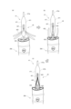
この実施形態におけるステントグラフト200は、図1、図2に示すように、大径長尺の主管210と、該主管210の一端部から分岐する小径短尺の枝管220とからなる枝付き形状をなすものであり、ここでは、例えば、大動脈弓部に留置される。<Structure of
As shown in FIGS. 1 and 2, the
前記主管210は、その先端(上流端)が、左鎖骨下動脈と左総頸動脈との間に位置づけられるとともに、そこから大動脈弓部に沿って湾曲しながら下流に延び、その基端(下流端)が、大動脈瘤よりも下流となるように配置される。また、前記枝管220は、主管210の一端部から分岐・延伸して、左鎖骨下動脈に挿入・配置される。
The
これら主管210及び枝管220は、管状をなすグラフト201と、該グラフト201を拡開させるためのステント202とをそれぞれ備えている。
The
前記グラフト201は、例えば、耐久性がよく、組織反応の少ない樹脂シートを管状に形成したものであり、この実施形態では、周方向に沿った多数の折り目(図示しない)を予め設けておくことにより、湾曲や管軸方向に沿った屈伸を容易ならしめてある。シートの素材としては、繊維の編織物、不織布、多孔質シートなどを挙げることができる。また、このグラフト201を構成するシートの表面を、ヘパリン、コラーゲン、アセチルサリチル酸、ゼラチン等の抗血栓性材料で被覆処理しても構わない。
The
前記ステント202は、グラフト201の一方から他方の開口端に亘って、所定間隔(ここでは略一定間隔であるが、一定間隔でなくともよい。)で配設した複数の円環状弾性リング202aからなるものであり、自然状態では、これら弾性リング202aによってグラフト201が概略円筒状に拡開する。なお、前記円環状弾性リング202aが互いに離間して配置されているという構成によって、このステントグラフト200は、軸方向に非常に曲がりやすい、湾曲性に富んだものとなっている。
The
該弾性リング202aは、例えば、所定の弾性を有する極細径の金属線(図示しない)を複数重(多重)に巻き回して形成した円環状のものである。その素材としては、ステンレス、タンタル、チタン、白金、金、タングステン、ニッケルチタンなどの金属やその合金を挙げることができる。このように、弾性リング202aを複数重巻きの細径金属線で構成することによって、単一線で形成した一重巻きのものと比べ、耐久性が向上し、また、仮に破損しても、部分破断が生じるだけで、即座にその機能が失われないという効果を得られる。なお、この弾性リング202aを、グラフト201同様、抗血栓性材料で被覆処理しても構わないし、樹脂製のものにしてもよい。
The
なお、ステント202として、曲がりにくいという欠点はあるものの、いわゆるZステント202や網状のものなど、他のタイプのものを用いても構わない。
As the
かかる構成の主管210及び枝管220は、図3に示すように、径方向外側から内向きの外力を与えると、各弾性リング202aが鞍状に湾曲し、それに応じてグラフト201も変形して径方向に収縮できるように構成してある。ここでいう「鞍状」に湾曲するとは、同図に示すように、弾性リング202aが2つ折となる向きに湾曲するとともに、さらにそれが2つ折になる向きに湾曲して、山谷が交互に2つずつ現われるように変形することをいう。
As shown in FIG. 3, the
<ステントグラフト搬送装置100の説明>
次に、ステントグラフト搬送装置100について説明する。
このステントグラフト搬送装置100は、図4、図5に示すように、血管を挿通可能な径にまで収縮させたステントグラフト200を所定の留置部位(この実施形態であれば大動脈弓部及び左鎖骨下動脈)にまで搬送する搬送機構と、前記搬送機構によって留置部位にまで搬送されたステントグラフト200を収縮状態から展開状態に展開させる展開機構とを備えている。
以下に各部を詳述する。<Description of Stent Graft Delivery Device 100>
Next, the stent graft delivery device 100 will be described.
As shown in FIGS. 4 and 5, this stent graft delivery device 100 carries a
Each part is described in detail below.
<搬送機構>
搬送機構は、図4、図5等に示すように、血管内に挿入されたガイドワイヤ3(請求項でいうガイド線)に沿って、収縮状態にあるステントグラフト200を大動脈弓部に搬送する主搬送機構4と、該主搬送機構4によって大動脈弓部に搬送されたステントグラフト200の枝管220を、分岐血管たる左鎖骨下動脈に挿入・配置する副搬送機構5とを備えたものである。
<主搬送機構4>
主搬送機構4は、図4、図5等に示すように、ガイドワイヤ3が内部をスライド可能に挿通する管状体41と、該管状体41に前記ステントグラフト200(の主管210)を取り外し可能に取り付ける第1取付機構42とを具備しており、大動脈内を通るガイドワイヤ3に沿って、管状体41及びこれに取り付けられたステントグラフト200を搬送できるように構成したものである。<Transport Mechanism>
As shown in FIGS. 4 and 5, the delivery mechanism mainly delivers the contracted
<
As shown in FIGS. 4 and 5, the
<管状体41>
前記管状体41は、図5、図6、図7等に示すように、ガイドワイヤ3が内部を挿通するチューブ状をなす第1搬送管412(請求項でいう搬送管に対応)と、この第1搬送管412の先端部に取り付けられた樹脂製の姿勢制御部材411とを備えたものである。ステントグラフト200は、この管状体41に外装されるとともに、その先端部において前記姿勢制御部材411を咥え込んで装着されることにより該管状体41に取り付けられる。<
As shown in FIGS. 5, 6, and 7, the
前記姿勢制御部材411は、長細いものであり、先端部が概略円錐状のような先細り形状となっている円柱状のヘッダ411aと、該ヘッダ411aの後端から一体に延伸する扁平形状をなす装着体411bとを具備している。その長手方向の長さは、前記ステントグラフト200(の主管210)の長手方向の長さの1/4以下であり、主管210と比べれば短尺である。
The
しかして、前記ヘッダ411aの先端部を円錐状としているのは、血管内を引っ掛かりなく円滑に進むことができるようにするためである。他方、装着体411bの基端(より具体的には、基端面における周縁部)は、角張らないように滑らかに丸めてある。これは、ステントグラフト200の留置後、該姿勢制御部材411を引き抜く際に引っ掛かりにくくするためである。
The reason why the tip of the
一方、前記装着体411bを扁平形状にしているのは、この装着体411bには、図4、図6等に示すように、収縮状態にした主管210の先端開口部を咥え込ませて取り付けるところ、この状態で主管210と姿勢制御部材411とを確実に共回りさせるためである。
On the other hand, the mounting
また、もうひとつの理由としては、装着体411bが扁平形状であるため、円柱状をなすヘッダ411aとの間に段差が生じるところ、この段差の高さを主管210の弾性リング202aの径以上に設定して、図6(b)に示すように、該装着体411bを咥え込んだ主管210の先端部が、前方から見て前記段差に隠れるようにするためである。このことによって、ステントグラフト200の搬送中に、主管210の開口先端部が血管などに引っ掛かることを抑制できるので、円滑な搬送を担保できる。
Another reason is that since the mounting
さらに、この姿勢制御部材411には、図7に示すように、ガイドワイヤ3が挿通する貫通孔411cが長手方向に沿って設けられている。本実施形態においては、この貫通孔411cのうち、装着体411bを貫通している部分が主に湾曲しており、ヘッダ411aを貫通する部分はほぼ直線状である。そのために、この実施形態では、装着体411bをやや湾曲させて扇形状をなすようにしてある。
Furthermore, as shown in FIG. 7, the
なお、貫通孔411cのうち、逆にヘッダ411aを貫通する部分が湾曲していてもよいし、貫通孔411c全体が湾曲していてもよい。
Conversely, a portion of the through
前記第1搬送管412は、図6、図7に示すように、内管412aと外管412bとからなり、内管412aが外管412bの先端部から突出するように構成された二重管構造のものである。
As shown in FIGS. 6 and 7, the first conveying
内管412aは、例えばポリイミドとPTFEの2層構造のものを採用しており、外管412bに比べて弾性があり、ねじれやすいくしてある。そして、この内管412aの先端部に前記姿勢制御部材411が接続してある。より具体的には、内管412aの先端部が前記貫通孔411cを貫通するようにして姿勢制御部材411に接着されている。この内管412aにおいて、外管412bから突出した部分の長さは、図4、図5に示すように、姿勢制御部材411とそれに取り付けられたステントグラフト200との合計長さよりも長くなるように設定してある。したがって、外管412bの先端は、ステントグラフト200の後端よりも後方に(手元側に)離間しており、その間は内管412aが露出している。
The
外管412bは、例えばポリイミド製のものであり、内管412aよりも剛性が高いものを用いている。
The
これら外管412bと内管412aとは、図7、図9に示すように、外管412bの先端よりも根元側のみにおいて、より具体的には、施術者が操作する操作部位近傍のみにおいて接着剤ATなどによって互いに固着されている。
As shown in FIGS. 7 and 9, the
<第1取付機構42>
第1取付機構42は、前記管状体41、より具体的には、姿勢制御部材411に、ステントグラフト200の主管210を抜脱可能に取り付けるための機構である。<
The
具体的に説明する。 A specific description will be given.
この第1取付機構42は、図6、図7、図11等に示すように、前記姿勢制御部材411の外周面に設けられた第1窓421と、この第1窓421内を挿通している第1係止線422と、前記管状体41(ここでは姿勢制御部材411)に基端部が取り付けられた複数の第1着脱紐423と、前記主管210の先端開口縁部に設けられた複数の第1紐挿通孔424とを利用して構成されたものである。
As shown in FIGS. 6, 7, 11, etc., the
前記第1窓421は、前記ヘッダ411aの一部を側周面から切り欠いて形成したものである。この実施形態での第1窓421は、同図に示すように、その貫通方向が姿勢制御部材411の湾曲方向と合致させてあるが、図37に示すように、湾曲方向とは直交する方向に貫通するようにしてもよい。この図37のような貫通方向とすることで、第1窓421の開口端が血管壁の大彎曲側と直接当たりにくくなり、そこを傷つける恐れを低減させることができる。
The
前記第1係止線422は、金属製又は樹脂製の細線である。
The
前記第1着脱紐423は、その先端部に少なくとも輪が形成された(ここでは全部が輪になっている。)ものであり、その基端部が当該管状体41に取り付けられている。
The first
より具体的に説明すると、第1着脱紐423の基端部は、第1搬送管412(の内管412a)に巻き回されて取り付けられており、その先端部が前記第1窓421を通って外側に引き出されている。なお、その他の態様として、第1着脱紐423の基端部を姿勢制御部材411に接着剤などによって固定しても構わない。しかして、このような構成の第1着脱紐423がここでは4本設けられている。
More specifically, the base end of the first
前記第1紐挿通孔424は、主管210の前端開口縁部に糸を環状にして取り付けることにより形成したものであり、ここでは等間隔に4つが設けられている。
The first string insertion holes 424 are formed by attaching a ring of string to the front end opening edge of the
次に、上述した第1取付機構42によって、管状体41が主管210にどのようにして取り付けられているかを説明する。
Next, how the
図11(a)~(c)に示すように、前記各4本の第1着脱紐423は、その先端から、主管210の開口縁部の4箇所に設けられた第1紐挿通孔424にそれぞれ通され、第1紐挿通孔424を通った第1着脱紐423の先端輪が前記第1窓421を通り、その内部の第1係止線422に引っ掛けられている。このようにして、主管210が第1着脱紐423を介して姿勢制御部材411に取着されている。
As shown in FIGS. 11(a) to 11(c), each of the four first
しかして、主管210を姿勢制御部材411(管状体41)から取り外す場合には、前記第1係止線422の基端部を施術者が引っ張ればよい。このことにより、第1係止線422の先端が第1窓421よりも手元側に移動し、第1着脱紐423の先端輪が第1係止線422から外れて、図11(a)の状態に戻り、主管210は姿勢制御部材411(管状体41)から離脱可能な状態になる。
Thus, when removing the
なお、第1着脱紐の本数と第1紐挿通孔の数とは同数でなくともよい。例えば、この実施形態のように第1紐挿通孔が4つ設けられてる場合、第1着脱紐の本数をそれよりも少ない1本のみとし、これを全ての第1紐挿通孔に通して、その先端輪を第1係止線に引っ掛けるようにしてもよい。また、第1着脱紐を2本にして、各1本が互いに異なる2つの第1紐挿通孔にそれぞれ通るようにしてもよい。 Note that the number of first detachable straps and the number of first strap insertion holes may not be the same. For example, when four first string insertion holes are provided as in this embodiment, the number of the first detachable string is reduced to one, and this is passed through all the first string insertion holes, The tip ring may be hooked on the first locking line. Alternatively, two first attachment/detachment straps may be provided, each of which may pass through two different first strap insertion holes.
<副搬送機構5>
副搬送機構5は、図4、図5、図12~図16等に示すように、枝管220を分岐血管(ここでは左鎖骨下動脈)に挿入・留置するためのものであり、第2搬送管51と、該第2搬送管51に前記枝管220を取り外し可能に取り付けるための第2取付機構52とを具備している。<
As shown in FIGS. 4, 5, 12 to 16, etc., the
<第2搬送管51>
第2搬送管51は、細径のフレキシブルなチューブ(ここでは複数ルーメン(図示では2ルーメンだが、3ルーメン以上でもよい。)のものである。)であり、その基端部が枝管220の開口部に取り付けられている。<
The second conveying
<第2取付機構52>
第2取付機構52は、前記第2搬送管51内を挿通する第2係止線521と、該第2搬送管51の外周面に設けられた第2窓522と、第2搬送管51に取り付けられた1又は複数の第2着脱紐523(ここでは1本)と、前記枝管220の先端開口縁部に設けられた複数(ここでは2つ)の第2紐挿通孔524とを利用して構成されたものであり、原理的には前記第1取付機構42と同じである。<
The
より具体的に説明する。
前記第2係止線521は、手元で押引操作可能な金属製又は樹脂製のものであり、第2搬送管51のいずれか1つのルーメン(以下、第1ルーメンという。)に挿入されている。More specific description will be given.
The
前記第2窓522は、ここでは、第2搬送管51の一部を側面から切り欠いて前記第1ルーメンに連通するように形成したものであり、この第2窓522から、前記第1ルーメンを通る前記第2係止線521が露出するようにしてある。
Here, the
前記第2着脱紐523は、少なくとも先端部に輪が形成されたもの(ここでは全部が輪になっている。)であり、その基端部が、前記第2搬送管51における第2窓522の近傍(ここでは第2窓522よりも下流側)に接着剤などによって固定されている。
The second
前記第2紐挿通孔524は、枝管220の先端開口縁部に糸を環状にして取り付けることにより形成したものである。
The second
このような第2取付機構52によって、枝管220は以下のような態様で第2搬送管51に取り付けられている。
With such a
すなわち、前記各第2着脱紐523は、その先端から枝管220の開口縁部の2箇所に設けられた前記第2紐挿通孔524に連続して通されている。そして、各第2紐挿通孔524を通った第2着脱紐523の先端輪が、前記第2窓522を通ってその内部の第2係止線521に引っ掛けられている。このようにして、枝管220が第2着脱紐523を介して第2搬送管51に取着されている。
That is, each of the second attachment/detachment strings 523 is continuously passed through the second string insertion holes 524 provided at two locations on the opening edge of the
しかして、枝管220を第2搬送管51から取り外す場合には、第2係止線521を引っ張る。このことによって、第2着脱紐523の先端輪が第2係止線521から外れ、枝管220は第2搬送管51から離脱可能な状態となる。
Thus, when removing the
<展開機構>
展開機構は、径方向に収縮されて留置位置にまで搬送されたステントグラフト200を、展開させ、血管内に密着させるものであり、この実施形態では、主管210用の第1展開機構21と枝管220用の第2展開機構22とが用意されている。<Deployment Mechanism>
The deployment mechanism deploys the radially contracted
<第1展開機構21>
第1展開機構21は、図4、図17に示すように、主管210の外側周面を縛って収縮状態を維持する第1繋縛紐211と、この第1繋縛紐211の繋縛と解除とを制御する金属製又は樹脂製の第1制御線212とを備えたものである。<
As shown in FIGS. 4 and 17, the
前記第1繋縛紐211は、例えば無端環状をなすものであり、繋縛するときには、この第1繋縛紐211を2つ折りの二重線にして、収縮状態にある主管210に巻き回し、その両端部が重合するようにしてある。そして、その重合によって形成された輪に、軸方向に沿って伸びる金属製又は樹脂製の細線である前記第1制御線212が挿通させてある。この構成によって、図17(a)に示すように、第1繋縛紐211の両端部の離間が防止されて繋縛状態が維持される。
The
しかして、この繋縛状態から第1制御線212を引き抜くと、図17(b)に示すように、第1繋縛紐211の両端部同士の結合が解かれ、繋縛状態が解除される。
Then, when the
本実施形態では、図4に示すように、複数の第1繋縛紐211が主管210の軸方向に沿って間欠的に設けられている。そして、主管210を縛っている各第1繋縛紐211に1本の第1制御線212が共通して挿通させてある。
In this embodiment, as shown in FIG. 4 , a plurality of first tying
したがって、この第1制御線212を抜けば、主管210を縛っている全ての第1繋縛紐211が解かれ、該主管210は、ステント202(各弾性リング202a)の弾性復元力によって展開状態となる。
Therefore, when the
<第2展開機構22>
第2展開機構22は、図12~図16等に示すように、枝管220の外側周面を縛って収縮状態を維持する第2繋縛紐221と、この第2繋縛紐221の繋縛と解除とを制御する金属製又は樹脂製の第2制御線222とを備えたものである。<
As shown in FIGS. 12 to 16 and the like, the
第2繋縛紐221は、第1緊縛紐211と同様の構成であるので説明は省略する。
The second
第2制御線222は、前記第2搬送管51のもう一つのルーメン(以下、第2ルーメンという)内を挿通させてある。そして、その先端部が、該第2搬送管51の途中に設けられた側面孔51aから外に出て、前記枝管220を縛っている第2繋縛紐221に挿通ずるようにしてある。
The
ところで、この実施形態において、当該第2搬送管51には、前記第2係止線521と第2制御線222とがともに挿通させてあるところ、前記第2係止線521は第2搬送管51内に全て収容されている一方、第2制御線222も、繋縛を維持するための先端部を除いては、第2搬送管51内に全て収容されている。
By the way, in this embodiment, both the
このように第2係止線521および第2制御線222の少なくも基端部が第2搬送管51内に収容されているのは、<使用方法>で後述するが、この第2搬送管51が、術間において、その手元端部(基端部)も含め、血管内を引き回されるからであり、その引き回しの間に、不測に第2制御線222や第2係止線521が引っ張られて、展開機構や取付機構が動作してしまうことを確実に防止するためである。
The reason why at least the proximal end portions of the
<引出機構>
一方、これら第2制御線222及び第2係止線521を第2搬送管51から引き出せないのでは、第2展開機構22や第2取付機構52を動作させることができないので、この実施形態では、第2制御線222及び第2係止線521を引き出すための引出機構がそれぞれ設けられている。<Drawer mechanism>
On the other hand, since the
引出機構としては、図12~図16等に示すように、第2制御線222を引き出すための制御線引出機構6と、第2係止線521を引き出すための係止線引出機構7とがあり、これらは、同じ原理のものである。
As the drawing mechanism, as shown in FIGS. 12 to 16 and the like, there are a control
制御線引出機構6は、第2搬送管51の途中(より具体的には、手元端部)に設けられた制御線引出窓61と、第2制御線222に結わえ付けられているとともに、該制御線引出窓61から第2搬送管51の外に引き出された非常にフレキシブルな制御線引出紐62とを備えている。
The control
この制御線引出紐62を引っ張ると、第2搬送管51内の第2制御線222の手元側が制御線引出窓61から引き出され、この引き出された第2制御線222を引っ張ることによって、枝管220を展開させることができる。
When the control
係止線引出機構7についても同様である。すなわち、この係止線引出機構7は、第2搬送管51の途中(より具体的には、手元端部)であって、前記制御線引出窓61とは異なる箇所(ここでは、軸方向に偏位した部位)に設けられた係止線引出窓71と、第2係止線521に結わえ付けられ、該係止線引出窓71から第2搬送管51の外に引き出された係止線引出紐72とを備えている。
The same applies to the locking
これら、制御線引出紐62及び係止線引出紐72は、その先端部が第2搬送管51から出ているが、第2制御線222や第2係止線521に比べて非常に柔軟に構成してあるうえ、ループ状にはなっておらず、開放端状にしてあるため、術中にいずれかの部位に不測に引っかかる恐れがほとんどない。
The control line lead-
<使用方法>
次に、本搬送装置によるステントグラフト200の搬送・留置方法の一例について説明する。<How to use>
Next, an example of a method of transporting and placing the
まず、ステントグラフト200の主管210に管状体41を挿通させた状態で、該主管210を収縮させてその先端開口で姿勢制御部材411を咥え込ませるとともに、第1取付機構42によって主管210を姿勢制御部材411に取り付けておく。
First, in a state in which the
ステントグラフト200の枝管220にも同様に、第2搬送管51を挿通させた状態で、該枝管220を収縮させるとともに、第2取付機構52によって枝管220を第2搬送管51に取り付けておく。
Similarly, the
さらに、ガイドワイヤ3を管状体41(第1搬送管412及び姿勢制御部材411)に挿入し、このガイドワイヤ3に沿って、管状体41及びこれに取り付けられたステントグラフト200を移動可能にしておく。
Further, the
この状態では、図4に示すように、ステントグラフト200における主管210の先端部に姿勢制御部材411が取り付けられているとともに、主管210から第1搬送管412、第1係止線422及び第1制御線212が延伸し、かつ、枝管220の先端からは第2搬送管51が延伸していることとなる。また、第1係止線422及び第1制御線212の先端部は、図6、図7に示すように、姿勢制御部材411の内部を挿通して、その先端部に設けられたトリプルルーメンチューブ45に収容されている。それら先端部が血管内で不測に引っかかるなどして不具合が生じるのを防止するためである。
In this state, as shown in FIG. 4, the
なお、この実施形態では、ステントグラフト200から延伸する管状体41、第1係止線422及び第1制御線212は、それらより大径の第1外装チューブT1に挿通させてまとめてある。また、この第1外装チューブT1には、図8、図9等に示すように、他の各線より剛性が高い金属製又は樹脂製の補強線GTを抜脱可能に挿入できるようにしてあり、ステントグラフト200を進行させていく途中での第1外装チューブT1及びその内部に挿通させてある管状体41等の座屈や縮みを防止できるようにしてある。さらにここでは、第1外装チューブT1の先端部分及び基端部分(根元部分)において、第1係止線422が挿入されているチューブ422x、第1制御線212が挿通されているチューブ212x、補強線GTが挿入されているチューブGTx及び外管412bを、第1外装チューブT1と接着剤(図示しない)を注入して接着している。
In this embodiment, the
そして、ステントグラフト200と、これから延伸する管状体41、第1係止線422、第1制御線212(、これらをまとめるための第1外装チューブT1)及び第2搬送管51を、シースカテーテルT2に挿入し、初期状態では、図18に示すように、シースカテーテルT2の先端からヘッダ411aのみが突出するように構成してある。なお、第1外装チューブT1など、いくつかのチューブの根元部分には、必要に応じて血液の逆流を防止する逆止弁が設けられている。
Then, the
次に、図19に示すように、予め動脈内を先行させたガイドワイヤ3に沿って、ステントグラフト200及びステントグラフト搬送装置100を収容したシースカテーテルT2を、下行動脈内に挿入する。
Next, as shown in FIG. 19, the sheath catheter T2 housing the
その後、図20~図22に示すように、第1外装チューブT1及び第2搬送管を繰り出すことにより、姿勢制御部材411に取り付けられたステントグラフト200を、シースカテーテルから突出、離脱させ、前記ガイドワイヤ3に案内させて、前記留置位置まで進行させる。
After that, as shown in FIGS. 20 to 22, the
その過程において、ガイドワイヤ3が湾曲している大動脈弓部を通過するとき、姿勢制御部材411は、その湾曲方向がガイドワイヤ3の湾曲方向、つまり大動脈の湾曲方向と合致するように、軸方向に自然に回転し(図20から図21に回転する様子を示す。)、その軸周りの位相が血管に対して常に一定となるように自動調整される。
In that process, when the
そして、この姿勢制御部材411に固定されたステントグラフト200も姿勢制御部材411と共回りし、所期の回転位相、すなわち最終留置位相に自動調整される。
The
しかして、図22に示す前記最終留置位相においては、軸方向から視て、ステントグラフト200の枝管220と分岐動脈との位置が合致するように、予め姿勢制御部材411にステントグラフト200を取り付けてあるので、ステントグラフト200の枝管220をなんら手元で操作することなく、分岐動脈の入口に対向する位相に自動的に合致させることができる。これがセルフアラインメント機能である。
Thus, in the final placement phase shown in FIG. 22, the
したがって、施術者は、枝管220が分岐動脈の入口近傍となるように、ステントグラフト200を前後に進退操作するだけでよくなり、従来のように、ステントグラフト200を手元で回転操作することなく、枝管220の位置を分岐動脈の位置に合致させることができるので、その操作性が、従来に比べ飛躍的に向上する。
Therefore, the operator only needs to move the
しかも、この姿勢制御部材411は短尺であり、ステントグラフト200の先端部にのみ取り付けられていて、この種のステントグラフト200の特徴である湾曲自在性を損なうものではないため、搬送過程において無理な抵抗等が作用しにくく、円滑な搬送が可能となる。
Moreover, since the
次に、このようにして、枝管220を分岐動脈の入口近傍に位置づけた後、枝管220を分岐動脈に挿入する。その手順は以下のとおりである。
Next, after positioning the
まず、カテーテル9の手元から突出している第2搬送管51の先端を、折り返すようにして当該カテーテル9に挿入し、繰り出す。
First, the tip of the
そのために、この実施形態では、まず、手元側に伸びている第2搬送管51の先端からそれより大径の第2外装チューブT3を外嵌するとともに、この第2外装チューブT3を繰り出して、図23に示すように、その先端を枝管220の先端近傍にまで到達させる。そして、第2搬送管51の先端を折り返して第2外装チューブT3の根元から挿入し、繰り出す。
For this reason, in this embodiment, first, the second outer tube T3 having a larger diameter is fitted from the tip of the second conveying
このことによって、図24に示すように、第2搬送管51の先端が第2外装チューブT3の先端から突出する。
As a result, as shown in FIG. 24, the tip of the
なお、第2外装チューブT3を入れることなく、第2搬送管51を折り返して直接シースカテーテルT2内に挿入してもよいが、折り返した第2搬送管51が途中で絡まるなどして進行させることができなくなる場合がある。これに対し、第2外装チューブT3を予め挿入し、折り返した第2搬送管51を第2外装チューブT3内で進行させれば、上述した不具合を未然に回避することができる。
Although the
その一方で、分岐動脈の先端側から、別途設けた把持具8を挿入しておく。この把持具8は、細径の把持チューブ81と把持チューブ81内を進退可能に挿通させた把持線82とを具備したものであり、この把持線82の先端には輪82aが形成されている。
On the other hand, a separately provided grasping
そして、この把持具8を繰り出し、この実施形態では、その先端の輪82aを分岐動脈から飛び出させて大動脈内に位置づける。
Then, the grasping
この状態で、第2搬送管51を操作し、図25に示すように、その先端部を前記輪82aに挿通させる。なお、この第2搬送管51の先端部は、輪に82aに挿通させやすいように、チューブではなく、それよりもやや細径で柔らかい線状部材にしてある。
In this state, the second conveying
次に、図26に示すように、把持チューブ81を繰り出して、先端輪82aを該把持チューブ81内に引き込み、先端輪82aを絞ることによって、第2搬送管51の先端部を掴む。なお、このときに、図27に示すように、第2外装チューブT3は手元から引き抜いておく。
Next, as shown in FIG. 26, the gripping
次に、図28に示すように、把持具8を手元側に引っ張って、それが掴んでいる第2搬送管51の先端部を人体から取り出す。この第2搬送管51をさらに引っ張れば、図29に示すように、これに取り付けられている枝管220も引っ張られて分岐動脈に挿入・配置される。
Next, as shown in FIG. 28, the grasping
このようにして、主管210を大動脈弓部に、また、枝管220を分岐動脈に配置した後、これらを展開させる。展開手順は以下のとおりである。
After the
まず主管210については、カテーテル9の手元側から体外に伸びている第1制御線212を引き抜く。このことによって、図30に示すように、第1繋縛紐211の結合が外れ、主管210が展開状態となって大動脈内に張り付く。
First, regarding the
一方、枝管220においては、図13に示すように第2搬送管51のうち、分岐動脈から体外に引き出された手元側部分において、制御線引出窓61から出ている制御線引出紐62を引っ張り、第2制御線222の手元側(基端部)を第2搬送管51から引き出す。そして、この引き出された第2制御線222を引き抜く。このことによって、第2繋縛紐221の結合が外れ、図14、図30に示すように、枝管220が展開状態となって分岐動脈内に張り付く。
On the other hand, in the
最後に、ステントグラフト200のみを残して、管状体41及び第2搬送管51を体外に引き出す。その手順は以下のとおりである。
Finally, leaving only the
まず、主管210については、カテーテル9の手元側から体外に伸びている第1係止線422を引き抜く。このことによって、図31に示すように、第1着脱紐423が管状体41から外れて、管状体41と主管210との接続が解除される。その後、管状体41(及び第1外装チューブT1)を体外に引き抜く。
First, with respect to the
一方、枝管220においては、図13に示すように、第2搬送管51のうち、分岐動脈から体外に引き出された手元側部分において、係止線引出窓71から出ている係止線引出紐72を引っ張り、第2係止線521の手元側を第2搬送管51から引き出す。そして、図14に示すように、この引き出された第2係止線521を引き抜く。このことによって、図15、図31に示すように、第2着脱紐523が第2搬送管51から外れて、第2搬送管51と枝管220との接続が解除される。その後、第2搬送管51を分岐動脈を介して体外に引き抜く。
On the other hand, in the
このことによって、図32に示すように、所望の位置にステントグラフト200が留置される。
This leaves the
なお、本発明は前記実施形態に限られるものではない。 It should be noted that the present invention is not limited to the above embodiments.
例えば、図32、図33に示すように、1又は複数の第2姿勢制御部材413を第1搬送管412に間欠的に接着するなどして回転不可能に固着してもよい。
For example, as shown in FIGS. 32 and 33, one or more second
この第2姿勢制御部材413は、短尺(少なくとも主管の長さの1/5以下のものであり、収縮したステントグラフト200(の主管210)が軸周りに回転できないような形状、例えば扁平な板状をなすものである。そして、その中心に貫通孔が設けてあり、この貫通孔に第1搬送管412及びガイドワイヤ3が貫通するように構成してある。この実施形態では、この第2姿勢制御部材211は、前端部及び後端部が先細りとなり、その端経が、第1搬送管412と略同一径となるようにした扁平板状のものである。先細りにしてあるのは、ステントグラフト200の留置後、引き抜く際に、この第2姿勢制御部材413が血管や他の部材に不測に引っ掛かるといったことを防止するためである。
The second
前記実施形態においては、ステントグラフト200の先端部のみが、姿勢制御部材に軸回転不能に取り付けられており、ステントグラフト200の中間部、根元部において先端部との間にねじれが生じ得るが、このように第1搬送管412の中間部にも第2姿勢制御部材413を設けることによって、前記ねじれを軽減することができる。
In the above-described embodiment, only the distal end of the
また、この第2姿勢制御部材413の貫通孔を湾曲または屈曲させて、第2姿勢制御部材413にも、前記セルフアラインメント機能を持たせてもよい。その場合は、前記姿勢制御部材411を設けなくとも構わない。
Further, the through hole of the second
第1搬送管412は、前記実施形態においては、外管412bの先端から内管412aが突出するようにして、根元部においては剛性が高く、先端部においては剛性が低い(柔軟性が高い)ように構成していたが、単管を用いてもよい。その場合は、素材や繊維の編み方等によって先端部と根元部とで剛性が異なるようにすればよい。
In the above-described embodiment, the first conveying
係止線引出紐と制御線引出紐とを互いに異なる形態にしておけば、術者がこれらを混同して引っ張る順序を間違える可能性をより低減させることができる。ここで、形態を異ならせるとは、色や長さ、太さなどを、視認あるいは触認で判別できるように異ならせることをいう。 If the locking line pull-out string and the control line pull-out string are formed in different forms, it is possible to further reduce the possibility that the operator will confuse them and make a mistake in the order of pulling them. Here, to make the shapes different means to make the colors, lengths, thicknesses, etc. different so that they can be visually or tactilely discriminated.
第1搬送管412にステントグラフト200を取り付けている第1取付機構を、図35に示すようなものとしてもよい。
すなわち、この図35では、ステントグラフト200に形成されている第1紐挿通孔424と、第1搬送管412に取り付けられている第1着脱紐423の輪との重合部分に、第1係止線422を挿通させることにより、ステントグラフト200を第1搬送管412に取り付けている。しかして、この第1係止線422を抜き取れば、第1紐挿通孔424と第1着脱紐423との係止状態が解除され、ステントグラフト200は第1搬送管412からは取り外すことができる状態となる。A first attachment mechanism for attaching
That is, in FIG. 35, the first locking line is attached to the overlapping portion between the first
なお、ここでは、第1紐挿通孔424と第1着脱紐423とがそれぞれ複数個(4個)設けられており(図35では、図面の煩雑化を避けるため、各2つだけを表示してある。)、それに対応する本数の第1係止線422が設けられている。
このようなものであれば、前記実施形態のものよりも外すことが容易にできる。
また、姿勢制御部材411において、図36に示すように、方向の異なる2つ以上の直線状の貫通孔411cが直列に設けられた構成にしてもよい。
さらに、第1、第2繋縛紐の代わりに、例えば、矩形シートまたはメッシュシート(繋縛シート)を筒状にし、それをステントグラフトに外装して収縮状態に維持しておいてもよい。この場合は、筒状にした繋縛シートの重なった端縁部に、制御線を直線的に縫うように挿通させ、該繋縛シートがほどけるのを防ぐようにする。
また、本発明は、枝管が1本のステントグラフトに限られず、2本以上のものに適用して同様の作用効果を奏し得る、 Here, a plurality (four) of first string insertion holes 424 and first
With such a device, it can be removed more easily than the device of the above-described embodiment.
In addition, as shown in FIG. 36, the
Further, instead of the first and second tying cords, for example, a rectangular sheet or a mesh sheet (tying sheet) may be formed into a tubular shape and wrapped around the stent graft to maintain the contracted state. In this case, the control line is linearly threaded through the overlapped end edges of the binding sheet formed in a cylindrical shape to prevent the binding sheet from unraveling.
In addition, the present invention is not limited to a stent graft having one branch vessel, and can be applied to a stent graft having two or more branch vessels to achieve the same effect.
その他、姿勢制御部材や第2制御部材の形状など、本発明は、前記実施形態に限定されず、その趣旨を逸脱しない範囲で種々変形が可能である。 In addition, the present invention is not limited to the above-described embodiments, such as the shape of the attitude control member and the second control member, and various modifications are possible without departing from the scope of the invention.
200 ステントグラフト
210 主管
220 枝管
100 ステントグラフト搬送装置
3 ガイドワイヤ
T1 第1外装チューブ
T2 シースカテーテル
T3 第2外装チューブ
21 第1展開機構
211 第1繋縛紐
212 第1制御線
22 第2展開機構
221 第2繋縛紐
222 第2制御線
4 主搬送機構
41 管状体
411 姿勢制御部材
411a ヘッダ
411b 装着体
411c 貫通孔
412 第1搬送管
412a 内管
412b 外管
42 第1取付機構
421 第1窓
422 第1係止線
423 第1着脱紐
424 第1紐挿通孔
5 副搬送機構
51 第2搬送管
52 第2取付機構
521 第2係止線
522 第2窓
523 第2着脱紐
524 第2紐挿通孔
6 制御線引出機構
61 制御線引出窓
62 制御線引出紐
7 係止線引出機構
71 係止線引出窓
72 係止線引出紐
8 把持具
81 把持チューブ200
422
Claims (5)
前記ステントグラフトの先端部に取り付けられる、該ステントグラフトよりも短尺の姿勢制御部材を備え、
該姿勢制御部材は、前記ガイド線が一方向に湾曲しながらスライド可能に貫通する貫通孔が設けられているとともに、ヘッダと該ヘッダの後端部に連続して設けられた装着体とを備えたものであり、前記装着体に前記ステントグラフトの先端部が装着され、前記ヘッダがステントグラフトから突出するように構成されており、
前記貫通孔のうち、前記装着体を貫通している部位において、ガイド線が湾曲するように構成されていることを特徴とするステントグラフト搬送装置。 A stent graft is transported to a lesion site along a guide wire inserted into a blood vessel,
A posture control member shorter than the stent graft attached to the distal end of the stent graft,
The attitude control member is provided with a through hole through which the guide wire is slidably curved while bending in one direction, and is provided with a header and a mounting body provided continuously with the rear end of the header. wherein the distal end portion of the stent graft is attached to the mounting body, and the header protrudes from the stent graft,
A stent graft delivery device, wherein the guide wire is curved at a portion of the through-hole that penetrates the mounting body.
前記ステントグラフトの先端部に取り付けられる、該ステントグラフトよりも短尺の姿勢制御部材を備え、
該姿勢制御部材は、前記ガイド線が一方向に湾曲しながらスライド可能に貫通する貫通孔が設けられているとともに、ヘッダと該ヘッダの後端部に連続して設けられた装着体とを備えたものであり、前記装着体に前記ステントグラフトの先端部が装着され、前記ヘッダがステントグラフトから突出するように構成されており、
前記装着体の横断面形状が非円形状であることを特徴とするステントグラフト搬送装置。 A stent graft is transported to a lesion site along a guide wire inserted into a blood vessel,
A posture control member shorter than the stent graft attached to the distal end of the stent graft,
The attitude control member is provided with a through hole through which the guide wire is slidably curved while bending in one direction, and is provided with a header and a mounting body provided continuously with the rear end of the header. wherein the distal end portion of the stent graft is attached to the mounting body, and the header protrudes from the stent graft,
A stent graft delivery device , wherein the mounting body has a non-circular cross-sectional shape .
前記ステントグラフトの先端部に取り付けられる、該ステントグラフトよりも短尺の姿勢制御部材を備え、
前記姿勢制御部材の後端から延伸する搬送管をさらに具備し、
前記搬送管は、内管と外管とからなる二重管構造を有し、
前記内管は、外管の先端部から突出してその先端部が前記姿勢制御部材に接続してあり、
外管の根元部位において、外管と内管とが固着されていることを特徴とするステントグラフト搬送装置。 A stent graft is transported to a lesion site along a guide wire inserted into a blood vessel,
A posture control member shorter than the stent graft attached to the distal end of the stent graft,
further comprising a carrier pipe extending from the rear end of the attitude control member;
The carrier tube has a double tube structure consisting of an inner tube and an outer tube,
The inner tube protrudes from the tip of the outer tube and the tip is connected to the attitude control member,
A stent graft delivery device, wherein the outer tube and the inner tube are fixed at the base of the outer tube.
Priority Applications (1)
| Application Number | Priority Date | Filing Date | Title |
|---|---|---|---|
| JP2023124015A JP2023134846A (en) | 2017-11-24 | 2023-07-31 | Carrier device |
Applications Claiming Priority (3)
| Application Number | Priority Date | Filing Date | Title |
|---|---|---|---|
| JP2017225806 | 2017-11-24 | ||
| JP2017225806 | 2017-11-24 | ||
| PCT/JP2018/043453 WO2019103147A1 (en) | 2017-11-24 | 2018-11-26 | Artificial blood vessel transport device |
Related Child Applications (1)
| Application Number | Title | Priority Date | Filing Date |
|---|---|---|---|
| JP2023124015A Division JP2023134846A (en) | 2017-11-24 | 2023-07-31 | Carrier device |
Publications (2)
| Publication Number | Publication Date |
|---|---|
| JPWO2019103147A1 JPWO2019103147A1 (en) | 2020-10-01 |
| JP7329247B2 true JP7329247B2 (en) | 2023-08-18 |
Family
ID=66631602
Family Applications (2)
| Application Number | Title | Priority Date | Filing Date |
|---|---|---|---|
| JP2019555398A Active JP7329247B2 (en) | 2017-11-24 | 2018-11-26 | Artificial blood vessel delivery device |
| JP2023124015A Pending JP2023134846A (en) | 2017-11-24 | 2023-07-31 | Carrier device |
Family Applications After (1)
| Application Number | Title | Priority Date | Filing Date |
|---|---|---|---|
| JP2023124015A Pending JP2023134846A (en) | 2017-11-24 | 2023-07-31 | Carrier device |
Country Status (5)
| Country | Link |
|---|---|
| US (1) | US11648137B2 (en) |
| EP (1) | EP3714846A4 (en) |
| JP (2) | JP7329247B2 (en) |
| CN (1) | CN111356421A (en) |
| WO (1) | WO2019103147A1 (en) |
Families Citing this family (1)
| Publication number | Priority date | Publication date | Assignee | Title |
|---|---|---|---|---|
| CN116531153A (en) * | 2022-01-26 | 2023-08-04 | 上海微创心脉医疗科技(集团)股份有限公司 | Branching sheath |
Citations (8)
| Publication number | Priority date | Publication date | Assignee | Title |
|---|---|---|---|---|
| WO2005099806A1 (en) | 2004-04-16 | 2005-10-27 | Kawasumi Laboratories, Inc. | Stent graft indwelling device and fixed chip |
| US20090264980A1 (en) | 2008-04-17 | 2009-10-22 | Mackay Allen B | Device delivery catheter having a curved distal tip |
| JP2010517705A (en) | 2007-02-09 | 2010-05-27 | タヘリ ラドュカ エルエルシー | Apparatus and method for deploying an implantable device in a body |
| JP2011511663A (en) | 2008-02-11 | 2011-04-14 | ウィリアム・クック・ヨーロッパ・アンパルトセルスカブ | Introducers for endovascular grafts and stents |
| JP2012139500A (en) | 2010-12-31 | 2012-07-26 | Cook Medical Technologies Llc | System for inserting shape-adaptive prosthesis, and method for arranging the system |
| JP2012523908A (en) | 2009-04-17 | 2012-10-11 | メドトロニック ヴァスキュラー インコーポレイテッド | Castered sleeve stent graft delivery system and method |
| US20170119560A1 (en) | 2014-05-13 | 2017-05-04 | The Charlotte-Mecklenburg Hospital Authority D/B/A Carolinas Healthcare System | Method and apparatus for ultrasound-guided delivery of vascular devices |
| JP2017109129A (en) | 2011-11-16 | 2017-06-22 | ボルトン メディカル インコーポレイテッド | Device and method for aortic branched vessel repair |
Family Cites Families (10)
| Publication number | Priority date | Publication date | Assignee | Title |
|---|---|---|---|---|
| JPH11221286A (en) * | 1992-03-19 | 1999-08-17 | Keiji Igaki | Medical tube |
| JPH05285222A (en) * | 1992-04-13 | 1993-11-02 | Inter Noba Kk | Balloon catheter and manufacture thereof |
| EP1043041A4 (en) | 1998-10-29 | 2008-12-17 | Kanji Inoue | Guiding device of instruments |
| US20070260225A1 (en) * | 2002-11-15 | 2007-11-08 | Applied Medical Resources Corporation | Steerable sheath actuator |
| US9198786B2 (en) | 2003-09-03 | 2015-12-01 | Bolton Medical, Inc. | Lumen repair device with capture structure |
| US7998186B2 (en) * | 2003-10-14 | 2011-08-16 | William A. Cook Australia Pty. Ltd. | Introducer for a side branch device |
| US20080109058A1 (en) * | 2005-06-01 | 2008-05-08 | Cook Incorporated | Intraoperative Anastomosis Method |
| WO2007035895A2 (en) * | 2005-09-21 | 2007-03-29 | Cook Incorporated | Endoluminal stent graft delivery assembly |
| US9486350B2 (en) * | 2014-03-31 | 2016-11-08 | Medtronic Vascular, Inc. | Stent-graft delivery system having handle mechanism for two-stage tip release |
| US10426646B2 (en) * | 2015-03-05 | 2019-10-01 | Cook Medical Technologies Llc | Pre-loaded delivery device with tri-fold proximal prosthesis attachment |
-
2018
- 2018-11-26 JP JP2019555398A patent/JP7329247B2/en active Active
- 2018-11-26 EP EP18881917.1A patent/EP3714846A4/en not_active Withdrawn
- 2018-11-26 US US16/765,981 patent/US11648137B2/en active Active
- 2018-11-26 CN CN201880073485.3A patent/CN111356421A/en active Pending
- 2018-11-26 WO PCT/JP2018/043453 patent/WO2019103147A1/en unknown
-
2023
- 2023-07-31 JP JP2023124015A patent/JP2023134846A/en active Pending
Patent Citations (8)
| Publication number | Priority date | Publication date | Assignee | Title |
|---|---|---|---|---|
| WO2005099806A1 (en) | 2004-04-16 | 2005-10-27 | Kawasumi Laboratories, Inc. | Stent graft indwelling device and fixed chip |
| JP2010517705A (en) | 2007-02-09 | 2010-05-27 | タヘリ ラドュカ エルエルシー | Apparatus and method for deploying an implantable device in a body |
| JP2011511663A (en) | 2008-02-11 | 2011-04-14 | ウィリアム・クック・ヨーロッパ・アンパルトセルスカブ | Introducers for endovascular grafts and stents |
| US20090264980A1 (en) | 2008-04-17 | 2009-10-22 | Mackay Allen B | Device delivery catheter having a curved distal tip |
| JP2012523908A (en) | 2009-04-17 | 2012-10-11 | メドトロニック ヴァスキュラー インコーポレイテッド | Castered sleeve stent graft delivery system and method |
| JP2012139500A (en) | 2010-12-31 | 2012-07-26 | Cook Medical Technologies Llc | System for inserting shape-adaptive prosthesis, and method for arranging the system |
| JP2017109129A (en) | 2011-11-16 | 2017-06-22 | ボルトン メディカル インコーポレイテッド | Device and method for aortic branched vessel repair |
| US20170119560A1 (en) | 2014-05-13 | 2017-05-04 | The Charlotte-Mecklenburg Hospital Authority D/B/A Carolinas Healthcare System | Method and apparatus for ultrasound-guided delivery of vascular devices |
Also Published As
| Publication number | Publication date |
|---|---|
| US20200352761A1 (en) | 2020-11-12 |
| EP3714846A4 (en) | 2021-10-20 |
| CN111356421A (en) | 2020-06-30 |
| JPWO2019103147A1 (en) | 2020-10-01 |
| WO2019103147A1 (en) | 2019-05-31 |
| JP2023134846A (en) | 2023-09-27 |
| US11648137B2 (en) | 2023-05-16 |
| EP3714846A1 (en) | 2020-09-30 |
Similar Documents
| Publication | Publication Date | Title |
|---|---|---|
| JP6626141B2 (en) | System for delivering a stent graft | |
| JP5020085B2 (en) | Variable flexible wire guide | |
| US8337546B2 (en) | Mobile external coupling for branch vessel connection | |
| JP4575151B2 (en) | Trigger wire system for prosthesis placement devices | |
| US10350096B2 (en) | Expandable stent-graft system having diameter reducing connectors | |
| US7722657B2 (en) | Asymmetric stent graft attachment | |
| JP6845011B2 (en) | Externally operable fibers for use in intracavitary deployment of expandable devices | |
| US20120109279A1 (en) | Apparatus and method of placement of a graft or graft system | |
| US10426646B2 (en) | Pre-loaded delivery device with tri-fold proximal prosthesis attachment | |
| JP2008513183A5 (en) | ||
| US10765544B2 (en) | Push and pull medical device delivery system | |
| US20110270379A1 (en) | Mobile External Coupling for Branch Vessel Connection | |
| JP2001519694A (en) | Stent / graft delivery system and method of use | |
| JP2017018330A (en) | Stent graft | |
| JP7459421B2 (en) | Digestive tract stents | |
| JP2023134846A (en) | Carrier device | |
| US20240091507A1 (en) | Looped wire for advanced stent grafts and methods of using same | |
| JP7194446B2 (en) | Artificial blood vessel delivery device | |
| JP2023133439A (en) | Low profile delivery system with lock wire lumen | |
| WO2019139077A1 (en) | Intravascular placement tool and intravascular placement system | |
| US20240024139A1 (en) | Transport device for medical devices | |
| TWI757005B (en) | Delivery shaft and delivery system | |
| WO2021176672A1 (en) | Delivery shaft and delivery system | |
| WO2023176909A1 (en) | Deployment device |
Legal Events
| Date | Code | Title | Description |
|---|---|---|---|
| A521 | Request for written amendment filed |
Free format text: JAPANESE INTERMEDIATE CODE: A821 Effective date: 20191009 |
|
| A621 | Written request for application examination |
Free format text: JAPANESE INTERMEDIATE CODE: A621 Effective date: 20210909 |
|
| A131 | Notification of reasons for refusal |
Free format text: JAPANESE INTERMEDIATE CODE: A131 Effective date: 20220531 |
|
| A601 | Written request for extension of time |
Free format text: JAPANESE INTERMEDIATE CODE: A601 Effective date: 20220727 |
|
| A521 | Request for written amendment filed |
Free format text: JAPANESE INTERMEDIATE CODE: A523 Effective date: 20220928 |
|
| A131 | Notification of reasons for refusal |
Free format text: JAPANESE INTERMEDIATE CODE: A131 Effective date: 20221117 |
|
| A601 | Written request for extension of time |
Free format text: JAPANESE INTERMEDIATE CODE: A601 Effective date: 20221221 |
|
| A521 | Request for written amendment filed |
Free format text: JAPANESE INTERMEDIATE CODE: A523 Effective date: 20230316 |
|
| TRDD | Decision of grant or rejection written | ||
| A01 | Written decision to grant a patent or to grant a registration (utility model) |
Free format text: JAPANESE INTERMEDIATE CODE: A01 Effective date: 20230629 |
|
| A61 | First payment of annual fees (during grant procedure) |
Free format text: JAPANESE INTERMEDIATE CODE: A61 Effective date: 20230731 |
|
| R150 | Certificate of patent or registration of utility model |
Ref document number: 7329247 Country of ref document: JP Free format text: JAPANESE INTERMEDIATE CODE: R150 |