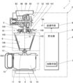
以下、本発明の実施例1について、図1~図19に基づいて説明する。1は、ミル装置としての電動ミル付きコーヒーメーカーであり、このコーヒーメーカー1の本体たるケース本体2は、後側の立設部3と、この立設部3の下部と一体的に形成された前側の載置部4と、前記立設部3の上部と一体的に形成された庇部5とを備える。そして、前記立設部3に貯水部6が設けられており、この貯水部6には、外部の水を供給することができ、この例では、前記貯水部6が前記ケース本体2に着脱可能に設けられ、前記貯水部6には貯水容器(図示せず)が内蔵される。
Embodiment 1 of the present invention will be described below with reference to FIGS. 1 to 19. FIG. 1 is a coffee maker with an electric mill as a milling device, and a case body 2 as a main body of the coffee maker 1 is integrally formed with a rear erected portion 3 and a lower portion of the erected portion 3. It has a front mounting portion 4 and a canopy portion 5 integrally formed with the upper portion of the standing portion 3 . A water storage portion 6 is provided in the standing portion 3, and external water can be supplied to the water storage portion 6. In this example, the water storage portion 6 is detachable from the case body 2. , and the water reservoir 6 contains a water reservoir (not shown).
前記貯水部6内には、図4に示すように、前記貯水容器内の水を加熱する加熱手段7が設けられる。また、ケース本体2には、前記加熱手段7により加熱して得られた湯を、ドリッパー8に送る送湯手段9が設けられる。なお、この送湯手段9としては、ポンプ等が例示される。
As shown in FIG. 4, a heating means 7 is provided in the water reservoir 6 for heating the water in the water reservoir. Further, the case main body 2 is provided with hot water supply means 9 for feeding hot water obtained by heating with the heating means 7 to the dripper 8 . A pump or the like is exemplified as the hot water supply means 9 .
前記載置部4は、上方が開口すると共に、この開口を塞ぐように、略平面状の加熱板11が設けられる。そして、この加熱板11の下面には、ヒーター12が熱的に接して設けられる。
The mounting portion 4 has an upper opening, and a substantially planar heating plate 11 is provided so as to block the opening. A heater 12 is provided in thermal contact with the lower surface of the heating plate 11 .
前記加熱板11上には、飲料サーバー13が着脱可能に載置される。この飲料サーバー13は、上方が開口した耐熱ガラス製の容器本体14と、この容器本体14の側板に取り付けられた合成樹脂製の把持部15と、前記容器本体14の上部開口を覆う合成樹脂製の蓋体16とを備える。
A beverage server 13 is detachably mounted on the heating plate 11 . The beverage server 13 includes a container body 14 made of heat-resistant glass with an upper opening, a grip part 15 made of synthetic resin attached to the side plate of the container body 14, and a synthetic resin material covering the upper opening of the container body 14. and a lid body 16 of.
前記立設部3の側部には、前記載置部4の飲料サーバー13の上方に、上からミル部17と、湯供給部18と、抽出部たる前記ドリッパー8とが配置される。
On the side portion of the standing portion 3, above the beverage server 13 of the mounting portion 4, the mill portion 17, the hot water supply portion 18, and the dripper 8 as the extraction portion are arranged from above.
ミル装置20は、前記ケース本体2の上部に設けられ飲料原料であるコーヒー豆を細かくして排出する前記ミル部17と、前記ケース本体2に設けられ前記ミル部17を作動させる電動機21とを有する。なお、前記ケース本体2及びミル装置20において、前側が前後方向一側であり、後側が前後方向他側である。
The mill device 20 includes the mill portion 17 provided on the upper portion of the case body 2 for crushing and discharging coffee beans, which are the raw materials of the beverage, and an electric motor 21 provided on the case body 2 for operating the mill portion 17. have. In addition, in the case main body 2 and the milling device 20, the front side is one side in the front-rear direction, and the rear side is the other side in the front-rear direction.
前記ミル部17は、前記ケース本体2の取付凹部19に対して着脱可能に取り付けられる。そして、図12及び図13に示すように、前記ミル部17は、円盤状の回転刃22を設けた回転刃取付部23と、円盤状の固定刃24を設けた固定刃取付部25と、に分解可能に構成される。なお、前記回転刃22及び固定刃24は、全体として円盤状である。
The mill portion 17 is detachably attached to the mounting recess 19 of the case body 2 . 12 and 13, the mill section 17 includes a rotary blade mounting portion 23 having a disk-shaped rotary blade 22, a fixed blade mounting portion 25 having a disk-shaped fixed blade 24, configured to be decomposable into The rotary blade 22 and fixed blade 24 are disk-shaped as a whole.
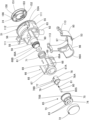
図5等に示すように、前記回転刃取付部23は、前側から前記回転刃22と、この回転刃22を取り付ける回転ホルダー31と、カバー部材32と、従動側伝達機構たる従動歯車33とを備える。前記回転ホルダー31は、前記回転刃22を取り付ける円盤状の取付板34と、この取付板34の中心から前側に突設されたミルスクリュー35とを一体に備え、このミルスクリュー35の中心には貫通孔36が穿設される。また、前記取付板34の前面の周囲には、前記回転刃22の周囲を挟む一対の突起部37,37が前側に突設される。
As shown in FIG. 5 and the like, the rotary blade mounting portion 23 includes, from the front side, the rotary blade 22, a rotary holder 31 for mounting the rotary blade 22, a cover member 32, and a driven gear 33 as a driven-side transmission mechanism. Prepare. The rotary holder 31 integrally includes a disk-shaped mounting plate 34 for mounting the rotary blade 22 and a mill screw 35 projecting forward from the center of the mounting plate 34. A through hole 36 is drilled. A pair of projecting portions 37, 37 that sandwich the rotary blade 22 are provided around the front surface of the mounting plate 34 so as to protrude forward.
前記回転刃22の一面側である前面には刃部151が設けられ、また、回転刃22の中心には貫通孔152が穿設される。そして、前記取付板34には複数の透孔34Aが穿設され、図8に示すように、後側から透孔34Aに挿通させたビス38を前記回転刃22の後面の取付ボス186の下孔186Aに螺合させることにより、前記取付板34に前記回転刃22が取り付けられる。なお、前記ビス38は螺合式の固定手段である。また、このビス38は、防錆性を有する金属(本例ではステンレス鋼)で構成される。
A blade portion 151 is provided on the front surface of the rotary blade 22 , and a through hole 152 is formed in the center of the rotary blade 22 . A plurality of through holes 34A are formed in the mounting plate 34, and as shown in FIG. The rotary blade 22 is attached to the attachment plate 34 by screwing it into the hole 186A. The screws 38 are screw-type fixing means. The screw 38 is made of a rust-proof metal (stainless steel in this example).
前記カバー部材32は、円板部41の中心に貫通孔42を設け、この貫通孔42の径より中心孔が大きな取付筒部43を、前記円板部41の前面に突設し、前記取付筒部43内に軸受部材44を固定している。また、前記円板部41の周囲に外筒部45が一体に設けられ、この外筒部45が前方に突設され、この外筒部45の内周に雌螺子部45Aが設けられる。また、前記外筒部45の外周には、複数の滑り止め用凹部45B,45Bを設けて滑り止め部を構成する。
The cover member 32 is provided with a through hole 42 in the center of the disc portion 41, and a mounting cylinder portion 43 having a central hole larger than the diameter of the through hole 42 is protruded from the front surface of the disc portion 41, and the mounting A bearing member 44 is fixed inside the cylindrical portion 43 . An outer cylindrical portion 45 is provided integrally around the disk portion 41, and this outer cylindrical portion 45 is projected forward. In addition, a plurality of non-slip concave portions 45B are provided on the outer circumference of the outer cylindrical portion 45 to form a non-slip portion.
前記従動歯車33の中心のハブ部46には貫通孔47が穿設され、この貫通孔47の内周面には、回転軸係合部たる平面部(図示せず)が形成される。そして、金属棒等からなる回転軸48が、前記ミルスクリュー35の貫通孔36にインサート成形等により固定される。前記回転軸48は、その後側が前記軸受部材44に回動自在に挿通されると共に、その後端が前記従動歯車33の貫通孔47に回り止め状態で挿通される。そして、ビス49を前記回転軸48の後端に螺合させることにより、この回転軸48に前記従動歯車33が固定される。
A hub portion 46 at the center of the driven gear 33 is formed with a through hole 47, and the inner peripheral surface of the through hole 47 is formed with a flat portion (not shown) serving as a rotary shaft engaging portion. A rotating shaft 48 made of a metal rod or the like is fixed to the through hole 36 of the mill screw 35 by insert molding or the like. The rotating shaft 48 has its rear end rotatably inserted through the bearing member 44 and its rear end inserted through the through hole 47 of the driven gear 33 in a non-rotating state. The driven gear 33 is fixed to the rotating shaft 48 by screwing a screw 49 onto the rear end of the rotating shaft 48 .
これにより、前記カバー部材32に対して、前記ミルスクリュー35を一体に設けた前記取付板34と従動歯車33とが回動自在に設けられ、これらミルスクリュー35が一体に設けられた取付板34,従動歯車33及び回転軸48により、従動側伝達構造50が構成される。
As a result, the mounting plate 34 integrally provided with the mill screw 35 and the driven gear 33 are rotatably provided with respect to the cover member 32, and the mounting plate 34 integrally provided with the mill screw 35 is provided. , the driven gear 33 and the rotating shaft 48 constitute a driven side transmission structure 50 .
前記固定刃取付部25は、図7等に示すように、ミルケース51と、このミルケース51の上部に取り付けられた上ケース52と、前記ミルケース51の下部に取り付けられた下ケース53とを備える。
The fixed blade attachment portion 25 includes a mill case 51, an upper case 52 attached to the upper portion of the mill case 51, and a lower case 53 attached to the lower portion of the mill case 51, as shown in FIG.
前記ミルケース51は、前記回転刃22と固定刃24を収納する筒状の収納筒部55を有し、この収納筒部55の前端に前壁部56を設け、この前壁部56の中央に貫通孔56Aを形成すると共に、この貫通孔56Aの後側に案内筒部57を突設する。また、この案内筒部57の位置に対応して、前記収納筒部55の前側には、他より径小な径小部55Bが形成される。前記固定刃24の一面側である後面には、前記刃部151が設けられ、また、前記固定刃24の中心には前記貫通孔152が穿設される。そして、前記固定刃24の貫通孔152に前記案内筒部57が挿入され、前記固定刃24の厚さ方向の一部が前記案内筒部57と径小部55Bとの間に収納される。
The mill case 51 has a cylindrical storage tube portion 55 for storing the rotary blade 22 and the fixed blade 24. A front wall portion 56 is provided at the front end of the storage tube portion 55. A through hole 56A is formed, and a guide tube portion 57 is protruded behind the through hole 56A. A small diameter portion 55B having a smaller diameter than the other parts is formed on the front side of the storage cylinder portion 55 corresponding to the position of the guide cylinder portion 57. As shown in FIG. The blade portion 151 is provided on the rear surface, which is one side of the fixed blade 24 , and the through hole 152 is formed in the center of the fixed blade 24 . The guide tube portion 57 is inserted into the through hole 152 of the fixed blade 24, and a portion of the fixed blade 24 in the thickness direction is accommodated between the guide tube portion 57 and the small diameter portion 55B.
また、前記固定刃取付部25は、前記貫通孔56Aの前側に断面略U字状の案内壁部58を有する。この案内壁部58の前端に、該案内壁部58の前側を塞ぐ縦壁部59が設けられ、この該縦壁部59に貫通孔59Aが設けられ、この貫通孔59Aの径より中心孔が大きな取付筒部60が、前記縦壁部59から前方に突設される。
Further, the fixed blade mounting portion 25 has a guide wall portion 58 having a substantially U-shaped cross section on the front side of the through hole 56A. A vertical wall portion 59 is provided at the front end of the guide wall portion 58 to block the front side of the guide wall portion 58. The vertical wall portion 59 is provided with a through hole 59A. A large mounting cylinder portion 60 projects forward from the vertical wall portion 59 .
前記取付筒部60内には、軸受部材61が固定され、後側から前記軸受部材61内に前記回転軸48の前端が着脱可能に挿入される。また、前記収納筒部55の後部は開口し、該収納筒部55の外周に雄螺子部55Aが形成され、この収納筒部55の雄螺子部55Aに前記カバー部材32の雌螺子部45Aが着脱可能に螺合する。
A bearing member 61 is fixed in the mounting cylinder portion 60, and the front end of the rotary shaft 48 is detachably inserted into the bearing member 61 from the rear side. Further, the rear portion of the storage cylinder portion 55 is opened, and a male screw portion 55A is formed on the outer periphery of the storage cylinder portion 55, and the female screw portion 45A of the cover member 32 is attached to the male screw portion 55A of the storage cylinder portion 55. Removably threaded.
そして、前記回転軸48の先端側を、前記収納筒部55の貫通孔56Aと前記案内筒部57の貫通孔59Aに後側から挿通させ、前記収納筒部55の雄螺子部55Aに前記カバー部材32の雌螺子部45Aを螺合させると共に、前記回転軸48の先端を前記軸受部材61に挿入させることにより、前記回転ホルダー31の取付板34及び前記回転刃22が前記収納筒部55内に収納されると共に、前記固定刃取付部25に前記回転刃取付部23が取り付けられ、前記ミル部17内に前記回転ホルダー31が回動可能に取り付けられる。
Then, the distal end side of the rotating shaft 48 is inserted through the through hole 56A of the housing cylinder portion 55 and the through hole 59A of the guide cylinder portion 57 from the rear side, and the male screw portion 55A of the housing cylinder portion 55 is engaged with the cover. By screwing the female threaded portion 45A of the member 32 and inserting the tip of the rotary shaft 48 into the bearing member 61, the mounting plate 34 of the rotary holder 31 and the rotary blade 22 are installed in the housing cylinder portion 55. , the rotary blade mounting portion 23 is mounted to the fixed blade mounting portion 25, and the rotary holder 31 is rotatably mounted in the mill portion 17. As shown in FIG.
また、前記収納筒部55の下部には、筒形の落下口62が下方に向かって突設される。この落下口62は、円筒状をなし、前記収納筒部55内の底部と連通する。そして、コーヒー豆が、前記回転刃22と固定刃24との間で挽かれてコーヒー粉(挽き豆)となり、前記収納筒部55内の前記コーヒー粉が前記落下口62から前記ドリッパー8の中央に落下供給される。
Further, a cylindrical drop port 62 is provided at the lower portion of the storage cylinder portion 55 so as to protrude downward. The drop port 62 has a cylindrical shape and communicates with the bottom portion inside the housing cylinder portion 55 . The coffee beans are ground between the rotating blade 22 and the fixed blade 24 to become coffee powder (ground beans), and the coffee powder in the storage tube portion 55 is discharged from the drop port 62 to the center of the dripper 8. to be fed drop-in.
前記ミル部17には、図9等に示すように、コーヒー粉の粉砕度合(粒度)を調整する粒度調整手段65が設けられる。この粒度調整手段65は、前記回転刃22の前面と固定刃24の後面との間隔を調整することにより、コーヒー粉の粉砕度合を調整するものである。
As shown in FIG. 9 and the like, the mill section 17 is provided with a particle size adjusting means 65 for adjusting the degree of pulverization (particle size) of the coffee powder. The particle size adjusting means 65 adjusts the degree of pulverization of coffee powder by adjusting the distance between the front surface of the rotary blade 22 and the rear surface of the fixed blade 24 .
前記粒度調整手段65について、具体的に説明する。前記固定刃取付部25には、固定刃用ホルダー66が前後位置調整可能に設けられる。図6等に示すように、前記固定刃用ホルダー66は、前記取付筒部60の外側に配置される円筒状の前筒部67を有し、この前筒部67の前端に、内鍔部67Aが周設される。また、前記前筒部67の後側左右には、側壁部68,68が設けられる。これら左右の側壁部68,68は、前記案内壁部58の外周面に沿って配置される。そして、前記側壁部68,68の後端に取付部69,69がそれぞれ設けられ、これら取付部69,69側が前記収納筒部55の挿通開口部63,63に挿通された状態で、前記取付部69,69の後面に前記固定刃24の前面が固定される。
The granularity adjusting means 65 will be specifically described. A fixed blade holder 66 is provided on the fixed blade mounting portion 25 so that the position thereof can be adjusted forward and backward. As shown in FIG. 6 and the like, the fixed blade holder 66 has a cylindrical front tubular portion 67 arranged outside the mounting tubular portion 60. At the front end of the front tubular portion 67 is an inner collar portion. 67A are provided around. Further, side wall portions 68 , 68 are provided on the rear left and right sides of the front tubular portion 67 . These left and right side wall portions 68 , 68 are arranged along the outer peripheral surface of the guide wall portion 58 . Mounting portions 69, 69 are provided at the rear ends of the side wall portions 68, 68, respectively. The front surface of the fixed blade 24 is fixed to the rear surfaces of the portions 69,69.
図7に示すように、前記ミルケース51の前壁部56の左右には、左右の前記取付部69,69が遊挿される前記挿通開口部63,63が設けられる。左右の前記取付部69,69には、それぞれ透孔69A,69Aが穿設される。そして、図9に示すように、前記透孔69Aに挿通されたビス70を前記固定刃24の前面の取付ボス186の下孔186Aに螺合させることで、左右の前記取付部69,69に前記固定刃24が固定される。なお、前記ビス70は、防錆性を有する金属(本例ではステンレス鋼)で構成される。また、前記固定刃用ホルダー66の前記内鍔部67Aと前記ミルケース51の前記縦壁部59との間には、付勢手段たるコイルスプリング71が前記取付筒部60に外装して設けられる。このコイルスプリング71は、前記ミルケース51に対して前記固定刃用ホルダー66を前側に移動させるように付勢する。
As shown in FIG. 7, the right and left sides of the front wall portion 56 of the mill case 51 are provided with the insertion openings 63, 63 into which the left and right mounting portions 69, 69 are loosely inserted. Through holes 69A, 69A are formed in the left and right mounting portions 69, 69, respectively. Then, as shown in FIG. 9, by screwing a screw 70 inserted through the through hole 69A into a lower hole 186A of a mounting boss 186 on the front surface of the fixed blade 24, the left and right mounting portions 69, 69 are connected to each other. The fixed blade 24 is fixed. The screws 70 are made of rust-proof metal (stainless steel in this example). A coil spring 71 serving as biasing means is mounted on the mounting cylinder portion 60 between the inner flange portion 67A of the fixed blade holder 66 and the vertical wall portion 59 of the mill case 51. As shown in FIG. The coil spring 71 urges the mill case 51 to move the fixed blade holder 66 forward.
前記粒度調整手段65は、操作部である回転式のダイヤル72を有する。このダイヤル72は、押圧体73の前板部74の前に固定される。前記押圧体73は、前記前板部74の後部に押圧筒部75が一体に設けられ、この押圧筒部75に雌螺子部75Aが形成される。そして、前記取付筒部60には雄螺子部60Aが設けられ、この雄螺子部60Aに前記雌螺子部75Aが螺合する。この螺合により、前記ミルケース51に対して前記押圧体73が進退可能に設けられる。
The granularity adjusting means 65 has a rotary dial 72 which is an operation part. This dial 72 is fixed in front of the front plate portion 74 of the pressing body 73 . The pressing body 73 is integrally provided with a pressing tube portion 75 at the rear portion of the front plate portion 74, and the pressing tube portion 75 is formed with a female screw portion 75A. A male screw portion 60A is provided on the mounting cylinder portion 60, and the female screw portion 75A is screwed into the male screw portion 60A. By this screwing, the pressing body 73 is provided so as to move forward and backward with respect to the mill case 51 .
そして、前記ダイヤル72により前記押圧体73が捩じ込む方向に回されることにより、前記押圧筒部75が後退し、この押圧筒部75の後端75Bに前記固定刃用ホルダー66が押されて後退すると共に、前記コイルスプリング71が圧縮される。これによって、前記固定刃24と回転刃22の間隔が狭まる。一方、前記ダイヤル72を逆に回すと、前記コイルスプリング71の弾性復元力により前記固定刃用ホルダー66が前進する。これによって、前記固定刃24と回転刃22の間隔が開く。
When the pressing body 73 is turned in the screwing-in direction by the dial 72, the pressing cylinder portion 75 is retracted, and the fixed blade holder 66 is pushed by the rear end 75B of the pressing cylinder portion 75. , the coil spring 71 is compressed. As a result, the distance between the fixed blade 24 and the rotary blade 22 is narrowed. On the other hand, when the dial 72 is turned in the opposite direction, the fixed blade holder 66 advances due to the elastic restoring force of the coil spring 71 . As a result, the space between the fixed blade 24 and the rotary blade 22 is increased.
また、前記粒度調整手段65は、図6及び図9に示すように、前記ダイヤル72の回転角度を規定するクリック手段77を備える。このクリック手段77は、筒体78を有する。この筒体78は、その前側外周に鍔部78Aが周設される。そして、前記筒体78は、前記固定刃用ホルダー66の前記前筒部67内に挿入配置されると共に、前記鍔部78Aが前記取付筒部60の前縁に当接する。この際、この取付筒部60の前縁に設けられた凸部60Bが、前記鍔部78Aに形成された切欠部78Bと係合することで、前記筒体78が前記取付筒部60に対し回り止め状態とされる。また、前記筒体78の中心から外れた位置で、この筒体78の前側に、取付筒部79が一体に突設される。この取付筒部79内にクリック杆80が前後スライド可能に挿入され、このクリック杆80の後で前記取付筒部79内に、付勢手段たるコイルスプリング81が配置される。そして、このコイルスプリング81により、前記クリック杆80が前側に付勢される。
6 and 9, the granularity adjusting means 65 comprises a click means 77 for defining the rotation angle of the dial 72. As shown in FIGS. This click means 77 has a cylinder 78 . A flange portion 78A is provided around the front outer periphery of the tubular body 78 . The tubular body 78 is inserted into the front tubular portion 67 of the fixed blade holder 66 , and the flange portion 78 A contacts the front edge of the mounting tubular portion 60 . At this time, the convex portion 60B provided on the front edge of the mounting cylinder portion 60 engages with the notch portion 78B formed in the flange portion 78A, so that the cylinder body 78 is moved relative to the mounting cylinder portion 60. It is in a non-rotating state. Further, a mounting tubular portion 79 is integrally protruded on the front side of the tubular body 78 at a position off the center of the tubular body 78 . A click rod 80 is inserted into the mounting cylinder portion 79 so as to be slidable back and forth. The click rod 80 is urged forward by the coil spring 81 .
更に、前記押圧体73の前板部74には、前記クリック杆80が係入する複数のクリック凹部83,83・・・が形成される。これらのクリック凹部83,83・・・は、前記押圧体73の回転中心を中心として、円周方向に等間隔に配置される。そして、図9に示すように、前記クリック杆80の先端80Sは、凸状湾曲面に形成される。前記クリック凹部83は段付き孔に形成され、この段付き孔の径大部83Aに、前記先端80Sが係入する。
Further, the front plate portion 74 of the pressing body 73 is formed with a plurality of click recesses 83, 83 . . . These click recesses 83, 83, . Then, as shown in FIG. 9, the tip 80S of the click rod 80 is formed into a convex curved surface. The click recess 83 is formed in a stepped hole, and the tip 80S engages with a large diameter portion 83A of the stepped hole.
従って、前記クリック杆80の先端80Sが前記クリック凹部83に係合している状態で、前記ダイヤル72を回すと、前記コイルスプリング81が収縮して、前記クリック凹部83から前記クリック杆80の先端80Sが外れ、この先端80Sが隣のクリック凹部83に係入する際、弾性復元力により前記コイルスプリング81が伸長し、所定のクリック感が得られる。そして、クリックの回数に応じて、前記固定刃24と回転刃22の間隔を調整することができる。このため、前記ダイヤル72には、前記クリック凹部83に対応して、粉砕度合を示す目盛りを設けるようにしてもよい。
Therefore, when the dial 72 is turned while the tip 80S of the click rod 80 is engaged with the click recess 83, the coil spring 81 is contracted, and the tip of the click rod 80 moves from the click recess 83 to the tip of the click rod 80. When the tip 80S is disengaged and the tip 80S engages with the adjacent click recess 83, the elastic restoring force causes the coil spring 81 to expand and a predetermined click feeling is obtained. The distance between the fixed blade 24 and the rotary blade 22 can be adjusted according to the number of clicks. For this reason, the dial 72 may be provided with a scale indicating the degree of pulverization corresponding to the click recess 83 .
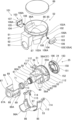
図7に示すように、前記上ケース52は、平面円形の上部開口85を有するホッパー86を有する。このホッパー86は、前記上ケース52の一部を構成する。また、前記ホッパー86の底面部86Aの左右には、下部開口87,87が設けられる。そして、これら下部開口87,87の下にシュート部88が設けられ、このシュート部88の下部が前記案内壁部58(図6)の上部の開口に連通する。また、前記上ケース52の上部開口85には、蓋体89が着脱可能に設けられる。
As shown in FIG. 7, the upper case 52 has a hopper 86 having a planar circular upper opening 85 . This hopper 86 forms part of the upper case 52 . Further, lower openings 87, 87 are provided on the left and right sides of the bottom portion 86A of the hopper 86. As shown in FIG. A chute portion 88 is provided under these lower openings 87, 87, and the lower portion of the chute portion 88 communicates with the upper opening of the guide wall portion 58 (FIG. 6). A lid body 89 is detachably provided in the upper opening 85 of the upper case 52 .
前記ホッパー86の前側には、上前カバー部91が一体に設けられる。図8等に示すように、この上前カバー部91は、前記上ケース52の一部を構成し、前記ミルケース51の前側上部を覆う。そして、前記上前カバー部91の前面部92には、前記押圧筒部75が挿通される挿通孔93が穿設される。
An upper front cover portion 91 is integrally provided on the front side of the hopper 86 . As shown in FIG. 8 and the like, the upper front cover portion 91 constitutes a part of the upper case 52 and covers the front upper portion of the mill case 51 . A front surface portion 92 of the upper front cover portion 91 is formed with an insertion hole 93 through which the pressing cylinder portion 75 is inserted.
前記下ケース53は、前記ミルケース51の下部周囲を覆う下ケース本体95と、前記ミルケース51の前側下部を覆うU字状の下前カバー部96とを一体に有する。そして、この下前カバー部96の前縁部96Aは、前記上前カバー部91の前面部92の後面に当接する(図8)。また、前記下ケース53は前記ミルケース51の後側下部を覆って前記上ケース52に固定される。更に、前記下ケース本体95には切欠部97が形成され、この切欠部97から前記落下口62が下方に突設される。
The lower case 53 integrally has a lower case main body 95 covering the periphery of the lower portion of the mill case 51 and a U-shaped lower front cover portion 96 covering the front lower portion of the mill case 51 . A front edge portion 96A of the lower front cover portion 96 contacts the rear surface of the front surface portion 92 of the upper front cover portion 91 (FIG. 8). Also, the lower case 53 is fixed to the upper case 52 while covering the rear lower portion of the mill case 51 . Further, a notch portion 97 is formed in the lower case main body 95, and the drop port 62 protrudes downward from the notch portion 97. As shown in FIG.
前記ミル部17には、着脱操作部101が設けられる。この着脱操作部101は、図7及び図10等に示すように、前記ホッパー86の左右の外側面に形成されたスライド凹部102,102に、スライダ103,103を左右方向移動可能に設けることで構成される。これらのスライダ103,103は、それぞれ左右方向に形成されるスライド板104の外側に、このスライド板104より幅広な係止爪部105が設けられ、この係止爪部105の外縁部105Aが斜めに形成される。前記係止爪部105の上部には、板状の縦部106が設けられる。この縦部106の上部には、横方向の摘み部107が外側に突設する。そして、前記縦部106と前記スライド凹部102の底面との間には、付勢手段たるコイルスプリング108が配置され、このコイルスプリング108により前記スライダ103が外側に付勢される。前記縦部106の前後両側縁には、当接縁部106A,106Aが突設され、これら当接縁部106A,106Aが当接する抜け止め縁部102A,102Aが、前記スライド凹部102の前後両側の縦縁の外端に内側向きに形成される。即ち、前記スライダ103の外側への移動範囲は、前記当接縁部106Aが前記抜け止め縁部102Aに当接する位置までに規制される。なお、図10では、前記スライダ103が後退した状態を実線で示し、前記摘み部107を押す前の状態を鎖線で示す。そして、前記着脱操作部101は、前記スライダ103が鎖線の位置にある状態で、その係止爪部105が後述する係止孔部119に係止する。
The mill section 17 is provided with an attachment/detachment operation section 101 . As shown in FIGS. 7 and 10 , the attachment/detachment operation portion 101 is provided with sliders 103 , 103 movably in the left-right direction in slide recesses 102 , 102 formed on the left and right outer surfaces of the hopper 86 . Configured. These sliders 103, 103 are each provided with an engaging claw portion 105 wider than the slide plate 104 on the outside of the slide plate 104 formed in the horizontal direction, and the outer edge portion 105A of the engaging claw portion 105 is inclined. formed in A plate-shaped vertical portion 106 is provided on the upper portion of the locking claw portion 105 . A horizontal knob 107 protrudes outward from the upper portion of the vertical portion 106 . A coil spring 108 as a biasing means is arranged between the vertical portion 106 and the bottom surface of the slide recess 102, and the coil spring 108 biases the slider 103 outward. Abutting edge portions 106A, 106A are protrudingly provided on both front and rear side edges of the vertical portion 106, and retaining edge portions 102A, 102A with which the abutting edge portions 106A, 106A abut are formed on both front and rear sides of the slide recess 102. formed inwardly at the outer ends of the longitudinal edges of the That is, the outward movement range of the slider 103 is restricted to a position where the contact edge portion 106A contacts the retaining edge portion 102A. In FIG. 10, the solid line indicates the state in which the slider 103 is retracted, and the chain line indicates the state before the knob 107 is pushed. The attachment/detachment operation portion 101 has the locking claw portion 105 locked to a locking hole portion 119 to be described later in a state in which the slider 103 is at the position indicated by the dashed line.
前記ミルケース51の収納筒部55の上側左右には、腕部111,111が外向きに突設され、これらの腕部111,111の上面に、それぞれ前記スライド板104がスライドするスライド溝部112が形成される。また、前記下ケース本体95の上縁の左右には、前記腕部111,111に対応して外鍔部113,113が設けられる。これら左右の外鍔部113,113には、前記腕部111,111が嵌合状態で載置される。そして、この状態で前記外鍔部113の透孔114にビス115(図7)を挿通し、このビス115を前記上ケース52に固定することで、上,下ケース52,53が一体化される。
Arms 111, 111 project outward from the upper left and right sides of the cylindrical storage portion 55 of the mill case 51, and slide grooves 112, in which the slide plate 104 slides, are formed on the upper surfaces of these arms 111, 111, respectively. It is formed. Outer flanges 113, 113 are provided on the left and right sides of the upper edge of the lower case body 95 corresponding to the arms 111, 111, respectively. The arm portions 111, 111 are placed on the left and right outer flange portions 113, 113 in a fitted state. In this state, a screw 115 (FIG. 7) is inserted through the through hole 114 of the outer collar portion 113, and the screw 115 is fixed to the upper case 52, whereby the upper and lower cases 52 and 53 are integrated. be.
前記取付凹部19は、前記ケース本体2の前面と上面に開口する略U字状の前側凹部116と、この前側凹部116の後側に位置し、ケース本体2の上面に開口する円形の後側凹部117を有する。前記前側凹部116には、前記上ケース52と下ケース53の前側が収納され、収納状態で前記前面部92が前記庇部5の前面と略面一となる。一方、前記後側凹部117には、前記上ケース52と下ケース53の後側が収納され、収納状態で前記上前カバー部91の上面が前記庇部5の上面と略面一となると共に、前記上ケース52の上部開口85が前記庇部5の上面から突出する。
The mounting recess 19 includes a substantially U-shaped front recess 116 that opens to the front and top surfaces of the case body 2 , and a circular rear recess 116 that is located behind the front recess 116 and opens to the top surface of the case body 2 . It has a recess 117 . The front sides of the upper case 52 and the lower case 53 are accommodated in the front concave portion 116 , and the front surface portion 92 is substantially flush with the front surface of the eaves portion 5 in the accommodated state. On the other hand, the rear sides of the upper case 52 and the lower case 53 are accommodated in the rear concave portion 117, and in the accommodated state, the upper surface of the upper front cover portion 91 is substantially flush with the upper surface of the eaves portion 5, An upper opening 85 of the upper case 52 protrudes from the upper surface of the eaves portion 5 .
前記後側凹部117の左右には、左右の前記スライダ103,103に対応して、左右の操作用凹部118,118が形成される。これら左右の操作用凹部118,118の底面部118A,118Aの下部には、左右の側面部が垂設され、左右の側面部の上部に、係止部たる前記係止爪部105,105が係止可能なスリット状の係止受部たる前記係止孔部119,119が形成される。
Left and right operating recesses 118 , 118 are formed on the left and right sides of the rear recess 117 so as to correspond to the left and right sliders 103 , 103 . Left and right side portions are vertically provided below the bottom portions 118A, 118A of the left and right operating recesses 118, 118, and the above-described locking claw portions 105, 105 as locking portions are provided above the left and right side portions. The locking holes 119, 119 are formed as slit-like locking receiving portions that can be locked.
従って、前記取付凹部19に前記ミル部17を上方から挿入すると、前記係止爪部105の外縁部105Aが、前記係止孔部119の上方の前記底面部118Aの角部に当接する。ここから前記ミル部17を下に押し込むと、前記外縁部105Aの傾斜により、前記スライダ103が後退すると共に、前記コイルスプリング108が収縮する。これによって、前記係止爪部105が角部を通過する。前記係止爪部105が角部を通過した後、前記コイルスプリング108が伸長して、前記係止爪部105が前記係止孔部119に係止される。これによって、前記取付凹部19に前記ミル部17が固定される。
Accordingly, when the mill portion 17 is inserted into the mounting recess 19 from above, the outer edge portion 105A of the locking claw portion 105 contacts the corner portion of the bottom surface portion 118A above the locking hole portion 119 . When the mill portion 17 is pushed downward from here, the slider 103 retreats and the coil spring 108 contracts due to the inclination of the outer edge portion 105A. As a result, the locking claw portion 105 passes through the corner. After the engaging claw portion 105 passes through the corner, the coil spring 108 is extended, and the engaging claw portion 105 is engaged with the engaging hole portion 119 . As a result, the mill portion 17 is fixed to the mounting recess 19 .
逆に、左右の前記摘み部107,107を内側に押すと、前記係止孔部119から前記係止爪部105が抜け出し、前記取付凹部19から前記ミル部17を取り外すことができる。
Conversely, when the left and right knob portions 107, 107 are pushed inward, the locking claw portion 105 is pulled out from the locking hole portion 119, and the mill portion 17 can be removed from the mounting recess portion 19. As shown in FIG.
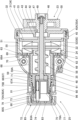
前記ケース本体2内には、駆動ユニット121が設けられる。この駆動ユニット121は、前記従動歯車33に噛合する駆動歯車122を有する。図2及び図11に示すように、前記駆動ユニット121は、前側ホルダー123と後側ホルダー124とを有する。前記前側ホルダー123と後側ホルダー124は、一体的に組み立てられる。また、前記後側ホルダー124には、前記電動機21が取り付けられる。そして、この電動機21の回転軸には、電動機側歯車126が設けられる。なお、前記前側ホルダー123は前収納部127を有し、後側ホルダー124は後収納部128を有する。これら前,後収納部127,128の内部には、減速歯車群129が配置される。
A drive unit 121 is provided in the case body 2 . The drive unit 121 has a drive gear 122 meshing with the driven gear 33 . As shown in FIGS. 2 and 11 , the drive unit 121 has a front holder 123 and a rear holder 124 . The front holder 123 and the rear holder 124 are assembled integrally. Also, the electric motor 21 is attached to the rear holder 124 . A motor-side gear 126 is provided on the rotating shaft of the electric motor 21 . The front holder 123 has a front storage portion 127 and the rear holder 124 has a rear storage portion 128 . A reduction gear group 129 is arranged inside the front and rear storage portions 127 and 128 .
前記減速歯車群129は、第1の回転板130及び第2の回転板130Aを有する。前記第1の回転板130の後部には、4本の軸部131,131,131,131が突設され、これらの軸部131,131,131,131に減速歯車132,132,132,132が回動可能に設けられる。そして、これら減速歯車132,132,132,132の中央で、前記電動機側歯車126が各減速歯車132,132,132,132に噛合する。一方、これら減速歯車132,132,132,132の外周側は、前記前収納部127の内面に形成された図示しない内歯車に噛合する。また、前記第1の回転板130の前側中央には、伝達歯車133が一体に設けられる。そして、前記第1の回転板130の前側には、前記第2の回転板130Aが配置される。この第2の回転板130Aの後部には、4本の軸部131A,131A,131A,131Aが突設され、これらの軸部131A,131A,131A,131Aに減速歯車132A,132A,132A,132Aが回動可能に設けられる。そして、これら減速歯車132A,132A,132A,132Aの中央で、前記伝達歯車133が各減速歯車132A,132A,132A,132Aに噛合する。一方、これら減速歯車132A,132A,132A,132Aの外周側は、前記前収納部127の内面に形成された図示しない内歯車に噛合する。また、前記第2の回転板130Aの前側中央には、前記駆動歯車122が一体に設けられる。前記第1の回転板130の後側には、前記軸部131の後端に近接する歯車ホルダー134が設けられる。また、前記第2の回転板130Aの軸部131の後端は第1の回転板130の前面に近接する。前記歯車ホルダー134は、前記軸部131の後端が近接する円板状の前面部134Aと、この前面部134Aの後部に一体に設けられた筒部134Bとを有する。そして、前記前面部134Aの中央部には、中心貫通孔134Cが貫通して形成される。そして、前記電動機側歯車126は、前記中心貫通孔134Cに挿通され、前記前面部134Aの前側において、前記電動機側歯車126が減速歯車132,132,132,132に噛合する。なお、前記第1の回転板130の軸部131から前記歯車ホルダー134の前面部134Aまでの距離は、前記減速歯車132の軸方向長さよりも短い。同様に、前記第2の回転板130Aの軸部131Aから前記第1の回転板130の前面までの距離も、前記減速歯車132Aの軸方向長さよりも短い。そして、前記電動機側歯車126と減速歯車132と図示しない内歯車とで、遊星歯車機構による減速機構が構成される。この部位において、前記電動機側歯車126が太陽歯車、前記減速歯車132が遊星歯車となる。同様に、前記伝達歯車133と減速歯車132Aと図示しない内歯車とで、遊星歯車機構による減速機構が構成される。この部位において、前記伝達歯車133が太陽歯車、前記減速歯車132Aが遊星歯車となる。
The reduction gear group 129 has a first rotary plate 130 and a second rotary plate 130A. Four shafts 131 , 131 , 131 , 131 are projected from the rear part of the first rotary plate 130 , and reduction gears 132 , 132 , 132 , 132 are attached to these shafts 131 , 131 , 131 , 131 . is rotatably provided. The motor-side gear 126 meshes with the reduction gears 132, 132, 132, 132 at the centers of the reduction gears 132, 132, 132, 132, respectively. On the other hand, the outer peripheral sides of these reduction gears 132 , 132 , 132 , 132 mesh with an internal gear (not shown) formed on the inner surface of the front housing portion 127 . A transmission gear 133 is integrally provided at the center of the front side of the first rotary plate 130 . In front of the first rotating plate 130, the second rotating plate 130A is arranged. Four shafts 131A, 131A, 131A, 131A are projected from the rear portion of the second rotary plate 130A, and reduction gears 132A, 132A, 132A, 132A are attached to these shafts 131A, 131A, 131A, 131A. is rotatably provided. At the center of these reduction gears 132A, 132A, 132A, 132A, the transmission gear 133 meshes with each reduction gear 132A, 132A, 132A, 132A. On the other hand, the outer peripheral sides of these reduction gears 132A, 132A, 132A, 132A mesh with an internal gear (not shown) formed on the inner surface of the front storage portion 127. As shown in FIG. Further, the drive gear 122 is integrally provided at the center of the front side of the second rotary plate 130A. A gear holder 134 adjacent to the rear end of the shaft portion 131 is provided on the rear side of the first rotating plate 130 . Also, the rear end of the shaft portion 131 of the second rotating plate 130A is close to the front surface of the first rotating plate 130A. The gear holder 134 has a disk-shaped front surface portion 134A to which the rear end of the shaft portion 131 is adjacent, and a cylindrical portion 134B integrally provided at the rear portion of the front surface portion 134A. A central through-hole 134C is formed through the central portion of the front surface portion 134A. The motor-side gear 126 is inserted through the center through-hole 134C, and meshes with the reduction gears 132, 132, 132, 132 on the front side of the front surface portion 134A. The distance from the shaft portion 131 of the first rotating plate 130 to the front surface portion 134A of the gear holder 134 is shorter than the length of the reduction gear 132 in the axial direction. Similarly, the distance from the shaft portion 131A of the second rotary plate 130A to the front surface of the first rotary plate 130 is also shorter than the axial length of the reduction gear 132A. The motor-side gear 126, the reduction gear 132, and an internal gear (not shown) constitute a reduction mechanism based on a planetary gear mechanism. At this portion, the motor-side gear 126 serves as a sun gear, and the reduction gear 132 serves as a planetary gear. Similarly, the transmission gear 133, the reduction gear 132A, and an internal gear (not shown) constitute a reduction mechanism based on a planetary gear mechanism. At this portion, the transmission gear 133 is the sun gear, and the reduction gear 132A is the planetary gear.
前記前側ホルダー123の前記前収納部127の前側には、前面部135が一体に設けられる。この前面部135の前面には、左右一側である右側に側部開口部136を有する切欠筒部137が設けられる。また、この切欠筒部137の右側には、正面視で略U字状の縦凹部138が設けられる。
A front part 135 is integrally provided on the front side of the front storage part 127 of the front holder 123 . The front surface of the front surface portion 135 is provided with a cutout cylinder portion 137 having a side opening portion 136 on the right side, which is one of the left and right sides. A vertical concave portion 138 having a substantially U shape in a front view is provided on the right side of the notched cylindrical portion 137 .
前記切欠筒部137内に後側から前記駆動歯車122が挿入配置された状態で、前記ケース本体2内に前記駆動ユニット121が固定され、前記側部開口部136から前記駆動歯車122の側部が、前記前側ホルダー123の前面部135の前側に露出する。また、前記縦凹部138には、その上部開口138Aから前記従動歯車33のハブ部46の後端が遊挿される。
The drive unit 121 is fixed in the case body 2 in a state in which the drive gear 122 is inserted from the rear side into the cutout cylindrical portion 137 , and the side portion of the drive gear 122 is opened from the side opening 136 . is exposed on the front side of the front face portion 135 of the front holder 123 . Further, the rear end of the hub portion 46 of the driven gear 33 is loosely inserted into the vertical recess 138 through an upper opening 138A.
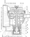
前記駆動歯車122と従動歯車33は、何れも平歯車であり、それぞれの回転中心軸122J,33Jの軸方向が水平且つ平行である。そして、前記ケース本体2に前記ミル部17を取り付けた状態で、前記駆動歯車122と従動歯車33の回転中心軸122J,33Jは、水平方向にずれて並ぶ。また、前記回転中心軸122J,33Jは同じ高さで並ぶことが望ましく、本実施例では、図14に示すように、取付状態で、前記回転中心軸122J,33Jが同一高さで噛合する。なお、この例では、前記従動歯車33の回転中心軸33Jは、前記回転軸48の中心軸である。
Both the driving gear 122 and the driven gear 33 are spur gears, and the axial directions of their respective rotation center shafts 122J and 33J are horizontal and parallel. When the mill portion 17 is attached to the case body 2, the rotation center axes 122J and 33J of the drive gear 122 and the driven gear 33 are horizontally offset. Moreover, it is desirable that the rotation center shafts 122J and 33J are arranged at the same height. In this embodiment, as shown in FIG. In this example, the rotation center axis 33J of the driven gear 33 is the center axis of the rotation shaft 48. As shown in FIG.
これによって、上述したように、前記ミル部17を前記ケース本体2の取付凹部19に取り付ける際に、前記従動歯車33が回転しながら前記駆動歯車122と噛み合うので、この駆動歯車122と従動歯車33を確実に噛み合わせることができる。また、図14に示すように、前記駆動歯車122は、従動歯車33との噛み合い側が下方に移動するように右回りに回転する。これによって、有負荷時に前記従動歯車33、ひいては前記ミル部17が下方に押し付けられるように力が働く。即ち、前記ミル部17が前記ケース本体2から外れる方向とは逆の方向に力が働く。
As a result, as described above, when the mill portion 17 is attached to the mounting recess 19 of the case body 2, the driven gear 33 is engaged with the driving gear 122 while rotating. can be reliably engaged. Further, as shown in FIG. 14, the drive gear 122 rotates clockwise so that the side that meshes with the driven gear 33 moves downward. As a result, a force acts to press the driven gear 33 and thus the mill portion 17 downward when a load is applied. That is, a force acts in a direction opposite to the direction in which the mill portion 17 is removed from the case body 2 .
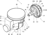
図4に示すように、前記湯供給部18のケース141の中央には、前記落下口62が着脱自在に挿入接続される挿通孔142が縦設される。そして、前記ミル部17を前記取付凹部19に取り付けることにより、前記挿通孔142に前記落下口62が接続される。また、前記挿通孔142の下部には、この挿通孔142を開閉するシャッター143が設けられる。
As shown in FIG. 4, in the center of the case 141 of the hot water supply portion 18, an insertion hole 142 into which the drop port 62 is detachably inserted and connected is vertically provided. By attaching the mill portion 17 to the attachment recess 19 , the drop port 62 is connected to the insertion hole 142 . A shutter 143 for opening and closing the insertion hole 142 is provided below the insertion hole 142 .
前記ケース141には接続部144が設けられ、この接続部144に、前記送湯手段9から送液路9Aを通して湯が送られる。そして、前記ケース141には、前記湯を前記ドリッパー8に供給するノズル145が複数設けられる。また、前記ドリッパー8内には、ペーパーフィルター146が交換可能に配置される。更に、前記ドリッパー8の底部には、止液弁147が設けられる。なお、10は、ミル装置としてのコーヒーメーカー1を使用する際に操作されるスイッチである。
A connection portion 144 is provided in the case 141, and hot water is sent to the connection portion 144 from the hot water supply means 9 through the liquid supply path 9A. The case 141 is provided with a plurality of nozzles 145 for supplying hot water to the dripper 8 . Also, a paper filter 146 is replaceably arranged in the dripper 8 . Furthermore, a stop valve 147 is provided at the bottom of the dripper 8 . A switch 10 is operated when using the coffee maker 1 as a mill.
以下、本発明の前記回転刃22と前記固定刃24の構成について説明する。なお、前記回転刃22と前記固定刃24は取付位置及び回転の有無以外は同一構成である。
The configurations of the rotary blade 22 and the fixed blade 24 of the present invention will be described below. Note that the rotary blade 22 and the fixed blade 24 have the same configuration except for the mounting position and the presence or absence of rotation.
図15~図19に示すように、前記回転刃22と前記固定刃24は、円盤状の基部たる円盤体150と、この円盤体150の一側面に一体に設けられると共に前記円盤体150より薄い円盤状の前記刃部151とを有する。前記円盤体150は、中央に円形の前記貫通孔152を有する。そして、前記円盤体150の一面側には、4本の溝部153,153,153,153が回転対称に設けられる。これらの溝部153,153,153,153は、外周側ほど相対回転方向に対し遅れるように形成される。前記刃部151は、一定厚さの板材からなる金属板151Aからなり、前記円盤体150と同径の円盤状に形成される。そして、前記刃部151は、その両面が平坦面に形成される。また、前記刃部151には、中央の貫通孔152Hと、この貫通孔152Hから外側に弧状に形成された4つの溝開口部155,155,155,155とが設けられる。そして、これら貫通孔152Hと溝開口部155,155,155,155により、孔部が構成される。前記刃部151は、母材となる金属板をプレス等で打ち抜くことにより、円盤状に形成されると共に、前記貫通孔152H及び4つの溝開口部155,155,155,155が形成される。なお、前記貫通孔152Hは、前記貫通孔152に対応する。また、前記溝開口部155,155,155,155は、前記溝部153,153,153,153に対応する。即ち、前記貫通孔152Hは、前記貫通孔152と略同径である。また、前記溝開口部155は、前記円盤体150の一側面における前記溝部153と同一形状である。また、前記刃部151は、前記円盤体150に比べて硬度が高く、且つ防錆性を有するステンレス鋼やチタン等の金属から形成される。なお、本例ではステンレス鋼を採用する。一方、前記円盤体150は、エンジニアリングプラスチック等の合成樹脂、アルミニウム合金等の防錆性を有する金属から形成される。即ち、前記円盤体150は、射出成形やダイキャスト成形等、型成形によって容易且つ安価に製造することができる。なお、本例では、耐油性を有するPOMやPBT等のエンジニアリングプラスチックを採用する。
As shown in FIGS. 15 to 19, the rotary blade 22 and the fixed blade 24 are provided integrally with a disc body 150 serving as a disc-shaped base and on one side of the disc body 150 and are thinner than the disc body 150. and the disk-shaped blade portion 151 . The disk body 150 has the circular through hole 152 in the center. Four grooves 153 , 153 , 153 , 153 are rotationally symmetrically provided on one side of the disc body 150 . These grooves 153 , 153 , 153 , 153 are formed so as to be delayed in the direction of relative rotation toward the outer circumference. The blade portion 151 is made of a metal plate 151A made of a plate material having a constant thickness, and is shaped like a disc having the same diameter as the disc body 150 . Both sides of the blade portion 151 are flat. Further, the blade portion 151 is provided with a central through hole 152H and four groove openings 155, 155, 155, 155 formed in an arc shape outwardly from the through hole 152H. These through holes 152H and the groove openings 155, 155, 155, 155 constitute holes. The blade portion 151 is formed in a disc shape by punching out a metal plate as a base material with a press or the like, and the through hole 152H and four groove openings 155, 155, 155, 155 are formed. The through hole 152H corresponds to the through hole 152. As shown in FIG. Also, the groove openings 155 , 155 , 155 , 155 correspond to the grooves 153 , 153 , 153 , 153 . That is, the through hole 152H has substantially the same diameter as the through hole 152H. Further, the groove opening 155 has the same shape as the groove 153 on one side surface of the disk body 150 . The blade portion 151 is made of metal such as stainless steel, titanium, etc., which has higher hardness than the disc body 150 and has antirust properties. In this example, stainless steel is adopted. On the other hand, the disc body 150 is made of a synthetic resin such as engineering plastic, or a rust-proof metal such as an aluminum alloy. That is, the disk body 150 can be manufactured easily and inexpensively by molding such as injection molding and die casting. In addition, in this example, an engineering plastic such as POM or PBT having oil resistance is adopted.
図17において、白抜き矢印で示す方向が前記回転刃22の回転方向である。前記溝開口部155,155,155,155は、正面視で、その回転方向前側に前側湾曲縁部156を有すると共に、その回転方向後側の後側湾曲縁部により構成されるカッター刃157を有する。これら前側湾曲縁部156及びカッター刃157が、前記刃部151に形成された縁部である。そして、組立状態で、前側湾曲縁部156及びカッター刃157が、前記円盤体150の溝部153に沿って設けられる。
In FIG. 17 , the direction indicated by the white arrow is the direction of rotation of the rotary blade 22 . Each of the groove openings 155, 155, 155, 155 has a front curved edge 156 on the front side in the rotational direction and a cutter blade 157 formed by the rear curved edge on the rear side in the rotational direction. have. The front curved edge 156 and the cutter blade 157 are edges formed on the blade portion 151 . Then, in the assembled state, the front side curved edge portion 156 and the cutter blade 157 are provided along the groove portion 153 of the disc body 150 .
また、正面視で、前記各前側湾曲縁部156及びカッター刃157は、回転方向前側が凸となるように湾曲する。即ち、前記溝開口部155,155,155,155は、内端側である前記貫通孔152の円弧内縁部170から外端側の交点部158に向かって、回転方向後側に湾曲する。なお、前記前側湾曲縁部156とカッター刃157は、何れも円弧状であり、前記前側湾曲縁部156に比べて前記カッター刃157の曲率半径が僅かに小さい。そして、前側湾曲縁部156の外端と前記カッター刃157の外端は、前記円盤体150の外周近傍位置において、前記交点部158で交わる。また、前記カッター刃157の内端は、内側交点部159で前記円弧内縁部170と交わる。一方、前記前側湾曲縁部156の内端は、内側交点部159Aで前記円弧内縁部170と交わる。
Further, when viewed from the front, each of the front curved edge portions 156 and the cutter blade 157 is curved so that the front side in the rotational direction is convex. That is, the groove openings 155 , 155 , 155 , 155 curve rearward in the rotational direction from the arc inner edge 170 of the through hole 152 on the inner end side toward the intersection point 158 on the outer end side. The front curved edge portion 156 and the cutter blade 157 are both arc-shaped, and the radius of curvature of the cutter blade 157 is slightly smaller than that of the front curved edge portion 156 . The outer end of the front curved edge portion 156 and the outer end of the cutter blade 157 intersect at the intersection point 158 near the outer periphery of the disc body 150 . Also, the inner end of the cutter blade 157 intersects the arc inner edge portion 170 at the inner intersection portion 159 . On the other hand, the inner end of the front curved edge 156 intersects the arc inner edge 170 at an inner intersection 159A.
前記交点部158と前記刃部151の外周面151Gとの間には、接続部165が設けられる。即ち、前記前側湾曲縁部156の外端とカッター刃157の外端は、前記外周面151Gに達しない。このように、前記刃部151に前記接続部165を設けることにより、飲料原料の破砕時に前記回転刃22が前記固定刃24に対し相対的に傾斜したとしても、前記接続部165同士が接触することになる。このため、前記回転刃22のカッター刃157と前記固定刃24のカッター刃157が接触して破損することが防止される。
A connection portion 165 is provided between the intersection portion 158 and the outer peripheral surface 151</b>G of the blade portion 151 . That is, the outer end of the front curved edge portion 156 and the outer end of the cutter blade 157 do not reach the outer peripheral surface 151G. Thus, by providing the connecting portion 165 to the blade portion 151, the connecting portions 165 are in contact with each other even if the rotary blade 22 is inclined relative to the fixed blade 24 when crushing the beverage ingredients. It will be. Therefore, the cutter blade 157 of the rotary blade 22 and the cutter blade 157 of the fixed blade 24 are prevented from coming into contact with each other and being damaged.
前記円盤体150の一側面において、前記溝部153には、前記前側湾曲縁部156及びカッター刃157に対応して、これらと同一形状の前側湾曲縁部156K及び後側湾曲縁部157Kが形成される。即ち、前記溝部153,153,153,153は、内端側である前記貫通孔152の円弧内面部170Kから外端側の交点部158Kに向かって、回転方向後側に湾曲する。また、前側湾曲縁部156K及び後側湾曲縁部157Kの外端は、交点部158Kで連結される。
On one side surface of the disc body 150, the groove portion 153 is formed with a front curved edge portion 156K and a rear curved edge portion 157K having the same shape as the front curved edge portion 156 and the cutter blade 157, respectively. be. That is, the grooves 153, 153, 153, 153 are curved rearward in the rotational direction from the arc inner surface portion 170K of the through hole 152 on the inner end side toward the intersection portion 158K on the outer end side. Further, the outer ends of the front curved edge portion 156K and the rear curved edge portion 157K are connected at an intersection portion 158K.
前記溝部153の一番低い部分である底部160が、前記貫通孔152の一側縁である。また、前記溝部153は、前記前側湾曲縁部156Kから深さ方向に形成された前側溝内面部161と、前記後側湾曲縁部157Kから深さ方向に形成された後側溝内面部162とを有する。そして、これら前側溝内面部161と後側溝内面部162とが、底部側の底縁部163で交差する。この底縁部163は、前記底部160の回転方向後端160Aから前記交点部158Kまで形成される。そして、前記底縁部163は、平面視で湾曲状をなす。また、前記底縁部163は、前記底部160の後端160Aから前記交点部158Kに向かって高くなるように傾斜して形成される。なお、この場合の平面視は、図17のように見た場合である。
A bottom portion 160 that is the lowest portion of the groove portion 153 is one side edge of the through hole 152 . The groove portion 153 includes a front groove inner surface portion 161 formed in the depth direction from the front curved edge portion 156K and a rear groove inner surface portion 162 formed in the depth direction from the rear curved edge portion 157K. have. The front groove inner surface portion 161 and the rear groove inner surface portion 162 intersect at a bottom edge portion 163 on the bottom side. The bottom edge portion 163 is formed from the rotation direction rear end 160A of the bottom portion 160 to the intersection portion 158K. The bottom edge portion 163 has a curved shape in plan view. Also, the bottom edge portion 163 is formed to be inclined from the rear end 160A of the bottom portion 160 toward the intersection portion 158K. It should be noted that the plane view in this case is the case of seeing as in FIG. 17 .
また、前記後側溝内面部162は、略垂直に起立して形成される。即ち、前記後側溝内面部162は、平面視で前記カッター刃157と同一形状の湾曲状をなす。そして、前記後側溝内面部162の下端に、前記底縁部163が位置する。一方、前記前側溝内面部161は、凹状の湾曲面により形成される。この前側溝内面部161の回転方向後端が前記底縁部163であると共に、前記前側溝内面部161の内端が前記底部160である。
Further, the rear groove inner surface portion 162 is formed to stand substantially vertically. That is, the rear groove inner surface portion 162 has the same curved shape as the cutter blade 157 in plan view. The bottom edge portion 163 is positioned at the lower end of the rear groove inner surface portion 162 . On the other hand, the front groove inner surface portion 161 is formed by a concave curved surface. The rear end of the front groove inner surface portion 161 in the rotational direction is the bottom edge portion 163 , and the inner end of the front groove inner surface portion 161 is the bottom portion 160 .
図15等に示すように、前記溝部153,153,153,153の前側溝内面部161は、前記円盤体150の回転方向(周方向)において、前記底縁部163から前記前側湾曲縁部156Kに向かって高くなるように傾斜する。そして、この前側湾曲縁部156Kにおいて、前記前側溝内面部161が前記円盤体150の一面側の平面部164と同一高さになる。そして、前記溝部153及び溝開口部155は、中央側から外周側に向かって幅が狭くなるように形成される。また、前記溝部153は、中央側から外周側に向かって浅くなるように形成される。
As shown in FIG. 15 and the like, the front groove inner surface portions 161 of the groove portions 153, 153, 153, 153 extend from the bottom edge portion 163 to the front curved edge portion 156K in the rotational direction (circumferential direction) of the disc body 150. As shown in FIG. slopes upwards towards At the front curved edge portion 156K, the front groove inner surface portion 161 is at the same height as the flat portion 164 on the one surface side of the disk body 150. As shown in FIG. The groove portion 153 and the groove opening portion 155 are formed so that the width thereof becomes narrower from the central side to the outer peripheral side. Further, the groove portion 153 is formed so as to become shallower from the central side to the outer peripheral side.
更に、前記後側溝内面部162は、垂直であることが望ましいが、金型の抜き勾配として、前記後側溝内面部162の上方ほど回転方向後側に向かって、ごく僅かに傾斜するようにしても良い。前記後側溝内面部162の傾斜角度は、垂直を基準として1度未満、本例では0.5度である。なお、前記後側溝内面部162の高さが、前記溝部153,153,153,153の深さである。また、前記溝部153,153,153,153の前記円盤体150中央側により、溝導入部153A,153A,153A,153Aが構成される。そして、前記溝導入部153Aは、前記貫通孔152に連続して設けられる。
Further, it is desirable that the rear groove inner surface portion 162 is vertical, but as the draft angle of the mold, the upper portion of the rear groove inner surface portion 162 is slightly inclined toward the rear side in the rotational direction. Also good. The inclination angle of the rear groove inner surface portion 162 is less than 1 degree, and 0.5 degrees in this example, with respect to the vertical. The height of the rear groove inner surface portion 162 is the depth of the groove portions 153 , 153 , 153 , 153 . Groove introduction portions 153A, 153A, 153A, and 153A are formed by the groove portions 153, 153, 153, and 153 on the center side of the disc body 150. As shown in FIG. The groove introduction portion 153A is provided continuously with the through hole 152. As shown in FIG.
また、前記後側溝内面部162の内端は、内側縦縁部159Kで前記円弧内面部170Kと交わる。一方、前記前側溝内面部161の内端は、内側交点部159B及び底部160で前記円弧内面部170Kと交わる。そして、前記内側縦縁部159K及び円弧内面部170Kは、前記内側交点部159及び円弧内縁部170の位置に設けられる。
Further, the inner end of the rear groove inner surface portion 162 intersects with the arcuate inner surface portion 170K at the inner vertical edge portion 159K. On the other hand, the inner end of the front groove inner surface portion 161 intersects with the circular arc inner surface portion 170K at the inner intersection portion 159B and the bottom portion 160 . The inner vertical edge portion 159K and the arc inner surface portion 170K are provided at the positions of the inner intersection portion 159 and the arc inner edge portion 170, respectively.
前記円盤体150は、前記刃部151を固定するための固定構造を備える。この固定構造は、前記円盤体150の一側面に形成された複数(本例では4個)の下孔171と、前記円盤体150の一側面に突設された複数(本例では2個)の位置決め突起172とを有する。そして、回転方向において隣り合う前記溝部153同士の間に、前記下孔171が設けられる。また、これらの下孔171の一部に隣接して、その回転方向後側に、前記位置決め突起172が設けられる。前記下孔171同士は、円周方向に等間隔(本例では90度間隔)で設けられる。同様に、前記位置決め突起172同士も、円周方向に等間隔(本例では180度間隔)で設けられる。一方、前記刃部151には、前記下孔171に対応するテーパー孔173と、前記位置決め突起172に対応する位置決め孔部174とが穿設される。そして、前記下孔171の上部には、前記テーパー孔173の円錐面が延長するように、前記テーパー孔部171Aが形成される。また、前記位置決め孔部174には、前記位置決め突起172が係入する。これら位置決め突起172と位置決め孔部174により、位置決め手段が構成される。なお、前記テーパー孔173は、前記位置決め突起172に比べて径が大きい。従って、誤って前記テーパー孔173に前記位置決め突起172が挿入されても、位置が定まらない。
The disk body 150 has a fixing structure for fixing the blade portion 151 . This fixing structure includes a plurality (four in this example) of pilot holes 171 formed on one side surface of the disk body 150 and a plurality (two in this example) protruding from one side surface of the disk body 150. and positioning projections 172 of the . The pilot holes 171 are provided between the grooves 153 adjacent to each other in the rotation direction. Adjacent to a portion of these pilot holes 171, the positioning projection 172 is provided on the rear side in the rotational direction. The pilot holes 171 are provided at equal intervals (in this example, at intervals of 90 degrees) in the circumferential direction. Similarly, the positioning projections 172 are also provided at regular intervals (in this example, at intervals of 180 degrees) in the circumferential direction. On the other hand, the blade portion 151 is formed with a tapered hole 173 corresponding to the pilot hole 171 and a positioning hole portion 174 corresponding to the positioning protrusion 172 . The tapered hole portion 171A is formed in the upper portion of the pilot hole 171 so that the conical surface of the tapered hole 173 extends. Further, the positioning protrusion 172 is engaged with the positioning hole 174 . The positioning projections 172 and the positioning holes 174 constitute positioning means. The tapered hole 173 has a diameter larger than that of the positioning protrusion 172 . Therefore, even if the positioning protrusion 172 is accidentally inserted into the tapered hole 173, the position cannot be fixed.
図18に示すように、前記位置決め突起172を前記位置決め孔部174に係入することにより、前記円盤体150に前記刃部151が位置決めされる。そして、前記テーパー孔173に挿通した皿螺子175を前記下孔171に螺合させることにより、前記円盤体150に前記刃部151が固定される。この固定状態で、前記皿螺子175の頭部175Aは、前記テーパー孔173内に収納されるので、前記刃部151の一側面から突出することがない。また、前記位置決め突起172は、その高さが前記刃部151の厚さよりも低い。このため、前記位置決め突起172は、前記位置決め孔部174に係入した状態で、前記刃部151の一側面から突出しない。また、前記皿螺子175は、固定手段である。そして、前記皿螺子175は、防錆性を有する金属(本例ではステンレス鋼)で構成される。なお、前記下孔171は、単なる円筒状の孔であってもよく、また、円筒状の孔の内面に雌螺子を形成してもよい。但し、本例では、前記円盤体150をPOMやPBT等で形成するので、雌螺子を形成するのは現実的ではない。このため、本例では、前記下孔171を単なる円筒状の孔とし、前記皿螺子175をタッピング螺子とする。
As shown in FIG. 18, the blade portion 151 is positioned on the disk body 150 by engaging the positioning protrusion 172 with the positioning hole portion 174 . The blade portion 151 is fixed to the disk body 150 by screwing a countersunk screw 175 inserted through the tapered hole 173 into the pilot hole 171 . In this fixed state, the head portion 175A of the countersunk screw 175 is accommodated in the tapered hole 173, so that it does not protrude from one side surface of the blade portion 151. As shown in FIG. Further, the height of the positioning projection 172 is lower than the thickness of the blade portion 151 . Therefore, the positioning projection 172 does not protrude from one side surface of the blade portion 151 while being engaged with the positioning hole portion 174 . Also, the countersunk screw 175 is a fixing means. The countersunk screw 175 is made of a rust-proof metal (stainless steel in this example). The pilot hole 171 may be a simple cylindrical hole, or a female screw may be formed on the inner surface of the cylindrical hole. However, in this example, since the disk body 150 is made of POM, PBT, or the like, it is not realistic to form a female screw. Therefore, in this example, the pilot hole 171 is a simple cylindrical hole, and the countersunk screw 175 is a tapping screw.
図19に示すように、前記円盤体150の他側面には肉抜き部181が設けられる。具体的には、板状をなす前記平面部164の周囲に外周筒部182を設け、前記平面部164の中央に中央筒部184を設け、更に、曲面板状の溝形成部185を形成することにより、他側が凹んだ前記肉抜き部181が形成される。前記外周面150Gは、前記外周筒部182に形成される。また、前記中央筒部184は、前記平面部164の中央に形成される。そして、前記中央筒部184の内面に、前記貫通孔152を構成する前記円弧内面部170Kが設けられる。更に、前記溝形成部185には、前記溝部153が形成される。そして、前記平面部164には、取付ボス183が他側に突設して形成される。この取付ボス183には、前記刃部151を取り付けるための前記下孔171が形成される。なお、前記取付ボス183は、前記平面部164の平坦な他側面に突設される。
As shown in FIG. 19, the disk body 150 is provided with a lightening portion 181 on the other side surface thereof. Specifically, an outer peripheral cylindrical portion 182 is provided around the plate-shaped flat portion 164, a central cylindrical portion 184 is provided in the center of the flat portion 164, and a curved plate-shaped grooved portion 185 is formed. As a result, the lightening portion 181 with the other side recessed is formed. The outer peripheral surface 150</b>G is formed on the outer peripheral cylindrical portion 182 . Also, the central tube portion 184 is formed at the center of the flat portion 164 . The arc inner surface portion 170K forming the through hole 152 is provided on the inner surface of the central tubular portion 184 . Furthermore, the groove portion 153 is formed in the groove forming portion 185 . A mounting boss 183 is formed on the flat portion 164 so as to protrude to the other side. The attachment boss 183 is formed with the pilot hole 171 for attaching the blade portion 151 . In addition, the mounting boss 183 protrudes from the other flat side surface of the flat portion 164 .
また、前記円盤体150の他側面には、対向する一対の取付ボス183,183に近接して、ミル刃用取付部たる一対の前記取付ボス186,186が突設される。更に、前記取付ボス183と前記取付ボス186は、それぞれ略円柱状をなす。そして、隣り合う前記取付ボス183と前記取付ボス186は、それらの一部が一体成形される。また、前記取付ボス186,186と螺合するビス38,70は、防錆性を有する金属(本例ではステンレス鋼)で構成される。なお、前記下孔186Aは、単なる円筒状の孔であってもよく、また、円筒状の孔の内面に雌螺子を形成してもよい。但し、本例では、前記円盤体150をPOMやPBT等で形成するので、雌螺子を形成するのは現実的ではない。このため、本例では、前記下孔186Aを単なる円筒状の孔とし、前記ビス38,70をタッピング螺子とする。
A pair of mounting bosses 186, 186, which are mill blade mounting portions, protrude from the other side surface of the disc body 150 in close proximity to the pair of mounting bosses 183, 183 facing each other. Furthermore, the mounting boss 183 and the mounting boss 186 each have a substantially cylindrical shape. Parts of the adjacent mounting bosses 183 and 186 are formed integrally. The screws 38, 70 screwed with the mounting bosses 186, 186 are made of rust-proof metal (stainless steel in this example). The pilot hole 186A may be a simple cylindrical hole, or a female screw may be formed on the inner surface of the cylindrical hole. However, in this example, since the disk body 150 is made of POM, PBT, or the like, it is not realistic to form a female screw. Therefore, in this example, the pilot hole 186A is a simple cylindrical hole, and the screws 38 and 70 are tapping screws.
次に、前記回転刃22及び固定刃24の製造工程について説明する。まず、前記刃部151の製造工程について説明する。この刃部151は、一定の厚さのステンレス鋼板をプレス加工により打ち抜いて形成する。このプレス加工により、前記ステンレス鋼板から円盤状の刃部151が打ち抜かれる。同時に、この刃部151に、前記貫通孔152Hと、前記溝開口部155と、前記テーパー孔173と、前記位置決め孔部174とが形成される。なお、前記テーパー孔173は、この段階では単なる貫通孔である。このように、上面側から雄型により前記金属板151Aを打ち抜くと、塑性変形により、前記金属板151Aの上面側の縁は略R状に成形される。一方、前記金属板151Aの下面側の縁には、バリが下方に突出するように生じる。そして、前記金属板151Aの下面側が平坦になるように削ることにより、バリが除去される。このようにバリを除去することによって、前記溝開口部155に、前記カッター刃157を構成する略直角で且つ鋭利な縁が形成される。そして、前記金属板151Aの下面を一側面に配置することにより、ミル刃の一側面に鋭いカッター刃157を設けることができる。なお、前記テーパー孔173は、プレス後に皿取り加工される。このように、プレス加工による孔開け加工及びその後の簡単なバリ取り等により、前記カッター刃157を備えた前記刃部151を安価に且つ容易に製造することができる。また、前記刃部151にステンレス鋼を用いたことで、錆が発生せず、水洗い等に適したものとなる。
Next, a manufacturing process of the rotary blade 22 and the fixed blade 24 will be described. First, the manufacturing process of the blade portion 151 will be described. The blade portion 151 is formed by punching out a stainless steel plate of a certain thickness by press working. By this press working, a disk-shaped blade portion 151 is punched out from the stainless steel plate. At the same time, the blade portion 151 is formed with the through hole 152H, the groove opening portion 155, the tapered hole 173, and the positioning hole portion 174. As shown in FIG. Note that the tapered hole 173 is a simple through hole at this stage. In this way, when the metal plate 151A is punched out from the upper surface side by a male die, the edge of the upper surface side of the metal plate 151A is formed into a substantially rounded shape due to plastic deformation. On the other hand, burrs protrude downward from the lower edge of the metal plate 151A. Then, burrs are removed by scraping the lower surface of the metal plate 151A so as to be flat. By removing the burrs in this manner, the groove opening 155 is formed with substantially right-angled and sharp edges that constitute the cutter blade 157 . By arranging the lower surface of the metal plate 151A on one side, a sharp cutter edge 157 can be provided on one side of the mill blade. The tapered hole 173 is countersunk after pressing. In this manner, the blade portion 151 having the cutter blade 157 can be manufactured easily and inexpensively by punching a hole by press working and simple deburring after that. Further, since the blade portion 151 is made of stainless steel, rust does not occur and it is suitable for washing with water.
また、円盤体150は、POMやPBT等のエンジニアリングプラスチック、即ち合成樹脂製の場合、射出成型等の型成形により成形される。一方、アルミニウム合金等の防錆性を有する金属製の場合は、ダイキャストやシェルモールド鋳造等、型を用いた鋳造により成形される。このように、前記円盤体150を合成樹脂や防錆性を有する金属で構成したことで、錆が発生せず、水洗い等に適したものとなる。
If the disc body 150 is made of engineering plastic such as POM or PBT, that is, synthetic resin, it is molded by molding such as injection molding. On the other hand, when it is made of a rust-proof metal such as an aluminum alloy, it is formed by casting using a mold, such as die casting or shell mold casting. Since the disk body 150 is made of synthetic resin or rust-proof metal, rust does not occur and it is suitable for washing with water.
そして、上述したように、前記刃部151と円盤体150とを前記皿螺子175により固定して一体化する。そして、前記皿螺子175をステンレス鋼としたことで、錆が発生せず、水洗い等に適したものとなる。
Then, as described above, the blade portion 151 and the disk body 150 are fixed by the countersunk screw 175 and integrated. Since the countersunk screw 175 is made of stainless steel, it does not rust and is suitable for washing with water.
このように、前記回転刃22及び前記固定刃24は、前記刃部151のみに硬い材質を用い、この刃部151のホルダーとなる前記円盤体150に、成形が容易で安価な合成樹脂等の材質を用いたから、成形が容易で、全体として安価なものとなる。
In this way, the rotary blade 22 and the fixed blade 24 use a hard material only for the blade portion 151, and the disc body 150, which serves as a holder for the blade portion 151, is made of synthetic resin or the like which is easy to mold and inexpensive. Since the material is used, molding is easy and the cost as a whole is low.
次に、前記コーヒーメーカー1の使用方法の一例について説明する。まず使用者は、前記ドリッパー8を前記庇部5の下方から水平に引き出して、前記ドリッパー8内に前記ペーパーフィルター146をセットした後、前記ドリッパー8を前記庇部5の下方へ水平に押し込む。そして、前記飲料サーバー13を前記載置部4の加熱板11上に載置する。なお、前記飲料サーバー13が前記加熱板11上にセットされると、前記飲料サーバー13の蓋体16に設けられた湾曲面状の凸部16Aが、前記止液弁147に当接することによって、前記止液弁147が押し上げられて開く。そして、前記貯水部6内に、抽出するコーヒー液の杯数に応じた量の水を入れる。更に、前記ミル部17の前記蓋体89を外し、投入口である前記上部開口85から前記ホッパー86内に所定量のコーヒー豆を入れる。なお、この段階では、前記シャッター143が前記落下口62を塞いだ状態であり、前記ミル部17とドリッパー8内とが連通していない。
Next, an example of how to use the coffee maker 1 will be described. First, the user pulls out the dripper 8 horizontally from below the eaves 5 , sets the paper filter 146 in the dripper 8 , and then pushes the dripper 8 horizontally below the eaves 5 . Then, the beverage server 13 is placed on the heating plate 11 of the placing section 4 . In addition, when the beverage server 13 is set on the heating plate 11, the convex portion 16A having a curved surface provided on the lid 16 of the beverage server 13 comes into contact with the liquid stop valve 147, The stop valve 147 is pushed up and opened. Then, an amount of water corresponding to the number of cups of coffee liquid to be extracted is put into the water storage part 6 . Further, the lid 89 of the mill portion 17 is removed, and a predetermined amount of coffee beans is put into the hopper 86 through the upper opening 85, which is an inlet. At this stage, the shutter 143 blocks the drop opening 62, and the mill section 17 and the inside of the dripper 8 are not communicated with each other.
そして、使用者が前記スイッチ10を操作すると、四つの動作が同時に行われる。一つ目は、シャッター進退手段(図示せず)が、前記落下口62を開く方向に、前記シャッター143を移動させることである。これによって、前記落下口62が開き、前記ミル部17が前記ドリッパー8内と連通する。二つ目は、前記ミル装置20を動作させることである。これによって、前記ミル装置20によりコーヒー豆が挽かれてコーヒー粉が得られ、このコーヒー粉が前記落下口62から前記ドリッパー8のペーパーフィルター146内に落下供給される。三つ目が、前記加熱手段7への通電を開始することである。これによって、前記貯水部6内の水が加熱されて湯となる。更に、四つ目が、前記ヒーター12への通電を開始することである。これによって、前記加熱板11に載置された前記飲料サーバー13が温められる。
When the user operates the switch 10, four actions are performed simultaneously. The first is that the shutter advance/retreat means (not shown) moves the shutter 143 in the direction to open the drop port 62 . As a result, the drop port 62 opens and the mill portion 17 communicates with the inside of the dripper 8 . The second is to operate the mill device 20 . As a result, the coffee beans are ground by the mill device 20 to obtain coffee powder, and the coffee powder is dropped and supplied from the drop port 62 into the paper filter 146 of the dripper 8 . The third is to start energizing the heating means 7 . As a result, the water in the water reservoir 6 is heated to become hot water. Furthermore, the fourth step is to start energizing the heater 12 . Thereby, the beverage server 13 placed on the heating plate 11 is warmed.
前記ミル装置20においては、コーヒー豆を投入する前に前記ダイヤル72を操作し、好みの粒度に調整しておく。そして、前記ミル装置20を動作させるために、前記電動機21を作動させると、この電動機21の回転が前記減速歯車群129により減速され、前記駆動歯車122に伝達され、この駆動歯車122に噛合した従動歯車33が回転する。
In the mill device 20, the dial 72 is operated before the coffee beans are put in to adjust the desired particle size. Then, when the electric motor 21 is operated to operate the mill device 20, the rotation of the electric motor 21 is reduced by the reduction gear group 129, transmitted to the driving gear 122, and meshed with the driving gear 122. The driven gear 33 rotates.
この場合、図14に示すように、前記駆動歯車122は、前記従動歯車33との噛み合い側が下方に移動するように回転する。これによって、有負荷時に前記従動歯車33、ひいては前記ミル部17が下方に押し付けられるように力が働く。即ち、前記ミル部17が前記ケース本体2から外れる方向とは逆の方向に力が働くため、前記ミル部17を安定して駆動させることができる。
In this case, as shown in FIG. 14, the drive gear 122 rotates so that the side that meshes with the driven gear 33 moves downward. As a result, a force acts to press the driven gear 33 and thus the mill portion 17 downward when a load is applied. That is, since the force acts in the direction opposite to the direction in which the mill portion 17 is removed from the case body 2, the mill portion 17 can be stably driven.
コーヒー豆は前記ホッパー86の下部開口87,87から前記シュート部88に落下し、回転する前記ミルスクリュー35により前記収納筒部55内に送られる。そして、この収納筒部55内において、コーヒー豆は、前記固定刃24と回転する前記回転刃22により粉砕される。
Coffee beans fall from the lower openings 87, 87 of the hopper 86 into the chute portion 88 and are sent into the storage tube portion 55 by the rotating mill screw 35. As shown in FIG. Then, the coffee beans are crushed by the fixed blade 24 and the rotating rotary blade 22 in the storage tube portion 55 .
具体的には、コーヒー豆は、回転する前記ミルスクリュー35により、前記固定刃24の貫通孔152から、前記回転刃22と固定刃24の溝導入部153A,153A,153A,153Aに送り込まれる。そして、前記回転刃22の回転運動により送り込まれたコーヒー豆が、対向した前記刃部151,151のカッター刃157,157,157,157により粉砕される。即ち、前記各溝導入部153A,153A,153A,153Aに送られたコーヒー豆は、まず前記カッター刃157によって剪断される。この際、コーヒー豆は二つに切断される訳ではなく、粗く粉砕される。前記カッター刃157によって粗く粉砕されたコーヒー豆は、前記カッター刃157よりも回転方向後側の前記各溝部153に送られる。そして、前記回転刃22の溝部153と固定刃24の溝部153が協働して、粉砕されたコーヒー豆が前記回転刃22及び固定刃24の遠心方向に送られると共に、前記回転刃22のカッター刃157,157,157,157と前記固定刃24のカッター刃157,157,157,157が協働して、粉砕されたコーヒー豆が更に剪断され、細かく粉砕される。そして、前記カッター刃157,157,157,157によって粉砕されたコーヒー豆は、更に回転方向後側の溝部153,153,153,153に送られた後、これらの溝部153,153,153,153にて同様に遠心方向に送られると共に、更に細かく粉砕される。このようなコーヒー豆の移動及び粉砕が繰り返されることで、コーヒー豆は細かく粉砕され、前記回転刃22と固定刃24の外周から排出される。
Specifically, the coffee beans are sent from the through hole 152 of the fixed blade 24 to the groove introducing portions 153A, 153A, 153A, 153A of the rotary blade 22 and the fixed blade 24 by the rotating mill screw 35 . The coffee beans fed by the rotary motion of the rotary blade 22 are crushed by the cutter blades 157, 157, 157, 157 of the blade portions 151, 151 facing each other. That is, the coffee beans sent to the groove introducing portions 153A, 153A, 153A, 153A are first sheared by the cutter blade 157. As shown in FIG. At this time, the coffee beans are not cut in two but are coarsely ground. The coffee beans coarsely ground by the cutter blade 157 are sent to the respective grooves 153 on the rear side of the cutter blade 157 in the rotational direction. The groove portion 153 of the rotary blade 22 and the groove portion 153 of the fixed blade 24 cooperate to feed the crushed coffee beans in the centrifugal direction of the rotary blade 22 and the fixed blade 24, and the cutter of the rotary blade 22 is fed. The blades 157, 157, 157, 157 and the cutter blades 157, 157, 157, 157 of the fixed blade 24 cooperate to further shear and finely grind the ground coffee beans. The coffee beans pulverized by the cutter blades 157, 157, 157, 157 are further sent to the grooves 153, 153, 153, 153 on the rear side in the rotation direction, and then these grooves 153, 153, 153, 153 It is sent in the centrifugal direction in the same way, and further finely pulverized. By repeating the movement and crushing of the coffee beans in this manner, the coffee beans are finely crushed and discharged from the outer peripheries of the rotary blade 22 and the fixed blade 24 .
なお、前記円盤体150は外周側ほど細く且つ浅くなるように形成された複数の溝部153,153,153,153からなる溝部群154を有する。このため、前記溝導入部153Aに送られたコーヒー豆は、前記各溝部153,153,153,153の深さの変化に応じて徐々に細かくなるように粉砕される。従って、コーヒー豆を一気に細かく粉砕することにならないので、小出力の前記電動機21でも効率よくコーヒー豆を挽くことができる。更に、小出力の前記電動機21でも前記減速機構を用いて低速で良好にコーヒー豆を挽くことができるので、粉砕時にコーヒー豆の温度があまり上昇しない。このため、コーヒー豆の風味が損なわれにくい。
The disk body 150 has a groove group 154 made up of a plurality of grooves 153, 153, 153, 153 formed so as to be thinner and shallower toward the outer circumference. Therefore, the coffee beans sent to the groove introducing portion 153A are pulverized so as to gradually become finer as the depths of the groove portions 153, 153, 153, 153 change. Therefore, since the coffee beans are not finely pulverized all at once, the coffee beans can be efficiently ground even with the electric motor 21 having a small output. Furthermore, even with the electric motor 21 having a small output, the coffee beans can be satisfactorily ground at a low speed using the speed reduction mechanism, so that the temperature of the coffee beans does not rise much during grinding. Therefore, the flavor of coffee beans is less likely to be spoiled.
更に、前記回転刃22と固定刃24の一面側は、前記溝開口部155及び貫通孔152Hが同一形状に形成されると共に、前記刃部151,151がそれぞれ回転対称に形成される。このため、前記回転刃22と固定刃24とを合わせて間でコーヒー豆を粉砕することにより、前記回転軸48を中心として対称となる位置でコーヒー豆が粉砕される。従って、コーヒー豆を粉砕する際の負荷をほぼ均等にして、コーヒー豆を良好に粉砕することができる。
Further, on one surface side of the rotary blade 22 and the fixed blade 24, the groove opening 155 and the through hole 152H are formed in the same shape, and the blade portions 151, 151 are formed rotationally symmetrically. Therefore, by combining the rotary blade 22 and the fixed blade 24 and crushing the coffee beans between them, the coffee beans are crushed at symmetrical positions about the rotary shaft 48 . Therefore, the coffee beans can be satisfactorily ground with a substantially uniform load when the coffee beans are ground.
なお、前記ミル装置20は、所定量のコーヒー豆を全て挽くのに十分な時間が経過すると、停止する。
Note that the milling device 20 stops after a time sufficient to grind all the predetermined amount of coffee beans has passed.
そして、前記ミル装置20の動作が停止すると、前記シャッター進退手段(図示せず)が前記シャッター143を動かすことで、このシャッター143が前記落下口62を塞ぐ。そして、前記シャッター143が前記落下口62を塞いだ後、前記貯水部6内の水は、前記加熱手段7によって、所定の温度(85~90℃)の湯となる。この貯水部6内の湯が所定の温度に達したことが温度センサ(図示せず)により検知されると、前記加熱手段7への通電を停止した後、前記貯水部6内の湯が前記送湯手段9により前記送液路9Aを介して前記湯供給部18に送られ、複数の前記ノズル145から、湯が斜め下方に向かって噴射される。この噴射による給湯が、所定時間、例えば8秒間連続して行われた後、所定蒸らし時間である20秒間給湯が停止し、この間、コーヒー粉が蒸らされる。
Then, when the operation of the mill device 20 stops, the shutter advance/retreat means (not shown) moves the shutter 143 so that the shutter 143 closes the drop opening 62 . After the shutter 143 closes the drop port 62 , the water in the water reservoir 6 is heated to a predetermined temperature (85 to 90° C.) by the heating means 7 . When it is detected by a temperature sensor (not shown) that the hot water in the water reservoir 6 reaches a predetermined temperature, power supply to the heating means 7 is stopped. Hot water is sent to the hot water supply unit 18 through the liquid sending path 9A by the hot water supply means 9, and the hot water is jetted obliquely downward from the plurality of nozzles 145. As shown in FIG. After the hot water supply by this injection is continuously performed for a predetermined time, for example, 8 seconds, the hot water supply is stopped for 20 seconds, which is the predetermined steaming time, during which coffee grounds are steamed.
蒸らし時間が経過したら、前記貯水部6内の湯を全て連続給湯する。なお、前述した通り、前記貯水部6内の水の量が、抽出するコーヒー液の杯数に応じた量であるので、前記貯水部6内の全ての湯を前記ドリッパー8に供給すれば、所定の杯数のコーヒー液が得られることになると共に、前記貯水部6内が空になる。
After the steaming time has passed, all the hot water in the water reservoir 6 is continuously supplied. As described above, since the amount of water in the water reservoir 6 corresponds to the number of cups of coffee liquid to be extracted, if all hot water in the water reservoir 6 is supplied to the dripper 8, A predetermined number of cups of liquid coffee is obtained, and the inside of the water reservoir 6 is emptied.
前記ドリッパー8において抽出されたコーヒー液は、前記止液弁147を通過した後、前記蓋体16の透孔を通過して、前記飲料サーバー13内に溜まる。そして、この飲料サーバー13を前記載置部4から取り外すと、コイルスプリング等の付勢手段(図示せず)によって前記止液弁147が押し下げられて閉じ、前記ドリッパー8からコーヒー液が滴下するのを防止することができる。
The coffee liquid extracted by the dripper 8 passes through the stop valve 147 , passes through the through hole of the lid 16 , and accumulates in the beverage server 13 . Then, when the beverage server 13 is removed from the mounting portion 4, the stop valve 147 is pushed down by an urging means (not shown) such as a coil spring to close, and the coffee liquid drips from the dripper 8. can be prevented.
使用後、前記ミル装置20を清掃するには、前記スライダ103,103の摘み部107,107の間隔を狭めるように持って前記係止爪部105を前記係止孔部119から外し、前記ミル部17を持ち上げて前記取付凹部19から取り外す。前記ミル部17を取り外した後、前記回転刃取付部23のカバー部材32を回して、前記固定刃取付部25のミルケース51との螺合を解除し、前記固定刃取付部25から前記回転刃取付部23を引き抜くようにして取り外す。
To clean the milling device 20 after use, hold the knobs 107 of the sliders 103, 103 so as to narrow the distance between the knobs 107, 107, remove the locking claws 105 from the locking holes 119, and remove the milling device 20. The portion 17 is lifted and removed from the mounting recess 19 . After removing the mill portion 17, the cover member 32 of the rotary blade mounting portion 23 is turned to release the screw engagement of the fixed blade mounting portion 25 with the mill case 51, and the rotary blade is removed from the fixed blade mounting portion 25. Remove the mounting portion 23 by pulling it out.
このように、前記ミル部17を前記固定刃取付部25と回転刃取付部23に分解することにより、図12及び図13に示すように、前記固定刃24と回転刃22が露出する。これによって、前記回転刃22及び前記回転刃取付部23内に残ったコーヒー粉や、前記固定刃24及び前記固定刃取付部25の内部に残ったコーヒー粉を簡便に掃除することができる。なお、前述したように、前記刃部151及び皿螺子175が防錆性を有するステンレス鋼からなり、また、円盤体150も防錆性を有する合成樹脂等の材質からなる。このため、前記回転刃22及び前記固定刃24を水洗いにより清浄にすることができる。更に、前述したように、前記22及び前記固定刃24を固定するためのビス38,70も、防錆性を有するステンレス鋼からなる。このため、前記回転刃取付部23及び前記固定刃取付部25、即ち前記ミル部17を、水洗いにより清浄にすることができる。
By disassembling the mill portion 17 into the fixed blade mounting portion 25 and the rotary blade mounting portion 23 in this manner, the fixed blade 24 and the rotary blade 22 are exposed as shown in FIGS. As a result, coffee powder remaining inside the rotary blade 22 and the rotary blade mounting portion 23 and coffee powder remaining inside the fixed blade 24 and the fixed blade mounting portion 25 can be easily cleaned. As described above, the blade portion 151 and the countersunk screw 175 are made of rust-proof stainless steel, and the disk body 150 is also made of a rust-proof synthetic resin or the like. Therefore, the rotary blade 22 and the fixed blade 24 can be cleaned by washing with water. Furthermore, as described above, the screws 38, 70 for fixing the 22 and the fixed blade 24 are also made of stainless steel having antirust properties. Therefore, the rotary blade mounting portion 23 and the fixed blade mounting portion 25, that is, the mill portion 17 can be cleaned by washing with water.
前記ミル部17を清掃した後、前記ミルスクリュー35を前記固定刃取付部25内に挿入し、前記回転軸48の先端を前記軸受部材61に挿入すると共に、前記収納筒部55の雄螺子部55Aに前記カバー部材32の雌螺子部45Aを螺合して、前記ミル部17を組み立てることができるから、組立も容易である。
After cleaning the mill portion 17, the mill screw 35 is inserted into the fixed blade mounting portion 25, and the tip of the rotating shaft 48 is inserted into the bearing member 61. The mill portion 17 can be assembled by screwing the female screw portion 45A of the cover member 32 to 55A, so assembly is easy.
前記ミル部17の組立後、このミル部17を上方から前記取付凹部19に挿入すると、前記係止爪部105の外縁部105Aが前記底面部118Aの角部に当接する。ここから前記ミル部17を下方に押し込むと、前記コイルスプリング108が収縮し、前記係止爪部105が前記底面部118Aの角部を通過して前記係止孔部119に係止する。これによって、前記取付凹部19に前記ミル部17を取り付けることができる。このように前記ミル部17を前記取付凹部19に取り付ける際に、降下する前記従動歯車33は、回転しながら前記取付凹部19内の駆動歯車122と噛み合うので、この駆動歯車122と前記従動歯車33を確実に噛み合わせることができる。なお、図14では、前記従動歯車33は、右回りに回動しながら前記駆動歯車122と噛み合う。そして、前記ミル部17を前記取付凹部19に取り付けると、前記駆動歯車122と従動歯車33の回転中心軸122J,33Jは、水平方向にずれて、同じ高さで並ぶ。
After assembling the mill portion 17, when the mill portion 17 is inserted into the mounting recess 19 from above, the outer edge portion 105A of the locking claw portion 105 contacts the corner portion of the bottom surface portion 118A. When the mill portion 17 is pushed downward from here, the coil spring 108 is contracted, and the locking pawl portion 105 passes through the corner portion of the bottom portion 118A and is locked to the locking hole portion 119. As shown in FIG. As a result, the mill portion 17 can be attached to the attachment recess 19 . When the mill portion 17 is mounted in the mounting recess 19 in this manner, the driven gear 33 that descends engages with the driving gear 122 in the mounting recess 19 while rotating. can be reliably engaged. 14, the driven gear 33 meshes with the driving gear 122 while rotating clockwise. When the mill portion 17 is attached to the attachment recess 19, the rotation center axes 122J and 33J of the drive gear 122 and the driven gear 33 are shifted in the horizontal direction and aligned at the same height.
以上のように本実施例は、円盤状の基部たる円盤体150と、この円盤体150の一面側に一体化された円盤状の刃部151とを有し、前記円盤体150が、外周側ほど細く且つ浅くなるように形成された複数の溝部153,153,153,153からなる溝部群154を有し、前記刃部151が、前記溝部153の後側溝内面部162と同一形状で且つこの後側溝内面部162に沿って形成された縁部たるカッター刃157を有すると共に、前記刃部151が、一定厚さの板材たる金属板151Aで且つ前記円盤体150を構成する材質よりも硬度が高い材質によって構成され、刃部151のみを硬い材質とし、円盤体150を加工の容易な材質で構成することが可能となるので、安価に構成することができる。
As described above, this embodiment has a disk-shaped base portion 150 and a disk-shaped blade portion 151 integrated with one side of the disk-shaped body 150. The disk-shaped body 150 is located on the outer peripheral side It has a groove group 154 consisting of a plurality of grooves 153, 153, 153, 153 formed so as to be thinner and shallower, and the blade part 151 has the same shape as the rear side groove inner surface part 162 of the groove part 153 and this It has a cutter blade 157 which is an edge portion formed along the rear groove inner surface portion 162, and the blade portion 151 is a metal plate 151A which is a plate material having a constant thickness and is harder than the material constituting the disk body 150. Since it is made of high quality material, only the blade portion 151 is made of a hard material, and the disk body 150 can be made of a material that is easy to process, it can be made at a low cost.
なお、前記刃部151が前記溝部153と同一形状の溝開口部155を有する有孔金属板からなり、前記刃部151の縁部たる前側湾曲縁部156及びカッター刃157が前記金属板151Aの溝開口部155に形成されるから、例えばプレス加工等によって、前記刃部151を容易且つ安価に製造することができる。
The blade portion 151 is made of a perforated metal plate having a groove opening portion 155 having the same shape as the groove portion 153, and the front side curved edge portion 156 and the cutter blade 157, which are the edges of the blade portion 151, are formed from the metal plate 151A. Since it is formed in the groove opening 155, the blade portion 151 can be manufactured easily and inexpensively by, for example, press working.
また、前記刃部151が、防錆性を有する金属板151Aからなるから、ミル刃を水洗いして清浄にすることができる。
Further, since the blade portion 151 is made of the metal plate 151A having antirust property, the mill blade can be washed with water to be clean.
また、前記刃部151がステンレス鋼からなるから、ミル刃を水洗いして清浄にすることができるばかりでなく、ミル刃を安価に製造することができる。
Further, since the blade portion 151 is made of stainless steel, the mill blade can be washed with water to be clean, and the mill blade can be manufactured at a low cost.
しかも、合成樹脂又は防錆性を有する金属からなる円盤状の基部たる円盤体150と、前記円盤体150の一面側に一体化され、前記基部に比べて硬度が高く、且つ防錆性を有する金属からなる円盤状の刃部151と、を有するミル刃の製造方法であって、前記円盤体150に、外周側ほど細く且つ浅くなる複数の溝部153,153,153,153を形成し、前記刃部151に、前記溝部153,153,153,153に対応する溝開口部155,155,155,155を形成すると共に、一定厚さの金属板151Aを上面側からプレス加工で打ち抜くことで、前記溝開口部155を有する前記刃部151を形成した後、前記プレス加工により前記金属板151Aの縁に生じたバリを有する前記金属板151Aの下面を削ることで、前記溝開口部155の縁を鋭利なカッター刃157とすることができるので、ミル刃の粉砕性能を高めることができるばかりでなく、前記ミル刃を安価に製造することができる。
In addition, the disk body 150, which is a disk-shaped base made of synthetic resin or rust-proof metal , is integrated with one side of the disk body 150 , has higher hardness than the base, and has rust resistance. A disk- shaped blade portion 151 made of metal , and a plurality of grooves 153, 153, 153, and 153 that become thinner and shallower toward the outer peripheral side are formed in the disk body 150, and the By forming groove openings 155, 155, 155, 155 corresponding to the grooves 153, 153, 153, 153 in the blade part 151, and punching out a metal plate 151A of a constant thickness from the upper surface side by press working, After the blade portion 151 having the groove opening 155 is formed, the lower surface of the metal plate 151A having burrs generated on the edge of the metal plate 151A by the press working is shaved to remove the groove opening 155. Since the cutter blades 157 can have sharp edges, not only can the grinding performance of the mill blades be enhanced, but also the mill blades can be manufactured at low cost.
また、前記基部たる円盤体150を型成形によって合成樹脂で形成するから、円盤体150を容易且つ安価に製造することができる。
Further, since the disk body 150, which is the base portion, is formed of synthetic resin by molding, the disk body 150 can be manufactured easily and inexpensively.
また、基部たる前記円盤体150が、防錆性を有し且つ型成形可能な材質からなるから、例えばインジェクション成型や鋳型成型等により安価に円盤体150を製造することができるばかりでなく、ミル刃を水洗いして清浄にすることができる。
In addition, since the disk body 150, which is the base, is made of a rust-proof material that can be molded, the disk body 150 can be manufactured at a low cost by injection molding, mold molding, or the like. The blade can be washed with water to clean it.
また、基部たる前記円盤体150が合成樹脂からなるから、前記円盤体150を安価に製造することができるばかりでなく、ミル刃を水洗いして清浄にすることができる。
Further, since the disk body 150, which is the base, is made of synthetic resin, not only can the disk body 150 be manufactured at a low cost, but also the mill blade can be cleaned by washing with water.
更に、対のミル刃が、それらの刃部151,151同士が対向するように設置され、一方が固定刃24、他方が回転刃22とされることで、ミル装置20を安価に構成することができる。
Furthermore, a pair of mill blades are installed so that their blade portions 151, 151 face each other, one of which is a fixed blade 24 and the other is a rotary blade 22, so that the mill device 20 can be constructed at a low cost. can be done.
以下、実施例上の効果として、前記溝導入部153A及び前記溝開口部155の組が複数(本例では4組)形成されると共に、これらの組が回転対称に形成されることで、前記回転刃22の回転軸48を中心として対称となる位置でコーヒー豆が粉砕されるので、コーヒー豆を粉砕する際の負荷をほぼ均等にして、コーヒー豆を良好に粉砕することができる。また、同一のミル刃である回転刃22と固定刃24が、それらの刃部151,151同士が対向するように設置され、一方が回転刃22、他方が固定刃24とされるから、前記回転刃22の回転軸48を中心として対称となる位置でコーヒー豆が粉砕されるので、コーヒー豆を粉砕する際の負荷をほぼ均等にして、コーヒー豆を良好に粉砕することができる。更に、前記カッター刃157,157,157,157及び前記溝部153,153,153,153が前記円盤体150の中央側から外周側に向かって回転方向に対し遅れるように湾曲形成されるから、粉砕されたコーヒー粉は円滑に外周面150G側へと排出される。また、前記溝導入部153A,153A,153A,153Aは、前記円弧内面部170Kを除いて、略全面的に前記貫通孔152に連通しているから、前記貫通孔152から前記溝導入部153A内に送られたコーヒー豆が、前記溝部153により前記カッター刃157に案内され、このカッター刃157により粗粉砕された後、回転方向後側の前記カッター刃157により徐々に所望の粒度に粉砕される。
Hereinafter, as an effect of the embodiment, a plurality of sets (four sets in this example) of the groove introduction portion 153A and the groove opening portion 155 are formed, and these sets are formed rotationally symmetrically. Since the coffee beans are pulverized at symmetrical positions about the rotary shaft 48 of the rotary blade 22, the load for pulverizing the coffee beans is substantially equalized and the coffee beans can be pulverized well. In addition, the rotary blade 22 and the fixed blade 24, which are the same mill blade, are installed so that their blade portions 151, 151 face each other, and one side is the rotary blade 22 and the other side is the fixed blade 24. Since the coffee beans are pulverized at symmetrical positions about the rotary shaft 48 of the rotary blade 22, the load for pulverizing the coffee beans is substantially equalized and the coffee beans can be pulverized well. Further, since the cutter blades 157, 157, 157, 157 and the grooves 153, 153, 153, 153 are curved from the central side to the outer peripheral side of the disk body 150 so as to delay in the rotation direction, The ground coffee powder is smoothly discharged toward the outer peripheral surface 150G. Further, since the groove introducing portions 153A, 153A, 153A, 153A communicate with the through hole 152 almost entirely except for the arcuate inner surface portion 170K, the inside of the groove introducing portion 153A is connected from the through hole 152 to the groove introducing portion 153A. is guided to the cutter blade 157 by the groove portion 153, coarsely ground by the cutter blade 157, and then gradually ground to a desired particle size by the cutter blade 157 on the rear side in the rotation direction. .
また、螺合固定手段たる前記皿螺子175により前記刃部151を前記円盤体150に固定したから、前記刃部151と前記円盤体150の一方を交換することができる。更に、前記円盤体150の他側面に前記肉抜き部181を形成したから、前記円盤体150の材料費を削減し、同時に軽量化を図ることができる。また、前記溝導入部153A,153A,153A,153Aは、円弧内面部170Kを除いて、略全面的に前記貫通孔152に連通しているから、この貫通孔152から送られてきたコーヒー豆等を前記溝部153に円滑に導くことができる。更に、前記位置決め突起172と前記位置決め孔部174からなる位置決め手段を備えるから、前記刃部151と前記円盤体150との組立作業を容易且つ確実に行うことができる。また、取付状態で、前記皿螺子175の頭部175Aの上面及び前記位置決め突起172の上面が前記刃部151の一側面より下に収納されるから、前記皿螺子175の頭部175A及び前記位置決め突起172が、他方の前記刃部151に干渉することがない。更に、前記皿螺子175の頭部175Aが、前記円盤体150のテーパー孔部171Aと前記刃部151のテーパー孔173に係止するから、前記円盤体150と前記刃部151との位置決め効果が得られる。また、隣り合う溝部153,153を仕切る仕切り部たる前記円弧内面部170Kが、前記貫通孔152に連続して略垂直に縦設されているから、複数の前記溝部153内に略均等にコーヒー豆等を供給することができる。更に、隣り合う前記取付ボス183と前記取付ボス186は、一部が一体成形されているから、前記円盤体150に対する前記刃部151の取付強度及びミル刃自体の取付強度を向上することができる。また、ステンレス製で一定厚さの前記金属板151Aに、プレス加工により前記貫通孔152H及び前記溝開口部155となる孔部を打ち抜いて形成し、この孔部の縁の下面側に突出したバリを削り、前記カッター刃157を構成する直角な縁を形成する前記カッター刃157の加工方法であるから、前記金属板151Aの下面を一側面に配置することにより、ミル刃の一側面に鋭い前記カッター刃157を設けることができ、簡単なバリ取りによって前記カッター刃157を鋭くすることができるので、ミル刃の粉砕性能を高めることができるばかりでなく、前記ミル刃を安価に製造することができる。
In addition, since the blade portion 151 is fixed to the disk body 150 by the countersunk screw 175 as screw fixing means, one of the blade portion 151 and the disk body 150 can be replaced. Furthermore, since the lightening portion 181 is formed on the other side surface of the disk body 150, the material cost of the disk body 150 can be reduced, and the weight can be reduced at the same time. Further, since the groove introducing portions 153A, 153A, 153A, 153A communicate with the through hole 152 almost entirely except for the arcuate inner surface portion 170K, the coffee beans and the like sent through the through hole 152 are communicated with each other. can be smoothly guided to the groove portion 153 . Furthermore, since the positioning means comprising the positioning protrusion 172 and the positioning hole 174 is provided, the work of assembling the blade portion 151 and the disk body 150 can be easily and reliably performed. In addition, since the upper surface of the head portion 175A of the countersunk screw 175 and the upper surface of the positioning projection 172 are accommodated below one side surface of the blade portion 151 in the attached state, the head portion 175A of the countersunk screw 175 and the positioning projection 172 are stored below one side surface of the blade portion 151. The protrusion 172 does not interfere with the other blade portion 151 . Furthermore, since the head portion 175A of the countersunk screw 175 is engaged with the tapered hole portion 171A of the disc body 150 and the tapered hole 173 of the blade portion 151, the positioning effect of the disc body 150 and the blade portion 151 is enhanced. can get. In addition, since the arcuate inner surface portion 170K, which is a partition portion that partitions the adjacent groove portions 153, 153, is vertically provided continuously with the through hole 152, the coffee beans are distributed substantially evenly in the plurality of groove portions 153. etc. can be supplied. Further, since the adjacent mounting bosses 183 and 186 are partly integrally molded, the mounting strength of the blade portion 151 to the disk body 150 and the mounting strength of the mill blade itself can be improved. . In addition, the metal plate 151A made of stainless steel and having a constant thickness is punched to form the through holes 152H and the groove openings 155 by pressing. and forming a right-angled edge that constitutes the cutter blade 157. Therefore, by arranging the lower surface of the metal plate 151A on one side, the sharp edge on one side of the mill blade is formed. Since the cutter blade 157 can be provided and the cutter blade 157 can be sharpened by simple deburring, not only can the grinding performance of the mill blade be improved, but also the mill blade can be manufactured at a low cost. can.
また、本体たるケース本体2と、このケース本体2の上部に設けられて飲料原料たるコーヒー豆を細かくして排出するミル部17と、前記ケース本体2に設けられて前記ミル部17を作動させるための電動機21と、を有するミル装置20において、前記ミル部17が前記ケース本体2に対し着脱可能に取り付けられ、前記ミル部17が、従動側伝達機構たる従動歯車33と、この従動歯車33に接続されて前記ミル部17に対し着脱可能に取り付けられた円盤状の回転刃22と、この回転刃22と対向して設けられて前記ミル部17に固定された円盤状の固定刃24とを有すると共に、前記ケース本体2に、前記電動機21によって回転させられて前記従動歯車33と着脱可能に結合する駆動側伝達機構たる駆動歯車122とを有するから、前記ケース本体2から前記ミル部17全体を取り外した後、このミル部17から前記従動歯車33ごと前記回転刃22を取り外すことで、前記回転刃22の手入れを容易に行うことができるばかりでなく、前記ミル部17を持って前記固定刃24の手入れを容易に行うことができる。
A case main body 2 as a main body, a mill portion 17 provided in the upper portion of the case main body 2 for crushing coffee beans as a beverage raw material and discharging them, and a mill portion 17 provided in the case main body 2 for operating the mill portion 17. In the mill device 20 having an electric motor 21 for A disc-shaped rotary blade 22 connected to and detachably attached to the mill section 17, and a disc-shaped fixed blade 24 provided opposite to the rotary blade 22 and fixed to the mill section 17. In addition, the case body 2 has a drive gear 122 which is a driving-side transmission mechanism which is rotated by the electric motor 21 and is detachably coupled to the driven gear 33. By removing the rotary blade 22 together with the driven gear 33 from the mill portion 17 after removing the entire assembly, not only can the rotary blade 22 be easily maintained, but also the mill portion 17 can be held and the Maintenance of the fixed blade 24 can be easily performed.
なお、前記駆動側伝達機構が前記駆動歯車122であり、前記従動側伝達機構が前記従動歯車33であるから、前記ミル部17のケース本体2に対する着脱構造の自由度を高めることができる。
Since the drive side transmission mechanism is the drive gear 122 and the driven side transmission mechanism is the driven gear 33, the degree of freedom in attaching and detaching the mill portion 17 to the case body 2 can be increased.
また、前記駆動歯車122の回転中心軸122Jが水平に設けられると共に、前記ミル部17が前記ケース本体2に対し前記回転中心軸122Jと交差する上方から着脱可能であり、前記回転中心軸122Jの方向と平行に係脱するものでないから、前記ミル部17をケース本体2に対し容易に着脱させることができるばかりでなく、前記歯車33,122同士を容易に噛み合わせることができる。
Further, the rotation center axis 122J of the drive gear 122 is provided horizontally, and the mill portion 17 can be attached to and detached from the case main body 2 from above the rotation center axis 122J. Since it does not engage and disengage in parallel with the direction, not only can the mill portion 17 be easily attached to and detached from the case body 2, but also the gears 33 and 122 can be easily meshed with each other.
また、前記ミルスクリュー35を前記回転刃取付部23に設けたから、前記固定刃取付部25から前記回転刃取付部23を外すことにより、前記案内壁部58内から前記ミルスクリュー35を引き抜き、前記ミルケース51内を掃除し易くなる。また、前記ミル部17が組み立てられた状態で、前記収納筒部55内に前記固定刃24と回転刃22が収納されるから、この回転刃22と前記カバー部材32との間に、コーヒー粉が侵入し難く、手入れが容易となる。また、前記粒度調整手段65を前記固定刃取付部25に組み込み、前記固定刃用ホルダー66を収納筒部55の前壁部56に挿通して前記固定刃用ホルダー66の後側を収納筒部55内に配置し、前記固定刃用ホルダー66を前後位置調整可能に構成し、前記固定刃24の位置を調整するから、飲料原料の粒度の調整を安定して行うことができる。更に、前記後側凹部117の左右には、左右の前記スライダ103,103に対応して、左右の前記操作用凹部118,118が形成されているから、前記ミル部17を取り外し易い。また、前記縦凹部138には、その上部開口138Aから前記従動歯車33のハブ部46の後端が遊挿されるから、前記ミル部17の取り付けの際、前記従動歯車33のハブ部46が前記縦凹部138に案内されて取付作業を安定して行うことができる。更に、前記取付板34の前面の周囲には、前記回転刃22の周囲を挟む一対の前記突起部37,37が前側に突設されており、前記回転刃22と共に前記突起部37,37が前記収納筒部55の内周に近接して回転することにより、前記収納筒部55の内周に溜まるコーヒー粉を除去することができる。
Further, since the mill screw 35 is provided in the rotary blade mounting portion 23, by removing the rotary blade mounting portion 23 from the fixed blade mounting portion 25, the mill screw 35 is pulled out from the guide wall portion 58, and the The inside of the mill case 51 can be cleaned easily. In addition, since the stationary blade 24 and the rotary blade 22 are housed in the housing cylinder portion 55 in the state where the mill portion 17 is assembled, coffee grounds are stored between the rotary blade 22 and the cover member 32. is difficult to invade and easy to maintain. Further, the grain size adjusting means 65 is incorporated into the fixed blade mounting portion 25, the fixed blade holder 66 is inserted through the front wall portion 56 of the storage cylinder portion 55, and the rear side of the fixed blade holder 66 is inserted into the storage cylinder portion. 55, the fixed blade holder 66 is configured to be adjustable in the forward and rearward positions, and the position of the fixed blade 24 is adjusted, so that the particle size of the beverage ingredients can be stably adjusted. Furthermore, since the left and right operating recesses 118, 118 are formed on the left and right sides of the rear recess 117 corresponding to the left and right sliders 103, 103, the mill portion 17 can be easily removed. Further, since the rear end of the hub portion 46 of the driven gear 33 is loosely inserted into the vertical concave portion 138 from the upper opening 138A thereof, when the mill portion 17 is attached, the hub portion 46 of the driven gear 33 is The installation work can be stably performed by being guided by the vertical recess 138 . Furthermore, a pair of protrusions 37, 37 that sandwich the periphery of the rotary blade 22 are provided around the front surface of the mounting plate 34 so as to protrude forward. Rotating close to the inner periphery of the cylindrical housing portion 55 removes the coffee grounds accumulated on the inner periphery of the cylindrical housing portion 55 .
更に、前記減速歯車群129は、第1の回転板130の後部に4本の軸部131,131,131,131を突設し、各軸部131,131,131,131に遊星歯車である減速歯車132,132,132,132を回動可能に設け、これら減速歯車132,132,132,132の中央で太陽歯車である前記電動機側歯車126が各減速歯車132,132,132,132に噛合し、第1の回転板130の一側面である前側中央に太陽歯車である前記伝達歯車133が一体に設けられており、前記第2の回転板130Aの他側面である後側に前記伝達歯車133より歯数の少ない複数の遊星歯車である減速歯車132A,132A,132A,132Aを回動可能に設け、このように、減速機構を遊星歯車機構で構成したから、小さいスペースで高い減速効果が得られる。
Further, the reduction gear group 129 has four shafts 131, 131, 131, 131 projecting from the rear part of the first rotary plate 130, and each of the shafts 131, 131, 131, 131 is a planetary gear. Reduction gears 132, 132, 132, 132 are rotatably provided, and the motor side gear 126, which is a sun gear, is connected to each reduction gear 132, 132, 132, 132 at the center of these reduction gears 132, 132, 132, 132. The transmission gear 133, which is a sun gear, is integrally provided at the center of the front side, which is one side surface of the first rotating plate 130, and the transmission gear 133 is provided at the rear side, which is the other side surface of the second rotating plate 130A. A plurality of reduction gears 132A, 132A, 132A, and 132A, which are planetary gears having a smaller number of teeth than the gear 133, are rotatably provided, and the reduction mechanism is constituted by the planetary gear mechanism in this way, so that a high reduction effect can be achieved in a small space. is obtained.
また、複数の前記ノズル145の中央に、前記ミル部17の落下口62を設けたから、コーヒー粉を前記ドリッパー8の中央に落下供給することができる。また、前記落下口62を開閉手段たる前記シャッター143により開閉することができる。更に、前記取付凹部19に対する前記ミル部17の着脱により、前記落下口62を前記湯供給部18の接続受け部たる前記挿通孔142に接続及び接続解除することができる。
Further, since the drop port 62 of the mill portion 17 is provided at the center of the plurality of nozzles 145, the coffee powder can be dropped and supplied to the center of the dripper 8. Further, the drop port 62 can be opened and closed by the shutter 143 as opening/closing means. Further, by attaching and detaching the mill portion 17 to and from the mounting recess 19 , the drop port 62 can be connected and disconnected to the insertion hole 142 as a connection receiving portion of the hot water supply portion 18 .