JP7326524B2 - Separation prevention structure for pipe connections - Google Patents
Separation prevention structure for pipe connections Download PDFInfo
- Publication number
- JP7326524B2 JP7326524B2 JP2022055639A JP2022055639A JP7326524B2 JP 7326524 B2 JP7326524 B2 JP 7326524B2 JP 2022055639 A JP2022055639 A JP 2022055639A JP 2022055639 A JP2022055639 A JP 2022055639A JP 7326524 B2 JP7326524 B2 JP 7326524B2
- Authority
- JP
- Japan
- Prior art keywords
- pipe
- peripheral surface
- socket
- ring
- tube
- Prior art date
- Legal status (The legal status is an assumption and is not a legal conclusion. Google has not performed a legal analysis and makes no representation as to the accuracy of the status listed.)
- Active
Links
Images


Landscapes
- Joints With Sleeves (AREA)
Description
本発明は、一方の管部の挿口と他方の管部の受口との嵌合接続部を密封状態で囲繞する分割構造の継ぎ輪が前記両管部に亘って外装され、前記継ぎ輪と他方の前記管部の受口側との管軸芯方向で相対向する部位には、前記受口と前記継ぎ輪との一定以上の相対離脱移動を当接阻止する離脱移動阻止手段が設けられている管接続部の離脱防止構造に関する。 In the present invention, a joint ring having a split structure that encloses a fitting connection portion between a spigot of one pipe portion and a socket of the other pipe portion in a sealed state is mounted over the two pipe portions, and the joint ring and the socket side of the other pipe portion facing each other in the direction of the tube axis, there is provided a detachment prevention means for abutting and preventing relative movement of the socket and the joint ring above a certain level. The present invention relates to a detachment prevention structure for a connected pipe connection.
上述の管接続部の離脱防止構造として、特許文献1に示す管取付け構造が存在する。この管取付け構造では、一方の管部の挿口と他方の管部の受口との嵌合接続部がK形のメカニカル継手から構成されている。このメカニカル継手は、挿口の外周面と受口のテーパー状の内周面との間にゴム輪等のシール材を装着し、このシール材を管軸芯方向から押圧可能な押圧部を備えた押輪のフランジ部と受口のフランジ部とをボルト・ナットで締め付け連結する。この締め付け連結により、受口のフランジ部に引き寄せ固定される押輪の押圧部でシール材が水密状態に圧縮され、その水密状態が維持される。
As a structure for preventing the disconnection of the above-described pipe connecting portion, there is a pipe mounting structure shown in
また、嵌合接続部であるメカニカル継手を密封状態で囲繞する分割構造の継ぎ輪は、受口よりも大径の円筒状の周壁部と、周壁部の管軸芯方向両端から径方向内方に一体的に延設される円環状の側壁部と、各側壁部の内径側端部から管軸芯方向に沿って外方に一体的に延設される管支持部と、を主要構成として備えている。
継ぎ輪の両管支持部の内周面には、両管部の外周面との間を密封するシール材が装着されたシール部が設けられている。
In addition, the joint ring having a split structure that encloses the mechanical joint, which is a fitting connection portion, in a sealed state includes a cylindrical peripheral wall portion having a larger diameter than the socket, and radially inward from both ends of the peripheral wall portion in the pipe axis direction. and a tube supporting portion integrally extending outward along the axial direction of the tube from the inner diameter side end of each side wall. I have.
A sealing portion is provided on the inner peripheral surface of the support portion of both pipes of the link ring and is provided with a sealing material for sealing between the outer peripheral surfaces of the two pipe portions.
離脱移動阻止手段は、受口側となる継ぎ輪の他端側の管支持部の内径を、受口のテーパー部の最大外径よりも小径に形成し、挿口と受口との離脱時に、継ぎ輪の他端側の管支持部が受口のテーパー部に管軸芯方向から当接して、それ以上の離脱移動を阻止するように構成されている。 The detachment movement prevention means forms the inner diameter of the pipe support portion on the other end side of the coupling ring serving as the socket side to be smaller than the maximum outer diameter of the tapered portion of the socket so that when the spigot and the socket are separated, , the pipe supporting portion on the other end side of the ring ring is configured to abut against the tapered portion of the socket from the direction of the pipe axis to prevent further separation movement.
また、継ぎ輪内に位置する挿口の外周面には、当該外周面に食い込む係止部材を備えた分割構造の離脱規制部が挟持固定され、この離脱規制部の外径を、挿口側となる継ぎ輪の一端側の管支持部の内径よりも大径に形成し、挿口と受口との離脱時に、挿口に挟持固定されている離脱規制部が継ぎ輪の一端側の管支持部に管軸芯方向から当接して、それ以上の離脱移動を阻止するように構成されている。 In addition, a detachment restricting portion having a split structure and having a locking member that bites into the outer peripheral surface is sandwiched and fixed to the outer peripheral surface of the spigot located in the link ring. It is formed to have a larger diameter than the inner diameter of the pipe support portion on the one end side of the connecting ring, and when the spigot and the socket are separated, the detachment restricting portion clamped and fixed to the spigot becomes the pipe on the one end side of the connecting ring. It is configured to abut on the support portion from the direction of the tube axis to prevent further separation movement.
特許文献1に示す管取付け構造では、挿口と受口との離脱時に、挿口に挟持固定されている離脱規制部が継ぎ輪の一端側の管支持部に管軸芯方向から当接するだけであり、挿口と継ぎ輪の一端側の管支持部との屈曲を規制する機能は有しない。そのため、挿口と受口とが離脱したとき、挿口と継ぎ輪の一端側の管支持部とが大きく屈曲し、継ぎ輪の一端側の管支持部の内周面に設けられているシール部の周方向での密封性が局部的に低下し、その密封性が低下した部位から流体の漏洩が発生する不都合がある。
In the pipe mounting structure disclosed in
この実情に鑑み、本発明の主たる課題は、挿口と受口との離脱時に、それ以上の離脱移動を確実に規制しながらも、挿口と継ぎ輪の一端側の管支持部との屈曲状態を適正な範囲に維持して、シール部の周方向での局部的な密封低下に起因する流体の漏洩を抑制することのできる管接続部の離脱防止構造を提供する点にある。 In view of this situation, the main object of the present invention is to prevent the insertion opening from bending with respect to the tube supporting portion on the one end side of the coupling ring, while surely restricting further separation movement when the insertion opening and socket are separated. It is an object of the present invention to provide a disconnection prevention structure for a pipe connecting portion that can maintain a state within an appropriate range and suppress fluid leakage due to a localized deterioration of sealing in the circumferential direction of a seal portion.
本発明による第1特徴構成は、一方の管部の挿口と他方の管部の受口との嵌合接続部を密封状態で囲繞する分割構造の継ぎ輪が前記両管部に亘って外装され、前記継ぎ輪と他方の前記管部の受口側との管軸芯方向で相対向する部位には、前記受口と前記継ぎ輪との一定以上の相対離脱移動を当接阻止する離脱移動阻止手段が設けられている管接続部の離脱防止構造であって、
一方の前記管部には、これに外装支持されている前記継ぎ輪の管軸芯方向の一端側の管支持部に固定連結される連結部と、前記継ぎ輪の一端側の管支持部に対する前記挿口の離脱移動に連れて前記挿口の外周面との間での抜止め抵抗が増大する抜止部とを備えた分割構造の補強固定手段が設けられている点にある。
In a first characteristic configuration according to the present invention, a joint ring having a split structure sealingly surrounds a fitting connection between a spigot of one pipe portion and a socket of the other pipe portion extends over the two pipe portions. A detachment mechanism is provided at a portion of the joint ring and the socket side of the other pipe portion facing each other in the axial direction of the pipe to prevent relative movement of the socket and the joint ring above a certain level. A disengagement prevention structure for a pipe joint provided with movement prevention means,
One of the pipe portions has a connection portion fixedly connected to a pipe support portion on one end side in the axial direction of the pipe axis of the joint ring externally supported by the pipe portion, and a connecting portion for the pipe support portion on the one end side of the joint ring It is characterized in that reinforcing fixing means of a divided structure is provided, which includes a retaining portion that increases a retaining resistance against the outer peripheral surface of the receptacle as the receptacle moves away from the receptacle.
上記構成によれば、挿口と受口との嵌合接続部に地震や不同沈下等に起因する離脱力が作用したとき、他方の管部の受口側と継ぎ輪との間においては、それらの管軸芯方向で相対向する部位に設けた離脱移動阻止手段により、他方の管部の受口と継ぎ輪との一定以上の相対離脱移動を当接阻止することができる。
また、一方の管部の挿口と継ぎ輪との間においては、挿口に設けた分割構造の補強固定手段の連結部が継ぎ輪の一端側の管支持部に固定連結されている。さらに、補強固定手段の抜止部は、継ぎ輪の一端側の管支持部に対する挿口の離脱移動に連れて当該挿口の外周面との間での抜止め抵抗が増大するので、全体として、一方の管部の挿口と継ぎ輪の一端側の管支持部とが補強固定手段を介して一体的に強固に固定連結される。
これにより、挿口と受口とが離脱しても、継ぎ輪の他端側の管支持部に対する受口の抜け出し移動、及び継ぎ輪の一端側の管支持部に対する挿口の抜け出し移動をそれぞれ強固に阻止することができる。
According to the above configuration, when a detachment force due to an earthquake, differential settlement, or the like acts on the fitting connection portion between the spigot and the socket, between the socket side of the other pipe portion and the ferrule, Separation movement prevention means provided at portions opposed to each other in the axial direction of the pipe can prevent relative movement of the socket and the joint ring of the other pipe portion beyond a certain level.
In addition, between the spigot of one of the pipe parts and the ferrule, the connecting portion of the split-structure reinforcing fixing means provided in the spigot is fixedly connected to the pipe support portion on the one end side of the ferrule. Furthermore, since the retaining portion of the reinforcing fixing means increases the retaining resistance against the outer peripheral surface of the spigot as the spigot moves away from the pipe support portion on the one end side of the ferrule, as a whole, The spigot of one of the pipe portions and the pipe support portion on the one end side of the collar are integrally and firmly fixedly connected via the reinforcing fixing means.
As a result, even if the spigot and the socket are detached, the socket can be removed from the pipe support portion on the other end side of the ferrule, and the spigot can be removed from the pipe support portion on the one end side of the spigot ring. can be strongly blocked.
しかも、継ぎ輪の一端側の管支持部と補強固定手段の抜止部とにより、管部の挿口における管軸芯方向に間隔をおいた二箇所を支持するので、挿口と受口とが離脱したとき、挿口と継ぎ輪の一端側の管支持部との屈曲を抑制することができる。 Moreover, since the tube supporting portion on one end side of the joint ring and the retainer portion of the reinforcing fixing means support two points of the spigot of the pipe portion spaced apart in the axial direction of the pipe, the spigot and socket are separated. When detached, bending of the spigot and the tube supporting portion on the one end side of the collar can be suppressed.
したがって、挿口と受口との離脱時に、それ以上の離脱移動を離脱移動阻止手段及び補強固定手段との協働で確実に規制しながらも、挿口と継ぎ輪の一端側の管支持部との屈曲状態を適正な範囲に維持して、シール部の周方向での局部的な密封低下に起因する流体の漏洩を抑制することができる。 Therefore, when the spigot and socket are separated from each other, the pipe supporting portion on the one end side of the spigot and the joint ring can be reliably regulated by the cooperation of the separation movement preventing means and the reinforcing fixing means against further separation movement. By maintaining the bent state between and within an appropriate range, it is possible to suppress leakage of fluid due to local deterioration of sealing in the circumferential direction of the seal portion.
本発明による第2特徴構成は、前記離脱移動阻止手段は、前記継ぎ輪の管軸芯方向の他端側の管支持部の内周面側で、且つ、他方の管部の外周面との間を密封するシール部よりも前記継ぎ輪の管軸芯方向中央側に偏位した部位に形成された前記受口の外周面と当接可能な離脱阻止部から構成されている点にある。 In a second characteristic configuration according to the present invention, the detachment movement preventing means is located on the inner peripheral surface side of the pipe support portion on the other end side of the joint ring in the axial direction of the pipe and between the outer peripheral surface of the other pipe portion. It consists of a detachment preventing portion that can come into contact with the outer peripheral surface of the receptacle formed at a portion that is displaced toward the center of the ring from the seal portion that seals the gap.
上記構成によれば、挿口と受口との嵌合接続部に地震や不同沈下等に起因する離脱力が作用したとき、継ぎ輪の他端側の管支持部の内周面側に形成された離脱阻止部が受口の外周面と当接して、それ以上の両者の離脱移動を阻止することができる。
このとき、継ぎ輪の離脱阻止部が受口の外周面のテーパー部分に当接すると、分割構造の継ぎ輪の分割面を押し開く力が発生する。しかし、本発明では、継ぎ輪の離脱阻止部がシール部よりも継ぎ輪の管軸芯方向中央側に偏位した部位に形成されているため、その偏位代の分だけ押し開き力が小さくなり、継ぎ輪の分割面の押し開きに伴うシール部の密封性低下による流体の漏洩発生を抑制することができる。
According to the above configuration, when a detachment force due to an earthquake or uneven subsidence acts on the fitting connection between the spigot and the socket, the The detachment preventing portion thus formed abuts against the outer peripheral surface of the receptacle to prevent further detachment movement of the two.
At this time, when the detachment prevention portion of the joint ring abuts against the tapered portion of the outer peripheral surface of the socket, a force is generated to push open the divided surface of the joint ring of the split structure. However, in the present invention, since the detachment prevention portion of the ring is formed at a portion that is displaced from the seal portion toward the central side of the pipe axial direction of the ring, the push-open force is reduced by the amount of the displacement. As a result, it is possible to suppress the occurrence of fluid leakage due to the deterioration of the sealing performance of the seal portion due to the push-open of the split face of the ring.
さらに、挿口と受口とが離脱して、継ぎ輪の他端側の管支持部と他方の管部の受口とが屈曲する際、他端側の管支持部に設けたシール部と、それから継ぎ輪の管軸芯方向中央側に偏位する離脱阻止部との二点で受口側の管部を支持することになるので、両者の屈曲を抑制することができる。これにより、受口側の管部と継ぎ輪の他端側の管支持部との屈曲状態を適正な範囲に維持して、シール部の周方向での局部的な密封性低下に起因する流体の漏洩を抑制することができる。 Furthermore, when the spigot and the socket are separated and the pipe support portion on the other end side of the collar and the socket on the other pipe portion are bent, the seal portion provided on the pipe support portion on the other end side is bent. , and the detachment-preventing portion deviating toward the center of the pipe axis direction of the collar, the pipe portion on the socket side is supported at two points, so that bending of both can be suppressed. As a result, the curved state of the pipe portion on the socket side and the pipe support portion on the other end side of the ferrule is maintained within an appropriate range, and the fluid flow caused by the local deterioration of sealing performance in the circumferential direction of the seal portion is prevented. leakage can be suppressed.
本発明による第3特徴構成は、前記離脱移動阻止手段は、前記継ぎ輪の管軸芯方向他端側の側壁部の内面に形成された当接面と、これに管軸芯方向で相対向する状態で前記受口側に固定された当接部材とからなり、前記継ぎ輪の前記当接面と前記当接部材の当接面とが、管軸芯に対して直交する直交面に形成されている点にある。 In a third characteristic configuration according to the present invention, the detachment movement preventing means is opposed to a contact surface formed on the inner surface of the side wall portion of the joint ring on the other end side in the tube axis direction. and an abutment member fixed to the socket side in a state in which the abutment surface of the joint ring and the abutment surface of the abutment member are perpendicular to the tube axis. in that it is
上記構成によれば、挿口と受口との嵌合接続部に地震や不同沈下等に起因する離脱力が作用したとき、継ぎ輪の他端側の側壁部の内面に形成された当接面と受口側に固定された当接部材とが管軸芯方向から当接して、それ以上の受口側の管部と継ぎ輪との離脱移動が阻止される。このとき、継ぎ輪の当接面と受口側の当接部材の当接面とが管軸芯に対して直交する直交面に形成されているため、継ぎ輪の当接面と当接部材の当接面とが直交方向に沿った面当たり状態となる。これにより、離脱力を確実に受け止めて離脱阻止効果を向上することができるとともに、当接時に継ぎ輪に作用する分割接合部の押し開き力が小さくなり、継ぎ輪の分割接合部での密封性低下を抑制することができる。 According to the above configuration, when a detachment force due to an earthquake or uneven subsidence acts on the fitting connection portion between the spigot and the socket, the abutment formed on the inner surface of the side wall portion on the other end side of the ferrule is applied. The face and the abutting member fixed to the socket side come into contact with each other from the axial direction of the tube, and further separation movement between the pipe portion on the socket side and the coupling ring is prevented. At this time, since the contact surface of the ring and the contact surface of the contact member on the socket side are formed on the orthogonal plane perpendicular to the tube axis, the contact surface of the ring and the contact member , and the contact surface of the contact surface of the contact surface along the orthogonal direction. As a result, it is possible to reliably receive the detachment force and improve the detachment prevention effect, and at the time of abutment, the split joint force acting on the joint ring is reduced, and the sealability at the split joint portion of the joint ring is reduced. Decrease can be suppressed.
本発明による第4特徴構成は、前記離脱阻止部の当接位置から前記シール部のシール保持溝までの距離は、前記継ぎ輪の一端側の管支持部の内周面において、一方の前記管部の外周面との間を密封するシール部のシール保持溝の両区画壁のうち、内方側の区画壁における管軸芯方向の厚み寸法よりも大に構成されている点にある。 A fourth characteristic configuration according to the present invention is that the distance from the abutment position of the detachment prevention portion to the seal holding groove of the seal portion is equal to or greater than one of the pipes on the inner peripheral surface of the pipe support portion on the one end side of the coupling ring. Of both partition walls of the seal holding groove of the seal portion that seals the space between the seal portion and the outer peripheral surface of the portion, the thickness dimension of the inner partition wall in the tube axis direction is larger than that of the partition wall.
上記構成によれば、継ぎ輪の離脱阻止部の当接位置からシール部のシール保持溝までの距離に相当する厚み寸法が、継ぎ輪の一端側の管支持部におけるシール保持溝の内方側の区画壁の厚み寸法よりも大に構成されているので、受口の外周面に当接する離脱阻止部を頑丈に構成することができる。しかも、継ぎ輪の分割面の押し開きに伴うシール部の密封性低下による流体の漏洩発生を一層抑制することができる。 According to the above configuration, the thickness dimension corresponding to the distance from the contact position of the detachment preventing portion of the ferrule to the seal holding groove of the seal portion is the inner side of the seal holding groove in the pipe support portion on the one end side of the ferrule. Since the thickness dimension of the partition wall is larger than that of the partition wall, the detachment preventing portion that abuts on the outer peripheral surface of the receptacle can be strongly constructed. Moreover, it is possible to further suppress the occurrence of fluid leakage due to deterioration in the sealing performance of the seal portion due to the push-open of the split face of the ring.
本発明による第5特徴構成は、前記継ぎ輪の他端側の前記管支持部の内周面で、且つ、前記離脱阻止部よりも前記継ぎ輪の管軸芯方向中央側に偏位した部位には、前記離脱阻止部が前記受口の外周面に当接した状態で当該受口の外周面との間を密封する弾性シール材が設けられている点にある。 A fifth characteristic configuration according to the present invention is a portion of the inner peripheral surface of the tube support portion on the other end side of the coupling ring, which is displaced toward the center of the coupling ring in the axial direction of the tube from the detachment preventing portion. (1) is provided with an elastic sealing material for sealing between the detachment preventing portion and the outer peripheral surface of the socket while the portion is in contact with the outer peripheral surface of the socket.
上記構成によれば、挿口と受口との嵌合接続部に地震や不同沈下等に起因する離脱力が作用したとき、継ぎ輪の他端側の管支持部の内周面側に形成された離脱阻止部が受口の外周面と当接して、それ以上の両者の離脱移動を阻止する。このとき、離脱阻止部が当接した受口の外周面に形成される粉体塗装等の被覆保護層が損傷するが、離脱阻止部よりも継ぎ輪の管軸芯方向中央側に偏位した部位に設けられた弾性シール材が受口の外周面との間を密封しているため、被覆保護層の損傷個所に流体が流入することがなく、被覆保護層の損傷個所での受口の腐食進行を抑制することができる。 According to the above configuration, when a detachment force due to an earthquake or uneven subsidence acts on the fitting connection between the spigot and the socket, the The detachment preventing portion abuts against the outer peripheral surface of the socket to prevent further detachment movement of the two. At this time, the coating protective layer such as powder coating formed on the outer peripheral surface of the socket with which the detachment prevention part abuts is damaged, but the detachment prevention part is displaced toward the central side of the pipe axis direction of the joint ring. Since the elastic sealing material provided at the site seals the outer peripheral surface of the socket, the fluid does not flow into the damaged part of the covering protective layer, and the socket at the damaged part of the covering protective layer is sealed. Corrosion progress can be suppressed.
本発明による第6の特徴構成は、前記補強固定手段の連結部は、前記継ぎ輪の一端側の管支持部の外周面に形成された係合凹部に対して管径方向外方側から着脱可能に係合される係合突起から構成されている点にある。 In a sixth characteristic configuration according to the present invention, the connection portion of the reinforcing fixing means is detachable from the outer side in the pipe radial direction with respect to an engagement recess formed in the outer peripheral surface of the pipe support portion on the one end side of the joint ring. The point is that it is composed of engaging projections that can be engaged.
上記構成によれば、補強固定手段の連結部を構成する係合突起が、継ぎ輪の一端側の管支持部の外周面に形成された係合凹部に対して管径方向外方側から係合されているため、挿口と受口とが離脱したとき、一方の管部の挿口と継ぎ輪の一端側の管支持部との屈曲を抑制することができる。これにより、管部の挿口と継ぎ輪の一端側の管支持部との屈曲状態を適正な範囲に維持して、シール部の周方向での局部的な密封性低下に起因する流体の漏洩を抑制することができる。 According to the above configuration, the engaging protrusions forming the connecting portion of the reinforcing fixing means are engaged with the engaging recesses formed in the outer peripheral surface of the pipe support portion on the one end side of the collar from the outside in the pipe radial direction. Therefore, when the spigot and the receptacle are detached, bending of the spigot of one of the pipe portions and the pipe supporting portion on the one end side of the joint ring can be suppressed. As a result, the bent state of the spigot of the pipe portion and the pipe support portion on the one end side of the joint ring is maintained within an appropriate range, and the leakage of fluid due to the local deterioration of sealing performance in the circumferential direction of the seal portion is prevented. can be suppressed.
本発明による第7の特徴構成は、前記当接部材は、前記受口の外周面におけるテーパー状外周面部分とストレート状外周面部分とに渡る屈曲部位に対して挾持固定可能な分割構造の挾持リングから構成されている点にある。 In a seventh characteristic configuration according to the present invention, the abutment member has a split structure that can be clamped and fixed to a bent portion extending between a tapered outer peripheral surface portion and a straight outer peripheral surface portion on the outer peripheral surface of the socket. It consists of rings.
上記構成によれば、挿口と受口との嵌合接続部に地震や不同沈下等に起因する離脱力が作用したとき、継ぎ輪の他端側の側壁部の内面に形成された当接面と、受口の外周面における屈曲部位に挾持固定されている挾持リングの当接面とが管軸芯方向から当接する。挾持リングは受口の外周面におけるテーパー状外周面部分に当接し、離脱力を強固に受止めることができる。それでいて、継ぎ輪の当接面と挾持リングの当接面とは管軸芯に対して直交方向に沿った面当たり状態にあるため、当接時に継ぎ輪に作用する分割接合部の押し開き力を小さくして、継ぎ輪の分割接合部での密封性低下を抑制することができる。 According to the above configuration, when a detachment force due to an earthquake or uneven subsidence acts on the fitting connection portion between the spigot and the socket, the abutment formed on the inner surface of the side wall portion on the other end side of the ferrule is applied. The surface and the contact surface of the clamping ring clamped and fixed to the bent portion on the outer peripheral surface of the socket come into contact with each other from the direction of the tube axis. The clamping ring abuts against the tapered outer peripheral surface portion of the outer peripheral surface of the socket, and can strongly receive the separating force. Even so, since the abutment surface of the joint ring and the abutment surface of the clamping ring are in a surface contact state along the direction perpendicular to the pipe axis, the force of the split joint that acts on the joint ring at the time of contact. can be reduced to suppress a decrease in sealing performance at the split joint portion of the ring.
〔第1実施形態〕
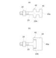
図1、図2は、流体の輸送配管系統に用いられる管接続部の離脱防止構造を示す。この管接続部の離脱防止構造では、一方の管部の一例である流体管1の挿口1Aと他方の管部の一例である流体管2の受口2Aとが嵌合接続部20で接続され、この嵌合接続部20を密封状態で囲繞する分割構造の継ぎ輪30は、両流体管1,2に亘って外装されている。
また、継ぎ輪30と他方の流体管2の受口2A側との管軸芯方向で相対向する部位には、他方の流体管2の受口2Aと継ぎ輪30との一定以上の相対離脱移動を当接阻止する離脱移動阻止手段40が設けられている。
[First embodiment]
1 and 2 show a disconnection prevention structure for a pipe joint used in a fluid transportation piping system. In this disconnection-preventing structure for pipe connection portions, a
In addition, at a portion where the
上述の管接続部の離脱防止構造では、管部として流体管1,2を例に挙げたが、管部としては従来から種々の形態のものが存在する。例えば、図示はしないが、流体管に密封状態で外装固定される分割構造の割T字管の分岐管部や流体管に一体的に突出形成された分岐管部、流体機材の一部を構成する管部等を挙げることができる。
さらに、本実施形態の流体管1,2は、流体の一例である上水を輸送するための水道管を構成するダクタイル鋳鉄管であるが、その他の鋳鉄管や鋼管等を使用することができ、
流体としても、上水以外に工業用水やガス等を挙げることができる。
Although the
Furthermore, the
Examples of fluids include industrial water, gas, etc., in addition to tap water.
一方の流体管1の挿口1Aと他方の流体管2の受口2Aとの嵌合接続部20は、図1~図3に示すように、K形のメカニカル継手から構成されている。このK形のメカニカル継手では、挿口1Aの外周面1aと受口2Aのテーパー状の内周面2aとの間に、ゴム輪等の第1シール部材21が装着されている。この第1シール部材21を管軸芯方向から押圧可能な押圧部22aを備えた分割構造の押輪22が挿口1Aに外装されている。押輪22のフランジ部22bと受口2Aのフランジ部2bとは、T頭ボルト23とナット24で管軸芯方向から締め付け連結されている。この締め付け連結により、受口2Aのフランジ部2bに引き寄せ固定される押輪22の押圧部22aで第1シール部材21が水密状態(密封状態)に圧縮され、その水密状態が維持される。
A
継ぎ輪30は、図2、図3に示すように、両流体管1,2の嵌合接続部20を囲繞する状態で両流体管1,2に亘って外装自在な二分割構造の鋳鉄製の両分割継ぎ輪ケース30A,30Bから構成されている。継ぎ輪30には、受口2Aよりも大径の円筒状の周壁部30aと、周壁部30aの管軸芯方向両端から径方向内方に一体的に延設される円環状の側壁部30b,30cと、各側壁部30b,30cの内径側端部から管軸芯方向に沿って外方に一体的に延設される筒状の管支持部30d,30eとが主要構成として備えられている。
As shown in FIGS. 2 and 3, the
継ぎ輪30の両分割継ぎ輪ケース30A,30Bの管周方向両端部には、図1に示すように、ボルト31・ナット32等の締結手段を介して互いに固定連結するための連結フランジ部30Cが一体形成されている。両分割継ぎ輪ケース30A,30Bの分割面には、継ぎ輪30の内周面30f(図2参照)と嵌合接続部20を含む両流体管1,2の外周面1a,2cとの間に形成される囲繞空間33を外部に対して水密に密封するシール部35(図2参照)が設けられている。
シール部35は、図2、図3に示すように、両分割継ぎ輪ケース30A,30Bの分割面の各々に形成された環状のシール保持溝36に、環状のガスケット等の第2シール部材37を装着して構成されている。両第2シール部材37は、両分割継ぎ輪ケース30A,30Bの管周方向両端部においては管径方向から互いに水密状態で接触し、継ぎ輪30の両管支持部30d,30eにおいては、両流体管1,2の外周面1a,2cに管周方向に沿って水密状態で接触する。
As shown in FIG. 1, connecting
As shown in FIGS. 2 and 3, the
離脱移動阻止手段40は、図2~図4に示すように、継ぎ輪30の管軸芯方向の他端側の管支持部30eの内周面側で、且つ、当該管支持部30eの内周面に形成されたシール保持溝36の管周方向シール溝部分36a及びそれに装着された第2シール部材37の管周方向シール部分37aよりも継ぎ輪30の管軸芯方向中央側に偏位した部位に、受口2Aの外周面2cと管軸芯方向から当接可能な円環状の当接面41aを備えた離脱阻止部41を形成して構成されている。
この離脱阻止部41は、他端側の管支持部30eの内周面において管周方向シール溝部分36aの管軸芯方向両側に位置する区画壁30gの内径よりも小径に形成されている。換言すれば、離脱阻止部41の内周面は、管周方向シール溝部分36aの両側に位置する区画壁30gの内周面よりも径方向内方側に突出形成されているとともに、離脱阻止部41は一方の区画壁30gと一体形成され、離脱阻止部41の当接面41aからシール部35までの管軸芯方向の厚みも大となる補強構造に構成されている。
また、離脱阻止部41の当接面41aは、受口2Aの外周面2cのテーパー状当接部位2dの傾斜角度と同一又は略同一の傾斜角度に形成されている。
As shown in FIGS. 2 to 4, the separation movement prevention means 40 is provided on the inner peripheral surface side of the
The
Further, the
そして、一方の流体管1の挿口1Aと他方の流体管2の受口2Aとの嵌合接続部20に地震や不同沈下等に起因する離脱力が作用したとき、他方の流体管2の受口2Aと継ぎ輪30の他端側の管支持部30eとの間においては、それらの管軸芯方向で相対向する部位に設けた離脱阻止部41の当接面41aと受口2Aの外周面2cのテーパー状当接部位2dとの当接により、他方の流体管2の受口2Aと継ぎ輪30の他端側の管支持部30eとの一定以上の相対離脱移動を当接阻止することができる。
Then, when a detachment force due to an earthquake, differential settlement, or the like acts on the
そのため、本実施形態においては、図2、図3に示すように、嵌合接続部20のT頭ボルト23の先端が、継ぎ輪30の一端側の側壁部30bの内面に当接した状態が初期組付け状態となる。また、図4に示すように、継ぎ輪30の他端側の管支持部30eに形成した離脱阻止部41の当接面41aが受口2Aの外周面2cのテーパー状当接部位2dに当接した状態が最大離脱移動状態となる。
これにより、図4に示すように、初期組付け状態で、のT頭ボルト23の先端位置又は継ぎ輪30の一端側の側壁部30bの内面から最大離脱移動状態にあるT頭ボルト23の先端位置までの距離Lが最大離脱移動距離となり、最大離脱移動状態では、一方の流体管1の挿口1Aと他方の流体管2の受口2Aとが抜け出した離脱状態にある。
Therefore, in this embodiment, as shown in FIGS. 2 and 3, the tip of the T-
As a result, as shown in FIG. 4, in the initial assembly state, the tip of the T-
そして、上述のように、挿口1Aと受口2Aとの嵌合接続部20に地震や不同沈下等に起因する離脱力が作用して、継ぎ輪30の他端側の管支持部30eの内周面側に形成された離脱阻止部41の当接面41aが受口2Aの外周面2cのテーパー状当接部位2dに当接すると、分割構造の継ぎ輪30の分割面を押し開く力が発生する。しかし、本発明では、継ぎ輪30の離脱阻止部41がシール部35の管周方向シール溝部分36aよりも継ぎ輪30の管軸芯方向中央側に偏位した部位に形成されているため、その偏位代の分だけ押し開く力が小さくなり、継ぎ輪30の分割面の押し開きに伴うシール部35の密封性低下(面圧低下)による流体の漏洩発生を抑制することができる。
Then, as described above, the disengagement force caused by an earthquake, uneven subsidence, or the like acts on the
また、図3に示すように、離脱阻止部41の当接位置である当接面41aから他端側の管支持部30eの内周面に形成されたシール保持溝36の管周方向シール溝部分36aまでの距離L1は、一端側の管支持部30dの内周面に形成されたシール保持溝36の管周方向シール溝部分36aにおける管軸芯方向両側の区画壁30hのうち、継ぎ輪30の管軸芯方向中央側となる内方側の区画壁30hにおける管軸芯方向の厚み寸法よりも大に構成されている。
図3に示すように、継ぎ輪30の離脱阻止部41の当接面41aからシール部35の管周方向シール溝部分36aまでの距離L1に相当する厚み寸法が、継ぎ輪30の一端側の管支持部30dにおける管周方向シール溝部分36aの区画壁30hの管軸芯方向での厚み寸法よりも大に構成されているので、受口2Aの外周面2cに当接する離脱阻止部41を頑丈に構成することができる。
Further, as shown in FIG. 3, the pipe circumferential direction seal groove of the
As shown in FIG. 3, the thickness dimension corresponding to the distance L1 from the
さらに、図1~図4に示すように、一方の流体管1と継ぎ輪30の管軸芯方向の一端側の管支持部30dとを一体的に固定連結する補強固定手段の一例である分割構造の耐震補強金具50が設けられている。この耐震補強金具50には、図1に示すように、管周方向で二分割され、且つ、一方の流体管1の挿口1Aに対して管径方向から脱着自在に挟持固定される一対の金属製の分割挟持部材51が備えられている。この一対の分割挟持部材51は、それの管周方向の両端部に設けられたフランジ部51A同士をボルト48・ナット49で締め付け連結することにより、流体管1の挿口1Aに強固に挟持固定される。
Furthermore, as shown in FIGS. 1 to 4, a split pipe which is an example of reinforcing fixing means for integrally fixing and connecting the one
耐震補強金具50には、図2~図4に示すように、継ぎ輪30の一端側の管支持部30dに固定連結される連結部52と、継ぎ輪30の一端側の管支持部30dに対する挿口1Aの離脱移動に連れて挿口1Aの外周面1aとの間での抜止め抵抗が増大する抜止部55とが設けられている。
連結部52は、一端側の管支持部30dの外周面に形成された径方向外方に開口する環状の係合凹部53と、当該係合凹部53に対して管径方向外方側から係脱自在に係合される係合突起54から構成されている。そのうち、係合突起54は、両分割挟持部材51の管周方向の複数個所から管軸芯方向に沿って一体的に突出形成されている。
耐震補強金具50を流体管1の挿口1Aに取付ける場合には、図1、図2に示すように、両分割挟持部材51に一体形成されている係合突起54を、一端側の管支持部30dの係合凹部53に対して管径方向外方側から係合し、この状態で両分割挟持部材51のフランジ部51A同士をボルト48・ナット49で締め付け連結する。
As shown in FIGS. 2 to 4, the earthquake-resistant reinforcing metal fitting 50 includes a connecting
The connecting
When attaching the earthquake-resistant reinforcing metal fitting 50 to the
抜止部55は、図1、図2に示すように、両分割挟持部材51の内周面に形成された径方向内方に向かって開口する爪収納部56と、当該爪収納部56内に管径方向内方に移動自在に収容される爪部材57とを備えている。爪部材57の内面には、挿口1Aの外周面1aに喰い込み可能な管周方向に沿う複数列の先鋭なテーパー状の刃部が形成されている。
爪部材57の外面及び爪収納部56の天井面は、両分割挟持部材51の爪収納部56と挿口1Aの外周面1aに喰い込む状態で爪収納部56内に収納されている爪部材57との管軸芯方向での相対離脱移動に伴って、爪部材57を径方向内方側に食い込み移動させる傾斜面に構成されている。
As shown in FIGS. 1 and 2, the
The outer surface of the
そして、一方の流体管1の挿口1Aと他方の流体管2の受口2Aとの嵌合接続部20に地震や不同沈下等に起因する離脱力が作用したとき、一方の流体管1の挿口1Aと継ぎ輪30との間においては、挿口1Aに設けた分割構造の耐震補強金具50の連結部52が継ぎ輪30の一端側の管支持部30dに固定連結されている。さらに、耐震補強金具50の抜止部55の爪部材57は、継ぎ輪30の一端側の管支持部30dに対する挿口1Aの離脱移動に伴って当該挿口1Aの外周面1aに食い込むことにより抜止め抵抗が増大する。そのため、全体として、一方の流体管1の挿口1Aと継ぎ輪30の一端側の管支持部30dとが耐震補強金具50を介して一体的に強固に固定連結される。
これにより、図4に示すように、挿口1Aと受口2Aとが離脱しても、継ぎ輪30の他端側の管支持部30eに対する受口2Aの抜け出し移動、及び継ぎ輪30の一端側の管支持部30dに対する挿口1Aの抜け出し移動をそれぞれ強固に阻止することができる。
Then, when a detachment force due to an earthquake, uneven settlement, or the like acts on the
As a result, as shown in FIG. 4, even if the
しかも、継ぎ輪30の一端側の管支持部30dと耐震補強金具50の抜止部55とにより、流体管1の挿口1Aにおける管軸芯方向に間隔をおいた二箇所を支持するので、図4に示すように、挿口1Aと受口2Aとが離脱したとき、挿口1Aと継ぎ輪30の一端側の管支持部30dとの屈曲を抑制することができる。
Moreover, since the
さらに、耐震補強金具50の連結部52を構成する係合突起54が、継ぎ輪30の一端側の管支持部30dの外周面に形成された係合凹部53に対して管径方向外方側から係合されているため、挿口1Aと受口2Aとが離脱したとき、一方の流体管1の挿口1Aと継ぎ輪30の一端側の管支持部30dとの屈曲を抑制することができる。これにより、流体管1の挿口1Aと継ぎ輪30の一端側の管支持部30dとの屈曲状態を適正な範囲に維持して、シール部35の周方向での局部的な密封性低下に起因する流体の漏洩を抑制することができる。
〔第2実施形態〕
図5に示す管接続部の離脱防止構造では、一方の流体管1の挿口1Aと他方の流体管2の受口2Aとの嵌合接続部20が、T形のメカニカル継手から構成されている。このT形のメカニカル継手は、受口2Aの内周面に形成した径方向内方に開口する円環状のシール保持溝60に、嵌合接続される挿口1Aの外周面1aとの間で水密状態に圧縮されるゴム輪等の第3シール部材61を装着して構成されている。
尚、その他の構成は、第1実施形態で説明した構成と同一であるから、同一の構成箇所には、第1実施形態と同一の番号を付記してそれの説明は省略する。
Furthermore, the engaging
[Second embodiment]
5, the
Since other configurations are the same as those described in the first embodiment, the same components are denoted by the same reference numerals as in the first embodiment, and the description thereof will be omitted.
〔第3実施形態〕
図6に示す管接続部の離脱防止構造では、一方の流体管1の挿口1Aと他方の流体管2の受口2Aとの嵌合接続部20が、T形のメカニカル継手から構成されている。この管接続部の離脱防止構造において、他方の流体管2の受口2Aと継ぎ輪30との一定以上の相対離脱移動を当接阻止する離脱移動阻止手段40の改良を示す。この実施形態においても、継ぎ輪30の管軸芯方向の他端側の管支持部30eの内周面側で、且つ、当該管支持部30eの内周面に形成されたシール保持溝36の管周方向シール溝部分36a及びそれに装着された第2シール部材37の管周方向シール部分37aよりも継ぎ輪30の管軸芯方向中央側に偏位した部位に、受口2Aの外周面2cのテーパー状当接部位2dと管軸芯方向から当接可能な円環状の当接面41aを備えた離脱阻止部41が形成されている。
[Third embodiment]
In the structure for preventing disconnection of pipe connection portions shown in FIG. 6, the
継ぎ輪30の他端側の管支持部30eの内周面で、且つ、離脱阻止部41よりも継ぎ輪30の管軸芯方向中央側に偏位した部位には、離脱阻止部41の当接面41aが受口2Aの外周面2cのテーパー状当接部位2dに当接した状態で当該受口2Aの外周面2cとの間を密封する環状の弾性シール材43が設けられている。
離脱阻止部41の当接面41a及び弾性シール材43を保持する第2シール保持溝44は、継ぎ輪30の他端側の側壁部30cの内周面に形成され、他端側の側壁部30cの管軸芯方向の厚みは、継ぎ輪30の一端側の側壁部30bの管軸芯方向の厚み(第1実施形態の図2、第2実施形態の図5参照)よりも大に構成されている。
On the inner peripheral surface of the
A second
一方の流体管1の挿口1Aと他方の流体管2の受口2Aとの嵌合接続部20に地震や不同沈下等に起因する離脱力が作用したとき、継ぎ輪30の他端側の管支持部30eの内周面側に形成された離脱阻止部41の当接面41aが受口2Aの外周面2cのテーパー状当接部位2dに当接して、それ以上の両者の離脱移動が阻止される。このとき、離脱阻止部41の当接面41aが当接した受口2Aの外周面2cに形成される粉体塗装等の被覆保護層が損傷するが、離脱阻止部41の当接面41aよりも継ぎ輪30の管軸芯方向中央側に偏位した部位に設けられた弾性シール材43が受口2Aの外周面2cとの間を密封しているため、被覆保護層の損傷個所に流体が流入することがなく、被覆保護層の損傷個所での受口2Aの腐食進行を抑制することができる。
尚、その他の構成は、第2実施形態で説明した構成と同一であるから、同一の構成箇所には、第1実施形態と同一の番号を付記してそれの説明は省略する。
When a detachment force due to an earthquake, differential settlement, or the like acts on the
Since the rest of the configuration is the same as the configuration explained in the second embodiment, the same reference numerals as in the first embodiment are given to the same constituent parts, and the explanation thereof will be omitted.
〔第4実施形態〕
図7に示す管接続部の離脱防止構造では、一方の流体管1の挿口1Aと他方の流体管2の受口2Aとの嵌合接続部20がK形のメカニカル継手から構成されている。この管接続部の離脱防止構造において、他方の流体管2の受口2Aと継ぎ輪30との一定以上の相対離脱移動を当接阻止する離脱移動阻止手段40の改良を示す。
この実施形態の離脱移動阻止手段40は、嵌合接続部20を構成するK形のメカニカル継手の構成部材のうち、管周方向に所定間隔を置いて配置される複数の金属製のT頭ボルト23が、受口2A側に固定される当接部材45に兼用構成され、各T頭ボルト23の頭部23Aの偏平な頂面23aは、当接部材45の当接面45aに構成されている。
[Fourth embodiment]
In the structure for preventing disconnection of pipe connection portions shown in FIG. 7, a
The detachment movement prevention means 40 of this embodiment is a plurality of metal T-head bolts arranged at predetermined intervals in the circumferential direction of the pipe, among the constituent members of the K-shaped mechanical joint that constitutes the
また、継ぎ輪30の管軸芯方向他端側の側壁部30cの内面のうち、各T頭ボルト23の頭部23Aに管軸芯方向で相対向する内面部分が当接面46に構成されている。
この側壁部30cの内面に形成された当接面46と、各T頭ボルト23の頭部23Aの頂面23aをもって構成される当接部材45の当接面45aの各々は、管軸芯に対して直交する直交面に形成されている。
Further, of the inner surface of the
The
一方の流体管1の挿口1Aと他方の流体管2の受口2Aとの嵌合接続部20に地震や不同沈下等に起因する離脱力が作用したとき、継ぎ輪30の他端側の側壁部30cの内面に形成された当接面46と、受口2A側に固定された各T頭ボルト23の頭部23Aの当接面45aをもって構成される当接部材45の当接面45aとが管軸芯方向から面当たりで当接して、それ以上の流体管2の受口2Aと継ぎ輪30との離脱移動が阻止される。この継ぎ輪30の当接面46と、各T頭ボルト23の当接面45aをもって構成される当接部材45の当接面45aとの面当たりにより、離脱力を確実に受け止めて離脱阻止効果を向上することができる。
尚、その他の構成は、第1実施形態で説明した構成と同一であるから、同一の構成箇所には、第1実施形態と同一の番号を付記してそれの説明は省略する。
When a detachment force due to an earthquake, differential settlement, or the like acts on the
Since other configurations are the same as those described in the first embodiment, the same components are denoted by the same reference numerals as in the first embodiment, and the description thereof will be omitted.
また、上述の第4実施形態では、各T頭ボルト23の頭部23Aの偏平な頂面23aを当接部材45の当接面45aに構成したが、図8(a)に示すように、各T頭ボルト23の頭部23Aに、継ぎ輪30の側壁部30cの当接面46と管軸芯方向から当接可能な当接面45aを備えた当接部材45を一体形成して実施してもよい。
この場合も、継ぎ輪30の当接面46と受口2A側の各T頭ボルト23における当接部材45の当接面45aとが管軸芯に対して直交する直交面に形成されている。これにより、継ぎ輪30の当接面46と各T頭ボルト23における当接部材45の当接面45aとが面当たりとなり、離脱力を確実に受け止めて離脱阻止効果を向上することができる。
Further, in the fourth embodiment described above, the flat
In this case also, the
さらに、図8(b)に示すように、各T頭ボルト23の頭部23Aに、継ぎ輪30の側壁部30cの当接面46と管軸芯方向から当接可能な当接面45aを備えた当接部材45をアタッチメントとして嵌合固定して実施してもよい。
この場合も、継ぎ輪30の当接面46と受口2A側の各T頭ボルト23における当接部材45Bの当接面45aとが管軸芯に対して直交する直交面に形成されている。これにより、継ぎ輪30の当接面46と各T頭ボルト23における当接部材45Bの当接面45aとが面当たりとなり、離脱力を確実に受け止めて離脱阻止効果を向上することができる。
Further, as shown in FIG. 8(b), the
In this case also, the
〔第5実施形態〕
図9に示す管接続部の離脱防止構造では、一方の流体管1の挿口1Aと他方の流体管2の受口2Aとの嵌合接続部20がT形のメカニカル継手から構成されている。この管接続部の離脱防止構造において、他方の流体管2の受口2Aと継ぎ輪30との一定以上の相対離脱移動を当接阻止する離脱移動阻止手段40の改良を示す。
この実施形態の離脱移動阻止手段40では、他方の流体管2の受口2A側に固定される当接部材45の一例で、流体管2の受口2Aに対して管径方向外方から挾持固定される分割構造(当該実施形態では二分割構造)の金属製の当接バンド70が用いられる。この当接バンド70には、受口2Aの接続口側の端面に当接する環状の第1位置決め部70bと、受口2Aの外周面2cのテーパー部分に当接する第2位置決め部70cとが設けられている。 そのため、当接バンド70を受口2Aの外周面に締め付け固定した状態では、第1位置決め部70bと第2位置決め部70cとにより当接バンド70の管軸芯方向での移動が阻止されている。
[Fifth Embodiment]
In the disconnection-preventing structure for pipe connection portions shown in FIG. 9, the
In the detachment movement blocking means 40 of this embodiment, an abutting
当接バンド70の第2位置決め部70cの先端面70aが、当接部材45の当接面45aに構成され、継ぎ輪30の管軸芯方向他端側の側壁部30cの内面のうち、当接バンド70の第2位置決め部45cの先端面70aをもって構成される当接面45aに対して管軸芯方向で相対向する内面部分が当接面46に構成されている。
The
この場合も、継ぎ輪30の当接面46と、受口2Aに固定された当接バンド70の先端面70aをもって構成される当接面45aとが管軸芯に対して直交する直交面に形成されている。これにより、継ぎ輪30の当接面46と当接バンド70の当接面45aとが面当たりとなり、離脱力を確実に受け止めて離脱阻止効果を向上することができる。
尚、その他の構成は、第1実施形態で説明した構成と同一であるから、同一の構成箇所には、第2実施形態と同一の番号を付記してそれの説明は省略する。
In this case as well, the
Since other configurations are the same as those described in the first embodiment, the same components are denoted by the same reference numerals as in the second embodiment, and description thereof will be omitted.
〔第6実施形態〕
図10に示す管接続部の離脱防止構造では、一方の流体管1の挿口1Aと他方の流体管2の受口2Aとの嵌合接続部20がK形のメカニカル継手から構成されている。この管接続部の離脱防止構造において、他方の流体管2の受口2Aと継ぎ輪30との一定以上の相対離脱移動を当接阻止する離脱移動阻止手段40の改良を示す。
この実施形態の離脱移動阻止手段40は、他方の流体管2の受口2A側に固定される当接部材45の一例で、受口2Aのフランジ部2bに対して管径方向外方から係合された状態で挾持固定される金属製の受口バンド71が用いられる。この受口バンド71の先端面71aが、当接部材45の当接面45aに構成され、継ぎ輪30の管軸芯方向他端側の側壁部30cの内面のうち、受口バンド71の先端面71aをもって構成される当接面45aに対して管軸芯方向で相対向する内面部分が当接面46に構成されている。
[Sixth embodiment]
In the structure for preventing disconnection of pipe connection portions shown in FIG. 10, the
The detachment movement prevention means 40 of this embodiment is an example of a
この場合も、継ぎ輪30の当接面46と受口2Aに固定された受口バンド71の先端面71aをもって構成される当接面45aの各々は、管軸芯に対して直交する直交面に形成されている。これにより、継ぎ輪30の当接面46と受口バンド71の当接面45aとが面当たりとなり、離脱力を確実に受け止めて離脱阻止効果を向上することができる。
尚、その他の構成は、第1実施形態で説明した構成と同一であるから、同一の構成箇所には、第1実施形態と同一の番号を付記してそれの説明は省略する。
In this case also, each of the abutment surfaces 45a, which are composed of the
Since other configurations are the same as those described in the first embodiment, the same components are denoted by the same reference numerals as in the first embodiment, and the description thereof will be omitted.
〔第7実施形態〕
図11に示す管接続部の離脱防止構造では、一方の流体管1の挿口1Aと他方の流体管2の受口2Aとの嵌合接続部20がK形のメカニカル継手から構成されている。この管接続部の離脱防止構造において、一方の流体管1と継ぎ輪30の管軸芯方向の一端側の管支持部30dとを一体的に固定連結する分割構造の耐震補強金具(補強固定手段の一例)50の改良を示す。
この実施形態の耐震補強金具50では、継ぎ輪30の管軸芯方向の一端側の管支持部30dのうち、それの内周面に形成されたシール保持溝36の管周方向シール溝部分36a及びそれに装着された第2シール部材37の管周方向シール部分37aよりも耐震補強金具50側に位置する端部側に、径方向内方に向かって開口する環状空間を備えた延長管支持部30jが一体形成されている。
[Seventh embodiment]
In the structure for preventing disconnection of pipe connection portions shown in FIG. 11, the
In the earthquake-resistant reinforcing metal fitting 50 of this embodiment, of the
この延長管支持部30jを含む一端側の管支持部30dの外周面に、径方向外方に開口する環状の係合凹部53を形成し、この係合凹部53内のうち、延長管支持部30jに対応する範囲の外端側部位に、耐震補強金具50の両分割挟持部材51に一体形成されている係合突起54を管径方向外方から係合させる。
An
この実施形態の場合は、継ぎ輪30の一端側の管支持部30dに対する耐震補強金具50の係合突起54による係合位置が、管支持部30dの内周面に形成されたシール保持溝36の管周方向シール溝部分36a及びそれに装着された第2シール部材37の管周方向シール部分37aから外端側に離間する。そのため、図4に示すように、挿口1Aと受口2Aとが離脱したとき、挿口1Aと継ぎ輪30の一端側の管支持部30dとの屈曲を抑制することができる。これにより、流体管1の挿口1Aと継ぎ輪30の一端側の管支持部30dとの屈曲状態を適正な範囲に維持して、シール部35の管周方向シール溝部分36aの周方向での局部的な密封性低下に起因する流体の漏洩を抑制することができる。
In the case of this embodiment, the engagement position of the
〔第8実施形態〕
図12に示す管接続部の離脱防止構造では、一方の流体管1の挿口1Aと他方の流体管2の受口2Aとの嵌合接続部20がK形のメカニカル継手から構成されている。この管接続部の離脱防止構造において、他方の流体管2の受口2Aと継ぎ輪30との一定以上の相対離脱移動を当接阻止する離脱移動阻止手段40の改良を示す。
この実施形態の離脱移動阻止手段40では、他方の流体管2の受口2A側に固定される当接部材45の一例で、受口2Aの外周面2cにおけるテーパー状外周面部分2eとストレート状外周面部分2fとに渡る屈曲部位に対して管径方向外方から脱着自在に挾持固定可能な分割構造(当該実施形態では二分割構造)の金属製の挾持リング80が用いられる。この挾持リング80には、管周方向で二分割された半円弧状の分割リング80Aが備えられている。この一対の分割リング80Aは、それの管周方向の両端部に設けられた連結片80B同士をボルト81で締め付け連結することにより、受口2Aの屈曲部位に強固に挟持固定される。
挾持リング80の管軸芯方向の一端面80aは、受口2Aの外周面2cにおけるテーパー状外周面部分2eに面当たり状態で当接するテーパー状端面に構成されている。挾持リング80の管軸芯方向の他端面80bは、分割リング80Aの管軸芯方向の他端面及び連結片80Bの管軸芯方向の他端面を含み、且つ、当接部材45の当接面45aに構成されている。継ぎ輪30の管軸芯方向他端側の側壁部30cの内面は、挾持リング80の他端面80bをもって構成される当接面45aに対して管軸芯方向から当接可能な当接面46に構成されている。継ぎ輪30の側壁部30cの内面をもって構成される当接面46と、挾持リング80の他端面80bをもって構成される当接面45aとは、管軸芯に対して直交する直交面に形成されている。
[Eighth embodiment]
12, the
In the detachment movement blocking means 40 of this embodiment, an
One
そして、一方の流体管1の挿口1Aと他方の流体管2の受口2Aとの嵌合接続部20に地震や不同沈下等に起因する離脱力が作用したとき、継ぎ輪30の他端側の側壁部30cの内面に形成された当接面46が、受口2Aの外周面2cにおける屈曲部位に挾持固定されている挾持リング80の当接面45aに管軸芯方向から当接する。挾持リング80のテーパー状の一端面80aは、受口2Aの外周面2cにおけるテーパー状外周面部分2eに管軸芯方向から面当たり状態で当接し、離脱力を強固に受止めることができる。それでいて、継ぎ輪30の当接面46と挾持リング80の当接面45aとは、管軸芯に対する直交方向に沿った面当たり状態にあるため、当接時に継ぎ輪30に作用する分割接合部の押し開き力を小さくして、継ぎ輪30の分割接合部での密封性低下(第2シール部材37の面圧低下)を抑制することができる。
尚、その他の構成は、第1実施形態で説明した構成と同一であるから、同一の構成箇所には、第1実施形態と同一の番号を付記してそれの説明は省略する。
Then, when a detachment force due to an earthquake or uneven subsidence acts on the
Since other configurations are the same as those described in the first embodiment, the same components are denoted by the same reference numerals as in the first embodiment, and the description thereof will be omitted.
〔その他の実施形態〕
(1)上述の第1実施形態では、図3に示すように、K形のメカニカル継手のT頭ボルト23の先端を、継ぎ輪30の一端側の側壁部30bの内面に当接又は近接させた組付け初期状態において、継ぎ輪30の離脱阻止部41の当接面41aが受口2Aの外周面2cのテーパー状当接部位2dとの間に伸縮代を形成したが、この伸縮代を削減又は少なく構成してもよい。
[Other embodiments]
(1) In the first embodiment described above, as shown in FIG. 3, the tip of the T-
(2)上述の第1実施形態では、継ぎ輪30の他端側の管支持部30eの内周面側に形成された離脱阻止部41の当接面41aを、受口2Aの外周面2cのテーパー状当接部位2dに直接に当接させるように構成したが、離脱阻止部41の当接面41aに弾性体を設けて構成してもよい。
(2) In the above-described first embodiment, the
(3)上述の第1実施形態では、耐震補強金具50の連結部52を、一端側の管支持部30dの外周面に形成された径方向外方に開口する環状の係合凹部53と、当該係合凹部53に対して管径方向外方側から係脱自在に係合される係合突起54から構成したが、この構成に限定されるものではない。例えば、耐震補強金具50の連結部52を、継ぎ輪30の一端側の管支持部30dと両分割挟持部材51とを固定連結するボルト・ナットから構成してもよい。
(3) In the above-described first embodiment, the connecting
1 一方の管部(流体管)
1A 挿口
2 他方の管部(流体管)
2A 受口
2c 外周面
2e テーパー状外周面部分
2f ストレート状外周面部分
20 嵌合接続部
30 継ぎ輪
30c 側壁部
30d 一端側の管支持部
30e 他端側の管支持部
35 シール部
36 シール保持溝
40 離脱移動阻止手段
41 離脱阻止部
41a 当接面
43 弾性シール材
45 当接部材
45a 当接面
50 補強固定手段(耐震補強金具)
52 連結部
53 係合凹部
54 係合突起
55 抜止部
70 当接バンド(当接部材)
71 受口バンド(当接部材)
80 挾持リング(当接部材)
1 One tube (fluid tube)
52 connecting
71 socket band (contact member)
80 clamping ring (abutting member)
Claims (3)
前記離脱移動阻止手段は、前記継ぎ輪の管軸芯方向両端の管支持部のうち、他方の管部側となる他端側の前記管支持部の内周面側で、且つ、他方の管部の外周面との間を密封するシール部よりも前記継ぎ輪の管軸芯方向中央側に偏位した部位に形成された前記受口の外周面と当接可能な離脱阻止部から構成され、
前記離脱阻止部の当接位置から前記シール部のシール保持溝までの距離は、前記継ぎ輪の一端側の管支持部の内周面において、一方の前記管部の外周面との間を密封するシール部のシール保持溝の両区画壁のうち、内方側の前記区画壁における管軸芯方向の厚み寸法よりも大に構成されている管接続部の離脱防止構造 A joint ring having a split structure that encloses the fitting connection between the spigot of one pipe portion and the socket of the other pipe portion in a sealed state is mounted over the two pipe portions. A pipe provided with a detachment prevention means for preventing a relative movement of the socket and the joint ring above a certain level at a portion facing the socket side of the pipe portion in the axial direction of the tube. A detachment prevention structure for a connecting part,
The detachment movement prevention means is provided on the inner peripheral surface side of the pipe support portion on the other end side, which is the other pipe portion side, of the pipe support portions on both ends in the pipe axis direction of the collar ring, and on the other pipe portion side. a detachment preventing portion capable of coming into contact with the outer peripheral surface of the socket formed at a portion deviated toward the central side of the connecting ring in the axial direction of the pipe from the seal portion that seals the gap with the outer peripheral surface of the socket. ,
The distance from the contact position of the detachment preventing portion to the seal holding groove of the seal portion is such that the inner peripheral surface of the tube support portion on the one end side of the coupling ring seals the outer peripheral surface of one of the pipe portions. A structure for preventing disconnection of a pipe connection portion, which is configured to be larger than the thickness dimension in the pipe axis direction of the inner partition wall of both partition walls of the seal holding groove of the seal portion.
前記継ぎ輪の他端側の前記管支持部の内周面で、且つ、前記離脱阻止部よりも前記継ぎ輪の管軸芯方向中央側に偏位した部位には、前記離脱阻止部が前記受口の外周面に当接した状態で当該受口の外周面との間を密封する弾性シール材が設けられている請求項1記載の管接続部の離脱防止構造。 The detachment movement prevention means is provided on the inner peripheral surface side of the tube support portion on the other end side, which is the other tube portion side, of the tube support portions on both ends in the tube axis direction of the ring ring, and on the other tube portion side. Consists of a detachment preventing portion capable of coming into contact with the outer peripheral surface of the socket formed at a portion deviated toward the central side of the connecting ring in the axial direction of the pipe from the seal portion that seals the gap with the outer peripheral surface of the pipe portion. is,
On the inner peripheral surface of the pipe support portion on the other end side of the connecting ring, the detachment preventing portion is provided at a portion deviated from the detachment preventing portion toward the center of the connecting ring in the axial direction of the tube. 2. The structure for preventing disconnection of a pipe connection part according to claim 1, further comprising an elastic sealing material that seals between the outer peripheral surface of the socket while in contact with the outer peripheral surface of the socket.
前記継ぎ輪の管軸芯方向の他端側の前記管支持部の内周面には、管軸芯方向で2つの凹部が形成され、管軸芯方向外方側の前記凹部は、前記シール部のシール保持溝に構成されている請求項1記載の管接続部の離脱防止構造。 sealing between the inner peripheral surface of the tube supporting portion on the other end side, which is the side of the other tube portion, and the outer peripheral surface of the other tube portion among the tube supporting portions on both ends in the tube axis direction of the ring ring ; A seal is provided,
Two recesses are formed in the tube axis direction on the inner peripheral surface of the tube support portion on the other end side in the tube axis direction of the collar ring. 2. The structure for preventing disconnection of a pipe connecting portion according to claim 1, wherein the seal holding groove is formed in the portion.
Priority Applications (2)
| Application Number | Priority Date | Filing Date | Title |
|---|---|---|---|
| JP2022055639A JP7326524B2 (en) | 2017-12-19 | 2022-03-30 | Separation prevention structure for pipe connections |
| JP2023126341A JP2023145677A (en) | 2017-12-19 | 2023-08-02 | Separation prevention structure of pipe connection part |
Applications Claiming Priority (2)
| Application Number | Priority Date | Filing Date | Title |
|---|---|---|---|
| JP2017242477A JP7051417B2 (en) | 2017-12-19 | 2017-12-19 | Detachment prevention structure for pipe connection |
| JP2022055639A JP7326524B2 (en) | 2017-12-19 | 2022-03-30 | Separation prevention structure for pipe connections |
Related Parent Applications (1)
| Application Number | Title | Priority Date | Filing Date |
|---|---|---|---|
| JP2017242477A Division JP7051417B2 (en) | 2017-12-19 | 2017-12-19 | Detachment prevention structure for pipe connection |
Related Child Applications (1)
| Application Number | Title | Priority Date | Filing Date |
|---|---|---|---|
| JP2023126341A Division JP2023145677A (en) | 2017-12-19 | 2023-08-02 | Separation prevention structure of pipe connection part |
Publications (3)
| Publication Number | Publication Date |
|---|---|
| JP2022091914A JP2022091914A (en) | 2022-06-21 |
| JP2022091914A5 JP2022091914A5 (en) | 2022-07-05 |
| JP7326524B2 true JP7326524B2 (en) | 2023-08-15 |
Family
ID=87563229
Family Applications (2)
| Application Number | Title | Priority Date | Filing Date |
|---|---|---|---|
| JP2022055639A Active JP7326524B2 (en) | 2017-12-19 | 2022-03-30 | Separation prevention structure for pipe connections |
| JP2023126341A Pending JP2023145677A (en) | 2017-12-19 | 2023-08-02 | Separation prevention structure of pipe connection part |
Family Applications After (1)
| Application Number | Title | Priority Date | Filing Date |
|---|---|---|---|
| JP2023126341A Pending JP2023145677A (en) | 2017-12-19 | 2023-08-02 | Separation prevention structure of pipe connection part |
Country Status (1)
| Country | Link |
|---|---|
| JP (2) | JP7326524B2 (en) |
Citations (3)
| Publication number | Priority date | Publication date | Assignee | Title |
|---|---|---|---|---|
| JP2001187996A (en) | 1999-12-28 | 2001-07-10 | Suido Gijutsu Kaihatsu Kiko:Kk | Reinforcing joint for pipe connection part |
| JP2008082418A (en) | 2006-09-27 | 2008-04-10 | Cosmo Koki Co Ltd | Packing |
| JP2016138637A (en) | 2015-01-29 | 2016-08-04 | コスモ工機株式会社 | Pipe fitting structure |
Family Cites Families (7)
| Publication number | Priority date | Publication date | Assignee | Title |
|---|---|---|---|---|
| JPS5540797B2 (en) * | 1973-11-19 | 1980-10-20 | ||
| JPS609511Y2 (en) * | 1980-03-13 | 1985-04-03 | 三菱樹脂株式会社 | pipe fittings |
| JPS59116685U (en) * | 1983-01-28 | 1984-08-07 | 三菱電機株式会社 | Fluid piping joint sealing device |
| JPH0139984Y2 (en) * | 1984-10-05 | 1989-11-30 | ||
| JPH0914569A (en) * | 1995-06-27 | 1997-01-17 | Tokyo Gas Co Ltd | Earthquake resistant reinforcing device for life line pipe conduit |
| JP3359510B2 (en) * | 1996-10-24 | 2002-12-24 | 株式会社クボタ | Seismic structure of pipe joints |
| KR200314162Y1 (en) * | 2002-11-08 | 2003-05-23 | 진원개발 주식회사 | Device for preventing a leakage of water |
-
2022
- 2022-03-30 JP JP2022055639A patent/JP7326524B2/en active Active
-
2023
- 2023-08-02 JP JP2023126341A patent/JP2023145677A/en active Pending
Patent Citations (3)
| Publication number | Priority date | Publication date | Assignee | Title |
|---|---|---|---|---|
| JP2001187996A (en) | 1999-12-28 | 2001-07-10 | Suido Gijutsu Kaihatsu Kiko:Kk | Reinforcing joint for pipe connection part |
| JP2008082418A (en) | 2006-09-27 | 2008-04-10 | Cosmo Koki Co Ltd | Packing |
| JP2016138637A (en) | 2015-01-29 | 2016-08-04 | コスモ工機株式会社 | Pipe fitting structure |
Also Published As
| Publication number | Publication date |
|---|---|
| JP2022091914A (en) | 2022-06-21 |
| JP2023145677A (en) | 2023-10-11 |
Similar Documents
| Publication | Publication Date | Title |
|---|---|---|
| JP6948372B2 (en) | Pipe fitting | |
| US3432189A (en) | Flexmaster end restraint | |
| JP7051417B2 (en) | Detachment prevention structure for pipe connection | |
| TWI629426B (en) | Fitting having retainer or apertures for connecting pipe elements and method of joining pipe elements | |
| KR101916892B1 (en) | Fast groove joint | |
| EP1394460A1 (en) | Flexible pipe joint | |
| JP2016138637A (en) | Pipe fitting structure | |
| JP2024012556A (en) | Separation prevention structure of pipe connection portion | |
| GB2167145A (en) | Pipe couplings | |
| JP7326524B2 (en) | Separation prevention structure for pipe connections | |
| JP2001330185A (en) | Aseismatic joint and aseismatic pipeline | |
| JP7013283B2 (en) | Detachment prevention structure for pipe connection | |
| CN113939682B (en) | Detachment prevention structure for pipe connection part | |
| US5360238A (en) | Pipe couplings | |
| JP2005090605A (en) | Piping connector | |
| JP3380526B2 (en) | Conduit connection device | |
| KR102177099B1 (en) | Pipe Connecting Device for Earthquake-Proof using Elastic space ring | |
| JP3939100B2 (en) | Earthquake resistant joints and earthquake resistant pipelines | |
| JP7427322B2 (en) | Pipe fitting separation prevention structure | |
| JPH0113900Y2 (en) | ||
| JPS6139916Y2 (en) | ||
| JP7054518B2 (en) | Detachment prevention pipe joint and method to prevent disengagement of pipe joint | |
| JP3569101B2 (en) | Seismic connection structure for buried piping | |
| JPH0569480U (en) | Pipe fitting | |
| JP4089794B2 (en) | Pipe connection device |
Legal Events
| Date | Code | Title | Description |
|---|---|---|---|
| A621 | Written request for application examination |
Free format text: JAPANESE INTERMEDIATE CODE: A621 Effective date: 20220330 |
|
| A521 | Request for written amendment filed |
Free format text: JAPANESE INTERMEDIATE CODE: A523 Effective date: 20220624 |
|
| A977 | Report on retrieval |
Free format text: JAPANESE INTERMEDIATE CODE: A971007 Effective date: 20230216 |
|
| A131 | Notification of reasons for refusal |
Free format text: JAPANESE INTERMEDIATE CODE: A131 Effective date: 20230222 |
|
| A521 | Request for written amendment filed |
Free format text: JAPANESE INTERMEDIATE CODE: A523 Effective date: 20230405 |
|
| TRDD | Decision of grant or rejection written | ||
| A01 | Written decision to grant a patent or to grant a registration (utility model) |
Free format text: JAPANESE INTERMEDIATE CODE: A01 Effective date: 20230705 |
|
| A61 | First payment of annual fees (during grant procedure) |
Free format text: JAPANESE INTERMEDIATE CODE: A61 Effective date: 20230802 |
|
| R150 | Certificate of patent or registration of utility model |
Ref document number: 7326524 Country of ref document: JP Free format text: JAPANESE INTERMEDIATE CODE: R150 |