JP7326341B2 - Medical probe with staggered microelectrode arrangement - Google Patents
Medical probe with staggered microelectrode arrangement Download PDFInfo
- Publication number
- JP7326341B2 JP7326341B2 JP2020564040A JP2020564040A JP7326341B2 JP 7326341 B2 JP7326341 B2 JP 7326341B2 JP 2020564040 A JP2020564040 A JP 2020564040A JP 2020564040 A JP2020564040 A JP 2020564040A JP 7326341 B2 JP7326341 B2 JP 7326341B2
- Authority
- JP
- Japan
- Prior art keywords
- spine
- microelectrodes
- spines
- microelectrode
- distal
- Prior art date
- Legal status (The legal status is an assumption and is not a legal conclusion. Google has not performed a legal analysis and makes no representation as to the accuracy of the status listed.)
- Active
Links
Images


Classifications
-
- A—HUMAN NECESSITIES
- A61—MEDICAL OR VETERINARY SCIENCE; HYGIENE
- A61B—DIAGNOSIS; SURGERY; IDENTIFICATION
- A61B5/00—Measuring for diagnostic purposes; Identification of persons
- A61B5/24—Detecting, measuring or recording bioelectric or biomagnetic signals of the body or parts thereof
- A61B5/25—Bioelectric electrodes therefor
- A61B5/279—Bioelectric electrodes therefor specially adapted for particular uses
- A61B5/28—Bioelectric electrodes therefor specially adapted for particular uses for electrocardiography [ECG]
- A61B5/283—Invasive
- A61B5/287—Holders for multiple electrodes, e.g. electrode catheters for electrophysiological study [EPS]
-
- A—HUMAN NECESSITIES
- A61—MEDICAL OR VETERINARY SCIENCE; HYGIENE
- A61B—DIAGNOSIS; SURGERY; IDENTIFICATION
- A61B5/00—Measuring for diagnostic purposes; Identification of persons
- A61B5/68—Arrangements of detecting, measuring or recording means, e.g. sensors, in relation to patient
- A61B5/6846—Arrangements of detecting, measuring or recording means, e.g. sensors, in relation to patient specially adapted to be brought in contact with an internal body part, i.e. invasive
- A61B5/6847—Arrangements of detecting, measuring or recording means, e.g. sensors, in relation to patient specially adapted to be brought in contact with an internal body part, i.e. invasive mounted on an invasive device
- A61B5/6852—Catheters
- A61B5/6859—Catheters with multiple distal splines
Description
(優先権)
本出願は、先に2018年2月6日に出願された、「CATHETER WITH INCREASED ELECTRODE DENSITY SPINE ASSEMBLY HAVING REINFORCED SPINE COVERS(「強化されたスパインカバーを有する、電極密度の高いスパインアセンブリを有するカテーテル」)」と題する米国特許出願第15/890318号(代理人整理番号BIO5891USNP)の一部継続出願として、米国特許法第120条の下での利益を主張し、参照により、本出願に完全に記載されているかのように本出願に組み込まれる。
(priority)
This application is entitled "CATHETER WITH INCREASED ELECTRODE DENSITY SPINE ASSEMBLY HAVING REINFORCED SPINE COVERS" previously filed on February 6, 2018. 15/890,318 (Attorney Docket No. BIO5891USNP), entitled "Attorney Docket No. BIO5891USNP", which claims benefit under 35 U.S.C. incorporated into this application as if
電極カテーテルは、長年にわたり医療現場で一般的に使用されている。電極カテーテルは心臓内の電気的活動を刺激及びマッピングし、異常な電気的活動が見られる部位をアブレーションするために用いられる。 Electrode catheters have been in common use in medical practice for many years. Electrode catheters are used to stimulate and map electrical activity within the heart and to ablate areas of abnormal electrical activity.
使用にあたり、微小電極カテーテルは、主要な静脈又は動脈、例えば大腿静脈の中に挿入され、次いで対象となる心房/心室の中に案内される。カテーテルが心臓内に配置された後、心臓内の異常な電気的活動の場所が特定される。 In use, the microelectrode catheter is inserted into a major vein or artery, such as the femoral vein, and then guided into the atrium/ventricle of interest. After the catheter is placed in the heart, the location of abnormal electrical activity within the heart is identified.
位置特定の1つの技術は電気生理学的マッピング手順を含み、この手順によって導電性の心臓内組織から生じる電気信号が組織的に監視され、それらの信号のマップが形成される。医師は、そのマップを解析することによって、干渉する電気経路を特定することができる。導電性心組織からの電気信号をマッピングするための従来の方法は、その遠位先端上にマッピング微小電極が搭載された電気生理学カテーテル(電極カテーテル)を、経皮的に導入することである。カテーテルは、これらの微小電極を心内膜に接触させて設置するように操作される。心内膜における電気信号を監視することによって、不整脈の原因である異常な導電性組織部位を正確に示すことができる。 One technique of localization involves an electrophysiological mapping procedure, which systematically monitors electrical signals emanating from conductive intracardiac tissue and forms a map of those signals. A physician can identify interfering electrical pathways by analyzing the map. A conventional method for mapping electrical signals from conductive cardiac tissue is the percutaneous introduction of an electrophysiology catheter (electrode catheter) with a mapping microelectrode mounted on its distal tip. A catheter is manipulated to place these microelectrodes in contact with the endocardium. By monitoring electrical signals in the endocardium, abnormally conductive tissue sites that are responsible for the arrhythmia can be pinpointed.
カテーテルに搭載されたリング微小電極による感知のために、リング微小電極からの信号を送信するリード線が、カテーテル制御ハンドルの遠位端において適切なコネクタに電気的に接続され、それは、ECG監視システム及び/又は適切な3-D電気生理学的(EP)マッピングシステム、例えば、カリフォルニア州アーウィンデールのBiosense Webster社から入手可能なCARTO、CARTO XP又はCARTO3等に電気的に接続される。 For sensing by the ring microelectrodes mounted on the catheter, the leads carrying the signals from the ring microelectrodes are electrically connected to suitable connectors at the distal end of the catheter control handle, which is the ECG monitoring system. and/or electrically connected to a suitable 3-D electrophysiological (EP) mapping system, such as CARTO, CARTO XP or CARTO3 available from Biosense Webster of Irwindale, CA.
より小さく、しかも互いにより近接して配置された微小電極対は、遠距離場の信号に対する近距離場の電位のより正確な検出を可能にし、このことは、心臓の特定領域の治療を試みる際に非常に重要であり得る。例えば、近距離場の肺静脈電位は極めて小さい信号であり、一方で心房は、肺静脈に極めて近接する場所にあり、遙かに大きい信号を提供する。したがって、カテーテルが肺静脈の領域内に配置される場合であっても、信号が、小さく、近い場所(肺静脈から)の電位、又はより大きく、より遠い場所(心房から)の電位のいずれであるかを、電気生理学者が判定することは、困難である場合がある。より小さく、しかも互いに近接して配置された双極子により、医師は、遠距離場の信号をより正確に除去し、局所組織における電気的活動をより正確に読み取ることが可能になる。したがって、より小さく、しかも互いに近接して配置される微小電極を有することによって、肺動脈電位を有する心筋組織の場所を、正確に標的とすることが可能であるため、臨床医は、その特定の組織に治療を施すことが可能になる。更には、より小さく、しかも互いに近接して配置される微小電極により、医師は、電気信号によって、小孔/複数の小孔の正確な解剖学的場所を判定することが可能になる。 Microelectrode pairs that are smaller and placed closer together allow for more accurate detection of near-field potentials relative to far-field signals, which is useful when attempting to treat specific regions of the heart. can be very important to For example, the near-field pulmonary vein potential is a very small signal, while the atrium, which is in close proximity to the pulmonary veins, provides a much larger signal. Therefore, even if the catheter is placed in the region of the pulmonary veins, the signal may be at either a small, near-field potential (from the pulmonary veins) or a larger, more distant potential (from the atria). It can be difficult for an electrophysiologist to determine if there is. Dipoles that are smaller and placed closer together allow the physician to more accurately filter out far-field signals and more accurately read electrical activity in local tissue. Thus, by having microelectrodes that are smaller and placed closer together, it is possible to precisely target the location of myocardial tissue that has a pulmonary artery potential, allowing the clinician to focus on that particular tissue. can be treated. Furthermore, microelectrodes that are smaller and placed closer together allow the physician to determine the precise anatomical location of the ostium/ostia by means of electrical signals.
微小電極密度を増加させる(例えば、カテーテル上に担持される複数個の微小電極の数を増加させる)ことによっても、検出精度が改善される。しかしながら、より多くの微小電極がカテーテル上に担持されると、特に、微小電極密度が高くなればなるほど、微小電極どうしが接触したり短絡したりするリスクが増大する。更に、微小電極と組織とを確実に接触させることができるが、微小電極保持構造体が制御可能かつ予測可能な様式で挙動して、組織に穿孔したりあるいは組織を損傷したりすることがない、高い可撓性を有する微小電極アセンブリ構造を用いて、微小電極と組織との接触を改善することが常に望まれている。これらの構造体を構築するために使用される材料が、より可撓性の高いものとなり、かつより繊細なものとなるにつれて、カテーテルを組み立てる最中に、より小さいリング微小電極及びそれらの支持構造体が変形、とりわけ伸長するリスクが増大する。更に、微小電極アセンブリ構造体がより繊細なものとなるにつれて、コンポーネントが外れたり、よじれたり、及びもつれたりするリスクが増大する。 Increasing the microelectrode density (eg, increasing the number of multiple microelectrodes carried on the catheter) also improves detection accuracy. However, as more microelectrodes are carried on the catheter, especially at higher microelectrode densities, the risk of microelectrodes touching or shorting together increases. Further, contact between the microelectrode and tissue can be ensured, but the microelectrode holding structure behaves in a controllable and predictable manner without perforating or damaging tissue. There is a constant desire to improve microelectrode-tissue contact using highly flexible microelectrode assembly structures. As the materials used to build these structures become more flexible and more delicate, smaller ring microelectrodes and their supporting structures are required during catheter assembly. Increased risk of body deformation, especially elongation. Furthermore, as microelectrode assembly structures become more delicate, the risk of components becoming dislodged, kinked and entangled increases.
したがって、互いに近接して配置された微小電極を有し、高い微小電極密度を実現した電気生理学カテーテルが必要とされている。また、そのつくりが繊細で、所望の可撓性を提供しながらも、組織との接触時の動きが予測可能である微小電極保持構造体を有する、電気生理学カテーテルが必要とされている。コンポーネントが外れたり、よじれたり、及びもつれたりするリスクを最小限に抑えるように構築され、スパイン構造を補強して、変形(軟らかいスパインカバー及びその上に担持された微小電極の伸長を含む)を最小限に抑えるように構築される、電気生理学カテーテルが更に必要とされている。 Therefore, there is a need for an electrophysiology catheter that has microelectrodes that are placed in close proximity to each other to achieve high microelectrode density. There is also a need for an electrophysiology catheter having a microelectrode-holding structure that is delicately constructed to provide the desired flexibility, yet has predictable movement upon contact with tissue. Constructed to minimize the risk of components becoming dislodged, kinked and tangled, the spine structure is reinforced to prevent deformation (including elongation of the soft spine cover and the microelectrodes carried thereon). There is a further need for electrophysiology catheters that are constructed to be minimal.
本発明は、遠距離場の信号を含む望ましくないノイズの検出を最小限として複数の場所で同時に信号を検出するために組織表面領域上に柔軟に広がることが可能な複数の放射状に広がるスパインに、非常に小型で、互いに近接して配置された微小電極を担持している遠位微小電極アセンブリを備える電気生理学カテーテルに関する。遠位微小電極アセンブリは、心臓の心房空洞内の組織の様々に異なる解剖学的構造に適合するように構成されている。スパインは、異なる組織表面に対して広範囲に適合するために、湾曲セグメントを有するか、又は直線的セグメントとともに湾曲セグメントを有する。一方でスパインは、より良好に組織と接触するのを容易にする、改善された可撓性及び剛性を得るために、別個のセグメントにおいて、機械的な有利点を提供する。各スパインは、スパインどうしの接触又は交絡のリスクを最小限に抑えながら、柔軟性特性を改善するために、より強固でより剛性の高い近位側基部とより可撓性の高い遠位端とを提供する。そのために、各スパインは、その近位端からその遠位端まで概ね先細になった形状を有する。 The present invention incorporates multiple radially extending spines that can be flexibly spread over a tissue surface area to detect signals at multiple locations simultaneously with minimal detection of unwanted noise, including far-field signals. , relates to an electrophysiology catheter comprising a distal microelectrode assembly carrying microelectrodes that are very compact and arranged in close proximity to each other. The distal microelectrode assembly is configured to conform to different anatomy of tissue within the atrial cavity of the heart. The spine has curved segments, or curved segments along with straight segments, to accommodate a wide range of different tissue surfaces. The spine, on the other hand, provides mechanical advantages in separate segments for improved flexibility and stiffness that facilitates better tissue contact. Each spine has a stronger, stiffer proximal base and a more flexible distal end for improved flexibility characteristics while minimizing the risk of spine-to-spine contact or entanglement. I will provide a. To that end, each spine has a generally tapered shape from its proximal end to its distal end.
一部の実施形態では、電気生理学カテーテルは、細長い本体と遠位微小電極アセンブリとを有する。遠位微小電極アセンブリは、近位側ステムと、ステムから発する複数のスパインと、それぞれがそれぞれ対応するスパインを取り囲む複数の非導電性スパインカバーとを有し、各スパインカバーは、カバーの側壁に埋め込まれた複数の引張部材を有する。 In some embodiments, an electrophysiology catheter has an elongated body and a distal microelectrode assembly. The distal microelectrode assembly has a proximal stem, a plurality of spines emanating from the stem, and a plurality of non-conductive spine covers, each surrounding a respective spine, each spine cover attached to a side wall of the cover. It has a plurality of tension members embedded therein.
一部の実施形態では、引張部材は、長手方向に延在する。 In some embodiments, the tension member extends longitudinally.
一部の実施形態では、引張部材は、長手方向に延在する部分を有する。 In some embodiments, the tension member has a longitudinally extending portion.
一部の実施形態では、引張部材はワイヤを含む。 In some embodiments the tension member comprises a wire.
一部の実施形態では、引張部材は繊維を含む。 In some embodiments, the tension members comprise fibers.
一部の実施形態では、電気生理学カテーテルは、細長い本体と遠位微小電極アセンブリとを有する。遠位微小電極アセンブリは、近位側ステム及び複数のスパインを有し、各スパインは、拡大された遠位部分を有し、拡大された遠位部分は貫通孔を有する。遠位微小電極アセンブリはまた、それぞれがそれぞれ対応するスパインを取り囲む、複数の非導電性スパインカバーを有する。遠位微小電極アセンブリは、拡大された遠位部分を封入するキャップカバーを更に有し、キャップカバーは、貫通孔を通って延在する部分を有する。 In some embodiments, an electrophysiology catheter has an elongated body and a distal microelectrode assembly. The distal microelectrode assembly has a proximal stem and a plurality of spines, each spine having an enlarged distal portion, the enlarged distal portion having a through hole. The distal microelectrode assembly also has a plurality of non-conductive spine covers, each surrounding a respective spine. The distal microelectrode assembly further has a cap cover enclosing the enlarged distal portion, the cap cover having a portion extending through the throughbore.
一部の実施形態では、電気生理学カテーテルは、細長い本体と遠位微小電極アセンブリとを有する。遠位微小電極アセンブリは、近位側ステムと、複数の、少なくとも8つのスパインとを有し、各スパインは、第1の半径によって画定された第1の予め成形された湾曲を有する第1の区域と、直線的区域とを有する。遠位微小電極アセンブリはまた、複数の非導電性スパインカバーと、複数の微小電極とを有し、各スパイン上には、少なくとも1つの微小電極を有する。 In some embodiments, an electrophysiology catheter has an elongated body and a distal microelectrode assembly. The distal microelectrode assembly has a proximal stem and a plurality of at least eight spines, each spine having a first preshaped curvature defined by a first radius. It has an area and a rectilinear area. The distal microelectrode assembly also has a plurality of non-conductive spine covers and a plurality of microelectrodes, with at least one microelectrode on each spine.
一部の実施形態では、各スパインは、第1の半径とは異なる第2の半径によって画定される第2の予め成形された湾曲を有する第2の区域を含み、第2の予め成形された湾曲を有する第2の区域は、第1の予め成形された湾曲を有する第1の区域の遠位側にある。 In some embodiments, each spine includes a second section having a second pre-shaped curvature defined by a second radius that is different than the first radius; The second section with curvature is distal to the first section with the first pre-shaped curvature.
一部の実施形態において、第1の半径は第2の半径よりも小さい。 In some embodiments, the first radius is smaller than the second radius.
一部の実施形態では、第2の予め成形された湾曲は、第1の予め成形された湾曲とは反対側である。 In some embodiments, the second pre-shaped curve is opposite the first pre-shaped curve.
一部の実施形態では、第2の予め成形された湾曲を有する第2の区域は、第1の予め成形された曲率を有する第1の区域の遠位側にある。 In some embodiments, the second section with the second pre-shaped curvature is distal to the first section with the first pre-shaped curvature.
一部の実施形態では、直線的区域は、第1の予め成形された湾曲を有する第1の区域と、第2の予め成形された湾曲を有する第2の区域との間にある。 In some embodiments, the straight section is between a first section having a first pre-shaped curvature and a second section having a second pre-shaped curvature.
一部の実施形態では、直線的区域を有する第2の区域は、第2の予め成形された湾曲を有する第2の区域の遠位側にある。 In some embodiments, the second section having the straight section is distal to the second section having the second pre-shaped curve.
一部の実施形態では、各カバーされたスパインは、3フレンチ未満の外周を有する。 In some embodiments, each covered spine has a perimeter of less than 3 French.
一部の実施形態では、外周は、約2.6フレンチである。 In some embodiments, the circumference is about 2.6 French.
一部の実施形態では、電気生理学カテーテルは、細長い本体と、遠位微小電極アセンブリとを有する。遠位微小電極アセンブリは、近位側部分と、複数のスパインとを有し、各スパインは、より広い近位端とより狭い遠位端とを有する直線的テーパを有する。遠位微小電極アセンブリはまた、複数の非導電性スパインカバーを有し、それぞれの非導電性スパインカバーが、それぞれ対応するスパインを取り囲んでいる。 In some embodiments, an electrophysiology catheter has an elongated body and a distal microelectrode assembly. The distal microelectrode assembly has a proximal portion and a plurality of spines, each spine having a linear taper with a wider proximal end and a narrower distal end. The distal microelectrode assembly also has a plurality of non-conductive spine covers, each non-conductive spine cover surrounding a respective spine.
一部の実施形態では、直線的テーパは連続的である。 In some embodiments, the linear taper is continuous.
一部の実施形態では、直線的テーパは非連続的である。 In some embodiments, the linear taper is discontinuous.
一部の実施形態では、非連続的な直線的テーパは、より近位側のステムの幅及びより遠位側の部分の幅よりも狭い幅を有する凹部を含む。 In some embodiments, the discontinuous linear taper includes a recess having a width that is less than the width of the more proximal stem and the width of the more distal portion.
一部の実施形態では、スパインは、スパインの面内偏向のために構成され、横方向縁部に沿ったヒンジを有する。 In some embodiments, the spine is configured for in-plane deflection of the spine and has hinges along the lateral edges.
一部の実施形態では、電気生理学カテーテルは、細長い本体と遠位微小電極アセンブリとを有する。遠位微小電極アセンブリは、近位側ステムと、複数の少なくとも8本のスパインと、を有し、各スパインは、より広い近位端とより狭い遠位端とを有する直線的テーパを有する。遠位電極アセンブリはまた、複数の非導電性スパインカバーを有し、各非導電性カバーは、それぞれ対応するスパインを取り囲んでいる。遠位微小電極アセンブリは、複数の微小電極を更に有し、その個数は少なくとも約48であり、各微小電極は約480μmの長さを有する。 In some embodiments, an electrophysiology catheter has an elongated body and a distal microelectrode assembly. The distal microelectrode assembly has a proximal stem and a plurality of at least eight spines, each spine having a linear taper with a wider proximal end and a narrower distal end. The distal electrode assembly also has a plurality of non-conductive spine covers, each non-conductive cover surrounding a respective spine. The distal microelectrode assembly further has a plurality of microelectrodes, the number of which being at least about 48, and each microelectrode having a length of about 480 μm.
一部の実施形態では、各スパイン上の微小電極どうしは、微小電極の前縁部どうしの間で測定したときに、約1mm~3mmの範囲の距離だけ分離されている。 In some embodiments, the microelectrodes on each spine are separated by a distance in the range of about 1 mm to 3 mm, measured between the leading edges of the microelectrodes.
一部の実施形態において、上記の距離は約2mmである。 In some embodiments, the distance is approximately 2 mm.
一部の実施形態では、各スパイン上の微小電極は双極子対として配置され、1つの対内の微小電極の前縁部どうしは、約1mm~3mmの範囲の第1の距離だけ分離され、対どうしの間の前側の微小電極の前縁部どうしは、1mm~6mmの範囲の第2の距離だけ分離されている。 In some embodiments, the microelectrodes on each spine are arranged as dipole pairs, the leading edges of the microelectrodes within a pair are separated by a first distance ranging from about 1 mm to 3 mm, and The front edges of the front microelectrodes therebetween are separated by a second distance ranging from 1 mm to 6 mm.
一部の実施形態では、第1の距離は約2mmであり、第2の距離は約6mmである。 In some embodiments, the first distance is approximately 2 mm and the second distance is approximately 6 mm.
一部の実施形態では、複数の微小電極の数は、約64に等しい。 In some embodiments, the number of microelectrodes in the plurality is equal to about 64.
一部の実施形態では、複数の微小電極の数は、約72に等しい。 In some embodiments, the number of microelectrodes in the plurality is equal to about 72.
一部の実施形態では、第1のリング微小電極が、遠位微小電極アセンブリの近位側ステム上に担持され、第2のリング微小電極及び第3のリング微小電極が、細長い本体の遠位部分上に担持される。 In some embodiments, a first ring microelectrode is carried on the proximal stem of the distal microelectrode assembly, and a second ring microelectrode and a third ring microelectrode are distal to the elongated body. carried on the part.
一部の実施形態では、電気生理学カテーテルは、細長い本体と、遠位微小電極アセンブリとを有する。遠位微小電極アセンブリは、長手方向軸線の周りに外周部を画定する近位側ステムを有する。遠位微小電極アセンブリはまた、近位側ステムから出て、それらの遠位端で放射状に広がる複数のスパインを有し、複数のスパインは、ステムの周りの周囲で、第1のスパインと第2のスパインとが交互になっている。遠位微小電極アセンブリは、複数の非導電性スパインカバーと、複数の微小電極とを更に有する。各スパインカバーはそれぞれ対応するスパインを取り囲み、複数の微小電極は、第1のスパイン及び第2のスパイン上に互い違い配列される。各第1のスパイン上の最も近位側の微小電極が、近位側ステムから、より大きな距離に位置付けられ、各第2のスパイン上の最も近位側の微小電極が、近位側ステムからの距離がより短い距離に位置付けられている。 In some embodiments, an electrophysiology catheter has an elongated body and a distal microelectrode assembly. The distal microelectrode assembly has a proximal stem defining a perimeter about the longitudinal axis. The distal microelectrode assembly also has a plurality of spines emanating from the proximal stem and radiating at their distal end, the plurality of spines being circumferentially arranged around the stem, a first spine and a first spine. 2 spines alternate. The distal microelectrode assembly further has a plurality of non-conductive spine covers and a plurality of microelectrodes. Each spine cover surrounds a respective spine, and the plurality of microelectrodes are staggered on the first spine and the second spine. The proximal-most microelectrode on each first spine is positioned at a greater distance from the proximal stem and the proximal-most microelectrode on each second spine is located at a greater distance from the proximal stem. is positioned at the shorter distance.
一部の実施形態では、遠位微小電極アセンブリは、少なくとも4本の第1のスパインと、4本の第2のスパインとを備え、各スパインは8個の微小電極を担持する。 In some embodiments, the distal microelectrode assembly comprises at least four first spines and four second spines, each spine carrying eight microelectrodes.
一部の実施形態では、各微小電極は、約480μmの長さを有する。 In some embodiments, each microelectrode has a length of about 480 μm.
一部の実施形態では、各スパイン上の微小電極どうしは、微小電極の前縁部どうしの間で測定したときに、約1mm~3mmの範囲の距離だけ分離されている。 In some embodiments, the microelectrodes on each spine are separated by a distance in the range of about 1 mm to 3 mm, measured between the leading edges of the microelectrodes.
一部の実施形態において、上記の距離は約2mmである。 In some embodiments, the distance is approximately 2 mm.
一部の実施形態では、各スパイン上の微小電極は双極子対として配置され、1つの対内の微小電極の前縁部どうしは、約1mm~3mmの範囲の第1の距離だけ分離され、対どうしの間の前側の微小電極の前縁部どうしは、1mm~6mmの範囲の第2の距離だけ分離されている。 In some embodiments, the microelectrodes on each spine are arranged as dipole pairs, the leading edges of the microelectrodes within a pair are separated by a first distance ranging from about 1 mm to 3 mm, and The front edges of the front microelectrodes therebetween are separated by a second distance ranging from 1 mm to 6 mm.
一部の実施形態では、第1の距離は約2mmであり、第2の距離は約6mmである。 In some embodiments, the first distance is approximately 2 mm and the second distance is approximately 6 mm.
一部の実施形態では、電気生理学カテーテルは、細長い本体と遠位微小電極アセンブリとを有する。遠位微小電極アセンブリは、側壁を有する近位側ステムを有する。その側壁は、内腔を画定する内側表面を有し、かつ開口部を有する。遠位微小電極アセンブリはまた、近位側ステムから出る複数のスパインであって、それらの遠位端で放射状に広がる複数のスパインと、複数の非導電性カバーとを有し、各非導電性カバーはそれぞれ対応するスパインを取り囲む。遠位微小電極アセンブリは、それぞれのスパイン上の複数の微小電極と、ステムの内腔に受容されるハウジングインサートとを更に有し、ハウジングインサートは外側表面を有し、外側表面とステムの内側表面との間には空隙が残される。接着剤が、近位側ステムの内側表面とハウジングインサートの外側表面との間の空隙を充填し、その接着剤は、近位側ステムの側壁の開口部を通過する部分を有する。 In some embodiments, an electrophysiology catheter has an elongated body and a distal microelectrode assembly. The distal microelectrode assembly has a proximal stem with sidewalls. The sidewall has an inner surface defining a lumen and has an opening. The distal microelectrode assembly also has a plurality of spines emanating from the proximal stem and radiating at their distal ends, and a plurality of non-conductive covers, each non-conductive Each cover surrounds a corresponding spine. The distal microelectrode assembly further includes a plurality of microelectrodes on each spine and a housing insert received in the lumen of the stem, the housing insert having an outer surface and an inner surface of the stem. A gap is left between An adhesive fills the gap between the inner surface of the proximal stem and the outer surface of the housing insert, the adhesive having a portion that passes through the opening in the side wall of the proximal stem.
一部の実施形態では、接着剤は、第2の層を有し、その第2の層は、ステムの外側表面をコーティングし、近位側ステムの側壁内の開口部を封止する。 In some embodiments, the adhesive has a second layer that coats the outer surface of the stem and seals the opening in the sidewall of the proximal stem.
一部の実施形態では、ハウジングインサートは、細長いインゲン豆形状を有する断面を有する内腔を有する。 In some embodiments, the housing insert has a lumen with a cross-section having an elongated kidney bean shape.
一部の実施形態では、ハウジングインサートは、C字形の形状を有する断面を有する内腔を有する。 In some embodiments, the housing insert has a lumen with a cross-section having a C-shape.
本発明のこれらの特徴及び利点、並びに他の特徴及び利点は、以下の詳細な説明を添付図面と併せて考慮することによってより充分な理解がなされるであろう。一部特定の図面では、ある選択された構造及び機構が、残りの構造及び機構を見やすくするために示されていないということを理解されたい。
以下の詳細な説明は、図面を参照しながら読まれるべきものであり、異なる図面における同様の要素には同じような番号が付けられている。図面は、必ずしも縮尺どおりとは限らず、選択された実施形態を示しており、本発明の範囲を限定するようには意図されていない。詳細な説明は、本発明の原理を限定するものではなく一例として例証するものである。この説明により、当業者が本発明を作製し使用することが明確に可能になり、本発明を実施する最良の形態であると現時点において考えられるものを含む、本発明のいくつかの実施形態、適用例、変形例、代替例、及び使用が説明される。 The following detailed description should be read with reference to the drawings, in which like elements in different drawings are similarly numbered. The drawings, which are not necessarily to scale, depict selected embodiments and are not intended to limit the scope of the invention. The detailed description illustrates by way of example rather than by way of limitation the principles of the invention. This description clearly enables those skilled in the art to make and use the invention, and several embodiments of the invention, including what is presently believed to be the best mode of carrying out the invention, Applications, variations, alternatives, and uses are described.
本明細書で任意の数値又は数値の範囲について用いる「約」又は「およそ」という用語は、構成要素の部分又は構成要素の集合が、本明細書で述べるその意図された目的に沿って機能することを可能とする、好適な寸法の許容誤差を示すものである。より具体的には、「約」又は「およそ」は、列挙された値の±10%の値の範囲を指し得、例えば、「約90%」は、81~99%の値の範囲を指し得る。更に、本明細書で使用するとき、「患者」、「ホスト」、「ユーザー」、及び「被験者」という用語は、任意のヒト又は動物対象を指し、システム又は方法をヒトにおける使用に限定することを意図していないが、ヒト患者における本発明の使用は、好ましい実施形態を代表するものである。同様に、用語「近位」は、操作者に近い方の位置を示す一方、「遠位部」は、操作者又は医師から更に遠い位置を示す。 The term "about" or "approximately," as used herein with respect to any value or range of values, means that a component portion or collection of components functions in accordance with its intended purpose as described herein. It shows the preferred dimensional tolerances that allow More specifically, "about" or "approximately" can refer to a range of values ±10% of the recited value, e.g., "about 90%" refers to a range of values of 81-99%. obtain. Further, as used herein, the terms "patient," "host," "user," and "subject" refer to any human or animal subject, limiting the system or method to use in humans. Although not intended to be an end use, use of the invention in human patients represents a preferred embodiment. Similarly, the term "proximal" refers to a position closer to the operator, while "distal" refers to a position further from the operator or physician.
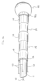
図1を参照すると、本発明の一部の実施形態では、カテーテル10は、カテーテル本体12、中間偏向区画14、遠位微小電極アセンブリ15、及びカテーテル本体12の近位側にある制御ハンドル16を含む。遠位微小電極アセンブリ15は、複数のスパイン17を含み、各スパインは複数の微小電極18を支持する。
Referring to FIG. 1, in some embodiments of the present invention,
一部の実施形態では、カテーテル本体12は、図2に示されるように、単一の、軸性すなわち中央内腔19を有する、細長い管状の構造を含む。カテーテル本体12は、可撓性を有し、言い換えると屈曲可能であるが、その長さに沿っては実質的に圧縮不可能である。カテーテル本体12は、任意の好適な構造を有することができ、任意の好適な材料で作製することができる。本発明において好ましい構造の1つは、ポリウレタン又はPEBAXで作製された外壁20を備えるものである。外壁20には高強度鋼、ステンレス鋼等の編組メッシュが埋め込まれていることによってカテーテル本体12のねじり剛性が高められているため、制御ハンドル16が回転させられると、カテーテル10の偏向区画14がこれに応じて回転する。
In some embodiments,
カテーテル本体12の外径は重要ではない。同様に、外壁20の厚さは重要ではないものの、中央内腔19が、例えば1本以上の牽引ワイヤ、微小電極リード線、灌流管材、並びに任意の他のワイヤ及び/又はケーブルを含むコンポーネントを収容可能な程度に十分に薄くなっている。一部の実施形態では、外壁20の内表面は、補強管21で裏打ちされるが、この補強管20は、例えばポリイミド又はナイロンなどの任意の適切な材料から作製可能である。補強管21は、編組みされた外壁20とともに、捻じれ安定性を改善する一方で、同時に、カテーテルの壁の厚さを最小化して、中央内腔19の直径を最大化するものである。当業者に理解されるように、カテーテル本体の構造は、所望に応じて変更され得る。例えば、補強管は省略可能である。
The outer diameter of
一部の実施形態では、中間偏向区画は、図3に示されるように、複数の内腔31を有する、管材30のより短い区画を含む。一部の実施形態では、管材30は、カテーテル本体12よりも可撓性が高い、好適な生体適合性材料で作製される。管材19に適した材料は、編組ポリウレタン、すなわち編組みされた高強度鋼、ステンレス鋼等のメッシュが埋め込まれたポリウレタンである。偏向区画14の外径は、カテーテル本体12の外径と同様である。内腔の個数及びサイズは必ずしも重要ではなく、特定の用途に応じて変更できる。
In some embodiments, the intermediate deflection section includes a shorter section of
様々なコンポーネントは、カテーテル10を通って延在する。一部の実施形態では、上記のコンポーネントには、遠位微小電極アセンブリ15用のリード線22と、偏向区画14を偏向させるための1本以上の牽引ワイヤ23A及び23Bと、偏向区画14の遠位端に又はその近くに収容される電磁位置センサ26(図14A及び図15Aを参照)用のケーブル24とが含まれる。一部の実施形態では、カテーテルは、流体を偏向区画14の遠位端に通すための灌注管材27を含む。これらのコンポーネントは、図2に示すように、カテーテル本体12の中央内腔19を通っている。
Various components extend through
図3に示すように、偏向区画14では、異なるコンポーネントが、管材30の異なる内腔31を通っている。一部の実施形態では、リード線22は、1つ以上の内腔31Aを通過し、第1の牽引ワイヤ23Aは内腔31Bを通過し、ケーブル24は内腔31Cを通過し、第2の牽引ワイヤ23Bは内腔31Dを通過し、灌注管材27は内腔31Eを通過する。内腔31B及び31Dは互いに、直径方向に正反対の位置にあり、中間偏向区画14が双方向に偏向できるようにしている。追加のコンポーネントは、必要に応じて、追加の内腔を通過するか、又は他の前述のコンポーネントと内腔を共有することができる。
As shown in FIG. 3 , in
偏向区画14の遠位側には、図4に示されるように、一体型支持部材40を含む遠位微小電極アセンブリ15がある。一部の実施形態において、一体型支持部材40は、形状記憶を有する超弾性材料、即ち、力が加えられると、その本来の形状から離れて一時的に直線状に伸ばされるか又は屈曲させられることができ、かつその力が加えられないか又は取り除かれると、本来の形状に実質的に戻ることが可能である超弾性材料を備える。支持部材に好適な材料の1つは、ニッケル/チタン合金である。そのような合金は、典型的には、約55%のニッケル及び約45%のチタンを含むが、約54%~約57%のニッケルを含み、残部をチタンとすることができる。ニッケル/チタン合金の1つは、ニチノールであり、耐久性、強度、耐食性、電気抵抗、及び温度安定性とともに、優れた形状記憶性を有する。
Distal to the
一部の実施形態では、部材40は、例えば、細長い中空円筒部材から構築及び成形されるが、その部分が(例えば、レーザー切断によって)切断されるかあるいは別の方法で取り除かれて、近位部分すなわちステム42と、ステムから長手方向に発し、かつステムから外側に向かって広がる、スパイン17の細長い本体とが形成される。ステム42は、その内部を通る内腔43を画定し、その内腔43は、偏向区画14の、複数の内腔を有する管材30(図14Aを参照)の遠位端部分30Dを受容し、かつ、以下で更に論じるように、ステム42内に収容されるか又は内腔43を通って延在する、様々なコンポーネントを受容する。
In some embodiments,
部材40の各スパイン17は、拡大された遠位部分46を有し、各スパインは、近位端がより広くかつ遠位端がより狭くなっている。一部の実施形態では、図5A、図5B、図5C、図5D、及び図5Eに示すように、スパインは、遠位端48に向かって増加する可撓性を含む、その長さに沿って変化する「面外」可撓性(図5Eの矢印A1を参照)が実現されるように、直線的にテーパ状となっている。一部の実施形態では、1つ以上のスパイン17は、均一な幅W1を有する近位部分17Pと、テーパ線T1によって画定される連続的な直線的テーパを有する遠位部分17D1(図5Bを参照)と、均一な幅W2(W1よりも狭い)を有するより遠位側に位置する部分17D2とを有する。遠位部分17D1は、その可撓性が連続的に漸増し、遠位部分46が組織と接触するときに、スパインが所定の形状又は曲率を取ることができるようになっている。結果として得られるスパインは、比較的より剛性の高い近位部分と、相対的により可撓性の高い遠位部分とを有するが、そのようなスパインは、使用中にスパインどうしが交差したり、互いに重なり合ったりすることを防止する助けとなる。
Each
一部の実施形態では、1つ以上のスパイン17は、図6A、図6B、図6C、図6D、図6E、図6F、及び図6Gに示されるように、端部41と46との間に非連続的な直線的テーパを有する。非連続的な直線的テーパは、1つ以上の幅狭部又は凹部50を含むが、それは、スパインに沿って戦略的に配置され、ステム42と拡大された遠位部分46との間のテーパT2によって画定される、それがなければ連続的であるはずの直線的テーパを、中断するようになっている。各凹部50は、幅W(図6Cを参照)を有し、幅Wは、より遠位側にある部分の幅WDよりも小さく、また幅WDよりも大きいより近位側にある部分の幅WPよりも小さくなっている。したがって、有利なことには、各凹部50は、スパインの当該領域が、スパインの直接隣接する(遠位側及び近位側)部分51とは異なる可撓性を有することを可能にしつつ、凹部50によって分離された部分どうしの間(図6B参照)に、ある程度の独立した可撓性を提供することを可能にする。したがって、これらのスパインは、遠位部分46が組織と接触するときに、スパインの部分51と比べて、凹部50の領域において、顕著により高い可撓性、したがって、より急な、言い換えると、より角度のきつい曲率を呈することが可能になる。
In some embodiments, one or
一部の実施形態では、各スパイン(ステム42の遠位端とスパインの遠位端との間)は、約1.0cm~2.5cm、又は約1.50cm~2.0cmの範囲の長さを有し、約0.009インチ~0.02インチの範囲の幅を有する。一部の実施形態では、凹部50は、スパインの長さの約10%~20%の範囲の長さを有し、直接隣接する場所の幅の約50%~80%の範囲の幅Wを有するが、凹部50の前側近位縁は、ステム42の遠位端から測定して、スパインの長さの約55%~65%の位置に存在する。
In some embodiments, each spine (between the distal end of
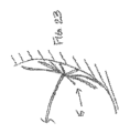
微小電極がスパインの全長に沿って組織と接触するのを更に容易にするために、各スパイン17は、例えば加熱及び成形用治具によって実現される、予め成形された形状又は湾曲を有する。1つ以上のスパイン17は、図7Aに示すように、少なくとも2つの異なる予め成形された湾曲C1及びC2を有する。セグメントS1が、半径R1によって画定される予め形成された湾曲C1を有し、セグメントS2が、半径R2によって画定される予め形成された湾曲C2を有する。ここで、R1はR2よりも小さく、かつ湾曲C1とC2とは、互いに概ね反対方向を向いており、一体型支持部材40のスパインが、開いた傘に似た、概ね前向きの凹面を有するようになっている。図7B(図を明瞭なものとするため2本のスパインのみ示している)に示すように、スパインの遠位端が例示的な表面SFと接触すると、予め成形されたスパインは、それらの中立的形状N(破線で示されている形状)から、その適応的又は一時的に「変形された」形状Aに移行する。この形状Aは、うねりを伴う心臓組織の領域により好適であり得る、(それらの中立形状と比較した場合に)「屈んだ」プロファイルを含み得る。有利なことには、一体型支持部材40は、組織と接触した際に、その概ね前向きの凹状形状を維持し、あたかも強力な風で傘がめくれ上がってしまうように、その内側を裏返らせることがない。
To further facilitate contact of the microelectrodes with tissue along the entire length of the spine, each
一部の実施形態では、1つ以上のスパイン17は、少なくとも湾曲したセグメントと直線的セグメントとを有する。一部の実施形態では、1つ以上のスパインは、その長さに沿って、少なくとも2つの異なる予め成形された湾曲を有する。例えば、図8Aに示すように、1つ以上のスパイン17は、半径RAによって画定される予め成形された湾曲CAを有する第1のセグメントSAと、半径RBによって画定される予め成形された湾曲CBを有する第2のセグメントSBと、直線的である第3のセグメントSCとを有し、半径RAは半径RBよりも小さくなっている。図8B(図を明瞭なものとするため2本のスパインのみ示している)に示すように、スパインの遠位端が例示的な表面SFと接触すると、予め成形されたスパインは、それらの中立的形状Nから、その適応的又は一時的に「変形された」形状Aに移行する。この形状Aは、凸面を有する心臓組織の領域により好適であり得る、(それらの中立形状と比較した場合に)より深い凹面を含み得る。
In some embodiments, one or
別の例として、図9Aに示すように、1つ以上のスパイン17Dは、半径RJによって画定される予め成形された湾曲CJを有する第1のセグメントSJと、直線的である第2のセグメントSKと、半径RLによって画定される予め成形された湾曲CLを有する第3のセグメントSLとを有し、半径RJは半径RLよりも小さくなっている。図9B(図を明瞭なものとするため2本のスパインのみ示している)に示すように、スパインの遠位端が例示的な表面SFと接触すると、予め成形されたスパインは、それらの中立的形状Nから、その適応的又は一時的に「変形された」形状Aに移行する。この形状Aは、心臓組織のより平坦な領域により好適であり得る、(それらの中立形状と比較した場合に)より低いプロファイルを含み得る。
As another example, as shown in FIG. 9A, one or
図10を参照すると、一部の実施形態では、一体型支持部材40及びそのスパイン17は、例えば、以下のものを含む複数のパラメータによって定義され得る:
a(第2の湾曲の高さ)=約0.00インチ~0.050インチの範囲
b(第2の湾曲の遠位側長さ)=約0.302インチ~0.694インチの範囲
c(第2の湾曲の近位側長さ)=約0.00インチ~0.302インチの範囲
d(第1の湾曲と第2の湾曲との間の距離)=約0.00インチ~0.170インチの範囲
e(第1の湾曲の半径)=約0.075インチ~0.100インチの範囲
f(均一幅のセグメントの長さ)=約0.100インチ
g(凹部の深さ)=約0.123インチ~0.590インチの範囲
Referring to FIG. 10, in some embodiments, the
a (height of second curve) = range from about 0.00 inch to 0.050 inch b (distal length of second curve) = range from about 0.302 inch to 0.694 inch c (proximal length of second curve) = range of about 0.00 inch to 0.302 inch d (distance between first curve and second curve) = about 0.00 inch to 0 .170 inch range e (radius of first curve) = range from about 0.075 inch to 0.100 inch f (length of uniform width segment) = about 0.100 inch g (recess depth) = about 0.123 inch to 0.590 inch range
特に、一体型支持部材40の一部の実施形態では、近位側(又は第1)の予め成形された湾曲は、遠位側(又は第2)の予め成形された湾曲と反対側にあり、その結果、遠位微小電極アセンブリ15のスパイン17は、組織との接触時に、その一般的な凹面を維持し、反転することなく、前向きの状態のままである。その一方で、可撓性の高いスパインは、柔軟性又は「しなり」をアセンブリが有することを可能にして、組織との接触時にスパインの遠位先端部が組織に穴をあけたり、別の方法で組織へ損傷を引き起こしたりすることを防止するとともに、遠位微小電極アセンブリが組織表面に向かって押し付けられるときには、スパイン17のそれぞれが組織に確実に接触できるようにする。更に、一部の実施形態では、凹部50は、近位側の予め成形された湾曲と遠位側の予め成形された湾曲との間に広がることができ、その結果、スパインの3つの部分(近位側部分、凹部、及び遠位側部分)のそれぞれが、組織との接触及びカテーテルを操作するユーザーによって加えられる関連する圧力に対して、異なる挙動をし、かつ互いに異なる可撓性の度合いを有することができるようになっている。
In particular, in some embodiments of the
前述の図は、論の展開及び説明を容易にするために、スパインの変形及び湾曲を誇張して示しているが、実際の変形及び湾曲は、はるかに微妙なものであり、図ほどは急なものではない場合があり得ることを理解されたい。 Although the foregoing figures exaggerate the deformation and curvature of the spine for ease of discussion and explanation, the actual deformation and curvature is much more subtle and less abrupt than the figures. It should be understood that it may not be
一部の実施形態では、1本以上のスパイン17はまた、面内(横方向での)偏向のためのヒンジ90を備えて構成される。図11A及び図11Bに示すように、スパイン17は、複数個のノッチ又は陥没部を、互いに対向する側辺部に沿って有することができる。それらのノッチ又は陥没部としては、一方の縁部85aに沿った、拡張可能な陥没部80(例えば、スリット81及び円形開口部82の形状で設けられるもの)と、反対側の縁部85bに沿った、圧縮可能な陥没部83(例えば、スロット84及び円形開口部82の形状で設けられるもの)が挙げられる。これらのノッチ又は陥没部は、更なる平面内の偏向のためのヒンジ90をそれらの縁部に沿って形成する。図11A及び図11Bの実施形態では、一方向への偏向が、スパイン17の縁部85bに向かって生じる。しかしながら、圧縮可能な陥没部83が縁部85a及び85bの両方に沿って形成される場合、スパイン17は、いずれかの縁部85a又は85bに向かう双方向の偏向を有するということが理解される。好適なヒンジが、米国特許第7,276,062号に記載されており、その特許の開示全体は、参照によって本明細書に組み込まれる。
In some embodiments, one or
図12A及び図12Bに示されるように、遠位微小電極アセンブリ15の各スパイン17は、その長さに沿って、非導電性スパインカバー又は管材28によって囲まれている。一部の実施形態では、非導電性スパインカバー28は、PEBAX又はPELLATHANEなどの非常に柔軟かつ可撓性の高い生体適合性プラスチックを含み、スパインカバー28は、ステム42と拡大された遠位部分46との間のスパインと同一の広がりを持つ長さを有して、スパイン上に取り付けられる。スパインカバー28を構築するための好適な材料は、スパイン17の可撓性を一般に妨げないように、十分に柔らかくかつ可撓性を有するものである。
As shown in FIGS. 12A and 12B, each
一部の実施形態では、各カバーされたスパイン17は、その長さに沿って、3フレンチ未満の直径D、好ましくは2.7フレンチ未満の直径、より好ましくは2フレンチの直径を有する(例えば、直径約0.025インチ~0.035インチである)。
In some embodiments, each covered
各スパイン17は、拡大された遠位部分46を封入する、非外傷性遠位カバー又はキャップ45(図12Aを参照)を含む。一部の実施形態では、カバー45は、ポリウレタンなどの生体適合性接着剤又はシーラントを含み、これは、組織との接触時又は組織に対する圧力の印加時に、組織への損傷を最小限に抑えるための球状の形状を有する。カバー45の構成物には、拡大された遠位部分46の貫通孔47を通過する、接着剤又はシーラントの架橋部分63が含まれ、この架橋部分63は、有利なことには、機械的ロックを形成し、カバー45を遠位部分46上に固定し、カバー45が拡大された遠位部分46から外れてしまうリスクを最小限に抑えるようになっている。
Each
各スパイン17は、複数の微小電極18を担持する。微小電極の個数及び配置は、意図される使用法に応じて変化し得る。一部の実施形態では、個数は約48~72の範囲であるが、個数は、より多くても少なくてもよいことが理解されよう。一部の実施形態では、各微小電極は、800μm未満の、例えば、約600μm~300μmの範囲の長さLを有し、例えば、約480μm、460μm、又は約450μmの測定値を有する。一部の実施形態では、遠位微小電極アセンブリ15は、1平方センチメートルあたり約7.1超、例えば、1平方センチメートルあたり約7.2~12.6の範囲の面積被覆率を有する。一部の実施形態では、遠位微小電極アセンブリ15は、微小電極約2.5個/cm2超、例えば、微小電極約4個/cm2~7個/cm2の範囲の微小電極密度を有する。
Each
一部の実施形態では、遠位微小電極アセンブリ15は8本のスパインを有し、それぞれのスパインの長さが約1.5cmで、8個の微小電極を担持しているので、合計48個の微小電極を有し、それぞれの微小電極は、約460μmの長さを有する。アセンブリ15は、1平方センチメートルあたり約7.1の面積被覆率、及び微小電極約7個/cm2の微小電極密度を有する。
In some embodiments, the
一部の実施形態では、遠位微小電極アセンブリ15は8本のスパインを有し、それぞれのスパインの長さが約2.0cmで、6個の微小電極を担持しているので、合計48個の微小電極を有し、それぞれの微小電極は、約460μmの長さを有する。アセンブリ15は、1平方センチメートルあたり約12.6の面積被覆率、及び微小電極約4個/cm2の微小電極密度を有する。
In some embodiments, the
スパイン17上の微小電極18は、単極子又は双極子のいずれかとして、それらどうしの間に様々な間隔を置いて配置されてもよいが、その間隔とは、隣接する微小電極どうし又は微小電極対のそれぞれの先端縁部どうしの間の分離幅として測定されるものを指す。図12Aを参照すると、単極子としては、微小電極18どうしは、約1mm~3mmの範囲の距離S1だけ分離することができる。図12Bを参照すると、双極子としては、隣接する微小電極18の対どうしは、1mm~6mmの範囲の距離S2だけ分離することができる。
The
図12Bを参照すると、一部の実施形態では、6つの微小電極は、3つの双極子対として配置され、1つの双極子対内の近位縁部どうしの間には2.0mmの間隔S1が、隣接する双極子対どうしの近位縁部どうしの間には6.0mmの間隔S2が確保されており、このような構成は、「2-6-2」構成と一般的に呼び得るものである。「2-5-2-5-2」構成と称される別の構成は、3つの双極子対を有し、1つの双極子対内の近位縁部どうしの間には2.0mmの間隔S1が、隣接する双極子対どうしの近位縁部どうしの間には5.0mmの間隔S2が確保されている。 Referring to FIG. 12B, in some embodiments, the six microelectrodes are arranged as three dipole pairs with a 2.0 mm spacing S1 between proximal edges within one dipole pair. , with a 6.0 mm spacing S2 between the proximal edges of adjacent dipole pairs, such a configuration can generally be referred to as a "2-6-2" configuration. is. Another configuration, referred to as the "2-5-2-5-2" configuration, has three dipole pairs with 2.0 mm spacing between the proximal edges within one dipole pair. There is a 5.0 mm spacing S2 between the proximal edges of adjacent dipole pairs.
図12Aを参照すると、一部の実施形態では、6個の微小電極は、単極子として配置され、隣接する単極子どうしの近位縁部どうしの間には、2.0mmの間隔S1が確保されており、このような構成は、「2-2-2-2-2」構成と呼び得るものである。一部の実施形態では、間隔S1は約3.0mmであり、したがって、「3-3-3-3-3」構成と呼ばれる。 Referring to FIG. 12A, in some embodiments, the six microelectrodes are arranged as monopoles with a 2.0 mm spacing S1 between the proximal edges of adjacent monopoles. Such a configuration can be called a "2-2-2-2-2" configuration. In some embodiments, the spacing S1 is approximately 3.0 mm, hence the term "3-3-3-3-3" configuration.
一部の実施形態では、各スパインの最も近位側の微小電極18Pは、隣接するスパインの最も近位側の微小電極18Pとは異なる場所で、当該スパイン上に担持される。エンドプローブ400の図13Aに示すように、任意の1つのスパイン上の微小電極どうしの間の間隔は、遠位微小電極アセンブリ全体にわたって均一であってもよく、任意の1本のスパインに沿った微小電極は、隣接するスパインに沿った微小電極に対して、互い違い状に配置されている。例えば、スパイン17A、17C、17E、及び17Gの場合の、最も近位側の微小電極18Pとステム42の端部との間の距離D1は、スパイン17B、17D、17G、及び17Gの場合の、最も近位側の微小電極18Pとステム42の端部との間の距離D2よりも大きい。この互い違い構成は、特に操作者が遠位微小電極アセンブリを組織に対して掃くように動かすときに、隣接するスパインどうしの上の微小電極どうしが接触及び短絡するリスクを最小限に抑える。
In some embodiments, the
遠位微小電極アセンブリと偏向区画14の遠位端部分との間の接合部の構造コンポーネント及びアセンブリは、その開示全体が参照により本明細書に組み込まれる、米国特許第7,089,045号、同第7,155,270号、同第7,228,164号、及び同第7,302,285号に記載されている。
The structural components and assembly of the junction between the distal microelectrode assembly and the distal end portion of the
図13Bは、図13Aのエンドプローブアセンブリ400の側面図を示し、同図では、アセンブリのスパインが平坦な表面Tと接触している。長手方向軸線L-L(ステム42によって画定される)が平坦な表面Tに概ね直交しているこの形状では、ステム42が管状部材27を含み、管状部材27には、基準微小電極67Aが、表面Tによって表される組織との接触を回避するため、間隙Gを残して、管状部材27の遠位部分に取り付けられ得ることが分かる。
13B shows a side view of the
特定の使用事例では、互いに隣接するスパインの微小電極どうしが、互いに接触し得ることを認識した。したがって、発明者は、互いに隣接するスパインの微小電極どうしが互いに接触しないように、各スパイン上に微小電極を配置することを考案した。具体的には、図13Bでは、8本のスパイン17A、17B、17C、17D、17E、17F、17G、及び17Hが存在し、各スパインが、それぞれ対応するスパイン17A、17B、17C、17D、17E、17F、17G、及び17Hに取り付けられたそれぞれ対応する6つの微小電極17A1~17A6、17B1~17B6、17C1~17C6、17D1~17D6、17E1~17E6、17F1~17F6、17G1~17G6、及び17H1~17H6を有することが分かる。スパイン17Aを基準データとして使用すると、エンドエフェクタ400が平坦で透明な表面(例えば、ガラス)に対して配置されるとき、スパイン17A上の微小電極は、長手方向軸線L-L(又は管材27)を基準とする様々な仮想円を画定することができるということが分かる。例えば、第1のマイクロ電極17A1は、第1の仮想円VC1を画定し、第2の微小電極17A2は、第2の仮想円VC2を画定し、第3の微小電極17A3は、第3の仮想円VC3を画定し、第4の微小電極17A4は、第4の仮想円VC4を画定し、第5のマイクロ電極17A5は、第5の仮想円VC5を画定し、第6の微小電極17A6は、第6の仮想円VC6を画定し、スパイン17A上により多くの微小電極が存在する場合、同様に微小電極が仮想円を画定する。仮想円は、1つのスパイン上に微小電極が、その隣接する隣接装置に対して「互い違い状」に配設されることを示す。本明細書で使用するとき、互い違い状ということは、基準スパイン上の1つの微小電極が、その隣接するスパイン上の異なる微小電極と接触していないことを示す。図13Cでは、基準スパイン17Aが軸線L-Lを中心に45度、スパイン17Bに向かって時計回りに回転することができる場合であっても、微小電極17A1、17A2、17A3、17A4、17A5、又は17A6のいずれも、スパイン17Bの微小電極17B1~17B6に接触することができない。同様に、スパイン17Aが図13Cで、軸線L-Lを中心に45度反時計回りに回転することができる場合であっても、微小電極17A1~17A6のいずれも、スパイン17Hの微小電極17H1~17H6と接触することができない。
It has been recognized that in certain use cases, microelectrodes of adjacent spines can touch each other. Therefore, the inventors have devised arranging the microelectrodes on each spine such that the microelectrodes of adjacent spines do not contact each other. Specifically, in FIG. 13B, there are eight
同様に、スパインが、軸線L-Lに対して同一線状に圧縮されるようにスパインが組織によって一体的に圧縮される状況でも、1本のスパインの微小電極は、その隣接する隣接するスパインの微小電極に接触することができない。このことは、スパイン17Aがスパイン17H、17G、17F、及び17Eと同一線上に圧縮される図13Dに、例示的に示されている。微小電極17A1及び17H1のそれぞれ対応する前縁部どうしの間に、互い違い配列距離Dstagger1が設定されているのを見ることができる。スパイン17A上の微小電極17A1~17A6のそれぞれと、隣接するスパイン17H上の対応する隣接微小電極17H1~17H6との間で、互い違い配列距離が同じであり得るが、例えば、互いに隣接するスパイン17A及び17H上のそれぞれ対応する第4の微小電極17A4及び17H4についての互い違い配列距離Dstagger4などのような、他の互い違い配列距離を用いることができる。互い違い配列距離は、約0.1mm~約6mmの任意の距離であり得る。
Similarly, in situations where the spines are compressed together by the tissue so that the spines are compressed collinearly with respect to the axis LL, the microelectrodes of one spine will not be able to reach its adjacent adjacent spines. cannot touch the microelectrodes. This is illustratively shown in FIG. 13D, where
再び図13Cを参照すると、スパインのそれぞれの微小電極は、それぞれのスパイン上の微小電極どうしの間に、同じ間隙距離D1=D2=D3=D4=D5を有するように構成されていることが分かる。間隙距離は、各微小電極の前縁部どうし、又は各微小電極の中心どうしで測定することができる。間隙距離は同じであるが、各スパイン(例えば、17A)上の微小電極のセット1~6は、同じ互い違い配列距離Dstagger1によって、隣接するスパイン(例えば、17H及び17B)の微小電極セット1~6に対してオフセットされる。図13Eは、間隙距離どうしが同じ値ではなく、異なる場合があり得る実施形態を示す。例えば、間隙距離D1が間隙距離D2よりも小さく、かつ間隙距離D1が間隙距離D3及びD5に等しくなり得る一方、間隙距離D4が間隙距離D2に等しくなり得る。各スパイン(例えば、17A)上に設定された微小電極が、その隣接するスパイン(例えば、17H及び17B)に対してオフセット又は互い違い配列状態(例えば、Dstagger1)である限り、間隙距離D1、D2、D3、D4、及びD5は、等しくない可能性がある。 Referring again to FIG. 13C, it can be seen that each microelectrode in the spine is configured to have the same gap distance D1=D2=D3=D4=D5 between the microelectrodes on each spine. . The gap distance can be measured between the leading edges of each microelectrode or between the centers of each microelectrode. Although the gap distance is the same, microelectrode sets 1-6 on each spine (eg, 17A) are aligned with microelectrode sets 1-6 on adjacent spines (eg, 17H and 17B) by the same staggering distance Dstagger1. offset with respect to FIG. 13E shows an embodiment in which the gap distances may not be the same value, but may be different. For example, gap distance D1 may be less than gap distance D2, and gap distance D1 may be equal to gap distances D3 and D5, while gap distance D4 may be equal to gap distance D2. As long as the microelectrodes set on each spine (e.g. 17A) are offset or staggered (e.g. Dstagger1) with respect to its adjacent spines (e.g. 17H and 17B), the gap distances D1, D2, D3, D4, and D5 may not be equal.
図13A~図13Eの実施形態に示される構成は、自由端を有するスパインを使用した光線様構成であるが、光線様構成に対するのと同じ原理は、図13Fに示されるような、バスケットを画定する閉端型のスパイン構成に適用することができる。具体的には、図13Fでは、バスケット形状のアセンブリを画定するように共通の中心270に接合するスパイン17A~17Lが存在する。各スパインは、複数の微小電極を担持し得る。例えば、微小電極17A1~1710は、微小電極17A1~17A10のうちの1つと交差する仮想円が、隣接するスパイン(例えば、17L又は17B)上の微小電極と交差しないように配設される。
Although the configuration shown in the embodiment of Figures 13A-13E is a ray-like configuration using spines with free ends, the same principle for the ray-like configuration defines a basket, as shown in Figure 13F. It can be applied to a closed-ended spine configuration. Specifically, in FIG. 13F there are
同様に、これらの実施形態に対する原理と同じ原理が、(図13A~図13Eの円錐様の構成の代わりに、)ここで図13G、図13H、及び図13Iに示される平面形状のスパインアレイに適用することができる。 Similarly, the same principles for these embodiments apply to the planar-shaped spine array shown here in FIGS. 13G, 13H, and 13I (instead of the cone-like configuration of FIGS. can be applied.
図13G~図13Hでは、実施形態は、ステム42及びスパイン170A、170B、170C、170Dが、単一平面(図13G及び図13H)又は多平面(図13I)上にあるように配列されているが、先に示したものと同じ命名の方法に従っている。各スパイン170A、170B、170C、及び170Dは、微小電極170A1~170A6、170B1~170B6、170C1~170C6、及び170D1~170D6を有する。微小電極セット170A1~170A6は、隣接するスパイン170B上のマイクロ電極セット170B1~170B6から互い違い状に配列されているか又はオフセットされている。マイクロ電極セット170B1~170B6は、その隣接する微小電極セット170A1~170A6及び170C1~170C6の両方からオフセットされている。エンドプローブアセンブリ400(少なくとも、複数のスパイン及び各スパインに対する微小電極セットを含む)は、スパインが単一の接触面に接触するよう、図13G及び図13Hに示すように構成することができる。図13Hでは、スパイン170Aは、コネクタ170ADによりスパイン170Dと接続されることができ、スパイン170Bは、コネクタ170BCによりスパイン170Cと接続される。2つ以上の平面内での接触は、図13Iの構成とともに利用することができる。その構成では、スパイン170Aはコネクタ170ACを介してスパイン170Cに接続されて、これらのスパインの微小電極セットに関する第1の接触面を画定し、スパイン170B及び170Dは、コネクタ170BDにより互いに接続されて、第2の接触面を画定する。
13G-13H, embodiments are arranged such that stems 42 and
なお、図13A~図13F、図13H、及び図13Iの実施形態が、1つのスパインの電極が、隣接するスパイン(複数可)上の電極に対して、(各スパインの)長手方向軸線L-Lに沿って互い違い配列されるか又はオフセットされ、かつ各電極の中心線又は質量中心L-LA1が、各スパインの長手方向軸線L-Lと一致することを示していることに留意すべきである。本発明者らはまた、1つのスパイン上の各電極の中心線が、その電極が装着されるスパインの第1の方向T1に長手方向軸線から偏心的にオフセットされる、更に別の互い違い配列を考案した。この偏心オフセットという特徴は、図13G及び図13Jに見ることができ、同図において、電極170A1は、その中心線L-LA1が、スパイン170Aの軸線L-Lに対して、概ね横断方向T1に偏心距離「e」だけオフセットしている。同様に、スパイン170B上の電極170B1は、図13Gのスパイン170A上の電極170A1に対して、概ね反対側の横断方向T2に偏心的にオフセットされる。1つのスパイン上の電極は、隣接するスパイン(複数可)上の隣接電極に対してのみ、長手方向にオフセットされても(図13A~図13F、図13H、及び図13I)、偏心的にのみ互い違い配列されても(図13J)、又は図13Gに示すように、長手方向及び偏心的の両方で互い違い配列されてもよいということが意図されている。
It should be noted that the embodiments of FIGS. 13A-13F, 13H, and 13I indicate that the electrodes on one spine are positioned relative to the electrodes on the adjacent spine(s) along the longitudinal axis L- (of each spine). Note that they are staggered or offset along L and indicate that the centerline or center of mass LL A1 of each electrode coincides with the longitudinal axis LL of each spine. is. The inventors have also proposed yet another staggered arrangement in which the centerline of each electrode on one spine is eccentrically offset from the longitudinal axis in the first direction T1 of the spine to which the electrode is attached. devised. This eccentric offset feature can be seen in FIGS. 13G and 13J, in which electrode 170A1 is positioned such that its centerline LL A1 extends generally transversely T1 with respect to axis LL of
要約すると、本発明者らは、図13A~図13Jの実施形態のための特定の共通の特徴を考案した。具体的には、医療プローブの様々な実施形態は、少なくとも以下のような特徴を含む:長手方向軸に沿って延在する細長い部材14であって、遠位微小電極アセンブリ400が連結された細長い部材14と、長手方向軸線L-Lに沿って延在する近位側ステム42と、長手方向軸線L-Lから放射状に離れる第1のスパイン(例えば、17A又は170A)であって、自らの上に配設された複数の第1の微小電極(17A1~17A6又は170A1~170A6)を有する第1のスパイン(17A又は170A)と、第1のスパイン(17A又は170A)に隣接し、かつ長手方向軸線L-Lから放射状に離れる第2のスパイン(17B又は170B)であって、自らの上に配設された複数の第2の微小電極(17B1~17B6又は170B1~170B6)を有する第2のスパイン(例えば17B又は170B)とを含み、複数の第1の微小電極のうちの1つと交差する第1の仮想円(例えば、VC1又はVC2)は、第2の微小電極のいずれとも交差しない。更なる改良点としては、第3のスパインが、第1のスパインに隣接し、長手方向軸線から放射状に離れるように提供され得る。第3のスパインは、自らの上に配設された複数の第3の微小電極を有し、複数の第1の微小電極のうちの1つと交差する第1の仮想円が、第2及び第3の微小電極のいずれとも交差しないようになっている。なお、第1の仮想円は、長手方向軸線を概ねその中心とし、長手方向軸線に概ね直交し得るということに留意されたい。スパインの形状を画定する目的のため、近位側ステムは、平坦面に概ね直交して配設され、第1、第2、及び第3のスパインが平坦な表面と接触して、スパインの放射状形状が画定される。複数のスパインは、長手方向軸線の周りに等角構成で配設された、5~8本の又はそれ以上のスパインを含み得る。
In summary, the inventors have devised certain common features for the embodiments of Figures 13A-13J. Specifically, various embodiments of the medical probe include at least the following features: an
実施形態の他の共通する特徴としては、長手方向軸線に沿って延在する複数のスパイン17A、17B、17C、17D、17E...17Nを含み、第1のスパイン17A上には、複数の第1の微小電極(例えば、17A1~17A6)が配設され、第1のスパイン(17A)に隣接する第2のスパイン(17H)上には、複数の第2の微小電極(17H1~17H6)が配設されているということが挙げられる。複数の第1の微小電極(17A1~17A6)は、第1のスパインに沿って離間配置され、第1の微小電極が、互い違い距離Dstagger1だけ、第2の微小電極(17H1~17H2)に対してオフセットされるようになっている。更なる改良点では、複数の第3の微小電極が、第1のスパインに隣接する第3のスパイン上に配設され、第1の微小電極が、互い違い配列距離Dstagger1だけ第2及び第3の微小電極に対してオフセットされている。互い違い配列距離としては、1つのスパイン上の1つの微小電極の前縁部と、それに隣接するスパイン上の最も近い微小電極の前縁部との間で測定した場合の、約0.1mm~約5mmの任意の距離が含まれる。
Another common feature of the embodiments is the plurality of
図14Aに示されるように、一体型支持部材40のステム42は、偏向区画14の、複数の内腔を有する管材30の幅狭遠位端30Dを受容する。その近位端とその遠位端との間でステム42と同一の広がりを持つ非導電性スリーブ68が、ステム42を周囲方向に取り囲んでいる。スリーブ68の遠位端68Dは、非導電性スパイン管材28の近位端28P上に延在し、スパイン17上に管材28を固定するのに役立つようになっている。
As shown in FIG. 14A, stem 42 of
遠位端30Dの近位側には、ハウジングインサート60があり、これもまた一体型支持部材40のステム42の内腔43内に受容され、位置決めされる。ハウジングインサート60は、その長手方向の長さがステム42の長さよりも短いので、ステム42の遠位端を越えて突出しない。ハウジングインサート60は、1つ以上の内腔を備えて構成される。1つの内腔71は、非円形の断面、例えば、「C」又は細長いキドニー豆に概ね似た断面を有してもよく、別の内腔72は、図14Bに示されるように円形の断面を有してもよい。その結果、内腔が互いに入れ子状になり、内腔のサイズを最大化し、ハウジングインサート60内の空間効率を高めることができる。より多くの内腔71を通過するコンポーネントは、いかなる1つの場所又は位置に捕捉されず、したがって、特にカテーテルのセグメントにトルクがかかり、コンポーネントが捻られるときに、より自由に移動し、破損の危険性がより少なくなっている。
Proximal to
一部の実施形態では、電磁位置センサ26(ケーブル24の遠位端にある)は、内腔72内に受容される。例えば、灌注管材27と、遠位微小電極アセンブリ15上の微小電極18のためのリード線22(及びスパイン17の近位側の任意のリング微小電極67、69、及び70用のリード線25)とを含む他のコンポーネントは、内腔71を通過する。その点に関し、ハウジングインサート60は、一体型支持部材40のステム42内の様々なコンポーネントを位置揃えさせ、位置決めすることを含む複数の機能を果たし、これらの様々なコンポーネントどうしの間の間隔を空けて分離させ、更には、偏向区画14の遠位端と遠位微小電極アセンブリ15との間の接合部を補強する機械的ロックとして機能する。後者に関して、接合部は、カテーテルの組み立て及び使用中に、その接合部にトルクを与え、又は引き寄せることができる様々な力を受ける可能性がある。トルク力は、例えば、灌注管材27を挟持して流れを妨害するか、又はリード線22及び25の破損を引き起こす可能性がある。そのため、接合部は、有利なことには、以下に説明するように、ハウジングインサート60を伴う構成で組み立てられて、機械的ロックを形成する。
In some embodiments, electromagnetic position sensor 26 (at the distal end of cable 24 ) is received within
ハウジングインサート60は、ステム42の内腔43の内周よりも所定量だけ小さい外径で選択的に構成されてもよい。これにより、ポリウレタンなどの好適な接着剤61で充填された内腔43内に感知可能な空隙が形成され、ハウジングインサート60とステム42との間の相対的な移動を防止しないまでも最小限に抑えるように、インサート60を、内腔43の内側及び複数の内腔を有する管材30の遠位端にしっかりと貼り付ける。ハウジングインサート60は、自らが包囲するコンポーネントを保護するものであり、そのようなコンポーネントには、電磁位置センサ26(及びケーブル24への取り付け具)、灌注管材27、並びにリード線22及び25が含まれる。また、ハウジングインサート60は、ステム42を取り付けるより大きく、より剛性の高い構造体を提供する。そのために、ハウジングインサート60は、ハウジングインサート60と接着剤61との間の固着を改善するための、非円形/多角形の外側断面及び/又はテクスチャ加工された表面を有してもよい。
接着剤の空隙内への塗布を容易にするために、ステム42は、その側壁内に開口部65を有して形成され、その形成される場所は、ハウジングインサート60がステム42の内腔43内に挿入された後に、ハウジングインサート60への視覚的及び機械的アクセスを可能にする位置である。接合部の組み立て中、内腔43及びその中のコンポーネントの目視検査が、開口部65を通して提供される。内腔43内への挿入前に、ハウジングインサート60の外側表面に塗布されたいかなる接着剤も、挿入中にステム42から外に噴出し得るが、有利なことには、追加の接着剤が開口部65を通して内腔43内に塗布されて、空隙を埋めて、ハウジングインサート60をステム42と、複数の内腔を有する管材30の遠位端部分とにしっかりと貼り付ける。ハウジングインサート60と、それを空間的に収容する内腔71との組み合わせにより、遠位微小電極アセンブリ15と偏向区画14との間に、より統合された、かつより脆弱ではない接合部が提供される。
To facilitate the application of adhesive into the void, stem 42 is formed with an
一部の実施形態では、カテーテル10は、灌注管材27を含み、灌注管材27の遠位端27Dは、一体型支持部材40のステム42の遠位端と概ね同一の広がりを持っている。したがって、灌注流体、例えば生理食塩水は、ルアーハブ100(図1)を介して灌注流体を提供する遠隔流体源から、制御ハンドル16を通って延在する灌注管材27と、カテーテル本体12の中央内腔19(図2)と、偏向区画14の管材30の内腔31E(図3)とを介して、遠位微小電極アセンブリ15に送達される。灌注流体は、図15A及び図25に示されるように、一体型支持部材40のステム42の遠位端において灌注管材27の遠位端から出るようになっている。ポリウレタンなどの好適な接着剤90は、灌注管材27の遠位端の周りの内腔43を塞ぎ、封止する。一部の実施形態では、図14Aに示されるように、カテーテルは灌注なしであり、一体型支持部材40のステム42の遠位端は、ポリウレタンなどの接着剤又はシーラント90によってその全体が封止される。
In some embodiments,
図16は、非導電性スパイン管材28が補強引張部材53を含む実施形態を示す。当業者には理解されるように、微小電極18は、スパインカバー又はスパイン管材28上に取り付けられ、細長い管状マンドレル(図示せず)がスパインカバー28の内腔内に配置されて、微小電極18が、スパインカバー28上に回転的にすえ込み加工されている間、微小電極18を支持するようになっている。微小電極18は、円又は楕円の形状を含む、円形の断面を有していてよい。すえ込み加工中、微小電極18及びスパインカバー28が、変形すること(長手方向に伸長することを含む)は望ましくないが、そのような変形を防止又は少なくとも最小限に抑えるために、微小電極が担持され、すえ込まれるスパインカバー28には、図16に示されるように、補強引張部材53が含まれている。引張部材53、例えば、ワイヤ又は繊維(本明細書では互換的に使用される)が、管材の側壁54内に(例えば、引張部材の押出加工中に)埋め込まれている。引張部材53は、一軸又は編組パターンで非導電性カバー押出成形物に埋め込まれてもよく、長手方向に延在するか、又は少なくとも長手方向に延在する部分を有する。特に柔軟で可撓性のあるスパインカバー28及び微小電極18が長手方向に伸長することは望ましくないが、上記のような引張部材は、この伸長に抵抗するように機能する。好適な引張部材の例としては、VECTRAN、DACRON、KEVLAR、又は低伸長特性を有する他の材料が挙げられる。補強引張部材の本数は重要ではない。一部の実施形態では、上記の本数は、2~6本の範囲であり得るが、ただしそれらは、径方向に等間隔で配置される。図示される実施形態では、スパインカバー28は、側壁54の周りで0度、90度、180度、及び270度の位置に、4本の引張部材を含む。
FIG. 16 shows an embodiment where the
一部の実施形態では、引張部材53の遠位端は、図16に示されるように、スパイン17の拡大された遠位部分を封入する球状のカバー45内及び/又はリング99D内に固定され、スパインカバー28の上かつスパイン17の上方に圧縮又はクランプ締めされてもよい。一部の実施形態では、引張部材53の近位端は、スパインカバー28の近位端と同一の広がりを有し、引張部材53の近位端もまた、リング99Pによって固定されてもよい(図14A及び図15Aを参照)。
In some embodiments, the distal end of
一部の実施形態では、引張部材53は、上記よりもはるかに長い長さを有する。図17、図18、図19、及び図20を参照すると、引張部材53は、一体型支持部材40のステム42に形成された開口部44を通って、ステム42の内腔43内に延在する。次いで、引張部材53は、ハウジングインサート60の内腔71、偏向区画14の管材30の内腔31F、及びカテーテル本体12の中央内腔19を通って、制御ハンドル16内へと延在する。引張部材53の近位端は、操作者が操作して遠位微小電極アセンブリ15のスパイン17を偏向させるように構成されているため、それらのスパイン17は個別に「フィンガー」として機能することができる。その点に関し、引張部材は、管材28に対する長手方向の移動を可能にする様式で管材28の側壁内に形成され得るが、それによって、任意の1本以上の引張部材が近位側に引かれると、それらの引張部材がそれに沿って延在する側に向かって、それぞれのスパインを屈曲又は偏向させるようになっている。したがって、操作者は、必要に応じて又は所望に応じて個々の偏向のために1本以上のスパインを操作することができる。そのような場合には、1本以上のスパインが、より良好な組織との接触のために調節を必要とするような、遠位微小電極アセンブリが、平らではない組織表面と接触する場合が含まれる。
In some embodiments,
図21、図22、図23、及び図24を参照すると、本発明のカテーテル10は、心臓の4つの心房及び心室の全て、すなわち左心房及び右心房、並びに左心室及び右心室に使用されている状態で示されている。遠位微小電極アセンブリ15のスパインは、例えば、肺静脈内部、右心房の後壁、並びに左心室及び右心室の前壁、下壁及び/又は側壁、更には頂点を含む、心臓組織の解剖学的構造の様々な輪郭及び表面に容易に適合し、順応する。有利なことには、スパインの予め成形された形状が、スパイン上に担持された微小電極と組織との間の接触を、その表面の解剖学的構造に関わらず容易にする。
21, 22, 23 and 24, the
一部の実施形態では、カテーテル10は、遠位微小電極アセンブリ15の近位側に複数のリング微小電極を有する。図1に示すように、カテーテルは、リング微小電極67に加えて、リング微小電極67よりも近位側の別のリング微小電極69と、リング微小電極69よりも近位側の別のリング微小電極70とを担持する。これらのリング微小電極には、リード線25が提供されている。一部の実施形態では、リング微小電極69は、偏向区画14の、複数の内腔を有する管材30の遠位端30Dの近くに位置し、リング微小電極70は、約1mm~3mmの範囲の距離Sだけリング微小電極69から離れている。それぞれのリード線25は、一体型支持部材40のステム42及びスリーブ68内に形成された開口部75を介してリング微小電極67に接続されている。リング微小電極69及び70それぞれ用のリード線25は、偏向区画14の管材30のこれらの側壁に形成されたビア開口部(図示せず)に接続されている。
In some embodiments,
カテーテル本体12を通って延在する牽引ワイヤ23A及び23Bの各部分は、当該技術分野において理解されるように、それぞれの圧縮コイル101A及び101Bによって周方向に囲まれている。偏向区画の、複数の内腔を有する管材30を通って延在する牽引ワイヤ23A及び23Bの各部分は、牽引ワイヤが偏向されたときに牽引ワイヤが管材に食い込むのを防ぐシースによって周方向に囲まれている。牽引ワイヤの遠位端は、当該技術分野において理解されるように、管材30の遠位端部で又はその近くで、管材30の側壁に固定されてもよい。牽引ワイヤの近位端は、当該技術分野において理解されるように、カテーテルの操作者による作動のために制御ハンドル16内に固定される。
Each portion of
上記の説明は、現時点における本発明の好ましい実施形態に関連して示したものである。本発明が関連する分野及び技術の当業者であれば、本発明の原理、趣旨、及び範囲を大きく逸脱することなく、記載される構造に改変及び変更を実施し得る点は認識されるであろう。1つの実施形態に開示される任意の特徴又は構成は、必要に応じて又は適宜、他の任意の実施形態の他の特徴に代えて、又はそれに加えて組み込むことができる。当業者には理解されるように、図面は必ずしも縮尺どおりではない。したがって、上記の説明文は、添付図面に記載及び例示される正確な構成のみに関連したものとして読まれるべきではなく、むしろ以下の最も完全で公正な範囲を有するものとされる特許請求の範囲と一致し、かつこれを支持するものとして読まれるべきである。 The above description has been presented in connection with presently preferred embodiments of the invention. Those skilled in the art and technology to which the present invention pertains will appreciate that modifications and variations can be made in the structure described without departing substantially from the principle, spirit and scope of the invention. deaf. Any feature or configuration disclosed in one embodiment may be incorporated in place of or in addition to other features of any other embodiment as desired or appropriate. As will be appreciated by those skilled in the art, the drawings are not necessarily to scale. Therefore, the above description should not be read as relating solely to the precise configurations shown and illustrated in the accompanying drawings, but rather the following claims, which are given their fullest and fairest scope: should be read as consistent with and in support of
〔実施の態様〕
(1) 長手方向軸線に沿って延在する細長い部材、及び
前記細長い部材に連結された遠位電極アセンブリであって、
前記長手方向軸線に沿って延在する近位側ステムと、
前記長手方向軸線から放射状に離れる第1のスパインであって、前記第1のスパインの上に配設された複数の第1の微小電極を有する、第1のスパインと、
前記第1のスパインに隣接し、前記長手方向軸線から放射状に離れる第2のスパインであって、前記第2のスパインの上に配設された複数の第2の微小電極を有する、第2のスパインと、
を備える、遠位電極アセンブリ
を備え、
前記複数の第1の微小電極のうちの1つと交差する第1の仮想円が、前記第2の微小電極のいずれとも交差しない、医療プローブ。
(2) 前記第1のスパインに隣接し、前記長手方向軸線から放射状に離れる第3のスパインを更に備え、
前記第3のスパインが、前記第3のスパイン上に配設された複数の第3の微小電極を有し、前記複数の第1の微小電極のうちの1つと交差する第1の仮想円が、前記第2の微小電極及び前記第3の微小電極のいずれとも交差しない、実施態様1に記載の医療プローブ。
(3) 第1の仮想円が、前記長手方向軸線を概ねその中心としている、実施態様1に記載の医療プローブ。
(4) 前記第1の仮想円が、前記長手方向軸線に概ね直交する、実施態様1に記載の医療プローブ。
(5) 前記近位側ステムが、平坦な表面と概ね直交して配設され、前記第1のスパイン、前記第2のスパイン、及び前記第3のスパインが前記平坦な表面と接触して、スパインの放射状形状を画定する、実施態様1に記載の医療プローブ。
[Mode of implementation]
(1) an elongated member extending along a longitudinal axis; and a distal electrode assembly coupled to the elongated member, comprising:
a proximal stem extending along the longitudinal axis;
a first spine radially away from the longitudinal axis, the first spine having a plurality of first microelectrodes disposed thereon;
a second spine adjacent to the first spine and radially spaced apart from the longitudinal axis, the second spine having a plurality of second microelectrodes disposed thereon; a spine;
a distal electrode assembly comprising
A medical probe, wherein a first imaginary circle that intersects one of the plurality of first microelectrodes does not intersect any of the second microelectrodes.
(2) further comprising a third spine adjacent the first spine and radially spaced apart from the longitudinal axis;
the third spine having a plurality of third microelectrodes disposed thereon, and a first imaginary circle intersecting one of the plurality of first microelectrodes; 2. The medical probe of claim 1, wherein the probe does not intersect either the second microelectrode or the third microelectrode.
(3) The medical probe of claim 1, wherein the first imaginary circle is generally centered on the longitudinal axis.
(5) the proximal stem is disposed generally perpendicular to a planar surface, the first spine, the second spine, and the third spine in contact with the planar surface; 2. The medical probe of embodiment 1, defining a radial shape of the spine.
(6) 前記複数のスパインが、前記長手方向軸線の周りに配列された等角構成で配設された8本のスパインを含む、実施態様1に記載の医療プローブ。
(7) 長手方向軸線を画定する近位側ステムと、
前記長手方向軸線に沿って延在する、複数のスパインと、
第1のスパイン上に配設された複数の第1の微小電極と、
前記第1のスパインに隣接する第2のスパイン上に配設された複数の第2の微小電極と、
を備える遠位電極アセンブリを備え、
前記複数の第1の微小電極が、前記第1のスパインに沿って離間配置され、前記第1の微小電極が、前記長手方向軸線に沿って測定される互い違い配列距離(stagger distance)だけ、前記第2の微小電極に対してオフセットされている、電気生理学医療プローブ。
(8) 各々が長手方向軸線を画定する複数のスパインと、
第1のスパイン上に配設された複数の第1の微小電極であって、そのそれぞれが、前記第1のスパインの前記長手方向軸線に対して偏心距離で、前記長手方向軸線に対して概ね横断する第1の方向に配設された中心線を有する、複数の第1の微小電極と、
前記第1のスパインに隣接する第2のスパイン上に配設された複数の第2の微小電極であって、そのそれぞれが、前記長手方向軸線に対して偏心距離で、前記第1の方向から離れる第2の方向に配設された中心線を有する、複数の第2の微小電極と、
を備える、遠位電極アセンブリを備える、電気生理学医療プローブ。
(9) 前記複数の第1の微小電極が、前記第1のスパインに沿って離間配置され、前記第1の微小電極が、前記長手方向軸線に沿って測定される互い違い配列距離だけ、前記第2の微小電極に対してオフセットされている、実施態様8に記載のプローブ。
(10) 前記第1の微小電極のそれぞれが、前記第1のスパインの前記長手方向軸線に対して偏心距離で、前記長手方向軸線に対して概ね横断する第1の方向に配設された中心線を含み、
前記第1のスパインに隣接する第2のスパイン上に複数の第2の微小電極が配設され、前記第2の微小電極のそれぞれが、前記長手方向軸線に対して偏心距離で、前記第1の方向から離れる第2の方向に配設された中心線を有する、実施態様7に記載のプローブ。
Aspect 6. The medical probe of aspect 1, wherein the plurality of spines includes eight spines arranged in an equiangular configuration arranged about the longitudinal axis.
(7) a proximal stem defining a longitudinal axis;
a plurality of spines extending along the longitudinal axis;
a plurality of first microelectrodes disposed on the first spine;
a plurality of second microelectrodes disposed on a second spine adjacent to the first spine;
a distal electrode assembly comprising
The plurality of first microelectrodes are spaced along the first spine, and the first microelectrodes are spaced apart from each other by a stagger distance measured along the longitudinal axis. An electrophysiology medical probe that is offset with respect to a second microelectrode.
(8) a plurality of spines each defining a longitudinal axis;
a plurality of first microelectrodes disposed on a first spine, each of which is an eccentric distance relative to the longitudinal axis of the first spine and approximately relative to the longitudinal axis; a plurality of first microelectrodes having centerlines disposed in a transverse first direction;
a plurality of second microelectrodes disposed on a second spine adjacent to the first spine, each of which is an eccentric distance relative to the longitudinal axis from the first direction; a plurality of second microelectrodes having centerlines disposed in a second direction apart;
An electrophysiology medical probe comprising a distal electrode assembly.
(9) said plurality of first microelectrodes are spaced along said first spine, wherein said first microelectrodes are spaced apart from said first microelectrode by a staggered distance measured along said longitudinal axis; 9. A probe according to embodiment 8 which is offset with respect to two microelectrodes.
(10) each of said first microelectrodes being center disposed in a first direction generally transverse to said longitudinal axis at an eccentric distance with respect to said longitudinal axis of said first spine; contains lines,
A plurality of second microelectrodes are disposed on a second spine adjacent to the first spine, each of the second microelectrodes being offset from the first spine by an off-center distance with respect to the longitudinal axis. 8. The probe of embodiment 7, having a centerline disposed in a second direction away from the direction of .
(11) 前記第1のスパインに隣接する第3のスパイン上に配設された複数の第3の微小電極を更に備え、
前記複数の第1の微小電極が、前記第1のスパインに沿って離間配置され、前記第1の微小電極が、前記互い違い配列距離だけ、前記第2の微小電極及び前記第3の微小電極に対してオフセットされている、
実施態様7又は8に記載のプローブ。
(12) 前記互い違い配列距離が、1つのスパイン上の1つの電極の前縁部と、隣接するスパイン上の最も近い電極の前縁部との間で測定される、約0.1mm~約5mmの任意の距離を含む、実施態様11に記載の医療プローブ。
(13) 各スパイン上の前記微小電極どうしが、前記微小電極の前縁部どうしの間で測定されるとき、約1mm~3mmの範囲の距離だけ分離されている、実施態様11に記載の医療プローブ。
(14) 前記距離が約2mmの距離を含む、実施態様11に記載の医療プローブ。
(15) 各スパイン上の前記微小電極が双極子対として配置され、
1つの対内の微小電極の前縁部どうしが、約1mm~3mmの間の範囲の第1の距離だけ分離され、
対どうしの間の前側の微小電極の前縁部どうしが、1mm~6mmの範囲の第2の距離だけ分離されている、実施態様11に記載の医療プローブ。
(11) further comprising a plurality of third microelectrodes disposed on a third spine adjacent to the first spine;
The plurality of first microelectrodes are spaced along the first spine, the first microelectrodes interspersing the second microelectrodes and the third microelectrodes by the staggered distance. is offset with respect to
9. A probe according to embodiment 7 or 8.
(12) the stagger distance is between about 0.1 mm and about 5 mm, measured between the leading edge of one electrode on one spine and the leading edge of the nearest electrode on an adjacent spine; 12. The medical probe of embodiment 11, comprising any distance of .
13. The medical treatment of claim 11, wherein the microelectrodes on each spine are separated by a distance in the range of about 1 mm to 3 mm, as measured between the leading edges of the microelectrodes. probe.
(14) The medical probe of embodiment 11, wherein said distance comprises a distance of about 2mm.
(15) the microelectrodes on each spine are arranged as dipole pairs;
leading edges of the microelectrodes within a pair are separated by a first distance ranging between about 1 mm and 3 mm;
12. The medical probe of embodiment 11, wherein the front edges of the front microelectrodes between pairs are separated by a second distance ranging from 1 mm to 6 mm.
(16) 前記第1の距離が約2mmを含み、かつ前記第2の距離が約6mmを含む、実施態様15に記載の医療プローブ。
(17) 前記複数の微小電極の数が約64に等しい、実施態様11に記載の医療プローブ。
(18) 前記複数の微小電極の数が約72に等しい、実施態様11に記載の医療プローブ。
(19) 前記遠位電極アセンブリの前記近位側ステム上に担持された第1のリング微小電極、並びに
前記細長い本体の遠位部分上に担持された第2のリング微小電極及び第3のリング微小電極、
を更に備える、実施態様11に記載の医療プローブ。
(20) 各微小電極が、約300μm~500μmの任意の値の範囲の長さを有する、実施態様11に記載の医療プローブ。
(16) The medical probe of
17. The medical probe of embodiment 11, wherein the number of said plurality of microelectrodes is equal to about sixty-four.
18. The medical probe of embodiment 11, wherein the number of said plurality of microelectrodes is equal to about seventy-two.
(19) a first ring microelectrode carried on said proximal stem of said distal electrode assembly, and a second ring microelectrode and a third ring carried on a distal portion of said elongated body; microelectrodes,
12. The medical probe of embodiment 11, further comprising:
(20) The medical probe of embodiment 11, wherein each microelectrode has a length ranging anywhere from about 300 μm to 500 μm.
(21) 各スパイン上の前記微小電極どうしが、前記微小電極の前縁部どうしの間で測定されるとき、約1mm~3mmの範囲の距離だけ分離されている、実施態様11に記載の医療プローブ。
(22) 前記距離が、約2mmを含む、実施態様21に記載の医療プローブ。
(23) 各スパイン上の前記微小電極が双極子対として配置され、
1つの対内の微小電極の前縁部どうしが、約1mm~3mmの間の範囲の第1の距離だけ分離され、
対どうしの間の前側の微小電極の前縁部どうしが、1mm~6mmの範囲の第2の距離だけ分離されている、実施態様11に記載の医療プローブ。
(24) 前記第1の距離が約2mmを含み、かつ前記第2の距離が約5mmを含む、実施態様23に記載の医療プローブ。
21. The medical treatment of claim 11, wherein the microelectrodes on each spine are separated by a distance in the range of about 1 mm to 3 mm, as measured between the leading edges of the microelectrodes. probe.
(22) The medical probe of
(23) the microelectrodes on each spine are arranged as dipole pairs;
leading edges of the microelectrodes within a pair are separated by a first distance ranging between about 1 mm and 3 mm;
12. The medical probe of embodiment 11, wherein the front edges of the front microelectrodes between pairs are separated by a second distance ranging from 1 mm to 6 mm.
(24) The medical probe of embodiment 23, wherein said first distance comprises approximately 2 mm and said second distance comprises approximately 5 mm.
Claims (4)
前記細長い部材に連結された遠位電極アセンブリであって、
前記長手方向軸線に沿って延在する近位側ステムと、
前記長手方向軸線から放射状に離れる複数の第1のスパインであって、前記第1のスパインの上に配設された複数の第1の微小電極を有する、第1のスパインと、
前記第1のスパインに隣接し、前記長手方向軸線から放射状に離れる複数の第2のスパインであって、前記第2のスパインの上に配設された複数の第2の微小電極を有する、第2のスパインと、
を備える、遠位電極アセンブリ
を備え、
前記第1のスパインと前記第2のスパインの長さが同一であり、
前記複数の第1の微小電極及び前記複数の第2の微小電極が、前記第1のスパインと前記第2のスパインが同一平面に接触し、前記近位側ステムが前記平面に対して直交して配置される場合に、隣接する前記第1のスパインにおける前記第1の微小電極同士を結ぶ仮想円が、前記第2の微小電極のいずれとも交差しないように配置される、医療プローブ。 an elongate member extending along a longitudinal axis; and a distal electrode assembly coupled to the elongate member, comprising:
a proximal stem extending along the longitudinal axis;
a plurality of first spines radially away from the longitudinal axis, the first spines having a plurality of first microelectrodes disposed thereon;
a plurality of second spines adjacent to the first spines and radially spaced apart from the longitudinal axis, having a plurality of second microelectrodes disposed on the second spines; 2 spines and
a distal electrode assembly comprising
the length of the first spine and the length of the second spine are the same;
The plurality of first microelectrodes and the plurality of second microelectrodes are configured such that the first spines and the second spines contact the same plane and the proximal stems are orthogonal to the plane. is arranged such that a virtual circle connecting said first microelectrodes in adjacent said first spines does not intersect any of said second microelectrodes.
Applications Claiming Priority (7)
| Application Number | Priority Date | Filing Date | Title |
|---|---|---|---|
| US15/890,318 US10905347B2 (en) | 2018-02-06 | 2018-02-06 | Catheter with increased electrode density spine assembly having reinforced spine covers |
| US15/890,318 | 2018-02-06 | ||
| US15/890,309 US10945626B2 (en) | 2018-02-06 | 2018-02-06 | Catheter with staggered electrodes spine assembly |
| US15/890,309 | 2018-02-06 | ||
| US16/219,580 | 2018-12-13 | ||
| US16/219,580 US20190239812A1 (en) | 2018-02-06 | 2018-12-13 | Medical Probe with Staggered Microelectrode Configuration |
| PCT/US2019/016577 WO2019156942A1 (en) | 2018-02-06 | 2019-02-05 | Medical probe with staggered microelectrode configuration |
Publications (2)
| Publication Number | Publication Date |
|---|---|
| JP2021512771A JP2021512771A (en) | 2021-05-20 |
| JP7326341B2 true JP7326341B2 (en) | 2023-08-15 |
Family
ID=65496982
Family Applications (1)
| Application Number | Title | Priority Date | Filing Date |
|---|---|---|---|
| JP2020564040A Active JP7326341B2 (en) | 2018-02-06 | 2019-02-05 | Medical probe with staggered microelectrode arrangement |
Country Status (5)
| Country | Link |
|---|---|
| EP (1) | EP3749191A1 (en) |
| JP (1) | JP7326341B2 (en) |
| CN (1) | CN112040860A (en) |
| IL (1) | IL276502A (en) |
| WO (1) | WO2019156942A1 (en) |
Families Citing this family (2)
| Publication number | Priority date | Publication date | Assignee | Title |
|---|---|---|---|---|
| US20200038101A1 (en) * | 2018-08-03 | 2020-02-06 | Biosense Webster (Israel) Ltd. | Unipolar reference electrode for electrophysiology mapping catheter |
| US20230210433A1 (en) * | 2021-12-31 | 2023-07-06 | Biosense Webster (Israel) Ltd. | Reconfigurable electrode apparatus for diagnosis of arrhythmias |
Citations (4)
| Publication number | Priority date | Publication date | Assignee | Title |
|---|---|---|---|---|
| JP2013192948A (en) | 2012-03-21 | 2013-09-30 | Biosense Webster (Israel) Ltd | Flower catheter for mapping and ablating venous and other tubular locations |
| JP2014133132A (en) | 2013-01-08 | 2014-07-24 | Biosense Webster (Israel) Ltd | Catheter including multi-spine with different length disposed in one or more distal assembly |
| JP2016104129A (en) | 2014-11-20 | 2016-06-09 | バイオセンス・ウエブスター・(イスラエル)・リミテッドBiosense Webster (Israel), Ltd. | Catheter with high density electrode spine array |
| JP2017140389A (en) | 2016-02-08 | 2017-08-17 | バイオセンス・ウエブスター・(イスラエル)・リミテッドBiosense Webster (Israel), Ltd. | Catheter spine assembly with closely spaced bipole microelectrodes |
Family Cites Families (19)
| Publication number | Priority date | Publication date | Assignee | Title |
|---|---|---|---|---|
| US4699147A (en) * | 1985-09-25 | 1987-10-13 | Cordis Corporation | Intraventricular multielectrode cardial mapping probe and method for using same |
| US5228442A (en) * | 1991-02-15 | 1993-07-20 | Cardiac Pathways Corporation | Method for mapping, ablation, and stimulation using an endocardial catheter |
| US5156151A (en) * | 1991-02-15 | 1992-10-20 | Cardiac Pathways Corporation | Endocardial mapping and ablation system and catheter probe |
| US5476495A (en) * | 1993-03-16 | 1995-12-19 | Ep Technologies, Inc. | Cardiac mapping and ablation systems |
| US5722401A (en) * | 1994-10-19 | 1998-03-03 | Cardiac Pathways Corporation | Endocardial mapping and/or ablation catheter probe |
| US6925318B2 (en) * | 2002-06-14 | 2005-08-02 | Scimed Life Systems, Inc. | Medical probe with variable tip length and shape |
| US7089045B2 (en) | 2002-08-30 | 2006-08-08 | Biosense Webster, Inc. | Catheter and method for mapping Purkinje fibers |
| US7276062B2 (en) | 2003-03-12 | 2007-10-02 | Biosence Webster, Inc. | Deflectable catheter with hinge |
| US7818048B2 (en) * | 2003-06-02 | 2010-10-19 | Biosense Webster, Inc. | Catheter and method for mapping a pulmonary vein |
| US7155270B2 (en) | 2003-10-24 | 2006-12-26 | Biosense Webster, Inc. | Catheter with multi-spine mapping assembly |
| CA2682055A1 (en) * | 2007-03-26 | 2008-10-02 | Boston Scientific Limited | High resolution electrophysiology catheter |
| US8712550B2 (en) * | 2008-12-30 | 2014-04-29 | Biosense Webster, Inc. | Catheter with multiple electrode assemblies for use at or near tubular regions of the heart |
| US8738110B2 (en) * | 2009-05-01 | 2014-05-27 | Livermore National Security, Llc | Rigid spine reinforced polymer microelectrode array probe and method of fabrication |
| EP2568905A4 (en) * | 2010-05-12 | 2017-07-26 | Shifamed Holdings, LLC | Low profile electrode assembly |
| US10517667B2 (en) * | 2014-05-16 | 2019-12-31 | Biosense Webster (Israel) Ltd. | Catheter tip with microelectrodes |
| US9750422B2 (en) * | 2014-02-12 | 2017-09-05 | Biosense Webster (Israel) Ltd | Catheter with transverse branches |
| US10758302B2 (en) * | 2014-11-11 | 2020-09-01 | Biosense Webster (Israel) Ltd. | Irrigated ablation catheter with sensor array |
| US9782099B2 (en) * | 2014-12-31 | 2017-10-10 | Biosense Webster (Israel) Ltd. | Basket catheter with improved spine flexibility |
| US20160338770A1 (en) * | 2015-05-19 | 2016-11-24 | Biosense Webster (Israel) Ltd. | Woven foldable catheter |
-
2019
- 2019-02-05 EP EP19706337.3A patent/EP3749191A1/en active Pending
- 2019-02-05 JP JP2020564040A patent/JP7326341B2/en active Active
- 2019-02-05 CN CN201980012149.2A patent/CN112040860A/en active Pending
- 2019-02-05 WO PCT/US2019/016577 patent/WO2019156942A1/en unknown
-
2020
- 2020-08-05 IL IL276502A patent/IL276502A/en unknown
Patent Citations (4)
| Publication number | Priority date | Publication date | Assignee | Title |
|---|---|---|---|---|
| JP2013192948A (en) | 2012-03-21 | 2013-09-30 | Biosense Webster (Israel) Ltd | Flower catheter for mapping and ablating venous and other tubular locations |
| JP2014133132A (en) | 2013-01-08 | 2014-07-24 | Biosense Webster (Israel) Ltd | Catheter including multi-spine with different length disposed in one or more distal assembly |
| JP2016104129A (en) | 2014-11-20 | 2016-06-09 | バイオセンス・ウエブスター・(イスラエル)・リミテッドBiosense Webster (Israel), Ltd. | Catheter with high density electrode spine array |
| JP2017140389A (en) | 2016-02-08 | 2017-08-17 | バイオセンス・ウエブスター・(イスラエル)・リミテッドBiosense Webster (Israel), Ltd. | Catheter spine assembly with closely spaced bipole microelectrodes |
Also Published As
| Publication number | Publication date |
|---|---|
| CN112040860A (en) | 2020-12-04 |
| IL276502A (en) | 2020-09-30 |
| WO2019156942A1 (en) | 2019-08-15 |
| EP3749191A1 (en) | 2020-12-16 |
| JP2021512771A (en) | 2021-05-20 |
Similar Documents
| Publication | Publication Date | Title |
|---|---|---|
| JP7317862B2 (en) | A catheter having a spine assembly with staggered electrodes | |
| JP7423550B2 (en) | electrophysiology catheter | |
| US9949656B2 (en) | Catheter with stacked spine electrode assembly | |
| AU2015202258B2 (en) | Catheter with multiple electrode assemblies for use at or near tubular regions of the heart | |
| CN104688197B (en) | Pericardial catheter with temperature sensing array | |
| US20140142408A1 (en) | Basket catheter having multiple electrodes | |
| JP2016097307A (en) | Catheter with soft distal tip for mapping and ablating tubular region | |
| US20210228136A1 (en) | Catheter with increased electrode density spine assembly having reinforced spine covers | |
| JP7326341B2 (en) | Medical probe with staggered microelectrode arrangement | |
| US20190239812A1 (en) | Medical Probe with Staggered Microelectrode Configuration |
Legal Events
| Date | Code | Title | Description |
|---|---|---|---|
| A621 | Written request for application examination |
Free format text: JAPANESE INTERMEDIATE CODE: A621 Effective date: 20220203 |
|
| A977 | Report on retrieval |
Free format text: JAPANESE INTERMEDIATE CODE: A971007 Effective date: 20221116 |
|
| A131 | Notification of reasons for refusal |
Free format text: JAPANESE INTERMEDIATE CODE: A131 Effective date: 20221129 |
|
| A521 | Request for written amendment filed |
Free format text: JAPANESE INTERMEDIATE CODE: A523 Effective date: 20230227 |
|
| A131 | Notification of reasons for refusal |
Free format text: JAPANESE INTERMEDIATE CODE: A131 Effective date: 20230328 |
|
| A521 | Request for written amendment filed |
Free format text: JAPANESE INTERMEDIATE CODE: A523 Effective date: 20230622 |
|
| TRDD | Decision of grant or rejection written | ||
| A01 | Written decision to grant a patent or to grant a registration (utility model) |
Free format text: JAPANESE INTERMEDIATE CODE: A01 Effective date: 20230704 |
|
| A61 | First payment of annual fees (during grant procedure) |
Free format text: JAPANESE INTERMEDIATE CODE: A61 Effective date: 20230802 |
|
| R150 | Certificate of patent or registration of utility model |
Ref document number: 7326341 Country of ref document: JP Free format text: JAPANESE INTERMEDIATE CODE: R150 |