JP7324191B2 - compact auto-injector - Google Patents
compact auto-injector Download PDFInfo
- Publication number
- JP7324191B2 JP7324191B2 JP2020512825A JP2020512825A JP7324191B2 JP 7324191 B2 JP7324191 B2 JP 7324191B2 JP 2020512825 A JP2020512825 A JP 2020512825A JP 2020512825 A JP2020512825 A JP 2020512825A JP 7324191 B2 JP7324191 B2 JP 7324191B2
- Authority
- JP
- Japan
- Prior art keywords
- injector
- needle
- auto
- cover
- housing
- Prior art date
- Legal status (The legal status is an assumption and is not a legal conclusion. Google has not performed a legal analysis and makes no representation as to the accuracy of the status listed.)
- Active
Links
Images


Classifications
-
- A—HUMAN NECESSITIES
- A61—MEDICAL OR VETERINARY SCIENCE; HYGIENE
- A61M—DEVICES FOR INTRODUCING MEDIA INTO, OR ONTO, THE BODY; DEVICES FOR TRANSDUCING BODY MEDIA OR FOR TAKING MEDIA FROM THE BODY; DEVICES FOR PRODUCING OR ENDING SLEEP OR STUPOR
- A61M5/00—Devices for bringing media into the body in a subcutaneous, intra-vascular or intramuscular way; Accessories therefor, e.g. filling or cleaning devices, arm-rests
- A61M5/178—Syringes
- A61M5/20—Automatic syringes, e.g. with automatically actuated piston rod, with automatic needle injection, filling automatically
- A61M5/2033—Spring-loaded one-shot injectors with or without automatic needle insertion
-
- A—HUMAN NECESSITIES
- A61—MEDICAL OR VETERINARY SCIENCE; HYGIENE
- A61M—DEVICES FOR INTRODUCING MEDIA INTO, OR ONTO, THE BODY; DEVICES FOR TRANSDUCING BODY MEDIA OR FOR TAKING MEDIA FROM THE BODY; DEVICES FOR PRODUCING OR ENDING SLEEP OR STUPOR
- A61M5/00—Devices for bringing media into the body in a subcutaneous, intra-vascular or intramuscular way; Accessories therefor, e.g. filling or cleaning devices, arm-rests
- A61M5/14—Infusion devices, e.g. infusing by gravity; Blood infusion; Accessories therefor
- A61M5/142—Pressure infusion, e.g. using pumps
- A61M5/14244—Pressure infusion, e.g. using pumps adapted to be carried by the patient, e.g. portable on the body
- A61M5/14248—Pressure infusion, e.g. using pumps adapted to be carried by the patient, e.g. portable on the body of the skin patch type
-
- A—HUMAN NECESSITIES
- A61—MEDICAL OR VETERINARY SCIENCE; HYGIENE
- A61M—DEVICES FOR INTRODUCING MEDIA INTO, OR ONTO, THE BODY; DEVICES FOR TRANSDUCING BODY MEDIA OR FOR TAKING MEDIA FROM THE BODY; DEVICES FOR PRODUCING OR ENDING SLEEP OR STUPOR
- A61M5/00—Devices for bringing media into the body in a subcutaneous, intra-vascular or intramuscular way; Accessories therefor, e.g. filling or cleaning devices, arm-rests
- A61M5/46—Devices for bringing media into the body in a subcutaneous, intra-vascular or intramuscular way; Accessories therefor, e.g. filling or cleaning devices, arm-rests having means for controlling depth of insertion
-
- A—HUMAN NECESSITIES
- A61—MEDICAL OR VETERINARY SCIENCE; HYGIENE
- A61M—DEVICES FOR INTRODUCING MEDIA INTO, OR ONTO, THE BODY; DEVICES FOR TRANSDUCING BODY MEDIA OR FOR TAKING MEDIA FROM THE BODY; DEVICES FOR PRODUCING OR ENDING SLEEP OR STUPOR
- A61M5/00—Devices for bringing media into the body in a subcutaneous, intra-vascular or intramuscular way; Accessories therefor, e.g. filling or cleaning devices, arm-rests
- A61M5/14—Infusion devices, e.g. infusing by gravity; Blood infusion; Accessories therefor
- A61M5/142—Pressure infusion, e.g. using pumps
- A61M5/14244—Pressure infusion, e.g. using pumps adapted to be carried by the patient, e.g. portable on the body
- A61M5/14276—Pressure infusion, e.g. using pumps adapted to be carried by the patient, e.g. portable on the body specially adapted for implantation
- A61M2005/14284—Pressure infusion, e.g. using pumps adapted to be carried by the patient, e.g. portable on the body specially adapted for implantation with needle insertion means
-
- A—HUMAN NECESSITIES
- A61—MEDICAL OR VETERINARY SCIENCE; HYGIENE
- A61M—DEVICES FOR INTRODUCING MEDIA INTO, OR ONTO, THE BODY; DEVICES FOR TRANSDUCING BODY MEDIA OR FOR TAKING MEDIA FROM THE BODY; DEVICES FOR PRODUCING OR ENDING SLEEP OR STUPOR
- A61M5/00—Devices for bringing media into the body in a subcutaneous, intra-vascular or intramuscular way; Accessories therefor, e.g. filling or cleaning devices, arm-rests
- A61M5/178—Syringes
- A61M5/20—Automatic syringes, e.g. with automatically actuated piston rod, with automatic needle injection, filling automatically
- A61M2005/206—With automatic needle insertion
-
- A—HUMAN NECESSITIES
- A61—MEDICAL OR VETERINARY SCIENCE; HYGIENE
- A61M—DEVICES FOR INTRODUCING MEDIA INTO, OR ONTO, THE BODY; DEVICES FOR TRANSDUCING BODY MEDIA OR FOR TAKING MEDIA FROM THE BODY; DEVICES FOR PRODUCING OR ENDING SLEEP OR STUPOR
- A61M5/00—Devices for bringing media into the body in a subcutaneous, intra-vascular or intramuscular way; Accessories therefor, e.g. filling or cleaning devices, arm-rests
- A61M5/178—Syringes
- A61M5/20—Automatic syringes, e.g. with automatically actuated piston rod, with automatic needle injection, filling automatically
- A61M2005/2073—Automatic syringes, e.g. with automatically actuated piston rod, with automatic needle injection, filling automatically preventing premature release, e.g. by making use of a safety lock
-
- A—HUMAN NECESSITIES
- A61—MEDICAL OR VETERINARY SCIENCE; HYGIENE
- A61M—DEVICES FOR INTRODUCING MEDIA INTO, OR ONTO, THE BODY; DEVICES FOR TRANSDUCING BODY MEDIA OR FOR TAKING MEDIA FROM THE BODY; DEVICES FOR PRODUCING OR ENDING SLEEP OR STUPOR
- A61M5/00—Devices for bringing media into the body in a subcutaneous, intra-vascular or intramuscular way; Accessories therefor, e.g. filling or cleaning devices, arm-rests
- A61M5/178—Syringes
- A61M5/24—Ampoule syringes, i.e. syringes with needle for use in combination with replaceable ampoules or carpules, e.g. automatic
- A61M5/2455—Ampoule syringes, i.e. syringes with needle for use in combination with replaceable ampoules or carpules, e.g. automatic with sealing means to be broken or opened
- A61M5/2466—Ampoule syringes, i.e. syringes with needle for use in combination with replaceable ampoules or carpules, e.g. automatic with sealing means to be broken or opened by piercing without internal pressure increase
- A61M2005/2474—Ampoule syringes, i.e. syringes with needle for use in combination with replaceable ampoules or carpules, e.g. automatic with sealing means to be broken or opened by piercing without internal pressure increase with movable piercing means, e.g. ampoule remains fixed or steady
-
- A—HUMAN NECESSITIES
- A61—MEDICAL OR VETERINARY SCIENCE; HYGIENE
- A61M—DEVICES FOR INTRODUCING MEDIA INTO, OR ONTO, THE BODY; DEVICES FOR TRANSDUCING BODY MEDIA OR FOR TAKING MEDIA FROM THE BODY; DEVICES FOR PRODUCING OR ENDING SLEEP OR STUPOR
- A61M5/00—Devices for bringing media into the body in a subcutaneous, intra-vascular or intramuscular way; Accessories therefor, e.g. filling or cleaning devices, arm-rests
- A61M5/178—Syringes
- A61M5/24—Ampoule syringes, i.e. syringes with needle for use in combination with replaceable ampoules or carpules, e.g. automatic
- A61M5/2455—Ampoule syringes, i.e. syringes with needle for use in combination with replaceable ampoules or carpules, e.g. automatic with sealing means to be broken or opened
- A61M5/2466—Ampoule syringes, i.e. syringes with needle for use in combination with replaceable ampoules or carpules, e.g. automatic with sealing means to be broken or opened by piercing without internal pressure increase
-
- A—HUMAN NECESSITIES
- A61—MEDICAL OR VETERINARY SCIENCE; HYGIENE
- A61M—DEVICES FOR INTRODUCING MEDIA INTO, OR ONTO, THE BODY; DEVICES FOR TRANSDUCING BODY MEDIA OR FOR TAKING MEDIA FROM THE BODY; DEVICES FOR PRODUCING OR ENDING SLEEP OR STUPOR
- A61M5/00—Devices for bringing media into the body in a subcutaneous, intra-vascular or intramuscular way; Accessories therefor, e.g. filling or cleaning devices, arm-rests
- A61M5/178—Syringes
- A61M5/31—Details
- A61M5/315—Pistons; Piston-rods; Guiding, blocking or restricting the movement of the rod or piston; Appliances on the rod for facilitating dosing ; Dosing mechanisms
- A61M5/31565—Administration mechanisms, i.e. constructional features, modes of administering a dose
- A61M5/31566—Means improving security or handling thereof
- A61M5/31571—Means preventing accidental administration
-
- A—HUMAN NECESSITIES
- A61—MEDICAL OR VETERINARY SCIENCE; HYGIENE
- A61M—DEVICES FOR INTRODUCING MEDIA INTO, OR ONTO, THE BODY; DEVICES FOR TRANSDUCING BODY MEDIA OR FOR TAKING MEDIA FROM THE BODY; DEVICES FOR PRODUCING OR ENDING SLEEP OR STUPOR
- A61M5/00—Devices for bringing media into the body in a subcutaneous, intra-vascular or intramuscular way; Accessories therefor, e.g. filling or cleaning devices, arm-rests
- A61M5/178—Syringes
- A61M5/31—Details
- A61M5/315—Pistons; Piston-rods; Guiding, blocking or restricting the movement of the rod or piston; Appliances on the rod for facilitating dosing ; Dosing mechanisms
- A61M5/31565—Administration mechanisms, i.e. constructional features, modes of administering a dose
- A61M5/31576—Constructional features or modes of drive mechanisms for piston rods
- A61M5/31578—Constructional features or modes of drive mechanisms for piston rods based on axial translation, i.e. components directly operatively associated and axially moved with plunger rod
- A61M5/3158—Constructional features or modes of drive mechanisms for piston rods based on axial translation, i.e. components directly operatively associated and axially moved with plunger rod performed by axially moving actuator operated by user, e.g. an injection button
-
- A—HUMAN NECESSITIES
- A61—MEDICAL OR VETERINARY SCIENCE; HYGIENE
- A61M—DEVICES FOR INTRODUCING MEDIA INTO, OR ONTO, THE BODY; DEVICES FOR TRANSDUCING BODY MEDIA OR FOR TAKING MEDIA FROM THE BODY; DEVICES FOR PRODUCING OR ENDING SLEEP OR STUPOR
- A61M5/00—Devices for bringing media into the body in a subcutaneous, intra-vascular or intramuscular way; Accessories therefor, e.g. filling or cleaning devices, arm-rests
- A61M5/178—Syringes
- A61M5/31—Details
- A61M5/32—Needles; Details of needles pertaining to their connection with syringe or hub; Accessories for bringing the needle into, or holding the needle on, the body; Devices for protection of needles
- A61M5/3202—Devices for protection of the needle before use, e.g. caps
-
- A—HUMAN NECESSITIES
- A61—MEDICAL OR VETERINARY SCIENCE; HYGIENE
- A61M—DEVICES FOR INTRODUCING MEDIA INTO, OR ONTO, THE BODY; DEVICES FOR TRANSDUCING BODY MEDIA OR FOR TAKING MEDIA FROM THE BODY; DEVICES FOR PRODUCING OR ENDING SLEEP OR STUPOR
- A61M5/00—Devices for bringing media into the body in a subcutaneous, intra-vascular or intramuscular way; Accessories therefor, e.g. filling or cleaning devices, arm-rests
- A61M5/178—Syringes
- A61M5/31—Details
- A61M5/32—Needles; Details of needles pertaining to their connection with syringe or hub; Accessories for bringing the needle into, or holding the needle on, the body; Devices for protection of needles
- A61M5/3205—Apparatus for removing or disposing of used needles or syringes, e.g. containers; Means for protection against accidental injuries from used needles
- A61M5/321—Means for protection against accidental injuries by used needles
- A61M5/322—Retractable needles, i.e. disconnected from and withdrawn into the syringe barrel by the piston
- A61M5/3232—Semi-automatic needle retraction, i.e. in which triggering of the needle retraction requires a deliberate action by the user, e.g. manual release of spring-biased retraction means
Description
(関連出願の相互参照)
本願は、両方の内容が、それらの全体として参照することによって本明細書に組み込まれる2017年8月30日に出願され、「Compact Auto-Injector」と題された、米国仮特許出願第62/552,052号、および2017年10月5日に出願され、「Protective Case for an Auto-Injector」と題された米国仮特許出願第62/568,567号の優先権の利益を主張する。
(Cross reference to related applications)
This application is filed on Aug. 30, 2017 and entitled "Compact Auto-Injector," the contents of both of which are hereby incorporated by reference in their entirety. 552,052, and claims priority benefit of US Provisional Patent Application No. 62/568,567, filed Oct. 5, 2017, entitled "Protective Case for an Auto-Injector."
(技術分野)
本発明は、概して、薬剤自動注射器に関し、より具体的には、比較的薄型および高アスペクト比の自動注射器に関する。自動注射器は、筋肉内または皮下に薬剤の所望の用量を投与することを可能にする。
(Technical field)
The present invention relates generally to pharmaceutical auto-injectors, and more particularly to relatively low profile and high aspect ratio auto-injectors. Auto-injectors allow administration of desired doses of drugs intramuscularly or subcutaneously.
自動注射器市場は、新しい使用に関するきざしとともに、処方の増加を通して急速に成長している。自動注射器は、それらが薬物または生物学的製剤を投与するための革新的アプローチを提供し、安全性を増進し、投薬正確度を向上させ、特に、自己投与設定において患者コンプライアンスを増加させ得るので、より優勢になりつつある。 The auto-injector market is growing rapidly through an increase in prescriptions with new uses on the horizon. Auto-injectors can provide innovative approaches for administering drugs or biologics, enhance safety, improve dosing accuracy, and increase patient compliance, especially in self-administration settings. , is becoming more dominant.
既存の自動注射器は、既存の問題点:不良な携帯性、不要な注意、偶発的注射、および裂傷に関連付けられた患者が感じる不安に対処するための代替物を患者に積極的に捜し求めさせる。改良された自動注射器が、必要とされる。 Existing auto-injectors force patients to actively seek alternatives to address existing problems: poor portability, unnecessary attention, accidental injections, and patient-feeling anxiety associated with lacerations. An improved auto-injector is needed.
人間中心設計を通して、本明細書に説明される自動注射器の実施形態は、ポータブルであり、直感的であり、かつ使いやすい。自動注射器技術は、固定用量の単回使用筋肉内または皮下注射を要求する多くの使用の適応に様々に適用可能である。自動注射器の実施形態は、人的要素を考慮するように設計される。デバイスの実施形態の増進した人間工学は、高アスペクト比注射器技術と組み合わせて、現代の生活様式に合致するように設計される。本発明の実施形態は、エピネフリンおよび他の薬剤の安全かつ効果的な投薬のためのポータブルおよびウェアラブルな自動注射器の作成を可能にする高アスペクト比自動注射器技術を含む(図141のチャート内の例示的値範囲は、複数の薬剤の送達に関するが、他の薬剤の送達に適応するように、必要に応じて調節され得ることに留意されたい)。図1は、従来の自動注射器および本明細書に説明される発明の自動注射器の両方を使用して、自動注射器のアスペクト比が計算される方法の例示的説明図を提供する。本明細書で使用されるように、図1を参照すると、高さ(H)は、(注射表面と垂直な)注射中に皮膚から離れた自動注射器の最大直線長として画定され、幅(W)は、(注射表面と平行な)注射中に患者の皮膚と接触している表面上の最小直線長として測定される。 Through human-centered design, the auto-injector embodiments described herein are portable, intuitive, and easy to use. Auto-injector technology is versatilely applicable to many use indications requiring fixed-dose, single-use intramuscular or subcutaneous injections. Embodiments of the auto-injector are designed to consider the human factor. The enhanced ergonomics of device embodiments, combined with high aspect ratio syringe technology, are designed to match modern lifestyles. Embodiments of the present invention include high aspect ratio auto-injector technology that enables the creation of portable and wearable auto-injectors for safe and effective dosing of epinephrine and other drugs (example in chart of FIG. 141). Note that the range of values relates to the delivery of multiple drugs, but can be adjusted as needed to accommodate the delivery of other drugs). FIG. 1 provides an exemplary illustration of how the auto-injector aspect ratio is calculated using both a conventional auto-injector and the inventive auto-injector described herein. As used herein, with reference to FIG. 1, height (H) is defined as the maximum linear length of the auto-injector away from the skin during injection (perpendicular to the injection surface), width (W ) is measured as the smallest linear length over the surface in contact with the patient's skin during injection (parallel to the injection surface).
新規の自動注射器技術は、自動注射器が、常に、緊急時に手に入ることを確実にするために、ブレスレット、ペンダント、または他のアクセサリの中に装着され得る自動注射器に容易に組み込まれることができる。安全で使いやすいポータブルかつウェアラブルな自動注射器の目的、ならびに他の目的が、当業者に明白であろう。 New auto-injector technology can be easily incorporated into an auto-injector that can be worn in a bracelet, pendant, or other accessory to ensure that the auto-injector is always available in an emergency. . The objectives of a safe, easy-to-use, portable and wearable auto-injector, as well as other objectives, will be apparent to those skilled in the art.
一側面では、本発明は、皮下または筋肉内に薬剤用量を送達するためのコンパクトな自動注射器である。自動注射器は、2つの主要構成要素、すなわち、密閉筐体およびカバーから成り得る。密閉筐体の内側に、薬剤を含む薬剤リザーバ、薬剤分注システム(MDS)、および針延長システム(NES)が、配置される。注射時、薬剤リザーバおよび針延長システムは、流体接続している。 In one aspect, the invention is a compact auto-injector for subcutaneous or intramuscular drug dose delivery. An auto-injector can consist of two main components: a sealed housing and a cover. Inside the sealed housing are disposed a drug reservoir containing the drug, a drug dispensing system (MDS) and a needle extension system (NES). During injection, the drug reservoir and needle extension system are in fluid communication.
密閉筐体は、カバーの中に回転可能に保持され得る。一実施形態では、密閉筐体は、設計されたインターフェースを通したユーザ入力に続いて、初期位置から第2の位置までカバーに対して回転させられ得る。密閉筐体またはカバーを備えている構成要素のうちの少なくとも1つは、第1、第2、またはその後の位置を示す印を含み得る。密閉筐体は、密閉筐体が制御された手段でカバーに対して変位させられ得るように、移行中に拘束支持され得る。自動注射器は、その機能がカバーに対して密閉筐体を変位させることを含む、付勢部材をさらに含むことができる。種々の実施形態では、付勢部材は、密閉筐体もしくはカバーと一体的に形成されるばね、または、逆に、密閉筐体とカバーとの間に配置され得る別個の構成要素であり得る。自動注射器は、自動注射器の使用が要求されるときにユーザによって機構が除去または解放されない限り、密閉筐体が変位させられることができないように、連動装置をさらに含み得る。 The sealed housing may be rotatably retained within the cover. In one embodiment, the enclosed housing can be rotated relative to the cover from an initial position to a second position following user input through a designed interface. At least one of the components comprising the hermetic enclosure or cover may include indicia indicating a first, second, or subsequent position. The enclosure may be restrainedly supported during transition so that the enclosure may be displaced relative to the cover in a controlled manner. The auto-injector may further include a biasing member whose function includes displacing the enclosure relative to the cover. In various embodiments, the biasing member can be a spring integrally formed with the enclosure or cover, or conversely, a separate component that can be positioned between the enclosure and cover. The auto-injector may further include an interlock so that the sealed housing cannot be displaced unless the mechanism is removed or released by the user when use of the auto-injector is desired.
ユーザが適切な投与を実施することにおいて支援するために、自動注射器は、注射時に正しく向けられるべきである。自動注射器は、標識、触覚表面、材料の色または透明度、および選択側面を示す他の印を用いて、向きを支援し得る。さらに、自動注射器が、回転補助を伴って存在し得る一方で、補助は、向きおよび動作をさらに示すように、輪郭形成される、テクスチャ加工され、コーティングされ、またはそのようなものの組み合わせであり得る。加えて、自動注射器は、薬剤点検のための自動注射器の内部の中への視認窓を含むことができ、それは、ユーザが向きを確立することをさらに支援し得る。 To assist the user in administering the proper dose, the auto-injector should be properly oriented when injecting. Auto-injectors may use markings, tactile surfaces, material color or transparency, and other indicia to indicate the selected side to aid orientation. Additionally, while the auto-injector may be present with a rotation aid, the aid may be contoured, textured, coated, or a combination thereof to further indicate orientation and motion. . Additionally, the auto-injector may include a viewing window into the interior of the auto-injector for medication inspection, which may further assist the user in establishing orientation.
一側面では、密閉筐体は、2つの構成要素、すなわち、一緒に篏合される上部および底部から成る。密閉筐体の内側に、薬剤を含む薬剤リザーバ、薬剤分注システム(MDS)、および針延長システム(NES)が、配置される。底半体の実施形態は、注射針が通過するための開口を提供し得る。2つの半体は、それらが内部構成要素を位置付けて固定し得るような幾何学形状である。密閉筐体を構成する2つの半体は、カバーに対して筐体を回転させるための機構またはインターフェースを提供し得る。いくつかの実施形態では、密閉筐体は、MDSおよびNESのための固定場所を決定することにおいて補助するとともに、注射時に両方のシステムの解放において補助し得る。加えて、筐体は、注射針が取り付けられる針筒の角度変位また回転を決定するための特徴を提供し得る。密閉筐体は、カバーに対する変位中に整列を提供することにおいて補助し得る。さらに、2つの半体の各々は、2つの半体の組立を支援し、正しい内部整列を確実にするための特徴を提供し得る。密閉筐体は、注射針を拘束支持または支持する手段を提供することができる。加えて、2つの半体は、注射が実施されると、カバーに対する密閉筐体の変位を防止するための連動装置を含むか、または整列させ得る。 In one aspect, the sealed housing consists of two components, a top and a bottom that are fitted together. Inside the sealed housing are disposed a drug reservoir containing the drug, a drug dispensing system (MDS) and a needle extension system (NES). A bottom half embodiment may provide an opening for an injection needle to pass through. The two halves are geometrically shaped such that they can position and secure internal components. The two halves that make up the enclosed housing may provide a mechanism or interface for rotating the housing with respect to the cover. In some embodiments, the sealed housing may aid in determining anchorage locations for the MDS and NES, as well as in releasing both systems during injection. Additionally, the housing may provide features for determining the angular displacement or rotation of the needle barrel to which the injection needle is attached. A sealed housing may assist in providing alignment during displacement relative to the cover. Additionally, each of the two halves may provide features to aid assembly of the two halves and ensure correct internal alignment. The enclosed housing can provide a means of restraining or supporting the needle. Additionally, the two halves may include or be aligned with an interlock to prevent displacement of the enclosure relative to the cover once an injection is performed.
薬剤を分注する薬剤分注システム(MDS)は、プランジャ、付勢部材、保持装置、およびキーパーから成る。付勢部材は、機械的圧縮ばねに類似し得る。ばねは、注射時に放出されるポテンシャルエネルギーを保った状態で保持され得る。プランジャを変位させる保持装置は、一方の端部上でばねを拘束支持し得、反対端上に固定点を有し得る。保持装置は、自己固定を促進するか、または注射時に解放もしくは係止解除され得る別個の係止機構を用いて定位置で固定され得る。キーパーは、保持装置の反対側のばねの側面を拘束支持し、キーパーに対して保持装置の変位を制御し得る。キーパーに対する保持装置の変位は、分注される薬剤の体積に比例する。MDSは、注射針に常に流体連通して保持装置に結合される分注針をさらに含み得る。保持装置がプランジャに接触すると、分注針は、プランジャを穿刺し、含まれた薬剤と連通し、したがって、薬剤は、注射針とも流体接続している。解放されると、保持装置は、プランジャをさらに変位させ、リザーバから外へ、分注針を通して、流体接続を通して、かつ注射針を通して、用量を圧送する。可撓性管または剛体および可撓性管の組み合わせが、分注針を注射針と相互接続するために使用され得る。 A drug dispensing system (MDS) for dispensing drugs consists of a plunger, a biasing member, a retainer and a keeper. A biasing member may resemble a mechanical compression spring. The spring can be held with the potential energy released upon injection. A retainer that displaces the plunger may constrain the spring on one end and have a fixed point on the opposite end. The retention device may facilitate self-fixation or may be locked in place using a separate locking mechanism that may be released or unlocked during injection. A keeper may constrain and support the side of the spring opposite the retainer to control displacement of the retainer relative to the keeper. The displacement of the retainer relative to the keeper is proportional to the volume of drug dispensed. The MDS may further include a dispensing needle coupled to the retention device in constant fluid communication with the injection needle. When the retaining device contacts the plunger, the dispensing needle punctures the plunger and communicates with the contained medicament, which is therefore also in fluid communication with the injection needle. Upon release, the retainer displaces the plunger further, pumping the dose out of the reservoir, through the dispensing needle, through the fluid connection, and through the injection needle. Flexible tubing or a combination of rigid and flexible tubing can be used to interconnect the dispensing needle with the injection needle.
ある実施形態では、針延長システム(NES)は、湾曲した注射針と、湾曲した注射針を支持するための針筒と、投与中に針筒および注射針を整列させるための針筒ガイドと、針筒を回転させ、湾曲した注射針をまっすぐにし、組織の遠位端を展開するための針筒に結合される付勢部材とを含むことができる。付勢部材は、ねじりばねであり得る。いくつかの実施形態では、針筒の回転軸は、薬剤リザーバの縦軸と実質的に垂直であり得る。NESは、針筒キャップ、または注射針の近位端を筒に固定もしくは固定する別の手段を含むことができる。加えて、針筒キャップは、可撓性管類を針に固定することにおいて補助し得る。筒キャップおよび/または筒は、注射の深度に比例する注射針の開始および終了回転位置を決定する手段を提供し得る。ある実施形態では、針筒は、負荷下で保持されている間にねじりばねのポテンシャルエネルギーを維持し、注射時に解放または除去されるように、係止機構を用いて固定され得る。さらに、針筒ガイドは、注射中に針筒の同心性を維持し得る。筐体内の開口を通して湾曲した注射針の展開をトリガするステップは、開口を通して湾曲した注射針の遠位端を駆動するための針筒の回転のために筐体が注射のためのカバーと整列させられるときに自動注射器を手動で圧縮することを含むことができる。有利なこととして、開口を通して注射針の遠位端を後退させるステップは、自動注射器の手動圧縮を解放することに起因する。注射に続いて、カバーに対する密閉筐体の変位は、連動装置を作動させ、自動注射器のさらなる再利用を防止し得る。 In some embodiments, a needle extension system (NES) includes a curved needle, a needle barrel for supporting the curved needle, a needle barrel guide for aligning the needle barrel and needle during administration, and a biasing member coupled to the needle barrel for rotating the needle barrel, straightening the curved needle, and deploying the distal tip of the tissue. The biasing member can be a torsion spring. In some embodiments, the axis of rotation of the needle barrel can be substantially perpendicular to the longitudinal axis of the drug reservoir. The NES may include a needle barrel cap or another means of securing or securing the proximal end of the needle to the barrel. Additionally, the needle barrel cap may aid in securing the flexible tubing to the needle. The barrel cap and/or barrel may provide a means of determining the starting and ending rotational positions of the needle proportional to the depth of injection. In certain embodiments, the needle barrel may be secured with a locking mechanism such that it maintains the potential energy of the torsion spring while held under load and is released or removed upon injection. Additionally, the needle barrel guide may maintain concentricity of the needle barrel during injection. Triggering deployment of the curved needle through the opening in the housing aligns the housing with the cover for injection for rotation of the needle barrel to drive the distal end of the curved needle through the opening. This can include manually compressing the auto-injector when it is ready. Advantageously, the step of retracting the distal end of the injection needle through the opening results from releasing manual compression of the auto-injector. Subsequent to injection, displacement of the sealed housing relative to the cover can activate the interlock and prevent further reuse of the auto-injector.
ある実施形態では、筐体は、自動注射器の格納中に密閉筐体のために保護を提供するカバーによって保護される。カバーは、密閉筐体が制御された様式でカバーに対して変位させられるように、密閉筐体を拘束支持する手段も提供し得る。種々の実施形態では、付勢部材は、カバーに対して筐体のこの変位を促進する。付勢部材は、カバーもしくは密閉筐体と一体的に形成されるばね、または、逆に、密閉筐体とカバーとの間に配置され得る別個の構成要素であり得る。カバーは、注射のためのトリガ機構として作用または機能し得る。保護およびトリガ機構として作用または機能することに加えて、カバーは、注射を実施するための安定した基部またはプラットフォームも提供し得る。カバーの注射接触表面は、以下の機能性を促進し得る触覚表面を提供し得る:注射中に自動注射器のための安定化基部を提供すること、向きを確立することにおいてユーザを補助すること、ならびに接着剤層の手段または他の取り付け手段を通して自動注射器を注射場所に取り付けること。さらに、カバーによる密閉筐体の拘束支持は、注射中に整列の手段としての役割を果たし得る。密閉筐体が注射を実施するようにカバーに対して変位させられると、カバーは、装備位置から注射位置への自動注射器の手動圧縮中、整列を維持し、MDSおよびNESを解放するであろう。注射を実施している間の密閉筐体の手動圧縮は、自動注射器の全高を低減させ、密閉筐体をカバー上の意図されたトリガまたは突出部と接触させる。注射を実施している間のカバーと密閉筐体との間のトリガまたは突出部との接触は、ユーザによる自動注射器の圧縮に起因して、付勢部材の中に貯蔵されたエネルギーを放出し、注射針の展開および薬剤の分注の両方を行い得る。カバーに対して密閉筐体を圧縮すると、注射針の遠位端は、開口を通してカバーを越えて突出し、所望の用量を分注するであろう。いくつかの実施形態では、カバーは、注射針をまっすぐにし、注射中に注射針を支持するための裏打ちを提供する手段としての役割を果たし得る。このようにして、組織の中に展開される注射針の長さは、直線状であり、注射表面と垂直であり得る。加えて、カバーは、手動圧縮中に密閉筐体を誘導し、2つの構成要素の間の整列を補助する手段を提供し、MDSおよびNESの適切な解放を確実にすることができる。加えられた圧縮力を解放すると、付勢部材は、カバーに対して密閉筐体を変位させ、自動注射器の高さを増加させ、注射針の遠位端を後退させ、針を隠し、偶発的な針刺しからユーザを保護する。有利なこととして、自動注射器は、自動注射器のその後の手動圧縮を防止し、それによって、自動注射器を単回使用にするための連動装置を含むことができる。連動装置は、筐体およびカバーの中の接触構造であり得る。上で記述される方法は、筐体内の開口を通した湾曲した注射針の展開をトリガするステップと、注射針をまっすぐにし、所望の深度において注射針の遠位端を組織に埋め込むステップと、分注針を用いて薬剤リザーバの穿刺をトリガし、リザーバと湾曲した注射針との間に流体連通を提供するステップと、注射針を通して用量を分注するステップと、その後、注射針の遠位端を後退させるステップとを含む。 In certain embodiments, the housing is protected by a cover that provides protection for the sealed housing during storage of the auto-injector. The cover may also provide means for constraining support of the enclosure so that the enclosure may be displaced relative to the cover in a controlled manner. In various embodiments, a biasing member facilitates this displacement of the housing relative to the cover. The biasing member can be a spring that is integrally formed with the cover or the enclosure, or conversely, a separate component that can be positioned between the enclosure and the cover. The cover may act or function as a triggering mechanism for injection. In addition to acting or functioning as a protective and triggering mechanism, the cover may also provide a stable base or platform for performing injections. The injection contact surface of the cover can provide a tactile surface that can facilitate the following functionality: providing a stabilizing base for the auto-injector during injection, assisting the user in establishing orientation, and attaching the auto-injector to the injection site by means of an adhesive layer or other attachment means. Additionally, the constrained support of the closed housing by the cover can serve as a means of alignment during injection. When the sealed housing is displaced relative to the cover to perform an injection, the cover will maintain alignment and release the MDS and NES during manual compression of the auto-injector from the loading position to the injection position. . Manual compression of the sealed housing while performing an injection reduces the overall height of the auto-injector and brings the sealed housing into contact with the intended trigger or protrusion on the cover. Contact with a trigger or protrusion between the cover and the sealed housing while performing an injection releases the energy stored in the biasing member due to compression of the auto-injector by the user. , can both deploy needles and dispense medicaments. Upon compression of the sealed housing against the cover, the distal end of the injection needle will protrude through the opening and beyond the cover to dispense the desired dose. In some embodiments, the cover may serve as a means of straightening the needle and providing a backing to support the needle during injection. In this way, the length of the injection needle deployed into the tissue can be straight and perpendicular to the injection surface. Additionally, the cover can guide the sealed enclosure during manual compression, provide a means to aid alignment between the two components, and ensure proper release of the MDS and NES. Upon release of the applied compressive force, the biasing member displaces the sealed housing relative to the cover, increasing the height of the auto-injector, retracting the distal tip of the injection needle, concealing the needle, and inadvertently protect the user from accidental needle sticks. Advantageously, the auto-injector can include an interlock to prevent subsequent manual compression of the auto-injector, thereby making the auto-injector single use. The interlock can be a contact structure in the housing and cover. The method described above includes the steps of triggering deployment of a curved needle through an opening in a housing, straightening the needle and embedding the distal end of the needle into tissue at a desired depth; triggering puncture of the drug reservoir with a dispensing needle to provide fluid communication between the reservoir and the curved needle; dispensing a dose through the needle; and retracting the edge.
ある実施形態では、自動注射器は、任意のその後の動作の前に最初に除去される安全機構を提示されるであろう。注射表面は、安全機構が除去されると、ユーザに露出され、自動注射器向きを確立することにおいてさらに補助し得る。安全機構は、注射シーケンスが最初に該機構を除去することなく開始しないように、密閉筐体が除去に先立ってカバーに対して変位することを防止する手段も提供し得る。代替として、または加えて、安全機構は、偶発的排出が起こった場合に注射針からユーザを保護する、または類似機能性を果たすであろう保護シュラウドもしくはシースを除去し得る。したがって、安全機構の除去は、以下の機能性を提供または促進し得る:自動注射器の向きを確立すること、除去に先立ってカバーに対する密閉筐体の変位を防止するための連動装置を提供すること、注射針からユーザを保護すること、注射針または該注射針からユーザをさらに保護するであろう、連合または結合された構成要素を除去すること、ならびにカバーの注射接触表面上の触覚コーティングまたは表面を保護すること。 In some embodiments, the auto-injector will be presented with a safety mechanism that is first removed before any subsequent operation. The injection surface is exposed to the user when the safety mechanism is removed and may further assist in establishing auto-injector orientation. The safety mechanism may also provide a means of preventing displacement of the enclosure relative to the cover prior to removal so that an injection sequence does not begin without first removing the mechanism. Alternatively, or in addition, the safety mechanism may remove a protective shroud or sheath that would protect the user from the needle in the event of accidental ejection, or serve similar functionality. Removal of the safety mechanism may thus provide or facilitate the following functionality: establishing the orientation of the auto-injector, providing an interlock to prevent displacement of the enclosure relative to the cover prior to removal. , protecting the user from the needle, removing the needle or associated or bonded components that would further protect the user from the needle, and the tactile coating or surface on the injection contact surface of the cover. to protect
注射を実施することに先立って、NES内の注射針およびMDS内の分注針は、自動注射器の格納中に所定の清浄度基準を維持するように覆われ、または密閉され得る。続いて、自動注射器の一実施形態は、針シースを用いて注射針の遠位端からの保護をユーザに提供し得る。針シースは、注射針を完全に包み込み、使用に先立って針へのいかなる汚染も防止し得る。一実施形態では、針シースは、汚染物質から、組織に埋め込まれるであろう注射器針の遠位部分を保護するために、別の構成要素と併せて使用される。針シースは、偶発的排出が起こった場合に針がユーザを傷害することを防止する手段も提供し得る。他の実施形態では、針シースは、偶発的注射を防止することにおいて補助するように、安全機構に固定され得る。針シースは、固定の手段を提供し、使用に先立って除去を補助し得る。一実施形態では、針シースは、安全機構への針シースの接合を可能にし、注射に先立って除去を支援するスナップ嵌めを有する。代替として、針シースは、注射針が汚染されることを防止する役割のみを果たし得、安全機構は、注射針の偶発的排出からの保護をユーザに提供することができる。 Prior to performing an injection, the injection needle in the NES and the dispensing needle in the MDS may be covered or sealed to maintain predetermined cleanliness standards during auto-injector storage. An embodiment of the auto-injector may then provide the user with protection from the distal end of the needle with a needle sheath. A needle sheath may completely enclose the injection needle and prevent any contamination of the needle prior to use. In one embodiment, the needle sheath is used in conjunction with another component to protect the distal portion of the syringe needle, which may be implanted in tissue, from contaminants. A needle sheath may also provide a means of preventing the needle from injuring the user in the event of accidental ejection. In other embodiments, the needle sheath may be secured to a safety mechanism to aid in preventing accidental injections. A needle sheath may provide a means of fixation and aid in removal prior to use. In one embodiment, the needle sheath has a snap fit that allows mating of the needle sheath to the safety mechanism and aids in removal prior to injection. Alternatively, the needle sheath may serve only to prevent the needle from becoming contaminated, and the safety mechanism may provide the user with protection from accidental expulsion of the needle.
いくつかの実施形態では、自動注射器は、格納中、注射中、および注射後、自動注射器のある機能性を可能にするための内部電源を有し得る。自動注射器は、注射を実施するための可聴命令を提供し得る。加えて、日常のスマートデバイスへの自動注射器の接続性は、追加の機能性を可能にする。接続されたスマートデバイスは、注射を実施するための視覚および/または聴覚命令を表示し得る。ある実施形態は、ユーザが温度および自動注射器の場所を監視することを可能にし得る。加えて、接続されたスマートデバイスは、ユーザが、他の自動注射器が近くにあるかどうかを確認することを可能にし得る。追加の実施形態は、注射が開始されると、スマートデバイスが緊急時対応要員または最近親者に連絡することを可能にし得る。さらに、自動注射器についての情報が、製造業者によって遠隔で監視され得る。 In some embodiments, the auto-injector may have an internal power source to enable certain functionality of the auto-injector during storage, injection, and after injection. Auto-injectors may provide audible instructions to administer the injection. Additionally, the auto-injector's connectivity to everyday smart devices enables additional functionality. A connected smart device may display visual and/or audible instructions to administer the injection. Certain embodiments may allow the user to monitor temperature and auto-injector location. Additionally, connected smart devices may allow users to see if other auto-injectors are nearby. Additional embodiments may allow the smart device to contact emergency responders or next of kin once an injection is initiated. Additionally, information about the auto-injector can be remotely monitored by the manufacturer.
一側面では、本発明は、皮下または筋肉内に薬剤用量を送達するためのコンパクトな高アスペクト比自動注射器に関する。自動注射器は、筐体と、筐体内に配置され、用量を含むように適合された薬剤リザーバを含む薬剤分注システムと、薬剤リザーバに結合された針延長機構であって、針の展開中にまっすぐにされ、自動注射器による用量の分注を促進するように適合される湾曲した注射針を備えている針延長機構とを含むことができる。 In one aspect, the invention relates to a compact, high aspect ratio auto-injector for subcutaneous or intramuscular drug dose delivery. The auto-injector comprises a drug dispensing system including a housing, a drug reservoir disposed within the housing and adapted to contain a dose, and a needle extension mechanism coupled to the drug reservoir, wherein during deployment of the needle, and a needle extension mechanism comprising a curved injection needle that is straightened and adapted to facilitate dispensing of the dose by the auto-injector.
上記の側面のいくつかの実施形態では、筐体は、カバーの中に回転可能に保持された密閉筐体を含む。筐体は、ユーザ入力を受信し、第1の係止位置から第2の係止解除位置までのカバーに対する筐体の手動回転を促進するためのインターフェースを含むこともできる。ある場合、筐体、カバー、ラベル、および/またはユーザに直接見える構成要素は、係止位置、係止解除位置、および装備位置を示す印を含む。自動注射器は、筐体が係止解除位置まで回転させられると、密閉筐体がカバーに対して軸方向に自動的に変位させられ、自動注射器の高さを増加させるように、付勢部材を含むこともできる。付勢部材は、カバーと一体的に形成された筐体と一体的に形成され、筐体とカバーとの間に配置されるばねを含むことができる。いくつかの事例では、自動注射器は、筐体が、連動装置の除去なしに、カバーに対して回転させられること、またはカバーに対して軸方向に変位させられることができないように、連動装置も含む。ある場合、装備位置における自動注射器の手動圧縮は、自動注射器の高さを低減させ、筐体を通して注射針の遠位端をまっすぐにして延長し、注射針を通して用量を分注し、連動装置を起動する機構を起動する。そのような場合、手動圧縮の解放時、付勢部材は、カバーに対して軸方向に筐体を自動的に変位させ、自動注射器の高さを増加させ、注射針の遠位端を筐体の中に後退させることができる。自動注射器は、自動注射器のその後の手動圧縮を防止し、それによって、自動注射器を単回使用にするための連動装置を含むこともできる。連動装置は、筐体およびカバーの中に接触構造を含むことができる。 In some embodiments of the above aspect, the housing includes a sealed housing rotatably retained within the cover. The housing may also include an interface for receiving user input and facilitating manual rotation of the housing relative to the cover from the first locked position to the second unlocked position. In some cases, housings, covers, labels, and/or components directly visible to the user include indicia indicating locked, unlocked, and armed positions. The auto-injector includes a biasing member such that when the housing is rotated to the unlocked position, the sealed housing is automatically displaced axially relative to the cover to increase the height of the auto-injector. can also contain The biasing member may include a spring integrally formed with a housing integrally formed with the cover and disposed between the housing and the cover. In some instances, the auto-injector also includes an interlock such that the housing cannot be rotated relative to the cover or axially displaced relative to the cover without removal of the interlock. include. In some cases, manual compression of the auto-injector in the armed position reduces the height of the auto-injector, straightens and extends the distal end of the needle through the housing, dispenses a dose through the needle, and engages the interlock. Activate the activation mechanism. In such a case, upon release of manual compression, the biasing member automatically displaces the housing axially with respect to the cover, increasing the height of the auto-injector and pushing the distal end of the needle into the housing. can be retracted into The auto-injector may also include an interlock to prevent subsequent manual compression of the auto-injector, thereby making the auto-injector single use. The interlock may include contact structures in the housing and cover.
上記の側面のいくつかの実施形態では、薬剤分注システムは、薬剤リザーバ内にあり、用量を保持するための密閉空洞を形成するプランジャをさらに含むことができる。薬剤分注システムは、注射針と流体連通している分注針を含むことができる。ある場合、自動注射器は、分注針を注射針と相互接続する可撓性管を含むことができる。薬剤分注システムは、係止機構が解放されると、ばねが保持装置を変位させ、分注針にプランジャを穿刺させて用量との流体連通を提供するように、ばねと、保持装置と、係止機構とを含むこともできる。ある場合、カバーは、保持装置および係止機構を解放するための第2のトリガを含む。ばね(例えば、圧縮ばね)は、バイアルから外へ分注針を通して注射針までプランジャをさらに変位させ得る。 In some embodiments of the above aspects, the drug-dispensing system can further include a plunger within the drug reservoir and forming an enclosed cavity for holding the dose. The drug dispensing system can include a dispensing needle in fluid communication with the injection needle. In some cases, the auto-injector can include a flexible tube that interconnects the dispensing needle with the injection needle. The drug dispensing system comprises a spring, a retainer, and a retainer such that when the locking mechanism is released, the spring displaces the retainer, causing the dispensing needle to pierce the plunger and provide fluid communication with the dose. A locking mechanism may also be included. In some cases, the cover includes a second trigger for releasing the retainer and locking mechanism. A spring (eg, a compression spring) can further displace the plunger out of the vial through the dispensing needle to the injection needle.
上記の側面のいくつかの実施形態では、針延長機構は、湾曲した注射針を支持するための針筒と、筒を回転させて湾曲した注射針の巻きを解くための筒に結合されたばね(例えば、ねじりばね)と、筒の不慮の回転を防止するための筒係止機構とを含むこともできる。カバーは、筒の回転中に注射針の遠位端が通過する開口を形成し、注射針をまっすぐにすることができる。ある場合、筒係止機構の解放は、ばねが筒を回転させ、注射針を展開することを可能にする。ある場合、カバーは、針筒係止機構を解放するための第1のトリガを含む。針延長機構は、注射針の近位端を針筒に固定するための筒キャップも含み得る。 In some embodiments of the above aspects, the needle extension mechanism includes a needle barrel for supporting the curved needle and a spring ( For example, a torsion spring) and a barrel locking mechanism to prevent inadvertent rotation of the barrel may also be included. The cover forms an opening through which the distal end of the needle passes during rotation of the barrel to straighten the needle. In some cases, release of the barrel locking mechanism allows the spring to rotate the barrel and deploy the needle. In some cases, the cover includes a first trigger for releasing the needle barrel locking mechanism. The needle extension mechanism may also include a barrel cap for securing the proximal end of the injection needle to the needle barrel.
別の側面では、本発明は、皮下または筋肉内に薬剤用量を送達するためのコンパクトな高アスペクト比自動注射器を動作させる方法に関する。自動注射器は、筐体と、用量を含むように適合された薬剤リザーバを含む薬剤分注システムと、薬剤リザーバに結合された針延長機構であって、湾曲した注射針を含む針延長機構とを含むことができる。方法は、筐体のカバー内の開口を通した湾曲した注射針の遠位端の展開をトリガし、注射針をまっすぐにするステップと、薬剤リザーバの穿刺をトリガし、リザーバと湾曲した注射針との間に流体連通を提供するステップと、所望の注射場所において注射針を通して用量を分注するステップと、その後、注射針の遠位端を自動注射器の中に後退させるステップとを含むことができる。 In another aspect, the invention relates to a method of operating a compact high aspect ratio auto-injector for subcutaneous or intramuscular drug dose delivery. The auto-injector comprises a housing, a drug dispensing system including a drug reservoir adapted to contain a dose, and a needle extension mechanism coupled to the drug reservoir, the needle extension mechanism including a curved injection needle. can contain. The method includes the steps of triggering deployment of a distal end of a curved needle through an opening in a cover of the housing to straighten the needle; triggering puncture of a drug reservoir; , dispensing the dose through the needle at the desired injection site, and then retracting the distal end of the needle into the auto-injector. can.
上記の側面のいくつかの実施形態では、自動注射器は、筐体が、連動装置の除去なしに、カバーに対して回転させられること、またはカバーに対して軸方向に変位させられることができないように、連動装置をさらに含む。ある場合、筐体は、カバーの中に回転可能に保持された密閉筐体を含むことができ、方法は、第1の係止位置から、密閉筐体が、装備位置までカバーに対して軸方向に自動的に変位させられ、自動注射器の高さを増加させる第2の係止解除位置まで、カバーに対して筐体を手動で回転させることをさらに含む。いくつかの事例では、方法は、筐体、カバー、ラベル、およびユーザに直接見える構成要素のうちの少なくとも1つの上の印に基づいて、係止位置、係止解除位置、および装備位置を決定するステップを含む。方法はさらに、自動注射器のトリガに先立って、カバーを所望の注射場所に接着することをさらに含むことができる。いくつかの事例では、薬剤リザーバの穿刺をトリガするステップは、薬剤分注機構を起動し、分注針の遠位端を用いた薬剤リザーバ内のプランジャの穿刺をトリガすることを含む自動注射器が装備位置にあるときに自動注射器を手動で圧縮することを含む。薬剤リザーバの穿刺をトリガするステップは、注射針までリザーバから外に用量を圧送することをさらに含むことができる。 In some embodiments of the above aspects, the auto-injector is such that the housing cannot be rotated relative to the cover or axially displaced relative to the cover without removal of the interlock. further includes an interlocking device. In one case, the housing may include an enclosed enclosure rotatably retained within the cover, and the method comprises: from the first locked position, the enclosed enclosure pivots relative to the cover to the mounted position; further including manually rotating the housing relative to the cover to a second unlocked position that is automatically displaced in a direction to increase the height of the auto-injector. In some cases, the method determines the locked, unlocked, and equipped positions based on indicia on at least one of the housing, cover, label, and component directly visible to the user. including the step of The method may further comprise adhering the cover to the desired injection site prior to triggering the auto-injector. In some instances, triggering puncture of the drug reservoir includes activating a drug dispensing mechanism and triggering puncture of a plunger within the drug reservoir with a distal end of the dispensing needle. Involves manually compressing the auto-injector when in the armed position. Triggering puncture of the drug reservoir can further include pumping the dose out of the reservoir to the injection needle.
上記の側面のいくつかの実施形態では、自動注射器が装備位置にあるときに自動注射器を手動で圧縮するステップは、針延長機構を起動し、カバー内の開口を通して湾曲した注射針の展開をトリガすることをさらに含む。ある場合、カバー内の開口を通して湾曲した注射針を展開することを含む、針延長機構を起動するステップは、針筒を回転させ、開口を通して湾曲した注射針の遠位端を駆動することをさらに含む。ある場合、針延長機構を起動するステップは、カバー内の開口を通して湾曲した注射針の遠位端を展開し、注射針をまっすぐにすることを含む。注射針の遠位端を自動注射器の中に後退させるステップは、自動注射器の手動圧縮を解放することに起因し得る。方法は、用量を分注した後、所望の注射場所から自動注射器を除去するステップを含むこともできる。方法はまた、針の後退後に自動注射器を自動的に連動させ、自動注射器の再利用および注射針の遠位端の露出を防止するステップを含むこともできる。方法は、単回使用後に自動注射器を廃棄するステップを含むこともできる。
本発明は、例えば、以下を提供する。
(項目1)
皮下または筋肉内に薬剤用量を送達するためのコンパクトな高アスペクト比自動注射器であって、前記自動注射器は、
筐体と、
前記筐体内に配置された薬剤分注システムであって、前記薬剤分注システムは、前記用量を含むように適合された薬剤リザーバを備えている、薬剤分注システムと、
前記薬剤リザーバに結合された針延長機構と
を備え、
前記針延長機構は、湾曲した注射針を備え、前記湾曲した注射針は、前記針の展開中、前記自動注射器による前記用量の分注を促進するためにまっすぐにされるように適合されている、自動注射器。
(項目2)
前記筐体は、カバーの中に回転可能に保持された密閉筐体を備えている、項目1に記載の自動注射器。
(項目3)
前記筐体は、ユーザ入力を受け取るためのインターフェースをさらに備え、前記インターフェースは、第1の係止位置から第2の係止解除位置までの前記カバーに対する前記筐体の手動回転を促進する、項目2に記載の自動注射器。
(項目4)
前記筐体、前記カバー、ラベル、および前記ユーザに直接見える構成要素のうちの少なくとも1つは、前記係止位置、前記係止解除位置、および装備位置を示す印を備えている、項目3に記載の自動注射器。
(項目5)
前記自動注射器は、付勢部材をさらに備え、それによって、前記筐体が前記係止解除位置まで回転させられると、前記密閉筐体が前記カバーに対して軸方向に自動的に変位させられ、前記自動注射器の高さを増加させる、項目3に記載の自動注射器。
(項目6)
前記付勢部材は、ばねを備え、前記ばねは、前記カバーと一体的に形成された前記筐体と一体的に形成されているか、または、前記筐体と前記カバーとの間に配置されている、項目5に記載の自動注射器。
(項目7)
前記自動注射器は、連動装置をさらに備え、それによって、前記筐体は、連動装置の除去なしに、前記カバーに対して回転させられること、または前記カバーに対して軸方向に変位させられることができない、項目5に記載の自動注射器。
(項目8)
装備位置における前記自動注射器の手動圧縮は、前記自動注射器の高さを低減させ、前記注射針の遠位端をまっすぐにし、それを前記筐体を通して延長することと、前記注射針を通して前記用量を分注することと、連動装置を起動することとを行う機構を起動する、項目5に記載の自動注射器。
(項目9)
手動圧縮の解放時、前記付勢部材は、前記カバーに対して軸方向に前記筐体を自動的に変位させ、前記自動注射器の高さを増加させ、前記注射針の前記遠位端を前記筐体の中に後退させる、項目8に記載の自動注射器。
(項目10)
前記自動注射器は、連動装置をさらに備え、前記連動装置は、前記自動注射器のその後の手動圧縮を防止し、それによって、前記自動注射器を単回使用にする、項目9に記載の自動注射器。
(項目11)
前記連動装置は、前記筐体および前記カバーの中に接触構造を備えている、項目10に記載の自動注射器。
(項目12)
前記薬剤分注システムは、前記薬剤リザーバ内のプランジャをさらに備え、前記プランジャは、前記用量を保持するための密閉空洞を形成する、項目1に記載の自動注射器。
(項目13)
前記薬剤分注システムは、前記注射針と流体連通している分注針をさらに備えている、項目12に記載の自動注射器。
(項目14)
前記分注針を前記注射針と相互接続する可撓性管をさらに備えている、項目13に記載の自動注射器。
(項目15)
前記薬剤分注システムは、ばねと、保持装置と、係止機構とをさらに備え、それによって、係止機構が解放されると、前記ばねは、保持装置を変位させ、前記分注針に前記プランジャを穿刺させ、前記用量との流体連通を提供する、項目13に記載の自動注射器。
(項目16)
前記カバーは、前記保持装置および前記係止機構を解放するための第2のトリガを備えている、項目15に記載の自動注射器。
(項目17)
前記ばねは、前記プランジャをさらに変位させることにより、前記バイアルから外へ前記分注針を通して前記注射針まで前記用量を圧送する、項目15に記載の自動注射器。
(項目18)
前記ばねは、圧縮ばねを備えている、項目15に記載の自動注射器。
(項目19)
前記針延長機構は、前記湾曲した注射針を支持するための針筒と、前記筒を回転させて前記湾曲した注射針の巻きを解くために前記筒に結合されたばねと、前記筒の不慮の回転を防止するための筒係止機構とをさらに備えている、項目1に記載の自動注射器。
(項目20)
前記ばねは、ねじりばねを備えている、項目19に記載の自動注射器。
(項目21)
前記カバーは、開口を形成し、前記注射針の遠位端は、前記筒の回転中、前記注射針をまっすぐにするために前記開口を通過する、項目19に記載の自動注射器。
(項目22)
前記筒係止機構の解放は、前記ばねが前記筒を回転させ、前記注射針を展開することを可能にする、項目21に記載の自動注射器。
(項目23)
前記カバーは、前記針筒係止機構を解放するための第1のトリガを備えている、項目22に記載の自動注射器。
(項目24)
前記針延長機構は、前記注射針の近位端を前記針筒に固定するための針筒キャップをさらに備えている、項目19に記載の自動注射器。
(項目25)
皮下または筋肉内に薬剤用量を送達するためのコンパクトな高アスペクト比自動注射器を動作させる方法であって、前記自動注射器は、筐体と、薬剤分注システムであって、前記薬剤分注システムは、前記用量を含むように適合された薬剤リザーバを備えている、薬剤分注システムと、前記薬剤リザーバに結合された針延長機構であって、前記針延長機構は、湾曲した注射針を備えている、針延長機構とを備え、前記方法は、
前記筐体のカバー内の開口を通した湾曲した注射針の遠位端の展開をトリガし、前記注射針をまっすぐにするステップと、
前記薬剤リザーバの穿刺をトリガし、前記リザーバと前記湾曲した注射針との間に流体連通を提供するステップと、
所望の注射場所において前記注射針を通して前記用量を分注するステップと、
その後、前記注射針の前記遠位端を前記自動注射器の中に後退させるステップと
を含む、方法。
(項目26)
前記自動注射器は、連動装置をさらに備え、それによって、前記筐体は、前記連動装置の除去なしに、前記カバーに対して回転させられること、または前記カバーに対して軸方向に変位させられることができない、項目25に記載の方法。
(項目27)
前記筐体は、カバーの中に回転可能に保持された密閉筐体を備え、前記方法は、第1の係止位置から第2の係止解除位置まで前記カバーに対して前記筐体を手動で回転させるステップをさらに含み、前記密閉筐体は、装備位置まで前記カバーに対して軸方向に自動的に変位させられ、前記自動注射器の高さを増加させる、項目25に記載の方法。
(項目28)
前記筐体、前記カバー、ラベル、および前記ユーザに直接見える構成要素のうちの少なくとも1つの上の印に基づいて、前記係止位置、前記係止解除位置、および装備位置を決定するステップをさらに含む、項目27に記載の方法。
(項目29)
前記自動注射器のトリガに先立って、前記カバーを前記所望の注射場所に接着するステップをさらに含む、項目27に記載の方法。
(項目30)
前記薬剤リザーバの穿刺をトリガするステップは、前記自動注射器が前記装備位置にあるとき、前記自動注射器を手動で圧縮することを含み、前記圧縮することは、前記薬剤分注機構を起動し、分注針の遠位端を用いた前記薬剤リザーバ内のプランジャの穿刺をトリガすることを含む、項目25に記載の方法。
(項目31)
前記薬剤リザーバの穿刺をトリガするステップは、前記注射針まで前記リザーバから外に前記用量を圧送することをさらに含む、項目30に記載の方法。
(項目32)
前記自動注射器が前記装備位置にあるときに前記自動注射器を手動で圧縮するステップは、前記針延長機構を起動し、前記カバー内の前記開口を通した前記湾曲した注射針の展開をトリガすることをさらに含む、項目30に記載の方法。
(項目33)
前記カバー内の前記開口を通して前記湾曲した注射針を展開することを含む前記針延長機構を起動するステップは、針筒を回転させ、前記開口を通して前記湾曲した注射針の遠位端を駆動することをさらに含む、項目32に記載の方法。
(項目34)
前記針延長機構を起動するステップは、前記カバー内の前記開口を通して前記湾曲した注射針の前記遠位端を展開し、前記注射針をまっすぐにすることを含む、項目32に記載の方法。
(項目35)
前記注射針の前記遠位端を前記自動注射器の中に後退させるステップは、前記自動注射器の手動圧縮を解放することに起因する、項目25に記載の方法。
(項目36)
前記用量を分注した後、前記所望の注射場所から前記自動注射器を除去するステップをさらに含む、項目25に記載の方法。
(項目37)
前記針の後退後、前記自動注射器を自動的に連動させ、前記自動注射器の再利用および前記注射針の遠位端の露出を防止するステップをさらに含む、項目25に記載の方法。
(項目38)
単回使用後、前記自動注射器を廃棄するステップをさらに含む、項目25に記載の方法。
In some embodiments of the above aspects, manually compressing the auto-injector when the auto-injector is in the armed position activates the needle extension mechanism and triggers deployment of the curved needle through the opening in the cover. further comprising: In some cases, activating the needle extension mechanism including deploying the curved needle through the opening in the cover further comprises rotating the needle barrel and driving the distal end of the curved needle through the opening. include. In some cases, activating the needle extension mechanism includes deploying a curved distal end of the needle through an opening in the cover to straighten the needle. Retracting the distal end of the injection needle into the auto-injector may result from releasing manual compression of the auto-injector. The method can also include removing the auto-injector from the desired injection site after dispensing the dose. The method can also include automatically engaging the auto-injector after retraction of the needle to prevent reuse of the auto-injector and exposure of the distal end of the needle. The method can also include discarding the auto-injector after a single use.
The present invention provides, for example, the following.
(Item 1)
A compact high aspect ratio auto-injector for subcutaneous or intramuscular drug dose delivery, said auto-injector comprising:
a housing;
a drug-dispensing system disposed within the housing, the drug-dispensing system comprising a drug reservoir adapted to contain the dose;
a needle extension mechanism coupled to the drug reservoir;
with
The needle extension mechanism comprises a curved needle, the curved needle adapted to be straightened to facilitate dispensing of the dose by the auto-injector during deployment of the needle. , auto-injector.
(Item 2)
2. The auto-injector of
(Item 3)
wherein said housing further comprises an interface for receiving user input, said interface facilitating manual rotation of said housing relative to said cover from a first locked position to a second unlocked position; 2. The automatic injector according to 2.
(Item 4)
in item 3, wherein at least one of the housing, the cover, the label, and the directly visible component to the user is provided with indicia indicating the locked position, the unlocked position, and the equipped position; Auto-injector as described.
(Item 5)
the auto-injector further comprising a biasing member whereby the closed housing is automatically axially displaced relative to the cover when the housing is rotated to the unlocked position; 4. The auto-injector of item 3, which increases the height of the auto-injector.
(Item 6)
The biasing member comprises a spring, the spring being integrally formed with the housing integrally formed with the cover or disposed between the housing and the cover. 6. The auto-injector of
(Item 7)
The auto-injector further comprises an interlock whereby the housing can be rotated relative to the cover or axially displaced relative to the cover without removal of the interlock. 6. The auto-injector of
(Item 8)
Manual compression of the auto-injector in the armed position reduces the height of the auto-injector, straightens the distal end of the needle and extends it through the housing, and pushes the dose through the needle. 6. The auto-injector of
(Item 9)
Upon release of manual compression, the biasing member automatically displaces the housing axially relative to the cover to increase the height of the auto-injector and push the distal end of the needle to the 9. The auto-injector of
(Item 10)
10. The auto-injector of item 9, wherein the auto-injector further comprises an interlock, wherein the interlock prevents subsequent manual compression of the auto-injector, thereby rendering the auto-injector single use.
(Item 11)
11. The auto-injector of item 10, wherein the interlock comprises contact structures in the housing and the cover.
(Item 12)
The auto-injector of
(Item 13)
13. The auto-injector of
(Item 14)
14. The auto-injector of item 13, further comprising a flexible tube interconnecting said dispensing needle with said injection needle.
(Item 15)
The drug-dispensing system further comprises a spring, a retaining device and a locking mechanism, whereby when the locking mechanism is released, the spring displaces the retaining device and causes the dispensing needle to engage the 14. The auto-injector of item 13, wherein the plunger punctures to provide fluid communication with the dose.
(Item 16)
16. Auto-injector according to item 15, wherein the cover comprises a second trigger for releasing the retaining device and the locking mechanism.
(Item 17)
16. The auto-injector of item 15, wherein the spring further displaces the plunger thereby pumping the dose out of the vial through the dispensing needle to the injection needle.
(Item 18)
16. The auto-injector of item 15, wherein the spring comprises a compression spring.
(Item 19)
The needle extension mechanism includes a needle barrel for supporting the curved needle, a spring coupled to the barrel for rotating the barrel and unwinding the curved needle, and an inadvertent extension of the barrel. The auto-injector of
(Item 20)
20. The auto-injector of item 19, wherein said spring comprises a torsion spring.
(Item 21)
20. The auto-injector of item 19, wherein the cover defines an opening through which the distal end of the needle passes to straighten the needle during rotation of the barrel.
(Item 22)
22. The auto-injector of clause 21, wherein release of the barrel locking mechanism allows the spring to rotate the barrel and deploy the needle.
(Item 23)
23. The auto-injector of item 22, wherein the cover comprises a first trigger for releasing the needle barrel locking mechanism.
(Item 24)
20. The auto-injector of item 19, wherein the needle extension mechanism further comprises a needle barrel cap for securing the proximal end of the injection needle to the needle barrel.
(Item 25)
A method of operating a compact high aspect ratio auto-injector for subcutaneous or intramuscular drug dose delivery, said auto-injector comprising a housing and a drug dispensing system, said drug dispensing system comprising: A drug dispensing system comprising: a drug reservoir adapted to contain said dose; and a needle extension mechanism coupled to said drug reservoir, said needle extension mechanism comprising a curved injection needle. a needle extension mechanism comprising:
triggering deployment of a distal end of a curved needle through an opening in the cover of the housing to straighten the needle;
triggering puncture of the drug reservoir to provide fluid communication between the reservoir and the curved needle;
dispensing the dose through the needle at the desired injection site;
thereafter retracting the distal end of the needle into the auto-injector;
A method, including
(Item 26)
The auto-injector further comprises an interlock whereby the housing can be rotated relative to the cover or axially displaced relative to the cover without removal of the interlock. 26. The method of item 25, wherein
(Item 27)
The housing comprises a closed housing rotatably retained within a cover, the method manually moving the housing relative to the cover from a first locked position to a second unlocked position. 26. The method of item 25, further comprising rotating at , wherein the enclosure is automatically axially displaced relative to the cover to an installed position to increase the height of the auto-injector.
(Item 28)
determining the locked position, the unlocked position, and the equipped position based on indicia on at least one of the housing, the cover, a label, and the component directly visible to the user; 28. The method of item 27, comprising:
(Item 29)
28. The method of item 27, further comprising adhering the cover to the desired injection site prior to triggering the auto-injector.
(Item 30)
The step of triggering puncture of the medicament reservoir includes manually compressing the auto-injector when the auto-injector is in the armed position, said compressing activating the medicament dispensing mechanism to dispense. 26. The method of item 25, comprising triggering puncture of a plunger in the drug reservoir with a distal end of an injection needle.
(Item 31)
31. The method of
(Item 32)
Manually compressing the auto-injector when the auto-injector is in the armed position activates the needle extension mechanism and triggers deployment of the curved needle through the opening in the cover. 31. The method of
(Item 33)
Activating the needle extension mechanism includes deploying the curved needle through the opening in the cover rotating a needle barrel to drive a distal end of the curved needle through the opening. 33. The method of item 32, further comprising:
(Item 34)
33. The method of paragraph 32, wherein activating the needle extension mechanism includes deploying the distal end of the curved needle through the opening in the cover to straighten the needle.
(Item 35)
26. The method of item 25, wherein retracting the distal end of the injection needle into the auto-injector results from releasing manual compression of the auto-injector.
(Item 36)
26. The method of item 25, further comprising removing the auto-injector from the desired injection site after dispensing the dose.
(Item 37)
26. The method of item 25, further comprising automatically engaging the auto-injector after retraction of the needle to prevent reuse of the auto-injector and exposure of the distal end of the needle.
(Item 38)
26. The method of item 25, further comprising discarding the auto-injector after a single use.
図面では、参照記号は、概して、異なる図の全体を通して同一の部品を指す。また、図面は、必ずしも一定の縮尺ではなく、代わりに、概して、本発明の原理を図示することが強調される。以下の説明では、本発明の種々の実施形態は、以下の図面を参照して説明される。 In the drawings, reference characters generally refer to identical parts throughout the different views. It is also emphasized that the drawings are not necessarily to scale, but instead generally illustrate the principles of the invention. In the following description, various embodiments of the invention are described with reference to the following drawings.
自動注射器1の第1の実施形態が、下で説明される。自動注射器1との例示的ユーザ相互作用および入力が、最初に説明され、その後、自動注射器1の構成要素の例示的内部機構、およびそれらの相互作用が続く。
A first embodiment of the auto-
ユーザが適切な投与を実施することにおいて支援するために、自動注射器1は、注射時に正しく向けられるべきである。自動注射器1は、標識、触覚表面、材料の色または透明度、および/または、選択側面を示す他の印を用いて、向きを支援し得る。さらに、自動注射器1は、それ自身に回転補助MC-301(例えば、図29参照)を提供し得、それは、向きおよび動作をさらに示すために、輪郭形成、テクスチャ加工、コーティングされ得る(またはそのようなものの組み合わせである)。加えて、自動注射器1は、薬剤点検のための自動注射器1の内部の中への視認窓を含むことができ、視認窓は、適切な向きを確立することにおいてユーザをさらに支援し得る。
To assist the user in administering the proper dose, the auto-
ある実施形態では、自動注射器1は、任意のその後の動作の前に最初に除去されるべき安全機構SS-200(例えば、図3-7参照)を含む。注射表面MC-121(例えば、図17参照)は、安全機構SS-200が除去されると、ユーザに露出され、適切な向きを確立することにおいてさらに補助し得る。安全機構SS-200は、密閉筐体MC-200、MC-300(例えば、図3-6参照)が除去に先立ってカバーMC-100(例えば、図3-6参照)に対して変位することを防止する手段も提供し得、それによって、注射シーケンスは、最初に該機構SS-200を除去することなく開始しないこともある。代替として、または加えて、安全機構SS-200は、偶発的排出が起こった場合、または同様の機能性を果たす保護シュラウドもしくはシースNES-100(例えば、図38-40参照)を除去した場合、注射針NES-700(例えば、図65参照)からユーザを保護し得る。したがって、安全機構SS-200の除去は、以下の機能性を提供または促進し得る:自動注射器1の向きを確立すること、除去に先立ってカバーMC-100に対する密閉筐体MC-200、MC-300の変位を防止するための連動装置SS-204(例えば、図101-102参照)を提供すること、注射針NES-700からユーザを保護すること、注射針NES-700をさらに保護し、または該注射針NES-700からユーザをさらに保護するであろう連合または結合された構成要素NES-100を除去すること、ならびに、カバーMC-100の注射接触表面MC-121(例えば、図17参照)上の触覚コーティングまたは表面を保護すること。
In certain embodiments, the auto-
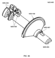
種々の実施形態では、下で開示される内部構成要素に加えて、自動注射器1は、2つの主要部品、密閉筐体MC-200、MC-300を含み、それらは、カップ形カバーMC-100の中に回転可能に保持され、カップ形カバーMC-100は、底側または注射接触表面MC-121も形成する。密閉筐体MC-200、MC-300は、上側MC-300半体および下側MC-200半体から作製され、それらは、十分な接着または強度を提供する超音波溶接の手段または代替手段を通して一緒に接合される。いくつかの実施形態では、上側MC-300半体と下側MC-200半体との間の接合は、それが気密シールであるようなものであり得る。さらに、筐体MC-200、MC-300、または筐体MC-200、MC-300を構成するその後の半体のうちの1つは、タブMC-210(例えば、図12参照)を含み得、それらは、動作中、カバーMC-100内で筐体MC-200、MC-300を誘導および拘束する成型または形成された突出部である。密閉筐体MC-200、MC-300は、その後の注射を実施するユーザのための一次インターフェースとして機能する。密閉筐体を形成する2つの半体は、それらが内部構成要素を位置付けて固定し得るような幾何学形状である(例えば、MC-201、MC-202、MC-204、MC-205、MC-206、MC-207、MC-208、MC-211、MC-213、MC-214、MC-216、MC-217、MC-218、MC-304、MC-305、MC-309、MC-310、MC-311、MC-312、MC-313、MC-314、MC-316)。
In various embodiments, in addition to the internal components disclosed below, the auto-
カバーMC-100は、筐体MC-200、MC-300の周囲に保護シュラウドを提供し、回転のために筐体を支持する。いくつかの実施形態では、注射を実施または開始することにおける第1のステップは、安全機構SS-200を除去することである。次のステップは、所定の場所にカバーMC-100の注射接触表面MC-121を設置することであり得る。前に記述されたように、安全機構SS-200は、自動注射器1の全体的向きを確立することにおいてユーザを補助し得、したがって、安全機構SS-200の除去から、カバーMC-100の注射接触表面MC-121が露出されると、それは、この向きをさらに確立し得る。カバーMC-100の注射接触表面MC-121は、以下の機能性を促進し得る触覚表面を提供し得る:注射中の自動注射器1のための安定化基部を提供すること、向きを確立することにおいてユーザを補助すること、および/または、接着剤の手段もしくは他の取り付け手段を通して自動注射器1を注射場所に取り付ける。
Cover MC-100 provides a protective shroud around enclosures MC-200, MC-300 and supports the enclosures for rotation. In some embodiments, the first step in performing or starting an injection is to remove the safety mechanism SS-200. The next step may be to put the injection contact surface MC-121 of the cover MC-100 in place. As previously described, the safety mechanism SS-200 may assist the user in establishing the general orientation of the auto-
種々の実施形態では、カバーMC-100は、起動中にカバーMC-100から離れるように筐体MC-200、MC-300を付勢し、使用を促進するために、その中に配置または形成されたばねSS-300(例えば、図5-6参照)を有する。カバーMC-100の側壁は、チャネル、スロット、戻り止め等MC-103(例えば、図15参照)を含み得、それらは、異なる位置MC-117、MC-118、MC-119、MC-120(図18参照)、または、筐体MC-200、MC-300の側壁上のタブもしくは突出部MC-210(例えば、21-22参照)または筐体MC-200、MC-300を形成し、整列を維持し、種々の位置(例えば、係止、係止解除、装備、および注射)の間の相対移動を制御するそのような構成要素と協働する位置(例えば、係止、係止解除、装備、および注射)に対応する。カバーMC-100に形成されるチャネル、スロット、戻り止め等MC-103は、自動注射器1のねじり、拡張、圧縮、およびその後の拡張中、筐体MC-200、MC-300を誘導し、注射方法および使用の異なる段階を促進する。
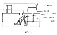
加えて、カバーMC-100は、連動装置SS-100(例えば、図11-14参照)を起動する手段を促進し、それによって、カバーMC100が注射位置MC-120にあり、注射が開始し、カバーMC-100に対する筐体MC-200、MC-300のその後の拡張が起こると、自動注射器1が2回圧縮されず、自動注射器1を単回使用にする。トリガ機構MC-109(例えば、図19-20参照)は、注射針NES-700が展開されたとしても、鋭器損傷防止特徴が機能することを確実にするために、連動装置SS-100が、常に、MDSまたはNESの前に起動されるであろうように、設計される。カバーMC-100は、自動注射器1の組立または動作管理のために、筐体MC-200、MC-300の向きを提供するように、形成、成型、または打抜加工された幾何学形状MC-101、MC-102、または印を含み得る。
In various embodiments, the cover MC-100 may be positioned or formed therein to bias the enclosures MC-200, MC-300 away from the cover MC-100 during activation and to facilitate use. spring SS-300 (see, eg, FIGS. 5-6). The sidewalls of the cover MC-100 may include channels, slots, detents, etc. MC-103 (see, eg, FIG. 15) that are located in different positions MC-117, MC-118, MC-119, MC-120 ( 18), or tabs or protrusions MC-210 on the sidewalls of the enclosure MC-200, MC-300 (see, e.g., 21-22) or enclosures MC-200, MC-300 to form and align positions (e.g., locking, unlocking, equipment, and injection). Channels, slots, detents, etc. MC-103 formed in the cover MC-100 guide the housings MC-200, MC-300 during twisting, expansion, compression and subsequent expansion of the auto-
In addition, the cover MC-100 facilitates a means of activating the interlock SS-100 (see, eg, FIGS. 11-14) so that the cover MC100 is in the injection position MC-120 and the injection begins; Subsequent expansion of the housings MC-200, MC-300 relative to the cover MC-100 occurs and the auto-
種々の実施形態では、自動注射器1が格納位置MC-117にあるとき、使用に先立って、自動注射器1は、ばねSS-300が圧縮され、自動注射器1が拘束される係止位置にある。係止位置MC-117から係止解除位置MC-118まで移動するために、ユーザは、筐体MC-200、MC-300の上面表面MC-300上に形成される握持表面MC-301(例えば、1つ以上のくぼみ、突出部、テクスチャ、コーティング、もしくは組み合わせ等)に起動力を加えることによって、筐体MC-200、MC-300を手動で回転させる。ユーザが加えた力は、係止位置MC-117から係止解除位置MC-118までカバーMC-100に対して密閉筐体MC-200、MC-300を変位させる。筐体MC-200、MC-300の側壁およびカバーMC-100上の整列マーク等の印は、自動注射器1の異なる位置(MC-117、MC-118、MC-119、MC-120)を示し得る。整列印は、外面から観察可能であるラベルまたは他の自動注射器1の構成要素(例えば、連動装置SS-100)を使用しても、示され得る。筐体MC-200、MC-300が係止位置MC-117から係止解除位置MC-118まで回転させられると、筐体MC-200、MC-300は、カバーMC-100から離れるように付勢され、自動注射器1は、装備位置MC-119まで拡張する。係止解除位置MC-118から装備位置MC-119までの拡張は、ユーザが、係止位置MC-117から係止解除位置MC-118まで自動注射器1を移動させるための起動力のみを握持表面MC-301に加える必要があるように、付勢部材SS-300内の貯蔵されたポテンシャルエネルギーを用いて自動的に実施される。カバーMC-100に対する密閉筐体MC-200、MC-300の自動平行移動および回転は、密閉筐体MC-200、MC-300上のタブまたは突出部MC-210と、カバーMC-100上のチャネル、スロット、戻り止め等MC-103とによって、拘束および誘導され得る。
In various embodiments, when the auto-
種々の実施形態では、筐体MC-200、MC-300が、装備位置MC-119に来ると、筐体MC-200、MC-300上のタブまたは突出部MC-210と、カバー壁MC-103上のガイドとは、筐体MC-200、MC-300が係止解除位置MC-118および係止位置MC-117に戻るように回転させられることを防止する。装備位置MC-119では、自動注射器1は、注射位置MC-120に向かって垂直にのみ変位させられることができる。自動注射器1の向きは、上側MC-300が上向きに(すなわち、注射場所から離れるように)面しており、カバーMC-100の平坦な底面MC-121が注射部位に対するようなものである。薬剤を注射するために、ユーザは、上側MC-300と垂直な法線力を加え、密閉筐体MC-200、MC-300をカバーMC-100の中に押し、自動注射器1の起動シーケンスおよび薬剤の注射を開始する。連動装置機構SS-100は、ユーザが圧力を解放すると、連動装置SS-100が係合され、第2の注射が試行されることができないように、自動注射器1が注射位置MC-120に到達する直前に起動される。完全な投薬を確実にするために、ユーザは、密閉筐体MC-200、MC-300上の力を維持し、配分された持続時間にわたって注射位置MC-120を維持し、次いで、自動注射器1の上側MC-300上の圧力を解放する。密閉筐体MC-200、MC-300上の圧力の解放は、付勢部材SS-300を用いて、密閉筐体MC-200、MC-300がカバーMC-100に対して平行移動することを可能にし、それによって、針NES-700を後退させ得る。種々の実施形態では、連動装置SS-100が前もって起動されたMC-109ので、それらは、密閉筐体MC-200、MC-300がカバーMC-100に対して平行移動している間に、それら自体に係合するであろう。注射が実施され、連動装置SS-100がトリガ機構MC-109に係合した後、最低でも、密閉筐体MC-200、MC-300上の注射力の2倍である力は、カバーMC-100の注射接触表面MC-121からの針NES-700の露出を可能にせず、安全に廃棄されることができる。
In various embodiments, when the chassis MC-200, MC-300 is in the mounting position MC-119, the tabs or protrusions MC-210 on the chassis MC-200, MC-300 and the cover wall MC- The guides on 103 prevent the housings MC-200, MC-300 from being rotated back to the unlocked position MC-118 and locked position MC-117. In the loading position MC-119, the auto-
以下の項目(1-11)のリストは、種々の実施形態による、自動注射器1の内部構成要素および機構の例示的起動シーケンス、ならびに個々の構成要素の相互作用を説明する。
The list of items (1-11) below describes an exemplary activation sequence of the internal components and mechanisms of the auto-
1.)注射を開始する前、ユーザは、任意のその後の動作の前に安全機構SS-200を除去することができる。安全機構SS-200は、除去時、注射表面MC-121がユーザに露出され、注射表面MC-121を保護し、それは、適切な向きを確立することにおいてさらに補助し得る。安全機構SS-200は、密閉筐体MC-200、MC-300が除去に先立ってカバーMC-100に対して変位することを防止する手段(例えば、連動装置SS-204)も提供することもでき、それによって、注射シーケンスは、最初に該機構SS-200を除去することなく開始しないこともある。安全機構SS-200は、偶発的排出の場合に注射針NES-700からユーザを保護する針シースNES-100も除去し得る。加えて、シースNES-100は、障壁NES-600(例えば、図38-40参照)と組み合わせて、注射針NES-700を覆うことができ、注射針NES-700の格納中、いかなる可能な汚染も防止し得る。したがって、注射時、針シースNES-100の除去に先立って、注射針NES-700は、無菌である。 1. ) Before starting an injection, the user can remove the safety mechanism SS-200 before any subsequent actions. Safety mechanism SS-200, upon removal, exposes injection surface MC-121 to the user and protects injection surface MC-121, which may further aid in establishing proper orientation. The safety mechanism SS-200 may also provide means (eg, interlock SS-204) to prevent displacement of the enclosure MC-200, MC-300 relative to the cover MC-100 prior to removal. can, whereby the injection sequence may not begin without first removing the mechanism SS-200. Safety mechanism SS-200 may also remove needle sheath NES-100, which protects the user from injection needle NES-700 in the event of accidental ejection. Additionally, the sheath NES-100 can be combined with a barrier NES-600 (see, eg, FIGS. 38-40) to cover the needle NES-700 and prevent any possible contamination during needle storage. can also be prevented. Therefore, prior to removal of the needle sheath NES-100, the needle NES-700 is sterile at the time of injection.
2.)安全機構SS-200の除去に続いて、ユーザは、係止位置MC-117から係止解除位置MC-118まで密閉筐体MC-200、MC-300を回転させることができ、そうすると、密閉筐体MC-200、MC-300は、付勢部材SS-300によって装備位置MC-119まで自動的に移動させられる。結果として、筐体MC-200、MC-300は、ある拘束された距離および角度で平行移動および回転する。ユーザが力を加え、装備位置MC-119から注射位置MC-120まで密閉筐体MC-200、MC-300を移行させると、密閉筐体MC-200、MC-300の内側で内部起動シーケンスを開始する機構は、トリガまたは突出部MC-106、MC-107(例えば、図15-16参照)である。起動トリガまたは突出部MC-106、MC-107は、カバーMC-100の表面上に成型または形成されることができる。空洞MC-202(例えば、図22-23参照)が、密閉筐体MC-200、MC-300の下半体MC-200の中に成型または形成され、密閉筐体MC-200、MC-300およびカバーMC-100が、起動機構MC-106、MC-107、または整列機構MC-105(例えば、図19-20参照)に干渉すること、もしくはそれを損傷することなく、互いに対して回転および平行移動することを可能にする。組立、起動、および注射中、密閉筐体MC-200、MC-300上に成型または形成される突出部またはタブMC-210と、カバーMC-100上の対応するチャネル、スロット、戻り止め等MC-103とは、界面接触し、カバー上の突出部またはトリガMC-105、MC-106、MC-107の損傷を防止するために十分なすき間および整列を提供し得る。カバーMC-100は、注射時に(例えば、自動注射器1が位置MC-120にあるときに)密閉筐体MC-200、MC-300内の対応する空洞MC-211(例えば、図23参照)と界面接触する整列支柱または突出部MC-105も有し得、それらは、密閉筐体MC-200、MC-300およびカバーMC-100の整列を補助し、密閉筐体MC-200、MC-300内に配置される対応する係止機構NES-500(例えば、図38-41参照)、MDS-100(例えば、図69-73参照)とともにカバーMC-100上のトリガMC-106、MC-107を向け得る。いくつかの実施形態では、カバーMC-100および/または密閉筐体MC-200、MC-300は、相対移動中に密閉筐体MC-200、MC-300とカバーMC-100との間の整列を維持することにおいて補助する追加の特徴(例えば、MC-103、MC-104、MC-109、MC-115、MC-210、SS-102)を含み得る。
2. ) Following removal of the safety mechanism SS-200, the user can rotate the sealed enclosure MC-200, MC-300 from the locked position MC-117 to the unlocked position MC-118, whereupon the sealed Enclosures MC-200, MC-300 are automatically moved to mounting position MC-119 by biasing member SS-300. As a result, the chassis MC-200, MC-300 translate and rotate at some constrained distance and angle. When the user applies force to move the sealed housings MC-200 and MC-300 from the installation position MC-119 to the injection position MC-120, the internal activation sequence is performed inside the sealed housings MC-200 and MC-300. The initiating mechanism is a trigger or protrusion MC-106, MC-107 (see, eg, FIGS. 15-16). Activation triggers or protrusions MC-106, MC-107 may be molded or formed on the surface of cover MC-100. A cavity MC-202 (see, for example, FIGS. 22-23) is molded or formed in the lower half MC-200 of the sealed enclosure MC-200, MC-300, and the sealed enclosure MC-200, MC-300. and cover MC-100 rotate and rotate relative to each other without interfering with or damaging activation mechanism MC-106, MC-107, or alignment mechanism MC-105 (see, eg, FIGS. 19-20). Allows for parallel movement. Protrusions or tabs MC-210 molded or formed on the sealed housing MC-200, MC-300 and corresponding channels, slots, detents, etc. MC on the cover MC-100 during assembly, activation and injection. -103 may interface and provide sufficient clearance and alignment to prevent damage to protrusions or triggers MC-105, MC-106, MC-107 on the cover. Cover MC-100 seals enclosure MC-200 during injection (eg, when auto-
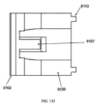
3.)ユーザが力を密閉筐体MC-200、MC-300の頂面MC-300に加え、密閉筐体MC-200、MC-300をカバーMC-100の中に圧縮し、注射を実施するとき、起動されるべき第1のシステムは、連動装置システムSS-100であり得る。連動装置システムSS-100を最初に起動することは、ユーザが針延長システム(NES)を展開するとき、連動装置システムSS-100が、常に、トリガ機構MC-109に係合するであろうことを確実にする。いくつかの実施形態では、連動装置SS-100は、密閉筐体MC-200、MC-300が注射中に圧縮されるとき、カバーMC-109と連動装置SS-101(例えば、図98-100参照)との間の締まり嵌めによって起動される。注射、および密閉筐体MC-200、MC-300上の圧力の解放に続いて、密閉筐体MC-200、MC-300が、カバーMC-100に対して自動的に変位させられ得、連動装置SS-100が、展開または係合される。起動に先立って、連動装置SS-100は、密閉筐体MC-200、MC-300内の空洞MC-201(例えば、図103参照)、MC-314(例えば、図29-34参照)の中に格納状態で保持されることができる。 3. ) When the user applies a force to the sealed enclosure MC-200, MC-300 top surface MC-300 to compress the sealed enclosure MC-200, MC-300 into the cover MC-100 and perform the injection. , the first system to be activated may be interlock system SS-100. The initial activation of the interlock system SS-100 is that whenever the user deploys the needle extension system (NES), the interlock system SS-100 will engage the trigger mechanism MC-109. to ensure In some embodiments, the interlock SS-100 is configured such that when the sealed enclosure MC-200, MC-300 is compressed during injection, the cover MC-109 and the interlock SS-101 (e.g., FIGS. 98-100 ) is activated by an interference fit between the Following injection and release of pressure on the enclosure MC-200, MC-300, the enclosure MC-200, MC-300 can be automatically displaced relative to the cover MC-100, interlocking Device SS-100 is deployed or engaged. Prior to activation, the interlock SS-100 is placed in a sealed enclosure MC-200, a cavity MC-201 (see, eg, FIG. 103) within MC-300, MC-314 (see, eg, FIGS. 29-34). can be held in storage at
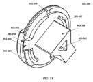
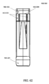
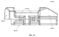
4.)連動装置SS-100の起動に続いて、針延長システム(NES)が、起動されることができる。カバーMC-100上の対応する針延長トリガまたは突出部MC-107は、所定の場所MC-203(例えば、図23参照)で密閉筐体MC-200、MC-300の平面を壊し、NESの固定具または係止機構NES-500に接触する。NESの固定具または係止機構NES-500は、付勢部材NES-800(例えば、図67-68参照)のポテンシャルエネルギーを保持することができる。付勢部材NES-800は、規定接触点NES-202(例えば、図48-50参照)において針筒NES-200(例えば、図46-50参照)に結合され得る。一実施形態では、付勢部材NES-800は、針筒NES-200を回転させるねじりばねである。固定具または係止機構NES-500は、針筒NES-200との干渉部分NES-201(例えば、図47参照)によって、ねじりばねNES-800のポテンシャルエネルギーを維持し得る。カバーMC-100上の針延長トリガまたは突出部MC-107と固定具または係止機構NES-500との間の接触部分NES-501(例えば、図60-62参照)は、係止機構NES-500を係合解除し、ねじりばねNES-800の中に貯蔵されたポテンシャルエネルギーを放出する。ねじりばねNES-800の解放は、針筒NES-200を回転させ、湾曲した注射針NES-700を展開する。筐体は、注射時に係止機構NES-500の係合解除を促進するための内部幾何学的部分MC-307(例えば、図31参照)を有し得る。 4. ) Following activation of the interlock SS-100, the Needle Extension System (NES) can be activated. A corresponding needle extension trigger or protrusion MC-107 on the cover MC-100 breaks the plane of the sealed housing MC-200, MC-300 at a predetermined location MC-203 (see, for example, FIG. 23) to open the NES. Contact the fixture or locking mechanism NES-500. The NES fixture or locking mechanism NES-500 can retain the potential energy of the biasing member NES-800 (see, eg, FIGS. 67-68). Biasing member NES-800 may be coupled to needle barrel NES-200 (see, eg, FIGS. 46-50) at defined contact point NES-202 (see, eg, FIGS. 48-50). In one embodiment, biasing member NES-800 is a torsion spring that rotates needle barrel NES-200. The fixture or locking mechanism NES-500 may maintain the potential energy of the torsion spring NES-800 through an interference portion NES-201 (see, eg, FIG. 47) with the needle barrel NES-200. The contact portion NES-501 (see, for example, FIGS. 60-62) between the needle extension trigger or protrusion MC-107 on the cover MC-100 and the fixture or locking mechanism NES-500 is the locking mechanism NES- 500 to release the potential energy stored in the torsion spring NES-800. Release of torsion spring NES-800 rotates needle barrel NES-200 and deploys curved needle NES-700. The housing may have an internal geometric portion MC-307 (see, eg, FIG. 31) to facilitate disengagement of the locking mechanism NES-500 during injection.
5.)係止機構NES-500が針筒NES-200から係合解除されると、ねじりばねNES-800は、針筒NES-200を回転させ得る。注射針NES-700は、要素NES-308(例えば、図53-54参照)を針筒NES-200に形成された対応する陥凹NES-207と篏合させる、針筒キャップNES-300(例えば、図51-54参照)によって、針筒NES-200に固定され、その中で保持され得る。針筒キャップNES-300は、要素NES-306(例えば、図53-54参照)、NES-206(例えば、図46-47参照)間の摩擦嵌めを通して、注射針NES-700を針筒NES-200に固定し得る。加えて、筒キャップNES-300は、要素NES-304(図51参照)、NES-305(図51参照)、NES-204(図49参照)、NES-205(図49参照)によって形成される摩擦または圧縮嵌めを通して、可撓性管類NES-900(図40参照)を注射針NES-700に固定し得る。さらに、針筒キャップNES-300は、針筒NES-200の回転を特定の角度に限定するための接触表面NES-301(図52参照)を提供する。種々の実施形態では、密閉筐体MC-200、MC-300の底半体MC-200は、回転中に針筒キャップNES-300に接触し、筒NES-200の角度変位を所望の注射深度に比例する所望の回転角に限定する、インターフェースMC-218(例えば、図21-22参照)を提供する。筒キャップNES-300と密閉筐体MC-200、MC-300の底半体MC-200とは、協働し、注射針NES-700が過剰回転することを防止し、適切な注射深度が達成されることを確実にする。針筒NES-200は、密閉筐体MC-200、MC-300の半体(例えば、MC-207、MC-312、MC-316、MC-302、MC-310、MC-309、MC-216)に形成されるガイド(例えば、NES-203(図46参照)、NES-303(図51参照)、NES-208(図48参照))、ならびに針筒ガイドNES-400(図55-59参照)を通して、回転中にその回転軸に沿って整列を維持する。これらのガイドは、軸方向整列を維持し、針筒NES-200および注射針NES-700が注射中に密閉筐体MC-200、MC-300に対して平行移動することを防止し得る。針筒ガイドNES-400は、自動注射器1の格納および注射中にNES係止機構NES-500(例えば、図60-62参照)を拘束支持および誘導するためのチャネルNES-401(図55参照)も提供し得る。いくつかの実施形態では、針筒キャップNES-300は、超音波溶接されるか(溶接NES-210(図49)、NES-307(図51)参照)、または2つの構成要素を一緒に接合する別の手段を利用することができる。加えて、システムのNES構成要素は、組立中、筐体MC-200、MC-300から独立して統合されることができる。
5. ) Once locking mechanism NES-500 is disengaged from needle barrel NES-200, torsion spring NES-800 may cause needle barrel NES-200 to rotate. Needle NES-700 includes needle barrel cap NES-300 (e.g., , FIGS. 51-54) can be secured to and retained within the needle barrel NES-200. The needle barrel cap NES-300 holds the injection needle NES-700 to the needle barrel NES- 300 through a friction fit between elements NES-306 (see, eg, FIGS. 53-54), NES-206 (see, eg, FIGS. 46-47). It can be fixed at 200. Additionally, barrel cap NES-300 is formed by elements NES-304 (see FIG. 51), NES-305 (see FIG. 51), NES-204 (see FIG. 49), and NES-205 (see FIG. 49). Flexible tubing NES-900 (see FIG. 40) may be secured to needle NES-700 through a friction or compression fit. Additionally, the needle barrel cap NES-300 provides a contact surface NES-301 (see FIG. 52) for limiting rotation of the needle barrel NES-200 to a specific angle. In various embodiments, the closed housing MC-200, the bottom half MC-200 of the MC-300, contacts the needle barrel cap NES-300 during rotation to adjust the angular displacement of the barrel NES-200 to the desired injection depth. An interface MC-218 (see, eg, FIGS. 21-22) is provided to define the desired rotation angle proportional to . The cylinder cap NES-300, the sealed housing MC-200, and the bottom half MC-200 of the MC-300 work together to prevent excessive rotation of the injection needle NES-700 and achieve an appropriate injection depth. ensure that The needle cylinder NES-200 is a sealed housing MC-200, half of MC-300 (for example, MC-207, MC-312, MC-316, MC-302, MC-310, MC-309, MC-216 ) (for example, NES-203 (see FIG. 46), NES-303 (see FIG. 51), NES-208 (see FIG. 48)), as well as the needle barrel guide NES-400 (see FIGS. 55-59). ) to maintain alignment along its axis of rotation during rotation. These guides may maintain axial alignment and prevent the needle barrel NES-200 and needle NES-700 from translating relative to the sealed housing MC-200, MC-300 during injection. Needle barrel guide NES-400 has channel NES-401 (see FIG. 55) for constraining support and guidance of NES locking mechanism NES-500 (see, eg, FIGS. 60-62) during retraction and injection of auto-
6.)注射針NES-700の回転時、湾曲した注射針の遠位端NES-701(図65-66参照)は、密閉筐体MC-200、MC-300の下半体に形成された開口MC-204(図23参照)を通過し、湾曲した注射針NES-700の一部が巻きを解く間にまっすぐにされるように、カバーMC-100上の針ガイドMC-110(図19参照)と接触する。注射針NES-700が針ガイドMC-110上の表面MC-112、MC-113(図19参照)に接触する場所は、針ガイドMC-110の引っかき、またはこすりの可能性を軽減するため、かつ残渣を生成する可能性を軽減するために、遠位端NES-701(例えば、ランセット)がガイドMC-110と接触していないようなものであり得る。針ガイドMC-110に加えて、密閉筐体MC-200、MC-300は、注射中に(針軸に対して)可能な半径方向変位をさらに限定するためのブレースMC-309(図31-34参照)を提供し得る。 6. ) When the needle NES-700 rotates, the curved needle distal end NES-701 (see FIGS. 65-66) passes through an opening MC formed in the lower half of the sealed housing MC-200, MC-300. -204 (see FIG. 23) and the needle guide MC-110 (see FIG. 19) on the cover MC-100 so that a portion of the curved needle NES-700 is straightened during unwinding. come into contact with The location where the needle NES-700 contacts the surfaces MC-112, MC-113 (see FIG. 19) on the needle guide MC-110 are: And to reduce the possibility of creating debris, the distal end NES-701 (eg, lancet) may be such that it is not in contact with the guide MC-110. In addition to the needle guide MC-110, the enclosed housing MC-200, MC-300 includes a brace MC-309 (Fig. 31- 34) can be provided.
7.)針筒係止機構NES-500が第1のトリガMC-107によって係合解除された後、カバーMC-100の中への筐体MC-200、MC-300のさらなる圧縮は、第2のトリガMC-106が薬剤分注システム(MDS)の解放を開始し、薬剤を送達することを可能にする。NESと同様に、薬剤分注トリガMC-106は、対応する固定具または係止機構MDS-100と接触しMDS-101、該係止機構MDS-100を解放する。トリガMC-106は、固定具または係止機構MDS-100が所定の場所MC-203にあるとき、インターフェース部分MDS-101(図74参照)において接触する。固定具または係止機構MDS-100は、付勢部材MDS-700(図72参照)の貯蔵されたポテンシャルエネルギーを維持する。一実施形態では、付勢部材MDS-700は、保持装置MDS-400、MDS-300(図72-73参照)およびキーパーMDS-200(図72-73参照)によって拘束支持される圧縮ばねである。固定具または係止機構MDS-100の解放は、保持装置MDS-300、MDS-400がキーパーMDS-200に対して変位し、プランジャMDS-900(図72参照)と接触することを可能にする。プランジャMDS-900に接触した後、保持装置MDS-300、MDS-400およびプランジャMDS-900は、一緒に変位する。保持装置MDS-300、MDS-400、およびそれに付随して、プランジャMDS-900の全変位は、干渉を提供し得るキーパーMDS-200、または保持装置MDS-300、MDS-400の移動を制限するための別の特徴MDS-201(図78-80参照)、MDS-309(図81-84参照)、MDS-409によって、決定される。したがって、キーパーMDS-200に対する保持装置MDS-300、MDS-400の変位は、リザーバMDS-800(図94-95参照)から放出される薬剤の量に比例し得る。さらに、筐体MC-200、MC-300は、注射中に固定具または係止機構MDS-100の係合解除を支援するために十分な内部幾何学形状MC-306(図31参照)を有し得る。 7. ) After the needle barrel locking mechanism NES-500 is disengaged by the first trigger MC-107, further compression of the housings MC-200, MC-300 into the cover MC-100 causes the second A trigger MC-106 initiates the release of the drug dispensing system (MDS), allowing drug to be delivered. Similar to the NES, the drug dispensing trigger MC-106 contacts a corresponding fixture or locking mechanism MDS-100 to release MDS-101, the locking mechanism MDS-100. Trigger MC-106 contacts at interface portion MDS-101 (see FIG. 74) when fixture or locking mechanism MDS-100 is in place MC-203. A fixture or locking mechanism MDS-100 maintains the stored potential energy of the biasing member MDS-700 (see FIG. 72). In one embodiment, biasing member MDS-700 is a compression spring that is constrained and supported by retainer MDS-400, MDS-300 (see FIGS. 72-73) and keeper MDS-200 (see FIGS. 72-73). . Release of the fixture or locking mechanism MDS-100 allows the retainers MDS-300, MDS-400 to be displaced relative to the keeper MDS-200 and contact the plunger MDS-900 (see FIG. 72). . After contacting plunger MDS-900, retainers MDS-300, MDS-400 and plunger MDS-900 are displaced together. The total displacement of the retainer MDS-300, MDS-400 and concomitantly the plunger MDS-900 limits the movement of the keeper MDS-200, or the retainer MDS-300, MDS-400, which can provide interference. determined by another feature MDS-201 (see FIGS. 78-80), MDS-309 (see FIGS. 81-84), MDS-409. Thus, the displacement of retention devices MDS-300, MDS-400 relative to keeper MDS-200 can be proportional to the amount of drug released from reservoir MDS-800 (see FIGS. 94-95). In addition, housings MC-200, MC-300 have internal geometry MC-306 (see FIG. 31) sufficient to assist disengagement of fasteners or locking mechanisms MDS-100 during injection. can.
8.)MDS固定具または係止機構MDS-100(図74)の解放時、保持装置MDS-300、MDS-400は、圧縮ばねMDS-700の貯蔵されたポテンシャルエネルギーに起因して、変位させられ、プランジャMDS-900に接触することができる。分注針MDS-600が、保持装置MDS-300、MDS-400に結合され、可撓性管類NES-900を通して注射針NES-700と流体接触することができる。さらに、注射針NES-700のような分注針MDS-600は、注射MC-120に先立っていかなる汚染も防止するように、保護障壁MDS-500を用いて保護される。したがって、圧縮ばねMDS-700の解放は、保持装置MDS-300、MDS-400をプランジャMDS-900に接触させ、強制的に分注針MDS-600に保護障壁MDS-500およびプランジャMDS-900の両方を穿刺させる。薬剤は、プランジャMDS-900の移動の反対方向に、リザーバMDS-800から分注針MDS-600(図91参照)の外に分注される。種々の実施形態では、保持装置MDS-300、MDS-400は、一緒に、または十分な接着もしくは強度を提供する代替手段によって、超音波溶接される(例えば、溶接MDS-405、MDS-305(図84、85参照)を伴う)、2つの半体(例えば、MDS-300、MDS-400)から成る。保持装置の半体MDS-300、MDS-400は、摩擦嵌め(MDS-602、MDS-302、MDS-402(図82、84、91参照))を通して分注針MDS-600を固定し得る。加えて、保持装置の半体MDS-300、MDS-400は、摩擦または圧縮嵌めMDS-303、MDS-304、MDS-403、MDS-404(図83-85参照)を通して、可撓性管類NES-900を分注針MDS-600に固定し、分注中にいかなる可能な係合解除も防止し得る。一緒に合わせられると、保持装置MDS-300、MDS-400の各半体は、組立中に2つの半体MDS-300、MDS-400の適切な整列を強制する向き特徴MDS-301、MDS-401(図83-85参照)を有し得、それらは、適切な整列で分注針MDS-600および管類NES-900を維持するようにも作用する。密閉されたリザーバMDS-800を維持するために、かつ薬剤を汚染しないために、分注針MDS-600は、注射時に保護障壁MDS-500(図89-90参照)およびプランジャMDS-900のみを貫通し得る。 8. ) upon release of the MDS fixture or locking mechanism MDS-100 (FIG. 74), the retainers MDS-300, MDS-400 are displaced due to the stored potential energy of the compression spring MDS-700, A plunger MDS-900 can be contacted. Dispensing needle MDS-600 is coupled to retainers MDS-300, MDS-400 and can be in fluid contact with injection needle NES-700 through flexible tubing NES-900. Additionally, a dispensing needle MDS-600, like the injection needle NES-700, is protected with a protective barrier MDS-500 to prevent any contamination prior to injection MC-120. Thus, the release of the compression spring MDS-700 brings the retainers MDS-300, MDS-400 into contact with the plunger MDS-900 and forces the dispensing needle MDS-600 into the protective barrier MDS-500 and the plunger MDS-900. Puncture both. Drug is dispensed from reservoir MDS-800 and out of dispensing needle MDS-600 (see FIG. 91) in the opposite direction of travel of plunger MDS-900. In various embodiments, the retainers MDS-300, MDS-400 are ultrasonically welded together or by alternative means that provide sufficient adhesion or strength (e.g., welding MDS-405, MDS-305 ( 84, 85)), consisting of two halves (eg MDS-300, MDS-400). The retainer halves MDS-300, MDS-400 may secure the dispensing needle MDS-600 through a friction fit (MDS-602, MDS-302, MDS-402 (see FIGS. 82, 84, 91)). In addition, the retainer halves MDS-300, MDS-400 are attached to flexible tubing through a friction or compression fit MDS-303, MDS-304, MDS-403, MDS-404 (see FIGS. 83-85). The NES-900 may be secured to the dispense needle MDS-600 to prevent any possible disengagement during dispense. When mated together, each half of the retainer MDS-300, MDS-400 has an orientation feature MDS-301, MDS-400 that enforces proper alignment of the two MDS-300, MDS-400 halves during assembly. 401 (see FIGS. 83-85), which also act to maintain the dispensing needle MDS-600 and tubing NES-900 in proper alignment. In order to keep the reservoir MDS-800 sealed and not to contaminate the drug, the dispensing needle MDS-600 only covers the protective barrier MDS-500 (see FIGS. 89-90) and plunger MDS-900 during injection. can penetrate.
9.)NESおよびMDSをそれぞれ起動する針延長および薬物分注トリガMC-106、MC-107の両方は、係合解除するために要求される力を低減させ、トリガMC-106、MC-107における誘発された応力を限定するための接触点におけるそれらのそれぞれの係止機構NES-501(図60-62参照)、MDS-101(図74参照)への補完的輪郭形成表面を有し得る。加えて、所定の相互作用場所MC-203を介して、筐体MC-200、MC-300は、拘束支持部MC-219(図26参照)を提供し、係合解除力によって誘発されるトリガMC-106、MC-107のいかなる可能な変位も限定し得る。 9. ) both the needle extension and drug dispense triggers MC-106, MC-107 activating the NES and MDS, respectively, reduced the force required to disengage, and the triggering in triggers MC-106, MC-107 May have complementary contoured surfaces to their respective locking mechanisms NES-501 (see FIGS. 60-62), MDS-101 (see FIG. 74) at the point of contact to limit applied stress. In addition, via predetermined interaction location MC-203, housing MC-200, MC-300 provides restraining support MC-219 (see FIG. 26) to provide a disengagement force induced trigger Any possible displacement of MC-106, MC-107 can be limited.
10.)分注針MDS-600の近位端MDS-604(図91参照)は、1本の可撓性ホースまたは管類NES-900によって注射針NES-700の近位端NES-703(図65参照)に流体的に接続され得る。NESおよびMDSの起動のタイミングは、注射針NES-700が組織に埋め込まれ、薬物が指定または所定の時間枠内に分注されるようなものであり得る。 10. ) The proximal end MDS-604 (see FIG. 91) of dispensing needle MDS-600 is connected to the proximal end NES-703 (see FIG. 65) of needle NES-700 by a piece of flexible hose or tubing NES-900. see). Timing of activation of NES and MDS may be such that the needle NES-700 is implanted in tissue and drug is dispensed within a specified or predetermined timeframe.
11.)注射およびユーザによる密閉筐体MC-200、MC-300への圧力の解放後、密閉筐体MC-200、MC-300は、付勢部材SS-300に起因して、カバーMC-100に対して自動的に平行移動し得る。いくつかの実施形態では、付勢部材は、圧縮ばねSS-300である。密閉筐体MC-200、MC-300のその後の拡張中、連動装置SS-100は、それらの空洞MC-201、MC-314から除去され、密閉筐体MC-200、MC-300とカバーMC-100との間のいかなる相対的移動も制限する。連動装置SS-100は、自動注射器1が圧潰されることを防止し、それによって、カバーMC-100からの注射針NES-700の遠位端NES-701のその後の延長を防止する。カバーMC-100に対する密閉筐体MC-200、MC-300の拡張は、自動注射器1の中の注射針NES-700を完全に引き出し、隠すために十分であり得る。加えて、カバーMC-100内のチャネル、スロット、戻り止め等MC-103、および密閉筐体MC-200、MC-300上の成型または形成されたタブもしくは突出部MC-210は、互いに対するカバーMC-100または密閉筐体MC-200、MC-300のいかなる回転も防止し得る。自動注射器1のその後の圧潰を防止する連動装置SS-100と、カバーMC-100または筐体MC-200、MC-300を回転させることができないこととは、安全な廃棄の手段を可能にし、偶発的な針露出NES-700を防止する。
11. ) After injection and release of pressure on the enclosure MC-200, MC-300 by the user, the enclosure MC-200, MC-300 is pushed into the cover MC-100 due to the biasing member SS-300. can be automatically translated in relation to In some embodiments, the biasing member is a compression spring SS-300. During subsequent expansion of enclosed enclosures MC-200, MC-300, interlocks SS-100 are removed from their cavities MC-201, MC-314 and enclosed enclosures MC-200, MC-300 and cover MC Limit any relative movement between -100. Interlock SS-100 prevents
以下の段落は、自動注射器1の代替または補完的構成および起動シーケンスを含む、自動注射器1の別の実施形態を説明する。
The following paragraphs describe alternative embodiments of the auto-
本実施形態では、自動注射器1は、格納中、注射中、および注射後、自動注射器1のある機能性を可能にするための内部電源を有し得る。自動注射器1は、注射を実施するための可聴命令を提供し得る。加えて、日常のスマートデバイスへの自動注射器1の接続性は、追加の機能性を可能にする。接続されたスマートデバイスは、注射を実施するための視覚および/または聴覚命令を表示し得る。ある実施形態は、ユーザが温度および自動注射器1の場所を監視することを可能にし得る。加えて、接続されたスマートデバイスは、ユーザが、他の自動注射器1が近くにあるかどうかを確認することを可能にし得る。追加の実施形態は、注射が開始されると、スマートデバイスが緊急時対応要員または最近親者に連絡することを可能にし得る。さらに、自動注射器1についての情報が、製造業者によって遠隔で監視され得る。
In this embodiment, the auto-
上で説明される実施形態と同様に、本実施形態は、適切な人間工学原理を通して、任意の注射を実施することに先立って、自動注射器1の向きを確立することができる。自動注射器1は、日常の用途からの既存の精神モデルを活用する直感的インターフェースをユーザに提示し得る。ユーザインターフェースに関して、追加のまたは代替実施形態は、注射を実施することに先立って、向きを確立することにおいてユーザを補助し得る、以下の要素の可能な変形例を用いて、同一の利益を提供するであろう:幾何学形状または要素1101(図115参照)、触覚表面、印、標識、および/または着色。
As with the embodiments described above, this embodiment, through appropriate ergonomic principles, can establish the orientation of the auto-
ある実施形態では、自動注射器1は、任意のその後の動作の前に除去されるべき安全機構SS-200を含む。注射表面MC-121は、安全機構SS-200が除去されると、ユーザに露出され、適切な向きを確立することにおいてさらに補助し得る。安全機構SS-200は、注射シーケンスが最初に安全機構SS-200を除去することなく開始しないように、自動注射器1が除去に先立って係止位置3102(図110-111参照)から係止解除位置3103、3104(図110-111参照)まで移動することを防止する手段も提供し得る。代替として、または加えて、安全機構SS-200は、偶発的排出が起こった場合に注射針4102(図122参照)からユーザを保護するか、または類似機能性を促進し得る保護シュラウドもしくはシースNES-100を除去し得る。したがって、安全機構SS-200の除去は、例えば、以下の機能性を提供または促進し得る:自動注射器1の向きを確立すること、除去に先立って密閉筐体の回転を防止するための連動装置SS-204を提供すること、注射針4102からユーザを保護すること、注射針4102または注射針4102からユーザをさらに保護するであろう、連合または結合された構成要素NES-100を除去すること、およびカバー3100(図110-111参照)の注射接触表面MC-121上の触覚コーティングまたは表面を保護すること。
In certain embodiments, auto-
下で開示される内部構成要素に加えて、自動注射器1は、2つの主要部品、密閉筐体1100、2100(図105-107参照)を含み、それらは、カップ形カバー3100の中に回転可能に保持され、底側または注射接触表面MC-121も形成し得る。密閉筐体は、十分な接着または接合強度を提供する超音波溶接の手段または代替手段を通して一緒に接合される上半体1100および下半体2100から作製されることができる。いくつかの実施形態では、上半体1100と下半体2100半体との間の接合は、気密シールを形成し得る。ある場合、筐体1100、2100、または筐体1100、2100を備えているその後の半体1100、2100のうちの1つは、動作中、カバー3100内の1100、2100を誘導および拘束する成型または形成された突出部2107(図112-113参照)を含む。密閉筐体1100、2100は、注射を実施するユーザのための一次インターフェースとして機能することができる。場合により密封されている筐体1100、2100に加えて、密閉筐体1100、2100は、筐体の内部チャンバを完全に封入するための追加の密閉構成要素MC-215(図26参照)、MC-315(図31-32参照)、または複合物を含み得る。この密閉チャンバは、例えば、以下の機能性を果たし得る:内部の所望の清浄度基準を提供および維持すること、耐水性エンクロージャを提供すること、および内部環境と外部環境との間の圧力差を可能にすること。自動注射器1のいくつかの実施形態は、注射の時間まで所望の内部条件を保持し得る。密閉筐体を形成する2つの半体1100、2100は、内部構成要素を位置付けて固定し得る幾何学形状および/または構成要素(例えば、1102、1103、1104、1105、1106、1107、1108、1109、2101、2102、2103、2104、2105、2106、2108、2109、2110、2112、2113)を有することができる。
In addition to the internal components disclosed below, the auto-
以下の項目(1-14)のリストは、種々の実施形態による、自動注射器1の内部構成要素および機構の別の例示的起動シーケンス、ならびに個々の構成要素の相互作用を説明する。
The list of items (1-14) below describes another exemplary activation sequence of the internal components and mechanisms of the auto-
1.)ユーザがカバー3100から筐体1100、2100を係止解除すると、筐体1100、2100は、装備位置3103(図110-111参照)まで自動的に移動する。筐体1100、2100は、ある拘束された距離および角度で平行移動および回転する。密閉筐体の内側で内部起動シーケンスを起動する機構は、カバー3100の表面上に成型または形成されるトリガまたは突出部MC-106、MC-107である。空洞MC-202、MC-211が、密閉筐体1100、2100の下半体2100の中に成型または形成され、密閉筐体およびカバー2100が、起動または整列機構に干渉すること、もしくはそれを損傷することなく、互いに対して回転および平行移動することを可能にする。組立(位置3105参照)、起動(位置3102、3103参照)、および注射(位置3104参照)中、密閉筐体1100、2100上に成型または形成される突出部またはタブ2107、およびカバー3100上の対応するチャネル、スロット、戻り止め等3106、3108、3107(図110参照)は、界面接触し、カバー3100上の突出部またはトリガMC-106、MC-107の損傷を防止するために十分なすき間および整列を提供し得る。さらに、カバー3100は、密閉筐体1100、2100およびカバー3100の整列を補助し、密閉筐体1100、2100内に配置される対応する係止機構5100(図136参照)、7110(図116参照)とともに、カバー3100上のトリガMC-106、MC-107を向け得るように、注射時に密閉筐体1100、2100内の対応する空洞MC-211と界面接触する整列支柱または突出部MC-105を有することができる。加えて、カバー3100および/または密閉筐体1100、2100は、相対移動中に密閉筐体1100、2100とカバー3100との間の整列を維持することにおいて補助する追加の特徴を含み得る。自動拡張が、その中に配置または形成されたばね3101(図108-111参照)に起因して起こり、起動中にカバー3100から離れるように筐体1100、2100を付勢し、使用を促進し得る。ある実施形態では、筐体1100、2100は、係止位置3102に戻され、密閉筐体の内部密閉性質を維持することができる。係止位置3103、3104に戻るために、ユーザは、筐体1100、2100をカバー3100中に圧縮し、反対方向に筐体1100、2100を回転させる。
1. ) When the user unlocks the
2.)ある実施形態では、内部注射針4102は、カバー3100の底側に形成された針開口MC-112と整列させられていない。したがって、注射針4102が不注意に不発であった場合、針NES-701の鋭い遠位端は、カバーMC-121の底側を通して貫通しないであろう。ユーザは、自動注射器1上に存在する印および標識を用いて、カバー3100に対して筐体1100、2100の位置付けを確かめ得る。
2. ) In some embodiments, the
3.)自動注射器1が係止解除位置MC-118に来て、起動された位置3103、3104に移行すると、筐体1100、2100は、トリガMC-106、MC-107への干渉なしに自由に回転することができる。注射を促進するための自動注射器1の手動圧縮に先行して、筐体1100、2100は、起動された位置3103への偶発的移動が起こった場合、係止位置3102にリセットされるか、または戻されることができる。
3. ) When the auto-
4.)筐体1100、2100がカバー3100の中に圧縮され、装備位置3104から注射位置MC-120まで移行すると、カバー3100上のトリガまたは突出部MC-106、MC-107は、筐体2100上の指定場所MC-203を穿刺し、対応するロック5100、7110と接触し、注射シーケンスを開始する。トリガMC-106、MC-107が、いかなる不正確な破損も引き起こすことなく、またはトリガMC-106、MC-107の構造を損なうことなく、下筐体半体2100の底部側を通して貫通することを可能にする。したがって、トリガMC-106、MC-107が貫通するエリアMC-203は、穿孔または他の補助MC-219(例えば、異なる材料等)を含み得る。
4. ) Triggers or protrusions MC-106, MC-107 on
5.)ユーザが自動注射器1を圧縮し、注射を実施すると、第1のトリガMC-107は、下筐体半体2100を穿刺し、湾曲した注射針4102の巻きを解くことを開始する。巻きを解くことは、係止機構5100を係合解除させる第1のトリガMC-107によって開始される。第1のトリガMC-107は、筐体を穿刺し、巻きを解く係止機構5100に接触する。巻きを解く係止機構5100は、それが格納位置、起動位置、および装備位置3102、3103、3104中にある針筒4100(図125-130参照)から後退させられることによって係合解除される。筐体1100、2100は、注射の時間中に係止機構5100、7110の係合解除を支援するために十分な内部幾何学形状(要素MC-306、MC-307参照(図31参照))を有し得る。第1のトリガMC-307との係合に先立って、注射針4102の巻きを解くことは、巻きを解く係止機構5100によって防止され、針筒4100が回転することを阻止し得る。したがって、対応するねじりばね8100は、巻かれたままであり、負荷下にある。本実施形態では、注射針4102の一部は、注射に先立った螺旋形状と、注射時のまっすぐにされた形状とを有する。注射針4102の螺旋形状は、自動注射器1が薄型および高アスペクト比を維持することを可能にする。加えて、針4102は、製造または注射中の巻きを解く間に損なわれないであろうような材料であり得る。
5. ) When the user compresses the auto-
6.)係止機構5100が針筒4100から係合解除されると、ねじりばね8100は、設定された角度で針筒4100を自由に回転させる。注射針4102は、針筒4100に形成された対応する陥凹4112(図125-126参照)と篏合する保持装置4103(図122参照)に固定されることができる。針筒4100が回転すると、螺旋注射針4102の一部は、巻きを解かれる。本実施形態では、注射前に湾曲された針4102の一部は、注射中にまっすぐにされ、組織に埋め込まれることができる。筐体の上半体1100および下半体2100に成型される一対の対向するリブ2102(図108参照)、1104(図114-115参照)は、巻きを解くことおよび跳ね返りの両方中、針筒4100を回転中に定位置で適切に整列させられた状態に保つ。加えて、針筒4100を整列させ、誘導するリブまたは筐体4113(図125-126参照)、1104、2102が、形成され、または注射針4102を誘導し、針筒4100から係合解除することを可能にするような幾何学形状(要素1103(図114-115参照)、2103(図112参照)参照)を有し得る。
6. ) Once
7.)螺旋注射針4102の遠位端NES-701は、注射針4102が開口2111によって巻きを解く間にまっすぐにされるように、下筐体半体2100に形成された注射針4102と類似するサイズの開口2111(図112-113参照)を通過する。干渉要素4107(図125-127参照)によって針筒4100の回転を制御することは、筒4100が所望される所定の度数で回転させられることを確実にし、針4102の遠位端NES-701が所望の注射深度において停止されることを確実にする。
7. ) The distal end NES-701 of the
8.)加えて、針4102の遠位端NES-701が、下筐体半体2100から退出するとき、それは、開口2111を覆うシールを通過し、穿刺し得る。シールは、筐体1100、2100の内部と外部側環境との間の障壁として作用する。このシールは、接着して付着させられた薄いTPE膜(例えば、Santoprene(登録商標)材料)であり得、それは、筐体1100、2100を密封した状態に保つ。加えて、このタイプのシールは、いかなる材料も除去することなく、針4102の遠位端NES-701が通過することを可能にし、注射中の閉栓効果および針4102の内部管腔またはボアの部分または完全遮断を回避する。シールはまた、筐体の無菌内部環境が維持されることも確実にし得る。
8. ) Additionally, as the distal end NES-701 of the
9.)針筒4100の巻きを解く回転が完了すると、ねじりばね8100は、針筒4100から係合解除することができる。ねじりばね8100は、針筒4100およびねじりばね8100の両方と接触している巻きを解くばねテンショナ4104(図128参照)が、ねじりばね接触点4106(図128参照)と、非円形を有するカラー付き表面4105(図129-130参照)とを有するので、針筒4100から係合解除することができる。一実施形態では、ねじりばね接触表面4114(図137-138参照)は、非円形カラー4105に起因して、ねじりばね8100の軸方向変位を引き起こし、ねじりばね8100の近位端8103(図140参照)が筒4100上の接触点4106から上および外に上昇し、針筒4100から係合解除することを可能にする。係合解除は、筒4100上に注射針4102の跳ね返りを実施する跳ね返りねじりばね8101が、巻きを解くねじりばね8100を再び巻く必要がないように、起こり得る。
9. ) Upon completion of the unwinding rotation of the
10.)針筒係止機構5100が第1のトリガMC-107によって係合解除された後、カバー3100の中への筐体1100、2100のさらなる圧縮は、第2のトリガMC-106が薬剤の分注を開始することを可能にする。薬剤を含むリザーバまたはバイアル7100に関連付けられるプランジャ7102は、圧縮ばね7106によって前方に推進または駆動され、それは、次に、薬剤を分注する。圧縮ばね7106は、第2のトリガMC-106が格納位置でばね7106を拘束支持および保持する保持装置7101を解放したとき、作動させられる。圧縮ばね7106は、保持装置7101、次に、プランジャ7102をバイアル7100の中に駆動し、分注ポート7104を通してバイアル7100から外に薬剤を押し進める。
10. ) After needle
11.)注射針4102の近位端NES-703は、1本の可撓性ホースまたは管類NES-900によって分注ポート7104に流体的に接続される。巻きを解くことNESおよび薬剤投与MDSのタイミングは、注射NESおよび薬剤MDS送達が短い指定時間窓内で(例えば、圧縮から数秒後に)起こるようなものである。
11. ) The proximal end NES-703 of the
12.)自動注射器1が注射場所に対して圧縮され、注射が開始すると、個人は、指定持続時間にわたって注射場所に対して自動注射器1を保持する。指定持続時間後の自動注射器1への圧力の解放時、注射針4102の跳ね返りが開始する。付勢部材3101に起因して、筐体1100、2100は、自動的に拡張し、拡張時、第3の係止9100(図133-134参照)機構を解放し、次に、跳ね返りねじりばね8101(図129参照)を起動する。
12. ) Once the auto-
13.)自動注射器1が圧縮構成である間、跳ね返りねじりばね8101は、別のテンショナ9101(図131-132参照)および保持装置9100によって巻かれた状態で維持されることができる。この跳ね返りばね保持装置9100は、自動注射器1の圧縮および用量の注射中、跳ね返りねじりばね8101の緊張状態を維持し得る。跳ね返りばね8101は、注射針4102の巻きを解く間に針筒4100から係合解除され得ることに留意されたい。拡張に続いて、注射後、跳ね返りばね8101は、注射針4102が跳ね返らせられるように、針筒4100の干渉要素4107に係合することができる。針筒4100上の跳ね返りばね8101のこの係合4107は、巻きを解くプロセス中に針筒4100の軸方向移動によって促進される。跳ね返りばね8100が針筒4100から係合解除されると、跳ね返りねじりばね8101が巻きを解除すること(かつ時期尚早に注射針4102を跳ね返らせること)を防止するために、トリガMC-106は、自動注射器1の完全圧縮が自動注射器1の拡張まで一時的ばね保持装置として作用するように、跳ね返りばね保持装置9100を作動させる。
13. ) While the auto-
14.)自動注射器1が、注射が完了した後に拡張することを可能にされると、トリガMC-106は、係合解除し、テンショナ9101を解放し、跳ね返りねじりばね8101が注射針4102を筐体1100、2100の中に跳ね返りさせることを可能にする。続いて、連動装置SS-100は、注射針4102が再び展開されることができることを防止する。
14. ) When the auto-
下記の表は、図に表出する参照番号の名称および簡潔な説明を提供する。
本明細書で採用される用語および表現は、限定ではなくて説明の用語および表現として使用され、そのような用語および表現の使用には、図示および説明される特徴またはその部分のいかなる均等物も除外する意図はない。加えて、本発明のある実施形態が説明されたが、本明細書に開示される概念を組み込む他の実施形態が、本発明の精神および範囲から逸脱することなく使用され得ることが、当業者に明白であろう。いくつかの実施形態の構造特徴および機能は、種々の組み合わせおよび順列で配列され得、全ては、開示される発明の範囲内と見なされる。別様に必要とされない限り、種々の方法における記載されたステップは、任意の順序で実施され得、あるステップは、実質的に同時に実施され得る。故に、説明される実施形態は、あらゆる点に関して、制限的ではなくて例証的のみと見なされるものである。さらに、本明細書に説明される構成は、決して限定的ではなくて例証的として意図される。同様に、物理的解説が解説目的のために提供されているが、任意の特定の理論もしくは機構によって拘束されること、またはそれに従って請求項を限定することも意図しない。 The terms and expressions employed herein are used as terms of description and not of limitation, and use of such terms and expressions does not imply any equivalents of the features illustrated and described or portions thereof. No exclusions are intended. Additionally, while certain embodiments of the invention have been described, it will be appreciated by those skilled in the art that other embodiments incorporating the concepts disclosed herein may be used without departing from the spirit and scope of the invention. will be clear to The structural features and functions of some embodiments may be arranged in various combinations and permutations, all considered within the scope of the disclosed invention. Unless required otherwise, steps recited in various methods may be performed in any order, and certain steps may be performed substantially concurrently. Accordingly, the described embodiments are to be considered in all respects only as illustrative and not restrictive. Additionally, the configurations described herein are intended to be illustrative rather than limiting in any way. Similarly, although a physical discussion is provided for illustrative purposes, it is not intended to be bound by any particular theory or mechanism, or to limit the claims accordingly.
Claims (24)
筐体と、
前記筐体内に配置された薬剤分注システムであって、前記薬剤分注システムは、前記薬剤用量を含むように適合された薬剤リザーバを備えている、薬剤分注システムと、
前記薬剤リザーバに結合された針延長機構と
を備え、
前記針延長機構は、湾曲した注射針と、針ガイドとを備え、前記針ガイドは、前記湾曲した注射針を、前記針ガイドを通した前記湾曲した注射針の展開中、まっすぐにするように適合されており、それによって、前記湾曲した注射針が自己でまっすぐになるものではなく前記針ガイドによってまっすぐにされるようになっていて、前記コンパクトな高アスペクト比自動注射器による前記薬剤用量の分注を促進する、コンパクトな高アスペクト比自動注射器。 A compact high aspect ratio auto-injector for subcutaneous or intramuscular drug dose delivery, said compact high aspect ratio auto-injector comprising:
a housing;
a drug-dispensing system disposed within the housing, the drug-dispensing system comprising a drug reservoir adapted to contain the drug dose;
a needle extension mechanism coupled to the drug reservoir;
The needle extension mechanism comprises a curved needle and a needle guide for straightening the curved needle during deployment of the curved needle through the needle guide. adapted so that the curved injection needle is straightened by the needle guide rather than self-straightening and dispensing the drug dose by the compact high aspect ratio auto-injector. A compact, high-aspect-ratio auto-injector that facilitates injection.
Priority Applications (1)
| Application Number | Priority Date | Filing Date | Title |
|---|---|---|---|
| JP2023123233A JP2023139258A (en) | 2017-08-30 | 2023-07-28 | compact auto-injector |
Applications Claiming Priority (5)
| Application Number | Priority Date | Filing Date | Title |
|---|---|---|---|
| US201762552052P | 2017-08-30 | 2017-08-30 | |
| US62/552,052 | 2017-08-30 | ||
| US201762568567P | 2017-10-05 | 2017-10-05 | |
| US62/568,567 | 2017-10-05 | ||
| PCT/US2018/048878 WO2019046593A1 (en) | 2017-08-30 | 2018-08-30 | Compact auto-injector |
Related Child Applications (1)
| Application Number | Title | Priority Date | Filing Date |
|---|---|---|---|
| JP2023123233A Division JP2023139258A (en) | 2017-08-30 | 2023-07-28 | compact auto-injector |
Publications (3)
| Publication Number | Publication Date |
|---|---|
| JP2020532379A JP2020532379A (en) | 2020-11-12 |
| JP2020532379A5 JP2020532379A5 (en) | 2021-10-07 |
| JP7324191B2 true JP7324191B2 (en) | 2023-08-09 |
Family
ID=63684474
Family Applications (2)
| Application Number | Title | Priority Date | Filing Date |
|---|---|---|---|
| JP2020512825A Active JP7324191B2 (en) | 2017-08-30 | 2018-08-30 | compact auto-injector |
| JP2023123233A Pending JP2023139258A (en) | 2017-08-30 | 2023-07-28 | compact auto-injector |
Family Applications After (1)
| Application Number | Title | Priority Date | Filing Date |
|---|---|---|---|
| JP2023123233A Pending JP2023139258A (en) | 2017-08-30 | 2023-07-28 | compact auto-injector |
Country Status (9)
| Country | Link |
|---|---|
| US (4) | US10265471B2 (en) |
| EP (2) | EP3675935B1 (en) |
| JP (2) | JP7324191B2 (en) |
| CN (2) | CN114259626A (en) |
| AU (1) | AU2018326619B2 (en) |
| CA (1) | CA3073835A1 (en) |
| DK (1) | DK3675935T3 (en) |
| ES (1) | ES2895098T3 (en) |
| WO (1) | WO2019046593A1 (en) |
Families Citing this family (17)
| Publication number | Priority date | Publication date | Assignee | Title |
|---|---|---|---|---|
| PT1762259E (en) | 2005-09-12 | 2010-12-10 | Unomedical As | Inserter for an infusion set with a first and second spring units |
| US10194938B2 (en) | 2011-03-14 | 2019-02-05 | UnoMedical, AS | Inserter system with transport protection |
| WO2015061690A1 (en) | 2013-10-24 | 2015-04-30 | Trustees Of Boston University | Infusion system for preventing mischanneling of multiple medicaments |
| AU2015372441A1 (en) | 2014-12-23 | 2017-08-10 | Automed Pty Ltd | Delivery apparatus, system and associated methods |
| JP7125204B2 (en) | 2015-07-08 | 2022-08-24 | トラスティーズ オブ ボストン ユニバーシティ | Infusion system and its components |
| BR112019013985A2 (en) | 2017-01-06 | 2020-03-03 | Trustees Of Boston University | INFUSION SYSTEM AND COMPONENTS OF THE SAME |
| WO2018184012A1 (en) | 2017-03-31 | 2018-10-04 | Capillary Biomedical, Inc. | Helical insertion infusion device |
| US10441714B2 (en) * | 2017-10-05 | 2019-10-15 | Pirouette Medical LLC | Protective case for an auto-injector |
| EP3852840A1 (en) * | 2018-09-22 | 2021-07-28 | SHL Medical AG | Injector needle insertion retraction assembly |
| CN109718423B (en) * | 2019-03-13 | 2023-11-10 | 深圳中科生物医疗电子有限公司 | Infusion device |
| CA3141608A1 (en) | 2019-05-20 | 2020-11-26 | Unomedical A/S | Rotatable infusion device and methods thereof |
| WO2021011699A1 (en) | 2019-07-16 | 2021-01-21 | Beta Bionics, Inc. | Ambulatory device and components thereof |
| US11278661B2 (en) | 2020-03-10 | 2022-03-22 | Beta Bionics, Inc. | Infusion system and components thereof |
| US11957542B2 (en) | 2020-04-30 | 2024-04-16 | Automed Patent Holdco, Llc | Sensing complete injection for animal injection device |
| US20230310740A1 (en) * | 2020-09-08 | 2023-10-05 | Medtrum Technologies Inc. | Infusion needle structure of drug infusion device |
| WO2023156523A1 (en) * | 2022-02-18 | 2023-08-24 | Medicaltree Patents Ltd. | Drug delivery system |
| CN117100949B (en) * | 2023-09-26 | 2024-02-23 | 安徽宏宇五洲医疗器械股份有限公司 | Take safety protection formula to independently inject general syringe needle |
Citations (4)
| Publication number | Priority date | Publication date | Assignee | Title |
|---|---|---|---|---|
| JP2012500696A (en) | 2008-08-28 | 2012-01-12 | オウエン マンフォード リミティド | Automatic injection device |
| JP2015080692A (en) | 2013-10-24 | 2015-04-27 | オリンパス株式会社 | Medical needle and medical instrument |
| JP2016523123A (en) | 2013-05-31 | 2016-08-08 | バレリタス, インコーポレイテッド | Fluid delivery device having an insertable preloaded cartridge |
| WO2017004315A1 (en) | 2015-07-02 | 2017-01-05 | Valeritas, Inc. | Needle control and drug mixing systems for a fluid delivery device |
Family Cites Families (133)
| Publication number | Priority date | Publication date | Assignee | Title |
|---|---|---|---|---|
| US1848711A (en) * | 1932-03-08 | Hypodermic sybinckb | ||
| US1817003A (en) * | 1924-04-26 | 1931-08-04 | George N Hein | Hypodermic syringe |
| US2490447A (en) * | 1947-01-23 | 1949-12-06 | Marshall L Lockhart | Syringe assembly |
| US2693186A (en) * | 1953-05-18 | 1954-11-02 | William M Riker | Disposable hypodermic injection syringe |
| US3074541A (en) | 1959-10-13 | 1963-01-22 | Brunswick Corp | Medicinal vial and needle assembly |
| US3368558A (en) * | 1964-08-21 | 1968-02-13 | Sarnoff | Two compartment cartridge |
| US3768474A (en) * | 1971-08-13 | 1973-10-30 | Burron Medical Prod Inc | Hypodermic syringe body structure |
| BE790813A (en) * | 1972-02-07 | 1973-02-15 | Ims Ltd | INJECTION SYRINGE |
| US4287943A (en) | 1978-07-05 | 1981-09-08 | Shimano Industrial Company, Limited | Heat insulating box |
| US4429793A (en) | 1982-05-13 | 1984-02-07 | Ehmann Corporation | Diabetic traveling case |
| US4573581A (en) | 1983-07-18 | 1986-03-04 | Network Medical Containers Pty, Ltd. | Environmentally controlled medication container |
| GB8704027D0 (en) | 1987-02-20 | 1987-03-25 | Owen Mumford Ltd | Syringe needle combination |
| US4738364A (en) | 1987-03-24 | 1988-04-19 | Medicool, Inc. | Portable medicine protector |
| US5237838A (en) | 1992-05-22 | 1993-08-24 | Merritt Munson Carolann | Portable refrigerated cosmetic carrying bag |
| US5543186A (en) | 1993-02-17 | 1996-08-06 | E. Khashoggi Industries | Sealable liquid-tight, thin-walled containers made from hydraulically settable materials |
| US5540664A (en) * | 1993-05-27 | 1996-07-30 | Washington Biotech Corporation | Reloadable automatic or manual emergency injection system |
| US5405012A (en) | 1993-10-13 | 1995-04-11 | Purisys Inc. | Insulated container for transporting temperature sensitive analytical samples |
| US5390791A (en) | 1993-10-18 | 1995-02-21 | Medicool, Inc. | Temperature controlled medecine carrier |
| US6245347B1 (en) | 1995-07-28 | 2001-06-12 | Zars, Inc. | Methods and apparatus for improved administration of pharmaceutically active compounds |
| US5658259A (en) | 1995-10-19 | 1997-08-19 | Meridian Medical Technologies, Inc. | Dental cartridge assembly auto-injector with protective needle cover |
| ZA9610374B (en) | 1995-12-11 | 1997-06-23 | Elan Med Tech | Cartridge-based drug delivery device |
| JP2001527435A (en) | 1996-04-24 | 2001-12-25 | ノボ ノルディスク アクティーゼルスカブ | Needle |
| JP3648254B2 (en) | 1996-11-12 | 2005-05-18 | メドラッド インコーポレーテッド | Prefillable syringes and plungers and injectors used with them |
| DE19725203C2 (en) | 1997-06-14 | 2002-10-10 | Sanacorp Pharmahandel Ag | Cooler |
| US6086562A (en) | 1997-10-27 | 2000-07-11 | Sarcos, Inc. | Disposable automatic injection device |
| US20010011242A1 (en) * | 1997-11-04 | 2001-08-02 | Katherine Roy Allex | System and method for interactive display of financial information and accompanying report generation |
| US5983661A (en) | 1997-11-28 | 1999-11-16 | Wiesman; Jon P. | Container arrangement and method for transporting equine semen |
| US6210369B1 (en) * | 1997-12-16 | 2001-04-03 | Meridian Medical Technologies Inc. | Automatic injector |
| AUPP560398A0 (en) | 1998-08-31 | 1998-09-24 | Laby, Ralph Henry | Cool keeping transport arrangement and method |
| US5950827A (en) | 1998-10-08 | 1999-09-14 | Odom; Jeffrey L. | Injector pen storage case |
| US6605067B1 (en) * | 1998-11-20 | 2003-08-12 | Novo Nordisk A/S | Injection needle |
| WO2001087739A1 (en) | 2000-05-12 | 2001-11-22 | Lindon Products, Inc. | Cases for medication delivery devices |
| MXPA03003303A (en) | 2000-10-13 | 2004-12-13 | Johnson & Johnson | Microprotrusion member retainer for impact applicator. |
| FR2815544B1 (en) * | 2000-10-23 | 2003-02-14 | Poudres & Explosifs Ste Nale | SAFETY NEEDLE SYRINGE WITH COMPACT ARCHITECTURE |
| US6405556B1 (en) | 2000-10-27 | 2002-06-18 | Frederick S. Bucholz | Insulated container |
| US6699218B2 (en) * | 2000-11-09 | 2004-03-02 | Insulet Corporation | Transcutaneous delivery means |
| US6508391B2 (en) | 2001-05-02 | 2003-01-21 | Patricia A. Gilbert | Medical storage pouch |
| GB2379390B (en) * | 2001-09-11 | 2005-01-26 | Caretek Medical Ltd | A novel drug delivery technology |
| US6830562B2 (en) | 2001-09-27 | 2004-12-14 | Unomedical A/S | Injector device for placing a subcutaneous infusion set |
| AU2003265226A1 (en) | 2002-03-11 | 2003-12-19 | Altea Therapeutics Corporation | Transdermal drug delivery device, method and use |
| US7047983B2 (en) | 2002-03-27 | 2006-05-23 | Manougian Katherine J | Protected containers |
| US6935133B2 (en) | 2002-11-13 | 2005-08-30 | Estelle Keeter | Temperature control case for medicines |
| ATE421345T1 (en) | 2002-11-25 | 2009-02-15 | Tecpharma Licensing Ag | DEVICE FOR TEMPORARY HOLDING A NEEDLE PROTECTIVE CAP OF AN INJECTION DEVICE |
| GB0304822D0 (en) | 2003-03-03 | 2003-04-09 | Dca Internat Ltd | Improvements in and relating to a pen-type injector |
| US20040211806A1 (en) | 2003-04-28 | 2004-10-28 | Ardoth Wilkerson | Epinephrine (EpiPen) carrier |
| US7500963B2 (en) * | 2003-07-22 | 2009-03-10 | Safety Syringes, Inc. | Systems and methods for automatic medical injection with safeguard |
| BRPI0413539B8 (en) | 2003-08-12 | 2021-06-22 | Becton Dickinson Co | device for delivering medicine to a patient's body by injection |
| CN100509069C (en) * | 2003-08-12 | 2009-07-08 | 贝克顿·迪金森公司 | Patch-like infusion device |
| US20050222539A1 (en) | 2004-03-30 | 2005-10-06 | Pediamed Pharmaceuticals, Inc. | Automatic injection device |
| US8048035B2 (en) * | 2004-08-06 | 2011-11-01 | Meridian Medical Technologies, Inc. | Automatic injector with needle cover |
| WO2006031500A2 (en) | 2004-09-10 | 2006-03-23 | Becton, Dickinson And Company | Reconstituting infusion device |
| EP1804865B1 (en) | 2004-10-21 | 2009-09-30 | Novo Nordisk A/S | Dial-down mechanism for wind-up pen |
| WO2006052737A1 (en) * | 2004-11-04 | 2006-05-18 | Sid Technologies, Llc | Automatic injector |
| US7434686B2 (en) | 2004-12-10 | 2008-10-14 | Michael Prindle | Auto-injector storage and dispensing system |
| US7959600B2 (en) | 2004-12-30 | 2011-06-14 | Byeong S. Chang | Container closure delivery system |
| US8137314B2 (en) | 2006-08-23 | 2012-03-20 | Medtronic Minimed, Inc. | Infusion medium delivery device and method with compressible or curved reservoir or conduit |
| HUE059454T2 (en) | 2005-11-02 | 2022-11-28 | Medicaltree Patents Ltd | Implantable infusion device with advanceable and retractable needle |
| US20070125677A1 (en) | 2005-12-06 | 2007-06-07 | Neil Oronsky | Thermal and/or light protective container assemblies and their methods of use |
| US7597196B2 (en) | 2006-06-08 | 2009-10-06 | Phyllis Langone | Insulated medication carrying case |
| GB0611443D0 (en) | 2006-06-09 | 2006-07-19 | Powderject Res Ltd | Improvements in, or relating to, particle cassettes |
| TW200817060A (en) * | 2006-10-12 | 2008-04-16 | Hong-Qi Huang | Safety syringe |
| EP2104525A4 (en) | 2006-12-29 | 2010-12-29 | Amir Genosar | Hypodermic drug delivery reservoir and apparatus |
| US20080228147A1 (en) * | 2007-03-15 | 2008-09-18 | Bristol-Myers Squibb Company | Injector for use with pre-filled syringes and method of assembly |
| US9220837B2 (en) | 2007-03-19 | 2015-12-29 | Insuline Medical Ltd. | Method and device for drug delivery |
| US8323250B2 (en) | 2007-04-30 | 2012-12-04 | Medtronic Minimed, Inc. | Adhesive patch systems and methods |
| EP1992378A1 (en) | 2007-05-16 | 2008-11-19 | Boehringer Ingelheim Pharma GmbH & Co. KG | Dispensing device |
| WO2009045622A1 (en) * | 2007-08-10 | 2009-04-09 | Medi-Life Cards, Llc | Method and apparatus for auto injection of a therapeutic |
| EP2219710B2 (en) | 2007-11-12 | 2020-08-05 | Medicom Innovation Partner a/s | Auto injector with automatic needle retraction |
| US8313467B2 (en) | 2007-12-27 | 2012-11-20 | Medtronic Minimed, Inc. | Reservoir pressure equalization systems and methods |
| GB2463071A (en) | 2008-09-02 | 2010-03-03 | Owen Mumford Ltd | Auto-injector syringe with safety shield |
| US9393369B2 (en) * | 2008-09-15 | 2016-07-19 | Medimop Medical Projects Ltd. | Stabilized pen injector |
| DK2179755T3 (en) | 2008-10-24 | 2013-06-17 | Hoffmann La Roche | Flexible medicine container with an inner container connection |
| EP2198903A1 (en) | 2008-12-19 | 2010-06-23 | Sanofi-Aventis Deutschland GmbH | Motor mechanism for a drug delivery device and drug delivery device |
| US20100187270A1 (en) | 2009-01-26 | 2010-07-29 | Gregory Puglisi | Transportable, surface-mounting system for an auto-injection case |
| US20100270315A1 (en) | 2009-04-25 | 2010-10-28 | Davis Joanne | Portable Container For Thermally Sensitive Material |
| US20100282762A1 (en) | 2009-05-11 | 2010-11-11 | Larry Wendall Leonard | Mobile Insulin Storage Cooler (MISC) |
| US8530372B2 (en) * | 2009-07-22 | 2013-09-10 | Basf Corporation | Oxygen storage catalyst with decreased ceria reduction temperature |
| GB0913136D0 (en) | 2009-07-28 | 2009-09-02 | Ucb Pharma Sa | Auto-injector |
| US10092691B2 (en) * | 2009-09-02 | 2018-10-09 | Becton, Dickinson And Company | Flexible and conformal patch pump |
| DK3034117T3 (en) | 2009-09-11 | 2018-02-19 | Hoffmann La Roche | MICRO-FLUID CHAMBERS FOR USE IN LIQUID PHARMACEUTICAL DELIVERY SYSTEMS |
| EP2477676B1 (en) | 2009-09-15 | 2019-10-30 | Becton, Dickinson and Company | Self-injection device |
| JP5385074B2 (en) | 2009-09-29 | 2014-01-08 | テルモ株式会社 | Drug infusion tool |
| US20110083445A1 (en) | 2009-10-08 | 2011-04-14 | Power*Otg Incorporated | Portable medical container with active temperature control |
| JP5650241B2 (en) | 2009-12-16 | 2015-01-07 | ベクトン・ディキンソン・アンド・カンパニーBecton, Dickinson And Company | Self injection device |
| SG10201503130UA (en) * | 2010-04-21 | 2015-06-29 | Abbvie Biotechnology Ltd | Wearable automatic injection device for controlled delivery of therapeutic agents |
| US9687640B2 (en) | 2010-05-04 | 2017-06-27 | Corium International, Inc. | Applicators for microneedles |
| US9694138B2 (en) * | 2010-07-02 | 2017-07-04 | Sanofi-Anetis Deutschland GMBH | Safety device for a pre-filled syringe, injection device and injection kit |
| WO2012012784A1 (en) * | 2010-07-23 | 2012-01-26 | Safeshot Technologies, Llc | Multi-chambered retractable safety syringe |
| US8517986B2 (en) * | 2010-07-23 | 2013-08-27 | Safeshot Technologies, Llc | Retractable safety syringe with non-loaded seal |
| WO2012058192A1 (en) | 2010-10-26 | 2012-05-03 | 7944942 Canada Inc. | Automatic medication injection device |
| US8814831B2 (en) | 2010-11-30 | 2014-08-26 | Becton, Dickinson And Company | Ballistic microneedle infusion device |
| EP2468338A1 (en) * | 2010-12-21 | 2012-06-27 | Sanofi-Aventis Deutschland GmbH | Auto-injector |
| CN103269730B (en) | 2010-12-31 | 2015-09-16 | 诺沃—诺迪斯克有限公司 | Medical injection device |
| CA2831031C (en) | 2011-03-24 | 2016-05-03 | Shl Group Ab | Medicament delivery device |
| EP2522378A1 (en) | 2011-05-11 | 2012-11-14 | Sanofi-Aventis Deutschland GmbH | Needle assembly storage device |
| EP2556815A1 (en) | 2011-08-10 | 2013-02-13 | Debiotech S.A. | Container for storing a drug such as insulin |
| WO2013070715A1 (en) * | 2011-11-07 | 2013-05-16 | Battelle Memorial Institute | Injection devices with ergonomic enhancements |
| KR20140105557A (en) | 2011-12-15 | 2014-09-01 | 에스에이치엘 그룹 에이비 | Auto-injection device |
| US9096364B2 (en) | 2012-01-30 | 2015-08-04 | Western New England University | Container for a medical device |
| US8632501B2 (en) | 2012-03-01 | 2014-01-21 | Joseph Wayne Kraft | Device for the rapid injection of local anesthesia through a plurality of needles |
| ES2741348T3 (en) * | 2012-03-13 | 2020-02-10 | Becton Dickinson France | Injection device having a miniaturized drug delivery portion |
| KR101381180B1 (en) | 2012-03-28 | 2014-04-04 | (주)이화프레지니우스카비 | Liquid medicine infusion device |
| US9849252B2 (en) | 2012-05-04 | 2017-12-26 | Sofia Eleni Armes | Electromechanical manipulating device for medical needle and syringe with sensory biofeedback and pain suppression capability |
| US9381294B2 (en) | 2012-06-17 | 2016-07-05 | Ulrike H. M. Ziegner | Auto-injector case |
| WO2014047657A2 (en) | 2012-09-24 | 2014-03-27 | Minipumps, Llc | Drug pump devices and needle-insertion mechanisms |
| EP2722065A1 (en) | 2012-10-18 | 2014-04-23 | Sanofi-Aventis Deutschland GmbH | Auto-injector |
| JP6205701B2 (en) | 2012-10-22 | 2017-10-04 | セイコーエプソン株式会社 | Fluid injection device |
| WO2014072993A2 (en) | 2012-11-08 | 2014-05-15 | Rathore Jai Hind | Folded- plunger auto-retractable disposable syringe |
| US20140138402A1 (en) | 2012-11-19 | 2014-05-22 | Ryan Warren | Insulated fluid dispensing system |
| EP2937111B1 (en) | 2012-12-21 | 2020-03-18 | Hisamitsu Pharmaceutical Co., Inc. | Applicator |
| WO2014096396A1 (en) | 2012-12-21 | 2014-06-26 | Novo Nordisk A/S | State changing appliance for a drug delivery device |
| EP2968736A4 (en) | 2013-03-15 | 2016-11-09 | Amgen Inc | Body contour adaptable autoinjector device |
| WO2014179117A1 (en) * | 2013-05-01 | 2014-11-06 | Unitract Syringe Pty Ltd | Plunger-driven auto-injectors |
| US9707156B2 (en) | 2013-05-16 | 2017-07-18 | Sandy Wengreen | Storage systems and methods for medicines |
| HUE059908T2 (en) | 2013-06-18 | 2023-01-28 | Enable Injections Inc | Vial transfer and injection apparatus and method |
| CN105682709A (en) | 2013-09-03 | 2016-06-15 | 赛诺菲 | Drive assembly for a drug delivery device and drug delivery device comprising a drive assembly |
| US20160237752A1 (en) | 2013-09-17 | 2016-08-18 | Tenax Energy Solutions, LLC | Subsurface drilling tool |
| EP3656425B1 (en) * | 2013-09-30 | 2024-02-21 | Medimop Medical Projects Ltd | Stabilized pen injector |
| WO2015071123A1 (en) | 2013-11-15 | 2015-05-21 | Carebay Europe Ltd | Medicament delivery device |
| WO2015117913A1 (en) * | 2014-02-05 | 2015-08-13 | Sanofi | Needle for administering a fluid |
| EP3107604A1 (en) | 2014-02-17 | 2016-12-28 | Novo Nordisk A/S | Telescopic drive arrangement with oldham coupling |
| US9590683B2 (en) | 2014-03-03 | 2017-03-07 | Alexander N. Greiner | Medical device case |
| EP3142727A1 (en) | 2014-05-14 | 2017-03-22 | Meamedical AG | Spindle device for a piston of a reservoir with medicament fluid |
| ES2796901T3 (en) | 2014-08-04 | 2020-11-30 | Hoffmann La Roche | Apparatus and procedures for sealing a medication within a medical delivery device |
| JP6594410B2 (en) * | 2014-08-18 | 2019-10-23 | ウィンドギャップ メディカル, インコーポレイテッド | Portable drug mixing and delivery device and related methods |
| WO2016041867A1 (en) * | 2014-09-15 | 2016-03-24 | Sanofi | Providing temperature-based feedback regarding delivery of a medicament |
| EP3204071A1 (en) | 2014-10-08 | 2017-08-16 | Novo Nordisk A/S | A torsion spring for an injection device and an injection device comprising such torsion spring |
| EP3233159B1 (en) * | 2014-12-19 | 2020-03-04 | Amgen Inc. | Drug delivery device with live button or user interface field |
| US10576207B2 (en) * | 2015-10-09 | 2020-03-03 | West Pharma. Services IL, Ltd. | Angled syringe patch injector |
| EP3162395A1 (en) | 2015-10-28 | 2017-05-03 | NNE Pharmaplan A/S | Single-use auto-injector |
| CN108472433B (en) | 2015-11-13 | 2021-12-14 | 拜耳医药保健有限公司 | Nested syringe assembly |
| WO2017091584A1 (en) | 2015-11-25 | 2017-06-01 | Insulet Corporation | Wearable medication delivery device |
| TW201733558A (en) | 2016-01-06 | 2017-10-01 | 賽諾菲阿凡提斯德意志有限公司 | Medicament container and method for producing same |
-
2018
- 2018-08-30 DK DK18778641.3T patent/DK3675935T3/en active
- 2018-08-30 CN CN202111427585.1A patent/CN114259626A/en active Pending
- 2018-08-30 ES ES18778641T patent/ES2895098T3/en active Active
- 2018-08-30 CN CN201880065137.1A patent/CN111278485B/en active Active
- 2018-08-30 AU AU2018326619A patent/AU2018326619B2/en active Active
- 2018-08-30 WO PCT/US2018/048878 patent/WO2019046593A1/en unknown
- 2018-08-30 EP EP18778641.3A patent/EP3675935B1/en active Active
- 2018-08-30 US US16/117,911 patent/US10265471B2/en active Active
- 2018-08-30 JP JP2020512825A patent/JP7324191B2/en active Active
- 2018-08-30 CA CA3073835A patent/CA3073835A1/en active Pending
- 2018-08-30 EP EP21189130.4A patent/EP3960222A1/en active Pending
-
2019
- 2019-02-11 US US16/272,628 patent/US10449296B2/en active Active
- 2019-05-23 US US16/420,738 patent/US10722653B2/en active Active
-
2020
- 2020-06-04 US US16/892,625 patent/US20200316297A1/en active Pending
-
2023
- 2023-07-28 JP JP2023123233A patent/JP2023139258A/en active Pending
Patent Citations (4)
| Publication number | Priority date | Publication date | Assignee | Title |
|---|---|---|---|---|
| JP2012500696A (en) | 2008-08-28 | 2012-01-12 | オウエン マンフォード リミティド | Automatic injection device |
| JP2016523123A (en) | 2013-05-31 | 2016-08-08 | バレリタス, インコーポレイテッド | Fluid delivery device having an insertable preloaded cartridge |
| JP2015080692A (en) | 2013-10-24 | 2015-04-27 | オリンパス株式会社 | Medical needle and medical instrument |
| WO2017004315A1 (en) | 2015-07-02 | 2017-01-05 | Valeritas, Inc. | Needle control and drug mixing systems for a fluid delivery device |
Also Published As
| Publication number | Publication date |
|---|---|
| CN114259626A (en) | 2022-04-01 |
| WO2019046593A1 (en) | 2019-03-07 |
| US20200316297A1 (en) | 2020-10-08 |
| US10265471B2 (en) | 2019-04-23 |
| EP3675935B1 (en) | 2021-08-04 |
| US20190167905A1 (en) | 2019-06-06 |
| US10722653B2 (en) | 2020-07-28 |
| US20190060569A1 (en) | 2019-02-28 |
| DK3675935T3 (en) | 2021-11-08 |
| CN111278485A (en) | 2020-06-12 |
| CN111278485B (en) | 2021-12-21 |
| JP2023139258A (en) | 2023-10-03 |
| EP3960222A1 (en) | 2022-03-02 |
| EP3675935A1 (en) | 2020-07-08 |
| US20190275252A1 (en) | 2019-09-12 |
| CA3073835A1 (en) | 2019-03-07 |
| US10449296B2 (en) | 2019-10-22 |
| AU2018326619A1 (en) | 2020-03-12 |
| JP2020532379A (en) | 2020-11-12 |
| ES2895098T3 (en) | 2022-02-17 |
| AU2018326619B2 (en) | 2024-04-18 |
Similar Documents
| Publication | Publication Date | Title |
|---|---|---|
| JP7324191B2 (en) | compact auto-injector | |
| JP6542481B2 (en) | system | |
| EP2654837B1 (en) | Auto-injector | |
| TWI597084B (en) | Auto-injector | |
| EP2654838B1 (en) | Front end for an auto-injector | |
| JP6033227B2 (en) | Automatic syringe | |
| EP2654841B1 (en) | Auto-injector | |
| EP2468340A1 (en) | Auto injector with an interlock switch detecting the position of the needle shroud | |
| TW201302258A (en) | Auto-injector | |
| BR112013000038B1 (en) | safety device for a pre-filled syringe and injection device | |
| JP6199743B2 (en) | Adapter means for combined use of prefilled syringe and safety device, safety device and injection device |
Legal Events
| Date | Code | Title | Description |
|---|---|---|---|
| A521 | Request for written amendment filed |
Free format text: JAPANESE INTERMEDIATE CODE: A523 Effective date: 20210827 |
|
| A621 | Written request for application examination |
Free format text: JAPANESE INTERMEDIATE CODE: A621 Effective date: 20210827 |
|
| A131 | Notification of reasons for refusal |
Free format text: JAPANESE INTERMEDIATE CODE: A131 Effective date: 20220628 |
|
| A977 | Report on retrieval |
Free format text: JAPANESE INTERMEDIATE CODE: A971007 Effective date: 20220629 |
|
| A601 | Written request for extension of time |
Free format text: JAPANESE INTERMEDIATE CODE: A601 Effective date: 20220926 |
|
| A521 | Request for written amendment filed |
Free format text: JAPANESE INTERMEDIATE CODE: A523 Effective date: 20221228 |
|
| A131 | Notification of reasons for refusal |
Free format text: JAPANESE INTERMEDIATE CODE: A131 Effective date: 20230424 |
|
| A521 | Request for written amendment filed |
Free format text: JAPANESE INTERMEDIATE CODE: A523 Effective date: 20230621 |
|
| TRDD | Decision of grant or rejection written | ||
| A01 | Written decision to grant a patent or to grant a registration (utility model) |
Free format text: JAPANESE INTERMEDIATE CODE: A01 Effective date: 20230630 |
|
| A61 | First payment of annual fees (during grant procedure) |
Free format text: JAPANESE INTERMEDIATE CODE: A61 Effective date: 20230728 |
|
| R150 | Certificate of patent or registration of utility model |
Ref document number: 7324191 Country of ref document: JP Free format text: JAPANESE INTERMEDIATE CODE: R150 |