JP7323757B2 - Information processing device, control method for information processing device, and program - Google Patents
Information processing device, control method for information processing device, and program Download PDFInfo
- Publication number
- JP7323757B2 JP7323757B2 JP2018204645A JP2018204645A JP7323757B2 JP 7323757 B2 JP7323757 B2 JP 7323757B2 JP 2018204645 A JP2018204645 A JP 2018204645A JP 2018204645 A JP2018204645 A JP 2018204645A JP 7323757 B2 JP7323757 B2 JP 7323757B2
- Authority
- JP
- Japan
- Prior art keywords
- image data
- destination
- image
- information processing
- screen
- Prior art date
- Legal status (The legal status is an assumption and is not a legal conclusion. Google has not performed a legal analysis and makes no representation as to the accuracy of the status listed.)
- Active
Links
Images


Description
本発明は、情報処理装置、情報処理装置の制御方法、およびプログラムに関し、特に、荷物の移動作業における、業務効率を向上させることが可能な仕組みに関する。 TECHNICAL FIELD The present invention relates to an information processing device, a control method for the information processing device, and a program, and more particularly to a mechanism capable of improving work efficiency in moving work of luggage.
工場のある場所に集荷された荷物を出荷するために、フォークリフトで各出荷先に荷物を配送する配送車のところまで運ぶという業務がある。 In order to ship the packages collected at the location of the factory, there is a task of transporting the packages to the delivery vehicle that delivers the packages to each shipping destination with a forklift.
各配送車の配送先に積むべき荷物を確認するために、フォークリフトから降りて、荷物に貼られたラベルを目視して荷物の配送先を確認いるが、毎回フォークリフトから降りる必要があるため効率性が悪く、また、乗降時に転倒したり、荷物のところまで行く途中で、他のフォークリフトにぶつかったりする可能性があり安全性に欠けるという課題があった。そのため、フォークリフトから降りずに出荷先を確認する方法が求められている。 In order to check the delivery destination of each delivery vehicle, we get off the forklift and visually check the label attached to the package to confirm the delivery destination. In addition, there was a lack of safety due to the possibility of overturning when getting on and off, or colliding with another forklift on the way to the luggage. Therefore, there is a demand for a method of confirming the shipping destination without getting off the forklift.
ところで、荷物にはラベルが張り付けられていて、このラベルに含まれるQRコード(QRコードは登録商標)内に配送先データが格納されている場合がある。そのため、ネットワークカメラでQRコードを読み取り、出荷先を特定できれば、運転手は毎回フォークリフトを降りて出荷先を目視する手間を省くことができる。 By the way, there is a case where a label is affixed to a parcel, and delivery destination data is stored in a QR code (QR code is a registered trademark) included in this label. Therefore, if the network camera can read the QR code and specify the shipping destination, the driver can save the trouble of getting off the forklift and visually checking the shipping destination every time.
上記特許文献1には、カメラ画像の中にある複数のQRコードを読み取るために、読み取ったQRコードの周辺画像を解析して次のQRコードを探す手段が記載されているが、特許文献1に記載の技術を用いた場合、荷物ごとにQRコードを探すことになるため、荷物の数が多い場合に、出荷先の特定に時間がかかり、ユーザにとって利便性の悪いものになる恐れがあった。
また、上記特許文献1は、あくまで読み取ったQRコードの情報を表示することが開示されているにすぎず、特許文献1に記載の技術を用いたとしても、QRコードから読み取った配送先がディスプレイ上に表示されるだけで、表示されている配送先に対応する荷物がどれなのかは依然として運転手は分からない恐れがあった。
In addition, the
本発明の目的は、荷物の移動作業における、業務効率を向上させることが可能な仕組みを提供することである。 SUMMARY OF THE INVENTION An object of the present invention is to provide a mechanism capable of improving work efficiency in moving work of luggage.
本発明は、移動対象の荷物を撮像する撮像装置と、画像表示端末と通信可能な情報処理装置であって、前記撮像装置から取得した画像データを用いて当該画像データに映る荷物の移動先を特定する特定手段と、前記特定手段で特定した荷物の移動先を識別可能な画面を生成する生成手段とを備え、前記特定手段は、前記撮像装置から取得した画像データから当該画像データに映る台を特定し、当該台に載っている荷物のうちの一つの荷物の移動先を特定することで、当該台に載っている他の荷物の移動先も同一の移動先として特定することを特徴とする。 The present invention is an imaging device for capturing an image of a package to be moved and an information processing device capable of communicating with an image display terminal . and a generation means for generating a screen that enables identification of the destination of the cargo identified by the identification means. is specified, and the destination of one of the packages on the table is specified, and the destinations of the other packages on the table are also specified as the same destination. do.
また、本発明は、移動対象の荷物を撮像する撮像装置と、画像表示端末と通信可能な情報処理装置であって、前記撮像装置から取得した画像データを用いて当該画像データに映る荷物の移動先を特定する特定手段と、前記特定手段で特定した荷物の移動先を識別可能な画面を生成する生成手段と、前記生成された画面を前記画像表示端末に送信する送信手段と、前記画像表示端末から前記画面を介して選択された前記画像データに映る荷物の選択情報を取得する選択情報取得手段と、を備え、前記生成手段は、前記選択情報手段で選択情報を取得した荷物が選択済みであることを識別可能な画面を再度生成し、前記送信手段は、前記再度生成された画面を他の画像表示端末に送信することを特徴とする。 The present invention also provides an imaging device for imaging a package to be moved, and an information processing device capable of communicating with an image display terminal, wherein image data acquired from the imaging device is used to detect movement of the luggage reflected in the image data. specifying means for specifying a destination; generating means for generating a screen capable of identifying the destination of the package specified by the specifying means; transmitting means for transmitting the generated screen to the image display terminal; selection information acquisition means for acquiring selection information of packages appearing in the image data selected from the terminal via the screen, wherein the generation means selects packages whose selection information is acquired by the selection information means. and the transmitting means transmits the regenerated screen to another image display terminal.
また、本発明は、画像表示部を備える情報処理装置であって、移動対象の荷物を撮像する撮像手段と、前記撮像手段で撮像された画像データを用いて当該画像データに映る荷物の移動先を特定する特定手段と、前記特定手段で特定した荷物の移動先を識別可能な画面を生成する生成手段と、前記生成された画面を前記画像表示部に送信する送信手段と、を備え、前記特定手段は、前記撮像手段で撮像された画像データから当該画像データに映る台を特定し、当該台に載っている荷物のうちの一つの荷物の移動先を特定することで、当該台に載っている他の荷物の移動先も同一の移動先として特定することを特徴とする。
Further, the present invention is an information processing apparatus having an image display section, and an image capturing means for capturing an image of a package to be moved, and image data captured by the image capturing means. , generating means for generating a screen that enables identification of the destination of the package identified by the identifying means, and transmitting means for transmitting the generated screen to the image display unit, The identifying means identifies a table appearing in the image data from the image data captured by the imaging means, and identifies the destination of one of the packages on the table so that the cargo placed on the table is identified. It is characterized in that the movement destinations of other packages that have already been stored are also identified as the same movement destinations .
また、本発明は、移動対象の荷物を撮像する撮像工程と、前記撮像工程で前記荷物を撮像することで得られる画像データを用いて当該画像データに映る荷物の移動先を特定する特定工程と、前記特定工程で特定した荷物の移動先を識別可能な画面を生成する生成工程とを備えることを特徴とする。 Further, the present invention includes an image capturing step of capturing an image of a package to be moved, and an identifying step of using image data obtained by capturing an image of the package in the image capturing step to specify a destination of the package reflected in the image data. and a generating step of generating a screen that enables identification of the destination of the package identified in the identifying step.
本発明によれば、荷物の移動作業における、業務効率を向上させることができる。 ADVANTAGE OF THE INVENTION According to this invention, the work efficiency in the movement work of a load can be improved.
以下、図面を参照して、本発明の実施形態を詳細に説明する。 BEST MODE FOR CARRYING OUT THE INVENTION Hereinafter, embodiments of the present invention will be described in detail with reference to the drawings.
図1は、本発明のネットワークカメラシステムの構成の一例を示すシステム構成図である。本ネットワークカメラシステムは、1又は複数のネットワークカメラ101、POE HUB102、画像解析サーバ103、無線LANルータ104、画像表示端末105を含む、各機器はネットワーク106により接続されている。
FIG. 1 is a system configuration diagram showing an example of the configuration of the network camera system of the present invention. This network camera system includes one or
ネットワークカメラ101は、例えば、倉庫や工場等で、荷物を載せるための荷役台である「パレット」が置かれる場所(集荷場所)を撮影可能な位置に設けられている。ネットワークカメラ101は、本発明における、撮像装置の一例である。
The
POE HUB(Power over Ethernet HUB)102は、ネットワークカメラ101に電力を供給して動作させる。
A POE HUB (Power over Ethernet HUB) 102 supplies power to the
画像解析サーバ103は、ネットワークカメラ101で撮影した画像データを取得し、取得した画像データを解析して、パレットに載っている荷物の配送先の特定等を行う。画像解析サーバ103は、本発明における、情報処理装置の一例である。
The
画像表示端末105は、フォークリフトを操縦する作業員等が持ち歩くか、フォークリフトに備え付けられる装置である。
The
画像表示端末105は、無線LANルータ104を介してネットワーク106に接続し、画像解析サーバ103により、各荷物の配送先が重畳された集荷場所画像データを表示部306に表示する。
The
作業員は、画像表示端末105の表示部306に表示された集荷場所画像データを閲覧することで、各荷物の配送先を特定し、特定した配送先に荷物を配送する配送車の所までフォークリフトで荷物を移動させる。
The worker identifies the delivery destination of each package by viewing the pickup location image data displayed on the
なお、本実施形態では、荷物の側面にラベルが貼られており、またラベルにはQRコード(QRコードは登録商標)と、荷物の配送先を一意に識別するための配送先コードが印字されている。なお、他の実施形態として、QRコードに限らずバーコード(1次元コードともいう)であっても、カラーバーコードであっても良い。以上で、図1の説明を終了する。 In this embodiment, a label is attached to the side of the parcel, and a QR code (QR code is a registered trademark) and a delivery destination code for uniquely identifying the delivery destination of the parcel are printed on the label. ing. In addition, as another embodiment, a bar code (also called a one-dimensional code) or a color bar code may be used instead of the QR code. This completes the description of FIG.
次に、図2を用いて、図1に示した画像解析サーバ103に適用可能な情報処理装置のハードウェア構成の一例について説明する。
Next, an example of a hardware configuration of an information processing apparatus applicable to the
図2において、201はCPUで、システムバス204に接続される各デバイスやコントローラを統括的に制御する。また、ROM202あるいは外部メモリ211には、CPU201の制御プログラムであるBIOS(Basic Input / Output System)やオペレーティングシステムプログラム(以下、OS)や、PCの実行する機能を実現するために必要な後述する各種プログラム等が記憶されている。
In FIG. 2,
203はRAMで、CPU201の主メモリ、ワークエリア等として機能する。CPU201は、処理の実行に際して必要なプログラム等をROM202あるいは外部メモリ211からRAM203にロードして、ロードしたプログラムを実行することで各種動作を実現するものである。
A
また、205は入力コントローラで、キーボード(KB)209等のポインティングデバイス等からの入力を制御する。206はビデオコントローラで、ディスプレイ210(液晶、ブラウン管を問わない)等の表示器への表示を制御する。
An
207はメモリコントローラで、ブートプログラム、各種のアプリケーション、フォントデータ、ユーザファイル、編集ファイル、各種データ等を記憶する外部記憶装置(ハードディスク(HD))や、フレキシブルディスク(FD)、或いはPCMCIAカードスロットにアダプタを介して接続されるコンパクトフラッシュ(登録商標)メモリ等の外部メモリ211へのアクセスを制御する。
A
208は通信I/Fコントローラで、ネットワークを介して外部機器と接続・通信するものであり、ネットワークでの通信制御処理を実行する。例えば、TCP/IPを用いた通信等が可能である。
A communication I/
なお、CPU201は、例えばRAM203内の表示情報用領域へアウトラインフォントの展開(ラスタライズ)処理を実行することにより、ディスプレイ210上での表示を可能としている。また、CPU201は、ディスプレイ210上の不図示のマウスカーソル等でのユーザ指示を可能とする。
It should be noted that the
本発明を実現するための後述する各種プログラムは、外部メモリ211に記録されており、必要に応じてRAM203にロードされることによりCPU201によって実行されるものである。さらに、上記プログラムの実行時に用いられる設定ファイル等も外部メモリ211に格納されており、これらについての詳細な説明も後述する。以上で、図2の説明を終了する。
Various programs described later for realizing the present invention are recorded in the
次に、図3を参照して、図1の画像表示端末105のハードウェア構成の一例について説明する。
Next, an example of the hardware configuration of the
図3において、301はCPUで、システムバス310に接続される後述する各種のデバイスを統括的に制御する。ROM303や外部メモリ309には、CPU301の制御プログラムであるBIOS(Basic Input/Output System)やオペレーティングシステム(OS)や、画像表示端末105が実行する機能を実現するために必要な各種プログラムやデータ等が記憶されている。
In FIG. 3,
302はRAMで、CPU301の主メモリ、ワークエリア等として機能する。CPU301は、後述する各種の処理の実行に際して必要なプログラム等をROM303や外部メモリ309からRAM302にロードして、ロードしたプログラムを実行することで、各種の動作を実現する。
A
撮影部304は、撮影レンズ、撮像素子、撮像素子で得られた画像信号を所定の形式に変換する回路等からなる。通信部305は、通信ネットワーク(例えば、図1のネットワーク106)を介して画像解析サーバ103等の外部機器と接続・通信するものであり、ネットワークでの通信制御処理を実行する。例えば、TCP/IPを用いた通信等が可能である。
The photographing
表示部306は、液晶ディスプレイ等からなり、CPU301が、例えばRAM302内の表示情報用領域へアウトラインフォントの展開(ラスタライズ)処理を実行することにより、表示部306への表示を可能としている。
The
操作部307はCPU301に対して各種の指示を入力するためのものであり、各種のボタンや表示部306に貼られているタッチパネルシートからなる。表示部306に表示されているシステムの操作画面に対する押下指示を受け付けると、押されるとその位置情報を操作部307はCPU301に伝える。
An
音声入力部308は、マイク等から構成され、入力された音声を音声信号に変換する。外部メモリ309は、画像表示端末105が後述するフローチャート示す各ステップの処理を実行するためのプログラムやデータを記憶する記憶装置である。
The
本発明を実現するための各種プログラムは外部メモリ309に記録されており、必要に応じてRAM302にロードされることにより、CPU301によって実行されるものである。さらに、上記プログラムの実行時に用いられる設定ファイル等も外部メモリ309に格納されており、これらについての詳細な説明も後述する。
Various programs for realizing the present invention are recorded in the
以上が、図1の画像表示端末105のハードウェア構成の一例の説明である。
An example of the hardware configuration of the
次に、図21を用いて、図1に示したネットワークカメラ101(情報処理装置)のハードウェア構成の一例について説明する。 Next, an example of the hardware configuration of the network camera 101 (information processing apparatus) shown in FIG. 1 will be described using FIG.
図21は、ネットワークカメラ101のハードウェアの構成を示す構成図である。
FIG. 21 is a configuration diagram showing the hardware configuration of the
CPU2101は、システムバス2104に接続される各デバイスやコントローラを統括的に制御する。また、ROM2102あるいは外部メモリ2105には、CPU2101の制御プログラムであるBIOS(Basic Input / Output System)やオペレーティングシステムプログラム(以下、OS)や、画像処理サーバ108の実行する機能を実現するために必要な後述する各種プログラム等が記憶されている。RAM2103は、CPU2101の主メモリ、ワークエリア等として機能する。
A
CPU2101は、処理の実行に際して必要なプログラム等をRAM2103にロードして、プログラムを実行することで各種動作を実現するものである。
The
メモリコントローラ(MC)2106は、ブートプログラム、各種のアプリケーション、フォントデータ、ユーザファイル、編集ファイル、各種データ、画像データ等を記憶するハードディスク(HD)やPCMCIAカードスロットにアダプタを介して接続されるスマートメディア(登録商標)等の外部メモリ2105へのアクセスを制御する。
A memory controller (MC) 2106 is connected via an adapter to a hard disk (HD) or PCMCIA card slot for storing boot programs, various applications, font data, user files, edit files, various data, image data, and the like. It controls access to the
カメラ部2107は、画像処理部2108と接続されており、監視対象に対して向けられたレンズを透過して得られた光をCCDやCMOS等の受光セルによって光電変換を行った後、RGB信号や補色信号を画像処理部2108に対して出力する。
The
画像処理部2108は、RGB信号や捕色信号に基づいて、ホワイトバランス調整、ガンマ処理、シャープネス処理を行い、更に、YC信号処理を施して輝度信号Yとクロマ信号(以下、YC信号)を生成し、YC信号を所定の圧縮形式(例えばJPEGフォーマット、あるいはMotionJPEGフォーマット等)で圧縮し、この圧縮されたデータは、画像データとして外部メモリ2105へ一時保管される。
An
通信I/Fコントローラ(通信I/FC)2109は、ネットワークを介して、外部機器と接続・通信するものであり、ネットワークでの通信制御処理を実行しており、外部メモリ2105に記憶された画像データは、通信I/Fコントローラ2109によって外部機器へ送信される。
A communication I/F controller (communication I/FC) 2109 connects and communicates with an external device via a network, and executes communication control processing in the network. Data is transmitted to the external device by the communication I/
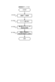
次に、図4について説明する(本発明の第1の実施形態)。図4は、画像表示端末105が画像解析サーバ103から解析結果の画像データを受け取り、出荷先を表示した集荷場所画像データを表示する本発明の出荷先表示処理の流れを示すフローチャートの一例である。
Next, FIG. 4 will be described (first embodiment of the present invention). FIG. 4 is an example of a flow chart showing the flow of shipping destination display processing according to the present invention, in which the
図4に示す各処理は、画像解析サーバ103のCPU201、または画像表示端末105のCPU301により実行される。
Each process shown in FIG. 4 is executed by the
ステップ401で、画像表示端末105は、表示部306に表示された配送先表示画面(図6)上で、出荷先表示ボタン(601)の選択をユーザから受け付けると、ステップ402で、画像解析サーバ103は、集荷場所のネットワークカメラ画像データの解析を行い、集荷場所画像データ内のパレットに配送先の配色をオーバレイした画像データを作成する。ステップ402の処理の詳細は、図5を用いて後ほど説明する。
In step 401, the
ここで、図6~図8について説明する。図6は画像表示端末105の表示部306に表示される、QRコード解析前の配送先表示画面である。
6 to 8 will now be described. FIG. 6 shows a delivery destination display screen displayed on the
出荷先表示ボタン601は、当該ボタンがユーザにより押下されることで、図7に示す通り、画像データ表示領域603に表示される画像データ中の各パレットの荷物に配送先の色がオーバレイされて表示(図7の701~703)される。また、各配送先をどの色で表示するかは、図8の配送先データテーブルにより決定される。
When the shipping
キャンセルボタン602は、配送先表示画面の表示を終了するためのボタンである。
A cancel
画像データ表示領域603は、ネットワークカメラ101で撮影した画像データが表示される。
An image
604は、ネットワークカメラ101で撮影した画像データに映るパレットを示す。
A
凡例605は、図7に示すように、画像データ表示領域603に表示される画像データ中の各パレットの荷物に配送先の色をオーバレイして表示するときに、各色が示す配送先がどこであるかを示す。
As shown in FIG. 7, the
配送先コードの文字列606は、荷物側面に貼られたラベルに印字される、荷物の配送先を一意に識別するためのコードである。
The delivery destination
図7は、後述する図4のステップ404で、出荷先表示ボタン601がユーザにより押下されることで各パレットの荷物に配送先の色をオーバレイした状態の一例を示す図である。
FIG. 7 is a diagram showing an example of a state in which the shipping
図8は、画像解析サーバ103の外部メモリ211で管理される配送先データテーブルの一例を示す図であり、QRコードに埋め込まれている配送先コードから、配送先と配送先を識別するための色を管理するデータテーブルである。
FIG. 8 is a diagram showing an example of a delivery destination data table managed by the
配送先コード801は、各配送先を一意に識別するためのコードであり、パレット上の荷物に張り付けられるQRコード(2次元コードともいう)に埋め込まれている情報である。配送先802はパレット上の荷物の配送先を示し、色803は、画像データ表示領域603に表示される画像データ中のパレットの荷物が、配送先802に示される配送先である場合に、何色をオーバレイするかを示す。
A
QRコードは、本発明における識別情報の一例である。以上で、図6~図8の説明を終了し、図4の説明に戻る。 A QR code is an example of identification information in the present invention. The description of FIGS. 6 to 8 is now completed, and the description of FIG. 4 is returned to.
画像解析サーバ103は、ステップ403で、画像表示端末105に対してステップ402で作成した画像データを送信し、ステップ404で、画像表示端末105は、受信した画像データを表示部306に表示する(図7)。以上で図4の説明を終了し、次に図5について説明する。
The
図5は、画像解析サーバ103が撮影した集荷場所画像データを解析し、パレット画像部分に配送先の配色をオーバレイする手順の一例を示すフローチャートであり、図4のステップ402の処理の詳細を示すフローチャートの一例を示す図である。
FIG. 5 is a flow chart showing an example of the procedure for analyzing the image data of the pick-up location taken by the
図5に示す各処理は、画像解析サーバ103のCPU201、またはネットワークカメラ101のCPUにより実行される。
Each process shown in FIG. 5 is executed by the
ステップ501で画像解析サーバ103は、ネットワークカメラ101に集荷場所画像データをリクエストする。
In step 501, the
ネットワークカメラ101は、画像解析サーバ103からのリクエストを受信し、ステップ502で、当該ネットワークカメラ101で撮影した集荷場所画像データを画像解析サーバ103に送信する。
The
ステップ503で、画像解析サーバ103は、集荷場所画像データを受信し、図9に示す通り、あらかじめ決められた数(横X、縦Y)で画像を分割する。図9は撮影した集荷場所画像データを横X、縦Yで分割した画面のイメージを表している。
In step 503, the
ステップ503と、後述するステップ1003は、本発明における、撮像装置から、画像データを取得する取得手段の一例である。 Step 503 and step 1003, which will be described later, are an example of acquiring means for acquiring image data from the imaging device in the present invention.
ステップ504で、画像解析サーバ103は、x=1,y=1で変数を初期化し、ステップ505で、画像解析サーバ103は、分割した(x,y)の領域の集荷場所画像データの色分布を解析する。
In step 504, the
ステップ506で、画像解析サーバ103は、ステップ505の解析の結果、白と黒の割合が所定以上あるかどうかを判定し、所定以上あればステップ507に移行し、所定以上なければ次の領域の画像を解析するためにステップ516に移行する。ステップ506は、本発明における、取得手段で取得した画像データを解析し、識別情報を特定する特定手段の一例である。
At step 506, the
白と黒の割合が所定以上であった場合、ステップ507で、画像解析サーバ103は、QRコードを解析するためにネットワークカメラ101に(x,y)領域のズーム画像の送信命令を送る。ステップ507は、本発明における、前記特定手段で特定した識別情報をズームして撮像するように前記撮像装置に指示する指示手段の一例である。
If the ratio of white to black is equal to or greater than the predetermined ratio, in step 507 the
ステップ508で、ネットワークカメラ101は、画像解析サーバ103からの送信命令を受信し、(x,y)領域のズーム画像を画像解析サーバ103へ送る。
At step 508 , the
ステップ509で、画像解析サーバ103は(x,y)領域のズーム画像を受信し、ステップ510で受信したズーム画像の中にQRコードのファインダパターンがあるかどうかを判定する。
At step 509, the
画像解析サーバ103は、ステップ510の判定によりQRコードのファインダパターンを検出できなかった場合はステップ516に処理を移行し、QRコードのファインダパターンを検出した場合は、ステップ511に処理を移行してQRコードの情報の読み取りを行う。
The
ステップ512で、画像解析サーバ103は、QRコードの情報が読み取れたかどうかの判定を行い、読み取れた場合はステップ514でQRコードに含まれている配送先コードに紐づいた色を配送先データベース(図8)から取得して、ステップ515に移行する。
At step 512, the
ステップ512でQRコードの情報が読み取れなかったと判定された場合、画像解析サーバ103は、ステップ513でQRコードの右上にある配送先コードの文字列(配送先コードの文字列606)をOCRで読み取り、ステップ515に移行する。
If it is determined in step 512 that the QR code information could not be read, the
なお、本実施例では、配送先コードはQRコードの右上にあるものとしたが、配送先コードがどの位置にあるかは、画像解析サーバ103にユーザが予め登録していれば、右上でなくとも良い。また、画像解析により、配送先コードを特定しても良い。 In this embodiment, the delivery address code is located on the upper right of the QR code. Both good. Also, the delivery destination code may be specified by image analysis.
ステップ515では、集荷場所画像データ中のQRコードを中心とした荷物のサイズに相当する矩形に配送先コードに紐づいた色をオーバレイ(図7)し、ステップ516へ移行する。なお、荷物のサイズは画像解析サーバであらかじめ記憶しても良いし、画像解析により、集荷場所画像中の荷物の領域を特定しても良い。 In step 515 , a rectangle corresponding to the size of the parcel centered on the QR code in the pickup location image data is overlaid with the color associated with the delivery destination code ( FIG. 7 ), and the process proceeds to step 516 . Note that the size of the package may be stored in advance in the image analysis server, or the area of the package in the image of the pickup location may be specified by image analysis.
次にステップ506で白と黒の割合が所定以上でなかった場合の説明を行う。ステップ516では、画像解析サーバ103は、xが横分割数Xと同じかどうかを比較して、同じであればステップ518に移行し、同じでなければ次の領域の画像をチェックするためにステップ517でxをインクリメントしてステップ505に戻る。
Next, the case where the ratio of white to black is not equal to or greater than a predetermined value in step 506 will be described. In step 516, the
ステップ518では、画像解析サーバ103は、yが縦分割数Yと同じかどうかを比較して、同じであれば全分割画像を解析したので処理を終了し、同じでなければ次の領域の画像をチェックするためにステップ519でyをインクリメントしてステップ505に戻る。
In step 518, the
なお、図5の処理を実行後に荷物が運ばれると、運ばれた荷物の後ろに置かれていた別の荷物が集荷場所画像データに新たに映ることもあるため、荷物が運ばれた場合、その荷物があった領域に対してのみステップ505~ステップ519の処理を実行することで、再度集荷場所画像データ全体に対してステップ505~ステップ519の処理を実行するよりも処理負荷を軽減することが可能となる。荷物が運ばれたか否かは、集荷場所画像データを解析することにより特定する。 Note that when a package is transported after the processing in FIG. By executing the processing of steps 505 to 519 only for the area where the cargo was present, the processing load is reduced more than executing the processing of steps 505 to 519 again for the entire pickup location image data. becomes possible. Whether or not the cargo has been delivered is specified by analyzing the collection location image data.
以上で、図5の説明を終了し、次に、図10を用いて、図4のステップ402の処理の詳細を示すフローチャートの他の実施形態について説明する。 The explanation of FIG. 5 is finished above, and next, another embodiment of the flowchart showing the details of the processing of step 402 of FIG. 4 will be explained using FIG. 10 .
図10は図5のフローチャートと別技術で、撮影した集荷場所画像データを解析し、パレット画像部分に配送先の配色をオーバレイする手順の一例を示すフローチャートである。 FIG. 10 is a flow chart showing an example of a procedure for analyzing photographed collection place image data and overlaying the color scheme of the delivery destination on the pallet image portion, using a technique different from the flow chart of FIG.
図5の処理では、パレットに載っている荷物一つ一つのQRコードの情報を読み取って、配送先の特定を荷物ごとに行っている。しかしながら、通常同一のパレットに載っている荷物は同一の配送先である。 In the process of FIG. 5, the QR code information of each package on the pallet is read, and the delivery destination is specified for each package. However, packages on the same pallet usually have the same destination.
そのため、本実施形態では、まず集荷場所画像データからパレットを特定し、パレットに載っている荷物のうちの1つのQRコードの情報を読み取ることで、その荷物の配送先を特定するとともに、当該荷物と同じパレットに載っているその他の荷物も特定した配送先と同じ配送先として特定する。そうすることで、パレットに載っている荷物一つ一つのQRコードの情報を読み取って、配送先の特定を荷物ごとに行うよりも、解析時間を短縮することができる。では、ここから図10のフローチャートの各ステップについて説明する。 Therefore, in this embodiment, first, a pallet is specified from the collection location image data, and the QR code information of one of the packages on the pallet is read to specify the delivery destination of the package and Other parcels on the same pallet are also specified as the same delivery address as the specified delivery address. By doing so, it is possible to shorten the analysis time compared to reading the QR code information of each package on the pallet and specifying the delivery destination for each package. Now, each step of the flowchart in FIG. 10 will be described.
なお、図10に示す各処理は、画像解析サーバ103のCPU201、またはネットワークカメラ101のCPUにより実行される。
Note that each process shown in FIG. 10 is executed by the
ステップ1001で、画像解析サーバ103は、ネットワークカメラ101に集荷場所画像データをリクエストする。
At
ステップ1002で、ネットワークカメラ101は、画像解析サーバ103からのリクエストを受信し、当該ネットワークカメラ101で撮影した集荷場所画像データを画像解析サーバ103に送信する。
At step 1002 , the
ステップ1003で、画像解析サーバ103は、ネットワークカメラ101から送信された集荷場所画像データを受信し、集荷場所画像データの中からパレット1102を検索する(図11)。パレットの検索には、既知の画像のパターンマッチング技術を用いる(例えば、予め荷台の画像データを画像解析サーバ103で管理し、当該パレットの画像データと特徴量が一致または所定以上類似するものを集荷場所画像データから検索する)。ステップ1003は、本発明における、取得手段で取得した画像データから台を特定する特定手段の一例である。
At step 1003, the
画像解析サーバ103は、ステップ1004でパレットが見つからなかった場合は本処理を終了し、パレットが見つかった場合は、ステップ1005で画像解析サーバ103はパレット上部の所定の位置の「横x,縦yのサイズのQRコード解析画像領域(図11のQRコード解析画像領域1101)」のズーム画像送信命令をネットワークカメラ101に送信する。
If the palette is not found in step 1004, the
本実施形態においては、「横x,縦yのサイズのQRコード解析画像領域」の所定の位置の情報は、ユーザが画像解析サーバ103にあらかじめ登録しておくものとする。
In this embodiment, it is assumed that the user registers in the
ステップ1006で、ネットワークカメラ101は、画像解析サーバ103からの命令を受信し、QRコード解析画像領域1101をズームして撮影した画像データを画像解析サーバ103へ送る。
At step 1006 , the
ステップ1007で、画像解析サーバ103は、QRコード解析画像領域1101をズームして撮影した画像データを受信し、ステップ1008で受信した画像データの中にQRコードのファインダパターンがあるかどうかを判定する。
In step 1007, the
画像解析サーバ103は、ステップ1008の判定でQRコードを検出できなかった場合はステップ1014に移行し、QRコードを検出した場合は、ステップ1009に移行してQRコードの情報を読み取る。
The
ステップ1010で、画像解析サーバ103は、QRコードの情報が読み取れたかどうかの判定を行い、読み取れた場合はステップ1012でQRコードに含まれている配送先コードに紐づいた色を配送先データベース(図8)から取得して、ステップ1013に移行する。
At step 1010, the
ステップ1010でQRコードが読み取れなかった場合は、ステップ1011でQRコードの右上にある配送先コードの文字列をOCRで読み取り、ステップ1013に移行する。 If the QR code could not be read in step 1010 , then in step 1011 the character string of the delivery destination code on the upper right of the QR code is read by OCR, and the process proceeds to step 1013 .
なお、本実施例では、配送先コードはQRコードの右上にあるものとしたが、配送先コードがどの位置にあるかは、画像解析サーバ103にユーザが予め登録していれば、右上でなくとも良い。また、画像解析により、配送先コードを特定しても良い。 In this embodiment, the delivery address code is located on the upper right of the QR code. Both good. Also, the delivery destination code may be specified by image analysis.
ステップ1013で、画像解析サーバ103は、集荷場所画像中のパレットに載っている全荷物に対して、配送先コードに紐づいた色をオーバレイ(図12)し、ステップ1014へ移行する。ステップ1013は、本発明における、前記特定手段で特定した前記台ごとに当該台上の荷物を識別表示した画面を生成する生成手段の一例である。
In step 1013, the
ステップ1014で、画像解析サーバ103は、ステップ1002でネットワークカメラ101から送信された集荷場所画像データの中から、画像検索により次のパレットを検索する。
At step 1014, the
ステップ1015でパレットが見つからなかった場合は本処理を終了し、見つかった場合は次のパレットの配送先を解析するためにステップ1005に戻る。以上で、図10の説明を終了する。 If the pallet is not found in step 1015, this process is terminated, and if found, the process returns to step 1005 to analyze the delivery destination of the next pallet. This completes the description of FIG.
次に図13を用いて、本発明の実施形態における、配送可能な配送車を提示する処理の流れを示すフローチャートの一例について説明する。 Next, with reference to FIG. 13, an example of a flowchart showing the flow of processing for presenting delivery vehicles that can be delivered in the embodiment of the present invention will be described.
図13は、既知の車番認識技術(例えば、特開2007-293492号公報や、特開2013-251005号公報に記載の技術)を利用し、各配送先に荷物を運ぶ配送車が配送可能な状態かどうかをユーザに提示する方法を示すフローチャートの一例である。これにより配送可能なパレットから出荷することができるため、配送車の待機時間を短縮し、効率良い配送業務が可能となる。 FIG. 13 shows that using a known car number recognition technology (for example, the technology described in Japanese Patent Application Laid-Open No. 2007-293492 and Japanese Patent Application Laid-Open No. 2013-251005), a delivery vehicle that carries packages to each delivery destination can deliver. 10 is an example of a flow chart showing a method of presenting to a user whether a state is As a result, it is possible to ship from a pallet that can be delivered, shortening the waiting time of delivery vehicles and enabling efficient delivery operations.
ステップ1301で、画像解析サーバ103は、駐車場の入り口など配送車の帰車が分かる場所に設置されたネットワークカメラから画像データを取得する。ステップ1301は、本発明における、前記撮像装置から、荷物を配送先に運ぶ車両を撮像した画像データ(車両画像)を取得する取得手段(車両画像取得手段)の一例である。
In step 1301, the
ステップ1302で、画像解析サーバ103は、ステップ1301で取得した画像データから、これから荷積を行う配送車のナンバーを読み取る。ステップ1302は、本発明における、取得手段で取得した画像データから、当該画像データに映る車両を識別可能な識別情報を特定する第1特定手段の一例である。
At step 1302, the
ステップ1303で、画像解析サーバ103は、配送車データベース(図14)を参照して、読み取ったナンバーと、ナンバー1403が一致する行の配送先1402を取得し、ステップ1304で、当該配送先1402によって示される配送先の配送車が到着したことをユーザに認識させるべく、通知する。
In step 1303, the
ステップ1303は、本発明における、第1特定手段で特定した前記識別情報を用いて、前記車両の荷物の配送先を特定する第2特定手段の一例である。また、ステップ1304は、本発明における、第2特定手段で特定した配送先をユーザに認識させるべく、通知する通知手段の一例である。 Step 1303 is an example of a second specifying means for specifying a delivery destination of the package of the vehicle using the identification information specified by the first specifying means in the present invention. Step 1304 is an example of notification means for notifying the user of the delivery destination specified by the second specifying means in the present invention.
具体的には、例えば、図15に示す通り、配送先表示画面上で「配送車到着済み」1501を表示することで通知する。なお、複数の配送車が到着した場合には、到着した順番を示す番号がそのまま優先度として、配送先表示画面上に表示される。 Specifically, for example, as shown in FIG. 15, notification is given by displaying "Delivery vehicle has arrived" 1501 on the delivery destination display screen. When a plurality of delivery vehicles arrive, the number indicating the order of arrival is displayed on the delivery destination display screen as the priority as it is.
なお、図13の処理は、ステップ401より後の画像表示端末105に配送先表示画面を表示している間に実行される。
13 is executed while the delivery destination display screen is being displayed on the
図14は、画像解析サーバ103の外部メモリ211に記憶される配送車データベースの一例を示す図である。
FIG. 14 is a diagram showing an example of a delivery vehicle database stored in the
配送先コード1401は、各配送車の配送先を一意に識別するためのコードである。
The
配送先1402は、配送車が荷物を配送する配送先を示す。ナンバー1403は、配送車のナンバープレートに記載のナンバーを示す。以上で図14の説明を終了する。
The
次に図16を用いて、配送先表示画面の他の実施形態について説明する。図16は、図4のステップ404において、画像表示端末105の表示部306に表示される配送先表示画面の一例を示す図である。
Next, another embodiment of the delivery destination display screen will be described with reference to FIG. FIG. 16 is a diagram showing an example of the delivery destination display screen displayed on the
パレット選択ボタン1601は、フォークリフトでパレットを運ぶ作業員が、配送先表示画面中の荷物の中からこれから運ぶ荷物をタッチ操作等により選択した後に押すボタンである。パレット選択ボタン1601が押下されると、その荷物の選択情報を画像解析サーバ103が取得・管理し、他の作業員の画像表示端末105の表示部306に対して、メッセージ1602に示すように、当該選択された荷物がすでに運ばれる予定であることを示すメッセージを含む配送先(移動先)表示画面を再度生成して表示する。これにより、例えば、複数のフォークリフトで荷物を運ぶ場合に、他の作業員に対して、選択済みの荷物を優先的に運ぶべきであることを認識させたり、逆に選択済みの荷物以外の荷物を運ぶべきであることを認識させたりすることが可能となる。以上で、図16の説明を終了する。
A
次に、図17を用いて、配送先(移動先)表示画面の他の実施形態について説明する。図17は、図4のステップ404において、画像表示端末105の表示部306に表示される配送先表示画面の一例を示す図である。上述の配送先表示画面では、荷物を最終的に送る先を表示したが、図17の実施形態では、荷物の移動先をパレットの荷物にオーバレイして表示する。そうすることで、例えば、東京行きの荷物は、東京行きの配送車が到着するエリアAに移動させるといった運用の場合に、東京行きの荷物であるというだけでは、どのエリアに荷物を移動させれば良いのかが分からないといった課題を解消することが可能となる。
Next, another embodiment of the delivery destination (destination) display screen will be described with reference to FIG. FIG. 17 is a diagram showing an example of the delivery destination display screen displayed on the
次に図18、図19を用いて、本発明の第2の実施形態について説明する。第2の実施形態では、図4、図5、図10、図13のフローチャートにおいて、画像解析サーバ103が実行していた処理をネットワークカメラ101が実行する。また、第1の実施形態において画像解析サーバ103の外部メモリ211で記憶する各データテーブルは、ネットワークカメラ101の外部メモリ2105で記憶するものとする。そのため、第2の実施形態におけるネットワークカメラシステムでは、画像解析サーバ103は必須の構成ではない。
Next, a second embodiment of the present invention will be described with reference to FIGS. 18 and 19. FIG. In the second embodiment, the
第2の実施形態では、まず、第1の実施形態同様、図4の処理を実行する。なお、上述のとおり、ステップ402、およびステップ403の処理はネットワークカメラ101が実行する。ただし、ステップ402の処理の詳細は、図5ではなく、図18、または図19である。
In the second embodiment, first, the process of FIG. 4 is executed as in the first embodiment. As described above, the
では、ここから図18、図19について説明する。 18 and 19 will now be described.
図18は、ネットワークカメラ101が撮影した集荷場所画像データを、当該ネットワークカメラ101が解析し、パレット画像部分に配送先の配色をオーバレイする手順の一例を示すフローチャートであり、図4のステップ402の処理の詳細を示すフローチャートの一例を示す図である。
FIG. 18 is a flow chart showing an example of the procedure for analyzing the pickup location image data captured by the
図18に示す各処理は、ネットワークカメラ101のCPU2101により実行される。なお、図5のフローチャートにおいて画像解析サーバ103が実行する処理を、ネットワークカメラ101が実行する以外は、図5のフローチャートと同様の処理であるため、簡潔に説明する。
Each process shown in FIG. 18 is executed by the
ステップ1801で、ネットワークカメラ101は、出荷先表示ボタン(601)が選択された旨の情報を画像表示端末105から受信し、ステップ1802で、当該ネットワークカメラ101で集荷場所画像データを撮影する。
At step 1801, the
ステップ1802と、後述するステップ1902は、本発明における、移動対象の荷物を撮像する撮像手段の一例である。 Step 1802 and step 1902, which will be described later, are an example of imaging means for imaging the luggage to be moved in the present invention.
ステップ1803で、ネットワークカメラ101は、集荷場所画像データを、図9に示す通り、あらかじめ決められた数(横X、縦Y)で画像を分割する。
In step 1803, the
ステップ1804で、ネットワークカメラ101は、x=1,y=1で変数を初期化し、ステップ1805で、ネットワークカメラ101は、分割した(x,y)の領域の集荷場所画像データの色分布を解析する。
At step 1804, the
ステップ1806で、ネットワークカメラ101は、ステップ1805の解析の結果、白と黒の割合が所定以上あるかどうかを判定し、所定以上あればステップ1807に移行し、所定以上なければ次の領域の画像を解析するためにステップ1814に移行する。
At step 1806, the
白と黒の割合が所定以上であった場合、ステップ1807で、ネットワークカメラ101は、(x,y)領域のズーム画像を撮影する。
If the ratio of white to black is equal to or greater than the predetermined ratio, in step 1807 the
ステップ1808で、ネットワークカメラ101は(x,y)領域のズーム画像の中にQRコードのファインダパターンがあるかどうかを判定する。
At step 1808, the
ネットワークカメラ101は、ステップ1808の判定によりQRコードのファインダパターンを検出できなかった場合はステップ1814に処理を移行し、QRコードのファインダパターンを検出した場合は、ステップ1809に処理を移行してQRコードの情報の読み取りを行う。ステップ1809と、後述するステップ1907は、本発明における、前記撮像手段で前記荷物を撮像することで得られる画像データを用いて当該画像データに映る荷物の移動先を特定する特定手段の一例である。
If the
ステップ1810で、ネットワークカメラ101は、QRコードの情報が読み取れたかどうかの判定を行い、読み取れた場合はステップ1812でQRコードに含まれている配送先コードに紐づいた色を配送先データベース(図8)から取得して、ステップ1813に移行する。
At step 1810, the
ステップ1810でQRコードの情報が読み取れなかったと判定された場合、ネットワークカメラ101は、ステップ1811でQRコードの右上にある配送先コードの文字列(配送先コードの文字列606)をOCRで読み取り、ステップ1813に移行する。
If it is determined in step 1810 that the QR code information could not be read, the
なお、本実施例では、配送先コードはQRコードの右上にあるものとしたが、配送先コードがどの位置にあるかは、ネットワークカメラ101にユーザが予め登録していれば、右上でなくとも良い。また、画像解析により、配送先コードを特定しても良い。 In this embodiment, the delivery address code is located in the upper right corner of the QR code. good. Also, the delivery destination code may be specified by image analysis.
ステップ1813では、集荷場所画像データ中のQRコードを中心とした荷物のサイズに相当する矩形に配送先コードに紐づいた色をオーバレイ(図7)し、ステップ1814へ移行する。なお、荷物のサイズは画像解析サーバであらかじめ記憶しても良いし、画像解析により、集荷場所画像中の荷物の領域を特定しても良い。 In step 1813, a rectangle corresponding to the size of the parcel around the QR code in the pickup location image data is overlaid with the color associated with the delivery destination code (FIG. 7), and the process proceeds to step 1814. Note that the size of the package may be stored in advance in the image analysis server, or the area of the package in the image of the pickup location may be specified by image analysis.
ステップ1813と、後述するステップ1911は、本発明における、前記特定手段で特定した荷物の移動先を識別可能な画面を生成する生成手段の一例である。 Step 1813 and step 1911, which will be described later, are an example of generating means for generating a screen capable of identifying the destination of the baggage specified by the specifying means in the present invention.
次にステップ1806で白と黒の割合が所定以上でなかった場合の説明を行う。ステップ1814では、ネットワークカメラ101は、xが横分割数Xと同じかどうかを比較して、同じであればステップ1816に移行し、同じでなければ次の領域の画像をチェックするためにステップ1815でxをインクリメントしてステップ1805に戻る。
Next, the case where the ratio of white to black is not equal to or greater than a predetermined value in step 1806 will be described. At step 1814, the
ステップ1816では、ネットワークカメラ101は、yが縦分割数Yと同じかどうかを比較して、同じであれば全分割画像を解析したので処理を終了し、同じでなければ次の領域の画像をチェックするためにステップ1817でyをインクリメントしてステップ1805に戻る。
In step 1816, the
なお、図18の処理を実行後に荷物が運ばれると、運ばれた荷物の後ろに置かれていた別の荷物が集荷場所画像データに新たに映ることもあるため、荷物が運ばれた場合、その荷物があった領域に対してのみステップ1805~ステップ1819の処理を実行することで、再度集荷場所画像データ全体に対してステップ1805~ステップ1817の処理を実行するよりも処理負荷を軽減することが可能となる。荷物が運ばれたか否かは、集荷場所画像データを解析することにより特定する。 It should be noted that when a package is transported after executing the processing of FIG. By executing the processing of steps 1805 to 1819 only for the area where the parcel was located, the processing load is reduced compared to executing the processing of steps 1805 to 1817 again for the entire pickup location image data. becomes possible. Whether or not the cargo has been delivered is specified by analyzing the collection location image data.
以上で、図18の説明を終了し、次に、図19を用いて、第2の実施形態における図4のステップ402の処理の詳細を示すフローチャートの他の実施形態について説明する。 This completes the description of FIG. 18, and next, another embodiment of a flowchart showing details of the processing of step 402 of FIG. 4 in the second embodiment will be described using FIG.
図19は、図5のフローチャートと別技術で、撮影した集荷場所画像データを解析し、パレット画像部分に配送先の配色をオーバレイする手順の一例を示すフローチャートである。 FIG. 19 is a flowchart showing an example of a procedure for analyzing photographed pickup location image data and overlaying the color scheme of the delivery destination on the palette image portion, using a technique different from the flowchart of FIG.
なお、図19に示す各処理は、ネットワークカメラ101のCPU2101により実行される。なお、図10のフローチャートにおいて画像解析サーバ103が実行する処理を、ネットワークカメラ101が実行する以外は、図10のフローチャートと同様の処理であるため、簡潔に説明する。
Note that each process shown in FIG. 19 is executed by the
ステップ1901で、ネットワークカメラ101は、出荷先表示ボタン(601)が選択された旨の情報を画像表示端末105から受信し、ステップ1902で、当該ネットワークカメラ101で集荷場所画像データを撮影する。
At step 1901, the
ステップ1903で、ネットワークカメラ101は、集荷場所画像データの中からパレット1102を検索する(図11)。
At step 1903, the
ネットワークカメラ101は、ステップ1904でパレットが見つからなかった場合は本処理を終了し、パレットが見つかった場合は、ステップ1905でネットワークカメラ101はパレット上部の所定の位置のQRコード解析画像領域1101をズームして撮影する。
If the palette is not found in step 1904, the
ステップ1906で、ネットワークカメラ101は、QRコード解析画像領域1101をズームして撮影した画像データの中にQRコードのファインダパターンがあるかどうかを判定する。
In step 1906, the
ネットワークカメラ101は、ステップ1906の判定でQRコードを検出できなかった場合はステップ1912に移行し、QRコードを検出した場合は、ステップ1907に移行してQRコードの情報を読み取る。
If the
ステップ1908で、ネットワークカメラ101は、QRコードの情報が読み取れたかどうかの判定を行い、読み取れた場合はステップ1910でQRコードに含まれている配送先コードに紐づいた色を配送先データベース(図8)から取得して、ステップ1911に移行する。
At step 1908, the
ステップ1908でQRコードが読み取れなかった場合は、ステップ1909でQRコードの右上にある配送先コードの文字列をOCRで読み取り、ステップ1911に移行する。 If the QR code could not be read in step 1908 , then in step 1909 the character string of the delivery destination code on the upper right of the QR code is read by OCR, and the process proceeds to step 1911 .
ステップ1911で、ネットワークカメラ101は、集荷場所画像中のパレットに載っている全荷物に対して、配送先コードに紐づいた色をオーバレイ(図12)し、ステップ1912へ移行する。
At step 1911 , the
ステップ1912で、ネットワークカメラ101は、ステップ1902でネットワークカメラ101から送信された集荷場所画像データの中から、画像検索により次のパレットを検索する。
At step 1912, the
ステップ1913でパレットが見つからなかった場合は本処理を終了し、見つかった場合は次のパレットの配送先を解析するためにステップ1905に戻る。以上で、図19の説明を終了する。 If the pallet is not found in step 1913, this process is terminated, and if found, the process returns to step 1905 to analyze the delivery destination of the next pallet. This is the end of the description of FIG. 19 .
図18、または図19の処理を実行後、図13の処理を実行する。ただし、第2の実施形態においては、図13の各処理は、画像解析サーバ103ではなく、ネットワークカメラ101が実行する。以上で第2の実施形態の説明を終了する。
After executing the processing in FIG. 18 or 19, the processing in FIG. 13 is executed. 13 is executed by the
次に、本発明の他の実施形態について説明する。上述の各実施形態では、QRコードに配送先コードが含まれているとしたが、運用によっては、必ずしもQRコードに配送先コードが含まれているとは限らない。そこで、本実施形態では、QRコードに配送先コードが含まれておらず、各荷物を一意に識別するための識別情報だけがQRコードに含まれている形態について、図20を用いて説明する。 Next, another embodiment of the present invention will be described. In each of the above-described embodiments, the QR code includes the delivery destination code, but depending on the operation, the QR code may not necessarily include the delivery destination code. Therefore, in the present embodiment, the QR code does not contain the delivery destination code, and only identification information for uniquely identifying each parcel will be described with reference to FIG. .
図20は、第1の実施形態では画像解析サーバ103の外部メモリ211に、第2の実施形態では、ネットワークカメラ101の外部メモリ2105に記憶される配送先特定テーブルの一例を示す図である。識別情報2001は、各荷物のQRに含まれる各荷物を一意に識別するための識別情報を示す。配送先コード2002は、識別情報2001によって識別される荷物の配送先を一意に識別するためのコードである。配送先2003は、配送先コード2002に対応する配送先を示す。このように、配送先特定テーブルをあらかじめ記憶することにより、QRコードに配送先コードが含まれていなかったとしても、荷物の配送先を特定することが可能となる。
FIG. 20 is a diagram showing an example of a delivery destination identification table stored in the
なお、図20の配送先特定テーブルを用いる場合、配送先を特定する処理は、ステップ514、ステップ1012、ステップ1812、ステップ1910の処理の前にそれぞれ実行される。以上で、図20の説明を終了する。 When using the delivery destination specification table of FIG. 20, the processing of specifying the delivery destination is executed before the processing of steps 514, 1012, 1812 and 1910 respectively. This concludes the description of FIG. 20 .
以上、本発明によると、荷物の移動作業における、業務効率を向上させることができる。 As described above, according to the present invention, it is possible to improve work efficiency in the work of moving packages.
本発明は、例えば、システム、装置、方法、プログラム若しくは記憶媒体等としての実施形態も可能であり、具体的には、複数の機器から構成されるシステムに適用してもよいし、また、1つの機器からなる装置に適用してもよい。 The present invention can also be embodied as, for example, a system, device, method, program, storage medium, etc. Specifically, it may be applied to a system composed of a plurality of devices, or It may be applied to an apparatus consisting of one device.
なお、本発明は、前述した実施形態の機能を実現するソフトウェアのプログラムを、システム或いは装置に直接、或いは遠隔から供給するものを含む。そして、そのシステム或いは装置のコンピュータが前記供給されたプログラムコードを読み出して実行することによっても達成される場合も本発明に含まれる。 It should be noted that the present invention includes those that directly or remotely supply a software program that implements the functions of the above-described embodiments to a system or apparatus. The present invention also includes a case where the computer of the system or apparatus reads and executes the supplied program code.
したがって、本発明の機能処理をコンピュータで実現するために、前記コンピュータにインストールされるプログラムコード自体も本発明を実現するものである。つまり、本発明は、本発明の機能処理を実現するためのコンピュータプログラム自体も含まれる。 Therefore, the program code itself installed in the computer to implement the functional processing of the present invention also implements the present invention. That is, the present invention also includes the computer program itself for realizing the functional processing of the present invention.
その場合、プログラムの機能を有していれば、オブジェクトコード、インタプリタにより実行されるプログラム、OSに供給するスクリプトデータ等の形態であってもよい。 In that case, as long as it has the function of a program, it may be in the form of object code, a program executed by an interpreter, script data supplied to the OS, or the like.
プログラムを供給するための記録媒体としては、例えば、フレキシブルディスク、ハードディスク、光ディスク、光磁気ディスク、MO、CD-ROM、CD-R、CD-RWなどがある。また、磁気テープ、不揮発性のメモリカード、ROM、DVD(DVD-ROM,DVD-R)などもある。 Recording media for supplying programs include, for example, flexible disks, hard disks, optical disks, magneto-optical disks, MOs, CD-ROMs, CD-Rs, and CD-RWs. There are also magnetic tapes, non-volatile memory cards, ROMs, and DVDs (DVD-ROM, DVD-R).
その他、プログラムの供給方法としては、クライアントコンピュータのブラウザを用いてインターネットのホームページに接続する。そして、前記ホームページから本発明のコンピュータプログラムそのもの、若しくは圧縮され自動インストール機能を含むファイルをハードディスク等の記録媒体にダウンロードすることによっても供給できる。 Another method of supplying the program is to connect to a home page on the Internet using a browser on the client computer. It can also be supplied by downloading the computer program itself of the present invention or a compressed file including an automatic installation function from the home page to a recording medium such as a hard disk.
また、本発明のプログラムを構成するプログラムコードを複数のファイルに分割し、それぞれのファイルを異なるホームページからダウンロードすることによっても実現可能である。つまり、本発明の機能処理をコンピュータで実現するためのプログラムファイルを複数のユーザに対してダウンロードさせるWWWサーバも、本発明に含まれるものである。 It is also possible to divide the program code constituting the program of the present invention into a plurality of files and download each file from a different home page. In other words, the present invention also includes a WWW server that allows a plurality of users to download program files for implementing the functional processing of the present invention on a computer.
また、本発明のプログラムを暗号化してCD-ROM等の記憶媒体に格納してユーザに配布し、所定の条件をクリアしたユーザに対し、インターネットを介してホームページから暗号化を解く鍵情報をダウンロードさせる。そして、ダウンロードした鍵情報を使用することにより暗号化されたプログラムを実行してコンピュータにインストールさせて実現することも可能である。 In addition, the program of the present invention is encrypted, stored in a storage medium such as a CD-ROM, distributed to users, and key information for decryption is downloaded from a homepage via the Internet to users who have cleared predetermined conditions. Let Then, by using the downloaded key information, the encrypted program can be executed and installed in the computer.
また、コンピュータが、読み出したプログラムを実行することによって、前述した実施形態の機能が実現される。その他、そのプログラムの指示に基づき、コンピュータ上で稼動しているOSなどが、実際の処理の一部又は全部を行い、その処理によっても前述した実施形態の機能が実現され得る。 Also, the functions of the above-described embodiments are realized by the computer executing the read program. In addition, based on the instructions of the program, the OS or the like running on the computer performs part or all of the actual processing, and the functions of the above-described embodiments can also be realized by the processing.
さらに、記録媒体から読み出されたプログラムが、コンピュータに挿入された機能拡張ボードやコンピュータに接続された機能拡張ユニットに備わるメモリに書き込まれる。その後、そのプログラムの指示に基づき、その機能拡張ボードや機能拡張ユニットに備わるCPUなどが実際の処理の一部又は全部を行い、その処理によっても前述した実施形態の機能が実現される。 Further, the program read from the recording medium is written into a memory provided in a function expansion board inserted into the computer or a function expansion unit connected to the computer. After that, based on the instruction of the program, the CPU or the like provided in the function expansion board or function expansion unit performs part or all of the actual processing, and the processing also realizes the functions of the above-described embodiments.
なお、前述した実施形態は、本発明を実施するにあたっての具体化の例を示したものに過ぎず、これらによって本発明の技術的範囲が限定的に解釈されてはならないものである。即ち、本発明はその技術思想、又はその主要な特徴から逸脱することなく、様々な形で実施することができる。 It should be noted that the above-described embodiments merely show specific examples for carrying out the present invention, and the technical scope of the present invention should not be construed to be limited by these. That is, the present invention can be embodied in various forms without departing from its technical concept or main features.
101 ネットワークカメラ
102 POE HUB
103 画像解析サーバ
104 無線LANルータ
105 画像表示装置
101
103 Image analysis server 104
Claims (10)
前記撮像装置から取得した画像データを用いて当該画像データに映る荷物の移動先を特定する特定手段と、
前記特定手段で特定した荷物の移動先を識別可能な画面を生成する生成手段と、
前記生成された画面を前記画像表示端末に送信する送信手段と、
を備え、
前記特定手段は、前記撮像装置から取得した画像データから当該画像データに映る台を特定し、当該台に載っている荷物のうちの一つの荷物の移動先を特定することで、当該台に載っている他の荷物の移動先も同一の移動先として特定する
ことを特徴とする情報処理装置。 An imaging device that captures an image of a package to be moved, and an information processing device that can communicate with an image display terminal,
an identifying means for identifying the destination of the baggage shown in the image data obtained from the imaging device;
generating means for generating a screen on which the destination of the package specified by the specifying means can be identified;
a transmitting means for transmitting the generated screen to the image display terminal;
with
The identification means identifies a platform appearing in the image data from the image data acquired from the imaging device, and identifies a destination of one of the packages on the platform, thereby allowing the luggage to be placed on the platform. An information processing device, characterized in that the destinations of other packages that have been stored are also specified as the same destination.
前記撮像装置から取得した画像データを用いて当該画像データに映る荷物の移動先を特定する特定手段と、
前記特定手段で特定した荷物の移動先を識別可能な画面を生成する生成手段と、
前記生成された画面を前記画像表示端末に送信する送信手段と、
前記画像表示端末から前記画面を介して選択された前記画像データに映る荷物の選択情報を取得する選択情報取得手段と、
を備え、
前記生成手段は、前記選択情報取得手段で選択情報を取得した荷物が選択済みであることを識別可能な画面を再度生成し、
前記送信手段は、前記再度生成された画面を他の画像表示端末に送信する
ことを特徴とする情報処理装置。 An imaging device that captures an image of a package to be moved, and an information processing device that can communicate with an image display terminal,
an identifying means for identifying the destination of the baggage shown in the image data obtained from the imaging device;
generating means for generating a screen on which the destination of the package specified by the specifying means can be identified;
a transmitting means for transmitting the generated screen to the image display terminal;
selection information acquisition means for acquiring selection information of packages appearing in the image data selected from the image display terminal via the screen;
with
The generation means regenerates a screen that enables identification of the fact that the package for which the selection information has been acquired by the selection information acquisition means has been selected,
The information processing apparatus, wherein the transmission means transmits the regenerated screen to another image display terminal.
前記取得手段で取得した画像データから、当該画像データに映る車両を識別可能な識別情報を特定する第1特定手段と、
前記第1特定手段で特定した前記識別情報を用いて、前記車両の荷物の運び先を特定する第2特定手段と、
前記第2特定手段で特定した運び先をユーザに認識させるべく、通知する通知手段とを備えることを特徴とする請求項1または2に記載の情報処理装置。 a vehicle image acquisition means for acquiring image data of an image of a vehicle for delivering packages from an imaging device for imaging the vehicle;
a first specifying means for specifying, from the image data acquired by the acquiring means, identification information capable of identifying a vehicle appearing in the image data;
a second specifying means for specifying a destination of the luggage of the vehicle using the identification information specified by the first specifying means;
3. The information processing apparatus according to claim 1, further comprising notifying means for notifying the user of the destination specified by said second specifying means.
前記検出手段で検出した識別情報をズームして撮像するように前記撮像装置に指示する指示手段とをさらに備えることを特徴とする請求項1乃至4のいずれか1項に記載の情報処理装置。 a detecting means for detecting identification information included in image data acquired from the imaging device;
5. The information processing apparatus according to any one of claims 1 to 4 , further comprising an instruction unit for instructing said imaging device to zoom and image the identification information detected by said detection unit.
移動対象の荷物を撮像する撮像手段と、
前記撮像手段で撮像された画像データを用いて当該画像データに映る荷物の移動先を特定する特定手段と、
前記特定手段で特定した荷物の移動先を識別可能な画面を生成する生成手段と、
前記生成された画面を前記画像表示部に送信する送信手段と、
を備え、
前記特定手段は、前記撮像手段で撮像された画像データから当該画像データに映る台を特定し、当該台に載っている荷物のうちの一つの荷物の移動先を特定することで、当該台に載っている他の荷物の移動先も同一の移動先として特定する
ことを特徴とする情報処理装置。 An information processing device comprising an image display unit,
an imaging means for imaging the luggage to be moved;
a specifying means for specifying a destination of the baggage shown in the image data by using the image data captured by the imaging means;
generating means for generating a screen on which the destination of the package specified by the specifying means can be identified;
sending means for sending the generated screen to the image display unit;
with
The identifying means identifies a table appearing in the image data from the image data captured by the imaging means, and identifies the destination of one of the packages on the table, thereby An information processing device characterized in that the destinations of other packages placed thereon are also specified as the same destination.
前記情報処理装置が、
前記撮像装置から取得した画像データを用いて当該画像データに映る荷物の移動先を特定する特定工程と、
前記特定工程で特定した荷物の移動先を識別可能な画面を生成する生成工程と、
前記生成された画面を前記画像表示端末に送信する送信工程と、
を実行し、
前記特定工程では、前記撮像装置から取得した画像データから当該画像データに映る台を特定し、当該台に載っている荷物のうちの一つの荷物の移動先を特定することで、当該台に載っている他の荷物の移動先も同一の移動先として特定する
ことを特徴とする情報処理装置の制御方法。 A control method for an imaging device that captures an image of a package to be moved and an information processing device that can communicate with an image display terminal,
The information processing device
an identifying step of identifying a movement destination of the baggage reflected in the image data using the image data acquired from the imaging device;
a generation step of generating a screen on which the destination of the package identified in the identification step can be identified;
a transmission step of transmitting the generated screen to the image display terminal;
and run
In the identifying step, a table shown in the image data acquired from the image pickup device is identified, and the destination of one of the packages on the table is identified, thereby allowing the cargo to be placed on the table. A control method for an information processing device, characterized in that the destinations of other packages that have already been transported are specified as the same destination.
前記情報処理装置が、
前記撮像装置から取得した画像データを用いて当該画像データに映る荷物の移動先を特定する特定工程と、
前記特定工程で特定した荷物の移動先を識別可能な画面を生成する生成工程と
前記生成された画面を前記画像表示端末に送信する第1送信工程と、
前記画像表示端末から前記画面を介して選択された前記画像データに映る荷物の選択情報を取得する選択情報取得工程と、
前記選択情報取得工程で選択情報を取得した荷物が選択済みであることを識別可能な画面を再度生成する再生成工程と、
前記再度生成された画面を他の画像表示端末に送信する第2送信工程と、
を実行することを特徴とする情報処理装置の制御方法。 A control method for an imaging device that captures an image of a package to be moved and an information processing device that can communicate with an image display terminal,
The information processing device
an identifying step of identifying a movement destination of the baggage reflected in the image data using the image data acquired from the imaging device;
a generation step of generating a screen capable of identifying the destination of the package identified in the identification step; a first transmission step of transmitting the generated screen to the image display terminal;
a selection information acquiring step of acquiring selection information of packages shown in the image data selected from the image display terminal via the screen;
a regenerating step of regenerating a screen that can identify that the package for which the selection information has been obtained in the selection information obtaining step has been selected;
a second transmission step of transmitting the regenerated screen to another image display terminal;
A control method for an information processing apparatus, characterized by executing
前記情報処理装置が、
移動対象の荷物を撮像する撮像工程と、
前記撮像工程で撮像された画像データを用いて当該画像データに映る荷物の移動先を特定する特定工程と、
前記特定工程で特定した荷物の移動先を識別可能な画面を生成する生成工程と、
前記生成された画面を前記画像表示部に送信する送信工程と、
を実行し、
前記特定工程では、前記撮像工程で取得した画像データから当該画像データに映る台を特定し、当該台に載っている荷物のうちの一つの荷物の移動先を特定することで、当該台に載っている他の荷物の移動先も同一の移動先として特定する
ことを特徴とする情報処理装置の制御方法。 A control method for an information processing device having an image display unit, comprising:
The information processing device
an imaging step of imaging the luggage to be moved;
an identifying step of using the image data captured in the imaging step to identify the destination of the baggage reflected in the image data;
a generation step of generating a screen on which the destination of the package identified in the identification step can be identified;
a transmission step of transmitting the generated screen to the image display unit;
and run
In the specifying step, the platform shown in the image data acquired in the imaging step is specified, and the destination of one of the packages on the platform is specified to allow the luggage to be placed on the platform. A control method for an information processing device, characterized in that the destinations of other packages that have already been transported are specified as the same destination.
A program for causing a computer to function as each means of the information processing apparatus according to any one of claims 1 to 6 .
Applications Claiming Priority (2)
| Application Number | Priority Date | Filing Date | Title |
|---|---|---|---|
| JP2017210006 | 2017-10-31 | ||
| JP2017210006 | 2017-10-31 |
Publications (3)
| Publication Number | Publication Date |
|---|---|
| JP2019083522A JP2019083522A (en) | 2019-05-30 |
| JP2019083522A5 JP2019083522A5 (en) | 2022-09-01 |
| JP7323757B2 true JP7323757B2 (en) | 2023-08-09 |
Family
ID=66670690
Family Applications (1)
| Application Number | Title | Priority Date | Filing Date |
|---|---|---|---|
| JP2018204645A Active JP7323757B2 (en) | 2017-10-31 | 2018-10-31 | Information processing device, control method for information processing device, and program |
Country Status (1)
| Country | Link |
|---|---|
| JP (1) | JP7323757B2 (en) |
Families Citing this family (1)
| Publication number | Priority date | Publication date | Assignee | Title |
|---|---|---|---|---|
| JP7467075B2 (en) | 2019-11-06 | 2024-04-15 | 東芝テック株式会社 | Information processing device and program |
Citations (4)
| Publication number | Priority date | Publication date | Assignee | Title |
|---|---|---|---|---|
| JP2014091609A (en) | 2012-11-02 | 2014-05-19 | Daifuku Co Ltd | Article information display device |
| JP2014122075A (en) | 2012-06-29 | 2014-07-03 | Toyo Kanetsu Solutions Kk | Supporting system for article picking operation |
| JP2015184894A (en) | 2014-03-24 | 2015-10-22 | パイオニア株式会社 | Information storage processing device, terminal device, control method, program, and storage medium |
| JP2017171444A (en) | 2016-03-23 | 2017-09-28 | パナソニックIpマネジメント株式会社 | Projection instruction device, goods assort system and projection instruction method |
-
2018
- 2018-10-31 JP JP2018204645A patent/JP7323757B2/en active Active
Patent Citations (4)
| Publication number | Priority date | Publication date | Assignee | Title |
|---|---|---|---|---|
| JP2014122075A (en) | 2012-06-29 | 2014-07-03 | Toyo Kanetsu Solutions Kk | Supporting system for article picking operation |
| JP2014091609A (en) | 2012-11-02 | 2014-05-19 | Daifuku Co Ltd | Article information display device |
| JP2015184894A (en) | 2014-03-24 | 2015-10-22 | パイオニア株式会社 | Information storage processing device, terminal device, control method, program, and storage medium |
| JP2017171444A (en) | 2016-03-23 | 2017-09-28 | パナソニックIpマネジメント株式会社 | Projection instruction device, goods assort system and projection instruction method |
Also Published As
| Publication number | Publication date |
|---|---|
| JP2019083522A (en) | 2019-05-30 |
Similar Documents
| Publication | Publication Date | Title |
|---|---|---|
| JP5083395B2 (en) | Information reading apparatus and program | |
| JP6569532B2 (en) | Management system, list creation device, list creation method, management method, and management program | |
| JP5879725B2 (en) | Sheet metal work support system | |
| WO2018003712A1 (en) | Information processing system, information processing device, information processing method, and program | |
| US20070242882A1 (en) | Image processing apparatus for identifying the position of a process target within an image | |
| JP6562716B2 (en) | Information processing apparatus, information processing method, program, and forklift | |
| CN1771505B (en) | Image pickup apparatus | |
| JP2010152728A (en) | Management system, management method, program, management device and on-vehicle machine | |
| KR100643557B1 (en) | Information management apparatus, information output system, portable terminal, and information outputting method | |
| AU2023222996A1 (en) | Operation information transmission device, construction management system, operation information transmission method, and program | |
| JP7323757B2 (en) | Information processing device, control method for information processing device, and program | |
| WO2018168113A1 (en) | Accumulation management apparatus, accumulation management method, and program | |
| JP2019082869A (en) | Information processing apparatus, control method of the same, and program | |
| US11445084B2 (en) | Work process managing system to manage progress of a job including multiple work processes, work process managing method, and work process managing apparatus | |
| JP6728995B2 (en) | Automated warehouse system and automated warehouse management method | |
| JP2019083424A (en) | Information processing apparatus, control method thereof, and program | |
| JP5454639B2 (en) | Image processing apparatus and program | |
| JP2013532451A (en) | Method and apparatus for locating an object in a warehouse | |
| JP6750315B2 (en) | Management system, management method, and transportation system | |
| JP2012053550A (en) | Information reading device and program | |
| JP6789517B1 (en) | Luggage management support system and luggage management support program | |
| JP2005184624A (en) | Commodity sale/management method, commodity sale/management system, and server | |
| US20170210564A1 (en) | Conveyor-using packing management system | |
| JP2018060498A (en) | Code reading device, code reading method, and program | |
| JP2005063290A (en) | Automatic object shape recognition system and system for writing in non-contact identification tag |
Legal Events
| Date | Code | Title | Description |
|---|---|---|---|
| RD04 | Notification of resignation of power of attorney |
Free format text: JAPANESE INTERMEDIATE CODE: A7424 Effective date: 20190109 |
|
| A621 | Written request for application examination |
Free format text: JAPANESE INTERMEDIATE CODE: A621 Effective date: 20211029 |
|
| A521 | Request for written amendment filed |
Free format text: JAPANESE INTERMEDIATE CODE: A523 Effective date: 20220824 |
|
| A977 | Report on retrieval |
Free format text: JAPANESE INTERMEDIATE CODE: A971007 Effective date: 20221128 |
|
| A131 | Notification of reasons for refusal |
Free format text: JAPANESE INTERMEDIATE CODE: A131 Effective date: 20221129 |
|
| A521 | Request for written amendment filed |
Free format text: JAPANESE INTERMEDIATE CODE: A523 Effective date: 20230119 |
|
| A131 | Notification of reasons for refusal |
Free format text: JAPANESE INTERMEDIATE CODE: A131 Effective date: 20230509 |
|
| A521 | Request for written amendment filed |
Free format text: JAPANESE INTERMEDIATE CODE: A523 Effective date: 20230612 |
|
| TRDD | Decision of grant or rejection written | ||
| A01 | Written decision to grant a patent or to grant a registration (utility model) |
Free format text: JAPANESE INTERMEDIATE CODE: A01 Effective date: 20230627 |
|
| A61 | First payment of annual fees (during grant procedure) |
Free format text: JAPANESE INTERMEDIATE CODE: A61 Effective date: 20230710 |
|
| R151 | Written notification of patent or utility model registration |
Ref document number: 7323757 Country of ref document: JP Free format text: JAPANESE INTERMEDIATE CODE: R151 |