JP7323010B2 - Ni-based alloy member made of laminate-molded body, method for manufacturing Ni-based alloy member, and product using Ni-based alloy member - Google Patents
Ni-based alloy member made of laminate-molded body, method for manufacturing Ni-based alloy member, and product using Ni-based alloy member Download PDFInfo
- Publication number
- JP7323010B2 JP7323010B2 JP2022090627A JP2022090627A JP7323010B2 JP 7323010 B2 JP7323010 B2 JP 7323010B2 JP 2022090627 A JP2022090627 A JP 2022090627A JP 2022090627 A JP2022090627 A JP 2022090627A JP 7323010 B2 JP7323010 B2 JP 7323010B2
- Authority
- JP
- Japan
- Prior art keywords
- based alloy
- alloy member
- laminate
- segregation
- molded body
- Prior art date
- Legal status (The legal status is an assumption and is not a legal conclusion. Google has not performed a legal analysis and makes no representation as to the accuracy of the status listed.)
- Active
Links
Images


Classifications
-
- C—CHEMISTRY; METALLURGY
- C22—METALLURGY; FERROUS OR NON-FERROUS ALLOYS; TREATMENT OF ALLOYS OR NON-FERROUS METALS
- C22C—ALLOYS
- C22C19/00—Alloys based on nickel or cobalt
- C22C19/03—Alloys based on nickel or cobalt based on nickel
- C22C19/05—Alloys based on nickel or cobalt based on nickel with chromium
- C22C19/051—Alloys based on nickel or cobalt based on nickel with chromium and Mo or W
-
- B—PERFORMING OPERATIONS; TRANSPORTING
- B22—CASTING; POWDER METALLURGY
- B22F—WORKING METALLIC POWDER; MANUFACTURE OF ARTICLES FROM METALLIC POWDER; MAKING METALLIC POWDER; APPARATUS OR DEVICES SPECIALLY ADAPTED FOR METALLIC POWDER
- B22F10/00—Additive manufacturing of workpieces or articles from metallic powder
- B22F10/20—Direct sintering or melting
- B22F10/28—Powder bed fusion, e.g. selective laser melting [SLM] or electron beam melting [EBM]
-
- B—PERFORMING OPERATIONS; TRANSPORTING
- B22—CASTING; POWDER METALLURGY
- B22F—WORKING METALLIC POWDER; MANUFACTURE OF ARTICLES FROM METALLIC POWDER; MAKING METALLIC POWDER; APPARATUS OR DEVICES SPECIALLY ADAPTED FOR METALLIC POWDER
- B22F10/00—Additive manufacturing of workpieces or articles from metallic powder
- B22F10/30—Process control
- B22F10/36—Process control of energy beam parameters
- B22F10/366—Scanning parameters, e.g. hatch distance or scanning strategy
-
- B—PERFORMING OPERATIONS; TRANSPORTING
- B22—CASTING; POWDER METALLURGY
- B22F—WORKING METALLIC POWDER; MANUFACTURE OF ARTICLES FROM METALLIC POWDER; MAKING METALLIC POWDER; APPARATUS OR DEVICES SPECIALLY ADAPTED FOR METALLIC POWDER
- B22F10/00—Additive manufacturing of workpieces or articles from metallic powder
- B22F10/60—Treatment of workpieces or articles after build-up
- B22F10/64—Treatment of workpieces or articles after build-up by thermal means
-
- B—PERFORMING OPERATIONS; TRANSPORTING
- B22—CASTING; POWDER METALLURGY
- B22F—WORKING METALLIC POWDER; MANUFACTURE OF ARTICLES FROM METALLIC POWDER; MAKING METALLIC POWDER; APPARATUS OR DEVICES SPECIALLY ADAPTED FOR METALLIC POWDER
- B22F12/00—Apparatus or devices specially adapted for additive manufacturing; Auxiliary means for additive manufacturing; Combinations of additive manufacturing apparatus or devices with other processing apparatus or devices
- B22F12/40—Radiation means
- B22F12/41—Radiation means characterised by the type, e.g. laser or electron beam
-
- B—PERFORMING OPERATIONS; TRANSPORTING
- B33—ADDITIVE MANUFACTURING TECHNOLOGY
- B33Y—ADDITIVE MANUFACTURING, i.e. MANUFACTURING OF THREE-DIMENSIONAL [3-D] OBJECTS BY ADDITIVE DEPOSITION, ADDITIVE AGGLOMERATION OR ADDITIVE LAYERING, e.g. BY 3-D PRINTING, STEREOLITHOGRAPHY OR SELECTIVE LASER SINTERING
- B33Y10/00—Processes of additive manufacturing
-
- B—PERFORMING OPERATIONS; TRANSPORTING
- B33—ADDITIVE MANUFACTURING TECHNOLOGY
- B33Y—ADDITIVE MANUFACTURING, i.e. MANUFACTURING OF THREE-DIMENSIONAL [3-D] OBJECTS BY ADDITIVE DEPOSITION, ADDITIVE AGGLOMERATION OR ADDITIVE LAYERING, e.g. BY 3-D PRINTING, STEREOLITHOGRAPHY OR SELECTIVE LASER SINTERING
- B33Y40/00—Auxiliary operations or equipment, e.g. for material handling
- B33Y40/20—Post-treatment, e.g. curing, coating or polishing
-
- B—PERFORMING OPERATIONS; TRANSPORTING
- B33—ADDITIVE MANUFACTURING TECHNOLOGY
- B33Y—ADDITIVE MANUFACTURING, i.e. MANUFACTURING OF THREE-DIMENSIONAL [3-D] OBJECTS BY ADDITIVE DEPOSITION, ADDITIVE AGGLOMERATION OR ADDITIVE LAYERING, e.g. BY 3-D PRINTING, STEREOLITHOGRAPHY OR SELECTIVE LASER SINTERING
- B33Y70/00—Materials specially adapted for additive manufacturing
-
- B—PERFORMING OPERATIONS; TRANSPORTING
- B33—ADDITIVE MANUFACTURING TECHNOLOGY
- B33Y—ADDITIVE MANUFACTURING, i.e. MANUFACTURING OF THREE-DIMENSIONAL [3-D] OBJECTS BY ADDITIVE DEPOSITION, ADDITIVE AGGLOMERATION OR ADDITIVE LAYERING, e.g. BY 3-D PRINTING, STEREOLITHOGRAPHY OR SELECTIVE LASER SINTERING
- B33Y80/00—Products made by additive manufacturing
-
- C—CHEMISTRY; METALLURGY
- C22—METALLURGY; FERROUS OR NON-FERROUS ALLOYS; TREATMENT OF ALLOYS OR NON-FERROUS METALS
- C22C—ALLOYS
- C22C1/00—Making non-ferrous alloys
- C22C1/04—Making non-ferrous alloys by powder metallurgy
- C22C1/0433—Nickel- or cobalt-based alloys
-
- C—CHEMISTRY; METALLURGY
- C22—METALLURGY; FERROUS OR NON-FERROUS ALLOYS; TREATMENT OF ALLOYS OR NON-FERROUS METALS
- C22C—ALLOYS
- C22C19/00—Alloys based on nickel or cobalt
- C22C19/03—Alloys based on nickel or cobalt based on nickel
- C22C19/05—Alloys based on nickel or cobalt based on nickel with chromium
- C22C19/051—Alloys based on nickel or cobalt based on nickel with chromium and Mo or W
- C22C19/055—Alloys based on nickel or cobalt based on nickel with chromium and Mo or W with the maximum Cr content being at least 20% but less than 30%
-
- B—PERFORMING OPERATIONS; TRANSPORTING
- B22—CASTING; POWDER METALLURGY
- B22F—WORKING METALLIC POWDER; MANUFACTURE OF ARTICLES FROM METALLIC POWDER; MAKING METALLIC POWDER; APPARATUS OR DEVICES SPECIALLY ADAPTED FOR METALLIC POWDER
- B22F2301/00—Metallic composition of the powder or its coating
- B22F2301/15—Nickel or cobalt
-
- B—PERFORMING OPERATIONS; TRANSPORTING
- B22—CASTING; POWDER METALLURGY
- B22F—WORKING METALLIC POWDER; MANUFACTURE OF ARTICLES FROM METALLIC POWDER; MAKING METALLIC POWDER; APPARATUS OR DEVICES SPECIALLY ADAPTED FOR METALLIC POWDER
- B22F2999/00—Aspects linked to processes or compositions used in powder metallurgy
-
- Y—GENERAL TAGGING OF NEW TECHNOLOGICAL DEVELOPMENTS; GENERAL TAGGING OF CROSS-SECTIONAL TECHNOLOGIES SPANNING OVER SEVERAL SECTIONS OF THE IPC; TECHNICAL SUBJECTS COVERED BY FORMER USPC CROSS-REFERENCE ART COLLECTIONS [XRACs] AND DIGESTS
- Y02—TECHNOLOGIES OR APPLICATIONS FOR MITIGATION OR ADAPTATION AGAINST CLIMATE CHANGE
- Y02P—CLIMATE CHANGE MITIGATION TECHNOLOGIES IN THE PRODUCTION OR PROCESSING OF GOODS
- Y02P10/00—Technologies related to metal processing
- Y02P10/25—Process efficiency
Description
本発明は、積層造形体からなるNi基合金部材、このNi基合金部材の製造方法およびNi基合金部材を用いた製造物に関する。 TECHNICAL FIELD The present invention relates to a Ni-based alloy member composed of a laminate-molded body, a method for manufacturing the Ni-based alloy member, and a product using the Ni-based alloy member.
従来より、化学プラント、半導体製造プロセス等において用いられる部材や部品は、腐食環境に耐える耐食性が要求される。そのため、SUS316Lから、より耐食性の優れたNi基合金へと変換が図られている。例えば、特許文献1に示すCrとMoを含むNi基合金(Ni-Cr-Mo系合金)が提案されている。しかしながら、より過酷な環境で用いられる射出成形用のスクリューや油井の掘削装置等の部材には、耐食性に加えて、高い強度や硬さ等が求められ、優れた機械的特性が要求される。特許文献1のNi-Cr-Mo系合金では、機械的特性をさらに高める必要がある。
Conventionally, members and parts used in chemical plants, semiconductor manufacturing processes, etc. are required to have corrosion resistance to withstand corrosive environments. Therefore, SUS316L is being converted to a Ni-based alloy with better corrosion resistance. For example, a Ni-based alloy containing Cr and Mo (Ni--Cr--Mo alloy) shown in
また、上述した部材や部品の設計が複雑さを増し、型鍛造や機械加工では製作困難な複雑な形状付与も要求されるようになってきている。近年では、複雑形状の部材の製作に付加製造が適用されつつある。 In addition, the design of the above-mentioned members and parts has become more complicated, and it has become necessary to provide complex shapes that are difficult to manufacture by die forging or machining. In recent years, additive manufacturing has been applied to the fabrication of parts with complex shapes.
付加製造方法は、例えば特許文献2に開示されるように、原料粉末に熱源を供給して原料粉末を溶融、凝固させることを繰り返して三次元形状の付加製造体を得る。付加製造方法によれば、複雑形状であってもネットシェイプまたはニアネットシェイプで三次元形状の製品を得ることができる。なお、特許文献2に開示されるように、「付加製造」という用語は、ASTM(American Society for Testing and Materials)F2792で規定されるように、業界標準用語とされている。
In the additive manufacturing method, as disclosed in
付加製造方法(Additive Manufacturing:AM)は、ネットシェイプまたはニアネットシェイプで三次元形状の製品を得ることができるところに大きな利点がある。付加製造方法(以下、積層造形と言う。)は、金属材料の分野において、溶解・鋳造・鍛造・圧延、または、金属粉末の焼結といった、これまでのプロセスとは異なるプロセスを経て、金属積層造形体(以下、積層造形体あるいは単に造形体と言う。)が製造される。
そこで本発明は、積層造形を利用することにより、ネットシェイプまたはニアネットシェイプで三次元形状の製品を得ることに加えて、機械的特性に優れるNi基合金部材、Ni基合金部材の製造方法およびNi基合金部材を用いた製造物を提供することを目的とする。
Additive Manufacturing (AM) has the great advantage of being able to obtain net-shape or near-net-shape products with three-dimensional shapes. The additive manufacturing method (hereafter referred to as additive manufacturing) is a process that is different from the conventional processes such as melting, casting, forging, rolling, or sintering of metal powder in the field of metal materials. A modeled body (hereinafter referred to as a layered modeled body or simply a modeled body) is manufactured.
Therefore, the present invention provides a Ni-based alloy member having excellent mechanical properties, a method for producing a Ni-based alloy member, and a method for producing a Ni-based alloy member, in addition to obtaining a three-dimensional product with a net shape or near net shape by using additive manufacturing. An object of the present invention is to provide a product using a Ni-based alloy member.
本発明のNi基合金部材は、質量比でNiの含有量が最も多く、次いでCrおよびMoの含有量が多いNi基合金部材である。このNi基合金部材は積層造形体であり、かつ結晶粒の少なくとも一部にMoの偏析を有し、積層造形体はその表層部にCrを主体とする酸化膜を備える。
本発明のNi基合金部材において、好ましくは、結晶粒は複数の柱状セル組織を有し、隣接する複数の柱状セル組織の間にMoの偏析がある。
Moの偏析のMo濃度は、好ましくは、結晶粒内の母相のMo濃度よりも3at%以上高い。
The Ni-based alloy member of the present invention is the Ni-based alloy member having the highest Ni content in terms of mass ratio, followed by the highest Cr and Mo content. This Ni-based alloy member is a laminate-molded body, and has segregation of Mo in at least a part of the crystal grains, and the laminate-molded body has an oxide film mainly composed of Cr on its surface layer.
In the Ni-based alloy member of the present invention, the grains preferably have a plurality of columnar cell structures, and Mo segregation is present between adjacent columnar cell structures.
The Mo concentration of Mo segregation is preferably higher than the Mo concentration of the parent phase in the crystal grains by 3 at % or more.
本発明のNi基合金部材において、好ましくは、柱状セル組織は、横断面における円相当径の平均直径が1000nm以下である。
柱状セル組織を透過電子顕微鏡によって断面観察したとき、転位長さ/評価体積(但し、評価体積は観察面積×試料厚み)で求められる転位密度が、好ましくは1012m-2以上である。
本発明のNi基合金部材において、好ましくは、結晶粒の平均粒径は80~150μmである。
In the Ni-based alloy member of the present invention, preferably, the columnar cell structure has an average equivalent circle diameter of 1000 nm or less in a cross section.
When the cross-section of the columnar cell structure is observed with a transmission electron microscope, the dislocation density obtained by dislocation length/evaluation volume (where evaluation volume is observation area×sample thickness) is preferably 10 12 m −2 or more.
In the Ni-based alloy member of the present invention, the average grain size of crystal grains is preferably 80 to 150 μm.
本発明のNi基合金部材の酸化膜は、好ましくは、酸化クロム(Cr2O3)を含む。また、この酸化膜は、好ましくは、酸化ニッケル(NiO)を含む。さらに、この酸化膜は、好ましくは、6nm以下の厚さを有する。 The oxide film of the Ni-based alloy member of the present invention preferably contains chromium oxide (Cr 2 O 3 ). Also, the oxide film preferably contains nickel oxide (NiO). Furthermore, this oxide film preferably has a thickness of 6 nm or less.
本発明は、上記のNi基合金部材を用いた製造物も提供する。その製造物の一例としては、半導体製造装置が挙げられる。 The present invention also provides a product using the above Ni-based alloy member. An example of the product is semiconductor manufacturing equipment.
本発明は、Ni基合金部材の製造方法も提供する。この製造方法は、レーザビームまたは電子ビームを用いた積層造形によって、質量比でNiの含有量が最も多く、次いでCrおよびMoの含有量が多いNi基合金からなる積層造形体を得る工程を有し、積層造形に伴う溶融・凝固の際に、複数の柱状セル組織を有する結晶粒を形成し、結晶粒の内部であって隣接する複数の柱状セル組織の間に、Moの偏析を形成し、積層造形体はその表層部にCrを主体とする酸化膜を備えることを特徴とする。
本発明のNi合金部材の製造方法において、好ましくは、10~2000ppmの酸素(O2)が含まれるシールドガス中において、積層造形体を得る工程が行われる。
The present invention also provides a method for manufacturing a Ni-based alloy member. This manufacturing method has a step of obtaining a laminate-molded body made of a Ni-based alloy having the highest Ni content in terms of mass ratio, followed by the highest Cr and Mo contents, by laminate fabrication using a laser beam or an electron beam. Then, during melting and solidification associated with additive manufacturing, crystal grains having a plurality of columnar cell structures are formed, and Mo segregation is formed inside the crystal grains and between a plurality of adjacent columnar cell structures. , The laminate-molded body is characterized by having an oxide film mainly composed of Cr on its surface layer.
In the method for producing a Ni alloy member of the present invention, the step of obtaining a laminate-molded body is preferably performed in a shielding gas containing 10 to 2000 ppm of oxygen (O 2 ).
本発明によれば、耐食性に加えて、機械的特性にも優れ、ネットシェイプまたはニアネットシェイプを得るのに好適なNi基合金部材と、Ni基合金部材の製造方法およびNi基合金部材を用いた製造物を提供することができる。 According to the present invention, a Ni-based alloy member having excellent mechanical properties in addition to corrosion resistance and suitable for obtaining a net shape or near net shape, a method for producing the Ni-based alloy member, and the Ni-based alloy member are used. It is possible to provide a product that was
以下、添付図面を参照しながら、本発明の実施形態に係るNi基合金部材について説明する。本実施形態に係るNi基合金部材は、質量比でNiの含有量が最も多く、次いでCrおよびMoの含有量が多いNi基合金からなる積層造形体である。この積層造形体は、結晶粒の少なくとも一部にMoの偏析を有することを主たる特徴としている。
以下では、この積層造形体について説明する。先ずネットシェイプまたはニアネットシェイプの部材に対応できる積層造形について説明し、本実施形態に係る積層造形体によれば、鍛造および圧延を経た同じ組成のNi基合金と比べて、高い強度を得ることができることを説明する。また、本実施形態に係る積層造形体は、表層にCrを主体とする酸化膜を形成することにより、耐食性を向上できることについても説明する。なお、本明細書において、「~」を用いて表される数値範囲は「~」の前後に記載される数値を下限値及び上限値として含むことを意味する。
Hereinafter, Ni-based alloy members according to embodiments of the present invention will be described with reference to the accompanying drawings. The Ni-based alloy member according to the present embodiment is a laminate-molded body made of a Ni-based alloy having the highest Ni content in terms of mass ratio, followed by the highest Cr and Mo content. This laminate-molded body is mainly characterized by having Mo segregation in at least part of the crystal grains.
This laminate-molded body will be described below. First, the layered manufacturing that can be used for net-shape or near-net-shape members will be described. According to the layered manufacturing body according to the present embodiment, compared to a Ni-based alloy of the same composition that has undergone forging and rolling, high strength can be obtained. explain what you can do. In addition, it will also be explained that the laminate-molded body according to the present embodiment can improve its corrosion resistance by forming an oxide film mainly composed of Cr on the surface layer. In the present specification, a numerical range represented using "-" means that the numerical values described before and after "-" are included as lower and upper limits.
[積層造形]
金属材料を対象とする積層造形としては、粉末床溶融結合方式(PBF:Powder Bed Fusion)と指向性エネルギー堆積方式(DED:Directed Energy Deposition)に区分することができるが、本実施形態の積層造形体はいずれの方式でも造形できる。
[Additive manufacturing]
Laminate manufacturing for metal materials can be classified into a powder bed fusion method (PBF) and a directed energy deposition method (DED). The body can be shaped in any way.
上記粉末床溶融結合方式(パウダーベッド方式)は、金属粉末を敷き詰め、造形する部分を熱源となるレーザビームや電子ビームで溶融し凝固させる(以下、溶融・凝固と言う。)方法である。金属粉末を敷き詰め、溶融・凝固させた凝固層を形成し、この操作を繰り返し行うことで凝固層を積層して所定形状の部材に造形する。パウダーベッド方式には、以下のレーザビーム熱源方式と電子ビーム熱源方式がある。
レーザビーム熱源方式は、敷き詰められた金属粉材料にレーザビームを照射して、溶融・凝固させて積層造形するものであり、粉末レーザ溶融法(Selective Laser Melting:SLM)と粉末レーザ焼結法(Selective Laser Sintering:SLS)が知られている。レーザビーム熱源方式は窒素などの不活性雰囲気中で溶融・凝固がなされる。
電子ビーム熱源方式は、敷き詰められた金属粉末に電子ビームを高真空中で照射し衝突させることで、運動エネルギーを熱に変換し粉末を溶融させる。電子ビーム方式は真空中で溶融・凝固がなされる。電子ビーム熱源方式は、粉末電子ビーム溶融法(Selective Electron Beam Melting:SEBM)あるいは単に電子ビーム溶融法(EBM)と称される。
The powder bed fusion method (powder bed method) is a method in which metal powder is spread and the part to be shaped is melted and solidified with a laser beam or electron beam as a heat source (hereinafter referred to as melting and solidification). A metal powder is laid down, melted and solidified to form a solidified layer, and by repeating this operation, the solidified layer is laminated to form a member of a predetermined shape. The powder bed method includes the following laser beam heat source method and electron beam heat source method.
The laser beam heat source method irradiates a laser beam to the metal powder material spread all over, melts and solidifies it, and laminates and manufactures it. Selective Laser Sintering (SLS) is known. The laser beam heat source method melts and solidifies in an inert atmosphere such as nitrogen.
In the electron beam heat source method, the kinetic energy is converted into heat and the powder is melted by irradiating and colliding with the metal powder covered with an electron beam in a high vacuum. The electron beam method melts and solidifies in a vacuum. The electron beam heat source method is called selective electron beam melting (SEBM) or simply electron beam melting (EBM).
指向性エネルギー堆積方式はメタルデポジッション方式(LMD)と呼ばれ、レーザビームまたは電子ビームを移動させる方向の前方位置に金属粉末を連続的に噴射し、供給された金属粉末にレーザビーム又は電子ビームを照射して溶融・凝固させて造形する。 The directional energy deposition method is called the metal deposition method (LMD), in which metal powder is continuously injected in front of the direction in which the laser beam or electron beam is moved, and the laser beam or electron beam is applied to the supplied metal powder. is irradiated to melt and solidify to shape.
パウダーベッド方式は積層造形体の形状精度が高いという利点があるのに対して、メタルデポジッション方式は高速造形が可能であるという利点がある。パウダーベッド方式の中でSLMは、積層厚さが数十μm単位の粉末床に対して、微細なレーザビームを用いて選択的に溶融・凝固させ、その凝固層を積層させることで造形する方法であり、他の積層造形法と比較して精密部品が造形可能であるという特徴を有している。したがって、本実施形態において、精密部品を造形する場合には、SLMを採用することが好ましい。このとき例えば、レーザパワー400W以下、走査速度7000mm/s以下、走査ピッチ0.06~0.15mm、層厚さ0.03~0.1mmの条件から選定し、エネルギー密度を適宜設定して造形することができる。 The powder bed method has the advantage that the shape accuracy of the laminate model is high, while the metal deposition method has the advantage that high-speed modeling is possible. Among the powder bed methods, SLM is a method in which a fine laser beam is used to selectively melt and solidify a powder bed with a layer thickness of several tens of microns, and the solidified layers are layered to create a model. , and has the feature of being able to mold precision parts compared to other additive manufacturing methods. Therefore, in the present embodiment, it is preferable to adopt SLM when molding precision parts. At this time, for example, the laser power is 400 W or less, the scanning speed is 7000 mm/s or less, the scanning pitch is 0.06 to 0.15 mm, and the layer thickness is 0.03 to 0.1 mm. can do.
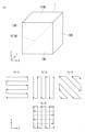
パウダーベッド方式およびメタルデポジッション方式におけるレーザビームまたは電子ビームの走査経路は任意である。例えば、図1(a)に示される積層造形体1において、所定の軸方向、例えば図1(b-1)に示すようにX軸方向に平行にかつ往復して走査することができるし、例えば図1(b-2)に示すようにY軸方向に平行にかつ往復して走査することができる。前者はX走査方式と称し、後者はY走査方式と称することができる。なお、ここではX軸に平行、Y軸に平行の例を示しているが、図1(b-3)に示すように、所定の軸方向がX軸、Y軸に交差する方向に平行であってもよい。これらは、一軸走査方式と称することができる。
また、図1(b-4)に示すように、X走査方式で先の層を造形し、次いで、Y走査方式で次の層を造形するという、XY走査方式と称する走査経路を採用することができる。一軸走査方式を互いに交差する方向で造形する場合には、交差走査方式と称することができ、XY走査方式は交差走査方式の一形態ということができる。
さらに、図示を省略するが、本実施形態においては、渦巻き状の走査経路を採用することができる。
さらにまた、本実施形態は、これらの走査方式を組み合わせることもできる。つまり、図1に示される積層造形体1は、直方体状の単純な構造を有しているが、ネットシェイプまたはニアネットシェイプで三次元形状の部材を造形する場合には、当該部材の構造に適した走査方式を採用することが肝要である。つまり、本発明における積層造形体とは最も広義に解釈されるべきであって、その形状、寸法および具体的な部品、物品などの用途は限定されない。
The scanning path of the laser beam or electron beam in the powder bed method and metal deposition method is arbitrary. For example, in the
Also, as shown in FIG. 1(b-4), adopting a scanning path called the XY scanning method in which the previous layer is modeled by the X scanning method and then the next layer is modeled by the Y scanning method. can be done. When the uniaxial scanning method is used for modeling in mutually intersecting directions, it can be called a cross scanning method, and the XY scanning method can be said to be a form of the cross scanning method.
Furthermore, although illustration is omitted, a spiral scanning path can be employed in this embodiment.
Furthermore, this embodiment can also combine these scanning methods. In other words, the
積層造形体1は、図1(a)に示すように、Z軸方向(通常は鉛直方向)に積層され、その上端面がXY面と称され、側面のそれぞれがZ面と称される。さらに、図1(a)に示すように、積層造形体1が立方体の場合には積層造形体1を対角線において2分割する面が45°面と称される。
また、図1に示される積層造形体1において、上端面であるXY面および側面であるZ面は、レーザビーム等の熱源の走査が2回以上(例えば2回)行われることが寸法精度や表面精度を向上する上で好ましい。なお、2回目以降の走査では金属粉末は供給せずに、レーザビーム等の走査だけが行われる。XY面およびZ面は、積層造形体1の外表面を構成する。この複数回のレーザビーム等の走査は、後述する積層造形体1の耐食性向上に寄与しうる。
As shown in FIG. 1(a), the laminate-molded
In addition, in the
[機械的特性]
本実施形態に係る積層造形体は、同じ化学組成を有するNi基合金であって、鍛造および圧延を経た材料である鍛圧体に比べて、後掲する実施例に示されるように、耐力、引張強さ、硬さが向上する。これらの機械的特性が向上した積層造形体は、その組織においてMoの偏析、つまり周囲に比べてMoの濃度が高い領域がある。このMo偏析が、転位(dislocation)のピン止め効果として機能することにより、機械的特性を向上させているものと解される。Moが偏析している箇所におけるMo濃度は、結晶粒内の母相のMo濃度よりも3at%以上高く、より具体的には3~5at%程度高い。なお、Mo偏析が形成されることにより、周囲にはMoの濃度の低いMo欠乏領域が生じる。
[Mechanical properties]
The laminate-molded body according to the present embodiment is a Ni-based alloy having the same chemical composition, and compared to the forged body, which is a material that has undergone forging and rolling, as shown in the examples below, yield strength, tensile strength Improves strength and hardness. These laminate-molded bodies with improved mechanical properties have Mo segregation in their structures, that is, regions with a higher concentration of Mo than the surroundings. It is understood that this Mo segregation improves the mechanical properties by functioning as a dislocation pinning effect. The Mo concentration at the location where Mo is segregated is 3 at % or more higher than the Mo concentration in the parent phase within the crystal grain, more specifically, about 3 to 5 at % higher. A Mo-depleted region having a low Mo concentration is formed in the surrounding area due to the formation of Mo segregation.
詳しくは後述するが、本実施形態におけるMo偏析は、Mo、CrおよびNiを構成元素として含む金属間化合物であるμ相ではなく、その主成分はMo単体である。積層造形体に形成されるMo偏析は有害相として機能することなく、機械的特性の向上に寄与できる。本実施形態におけるMo偏析は、偏析の程度が極めて微細かつ微量であるために、耐食性の低下も問題とならない程度で収まる。 Although details will be described later, the Mo segregation in this embodiment is not the μ phase, which is an intermetallic compound containing Mo, Cr and Ni as constituent elements, but the main component is Mo alone. Mo segregation formed in the laminate-molded body does not function as a harmful phase and can contribute to the improvement of mechanical properties. Since the degree of Mo segregation in the present embodiment is extremely fine and very small, the decrease in corrosion resistance is not a problem.
次に、積層造形体に形成されるMo偏析が、機械的特性の向上に寄与できるメカニズムを説明する。
上述のとおり、本願では、レーザビームまたは電子ビームを用いた積層造形を採用する。レーザビームまたは電子ビームを用いて溶融・凝固が行われるため、極めて凝固速度が高く、急速凝固により微細で柱状のセル組織が結晶粒内に生成される。
凝固後の組織を観察すると、図4(d)に模式的に示すように、多数の柱状のセルCLが集合して結晶粒を構成している。図4(d)において、円形に見えるのもセルCLであるが、このセルCLは図の紙面の奥の方向に延びているために円形に見えるが、実際には柱状である。
そして、Mo偏析は、隣接するセル組織の間(セルCLの境界)に存在している。積層造形工程における急速凝固により、セル組織内に転位(筋のようなもの)が生じる。セル組織内の転位はエネルギー的に安定になろうとして移動し転位結合を図ろうとするが、Mo偏析によりそれが阻害される。その結果、積層造形工程における急速凝固で生じた多数の転位がセル組織内であまり減少せずに残存するため、セル組織内の転位密度(dislocation density)が高いまま維持される。転位密度が高いことにより、積層造形体の機械的特性向上につながると考えられる。
Next, the mechanism by which Mo segregation formed in the laminate-molded body can contribute to the improvement of mechanical properties will be described.
As described above, the present application employs additive manufacturing using laser beams or electron beams. Since the melting and solidification are performed using a laser beam or an electron beam, the solidification rate is extremely high, and a fine columnar cell structure is generated in the crystal grains by rapid solidification.
Observing the structure after solidification, as schematically shown in FIG. 4(d), a large number of columnar cells CL aggregate to form crystal grains. In FIG. 4(d), it is also the cell CL that looks circular. Although the cell CL looks circular because it extends in the depth direction of the paper surface of the figure, it is actually columnar.
Mo segregation exists between adjacent cell structures (borders of cells CL). Rapid solidification in the additive manufacturing process creates dislocations (like streaks) within the cell structure. Dislocations in the cell structure move to become energetically stable and attempt dislocation bonding, but this is hindered by Mo segregation. As a result, a large number of dislocations generated by rapid solidification in the additive manufacturing process remain in the cell structure without being reduced so much, so that the dislocation density in the cell structure remains high. It is considered that the high dislocation density leads to the improvement of the mechanical properties of the laminate-molded body.
ここで、図2は、積層造形体(後述する実施例における造形体1)のas built面(as built面:研磨・切削等の機械加工や、熱処理が施されていない積層造形のままの面)のSTEM像である。
なお、STEM試料作製手順およびSTEM観察の条件は以下のとおりである。
<STEM試料作製手順>
研磨で薄片を準備したのちFIB(日立ハイテクノロジーズ社製 FB-2100型)でマイクロサンプリングした。
<STEM観察の条件>
試料の厚さ:目標値80nm
装置の機種:日本電子株式会社製 型式JEM-ARM200F
加速電圧:200kV
Here, FIG. 2 shows the as built surface of the layered product (modeled
The STEM sample preparation procedure and STEM observation conditions are as follows.
<STEM sample preparation procedure>
After preparing a thin piece by polishing, it was micro-sampled by FIB (FB-2100 type manufactured by Hitachi High-Technologies Corporation).
<Conditions for STEM observation>
Sample thickness: target value 80 nm
Equipment model: Model JEM-ARM200F manufactured by JEOL Ltd.
Accelerating voltage: 200 kV
図2中、DF-STEM像では白色領域として示されている部分が、BF-STEM像では黒色領域として示されている。BF-STEM像において、ほぼ中央に斜めにくっきりと伸びる黒色領域、およびそこから分岐して斜めに伸びる黒色領域はセル境界であり、セル境界の少なくとも一部にMo偏析が存在している。このようにMo偏析の存在は、詳しくは後述するがSTEM像により確認することができる。
そして、DF-STEM像ではセル組織内に白い筋が多数存在しており、BF-STEM像ではセル組織内に黒い筋が多数存在していることがわかる。これらが、上述したセル組織内に生じた転位である。ここで筋が多いほど転位密度が高いことを示している。
図3は、Mo偏析がセル組織内の転位の移動結合を阻害することを説明するための図であり、この図は図2に示したBF-STEM像を簡略したイメージ図である。例えば、セル組織内の正負の転位が移動して、同一すべり面上で出会うと、転位が消滅することが知られている。ところが、本実施の形態に係る積層造形体では、セル境界の少なくとも一部にMo偏析が存在しているために、上記のような転位の移動結合による消滅が生じにくい。したがって、転位密度が高いまま維持された積層造形体を得ることができるため、最終的に機械的特性、特に硬さが高い積層造形体を得ることができる。転位密度は、例えば「転位長さ/評価体積」で測定できる。本願においては、評価体積は、観察面積に試料厚みを乗じることで、算出される。
一般的には、完全に焼きなまされた金属材料中の転位密度ρは109~1011m-2程度である。また、強加工された金属材料中の転位密度ρは1014~1016m-2程度であることが知られている。本実施の形態に係る積層造形体は、強加工を伴うことなく、転位密度ρを1014m-2以上、さらには1016m-2以上とすることができる。
In FIG. 2, a portion shown as a white area in the DF-STEM image is shown as a black area in the BF-STEM image. In the BF-STEM image, a black area that clearly extends obliquely in the center and a black area that branches off from the black area and extends obliquely are cell boundaries, and Mo segregation exists in at least a portion of the cell boundaries. Thus, the presence of Mo segregation can be confirmed by an STEM image, which will be described later in detail.
It can be seen that many white streaks are present in the cell tissue in the DF-STEM image, and many black streaks are present in the cell tissue in the BF-STEM image. These are the dislocations generated in the cell structure described above. Here, the more streaks, the higher the dislocation density.
FIG. 3 is a diagram for explaining that Mo segregation inhibits the movement and coupling of dislocations in the cell structure, and this diagram is a simplified image diagram of the BF-STEM image shown in FIG. For example, it is known that when positive and negative dislocations in the cell structure move and meet on the same slip plane, the dislocations disappear. However, in the laminate-molded body according to the present embodiment, since Mo segregation exists in at least a part of the cell boundary, disappearance due to the above-described dislocation migration coupling does not easily occur. Therefore, it is possible to obtain a laminate-molded body in which a high dislocation density is maintained, and finally obtain a laminate-molded body having high mechanical properties, particularly high hardness. The dislocation density can be measured by, for example, "dislocation length/evaluation volume". In the present application, the evaluation volume is calculated by multiplying the observation area by the sample thickness.
Generally, the dislocation density ρ in a fully annealed metallic material is on the order of 10 9 -10 11 m −2 . Also, it is known that the dislocation density ρ in a heavily worked metal material is about 10 14 to 10 16 m −2 . The laminate-molded body according to the present embodiment can have a dislocation density ρ of 10 14 m −2 or more, further 10 16 m −2 or more without heavy working.
機械的特性を示す指標として、耐力、引張強さ、伸び、絞り、ビッカース硬さ(HV)が一例として挙げられる。
適度のMo偏析を含む本実施形態に係る積層造形体は、好ましくは400MPa以上、より好ましくは500MPa以上、さらに好ましくは600MPa以上の耐力を有することができる。
また、引張強さについては、本実施形態に係る積層造形体は、好ましくは800MPa以上、より好ましくは900MPa以上、さらに好ましくは950MPa以上の値を示すことができる。
ビッカース硬さ(HV10)については、本実施形態に係る積層造形体は、好ましくは200HV以上、より好ましくは250HV以上、さらに好ましくは300HV以上の値を示すことができる。
本実施形態に係る積層造形体は、好ましくは40%以上、より好ましくは60%以上、さらに好ましくは70%以上の伸びを有することができる。
また、絞りについては、好ましくは40%以上、より好ましくは50%以上、さらに好ましくは60%以上の値を示すことができる。
なお、上記した機械的特性のうち、耐力、および引張強さは強度を判断するための指標であり、伸びおよび絞りは延性を判断するための指標である。ビッカース硬さ(HV)は字義どおり、硬さを判断するための指標である。
Examples of indicators of mechanical properties include yield strength, tensile strength, elongation, area of reduction, and Vickers hardness (HV).
The laminate-molded article according to the present embodiment containing moderate Mo segregation can preferably have a yield strength of 400 MPa or more, more preferably 500 MPa or more, and even more preferably 600 MPa or more.
As for the tensile strength, the laminate-molded article according to the present embodiment can exhibit a value of preferably 800 MPa or higher, more preferably 900 MPa or higher, and even more preferably 950 MPa or higher.
As for Vickers hardness (HV10), the layered product according to the present embodiment can exhibit a value of preferably 200 HV or higher, more preferably 250 HV or higher, and even more preferably 300 HV or higher.
The laminate-molded article according to this embodiment can preferably have an elongation of 40% or more, more preferably 60% or more, and even more preferably 70% or more.
In addition, the aperture can exhibit a value of preferably 40% or more, more preferably 50% or more, and even more preferably 60% or more.
Among the mechanical properties described above, yield strength and tensile strength are indicators for determining strength, and elongation and reduction of area are indicators for determining ductility. Vickers hardness (HV) is literally an index for judging hardness.
Mo偏析は、結晶粒の内部に形成される。Mo偏析が形成されるのは、全ての結晶粒に形成されることもあれば、一部の結晶粒に形成される場合もある。好ましくは全ての結晶粒の個数の70%以上、より好ましくは全ての結晶粒の個数の80%以上の結晶粒、さらに好ましくは全ての結晶粒の個数の90%以上の結晶粒にMo偏析が形成される。 Mo segregation is formed inside the grains. Mo segregation may be formed in all crystal grains or may be formed in some crystal grains. Preferably, 70% or more of all crystal grains, more preferably 80% or more of all crystal grains, and still more preferably 90% or more of all crystal grains have Mo segregation. It is formed.
上述したように、積層造形体において、結晶粒は柱状のセル組織を複数有し、隣接する柱状セル組織の間にMoの偏析がある。結晶粒の平均粒径は80~150μm、さらには10~50μm程度である。
柱状セル組織は、横断面の平均直径が2500~3500nm、さらには300~1000nm程度である(なお、ここでの寸法は熱処理後の寸法である。)。柱状セル組織の横断面は真円ではないため、柱状セル組織の横断面の平均直径は、円相当径の平均直径として算出される。
Mo偏析の度合いは、柱状セル組織の大きさと関連している。柱状セル組織が微細なほど、セル境界に存在するMo偏析による転位のピン止め効果が効果的に発揮されるため、その結果、高強度を有する積層造形体を得ることができる。
柱状セル組織の長さは、30~80μm、さらには10~30μm程度である。
1つの結晶粒は、その内部に柱状セル組織を50~1000個程度有している。
但し、本願の積層造形体を構成するすべての結晶粒が、柱状セル組織を有していることが必須ではない。
なお、鍛圧体については、結晶粒の平均粒径が通常100~数百μmであることを考慮すると、積層造形体が微細な組織を有していることがわかる。
As described above, in the laminate-molded body, crystal grains have a plurality of columnar cell structures, and Mo segregates between adjacent columnar cell structures. The average grain size of crystal grains is about 80 to 150 μm, more preferably about 10 to 50 μm.
The columnar cell structure has an average cross-sectional diameter of about 2500 to 3500 nm, more preferably about 300 to 1000 nm (the dimensions here are dimensions after heat treatment). Since the cross section of the columnar cell structure is not a perfect circle, the average diameter of the cross section of the columnar cell structure is calculated as the average diameter of the equivalent circle diameter.
The degree of Mo segregation is related to the size of the columnar cell structure. The finer the columnar cell structure, the more effectively the pinning effect of dislocations due to Mo segregation existing at the cell boundary is exhibited, and as a result, a layered structure having high strength can be obtained.
The columnar cell structure has a length of about 30 to 80 μm, more preferably about 10 to 30 μm.
One crystal grain has about 50 to 1000 columnar cell structures inside.
However, it is not essential that all the crystal grains forming the laminate-molded body of the present application have a columnar cell structure.
As for the forged body, considering that the average grain size of the crystal grains is usually 100 to several hundred μm, it can be seen that the laminate-molded body has a fine structure.
[積層造形体の製造方法]
次に、Moの偏析を有する本願の積層造形体の好ましい製造方法について説明する。
この製造方法は、レーザビームまたは電子ビームを用いた積層造形によって、質量比でNiの含有量が最も多く、次いでCrおよびMoの含有量が多いNi基合金からなる積層造形体を得る工程を有する。積層造形に伴う溶融・凝固の際に、複数の柱状セル組織を有する結晶粒を形成するとともに、結晶粒の内部であって隣接する複数の柱状セル組織の間に、Moの偏析を形成することが、この製造方法の基本的なコンセプトである。
そして、以下の熱処理および/または時効熱処理を積層造形体に施すことによって、積層造形体の機械的特性を、適宜調整することができる。
本願では、Moの偏析をあえて結晶粒内にある柱状セルの境界に残すことで、上記のメカニズムに基づき、積層造形体の機械的特性を向上させる。このため、専ら機械的特性の向上を期待する場合には、Moの偏析が完全に消失してしまうような、高温かつ長時間の熱処理は採用しないことが望ましい。
また、以下の熱処理および/または時効熱処理は、任意で行うものであり、必須の工程ではない。後述するように、熱処理や時効熱処理を施さない、造形ままの積層造形体(後述する実施例では「造形体1」)は、600MPa以上の耐力と250HV以上のビッカース硬さを兼備しており、鍛圧体の機械的特性を凌駕している。造形ままの積層造形体は、他の機械的特性(引張強さ、伸び、および絞り)の値も必要十分であり、用途によっては造形ままの積層造形体を用いることができる。
[Manufacturing method of laminate model]
Next, a preferred method for manufacturing the layered product of the present application having Mo segregation will be described.
This manufacturing method has a step of obtaining a laminate-molded body made of a Ni-based alloy having the highest Ni content in terms of mass ratio, followed by the highest Cr and Mo contents, by lamination fabrication using a laser beam or an electron beam. . During melting and solidification associated with additive manufacturing, crystal grains having a plurality of columnar cell structures are formed, and Mo segregation is formed between a plurality of adjacent columnar cell structures inside the crystal grains. is the basic concept of this manufacturing method.
By subjecting the laminate-molded article to the following heat treatment and/or aging heat treatment, the mechanical properties of the laminate-molded article can be appropriately adjusted.
In the present application, the mechanical properties of the layered product are improved based on the above-described mechanism by intentionally leaving the segregation of Mo at the boundaries of the columnar cells in the crystal grains. For this reason, if only improvement in mechanical properties is expected, it is desirable not to adopt a high-temperature, long-time heat treatment that completely eliminates the segregation of Mo.
Moreover, the following heat treatment and/or aging heat treatment are optional and not essential steps. As will be described later, an as-molded layered body ("modeled
(熱処理)
積層造形体は、熱処理を施すことにより、後述する実施例に示すように機械的特性を調節できる。この熱処理は、大気中、800℃以上1300℃以下、より好ましくは800℃以上1200℃以下、さらに好ましくは900℃以上1200℃以下で行われる。熱処理は、積層造形体のサイズに応じて、上記温度範囲で10分以上10時間以下、好ましくは0.5時間以上3時間以下で保持すればよい。
熱処理の条件を上記の範囲内とすることにより、機械的特性の向上に寄与する適度のMo偏析をセル境界に残しつつ、積層造形体の歪をとることができる。積層造形体の歪とりは、積層造形体の耐食性向上に寄与する。
熱処理温度が1300℃を超えるほどの高温になると、成分均質化が充分進み、機械的特性の向上に寄与するMo偏析が消失してしまう。このため、熱処理温度の上限は1300℃、より好ましくは1200℃とする。
なお、以下では、1100℃以上1300℃以下の範囲内での熱処理を、溶体化処理ということがある。この範囲で熱処理を行うことにより、材料の合金成分を母相の中に溶かし込むプロセスが進行するからである。
熱処理温度の下限は、800℃、好ましくは900℃、より好ましくは1000℃である。800℃以上であると、造形体ひずみを除去する効果が得られ、かつ時間調整によりMo偏析の効果を残すことが可能となる。
また、熱処理の時間は、熱処理温度に基づき適宜設定する必要がある。例えば、熱処理温度を1200℃以上1300℃以下の範囲に設定する場合には、保持時間を10分以上20分以下とすることができる。熱処理温度を1100℃以上1200℃未満の範囲に設定する場合には、保持時間を20分以上40分以下とすることができる。熱処理温度を800℃以上1100℃未満の範囲に設定する場合には、保持時間を30分以上2時間以下とすることができる。
(Heat treatment)
By subjecting the layered product to a heat treatment, the mechanical properties can be adjusted as shown in Examples described later. This heat treatment is performed in air at a temperature of 800° C. to 1300° C., more preferably 800° C. to 1200° C., still more preferably 900° C. to 1200° C. The heat treatment may be held in the above temperature range for 10 minutes or more and 10 hours or less, preferably 0.5 hours or more and 3 hours or less, depending on the size of the laminate-molded body.
By setting the heat treatment conditions within the above range, it is possible to remove the distortion of the layered product while leaving moderate Mo segregation at the cell boundary, which contributes to the improvement of the mechanical properties. Relieving strain in the laminate-molded body contributes to improving the corrosion resistance of the laminate-molded body.
When the heat treatment temperature exceeds 1300° C., the homogenization of the components progresses sufficiently, and the Mo segregation that contributes to the improvement of the mechanical properties disappears. Therefore, the upper limit of the heat treatment temperature is 1300°C, preferably 1200°C.
In addition, below, the heat treatment within the range of 1100° C. or higher and 1300° C. or lower may be referred to as solution treatment. This is because the process of dissolving the alloy components of the material into the parent phase proceeds by performing the heat treatment within this range.
The lower limit of the heat treatment temperature is 800°C, preferably 900°C, more preferably 1000°C. When the temperature is 800° C. or higher, the effect of removing the distortion of the shaped body can be obtained, and the effect of Mo segregation can be left by adjusting the time.
Also, the heat treatment time must be appropriately set based on the heat treatment temperature. For example, when the heat treatment temperature is set in the range of 1200° C. or more and 1300° C. or less, the holding time can be set to 10 minutes or more and 20 minutes or less. When the heat treatment temperature is set in the range of 1100° C. or more and less than 1200° C., the holding time can be 20 minutes or more and 40 minutes or less. When the heat treatment temperature is set in the range of 800° C. or more and less than 1100° C., the holding time can be 30 minutes or more and 2 hours or less.
(時効熱処理)
また、上記の熱処理に代えて、または上記の熱処理に加えて、600℃以上800℃未満の温度範囲で所定時間保持する時効処理を行うことができる。この時効処理により、積層造形体の強度および硬さをさらに向上できる。
時効処理の時間は、時効処理の温度に応じて適宜調整される。時効処理の温度が600℃以上700℃未満の場合には、20時間以上100時間以下、さらには50時間以上保持することが好ましい。一方、時効処理の温度が700℃以上800℃未満の場合には、保持時間は30時間以上40時間以下であってもよい。本時効処理によりナノサイズの金属間化合物(Ni2(Cr,Mo))を析出させることができ、析出硬化によって、より強度を向上させることが可能となる。
(Aging heat treatment)
Further, instead of or in addition to the above heat treatment, aging treatment can be performed in which the temperature is maintained in the temperature range of 600° C. or more and less than 800° C. for a predetermined period of time. This aging treatment can further improve the strength and hardness of the layered product.
The aging treatment time is appropriately adjusted according to the temperature of the aging treatment. When the temperature of the aging treatment is 600° C. or more and less than 700° C., it is preferable to hold for 20 hours or more and 100 hours or less, more preferably 50 hours or more. On the other hand, when the aging treatment temperature is 700° C. or more and less than 800° C., the holding time may be 30 hours or more and 40 hours or less. Nano-sized intermetallic compounds (Ni 2 (Cr, Mo)) can be precipitated by this aging treatment, and the strength can be further improved by precipitation hardening.
[耐食性]
本実施形態に係る積層造形体は、Crを構成元素とする酸化物(Cr2O3)からなる膜を表層に備えることにより、耐食性を向上させることができる。この酸化膜は、積層造形体の表面から、1nm~20nmの範囲で形成されており、好ましくは1nm~10nmの厚さを有する。酸化膜の厚さは、より好ましくは2~8nmであり、さらに好ましくは3~5nmまでの厚さに形成される。
[Corrosion resistance]
The laminate-molded body according to the present embodiment can improve corrosion resistance by providing a film made of an oxide (Cr 2 O 3 ) containing Cr as a constituent element on the surface layer. This oxide film is formed in a range of 1 nm to 20 nm from the surface of the laminate-molded body, and preferably has a thickness of 1 nm to 10 nm. The thickness of the oxide film is more preferably 2 to 8 nm, more preferably 3 to 5 nm.
本実施形態に係る酸化膜は、高温環境下であってかつ低酸素雰囲気下における酸化処理により形成されるのが好ましい。この酸化処理は、積層造形の際に行うことができる。酸化膜は積層造形体の外表面に形成されるものであるから、積層造形の際に行われる酸化処理は外表面を造形する際に行われる。
パウダーベッド方式のレーザビーム熱源式において、前述したように、窒素、アルゴンなどの不活性雰囲気で積層造形が行われるが、この不活性ガス中に微量の酸素を含有させれば、原料合金粉末が溶融・凝固する積層造形法の過程で酸化処理を行うことができる。
The oxide film according to this embodiment is preferably formed by oxidation treatment in a high-temperature environment and in a low-oxygen atmosphere. This oxidation treatment can be performed during layered manufacturing. Since the oxide film is formed on the outer surface of the laminate-molded body, the oxidation treatment performed during laminate-molding is performed when the outer surface is modeled.
In the powder bed type laser beam heat source type, as described above, additive manufacturing is performed in an inert atmosphere such as nitrogen or argon. Oxidation treatment can be performed in the process of the additive manufacturing method in which the material is melted and solidified.
本実施形態における酸化処理における酸素濃度は、100ppm~21%の範囲とすることが好ましく、100ppm~1%の範囲とすることがより好ましく、100~2000ppmの範囲とすることがさらに好ましい。酸素濃度は、体積を基準にして定められる。
また、本実施形態における酸化処理における温度は、300~1000℃の範囲とすることが好ましく、400~800℃の範囲とすることがより好ましく、500~600℃の範囲とすることがさらに好ましい。
以上の酸素濃度の範囲において、低酸素濃度で酸化処理することが緻密な酸化膜を得る上で好ましいが、例えば酸素濃度が21%であっても、200~300℃近傍の低い温度を選択すれば、緻密な酸化膜を生成することができる。
The oxygen concentration in the oxidation treatment in this embodiment is preferably in the range of 100 ppm to 21%, more preferably in the range of 100 ppm to 1%, and even more preferably in the range of 100 to 2000 ppm. Oxygen concentration is defined on a volume basis.
The temperature in the oxidation treatment in this embodiment is preferably in the range of 300 to 1000.degree. C., more preferably in the range of 400 to 800.degree. C., and even more preferably in the range of 500 to 600.degree.
In the above oxygen concentration range, it is preferable to perform the oxidation treatment at a low oxygen concentration in order to obtain a dense oxide film. can produce a dense oxide film.
[合金組成]
積層造形体1は、質量比でNiの含有量が最も多く、次いでCrおよびMoの含有量が多いNi基合金から構成される。つまり、積層造形体1は、Ni-Cr-Mo系合金部材である。本実施形態におけるNi基合金においてCr、MoおよびNiを主構成元素という。主構成元素のなかで、CrおよびMoは、質量%で、Cr:14.5%~24.5%、Mo:12.0%~23.0%の範囲で含有されるのが好ましい。なお、Niの含有量はCrおよびMoに加えて他の元素に対して残部として特定される。
本発明は、CrおよびMoを含むNi基合金であれば、その合金組成は限定されないが、例えば、過酷な腐食環境で使用される半導体製造装置の構成部材に好適な組成の例を以下に述べる。金属元素の含有量を示す%は質量%を意味するものとする。また、上限値と下限値は任意に組み合わせることができる。
[Alloy composition]
The laminate-molded
Although the alloy composition of the present invention is not limited as long as it is a Ni-based alloy containing Cr and Mo, for example, examples of compositions suitable for constituent members of semiconductor manufacturing equipment used in severely corrosive environments will be described below. . % indicating the content of metal elements means % by mass. Moreover, the upper limit value and the lower limit value can be combined arbitrarily.
[Cr:14.5%~24.5%]
Crは、半導体製造装置に用いられるHCl,Cl2,HF,F2,NF3,ClF3およびHBrなどのハロゲン系ガスに対して、耐食性を向上させる効果がある。特に、半導体製造装置の構成部材が、開放時に一旦外気に触れた際に、金属表面に大気起源の水分が吸着し、吸着した水分とハロゲン系プロセスガスが水和すると、電気化学的腐食が発生する。水和した酸に対して、Crは特に比較的濃度が希薄な領域でその耐食性を発揮する。その場合、Crは14.5%以上含有することが必要であるが、24.5%を超えて含有するとMoとの組み合わせにおいて、積層造形時に相安定性を損ない単一相維持が困難となる。そうすると、粗大なμ相が形成されてしまい耐食性劣化をもたらすので、その含有量を14.5%~24.5%とするのが好ましい。
より好ましいCrの上限は、22.5%であり、さらに好ましくは20.5%である。また、より好ましいCrの下限は、15.0%であり、さらに好ましくは18.0%である。
[Cr: 14.5% to 24.5%]
Cr has the effect of improving corrosion resistance against halogen gases such as HCl, Cl 2 , HF, F 2 , NF 3 , ClF 3 and HBr used in semiconductor manufacturing equipment. In particular, when components of semiconductor manufacturing equipment are exposed to the outside air when they are open, moisture originating from the atmosphere is adsorbed on the metal surface, and when the adsorbed moisture and halogen-based process gas hydrate, electrochemical corrosion occurs. do. For hydrated acids, Cr exerts its corrosion resistance, especially in relatively dilute regions. In that case, it is necessary to contain 14.5% or more of Cr, but if it contains more than 24.5%, in combination with Mo, phase stability will be impaired during additive manufacturing, making it difficult to maintain a single phase. . If this is the case, a coarse μ-phase is formed, resulting in deterioration of corrosion resistance.
A more preferable upper limit of Cr is 22.5%, more preferably 20.5%. Also, the lower limit of Cr is more preferably 15.0%, more preferably 18.0%.
[Mo:12.0%~23.0%]
Moは、Crと同様に、HCl,Cl2,HF,F2,NF3,ClF3およびHBrなどのハロゲン系ガスに対して、耐食性を向上させる効果がある。特に、Moは水和した酸に対して中~高濃度領域でその耐食性を発揮する。これに対応するために、Moは12.0%以上含有することが好ましい。ただし、23.0%を超えて含有すると、Moは高温における酸化性が劣る。そのため、ガスアトマイズ法によって粉末を製造すると、個々の粉末表面に形成される酸化膜が厚くなり、この粉末を用いて製造された積層造形品に酸化物起因の欠陥が顕在化するおそれがある。そのため、その含有量を12.0%~23.0%とすることが好ましい。
好ましいMoの上限は、20.5%であり、さらに好ましくは19.5%である。また、好ましいMoの下限は、14.0%であり、さらに好ましくは16.0%である。
[Mo: 12.0% to 23.0%]
Mo, like Cr, has the effect of improving corrosion resistance against halogen gases such as HCl, Cl2 , HF, F2 , NF3 , ClF3 and HBr. In particular, Mo exhibits its corrosion resistance to hydrated acids in the medium to high concentration range. In order to correspond to this, it is preferable to contain 12.0% or more of Mo. However, when the Mo content exceeds 23.0%, Mo has poor oxidizing properties at high temperatures. Therefore, when the powder is produced by the gas atomization method, the oxide film formed on the surface of each powder becomes thick, and there is a risk that defects caused by the oxide will become apparent in the laminate-molded product produced using this powder. Therefore, it is preferable to set the content to 12.0% to 23.0%.
The upper limit of Mo is preferably 20.5%, more preferably 19.5%. Moreover, the lower limit of Mo is preferably 14.0%, more preferably 16.0%.
[他の元素]
本実施形態の積層造形体におけるNi基合金は、Cr:14.5%~24.5%、Mo:12.0%~23.0%および残部Niおよび不可避的不純物を基本組成とする。本実施形態に係るNi基合金はCr、MoおよびNiからなる場合、及び、主構成元素以外に他の任意元素、例えばTaなどを必要に応じて含むことができる。以下、この任意元素について説明する。
[Other elements]
The basic composition of the Ni-based alloy in the layered product of the present embodiment is Cr: 14.5% to 24.5%, Mo: 12.0% to 23.0%, and the balance Ni and unavoidable impurities. When the Ni-based alloy according to the present embodiment is composed of Cr, Mo, and Ni, it can optionally contain other optional elements such as Ta in addition to the main constituent elements. This optional element will be described below.
[Ta:2.5%以下]
Taは、還元性酸や酸化性酸での耐食性や、孔食やすきま腐食に対する耐食性を改善する効果があるため、必要に応じて1.0%~2.5%の範囲で含有される。
[Ta: 2.5% or less]
Ta has the effect of improving corrosion resistance to reducing acids and oxidizing acids, and corrosion resistance to pitting corrosion and crevice corrosion, so it is contained in the range of 1.0% to 2.5% as necessary.
[W:5%以下]
Wは、Moと同様に還元性酸に対する耐食性を向上させる効果があると同時に、融点を高めることで溶湯の粘度を高め粉末を製造する際に、粒径制御が容易になるとともに、積層造形が困難となりやすい微粉(粒径5μm未満)の生成を抑制できる。そのため、必要に応じて2%~5%の範囲で含有される。
[W: 5% or less]
W, like Mo, has the effect of improving corrosion resistance to reducing acids, and at the same time, raises the melting point to increase the viscosity of the molten metal, making it easier to control the particle size when producing powder. It is possible to suppress the generation of fine powder (particle size less than 5 μm), which tends to be difficult. Therefore, it is contained in the range of 2% to 5% as necessary.
以下、7.00%以下のFe、2.500%以下のCo、0.040%以下のN、0.50%以下のMn、0.010%以下のMg、0.200%以下のSi、0.500%以下のAl、0.500%以下のTi、0.250%以下のCu、0.300%以下のV、0.0050%以下のB、0.0200%以下のZr、0.0300%以下のO等が含有され得る。 7.00% or less Fe, 2.500% or less Co, 0.040% or less N, 0.50% or less Mn, 0.010% or less Mg, 0.200% or less Si, Al up to 0.500% Ti up to 0.500% Cu up to 0.250% V up to 0.300% B up to 0.0050% Zr up to 0.0200% 0300% or less of O and the like may be contained.
その他の不可避不純物として、Cは、結晶粒界近傍でCrと炭化物を形成し、耐食性の劣化を増大させる。そのため、Cは0.05%未満とするのが好ましい。また、SやPは粒界に偏析し、高温割れの原因となるため、0.01%未満に抑制することが好ましい。
また、これら不可避不純物の含有量は少ないほうが好ましく、0%であっても良い。
As other unavoidable impurities, C forms carbides with Cr in the vicinity of grain boundaries, increasing the deterioration of corrosion resistance. Therefore, C is preferably less than 0.05%. Also, S and P segregate at grain boundaries and cause hot cracks, so it is preferable to suppress them to less than 0.01%.
Also, the content of these inevitable impurities is preferably as small as possible, and may be 0%.
[原料合金粉末]
本実施形態に係るNi基合金は以上の組成を有するが、積層造形体を造形するために以上の組成を有する原料合金粉末が用意される。原料合金粉末の化学組成は基本的に積層造形体の化学組成と同じであるが、積層造形体が耐食性に優れる酸化膜を表層に備える場合には、積層造形体の酸素含有量が原料合金粉末よりも多い。酸化膜については後述する。
原料合金粉末及び積層造形体の化学組成は、蛍光X線分析や高周波誘導結合プラズマ(ICP)分析することにより、測定できる。また、C、S、N、Oについては、燃焼法によるガス分析を行って、その含有量を求めることができる。
[Raw material alloy powder]
The Ni-based alloy according to the present embodiment has the above composition, and a raw material alloy powder having the above composition is prepared in order to form a laminate-molded body. The chemical composition of the raw material alloy powder is basically the same as the chemical composition of the layered body, but if the layered body is provided with an oxide film with excellent corrosion resistance on the surface layer, the oxygen content of the layered body more than The oxide film will be described later.
The chemical composition of the raw material alloy powder and the laminate-molded body can be measured by fluorescent X-ray analysis or high-frequency inductively coupled plasma (ICP) analysis. In addition, the contents of C, S, N, and O can be determined by performing gas analysis by a combustion method.
積層造形法は、個々の粉末について溶融・凝固を繰り返すことにより所望する形状を得る造形法であるが、原料合金粉末の粒径が小さすぎると1回の溶融・凝固に必要な容積が得にくくなるため、健全な積層造形体を得にくい。逆に、原料合金粉末の粒径が大きすぎると、1回の溶融凝固に必要な容積が大きくなり、健全な積層造形体が得にくい。したがって、原料合金粉末の粒径は、およそ5~500μmの範囲で用いられるが、パウダーベッド方式とメタルデポジッション方式とでは求められる粒度分布が異なる。パウダーベッド方式では、レーザ回折法によって求められる、粒子径と小粒子径側からの体積積算との関係を示す積算分布曲線における積算50体積%に対応する粒子径d50が10~60μmが好ましい。また、メタルデポジッション方式では粒子径d50が30~250μmが好ましい。 The additive manufacturing method is a manufacturing method in which a desired shape is obtained by repeatedly melting and solidifying individual powders. Therefore, it is difficult to obtain a sound laminate-molded body. Conversely, if the grain size of the raw material alloy powder is too large, the volume required for one melting and solidification will be large, making it difficult to obtain a sound laminate-molded body. Therefore, the grain size of the raw material alloy powder is in the range of about 5 to 500 μm, but the grain size distribution required differs between the powder bed method and the metal deposition method. In the powder bed method, the particle diameter d50 corresponding to the cumulative 50% by volume in the cumulative distribution curve showing the relationship between the particle size and the volume cumulative from the small particle size side determined by the laser diffraction method is preferably 10 to 60 μm. Also, in the metal deposition method, the particle diameter d50 is preferably 30 to 250 μm.
原料合金粉末の製造は、ガスアトマイズ法、水アトマイズ法、ジェットアトマイズ法などを用いることができる。原料合金粉末は球状であることが好ましいため、原料合金粉末は、ガスアトマイズ法で作製することが好ましい。 A gas atomization method, a water atomization method, a jet atomization method, or the like can be used to produce the raw material alloy powder. Since the raw material alloy powder is preferably spherical, the raw material alloy powder is preferably produced by gas atomization.
[用途]
本実施形態に係る積層造形体の用途は任意である。積層造形のままでも高強度高耐食の用途に使用することもできるし、熱処理あるいは時効熱処理を行うか行わないかによって用途に応じた機械的特性を得ることができる。
用途の一例として、HCl,Cl2,HF,F2,NF3,ClF3およびHBrなどに代表される強い腐食性を有するハロゲン系ガスを扱う半導体製造装置に、本実施形態に係る積層造形体を適用できる。特に、これらのガスが直接接触する半導体製造装置の部材に適用されるのが好ましい。また、本実施形態に係る積層造形体は、他の用途として、射出成形用のスクリューやシリンダー、油井の掘削装置や腐食性流体が流れる化学プラントのバルブや継手、熱交換機、ポンプ、発電機などのタービンホール、圧縮機のインペラ等に適用されるのが好ましい。本発明ではこれらの機械、機器、部材、部品等を総称して製造物と言う。
[Use]
The use of the laminate-molded body according to this embodiment is arbitrary. It can be used for high-strength and high-corrosion-resistant applications even as it is laminated and manufactured, and it is possible to obtain mechanical properties according to the application depending on whether or not heat treatment or aging heat treatment is performed.
As an example of the application, the laminated body according to the present embodiment is used in semiconductor manufacturing equipment that handles halogen-based gases with strong corrosive properties, such as HCl, Cl 2 , HF, F 2 , NF 3 , ClF 3 and HBr. can be applied. In particular, it is preferable to be applied to members of semiconductor manufacturing equipment with which these gases come into direct contact. In addition, the laminate-molded body according to the present embodiment has other uses such as screws and cylinders for injection molding, valves and joints of oil well drilling equipment and chemical plants in which corrosive fluid flows, heat exchangers, pumps, and generators. It is preferably applied to a turbine hall of a compressor, an impeller of a compressor, and the like. In the present invention, these machines, devices, members, parts, etc. are collectively referred to as products.
本実施形態に係る酸化膜を有する積層造形体の表面は、適用される用途の部材に応じて、設けられる部位が選択されることが好ましい。つまり、当該部材の全体が腐食性の気体、液体などの腐食環境に接触する場合には、当該部材の全体に本実施形態に係る酸化膜を形成するのが好ましい。また、当該部材の一部だけが腐食性の気体、液体などの腐食環境に接触する場合には、その一部だけに本実施形態に係る酸化膜を形成するのが好ましい。このように酸化膜は、腐食環境接触面に対応して形成され得る。もちろん、当該部材の一部だけが腐食性の気体、液体などの腐食環境接触面となる場合であっても、当該部材の全体に本実施形態に係る酸化膜を形成してもよい。また、他の部材との接合面を構成するために、一部に研磨、研削等の機械加工を施してもよく、この場合は加工によって酸化膜が一部だけになってもよい。
本実施形態において、酸化膜が形成された表面は、研磨・切削等の機械加工が施されていない積層造形のままの面(as built面)である。
It is preferable that the surface of the layered product having the oxide film according to the present embodiment is provided at a site selected according to the member for the application. That is, when the entire member comes into contact with a corrosive environment such as a corrosive gas or liquid, it is preferable to form the oxide film according to the present embodiment on the entire member. Moreover, when only a part of the member comes into contact with a corrosive environment such as a corrosive gas or liquid, it is preferable to form the oxide film according to the present embodiment only on that part. Thus, an oxide film can be formed corresponding to the corrosive environment interface. Of course, even if only a part of the member comes into contact with a corrosive environment such as a corrosive gas or liquid, the oxide film according to the present embodiment may be formed on the entire member. Moreover, in order to configure a joint surface with another member, a part may be subjected to mechanical processing such as polishing and grinding, and in this case, the oxide film may be partially removed by the processing.
In the present embodiment, the surface on which the oxide film is formed is a surface (as built surface) that has not undergone mechanical processing such as polishing and cutting.
以下、本発明を実施例に基づいて具体的に説明する。
表1に示される化学組成を有する付加製造用の原料合金粉末を用意した。この原料合金粉末は、溶解原料を準備し、通常の高周波真空溶解炉を用いて溶解して母合金を作製し、アルゴン雰囲気中、ガスアトマイズ法により作製された。なお、アトマイズ粉末から粒径10~60μmの粉末を分級して付加製造に供した。分級された粉末のd10、d50、d90は、それぞれd10:15.6μm、d50:25.3μm、d90:50.2μmである。
EXAMPLES The present invention will be specifically described below based on examples.
A raw material alloy powder for additive manufacturing having the chemical composition shown in Table 1 was prepared. This raw material alloy powder was prepared by preparing a melting raw material, melting it using a normal high-frequency vacuum melting furnace to produce a mother alloy, and producing it by a gas atomization method in an argon atmosphere. A powder having a particle size of 10 to 60 μm was classified from the atomized powder and subjected to additive manufacturing. The d10, d50 and d90 of the classified powder are d10: 15.6 μm, d50: 25.3 μm and d90: 50.2 μm, respectively.

以下の条件で積層造形を行って、積層造形体1(30mm×30mm×5mm)を作製した(以下、積層造形体を単に造形体と言うことがある)。積層造形におけるシールドガス(アルゴンガス)に540ppmの酸素が含まれている。
積層造形装置:EOS M290(SLM方式)
積層造形条件:
エネルギー密度:20~200J/mm3となるように、
エネルギー密度
=レーザパワー(W)/(走査速度(mm/s)×走査ピッチ(mm)×層厚(mm))を設定する。
実施例では、レーザパワー300W、走査速度800mm/s、走査ピッチ0.1mm、層厚さ0.04mm、よって、エネルギー密度は94J/mm3であった。
雰囲気:Ar(O2<0.10%)
走査方式:交差走査方式(但し、表面のXY面およびZ面は、レーザビームを2回走査)
Laminate modeling was performed under the following conditions to produce a laminate model 1 (30 mm×30 mm×5 mm) (hereinafter, the laminate model may be simply referred to as a model). A shield gas (argon gas) in additive manufacturing contains 540 ppm of oxygen.
Additive manufacturing device: EOS M290 (SLM method)
Additive manufacturing conditions:
Energy density: 20 to 200 J / mm 3 ,
Energy density=laser power (W)/(scanning speed (mm/s)×scanning pitch (mm)×layer thickness (mm)) is set.
In the example, the laser power was 300 W, scanning speed 800 mm/s, scanning pitch 0.1 mm, layer thickness 0.04 mm, so the energy density was 94 J/mm 3 .
Atmosphere: Ar ( O2 <0.10%)
Scanning method: Cross-scanning method (however, the XY plane and Z plane of the surface are scanned twice with a laser beam)
造形体1についても化学組成を分析した。結果を表1に示すが、酸素(O)の含有量が顕著に高くなっている。これは積層造形におけるシールドガス(アルゴンガス)に540ppmの酸素が含まれていることに基づいていると解される。
なお、Mo、CrおよびTaについての組成分析は、蛍光X線分析装置であるSimultix10(株式会社リガク製)によって行われた。また、O(酸素)についての組成分析は、酸素窒素分析装置であるON-836(LECOジャパン合同会社製)によって行われた。
The chemical composition of
The composition analysis of Mo, Cr and Ta was performed using a fluorescent X-ray spectrometer, Simultix10 (manufactured by Rigaku Corporation). Further, the composition analysis of O (oxygen) was performed using an oxygen nitrogen analyzer, ON-836 (manufactured by LECO Japan LLC).
[機械的特性]
次に、造形体1、造形体1に熱処理を施した造形体2~4、および造形体1と同じ化学組成の鍛造および圧延を経た鍛圧体を用意して、機械的特性および転位密度を測定した。その結果を表2に示す。
なお、造形体2、3、4に関して、熱処理の条件は、以下のとおりである。
造形体2:1180℃で30分だけ大気中で保持。
この熱処理により溶体化が進むため、造形体2についての熱処理を、「溶体化熱処理」という。
造形体3:900℃で30分だけ大気中で保持。
この造形体3についての熱処理は、主には歪取りを目的としたものである。
造形体4:650℃で60時間、大気中で保持。
造形体4についての熱処理を、「時効熱処理」という。
また、機械的特性はJIS(JIS Z 2244)に準拠して測定した。ビッカース硬さHVは、荷重10Kgでの測定値である。また、表2におけるXY面、Z面は図1を用いて説明した定義による。以下も同様である。
[Mechanical properties]
Next, molded
In addition, the conditions of the heat treatment for the shaped
Model 2: Hold in air at 1180° C. for 30 minutes.
Since this heat treatment promotes solutionization, the heat treatment of the shaped
Model 3: Hold in air at 900° C. for 30 minutes.
The heat treatment of the modeled
Shaped body 4: maintained in air at 650° C. for 60 hours.
The heat treatment for the shaped
Also, the mechanical properties were measured according to JIS (JIS Z 2244). The Vickers hardness HV is a measured value with a load of 10 Kg. The XY plane and Z plane in Table 2 are defined as described with reference to FIG. The same applies to the following.
(転位密度の測定)
各サンプルの転位密度は、「転位長さ/評価体積」によって求めた。
転位長さは、STEM像(観察面積:4.32μm2 (1.44μm2x3枚))で観察可能な各転位を実測し、それらの合計長さとして求めた。
評価体積は「観察面積×試料厚み」によって求めた。各サンプルについて、STEM試料の作製条件は上記と同じであり、試料厚みは80nmである。
(Measurement of dislocation density)
The dislocation density of each sample was determined by "dislocation length/evaluation volume".
The dislocation length was obtained by actually measuring each dislocation observable in an STEM image (observation area: 4.32 μm 2 (1.44 μm 2 x 3 sheets)) and calculating the total length thereof.
The evaluation volume was determined by "observation area x sample thickness". For each sample, the STEM sample preparation conditions are the same as above, and the sample thickness is 80 nm.
表2に示すように、積層造形による造形体1は、鍛圧体を凌駕する機械的特性が得られることがわかる。また、造形体2の結果より、溶体化熱処理を施すことにより、伸びを鍛圧体に近づけることができる。
造形体2(1180℃×30分)と造形体3(900℃×30分)とを比較すると、造形体3の方が耐力およびビッカース硬さが高い。よって、これらの機械的特性を重視する場合には、800℃以上1000℃以下、さらには850℃以上950℃以下の温度範囲での熱処理が有効であることが確認できた。
造形体4(650℃×60時間)は、表2におけるすべてのサンプルの中で最もビッカース硬さが高く、その値は350HV以上に達している。造形体4は延性(伸び、絞り)についても必要なレベルを維持しつつ、650MPa以上の耐力、1000MPa以上の引張強さ、および350HV以上のビッカース硬さを兼備している。
つまり、熱処理の有無および熱処理の条件を適宜選択すれば、必要とされる機械的特性を満たすことができる。
また、溶体化熱処理を行った造形体2(1180℃×30分)に対して、さらに造形体4と同じ条件で時効熱処理を施したところ、HV10(荷重10Kg)で300HV程度の硬さが得られた。
As shown in Table 2, it can be seen that the molded
Comparing the shaped body 2 (1180° C.×30 minutes) and the shaped body 3 (900° C.×30 minutes), the shaped
Model 4 (650° C.×60 hours) has the highest Vickers hardness among all the samples in Table 2, reaching 350 HV or higher. The shaped
In other words, by appropriately selecting the presence or absence of heat treatment and the conditions of heat treatment, the required mechanical properties can be achieved.
In addition, when the aging heat treatment was further applied to the shaped body 2 (1180° C.×30 minutes) subjected to the solution heat treatment under the same conditions as the
次に表2の転位密度に着目すると、造形体1~造形体4の転位密度(6.3×10¹²m-2 ~2.4×10¹⁷m-2)が、鍛圧体の転位密度(8.2×10⁹m-2)を大きく上回っていることがわかる。造形体1~造形体4のなかでは、熱処理および時効熱処理を行っていない造形体1が最も転位密度が高く、次に転位密度が高いのは時効熱処理を行った造形体4(650℃×60時間)である。転位密度が高い造形体1および造形体4は、耐力、引張強さおよびビッカース硬さの値も高いため、転位密度と、これらの機械的特性には相関関係があると考えられる。
造形体2(1180℃×30分)と造形体3(900℃×30分)は、造形体1および造形体4よりは転位密度が低いが、依然として1012m-2以上の転位密度を示しており、鍛圧体よりも耐力、引張強さおよびビッカース硬さの値が高い。
Next, focusing on the dislocation densities in Table 2, the dislocation densities of the
Shaped body 2 (1180° C.×30 minutes) and shaped body 3 (900° C.×30 min) have lower dislocation densities than shaped

[耐食性]
次に、造形体1および鍛圧体を用いて耐食性の評価を行った。
耐食性の評価は、塩酸水溶液へ浸漬することによる耐食性試験と孔食試験の2種類で行った。なお、耐食性の評価試験において、XY面、45°面およびZ面とは、図1の積層造形体に示されるXY面、45°面およびZ面のことをいう。
(1)塩酸浸漬試験
2種類の腐食溶液(1%塩酸水溶液(沸騰)、5%塩酸水溶液(沸騰))に24時間浸漬して、腐食速度(mm/year)を求めた。結果を図5に示す。なお、研磨ありの場合は1000番の研磨紙を用いて、いずれの試験片についても研磨を行ったうえで腐食溶液に浸漬した。
図5(a)に示すように、造形体1と鍛圧体とで腐食速度に有意な差異はない。また、図5(b)より、耐食性について積層方向に依存性はない。
(2)孔食試験
JIS G0578に準拠し、塩化第二鉄水溶液に試験片を浸漬して、孔食が発生する臨界温度を求めた。結果を表3に示すが、研磨をしないほうの臨界温度が5~10℃程度高くなる。なお、研磨をしない造形体1を造形体1Aといい、研磨をした造形体1を造形体1Bというものとする。
また、同様に隙間腐食試験を行ったが、表3と同様の結果が得られた。
[Corrosion resistance]
Next, the molded
Corrosion resistance was evaluated by two types of corrosion resistance test and pitting corrosion test by immersion in an aqueous solution of hydrochloric acid. In the corrosion resistance evaluation test, the XY plane, the 45° plane and the Z plane refer to the XY plane, the 45° plane and the Z plane shown in the layered product in FIG.
(1) Hydrochloric Acid Immersion Test Corrosion rate (mm/year) was determined by immersing in two types of corrosion solutions (1% hydrochloric acid aqueous solution (boiling), 5% hydrochloric acid aqueous solution (boiling)) for 24 hours. The results are shown in FIG. In the case of polishing, all test pieces were polished with No. 1000 abrasive paper and then immersed in the corrosive solution.
As shown in FIG. 5(a), there is no significant difference in corrosion rate between the compact 1 and the forged compact. Further, from FIG. 5(b), the corrosion resistance does not depend on the stacking direction.
(2) Pitting Corrosion Test According to JIS G0578, a test piece was immersed in an aqueous solution of ferric chloride to determine the critical temperature at which pitting corrosion occurs. The results are shown in Table 3. The critical temperature of the non-polished one is about 5 to 10°C higher. The modeled
A crevice corrosion test was also conducted in the same manner, and results similar to those in Table 3 were obtained.

以上の評価結果をまとめると以下の通りである。
(1)機械的特性
鍛圧体に比べて積層造形体は耐力、引張強さおよび硬さが顕著に向上する。
表2に示したように、本実施形態の積層造形体(造形体1)によれば、熱処理を施していない状態で、600MPa以上の耐力、850MPa以上の引張強さ、および250HV以上のビッカース硬さを兼備することができた。
また、溶体化熱処理を行った積層造形体(造形体2)によれば、70%以上の伸びを維持しつつ、400MPa以上の耐力、850MPa以上の引張強さ、および200HV以上のビッカース硬さを兼備することができた。
歪取りのための熱処理を行った積層造形体(造形体3)によれば、50%以上の伸びを維持しつつ、500MPa以上の耐力、850MPa以上の引張強さ、および250HV以上のビッカース硬さを兼備することができた。
時効熱処理を行った積層造形体(造形体4)については、硬さが著しく向上し、350HV以上のビッカース硬さを得ることができた。それと同時に、600MPa以上の耐力、1000MPa以上の引張強さ、40%以上の伸びおよび絞りを得ることができた。
なお、表2に示した鍛圧体は、溶体化されているものであることを考慮すると、この鍛圧体に本願が推奨する800℃以上1300℃以下での熱処理をさらに施したとしても、機械的特性の飛躍的な向上は期待できない。
The above evaluation results are summarized as follows.
(1) Mechanical Properties Compared to forged bodies, laminated bodies have remarkably improved yield strength, tensile strength and hardness.
As shown in Table 2, according to the laminate-molded body (modeled body 1) of the present embodiment, a proof stress of 600 MPa or more, a tensile strength of 850 MPa or more, and a Vickers hardness of 250 HV or more I was able to combine
In addition, according to the layered product (modeled product 2) subjected to solution heat treatment, while maintaining elongation of 70% or more, yield strength of 400 MPa or more, tensile strength of 850 MPa or more, and Vickers hardness of 200 HV or more. I was able to combine
According to the laminate-molded body (modeled body 3) subjected to heat treatment for strain relief, it has a proof stress of 500 MPa or more, a tensile strength of 850 MPa or more, and a Vickers hardness of 250 HV or more while maintaining an elongation of 50% or more. I was able to combine
The laminate-molded body (modeled body 4) subjected to the aging heat treatment had significantly improved hardness, and a Vickers hardness of 350 HV or more could be obtained. At the same time, yield strength of 600 MPa or more, tensile strength of 1000 MPa or more, elongation and reduction of area of 40% or more could be obtained.
In addition, considering that the forged bodies shown in Table 2 are solution-treated, even if this forged body is further subjected to heat treatment at 800 ° C. or more and 1300 ° C. or less recommended by the present application, mechanical A drastic improvement in characteristics cannot be expected.
表2に示したように、本実施形態の積層造形体(造形体1~4)によれば、1012m-2以上、さらには1014m-2 以上という高い転位密度を得ることができた。造形体1~4は、鍛圧体に比べて転位密度が高く、これが耐力、引張強さおよび硬さの顕著な向上に寄与しているものと考えられる。
As shown in Table 2, according to the laminate-molded bodies (modeled
(2)耐食性
同じ化学組成、積層条件による積層造形体であっても、研磨をしない方の耐食性が優れる。
以下では、上記の機械的特性および耐食性についての評価結果が得られる要因を明らかにすべく行った観察を説明する。
(2) Corrosion resistance The corrosion resistance of the non-polished layered body is superior even if the layered body has the same chemical composition and layering conditions.
Observations made to clarify the factors for obtaining the evaluation results for the above mechanical properties and corrosion resistance will be described below.
[造形体1の組織観察]
造形体1の組織を観察した結果を説明する。この観察は主に機械的な強度が向上する理由を認識するために行われた。
図4(a)、(b)に光学顕微鏡で観察した研磨およびエッチング後の造形体1のXY面およびZ面の観察結果を示す。
XY面には、図4(a)に示すように、およそ100μmの間隔の直線状の境界が観察された。これはXY面をレーザビームが走査した際の他の走査パスとの境界に相当すると解される。図4(a)において、直線状の境界は破線で示され、レーザビームの走査の向きを矢印で示してある。
次に、Z面には、図4(b)に示すように、半円状の境界が観察された。この境界はレーザビームの走査時に形成された溶融池の底面側の境界に相当すると解される。半円状の境界は破線で示されている。
図4(c)は、研磨、エッチング後の造形体1のZ面におけるSEM(走査型電子顕微鏡:Scanning Electron Microscope)像を示し、図4(d)は図4(c)を参照して描いた組織の模式図である。図4(c),(d)に示すように、ナノオーダーのセルCLが観察された。図4(d)において、細長い柱状のものがセルCLであり、図4(b)で観察された結晶粒はこのセルCLが集合して形成されていると推測される。図4(d)において、円形に見えるのもセルCLであるが、このセルCLは図の紙面の奥の方向に延びているために、円形に見える。また、図4(c),(d)に示される組織の形態としては、一般的に溶接で形成される組織に似ているものの、単体のセルの厚みはおよそ1μm以下、長さは数100μm程度であり、溶接組織と比較すれば3~6桁程度小さいセルで構成されている。
[Observation of structure of model 1]
The results of observing the structure of the modeled
4(a) and 4(b) show the observation results of the XY plane and Z plane of the shaped
On the XY plane, as shown in FIG. 4A, linear boundaries with an interval of approximately 100 μm were observed. It is understood that this corresponds to a boundary with another scanning pass when the laser beam scans the XY plane. In FIG. 4(a), a straight boundary is indicated by a dashed line, and the scanning direction of the laser beam is indicated by an arrow.
Next, a semicircular boundary was observed on the Z plane, as shown in FIG. 4(b). It is understood that this boundary corresponds to the boundary on the bottom side of the molten pool formed during laser beam scanning. Semicircular boundaries are indicated by dashed lines.
FIG. 4(c) shows an SEM (Scanning Electron Microscope) image in the Z plane of the shaped
[組織に基づく機械的強度の考察]
図6(a)に鍛圧体のSEMによる反射電子像を、また、図6(b)に造形体1のSEMによる反射電子像を示す。鍛圧体(図6(a))では観察されない微細な白色領域が造形体1(図6(b))において観察された。また、図6(c)の左側にSEMで観察した造形体1のMoのSEM像を示し、図6(c)の右側にEDX(Energy Dispersive X-ray Spectroscopy:エネルギー分散型X線分光法)で観察した造形体1のMoのEDX像を示す。図6(b)と図6(c)を照合することにより、図6(b)で観察される白色領域は、他の領域よりもMoが富化されたMo偏析であることが確認される。このMo偏析は、隣接するセル組織の間、つまりセル境界に形成されているものと推測される。
[Consideration of mechanical strength based on structure]
FIG. 6A shows a backscattered electron image of the forged body by SEM, and FIG. 6B shows a backscattered electron image of the shaped
図6(d)に溶体化処理された造形体2のSEMによる反射電子像を示すが、溶体化処理することにより白色領域、つまりMo偏析が基地に固溶してMo偏析の一部が消失したであろうことがわかる。ただし、上述したように造形体2の機械的特性(耐力、引張強さ)が鍛圧体よりも高いという事実は、1180℃で30分保持するという熱処理条件では、Mo偏析が完全には消失せずに適度に残っていることを示唆している。
1180℃で30分保持する熱処理を経た造形体2をSTEM(Scanning Transmission Electron Microscopy:走査透過電子顕微鏡)で観察したSTEM像を、図7に示す。
図7中、左側のDF-STEM像では白色領域として示されている部分が、右側のBF-STEM像では黒色領域として示されている。右側のBF-STEM像において、中央にくっきりと延びる黒線がセル境界であり、このセル境界にMo偏析が存在していると考えられる。
FIG. 6(d) shows a backscattered electron image by SEM of the shaped
FIG. 7 shows an STEM image of the shaped
In FIG. 7, the portion shown as a white area in the DF-STEM image on the left side is shown as a black area in the BF-STEM image on the right side. In the BF-STEM image on the right side, the black line clearly extending in the center is the cell boundary, and it is considered that Mo segregation exists at this cell boundary.
造形体1におけるMo偏析は、Mo、CrおよびNiを構成元素として含む金属間化合物であるμ相であるのか否かを確認するために、造形体1(未エッチング)について電子回折を行った。その結果を、図8を用いて説明する。
なお、電子回折の条件は以下の通りである。
装置の機種:日本電子格式会社製 型式JEM-ARM200F
加速電圧:200kV
制限視野回折法 絞り径0.5μmφ カメラ長80cm
In order to confirm whether or not the Mo segregation in the shaped
The electron diffraction conditions are as follows.
Equipment model: Model JEM-ARM200F manufactured by JEOL Ltd.
Accelerating voltage: 200 kV
Selected area diffraction method Aperture diameter 0.5 μmφ Camera length 80 cm
図8(a)に示すように、制限視野回折領域は白丸で囲んだ3つの領域(領域A、領域B、領域C)である。図8(b)において、電子回折像A、電子回折像B、電子回折像Cは、それぞれ領域A、領域B、領域Cにおける電子回折像である。
電子回折像A~Cを比較すると、回折パターンが等しいことがわかる。これは、セル境界に位置する領域Bにおいても、母相とは異なる金属間化合物が積層造形体(造形体1)には形成されていないことを示している。よって、造形体1におけるMo偏析は、上記のμ相ではないことが確認できた。造形体1におけるMo偏析は、Mo単体を主成分としていると推察される。微細なMo偏析が隣接する柱状セル組織の間、つまりセル境界に適度に存在することによって、転位結合が阻害され、その結果、セル組織内の転位密度が高い状態が維持されて機械的特性が向上していると解される。
As shown in FIG. 8A, the selected area diffraction area is three areas (area A, area B, and area C) surrounded by white circles. In FIG. 8B, electron diffraction image A, electron diffraction image B, and electron diffraction image C are electron diffraction images in region A, region B, and region C, respectively.
Comparing the electron diffraction images A to C, it can be seen that the diffraction patterns are the same. This indicates that an intermetallic compound different from the parent phase is not formed in the layered product (modeled product 1) even in the region B positioned at the cell boundary. Therefore, it was confirmed that the Mo segregation in the shaped
図9は、図2に示した造形体1のSTEM像(BF-STEM像)に、四角囲みを追加した図である。四角囲みは、結晶粒における母相のEDX分析位置を示している。
また、図10は、図2に示した造形体1のSTEM像(BF-STEM像)に、セル境界のEDX分析位置を示す符号1、2、3、4を追加した図である。
母相およびセル境界のEDX分析結果を、表4にまとめて示す。
表4中、Moの値に着目すると、セル境界ではMo濃度が16.7~19.4at%であり、母相のMo濃度(13.7at%)よりも3.0~5.7at%高い。この結果から、複数の柱状セル組織が隣接するセル境界では、Mo濃度が母相よりも高い領域が存在していることが確認できた。すなわち、積層造形体1を構成する結晶粒において、Mo濃度が母相よりも3.0at%以上、さらには5.0at%以上高いMo偏析がセル境界に存在していることが確認できた。
FIG. 9 is a diagram in which a square is added to the STEM image (BF-STEM image) of the modeled
FIG. 10 is a diagram obtained by adding
EDX analysis results of the matrix phase and cell boundaries are summarized in Table 4.
Focusing on the value of Mo in Table 4, the Mo concentration at the cell boundary is 16.7 to 19.4 at%, which is 3.0 to 5.7 at% higher than the Mo concentration in the mother phase (13.7 at%). . From this result, it was confirmed that there was a region where the Mo concentration was higher than that of the parent phase at the cell boundary where a plurality of columnar cell structures were adjacent to each other. That is, it was confirmed that in the crystal grains constituting the

[表層の元素挙動観察]
次に、造形体1A(研磨なし)と造形体1B(研磨あり)について、表層部の元素の挙動を観察した。それぞれの結果を図11(a)、(b)に示す。この観察は主に耐食性が向上する理由を認識するために行われた。なお、観察条件は以下の通りである。
装置:アルバック・ファイ社製 ESCA-5400R(3057カスタマイズ)
X-Ray(Mgkα) :15.0kV 26.7mA (400W)
検出深さ:20nm(取り出し角 45°)
分析領域:800μmφ
スパッタ条件(Ar+):加速電圧;2kV, ラスターサイズ;3×3mm
スパッタ速度:約2.0nm/min(SiO2換算値)
[Observation of surface element behavior]
Next, the behavior of the elements in the surface layer portion was observed for the shaped body 1A (without polishing) and the shaped body 1B (with polishing). The respective results are shown in FIGS. 11(a) and 11(b). This observation was made primarily to identify the reason for the increased corrosion resistance. Observation conditions are as follows.
Device: ESCA-5400R (3057 customized) manufactured by ULVAC-Phi
X-Ray (Mgkα): 15.0kV 26.7mA (400W)
Detection depth: 20 nm (extraction angle 45°)
Analysis area: 800 μmφ
Sputtering conditions (Ar + ): acceleration voltage; 2 kV, raster size; 3 × 3 mm
Sputtering speed: about 2.0 nm/min (SiO 2 conversion value)
図11(a)に示すように、造形体1Aは、表層部に酸化物からなる薄膜が形成されているものと推察される。この表層部におけるCrとOの濃度比から、この酸化物は酸化クロム(Cr2O3)と認められる。酸化クロムは、表層部における酸素とCrの含有量から深さ方向に3nm程度までの範囲で形成されており、3nmを超えても相当の酸素濃度が観察されるので、この造形体A1については、6nm程度までの厚さを有しているものと認められる。
この表層部におけるCrとNiの含有量について着目すると、表面から3nm程度の範囲まではCr含有量がNi含有量よりも多い。この領域にはNiの酸化物(NiO)が含まれているものと推察されるが、CrとNiの含有量からすると、酸化クロムの生成量が多く、この領域において酸化クロムと酸化ニッケルを含むが、Crを主体とする酸化膜が形成されていると解される。
As shown in FIG. 11A, the modeled body 1A is presumed to have a thin film of oxide formed on the surface layer. From the concentration ratio of Cr and O in this surface layer portion, this oxide is recognized as chromium oxide (Cr 2 O 3 ). Chromium oxide is formed in a depth range of about 3 nm from the oxygen and Cr content in the surface layer, and a considerable oxygen concentration is observed even if it exceeds 3 nm. , and has a thickness of up to about 6 nm.
Focusing on the contents of Cr and Ni in this surface layer portion, the Cr content is higher than the Ni content in a range of about 3 nm from the surface. This region is presumed to contain Ni oxide (NiO), but from the content of Cr and Ni, the amount of chromium oxide produced is large, and this region contains chromium oxide and nickel oxide. However, it is understood that an oxide film mainly composed of Cr is formed.
表面から3nm程度の領域を越えると、Cr含有量とNi含有量が逆転する。そして、表面からおよそ6nmの深さを超えると、Cr含有量およびNi含有量ともに安定する金属成分領域になる。Cr含有量とNi含有量が逆転するところからCrおよびNiの金属成分領域までの間は、Ni含有量がCr含有量より多いので、当該領域は酸化クロムと酸化ニッケルあるいはNiCr酸化物を含むが、Crを主体とする酸化膜が形成されているものと解される。 Beyond a region of about 3 nm from the surface, the Cr content and the Ni content are reversed. Then, beyond a depth of about 6 nm from the surface, a metal component region in which both the Cr content and the Ni content are stable is formed. Since the Ni content is greater than the Cr content from the point where the Cr content and the Ni content are reversed to the Cr and Ni metallic component region, the region contains chromium oxide and nickel oxide or NiCr oxide. , an oxide film mainly composed of Cr is formed.
図11(b)に示すように、造形体1Bにおいても、表層部に酸化物からなる薄膜が形成されているものと推察されるが、Cr含有量よりもNi含有量が多い。したがって、造形体1Bにおいては、表層部に酸化Crが存在していないか、存在していたとしても酸化Niの量が多く、Niを主体とする酸化膜が形成されているものと認められる。なお、造形体1Bは表面が研磨されているが、研磨中または研磨後に大気と接触することにより、自然に酸化されたために表層部に酸素(O)が含まれる。 As shown in FIG. 11(b), it is presumed that a thin film made of oxide is also formed on the surface layer of the shaped body 1B, but the Ni content is higher than the Cr content. Therefore, in the modeled body 1B, Cr oxide does not exist in the surface layer portion, or even if it exists, the amount of Ni oxide is large, and it is recognized that an oxide film mainly composed of Ni is formed. Although the surface of the modeled body 1B is polished, oxygen (O) is included in the surface layer portion due to natural oxidation due to contact with the atmosphere during or after polishing.
[耐食性についての考察]
積層造形の後に研磨をしない造形体1Aが研磨をした造形体1Bよりも高い耐食性を示し、造形体1Aは表層のごく浅い範囲に酸化物が形成されている。
この酸化物は、積層造形の際に形成されたものと解されるが、これはシールドガスであるアルゴンガス(Arガス)に酸素(O2)が含まれていることに起因する。このアルゴンガスにおける酸素の含有量は、前述したように10~2000ppm程度と、例えば大気中の酸素量である21%程度と比べると微量である。この微量に含まれる酸素が、積層造形時には合金粉末が溶融する1300℃~1800℃の高温な雰囲気に曝されることで、緻密な酸化物が形成される。しかも、耐食性が評価された積層造形体のXY面およびZ面、つまり表面は同じ走査パスについてレーザビームの走査が2回行われる。この2回繰り返されるレーザビームの走査が、より緻密な酸化物の生成に寄与しているものと解される。
[Discussion on corrosion resistance]
The modeled body 1A that is not polished after lamination manufacturing exhibits higher corrosion resistance than the grounded modeled body 1B, and oxide is formed in a very shallow range of the surface layer of the modeled body 1A.
This oxide is considered to have been formed during layered manufacturing, and this is due to the fact that argon gas (Ar gas), which is a shielding gas, contains oxygen (O 2 ). The oxygen content in this argon gas is about 10 to 2000 ppm as described above, which is a very small amount compared to, for example, about 21%, which is the amount of oxygen in the atmosphere. The minute amount of oxygen is exposed to a high temperature atmosphere of 1300° C. to 1800° C. at which the alloy powder melts during additive manufacturing, forming a dense oxide. Moreover, the XY plane and Z plane of the layered product evaluated for corrosion resistance, ie, the surface, are scanned with the laser beam twice for the same scanning path. It is understood that the scanning of the laser beam repeated twice contributes to the formation of a denser oxide.
1 積層造形体(造形体) 1 Laminated body (modeled body)
Claims (11)
前記Ni基合金部材は積層造形体であり、かつ結晶粒の少なくとも一部にMoの偏析を有し、
前記積層造形体はその表層部にCrを主体とする酸化膜を備え、
前記酸化膜は、6nm以下の厚さを有する、
Ni基合金部材。 A Ni-based alloy member having the highest Ni content and the next highest Cr and Mo content in terms of mass ratio,
The Ni-based alloy member is a laminate-molded body, and has Mo segregation in at least part of the crystal grains,
The layered product has an oxide film mainly composed of Cr on its surface layer,
the oxide film has a thickness of 6 nm or less;
Ni-based alloy member.
隣接する前記複数の柱状セル組織の間に前記Moの偏析がある、
請求項1に記載のNi基合金部材。 The crystal grains have a plurality of columnar cell structures,
There is segregation of Mo between the plurality of adjacent columnar cell structures,
The Ni-based alloy member according to claim 1.
請求項2に記載のNi基合金部材。 The columnar cell structure has an average equivalent circle diameter in a cross section of 1000 nm or less.
The Ni-based alloy member according to claim 2.
請求項1から請求項6のいずれか一項に記載のNi基合金部材。 The oxide film contains chromium oxide (Cr 2 O 3 ),
The Ni-based alloy member according to any one of claims 1 to 6.
請求項1から請求項7のいずれか一項に記載のNi基合金部材。 The oxide film contains nickel oxide (NiO),
The Ni-based alloy member according to any one of claims 1 to 7.
前記積層造形体を得る工程が10~2000ppmの酸素(O 2 )が含まれるシールドガス中において行われ、
前記積層造形に伴う溶融・凝固の際、複数の柱状セル組織を有する結晶粒を形成し、前記結晶粒の内部であって隣接する前記複数の柱状セル組織の間に、Moの偏析を形成し、
前記積層造形体はその表層部にCrを主体とする酸化膜を備える、
Ni基合金部材の製造方法。 A step of obtaining a laminate-molded body made of a Ni-based alloy having the highest Ni content in terms of mass ratio, followed by the highest Cr and Mo contents, by lamination fabrication using a laser beam or an electron beam;
The step of obtaining the layered product is performed in a shielding gas containing 10 to 2000 ppm of oxygen (O 2 ),
During the melting and solidification associated with the additive manufacturing, crystal grains having a plurality of columnar cell structures are formed, and Mo segregation is formed between the plurality of adjacent columnar cell structures inside the crystal grains. ,
The layered product has an oxide film mainly composed of Cr on its surface layer,
A method for producing a Ni-based alloy member.
Applications Claiming Priority (4)
| Application Number | Priority Date | Filing Date | Title |
|---|---|---|---|
| JP2019038724 | 2019-03-04 | ||
| JP2019038724 | 2019-03-04 | ||
| JP2021504098A JPWO2020179766A1 (en) | 2019-03-04 | 2020-03-03 | Ni-based alloy member made of laminated model, manufacturing method of Ni-based alloy member, and product using Ni-based alloy member |
| PCT/JP2020/008832 WO2020179766A1 (en) | 2019-03-04 | 2020-03-03 | Ni-based alloy member comprising additively manufactured article, method for manufacturing ni-based alloy member, and product using ni-based alloy member |
Related Parent Applications (1)
| Application Number | Title | Priority Date | Filing Date |
|---|---|---|---|
| JP2021504098A Division JPWO2020179766A1 (en) | 2019-03-04 | 2020-03-03 | Ni-based alloy member made of laminated model, manufacturing method of Ni-based alloy member, and product using Ni-based alloy member |
Publications (2)
| Publication Number | Publication Date |
|---|---|
| JP2022130403A JP2022130403A (en) | 2022-09-06 |
| JP7323010B2 true JP7323010B2 (en) | 2023-08-08 |
Family
ID=72337443
Family Applications (2)
| Application Number | Title | Priority Date | Filing Date |
|---|---|---|---|
| JP2021504098A Pending JPWO2020179766A1 (en) | 2019-03-04 | 2020-03-03 | Ni-based alloy member made of laminated model, manufacturing method of Ni-based alloy member, and product using Ni-based alloy member |
| JP2022090627A Active JP7323010B2 (en) | 2019-03-04 | 2022-06-03 | Ni-based alloy member made of laminate-molded body, method for manufacturing Ni-based alloy member, and product using Ni-based alloy member |
Family Applications Before (1)
| Application Number | Title | Priority Date | Filing Date |
|---|---|---|---|
| JP2021504098A Pending JPWO2020179766A1 (en) | 2019-03-04 | 2020-03-03 | Ni-based alloy member made of laminated model, manufacturing method of Ni-based alloy member, and product using Ni-based alloy member |
Country Status (7)
| Country | Link |
|---|---|
| US (1) | US20220001449A1 (en) |
| EP (1) | EP3936259A4 (en) |
| JP (2) | JPWO2020179766A1 (en) |
| CN (1) | CN113165077A (en) |
| SG (1) | SG11202109038PA (en) |
| TW (1) | TWI820307B (en) |
| WO (1) | WO2020179766A1 (en) |
Families Citing this family (2)
| Publication number | Priority date | Publication date | Assignee | Title |
|---|---|---|---|---|
| WO2023158448A1 (en) * | 2022-02-19 | 2023-08-24 | Massachusetts Institute Of Technology | Directional recrystallization processing of additively manufactured metal alloys |
| WO2023214567A1 (en) * | 2022-05-02 | 2023-11-09 | 株式会社プロテリアル | Alloy, alloy powder, alloy member, and composite member |
Citations (2)
| Publication number | Priority date | Publication date | Assignee | Title |
|---|---|---|---|---|
| JP2008118103A (en) | 2006-10-10 | 2008-05-22 | Hitachi Kokusai Electric Inc | Substrate treatment apparatus and method for manufacturing semiconductor device |
| WO2016158687A1 (en) | 2015-03-31 | 2016-10-06 | 山陽特殊製鋼株式会社 | Metal powder composed of spherical particles |
Family Cites Families (8)
| Publication number | Priority date | Publication date | Assignee | Title |
|---|---|---|---|---|
| JP4816950B2 (en) * | 2006-11-10 | 2011-11-16 | 三菱マテリアル株式会社 | Ni-base alloy excellent in corrosion resistance and wear resistance and conductor roll made of the Ni-base alloy |
| JP5305078B2 (en) * | 2008-05-22 | 2013-10-02 | 三菱マテリアル株式会社 | Valve member for cylinders filled with halogen gas and halogen compound gas |
| BR112015008352B1 (en) | 2012-11-01 | 2020-02-18 | General Electric Company | ADDITIVE MANUFACTURING METHOD OF MANUFACTURING AN OBJECT |
| JP5725630B1 (en) | 2014-02-26 | 2015-05-27 | 日立金属Mmcスーパーアロイ株式会社 | Ni-base alloy with excellent hot forgeability and corrosion resistance |
| JP6620029B2 (en) * | 2015-03-31 | 2019-12-11 | 山陽特殊製鋼株式会社 | Metal powder consisting of spherical particles |
| CN107119270B (en) * | 2017-05-24 | 2019-07-30 | 首钢集团有限公司 | A kind of top laser 3D printing reproducing method of perforation |
| JP6519961B2 (en) * | 2017-09-07 | 2019-05-29 | 日立金属株式会社 | Ni-based corrosion resistant alloy powder for laminate molding, laminate molded article using this powder, and method of manufacturing member for semiconductor manufacturing apparatus |
| CN108480629B (en) * | 2018-03-23 | 2020-08-25 | 山东矿机集团股份有限公司 | Laser additive manufacturing method for hollow blade of steam turbine |
-
2020
- 2020-03-03 CN CN202080006940.5A patent/CN113165077A/en active Pending
- 2020-03-03 EP EP20766485.5A patent/EP3936259A4/en active Pending
- 2020-03-03 TW TW109106969A patent/TWI820307B/en active
- 2020-03-03 WO PCT/JP2020/008832 patent/WO2020179766A1/en unknown
- 2020-03-03 JP JP2021504098A patent/JPWO2020179766A1/en active Pending
- 2020-03-03 US US17/432,787 patent/US20220001449A1/en active Pending
- 2020-03-03 SG SG11202109038PA patent/SG11202109038PA/en unknown
-
2022
- 2022-06-03 JP JP2022090627A patent/JP7323010B2/en active Active
Patent Citations (2)
| Publication number | Priority date | Publication date | Assignee | Title |
|---|---|---|---|---|
| JP2008118103A (en) | 2006-10-10 | 2008-05-22 | Hitachi Kokusai Electric Inc | Substrate treatment apparatus and method for manufacturing semiconductor device |
| WO2016158687A1 (en) | 2015-03-31 | 2016-10-06 | 山陽特殊製鋼株式会社 | Metal powder composed of spherical particles |
Also Published As
| Publication number | Publication date |
|---|---|
| JP2022130403A (en) | 2022-09-06 |
| EP3936259A4 (en) | 2022-11-30 |
| TWI820307B (en) | 2023-11-01 |
| JPWO2020179766A1 (en) | 2021-11-11 |
| WO2020179766A1 (en) | 2020-09-10 |
| TW202033784A (en) | 2020-09-16 |
| CN113165077A (en) | 2021-07-23 |
| SG11202109038PA (en) | 2021-09-29 |
| EP3936259A1 (en) | 2022-01-12 |
| US20220001449A1 (en) | 2022-01-06 |
Similar Documents
| Publication | Publication Date | Title |
|---|---|---|
| JP7323010B2 (en) | Ni-based alloy member made of laminate-molded body, method for manufacturing Ni-based alloy member, and product using Ni-based alloy member | |
| JP6690789B2 (en) | Alloy material, product using the alloy material, and fluid machine having the product | |
| TWI624551B (en) | Metal powder, method of producing additively-manufactured article, and additively-manufactured article | |
| Du et al. | A novel method for additive/subtractive hybrid manufacturing of metallic parts | |
| CN111050957B (en) | Ni-based corrosion-resistant alloy powder for laminate molding, laminate molding using same, and method for manufacturing member for semiconductor manufacturing apparatus | |
| WO2020179724A1 (en) | Multilayer model and method for producing multilayer model | |
| CN113862543A (en) | Method for manufacturing alloy member | |
| KR20210118131A (en) | How to make aluminum alloy parts | |
| CN113490560B (en) | Nickel-based corrosion-resistant alloy powder for laminated molding and method for producing laminated molded article | |
| US20230122004A1 (en) | Production method of alloy member, alloy member, and product using alloy member | |
| Duan et al. | Achieving enhanced strength and ductility in 316L stainless steel via wire arc additive manufacturing using pulsed arc plasma | |
| EP3903971A1 (en) | Auto-tempering steels for additive manufacturing | |
| Salunkhe et al. | Advances in Metal Additive Manufacturing | |
| CN113490558B (en) | Nickel-based corrosion-resistant alloy powder for laminated molding and method for producing laminated molded article | |
| Marchese et al. | Inconel 625 by direct metal laser sintering: Effects of the process parameters and heat treatments on microstructure and hardness | |
| WO2021201106A1 (en) | Ni-cr-mo alloy member, ni-cr-mo alloy powder, and composite member | |
| WO2023176650A1 (en) | Ni-cr alloy member comprising additively manufactured article, method for manufacturing ni-cr alloy member, and product using ni-cr alloy member | |
| TW202222451A (en) | Method for manufacturing cobalt-based alloy structure, and cobalt-based alloy structure obtained thereby | |
| WO2020222695A1 (en) | Process for producing a steel workpiece by additive powder bed fusion manufacturing, and steel workpiece obtained therefrom | |
| WO2024075443A1 (en) | Fe-cr-al-based alloy powder for additive manufacturing, fe-cr-al-based alloy member, and method for producing fe-cr-al-based alloy member | |
| Surreddi et al. | In-situ micro-tensile testing of additive manufactured maraging steels in the SEM: Influence of build orientation, thickness and roughness on the resulting mechanical properties | |
| Liljestrand | Porosity closure during hot isostatic pressing of additively manufactured Ni-based superalloy IN718 produced by LPBF and EBM | |
| Chandra Achinadka | Study of Condensate Generated During Direct Metal Laser Sintering | |
| JP7327704B2 (en) | Alloy materials, alloy products using alloy materials, and machinery equipped with alloy products | |
| Vogelpoth | Development of Adapted Ni-738 Powder for Additive Manufacturing |
Legal Events
| Date | Code | Title | Description |
|---|---|---|---|
| A521 | Request for written amendment filed |
Free format text: JAPANESE INTERMEDIATE CODE: A523 Effective date: 20220603 |
|
| A621 | Written request for application examination |
Free format text: JAPANESE INTERMEDIATE CODE: A621 Effective date: 20220603 |
|
| A977 | Report on retrieval |
Free format text: JAPANESE INTERMEDIATE CODE: A971007 Effective date: 20230322 |
|
| A131 | Notification of reasons for refusal |
Free format text: JAPANESE INTERMEDIATE CODE: A131 Effective date: 20230328 |
|
| A521 | Request for written amendment filed |
Free format text: JAPANESE INTERMEDIATE CODE: A523 Effective date: 20230523 |
|
| TRDD | Decision of grant or rejection written | ||
| A01 | Written decision to grant a patent or to grant a registration (utility model) |
Free format text: JAPANESE INTERMEDIATE CODE: A01 Effective date: 20230627 |
|
| A61 | First payment of annual fees (during grant procedure) |
Free format text: JAPANESE INTERMEDIATE CODE: A61 Effective date: 20230710 |
|
| R150 | Certificate of patent or registration of utility model |
Ref document number: 7323010 Country of ref document: JP Free format text: JAPANESE INTERMEDIATE CODE: R150 |