JP7321663B2 - Paper sheet storage device and paper sheet handling device - Google Patents
Paper sheet storage device and paper sheet handling device Download PDFInfo
- Publication number
- JP7321663B2 JP7321663B2 JP2022541030A JP2022541030A JP7321663B2 JP 7321663 B2 JP7321663 B2 JP 7321663B2 JP 2022541030 A JP2022541030 A JP 2022541030A JP 2022541030 A JP2022541030 A JP 2022541030A JP 7321663 B2 JP7321663 B2 JP 7321663B2
- Authority
- JP
- Japan
- Prior art keywords
- guide
- guide portion
- storage
- paper sheet
- storage space
- Prior art date
- Legal status (The legal status is an assumption and is not a legal conclusion. Google has not performed a legal analysis and makes no representation as to the accuracy of the status listed.)
- Active
Links
Images


Classifications
-
- B—PERFORMING OPERATIONS; TRANSPORTING
- B65—CONVEYING; PACKING; STORING; HANDLING THIN OR FILAMENTARY MATERIAL
- B65H—HANDLING THIN OR FILAMENTARY MATERIAL, e.g. SHEETS, WEBS, CABLES
- B65H31/00—Pile receivers
- B65H31/02—Pile receivers with stationary end support against which pile accumulates
-
- B—PERFORMING OPERATIONS; TRANSPORTING
- B65—CONVEYING; PACKING; STORING; HANDLING THIN OR FILAMENTARY MATERIAL
- B65H—HANDLING THIN OR FILAMENTARY MATERIAL, e.g. SHEETS, WEBS, CABLES
- B65H29/00—Delivering or advancing articles from machines; Advancing articles to or into piles
- B65H29/26—Delivering or advancing articles from machines; Advancing articles to or into piles by dropping the articles
-
- B—PERFORMING OPERATIONS; TRANSPORTING
- B65—CONVEYING; PACKING; STORING; HANDLING THIN OR FILAMENTARY MATERIAL
- B65H—HANDLING THIN OR FILAMENTARY MATERIAL, e.g. SHEETS, WEBS, CABLES
- B65H29/00—Delivering or advancing articles from machines; Advancing articles to or into piles
- B65H29/52—Stationary guides or smoothers
-
- B—PERFORMING OPERATIONS; TRANSPORTING
- B65—CONVEYING; PACKING; STORING; HANDLING THIN OR FILAMENTARY MATERIAL
- B65H—HANDLING THIN OR FILAMENTARY MATERIAL, e.g. SHEETS, WEBS, CABLES
- B65H31/00—Pile receivers
-
- G—PHYSICS
- G07—CHECKING-DEVICES
- G07D—HANDLING OF COINS OR VALUABLE PAPERS, e.g. TESTING, SORTING BY DENOMINATIONS, COUNTING, DISPENSING, CHANGING OR DEPOSITING
- G07D11/00—Devices accepting coins; Devices accepting, dispensing, sorting or counting valuable papers
- G07D11/10—Mechanical details
- G07D11/12—Containers for valuable papers
-
- B—PERFORMING OPERATIONS; TRANSPORTING
- B65—CONVEYING; PACKING; STORING; HANDLING THIN OR FILAMENTARY MATERIAL
- B65H—HANDLING THIN OR FILAMENTARY MATERIAL, e.g. SHEETS, WEBS, CABLES
- B65H2301/00—Handling processes for sheets or webs
- B65H2301/40—Type of handling process
- B65H2301/42—Piling, depiling, handling piles
- B65H2301/421—Forming a pile
- B65H2301/4212—Forming a pile of articles substantially horizontal
-
- B—PERFORMING OPERATIONS; TRANSPORTING
- B65—CONVEYING; PACKING; STORING; HANDLING THIN OR FILAMENTARY MATERIAL
- B65H—HANDLING THIN OR FILAMENTARY MATERIAL, e.g. SHEETS, WEBS, CABLES
- B65H2404/00—Parts for transporting or guiding the handled material
- B65H2404/50—Surface of the elements in contact with the forwarded or guided material
- B65H2404/51—Cross section, i.e. section perpendicular to the direction of displacement
- B65H2404/513—Cross section, i.e. section perpendicular to the direction of displacement with limited number of active areas
- B65H2404/5131—Cross section, i.e. section perpendicular to the direction of displacement with limited number of active areas saw profile
-
- B—PERFORMING OPERATIONS; TRANSPORTING
- B65—CONVEYING; PACKING; STORING; HANDLING THIN OR FILAMENTARY MATERIAL
- B65H—HANDLING THIN OR FILAMENTARY MATERIAL, e.g. SHEETS, WEBS, CABLES
- B65H2404/00—Parts for transporting or guiding the handled material
- B65H2404/60—Other elements in face contact with handled material
- B65H2404/69—Other means designated for special purpose
- B65H2404/692—Chute, e.g. inclined surface on which material slides by gravity
- B65H2404/6922—Shaft-like element channel
-
- B—PERFORMING OPERATIONS; TRANSPORTING
- B65—CONVEYING; PACKING; STORING; HANDLING THIN OR FILAMENTARY MATERIAL
- B65H—HANDLING THIN OR FILAMENTARY MATERIAL, e.g. SHEETS, WEBS, CABLES
- B65H2405/00—Parts for holding the handled material
- B65H2405/10—Cassettes, holders, bins, decks, trays, supports or magazines for sheets stacked substantially horizontally
- B65H2405/11—Parts and details thereof
- B65H2405/111—Bottom
- B65H2405/1115—Bottom with surface inclined, e.g. in width-wise direction
-
- B—PERFORMING OPERATIONS; TRANSPORTING
- B65—CONVEYING; PACKING; STORING; HANDLING THIN OR FILAMENTARY MATERIAL
- B65H—HANDLING THIN OR FILAMENTARY MATERIAL, e.g. SHEETS, WEBS, CABLES
- B65H2701/00—Handled material; Storage means
- B65H2701/10—Handled articles or webs
- B65H2701/19—Specific article or web
- B65H2701/1912—Banknotes, bills and cheques or the like
Landscapes
- Engineering & Computer Science (AREA)
- Mechanical Engineering (AREA)
- Physics & Mathematics (AREA)
- General Physics & Mathematics (AREA)
- Pile Receivers (AREA)
Description
本発明は、紙葉類収納装置と、この紙葉類収納装置を備える紙葉類取扱装置とに関する。 The present invention relates to a paper sheet storage device and a paper sheet handling device equipped with the paper sheet storage device.
従来、内部集積空間の幅が投入紙葉類を横たえた状態に集積できない薄型に設定された紙葉類収納箱において、投入口側の第1集積空間と下側の第2集積空間とを区分する仕切り板が所定負荷によって開放可能に設けられた紙葉類収納箱が提案されている(例えば、特許文献1参照)。 Conventionally, in a paper sheet storage box in which the width of the internal stacking space is set to be thin so that the inserted paper sheets cannot be stacked in a laid state, the first stacking space on the inlet side and the second stacking space on the lower side are separated. A paper sheet storage box has been proposed in which a partition plate is provided so that it can be opened by a predetermined load (see, for example, Patent Document 1).
ところで、紙幣等の紙葉類の収納は、紙葉類のサイズよりも少し大きい収納庫に、収納空間を有効に活用できるように紙葉類を整列させながら収納するのが一般的である。このように紙葉類を整列させながら収納するためには、紙葉類の収納空間が常に一定となるようにステージを昇降させる昇降機構などの設置が必要であった。この昇降機構は、例えば、紙葉類の重みに追従してステージの高さを可変にするためのスプリングや、電動の昇降機構などである。 By the way, paper sheets such as banknotes are generally stored in a storage box slightly larger than the size of the paper sheets while aligning the paper sheets so as to effectively utilize the storage space. In order to store the paper sheets while aligning them in this way, it is necessary to install an elevating mechanism or the like for moving up and down the stage so that the storage space for the paper sheets is always constant. This elevating mechanism is, for example, a spring for varying the height of the stage following the weight of the paper sheet, or an electric elevating mechanism.
また、紙葉類のサイズよりも幅狭の収納空間に紙葉類を収納する場合でも、紙葉類が斜めに整列して収納されるよう床(ステージ)を斜めにしたり、昇降機構を設置したりする必要があった。 In addition, even when paper sheets are stored in a storage space narrower than the size of the paper sheets, the floor (stage) is slanted so that the paper sheets can be stored diagonally, and a lifting mechanism is installed. I had to do something.
上述のように、従来は収納枚数を安定させるために紙葉類を整列させながら収納してきたが、そのために必要な昇降機構や羽根車などの可動部品が必要であり、高価となっていた。ただし、これら可動部品が無い場合は紙葉類の挙動が安定しないため、紙葉類同士が衝突し収納枚数が極端に少なくなることがあり、特に収納庫に紙葉類を自由落下で収納する場合、紙葉類同士が縦に積み上がり少ない枚数で紙葉類のフル状態を検知する現象が発生することがある。 As described above, conventionally, paper sheets are stored while being aligned in order to stabilize the number of stored sheets, but this requires moving parts such as a lifting mechanism and an impeller, which are expensive. However, without these movable parts, the behavior of the paper sheets is not stable, so the paper sheets may collide with each other and the number of stored sheets may be extremely reduced. In this case, a phenomenon may occur in which the full state of paper sheets is detected with a small number of paper sheets stacked vertically.
近年のATM(Automated Teller Machine)では、取扱い金種を増やすためカセットの小型化や増加の要望があり、収納専用カセットの小型化(幅狭化)の要求がある。 In recent ATMs (Automated Teller Machines), there is a demand for miniaturization and an increase in the size of cassettes in order to increase the number of denominations handled, and there is also a demand for miniaturization (narrow width) of cassettes dedicated to storage.
なお、上述のように、所定負荷によって開放可能に設けられた仕切り板を備える紙葉類収納箱は、開閉可能な仕切り板を配置することによって構成が複雑化する。 In addition, as described above, the configuration of the paper sheet storage box provided with the partition plate that can be opened under a predetermined load is complicated due to the arrangement of the partition plate that can be opened and closed.
本発明は、簡素な構成で、紙葉類よりも幅狭の収納空間における紙葉類の収納枚数を確保することができる紙葉類収納装置及び紙葉類取扱装置を提供することである。 SUMMARY OF THE INVENTION It is an object of the present invention to provide a paper sheet storage device and a paper sheet handling device capable of securing the number of paper sheets to be stored in a storage space narrower than the width of the paper sheets with a simple configuration.
開示の紙葉類収納装置は、紙葉類よりも幅狭の収納空間において、水平に対して傾いた状態の前記紙葉類を収納する収納庫と、前記紙葉類のすべての辺が水平方向とは異なる角度で前記収納空間を自由落下するように前記紙葉類をガイドするガイド部とを備える。 The disclosed paper sheet storage device comprises a storage space narrower than the paper sheets, a storage box for storing the paper sheets tilted with respect to the horizontal, and A guide section for guiding the paper sheets so as to freely fall in the storage space at an angle different from the direction.
開示の紙葉類取扱装置は、紙葉類収納装置を備える紙葉類取扱装置であって、前記紙葉類収納装置は、紙葉類よりも幅狭の収納空間において、水平に対して傾いた状態の前記紙葉類を収納する収納庫と、前記紙葉類のすべての辺が水平方向とは異なる角度で前記収納空間を自由落下するように前記紙葉類をガイドするガイド部とを備える。 The disclosed paper sheet handling device is a paper sheet handling device including a paper sheet storage device, wherein the paper sheet storage device is tilted with respect to the horizontal in a storage space narrower than the paper sheets. and a guide section for guiding the paper sheets so that all sides of the paper sheets fall freely in the storage space at an angle different from the horizontal direction. Prepare.
開示の紙葉類収納装置及び紙葉類取扱装置によれば、簡素な構成で、紙葉類よりも幅狭の収納空間における紙葉類の収納枚数を確保することができる。 According to the disclosed paper sheet storage device and paper sheet handling device, it is possible to secure the number of paper sheets to be stored in a storage space narrower than the paper sheets with a simple configuration.
以下、本発明の一実施の形態に係る紙葉類収納装置及び紙葉類取扱装置について、紙葉類収納装置の一例を第1リジェクト庫1とし、紙葉類取扱装置の一例を自動取引装置100として、図面を参照しながら説明する。
Hereinafter, regarding the paper sheet storage device and the paper sheet handling device according to the embodiment of the present invention, an example of the paper sheet storage device will be referred to as the
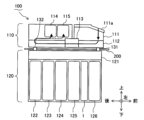
図1は、自動取引装置100の内部構成を示す左側面図である。
FIG. 1 is a left side view showing the internal configuration of the
なお、図1並びに後述する図2A~図10に示す上下、前後、左右の各方向は、自動取引装置100の顧客側を前方向とした場合の一例にすぎないが、例えば、上下方向は鉛直方向であり、前後方向及び左右方向は水平方向である。
1 and FIGS. 2A to 10, which will be described later, are only examples when the customer side of the
図1に示す自動取引装置100は、例えばATM、BRU(Bill Recycle Unit)、CD(Cash Dispenser)、TCR(Teller Cash Recycler)などであり、本体部110と、収納部120と、中間搬送部131,132とを備える。自動取引装置100においては、紙葉類の一例である紙幣Bの入金、出金などの処理が行われる。なお、紙葉類取扱装置としては、紙幣Bを一例とする紙葉類の受け入れ(入金)、排出(出金)、搬送などの何らかの処理を行うものであればよい。
The
本体部110は、紙幣入出金部111と、本体搬送部112と、鑑別部113と、一時保留部114,115とを有する。
The
紙幣入出金部111は、シャッタ111aを有し、入金時に紙幣Bが投入され、出金時に紙幣Bを排出する。
The banknote deposit/
本体搬送部112は、本体部110の下部に配置され、紙幣入出金部111と一時保留部114,115と後述する中間搬送部131,132との間で紙幣Bを搬送する。
The main
鑑別部113は、本体搬送部112の搬送経路に配置され、紙幣Bの真贋、汚れ、角折れ等を判定する。
The
一時保留部114,115の一方の一時保留部114は、鑑別部113によって正常と判定された紙幣Bを例えば巻き取ることによって一時的に収納する。また、他方の一時保留部115は、鑑別部113によって異常と判定された紙幣Bを例えば巻き取ることによって一時的に収納する。
The
収納部120は、本体部110の下方に配置され、収納搬送部121と、紙幣収納庫122~125と、第1リジェクト庫1と、第2リジェクト庫126とを有する。
The
収納搬送部121は、収納部120の上部に配置され、本体部110(中間搬送部131及び中間搬送部132)と各収納装置(紙幣収納庫122~125、第1リジェクト庫1、及び第2リジェクト庫126)との間で紙幣Bを搬送する。
The
紙幣収納庫122~125は、例えば互いに異なる金種の紙幣Bを収納する。また、紙幣収納庫122~125は、収納された紙幣Bを排出可能である。そのため、紙幣収納庫122~125に収納された紙幣Bは、出金に利用される。
The
第1リジェクト庫1及び第2リジェクト庫126は、例えば、鑑別部113によって異常と判定された紙幣Bのうち返却されない紙幣Bを収納する。特に、第1リジェクト庫1には、偽造紙幣などの紙幣Bが収納されるとよい。なお、第1リジェクト庫1について詳しくは図5~図10を参照しながら後述する。
The
上述の本体部110及び収納部120は、仕切り板200を介して異なる空間に配置されており、中間搬送部131,132は、仕切り板200を貫通するように紙幣Bを搬送する。
The
中間搬送部131,132の一方の中間搬送部131は、自動取引装置100の前部側で、仕切り板200を貫通するように紙幣Bを搬送する。他方の中間搬送部132は、自動取引装置100の後部側で、仕切り板200を貫通するように紙幣Bを搬送する。
One
次に、自動取引装置100における紙幣Bの搬送経路について説明する。
Next, the transport route of the banknote B in the
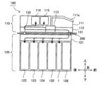
図2A及び図2Bは、自動取引装置100の入金時の一時保留部114,115を経由する搬送経路を説明するための説明図である。
FIGS. 2A and 2B are explanatory diagrams for explaining the transport route via the
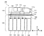
図3は、自動取引装置100の直接入金時の搬送経路を説明するための説明図である。
FIG. 3 is an explanatory diagram for explaining the transport route of the
図4は、自動取引装置100の出金時の搬送経路を説明するための説明図である。
FIG. 4 is an explanatory diagram for explaining the transport route of the
まず、図2Aに実線矢印で示すように、紙幣入出金部111に投入された紙幣Bは、本体搬送部112を搬送され、鑑別部113によって紙幣Bの真贋、汚れ、角折れ等が判定される。
First, as indicated by the solid line arrow in FIG. 2A, the banknote B inserted into the banknote deposit/
その後、鑑別部113によって正常と判定された紙幣Bは、図2Aに実線矢印で示すように、一時保留部114に搬送される。一方、鑑別部113によって異常と判定された紙幣Bは、図2Aに破線矢印で示すように、一時保留部115に搬送される。
Thereafter, banknotes B determined to be normal by the
次に、図2Bに実線矢印で示すように、一時保留部114に一時的に収納された紙幣Bは、本体搬送部112、中間搬送部131、及び収納搬送部121を通って、各紙幣収納庫122~125に搬送される。一方、一時保留部115に一時的に収納された紙幣Bは、本体搬送部112、中間搬送部131、及び収納搬送部121を通って、図2Bに破線矢印で示すように第1リジェクト庫1に搬送される。なお、一時保留部115に一時的に収納された紙幣Bは、第2リジェクト庫126に搬送される場合もある。
Next, as indicated by the solid line arrow in FIG. 2B, the bill B temporarily stored in the
図3に実線矢印で示すように、一時保留部114,115を経ずに紙幣Bが直接入金される場合、紙幣入出金部111に投入された紙幣Bは、本体搬送部112を搬送され、鑑別部113によって紙幣Bの真贋、汚れ、角折れ等が判定される。その後、鑑別部113によって正常と判定された紙幣Bは、中間搬送部132及び収納搬送部121を通って、各紙幣収納庫122~125に搬送される。一方、鑑別部113によって異常と判定された紙幣Bは、中間搬送部132及び収納搬送部121を通って、破線矢印で示すように第1リジェクト庫1に搬送される。
As indicated by solid line arrows in FIG. 3, when banknotes B are directly deposited without passing through the
図4に実線矢印で示すように、紙幣収納庫122~125から紙幣Bが出金される場合、紙幣収納庫122~125に収納された紙幣Bは、収納搬送部121、中間搬送部132、及び本体搬送部112を通って、紙幣入出金部111に搬送される。なお、紙幣収納庫122~125に収納された紙幣Bが鑑別部113によって異常と判定された場合、破線矢印で示すように、中間搬送部131及び収納搬送部121を通って、第1リジェクト庫1に搬送されるとよい。
As indicated by the solid line arrows in FIG. 4, when banknotes B are dispensed from the
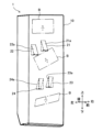
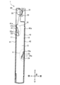
図5は、第1リジェクト庫1の一部(第1~第4のガイド部21~24)の内部構成を示す斜視図である。
FIG. 5 is a perspective view showing the internal configuration of part of the first reject warehouse 1 (first to
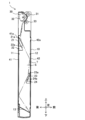
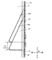
図6は、第1リジェクト庫1の内部構成を示す左側面図である。
FIG. 6 is a left side view showing the internal configuration of the
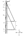
図7は、第1リジェクト庫1の落下軌道Tを説明するための説明図である。
FIG. 7 is an explanatory diagram for explaining the drop trajectory T of the
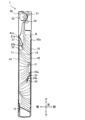
図8は、第1リジェクト庫1の紙幣Bの収納状態を説明するための説明図である。
FIG. 8 is an explanatory diagram for explaining the storage state of banknotes B in the
図9は、図6のIX部拡大図である。 9 is an enlarged view of the IX part of FIG. 6. FIG.
図10は、図6のX部拡大図である。 10 is an enlarged view of the X portion of FIG. 6. FIG.
図5及び図6に示すように、第1リジェクト庫1は、収納庫10と、第1~第4のガイド部21~24とを備える。また、図6に示すように、第1リジェクト庫1は、搬送部30と、第1のリブ41と、第2のリブ42とを更に備える。
As shown in FIGS. 5 and 6, the
図6に示す収納庫10は、前後方向において紙幣Bよりも幅狭の収納空間Sにおいて、図8に示すように、水平に対して傾いた状態の紙幣Bを収納する。
The
第1~第4のガイド部21~24は、収納庫10の内壁から収納空間Sに向かって突出する。第1~第4のガイド部21~24は、収納庫10の内壁から収納空間Sに向かって水平方向よりも下方に傾斜したガイド面21a~24aを有する。なお、第1~第4のガイド部21~24は、下端が例えば水平であることで、図6に示す左側面視において三角形状を呈する。
The first to
図6のIX部拡大図である図9に示すように、第1のガイド部21及び第2のガイド部22は、収納庫10の内壁の同一面である第1の面11において互いに高さが異なる位置(高さの差h1)に横並びに配置されている。これにより、第1のガイド部21及び第2のガイド部22は、図5に示すように、紙幣Bのすべての辺が水平方向とは異なる角度で収納空間Sを自由落下するように紙幣Bをガイドする。但し、紙幣Bの対角線が鉛直方向に近づくまで紙幣Bを傾かせると、紙幣Bの向きが変化するため、紙幣Bを傾かせる角度は、例えば45度以下であるとよい。なお、第1のガイド部21及び第2のガイド部22のうち右側に位置する第1のガイド部21が第2のガイド部22よりも上方に位置する。
As shown in FIG. 9, which is an enlarged view of the IX section of FIG. are arranged side by side at different positions (height difference h1). As a result, the
図7に落下軌道Tを一点鎖線で示すように、収納空間S内を落下する紙幣Bは、例えば、後述する搬送部30から、第1のガイド部21及び第2のガイド部22のガイド面21a,22a、第2の面12(第2のリブ42)、第3のガイド部23及び第4のガイド部24のガイド面23a,24a、第1の面11(第1のリブ41)、及び底板13の順に紙幣Bの下端が接触するように落下する。もちろん、収納空間Sにおける紙幣Bの収納枚数が増えるのに伴って、紙幣Bは、落下軌道Tの途中までの位置で積層されることになる。
As the drop trajectory T is indicated by the dashed line in FIG. 7, the banknotes B falling in the storage space S are, for example, transported from the transport unit 30 (to be described later) to the guide surfaces of the
図6のX部拡大図である図10に示すように、第3のガイド部23及び第4のガイド部24は、収納庫10の内壁のうち第1のガイド部21及び第2のガイド部22が配置された第1の面11に対向する面である第2の面12において、第1のガイド部11及び第2のガイド部12よりも下方に、互いに高さが異なる位置(高さの差h2)に横並びに配置されている。これにより、第3のガイド部23及び第4のガイド部24も、図5に示すように、紙幣Bのすべての辺が水平方向とは異なる角度で収納空間Sを自由落下するように紙幣Bをガイドする。なお、第3のガイド部23及び第4のガイド部24のうち第1のガイド部21と同様に右側に位置する第3のガイド部23が第4のガイド部24よりも上方に位置する。
As shown in FIG. 10, which is an enlarged view of the X section in FIG. In the
ここで、第3のガイド部23と第4のガイド部24との高さの差h2は、第1のガイド部21と第2のガイド部22との高さの差h1よりも小さい差(h2<h1)であるとよい。これは、紙幣Bが既に第1のガイド部21及び第2のガイド部22によってガイドされることで、すべての辺が水平方向とは異なる角度で自由落下し、第3のガイド部23と第4のガイド部24との高さの差h2が小さくとも、紙幣Bのすべての辺が水平方向とは異なる角度で自由落下できるためである。また、第3のガイド部23と第4のガイド部24との高さの差h2を小さくするほど、第3のガイド部23及び第4のガイド部24の周囲に積層される紙幣Bの量を増やすことができる。
Here, the height difference h2 between the
なお、紙幣Bのすべての辺が水平方向とは異なる角度で収納空間Sを自由落下するように紙幣Bをガイドするガイド部としては、収納庫10の内壁から収納空間Sに向かって突出する第1~第4のガイド部21~24に限られない。例えば、搬送部30が左側と右側とで異なる回転速度で紙幣Bを搬送する場合には、紙幣Bのすべての辺が水平方向とは異なる角度で収納空間Sを自由落下するように搬送部30が紙幣Bをガイドするため、搬送部30がガイド部として機能する。
As a guide portion for guiding the banknote B so that all the sides of the banknote B freely fall in the storage space S at an angle different from the horizontal direction, a guide portion projecting from the inner wall of the
また、本実施の形態では、第1のガイド部21及び第2のガイド部22に加えて第3のガイド部23及び第4のガイド部24が配置されているが、第1のガイド部21及び第2のガイド部22のみ、或いは、第3のガイド部23及び第4のガイド部24のみが配置されていてもよいし、ガイド部の数は任意に設定されればよい。
Further, in the present embodiment, in addition to the
また、本実施の形態では、第1のガイド部21と第2のガイド部22とが異なる高さで横並びに配置され、第3のガイド部23と第4のガイド部24とが異なる高さで横並びに配置されているが、第1のガイド部21と第2のガイド部22とが一体の又は第3のガイド部23と第4のガイド部24とが一体の単一のガイド部が、左右方向に亘って高さが変化するガイド面を有していてもよい。或いは、第1のガイド部21と第2のガイド部22とが同じ高さに配置され、第3のガイド部23と第4のガイド部24とが同じ高さに配置されていても、第1のガイド部21のガイド面21aと第2のガイド部22のガイド面22aとで、或いは第3のガイド部23のガイド面23aと第4のガイド部24のガイド面24aとで、表面粗さが異なる場合などには、紙幣Bのすべての辺が水平方向とは異なる角度で収納空間Sを自由落下するように紙幣Bをガイドすることができる。
Further, in the present embodiment, the
図6~図8に示す搬送部30は、搬送ローラ31~33によって第1リジェクト庫1に搬送される紙幣Bを下方に搬送し、収納空間Sにおいて自由落下させる。搬送部30は、搬送ローラ31~33に代えて或いは搬送ローラ31~33とともに、他の搬送部材(例えば羽根車)を有していてもよい。
The
図6~図8に示す第1のリブ41及び第2のリブ42は、収納庫10の内壁から突出するように、例えば絞り加工によって設けられている。このように第1のリブ41及び第2のリブ42が絞り加工によって設けられている場合には、第1の面11及び第2の面12の強度を高めることができる。なお、第1のリブ41及び第2のリブ42のそれぞれは、例えば、収納空間Sのほぼ全体の高さに亘って設けられ、左右方向に複数本(例えば3本)ずつ横並びにガイド部を挟み込むように設けられているとよい。
The
第1のリブ41及び第2のリブ42は、第1~第4のガイド部21~24よりも、収納庫10の内壁からの突出量が小さい。また、第1のリブ41及び第2のリブ42の上端には、上端に向かって突出量が小さくなる上端テーパ部41a,42aが設けられている。第1のリブ41及び第2のリブ42は、紙幣Bが第1~第4のガイド部21~24のガイド面21a~24aの上端に引っ掛かるのを抑制する。
The
以上説明した本実施の形態では、紙葉類収納装置の一例である第1リジェクト庫1は、紙葉類の一例である紙幣Bよりも幅狭の収納空間Sにおいて、水平に対して傾いた状態の紙幣Bを収納する収納庫10と、紙幣Bのすべての辺が水平方向とは異なる角度で収納空間Sを自由落下するように紙幣Bをガイドするガイド部の一例である第1~第4のガイド部21~24とを備える。
In the present embodiment described above, the
このように第1~第4のガイド部21~24が紙幣Bのすべての辺が水平方向とは異なる角度で収納空間Sを自由落下するように紙幣Bをガイドする簡素な構成によって、紙幣Bが角を下端として落下する。そのため、自由落下する紙幣Bの辺(端面)が収納済みの紙幣Bの辺に接触するのを抑制することができる。したがって、紙幣Bの辺の上に紙幣Bが積み上がるのを防ぐことができる。
In this manner, the first to
よって、本実施の形態によれば、簡素な構成で、紙幣Bよりも幅狭の収納空間Sにおける紙幣Bの収納枚数を確保することができる。また、第1リジェクト庫1ひいては自動取引装置100を簡素な構成にすることができることによって、コストダウンを図ることもできる。
Therefore, according to the present embodiment, it is possible to secure the number of stored banknotes B in the storage space S narrower than the banknotes B with a simple configuration. In addition, cost reduction can be achieved by simplifying the configuration of the
また、本実施の形態では、第1~第4のガイド部21~24は、収納庫10の内壁から収納空間Sに向かって突出する。また、第1~第4のガイド部21~24は、収納庫10の内壁から収納空間Sに向かって水平方向よりも下方に傾斜したガイド面21a~24aを有する。これにより、収納庫10の内壁から第1~第4のガイド部21~24を突出させる簡素な構成で、紙幣Bに斜め下方に重心を働かせ、第1~第4のガイド部21~24に紙幣Bがもたれ掛かるのを抑制することができる。したがって、収納空間Sにおける紙幣Bの収納枚数をより一層確保することができる。
Further, in the present embodiment, the first to
また、本実施の形態では、第1リジェクト庫1は、第1のガイド部21及び第2のガイド部22を含む複数のガイド部を備え、第1のガイド部21及び第2のガイド部22は、収納庫10の内壁の同一面である第1の面11において互いに高さが異なる位置に横並びに配置されている。これにより、第1のガイド部21と第2のガイド部22との高さをずらした簡素な構成で、紙幣Bのすべての辺が水平方向とは異なる角度で収納空間Sを自由落下するように紙幣Bをガイドすることができる。
Further, in the present embodiment, the
また、本実施の形態では、複数のガイド部は、第3のガイド部23及び第4のガイド部24を更に含み、第3のガイド部23及び第4のガイド部24は、収納庫10の内壁のうち第1のガイド部21及び第2のガイド部22が配置された第1の面11に対向する第2の面12において、第1のガイド部21及び第2のガイド部22よりも下方に、且つ、第1のガイド部21と第2のガイド部22との高さの差h1よりも小さい差h2で互いに高さが異なる位置に横並びに配置されている。これにより、第1のガイド部21及び第2のガイド部22によってガイドされることですべての辺が水平方向とは異なる角度で自由落下する紙幣Bを、すべての辺が水平方向とは異なる角度に維持したまま自由落下するようにガイドすることができる。更には、第3のガイド部23と第4のガイド部24との高さの差h2を高さの差h1よりも小さくすることによって、高さの差がより大きい場合と比較して、第3のガイド部23及び第4のガイド部24の周囲に積層される紙幣Bの量を増やすことができる。
Further, in the present embodiment, the plurality of guide parts further include a
また、本実施の形態では、第1リジェクト庫1は、リブの一例である第1のリブ41及び第2のリブ42を更に備える。この第1のリブ41及び第2のリブ42は、第1~第4のガイド部21~24の収納庫10の内壁からの突出量よりも小さい突出量で内壁から収納空間Sに向かって突出し、紙幣Bがガイド面21a~24aの上端に引っ掛かるのを抑制する。これにより、紙幣Bがガイド面21a~24aの上端に引っ掛かって、意図しない軌道で紙幣Bが落下するのを抑制することができる。したがって、収納空間Sにおける紙幣Bの収納枚数をより一層確保することができる。
Moreover, in this embodiment, the
なお、本発明は、上述の実施の形態そのままに限定されず、構成要素を変形して具体化することができる。例えば、本実施の形態に開示されている複数の構成要素の適宜な組み合わせにより、種々の発明を形成することができる。このように、発明の趣旨を逸脱しない範囲内において発明の種々の変形や応用が可能である。 The present invention is not limited to the above-described embodiment as it is, and can be embodied by modifying the constituent elements. For example, various inventions can be formed by appropriately combining a plurality of constituent elements disclosed in this embodiment. Thus, various modifications and applications of the invention are possible without departing from the gist of the invention.
1 第1リジェクト庫(紙葉類収納装置)
10 収納庫
11 第1の面
12 第2の面
13 底板
21~24 第1~第4のガイド部
21a,22a,23a,24a ガイド面
30 搬送部
31,32,33 搬送ローラ
41 第1のリブ
41a 上端テーパ部
42 第2のリブ
42a 上端テーパ部
100 自動取引装置(紙葉類取扱装置)
110 本体部
111 紙幣入出金部
111a シャッタ
112 本体搬送部
113 鑑別部
114,115 一時保留部
120 収納部
121 収納搬送部
122~125 紙幣収納庫
126 第2リジェクト庫
131,132 中間搬送部
200 仕切り板
B 紙幣
h1,h2 高さの差
S 収納空間
T 落下軌道1 1st reject storage (paper sheet storage device)
10
110
Claims (4)
前記収納庫の内壁から前記収納空間に向かって突出し、前記紙葉類をガイドする第1のガイド部及び第2のガイド部を含む複数のガイド部とを備え、
前記複数のガイド部は、前記内壁から前記収納空間に向かって水平方向よりも下方に傾斜したガイド面を有し、
前記第1のガイド部及び前記第2のガイド部は、前記内壁の同一面において互いに高さが異なる位置に横並びに配置されている
ことを特徴とする紙葉類収納装置。 a storage space for storing the paper sheets inclined with respect to the horizontal in a storage space narrower than the paper sheets;
A plurality of guide portions including a first guide portion and a second guide portion projecting from the inner wall of the storage toward the storage space and guiding the paper sheets ,
The plurality of guide portions have a guide surface inclined downward from the horizontal direction toward the storage space from the inner wall,
The first guide part and the second guide part are arranged side by side on the same surface of the inner wall at positions with different heights.
A paper sheet storage device characterized by :
前記第3のガイド部及び前記第4のガイド部は、前記内壁のうち前記第1のガイド部及び前記第2のガイド部が配置された面に対向する面において、前記第1のガイド部及び前記第2のガイド部よりも下方に、且つ、前記第1のガイド部と前記第2のガイド部との高さの差よりも小さい差で互いに高さが異なる位置に横並びに配置されている
ことを特徴とする請求項1記載の紙葉類収納装置。 The plurality of guides further includes a third guide and a fourth guide,
The third guide portion and the fourth guide portion are provided on a surface of the inner wall facing the surface on which the first guide portion and the second guide portion are arranged. They are arranged side by side below the second guide part and at positions different in height from each other by a difference smaller than the difference in height between the first guide part and the second guide part. The paper sheet storage device according to claim 1 , characterized in that:
ことを特徴とする請求項1又は2記載の紙葉類収納装置。 It further comprises a rib that protrudes from the inner wall toward the storage space with a projection amount that is smaller than the protrusion amount of the guide portion from the inner wall, and prevents the paper sheet from being caught on the upper end of the guide surface. 3. The paper sheet storage device according to claim 1 or 2 .
前記紙葉類収納装置は、
紙葉類よりも幅狭の収納空間において、水平に対して傾いた状態の前記紙葉類を収納する収納庫と、
前記収納庫の内壁から前記収納空間に向かって突出し、前記紙葉類をガイドする第1のガイド部及び第2のガイド部を含む複数のガイド部とを備え、
前記複数のガイド部は、前記内壁から前記収納空間に向かって水平方向よりも下方に傾斜したガイド面を有し、
前記第1のガイド部及び前記第2のガイド部は、前記内壁の同一面において互いに高さが異なる位置に横並びに配置されている
ことを特徴とする紙葉類取扱装置。 A paper sheet handling device comprising a paper sheet storage device,
The paper sheet storage device is
a storage space for storing the paper sheets inclined with respect to the horizontal in a storage space narrower than the paper sheets;
A plurality of guide portions including a first guide portion and a second guide portion projecting from the inner wall of the storage toward the storage space and guiding the paper sheets ,
The plurality of guide portions have a guide surface inclined downward from the horizontal direction toward the storage space from the inner wall,
The first guide part and the second guide part are arranged side by side on the same surface of the inner wall at positions with different heights.
A paper sheet handling device characterized by :
Applications Claiming Priority (1)
| Application Number | Priority Date | Filing Date | Title |
|---|---|---|---|
| PCT/JP2020/030096 WO2022029944A1 (en) | 2020-08-05 | 2020-08-05 | Paper sheet storage device and paper sheet handling device |
Publications (2)
| Publication Number | Publication Date |
|---|---|
| JPWO2022029944A1 JPWO2022029944A1 (en) | 2022-02-10 |
| JP7321663B2 true JP7321663B2 (en) | 2023-08-07 |
Family
ID=80117811
Family Applications (1)
| Application Number | Title | Priority Date | Filing Date |
|---|---|---|---|
| JP2022541030A Active JP7321663B2 (en) | 2020-08-05 | 2020-08-05 | Paper sheet storage device and paper sheet handling device |
Country Status (3)
| Country | Link |
|---|---|
| US (1) | US12552629B2 (en) |
| JP (1) | JP7321663B2 (en) |
| WO (1) | WO2022029944A1 (en) |
Citations (4)
| Publication number | Priority date | Publication date | Assignee | Title |
|---|---|---|---|---|
| JP2015088137A (en) | 2013-11-01 | 2015-05-07 | 沖電気工業株式会社 | Medium bundle storage device and medium processor |
| JP2016012169A (en) | 2014-06-27 | 2016-01-21 | 沖電気工業株式会社 | Cash processing unit |
| JP2018027847A (en) | 2016-08-19 | 2018-02-22 | マミヤ・オーピー・ネクオス株式会社 | Bill collection stack device |
| JP2018144999A (en) | 2017-03-09 | 2018-09-20 | 武蔵エンジニアリング株式会社 | Paper sheet aligning device |
Family Cites Families (8)
| Publication number | Priority date | Publication date | Assignee | Title |
|---|---|---|---|---|
| JPS51115897A (en) * | 1975-04-04 | 1976-10-12 | Nissin Electric Co Ltd | Paper money receiver |
| US5172905A (en) * | 1991-06-19 | 1992-12-22 | Minnesota Mining And Manufacturing Company | Film receive magazine for a laser imager |
| JP2906796B2 (en) * | 1991-11-25 | 1999-06-21 | オムロン株式会社 | Paper storage box |
| JP4001539B2 (en) * | 2002-10-30 | 2007-10-31 | 富士フイルム株式会社 | Paper discharging apparatus and printing apparatus using the same |
| JP5440445B2 (en) * | 2010-08-26 | 2014-03-12 | 沖電気工業株式会社 | Media accumulator |
| JP6449676B2 (en) * | 2015-02-24 | 2019-01-09 | 日本シーディーアール株式会社 | Sheet material feeder |
| JP6215247B2 (en) * | 2015-03-17 | 2017-10-18 | 株式会社東芝 | Paper sheet stacking apparatus and paper sheet processing apparatus |
| JP6972767B2 (en) * | 2017-08-22 | 2021-11-24 | 富士フイルムビジネスイノベーション株式会社 | Image forming device |
-
2020
- 2020-08-05 JP JP2022541030A patent/JP7321663B2/en active Active
- 2020-08-05 WO PCT/JP2020/030096 patent/WO2022029944A1/en not_active Ceased
-
2023
- 2023-01-31 US US18/162,484 patent/US12552629B2/en active Active
Patent Citations (4)
| Publication number | Priority date | Publication date | Assignee | Title |
|---|---|---|---|---|
| JP2015088137A (en) | 2013-11-01 | 2015-05-07 | 沖電気工業株式会社 | Medium bundle storage device and medium processor |
| JP2016012169A (en) | 2014-06-27 | 2016-01-21 | 沖電気工業株式会社 | Cash processing unit |
| JP2018027847A (en) | 2016-08-19 | 2018-02-22 | マミヤ・オーピー・ネクオス株式会社 | Bill collection stack device |
| JP2018144999A (en) | 2017-03-09 | 2018-09-20 | 武蔵エンジニアリング株式会社 | Paper sheet aligning device |
Also Published As
| Publication number | Publication date |
|---|---|
| WO2022029944A1 (en) | 2022-02-10 |
| US20230174336A1 (en) | 2023-06-08 |
| US12552629B2 (en) | 2026-02-17 |
| JPWO2022029944A1 (en) | 2022-02-10 |
Similar Documents
| Publication | Publication Date | Title |
|---|---|---|
| CN1577406A (en) | Bill handling apparatus | |
| JP2004240904A (en) | Bill receiving / dispensing device | |
| JP2003160271A (en) | Bill receiving / dispensing device | |
| JP6303775B2 (en) | Medium accumulation apparatus and medium transaction apparatus | |
| JP2011170668A (en) | Bill storage and teller machine therewith | |
| WO2013035437A1 (en) | Medium stacking device and medium processing device | |
| JP2000048234A (en) | Paper storage mechanism | |
| JP2016224869A (en) | Cash automatic transaction machine | |
| JP6571795B2 (en) | Paper sheet storage device and paper sheet handling device | |
| JP6102487B2 (en) | Medium storage apparatus and medium transaction apparatus | |
| JP7321663B2 (en) | Paper sheet storage device and paper sheet handling device | |
| JP7196360B2 (en) | Paper sheet handling equipment | |
| JP7253107B2 (en) | Paper sheet handling equipment | |
| JP5686059B2 (en) | Medium stacking apparatus and medium processing apparatus | |
| JP7205182B2 (en) | Coin handling equipment and automatic transaction equipment | |
| US8496101B2 (en) | Medium recovery device for medium processing device | |
| JP6702040B2 (en) | Media processing device | |
| JP7512797B2 (en) | Media handling devices | |
| KR101629015B1 (en) | Paper money stack structure in reject box | |
| JP6020303B2 (en) | Paper sheet storage device, paper sheet handling device, and paper sheet conveying device | |
| JP2021067986A (en) | Banknote processor and banknote storage cassette | |
| JP6194759B2 (en) | Medium bundle storage device | |
| JP5034514B2 (en) | How to pay out vertically stored bills | |
| KR20100080217A (en) | Temporary stacker of atm | |
| JP4652107B2 (en) | Small bundle banknote processing machine |
Legal Events
| Date | Code | Title | Description |
|---|---|---|---|
| A621 | Written request for application examination |
Free format text: JAPANESE INTERMEDIATE CODE: A621 Effective date: 20220905 |
|
| A131 | Notification of reasons for refusal |
Free format text: JAPANESE INTERMEDIATE CODE: A131 Effective date: 20230516 |
|
| A521 | Request for written amendment filed |
Free format text: JAPANESE INTERMEDIATE CODE: A523 Effective date: 20230703 |
|
| TRDD | Decision of grant or rejection written | ||
| A01 | Written decision to grant a patent or to grant a registration (utility model) |
Free format text: JAPANESE INTERMEDIATE CODE: A01 Effective date: 20230725 |
|
| A61 | First payment of annual fees (during grant procedure) |
Free format text: JAPANESE INTERMEDIATE CODE: A61 Effective date: 20230725 |
|
| R150 | Certificate of patent or registration of utility model |
Ref document number: 7321663 Country of ref document: JP Free format text: JAPANESE INTERMEDIATE CODE: R150 |