JP7321508B2 - combination desk - Google Patents
combination desk Download PDFInfo
- Publication number
- JP7321508B2 JP7321508B2 JP2019134884A JP2019134884A JP7321508B2 JP 7321508 B2 JP7321508 B2 JP 7321508B2 JP 2019134884 A JP2019134884 A JP 2019134884A JP 2019134884 A JP2019134884 A JP 2019134884A JP 7321508 B2 JP7321508 B2 JP 7321508B2
- Authority
- JP
- Japan
- Prior art keywords
- desk
- bookshelf
- top plate
- plate
- side plate
- Prior art date
- Legal status (The legal status is an assumption and is not a legal conclusion. Google has not performed a legal analysis and makes no representation as to the accuracy of the status listed.)
- Active
Links
Images


Landscapes
- Tables And Desks Characterized By Structural Shape (AREA)
- Combinations Of Kitchen Furniture (AREA)
Description
本発明は、机と書棚を組み合わせて使用する組み合わせデスクに係り、詳しくは、使い勝手に応じてデスクと書棚を様々な体系に組み合わせ可能とする組み合せデスク装置に関するものである。 The present invention relates to a combination desk that combines a desk and a bookshelf, and more particularly, to a combination desk device that allows the desk and the bookshelf to be combined in various systems according to usability.
家庭等の勉強部屋や書斎等の執務空間で使用される机において、学習効率の向上や、使い勝手の向上を目的として、学習に使用する書籍、参考書、教科書等を整理収納しておく書棚が、机に近接して置かれる場合がある。
そして、机の側方に書棚を配置し机と書棚を一体的に使用する組み合わせデスクが従前よりある。
Bookshelves for organizing and storing books, reference books, textbooks, etc. used for learning are used on desks used in home study rooms and office spaces such as dens, for the purpose of improving learning efficiency and improving usability. , may be placed in close proximity to the desk.
Further, there has been a combination desk in which a bookshelf is arranged on the side of the desk and the desk and the bookshelf are used integrally.
このような組み合わせデスクの中には、書棚を上下に分離して、分離した一方側の書棚を、書棚の正面側が机の側方に沿うように回転配置して、他方の書棚を机上の後端部に配置し、該書棚の側板を取り外し、あるいは、退避させ、机の側方に書棚の棚板と机上に配置した書棚の棚板を一体的に使用できるものがある(例えば特許文献1)。
しかしながら、このような組み合わせデスクの場合、書棚の正面側を机の側面に沿うように回転させ、書棚を上下に分離して、分離した一方側の書棚を机上の後端に書棚の一部を載置する必要があり大掛かりなものであった。
In such a combination desk, the bookshelf is separated into upper and lower parts, and one of the separated bookshelves is rotated so that the front side of the separated bookshelf is along the side of the desk, and the other bookshelf is placed at the back of the desk. There is a bookcase that is arranged at the end, removes or retracts the side plate of the bookshelf, and can be used integrally with the shelf plate of the bookshelf on the side of the desk and the shelf plate of the bookshelf arranged on the desk (for example, Patent Document 1) ).
However, in the case of such a combination desk, the front side of the bookshelf is rotated along the side of the desk, the bookshelf is separated vertically, and a part of the bookshelf is placed at the rear end of the desk. It was a large-scale thing that needed to be placed.
他方、机と書棚による組み合わせデスクの中には、同じく書棚を上下に分離して、分離した一方側の書棚を、書棚の正面側が机の側方に沿うように回転配置して、他方の書棚を机上の後端部に配置し、机の側方の書棚と机上の書棚間の隙間を板状の連結部材で閉塞するものがある(例えば特許文献2)。
しかしながら、このような組み合わせデスクの場合、特許文献1と同様に書棚の正面側を机の側面に沿うように回転さ、書棚を上下に分離して、分離した一方側の書棚を机上の後端に書棚の一部を載置する必要があり、かつ、書棚間の隙間を閉塞させるための連結部材が必要となるといった大掛かりなものであった。
このように、特許文献1、特許文献2のいずれにおいても、分離した書棚の一方側を机上に配置させる大掛かりなものである。
On the other hand, in a combined desk consisting of a desk and a bookshelf, the bookshelves are also separated vertically, and one of the separated bookshelves is rotated so that the front side of the bookshelf follows the side of the desk, and the other bookshelf is arranged. is placed at the rear end of the desk, and the gap between the bookshelf on the side of the desk and the bookshelf on the desk is closed with a plate-like connecting member (for example, Patent Document 2).
However, in the case of such a combination desk, the front side of the bookshelf is rotated along the side of the desk as in
Thus, in both
本発明は、机と書棚を組み合わせて使用する組み合わせデスクに係り、簡単な構成で、書棚を独立して使用することも、デスクと書棚を組み合わせて使用することもでき、かつ、使い勝手がよい組み合せデスクを提供することを課題とするものである。 The present invention relates to a combination desk in which a desk and a bookshelf are used in combination, the bookshelf can be used independently or the desk and the bookshelf can be used in combination with a simple structure, and the combination is easy to use. The task is to provide a desk.
主に机と書棚と一対の側板からなる組み合わせデスクにおいて、机は少なくとも天板を有し、書棚は机天板の高さと同じ高さに設定される書棚天板を有し、さらに、机と書棚は、それぞれに天板上方に延出する背面パネル部を備え、側板は、書棚天板の上方の左右側方寄りそれぞれに設置され、書棚天板上方で書棚の左右の側板とされ、書棚に備えられる前記背面パネル部に連結される形態と、一対の側板の一方あるいは両方が書棚から取り外され、机と書棚のそれぞれの背面パネル部を移動させることなく机の天板上方で机の側板とされ、机に備えられる前記背面パネル部に連結されて設置される形態とで選択可能な構成とした。 In a combination desk mainly consisting of a desk, a bookshelf and a pair of side plates, the desk has at least a top plate, the bookshelf has a bookshelf top plate set at the same height as the desk top plate, and the desk and the Each of the bookshelves has a back panel portion extending upward from the top plate, and side plates are installed on the left and right sides above the top plate of the bookshelf, and serve as left and right side plates of the bookshelf above the top plate of the bookshelf. and one or both of the pair of side plates can be removed from the bookshelf, and the side plates of the desk can be placed above the top plate of the desk without moving the respective back panel portions of the desk and the bookshelf. , and a configuration in which it is installed by being connected to the back panel portion provided on the desk is selectable.
次に第2の手段として、前記第1の手段として構成したところに加え、机と書棚は、それぞれ天板上方に延出する背面パネルを備え、側板は、該背面パネルに連結されるとともに、机あるいは書棚の天板と連結され固定される構成とした。 Next, as a second means, in addition to the configuration as the first means, the desk and the bookshelf each have a back panel extending above the top plate, and the side plates are connected to the back panel, It is configured to be connected and fixed to the top plate of a desk or bookshelf.
第1の手段として構成したところによると、書棚の側板を取り外して、机の側板として使用できるので、棚板を取り外した側の側面を、側板を設置していない机の側面に沿わせると、それぞれの天板の高さが同じに設定されているので、机の机上面を書棚の机上面と合わせて広く使用することができる。
また、書棚から取り外した側板は、机の側板として使用できるので、側板の収納場所を別途用意する必要がないばかりか、机の机上の側板として設置できるので、机に囲まれ感を付与することが可能である。
According to the configuration as the first means, the side plate of the bookshelf can be removed and used as the side plate of the desk. Since the height of each top plate is set to be the same, the desk surface of the desk can be used widely together with the desk surface of the bookshelf.
In addition, since the side plate removed from the bookshelf can be used as the side plate of the desk, it is not necessary to separately prepare a storage space for the side plate, and it can be installed as the side plate on the desk, giving the feeling of being surrounded by the desk. is possible.
第2の手段として構成したところによると、第1の手段の効果に加え、書棚にも背面パネルを装備し、側板は、机あるいは書棚の天板と、机あるいは書棚の背面パネルと天板に連結されるので、側板の底面部と立直部の双方で固定でき、側板をしっかりと固定することができる。 According to the configuration as the second means, in addition to the effect of the first means, the bookshelf is also equipped with a back panel, and the side plates are the top plate of the desk or the bookshelf, and the back panel and the top plate of the desk or the bookshelf. Since they are connected, they can be fixed at both the bottom surface portion and the vertical portion of the side plate, and the side plate can be firmly fixed.
主に机と書棚を組み合わせて使用する組み合わせデスクに係り、分割した書棚を移動させるような大掛かりな構成ではなくとも書棚を独立して使用することや、デスクと書棚を組み合わせて使用することができ、かつ、使い勝手がよい組み合せデスクを実施例に基づいて以下に説明する。 Mainly related to a combination desk that combines a desk and a bookshelf, and it is possible to use the bookshelf independently even if it is not a large-scale structure such as moving divided bookshelves, or to use the desk and bookshelf in combination. A convenient combination desk will be described below based on an embodiment.
第1実施例を、添付図面に基づいて詳述する。
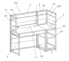
図1~図4において、符号1は机本体を示し、符号3は書棚を示し、符号4は、机背面パネルを示し、符号5は、側板を示し、符号100は、主に机本体1と書棚3と側板5からなる組み合わせデスクを示している。
A first embodiment will be described in detail based on the accompanying drawings.
1 to 4,
図5に示すように、机本体1は天板本体部10と、天板本体部10の左右端部側に連結ネジにて連結された左右脚体2、2より構成されている。
天板本体部10は、主に左右方向に長い長方形板状の机天板11と、机天板11下面部に配置される左右の引き出しを有する引き出しユニット12で構成されている。
As shown in FIG. 5, the
The tabletop
左右脚体2、2は対向した対称形に形成されているので、一方側のみ説明する。
右側脚体2は、前後に離間して配置する棒状の前支持脚21、後支持脚22と、前支持脚21、後支持脚22の上部で、前支持脚21と後支持脚22を連結する脚体上部補強材221、前支持脚21と後支持脚22の下部で、前支持脚21と後支持脚22を連結する脚体下部補強材222で構成されている。
Since the left and
The
そして、左右脚体2、2は、前記左右天板側板12、12の側面にネジ止め固定される。
また、左右脚体2、2間を左右方向で連結する棒状の横補強材23が、左右脚体2、2の下部に配置され、左右脚体2、2間の後方部を左右方向で連結している。
さらに、背板24、24が、後支持脚22、22間であって、机天板11の下面付近と、後支持脚22の中間高さ付近に設置される。
背板24は、縦断面で縦長長方形に形成され、後支持脚22、22の内面間に架け渡される長さに設定される板状なものである。
The left and
A rod-shaped horizontal reinforcing
Further,
The
尚、背板24はネジにて左右脚体2、2に着脱自在に固定されているもので、取り外して後述する机背面パネルに設置することができる。
また、背板24は、コンセント24aが設置されたものと、コンセントが設置されていないものが用意され、コンセント24aの使用状況に合わせて、机天板11の下面付近と、後支持脚22の中間高さ付近で設置場所が設定できる。
机天板11の下面付近にコンセント24a付きの背板24を設置しても、引き出しの背面側と背板24間に空間が設けられているため、コンセントを使用することができる。
The
Also, the
Even if a
書棚3は、図6に示すように、主に左右の書棚脚体30、30と、左右の脚体30、30を左右方向で連結する棚板31、31と、左右の脚体30、30の上面に設置される書棚天板32と、天板32の後端部で上方に延伸する書棚背面パネル33で構成される。
The
書棚脚体30、30は対向した対称形に形成されているので、一方側のみ説明する。
書棚脚体30は、棒状の前支持フレーム301と、前支持フレーム301の後方に離間して配置され、前支持フレーム301より上方に延伸した長さの後支持フレーム302と、前支持フレーム301の上部と後支持フレーム302の中間部付近で、前支持フレーム301と後支持フレーム302を連結するフレーム上部補強材303、前支持フレーム301、後支持フレーム302の下部で、前支持フレーム301と後支持フレーム302を連結するフレーム下部補強材304で構成されている。
Since the
The
そして、後支持フレーム302、302間を左右方向で連結するフレーム横補強305、305が、後支持フレーム302の下部と後支持フレーム302の上端部に配置され書棚脚体30、30の後方部を左右方向で連結している。
また、書棚脚体30、30間に板状の棚板31、31が前支持フレーム301の下部と中間部高さに配置され、棚板31、31で書棚脚体30、30の前方部、後方部を左右方向で連結している。
フレーム横補強305は四角パイプ状のものであって、左右の両端部で、四角を形成する背面側の一辺が延伸突出しており、該突出片が後支持フレーム302、302の背面側に接し、フレーム横補強305の延伸方向を軸芯として回転することを防止している。
Plate-
The frame
次に、前支持フレーム301、301の上端面と、フレーム上部補強材303、303の上面に、書棚天板32に載置連結される。
書棚天板32は板状矩形のもので、前端は、前支持フレーム301、301より若干前方に飛び出し、後ろ端は後支持フレーム302、302に前端面に沿い、左右幅は、前支持フレーム301、301、後支持フレーム302、302の左右外側面とほぼ面一となる大きさに設定され、上面の高さは、机本体1の机天板11と上面と同じ高さになるように設定される。
Next, the upper end surfaces of the
The bookshelf
そして、書棚水平部材306、306が、書棚天板32の後方と、書棚天板32の上方の後支持フレーム302、302間に設置される。
書棚水平部材306は、前述の机の背板24と同じ縦断面形状で縦長長方形に形成され、後支持フレーム302、302の内面間に架け渡される長さに設定される板状なものである。
書棚天板32の上方の書棚水平部材306は、書棚天板32と後支持フレーム302の上端間の中間部付近の高さに配置される。
Bookshelf
The bookshelf
A bookshelf
そして、書棚水平部材306、306は、図6に示すように、下側の書棚水平部材306の上端と、上側の書棚水平部材306の下端間に空間が設けられ、上側の書棚水平部材306の上端と、後支持フレーム302、302間を連結する上端部側のフレーム横補強305の下端間に空間が設けられる。
尚、本実施例においては、後支持フレーム302が書棚天板32の上方まで延伸し、書棚背面パネル33を一体的に形成しているが、後支持フレーム302の書棚背面パネル33部を分割し、書棚脚体30と書棚背面パネル33を分割構成としても構わない。
As shown in FIG. 6, the bookshelf
In this embodiment, the
机背面パネル4は、図7に示すように、左右に離間して配置される一対の棒状のパネル縦フレーム41、41と、パネル縦フレーム41、41間を左右方向で連結するパネル横フレーム42が、パネル縦フレーム41、41の上部に配置され、門型にパネルフレーム体4aが形成される。パネル横フレーム42は四角パイプ状のものであって、左右の両端部で、四角を形成する背面側の一辺が延伸突出しており、該突出片がパネル縦フレーム41、41の背面側に接し、パネル横フレーム42の延伸方向を軸芯として回転することを防止している。
尚、パネル縦フレーム41、41は、机本体の脚体2、2間と同じ寸法で離間して配置され、パネル縦フレーム41は、書棚3の後支持フレーム302と同じ高さに設定される。
そして、前述の机の背板24と同型に形成された、背面パネル水平部材43が、書棚3の書棚水平部材306と同じ高さとなるようにパネル縦フレーム41、41間に設置される。
As shown in FIG. 7, the desk back
The vertical panel frames 41, 41 are spaced apart by the same dimension as the
A rear panel
このように形成された机背面パネル4は、机本体1の背面に、後支持脚22に設けられた螺孔と、パネル縦フレーム41に設けられた貫通孔を使用してネジにて着脱自在に連結される。
また、パネル縦フレーム41、41は、机本体の脚体2、2間と同じ寸法で離間して配置されるから、前記机の背板24が机本体1から取り外され、パネル縦フレーム41、41間に設置することができる。
このようにすると、机背面パネルを設置した時には、背板24が机本体1の奥側に配置されることになるから、足元空間を広くすることが可能である。
The desk back
Further, since the vertical panel frames 41, 41 are spaced apart by the same dimension as the
In this way, when the desk back panel is installed, the
尚、背板24は、コンセント24aが設置されたものと、コンセントが設置されていないものが用意されるが、コンセント24aの使用状況に合わせて、机天板11上面より上方にコンセントが露呈した位置と、パネル縦フレーム41の下端と机天板11間の略中間高さ付近の位置で設置場所を設定し、選択可能としている。
机天板11の下面付近にコンセント24a付きの背板24を設置しても、引き出しの背面側と背板24間に空間が設けられているため、コンセントを使用することができる。
As for the
Even if a
側板5は、図8に示すように、前後に離間して配置される一対の棒状の側板縦フレーム51、51と、フレーム51、51間を前後方向で連結する側板水平フレーム52、52が、フレーム51、51の上部と下部に配置され、四方枠状に側板フレーム体5aが形成される。
尚、側板縦フレーム51、51は、側板縦フレーム51、51の外側面側間の寸法が書棚3の書棚天板32の前後方向と同じ寸法となるように離間して配置され、高さは、書棚天板32の上面と、書棚3の後支持フレーム302の上端までの高さと同じ高さに設定されている。
As shown in FIG. 8, the
In addition, the side plate
そして、側板水平部材53が、側板縦フレーム51、51間であって、後述する側板5を書棚3に取り付けた状態で書棚3の書棚水平部材306と同じ高さとなるように設置される。
側板水平部材53は、前述の机の背板24と同じ縦断面形状で縦長長方形に形成され、側板縦フレーム51、51の内面間に架け渡される長さに設定される板状なものである。
側板水平部材53は、下側の側板水平フレーム52の上面と、側板水平部材53の下面間に空間が設けられ、上側の側板水平フレーム52の下面と、側板水平部材53の上面間に空間が設けられる。
The side plate
The side plate
In the side plate
以上のように構成される組み合わせデスク100の組み合わせ方法について説明する。
図1に示すのが基本形態であって、机背面パネル4が連結された机本体1の一方側面に書棚3の側面が沿うように配置され、2体用意される側板5が書棚3の書棚天板32の両側端に設置され、机本体1と書棚3を個別に使用するものである。
A method of combining the
The basic form shown in FIG. 1 is arranged so that the side surface of the
書棚3に側板5、5が設置された状態では、側板フレーム体5aの下面が、書棚天板32の上面に載置し、側板5の後側の側板縦フレーム51の後面と、書棚3の後支持フレーム302の前面が当接した状態で、ネジにて固定される。
そのため、側板5の下側の側板水平フレーム52には、鉛直方向に貫通する貫通孔52aが所定の位置に設けられ、後側の側板縦フレーム51には、前後方向に貫通する貫通孔51aが所定の位置に設けられている。
そして、書棚天板32の上面の両側寄りに、前記貫通孔52aに対応した螺孔32a、32aが設けられ、後支持フレーム302には、前記貫通孔51aに対応した螺孔302aが設けられている。これらの螺孔は、不使用時にはキャップで閉塞されている。
When the
Therefore, the side plate
Screw holes 32a, 32a corresponding to the through holes 52a are provided on both sides of the upper surface of the
次に基本形態から、机の天板を書棚の天板と合わせて広く使用する第3形態について説明する。
基本形態から、机本体1に面した側の側板5の書棚3と固定するためのネジを外し、側板5を書棚3から分離する。
そして、図3に示すように分離した側板5を、机本体1の書棚3側と対向側の机天板11上に設置する。
机天板11上に側板5が設置された状態では、側板フレーム体5aの下面が、机天板11の上面に載置し、側板5の後側の側板縦フレーム51の後面と、パネル縦フレーム41の前面が当接した状態で、ネジにて固定される。
そのため、机天板11の上面の両側寄りに、側板5の貫通孔52aに対応した螺孔11a、11aが設けられ、パネル縦フレーム41には、側板5の貫通孔51aに対応した螺孔41aが設けられている。これらの螺孔は、不使用時にはキャップで閉塞されている。
Next, from the basic configuration, a description will be given of a third configuration in which the desk top is widely used in combination with the bookshelf top.
A screw for fixing the
Then, as shown in FIG. 3, the separated
When the
Therefore, screw holes 11a, 11a corresponding to the through holes 52a of the
第3形態では、机天板11と書棚天板32は同じ高さに設定されているので両天板を連続して使用することができ執務スペースを広く取ることができる。
そして、机本体1に側板5が設置されるので、執務者には、適度な目隠しパネルが設置された状態となり集中力を高め易い。
また、側板5の側板水平フレーム52には後述するオプション部材を吊り懸けできるので、デスクの使用者に近い位置でオプション部材を利用できることになり使い勝手がよい。
このように、側板5を移動するだけの簡単な作業で第3形態とすることができる。
さらに、机背面パネル4と書棚背面パネル33と側板5の上端高さは、ほぼ同じとなるように設定されているから、オプション部材を同じ高さで使用できるので使い勝手がよいばかりか、体裁よく組み合わせデスクが使用できるので組み合わせデスク100を設置した部屋がスッキリとした印象を与えることができる。
当然ながら、側板5、5は書棚3から取り外し、机本体1の机天板11上の左右の両側に設置することも可能である。
In the third mode, the
Since the
Further, since optional members, which will be described later, can be hung from the side plate
In this manner, the third mode can be achieved by a simple operation of moving the
Furthermore, since the desk back
Of course, it is also possible to remove the
次に第2形態について説明する。
第2形態は、机背面パネル4が連結された机本体1の一方側面に書棚3の正面が沿うように配置され、2体用意される側板5が書棚3の書棚天板32の両側端(机本体1の前後方向)に設置され、机天板11と書棚天板32を連続して使用するものである。
尚、第2形態で、書棚3の幅寸法は机天板11の前後寸法とほぼ同じに設定しているため、机本体1の正面側に位置する側板5は机天板11より前方に突出することがない。
そして、この状態では、机本体1の正面側に位置する側板5の側板水平フレーム52に、正面側を向いている側からオプション部材を吊り懸けすると、執務者側にオプション部材を設置できるので、オプション部材の使い勝手がよい。
Next, the 2nd form is demonstrated.
In the second form, the front of the
In the second embodiment, the width dimension of the
In this state, if the option member is hung from the side facing the front side on the side plate
次に第4形態について説明する。
第4形態は、第2形態の机本体1の正面側に位置する側板5の書棚3と固定するためのネジを外し、側板5を書棚3から分離する。
そして、図4に示すように分離した側板5を、机本体1の書棚3側と対向側の机天板11上に設置する。
第4形態では、机天板11と書棚天板32の両天板を連続して使用することができ、机の正面側の側板5が書棚3に設置されないので、第3形態に比べ天板の執務スペースが使い易い。
Next, the 4th form is demonstrated.
In the fourth form, the
Then, as shown in FIG. 4, the separated
In the fourth form, both the
そして、側板5は、第3形態と同様に机本体1に側面に設置されるので、執務者には、適度な目隠しパネルが設置された状態となり集中力を高め易い。
また、側板5の側板水平フレーム52には後述するオプション部材を吊り懸けできるので、デスクの使用者に近い位置でオプション部材を利用できることになり使い勝手がよいのも第3形態と同様である。
Since the
In addition, since optional members, which will be described later, can be hung from the side plate
尚、第4形態で、書棚3の天板の幅寸法は机天板11の前後寸法とほぼ同じに設定しているため、机天板11の側面がそのまま延伸したように書棚天板32配置されることになり、両天板面を一体的に使用することができるので使い勝手がよい。
また、組み合わせデスク100の平面視で略長方形となり、外形に凹凸が少ないから組み合わせデスク100を設置する部屋のレイアウトに合わせやすい。
さらに、机背面パネル4と書棚背面パネル33と側板5の上端高さは、ほぼ同じとなるように設定されているから、オプション部材を同じ高さで使用できるので使い勝手がよいばかりか、体裁よく組み合わせデスクが使用できるので組み合わせデスク100を設置した部屋がスッキリとした印象を与えることができる。
このように、側板5を移動するだけの簡単な作業で第4形態とすることができる。
In the fourth embodiment, since the width dimension of the top plate of the
In addition, the
Furthermore, since the desk back
In this manner, the fourth mode can be achieved by a simple operation of moving the
オプション部材は、フック6を基本部材として、図9に示すようにフック6を側板水平部材53の上方から吊り懸ける。
そして、該フック6を収納ボックス61や棚板62と組み合わせることや、板状パネルに複数の小径貫通孔63a・・・を規則的に設けたユーティリティーボード63と組み合わせて、これらを側板水平部材53に吊り懸けて使用することができる。また、フック6の下部を鉤状として、引っ掛け具63として使用することもできる。
ユーティリティーボード63は、小径貫通孔63a・・・に線材で形成されるフック部材などを引っ掛けで使用できるものであり、組み合わせデスクの使用者が好みに応じてアレンジするスペースである。
また、オプション部材は、側板水平部材53に限らず、書棚水平部材306や背面パネル水平部材43や背板24や脚体上部補強材221にも吊り懸け可能である。
The optional member uses the
The
The
In addition, optional members can be hung not only on the side plate
そして、前記実施例における組み合わせデスクは、側板水平部材53と、書棚水平部材306と背面パネル水平部材43の上端面が同じ高さになるように設定されているから、基本形態から第4形態に至るまで、側板水平部材53と、書棚水平部材306と背面パネル水平部材43の上端面は水平方向に連続したように並ぶので、オプション部材を同じ高さで使用することができるので使い勝手がよい。
In the combined desk of the above embodiment, the side plate
図14~図16に示すのは、机背面パネル4の背面パネル水平部材43をユーティリティーボード63のように複数の小径貫通孔・・・を規則的に設けたパネル44に置き換えたもので、ユーティリティーボード63と同様に、小径貫通孔に線材で形成されるフック部材などを引っ掛けで使用できるものであり、組み合わせデスクの使用者が好みに応じてアレンジすることができる。
14 to 16 show that the rear panel
以上のように、本発明は、側板を書棚や机に選択的に移設可能であるから、組み合わせデスクのレイアウトを多彩にすることができ、組み合わせデスクを設置する部屋のレイアウトに合わせて、使い勝手のよい机と書棚の組み合わせが可能であるから、家庭等の勉強部屋や書斎等の執務空間で広く利用することができる。 As described above, according to the present invention, since the side plates can be selectively moved to the bookshelf or the desk, the layout of the combination desk can be varied, and the combination desk can be installed in a room layout that is easy to use. Since it is possible to combine a good desk and bookshelf, it can be widely used in a study room at home or in an office space such as a study.
100 組み合わせデスク
1 机本体
11 机天板
11a 螺孔
3 書棚
30 書棚脚体
301 前支持フレーム
302 後支持フレーム
302a 螺孔
306 書棚水平部材
32 書棚天板
32a 螺孔
33 書棚背面パネル
4 机背面パネル
41 パネル縦フレーム
41a 螺孔
42 パネル横フレーム
43 背面パネル水平部材
5 側板
51 側板縦フレーム
51a 貫通孔
52 側板水平フレーム
52a 貫通孔
53 側板水平部材
6 フック
100
Claims (2)
Priority Applications (1)
| Application Number | Priority Date | Filing Date | Title |
|---|---|---|---|
| JP2019134884A JP7321508B2 (en) | 2019-07-22 | 2019-07-22 | combination desk |
Applications Claiming Priority (1)
| Application Number | Priority Date | Filing Date | Title |
|---|---|---|---|
| JP2019134884A JP7321508B2 (en) | 2019-07-22 | 2019-07-22 | combination desk |
Publications (2)
| Publication Number | Publication Date |
|---|---|
| JP2021016635A JP2021016635A (en) | 2021-02-15 |
| JP7321508B2 true JP7321508B2 (en) | 2023-08-07 |
Family
ID=74566282
Family Applications (1)
| Application Number | Title | Priority Date | Filing Date |
|---|---|---|---|
| JP2019134884A Active JP7321508B2 (en) | 2019-07-22 | 2019-07-22 | combination desk |
Country Status (1)
| Country | Link |
|---|---|
| JP (1) | JP7321508B2 (en) |
Citations (4)
| Publication number | Priority date | Publication date | Assignee | Title |
|---|---|---|---|---|
| JP2004024425A (en) | 2002-06-24 | 2004-01-29 | Itoki Crebio Corp | Combination furniture of bed and desk |
| JP2012170633A (en) | 2011-02-22 | 2012-09-10 | Koizumi Furnitech Corp | System desk |
| JP2013059636A (en) | 2012-11-08 | 2013-04-04 | Nitori Holdings Co Ltd | Modular desk |
| JP5806182B2 (en) | 2012-08-29 | 2015-11-10 | コイズミファニテック株式会社 | Unit desk |
-
2019
- 2019-07-22 JP JP2019134884A patent/JP7321508B2/en active Active
Patent Citations (5)
| Publication number | Priority date | Publication date | Assignee | Title |
|---|---|---|---|---|
| JP2004024425A (en) | 2002-06-24 | 2004-01-29 | Itoki Crebio Corp | Combination furniture of bed and desk |
| JP2012170633A (en) | 2011-02-22 | 2012-09-10 | Koizumi Furnitech Corp | System desk |
| JP5421308B2 (en) | 2011-02-22 | 2014-02-19 | コイズミファニテック株式会社 | System desk |
| JP5806182B2 (en) | 2012-08-29 | 2015-11-10 | コイズミファニテック株式会社 | Unit desk |
| JP2013059636A (en) | 2012-11-08 | 2013-04-04 | Nitori Holdings Co Ltd | Modular desk |
Also Published As
| Publication number | Publication date |
|---|---|
| JP2021016635A (en) | 2021-02-15 |
Similar Documents
| Publication | Publication Date | Title |
|---|---|---|
| JP7321508B2 (en) | combination desk | |
| JP5516517B2 (en) | Desktop panel mounting device | |
| KR200486886Y1 (en) | No instrument fast assembly accomodates cabinet | |
| JP6422373B2 (en) | Furniture with a top plate | |
| JP4520476B2 (en) | System furniture with desk and bookshelf | |
| KR101830369B1 (en) | Desk body frame | |
| JP5923872B2 (en) | desk | |
| JP4328567B2 (en) | Desk system | |
| KR200481408Y1 (en) | convertible table | |
| JP3732222B1 (en) | Desk with bookcase | |
| JP4905177B2 (en) | Desk system | |
| JP2018000588A (en) | Combination desk | |
| JP6422374B2 (en) | Furniture with a top plate | |
| JP2016202518A (en) | System desk | |
| JP5337003B2 (en) | desk | |
| JP2006325788A (en) | Kitchen counter | |
| KR200481798Y1 (en) | Partition apparatus | |
| JP2007054184A (en) | Study desk with anti-seismic structure and system furniture having the same | |
| JP6597998B2 (en) | Storage rack | |
| JP6684653B2 (en) | Book support device for bookcase | |
| JP2005342377A (en) | Desk having bookshelf | |
| JP2016202517A (en) | desk | |
| JPH0221956Y2 (en) | ||
| JP2016150051A (en) | Desk | |
| JP2014004001A (en) | Leg device for desk |
Legal Events
| Date | Code | Title | Description |
|---|---|---|---|
| A621 | Written request for application examination |
Free format text: JAPANESE INTERMEDIATE CODE: A621 Effective date: 20220524 |
|
| A621 | Written request for application examination |
Free format text: JAPANESE INTERMEDIATE CODE: A621 Effective date: 20220524 |
|
| A977 | Report on retrieval |
Free format text: JAPANESE INTERMEDIATE CODE: A971007 Effective date: 20230307 |
|
| A131 | Notification of reasons for refusal |
Free format text: JAPANESE INTERMEDIATE CODE: A131 Effective date: 20230314 |
|
| A521 | Request for written amendment filed |
Free format text: JAPANESE INTERMEDIATE CODE: A523 Effective date: 20230425 |
|
| TRDD | Decision of grant or rejection written | ||
| A01 | Written decision to grant a patent or to grant a registration (utility model) |
Free format text: JAPANESE INTERMEDIATE CODE: A01 Effective date: 20230711 |
|
| A61 | First payment of annual fees (during grant procedure) |
Free format text: JAPANESE INTERMEDIATE CODE: A61 Effective date: 20230719 |
|
| R150 | Certificate of patent or registration of utility model |
Ref document number: 7321508 Country of ref document: JP Free format text: JAPANESE INTERMEDIATE CODE: R150 |