JP7320703B2 - LASER WELDING APPARATUS AND LASER WELDING METHOD - Google Patents
LASER WELDING APPARATUS AND LASER WELDING METHOD Download PDFInfo
- Publication number
- JP7320703B2 JP7320703B2 JP2020500370A JP2020500370A JP7320703B2 JP 7320703 B2 JP7320703 B2 JP 7320703B2 JP 2020500370 A JP2020500370 A JP 2020500370A JP 2020500370 A JP2020500370 A JP 2020500370A JP 7320703 B2 JP7320703 B2 JP 7320703B2
- Authority
- JP
- Japan
- Prior art keywords
- measurement
- laser
- penetration depth
- measurement light
- light
- Prior art date
- Legal status (The legal status is an assumption and is not a legal conclusion. Google has not performed a legal analysis and makes no representation as to the accuracy of the status listed.)
- Active
Links
Images


Classifications
-
- B—PERFORMING OPERATIONS; TRANSPORTING
- B23—MACHINE TOOLS; METAL-WORKING NOT OTHERWISE PROVIDED FOR
- B23K—SOLDERING OR UNSOLDERING; WELDING; CLADDING OR PLATING BY SOLDERING OR WELDING; CUTTING BY APPLYING HEAT LOCALLY, e.g. FLAME CUTTING; WORKING BY LASER BEAM
- B23K26/00—Working by laser beam, e.g. welding, cutting or boring
- B23K26/02—Positioning or observing the workpiece, e.g. with respect to the point of impact; Aligning, aiming or focusing the laser beam
- B23K26/03—Observing, e.g. monitoring, the workpiece
- B23K26/032—Observing, e.g. monitoring, the workpiece using optical means
-
- B—PERFORMING OPERATIONS; TRANSPORTING
- B23—MACHINE TOOLS; METAL-WORKING NOT OTHERWISE PROVIDED FOR
- B23K—SOLDERING OR UNSOLDERING; WELDING; CLADDING OR PLATING BY SOLDERING OR WELDING; CUTTING BY APPLYING HEAT LOCALLY, e.g. FLAME CUTTING; WORKING BY LASER BEAM
- B23K26/00—Working by laser beam, e.g. welding, cutting or boring
- B23K26/02—Positioning or observing the workpiece, e.g. with respect to the point of impact; Aligning, aiming or focusing the laser beam
- B23K26/06—Shaping the laser beam, e.g. by masks or multi-focusing
- B23K26/064—Shaping the laser beam, e.g. by masks or multi-focusing by means of optical elements, e.g. lenses, mirrors or prisms
- B23K26/0643—Shaping the laser beam, e.g. by masks or multi-focusing by means of optical elements, e.g. lenses, mirrors or prisms comprising mirrors
-
- B—PERFORMING OPERATIONS; TRANSPORTING
- B23—MACHINE TOOLS; METAL-WORKING NOT OTHERWISE PROVIDED FOR
- B23K—SOLDERING OR UNSOLDERING; WELDING; CLADDING OR PLATING BY SOLDERING OR WELDING; CUTTING BY APPLYING HEAT LOCALLY, e.g. FLAME CUTTING; WORKING BY LASER BEAM
- B23K26/00—Working by laser beam, e.g. welding, cutting or boring
- B23K26/02—Positioning or observing the workpiece, e.g. with respect to the point of impact; Aligning, aiming or focusing the laser beam
- B23K26/06—Shaping the laser beam, e.g. by masks or multi-focusing
- B23K26/064—Shaping the laser beam, e.g. by masks or multi-focusing by means of optical elements, e.g. lenses, mirrors or prisms
- B23K26/0648—Shaping the laser beam, e.g. by masks or multi-focusing by means of optical elements, e.g. lenses, mirrors or prisms comprising lenses
-
- B—PERFORMING OPERATIONS; TRANSPORTING
- B23—MACHINE TOOLS; METAL-WORKING NOT OTHERWISE PROVIDED FOR
- B23K—SOLDERING OR UNSOLDERING; WELDING; CLADDING OR PLATING BY SOLDERING OR WELDING; CUTTING BY APPLYING HEAT LOCALLY, e.g. FLAME CUTTING; WORKING BY LASER BEAM
- B23K26/00—Working by laser beam, e.g. welding, cutting or boring
- B23K26/08—Devices involving relative movement between laser beam and workpiece
- B23K26/082—Scanning systems, i.e. devices involving movement of the laser beam relative to the laser head
-
- B—PERFORMING OPERATIONS; TRANSPORTING
- B23—MACHINE TOOLS; METAL-WORKING NOT OTHERWISE PROVIDED FOR
- B23K—SOLDERING OR UNSOLDERING; WELDING; CLADDING OR PLATING BY SOLDERING OR WELDING; CUTTING BY APPLYING HEAT LOCALLY, e.g. FLAME CUTTING; WORKING BY LASER BEAM
- B23K26/00—Working by laser beam, e.g. welding, cutting or boring
- B23K26/20—Bonding
- B23K26/21—Bonding by welding
- B23K26/24—Seam welding
-
- B—PERFORMING OPERATIONS; TRANSPORTING
- B23—MACHINE TOOLS; METAL-WORKING NOT OTHERWISE PROVIDED FOR
- B23K—SOLDERING OR UNSOLDERING; WELDING; CLADDING OR PLATING BY SOLDERING OR WELDING; CUTTING BY APPLYING HEAT LOCALLY, e.g. FLAME CUTTING; WORKING BY LASER BEAM
- B23K31/00—Processes relevant to this subclass, specially adapted for particular articles or purposes, but not covered by only one of the preceding main groups
- B23K31/12—Processes relevant to this subclass, specially adapted for particular articles or purposes, but not covered by only one of the preceding main groups relating to investigating the properties, e.g. the weldability, of materials
- B23K31/125—Weld quality monitoring
-
- G—PHYSICS
- G01—MEASURING; TESTING
- G01B—MEASURING LENGTH, THICKNESS OR SIMILAR LINEAR DIMENSIONS; MEASURING ANGLES; MEASURING AREAS; MEASURING IRREGULARITIES OF SURFACES OR CONTOURS
- G01B11/00—Measuring arrangements characterised by the use of optical techniques
- G01B11/22—Measuring arrangements characterised by the use of optical techniques for measuring depth
Description
本開示は、レーザ溶接装置及びレーザ溶接方法に関するものである。 The present disclosure relates to a laser welding device and a laser welding method.
従来、溶接部の溶け込み深さを直接測定することで、溶接部の品質を評価するようにしたレーザ溶接装置が知られている(例えば、特許文献1参照)。 Conventionally, there is known a laser welding apparatus that evaluates the quality of a welded portion by directly measuring the penetration depth of the welded portion (see, for example, Patent Document 1).
特許文献1には、レーザ光と測定光とを同軸状に重ね合わせて溶接部のキーホール内部に照射して、キーホールの底部で反射した測定光を、ビームスプリッタを介して光干渉計に入射させるようにした構成が開示されている。ここで、光干渉計では、測定光の光路長を測定できるため、測定した光路長からキーホールの深さを、溶接部の溶け込み深さとして特定するようにしている。
In
しかしながら、溶融池のキーホールの状態(キーホールのつぶれ、溶融金属の巻き込み等)や外乱(ノイズ、振動、ヒューム等)に起因して、キーホールの深さの途中で測定光が乱反射してしまうことがある。この場合には、キーホールの実際の最深部よりも浅い深さが測定されてしまい、測定値にばらつきが生じ、精度良く測定できないという問題がある。 However, due to the state of the keyhole in the molten pool (collapse of the keyhole, entrainment of molten metal, etc.) and disturbances (noise, vibration, fume, etc.), the measurement light is diffusely reflected in the middle of the keyhole depth. I can put it away. In this case, a depth that is shallower than the actual deepest portion of the keyhole is measured, resulting in variations in the measured values and a problem of inaccurate measurement.
本開示は、かかる点に鑑みてなされたものであり、その目的は、溶接部の溶け込み深さを精度良く測定できるようにすることにある。 The present disclosure has been made in view of this point, and an object thereof is to enable accurate measurement of the penetration depth of the welded portion.
本開示の一態様に係るレーザ溶接装置は、レーザ光で溶接部を溶接するレーザ溶接装置であって、レーザ光と、レーザ光とは波長の異なる測定光とを同軸に重ね合わせて溶接部に照射する照射部と、照射部から照射されて溶接部で反射した測定光に基づいて、溶接部の溶け込み深さを繰り返し測定する測定部と、測定部で測定された複数の溶け込み深さの測定値のうちの一部となる、最も深い側の溶け込み深さの測定値を基準とした所定の範囲内に分布する複数の抽出測定値、又は複数の抽出測定値の平均値に基づいて、溶接部の溶け込み深さを判定する判定部と、測定光の照射位置を、所定の溶接経路上を移動するように変化させ、測定光の照射位置としての光軸位置を、レーザ光のスポット径の1/2よりも小さな回転半径領域内で移動するように変化させる照射位置変化部を備え、測定部は、測定光の移動中に複数の溶け込み深さの測定値を測定することを特徴とするものである。 A laser welding device according to an aspect of the present disclosure is a laser welding device that welds a welded portion with a laser beam, wherein a laser beam and a measurement light having a wavelength different from that of the laser beam are coaxially superimposed to form a welded portion. Based on the irradiating part, the measuring part that repeatedly measures the penetration depth of the welded part based on the measurement light that is emitted from the irradiating part and reflected by the welded part, and the measurement of the plurality of penetration depths measured at the measuring part. Based on multiple sampled measurements distributed within a predetermined range based on the deepest penetration depth measurement, or the average of multiple sampled measurements, as part of the weld The determination unit that determines the penetration depth of the part and the irradiation position of the measurement light are changed so as to move on a predetermined welding path, and the optical axis position as the irradiation position of the measurement light is changed to the spot diameter of the laser light. An irradiation position changing unit that changes so as to move within a rotation radius area smaller than 1/2 is provided, and the measurement unit measures a plurality of penetration depth measurement values while the measurement light is moving. It is.
本開示の一態様に係るレーザ溶接装置では、溶接部の溶け込み深さを複数回測定し、複数の溶け込み深さの測定値のうちの一部となる、最も深い側の溶け込み深さの測定値を基準とした所定の範囲内に分布する複数の抽出測定値、又は複数の抽出測定値の平均値に基づいて、溶け込み深さを判定するようにしている。 In the laser welding apparatus according to one aspect of the present disclosure, the penetration depth of the welded portion is measured multiple times, and the measured value of the penetration depth on the deepest side, which is part of the plurality of measured values of the penetration depth The penetration depth is determined based on a plurality of extracted measured values distributed within a predetermined range based on or an average value of the plurality of extracted measured values.
これにより、複数の溶け込み深さの測定値のうち、キーホールが浅く測定されるばらつきの値を除いて、溶接部の溶け込み深さを精度良く測定することができる。 As a result, the penetration depth of the welded portion can be measured with high accuracy by excluding, among a plurality of measurement values of the penetration depth, the value of variation in which the keyhole is shallowly measured.
ここで、実際の最深部の深さを表す最も深い側の溶け込み深さの測定値を基準とした所定の範囲内に分布する複数の抽出測定値とは、溶け込み深さの測定値の最深部側を下位側としたときの、下位数%の範囲内の測定値である。そして、この複数の抽出測定値の平均値とは、下位数%の範囲内の測定値を抽出して算出した平均値である。 Here, the plurality of extracted measurement values distributed within a predetermined range based on the measurement value of the penetration depth on the deepest side representing the actual depth of the deepest part is the deepest part of the measurement value of the penetration depth It is a measured value within the range of the lower few percent when the side is the lower side. The average value of the plurality of extracted measured values is the average value calculated by extracting the measured values within the range of the lower several percent.
ここで、平均値とは、単に複数の値の平均値としても良いし、より好ましくは、所定の一定期間の間隔を定め、その間隔内の平均値を連続して計算する移動平均値である。 Here, the average value may simply be the average value of a plurality of values, or more preferably, it is a moving average value in which an interval of a predetermined constant period is determined and the average value within that interval is continuously calculated. .
本開示の一態様に係るレーザ溶接装置では、測定光の照射位置を、溶接経路上を移動するように変化させ、測定光の照射位置としての光軸位置を、レーザ光のスポット径の1/2よりも小さな回転半径領域内で移動するように変化させている。そして、測定光の移動中に溶接部の溶け込み深さを複数回測定し、その一部となる複数の抽出測定値に基づいて、溶け込み深さを判定するようにしている。 In the laser welding apparatus according to one aspect of the present disclosure, the irradiation position of the measurement light is changed so as to move along the welding path, and the optical axis position as the irradiation position of the measurement light is set to 1/ of the spot diameter of the laser light. It is changed so as to move within a radius of gyration region smaller than 2. Then, the penetration depth of the welded portion is measured a plurality of times while the measurement light is moving, and the penetration depth is determined based on a plurality of extracted measurement values that are part of the measurements.
これにより、レーザ光と測定光との光軸ずれが生じた場合でも、溶接部の溶け込み深さを精度良く測定することができる。 As a result, the penetration depth of the welded portion can be measured with high accuracy even when the optical axis of the laser beam and the measurement beam are misaligned.
具体的に、レーザ光よりも溶接方向の前方に測定光が光軸ずれした場合には、溶接部のキーホールの最深部ではなく、最深部よりも溶け込みの浅い部分に測定光が照射されてしまい、キーホールの実際の最深部よりも浅い深さが測定されてしまう。 Specifically, when the optical axis of the measurement light is shifted ahead of the laser beam in the welding direction, the measurement light is irradiated not on the deepest part of the keyhole of the weld but on the part where the penetration is shallower than the deepest part. Otherwise, the measured depth is less than the actual deepest part of the keyhole.
そこで、測定光の照射位置を移動させながら溶け込み深さの測定を行うことで、キーホールの最深部に測定光が照射されるように探索して、レーザ光と測定光との光軸ずれの影響を抑えることができる。 Therefore, by measuring the penetration depth while moving the irradiation position of the measurement light, it is possible to search so that the measurement light is irradiated to the deepest part of the keyhole, and the optical axis misalignment between the laser light and the measurement light is detected. You can limit the impact.
また、照射位置変化部は、測定光の照射位置を、所定の溶接経路上を移動する回転中心の周りを旋回移動するように変化させ、判定部は、測定光の旋回移動中にレーザ光の照射位置よりも溶接方向の後方位置で測定された複数の抽出測定値に基づいて、溶接部の溶け込み深さを判定することとしてもよい。 The irradiation position changing unit changes the irradiation position of the measurement light so as to rotate around a rotation center that moves on a predetermined welding path, and the determination unit rotates the laser beam during the rotation of the measurement light. The penetration depth of the weld may be determined based on a plurality of sampled measurements taken at positions rearward of the irradiation position in the welding direction.
本開示の一態様に係るレーザ溶接装置では、測定光の旋回移動中に、レーザ光の照射位置よりも溶接方向の後方位置の溶接部の溶け込み深さを複数回測定し、その一部となる複数の抽出測定値に基づいて、溶け込み深さを判定するようにしている。これにより、キーホールの最深部の深さを精度良く測定することができる。 In the laser welding apparatus according to one aspect of the present disclosure, during the turning movement of the measurement light, the penetration depth of the welded portion at the rear position in the welding direction from the irradiation position of the laser light is measured multiple times, and it becomes a part of the measurement. A penetration depth is determined based on a plurality of extracted measurements. This makes it possible to accurately measure the depth of the deepest part of the keyhole.
具体的に、レーザ光の照射位置よりも溶接方向の前方位置では、キーホールの実際の最深部よりも浅い深さが測定されてしまう。これに対し、レーザ光の照射位置よりも溶接方向の後方位置で溶接部の溶け込み深さを複数回測定すれば、キーホールの実際の最深部よりも浅い深さが測定されるのを抑えることができる。 Specifically, at a position forward of the laser beam irradiation position in the welding direction, the measured depth is shallower than the actual deepest portion of the keyhole. On the other hand, if the penetration depth of the welded portion is measured multiple times at a position behind the laser beam irradiation position in the welding direction, it is possible to suppress the measurement of a depth shallower than the actual deepest part of the keyhole. can be done.
また、測定部は、測定区間を所定の一定期間の間隔とし、測定区間の測定開始点をずらしながら複数の溶け込み深さの測定値を測定することとしてもよい。 Further, the measurement unit may set the measurement interval at intervals of a predetermined constant period, and measure a plurality of measurement values of the penetration depth while shifting the measurement start point of the measurement interval.
本開示の一態様に係るレーザ溶接装置では、測定区間の測定開始点をずらしながら複数の溶け込み深さの測定値を測定して簡易的な移動平均とすることで、演算時のメモリ量を抑制しつつ、溶け込み深さを信頼性良く求めることができる。 In the laser welding device according to one aspect of the present disclosure, by measuring a plurality of penetration depth measurement values while shifting the measurement start point of the measurement section and using a simple moving average, the memory amount during calculation is suppressed. While doing so, the penetration depth can be obtained with high reliability.
また、測定部は、測定区間を所定の一定期間の間隔とし、測定区間内に複数の溶け込み深さの測定値を測定することとしてもよい。 Further, the measurement unit may set the measurement interval to be an interval of a predetermined constant period, and measure a plurality of penetration depth measurement values in the measurement interval.
本開示の一態様に係るレーザ溶接装置では、所定の一定期間の区間内で複数の溶け込み深さの測定値を測定することで、その区間毎に演算が完結できるので、演算時のメモリ量を抑制しつつ、溶け込み深さを測定することができる。 In the laser welding device according to one aspect of the present disclosure, by measuring a plurality of measured values of penetration depth within a section of a predetermined constant period, calculation can be completed for each section, so the amount of memory during calculation can be reduced. The penetration depth can be measured while suppressing it.
また、所定の範囲は、溶け込み深さの測定値の最深部側を下位としたときの、下位の1%以上で且つ20%以下の範囲であることとしてもよい。 Further, the predetermined range may be a range of 1% or more and 20% or less of the lowest part of the measured value of the penetration depth when the lowest part is the lowest.
本開示の一態様に係るレーザ溶接装置では、最深部側を下位としたときの、下位の1%以上で且つ20%以下の範囲の抽出測定値を抽出するようにしている。 In the laser welding apparatus according to one aspect of the present disclosure, when the deepest part side is the lowest, the extracted measurement values are extracted in the range of 1% or more and 20% or less of the bottom.
または、所定の範囲は、溶け込み深さの測定値の最深部側を下位としたときの、下位の3%以上で且つ7%以下の範囲であることとしてもよい。 Alternatively, the predetermined range may be a range of 3% or more and 7% or less of the bottom when the deepest part side of the measured value of the penetration depth is the bottom.
本開示の一態様に係るレーザ溶接装置では、最深部側を下位としたときの、下位の3%以上で且つ7%以下の範囲の抽出測定値を抽出するようにしている。 In the laser welding apparatus according to one aspect of the present disclosure, when the deepest part side is defined as the lowest, the extracted measurement values are extracted in the range of 3% or more and 7% or less of the bottom.
本開示の一態様に係るレーザ溶接方法は、レーザ光で溶接部を溶接するレーザ溶接方法であって、レーザ光と、レーザ光とは波長の異なる測定光とを同軸に重ね合わせて溶接部に照射する照射ステップと、溶接部で反射した測定光に基づいて、溶接部の溶け込み深さを測定する測定ステップと、測定された複数の溶け込み深さの測定値のうちの一部となる、最も深い側の溶け込み深さの測定値を基準とした所定の範囲内に分布する複数の抽出測定値、又は複数の抽出測定値の平均値に基づいて、溶接部の溶け込み深さを判定する判定ステップと、測定光の照射位置を、所定の溶接経路上を移動するように変化させ、測定光の照射位置としての光軸位置を、レーザ光のスポット径の1/2よりも小さな回転半径領域内で移動するように変化させる照射位置変化ステップとを有し、測定ステップは、測定光の移動中に複数の溶け込み深さの測定値を測定することを特徴とするものである。 A laser welding method according to an aspect of the present disclosure is a laser welding method for welding a welded portion with a laser beam, wherein the laser beam and a measurement light having a different wavelength from the laser beam are coaxially superimposed on each other to form the welded portion. The irradiation step of irradiating, the measurement step of measuring the penetration depth of the weld based on the measurement light reflected at the weld, and the most Determination step of determining the penetration depth of the weld based on a plurality of sampled measurements distributed within a predetermined range based on the deeper side penetration depth measurement, or an average value of the plurality of sampled measurements Then, the irradiation position of the measurement light is changed so as to move along a predetermined welding path, and the optical axis position as the irradiation position of the measurement light is set within a radius of rotation smaller than 1/2 of the spot diameter of the laser light. and the measuring step is characterized by measuring a plurality of penetration depth measurements during the movement of the measurement light .
本開示の一態様に係るレーザ溶接方法では、溶接部の溶け込み深さを複数回測定し、複数の溶け込み深さの測定値のうちの一部となる、最も深い側の溶け込み深さの測定値を基準とした所定の範囲内に分布する複数の抽出測定値、又は複数の抽出測定値の平均値に基づいて、溶け込み深さを判定するようにしている。 In the laser welding method according to one aspect of the present disclosure, the penetration depth of the weld is measured multiple times, and the measurement value of the penetration depth on the deepest side, which is part of the plurality of penetration depth measurements The penetration depth is determined based on a plurality of extracted measured values distributed within a predetermined range based on or an average value of the plurality of extracted measured values.
これにより、複数の溶け込み深さの測定値のうち、キーホールが浅く測定されるばらつきの値を除いて、溶接部の溶け込み深さを精度良く特定することができる。 As a result, the penetration depth of the welded portion can be specified with high accuracy by excluding the value of variation in which the keyhole is shallowly measured among the plurality of penetration depth measurement values.
本開示によれば、溶接部の溶け込み深さをより精度良く測定することができる。 According to the present disclosure, it is possible to measure the penetration depth of the welded portion with higher accuracy.
以下、本開示の実施形態を図面に基づいて説明する。なお、以下の好ましい実施形態の説明は、本質的に例示に過ぎず、本開示、その適用物或いはその用途を制限することを意図するものではない。 Hereinafter, embodiments of the present disclosure will be described based on the drawings. It should be noted that the following description of preferred embodiments is merely illustrative in nature and is not intended to limit the present disclosure, its applications or uses.
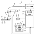
図1は、実施形態に係るレーザ溶接装置10の模式図である。
FIG. 1 is a schematic diagram of a
図1に示すように、レーザ溶接装置10は、レーザ光Lを出力するレーザ発振器11と、測定光Sを出力する光干渉計12と、レーザ光L及び測定光Sを溶接対象物30に向けて照射するレーザ照射ヘッド20(照射部)と、レーザ照射ヘッド20が取り付けられてレーザ照射ヘッド20を移動させるロボット18と、レーザ発振器11、光干渉計12、レーザ照射ヘッド20及びロボット18を制御してレーザ溶接を行う制御装置16とを備えている。
As shown in FIG. 1, a
レーザ発振器11は、制御装置16からの指令に基づいて、レーザ光Lを出力する。レーザ発振器11とレーザ照射ヘッド20とは、光ファイバ19で接続されている。レーザ光Lは、光ファイバ19を介して、レーザ発振器11からレーザ照射ヘッド20に伝送される。
光干渉計12は、レーザ光Lとは波長の異なる測定光Sを出力する測定光発振器13と、後述する溶接部35の溶け込み深さを測定する測定部14とを有する。測定光発振器13は、制御装置16からの指令に基づいて、測定光Sを出力する。光干渉計12とレーザ照射ヘッド20とは、光ファイバ19で接続されている。測定光Sは、光ファイバ19を介して、光干渉計12からレーザ照射ヘッド20に伝送される。
The
レーザ照射ヘッド20は、ロボット18のアーム先端部分に取り付けられており、制御装置16からの指令に基づいて、レーザ光L及び測定光Sを溶接対象物30で結像する。
The
ロボット18は、制御装置16からの指令に基づいて、レーザ照射ヘッド20を指定された位置まで移動させ、レーザ光L及び測定光Sを走査する。
The
制御装置16は、レーザ発振器11、光干渉計12、ロボット18、レーザ照射ヘッド20と接続されており、レーザ照射ヘッド20の移動速度の他に、レーザ光Lの出力開始や停止、レーザ光Lの出力強度などを制御する機能も備えている。詳しくは後述するが、制御装置16は、測定部14で測定された複数の測定値に基づいて、溶接部35の溶け込み深さを判定する判定部17を有する。
The
溶接対象物30は、上下に重ね合わされた上側金属板31と下側金属板32とを有する。レーザ溶接装置10は、上側金属板31の上面にレーザ光Lを照射することで、上側金属板31と下側金属板32とを溶接する。
The object to be welded 30 has an
ここで、本実施形態に係るレーザ溶接装置10では、レーザ溶接と同時に溶接部35の溶け込み深さの測定を行うことができる。以下、図2を用いて具体的に説明する。
Here, with the
図2は、レーザ照射ヘッド20の構成を示す模式図である。
FIG. 2 is a schematic diagram showing the configuration of the
図2に示すように、レーザ照射ヘッド20は、レーザ光Lが通過する第1のコリメートレンズ21及び第1のフォーカスレンズ22と、測定光Sが通過する第2のコリメートレンズ23及び第2のフォーカスレンズ24と、レーザ光Lと測定光Sとを同軸の光束に結合するビームスプリッタ25と、第1の平行平板26と、第2の平行平板27とを有する。
As shown in FIG. 2, the
ビームスプリッタ25は、ダイクロイックミラーであり、レーザ発振器11からのレーザ光Lを透過し、光干渉計12からの測定光Sを反射するように、透過・反射させる波長が設定されている。
The
このとき、ビームスプリッタ25で、レーザ光Lと測定光Sとを十分に分離するために、レーザ光Lと測定光Sとの波長差を100nm以上とすることが望ましい。
At this time, in order to sufficiently separate the laser light L and the measurement light S by the
第1の平行平板26及び第2の平行平板27は、図示しないモータに接続され、制御装置16からの指令に従って回転する。
The first
レーザ発振器11から出力されたレーザ光Lは、光ファイバ19を通ってレーザ照射ヘッド20に送られる。レーザ照射ヘッド20に入ったレーザ光Lは、第1のコリメートレンズ21によって平行化され、第1のフォーカスレンズ22によって集光される。第1のフォーカスレンズ22で集光されたレーザ光Lは、ビームスプリッタ25を透過する。
A laser beam L output from the
一方、光干渉計12から出力された測定光Sは、光ファイバ19を通ってレーザ照射ヘッド20に送られる。レーザ照射ヘッド20に入った測定光Sは、第2のコリメートレンズ23によって平行化され、第2のフォーカスレンズ24によって集光される。その後、測定光Sは、ビームスプリッタ25によって、レーザ光Lと同心・同軸状に重ね合わされる。
On the other hand, the measurement light S output from the
なお、第2のフォーカスレンズ24は、溶接部35から反射した測定光Sを、ビームスプリッタ25を介して、光干渉計12に再度、入射させる機能も有している。
The second focus lens 24 also has a function of causing the measurement light S reflected from the welded
そして、同軸に重ね合わされたレーザ光Lと測定光Sとは、制御装置16によって制御された第1の平行平板26及び第2の平行平板27を通る。このことによって、レーザ光L及び測定光Sの照射位置(焦点距離)が決定され、溶接対象物30の溶接部35にレーザ光L及び測定光Sが照射される。
The coaxially superimposed laser light L and measurement light S pass through the first
このとき、レーザ照射ヘッド20は、第1の平行平板26及び第2の平行平板27を回転させることにより、レーザ光Lと測定光Sとが円軌道となるように回転させ、旋回移動させることができる。つまり、第1の平行平板26及び第2の平行平板27は、レーザ光L及び測定光Sの照射位置を変更可能な照射位置変化部を構成している。
At this time, the
また、ロボット18によって、レーザ照射ヘッド20を移動させることで、溶接対象物30における溶接領域において、レーザ光L及び測定光Sの照射位置を移動させることができる。
In addition, by moving the
図3は、レーザ光L、測定光S、キーホール37の位置関係を示す側面断面図である。
FIG. 3 is a side cross-sectional view showing the positional relationship among the laser light L, the measurement light S, and the
図3に示すように、レーザ溶接装置10では、上側金属板31と下側金属板32とを有する溶接対象物30の溶接部35を溶接するにあたり、溶接対象物30の上方から上側金属板31の上面にレーザ光Lが照射される。
As shown in FIG. 3, in the
レーザ光Lの照射された溶接部35は、その上部から溶融し、溶接部35に溶融池36が形成される。溶接部35が溶融する際に、溶融池36から溶融金属が蒸発し、蒸発時に生じる蒸気の圧力によってキーホール37が形成される。ここでは、溶融池36とキーホール37とを合わせて溶接部35として扱う。溶融池36の溶接方向の後方には、溶融池36が凝固することで凝固部38が形成される。
The welded
このとき、光干渉計12から出射される測定光Sが、ビームスプリッタ25により、レーザ発振器11からのレーザ光Lと同心・同軸状に重ね合わされ、キーホール37の内部に照射される。照射された測定光Sは、キーホール37の底部37aで反射し、ビームスプリッタ25を介して、光干渉計12に入射する。
At this time, the measurement light S emitted from the
光干渉計12に入射した測定光Sの光路長は、測定部14で測定される。測定部14では、測定した光路長からキーホール37の深さを、溶接部35の溶け込み深さ(測定値)として特定する。レーザ溶接装置10では、測定した溶け込み深さに基づいて、溶接部35の良否を判断するようにしている。
The optical path length of the measurement light S incident on the
以上の構成により、レーザ溶接装置10は、溶け込み深さ測定機能と、レーザ溶接機能とを同時に果たすことができる。
With the configuration described above, the
ところで、例えば、ビームスプリッタ25を保持している部品が振動等によって位置ずれしてしまい、レーザ光Lと測定光Sとの光軸ずれが生じることがある。そして、レーザ光Lと測定光Sとの光軸ずれが生じた場合には、光干渉計12が、キーホール37の深さを実際の深さよりも浅く測定してしまい、溶け込み深さを精度良く測定することができない場合がある。
By the way, for example, a component holding the
具体的には、キーホール37は、溶接部35で溶融した金属が蒸発し、蒸発時の蒸気の圧力によって形成される。形成されるキーホール37の形状は、レーザ光Lの照射時間や溶融池36の状態によって変化する。
Specifically, the
ここで、キーホール37の溶接方向の前方の内壁部は、レーザ照射ヘッド20の移動速度(溶接速度)が速くなるほど、キーホール37の後方に向かって湾曲した形状となる傾向を示す。そこで、キーホール37の底部37aの湾曲部分の曲率を低減するために、レーザ溶接速度を適切に設定するのが好ましい。
Here, the front inner wall portion of the
しかしながら、レーザ溶接速度を適切に設定したとしても、キーホール37の開口径と底部37aの孔径とを略等しくするのは困難であり、キーホール37の溶接方向の前方の内壁部では、溶け込みが浅い湾曲形状が生じてしまうこととなる。
However, even if the laser welding speed is appropriately set, it is difficult to make the opening diameter of the
なお、キーホール37の開口径は、加工光であるレーザ光Lのスポット径に略等しい。
Note that the opening diameter of the
また、レーザ光Lのスポット径および測定光Sのスポット径は、溶接対象物30の表面に結像される焦点位置でのスポット光のサイズとする。
Also, the spot diameter of the laser beam L and the spot diameter of the measurement beam S are the size of the spot beam at the focal position imaged on the surface of the
そのため、図4の仮想線で示すように、レーザ光Lの光軸と同軸状に照射されている測定光Sの光軸が、たとえば、レーザ光Lのスポット径内の領域でレーザ光Lに対して溶接方向の前方に位置ずれした場合には、キーホール37の底部37aの位置と、測定光Sのスポットの中心の位置とが一致しなくなり、測定光Sが底部37aに照射されない状態が生じ得る。
Therefore, as shown by the phantom line in FIG. 4, the optical axis of the measurement light S irradiated coaxially with the optical axis of the laser light L is, for example, within the spot diameter of the laser light L. On the other hand, when the position is shifted forward in the welding direction, the position of the
なお、図3では、レーザ光Lの光軸と同軸状に照射されている測定光Sの光軸との2つの光軸が、一致しズレが生じていない状態を示している。 Note that FIG. 3 shows a state in which the optical axis of the laser light L and the optical axis of the coaxially irradiated measurement light S are aligned and there is no deviation.
底部37aに測定光Sが照射されない状態としては、例えば、測定光Sが、レーザ光Lに対して溶接方向の前方に位置ずれして、詳細に言い替えると、測定光Sの光軸が、たとえばレーザ光Lの光軸に対して溶接方向の前方にレーザ光Lのスポット径の領域内での位置ずれが生じた場合、キーホール37の前側の内壁部に測定光Sが照射された状態が考えられる。この状態では、測定光Sの反射した位置を底部37aの位置として、光干渉計12は、キーホール37の深さを測定してしまう。
As a state in which the measurement light S is not irradiated to the
つまり、底部37aに測定光Sが照射されなければ、光干渉計12は、キーホール37の深さを実際の深さよりも浅く測定してしまう。言い替えると、レーザ光Lよりも溶接方向の前方に測定光Sが光軸ずれした場合には、溶接部35のキーホール37の最深部ではなく、最深部よりも溶け込みの浅い部分に測定光Sが照射されてしまい、キーホール37の実際の最深部よりも浅い深さが測定されてしまう。
That is, if the
図4に示す例では、キーホール37の実際の深さDminよりも浅い深さDを測定することとなる。このように、実際の深さよりも浅く測定したキーホール37の深さからは、精度良く溶接部35の検査を行うことはできない。
In the example shown in FIG. 4, a depth D that is shallower than the actual depth Dmin of the
ここで、光干渉計12が、キーホール37を実際の深さよりも浅く測定するのを抑えるためには、的確に測定光Sを底部37aに照射する必要がある。そこで、以下に、的確に測定光Sを底部37aに照射するための構成を説明する。
Here, in order to prevent the
図5に示すように、レーザ溶接装置10は、溶接対象物30に対して、螺旋状にレーザ光L及び測定光Sを照射しながら溶接方向に相対的にビームスポットを移動させるスピン軌道40でレーザ光L及び測定光Sを照射して、溶接対象物30を溶接する。
As shown in FIG. 5, the
なお、スピン軌道40とは、照射するレーザ光L及び測定光Sによるスポットを円形状の軌道で移動させながら溶接方向に移動させるレーザ光L及び測定光Sの軌道である。言い換えると、スピン軌道40は、溶接方向において、レーザ光L及び測定光Sの軌跡が回転しながら相対的に直線移動されている軌道である。
The
レーザ光L及び測定光Sの照射位置は、溶接経路34上を移動する回転中心RCから回転半径rだけ離れて且つ所定の回転周波数で回転中心RCを周回するように旋回移動する。つまり、レーザ光L及び測定光Sの照射位置は、螺旋形状を有するスピン軌道40に沿って、溶接対象物30に対して相対的に移動する。
The irradiation positions of the laser light L and the measurement light S are separated from the rotation center RC moving on the
ここで、レーザ照射ヘッド20では、測定光Sの照射位置を、レーザ光Lのスポット径よりも小さな回転半径rで移動するように変化させている。なお、回転半径とは回転運動をすると仮定した場合の軌道の半径を表すものである。キーホール37の開口径は、加工光であるレーザ光Lのスポット径と略等しくなる。このため、測定光Sの光軸の位置は、測定光Sの照射位置がレーザ光Lのスポット径の領域内で重なるように、レーザ光Lのスポット径の1/2よりも測定光Sの回転半径rを小さくし、回転半径rをレーザ光Lのスポット径の1/20以上1/2未満とするのが好ましく、1/16以上1/8以下がより好ましい。例えば、レーザ光Lのスポット径が800μmの場合には、測定光Sの回転半径rを50~100μm程度に設定すればよい。これにより、スポット径の領域内において、レーザ光Lによって形成されたキーホール37の最深部が存在する範囲のみに絞って、より高品質に測定光Sを照射することができる。
Here, in the
なお、測定光Sのスポット径は100~150μm程度である。 Incidentally, the spot diameter of the measurement light S is about 100 to 150 μm.
また、レーザ光Lのスポット径を800μmとしたが、600μmから900μmであっても良い。 Also, although the spot diameter of the laser beam L is 800 μm, it may be 600 μm to 900 μm.
なお、測定光Sの回転半径rは、レーザ光Lのスポット径に重なる半径であればよいので、測定光Sの照射位置を、レーザ光Lのスポット径の領域に重なるように、レーザ光Lのスポット径の半径よりも小さな旋回範囲で測定光Sの照射位置が移動するように、レーザ光Lのスポット径の1/2未満の回転半径で移動するように変化させるのが好ましい。言い替えると、測定光Sの照射位置を、所定の溶接経路上を移動するように変化させ、測定光Sの照射位置としての光軸位置を、レーザ光Lのスポット径の1/2よりも小さな回転半径の領域内で移動するように変化させるのが好ましい。 Note that the radius of gyration r of the measurement light S may be a radius that overlaps with the spot diameter of the laser light L. It is preferable to change so that the irradiation position of the measurement light S moves in a turning range smaller than the radius of the spot diameter of the laser light L so that the rotation radius is less than 1/2 of the spot diameter of the laser light L. In other words, the irradiation position of the measurement light S is changed so as to move along a predetermined welding path, and the optical axis position as the irradiation position of the measurement light S is set to be smaller than 1/2 of the spot diameter of the laser light L. It is preferred to vary the movement within the radius of gyration.
例えば、レーザ光Lのスポット径が800μmの場合、測定光Sの回転周波数を40Hz、回転半径rを400μm未満に設定してもよい。 For example, when the spot diameter of the laser light L is 800 μm, the rotation frequency of the measurement light S may be set to 40 Hz, and the rotation radius r may be set to less than 400 μm.
なお、測定光Sの照射位置を、レーザ光Lのスポット径の半径以上の回転半径で、大きく旋回移動するように変化させると、キーホール開口内の領域内や、キーホール開口内の領域内のレーザ光Lによって形成されたキーホール37の最深部が存在する範囲に対して測定光Sが照射される度合いが減少し、キーホールの深さである溶け込み深さのデータは、旋回移動とともに、深いデータと浅いデータ検出されて大きくうねり、正確な溶け込み深さの測定がより難しくなる。
Note that if the irradiation position of the measurement light S is changed so as to make a large turning movement with a radius of rotation equal to or greater than the spot diameter of the laser light L, the area inside the keyhole opening or the area inside the keyhole opening can be changed. The degree of irradiation of the measurement light S to the range where the deepest part of the
これにより、溶接対象物30に対して、回転中心RCが溶接経路34上を移動する螺旋状の軌跡に沿って、測定光Sを照射しながらキーホール37の底部37aの探索を行うことができる。
This makes it possible to search for the
このように、レーザ光L及び測定光Sの照射位置を螺旋状に旋回移動させながら、キーホール37に測定光Sを照射すれば、略確実に、底部37aに測定光Sが照射されることとなる。このため、測定光Sのスポットの中心と底部37aとが一致しない場合でも、測定光Sを底部37aに照射することが可能となる。
In this way, if the
以下、測定光Sをスピン軌道40で旋回移動させた場合とさせなかった場合とで、溶接部35の溶け込み深さ、つまり、キーホール37の深さの測定値がどのように変化するのかについて説明する。
Below, how the measurement value of the penetration depth of the welded
図4に示す例では、上側金属板31の板厚が1mm、下側金属板32の板厚が4.3mmであり、測定光Sの光軸が、レーザ光Lの光軸よりも溶接方向の前方に100μmずれているものとする。
In the example shown in FIG. 4, the plate thickness of the
図6は、溶接対象物30の表面又は基準となる仮想の面からの、溶接部35の溶け込み深さとして、キーホール37の深さを測定したときのグラフである。図6に示すように、測定光Sをスピン軌道40で旋回移動させなかった場合には、キーホール37の深さの測定値が3mm付近を推移している。これに対し、測定光Sをスピン軌道40で旋回移動させた場合には、キーホール37の深さの測定値が4mm付近を推移している。
FIG. 6 is a graph when the depth of the
このことから、測定光Sをスピン軌道40で旋回移動させた場合の方が、旋回移動させなかった場合に比べて、キーホール37の測定値が大きい、つまり、キーホール37の底部37aの深い位置まで探索できていることが分かる。なお、図6の測定値のグラフは、測定光Sの旋回移動中に複数回測定した測定値のうち、下位数%の測定値(抽出測定値)を抽出して、所定の一定期間である間隔SA(Sampling Area)毎に算出した移動平均値(以下、単に「平均値」ともいう)を示している。
From this, the measurement value of the
なお、下位数%の測定値を抽出するとは、溶接部35の溶け込み深さを複数回測定し、溶け込み深さの測定値の最深部側を下位側として、最も深い側の数%の範囲の測定値を抽出することをいう。
It should be noted that extracting the measured value of the lowest few percent means that the penetration depth of the welded
ここで、予め実験等により求めた実際のキーホールの深さと抽出した下位数%の測定値の平均値とを比較したところ、これらが実質的に一致することが見出された。そのため、複数の測定値に基づいて、溶け込み深さを判定することとした。 Here, when comparing the actual keyhole depth obtained in advance by experiment or the like with the average value of the measured values of the lower few percent extracted, it was found that they substantially match. Therefore, we decided to determine the penetration depth based on a plurality of measured values.
図7は、光軸ずれが生じていない場合において、複数回測定した測定値の全データの平均値と、抽出した下位数%の測定値の平均値とを比較したグラフである。 FIG. 7 is a graph showing a comparison between the average value of all the measured values measured multiple times and the average value of the extracted lower several percent measured values when no optical axis deviation occurs.
図7に示すように、複数の測定値の全データを用いて平均値を算出した場合には、キーホール37の深さの測定値が3mm付近を推移している。一方、複数の測定値のうち、最も深い側の測定値を基準とした所定の範囲内に分布する複数の測定値の平均値を算出した場合には、キーホール37の深さの測定値が4mm付近を推移している。
As shown in FIG. 7, when the average value is calculated using all data of a plurality of measured values, the measured value of the depth of the keyhole 37 changes around 3 mm. On the other hand, when the average value of a plurality of measured values distributed within a predetermined range based on the measured value on the deepest side among the plurality of measured values is calculated, the measured value of the depth of the
ここで、複数の測定値のうち、実際の最深部の深さを表す最も深い側の測定値を基準とした所定の範囲内に分布する測定値とは、溶け込み深さの測定値の最深部側を下位側としたときの下位数%の範囲内の測定値である。 Here, among the plurality of measured values, the measured value distributed within a predetermined range based on the measured value on the deepest side representing the actual depth of the deepest part is the deepest part of the measured value of the penetration depth It is a measured value within the range of the lower few percent when the side is the lower side.
このことから、複数の測定値の下位数%の平均値を算出した方が、複数の測定値の全データを用いて平均値を算出した場合に比べて、キーホール37の測定値が大きい、つまり、キーホール37の底部37aの深い位置まで測定できていることが分かる。
For this reason, calculating the average value of the lower few percent of the plurality of measured values will increase the measured value of the
また、測定値の下位数%とは、最も深い側の数%の範囲の測定値であり、最深部側の測定値数%と同意である。 In addition, the lower several percent of the measured value is the measured value in the range of several percent on the deepest side, and is the same as the measured value several percent on the deepest side.
また、複数の測定値のうち、キーホール37の深さが浅い測定値を除いているのは、溶融池36のキーホール37の状態やノイズ、振動、ヒュームやスパッタ等の外乱により、キーホール37が浅く測定されるばらつきの値を除いて、溶接部35の溶け込み深さを精度良く特定するためである。
In addition, among the plurality of measured values, the measured values for which the depth of the
言い換えると、レーザ光Lと同軸状に照射される測定光Sで測定されるキーホール37の深さのうち、深い値は、実際に深くないと測定され難い。一方、浅い値は、溶融池36のキーホール37の状態(キーホール37のつぶれ、溶融金属の巻き込み等)や外乱(ノイズ、振動、ヒューム等)によって、キーホール37の深さの途中の乱反射等により誤反射されて浅く測定される等、イレギュラーな値が測定される場合があり、これを除くためである。
In other words, of the depths of the
なお、下位数%の範囲は、好ましくは、下位の1%以上20%以下である。これは、下位の1%より小さいと、深い値の特異点値が集中して含まれるおそれがあり、キーホール37の深さは、実際の値(実際の最深部の深さを表す実際の深さの移動平均値)より深めの値となるからである。
The range of the lower several percent is preferably the lower 1% or more and 20% or less. If this is less than the bottom 1%, deep singularity values may be concentrated, and the depth of the
また、下位の20%より大きいと、キーホール37の状態や外乱の影響によるイレギュラーな値が含まれることや、スピン軌道40上の測定値が浅い部分が含まれるため、キーホール37の深さは、実際の値より浅めの値となるからである。
In addition, if it is larger than the lower 20%, it includes irregular values due to the state of the
より好ましくは、下位数%の範囲は、3%以上7%以下であり、下位5%前後の範囲である。これにより、複数の測定値のばらつきを抑えて、溶接部35の溶け込み深さを精度良く特定することができる。
More preferably, the range of the lower several percent is 3% or more and 7% or less, and is in the range of around the lower 5%. As a result, the penetration depth of the welded
ここで、平均値とは、単に複数の値の平均値としても良いし、より好ましくは、所定の一定期間の間隔を定め、その間隔内の平均値を連続して計算する移動平均値とするのが良い。 Here, the average value may simply be the average value of a plurality of values, or more preferably, a moving average value in which an interval of a predetermined fixed period is determined and the average value within that interval is continuously calculated. is good.
図8は、光軸ずれが生じていない場合と、光軸ずれが生じており且つ測定光Sをスピン軌道40で旋回移動させた場合との、溶接部35の溶け込み深さ、つまり、キーホール37の深さの測定値を比較したグラフである。なお、何れの測定結果も、抽出した下位数%の測定値の平均値を用いている。
FIG. 8 shows the penetration depth of the welded
図8に示すように、光軸ずれが生じていない場合には、キーホール37の深さの測定値が4mm付近を推移している。一方、測定光Sをスピン軌道40で旋回移動させた場合にも、キーホール37の深さの測定値が4mm付近を推移している。つまり、測定光Sをスピン軌道40で旋回移動させた場合には、光軸ずれが生じていない場合のキーホール37の底部37aの深さと、略同じ深さまで探索できていることが分かる。
As shown in FIG. 8, when there is no optical axis deviation, the measured value of the depth of the keyhole 37 changes around 4 mm. On the other hand, even when the measuring beam S is swung along the
以下、溶接部35の溶け込み深さの測定動作について説明する。
The operation of measuring the penetration depth of the welded
図9は、溶接部35の溶け込み深さの測定動作を示すフローチャートである。
FIG. 9 is a flow chart showing the operation of measuring the penetration depth of the welded
図9に示すように、まず、ステップS101では、レーザ照射ヘッド20においてレーザ光Lと測定光Sとを同軸に重ね合わせて溶接部35に照射を開始し、ステップS102に進む。
As shown in FIG. 9, first, in step S101, the
ステップS102では、レーザ光L及び測定光Sの照射位置の旋回移動を開始し、ステップS103に進む。旋回移動は、溶接経路34上を移動する回転中心RCの周りを螺旋状に旋回移動させるように、レーザ光L及び測定光Sの照射位置を変化させる。
In step S102, the irradiation positions of the laser light L and the measurement light S start to rotate, and the process proceeds to step S103. The turning movement changes the irradiation positions of the laser light L and the measurement light S so as to turn spirally around the rotation center RC that moves on the
ステップS103では、測定部14が、溶接部35で反射した測定光Sに基づいて、溶接部35の溶け込み深さの測定を開始し、ステップS104に進む。すなわち、ステップS103の処理により、測定部14は、溶接部35の溶け込み深さを繰り返し測定することになる。
In step S103, the
ここで繰り返し測定とは、具体的に説明すると例えば500~3500mm/分の溶接速度で、80~120KHZの測定サンプリングレートで複数個所を微細な間隔で繰り返し測定するものである。 Here, the repeated measurement is, for example, repeated measurement at a welding speed of 500 to 3500 mm/min and a measurement sampling rate of 80 to 120 KHz at fine intervals.
なお、同一測定箇所を複数回繰り返し測定しても良い。 Note that the same measurement location may be repeatedly measured a plurality of times.
これにより、より高品質な測定が出来る。 This allows for higher quality measurements.
溶接が完了すると、ステップS101~S103で開始した処理を終了し、ステップS104では、判定部17が、測定光Sの旋回移動中に測定された溶け込み深さの複数の測定値の全てが所定の閾値の範囲外(すなわち、所定の閾値未満)であるかを判定する。ステップS104での判定が「YES」の場合には、測定値が異常であると判断して、ステップS105に分岐する。ステップS104での判定が「NO」の場合には、ステップS106に分岐する。
When the welding is completed, the processing started in steps S101 to S103 is terminated, and in step S104, the
ここで、所定の閾値は、例えば、レーザ光Lの出力強度や溶接速度に応じて予め決定される溶け込み深さの基準となる閾値である。言い換えると、所定の閾値は、予め実験等により求めた、レーザ光Lの出力強度や溶接速度に応じた溶け込み深さとしてのキーホール37の深さの値であり、判定部17にテーブルとして記憶されている。
Here, the predetermined threshold is, for example, a threshold that serves as a reference for the penetration depth that is determined in advance according to the output intensity of the laser beam L and the welding speed. In other words, the predetermined threshold value is a value of the depth of the
そして、測定値が閾値の範囲外、つまり、測定値が閾値から大きく乖離している場合には、溶け込み深さを正確に測定できていないと判断する。これにより、閾値から大きく乖離している異常値を、キーホール37の最深部の測定値であると誤って特定してしまうのを抑えることができる。
If the measured value is outside the range of the threshold value, that is, if the measured value deviates greatly from the threshold value, it is determined that the penetration depth cannot be measured accurately. As a result, it is possible to prevent an abnormal value greatly deviating from the threshold value from being erroneously identified as the measured value of the deepest part of the
ステップS105では、図示しない表示モニタに測定値の異常を警告するメッセージを表示する等、ユーザーに異常を報知して、溶接部35の溶け込み深さの測定動作の処理を終了する。
In step S105, the user is notified of the abnormality by displaying a message warning of the abnormality in the measured value on a display monitor (not shown), and the process of measuring the penetration depth of the welded
一方、ステップS106では、判定部17が、測定部14で測定された複数の測定値に基づいて、溶接部35の溶け込み深さを特定して、溶接部35の溶け込み深さの測定動作の処理を終了する。例えば、複数の測定値のうち、下位数%の測定値を抽出して、その平均値、具体的には、所定の一定期間である間隔SA(Sampling Area)内の平均値を連続して算出することで、溶け込み深さを判定する。なお、複数の測定値のうち、キーホール37の深さが浅い測定値を除いて、キーホール37の深さが所定の閾値よりも大きな下位数%の測定値を抽出して、その平均値を算出することで、溶け込み深さを判定するようにしてもよい。これにより、複数の測定値のばらつきを抑えて、溶接部35の溶け込み深さを精度良く特定することができる。
On the other hand, in step S106, the determining
なお、測定光Sの旋回移動中に、レーザ光Lの照射位置よりも溶接方向の後方位置の溶接部35の溶け込み深さを複数回測定し、複数の測定値に基づいて、溶け込み深さを判定するようにすれば、キーホール37の最深部の深さをさらに精度良く特定することができる。
During the turning movement of the measurement light S, the penetration depth of the welded
つまり、レーザ光Lの照射位置よりも溶接方向の前方位置では、キーホール37の実際の最深部よりも浅い深さが測定されてしまう。一方、レーザ光Lの照射位置よりも溶接方向の後方位置で溶接部35の溶け込み深さを複数回測定すれば、キーホール37の実際の最深部よりも浅い深さが測定されるのを抑えることができる。
In other words, at a position forward of the irradiation position of the laser beam L in the welding direction, a depth shallower than the actual deepest portion of the
なお、複数の測定値間でばらつきがそれほど生じていないのであれば、複数の測定値のうち最も大きい値や、複数の測定値の平均値を、溶接部35の溶け込み深さと判定するようにしてもよい。
If there is not much variation among the plurality of measured values, the largest value among the plurality of measured values or the average value of the plurality of measured values is determined as the penetration depth of the welded
以上のように、測定光Sの照射位置を移動し旋回移動させ、測定光Sの照射位置としての光軸位置を、レーザ光Lのスポット径の1/2よりも小さな半径領域内での回転半径rで移動するように変化させながら溶け込み深さの測定を行うことで、キーホール37の最深部に測定光Sが照射されるように探索して、レーザ光Lと測定光Sとの光軸ずれの影響を抑えることができる。そして、さらに例えば、一定期間内に測定された複数の測定値のうち最も大きな値、複数の測定値の平均値、複数の測定値のうち下位数%の平均値などを、最深部の溶け込み深さとして判定すればよい。
As described above, the irradiation position of the measurement light S is moved and rotated, and the optical axis position as the irradiation position of the measurement light S is rotated within a radius area smaller than 1/2 of the spot diameter of the laser light L. By measuring the penetration depth while changing so as to move with a radius r, a search is performed so that the deepest part of the
《その他の実施形態》
前記実施形態については、以下のような構成としてもよい。<<Other embodiments>>
The above embodiment may be configured as follows.
本実施形態では、スピン軌道40の軌跡は、単純な螺旋形状だけでなく、円形状や、四角形等の多角形状であってもよい。また、図10に示すように、楕円状の軌跡が不連続に形成されたものであってもよい。つまり、測定光Sがキーホール37内部に照射される連続的な軌跡であれば、種々の形状とすることができる。また、スピン軌道40のレーザ光Lの溶接方向に対しての照射の回転方向は、時計回りであっても良いし、反時計回りであっても良い。
In this embodiment, the trajectory of the
また、本実施形態では、直線状の溶接経路34に沿って、レーザ光L及び測定光Sを螺旋状に移動させて照射するようにしたが、溶接経路は直線状に限られない。例えば、ロボット18によってレーザ照射ヘッド20を螺旋状に移動させながらレーザ光Lを照射することで、溶接経路が螺旋形状となる場合が考えられる。このような場合には、この螺旋形状の溶接経路上で、測定光Sの照射位置を旋回移動させてキーホール37の底部37aの探索を行うようにすればよい。
Further, in the present embodiment, the laser light L and the measurement light S are spirally moved along the
また、本実施形態では、レーザ照射ヘッド20やロボット18によって、レーザ光L及び測定光Sの照射位置を移動させているが、螺旋状の軌跡を通るようにレーザ照射位置を変更できれば、ガルバノスキャナなどを用いてもよい。
In this embodiment, the
また、本実施形態では、上側金属板31及び下側金属板32の2枚を重ねてレーザ溶接を行う構成について説明したが、例えば、3枚以上の金属板を重ねてレーザ溶接を行うようにしてもよい。
In addition, in the present embodiment, the configuration in which the
また、本実施形態では、ビームスプリッタ25の手前に、第1のコリメートレンズ21及び第1のフォーカスレンズ22と、第2のコリメートレンズ23及び第2のフォーカスレンズ24とをそれぞれ設けて、別々に集光するようにしているが、この形態に限定するものではない。
Further, in the present embodiment, a
例えば、第1のコリメートレンズ21及び第1のフォーカスレンズ22と、第2のコリメートレンズ23及び第2のフォーカスレンズ24とを設ける代わりに、図11に示すようにしてもよい。すなわち、ビームスプリッタ25の直下に、コリメートレンズ41及びフォーカスレンズ42を設け、レーザ光L及び測定光Sを、ビームスプリッタ25を介した後で共に集光するようにしても良い。
For example, instead of providing the
具体的には、コリメートレンズ41及びフォーカスレンズ42からなる1組のレンズ構成によって集光する構造とすることが好ましい。このように、1組のレンズ構成とすれば、光軸の調整やレンズの固定をより容易に行うことができる。
Specifically, it is preferable to have a structure in which light is condensed by a set of lens configuration consisting of a
また、本実施形態では、溶け込み深さである最深部の深さは、溶け込み深さの測定値の最深部側を下位側としたときの下位数%の測定値(抽出測定値)を抽出して、その平均値、具体的には、所定の一定期間である間隔SA内の平均値を連続して計算する等の移動平均値を算出するようにしたが、この形態に限定するものでない。 In addition, in the present embodiment, the depth of the deepest portion, which is the penetration depth, is a measured value (extracted measured value) of the lowest few percent when the deepest portion side of the measured value of the penetration depth is taken as the lower side. Then, the average value, more specifically, the moving average value is calculated by continuously calculating the average value within the interval SA, which is a predetermined constant period, but the present invention is not limited to this form.
例えば、所定の一定期間である間隔SA毎の下位数%の測定値を抽出して、それぞれの間隔SA毎における、それぞれの値、又はそれぞれの平均値を抽出することで、溶け込み深さの測定値として算出しても良い。 For example, by extracting the lower several percent of measured values for each interval SA, which is a predetermined constant period, and extracting each value or each average value for each interval SA, measurement of penetration depth It may be calculated as a value.
具体的には、例えば、所定の一定期間である間隔SAを50msecとして、間隔SA毎の測定開始点を50msec単位で変更しながら、間隔SA内の複数のデータの下位数%の値を連続的に算出していっても良い。あるいは測定開始点を1msec単位で変更しながら、間隔SA毎の下位数%の値を連続的に算出するものであっても良い。 Specifically, for example, the interval SA, which is a predetermined constant period, is set to 50 msec, and while changing the measurement start point for each interval SA in units of 50 msec, the values of the lower few percent of the plurality of data within the interval SA are continuously measured. You can calculate to Alternatively, it is also possible to continuously calculate the value of the lowest few percent for each interval SA while changing the measurement start point in units of 1 msec.
これによって、最深部の深さをより精度よく効率的に特定できる。全データの下位数%を抽出した後の、移動平均としての所定の一定期間である間隔SA毎の平均値演算よりも、間隔SA毎の下位数%の平均値の演算処理の方が、間隔SA毎に演算が完結できて演算処理が少なくなる。そのため、演算部のメモリ等のスペックが低い場合でも短時間での処理が可能である。また、演算処理が少ないことにより、演算処理の時間を短縮できるため、加工・計測工程における生産タクトタイムの短縮に有効である。 This makes it possible to more accurately and efficiently identify the depth of the deepest part. Calculation processing of the average value of the lower few % for each interval SA is better than the average value calculation for each interval SA, which is a predetermined constant period as a moving average after extracting the lower several % of all data. Computation can be completed for each SA, reducing computation processing. Therefore, even if the specifications of the memory of the arithmetic unit are low, the processing can be performed in a short time. In addition, since the amount of arithmetic processing can be reduced, the time for arithmetic processing can be shortened, which is effective in shortening the production tact time in the machining/measurement process.
また、測定区間を所定の一定期間である間隔SAとして、例えば、この間隔SAを50msecとし、測定周波数(サンプリング周波数)を20kHzとすることで、その間隔SAにおいて1000回の測定値を取得した場合について説明する。 In addition, when the measurement interval is an interval SA that is a predetermined constant period, for example, the interval SA is 50 msec and the measurement frequency (sampling frequency) is 20 kHz, and 1000 measurement values are obtained in the interval SA. will be explained.
この場合には、間隔SAにおける1000回の測定値のうち、最深部を下位側とした場合の下位5%目、すなわち、下位側より50番目の深さの測定値をそのまま抽出し、溶け込み深さの測定値とする(平均はしない)。 In this case, among the 1000 measured values at the interval SA, the lowest 5% when the deepest part is on the lower side, that is, the 50th depth measured value from the lower side is extracted as it is, and the penetration depth measured (not averaged).
さらに、例えば、50msecの間隔SAの測定開始点を2msec単位で細かくずらしながら重複するように変更し、それぞれの下位5%目の値を溶け込み深さの測定値として抽出する。 Further, for example, the measurement start point of the interval SA of 50 msec is changed so as to be overlapped while being finely shifted by 2 msec, and the lowest 5% value of each is extracted as the measurement value of the penetration depth.
これにより、演算時のメモリ量を抑制し、CPUの負担を低減させて効率良く、溶け込み深さを測定することができる。言い換えると、簡易的な移動平均のように、溶け込み深さを信頼性良く求めることができる。 As a result, it is possible to reduce the amount of memory required for calculation, reduce the load on the CPU, and efficiently measure the penetration depth. In other words, like a simple moving average, the penetration depth can be obtained with high reliability.
なお、間隔SAや測定周波数の設定により、下位5%目の値が存在せず、例えば下位4%目や6%目等、他の値しか存在しない場合は、5%目に最も近い下位数%目の測定値を下位5%目の値として抽出し、溶け込み深さの測定値とする。 Note that if there is no lower 5% value due to the setting of the interval SA and the measurement frequency, and only other values such as the lower 4% and 6% exist, the lower number closest to the 5% The 5th percentile measured value is extracted as the lowest 5th percentile value and used as the measured value of the penetration depth.
このとき、下位数%の範囲の許容値は、好ましくは、下位の1%以上20%以下である。より好ましくは、下位数%の範囲は、3%以上7%以下であり、下位5%前後の範囲である。 At this time, the allowable value in the range of the lower several percent is preferably the lower 1% or more and 20% or less. More preferably, the range of the lower several percent is 3% or more and 7% or less, and is in the range of around the lower 5%.
ここで、間隔SAにおける測定値の取得回数は、好ましくは100~200回以上である。これは、100回未満では、取得回数が少ないことにより、溶融池36のキーホール37の状態(キーホールのつぶれ、溶融金属の巻き込み等)や外乱(ノイズ、振動、ヒューム等)の影響を受けてイレギュラーな値が測定された場合がある。このような場合、イレギュラーな値を高品質で除くことが困難になるためである。
Here, the number of acquisitions of measured values in the interval SA is preferably 100 to 200 times or more. This is because when the number of times of acquisition is less than 100, the number of times of acquisition is small, and the
そのため、間隔SAにおける測定値の取得回数が100~200回以上であれば、イレギュラーな値が測定された場合でも、イレギュラーな値を高品質で除くことができる。 Therefore, if the number of acquisitions of measured values in the interval SA is 100 to 200 or more, even if irregular values are measured, the irregular values can be removed with high quality.
これにより、例えば、下位5%目が存在せずとも下位の4%以上、6%以下の測定値を、溶け込み深さの測定値として特定することができるため、溶け込み深さを精度良く特定できる。 As a result, for example, even if the lowest 5% does not exist, the measured value of the lower 4% or more and 6% or less can be specified as the measured value of the penetration depth, so the penetration depth can be specified with high accuracy. .
なお、ビームスプリッタ25は、より好ましくは特定の波長の光を反射し、その他の波長の光を透過するダイクロイックミラーを用いても良い。
More preferably, the
何れを用いる場合においても、レーザ光Lの波長は透過し、測定光Sの波長は反射する光学部材を用いることで、レーザ光Lと測定光Sを同軸状に溶接対象物30の溶接部35に向かって照射できる。その結果、十分な光量を溶接部35の溶融時に形成されるキーホール37の内部に照射できるため、キーホール深さの特定に有用である。
In either case, by using an optical member that transmits the wavelength of the laser light L and reflects the wavelength of the measurement light S, the laser light L and the measurement light S are coaxially applied to the welded
本実施形態では、レーザ光L及び測定光Sの照射位置をともに螺旋状に移動させるものとして説明した。この場合、レーザ光Lとともに測定光Sの照射位置を移動させても良く、また、レーザ光Lに対して測定光Sの照射位置を相対的に移動させて、レーザ光Lのスポット径の1/2よりも小さな回転半径で移動させてもよい。 In the present embodiment, the irradiation positions of the laser light L and the measurement light S are both moved spirally. In this case, the irradiation position of the measurement light S may be moved together with the laser light L. Alternatively, the irradiation position of the measurement light S may be moved relative to the laser light L so that it is 1 of the spot diameter of the laser light L. It may be moved with a rotation radius smaller than /2.
また、レーザ光Lに対して測定光Sの照射位置を相対的に移動させる場合は、例えばレーザ光Lの照射位置を直線状に移動させ、測定光Sの照射位置を単純な螺旋形状だけでなく、円形状や、三角形、四角形等の多角形状となるように移動させてもよい。以下、図12及び図13を用いて具体的に説明する。 When the irradiation position of the measurement light S is moved relative to the laser light L, for example, the irradiation position of the laser light L is moved linearly, and the irradiation position of the measurement light S is changed only in a simple spiral shape. Instead, it may be moved in a circular shape, or in a polygonal shape such as a triangle or a square. A specific description will be given below with reference to FIGS. 12 and 13. FIG.
図12は、変形例に係るレーザ照射ヘッド20Aの構成を示す模式図である。また、図13は、測定光Sの光路の変化の様子を示す模式図である。なお、図11に示すレーザ照射ヘッド20の構成と同じ部分については同じ符号を付しており、以下では相違点についてのみ説明する。
FIG. 12 is a schematic diagram showing the configuration of a
図12に示すように、レーザ照射ヘッド20Aは、図11に示すレーザ照射ヘッド20の構成に加え、第3の平行平板43を備える。
As shown in FIG. 12, the
第3の平行平板43は、第1の平行平板26や第2の平行平板27と同様に、図示しないモータに接続され、制御装置16からの指令に従って回転するものであり、測定光Sの照射位置を変更可能な照射位置変化部を構成している。レーザ照射ヘッド20aに入った測定光Sは、第3の平行平板43を通ることで、ビームスプリッタ25への入射位置が切り替えられる。
Like the first
具体的には、第3の平行平板43を回転させ、図12に示す角度となるように第3の平行平板43を調整した場合には、測定光Sは、ビームスプリッタ25を透過したレーザ光Lと結合する位置に照射される。なお、この例では、第2の平行平板27は、図11に示す角度とは異なり、第1の平行平板26と略平行となる角度に調整されている。
Specifically, when the third
そして、測定光Sは、ビームスプリッタ25によって、レーザ光Lと同心・同軸状に重ね合わされる。同軸に重ね合わされたレーザ光Lと測定光Sとは、コリメートレンズ41によって平行化され、フォーカスレンズ42によって集光される。
Then, the measurement light S is concentrically and coaxially superimposed on the laser light L by the
一方、第3の平行平板43を回転させ、図13に示す角度となるように第3の平行平板43を調整した場合には、測定光Sは、ビームスプリッタ25を透過したレーザ光Lよりも溶接方向の後方位置に照射される。具体的には、図13に示す例では、レーザ照射ヘッド20Aを右方向に移動させながら溶接を行っているので、測定光Sは、ビームスプリッタ25によって、レーザ光Lよりも溶接方向の後方(左方向)の位置で屈折して、レーザ光Lと測定光Sとが平行となる。そして、レーザ光Lと測定光Sとは、コリメートレンズ41によって平行化され、フォーカスレンズ42によって集光される。
On the other hand, when the third
このように、第3の平行平板43を回転させ、角度を調整することで、レーザ光Lに対して測定光Sの照射位置を相対的に移動させることができ、測定光Sの照射位置を単純な螺旋形状だけでなく、円形状や、三角形、四角形等の多角形状となるように移動させることができる。
Thus, by rotating the third
また、レーザ光Lの照射位置を直線状に移動させた場合(いわゆるライン状加工)、螺旋状に移動させたとき(いわゆるスピン状加工)よりも、高速に、つまり短時間での加工が可能となる。すなわち、ライン状加工で加工生産タクトの向上を図りつつ、より細かくキーホール37の底部37aを探索し、キーホール37内の溶け込み深さをより精度良く測定することができる。
In addition, when the irradiation position of the laser beam L is moved linearly (so-called line processing), it is possible to process at a higher speed, that is, in a short time, than when it is moved spirally (so-called spin processing). becomes. That is, it is possible to search the
なお、測定光Sの照射位置を螺旋形状、円形状、多角形状となるように移動させる際の照射の方向は、時計回りであっても良いし、反時計回りであっても良い。 The direction of irradiation when moving the irradiation position of the measurement light S in a spiral shape, a circular shape, or a polygonal shape may be clockwise or counterclockwise.
また、この変形例では、レーザ光Lの照射位置を直線状に移動させる例を挙げたが、レーザ光Lの照射位置を比較的大きな径のスピン軌道40に沿って、移動させてもよい。この変形例では、測定光Sの照射位置を、レーザ光Lとは独立して相対的に移動させている。従って、レーザ光Lの照射位置を比較的大きな径のスピン軌道40に沿って移動させた場合でも、測定光Sの照射位置を、レーザ光Lのスポット径の1/2よりも小さな回転半径で移動するように変化させ、言い替えると、測定光Sの照射位置を、所定の溶接経路上を移動するように変化させ、測定光Sの照射位置としての光軸位置を、レーザ光Lのスポット径の1/2よりも小さな回転半径の領域内で移動するように変化させ、測定光Sを高速に移動・回転させることができる。すなわち、より細かくキーホール37の底部37aを探索し、キーホール37内の溶け込み深さを測定することができる。
Further, in this modified example, an example in which the irradiation position of the laser light L is moved linearly was given, but the irradiation position of the laser light L may be moved along the
また、レーザ光Lの軌跡は連続的なものだけではなく、不連続に形成されたものであってもよい。つまり、レーザ光Lが照射される移動軌跡の進行方向である溶接方向にレーザ光Lが移動し、キーホール37内部に照射されたレーザ光Lに対して、レーザ光Lの照射方向の平面視で、測定光Sが交差する軌跡であれば、種々の形状とすることができる。 Further, the trajectory of the laser light L is not limited to being continuous, and may be discontinuous. That is, the laser beam L moves in the welding direction, which is the traveling direction of the movement locus along which the laser beam L is irradiated. In addition, as long as the trajectory intersects with the measuring beam S, various shapes can be used.
なお、変形例に係るレーザ照射ヘッド20Aは、図11に示すレーザ照射ヘッド20と同様に、ビームスプリッタ25の直下に、コリメートレンズ41及びフォーカスレンズ42を設け、レーザ光L及び測定光Sを、ビームスプリッタ25を介した後で共に集光するものとして説明した。しかしながら、図2に示すレーザ照射ヘッド20と同様に、レーザ光Lまたは測定光Sが通過する通過方向でのビームスプリッタ25の手前に、第1のコリメートレンズ21及び第1のフォーカスレンズ22と、第2のコリメートレンズ23及び第2のフォーカスレンズ24とをそれぞれ設けて、別々に集光するようにしてももちろん良い。
11, the
以上説明したように、本開示は、溶接部の溶け込み深さをより精度良く測定することができるという実用性の高い効果が得られることから、きわめて有用で産業上の利用可能性は高い。 INDUSTRIAL APPLICABILITY As described above, the present disclosure has the highly practical effect of being able to measure the penetration depth of a weld zone with higher accuracy, and therefore is extremely useful and has high industrial applicability.
10 レーザ溶接装置
11 レーザ発振器
12 光干渉計
13 測定光発振器
14 測定部
16 制御装置
17 判定部
18 ロボット
19 光ファイバ
20 レーザ照射ヘッド(照射部)
20A レーザ照射ヘッド(照射部)
21 第1のコリメートレンズ
22 第1のフォーカスレンズ
23 第2のコリメートレンズ
24 第2のフォーカスレンズ
25 ビームスプリッタ
26 第1の平行平板(照射位置変化部)
27 第2の平行平板(照射位置変化部)
30 溶接対象物
31 上側金属板
32 下側金属板
34 溶接経路
35 溶接部
36 溶融池
37 キーホール
37a 底部
38 凝固部
40 スピン軌道
41 コリメートレンズ
42 フォーカスレンズ
43 第3の平行平板(照射位置変化部)
L レーザ光
r 回転半径
S 測定光
RC 回転中心REFERENCE SIGNS
20A laser irradiation head (irradiation part)
21
27 Second parallel plate (irradiation position changing part)
30
L Laser light r Rotation radius S Measurement light RC Rotation center
Claims (8)
前記レーザ光と、前記レーザ光とは波長の異なる測定光とを同軸に重ね合わせて前記溶接部に照射する照射部と、
前記照射部から照射されて前記溶接部で反射した前記測定光に基づいて、前記溶接部の溶け込み深さを繰り返し測定する測定部と、前記測定部で測定された複数の溶け込み深さの測定値のうちの一部となる、最も深い側の前記溶け込み深さの測定値を基準とした所定の範囲内に分布する複数の抽出測定値、又は前記複数の抽出測定値の平均値に基づいて、前記溶接部の溶け込み深さを判定する判定部と、前記測定光の照射位置を、所定の溶接経路上を移動するように変化させ、前記測定光の前記照射位置としての光軸位置を、前記レーザ光のスポット径の1/2よりも小さな回転半径領域内で移動するように変化させる照射位置変化部を備え、
前記測定部は、前記測定光の前記移動中に前記複数の溶け込み深さの測定値を測定することを特徴とするレーザ溶接装置。 A laser welding device that welds a weld with a laser beam,
an irradiating unit that irradiates the welded portion by coaxially superimposing the laser light and a measurement light having a wavelength different from that of the laser light;
a measurement unit for repeatedly measuring the penetration depth of the weld based on the measurement light emitted from the irradiation unit and reflected by the weld; and a plurality of measured penetration depth values measured by the measurement unit. Based on a plurality of extracted measurements distributed within a predetermined range based on the measured value of the penetration depth on the deepest side, or the average value of the plurality of extracted measurements, a determining unit that determines the penetration depth of the welded portion; and an irradiation position of the measurement light is changed so as to move along a predetermined welding path, and the optical axis position as the irradiation position of the measurement light is changed to the Equipped with an irradiation position changing unit that changes so as to move within a rotation radius area smaller than 1/2 of the spot diameter of the laser light,
The laser welding apparatus according to claim 1, wherein the measurement unit measures the plurality of penetration depth measurements during the movement of the measurement light .
前記照射位置変化部は、前記測定光の前記照射位置を、所定の溶接経路上を移動する回転中心の周りを旋回移動するように変化させ、前記判定部は、前記測定光の前記旋回移動中に前記レーザ光の前記照射位置よりも溶接方向の後方位置で測定された前記複数の抽出測定値に基づいて、前記溶接部の溶け込み深さを判定することを特徴とするレーザ溶接装置。 In the laser welding device according to claim 1 ,
The irradiation position changing section changes the irradiation position of the measurement light so as to turn around a rotation center that moves on a predetermined welding path, and the determination section changes the measurement light during the turning movement of the measurement light. and determining the penetration depth of the welded portion based on the plurality of extracted measurement values measured at a position behind the irradiation position of the laser beam in the welding direction.
前記測定部は、測定区間を所定の一定期間の間隔とし、前記測定区間の測定開始点をずらしながら前記複数の溶け込み深さの測定値を測定することを特徴とするレーザ溶接装置。 In the laser welding device according to claim 1 or 2 ,
The laser welding device, wherein the measuring unit measures the plurality of measured values of the penetration depth while shifting the measurement start point of the measurement section with the measurement section being an interval of a predetermined constant period.
前記測定部は、測定区間を所定の一定期間の間隔とし、前記測定区間内に前記複数の溶け込み深さの測定値を測定することを特徴とするレーザ溶接装置。 In the laser welding device according to claim 1 or 2,
The laser welding device, wherein the measurement unit measures the plurality of penetration depth measurement values in the measurement section, with the measurement section having an interval of a predetermined constant period.
前記所定の範囲は、前記溶け込み深さの測定値の最深部側を下位としたときの、下位の1%以上で且つ20%以下の範囲であることを特徴とするレーザ溶接装置。 In the laser welding device according to claim 3 or 4 ,
The laser welding device, wherein the predetermined range is a range of 1% or more and 20% or less of the lowermost side of the measured value of the penetration depth when the lowest side is the lowermost side.
前記所定の範囲は、前記溶け込み深さの測定値の最深部側を下位としたときの、下位の3%以上で且つ7%以下の範囲であることを特徴とするレーザ溶接装置。 In the laser welding device according to claim 3 or 4 ,
The laser welding device, wherein the predetermined range is a range of 3% or more and 7% or less of the lowest part of the measured penetration depth.
前記レーザ光と、前記レーザ光とは波長の異なる測定光とを同軸に重ね合わせて前記溶接部に照射する照射ステップと、
前記溶接部で反射した前記測定光に基づいて、前記溶接部の溶け込み深さを繰り返し測定する測定ステップと、
測定された複数の溶け込み深さの測定値のうちの一部となる、最も深い側の前記溶け込み深さの測定値を基準とした所定の範囲内に分布する複数の抽出測定値、又は前記複数の抽出測定値の平均値に基づいて、前記溶接部の溶け込み深さを判定する判定ステップと、
前記測定光の照射位置を、所定の溶接経路上を移動するように変化させ、前記測定光の前記照射位置としての光軸位置を、前記レーザ光のスポット径の1/2よりも小さな回転半径領域内で移動するように変化させる照射位置変化ステップとを有し、前記測定ステップは、前記測定光の前記移動中に前記複数の溶け込み深さの測定値を測定することを特徴とするレーザ溶接方法。 A laser welding method for welding a weld with a laser beam,
an irradiation step of coaxially superimposing the laser light and a measurement light having a different wavelength from the laser light and irradiating the weld zone;
a measuring step of repeatedly measuring the penetration depth of the welded portion based on the measurement light reflected by the welded portion;
A plurality of extracted measurements distributed within a predetermined range relative to the penetration depth measurement on the deepest side as part of the plurality of measured penetration depth measurements, or the plurality of a determination step of determining the penetration depth of the weld based on the average value of the extracted measurements of
The irradiation position of the measurement light is changed so as to move along a predetermined welding path, and the optical axis position as the irradiation position of the measurement light is set to a rotation radius smaller than 1/2 of the spot diameter of the laser light. and an irradiation position changing step for changing so as to move within a region , wherein the measuring step measures the plurality of penetration depth measurements during the movement of the measurement light. Method.
前記照射位置変化ステップは、前記測定光の前記照射位置を、所定の溶接経路上を移動する回転中心の周りを旋回移動するように変化させ、前記判定ステップは、前記測定光の前記旋回移動中に前記レーザ光の前記照射位置よりも溶接方向の後方位置で測定された前記複数の抽出測定値に基づいて、前記溶接部の溶け込み深さを判定することを特徴とするレーザ溶接方法。The irradiation position changing step changes the irradiation position of the measurement light so as to turn around a rotation center that moves on a predetermined welding path, and the determination step changes the irradiation position of the measurement light during the turning movement of the measurement light. and determining the penetration depth of the welded portion based on the plurality of extracted measurement values measured at a position behind the irradiation position of the laser beam in the welding direction.
Applications Claiming Priority (3)
| Application Number | Priority Date | Filing Date | Title |
|---|---|---|---|
| JP2018025737 | 2018-02-16 | ||
| JP2018025737 | 2018-02-16 | ||
| PCT/JP2019/002615 WO2019159660A1 (en) | 2018-02-16 | 2019-01-28 | Laser welding device and laser welding method |
Publications (2)
| Publication Number | Publication Date |
|---|---|
| JPWO2019159660A1 JPWO2019159660A1 (en) | 2021-01-28 |
| JP7320703B2 true JP7320703B2 (en) | 2023-08-04 |
Family
ID=67621011
Family Applications (1)
| Application Number | Title | Priority Date | Filing Date |
|---|---|---|---|
| JP2020500370A Active JP7320703B2 (en) | 2018-02-16 | 2019-01-28 | LASER WELDING APPARATUS AND LASER WELDING METHOD |
Country Status (4)
| Country | Link |
|---|---|
| EP (1) | EP3753667B1 (en) |
| JP (1) | JP7320703B2 (en) |
| CN (1) | CN111093887B (en) |
| WO (1) | WO2019159660A1 (en) |
Families Citing this family (2)
| Publication number | Priority date | Publication date | Assignee | Title |
|---|---|---|---|---|
| EP3898061B1 (en) * | 2018-12-19 | 2024-03-06 | IPG Photonics Corporation | Monitoring material processing using imaging signal density determined from inline coherent imaging (ici) |
| GB2605410A (en) * | 2021-03-31 | 2022-10-05 | Jaguar Land Rover Ltd | Methods for welding components of battery modules |
Citations (4)
| Publication number | Priority date | Publication date | Assignee | Title |
|---|---|---|---|---|
| WO2014132503A1 (en) | 2013-02-27 | 2014-09-04 | 三菱重工業株式会社 | Machining device and machining method |
| WO2014138939A1 (en) | 2013-03-13 | 2014-09-18 | Queen's University At Kingston | Methods and systems for characterizing laser machining properties by measuring keyhole dynamics using interferometry |
| JP2016538134A (en) | 2013-09-23 | 2016-12-08 | プレシテク オプトロニク ゲゼルシャフト ミット ベシュレンクテル ハフツング | Method for measuring depth of penetration of laser beam into workpiece and laser processing apparatus |
| JP2018501964A (en) | 2014-10-20 | 2018-01-25 | プレシテック ゲーエムベーハー ウント ツェーオー カーゲー | Equipment for measuring weld seam depth in real time |
Family Cites Families (4)
| Publication number | Priority date | Publication date | Assignee | Title |
|---|---|---|---|---|
| CN201632766U (en) * | 2009-09-23 | 2010-11-17 | 上海市激光技术研究所 | Rotary double-optical wedge laser micropore processing device |
| JP5252026B2 (en) | 2011-05-10 | 2013-07-31 | パナソニック株式会社 | Laser welding apparatus and laser welding method |
| CN205380365U (en) * | 2015-12-14 | 2016-07-13 | 武汉隽龙科技股份有限公司 | A optical scanning system for laser rotation is punched |
| KR101837018B1 (en) * | 2016-05-25 | 2018-03-09 | 주식회사 티프렌즈 | Quality inspection apparatus of laser-welding, and method thereof |
-
2019
- 2019-01-28 CN CN201980004454.7A patent/CN111093887B/en active Active
- 2019-01-28 EP EP19753686.5A patent/EP3753667B1/en active Active
- 2019-01-28 JP JP2020500370A patent/JP7320703B2/en active Active
- 2019-01-28 WO PCT/JP2019/002615 patent/WO2019159660A1/en unknown
Patent Citations (4)
| Publication number | Priority date | Publication date | Assignee | Title |
|---|---|---|---|---|
| WO2014132503A1 (en) | 2013-02-27 | 2014-09-04 | 三菱重工業株式会社 | Machining device and machining method |
| WO2014138939A1 (en) | 2013-03-13 | 2014-09-18 | Queen's University At Kingston | Methods and systems for characterizing laser machining properties by measuring keyhole dynamics using interferometry |
| JP2016538134A (en) | 2013-09-23 | 2016-12-08 | プレシテク オプトロニク ゲゼルシャフト ミット ベシュレンクテル ハフツング | Method for measuring depth of penetration of laser beam into workpiece and laser processing apparatus |
| JP2018501964A (en) | 2014-10-20 | 2018-01-25 | プレシテック ゲーエムベーハー ウント ツェーオー カーゲー | Equipment for measuring weld seam depth in real time |
Also Published As
| Publication number | Publication date |
|---|---|
| US20200376592A1 (en) | 2020-12-03 |
| JPWO2019159660A1 (en) | 2021-01-28 |
| EP3753667B1 (en) | 2022-06-22 |
| CN111093887A (en) | 2020-05-01 |
| WO2019159660A1 (en) | 2019-08-22 |
| EP3753667A1 (en) | 2020-12-23 |
| CN111093887B (en) | 2022-06-28 |
| EP3753667A4 (en) | 2021-05-05 |
Similar Documents
| Publication | Publication Date | Title |
|---|---|---|
| JP7126219B2 (en) | Laser welding method | |
| JP7203306B2 (en) | LASER WELDING APPARATUS AND LASER WELDING METHOD | |
| JP6645960B2 (en) | Method of measuring depth of penetration of laser beam into workpiece and laser processing device | |
| CA2792322C (en) | Laser processing head and method for processing a workpiece by means of a laser beam | |
| JP7320703B2 (en) | LASER WELDING APPARATUS AND LASER WELDING METHOD | |
| JP7126221B2 (en) | laser welding equipment | |
| EP3778100B1 (en) | Laser welding method, and laser welding device | |
| JP2006192461A (en) | Laser beam machining apparatus, the laser beam focal position adjusting method, and laser beam position adjusting method | |
| JPWO2018097018A1 (en) | Laser processing apparatus and laser processing method | |
| JP7113315B2 (en) | Laser welding method | |
| JP7117556B2 (en) | LASER WELDING APPARATUS AND LASER WELDING METHOD | |
| US10928615B2 (en) | Laser processing device having approach function of processing head | |
| JP6277986B2 (en) | Laser welding apparatus and laser welding method | |
| US11964339B2 (en) | Laser welding device and laser welding method | |
| US20210316402A1 (en) | Process control method for laser material processing | |
| WO2021210602A1 (en) | Laser welding method | |
| JP2023108708A (en) | Laser welding device and laser welding method | |
| JP2023112732A (en) | Laser machining device | |
| JP2023168776A (en) | Laser processing device and evaluation method | |
| JP2023070497A (en) | Laser processing method and laser processing machine |
Legal Events
| Date | Code | Title | Description |
|---|---|---|---|
| A621 | Written request for application examination |
Free format text: JAPANESE INTERMEDIATE CODE: A621 Effective date: 20220105 |
|
| RD01 | Notification of change of attorney |
Free format text: JAPANESE INTERMEDIATE CODE: A7421 Effective date: 20221021 |
|
| A131 | Notification of reasons for refusal |
Free format text: JAPANESE INTERMEDIATE CODE: A131 Effective date: 20230117 |
|
| A521 | Request for written amendment filed |
Free format text: JAPANESE INTERMEDIATE CODE: A523 Effective date: 20230317 |
|
| TRDD | Decision of grant or rejection written | ||
| A01 | Written decision to grant a patent or to grant a registration (utility model) |
Free format text: JAPANESE INTERMEDIATE CODE: A01 Effective date: 20230613 |
|
| A61 | First payment of annual fees (during grant procedure) |
Free format text: JAPANESE INTERMEDIATE CODE: A61 Effective date: 20230626 |
|
| R151 | Written notification of patent or utility model registration |
Ref document number: 7320703 Country of ref document: JP Free format text: JAPANESE INTERMEDIATE CODE: R151 |