JP7319115B2 - air conditioner - Google Patents
air conditioner Download PDFInfo
- Publication number
- JP7319115B2 JP7319115B2 JP2019127507A JP2019127507A JP7319115B2 JP 7319115 B2 JP7319115 B2 JP 7319115B2 JP 2019127507 A JP2019127507 A JP 2019127507A JP 2019127507 A JP2019127507 A JP 2019127507A JP 7319115 B2 JP7319115 B2 JP 7319115B2
- Authority
- JP
- Japan
- Prior art keywords
- compressor
- sequence
- rotation speed
- air conditioner
- drive current
- Prior art date
- Legal status (The legal status is an assumption and is not a legal conclusion. Google has not performed a legal analysis and makes no representation as to the accuracy of the status listed.)
- Active
Links
Images


Classifications
-
- F—MECHANICAL ENGINEERING; LIGHTING; HEATING; WEAPONS; BLASTING
- F24—HEATING; RANGES; VENTILATING
- F24F—AIR-CONDITIONING; AIR-HUMIDIFICATION; VENTILATION; USE OF AIR CURRENTS FOR SCREENING
- F24F11/00—Control or safety arrangements
- F24F11/89—Arrangement or mounting of control or safety devices
-
- F—MECHANICAL ENGINEERING; LIGHTING; HEATING; WEAPONS; BLASTING
- F24—HEATING; RANGES; VENTILATING
- F24F—AIR-CONDITIONING; AIR-HUMIDIFICATION; VENTILATION; USE OF AIR CURRENTS FOR SCREENING
- F24F1/00—Room units for air-conditioning, e.g. separate or self-contained units or units receiving primary air from a central station
- F24F1/06—Separate outdoor units, e.g. outdoor unit to be linked to a separate room comprising a compressor and a heat exchanger
- F24F1/08—Compressors specially adapted for separate outdoor units
- F24F1/12—Vibration or noise prevention thereof
-
- F—MECHANICAL ENGINEERING; LIGHTING; HEATING; WEAPONS; BLASTING
- F24—HEATING; RANGES; VENTILATING
- F24F—AIR-CONDITIONING; AIR-HUMIDIFICATION; VENTILATION; USE OF AIR CURRENTS FOR SCREENING
- F24F11/00—Control or safety arrangements
- F24F11/62—Control or safety arrangements characterised by the type of control or by internal processing, e.g. using fuzzy logic, adaptive control or estimation of values
- F24F11/63—Electronic processing
- F24F11/64—Electronic processing using pre-stored data
-
- F—MECHANICAL ENGINEERING; LIGHTING; HEATING; WEAPONS; BLASTING
- F24—HEATING; RANGES; VENTILATING
- F24F—AIR-CONDITIONING; AIR-HUMIDIFICATION; VENTILATION; USE OF AIR CURRENTS FOR SCREENING
- F24F11/00—Control or safety arrangements
- F24F11/70—Control systems characterised by their outputs; Constructional details thereof
- F24F11/80—Control systems characterised by their outputs; Constructional details thereof for controlling the temperature of the supplied air
- F24F11/86—Control systems characterised by their outputs; Constructional details thereof for controlling the temperature of the supplied air by controlling compressors within refrigeration or heat pump circuits
-
- F—MECHANICAL ENGINEERING; LIGHTING; HEATING; WEAPONS; BLASTING
- F24—HEATING; RANGES; VENTILATING
- F24F—AIR-CONDITIONING; AIR-HUMIDIFICATION; VENTILATION; USE OF AIR CURRENTS FOR SCREENING
- F24F11/00—Control or safety arrangements
- F24F11/88—Electrical aspects, e.g. circuits
-
- F—MECHANICAL ENGINEERING; LIGHTING; HEATING; WEAPONS; BLASTING
- F25—REFRIGERATION OR COOLING; COMBINED HEATING AND REFRIGERATION SYSTEMS; HEAT PUMP SYSTEMS; MANUFACTURE OR STORAGE OF ICE; LIQUEFACTION SOLIDIFICATION OF GASES
- F25B—REFRIGERATION MACHINES, PLANTS OR SYSTEMS; COMBINED HEATING AND REFRIGERATION SYSTEMS; HEAT PUMP SYSTEMS
- F25B13/00—Compression machines, plants or systems, with reversible cycle
Description
本発明は、空気調和機に関する。 The present invention relates to an air conditioner.
特許文献1には、空気調和機における圧縮機の起動を行うための圧縮機起動シーケンスが開示されている。特許文献1には、圧縮機の駆動モータの起動時における起動失敗が検出されると、起動電圧を所定電圧ずつ順次上昇させて再起動をかけることが開示されている。また、特許文献1の圧縮機起動シーケンスは、起動失敗が所定回数に達したときに、空気調和機を異常停止させるものとなっている。
空気調和機における圧縮機起動シーケンスは、通常、起動時の振動や騒音を抑えながら圧縮機を起動させるものとされている一方、外気温が高く圧縮機の負荷が大きくなるような状況でも確実な起動を行うことも要求される。 Normally, the compressor start-up sequence in an air conditioner is supposed to start the compressor while suppressing vibration and noise at start-up. You are also asked to perform a boot.
特許文献1における圧縮機起動シーケンスは、何らかの原因で起動失敗が生じた場合に、起動失敗後の再起動時にモータの起動電圧を上昇させることで起動の確実性を上げるものとなっているが、圧縮機の負荷が大きい場合の起動失敗を想定しているものではない。また、本願発明者の検討によれば、特許文献1のようにモータの起動電圧を上昇させる方法は、圧縮機の負荷が大きい場合において、起動の確実性を上げるための最適な方法と言えるものではない。このため、特許文献1における圧縮機起動シーケンスでは、圧縮機起動にとってより過酷となる状況では、圧縮機の起動が行えないこともあり得る。
The compressor start-up sequence in
例えば、外気温の高い状態で運転されていた空気調和機を一旦止めて再起動するような場合、すなわち、外気温と圧縮機温度とが共に高い状況では、圧縮機が異常な過負荷状態となり、空気調和機を再起動したときに保護動作が働いて圧縮機の起動が失敗しやすい。特許文献1の起動シーケンスでは、このような状況に対応できず、起動失敗を繰り返した後に空気調和機の運転が停止する恐れがある。
For example, when an air conditioner that has been operating at a high outside temperature is stopped and restarted, that is, in a situation where both the outside temperature and the compressor temperature are high, the compressor will be in an abnormal overload state. , when the air conditioner is restarted, the protective action is activated and the compressor tends to fail to start. The startup sequence of
本発明は、上記課題に鑑みてなされたものであり、外気温および圧縮機温度が共に高い状況でも圧縮機の確実な起動を行うことのできる空気調和機を提供することを目的とする。 SUMMARY OF THE INVENTION It is an object of the present invention to provide an air conditioner capable of reliably starting a compressor even when both the outside air temperature and the compressor temperature are high.
上記の課題を解決するために、本発明の空気調和機は、運転開始時に圧縮機が過負荷状態であるか否かを判定する判定部と、前記圧縮機の起動制御を行う制御部とを備え、前記制御部は、前記判定部によって前記圧縮機が過負荷状態でないと判定された場合には、起動時における振動および騒音の抑制効果が高い第1の起動シーケンスにて前記圧縮機を起動させ、前記判定部によって前記圧縮機が過負荷状態であると判定された場合には、過負荷状態においても前記圧縮機の確実な起動が行える第2の起動シーケンスにて前記圧縮機を起動させることを特徴としている。 In order to solve the above problems, the air conditioner of the present invention includes a determination unit that determines whether or not the compressor is in an overloaded state at the start of operation, and a control unit that performs start-up control of the compressor. When the determination unit determines that the compressor is not in an overloaded state, the control unit starts the compressor in a first start sequence that is highly effective in suppressing vibration and noise during start-up. and if the determination unit determines that the compressor is in an overloaded state, the compressor is started in a second start-up sequence that enables reliable start-up of the compressor even in the overloaded state. It is characterized by
上記の構成によれば、圧縮機が過負荷状態であると判定された場合には、圧縮機の確実な起動が行える第2の起動シーケンスにて圧縮機を起動させることで、圧縮機の起動失敗を防止し、確実な起動を行うことができる。 According to the above configuration, when it is determined that the compressor is in an overloaded state, the compressor is started by the second startup sequence that enables reliable startup of the compressor. Failure can be prevented and reliable start can be performed.
また、上記空気調和機では、前記第1および第2の起動シーケンスは、前記圧縮機のモータ駆動電流を起動途中で強制的に上昇させる期間を含んで、圧縮機回転数を所望の回転数まで上昇させる起動シーケンスであり、前記第2の起動シーケンスでは、前記モータ駆動電流を上昇させるタイミングが、前記第1の起動シーケンスよりも後ろにずらされている構成とすることができる。 Further, in the above air conditioner, the first and second startup sequences include a period during which the motor drive current of the compressor is forcibly increased during startup, and the compressor rotation speed is increased to a desired rotation speed. In the second startup sequence, the timing of increasing the motor drive current may be shifted later than in the first startup sequence.
上記の構成によれば、第2の起動シーケンスでは、モータ駆動電流を上昇させるタイミングが第1の起動シーケンスよりも後ろにずらされることで、駆動モータのロータに十分な回転惰性が働いた状態で駆動モータのロータを加速することができる。これにより、外気温および圧縮機温度が共に高いような過負荷状態でも、圧縮機の起動失敗を防止し、確実な起動を行うことができる。 According to the above configuration, in the second start-up sequence, the timing of increasing the motor drive current is shifted later than in the first start-up sequence. The rotor of the drive motor can be accelerated. As a result, even in an overloaded state where both the outside air temperature and the compressor temperature are high, it is possible to prevent the compressor from failing to start and to start it reliably.
また、上記空気調和機では、前記第1および第2の起動シーケンスは、前記圧縮機回転数が所定の圧縮機回転数に到達したタイミングで前記モータ駆動電流を上昇させる起動シーケンスであり、前記第2の起動シーケンスでは、前記所定の圧縮機回転数が、前記第1の起動シーケンスよりも大きな圧縮機回転数とされている構成とすることができる。 Further, in the above air conditioner, the first and second startup sequences are startup sequences for increasing the motor drive current at timing when the compressor rotational speed reaches a predetermined compressor rotational speed, and In the second startup sequence, the predetermined compressor rotation speed may be set to a higher compressor rotation speed than in the first startup sequence.
また、上記空気調和機では、前記判定部は、外気温が第1温度閾値よりも高く、かつ圧縮機温度が第2温度閾値よりも高い場合に、前記圧縮機が過負荷状態であると判定する構成とすることができる。 Further, in the above air conditioner, the determination unit determines that the compressor is in an overload state when the outside air temperature is higher than a first temperature threshold and the compressor temperature is higher than a second temperature threshold. It can be configured to
本発明の空気調和機は、外気温および圧縮機温度が共に高いような過負荷状態においても、第2の起動シーケンスで圧縮機を起動することによって、圧縮機の確実な起動を行うことができるといった効果を奏する。 The air conditioner of the present invention can reliably start the compressor by starting the compressor in the second starting sequence even in an overload state where both the outside air temperature and the compressor temperature are high. It has such an effect.
〔実施の形態1〕
以下、本発明の実施の形態1について、図面を参照して詳細に説明する。図1は、本実施の形態1に係る空気調和機10の概略構成図であり、空気調和機10において適用される冷凍サイクルを示している。
[Embodiment 1]
空気調和機10は、室内ユニット(室内機)100および室外ユニット(室外機)110により構成されている。空気調和機10における冷凍サイクル(ヒートポンプ)の経路上には、室内ユニット100側に室内熱交換器101が備えられており、室外ユニット110側に圧縮機111、室外熱交換器112、四方弁113および膨張弁114が備えられている。また、室内ユニット100には、室内熱交換器101で熱交換された空気を室内に送り出すための室内ファン102が備えられており、室外ユニット110には、室外熱交換器112に空気を送るための室外ファン115が備えられている。
The
また、空気調和機10は、外気温を検出する第1温度センサ121と、圧縮機温度を検出する第2温度センサ122とを備えている。第1温度センサ121は、室外熱交換器112の吸気温度を外気温として検出するものとする。尚、図1では詳細な図示を省略しているが、空気調和機10には、第1温度センサ121および第2温度センサ122以外にも、必要に応じて冷凍サイクル内の各部の温度を検出する温度センサが適宜設けられている。
The
四方弁113は、空気調和機10の冷房/暖房運転に応じて、冷媒の循環の向きを切り替えるものである(図1は冷房運転時の状態を示している)。冷房運転時には、圧縮機111、四方弁113、室外熱交換器112、膨張弁114、室内熱交換器101、四方弁113、圧縮機111の順で冷媒が循環する。すなわち、冷房運転時には、室外熱交換器112が凝縮器、室内熱交換器101が蒸発器として機能する。一方、暖房運転時には、圧縮機111、四方弁113、室内熱交換器101、膨張弁114、室外熱交換器112、四方弁113、圧縮機111の順で冷媒が循環する。すなわち、暖房運転時には、室内熱交換器101が凝縮器、室外熱交換器112が蒸発器として機能する。
The four-
図2は、本実施の形態1に係る空気調和機10の運転開始時における圧縮機111の起動シーケンス(圧縮機起動シーケンス)を示すフローチャートである。以下の圧縮機起動シーケンスは、空気調和機10に備えられる制御部(図示省略)が、圧縮機111の駆動モータ(図示省略)の駆動電流(モータ駆動電流)を制御することによって実施される。
FIG. 2 is a flowchart showing a startup sequence (compressor startup sequence) of the
空気調和機10が運転を開始するとき、第1温度センサ121が外気温を検出し、第2温度センサ122が圧縮機温度を検出する。検出された外気温および圧縮機温度は、制御部において、それぞれ第1温度閾値T1(例えば50℃)および第2温度閾値T2(例えば80℃)と比較される(S1,S2)。
When the
制御部(判定部)は、検出された外気温および圧縮機温度に基づいて、運転開始時に圧縮機111が過負荷状態であるか否かを判定する。外気温および圧縮機温度の少なくとも一方が閾値以下である場合、すなわち“外気温≦T1”または“圧縮機温度≦T2”の場合(S1またはS2がNO)は過負荷状態ではないと判定されてS3に移行する。外気温および圧縮機温度が共に閾値より高い場合、すなわち“外気温>T1”かつ“圧縮機温度>T2”の場合(S1,S2が共にYES)は過負荷状態であると判定されてS4に移行する。
The control unit (determining unit) determines whether the
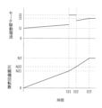
S3では、第1の起動シーケンスにて圧縮機111の起動が開始される。第1の起動シーケンスは、圧縮機111が過負荷状態でない場合に適用される通常の起動シーケンスであり、起動時の振動および騒音の抑制効果が高い起動シーケンスとされている。図3は、第1の起動シーケンスにおけるモータ駆動電流と圧縮機回転数との変化を示すタイミングチャートである。
In S3, activation of the
圧縮機111を起動させる場合、通常は、モータ駆動電流を途中で強制的に上昇させることで、圧縮機回転数を所望の回転数まで上昇させる。ここでは、圧縮機回転数を最終的にN3(例えば3500rpm)まで上昇させる圧縮機起動シーケンスを例示する。また、本実施の形態1では、モータ駆動電流を上昇させるタイミングは圧縮機回転数に基づいて制御されるものとする。このため、本実施の形態1に係る制御部は、圧縮機回転数を監視している。
When the
第1の起動シーケンスでは、図3に示すように、起動開始時はモータ駆動電流をI1とし、圧縮機回転数がN11(例えば1500rpm)に到達した時点(時刻t11)でモータ駆動電流をI2に強制的に上昇させる。さらに、圧縮機回転数がN12(例えば2000rpm)に到達した時点(時刻t12)でモータ駆動電流の上昇を終了させる。そして、圧縮機回転数がN3に到達(時刻t13)し、モータ駆動電流がI3に安定すれば圧縮機111の起動が完了する(圧縮機起動シーケンスが終了する)。ここでは、モータ駆動電流I3が圧縮機回転数N3に対応するモータ駆動電流である。
In the first startup sequence, as shown in FIG. 3, the motor drive current is set to I1 at the start of startup, and the motor drive current is set to I2 when the compressor rotation speed reaches N11 (for example, 1500 rpm) (time t11). forced to rise. Furthermore, when the compressor rotation speed reaches N12 (for example, 2000 rpm) (time t12), the increase of the motor drive current is terminated. Then, when the compressor rotation speed reaches N3 (time t13) and the motor drive current stabilizes at I3, the start-up of the
起動開始から時刻t11までの間は、圧縮機回転数の増加に伴って仕事量が増えるため、電流も増加している。時刻t11から時刻t12の間は、モータ駆動電流I3よりも電流値の大きいモータ駆動電流I2が強制的に印加され、電流値はほぼ一定となる。時刻t12においてモータ駆動電流の上昇期間が終了すると、モータ駆動電流はその時の圧縮機回転数に応じた電流に変化(低下)する。そして、時刻t12から時刻t13の間は、圧縮機回転数がN3に安定するまで圧縮機回転数の増加に伴って仕事量が増えるため、電流も増加している。 From the start to time t11, the amount of work increases as the compressor rotation speed increases, so the current also increases. Between time t11 and time t12, motor drive current I2 having a larger current value than motor drive current I3 is forcibly applied, and the current value becomes substantially constant. When the rising period of the motor drive current ends at time t12, the motor drive current changes (decreases) to a current corresponding to the compressor rotation speed at that time. From time t12 to time t13, the current increases as the work load increases as the compressor rotation speed increases until the compressor rotation speed stabilizes at N3.
第1の起動シーケンスでは、モータ駆動電流を上昇させるタイミング(すなわち、圧縮機回転数N11,N12)は、起動時の振動や騒音を抑制できるように設定されている。 In the first startup sequence, the timing for increasing the motor drive current (that is, the compressor rotation speeds N11 and N12) is set so as to suppress vibration and noise during startup.
S4では、第2の起動シーケンスにて圧縮機111の起動が開始される。第2の起動シーケンスは、圧縮機111が過負荷状態であり、通常の起動シーケンスでは起動失敗が起こりやすいと判断される場合に適用される起動シーケンスである。すなわち、第2の起動シーケンスは、第1の起動シーケンスに比べると起動時の振動や騒音が大きくなるが、過負荷状態においても圧縮機111の確実な起動が行える。図4は、第2の起動シーケンスにおけるモータ駆動電流と圧縮機回転数との変化を示すタイミングチャートである。
In S4, activation of the
第2の起動シーケンスでは、図4に示すように、起動開始時はモータ駆動電流をI1とし、圧縮機回転数がN21(例えば2000rpm)に到達した時点(時刻t21)でモータ駆動電流をI2に強制的に上昇させる。さらに、圧縮機回転数がN22(例えば2500rpm)に到達した時点(時刻t22)でモータ駆動電流の上昇を終了させる。そして、圧縮機回転数がN3に到達(時刻t23)し、モータ駆動電流がI3に安定すれば圧縮機111の起動が完了する(圧縮機起動シーケンスが終了する)。第2の起動シーケンスでは、モータ駆動電流の上昇期間の切替えタイミングとなる圧縮機回転数を、第1の起動シーケンスよりも大きな回転数としている。すなわち、N21>N11かつN22>N12となる。
In the second startup sequence, as shown in FIG. 4, the motor drive current is set to I1 at the start of startup, and the motor drive current is set to I2 when the compressor rotation speed reaches N21 (for example, 2000 rpm) (time t21). forced to rise. Furthermore, when the compressor rotation speed reaches N22 (for example, 2500 rpm) (time t22), the increase of the motor drive current is terminated. When the compressor rotation speed reaches N3 (time t23) and the motor drive current stabilizes at I3, the start-up of the
圧縮機111の起動時には、モータ駆動電流を上昇させるタイミングで駆動モータのロータが加速するが、圧縮機111が過負荷状態のときには、この加速タイミングで起動失敗が生じやすい。第2の起動シーケンスでは、第1の起動シーケンスよりも圧縮機回転数を上げた状態でモータ駆動電流を上昇させるため、モータ駆動電流を上昇させるタイミングが第1の起動シーケンスよりも後ろにずらされたものとなる。このように、モータ駆動電流を上昇させるタイミングを後ろにずらすことで、駆動モータのロータに十分な回転惰性が働いた状態で駆動モータのロータが加速されることとなり、圧縮機111の起動失敗を防止することができる(確実な起動が行える)。
When the
〔実施の形態2〕
上記実施の形態1では、第1の起動シーケンスおよび第2の起動シーケンスにおいて、モータ駆動電流を上昇させるタイミングを圧縮機回転数に基づいて制御している。しかしながら、本発明はこれに限定されるものではなく、モータ駆動電流を上昇させるタイミングを、起動開始からの経過時間に基づいて制御することも可能である。
[Embodiment 2]
In the first embodiment described above, the timing for increasing the motor drive current is controlled based on the compressor rotation speed in the first startup sequence and the second startup sequence. However, the present invention is not limited to this, and it is also possible to control the timing of increasing the motor drive current based on the elapsed time from the start of activation.
例えば、図3に示すタイミングチャートにおいて、圧縮機回転数がN11に到達すると予測される時間t11、および圧縮機回転数がN12に到達すると予測される時間t12を予め設定しておき、制御部は時間t11およびt12が経過した時点でモータ駆動電流を上昇させるようにしてもよい。 For example, in the timing chart shown in FIG. 3, time t11 at which the compressor rotation speed is expected to reach N11 and time t12 at which the compressor rotation speed is expected to reach N12 are set in advance, and the control unit The motor drive current may be increased after the times t11 and t12 have passed.
同様に、図4に示すタイミングチャートにおいて、圧縮機回転数がN21に到達すると予測される時間t21、および圧縮機回転数がN22に到達すると予測される時間t22を予め設定しておき、制御部は時間t21およびt22が経過した時点でモータ駆動電流を上昇させるようにしてもよい。 Similarly, in the timing chart shown in FIG. 4, a time t21 at which the compressor rotation speed is expected to reach N21 and a time t22 at which the compressor rotation speed is expected to reach N22 are set in advance, and the control unit may increase the motor drive current when times t21 and t22 have passed.
本実施の形態2に係る圧縮機起動シーケンスでは、制御部は圧縮機回転数を監視する代わりに、タイマによる時間計測によって圧縮機起動シーケンスを実行することができる。 In the compressor startup sequence according to the second embodiment, instead of monitoring the compressor rotation speed, the controller can execute the compressor startup sequence by measuring time with a timer.
〔実施の形態3〕
上記実施の形態1では、第1の起動シーケンスおよび第2の起動シーケンスともに、起動途中で段階的に上昇させるモータ駆動電流(起動電流)の電流値(すなわちI1,I2)を同じとしている。しかしながら、本発明はこれに限定されるものではなく、起動電流を、第1の起動シーケンスおよび第2の起動シーケンスで異ならせるものとしてもよい(最終的に到達させるモータ駆動電流I3は同じである)。
[Embodiment 3]
In the first embodiment described above, the current values (ie, I1, I2) of the motor drive current (starting current) to be increased stepwise during starting are the same for both the first starting sequence and the second starting sequence. However, the present invention is not limited to this, and the starting current may be different between the first starting sequence and the second starting sequence (the motor drive current I3 to be finally reached is the same. ).
具体的には、第2の起動シーケンスの起動電流I1’,I2’を、第1の起動シーケンスにおける起動電流I1,I2よりも大きな電流としてもよい(I1’>I1かつI2’>I2)。このように、第2の起動シーケンスにおける起動電流を第1の起動シーケンスにおける起動電流よりも大きくすることで、圧縮機111の起動失敗をより確実に防止することができる。
Specifically, the starting currents I1' and I2' in the second starting sequence may be larger than the starting currents I1 and I2 in the first starting sequence (I1'>I1 and I2'>I2). Thus, by making the starting current in the second starting sequence larger than the starting current in the first starting sequence, it is possible to more reliably prevent the
〔実施の形態4〕
上記実施の形態1では、第2の起動シーケンスを実施する過負荷状態を、外気温および圧縮機温度に基づいて判定している。しかしながら、本発明はこれに限定されるものではなく、第2の起動シーケンスを実施する過負荷状態を、他のパラメータに基づいて判定することも可能である。
[Embodiment 4]
In
例えば、第2の起動シーケンスを実施する過負荷状態を、外気温と、前回の運転停止からの経過時間とに基づいて判定することが考えられる。すなわち、圧縮機温度は、前回の運転停止から十分な時間が経過すれば、過負荷状態とならない程度にまで温度が下がると想定されるが、十分な時間が経過していなければ温度が高いままであると予測される。 For example, it is conceivable to determine the overload condition for executing the second startup sequence based on the outside temperature and the elapsed time since the previous shutdown. In other words, if enough time has passed since the last shutdown, the compressor temperature is expected to drop to the extent that it does not become overloaded. is expected to be up to
このため、本実施の形態4に係る圧縮機起動シーケンスは、外気温が第1温度閾値T1(例えば50℃)よりも高く、かつ前回の運転停止からの経過時間が予め定められた時間閾値(例えば1時間)よりも短い場合に圧縮機111が過負荷状態であると見なし、第2の起動シーケンスを実施するものであってよい。
Therefore, in the compressor startup sequence according to the fourth embodiment, the outside air temperature is higher than the first temperature threshold T1 (for example, 50° C.), and the time threshold ( for example, one hour), the
今回開示した実施形態はすべての点で例示であって、限定的な解釈の根拠となるものではない。従って、本発明の技術的範囲は、上記した実施形態のみによって解釈されるものではなく、特許請求の範囲の記載に基づいて画定される。また、特許請求の範囲と均等の意味および範囲内でのすべての変更が含まれる。 The embodiments disclosed this time are exemplifications in all respects and are not grounds for restrictive interpretation. Therefore, the technical scope of the present invention is not to be interpreted only by the above-described embodiments, but is defined based on the claims. In addition, all changes within the meaning and range of equivalents to the scope of claims are included.
10 空気調和機
100 室内ユニット(室内機)
101 室内熱交換器
102 室内ファン
110 室外ユニット(室外機)
111 圧縮機
112 室外熱交換器
113 四方弁
114 膨張弁
115 室外ファン
121 第1温度センサ
122 第2温度センサ
10
101
111
Claims (3)
前記圧縮機の起動制御を行う制御部とを備え、
前記制御部は、
前記判定部によって前記圧縮機が過負荷状態でないと判定された場合には、第1の起動シーケンスにて前記圧縮機を起動させ、
前記判定部によって前記圧縮機が過負荷状態であると判定された場合には、第2の起動シーケンスにて前記圧縮機を起動させ、
前記第1および第2の起動シーケンスは、前記圧縮機のモータ駆動電流を起動途中で強制的に上昇させる期間を含んで、圧縮機回転数を所望の回転数まで上昇させる起動シーケンスであり、
前記第2の起動シーケンスでは、前記モータ駆動電流を上昇させるタイミングが、前記第1の起動シーケンスよりも後ろにずらされていることを特徴とする空気調和機。 A determination unit that determines whether the compressor is in an overloaded state at the start of operation;
A control unit that performs start-up control of the compressor,
The control unit
when the determining unit determines that the compressor is not in an overloaded state , starting the compressor in a first starting sequence;
when the determining unit determines that the compressor is in an overloaded state , starting the compressor in a second starting sequence ;
The first and second startup sequences are startup sequences for increasing the compressor rotation speed to a desired rotation speed, including a period during which the motor drive current of the compressor is forcibly increased during startup,
The air conditioner according to claim 1, wherein, in the second start-up sequence, timing for increasing the motor drive current is shifted later than in the first start-up sequence.
前記第1および第2の起動シーケンスは、前記圧縮機回転数が所定の圧縮機回転数に到達したタイミングで前記モータ駆動電流を上昇させる起動シーケンスであり、
前記第2の起動シーケンスでは、前記所定の圧縮機回転数が、前記第1の起動シーケンスよりも大きな圧縮機回転数とされていることを特徴とする空気調和機。 The air conditioner according to claim 1 ,
The first and second startup sequences are startup sequences for increasing the motor drive current at the timing when the compressor rotation speed reaches a predetermined compressor rotation speed,
The air conditioner according to claim 1, wherein in the second activation sequence, the predetermined compressor rotation speed is set to a greater compressor rotation speed than in the first activation sequence.
前記判定部は、外気温が第1温度閾値よりも高く、かつ圧縮機温度が第2温度閾値よりも高い場合に、前記圧縮機が過負荷状態であると判定することを特徴とする空気調和機。 The air conditioner according to claim 1 or 2 ,
The determination unit determines that the compressor is in an overload state when the outside air temperature is higher than a first temperature threshold and the compressor temperature is higher than a second temperature threshold. machine.
Priority Applications (2)
| Application Number | Priority Date | Filing Date | Title |
|---|---|---|---|
| JP2019127507A JP7319115B2 (en) | 2019-07-09 | 2019-07-09 | air conditioner |
| CN202010634181.9A CN112212482B (en) | 2019-07-09 | 2020-07-02 | Air conditioner |
Applications Claiming Priority (1)
| Application Number | Priority Date | Filing Date | Title |
|---|---|---|---|
| JP2019127507A JP7319115B2 (en) | 2019-07-09 | 2019-07-09 | air conditioner |
Publications (2)
| Publication Number | Publication Date |
|---|---|
| JP2021011995A JP2021011995A (en) | 2021-02-04 |
| JP7319115B2 true JP7319115B2 (en) | 2023-08-01 |
Family
ID=74059083
Family Applications (1)
| Application Number | Title | Priority Date | Filing Date |
|---|---|---|---|
| JP2019127507A Active JP7319115B2 (en) | 2019-07-09 | 2019-07-09 | air conditioner |
Country Status (2)
| Country | Link |
|---|---|
| JP (1) | JP7319115B2 (en) |
| CN (1) | CN112212482B (en) |
Citations (3)
| Publication number | Priority date | Publication date | Assignee | Title |
|---|---|---|---|---|
| JP2003039942A (en) | 2001-07-30 | 2003-02-13 | Suzuki Motor Corp | Air conditioner for electric vehicle |
| JP2005337679A (en) | 2004-05-31 | 2005-12-08 | Matsushita Electric Ind Co Ltd | Refrigerator |
| JP2008104337A (en) | 2006-09-21 | 2008-05-01 | Sanyo Electric Co Ltd | Control unit of electromotor for refrigerant compressor |
Family Cites Families (9)
| Publication number | Priority date | Publication date | Assignee | Title |
|---|---|---|---|---|
| JPS62233652A (en) * | 1986-04-01 | 1987-10-14 | 松下電器産業株式会社 | Heat pump type air conditioner |
| JPH06213548A (en) * | 1993-01-18 | 1994-08-02 | Hitachi Ltd | Refrigerator |
| JP3506457B2 (en) * | 1993-04-23 | 2004-03-15 | 東芝キヤリア株式会社 | Startup control method of compressor in air conditioner |
| JPH10267432A (en) * | 1997-03-24 | 1998-10-09 | Mitsubishi Heavy Ind Ltd | Actuation control device of air conditioner |
| CN101917152B (en) * | 2010-07-29 | 2013-01-16 | 宁波奥克斯空调有限公司 | Starting method of permanent-magnet synchronous compressor for variable-frequency air conditioner |
| JP2015105648A (en) * | 2013-12-03 | 2015-06-08 | カルソニックカンセイ株式会社 | Electric compressor and its control method |
| CN104791960B (en) * | 2015-04-30 | 2018-02-06 | 广东美的制冷设备有限公司 | A kind of air conditioner unloading control system and method |
| CN106123417B (en) * | 2016-06-27 | 2018-09-11 | 广东美的制冷设备有限公司 | A kind of control method and control device of compressor of air conditioner startup |
| CN109028491B (en) * | 2018-08-13 | 2020-07-31 | 宁波奥克斯电气股份有限公司 | Variable frequency air conditioner compressor soft start method and system and air conditioner |
-
2019
- 2019-07-09 JP JP2019127507A patent/JP7319115B2/en active Active
-
2020
- 2020-07-02 CN CN202010634181.9A patent/CN112212482B/en active Active
Patent Citations (3)
| Publication number | Priority date | Publication date | Assignee | Title |
|---|---|---|---|---|
| JP2003039942A (en) | 2001-07-30 | 2003-02-13 | Suzuki Motor Corp | Air conditioner for electric vehicle |
| JP2005337679A (en) | 2004-05-31 | 2005-12-08 | Matsushita Electric Ind Co Ltd | Refrigerator |
| JP2008104337A (en) | 2006-09-21 | 2008-05-01 | Sanyo Electric Co Ltd | Control unit of electromotor for refrigerant compressor |
Also Published As
| Publication number | Publication date |
|---|---|
| JP2021011995A (en) | 2021-02-04 |
| CN112212482B (en) | 2023-07-04 |
| CN112212482A (en) | 2021-01-12 |
Similar Documents
| Publication | Publication Date | Title |
|---|---|---|
| JP6854901B2 (en) | Air conditioner | |
| CN106796070B (en) | Variable speed compressor control with acoustic defrost mode | |
| US9719709B2 (en) | Air-conditioning apparatus with thermo-off postponement control | |
| JP2002272167A (en) | Air conditioner and its drive method | |
| JP2018128194A (en) | Air conditioner | |
| CN113405231B (en) | Self-cleaning sterilization control method and device for air conditioner, air conditioner and storage medium | |
| CN110953662A (en) | Air conditioner | |
| JP2016114345A (en) | Air conditioner | |
| JP2019082278A (en) | Air conditioner | |
| JP2011252639A (en) | Air conditioner | |
| CN113405229B (en) | Self-cleaning sterilization control method and device for air conditioner, air conditioner and storage medium | |
| JP7319115B2 (en) | air conditioner | |
| JP3597053B2 (en) | Air conditioner | |
| JP5686754B2 (en) | Air conditioner | |
| JP2003240311A (en) | Control method for air conditioner | |
| JPH1030835A (en) | Controller for air conditioner | |
| JP5902521B2 (en) | Control device for compressor motor and air conditioner equipped with the same | |
| JP2007212023A (en) | Air conditioning system | |
| WO2021095237A1 (en) | Cold heat source unit and refrigeration circuit device | |
| JP2011158190A (en) | Method for controlling air-conditioner | |
| KR101097976B1 (en) | A method for controlling an operation of refrigerators | |
| CN112050381A (en) | Air conditioner | |
| JP2015052438A (en) | Refrigeration unit | |
| JP2006343095A (en) | Air conditioner | |
| JPH09178273A (en) | Air conditioner |
Legal Events
| Date | Code | Title | Description |
|---|---|---|---|
| A621 | Written request for application examination |
Free format text: JAPANESE INTERMEDIATE CODE: A621 Effective date: 20220323 |
|
| A977 | Report on retrieval |
Free format text: JAPANESE INTERMEDIATE CODE: A971007 Effective date: 20230131 |
|
| A131 | Notification of reasons for refusal |
Free format text: JAPANESE INTERMEDIATE CODE: A131 Effective date: 20230207 |
|
| A521 | Request for written amendment filed |
Free format text: JAPANESE INTERMEDIATE CODE: A523 Effective date: 20230407 |
|
| TRDD | Decision of grant or rejection written | ||
| A01 | Written decision to grant a patent or to grant a registration (utility model) |
Free format text: JAPANESE INTERMEDIATE CODE: A01 Effective date: 20230711 |
|
| A61 | First payment of annual fees (during grant procedure) |
Free format text: JAPANESE INTERMEDIATE CODE: A61 Effective date: 20230720 |
|
| R150 | Certificate of patent or registration of utility model |
Ref document number: 7319115 Country of ref document: JP Free format text: JAPANESE INTERMEDIATE CODE: R150 |