JP7319083B2 - optical displacement meter - Google Patents
optical displacement meter Download PDFInfo
- Publication number
- JP7319083B2 JP7319083B2 JP2019085198A JP2019085198A JP7319083B2 JP 7319083 B2 JP7319083 B2 JP 7319083B2 JP 2019085198 A JP2019085198 A JP 2019085198A JP 2019085198 A JP2019085198 A JP 2019085198A JP 7319083 B2 JP7319083 B2 JP 7319083B2
- Authority
- JP
- Japan
- Prior art keywords
- binning
- light
- image sensor
- profile
- optical displacement
- Prior art date
- Legal status (The legal status is an assumption and is not a legal conclusion. Google has not performed a legal analysis and makes no representation as to the accuracy of the status listed.)
- Active
Links
Images


Classifications
-
- G—PHYSICS
- G01—MEASURING; TESTING
- G01B—MEASURING LENGTH, THICKNESS OR SIMILAR LINEAR DIMENSIONS; MEASURING ANGLES; MEASURING AREAS; MEASURING IRREGULARITIES OF SURFACES OR CONTOURS
- G01B11/00—Measuring arrangements characterised by the use of optical techniques
- G01B11/02—Measuring arrangements characterised by the use of optical techniques for measuring length, width or thickness
- G01B11/06—Measuring arrangements characterised by the use of optical techniques for measuring length, width or thickness for measuring thickness ; e.g. of sheet material
- G01B11/0608—Height gauges
-
- G—PHYSICS
- G01—MEASURING; TESTING
- G01B—MEASURING LENGTH, THICKNESS OR SIMILAR LINEAR DIMENSIONS; MEASURING ANGLES; MEASURING AREAS; MEASURING IRREGULARITIES OF SURFACES OR CONTOURS
- G01B11/00—Measuring arrangements characterised by the use of optical techniques
- G01B11/02—Measuring arrangements characterised by the use of optical techniques for measuring length, width or thickness
- G01B11/06—Measuring arrangements characterised by the use of optical techniques for measuring length, width or thickness for measuring thickness ; e.g. of sheet material
- G01B11/0691—Measuring arrangements characterised by the use of optical techniques for measuring length, width or thickness for measuring thickness ; e.g. of sheet material of objects while moving
-
- G—PHYSICS
- G01—MEASURING; TESTING
- G01B—MEASURING LENGTH, THICKNESS OR SIMILAR LINEAR DIMENSIONS; MEASURING ANGLES; MEASURING AREAS; MEASURING IRREGULARITIES OF SURFACES OR CONTOURS
- G01B11/00—Measuring arrangements characterised by the use of optical techniques
- G01B11/24—Measuring arrangements characterised by the use of optical techniques for measuring contours or curvatures
-
- G—PHYSICS
- G01—MEASURING; TESTING
- G01B—MEASURING LENGTH, THICKNESS OR SIMILAR LINEAR DIMENSIONS; MEASURING ANGLES; MEASURING AREAS; MEASURING IRREGULARITIES OF SURFACES OR CONTOURS
- G01B11/00—Measuring arrangements characterised by the use of optical techniques
- G01B11/02—Measuring arrangements characterised by the use of optical techniques for measuring length, width or thickness
- G01B11/026—Measuring arrangements characterised by the use of optical techniques for measuring length, width or thickness by measuring distance between sensor and object
-
- G—PHYSICS
- G01—MEASURING; TESTING
- G01S—RADIO DIRECTION-FINDING; RADIO NAVIGATION; DETERMINING DISTANCE OR VELOCITY BY USE OF RADIO WAVES; LOCATING OR PRESENCE-DETECTING BY USE OF THE REFLECTION OR RERADIATION OF RADIO WAVES; ANALOGOUS ARRANGEMENTS USING OTHER WAVES
- G01S17/00—Systems using the reflection or reradiation of electromagnetic waves other than radio waves, e.g. lidar systems
- G01S17/02—Systems using the reflection of electromagnetic waves other than radio waves
- G01S17/06—Systems determining position data of a target
- G01S17/46—Indirect determination of position data
- G01S17/48—Active triangulation systems, i.e. using the transmission and reflection of electromagnetic waves other than radio waves
-
- G—PHYSICS
- G01—MEASURING; TESTING
- G01S—RADIO DIRECTION-FINDING; RADIO NAVIGATION; DETERMINING DISTANCE OR VELOCITY BY USE OF RADIO WAVES; LOCATING OR PRESENCE-DETECTING BY USE OF THE REFLECTION OR RERADIATION OF RADIO WAVES; ANALOGOUS ARRANGEMENTS USING OTHER WAVES
- G01S7/00—Details of systems according to groups G01S13/00, G01S15/00, G01S17/00
- G01S7/48—Details of systems according to groups G01S13/00, G01S15/00, G01S17/00 of systems according to group G01S17/00
- G01S7/4808—Evaluating distance, position or velocity data
Description
本発明は光学式変位計に関する。 The present invention relates to an optical displacement meter.
コンベイヤによってY方向に搬送される測定対象物(ワーク)についてZ方向における高さを測定するために、光切断方式の光学式変位計が提案されている(特許文献1、2)。Y方向とZ方向とに直交する方向がX方向であり、XY平面にワークが載置されている。光学式変位計は、X方向に幅を有するスリット光をワークに照射し、ワークからの反射光を二次元配列の画像センサで受光する。スリット光の投光方向と画像センサの受光方向とは傾いており、三角測距の原理に基づき、ワークの高さが算出される。このような、光切断方式の光学式変位計はワークのX-Z断面の輪郭(プロファイル)を一度に取得できる。Y方向にワークを搬送しながら繰り返し撮像を実行することで、Y方向における異なる位置でのプロファイルが取得される。また、複数のプロファイルからワークの三次元形状を示すデータが取得される。
In order to measure the height in the Z direction of an object to be measured (workpiece) conveyed in the Y direction by a conveyor, a light-section type optical displacement meter has been proposed (
画像センサを構成する複数の画素はUV平面に並んでいる。画像センサのU方向はワークのX方向に対応している。画像センサのV方向はワークのZ方向に対応している。つまり、V方向において反射光が入射する画素の位置は、Z方向におけるワークの高さを示している。 A plurality of pixels forming the image sensor are arranged in a UV plane. The U direction of the image sensor corresponds to the X direction of the workpiece. The V direction of the image sensor corresponds to the Z direction of the workpiece. That is, the position of the pixel on which the reflected light is incident in the V direction indicates the height of the workpiece in the Z direction.
単位時間あたりに測定可能なワークの個数を増加させるには、コンベイヤの搬送速度を増加させることが必要となる。さらに、画像センサを構成する全画素からの測定結果の読み出し時間を高速化することが必要となる。 In order to increase the number of workpieces that can be measured per unit time, it is necessary to increase the conveying speed of the conveyor. Furthermore, it is necessary to speed up the readout time of measurement results from all the pixels constituting the image sensor.
画像センサの高速読み出し技術としてビニングと呼ばれる手法が存在する。ビニングでは、n×n個の画素群を一つの塊として扱うことで、n×n個の画素群の合成した測定結果を一度に読み出すことが可能となる。しかし、このようなビニングではU方向とV方向との両方の測定精度がn分の1に低下してしまうため、測定精度の高さを要求される光切断方式の光学式変位計には採用できなかった。そこで、本発明は光切断方式の光学式変位計において、U方向における測定精度の低下を抑えつつ、V方向の読み出しを高速化することを目的とする。 A technique called binning exists as a high-speed readout technique for image sensors. In binning, a group of n.times.n pixels is handled as one block, so that the combined measurement result of the group of n.times.n pixels can be read out at once. However, with this type of binning, the measurement accuracy in both the U and V directions drops to 1/n, so it is used for light-section optical displacement sensors that require high measurement accuracy. could not. SUMMARY OF THE INVENTION Accordingly, it is an object of the present invention to increase the speed of reading in the V direction while suppressing deterioration in measurement accuracy in the U direction in a light-section optical displacement meter.
本発明は、たとえば、
Y方向に搬送される測定対象物のX-Z断面のプロファイルを三角測距の原理に基づき測定する光切断方式の光学式変位計であって、
X方向に幅を有するスリット光を前記測定対象物に照射する光源と、
前記測定対象物からの反射光を受光する画像センサであって、前記X方向に対応するU方向とZ方向に対応するV方向とに二次元配列された複数の画素を有し、前記複数の画素による前記反射光の受光量を出力する画像センサと、
前記U方向に並んだ複数の画素列のそれぞれについて受光量のピークとなる前記V方向における画素の位置をピーク位置として検出する検出手段と、
前記U方向における前記複数の画素列のそれぞれの位置と、前記V方向における前記ピーク位置とからX-Z断面のプロファイルを生成し、前記Y方向の複数の位置における複数の前記X-Z断面のプロファイルから前記測定対象物の三次元形状を示すデータを生成する生成手段と
を有し、
前記画像センサは、前記V方向における解像度を前記U方向における解像度よりも低くするビニングを実行してから受光量を出力し、
前記検出手段は、前記ビニングが実行されてから出力された受光量に基づいて得られた複数のサンプリング値から前記V方向における前記ピーク位置を検出することを特徴とする光学式変位計を提供する。
The present invention, for example,
A light-section optical displacement meter that measures the XZ cross-sectional profile of an object to be measured conveyed in the Y direction based on the principle of triangulation,
a light source that irradiates the object to be measured with slit light having a width in the X direction;
An image sensor for receiving reflected light from the object to be measured, the image sensor having a plurality of pixels arranged two-dimensionally in a U direction corresponding to the X direction and a V direction corresponding to the Z direction, an image sensor that outputs the amount of the reflected light received by a pixel;
detection means for detecting, as a peak position, a position of a pixel in the V direction at which the amount of light received reaches a peak for each of the plurality of pixel rows arranged in the U direction;
A profile of the XZ cross section is generated from each position of the plurality of pixel rows in the U direction and the peak position in the V direction, and the profile of the plurality of XZ cross sections at the plurality of positions in the Y direction generating means for generating data representing the three-dimensional shape of the measurement object from the profile ;
The image sensor performs binning in which the resolution in the V direction is lower than the resolution in the U direction, and then outputs the amount of received light;
The detecting means detects the peak position in the V direction from a plurality of sampling values obtained based on the amount of received light output after the binning is performed. .
本発明によれば、U方向における測定精度の低下なく、V方向の読み出しを高速化することが可能となる。 According to the present invention, it is possible to speed up the reading in the V direction without lowering the measurement accuracy in the U direction.
以下、添付図面を参照して実施形態が詳しく説明される。尚、以下の実施形態は特許請求の範囲に係る発明を限定するものではなく、また実施形態で説明されている特徴の組み合わせの全てが発明に必須のものとは限らない。実施形態で説明されている複数の特徴のうち二つ以上の特徴が任意に組み合わされてもよい。また、同一または同様の構成には同一の参照番号が付され、重複した説明は省略される。 Embodiments are described in detail below with reference to the accompanying drawings. It should be noted that the following embodiments do not limit the invention according to the claims, and not all combinations of features described in the embodiments are essential to the invention. Two or more of the features described in the embodiments may be combined arbitrarily. Identical or similar configurations are given the same reference numerals, and duplicate descriptions are omitted.
<光学式変位計>
図1は光学式変位計100を示す図である。光学式変位計100はベルトコンベイヤ4によりY方向に搬送されるワークWのプロファイルおよび三次元形状を測定する装置である。この例では、Z方向はワークWの高さ方向に対応している。ヘッド部1はXZ平面と平行なスリット光L1を出力し、ワークWからの反射光L2を受光することで、受光結果を制御部2に出力する。制御部2は、ヘッド部1が出力する受光結果に基づきワークWのプロファイルを演算する。なお、制御部2はヘッド部1に統合されてもよい。プロファイルとはXZ平面と平行なワークWの切断面の外縁を示すデータである。たとえば、プロファイルは(xi,zi)の集合体である(iはインデックス)。xiはX方向における位置を示す。ziはZ方向における高さを示す。なお、3次元形状は、(xi,yi,zi)の集合体である。yiは、Y方向における位置を示す。制御部2は、一定周期ごとに、ヘッド部1に撮像を実行させることで、yiが異なるワークWのプロファイル(xi,zi)を求める。表示装置3は、光学式変位計100によるワークWの測定結果を表示したり、光学式変位計100の設定を行うためのUI(ユーザインタフェース)を表示したりする。操作部5は、光学式変位計100に対するユーザ入力を受け付けるための入力装置である。
<Optical displacement meter>
FIG. 1 is a diagram showing an
<三次元測距の原理>
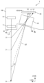
図2は光切断方式(三角測距)の原理を説明する図である。ヘッド部1の筐体15の内部には、光源6、投光レンズ7、受光レンズ12および画像センサ13が内蔵されている。光源6から出力された光は投光レンズ7を通過することでスリット光L1に変換される。筐体15には、スリット光L1が通過するための透光窓8が設けられている。透光窓8には、防塵のための透光ガラス9aが設けられている。同様に、筐体15には反射光L2を筐体15の内部に導くための受光窓10が設けられている。受光窓10には、防塵のための透光ガラス9bが設けられている。受光レンズ12は反射光L2を画像センサ13に結像させるためのレンズである。画像センサ13は二次元配列された複数の画素(受光素子や光電変換素子と呼ばれてもよい)を有するセンサである。図2が示すように、光源6の投光軸に対して、画像センサ13の受光軸は角度θだけ傾いている。つまり、高さZ0からの反射光L2は画像センサ13のV方向におけるV0の位置に結像する。高さZ1からの反射光L2は画像センサ13のV方向におけるV1の位置に結像する。高さZ2からの反射光L2は画像センサ13のV方向におけるV2の位置に結像する。このように画像センサ13のV方向は、ワークWのZ方向に対応している。画像センサ13のU方向は図示されていないが、U方向はワークWのX方向に対応している。つまり、画像センサ13が出力する受光結果である画像の縦方向はV方向であり、横方向はU方向である。
<Principle of three-dimensional ranging>
FIG. 2 is a diagram for explaining the principle of the light section method (triangulation distance measurement). Inside the
図2においてはスリット光L1がZ軸方向に出力されるように光源6が配置されているが、光源6および投光レンズ7のペアと、画像センサ13および結像レンズ12とのペアとの位置関係は逆であってもよい。
In FIG. 2, the
図3は画像センサ13が出力する画像I1と、ワークWの断面との関係を説明する図である。この例では、ワークWのXZ断面において高さが三段階に変化している。より具体的には、X方向における位置X0から位置X1までの高さはZ0である。位置X1からX2までの高さはZ2である。位置X2からX3までの高さはZ1である。画像I1は、このようなワークWをヘッド部1により撮像して得られる画像である。なお、画像I1のU方向(横方向)はワークWのX方向に対応している。つまり、画像I1の位置U0、U1、U2、U3はそれぞれ位置X0、X1、X2、X3に対応している。同様に、画像I1のV方向における位置V0、V1、V2はそれぞれ高さZ0、Z1、Z2に対応している。スリット光L1がXY平面に入射することで形成される光スポット(反射位置の集合)は直線状である。つまり、ベルトコンベイヤ4上にワークWが存在しないときにヘッド部1が出力する画像には、ほぼ一直線状の光スポットが並ぶことになる。その一方で、一般的なワークWの切断面のエッジの高さは一定でないことが多い。この場合、図3が示すように、複数の高さのそれぞれに対応したV方向の位置に光スポットが並ぶことになる。高さに応じてV方向の位置が変わることは、図2が示す通りである。このように制御部2は、あるY方向の位置で取得された画像IMから各U方向の位置ごとにV方向の位置を演算することでプロファイルを生成する。なお、XZ座標系とUV座標系との間には一定の縮尺関係があるため、制御部2は、簡単な演算により、UV座標系におけるプロファイルをXZ座標系におけるプロファイルに変換できる。
FIG. 3 is a diagram for explaining the relationship between the image I1 output by the
<内部機能>
図4は光学式変位計100の内部機能を示している。ヘッド部1の通信部21aは、制御部2と通信するための通信回路である。駆動部22は、通信部21aを介して受信される制御部2からの指示にしたがって駆動電流を光源6に流すことで光源6を点灯させる駆動回路である。センサ制御部23は、通信部21aを介して受信される制御部2からの指示にしたがった所定の露光時間により画像センサ13に撮像を実行させる制御回路である。なお、本実施形態では、センサ制御部23は、通信部21aを介して受信される制御部2からの指示にしたがって所定のビニングを画像センサ13に実行させる。
<Internal function>
FIG. 4 shows the internal functions of the
制御部2の通信部21bはヘッド部1と通信するための通信回路である。CPU25は記憶部30に記憶されている制御プログラムを実行することでヘッド部1を制御し、ヘッド部1から出力される受光結果に基づきワークWのプロファイルおよび三次元形状を測定する。ピーク検出部26は、画像センサ13が出力する受光結果に基づき輝度値のピークをもたらすV方向の位置(ピーク位置)を検出する。ピーク位置はワークWの高さに対応している。つまり、ピーク検出部26は、X方向における各位置ごとのワークWの高さを演算により求める。プロファイル生成部27は、ピーク検出部26により求められたX方向における各位置(xi)ごとのワークWの高さ(zi)をまとめることで、一つのプロファイルデータを生成する。つまり、一つのプロファイルデータは、複数の高さ(zi)の集合体である。プロファイル生成部27は、Y方向における異なる位置(yi)ごとにプロファイルデータを求め、求められた複数のプロファイルデータからワークWの三次元形状を示すデータを生成する。なお、ワークWの三次元形状のデータは、求められた複数のプロファイルデータの集合体である。選択部28は、操作部5から入力されるユーザ指示に基づいて、後述されるビニングの比率を選択する。UI部29は、プロファイル生成部27により求められたプロファイルデータまたは画像I1を表示装置3に表示したり、ビニングの比率を選択するためのUIを表示装置3に表示したりする。
A
<ビニング>
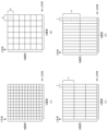
図5(A)はビニングを行わない場合の画像センサ13における複数の画素を示している。画像センサ13はM×N個の画素を有している。つまり、U方向にはN列の画素が並んでいる。V方向にM行の画素が並んでいる。
<Binning>
FIG. 5A shows a plurality of pixels in the
図5(B)は一般的なビニングを示している。一般的なビニングは、主に、デジタルスチルカメラなどで実行される処理であり、U方向の解像度とV方向の解像度との比が維持される。図5(B)が示すように、n×n個の画素ブロックごとに合成された一つの画像信号(輝度値)が出力される。このように、U方向の解像度とV方向の解像度との比が維持されるようにビニングが実行されるため、ビニング前の画像の縦横比とビニング後の縦横比は維持される。また、読み出し速度が概ねn×n分の1になる利点がある。その一方で、V方向に加えてU方向における測定精度が低下してしまう。とりわけ、光切断式の光学式変位計100のように、U方向においても高い測定精度が要求される用途にはこのような一般的なビニングは向いていない。
FIG. 5B shows general binning. General binning is a process mainly performed in a digital still camera or the like, and maintains the ratio between the resolution in the U direction and the resolution in the V direction. As shown in FIG. 5B, one image signal (luminance value) synthesized for each n×n pixel block is output. In this manner, binning is performed such that the ratio between the resolution in the U direction and the resolution in the V direction is maintained, thus preserving the aspect ratio of the image before binning and after binning. In addition, there is an advantage that the reading speed becomes approximately 1/n×n. On the other hand, in addition to the V direction, the measurement accuracy in the U direction is lowered. In particular, such general binning is not suitable for applications that require high measurement accuracy even in the U direction, such as the light-section
図5(C)は本実施例のビニングを示している。本実施例では、V方向における解像度とU方向における解像度との比(ビニング比率)が1:nになっている。つまり、画像センサ13は、V方向に並んだn個の画素からなる一つの画素ブロックごとに受光結果を出力する。これにより、U方向における測定精度の低下を抑えつつ、V方向の読み出しを高速化することが可能となる。制御部2のプロファイル生成部27は、V方向において得られた高さをn倍することで正しい高さ情報を求めることができる。
FIG. 5C shows binning in this embodiment. In this embodiment, the ratio (binning ratio) between the resolution in the V direction and the resolution in the U direction is 1:n. That is, the
図5(D)は本実施例のビニングを示している。ユーザは、図5(C)に示された1:nのビニングと、図5(D)に示された1:mのビニングとを操作部5を通じて選択してもよい。つまり、選択部28はユーザ指示にしたがってビニングの比率を選択してもよい。ここでmはnよりも大きい正の整数である。なお、ビニング処理によりV方向におけるノイズが軽減される利点もある。また、選択部28はユーザ指示にしたがって、ビニング処理のONとOFFを切り替えるようにしてもよい。例えば、ビニング処理がONの状態を高速モード、ビニング処理がOFFの状態を高精度モードとし、ユーザにモードを選択させるようにしてもよい。
FIG. 5(D) shows binning in this embodiment. The user may select 1:n binning shown in FIG. 5C and 1:m binning shown in FIG. In other words, the
<位置(高さの演算)>
図6は画像I1からプロファイルを構成する高さを演算する方法を説明する図である。スリット光L1はY方向において、ある程度の幅を持っている。そのため、反射光L2が画像センサ13にもたらす光スポットの幅も複数画素にまたがるような幅となる。そこで、制御部2のCPU25(ピーク検出部26)は各画素の輝度値から輝度値の変化を示す近似曲線P1を求め、近似曲線P1においてピーク値をもたらすV方向における位置を演算する。近似曲線P1は、複数のサンプル値をカーブフィッティングするなどして求められる。このピーク値をもたらすV方向における位置がワークWの高さを示している。CPU25(ピーク検出部26)は、U方向における各位置について近似曲線P1を求め、近似曲線P1からピーク値をもたらすV方向の位置(高さ)を演算する。この演算処理をU方向における各位置で実行することで、一つのプロファイルが得られる。このような演算処理はサブピクセル処理と呼ばれてもよい。
<Position (calculation of height)>
FIG. 6 is a diagram for explaining a method of calculating the heights forming the profile from the image I1. The slit light L1 has a certain width in the Y direction. Therefore, the width of the light spot that the reflected light L2 brings to the
<ビニングと近似曲線との関係>
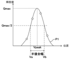
図7はV方向における位置と輝度値との関係を示す近似曲線P1を示している。ここでは、四つのサンプリング値から近似曲線P1が求められている。ところで、本実施例のビニングを適用すると、V方向における画素数が減少するため、近似曲線P1を求めるために使用可能なサンプリング値の数も減少する。つまり、nを増加すればするほど、輝度値の読み出しが高速化するものの、近似曲線P1の演算精度が低下する。したがって、ビニングのパラメータnと近似曲線P1の演算精度との間にはトレードオフの関係が存在する。なお、図7において、近似曲線P1のピーク値はQmaxである。近似曲線P1の半値全幅とは、輝度値がピーク値Qmaxの半分(Qmax/2)となるときの、V方向における二つの位置Va、Vb間の距離である。なお、図7にはピーク値QmaxをもたらすV方向の位置であるピーク位置Vpeakも示されている。ピーク検出部26は、近似曲線P1を求め、近似曲線P1からピーク値Qmaxをもたらすピーク位置Vpeakを演算する。
<Relationship between binning and approximation curve>
FIG. 7 shows an approximate curve P1 representing the relationship between the position in the V direction and the luminance value. Here, an approximated curve P1 is obtained from four sampled values. By the way, when the binning of this embodiment is applied, the number of pixels in the V direction is reduced, so the number of sampled values that can be used to obtain the approximated curve P1 is also reduced. In other words, the more n is increased, the higher the speed of reading the luminance value is, but the lower is the calculation accuracy of the approximated curve P1. Therefore, there is a trade-off relationship between the binning parameter n and the calculation accuracy of the approximated curve P1. In addition, in FIG. 7, the peak value of the approximated curve P1 is Qmax. The full width at half maximum of the approximated curve P1 is the distance between two positions Va and Vb in the V direction when the luminance value is half the peak value Qmax (Qmax/2). FIG. 7 also shows the peak position Vpeak, which is the position in the V direction at which the peak value Qmax is obtained. The
図8は近似曲線の半値全幅と、あるサブピクセル処理における近似曲線P1から求められるピーク値Qmaxの演算誤差との関係を示している。図8が示すように、半値全幅(サンプリング数)を増やせば増やすほど、演算誤差は小さくなるが、演算誤差の改善効果が期待できるサンプリング数は5程度である。サンプリング数を6以上にしても演算誤差の低減は期待できず、読出し時間が長くなるというデメリットが増加してしまう。近似曲線からピーク位置を精度よく求めるには、サンプリング間隔が十分に細かいことが重要である。すでにサンプリング間隔が十分に細かい場合、更にサンプリング間隔を細かくしても精度の向上に寄与しない。V方向にのみビニングを適用し、十分なピーク検出精度を維持できる程度にサンプリング間隔を落とすことにより、検出精度を落とさずに読出し速度を早くすることができる。また、U方向にはビニングを適用しないことで、X方向の測定分解能は維持できる。 FIG. 8 shows the relationship between the full width at half maximum of the approximated curve and the calculation error of the peak value Qmax obtained from the approximated curve P1 in certain sub-pixel processing. As shown in FIG. 8, the more the full width at half maximum (the number of samplings), the smaller the computational error. Even if the number of samplings is 6 or more, a reduction in calculation error cannot be expected, and the demerit of longer readout time increases. It is important that the sampling interval is sufficiently fine in order to accurately obtain the peak position from the approximated curve. If the sampling interval is already fine enough, making the sampling interval even finer does not contribute to the improvement of accuracy. By applying binning only in the V direction and reducing the sampling interval to such an extent that sufficient peak detection accuracy can be maintained, the readout speed can be increased without degrading the detection accuracy. Also, by not applying binning in the U direction, the measurement resolution in the X direction can be maintained.
一般に、演算誤差以外の要因の誤差をεとすると、演算誤差はεよりも十分に小さいことが求められる。図8によれば、半値全幅が2以上であれば、演算誤差はεよりも小さくなる。つまり、近似曲線P1の半値全幅に対するサンプリング数は2以上でかつ5以下となればよいだろう。 In general, if the error due to factors other than the calculation error is ε, the calculation error is required to be sufficiently smaller than ε. According to FIG. 8, if the full width at half maximum is 2 or more, the calculation error is smaller than ε. That is, the number of samples for the full width at half maximum of the approximated curve P1 should be 2 or more and 5 or less.
<ビニングに伴う表示処理の工夫>
図9はプロファイルを表示する際の表示画像を構成する複数の画素を示している。上述したように、本実施例では1:nのビニングを実行するため、V方向における画素数がMからM/nに減少してしまう。ここで、画像センサ13においてはビニングによって一つのブロックの形状が長方形となるが、出力画像における各画素は正方形であることが仮定されている。したがって、ビニングにより読み出された出力画像をそのまま表示装置3に表示してしまうと、画像の高さ方向が圧縮されてしまう。
<Ingenuity of display processing associated with binning>
FIG. 9 shows a plurality of pixels forming a display image when displaying a profile. As described above, since 1:n binning is performed in this embodiment, the number of pixels in the V direction is reduced from M to M/n. Here, it is assumed that each pixel in the output image is square although the shape of one block is rectangular due to binning in the
図10はワークWとビニングに伴う高さの圧縮された出力画像I2との関係を説明する図である。図3と図10と比較すると、図3における画像I1ではワークWの実際の断面形状と、画像I1が示すプロファイルとは一致している。よって、ユーザは、光学式変位計100により測定されたプロファイルが、実際のワークWのプロファイルとして正しいかどうかを判断しやすい。それに対して、図10が示す出力画像I2が示すプロファイルは実際のワークWのプロファイルと異なっている。よって、ユーザは、測定されたプロファイルが正しいかどうかを表示装置3に表示された画像から視覚的に判断しにくい。
FIG. 10 is a diagram for explaining the relationship between the work W and the output image I2 whose height is compressed due to binning. 3 and 10, in the image I1 in FIG. 3, the actual cross-sectional shape of the workpiece W matches the profile shown by the image I1. Therefore, the user can easily judge whether the profile measured by the
そこで、CPU25(UI部29)は、出力画像I2におけるV方向の画素数をn倍に増加させて表示装置3に表示することで、出力画像I2におけるプロファイルの縮尺を実際のワークWのプロファイルの縮尺に一致させる。なお、一つの画素の画素値がn個の画素値にコピーされる。これにより、ユーザは、光学式変位計100により測定されたプロファイルが、実際のワークWのプロファイルとして正しいかどうかを視覚的に判断しやすくなる。
Therefore, the CPU 25 (UI unit 29) increases the number of pixels in the V direction in the output image I2 by n times and displays it on the
<まとめ>
[観点1]
図1が示すように、光学式変位計100は、Y方向に搬送される測定対象物のX-Z断面のプロファイルを三角測距の原理に基づき測定する光切断方式の光学式変位計の一例である。光源6はX方向とZ方向との両方に平行なスリット光L1を測定対象物に照射する光源の一例である。また、光源6はX方向に幅を有するスリット光を測定対象物に照射する光源の一例である。画像センサ13は測定対象物からの反射光L2を受光する画像センサの一例である。図5(A)などが示すように、画像センサ13は、X方向に対応するU方向とZ方向に対応するV方向とに二次元配列された複数の画素を有している。さらに、画像センサ13は、複数の画素による反射光の受光量(例:輝度値)を出力する。ピーク検出部26は、U方向に並んだ複数の画素列のそれぞれについて受光量のピークとなるV方向における画素の位置をピーク位置として検出する検出手段として機能する。プロファイル生成部27は、U方向における複数の画素列のそれぞれの位置と、V方向におけるピーク位置とからX-Z断面のプロファイルを生成する生成手段として機能する。図5(C)および図5(D)が示すように、画像センサ13のV方向における解像度はU方向における解像度と比較して低い。つまり、画像センサ13は、V方向における解像度をU方向における解像度よりも低くするビニングを実行してから受光量を出力する。これにより、U方向における測定精度の低下させずに、V方向の読み出しを高速化することが可能となる。
<Summary>
[Viewpoint 1]
As shown in FIG. 1, the
[観点2]
図5(C)が示すように、画像センサ13についてのU方向とV方向とのビニングの比率が1:n(nは2以上の整数)であってもよい。画像センサ13はV方向に並んだn個の画素ごとに一つの受光量を出力するように構成されていてもよい。これにより、U方向における測定精度の低下させずに、V方向の読み出しを高速化することが可能となる。
[Viewpoint 2]
As shown in FIG. 5C, the binning ratio between the U direction and the V direction for the
図7や図8を用いて説明されたように、nは2以上でかつ5以下の整数であってもよい。これにより、V方向の読み出しの高速化と、V方向における測定精度とを両立させることが可能となる。 As described with reference to FIGS. 7 and 8, n may be an integer of 2 or more and 5 or less. This makes it possible to achieve both high speed reading in the V direction and high measurement accuracy in the V direction.
[観点3]
光学式変位計は、ビニングを実行し、画像センサ13からの受光量の読出しを高速化した高速モードと、ビニングを実行せずに、画像センサ13からの受光量の読出しを行う高精度モードとを有してもよい。この場合、光学式変位計は、高速モードと高精度モードのいずれかの選択を受け付ける選択手段(例:ユーザーインタフェースなど)を有してもよい。これにより、ユーザは、高速化を希望するか、それとも高精度化を希望するかを選択できるようになろう。
[Viewpoint 3]
The optical displacement meter has a high-speed mode in which binning is performed to read out the amount of light received from the
[観点4]
選択部28は、U方向とV方向とのビニングの比率として1:nと1:m(mはnより大きな整数)とのいずれかを選択する選択手段として機能してもよい。これにより、ユーザの希望に応じて、ビニングの比率を選択することが可能となる。
[Viewpoint 4]
The
図7や図8を用いて説明されたように、nは、受光量の分布(例:近似曲線P1)における半値全幅よりも小さくかつ2以上の整数である。これにより、V方向の読み出しの高速化と、V方向における測定精度とを両立させることが可能となる。 As described with reference to FIGS. 7 and 8, n is an integer of 2 or more that is smaller than the full width at half maximum in the distribution of the amount of received light (eg, the approximated curve P1). This makes it possible to achieve both high speed reading in the V direction and high measurement accuracy in the V direction.
[観点5]
図5(C)および図5(D)が示すように、画像センサ13は、U方向についてはビニングを実行せず、V方向についてビニングを実行するように設定されていてもよい。これにより、U方向における測定精度の低下を抑えつつ、V方向の読み出しを高速化することが可能となる。
[Viewpoint 5]
As shown in FIGS. 5(C) and 5(D), the
図5(A)が示すように、複数の画素のそれぞれは正方形の画素である。これにより、静止画を取得するための画像センサを、本実施例の光学式変位計100のための画像センサ13として流用しやすくなろう。
As shown in FIG. 5A, each of the plurality of pixels is a square pixel. This will make it easier to use the image sensor for acquiring still images as the
図5(C)や図5(D)が示すように、複数の画素のそれぞれはV方向における長さがU方向における長さよりも長い長方形の画素であるように、画像センサ13が設計されてもよい。複数の正方形の画素からなる画素ブロックでは、隣接した画素間に受光に使用されない領域が存在する。一方で長方形の画素を採用することで、受光面積が増加するため、受光感度およびダイナミックレンジが増加する。
As shown in FIGS. 5C and 5D, the
[観点6]
ピーク検出部26は、V方向における複数の受光量をサブピクセル処理することでV方向における受光量の変化を示す近似曲線を決定し、近似曲線に基づき受光量のピークとなるピーク位置を検出するように構成されていてもよい。これにより、ピーク位置が精度よく求められるため、プロファイルの測定精度が向上する。
[Viewpoint 6]
The
[観点7]
図3や図10に関連して説明されたように、表示装置3およびCPU25のUI部29は、X-Z断面のプロファイルを示す画像を表示する表示手段として機能する表示装置3およびUI部29は、U方向の解像度とV方向の解像度との比率に基づき画像をV方向に引き伸ばして生成されたプロファイル画像を表示してもよい。これにより、ユーザは、光学式変位計100により測定されたプロファイルが、実際のワークWのプロファイルとして正しいかどうかを判断しやすくなる。
[Viewpoint 7]
As described with reference to FIGS. 3 and 10, the
Claims (7)
X方向に幅を有するスリット光を前記測定対象物に照射する光源と、
前記測定対象物からの反射光を受光する画像センサであって、前記X方向に対応するU方向とZ方向に対応するV方向とに二次元配列された複数の画素を有し、前記複数の画素による前記反射光の受光量を出力する画像センサと、
前記U方向に並んだ複数の画素列のそれぞれについて受光量のピークとなる前記V方向における画素の位置をピーク位置として検出する検出手段と、
前記U方向における前記複数の画素列のそれぞれの位置と、前記V方向における前記ピーク位置とからX-Z断面のプロファイルを生成し、前記Y方向の複数の位置における複数の前記X-Z断面のプロファイルから前記測定対象物の三次元形状を示すデータを生成する生成手段と
を有し、
前記画像センサは、前記V方向における解像度を前記U方向における解像度よりも低くするビニングを実行してから受光量を出力し、
前記検出手段は、前記ビニングが実行されてから出力された受光量に基づいて得られた複数のサンプリング値から前記V方向における前記ピーク位置を検出することを特徴とする光学式変位計。 A light-section optical displacement meter that measures the XZ cross-sectional profile of an object to be measured conveyed in the Y direction based on the principle of triangulation,
a light source that irradiates the object to be measured with slit light having a width in the X direction;
An image sensor for receiving reflected light from the object to be measured, the image sensor having a plurality of pixels arranged two-dimensionally in a U direction corresponding to the X direction and a V direction corresponding to the Z direction, an image sensor that outputs the amount of the reflected light received by a pixel;
detection means for detecting, as a peak position, a position of a pixel in the V direction at which the amount of light received reaches a peak for each of the plurality of pixel rows arranged in the U direction;
A profile of the XZ cross section is generated from each position of the plurality of pixel rows in the U direction and the peak position in the V direction, and the profile of the plurality of XZ cross sections at the plurality of positions in the Y direction generating means for generating data representing the three-dimensional shape of the measurement object from the profile ;
The image sensor performs binning in which the resolution in the V direction is lower than the resolution in the U direction, and then outputs the amount of received light;
The optical displacement meter, wherein the detection means detects the peak position in the V direction from a plurality of sampling values obtained based on the amount of light received after the binning is performed.
前記表示手段は、前記U方向の解像度と前記V方向の解像度との比率に基づき前記画像を前記V方向に引き伸ばして生成されたプロファイル画像を表示することを特徴とする請求項1ないし6のいずれか一項に記載の光学式変位計。 further comprising display means for displaying an image showing the profile of the XZ cross section;
7. A profile image according to any one of claims 1 to 6, wherein said display means displays a profile image generated by stretching said image in said V direction based on a ratio of resolution in said U direction and resolution in said V direction. or the optical displacement meter according to claim 1.
Priority Applications (3)
| Application Number | Priority Date | Filing Date | Title |
|---|---|---|---|
| JP2019085198A JP7319083B2 (en) | 2019-04-26 | 2019-04-26 | optical displacement meter |
| US16/823,363 US10921114B2 (en) | 2019-04-26 | 2020-03-19 | Optical displacement meter |
| CN202010329749.6A CN111854630A (en) | 2019-04-26 | 2020-04-24 | Optical displacement meter |
Applications Claiming Priority (1)
| Application Number | Priority Date | Filing Date | Title |
|---|---|---|---|
| JP2019085198A JP7319083B2 (en) | 2019-04-26 | 2019-04-26 | optical displacement meter |
Publications (2)
| Publication Number | Publication Date |
|---|---|
| JP2020180916A JP2020180916A (en) | 2020-11-05 |
| JP7319083B2 true JP7319083B2 (en) | 2023-08-01 |
Family
ID=72922536
Family Applications (1)
| Application Number | Title | Priority Date | Filing Date |
|---|---|---|---|
| JP2019085198A Active JP7319083B2 (en) | 2019-04-26 | 2019-04-26 | optical displacement meter |
Country Status (3)
| Country | Link |
|---|---|
| US (1) | US10921114B2 (en) |
| JP (1) | JP7319083B2 (en) |
| CN (1) | CN111854630A (en) |
Families Citing this family (1)
| Publication number | Priority date | Publication date | Assignee | Title |
|---|---|---|---|---|
| JP2022138028A (en) | 2021-03-09 | 2022-09-22 | 株式会社キーエンス | Optical displacement measuring system, processor, optical displacement measuring method, and optical displacement measuring program |
Citations (5)
| Publication number | Priority date | Publication date | Assignee | Title |
|---|---|---|---|---|
| JP2013123589A (en) | 2011-12-15 | 2013-06-24 | Canon Inc | Image processor, image processing method, and program |
| JP2016109671A (en) | 2014-12-01 | 2016-06-20 | キヤノン株式会社 | Three-dimensional measuring apparatus and control method therefor |
| JP2016161474A (en) | 2015-03-04 | 2016-09-05 | 株式会社キーエンス | Optical displacement measurement system, measurement simulation method and measurement simulation program |
| JP2016200607A (en) | 2016-09-06 | 2016-12-01 | 株式会社キーエンス | Shape measurement device, shape measurement method, and shape measurement program |
| JP2017207520A (en) | 2017-08-31 | 2017-11-24 | 株式会社キーエンス | Shape measurement device, shape measurement method and shape measurement program |
Family Cites Families (12)
| Publication number | Priority date | Publication date | Assignee | Title |
|---|---|---|---|---|
| JP2008096125A (en) | 2006-10-05 | 2008-04-24 | Keyence Corp | Optical displacement meter, optical method and program for recording displacement, computer-readable recording medium, and apparatus with the program stored |
| JP5271427B2 (en) | 2006-10-05 | 2013-08-21 | 株式会社キーエンス | Optical displacement meter, optical displacement measuring method, optical displacement measuring program |
| ES2634677T3 (en) * | 2007-11-15 | 2017-09-28 | Sick Ivp Ab | Optical triangulation |
| JP5528739B2 (en) * | 2009-08-12 | 2014-06-25 | 株式会社ジャパンディスプレイ | Detection device, display device, and method for measuring proximity distance of object |
| JP5637836B2 (en) * | 2010-12-17 | 2014-12-10 | 株式会社キーエンス | Optical displacement meter |
| JP6112807B2 (en) * | 2012-09-11 | 2017-04-12 | 株式会社キーエンス | Shape measuring device, shape measuring method, and shape measuring program |
| JP6116164B2 (en) * | 2012-09-11 | 2017-04-19 | 株式会社キーエンス | Shape measuring device, shape measuring method, and shape measuring program |
| US10677923B2 (en) * | 2014-11-12 | 2020-06-09 | Ams Sensors Singapore Pte. Ltd. | Optoelectronic modules for distance measurements and/or multi-dimensional imaging |
| JP6425586B2 (en) * | 2015-03-04 | 2018-11-21 | 株式会社キーエンス | Optical displacement measurement system, imaging condition optimization method and imaging condition optimization program |
| JP6862303B2 (en) * | 2017-06-30 | 2021-04-21 | 株式会社ミツトヨ | Optical measuring device |
| JP7064404B2 (en) | 2018-08-13 | 2022-05-10 | 株式会社キーエンス | Optical displacement meter |
| JP7117189B2 (en) | 2018-08-13 | 2022-08-12 | 株式会社キーエンス | Optical displacement meter |
-
2019
- 2019-04-26 JP JP2019085198A patent/JP7319083B2/en active Active
-
2020
- 2020-03-19 US US16/823,363 patent/US10921114B2/en active Active
- 2020-04-24 CN CN202010329749.6A patent/CN111854630A/en active Pending
Patent Citations (5)
| Publication number | Priority date | Publication date | Assignee | Title |
|---|---|---|---|---|
| JP2013123589A (en) | 2011-12-15 | 2013-06-24 | Canon Inc | Image processor, image processing method, and program |
| JP2016109671A (en) | 2014-12-01 | 2016-06-20 | キヤノン株式会社 | Three-dimensional measuring apparatus and control method therefor |
| JP2016161474A (en) | 2015-03-04 | 2016-09-05 | 株式会社キーエンス | Optical displacement measurement system, measurement simulation method and measurement simulation program |
| JP2016200607A (en) | 2016-09-06 | 2016-12-01 | 株式会社キーエンス | Shape measurement device, shape measurement method, and shape measurement program |
| JP2017207520A (en) | 2017-08-31 | 2017-11-24 | 株式会社キーエンス | Shape measurement device, shape measurement method and shape measurement program |
Also Published As
| Publication number | Publication date |
|---|---|
| JP2020180916A (en) | 2020-11-05 |
| US20200340799A1 (en) | 2020-10-29 |
| US10921114B2 (en) | 2021-02-16 |
| CN111854630A (en) | 2020-10-30 |
Similar Documents
| Publication | Publication Date | Title |
|---|---|---|
| JP4238891B2 (en) | 3D shape measurement system, 3D shape measurement method | |
| Bešić et al. | Accuracy improvement of laser line scanning for feature measurements on CMM | |
| US8218153B2 (en) | Apparatus and method for improving the measurement accuracy of digital 3D geometrical measurement systems | |
| Vukašinović et al. | The influence of incident angle, object colour and distance on CNC laser scanning | |
| US11619485B2 (en) | Hybrid 3D optical scanning system | |
| JP7306867B2 (en) | Optical displacement meter | |
| US10151580B2 (en) | Methods of inspecting a 3D object using 2D image processing | |
| TWI420081B (en) | Distance measuring system and distance measuring method | |
| CN108801164B (en) | Method and system for testing gap value of workpiece based on laser | |
| JP2008505312A (en) | Measuring apparatus and method for range inspection | |
| JP2012058076A (en) | Three-dimensional measurement device and three-dimensional measurement method | |
| CN108369090B (en) | Shape measuring method | |
| JP4970204B2 (en) | Straightness measuring device, thickness variation measuring device, and orthogonality measuring device | |
| CN105043304A (en) | Novel calibration plate and calibration method for performing length measurement by using calibration plate | |
| JP7319084B2 (en) | Optical displacement meter | |
| JP7319083B2 (en) | optical displacement meter | |
| WO2022068818A1 (en) | Apparatus and method for calibrating three-dimensional scanner and refining point cloud data | |
| Clark et al. | Measuring range using a triangulation sensor with variable geometry | |
| KR101549310B1 (en) | Apparatus and method phase shifting stripe patterns projection for detecting defect of transparent object | |
| Suliga | A feature analysis of a laser triangulation stand used to acquire a3D screw thread image | |
| JP7202964B2 (en) | Optical displacement meter | |
| WO2022113877A1 (en) | Three-dimensional-measurement device and three-dimensional-measurement method | |
| JP5950760B2 (en) | Calibration method of interference shape measuring mechanism | |
| Radil et al. | A novel optical method of dimension measurement of objects with circular cross-section | |
| Klimanov | Triangulating laser system for measurements and inspection of turbine blades |
Legal Events
| Date | Code | Title | Description |
|---|---|---|---|
| RD02 | Notification of acceptance of power of attorney |
Free format text: JAPANESE INTERMEDIATE CODE: A7422 Effective date: 20210113 |
|
| A621 | Written request for application examination |
Free format text: JAPANESE INTERMEDIATE CODE: A621 Effective date: 20220309 |
|
| A977 | Report on retrieval |
Free format text: JAPANESE INTERMEDIATE CODE: A971007 Effective date: 20221221 |
|
| A131 | Notification of reasons for refusal |
Free format text: JAPANESE INTERMEDIATE CODE: A131 Effective date: 20230127 |
|
| A521 | Request for written amendment filed |
Free format text: JAPANESE INTERMEDIATE CODE: A523 Effective date: 20230320 |
|
| TRDD | Decision of grant or rejection written | ||
| A01 | Written decision to grant a patent or to grant a registration (utility model) |
Free format text: JAPANESE INTERMEDIATE CODE: A01 Effective date: 20230630 |
|
| A61 | First payment of annual fees (during grant procedure) |
Free format text: JAPANESE INTERMEDIATE CODE: A61 Effective date: 20230720 |
|
| R150 | Certificate of patent or registration of utility model |
Ref document number: 7319083 Country of ref document: JP Free format text: JAPANESE INTERMEDIATE CODE: R150 |