JP7318327B2 - Media alignment device, media handling device, and recording system - Google Patents
Media alignment device, media handling device, and recording system Download PDFInfo
- Publication number
- JP7318327B2 JP7318327B2 JP2019108948A JP2019108948A JP7318327B2 JP 7318327 B2 JP7318327 B2 JP 7318327B2 JP 2019108948 A JP2019108948 A JP 2019108948A JP 2019108948 A JP2019108948 A JP 2019108948A JP 7318327 B2 JP7318327 B2 JP 7318327B2
- Authority
- JP
- Japan
- Prior art keywords
- medium
- alignment
- tray
- aligning
- media
- Prior art date
- Legal status (The legal status is an assumption and is not a legal conclusion. Google has not performed a legal analysis and makes no representation as to the accuracy of the status listed.)
- Active
Links
Images


Classifications
-
- B—PERFORMING OPERATIONS; TRANSPORTING
- B65—CONVEYING; PACKING; STORING; HANDLING THIN OR FILAMENTARY MATERIAL
- B65H—HANDLING THIN OR FILAMENTARY MATERIAL, e.g. SHEETS, WEBS, CABLES
- B65H31/00—Pile receivers
- B65H31/02—Pile receivers with stationary end support against which pile accumulates
-
- B—PERFORMING OPERATIONS; TRANSPORTING
- B65—CONVEYING; PACKING; STORING; HANDLING THIN OR FILAMENTARY MATERIAL
- B65H—HANDLING THIN OR FILAMENTARY MATERIAL, e.g. SHEETS, WEBS, CABLES
- B65H1/00—Supports or magazines for piles from which articles are to be separated
- B65H1/04—Supports or magazines for piles from which articles are to be separated adapted to support articles substantially horizontally, e.g. for separation from top of pile
-
- B—PERFORMING OPERATIONS; TRANSPORTING
- B65—CONVEYING; PACKING; STORING; HANDLING THIN OR FILAMENTARY MATERIAL
- B65H—HANDLING THIN OR FILAMENTARY MATERIAL, e.g. SHEETS, WEBS, CABLES
- B65H31/00—Pile receivers
- B65H31/30—Arrangements for removing completed piles
- B65H31/3027—Arrangements for removing completed piles by the nip between moving belts or rollers
-
- B—PERFORMING OPERATIONS; TRANSPORTING
- B65—CONVEYING; PACKING; STORING; HANDLING THIN OR FILAMENTARY MATERIAL
- B65H—HANDLING THIN OR FILAMENTARY MATERIAL, e.g. SHEETS, WEBS, CABLES
- B65H31/00—Pile receivers
- B65H31/30—Arrangements for removing completed piles
- B65H31/3036—Arrangements for removing completed piles by gripping the pile
- B65H31/3045—Arrangements for removing completed piles by gripping the pile on the outermost articles of the pile for clamping the pile
-
- B—PERFORMING OPERATIONS; TRANSPORTING
- B65—CONVEYING; PACKING; STORING; HANDLING THIN OR FILAMENTARY MATERIAL
- B65H—HANDLING THIN OR FILAMENTARY MATERIAL, e.g. SHEETS, WEBS, CABLES
- B65H31/00—Pile receivers
- B65H31/34—Apparatus for squaring-up piled articles
- B65H31/36—Auxiliary devices for contacting each article with a front stop as it is piled
-
- B—PERFORMING OPERATIONS; TRANSPORTING
- B65—CONVEYING; PACKING; STORING; HANDLING THIN OR FILAMENTARY MATERIAL
- B65H—HANDLING THIN OR FILAMENTARY MATERIAL, e.g. SHEETS, WEBS, CABLES
- B65H2301/00—Handling processes for sheets or webs
- B65H2301/40—Type of handling process
- B65H2301/42—Piling, depiling, handling piles
- B65H2301/421—Forming a pile
- B65H2301/4212—Forming a pile of articles substantially horizontal
-
- B—PERFORMING OPERATIONS; TRANSPORTING
- B65—CONVEYING; PACKING; STORING; HANDLING THIN OR FILAMENTARY MATERIAL
- B65H—HANDLING THIN OR FILAMENTARY MATERIAL, e.g. SHEETS, WEBS, CABLES
- B65H2301/00—Handling processes for sheets or webs
- B65H2301/40—Type of handling process
- B65H2301/42—Piling, depiling, handling piles
- B65H2301/421—Forming a pile
- B65H2301/4213—Forming a pile of a limited number of articles, e.g. buffering, forming bundles
-
- B—PERFORMING OPERATIONS; TRANSPORTING
- B65—CONVEYING; PACKING; STORING; HANDLING THIN OR FILAMENTARY MATERIAL
- B65H—HANDLING THIN OR FILAMENTARY MATERIAL, e.g. SHEETS, WEBS, CABLES
- B65H2301/00—Handling processes for sheets or webs
- B65H2301/40—Type of handling process
- B65H2301/44—Moving, forwarding, guiding material
- B65H2301/443—Moving, forwarding, guiding material by acting on surface of handled material
- B65H2301/4431—Moving, forwarding, guiding material by acting on surface of handled material by means with operating surfaces contacting opposite faces of material
- B65H2301/44318—Moving, forwarding, guiding material by acting on surface of handled material by means with operating surfaces contacting opposite faces of material between rollers
-
- B—PERFORMING OPERATIONS; TRANSPORTING
- B65—CONVEYING; PACKING; STORING; HANDLING THIN OR FILAMENTARY MATERIAL
- B65H—HANDLING THIN OR FILAMENTARY MATERIAL, e.g. SHEETS, WEBS, CABLES
- B65H2301/00—Handling processes for sheets or webs
- B65H2301/40—Type of handling process
- B65H2301/44—Moving, forwarding, guiding material
- B65H2301/443—Moving, forwarding, guiding material by acting on surface of handled material
- B65H2301/4433—Moving, forwarding, guiding material by acting on surface of handled material by means holding the material
- B65H2301/44331—Moving, forwarding, guiding material by acting on surface of handled material by means holding the material at particular portion of handled material
-
- B—PERFORMING OPERATIONS; TRANSPORTING
- B65—CONVEYING; PACKING; STORING; HANDLING THIN OR FILAMENTARY MATERIAL
- B65H—HANDLING THIN OR FILAMENTARY MATERIAL, e.g. SHEETS, WEBS, CABLES
- B65H2404/00—Parts for transporting or guiding the handled material
- B65H2404/10—Rollers
- B65H2404/11—Details of cross-section or profile
- B65H2404/111—Details of cross-section or profile shape
- B65H2404/1114—Paddle wheel
-
- B—PERFORMING OPERATIONS; TRANSPORTING
- B65—CONVEYING; PACKING; STORING; HANDLING THIN OR FILAMENTARY MATERIAL
- B65H—HANDLING THIN OR FILAMENTARY MATERIAL, e.g. SHEETS, WEBS, CABLES
- B65H2405/00—Parts for holding the handled material
- B65H2405/10—Cassettes, holders, bins, decks, trays, supports or magazines for sheets stacked substantially horizontally
- B65H2405/11—Parts and details thereof
- B65H2405/111—Bottom
- B65H2405/1115—Bottom with surface inclined, e.g. in width-wise direction
- B65H2405/11151—Bottom with surface inclined, e.g. in width-wise direction with surface inclined upwardly in transport direction
-
- B—PERFORMING OPERATIONS; TRANSPORTING
- B65—CONVEYING; PACKING; STORING; HANDLING THIN OR FILAMENTARY MATERIAL
- B65H—HANDLING THIN OR FILAMENTARY MATERIAL, e.g. SHEETS, WEBS, CABLES
- B65H2405/00—Parts for holding the handled material
- B65H2405/10—Cassettes, holders, bins, decks, trays, supports or magazines for sheets stacked substantially horizontally
- B65H2405/11—Parts and details thereof
- B65H2405/113—Front, i.e. portion adjacent to the feeding / delivering side
- B65H2405/1134—Front, i.e. portion adjacent to the feeding / delivering side movable, e.g. pivotable
-
- B—PERFORMING OPERATIONS; TRANSPORTING
- B65—CONVEYING; PACKING; STORING; HANDLING THIN OR FILAMENTARY MATERIAL
- B65H—HANDLING THIN OR FILAMENTARY MATERIAL, e.g. SHEETS, WEBS, CABLES
- B65H2405/00—Parts for holding the handled material
- B65H2405/10—Cassettes, holders, bins, decks, trays, supports or magazines for sheets stacked substantially horizontally
- B65H2405/11—Parts and details thereof
- B65H2405/113—Front, i.e. portion adjacent to the feeding / delivering side
- B65H2405/1136—Front, i.e. portion adjacent to the feeding / delivering side inclined, i.e. forming an angle different from 90 with the bottom
-
- B—PERFORMING OPERATIONS; TRANSPORTING
- B65—CONVEYING; PACKING; STORING; HANDLING THIN OR FILAMENTARY MATERIAL
- B65H—HANDLING THIN OR FILAMENTARY MATERIAL, e.g. SHEETS, WEBS, CABLES
- B65H2801/00—Application field
- B65H2801/03—Image reproduction devices
- B65H2801/06—Office-type machines, e.g. photocopiers
-
- B—PERFORMING OPERATIONS; TRANSPORTING
- B65—CONVEYING; PACKING; STORING; HANDLING THIN OR FILAMENTARY MATERIAL
- B65H—HANDLING THIN OR FILAMENTARY MATERIAL, e.g. SHEETS, WEBS, CABLES
- B65H2801/00—Application field
- B65H2801/24—Post -processing devices
- B65H2801/27—Devices located downstream of office-type machines
Landscapes
- Engineering & Computer Science (AREA)
- Mechanical Engineering (AREA)
- Pile Receivers (AREA)
Description
本発明は、媒体を整合する媒体整合装置、媒体整合装置を備える媒体処理装置、及び媒体処理装置を備える記録システムに関する。 The present invention relates to a medium alignment device for aligning media, a media processing device comprising the media alignment device, and a recording system comprising the media processing device.
媒体にステープル処理やパンチング処理等の処理を行う媒体処理装置には、媒体を搬送して第1トレイにスタックし、第1トレイにスタックされた媒体束を第2トレイに排出するように構成されたものがある。
尚、このような媒体処理装置は、インクジェットプリンターに代表される記録装置における媒体への記録から、記録後の媒体へのステープル処理等の後処理までを連続して実行可能な記録システムに組み込まれる場合もある。
2. Description of the Related Art A media processing apparatus that performs processing such as stapling and punching on media is configured to transport media, stack them on a first tray, and discharge the media bundle stacked on the first tray to a second tray. There is something
Such a media processing apparatus is incorporated in a recording system capable of continuously executing from recording on a medium in a recording apparatus represented by an inkjet printer to post-processing such as stapling of the medium after recording. In some cases.
例えば特許文献1には、第1トレイとしての積載部に積載された用紙を第2トレイとしての外部トレイに排出する構成を備えた、媒体処理装置としての後処理装置が開示されている。
特許文献1記載の後処理装置は、積載部に積載された用紙は、放出爪によって排紙ローラー対に搬送され、排紙ローラー対によって外部トレイに排出されることとなる。
For example,
In the post-processing device disclosed in Japanese Patent Application Laid-Open No. 2002-200000, sheets stacked on a stacking unit are conveyed to a pair of discharge rollers by a discharge claw, and discharged to an external tray by the pair of discharge rollers.
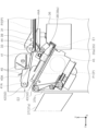
以下、図22を参照して従来技術の技術的課題について説明する。図22において用紙Pは積載トレイ35に積載され、後端E1が第1後端整合部38に当接し、整合される。第1後端整合部38は、特許文献1記載の放出爪に対応する部材である。
積載トレイ35に積載された用紙Pの束は、下側ローラー43と上側ローラー42とで挟持されつつ排出方向Uに排出され、排出トレイ37に落下し、積載される。
Technical problems of the prior art will be described below with reference to FIG. In FIG. 22, the paper P is stacked on the
A bundle of sheets P stacked on the
ここで、第1後端整合部38による後端E1の整合方向は、綴じ針による綴じ処理の観点から積載トレイ35の用紙積載面に対して垂直な方向であるのが一般的であり、排出トレイ37の基端側に位置する壁面37bに対し角度Gを成している。従って排出トレイ37に落下した用紙束M1、M2、M3、M4は、排出トレイ37上において図示するように階段状にずれた状態で積載されることとなる。
この場合において、例えば各用紙束が綴じ針によって綴じられている場合には問題は生じない。しかしながら各用紙束で仕分けを意図しておらず、排出トレイ37において単純に用紙を積み上げたい場合では、上述のように排出トレイ37において用紙束毎に階段状にずれた状態で積み上げられてしまうと、ユーザーによっては排出トレイ37から用紙束を取り出した後、机などの平坦面に用紙後端を突き当てて整合する場合がある。従ってこの場合、ユーザーに手間を掛けるとともに、用紙後端を潰してしまうなどの問題が生じる虞がある。
Here, the alignment direction of the trailing edge E1 by the first trailing
In this case, no problem arises if, for example, each bundle of sheets is bound by a staple. However, if sorting is not intended for each bundle of paper, and the paper is simply stacked on the
上記課題を解決する本発明の媒体整合装置は、媒体を排出する排出手段により排出された媒体を積載する積載面を有する積載トレイと、前記積載トレイに積載された媒体の、前記排出手段による媒体の排出方向の上流端である後端を位置決めして整合する第1整合面と、前記積載トレイに積載された媒体の前記後端を位置決めして整合する第2整合面と、を有するとともに、前記第1整合面と前記第2整合面とを切り換え可能であり、前記積載トレイから排出された媒体を受ける排出トレイにおいて媒体の前記後端が接する壁面と、前記第2整合面との成す角度は、前記壁面と、前記第1整合面との成す角度より小さいことを特徴とする。 A medium aligning device of the present invention for solving the above problems comprises a stacking tray having a stacking surface for stacking media discharged by a discharge means for discharging a medium, and media stacked on the stacking tray by the discharge means. a first aligning surface for positioning and aligning the rear end, which is the upstream end in the discharge direction of the medium, and a second aligning surface for positioning and aligning the rear end of the medium stacked on the stacking tray, The first aligning surface and the second aligning surface can be switched, and an angle formed between the second aligning surface and a wall surface with which the trailing edge of the medium is in contact in the ejection tray that receives the medium ejected from the stacking tray. is smaller than the angle formed by the wall surface and the first matching surface.
以下、本発明について概略的に説明する。
第1の態様に係る媒体整合装置は、媒体を排出する排出手段により排出された媒体を積載する積載面を有する積載トレイと、前記積載トレイに積載された媒体の、前記排出手段による媒体の排出方向の上流端である後端を位置決めして整合する第1整合面と、前記積載トレイに積載された媒体の前記後端を位置決めして整合する第2整合面と、を有するとともに、前記第1整合面と前記第2整合面とを切り換え可能であり、前記積載トレイから排出された媒体を受ける排出トレイにおいて媒体の前記後端が接する壁面と、前記第2整合面との成す角度は、前記壁面と、前記第1整合面との成す角度より小さいことを特徴とする。
The present invention will be briefly described below.
A medium aligning device according to a first aspect includes a stacking tray having a stacking surface for stacking media discharged by a discharging means for discharging media, and discharging the media loaded on the loading tray by the discharging means. a first aligning surface for positioning and aligning the trailing end, which is the upstream end of the direction, and a second aligning surface for positioning and aligning the trailing end of the media stacked on the stacking tray; The first alignment surface and the second alignment surface can be switched, and the angle formed between the second alignment surface and the wall surface with which the trailing edge of the medium is in contact in the ejection tray that receives the medium ejected from the stacking tray is The angle formed by the wall surface and the first matching surface is smaller than the angle formed by the wall surface.
本態様によれば、前記第1整合面と前記第2整合面とを切り換え可能であり、前記積載トレイから排出された媒体を受ける排出トレイにおいて媒体の前記後端が接する壁面と、前記第2整合面との成す角度は、前記壁面と、前記第1整合面との成す角度より小さいので、前記第2整合面を選択することにより、前記排出トレイに排出された媒体が階段状にずれた状態で積載されることを抑制できる。その結果、ユーザーの使い勝手が向上するとともに、媒体の前記後端にダメージが形成されることも抑制できる。 According to this aspect, the first aligning surface and the second aligning surface can be switched, and the wall surface with which the trailing edge of the medium contacts the ejection tray that receives the medium ejected from the stacking tray; Since the angle formed by the aligning surface is smaller than the angle formed by the wall surface and the first aligning surface, by selecting the second aligning surface, the medium discharged to the discharge tray is deviated stepwise. It can be suppressed to be loaded in the state. As a result, it is possible to improve user-friendliness and prevent damage from being formed on the trailing edge of the medium.
第2の態様は、第1の態様において、前記積載トレイの前記積載面と、前記第1整合面との成す角度は90°であり、前記壁面と、前記第2整合面との成す角度は0°であることを特徴とする。
本態様によれば、前記積載トレイの前記積載面と、前記第1整合面との成す角度は90°であるので、前記第1整合面を選択することで、前記積載トレイに積載された媒体に対し所定の処理を行う場合、例えば綴じ針によって綴じる場合に、適切な処理結果が得られる。また、前記壁面と、前記第2整合面との成す角度は0°であるので、前記排出トレイに排出された媒体が階段状にずれることをより確実に回避できる。
尚、前記積載トレイの前記積載面と、前記第1整合面との成す角度が90°であるとは、厳密に90°である場合に限られず、製造ばらつき等の要因によって多少の誤差をも含む意味である。同様に前記壁面と、前記第2整合面との成す角度が0°であるとは、厳密に0°である場合に限られず、製造ばらつき等の要因によって多少の誤差をも含む意味である。
In a second aspect based on the first aspect, the angle formed between the loading surface of the loading tray and the first alignment surface is 90°, and the angle formed between the wall surface and the second alignment surface is 0°.
According to this aspect, since the angle formed by the stacking surface of the stacking tray and the first alignment surface is 90°, by selecting the first alignment surface, the media stacked on the stacking tray can be Appropriate processing results can be obtained when performing a predetermined process on the document, for example, when binding with a staple. In addition, since the angle formed by the wall surface and the second alignment surface is 0°, it is possible to more reliably prevent the media discharged to the discharge tray from being displaced stepwise.
It should be noted that the 90° angle between the loading surface of the loading tray and the first alignment surface is not limited to being strictly 90°. It means to include. Similarly, the angle formed by the wall surface and the second alignment surface being 0° is not limited to being strictly 0°, and includes some errors due to manufacturing variations and other factors.
第3の態様は、第1のまたは第2の態様において、前記積載トレイの前記積載面と、前記排出トレイが媒体を支持する支持面とは、前記排出方向の下流に向かって上向き傾斜を成すことを特徴とする。
本態様によれば、前記積載トレイの前記積載面と、前記排出トレイが媒体を支持する支持面とは、前記排出方向の下流に向かって上向き傾斜を成すので、前記積載トレイ及び前記排出トレイの双方において媒体の前記後端を適切に整合できる。
According to a third aspect, in the first or second aspect, the loading surface of the loading tray and the support surface on which the ejection tray supports the medium form an upward slope downstream in the ejection direction. It is characterized by
According to this aspect, the stacking surface of the stacking tray and the support surface on which the discharge tray supports the medium are inclined upward toward the downstream side in the discharge direction. In both cases the trailing edge of the media can be properly aligned.
第4の態様は、第1から第3の態様のいずれかにおいて、少なくとも前記積載トレイに積載される媒体に対し処理を行わない場合には前記第2整合面を用いて媒体の前記後端を整合することを特徴とする。
本態様によれば、少なくとも前記積載トレイに積載される媒体に対し処理を行わない場合には前記第2整合面を用いて媒体の前記後端を整合するので、前記積載トレイに積載される媒体に対し処理を行わない場合に、前記排出トレイに排出された媒体が階段状にずれた状態で積載されることを抑制でき、ひいてはユーザーの使い勝手が向上するとともに、媒体の前記後端にダメージが形成されることも抑制できる。
尚、ここでの処理とは、前記積載トレイに積載された複数の媒体を綴じ針により綴じる等の後処理を意味し、少なくとも前記積載トレイに積載された媒体に対し前記第1整合面或いは前記第2整合面により行う整合処理は含まない。
According to a fourth aspect, in any one of the first to third aspects, at least when the media stacked on the stacking tray are not processed, the trailing edge of the media is held using the second alignment surface. It is characterized by matching.
According to this aspect, at least when the media stacked on the stacking tray are not processed, the trailing edges of the media are aligned using the second aligning surface. When the processing is not performed for the media, it is possible to prevent the media discharged to the discharge tray from being stacked in a stepped state, thereby improving user-friendliness and preventing damage to the trailing end of the media. Formation can also be suppressed.
Note that the processing here means post-processing such as binding a plurality of media stacked on the stacking tray with a binding needle, and at least the media stacked on the stacking tray are subjected to the first aligning surface or the above-described processing. Alignment processing performed by the second alignment surface is not included.
第5の態様は、第1から第4の態様のいずれかにおいて、前記第1整合面と前記第2整合面とが別部材で形成されることを特徴とする。
本態様によれば、前記第1整合面と前記第2整合面とが別部材で形成されるので、前記第1整合面と前記積載面とが成す角度と、前記第2整合面と前記壁面とが成す角度の設計の自由度が向上する。
A fifth aspect is characterized in that, in any one of the first to fourth aspects, the first matching surface and the second matching surface are formed by separate members.
According to this aspect, since the first aligning surface and the second aligning surface are formed by separate members, the angle formed by the first aligning surface and the loading surface and the second aligning surface and the wall surface The degree of freedom in designing the angle formed by and is improved.
第6の態様は、第5の態様において、前記第2整合面が、回転可能な回転部材に設けられ、前記回転部材が回転することにより、前記第2整合面が前記積載トレイ上に進出する第1状態と、前記第2整合面が前記積載トレイ上から退避する第2状態と、を切り換え可能であることを特徴とする。
本態様によれば、前記回転部材が回転することにより、前記第2整合面が前記積載トレイ上に進出する第1状態と、前記第2整合面が前記積載トレイ上から退避する第2状態と、を切り換え可能であるので、簡易な構成により前記第1整合面と前記第2整合面とを切り換えることができる。
In a sixth aspect based on the fifth aspect, the second alignment surface is provided on a rotatable rotating member, and the rotation of the rotating member advances the second alignment surface onto the stacking tray. A first state and a second state in which the second alignment surface is retracted from the stacking tray are switchable.
According to this aspect, by rotating the rotating member, a first state in which the second aligning surface advances onto the stacking tray and a second state in which the second aligning surface retreats from the stacking tray. , can be switched between the first alignment surface and the second alignment surface with a simple configuration.
第7の態様は、第1から第4の態様のいずれかにおいて、前記第1整合面と前記第2整合面とが同一部材で形成されることを特徴とする。
本態様によれば、前記第1整合面と前記第2整合面とが同一部材で形成されるので、装置の低コスト化を図ることができる。
A seventh aspect is characterized in that, in any one of the first to fourth aspects, the first matching surface and the second matching surface are formed of the same member.
According to this aspect, since the first alignment surface and the second alignment surface are formed of the same member, the cost of the device can be reduced.
第8の態様は、第7の態様において、前記第1整合面及び前記第2整合面が、回転可能な回転部材に設けられ、前記回転部材が回転することにより、前記第2整合面により媒体の前記後端を整合する第1状態と、前記第1整合面により媒体の前記後端を整合する第2状態と、を切り換え可能であることを特徴とする。 In an eighth aspect based on the seventh aspect, the first aligning surface and the second aligning surface are provided on a rotatable rotating member, and when the rotating member rotates, the medium is moved by the second aligning surface. and a second state of aligning the trailing edge of the medium by the first alignment surface.
本態様によれば、前記第1整合面及び前記第2整合面が、回転可能な回転部材に設けられ、前記回転部材が回転することにより、前記第2整合面により媒体の前記後端を整合する第1状態と、前記第1整合面により媒体の前記後端を整合する第2状態と、を切り換え可能であるので、簡易な構成で前記第1状態と前記第2状態とを切り換えることができる。 According to this aspect, the first aligning surface and the second aligning surface are provided on a rotatable rotating member, and when the rotating member rotates, the trailing edge of the medium is aligned by the second aligning surface. and the second state of aligning the trailing edge of the medium by the first aligning surface. Therefore, the first state and the second state can be switched with a simple configuration. can.
第9の態様は、媒体を排出する排出手段により排出された媒体を積載する積載トレイと、前記積載トレイに積載された媒体の、前記排出手段による媒体の排出方向の上流端である後端を位置決めして整合する後端整合面と、を備え、前記積載トレイから排出された媒体を受ける排出トレイにおいて媒体の前記後端が接する壁面と、前記後端整合面とが平行であることを特徴とする。 In a ninth aspect, a stacking tray for stacking media discharged by a discharge means for discharging media, and a trailing end of the media stacked on the stacking tray, which is an upstream end in a direction in which the media are discharged by the discharge means, are provided. a rear end alignment surface for positioning and alignment, wherein the rear end alignment surface is parallel to a wall surface in contact with the rear end of the medium in the discharge tray for receiving the media discharged from the stacking tray. and
本態様によれば、前記積載トレイから排出された媒体を受ける排出トレイにおいて媒体の前記後端が接する壁面と、前記後端整合面とが平行であるので、前記排出トレイに排出された媒体が階段状にずれた状態で積載されることを抑制できる。その結果、ユーザーの使い勝手が向上するとともに、媒体の前記後端にダメージが形成されることも抑制できる。
尚、前記壁面と前記後端整合面とが平行であるとは、前記壁面と前記後端整合面とが厳密に平行である場合に限られず、製造ばらつき等の要因によって多少の誤差をも含む意味である。
According to this aspect, in the ejection tray that receives the media ejected from the stacking tray, the wall surface with which the trailing edge of the medium is in contact is parallel to the trailing edge alignment surface. It is possible to suppress loading in a stepped state. As a result, it is possible to improve user-friendliness and prevent damage from being formed on the trailing edge of the medium.
Note that the parallelism between the wall surface and the trailing edge alignment surface is not limited to the case where the wall surface and the trailing edge alignment surface are strictly parallel, and may include some errors due to factors such as manufacturing variations. Meaning.
第10態様に係る媒体処理装置は、媒体の排出方向と交差する方向である幅方向の中心位置に対し両側に配置された、第1から第9の態様のいずれかに係る媒体整合装置と、前記積載トレイに対し、前記排出手段による媒体の排出方向の上流に位置し、前記積載トレイに積載された媒体に対して処理を行う処理部とを備えたことを特徴とする。
本態様によれば、媒体処理装置において、第1から第9の態様のいずれかと同様の作用効果が得られる。
A medium processing device according to a tenth aspect comprises a medium aligning device according to any one of the first to ninth aspects, which are arranged on both sides of a center position in a width direction that intersects the medium ejection direction; A processing unit is provided upstream of the stacking tray in a direction in which the media are ejected by the ejecting means, and performs processing on the media stacked on the stacking tray.
According to this aspect, in the medium processing device, the same effects as those of any one of the first to ninth aspects can be obtained.
第11の態様に係る記録システムは、媒体に記録を行う記録手段を備える記録ユニットと、前記記録ユニットにおける記録後の媒体に処理を行う、第10の態様に係る媒体処理装置とを備えたことを特徴とする。
本態様によれば、記録システムにおいて、第10の態様の作用効果が得られる。
A recording system according to an eleventh aspect comprises a recording unit having recording means for recording on a medium, and a medium processing apparatus according to the tenth aspect for performing processing on the medium after recording in the recording unit. characterized by
According to this aspect, in the recording system, the effects of the tenth aspect can be obtained.
以下、本発明を具体的に説明する。
各図において示すX-Y-Z座標系はX軸方向が媒体の幅方向であり、装置奥行き方向でもあり、Y軸方向が装置幅方向であり、Z軸方向が装置高さ方向であり鉛直方向を示している。
尚、以下では媒体を媒体Pと称し、後述する媒体整合装置における媒体Pの-Y方向の端部を後端E1と称し、同様に+Y方向の端部を先端E2と称する。媒体Pの一例としては、記録用紙が挙げられる。
尚、各図において同一の構成要素には同一の符号を付しており、以降説明する複数の実施形態において、重複した説明は避けることとする。
The present invention will be specifically described below.
In the XYZ coordinate system shown in each figure, the X-axis direction is the width direction of the medium and is also the depth direction of the device, the Y-axis direction is the width direction of the device, and the Z-axis direction is the height direction of the device and is vertical. showing direction.
In the following description, the medium will be referred to as medium P, the -Y direction end of medium P in a medium alignment device to be described later will be referred to as trailing edge E1, and the +Y direction end will be referred to as leading edge E2. An example of the medium P is recording paper.
In each figure, the same constituent elements are denoted by the same reference numerals, and overlapping descriptions will be avoided in a plurality of embodiments described below.
図1に示す記録システム1は、一例として、図1の右方から左方に向かって順に記録ユニット2と、中間ユニット3と、処理ユニット4とを備えている。
記録ユニット2は、媒体Pに記録を行う記録手段としてのラインヘッド10を備えている。中間ユニット3は、記録後の媒体Pを記録ユニット2から受け入れて処理ユニット4に受け渡す。処理ユニット4は、積載トレイ35に載置された媒体Pに所定の処理を実行する処理部36を備えている。尚、媒体処理装置の一例である処理ユニット4は媒体整合装置を備えているが、これについては後に別途説明する。
記録システム1において、記録ユニット2、中間ユニット3、及び処理ユニット4は互いに接続されて、記録ユニット2から処理ユニット4まで媒体Pを搬送可能に構成されている。
A
The
In the
記録システム1は、図示を省略する操作パネルから、記録ユニット2、中間ユニット3及び処理ユニット4における媒体Pへの記録動作や後処理の有無等を入力することができるように構成されている。操作パネルは、一例として記録ユニット2に設けることができる。
以下、記録ユニット2、中間ユニット3と、処理ユニット4の順にそれぞれの概略構成を説明する。
The
Schematic configurations of the
図1に示す記録ユニット2は、媒体Pに液体であるインクを吐出して記録を行うラインヘッド10を備えるプリンター部5と、スキャナー部6を備える複合機として構成されている。本実施形態において、プリンター部5は、ラインヘッド10から液体であるインクを媒体Pに吐出して記録を行う、所謂インクジェットプリンターとして構成されている。
記録ユニット2の装置下部には、複数の媒体収容カセット7が設けられている。媒体収容カセット7に収容された媒体Pが、図1の記録ユニット2において実線で示す給送経路11を通ってラインヘッド10による記録領域に送られて、記録動作が行われる。ラインヘッド10による記録後の媒体Pは、ラインヘッド10の上方に設けられる記録後排出トレイ8に媒体Pを排出するための経路である第1排出経路12か、中間ユニット3に媒体Pを送るための経路である第2排出経路13か、のいずれかに送られる。図1の記録ユニット2において、第1排出経路12を破線で示し、第2排出経路13を一点鎖線で示している。
The
A plurality of
また、記録ユニット2は、図1の記録ユニット2において二点鎖線で示す反転用経路14を備え、媒体Pの第1面への記録後に、媒体Pを反転して第2面への記録を行う両面記録が可能に構成されている。
尚、給送経路11、第1排出経路12、第2排出経路13、及び反転用経路14のそれぞれには、媒体Pを搬送する手段の一例として、図示を省略する搬送ローラー対が一対以上配置されている。
記録ユニット2には、記録システム1による各種動作を制御する制御部15が設けられている。
In addition, the
At least one pair of transport rollers (not shown) is arranged in each of the
The
図1に示す中間ユニット3は、記録ユニット2と処理ユニット4との間に配置され、記録ユニット2の第2排出経路から受け渡される記録後の媒体Pを受入経路20で受けて、処理ユニット4に搬送するように構成されている。受入経路20は、図1に示す中間ユニット3において実線で示している。
The
中間ユニット3において、媒体Pを搬送する搬送経路は二つある。一つ目の搬送経路は、受入経路20から第1スイッチバック経路21を経て、排出経路23に搬送される経路である。二つ目の経路は、受入経路20から第2スイッチバック経路22を経て、排出経路23に搬送される経路である。
第1スイッチバック経路21は矢印A1方向に媒体Pを受け入れた後、矢印A2方向に媒体Pをスイッチバックさせる経路である。第2スイッチバック経路22は矢印B1方向に媒体Pを受け入れた後、矢印B2方向に媒体Pをスイッチバックさせる経路である。
There are two transport paths for transporting the medium P in the
The
受入経路20は、分岐部24において第1スイッチバック経路21と第2スイッチバック経路22とに分岐している。また、第1スイッチバック経路21と第2スイッチバック経路22は合流部25において合流している。したがって、媒体Pが受入経路20からいずれのスイッチバック経路に送られても、共通の排出経路23から処理ユニット4に媒体Pを受け渡すことができる。
受入経路20、第1スイッチバック経路21、第2スイッチバック経路22、及び排出経路23のそれぞれには、図示を省略する搬送ローラー対が一つ以上配置されている。
The receiving
One or more conveying roller pairs (not shown) are disposed in each of the receiving
記録ユニット2において、複数の媒体Pに連続して記録を行う場合、中間ユニット3に入った媒体Pは、第1スイッチバック経路21を通る搬送経路と、第2スイッチバック経路22を通る搬送経路とに交互に送られる。このことによって、中間ユニット3における媒体搬送のスループットを高めることができる。
尚、記録システム1は、中間ユニット3は省略した構成とすることも可能である。つまり、記録ユニット2と処理ユニット4とを接続し、記録ユニット2における記録後の媒体Pを、中間ユニット3を介さずに直接処理ユニット4に送る構成とすることができる。
本実施形態のように、記録ユニット2における記録後の媒体Pを、中間ユニット3を経由して処理ユニット4に送る場合には、記録ユニット2から直接処理ユニット4に媒体Pを送る場合よりも搬送時間が長くなるので、処理ユニット4に搬送される前に媒体Pのインクをより乾燥させることができる。
In the
Note that the
When the medium P after recording in the
図1に示す処理ユニット4は、媒体Pに処理を行う処理部36と、処理部36によって処理が行われた媒体Pを排出する排出手段50を備えている。処理部36が行う処理の一例としては、ステープル処理や、パンチング処理が挙げられる。
媒体Pは、中間ユニット3の排出経路23から処理ユニット4の搬送経路31に受け渡される。搬送経路31の搬送方向(+Y方向)の上流には、媒体Pを搬送する搬送ローラー対32が設けられている。また、搬送経路31の搬送方向の下流には、媒体Pを後述する積載トレイ35に排出する排出手段である排出ローラー対33が設けられている。
The
The medium P is transferred from the
中間ユニット3から受け渡された媒体Pは、搬送ローラー対32によって+Y方向に搬送され、排出ローラー対33によって積載トレイ35に排出される。積載トレイ35に載置された媒体Pは、処理部36による処理が行われ、積載トレイ35から排出トレイ37に排出される場合のほか、積載トレイ35に複数枚の媒体Pをスタックするとともに、排出方向の端部や幅方向の端部を整合させ、処理部36による処理が行われないでそのまま排出トレイ37に排出される場合もある。
The medium P delivered from the
以下、図2を参照して積載トレイ35への媒体Pの排出及び積載について説明する。尚、図2では後述する媒体整合装置を構成する第2後端整合部の図示は省略している。
排出ローラー対33から排出された媒体Pは、先端E2が積載トレイ35における載置面35a上に着地し、後端E1が排出ローラー対33のニップから外れるまで、載置面35a上を+Y方向に進む。
排出ローラー対33に対し+Y方向には案内部材41が設けられており、排出ローラー対33による媒体Pの排出が行われている間は、案内部材41は図2の実線で示す退避位置に位置しており、案内部材41が排出ローラー対33による媒体Pの排出を妨げないようになっている。そして案内部材41は、媒体Pの後端E1が排出ローラー対33のニップから外れると、破線で示す進出位置に進出する。このとき媒体Pは自重により載置面35a上に落下し、退避位置から進出位置に変位した案内部材41によって確実に載置面35a上に載置される。
Ejection and stacking of the media P onto the stacking
The medium P ejected from the
A
また積載トレイ35の上方には、積載トレイ35に排出された媒体Pに接触して回転し、媒体Pを第1後端整合部38に向けて移動させるパドル40が設けられている。パドル40及び案内部材41は、図3に示される様に幅方向の中央Cの両側に一つずつ、中央Cに対して対称に配置されている。中央Cに対して+X方向にパドル40aと案内部材41aが設けられ、-X方向にパドル40bと案内部材41bとが設けられている。
パドル40は板状体であり、複数の板状体が回転軸40Aの外周に沿って間隔を空けて取り付けられている。案内部材41は、排出方向の下流である+Y方向が揺動軸41Aに取り付けられ、-Y方向を自由端として揺動可能に構成されている。
Above the stacking
The
媒体Pが載置面35a上に載置されたら、パドル40が図2の反時計回り方向に回転する。パドル40が媒体Pに接触しつつ回転することにより、媒体Pは-Y方向に進む。また積載トレイ35の積載面35aは、+Y方向に向かって上向き傾斜を成しているので、このことによっても媒体Pは-Y方向に進む。
積載トレイ35において-Y方向には、媒体Pの後端E1を整合させる第1後端整合部38が設けられている。尚、本実施形態では第1後端整合部38に加え、更に第2後端整合部104(図4~図7参照)を備えるが、これについては後に詳説する。
後端E1が第1後端整合部38或いは後述する第2後端整合部104に向かう方向に移動し、後端E1が第1後端整合部38或いは後述する第2後端整合部104に突き当てられると、積載トレイ35に載置された媒体Pの後端E1の位置が揃えられ、即ち整合される。
After the medium P is placed on the
A first rear
The rear end E1 moves toward the first rear
尚、本実施形態においては排出ローラー対33の下方に、回転軸44Aに対して回転する補助パドル44が設けられている。補助パドル44は、パドル40よりも-Y方向に配置されており、パドル40と同じく、図2の反時計回り方向に回転する。補助パドル44を備えることにより、媒体Pをより確実に第1後端整合部38或いは後述する第2後端整合部104に突き当てて整合させることができる。
In this embodiment, an
また、積載トレイ35には、媒体Pの幅方向の端部を整合させる幅方向整合部材45が設けられている。幅方向整合部材45は、図3に示すように幅方向の中央Cに対して+X方向に設けられる第1整合部45aと、中央Cに対して-X方向に設けられる第2整合部45bと、によって構成されている。幅方向整合部材45は、第1整合部45aと第2整合部45bとの間に媒体Pが載置された後、第1整合部45aと第2整合部45bとが互いに近づいて媒体Pの幅方向の端部に当接することにより、媒体Pの幅方向の端部を整合させる。
連続して複数の媒体Pを積載トレイ35に載置する場合には、先に排出される媒体P1に対して、パドル40を用いて行う後端E1の整合と、幅方向整合部材45を用いて行う幅方向における両側の端部の整合とを行った後、排出ローラー対33から次の媒体P2が排出される前に、案内部材41が退避位置に戻される。
In addition, the stacking
When a plurality of media P are continuously placed on the stacking
案内部材41の退避位置と進出位置とに変位させるタイミング、パドル40を回転させるタイミング、幅方向整合部材45における整合動作を行うタイミングは、排出ローラー対33の上流に設けられる媒体検出手段39における、媒体Pの検出を基準として決定することができる。例えば、媒体検出手段39において媒体Pの後端E1が検出されてから所定時間経過後に、各動作を行うようにすることができる。
The timing of displacing the
媒体Pの後端E1及び幅方向の両端部を整合させて積載トレイ35に載置された複数枚の媒体Pに対し、図2に示す処理部36によってステープル処理等の処理が施される。処理部36による処理後の媒体Pは、上側ローラー42及び下側ローラー43を備えて構成された排出手段50によって、積載トレイ35から排出トレイ37に排出される。
尚、積載トレイ35において端部が整合された状態の複数枚の媒体Pを、処理部36による処理を行わず、媒体束としてそのまま積載トレイ35から排出トレイ37に排出することもできる。
A plurality of media P placed on the stacking
A plurality of media P whose edges are aligned on the stacking
排出手段50を構成する下側ローラー43は、不図示のモーターにより回転駆動され、上側ローラー42は、媒体Pに接して従動回転する。より詳しくは、図3に示すように下側ローラー43は、積載トレイ35に対して回転可能に取り付けられ、上側ローラー42は、ローラーホルダー46に対して回転可能に取り付けられている。上側ローラー42及び下側ローラー43は、幅方向の中央Cを挟んで対称に配置されている。
The
上側ローラー42を支持するローラーホルダー46は、不図示の揺動軸を中心にして揺動可能に設けられ、不図示の駆動源により、上側ローラー42が下側ローラー43から離間した離間状態と、離間状態よりも上側ローラー42が下側ローラー43に近づく接近状態と、を切り換え可能になっている。
上側ローラー42は、排出ローラー対33から積載トレイ35への媒体Pの排出が行われている間は離間状態にされる。そして積載トレイ35に載置された媒体Pを排出トレイ37に排出する場合には、上側ローラー42が接近状態にされ、上側ローラー42と下側ローラー43との間で媒体Pをニップして排出トレイ37の上部に向けて送る。そして媒体Pの後端E1が上側ローラー42及び下側ローラー43のニップを抜けたら、媒体Pの束は自重で落下し、排出トレイ37上に載置される。
A
The
尚、符号37bは、排出トレイ37に対し-Y方向に位置する壁面であり、排出トレイ37に載置された媒体Pの後端E1は、壁面37bに当接する。尚、排出トレイ37が媒体Pを支持する支持面37aは、本実施形態では+Y方向に向かって上向き傾斜を成しているので、このことによって排出トレイ37に排出された媒体Pは-Y方向に滑り、その後端E1が壁面37bに当接する。
尚、本実施形態において壁面37bは、鉛直方向に沿って延設されており、即ち鉛直方向に平行な面である。
In this embodiment, the
[第1実施形態]
続いて媒体Pの後端E1を整合する媒体整合装置100Aについて図4~図7を参照して詳説する。媒体整合装置100Aは媒体整合装置の第1実施形態である。
本実施形態に係る媒体整合装置100Aは、媒体Pの後端を位置決めして整合する第1後端整合部38に加え、更に媒体Pの後端を位置決めして整合する第2後端整合部104を備え、第1後端整合部38を用いた整合と第2後端整合部104を用いた整合とを切り換え可能に構成されている。
[First embodiment]
Next, the medium aligning
The medium aligning
尚、図3では第1後端整合部38と第2後端整合部104の図示は省略されているが、第1後端整合部38と第2後端整合部104は幅方向にずれた位置に設けられており、例えば第1後端整合部38は幅方向において位置M1に設けられ、第2後端整合部104は位置M2に設けられる。第1後端整合部38及び第2後端整合部104は、いずれも中央Cに対して対称配置される。尚、第1後端整合部38を位置M2に設け、第2後端整合部104を位置M1に設けても良いし、或いは各整合部をその他の位置に設けても良い。即ち各整合部は使用が想定される全てのサイズの媒体Pの後端E1を整合できる位置であればどの様な位置に設けられていても良い。
Although illustration of the first rear
図4~図6に示す様に媒体整合装置100Aは、カム部材101と、回転部材103とを備えている。カム部材101は回転軸102を中心に図4~図6の時計回り方向及び反時計回り方向に回転可能であり、歯車98、99を介して不図示のモーターの駆動力が伝達され、回転する。カム部材101はカム部101aを有し、このカム部101aが、隣接する回転部材103を回転させる。
As shown in FIGS. 4 to 6, the
回転部材103は、被押圧部103aと、第2後端整合部104とを備えているとともに、回転軸105を中心に図4~図6の時計回り方向及び反時計回り方向に回転可能に設けられている。回転部材103には、不図示のばねによって図4~図6の時計回り方向に回転するばね力が付与されており、被押圧部103aがカム部101aに押し当たることで前記ばね力による回転が止められている。そしてカム部材101が図4の時計回り方向に回転すると、カム部101aが被押圧部103aを図4の下方向に押し下げ、これにより回転部材103が図4の反時計回り方向に回転し、図4に示す状態から図5に示す状態に変化できる。尚、図5の状態からカム部材101が図5の反時計回り方向に回転すると、回転部材103は上記ばねのばね力により、図5から図4の状態に戻ることができる。
The rotating
回転部材103には第2後端整合部104が設けられており、第2後端整合部104は回転部材103の回転により、図5及び図6に示す様に積載トレイ35上に進出する第1状態と、図4に示す様に積載トレイ35から退避する第2状態と、を切り換え可能となっている。尚、図5及び図6において符号Mは媒体Pの束を示している。
図5及び図6に示す様に第2後端整合部104が第1状態をとると、当該第2後端整合部104は、第1後端整合部38よりも+Y方向に位置する状態となり、媒体Pの後端E1は第1後端整合部38ではなく第2後端整合部104によって整合される。また逆に、図4に示す様に第2後端整合部104が第2状態をとると、当該第2後端整合部104は積載トレイ35から退避するので、媒体Pの後端E1は第1後端整合部38によって整合される。
尚、図4~図6において符号48は、媒体Pの-Y方向の端部領域を上から押さえる押さえ部材である。押さえ部材48は、不図示のばねによって媒体Pの-Y方向の端部領域を上から押さえる方向に押圧されている。
そして整合された媒体Pの束Mは、図6に示す様に下降した上側ローラー42と、下側ローラー43とで挟持され、排出トレイ37へ排出される。
The rotating
As shown in FIGS. 5 and 6, when the second rear
4 to 6,
The aligned bundle M of media P is nipped between the lowered
第2後端整合部104は、図7に示す様に媒体Pの後端E1を整合する第2整合面104aを有している。図7において直線Lvは排出トレイ37に排出された媒体Pの後端E1が当接する壁面37b(図4~図6参照)に平行な直線であって、上述したように本実施形態では鉛直方向に平行な直線となる。
そして図7に示す様に第2後端整合部104が積載トレイ35上に進出した状態において、第2整合面104aは直線Lvと平行になり、換言すれば壁面37bと第2整合面104aとの成す角度は0°となる。
一方、図7において角度αは、第1後端整合部38において媒体Pの後端E1が当接する第1整合面38aと、壁面37bとの成す角度である。
The second trailing
As shown in FIG. 7, when the second trailing
On the other hand, in FIG. 7, the angle α is the angle between the
図7から明かな様に、壁面37bと第2整合面104aとの成す角度は、壁面37bと第1整合面38aとの成す角度αより小さいので、第2整合面104aを選択することにより、排出トレイ37に排出された媒体Pが図22を参照しつつ説明した様に階段状にずれた状態で積載されることを抑制できる。その結果、ユーザーの使い勝手が向上するとともに、媒体Pの後端E1にダメージが形成されることも抑制できる。
As is clear from FIG. 7, the angle between the
尚、第2整合面104aは、本実施形態では高摩擦材104bにより形成されている。これにより媒体Pの後端E1が第2整合面104aに当接した際、後端E1が下に潜り込むことを抑制できる。高摩擦材104bとしては、例えばコルク、ゴム、エラストマーなどの弾性材料を用いることができる。
In addition, the
また本実施形態では、積載トレイ35の積載面35aと、第1整合面38aとの成す角度は90°であり、壁面37bと第2整合面104aとの成す角度は0°であって、換言すれば壁面37bと第2整合面104aとが平行である。但しここでの壁面37bと第2整合面104aとの成す角度とは、第2整合面104aが媒体Pの後端E1を整合する際における、壁面37bと第2整合面104aとの成す角度である。
このことにより、第1整合面38aを選択することで積載トレイ35に積載された媒体Pに対し処理部36により処理を行う場合、例えば綴じ針によって綴じる場合に、適切な処理結果が得られる。また、第2整合面104aを選択して媒体Pの整合を行った場合、壁面37bと第2整合面104aとの成す角度は0°であることにより、排出トレイ37に排出された媒体Pが階段状にずれることをより確実に回避できる。
尚、積載トレイ35の積載面35aと、第1整合面38aとの成す角度が90°であるとは、厳密に90°である場合に限られず、製造ばらつき等の要因によって多少の誤差をも含む意味である。同様に壁面37bと第2整合面104aとの成す角度が0°であり、壁面37bと第2整合面104aとが平行であるとは、厳密に0°つまり平行である場合に限られず、製造ばらつき等の要因によって多少の誤差をも含む意味である。
In this embodiment, the angle between the
As a result, when the
It should be noted that the 90° angle between the
従って記録システム1において各種動作を制御する制御部15(図1参照)は、少なくとも積載トレイ35に積載される媒体Pに対し処理部36による処理を行わない場合には第2整合面104aを用いて媒体Pの後端E1を整合することで、積載トレイ35に積載される媒体Pに対し処理を行わない場合に、排出トレイ37に排出された媒体Pが階段状にずれた状態で積載されることを抑制でき、ひいてはユーザーの使い勝手が向上するとともに、媒体Pの後端E1にダメージが形成されることも抑制できる。
また制御部15は、積載トレイ35に積載される媒体Pに対し処理部36による処理を行う場合には第1整合面38aを用いて媒体Pの後端E1を整合することで、適切な処理結果が得られる。
尚、本実施形態において壁面37bと第2整合面104aとの成す角度は0°であるが、多少の角度を有していても良い。
Therefore, the control unit 15 (see FIG. 1) that controls various operations in the
Further, when the
Although the angle formed by the
また本実施形態では、第1整合面38aと第2整合面104aとが別部材で形成されるので、第1整合面38aと積載面35aとが成す角度と、第2整合面104と壁面37bとが成す角度の設計の自由度が向上する。
Further, in this embodiment, since the
また本実施形態では、第2整合面104aを有する第2後端整合部104が、回転可能な回転部材103に設けられ、回転部材103が回転することにより、第2整合面104aが積載トレイ35上に進出する第1状態と、第2整合面104aが積載トレイ35上から退避する第2状態と、を切り換え可能であるので、簡易な構成により第1整合面38aを利用する状態と第2整合面104aを利用する状態とを切り換えることができる。
Further, in this embodiment, the second trailing
[第2実施形態]
続いて媒体整合装置100Bについて図8及び図9を参照して詳説する。媒体整合装置100Bは媒体整合装置の第2実施形態である。
本実施形態では、第1整合面と第2整合面とが同一部材で形成される。図8及び図9において符号106aは、上述した第1実施形態における第1整合面38aに対応する第1整合面であり、符号106bは、上述した第1実施形態における第2整合面104aに対応する第2整合面である。これら第1整合面106aと第2整合面106bは、ともに後端整合部106に設けられており、即ち第1整合面106aと第2整合面106bは同一部材で形成されている。このことにより、装置の低コスト化を図ることができる。
尚、矢印Waで示す領域は第1整合面106aの領域であり、矢印Wbで示す領域は第2整合面106bの領域である。尚、本実施形態においても各整合面は上述した第1実施形態と同様に高摩擦材で形成することが好適である。
[Second embodiment]
Next, the
In this embodiment, the first matching surface and the second matching surface are made of the same material. 8 and 9,
The area indicated by the arrow Wa is the area of the
本実施形態において後端整合部106は、上述した第1実施形態と同様に、回転部材103に設けられている。そして回転部材103が回転することにより、第2整合面106bにより媒体Pの後端E1を整合する第1状態(図9参照)と、第1整合面106aにより媒体Pの後端E1を整合する第2状態(図8参照)と、を切り換え可能であるので、簡易な構成で前記第1状態と前記第2状態とを切り換えることができる。
In the present embodiment, the trailing
[第3実施形態]
続いて、図10以降を参照して媒体整合装置100Cについて詳説する。媒体整合装置100Cは媒体整合装置の第3実施形態である。
媒体整合装置100Cは、第1カール抑制部材51、リンク機構60、カム機構80、及びベルト駆動機構70を備えている。
[Third Embodiment]
Next, the
The medium alignment device 100</b>C includes a first
先ず、第1カール抑制部材51について説明する。第1カール抑制部材51は、幅方向における中央C(図3参照)を挟んで対称に配置され、例えば図3の位置M2に配置される。第1カール抑制部材51は、上側ローラー42及び下側ローラー43に対して幅方向の外側に配置される。
第1カール抑制部材51は、図17に示すように、積載トレイ35内において排出された媒体Pの後端E1を含む後端領域S1の上方に位置する。
尚、本実施形態において後端領域S1は、媒体Pにおいて、第1カール抑制部材51の対向面52と対向する領域とする。また、本実施形態において後端領域S1は後端E1を含んでいるが、後端領域S1は必ずしも後端E1を含んでいなくても良い。即ち後端領域S1の排出方向中心位置が、媒体Pの排出方向中心位置よりも後端寄りにあれば、後端領域S1はどのような範囲でも構わない。
First, the first
As shown in FIG. 17, the first
In the present embodiment, the rear end region S1 is a region of the medium P that faces the facing
ここで、第1カール抑制部材51は、排出手段50によって媒体Pの束Mが積載トレイ35から排出トレイ37に排出されるまで、すなわち、図17から図20に至るまで、媒体Pの後端領域S1の上方に位置するとともに姿勢を維持しつつ移動する点が特徴である。
つまり、第1カール抑制部材51は、媒体Pが積載トレイ35から排出トレイ37に排出されるまで、媒体Pの後端領域S1に対する相対位置を変えずに、且つ姿勢を変えずに媒体Pの移動に追従する。
このことにより、排出手段50によって媒体Pが積載トレイ35から排出トレイ37に排出されるまで、第1カール抑制部材51が媒体Pの後端領域S1のカールを抑制するとともに、排出される媒体Pに追従して移動する第1カール抑制部材51が、媒体Pに接触してその姿勢や整列状態に影響を及ぼす虞を低減できる。また、第1カール抑制部材51によって、重なった媒体P同士が擦れるような力が加わる虞を低減できる。尚、第1カール抑制部材51を排出方向に移動させる構成については後で説明する。
Here, the first
In other words, the first
As a result, the first
第1カール抑制部材51は、図17に示すように、媒体Pがカールしない状態で積載トレイ35に載置可能な最大枚数の媒体Pの束、すなわち、媒体束Mの後端領域S1に対して接触しない位置に配置されている。また第1カール抑制部材51は、媒体Pがカールしている場合には、媒体Pの後端領域S1が接触する位置にある。つまり、第1カール抑制部材51は、図17に示すように、カールしていない媒体Pの後端領域S1に対して間隔を空けて配置されている。媒体Pがカールしている場合には、積載トレイ35に載置される媒体Pが一枚であっても、媒体Pの後端領域S1が接触するように配置されている。
このことにより、第1カール抑制部材51によってカールした媒体Pの後端領域S1の浮き上がりを抑制できるとともに、カールしていない媒体Pに対して第1カール抑制部材51が不用意に接触することを回避することができる。
As shown in FIG. 17, the first
As a result, the first
また、図17~図20に示す第1カール抑制部材51は、媒体Pと対向する対向面52を備え、対向面52が媒体Pと平行になる姿勢を維持して移動する。このことにより、媒体Pの後端領域S1のカールをより適切に抑制することができる。
尚、本実施形態においては、積載トレイ35と排出トレイ37が平行になるように形成されている。したがって、媒体束Mが積載トレイ35上または排出トレイ37上のいずれにあっても、第1カール抑制部材51は、対向面52が媒体Pと平行になる姿勢を維持することができる。
また、第1カール抑制部材51は、対向面52の+Y方向に、対向面52に連なる斜面55を備えている。第1カール抑制部材51に斜面55が設けられることにより、対向面52の下方に媒体Pを受け入れ易くすることができる。
The first
Incidentally, in this embodiment, the stacking
In addition, the first
続いて、第1カール抑制部材51の姿勢を維持させつつ移動させる具体的な構成について説明する。特に以下では、リンク機構60、カム機構80、ベルト駆動機構70、のこれらについて説明する。
リンク機構60は、図11~図14に示すように、所謂4節リンク機構として形成されている。リンク機構60は、積載トレイ35に対する移動方向に沿って設けられる第1の腕部61と、第1の腕部61に対して互いに平行を維持しつつ回動可能な第2の腕部62及び第3の腕部63と、第1の腕部61に対して平行に配置され、第2の腕部62及び第3の腕部63に対して回動可能な第4の腕部64と、を備えている。
Next, a specific configuration for moving the first
The
第2の腕部62は、第1回動部65において第1の腕部61に対して回動可能に接続されており、第2回動部67において第4の腕部64に対して回動可能に接続されている。第3の腕部63は、第3回動部66において第1の腕部61に対して回動可能に接続されており、第4回動部68において第4の腕部64に対して回動可能に接続されている。
The
第1の腕部61は幅方向に間隔を空けて一対で設けられている。また、第2の腕部62は、第1の腕部61、61の間に、間隔を空けて一対で設けられている。第3の腕部63は、第2の腕部62、62の間に一つ設けられている。第4の腕部64は、第2の腕部62、62の外側に、間隔を空けて一対で設けられている。第1カール抑制部材51は、第4の腕部64、64の下部に連なるように、第4の腕部64、64と一体に形成されている。
図12において、第1回動部65、第2回動部67、第3回動部66、及び第4回動部68の中心を結ぶと、平行四辺形T1が形成される。
The
In FIG. 12, connecting the centers of the first rotating
第2の腕部62の第1回動部65側の端部には、カム機構80を構成するカム部材83が固定されている。図12において、カム部材83を反時計回りに回転させると、第1回動部65を軸として第2の腕部62が反時計回りに回転し、第3の腕部63は、第2の腕部62と平行を維持するように回転する。そして、第4の腕部64は第1の腕部61に近づく方向に平行移動する。第1カール抑制部材51は第4の腕部64に設けられているので、第1カール抑制部材51の姿勢を維持したまま高さ方向の位置を変えることができる。図13において、第1回動部65、第2回動部67、第3回動部66、及び第4回動部68の中心を結ぶと、平行四辺形T1よりも平たい平行四辺形T2が形成される。また図14において第1回動部65、第2回動部67、第3回動部66、及び第4回動部68の中心は、直線状に並ぶ。即ちリンク機構60は、カム部材83の回転によって、図12の状態から図13の状態を経て図14の状態に変化し、或いは図14の状態から図13の状態を経て図12の状態に変化する。
A
リンク機構60には、図11に示す捻りバネ85が設けられている。捻りバネ85は、カム部材83を図12~図14の反時計回り方向に押圧している。リンク機構60は、捻りバネ85の押圧力に抗して図12に示す姿勢をとる。尚、カム部材83を回転させるカム機構80の詳細な構成については、ベルト駆動機構70について説明した後に説明する。
The
続いてベルト駆動機構70について説明する。図10に示すベルト駆動機構70は、第1の腕部61を排出方向+Rと、排出方向とは逆の復帰方向-Rと、の双方に移動可能とする機構である。
ベルト駆動機構70は、不図示の駆動源により回転駆動される駆動プーリー71と、従動プーリー72と、駆動プーリー71と従動プーリー72とに掛け回される無端ベルト73とを備えている。無端ベルト73の環の内側には、無端ベルト73にテンションを付与するテンションプーリー74が設けられている。無端ベルト73には、リンク機構60がキャリッジ部75を介して取り付けられている。図10において無端ベルト73が反時計回り方向に回転することにより、第1カール抑制部材51を含むリンク機構60が排出方向+Rに移動し、無端ベルト73が時計回り方向に回転することにより、第1カール抑制部材51を含むリンク機構60が復帰方向-Rに移動する。
Next, the
The
次に、カム機構80について説明する。カム機構80は、第1の腕部61の排出方向+Rまたは復帰方向-Rへの移動に応じて第2の腕部62を回動させる。
より具体的には、カム機構80は、図11に示すようにリンク機構60の第2の腕部62に固定されるカム部材83と、カム部材83に設けられるガイドピン82と、図16において積載トレイ35の下方に設けられ、ガイドピン82をガイドするガイド溝81と、を備えている。ガイド溝81は、リンク機構60が排出方向+Rに移動する場合にガイドピン82が通る第1溝部81aと、第1溝部81aの下方に設けられ、リンク機構60が復帰方向-Rに移動する場合にガイドピン82が通る第2溝部81bと、を備えている。図16において、第1溝部81aにおいてガイドピン82が通る経路を一点鎖線で示し、第2溝部81bにおいてガイドピン82が通る経路を点線で示す。
Next, the
More specifically, the
図17は、積載トレイ35に媒体Pの束Mが載置されており、第1カール抑制部材51が、復帰方向-Rにあるホーム位置にある状態を示している。ベルト駆動機構70の無端ベルト73が、図17の反時計回り方向に回転すると、キャリッジ部75を介して無端ベルト73に取り付けられたリンク機構60が排出方向+Rに移動する。すなわち、第1カール抑制部材51が排出方向+Rに移動する。また、カム部材83に設けられたガイドピン82は、第1溝部81aにガイドされて排出方向+Rに移動する。
FIG. 17 shows a state in which a stack M of media P is placed on the stacking
図18に示すように、ガイドピン82が第1溝部81aの排出方向+R側の端部までくると、ガイドピン82は第1溝部81aから外れる。そして、図11に示す捻りバネ85の押圧力により、第2の腕部62及びこれに固定されたカム部材83が、図19及び図20に示すように反時計回り方向に回転する。以って、第1カール抑制部材51が積載トレイ35上から排出トレイ37上に位置するように移動する。第1カール抑制部材51は、排出トレイ37に載置された媒体Pの後端領域S1の上方に位置する。
As shown in FIG. 18, when the
リンク機構60に設けられた第1カール抑制部材51を復帰方向-Rに移動させて、図16に示す位置に戻す場合には、図16において無端ベルト73を時計回りに回転させる。
カム部材83に設けられたガイドピン82は、第2溝部81bにガイドされて復帰方向-Rに移動する。第2溝部81bは復帰方向-Rにおいて第1溝部81aと合流しており、位置センサー90にキャリッジ部75が検出されるまで、リンク機構60を復帰方向-Rに移動させる。これにより、第1カール抑制部材51をホーム位置に戻すことができる。
尚、符号90は、キャリッジ部75即ち第1カール抑制部材51がホーム位置にあることを検出する位置センサーである。
When the first
The
尚、第2溝部81bは、図15において符号Wで示す領域が、他の領域よりも浅く形成されている。第2溝部81bにおいて領域W以外の領域は、第1溝部81aと同じ深さに形成されている。つまり、図15に示す第1溝部81aと第2溝部81bとの連結部V1と連結部V2のうち、排出方向+R側の連結部V1には段差がないが、復帰方向-R側の連結部V2には段差があり、第1溝部81aの方が深くなっている。
ガイドピン82は、コイルバネ84(図11参照)により+X方向に押圧されており、ガイド溝81に押し当たる様に設けられている。コイルバネ84の押圧力により、第2溝部81bを復帰方向-Rに移動するガイドピン82を、連結部V2において、浅い第2溝部81bから深い第1溝部81aに確実に戻すことができ、また、ガイドピン82が第1溝部81aを排出方向+Rに向かって動くとき、連結部V2において第2溝部81bに誤って入り込んでしまうことを回避できる。
以上のようなリンク機構60とカム機構80によって、第1カール抑制部材51が排出方向に移動する際に所定の姿勢を維持する構成を実現できる。
In addition, the
The
With the
次に、上述したリンク機構60を構成する第2の腕部62には、第2整合面62aが形成されている。図17に示す様に第1カール抑制部材51がホーム位置にあるとき、第2の腕部62が第1後端整合部38の第1整合面38aよりも排出方向+Rに位置している。従って第1カール抑制部材51がホーム位置にあるとき、媒体Pの後端E1は第1整合面38aではなく第2整合面62aによって整合される。
Next, a
この第2整合面62aは、図7を参照しつつ説明した第2整合面104aと同様に、壁面37bとの成す角度が、壁面37bと第1整合面38aとの成す角度αより小さいので、第2整合面62aによって媒体Pの後端E1を整合することにより、排出トレイ37に排出された媒体Pが階段状にずれた状態で積載されることを抑制できる。その結果、ユーザーの使い勝手が向上するとともに、媒体Pの後端E1にダメージが形成されることも抑制できる。
尚、本実施形態では、第2整合面62aと壁面37bとの成す角度は0°である。このことにより、より確実に、排出トレイ37に排出された媒体Pが階段状にずれた状態で積載されることを抑制できる。
Similar to the
In this embodiment, the angle formed by the
尚、本実施形態において第1整合面38aを用いて媒体Pの後端E1を整合する場合、リンク機構60は図21に示す位置で保持される。この状態では、リンク機構60は積載トレイ35から上に突出しない為、積載トレイ35に排出される媒体Pがリンク機構60に接することがなく、媒体Pの後端E1は第1整合面38aによって整合されることとなる。
In this embodiment, when the trailing edge E1 of the medium P is aligned using the
尚、媒体Pの束Mを積載トレイ35から排出トレイ37に排出する場合、図17に示す状態から先ず排出手段50を構成する上側ローラー42を下降させ、媒体Pの束Mを上側ローラー42と下側ローラー43とでニップした後、これらローラーによる媒体Pの束Mの排出動作と、リンク機構60の排出方向+Rへの移動動作とを同時に行う。このとき、媒体Pの排出動作は基本的に排出手段50によって行い、第2整合面62aが、媒体Pの後端E1に追従して排出方向+Rへ移動する様に制御される。但し、媒体Pの束Mにおいて上側の媒体Pは、上側ローラー42が従動ローラーであることから媒体Pの束Mにおいて下側の媒体Pよりも排出が遅れ気味となる場合がある。しかしながら、その場合は後端E1が第2整合面62aに押し当たることで、後端E1の整合状態が大きく乱れることなく、媒体Pの束Mが適切に排出方向に移動する。
When the bundle M of media P is discharged from the stacking
本発明は上記実施形態に限定されることなく、特許請求の範囲に記載した発明の範囲内で、種々の変形が可能であり、それらも本発明の範囲内に含まれるものであることは言うまでもない。 It goes without saying that the present invention is not limited to the above-described embodiments, and that various modifications are possible within the scope of the invention described in the claims, which are also included in the scope of the present invention. stomach.
1…記録システム、2…記録ユニット、3…中間ユニット、4…処理ユニット、5…プリンター部、6…スキャナー部、7…媒体収容カセット、8…記録後排出トレイ、10…ラインヘッド、11…給送経路、12…第1排出経路、13…第2排出経路、14…反転用経路、15…制御部、20…受入経路、21…第1スイッチバック経路、22…第2スイッチバック経路、23…排出経路、24…分岐部、25…合流部、31…搬送経路、32…搬送ローラー対、33…排出ローラー対、35…積載トレイ、36…処理部、37…排出トレイ、37a…支持面、37b…壁面、38…第1後端整合部、38a…第1整合面、39…媒体検出手段、40…パドル、41…案内部材、42…上側ローラー、43…下側ローラー、44…補助パドル、45…幅方向整合部材、45a…第1整合部、45b…第2整合部、46…ローラーホルダー、48…押さえ部材、50…排出手段、51…第1カール抑制部材、52…対向面、55…斜面、60…リンク機構、61…第1の腕部、62…第2の腕部、62a…第2整合面、63…第3の腕部、64…第4の腕部、65…第1回動部、66…第3回動部、67…第2回動部、70…ベルト駆動機構、71…駆動プーリー、72…従動プーリー、73…無端ベルト、74…テンションプーリー、75…キャリッジ部、80…カム機構、81…ガイド溝、81a…第1溝部、81b…第2溝部、82…ガイドピン、83…カム部材、84…コイルバネ、85…捻りバネ、90…位置センサー、98、99…歯車、100A、100B、100C…媒体整合装置、101…カム部材、101a…カム部、102…回転軸、103…回転部材、103a…被押圧部、104…第2後端整合部、104a…第2整合面、104b…高摩擦材、105…回転軸、106…後端整合部、106a…第1整合面、106b…第2整合面、P…媒体、P1…第1の媒体、P2…第2の媒体、M…媒体の束
DESCRIPTION OF
Claims (11)
前記積載トレイに積載された媒体の、前記第1排出手段による媒体の排出方向の上流端である後端を位置決めして整合する第1整合面と、
前記積載トレイに積載された媒体の前記後端を位置決めして整合する第2整合面と、
前記積載トレイから排出された媒体を受ける排出トレイと、
を有し、
前記第1整合面と前記第2整合面は切り換え可能であって、前記第1整合面が選択された状態では媒体の前記後端は前記第1整合面に当接して位置決めされ、前記第2整合面が選択された状態では媒体の前記後端は前記第2整合面に当接して位置決めされ、
前記排出トレイにおいて媒体の前記後端が接する壁面と、前記第2整合面との成す角度は、前記壁面と、前記第1整合面との成す角度より小さく、
前記積載トレイに積載される媒体に対し処理を行う場合には前記第1整合面が用いられ、
前記積載トレイに積載される媒体に対し処理を行わない場合には前記第2整合面が用いられ、
前記第1整合面によって前記後端が位置決めされた媒体は、前記第1整合面よりも前記排出トレイ方向に位置する第2排出手段によって前記積載トレイから前記排出トレイに排出され、
前記第2整合面によって前記後端が位置決めされた媒体は、前記第2整合面よりも前記排出トレイ方向に位置する前記第2排出手段によって前記積載トレイから前記排出トレイに排出される、
ことを特徴とする媒体整合装置。 a stacking tray having a stacking surface for stacking the medium ejected by the first ejecting means for ejecting the medium;
a first aligning surface for positioning and aligning a trailing end, which is an upstream end of the medium stacked on the stacking tray in a direction in which the medium is ejected by the first ejecting means;
a second aligning surface that positions and aligns the trailing edge of the media loaded on the stacking tray;
a discharge tray for receiving media discharged from the stacking tray;
has
The first aligning surface and the second aligning surface are switchable, and when the first aligning surface is selected, the trailing edge of the medium is positioned in contact with the first aligning surface, and the when the second alignment surface is selected, the trailing edge of the medium is positioned in contact with the second alignment surface;
an angle formed between a wall surface of the discharge tray with which the rear end of the medium is in contact and the second alignment surface is smaller than an angle formed between the wall surface and the first alignment surface;
The first matching surface is used when processing the media stacked on the stacking tray,
When the media loaded on the stacking tray are not processed, the second alignment surface is used,
The medium, the trailing edge of which is positioned by the first alignment surface, is ejected from the stacking tray to the ejection tray by a second ejecting means positioned in the direction of the ejection tray from the first alignment surface,
The medium, the trailing edge of which is positioned by the second alignment surface, is ejected from the stacking tray to the ejection tray by the second ejecting means positioned in the ejection tray direction with respect to the second alignment surface.
A medium alignment device characterized by:
前記第2排出手段は、下側ローラーと上側ローラーとを有し、前記下側ローラーと前記上側ローラーとで前記積載トレイに積載された媒体をニップして排出する、The second ejection means has a lower roller and an upper roller, and ejects the medium stacked on the stacking tray by nipping the medium with the lower roller and the upper roller.
ことを特徴とする媒体整合装置。A medium alignment device characterized by:
前記壁面と、前記第2整合面との成す角度は0°である、
ことを特徴とする媒体整合装置。 3. The medium alignment device according to claim 1 , wherein an angle formed by said loading surface of said loading tray and said first alignment surface is 90°,
The angle between the wall surface and the second matching surface is 0°.
A medium alignment device characterized by:
ことを特徴とする媒体整合装置。 4. The medium alignment device according to any one of claims 1 to 3 , wherein the loading surface of the loading tray and the support surface on which the ejection tray supports the medium are arranged downstream in the ejection direction. form an upward slope,
A medium alignment device characterized by:
ことを特徴とする媒体整合装置。 5. The medium alignment device according to any one of claims 1 to 4, wherein the first alignment surface and the second alignment surface are formed by separate members.
A medium alignment device characterized by:
前記回転部材が回転することにより、前記第2整合面が前記積載トレイ上に進出する第1状態と、前記第2整合面が前記積載トレイ上から退避する第2状態と、を切り換え可能である、
ことを特徴とする媒体整合装置。 6. The media registration device of claim 5, wherein the second registration surface is provided on a rotatable rotating member,
By rotating the rotating member, it is possible to switch between a first state in which the second aligning surface advances onto the stacking tray and a second state in which the second aligning surface retreats from the stacking tray. ,
A medium alignment device characterized by:
ことを特徴とする媒体整合装置。 5. The medium alignment device according to any one of claims 1 to 4, wherein the first alignment surface and the second alignment surface are formed of the same material.
A medium alignment device characterized by:
前記回転部材が回転することにより、前記第2整合面により媒体の前記後端を整合する第1状態と、前記第1整合面により媒体の前記後端を整合する第2状態と、を切り換え可能である、
ことを特徴とする媒体整合装置。 8. The media alignment device of claim 7, wherein the first alignment surface and the second alignment surface are provided on a rotatable rotating member,
By rotating the rotating member, it is possible to switch between a first state in which the trailing edge of the medium is aligned by the second alignment surface and a second state in which the trailing edge of the medium is aligned by the first alignment surface. is
A medium alignment device characterized by:
媒体を排出する第1排出手段により排出された媒体を積載する積載面を有する積載トレイと、
前記積載トレイに積載された媒体の、前記第1排出手段による媒体の排出方向の上流端である後端を位置決めして整合する第1整合面及び第2整合面と、
前記積載トレイに載置された複数の媒体に対してステープル処理を実施可能な処理部と、
前記積載トレイから排出された媒体を受ける排出トレイと、
前記排出トレイに排出された媒体の前記後端が当接する壁面と、
を有し、
前記壁面と前記第2整合面との成す角度は、前記壁面と前記第1整合面との成す角度より小さく、
前記処理部が前記ステープル処理を実施する場合、前記第1整合面を用いて媒体の前記後端を整合し、
前記処理部が前記ステープル処理を実施しない場合、前記第2整合面を用いて媒体の前記後端を整合し、
前記第1整合面によって前記後端が位置決めされた媒体は、前記第1整合面よりも前記排出トレイ方向に位置する第2排出手段によって前記積載トレイから前記排出トレイに排出され、
前記第2整合面によって前記後端が位置決めされた媒体は、前記第2整合面よりも前記排出トレイ方向に位置する前記第2排出手段によって前記積載トレイから前記排出トレイに排出される、
ことを特徴とする媒体処理装置。 A media processing device,
a stacking tray having a stacking surface for stacking the medium ejected by the first ejecting means for ejecting the medium;
a first aligning surface and a second aligning surface for positioning and aligning the trailing end, which is the upstream end of the medium loaded on the stacking tray in the direction in which the medium is ejected by the first ejecting means;
a processing unit capable of stapling a plurality of media placed on the stacking tray;
a discharge tray for receiving media discharged from the stacking tray;
a wall surface with which the rear end of the medium discharged to the discharge tray abuts;
has
an angle formed between the wall surface and the second matching surface is smaller than an angle formed between the wall surface and the first matching surface;
when the processing unit performs the stapling process, aligning the trailing edge of the medium using the first aligning surface;
aligning the trailing edge of the medium using the second aligning surface when the processing unit does not perform the stapling process;
The medium, the trailing edge of which is positioned by the first alignment surface, is ejected from the stacking tray to the ejection tray by a second ejecting means positioned in the direction of the ejection tray from the first alignment surface,
The medium, the trailing edge of which is positioned by the second alignment surface, is ejected from the stacking tray to the ejection tray by the second ejecting means positioned in the ejection tray direction with respect to the second alignment surface.
A media processing device characterized by:
前記積載トレイに対し、前記第1排出手段による媒体の排出方向の上流に位置し、前記積載トレイに積載された媒体に対して処理を行う処理部と、
を備えた媒体処理装置。 9. The medium aligning device according to any one of claims 1 to 8 , which are arranged on both sides of the center position in the width direction, which is the direction intersecting the ejection direction of the medium;
a processing unit located upstream of the stacking tray in a direction in which the media are ejected by the first ejecting unit and performing processing on the media stacked on the stacking tray;
A media handling device with a
前記記録ユニットにおける記録後の媒体に処理を行う、請求項9または請求項10に記載の媒体処理装置と、
を備えた記録システム。 a recording unit comprising recording means for recording on a medium;
11. The medium processing device according to claim 9 or 10 , which processes the medium after recording in the recording unit;
system of record with
Priority Applications (3)
| Application Number | Priority Date | Filing Date | Title |
|---|---|---|---|
| JP2019108948A JP7318327B2 (en) | 2019-06-11 | 2019-06-11 | Media alignment device, media handling device, and recording system |
| US16/895,021 US11447349B2 (en) | 2019-06-11 | 2020-06-08 | Medium aligning apparatus, medium processing apparatus, and recording system |
| US17/812,870 US11827472B2 (en) | 2019-06-11 | 2022-07-15 | Medium aligning apparatus, medium processing apparatus, and recording system |
Applications Claiming Priority (1)
| Application Number | Priority Date | Filing Date | Title |
|---|---|---|---|
| JP2019108948A JP7318327B2 (en) | 2019-06-11 | 2019-06-11 | Media alignment device, media handling device, and recording system |
Publications (3)
| Publication Number | Publication Date |
|---|---|
| JP2020200156A JP2020200156A (en) | 2020-12-17 |
| JP2020200156A5 JP2020200156A5 (en) | 2022-05-24 |
| JP7318327B2 true JP7318327B2 (en) | 2023-08-01 |
Family
ID=73743680
Family Applications (1)
| Application Number | Title | Priority Date | Filing Date |
|---|---|---|---|
| JP2019108948A Active JP7318327B2 (en) | 2019-06-11 | 2019-06-11 | Media alignment device, media handling device, and recording system |
Country Status (2)
| Country | Link |
|---|---|
| US (2) | US11447349B2 (en) |
| JP (1) | JP7318327B2 (en) |
Families Citing this family (1)
| Publication number | Priority date | Publication date | Assignee | Title |
|---|---|---|---|---|
| JP7505234B2 (en) * | 2020-04-02 | 2024-06-25 | セイコーエプソン株式会社 | Media loading device and post-processing device |
Citations (2)
| Publication number | Priority date | Publication date | Assignee | Title |
|---|---|---|---|---|
| JP2014129148A (en) | 2012-12-28 | 2014-07-10 | Nisca Corp | Sheet storage device and image formation system including the same |
| JP2017105589A (en) | 2015-12-10 | 2017-06-15 | 株式会社リコー | Sheet alignment device and image formation apparatus |
Family Cites Families (8)
| Publication number | Priority date | Publication date | Assignee | Title |
|---|---|---|---|---|
| JP2504957Y2 (en) * | 1990-11-16 | 1996-07-24 | 富士ゼロックス株式会社 | Paper ejection device |
| JPH0818669B2 (en) * | 1992-07-14 | 1996-02-28 | 渡辺機開工業株式会社 | Device for receiving long articles |
| JP2579681Y2 (en) * | 1992-09-30 | 1998-08-27 | 富士ゼロックス株式会社 | Image Recorder Finisher |
| JP3477845B2 (en) * | 1994-03-10 | 2003-12-10 | 富士ゼロックス株式会社 | Sheet processing equipment |
| JP3479798B2 (en) * | 1997-07-31 | 2003-12-15 | ニスカ株式会社 | Sheet post-processing equipment |
| CN103723552B (en) * | 2012-10-12 | 2017-11-07 | 立志凯株式会社 | Sheet material is stored device and the image formation system of device is stored using sheet material |
| JP2017001788A (en) * | 2015-06-08 | 2017-01-05 | 株式会社東芝 | Sheet processing device |
| JP2017081665A (en) | 2015-10-23 | 2017-05-18 | 株式会社リコー | Post-processing device and image formation apparatus |
-
2019
- 2019-06-11 JP JP2019108948A patent/JP7318327B2/en active Active
-
2020
- 2020-06-08 US US16/895,021 patent/US11447349B2/en active Active
-
2022
- 2022-07-15 US US17/812,870 patent/US11827472B2/en active Active
Patent Citations (2)
| Publication number | Priority date | Publication date | Assignee | Title |
|---|---|---|---|---|
| JP2014129148A (en) | 2012-12-28 | 2014-07-10 | Nisca Corp | Sheet storage device and image formation system including the same |
| JP2017105589A (en) | 2015-12-10 | 2017-06-15 | 株式会社リコー | Sheet alignment device and image formation apparatus |
Also Published As
| Publication number | Publication date |
|---|---|
| US20220348429A1 (en) | 2022-11-03 |
| US11827472B2 (en) | 2023-11-28 |
| US11447349B2 (en) | 2022-09-20 |
| US20200391965A1 (en) | 2020-12-17 |
| JP2020200156A (en) | 2020-12-17 |
Similar Documents
| Publication | Publication Date | Title |
|---|---|---|
| US11597622B2 (en) | Medium discharging apparatus, medium processing apparatus, and recording system | |
| JP4709688B2 (en) | Sheet stacking apparatus and bookbinding apparatus provided with the same | |
| JP7208583B2 (en) | Media transport device and media processing device | |
| JP7131264B2 (en) | MEDIA TRANSPORT DEVICE, MEDIA HANDLING DEVICE AND RECORDING SYSTEM | |
| JP2019178002A (en) | Medium processing device and post-processing device | |
| JP7318327B2 (en) | Media alignment device, media handling device, and recording system | |
| JP2014152012A (en) | Sheet post-processing device and image formation device | |
| JP7310494B2 (en) | Media transport device, processing device, recording system | |
| JP5888020B2 (en) | Paper processing apparatus and image forming system | |
| CN112520482B (en) | Medium processing apparatus and recording apparatus | |
| US11345560B2 (en) | Sheet discharging device, processing device, and recording system | |
| JP7131262B2 (en) | MEDIA TRANSPORT DEVICE, MEDIA HANDLING DEVICE AND RECORDING SYSTEM | |
| JP2024008357A (en) | Medium conveying device and image reading device | |
| CN112010087B (en) | Medium integrating device, medium processing device, and recording system | |
| JP2011057303A (en) | Medium feeding device and recording device | |
| CN112573274B (en) | Processing apparatus, control method of processing apparatus, and recording system | |
| US11608242B2 (en) | Post-processing device | |
| JP2024012954A (en) | Medium feeding device and image reading device | |
| JP2723883B2 (en) | Paper feeder | |
| JP2023105142A (en) | Medium loading device | |
| JP2018087078A (en) | Sheet carrier device | |
| JP2017145070A (en) | Recording device | |
| JP2011068472A (en) | Medium feeding device and recording device |
Legal Events
| Date | Code | Title | Description |
|---|---|---|---|
| A521 | Request for written amendment filed |
Free format text: JAPANESE INTERMEDIATE CODE: A523 Effective date: 20220513 |
|
| A621 | Written request for application examination |
Free format text: JAPANESE INTERMEDIATE CODE: A621 Effective date: 20220513 |
|
| A977 | Report on retrieval |
Free format text: JAPANESE INTERMEDIATE CODE: A971007 Effective date: 20230215 |
|
| A131 | Notification of reasons for refusal |
Free format text: JAPANESE INTERMEDIATE CODE: A131 Effective date: 20230221 |
|
| A521 | Request for written amendment filed |
Free format text: JAPANESE INTERMEDIATE CODE: A523 Effective date: 20230410 |
|
| TRDD | Decision of grant or rejection written | ||
| A01 | Written decision to grant a patent or to grant a registration (utility model) |
Free format text: JAPANESE INTERMEDIATE CODE: A01 Effective date: 20230620 |
|
| A61 | First payment of annual fees (during grant procedure) |
Free format text: JAPANESE INTERMEDIATE CODE: A61 Effective date: 20230703 |
|
| R150 | Certificate of patent or registration of utility model |
Ref document number: 7318327 Country of ref document: JP Free format text: JAPANESE INTERMEDIATE CODE: R150 |