JP7316280B2 - Aerosol generators and aerosol generating systems containing bimetallic elements - Google Patents
Aerosol generators and aerosol generating systems containing bimetallic elements Download PDFInfo
- Publication number
- JP7316280B2 JP7316280B2 JP2020535255A JP2020535255A JP7316280B2 JP 7316280 B2 JP7316280 B2 JP 7316280B2 JP 2020535255 A JP2020535255 A JP 2020535255A JP 2020535255 A JP2020535255 A JP 2020535255A JP 7316280 B2 JP7316280 B2 JP 7316280B2
- Authority
- JP
- Japan
- Prior art keywords
- aerosol
- tubular section
- housing
- bimetallic
- generating
- Prior art date
- Legal status (The legal status is an assumption and is not a legal conclusion. Google has not performed a legal analysis and makes no representation as to the accuracy of the status listed.)
- Active
Links
Images


Classifications
-
- A—HUMAN NECESSITIES
- A61—MEDICAL OR VETERINARY SCIENCE; HYGIENE
- A61M—DEVICES FOR INTRODUCING MEDIA INTO, OR ONTO, THE BODY; DEVICES FOR TRANSDUCING BODY MEDIA OR FOR TAKING MEDIA FROM THE BODY; DEVICES FOR PRODUCING OR ENDING SLEEP OR STUPOR
- A61M11/00—Sprayers or atomisers specially adapted for therapeutic purposes
- A61M11/04—Sprayers or atomisers specially adapted for therapeutic purposes operated by the vapour pressure of the liquid to be sprayed or atomised
- A61M11/041—Sprayers or atomisers specially adapted for therapeutic purposes operated by the vapour pressure of the liquid to be sprayed or atomised using heaters
- A61M11/048—Sprayers or atomisers specially adapted for therapeutic purposes operated by the vapour pressure of the liquid to be sprayed or atomised using heaters with a flame, e.g. using a burner
-
- A—HUMAN NECESSITIES
- A24—TOBACCO; CIGARS; CIGARETTES; SIMULATED SMOKING DEVICES; SMOKERS' REQUISITES
- A24D—CIGARS; CIGARETTES; TOBACCO SMOKE FILTERS; MOUTHPIECES FOR CIGARS OR CIGARETTES; MANUFACTURE OF TOBACCO SMOKE FILTERS OR MOUTHPIECES
- A24D1/00—Cigars; Cigarettes
- A24D1/22—Cigarettes with integrated combustible heat sources, e.g. with carbonaceous heat sources
-
- A—HUMAN NECESSITIES
- A24—TOBACCO; CIGARS; CIGARETTES; SIMULATED SMOKING DEVICES; SMOKERS' REQUISITES
- A24F—SMOKERS' REQUISITES; MATCH BOXES; SIMULATED SMOKING DEVICES
- A24F42/00—Simulated smoking devices other than electrically operated; Component parts thereof; Manufacture or testing thereof
- A24F42/10—Devices with chemical heating means
-
- A—HUMAN NECESSITIES
- A24—TOBACCO; CIGARS; CIGARETTES; SIMULATED SMOKING DEVICES; SMOKERS' REQUISITES
- A24F—SMOKERS' REQUISITES; MATCH BOXES; SIMULATED SMOKING DEVICES
- A24F42/00—Simulated smoking devices other than electrically operated; Component parts thereof; Manufacture or testing thereof
- A24F42/60—Constructional details
-
- F—MECHANICAL ENGINEERING; LIGHTING; HEATING; WEAPONS; BLASTING
- F03—MACHINES OR ENGINES FOR LIQUIDS; WIND, SPRING, OR WEIGHT MOTORS; PRODUCING MECHANICAL POWER OR A REACTIVE PROPULSIVE THRUST, NOT OTHERWISE PROVIDED FOR
- F03G—SPRING, WEIGHT, INERTIA OR LIKE MOTORS; MECHANICAL-POWER PRODUCING DEVICES OR MECHANISMS, NOT OTHERWISE PROVIDED FOR OR USING ENERGY SOURCES NOT OTHERWISE PROVIDED FOR
- F03G7/00—Mechanical-power-producing mechanisms, not otherwise provided for or using energy sources not otherwise provided for
- F03G7/06—Mechanical-power-producing mechanisms, not otherwise provided for or using energy sources not otherwise provided for using expansion or contraction of bodies due to heating, cooling, moistening, drying or the like
- F03G7/065—Mechanical-power-producing mechanisms, not otherwise provided for or using energy sources not otherwise provided for using expansion or contraction of bodies due to heating, cooling, moistening, drying or the like using a shape memory element
-
- A—HUMAN NECESSITIES
- A61—MEDICAL OR VETERINARY SCIENCE; HYGIENE
- A61M—DEVICES FOR INTRODUCING MEDIA INTO, OR ONTO, THE BODY; DEVICES FOR TRANSDUCING BODY MEDIA OR FOR TAKING MEDIA FROM THE BODY; DEVICES FOR PRODUCING OR ENDING SLEEP OR STUPOR
- A61M2205/00—General characteristics of the apparatus
- A61M2205/82—Internal energy supply devices
- A61M2205/8268—Fuel storage cells
Description
本発明はバイメタル要素を含むエアロゾル発生装置に関する。特に、本発明は、可燃性熱源から物理的に分離したエアロゾル発生基体への熱の伝達によってエアロゾルを発生させるためのバイメタル要素を含む非電気的エアロゾル発生装置に関連する。本発明はまた、エアロゾル発生装置および一つ以上の可燃性熱源を含むエアロゾル発生装置に関連する。 The present invention relates to an aerosol generator containing a bimetallic element. In particular, the present invention relates to non-electrical aerosol-generating devices that include bimetallic elements for generating aerosol by transfer of heat from a combustible heat source to a physically separate aerosol-generating substrate. The present invention also relates to an aerosol generating device that includes an aerosol generating device and one or more combustible heat sources.
たばこ材料が燃焼するよりはむしろ加熱される多くのエアロゾル発生物品が、当業界において提唱されてきた。このような「加熱式」エアロゾル発生物品の一つの目的は、従来的な点火端のある紙巻たばこなどの従来の喫煙物品におけるたばこの燃焼および熱分解によって生成されるタイプの公知の有害な煙成分を低減することである。 A number of aerosol-generating articles have been proposed in the art in which the tobacco material is heated rather than combusted. One purpose of such "heated" aerosol-generating articles is to eliminate known harmful smoke components of the type produced by the combustion and thermal decomposition of tobacco in conventional smoking articles, such as conventional lit-tip cigarettes. is to reduce
加熱式エアロゾル発生物品では通常、エアロゾルは、熱源、例えば、化学的、電気的または可燃性熱源から、熱源の内部、周囲、または下流に位置しうる物理的に分離されたエアロゾル発生基体に熱伝達することにより生成される。 In heated aerosol-generating articles, the aerosol typically transfers heat from a heat source, such as a chemical, electrical, or combustible heat source, to a physically separate aerosol-generating substrate that can be located within, around, or downstream of the heat source. generated by
加熱式エアロゾル発生物品の一つの種類では、可燃性炭素質熱源から可燃性炭素質熱源の下流に位置するたばこ材料を含む物理的に分離されたエアロゾル発生基体への熱伝達によりエアロゾルが生成される。使用時に、揮発性化合物は可燃性炭素質熱源からエアロゾル発生基体への熱伝達によってたばこ材料から放出され、喫煙物品を通して引き込まれた空気中に混入される。放出された化合物が冷えるにつれて、これらは凝縮してユーザーによって吸入されるエアロゾルを形成する。 In one type of heated aerosol-generating article, the aerosol is generated by heat transfer from a combustible carbonaceous heat source to a physically separated aerosol-generating substrate comprising tobacco material located downstream of the combustible carbonaceous heat source. . During use, the volatile compounds are released from the tobacco material by heat transfer from the combustible carbonaceous heat source to the aerosol-generating substrate and become entrained in air drawn through the smoking article. As the released compounds cool, they condense to form an aerosol that is inhaled by the user.
こうした加熱式エアロゾル発生物品において、エアロゾルを得るのに、可燃性炭素質熱源からエアロゾル発生基体への伝導性熱伝達を確保するために、加熱式喫煙物品のエアロゾル発生基体の少なくとも一部分の周りに、一つまたは複数の熱伝導性要素を含めることは公知である。特に、エアロゾルを得るのに、可燃性炭素質熱源からエアロゾル発生基体への伝導性熱伝達を確保するために、加熱式喫煙物品の可燃性炭素質熱源の少なくとも後方部分およびエアロゾル発生基体の少なくとも前方部分の周りに、熱伝導性要素を含めることは公知である。例えば、WO 2009/022232 A2号は、可燃性炭素質熱源、可燃性熱源の下流のエアロゾル形成基体、ならびに可燃性炭素質熱源の後方部分およびエアロゾル形成基体の隣接する前方部分の周りにあり、かつそれらと直接接触する熱伝導性要素を備える喫煙物品を開示している。使用時に、可燃性炭素質熱源の燃焼の間に生成された熱は、当接する可燃性炭素質熱源の下流端および熱伝導性要素を通じる伝導によって、エアロゾル形成基体の前方部分の周辺部に伝達される。 In such heated aerosol-generating articles, to obtain an aerosol, around at least a portion of the aerosol-generating substrate of the heated smoking article to ensure conductive heat transfer from the combustible carbonaceous heat source to the aerosol-generating substrate; It is known to include one or more thermally conductive elements. In particular, at least a rear portion of the combustible carbonaceous heat source and at least an anterior portion of the aerosol-generating substrate of the heat-not-burnable smoking article to ensure conductive heat transfer from the combustible carbonaceous heat source to the aerosol-generating substrate to obtain the aerosol. It is known to include thermally conductive elements around portions. For example, WO 2009/022232 A2 is about a combustible carbonaceous heat source, an aerosol-forming substrate downstream of the combustible heat source, and a rear portion of the combustible carbonaceous heat source and an adjacent front portion of the aerosol-forming substrate, and Smoking articles are disclosed that include thermally conductive elements in direct contact therewith. In use, heat generated during combustion of the combustible carbonaceous heat source is transferred to the periphery of the forward portion of the aerosol-forming substrate by conduction through the abutting downstream end of the combustible carbonaceous heat source and the thermally conductive element. be done.
加熱式エアロゾル発生物品の別のタイプにおいて、エアロゾルは電気ヒーターからたばこ材料を含むエアロゾル発生基体への熱伝達によって生成される。エアロゾル発生基体を備えるエアロゾル発生物品は典型的に、電気ヒーターを備える物理的に分離されたエアロゾル発生装置内のチャンバーまたはくぼみの中へと挿入される。電気ヒーターは加熱式エアロゾル発生物品内に挿入されてもよく、または電気ヒーターは加熱式エアロゾル発生物品の外側の周りに位置してもよい。例えば、EP0822760A2号は、ライターおよびたばこロッドを含む物品を備え、該たばこロッドが管状たばこウェブおよび該管状たばこウェブ内に配置されたたばこのプラグを含む、電気喫煙システムを開示する。ライターは、物品を受けるための受容部を画定する複数の抵抗ヒーターブレードを有し、それによって該物品が受容部の中へと挿入された時にブレードが少なくとも部分的に該たばこプラグに重なる。 In another type of heated aerosol-generating article, the aerosol is generated by heat transfer from an electric heater to an aerosol-generating substrate comprising tobacco material. An aerosol-generating article comprising an aerosol-generating substrate is typically inserted into a chamber or cavity within a physically separate aerosol-generating device comprising an electric heater. The electric heater may be inserted within the heated aerosol-generating article, or the electric heater may be located around the outside of the heated aerosol-generating article. For example, EP0822760A2 discloses an electric smoking system comprising an article including a lighter and a tobacco rod, the tobacco rod including a tubular tobacco web and a tobacco plug disposed within the tubular tobacco web. The lighter has a plurality of resistive heater blades defining a receptacle for receiving an article such that the blades at least partially overlap the cigarette plug when the article is inserted into the receptacle.
エアロゾル発生基体が燃焼するよりはむしろ加熱される加熱式エアロゾル発生物品では、エアロゾル発生基体において達成される温度は、知覚的に許容されるエアロゾルを生成する能力に顕著な影響を与える。ユーザーへのエアロゾル送達を最適化するために、一定の範囲内でエアロゾル発生基体の温度を維持することが典型的には望ましい。例えば、エアロゾル形成基体の温度が低下し過ぎる場合、それはユーザーに送達されるエアロゾルの一貫性および量に悪影響を与えうる。しかしながら、エアロゾル発生基体の温度が高くなりすぎると、逆にエアロゾル発生基体の燃焼または熱分解をもたらしうる。 In heated aerosol-generating articles in which the aerosol-generating substrate is heated rather than combusted, the temperature achieved at the aerosol-generating substrate has a significant impact on its ability to generate a perceptually acceptable aerosol. It is typically desirable to maintain the temperature of the aerosol-generating substrate within a certain range in order to optimize aerosol delivery to the user. For example, if the temperature of the aerosol-forming substrate drops too much, it can adversely affect the consistency and amount of aerosol delivered to the user. However, if the temperature of the aerosol-generating substrate becomes too high, it can adversely lead to combustion or thermal decomposition of the aerosol-generating substrate.
本発明によれば、可燃性熱源を受けるための第一の管状セクションおよびエアロゾル発生基体を受けるための第二の管状セクションを含むハウジングと、第一の管状セクションに受けられた可燃性熱源から第二の管状セクションに受けられたエアロゾル発生基体に熱を伝達するための、ハウジングの第一の管状セクションと第二の管状セクションとの間に配置された熱伝導性要素と、を含み、熱伝導性要素がバイメタル要素を含み、バイメタル要素が、バイメタル要素の第一の部分がハウジングの第一の管状セクションの近位にあり、バイメタル要素の第二の部分がハウジングの第二の管状セクションの近位にある第一の位置から、バイメタル要素の第一の部分がハウジングの第一の管状セクションからハウジングの第二の管状セクションの方に向かって変位される第二の位置に変形するように配置される、エアロゾル発生装置が提供される。 According to the present invention, a housing includes a first tubular section for receiving a combustible heat source and a second tubular section for receiving an aerosol-generating substrate; a thermally conductive element disposed between the first tubular section and the second tubular section of the housing for transferring heat to the aerosol-generating substrate received in the two tubular sections; The magnetic element comprises a bimetallic element, the bimetallic element having a first portion of the bimetallic element proximal to the first tubular section of the housing and a second portion of the bimetallic element proximal to the second tubular section of the housing. from a first position in position to a second position in which the first portion of the bimetallic element is displaced from the first tubular section of the housing towards the second tubular section of the housing. An aerosol generating device is provided.
本発明によれば、本発明によるエアロゾル発生装置、およびエアロゾル発生装置の第一の管状セクションへの挿入のための一つ以上の可燃性熱源を備えるエアロゾル発生システムも提供される。 According to the invention there is also provided an aerosol generating system comprising an aerosol generating device according to the invention and one or more combustible heat sources for insertion into the first tubular section of the aerosol generating device.
本発明に関連して本明細書で使用される場合、「エアロゾル発生装置」という用語は、エアロゾル発生基体と相互作用して、ユーザーの口を通してユーザーの肺に直接吸入可能なエアロゾルを発生するエアロゾル発生装置を記述するために使用される。 As used herein in connection with the present invention, the term "aerosol-generating device" means an aerosol that interacts with an aerosol-generating substrate to generate an aerosol that can be directly inhaled through the user's mouth into the user's lungs. Used to describe generators.
本発明に関連して本明細書に使用される場合、「エアロゾル発生基体」という用語は、エアロゾルを形成することができる揮発性化合物の加熱に応じて放出することができるエアロゾル形成材料を含む基体を説明するために使用される。本発明によるエアロゾル発生装置で使用するためのエアロゾル発生基体から生成されるエアロゾルは、見えても、または見えなくてもよく、蒸気(例えば、気状である物質の微粉は室温にて通常、液体または固体である)、ならびに気体および凝縮された蒸気の液体の小滴を含んでもよい。 As used herein in connection with the present invention, the term "aerosol-generating substrate" means a substrate comprising an aerosol-forming material capable of releasing volatile compounds capable of forming an aerosol upon heating. used to describe Aerosols produced from aerosol-generating substrates for use in aerosol-generating devices according to the present invention may or may not be visible and vapor (e.g., fine powders of substances that are gaseous are usually liquid at room temperature). or solid), as well as liquid droplets of gases and condensed vapors.
本発明によるエアロゾル発生装置のハウジングの第一の管状セクションと第二の管状セクションとの間にバイメタル要素を含む熱伝導性要素の提供により、有利には、ハウジングの第一の管状セクション内に受けられた可燃性熱源からハウジングの第二の管状セクションに受けられたエアロゾル発生基体への熱伝導性要素を介した熱伝達の制御が可能となる。以下でさらに説明する通り、本発明によるエアロゾル発生装置は、有利には、エアロゾル発生基体が加熱される温度の制御を可能にする。特に、本発明によるエアロゾル発生装置は、それによって、ハウジングの第二の管状セクション内に受けられたエアロゾル発生基体が加熱される最大温度の自己調節制御を有利にも可能となる。 By providing a thermally conductive element comprising a bimetallic element between the first tubular section and the second tubular section of the housing of the aerosol generating device according to the present invention, it is advantageous to receive within the first tubular section of the housing Heat transfer from a combustible heat source received in the second tubular section of the housing to the aerosol-generating substrate received in the second tubular section of the housing can be controlled via the thermally conductive element. As explained further below, aerosol-generating devices according to the invention advantageously allow control of the temperature to which the aerosol-generating substrate is heated. In particular, the aerosol-generating device according to the invention advantageously allows self-regulating control of the maximum temperature to which the aerosol-generating substrate received within the second tubular section of the housing is heated.
本発明によるエアロゾル発生装置は再利用可能である。 The aerosol generator according to the invention is reusable.
エアロゾル発生装置のハウジングの第一の管状セクションは、可燃性熱源を取り外し可能に受容するためのものである。つまり、エアロゾル発生装置のハウジングの第一の管状セクションは、可燃性熱源を取り外し可能に受容するように構成される。 A first tubular section of the aerosol generator housing is for removably receiving a combustible heat source. That is, the first tubular section of the housing of the aerosol generator is configured to removably receive the combustible heat source.
最初は、エアロゾル発生装置のハウジングの第一の管状セクションは空である。可燃性熱源は、ハウジングの空の第一の管状セクションに挿入されうる。可燃性熱源が消費されると、可燃性熱源はハウジングの第一の管状セクションから取り外されうる。エアロゾル発生装置を再利用するために、さらなる可燃性熱源が、その後ハウジングの空の第一の管状セクションに挿入されうる。 Initially, the first tubular section of the housing of the aerosol generator is empty. A combustible heat source may be inserted into the empty first tubular section of the housing. When the combustible heat source is consumed, the combustible heat source can be removed from the first tubular section of the housing. A further combustible heat source can then be inserted into the empty first tubular section of the housing to recycle the aerosol generating device.
本発明によるエアロゾル発生システムは、本発明による再利用可能なエアロゾル発生装置、および再利用可能なエアロゾル発生装置の第一の管状セクションへの挿入のための一つ以上の可燃性熱源を備える。 An aerosol-generating system according to the invention comprises a reusable aerosol-generating device according to the invention and one or more combustible heat sources for insertion into the first tubular section of the reusable aerosol-generating device.
エアロゾル発生装置のハウジングの第二の管状セクションは、エアロゾル発生基体を取り外し可能に受容するためのものである。つまり、エアロゾル発生装置のハウジングの第二の管状セクションは、エアロゾル発生基体を取り外し可能に受容するように構成される。 A second tubular section of the aerosol-generating device housing is for removably receiving an aerosol-generating substrate. That is, the second tubular section of the housing of the aerosol-generating device is configured to removably receive the aerosol-generating substrate.
最初は、エアロゾル発生装置のハウジングの第二の管状セクションは空である。エアロゾル発生基体は、ハウジングの空の第二の管状セクションに挿入されうる。エアロゾル発生基体が消費されると、エアロゾル発生基体はハウジングの第二の管状セクションから取り外されうる。エアロゾル発生装置を再利用するために、さらなるエアロゾル発生基体が、その後ハウジングの空の第二の管状セクションに挿入されうる。 Initially, the second tubular section of the aerosol generator housing is empty. An aerosol-generating substrate can be inserted into the empty second tubular section of the housing. Once the aerosol-generating substrate is consumed, the aerosol-generating substrate can be removed from the second tubular section of the housing. A further aerosol-generating substrate can then be inserted into the empty second tubular section of the housing in order to reuse the aerosol-generating device.
ハウジングの第一の管状セクションおよび第二のセクションは、同様のまたは異なる材料から形成されうる。 The first tubular section and the second section of the housing can be formed from similar or different materials.
ハウジングの第一の管状セクションは、第一の管状セクションに受けられた可燃性熱源の点火および燃焼中に到達する温度で実質的に熱的に安定かつ不燃性である一つ以上の適切な材料から形成されうる。 The first tubular section of the housing is made of one or more suitable materials that are substantially thermally stable and non-combustible at temperatures reached during ignition and combustion of the combustible heat source received in the first tubular section. can be formed from
ハウジングの第二の管状セクションは、エアロゾル発生装置の使用中、ハウジングの第二の管状セクションに受けられたエアロゾル発生基体が加熱される温度で実質的に熱的に安定かつ不燃性である一つ以上の適切な材料から形成されうる。 The second tubular section of the housing is substantially thermally stable and non-flammable at temperatures to which the aerosol-generating substrate received in the second tubular section of the housing is heated during use of the aerosol-generating device. It can be formed from any of the above suitable materials.
ハウジングの第一の管状セクションおよび第二の管状セクションの一方または両方が、熱伝導性材料を含むことが好ましい。ハウジングの第一の管状セクションおよび第二の管状セクションの両方が、熱伝導性材料を含むことがより好ましい。これにより、有利なことに、ハウジングの第一の管状セクションに受けられた可燃性熱源から、ハウジングの第一の管状セクションおよび第二の管状セクションを介して、ハウジングの第二の管状セクションに受けられたエアロゾル発生基体の周辺に熱伝導が可能になる。 One or both of the first tubular section and the second tubular section of the housing preferably comprise a thermally conductive material. More preferably, both the first tubular section and the second tubular section of the housing comprise thermally conductive material. Advantageously, this provides that a combustible heat source received in the first tubular section of the housing passes through the first tubular section and the second tubular section of the housing into the second tubular section of the housing. heat transfer to the perimeter of the aerosol-generating substrate.
特定の実施形態では、ハウジングの第一の管状セクションおよび第二の管状セクションの一方または両方が、熱伝導性材料で形成される。 In certain embodiments, one or both of the first tubular section and the second tubular section of the housing are formed of a thermally conductive material.
特定の実施形態では、ハウジングの第一の管状セクションおよび第二の管状セクションの両方が、熱伝導性材料で形成される。 In certain embodiments, both the first tubular section and the second tubular section of the housing are formed of a thermally conductive material.
ハウジングの第一の管状セクションおよび第二の管状セクションは、熱伝導性材料で部分的に形成されてもよく、または完全に熱伝導性材料で形成されてもよい。 The first tubular section and the second tubular section of the housing may be partially formed of a thermally conductive material, or may be formed entirely of a thermally conductive material.
ハウジングの第一の管状セクションおよび第二の管状セクションが形成されうる適切な材料は、当技術分野で公知であり、限定するものではないが、アルミニウム、鋼、黒鉛およびそれらの組み合わせを含む。 Suitable materials from which the first tubular section and the second tubular section of the housing may be formed are known in the art and include, but are not limited to, aluminum, steel, graphite and combinations thereof.
ハウジングの第一の管状セクションは、空気がハウジングの第一の管状セクション内へと引き込まれることを可能にする一つ以上の空気吸込み口を含みうる。これにより、有利なことに、ハウジングの第一の管状セクションに受けられた可燃性熱源の点火および持続的な燃焼が容易となる。ハウジングの第一の管状セクションの一つ以上の空気吸込み口は、有利なことに、ハウジングの第一の管状セクションに受けられた可燃性熱源の点火および燃焼中に形成された生成物およびその他の材料の燃焼および分解を可能とし、ハウジングの第一の管状セクションから排出することを可能にしうる。 The first tubular section of the housing may include one or more air inlets that allow air to be drawn into the first tubular section of the housing. This advantageously facilitates ignition and sustained combustion of a combustible heat source received in the first tubular section of the housing. The one or more air inlets in the first tubular section of the housing are advantageously adapted to the products and other gases formed during the ignition and combustion of the combustible heat source received in the first tubular section of the housing. Combustion and decomposition of the material may be allowed to exit from the first tubular section of the housing.
ハウジングの第二の管状セクションは、空気がハウジングの第二の管状セクション内へと引き込まれることを可能にする一つ以上の空気吸込み口を含みうる。これにより、有利には、ユーザーによる吸入のための、ハウジングの第二の管状セクションに受けられたエアロゾル発生基体を通した空気の吸込みが容易となる。 The second tubular section of the housing may include one or more air inlets that allow air to be drawn into the second tubular section of the housing. This advantageously facilitates the drawing of air through the aerosol-generating substrate received in the second tubular section of the housing for inhalation by the user.
ハウジングおよび熱伝導性要素は、バイメタル要素が第一の位置にあり、バイメタル要素が第二の位置にある時に、ハウジングの第一の管状セクションから第二の管状セクションへの気流が実質的に防止されるように構成されることが好ましい。これにより、有利なことに、ハウジングの第一の管状セクションに受けられた可燃性熱源の点火および燃焼中に形成される燃焼および分解生成物並びにその他の材料が、ユーザーによる吸入のために、エアロゾル発生物品を通して引き込まれた空気に入るのを実質的に阻止または抑制しうる。これはまた、有利なことに、ユーザーによる吸煙の間にハウジングの第一の管状セクションに受けられた可燃性熱源の燃焼の活性化を防止または阻止し、それによってユーザーによる吸煙の間、エアロゾル形成基体の温度の上昇を実質的に防止または阻止する助けとなりうる。 The housing and the thermally conductive element substantially prevent airflow from the first tubular section of the housing to the second tubular section when the bimetallic element is in the first position and the bimetallic element is in the second position. preferably configured to be This advantageously allows combustion and decomposition products and other materials formed during ignition and combustion of the combustible heat source received in the first tubular section of the housing to be converted into an aerosol for inhalation by the user. It may substantially prevent or inhibit entry of air drawn through the generating article. It also advantageously prevents or inhibits combustion activation of the combustible heat source received in the first tubular section of the housing during puffing by the user, thereby forming an aerosol during puffing by the user. It can help substantially prevent or inhibit the temperature rise of the substrate.
ハウジングの第一の管状セクションと第二の管状セクションとの間に配置された熱伝導性要素は、温度変化に応答して機械的変位を受けるバイメタル要素を含む。 A thermally conductive element disposed between the first tubular section and the second tubular section of the housing includes a bimetallic element that undergoes mechanical displacement in response to temperature changes.
本発明に関連して本明細書で使用される場合、「バイメタル要素」という用語は、熱膨張の異なる係数を有する二つの金属層を含む要素を記述するために使用される。二つの金属層は、任意の適切な公知のプロセスによって一緒に接合されうる。例えば、二つの金属層は、クラッディングまたは溶接によって一緒に接合されうる。バイメタル要素の二つの金属層を形成するための適切な金属および合金は、限定するものではないが、アルミニウム、アルミニウム合金、ベリリウム合金、ビスマス、黄銅、青銅、カドミウム、コバルト合金、銅、銅-ニッケル合金、金、鉄、鉛、マグネシウム、マグネシウム合金、モネル、ニッケル、ニッケル合金、ニッケルアルミナイド、ニオビウム、ニオビウム合金、パラジウム、白金、レニウム、銀、銀合金、鋼、タンタル、タンタル合金、スズ、スズ合金、チタン、チタンアルミナイド、ウラニウム、バナジウム合金、亜鉛、亜鉛合金、およびジルコニウムを含む。 As used herein in connection with the present invention, the term "bimetallic element" is used to describe an element comprising two metal layers having different coefficients of thermal expansion. The two metal layers can be bonded together by any suitable known process. For example, two metal layers can be joined together by cladding or welding. Suitable metals and alloys for forming the two metal layers of the bimetallic element include, but are not limited to, aluminum, aluminum alloys, beryllium alloys, bismuth, brass, bronze, cadmium, cobalt alloys, copper, copper-nickel. alloy, gold, iron, lead, magnesium, magnesium alloy, monel, nickel, nickel alloy, nickel aluminide, niobium, niobium alloy, palladium, platinum, rhenium, silver, silver alloy, steel, tantalum, tantalum alloy, tin, tin alloy , titanium, titanium aluminide, uranium, vanadium alloys, zinc, zinc alloys, and zirconium.
バイメタル素子が形成されうる適切な市販のバイメタル材料は、限定するものではないが、スウェーデンのKanthal ABから入手可能な、ANTHAL 60、KANTHAL 180R05、KANTHAL 145R10、KANTHAL 135R05、KANTHAL 130R03、KANTHAL 127R09およびKANTHAL 115R09を含む。 Suitable commercially available bimetallic materials from which the bimetallic element can be formed include, but are not limited to, ANTHAL 60, KANTHAL 180R05, KANTHAL 145R10, KANTHAL 135R05, KANTHAL 130R03, KANTHAL 127R09 and KANTHAL available from Kanthal AB of Sweden. 115R09 including.
バイメタル要素は、バイメタル要素の第一の部分がハウジングの第一管状セクションの近位にあり、バイメタル要素の第二の部分がハウジングの第二の管状セクションの近位にある、第一の位置から、バイメタル要素が閾値温度超に加熱されたとき、バイメタル要素の第一の部分がハウジングの第一の管状セクションから、ハウジングの第二の管状セクションに向かって変位する、第二の位置に変形するように配置される。 The bimetallic element is positioned from a first position with a first portion of the bimetallic element proximal to the first tubular section of the housing and a second portion of the bimetallic element proximal to the second tubular section of the housing. , the first portion of the bimetallic element deforms to a second position displacing from the first tubular section of the housing toward the second tubular section of the housing when the bimetallic element is heated above the threshold temperature. are arranged as follows.
本発明に関連して本明細書で使用される場合、「変形」という用語は、バイメタル要素の形状の変化または寸法の変化の一方または両方を記述するために使用される。 As used herein in connection with the present invention, the term "deformation" is used to describe either or both a change in shape or a change in dimensions of the bimetallic element.
バイメタル要素は、好ましくは少なくとも約200℃の閾値温度超に加熱された時、より好ましくは少なくとも約300℃の閾値温度超に加熱された時、最も好ましくは少なくとも約350℃の閾値温度超に加熱された時、第一の位置から第二の位置まで変形するように配置される。 The bimetallic element preferably heats above a threshold temperature of at least about 200°C, more preferably above a threshold temperature of at least about 300°C, and most preferably above a threshold temperature of at least about 350°C. arranged to transform from a first position to a second position when pulled.
バイメタル要素は、バイメタル素子が閾値温度超に加熱された時、第一の位置から第二の位置まで弾性的に変形する。 The bimetallic element elastically deforms from the first position to the second position when the bimetallic element is heated above the threshold temperature.
バイメタル要素は、バイメタル素子が閾値温度未満に冷却した時、第二の位置から第一の位置まで変形するように配置される。 The bimetallic element is arranged to deform from the second position to the first position when the bimetallic element cools below the threshold temperature.
バイメタル要素は、バイメタル素子が閾値温度未満に冷却した時、第二の位置から第一の位置まで弾性的に変形する。 The bimetallic element elastically deforms from the second position to the first position when the bimetallic element cools below the threshold temperature.
特定の実施形態では、バイメタル要素は、第一の位置から第二の位置にスナップ作用で変形するように予め応力をかけうる。このような実施形態では、バイメタル要素は、閾値温度超に加熱された時、第一の位置から第二の位置まで瞬時に変形する。 In certain embodiments, the bimetallic element may be pre-stressed to snap from the first position to the second position. In such embodiments, the bimetallic element instantly deforms from the first position to the second position when heated above the threshold temperature.
特定の実施形態では、バイメタル要素は予め応力をかけられていなくてもよい。こうした実施形態では、バイメタル要素は、バイメタル要素の温度が上昇するにつれて、第一の位置から第二の位置へ徐々に変形する。 In certain embodiments, the bimetallic element may not be prestressed. In such embodiments, the bimetallic element gradually deforms from the first position to the second position as the temperature of the bimetallic element increases.
特定実施形態では、バイメタル要素は、閾値温度超に加熱された時、第一の位置から第二の位置まで湾曲し得る。 In certain embodiments, the bimetallic element can bend from a first position to a second position when heated above a threshold temperature.
特定の実施形態では、バイメタル要素は、第一の位置では実質的に平らであってもよく、第二の位置では第一の管状セクションに対して湾曲していてもよい。 In certain embodiments, the bimetallic element may be substantially flat in the first position and curved relative to the first tubular section in the second position.
特定の実施形態では、バイメタル要素は、第一の位置では第一の管状セクションに対して凸状に湾曲し、第二の位置では実質的に平らであってもよい。 In certain embodiments, the bimetallic element may be convexly curved with respect to the first tubular section in the first position and substantially flat in the second position.
特定の実施形態では、バイメタル要素は、第一の位置では第一の管状セクションに対して凸状に湾曲し、第二の位置では第一の管状セクションに対して凸状に湾曲していてもよい。 In certain embodiments, the bimetallic element may be convexly curved relative to the first tubular section in the first position and convexly curved relative to the first tubular section in the second position. good.
特定の実施形態では、バイメタル要素は、閾値温度超に加熱された時、第一の位置から第二の位置まで収縮しうる。 In certain embodiments, the bimetallic element can contract from a first position to a second position when heated above a threshold temperature.
バイメタル要素は任意の適切な形状であってもよい。例えば、バイメタル素子は、バイメタルストリップ、バイメタルディスクまたは例えばバイメタルらせんコイルまたはバイメタルスパイラルコイルなどのバイメタルコイルであってもよい。 The bimetallic element may be of any suitable shape. For example, the bimetallic element may be a bimetallic strip, a bimetallic disc or a bimetallic coil, such as a bimetallic spiral coil or a bimetallic spiral coil.
バイメタル要素がバイメタルストリップまたはバイメタルディスクである場合、バイメタル要素の第一の部分は、バイメタル要素の第一の金属層であってもよく、バイメタル要素の第二の部分は、バイメタル要素の第二の金属層であってもよい。 When the bimetallic element is a bimetallic strip or a bimetallic disc, the first portion of the bimetallic element may be the first metal layer of the bimetallic element and the second portion of the bimetallic element may be the second metal layer of the bimetallic element. It may be a metal layer.
バイメタル要素がバイメタルストリップまたはバイメタルディスクである場合、バイメタル要素の第一の部分は、バイメタル要素の第一の金属層であってもよく、バイメタル要素の第二の部分は、バイメタル要素の第二の金属層であってもよい。 When the bimetallic element is a bimetallic strip or a bimetallic disc, the first portion of the bimetallic element may be the first metal layer of the bimetallic element and the second portion of the bimetallic element may be the second metal layer of the bimetallic element. It may be a metal layer.
バイメタル要素がバイメタルコイルである場合、バイメタル要素の第一の部分は、バイメタル要素の第一端であってもよく、バイメタル要素の第二の部分は、バイメタル要素の第二端であってもよい。 When the bimetallic element is a bimetallic coil, the first portion of the bimetallic element may be the first end of the bimetallic element and the second portion of the bimetallic element may be the second end of the bimetallic element. .
特定の実施形態では、バイメタル要素の第二の部分は、ハウジングの第一の管状セクションおよび第二の管状セクションに対して定位置に固定されてもよい。 In certain embodiments, the second portion of the bimetallic element may be fixed in place with respect to the first tubular section and the second tubular section of the housing.
エアロゾル発生装置の使用中、熱は、バイメタル要素を含む熱伝導要素を介した伝導によってハウジングの第一の管状セクションに受けられた可燃性熱源から、ハウジングの第二の管状セクションに受けられたエアロゾル発生基体に伝達される。 During use of the aerosol generator, heat is transferred from a combustible heat source received in the first tubular section of the housing by conduction through a heat conducting element, including a bimetallic element, to the aerosol received in the second tubular section of the housing. transmitted to the generating substrate.
ハウジングの第一の管状セクションに受けられた可燃性熱源から第二の管状のセクションに受けられたエアロゾル発生基体への伝導性熱伝達を促進するために、バイメタル要素は、有利には、例えば20℃の周囲温度でASTM C518-10に従って測定した場合、約1ワット/メートルセルシウス温度(W/(m℃)~約400ワット/メートルセルシウス温度(W/(m℃)の熱伝導率を有する。 To facilitate conductive heat transfer from the combustible heat source received in the first tubular section of the housing to the aerosol-generating substrate received in the second tubular section, the bimetallic element advantageously comprises, for example, 20 It has a thermal conductivity of from about 1 Watt/meter Celsius (W/(m°C)) to about 400 Watt/meter Celsius (W/(m°C)) when measured according to ASTM C518-10 at an ambient temperature of °C.
バイメタル要素は、例えば20℃の周囲温度でASTM C518-10に従って測定した場合、好ましくは、少なくとも約20ワット/メートルセルシウス温度(W/(m℃))、より好ましくは、少なくとも約40ワット/メートルセルシウス温度(W/(m℃))の熱伝導率を有する。 The bimetallic element is preferably at least about 20 Watts/meter Celsius (W/(m°C)), more preferably at least about 40 Watts/meter, measured according to ASTM C518-10 at an ambient temperature of, for example, 20°C. It has a thermal conductivity of the Celsius temperature (W/(m°C)).
その熱伝導率を向上させるために、バイメタル要素は、熱膨張の異なる係数、および熱膨張の異なる係数を有する二つの金属層の間の、例えば銅などの高熱伝導率を有する材料の中間層を有する二つの金属層を含みうる。 In order to improve its thermal conductivity, the bimetallic element has a different coefficient of thermal expansion and an intermediate layer of a material with high thermal conductivity, such as copper, between two metal layers with different coefficients of thermal expansion. can include two metal layers with
バイメタル要素の組成、形状および寸法は、所望の変形速度、所望の変形程度、およびバイメタル要素の所望の熱伝達容量を提供するように選択されうる。 The composition, shape and dimensions of the bimetallic element can be selected to provide the desired rate of deformation, the desired degree of deformation, and the desired heat transfer capacity of the bimetallic element.
エアロゾル発生装置の使用中に、バイメタル要素の第一の部分がハウジングの第一の管状セクションの近位にあり、バイメタル要素の第二の部分がハウジングの第二の管状セクションに近位にある、第一の位置で、バイメタル要素はハウジングの第一の管状セクションに受けられた可燃性熱源によって加熱される。バイメタル要素が閾値温度超に加熱された時、バイメタル要素は、第一の位置から、バイメタル要素の第一の部分が、ハウジングの第一の管状セクションからハウジングの第二の管状セクションに向かって離れるように変位する、第二の位置に自動的に変形する。 a first portion of the bimetallic element is proximal to the first tubular section of the housing and a second portion of the bimetallic element is proximal to the second tubular section of the housing during use of the aerosol generating device; At the first position, the bimetallic element is heated by a combustible heat source received in the first tubular section of the housing. When the bimetallic element is heated above the threshold temperature, the bimetallic element moves away from the first position with the first portion of the bimetallic element moving away from the first tubular section of the housing toward the second tubular section of the housing. automatically deforms to a second position.
第二の位置では、バイメタル要素を含む熱伝導性要素から、ハウジングの第二の管状セクションに受けられたエアロゾル発生基体への伝導によって熱が伝達され、またバイメタル要素が冷却される。バイメタル要素が閾値温度未満に冷却された時、バイメタル要素は、第二の位置から第一の位置に自動的に変形し、バイメタル要素の第一の部分は、ハウジングの第二の管状セクションからハウジングの第一の管状セクションに向かって離れるように変位して、可燃性熱源からバイメタル要素への熱伝達を促進する。 In the second position, heat is transferred by conduction from the thermally conductive element, including the bimetallic element, to the aerosol-generating substrate received in the second tubular section of the housing, and the bimetallic element is cooled. When the bimetallic element cools below the threshold temperature, the bimetallic element automatically deforms from the second position to the first position and the first portion of the bimetallic element is removed from the second tubular section of the housing. to facilitate heat transfer from the combustible heat source to the bimetallic element.
第一の位置と第二の位置との間のバイメタル要素の変形は、ハウジングの第一の管状セクションに受けられた可燃性熱源からエアロゾル発生基体へのバイメタル要素を含む熱伝導性要素を介した伝導性熱伝達の動的調整を通して、ハウジングの第二の管状セクションに受けられたエアロゾル発生基体の温度の温度制御を提供する。 Deformation of the bimetallic element between the first position and the second position is via a thermally conductive element including the bimetallic element from a combustible heat source received in the first tubular section of the housing to the aerosol-generating substrate. Temperature control of the temperature of the aerosol-generating substrate received in the second tubular section of the housing is provided through dynamic adjustment of the conductive heat transfer.
特定の実施例では、バイメタル要素は、エアロゾル発生物品の温度が約200℃~約350℃であるように、ハウジングの第一の管状セクションに受けられた可燃性熱源からハウジングの第二の管状セクションに受けられたエアロゾル発生基体への熱伝導要素を介した伝導性熱伝達を制御しうる。 In certain embodiments, the bimetallic element is heated to the second tubular section of the housing from a combustible heat source received in the first tubular section of the housing such that the temperature of the aerosol-generating article is between about 200°C and about 350°C. Conductive heat transfer through the heat-conducting element to the received aerosol-generating substrate can be controlled.
第一の位置では、バイメタル要素の第一の部分は、有利には、ハウジングの第一の管状セクションに受けられた可燃性熱源と熱的に接触する。 In the first position, the first portion of the bimetallic element is advantageously in thermal contact with a combustible heat source received in the first tubular section of the housing.
第一の位置では、バイメタル要素の第一の部分は、ハウジングの第一の管状セクションに受けられた可燃性熱源と直接、熱的に接触しうる。 In the first position, the first portion of the bimetallic element may be in direct thermal contact with a combustible heat source received in the first tubular section of the housing.
第一の位置では、バイメタル要素の第一の部分は、ハウジングの第一の管状セクションに受けられた可燃性熱源と間接的に、熱的に接触しうる。 In the first position, the first portion of the bimetallic element may be in indirect thermal contact with a combustible heat source received in the first tubular section of the housing.
本発明に関連して本明細書で使用される場合、「熱的接触」という用語は、伝導によって二つの構成要素の間で熱が移動することができるように配置された二つの構成要素を記述するのに使用される。二つの構成要素は互いに直接接触してもよい。本発明に関連して本明細書で使用される場合、これは「直接的熱接触」として記述される。一つ以上の追加的な熱伝導性構成要素が、二つ以上の追加的な熱伝導性構成要素を介して伝導によって二つの構成要素間を熱が移動できるように、二つの構成要素間に提供されうる。本発明に関連して本明細書で使用される場合、これは「間接的熱接触」として記述される。 As used herein in connection with the present invention, the term "thermal contact" refers to two components arranged such that heat can be transferred between the two components by conduction. used to describe The two components may be in direct contact with each other. As used herein in relation to the present invention, this is described as "direct thermal contact." One or more additional thermally conductive components are disposed between the two components such that heat can be transferred between the two components by conduction through the two or more additional thermally conductive components. can be provided. As used herein in relation to the present invention, this is described as "indirect thermal contact."
特定の実施形態では、熱伝導性要素は、バイメタル要素とハウジングの第一の管状セクションとの間に配置された第一の熱伝導性構成要素を含みうる。 In certain embodiments, the thermally conductive element can include a first thermally conductive component disposed between the bimetallic element and the first tubular section of the housing.
第一の熱伝導性構成要素は、ハウジングの第一の管状セクションに受けられる可燃性熱源と直接、熱的接触してもよい。 The first thermally conductive component may be in direct thermal contact with a combustible heat source received in the first tubular section of the housing.
第一の位置では、バイメタル要素の第一の部分は、第一の熱伝導性構成要素を介して、ハウジングの第一の管状セクションに受けられた可燃性熱源と間接的に、熱的に接触しうる。 In the first position, the first portion of the bimetallic element is in indirect thermal contact with a combustible heat source received in the first tubular section of the housing via the first thermally conductive component. I can.
この第一の熱伝導性構成要素は、第一の管状セクションに受けられた可燃性熱源内に挿入するために、ハウジングの第一の管状セクション内に突出する第一の細長い熱伝導性部材を含みうる。 The first thermally conductive component comprises a first elongated thermally conductive member projecting into the first tubular section of the housing for insertion into the combustible heat source received in the first tubular section. can contain
第一の細長い熱伝導性部材は、有利には、ハウジングの第一の管状セクションに受けられた可燃性熱源から、熱伝導性要素を介してハウジングの第二の管状セクションに受けられたエアロゾル発生物品へ伝導性熱伝達を促進しうる。 The first elongated thermally conductive member is advantageously adapted for aerosol generation received in the second tubular section of the housing via a thermally conductive element from a combustible heat source received in the first tubular section of the housing. It can facilitate conductive heat transfer to the article.
第一の細長い熱伝導性部材は有利なことに、ハウジングの第一の管状セクション内での可燃性熱源の保持を容易にしうる。 The first elongated thermally conductive member can advantageously facilitate retention of the combustible heat source within the first tubular section of the housing.
第二の位置では、バイメタル要素の第二の部分は、有利には、ハウジングの第二の管状セクションに受けられたエアロゾル発生剤と熱的に接触する。 In the second position, the second portion of the bimetallic element is advantageously in thermal contact with the aerosol-generating agent received in the second tubular section of the housing.
第二の位置では、バイメタル要素の第二の部分は、ハウジングの第二の管状セクションに受けられたエアロゾル発生剤と直接、熱的に接触しうる。 In the second position, the second portion of the bimetallic element can be in direct thermal contact with the aerosol-generating agent received in the second tubular section of the housing.
第二の位置では、バイメタル要素の第二の部分は、ハウジングの第二の管状セクションに受けられたエアロゾル発生剤と間接的に、熱的に接触しうる。 In the second position, the second portion of the bimetallic element can be in indirect thermal contact with the aerosol-generating agent received in the second tubular section of the housing.
第一の位置では、バイメタル要素の第二の部分は、ハウジングの第二の管状セクションに受けられたエアロゾル発生剤と熱的に接触しうる。 In the first position, the second portion of the bimetallic element can be in thermal contact with the aerosol-generating agent received in the second tubular section of the housing.
第一の位置では、バイメタル要素の第二の部分は、ハウジングの第二の管状セクションに受けられたエアロゾル発生剤と直接、熱的に接触しうる。 In the first position, the second portion of the bimetallic element can be in direct thermal contact with the aerosol-generating agent received in the second tubular section of the housing.
第一の位置では、バイメタル要素の第二の部分は、ハウジングの第二の管状セクションに受けられたエアロゾル発生剤と間接的に、熱的に接触しうる。 In the first position, the second portion of the bimetallic element can be in indirect thermal contact with the aerosol-generating agent received in the second tubular section of the housing.
特定の実施形態では、熱伝導性要素は、バイメタル要素とハウジングの第二の管状セクションとの間に配置された第二の熱伝導性構成要素を含みうる。 In certain embodiments, the thermally conductive element can include a second thermally conductive component positioned between the bimetallic element and the second tubular section of the housing.
第二の熱伝導性構成要素は、ハウジングの第二の管状セクション内に受けられたエアロゾル発生物品と直接、熱的接触していてもよい。 The second thermally conductive component may be in direct thermal contact with an aerosol-generating article received within the second tubular section of the housing.
第二の位置では、バイメタル要素の第二の部分は、第二の熱伝導性構成要素を介して、ハウジングの第二の管状セクションに受けられたエアロゾル発生物品と間接的に、熱的に接触しうる。 In the second position, the second portion of the bimetallic element is in indirect thermal contact with the aerosol-generating article received in the second tubular section of the housing via the second thermally conductive component. I can.
第一の位置では、バイメタル要素の第二の部分は、第二の熱伝導性構成要素を介して、ハウジングの第二の管状セクションに受けられたエアロゾル発生物品と間接的に、熱的に接触しうる。 In the first position, the second portion of the bimetallic element is in thermal contact, indirectly via the second thermally conductive component, with the aerosol-generating article received in the second tubular section of the housing. I can.
第二の熱伝導性構成要素は、第二の管状セクションに受けられたエアロゾル発生基体内に挿入するための、ハウジングの第二の管状セクション内に突出する第二の細長い熱伝導性部材を含みうる。 The second thermally conductive component includes a second elongated thermally conductive member projecting into the second tubular section of the housing for insertion into the aerosol-generating substrate received in the second tubular section. sell.
第二の細長い熱伝導性部材は、有利には、ハウジングの第一の管状セクションに受けられた可燃性熱源から、熱伝導性要素を介してハウジングの第二の管状セクションに受けられたエアロゾル発生基体へ伝導性熱伝達を促進しうる。 The second elongated thermally conductive member is advantageously adapted for aerosol generation received in the second tubular section of the housing via the thermally conductive element from a combustible heat source received in the first tubular section of the housing. It can promote conductive heat transfer to the substrate.
第二の細長い熱伝導性部材は有利なことに、ハウジングの第二の管状セクションでのエアロゾル発生基体の保持を容易にする。 The second elongated thermally conductive member advantageously facilitates retention of the aerosol-generating substrate in the second tubular section of the housing.
エアロゾル発生装置は、ハウジングの第二の管状セクションの少なくとも一部分の周りに熱絶縁スリーブを含みうる。熱絶縁スリーブは、有利なことに、エアロゾル発生装置からの熱損失を低減しうる。熱絶縁スリーブは、有利なことに、ユーザーによるエアロゾル発生装置の取り扱いを容易にしうる。 The aerosol-generating device may include a thermally insulating sleeve around at least a portion of the second tubular section of the housing. A thermally insulating sleeve can advantageously reduce heat loss from the aerosol generating device. A thermally insulating sleeve can advantageously facilitate handling of the aerosol generating device by a user.
熱絶縁スリーブは、ハウジングの第二の管状セクションの少なくとも一部分、および第一の管状セクションの少なくとも一部分の周りにあってもよい。 A thermally insulating sleeve may surround at least a portion of the second tubular section and at least a portion of the first tubular section of the housing.
熱絶縁スリーブは、ハウジングの第二の部分の実質的に全長の周りにあってもよい。 The thermally insulating sleeve may be around substantially the entire length of the second portion of the housing.
特定の実施形態では、熱絶縁スリーブは、ハウジングの第一の部分の実質的に全長の周りにあってもよい。 In certain embodiments, the thermally insulating sleeve may be around substantially the entire length of the first portion of the housing.
熱絶縁スリーブは、空気がエアロゾル発生装置内に引き込まれることを可能にする一つ以上の空気吸込み口を含みうる。 The thermally insulating sleeve may include one or more air inlets that allow air to be drawn into the aerosol generating device.
熱絶縁スリーブの一つ以上の空気吸込み口は、空気がハウジングの第一の管状セクション内に引き込まれることを可能にしうる。これにより、有利なことに、ハウジングの第一の管状セクションに受けられた可燃性熱源の点火および持続的な燃焼が容易となる。 One or more air inlets in the thermal insulating sleeve may allow air to be drawn into the first tubular section of the housing. This advantageously facilitates ignition and sustained combustion of a combustible heat source received in the first tubular section of the housing.
熱絶縁スリーブの一つ以上の空気吸込み口は、空気がハウジングの第二の管状セクション内に引き込まれることを可能にしうる。これにより、有利には、ユーザーによる吸入のための、ハウジングの第二の管状セクションに受けられたエアロゾル発生基体を通した空気の吸込みが容易となる。 One or more air inlets in the thermal insulating sleeve may allow air to be drawn into the second tubular section of the housing. This advantageously facilitates the drawing of air through the aerosol-generating substrate received in the second tubular section of the housing for inhalation by the user.
熱絶縁スリーブの一つ以上の空気吸込み口は、有利なことに、ハウジングの第一の管状セクションに受けられた可燃性熱源の点火および燃焼中に形成された生成物およびその他の材料の燃焼および分解を可能とし、エアロゾル発生装置から排出することを可能にしうる。 The one or more air inlets of the thermally insulating sleeve are advantageously adapted to combust and burn products and other materials formed during the ignition and combustion of the combustible heat source received in the first tubular section of the housing. It can be allowed to decompose and be expelled from the aerosol generator.
エアロゾル発生装置は、熱絶縁スリーブに取り外し可能に接続された第一の管状セクションの少なくとも一部分の周りに熱絶縁カバーを含みうる。 The aerosol-generating device can include a thermal insulating cover around at least a portion of the first tubular section removably connected to the thermal insulating sleeve.
熱絶縁カバーは、ハウジングの第一の管状セクションを越えて軸方向外側に突出してもよい。これは、有利には、エアロゾル発生装置の使用中、ハウジングの第一の管状セクションに受けられた可燃性熱源からのユーザーの遮蔽を改善しうる。 The thermal insulating cover may project axially outward beyond the first tubular section of the housing. This may advantageously improve shielding of the user from the combustible heat source received in the first tubular section of the housing during use of the aerosol generating device.
エアロゾル発生装置を使用する前、熱絶縁カバーは、有利には、ハウジングの第一の管状セクション内への可燃性熱源の挿入を容易にするために、熱絶縁性スリーブから分離されうる。 Prior to using the aerosol-generating device, the thermally insulating cover can advantageously be separated from the thermally insulating sleeve to facilitate insertion of the combustible heat source into the first tubular section of the housing.
エアロゾル発生装置を使用した後、熱絶縁カバーは、有利には、ハウジングの第一の管状セクションからの可燃性熱源の除去を容易にするために、熱絶縁性スリーブから分離されうる。 After using the aerosol generating device, the thermally insulating cover can advantageously be separated from the thermally insulating sleeve to facilitate removal of the combustible heat source from the first tubular section of the housing.
可燃性熱源は、固体の可燃性熱源であることが好ましい。 The combustible heat source is preferably a solid combustible heat source.
可燃性熱源は、モノシリックな固体の可燃性熱源であることがより好ましい。すなわち、一体型の固体の可燃性熱源である。 More preferably, the combustible heat source is a monolithic solid combustible heat source. That is, an integral, solid, combustible heat source.
可燃性熱源は実質的に円筒状であることが有利である。 Advantageously, the combustible heat source is substantially cylindrical.
可燃性熱源は、約7ミリメートル~約17ミリメートルの長さ、例えば約7ミリメートル~約15ミリメートルの長さ、または約7ミリメートル~約13ミリメートルの長さを有してもよい。 The combustible heat source may have a length of about 7 millimeters to about 17 millimeters, such as a length of about 7 millimeters to about 15 millimeters, or a length of about 7 millimeters to about 13 millimeters.
可燃性熱源は、約5ミリメートル~約9ミリメートルの直径、例えば約7ミリメートル~約8ミリメートルの直径を有してもよい。 The combustible heat source may have a diameter of about 5 millimeters to about 9 millimeters, such as a diameter of about 7 millimeters to about 8 millimeters.
可燃性熱源は可燃性炭素質熱源であることが有利である。 Advantageously, the combustible heat source is a combustible carbonaceous heat source.
本発明に関連して本明細書に使用される場合、「炭素質」という用語は、炭素を含む可燃性熱源を記述するために使用される。 As used herein in connection with the present invention, the term "carbonaceous" is used to describe combustible heat sources containing carbon.
可燃性熱源は、カーボン化された材料を含むことが有利である。 Advantageously, the combustible heat source comprises a carbonized material.
可燃性炭素質熱源の炭素含有量は、可燃性炭素質熱源の乾燥質量の少なくとも約35パーセントであることが有利である。 Advantageously, the carbon content of the combustible carbonaceous heat source is at least about 35 percent of the dry mass of the combustible carbonaceous heat source.
可燃性炭素質熱源は、可燃性炭素質熱源の乾燥質量で少なくとも約40パーセント、または可燃性炭素質熱源の乾燥質量で少なくとも約45パーセントの炭素含有量を有してもよい。 The combustible carbonaceous heat source may have a carbon content of at least about 40 percent by dry mass of the combustible carbonaceous heat source, or at least about 45 percent by dry mass of the combustible carbonaceous heat source.
可燃性炭素質熱源は可燃性炭素ベース熱源であってもよい。 The combustible carbonaceous heat source may be a combustible carbon-based heat source.
本発明に関連して本明細書に使用される場合、「炭素ベース」という用語は、主に炭素から成る可燃性炭素質熱源であって、可燃性炭素質熱源の乾燥質量で少なくとも約50パーセントの炭素含有量を有する可燃性炭素質熱源を説明するために使用される。例えば、可燃性炭素質熱源は、可燃性炭素質熱源の乾燥質量で少なくとも約60パーセント、または可燃性炭素質熱源の乾燥質量で少なくとも約70パーセント、もしくは可燃性炭素質熱源の乾燥質量で少なくとも約80パーセントの炭素含有量を有してもよい。 As used herein in connection with the present invention, the term "carbon-based" means a combustible carbonaceous heat source consisting primarily of carbon and having at least about 50 percent by dry mass of the combustible carbonaceous heat source is used to describe a combustible carbonaceous heat source with a carbon content of For example, the combustible carbonaceous heat source is at least about 60 percent by dry weight of the combustible carbonaceous heat source, or at least about 70 percent by dry weight of the combustible carbonaceous heat source, or at least about It may have a carbon content of 80 percent.
可燃性炭素質熱源は、一つ以上の適切な炭素含有材料から形成されてもよい。 A combustible carbonaceous heat source may be formed from one or more suitable carbon-containing materials.
一つ以上の結合剤を、一つ以上の炭素含有材料と組み合わせてもよい。こうした実施形態において、可燃性炭素質熱源は、一つ以上の有機結合剤、一つ以上の無機結合剤、または一つ以上の有機結合剤と一つ以上の無機結合剤の組み合わせを含みうる。 One or more binders may be combined with one or more carbon-containing materials. In such embodiments, the combustible carbonaceous heat source may include one or more organic binders, one or more inorganic binders, or a combination of one or more organic binders and one or more inorganic binders.
可燃性炭素質熱源は、可燃性炭素質熱源の特性を改善するために一つ以上の添加剤を含みうる。適切な添加剤としては、可燃性炭素質熱源の圧密を促進する添加剤(例えば、焼結助剤)、可燃性炭素質熱源の点火を促進する添加剤(例えば、過塩素酸塩、塩素酸塩、硝酸塩、過酸化物、過マンガン酸塩、ジルコニウムおよびこれらの組み合わせなどの酸化剤)、可燃性炭素質熱源の燃焼を促進する添加剤(例えば、クエン酸カリウムなどのカリウムおよびカリウム塩)、可燃性炭素質熱源の燃焼によって生成される一つ以上の気体の分解を促進する添加剤(例えば、CuO、Fe2O3およびAl2O3などの触媒)、またはこれらの任意の組み合わせが挙げられるが、これらに限定されない。 The combustible carbonaceous heat source may contain one or more additives to improve the properties of the combustible carbonaceous heat source. Suitable additives include additives that promote compaction of combustible carbonaceous heat sources (e.g., sintering aids), additives that promote ignition of combustible carbonaceous heat sources (e.g., perchlorates, chloric acid oxidizing agents such as salts, nitrates, peroxides, permanganates, zirconium and combinations thereof), additives that enhance the combustion of combustible carbonaceous heat sources (e.g. potassium and potassium salts such as potassium citrate), additives that promote decomposition of one or more gases produced by combustion of the combustible carbonaceous heat source (e.g., catalysts such as CuO, Fe2O3 and Al2O3 ), or any combination thereof ; include but are not limited to:
可燃性炭素質熱源は少なくとも一つの点火補助剤を含むことが有利である。特定の好ましい実施形態において、可燃性炭素質熱源は、WO 2012/164077 A1号に記載の通りの少なくとも一つの点火補助剤を含む。 Advantageously, the combustible carbonaceous heat source contains at least one ignition aid. In certain preferred embodiments, the combustible carbonaceous heat source comprises at least one ignition aid as described in WO 2012/164077 A1.
本発明によるエアロゾル発生装置と使用するための可燃性炭素質熱源を製造するための適切なプロセスは、当技術分野において周知であり、押し付けプロセスおよび押し出し成形プロセスを含むが、これらに限定されない。 Suitable processes for manufacturing combustible carbonaceous heat sources for use with aerosol generating devices according to the present invention are well known in the art and include, but are not limited to pressing and extrusion processes.
特定の好ましい実施形態において、可燃性熱源はプレスされた可燃性炭素質熱源である。 In certain preferred embodiments, the combustible heat source is a pressed combustible carbonaceous heat source.
可燃性熱源は、非ブラインド可燃性熱源であってもよい。 The combustible heat source may be a non-blind combustible heat source.
本発明に関連して本明細書に使用される用語「非ブラインド」は、可燃性熱源の長さに沿って延在する少なくとも一つの気流チャネルを含む可燃性熱源を記述するために使用される。 As used herein in connection with the present invention, the term "non-blind" is used to describe a combustible heat source that includes at least one airflow channel extending along the length of the combustible heat source. .
本発明に関連して本明細書に使用される場合、「気流チャネル」という用語は、引き込まれうる空気が通る可燃性炭素質熱源の長さに沿って延在するチャネルを記述するために使用される。 As used herein in connection with the present invention, the term "airflow channel" is used to describe a channel extending along the length of a combustible carbonaceous heat source through which air may be entrained. be done.
可燃性熱源は、ブラインド可燃性熱源であることが有利である。 Advantageously, the combustible heat source is a blind combustible heat source.
本発明に関連して本明細書に使用される場合、「ブラインド」という用語は、それを通して空気が引き込まれうる可燃性炭素質熱源の長さに沿って延在する気流チャネルを含まない可燃性熱源を記述するために使用される。 As used herein in connection with the present invention, the term "blind" means a combustible blind that does not include airflow channels extending along the length of a combustible carbonaceous heat source through which air can be drawn. Used to describe heat sources.
可燃性熱源が非ブラインド可燃性熱源またはブラインド可燃性熱源である場合、可燃性熱源は、それを通って空気が引き込まれない一つまたは複数の閉じた、または閉鎖された通路も含んでもよい。 If the combustible heat source is a non-blind combustible heat source or a blind combustible heat source, the combustible heat source may also include one or more closed or closed passageways through which air is not drawn.
例えば、可燃性熱源は、可燃性熱源の長さに沿って途中までのみ延在する一つまたは複数の閉じた通路を含んでもよい。 For example, the combustible heat source may include one or more closed passageways that extend only part way along the length of the combustible heat source.
一つまたは複数の閉じた空気通路を含めることにより、空気からの酸素に曝される可燃性熱源の表面領域が増大し、可燃性熱源の点火および燃焼の持続が有利に容易となりうる。 The inclusion of one or more closed air passages increases the surface area of the combustible heat source exposed to oxygen from the air and can advantageously facilitate ignition and sustained combustion of the combustible heat source.
エアロゾル発生装置の熱伝導性要素が、ハウジングの第一の管状セクション内に突出する第一の細長い熱伝導性部材を含み、可燃性熱源は、有利には、その中に第一の細長い熱伝導性部材が挿入されうるくぼみを含む。 The thermally-conductive element of the aerosol-generating device includes a first elongated thermally-conductive member projecting into the first tubular section of the housing, the combustible heat source advantageously being disposed therein through the first elongated thermally-conductive member. It includes a recess into which a sexual member can be inserted.
有利には、ハウジングは、可燃性熱源を受けるための第一の管状セクション、およびエアロゾル発生基体を含むエアロゾル発生物品を受けるための第二の管状セクションを含む。 Advantageously, the housing includes a first tubular section for receiving the combustible heat source and a second tubular section for receiving the aerosol-generating article including the aerosol-generating substrate.
本発明によるエアロゾル発生装置は、有利には、電気ヒーターを備えたエアロゾル発生装置での使用が意図されたエアロゾル発生物品を、代わりに可燃性熱源と使用することができるようにしうる。 Aerosol-generating devices according to the present invention may advantageously allow aerosol-generating articles intended for use in aerosol-generating devices with electric heaters to be used with combustible heat sources instead.
エアロゾル発生基体は、エアロゾル形成体を含むエアロゾル形成材料を含むことが有利である。 Advantageously, the aerosol-generating substrate comprises an aerosol-forming material comprising an aerosol former.
エアロゾル形成体は、使用時に密度が高く安定したエアロゾルの形成を容易にし、かつエアロゾル発生物品の動作温度で実質的に熱劣化に対する耐性のある、任意の適切な化合物または化合物の混合物であってもよい。適切なエアロゾル形成体は当技術分野で周知であり、多価アルコール(トリエチレングリコール、プロピレングリコール、1,3-ブタンジオールおよびグリセリンなど)、多価アルコールのエステル(グリセロールモノ-、ジ-またはトリアセテートなど)、およびモノ-、ジ-またはポリカルボン酸の脂肪族エステル(ドデカン二酸およびテトラデカン二酸ジメチルなど)を含むが、これらに限定されない。 The aerosol former may be any suitable compound or mixture of compounds that facilitates the formation of a dense and stable aerosol in use and that is substantially resistant to thermal degradation at the operating temperatures of the aerosol-generating article. good. Suitable aerosol formers are well known in the art and include polyhydric alcohols such as triethylene glycol, propylene glycol, 1,3-butanediol and glycerin, esters of polyhydric alcohols such as glycerol mono-, di- or triacetate. etc.), and aliphatic esters of mono-, di- or polycarboxylic acids (such as dimethyldodecanedioic acid and dimethyl tetradecanedioate).
エアロゾル形成体は一つ以上の多価アルコールを含むことが有利である。 Advantageously, the aerosol former comprises one or more polyhydric alcohols.
エアロゾル形成体はグリセリンを含むことがより有利である。 More advantageously, the aerosol former comprises glycerin.
エアロゾル発生基体は固体のエアロゾル形成基体であることが好ましい。エアロゾル発生基体は固体と液体の両方の成分を含みうる。 Preferably, the aerosol-generating substrate is a solid aerosol-forming substrate. Aerosol-generating substrates can include both solid and liquid components.
エアロゾル発生基体は植物由来材料を含んでもよい。エアロゾル発生基体は均質化した植物由来材料を含んでもよい。 The aerosol-generating substrate may comprise plant-derived materials. The aerosol-generating substrate may comprise homogenized plant-derived material.
エアロゾル発生基体はニコチンを含んでもよい。 The aerosol-generating substrate may comprise nicotine.
エアロゾル発生基体はたばこ材料を含んでもよい。 The aerosol-generating substrate may comprise tobacco material.
本発明に関連して本明細書で使用される場合、「たばこ材料」という用語は、たばこ葉、たばこリブ、たばこ茎、たばこ幹、たばこダスト、膨化たばこ、再構成たばこ材料、および均質化したたばこ材料を含むが、それらに限定されないたばこを含む何らかの材料を説明するために使用される。 As used herein in connection with the present invention, the term "tobacco material" includes tobacco leaves, tobacco ribs, tobacco stems, tobacco stems, tobacco dust, expanded tobacco, reconstituted tobacco material, and homogenized tobacco material. Used to describe any material including tobacco, including but not limited to tobacco material.
たばこ材料は、例えば粉末、顆粒、ペレット、断片、より糸、細片、シート、またはそれらの任意の組み合わせの形態であってもよい。 Tobacco material may be in the form of, for example, powder, granules, pellets, shreds, strands, strips, sheets, or any combination thereof.
エアロゾル発生基体は、均質化したたばこ材料を含むことが有利である。 Advantageously, the aerosol-generating substrate comprises a homogenized tobacco material.
本発明に関連して本明細書で使用される場合、「均質化したたばこ材料」という用語は、粒子状たばこを凝集することによって形成される材料を説明するために使用される。 As used herein in connection with the present invention, the term "homogenized tobacco material" is used to describe material formed by agglomerating particulate tobacco.
特定の実施形態において、エアロゾル発生基体は、有利には、均質化したたばこ材料の複数のストランドを含む。 In certain embodiments, the aerosol-generating substrate advantageously comprises a plurality of strands of homogenized tobacco material.
有利には、均質化したたばこ材料の複数のストランドは、エアロゾル発生基体内で互いに実質的に平行に整列されうる。 Advantageously, the plurality of strands of homogenized tobacco material can be aligned substantially parallel to each other within the aerosol-generating substrate.
特定の実施形態では、エアロゾル発生基体は、有利には、均質化したたばこ材料のシートの集合体を含む。 In certain embodiments, the aerosol-generating substrate advantageously comprises a collection of sheets of homogenized tobacco material.
エアロゾル発生基体は、均質化したたばこ材料のシートの集合体を含むロッドを含みうる。 The aerosol-generating substrate may comprise a rod comprising a collection of sheets of homogenized tobacco material.
エアロゾル発生基体は、エアロゾル形成材料と、エアロゾル形成材料の周りにあり、かつそれと接触するラッパーと、を含みうる。 The aerosol-generating substrate can include an aerosol-forming material and a wrapper around and in contact with the aerosol-forming material.
ラッパーは、エアロゾル形成材料の周りに巻かれて、エアロゾル発生基体を形成することが可能な任意の適切なシート材料から形成されうる。 The wrapper may be formed from any suitable sheet material capable of being wrapped around the aerosol-forming material to form an aerosol-generating substrate.
特定の実施形態では、エアロゾル発生基体は、均質化したたばこ材料のシートの集合体を含むロッド、およびたばこ材料の周りにあり、かつそれと接触するラッパーを含みうる。 In certain embodiments, an aerosol-generating substrate can include a rod comprising a collection of sheets of homogenized tobacco material and a wrapper around and in contact with the tobacco material.
本発明に関連して本明細書で使用される「ロッド」という用語は、実質的に円形、長円形または楕円形の断面の一般的に円柱状の要素を示すために使用される。 As used herein in connection with the present invention, the term "rod" is used to denote a generally cylindrical element of substantially circular, oval or elliptical cross-section.
本発明に関連して本明細書で使用される「シート」という用語は、その厚さよりもかなり大きい幅および長さを有する薄層状の要素を説明するために使用される。 As used herein in connection with the present invention, the term "sheet" is used to describe a laminar element having a width and length substantially greater than its thickness.
本発明に関連して本明細書に使用される「集められた」という用語は、巻き込まれ、折り畳まれ、または別途エアロゾル発生物品の長軸方向軸に対して実質的に横断方向に圧縮され、または収縮したシートを説明するために使用される。 The term "collected" as used herein in connection with the present invention means rolled, folded or otherwise compressed substantially transversely to the longitudinal axis of the aerosol-generating article, Or used to describe a shrunken sheet.
特定の実施形態では、エアロゾル発生基体は、有利には、均質化したたばこ材料のきめのあるシートの集合体を含む。 In certain embodiments, the aerosol-generating substrate advantageously comprises a collection of textured sheets of homogenized tobacco material.
本発明に関連して本明細書で使用される「きめのあるシート」という用語は、捲縮され、型押しされ、デボス加工され、穿孔され、または別途変形されたシートを説明するために使用される。 As used herein in connection with the present invention, the term "textured sheet" is used to describe sheets that have been crimped, embossed, debossed, perforated, or otherwise deformed. be done.
均質化したたばこ材料のテクスチャードシートの使用は有利なことに、均質化したたばこ材料シートを集合してエアロゾル形成基体を形成するのを容易にしうる。 The use of textured sheets of homogenized tobacco material can advantageously facilitate assembly of the homogenized sheets of tobacco material to form an aerosol-forming substrate.
エアロゾル発生基体は、複数の間隔を置いたへこみ、突起、穿孔またはそれらの任意の組み合わせを含む均質化したたばこ材料のきめのあるシートの集合体を含んでもよい。 The aerosol-generating substrate may comprise a collection of textured sheets of homogenized tobacco material containing a plurality of spaced indentations, protrusions, perforations or any combination thereof.
エアロゾル発生基体は、均質化したたばこ材料の捲縮したシートの集合体を含むことができる。 The aerosol-generating substrate can comprise an assembly of crimped sheets of homogenized tobacco material.
本発明に関連して本明細書で使用される「捲縮したシート」という用語は、複数の実質的に平行な隆起または波型形状を有するシートを説明するために使用される。 As used herein in connection with the present invention, the term "crimped sheet" is used to describe a sheet having a plurality of substantially parallel ridges or corrugations.
有利には、エアロゾル発生基体を含むエアロゾル発生物品が組み立てられた時に、実質的に平行な隆起またはコルゲーションは、エアロゾル発生物品の長軸方向軸に沿って、またはそれと平行に延びる。これは均質化したたばこ材料の捲縮したシートの集合を容易にしてエアロゾル発生基体を形成する。 Advantageously, the substantially parallel ridges or corrugations extend along or parallel to the longitudinal axis of the aerosol-generating article when the aerosol-generating article including the aerosol-generating substrate is assembled. This facilitates assembly of crimped sheets of homogenized tobacco material to form an aerosol-generating substrate.
しかし、本発明によるエアロゾル発生装置と使用するためのエアロゾル発生物品のエアロゾル形成基体に含めるための均質化したたばこ材料の捲縮したシートは別の方法として、または追加的に、エアロゾル発生物品が組み立てられた時に、エアロゾル発生物品の長軸方向軸に鋭角または鈍角で配置されている複数の実質的に平行な隆起またはコルゲーションを有してもよいことが認識される。 However, a crimped sheet of homogenized tobacco material for inclusion in the aerosol-forming substrate of an aerosol-generating article for use with an aerosol-generating device according to the present invention may alternatively or additionally be used to construct the aerosol-generating article. It will be appreciated that it may have a plurality of substantially parallel ridges or corrugations arranged at acute or obtuse angles to the longitudinal axis of the aerosol-generating article when mounted.
エアロゾル発生基体は実質的に円筒形であることが好ましい。 Preferably, the aerosol-generating substrate is substantially cylindrical.
エアロゾル発生基体は、約5ミリメートル~約20ミリメートルの長さ、例えば約6ミリメートル~約15ミリメートルの長さ、または約7ミリメートル~約12ミリメートルの長さを有してもよい。 The aerosol-generating substrate may have a length of about 5 millimeters to about 20 millimeters, such as a length of about 6 millimeters to about 15 millimeters, or a length of about 7 millimeters to about 12 millimeters.
エアロゾル発生基体は、約5ミリメートル~約9ミリメートルの直径、例えば約7ミリメートル~約8ミリメートルの直径を有してもよい。 The aerosol-generating substrate may have a diameter of about 5 millimeters to about 9 millimeters, such as a diameter of about 7 millimeters to about 8 millimeters.
本発明によるエアロゾル発生装置と使用するためのエアロゾル発生物品は、エアロゾル発生基体および一つ以上のその他の構成要素を含みうる。 Aerosol-generating articles for use with aerosol-generating devices according to the present invention may comprise an aerosol-generating substrate and one or more other components.
エアロゾル発生基体および一つ以上のその他の構成要素は、エアロゾル発生物品の一つ以上のラッパー内で組み立てられ、近位端および対向する遠位端を有する細長いロッドを形成する。本発明によるエアロゾル発生装置と使用するためのエアロゾル発生物品は、従来的な点火端のある紙巻たばことこのように類似する。 The aerosol-generating substrate and one or more other components are assembled within one or more wrappers of the aerosol-generating article to form an elongated rod having a proximal end and an opposed distal end. Aerosol-generating articles for use with aerosol-generating devices according to the present invention thus resemble conventional lit-ended cigarettes.
一つ以上のその他の構成要素は、支持要素、移動またはスペーサー要素、エアロゾル冷却要素、およびマウスピースのうち一つ以上を含みうる。 The one or more other components may include one or more of support elements, displacement or spacer elements, aerosol cooling elements, and mouthpieces.
本発明によるエアロゾル発生装置と使用するためのエアロゾル発生物品は、エアロゾル発生基体のすぐ下流の支持要素を含みうる。 Aerosol-generating articles for use with aerosol-generating devices according to the present invention may include a support element immediately downstream of the aerosol-generating substrate.
支持要素は、エアロゾル発生物品内のエアロゾル形成基体の下流への移動に抵抗するように構成されうる。 The support element can be configured to resist downstream movement of the aerosol-forming substrate within the aerosol-generating article.
支持要素は少なくとも一つの端の開いた管状中空体を含みうる。 The support element may comprise a tubular hollow body open at at least one end.
本発明によるエアロゾル発生装置と使用するためのエアロゾル発生物品は、エアロゾル発生基体のすぐ下流の移動要素またはスペーサー要素を含みうる。すなわち、移動要素またはスペーサー要素は、エアロゾル発生基体とエアロゾル発生物品の近位端との間に位置する。 Aerosol-generating articles for use with aerosol-generating devices according to the present invention may include a moving element or spacer element immediately downstream of the aerosol-generating substrate. That is, the moving element or spacer element is located between the aerosol-generating substrate and the proximal end of the aerosol-generating article.
移動要素は、エアロゾル発生基体に当接しうる。代替的に、移動要素はエアロゾル発生基体から長軸方向に離間していてもよい。 The moving element can abut the aerosol-generating substrate. Alternatively, the moving element may be longitudinally spaced from the aerosol-generating substrate.
移動要素を含めることにより、エアロゾル発生基体への熱伝達によって生成されるエアロゾルの冷却が有利に可能となる。移動要素を含めることにより、本発明によるエアロゾル発生装置と使用するためのエアロゾル発生物品の全長を、移動要素の長さの適切な選択により所望の値、例えば従来の紙巻たばこの長さに類似した長さに調整することも有利には可能となる。 Inclusion of the moving element advantageously allows cooling of the aerosol produced by heat transfer to the aerosol-generating substrate. By including a moving element, the overall length of the aerosol-generating article for use with an aerosol-generating device according to the present invention can be adjusted to a desired value, e.g. similar to the length of a conventional cigarette, by appropriate selection of the length of the moving element. It is also advantageously possible to adjust the length.
移動要素は、約7ミリメートル~約50ミリメートルの長さ、例えば約10ミリメートル~約45ミリメートルの長さ、または約15ミリメートル~約30ミリメートルの長さを有してもよい。移動要素の長さは、エアロゾル発生物品の所望の全長、およびエアロゾル発生物品内のその他の構成要素の存在および長さに依存して、その他の長さであってもよい。 The moving element may have a length of about 7 millimeters to about 50 millimeters, such as a length of about 10 millimeters to about 45 millimeters, or a length of about 15 millimeters to about 30 millimeters. The length of the moving element may be other lengths depending on the desired overall length of the aerosol-generating article and the presence and length of other components within the aerosol-generating article.
移動要素は少なくとも一つの端の開いた管状中空体を含みうる。こうした実施形態では、使用において、エアロゾル発生物品の中へと引き込まれる空気は、それがエアロゾル発生基体からエアロゾル発生物品の近位端へエアロゾル発生物品を通って下流に通過する時に、少なくとも一つの端の開いた管状中空体を通って通過する。 The moving element may comprise a tubular hollow body open at at least one end. In such embodiments, in use, air that is drawn into the aerosol-generating article will flow through at least one end as it passes downstream through the aerosol-generating article from the aerosol-generating substrate to the proximal end of the aerosol-generating article. passes through the open tubular hollow body of the
移動要素は、エアロゾル発生基体への熱の移動によって生成されるエアロゾルの温度で実質的に熱安定している一つまたは複数の適切な材料から形成される少なくとも一つの端の開いた管状中空体を含んでいてもよい。適切な材料は当技術分野で公知であり、紙、ボール紙、プラスチック、このような酢酸セルロース、セラミックおよびこれらの組み合わせを含むが限定されない。 The transfer element is at least one open-ended tubular hollow body formed from one or more suitable materials that are substantially thermally stable at the temperature of the aerosol produced by the transfer of heat to the aerosol-generating substrate. may contain Suitable materials are known in the art and include, but are not limited to, paper, cardboard, plastics such as cellulose acetate, ceramics and combinations thereof.
本発明によるエアロゾル発生装置と使用するためのエアロゾル発生物品は、エアロゾル発生基体の下流にあるエアロゾル冷却要素または熱交換器を含んでもよい。すなわち、エアロゾル冷却要素または熱交換器は、エアロゾル発生基体とエアロゾル発生物品の近位端との間に位置する。 Aerosol-generating articles for use with aerosol-generating devices according to the present invention may include an aerosol-cooling element or heat exchanger downstream of the aerosol-generating substrate. That is, the aerosol cooling element or heat exchanger is located between the aerosol-generating substrate and the proximal end of the aerosol-generating article.
エアロゾル冷却要素は複数の長軸方向に延びるチャネルを含んでもよい。 The aerosol cooling element may include a plurality of longitudinally extending channels.
エアロゾル冷却要素は、金属箔、重合体材料および実質的に非多孔性の紙またはボール紙から成る群より選択される材料シートの集合体を含んでもよい。一定の実施形態において、エアロゾル冷却要素は、ポリエチレン(PE)、ポリプロピレン(PP)、ポリ塩化ビニル(PVC)、ポリエチレンテレフタレート(PET)、ポリ乳酸(PLA)、酢酸セルロース(CA)およびアルミ箔から成る群より選択される材料シートの集合体を含んでもよい。 The aerosol cooling element may comprise a collection of material sheets selected from the group consisting of metal foil, polymeric material and substantially non-porous paper or cardboard. In certain embodiments, the aerosol cooling element is composed of polyethylene (PE), polypropylene (PP), polyvinyl chloride (PVC), polyethylene terephthalate (PET), polylactic acid (PLA), cellulose acetate (CA) and aluminum foil. It may comprise a collection of sheets of material selected from the group.
エアロゾル冷却要素は、ポリ乳酸(PLA)またはMater-Bi(登録商標)の等級(デンプンベースのコポリエステルの市販のファミリー)などの生物分解性高分子材料のシートの集合体を含みうる。 The aerosol cooling element may comprise an assembly of sheets of biodegradable polymeric material such as polylactic acid (PLA) or Mater-Bi® grades (a commercial family of starch-based copolyesters).
本発明によるエアロゾル発生装置と使用するためのエアロゾル発生物品が、エアロゾル発生基体の下流の移動要素、およびエアロゾル発生基体の下流のエアロゾル冷却要素を含む場合、エアロゾル冷却要素は、移動要素の下流にあることが好ましい。すなわち、エアロゾル冷却要素は、移動要素とエアロゾル発生物品の近位端との間に位置することが好ましい。 When an aerosol-generating article for use with an aerosol-generating device according to the invention comprises a moving element downstream of the aerosol-generating substrate and an aerosol-cooling element downstream of the aerosol-generating substrate, the aerosol-cooling element is downstream of the moving element. is preferred. That is, the aerosol-cooling element is preferably located between the moving element and the proximal end of the aerosol-generating article.
本発明によるエアロゾル発生装置と使用するためのエアロゾル発生物品は、エアロゾル発生基体のすぐ下流のマウスピースを含みうる。すなわち、マウスピースは、エアロゾル発生基体とエアロゾル発生物品の近位端との間に位置する。 Aerosol-generating articles for use with aerosol-generating devices according to the present invention may include a mouthpiece immediately downstream of the aerosol-generating substrate. That is, the mouthpiece is located between the aerosol-generating substrate and the proximal end of the aerosol-generating article.
マウスピースは、エアロゾル発生物品の近位端に位置することが好ましい。 The mouthpiece is preferably located at the proximal end of the aerosol-generating article.
マウスピースは濾過効率が低いことが好ましく、濾過効率が非常に低いことがより好ましい。 The mouthpiece preferably has a low filtration efficiency, more preferably a very low filtration efficiency.
マウスピースは単一のセグメントまたは構成要素のマウスピースであってもよい。 The mouthpiece may be a single segment or component mouthpiece.
別の方法として、マウスピースはマルチセグメントマウスピースであっても、または複数構成要素マウスピースであってもよい。 Alternatively, the mouthpiece may be a multi-segment mouthpiece or a multi-component mouthpiece.
マウスピースは、適切な濾過材料を含む一つ以上のセグメントを含むフィルターを備えてもよい。適切な濾過材料は当技術分野で周知であり、これには酢酸セルロースおよび紙が含まれる、これらに限定されない。別の方法として、または追加的に、マウスピースは吸収剤、吸着剤、風味剤、およびその他のエアロゾル変性剤および添加剤またはその組み合わせを含む一つ以上のセグメントを含みうる。 The mouthpiece may comprise a filter comprising one or more segments containing suitable filtering material. Suitable filtration materials are well known in the art and include, but are not limited to, cellulose acetate and paper. Alternatively or additionally, the mouthpiece may include one or more segments containing absorbents, adsorbents, flavorants, and other aerosol modifiers and additives or combinations thereof.
本発明によるエアロゾル発生装置と使用するためのエアロゾル発生物品は、エアロゾル発生基体の下流に一つ以上のエアロゾル修飾剤を含んでもよい。例えば、含まれる場合、本発明によるエアロゾル発生装置と使用するためのエアロゾル発生物品のマウスピース、移動要素、およびエアロゾル冷却要素のうちの一つ以上は、一つ以上のエアロゾル修飾剤を含んでもよい。 Aerosol-generating articles for use with aerosol-generating devices according to the present invention may include one or more aerosol-modifying agents downstream of the aerosol-generating substrate. For example, if included, one or more of the mouthpiece, transfer element, and aerosol cooling element of an aerosol-generating article for use with an aerosol-generating device according to the invention may comprise one or more aerosol modifiers. .
本発明に関連して本明細書に使用される場合、「エアロゾル修飾剤」という用語は、使用時に、エアロゾル発生物品のエアロゾル発生基体によって生成されるエアロゾルの一つまたは複数の特徴または特性を修飾する任意の薬剤を説明するために使用される。 As used herein in connection with the present invention, the term "aerosol modifier" modifies one or more characteristics or properties of the aerosol produced by the aerosol-generating substrate of the aerosol-generating article in use. used to describe any agent that
適切なエアロゾル修飾剤には風味剤、および化学感覚剤が含まれるが、これらに限定されない。 Suitable aerosol modifiers include, but are not limited to, flavorants, and chemosensory agents.
本発明に関連して本明細書で使用される場合、「化学感覚剤」という用語は、使用時に、味覚受容体または嗅覚受容体細胞を介した知覚以外の、またはそれに加えた手段によってユーザーの口または嗅空洞において知覚される任意の薬剤を記述するために使用される。化学感覚剤の知覚は典型的に、「三叉神経応答」(三叉神経、舌咽神経、迷走神経またはこれらの何らかの組み合わせのいずれか)を経る。化学感覚剤は、辛い、香ばしい、清涼感のある、または鎮静する感覚として知覚されることが典型的である。 As used herein in connection with the present invention, the term "chemosensory agent" means that, in use, the user's sense of Used to describe any agent perceived in the mouth or olfactory cavity. Sensation of chemosensory agents is typically via a "trigeminal response" (either trigeminal, glossopharyngeal, vagus, or some combination thereof). Chemosensors are typically perceived as pungent, savory, cooling, or soothing sensations.
本発明によるエアロゾル発生装置と使用するためのエアロゾル発生物品は、エアロゾル発生基体の下流に、風味剤と化学感覚剤の両方である一つ以上のエアロゾル修飾剤を含んでもよい。例えば、含まれる場合、本発明によるエアロゾル発生物品のマウスピース、移動要素およびエアロゾル冷却要素のうちの一つ以上は、冷却する化学感覚効果を提供するメントールまたは別の風味剤を含んでもよい。 Aerosol-generating articles for use with aerosol-generating devices according to the present invention may include one or more aerosol-modifying agents, both flavorants and chemosensory agents, downstream of the aerosol-generating substrate. For example, if included, one or more of the mouthpiece, transfer element and aerosol cooling element of an aerosol-generating article according to the invention may comprise menthol or another flavoring agent that provides a cooling chemosensory effect.
本発明によるエアロゾル発生装置と使用するためのエアロゾル発生物品が、例えば、移動要素、冷却要素、またはマウスピースなどのエアロゾル発生基体の下流の一つ以上の構成要素を含む場合、エアロゾル発生装置のハウジングの第二の管状セクションは、エアロゾル発生基体の下流にあるエアロゾル発生物品の構成要素の一部または全部を受容しうる。 If the aerosol-generating article for use with an aerosol-generating device according to the invention includes one or more components downstream of the aerosol-generating substrate, such as, for example, a moving element, a cooling element, or a mouthpiece, the housing of the aerosol-generating device. The second tubular section of may receive some or all of the components of the aerosol-generating article downstream of the aerosol-generating substrate.
本発明によるエアロゾル発生装置と使用するためのエアロゾル発生物品は、エアロゾル発生装置のハウジングの第二の管状セクションの内径と実質的に同じ外径を有しうる。これは、有利なことに、ハウジングの第二の管状セクションでのエアロゾル発生物品の保持を容易にしうる。 An aerosol-generating article for use with an aerosol-generating device according to the invention may have an outer diameter that is substantially the same as the inner diameter of the second tubular section of the aerosol-generating device housing. This may advantageously facilitate retention of the aerosol-generating article in the second tubular section of the housing.
本発明によるエアロゾル発生装置と使用するためのエアロゾル発生物品は、エアロゾル発生装置のハウジングの第二の管状セクションの内径より小さい外径を有しうる。これは、有利には、ユーザーによる吸入のためのエアロゾル発生物品のエアロゾル発生基体を通した空気の引き込みを容易にしうる。 An aerosol-generating article for use with an aerosol-generating device according to the invention may have an outer diameter that is less than the inner diameter of the second tubular section of the housing of the aerosol-generating device. This can advantageously facilitate the drawing of air through the aerosol-generating substrate of the aerosol-generating article for inhalation by the user.
本発明によるエアロゾル発生装置と使用するエアロゾル発生物品は、公知の方法および機械を使用して組み立てられうる。 Aerosol-generating articles for use with aerosol-generating devices according to the present invention can be assembled using known methods and machines.
誤解を避けるために、本発明の一つの態様に関する上述の特徴はまた、本発明の他の態様に適用されてもよい。
例証としてのみであるが、以下の添付図面を参照しながら本発明をさらに説明する。
For the avoidance of doubt, features described above with respect to one aspect of the invention may also be applied to other aspects of the invention.
The invention will be further described, by way of example only, with reference to the following accompanying drawings.
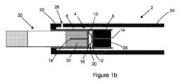
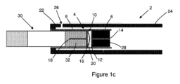
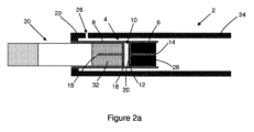
図1a~図1cに示す本発明の第一の実施形態によるエアロゾル発生装置2は、第一の剛直な円筒形の管状のセクション6および第二の剛直な円筒形の管状のセクション8を含むハウジング4を含む。特定の実施形態では、ハウジング4の第一の管状セクション6および第二の管状セクション8は、熱伝導性材料から形成される。エアロゾル発生装置2は、ハウジング4の第一の管状セクション6と第二の管状セクション8との間に配置された熱伝導性要素10を含む。
The
熱伝導性要素10は、ハウジング4の第一の管状セクション6の近位の第一の熱伝導性構成要素を含む。第一の熱伝導性要素は、第一の熱伝導ディスク12と、第一の熱伝導ディスク12からハウジング4の第一の管状セクション6の中へ突出する第一の細長い熱伝導性部材14と、を含む。
Thermally
熱伝導性要素10はまた、ハウジング4の第二の管状セクション8の近位の第二の熱伝導性構成要素も含む。第二の熱伝導性要素は、第二の熱伝導ディスク16と、第二の熱伝導ディスク16からハウジング4の第二の管状セクション8の中へ突出する第二の細長い熱伝導性部材18と、を含む。
Thermally
熱伝導性要素10は、第一の熱伝導性構成要素の第一の熱伝導ディスク12と第二の熱伝導性構成要素の第二の熱伝導ディスク16との間に配置されたバイメタルストリップ20の形態のバイメタル要素をさらに含む。バイメタルストリップ20の対向する両端は、第二の熱伝導性構成要素の第二の熱伝導ディスク16に固定される。
The thermally
エアロゾル発生装置2は、ハウジング4の第二の管状セクション8の周りに、およびハウジング4の第一の管状セクション6の一部分の周りに剛直な熱絶縁円筒形スリーブ22を含む。エアロゾル発生装置はまた、熱絶縁スリーブ22に取り外し可能に接続された剛直な熱絶縁円筒形カバー24も含む。図1bおよび1cに示すように、熱絶縁スリーブ22に接続された時、熱絶縁カバー24は、ハウジング4の第一の管状セクション6を越えて外向きに突出する。一つ以上の空気吸込み口26は、ハウジング4の第二の管状セクション8の周りの熱絶縁スリーブ22に提供される。
The aerosol-generating
エアロゾル発生装置2を使用するために、図1aに示すように、熱絶縁カバー24は熱絶縁スリーブ22から分離される。軸方向くぼみを含む固体の円筒形の可燃性炭素質熱源28が、ハウジング4の第一の管状セクション6内に挿入される。可燃性熱源28の端面は、熱伝導性要素10の第一の熱伝導性要素の第一の熱伝導ディスク12に当接する。熱伝導性要素10の第一の熱伝導性構成要素の第一の細長い熱伝導性部材14は、可燃性熱源28の軸方向くぼみ内に突出する。
To use the
エアロゾル発生基体32を含むエアロゾル発生物品30が、ハウジング4の第二の管状セクション8内に挿入される。エアロゾル発生物品30のエアロゾル発生基体32の端面は、熱伝導性要素10の第二の熱伝導性構成要素の第二の熱伝導ディスク16に当接する。熱伝導性要素10の第二の熱伝導性構成要素の第二の細長い熱伝導性部材18は、エアロゾル発生物品30のエアロゾル発生基体32内に突出する。
An aerosol-generating
可燃性熱源28は、ライターまたはその他の適切な装置を使用して点火され、熱絶縁カバー24は次に、図1bに示したように熱絶縁スリーブ22に接続される。
最初に、熱伝導性要素10のバイメタルストリップ20は、図1bに示す第一の位置にある。第一の位置では、バイメタルストリップ20は、ハウジング4の第一の管状セクション6に対して凸状に湾曲し、熱伝導性要素10の第一の熱伝導性構成要素の第一の熱伝導ディスク12と直接接触する。
Initially, the
可燃性熱源28の点火後、ハウジング4の第二の管状セクション8のエアロゾル発生物品30のエアロゾル発生基体32は、ハウジング4の第一の管状セクション6および第二の管状セクション8を介して、また熱伝導性要素10を介して、ハウジング4の第一の管状セクション6の可燃性熱源28からの伝導性熱伝達によって加熱される。揮発性化合物はエアロゾル発生基体32から放出され、エアロゾル発生物品30を通して引き出された空気中に混入される。放出された化合物が冷えるにつれて、これらは凝縮して、エアロゾル発生物品30の口側端を通してユーザーによって吸入されるエアロゾルを形成する。
After ignition of the
熱伝導性要素10のバイメタルストリップ20が、可燃性熱源28によって閾値温度超に加熱された時、図1bに示す第一の位置から図1cに示す第二の位置に変形する。第二の位置では、バイメタルストリップ20は、熱伝導要素10の第一の熱伝導性構成要素の第一の熱伝導性ディスク12ともはや直接接触しなくなり、ハウジング4の第二の管状部分8のエアロゾル発生物品30のエアロゾル発生基体32は、熱伝導要素10を介してハウジング4の第一の管状セクション6の可燃性熱源28からの伝導性熱伝達によって加熱されなくなる。
When the
第二の位置では、バイメタルストリップ20を含む熱伝導性要素10から、ハウジング4の第二の管状セクション8に受けられたエアロゾル発生物品30のエアロゾル発生基体32への伝導によって熱が伝達され、またバイメタルストリップ20が冷却される。バイメタルストリップ20が閾値温度未満に冷却されると、バイメタルストリップ20は、図1cに示す第二の位置から図1bに示す第一の位置に変形する。第一の位置では、バイメタルストリップは、熱伝導要素10の第一の熱伝導性構成要素の第一の熱伝導性ディスク12と再び直接接触し、エアロゾル発生物品30のエアロゾル発生基体32は、熱伝導要素10を介してハウジング4の第一の管状セクション6の可燃性熱源28からの伝導性熱伝達によって再び加熱される。
In the second position, heat is transferred from the thermally
エアロゾル発生物品30の可燃性熱源およびエアロゾル発生基体32の一方または両方が消費されると、熱絶縁カバー24は、図1aに示すように熱絶縁スリーブ22から分離されうる。可燃性熱源28およびエアロゾル発生物品30の一方または両方は、それぞれハウジング4の第一の管状セクション6および第二の管状セクション8から取り外されてもよい。
Once one or both of the combustible heat source of the aerosol-generating
エアロゾル発生装置2を再利用するために、さらなる可燃性熱源28およびさらなるエアロゾル発生物品30の一方または両方を、それぞれハウジング4の第一の管状セクション6および第二の管状セクション8に挿入しうる。
To recycle aerosol-generating
図2aおよび図2bに示す本発明の第二の実施形態によるエアロゾル発生装置2は図1a~図1cに示す本発明の第一の実施形態によるエアロゾル圧制装置と概して類似した構造である。しかしながら、本発明の第二の実施形態によるエアロゾル発生装置では、熱伝導性要素10のバイメタルストリップ20の対向する両端は、第一の熱伝導性構成要素の第一の熱伝導ディスク12に固定される。
The
最初に、熱伝導性要素10のバイメタルストリップ20は、図2aに示す第一の位置にある。第一の位置では、バイメタルストリップ20は平らであり、熱伝導性要素10の第一の熱伝導性構成要素の第一の熱伝導ディスク12と直接接触する。
Initially, the
ハウジング4の第一の管状セクション6内に挿入された可燃性熱源28の点火後、ハウジング4の第二の管状セクションのエアロゾル発生物品30のエアロゾル発生基体32は、ハウジングの第一の管状セクション6および第二の管状セクション8を介して、ハウジング4の第一の管状セクション6の可燃性熱源28からの伝導性熱伝達によって加熱される。第一の位置では、バイメタルストリップは、熱伝導要素10の第一の熱伝導性構成要素の第二の熱伝導性ディスク16と直接接触せず、エアロゾル発生物品30のエアロゾル発生基体32は、熱伝導要素10を介してハウジング4の第一の管状セクション6の可燃性熱源28からの伝導性熱伝達によって加熱されない。
After ignition of
揮発性化合物はエアロゾル発生基体32から放出され、エアロゾル発生物品30を通して引き出された空気中に混入される。放出された化合物が冷えるにつれて、これらは凝縮して、エアロゾル発生物品30の口側端を通してユーザーによって吸入されるエアロゾルを形成する。
The volatile compounds are released from the aerosol-generating
熱伝導性要素10のバイメタルストリップ20が、可燃性熱源28によって閾値温度超に加熱された時、図2aに示す第一の位置から図2bに示す第二の位置に変形する。第二の位置では、バイメタルストリップは、熱伝導要素10の第二の熱伝導性構成要素の第二の熱伝導性ディスク16と直接接触し、エアロゾル発生物品30のエアロゾル発生基体32は、熱伝導要素10を介してハウジング4の第一の管状セクション6の可燃性熱源28からの伝導性熱伝達によって加熱される。
When the
第二の位置では、バイメタルストリップ20は冷却される。バイメタルストリップ20が閾値温度未満に冷却される時、バイメタルストリップ20は、図2bに示す第二の位置から図2aに示す第一の位置に変形する。第一の位置では、バイメタルストリップ20は、熱伝導要素10の第二の熱伝導性構成要素の第二の熱伝導ディスク16ともはや直接接触しなくなり、ハウジング4の第二の管状部分8のエアロゾル発生物品30のエアロゾル発生基体32は、熱伝導要素10を介してハウジング4の第一の管状セクション6の可燃性熱源28からの伝導性熱伝達によって加熱されなくなる。
In the second position the
エアロゾル発生物品30の可燃性熱源およびエアロゾル発生基体32の一方または両方が消費されると、熱絶縁カバー24は、熱絶縁スリーブ22から分離されうる。可燃性熱源28およびエアロゾル発生物品30の一方または両方は、それぞれハウジング4の第一の管状セクション6および第二の管状セクション8から取り外されてもよい。
Once one or both of the combustible heat source of the aerosol-generating
エアロゾル発生装置2を再利用するために、さらなる可燃性熱源28およびさらなるエアロゾル発生物品30の一方または両方を、それぞれハウジング4の第一の管状セクション6および第二の管状セクション8に挿入しうる。
To recycle aerosol-generating
図3aおよび図3bに示す本発明の第三の実施形態によるエアロゾル発生装置2は図1a~図1cに示す本発明の第一の実施形態によるエアロゾル圧制装置と類似した構造である。しかしながら、本発明の第三の実施形態によるエアロゾル発生装置2では、バイメタル要素がバイメタルコイル40の形態であり、第一の熱伝導性構成要素の第一の熱伝導ディスク12と第二の熱伝導性構成要素の第二の熱伝導ディスク16の両方に固定される。さらに、本発明の第三の実施形態によるエアロゾル発生装置では、熱伝導要素10の第一の熱伝導性構成要素の第一の細長い熱伝導部材14は省略され、熱伝導要素10の第一の熱伝導性構成要素の第一の熱伝導ディスク12は、ハウジング4の第一の管状セクション6に対して移動可能である。
The
最初に、熱伝導性要素10のバイメタルコイル40は、図3aに示す第一の位置にある。第一の位置では、バイメタルコイル40はゆるく巻かれ、熱伝導性要素10の第一の熱伝導性構成要素の第一の熱伝導ディスク12は、ハウジング4の第一の管状セクション6内に挿入される可燃性熱源28と直接接触する。
Initially, the
可燃性熱源28の点火後、ハウジング4の第二の管状セクション8内に挿入されたエアロゾル発生物品30のエアロゾル発生基体32は、ハウジング4の第一の管状セクション6および第二の管状セクション8を介して、また熱伝導性要素10を介して、ハウジング4の第一の管状セクション6の可燃性熱源28からの伝導性熱伝達によって加熱される。揮発性化合物はエアロゾル発生基体32から放出され、エアロゾル発生物品30を通して引き出された空気中に混入される。放出された化合物が冷えるにつれて、これらは凝縮して、エアロゾル発生物品30の口側端を通してユーザーによって吸入されるエアロゾルを形成する。
After ignition of
熱伝導性要素10のバイメタルコイル40が、可燃性熱源28によって閾値温度超に加熱された時、図3aに示す第一の位置から図3bに示す第二の位置に変形する。第二の位置では、バイメタルコイル40はかたく巻かれ、熱伝導要素10の第一の熱伝導性構成要素の第一の熱伝導性ディスク12はもはや可燃性熱源28と直接接触しなくなり、ハウジング4の第二の管状部分8のエアロゾル発生物品30のエアロゾル発生基体32は、熱伝導要素10を介してハウジング4の第一の管状セクション6の可燃性熱源28からの伝導性熱伝達によって加熱されなくなる。
When the
第二の位置では、バイメタルコイル40を含む熱伝導性要素10から、ハウジング4の第二の管状セクション8に受けられたエアロゾル発生物品30のエアロゾル発生基体32への伝導によって熱が伝達され、またバイメタルコイル40が冷却される。バイメタルコイル40が閾値温度未満に冷却される時、バイメタルコイル40は、図3bに示す第二の位置から図3aに示す第一の位置に変形する。第一の位置では、バイメタルストリップはゆるく巻かれ、熱伝導要素10の第一の熱伝導性構成要素の第一の熱伝導性ディスク12は再び可燃性熱源28と直接接触し、エアロゾル発生物品30のエアロゾル発生基体32は、熱伝導要素10を介してハウジング4の第一の管状セクション6の可燃性熱源28からの伝導性熱伝達によって再び加熱される。
In the second position, heat is transferred from the thermally
エアロゾル発生物品30の可燃性熱源およびエアロゾル発生基体32の一方または両方が消費されると、エアロゾル発生装置2の熱絶縁カバー24は、その熱絶縁スリーブ22から分離されうる。可燃性熱源28およびエアロゾル発生物品30の一方または両方は、それぞれハウジング4の第一の管状セクション6および第二の管状セクション8から取り外されてもよい。
Once one or both of the combustible heat source and the aerosol-generating
エアロゾル発生装置2を再利用するために、さらなる可燃性熱源28およびさらなるエアロゾル発生物品30の一方または両方を、それぞれハウジング4の第一の管状セクション6および第二の管状セクション8に挿入しうる。
To recycle aerosol-generating
図1a~図1c、図2aおよび図2bおよび図3aおよび図3bに示す本発明の第一、第二および第三の実施形態によるエアロゾル発生装置では、それぞれ、第一の位置と第二の位置の間のバイメタル要素20の変形が、ハウジング4の第一の管状セクション6に受けられた可燃性熱源28から、エアロゾル発生30のエアロゾル発生基体32への、熱伝導性要素を介した伝導性熱伝達の動的調整を通した、ハウジング4の第二の管状セクション8に受けられたエアロゾル発生物品30のエアロゾル発生基体32の温度の温度制御を提供する。バイメタル要素20は、それによって、ユーザーへのエアロゾル送達を最適化するため、エアロゾル発生物品30のエアロゾル発生基体32の温度を一定の範囲内に維持する。
In the aerosol generators according to the first, second and third embodiments of the invention shown in FIGS. 1a-1c, 2a and 2b and 3a and 3b respectively, the first position and the second position deformation of the
Claims (14)
可燃性熱源を受けるための第一の管状セクション、およびエアロゾル発生基体を受けるための第二の管状セクションを含むハウジングと、
前記第一の管状セクションに受けられた可燃性熱源から前記第二の管状セクションに受けられたエアロゾル発生基体に熱を伝達するための、前記ハウジングの前記第一の管状セクションと前記第二の管状セクションとの間に配置された熱伝導性要素であって、第一の部分および第二の部分を有するバイメタル要素を含む熱伝導性要素と、
前記ハウジングの前記第二の管状セクションの少なくとも一部分の周りの熱絶縁スリーブと、を含み、
前記熱絶縁スリーブが、一つ以上の空気吸込み口を含み、前記バイメタル要素が、前記バイメタル要素の第一の部分が前記ハウジングの前記第一管状セクションの近位にあり、前記バイメタル要素の第二の部分が前記ハウジングの前記第二の管状セクションの近位にある、第一の位置から、前記バイメタル要素が閾値温度超に加熱されたとき、前記バイメタル要素の前記第一の部分が前記ハウジングの前記第一の管状セクションから、前記ハウジングの前記第二の管状セクションに向かって変位する、第二の位置に変形するように配置される、エアロゾル発生装置。 An aerosol generator,
a housing including a first tubular section for receiving a combustible heat source and a second tubular section for receiving an aerosol-generating substrate;
said first tubular section and said second tubular section of said housing for transferring heat from a combustible heat source received in said first tubular section to an aerosol-generating substrate received in said second tubular section; a thermally conductive element disposed between the sections, the thermally conductive element comprising a bimetallic element having a first portion and a second portion;
a thermally insulating sleeve around at least a portion of the second tubular section of the housing;
The thermally insulating sleeve includes one or more air inlets, and the bimetallic element has a first portion proximal to the first tubular section of the housing and a second portion of the bimetallic element. is proximal to the second tubular section of the housing, when the bimetallic element is heated above a threshold temperature, the first portion of the bimetallic element is in the An aerosol generating device arranged to deform to a second position displaced from said first tubular section towards said second tubular section of said housing.
請求項1~13のいずれか一項に記載のエアロゾル発生装置と、
前記エアロゾル発生装置の前記第一の管状セクション内に挿入するための、一つ以上の可燃性熱源と、を備える、エアロゾル発生装置。 An aerosol generating system comprising:
The aerosol generator according to any one of claims 1 to 13 ,
one or more combustible heat sources for insertion within the first tubular section of the aerosol generator.
Applications Claiming Priority (3)
| Application Number | Priority Date | Filing Date | Title |
|---|---|---|---|
| EP17211112 | 2017-12-29 | ||
| EP17211112.2 | 2017-12-29 | ||
| PCT/EP2018/097115 WO2019129871A1 (en) | 2017-12-29 | 2018-12-28 | Aerosol-generating device and aerosol-generating system comprising a bimetallic element |
Publications (3)
| Publication Number | Publication Date |
|---|---|
| JP2021507719A JP2021507719A (en) | 2021-02-25 |
| JPWO2019129871A5 JPWO2019129871A5 (en) | 2022-01-12 |
| JP7316280B2 true JP7316280B2 (en) | 2023-07-27 |
Family
ID=60856962
Family Applications (1)
| Application Number | Title | Priority Date | Filing Date |
|---|---|---|---|
| JP2020535255A Active JP7316280B2 (en) | 2017-12-29 | 2018-12-28 | Aerosol generators and aerosol generating systems containing bimetallic elements |
Country Status (7)
| Country | Link |
|---|---|
| US (1) | US20210052010A1 (en) |
| EP (1) | EP3731682B1 (en) |
| JP (1) | JP7316280B2 (en) |
| KR (1) | KR20200101447A (en) |
| CN (1) | CN111526742B (en) |
| BR (1) | BR112020010956A2 (en) |
| WO (1) | WO2019129871A1 (en) |
Families Citing this family (4)
| Publication number | Priority date | Publication date | Assignee | Title |
|---|---|---|---|---|
| KR102392126B1 (en) * | 2019-08-02 | 2022-04-28 | 주식회사 케이티앤지 | Heating assembly, aerosol generating device and system comprising the same |
| CN115884690A (en) * | 2020-06-19 | 2023-03-31 | 菲利普莫里斯生产公司 | Enhanced heat source |
| US20240122243A1 (en) * | 2020-08-04 | 2024-04-18 | Jt International Sa | Aerosol Generation System with Thermal Regulation Mechanism |
| CN113367393A (en) * | 2021-05-25 | 2021-09-10 | 深圳市华诚达精密工业有限公司 | Atomizing device and aerosol generating device |
Citations (5)
| Publication number | Priority date | Publication date | Assignee | Title |
|---|---|---|---|---|
| JP2015506709A (en) | 2012-02-13 | 2015-03-05 | フィリップ・モーリス・プロダクツ・ソシエテ・アノニム | Smoking articles containing isolated flammable heat sources |
| WO2015097005A1 (en) | 2013-12-23 | 2015-07-02 | Philip Morris Products S.A. | Smoking article with a valve |
| WO2016156213A1 (en) | 2015-03-27 | 2016-10-06 | Philip Morris Products S.A. | Aerosol-generating system comprising a bimetallic strip |
| WO2016156217A1 (en) | 2015-03-27 | 2016-10-06 | Philip Morris Products S.A. | Aerosol-generating system comprising a resilient member |
| WO2017115181A1 (en) | 2015-12-29 | 2017-07-06 | Philip Morris Products S.A. | End piece for aerosol generating article |
Family Cites Families (21)
| Publication number | Priority date | Publication date | Assignee | Title |
|---|---|---|---|---|
| JPS4992654U (en) * | 1972-11-27 | 1974-08-10 | ||
| US4655229A (en) * | 1984-01-30 | 1987-04-07 | R. J. Reynolds Tobacco Company | Flavor delivery system |
| IE65680B1 (en) * | 1984-09-14 | 1995-11-15 | Reynolds Tobacco Co R | Smoking article |
| US4913168A (en) * | 1988-11-30 | 1990-04-03 | R. J. Reynolds Tobacco Company | Flavor delivery article |
| US5240012A (en) * | 1991-11-13 | 1993-08-31 | Philip Morris Incorporated | Carbon heat smoking article with reusable body |
| AR002035A1 (en) | 1995-04-20 | 1998-01-07 | Philip Morris Prod | A CIGARETTE, A CIGARETTE AND LIGHTER ADAPTED TO COOPERATE WITH THEMSELVES, A METHOD TO IMPROVE THE DELIVERY OF A SPRAY OF A CIGARETTE, A CONTINUOUS MATERIAL OF TOBACCO, A WORKING CIGARETTE, A MANUFACTURING MANUFACTURING METHOD , A METHOD FOR FORMING A HEATER AND AN ELECTRICAL SYSTEM FOR SMOKING |
| JPH0975058A (en) * | 1995-09-18 | 1997-03-25 | Masaya Nagai | Nicotine inhalator |
| DE19854009C2 (en) * | 1998-11-12 | 2001-04-26 | Reemtsma H F & Ph | Inhalable aerosol delivery system |
| CN101912654A (en) * | 2005-02-02 | 2010-12-15 | 奥格尔斯比&巴特勒研究与发展有限公司 | The device that is used for vaporising vaporisable matter |
| JP2008035742A (en) * | 2006-08-03 | 2008-02-21 | British American Tobacco Pacific Corporation | Evaporating apparatus |
| JP5357878B2 (en) | 2007-08-10 | 2013-12-04 | フィリップ・モーリス・プロダクツ・ソシエテ・アノニム | Distillation-based smoking articles |
| US8991402B2 (en) * | 2007-12-18 | 2015-03-31 | Pax Labs, Inc. | Aerosol devices and methods for inhaling a substance and uses thereof |
| US20110061665A1 (en) * | 2009-09-15 | 2011-03-17 | Mack Hylton | Protective cover for smoking pipe and method |
| CA2708453C (en) * | 2010-07-15 | 2013-08-20 | Dean R. Rosendahl | Housing formed from extruded panels |
| UA112440C2 (en) | 2011-06-02 | 2016-09-12 | Філіп Морріс Продактс С.А. | SMOKING SOURCE OF HEAT FOR SMOKING PRODUCTS |
| CA2749077A1 (en) * | 2011-08-11 | 2013-02-11 | Wisplite Technology Group Incorporated | Portable electronic vapor-producing device and method |
| US11213073B2 (en) * | 2012-12-27 | 2022-01-04 | George R. Breiwa, III | Tubular volatizing device |
| WO2014136872A1 (en) * | 2013-03-08 | 2014-09-12 | 日本たばこ産業株式会社 | Non-combustion-type flavor inhaler |
| PL3082485T3 (en) * | 2013-12-16 | 2018-01-31 | Philip Morris Products Sa | Aerosol-generating device comprising a heat exchanger |
| TWI657755B (en) * | 2013-12-30 | 2019-05-01 | Philip Morris Products S. A. | Smoking article comprising an insulated combustible heat source |
| US10314334B2 (en) * | 2015-12-10 | 2019-06-11 | R.J. Reynolds Tobacco Company | Smoking article |
-
2018
- 2018-12-28 CN CN201880083741.7A patent/CN111526742B/en active Active
- 2018-12-28 EP EP18836600.9A patent/EP3731682B1/en active Active
- 2018-12-28 KR KR1020207021910A patent/KR20200101447A/en not_active Application Discontinuation
- 2018-12-28 BR BR112020010956-8A patent/BR112020010956A2/en unknown
- 2018-12-28 WO PCT/EP2018/097115 patent/WO2019129871A1/en unknown
- 2018-12-28 US US16/958,390 patent/US20210052010A1/en not_active Abandoned
- 2018-12-28 JP JP2020535255A patent/JP7316280B2/en active Active
Patent Citations (6)
| Publication number | Priority date | Publication date | Assignee | Title |
|---|---|---|---|---|
| JP2015506709A (en) | 2012-02-13 | 2015-03-05 | フィリップ・モーリス・プロダクツ・ソシエテ・アノニム | Smoking articles containing isolated flammable heat sources |
| WO2015097005A1 (en) | 2013-12-23 | 2015-07-02 | Philip Morris Products S.A. | Smoking article with a valve |
| JP2017500023A (en) | 2013-12-23 | 2017-01-05 | フィリップ・モーリス・プロダクツ・ソシエテ・アノニム | Smoking articles with valves |
| WO2016156213A1 (en) | 2015-03-27 | 2016-10-06 | Philip Morris Products S.A. | Aerosol-generating system comprising a bimetallic strip |
| WO2016156217A1 (en) | 2015-03-27 | 2016-10-06 | Philip Morris Products S.A. | Aerosol-generating system comprising a resilient member |
| WO2017115181A1 (en) | 2015-12-29 | 2017-07-06 | Philip Morris Products S.A. | End piece for aerosol generating article |
Also Published As
| Publication number | Publication date |
|---|---|
| JP2021507719A (en) | 2021-02-25 |
| RU2020124958A3 (en) | 2022-01-31 |
| RU2020124958A (en) | 2022-01-31 |
| EP3731682B1 (en) | 2022-12-14 |
| BR112020010956A2 (en) | 2020-11-17 |
| EP3731682A1 (en) | 2020-11-04 |
| WO2019129871A1 (en) | 2019-07-04 |
| CN111526742B (en) | 2023-10-20 |
| CN111526742A (en) | 2020-08-11 |
| KR20200101447A (en) | 2020-08-27 |
| US20210052010A1 (en) | 2021-02-25 |
Similar Documents
| Publication | Publication Date | Title |
|---|---|---|
| CN109496128B (en) | Aerosol-generating article comprising an aerosol-forming substrate and a heat-conducting element | |
| JP7316280B2 (en) | Aerosol generators and aerosol generating systems containing bimetallic elements | |
| JP6692993B2 (en) | Aerosol-generating article with improved outermost wrapper | |
| KR102555646B1 (en) | Combustible heat sources including ignition aids and binders | |
| RU2780514C2 (en) | Aerosol generating device and aerosol generating system containing bimetal element | |
| KR20220116493A (en) | Combustible heat sources including ignition aids and binders | |
| US20230240355A1 (en) | Reinforced heat source | |
| RU2807049C2 (en) | Aerosol generator with improved centre wrap (variants) | |
| KR20220116474A (en) | A method of producing a combustible heat source comprising carbon and a binder |
Legal Events
| Date | Code | Title | Description |
|---|---|---|---|
| A521 | Request for written amendment filed |
Free format text: JAPANESE INTERMEDIATE CODE: A523 Effective date: 20211227 |
|
| A621 | Written request for application examination |
Free format text: JAPANESE INTERMEDIATE CODE: A621 Effective date: 20211227 |
|
| A131 | Notification of reasons for refusal |
Free format text: JAPANESE INTERMEDIATE CODE: A131 Effective date: 20221205 |
|
| A601 | Written request for extension of time |
Free format text: JAPANESE INTERMEDIATE CODE: A601 Effective date: 20230303 |
|
| A521 | Request for written amendment filed |
Free format text: JAPANESE INTERMEDIATE CODE: A523 Effective date: 20230508 |
|
| TRDD | Decision of grant or rejection written | ||
| A01 | Written decision to grant a patent or to grant a registration (utility model) |
Free format text: JAPANESE INTERMEDIATE CODE: A01 Effective date: 20230615 |
|
| A61 | First payment of annual fees (during grant procedure) |
Free format text: JAPANESE INTERMEDIATE CODE: A61 Effective date: 20230714 |
|
| R150 | Certificate of patent or registration of utility model |
Ref document number: 7316280 Country of ref document: JP Free format text: JAPANESE INTERMEDIATE CODE: R150 |