JP7314918B2 - Control device, contactless power supply diagnostic program, and contactless power supply system - Google Patents
Control device, contactless power supply diagnostic program, and contactless power supply system Download PDFInfo
- Publication number
- JP7314918B2 JP7314918B2 JP2020187141A JP2020187141A JP7314918B2 JP 7314918 B2 JP7314918 B2 JP 7314918B2 JP 2020187141 A JP2020187141 A JP 2020187141A JP 2020187141 A JP2020187141 A JP 2020187141A JP 7314918 B2 JP7314918 B2 JP 7314918B2
- Authority
- JP
- Japan
- Prior art keywords
- power supply
- coil
- induced current
- supply device
- power
- Prior art date
- Legal status (The legal status is an assumption and is not a legal conclusion. Google has not performed a legal analysis and makes no representation as to the accuracy of the status listed.)
- Active
Links
Images


Classifications
-
- B—PERFORMING OPERATIONS; TRANSPORTING
- B60—VEHICLES IN GENERAL
- B60L—PROPULSION OF ELECTRICALLY-PROPELLED VEHICLES; SUPPLYING ELECTRIC POWER FOR AUXILIARY EQUIPMENT OF ELECTRICALLY-PROPELLED VEHICLES; ELECTRODYNAMIC BRAKE SYSTEMS FOR VEHICLES IN GENERAL; MAGNETIC SUSPENSION OR LEVITATION FOR VEHICLES; MONITORING OPERATING VARIABLES OF ELECTRICALLY-PROPELLED VEHICLES; ELECTRIC SAFETY DEVICES FOR ELECTRICALLY-PROPELLED VEHICLES
- B60L53/00—Methods of charging batteries, specially adapted for electric vehicles; Charging stations or on-board charging equipment therefor; Exchange of energy storage elements in electric vehicles
- B60L53/10—Methods of charging batteries, specially adapted for electric vehicles; Charging stations or on-board charging equipment therefor; Exchange of energy storage elements in electric vehicles characterised by the energy transfer between the charging station and the vehicle
- B60L53/12—Inductive energy transfer
- B60L53/124—Detection or removal of foreign bodies
-
- B—PERFORMING OPERATIONS; TRANSPORTING
- B60—VEHICLES IN GENERAL
- B60L—PROPULSION OF ELECTRICALLY-PROPELLED VEHICLES; SUPPLYING ELECTRIC POWER FOR AUXILIARY EQUIPMENT OF ELECTRICALLY-PROPELLED VEHICLES; ELECTRODYNAMIC BRAKE SYSTEMS FOR VEHICLES IN GENERAL; MAGNETIC SUSPENSION OR LEVITATION FOR VEHICLES; MONITORING OPERATING VARIABLES OF ELECTRICALLY-PROPELLED VEHICLES; ELECTRIC SAFETY DEVICES FOR ELECTRICALLY-PROPELLED VEHICLES
- B60L53/00—Methods of charging batteries, specially adapted for electric vehicles; Charging stations or on-board charging equipment therefor; Exchange of energy storage elements in electric vehicles
- B60L53/10—Methods of charging batteries, specially adapted for electric vehicles; Charging stations or on-board charging equipment therefor; Exchange of energy storage elements in electric vehicles characterised by the energy transfer between the charging station and the vehicle
- B60L53/12—Inductive energy transfer
- B60L53/122—Circuits or methods for driving the primary coil, e.g. supplying electric power to the coil
-
- B—PERFORMING OPERATIONS; TRANSPORTING
- B60—VEHICLES IN GENERAL
- B60L—PROPULSION OF ELECTRICALLY-PROPELLED VEHICLES; SUPPLYING ELECTRIC POWER FOR AUXILIARY EQUIPMENT OF ELECTRICALLY-PROPELLED VEHICLES; ELECTRODYNAMIC BRAKE SYSTEMS FOR VEHICLES IN GENERAL; MAGNETIC SUSPENSION OR LEVITATION FOR VEHICLES; MONITORING OPERATING VARIABLES OF ELECTRICALLY-PROPELLED VEHICLES; ELECTRIC SAFETY DEVICES FOR ELECTRICALLY-PROPELLED VEHICLES
- B60L3/00—Electric devices on electrically-propelled vehicles for safety purposes; Monitoring operating variables, e.g. speed, deceleration or energy consumption
-
- B—PERFORMING OPERATIONS; TRANSPORTING
- B60—VEHICLES IN GENERAL
- B60L—PROPULSION OF ELECTRICALLY-PROPELLED VEHICLES; SUPPLYING ELECTRIC POWER FOR AUXILIARY EQUIPMENT OF ELECTRICALLY-PROPELLED VEHICLES; ELECTRODYNAMIC BRAKE SYSTEMS FOR VEHICLES IN GENERAL; MAGNETIC SUSPENSION OR LEVITATION FOR VEHICLES; MONITORING OPERATING VARIABLES OF ELECTRICALLY-PROPELLED VEHICLES; ELECTRIC SAFETY DEVICES FOR ELECTRICALLY-PROPELLED VEHICLES
- B60L53/00—Methods of charging batteries, specially adapted for electric vehicles; Charging stations or on-board charging equipment therefor; Exchange of energy storage elements in electric vehicles
- B60L53/60—Monitoring or controlling charging stations
- B60L53/62—Monitoring or controlling charging stations in response to charging parameters, e.g. current, voltage or electrical charge
-
- B—PERFORMING OPERATIONS; TRANSPORTING
- B60—VEHICLES IN GENERAL
- B60L—PROPULSION OF ELECTRICALLY-PROPELLED VEHICLES; SUPPLYING ELECTRIC POWER FOR AUXILIARY EQUIPMENT OF ELECTRICALLY-PROPELLED VEHICLES; ELECTRODYNAMIC BRAKE SYSTEMS FOR VEHICLES IN GENERAL; MAGNETIC SUSPENSION OR LEVITATION FOR VEHICLES; MONITORING OPERATING VARIABLES OF ELECTRICALLY-PROPELLED VEHICLES; ELECTRIC SAFETY DEVICES FOR ELECTRICALLY-PROPELLED VEHICLES
- B60L53/00—Methods of charging batteries, specially adapted for electric vehicles; Charging stations or on-board charging equipment therefor; Exchange of energy storage elements in electric vehicles
- B60L53/60—Monitoring or controlling charging stations
- B60L53/68—Off-site monitoring or control, e.g. remote control
-
- B—PERFORMING OPERATIONS; TRANSPORTING
- B60—VEHICLES IN GENERAL
- B60L—PROPULSION OF ELECTRICALLY-PROPELLED VEHICLES; SUPPLYING ELECTRIC POWER FOR AUXILIARY EQUIPMENT OF ELECTRICALLY-PROPELLED VEHICLES; ELECTRODYNAMIC BRAKE SYSTEMS FOR VEHICLES IN GENERAL; MAGNETIC SUSPENSION OR LEVITATION FOR VEHICLES; MONITORING OPERATING VARIABLES OF ELECTRICALLY-PROPELLED VEHICLES; ELECTRIC SAFETY DEVICES FOR ELECTRICALLY-PROPELLED VEHICLES
- B60L2240/00—Control parameters of input or output; Target parameters
- B60L2240/70—Interactions with external data bases, e.g. traffic centres
-
- B—PERFORMING OPERATIONS; TRANSPORTING
- B60—VEHICLES IN GENERAL
- B60L—PROPULSION OF ELECTRICALLY-PROPELLED VEHICLES; SUPPLYING ELECTRIC POWER FOR AUXILIARY EQUIPMENT OF ELECTRICALLY-PROPELLED VEHICLES; ELECTRODYNAMIC BRAKE SYSTEMS FOR VEHICLES IN GENERAL; MAGNETIC SUSPENSION OR LEVITATION FOR VEHICLES; MONITORING OPERATING VARIABLES OF ELECTRICALLY-PROPELLED VEHICLES; ELECTRIC SAFETY DEVICES FOR ELECTRICALLY-PROPELLED VEHICLES
- B60L2270/00—Problem solutions or means not otherwise provided for
- B60L2270/10—Emission reduction
- B60L2270/14—Emission reduction of noise
- B60L2270/147—Emission reduction of noise electro magnetic [EMI]
-
- Y—GENERAL TAGGING OF NEW TECHNOLOGICAL DEVELOPMENTS; GENERAL TAGGING OF CROSS-SECTIONAL TECHNOLOGIES SPANNING OVER SEVERAL SECTIONS OF THE IPC; TECHNICAL SUBJECTS COVERED BY FORMER USPC CROSS-REFERENCE ART COLLECTIONS [XRACs] AND DIGESTS
- Y02—TECHNOLOGIES OR APPLICATIONS FOR MITIGATION OR ADAPTATION AGAINST CLIMATE CHANGE
- Y02T—CLIMATE CHANGE MITIGATION TECHNOLOGIES RELATED TO TRANSPORTATION
- Y02T10/00—Road transport of goods or passengers
- Y02T10/60—Other road transportation technologies with climate change mitigation effect
- Y02T10/70—Energy storage systems for electromobility, e.g. batteries
-
- Y—GENERAL TAGGING OF NEW TECHNOLOGICAL DEVELOPMENTS; GENERAL TAGGING OF CROSS-SECTIONAL TECHNOLOGIES SPANNING OVER SEVERAL SECTIONS OF THE IPC; TECHNICAL SUBJECTS COVERED BY FORMER USPC CROSS-REFERENCE ART COLLECTIONS [XRACs] AND DIGESTS
- Y02—TECHNOLOGIES OR APPLICATIONS FOR MITIGATION OR ADAPTATION AGAINST CLIMATE CHANGE
- Y02T—CLIMATE CHANGE MITIGATION TECHNOLOGIES RELATED TO TRANSPORTATION
- Y02T10/00—Road transport of goods or passengers
- Y02T10/60—Other road transportation technologies with climate change mitigation effect
- Y02T10/7072—Electromobility specific charging systems or methods for batteries, ultracapacitors, supercapacitors or double-layer capacitors
-
- Y—GENERAL TAGGING OF NEW TECHNOLOGICAL DEVELOPMENTS; GENERAL TAGGING OF CROSS-SECTIONAL TECHNOLOGIES SPANNING OVER SEVERAL SECTIONS OF THE IPC; TECHNICAL SUBJECTS COVERED BY FORMER USPC CROSS-REFERENCE ART COLLECTIONS [XRACs] AND DIGESTS
- Y02—TECHNOLOGIES OR APPLICATIONS FOR MITIGATION OR ADAPTATION AGAINST CLIMATE CHANGE
- Y02T—CLIMATE CHANGE MITIGATION TECHNOLOGIES RELATED TO TRANSPORTATION
- Y02T10/00—Road transport of goods or passengers
- Y02T10/60—Other road transportation technologies with climate change mitigation effect
- Y02T10/72—Electric energy management in electromobility
-
- Y—GENERAL TAGGING OF NEW TECHNOLOGICAL DEVELOPMENTS; GENERAL TAGGING OF CROSS-SECTIONAL TECHNOLOGIES SPANNING OVER SEVERAL SECTIONS OF THE IPC; TECHNICAL SUBJECTS COVERED BY FORMER USPC CROSS-REFERENCE ART COLLECTIONS [XRACs] AND DIGESTS
- Y02—TECHNOLOGIES OR APPLICATIONS FOR MITIGATION OR ADAPTATION AGAINST CLIMATE CHANGE
- Y02T—CLIMATE CHANGE MITIGATION TECHNOLOGIES RELATED TO TRANSPORTATION
- Y02T90/00—Enabling technologies or technologies with a potential or indirect contribution to GHG emissions mitigation
- Y02T90/10—Technologies relating to charging of electric vehicles
- Y02T90/12—Electric charging stations
-
- Y—GENERAL TAGGING OF NEW TECHNOLOGICAL DEVELOPMENTS; GENERAL TAGGING OF CROSS-SECTIONAL TECHNOLOGIES SPANNING OVER SEVERAL SECTIONS OF THE IPC; TECHNICAL SUBJECTS COVERED BY FORMER USPC CROSS-REFERENCE ART COLLECTIONS [XRACs] AND DIGESTS
- Y02—TECHNOLOGIES OR APPLICATIONS FOR MITIGATION OR ADAPTATION AGAINST CLIMATE CHANGE
- Y02T—CLIMATE CHANGE MITIGATION TECHNOLOGIES RELATED TO TRANSPORTATION
- Y02T90/00—Enabling technologies or technologies with a potential or indirect contribution to GHG emissions mitigation
- Y02T90/10—Technologies relating to charging of electric vehicles
- Y02T90/14—Plug-in electric vehicles
-
- Y—GENERAL TAGGING OF NEW TECHNOLOGICAL DEVELOPMENTS; GENERAL TAGGING OF CROSS-SECTIONAL TECHNOLOGIES SPANNING OVER SEVERAL SECTIONS OF THE IPC; TECHNICAL SUBJECTS COVERED BY FORMER USPC CROSS-REFERENCE ART COLLECTIONS [XRACs] AND DIGESTS
- Y02—TECHNOLOGIES OR APPLICATIONS FOR MITIGATION OR ADAPTATION AGAINST CLIMATE CHANGE
- Y02T—CLIMATE CHANGE MITIGATION TECHNOLOGIES RELATED TO TRANSPORTATION
- Y02T90/00—Enabling technologies or technologies with a potential or indirect contribution to GHG emissions mitigation
- Y02T90/10—Technologies relating to charging of electric vehicles
- Y02T90/16—Information or communication technologies improving the operation of electric vehicles
Landscapes
- Engineering & Computer Science (AREA)
- Power Engineering (AREA)
- Transportation (AREA)
- Mechanical Engineering (AREA)
- Life Sciences & Earth Sciences (AREA)
- Sustainable Development (AREA)
- Sustainable Energy (AREA)
- Electric Propulsion And Braking For Vehicles (AREA)
- Charge And Discharge Circuits For Batteries Or The Like (AREA)
- Current-Collector Devices For Electrically Propelled Vehicles (AREA)
Description
本開示は、制御装置、非接触給電診断プログラム、及び、非接触給電システムに関する。 The present disclosure relates to a control device, a contactless power supply diagnosis program, and a contactless power supply system.
特許文献1には、交流電源から電力の供給を受ける一次側共鳴コイルを有する給電設備と、一次側共鳴コイルからの電力を受電する二次側共鳴コイルを有する移動体設備と、を備えた共鳴型非接触給電システムが開示されている。 Patent Literature 1 discloses a resonance-type contactless power supply system including power supply equipment having a primary side resonance coil that receives power from an AC power supply, and mobile equipment that has a secondary side resonance coil that receives power from the primary side resonance coil.
車両に非接触給電を行う非接触式給電装置が故障していると、車両に非接触給電を行うことができないため、非接触式給電装置が正常であるか否かを判定することが求められている。 If the non-contact power supply device that supplies power to the vehicle is out of order, the vehicle cannot be supplied with power in a non-contact manner.
本開示は、上記に鑑みてなされたものであって、その目的は、非接触式給電装置が正常であるか否かを判定することができる制御装置、非接触給電診断プログラム、及び、非接触給電システムを提供することである。 The present disclosure has been made in view of the above, and an object thereof is to provide a control device, a contactless power supply diagnostic program, and a contactless power supply system that can determine whether or not the contactless power supply apparatus is normal.
本開示に係る制御装置は、非接触式給電装置の給電コイルを介した給電により非接触式受電装置の受電コイルを流れる誘導電流に基づいて、前記非接触式給電装置が正常であるか否かを判定するように構成されるプロセッサ、を備える。 A control device according to the present disclosure includes a processor configured to determine whether the non-contact power supply device is normal based on an induced current flowing through a power receiving coil of the non-contact power receiving device due to power supply via the power feeding coil of the non-contact power supply device.
本開示に係る非接触給電診断プログラムは、プロセッサに、非接触式給電装置の給電コイルを介した給電により非接触式受電装置の受電コイルを流れる誘導電流に基づいて、前記非接触式給電装置が正常であるか否かを判定する、ことを実行させる。 A non-contact power supply diagnosis program according to the present disclosure causes a processor to determine whether or not the non-contact power supply is normal based on an induced current flowing through a power receiving coil of the non-contact power receiving apparatus due to power supply via the power supply coil of the non-contact power supply.
本開示に係る非接触給電システムは、給電コイル及び第1のプロセッサを有する非接触式給電装置と、前記非接触式給電装置の前記給電コイルを介した給電により非接触式受電装置の受電コイルを流れる誘導電流に基づいて、前記非接触式給電装置が正常であるか否かを判定するように構成される第2のプロセッサを有する制御装置と、を備える。 A contactless power supply system according to the present disclosure includes a contactless power supply device having a power feeding coil and a first processor, and a control device having a second processor configured to determine whether or not the contactless power supply device is normal based on an induced current flowing through a power receiving coil of a contactless power receiving device due to power supply via the power feeding coil of the contactless power supply device.
本開示によれば、非接触式給電装置が正常であるか否かを判定することができるという効果を奏する。 Advantageous Effects of Invention According to the present disclosure, it is possible to determine whether or not a contactless power supply device is normal.
以下に、本開示に係る非接触給電システムの実施形態について説明する。なお、本実施形態により本開示が限定されるものではない。 An embodiment of a contactless power supply system according to the present disclosure will be described below. In addition, this disclosure is not limited by this embodiment.
図1は、実施形態に係る非接触給電システムを示した図である。非接触給電システムに適用される車両10は、バッテリの電力で走行用モータを駆動して走行する電動車両である。
FIG. 1 is a diagram showing a contactless power supply system according to an embodiment. A
非接触給電システムは、車載端末30、センターサーバー100、充電インフラ情報サーバー300、非接触式給電装置400、及び、通信回線網500を備えている。車載端末30は、車両10に関連付けされた車載情報通信端末装置である。センターサーバー100は、車両情報センターに設けられたナビゲーションサーバーとして機能する。充電インフラ情報サーバー300は、充電インフラセンターに設けられている。非接触式給電装置400は、車両10の走行路である道路に設けられている。通信回線網500は、車載端末30とセンターサーバー100と充電インフラ情報サーバー300と非接触式給電装置400とを相互に通信可能に接続するインターネット等である。通信回線網500には、無線基地局510が接続され、車載端末30は、この無線基地局510を介して通信回線網500に接続される。
The contactless power supply system includes an in-
車両10は、走行用のエネルギー源となるバッテリ20を備えている。車両10は、充電ケーブル110を介して外部電源からバッテリ20に給電するケーブル接続式給電系統と、非接触式給電装置400から送電された電力を非接触で受電してバッテリ20に給電する非接触式給電系統との2つの給電系統を備えている。
The
ケーブル接続式給電系統は、受電口50、充電器51、及び、充電ECU(Electronic Control Unit)52を備えている。受電口50は、充電ケーブル110の接続プラグ111の接続口である。充電器51は、受電口50に供給される電力をバッテリ20の充電用電力に変換してバッテリ20を充電する。充電ECU52は、充電器51によるバッテリ20への充電を制御する充電制御装置である。非接触式給電系統は、非接触式受電装置60を備えている。ケーブル接続式給電系統の出力である充電器51の出力と、非接触式受電装置60の出力とは、それぞれ切替スイッチ70の入力端子に接続され、どちらか一方の出力が選択的にバッテリ20への充電路に接続される。
The cable-connected power supply system includes a
バッテリ20には、バッテリ20の充電状態を示す値であるSOC(State Of Charge)を検出するSOC検出器71が設けられる。SOC検出器71は、SOCとしてバッテリ20から出力できる電気エネルギー量の指標となる値を表す信号を、CAN(Controller Area Network)通信システムのCAN通信ライン72に所定の周期で出力する。以下、このSOC検出器71が検出するSOCをバッテリ残量とも言う。バッテリ残量は、例えば、充電率[%]で表されるものであってもよいし、バッテリ20から出力可能な電気エネルギー量で表されるものであってもよい。
Battery 20 is provided with an
充電ECU52は、CPU(Central Processing Unit)やFPGA(Field-Programmable Gate Array)等からなるプロセッサと、RAM(Random Access Memory)やROM(Read Only Memory)等からなるメモリと、を備えたマイクロコンピュータを用いて構成されている。バッテリ20の充電時においては、SOC検出器71により検出されるバッテリ残量をCAN通信ライン72から取得し、バッテリ残量がユーザーの設定した目標値(例えば、満充電)に達するまで充電器51を作動させてバッテリ20を充電する。また、充電ECU52は、充電ケーブル110の接続プラグ111が受電口50に装着されているときに、ケーブル接続式給電系統がバッテリ20に電気的に接続されるように、切替スイッチ70の選択状態を切り替える。また、充電ECU52は、充電ケーブル110の接続プラグ111が受電口50に装着されていないときに、非接触式給電系統がバッテリ20に電気的に接続されるように、切替スイッチ70の選択状態を切り替える。受電口50には、接続プラグ111が接続されていることを検出するための検出スイッチ53が設けられている。充電ECU52は、この検出スイッチ53の検出信号を入力して接続プラグ111の接続の有無を判断し、切替スイッチ70を切替制御する。
The charging ECU 52 is configured using a microcomputer including a processor such as a CPU (Central Processing Unit) and an FPGA (Field-Programmable Gate Array), and a memory such as a RAM (Random Access Memory) and a ROM (Read Only Memory). When charging the battery 20, the remaining battery level detected by the
車両10は、走行駆動系の構成として、PCU(Power Control Unit)80、走行用のモータ81、及び、モータECU82を備えている。PCU80は、バッテリ20から出力される直流電力を三相交流電力に変換する。モータ81は、PCU80から出力される三相交流電力により駆動されて車輪Wを回転させる。モータECU82は、運転者の運転操作に応じてPCU80の出力を制御するモータ制御ユニットである。モータECU82は、CPUやFPGA等からなるプロセッサと、RAMやROM等からなるメモリと、を備えたマイクロコンピュータを用いて構成されている。
The
図2は、非接触式受電装置60と非接触式給電装置400との概略構成図である。非接触式給電系統に設けられた非接触式受電装置60は、道路に設けられた非接触式給電装置400から非接触で給電される。非接触式給電装置400は、交流電源401、高周波変換装置402、電磁誘導コイル403、一次コイル404、可変コンデンサ405、通信機406、給電制御装置である給電ECU407、及び、外部通信装置408を備えている。給電ECU407は、CPUやFPGA等からなるプロセッサと、RAMやROM等からなるメモリと、を備えたマイクロコンピュータを用いて構成されている。
FIG. 2 is a schematic configuration diagram of the non-contact
交流電源401は、例えば、電力会社から供給される系統電源である。高周波変換装置402は、交流電源401から供給される電力を所定の周波数の電力に変換し、変換した電力を電磁誘導コイル403に出力する。電磁誘導コイル403は、一次コイル404と同軸上に配設され、電磁誘導により一次コイル404と磁気的に結合可能となっており、高周波変換装置402から供給された高周波電力を電磁誘導により一次コイル404に出力する。
The AC
給電コイルである一次コイル404は、LC共振コイルであり、車両10に搭載された非接触式受電装置60の二次コイル61と電磁場を介して共鳴することによって、車両10へ送電可能に構成される。可変コンデンサ405は、一次コイル404と、非接触式受電装置60の二次コイル61とによって形成される共鳴系の静電容量を変更するために設けられている。
通信機406は、給電先の車両10の位置、詳細には車両10に搭載された非接触式受電装置60の二次コイル61の位置、並びに、車両10の速度の検出値を受信するために設けられている。通信機406は、非接触式受電装置60に設けられた通信機66から無線送信される車両10の位置及び速度の検出値を受信する。
The communication device 406 is provided to receive the position of the
給電ECU407は、非接触式給電装置400から車両10への給電が行なわれるときに、通信機406によって受信した車両10の位置及び速度の検出値に応じて、一次コイル404と、非接触式受電装置60の二次コイル61とによって形成される共鳴系の静電容量を変更する。一次コイル404と、非接触式受電装置60の二次コイル61との間の距離が変化すると、一次コイル404と二次コイル61と間の静電容量が変化することにより、共鳴系の共振周波数が変化する。送電電力の周波数、すなわち、高周波変換装置402によって生成される高周波電力の周波数から共振周波数が大きくずれると、送電効率が著しく低下する。そのために、給電ECU407は、高周波変換装置402によって生成される高周波電力の周波数に、共鳴系の共振周波数が近づくように、車両10の位置及び速度の各検出値に応じて可変コンデンサ405を制御して、共鳴系の静電容量を調整する。例えば、給電ECU407は、車速が高いほど可変コンデンサ405の静電容量が小さくなるように調整し、非接触式給電装置400から車両10が離れるほど(一次コイル404と二次コイル61との距離が大きくなるほど)可変コンデンサ405の静電容量が小さくなるように調整する。
Power feeding ECU 407 changes the capacitance of a resonance system formed by
また、外部通信装置408は、非接触式給電装置400の稼動状況を表す情報などを、通信回線網500を介して充電インフラ情報サーバー300に所定の周期で送信する。この場合、外部通信装置408は、非接触式給電装置400を識別する識別IDを付加して稼働状況情報(給電可能か否かを表す情報)を送信する。非接触式給電装置400は、道路において、たくさん設けられている。したがって、充電インフラセンターにおいては、管轄区域内において、どの非接触式給電装置400が稼動しているかを把握できるようになっている。
In addition,
一方、車両10に搭載されている非接触式受電装置60は、二次コイル61、電磁誘導コイル62、整流器63、DC/DCコンバータ64、受電制御装置である受電ECU65、及び、通信機66を備えている。受電ECU65は、CPUやFPGA等からなるプロセッサと、RAMやROM等からなるメモリと、を備えたマイクロコンピュータを用いて構成されている。
On the other hand, the non-contact
受電コイルである二次コイル61は、LC共振コイルであり、非接触式給電装置400の一次コイル404と電磁場を介して共鳴することにより、非接触式給電装置400から受電可能に構成される。電磁誘導コイル62は、二次コイル61と同軸上に配設され、電磁誘導により二次コイル61と磁気的に結合可能となっており、二次コイル61により受電された電力を電磁誘導により取り出して整流器63へ出力する。整流器63は、電磁誘導コイル62から出力された交流電力を整流し、整流した電力をDC/DCコンバータ64に出力する。DC/DCコンバータ64は、整流器63によって整流された電力をバッテリ20の充電用電圧レベルに変換してバッテリ20へ出力する。受電ECU65は、非接触式給電装置400からの受電時において、DC/DCコンバータ64を駆動することにより、バッテリ20を充電する。また、受電ECU65は、CAN通信ライン72から車速及び自車両位置を表す情報を取得し、取得した車速及び自車両位置を表す情報を通信機66に出力する。通信機66は、車速及び自車両位置を表す情報を非接触式給電装置400の外部通信装置408に無線で送信する。
次に、車載端末30について説明する。図3は、車載端末30の概略構成図である。車載端末30は、主制御部31、表示部32、操作部33、発音部34、無線通信部35、車両位置検出部36、及び、記憶部37を備えている。主制御部31は、CPUやFPGA等からなるプロセッサと、RAMやROM等からなるメモリと、を備えたマイクロコンピュータを用いて構成されている。表示部32及び操作部33は、液晶または有機ELなどのタッチパネル式ディスプレイを用いて構成されている。発音部34は、音声案内するためのアンプやスピーカなどを用いて構成されている。無線通信部35は、無線基地局510を介して外部と交信する。車両位置検出部36は、GPS衛星からの電波に基づいて自車両の現在位置座標を検出するGPSユニット及び車両10の進行方向を検出するジャイロセンサを備えている。記憶部37は、EPROM(Erasable Programmable ROM)及びハードディスクドライブ(Hard Disk Drive:HDD)等の記憶装置を用いて構成されている。記憶部37は、地図情報や施設情報や各種の車両特性などの情報を記憶する。
Next, the in-
車両10には、車両状態を制御する複数の電子制御装置である車両ECUが設けられている。充電ECU52、受電ECU65及びモータECU82を含む各車両ECU、及び、SOC検出器71は、CAN通信ライン72に接続され、各種の車両情報(例えば、走行距離情報、SOC情報、車両診断情報、及び、各種要求情報等)を、CAN通信ライン72に送信する。したがって、各車両ECUは、CAN通信ライン72を介して車両情報を共有できるように構成されている。また、車載端末30は、CAN通信ライン72に接続され、所定の手順にしたがってCAN通信ライン72に送信される車両情報を、センターサーバー100に送信する。センターサーバー100は、車載端末30から送信された車両情報及び外部から取得した外部情報に基づいて、ユーザーに有益なサービス情報を車載端末30に送信する。
The
車載端末30に設けられた主制御部31は、車両情報送信部311、ナビゲーション制御部312、走行経路情報取得部313、及び、走行経路情報提供部314を備えている。車両情報送信部311は、自車両の情報(例えば、現在位置情報、SOC情報、電費情報、及び、車両診断情報など)や各種の要求指令を、車両ID(車両10あるいは車載端末30を識別するID)と合わせてセンターサーバー100に送信する。ナビゲーション制御部312は、記憶部37に記憶された地図情報、及び、車両位置検出部36により検出される自車両位置に基づいて、ユーザーにより設定された目的地へ自車両を案内する。走行経路情報取得部313は、センターサーバー100から送信される走行経路情報、及び、走行経路情報に関連する詳細情報を取得する。走行経路情報提供部314は、走行経路情報取得部313が取得した走行経路情報、及び、走行経路情報に関連する詳細情報を、表示部32を使ってユーザーに提供する。車両情報送信部311、ナビゲーション制御部312、走行経路情報取得部313、及び、走行経路情報提供部314は、マイクロコンピュータの制御プログラムの実行により実現されるものである。
The
センターサーバー100は、CPUやFPGA等からなるプロセッサと、RAMやROM等からなるメモリと、を備えたマイクロコンピュータ、及び、EPROMやハードディスクドライブ等の記憶装置を主要部として備えている。図1に示すように、センターサーバー100は、通信制御部101、車両情報管理部102、地図情報管理部103、充電インフラ情報管理部104、及び、情報作成提供部105を備えている。通信制御部101は、通信回線網500と接続して通信制御を行う。車両情報管理部102は、車両情報をユーザー情報とあわせて記憶管理する。地図情報管理部103は、道路地図情報を記憶管理する。充電インフラ情報管理部104は、充電施設のインフラに係る情報を記憶管理する。情報作成提供部105は、ユーザーに有益な情報を作成して提供する。
The
充電インフラ情報サーバー300は、CPUやFPGA等からなるプロセッサと、RAMやROM等からなるメモリと、を備えたマイクロコンピュータを主要部として備えている。充電インフラ情報サーバー300は、各充電施設(例えば、非接触式給電装置400や給電ステーションなどのバッテリ充電を行う施設)から最新の稼働状況を収集し、充電施設ごとの稼働状況を表す充電インフラ情報を作成する。そして充電インフラ情報サーバー300は、作成した充電インフラ情報を、通信回線網500を介してリアルタイムでセンターサーバー100に送信する。センターサーバー100においては、充電インフラ情報管理部104が、充電インフラ情報サーバー300から送信された最新の充電インフラ情報を記憶更新する。センターサーバー100の充電インフラ情報管理部104は、地図情報管理部103で記憶している地図情報と関連させて、各充電施設の地図上における位置を記憶している。また、充電インフラ情報管理部104は、非接触式給電装置400毎の給電能力情報も記憶している。この給電能力情報は、車両10が予め想定した車速で非接触給電位置を通過したときに車両10に給電できる電力量を設定したものである。
The charging
実施形態に係る非接触給電システムにおいては、非接触式給電装置400が設置されている道路(車両10の走行路)をメンテナンスカーとして車両10が走行し、非接触式給電装置400から給電された車両10の二次コイル61の誘導電流に基づいて、非接触式給電装置40の給電機能が正常であるか否(故障)かを判定することができる。
In the contactless power supply system according to the embodiment, the
図4は、給電診断制御ルーチンの第1の例を示した図である。なお、図4に示した給電診断制御ルーチンは、車両10(受電ECU65)と非接触式給電装置400(給電ECU407)との協働により行われ、車両10(受電ECU65)により実行される制御ルーチンと、非接触式給電装置400(給電ECU407)によって実行される制御ルーチンとからなる。 FIG. 4 is a diagram showing a first example of the power supply diagnosis control routine. The power supply diagnostic control routine shown in FIG. 4 is performed by cooperation between the vehicle 10 (power receiving ECU 65) and the non-contact power supply device 400 (power supply ECU 407), and includes a control routine executed by the vehicle 10 (power receiving ECU 65) and a control routine executed by the non-contact power supply device 400 (power supply ECU 407).
車両10の受電ECU65は、ステップS11において、車両10の受電情報(車両IDや要求電力などの情報)を非接触式給電装置400へ送信する。非接触式給電装置400の給電ECU407は、車両10の受電情報を取得すると、ステップS21において、一次コイル404に誘電電流を流し、非接触給電を開始する。車両10の受電ECU65は、非接触式給電装置400による非接触給電が開始されると、ステップS12において、二次コイル61に流れる誘導電流を検出する。そして、車両10の受電ECU65は、ステップS13において、検出した二次コイル61の誘導電流が電流値Th1(第1の閾値)以下であるかを判断する。なお、電流値Th1は、例えば、給電機能が正常な場合における二次コイル61の誘導電流を、車両10の受電情報などに基づいて予め設定しておけばよい。二次コイル61の誘導電流が電流値Th1以下であると判断した場合(ステップS13にてYes)、車両10の受電ECU65は、ステップS14において、非接触式給電装置400の給電機能が故障していると判定する。一方、二次コイル61の誘導電流が電流値Th1よりも大きいと判断した場合(ステップS13にてNo)、車両10の受電ECU65は、ステップS15において、非接触式給電装置400の給電機能が正常であると判定する。車両10の受電ECU65は、ステップS14において故障判定、または、ステップS15において正常判定を行った後、ステップS16において、非接触式給電装置400に非接触給電の停止要求を送信し、本ルーチンを終了する。非接触式給電装置400の給電ECU407は、非接触給電の停止要求を取得すると、ステップS22において、非接触給電を停止し、本ルーチンを終了する。なお、非接触給電は、車両10の受電ECU65からの停止要求によらず、車両10と非接触式給電装置400とが所定の距離以上離れたら停止するようにしてもよい。
実施形態に係る非接触給電システムにおいては、車両10の非接触式受電装置60に設けられた二次コイル61に所定の誘導電流が流れたか否かによって、非接触式給電装置400の給電機能が正常であるか否(故障)かを判定する。これにより、非接触式給電装置400に給電機能の故障を検知する機能を設けなくても、車両10に非接触式給電装置400の給電機能の故障検知を任せることができる。
In the contactless power supply system according to the embodiment, it is determined whether or not the power supply function of the contactless
また、実施形態に係る非接触給電システムにおいては、非接触式給電装置400に一次コイル404と二次コイル61との間の異物(金属異物)を検出する異物検出機能を非接触式給電装置400に持たせて、給電ECU407が異物検出処理を実行することによって異物を検出するようにしてもよい。給電ECU407による異物検出処理は、例えば、車両10の受電ECU65から取得した二次コイル61の誘導電流を示す情報に基づいて、一次コイル404と二次コイル61との間の異物を検出する。具体的には、給電ECU407は二次コイル61の誘導電流が電流値Th1よりも小さい電流値Th2(第2の閾値)以下の場合に、一次コイル404と二次コイル61との間に異物が存在することを検出する。なお、給電ECU407は、二次コイル61の誘導電流ではなく誘導電圧(検出電圧)に基づいて、異物を検出するようにしてもよい。給電ECU407は、異物検出処理によって異物を検出すると非接触給電を停止させる。また、給電ECU407は、異物が存在することを示す情報を、例えば、車両10の車載端末30に送信し、主制御部31によって表示部32に異物が存在することを知らせるための画像などを表示させて、ユーザーに異物が検出されたことを報知するようにしてもよい。
Further, in the contactless power supply system according to the embodiment, the contactless
なお、実施形態に係る非接触給電システムにおいては、一次コイル404と二次コイル61との間の異物の検出方法としては、例えば、図1に破線で示したカメラなどの撮像装置700を、非接触式給電装置400やその近傍に設置して、一次コイル404と二次コイル61との間を撮像する。そして、撮像装置700が撮像した画像データを給電ECU407に送信し、給電ECU407が画像データに対して所定の画像処理を行って、一次コイル404と二次コイル61との間に異物が存在しているか否かを判定(検出)するようにしてもよい。
In the contactless power supply system according to the embodiment, as a method of detecting a foreign object between the
図5は、給電診断制御ルーチンの第2の例を示した図である。なお、図5に示した給電診断制御ルーチンは、車両10(受電ECU65)と非接触式給電装置400(給電ECU407)との協働により行われ、車両10(受電ECU65)により実行される制御ルーチンと、非接触式給電装置400(給電ECU407)によって実行される制御ルーチンとからなる。 FIG. 5 is a diagram showing a second example of the power supply diagnosis control routine. The power supply diagnosis control routine shown in FIG. 5 is performed by cooperation between the vehicle 10 (power receiving ECU 65) and the non-contact power supply device 400 (power supply ECU 407), and includes a control routine executed by the vehicle 10 (power receiving ECU 65) and a control routine executed by the non-contact power supply device 400 (power supply ECU 407).
車両10の受電ECU65は、ステップS31において、車両10の受電情報(車両IDや要求電力などの情報)を非接触式給電装置400へ送信する。非接触式給電装置400の給電ECU407は、車両10の受電情報を取得すると、ステップS41において、一次コイル404に誘電電流を流し、非接触給電を開始する。車両10の受電ECU65は、非接触式給電装置400による非接触給電が開始されると、ステップS32において、二次コイル61に流れる誘導電流を検出する。そして、車両10の受電ECU65は、ステップS33において、検出した二次コイル61の誘導電流が電流値Th1以下であるかを判断する。二次コイル61の誘導電流が電流値Th1以下であると判断した場合(ステップS33にてYes)、車両10の受電ECU65は、ステップS34において、非接触式給電装置400に異物検出処理の要求を送信する。非接触式給電装置400の給電ECU407は、異物検出処理の要求を取得すると、ステップS42において、異物検出処理を実行して処理結果を車両10の受電ECU65に送信する。車両10の受電ECU65は、取得した異物検出処理の結果に基づいて、ステップS35において、一次コイル404と二次コイル61との間に異物が検出されたかを判断する。車両10の受電ECU65は、異物が検出されたと判断した場合(ステップS35にてYes)、ステップS36において、一次コイル404と二次コイル61との間に異物があると判定する。一方、車両10の受電ECU65は、異物が検出されていないと判断した場合(ステップS35にてNo)、ステップS37において、非接触式給電装置400(一次コイル404)が故障していると判定する。また、車両10の受電ECU65は、ステップS33において、検出した二次コイル61の誘導電流が電流値Th1よりも大きいと判断した場合(ステップS33にてNo)、ステップS38において、非接触式給電装置400(一次コイル404)が正常であると判定する。
車両10の受電ECU65は、ステップS36において異物あり判定、ステップS37において故障判定、または、ステップS38において正常判定を行った後、ステップS39において、非接触式給電装置400に非接触給電の停止要求を送信し、本ルーチンを終了する。非接触式給電装置400の給電ECU407は、非接触給電の停止要求を取得すると、ステップS43において、非接触給電を停止し、本ルーチンを終了する。なお、非接触給電は、車両10の受電ECU65からの停止要求によらず、車両10と非接触式給電装置400とが所定の距離以上離れたら停止するようにしてもよい。
The
実施形態に係る非接触給電システムにおいては、一次コイル404と二次コイル61との間に異物が存在する場合には、二次コイル61に所定の誘電電流が流れていないと判断しても、非接触式給電装置400が故障しているとは判定せずに異物ありと判定する。これにより、実施形態に係る非接触給電システムにおいては、一次コイル404と二次コイル61との間に異物が存在する場合に、非接触式給電装置400が故障していると誤判定することを抑制することができる。
In the non-contact power supply system according to the embodiment, when a foreign object exists between the
また、非接触式給電装置400が二次コイル61の誘導電流に基づいて異物の検出を行う異物検出機能を有する場合には、車両10をメンテナンスカーとして非接触式給電装置400上を走行させて、異物検出機能が故障しているか否かを判定するようにしてもよい。
Further, if the non-contact
図6は、車両10を用いて非接触式給電装置400の給電診断と異物検出診断とを実施する場合を示した図である。図6に示した車両10は、非接触式受電装置60に受電コイルとして、給電診断に用いる第1の二次コイル61Aと、異物検出診断に用いる第2の二次コイル61Bとを備えている。また、車両10における第2の二次コイル61Bの下には、一次コイル404と第2の二次コイル61Bとの間の異物として金属板からなる金属異物600が設けられている。
FIG. 6 is a diagram showing a case where power supply diagnosis and foreign object detection diagnosis of non-contact
実施形態に係る非接触給電システムにおいては、非接触式給電装置400から給電診断用の電力が給電された第1の二次コイル61Aの誘導電流に基づいて、非接触式給電装置400の給電機能が正常であるか否かの給電診断を行う。例えば、検出された第1の二次コイル61Aの誘電電流が電流値Th1よりも大きい場合に、非接触式給電装置400の給電機能が正常であると判定する。一方、検出された第1の二次コイル61Aの誘導電流が電流値Th1以下の場合に、非接触式給電装置400の給電機能が故障している可能性があると判定する。また、実施形態に係る非接触給電システムは、非接触式給電装置400から異物検出診断用の電力が給電された第2の二次コイル61Bの誘導電流に基づいて、非接触式給電装置400の異物検出機能が正常であるか否かの異物検出診断を行う。例えば、検出された第2の二次コイル61Bの誘導電流が電流値Th2以下であることを示す情報を、非接触式受電装置60から非接触式給電装置400の給電ECU407が取得して車両10の金属異物600を検出することができた場合に、異物検出機能が正常であると判定する。一方、例えば、検出された第2の二次コイル61Bの誘導電流が電流値Th2以下であることを示す情報を取得できないなど、給電ECU407が車両10の金属異物600を検出することができなかった場合に、異物検出機能が故障している可能性があると判定する。
In the contactless power supply system according to the embodiment, based on the induced current of the first
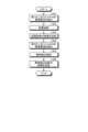
図7は、給電診断及び異物検出診断の制御ルーチンを示した図である。なお、図7に示した制御ルーチンにおいては、非接触式給電装置400が設置されている道路を車両10が走行し、非接触式給電装置400から給電診断用及び異物検出診断用の電力が給電された車両10の二次コイル61の誘導電流に基づいて、非接触式給電装置40の給電機能及び異物検出機能が正常であるか否(故障)かを診断する。
FIG. 7 is a diagram showing a control routine for power supply diagnosis and foreign object detection diagnosis. In the control routine shown in FIG. 7, the
車両10の受電ECU65は、ステップS51において、非接触式給電装置400から給電診断用の電力が給電された第1の二次コイル61Aの誘導電流を検出する。次に、車両10の受電ECU65は、ステップS52において、検出した第1の二次コイル61Aの誘電電流に基づいて、非接触式給電装置400の給電機能が正常であるか否かの給電診断を行う。次に、車両10の受電ECU65は、ステップS53において、給電診断の結果を、例えば、通信機66から車載端末30や、車載端末30から充電インフラ情報サーバー300などに送信し、報知する。次に、車両10の受電ECU65は、ステップS54において、非接触式給電装置400から異物検出診断用の電力が給電された第2の二次コイル61Bの誘導電流を検出する。次に、非接触式給電装置400の給電ECU407は、ステップS55において、受電ECU65によって検出された第2の二次コイル61Bの誘導電流に基づいて、異物検出機能が正常であるか否かの異物検出診断を行う。次に、非接触式給電装置400の給電ECU407は、ステップS56において、異物検出診断の結果を、例えば、通信機406や外部通信装置408から車載端末30や充電インフラ情報サーバー300などに送信し、報知して、制御ルーチンを終了する。
In step S<b>51 , the
実施形態に係る非接触給電システムにおいては、車両10を用いて、非接触式受電装置60に設けられた二次コイル61に所定の誘導電流が流れたか否かによって、非接触式給電装置400の給電機能及び異物検出機能が正常であるか否かの診断を行うことができる。
In the contactless power supply system according to the embodiment, by using the
なお、図6に破線で示した撮像装置700が、非接触式給電装置400やその近傍に設けられている場合には、撮像装置700による異物検出の結果も用いることによって、より精度良く非接触式給電装置400の異物検出機能の診断を行うことが可能となる。
6 is provided in or near the non-contact
また、実施形態に係る非接触給電システムにおいて、非接触式給電装置400の給電機能及び異物検出機能の診断は、二次コイル61の誘導電流に基づいて、車両10の受電ECU65と、非接触式給電装置400の給電ECU407と、の少なくとも一方が行うようにすればよい。また、実施形態に係る非接触給電システムにおいて、非接触式給電装置400の給電機能の診断は、二次コイル61の誘導電流に基づいて、センターサーバー100などの車両10及び非接触式給電装置400とは異なる装置に設けられた制御装置を用いて行ってもよい。
In the contactless power supply system according to the embodiment, the power supply function and the foreign object detection function of the non-contact
さらなる効果や変形例は、当業者によって容易に導き出すことができる。本発明のより広範な態様は、以上のように表しかつ記述した特定の詳細および代表的な実施の形態に限定されるものではない。したがって、添付のクレームおよびその均等物によって定義される総括的な発明の概念の精神または範囲から逸脱することなく、様々な変更が可能である。 Further effects and modifications can be easily derived by those skilled in the art. The broader aspects of the invention are not limited to the specific details and representative embodiments shown and described above. Accordingly, various changes may be made without departing from the spirit or scope of the general inventive concept defined by the appended claims and equivalents thereof.
10 車両
20 バッテリ
30 車載端末
32 表示部
33 操作部
34 発音部
35 無線通信部
36 車両位置検出部
37 記憶部
50 受電口
51 充電器
52 充電ECU
53 検出スイッチ
60 非接触式受電装置
61 二次コイル
61A 第1の二次コイル
61B 第2の二次コイル
62 電磁誘導コイル
63 整流器
64 DC/DCコンバータ
65 受電ECU
66 通信機
70 切替スイッチ
71 SOC検出器
72 CAN通信ライン
80 PCU
82 モータECU
100 センターサーバー
101 通信制御部
102 車両情報管理部
103 地図情報管理部
104 充電インフラ情報管理部
105 情報作成提供部
110 充電ケーブル
111 接続プラグ
300 充電インフラ情報サーバー
311 車両情報送信部
312 ナビゲーション制御部
313 走行経路情報取得部
314 走行経路情報提供部
400 非接触式給電装置
401 交流電源
402 高周波変換装置
403 電磁誘導コイル
404 一次コイル
405 可変コンデンサ
406 通信機
407 給電ECU
408 外部通信装置
500 通信回線網
510 無線基地局
600 金属異物
700 撮像装置
10 Vehicle 20
53
66
82 motor ECU
100
408
Claims (17)
を備える制御装置であって、
前記プロセッサは、
前記誘導電流が第1の閾値よりも大きい場合に、前記非接触式給電装置が正常であると判定し、
前記誘導電流が前記第1の閾値以下の場合に、前記非接触式給電装置が故障していると判定する、
制御装置。 A processor configured to determine whether the non-contact power supply device is normal based on an induced current flowing through a power receiving coil of the non-contact power receiving device due to power supply via the power feeding coil of the non-contact power supply device,
A control device comprising
The processor
determining that the contactless power supply device is normal when the induced current is greater than a first threshold;
determining that the non-contact power supply device is faulty when the induced current is equal to or less than the first threshold;
controller .
を備える制御装置であって、
前記プロセッサは、
前記誘導電流が第1の閾値よりも大きい場合に、前記非接触式給電装置が正常であると判定し、
前記誘導電流が前記第1の閾値以下であり、且つ、前記給電コイルと前記受電コイルとの間に異物が存在していない場合に、前記非接触式給電装置が故障していると判定する、
制御装置。 A processor configured to determine whether the non-contact power supply device is normal based on an induced current flowing through a power receiving coil of the non-contact power receiving device due to power supply via the power feeding coil of the non-contact power supply device,
A control device comprising
The processor
determining that the contactless power supply device is normal when the induced current is greater than a first threshold;
When the induced current is equal to or less than the first threshold and no foreign object exists between the power feeding coil and the power receiving coil, it is determined that the non-contact power feeding device is out of order.
controller .
前記誘導電流が、前記第1の閾値以下、且つ、前記第1の閾値よりも小さい第2の閾値以下の場合に、前記給電コイルと前記受電コイルとの間に前記異物が存在していると判定し、
前記誘導電流が、前記第1の閾値以下、且つ、前記第2の閾値よりも大きい場合に、前記給電コイルと前記受電コイルとの間に前記異物が存在していないと判定する、
請求項2に記載の制御装置。 The processor
When the induced current is equal to or less than the first threshold and equal to or less than a second threshold smaller than the first threshold, determining that the foreign object is present between the power supply coil and the power reception coil,
When the induced current is equal to or less than the first threshold value and greater than the second threshold value, it is determined that the foreign object does not exist between the power supply coil and the power reception coil.
3. A control device according to claim 2 .
前記給電コイルと前記受電コイルとの間を撮像した画像に基づいて、前記給電コイルと前記受電コイルとの間に前記異物が存在しているか否かを判定する、
請求項2に記載の制御装置。 The processor
Determining whether the foreign object exists between the power supply coil and the power reception coil based on an image captured between the power supply coil and the power reception coil;
3. A control device according to claim 2 .
前記非接触式給電装置に異物検出用の電力を給電させた際に前記受電コイルを流れる前記誘導電流に基づいて、前記非接触式給電装置の異物検出機能が正常であるか否かを判定する、
請求項1乃至4のいずれか1項に記載の制御装置。 The processor
Determining whether the foreign object detection function of the non-contact power supply device is normal based on the induced current flowing through the power receiving coil when power for foreign object detection is supplied to the non-contact power supply device;
A control device according to any one of claims 1 to 4 .
非接触式給電装置の給電コイルを介した給電により非接触式受電装置の受電コイルを流れる誘導電流に基づいて、前記非接触式給電装置が正常であるか否かを判定する、
ことを実行させる非接触給電診断プログラムであって、
前記プロセッサに、
前記誘導電流が第1の閾値よりも大きい場合に、前記非接触式給電装置が正常であると判定し、
前記誘導電流が前記第1の閾値以下の場合に、前記非接触式給電装置が故障していると判定する、
ことを実行させる非接触給電診断プログラム。 to the processor,
Determining whether the non-contact power supply device is normal based on the induced current flowing through the power receiving coil of the non-contact power supply device due to power supply via the power supply coil of the non-contact power supply device;
A wireless power supply diagnostic program that executes
to the processor;
determining that the contactless power supply device is normal when the induced current is greater than a first threshold;
determining that the non-contact power supply device is faulty when the induced current is equal to or less than the first threshold;
A wireless power supply diagnostic program that lets you do things.
非接触式給電装置の給電コイルを介した給電により非接触式受電装置の受電コイルを流れる誘導電流に基づいて、前記非接触式給電装置が正常であるか否かを判定する、
ことを実行させる非接触給電診断プログラムであって、
前記プロセッサに、
前記誘導電流が第1の閾値よりも大きい場合に、前記非接触式給電装置が正常であると判定し、
前記誘導電流が前記第1の閾値以下であり、且つ、前記給電コイルと前記受電コイルとの間に異物が存在していない場合に、前記非接触式給電装置が故障していると判定する、
ことを実行させる非接触給電診断プログラム。 to the processor,
Determining whether the non-contact power supply device is normal based on the induced current flowing through the power receiving coil of the non-contact power supply device due to power supply via the power supply coil of the non-contact power supply device;
A wireless power supply diagnostic program that executes
to the processor;
determining that the contactless power supply device is normal when the induced current is greater than a first threshold;
When the induced current is equal to or less than the first threshold and no foreign object exists between the power feeding coil and the power receiving coil, it is determined that the non-contact power feeding device is out of order.
A wireless power supply diagnostic program that lets you do things.
前記誘導電流が、前記第1の閾値以下、且つ、前記第1の閾値よりも小さい第2の閾値以下の場合に、前記給電コイルと前記受電コイルとの間に前記異物が存在していると判定し、
前記誘導電流が、前記第1の閾値以下、且つ、前記第2の閾値よりも大きい場合に、前記給電コイルと前記受電コイルとの間に前記異物が存在していないと判定する、
ことを実行させる請求項7に記載の非接触給電診断プログラム。 to the processor;
When the induced current is equal to or less than the first threshold and equal to or less than a second threshold smaller than the first threshold, determining that the foreign object is present between the power supply coil and the power reception coil,
When the induced current is equal to or less than the first threshold value and greater than the second threshold value, it is determined that the foreign object does not exist between the power supply coil and the power reception coil.
8. The non-contact power supply diagnostic program according to claim 7 , wherein:
前記給電コイルと前記受電コイルとの間を撮像した画像に基づいて、前記給電コイルと前記受電コイルとの間に前記異物が存在しているか否かを判定する、
ことを実行させる請求項7に記載の非接触給電診断プログラム。 to the processor;
Determining whether the foreign object exists between the power supply coil and the power reception coil based on an image captured between the power supply coil and the power reception coil;
8. The non-contact power supply diagnostic program according to claim 7 , wherein:
前記非接触式給電装置に異物検出用の電力を給電させた際に前記受電コイルを流れる前記誘導電流に基づいて、前記非接触式給電装置の異物検出機能が正常であるか否かを判定する、
ことを実行させる請求項6乃至9のいずれか1項に記載の非接触給電診断プログラム。 to the processor;
Determining whether the foreign object detection function of the non-contact power supply device is normal based on the induced current flowing through the power receiving coil when power for foreign object detection is supplied to the non-contact power supply device;
10. The non-contact power supply diagnosis program according to any one of claims 6 to 9 , which executes:
前記非接触式給電装置の前記給電コイルを介した給電により非接触式受電装置の受電コイルを流れる誘導電流に基づいて、前記非接触式給電装置が正常であるか否かを判定するように構成される第2のプロセッサを有する制御装置と、
を備える非接触給電システムであって、
前記第2のプロセッサは、
前記誘導電流が第1の閾値よりも大きい場合に、前記非接触式給電装置が正常であると判定し、
前記誘導電流が前記第1の閾値以下の場合に、前記非接触式給電装置が故障していると判定する、
非接触給電システム。 a contactless power supply device having a power supply coil and a first processor;
a control device having a second processor configured to determine whether the non-contact power supply device is normal based on an induced current flowing through a power receiving coil of the non-contact power receiving device due to power supply via the power feeding coil of the non-contact power supply device;
A contactless power supply system comprising
the second processor,
determining that the contactless power supply device is normal when the induced current is greater than a first threshold;
determining that the non-contact power supply device is faulty when the induced current is equal to or less than the first threshold;
Contactless power supply system.
前記非接触式給電装置の前記給電コイルを介した給電により非接触式受電装置の受電コイルを流れる誘導電流に基づいて、前記非接触式給電装置が正常であるか否かを判定するように構成される第2のプロセッサを有する制御装置と、
を備える非接触給電システムであって、
前記第2のプロセッサは、
前記誘導電流が第1の閾値よりも大きい場合に、前記非接触式給電装置が正常であると判定し、
前記誘導電流が前記第1の閾値以下であり、且つ、前記給電コイルと前記受電コイルとの間に異物が存在していない場合に、前記非接触式給電装置が故障していると判定する、
非接触給電システム。 a contactless power supply device having a power supply coil and a first processor;
a control device having a second processor configured to determine whether the non-contact power supply device is normal based on an induced current flowing through a power receiving coil of the non-contact power receiving device due to power supply via the power feeding coil of the non-contact power supply device;
A contactless power supply system comprising
the second processor,
determining that the contactless power supply device is normal when the induced current is greater than a first threshold;
When the induced current is equal to or less than the first threshold and no foreign object exists between the power feeding coil and the power receiving coil, it is determined that the non-contact power feeding device is out of order.
Contactless power supply system.
前記誘導電流が、前記第1の閾値以下、且つ、前記第1の閾値よりも小さい第2の閾値以下の場合に、前記給電コイルと前記受電コイルとの間に前記異物が存在していると判定して、判定結果を前記第2のプロセッサに出力し、
前記誘導電流が、前記第1の閾値以下、且つ、前記第2の閾値よりも大きい場合に、前記給電コイルと前記受電コイルとの間に前記異物が存在していないと判定して、判定結果を前記第2のプロセッサに出力する、
請求項12に記載の非接触給電システム。 The first processor
When the induced current is equal to or less than the first threshold and equal to or less than a second threshold smaller than the first threshold, it is determined that the foreign object exists between the power supply coil and the power reception coil, and the determination result is output to the second processor,
When the induced current is equal to or less than the first threshold and greater than the second threshold, it is determined that the foreign object does not exist between the power supply coil and the power reception coil, and the determination result is output to the second processor.
The contactless power supply system according to claim 12 .
前記給電コイルと前記受電コイルとの間を撮像した画像に基づいて、前記給電コイルと前記受電コイルとの間に前記異物が存在しているか否かを判定して、判定結果を前記第2のプロセッサに出力する、
請求項12に記載の非接触給電システム。 The first processor
Based on an image captured between the power feeding coil and the power receiving coil, it is determined whether the foreign object exists between the power feeding coil and the power receiving coil, and the determination result is output to the second processor.
The contactless power supply system according to claim 12 .
前記非接触式給電装置に異物検出用の電力を給電させた際に前記受電コイルを流れる前記誘導電流に基づいて、前記非接触式給電装置の異物検出機能が正常であるか否かを判定する、
請求項11乃至14のいずれか1項に記載の非接触給電システム。 the second processor,
Determining whether the foreign object detection function of the non-contact power supply device is normal based on the induced current flowing through the power receiving coil when power for foreign object detection is supplied to the non-contact power supply device;
The contactless power supply system according to any one of claims 11 to 14 .
請求項11乃至15のいずれか1項に記載の非接触給電システム。 wherein the control device is provided in the contactless power receiving device;
The contactless power supply system according to any one of claims 11 to 15 .
前記非接触式給電装置は前記車両の走路に設けられている、
請求項11乃至16のいずれか1項に記載の非接触給電システム。 The contactless power receiving device is provided in a vehicle,
The non-contact power supply device is provided on a track of the vehicle,
The contactless power supply system according to any one of claims 11 to 16 .
Priority Applications (3)
| Application Number | Priority Date | Filing Date | Title |
|---|---|---|---|
| JP2020187141A JP7314918B2 (en) | 2020-11-10 | 2020-11-10 | Control device, contactless power supply diagnostic program, and contactless power supply system |
| US17/395,982 US20220144105A1 (en) | 2020-11-10 | 2021-08-06 | Control device, non-contact power supply diagnostic program, and non-contact power supply system |
| CN202111282281.0A CN114454740B (en) | 2020-11-10 | 2021-11-01 | Control device, non-contact power supply diagnosis program, and non-contact power supply system |
Applications Claiming Priority (1)
| Application Number | Priority Date | Filing Date | Title |
|---|---|---|---|
| JP2020187141A JP7314918B2 (en) | 2020-11-10 | 2020-11-10 | Control device, contactless power supply diagnostic program, and contactless power supply system |
Publications (2)
| Publication Number | Publication Date |
|---|---|
| JP2022076657A JP2022076657A (en) | 2022-05-20 |
| JP7314918B2 true JP7314918B2 (en) | 2023-07-26 |
Family
ID=81406640
Family Applications (1)
| Application Number | Title | Priority Date | Filing Date |
|---|---|---|---|
| JP2020187141A Active JP7314918B2 (en) | 2020-11-10 | 2020-11-10 | Control device, contactless power supply diagnostic program, and contactless power supply system |
Country Status (3)
| Country | Link |
|---|---|
| US (1) | US20220144105A1 (en) |
| JP (1) | JP7314918B2 (en) |
| CN (1) | CN114454740B (en) |
Citations (7)
| Publication number | Priority date | Publication date | Assignee | Title |
|---|---|---|---|---|
| JP2010220418A (en) | 2009-03-17 | 2010-09-30 | Olympus Imaging Corp | Electronic apparatus, charger, and charging system |
| JP2012029528A (en) | 2010-07-27 | 2012-02-09 | Toyota Industries Corp | Abnormality detection device |
| JP2012055109A (en) | 2010-09-02 | 2012-03-15 | Nippon Soken Inc | Abnormality detection device of non-contact power transfer apparatus, non-contact power transmission apparatus equipped with same, non-contact power reception apparatus, and vehicle |
| JP2015104161A (en) | 2013-11-21 | 2015-06-04 | トヨタ自動車株式会社 | Non-contact power transmission device and non-contact power transmission system |
| JP2017184487A (en) | 2016-03-30 | 2017-10-05 | 矢崎総業株式会社 | Non-contact power transmission device |
| JP2019022390A (en) | 2017-07-20 | 2019-02-07 | トヨタ自動車株式会社 | Electric power transmission system |
| JP2019054578A (en) | 2017-09-13 | 2019-04-04 | トヨタ自動車株式会社 | Power transmitting device, power receiving device and non-contact power transmission system |
Family Cites Families (9)
| Publication number | Priority date | Publication date | Assignee | Title |
|---|---|---|---|---|
| JP2011211760A (en) * | 2010-03-26 | 2011-10-20 | Panasonic Electric Works Co Ltd | Contactless power supply device and contactless charging system |
| JP2013005527A (en) * | 2011-06-14 | 2013-01-07 | Sumitomo Electric Ind Ltd | Non-contact charging system and non-contact charging method |
| DE102012108671A1 (en) * | 2012-09-17 | 2014-05-28 | Paul Vahle Gmbh & Co. Kg | Metal foreign object detection system for inductive power transmission systems |
| JP5823433B2 (en) * | 2013-03-13 | 2015-11-25 | 株式会社東芝 | Wireless power feeding system, power transmission unit, power reception unit, power transmission control device, and power reception control device |
| JP6165009B2 (en) * | 2013-09-27 | 2017-07-19 | エスアイアイ・セミコンダクタ株式会社 | Power supply system, power supply apparatus, and power supply method |
| JP6519573B2 (en) * | 2016-11-30 | 2019-05-29 | トヨタ自動車株式会社 | Power transmission device and power transmission system |
| JP6618519B2 (en) * | 2017-11-22 | 2019-12-11 | 株式会社Subaru | vehicle |
| JP7035681B2 (en) * | 2018-03-22 | 2022-03-15 | 株式会社デンソー | Control device |
| JP7451916B2 (en) * | 2019-09-25 | 2024-03-19 | オムロン株式会社 | Foreign object detection device |
-
2020
- 2020-11-10 JP JP2020187141A patent/JP7314918B2/en active Active
-
2021
- 2021-08-06 US US17/395,982 patent/US20220144105A1/en not_active Abandoned
- 2021-11-01 CN CN202111282281.0A patent/CN114454740B/en active Active
Patent Citations (7)
| Publication number | Priority date | Publication date | Assignee | Title |
|---|---|---|---|---|
| JP2010220418A (en) | 2009-03-17 | 2010-09-30 | Olympus Imaging Corp | Electronic apparatus, charger, and charging system |
| JP2012029528A (en) | 2010-07-27 | 2012-02-09 | Toyota Industries Corp | Abnormality detection device |
| JP2012055109A (en) | 2010-09-02 | 2012-03-15 | Nippon Soken Inc | Abnormality detection device of non-contact power transfer apparatus, non-contact power transmission apparatus equipped with same, non-contact power reception apparatus, and vehicle |
| JP2015104161A (en) | 2013-11-21 | 2015-06-04 | トヨタ自動車株式会社 | Non-contact power transmission device and non-contact power transmission system |
| JP2017184487A (en) | 2016-03-30 | 2017-10-05 | 矢崎総業株式会社 | Non-contact power transmission device |
| JP2019022390A (en) | 2017-07-20 | 2019-02-07 | トヨタ自動車株式会社 | Electric power transmission system |
| JP2019054578A (en) | 2017-09-13 | 2019-04-04 | トヨタ自動車株式会社 | Power transmitting device, power receiving device and non-contact power transmission system |
Also Published As
| Publication number | Publication date |
|---|---|
| CN114454740B (en) | 2024-06-18 |
| JP2022076657A (en) | 2022-05-20 |
| CN114454740A (en) | 2022-05-10 |
| US20220144105A1 (en) | 2022-05-12 |
Similar Documents
| Publication | Publication Date | Title |
|---|---|---|
| JP2013228238A (en) | Vehicle information provision system, terminal device, and server | |
| CN103782489A (en) | Moving-vehicle electric power feeding system | |
| JP2014193095A (en) | Non-contact power supply system | |
| JP7314918B2 (en) | Control device, contactless power supply diagnostic program, and contactless power supply system | |
| CN114379387B (en) | Navigation server, navigation program, and navigation system | |
| EP4106146A1 (en) | Ground power supplying apparatus, method for controlling ground power supplying apparatus, and nontransitory computer recording medium | |
| US20220252678A1 (en) | Abnormality determination apparatus and abnormality determination method | |
| EP4106136A1 (en) | Vehicle, method of control of power reception of vehicle, and nontransitory computer recording medium | |
| EP4105062A1 (en) | Vehicle, power supplying method, and communication device | |
| JP2022107345A (en) | Charging system | |
| CN115489328A (en) | Non-contact power supply system, ground power supply device, and vehicle | |
| JP2023016542A (en) | Ground power supply device | |
| JP2022175780A (en) | Operating state determination device and wireless power supply system | |
| US20220134894A1 (en) | Control device, non-contact power supply program, and non-contact power supply system | |
| JP2022100766A (en) | Navigation system | |
| US20220410732A1 (en) | Vehicle, method of control of power reception of vehicle, and nontransitory computer recording medium | |
| CN115352291B (en) | Abnormality determination device, abnormality determination system, moving object, and abnormality determination method | |
| WO2024095600A1 (en) | Abnormality diagnosis method | |
| WO2024101027A1 (en) | Server, power supply system, and power price setting method | |
| US20220363148A1 (en) | Abnormality determination apparatus and information providing apparatus | |
| US20230032752A1 (en) | Running mode proposal device, navigation device, and running control device | |
| JP7355076B2 (en) | Signal transmitting equipment and signal transmitting/receiving system | |
| KR20180069604A (en) | Wireless charging method and apparatus for transport device | |
| JP2023006755A (en) | server | |
| CN118451442A (en) | Non-contact power supply system, server, and utilization cost calculation method for non-contact power supply system |
Legal Events
| Date | Code | Title | Description |
|---|---|---|---|
| A621 | Written request for application examination |
Free format text: JAPANESE INTERMEDIATE CODE: A621 Effective date: 20220524 |
|
| A977 | Report on retrieval |
Free format text: JAPANESE INTERMEDIATE CODE: A971007 Effective date: 20230125 |
|
| A131 | Notification of reasons for refusal |
Free format text: JAPANESE INTERMEDIATE CODE: A131 Effective date: 20230214 |
|
| A521 | Request for written amendment filed |
Free format text: JAPANESE INTERMEDIATE CODE: A523 Effective date: 20230301 |
|
| TRDD | Decision of grant or rejection written | ||
| A01 | Written decision to grant a patent or to grant a registration (utility model) |
Free format text: JAPANESE INTERMEDIATE CODE: A01 Effective date: 20230613 |
|
| A61 | First payment of annual fees (during grant procedure) |
Free format text: JAPANESE INTERMEDIATE CODE: A61 Effective date: 20230626 |
|
| R151 | Written notification of patent or utility model registration |
Ref document number: 7314918 Country of ref document: JP Free format text: JAPANESE INTERMEDIATE CODE: R151 |