JP7313962B2 - Driving device and image forming device - Google Patents
Driving device and image forming device Download PDFInfo
- Publication number
- JP7313962B2 JP7313962B2 JP2019145040A JP2019145040A JP7313962B2 JP 7313962 B2 JP7313962 B2 JP 7313962B2 JP 2019145040 A JP2019145040 A JP 2019145040A JP 2019145040 A JP2019145040 A JP 2019145040A JP 7313962 B2 JP7313962 B2 JP 7313962B2
- Authority
- JP
- Japan
- Prior art keywords
- engaging portion
- clutch
- cam
- gear
- driving
- Prior art date
- Legal status (The legal status is an assumption and is not a legal conclusion. Google has not performed a legal analysis and makes no representation as to the accuracy of the status listed.)
- Active
Links
Images


Classifications
-
- G—PHYSICS
- G03—PHOTOGRAPHY; CINEMATOGRAPHY; ANALOGOUS TECHNIQUES USING WAVES OTHER THAN OPTICAL WAVES; ELECTROGRAPHY; HOLOGRAPHY
- G03G—ELECTROGRAPHY; ELECTROPHOTOGRAPHY; MAGNETOGRAPHY
- G03G15/00—Apparatus for electrographic processes using a charge pattern
- G03G15/75—Details relating to xerographic drum, band or plate, e.g. replacing, testing
- G03G15/757—Drive mechanisms for photosensitive medium, e.g. gears
-
- G—PHYSICS
- G03—PHOTOGRAPHY; CINEMATOGRAPHY; ANALOGOUS TECHNIQUES USING WAVES OTHER THAN OPTICAL WAVES; ELECTROGRAPHY; HOLOGRAPHY
- G03G—ELECTROGRAPHY; ELECTROPHOTOGRAPHY; MAGNETOGRAPHY
- G03G21/00—Arrangements not provided for by groups G03G13/00 - G03G19/00, e.g. cleaning, elimination of residual charge
- G03G21/16—Mechanical means for facilitating the maintenance of the apparatus, e.g. modular arrangements
- G03G21/18—Mechanical means for facilitating the maintenance of the apparatus, e.g. modular arrangements using a processing cartridge, whereby the process cartridge comprises at least two image processing means in a single unit
- G03G21/1839—Means for handling the process cartridge in the apparatus body
- G03G21/1857—Means for handling the process cartridge in the apparatus body for transmitting mechanical drive power to the process cartridge, drive mechanisms, gears, couplings, braking mechanisms
-
- G—PHYSICS
- G03—PHOTOGRAPHY; CINEMATOGRAPHY; ANALOGOUS TECHNIQUES USING WAVES OTHER THAN OPTICAL WAVES; ELECTROGRAPHY; HOLOGRAPHY
- G03G—ELECTROGRAPHY; ELECTROPHOTOGRAPHY; MAGNETOGRAPHY
- G03G2221/00—Processes not provided for by group G03G2215/00, e.g. cleaning or residual charge elimination
- G03G2221/16—Mechanical means for facilitating the maintenance of the apparatus, e.g. modular arrangements and complete machine concepts
- G03G2221/1651—Mechanical means for facilitating the maintenance of the apparatus, e.g. modular arrangements and complete machine concepts for connecting the different parts
- G03G2221/1657—Mechanical means for facilitating the maintenance of the apparatus, e.g. modular arrangements and complete machine concepts for connecting the different parts transmitting mechanical drive power
Landscapes
- Physics & Mathematics (AREA)
- General Physics & Mathematics (AREA)
- Engineering & Computer Science (AREA)
- Computer Vision & Pattern Recognition (AREA)
- Electrophotography Configuration And Component (AREA)
- Mechanical Operated Clutches (AREA)
Description
本発明は、複数の感光体と複数の現像ローラを回転駆動させる駆動装置および前記駆動装置を備えた画像形成装置に関するものである。 The present invention relates to a driving device for rotating a plurality of photoreceptors and a plurality of developing rollers, and an image forming apparatus provided with the driving device.
ここで、画像形成装置とは、電子写真方式を用いて記録媒体に画像を形成するものである。そして、電子写真画像形成装置の例としては、例えば電子写真複写機、電子写真プリンタ(例えば、レーザビームプリンタ、LEDプリンタ等)、ファクシミリ装置およびワードプロセッサ等が含まれる。 Here, the image forming apparatus forms an image on a recording medium using an electrophotographic method. Examples of electrophotographic image forming apparatuses include electrophotographic copiers, electrophotographic printers (eg, laser beam printers, LED printers, etc.), facsimile machines, word processors, and the like.
従来、画像形成装置において現像剤や現像ローラの劣化を抑えるために、感光体と現像ローラの回転を別々に制御して、現像ローラの回転を最低限に抑える方法が知られている。 2. Description of the Related Art Conventionally, in order to suppress deterioration of a developer and a developing roller in an image forming apparatus, a method is known in which the rotation of the developing roller is minimized by controlling the rotation of the photosensitive member and the developing roller separately.
また、省スペース、低コストのため1つのモータで感光体と現像ローラを駆動している構成においては、駆動ユニットの中にクラッチを設けて、不要な駆動を切断する構成が知られている。 Further, in a configuration in which a single motor drives the photosensitive member and the developing roller for space saving and low cost, a configuration is known in which a clutch is provided in the drive unit to cut off unnecessary driving.
駆動切断手段として、近年では、低コストで形状自由度が高く、スリップなどの動作不良に強い、機械式クラッチ機構を用いられることが多くなっている。 In recent years, a mechanical clutch mechanism, which is low-cost, has a high degree of freedom in shape, and is resistant to malfunctions such as slippage, is often used as a drive disconnecting means.
ただし、機械式クラッチ機構は、上記のような利点があるものの、係合時、係合解除時の衝撃があることも知られている。 However, although the mechanical clutch mechanism has the advantages described above, it is also known that there is a shock at the time of engagement and disengagement.
特許文献1に示される機械式クラッチ機構は、解除部材を回転軸方向に移動させて駆動部材を従動部材から離間させて、駆動部材と従動部材との係合を解除し、解除部材が作用しなくなるとコイルバネの付勢力によって駆動部材と従動部材が係合する構成である。
The mechanical clutch mechanism disclosed in
特許文献1の機械式クラッチ機構では、駆動側の係合部材を正回転方向に付勢しておくことで、係合時の衝撃を抑制する構成が開示されている。 In the mechanical clutch mechanism of Japanese Patent Laid-Open No. 2002-100001, a configuration is disclosed in which the engagement member on the driving side is urged in the forward rotation direction to suppress the impact at the time of engagement.
しかしながら、上記従来例では、駆動側の係合部材が正回転方向に付勢されているため、係合解除時に駆動側の係合部材が付勢力によって正回転方向に回転して従動側の係合部材と衝突し、突発音を発生するといった課題があった。 However, in the conventional example described above, since the engagement member on the drive side is biased in the forward rotation direction, when the engagement is released, the engagement member on the drive side rotates in the forward rotation direction due to the biasing force and collides with the engagement member on the driven side, resulting in a sudden sound.
そこで、本発明の目的は、機械式クラッチ機構を備えた画像形成装置において、係合時、係合解除時の衝撃と突発音の発生を抑制することである。 SUMMARY OF THE INVENTION Accordingly, it is an object of the present invention to suppress the occurrence of impact and sudden noise during engagement and disengagement in an image forming apparatus having a mechanical clutch mechanism.
上記目的を達成するための本発明の代表的な構成は、複数の感光体と複数の現像ローラを回転駆動させる駆動装置であって、駆動源から出力された回転力を前記現像ローラに伝達または伝達を解除するクラッチ手段を有し、前記クラッチ手段は、第1係合部を備え、前記駆動源から出力された回転力を受けて軸を中心に前記第1係合部と共に回転方向に回転する駆動部材と、前記駆動部材から伝達される前記回転力を受けることで前記現像ローラを回転させるように構成された従動部材であって、前記第1係合部と接触可能な第2係合部を備え、前記第2係合部が前記第1係合部と接触することで前記第2係合部と共に前記軸を中心に回転可能な従動部材と、前記駆動部材の前記回転方向とは逆方向の逆回転方向に回転されることによって、(i)前記第1係合部が前記第2係合部から離れ、前記駆動源からの前記回転力が前記現像ローラに伝達されない第1状態から、(ii)前記第1係合部と前記第2係合部の係合によって前記現像ローラが回転される第2状態に、状態を変えることが可能な回転部材と、を有し、前記回転部材は前記従動部材に接触し、前記逆回転方向の回転により、前記第1係合部と前記第2係合部が係合しないときに前記従動部材を前記逆回転方向に向けて付勢することを特徴とする。 To achieve the above purposesofthe present inventiontypical configuration ofteeth,multipleA driving device for rotationally driving a plurality of photoreceptors and a plurality of developing rollers,having clutch means for transmitting or canceling the transmission of the rotational force output from the driving source to the developing roller;The clutch means iscomprising a first engaging portion,around the shaft by receiving the rotational force output from the drive sourcein the rotational direction together with the first engaging portiona rotating drive member;A driven member configured to rotate the developing roller by receiving the rotational force transmitted from the driving member, the driven member including a second engaging portion contactable with the first engaging portion, and the second engaging portion contacts with the first engaging portion, thereby moving together with the second engaging portion.rotate about said axisPossible driven memberand the drive memberSaidOpposite direction of rotationreverse direction of rotationby being rotated to(i) a first state in which the first engaging portion is separated from the second engaging portion and the rotational force from the drive source is not transmitted to the developing roller; and (ii) a second state in which the developing roller is rotated by engagement of the first engaging portion and the second engaging portion, wherein the rotating member contacts the driven member and rotates in the reverse rotation direction to rotate the driven member in the reverse direction when the first engaging portion and the second engaging portion are not engaged. bias in the directionIt is characterized by
本発明によれば、クラッチ手段の係合時、係合解除時の衝撃と突発音の発生を抑制することができる。 According to the present invention, it is possible to suppress the occurrence of impact and sudden noise when the clutch means is engaged and disengaged.
以下に図面を参照して、この発明を実施するための形態を、実施例に基づいて例示的に詳しく説明する。ただし、この実施例に記載されている構成部品の寸法、材質、形状、その相対配置などは、特に特定的な記載がない限りは、この発明の範囲をそれらのみに限定する趣旨のものではない。 BEST MODE FOR CARRYING OUT THE INVENTION A mode for carrying out the present invention will be exemplarily described in detail below based on an embodiment with reference to the drawings. However, the dimensions, materials, shapes, relative positions, etc. of the components described in this embodiment are not intended to limit the scope of the present invention only to them, unless otherwise specified.
〔実施例1〕
<画像形成装置>
図1を参照して、本発明の実施例に係る画像形成装置の一例を説明する。ここでは、電子写真プロセス方式を採用した4色フルカラーレーザプリンタを例にして説明する。なお、図1は画像形成装置1の概略構成を断面的に示した図である。また、以下の説明において、画像形成装置1に関して、前側(正面側)とは装置開閉ドア(開閉部材)2を配設した側であり、後側(奥側)とはそれとは対向側である。また、左右とは画像形成装置1を前側から見た場合の左右を指す。
[Example 1]
<Image forming apparatus>
An example of an image forming apparatus according to an embodiment of the present invention will be described with reference to FIG. Here, a four-color full-color laser printer employing an electrophotographic process system will be described as an example. FIG. 1 is a cross-sectional view showing a schematic configuration of the
<画像形成装置の構成>
本実施例に係る画像形成装置1は、インライン構成かつタンデム型の4色フルカラーレーザプリンタである。図1に示すように、画像形成装置1には、後側から前側にかけて、イエロー(Y)、マゼンタ(M)、シアン(C)、ブラック(K)の各色のプロセスカートリッジPY,PM,PC,PK(以下、カートリッジPと称する)が並べて配設されている。各カートリッジPは、各カートリッジ枠体内に、電子写真感光体ドラム11a,11b,11c,11d(以下、感光体ドラム11と称する)がそれぞれ設けられている。また、各カートリッジ枠体内には、各感光体ドラム11の表面を一様に帯電するための帯電ローラ12a,12b,12c,12d(以下、帯電ローラ12と称する)もそれぞれ設けられている。また、各カートリッジ枠体内には、各感光体ドラム11に形成された静電潜像を現像する現像器も設けられている。各現像器は、それぞれ現像ローラ13a,13b,13c,13d(以下、現像ローラ13と称する)が設けられており、各現像器内には、現像剤(トナー)が収容されている。更に、各カートリッジ枠体内には、各感光体ドラム11の表面に残った残存トナーを取り除くクリーニング器14a,14b,14c,14dも設けられている。
<Configuration of Image Forming Apparatus>
The
各カートリッジPが配列されている領域の上方には、レーザスキャナユニット3が設けられている。このレーザスキャナユニット3は、入力される画像情報に応じてレーザー光を出力し、各感光体ドラム11の表面を走査露光する。これにより、各感光体ドラム11に静電潜像が形成される。
A
各カートリッジPが配置されている領域の下方には、中間転写ベルトユニット(以下、ベルトユニット20と称する)が設けられている。このベルトユニット20は、中間転写体として機能する、誘電体性かつ可撓性を有するエンドレスベルト(以下、ベルト21と称する)を備えている。また、ベルトユニット20は、このベルト21を張架させた状態で循環移動させるために、駆動ローラ22と、ターンローラ23と、テンションローラ24とを備えている。ベルト21の内側には、上側のベルト部分を介して各感光体ドラム11に対向させて、4つの一次転写ローラ25a,25b,25c,25dが設けられている。また、駆動ローラ22に対してベルト21を介して対向するように、二次転写ローラ26が設けられている。
Below the area where each cartridge P is arranged, an intermediate transfer belt unit (hereinafter referred to as belt unit 20) is provided. The
上述した各カートリッジPと、レーザスキャナユニット3と、ベルトユニット20と、一次転写ローラ25a,25b,25c,25dと、二次転写ローラ26は、記録媒体に未定着トナー像を形成する画像形成部の主要構成部材である。
The cartridges P, the
ベルト21の下方には、記録媒体としての紙などのシートSを供給するシート供給部30が設けられている。シート供給部30は、画像形成前のシートSを積載するシートカセット31と、手差しのシートSが搬送される搬送路32とを備えている。また、シート供給部30は、シートSを供給する供給ローラ33と、シートSを1枚に分離する分離ローラ34と、シートSを下流に向けて搬送する搬送ローラ35とを備えている。なお、シートカセット31と搬送路32は、いずれも画像形成装置1に対して前側から着脱可能に構成されている。
Below the
画像形成装置1において、シート供給部30により搬送されるシートSの搬送方向下流側には、シートS上に未定着トナー像を定着させる定着装置40が設けられている。また、この定着装置40によってトナー像が定着されたシートSを排出させる排出ローラ対44と、排出されたシートSを積載する排出シート積載トレイ47も設けられている。なお、排出ローラ対44は、排出ローラ45と排出アイドラローラ46とから構成される。
In the
定着装置40は、画像形成装置1の装置本体から駆動力が伝達されることで回転する加圧ローラ42と加熱ユニット41を備えている。加圧ローラ42と加熱ユニット41で、搬送されるシートSを挟持する定着ニップを形成する。
The
<画像形成動作>
各感光体ドラム11が図中矢印の方向に所定の制御速度で回転駆動される。ベルト21も感光体ドラム11の回転に順じた方向に、感光体ドラム11の回転速度に対応した速度で回転駆動され、略同タイミングでレーザスキャナユニット3も駆動される。この駆動に同期して、各カートリッジPにおいて所定の制御タイミングで、各帯電ローラ12が各感光体ドラム11の表面を所定の極性・電位に一様に帯電する。レーザスキャナユニット3は各感光体ドラム11の表面を各色の画像信号に応じてレーザー光で走査露光する。これにより、各感光体ドラム11の表面において、レーザー光で走査露光された領域が、画像信号に応じた静電潜像となる。そして、各感光体ドラム11の表面に形成された静電潜像が、各現像器の現像ローラ13によりトナー像として現像される。以上の電子写真画像形成プロセス動作により、ベルト21上に各色の未定着トナー像が重畳した状態で形成される。
<Image forming operation>
Each photosensitive drum 11 is rotationally driven at a predetermined control speed in the direction of the arrow in the drawing. The
一方、所定の制御タイミングでシートカセット31上のシートSは、分離ローラ34と搬送ローラ35により1枚ずつ給送される。そして、二次転写ローラ26とベルト21との転写ニップに搬送されたシートS上に、ベルト21上の未定着トナー像が転写される。その後、シートSはベルト21の表面から分離されて定着装置40に送られる。シートSは定着ニップにおいて加熱かつ加圧され、各色の未定着トナー像が、混色された状態でシートSに定着される。シートSは、定着装置40を経て、排出ローラ対44により排出シート積載トレイ47上に排出される。
On the other hand, the sheets S on the
<駆動装置>
次に、図2,図3,図4を用いて上記画像形成装置1における駆動装置70の構成について説明する。
<Driving device>
Next, the configuration of the driving
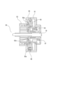
図2は画像形成装置の本体フレームの右側板72に取り付けた状態の駆動装置70を本体外側から見た斜視図である。図2では、簡略化のため、本体フレームの右側板72と駆動装置70のみの表示としてある。図3は駆動装置70の分解斜視図である。図4は駆動装置70における現像ローラ駆動列の斜視図である。
FIG. 2 is a perspective view of the driving
駆動装置70は、駆動源であるメインモータ71と、定着モータ73と、各モータ71,73から出力された回転力を伝達するギア列と、を有している。駆動源であるメインモータ71は、出力された回転力が駆動装置70内部のギア列によって伝達され、4つの感光体ドラム11、4つの現像ローラ13およびベルトユニット20の駆動ローラ22の他、図示しない現像当接離間機構を回転駆動する。また、定着モータ73は、出力された回転力が駆動装置70内部のギア列によって伝達され、定着装置40の加圧ローラ42を回転駆動する。
The driving
なお、ここでは、ベルトユニット20の駆動ローラ22へのギア列と、定着装置40の加圧ローラ42へのギア列、現像当接離間機構の詳細説明は省略する。
Here, detailed descriptions of the gear train to the
図3および図4を用いて、メインモータ71から出力された回転力を、4つの感光体ドラム11に伝達するドラムギア列、4つの現像ローラ13に伝達する現像ギア列について説明する。
3 and 4, the drum gear train for transmitting the rotational force output from the
図3に示す駆動装置70において、ドラムギア列は、メインモータ71から出力された回転力を、モータ軸上のモータギア71a、複数のギアからなるギア列を介して、4つのドラムギア77(77a,77b,77c,77d)に伝達する。4つのドラムギア77(77a,77b,77c,77d)には、それぞれ4つの感光体ドラムの軸上に設けられたカップリング(不図示)と係合するカップリングが設けられている。カートリッジが画像形成装置に装着された際に、カートリッジにおける感光体ドラム軸上のカップリングが駆動装置70におけるドラムギア77のカップリングに係合される。メインモータ71から出力された回転力が前記ドラムギア列を介して伝達されることで、カートリッジの感光体ドラムが回転される。なお、第一駆動フレーム74に設けられた4つのドラムギア77が有するカップリング部分は、第二駆動フレーム75に設けられた4つの穴75a,75b,75c,75dにそれぞれ挿入される。
In the
また図3および図4に示すように、駆動装置70において、現像ギア列は、モータギア71aからイエロー、マゼンタ、シアンを含むカラー側のギア列とブラック側のギア列に分岐されている。現像ギア列のうち、モータギア71aから分岐されたカラー側のギア列は、カラー側のクラッチ90C、クラッチ90Cに連結された下流側のギア列を介して現像ギア78a,78b,78cに連結されている。また現像ギア列のうち、モータギア71aから分岐されたブラック側のギア列は、ブラック側のクラッチ90B、クラッチ90Bに連結された下流側のギア列を介して現像ギア78dに連結されている。4つの現像ギア78a,78b,78c,78dには、それぞれ4つの現像ローラの軸上に設けられたカップリング(不図示)と係合するカップリングが設けられている。カートリッジが画像形成装置に装着された際に、カートリッジにおける現像ローラ軸上のカップリングが駆動装置70における現像ギア78のカップリングに係合される。メインモータ71から出力された回転力が前記現像ギア列を介して伝達されることで、カートリッジの現像ローラが回転される。なお、第一駆動フレーム74に設けられたカラー側のクラッチ90Cは、第二駆動フレーム75に設けられた穴75fに挿入され、第二駆動フレーム75に設けられた現像ギア78a,78b,78cに連結された前記下流側のギア列に連結される。また第一駆動フレーム74に設けられたブラック側のクラッチ90Bは、第二駆動フレーム75に設けられた穴75eに挿入され、第二駆動フレーム75に設けられた現像ギア78dに連結された前記下流側のギア列に連結される。
As shown in FIGS. 3 and 4, in the driving
なお、前記現像ギア列において、メインモータ71から各クラッチ90B,90Cに伝達された回転力は、各クラッチ90B,90CのON/OFFを切り替えることによって、クラッチ90B,90Cの下流側の現像ギアに伝達され、または伝達が切断される。
In the development gear train, the rotational force transmitted from the
すなわち、クラッチ90B,90CをOFFすることによって、メインモータ71が回転中でも4つの現像ローラへの回転力の伝達を切断することができる。
That is, by turning off the
一方、カラー側のクラッチ90CがONのときは、メインモータ71から出力された回転力がクラッチ90Cを介して現像ギア78a,78b,78cに伝達され、カラー側の現像ローラが回転される。また、ブラック側のクラッチ90BがONのときは、メインモータ71から出力された回転力がクラッチ90Bを介して現像ギア78dに伝達され、ブラック側の現像ローラが回転される。
On the other hand, when the color-
クラッチ90B,90CのON/OFFの切り替えは、図4に示すソレノイド60とW欠歯ギア61によって行われるが、これについては後述する。なお、第一駆動フレーム74に設けられたW欠歯ギア61は、第二駆動フレーム75に設けられた穴75g(図3参照)に挿入され、図4に示すように、カラー側のクラッチ90Cに連結されたギア列と、ブラック側のクラッチ90Bに連結されたギア列に連結される。カラー側のクラッチ90Cに連結されたギア列と、ブラック側のクラッチ90Bに連結されたギア列は、第二駆動フレーム75(図3参照)に設けられている。
ON/OFF switching of the
≪クラッチ≫
図5(a),図5(b),図6,図7を参照し、上記駆動装置70におけるクラッチ90B,90Cの構成について説明する。メインモータからブラック側の現像ローラに至るギア列に配置されたクラッチ90Bとカラー側の現像ローラに至るギア列に配置されたクラッチ90Cの構成について説明する。クラッチ90B,90Cは、メインモータから出力された回転力を現像ローラに伝達または伝達を解除するクラッチ手段である。クラッチ90B,90Cは、カム形状以外はともに同じ構成であるため、ここでは符号B,Cは付さずに、クラッチ90として説明する。なお、クラッチを構成する各部材についても、同様に符号B,Cを付さずに説明する。
≪Clutch≫
The configuration of the
図5(a),図5(b)に示すように、クラッチ手段であるクラッチ90は、クラッチ駆動ギア91、クラッチ従動ギア92、クラッチカムギア93、駆動側の係合部材(第1係合部材)94、クラッチ解除部材95、回転ストッパ96、圧縮バネ97によって構成されている。
As shown in FIGS. 5(a) and 5(b), a clutch 90, which is a clutch means, is composed of a
従動部材であるクラッチ従動ギア92は、第一駆動フレーム74(図3参照)に加締められた軸79に回転可能に支持されている。クラッチ従動ギア92のクラッチ駆動ギア91に対向している側には、第2係合部材92aが形成されている。従動側の係合部材である第2係合部材92aは、軸79を中心に回転可能に設けられ、第1係合部材94と係合することで第1係合部材94に従動して回転する。第2係合部材92aは、第1係合部材94と係合することなく、メインモータ71(図3参照)からの駆動力が伝達されない状態と、第1係合部材94と係合することによりメインモータ71(図3参照)からの駆動力によって軸79を中心に回転する状態と、を取りうる。ここでは、第2係合部材92aはクラッチ従動ギア92と一体となって動くように構成されている。よって、従動部材であるクラッチ従動ギア92は、第2係合部材92aとともに軸79を中心に回転するように構成されている。
A clutch driven
回転部材であるクラッチカムギア93は、クラッチ従動ギア92の第2係合部材92aの外周面に嵌合され、クラッチ従動ギア92を中心として回転可能に支持されている。クラッチカムギア93は、クラッチ駆動ギア91に対向している側に、回転方向Rへ向かうにしたがい、クラッチ駆動ギア91へ向うように傾斜した斜面を備えたカム形状93aが形成されている。第一のカムであるカム形状93aは、クラッチ解除部材95に設けられたカム形状95aと係合する。
The
クラッチ解除部材95は、第一駆動フレーム74に固定された回転ストッパ96の係合部96aに対して、回転方向の移動が規制され、軸方向に移動可能とされるよう係合する被係合部95bを有している。クラッチ解除部材95は、クラッチカムギア93のカム形状93aに対向する側に、回転方向Rとは逆方向Gへ向かうにしたがい、クラッチカムギア93へ向うように傾斜した斜面を備えたカム形状95aが設けられている。第二のカムであるカム形状95aは、クラッチカムギア93に設けられたカム形状93aと係合する。
The
駆動部材であるクラッチ駆動ギア91は、第一駆動フレーム74に加締められた軸79に回転可能に支持されている。クラッチ駆動ギア91は、メインモータ71から出力された駆動力を受けて軸79を中心に回転する。第1係合部材94は、クラッチ駆動ギア91に対して軸方向に移動可能とされる一方、回転方向への移動が規制されてクラッチ駆動ギア91とともに軸79を中心として回転するように設けられている。クラッチ駆動ギア91と第1係合部材94の間には、付勢部材である圧縮バネ97が配置されている。第1係合部材94は、圧縮バネ97によってクラッチ従動ギア92の第2係合部材92aと係合する方向に付勢されている。
A
従って、上記構成のクラッチ90において、クラッチ駆動ギア91に入力された駆動力の、クラッチ従動ギア92への伝達、および伝達の切断は以下のようになる。
Therefore, in the clutch 90 configured as described above, the driving force input to the
クラッチ駆動ギア91に入力された駆動力は、クラッチ駆動ギア91と係合して一体的に回転する係合部材94に伝達され、図6に示すように係合部材94がクラッチ従動ギア92の第2係合部材92aと係合することでクラッチ従動ギア92に伝達される。
The driving force input to the
一方で、クラッチカムギア93が回転させられ、クラッチカムギア93のカム形状93aがクラッチ解除部材95のカム形状95aと係合することで、クラッチ解除部材95が軸方向に移動される。このとき、クラッチ解除部材95は、回転ストッパ96により回転方向への移動を規制されつつ、軸方向においてクラッチカムギア93から離れる方向に移動される。ひいては、クラッチ解除部材95に係合した係合部材94は、クラッチ駆動ギア91と係合部材94の間の圧縮バネ97を圧縮するようにして、クラッチ従動ギア92の第2係合部材92aから離れ、係合が解除される。図7に示すようにクラッチ駆動ギア91と係合部材94とクラッチ従動ギア92の第2係合部材92aとの係合が解除されることで、クラッチ駆動ギア91に入力された駆動力の、クラッチ従動ギア92への伝達は切断される。
On the other hand, the
なお、クラッチ駆動ギア91に入力された駆動力がクラッチ従動ギア92に伝達される状態は、クラッチ90のON状態である。一方、クラッチ駆動ギア91に入力された駆動力のクラッチ従動ギア92への伝達が切断される状態は、クラッチ90のOFF状態である。
The state in which the driving force input to the
ここで、クラッチ90のON/OFFの切り替えについて説明する。クラッチ90のON/OFFの切り替えは、図4に示すソレノイド60とW欠歯ギア61によって行われる。ソレノイド60とW欠歯ギア61は、クラッチ90B,90Cが有する回転部材であるカムギア93B,93Cを回転させる制御手段である。
Here, ON/OFF switching of the clutch 90 will be described. ON/OFF switching of the clutch 90 is performed by a
W欠歯ギア61は、メインモータ71からの駆動力を伝達するギア列のギアに噛み合い可能な欠歯ギア(不図示)と、各クラッチ90B,90Cに駆動力を伝達するギア列のギアと噛み合うギア61aと、を同一軸上に有する構成である。W欠歯ギア61は、メインモータ71からのギア列のギアに対して、不図示の欠歯ギアの欠歯部が対向した位置で、ソレノイド60の通電により図4に示す係止解除位置に回動されるアーム60aに係止されている。W欠歯ギア61は、ギア61aと欠歯ギア(不図示)との間に、欠歯ギアを回転方向に付勢するバネが設けられている。
The W
ソレノイド60に通電すると、アーム60aが図4に示す係止解除位置に回動され、W欠歯ギア61の欠歯ギア(不図示)の係止が解除される。すると、欠歯ギアがバネの付勢力により回転され、メインモータ71からのギア列のギアと噛み合う。すると、メインモータ71からの駆動力がギア61aに伝達され、W欠歯ギア61を介して各クラッチ90B,90Cのギア列に伝達される。W欠歯ギア61は、不図示の欠歯ギアが1回転して、欠歯ギアの欠歯部がメインモータ71からのギア列のギアと対向すると、噛み合いが解除される。そのため、W欠歯ギア61は1回転すると、メインモータ71からの駆動力の伝達が解除されて停止する。なお、ソレノイド60の通電により図4に示す係止解除位置に回動されたアーム60aは、所定のタイミングでソレノイド60の通電がOFFされ、欠歯ギアの欠歯部がメインモータ71からのギア列のギアと対向したW欠歯ギア61に係止される。
When the
このようにソレノイド60の通電によりW欠歯ギア61が1回転されると、W欠歯ギア61のギア61aに連結されたギア列を介して、カラー側のクラッチ90Cのカムギア93Cとブラック側のクラッチ90Bのカムギア93Bにメインモータ71からの駆動力が伝達される。カムギア93B,93Cは、W欠歯ギア61が1回転されたとき、1/3回転するようにギア歯数が設定されている。クラッチ90C及びクラッチ90Bは、1つのソレノイド60によってON/OFFの切り替えが制御されているため、同期して回転するよう構成されている。
When the W
次に、クラッチON状態からクラッチOFF状態へのクラッチ90の動きについて説明する。 Next, the movement of the clutch 90 from the clutch-on state to the clutch-off state will be described.
上述したように、ソレノイド60(図4参照)に通電されると、メインモータ71(図3参照)からの駆動力がクラッチカムギア93に伝達され、クラッチカムギア93が回転される。クラッチカムギア93が回転されると、クラッチカムギア93のカム形状93aの斜面とクラッチ解除部材95のカム形状95aの斜面が係合するようになる。さらに回転されると、カム形状93a,95aの斜面同士の係合によって、クラッチ解除部材95がクラッチカムギア93から離れる方向に移動される。そして、このクラッチ解除部材95に係合した第1係合部材94は、圧縮バネ97の力に抗って軸方向に移動されていく。第1係合部材94は、クラッチ従動ギア92の第2係合部材92aに対してクラッチカムギア93から離れる方向に移動され、前記カム形状93a,95aの斜面同士の係合量は減少していく。クラッチカムギア93が1/3回転されると、クラッチカムギア93の回転は停止され、クラッチカムギア93とクラッチ解除部材95は、カム形状93aの斜面より回転方向Rの下流側に設けた平面と、カム形状95aの斜面より逆方向Gの下流側に設けた平面と、が係合した状態が維持される。これにより、第1係合部材94は、クラッチ従動ギア92の第2係合部材92aから完全に退避され、第2係合部材92aとの係合が解除された状態となる。
As described above, when the solenoid 60 (see FIG. 4) is energized, the driving force from the main motor 71 (see FIG. 3) is transmitted to the
次に、クラッチOFF状態からクラッチON状態へのクラッチ90の動きについて説明する。 Next, the movement of the clutch 90 from the clutch OFF state to the clutch ON state will be described.
ソレノイド60に通電されると、メインモータ71からの駆動力がクラッチカムギア93に伝達され、クラッチカムギア93を矢印G方向に回転させる。クラッチカムギア93を矢印G方向に回転させると、クラッチカムギア93のカム形状93aとクラッチ解除部材のカム形状95aとの係合が解除される。すると、第1係合部材94は、圧縮バネ97の力によってクラッチ従動ギア92の第2係合部材92aに向けて移動され、クラッチ従動ギア92の第2係合部材92aに係合(接触)される。クラッチカムギア93が1/3回転すると、クラッチカムギア93の回転は停止され、第1係合部材94と従動ギアの第2係合部材92aの係合状態は維持される。
When the
なお、図5に示すクラッチ90では、クラッチカムギア93のカム形状93a及びクラッチ解除部材95のカム形状95aが、クラッチON状態からクラッチOFF状態への切り替え時に互いに係合する斜面を備えた構成を例示した。しかし、カム形状の構成は、これに限定されるものではない。
In the clutch 90 shown in FIG. 5, the
例えば、クラッチカムギア93のカム形状93a及びクラッチ解除部材95のカム形状95aが、クラッチOFF状態からクラッチON状態への切り替え時に互いに係合する第二の斜面も備えた構成としても良い。この場合、クラッチカムギア93のカム形状93aは、回転方向Rへ向かうにしたがい、クラッチ駆動ギア91へ向うように傾斜した第一の斜面を備え、さらに前記第一の斜面よりも回転方向Rの下流側に、回転方向Rへ向かうにしたがい、クラッチ駆動ギア91から離れるように傾斜した第二の傾斜を備えた構成とする。また、クラッチ解除部材95のカム形状95aは、回転方向Rとは逆方向Gへ向かうにしたがい、クラッチカムギア93へ向うように傾斜した第一の斜面を備え、さらに前記第一の斜面よりも逆方向Gの下流側に、逆方向Gへ向かうにしたがい、クラッチカムギア93から離れるように傾斜した第二の斜面を備えた構成とする。
For example, the
この場合、クラッチOFF状態からクラッチON状態へのクラッチ90の動きは、以下のようになる。ソレノイド60に通電され、クラッチカムギア93が回転されると、クラッチカムギア93のカム形状93aの第二の斜面とクラッチ解除部材95のカム形状95aの第二の斜面が係合するようになる。さらに回転されると、第1係合部材94は、カム形状と圧縮バネ97の力によって、第1係合部材94の先端94a(図9参照)がクラッチ従動ギア92の第2係合部材92aの先端92b(図9参照)に対して軸方向で近づく方向に移動されていく。クラッチカムギア93が1/3回転すると、カム形状93a,95aの第二の斜面同士の係合が解除され、第1係合部材94と従動ギアの第2係合部材92aは係合状態となる。カム形状をこのように構成しても良い。
In this case, the movement of the clutch 90 from the clutch-off state to the clutch-on state is as follows. When the
なお、ブラック側のクラッチ90Bとカラー側のクラッチ90Cとでは、クラッチのON/OFFの状態変化に応じて、カム形状が異なる。カム形状は、クラッチのON/OFFのタイミングや、ONからOFF、OFFからON、OFFからOFF、ONからONなどの状態変化に応じて、配置や形状を適宜設定されるべきものである。
It should be noted that the black-
本実施例に係る画像形成装置では、ブラック側のクラッチ90Bは、ソレノイドONによるクラッチカムギア93の1/3回転でOFF⇒ON⇒ONと状態が変化していき、1回転して再びOFFに戻る。一方、カラー側のクラッチ90Cは、ソレノイドONによるクラッチカムギア93の1/3回転で、OFF⇒ON⇒OFFと状態が変化していく。
In the image forming apparatus according to the present embodiment, the black side clutch 90B changes its state from OFF to ON to ON in 1/3 rotation of the
カラー側とブラック側の2つのクラッチ90B,90Cが共にOFFのとき、全ての現像ローラが停止している、非画像形成状態となる。
When both of the two
カラー側とブラック側の2つのクラッチ90B,90Cが共にONのとき、全ての現像ローラが回転し、フルカラーによる画像形成状態となる。
When the two
カラー側のクラッチ90CがOFFで、ブラック側のクラッチ90BがONのとき、ブラック側の現像ローラのみが回転している、モノクロ画像形成状態となる。
When the color-
比較例のクラッチを用いて、クラッチの接続状態がOFF⇒ONになる際に発生することがある不具合について図8を参照して説明する。図8は、比較例のクラッチの係合部拡大図である。 Using the clutch of the comparative example, a problem that may occur when the engagement state of the clutch changes from OFF to ON will be described with reference to FIG. 8 . FIG. 8 is an enlarged view of an engaging portion of a clutch of a comparative example.
図8に示すように、第1係合部材94がクラッチ従動ギアの第2係合部材92aと係合し始めるときに、第1係合部材94の先端94aとクラッチ従動ギアの第2係合部材92aの先端92bの微小な円弧形状同士で接触することがある。先端の微小円弧は部品を製作する上で避けられない形状である。型に樹脂を流し込んでギアを成形する場合、ギアの係合部先端まで樹脂が行き渡らないため、係合部材の係合部先端やギアの係合部先端が微小な円弧形状になる。あるいは、金属を削ってギアを成形する場合も同様に、ギアの係合部先端が微小な円弧形状になる。
As shown in FIG. 8, when the first engaging
クラッチ従動ギアの第2係合部材92aの先端92bと、第1係合部材94の先端94aの微小な円弧形状同士が接触したとき、第1係合部材94は圧縮バネ97(図5(a)参照)によって、クラッチ従動ギアの第2係合部材92aに向かって軸方向の力Fが作用している。しかし、前記先端92b,94a同士の接触があるため、軸方向には移動できない。
When the
力Fは、接触部の円弧形状により向きを変え、第1係合部材94からクラッチ従動ギアの第2係合部材92aに回転方向Rへ向いた、力F´となる。
The force F changes its direction due to the arc shape of the contact portion, and becomes a force F' directed in the rotational direction R from the first engaging
しかし、クラッチ従動ギアの回転方向下流側のギア列は、現像ローラまで上流側のギアのギア歯は回転方向において隣接する下流側のギアのギア歯との間の隙間が無い状態でギア列が連結されているため、お互いの係合部同士が少しでも接触すると、駆動が連結されてしまう。また、回転方向のギア列に隙間が無いため、力F´では負荷トルクが大きく、現像ローラを回転させることができない。 However, the gear train on the downstream side in the rotation direction of the clutch driven gear is connected in a state where there is no gap between the gear teeth of the gear on the upstream side of the developing roller and the gear teeth of the gear on the downstream side adjacent in the rotation direction. Further, since there is no gap in the gear train in the rotation direction, the load torque is large with the force F', and the developing roller cannot be rotated.
従って、第1係合部材94とクラッチ従動ギアの第2係合部材92aは、先端の微小な円弧形状同士で接触している不完全な係合状態のまま駆動が伝達される。
Therefore, the first engaging
しかしながら、上記のような不完全な係合状態では、回転しているうちに係合が外れ、現像ローラの回転が一時的に停止して、画像に筋などが生じる画像不良が発生することがある。また、前述の不完全な係合が外れて、再び係合する際に大きな衝突音が発生する。 However, in the incompletely engaged state as described above, the engagement may be disengaged during rotation, and the rotation of the developing roller may be temporarily stopped, resulting in an image defect such as streaks in the image. In addition, when the above-mentioned incomplete engagement is disengaged and re-engaged, a loud collision noise is generated.
そこで、本実施例では、第1係合部材94とクラッチ従動ギアの係合部とが係合されていないときに、クラッチ従動ギアを第1係合部材94の回転方向とは逆方向に付勢する構成となっている。以下、図9、図10を参照して、クラッチ従動ギアの第2係合部材92aの回転方向の付勢について説明する。
Therefore, in this embodiment, when the first engaging
本実施例では、画像形成時にクラッチ駆動ギア91がメインモータからの駆動力を受けて回転される回転方向Rとは逆方向(反対方向)Gにクラッチカムギア93が回転されるように構成されている。
In this embodiment, the
第1係合部材94とクラッチ従動ギアの第2係合部材92aが係合していないときに、クラッチカムギア93はメインモータ71からの駆動力を上流側ギア99から受けて回転方向Rとは逆方向である矢印G方向に回転される。すると、クラッチカムギア93とクラッチ従動ギア92の接触部Tにおける摩擦力(又は接触部Tに介在している潤滑剤であるグリスの粘性)により、クラッチ従動ギア92には、クラッチカムギア93と同じ矢印G方向に回転(付勢)する力が働く。しかし、矢印G方向に付勢されたクラッチ従動ギア92は、下流側ギア98の歯面と接触すると、クラッチ従動ギア92に作用する回転力(摩擦力によって生じる付勢力)よりも現像ローラ13の回転トルクが大きいため、付勢された状態で停止する。このとき、クラッチ従動ギア92は、回転方向Rに下流側ギア98との間に噛み合い隙間J分だけ隙間を有している。さらに、クラッチカムギア93が停止すると、クラッチ従動ギア92は、回転方向Rに下流側ギア98との噛み合い隙間Jを有した状態で停止し、回転方向の力はフリーとなる。
When the
図10に示すように、第1係合部材94とクラッチ従動ギアの第2係合部材92aとが係合されていないときに、クラッチ従動ギア92を第1係合部材94の回転方向Rとは逆方向Gに付勢する本構成では、クラッチ従動ギア92が下流側ギア98に対して回転方向R側に隙間Jを有している。
As shown in FIG. 10, when the first engaging
この隙間Jを有する状態で、図9に示すように第1係合部材94とクラッチ従動ギアの第2係合部材92aとが先端94a,92bの微小な円弧形状同士で接触しても、接触部の円弧形状による回転方向Rの力F´によって、フリー状態のクラッチ従動ギア92を回転方向Rに回転移動させることができる。クラッチ従動ギア92が第1係合部材94に対して相対的に矢印R方向に回転移動する構成とすることにより、第1係合部材94とクラッチ従動ギアの第2係合部材92aとは微小な円弧形状同士の接触状態から面同士の接触状態になる。すると、圧縮バネ97(図5(a)参照)の力Fで第1係合部材94は軸方向に移動可能となり、第1係合部材94とクラッチ従動ギアの第2係合部材92aは完全な係合状態とすることができる。
With this gap J, even if the first engaging
上述したように、本実施例では、第1係合部材94とクラッチ従動ギアの係合部とが係合されていないときに、クラッチカムギア93を画像形成時の回転方向Rとは逆方向Gに回転させてクラッチ従動ギアの第2係合部材92aを逆方向Gに付勢して、下流側ギアに対して画像形成時の回転方向Rに隙間Jを設けておく。これにより、クラッチの係合時の係合不良による画像不良や衝突音の発生を抑制することができる。
As described above, in this embodiment, when the first engaging
また、本実施例によれば、クラッチカムギア93を画像形成時の回転方向Rとは逆方向Gに回転させてクラッチ従動ギア92の第2係合部材92a回転方向Rとは逆方向Gに付勢する構成であるため、係合解除時にクラッチ従動ギア92が回転方向Rに回転してしまうことがない。そのため、クラッチの係合解除時に第1係合部材94が第2係合部材92aと衝突して、突発音を発生することもない。
Further, according to this embodiment, the
すなわち、本実施例によれば、クラッチの係合時、係合解除時の衝撃と突発音の発生を抑制することができる。 That is, according to this embodiment, it is possible to suppress the occurrence of impact and sudden noise when the clutch is engaged and disengaged.
〔実施例2〕
次に図11~図13を用いて実施例2に係る画像形成装置について説明する。なお、画像形成装置の概略構成は前述した実施例と同様であるため、ここでは詳しい説明は省略する。また本実施例において、前述した実施例と同等の機能を有する部材には同一符号を付して説明を省略する。前述した実施例1では駆動装置のクラッチにおいてクラッチ従動ギアと第2係合部材を一体に構成したが、本実施例ではクラッチ従動ギアと第2係合部材を別体で構成している。以下、この構成について説明する。
[Example 2]
Next, an image forming apparatus according to the second embodiment will be described with reference to FIGS. 11 to 13. FIG. Since the schematic configuration of the image forming apparatus is the same as that of the above-described embodiment, detailed description is omitted here. Also, in this embodiment, members having functions equivalent to those of the above-described embodiments are denoted by the same reference numerals, and descriptions thereof are omitted. In the first embodiment described above, the clutch driven gear and the second engaging member are integrally formed in the clutch of the driving device, but in this embodiment, the clutch driven gear and the second engaging member are formed separately. This configuration will be described below.
実施例2に係る駆動装置のクラッチにおいて、図11および図12に示すように、クラッチ従動ギア192と第2係合部材202は別体で設けられており、軸方向には移動不可能かつ回転可能に保持されている。第2係合部材202は、第1係合部材94と係合することなく、メインモータからの駆動力が伝達されない状態と、第1係合部材94と係合することによりメインモータからの駆動力によって軸を中心に回転する状態と、を取りうる。第2係合部材202とクラッチ従動ギア192の間には、圧縮バネ199が設けられている。圧縮バネ199は、一方の端部がクラッチ従動ギア192の座面リブ192cに保持され、他方の端部が第2係合部材202の座面リブ202bに保持されている。この圧縮バネ199の力F2によって、クラッチ従動ギア192は画像形成時と同じ矢印R方向に付勢され、第2係合部材202は矢印R´方向と反対の矢印G方向に付勢されている。圧縮バネ199の力F2は、第1係合部材94と第2係合部材202の先端の微小な円弧形状による回転方向Rの力F´よりも小さく設定されている。なお、クラッチのその他の構成は前述した実施例と同様である。
In the clutch of the driving device according to the second embodiment, as shown in FIGS. 11 and 12, the clutch driven
画像形成時には、第1係合部材94から矢印R方向の回転力が伝達されて、第2係合部材202が従動して矢印R方向に回転される。すると、第2係合部材202の第一の当接部であるリブ202aがクラッチ従動ギア192の第二の当接部であるリブ192aと当接して回転力が伝達され、クラッチ従動ギア192は第2係合部材202とともに軸を中心に回転方向Rに回転される。
During image formation, a rotational force in the arrow R direction is transmitted from the first engaging
第2係合部材202に回転力が伝わっていないフリーな状態では、前記圧縮バネ199の力F2によって、クラッチ従動ギア192は画像形成時の回転方向と同じ矢印R方向、第2係合部材202は回転方向(矢印R方向)とは逆方向の矢印G方向に付勢される。ここで、クラッチ従動ギア192は、係合部同士の係合が解除されても、圧縮バネ199の力F2によって、回転方向Rにおける自身の歯面と下流側のギア198の歯面との当接状態が維持される。一方、第2係合部材202は、係合部同士の係合が解除された際に、圧縮バネ199の力F2によって第2係合部材202の座面リブ202bがクラッチ従動ギア192のリブ192bに接触する位置まで回転されて、矢印G方向への回転が停止される。
In a free state in which no rotational force is transmitted to the second engaging
このとき、クラッチ従動ギア192と第2係合部材202とは、矢印R方向に隙間Kを有している。具体的には、第1係合部材94から伝達された回転力を伝達する際に当接する、第2係合部材202のリブ202aとクラッチ従動ギア192のリブ192aの間に隙間Kを有している。
At this time, there is a gap K between the clutch driven
この隙間Kを有する状態で、図13に示すように第1係合部材94と第2係合部材202とが先端94a,202cの微小な円弧形状同士で接触しても、円弧形状による回転方向Rの力F´は圧縮バネ199の力F2よりも大きいため、クラッチ従動ギア192を回転方向Rに回転移動させることができる。クラッチ従動ギア192が第1係合部材94と相対的に矢印R方向に回転移動されると、第1係合部材94と第2係合部材202とは微小な円弧形状同士の接触状態から面同士の接触状態になる。すると、第1係合部材94は圧縮バネ97(図5(a)参照)の力Fで軸方向に移動可能となり、第1係合部材94と第2係合部材202を完全な係合状態とすることができる。
13, even if the first engaging
上述したように、本実施例では、第1係合部材94と第2係合部材202とが係合されていないときに、圧縮バネ199によって第2係合部材202を第1係合部材94の回転方向Rとは逆方向Gに付勢して、クラッチ従動ギア192に対して画像形成時の回転方向Rに隙間Kを設けておく。これにより、クラッチの係合時の係合不良による画像不良や衝突音の発生を抑制することができる。
As described above, in the present embodiment, when the first engaging
また、本実施例によれば、圧縮バネ199によって第2係合部材202を第1係合部材94の回転方向とは逆方向Gに付勢する構成であるため、係合解除時にクラッチ従動ギアが回転方向Rに回転してしまうことがない。そのため、クラッチの係合解除時に第1係合部材94が第2係合部材202と衝突して、突発音を発生することもない。
Further, according to this embodiment, since the
すなわち、本実施例によれば、クラッチの係合時、係合解除時の衝撃と突発音の発生を抑制することができる。 That is, according to this embodiment, it is possible to suppress the occurrence of impact and sudden noise when the clutch is engaged and disengaged.
〔他の実施例〕
前述した実施例では、クラッチ手段であるクラッチにおいて、第1係合部材が軸方向に移動可能な構成を例示したが、これに限定されるものではない。例えば、前記クラッチにおいて、第2係合部材が軸方向に移動可能な構成であっても良い。この場合、圧縮バネなどの付勢部材によって第2係合部材が第1係合部材と係合する方向に付勢される構成となる。また、カムギアの回転により解除部材が軸方向に移動されることで、その解除部材が第2係合部材を軸方向に移動させて第1係合部材との係合を解除する構成となる。このように構成しても、前述した実施例と同様の効果が得られる。
[Other embodiments]
In the above-described embodiment, the configuration in which the first engagement member is axially movable in the clutch, which is the clutch means, was illustrated, but the configuration is not limited to this. For example, in the clutch, the second engaging member may be axially movable. In this case, a biasing member such as a compression spring biases the second engaging member in the direction of engagement with the first engaging member. Further, the rotation of the cam gear causes the release member to move in the axial direction, so that the release member axially moves the second engagement member to release the engagement with the first engagement member. Even with this configuration, the same effect as the above-described embodiment can be obtained.
また前述した実施例1では、クラッチ従動ギアと第2係合部材を一体に設け、この一体に設けた第2係合部材を第1係合部材の回転方向とは逆方向に付勢して、画像形成時の回転方向に隙間を設けておく構成を例示した。しかし、これに限定されるものではない。クラッチ従動ギアと第2係合部材を一体に設け、この一体に設けたクラッチ従動ギアを第1係合部材の回転方向とは逆方向に付勢して、画像形成時の回転方向に隙間を設けておく構成としても良い。この構成においても、前述した実施例と同様の効果が得られる。 In the first embodiment described above, the clutch driven gear and the second engaging member are integrally provided, and the integrally provided second engaging member is urged in the direction opposite to the rotational direction of the first engaging member to provide a gap in the rotational direction during image formation. However, it is not limited to this. The clutch driven gear and the second engaging member may be integrally provided, and the integrally provided clutch driven gear may be biased in a direction opposite to the rotating direction of the first engaging member to provide a gap in the rotating direction during image formation. Even in this configuration, the same effect as in the above-described embodiment can be obtained.
また前述した実施例では、複数の感光体ドラム、複数の現像ローラとして、4つの感光体ドラム11、4つの現像ローラ13を有する画像形成装置を例示したが、この使用個数は限定されるものではなく、必要に応じて適宜設定すれば良い。 In the above-described embodiment, an image forming apparatus having four photoreceptor drums 11 and four developing rollers 13 as a plurality of photoreceptor drums and a plurality of developing rollers was exemplified.
また前述した実施例では、画像形成装置に対して着脱可能なプロセスカートリッジとして、感光体ドラムと、該感光体ドラムに作用するプロセス手段としての帯電手段,現像手段,クリーニング手段を一体に有するプロセスカートリッジを例示した。しかし、これに限定されるものではない。感光体ドラムの他に、帯電手段、現像手段、クリーニング手段のうち、いずれか1つを一体に有するプロセスカートリッジであっても良い。 Further, in the above-described embodiments, as a process cartridge detachable from the image forming apparatus, a process cartridge integrally including a photosensitive drum and charging means, developing means, and cleaning means acting on the photosensitive drum as process means acting on the photosensitive drum is exemplified. However, it is not limited to this. In addition to the photosensitive drum, a process cartridge integrally including any one of charging means, developing means, and cleaning means may be used.
また前述した実施例では、感光体ドラムを含むプロセスカートリッジが画像形成装置に対して着脱可能な構成を例示したが、これに限定されるものではない。例えば感光体ドラムや感光体ドラムに作用する各プロセス手段がそれぞれ組み込まれた画像形成装置、或いは感光体ドラムや感光体ドラムに作用する各プロセス手段がそれぞれ着脱可能な画像形成装置であっても良い。 Further, in the above-described embodiment, the process cartridge including the photosensitive drum is detachable from the image forming apparatus, but the present invention is not limited to this. For example, it may be an image forming apparatus in which a photoreceptor drum and each process means acting on the photoreceptor drum are incorporated, or an image forming apparatus in which the photoreceptor drum and each process means acting on the photoreceptor drum are detachable.
また前述した実施例では、画像形成装置としてプリンタを例示したが、本発明はこれに限定されるものではなく、例えば複写機、ファクシミリ装置等の他の画像形成装置や、或いはこれらの機能を組み合わせた複合機等の他の画像形成装置であっても良い。また中間転写体を使用し、該中間転写体に各色のトナー像を順次重ねて転写し、該中間転写体に担持されたトナー像をシートに一括して転写する画像形成装置に限定されるものでもない。例えばシート担持体を使用し、該シート担持体に担持されたシートに各色のトナー像を順次重ねて転写する画像形成装置であっても良い。これらの画像形成装置に本発明を適用することにより同様の効果を得ることができる。 In the above-described embodiments, a printer is used as an example of an image forming apparatus, but the present invention is not limited to this, and may be other image forming apparatuses such as copiers, facsimile machines, etc., or other image forming apparatuses such as multifunction machines combining these functions. Further, the present invention is not limited to an image forming apparatus that uses an intermediate transfer member, sequentially superimposes and transfers toner images of respective colors onto the intermediate transfer member, and collectively transfers the toner images carried on the intermediate transfer member onto a sheet. For example, it may be an image forming apparatus that uses a sheet carrier and sequentially superimposes and transfers toner images of respective colors onto a sheet carried by the sheet carrier. Similar effects can be obtained by applying the present invention to these image forming apparatuses.
P(PY,PM,PC,PK) …プロセスカートリッジ
1 …画像形成装置
11(11a,11b,11c,11d) …感光体ドラム
13(13a,13b,13c,13d) …現像ローラ
60 …ソレノイド
61 …W欠歯ギア
70 …駆動装置
71 …メインモータ
71a …モータギア
74 …第一駆動フレーム
77a,77b,77c,77d …ドラムギア
78a,78b,78c,78d …現像ギア
79 …軸
90(90B,90C) …クラッチ
91 …クラッチ駆動ギア
92,192 …クラッチ従動ギア
92a、202 …第2係合部材
92b …先端
93 …クラッチカムギア
93a …カム形状
94 …第1係合部材
94a …先端
95 …クラッチ解除部材
95a …カム形状
96 …回転ストッパ
97,199 …圧縮バネ
P (PY, PM, PC, PK)
Claims (21)
駆動源から出力された回転力を前記現像ローラに伝達または伝達を解除するクラッチ手段を有し、
前記クラッチ手段は、
第1係合部を備え、前記駆動源から出力された回転力を受けて軸を中心に前記第1係合部と共に回転方向に回転する駆動部材と、
前記駆動部材から伝達される前記回転力を受けることで前記現像ローラを回転させるように構成された従動部材であって、前記第1係合部と接触可能な第2係合部を備え、前記第2係合部が前記第1係合部と接触することで前記第2係合部と共に前記軸を中心に回転可能な従動部材と、
前記駆動部材の前記回転方向とは逆方向の逆回転方向に回転されることによって、(i)前記第1係合部が前記第2係合部から離れ、前記駆動源からの前記回転力が前記現像ローラに伝達されない第1状態から、(ii)前記第1係合部と前記第2係合部の係合によって前記現像ローラが回転される第2状態に、状態を変えることが可能な回転部材と、
を有し、
前記回転部材は前記従動部材に接触し、前記逆回転方向の回転により、前記第1係合部と前記第2係合部が係合しないときに前記従動部材を前記逆回転方向に向けて付勢する
ことを特徴とする駆動装置。 A driving device for rotating a plurality of photoreceptors and a plurality of developing rollers,
having clutch means for transmitting or canceling the transmission of the rotational force output from the driving source to the developing roller;
The clutch means is
a driving member having a first engaging portion and rotating in a rotational direction about an axis together with the first engaging portion upon receiving a rotational force output from the driving source;
a driven member configured to rotate the developing roller by receiving the rotational force transmitted from the driving member, the driven member including a second engaging portion contactable with the first engaging portion, the driven member being rotatable about the shaft together with the second engaging portion when the second engaging portion comes into contact with the first engaging portion;
a rotating member capable of changing its state from (i) a first state in which the first engaging portion is separated from the second engaging portion so that the rotational force from the drive source is not transmitted to the developing roller to (ii) a second state in which the developing roller is rotated by engagement between the first engaging portion and the second engaging portion, by rotating the driving member in a direction opposite to the rotating direction;
has
The rotating member contacts the driven member, and biases the driven member in the reverse rotation direction when the first engaging portion and the second engaging portion do not engage due to the rotation in the reverse rotation direction.
前記駆動部材に対して軸方向に移動可能とされる前記第1係合部と、
前記第1係合部を前記第2係合部と係合する方向に付勢する付勢部材と、
前記従動部材もしくは前記第2係合部に回転可能に支持され、第一のカムを有する前記回転部材と、
前記第一のカムと係合する第二のカムを有し、前記軸方向に移動可能に支持され、前記第1係合部に係合する解除部材と、
前記回転部材を回転させる制御手段と、
を有し、
前記回転部材を前記逆回転方向に回転させ、前記第二のカムと前記第一のカムとを係合させることにより、前記付勢部材の力に抗して前記解除部材を前記軸方向に移動させ、前記第1係合部を前記軸方向に移動させて前記第2係合部との係合を解除し、
前記回転部材を前記逆回転方向に回転させ、前記第二のカムと前記第一のカムとの係合を解除することにより、前記付勢部材により前記第1係合部を前記軸方向に移動させ、前記第2係合部と係合する
ことを特徴とする請求項1に記載の駆動装置。 The clutch means is
the first engaging portion axially movable with respect to the driving member;
a biasing member that biases the first engaging portion in a direction to engage with the second engaging portion;
the rotating member rotatably supported by the driven member or the second engaging portion and having a first cam;
a releasing member that has a second cam that engages with the first cam, is supported so as to be movable in the axial direction, and engages with the first engaging portion;
a control means for rotating the rotating member;
has
By rotating the rotating member in the reverse rotation direction and engaging the second cam with the first cam, the release member is moved in the axial direction against the force of the biasing member, and the first engaging portion is moved in the axial direction to release the engagement with the second engaging portion;
2. The driving device according to claim 1, wherein the rotating member is rotated in the reverse rotation direction to release the engagement between the second cam and the first cam, whereby the first engaging portion is moved in the axial direction by the biasing member to engage with the second engaging portion.
前記従動部材に対して軸方向に移動可能とされる前記第2係合部と、
前記第2係合部を前記第1係合部と係合する方向に付勢する付勢部材と、
前記駆動部材もしくは前記第1係合部に回転可能に支持され、第一のカムを有する前記回転部材と、
前記第一のカムと係合する第二のカムを有し、前記軸方向に移動可能に支持され、前記第2係合部に係合する解除部材と、
前記回転部材を回転させる制御手段と、
を有し、
前記回転部材を前記逆回転方向に回転させ、前記第二のカムと前記第一のカムとを係合させることにより、前記付勢部材の力に抗して前記解除部材を前記軸方向に移動させ、前記第2係合部を前記軸方向に移動させて前記第1係合部との係合を解除し、
前記回転部材を前記逆回転方向に回転させ、前記第二のカムと前記第一のカムとの係合を解除することにより、前記付勢部材により前記第2係合部を前記軸方向に移動させ、前記第1係合部と係合する
ことを特徴とする請求項1に記載の駆動装置。 The clutch means is
the second engaging portion axially movable with respect to the driven member;
a biasing member that biases the second engaging portion in a direction to engage with the first engaging portion;
the rotating member rotatably supported by the driving member or the first engaging portion and having a first cam;
a releasing member having a second cam that engages with the first cam, is supported so as to be movable in the axial direction, and engages with the second engaging portion;
a control means for rotating the rotating member;
has
By rotating the rotating member in the reverse rotation direction and engaging the second cam and the first cam, the release member is moved in the axial direction against the force of the biasing member, and the second engaging portion is moved in the axial direction to release the engagement with the first engaging portion;
2. The driving device according to claim 1, wherein the rotating member is rotated in the reverse rotation direction to release the engagement between the second cam and the first cam, whereby the second engaging portion is moved in the axial direction by the biasing member to engage with the first engaging portion.
駆動源から出力された回転力を前記現像ローラに伝達または伝達を解除するクラッチ手段を有し、
前記クラッチ手段は、
第1係合部を備え、前記駆動源から出力された回転力を受けて軸を中心に前記第1係合部と共に回転する駆動部材と、
第一の当接部と受け部を含み、前記第1係合部と係合可能な第2係合部と、
前記駆動部材から伝達された前記回転力を受けることで、前記現像ローラを回転する従動部材であって、第一の当接部と当接する第二の当接部が設けられ、前記第一の当接部が前記第二の当接部に当接することで前記第2係合部とともに前記軸を中心に回転する従動部材と、
を有し、
前記第2係合部の前記受け部と前記従動部材との間に、前記受け部と前記従動部材に当接するように設けられ、前記第1係合部と前記第2係合部との係合が解除されたときに、前記第一の当接部から前記第二の当接部を離間させるように、前記第2係合部を前記第1係合部の回転方向とは逆方向に付勢する付勢手段を有し、
前記回転方向について、前記第一の当接部の位置は、前記受け部の位置と異なることを特徴とする駆動装置。 A driving device for rotating a plurality of photoreceptors and a plurality of developing rollers,
having clutch means for transmitting or canceling the transmission of the rotational force output from the driving source to the developing roller;
The clutch means is
a driving member that includes a first engaging portion and rotates about an axis together with the first engaging portion upon receiving a rotational force output from the driving source;
a second engaging portion that includes a first contact portion and a receiving portion and is engageable with the first engaging portion;
a driven member that rotates the developing roller by receiving the rotational force transmitted from the driving member, the driven member having a second contact portion that contacts the first contact portion, and rotating about the shaft together with the second engaging portion when the first contact portion comes into contact with the second contact portion;
has
biasing means provided between the receiving portion of the second engaging portion and the driven member so as to abut on the receiving portion and the driven member, and biasing the second engaging portion in a direction opposite to the rotational direction of the first engaging portion so as to separate the second contact portion from the first contact portion when the engagement between the first engaging portion and the second engaging portion is released;
The driving device, wherein the position of the first contact portion is different from the position of the receiving portion with respect to the rotation direction.
前記ローラに駆動源からの力を伝達することによって、前記ローラを回転させる駆動装置と、を有する画像形成装置であって、
前記駆動装置は、
第1係合部を含む駆動部であって、前記第1係合部が軸の周りに第1方向に向けて回転するように、前記駆動源から伝達された前記力を受ける駆動部と、
前記ローラを回転するように構成された被駆動ギアであって、前記軸の周りに回転可能であり、第2係合部を含み、前記第2係合部が前記第1係合部と係合して前記第1方向に回転されたときに、前記第1方向に回転する被駆動ギアと、
前記第1係合部と前記第2係合部の係合の状態が(i)前記第2係合部から前記第1係合部が離れる第1状態から(ii)前記第1係合部によって前記第2係合部が回転されるように、前記第1係合部が前記第2係合部に当接する第2状態に変わるように、回転する回転部材と、
を有し、
前記回転部材は前記被駆動ギアと当接し、前記第2係合部が前記第1方向とは反対の第2方向に向けて付勢されるように、前記回転部材は前記第1係合部が前記第2係合部から離れたときに前記第2方向に向けて回転するように構成されることを特徴とする画像形成装置。 Laura and
a driving device that rotates the roller by transmitting a force from a driving source to the roller, the image forming apparatus comprising:
The drive device
a driving portion including a first engaging portion, the driving portion receiving the force transmitted from the driving source such that the first engaging portion rotates about an axis in a first direction;
a driven gear configured to rotate the roller, the driven gear being rotatable about the axis and including a second engagement portion, the driven gear rotating in the first direction when the second engagement portion engages the first engagement portion and is rotated in the first direction;
a rotating member that rotates such that the state of engagement between the first engaging portion and the second engaging portion changes from (i) a first state in which the first engaging portion is separated from the second engaging portion to (ii) a second state in which the first engaging portion is in contact with the second engaging portion such that the second engaging portion is rotated by the first engaging portion;
has
The image forming apparatus according to claim 1, wherein the rotating member abuts against the driven gear, and is configured to rotate in the second direction when the first engaging portion is separated from the second engaging portion so that the second engaging portion is urged in a second direction opposite to the first direction.
前記駆動装置は、前記回転部材によって移動され、かつ前記軸の方向で前記第2係合部に対し前記第1係合部を移動するように構成された解除部材を含むことを特徴とする請求項11から15のいずれか一項に記載の画像形成装置。 the first engaging portion is movable relative to the second engaging portion in the direction of the axis;
16. The image forming apparatus according to any one of claims 11 to 15, wherein the drive device includes a release member that is moved by the rotating member and configured to move the first engagement portion relative to the second engagement portion in the direction of the axis.
前記解除部材は、前記第1カムと前記第2カムの当接によって、前記軸の方向に移動されることを特徴とする請求項16に記載の画像形成装置。 the rotating member includes a first cam, the releasing member includes a second cam capable of coming into contact with the first cam,
17. The image forming apparatus according to claim 16, wherein the release member is moved in the direction of the shaft by contact between the first cam and the second cam.
Priority Applications (2)
| Application Number | Priority Date | Filing Date | Title |
|---|---|---|---|
| JP2019145040A JP7313962B2 (en) | 2019-08-07 | 2019-08-07 | Driving device and image forming device |
| US16/987,737 US11281147B2 (en) | 2019-08-07 | 2020-08-07 | Driving device and image forming apparatus |
Applications Claiming Priority (1)
| Application Number | Priority Date | Filing Date | Title |
|---|---|---|---|
| JP2019145040A JP7313962B2 (en) | 2019-08-07 | 2019-08-07 | Driving device and image forming device |
Publications (3)
| Publication Number | Publication Date |
|---|---|
| JP2021026136A JP2021026136A (en) | 2021-02-22 |
| JP2021026136A5 JP2021026136A5 (en) | 2022-07-29 |
| JP7313962B2 true JP7313962B2 (en) | 2023-07-25 |
Family
ID=74498290
Family Applications (1)
| Application Number | Title | Priority Date | Filing Date |
|---|---|---|---|
| JP2019145040A Active JP7313962B2 (en) | 2019-08-07 | 2019-08-07 | Driving device and image forming device |
Country Status (2)
| Country | Link |
|---|---|
| US (1) | US11281147B2 (en) |
| JP (1) | JP7313962B2 (en) |
Citations (4)
| Publication number | Priority date | Publication date | Assignee | Title |
|---|---|---|---|---|
| JP2003208024A (en) | 2002-01-15 | 2003-07-25 | Canon Inc | Driving device and color image forming device |
| JP2005258039A (en) | 2004-03-11 | 2005-09-22 | Canon Inc | Apparatus and unit for image formation |
| JP2010107008A (en) | 2008-10-31 | 2010-05-13 | Canon Inc | Image forming apparatus |
| JP2018105375A (en) | 2016-12-26 | 2018-07-05 | キヤノン株式会社 | Clutch device, process cartridge, and image formation device |
Family Cites Families (13)
| Publication number | Priority date | Publication date | Assignee | Title |
|---|---|---|---|---|
| JPS5821051A (en) * | 1981-07-31 | 1983-02-07 | Ricoh Co Ltd | Driving transmission device of unit |
| ES2186814T3 (en) * | 1989-09-18 | 2003-05-16 | Canon Kk | PRINTING DEVICE FOR INK JETS. |
| JP2832788B2 (en) * | 1993-01-11 | 1998-12-09 | 三田工業株式会社 | Photoreceptor drum grounding mechanism |
| JP2001027261A (en) * | 1999-07-12 | 2001-01-30 | Nsk Warner Kk | One-way clutch assembly |
| US6790308B2 (en) * | 2003-01-03 | 2004-09-14 | Borgwarner Inc. | Method and apparatus for making clutch plate with multi segment friction material |
| JP4366400B2 (en) * | 2006-01-11 | 2009-11-18 | キヤノン株式会社 | Electrophotographic image forming apparatus |
| WO2013165009A1 (en) | 2012-05-02 | 2013-11-07 | Canon Kabushiki Kaisha | Drive transmission apparatus and image forming apparatus |
| JP2014119102A (en) * | 2012-12-19 | 2014-06-30 | Canon Finetech Inc | Rotational force transmission device and image formation apparatus |
| JP6456024B2 (en) | 2014-01-31 | 2019-01-23 | キヤノン株式会社 | Roller, cartridge, image forming apparatus, and cylindrical shaft manufacturing method |
| JP6755674B2 (en) | 2016-02-26 | 2020-09-16 | キヤノン株式会社 | Drive device and image forming device |
| AU2017271569B2 (en) * | 2016-05-27 | 2020-05-14 | Zhuhai Un-Tern Imaging Products Co., Ltd | Driving force reception assembly and processing box using assembly |
| JP6699625B2 (en) * | 2017-05-31 | 2020-05-27 | 京セラドキュメントソリューションズ株式会社 | Joint mechanism and image forming apparatus including the same |
| JP7034651B2 (en) * | 2017-09-28 | 2022-03-14 | キヤノン株式会社 | Image forming device |
-
2019
- 2019-08-07 JP JP2019145040A patent/JP7313962B2/en active Active
-
2020
- 2020-08-07 US US16/987,737 patent/US11281147B2/en active Active
Patent Citations (4)
| Publication number | Priority date | Publication date | Assignee | Title |
|---|---|---|---|---|
| JP2003208024A (en) | 2002-01-15 | 2003-07-25 | Canon Inc | Driving device and color image forming device |
| JP2005258039A (en) | 2004-03-11 | 2005-09-22 | Canon Inc | Apparatus and unit for image formation |
| JP2010107008A (en) | 2008-10-31 | 2010-05-13 | Canon Inc | Image forming apparatus |
| JP2018105375A (en) | 2016-12-26 | 2018-07-05 | キヤノン株式会社 | Clutch device, process cartridge, and image formation device |
Also Published As
| Publication number | Publication date |
|---|---|
| JP2021026136A (en) | 2021-02-22 |
| US20210041824A1 (en) | 2021-02-11 |
| US11281147B2 (en) | 2022-03-22 |
Similar Documents
| Publication | Publication Date | Title |
|---|---|---|
| JP5147209B2 (en) | Drive transmission device and image forming apparatus | |
| US10436256B2 (en) | Drive transmission device | |
| JP2003208024A (en) | Driving device and color image forming device | |
| US10029870B2 (en) | Recording medium conveyance apparatus and image forming apparatus | |
| JP2016224418A (en) | Image forming apparatus | |
| JP2001147618A (en) | Image forming device | |
| US20110318035A1 (en) | Image forming apparatus | |
| US9964911B2 (en) | Driving force transmitting apparatus and image forming apparatus | |
| US11106160B2 (en) | Drive transmission device and image forming apparatus including the drive transmission device | |
| CN113253590A (en) | Driving force transmission device and image forming apparatus | |
| US11209743B2 (en) | Image forming apparatus | |
| JP7447402B2 (en) | Image forming device | |
| JP7313962B2 (en) | Driving device and image forming device | |
| US9617098B2 (en) | Image forming apparatus | |
| US8897671B2 (en) | Image formation apparatus | |
| JP2011203528A (en) | Jam processing device and image forming apparatus | |
| JP2002040738A (en) | Image forming device | |
| JP6632408B2 (en) | Drive transmission device and image forming apparatus | |
| JP2014109332A (en) | Drive control device, image forming device | |
| JP7562390B2 (en) | Image forming device | |
| US8532527B2 (en) | Image-forming apparatus | |
| US20230036514A1 (en) | Image forming apparatus | |
| JP3607801B2 (en) | Image forming apparatus | |
| JP6741231B2 (en) | Driving device and image forming apparatus | |
| JP2006259614A (en) | Image forming apparatus |
Legal Events
| Date | Code | Title | Description |
|---|---|---|---|
| A521 | Request for written amendment filed |
Free format text: JAPANESE INTERMEDIATE CODE: A523 Effective date: 20220721 |
|
| A621 | Written request for application examination |
Free format text: JAPANESE INTERMEDIATE CODE: A621 Effective date: 20220721 |
|
| A977 | Report on retrieval |
Free format text: JAPANESE INTERMEDIATE CODE: A971007 Effective date: 20230323 |
|
| A131 | Notification of reasons for refusal |
Free format text: JAPANESE INTERMEDIATE CODE: A131 Effective date: 20230404 |
|
| A521 | Request for written amendment filed |
Free format text: JAPANESE INTERMEDIATE CODE: A523 Effective date: 20230530 |
|
| TRDD | Decision of grant or rejection written | ||
| A01 | Written decision to grant a patent or to grant a registration (utility model) |
Free format text: JAPANESE INTERMEDIATE CODE: A01 Effective date: 20230613 |
|
| A61 | First payment of annual fees (during grant procedure) |
Free format text: JAPANESE INTERMEDIATE CODE: A61 Effective date: 20230712 |
|
| R151 | Written notification of patent or utility model registration |
Ref document number: 7313962 Country of ref document: JP Free format text: JAPANESE INTERMEDIATE CODE: R151 |