JP7311342B2 - Three-dimensional surveying device, three-dimensional surveying method and three-dimensional surveying program - Google Patents
Three-dimensional surveying device, three-dimensional surveying method and three-dimensional surveying program Download PDFInfo
- Publication number
- JP7311342B2 JP7311342B2 JP2019132776A JP2019132776A JP7311342B2 JP 7311342 B2 JP7311342 B2 JP 7311342B2 JP 2019132776 A JP2019132776 A JP 2019132776A JP 2019132776 A JP2019132776 A JP 2019132776A JP 7311342 B2 JP7311342 B2 JP 7311342B2
- Authority
- JP
- Japan
- Prior art keywords
- unit
- collimation
- distance
- movement
- dimensional
- Prior art date
- Legal status (The legal status is an assumption and is not a legal conclusion. Google has not performed a legal analysis and makes no representation as to the accuracy of the status listed.)
- Active
Links
Images


Classifications
-
- G—PHYSICS
- G01—MEASURING; TESTING
- G01C—MEASURING DISTANCES, LEVELS OR BEARINGS; SURVEYING; NAVIGATION; GYROSCOPIC INSTRUMENTS; PHOTOGRAMMETRY OR VIDEOGRAMMETRY
- G01C3/00—Measuring distances in line of sight; Optical rangefinders
- G01C3/02—Details
- G01C3/04—Adaptation of rangefinders for combination with telescopes or binoculars
-
- G—PHYSICS
- G01—MEASURING; TESTING
- G01C—MEASURING DISTANCES, LEVELS OR BEARINGS; SURVEYING; NAVIGATION; GYROSCOPIC INSTRUMENTS; PHOTOGRAMMETRY OR VIDEOGRAMMETRY
- G01C15/00—Surveying instruments or accessories not provided for in groups G01C1/00 - G01C13/00
- G01C15/002—Active optical surveying means
- G01C15/008—Active optical surveying means combined with inclination sensor
-
- G—PHYSICS
- G01—MEASURING; TESTING
- G01S—RADIO DIRECTION-FINDING; RADIO NAVIGATION; DETERMINING DISTANCE OR VELOCITY BY USE OF RADIO WAVES; LOCATING OR PRESENCE-DETECTING BY USE OF THE REFLECTION OR RERADIATION OF RADIO WAVES; ANALOGOUS ARRANGEMENTS USING OTHER WAVES
- G01S17/00—Systems using the reflection or reradiation of electromagnetic waves other than radio waves, e.g. lidar systems
- G01S17/02—Systems using the reflection of electromagnetic waves other than radio waves
- G01S17/06—Systems determining position data of a target
- G01S17/08—Systems determining position data of a target for measuring distance only
- G01S17/10—Systems determining position data of a target for measuring distance only using transmission of interrupted, pulse-modulated waves
-
- G—PHYSICS
- G01—MEASURING; TESTING
- G01S—RADIO DIRECTION-FINDING; RADIO NAVIGATION; DETERMINING DISTANCE OR VELOCITY BY USE OF RADIO WAVES; LOCATING OR PRESENCE-DETECTING BY USE OF THE REFLECTION OR RERADIATION OF RADIO WAVES; ANALOGOUS ARRANGEMENTS USING OTHER WAVES
- G01S17/00—Systems using the reflection or reradiation of electromagnetic waves other than radio waves, e.g. lidar systems
- G01S17/02—Systems using the reflection of electromagnetic waves other than radio waves
- G01S17/06—Systems determining position data of a target
- G01S17/42—Simultaneous measurement of distance and other co-ordinates
-
- G—PHYSICS
- G01—MEASURING; TESTING
- G01S—RADIO DIRECTION-FINDING; RADIO NAVIGATION; DETERMINING DISTANCE OR VELOCITY BY USE OF RADIO WAVES; LOCATING OR PRESENCE-DETECTING BY USE OF THE REFLECTION OR RERADIATION OF RADIO WAVES; ANALOGOUS ARRANGEMENTS USING OTHER WAVES
- G01S17/00—Systems using the reflection or reradiation of electromagnetic waves other than radio waves, e.g. lidar systems
- G01S17/86—Combinations of lidar systems with systems other than lidar, radar or sonar, e.g. with direction finders
-
- G—PHYSICS
- G01—MEASURING; TESTING
- G01S—RADIO DIRECTION-FINDING; RADIO NAVIGATION; DETERMINING DISTANCE OR VELOCITY BY USE OF RADIO WAVES; LOCATING OR PRESENCE-DETECTING BY USE OF THE REFLECTION OR RERADIATION OF RADIO WAVES; ANALOGOUS ARRANGEMENTS USING OTHER WAVES
- G01S17/00—Systems using the reflection or reradiation of electromagnetic waves other than radio waves, e.g. lidar systems
- G01S17/88—Lidar systems specially adapted for specific applications
- G01S17/89—Lidar systems specially adapted for specific applications for mapping or imaging
Description
本発明は、測定対象物の3次元データを取得する3次元測量装置、3次元測量方法および3次元測量プログラムに関する。 The present invention relates to a three-dimensional surveying device, a three-dimensional surveying method, and a three-dimensional surveying program for obtaining three-dimensional data of an object to be measured.
一般的に、例えば建築物などの測定対象物の3次元データを取得する3次元測量装置がある。3次元測量装置により取得された3次元データは、例えば図面や3次元モデルなどを生成する際に用いられる。測定対象物が建築物などの比較的大きい場合には、3次元測量装置は、1つの位置において測定対象物の全体の3次元データを取得することはできない。例えば、3次元測量装置は、3次元測量装置が設置された位置から視準できない建築物の裏側の壁面の3次元データを取得することはできない。そのため、このような場合には、作業者は、3次元測量装置を移動させ、互いに異なる複数の位置のそれぞれにおいて測定対象物の3次元データを取得することより、測定対象物の全体の3次元データを取得する。 Generally, there is a three-dimensional surveying device that acquires three-dimensional data of a measurement object such as a building. Three-dimensional data acquired by a three-dimensional surveying device is used, for example, when generating drawings, three-dimensional models, and the like. When the object to be measured is relatively large, such as a building, the three-dimensional surveying device cannot acquire three-dimensional data of the entire object to be measured at one position. For example, a three-dimensional surveying device cannot acquire three-dimensional data of the back wall of a building that cannot be collimated from the position where the three-dimensional surveying device is installed. Therefore, in such a case, the operator moves the three-dimensional surveying device and obtains three-dimensional data of the object to be measured at each of a plurality of positions different from each other, thereby obtaining three-dimensional data of the entire object to be measured. Get data.
そして、例えば、測定対象物の全体の3次元データ(点群データ)が3次元測量装置とは異なる他のコンピュータなどに入力され、互いに異なる複数の位置で取得された3次元データ(点群データ)の位置合わせを行うレジストレーションが他のコンピュータにより実行される。これにより、互いに異なる複数の位置で取得された3次元データに基づいて、例えば建築物などの測定対象物の全体の3次元モデルが生成される。 Then, for example, the three-dimensional data (point cloud data) of the entire object to be measured is input to another computer different from the three-dimensional surveying device, and the three-dimensional data (point cloud data) acquired at a plurality of mutually different positions. ) is performed by another computer. As a result, an overall three-dimensional model of the object to be measured, such as a building, is generated based on the three-dimensional data acquired at a plurality of positions different from each other.
特許文献1には、レーザスキャナが有する複数のカメラにより1以上の背景画像を取得し、第1位置に対する第2位置の配置を推定する方法が開示されている。すなわち、特許文献1に記載された方法では、レーザスキャナが第1位置から離れて移動する間にレーザスキャナの複数のカメラにより取得された複数の画像の中の1以上の特徴の追跡と、1以上の特徴とスキャン点データとの関連付けと、に基づいて第1位置に対する第2位置の配置を推定する。スキャン点データは、レーザスキャナが第1位置にある間にレーザスキャナのレーザによる背景のスキャンから得られる。
しかし、互いに異なる複数の位置で取得された3次元データの間において、測定対象物の同一箇所の相対的位置のずれが大きい場合や、測定対象物の傾きの相対的角度のずれが大きい場合には、レジストレーションにおいて比較的長い処理時間が必要になったり、レジストレーションが完了できなかったりすることがある。また、レジストレーションの処理時間を短縮化したり、レジストレーションをより確実に完了させたりするために、互いに異なる複数の位置で取得された3次元データの間における測定対象物の同一箇所の相対的位置や測定対象物の傾きの相対的角度を手動で一定程度まで合わせることがある。 However, if there is a large deviation in the relative position of the same part of the object to be measured, or if there is a large deviation in the relative angle of inclination of the object to be measured, among the three-dimensional data acquired at a plurality of positions different from each other, However, registration may require a relatively long processing time or registration may not be completed. In addition, in order to shorten the processing time of registration and to complete registration more reliably, the relative position of the same part of the measurement object among the three-dimensional data acquired at a plurality of positions different from each other Also, the relative angle of inclination of the object to be measured may be manually adjusted to a certain extent.
このように、互いに異なる複数の位置で取得された3次元データの間において、測定対象物の同一箇所の相対的位置のずれが大きい場合や、測定対象物の傾きの相対的角度のずれが大きい場合には、点群データのレジストレーションにおいて時間や手間がかかるという問題がある。 In this way, among three-dimensional data acquired at a plurality of positions different from each other, when there is a large deviation in the relative position of the same part of the measurement object, or there is a large deviation in the relative angle of the inclination of the measurement object. In some cases, there is a problem that registration of point cloud data takes time and effort.
本発明は、前記課題を解決するためになされたものであり、点群データのレジストレーションを効率的に実行させることができる3次元測量装置、3次元測量方法および3次元測量プログラムを提供することを目的とする。 SUMMARY OF THE INVENTION The present invention has been made to solve the above problems, and provides a three-dimensional surveying apparatus, a three-dimensional surveying method, and a three-dimensional surveying program capable of efficiently performing registration of point cloud data. With the goal.
前記課題は、測定対象物の3次元データを取得する3次元測量装置であって、望遠鏡部の視準により前記測定対象物に第1測距光を照射し前記測定対象物までの距離を測定するとともに前記視準の方向を検出する視準測距ユニットと、前記視準測距ユニットと一体で設けられるとともに前記視準測距ユニットに対して回転自在に設けられ、第2測距光を回転照射し前記測定対象物までの距離を測定するとともに前記第2測距光の照射方向を検出することにより前記測定対象物に関する点群データを取得するスキャナユニットと、前記視準測距ユニットおよび前記スキャナユニットの少なくともいずれかに設けられた制御演算部と、を備え、前記制御演算部は、バックサイトにより測量開始位置における前記視準測距ユニットの機械基準点の座標と前記望遠鏡部の基準視準の方向とを記憶し、前記スキャナユニットを制御することにより移動元位置において取得された第1点群データを記憶し、前記移動元位置から移動先位置に向けられた前記望遠鏡部の第1視準の方向を記憶し、前記移動先位置から前記移動元位置に向けられた前記望遠鏡部の第2視準の方向および前記移動元位置と前記移動先位置との間の移動距離を記憶し、前記第1視準の方向と前記第2視準の方向と前記移動距離とに基づいて前記測量開始位置を基準とした前記移動先位置における前記機械基準点の座標を算出して記憶し、前記スキャナユニットを制御することにより前記移動先位置において取得された第2点群データを記憶することを特徴とする本発明に係る3次元測量装置により解決される。 The subject is a three-dimensional surveying device that acquires three-dimensional data of an object to be measured, and measures the distance to the object by irradiating the object to be measured with a first ranging light through collimation of a telescope unit. a collimating and ranging unit for detecting the direction of collimation, and a collimating and ranging unit provided integrally with the collimating and ranging unit and rotatably provided with respect to the collimating and ranging unit to emit a second ranging light. a scanner unit that obtains point cloud data on the measurement object by rotating irradiation to measure the distance to the measurement object and by detecting the irradiation direction of the second ranging light; the collimation and distance measurement unit; a control calculation unit provided in at least one of the scanner units, the control calculation unit calculating the coordinates of the mechanical reference point of the sighting and ranging unit and the reference of the telescope unit at the survey start position by backsight; a first point cloud data acquired at a movement source position by controlling the scanner unit; 1st sighting direction is stored, second sighting direction of the telescope unit directed from the movement destination position to the movement origin position and movement distance between the movement origin position and the movement destination position are stored. and calculating and storing the coordinates of the mechanical reference point at the destination position with reference to the survey start position based on the first sighting direction, the second sighting direction, and the movement distance. , the second point cloud data obtained at the destination position is stored by controlling the scanner unit.
本発明に係る3次元測量装置によれば、まず、制御演算部は、バックサイトにより測量開始位置における視準測距ユニットの機械基準点の座標と、視準測距ユニットの望遠鏡部の基準視準の方向と、を記憶する。続いて、制御演算部は、スキャナユニットを制御することにより、3次元測量装置を移動させる前の移動元位置において取得された第1点群データを記憶する。続いて、制御演算部は、移動元位置から3次元測量装置を移動させた後の移動先位置に向けられた望遠鏡部の第1視準の方向を記憶する。なお、望遠鏡部は、例えば作業者等により、移動元位置から移動先位置に向けられる。 According to the three-dimensional surveying apparatus according to the present invention, first, the control calculation unit calculates the coordinates of the mechanical reference point of the collimation and distance measurement unit at the survey start position and the reference view of the telescope unit of the collimation and distance measurement unit using the back sight. Stores the direction of the reference. Subsequently, the control calculation unit controls the scanner unit to store the first point cloud data acquired at the movement source position before moving the three-dimensional surveying device. Subsequently, the control calculation unit stores the direction of the first collimation of the telescope unit directed to the destination position after the three-dimensional surveying device is moved from the movement source position. Note that the telescope unit is directed from the movement source position to the movement destination position, for example, by an operator or the like.
ここで、移動元位置は、3次元測量装置を移動させる前の測量位置である。そのため、移動元位置は、測量開始位置を含む。すなわち、作業者等が測量開始位置において測量を開始してから最初に3次元測量装置を移動させる場合には、測量開始位置が移動元位置に相当する。 Here, the movement source position is the surveying position before the three-dimensional surveying device is moved. Therefore, the source position includes the survey start position. That is, when the operator or the like starts the survey at the survey start position and then moves the three-dimensional surveying device for the first time, the survey start position corresponds to the movement source position.
続いて、制御演算部は、移動先位置から移動元位置に向けられた望遠鏡部の第2視準の方向と、移動元位置と移動先位置との間の移動距離と、を記憶する。なお、望遠鏡部は、例えば作業者等により、移動先位置から移動元位置に向けられる。すなわち、例えば、作業者等は、移動元位置においてスキャナユニットを用いて第1点群データを取得した後、3次元測量装置を任意の移動先位置に移動させ、移動先位置から移動元位置に向けて望遠鏡部の視準を行う。このようにして、望遠鏡部は、例えば作業者等により、移動先位置から移動元位置に向けられる。続いて、制御演算部は、第1視準の方向と、第2視準の方向と、移動距離と、に基づいて測量開始位置を基準とした移動先位置における視準測距ユニットの機械基準点の座標を算出して記憶する。 Subsequently, the control calculation unit stores the direction of the second collimation of the telescope unit directed from the movement destination position to the movement source position, and the movement distance between the movement source position and the movement destination position. Note that the telescope unit is directed from the destination position to the source position by, for example, an operator. That is, for example, after acquiring the first point cloud data using the scanner unit at the movement source position, the operator or the like moves the three-dimensional surveying device to an arbitrary movement destination position, and moves from the movement destination position to the movement source position. and collimate the telescope unit. In this manner, the telescope is directed from the destination position to the source position by, for example, an operator. Subsequently, the control calculation unit calculates the mechanical reference of the collimation and ranging unit at the movement destination position with reference to the survey start position based on the first collimation direction, the second collimation direction, and the movement distance. Calculate and store the coordinates of the point.
すなわち、制御演算部は、移動元位置から移動先位置に向かう第1視準の方向と、移動先位置から移動元位置に向かう第2視準の方向と、の間の相対的角度に基づいて、移動元位置から移動先位置に向かう視準測距ユニットの機械基準点の移動方向を算出する。そして、制御演算部は、視準測距ユニットの機械基準点の移動方向と、移動元位置と移動先位置との間の移動距離(すなわち視準測距ユニットの機械基準点の移動距離)と、に基づいて、測量開始位置を基準とした移動先位置における視準測距ユニットの機械基準点の座標を算出し記憶する。続いて、制御演算部は、スキャナユニットを制御することにより、移動先位置において取得された第2点群データを記憶する。 That is, the control calculation unit calculates the relative angle between the first collimation direction from the movement source position to the movement destination position and the second collimation direction from the movement destination position to the movement source position. , the moving direction of the mechanical reference point of the sighting and ranging unit from the source position to the destination position is calculated. Then, the control calculation unit calculates the moving direction of the mechanical reference point of the collimation and distance measuring unit and the movement distance between the movement source position and the movement destination position (that is, the movement distance of the mechanical reference point of the collimation and distance measurement unit). , the coordinates of the machine reference point of the sighting and ranging unit at the destination position with reference to the survey start position are calculated and stored. Subsequently, the control calculation unit stores the second point cloud data acquired at the destination position by controlling the scanner unit.
これによれば、制御演算部が、測量開始位置における前記視準測距ユニットの機械基準点の座標と、測量開始位置を基準とした移動先位置における視準測距ユニットの機械基準点の座標と、を記憶するため、例えば第1点群データおよび第2点群データが入力された他のコンピュータなどは、簡易的な点群データのレジストレーションを実行することができる。簡易的な点群データのレジストレーションが実行されることにより、互いに異なる複数の位置で取得された複数の点群データの間において、測定対象物の同一箇所の相対的位置、および測定対象物の傾きの相対的角度がおおよそ一致する。すなわち、互いに異なる複数の位置で取得された複数の点群データの間において、測定対象物の同一箇所の相対的位置のずれ、および測定対象物の傾きの相対的角度のずれを抑えることができる。そのため、詳細な点群データのレジストレーションが実行される際に、比較的長い処理時間が必要になったり、詳細な点群データのレジストレーションが完了できなかったりすることを抑えることができる。これにより、本発明に係る3次元測量装置は、点群データのレジストレーションを効率的に実行させることができる。 According to this, the control calculation unit calculates the coordinates of the mechanical reference point of the collimation and distance measurement unit at the survey start position and the coordinates of the mechanical reference point of the collimation and distance measurement unit at the destination position relative to the survey start position. , so that another computer to which the first point cloud data and the second point cloud data are input, for example, can perform simple point cloud data registration. By performing simple point cloud data registration, the relative position of the same part of the measurement object and the The relative angles of tilt approximately match. That is, among a plurality of point cloud data acquired at a plurality of positions different from each other, it is possible to suppress the deviation of the relative position of the same part of the measurement object and the deviation of the relative angle of the inclination of the measurement object. . Therefore, when the detailed point cloud data registration is executed, it is possible to prevent the need for a relatively long processing time and the inability to complete the detailed point cloud data registration. As a result, the three-dimensional surveying apparatus according to the present invention can efficiently perform registration of point cloud data.
本発明に係る3次元測量装置において、好ましくは、前記視準測距ユニットは、操作により入力された情報を前記制御演算部に送信する操作入力部を有し、前記移動距離は、前記操作入力部に対する作業者の操作に応じて前記作業者により入力された距離であることを特徴とする。 In the three-dimensional surveying apparatus according to the present invention, preferably, the collimation and ranging unit has an operation input unit that transmits information input by operation to the control calculation unit, and the moving distance is determined by the operation input. The distance is input by the operator according to the operator's operation on the part.
本発明に係る3次元測量装置によれば、作業者等が操作入力部に対して操作を行うことにより、移動元位置と移動先位置との間の移動距離を簡易的に入力することができる。例えば、移動先位置が移動元位置からみて直接的に視準できない位置である場合において、作業者等は、プリズムなどの計測用ターゲットを用いなくとも、操作入力部に対する操作により移動元位置と移動先位置との間の移動距離を入力できる。 According to the three-dimensional surveying apparatus of the present invention, a worker or the like can easily input the movement distance between the movement source position and the movement destination position by operating the operation input unit. . For example, when the destination position is a position that cannot be directly collimated when viewed from the source position, a worker or the like can move to and from the source position by operating the operation input unit without using a measurement target such as a prism. You can enter the movement distance from the destination position.
本発明に係る3次元測量装置において、好ましくは、前記制御演算部は、前記第1測距光が前記測定対象物で反射した反射測距光に基づいて前記測定対象物までの距離を演算する距離測定部を有し、前記移動距離は、前記距離測定部により演算され入力された距離であることを特徴とする。 In the three-dimensional surveying apparatus according to the present invention, preferably, the control calculation unit calculates the distance to the measurement object based on reflected ranging light reflected by the measurement object from the first ranging light. A distance measuring unit is provided, and the moving distance is a distance calculated and input by the distance measuring unit.
本発明に係る3次元測量装置によれば、移動元位置と移動先位置との間の移動距離が、距離測定部の演算により自動的に入力される。そのため、作業者等は、移動元位置と移動先位置との間の移動距離を手入力しなくとも、移動先位置から移動元位置に向けて望遠鏡部の視準を行うことで、移動元位置と移動先位置との間の移動距離を容易に入力できる。 According to the three-dimensional surveying apparatus according to the present invention, the movement distance between the movement source position and the movement destination position is automatically input by the calculation of the distance measurement unit. Therefore, without manually inputting the movement distance between the movement source position and the movement destination position, the operator or the like can collimate the telescope unit from the movement destination position toward the movement source position, thereby enabling the movement source position. and the destination position can be easily entered.
前記課題は、望遠鏡部の視準により測定対象物に第1測距光を照射し前記測定対象物までの距離を測定するとともに前記視準の方向を検出する視準測距ユニットと、前記視準測距ユニットと一体で設けられるとともに前記視準測距ユニットに対して回転自在に設けられ、第2測距光を回転照射し前記測定対象物までの距離を測定するとともに前記第2測距光の照射方向を検出することにより前記測定対象物に関する点群データを取得するスキャナユニットと、前記視準測距ユニットおよび前記スキャナユニットの少なくともいずれかに設けられた制御演算部と、を備え、前記測定対象物の3次元データを取得する3次元測量装置が実行する3次元測量方法であって、バックサイトにより測量開始位置における前記視準測距ユニットの機械基準点の座標と前記望遠鏡部の基準視準の方向とを記憶するステップと、前記スキャナユニットを制御することにより移動元位置において取得された第1点群データを記憶するステップと、前記移動元位置から移動先位置に向けられた前記望遠鏡部の第1視準の方向を記憶するステップと、前記移動先位置から前記移動元位置に向けられた前記望遠鏡部の第2視準の方向および前記移動元位置と前記移動先位置との間の移動距離を記憶するステップと、前記第1視準の方向と前記第2視準の方向と前記移動距離とに基づいて前記測量開始位置を基準とした前記移動先位置における前記機械基準点の座標を算出して記憶するステップと、前記スキャナユニットを制御することにより前記移動先位置において取得された第2点群データを記憶するステップと、を備えたことを特徴とする本発明に係る3次元測量方法により解決される。 The object is to provide a collimation and distance measurement unit for irradiating a first distance measuring light onto an object to be measured by collimation of a telescope unit to measure the distance to the object to be measured and to detect the direction of the collimation; It is provided integrally with the quasi-range-finding unit and is rotatable with respect to the collimation-range-finding unit. a scanner unit that acquires point cloud data about the object to be measured by detecting the irradiation direction of light; and a control calculation unit provided in at least one of the collimation and ranging unit and the scanner unit A three-dimensional surveying method executed by a three-dimensional surveying device that acquires three-dimensional data of the object to be measured, wherein the coordinates of the mechanical reference point of the sighting and ranging unit at the survey start position and the coordinates of the telescope unit at the survey start position by back sight storing a reference collimation direction; storing first point cloud data acquired at a source position by controlling the scanner unit; a step of storing a first collimation direction of the telescope unit; a second collimation direction of the telescope unit directed from the movement destination position to the movement origin position, the movement origin position, and the movement destination position; and the machine reference at the movement destination position relative to the survey start position based on the first sighting direction, the second sighting direction, and the movement distance. and storing the second point cloud data obtained at the destination position by controlling the scanner unit. It is solved by such a three-dimensional survey method.
本発明に係る3次元測量方法によれば、バックサイトにより測量開始位置における視準測距ユニットの機械基準点の座標と、視準測距ユニットの望遠鏡部の基準視準の方向と、を記憶するステップが実行される。続いて、スキャナユニットを制御することにより、3次元測量装置を移動させる前の移動元位置において取得された第1点群データを記憶するステップが実行される。続いて、移動元位置から3次元測量装置を移動させた後の移動先位置に向けられた望遠鏡部の第1視準の方向を記憶するステップが実行される。なお、望遠鏡部は、例えば作業者等により、移動元位置から移動先位置に向けられる。 According to the three-dimensional surveying method of the present invention, the coordinates of the mechanical reference point of the collimating and ranging unit at the survey start position and the reference collimation direction of the telescope section of the collimating and ranging unit are stored by the back sight. steps are performed. Subsequently, by controlling the scanner unit, a step of storing the first point cloud data acquired at the movement source position before moving the three-dimensional surveying device is executed. Subsequently, a step of storing the direction of the first collimation of the telescope directed to the movement destination position after moving the three-dimensional surveying device from the movement source position is executed. Note that the telescope unit is directed from the movement source position to the movement destination position, for example, by an operator or the like.
ここで、移動元位置は、3次元測量装置を移動させる前の測量位置である。そのため、移動元位置は、測量開始位置を含む。すなわち、作業者等が測量開始位置において測量を開始してから最初に3次元測量装置を移動させる場合には、測量開始位置が移動元位置に相当する。 Here, the movement source position is the surveying position before the three-dimensional surveying device is moved. Therefore, the source position includes the survey start position. That is, when the operator or the like starts the survey at the survey start position and then moves the three-dimensional surveying device for the first time, the survey start position corresponds to the movement source position.
続いて、移動先位置から移動元位置に向けられた望遠鏡部の第2視準の方向と、移動元位置と移動先位置との間の移動距離と、を記憶するステップが実行される。なお、望遠鏡部は、例えば作業者等により、移動先位置から移動元位置に向けられる。すなわち、例えば、作業者等は、移動元位置においてスキャナユニットを用いて第1点群データを取得した後、3次元測量装置を任意の移動先位置に移動させ、移動先位置から移動元位置に向けて望遠鏡部の視準を行う。このようにして、望遠鏡部は、例えば作業者等により、移動先位置から移動元位置に向けられる。続いて、第1視準の方向と、第2視準の方向と、移動距離と、に基づいて測量開始位置を基準とした移動先位置における視準測距ユニットの機械基準点の座標を算出して記憶するステップが実行される。 Subsequently, a step of storing the direction of the second collimation of the telescope unit directed from the movement destination position to the movement origin position and the movement distance between the movement origin position and the movement destination position is executed. Note that the telescope unit is directed from the destination position to the source position by, for example, an operator. That is, for example, after acquiring the first point cloud data using the scanner unit at the movement source position, the operator or the like moves the three-dimensional surveying device to an arbitrary movement destination position, and moves from the movement destination position to the movement source position. and collimate the telescope unit. In this manner, the telescope is directed from the destination position to the source position by, for example, an operator. Subsequently, the coordinates of the mechanical reference point of the sighting and ranging unit at the destination position relative to the survey start position are calculated based on the direction of the first sighting, the direction of the second sighting, and the movement distance. and storing is performed.
すなわち、移動元位置から移動先位置に向かう第1視準の方向と、移動先位置から移動元位置に向かう第2視準の方向と、の間の相対的角度に基づいて、移動元位置から移動先位置に向かう視準測距ユニットの機械基準点の移動方向が算出される。そして、視準測距ユニットの機械基準点の移動方向と、移動元位置と移動先位置との間の移動距離(すなわち視準測距ユニットの機械基準点の移動距離)と、に基づいて、測量開始位置を基準とした移動先位置における視準測距ユニットの機械基準点の座標が算出され記憶される。続いて、スキャナユニットを制御することにより、移動先位置において取得された第2点群データを記憶するステップが実行される。 That is, based on the relative angle between the first collimation direction from the movement source position to the movement destination position and the second collimation direction from the movement destination position to the movement source position, A direction of movement of the mechanical reference point of the sighting and ranging unit towards the destination position is calculated. Then, based on the movement direction of the mechanical reference point of the collimation and ranging unit and the movement distance between the movement source position and the movement destination position (that is, the movement distance of the mechanical reference point of the collimation and ranging unit), The coordinates of the machine reference point of the sighting and ranging unit at the destination position with reference to the survey start position are calculated and stored. Subsequently, a step of storing the second point cloud data acquired at the destination position is executed by controlling the scanner unit.
これによれば、測量開始位置における前記視準測距ユニットの機械基準点の座標と、測量開始位置を基準とした移動先位置における視準測距ユニットの機械基準点の座標と、を記憶するステップが実行されるため、例えば第1点群データおよび第2点群データが入力された他のコンピュータなどは、簡易的な点群データのレジストレーションを実行することができる。簡易的な点群データのレジストレーションが実行されることにより、互いに異なる複数の位置で取得された複数の点群データの間において、測定対象物の同一箇所の相対的位置、および測定対象物の傾きの相対的角度がおおよそ一致する。すなわち、互いに異なる複数の位置で取得された複数の点群データの間において、測定対象物の同一箇所の相対的位置のずれ、および測定対象物の傾きの相対的角度のずれを抑えることができる。そのため、詳細な点群データのレジストレーションが実行される際に、比較的長い処理時間が必要になったり、詳細な点群データのレジストレーションが完了できなかったりすることを抑えることができる。これにより、本発明に係る3次元測量方法は、点群データのレジストレーションを効率的に実行させることができる。 According to this, the coordinates of the mechanical reference point of the collimating and ranging unit at the survey start position and the coordinates of the mechanical reference point of the collimating and ranging unit at the destination position relative to the survey starting position are stored. Since the steps are executed, for example, another computer to which the first point cloud data and the second point cloud data are input can execute simple point cloud data registration. By performing simple point cloud data registration, the relative position of the same part of the measurement object and the The relative angles of tilt approximately match. That is, among a plurality of point cloud data acquired at a plurality of positions different from each other, it is possible to suppress the deviation of the relative position of the same part of the measurement object and the deviation of the relative angle of the inclination of the measurement object. . Therefore, when the detailed point cloud data registration is executed, it is possible to prevent the need for a relatively long processing time and the inability to complete the detailed point cloud data registration. As a result, the three-dimensional survey method according to the present invention can efficiently perform registration of point cloud data.
前記課題は、望遠鏡部の視準により測定対象物に第1測距光を照射し前記測定対象物までの距離を測定するとともに前記視準の方向を検出する視準測距ユニットと、前記視準測距ユニットと一体で設けられるとともに前記視準測距ユニットに対して回転自在に設けられ、第2測距光を回転照射し前記測定対象物までの距離を測定するとともに前記第2測距光の照射方向を検出することにより前記測定対象物に関する点群データを取得するスキャナユニットと、前記視準測距ユニットおよび前記スキャナユニットの少なくともいずれかに設けられた制御演算部と、を備え、前記測定対象物の3次元データを取得する3次元測量装置のコンピュータによって実行される3次元測量プログラムであって、前記コンピュータに、バックサイトにより測量開始位置における前記視準測距ユニットの機械基準点の座標と前記望遠鏡部の基準視準の方向とを記憶するステップと、前記スキャナユニットを制御することにより移動元位置において取得された第1点群データを記憶するステップと、前記移動元位置から移動先位置に向けられた前記望遠鏡部の第1視準の方向を記憶するステップと、前記移動先位置から前記移動元位置に向けられた前記望遠鏡部の第2視準の方向および前記移動元位置と前記移動先位置との間の移動距離を記憶するステップと、前記第1視準の方向と前記第2視準の方向と前記移動距離とに基づいて前記測量開始位置を基準とした前記移動先位置における前記機械基準点の座標を算出して記憶するステップと、前記スキャナユニットを制御することにより前記移動先位置において取得された第2点群データを記憶するステップと、を実行させることを特徴とする本発明に係る3次元測量プログラムにより解決される。 The object is to provide a collimation and distance measurement unit for irradiating a first distance measuring light onto an object to be measured by collimation of a telescope unit to measure the distance to the object to be measured and to detect the direction of the collimation; It is provided integrally with the quasi-range-finding unit and is rotatable with respect to the collimation-range-finding unit. a scanner unit that acquires point cloud data about the object to be measured by detecting the irradiation direction of light; and a control calculation unit provided in at least one of the collimation and ranging unit and the scanner unit A three-dimensional surveying program executed by a computer of a three-dimensional surveying device for acquiring three-dimensional data of the object to be measured, wherein the computer is provided with a mechanical reference point of the sighting and ranging unit at a surveying start position by backsight. and a reference collimation direction of the telescope unit; storing first point cloud data acquired at the movement source position by controlling the scanner unit; a step of storing a first collimation direction of the telescope unit directed to a movement destination position; a second collimation direction of the telescope unit directed from the movement destination position to the movement source position and the movement source; storing a movement distance between a position and the movement destination position; and using the survey start position as a reference based on the first sighting direction, the second sighting direction, and the movement distance. calculating and storing coordinates of the machine reference point at the destination position; and storing second point cloud data acquired at the destination position by controlling the scanner unit. It is solved by a three-dimensional survey program according to the present invention characterized by:
本発明に係る3次元測量プログラムによれば、バックサイトにより測量開始位置における視準測距ユニットの機械基準点の座標と、視準測距ユニットの望遠鏡部の基準視準の方向と、を記憶するステップが実行される。続いて、スキャナユニットを制御することにより、3次元測量装置を移動させる前の移動元位置において取得された第1点群データを記憶するステップが実行される。続いて、移動元位置から3次元測量装置を移動させた後の移動先位置に向けられた望遠鏡部の第1視準の方向を記憶するステップが実行される。なお、望遠鏡部は、例えば作業者等により、移動元位置から移動先位置に向けられる。 According to the three-dimensional survey program according to the present invention, the backsight stores the coordinates of the mechanical reference point of the collimation and distance measurement unit at the survey start position and the reference collimation direction of the telescope section of the collimation and distance measurement unit. steps are performed. Subsequently, by controlling the scanner unit, a step of storing the first point cloud data acquired at the movement source position before moving the three-dimensional surveying device is executed. Subsequently, a step of storing the direction of the first collimation of the telescope directed to the movement destination position after moving the three-dimensional surveying device from the movement source position is executed. Note that the telescope unit is directed from the movement source position to the movement destination position, for example, by an operator or the like.
ここで、移動元位置は、3次元測量装置を移動させる前の測量位置である。そのため、移動元位置は、測量開始位置を含む。すなわち、作業者等が測量開始位置において測量を開始してから最初に3次元測量装置を移動させる場合には、測量開始位置が移動元位置に相当する。 Here, the movement source position is the surveying position before the three-dimensional surveying device is moved. Therefore, the source position includes the survey start position. That is, when the operator or the like starts the survey at the survey start position and then moves the three-dimensional surveying device for the first time, the survey start position corresponds to the movement source position.
続いて、移動先位置から移動元位置に向けられた望遠鏡部の第2視準の方向と、移動元位置と移動先位置との間の移動距離と、を記憶するステップが実行される。なお、望遠鏡部は、例えば作業者等により、移動先位置から移動元位置に向けられる。すなわち、例えば、作業者等は、移動元位置においてスキャナユニットを用いて第1点群データを取得した後、3次元測量装置を任意の移動先位置に移動させ、移動先位置から移動元位置に向けて望遠鏡部の視準を行う。このようにして、望遠鏡部は、例えば作業者等により、移動先位置から移動元位置に向けられる。続いて、第1視準の方向と、第2視準の方向と、移動距離と、に基づいて測量開始位置を基準とした移動先位置における視準測距ユニットの機械基準点の座標を算出して記憶するステップが実行される。 Subsequently, a step of storing the direction of the second collimation of the telescope unit directed from the movement destination position to the movement origin position and the movement distance between the movement origin position and the movement destination position is executed. Note that the telescope unit is directed from the destination position to the source position by, for example, an operator. That is, for example, after acquiring the first point cloud data using the scanner unit at the movement source position, the operator or the like moves the three-dimensional surveying device to an arbitrary movement destination position, and moves from the movement destination position to the movement source position. and collimate the telescope unit. In this manner, the telescope is directed from the destination position to the source position by, for example, an operator. Subsequently, the coordinates of the mechanical reference point of the sighting and ranging unit at the destination position relative to the survey start position are calculated based on the direction of the first sighting, the direction of the second sighting, and the movement distance. and storing is performed.
すなわち、移動元位置から移動先位置に向かう第1視準の方向と、移動先位置から移動元位置に向かう第2視準の方向と、の間の相対的角度に基づいて、移動元位置から移動先位置に向かう視準測距ユニットの機械基準点の移動方向が算出される。そして、視準測距ユニットの機械基準点の移動方向と、移動元位置と移動先位置との間の移動距離(すなわち視準測距ユニットの機械基準点の移動距離)と、に基づいて、測量開始位置を基準とした移動先位置における視準測距ユニットの機械基準点の座標が算出され記憶される。続いて、スキャナユニットを制御することにより、移動先位置において取得された第2点群データを記憶するステップが実行される。 That is, based on the relative angle between the first collimation direction from the movement source position to the movement destination position and the second collimation direction from the movement destination position to the movement source position, A direction of movement of the mechanical reference point of the sighting and ranging unit towards the destination position is calculated. Then, based on the movement direction of the mechanical reference point of the collimation and ranging unit and the movement distance between the movement source position and the movement destination position (that is, the movement distance of the mechanical reference point of the collimation and ranging unit), The coordinates of the machine reference point of the sighting and ranging unit at the destination position with reference to the survey start position are calculated and stored. Subsequently, a step of storing the second point cloud data acquired at the destination position is executed by controlling the scanner unit.
これによれば、測量開始位置における前記視準測距ユニットの機械基準点の座標と、測量開始位置を基準とした移動先位置における視準測距ユニットの機械基準点の座標と、を記憶するステップが実行されるため、例えば第1点群データおよび第2点群データが入力された他のコンピュータであって3次元測量装置のコンピュータとは異なる他のコンピュータなどは、簡易的な点群データのレジストレーションを実行することができる。簡易的な点群データのレジストレーションが実行されることにより、互いに異なる複数の位置で取得された複数の点群データの間において、測定対象物の同一箇所の相対的位置、および測定対象物の傾きの相対的角度がおおよそ一致する。すなわち、互いに異なる複数の位置で取得された複数の点群データの間において、測定対象物の同一箇所の相対的位置のずれ、および測定対象物の傾きの相対的角度のずれを抑えることができる。そのため、詳細な点群データのレジストレーションが実行される際に、比較的長い処理時間が必要になったり、詳細な点群データのレジストレーションが完了できなかったりすることを抑えることができる。これにより、本発明に係る3次元測量プログラムは、点群データのレジストレーションを効率的に実行させることができる。 According to this, the coordinates of the mechanical reference point of the collimating and ranging unit at the survey start position and the coordinates of the mechanical reference point of the collimating and ranging unit at the destination position relative to the survey starting position are stored. Since the step is executed, for example, another computer to which the first point cloud data and the second point cloud data are input, and which is different from the computer of the three-dimensional surveying device, can process the simple point cloud data. registration can be performed. By performing simple point cloud data registration, the relative position of the same part of the measurement object and the The relative angles of tilt approximately match. That is, among a plurality of point cloud data acquired at a plurality of positions different from each other, it is possible to suppress the deviation of the relative position of the same part of the measurement object and the deviation of the relative angle of the inclination of the measurement object. . Therefore, when the detailed point cloud data registration is executed, it is possible to prevent the need for a relatively long processing time and the inability to complete the detailed point cloud data registration. As a result, the three-dimensional survey program according to the present invention can efficiently perform registration of point cloud data.
本発明によれば、点群データのレジストレーションを効率的に実行させることができる3次元測量装置、3次元測量方法および3次元測量プログラムを提供することができる。 According to the present invention, it is possible to provide a three-dimensional surveying apparatus, a three-dimensional surveying method, and a three-dimensional surveying program capable of efficiently performing registration of point cloud data.
以下に、本発明の好ましい実施形態を、図面を参照して詳しく説明する。
なお、以下に説明する実施形態は、本発明の好適な具体例であるから、技術的に好ましい種々の限定が付されているが、本発明の範囲は、以下の説明において特に本発明を限定する旨の記載がない限り、これらの態様に限られるものではない。また、各図面中、同様の構成要素には同一の符号を付して詳細な説明は適宜省略する。
Preferred embodiments of the invention are described in detail below with reference to the drawings.
Since the embodiments described below are preferred specific examples of the present invention, various technically preferable limitations are applied. Unless otherwise stated, the invention is not limited to these modes. Further, in each drawing, the same constituent elements are denoted by the same reference numerals, and detailed description thereof will be omitted as appropriate.
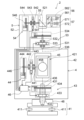
図1は、本発明の実施形態に係る3次元測量装置の構造系を主として表すブロック図である。
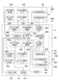
図2は、本実施形態に係る3次元測量装置の制御系を主として表すブロック図である。
FIG. 1 is a block diagram mainly showing a structural system of a three-dimensional surveying apparatus according to an embodiment of the present invention.
FIG. 2 is a block diagram mainly showing the control system of the three-dimensional surveying apparatus according to this embodiment.
本実施形態に係る3次元測量装置2は、視準測距ユニット4と、スキャナユニット5と、を備え、例えば建築物などの測定対象物7の3次元データを取得する。視準測距ユニット4は、例えばトータルステーションなどと呼ばれ、望遠鏡部45の視準により、測定対象物7に第1測距光455(図2参照)を照射し、第1測距光455が測定対象物7で反射した第1反射測距光456(図2参照)と第1内部参照光(図示せず)とに基づいて測定対象物7までの距離を測定するとともに、第1測距光455の照射方向すなわち望遠鏡部45の視準の方向を検出する。つまり、視準測距ユニット4は、測距および測角を行う機器である。視準測距ユニット4の詳細については、後述する。
A three-
視準測距ユニット4が測距および測角を行う測定対象物には、例えばプリズムなどの計測用ターゲット6が含まれる。つまり、視準測距ユニット4は、測定対象物として例えばプリズムなどの計測用ターゲット6に関する測距および測角を行うことができる。計測用ターゲット6として用いられるプリズムは、特には限定されず、例えば全周プリズムや球状プリズムや面状プリズムなどである。
The measurement target for which the collimation and
スキャナユニット5は、視準測距ユニット4と一体で設けられ、視準測距ユニット4に対して回転自在に設けられている。スキャナユニット5は、測定対象物7に第2測距光565(図2参照)を照射し、第2測距光565が測定対象物7で反射した第2反射測距光566(図2参照)と第2内部参照光(図示せず)とに基づいて測定対象物7までの距離を測定するとともに、第2測距光565の照射方向を検出する。スキャナユニット5は、視準測距ユニット4と同様に、測距および測角を行う機器である。
The
より具体的には、スキャナユニット5は、第2測距光565を回転照射し、測定対象物7までの距離を測定するとともに第2測距光565の照射方向を検出することにより、測定対象物7に関する多数の測定点の3次元座標(3次元データ)を取得する。すなわち、スキャナユニット5は、測定対象物7における多数の測定点の3次元データ(点群データ)を取得する。スキャナユニット5の詳細については、後述する。
More specifically, the
本実施形態の視準測距ユニット4は、整準部41と、第1托架部42と、第1水平回転部43と、第1鉛直回転部44と、望遠鏡部45と、制御演算部46と、操作表示部47と、基盤部48と、傾斜計49と、を有する。なお、視準測距ユニット4は、傾斜計49を必ずしも有していなくともよい。視準測距ユニット4は、測定対象物としての計測用ターゲット6を自動的に探す自動追尾機能を有していてもよい。
The collimating and ranging
制御演算部46は、演算部461と、第1距離測定部462と、第1水平回転駆動部463と、第1鉛直回転駆動部464と、第2距離測定部465と、第2水平回転駆動部466と、第2鉛直回転駆動部467と、記憶部468と、画像処理部469と、を有する。演算部461は、例えばCPU(Central Processing Unit)などであり、操作表示部47の操作入力部472から送信された信号(指令)に基づいて、プログラムの起動や、信号の制御処理や、演算や、操作表示部47の表示部471などの駆動制御などを実行する。すなわち、演算部461は、3次元測量装置2の全体の制御を行うとともに、測量条件や、測定結果(測距結果および測角結果)や、画像処理された結果(視準範囲の画像)などを表示部471に表示させる。
The
なお、制御演算部46は、スキャナユニット5に設けられていてもよく、視準測距ユニット4およびスキャナユニット5の両方に設けられていてもよい。すなわち、制御演算部46は、視準測距ユニット4およびスキャナユニット5の少なくともいずれかに設けられる。
Note that the
第1距離測定部462、第1水平回転駆動部463、第1鉛直回転駆動部464、第2距離測定部465、第2水平回転駆動部466、第2鉛直回転駆動部467、および画像処理部469は、記憶部468に格納(記憶)されているプログラムを演算部461が実行することにより実現される。なお、第1距離測定部462、第1水平回転駆動部463、第1鉛直回転駆動部464、第2距離測定部465、第2水平回転駆動部466、第2鉛直回転駆動部467、および画像処理部469は、ハードウェアによって実現されてもよく、ハードウェアとソフトウェアとの組み合わせによって実現されてもよい。
First
記憶部468には、例えば、測定のためのシーケンスプログラムや、画像処理のための画像処理プログラムや、演算プログラムなどが格納されている。記憶部468としては、例えば、3次元測量装置2に内蔵された半導体メモリなどが挙げられる。あるいは、記憶部468としては、3次元測量装置2に接続可能なCD(Compact Disc)、DVD(Digital Versatile Disc)、RAM(Random access memory)、ROM(Read only memory)、ハードディスク、メモリカードなどの種々の記憶媒体が挙げられる。
The
制御演算部46を含むコンピュータによって実行されるプログラムは、本発明の「3次元測量プログラム」に相当する。ここでいう「コンピュータ」とは、パソコンには限定されず、情報処理機器に含まれる演算処理装置、マイコン等も含み、プログラムによって本発明の機能を実現することが可能な機器、装置を総称している。
A program executed by a computer including the
整準部41は、三脚(図示せず)に取付けられる部分であり、例えば3つの調整螺子411を有する。整準部41の整準は、測量位置において、第1托架部42に設けられた傾斜センサ(図示せず)が水平を検出するように調整螺子411が調整されることにより行われる。すなわち、第1托架部42は、測量位置において、調整螺子411による整準が行われることで水平に維持される。
The leveling part 41 is a part attached to a tripod (not shown) and has, for example, three adjusting
第1水平回転部43は、第1水平回転軸431と、軸受432と、第1水平駆動モータ433と、第1水平角検出器(例えばエンコーダ)434と、を有する。第1水平回転軸431は、鉛直に延びた第1鉛直軸心436を有し、軸受432を介して基盤部48に回転自在に支持されている。第1托架部42は、第1水平回転軸431に支持され、第1水平駆動モータ433から伝達された駆動力により第1鉛直軸心436を中心として水平方向に第1水平回転軸431と一体的に回転する。
The first
基盤部48に対する第1水平回転軸431の回転角(すなわち第1托架部42の回転角)は、第1水平角検出器434によって検出される。第1水平角検出器434の検出結果は、演算部461に入力される。第1水平駆動モータ433の駆動は、第1水平角検出器434の検出結果に基づいて第1水平回転駆動部463により制御される。
A first
第1鉛直回転部44は、第1鉛直回転軸441と、軸受442と、第1鉛直駆動モータ443と、第1鉛直角検出器(例えばエンコーダ)444と、を有する。第1鉛直回転軸441は、水平に延びた第1水平軸心446を有し、軸受442を介して第1托架部42に回転自在に支持されている。第1鉛直回転軸441の一方の端部は、第1托架部42の間隙部421に突出している。望遠鏡部45は、第1托架部42の間隙部421に突出した第1鉛直回転軸441の一方の端部に支持され、第1鉛直駆動モータ443から伝達された駆動力により第1水平軸心446を中心として鉛直方向に第1鉛直回転軸441と一体的に回転する。
The first
第1鉛直角検出器444は、第1鉛直回転軸441の他方の端部に設けられている。第1托架部42に対する第1鉛直回転軸441の回転角(すなわち望遠鏡部45の回転角)は、第1鉛直角検出器444により検出される。第1鉛直角検出器444の検出結果は、演算部461に入力される。第1鉛直駆動モータ443の駆動は、第1鉛直角検出器444の検出結果に基づいて第1鉛直回転駆動部464により制御される。
The first
望遠鏡部45は、前述したように、第1鉛直回転軸441に支持され、第1鉛直駆動モータ443から伝達された駆動力により第1水平軸心446を中心として鉛直方向に回転する。望遠鏡部45は、視準望遠鏡458を有し、計測用ターゲット6を含む測定対象物7に視準され第1測距光455を照射する。第1測距光455は、望遠鏡部45の測距光軸上に射出される。望遠鏡部45の測距光軸は、第1鉛直軸心436と交差するとともに、第1水平軸心446と直交する。望遠鏡部45の測距光軸と、第1鉛直軸心436と、の交差点は、視準測距ユニット4の機械基準点に設定されてもよい。本実施形態の説明では、視準測距ユニット4の機械基準点が、望遠鏡部45の測距光軸と、第1鉛直軸心436と、の交差点である場合を例に挙げる。
As described above, the
望遠鏡部45は、第1測距発光部451と、第1測距受光部452と、視準受光部453と、を有する。
The
第1測距発光部451は、第1距離測定部462により駆動制御される。第1測距発光部451は、望遠鏡部45の内部に設けられ、例えばレーザ光などの第1測距光455を第1水平軸心446に直交する方向に射出する。第1測距発光部451から射出された第1測距光455は、測定対象物7に照射される。なお、前述したように、視準測距ユニット4が測距および測角を行う測定対象物は、建築物などの測定対象物7に限定されるわけではなくプリズムなどの計測用ターゲット6であってもよい。測定対象物7で反射した第1反射測距光456は、望遠鏡部45の内部に設けられた第1測距受光部452において受光される。第1測距受光部452は、受光した第1反射測距光456による明暗(受光結果)を電子信号(受光信号)に変換し、受光信号を第1距離測定部462に送信する。また、第1測距受光部452は、参照光光学部(図示せず)から導かれた内部参照光(図示せず)を受光し電気信号に変換して、第1距離測定部462に送信する。
The first distance measuring
第1距離測定部462は、第1測距受光部452から送信された受光信号に基づいて測定対象物7までの距離を演算する。すなわち、第1反射測距光456および内部参照光は、第1反射測距光電気信号および内部参照光電気信号のそれぞれに変換され、第1距離測定部462に送られる。測定対象物7までの距離は、第1反射測距光電気信号と内部参照光電気信号との間の時間的間隔の差に基づいて測定される。第1距離測定部462の演算結果は、演算部(CPU)461に入力される。
The first
演算部461は、測定した測定対象物7までの距離と、第1鉛直角検出器444により検出された鉛直角と、第1水平角検出器434により検出された水平角と、に基づいて、測定対象物7の座標を算出する。あるいは、演算部461は、測定した測定対象物7までの距離と、第1鉛直角検出器444により検出された鉛直角と、第1水平角検出器434により検出された水平角と、に基づいて、所定位置(例えば後述する測量開始位置)を基準とした視準測距ユニット4の機械基準点の座標を算出してもよい。
Based on the measured distance to the
視準受光部453は、例えばCCD(Charge Coupled Device)やCMOS(Complementary Metal Oxide Semiconductor)などのイメージセンサであり、第1反射測距光456の波長域とは異なる波長域の反射視準光457を受光する。反射視準光457は、第1反射測距光456の波長域とは異なる波長域を有する光であって、測定対象物7で反射した光である。すなわち、視準受光部453は、測定対象物7で反射した反射視準光457を受光し、測定対象物7の画像を受光する。反射視準光457としては、例えば自然光や赤外光などが挙げられる。但し、反射視準光457は、これだけには限定されない。反射視準光457は、望遠鏡部45の内部に設けられた視準受光部453において受光される。視準受光部453は、反射視準光457による明暗(受光結果)を電子信号(画像信号)に変換し、画像信号を画像処理部469に送信する。
The collimation
画像処理部469は、視準受光部453から送信された画像信号の画像処理を実行し、画像データ信号として演算部461に送信する。演算部461は、画像処理部469から送信された画像データ信号に基づいて演算を実行し、望遠鏡部45による視準範囲の画像を操作表示部47の表示部471に表示させる制御を実行する。
The
傾斜計49は、重力に対する視準測距ユニット4の傾き(傾斜角)を計測する。傾斜計49の計測結果は、演算部461に入力される。
The
本実施形態のスキャナユニット5は、第2托架部52と、第2水平回転部53と、第2鉛直回転部54と、走査鏡55と、第2測距発光部56と、第2測距受光部57と、を有する。
The
第2水平回転部53は、第2水平回転軸531と、軸受532と、第2水平駆動モータ533と、第2水平角検出器(例えばエンコーダ)534と、を有する。第2水平回転軸531は、鉛直に延びた第2鉛直軸心536を有し、軸受532を介して第2托架部52に回転自在に支持されている。第2水平回転軸531の一方の端部は、視準測距ユニット4の第1托架部42に接続されている。第2托架部52は、第2水平回転軸531に支持され、第2水平駆動モータ533から伝達された駆動力により第2鉛直軸心536を中心として水平方向に第2水平回転軸531と一体的に回転する。
The second
第2鉛直軸心536は、第1鉛直軸心436と平行である。本実施形態に係る3次元測量装置2では、第1鉛直軸心436および第2鉛直軸心536は、互いに同一直線上に存在する。ただし、第1鉛直軸心436および第2鉛直軸心536は、互いに同一直線上に存在することには限定されない。第1鉛直軸心436と第2鉛直軸心536との間の距離は、既知である。すなわち、第1鉛直軸心436に対する第2鉛直軸心536の位置は、既知である。
Second
第2水平角検出器534は、第2水平回転軸531の他方の端部に設けられている。第1托架部42に対する第2水平回転軸531の回転角(すなわち第2托架部52の回転角)は、第2水平角検出器534により検出される。第2水平角検出器534の検出結果は、演算部461に入力される。第2水平駆動モータ533の駆動は、第2水平角検出器534の検出結果に基づいて第2水平回転駆動部466により制御される。
A second
第2鉛直回転部54は、第2鉛直回転軸541と、軸受542と、第2鉛直駆動モータ543と、第2鉛直角検出器(例えばエンコーダ)544と、を有する。第2鉛直回転軸541は、水平に延びた第2水平軸心546を有し、軸受542を介して第2托架部52に回転自在に支持されている。第2鉛直回転軸541の一方の端部は、第2托架部52の凹部521に突出している。走査鏡55は、第2托架部52の凹部521に突出した第2鉛直回転軸541の一方の端部に支持され、第2鉛直駆動モータ543から伝達された駆動力により第2水平軸心546を中心として鉛直方向に第2鉛直回転軸541と一体的に回転する。
The second
第2鉛直角検出器544は、第2鉛直回転軸541の他方の端部に設けられている。第2托架部52に対する第2鉛直回転軸541の回転角(すなわち走査鏡55の回転角)は、第2鉛直角検出器544により検出される。第2鉛直角検出器544の検出結果は、演算部461に入力される。第2鉛直駆動モータ543の駆動は、第2鉛直角検出器544の検出結果に基づいて第2鉛直回転駆動部467により制御される。
A second
第2水平軸心546は、第1水平軸心446と平行である。第1水平軸心446と第2水平軸心546との間の距離は、既知である。すなわち、第1水平軸心446に対する第2水平軸心546の位置は、既知である。
Second
走査鏡55は、偏向光学部材であり、水平方向から入射した第2測距光565を直角に反射する。すなわち、走査鏡55は、水平方向から入射した第2測距光565を第2水平軸心546に直交する方向に反射する。走査鏡55は、前述したように、第2鉛直回転軸541に支持され、第2鉛直駆動モータ543から伝達された駆動力により第2水平軸心546を中心として鉛直方向に回転する。これにより、走査鏡55は、第2測距光565を第2水平軸心546に交差(具体的には直交)する面内で回転照射させる。また、走査鏡55は、測定対象物7で反射され走査鏡55に入射した第2反射測距光566を第2測距受光部57に向かって反射する。すなわち、走査鏡55は、測定対象物7で反射され走査鏡55に入射した第2反射測距光566を第2水平軸心546に平行な方向に反射する。
The
第2水平軸心546と、走査鏡55と、の交差点は、スキャナユニット5の機械基準点に設定されている。例えば、視準測距ユニット4の機械基準点と、スキャナユニット5の機械基準点と、は、互いに同一直線上に存在する第1鉛直軸心436および第2鉛直軸心536の上に存在する。視準測距ユニット4の機械基準点と、スキャナユニット5の機械基準点と、の間の距離は、既知である。
The intersection of the second
図2に表したように、第2測距発光部56は、発光素子561と、対物レンズ等を含む投光光学部562と、を有し、第2距離測定部465により駆動制御される。発光素子561は、例えば半導体レーザ等であり、投光光学部562を介して第2測距光565を第2水平軸心546に合致する光軸上に射出する。第2測距光565は、不可視光としての赤外光のパルスレーザ光線である。発光素子561は、第2距離測定部465に制御され、所要の光強度や所要のパルス間隔などを含む所要の状態でパルス光を発光する。
As shown in FIG. 2 , the second distance measuring
図2に表したように、第2測距受光部57は、受光素子571と、集光レンズなどを含む受光光学部572と、を有する。受光素子571は、第2測距光565が測定対象物7で反射した第2反射測距光566であって、走査鏡55で反射し受光光学部572を透過した第2反射測距光566を受光する。受光素子571は、受光した第2反射測距光566による明暗(受光結果)を電子信号(受光信号)に変換し、受光信号を第2距離測定部465に送信する。また、受光素子571は、参照光光学部(図示せず)から導かれた内部参照光(図示せず)を受光し電気信号に変換して、第2距離測定部465に送信する。
As shown in FIG. 2, the second distance measuring
第2距離測定部465は、第2測距受光部57(具体的には受光素子571)から送信された受光信号に基づいて測定対象物7までの距離を演算する。すなわち、第2反射測距光566および内部参照光は、第2反射測距光電気信号および内部参照光電気信号のそれぞれに変換され、第2距離測定部465に送られる。測定対象物7までの距離は、第2反射測距光電気信号と内部参照光電気信号との間の時間的間隔の差に基づいて測定される。第2距離測定部465の演算結果は、演算部461に入力される。
The second
演算部461は、測定した測定対象物7までの距離と、第2鉛直角検出器544により検出された鉛直角と、第2水平角検出器534により検出された水平角と、に基づいて、測定対象物7の座標を算出する。また、演算部461は、パルス光毎の測定対象物7の座標を記録することで、測定範囲全域に関する点群データ、あるいは測定対象物7に関する点群データを得ることができる。
Based on the measured distance to the
次に、本実施形態に係る3次元測量装置の動作の概略を、図面を参照して説明する。
図3は、本実施形態に係る3次元測量装置の動作の概略を表すフローチャートである。
図4は、本実施形態に係る3次元測量装置が複数の位置で測定対象物の3次元データを取得する状況を例示する模式図である。
図5は、複数の位置のそれぞれにおいて取得された測定対象物の3次元データを例示する模式図である。
図6は、簡易的な点群データのレジストレーションが実行された状態を例示する模式図である。
図7は、詳細な点群データのレジストレーションが実行された状態を例示する模式図である。
なお、図3は、すなわち、本実施形態に係る3次元測量方法により実行されるステップと、本実施形態に係る3次元測量プログラムが3次元測量装置2のコンピュータに実行させるステップと、の概略を表すフローチャートである。
Next, the outline of the operation of the three-dimensional surveying device according to this embodiment will be described with reference to the drawings.
FIG. 3 is a flow chart showing the outline of the operation of the three-dimensional surveying device according to this embodiment.
FIG. 4 is a schematic diagram illustrating a situation in which the three-dimensional surveying apparatus according to this embodiment acquires three-dimensional data of a measurement object at a plurality of positions.
FIG. 5 is a schematic diagram illustrating three-dimensional data of the measurement object obtained at each of a plurality of positions.
FIG. 6 is a schematic diagram illustrating a state in which simple point cloud data registration is performed.
FIG. 7 is a schematic diagram illustrating a state in which detailed point cloud data registration has been performed.
FIG. 3 outlines the steps executed by the three-dimensional survey method according to the present embodiment and the steps executed by the computer of the three-
測定対象物7が例えば建築物などの比較的大きい場合には、3次元測量装置2は、1つの位置において測定対象物7の全体の3次元データを取得することはできない。例えば、3次元測量装置2は、3次元測量装置2が設置された位置(測量位置)から視準できない建築物の裏側の壁面の3次元データを取得することはできない。そのため、このような場合には、作業者等は、3次元測量装置2を移動させ、互いに異なる複数の位置のそれぞれにおいて測定対象物7の3次元データを取得することより、測定対象物7の全体の3次元データを取得する。
If the
図4は、矢印A11、A12、A13に表したように、3次元測量装置2が、測量開始位置(第1測量位置)P1において測定対象物7の3次元データの取得を開始した後、第2測量位置P2と、第3測量位置P3と、第4測量位置P4と、にこの順に移動され、それぞれの測量位置P2、P3、P4において測定対象物7の3次元データを取得する例を表している。
In FIG. 4, as indicated by arrows A11, A12, and A13, after the three-
図3に表したように、まず、ステップS11において、3次元測量装置2の制御演算部46は、例えば後方交会法などを用いたバックサイトにより測量開始位置P1における視準測距ユニット4の機械基準点の座標と、視準測距ユニット4の望遠鏡部45の基準視準の方向と、を記憶部468に記憶する。すなわち、制御演算部46は、視準測距ユニット4から例えばプリズムなどの計測用ターゲット6までの距離と、第1鉛直角検出器444により検出された鉛直角と、第1水平角検出器434により検出された水平角と、に基づいて、視準測距ユニット4の機械基準点の座標と、視準測距ユニット4の望遠鏡部45の基準視準の方向と、を算出し記憶部468に記憶する。なお、ステップS11において、計測用ターゲット6は、必ずしも用いられなくともよい。
As shown in FIG. 3, first, in step S11, the
続いて、ステップS12において、制御演算部46は、測量開始位置P1において取得された3次元データ(点群データ)を記憶部468に記憶する。測量開始位置P1において取得され記憶部468に記憶された3次元データD1の例は、図5(a)に表した通りである。続いて、ステップS13において、作業者等は、測量開始位置P1から第2測量位置P2に3次元測量装置2を移動させる。第2測量位置P2は、作業者等により任意に決定され、測量開始位置P1からみて直接的に視準できる位置であってもよく、測量開始位置P1からみて直接的に視準できない位置であってもよい。続いて、ステップS14において、制御演算部46は、第2測量位置P2において取得された3次元データ(点群データ)を記憶する。第2測量位置P2において取得され記憶部468に記憶された3次元データD2の例は、図5(b)に表した通りである。
Subsequently, in step S<b>12 , the
続いて、3次元測量装置2による3次元測量を終了しない場合には(ステップS15:NO)、制御演算部46は、ステップS13およびステップS14に関して前述した処理を繰り返し実行する。すなわち、図4に表した例では、ステップS15に続くステップS13において、作業者等は、第2測量位置P2から第3測量位置P3に3次元測量装置2を移動させる。続いて、ステップS14において、制御演算部46は、第3測量位置P3において取得された3次元データ(点群データ)を記憶する。第3測量位置P3において取得され記憶部468に記憶された3次元データD3の例は、図5(c)に表した通りである。
Subsequently, when the three-dimensional surveying by the three-
さらに、ステップS15に続くステップS13において、作業者等は、第3測量位置P3から第4測量位置P4に3次元測量装置2を移動させる。続いて、ステップS14において、制御演算部46は、第4測量位置P4において取得された3次元データ(点群データ)を記憶する。第4測量位置P4において取得され記憶部468に記憶された3次元データD4の例は、図5(d)に表した通りである。
Further, in step S13 following step S15, the operator or the like moves the three-
3次元測量装置2による3次元測量を終了する場合には(ステップS15:YES)、制御演算部46は、3次元測量装置2による3次元測量を終了する。
When the three-dimensional surveying by the three-
図6に表したように、3次元データD1、D2、D3、D4が例えば3次元測量装置2とは異なる他のコンピュータ(例えばパソコン)に入力されると、他のコンピュータは、自動的に簡易的な点群データのレジストレーションを実行する。
As shown in FIG. 6, when the three-dimensional data D1, D2, D3, and D4 are input to another computer (for example, a personal computer) different from the three-
ここで、3次元データD1、D2、D3、D4の間において、測定対象物7の同一箇所の相対的位置のずれが大きい場合や、測定対象物7の傾きの相対的角度のずれが大きい場合には、点群データのレジストレーションにおいて比較的長い処理時間が必要になったり、点群データのレジストレーションが完了できなかったりすることがある。また、点群データのレジストレーションの処理時間を短縮化したり、点群データのレジストレーションをより確実に完了させたりするために、3次元データD1、D2、D3、D4の間における測定対象物7の同一箇所の相対的位置や測定対象物7の傾きの相対的角度を手動で一定程度まで合わせることがある。このように、3次元データD1、D2、D3、D4の間において、測定対象物7の同一箇所の相対的位置のずれが大きい場合や、測定対象物7の傾きの相対的角度のずれが大きい場合には、点群データのレジストレーションにおいて時間や手間がかかることがある。
Here, between the three-dimensional data D1, D2, D3, and D4, when there is a large deviation in the relative position of the same part of the
これに対して、本実施形態に係る3次元測量装置2では、後に詳述する動作や処理に基づいて、制御演算部が、測量開始位置P1における視準測距ユニット4の機械基準点の座標と、測量開始位置P1を基準とした移動先位置における視準測距ユニット4の機械基準点の座標と、を記憶する。図4に表した例では、第2測量位置P2、第3測量位置P3および第4測量位置P4が、「移動先位置」に相当する。これにより、図6に表したように、3次元データD1、D2、D3、D4が入力された例えば他のコンピュータにより、簡易的な点群データのレジストレーションが実行されると、互いに異なる複数の測量位置P1、P2、P3、P4で取得された複数の3次元データ(点群データ)D1、D2、D3、D4の間において、測定対象物7の同一箇所の相対的位置、および測定対象物7の傾きの相対的角度がおおよそ一致する。すなわち、互いに異なる複数の測量位置P1、P2、P3、P4で取得された複数の3次元データ(点群データ)D1、D2、D3、D4の間において、測定対象物7の同一箇所の相対的位置のずれ、および測定対象物7の傾きの相対的角度のずれを抑えることができる。そのため、図7に表したように、詳細な点群データのレジストレーションが実行される際に、比較的長い処理時間が必要になったり、詳細な点群データのレジストレーションが完了できなかったりすることを抑えることができる。これにより、本実施形態に係る3次元測量装置2は、点群データのレジストレーションを効率的に実行させることができる。
On the other hand, in the three-
なお、簡易的な点群データのレジストレーションおよび詳細な点群データのレジストレーションは、3次元測量装置2とは異なる他のコンピュータ(例えばパソコン)により実行されることに限定されるわけではなく、3次元測量装置2の制御演算部46により実行されてもよい。本実施形態の説明では、簡易的な点群データのレジストレーションおよび詳細な点群データのレジストレーションが、3次元測量装置2とは異なる他のコンピュータ(例えばパソコン)により実行される場合を例に挙げる。また、詳細な点群データのレジストレーションとしては、ICP(Interactive Closest Point)アルゴリズムや、ICPアルゴリズムを拡張した手法など、種々の公知技術が利用可能である。
Simple point cloud data registration and detailed point cloud data registration are not limited to being executed by another computer (for example, a personal computer) different from the three-
次に、本実施形態に係る3次元測量装置の動作の詳細を、図面を参照して説明する。
図8~図10は、本実施形態に係る3次元測量装置の動作の詳細を表すフローチャートである。
図11は、本実施形態に係る3次元測量装置の各位置での動作および複数の位置同士の間の移動を説明する模式図である。
図12は、移動先位置における視準測距ユニットの機械基準点の座標の算出方法を説明する模式図である。
なお、図8~図10は、すなわち、本実施形態に係る3次元測量方法により実行されるステップと、本実施形態に係る3次元測量プログラムが3次元測量装置2のコンピュータに実行させるステップと、の詳細を表すフローチャートである。
Next, details of the operation of the three-dimensional surveying apparatus according to this embodiment will be described with reference to the drawings.
8 to 10 are flow charts showing the details of the operation of the three-dimensional surveying device according to this embodiment.
FIG. 11 is a schematic diagram for explaining the operation at each position and movement between a plurality of positions of the three-dimensional surveying apparatus according to this embodiment.
FIG. 12 is a schematic diagram illustrating a method of calculating the coordinates of the machine reference point of the collimation and distance measurement unit at the destination position.
8 to 10 show the steps executed by the three-dimensional survey method according to the present embodiment, the steps executed by the three-dimensional survey program according to the present embodiment to the computer of the three-
図8~図12を参照して説明する例では、図11に表した矢印A11、A12、A13のように、3次元測量装置2は、測量開始位置(第1測量位置)P1において測定対象物7の3次元データの取得を開始した後、第2測量位置P2と、第3測量位置P3と、第4測量位置P4と、にこの順に移動され、それぞれの測量位置P2、P3、P4において測定対象物7の3次元データを取得する。
In the example described with reference to FIGS. 8 to 12, as indicated by arrows A11, A12, and A13 shown in FIG. After starting the acquisition of the three-dimensional data of 7, it is moved to the second survey position P2, the third survey position P3, and the fourth survey position P4 in this order, and measurements are taken at the respective survey positions P2, P3, and P4. Three-dimensional data of the
まず、図8に表したステップS21~S28を参照し、図11に表した矢印A11のように、3次元測量装置2が、測量開始位置P1から第2測量位置P2に移動され、測量開始位置P1および第2測量位置P2のそれぞれにおいて測定対象物7の3次元データ(点群データ)を取得する場合を説明する。そのため、図8に表したステップS21~S28では、測量開始位置(第1測量位置)P1が「移動元位置」に相当し、第2測量位置P2が「移動先位置」に相当する。
First, referring to steps S21 to S28 shown in FIG. 8, the three-
図8に表したように、ステップS21において、3次元測量装置2の制御演算部46は、例えば後方交会法などを用いたバックサイトにより測量開始位置P1における視準測距ユニット4の機械基準点の座標と、視準測距ユニット4の望遠鏡部45の基準視準の方向TS0(図11参照)と、を記憶部468に記憶する。すなわち、制御演算部46は、視準測距ユニット4から例えばプリズムなどの計測用ターゲット6までの距離と、第1鉛直角検出器444により検出された鉛直角と、第1水平角検出器434により検出された水平角と、に基づいて、視準測距ユニット4の機械基準点の座標と、視準測距ユニット4の望遠鏡部45の基準視準の方向TS0と、を算出し記憶部468に記憶する。なお、ステップS21において、計測用ターゲット6は、必ずしも用いられなくともよい。
As shown in FIG. 8, in step S21, the
図12に表したように、バックサイトにより視準測距ユニット4の基準視準の方向TS0が設定され記憶されると、視準測距ユニット4の基準視準の方向TS0と、スキャナユニット5の基準視準の方向SC0と、の間の相対的角度が決まる。すなわち、スキャナユニット5の基準視準の方向SC0は、予め設定され固定されており、作業者等がスキャナユニット5の基準視準の方向SC0を設定変更することはできない。一方で、ステップS21に関して前述したように、視準測距ユニット4の基準視準の方向TS0は、測量開始位置P1におけるバックサイトにより設定され記憶されると、再び設定され記憶されるまで変わらない。言い換えると、作業者等は、再度のバックサイトにより、視準測距ユニット4の基準視準の方向TS0を再び設定し記憶することができる。そのため、バックサイトにより視準測距ユニット4の基準視準の方向TS0が設定され記憶されると、視準測距ユニット4の基準視準の方向TS0と、スキャナユニット5の基準視準の方向SC0と、の間の相対的角度は、視準測距ユニット4の基準視準の方向TS0が再び設定され記憶されるまで固定された状態になる。これにより、制御演算部46は、測量開始位置P1を基準として複数の測量位置P2、P3、P4における視準測距ユニット4の回転角度(望遠鏡部45の視準の回転角度)を算出することができる。
As shown in FIG. 12, when the reference collimation direction TS0 of the collimating and ranging
続いて、ステップS22において、図11に表した矢印A21のように、制御演算部46は、スキャナユニット5を制御することにより、3次元測量装置2を移動させる前の移動元位置(測量開始位置P1)において取得された第1点群データを記憶部468に記憶する。
Subsequently, in step S22, as indicated by an arrow A21 shown in FIG. The first point cloud data acquired in P1) is stored in the
続いて、ステップS23において、制御演算部46は、移動元位置(測量開始位置P1)から3次元測量装置2を移動させた後の移動先位置(第2測量位置P2)に向けられた望遠鏡部45の第1視準の方向A1(図11参照)を記憶する。第1視準の方向A1は、精密な方向でなくともよく、粗い精度の方向であってもよい。なお、望遠鏡部45は、例えば作業者等により、移動元位置(測量開始位置P1)から移動先位置(第2測量位置P2)に向けられる。
Subsequently, in step S23, the
続いて、ステップS24において、作業者等は、移動元位置(測量開始位置P1)から移動先位置(第2測量位置P2)に3次元測量装置2を移動させる。続いて、ステップS25において、制御演算部46は、移動先位置(第2測量位置P2)から移動元位置(測量開始位置P1)に向けられた望遠鏡部45の第2視準の方向A2(図11参照)を記憶する。第2視準の方向A2は、精密な方向でなくともよく、粗い精度の方向であってもよい。なお、望遠鏡部45は、例えば作業者等により、移動先位置(第2測量位置P2)から移動元位置(測量開始位置P1)に向けられる。
Subsequently, in step S24, the operator or the like moves the three-
また、ステップS26において、制御演算部46は、移動元位置(測量開始位置P1)と、移動先位置(第2測量位置P2)と、の間の第1移動距離を記憶する。第1移動距離は、精密な距離でなくともよく、粗い精度の距離であってもよい。例えば、第1移動距離は、操作入力部472(図2参照)に対する作業者等の操作に応じて作業者等により入力される。この場合には、作業者等は、操作入力部472に対して操作を行うことにより、第1移動距離を簡易的に入力することができる。例えば、移動先位置(第2測量位置P2)が移動元位置(測量開始位置P1)からみて直接的に視準できない位置である場合において、作業者等は、プリズムなどの計測用ターゲット6を用いなくとも、操作入力部472に対する操作により第1移動距離を入力できる。
In step S26, the
あるいは、例えば、第1移動距離は、視準測距ユニット4の第1距離測定部462により演算され自動的に入力される。第1距離測定部462は、本発明の「距離測定部」の一例である。この場合には、作業者等は、第1移動距離を手入力しなくとも、移動先位置(第2測量位置P2)から移動元位置(測量開始位置P1)に向けて望遠鏡部45の視準を行うことで、第1移動距離を容易に入力できる。
Alternatively, for example, the first movement distance is calculated by the first
なお、ステップS26の処理は、ステップS25の処理と同時に実行されてもよく、ステップS24とステップS25との間に実行されてもよい。 Note that the process of step S26 may be performed simultaneously with the process of step S25, or may be performed between steps S24 and S25.
続いて、ステップS27において、制御演算部46は、第1視準の方向A1と、第2視準の方向A2と、第1移動距離と、に基づいて測量開始位置P1を基準とした移動先位置(第2測量位置P2)における視準測距ユニット4の機械基準点の座標を算出し記憶部468に記憶する。
Subsequently, in step S27, the
すなわち、ステップS21に関して前述したように、制御演算部46は、測量開始位置P1を基準として複数の測量位置P2、P3、P4における視準測距ユニット4の回転角度(望遠鏡部45の視準の回転角度)を算出することができる。そのため、図12に表したように、制御演算部46は、第1視準の方向A1と、第2視準の方向A2と、の間の相対的角度を算出することができる。そして、制御演算部46は、第1視準の方向A1と第2視準の方向A2との間の相対的角度に基づいて、移動元位置(測量開始位置P1)から移動先位置(第2測量位置P2)に向かう視準測距ユニット4の機械基準点の移動方向を算出する。また、制御演算部46は、視準測距ユニット4の機械基準点の移動方向と、移動元位置(測量開始位置P1)と移動先位置(第2測量位置P2)との間の第1移動距離(すなわち視準測距ユニット4の機械基準点の第1移動距離)と、に基づいて、測量開始位置P1を基準とした移動先位置(第2測量位置P2)における視準測距ユニット4の機械基準点の座標を算出し記憶部468に記憶する。図12に表した例では、測量開始位置P1における視準測距ユニット4の機械基準点の座標が(0,0)であり、第2測量位置P2における視準測距ユニット4の機械基準点の座標が(0,10)である。
That is, as described above with respect to step S21, the
続いて、ステップS28において、図11に表した矢印A22のように、制御演算部46は、スキャナユニット5を制御することにより、移動先位置(第2測量位置P2)において取得された第2点群データを記憶部468に記憶する。
Subsequently, in step S28, as indicated by arrow A22 shown in FIG. Group data is stored in the
続いて、図9に表したステップS31~S36を参照し、図11に表した矢印A12のように、3次元測量装置2が、第2測量位置P2から第3測量位置P3に移動され、第3測量位置P3において測定対象物7の3次元データ(点群データ)を取得する場合を説明する。そのため、図9に表したステップS31~S36では、第2測量位置P2が「移動元位置」に相当し、第3測量位置P3が「移動先位置」に相当する。
Subsequently, referring to steps S31 to S36 shown in FIG. 9, the three-
ステップS31において、制御演算部46は、3次元測量装置2を移動させる前の移動元位置(第2測量位置P2)から3次元測量装置2を移動させた後の移動先位置(第3測量位置P3)に向けられた望遠鏡部45の第3視準の方向A3(図11参照)を記憶する。第3視準の方向A3は、精密な方向でなくともよく、粗い精度の方向であってもよい。なお、望遠鏡部45は、例えば作業者等により、移動元位置(第2測量位置P2)から移動先位置(第3測量位置P3)に向けられる。
In step S31, the
続いて、ステップS32において、作業者等は、移動元位置(第2測量位置P2)から移動先位置(第3測量位置P3)に3次元測量装置2を移動させる。続いて、ステップS33において、制御演算部46は、移動先位置(第3測量位置P3)から移動元位置(第2測量位置P2)に向けられた望遠鏡部45の第4視準の方向A4(図11参照)を記憶する。第4視準の方向A4は、精密な方向でなくともよく、粗い精度の方向であってもよい。なお、望遠鏡部45は、例えば作業者等により、移動先位置(第3測量位置P3)から移動元位置(第2測量位置P2)に向けられる。
Subsequently, in step S32, the operator or the like moves the three-
また、ステップS34において、制御演算部46は、移動元位置(第2測量位置P2)と、移動先位置(第3測量位置P3)と、の間の第2移動距離を記憶する。第2移動距離は、精密な距離でなくともよく、粗い精度の距離であってもよい。第2移動距離の入力手段は、第1移動距離(図8参照)の入力手段に関して前述した通りである。
Further, in step S34, the
なお、ステップS34の処理は、ステップS33の処理と同時に実行されてもよく、ステップS32とステップS33との間に実行されてもよい。 Note that the process of step S34 may be performed simultaneously with the process of step S33, or may be performed between steps S32 and S33.
続いて、ステップS35において、制御演算部46は、第3視準の方向A3と、第4視準の方向A4と、第2移動距離と、に基づいて測量開始位置P1を基準とした移動先位置(第3測量位置P3)における視準測距ユニット4の機械基準点の座標を算出し記憶部468に記憶する。測量開始位置P1を基準とした移動先位置(第3測量位置P3)における視準測距ユニット4の機械基準点の座標の算出方法は、ステップS27(図8参照)に関して前述した通りである(図12参照)。
Subsequently, in step S35, the
続いて、ステップS36において、図11に表した矢印A23のように、制御演算部46は、スキャナユニット5を制御することにより、移動先位置(第3測量位置P3)において取得された第3点群データを記憶部468に記憶する。
Subsequently, in step S36, as indicated by an arrow A23 shown in FIG. 11, the
続いて、図10に表したステップS41~S46を参照し、図11に表した矢印A13のように、3次元測量装置2が、第3測量位置P3から第4測量位置P4に移動され、第4測量位置P4において測定対象物7の3次元データ(点群データ)を取得する場合を説明する。そのため、図10に表したステップS41~S46では、第3測量位置P3が「移動元位置」に相当し、第4測量位置P4が「移動先位置」に相当する。
Subsequently, referring to steps S41 to S46 shown in FIG. 10, the three-
ステップS41において、制御演算部46は、3次元測量装置2を移動させる前の移動元位置(第3測量位置P3)から3次元測量装置2を移動させた後の移動先位置(第4測量位置P4)に向けられた望遠鏡部45の第5視準の方向A5(図11参照)を記憶する。第5視準の方向A5は、精密な方向でなくともよく、粗い精度の方向であってもよい。なお、望遠鏡部45は、例えば作業者等により、移動元位置(第3測量位置P3)から移動先位置(第4測量位置P4)に向けられる。
In step S41, the
続いて、ステップS42において、作業者等は、移動元位置(第3測量位置P3)から移動先位置(第4測量位置P4)に3次元測量装置2を移動させる。続いて、ステップS43において、制御演算部46は、移動先位置(第4測量位置P4)から移動元位置(第3測量位置P3)に向けられた望遠鏡部45の第6視準の方向A6(図11参照)を記憶する。第6視準の方向A6は、精密な方向でなくともよく、粗い精度の方向であってもよい。なお、望遠鏡部45は、例えば作業者等により、移動先位置(第4測量位置P4)から移動元位置(第3測量位置P3)に向けられる。
Subsequently, in step S42, the operator or the like moves the three-
また、ステップS44において、制御演算部46は、移動元位置(第3測量位置P3)と、移動先位置(第4測量位置P4)と、の間の第3移動距離を記憶する。第3移動距離は、精密な距離でなくともよく、粗い精度の距離であってもよい。第3移動距離の入力手段は、第1移動距離(図8参照)の入力手段に関して前述した通りである。
Further, in step S44, the
なお、ステップS44の処理は、ステップS43の処理と同時に実行されてもよく、ステップS42とステップS43との間に実行されてもよい。 Note that the process of step S44 may be performed simultaneously with the process of step S43, or may be performed between steps S42 and S43.
続いて、ステップS45において、制御演算部46は、第5視準の方向A5と、第6視準の方向A6と、第3移動距離と、に基づいて測量開始位置P1を基準とした移動先位置(第4測量位置P4)における視準測距ユニット4の機械基準点の座標を算出し記憶部468に記憶する。測量開始位置P1を基準とした移動先位置(第4測量位置P4)における視準測距ユニット4の機械基準点の座標の算出方法は、ステップS27(図8参照)に関して前述した通りである(図12参照)。
Subsequently, in step S45, the
続いて、ステップS46において、図11に表した矢印A24のように、制御演算部46は、スキャナユニット5を制御することにより、移動先位置(第4測量位置P4)において取得された第4点群データを記憶部468に記憶する。続いて、作業者等は、3次元測量装置2による3次元データの取得を停止する操作を行い、3次元測量装置2による測量を終了させる。
Subsequently, in step S46, as indicated by arrow A24 shown in FIG. Group data is stored in the
本実施形態に係る3次元測量装置2によれば、制御演算部46は、測量開始位置P1における視準測距ユニット4の機械基準点の座標と、測量開始位置P1を基準とした移動先位置(第2測量位置P2、第3測量位置P3および第4測量位置P4)における視準測距ユニット4の機械基準点の座標と、を記憶する。そのため、例えば第1点群データ、第2点群データ、第3点群データおよび第4点群データが入力された他のコンピュータなどは、簡易的な点群データのレジストレーションを実行することができる。簡易的な点群データのレジストレーションが実行されることにより、互いに異なる複数の測量位置P1、P2、P3、P4で取得された複数の点群データの間において、測定対象物7の同一箇所の相対的位置、および測定対象物7の傾きの相対的角度がおおよそ一致する。すなわち、互いに異なる複数の測量位置P1、P2、P3、P4で取得された複数の点群データの間において、測定対象物7の同一箇所の相対的位置のずれ、および測定対象物7の傾きの相対的角度のずれを抑えることができる。そのため、詳細な点群データのレジストレーションが実行される際に、比較的長い処理時間が必要になったり、詳細な点群データのレジストレーションが完了できなかったりすることを抑えることができる。これにより、本実施形態に係る3次元測量装置2は、点群データのレジストレーションを効率的に実行させることができる。
According to the three-
図3~図7に関して前述したように、簡易的な点群データのレジストレーションおよび詳細な点群データのレジストレーションは、3次元測量装置2とは異なる他のコンピュータ(例えばパソコン)により実行されることに限定されるわけではなく、3次元測量装置2の制御演算部46により実行されてもよい。また、本実施形態に係る3次元測量方法および3次元測量プログラムについても、同様の効果が得られる。
As described above with reference to FIGS. 3 to 7, simple point cloud data registration and detailed point cloud data registration are performed by another computer (eg, personal computer) different from the three-
次に、本発明者が実施した検討の結果の一例を、図面を参照して説明する。
図13は、簡易的な点群データのレジストレーションが実行された結果の一例を表す模式図である。
図14は、詳細な点群データのレジストレーションが実行された結果の一例を表す模式図である。
図15は、比較例の結果の一例を表す模式図である。
Next, an example of the results of studies conducted by the inventor will be described with reference to the drawings.
FIG. 13 is a schematic diagram showing an example of a result of execution of simple point cloud data registration.
FIG. 14 is a schematic diagram showing an example of a result of detailed point cloud data registration.
FIG. 15 is a schematic diagram showing an example of the results of the comparative example.
まず、図15を参照し、比較例の結果の一例を説明する。図15は、第1点群データD21、第2点群データD22および第3点群データD23が3次元測量装置とは異なる他のコンピュータに入力された結果の一例を表している。第1点群データD21、第2点群データD22および第3点群データD23は、互いに異なる複数の測量位置で取得された点群データであり、自動的な点群データのレジストレーションを実行可能な情報を含んでいるわけではない。図15に表した比較例では、第1点群データD21、第2点群データD22および第3点群データD23が他のコンピュータに入力されたとしても、自動的な点群データのレジストレーションを実行可能な情報が存在しないため、各点群データD21、D22、D23における視準測距ユニット4の機械基準点が座標原点に集まり、また、各点群データD21、D22、D23における回転が不揃いである。
First, with reference to FIG. 15, an example of the results of the comparative example will be described. FIG. 15 shows an example of the result of inputting the first point cloud data D21, the second point cloud data D22, and the third point cloud data D23 to another computer different from the three-dimensional surveying device. The first point cloud data D21, the second point cloud data D22, and the third point cloud data D23 are point cloud data acquired at a plurality of different surveying positions, and automatic point cloud data registration can be executed. does not contain useful information. In the comparative example shown in FIG. 15, even if the first point cloud data D21, the second point cloud data D22, and the third point cloud data D23 are input to another computer, automatic point cloud data registration is performed. Since there is no executable information, the mechanical reference points of the sighting and ranging
このように、本比較例では、図3~図12に関して前述した本実施形態の動作や処理が実行されないため、第1点群データD21、第2点群データD22および第3点群データD23の間において、測定対象物7の同一箇所の相対的位置のずれ、および測定対象物7の傾きの相対的角度のずれが大きい。この場合には、点群データのレジストレーションが完了できなかったり、点群データのレジストレーションを完了させるために、第1点群データD21、第2点群データD22および第3点群データD23の間における測定対象物7の同一箇所の相対的位置や測定対象物7の傾きの相対的角度を手動で一定程度まで合わせる必要があったりする。
As described above, in this comparative example, the operations and processes of the present embodiment described above with reference to FIGS. 3 to 12 are not executed. In between, the deviation of the relative position of the same part of the
これに対して、図3~図12に関して前述した本実施形態の動作や処理が実行され取得された第1点群データD11、第2点群データD12および第3点群データD13が3次元測量装置とは異なる他のコンピュータに入力されると、他のコンピュータが第1点群データD11、第2点群データD12および第3点群データD13の簡易的なレジストレーションを自動的に実行する。第1点群データD11、第2点群データD12および第3点群データD13は、互いに異なる複数の測量位置(例えば図8~図12に関して前述した測量開始位置(第1測量位置)P1、第2測量位置P2および第3測量位置P3)で取得された点群データである。 On the other hand, the first point cloud data D11, the second point cloud data D12, and the third point cloud data D13 obtained by executing the operations and processes of the present embodiment described above with reference to FIGS. When input to another computer different from the apparatus, the other computer automatically performs simple registration of the first point cloud data D11, the second point cloud data D12 and the third point cloud data D13. The first point cloud data D11, the second point cloud data D12, and the third point cloud data D13 are composed of a plurality of different survey positions (for example, the survey start position (first survey position) P1 described above with reference to FIGS. Point cloud data acquired at two survey positions P2 and a third survey position P3).
これによれば、図13に表したように、第1点群データD11、第2点群データD12および第3点群データD13の間において、測定対象物7の同一箇所の相対的位置、および測定対象物7の傾きの相対的角度がおおよそ一致する。すなわち、図13に表した結果の一例では、互いに異なる複数の測量位置で取得された第1点群データD11、第2点群データD12および第3点群データD13の間において、測定対象物7の同一箇所の相対的位置のずれ、および測定対象物7の傾きの相対的角度のずれが抑えられている。
According to this, as shown in FIG. 13, between the first point cloud data D11, the second point cloud data D12, and the third point cloud data D13, the relative position of the same part of the
そのため、図14に表したように、第1点群データD11、第2点群データD12および第3点群データD13の詳細なレジストレーションが実行される際に、比較的長い処理時間が必要になったり、詳細な点群データのレジストレーションが完了できなかったりすることを抑えることができる。例えば、第1点群データD11、第2点群データD12および第3点群データD13の詳細なレジストレーションは、他のコンピュータに対する所定の操作が入力されることにより実行される。図13および図14に表したように、第1点群データD11、第2点群データD12および第3点群データD13の詳細なレジストレーションの結果は、第1点群データD11、第2点群データD12および第3点群データD13の簡易的なレジストレーションの結果に近似している。これにより、本発明者は、本実施形態に係る3次元測量装置2が点群データのレジストレーションを効率的に実行できることを確認することができた。
Therefore, as shown in FIG. 14, when detailed registration of the first point cloud data D11, the second point cloud data D12, and the third point cloud data D13 is executed, a relatively long processing time is required. It is possible to suppress the inability to complete the registration of detailed point cloud data. For example, detailed registration of the first point cloud data D11, the second point cloud data D12 and the third point cloud data D13 is executed by inputting a predetermined operation to another computer. As shown in FIGS. 13 and 14, the results of detailed registration of the first point cloud data D11, the second point cloud data D12, and the third point cloud data D13 are the first point cloud data D11, the second point This is similar to the result of simple registration of the group data D12 and the third point group data D13. As a result, the inventor was able to confirm that the three-
以上、本発明の実施形態について説明した。しかし、本発明は、上記実施形態に限定されず、特許請求の範囲を逸脱しない範囲で種々の変更を行うことができる。上記実施形態の構成は、その一部を省略したり、上記とは異なるように任意に組み合わせたりすることができる。 The embodiments of the present invention have been described above. However, the present invention is not limited to the above embodiments, and various modifications can be made without departing from the scope of the claims. Some of the configurations of the above embodiments can be omitted or can be arbitrarily combined in a manner different from the above.
2:3次元測量装置、 4:視準測距ユニット、 5:スキャナユニット、 6:計測用ターゲット、 7:測定対象物、 41:整準部、 42:第1托架部、 43:第1水平回転部、 44:第1鉛直回転部、 45:望遠鏡部、 46:制御演算部、 47:操作表示部、 48:基盤部、 49:傾斜計、 52:第2托架部、 53:第2水平回転部、 54:第2鉛直回転部、 55:走査鏡、 56:第2測距発光部、 57:第2測距受光部、 411:調整螺子、 421:間隙部、 431:第1水平回転軸、 432:軸受、 433:第1水平駆動モータ、 434:第1水平角検出器、 436:第1鉛直軸心、 441:第1鉛直回転軸、 442:軸受、 443:第1鉛直駆動モータ、 444:第1鉛直角検出器、 446:第1水平軸心、 451:第1測距発光部、 452:第1測距受光部、 453:視準受光部、 455:第1測距光、 456:第1反射測距光、 457:反射視準光、 458:視準望遠鏡、 461:演算部、 462:第1距離測定部、 463:第1水平回転駆動部、 464:第1鉛直回転駆動部、 465:第2距離測定部、 466:第2水平回転駆動部、 467:第2鉛直回転駆動部、 468:記憶部、 469:画像処理部、 471:表示部、 472:操作入力部、 521:凹部、 531:第2水平回転軸、 532:軸受、 533:第2水平駆動モータ、 534:第2水平角検出器、 536:第2鉛直軸心、 541:第2鉛直回転軸、 542:軸受、 543:第2鉛直駆動モータ、 544:第2鉛直角検出器、 546:第2水平軸心、 561:発光素子、 562:投光光学部、 565:第2測距光、 566:第2反射測距光、 571:受光素子、 572:受光光学部、 P1:測量開始位置(第1測量位置)、 P2:第2測量位置、 P3:第3測量位置、 P4:第4測量位置
2: three-dimensional surveying device, 4: collimation and ranging unit, 5: scanner unit, 6: measurement target, 7: object to be measured, 41: leveling section, 42: first mounting section, 43: first Horizontal rotating part 44: First vertical rotating part 45: Telescope part 46: Control calculation part 47: Operation display part 48: Base part 49: Inclinometer 52: Second mounting part 53: Third 2 horizontal rotating parts 54: second vertical rotating part 55: scanning mirror 56: second distance measuring light emitting part 57: second distance measuring light receiving part 411: adjusting screw 421: gap 431: first Horizontal rotary shaft 432: Bearing 433: First horizontal drive motor 434: First horizontal angle detector 436: First vertical axis 441: First vertical rotary shaft 442: Bearing 443: First vertical Drive motor 444: First vertical angle detector 446: First horizontal axis 451: First distance measuring light emitting unit 452: First distance measuring light receiving unit 453: Collimation light receiving unit 455: First measurement Distance light 456: First reflected distance measuring light 457: Reflected collimating light 458: Collimating telescope 461: Calculation unit 462: First distance measuring unit 463: First horizontal rotation driving unit 464: Third 1 vertical rotation drive unit 465: second distance measurement unit 466: second horizontal rotation drive unit 467: second vertical rotation drive unit 468: storage unit 469: image processing unit 471: display unit 472: Operation input unit 521: recess 531: second horizontal rotation shaft 532: bearing 533: second horizontal drive motor 534: second horizontal angle detector 536: second vertical axis 541: second vertical Rotating shaft 542: Bearing 543: Second vertical drive motor 544: Second vertical angle detector 546: Second horizontal axis 561: Light emitting element 562: Projection optical unit 565: Second distance measurement Light 566: Second reflected ranging light 571: Light receiving element 572: Light receiving optical unit P1: Survey start position (first survey position) P2: Second survey position P3: Third survey position P4: 4th survey position
Claims (6)
望遠鏡部の視準により前記測定対象物に第1測距光を照射し前記測定対象物までの距離を測定するとともに前記視準の方向を検出する視準測距ユニットと、
前記視準測距ユニットと一体で設けられるとともに前記視準測距ユニットに対して回転自在に設けられ、第2測距光を回転照射し前記測定対象物までの距離を測定するとともに前記第2測距光の照射方向を検出することにより前記測定対象物に関する点群データを取得するスキャナユニットと、
前記視準測距ユニットおよび前記スキャナユニットの少なくともいずれかに設けられた制御演算部と、
を備え、
前記スキャナユニットの基準視準の方向は、予め設定され固定されており、
前記制御演算部は、バックサイトにより測量開始位置における前記視準測距ユニットの機械基準点の座標と前記望遠鏡部の基準視準の方向とを記憶するとともに前記望遠鏡部の前記基準視準の方向と前記スキャナユニットの前記基準視準の方向との間の相対的角度を決定し、前記スキャナユニットを制御することにより移動元位置において取得された複数の前記3次元データを含む第1点群データを記憶し、前記移動元位置から移動先位置に向けられた前記望遠鏡部の第1視準の方向を記憶し、前記移動先位置から前記移動元位置に向けられた前記望遠鏡部の第2視準の方向および前記移動元位置と前記移動先位置との間の移動距離を記憶し、前記第1視準の方向と前記移動距離とに基づいて前記測量開始位置を基準とした前記移動先位置における前記機械基準点の座標を算出して記憶するとともに前記第1視準の方向と前記第2視準の方向とに基づいて前記移動元位置における前記スキャナユニットの前記基準視準の方向に対する前記移動先位置における前記スキャナユニットの前記基準視準の方向の相対的角度差を算出して記憶し、前記スキャナユニットを制御することにより複数の前記3次元データを含む第2点群データを記憶することを特徴とする3次元測量装置。 A three-dimensional surveying device for acquiring three-dimensional data of an object to be measured,
a collimation and distance measurement unit that irradiates the object to be measured with a first distance measuring light through collimation of a telescope unit, measures the distance to the object to be measured, and detects the direction of the collimation;
It is provided integrally with the collimation and distance measuring unit and is rotatably provided with respect to the collimation and distance measuring unit. a scanner unit that acquires point cloud data about the object to be measured by detecting the irradiation direction of the ranging light;
a control calculation unit provided in at least one of the collimation and ranging unit and the scanner unit;
with
a reference collimation direction of the scanner unit is preset and fixed;
The control calculation unit stores the coordinates of the mechanical reference point of the collimation and distance measurement unit at the survey start position and the reference collimation direction of the telescope unit by backsight , and stores the reference collimation direction of the telescope unit. and the reference collimation direction of the scanner unit, and the first point cloud data including the plurality of three-dimensional data acquired at the movement source position by controlling the scanner unit is stored, the direction of the first sighting of the telescope unit directed from the movement source position to the movement destination position is stored, and the second sighting direction of the telescope unit directed from the movement destination position to the movement source position is stored A reference direction and a movement distance between the movement source position and the movement destination position are stored, and the movement destination relative to the survey start position is based on the first sighting direction and the movement distance. calculating and storing the coordinates of the mechanical reference point at the position, and calculating the coordinates of the scanner unit with respect to the reference collimation direction at the movement source position based on the first collimation direction and the second collimation direction; calculating and storing a relative angular difference in the reference collimation direction of the scanner unit at the destination position, and storing second point cloud data including a plurality of the three-dimensional data by controlling the scanner unit; A three-dimensional surveying device characterized by:
前記移動距離は、前記操作入力部に対する作業者の操作に応じて前記作業者により入力された距離であることを特徴とする請求項1または2に記載の3次元測量装置。 The collimation and ranging unit has an operation input unit that transmits information input by operation to the control calculation unit,
3. The three-dimensional surveying apparatus according to claim 1 , wherein the movement distance is a distance input by the operator according to the operator's operation on the operation input unit.
前記移動距離は、前記距離測定部により演算され入力された距離であることを特徴とする請求項1または2に記載の3次元測量装置。 The control calculation unit has a distance measurement unit that calculates the distance to the measurement object based on the reflected distance measurement light reflected by the measurement object from the first distance measurement light,
3. The three-dimensional surveying apparatus according to claim 1 , wherein the moving distance is a distance calculated and input by the distance measuring unit.
前記視準測距ユニットと一体で設けられるとともに前記視準測距ユニットに対して回転自在に設けられ、第2測距光を回転照射し前記測定対象物までの距離を測定するとともに前記第2測距光の照射方向を検出することにより前記測定対象物に関する点群データを取得するスキャナユニットと、
前記視準測距ユニットおよび前記スキャナユニットの少なくともいずれかに設けられた制御演算部と、
を備え、前記測定対象物の3次元データを取得する3次元測量装置が実行する3次元測量方法であって、
バックサイトにより測量開始位置における前記視準測距ユニットの機械基準点の座標と前記望遠鏡部の基準視準の方向とを記憶するとともに前記望遠鏡部の前記基準視準の方向と予め設定され固定された前記スキャナユニットの前記基準視準の方向との間の相対的角度を決定するステップと、
前記スキャナユニットを制御することにより移動元位置において取得された複数の前記3次元データを含む第1点群データを記憶するステップと、
前記移動元位置から移動先位置に向けられた前記望遠鏡部の第1視準の方向を記憶するステップと、
前記移動先位置から前記移動元位置に向けられた前記望遠鏡部の第2視準の方向および前記移動元位置と前記移動先位置との間の移動距離を記憶するステップと、
前記第1視準の方向と前記移動距離とに基づいて前記測量開始位置を基準とした前記移動先位置における前記機械基準点の座標を算出して記憶するとともに前記第1視準の方向と前記第2視準の方向とに基づいて前記移動元位置における前記スキャナユニットの前記基準視準の方向に対する前記移動先位置における前記スキャナユニットの前記基準視準の方向の相対的角度差を算出して記憶するステップと、
前記スキャナユニットを制御することにより複数の前記3次元データを含む第2点群データを記憶するステップと、
を備えたことを特徴とする3次元測量方法。 a collimating and ranging unit that irradiates a first ranging light onto an object to be measured by collimation of a telescope unit, measures a distance to the object to be measured, and detects a direction of the collimation;
It is provided integrally with the collimation and distance measuring unit and is rotatably provided with respect to the collimation and distance measuring unit. a scanner unit that acquires point cloud data about the object to be measured by detecting the irradiation direction of the ranging light;
a control calculation unit provided in at least one of the collimation and ranging unit and the scanner unit;
A three-dimensional surveying method executed by a three-dimensional surveying device that acquires three-dimensional data of the measurement object,
Backsight stores the coordinates of the mechanical reference point of the collimation and distance measuring unit at the survey start position and the reference collimation direction of the telescope unit, and presets and fixes the reference collimation direction of the telescope unit. determining a relative angle between the direction of reference collimation of the scanner unit and the reference collimation direction ;
storing first point cloud data including a plurality of the three-dimensional data acquired at the movement source position by controlling the scanner unit;
a step of storing a first collimation direction of the telescope unit directed from the movement source position to the movement destination position;
storing the direction of the second collimation of the telescope unit directed from the destination position to the source position and the movement distance between the source position and the destination position;
calculating and storing the coordinates of the machine reference point at the destination position with respect to the survey start position based on the direction of the first sighting and the moving distance , and storing the direction of the first sighting; calculating a relative angular difference between the reference collimation direction of the scanner unit at the movement destination position and the reference collimation direction of the scanner unit at the movement source position based on the second collimation direction and the second collimation direction; and storing
storing second point cloud data including a plurality of the three-dimensional data by controlling the scanner unit;
A three-dimensional surveying method comprising:
前記視準測距ユニットと一体で設けられるとともに前記視準測距ユニットに対して回転自在に設けられ、第2測距光を回転照射し前記測定対象物までの距離を測定するとともに前記第2測距光の照射方向を検出することにより前記測定対象物に関する点群データを取得するスキャナユニットと、
前記視準測距ユニットおよび前記スキャナユニットの少なくともいずれかに設けられた制御演算部と、
を備え、前記測定対象物の3次元データを取得する3次元測量装置のコンピュータによって実行される3次元測量プログラムであって、
前記コンピュータに、
バックサイトにより測量開始位置における前記視準測距ユニットの機械基準点の座標と前記望遠鏡部の基準視準の方向とを記憶するとともに前記望遠鏡部の前記基準視準の方向と予め設定され固定された前記スキャナユニットの前記基準視準の方向との間の相対的角度を決定するステップと、
前記スキャナユニットを制御することにより移動元位置において取得された複数の前記3次元データを含む第1点群データを記憶するステップと、
前記移動元位置から移動先位置に向けられた前記望遠鏡部の第1視準の方向を記憶するステップと、
前記移動先位置から前記移動元位置に向けられた前記望遠鏡部の第2視準の方向および前記移動元位置と前記移動先位置との間の移動距離を記憶するステップと、
前記第1視準の方向と前記移動距離とに基づいて前記測量開始位置を基準とした前記移動先位置における前記機械基準点の座標を算出して記憶するとともに前記第1視準の方向と前記第2視準の方向とに基づいて前記移動元位置における前記スキャナユニットの前記基準視準の方向に対する前記移動先位置における前記スキャナユニットの前記基準視準の方向の相対的角度差を算出して記憶するステップと、
前記スキャナユニットを制御することにより複数の前記3次元データを含む第2点群データを記憶するステップと、
を実行させることを特徴とする3次元測量プログラム。 a collimating and ranging unit that irradiates a first ranging light onto an object to be measured by collimation of a telescope unit, measures a distance to the object to be measured, and detects a direction of the collimation;
It is provided integrally with the collimation and distance measuring unit and is rotatably provided with respect to the collimation and distance measuring unit. a scanner unit that acquires point cloud data about the object to be measured by detecting the irradiation direction of the ranging light;
a control calculation unit provided in at least one of the collimation and ranging unit and the scanner unit;
A three-dimensional survey program executed by a computer of a three-dimensional survey device that acquires three-dimensional data of the measurement object,
to the computer;
Backsight stores the coordinates of the mechanical reference point of the collimation and distance measuring unit at the survey start position and the reference collimation direction of the telescope unit, and presets and fixes the reference collimation direction of the telescope unit. determining a relative angle between the direction of reference collimation of the scanner unit and the reference collimation direction ;
storing first point cloud data including a plurality of the three-dimensional data acquired at the movement source position by controlling the scanner unit;
a step of storing a first collimation direction of the telescope unit directed from the movement source position to the movement destination position;
storing the direction of the second collimation of the telescope unit directed from the destination position to the source position and the movement distance between the source position and the destination position;
calculating and storing the coordinates of the machine reference point at the destination position with respect to the survey start position based on the direction of the first sighting and the moving distance , and storing the direction of the first sighting; calculating a relative angular difference between the reference collimation direction of the scanner unit at the movement destination position and the reference collimation direction of the scanner unit at the movement source position based on the second collimation direction and the second collimation direction; and storing
storing second point cloud data including a plurality of the three-dimensional data by controlling the scanner unit;
A three-dimensional survey program characterized by executing
Priority Applications (3)
| Application Number | Priority Date | Filing Date | Title |
|---|---|---|---|
| JP2019132776A JP7311342B2 (en) | 2019-07-18 | 2019-07-18 | Three-dimensional surveying device, three-dimensional surveying method and three-dimensional surveying program |
| EP20184709.2A EP3767232A1 (en) | 2019-07-18 | 2020-07-08 | Three-dimensional survey apparatus, three-dimensional survey method, and three-dimensional survey program |
| US16/923,135 US10895456B1 (en) | 2019-07-18 | 2020-07-08 | Three-dimensional survey apparatus, three-dimensional survey method, and three-dimensional survey program |
Applications Claiming Priority (1)
| Application Number | Priority Date | Filing Date | Title |
|---|---|---|---|
| JP2019132776A JP7311342B2 (en) | 2019-07-18 | 2019-07-18 | Three-dimensional surveying device, three-dimensional surveying method and three-dimensional surveying program |
Publications (2)
| Publication Number | Publication Date |
|---|---|
| JP2021018107A JP2021018107A (en) | 2021-02-15 |
| JP7311342B2 true JP7311342B2 (en) | 2023-07-19 |
Family
ID=71527663
Family Applications (1)
| Application Number | Title | Priority Date | Filing Date |
|---|---|---|---|
| JP2019132776A Active JP7311342B2 (en) | 2019-07-18 | 2019-07-18 | Three-dimensional surveying device, three-dimensional surveying method and three-dimensional surveying program |
Country Status (3)
| Country | Link |
|---|---|
| US (1) | US10895456B1 (en) |
| EP (1) | EP3767232A1 (en) |
| JP (1) | JP7311342B2 (en) |
Citations (4)
| Publication number | Priority date | Publication date | Assignee | Title |
|---|---|---|---|---|
| JP2011117833A (en) | 2009-12-03 | 2011-06-16 | Shimizu Corp | Survey method and survey system |
| JP2018004401A (en) | 2016-06-30 | 2018-01-11 | 株式会社トプコン | Laser scanner and laser scanner system, and registration method for dot group data |
| JP2018054380A (en) | 2016-09-27 | 2018-04-05 | 株式会社トプコン | Laser scanner system and point group data registration method |
| JP2019095371A (en) | 2017-11-27 | 2019-06-20 | 株式会社トプコン | Surveying device |
Family Cites Families (11)
| Publication number | Priority date | Publication date | Assignee | Title |
|---|---|---|---|---|
| JP3390629B2 (en) * | 1997-07-01 | 2003-03-24 | 株式会社奥村組 | Survey method of propulsion method |
| US6140957A (en) * | 1998-03-12 | 2000-10-31 | Trimble Navigation Limited | Method and apparatus for navigation guidance |
| US9400170B2 (en) * | 2010-04-21 | 2016-07-26 | Faro Technologies, Inc. | Automatic measurement of dimensional data within an acceptance region by a laser tracker |
| US8705893B1 (en) * | 2013-03-14 | 2014-04-22 | Palo Alto Research Center Incorporated | Apparatus and method for creating floor plans |
| EP2787321B1 (en) * | 2013-04-05 | 2015-09-16 | Leica Geosystems AG | Surface determination for objects using precise geodesic point determination and scanning |
| JP6316568B2 (en) * | 2013-10-31 | 2018-04-25 | 株式会社トプコン | Surveying system |
| US10310054B2 (en) * | 2014-03-21 | 2019-06-04 | The Boeing Company | Relative object localization process for local positioning system |
| US9462108B2 (en) * | 2014-05-12 | 2016-10-04 | Lg Electronics Inc. | Mobile terminal and method for controlling the mobile terminal |
| US9903950B2 (en) | 2014-08-27 | 2018-02-27 | Leica Geosystems Ag | Multi-camera laser scanner |
| US10175360B2 (en) * | 2015-03-31 | 2019-01-08 | Faro Technologies, Inc. | Mobile three-dimensional measuring instrument |
| EP3333538B1 (en) * | 2016-12-07 | 2020-09-09 | Hexagon Technology Center GmbH | Scanner vis |
-
2019
- 2019-07-18 JP JP2019132776A patent/JP7311342B2/en active Active
-
2020
- 2020-07-08 US US16/923,135 patent/US10895456B1/en active Active
- 2020-07-08 EP EP20184709.2A patent/EP3767232A1/en active Pending
Patent Citations (4)
| Publication number | Priority date | Publication date | Assignee | Title |
|---|---|---|---|---|
| JP2011117833A (en) | 2009-12-03 | 2011-06-16 | Shimizu Corp | Survey method and survey system |
| JP2018004401A (en) | 2016-06-30 | 2018-01-11 | 株式会社トプコン | Laser scanner and laser scanner system, and registration method for dot group data |
| JP2018054380A (en) | 2016-09-27 | 2018-04-05 | 株式会社トプコン | Laser scanner system and point group data registration method |
| JP2019095371A (en) | 2017-11-27 | 2019-06-20 | 株式会社トプコン | Surveying device |
Also Published As
| Publication number | Publication date |
|---|---|
| US10895456B1 (en) | 2021-01-19 |
| JP2021018107A (en) | 2021-02-15 |
| US20210018316A1 (en) | 2021-01-21 |
| EP3767232A1 (en) | 2021-01-20 |
Similar Documents
| Publication | Publication Date | Title |
|---|---|---|
| US7715998B2 (en) | Surveying instrument | |
| JP6577295B2 (en) | measuring device | |
| JP4971344B2 (en) | Surveying method and surveying device | |
| JP6621305B2 (en) | Surveying system | |
| JP3937154B2 (en) | Position detection device | |
| JP7355484B2 (en) | 3D surveying equipment and 3D surveying method | |
| JP2017142081A (en) | Measuring device | |
| JP6823482B2 (en) | 3D position measurement system, 3D position measurement method, and measurement module | |
| JP6982424B2 (en) | Surveying system | |
| JP7313955B2 (en) | Surveying instrument, surveying method and surveying program | |
| US20230305152A2 (en) | Three-dimensional survey apparatus, three-dimensional survey method, and three-dimensional survey program | |
| JP2016223840A (en) | Surveying device | |
| JP7448397B2 (en) | Surveying equipment and surveying systems | |
| JP7311342B2 (en) | Three-dimensional surveying device, three-dimensional surveying method and three-dimensional surveying program | |
| JP7324097B2 (en) | Three-dimensional surveying device, three-dimensional surveying method and three-dimensional surveying program | |
| JP7336927B2 (en) | Three-dimensional surveying device, three-dimensional surveying method and three-dimensional surveying program | |
| JP6732618B2 (en) | Surveying device and surveying method | |
| JP2021067615A (en) | Scanner system and scan method | |
| WO2024058148A1 (en) | Three-dimensional surveying apparatus, three-dimensional surveying apparatus driving method, and three-dimensional surveying apparatus driving program | |
| JP7297636B2 (en) | Scanner device and surveying method using the same | |
| JP2019015602A (en) | Survey system | |
| JP2022053397A (en) | Surveying device and surveying program |
Legal Events
| Date | Code | Title | Description |
|---|---|---|---|
| A621 | Written request for application examination |
Free format text: JAPANESE INTERMEDIATE CODE: A621 Effective date: 20220715 |
|
| A977 | Report on retrieval |
Free format text: JAPANESE INTERMEDIATE CODE: A971007 Effective date: 20230313 |
|
| A131 | Notification of reasons for refusal |
Free format text: JAPANESE INTERMEDIATE CODE: A131 Effective date: 20230322 |
|
| A521 | Request for written amendment filed |
Free format text: JAPANESE INTERMEDIATE CODE: A523 Effective date: 20230516 |
|
| TRDD | Decision of grant or rejection written | ||
| A01 | Written decision to grant a patent or to grant a registration (utility model) |
Free format text: JAPANESE INTERMEDIATE CODE: A01 Effective date: 20230607 |
|
| A61 | First payment of annual fees (during grant procedure) |
Free format text: JAPANESE INTERMEDIATE CODE: A61 Effective date: 20230706 |
|
| R150 | Certificate of patent or registration of utility model |
Ref document number: 7311342 Country of ref document: JP Free format text: JAPANESE INTERMEDIATE CODE: R150 |