JP7310642B2 - In-vehicle ECU, program and information processing method - Google Patents
In-vehicle ECU, program and information processing method Download PDFInfo
- Publication number
- JP7310642B2 JP7310642B2 JP2020027383A JP2020027383A JP7310642B2 JP 7310642 B2 JP7310642 B2 JP 7310642B2 JP 2020027383 A JP2020027383 A JP 2020027383A JP 2020027383 A JP2020027383 A JP 2020027383A JP 7310642 B2 JP7310642 B2 JP 7310642B2
- Authority
- JP
- Japan
- Prior art keywords
- vehicle
- threshold
- signal
- ecu
- value
- Prior art date
- Legal status (The legal status is an assumption and is not a legal conclusion. Google has not performed a legal analysis and makes no representation as to the accuracy of the status listed.)
- Active
Links
Images


Classifications
-
- B—PERFORMING OPERATIONS; TRANSPORTING
- B60—VEHICLES IN GENERAL
- B60R—VEHICLES, VEHICLE FITTINGS, OR VEHICLE PARTS, NOT OTHERWISE PROVIDED FOR
- B60R16/00—Electric or fluid circuits specially adapted for vehicles and not otherwise provided for; Arrangement of elements of electric or fluid circuits specially adapted for vehicles and not otherwise provided for
- B60R16/02—Electric or fluid circuits specially adapted for vehicles and not otherwise provided for; Arrangement of elements of electric or fluid circuits specially adapted for vehicles and not otherwise provided for electric constitutive elements
- B60R16/023—Electric or fluid circuits specially adapted for vehicles and not otherwise provided for; Arrangement of elements of electric or fluid circuits specially adapted for vehicles and not otherwise provided for electric constitutive elements for transmission of signals between vehicle parts or subsystems
-
- G—PHYSICS
- G08—SIGNALLING
- G08B—SIGNALLING OR CALLING SYSTEMS; ORDER TELEGRAPHS; ALARM SYSTEMS
- G08B21/00—Alarms responsive to a single specified undesired or abnormal condition and not otherwise provided for
- G08B21/18—Status alarms
- G08B21/182—Level alarms, e.g. alarms responsive to variables exceeding a threshold
-
- H—ELECTRICITY
- H04—ELECTRIC COMMUNICATION TECHNIQUE
- H04L—TRANSMISSION OF DIGITAL INFORMATION, e.g. TELEGRAPHIC COMMUNICATION
- H04L12/00—Data switching networks
- H04L12/28—Data switching networks characterised by path configuration, e.g. LAN [Local Area Networks] or WAN [Wide Area Networks]
- H04L12/40—Bus networks
-
- H—ELECTRICITY
- H04—ELECTRIC COMMUNICATION TECHNIQUE
- H04L—TRANSMISSION OF DIGITAL INFORMATION, e.g. TELEGRAPHIC COMMUNICATION
- H04L12/00—Data switching networks
- H04L12/28—Data switching networks characterised by path configuration, e.g. LAN [Local Area Networks] or WAN [Wide Area Networks]
- H04L12/42—Loop networks
-
- H—ELECTRICITY
- H04—ELECTRIC COMMUNICATION TECHNIQUE
- H04L—TRANSMISSION OF DIGITAL INFORMATION, e.g. TELEGRAPHIC COMMUNICATION
- H04L12/00—Data switching networks
- H04L12/28—Data switching networks characterised by path configuration, e.g. LAN [Local Area Networks] or WAN [Wide Area Networks]
- H04L12/46—Interconnection of networks
-
- H—ELECTRICITY
- H04—ELECTRIC COMMUNICATION TECHNIQUE
- H04L—TRANSMISSION OF DIGITAL INFORMATION, e.g. TELEGRAPHIC COMMUNICATION
- H04L12/00—Data switching networks
- H04L12/28—Data switching networks characterised by path configuration, e.g. LAN [Local Area Networks] or WAN [Wide Area Networks]
- H04L12/40—Bus networks
- H04L2012/40208—Bus networks characterized by the use of a particular bus standard
- H04L2012/40215—Controller Area Network CAN
-
- H—ELECTRICITY
- H04—ELECTRIC COMMUNICATION TECHNIQUE
- H04L—TRANSMISSION OF DIGITAL INFORMATION, e.g. TELEGRAPHIC COMMUNICATION
- H04L12/00—Data switching networks
- H04L12/28—Data switching networks characterised by path configuration, e.g. LAN [Local Area Networks] or WAN [Wide Area Networks]
- H04L12/40—Bus networks
- H04L2012/40208—Bus networks characterized by the use of a particular bus standard
- H04L2012/40234—Local Interconnect Network LIN
-
- H—ELECTRICITY
- H04—ELECTRIC COMMUNICATION TECHNIQUE
- H04L—TRANSMISSION OF DIGITAL INFORMATION, e.g. TELEGRAPHIC COMMUNICATION
- H04L12/00—Data switching networks
- H04L12/28—Data switching networks characterised by path configuration, e.g. LAN [Local Area Networks] or WAN [Wide Area Networks]
- H04L12/40—Bus networks
- H04L2012/40208—Bus networks characterized by the use of a particular bus standard
- H04L2012/40241—Flexray
-
- H—ELECTRICITY
- H04—ELECTRIC COMMUNICATION TECHNIQUE
- H04L—TRANSMISSION OF DIGITAL INFORMATION, e.g. TELEGRAPHIC COMMUNICATION
- H04L12/00—Data switching networks
- H04L12/28—Data switching networks characterised by path configuration, e.g. LAN [Local Area Networks] or WAN [Wide Area Networks]
- H04L12/40—Bus networks
- H04L2012/40267—Bus for use in transportation systems
- H04L2012/40273—Bus for use in transportation systems the transportation system being a vehicle
Landscapes
- Engineering & Computer Science (AREA)
- Mechanical Engineering (AREA)
- Lock And Its Accessories (AREA)
- Small-Scale Networks (AREA)
Description
本発明は、車載ECU、プログラム及び情報処理方法に関する。 The present invention relates to an in-vehicle ECU, a program, and an information processing method.
車両には、例えば、ワイパー駆動装置、車両の内外の灯火装置、ドアロック装置、パワーウインドウ等のボデー系の装置の制御を統括して行う車載ECUであるボデーECUが搭載されている。(例えば特許文献1)。特許文献1のボデーECUを含むワイパー駆動装置には、チャタリング除去回路が適用されており、当該チャタリング除去回路によって、ワイパーの動作モードを選択するコンビスイッチの操作により発生する入力信号に含まれるチャタリングを除去する処理を行う。 A vehicle is equipped with a body ECU, which is an in-vehicle ECU that performs overall control of body devices such as a wiper drive device, lighting devices inside and outside the vehicle, door lock devices, power windows, and the like. (For example, Patent Document 1). A wiper drive device including a body ECU disclosed in Patent Document 1 employs a chattering elimination circuit. The chattering elimination circuit eliminates chattering contained in an input signal generated by operating a combination switch for selecting an operation mode of the wiper. Perform the process to remove.
しかしながら、特許文献1のワイパー駆動装置(ボデーECU)は、単にチャタリングを除去する処理する処理を行うため、例えばノイズにより発生したチャタリングについても除去し、ワイパー駆動装置の制御操作を行うため、制御精度が低いという問題点がある。 However, since the wiper driving device (body ECU) of Patent Document 1 simply performs a process of removing chattering, for example, chattering generated by noise is also removed, and control operation of the wiper driving device is performed. is low.
本発明は、チャタリングに効率的に対応することができる車載ECU等を提供することを目的とする。 An object of the present invention is to provide an in-vehicle ECU and the like that can efficiently cope with chattering.
本開示の一態様に係る車載ECUは、車両に搭載される車載装置と、車載装置の駆動に関する処理を行う車両制御装置とに通信可能に接続される車載ECUであって、前記車載装置の制御に関する処理を行う制御部を備え、前記制御部は、前記車載装置の制御に関する入力信号を取得し、取得した前記入力信号の変化に基づきカウント値を導出し、導出した前記カウント値が第1閾値に到達した場合、前記車両制御装置を起動状態に遷移させる第1信号を出力し、導出した前記カウント値が第2閾値に到達した場合、前記車載装置の駆動を要求する第2信号を出力し、前記第2閾値は、前記第1閾値よりも大きい値である。 An in-vehicle ECU according to an aspect of the present disclosure is an in-vehicle ECU communicably connected to an in-vehicle device mounted in a vehicle and a vehicle control device that performs processing related to driving the in-vehicle device, and controls the in-vehicle device. The control unit acquires an input signal related to control of the in-vehicle device, derives a count value based on a change in the acquired input signal, and the derived count value is a first threshold When the count value reaches a second threshold value, a second signal is output to request driving of the in-vehicle device. , the second threshold is a value greater than the first threshold.
本開示の一態様によれば、チャタリングに効率的に対応する車載ECU等を提供することができる。 According to one aspect of the present disclosure, it is possible to provide an in-vehicle ECU or the like that efficiently copes with chattering.
[本発明の実施形態の説明]
最初に本開示の実施態様を列挙して説明する。また、以下に記載する実施形態の少なくとも一部を任意に組み合わせてもよい。
[Description of the embodiment of the present invention]
First, embodiments of the present disclosure are enumerated and described. Moreover, at least part of the embodiments described below may be combined arbitrarily.
(1)本開示の一態様に係る車載ECUは、車両に搭載される車載装置と、車載装置の駆動に関する処理を行う車両制御装置とに通信可能に接続される車載ECUであって、
前記車載装置の制御に関する処理を行う制御部を備え、
前記制御部は、
前記車載装置の制御に関する入力信号を取得し、
取得した前記入力信号の変化に基づきカウント値を導出し、
導出した前記カウント値が第1閾値に到達した場合、前記車両制御装置を起動状態に遷移させる第1信号を出力し、
導出した前記カウント値が第2閾値に到達した場合、前記車載装置の駆動を要求する第2信号を出力し、
前記第2閾値は、前記第1閾値よりも大きい値である。
(1) An in-vehicle ECU according to an aspect of the present disclosure is an in-vehicle ECU communicably connected to an in-vehicle device mounted in a vehicle and a vehicle control device that performs processing related to driving the in-vehicle device,
A control unit that performs processing related to control of the in-vehicle device,
The control unit
Acquiring an input signal related to control of the in-vehicle device,
Deriving a count value based on the acquired change in the input signal,
when the derived count value reaches a first threshold value, outputting a first signal for transitioning the vehicle control device to an activated state;
when the derived count value reaches a second threshold, outputting a second signal requesting driving of the in-vehicle device;
The second threshold is a value greater than the first threshold.
本態様にあたっては、制御部は、取得した入力信号において、例えばチャタリングにより発生する入力信号の値が変化した回数をカウントし、当該回数をカウント値として導出する。例えば、入力信号が、車両の操作者等によって押下されるスイッチから出力される場合、当該入力信号において、当該スイッチの特性に応じて決定されるチャタリング時間にてスイッチのオン及びオフが切り替わる現象(チャタリング)が発生する。制御部は、入力信号の取得を開始した以降、スイッチのオン及びオフが切り替わることによる入力信号の値が変化した回数をカウント(計測)し、当該回数をカウント値として導出する。導出したカウント値が第1閾値に到達した場合、制御部は、車両制御装置に対し、当該車両制御装置を待機状態又は停止状態等の起動状態以外の状態から、起動状態に遷移させるための第1信号を出力する。更に、導出したカウント値が第2閾値に到達した場合、制御部は、制御対象の車載装置を駆動するための駆動信号を生成する車両制御装置又は他の車載ECUに対し、当該車載装置の駆動を要求する要求信号等、車載装置を駆動させるための第2信号を出力する。このような制御を行うにあたり、第2閾値は、第1閾値よりも大きい値としているため、制御部は、入力信号を取得した場合、車両制御装置に対し、まずは第1信号を出力することにより、当該車両制御装置を起動状態に遷移させ、その後、第2信号を出力することにより、車両制御装置に対し車載装置の駆動を要求することができる。従って、取得した入力信号に基づき、制御対象となる車載装置を駆動するにあたり、当該駆動制御を行う車両制御装置が例えば待機状態であっても、カウント値が第1閾値に到達した場合は、第1信号を出力することにより、当該車両制御装置を起動させ、駆動制御における即応性を向上させることができる。また、カウント値が第2閾値に到達した場合は、車載装置の駆動を要求する要求信号等の第2信号を車両制御装置に出力することにより、ノイズ等によって第2信号が誤って出力され、制御対象の車載装置が誤動作されることを抑制することができる。このように構成された車載ECUを用いることにより、入力信号に基づく制御対象の車載装置に対する即応性を向上させる共に、当該車載装置に対する誤動作を抑制し、入力信号において発生するチャタリングに効率的に対応することができる。 In this aspect, the control unit counts the number of times the value of the input signal changes due to, for example, chattering in the acquired input signal, and derives the number of times as a count value. For example, when an input signal is output from a switch that is pressed by an operator of a vehicle, etc., a phenomenon in which the switch is switched on and off at a chattering time determined according to the characteristics of the switch in the input signal ( chattering) occurs. The control unit counts (measures) the number of times the value of the input signal changes due to switching between ON and OFF of the switch after starting acquisition of the input signal, and derives the number of times as a count value. When the derived count value reaches the first threshold value, the control unit instructs the vehicle control device to make a transition from a state other than an active state such as a standby state or a stopped state to an active state. 1 signal is output. Further, when the derived count value reaches the second threshold value, the control unit instructs the vehicle control device or other in-vehicle ECU that generates a drive signal for driving the in-vehicle device to be controlled to drive the in-vehicle device. output a second signal for driving the in-vehicle device, such as a request signal for requesting In performing such control, the second threshold is set to a value larger than the first threshold. Therefore, when the control unit acquires the input signal, the control unit first outputs the first signal to the vehicle control device. , the vehicle control device is switched to the activated state, and then the second signal is output, whereby the vehicle control device can be requested to drive the in-vehicle device. Therefore, when driving an in-vehicle device to be controlled based on the acquired input signal, even if the vehicle control device that performs the drive control is in a standby state, for example, when the count value reaches the first threshold, the first By outputting the 1 signal, the vehicle control device can be activated to improve responsiveness in drive control. Further, when the count value reaches the second threshold, by outputting a second signal such as a request signal for requesting driving of the in-vehicle device to the vehicle control device, the second signal is erroneously output due to noise or the like. It is possible to prevent the in-vehicle device to be controlled from malfunctioning. By using the in-vehicle ECU configured in this way, the responsiveness of the in-vehicle device to be controlled based on the input signal is improved, malfunction of the in-vehicle device is suppressed, and chattering that occurs in the input signal is efficiently handled. can do.
(2)本開示の一態様に係る車載ECUは、前記カウント値が前記第2閾値に到達した場合、前記制御部は、前記第1閾値を減少させる。 (2) In the in-vehicle ECU according to one aspect of the present disclosure, when the count value reaches the second threshold, the controller decreases the first threshold.
本態様にあたっては、制御部は、入力信号の取得を開始し、例えば、入力信号を出力するスイッチ等の特性に基づき決定される所定時間であるチャタリング時間(チャタリングが発生したから落ち着くまでの時間)が経過するまでに導出したカウント値が、第2閾値に到達した場合、第1閾値を減少させる。カウント値が第2閾値に到達した場合、当該カウント値のチャタリングを含む入力信号は、正常な信号である蓋然性が高く、車両(自車)において、ノイズ等による異常な信号(誤信号)が発生する頻度は、低いと判定することができる。従って、カウント値が第2閾値に到達した場合、第1閾値を減少させることにより、車両制御装置に対し早期に第1信号を出力し、車両制御装置を早期に起動させ、駆動制御における即応性を向上させることができる。 In this aspect, the control unit starts acquiring an input signal, for example, a chattering time (a time from when chattering occurs until it settles down), which is a predetermined time determined based on the characteristics of a switch or the like that outputs the input signal. When the count value derived until elapses reaches the second threshold, the first threshold is decreased. When the count value reaches the second threshold, there is a high probability that the input signal including the chattering of the count value is a normal signal, and an abnormal signal (erroneous signal) due to noise or the like is generated in the vehicle (own vehicle). The frequency of doing so can be determined to be low. Therefore, when the count value reaches the second threshold, by decreasing the first threshold, the first signal is output to the vehicle control device early, the vehicle control device is started early, and the responsiveness in drive control is improved. can be improved.
(3)本開示の一態様に係る車載ECUは、前記カウント値が前記第1閾値に到達した後、前記第2閾値に到達しなかった場合、前記制御部は、前記第1閾値を増加させる。 (3) In the in-vehicle ECU according to one aspect of the present disclosure, if the count value does not reach the second threshold after reaching the first threshold, the control unit increases the first threshold. .
本態様にあたっては、制御部は、入力信号の取得を開始し、例えば、入力信号を出力するスイッチ等の特性に基づき決定される所定時間であるチャタリング時間(チャタリングが発生したから落ち着くまでの時間)が経過するまでに導出したカウント値が、第1閾値が到達した後、第2閾値に到達しなかった場合、第1閾値を増加させる。カウント値が第1閾値に到達した後、第2閾値に到達しなかった場合、すなわち、制御部が、入力信号の取得を開始し、チャタリング時間が経過するまで、又は入力信号の出力が終了するまでに導出したカウント値が、第1閾値以上かつ第2閾値未満である場合、当該カウント値のチャタリングを含む入力信号は、異常な信号である蓋然性が高い。すなわち、車両(自車)において、ノイズ等による異常な信号(誤信号)が発生する頻度は、高いと判定することができる。従って、カウント値が、第1閾値以上かつ第2閾値未満である場合、第1閾値を増加させることにより、次回の入力信号に対し、不要な第1信号が出力されることを抑制することができる。車両制御装置が、起動状態以外の状態である待機状態又は停止状態にある場合、車両制御装置による電力消費は、抑制されている。カウント値が第1閾値以上かつ第2閾値未満である場合、第1閾値を増加させて不要な第1信号が出力されることを抑制し、車両制御装置が不必要に起動状態に遷移されることを防止することができ、車両制御装置によって消費される電力量を削減することができる。 In this aspect, the control unit starts acquiring an input signal, for example, a chattering time (a time from when chattering occurs until it settles down), which is a predetermined time determined based on the characteristics of a switch or the like that outputs the input signal. If the count value derived until elapses does not reach the second threshold after reaching the first threshold, the first threshold is increased. If the count value does not reach the second threshold after reaching the first threshold, that is, the control unit starts acquiring the input signal until the chattering time elapses or the output of the input signal ends If the count value derived up to is equal to or greater than the first threshold value and less than the second threshold value, the input signal including chattering of the count value is likely to be an abnormal signal. That is, it can be determined that the frequency of occurrence of abnormal signals (erroneous signals) due to noise or the like in the vehicle (own vehicle) is high. Therefore, when the count value is greater than or equal to the first threshold and less than the second threshold, by increasing the first threshold, it is possible to suppress the output of the unnecessary first signal for the next input signal. can. Power consumption by the vehicle control device is suppressed when the vehicle control device is in a standby state or a stopped state, which is a state other than the activated state. When the count value is greater than or equal to the first threshold and less than the second threshold, the first threshold is increased to suppress unnecessary output of the first signal, and the vehicle control device is unnecessarily transitioned to the activated state. can be prevented, and the amount of electric power consumed by the vehicle control device can be reduced.
(4)本開示の一態様に係る車載ECUは、前記制御部は、前記第1閾値を増加させることにより、前記第1閾値が予め決定されている上限値に達した場合、
前記第1閾値を前記上限値に固定し、
前記第1閾値が前記上限値に達した旨を示す情報を出力する。
(4) In the in-vehicle ECU according to an aspect of the present disclosure, when the first threshold reaches a predetermined upper limit value by increasing the first threshold,
fixing the first threshold to the upper limit;
Outputting information indicating that the first threshold has reached the upper limit.
本態様にあたっては、制御部は、カウント値が第1閾値以上かつ第2閾値未満である場合、第1閾値を増加させ、第1閾値が予め決定されている上限値に達した場合、これ以上の増加を行うことなく第1閾値を上限値に固定する。更に、制御部は、第1閾値が上限値に達した旨を示す情報を、例えば、車両に搭載されているディスプレイ等のMHI装置又は、外部ネットワークを介して車外サーバに出力する。第1閾値が上限値に達する場合、ノイズ等による異常な信号が発生する頻度が高い、又は入力信号を出力するスイッチ等の故障が想定される。そこで、第1閾値を上限値に固定することにより、第1閾値が増加されて上限値を越えることを防止し、第1閾値と第2閾値との差異が小さくなることを抑制し、第1信号が出力されてから第2信号が出力されるまでの時間を確保し、車両制御装置との通信保証を担保することができる。 In this aspect, when the count value is equal to or more than the first threshold and less than the second threshold, the control unit increases the first threshold, and when the first threshold reaches a predetermined upper limit, The first threshold is fixed at the upper limit without increasing the . Further, the control unit outputs information indicating that the first threshold value has reached the upper limit value to an external server via an MHI device such as a display mounted on the vehicle or an external network. When the first threshold reaches the upper limit, it is assumed that an abnormal signal due to noise or the like is frequently generated, or that a switch or the like that outputs the input signal is out of order. Therefore, by fixing the first threshold to the upper limit, the first threshold is prevented from increasing and exceeding the upper limit, suppressing the difference between the first threshold and the second threshold from becoming small, and It is possible to ensure the time from when the signal is output until when the second signal is output, and to guarantee the communication with the vehicle control device.
(5)本開示の一態様に係る車載ECUは、前記制御部は、
前記車両の状態に関する車両状態情報を取得し、
前記車両状態情報が所定の条件を満たす場合、前記第1閾値を予め定められている初期値に戻す初期化処理を行う。
(5) In the in-vehicle ECU according to one aspect of the present disclosure, the control unit
obtaining vehicle state information about the state of the vehicle;
When the vehicle state information satisfies a predetermined condition, initialization processing is performed to return the first threshold value to a predetermined initial value.
本態様にあたっては、制御部は、取得した車両状態情報が所定の条件を満たす場合、第1閾値を予め定められている初期値に戻す初期化処理を行う。ノイズ等による異常な信号の発生は、車両(自車)が置かれている周辺環境又は車両(自車)の走行状態等によって影響を受ける場合があるところ、制御部は、車両状態情報が所定の条件を満たす場合、初期化処理を行い、第1閾値を予め定められている初期値に戻す。このように第1閾値を初期値に戻す初期化処理を車両状態情報に基づき行うことにより、第1信号を出力するタイミングを定常的に適正化し、制御の安定化を促進することができる。 In this aspect, when the acquired vehicle state information satisfies a predetermined condition, the control unit performs initialization processing to return the first threshold value to a predetermined initial value. The generation of abnormal signals due to noise, etc., may be affected by the surrounding environment in which the vehicle (own vehicle) is placed or the running state of the vehicle (own vehicle). is satisfied, initialization processing is performed to return the first threshold to a predetermined initial value. By performing the initialization process of returning the first threshold value to the initial value based on the vehicle state information in this way, the timing of outputting the first signal can be constantly optimized, and the stabilization of the control can be promoted.
(6)本開示の一態様に係る車載ECUは、前記車両状態情報は、車前記両に搭載される蓄電装置の残容量に関する情報を含み、
前記制御部は、前記蓄電装置の残容量が所定値以上である場合、
前記所定の条件を満たすと判定し、
前記第1閾値を予め定められている初期値に戻す初期化処理を行う。
(6) In the in-vehicle ECU according to one aspect of the present disclosure, the vehicle state information includes information about the remaining capacity of a power storage device mounted in the vehicle,
When the remaining capacity of the power storage device is equal to or greater than a predetermined value, the control unit
determining that the predetermined condition is satisfied;
An initialization process for returning the first threshold to a predetermined initial value is performed.
本態様にあたっては、制御部は、蓄電装置の残容量(SOC:statement of charge)に関する情報を取得し、当該残容量が所定値以上である場合、所定の条件を満たすと判定し、第1閾値を予め定められている初期値に戻す初期化処理を行う。初期値は、比較的に小さい値に設定されており、第1閾値を初期値とすることにより、車両制御装置に対し早期に第1信号を出力し、車両制御装置を早期に起動させ、駆動制御における即応性を向上させることができる。車両制御装置を起動、すなわち起動状態に遷移されることにより、車両制御装置による消費される電力量は増加するものとなるが、第1閾値を初期値に戻す初期化処理は、蓄電装置の残容量が所定値以上である場合に行われるため、蓄電装置の残容量が不足して、所謂バッテリ上がりが発生することを効率的に防止することができる。 In this aspect, the control unit acquires information about the remaining capacity (SOC: statement of charge) of the power storage device, determines that the predetermined condition is satisfied, and determines that the first threshold value is met when the SOC is equal to or greater than a predetermined value. is initialized to a predetermined initial value. The initial value is set to a relatively small value. By using the first threshold value as the initial value, the first signal is output early to the vehicle control device, the vehicle control device is activated early, and the driving It is possible to improve responsiveness in control. By activating the vehicle control device, that is, transitioning to the activated state, the amount of electric power consumed by the vehicle control device increases. Since this is performed when the capacity is equal to or greater than the predetermined value, it is possible to efficiently prevent the occurrence of so-called dead battery due to insufficient remaining capacity of the power storage device.
(7)本開示の一態様に係るプログラムは、車載装置の制御に関する入力信号を取得し、
取得した前記入力信号の変化に基づきカウント値を導出し、
導出した前記カウント値が第1閾値に到達した場合、前記車載装置の駆動に関する処理を行う車両制御装置を起動状態に遷移させる第1信号を出力し、
導出した前記カウント値が、前記第1閾値よりも大きい第2閾値に到達した場合、
前記車載装置の駆動を要求する第2信号を出力する。
(7) A program according to an aspect of the present disclosure acquires an input signal regarding control of an in-vehicle device,
Deriving a count value based on the acquired change in the input signal,
when the derived count value reaches a first threshold value, outputting a first signal for transitioning a vehicle control device that performs processing related to driving of the in-vehicle device to an activation state;
When the derived count value reaches a second threshold greater than the first threshold,
A second signal requesting driving of the in-vehicle device is output.
本態様にあたっては、コンピュータを、チャタリングに対し効率的に対応する車載ECUとして機能させることができる。
(8)本開示の一態様に係る情報処理方法は、コンピュータに、
車載装置の制御に関する入力信号を取得し、
取得した前記入力信号の値の変化に基づきカウント値を導出し、
導出した前記カウント値が第1閾値に到達した場合、前記車載装置の駆動に関する処理を行う車両制御装置を起動状態に遷移させる第1信号を出力し、
導出した前記カウント値が、前記第1閾値よりも大きい第2閾値に到達した場合、
前記車載装置の駆動を要求する第2信号を出力する。
In this aspect, the computer can function as an in-vehicle ECU that efficiently copes with chattering.
(8) An information processing method according to an aspect of the present disclosure comprises:
Acquire input signals related to control of in-vehicle equipment,
Deriving a count value based on a change in the value of the acquired input signal,
when the derived count value reaches a first threshold value, outputting a first signal for transitioning a vehicle control device that performs processing related to driving of the in-vehicle device to an activation state;
When the derived count value reaches a second threshold greater than the first threshold,
A second signal requesting driving of the in-vehicle device is output.
本態様にあたっては、コンピュータを、チャタリングに対し効率的に対応する車載ECUとして機能させる情報処理方法を提供することができる。 In this aspect, it is possible to provide an information processing method that causes a computer to function as an in-vehicle ECU that efficiently copes with chattering.
[本開示の実施形態の詳細]
本開示をその実施の形態を示す図面に基づいて具体的に説明する。本開示の実施形態に係る車載ECU(個別ECU2)を、以下に図面を参照しつつ説明する。なお、本開示はこれらの例示に限定されるものではなく、特許請求の範囲によって示され、特許請求の範囲と均等の意味及び範囲内でのすべての変更が含まれることが意図される。
[Details of Embodiments of the Present Disclosure]
The present disclosure will be specifically described based on the drawings showing the embodiments thereof. An in-vehicle ECU (individual ECU 2) according to an embodiment of the present disclosure will be described below with reference to the drawings. The present disclosure is not limited to these examples, but is indicated by the scope of the claims, and is intended to include all modifications within the scope and meaning equivalent to the scope of the claims.
(実施形態1)
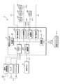
以下、実施の形態について図面に基づいて説明する。図1は、実施形態1に係る個別ECU2(車載ECU)及び統合ECU6(車両制御装置)を含むシステム構成を例示する模式図である。図2は、個別ECU2(車載ECU)の内部構成を例示するブロック図である。
(Embodiment 1)
Embodiments will be described below with reference to the drawings. FIG. 1 is a schematic diagram illustrating a system configuration including an individual ECU 2 (in-vehicle ECU) and an integrated ECU 6 (vehicle control device) according to the first embodiment. FIG. 2 is a block diagram illustrating the internal configuration of the individual ECU 2 (in-vehicle ECU).
車載システムSは、車両に搭載される複数の個別ECU2(車載ECU)、複数の車載装置3及び統合ECU6(車両制御装置)を含む。個別ECU2は、車両における各エリアに配置され、当該個別ECU2に車載ネットワーク4を介して接続される複数の車載装置3間の通信又は、車載装置3と統合ECU6との通信を中継するゲートウェイ又はイーサスイッチ等の車載中継装置として機能する中継制御ECUである。個別ECU2は、通信に関する中継に加え、蓄電装置5から出力された電力を分配及び中継し、自ECUに接続される車載装置3に供給する電力分配装置としても機能するPLB(Power Lan Box)であってもよい
The in-vehicle system S includes a plurality of individual ECUs 2 (in-vehicle ECUs) mounted on the vehicle, a plurality of in-
統合ECU6は、個別ECU2を介して中継された車載装置3からのデータに基づき、個々の車載装置3への制御信号を生成及び出力するものであり、例えばヴィークルコンピュータ等の中央制御装置である。統合ECU6は、車載装置の駆動に関する処理を行う車両制御装置に相当する。
The
車載装置3は、例えばLiDAR(Light Detection and Ranging)、ライトセンサ、CMOSカメラ、赤外線センサ等の各種センサ31、ドアSW(スイッチ)、ランプSW等のスイッチ32、ランプ、ドア開閉装置等のアクチュエータ30、アクチュエータ30に直接接続される駆動用ECU33、及び、蓄電装置5を含む。本実施形態において、アクチュエータ30は、CAN等通の通信部を備える駆動用ECU33に接続されるとしたが、これに限定されない。アクチュエータ30がCAN等通信部又は入出力I/Fを内蔵し、アクチュエータ30と個別ECU2とが直接接続され、相互に通信する構成であってもよい。
The in-
外部サーバ100は、例えばインターネット又は公衆回線網等の車外ネットワークNに接続されているサーバ等のコンピュータであり、RAM(Random Access Memory)、ROM(Read Only Memory)又はハードディスク等による記憶部を備える。いずれかの個別ECU2は、車外通信装置1と通信可能に接続され、車外通信装置1に車外ネットワークNを介して接続された外部サーバ100と通信し、外部サーバ100と、車両Cに搭載される車載装置3との間の通信を中継するものであってもよい。
The
車両Cには、統合ECU6、車外通信装置1、個別ECU2、及び複数の車載装置3が搭載されている。個別ECU2と車外通信装置1とは、例えばシリアルケーブル等のワイヤーハーネスにより通信可能に接続されている。個別ECU2及び車載装置3は、CAN(Control Area Network/登録商標)又はイーサネット(Ethernet/登録商標)等の通信プロトコルに対応した通信線41及び車載ネットワーク4によって通信可能に接続されている。個別ECU2及び車載装置3における通信プロトコルは、LIN、MOST、FlexRay等によるものであってもよい。又は、個別ECU2及び車載装置3は、例えばシリアルケーブル等のワイヤーハーネスにより通信可能に接続されるものであってもよい。
The vehicle C is equipped with an
車外通信装置1は、車外通信部(図示せず)及び、個別ECU2と通信するための入出力I/F(図示せず)を含む。車外通信部は、4G、LTE(Long Term Evolution/登録商標)、5G、WiFi等の移動体通信のプロトコルを用いて無線通信をするための通信装置であり、車外通信部に接続されたアンテナ11を介して外部サーバ100とデータの送受信を行う。車外通信装置1と外部サーバ100との通信は、例えば公衆回線網又はインターネット等の外部ネットワークNを介して行われる。入出力I/Fは、個別ECU2と、例えばシリアル通信するための通信インターフェイスである。車外通信装置1と個別ECU2とは、入出力I/F及び入出力I/Fに接続されたシリアルケーブル等のワイヤーハーネスを介して相互に通信する。本実施形態では、車外通信装置1は、個別ECU2と別装置とし、入出力I/F等によってこれら装置を通信可能に接続しているが、これに限定されない。車外通信装置1は、個別ECU2の一構成部位として、個別ECU2に内蔵されるものであってもよい。
The vehicle-external communication device 1 includes a vehicle-external communication unit (not shown) and an input/output I/F (not shown) for communicating with the
個別ECU2は、制御部20、記憶部21、入出力I/F22及び車内通信部23を含む。車内通信部23及び入出力I/F22は、個別ECU2に接続される車載装置3と通信するための通信部に相当する。
The
個別ECU2夫々は、例えば、認知系の車載装置3、判断系の車載装置3及び、操作系の車載装置3等の複数の通信線41による系統夫々のセグメントを統括し、これらセグメント間での車載装置3同士の通信を中継するゲートウェイ(中継器)として機能する。複数の通信線41夫々は、各セグメント(エリア)におけるバスに相当するものであり、個別ECU2は、自ECUに接続されるエリアを管理するエリア・コントロール・ユニットとして機能するものであってもよい。又、個別ECU2は、リチウムイオン電池等の二次電池からなる蓄電装置5と接続され、蓄電装置5から供給される電力を、自ECUが管理するセグメントに含まれる車載装置3に分配するPLB(Power Lan Box)として機能するものであってもよい。個別ECU2は、車外通信装置1が無線通信によって外部サーバ100から受信した更新プログラムを、車外通信装置1から取得し、車載ネットワーク4を介して当該更新プログラムを所定の車載装置3(更新対象の車載装置3)に送信するように構成されているもの(リプロマスター)であってもよい。
Each of the
制御部20は、CPU(Central Processing Unit)又はMPU(Micro Processing Unit)等により構成してあり、記憶部21に予め記憶された制御プログラム及びデータを読み出して実行することにより、種々の制御処理及び演算処理等を行うようにしてある。制御部20は、CPU等のソフトウェア処理を行うソフトウェア処理部のみに限定されず、FPGA、ASIC又はSOC等のハードウェア処理にて種々の制御処理及び演算処理等を行うハードウェア処理部を含むものであってもよい。例えば、制御部20は、入出力I/F22を介して接続されるドアSW等のスイッチ32から入力信号をFPGA等のハードウェア処理部にて受信し、当該ハードウェア処理部が、CPU等のソフトウェア処理部を起動することにより、当該CPUによってスイッチ32からの入力信号に関する処理を行うものであってもよい。このようにスイッチ32からの入力信号による電流又は電圧によって行われるFPGA等の処理をトリガーとしてCPUを起動することにより、CPUによる電力消費を抑制することができる。
The
記憶部21は、RAM(Random Access Memory)等の揮発性のメモリ素子又は、ROM(Read Only Memory)、EEPROM(Electrically Erasable Programmable ROM)若しくはフラッシュメモリ等の不揮発性のメモリ素子により構成してあり、制御プログラム及び処理時に参照するデータがあらかじめ記憶してある。記憶部21に記憶された制御プログラムは、個別ECU2が読み取り可能な記録媒体211から読み出された制御プログラムを記憶したものであってもよい。また、図示しない通信網に接続されている図示しない外部コンピュータから制御プログラムをダウンロードし、記憶部21に記憶させたものであってもよい。
The
記憶部21には、車載装置3間の通信、車載装置3と統合ECU6との通信又は、車載装置3と外部サーバ100との間の通信のための中継処理を行うにあたり用いられる中継経路情報(ルーティングテーブル)が、記憶される。当該中継経路情報は、通信プロトコルに基づき書式が決定される。通信プロトコルがCANの場合、CAN用中継経路情報は、CANメッセージに含まれるメッセージ識別子(CAN-ID)及び、当該CAN-IDに関連付けられた中継先(CAN通信部232のI/Oポート番号)を含む。通信プロトコルがTCP/IPの場合、TCP/IP用中継経路情報は、IPパケットに含まれる送信先アドレス(MACアドレス又はIPアドレス)及び、当該送信先アドレスに関連付けられた中継先(イーサネット通信部231の物理ポート番号)を含む。記憶部21には、更に後述するチャタリング等に基づき計測されるカウンタ値の閾値(第1閾値、第2閾値)、第1閾値の初期値及び、当該第1閾値を初期化処理する際に用いられる所定値が記憶されている。第1閾値を初期化処理する際に用いられる所定値は、例えば、蓄電装置5の残容量(SOC)に関する値である。
The
入出力I/F22は、車外通信装置1の入出力I/Fと同様に、例えばシリアル通信するための通信インターフェイスである。入出力I/F22及びシリアルケーブル等のワイヤーハーネスを介して、個別ECU2は、車外通信装置1及び、センサ31、スイッチ32又はアクチュエータ30等の車載装置3と通信可能に接続される。
The input/output I/
車内通信部23は、例えばCAN(Control Area Network)又はイーサネット(Ethernet/登録商標)の通信プロトコルを用いた入出力インターフェイス(CAN通信部232、イーサネット通信部231)であり、制御部20は、車内通信部23を介して車載ネットワーク4に接続されている車載装置3又は他の中継装置等の車載機器と相互に通信する。
The in-
イーサネット通信部231は、100BASE-T1又は1000BASE-T1等のイーサネットケーブル411にて伝送されるTCP/IPのパケットに対応するイーサネットPHY部である。
The
CAN通信部232は、CANバス412上にて伝送されるCANメッセージに対応するものであり、ハイ側及びロー側の2本の配線により構成されるCANバス412上の差動電圧の電位差による波形を受信し、受信した波形を1と0のビット列で表される信号に復号するCANトランシーバである。又は、CAN通信部232は、CANトランシーバ及びCANコントローラを含むものであってもよい。
The
車内通信部23(イーサネット通信部231、CAN通信部232)は、複数個設けられており、車内通信部23夫々に、車載ネットワーク4を構成する通信線41夫々(イーサネットケーブル411、CANバス412)、すなわちバス夫々が接続されている。このように車内通信部23を複数個設けることにより、車載ネットワーク4を複数個のセグメントに分け、各セグメントに車載装置3を、当該車載装置3の機能(認知系機能、判断系機能、操作系機能)に応じて接続するものであってもよい。
A plurality of in-vehicle communication units 23 (
このように構成された統合ECU6、複数の個別ECU2は、例えば図1に示すとおり、リング状のネットワークトポロジーにて通信可能に接続されている。すなわち、統合ECU6及び個別ECU2は複数個のイーサネット通信部231を備え、リング状のネットワークトポロジーを構成し、双方向通信を可能として冗長化を図るものであってもよい。更に、当該リング状のネットワークトポロジーにて、統合ECU6に直接的に隣接していない個別ECU2と、統合ECU6とをイーサネットケーブル411等による通信線41で接続してバイパスラインを形成し、通信経路の更なる冗長化を図るものであってもよい。又は、CANバス412によるバス状のネットワークトポロジーにて、統合ECU6及び、複数の個別ECU2を通信可能に接続するものであってもよい。
The
図3は、個別ECU2及び統合ECU6による処理の流れ(シーケンス)例示する説明図である。ドアSW等のスイッチ32に直接接続された個別ECU2、統合ECU6及び、ドア開閉装置等のアクチュエータ30に直接接続された個別ECU2(その他の個別ECU2)において、例えば、ドアSWが操作された際にドア開閉装置が開操作される場合の処理の流れを、シーケンス図を用いて説明する。
FIG. 3 is an explanatory diagram illustrating the flow (sequence) of processing by the
例えば、車両Cの操作者の操作により、車両Cのドアの外面に設けられたドアSW等のスイッチ32が押下された場合、当該ドアSWから入力信号が、ドアSWに直接接続された個別ECU2に出力される(S1)。
For example, when a
個別ECU2はドアSWから出力された入力信号の取得(受信)を開始し、チャタリングにより発生する入力信号の変化の値に基づき、例えば、当該変化の回数又は、所定のタイミングにて取得した入力信号(電流値等)のサンプリング回数等を計測し、当該計測した値をカウント値として導出する(S2)。このようなチャタリングに対応するためのカウント値の導出は、例えば、ゲージ判定方式又はサンプリング方式を用いるものであってもよい。ノイズ等により電流が流れ、当該ノイズにより個別ECU2がカウント値の計測(導出)を開始することも発生し得るが、これに対する対応処理については、後述するフローチャートにて説明する。
The
個別ECU2は、カウント値を継続的に計測(導出)するにあたり、当該カウント値が第1閾値に達した場合、第1信号を統合ECU6及び他の個別ECU2に出力する(S3)。第1信号は、統合ECU6及び他の個別ECU2を停止状態又は待機(スリープ)状態から、起動状態に遷移(復帰)させるためのWakeUp信号等の起動信号(復帰信号)である。車両Cが停止状態、すなわち車両CのIGスイッチ32がオフにされた場合、統合ECU6及び個別ECU2は、停止状態又は待機(スリープ)状態となっているが、このようなWakeUp信号を受信することにより、起動状態に遷移する。
In continuously measuring (deriving) the count value, the
第1信号を受信した統合ECU6及びその他の個別ECU2は、起動状態に遷移にすべく、自ECUに含まれるCPU等を起動し、必要に応じて初期化処理、自己診断処理等を実行する(S4,S5)。
Upon receiving the first signal, the
個別ECU2は、ドアSWから出力された入力信号の取得(受信)を継続し、カウント値を継続的に計測(導出)しており、当該カウント値が第2閾値に達した場合、第2信号を統合ECU6に出力する(S6)。第2信号は、ドアSWから出力された入力信号に対応するドア開閉装置の駆動を要求する駆動要求信号である。
The
本実施形態における図示のとおり、第2閾値は、第1閾値より大きい(第2閾値>第1閾値)値としてあり、これら第2閾値及び第1閾値は、個別ECU2の記憶部21に記憶されている。例えば、第1閾値を10とし、第2閾値を100とするものであってもよい。後述にて詳細は説明するが、第1閾値はカウント値に基づく判定結果に応じて、増減される。増減された現時点における第1閾値に加え、第1閾値の初期値も、個別ECU2の記憶部21に記憶されている。
As illustrated in this embodiment, the second threshold is greater than the first threshold (second threshold>first threshold), and these second threshold and first threshold are stored in the
第2閾値は、例えばスイッチ32の動作仕様又は接点特性に基づき、チャタリングが発生してから落ち着くまでの時間に応じて決定される値であり、スイッチ32夫々の種類又は型式等に応じたチャタリング時間に基づき決定される値である。第2閾値は、固定の値として個別ECU2の記憶部21に記憶されているものであってもよい。又は、第2閾値は、現時点における第1閾値に対し、後述する起動待機時間に対応する値を加算した値となるように可変の値であってもよい。
The second threshold value is a value determined according to the time from chattering occurrence until it settles down, for example, based on the operation specifications or contact characteristics of the
第1閾値に達してから、第2閾値に達するまでの差分時間(Δt)は、統合ECU6及び個別ECU2の起動待機時間(WakeUp待機時間)よりも、長くしてある。すなわち、第1閾値を増加した場合であっても、第2閾値及び第1閾値による差分時間(Δt)は、起動待機時間(WakeUp待機時間)よりも長くなるように、第1閾値の上限値は決定されている。第2閾値及び第1閾値による差分時間(Δt)とは、例えば、カウント値を計測するにあたってサンプリングタイム(サンプリング周期)に、第2閾値から第1閾値を減算した値を乗算することにより算出されるものである。
The difference time (Δt) from reaching the first threshold to reaching the second threshold is set longer than the startup standby time (WakeUp standby time) of the integrated
起動待機時間(WakeUp待機時間)とは、統合ECU6及び個別ECU2が起動を開始してから完了するまでに要する時間であり、統合ECU6及び個別ECU2に含まれるCPU等の仕様又は特性に基づき決定される時間である。すなわち、第1信号の出力時点から、第2信号の出力時点までの経過時間は、起動待機時間(WakeUp待機時間)よりも、長くなるように、第1閾値の上限値は、第2閾値に対し決定されている。このように差分時間(Δt)を、起動待機時間よりも長くすることにより、統合ECU6及び他の個別ECU2が起動状態に遷移する前(復帰する前)に、これら統合ECU6等に第2信号が送信されることを防止し、統合ECU6と個別ECU2とにおける通信保証を担保することができる。
The activation standby time (WakeUp standby time) is the time required for the
第2信号を受信した統合ECU6は、当該第2信号に対応するアクチュエータ30(ドア開閉装置)を制御するための制御信号を生成し(S7)、当該アクチュエータ30(ドア開閉装置)に直接接続されている個別ECU2(他の個別ECU2)に当該制御信号を出力する(S8)。統合ECU6は、この制御信号の生成及び出力を行うにあたり、同一又は互いに連関するアクチュエータ30に対する駆動要求が重複又は相反(コンフリクト)する場合、これら複数の駆動要求における調停を行い、制御信号の生成及び出力するものであってもよい。
The
統合ECU6からの制御信号を受信した個別ECU2(他の個別ECU2)は、アクチュエータ30(ドア開閉装置)を駆動するためのパルス信号、デューティ又はオン信号等の駆動信号を生成し(S9)、アクチュエータ30(ドア開閉装置)に出力する(S10)。アクチュエータ30(ドア開閉装置)は、当該駆動信号に基づき、例えばドア又はドアキーを開にする等の駆動を行う。
The individual ECU 2 (another individual ECU 2) that has received the control signal from the integrated
本実施形態において、スイッチ32及び当該スイッチ32からの信号に基づき駆動するアクチュエータ30として、ドアSW及びドア開閉装置としたが、これに限定されない。スイッチ32及び当該スイッチ32からの信号に基づき駆動するアクチュエータ30は、例えば、室内ランプSW及び室内ランプ等であってもよい。
In the present embodiment, the
個別ECU2は、チャタリング対策のデジタルフィルタ回数として、第1閾値及び第2閾値の2つの値を用いて、入力信号を出力するドアSW等のスイッチ32の操作に関する判定を2段階で行う。個別ECU2は、第1閾値に基づく最初の判定(第1段階での判定)に応じて、統合ECU6及びその他の個別ECU2の起動処理のための第1信号を出力する。第1信号の出力後、個別ECU2は、第2閾値に基づく2番目の判定(第2段階での判定)に応じて、アクチュエータ30の駆動を要求するための第2信号を出力する。
The
例えばノイズ等により電流が流れた場合であっても、個別ECU2によって導出されたカウント値が、第1閾値に到達しなかった場合、個別ECU2は、第1信号を統合ECU6等に出力しないため、統合ECU6等の待機状態は維持される。従って、統合ECU6等により不要な電力が消費されることを抑制することができる。
For example, even if current flows due to noise or the like, if the count value derived by the
また、個別ECU2によって導出されたカウント値が、第1閾値に到達しつつ、第2閾値に到達しなかった場合、個別ECU2は、第2信号を統合ECU6に出力しないため、アクチュエータ30は駆動されない。従って、当該アクチュエータ30により不要な電力が消費されることを抑制することができる。
Further, when the count value derived by the
ドアSW等のスイッチ32から正規の入力信号が出力された場合、個別ECU2によって導出されたカウント値は、第1閾値及び第2閾値に到達する。従って、統合ECU6及び他の個別ECU2は起動(復帰)され、統合ECU6及び他の個別ECU2によって生成及び出力される制御信号、駆動信号により、当該入力信号に対応するドア開閉装置等のアクチュエータ30を確実に駆動することができる。
When a normal input signal is output from the
個別ECU2は、カウント値が第1閾値に到達した時点にて、統合ECU6及び他の個別ECU2に第1信号を出力し、統合ECU6及び他の個別ECU2を早期に起動状態に遷移させることができる。従って、第2閾値に到達した時点にて、第1信号を出力し、第1信号の出力時点から上述のWakeUp待機時間を経過した後に第2信号を出力する場合と比較し、早期にアクチュエータ30を駆動させることができ、ドアSW等のスイッチ32に対するドア開閉装置等のアクチュエータ30の応答性(レスポンス)を向上させることができる。すなわち、当該応答性を向上させつつ、ノイズ等による誤信号が入力された場合であっても、カウント値が第2閾値に到達しなかった場合は、アクチュエータ30が駆動されることを防止し、不要な電力が消費されることを抑制することができる。
When the count value reaches the first threshold, the
図4は、個別ECU2の制御部20の処理を例示するフローチャートである。個別ECU2の制御部20は、例えば車両Cが起動状態(イグニッションスイッチがオン)又は停止状態(イグニッションスイッチがオフ)において、定常的に以下の処理を行う。
FIG. 4 is a flowchart illustrating processing of the
個別ECU2の制御部20は、スイッチ32から信号(入力信号)が出力されたか否かを判定する(S101)。制御部20は、例えばドアSW等のスイッチ32から信号(入力信号)が出力されたか否かを判定する。例えば、制御部20は、ドアSW等のスイッチ32との間に接続されているハーネスに流れる電流、信号、パルス又は当該ハーネスを介して印加される電圧、デューティを監視し、所定の電流値、電圧値又は信号波形等を検出した場合、スイッチ32から信号(入力信号)が出力された判定する。
The
スイッチ32から信号(入力信号)が出力されていない場合(S101:NO)、個別ECU2の制御部20は、再度S101の処理を実行すべく、ループ処理を行う。すなわち、個別ECU2の制御部20は、スイッチ32の状態監視を継続する。
When no signal (input signal) is output from the switch 32 (S101: NO), the
スイッチ32から信号(入力信号)が出力された場合(S101:YES)、個別ECU2の制御部20は、入力信号の取得及びカウント値の導出を開始する(S102)。スイッチ32から信号(入力信号)が出力された場合、個別ECU2の制御部20は、当該入力信号の取得を開始する。更に、制御部20は、取得を開始した入力信号に基づき、所定のサンプリングタイミングに基づき当該入力信号に含まれるスイッチ32のオンを示す回数等を計測することにより、カウント値の計測(導出)を開始する。例えば、カウント値の初期値は、0に設定されており、個別ECU2の制御部20は、サンプリングタイミングに基づき検出したオンを示す回数に応じて、又はチャタリングの発生都度、当該カウント値を1つずつ増加させるインクリメント処理を行うものであってもよい。
When a signal (input signal) is output from the switch 32 (S101: YES), the
個別ECU2の制御部20は、計測しているカウント値が第1閾値に達したか否かを判定する(S103)。カウント値が第1閾値に達していない場合(S103:NO)、個別ECU2の制御部20は、スイッチ32からの信号(入力信号)の出力は、継続しているか否かを判定する(S1031)。個別ECU2の制御部20は、例えば、スイッチ32と自ECUとを接続するワイヤーハーネスの電流又は電圧に基づき、スイッチ32からの信号(入力信号)の出力が継続しているか否かを判定する。
The
スイッチ32からの信号(入力信号)の出力が継続している場合(S1031:YES)、個別ECU2の制御部20は、再度S103の処理を事項すべく、ループ処理を行う。すなわち、制御部20は、スイッチ32からの信号(入力信号)が出力されている間、カウント値の計測(導出)を継続して行う。
When the output of the signal (input signal) from the
スイッチ32からの信号(入力信号)の出力が継続していない場合(S1031:NO)、すなわち信号の出力が終了している場合、個別ECU2の制御部20は、再度S101の処理を実行すべく、ループ処理を行う。すなわち、制御部20は、今回、取得した入力信号は、スイッチ32から出力された正規の信号でなく、例えばノイズ等により発生した誤信号であると判定し、再度、スイッチ32から出力される入力信号の有無を判定すべく、当該スイッチ32を監視する処理を行う。処理S101を行うループ処理を行うにあたり、個別ECU2の制御部20は、インクリメント処理にて増加させたカウント値を初期値である0に戻す処理を行うものであってもよい。
When the output of the signal (input signal) from the
カウント値が第1閾値に達することなく終了した信号は、ノイズ等により発生した誤信号であるため、第1閾値を第1デジタルフィルタ回数として用いることにより、当該誤信号によって、統合ECU6及び車載装置3にて不要な処理が実行され、不要に電力が消費されることを抑制することができる。
A signal whose count value ends without reaching the first threshold value is an erroneous signal generated by noise or the like. It is possible to suppress the unnecessary power consumption caused by the execution of unnecessary processing in
カウント値が第1閾値に達した場合(S103:YES)、個別ECU2の制御部20は、第1信号を出力する(S104)。カウント値が第1閾値に達した場合、個別ECU2の制御部20は、統括ECU及び他の個別ECU2に対し、これら統括ECUを起動状態に遷移させるための第1信号を出力する。第1信号を受信した統括ECU及び他の個別ECU2は、停止状態又は待機状態から、起動状態に遷移(復帰)する。
When the count value reaches the first threshold (S103: YES), the
個別ECU2の制御部20は、カウント値が第2閾値に達したか否かを判定する(S105)。カウント値が第2閾値に達していない場合(S105:NO)、個別ECU2の制御部20は、S1031と同様に、スイッチ32からの信号(入力信号)の出力は、継続しているか否かを判定する(S1051)。
The
スイッチ32からの信号(入力信号)の出力が継続している場合(S1051:YES)、個別ECU2の制御部20は、再度S105の処理を事項すべく、ループ処理を行う。すなわち、制御部20は、スイッチ32からの信号(入力信号)が出力されている間、カウント値の計測(導出)を継続して行う。
When the output of the signal (input signal) from the
スイッチ32からの信号(入力信号)の出力が継続していない場合(S1051:NO)、すなわち信号の出力が終了している場合、個別ECU2の制御部20は、第1閾値の値を増加する(S1052)。制御部20は、今回、取得した入力信号は、スイッチ32から出力された正規の信号でなく、例えばノイズ等により発生した誤信号であると判定し、第1閾値の値を、例えば1つ等、所定数にて増加する処理を行う。個別ECU2の制御部20は、S1052の実行後、再度S101の処理を実行すべくループ処理を行う。
When the output of the signal (input signal) from the
カウント値が第1閾値に到達しつつ第2閾値に達することなく終了した信号は、ノイズ等により発生した誤信号であるため、第2閾値を第2デジタルフィルタ回数として用いることにより、当該誤信号によって、車載装置3にて不要な処理が実行され、不要に電力が消費されることを抑制することができる。
A signal whose count value reaches the first threshold but does not reach the second threshold is an erroneous signal generated by noise or the like. Therefore, it is possible to prevent the in-
カウント値が第1閾値に到達したにもかかわらず、第2閾値に到達しなかった場合、ノイズにより電流が流れた時間が長く、比較的に多数回のチャタリングが発生した場合である。従って、個別ECU2の制御部20は、第1閾値の値を増加することにより、次回にてノイズ等による誤信号が入力された場合であっても、統合ECU6等を起動させる第1信号を出力する時点を遅らせることにより、当該誤信号により不要に統合ECU6等を起動させることを防止し、消費電力が増加することを抑制することができる。
When the count value does not reach the second threshold even though it reaches the first threshold, it means that the noise has caused the current to flow for a long time and the chattering has occurred relatively many times. Therefore, by increasing the value of the first threshold value, the
カウント値が第2閾値に達した(S105:YES)、個別ECU2の制御部20は、第1閾値の値を減少し(S106)、第2信号を出力する(S107)。本実施形態において、第1閾値の値の減少した後、第2信号を出力するとしているが、これに限定されない。個別ECU2の制御部20は、第2信号を出力した後、第1閾値の値を減少するものであってもよい。又は、個別ECU2の制御部20は、サブプロセスを発生させ、第1閾値の値の減少及び、第2信号の出力を並行処理するものであってもよい。
When the count value reaches the second threshold (S105: YES), the
カウント値が第1閾値のみならず第2閾値に到達した場合、個別ECU2の制御部20は、取得した入力信号は、スイッチ32から出力された正規の信号であると判定し、第1閾値を、例えば1つ等、所定数にて減少する処理を行う。このようにカウント値が第2閾値に到達する場合、ノイズ等による誤信号の発生頻度が低い動作環境に車両Cがおかれている蓋然性が高い。そこで第1閾値を減少させることにより、次回の入力信号においては、早期に第1信号を統合ECU6等に出力して統合ECU6等を起動し、入力信号を出力するスイッチ32に対応するアクチュエータ30に対する応答性を向上させることができる。
When the count value reaches not only the first threshold value but also the second threshold value, the
個別ECU2の制御部20が出力した第2信号を取得(受信)した統合ECU6は、入力信号を出力したスイッチ32に対応するアクチュエータ30に直接接続される他の個別ECU2に対し、制御信号を出力する。当該他の個別ECU2は、統合ECU6からの制御信号に基づき、アクチュエータ30を駆動するための駆動信号を生成及び出力することにより、当該アクチュエータ30を駆動する。
The
個別ECU2の制御部20は、生成した第2信号を、入力信号を出力したスイッチ32に対応するアクチュエータ30に直接接続される他の個別ECU2に対し、直接出力するものであってもよい。第2信号を取得(受信)した当該他の個別ECU2は、当該第2信号に基づき駆動信号を生成及び出力することにより、当該アクチュエータ30を駆動するものであってもよい。
The
本実施形態において、個別ECU2の制御部20は、S1052の処理にて第1閾値を増加するとしたが、これに限定されない。個別ECU2の制御部20は、S1052の処理を実行すべき場合、すなわちスイッチ32からの信号(入力信号)の出力が継続していない場合(S1051:NO)であっても、現時点における第1閾値の値が、所定の上限値と等しい場合又は、当該現時点における第1閾値を増加することにより、上限値を越える場合は、第1閾値を増加せず、固定するものであってもよい。
In the present embodiment, the
第1閾値の上限値は、例えば、第2閾値との関係において、起動待機時間(WakeUp待機時間)を確保するために決定される値である。又は、第1閾値の上限値は、第2閾値の80%等、第2閾値との比率に基づき決定されるものであってもよい。 The upper limit value of the first threshold is, for example, a value determined in order to ensure a startup standby time (WakeUp standby time) in relation to the second threshold. Alternatively, the upper limit of the first threshold may be determined based on a ratio to the second threshold, such as 80% of the second threshold.
個別ECU2の制御部20は、現時点における第1閾値の値が上限値に達する等により、第1閾値を固定した場合、車両Cがおかれている動作環境はノイズより誤信号が発生する頻度が高いと判定し、当該判定に関する情報をディスプレイ等のHMI装置又は車外通信装置1を介して外部サーバ100に出力(送信)するものであってもよい。当該判定に関する情報をHMI装置又外部サーバ100に出力(送信)することにより、車両Cの操作者等に対し、車両C(自車)がおかれている動作環境はノイズより誤信号が発生する頻度が高い旨を報知することができる。
When the
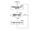
(実施形態2)
図5は、実施形態2(第1閾値の初期化)に係る個別ECU2の制御部20の処理を例示するフローチャートである。個別ECU2の制御部20は、例えば車両Cが起動状態(イグニッションスイッチがオン)又は停止状態(イグニッションスイッチがオフ)において、定常的に以下の処理を行う。
(Embodiment 2)
FIG. 5 is a flowchart illustrating processing of the
個別ECU2の制御部20は、本実施形態の一連の処理を行うにあたり、スイッチ32から信号(入力信号)が出力されていない場合、当該一連の処理を行うものであってもよい。すなわち、制御部20は、実施形態1の処理S101と同様にスイッチ32から信号(入力信号)が出力されたか否かを判定し、スイッチ32から信号(入力信号)が出力されていない場合、第1閾値の初期化に関する処理を行うものであってもよい。
The
個別ECU2の制御部20は、蓄電装置5の残容量に関する情報を取得する(S201)。制御部20は、蓄電装置5又は蓄電装置5に接続されている駆動ECU等と通信することにより、蓄電装置5の残容量(SOC:statement of charge)に関する情報を取得する。または、個別ECU2の制御部20は、自ECUと蓄電装置5とを接続する電力線の電圧を検出することにより、蓄電装置5の残容量に関する情報を取得するものであってもよい。
The
個別ECU2の制御部20は、蓄電装置5の残容量が所定値以上であるか否かを判定する(S202)。制御部20は、例えば、蓄電装置5の満容量を基準に、例えば当該満容量の85%を所定値として、蓄電装置5の残容量が所定値以上であるか否かを判定する。
The
残容量が所定値以上である場合(S202:YES)、個別ECU2の制御部20は、第1閾値の値を初期値に設定する(S203)。第1閾値の初期値は、記憶部21に記憶されており、残容量が所定値以上である場合、制御部20は、現時点における第1閾値の値を、初期値に設定する。制御部20は、S203の実行後、再度S201の処理を事項すべくループ処理を行う。
When the remaining capacity is equal to or greater than the predetermined value (S202: YES), the
現時点における第1閾値の値が、例えば初期値よりも高い場合であっても、第1閾値を初期値に戻す初期化処理は、蓄電装置5の残容量が所定値以上である場合に行われるため、蓄電装置5の残容量が不足して、所謂バッテリ上がりが発生することを効率的に防止することができる。 Even if the current value of the first threshold is higher than the initial value, for example, the initialization process of returning the first threshold to the initial value is performed when the remaining capacity of the power storage device 5 is equal to or greater than the predetermined value. Therefore, it is possible to efficiently prevent the occurrence of so-called dead battery due to insufficient remaining capacity of the power storage device 5 .
残容量が所定値以上でない場合(S202:NO)、再度S201の処理を事項すべくループ処理を行う。残容量が所定値以上でない場合、制御部20は、現時点における第1閾値の値を変更することなく当該値を維持し、再度S201の処理を事項すべくループ処理を行う。
If the remaining capacity is not equal to or greater than the predetermined value (S202: NO), loop processing is performed to perform the processing of S201 again. If the remaining capacity is not equal to or greater than the predetermined value, the
上述のとおり、第1閾値はカウント値に基づく処理により増減されるところ、当該増減の要因となるノイズ等による誤信号の発生は、車両C(自車)の動作環境に影響を受けるものであることが想定される。そこで、例えば、蓄電装置5の残容量等の車両状態情報が所定の条件を満たす場合、初期化処理を行い、第1閾値を予め定められている初期値に戻すことにより、第1信号を出力するタイミングを定常的に適正化し、制御の安定化を図ることができる。蓄電装置5の残容量に基づき、当該所定の条件の判定を行うことにより、アクチュエータ30の即応性の向上しつつ、蓄電装置5の残容量が不足等する事態を効率的に防止することができる。
As described above, the first threshold value is increased or decreased by processing based on the count value, and the occurrence of an erroneous signal due to noise or the like, which is a factor of the increase or decrease, is affected by the operating environment of the vehicle C (own vehicle). is assumed. Therefore, for example, when the vehicle state information such as the remaining capacity of the power storage device 5 satisfies a predetermined condition, initialization processing is performed to return the first threshold to a predetermined initial value, thereby outputting the first signal. It is possible to constantly optimize the timing to control and stabilize the control. By determining the predetermined condition based on the remaining capacity of the power storage device 5, it is possible to improve the responsiveness of the
今回開示された実施形態はすべての点で例示であって、制限的なものではないと考えられるべきである。本発明の範囲は、上記した意味ではなく、特許請求の範囲によって示され、特許請求の範囲と均等の意味及び範囲内でのすべての変更が含まれることが意図される。 The embodiments disclosed this time are illustrative in all respects and should be considered not restrictive. The scope of the present invention is indicated by the scope of the claims rather than the meaning described above, and is intended to include all modifications within the scope and meaning equivalent to the scope of the claims.
C 車両
S 車載システム
100 外部サーバ
1 車外通信装置
11 アンテナ
2 個別ECU(車載ECU)
20 制御部
21 記憶部
211 記録媒体
22 入出力I/F(通信部)
23 車内通信部(通信部)
231 イーサネット通信部
232 CAN通信部
3 車載装置
30 アクチュエータ(ドア開閉装置)
31 センサ
32 スイッチ(ドアSW)
33 駆動用ECU
4 車載ネットワーク
41 通信線
411 イーサネットケーブル
412 CANバス
5 蓄電装置
6 統合ECU(車両制御装置)
C vehicle
S In-
20
23 In-vehicle communication unit (communication unit)
231
31
33 drive ECU
4 in-
Claims (8)
前記車載装置の制御に関する処理を行う制御部を備え、
前記制御部は、
前記車載装置の制御に関する入力信号を取得し、
取得した前記入力信号の変化に基づきカウント値を導出し、
導出した前記カウント値が第1閾値に到達した場合、前記車両制御装置を起動状態に遷移させる第1信号を出力し、
導出した前記カウント値が第2閾値に到達した場合、前記車載装置の駆動を要求する第2信号を出力し、
前記第2閾値は、前記第1閾値よりも大きい値である
車載ECU。 An in-vehicle ECU communicably connected to an in-vehicle device mounted in a vehicle and a vehicle control device that performs processing related to driving the in-vehicle device,
A control unit that performs processing related to control of the in-vehicle device,
The control unit
Acquiring an input signal related to control of the in-vehicle device,
Deriving a count value based on the acquired change in the input signal,
when the derived count value reaches a first threshold value, outputting a first signal for transitioning the vehicle control device to an activated state;
when the derived count value reaches a second threshold, outputting a second signal requesting driving of the in-vehicle device;
The in-vehicle ECU, wherein the second threshold is a value larger than the first threshold.
請求項1に記載の車載ECU。 The in-vehicle ECU according to claim 1, wherein when the count value reaches the second threshold, the control unit decreases the first threshold.
請求項1又は請求項2に記載の車載ECU。 The in-vehicle ECU according to claim 1 or 2, wherein when the count value reaches the first threshold and does not reach the second threshold, the controller increases the first threshold.
前記第1閾値を前記上限値に固定し、
前記第1閾値が前記上限値に達した旨を示す情報を出力する
請求項3に記載の車載ECU。 By increasing the first threshold, the control unit, when the first threshold reaches a predetermined upper limit,
fixing the first threshold to the upper limit;
The in-vehicle ECU according to claim 3, which outputs information indicating that the first threshold value has reached the upper limit value.
前記車両の状態に関する車両状態情報を取得し、
前記車両状態情報が所定の条件を満たす場合、前記第1閾値を予め定められている初期値に戻す初期化処理を行う
請求項1から請求項4のいずれか1項に記載の車載ECU。 The control unit
obtaining vehicle state information about the state of the vehicle;
The in-vehicle ECU according to any one of claims 1 to 4, wherein when the vehicle state information satisfies a predetermined condition, initialization processing is performed to return the first threshold value to a predetermined initial value.
前記制御部は、前記蓄電装置の残容量が所定値以上である場合、
前記所定の条件を満たすと判定し、
前記第1閾値を予め定められている初期値に戻す初期化処理を行う
請求項5に記載の車載ECU。 The vehicle state information includes information about the remaining capacity of a power storage device mounted on the vehicle ,
When the remaining capacity of the power storage device is equal to or greater than a predetermined value, the control unit
determining that the predetermined condition is satisfied;
The in-vehicle ECU according to claim 5, wherein initialization processing is performed to return the first threshold value to a predetermined initial value.
取得した前記入力信号の変化に基づきカウント値を導出し、
導出した前記カウント値が第1閾値に到達した場合、前記車載装置の駆動に関する処理を行う車両制御装置を起動状態に遷移させる第1信号を出力し、
導出した前記カウント値が、前記第1閾値よりも大きい第2閾値に到達した場合、
前記車載装置の駆動を要求する第2信号を出力する
処理をコンピュータに実行させるプログラム。 Acquire input signals related to control of in-vehicle equipment,
Deriving a count value based on the acquired change in the input signal,
when the derived count value reaches a first threshold value, outputting a first signal for transitioning a vehicle control device that performs processing related to driving of the in-vehicle device to an activation state;
When the derived count value reaches a second threshold greater than the first threshold,
A program that causes a computer to execute a process of outputting a second signal requesting driving of the in-vehicle device.
車載装置の制御に関する入力信号を取得し、
取得した前記入力信号の値の変化に基づきカウント値を導出し、
導出した前記カウント値が第1閾値に到達した場合、前記車載装置の駆動に関する処理を行う車両制御装置を起動状態に遷移させる第1信号を出力し、
導出した前記カウント値が、前記第1閾値よりも大きい第2閾値に到達した場合、
前記車載装置の駆動を要求する第2信号を出力する
処理を実行させる情報処理方法。 to the computer,
Acquire input signals related to control of in-vehicle equipment,
Deriving a count value based on a change in the value of the acquired input signal,
when the derived count value reaches a first threshold value, outputting a first signal for transitioning a vehicle control device that performs processing related to driving of the in-vehicle device to an activation state;
When the derived count value reaches a second threshold greater than the first threshold,
An information processing method for executing a process of outputting a second signal requesting driving of the in-vehicle device.
Priority Applications (4)
| Application Number | Priority Date | Filing Date | Title |
|---|---|---|---|
| JP2020027383A JP7310642B2 (en) | 2020-02-20 | 2020-02-20 | In-vehicle ECU, program and information processing method |
| CN202180013598.6A CN115066869B (en) | 2020-02-20 | 2021-02-04 | Vehicle-mounted ECU, program, and information processing method |
| US17/904,067 US20230089480A1 (en) | 2020-02-20 | 2021-02-04 | Onboard ecu, program, and information processing method |
| PCT/JP2021/004075 WO2021166658A1 (en) | 2020-02-20 | 2021-02-04 | Vehicle-mounted ecu, program, and information processing method |
Applications Claiming Priority (1)
| Application Number | Priority Date | Filing Date | Title |
|---|---|---|---|
| JP2020027383A JP7310642B2 (en) | 2020-02-20 | 2020-02-20 | In-vehicle ECU, program and information processing method |
Publications (3)
| Publication Number | Publication Date |
|---|---|
| JP2021132336A JP2021132336A (en) | 2021-09-09 |
| JP2021132336A5 JP2021132336A5 (en) | 2022-06-27 |
| JP7310642B2 true JP7310642B2 (en) | 2023-07-19 |
Family
ID=77391966
Family Applications (1)
| Application Number | Title | Priority Date | Filing Date |
|---|---|---|---|
| JP2020027383A Active JP7310642B2 (en) | 2020-02-20 | 2020-02-20 | In-vehicle ECU, program and information processing method |
Country Status (4)
| Country | Link |
|---|---|
| US (1) | US20230089480A1 (en) |
| JP (1) | JP7310642B2 (en) |
| CN (1) | CN115066869B (en) |
| WO (1) | WO2021166658A1 (en) |
Citations (3)
| Publication number | Priority date | Publication date | Assignee | Title |
|---|---|---|---|---|
| JP2005280374A (en) | 2004-03-26 | 2005-10-13 | Pioneer Electronic Corp | On-vehicle instrument control device |
| JP2011192231A (en) | 2010-03-17 | 2011-09-29 | Aisin Aw Co Ltd | In-vehicle input device, and input program therefor |
| JP2012132722A (en) | 2010-12-20 | 2012-07-12 | Stanley Electric Co Ltd | Signal processing method for rotary encoder |
Family Cites Families (26)
| Publication number | Priority date | Publication date | Assignee | Title |
|---|---|---|---|---|
| JP2733961B2 (en) * | 1988-06-13 | 1998-03-30 | 富士ゼロックス株式会社 | Hand-driven copying machine |
| JP2928651B2 (en) * | 1991-03-19 | 1999-08-03 | 株式会社日立製作所 | Control device with communication function |
| KR100302384B1 (en) * | 1999-07-01 | 2001-09-22 | 김오영 | Digital unified control apparatus and method in automobile electric device |
| JP4640309B2 (en) * | 2006-10-03 | 2011-03-02 | 株式会社デンソー | In-vehicle electronic device control system |
| JP2009190517A (en) * | 2008-02-13 | 2009-08-27 | Toyota Motor Corp | Vehicle behavior control device |
| JP2010028356A (en) * | 2008-07-17 | 2010-02-04 | Mitsubishi Fuso Truck & Bus Corp | Communication management device of on-vehicle network |
| US8570147B2 (en) * | 2010-05-26 | 2013-10-29 | Lear Corporation | Debounce strategy for validating switch actuation |
| JP2012086823A (en) * | 2010-09-22 | 2012-05-10 | Autonetworks Technologies Ltd | Intrusion detection device and on-vehicle control device |
| JP5951195B2 (en) * | 2011-06-28 | 2016-07-13 | 株式会社小糸製作所 | Vehicle lamp control device |
| US9041243B2 (en) * | 2011-12-09 | 2015-05-26 | Honda Motor Co., Ltd. | Power control apparatus |
| JP5545321B2 (en) * | 2012-06-12 | 2014-07-09 | トヨタ自動車株式会社 | Smart communication system |
| JP5752668B2 (en) * | 2012-11-16 | 2015-07-22 | 日信工業株式会社 | Brake hydraulic pressure control device for vehicles |
| JP2014125763A (en) * | 2012-12-26 | 2014-07-07 | Smk Corp | Vehicle control device |
| JP6099129B2 (en) * | 2013-01-21 | 2017-03-22 | オムロンオートモーティブエレクトロニクス株式会社 | Opening and closing body control device |
| JP6286191B2 (en) * | 2013-11-25 | 2018-02-28 | クラリオン株式会社 | In-vehicle communication device and control method thereof |
| US9865413B2 (en) * | 2015-04-10 | 2018-01-09 | Honda Motor Co., Ltd. | Vehicle control device |
| KR101775819B1 (en) * | 2016-03-02 | 2017-09-11 | 원우엔지니어링주식회사 | Zero Crossing Switch for Correcting Delay Contact and Operating Method thereof |
| US10005448B2 (en) * | 2016-03-22 | 2018-06-26 | Ford Global Technologies, Llc | Load based engine start-stop control |
| JP2017224926A (en) * | 2016-06-14 | 2017-12-21 | 株式会社デンソー | Chattering elimination circuit |
| JP2017228033A (en) * | 2016-06-21 | 2017-12-28 | 株式会社オートネットワーク技術研究所 | On-vehicle storage device, vehicle information storage method and program |
| CN106043712B (en) * | 2016-06-23 | 2023-12-08 | 零度智控(北京)智能科技有限公司 | Unmanned aerial vehicle and starting method thereof |
| JP6665728B2 (en) * | 2016-08-05 | 2020-03-13 | 株式会社オートネットワーク技術研究所 | In-vehicle update device, in-vehicle update system and communication device update method |
| KR101883934B1 (en) * | 2016-10-14 | 2018-08-01 | 콘티넨탈 오토모티브 시스템 주식회사 | Card type smart key for vehicles ana method thereof |
| JP6642393B2 (en) * | 2016-11-28 | 2020-02-05 | 株式会社オートネットワーク技術研究所 | In-car update system |
| CN109118693A (en) * | 2018-08-18 | 2019-01-01 | 北京旺马科技有限公司 | A kind of vehicle monitoring method, device, system and storage medium |
| CN110805367A (en) * | 2019-11-12 | 2020-02-18 | 合肥长安汽车有限公司 | Trunk opening control method with driving protection function |
-
2020
- 2020-02-20 JP JP2020027383A patent/JP7310642B2/en active Active
-
2021
- 2021-02-04 US US17/904,067 patent/US20230089480A1/en active Pending
- 2021-02-04 WO PCT/JP2021/004075 patent/WO2021166658A1/en active Application Filing
- 2021-02-04 CN CN202180013598.6A patent/CN115066869B/en active Active
Patent Citations (3)
| Publication number | Priority date | Publication date | Assignee | Title |
|---|---|---|---|---|
| JP2005280374A (en) | 2004-03-26 | 2005-10-13 | Pioneer Electronic Corp | On-vehicle instrument control device |
| JP2011192231A (en) | 2010-03-17 | 2011-09-29 | Aisin Aw Co Ltd | In-vehicle input device, and input program therefor |
| JP2012132722A (en) | 2010-12-20 | 2012-07-12 | Stanley Electric Co Ltd | Signal processing method for rotary encoder |
Also Published As
| Publication number | Publication date |
|---|---|
| CN115066869B (en) | 2024-07-02 |
| US20230089480A1 (en) | 2023-03-23 |
| JP2021132336A (en) | 2021-09-09 |
| WO2021166658A1 (en) | 2021-08-26 |
| CN115066869A (en) | 2022-09-16 |
Similar Documents
| Publication | Publication Date | Title |
|---|---|---|
| CN107659494B (en) | Data processing method and intelligent vehicle-mounted gateway | |
| US20130318380A1 (en) | Handling of Wake-Up Messages in Controller Area Networks | |
| JP2014088150A (en) | In-vehicle battery management device | |
| JP5286659B2 (en) | In-vehicle device relay system, in-vehicle device relay method, and relay device | |
| JP2017079406A (en) | On-vehicle record system and on-vehicle controller | |
| US20100169717A1 (en) | Relay connection unit | |
| JP2015199444A (en) | Electronic control device | |
| US9411609B2 (en) | Electronic control apparatus | |
| WO2016111213A1 (en) | In-vehicle relay device and relay method | |
| JP2013106200A (en) | Communication repeater for vehicle and sleep control method | |
| US8892925B2 (en) | Method and device for controlling the awaking of facilities belonging to at least one multiplexed network, by counting untimely wake-ups | |
| JP7310642B2 (en) | In-vehicle ECU, program and information processing method | |
| WO2023276657A1 (en) | Relay device, relay system, relay method, and computer program | |
| US20220182258A1 (en) | In-vehicle network system | |
| CN117397211A (en) | In-vehicle apparatus, information processing method, and program | |
| JP2020039034A (en) | Communication device, transmission method, and computer program | |
| JP5407757B2 (en) | Electronic device, power management device, and control method | |
| JP6040952B2 (en) | Communication system, electronic control device | |
| WO2020012822A1 (en) | Computation system and computation device | |
| JPWO2017018179A1 (en) | Electronic control unit | |
| JP2010258635A (en) | Control apparatus | |
| JP7192747B2 (en) | In-vehicle relay device and information processing method | |
| JP2020189586A (en) | Data rewriting method and data rewriting system | |
| US20240089170A1 (en) | On-board apparatus, method for controlling communication speed, and program | |
| JP7444223B2 (en) | In-vehicle device, program and information processing method |
Legal Events
| Date | Code | Title | Description |
|---|---|---|---|
| A521 | Request for written amendment filed |
Free format text: JAPANESE INTERMEDIATE CODE: A523 Effective date: 20220617 |
|
| A621 | Written request for application examination |
Free format text: JAPANESE INTERMEDIATE CODE: A621 Effective date: 20220628 |
|
| TRDD | Decision of grant or rejection written | ||
| A01 | Written decision to grant a patent or to grant a registration (utility model) |
Free format text: JAPANESE INTERMEDIATE CODE: A01 Effective date: 20230606 |
|
| A61 | First payment of annual fees (during grant procedure) |
Free format text: JAPANESE INTERMEDIATE CODE: A61 Effective date: 20230619 |
|
| R150 | Certificate of patent or registration of utility model |
Ref document number: 7310642 Country of ref document: JP Free format text: JAPANESE INTERMEDIATE CODE: R150 |