JP7309600B2 - multicopter takeoff and landing gear - Google Patents
multicopter takeoff and landing gear Download PDFInfo
- Publication number
- JP7309600B2 JP7309600B2 JP2019237908A JP2019237908A JP7309600B2 JP 7309600 B2 JP7309600 B2 JP 7309600B2 JP 2019237908 A JP2019237908 A JP 2019237908A JP 2019237908 A JP2019237908 A JP 2019237908A JP 7309600 B2 JP7309600 B2 JP 7309600B2
- Authority
- JP
- Japan
- Prior art keywords
- multicopter
- state
- plate members
- deployment
- deployed state
- Prior art date
- Legal status (The legal status is an assumption and is not a legal conclusion. Google has not performed a legal analysis and makes no representation as to the accuracy of the status listed.)
- Active
Links
- 230000007246 mechanism Effects 0.000 claims description 24
- 239000000126 substance Substances 0.000 description 8
- 239000007788 liquid Substances 0.000 description 6
- 238000005507 spraying Methods 0.000 description 6
- 230000008859 change Effects 0.000 description 5
- 238000001514 detection method Methods 0.000 description 4
- 239000003337 fertilizer Substances 0.000 description 4
- 239000000463 material Substances 0.000 description 4
- 230000005540 biological transmission Effects 0.000 description 3
- 230000036544 posture Effects 0.000 description 3
- 230000007704 transition Effects 0.000 description 3
- XLYOFNOQVPJJNP-UHFFFAOYSA-N water Substances O XLYOFNOQVPJJNP-UHFFFAOYSA-N 0.000 description 3
- 239000003905 agrochemical Substances 0.000 description 2
- 230000008878 coupling Effects 0.000 description 2
- 238000010168 coupling process Methods 0.000 description 2
- 238000005859 coupling reaction Methods 0.000 description 2
- 239000012895 dilution Substances 0.000 description 2
- 238000010790 dilution Methods 0.000 description 2
- 230000000694 effects Effects 0.000 description 2
- 238000003384 imaging method Methods 0.000 description 2
- 230000001133 acceleration Effects 0.000 description 1
- 238000004891 communication Methods 0.000 description 1
- 230000007423 decrease Effects 0.000 description 1
- 230000002452 interceptive effect Effects 0.000 description 1
- 238000012986 modification Methods 0.000 description 1
- 230000004048 modification Effects 0.000 description 1
- 238000010899 nucleation Methods 0.000 description 1
- 238000005192 partition Methods 0.000 description 1
- 230000000149 penetrating effect Effects 0.000 description 1
- 239000000575 pesticide Substances 0.000 description 1
- 239000007921 spray Substances 0.000 description 1
- 210000001364 upper extremity Anatomy 0.000 description 1
Images


Classifications
-
- B—PERFORMING OPERATIONS; TRANSPORTING
- B64—AIRCRAFT; AVIATION; COSMONAUTICS
- B64F—GROUND OR AIRCRAFT-CARRIER-DECK INSTALLATIONS SPECIALLY ADAPTED FOR USE IN CONNECTION WITH AIRCRAFT; DESIGNING, MANUFACTURING, ASSEMBLING, CLEANING, MAINTAINING OR REPAIRING AIRCRAFT, NOT OTHERWISE PROVIDED FOR; HANDLING, TRANSPORTING, TESTING OR INSPECTING AIRCRAFT COMPONENTS, NOT OTHERWISE PROVIDED FOR
- B64F1/00—Ground or aircraft-carrier-deck installations
- B64F1/12—Anchoring
Description
本発明は、マルチコプターの離着陸装置に関する。 The present invention relates to take-off and landing gear for multicopters.
従来、特許文献1に開示されたヘリポートを備えた搬送体が知られている。特許文献1の搬送体は、無人走行移動体と当該無人走行移動体の上面に設けられたドローン用ヘリポートを備えている。
2. Description of the Related Art Conventionally, a carrier having a heliport disclosed in
しかし、特許文献1に開示の搬送体は、無人走行移動体の移動時にヘリポートが障害物等に接触することを避けるため、ヘリポートが当該移動体より幅狭(左右長さが短く)に且つ当該移動体より前後長さが短く形成されている。そのため、ヘリポートの大きさが制限され、ドローンが離着陸するための十分な面積を確保できないという問題があった。
そこで、本発明は上記問題点に鑑み、搬送時の障害物等への接触を抑制しつつ、マルチコプターが離着陸可能な大きさを確保できる離着陸装置を提供することを目的とする。
However, in the carrier disclosed in
SUMMARY OF THE INVENTION Accordingly, it is an object of the present invention to provide a take-off/landing apparatus capable of securing a size that allows a multicopter to take off and land while suppressing contact with obstacles during transportation.
この技術的課題を解決するための本発明の技術的手段は、以下に示す点を特徴とする。
マルチコプターの離着陸装置は、機枠と、前記機枠に搭載された展開構造体であって、複数の板材を有し且つ前記複数の板材を展開していない非展開状態と、前記複数の板材を展開して前記非展開状態よりも平面視領域が大きい展開状態とに変更可能な展開構造体と、前記展開構造体を前記機枠に対して第1位置から第2位置にスライドさせるスライドステーと、を備え、前記展開構造体は、前記展開状態における平面視領域の大きさがマルチコプターの離着陸が可能な大きさに設定され、前記複数の板材を前記非展開状態において前記板材の厚み方向に重ねて支持し、前記複数の板材を前記展開状態において前記複数の板材のそれぞれを前記厚み方向と直交する方向に展開にして支持し、前記複数の板材は、同一の軸が貫通することによって枢支されており、厚み方向に重なった前記非展開状態から前記同一の軸回りに回転することにより前記展開状態とすることができ、前記展開構造体は、前記第1位置にあるとき前記非展開状態とされ、前記第2位置にあるとき前記展開状態とすることができ、前記展開構造体を前記第1位置から前記第2位置にスライドさせることにより、前記軸が移動して前記複数の板材が前記軸回りに回転するスペースが確保されて前記展開構造体を前記展開状態とすることができる。
The technical means of the present invention for solving this technical problem are characterized by the following points.
A take-off and landing gear for a multicopter includes an aircraft frame, a deployment structure mounted on the aircraft frame, a non-deployed state in which the plurality of plate members are not deployed, and the plurality of plate members. and a slide stay for sliding the deployment structure from a first position to a second position with respect to the machine frame. and, in the deployable structure, the size of the planar view area in the deployed state is set to a size that allows takeoff and landing of the multicopter, and the plurality of plate members are arranged in the non-deployed state in the thickness direction of the plate members. each of the plurality of plate members is supported in the unfolded state in a direction orthogonal to the thickness direction, and the plurality of plate members are supported by the same axis penetrating the It can be brought into the deployed state by rotating about the same axis from the non-deployed state that is pivotally supported and overlapped in the thickness direction, and the deployment structure is in the non-deployed state when it is in the first position. It is in a deployed state and can be in the deployed state when it is in the second position, and by sliding the deployment structure from the first position to the second position, the shaft is moved to expand the plurality of structures. A space is secured for the plate member to rotate about the axis, and the deployment structure can be in the deployment state.
マルチコプターの離着陸装置は、前記展開状態において前記展開構造体に装着可能であって、前記展開構造体に装着した状態で前記マルチコプターが離着陸する平面視領域を拡張する拡張部材を備えている。 The multicopter take-off and landing gear includes an extension member that can be attached to the deployment structure in the deployment state, and that expands a plane view area in which the multicopter takes off and lands while attached to the deployment structure.
前記拡張部材は、前記展開構造体を展開状態にしたときの前記複数の板材のうち、隣接する板材の間に装着可能な板体である。
前記機枠は、前記マルチコプターを充電可能な発電機を少なくとも積載する積載スペースを備えている。
前記機枠は、作業車両に連結される連結部を備え、前記連結部は、前記展開状態において前記マルチコプターが離着陸する平面視領域を水平に調整する調整機構を介して前記作業車両に連結される。
The extension member is a plate body that can be mounted between adjacent plate members among the plurality of plate members when the deployment structure is in the deployed state.
The machine frame has a loading space for loading at least a generator capable of charging the multicopter.
The machine frame includes a connection portion connected to the work vehicle, and the connection portion is connected to the work vehicle via an adjustment mechanism that horizontally adjusts a plane view area in which the multicopter takes off and lands in the deployed state. be.
本発明によれば、非展開状態よりも平面視領域が大きい展開状態に変更する展開構造体を備えているため、非展開状態にて搬送時の障害物等への接触を抑制しつつ、展開状態にてマルチコプターが離着陸可能な大きさを確保できる離着陸装置を提供することができる。 According to the present invention, since it is provided with the deployment structure that changes to the deployment state in which the planar view area is larger than the non-deployment state, the deployment structure can be deployed while suppressing contact with obstacles or the like during transportation in the non-deployment state. It is possible to provide a take-off and landing gear that can secure a size that allows a multicopter to take off and land in a state.
以下、本発明の実施の形態を図面に基づいて説明する。
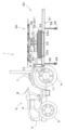
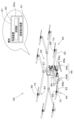
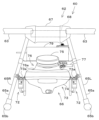
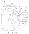
図1及び図2は、マルチコプター60の離着陸等の作業を行うことができる作業機1を示している。作業機1は、作業車両2と、作業車両2の後部に装着された離着陸装置20とを備えている。
図1に示す作業機1では、作業車両2は農業機械の一つであるトラクタ2である。トラクタ2には、離着陸装置20を装着可能な連結機構10が設けられている。本実施形態の場合、連結機構10は、トラクタ2の後部に設けられた3点リンク機構である。図15に示すように、3点リンク機構は、トップリンク10aと、左側及び右側のロアリンク10bと、左側及び右側のリフトアーム10cと、左側及び右側のリフトロッド10dと、左側及び右側のリフトシリンダ10eを有する。左側のロアリンク10bは、左側のリフトシリンダ10eの駆動によって揺動(昇降)可能である。右側のロアリンク10bは、右側のリフトシリンダ10eの駆動によって揺動(昇降)可能である。離着陸装置20は、当該離着陸装置20に設けられた連結部30を介して、トラクタ2の連結機構10に対して着脱自在に装着される。離着陸装置20は、トラクタ2に牽引されて移動することができる。
BEST MODE FOR CARRYING OUT THE INVENTION An embodiment of the present invention will be described below with reference to the drawings.
1 and 2 show a
In the
図2に示す作業機1では、作業車両2はトラックであり、好ましくは軽トラック(軽自動車の規格に合わせて製造されたトラック)である。作業車両2がトラック2である場合、当該トラック2の荷台に離着陸装置20が積載される。離着陸装置20は、トラック2に積載されて移動することができる。
尚、作業車両2は、トラクタ及びトラックには限定されず、他の種類の作業車両であってもよい。
In the
The
<作業車両>
以下に説明する実施形態において、作業車両2の運転席7(図2では不図示)に着座した運転者の前側(図1及び図2の左側)を前方、運転者の後側(図1及び図2の右側)を後方、運転者の左側(図1及び図2の手前側)を左方、運転者の右側(図1及び図2の奥側)を右方として説明する。また、作業車両2の前後方向に直交する方向である水平方向を車両幅方向として説明する。また、車両幅方向の中央部から右部、或いは、左部へ向かう方向を幅方向外方として説明する。言い換えれば、幅方向外方とは、車両幅方向であって車両幅方向の中央部から離れる方向のことである。
<Work vehicle>
In the embodiment described below, the front side (left side in FIGS. 1 and 2) of the driver seated in the driver's seat 7 (not shown in FIG. 2) of the
以下、作業車両2がトラクタ2である場合(図1参照)を例にあげて説明する。
トラクタ(作業車両)2は、車体3と、車体3の前部に装着された前輪5と、車体3の後部に装着された後輪6とを有する。車体3は、原動機(エンジン)4、クラッチを有するクラッチハウジング、変速装置を有するミッションケース11、作動装置を有するデフケース等を直結して構成されている。運転席7は、車体3の後部に設けられている。運転席7の前方には、ステアリングホイール8が設けられている。車体3の後部には、動力取出し用のPTO軸9、連結機構10、油圧取出し部(図示せず)が装備されている。
A case where the
A tractor (work vehicle) 2 has a
<離着陸装置の全体構成>
離着陸装置20は、マルチコプター60を離着陸させたり、離着陸させる際の支援を行ったりするための装置である。
図1、図2に示すように、離着陸装置20は、機枠21と、機枠21に搭載された展開構造体22を備えている。また、図1~図10に示すように、離着陸装置20は、展開構造体22を、機枠21に対してスライドさせるスライドステー23を備えている。
<Overall configuration of takeoff and landing gear>
The takeoff and
As shown in FIGS. 1 and 2, the take-off and
さらに、図1~図5等に示すように、離着陸装置20は、少なくとも発電機26を積載する積載スペース27、脚部材28、キャスタ29、当該離着陸装置20を作業車両2に連結させる連結部30を備えている。
また、図10、図14に示すように、離着陸装置20は、展開状態Yの展開構造体22に装着可能な拡張部材24を備えている。
Further, as shown in FIGS. 1 to 5 and the like, the takeoff/
Further, as shown in FIGS. 10 and 14, the take-off/
<マルチコプター>
図1、図2及び図11~図13に示すように、マルチコプター60は、複数の回転翼により無人で飛行可能な回転翼機であって、例えば、ドローンと呼ばれる飛行体である。マルチコプター60は、無線または有線通信による遠隔操作により飛行するものであってもよいし、遠隔装置に依らずに自律制御により飛行するものであってもよい。
<Multicopter>
As shown in FIGS. 1, 2, and 11 to 13, the
マルチコプター60は、機体61と作業装置66とを備えている。
まず、機体61について説明する。機体61は、本体62と、アーム63と、回転翼64と、スキッド(脚部)65を有する。
本体62の形状(外形)は、本実施形態の場合、略直方体形であるが、円板形等の他の形状であってもよい。本体62は、ケース67(以下、「第1ケース67」という)と、電装品68(以下、「第1電装品68」という)と、を備えている。
The
First, the
The shape (outer shape) of the
第1ケース67は、本体62の外殻を構成する箱体であって、密閉可能な内部空間を有する。第1ケース67の内部空間には、第1電装品68が収容されている。つまり、第1電装品68の周囲は、第1ケース67により覆われている。
第1電装品68は、マルチコプター60の飛行に関する制御を行う電装品であって、例えば、GPSアンテナ、制御装置90、各種センサ(ジャイロセンサ、加速度センサ等)等である。
The
The first
本体62には、複数本のアーム63が取り付けられている。本実施形態の場合、4本のアーム63が本体62に取り付けられている。4本のアーム63は、本体62の中心から水平面(着地状態で地面と平行な面)内で放射状に延びている。但し、アーム63の本数は、4本に限定されず、5本以上であってもよいし、3本以下であってもよい。また、アーム63は、本体62側に向けて折り畳み可能な構造としてもよい。
A plurality of
アーム63の基端側は、本体62に取り付けられている。アーム63の先端側は、中途部で二股状(Y字状)に分岐している。複数のアーム63の先端側には、夫々回転翼64が取り付けられている。本実施形態の場合、4本のアーム63の先端側が夫々二股状に分岐し、各分岐端に回転翼64が取り付けられているため、回転翼64の数は8つである。
回転翼64は、マルチコプター60が飛行するための揚力を発生させる。回転翼64は、ロータ69及びブレード(プロペラ)70から構成されている。ロータ69は、電動モータ(DCモータ等)から構成されている。ロータ69は、後述するバッテリ71から供給される電力により駆動される。ロータ69の回転軸の上部には、ブレード70が取り付けられている。隣り合う回転翼64は、互いに逆方向に回転する。回転翼64の数は、特に限定はされず、必要な揚力等に応じて変更することができる。例えば、マルチコプター60は、3つの回転翼64を有するトリコプターであってもよいし、4つの回転翼64を有するクアッドコプターであってもよいし、6つの回転翼64を有するヘキサコプターであってもよいし、8つの回転翼64を有するオクトコプターであってもよい。
A base end side of the
The
スキッド65は、マルチコプター60が着地した時に接地して本体62を地面上に支持する。スキッド65は、本体62の左側に設けられたスキッド65Lと、右側に設けられたスキッド65Rと、を有する。スキッド65L,65Rは、本体62から下方に延びる下延部65aと、下延部65aの下端に設けられた接地部65bとを有する。スキッド65Lの接地部65bとスキッド65Rの接地部65bは、互いに平行に前後方向に延びている。
The
本体62の下方にはタンク装着部72が設けられている。タンク装着部72は、作業装置66をスキッド65Lとスキッド65Rの間で着脱可能に支持する。
次に、作業装置66について説明する。
作業装置66は、農業に関する作業を行う装置である。作業装置66としては、例えば、農場に農薬等の薬剤や希釈薬剤、肥料など液体(散布物)を散布する散布装置、農場を撮影する撮像装置(カメラ)、農場の温度を検知する温度センサ(赤外線センサ等)、農場の色(農作物の色)を検知する色センサ等のセンサ装置等が例示できる。
A
Next, the
The
図1に示す実施形態の場合、作業装置66は、散布装置であって、液体を収容する飛行体タンク73を有する。図2に示す実施形態の場合、作業装置66は、撮像装置である。以下、作業装置66が散布装置である場合を例として説明する。
図1、図2及び図11~図13に示すように、飛行体タンク73は、本体62の下方に設けられたタンク装着部72に装着される。飛行体タンク73は、タンク装着部72に対して着脱可能である。なお、飛行体タンク73は、タンク装着部72に対して一体成形されていてもよい。タンク装着部72は、断面L字形状のレールである。タンク装着部72には、飛行体タンク73の側方から幅方向外方に向かって夫々突出した被装着部73aが懸架される。図13において、飛行体タンク73の装着状態を実線で示し、飛行体タンク73をタンク装着部72から離脱させる方向(矢印Bで示す)にスライド移動させた状態を仮想線で示している。
In the embodiment shown in FIG. 1, the
As shown in FIGS. 1, 2, and 11 to 13, the
飛行体タンク73は、容器74と蓋75とを有する。
容器74は、農場に散布される液体が収容される内部空間を形成している。液体は、例えば、農薬等の薬剤や希釈薬剤、肥料、水などである。容器74は、当該容器74の上面に、液体を内部空間に供給するための供給部76を有する。供給部76は、容器74の上面から円筒状に突出する筒状体76aを有する。筒状体76aには、蓋75がネジ等により着脱可能に装着される。なお、飛行体タンク73に収容されている薬剤や希釈薬剤、肥料、水などは飛行体タンク73からポンプ77に供給される。
The
機体61には、第1電装品68とは別の電装品78(以下、「第2電装品78」という)が装着されている。第2電装品78は、本体62の下方であって且つ回転翼64の下方に着脱可能に配置されている。第2電装品78は、回転翼64のロータ69にエネルギーを供給するエネルギー供給部71を含む。本実施形態において、エネルギー供給部71は、電力を供給するバッテリ71を含んでいる。なお、回転翼64のロータ69の代わりにエンジンでブレード70を回転させる場合には、エネルギー供給部71は、ガソリンを収容したガソリンタンクである。
An electrical component 78 (hereinafter referred to as a “second
図11~図13に示すように、第2電装品78は、第1ケース67とは別のケース79(以下、「第2ケース79」という)に一部又は全部が収容されている。第2ケース79は、本体62の下方に設けられている。
図11に示すように、マルチコプター60は制御装置90と、高度検出装置91と、を有する。制御装置90は、CPUや記憶部90aに記憶(保存)されているプログラム等から構成され、マルチコプター60に関する様々な制御を行う。具体的には、制御装置90は、例えば、ロータ69の回転を制御する。制御装置90は、記憶部90aを有する。記憶部90aは、不揮発性のメモリ等であって、マルチコプター60の情報を含む様々な情報を記憶する。
As shown in FIGS. 11 to 13, the second
As shown in FIG. 11, the
高度検出装置91は、衛星測位システム(Global Positioning System,Galileo、GLONASSなど)によって自己の位置(緯度、経度、高度を含む測位情報)を検出する装置である。この高度検出装置91は、測位衛星(例えば、GPS衛星)Gから送信された信号(GPS衛星の位置、送信時刻、補正情報等)を受信し、受信した信号に基づいて高度を含む自己の位置(位置情報)を検出する。高度検出装置91が検出した高度は、制御装置90に出力される。制御装置90は、当該高度に基づいて、ロータ69の回転を制御する。
The
<機枠>
図1~図10に示すように、機枠21は、展開構造体22、スライドステー23、積載スペース27を構成する構造体(箱体)、連結部30等を支持する枠材であって、脚部材28が設けられている。機枠21は、前枠材31と、前枠材31の左端に接続された左枠材32Lと、前枠材31の右端部に接続された右枠材32Rと、左枠材32Lと右枠材32Rの後端部同士を接続する後枠材33とを有する。なお、機枠21は、後枠材33を有していないものであってもよい。本実施形態の場合、機枠21の平面視形状は、略四角形状であるが、略六角形状、略円形状等であってもよく、特に限定はされない。機枠21は、前枠材31、左枠材32L、右枠材32R及び後枠材33の下面が、板材に覆われていてもよい。
<machine frame>
As shown in FIGS. 1 to 10, the
前枠材31、左枠材32L、右枠材32R及び後枠材33は、例えば、柱材や棒材、パイプ材などにより形成されている。前枠材31、左枠材32L、右枠材32R及び後枠材33の断面形状は、例えば、略U字状、略矩形状、略円形状等とすることができる。前枠材31には、連結部30が設けられている。前枠材31、左枠材32L、右枠材32Rの前部には、積載スペース27を構成する構造体が支持されている。左枠材32L及び右枠材32Rは、スライドステー23を介して展開構造体22を前後方向に移動可能に支えている。機枠21の角部の下面には、機枠21を下方から支持する脚部材28が設けられている。
The
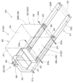
<第1実施形態の展開構造体>
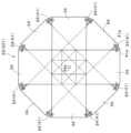
図1~図8及び図14は、第1実施形態の展開構造体22(221)を示している。第1実施形態の展開構造体22(221)は、複数の板材34を有する。第1実施形態の展開構造体22(221)は、複数の板材34を、展開していない非展開状態X(X1)(図3参照)と、複数の板材34を展開して非展開状態X1よりも平面視領域Z(Z1)が大きい展開状態Y(Y1)(図4参照)とに変更可能な構造体である。
<Deployment structure of the first embodiment>
1 to 8 and 14 show the deployment structure 22 (221) of the first embodiment. The deployment structure 22 ( 221 ) of the first embodiment has a plurality of
展開構造体221は、展開状態Y1における平面視領域Z(Z1)の大きさがマルチコプター60の離着陸が可能な大きさに設定される。平面視領域Z(Z1)は、マルチコプター60が離着陸する離着陸スペースである。
展開構造体221は、複数の板材34を、非展開状態X1において板材34の厚み方向に重ねて支持し、展開状態Y1において複数の板材34のそれぞれを板材34の厚み方向と直交する方向(水平方向)に展開して支持する。板材34の厚み方向と直交する方向は、例えば、板材34の幅方向である。
In the
The
複数の板材34は、機枠21に取り付けられた同一の軸34aによって枢支されており、同一の軸34a回りに回転可能であって、回転によって展開可能である。この場合、上記「板材34の厚み方向と直交する方向に展開」は、「板材34の軸34a回りの展開」と言い換えることができる。
また、図示していないが、複数の板材34は、それぞれ長孔を有し、各長孔に機枠21に取り付けられた同一の軸34aが挿通されている構成であってもよい。この構成では、各板材34は、軸34aが長孔に沿って相対的に移動することにより互いにスライドして展開可能である。この場合、上記「板材34の厚み方向と直交する方向に展開」は、「板材34の長孔に沿った移動による展開」と言い換えることができる。
The plurality of
Moreover, although not shown, the plurality of
本実施形態の場合、複数の板材34は、同一の軸34a回りに回転可能な複数の板材から構成されている。複数の板材34の平面視形状は、長方形、正方形等が好適であるが、三角形や扇形等のその他の形状であってもよい。複数の板材34の回転の支点となる軸34aは、各板材34の中心に対して偏心した位置にある。本実施形態の場合、軸34aは、積層した状態(非展開状態)において、各板材34の中心に対して前方寄りに偏心している。
In the case of this embodiment, the plurality of
複数の板材34は、重なって閉じた状態(非展開状態X1)から同一の軸34a回りに回転することにより、展開して開いた状態(非展開状態X1より平面視領域Z1が大きい展開状態Y1)とすることができる。このとき、スライドステー23を介して展開構造体221を後方へスライドする(図3に示す位置から図4に示す位置にスライドする)ことにより、非展開状態X1から展開状態Y1への移行を円滑に行うことが可能となる。
A plurality of
複数の板材34の何れか(例えば最も上側の板材)の上面には、取手などの固定部(図示略)を設けることができる。この固定部に、フックやバンド等を介して、マルチコプター60を固定することができる。また、複数の板材34の何れか(例えば最も上側の板材)の上面には、マルチコプター60が着陸時に搭載したカメラ等により画像認識することができるマーク(Hマークなど)が描かれていてもよい。
A fixing part (not shown) such as a handle can be provided on the upper surface of any one of the plurality of plate members 34 (for example, the uppermost plate member). The
本実施形態の場合、複数の板材34を有する展開構造体221は、スライドステー23を介して、機枠21の上側に取り付けられている。但し、展開構造体221は、スライドステー23を介さず、直接機枠21の上側に取り付けられていてもよい。展開構造体221が直接機枠21の上側に取り付けられる場合、複数の板材34を回転可能に支持する軸34aは、各板材34の中心に対して後方寄りに偏心していることが好ましい。これにより、スライドステー23を介して展開構造体221を後方へスライドせずとも、当該展開構造体221を展開状態Y1に変更し易くなる。
また、上述した展開構造体221は、機枠21に対して着脱自在であってもよい。
In the case of this embodiment, a
Further, the
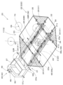
<第2実施形態の展開構造体>
図9及び図10等に示すように、第2実施形態の展開構造体22(222)を示している。第2実施形態の展開構造体22(222)は、複数の板材36~39を有する。第2実施形態の展開構造体22(222)は、複数の板材36~39を、展開していない非展開状態X(X2)(図9参照)と、展開して非展開状態X2よりも平面視領域Z(Z2)が大きい展開状態Y(Y2)(図10参照)とに変更可能な構造体である。展開構造体222は、展開状態Y2における平面視領域Z2の大きさがマルチコプター60の離着陸が可能な大きさに設定される。
<Deployment structure of the second embodiment>
As shown in FIGS. 9 and 10, etc., the deployment structure 22 (222) of the second embodiment is shown. The deployment structure 22 (222) of the second embodiment has a plurality of plate members 36-39. The deployment structure 22 (222) of the second embodiment has a plurality of
展開構造体222は、非展開状態X2において複数の板材36~39を組み合わせて立体構造に形成し、展開状態Y2において立体構造を展開して複数の板材36~39を平面状に形成する。展開構造体222は、立体構造において、マルチコプター60を収納する収納箱35を形成する。なお、本実施形態の場合、立体構造は、マルチコプター60の前方、後方、右側方、左側方を覆う直方体又は立方体の収納箱35として形成される。但し、収納箱35の形状は、これに限定されず、例えば、マルチコプター60の前方、後方、右側方、左側方のうち、2方向又は3方向のみを覆うものであってもよい。また、収納箱35は、円筒形等の他の形状であってもよい。
The unfolded
収納箱35を構成する複数の板材36~39は、底板材36、前板材37、左板材38L、右板材38R、後板材39である。底板材36は、平面視にて矩形状の板である。前板材37は、底板材36の前辺に蝶番等を介して上方に回動可能に設けられた矩形状の板である。前板材37は、底板材36に対して略垂直に立設した立設状態と、底板材36の上面と略面一になった面一状態とに姿勢を変更可能である。左板材38L及び右板材38Rは、底板材36の左辺及び右辺それぞれに蝶番等を介して上方に回動可能に設けられた矩形状の板である。左板材38L及び右板材38Rは、底板材36に対して略垂直に立設した立設状態と、底板材36の上面と略面一になった面一状態とに姿勢を変更可能である。後板材39は、底板材36の後辺に蝶番等を介して上方に回動可能に設けられた矩形状の板である。後板材39は、底板材36に対して略垂直に立設した立設状態と底板材36の上面と、底板材36の上面と略面一になった面一状態とに姿勢を変更可能である。
A plurality of
4枚の板材(前板材37、左板材38L、右板材38R、後板材39)は、底板材36に対して略垂直に立設した立設状態となったとき、隣り合う板材同士がラッチなどの固定具(図示略)で互いに固定されることが好ましい。
図10に示すように、底板材36の上面には、取手などの固定部43を設けることができる。この固定部43に、フックやバンド等を介して、マルチコプター60を固定することができる。固定部43は、後述する上蓋40の上面に設けてもよい。また、底板材36の上面には、マルチコプター60が着陸時にカメラ等により画像認識することができるマーク(Hマークなど)が描かれていてもよい。
When the four plate members (
As shown in FIG. 10 , a fixing
図9に示すように、収納箱35は、上蓋40を有していてもよい。この上蓋40は、非展開状態X2で立設した4枚の板材(前板材37、左板材38L、右板材38R、後板材39)の上部(即ち、収納箱35の上部)に被せることができる。
本実施形態の場合、収納箱35を構成する展開構造体222は、スライドステー23を介して、機枠21の上側に取り付けられているが、スライドステー23を介さず、直接機枠21の上側に取り付けられていてもよい。また、展開構造体222は、機枠21に対して着脱自在であってもよい。
As shown in FIG. 9, the
In the case of this embodiment, the unfolding
<スライドステー>
図1~図10に示すように、スライドステー23は、展開構造体22(221、222)を、機枠21に対してスライドさせる部材である。展開構造体22(221、222)は、スライドステー23と共に機枠21に対して前後方向にスライドすることができる。
スライドステー23は、左右一対の部材から構成されている。具体的には、スライドステー23は、機枠21の左枠材32Lに対してスライド可能な左側の部材と、右枠材32Rに対してスライド可能な右側の部材によって構成されている。本実施形態の場合、スライドステー23は、左枠材32L及び右枠材32Rにそれぞれ上側から被さってスライド可能な断面略U字状の部材である。但し、スライドステー23は、左枠材32L及び右枠材32Rをそれぞれ外側から囲ってスライド可能な断面略矩形状の部材や、レール溝等が形成された左枠材32L及び右枠材32R内にそれぞれスライド可能に入れられたランナー状の部材などであってもよい。また、スライドステー23は、機枠21に対して着脱自在であってもよい。
<Slide stay>
As shown in FIGS. 1 to 10, the
The slide stay 23 is composed of a pair of left and right members. Specifically, the
スライドステー23は、左枠材32L及び右枠材32Rに対する位置を固定する位置固定部材23aを備えている。本実施形態の場合、位置固定部材23aは、スライドステー23に形成された貫通孔と、左枠材32L及び右枠材32Rそれぞれに形成された貫通孔に連通する棒部材(ピン、ボルト等)である。
スライドステー23が位置固定部材23aによって固定される位置は、少なくとも機枠21の前方寄りの位置と後方寄りの位置である。スライドステー23が機枠21の前方寄りの位置にあるとき、展開構造体22は非展開状態Xとなる(図3、図9参照)。スライドステー23が機枠21の後方寄りの位置にあるとき、展開構造体22は展開状態Y(図4、図10参照)となる。
The slide stay 23 includes a
The position where the
<拡張部材>
図10及び図14に示すように、拡張部材24は、展開状態Yにおいて展開構造体22に装着可能であって、展開構造体22に装着した装着状態でマルチコプター60が離着陸する平面視領域Zを拡張する部材である。
拡張部材24は、展開構造体22を展開状態Yにしたときの複数の板材のうち、隣接する板材の間に装着可能な板体(以下、「第1板体41」という)である。また、拡張部材24は、展開構造体22に装着され且つ折り畳み可能な複数の板材等であってもよい。
<Expansion member>
As shown in FIGS. 10 and 14, the
The
図14は、展開状態Y1となった第1実施形態の展開構造体22(221)に対して拡張部材24を装着した状態を示している。拡張部材24を構成する第1板体41は、展開状態Y1となった第1実施形態の展開構造体22(221)の隣り合う板材34の間に装着される。このとき、第1板体41の上面は、展開構造体221の少なくとも何れかの板材34の上面と略面一となる。図14に示す例では、第1板体41は、平面視三角形状の複数(8枚)の板体から構成されている。但し、第1板体41の形状及び枚数は、展開構造体22(221)を展開状態Y1にしたときの形状等によって適宜変更することができる。
FIG. 14 shows a state in which the
図10は、展開状態Y2となった第2実施形態の展開構造体22(222)に対して拡張部材24を装着した状態を示している。図10に示すように、拡張部材24を構成する第1板体41は、展開状態Y2となった第2実施形態の展開構造体22(222)の隣り合う板材34の間に装着される。このとき、第1板体41の上面は、展開構造体222の各板材36~39の上面と略面一となる。図10に示す例では、第1板体41は、平面視三角形状の複数(4枚)の板体から構成されている。但し、第1板体41の形状及び枚数は、展開構造体22(222)を展開状態Y2にしたときの形状等によって適宜変更することができる。
FIG. 10 shows a state in which the
第1又は第2実施形態の展開構造体22に対して第1板体41を装着する場合、展開構造体22を展開状態Yとした状態で、第1板体41は隣接する板材34と取付具41aを介して連結されることが好ましい。
When the
<発電機>
図1、図2及び図5~図7に示すように、発電機26は、積載スペース27に積載されている。具体的には、発電機26は、積載スペース27を構成する箱体に収容されている。発電機26は、マルチコプター60のバッテリ71を充電可能な機器である。
<Generator>
As shown in FIGS. 1, 2 and 5-7,
発電機26は、本実施形態の場合、オルタネータである。但し、発電機26は、モータジェネレータであってもよい。発電機26は、例えば出力電圧が60V以下のものが使用されるが、出力電圧が60V超であってもよい。出力電圧が60V以下の発電機26を使用することによって、消費電力を削減することができ、安全性にも優れている。したがって、マルチコプター60や、当該マルチコプター60の作業装置66は、60V以下の低電圧で作動可能なものが好適に使用される。具体的には、作業装置66として、散布装置や播種装置が好適に使用される。本実施形態の場合、作業装置66は散布装置である。なお、発電機26の動力源としては、トラクタなどの作業車両2におけるPTO軸9や油圧取出し部から取り出した動力等を使用することができる。
The
<積載スペース>
図1、図2、図5~図7、図9及び図10に示すように、積載スペース27は、少なくとも発電機26を積載するスペースである。
積載スペース27は、機枠21の前部に設けられ、上方開口した略直方体状の構造体(箱体)により構成されている。積載スペース27の前部は、機枠21の前枠材31の上面に設けられている。積載スペース27の前後方向中途部から後部にかけての左右端部は、機枠21の左枠材32L及び右枠材32Rの前部から中途部にかけての上面に設けられている。積載スペース27を構成する箱体は、着脱可能な蓋体を有していてもよい。積載スペース27を構成する箱体は、その内部に仕切が設けられていてもよい。積載スペース27を構成する箱体は、その前面によって連結部30の中央ブラケットを後方から支持してもよい。積載スペース27は、発電機26以外に、農薬等の薬剤、希釈薬剤、肥料、水などの液体を貯留する予備タンクや、農作業具、工具など、その他の付属品を積載することができる。
<Loading space>
As shown in FIGS. 1, 2, 5 to 7, 9 and 10, the
The
<脚部材>
図1、図2及び図5~図8に示すように、脚部材28は、機枠21の下部に取り付けられている。本実施形態の場合、脚部材28は、伸縮可能で且つ機枠21に対して着脱可能な部材である。但し、脚部材28は、長さが一定の部材でもよいし、機枠21に対して着脱不能な部材であってもよい。また、図示したものよりも短い部材であってもよい。
<Leg member>
As shown in FIGS. 1, 2 and 5 to 8, the
脚部材28は、略矩形の機枠21における4つの角部下面に対して下方に突出するように着脱自在に取り付けられる。脚部材28は、下方に向けて徐々に直径が小さくなる複数の筒体から構成されている。脚部材28は、より直径の小さい筒体がより直径の大きい筒体の内部に入ることにより短縮し、より直径の小さい筒体がより直径の大きい筒体の内部から抜止め位置まで出ることにより伸長する。脚部材28は、伸長したときの長さを所定の長さで保持するため、より直径の小さい筒体をより直径の大きい筒体の内部から出た位置で留める留め具47を有していてもよい。この留め具47は、出退自在の円柱状の部材であり、各筒体に設けられた貫通孔に嵌入することにより、より直径の小さい筒体をより直径の大きい筒体の内部から出た位置で留める。
The
4つの脚部材28の全ての下端部には、キャスタ29が設けられていることが好ましい。但し、図5に示すように、4つの脚部材28のうち、左右の前脚部材28aの下端部にだけキャスタ29が設けられていてもよい。この場合、キャスタ29が設けられていない左右の後脚部材28bは下端部が丸くなっていることが好ましい。
<キャスタ>
図1、図2及び図5~図8に示すように、キャスタ29は、脚部材28の下端部に設けられている。
キャスタ29は、脚部材28の下端部に対して、板材(ブラケット)を介して、首振り可能(自在式)または首振り不可能(固定式)に取り付けられている。キャスタ29は、例えば、単輪式、双輪式、球体式などの構造を有する。
尚、キャスタ29は、機枠21の下部に直接取り付けられていてもよい。この場合、脚部材28は省略される。
<Caster>
As shown in FIGS. 1, 2 and 5 to 8, the
The
Note that the
<連結部>
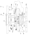
図1、図2及び図5~図10に示すように、連結部30は、離着陸装置20の前部に設けられている。連結部30は、作業車両2の後部に設けられる連結機構10(3点リンク機構等)に連結される部分である。
図7~図10等に示すように、連結部30は、中央ブラケット48と、この中央ブラケット48の上端部に設けられた中央孔49と、中央ブラケット48を支える前アーチ50と、左右の端軸51L、51Rを有する。
<Connector>
As shown in FIGS. 1, 2, and 5 to 10, the connecting
7 to 10, the connecting
中央ブラケット48は、左右2枚の板材から構成されている。これら左右2枚の板材は、機枠21の前部に立設された前アーチ50から上方に延びている。前アーチ50は、機枠21の前枠材31の左部上面から上方に延びる部分と右部上面から上方に延びる部分を有し、両部分の上端部同士が繋がっている。中央ブラケット48を構成する左右2枚の板材は、前アーチ50の左右方向略中央部の上面から上方に延びている。
The
中央孔49は、中央ブラケット48における左右の板材それぞれの上端部に設けられている。中央孔49の孔心方向は車両幅方向(左右方向)を向いている。
左右の端軸51L、51Rは、機枠21の前枠材31の前部に設けられている。端軸51L、51Rは、前枠材31の幅方向外方の面(左右外方面)における前部からそれぞれ幅方向外方(左右外方)に突出している。端軸51L、51Rは、その軸心方向が車両幅方向(左右方向)を向いている。左右の端軸51L、51Rの先端部には貫通孔が設けられている。
A
The left and
連結部30は、中央ブラケット48、中央孔49、前アーチ50及び左右の端軸51L、51Rにより、ヒッチフレームのAフレームに対応する構造となる。
中央ブラケット48は、中央孔49を介して連結機構10のトップリンク10aに連結することができる。端軸51L、51Rは、連結機構10のロアリンク10bに連結することができる。これにより、連結部30を作業車両2の連結機構10(3点リンク機構)に連結することができる。連結部30を作業車両2の連結機構10に連結した状態において、当該連結機構10を操作する(3点リンク機構の左側と右側のロアリンク10bの高さを個別に調整する)ことにより、マルチコプター60が離着陸する平面視領域Zを水平に調整することができる。つまり、作業車両2の連結機構10は、展開構造体22の展開状態Yにおいてマルチコプター60が離着陸する平面視領域Zを水平に調整する調整機構42を構成している。連結部30を構成する中央ブラケット48、中央孔49、前アーチ50及び左右の端軸51L、51Rは、調整機構42を構成する連結機構10を介して作業車両2に連結される。
The connecting
The
<効果>
上記したマルチコプターの離着陸装置20によれば、以下の効果を奏する。
離着陸装置20は、機枠21と、機枠21に搭載された展開構造体22であって、複数の板材を有し且つ複数の板材を展開していない非展開状態Xと、複数の板材を展開して非展開状態Xよりも平面視領域Zが大きい展開状態Yとに変更可能な展開構造体22を備え、展開構造体22は、展開状態Yにおいて平面視領域Zの大きさがマルチコプター60の離着陸可能な大きさに設定される。
<effect>
The multicopter takeoff and
The take-off and
この構成によれば、離着陸装置20が非展開状態Xよりも平面視領域Zが大きい展開状態Yに変更する展開構造体22を備えているため、非展開状態Xにて搬送時の障害物等への接触を抑制しつつ、展開状態Yにてマルチコプター60が離着陸可能な大きさを確保できる。
また、展開構造体22(221)は、複数の板材34を非展開状態X(X1)において板材34の厚み方向に重ねて支持し、複数の板材34を展開状態Y(Y1)において複数の板材34のそれぞれを板材34の厚み方向と直交する方向に展開にして支持する。
According to this configuration, since the take-off and
Further, the unfolded structure 22 (221) stacks and supports the plurality of
この構成によれば、複数の板材34を厚み方向に重ねることにより非展開状態X1における展開構造体22(221)の平面視領域をコンパクトにすることができる。また、非展開状態X1から展開状態Y(Y1)への移行を、板材34の厚み方向と直交する方向への展開によって容易に行うことができる。
また、展開構造体22(222)は、複数の板材36~39を非展開状態X(X2)において複数の板材36~39を組み合わせて立体構造に形成し、展開状態Y(Y2)において立体構造を展開して複数の板材36~39を平面状に形成する。
According to this configuration, by stacking the plurality of
Further, the unfolded structure 22 (222) is formed into a three-dimensional structure by combining the plurality of
この構成によれば、複数の板材36~39を組み合わせて立体構造に形成することにより非展開状態X1における展開構造体22(222)の平面視領域をコンパクトにすることができる。また、非展開状態X1から展開状態Y(Y2)への移行を、立体構造の展開によって容易に行うことができる。
また、展開構造体22(222)は、立体構造において、マルチコプター60を収納する収納箱35を形成する。
According to this configuration, by combining a plurality of
In addition, the deployment structure 22 (222) forms a
この構成によれば、離着陸装置20の搬送時や保管時において、展開構造体222を非展開状態X2にすることによって、マルチコプター60を収納箱35に収納することができる。また、収納箱35をマルチコプター60を保管するための保管箱としても使用できる。
また、離着陸装置20は、展開構造体22を、機枠21に対してスライドさせるスライドステー23を備えている。
According to this configuration, the
The take-off and
この構成によれば、展開構造体22をスライドステー23を介してスライドすることによって、機枠21に対するスライドステー23の位置を変更することができる。これにより、展開構造体22を非展開状態Xから展開状態Yに変更する際には、当該変更のために必要な十分なスペースを展開構造体22の周囲に確保することができる。また、展開構造体22を非展開状態Xとしたときには、非展開状態Xとした展開構造体22を障害物等への接触を回避できる位置に配置することができる。
According to this configuration, the position of the slide stay 23 with respect to the
より具体的には、例えば、展開構造体22をスライドステー23を介して後方寄りにスライドすることで、展開構造体221を構成する複数の板材34が回動するスペースや、展開構造体222を構成する前板材37が前方に回動するスペースなどを確保できる。また、離着陸装置20の搬送時や保管時には、展開構造体22を非展開状態Xにし且つ当該展開構造体22をスライドステー23を介して前方寄りにスライドすることによって、障害物等への接触回避や保管場所の省スペース化を図ることができる。
More specifically, for example, by sliding the
また、離着陸装置20は、展開状態Yにおいて、展開構造体22に装着可能であって、装着状態でマルチコプター60が離着陸する平面視領域Zを拡張する拡張部材24を備えている。
この構成によれば、マルチコプター60の離着陸時には、拡張部材24を展開構造体22に装着することによって、マルチコプター60の離着陸のために十分に広い面積をもつ平面視領域Zを確保できる。また、離着陸装置20の搬送時・保管時などには、拡張部材24を取り外すことで、搬送の邪魔にならずスムースな搬送が可能となり、保管場所を省スペース化することができる。
The take-off/
According to this configuration, when the
また、拡張部材24は、展開構造体22を展開状態Yにしたときの複数の板材のうち、隣接する板材の間に装着可能な板体(第1板体)41である。
この構成によれば、第1板体41を装着することによって、マルチコプター60の離着陸に適した面積及び形状を有する平面視領域Zを確保することができる。
また、機枠21は、マルチコプター60を充電可能な発電機26を少なくとも積載する積載スペース27を備えている。
The
According to this configuration, by attaching the
The
この構成によれば、発電機26により、圃場等のマルチコプター60を離着陸させる現場において、マルチコプター60に搭載されたバッテリの充電を行うことができるとともに、このような発電機26を離着陸装置20と一緒に搬送することができる。
また、機枠21は、作業車両2に連結される連結部30を備え、連結部30は、展開状態Yにおいてマルチコプター60が離着陸する平面視領域Zを水平に調整する調整機構42を介して作業車両2に連結される。
According to this configuration, the battery mounted on the
In addition, the
この構成によれば、地面が水平ではない場所に離着陸装置20が移動した場合であっても、調整機構42によって平面視領域Zを水平にすることができるため、マルチコプター60の円滑な離着陸が可能となる。
以上、本発明の実施形態について説明したが、今回開示された実施の形態はすべての点で例示であって制限的なものではないと考えられるべきである。本発明の範囲は上記した説明ではなくて特許請求の範囲によって示され、特許請求の範囲と均等の意味及び範囲内でのすべての変更が含まれることが意図される。
According to this configuration, even if the takeoff/
Although the embodiments of the present invention have been described above, the embodiments disclosed this time should be considered as examples in all respects and not restrictive. The scope of the present invention is indicated by the scope of the claims rather than the above description, and is intended to include all modifications within the scope and meaning equivalent to the scope of the claims.
2 作業車両
20 離着陸装置
21 機枠
22 展開構造体
23 スライドステー
24 拡張部材
26 発電機
27 積載スペース
30 連結部
34 板材
35 収納箱
36 板材
37 板材
38 板材
39 板材
41 板体(第1板体)
42 調整機構
221 展開構造体
222 展開構造体
X 非展開状態
X1 非展開状態
X2 非展開状態
Y 展開状態
Y1 展開状態
Y2 展開状態
Z 平面視領域
2
42
Claims (5)
前記機枠に搭載された展開構造体であって、複数の板材を有し且つ前記複数の板材を展開していない非展開状態と、前記複数の板材を展開して前記非展開状態よりも平面視領域が大きい展開状態とに変更可能な展開構造体と、
前記展開構造体を前記機枠に対して第1位置から第2位置にスライドさせるスライドステーと、
を備え、
前記展開構造体は、前記展開状態における平面視領域の大きさがマルチコプターの離着陸が可能な大きさに設定され、前記複数の板材を前記非展開状態において前記板材の厚み方向に重ねて支持し、前記複数の板材を前記展開状態において前記複数の板材のそれぞれを前記厚み方向と直交する方向に展開にして支持し、
前記複数の板材は、同一の軸が貫通することによって枢支されており、厚み方向に重なった前記非展開状態から前記同一の軸回りに回転することにより前記展開状態とすることができ、
前記展開構造体は、前記第1位置にあるとき前記非展開状態とされ、前記第2位置にあるとき前記展開状態とすることができ、
前記展開構造体を前記第1位置から前記第2位置にスライドさせることにより、前記軸が移動して前記複数の板材が前記軸回りに回転するスペースが確保されて前記展開構造体を前記展開状態とすることができるマルチコプターの離着陸装置。 machine frame and
A deployment structure mounted on the machine frame, comprising: a non-deployment state having a plurality of plate members and in which the plurality of plate members are not deployed; an unfolded structure changeable to an unfolded state with a large viewing area ;
a slide stay for sliding the deployment structure from a first position to a second position with respect to the machine frame;
with
The deployable structure has a plane view area in the deployed state set to a size that allows the multicopter to take off and land , and supports the plurality of plate members in the non-developed state by stacking them in the thickness direction of the plate members. , supporting each of the plurality of plate members in the developed state by developing each of the plurality of plate members in a direction orthogonal to the thickness direction;
The plurality of plate members are pivotally supported by the same shaft passing therethrough, and can be brought into the deployed state by rotating around the same shaft from the non-developed state overlapping in the thickness direction,
The deployment structure may be in the non-deployed state when in the first position and in the deployed state when in the second position,
By sliding the unfolding structure from the first position to the second position, a space is secured for the shaft to move and the plurality of plate members to rotate about the axis, thereby moving the unfolding structure to the unfolded state. Multicopter takeoff and landing gear that can be
前記連結部は、前記展開状態において前記マルチコプターが離着陸する平面視領域を水平に調整する調整機構を介して前記作業車両に連結される請求項1~4のいずれかに記載のマルチコプターの離着陸装置。 The machine frame includes a connecting portion connected to the work vehicle,
The take-off and landing of the multicopter according to any one of claims 1 to 4 , wherein the connecting portion is connected to the work vehicle via an adjustment mechanism that horizontally adjusts a planar view area from which the multicopter takes off and lands in the deployed state. Device.
Priority Applications (3)
| Application Number | Priority Date | Filing Date | Title |
|---|---|---|---|
| JP2019237908A JP7309600B2 (en) | 2019-12-27 | 2019-12-27 | multicopter takeoff and landing gear |
| PCT/JP2020/047026 WO2021131982A1 (en) | 2019-12-27 | 2020-12-16 | Multicopter takeoff/landing device |
| JP2023110807A JP7443604B2 (en) | 2019-12-27 | 2023-07-05 | multicopter takeoff and landing gear |
Applications Claiming Priority (1)
| Application Number | Priority Date | Filing Date | Title |
|---|---|---|---|
| JP2019237908A JP7309600B2 (en) | 2019-12-27 | 2019-12-27 | multicopter takeoff and landing gear |
Related Child Applications (1)
| Application Number | Title | Priority Date | Filing Date |
|---|---|---|---|
| JP2023110807A Division JP7443604B2 (en) | 2019-12-27 | 2023-07-05 | multicopter takeoff and landing gear |
Publications (2)
| Publication Number | Publication Date |
|---|---|
| JP2021104786A JP2021104786A (en) | 2021-07-26 |
| JP7309600B2 true JP7309600B2 (en) | 2023-07-18 |
Family
ID=76573245
Family Applications (2)
| Application Number | Title | Priority Date | Filing Date |
|---|---|---|---|
| JP2019237908A Active JP7309600B2 (en) | 2019-12-27 | 2019-12-27 | multicopter takeoff and landing gear |
| JP2023110807A Active JP7443604B2 (en) | 2019-12-27 | 2023-07-05 | multicopter takeoff and landing gear |
Family Applications After (1)
| Application Number | Title | Priority Date | Filing Date |
|---|---|---|---|
| JP2023110807A Active JP7443604B2 (en) | 2019-12-27 | 2023-07-05 | multicopter takeoff and landing gear |
Country Status (2)
| Country | Link |
|---|---|
| JP (2) | JP7309600B2 (en) |
| WO (1) | WO2021131982A1 (en) |
Families Citing this family (2)
| Publication number | Priority date | Publication date | Assignee | Title |
|---|---|---|---|---|
| WO2023187953A1 (en) * | 2022-03-29 | 2023-10-05 | 株式会社クボタ | Work assisting system |
| WO2023187964A1 (en) * | 2022-03-29 | 2023-10-05 | 株式会社クボタ | Work assistance system |
Citations (3)
| Publication number | Priority date | Publication date | Assignee | Title |
|---|---|---|---|---|
| WO2015026018A1 (en) | 2013-08-23 | 2015-02-26 | 한국항공우주연구원 | Apparatus for charging and housing unmanned vertical takeoff and landing aircraft and method for same |
| JP2017124758A (en) | 2016-01-14 | 2017-07-20 | 田淵電機株式会社 | Landing object device for flying object and method for controlling flying object |
| JP2019085104A (en) | 2017-11-06 | 2019-06-06 | 株式会社エアロネクスト | Flight unit and control method of flight unit |
Family Cites Families (4)
| Publication number | Priority date | Publication date | Assignee | Title |
|---|---|---|---|---|
| JPH09302628A (en) * | 1996-05-16 | 1997-11-25 | Mutsuo Hamaguchi | Movable landing facility for small-sized aircraft |
| AU2018409776A1 (en) | 2018-02-21 | 2020-07-30 | SCHÜCO International KG | Element for a window, door, pitched roof or facade, comprising a device for sending or receiving letters and parcels from an unmanned air vehicle |
| CN207956095U (en) | 2018-03-13 | 2018-10-12 | 江苏捷诚车载电子信息工程有限公司 | Unmanned plane transports and launch vehicle |
| CN109623839A (en) | 2018-12-24 | 2019-04-16 | 西南交通大学 | Power distribution station indoor equipment air-ground coordination inspection device and its method for inspecting |
-
2019
- 2019-12-27 JP JP2019237908A patent/JP7309600B2/en active Active
-
2020
- 2020-12-16 WO PCT/JP2020/047026 patent/WO2021131982A1/en active Application Filing
-
2023
- 2023-07-05 JP JP2023110807A patent/JP7443604B2/en active Active
Patent Citations (3)
| Publication number | Priority date | Publication date | Assignee | Title |
|---|---|---|---|---|
| WO2015026018A1 (en) | 2013-08-23 | 2015-02-26 | 한국항공우주연구원 | Apparatus for charging and housing unmanned vertical takeoff and landing aircraft and method for same |
| JP2017124758A (en) | 2016-01-14 | 2017-07-20 | 田淵電機株式会社 | Landing object device for flying object and method for controlling flying object |
| JP2019085104A (en) | 2017-11-06 | 2019-06-06 | 株式会社エアロネクスト | Flight unit and control method of flight unit |
Also Published As
| Publication number | Publication date |
|---|---|
| JP2023118892A (en) | 2023-08-25 |
| JP7443604B2 (en) | 2024-03-05 |
| WO2021131982A1 (en) | 2021-07-01 |
| JP2021104786A (en) | 2021-07-26 |
Similar Documents
| Publication | Publication Date | Title |
|---|---|---|
| JP7443604B2 (en) | multicopter takeoff and landing gear | |
| US8342440B2 (en) | Miniature robotic vehicle with ground and flight capability | |
| US20220203880A1 (en) | Modular container transport systems | |
| US10947036B2 (en) | Modular container transport systems | |
| CN109070989B (en) | Foldable unmanned aerial vehicle | |
| US9737067B2 (en) | Autonomous spraying platform | |
| US20140217230A1 (en) | Drone cargo helicopter | |
| RU2719047C1 (en) | Working vehicle (embodiments) | |
| CA3013273A1 (en) | Aerial platforms for aerial spraying and methods for controlling the same | |
| JP2020199818A (en) | Delivery system, flying body, and controller | |
| JP6296926B2 (en) | Parallel work system | |
| CN111976980A (en) | Multipurpose unmanned aerial vehicle | |
| BR112018074142B1 (en) | MULTIPURPOSE AGRICULTURAL VEHICLE SYSTEM | |
| WO2021131983A1 (en) | Takeoff/landing apparatus for multicopter having spraying function | |
| ES2933962T3 (en) | Self-propelled work device | |
| JP6746137B2 (en) | Unmanned aerial vehicle | |
| CN210191813U (en) | Unmanned aerial vehicle of collapsible rotor | |
| JP7235245B2 (en) | multicopter takeoff and landing gear | |
| JP2020082820A (en) | Flight vehicle | |
| CN110461722A (en) | Modular containers transportation system | |
| CN114393965A (en) | Automatic folding air-ground amphibious multi-mode carrying device | |
| JP7024814B2 (en) | Crop extractor | |
| JP6881336B2 (en) | Work vehicle | |
| JP6618056B2 (en) | Work system | |
| WO2020022264A1 (en) | Flying body |
Legal Events
| Date | Code | Title | Description |
|---|---|---|---|
| A621 | Written request for application examination |
Free format text: JAPANESE INTERMEDIATE CODE: A621 Effective date: 20211222 |
|
| A131 | Notification of reasons for refusal |
Free format text: JAPANESE INTERMEDIATE CODE: A131 Effective date: 20221206 |
|
| A521 | Request for written amendment filed |
Free format text: JAPANESE INTERMEDIATE CODE: A523 Effective date: 20230125 |
|
| TRDD | Decision of grant or rejection written | ||
| A01 | Written decision to grant a patent or to grant a registration (utility model) |
Free format text: JAPANESE INTERMEDIATE CODE: A01 Effective date: 20230509 |
|
| A601 | Written request for extension of time |
Free format text: JAPANESE INTERMEDIATE CODE: A601 Effective date: 20230515 |
|
| A61 | First payment of annual fees (during grant procedure) |
Free format text: JAPANESE INTERMEDIATE CODE: A61 Effective date: 20230705 |
|
| R150 | Certificate of patent or registration of utility model |
Ref document number: 7309600 Country of ref document: JP Free format text: JAPANESE INTERMEDIATE CODE: R150 |