JP7308698B2 - Delivery container - Google Patents

Delivery container Download PDF

Info

Publication number
JP7308698B2
JP7308698B2 JP2019158900A JP2019158900A JP7308698B2 JP 7308698 B2 JP7308698 B2 JP 7308698B2 JP 2019158900 A JP2019158900 A JP 2019158900A JP 2019158900 A JP2019158900 A JP 2019158900A JP 7308698 B2 JP7308698 B2 JP 7308698B2
Authority
JP
Japan
Prior art keywords
helical
sleeve
cylinder portion
restricting
rotation
Prior art date
Legal status (The legal status is an assumption and is not a legal conclusion. Google has not performed a legal analysis and makes no representation as to the accuracy of the status listed.)
Active
Application number
JP2019158900A
Other languages
Japanese (ja)
Other versions
JP2021036965A (en
Inventor
圭介 宮入
Current Assignee (The listed assignees may be inaccurate. Google has not performed a legal analysis and makes no representation or warranty as to the accuracy of the list.)
Yoshino Kogyosho Co Ltd
Original Assignee
Yoshino Kogyosho Co Ltd
Priority date (The priority date is an assumption and is not a legal conclusion. Google has not performed a legal analysis and makes no representation as to the accuracy of the date listed.)
Filing date
Publication date
Application filed by Yoshino Kogyosho Co Ltd filed Critical Yoshino Kogyosho Co Ltd
Priority to JP2019158900A priority Critical patent/JP7308698B2/en
Publication of JP2021036965A publication Critical patent/JP2021036965A/en
Application granted granted Critical
Publication of JP7308698B2 publication Critical patent/JP7308698B2/en
Active legal-status Critical Current
Anticipated expiration legal-status Critical

Links

Images

Landscapes

  • Containers And Packaging Bodies Having A Special Means To Remove Contents (AREA)

Description

本発明は、繰出容器に関する。 The present invention relates to dispensing containers.

特許文献1には、内容物を保持する中皿部と、中皿部を囲うスリーブと、スリーブの下方に設けられた操作筒部と、を備えた繰出容器が開示されている。この繰出容器は、操作筒部をスリーブに対して容器軸回りに回転させることで、中皿部を上昇させて、内容物をスリーブから上方に突出させることができるように構成されている。また、特許文献1の繰出容器は2つの螺旋溝を有しており、中皿部を2段階で繰り上げ可能となっている。この構成により、中皿部のストローク量を大きくしつつ、繰出容器の全長を小さくしている。 Patent Literature 1 discloses a dispensing container that includes a middle plate portion that holds contents, a sleeve that surrounds the middle plate portion, and an operation cylinder portion that is provided below the sleeve. The delivery container is configured such that the operation cylinder is rotated about the container axis with respect to the sleeve to raise the middle plate portion so that the contents can be protruded upward from the sleeve. In addition, the delivery container of Patent Document 1 has two spiral grooves, and the middle plate portion can be raised in two stages. With this configuration, the total length of the delivery container is reduced while increasing the stroke amount of the middle tray.

実開昭51-47745号公報Japanese Utility Model Laid-Open No. 51-47745

特許文献1の構成では、各部材の相対回転を規制するための構造について、繰出容器の上下方向における寸法をより小さくする点で改善の余地があった。 In the configuration of Patent Document 1, the structure for restricting the relative rotation of each member has room for improvement in terms of making the dimension of the feeding container in the vertical direction smaller.

本発明はこのような事情を考慮してなされ、中皿部のストローク量を確保しつつ、上下方向における全長をより小さくすることが可能な繰出容器を提供することを目的とする。 SUMMARY OF THE INVENTION It is an object of the present invention to provide a feeding container that can reduce the total length in the vertical direction while ensuring the stroke amount of the middle plate portion.

上記課題を解決するために、本発明の一態様に係る繰出容器は、内容物を保持する中皿部と、上下方向に延びる柱状部および前記柱状部に対する容器軸回りの回転が規制された操作筒部を有する操作部と、前記柱状部を径方向外側から囲う筒状の回動規制軸と、前記回動規制軸を径方向外側から囲い、外周面に第1螺旋溝が形成されるとともに、前記中皿部に固定された第1螺旋筒部と、前記第1螺旋筒部を径方向外側から囲い、外周面に第2螺旋溝が形成された第2螺旋筒部と、前記操作筒部から上方に向けて延び、前記中皿部および前記第2螺旋筒部を径方向外側から囲うスリーブと、を備え、前記柱状部と、前記回動規制軸と、前記第1螺旋筒部と、の容器軸回りの相対回転は規制され、前記回動規制軸には、前記第1螺旋筒部の内周面に形成された第1規制部に当接することで前記第1螺旋筒部の前記回動規制軸に対する所定量以上の上昇を規制する第2規制部と、前記柱状部の外周面に形成された第3規制部に当接することで前記回動規制軸の前記柱状部に対する所定量以上の上昇を規制する第4規制部と、が形成され、前記第2螺旋筒部には、前記第1螺旋溝に係合することで、前記第2螺旋筒部と前記第1螺旋筒部とが容器軸回りに相対回転したときに前記第1螺旋筒部を前記第2螺旋筒部に対して上下動させる第1係合部が形成され、前記スリーブには、前記第2螺旋溝に係合することで、前記スリーブと前記第2螺旋筒部とが容器軸回りに相対回転したときに前記第2螺旋筒部を前記スリーブに対して上下動させる第2係合部が形成されている。 In order to solve the above problems, a delivery container according to one aspect of the present invention includes a middle plate portion for holding contents, a columnar portion extending in the vertical direction, and an operation mechanism in which rotation about the container axis with respect to the columnar portion is restricted. an operation portion having a tubular portion; a tubular rotation restricting shaft that surrounds the columnar portion from the outside in the radial direction; and a first spiral groove that surrounds the rotation restricting shaft from the outside in the radial direction. a first helical cylinder portion fixed to the intermediate plate portion; a second helical cylinder portion surrounding the first helical cylinder portion from the outside in a radial direction and having a second helical groove formed on an outer peripheral surface thereof; and the operation cylinder. a sleeve that extends upward from the portion and surrounds the intermediate plate portion and the second helical cylinder portion from the outside in the radial direction, the columnar portion, the rotation restricting shaft, and the first helical cylinder portion; , relative rotation around the container axis is regulated, and the rotation regulating shaft abuts against a first regulating portion formed on the inner peripheral surface of the first helical tubular portion, thereby allowing the first helical tubular portion to rotate. A second restricting portion for restricting the rotation restricting shaft from rising by a predetermined amount or more, and a third restricting portion formed on the outer peripheral surface of the columnar portion. and a fourth restricting portion that restricts upward movement of a fixed amount or more. A first engaging portion is formed to move the first helical cylinder portion up and down with respect to the second helical cylinder portion when the portion rotates relative to the container axis, and the sleeve includes the second helical groove. By engaging with the second engaging portion, the second engaging portion is formed to move the second spiral tube portion up and down with respect to the sleeve when the sleeve and the second spiral tube portion rotate relative to each other around the container axis. ing.

上記態様によれば、スリーブと操作筒部とを容器軸回りに相対回転させたとき、操作筒部に対する回転が規制されている柱状部、回動規制軸、および第1螺旋筒部が一体となって、スリーブに対して回転する。すると、第1螺旋溝と第1係合部とが係合すること、あるいは、第2螺旋溝と第2係合部とが係合することにより、中皿部が上昇する。これにより、内容物が上方に繰り出されるので、使用者は内容物を使用することができる。
また、回動規制軸は柱状部を径方向外側から囲い、第1螺旋筒部は回動規制軸を径方向外側から囲い、第2螺旋筒部は第1螺旋筒部を径方向外側から囲っている。これにより、初期状態では、柱状部、回動規制軸、第1螺旋筒部、および第2螺旋筒部を上下方向において同じ位置に配置することが可能であり、繰出容器全体の上下方向における全長を小さくすることができる。そして、中皿部は、第2規制部が第1規制部に当接し、かつ、第4規制部が第3規制部に当接するまで上昇することができる。つまり、中皿部のストローク量は、回動規制軸の柱状部に対するストローク量および第1螺旋筒部の回動規制軸に対するストローク量の合計値となる。これにより、中皿部のストローク量を大きくすることができる。
According to the above aspect, when the sleeve and the operation cylinder part are relatively rotated around the container axis, the columnar part, the rotation restriction shaft, and the first helical cylinder part, which are restricted from rotating with respect to the operation cylinder part, are integrally formed. and rotate with respect to the sleeve. As a result, the first helical groove and the first engaging portion engage, or the second helical groove and the second engaging portion engage, thereby raising the intermediate plate portion. As a result, the contents are drawn out upward, so that the user can use the contents.
The rotation restricting shaft radially surrounds the columnar portion, the first spiral cylinder surrounds the rotation restricting shaft from the radial outside, and the second spiral cylinder surrounds the first spiral cylinder from the radial outside. ing. As a result, in the initial state, the columnar portion, the rotation restricting shaft, the first helical cylinder portion, and the second helical cylinder portion can be arranged at the same position in the vertical direction. can be made smaller. Then, the middle plate portion can be raised until the second restricting portion abuts against the first restricting portion and the fourth restricting portion abuts against the third restricting portion. That is, the stroke amount of the intermediate plate portion is the total value of the stroke amount of the rotation restricting shaft with respect to the columnar portion and the stroke amount of the first helical cylinder portion with respect to the rotation restricting shaft. Thereby, the stroke amount of the intermediate plate portion can be increased.

本発明の上記態様によれば、上下方向における全長を小さくしながら、中皿部のストローク量を大きくすることが可能な繰出容器を提供することができる。 According to the aspect of the present invention, it is possible to provide a feeding container that can increase the stroke amount of the middle plate portion while reducing the total length in the vertical direction.

第1実施形態に係る繰出容器の半縦断面図である。It is a semi-longitudinal cross-sectional view of the delivery container which concerns on 1st Embodiment. 図1の外側部材の半縦断面図である。2 is a semi-longitudinal cross-sectional view of the outer member of FIG. 1; FIG. 図1の内側部材の半縦断面図である。Figure 2 is a semi-longitudinal cross-sectional view of the inner member of Figure 1; 図2Bの平面図である。Figure 2B is a plan view of Figure 2B; 図1の回動規制軸の側面図である。FIG. 2 is a side view of a rotation restricting shaft in FIG. 1; 図3Aの平面図である。3B is a plan view of FIG. 3A; FIG. 図3BのIII-III断面矢視図である。FIG. 3B is a cross-sectional view taken along line III-III of FIG. 3B; 図1の中皿部材の半縦断面図である。FIG. 2 is a semi-longitudinal cross-sectional view of the inner tray member of FIG. 1; 図4Aの下面図である。4B is a bottom view of FIG. 4A; FIG. 図4BのIV-IV断面矢視図である。FIG. 4B is a cross-sectional view taken along line IV-IV of FIG. 4B; 図1の第2螺旋筒部の側面図である。FIG. 2 is a side view of the second helical cylinder portion of FIG. 1; 図5Aの第2螺旋筒部の縦断面図である。5B is a vertical cross-sectional view of the second helical cylinder portion of FIG. 5A; FIG. 図1のスリーブの半縦断面図である。2 is a semi-longitudinal section of the sleeve of FIG. 1; FIG. 図6AのスリーブをVI方向から見た側面図である。FIG. 6B is a side view of the sleeve of FIG. 6A viewed from direction VI. 図1の繰出容器の使用状態を示す図である。It is a figure which shows the use condition of the feeding container of FIG. 第2実施形態に係る操出容器の半縦断面図である。It is a semi-longitudinal cross-sectional view of the unloading container according to the second embodiment. 図8の内側部材の縦断面図である。Figure 9 is a longitudinal cross-sectional view of the inner member of Figure 8; 図9Aの平面図である。9B is a plan view of FIG. 9A; FIG.

(第1実施形態)
以下、第1実施形態の繰出容器について図面に基づいて説明する。
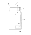
図1に示すように、繰出容器1は、操作部10と、回動規制軸20と、中皿部材30と、第2螺旋筒部40と、スリーブ50と、キャップ60と、介在部材70と、を備えている。操作部10、回動規制軸20、中皿部材30、第2螺旋筒部40、キャップ60、および介在部材70は、樹脂によって形成されている。スリーブ50は、金属によって形成されている。なお、各部材の材質は適宜変更してもよい。
(First embodiment)
Hereinafter, the delivery container of the first embodiment will be described based on the drawings.
As shown in FIG. 1, the delivery container 1 includes an operating portion 10, a rotation restricting shaft 20, an intermediate plate member 30, a second spiral tube portion 40, a sleeve 50, a cap 60, and an intervening member 70. , is equipped with The operating portion 10, the rotation restricting shaft 20, the middle plate member 30, the second helical cylinder portion 40, the cap 60, and the intervening member 70 are made of resin. The sleeve 50 is made of metal. Note that the material of each member may be changed as appropriate.

中皿部材30は、内容物を保持する中皿部31を有している。中皿部31は有底筒状に形成されており、その内側には内容物の下端部が収容される。内容物としては、棒状の固形化粧料(例えば口紅、リップクリーム)、あるいは棒状の固形糊などを用いることができる。なお、内容物の種類は適宜変更可能である。 The middle plate member 30 has a middle plate portion 31 that holds contents. The middle plate portion 31 is formed in a cylindrical shape with a bottom, and the lower end portion of the contents is accommodated therein. As the content, stick-shaped solid cosmetics (eg, lipstick, lip balm), stick-shaped solid glue, or the like can be used. Note that the type of content can be changed as appropriate.

(方向定義)
本実施形態では、操作部10、回動規制軸20、中皿部材30、第2螺旋筒部40、スリーブ50、キャップ60、および介在部材70は、それぞれの中心軸線が共通軸上に位置する状態で配設されている。以下、この共通軸を容器軸Oといい、容器軸Oに沿う方向を上下方向(容器軸方向)という。上下方向から見た平面視において、容器軸Oに交差する方向を径方向といい、容器軸O回りに周回する方向を周方向という。上下方向における中皿部31の開口部側を上方といい、操作部10側を下方という。容器軸Oに沿う断面を縦断面といい、容器軸Oに直交する断面を横断面という。
(direction definition)
In the present embodiment, the central axes of the operating portion 10, the rotation restricting shaft 20, the middle plate member 30, the second spiral cylinder portion 40, the sleeve 50, the cap 60, and the intervening member 70 are positioned on a common axis. placed in a state. Hereinafter, this common axis will be referred to as container axis O, and the direction along container axis O will be referred to as the vertical direction (container axial direction). In a plan view viewed from above and below, the direction intersecting the container axis O is called the radial direction, and the direction rotating around the container axis O is called the circumferential direction. The opening side of the inner plate portion 31 in the vertical direction is referred to as the upper side, and the operation section 10 side is referred to as the lower side. A section along the container axis O is called a vertical section, and a section orthogonal to the container axis O is called a transverse section.

また、繰出容器1は、スリーブ50と操作部10とを容器軸O回りに相対回転させることで、内容物を上昇させてスリーブ50から上方に繰り出したり、繰り出された内容物を下降させてスリーブ50内に再び収容させたりすることができる。本実施形態では、容器軸O回りの回転方向のうち、内容物を上昇させる方向を繰出方向といい、内容物を下降させる方向を収容方向という。 In addition, the dispensing container 1 rotates the sleeve 50 and the operating portion 10 relative to each other around the container axis O to raise the contents and extend the contents upward from the sleeve 50 or to lower the contents to the sleeve. 50 can be accommodated again. In this embodiment, among the rotation directions about the container axis O, the direction in which the contents are raised is called the delivery direction, and the direction in which the contents are lowered is called the storage direction.

操作部10は、外側部材10aおよび内側部材10bが組み合わされることで構成されている。本実施形態の外側部材10aおよび内側部材10bは別体として形成されているが、これらは一体に形成されていてもよい。内側部材10bは、外側部材10aの径方向内側に位置している。 The operating portion 10 is configured by combining an outer member 10a and an inner member 10b. Although the outer member 10a and the inner member 10b of this embodiment are formed separately, they may be integrally formed. The inner member 10b is located radially inside the outer member 10a.

図2Aに示すように、外側部材10aは、上下方向に延びる操作筒部11と、操作筒部11から上方に向けて延びる上筒部12と、を有している。操作筒部11の下端部には、径方向外側に向けて窪む環状溝部11aが形成されている。環状溝部11aは、操作筒部11の内周面に、全周にわたって形成されている。操作筒部11の内周面のうち、環状溝部11aよりも上方に位置する部分には、複数の嵌合溝11bが形成されている。複数の嵌合溝11bは、上下方向に延びるとともに、周方向に間隔を空けて配置されている。 As shown in FIG. 2A , the outer member 10 a has an operating tube portion 11 extending in the vertical direction and an upper tube portion 12 extending upward from the operating tube portion 11 . An annular groove portion 11a that is recessed radially outward is formed in the lower end portion of the operation cylinder portion 11 . The annular groove portion 11a is formed on the inner peripheral surface of the operation cylinder portion 11 over the entire circumference. A plurality of fitting grooves 11b are formed in a portion of the inner peripheral surface of the operation cylinder portion 11 located above the annular groove portion 11a. The plurality of fitting grooves 11b extend in the vertical direction and are arranged at intervals in the circumferential direction.

上筒部12の外径は操作筒部11の外径よりも小さい。上筒部12の外周面には、複数の保持突起12aが形成されている。保持突起12aは、周方向に間隔を空けて配置されている。図1に示すように、上筒部12には、有頂筒状のキャップ60の下端部が外嵌される。キャップ60が上筒部12に装着された状態では、保持突起12aがキャップ60の内周面に接触する。 The outer diameter of the upper cylinder portion 12 is smaller than the outer diameter of the operation cylinder portion 11 . A plurality of holding protrusions 12a are formed on the outer peripheral surface of the upper cylindrical portion 12 . The holding protrusions 12a are arranged at intervals in the circumferential direction. As shown in FIG. 1 , the lower end portion of a cap 60 having a capped tubular shape is fitted onto the upper tubular portion 12 . When the cap 60 is attached to the upper tubular portion 12 , the holding protrusion 12 a contacts the inner peripheral surface of the cap 60 .

図2B、図2Cに示すように、内側部材10bは、下板部13と、嵌合筒部14と、柱状部15と、を有している。下板部13は、平面視において円板状に形成されている。嵌合筒部14は、下板部13の外周縁から上方に向けて延びている。嵌合筒部14の下端には、径方向外側に向けて突出する環状突部14aが形成されている。環状突部14aは、嵌合筒部14の外周面に、全周にわたって形成されている。嵌合筒部14の外周面のうち、環状突部14aよりも上方に位置する部分には、複数の嵌合リブ14bが形成されている。複数の嵌合リブ14bは、上下方向に延びるとともに、周方向に間隔を空けて配置されている。 As shown in FIGS. 2B and 2C, the inner member 10b has a lower plate portion 13, a fitting tubular portion 14, and a columnar portion 15. As shown in FIGS. The lower plate portion 13 is formed in a disc shape in plan view. The fitting cylinder portion 14 extends upward from the outer peripheral edge of the lower plate portion 13 . An annular protrusion 14a is formed at the lower end of the fitting cylinder 14 and protrudes radially outward. The annular protrusion 14a is formed on the outer peripheral surface of the fitting tube portion 14 over the entire circumference. A plurality of fitting ribs 14b are formed on a portion of the outer peripheral surface of the fitting tube portion 14 located above the annular projection 14a. The plurality of fitting ribs 14b extend in the vertical direction and are spaced apart in the circumferential direction.

嵌合リブ14bが嵌合溝11bに嵌合することで、内側部材10bの外側部材10aに対する容器軸O回りの回転が規制されている。また、環状溝部11aに環状突部14aが入り込むことで、内側部材10bの外側部材10aに対する上下動が規制されている。これらの構成により、内側部材10bが外側部材10aに固定されている(図1参照)。なお、内側部材10bを外側部材10aに固定するための構成は適宜変更してもよい。 By fitting the fitting rib 14b into the fitting groove 11b, rotation of the inner member 10b about the container axis O with respect to the outer member 10a is restricted. Moreover, the vertical movement of the inner member 10b with respect to the outer member 10a is restricted by the annular protrusion 14a entering the annular groove 11a. With these configurations, the inner member 10b is fixed to the outer member 10a (see FIG. 1). The configuration for fixing the inner member 10b to the outer member 10a may be changed as appropriate.

図2B、図2Cに示すように、柱状部15は、下板部13の径方向中央部から上方に向けて延びている。柱状部15の外周面には、径方向外側に向けて突出する2つ(複数)の第1ガイドリブ15aが形成されている。2つの第1ガイドリブ15aは、周方向に間隔を空けて配置されており、柱状部15の下端から上方に向けて延びている。第1ガイドリブ15aの上端は、柱状部15の上端よりも下方に位置している。柱状部15の外周面のうち、第1ガイドリブ15aよりも上方に位置する部分には、2つ(複数)の第3規制部15bが形成されている。2つの第3規制部15bは、柱状部15の外周面から径方向外側に向けて突出しており、周方向に間隔をあけて配置されている。なお、第1ガイドリブ15aおよび第3規制部15bの数は適宜変更可能であり、1つでもよいし、3つ以上でもよい。 As shown in FIGS. 2B and 2C, the columnar portion 15 extends upward from the radial center portion of the lower plate portion 13 . Two (a plurality of) first guide ribs 15 a are formed on the outer peripheral surface of the columnar portion 15 so as to protrude radially outward. The two first guide ribs 15 a are circumferentially spaced apart and extend upward from the lower end of the columnar portion 15 . The upper ends of the first guide ribs 15 a are positioned below the upper ends of the columnar portions 15 . Two (plural) third restricting portions 15b are formed in a portion of the outer peripheral surface of the columnar portion 15 located above the first guide ribs 15a. The two third restricting portions 15b protrude radially outward from the outer peripheral surface of the columnar portion 15 and are spaced apart in the circumferential direction. The numbers of the first guide ribs 15a and the third restricting portions 15b can be changed as appropriate, and may be one or three or more.

第3規制部15bの周方向における位置は、第1ガイドリブ15aの周方向における位置と異なっている。すなわち、第3規制部15bは、平面視において第1ガイドリブ15aと重ならない位置に配置されている。柱状部15の上端面には、下方に向けて窪む溝部15cが形成されている。平面視において、溝部15cは径方向に延びており、周方向において第1ガイドリブ15aと同じ位置に配置されている。 The circumferential position of the third restricting portion 15b is different from the circumferential position of the first guide rib 15a. That is, the third restricting portion 15b is arranged at a position not overlapping with the first guide rib 15a in plan view. A groove portion 15c that is recessed downward is formed in the upper end surface of the columnar portion 15 . In plan view, the groove portion 15c extends in the radial direction and is arranged at the same position as the first guide rib 15a in the circumferential direction.

図3A、図3B、図3Cに示すように、回動規制軸20は、上下方向に延びる筒状に形成されている。回動規制軸20の内周面には、径方向外側に向けて窪む2つ(複数)の第1ガイド溝21が形成されている。2つの第1ガイド溝21は、回動規制軸20の上下方向における全長にわたって延びており、周方向に間隔を空けて配置されている。 As shown in FIGS. 3A, 3B, and 3C, the rotation restricting shaft 20 has a tubular shape extending in the vertical direction. Two (plural) first guide grooves 21 are formed on the inner peripheral surface of the rotation restricting shaft 20 so as to be recessed radially outward. The two first guide grooves 21 extend over the entire length of the rotation restricting shaft 20 in the vertical direction and are spaced apart in the circumferential direction.

回動規制軸20の外周面には、径方向内側に向けて窪む2つ(複数)の第2ガイド溝22が形成されている。2つの第2ガイド溝22は、回動規制軸20の上下方向における全長にわたって延びており、周方向に間隔を空けて配置されている。第1ガイド溝21および第2ガイド溝22は、周方向において互いに異なる位置に配置されている。
回動規制軸20の内周面には、径方向内側に向けて突出する2つ(複数)の第4規制部23が形成されている。2つの第4規制部23は、周方向において第1ガイド溝21と異なる位置に配置されている。
Two (plurality) of second guide grooves 22 recessed radially inward are formed on the outer peripheral surface of the rotation restricting shaft 20 . The two second guide grooves 22 extend over the entire length of the rotation restricting shaft 20 in the vertical direction and are spaced apart in the circumferential direction. The first guide groove 21 and the second guide groove 22 are arranged at different positions in the circumferential direction.
Two (plurality) of fourth restricting portions 23 projecting radially inward are formed on the inner peripheral surface of the rotation restricting shaft 20 . The two fourth restricting portions 23 are arranged at different positions from the first guide groove 21 in the circumferential direction.

回動規制軸20の外周面には、径方向外側に向けて突出する4つ(複数)の第2規制部24が形成されている。4つの第2規制部24は、回動規制軸20の上端部に配置されている。第2規制部24および第2ガイド溝22は、周方向において互いに異なる位置に配置されている。なお、第1ガイド溝21、第2ガイド溝22、第4規制部23、および第2規制部24の数は適宜変更可能である。 Four (a plurality of) second restricting portions 24 projecting radially outward are formed on the outer peripheral surface of the rotation restricting shaft 20 . The four second restricting portions 24 are arranged at the upper end portion of the rotation restricting shaft 20 . The second restricting portion 24 and the second guide groove 22 are arranged at different positions in the circumferential direction. The numbers of the first guide grooves 21, the second guide grooves 22, the fourth restricting portions 23, and the second restricting portions 24 can be changed as appropriate.

回動規制軸20は、柱状部15の外側に装着されている(図1参照)。第1ガイド溝21に第1ガイドリブ15aが入り込むことで、回動規制軸20の柱状部15に対する容器軸O回りの回転が規制されている。また、回動規制軸20が柱状部15に対して上下動するとき、第1ガイドリブ15aと第1ガイド溝21とが上下に摺動する。回動規制軸20が柱状部15に対して所定量上昇したとき、第4規制部23が第3規制部15bに当接することで、回動規制軸20のそれ以上の上昇が規制される。 The rotation restricting shaft 20 is attached to the outside of the columnar portion 15 (see FIG. 1). Since the first guide rib 15 a enters the first guide groove 21 , rotation of the rotation restricting shaft 20 about the container axis O with respect to the columnar portion 15 is restricted. Further, when the rotation restricting shaft 20 moves up and down with respect to the columnar portion 15, the first guide rib 15a and the first guide groove 21 slide up and down. When the rotation restricting shaft 20 rises by a predetermined amount with respect to the columnar portion 15, the fourth restricting portion 23 contacts the third restricting portion 15b, thereby restricting the rotation restricting shaft 20 from further rising.

図4A、図4B、図4Cに示すように、中皿部材30は、中皿部31と、第1螺旋筒部32と、を有している。本実施形態の中皿部31および第1螺旋筒部32は一体に形成されており、これによって、第1螺旋筒部32は中皿部31に固定されている。なお、中皿部31と第1螺旋筒部32とを別体に形成し、これらを互いに固定してもよい。 As shown in FIGS. 4A, 4B, and 4C, the middle plate member 30 has a middle plate portion 31 and a first helical cylinder portion 32 . The middle plate portion 31 and the first helical cylinder portion 32 of the present embodiment are integrally formed, whereby the first helical cylinder portion 32 is fixed to the middle plate portion 31 . Alternatively, the middle plate portion 31 and the first helical cylinder portion 32 may be formed separately and fixed to each other.

中皿部31の内周面には、上下方向に延びる複数の保持リブ31aが、周方向に間隔を空けて形成されている。保持リブ31aにより、内容物が中皿部31内により確実に固定される。第1螺旋筒部32は、中皿部31の下面から下方に向けて延びている。第1螺旋筒部32の外径は中皿部31の外径より小さい。 A plurality of vertically extending holding ribs 31a are formed on the inner peripheral surface of the intermediate plate portion 31 at intervals in the circumferential direction. The holding ribs 31a more reliably fix the contents in the middle plate portion 31. As shown in FIG. The first helical cylinder portion 32 extends downward from the lower surface of the intermediate plate portion 31 . The outer diameter of the first helical cylinder portion 32 is smaller than the outer diameter of the intermediate plate portion 31 .

第1螺旋筒部32の外周面には、第1螺旋溝32aが形成されている。本実施形態の第1螺旋溝32aは2条ネジ(多条ネジ)であるが、第1螺旋溝32aは1条ネジであってもよい。図4Cに示すように、第1螺旋溝32aの下端は、第1螺旋筒部32の下端より上方に位置しており、下方に向けて開口していない。図4Bに示すように、第1螺旋筒部32の内周面には、径方向内側に向けて突出する2つ(複数)の第2ガイドリブ33が形成されている。2つの第2ガイドリブ33は、周方向に間隔を空けて配置されており、第1螺旋筒部32の全長にわたって上下方向に延びている。 A first spiral groove 32 a is formed on the outer peripheral surface of the first spiral cylinder portion 32 . Although the first helical groove 32a of this embodiment is a double thread (multiple thread), the first helical groove 32a may be a single thread. As shown in FIG. 4C, the lower end of the first spiral groove 32a is located above the lower end of the first spiral cylinder portion 32 and does not open downward. As shown in FIG. 4B , two (plurality) of second guide ribs 33 protruding radially inward are formed on the inner peripheral surface of the first helical cylinder portion 32 . The two second guide ribs 33 are circumferentially spaced apart and extend vertically over the entire length of the first helical cylinder portion 32 .

第1螺旋筒部32には、2つ(複数)の切込部34が形成されている。2つの切込部34は、第1螺旋筒部32を径方向に貫通しており、周方向に間隔を空けて配置されている。2つの切込部34は、第1螺旋筒部32の下端から、第1螺旋筒部32の上下方向における中央部まで、上下方向に延びている。 Two (plurality) cut portions 34 are formed in the first helical cylinder portion 32 . The two cut portions 34 penetrate the first helical cylinder portion 32 in the radial direction and are spaced apart in the circumferential direction. The two cut portions 34 extend vertically from the lower end of the first spiral tube portion 32 to the center portion of the first spiral tube portion 32 in the vertical direction.

第1螺旋筒部32の内周面には、4つ(複数)の第1規制部35が形成されている。4つの第1規制部35は、第1螺旋筒部32の内周面から径方向内側に向けて突出しており、周方向に間隔を空けて配置されている。第1規制部35の周方向における位置は、第2ガイドリブ33および切込部34の周方向における位置と異なっている。なお、第2ガイドリブ33、切込部34、および第1規制部35の数は適宜変更可能である。 Four (plural) first restricting portions 35 are formed on the inner peripheral surface of the first helical cylinder portion 32 . The four first restricting portions 35 protrude radially inward from the inner peripheral surface of the first helical cylinder portion 32 and are arranged at intervals in the circumferential direction. The position of the first restricting portion 35 in the circumferential direction is different from the positions of the second guide rib 33 and the cut portion 34 in the circumferential direction. Note that the numbers of the second guide ribs 33, the cut portions 34, and the first restricting portions 35 can be changed as appropriate.

第1螺旋筒部32は、回動規制軸20の外側に装着されている(図1参照)。第2ガイドリブ33が、第2ガイド溝22内に入り込むことで、第1螺旋筒部32の回動規制軸20に対する容器軸O回りの回転が規制されている。また、第1螺旋筒部32が回動規制軸20に対して上下動するとき、第2ガイドリブ33と第2ガイド溝22とが上下に摺動する。 The first helical cylinder portion 32 is attached to the outside of the rotation restricting shaft 20 (see FIG. 1). The rotation of the first helical cylinder portion 32 about the container axis O with respect to the rotation restriction shaft 20 is restricted by the second guide rib 33 entering the second guide groove 22 . Further, when the first helical cylinder portion 32 moves up and down with respect to the rotation restricting shaft 20, the second guide rib 33 and the second guide groove 22 slide up and down.

図5A、図5Bに示すように、第2螺旋筒部40は、上下方向に延びる筒状に形成されている。第2螺旋筒部40の外周面には、第2螺旋溝41が形成されている。本実施形態の第2螺旋溝41は2条ネジ(多条ネジ)であるが、第2螺旋溝41は1条ネジであってもよい。第2螺旋溝41は第2螺旋筒部40の上端まで延びており、第2螺旋溝41の上端は上方に向けて開口している。第2螺旋溝41の下端は第2螺旋筒部40の下端より上方に位置しており、下方に向けて開口していない。 As shown in FIGS. 5A and 5B, the second helical tubular portion 40 is formed in a tubular shape extending in the vertical direction. A second spiral groove 41 is formed on the outer peripheral surface of the second spiral cylinder portion 40 . Although the second helical groove 41 of this embodiment is a double thread (multiple thread), the second helical groove 41 may be a single thread. The second spiral groove 41 extends to the upper end of the second spiral tube portion 40, and the upper end of the second spiral groove 41 opens upward. The lower end of the second spiral groove 41 is located above the lower end of the second spiral cylinder portion 40 and does not open downward.

第2螺旋筒部40の内周面には、径方向内側に向けて突出した第1係合部42が形成されている。第1係合部42は、第1螺旋溝32aの形状に合うように、容器軸Oに対して傾斜して延びている。本実施形態では、第1螺旋溝32aが2条ネジであるため、これに合わせて、第2螺旋筒部40は2つの第1係合部42を有している。図示は省略するが、2つの第1係合部42は周方向に間隔を空けて配置されている。
第2螺旋筒部40は、第1螺旋筒部32の外側に装着されている(図1参照)。第1螺旋筒部32と第2螺旋筒部40とが容器軸O回りに相対的に回転すると、第1係合部42と第1螺旋溝32aとが係合することで、第1螺旋筒部32と第2螺旋筒部40とが上下に相対移動する。
A first engaging portion 42 protruding radially inward is formed on the inner peripheral surface of the second helical cylinder portion 40 . The first engaging portion 42 extends obliquely with respect to the container axis O so as to match the shape of the first spiral groove 32a. In this embodiment, the first helical groove 32a is a double thread, so the second helical cylinder portion 40 has two first engagement portions 42 accordingly. Although illustration is omitted, the two first engaging portions 42 are arranged with an interval in the circumferential direction.
The second helical cylinder portion 40 is attached to the outside of the first helical cylinder portion 32 (see FIG. 1). When the first helical cylinder portion 32 and the second helical cylinder portion 40 rotate relatively around the container axis O, the first engaging portion 42 and the first helical groove 32a are engaged with each other, thereby rotating the first helical cylinder. The portion 32 and the second helical cylinder portion 40 move vertically relative to each other.

図1に示すように、スリーブ50は、全体として容器軸Oと同軸の円筒状に形成されている。本実施形態のスリーブ50は金属により形成されており、全体として厚みが均一となっている。ただし、スリーブ50の材質は適宜変更可能であり、樹脂などであってもよい。スリーブ50は、上スリーブ部51と、下スリーブ部52と、を有している。上スリーブ部51は、中皿部31を径方向外側から囲っている。上スリーブ部51の上端面は、容器軸Oに対して傾斜している。上スリーブ部51の内周面は、全域にわたって平滑に形成されている。これにより、中皿部31および内容物がスリーブ50に対して上下動するときに、内容物が削れてしまうのを抑制することができる。 As shown in FIG. 1, the sleeve 50 is formed in a cylindrical shape coaxial with the container axis O as a whole. The sleeve 50 of this embodiment is made of metal and has a uniform thickness as a whole. However, the material of the sleeve 50 can be changed as appropriate, and may be resin or the like. The sleeve 50 has an upper sleeve portion 51 and a lower sleeve portion 52 . The upper sleeve portion 51 surrounds the intermediate plate portion 31 from the radially outer side. The upper end surface of the upper sleeve portion 51 is inclined with respect to the container axis O. As shown in FIG. The inner peripheral surface of the upper sleeve portion 51 is formed smooth over the entire area. As a result, scraping of the contents can be suppressed when the middle plate portion 31 and the contents move up and down with respect to the sleeve 50 .

下スリーブ部52は、上スリーブ部51の下方に位置している。下スリーブ部52の内径および外径は、上スリーブ部51の内径および外径よりも小さい。下スリーブ部52は、第2螺旋筒部40を径方向外側から囲っている。図6Aに示すように、下スリーブ部52には、突部54と、第2係合部53と、が形成されている。突部54は、下スリーブ部52の外周面から径方向外側に向けて突出しており、平面視で環状に形成されている。突部54は、操作部10の嵌合筒部14の上方に位置している。 The lower sleeve portion 52 is positioned below the upper sleeve portion 51 . The inner and outer diameters of the lower sleeve portion 52 are smaller than the inner and outer diameters of the upper sleeve portion 51 . The lower sleeve portion 52 surrounds the second helical cylinder portion 40 from the radial outside. As shown in FIG. 6A, the lower sleeve portion 52 is formed with a protrusion 54 and a second engaging portion 53 . The protrusion 54 protrudes radially outward from the outer peripheral surface of the lower sleeve portion 52 and has an annular shape in a plan view. The projecting portion 54 is positioned above the fitting tube portion 14 of the operating portion 10 .

第2係合部53は、突部54よりも上方に位置している。図6Bに示すように、第2係合部53は、第2螺旋溝41の形状に合うように容器軸Oに対して傾斜して延びている。本実施形態では、第2螺旋溝41が2条ネジであるため、これに合わせて、スリーブ50は2つの第2係合部53を有している。図示は省略するが、2つの第2係合部53は周方向に間隔を空けて配置されている。
スリーブ50と第2螺旋筒部40とが容器軸O回りに相対的に回転すると、第2係合部53と第2螺旋溝41とが係合することで、第2螺旋筒部40がスリーブ50に対して上昇または下降する。
The second engaging portion 53 is positioned above the projecting portion 54 . As shown in FIG. 6B , the second engaging portion 53 extends obliquely with respect to the container axis O so as to match the shape of the second spiral groove 41 . In this embodiment, the second helical groove 41 is a double thread, so the sleeve 50 has two second engaging portions 53 accordingly. Although not shown, the two second engaging portions 53 are arranged with a space therebetween in the circumferential direction.
When the sleeve 50 and the second helical tube portion 40 rotate relative to each other around the container axis O, the second engaging portion 53 and the second helical groove 41 are engaged with each other, so that the second helical tube portion 40 becomes the sleeve. Ascending or descending relative to 50.

図1に示すように、介在部材70は、容器軸Oと同軸の円筒状に形成されている。介在部材70は、下スリーブ部52と操作筒部11との間に挟まれている。介在部材70により、スリーブ50と操作部10とが相対的に回転するときのがたつきが抑えられる。また、例えば、スリーブ50および操作部10が互いの摩擦係数が大きい材質により形成されている場合、仮に介在部材70を設けずにスリーブ50と操作部10とを摺動させると、摩擦による抵抗が使用者に伝わり、操作感の低下につながってしまう。これに対して、摩擦力を低減可能な介在部材70を設けることで、操作部10をスリーブ50に対して滑らかに回動させることができる。本実施形態では、介在部材70の操作部10に対する回転は規制されているため、介在部材70は、スリーブ50との間の摩擦係数が小さい材質により形成するとよい。 As shown in FIG. 1, the intervening member 70 is formed in a cylindrical shape coaxial with the container axis O. As shown in FIG. The intervening member 70 is sandwiched between the lower sleeve portion 52 and the operating cylinder portion 11 . The intervening member 70 suppresses rattling when the sleeve 50 and the operating portion 10 rotate relative to each other. Further, for example, when the sleeve 50 and the operation portion 10 are made of a material having a high coefficient of friction with each other, if the sleeve 50 and the operation portion 10 are slid without providing the intervening member 70, resistance due to friction will be generated. This is transmitted to the user and leads to a decrease in operational feeling. On the other hand, by providing the intervening member 70 capable of reducing the frictional force, the operating portion 10 can be smoothly rotated with respect to the sleeve 50 . In the present embodiment, the intervening member 70 is restricted from rotating with respect to the operating portion 10 , so the intervening member 70 is preferably made of a material having a small coefficient of friction with the sleeve 50 .

次に、以上のように構成された繰出容器1の作用について説明する。 Next, the operation of the dispensing container 1 configured as above will be described.

繰出容器1を使用する際には、まず、キャップ60を操作部10から取り外す。次に、例えばスリーブ50および操作部10を両手でそれぞれ把持することなどにより、操作部10をスリーブ50に対して容器軸O回りに回転させる。このとき、外側部材10aと内側部材10bとの相対回転は、嵌合リブ14bおよび嵌合溝11bによって規制されているため、外側部材10aおよび内側部材10bが一体となって回転する。また、内側部材10bと回動規制軸20との相対回転は、第1ガイド溝21および第1ガイドリブ15aによって規制されている。さらに、回動規制軸20と第1螺旋筒部32(中皿部材30)との相対回転は、第2ガイドリブ33および第2規制部24によって規制されている。したがって、外側部材10a、内側部材10b、回動規制軸20、および第1螺旋筒部32は、一体となって、スリーブ50に対して回転する。 When using the dispensing container 1 , first, the cap 60 is removed from the operating portion 10 . Next, the operating portion 10 is rotated about the container axis O with respect to the sleeve 50 by, for example, gripping the sleeve 50 and the operating portion 10 with both hands. At this time, since the relative rotation between the outer member 10a and the inner member 10b is restricted by the fitting rib 14b and the fitting groove 11b, the outer member 10a and the inner member 10b rotate together. Relative rotation between the inner member 10b and the rotation restricting shaft 20 is restricted by the first guide grooves 21 and the first guide ribs 15a. Further, relative rotation between the rotation restricting shaft 20 and the first helical cylinder portion 32 (middle plate member 30 ) is restricted by the second guide ribs 33 and the second restricting portion 24 . Therefore, the outer member 10 a , the inner member 10 b , the rotation restricting shaft 20 , and the first helical tubular portion 32 rotate together with respect to the sleeve 50 .

ここで、第1螺旋筒部32とスリーブ50との間には、第2螺旋筒部40が設けられている。このため、第1螺旋筒部32とスリーブ50とが相対回転するとき、第1螺旋筒部32およびスリーブ50のうち、少なくとも一方は、第2螺旋筒部40に対して回転する。 Here, the second helical cylinder portion 40 is provided between the first helical cylinder portion 32 and the sleeve 50 . Therefore, when the first spiral tube portion 32 and the sleeve 50 rotate relative to each other, at least one of the first spiral tube portion 32 and the sleeve 50 rotates with respect to the second spiral tube portion 40 .

第1螺旋筒部32と第2螺旋筒部40とが繰出方向に相対回転する場合には、第1係合部42と第1螺旋溝32aとが係合することで、第1螺旋筒部32(中皿部材30)が第2螺旋筒部40に対して上昇する。このように、第1螺旋筒部32と第2螺旋筒部40とが繰出方向に相対回転することで中皿部材30が上昇する動作を、本明細書では「第1動作」という。 When the first helical cylinder portion 32 and the second helical cylinder portion 40 rotate relative to each other in the delivery direction, the first engaging portion 42 and the first helical groove 32a are engaged with each other, so that the first helical cylinder portion 32 (intermediate plate member 30 ) rises with respect to the second helical cylinder portion 40 . In this specification, the operation in which the middle tray member 30 is lifted by the relative rotation of the first helical cylinder portion 32 and the second helical cylinder portion 40 in the delivery direction is referred to as the "first operation".

スリーブ50と第2螺旋筒部40とが繰出方向に相対回転する場合には、第2係合部53と第2螺旋溝41とが係合することで、第2螺旋筒部40がスリーブ50に対して上昇する。このとき、第2螺旋筒部40の第1係合部42が第1螺旋溝32aの内面を上方に押し上げることで、中皿部材30も上昇する。このように、スリーブ50と第2螺旋筒部40とが繰出方向に相対回転することで中皿部材30が上昇する動作を、本明細書では「第2動作」という。 When the sleeve 50 and the second helical tube portion 40 rotate relative to each other in the delivery direction, the second engaging portion 53 and the second helical groove 41 are engaged with each other so that the second helical tube portion 40 rotates relative to the sleeve 50 . rise against At this time, the inner surface of the first spiral groove 32a is pushed upward by the first engaging portion 42 of the second spiral cylinder portion 40, so that the inner plate member 30 is also raised. In this specification, the operation in which the sleeve 50 and the second helical cylinder portion 40 rotate relative to each other in the delivery direction to raise the intermediate tray member 30 is referred to as the "second operation".

つまり、スリーブ50と操作部10とを繰出方向に相対回転させると、第1動作および第2動作の少なくとも一方により中皿部材30が上昇し、これによって内容物がスリーブ50から上方に繰り出される(図7参照)。第1動作および第2動作のうちどちらが生じるかは、各部材間の摩擦抵抗等によって変動しうるが、いずれにしても内容物が繰り出されるため、使用者は内容物を使用することができる。 That is, when the sleeve 50 and the operating portion 10 are relatively rotated in the feeding direction, the middle tray member 30 is lifted by at least one of the first action and the second action, thereby feeding the contents upward from the sleeve 50 ( See Figure 7). Which of the first action and the second action occurs may vary depending on the frictional resistance between each member and the like, but the user can use the content because the content is delivered in any case.

また、例えば第1動作が先に生じて、第1螺旋筒部32が第2螺旋筒部40に対して最上昇位置まで到達した場合を考える。このとき、第1係合部42が第1螺旋溝32aの下端に位置するが、第1螺旋溝32aの下端は下方に開口していないため、それ以上の第1螺旋筒部32と第2螺旋筒部40との繰出方向における相対回転は規制される。言い換えると、第1係合部42が第1螺旋溝32aの下端に到達した時点で、第1螺旋筒部32と第2螺旋筒部40との繰出方向における相対回転は規制される。 Also, for example, consider a case where the first movement occurs first and the first helical cylinder portion 32 reaches the highest position with respect to the second helical cylinder portion 40 . At this time, the first engaging portion 42 is positioned at the lower end of the first spiral groove 32a, but since the lower end of the first spiral groove 32a is not open downward, the first spiral cylinder portion 32 and the second spiral cylinder portion 32 are further arranged than that. Relative rotation in the delivery direction with the helical cylinder portion 40 is restricted. In other words, when the first engaging portion 42 reaches the lower end of the first spiral groove 32a, the relative rotation of the first spiral tube portion 32 and the second spiral tube portion 40 in the delivery direction is restricted.

この状態で、スリーブ50と操作部10とをさらに繰出方向に相対回転させると、第1螺旋筒部32および第2螺旋筒部40が一体となって、スリーブ50に対して繰出方向に相対回転する。これにより第2動作が生じて、中皿部材30が上昇する。 In this state, when the sleeve 50 and the operating portion 10 are further rotated relative to each other in the delivery direction, the first helical tube portion 32 and the second helical tube portion 40 are integrally rotated relative to the sleeve 50 in the delivery direction. do. This causes a second motion to raise the inner tray member 30 .

同様に、第2動作が先に生じた場合は、第2係合部53が第2螺旋溝41の下端に到達した時点で、スリーブ50と第2螺旋筒部40との繰出方向における相対回転は規制される。この状態でスリーブ50と操作部10とをさらに繰出方向に相対回転させると、第2螺旋筒部40およびスリーブ50が一体となって第1螺旋筒部32に対して繰出方向に相対回転する。これにより第1動作が生じて、中皿部材30が上昇する。 Similarly, when the second action occurs first, when the second engaging portion 53 reaches the lower end of the second spiral groove 41, relative rotation of the sleeve 50 and the second spiral tube portion 40 in the delivery direction is regulated. When the sleeve 50 and the operating portion 10 are further rotated relative to each other in the delivery direction in this state, the second spiral tube portion 40 and the sleeve 50 integrally rotate relative to the first spiral tube portion 32 in the delivery direction. This causes the first motion to raise the inner tray member 30 .

また、中皿部材30が所定量上昇すると、第1規制部35が第2規制部24に当接し、回動規制軸20にも上方に向けた力が加わる。これにより、中皿部材30と回動規制軸20とが一体となって上昇する。回動規制軸20が所定量上昇すると、第4規制部23が第3規制部15bに当接し、それ以上の回動規制軸20の上昇が規制される。このように、第1規制部35、第2規制部24、第3規制部15b、および第4規制部23によって、中皿部材30の操作部10に対する所定量以上の上昇は規制されている。 Further, when the inner tray member 30 rises by a predetermined amount, the first restricting portion 35 contacts the second restricting portion 24 , and an upward force is applied to the rotation restricting shaft 20 . As a result, the inner tray member 30 and the rotation restricting shaft 20 are raised together. When the rotation restricting shaft 20 rises by a predetermined amount, the fourth restricting portion 23 comes into contact with the third restricting portion 15b, and any further rise of the rotating restricting shaft 20 is restricted. Thus, the first restricting portion 35, the second restricting portion 24, the third restricting portion 15b, and the fourth restricting portion 23 restrict the intermediate plate member 30 from rising above the operating portion 10 by a predetermined amount or more.

このように、繰出容器1は、第1動作および第2動作のどちらが先に生じたとしても、中皿部材30の操作部10に対する最上昇位置は変化しないように構成されている。
詳細な説明は省略するが、スリーブ50と操作部10とを収容方向に相対回転させると、第1螺旋溝32aと第1係合部42との係合、および第2螺旋溝41と第2係合部53との係合により、中皿部材30を初期状態の位置(図1)まで下降させることができる。これにより、内容物を再びスリーブ50内に収容することができる。
In this manner, the delivery container 1 is configured such that the highest position of the inner tray member 30 with respect to the operating portion 10 does not change regardless of which of the first action and the second action occurs first.
Although detailed description is omitted, when the sleeve 50 and the operating portion 10 are relatively rotated in the accommodation direction, the engagement between the first spiral groove 32a and the first engaging portion 42 and the engagement between the second spiral groove 41 and the second By engaging with the engaging portion 53, the inner tray member 30 can be lowered to the initial state position (FIG. 1). Thereby, the contents can be accommodated in the sleeve 50 again.

以上説明したように、本実施形態の繰出容器1は、内容物を保持する中皿部31と、上下方向に延びる柱状部15および柱状部15に対する容器軸O回りの回転が規制された操作筒部11を有する操作部10と、柱状部15を径方向外側から囲う筒状の回動規制軸20と、回動規制軸20を径方向外側から囲い、外周面に第1螺旋溝32aが形成されるとともに、中皿部31に固定された第1螺旋筒部32と、第1螺旋筒部32を径方向外側から囲い、外周面に第2螺旋溝41が形成された第2螺旋筒部40と、操作筒部11から上方に向けて延び、中皿部31および第2螺旋筒部40を径方向外側から囲うスリーブ50と、を備えている。 As described above, the dispensing container 1 of the present embodiment includes the middle plate portion 31 for holding the contents, the columnar portion 15 extending in the vertical direction, and the operation cylinder in which the rotation of the columnar portion 15 about the container axis O is restricted. An operation portion 10 having a portion 11, a cylindrical rotation restricting shaft 20 radially surrounding the columnar portion 15, and a first spiral groove 32a formed on the outer peripheral surface surrounding the rotation restricting shaft 20 from the radially outer side. A first helical cylinder portion 32 fixed to the middle plate portion 31 and a second helical cylinder portion surrounding the first helical cylinder portion 32 from the outside in the radial direction and having a second helical groove 41 formed on the outer peripheral surface. 40, and a sleeve 50 that extends upward from the operation cylinder portion 11 and surrounds the intermediate plate portion 31 and the second helical cylinder portion 40 from the outside in the radial direction.

また、柱状部15と、回動規制軸20と、第1螺旋筒部32と、の容器軸O回りの相対回転は規制され、回動規制軸20には、第1螺旋筒部32の内周面に形成された第1規制部35に当接することで第1螺旋筒部32の回動規制軸20に対する所定量以上の上昇を規制する第2規制部24と、柱状部15の外周面に形成された第3規制部15bに当接することで回動規制軸20の柱状部15に対する所定量以上の上昇を規制する第4規制部23と、が形成されている。そして、第2螺旋筒部40には、第1螺旋溝32aに係合することで、第2螺旋筒部40と第1螺旋筒部32とが容器軸O回りに相対回転したときに第1螺旋筒部32を第2螺旋筒部40に対して上下動させる第1係合部42が形成され、スリーブ50には、第2螺旋溝41に係合することで、スリーブ50と第2螺旋筒部40とが容器軸O回りに相対回転したときに第2螺旋筒部40をスリーブ50に対して上下動させる第2係合部53が形成されている。 Further, the relative rotation of the columnar portion 15, the rotation restricting shaft 20, and the first spiral tube portion 32 around the container axis O is restricted, and the rotation restricting shaft 20 has a A second restricting portion 24 that abuts on a first restricting portion 35 formed on the peripheral surface to restrict the first helical cylinder portion 32 from rising by a predetermined amount or more with respect to the rotation restricting shaft 20, and the outer peripheral surface of the columnar portion 15. and a fourth restricting portion 23 that restricts the rotation restricting shaft 20 from rising by a predetermined amount or more with respect to the columnar portion 15 by coming into contact with the third restricting portion 15b formed at the top. The second helical cylinder portion 40 is engaged with the first helical groove 32a so that when the second helical cylinder portion 40 and the first helical cylinder portion 32 are relatively rotated around the container axis O, the first A first engagement portion 42 is formed to vertically move the helical cylinder portion 32 with respect to the second helical cylinder portion 40 , and the sleeve 50 engages with the second helical groove 41 so that the sleeve 50 and the second helical cylinder are engaged with each other. A second engaging portion 53 is formed to move the second helical cylindrical portion 40 up and down with respect to the sleeve 50 when the cylindrical portion 40 and the cylindrical portion 40 rotate relative to each other around the container axis O.

このような構成によれば、スリーブ50と操作筒部11とを容器軸O回りに相対回転させると、柱状部15、回動規制軸20、および第1螺旋筒部32が一体となって、スリーブ50に対して回転する。すると、第1螺旋溝32aと第1係合部42とが係合すること(第1動作)、あるいは、第2螺旋溝41と第2係合部53とが係合すること(第2動作)により、中皿部31が上昇する。これにより、内容物が上方に繰り出されるので、使用者は内容物を使用することができる。 According to such a configuration, when the sleeve 50 and the operation tube portion 11 are relatively rotated around the container axis O, the columnar portion 15, the rotation restricting shaft 20, and the first spiral tube portion 32 are integrated, It rotates with respect to the sleeve 50 . Then, the first spiral groove 32a and the first engaging portion 42 are engaged (first operation), or the second spiral groove 41 and the second engaging portion 53 are engaged (second operation). ) causes the middle plate portion 31 to rise. As a result, the contents are drawn out upward, so that the user can use the contents.

また、回動規制軸20は柱状部15を径方向外側から囲い、第1螺旋筒部32は回動規制軸20を径方向外側から囲い、第2螺旋筒部40は第1螺旋筒部32を径方向外側から囲っている。これにより、初期状態(図1)では、柱状部15、回動規制軸20、第1螺旋筒部32、および第2螺旋筒部40を上下方向において同じ位置に配置することが可能であり、繰出容器1全体の上下方向における全長を小さくすることができる。そして、中皿部31は、第2規制部24が第1規制部35に当接し、かつ、第4規制部23が第3規制部15bに当接するまで上昇することができる。つまり、中皿部31のストローク量は、回動規制軸20の柱状部15に対するストローク量および第1螺旋筒部32の回動規制軸20に対するストローク量の合計値となる。これにより、中皿部31のストローク量を大きくすることができる。 Further, the rotation restricting shaft 20 surrounds the columnar portion 15 from the outside in the radial direction, the first spiral tube portion 32 surrounds the rotation restricting shaft 20 from the outside in the radial direction, and the second spiral tube portion 40 surrounds the first spiral tube portion 32 in the radial direction. is surrounded from the outside in the radial direction. As a result, in the initial state (FIG. 1), the columnar portion 15, the rotation restricting shaft 20, the first helical cylinder portion 32, and the second helical cylinder portion 40 can be arranged at the same position in the vertical direction. The total length of the feeding container 1 in the vertical direction can be reduced. Then, the middle plate portion 31 can be raised until the second restricting portion 24 contacts the first restricting portion 35 and the fourth restricting portion 23 contacts the third restricting portion 15b. That is, the stroke amount of the middle plate portion 31 is the total value of the stroke amount of the rotation restricting shaft 20 with respect to the columnar portion 15 and the stroke amount of the first helical cylinder portion 32 with respect to the rotation restricting shaft 20 . Thereby, the stroke amount of the intermediate plate portion 31 can be increased.

(第2実施形態)
次に、本発明に係る第2実施形態について説明するが、第1実施形態と基本的な構成は同様である。このため、同様の構成には同一の符号を付してその説明は省略し、異なる点についてのみ説明する。
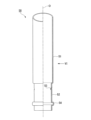
本実施形態では、スリーブ50の形状および材質と、操作部10の内側部材10bの形状と、が第1実施形態と異なる。
(Second embodiment)
Next, a second embodiment according to the present invention will be described, but the basic configuration is the same as that of the first embodiment. For this reason, the same reference numerals are assigned to the same configurations, the description thereof is omitted, and only the points of difference will be described.
In this embodiment, the shape and material of the sleeve 50 and the shape of the inner member 10b of the operating portion 10 are different from those of the first embodiment.

図8に示すように、本実施形態のスリーブ50は樹脂により形成されている。スリーブ50を樹脂により形成した場合でも、表面に加飾を行って外観を良好にすることができる。また、特に樹脂製のスリーブ50に蒸着を行うことで、金属光沢を付与し、高級感を与えることもできる。スリーブ50の各部の役割は、第1実施形態で述べたものと同様である。
図9A、図9Bに示すように、内側部材10bは、嵌合筒部14から上方に向けて延びる介在筒部16を有している。介在筒部16には、周方向に間隔を空けて、複数のスリット17が形成されている。スリット17は、介在筒部16の上下方向における全長にわたって延びている。介在筒部16は、スリット17によって複数の弾性片に分割されており、各弾性片は下端部を起点として径方向に弾性変形可能となっている。また、各弾性片は周方向に間隔を空けて配置されている。
As shown in FIG. 8, the sleeve 50 of this embodiment is made of resin. Even when the sleeve 50 is made of resin, the surface can be decorated to improve the appearance. In addition, by vapor-depositing the resin sleeve 50 in particular, it is possible to impart a metallic luster and give a high-class feeling. The role of each part of the sleeve 50 is the same as that described in the first embodiment.
As shown in FIGS. 9A and 9B, the inner member 10b has an intervening tubular portion 16 extending upward from the fitting tubular portion 14. As shown in FIGS. A plurality of slits 17 are formed in the intervening cylinder portion 16 at intervals in the circumferential direction. The slit 17 extends over the entire length of the interposed tubular portion 16 in the vertical direction. The intervening tubular portion 16 is divided into a plurality of elastic pieces by slits 17, and each elastic piece is elastically deformable in the radial direction with its lower end as a starting point. Moreover, each elastic piece is arrange|positioned at intervals in the circumferential direction.

介在筒部16(各弾性片)は、外径および内径が嵌合筒部14と同等である下部16bと、下部16bよりも上方に位置する上部16aと、を有している。上部16aの内径は下部16bの内径と同等であるが、上部16aの外径は下部16bの外径より小さい。上部16aの内周面には、径方向内側に向けて突出する突起16cが形成されている。突起16cは、スリット17同士の間に形成されている。言い換えると、突起16cは各弾性片に形成されている。突起16cは下スリーブ部52の外周面に接している。 The intervening tubular portion 16 (each elastic piece) has a lower portion 16b whose outer diameter and inner diameter are the same as those of the fitting tubular portion 14, and an upper portion 16a positioned above the lower portion 16b. The inner diameter of upper portion 16a is equal to the inner diameter of lower portion 16b, but the outer diameter of upper portion 16a is smaller than the outer diameter of lower portion 16b. A protrusion 16c protruding radially inward is formed on the inner peripheral surface of the upper portion 16a. The protrusion 16c is formed between the slits 17. As shown in FIG. In other words, the protrusion 16c is formed on each elastic piece. The protrusion 16c is in contact with the outer peripheral surface of the lower sleeve portion 52. As shown in FIG.

下部16bの内周面には、径方向内側に向けて窪む凹部16dが形成されている。凹部16dは、介在筒部16の内周面の全周にわたって形成されている。言い換えると、凹部16dは各弾性片に形成されている。凹部16d内に、スリーブ50の突部54が位置している。下部16bの外周面は操作筒部11の内周面に接している。 A concave portion 16d that is recessed radially inward is formed on the inner peripheral surface of the lower portion 16b. The recess 16 d is formed along the entire circumference of the inner peripheral surface of the intervening tubular portion 16 . In other words, the recess 16d is formed in each elastic piece. A protrusion 54 of the sleeve 50 is positioned in the recess 16d. The outer peripheral surface of the lower portion 16 b is in contact with the inner peripheral surface of the operation cylinder portion 11 .

本実施形態では、第1実施形態における介在部材70の役割を介在筒部16が担っている。すなわち、介在筒部16(各弾性片)は、下スリーブ部52と操作筒部11との間に挟まれており、スリーブ50との間の摩擦係数が小さい材質により形成されている。介在筒部16により、スリーブ50と操作部10とが相対的に回転するときのがたつきが抑えられるとともに、操作部10をスリーブ50に対して滑らかに回転させることができる。内側部材10bが介在筒部16を有していることにより、本実施形態の繰出容器1は、第1実施形態における介在部材70を備えていない。 In this embodiment, the intervening tubular portion 16 plays the role of the intervening member 70 in the first embodiment. That is, the intervening tubular portion 16 (each elastic piece) is sandwiched between the lower sleeve portion 52 and the operating tubular portion 11 and is made of a material having a small coefficient of friction with the sleeve 50 . The intervening cylindrical portion 16 suppresses rattling when the sleeve 50 and the operation portion 10 rotate relatively, and allows the operation portion 10 to rotate smoothly with respect to the sleeve 50 . Since the inner member 10b has the interposed tubular portion 16, the delivery container 1 of the present embodiment does not have the interposed member 70 of the first embodiment.

なお、本発明の技術的範囲は前記実施形態に限定されず、本発明の趣旨を逸脱しない範囲において種々の変更を加えることが可能である。 The technical scope of the present invention is not limited to the above embodiments, and various modifications can be made without departing from the scope of the present invention.

例えば、前記実施形態の繰出容器1は介在部材70を備えていたが、繰出容器1は介在部材70を備えていなくてもよい。 For example, although the delivery container 1 of the above-described embodiment includes the intervening member 70 , the delivery container 1 does not have to include the intervening member 70 .

その他、本発明の趣旨を逸脱しない範囲で、上記した実施形態における構成要素を周知の構成要素に置き換えることは適宜可能であり、また、上記した実施形態や変形例を適宜組み合わせてもよい。 In addition, it is possible to appropriately replace the components in the above-described embodiments with well-known components without departing from the scope of the present invention, and the above-described embodiments and modifications may be combined as appropriate.

1…繰出容器 10…操作部 11…操作筒部 15…柱状部 15b…第3規制部 20…回動規制軸 23…第4規制部 24…第2規制部 35…第1規制部 31…中皿部 32…第1螺旋筒部 32a…第1螺旋溝 40…第2螺旋筒部 41…第2螺旋溝 42…第1係合部 50…スリーブ 53…第2係合部 O…容器軸 DESCRIPTION OF SYMBOLS 1... Delivery container 10... Operation part 11... Operation cylinder part 15... Columnar part 15b... 3rd control part 20... Rotation control shaft 23... 4th control part 24... 2nd control part 35... 1st control part 31... Middle Plate portion 32 First spiral cylinder portion 32a First spiral groove 40 Second spiral cylinder portion 41 Second spiral groove 42 First engagement portion 50 Sleeve 53 Second engagement portion O Container axis

Claims (1)

内容物を保持する中皿部と、
上下方向に延びる柱状部および前記柱状部に対する容器軸回りの回転が規制された操作筒部を有する操作部と、
前記柱状部を径方向外側から囲う筒状の回動規制軸と、
前記回動規制軸を径方向外側から囲い、外周面に第1螺旋溝が形成されるとともに、前記中皿部に固定された第1螺旋筒部と、
前記第1螺旋筒部を径方向外側から囲い、外周面に第2螺旋溝が形成された第2螺旋筒部と、
前記操作筒部から上方に向けて延び、前記中皿部および前記第2螺旋筒部を径方向外側から囲うスリーブと、を備え、
前記柱状部と、前記回動規制軸と、前記第1螺旋筒部と、の容器軸回りの相対回転は規制され、
前記回動規制軸には、
前記第1螺旋筒部の内周面に形成された第1規制部に当接することで前記第1螺旋筒部の前記回動規制軸に対する所定量以上の上昇を規制する第2規制部と、
前記柱状部の外周面に形成された第3規制部に当接することで前記回動規制軸の前記柱状部に対する所定量以上の上昇を規制する第4規制部と、が形成され、
前記第2螺旋筒部には、前記第1螺旋溝に係合することで、前記第2螺旋筒部と前記第1螺旋筒部とが容器軸回りに相対回転したときに前記第1螺旋筒部を前記第2螺旋筒部に対して上下動させる第1係合部が形成され、
前記スリーブには、前記第2螺旋溝に係合することで、前記スリーブと前記第2螺旋筒部とが容器軸回りに相対回転したときに前記第2螺旋筒部を前記スリーブに対して上下動させる第2係合部が形成されている、繰出容器。
a middle plate portion for holding contents;
an operating portion having a vertically extending columnar portion and an operating tube portion in which rotation about the container axis with respect to the columnar portion is restricted;
a cylindrical rotation restricting shaft that surrounds the columnar portion from the outside in the radial direction;
a first helical cylindrical portion that surrounds the rotation restricting shaft from the outside in the radial direction, has a first helical groove formed on an outer peripheral surface, and is fixed to the intermediate plate portion;
a second helical cylinder portion surrounding the first helical cylinder portion from the outside in the radial direction and having a second helical groove formed on an outer peripheral surface;
a sleeve that extends upward from the operation cylinder portion and surrounds the intermediate plate portion and the second spiral cylinder portion from the outside in the radial direction;
relative rotation of the columnar portion, the rotation restriction shaft, and the first helical cylinder portion about the container axis is restricted;
The rotation restricting shaft includes:
a second restricting portion that abuts against a first restricting portion formed on the inner peripheral surface of the first spiral tube portion to restrict the first spiral tube portion from rising by a predetermined amount or more with respect to the rotation restricting shaft;
a fourth restricting portion that abuts against a third restricting portion formed on the outer peripheral surface of the columnar portion to restrict the rotation restricting shaft from rising by a predetermined amount or more with respect to the columnar portion;
The second helical cylinder portion is engaged with the first helical groove so that when the second helical cylinder portion and the first helical cylinder portion are relatively rotated around the container axis, the first helical cylinder is engaged with the first helical cylinder. A first engaging portion is formed for moving the portion up and down with respect to the second helical cylinder portion,
The sleeve is engaged with the second helical groove so that the second helical cylinder portion can be moved up and down with respect to the sleeve when the sleeve and the second helical cylinder portion are relatively rotated around the container axis. A delivery container formed with a second engaging portion for movement.
JP2019158900A 2019-08-30 2019-08-30 Delivery container Active JP7308698B2 (en)

Priority Applications (1)

Application Number Priority Date Filing Date Title
JP2019158900A JP7308698B2 (en) 2019-08-30 2019-08-30 Delivery container

Applications Claiming Priority (1)

Application Number Priority Date Filing Date Title
JP2019158900A JP7308698B2 (en) 2019-08-30 2019-08-30 Delivery container

Publications (2)

Publication Number Publication Date
JP2021036965A JP2021036965A (en) 2021-03-11
JP7308698B2 true JP7308698B2 (en) 2023-07-14

Family

ID=74847542

Family Applications (1)

Application Number Title Priority Date Filing Date
JP2019158900A Active JP7308698B2 (en) 2019-08-30 2019-08-30 Delivery container

Country Status (1)

Country Link
JP (1) JP7308698B2 (en)

Families Citing this family (1)

* Cited by examiner, † Cited by third party
Publication number Priority date Publication date Assignee Title
JP2022183619A (en) * 2021-05-31 2022-12-13 株式会社吉野工業所 Delivery container

Citations (4)

* Cited by examiner, † Cited by third party
Publication number Priority date Publication date Assignee Title
JP4024428B2 (en) 1999-06-16 2007-12-19 ジョンソン コントロールズ オートモーティブ システムズ株式会社 Vehicle flattened seat structure
JP2008125947A (en) 2006-11-24 2008-06-05 Suzuno Kasei Kk Stick cosmetic material feeding container
JP2016083098A (en) 2014-10-24 2016-05-19 株式会社吉野工業所 Delivery container
JP2019022617A (en) 2017-07-24 2019-02-14 花王株式会社 Method for manufacturing rod-like cosmetic product

Patent Citations (4)

* Cited by examiner, † Cited by third party
Publication number Priority date Publication date Assignee Title
JP4024428B2 (en) 1999-06-16 2007-12-19 ジョンソン コントロールズ オートモーティブ システムズ株式会社 Vehicle flattened seat structure
JP2008125947A (en) 2006-11-24 2008-06-05 Suzuno Kasei Kk Stick cosmetic material feeding container
JP2016083098A (en) 2014-10-24 2016-05-19 株式会社吉野工業所 Delivery container
JP2019022617A (en) 2017-07-24 2019-02-14 花王株式会社 Method for manufacturing rod-like cosmetic product

Also Published As

Publication number Publication date
JP2021036965A (en) 2021-03-11

Similar Documents

Publication Publication Date Title
EP3524088B1 (en) Container for a rod-shaped material
JP7206038B2 (en) Delivery container
US10595614B2 (en) Device for dispensing a product
WO2019131821A1 (en) Lipstick container
JP7292166B2 (en) Delivery container
JP7308698B2 (en) Delivery container
JP7224262B2 (en) Delivery container
JP7203601B2 (en) Delivery container
WO2022254966A1 (en) Dispensing container
JP7450327B2 (en) feeding container
JP6972111B2 (en) Decorative case rotation mechanism
JP7511445B2 (en) Feeding container
JP7378360B2 (en) feeding container
JP6817046B2 (en) Feeding container
JP7550708B2 (en) Feeding container
US7172356B2 (en) Packaging and dispensing device with disengaging mechanism
JP7370676B2 (en) feeding container
JP7433728B2 (en) feeding container
JP7309273B2 (en) Feeding container
JP7507109B2 (en) Application container
JP7309285B2 (en) Feeding container
JP2019097817A (en) Lipstick container
EP3864999B1 (en) Mechanism for cosmetic container and container comprising said mechanism
JP7175846B2 (en) Feeding container
JP7117947B2 (en) Delivery container

Legal Events

Date Code Title Description
A621 Written request for application examination

Free format text: JAPANESE INTERMEDIATE CODE: A621

Effective date: 20220301

TRDD Decision of grant or rejection written
A01 Written decision to grant a patent or to grant a registration (utility model)

Free format text: JAPANESE INTERMEDIATE CODE: A01

Effective date: 20230606

A61 First payment of annual fees (during grant procedure)

Free format text: JAPANESE INTERMEDIATE CODE: A61

Effective date: 20230704

R150 Certificate of patent or registration of utility model

Ref document number: 7308698

Country of ref document: JP

Free format text: JAPANESE INTERMEDIATE CODE: R150