JP7307430B2 - motion simulator - Google Patents
motion simulator Download PDFInfo
- Publication number
- JP7307430B2 JP7307430B2 JP2022103348A JP2022103348A JP7307430B2 JP 7307430 B2 JP7307430 B2 JP 7307430B2 JP 2022103348 A JP2022103348 A JP 2022103348A JP 2022103348 A JP2022103348 A JP 2022103348A JP 7307430 B2 JP7307430 B2 JP 7307430B2
- Authority
- JP
- Japan
- Prior art keywords
- motion
- platform
- base
- actuator
- disposed
- Prior art date
- Legal status (The legal status is an assumption and is not a legal conclusion. Google has not performed a legal analysis and makes no representation as to the accuracy of the status listed.)
- Active
Links
Images


Classifications
-
- A—HUMAN NECESSITIES
- A63—SPORTS; GAMES; AMUSEMENTS
- A63G—MERRY-GO-ROUNDS; SWINGS; ROCKING-HORSES; CHUTES; SWITCHBACKS; SIMILAR DEVICES FOR PUBLIC AMUSEMENT
- A63G31/00—Amusement arrangements
- A63G31/02—Amusement arrangements with moving substructures
-
- G—PHYSICS
- G09—EDUCATION; CRYPTOGRAPHY; DISPLAY; ADVERTISING; SEALS
- G09B—EDUCATIONAL OR DEMONSTRATION APPLIANCES; APPLIANCES FOR TEACHING, OR COMMUNICATING WITH, THE BLIND, DEAF OR MUTE; MODELS; PLANETARIA; GLOBES; MAPS; DIAGRAMS
- G09B9/00—Simulators for teaching or training purposes
- G09B9/02—Simulators for teaching or training purposes for teaching control of vehicles or other craft
- G09B9/08—Simulators for teaching or training purposes for teaching control of vehicles or other craft for teaching control of aircraft, e.g. Link trainer
- G09B9/12—Motion systems for aircraft simulators
-
- A—HUMAN NECESSITIES
- A47—FURNITURE; DOMESTIC ARTICLES OR APPLIANCES; COFFEE MILLS; SPICE MILLS; SUCTION CLEANERS IN GENERAL
- A47C—CHAIRS; SOFAS; BEDS
- A47C1/00—Chairs adapted for special purposes
-
- A—HUMAN NECESSITIES
- A63—SPORTS; GAMES; AMUSEMENTS
- A63G—MERRY-GO-ROUNDS; SWINGS; ROCKING-HORSES; CHUTES; SWITCHBACKS; SIMILAR DEVICES FOR PUBLIC AMUSEMENT
- A63G31/00—Amusement arrangements
- A63G31/16—Amusement arrangements creating illusions of travel
-
- G—PHYSICS
- G09—EDUCATION; CRYPTOGRAPHY; DISPLAY; ADVERTISING; SEALS
- G09B—EDUCATIONAL OR DEMONSTRATION APPLIANCES; APPLIANCES FOR TEACHING, OR COMMUNICATING WITH, THE BLIND, DEAF OR MUTE; MODELS; PLANETARIA; GLOBES; MAPS; DIAGRAMS
- G09B9/00—Simulators for teaching or training purposes
- G09B9/02—Simulators for teaching or training purposes for teaching control of vehicles or other craft
- G09B9/08—Simulators for teaching or training purposes for teaching control of vehicles or other craft for teaching control of aircraft, e.g. Link trainer
- G09B9/12—Motion systems for aircraft simulators
- G09B9/14—Motion systems for aircraft simulators controlled by fluid actuated piston or cylinder ram
Description
本発明は、概して、モーション・シミュレーション技術、より具体的には、シンプルな構造で様々な動きをシミュレートするモーション・シミュレータに関する。 The present invention relates generally to motion simulation technology, and more particularly to a motion simulator that simulates various motions with a simple structure.
モーション・シミュレータは、通常、座席の運動を制御して、その座席上の乗客も同様に動かされるようにする。座席の運動が特定の視覚的コンテンツに一致するように構成される場合に、乗客は、錯覚し、自分が視覚的コンテンツ内の動きを体験していると信じてしまう場合がある。スチュワート(Steward)プラットフォームは、6つの伸縮アクチュエータによって形成される一般的なモーション・シミュレーション・プラットフォームである。スチュワート・プラットフォームは様々な動きをシミュレートできるが、1つの伸縮アクチュエータの運動は他の伸縮アクチュエータの運動に依存するため、所望の動きの運動を制御することは困難である。さらに、スチュワート・プラットフォームのコストは、6つの伸縮アクチュエータを必要とするために高価である。 Motion simulators typically control the movement of the seat so that the passenger on that seat is similarly moved. When seat motion is configured to match specific visual content, passengers may be deceived into believing that they are experiencing motion within the visual content. The Steward platform is a general motion simulation platform formed by six telescopic actuators. Although the Stewart Platform can simulate a variety of motions, it is difficult to control the motion of the desired motion because the motion of one telescoping actuator depends on the motion of the other telescoping actuator. Additionally, the cost of the Stewart Platform is high due to the need for six telescoping actuators.
一般に、既存のモーション・シミュレータには以下の欠点がある。 In general, existing motion simulators have the following drawbacks.
1. 複雑な構造:
現在のモーション・シミュレータ技術によれば、シミュレートされた各動きを実現するには、複数のアクチュエータが必要である。従って、複数のアクチュエータによって形成されるモーション・シミュレータの構造は複雑である。
1. Complex structure:
Current motion simulator technology requires multiple actuators to achieve each simulated motion. Therefore, the structure of the motion simulator formed by multiple actuators is complicated.
2. ヨー運動の角度が不十分である:
構造が複雑なスチュワート・プラットフォームを例にとると、伸縮ロッドによって実行されるヨー運動の水平方向の回転角度は固定されるので、瞬間的なヨー運動のみが提供され得、ヨー運動の角度範囲は制限され、それによってヨー運動の方向の効果が不十分である。
2. Insufficient yaw angle:
Taking the structurally complex Stewart platform as an example, the horizontal rotation angle of the yaw movement performed by the telescopic rod is fixed, so only instantaneous yaw movement can be provided, and the angular range of the yaw movement is limited, whereby the directional effect of the yaw motion is poor.
3. 既存の簡略化したモーション・シミュレータの動きの多様性が不十分である:
モーション・シミュレータは、アクチュエータの数を減らしてコストを節約し、制御の複雑さを減らすことによって簡素化することができる。しかしながら、既存の簡略化したモーション・シミュレータは、限られた動きしか提供できないため、これは、視覚的コンテンツに対応する所望の動きを形成(create)することをより困難にさせる。
3. Existing parsimonious motion simulators have insufficient motion diversity:
Motion simulators can be simplified by reducing the number of actuators to save cost and reduce control complexity. However, existing simplified motion simulators can only provide limited motion, which makes it more difficult to create desired motion corresponding to visual content.
従って、構造がシンプルで、様々な動きを提供することができるモーション・シミュレータが必要とされる。 Therefore, there is a need for a motion simulator that is simple in structure and capable of providing various motions.
上記を考慮して、本発明は、シンプルな構造で様々な動きをシミュレートすることができるモーション・シミュレータを提供する。 In view of the above, the present invention provides a motion simulator capable of simulating various motions with a simple structure.
本発明の一態様によれば、モーション・シミュレータは、ベースプレート、モーション・プラットフォーム、第1のアクチュエータ、ベース、第2のアクチュエータ、及び運搬プラットフォームを含む。モーション・プラットフォームは、ベースプレート上に配置され、ベースプレートに移動可能に接続される。第1のアクチュエータは、モーション・プラットフォーム上に配置され、モーション・プラットフォームに移動可能に接続される。ベースは、長さ方向に延びるベース本体と、幅方向に延びるベース延長面とを有する。第1のアクチュエータは、ベース延長面に移動可能に接続される。第2のアクチュエータは、ベース上に移動可能に配置される。運搬プラットフォームは、第2のアクチュエータに移動可能に接続される。ここで、ベースと、ベース上に配置された第2のアクチュエータとの間の接続関係を介して、第1のアクチュエータは、運搬プラットフォームのモーション・プラットフォームに対する左右方向の運動を実行し、第2のアクチュエータは、運搬プラットフォームのモーション・プラットフォームに対する前後方向の運動を実行する。 According to one aspect of the invention, a motion simulator includes a baseplate, a motion platform, a first actuator, a base, a second actuator, and a carriage platform. A motion platform is disposed on and movably connected to the baseplate. A first actuator is disposed on the motion platform and movably connected to the motion platform. The base has a base body extending in the length direction and a base extension surface extending in the width direction. A first actuator is movably connected to the base extension surface. A second actuator is movably disposed on the base. A carriage platform is movably connected to the second actuator. Here, via a connection relationship between the base and a second actuator arranged on the base, the first actuator performs lateral movement of the carriage platform with respect to the motion platform and the second The actuators effect forward and backward motion of the haulage platform with respect to the motion platform.
本発明のこれら及び他の目的は、様々な図及び図面に示される好ましい実施形態の以下の詳細な説明を読んだ後に、当業者には間違いなく明らかになるであろう。 These and other objects of the present invention will no doubt become apparent to those skilled in the art after reading the following detailed description of the preferred embodiments illustrated in the various figures and drawings.
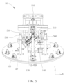
図1、図2、及び図3は、本発明の一実施形態によるモーション・シミュレータ10を示す概略図である。図1、図2、及び図3において、X方向軸線、Y方向軸線、及びZ方向軸線は互いに直交している。モーション・シミュレータ10は、ベースプレート100、運搬(carrying)プラットフォーム110、モーション・プラットフォーム120、第1のアクチュエータ130、ベース180、及び第2のアクチュエータ140を含む。ベースプレート100の水平レベルは、複数の水平方向調整部材によって調整され、ベースプレート100は、水平面(X方向軸線及びZ方向軸線によって形成される平面)上に配置される。モーション・プラットフォーム120は、ベースプレート100上に配置され、ベースプレート100に移動可能に接続される。運搬プラットフォーム110は、モーション・プラットフォーム120の上に配置され、モーション・プラットフォーム120から離れて配置される。運搬プラットフォーム110は、運搬プラットフォーム110上に配置されたキャリア(carrier)を含む。一実施形態では、キャリアは、椅子を含み得るが、これに限定されない。一実施形態では、運搬プラットフォーム110は、前端112及び後端114を含む。乗客がキャリアに座るときに、乗客は前端112の方向を向き、乗客の背中は後端114の方向を向く。第1のアクチュエータ130(電動シリンダ等)は、モーション・プラットフォーム120上に配置され、モーション・プラットフォーム120に移動可能に接続される(例えば、枢動可能(pivotally)に接続される)。ベース180は、長さ方向に延びるベース本体182と、幅方向に延びるベース延長面184とを含む。ここで、第1のアクチュエータ130は、ベース延長面184に移動可能に接続される。第2のアクチュエータ140(スクリューロッド(screw rod:ねじ付きロッド)摺動テーブル等)は、ベース180上に移動可能に配置され、運搬プラットフォーム110は、第2のアクチュエータ140に移動可能に接続される。ここで、ベース180と、ベース180上に配置された第2のアクチュエータ140との接続関係を介して、第1のアクチュエータ130は、運搬プラットフォーム110のモーション・プラットフォーム120に対する左右方向の運動を実行し、第2のアクチュエータ140は、運搬プラットフォーム110のモーション・プラットフォーム120に対する前後方向の運動を実行する。一実施形態では、運搬プラットフォーム110の左右方向の運動は、左に傾く、右に傾く、左に動く、及び/又は右に動くことであり、運搬プラットフォーム110の前後方向の運動は、前方に傾く、後方に傾く、前方に移動する、及び/又は後方に移動することであるが、これらに限定されない。
1, 2 and 3 are schematic diagrams illustrating a
一実施形態では、モーション・シミュレータ10は、支持アセンブリ150、駆動アセンブリ160、及び複数の回転ホイール170をさらに含む。支持アセンブリ150は、モーション・プラットフォーム120上に配置され、モーション・プラットフォーム120とベース本体182との間に接続される。支持アセンブリ150は、第1の支持ロッド152及び第2の支持ロッド154を含む。第1の支持ロッド152は、モーション・プラットフォーム120上に配置され、その一端がモーション・プラットフォーム120に枢動可能に接続され、他端がベース本体182に固定して接続される。第2の支持ロッド154は、モーション・プラットフォーム120上に配置され、その一端がモーション・プラットフォーム120に枢動可能に接続され、他端がベース本体182に固定して接続される。第1の支持ロッド152及び第2の支持ロッド152はそれぞれ、ベース延長面184の反対側に配置される。駆動アセンブリ160は、ベースプレート100上(例えば、ベースプレート100の中心)に配置され、モーション・プラットフォーム120を駆動してベースプレート100に対して回転させる(例えば、時計回りの回転又は反時計回りの回転)ように構成される。複数の回転ホイール170は、モーション・プラットフォーム120の回転を支援(又は実行)するためにモーション・プラットフォーム120上に配置される。モーション・プラットフォーム120の回転によって、モーション・プラットフォーム120の上に配置された運搬プラットフォーム110を駆動して回転させることができ、モーション・プラットフォーム120上に配置された第1のアクチュエータ130及び第2のアクチュエータ140を駆動して回転させることができる。従って、駆動アセンブリ160及び複数の回転ホイール170は、キャリア上の乗客にヨー運動を提供することができる。モーション・プラットフォーム120の(ヨー運動の)回転角は、全体的な構造によって制限されないことに留意されたい。一般的なスチュワート・プラットフォームと比較して、モーション・プラットフォーム120は、より現実的な360度の回転運動を提供することができる。
In one embodiment,
図2を参照すると、第1のアクチュエータ130は、基礎(basic)部分200及び伸縮部分220を含む。基礎部分200は、モーション・プラットフォーム120上に配置される。基礎部分200の下端は、モーション・プラットフォームに移動可能に接続される(例えば、枢動可能に接続される)。伸縮部分220の下端は、基礎部分200の上端に接続され、伸縮部分220の上端は、ベース延長面184に移動可能に接続される。基礎部分200の制御イベントに従って、伸縮部分220は、運搬プラットフォーム110の左右方向の運動を実行するために伸長又は収縮される。本発明の一実施形態では、第1の支持ロッド152とモーション・プラットフォーム120との間のピボット(pivot:枢動)接続、及び第2の支持ロッド154とモーション・プラットフォーム120との間のピボット接続は、第1の回転軸線240によって貫通される。第1のアクチュエータ130の伸縮部分220が伸長又は収縮されるときに、ベース180及び運搬プラットフォーム110は、第1の回転軸線240に基づいて左右方向の運動を実行する。例えば、第1の回転軸線240に従って、伸縮部分220を伸長させるときに、第2アクチュエータ140及び運搬プラットフォーム110は、X方向軸線及び/又はY方向軸線の方向に沿って移動し、それによって、キャリアに座っている乗客は左に移動する(例えば、左に傾く及び/又は左に移動する)。別の例では、第1の回転軸線240に従って、伸縮部分220を収縮させるときに、第2のアクチュエータ140及びベース180上に配置された運搬プラットフォーム110は、X方向軸線及び/又はY方向軸線の反対方向に沿って移動し、それによって、キャリアに座っている乗客は右に移動する(例えば、右に傾く及び/又は右に移動する)。従って、運搬プラットフォーム110の左右方向の運動は、キャリア上の乗客にロール運動を与えることができる。
Referring to FIG. 2,
本発明の一実施形態では、第1のアクチュエータ130は、モータ及びリンク機構を含む。モータは、運搬プラットフォーム110の左右方向の運動を制御するように構成される。リンク機構は、モータ及び運搬プラットフォーム110に移動可能に接続される。モータの制御イベントに従って、リンク機構は、運搬プラットフォーム110の左右方向の運動を実行することができる。換言すれば、リンク機構は、従来技術における他の第1のアクチュエータ(電動シリンダ等)を置き換えて、運搬プラットフォーム110の左右方向の運動を制御することができる。リンク機構は、複数の第1のアクチュエータ(電動シリンダ等)の間の計算の複雑さを軽減することができる。運搬プラットフォーム110の左右方向の運動を実行するリンク機構の実施形態については、図7を参照されたい。
In one embodiment of the invention,
図3を参照すると、第2のアクチュエータ140は、モータ310及び変換アセンブリ310を含む。モータ310は、運搬プラットフォーム110の前後方向の運動を制御するために円運動を実行するように構成される。変換アセンブリ320は、ベース180上に配置され、モータ310と運搬プラットフォーム110との間に移動可能に接続される。変換アセンブリ320は、線形運動部材322及びプルロッド(pull rod:引張りロッド)324を含む。線形運動部材322は、モータ310に移動可能に接続され、モータ310の円運動をベース180の長さ方向に沿った直線運動に変換して、運搬プラットフォーム110の前後方向の運動を実行する。プルロッド324は、直線運動に従った運搬プラットフォーム110の前後方向の運動を実行するために、線形運動部材322及び運搬プラットフォーム110に移動可能に(例えば、摺動可能に)接続される。
Referring to FIG. 3,
本発明の一実施形態では、線形運動部材322は、スクリューロッド326及び摺動(sliding:滑動)ブロック328を含む。スクリューロッド326は、ベース180上に配置され、モータ310に接続される。摺動ブロック328は、スクリューロッド326上に配置され、モータ310の円運動に従って、スクリューロッド326上で直線運動を実行するように構成される。プルロッド324は、摺動ブロック328及び運搬プラットフォーム110に移動可能に接続される(例えば、枢動可能に接続される)。摺動ブロック328の直線運動に従って、第2のアクチュエータ140は、運搬プラットフォーム110の前後方向の運動を実行する。
In one embodiment of the invention,
本発明の一実施形態では、第1の関節30に従って、摺動ブロック328は、プルロッド324の端部に移動可能に接続される(例えば、枢動可能に接続される)。本発明の一実施形態では、第2の関節32に従って、プルロッド324の他端は、運搬プラットフォーム110に移動可能に接続される(例えば、枢動可能に接続される)。摺動ブロック328がスクリューロッド326上で直線運動を実行するときに、運搬プラットフォーム110は、第2の回転軸線に基づいて、運搬プラットフォーム110の前後方向の運動を実行する。例えば、摺動ブロック328が、第1の関節30及び第2の関節32に従って、Z方向軸線の方向に沿ってスクリューロッド326上を摺動するときに、運搬プラットフォーム110は、Z方向軸線及び/又はY方向軸線の方向に沿って移動し、それによって、キャリアに座っている乗客が前方に移動する(例えば、前方に傾く及び/又は前方に移動する)。別の例では、摺動ブロック328が、第1の関節30及び第2の関節32に従って、Z方向軸線の反対方向に沿ってスクリューロッド326上を摺動するときに、運搬プラットフォーム110は、Z方向軸線及び/又はY方向軸線の反対方向に沿って移動し、それによって、キャリアに座っている乗客が後方に移動する(例えば、後方に傾く及び/又は後方に移動する)。従って、運搬プラットフォーム110の前後方向の運動によって、キャリア上の乗客にピッチ運動及び/又はサージ運動(surge motion)を与えることができる。
In accordance with
本発明の一実施形態では、第2のアクチュエータ140は、モータ310及びベルト駆動アセンブリを含む。ベルト駆動アセンブリは、モータ310及び運搬プラットフォーム110に移動可能に接続され、モータ310の円運動を直線運動に変換して、運搬プラットフォーム110の前後方向の運動を実行する。運搬プラットフォーム110の前後方向の運動を実行するモータ310及びベルト駆動アセンブリの実施形態については、図8を参照されたい。
In one embodiment of the invention,
図4は、本発明の一実施形態によるモーション・シミュレータ40を示す概略図である。図4を参照すると、X方向軸線、Y方向軸線、及びZ方向軸線は互いに直交している。モーション・シミュレータ40は、ベースプレート100、運搬プラットフォーム110、モーション・プラットフォーム120、第1のアクチュエータ130、ベース180、第2のアクチュエータ140、及び接続アセンブリ400を含む。モーション・シミュレータ40は、図1のモーション・シミュレータに適用することができる。ベースプレート100、運搬プラットフォーム110、モーション・プラットフォーム120、第1のアクチュエータ130、ベース180、及び第2のアクチュエータ140の実施形態の機構は、図1、図2、及び図3の機構と同様である。簡潔にするために、この実施形態についての同様の説明は、ここでは詳細に繰り返さない。接続アセンブリ400は、ベース180と運搬プラットフォーム110との間に配置される。接続アセンブリ400は、上部プラットフォーム408、下部プラットフォーム410、延長部材402、回転アセンブリ404、及び接続部材406を含む。上部プラットフォーム408は、ベース180の下に固定して接続される。下部プラットフォーム410は、上部プラットフォーム408に対して配置される。延長部材402は、上部プラットフォーム408と下部プラットフォーム410との間に固定して接続され、回転アセンブリ404は、ベアリング構造を介して、下部プラットフォーム410の下に回転可能に配置される。回転アセンブリ404のX方向軸線及びZ方向軸線によって形成される平面上の投影は、モーション・プラットフォームに対して固定される。換言すれば、モーション・プラットフォーム120がヨー運動を達成するために回転を実行するときに、回転アセンブリ404も一緒に回転する。接続部材406は、運搬プラットフォーム110と回転アセンブリ404との間に(固定して)配置され、第2の回転軸線420に基づいて回転を実行する。本発明の一実施形態では、モーション・プラットフォーム120は、モーション・プラットフォーム120に直交する回転軸線に基づいて回転を実行し、運搬プラットフォーム110の中心は、モーション・プラットフォーム120の回転軸線と整列される。
FIG. 4 is a schematic diagram illustrating a
図5及び図6は、本発明の一実施形態によるモーション・シミュレータ50を示す概略図である。図5及び図6において、X方向軸線、Y方向軸線、及びZ方向軸線は互いに直交している。モーション・シミュレータ50は、ベースプレート100、運搬プラットフォーム110、モーション・プラットフォーム120、第1のアクチュエータ130、ベース180、第2のアクチュエータ140、複数のストッパ500(例えば、故障停止(failure stop)構造等)、複数の第1のバンパー510、及び複数の第2のバンパー520を含む。モーション・シミュレータ50は、図1のモーション・シミュレータ10に適用することができる。ベースプレート100、運搬プラットフォーム110、モーション・プラットフォーム120、第1のアクチュエータ130、ベース180、及び第2のアクチュエータ140の実施形態の機構は、図1、図2、及び図3の機構と同様である。簡潔にするために、この実施形態についての同様の説明は、ここでは詳細に繰り返さない。
5 and 6 are schematic diagrams illustrating a
図5を参照すると、複数のストッパ500は、運搬プラットフォーム110の左右方向の運動の運動範囲を制御(又は制限)するために、モーション・プラットフォーム120上に配置される。複数の第1のバンパー510は、ベースの両側に配置される。第1のアクチュエータ130が運搬プラットフォーム110の左右方向の運動を実行するときに、複数の第1のバンパー510は、ベース180と複数のストッパ500との間の少なくとも1つの衝撃を緩和する。例えば、ベース180及び運搬プラットフォーム110がX方向軸線の方向に沿って移動するときに、ベース180は、図5の左側のストッパに衝突する。図5の左側の第1のバンパーは、ベース180と左側のストッパとの間の衝撃を緩和し、それによって、運搬プラットフォーム110の左方向への運動範囲が制御される。別の例として、ベース180及び運搬プラットフォーム110がX方向軸線の反対方向に移動するときに、ベース180は、図5の右側のストッパに衝突する。図5の右側の第1のバンパーは、ベース180と右側のストッパとの間の衝撃を緩和し、それによって、運搬プラットフォーム110の右方向への運動範囲が制御される。従って、複数のストッパ500は、運搬プラットフォーム110の運動範囲を制御して、モーション・シミュレータ50の安全性を向上させる。複数の第1のバンパー510は、キャリアに座る乗客が快適な体験を得ることができるように、緩衝機能を提供する。
Referring to FIG. 5, a plurality of
図6を参照すると、複数の第2のバンパー520は、ベース延長面184上に配置される。第2のアクチュエータ140が運搬プラットフォーム110の前後方向の運動を実行するときに、ベース延長面184と運搬プラットフォーム110との間の少なくとも1つの衝撃が緩和される。本発明の一実施形態では、運搬プラットフォーム110がZ方向軸線の方向に沿って移動するときに、運搬プラットフォーム110は、第2のアクチュエータ140に衝突する。図6の右側の第2のバンパーは、第2のアクチュエータ140と運搬プラットフォーム110との間の衝撃を緩和し、それによって、運搬プラットフォーム110の前方向への運動範囲が制御される。本発明の一実施形態では、運搬プラットフォーム110がZ方向軸線の反対方向に沿って移動するときに、運搬プラットフォーム110は、第2のアクチュエータ140に衝突する。図5の左側の2つの第2のバンパーは、第2のアクチュエータ140と運搬プラットフォーム110との間の衝撃を緩和し、それによって、運搬プラットフォーム110の後方向への運動範囲が制御される。従って、複数の第2のバンパー520は、キャリアに座っている乗客が快適な体験を得ることができるように、緩衝機能を提供する。
Referring to FIG. 6, a plurality of
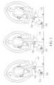
図7は、本発明の一実施形態による、運搬プラットフォーム110を駆動して左右方向の運動を実行するモーション・シミュレータのリンク機構700を示す概略図である。リンク機構700を伸長又は収縮させることにより、これに対応して、運搬プラットフォーム110を左又は右に傾けることができる。例えば、リンク機構700が長さ(例えば、元の長さ)を維持する場合に、第1の角度Aが、第1のリンクロッド710と第2のリンクロッド720との間に形成される。このとき、運搬プラットフォーム110は、(図7の中間部分に示されるように)左又は右に傾かない。運搬プラットフォーム110を右に傾けると、第1のリンクロッド710と第2のリンクロッド720との間に、第1の角度Aよりも小さい第2の角度Bが形成される。このとき、リンク機構700は収縮し、運搬プラットフォーム110は、リンク機構700によって駆動されて(図7の左側部分に示されるように)右に傾くことができる。運搬プラットフォーム110を左に傾けると、第1のリンク710と第2のリンク720との間に、第1の角度Aよりも大きい第3の角度Cが形成される。このとき、リンク機構700は伸長され、運搬プラットフォーム110は、リンク機構700によって駆動されて(図7の左側部分に示されるように)左に傾くことができる。従って、リンク機構700は、従来技術における他の第1のアクチュエータ(電動シリンダ等)を介した運搬プラットフォーム110の左右方向の運動の代わりに、運搬プラットフォーム110を駆動するための左右方向の運動を提供する。リンク機構700は、複数の第1のアクチュエータ(電動シリンダ等)の間の計算の複雑さを軽減することができる。
FIG. 7 is a schematic diagram illustrating a
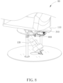
図8は、本発明の一実施形態によるモーション・シミュレータ80を示す概略図である。モーション・シミュレータ80は、運搬プラットフォーム110、第1のアクチュエータ130、モータ310、及びベルト駆動アセンブリ800を含む。モーション・シミュレータ80では、ベルト駆動アセンブリ800は、モータ310及び運搬プラットフォーム110(例えば、運搬プラットフォーム110の回転軸線810)に移動可能に接続され、モータ310の円運動を直線運動に変換し、運搬プラットフォーム110の前後方向の運動を実行する。換言すれば、モータ310及びベルト駆動アセンブリ800は、運搬プラットフォーム110を駆動するために前後方向の運動を提供し、これは、図3のモーション・シミュレータ10のスクリューロッド326及び摺動ブロック328を置き換えて(replace)、キャリアの乗客にピッチ運動を提供することができる。
FIG. 8 is a schematic diagram illustrating a
図9は、本発明の一実施形態によるモーション・シミュレータ90を示す概略図である。図9において、X方向軸線、Y方向軸線、及びZ方向軸線は互いに直交しており、X方向軸線は図に入る方向であり、ここでは簡単にするためにX方向を省略している。モーション・シミュレータ90は、ベースプレート100、運搬プラットフォーム110、モーション・プラットフォーム120、第1のアクチュエータ130、第2のアクチュエータ140、モータ910、1組のギア及びベルト912、クロスバー914、複数のストッパ920、及び複数のバンパー930を含む。運搬プラットフォーム110の中心(例えば、構造中心)とモーション・プラットフォーム120の中心(例えば、回転中心)とを結ぶ線は、モーション・プラットフォーム120に直交している。換言すれば、運搬プラットフォーム110の中心は、モーション・プラットフォーム120の中心と整列され、それによって、ピッチ運動を実行するときに運搬プラットフォーム110がひっくり返る可能性が低減される。モータ910は、運搬プラットフォーム110の下に配置される。モーション・シミュレータ10のモータ310と比較して、モータ910のX-Z平面上の投影は、モーション・プラットフォーム120の最大円を超えない。1組のギア及びベルト912は、モータ910の動作を駆動するように構成される。運搬プラットフォーム110の負荷要件に従って、1組のギア及びベルト912は、モータ910と同じ仕様及び条件の下でトルクを増幅することができる。クロスバー914は、運搬プラットフォーム110の下に配置される。
FIG. 9 is a schematic diagram illustrating a
図9を参照すると、モーション・シミュレータ90の複数のストッパ920及び複数のバンパー930は、運搬プラットフォーム110の前後方向の運動の運動範囲を制御する(例えば、制限する)ように構成される。複数のストッパ920は、ベース本体182上に配置され、ベース延長面184の両側で上向きに延びて、運搬プラットフォーム110の前後方向の運動の運動範囲を制御する(例えば、制限する)。複数のバンパー930は、衝撃力を緩和するために、複数のストッパ920上に配置される。複数のバンパー930は、1組の緩衝発泡体であり得るが、本発明はこれに限定されない。第1のアクチュエータ130が運搬プラットフォーム110の前後方向の運動を実行し、前方傾斜角又は後方傾斜角が大き過ぎる場合に、運搬プラットフォーム110下のクロスバー914が複数のストッパ920に衝突し、複数のバンパー930は、クロスバー914と複数のストッパ920との間の少なくとも1つの衝撃を緩和する。例えば、運搬プラットフォーム110がZ方向軸線の方向に沿って移動するとき(例えば、運搬プラットフォーム110の前方に傾くとき)に、運搬プラットフォーム110の下のクロスバー914は、図9の複数のストッパ920のうちの右側のストッパで、複数のバンパー930のうちの右側のバンパーに衝突し、図9の複数のバンパー930のうちの右側のバンパーは、クロスバー914と右側のストッパとの間の衝撃を緩和し、それによって、運搬プラットフォーム110の前進運動の運動範囲が制御され、衝撃力が緩和される。運搬プラットフォーム110がZ方向軸線の反対方向に動かされると(例えば、運搬プラットフォーム110の後方に傾くとき)に、運搬プラットフォーム110の下のクロスバー914は、図9の複数のストッパ920の左側のストッパで、複数のバンパー930の左側のバンパーに衝突し、図9の複数のバンパー930の左側のバンパーは、クロスバー914と左側のストッパとの間の衝撃を緩和し、それによって、運搬プラットフォーム110の後方運動の運動範囲が制御され、衝撃力が緩和される。従って、複数のストッパ920及び複数のバンパー930は、運搬プラットフォーム110の前方傾斜及び後方傾斜の運動範囲を制御し、第1のアクチュエータ130(電動シリンダ等)が破損するときに、運搬プラットフォーム110が無制限に前後方向に運動して危険を引き起こすのを防ぐために、安全機構として使用することもでき、モーション・シミュレータ90の安全性を向上させる。複数のストッパ920及び複数のバンパー930は、キャリアに座っている乗客が快適な体験を得ることができるように、緩衝機能を提供する。
Referring to FIG. 9, stops 920 and
図10は、本発明の一実施形態によるモーション・シミュレータ101を示す概略図である。図10において、X方向軸線、Y方向軸線、及びZ方向軸線は互いに直交しており、Z方向軸線は図に入る方向であり、ここでは簡単にするためにZ方向を省略している。モーション・シミュレータ101は、ベースプレート100、運搬プラットフォーム110、モーション・プラットフォーム120、第1のアクチュエータ130、第2のアクチュエータ140、減速機モータ1000、複数のストッパ1010、及び複数のホイール1020を含む。減速機モータ1000は、ベースプレート100上に配置され、モーション・プラットフォーム120を駆動してベースプレート100に対して回転させるように構成される。複数のストッパ1010は、運搬プラットフォーム110の左右方向の運動の運動範囲を制御する(例えば、制限する)ために使用される。運搬プラットフォーム110の左右方向の運動を制御する方法は、上述したモーション・シミュレータ50の複数のストッパ500と同様である。簡潔にするために、この実施形態についての同様の説明は、ここでは詳細に繰り返さない。モーション・シミュレータ101の複数のストッパ1010の形状は、モーション・シミュレータ50の複数のストッパ500の形状とは異なる。複数のストッパ1010の形状は、三角形として設計されており、これは、運搬プラットフォーム110の衝撃中の変形の可能性を低減することができる。複数のホイール1020は、ベースプレート100とモーション・プラットフォーム120との間に配置される。複数のホイール1020は、ローラーであり得る。モーション・シミュレータ10の複数のホイール170と比較して、ローラーは、より小さな体積で同じ支持力を達成することができる。従って、モーション・プラットフォーム120とベースプレート100との間の距離を短縮することができ、モーション・シミュレータ50の全体的な安定性を向上させることができる。モーション・シミュレータ101が減速機モータ1000を使用してモーション・プラットフォーム120を駆動して回転させる場合に、複数のホイール1020は、モーション・プラットフォーム120を駆動して回転させることなく、支持しているモーション・プラットフォーム120を支援する必要があるだけである。
FIG. 10 is a schematic diagram illustrating a
一実施形態では、モーション・プラットフォーム120は、ベースプレート100上に着脱可能に配置される。ベースプレート100とモーション・プラットフォーム120との両方はそれぞれ、組合せインターフェイスを有する。2つの組合せインターフェイスは互いに整列され、組合せインターフェイスは、第1のアクチュエータ130及び支持アセンブリ150に着脱可能に接続されるように構成され得る。換言すれば、ベースプレート100及びモーション・プラットフォーム120が、2つの組合せインターフェイスを有しており、それぞれ互いに整列されるので、モーション・プラットフォーム120及び複数のホイール170は、モーション・シミュレータから取り外され得、ベースプレート100は、要件に応じて様々な使用法を提供するために、第1のアクチュエータ130及び支持アセンブリ150に依然として接続され得る。
In one embodiment,
図11は、本発明の一実施形態によるモーション・シミュレータ111を示す概略図である。図11において、X方向軸線、Y方向軸線、及びZ方向軸線は互いに直交しており、X方向軸線は図に入る方向であり、ここでは簡単にするためにX方向を省略している。モーション・シミュレータ111は、ベースプレート100、運搬プラットフォーム110、第1のアクチュエータ130、第2のアクチュエータ140、及び支持アセンブリ150を含む。それぞれ2つの組合せインターフェイスを有し、互いに整列されるベースプレート100及びモーション・プラットフォーム120について、モーション・プラットフォーム120及び複数のホイール170がモーション・シミュレータ111から取り外されても、第1のアクチュエータ130及び支持アセンブリ150は、依然として、モーション・シミュレータ111のベースプレート100上に直接配置され得る。
FIG. 11 is a schematic diagram illustrating a
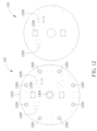
図12は、本発明の一実施形態によるモーション・シミュレータのベースプレート100及びモーション・プラットフォーム120を示す概略図である。ベースプレート100の外径(例えば、1000mm(ミリメートル))は、モーション・プラットフォーム120の外径(例えば、950mm)よりも大きい。ベースプレート100は、複数のホイールを配置するための複数のホイールインターフェイス1200を有しており、モーション・プラットフォーム120は、ホイールインターフェイスを有さない。ベースプレート100は、複数のキャスターを配置するための複数のキャスターインターフェイス1202を有しており、モーション・プラットフォーム120は、キャスターインターフェイスを有さない。ベースプレートは、減速機モータを配置するための減速機組合せインターフェイス1204を有しており、モーション・プラットフォーム120は、減速機組合せインターフェイス1204を有さない。ベースプレート100及びモーション・プラットフォーム120は、それぞれ、第1のアクチュエータ・インターフェイス1206及び支持アセンブリ・インターフェイス1208を有する。第1のアクチュエータ・インターフェイス1206及び支持アセンブリ・インターフェイス1208は、互いに整列される。第1のアクチュエータ・インターフェイス1206は、第1のアクチュエータ130を配置するように構成され、支持アセンブリ・インターフェイス1208は、支持アセンブリ150を配置するように構成される。
FIG. 12 is a schematic diagram illustrating a
上記の構成によれば、本発明は、モーション・シミュレータを提供する。モーション・シミュレータの1つのアクチュエータは運動を実行する。例えば、第1のアクチュエータは運搬プラットフォームの左右方向の運動(ロール運動等)を実行し、第2のアクチュエータは運搬プラットフォームの前後方向の運動(ピッチ運動等)を実行する。本発明は、様々な動きをシミュレートすることができる。一般的なスチュワート・プラットフォームと比較して、本発明は、構造がシンプルであり、設定コストが低く、モーション・シミュレータの動作が容易である。また、複数のストッパ及び複数のバンパーにより、モーション・シミュレータの安全性が向上し、乗客は快適な体験を得ることができる。 According to the above arrangement, the present invention provides a motion simulator. One actuator in the motion simulator executes motion. For example, a first actuator may effect side-to-side motion of the carriage platform (such as roll motion) and a second actuator may effect longitudinal motion of the carriage platform (such as pitch motion). The present invention can simulate various movements. Compared with the common Stewart platform, the present invention has simple structure, low set-up cost, and easy motion simulator operation. Multiple stops and multiple bumpers also increase the safety of the motion simulator and provide a comfortable experience for passengers.
上記の実施形態は、本発明の実施形態に過ぎないことに留意されたい。本明細書及び添付の特許請求の範囲に開示する概念を使用する全ての同等の構造は、本発明の範囲内に含まれるはずである。 It should be noted that the above embodiments are merely embodiments of the present invention. All equivalent constructions using the concepts disclosed in this specification and appended claims are intended to be within the scope of this invention.
当業者は、本発明の教示を保持しながら、装置及び方法の多数の修正及び変更を行うことができることを容易に気付くだろう。従って、上記の開示は、添付の特許請求の範囲によってのみ制限されると解釈されるべきである。 Those skilled in the art will readily observe that numerous modifications and alterations of the device and method may be made while retaining the teachings of the invention. Accordingly, the above disclosure should be construed as limited only by the appended claims.
Claims (14)
ベースプレートと、
該ベースプレート上に配置され、前記ベースプレートに移動可能に接続されたモーション・プラットフォームと、
該モーション・プラットフォーム上に配置され、前記モーション・プラットフォームに移動可能に接続された第1のアクチュエータと、
長さ方向に延びるベース本体と幅方向に延びるベース延長面とを含むベースであって、前記第1のアクチュエータは前記ベース延長面に移動可能に接続される、ベースと、
前記ベース上に移動可能に配置された第2のアクチュエータと、
該第2のアクチュエータに移動可能に接続された運搬プラットフォームと、を含み、
前記ベースと該ベース上に配置された前記第2のアクチュエータとの間の接続関係を介して、前記第1のアクチュエータは、前記運搬プラットフォームの前記モーション・プラットフォームに対する左右方向の運動を実行し、前記第2のアクチュエータは、前記運搬プラットフォームの前記モーション・プラットフォームに対する前後方向の運動を実行する、
モーション・シミュレータ。 A motion simulator, the motion simulator comprising:
a base plate;
a motion platform disposed on the baseplate and movably connected to the baseplate;
a first actuator disposed on the motion platform and movably connected to the motion platform;
a base including a longitudinally extending base body and a widthwise extending base extension surface, wherein the first actuator is movably connected to the base extension surface;
a second actuator movably disposed on the base;
a carrying platform movably connected to the second actuator;
Via a connection relationship between the base and the second actuator disposed on the base, the first actuator effects lateral movement of the carriage platform with respect to the motion platform, and a second actuator for effecting forward and backward motion of the transport platform with respect to the motion platform;
motion simulator.
前記モーション・プラットフォーム上に配置された第1の支持ロッドであって、前記モーション・プラットフォームに枢動可能に接続された一端と、前記ベース本体上に固定して配置された他端とを有する第1の支持ロッドと、
前記モーション・プラットフォーム上に配置された第2の支持ロッドであって、前記モーション・プラットフォームに枢動可能に接続された一端と、前記ベース本体上に固定して配置された他端とを有する第2の支持ロッドと、を含み、
前記第1の支持ロッド及び前記第2の支持ロッドはそれぞれ、前記ベース延長面の反対側に配置される、請求項1に記載のモーション・シミュレータ。 further comprising a support assembly disposed on the motion platform and connected between the motion platform and the base body, the support assembly comprising:
a first support rod disposed on the motion platform, having one end pivotally connected to the motion platform and the other end fixedly disposed on the base body; 1 support rod;
a second support rod disposed on the motion platform, having one end pivotally connected to the motion platform and the other end fixedly disposed on the base body; 2 support rods;
2. The motion simulator of claim 1, wherein said first support rod and said second support rod are each positioned on opposite sides of said base extension surface.
前記モーション・プラットフォーム上に配置された基礎部分であって、該基礎部分の下端が前記モーション・プラットフォームに移動可能に接続される、基礎部分と、
伸縮部分であって、該伸縮部分の下端が前記基礎部分の上端に接続され、前記伸縮部分の上端が前記ベース延長面に移動可能に接続される、伸縮部分と、をさらに含み、
前記基礎部分の制御イベントに従って、前記伸縮部分は、前記左右方向の運動を実行するために伸長又は収縮される、請求項2に記載のモーション・シミュレータ。 The first actuator is
a base portion disposed on the motion platform, wherein a lower end of the base portion is movably connected to the motion platform;
a telescopic portion, the lower end of the telescopic portion being connected to the upper end of the base portion, and the upper end of the telescopic portion being movably connected to the base extension surface;
3. The motion simulator of claim 2, wherein, according to control events of the base portion, the telescoping portion is extended or retracted to perform the lateral movement.
円運動を実行するように構成されたモータと、
前記ベース上に配置され、前記モータと前記運搬プラットフォームとの間に移動可能に接続された変換アセンブリと、を含み、
該変換アセンブリは、前記モータに移動可能に接続された線形運動部材であって、前記モータの前記円運動を前記ベースの前記長さ方向に沿った直線運動に変換して、前記運搬プラットフォームの前記前後方向の運動を実行する、線形運動部材と、を含む、請求項1に記載のモーション・シミュレータ。 The second actuator is
a motor configured to perform a circular motion;
a conversion assembly disposed on the base and movably connected between the motor and the carriage platform;
The transforming assembly is a linear motion member movably connected to the motor for transforming the circular motion of the motor into linear motion along the length of the base to produce the motion of the carriage platform. 2. The motion simulator of claim 1, comprising a linear motion member that performs forward and backward motion.
前記ベース上に配置され、前記モータに接続されたスクリューロッドと、
該スクリューロッド上に配置され、前記モータの前記円運動に従って、前記スクリューロッド上で前記直線運動を実行するように構成された摺動ブロックと、を含む、請求項5に記載のモーション・シミュレータ。 The linear motion member is
a screw rod disposed on the base and connected to the motor;
a sliding block disposed on the screw rod and configured to perform the linear motion on the screw rod according to the circular motion of the motor.
前記ベースの下に固定して接続された上部プラットフォームと、
該上部プラットフォームに対して配置された下部プラットフォームと、
前記上部プラットフォームと前記下部プラットフォームとの間に固定して接続された延長部材と、
前記第2の回転軸線を形成するために、ベアリング構造を介して前記下部プラットフォームの下に回転可能に配置された回転アセンブリと、
前記運搬プラットフォームと前記回転アセンブリとの間に配置され、前記第2の回転軸線に基づいて回転を実行するように構成された接続部材と、を含む、請求項8に記載のモーション・シミュレータ。 further comprising a connection assembly disposed between the base and the carriage platform, the connection assembly comprising:
an upper platform fixedly connected under the base;
a lower platform positioned relative to the upper platform;
an extension member fixedly connected between the upper platform and the lower platform;
a rotating assembly rotatably disposed below the lower platform via a bearing structure to define the second axis of rotation;
9. The motion simulator of claim 8, comprising a connecting member disposed between the carriage platform and the rotating assembly and configured to perform rotation based on the second axis of rotation.
前記ベースの両側に配置された複数の第1のバンパーであって、前記第1のアクチュエータが前記左右方向の運動を実行するときに、前記ベースと前記複数のストッパとの間の少なくとも1つの衝撃を緩和するように構成された複数の第1のバンパーと、をさらに含む、請求項1に記載のモーション・シミュレータ。 a plurality of stops disposed on the motion platform and configured to control the range of motion of the lateral motion;
a plurality of first bumpers positioned on opposite sides of said base, wherein at least one impact between said base and said plurality of stoppers when said first actuator performs said lateral movement; 3. The motion simulator of claim 1, further comprising: a plurality of first bumpers configured to dampen the .
Applications Claiming Priority (2)
| Application Number | Priority Date | Filing Date | Title |
|---|---|---|---|
| TW110133124 | 2021-09-07 | ||
| TW110133124A TWI792539B (en) | 2021-09-07 | 2021-09-07 | Motion simulator |
Publications (2)
| Publication Number | Publication Date |
|---|---|
| JP2023038898A JP2023038898A (en) | 2023-03-17 |
| JP7307430B2 true JP7307430B2 (en) | 2023-07-12 |
Family
ID=82595187
Family Applications (1)
| Application Number | Title | Priority Date | Filing Date |
|---|---|---|---|
| JP2022103348A Active JP7307430B2 (en) | 2021-09-07 | 2022-06-28 | motion simulator |
Country Status (4)
| Country | Link |
|---|---|
| US (1) | US20230075870A1 (en) |
| EP (1) | EP4145424A1 (en) |
| JP (1) | JP7307430B2 (en) |
| TW (1) | TWI792539B (en) |
Citations (2)
| Publication number | Priority date | Publication date | Assignee | Title |
|---|---|---|---|---|
| EP2623169A1 (en) | 2012-02-06 | 2013-08-07 | Brogent Technologies, inc. | Biaxial suspension type dynamic simulator |
| WO2019031539A1 (en) | 2017-08-09 | 2019-02-14 | 公立大学法人広島市立大学 | Motion base |
Family Cites Families (6)
| Publication number | Priority date | Publication date | Assignee | Title |
|---|---|---|---|---|
| US20030219701A1 (en) * | 2000-05-12 | 2003-11-27 | Zeier Bruce E. | Simulator for aircraft flight training |
| KR101377594B1 (en) * | 2013-02-20 | 2014-03-25 | 주식회사 모션디바이스 | Motion simulator |
| CN104835399B (en) * | 2015-03-17 | 2017-08-15 | 山西省交通科学研究院 | The emulation platform and its implementation of a kind of simulated vehicle low-and high-frequency motion |
| CN105858535B (en) * | 2016-05-16 | 2018-04-20 | 国网江苏省电力有限公司宿迁供电分公司 | A kind of electric power overhaul support device |
| CN107424473A (en) * | 2017-08-14 | 2017-12-01 | 徐舒青 | Single seat moves plane simulation steer entirely |
| CN113230663A (en) * | 2021-04-06 | 2021-08-10 | 徐州拓普互动智能科技有限公司 | Six VR cycle racing motion platforms of high security |
-
2021
- 2021-09-07 TW TW110133124A patent/TWI792539B/en active
-
2022
- 2022-06-07 US US17/834,921 patent/US20230075870A1/en active Pending
- 2022-06-28 JP JP2022103348A patent/JP7307430B2/en active Active
- 2022-07-13 EP EP22184580.3A patent/EP4145424A1/en active Pending
Patent Citations (2)
| Publication number | Priority date | Publication date | Assignee | Title |
|---|---|---|---|---|
| EP2623169A1 (en) | 2012-02-06 | 2013-08-07 | Brogent Technologies, inc. | Biaxial suspension type dynamic simulator |
| WO2019031539A1 (en) | 2017-08-09 | 2019-02-14 | 公立大学法人広島市立大学 | Motion base |
Also Published As
| Publication number | Publication date |
|---|---|
| TW202312112A (en) | 2023-03-16 |
| TWI792539B (en) | 2023-02-11 |
| US20230075870A1 (en) | 2023-03-09 |
| EP4145424A1 (en) | 2023-03-08 |
| JP2023038898A (en) | 2023-03-17 |
Similar Documents
| Publication | Publication Date | Title |
|---|---|---|
| KR101198255B1 (en) | Motion simulator | |
| US20190291608A1 (en) | Vehicle seat and method for controlling sitting position using the same | |
| CN109878385B (en) | Leisure seat for vehicle | |
| JP5922797B2 (en) | Adjustable headrest for aircraft seat | |
| US8864593B2 (en) | Seat assembly such as for an amusement ride | |
| US9434277B2 (en) | Passenger seat having a bucket seat structure and adjustable position | |
| JP6599770B2 (en) | Motion simulator | |
| US11084403B1 (en) | Kinetic seat backs for vehicles | |
| US20210237629A1 (en) | Kinetic seat cushions for vehicles | |
| US20210237631A1 (en) | Kinetic seat assemblies for vehicles | |
| WO2021116871A1 (en) | Vehicle with transforming seat | |
| JP7307430B2 (en) | motion simulator | |
| WO2019069077A1 (en) | Motion arrangement | |
| KR102580729B1 (en) | Motion simulator | |
| EP3917631B1 (en) | A motion simulation apparatus | |
| CN115770397A (en) | Somatosensory simulator | |
| CN108608900B (en) | A kind of anti-descent structure of back seat | |
| JP6871754B2 (en) | Seat drive | |
| US11717761B2 (en) | Motion simulator | |
| JP2008173332A (en) | Seat structure | |
| JP2012126153A (en) | Vehicle seat | |
| CN2878126Y (en) | Double-lock suspension type seat adjustment mechanism assembly | |
| JP2022095277A (en) | Electric wheelchair | |
| CN116409220A (en) | Seat adjusting device and seat with same | |
| JP2018192945A (en) | Vehicle seat |
Legal Events
| Date | Code | Title | Description |
|---|---|---|---|
| A621 | Written request for application examination |
Free format text: JAPANESE INTERMEDIATE CODE: A621 Effective date: 20220628 |
|
| TRDD | Decision of grant or rejection written | ||
| A01 | Written decision to grant a patent or to grant a registration (utility model) |
Free format text: JAPANESE INTERMEDIATE CODE: A01 Effective date: 20230613 |
|
| A61 | First payment of annual fees (during grant procedure) |
Free format text: JAPANESE INTERMEDIATE CODE: A61 Effective date: 20230621 |
|
| R150 | Certificate of patent or registration of utility model |
Ref document number: 7307430 Country of ref document: JP Free format text: JAPANESE INTERMEDIATE CODE: R150 |