JP7306310B2 - optical rangefinder - Google Patents
optical rangefinder Download PDFInfo
- Publication number
- JP7306310B2 JP7306310B2 JP2020072685A JP2020072685A JP7306310B2 JP 7306310 B2 JP7306310 B2 JP 7306310B2 JP 2020072685 A JP2020072685 A JP 2020072685A JP 2020072685 A JP2020072685 A JP 2020072685A JP 7306310 B2 JP7306310 B2 JP 7306310B2
- Authority
- JP
- Japan
- Prior art keywords
- light
- optical
- pseudo
- detected
- distance
- Prior art date
- Legal status (The legal status is an assumption and is not a legal conclusion. Google has not performed a legal analysis and makes no representation as to the accuracy of the status listed.)
- Active
Links
Images


Classifications
-
- G—PHYSICS
- G01—MEASURING; TESTING
- G01S—RADIO DIRECTION-FINDING; RADIO NAVIGATION; DETERMINING DISTANCE OR VELOCITY BY USE OF RADIO WAVES; LOCATING OR PRESENCE-DETECTING BY USE OF THE REFLECTION OR RERADIATION OF RADIO WAVES; ANALOGOUS ARRANGEMENTS USING OTHER WAVES
- G01S7/00—Details of systems according to groups G01S13/00, G01S15/00, G01S17/00
- G01S7/48—Details of systems according to groups G01S13/00, G01S15/00, G01S17/00 of systems according to group G01S17/00
- G01S7/483—Details of pulse systems
- G01S7/486—Receivers
- G01S7/487—Extracting wanted echo signals, e.g. pulse detection
- G01S7/4876—Extracting wanted echo signals, e.g. pulse detection by removing unwanted signals
-
- G—PHYSICS
- G01—MEASURING; TESTING
- G01S—RADIO DIRECTION-FINDING; RADIO NAVIGATION; DETERMINING DISTANCE OR VELOCITY BY USE OF RADIO WAVES; LOCATING OR PRESENCE-DETECTING BY USE OF THE REFLECTION OR RERADIATION OF RADIO WAVES; ANALOGOUS ARRANGEMENTS USING OTHER WAVES
- G01S17/00—Systems using the reflection or reradiation of electromagnetic waves other than radio waves, e.g. lidar systems
- G01S17/02—Systems using the reflection of electromagnetic waves other than radio waves
- G01S17/06—Systems determining position data of a target
- G01S17/42—Simultaneous measurement of distance and other co-ordinates
-
- G—PHYSICS
- G01—MEASURING; TESTING
- G01S—RADIO DIRECTION-FINDING; RADIO NAVIGATION; DETERMINING DISTANCE OR VELOCITY BY USE OF RADIO WAVES; LOCATING OR PRESENCE-DETECTING BY USE OF THE REFLECTION OR RERADIATION OF RADIO WAVES; ANALOGOUS ARRANGEMENTS USING OTHER WAVES
- G01S17/00—Systems using the reflection or reradiation of electromagnetic waves other than radio waves, e.g. lidar systems
- G01S17/02—Systems using the reflection of electromagnetic waves other than radio waves
- G01S17/06—Systems determining position data of a target
- G01S17/08—Systems determining position data of a target for measuring distance only
- G01S17/10—Systems determining position data of a target for measuring distance only using transmission of interrupted, pulse-modulated waves
-
- G—PHYSICS
- G01—MEASURING; TESTING
- G01S—RADIO DIRECTION-FINDING; RADIO NAVIGATION; DETERMINING DISTANCE OR VELOCITY BY USE OF RADIO WAVES; LOCATING OR PRESENCE-DETECTING BY USE OF THE REFLECTION OR RERADIATION OF RADIO WAVES; ANALOGOUS ARRANGEMENTS USING OTHER WAVES
- G01S17/00—Systems using the reflection or reradiation of electromagnetic waves other than radio waves, e.g. lidar systems
- G01S17/02—Systems using the reflection of electromagnetic waves other than radio waves
- G01S17/50—Systems of measurement based on relative movement of target
-
- G—PHYSICS
- G01—MEASURING; TESTING
- G01S—RADIO DIRECTION-FINDING; RADIO NAVIGATION; DETERMINING DISTANCE OR VELOCITY BY USE OF RADIO WAVES; LOCATING OR PRESENCE-DETECTING BY USE OF THE REFLECTION OR RERADIATION OF RADIO WAVES; ANALOGOUS ARRANGEMENTS USING OTHER WAVES
- G01S17/00—Systems using the reflection or reradiation of electromagnetic waves other than radio waves, e.g. lidar systems
- G01S17/88—Lidar systems specially adapted for specific applications
- G01S17/93—Lidar systems specially adapted for specific applications for anti-collision purposes
- G01S17/931—Lidar systems specially adapted for specific applications for anti-collision purposes of land vehicles
-
- G—PHYSICS
- G01—MEASURING; TESTING
- G01S—RADIO DIRECTION-FINDING; RADIO NAVIGATION; DETERMINING DISTANCE OR VELOCITY BY USE OF RADIO WAVES; LOCATING OR PRESENCE-DETECTING BY USE OF THE REFLECTION OR RERADIATION OF RADIO WAVES; ANALOGOUS ARRANGEMENTS USING OTHER WAVES
- G01S7/00—Details of systems according to groups G01S13/00, G01S15/00, G01S17/00
- G01S7/48—Details of systems according to groups G01S13/00, G01S15/00, G01S17/00 of systems according to group G01S17/00
- G01S7/4808—Evaluating distance, position or velocity data
-
- G—PHYSICS
- G01—MEASURING; TESTING
- G01S—RADIO DIRECTION-FINDING; RADIO NAVIGATION; DETERMINING DISTANCE OR VELOCITY BY USE OF RADIO WAVES; LOCATING OR PRESENCE-DETECTING BY USE OF THE REFLECTION OR RERADIATION OF RADIO WAVES; ANALOGOUS ARRANGEMENTS USING OTHER WAVES
- G01S7/00—Details of systems according to groups G01S13/00, G01S15/00, G01S17/00
- G01S7/48—Details of systems according to groups G01S13/00, G01S15/00, G01S17/00 of systems according to group G01S17/00
- G01S7/483—Details of pulse systems
- G01S7/486—Receivers
- G01S7/4865—Time delay measurement, e.g. time-of-flight measurement, time of arrival measurement or determining the exact position of a peak
-
- G—PHYSICS
- G08—SIGNALLING
- G08G—TRAFFIC CONTROL SYSTEMS
- G08G1/00—Traffic control systems for road vehicles
- G08G1/16—Anti-collision systems
Description
本開示は、光測距装置に関する。 The present disclosure relates to optical ranging devices.
予め設定された探査範囲にレーザ光を照射し、物標からの反射光を複数の受光素子で受光して物標を検出する物標検出システムが知られている(例えば、特許文献1)。 A target detection system is known that irradiates a preset search range with laser light and receives reflected light from the target with a plurality of light receiving elements to detect the target (for example, Patent Document 1).
このような物標検出システムにおいて、物標からの反射光の強度が大きくなると、物標からの反射光がさらに受光素子の表面で物標に向かって反射することにより、物標が正確に検出することができないことがある。 In such a target detection system, when the intensity of the reflected light from the target increases, the reflected light from the target is further reflected toward the target on the surface of the light receiving element, thereby accurately detecting the target. Sometimes you can't.
本開示は、以下の形態として実現することが可能である。
[形態1]
本開示の一形態によれば、光測距装置(200)が提供される。この光測距装置は、出射光(DL)を出射する発光部(40)と、前記出射光を透過する窓部(82)と、入射光を受光するための受光画素(66)を有し、前記受光画素に受光した前記入射光の受光強度に対応する検出信号を出力する受光部(60)と、物体(OB)によって反射された前記出射光に対応する反射光(RL)を前記入射光として受光した前記受光部から、前記反射光の受光強度に対応する検出信号を取得し、前記反射光の受光強度に対応する検出信号を用いて前記物体までの距離を検出する制御装置(100)と、を備える。前記制御装置は、第一物体(OB1,OB21,OB31,OB41)と、前記光測距装置と前記第一物体とを結ぶ直線(OL)の延長上であって前記第一物体までの距離(D1)のN倍(Nは2以上の自然数)の距離(D2)に位置する第二物体(OB2,OB22,OB32,OB42)とが検出され、かつ、前記第二物体が前記第一物体に対応する疑似物体であると判定した場合に、前記第二物体の検出結果を除去する処理と、取得した前記検出信号が、前記窓部によって反射された反射光に対応する検出信号であると判定した場合に、前記窓部に対応する検出結果を除去する処理と、前記第一物体と前記第二物体とが検出された後に、さらに、前記出射光の出力を、前記第一物体と前記第二物体とを検出した出力よりも低減させる第一測距条件、または前記受光部から検出信号を取得する回数を、前記第一物体と前記第二物体とを検出した出力よりも低減させる第二測距条件、のうち少なくともいずれかの条件を含む測距である強反射物検出処理を実行し、前記強反射物検出処理において、前記第一物体が検出される場合に、前記第二物体が前記疑似物体であると判定する処理と、を実行する。
The present disclosure can be implemented as the following forms.
[Mode 1]
According to one aspect of the present disclosure, an optical ranging device (200) is provided. This optical distance measuring device has a light-emitting portion (40) for emitting outgoing light (DL), a window portion (82) for transmitting the outgoing light, and light-receiving pixels (66) for receiving incident light. a light receiving unit (60) for outputting a detection signal corresponding to the received light intensity of the incident light received by the light receiving pixels; and a reflected light (RL) corresponding to the emitted light reflected by an object (OB). A control device (100) for acquiring a detection signal corresponding to the received light intensity of the reflected light from the light receiving unit that received the incident light, and detecting the distance to the object using the detection signal corresponding to the received light intensity of the reflected light. ) and The control device controls a first object (OB1, OB21, OB31, OB41) and a distance ( A second object (OB2, OB22, OB32, OB42) located at a distance (D2) that is N times D1) (N is a natural number of 2 or more) is detected, and the second object is located at the first object A process of removing the detection result of the second object when it is determined to be the corresponding pseudo object, and determining that the acquired detection signal is a detection signal corresponding to the reflected light reflected by the window. In this case, after the processing of removing the detection result corresponding to the window portion and the detection of the first object and the second object, the output of the emitted light is further processed to detect the output of the first object and the second object. A first distance measurement condition that reduces the output from detecting two objects, or a second condition that the number of times the detection signal is acquired from the light receiving unit is reduced from the output from detecting the first object and the second object. distance measurement conditions, and executing a strongly reflective object detection process that is distance measurement including at least one condition, and in the strong reflective object detection process, when the first object is detected, the second object is and a process of determining that it is the pseudo object .
本開示の一形態によれば、光測距装置(200)が提供される。この光測距装置は、出射光(DL)を出射する発光部(40)と、入射光を受光するための受光画素(66)を有し、前記受光画素に受光した前記入射光の受光強度に対応する検出信号を出力する受光部(60)と、物体(OB)によって反射された前記出射光に対応する反射光(RL)を前記入射光として受光した前記受光部から、前記反射光の受光強度に対応する検出信号を取得し、前記反射光の受光強度に対応する検出信号を用いて前記物体までの距離を検出する制御装置(100)と、を備える。前記制御装置は、第一物体(OB1,OB21,OB31,OB41)と、前記光測距装置と前記第一物体とを結ぶ直線(OL)の延長上であって前記第一物体までの距離(D1)のN倍(Nは2以上の自然数)の距離(D2)に位置する第二物体(OB2,OB22,OB32,OB42)とが検出され、かつ、前記第二物体が前記第一物体に対応する疑似物体であると判定した場合に、前記第二物体の検出結果を除去してよい。 According to one aspect of the present disclosure, an optical ranging device (200) is provided. This optical distance measuring device has a light-emitting portion (40) for emitting output light (DL) and light-receiving pixels (66) for receiving incident light. from the light receiving unit (60) that outputs a detection signal corresponding to and the light receiving unit that receives the reflected light (RL) corresponding to the emitted light reflected by the object (OB) as the incident light, the reflected light a control device (100) that acquires a detection signal corresponding to the received light intensity and detects the distance to the object using the detection signal corresponding to the received light intensity of the reflected light. The control device controls a first object (OB1, OB21, OB31, OB41) and a distance ( A second object (OB2, OB22, OB32, OB42) located at a distance (D2) that is N times D1) (N is a natural number of 2 or more) is detected, and the second object is located at the first object The detection result of the second object may be removed if it is determined to be the corresponding pseudo object.
この形態の光測距装置によれば、第一物体と、第二物体とが検出され、かつ、第二物体が第一物体に対応する疑似物体であると判定した場合に、第二物体の検出結果が除去される。したがって、距離の検出に対する疑似物体の影響を低減して、物標を正確に検出することができる。光測距装置を搭載した車両が、第二物体を実在する物標として検出することを回避し、疑似物体との衝突を回避するための制御が実行されることを抑制または防止することができる。 According to the optical distance measuring device of this aspect, when the first object and the second object are detected and the second object is determined to be a pseudo object corresponding to the first object, Detection results are removed. Therefore, the target can be accurately detected by reducing the influence of the pseudo object on distance detection. It is possible to suppress or prevent the vehicle equipped with the optical range finder from detecting the second object as a real target, and to suppress or prevent the execution of control for avoiding collision with the pseudo object. .
A.第1実施形態:
図1に示すように、本開示における第1実施形態としての光測距装置200は、例えば車両などの移動体に搭載されて用いられる。光測距装置200は、設定した測距範囲に存在する、例えば、他の車両、歩行者、建物等の物体との距離、相対速度および角度を検出する。光測距装置200の検出結果は、例えば、車両の運転制御に利用される。光測距装置200は、制御装置100を備え、筐体80内部に、発光部40と、走査部50と、受光部60とを備えている。筐体80の壁面には、レーザ光を透過する窓部82が備えられている。
A. First embodiment:
As shown in FIG. 1, an optical
発光部40は、光測距の光源としてのレーザダイオードを備え、測距用の出射光としてのレーザ光DLを射出する。発光部40の光源は、レーザダイオードのほか、固体レーザといった他の光源を用いてもよい。
The
走査部50は、いわゆる一次元スキャナとして機能する。走査部50は、ミラー51と、回転部52とを備えている。ミラー51は、回転部52に固定されている。回転部52は、制御装置100からの制御信号を受けて、中心軸AXを回転軸として正転および逆転を行う。発光部40から出射されたレーザ光DLは、ミラー51によって反射され、窓部82を透過して筐体80の外部に出射される。
The
レーザ光DLは、回転部52の回転に伴うミラー51によって、図1に示すS方向に沿って予め定められた範囲内を走査する。光測距装置200が測距を行うためにレーザ光DLを走査する範囲を、以下、走査範囲RAとも呼ぶ。S方向は、レーザ光DLの走査方向であり、本実施形態において、水平面と平行である。図1に示すV方向は、後述する画素66の配列方向である。V方向は、S方向に垂直な向きであり、本実施形態において、鉛直方向と平行である。
The laser beam DL scans a predetermined range along the S direction shown in FIG. The range scanned by the laser light DL for the
受光部60は、入射光を受光し、受光した入射光の受光強度に対応する検出信号を出力する。入射光には、走査範囲RA内の物標、例えば図1に示す物体OBによって反射されたレーザ光DLに対応する反射光RLや、例えば太陽光、街灯の光、他車両の照灯などの外乱光が含まれ得る。
The
制御装置100は、周知のマイクロプロセッサやメモリを備えるマイクロコンピュータである。マイクロプロセッサがメモリ内に予め格納されたプログラムを実行することで、制御部110と、加算部120と、ヒストグラム生成部130と、ピーク検出部140と、疑似物体判定部150と、距離演算部160との各部の機能を実現する。
The control device 100 is a microcomputer with a well-known microprocessor and memory. A microprocessor executes a program pre-stored in memory to control a
制御部110は、発光部40と、走査部50と、受光部60との駆動制御を実行する。より具体的には、制御部110は、発光部40に対してレーザダイオードを発光させる指令信号や、受光部60に対して受光素子をアクティブにするアドレス信号や、走査部50に対して回転部52に対する制御信号を出力する。
The
加算部120は、受光部60が有する受光素子の信号強度を加算する回路である。ヒストグラム生成部130は、加算部120の加算結果を複数回足し合せて時間軸に対する信号強度のヒストグラムを生成する。ピーク検出部140は、ヒストグラム生成部130から入力されたヒストグラムを解析して、反射光RLに対応する信号の時間に対するピーク信号の位置を検出する。ヒストグラム中のピーク信号は、反射光パルスの強度を示し、ピーク信号に対応するTOF(time of flight)に応じた位置(距離)に物体が存在し得ることを表している。検出されたピーク信号の位置は、疑似物体判定部150に出力される。
The
疑似物体判定部150は、ピーク検出部140によって検出されたピーク信号を用いて、検出された物体が疑似物体であるか否かを判定する。「疑似物体」とは、光測距装置200から出射される出射光が物体と受光素子とを多重に反射することによって受光部60によって検出される実際には存在しない物体を意味する。疑似物体は、「ゴースト」とも呼ばれる。光測距装置を搭載した車両が、疑似物体を実在する物標として検出すると、例えば、ブレーキ制御など、疑似物体との衝突を回避するための制御が実行され得る。
Pseudo-object
発光部40から出射されたレーザ光DLは、例えば、高反射材などの高い反射率を有する物体に当たると、高い強度の反射光RLが得られる。高い強度の反射光RLが受光素子68に入射すると、反射光RLの一部は、物体までの距離に対応する一のピーク信号として受光素子68によって検出される。受光素子68に受光されなかった反射光RLは、例えば、受光素子68に入射せず受光素子68の表面で反射して再び物体の方に進行し得る。受光素子68の表面で反射して再び物体の方に進行する反射光を、以下、「第二反射光」とも呼ぶ。第二反射光は、物体によって反射されて受光素子68に入射すると、反射光RLのピーク信号とは異なる疑似物体に対応するピーク信号として検出される。第二反射光が、受光素子68に入射せずさらに受光素子68によって反射される場合には、さらに第二反射光とは異なるピーク信号として検出され、以降も同様に繰り返され得る。レーザ光は、物体と受光素子との多重の反射により、物体に反射された回数N(Nは2以上の自然数)だけ光測距装置200と物体との間を往復することになる。そのため、疑似物体は、光測距装置200から物体までの距離のN倍の位置にピーク信号として検出され得る。
When the laser light DL emitted from the
距離演算部160は、TOFを利用して、走査範囲RA内に存在する物標、例えば、物体OBまでの距離の測定を行う。より具体的には、距離演算部160は、発光部40からレーザ光DLが出射された時点から、反射光RLのピーク信号を受光するまでの時間、すなわちレーザ光DLの飛行時間から、物体OBまでの距離を演算する。本実施形態の光測距装置200では、後述する疑似物体除去処理を実行し、疑似物体判定部150によって疑似物体が検出された場合には、距離演算部160は、疑似物体に対応する検出結果を除去して距離を検出し、疑似物体が検出されなかった場合には、取得したピーク信号を用いて距離を検出する。
The
図2を用いて、受光部60の構成について説明する。受光部60は、受光面に複数の画素66を備えている。画素66は、S方向とV方向とに対応する二次元平面上において、V方向に沿って長尺な矩形状となるように配列されている。図2に示す受光部60の配列は、レーザ光DLの走査範囲RAにおける1スロット分の受光画素に相当する。
The configuration of the
各画素66は、複数の受光素子68を含んでいる。本実施形態において、画素66は、S方向およびV方向においてそれぞれ5個ずつの受光素子68で配列される。本実施形態において、受光素子68には、シングルフォトンアバランシェダイオード(SPAD)が用いられる。各SPADは、光(フォトン)を入力すると、光の入射を示すパルス状の信号を出力し得る。加算部120は、各画素66の複数の受光素子68から出力される信号の数を計数することにより、画素66毎に加算値を求める。画素66は、一つの受光素子68で構成されてもよく、2以上の任意の数の受光素子68を含んでもよい。受光素子68は、任意の形状で配列されてもよい。受光素子68には、SPADに代えてPINフォトダイオードが用いられてもよい。
Each
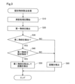
図3を用いて、本実施形態の光測距装置200が実行する疑似物体除去処理について説明する。疑似物体除去処理は、例えば、光測距装置200の電源をオンにすることにより開始される。疑似物体除去処理は、例えば、走査範囲RAに含まれるスロット(方向)ごとの各画素66に対して実行される。図3に示すフロー図は、走査範囲RAにおける一のスロット(方向)における一の画素66での処理の例を示している。
Pseudo-object removal processing executed by the optical
図3に示すように、制御装置100は、制御部110によって発光部40、走査部50、受光部60を駆動制御し、走査範囲RA内の物標の検出および距離の検出(以下、「測距処理」とも呼ぶ)を開始する(ステップS10)。加算部120は、画素66の受光素子68から出力される信号の数を計数し、ヒストグラム生成部130は、時間軸に対する信号強度のヒストグラムを生成する。ピーク検出部140は、ヒストグラムを解析して、走査範囲RA内の一の物体としての第一物体から反射光を受光することによって、第一物体のピーク信号を検出する(ステップS20)。
As shown in FIG. 3, the control device 100 drives and controls the
ピーク検出部140は、第一物体を検出すると、ヒストグラムに第二物体に該当するピーク信号があるか否か、すなわち第二物体が検出されたか否かを確認する(ステップS30)。第二物体とは、第一物体とともに検出された物体のうち、第一物体に対応する疑似物体と判定され得る物体を意味する。本実施形態において、光測距装置200と第一物体とを結ぶ直線の延長上、すなわちレーザ光DLの出射方向において、第一物体までの距離のN倍(Nは2以上の自然数)の距離に位置する物体を第二物体と判定する。第二物体が検出されない場合(S30:NO)、距離演算部160は、検出された第一物体およびその他の物体のピーク信号を用いて距離を検出し(ステップS60)、処理を完了する。第二物体が検出された場合(S30:YES)、疑似物体判定部150は、検出された第二物体が疑似物体であるか否かの判定を行う(ステップS40)。
After detecting the first object, the
本実施形態において、疑似物体判定部150は、光を透過しない物体、すなわち光非透過性を有する物体(以下、「第三物体」とも呼ぶ)が検出されており、第二物体が第三物体よりも光測距装置200から離れた位置に検出されている場合に、第二物体が疑似物体であると判定する。第三物体としては、例えば、道路や地面、建物の壁面など、光非透過性を有する種々の物体が含まれる。第三物体が検出されているか否かは、光測距装置200による測距の結果から判定されてもよく、例えば、カメラやレーダなどの光測距装置200以外の検出器の検出結果から判定されてもよい。
In the present embodiment, the
第二物体が疑似物体であると判定されると(S40:YES)、距離演算部160は、第二物体に対応するピーク信号を距離の演算から除外し、検出された第一物体およびその他の物体のピーク信号を用いて距離を検出し(ステップS50)、処理を完了する。第二物体に対応するピーク信号が距離の演算から除外される処理に代えて、第二物体に対応するピーク信号をヒストグラムから削除する処理が実行されてもよい。第二物体が疑似物体と判定されない場合(S40:NO)、距離演算部160は、検出された第一物体および第二物体と、その他の物体とのピーク信号を用いて距離を検出し(ステップS60)、処理を完了する。
When it is determined that the second object is a pseudo object (S40: YES), the
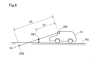
図4から図6を用いて、本実施形態の光測距装置200が実行する疑似物体除去処理の具体例を説明する。図4には、本実施形態の光測距装置200を搭載する車両C1が道路RSを走行している状態が示されている。図4には、第一物体OB1と、第一物体OB1に対応する疑似物体としての第二物体OB2とが概念的に示されている。第一物体OB1は、入射光が入射光の光源に向かって反射するいわゆる再帰反射を利用した、いわゆる強反射材である。第一物体OB1は、例えば、リトロリフレクタ、コーナーキューブ、再帰反射器、再帰反射材などとも呼ばれる。第一物体OB1からの反射光の強度は、通常時よりも大きくなり得る。図4に示すように、第一物体OB1は、光測距装置200から方向OLに向かって距離D1に位置し、第二物体OB2は、光測距装置200から方向OLに向かって距離D2に位置している。距離D2は、距離D1の2倍の距離に相当する。光測距装置200は、車両C1の走行中に第三物体としての道路RSの検出を完了している。
A specific example of pseudo object removal processing executed by the optical
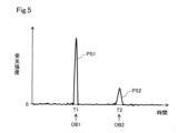
図4に示すように、測距のために出射された方向OLへのレーザ光は、方向OL上の物体のうち第一物体OB1によって反射される。図5の信号強度のヒストグラムとして示すように、第一物体OB1からの反射光の一部は、受光部60の受光素子68によって受光され、第一物体OB1に対応するピーク信号PS1として検出される。距離演算部160は、TOFを利用し、ピーク信号PS1を検出した時間T1を用いて、第一物体OB1までの距離D1を演算する。
As shown in FIG. 4, the laser light emitted in the direction OL for distance measurement is reflected by the first object OB1 among the objects on the direction OL. As shown by the signal intensity histogram in FIG. 5, part of the reflected light from the first object OB1 is received by the
第一物体OB1は強反射材であり、第一物体OB1からの反射光の強度が大きい。そのため、第一物体OB1からの反射光の一部は、受光部60の表面で反射し、第二反射光として方向OLに向かって進む。第二反射光は、第一物体OB1によって反射されて受光素子68によって受光される。図5に示すように、受光素子68に入射した第二反射光は、第一物体OB1と受光素子68との間を2往復しているため、方向OLにおいて距離D1の2倍である距離D2の位置に第二物体OB2に対応するピーク信号PS2として検出される。
The first object OB1 is a strong reflector, and the intensity of reflected light from the first object OB1 is high. Therefore, part of the reflected light from the first object OB1 is reflected by the surface of the
図6には、光測距装置200により第一物体OB1および第二物体OB2の距離が検出される様子を車両C1の側面側から見た状態が概念的に示されている。図6に示すように、光測距装置200は、第一物体OB1と、第二物体OB2ととともに、道路RSを検出している。疑似物体判定部150は、道路RSの検出結果と、第二物体OB2の距離の検出結果とを用いて、第二物体OB2が道路RSよりも光測距装置200から離れた位置であるか否かを判定する。図6に示すように、第二物体OB2は、直線OLにおいて第三物体である道路RSよりも光測距装置200から離れた位置に検出されている。そのため、疑似物体判定部150は、第二物体OB2が疑似物体であると判定する。距離演算部160は、第二物体OB2に対応するピーク信号を距離の演算から除外し、第一物体OB1のピーク信号を用いて距離を検出する。
FIG. 6 conceptually shows how the distance between the first object OB1 and the second object OB2 is detected by the optical
以上、説明したように、本実施形態の光測距装置200によれば、第一物体OB1と、第二物体OB2とが検出され、かつ、第二物体OB2が第一物体OB1に対応する疑似物体であると判定した場合に、第二物体OB2の検出結果が除去される。したがって、疑似物体の影響を低減して、物標を正確に検出することができる。光測距装置200を搭載した車両が、第二物体OB2を実在する物標として検出することを回避し、疑似物体との衝突を回避するための制御が実行されることを抑制または防止することができる。
As described above, according to the optical
本実施形態の光測距装置200によれば、疑似物体判定部150は、光非透過性を有する第三物体としての道路RSが検出され、第二物体OB2が道路RSよりも光測距装置200から離れた位置に検出されている場合に、第二物体OB2を疑似物体として判定する。物標が物理的に検出されることがない状態を疑似物体の判定条件として用いることにより、疑似物体であるか否かを確実に判定することができる。
According to the optical
B.第2実施形態:
図7を用いて第2実施形態の光測距装置200について説明する。第2実施形態の光測距装置200では、疑似物体除去処理のステップS40における疑似物体の判定方法が第1実施形態の光測距装置200と相違し、それ以外の構成は第1実施形態の光測距装置200と同様である。
B. Second embodiment:
An optical
本実施形態の光測距装置200は、光測距装置200の移動中に第二物体を検出した場合に、第一物体に対する第二物体の相対位置を追跡した結果を用いることによって、第二物体が疑似物体であるか否かを判定する。より具体的には、疑似物体判定部150は、第二物体を検出した時点から予め定められた期間内において、第一物体に対する第二物体の相対位置を追跡する。予め定められた期間とは、光測距装置200の移動期間であり、任意の期間に設定してよい。第一物体に対する第二物体の相対位置が光測距装置200から第一物体までの距離のN倍の距離となる位置を維持している場合に、疑似物体判定部150は、第二物体を疑似物体と判定する。
When the optical
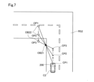
図7に示すように、光測距装置200は、車両C2に搭載されている。光測距装置200は、車両C2の走行に伴い、予め定められた期間内に、道路RS2上の位置CP1と、位置CP2と、位置CP3とをこの順序で移動する。光測距装置200は、位置CP1において、強反射材である第一物体OB21を検出するとともに、位置OP1の第二物体OB22を検出する。光測距装置200は、位置CP2において、第一物体OB21を検出するとともに、位置OP2の第二物体OB22を検出し、位置CP3において、第一物体OB21を検出するとともに、位置OP3の第二物体OB22を検出する。第二物体OB22が検出された位置CP1の時点から車両C2が位置CP3に移動する時点までの予め定められた期間内において、第一物体OB21に対する第二物体OB22の相対位置が、光測距装置200から第一物体OB21までの距離の2倍の距離を維持している。したがって、疑似物体判定部150は、第二物体OB22を疑似物体と判定する。
As shown in FIG. 7, the
本実施形態の光測距装置200によれば、光測距装置200の移動中に測距処理を実行して、第二物体OB22を検出した時点から予め定められた期間内において第二物体OB22を追跡する。疑似物体判定部150は、第一物体OB21に対する第二物体OB22の相対位置が、光測距装置200から第一物体OB21までの距離のN倍の距離を維持している場合に、第二物体OB2を疑似物体と判定する。光測距装置200の移動中での第二物体OB2の挙動を利用して、第二物体OB2が疑似物体であるか否かを判定することができる。したがって、光測距装置200の移動中に第二物体OB2が疑似物体であるか否かを判定することができる。
According to the optical
C.第3実施形態:
図8を用いて第3実施形態の光測距装置200について説明する。第3実施形態の光測距装置200では、疑似物体除去処理のステップS40における疑似物体の判定方法が第1実施形態の光測距装置200と相違し、それ以外の構成は第1実施形態の光測距装置200と同様である。
C. Third embodiment:
An optical
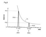
本実施形態の光測距装置200では、疑似物体の判定方法として、光の強さが光源からの距離の2乗に反比例する、いわゆる光の減衰の法則を利用している。第二物体の信号強度が、第一物体の信号強度に対して、いわゆる逆2乗の法則(inverse square law)に適合する場合に、第二物体が疑似物体であると判定する。より具体的には、光測距装置200から第一物体OB1までの距離のN倍の距離に位置する第二物体の信号強度が、第一物体の信号強度に対して、Nの2乗に反比例している場合に、第二物体が疑似物体であると判定する。
The optical
図8に示すように、光測距装置200から距離D31に位置する強反射材である第一物体OB31は、ピーク信号PS31として検出されている。光測距装置200から距離D31の2倍の距離に相当する距離D32に位置する第二物体OB22は、ピーク信号PS32として検出されている。図8に示す曲線PLは、第一物体OB31までの距離D31を基準とし、距離D31に対する比率の2乗に反比例するグラフである。疑似物体判定部150は、第二物体OB32の信号強度が曲線PL上に位置する場合に、第二物体OB32が疑似物体であると判定する。第二物体OB32の信号強度が曲線PL上に位置する場合のみには限定されず、検出誤差などを考慮し、第二物体OB32の信号強度が曲線PLを含む予め定められた範囲内に位置する場合に、第二物体OB32が疑似物体であると判定してもよい。図8に示す距離D32は、距離D31の2倍(N=2)であり、ピーク信号PS32の信号強度P32は、Nの2乗分の1であり、ピーク信号PS31の信号強度P31の約4分の1である。疑似物体判定部150は、第二物体OB32の信号強度が、第一物体OB31の信号強度に対してNの2乗に反比例すると判定し、第二物体OB32が疑似物体であると判定する。
As shown in FIG. 8, a first object OB31, which is a strong reflector located at a distance D31 from the
本実施形態の光測距装置200によれば、第二物体OB32の信号強度P32が、第一物体OB31の信号強度P31に対して、Nの2乗に反比例している場合に、疑似物体判定部150は、第二物体OB32が疑似物体であると判定する。信号強度のヒストグラムから第二物体が疑似物体であるか否かを判定でき、簡易な方法で疑似物体を検出することができる。
According to the optical
D.第4実施形態:
図9を用いて第4実施形態の光測距装置200について説明する。第4実施形態の光測距装置200では、疑似物体除去処理のステップS40における疑似物体の判定方法が第1実施形態の光測距装置200と相違し、それ以外の構成は第1実施形態の光測距装置200と同様である。
D. Fourth embodiment:
An optical
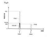
本実施形態の光測距装置200は、第一物体と第二物体とが検出された後に、発光部40の出力を第一物体と第二物体とを検出した際の出力よりも低減させる第一測距条件による測距処理を実行する。光測距装置200は、第一測距条件とともに、または第一測距条件に代えて、ヒストグラム生成部130によって受光部60から検出信号を取得する回数を、第一物体と第二物体とを検出した際の回数よりも低減させる第二測距条件による測距処理を実行してもよい。
The optical
図9に示すように、ピーク検出部140により検出された強反射材である第一物体OB41に対応するピーク信号PS41と、第一物体OB41までの距離の2倍の距離に位置する第二物体OB42に対応するピーク信号PS42とが破線で示されている。本実施形態において、第一物体OB41とともに第二物体OB42とが検出されると、制御部110は、発光部40を制御して、レーザ光の出力を第一物体OB41と第二物体OB42とを検出した際の出力よりも低減させた状態で、距離の検出を行う。第一測距条件または第二測距条件の少なくともいずれかの条件による測距処理を「強反射物検出処理」とも呼ぶ。強反射物検出処理において低減されるレーザ光の出力は、強反射材としての第一物体OB41のピーク信号PS41Wが検出できる程度の出力に設定される。レーザ光の出力が低減されることにより、図9に示すように、第一物体OB41に対応するピーク信号PS41の信号強度P41は低減し、信号強度P41Wを有するピーク信号PS41Wが得られる。第二物体OB42に対応する信号強度P42のピーク信号PS42は消滅し、ピーク信号として検出されない。このように、第一物体OB41と第二物体OB42とを検出した後に、強反射物検出処理を実行することにより、第一物体OB41が検出されるか否かを判定することで、第一物体OB41が強反射材であるか否かを判定する。疑似物体判定部150は、第一物体OB41が強反射材と判定する場合には、第二物体OB42を疑似物体と判定する。
As shown in FIG. 9, the peak signal PS41 corresponding to the first object OB41, which is a strong reflector detected by the
本実施形態の光測距装置200によれば、第一物体OB41と第二物体OB42とを検出した場合に、レーザ光の出力を第一物体OB41と第二物体OB42とを検出した際の出力よりも低減させる強反射物検出処理を実行し、第一物体OB41が検出される場合に、第一物体OB41を強反射材と判定し、第二物体OB42を疑似物体と判定する。したがって、簡易な方法で疑似物体を検出することができる。
According to the optical
E.第5実施形態:
図10を用いて第5実施形態の光測距装置200について説明する。第5実施形態の光測距装置200は、第1実施形態の疑似物体除去処理に加え、さらにクラッタの検出結果を除去するクラッタ除去処理を行う点において、第1実施形態の光測距装置200と相違し、それ以外の構成は、第1実施形態の光測距装置200と同様である。「クラッタ」とは、発光部40から出射された出射光が筐体80の窓部82によって反射される反射光を意味する。クラッタは、受光部60に入射することにより、ピーク信号として検出され得るため、光測距装置200の測距精度を低下させることがある。一般に、クラッタは、光測距装置200から近距離、かつ物体OBからの反射光に比べて強度の小さなピーク信号として検出される。
E. Fifth embodiment:
An optical
図10には、クラッタに対応するピーク信号PS5が示されている。ピーク信号PS5は、ピーク検出部140によるヒストグラム解析によって、第一物体OB1のピーク信号PS1等とともに検出される。本実施形態において、疑似物体判定部150は、検出したピーク信号の検出距離が予め定められた時間閾値Ttよりも小さく、かつ、受光強度が予め定められた強度閾値Ptよりも小さい場合、検出したピーク信号がクラッタに対応するピーク信号であると判定する。距離演算部160は、クラッタに対応するピーク信号PS5の検出結果を除去して、距離を検出する。
FIG. 10 shows the peak signal PS5 corresponding to clutter. The peak signal PS5 is detected together with the peak signal PS1 of the first object OB1 and the like by the histogram analysis by the
図10には、受光強度が取り得る最大値Pmaxが示されている。最大値Pmaxは、ヒストグラムを作成する際に使用される1画素当りの受光素子68の延べ数である。図2で説明したように、1つの画素66は5×5個の受光素子68で構成されている。Nを2以上の整数とするとき、N回の発光による受光結果を合計してヒストグラムを作成する場合には、受光強度が取り得る最大値Pmaxは、N×5×5に等しい。強度閾値Ptは、通常は受光強度が取り得る最大値Pmaxよりも小さな値に設定される。本実施形態において、強度閾値Ptは、最大値Pmaxの50%の受光強度で設定されている。強度閾値Ptは、最大値Pmaxと等しい値に設定されてもよい。時間閾値Ttは、光測距装置200から近距離となる任意の距離で設定される。時間閾値Ttは、発光部40から窓部82までの光路の距離に相当する特定の飛行時間で設定されてもよく、誤差等を考慮して発光部40から窓部82までの光路の距離よりも大きい距離で設定されてもよい。本実施形態において、時間閾値Ttは、発光部40から窓部82までの光路の距離よりも大きい発光部40から1メートルで設定されている。
FIG. 10 shows the maximum value Pmax that the received light intensity can take. The maximum value Pmax is the total number of light receiving
本実施形態の光測距装置200によれば、測距処理時に、疑似物体の検出結果の加え、クラッタによるピーク信号が除去される。したがって、クラッタに起因する光測距装置200の測距精度の低下を抑制し、物標をより正確に検出することができる。
According to the optical
他の実施形態:
本開示に記載の制御部及びその手法は、コンピュータプログラムにより具体化された一つ乃至は複数の機能を実行するようにプログラムされたプロセッサ及びメモリを構成することによって提供された専用コンピュータにより、実現されてもよい。あるいは、本開示に記載の制御部及びその手法は、一つ以上の専用ハードウェア論理回路によってプロセッサを構成することによって提供された専用コンピュータにより、実現されてもよい。もしくは、本開示に記載の制御部及びその手法は、一つ乃至は複数の機能を実行するようにプログラムされたプロセッサ及びメモリと一つ以上のハードウェア論理回路によって構成されたプロセッサとの組み合わせにより構成された一つ以上の専用コンピュータにより、実現されてもよい。また、コンピュータプログラムは、コンピュータにより実行されるインストラクションとして、コンピュータ読み取り可能な非遷移有形記録媒体に記憶されていてもよい。
Other embodiments:
The controller and techniques described in this disclosure may be implemented by a dedicated computer provided by configuring a processor and memory programmed to perform one or more functions embodied by the computer program. may be Alternatively, the controller and techniques described in this disclosure may be implemented by a dedicated computer provided by configuring the processor with one or more dedicated hardware logic circuits. Alternatively, the control units and techniques described in this disclosure can be implemented by a combination of a processor and memory programmed to perform one or more functions and a processor configured by one or more hardware logic circuits. It may also be implemented by one or more dedicated computers configured. The computer program may also be stored as computer-executable instructions on a computer-readable non-transitional tangible recording medium.
本開示は、上述の実施形態や変形例に限られるものではなく、その趣旨を逸脱しない範囲において種々の構成で実現することができる。例えば、発明の概要の欄に記載した各形態中の技術的特徴に対応する実施形態、変形例中の技術的特徴は、上述の課題の一部又は全部を解決するために、あるいは、上述の効果の一部又は全部を達成するために、適宜、差し替えや、組み合わせを行うことが可能である。また、その技術的特徴が本明細書中に必須なものとして説明されていなければ、適宜、削除することが可能である。 The present disclosure is not limited to the embodiments and modifications described above, and can be implemented in various configurations without departing from the scope of the present disclosure. For example, the technical features in the embodiments and modifications corresponding to the technical features in each form described in the summary column of the invention are used to solve some or all of the above problems, or In order to achieve some or all of the effects, it is possible to appropriately replace or combine them. Also, if the technical features are not described as essential in this specification, they can be deleted as appropriate.
40…発光部、60…受光部、66…画素、100…制御装置、200…光測距装置、D1,D2…距離、DL…レーザ光、OB…物体、OB1,OB21,OB31,OB41…第一物体、OB2,OB22,OB32,OB42…第二物体、OL…直線、RL…反射光
40... Light-emitting
Claims (4)
出射光(DL)を出射する発光部(40)と、
前記出射光を透過する窓部(82)と、
入射光を受光するための受光画素(66)を有し、前記受光画素に受光した前記入射光の受光強度に対応する検出信号を出力する受光部(60)と、
物体(OB)によって反射された前記出射光に対応する反射光(RL)を前記入射光として受光した前記受光部から、前記反射光の受光強度に対応する検出信号を取得し、前記反射光の受光強度に対応する検出信号を用いて前記物体までの距離を検出する制御装置(100)と、を備え、
前記制御装置は、
第一物体(OB1,OB21,OB31,OB41)と、前記光測距装置と前記第一物体とを結ぶ直線(OL)の延長上であって前記第一物体までの距離(D1)のN倍(Nは2以上の自然数)の距離(D2)に位置する第二物体(OB2,OB22,OB32,OB42)とが検出され、かつ、前記第二物体が前記第一物体に対応する疑似物体であると判定した場合に、前記第二物体の検出結果を除去する処理と、
取得した検出信号が、前記窓部によって反射された反射光に対応する検出信号であると判定した場合に、前記窓部に対応する検出結果を除去する処理と、
前記第一物体と前記第二物体とが検出された後に、さらに、前記出射光の出力を、前記第一物体と前記第二物体とを検出した出力よりも低減させる第一測距条件、または前記受光部から検出信号を取得する回数を、前記第一物体と前記第二物体とを検出した出力よりも低減させる第二測距条件、のうち少なくともいずれかの条件を含む測距である強反射物検出処理を実行し、
前記強反射物検出処理において、前記第一物体が検出される場合に、前記第二物体が前記疑似物体であると判定する処理と、を実行する、
光測距装置。 An optical ranging device (200),
a light emitting part (40) for emitting emitted light (DL);
a window (82) that transmits the emitted light;
a light-receiving unit (60) having light-receiving pixels (66) for receiving incident light and outputting a detection signal corresponding to the received light intensity of the incident light received by the light-receiving pixels;
Acquiring a detection signal corresponding to the received light intensity of the reflected light from the light receiving unit that receives the reflected light (RL) corresponding to the emitted light reflected by the object (OB) as the incident light, and obtaining a detection signal corresponding to the received light intensity of the reflected light A control device (100) that detects the distance to the object using a detection signal corresponding to the received light intensity,
The control device is
N times the distance (D1) to the first object (OB1, OB21, OB31, OB41) and the extension of the straight line (OL) connecting the optical distance measuring device and the first object A second object (OB2, OB22, OB32, OB42) located at a distance (D2) of (N is a natural number of 2 or more) is detected, and the second object is a pseudo object corresponding to the first object a process of removing the detection result of the second object when it is determined that there is;
a process of removing the detection result corresponding to the window when it is determined that the acquired detection signal is the detection signal corresponding to the reflected light reflected by the window;
a first ranging condition that, after the first object and the second object are detected, further reduces the output of the emitted light below the output of the detection of the first object and the second object; or a second ranging condition for reducing the number of times the detection signal is acquired from the light receiving unit below the output for detecting the first object and the second object. Execute reflection object detection processing,
a process of determining that the second object is the pseudo object when the first object is detected in the strongly reflective object detection process;
optical rangefinder.
前記制御装置は、
さらに光非透過性を有する第三物体が検出され、前記第二物体が、前記第三物体よりも前記光測距装置から離れた位置に検出されている場合に、
前記第二物体が前記疑似物体であると判定する、
光測距装置。 The optical distance measuring device according to claim 1,
The control device is
Furthermore, when a third object having light impermeability is detected, and the second object is detected at a position farther from the optical ranging device than the third object,
determining that the second object is the pseudo object;
optical rangefinder.
前記制御装置は、
前記光測距装置の移動中の予め定められた期間内において前記物体までの距離を検出し、前記第一物体に対する前記第二物体の相対位置が前記N倍の距離を維持している場合に、
前記第二物体が前記疑似物体であると判定する、
光測距装置。 The optical distance measuring device according to claim 1 or claim 2,
The control device is
When the distance to the object is detected within a predetermined period during the movement of the optical range finder, and the relative position of the second object with respect to the first object maintains the N times distance. ,
determining that the second object is the pseudo object;
optical rangefinder.
前記制御装置は、
前記第二物体の信号強度が、前記第一物体の信号強度に対して、前記Nの2乗に反比例している場合に、
前記第二物体が前記疑似物体であると判定する、
光測距装置。 The optical distance measuring device according to any one of claims 1 to 3,
The control device is
When the signal strength of the second object is inversely proportional to the signal strength of the first object to the square of N,
determining that the second object is the pseudo object;
optical rangefinder.
Priority Applications (4)
| Application Number | Priority Date | Filing Date | Title |
|---|---|---|---|
| JP2020072685A JP7306310B2 (en) | 2020-04-15 | 2020-04-15 | optical rangefinder |
| CN202180028772.4A CN115427831A (en) | 2020-04-15 | 2021-04-01 | Optical distance measuring device |
| PCT/JP2021/014142 WO2021210415A1 (en) | 2020-04-15 | 2021-04-01 | Optical ranging device |
| US18/046,772 US20230065210A1 (en) | 2020-04-15 | 2022-10-14 | Optical distance measuring device |
Applications Claiming Priority (1)
| Application Number | Priority Date | Filing Date | Title |
|---|---|---|---|
| JP2020072685A JP7306310B2 (en) | 2020-04-15 | 2020-04-15 | optical rangefinder |
Publications (3)
| Publication Number | Publication Date |
|---|---|
| JP2021169944A JP2021169944A (en) | 2021-10-28 |
| JP2021169944A5 JP2021169944A5 (en) | 2022-03-23 |
| JP7306310B2 true JP7306310B2 (en) | 2023-07-11 |
Family
ID=78083667
Family Applications (1)
| Application Number | Title | Priority Date | Filing Date |
|---|---|---|---|
| JP2020072685A Active JP7306310B2 (en) | 2020-04-15 | 2020-04-15 | optical rangefinder |
Country Status (4)
| Country | Link |
|---|---|
| US (1) | US20230065210A1 (en) |
| JP (1) | JP7306310B2 (en) |
| CN (1) | CN115427831A (en) |
| WO (1) | WO2021210415A1 (en) |
Families Citing this family (2)
| Publication number | Priority date | Publication date | Assignee | Title |
|---|---|---|---|---|
| WO2023181947A1 (en) * | 2022-03-23 | 2023-09-28 | 株式会社デンソー | Object detection device and object detection method |
| WO2023181948A1 (en) * | 2022-03-24 | 2023-09-28 | 株式会社デンソー | Noise eliminating device, object detecting device, and noise eliminating method |
Citations (8)
| Publication number | Priority date | Publication date | Assignee | Title |
|---|---|---|---|---|
| JP2006030094A (en) | 2004-07-20 | 2006-02-02 | Keyence Corp | Optical displacement gauge |
| JP2007304069A (en) | 2006-05-15 | 2007-11-22 | Honda Motor Co Ltd | Object detection device |
| JP2011128112A (en) | 2009-12-21 | 2011-06-30 | Denso Wave Inc | Laser radar system |
| JP2013164385A (en) | 2012-02-13 | 2013-08-22 | Denso Corp | Radar system |
| JP2016080649A (en) | 2014-10-22 | 2016-05-16 | 株式会社デンソー | Object detector |
| WO2017221909A1 (en) | 2016-06-21 | 2017-12-28 | コニカミノルタ株式会社 | Distance measuring device |
| JP2019144210A (en) | 2018-02-23 | 2019-08-29 | コニカミノルタ株式会社 | Object detection system |
| JP2020020612A (en) | 2018-07-30 | 2020-02-06 | 株式会社リコー | Distance measuring device, method for measuring distance, program, and mobile body |
Family Cites Families (2)
| Publication number | Priority date | Publication date | Assignee | Title |
|---|---|---|---|---|
| GB9502087D0 (en) * | 1995-02-02 | 1995-03-22 | Croma Dev Ltd | Improvements relating to pulse echo distance measurement |
| JPH1164497A (en) * | 1997-08-15 | 1999-03-05 | Mitsubishi Electric Corp | Laser device |
-
2020
- 2020-04-15 JP JP2020072685A patent/JP7306310B2/en active Active
-
2021
- 2021-04-01 CN CN202180028772.4A patent/CN115427831A/en active Pending
- 2021-04-01 WO PCT/JP2021/014142 patent/WO2021210415A1/en active Application Filing
-
2022
- 2022-10-14 US US18/046,772 patent/US20230065210A1/en active Pending
Patent Citations (8)
| Publication number | Priority date | Publication date | Assignee | Title |
|---|---|---|---|---|
| JP2006030094A (en) | 2004-07-20 | 2006-02-02 | Keyence Corp | Optical displacement gauge |
| JP2007304069A (en) | 2006-05-15 | 2007-11-22 | Honda Motor Co Ltd | Object detection device |
| JP2011128112A (en) | 2009-12-21 | 2011-06-30 | Denso Wave Inc | Laser radar system |
| JP2013164385A (en) | 2012-02-13 | 2013-08-22 | Denso Corp | Radar system |
| JP2016080649A (en) | 2014-10-22 | 2016-05-16 | 株式会社デンソー | Object detector |
| WO2017221909A1 (en) | 2016-06-21 | 2017-12-28 | コニカミノルタ株式会社 | Distance measuring device |
| JP2019144210A (en) | 2018-02-23 | 2019-08-29 | コニカミノルタ株式会社 | Object detection system |
| JP2020020612A (en) | 2018-07-30 | 2020-02-06 | 株式会社リコー | Distance measuring device, method for measuring distance, program, and mobile body |
Also Published As
| Publication number | Publication date |
|---|---|
| JP2021169944A (en) | 2021-10-28 |
| WO2021210415A1 (en) | 2021-10-21 |
| CN115427831A (en) | 2022-12-02 |
| US20230065210A1 (en) | 2023-03-02 |
Similar Documents
| Publication | Publication Date | Title |
|---|---|---|
| CN111742241B (en) | Optical distance measuring device | |
| KR101773020B1 (en) | Ladar sensor device | |
| US20230065210A1 (en) | Optical distance measuring device | |
| JP4894360B2 (en) | Radar equipment | |
| JP2003302468A (en) | Distance measuring equipment | |
| CN112368597A (en) | Optical distance measuring device | |
| US20230012091A1 (en) | Rangefinder | |
| JP7214888B2 (en) | Radar power control method and apparatus | |
| JP7375789B2 (en) | distance measuring device | |
| WO2017110574A1 (en) | Light projection/reception unit, and radar | |
| JP2020153706A (en) | Electronic device and method therefor | |
| JP2024009033A (en) | Retroreflector detection and avoidance in lidar device | |
| JP6186863B2 (en) | Ranging device and program | |
| JP3622314B2 (en) | Laser radar equipment for vehicles | |
| JP2020187042A (en) | Optical distance measurement device | |
| WO2021251161A1 (en) | Ranging device | |
| JP6725982B2 (en) | Obstacle determination device | |
| CN112513574B (en) | distance measuring device | |
| JP2002022830A (en) | Apparatus for measuring distance and its method of measuring distance | |
| WO2021235317A1 (en) | Optical distance measurement device | |
| US20230266450A1 (en) | System and Method for Solid-State LiDAR with Adaptive Blooming Correction | |
| WO2023171659A1 (en) | Information processing device, distance measuring system, control method, program, and storage medium | |
| JP2024004277A (en) | Object detection device and vehicle control system | |
| JP2021143945A (en) | Optical range finder | |
| JP2024021392A (en) | Object detection devices, information provision devices, driving control devices, and vehicle systems |
Legal Events
| Date | Code | Title | Description |
|---|---|---|---|
| A521 | Request for written amendment filed |
Free format text: JAPANESE INTERMEDIATE CODE: A523 Effective date: 20220314 |
|
| A621 | Written request for application examination |
Free format text: JAPANESE INTERMEDIATE CODE: A621 Effective date: 20220314 |
|
| A131 | Notification of reasons for refusal |
Free format text: JAPANESE INTERMEDIATE CODE: A131 Effective date: 20230221 |
|
| A521 | Request for written amendment filed |
Free format text: JAPANESE INTERMEDIATE CODE: A523 Effective date: 20230411 |
|
| TRDD | Decision of grant or rejection written | ||
| A01 | Written decision to grant a patent or to grant a registration (utility model) |
Free format text: JAPANESE INTERMEDIATE CODE: A01 Effective date: 20230530 |
|
| A61 | First payment of annual fees (during grant procedure) |
Free format text: JAPANESE INTERMEDIATE CODE: A61 Effective date: 20230612 |
|
| R151 | Written notification of patent or utility model registration |
Ref document number: 7306310 Country of ref document: JP Free format text: JAPANESE INTERMEDIATE CODE: R151 |