JP7303723B2 - Stream switching valve system and liquid chromatograph - Google Patents
Stream switching valve system and liquid chromatograph Download PDFInfo
- Publication number
- JP7303723B2 JP7303723B2 JP2019190312A JP2019190312A JP7303723B2 JP 7303723 B2 JP7303723 B2 JP 7303723B2 JP 2019190312 A JP2019190312 A JP 2019190312A JP 2019190312 A JP2019190312 A JP 2019190312A JP 7303723 B2 JP7303723 B2 JP 7303723B2
- Authority
- JP
- Japan
- Prior art keywords
- stator
- rotor
- flowpath
- flow path
- seal
- Prior art date
- Legal status (The legal status is an assumption and is not a legal conclusion. Google has not performed a legal analysis and makes no representation as to the accuracy of the status listed.)
- Active
Links
Images


Classifications
-
- G—PHYSICS
- G01—MEASURING; TESTING
- G01N—INVESTIGATING OR ANALYSING MATERIALS BY DETERMINING THEIR CHEMICAL OR PHYSICAL PROPERTIES
- G01N30/00—Investigating or analysing materials by separation into components using adsorption, absorption or similar phenomena or using ion-exchange, e.g. chromatography or field flow fractionation
- G01N30/02—Column chromatography
- G01N30/26—Conditioning of the fluid carrier; Flow patterns
- G01N30/38—Flow patterns
-
- F—MECHANICAL ENGINEERING; LIGHTING; HEATING; WEAPONS; BLASTING
- F16—ENGINEERING ELEMENTS AND UNITS; GENERAL MEASURES FOR PRODUCING AND MAINTAINING EFFECTIVE FUNCTIONING OF MACHINES OR INSTALLATIONS; THERMAL INSULATION IN GENERAL
- F16K—VALVES; TAPS; COCKS; ACTUATING-FLOATS; DEVICES FOR VENTING OR AERATING
- F16K11/00—Multiple-way valves, e.g. mixing valves; Pipe fittings incorporating such valves
- F16K11/02—Multiple-way valves, e.g. mixing valves; Pipe fittings incorporating such valves with all movable sealing faces moving as one unit
- F16K11/06—Multiple-way valves, e.g. mixing valves; Pipe fittings incorporating such valves with all movable sealing faces moving as one unit comprising only sliding valves, i.e. sliding closure elements
- F16K11/072—Multiple-way valves, e.g. mixing valves; Pipe fittings incorporating such valves with all movable sealing faces moving as one unit comprising only sliding valves, i.e. sliding closure elements with pivoted closure members
- F16K11/074—Multiple-way valves, e.g. mixing valves; Pipe fittings incorporating such valves with all movable sealing faces moving as one unit comprising only sliding valves, i.e. sliding closure elements with pivoted closure members with flat sealing faces
- F16K11/0743—Multiple-way valves, e.g. mixing valves; Pipe fittings incorporating such valves with all movable sealing faces moving as one unit comprising only sliding valves, i.e. sliding closure elements with pivoted closure members with flat sealing faces with both the supply and the discharge passages being on one side of the closure plates
-
- F—MECHANICAL ENGINEERING; LIGHTING; HEATING; WEAPONS; BLASTING
- F16—ENGINEERING ELEMENTS AND UNITS; GENERAL MEASURES FOR PRODUCING AND MAINTAINING EFFECTIVE FUNCTIONING OF MACHINES OR INSTALLATIONS; THERMAL INSULATION IN GENERAL
- F16K—VALVES; TAPS; COCKS; ACTUATING-FLOATS; DEVICES FOR VENTING OR AERATING
- F16K11/00—Multiple-way valves, e.g. mixing valves; Pipe fittings incorporating such valves
- F16K11/02—Multiple-way valves, e.g. mixing valves; Pipe fittings incorporating such valves with all movable sealing faces moving as one unit
- F16K11/06—Multiple-way valves, e.g. mixing valves; Pipe fittings incorporating such valves with all movable sealing faces moving as one unit comprising only sliding valves, i.e. sliding closure elements
- F16K11/072—Multiple-way valves, e.g. mixing valves; Pipe fittings incorporating such valves with all movable sealing faces moving as one unit comprising only sliding valves, i.e. sliding closure elements with pivoted closure members
- F16K11/074—Multiple-way valves, e.g. mixing valves; Pipe fittings incorporating such valves with all movable sealing faces moving as one unit comprising only sliding valves, i.e. sliding closure elements with pivoted closure members with flat sealing faces
-
- F—MECHANICAL ENGINEERING; LIGHTING; HEATING; WEAPONS; BLASTING
- F16—ENGINEERING ELEMENTS AND UNITS; GENERAL MEASURES FOR PRODUCING AND MAINTAINING EFFECTIVE FUNCTIONING OF MACHINES OR INSTALLATIONS; THERMAL INSULATION IN GENERAL
- F16K—VALVES; TAPS; COCKS; ACTUATING-FLOATS; DEVICES FOR VENTING OR AERATING
- F16K37/00—Special means in or on valves or other cut-off apparatus for indicating or recording operation thereof, or for enabling an alarm to be given
- F16K37/0025—Electrical or magnetic means
- F16K37/0041—Electrical or magnetic means for measuring valve parameters
-
- F—MECHANICAL ENGINEERING; LIGHTING; HEATING; WEAPONS; BLASTING
- F16—ENGINEERING ELEMENTS AND UNITS; GENERAL MEASURES FOR PRODUCING AND MAINTAINING EFFECTIVE FUNCTIONING OF MACHINES OR INSTALLATIONS; THERMAL INSULATION IN GENERAL
- F16K—VALVES; TAPS; COCKS; ACTUATING-FLOATS; DEVICES FOR VENTING OR AERATING
- F16K37/00—Special means in or on valves or other cut-off apparatus for indicating or recording operation thereof, or for enabling an alarm to be given
- F16K37/0025—Electrical or magnetic means
- F16K37/005—Electrical or magnetic means for measuring fluid parameters
-
- G—PHYSICS
- G01—MEASURING; TESTING
- G01N—INVESTIGATING OR ANALYSING MATERIALS BY DETERMINING THEIR CHEMICAL OR PHYSICAL PROPERTIES
- G01N30/00—Investigating or analysing materials by separation into components using adsorption, absorption or similar phenomena or using ion-exchange, e.g. chromatography or field flow fractionation
- G01N30/02—Column chromatography
- G01N30/04—Preparation or injection of sample to be analysed
- G01N30/16—Injection
- G01N30/20—Injection using a sampling valve
-
- G—PHYSICS
- G01—MEASURING; TESTING
- G01N—INVESTIGATING OR ANALYSING MATERIALS BY DETERMINING THEIR CHEMICAL OR PHYSICAL PROPERTIES
- G01N30/00—Investigating or analysing materials by separation into components using adsorption, absorption or similar phenomena or using ion-exchange, e.g. chromatography or field flow fractionation
- G01N30/02—Column chromatography
- G01N30/26—Conditioning of the fluid carrier; Flow patterns
-
- G—PHYSICS
- G01—MEASURING; TESTING
- G01N—INVESTIGATING OR ANALYSING MATERIALS BY DETERMINING THEIR CHEMICAL OR PHYSICAL PROPERTIES
- G01N30/00—Investigating or analysing materials by separation into components using adsorption, absorption or similar phenomena or using ion-exchange, e.g. chromatography or field flow fractionation
- G01N30/02—Column chromatography
- G01N30/04—Preparation or injection of sample to be analysed
- G01N30/16—Injection
- G01N30/20—Injection using a sampling valve
- G01N2030/201—Injection using a sampling valve multiport valves, i.e. having more than two ports
-
- G—PHYSICS
- G01—MEASURING; TESTING
- G01N—INVESTIGATING OR ANALYSING MATERIALS BY DETERMINING THEIR CHEMICAL OR PHYSICAL PROPERTIES
- G01N30/00—Investigating or analysing materials by separation into components using adsorption, absorption or similar phenomena or using ion-exchange, e.g. chromatography or field flow fractionation
- G01N30/02—Column chromatography
- G01N30/04—Preparation or injection of sample to be analysed
- G01N30/16—Injection
- G01N30/20—Injection using a sampling valve
- G01N2030/202—Injection using a sampling valve rotary valves
-
- G—PHYSICS
- G01—MEASURING; TESTING
- G01N—INVESTIGATING OR ANALYSING MATERIALS BY DETERMINING THEIR CHEMICAL OR PHYSICAL PROPERTIES
- G01N30/00—Investigating or analysing materials by separation into components using adsorption, absorption or similar phenomena or using ion-exchange, e.g. chromatography or field flow fractionation
- G01N30/02—Column chromatography
- G01N30/26—Conditioning of the fluid carrier; Flow patterns
- G01N30/38—Flow patterns
- G01N2030/382—Flow patterns flow switching in a single column
- G01N2030/385—Flow patterns flow switching in a single column by switching valves
Description
この発明は、流路切替バルブ、流路切替バルブシステムおよび液体クロマトグラフに関する。 The present invention relates to a channel switching valve, a channel switching valve system, and a liquid chromatograph.
液体クロマトグラフなどの分析装置には、多数の流路を切り替える流路切替バルブが搭載されている。流路切替バルブは、配管を接続するステータ、ロータシール、ロータシールを回転させるロータ、それらを保持するハウジングなどから構成される。ロータシールはばねなどによってステータに押しつけられており、ロータシールに形成された流路とステータに形成された流路との液密性が保たれている。ロータシールはピンでロータに固定され、ロータをモータにより回転することでロータシールも回転し、ステータの流路に対してロータシールの流路が切り替わる。 Analytical devices such as liquid chromatographs are equipped with channel switching valves for switching between a large number of channels. A flow path switching valve is composed of a stator that connects pipes, a rotor seal, a rotor that rotates the rotor seal, a housing that holds them, and the like. The rotor seal is pressed against the stator by a spring or the like, and liquid tightness is maintained between the flow path formed in the rotor seal and the flow path formed in the stator. The rotor seal is fixed to the rotor with a pin, and when the rotor is rotated by the motor, the rotor seal also rotates, switching the flow path of the rotor seal with respect to the flow path of the stator.
流路切替バルブのロータシールは、ステータに押しつけられながら回転し摺動する。そのため、ロータシールの回転時にロータシールとステータの摺動面が摩耗し、ある一定値の摩耗量を超えると液漏れが発生してバルブとしての機能を果たさなくなる。 The rotor seal of the flow path switching valve rotates and slides while being pressed against the stator. Therefore, when the rotor seal rotates, the sliding surface between the rotor seal and the stator wears, and when the amount of wear exceeds a certain value, liquid leakage occurs and the valve ceases to function.
この摺動面の摩耗を抑制する構造を備えた流路切替バルブが特許文献1に示されている。特許文献1の流路切替バルブは、ステータとステータの一面と接触する面を有し、このステータの一面と接触する面を有し、接触面で摺動しつつ回転するロータとを備え、前記ステータは前記接触面に開口する複数の液体流通ポートを有し、前記ロータは前記液体流通ポートを連結する複数の流路溝を有し、ロータシールに圧力開放溝を備えることを特徴とする。この流路切替バルブは、ロータシールを十分に長い圧力開放範囲に伴って同心でそして円周上に延伸することで、圧力開放溝とステータのポート開口が重なり合ったときに発生する流体の流速が十分に小さくなり、ステータとロータシールの流路の損傷を回避するようになる。従って、ロ-タ回転時にポート開口部のエッジによって接触面が削り取られることを防止でき、流路の摩耗や損傷によって寿命が短くなることを防止することができる。
また、このような流路切替バルブの例は、特許文献2にも記載される。特許文献2には、第1状態と第2状態を切り替えることができる流路切替バルブの構成が記載されている。
Further, an example of such a flow path switching valve is also described in
従来の流路切替バルブは、流路間の圧力差が存在する場合、ステータとロータの摺動面において摩耗する領域が局在化する。特許文献1および2に記載されるものについても同様である。本発明は、このような事情に鑑みてなされたものであり、その目的とするところは、ステータとロータの摺動面において摩耗する領域を摺動面全体に分散させることで、長寿命な流路切替バルブを提供することである。
In the conventional flow path switching valve, when there is a pressure difference between the flow paths, the wear area is localized on the sliding surfaces of the stator and the rotor. The same applies to those described in
この発明に係る流路切替バルブの一例は、ステータと、前記ステータに対して回転可能に構成されるロータとを備える、流路切替バルブであって、
前記ステータは、第1ステータ流路、第2ステータ流路および第3ステータ流路を備え、
前記ロータは、第1ロータ流路および第2ロータ流路を備え、
前記流路切替バルブは、
前記第1ロータ流路が前記第1ステータ流路および前記第2ステータ流路を接続する、第1接続パターンと、
前記第1ロータ流路が前記第1ステータ流路および前記第3ステータ流路を接続する、第2接続パターンと、
前記第2ロータ流路が前記第1ステータ流路および前記第2ステータ流路を接続する、第3接続パターンと、
前記第2ロータ流路が前記第1ステータ流路および前記第3ステータ流路を接続する、第4接続パターンと、
を含む複数の接続パターンのいずれかを、前記ロータの回転状態に応じて実現する。
An example of the flow path switching valve according to the present invention is a flow path switching valve including a stator and a rotor rotatable with respect to the stator,
the stator includes a first stator flow path, a second stator flow path and a third stator flow path,
the rotor comprises a first rotor flowpath and a second rotor flowpath;
The flow path switching valve is
a first connection pattern in which the first rotor flowpath connects the first stator flowpath and the second stator flowpath;
a second connection pattern in which the first rotor flowpath connects the first stator flowpath and the third stator flowpath;
a third connection pattern in which the second rotor flowpath connects the first stator flowpath and the second stator flowpath;
a fourth connection pattern in which the second rotor flowpath connects the first stator flowpath and the third stator flowpath;
any one of a plurality of connection patterns including are realized according to the rotation state of the rotor.
本発明によれば、ステータとロータの摺動面の摩耗する領域を分散させ、流路切替バルブの長寿命化を図ることができる。 According to the present invention, it is possible to disperse the worn regions of the sliding surfaces of the stator and the rotor, thereby extending the service life of the flow path switching valve.
以下、添付図面を参照して本発明の実施例について説明する。なお、本発明は以下に説明する実施例に限定されるものではない。 Hereinafter, embodiments of the present invention will be described with reference to the accompanying drawings. It should be noted that the present invention is not limited to the examples described below.
[実施例1]
図1に、本発明の流路切替バルブ5の構成の例を示す。流路切替バルブ5の、軸(たとえば回転軸、以下同じ)に平行な平面による断面図を図1(a)に示す。図1(a)は、とくに図1(d)の破線に沿った断面によるものである。ロータシール22の上面図を図1(b)に、ステータ本体21のロータシール22と接触している部分の上面図を図1(c)に示す。なお、ステータ本体21の図1(c)に示す面は実際には下方に面しており、上側から見ることはできないが、ロータシール22との重ね合わせをわかりやすくするため上側から見た形状を示している。また図1(d)に、ステータ本体21の接触面とロータシール22の接触面を重ね合わせたときの、それぞれの流路の位置関係を示す。
[Example 1]
FIG. 1 shows an example of the configuration of the flow
流路切替バルブ5は、ステータおよびロータを備える。ロータはステータに対して回転可能に構成され、たとえば所定の回転軸の周りに回転する。
The flow
本実施例では、図1(a)に示すように、流路切替バルブ5は、配管を接続するステータ本体21と、ロータシール22と、ロータシール22を回転させるロータ本体23と、ステータ本体21およびロータ本体23を保持するハウジング26とを備える。ステータ本体21が本実施例におけるステータを構成し、ロータシール22およびロータ本体23が本実施例におけるロータを構成する。
In this embodiment, as shown in FIG. 1A, the flow
ロータ本体23は、バネなど(図示なし)によって、ロータシール22を介してステータ本体21に向かって押し付けられ、それによって、ロータシール22がステータ本体21に押し付けられる。ステータ本体21はたとえば、金属やセラミックからなり、ロータシール22はたとえば、金属、セラミック、または樹脂からなる。ステータ本体21とロータシール22には、耐摩耗性能を向上させるために、ダイヤモンドライクカーボンがコーティングされていてもよい。
The
ステータ本体21には複数の固定ステータ流路が構成され、固定ステータ流路によってステータ本体21の内部を流体が流動することができる。本実施例では、図1(c)に示すように、ステータ本体21は6つの固定ステータ流路31~36を備え、これらの固定ステータ流路のそれぞれが、本実施例におけるステータ流路を構成する。とくに、本実施例では、固定ステータ流路31が第1ステータ流路であり、固定ステータ流路32が第2ステータ流路であり、固定ステータ流路36が第3ステータ流路である。
A plurality of fixed stator flow paths are formed in the
なお、「固定ステータ流路」という名称は、本実施例において各流路がステータ本体21に対して固定されていることを表す。これは、後述の実施例2において中間ステータシール流路がステータ本体に対して移動する構成との対比を明確にするための表現であるが、この表現は、本発明の他の実施例において各流路が固定されていることを、いかなる意味においても要求するものではない。
The name “fixed stator flow path” indicates that each flow path is fixed to the stator
本実施例では、固定ステータ流路31~36は軸を中心とする円周上に設けられる。すなわち、ステータ本体21の軸から固定ステータ流路31~36までの距離はいずれも等しい。ただし、そうでない変形例も実施可能である。また、本実施例では、固定ステータ流路31~36の軸に垂直な断面はすべて同一形状かつ同一面積となるよう設けられる。とくに、本実施例では、固定ステータ流路31~36の軸に垂直な断面はすべて同一半径の円である。ただし、形状が異なる変形例や面積が異なる変形例も実施可能である。また、本実施例では、固定ステータ流路31~36は周方向に等間隔に設けられており、すなわち隣接する2つの固定ステータ流路は軸に対して互いに60度の角度をなす方向に配置される。ただし、周方向に等間隔とならない変形例も実施可能である。
In this embodiment, the fixed stator channels 31-36 are provided on a circumference around the axis. That is, the distances from the axis of the
また、ロータにも複数のロータ流路が構成され、ロータ流路によってロータの内部を流体が流動することができる。本実施例では、図1(b)に示すように、ロータシール22は3つのロータ流路241~243を備える。とくに、本実施例では、ロータ流路241が第1ロータ流路であり、ロータ流路242が第2ロータ流路である。なお変形例としてロータはロータシール22を備えないものであってもよく、その場合にはロータ流路はロータ本体23に設けられてもよい。
The rotor also has a plurality of rotor channels, and the rotor channels allow the fluid to flow inside the rotor. In this embodiment, as shown in FIG. 1(b), the
本実施例では、ロータ流路241~243は軸を中心とする円周上に設けられる。すなわち、ロータシール22の軸からロータ流路241~243までの距離はいずれも等しい。ただし、そうでない変形例も実施可能である。また、本実施例では、ロータ流路241~243の軸に垂直な断面はすべて同一形状かつ同一面積となるよう設けられる。ただし、形状が異なる変形例や面積が異なる変形例も実施可能である。また、本実施例では、ロータ流路241~243は周方向に等間隔に設けられており、すなわち隣接する2つのロータ流路は軸に対して120度の角度をなす。ただし、周方向に等間隔とならない変形例も実施可能である。
In this embodiment, the rotor channels 241-243 are provided on a circumference around the axis. That is, the distances from the axis of the
各ロータ流路は、ロータの回転状態に応じて、2つの固定ステータ流路を接続できるよう構成されている。ロータの回転状態とは、たとえばステータとロータとの回転位置関係を表す。より具体的には、ステータ本体21に対してロータシール22の基準回転位置が定義される場合に、その基準回転位置に対するロータシール22の相対的回転位置として定義してもよい。例として、図1(a)および図1(d)に示す状態では、ロータ流路241は固定ステータ流路31および32を接続し、ロータ流路242は固定ステータ流路35および36を接続し、ロータ流路243は固定ステータ流路33および34を接続する。
Each rotor channel is configured to connect two stationary stator channels depending on the rotational state of the rotor. The rotational state of the rotor represents, for example, the rotational positional relationship between the stator and the rotor. More specifically, when a reference rotational position of the
前述したように、ロータシール22はロータ本体23によりステータ本体21に押しつけられており、これによって液密性が保たれている。すなわち、ロータ流路241と固定ステータ流路31、32が連結した流路、ロータ流路242と固定ステータ流路35、36が連結した流路、および、ロータ流路243と固定ステータ流路33、34が連結した流路から自身以外の流路へ、もしくは、流路切替バルブ5の外部へ、液が漏れないようになっている。
As described above, the
ロータシール22はピン等(図示せず)でロータ本体23に固定され、ロータ本体23に接続されたモータ(図示せず)により、ロータ本体23と一体に回転する。ロータの回転角度は、例えば、モータにエンコーダーを備えて測定される。また、例えば、ロータシール22に設ける位置検知溝28を、ハウジング26に設ける位置検知窓30を通して外部から光学的に検出することで測定することができる。このとき、位置検知溝28や位置検知窓30は複数存在してもよい。
The
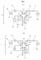
図2を用いて、従来の流路切替バルブについて説明する。図2(a)の状態から、ロータシール22が摺動方向29(時計回り)に60度回転し、図2(b)の状態を経て、図2(c)の状態となる。ロータ流路241は、図2(a)の状態では固定ステータ流路31、32を連結していて、図2(c)の状態では固定ステータ流路32、33を連結している。同様に、ロータ流路242は、図2(a)の状態では固定ステータ流路35、36を連結していて、図2(c)では固定ステータ流路36、31を連結している。また、ロータ流路243は、図2(a)の状態では固定ステータ流路33、34を連結していて、図2(c)では固定ステータ流路34、35を連結している。図2(a)の状態から図2(c)の状態に切り替わった後は、図2(c)の状態から摺動方向29と反対方向に60度回転し、図2(b)の状態を経て、図2(a)の状態に戻る。このように、摺動方向29に60度の回転運動と、摺動方向29と反対方向(反時計回り)に60度の回転運動とからなる往復動作をする。
A conventional flow path switching valve will be described with reference to FIG. From the state of FIG. 2(a), the
なお、本明細書において、回転方向および回転量の表現は便宜上のものであり、実際の回転方向および回転量をこれらと一致させる必要はない。たとえば、摺動方向29の60度の回転は、摺動方向29の420度の回転によっても実現することができるし、摺動方向29と反対方向の300度の回転によっても実現することができる。
In this specification, the expressions of the direction of rotation and the amount of rotation are for convenience, and the actual direction of rotation and the amount of rotation do not need to match these. For example, a rotation of 60 degrees in the sliding
図3は、本発明の実施例1に係る液体クロマトグラフ1の流路模式図である。本発明の実施例1の流路切替バルブ5を搭載した液体クロマトグラフ1の流路模式図を図3(a),図3(b)に示す。液体クロマトグラフ1は、送液ポンプ2、ニードル3、シリンジポンプ4、流路切替バルブ5、分離カラム6、検出器7、およびそれらを接続する配管を備える。流路切替バルブ5の固定ステータ流路31,32,33,34,35,36は、それぞれ送液ポンプ2、分離カラム6、ニードルポート10、廃液タンク11、シリンジポンプ4、ニードル3に接続されている。
FIG. 3 is a flow channel schematic diagram of the
まず、図3(a)の状態では、送液ポンプ2により送液される溶離液9は、固定ステータ流路31、ロータ流路241、固定ステータ流路32を通って、分離カラム6、検出器7、廃液タンク16に流れる。また、ニードルポート10が固定ステータ流路33、ロータ流路243、固定ステータ流路34を介して廃液タンク11に接続され、シリンジポンプ4が固定ステータ流路35、ロータ流路242、固定ステータ流路36を介してニードル3と接続される。この状態で、シリンジポンプ4を吸引することで、ニードル3内にサンプル8が吸引される。
First, in the state of FIG. 3( a ), the
その後、ロータシール22を摺動方向29(時計回り)に60度回転させて流路を切り替え、図3(b)の状態にする。また、図3(b)の状態では、サンプル8を保持したニードル3を移動させてニードルポート10に接続し、この状態で、送液ポンプ2で溶離液を送液してニードル3内のサンプル8を分離カラム6に送液し、分離カラム6でサンプル8を分離し、分離されたサンプルを検出器7で検出する。その後、サンプルの流れた流路を洗浄するために溶離液を送液する。
After that, the
従来の流路切替バルブでは、図3(b)の状態からロータシール22を摺動方向29と反対方向(反時計回り)に60度回転させて、図3(a)の状態に戻す。その状態で、送液ポンプ2、シリンジポンプ4で溶離液を流して流路を洗浄する。以上の動作を、分析するサンプル毎に繰り返す。
In the conventional channel switching valve, the
分離カラム6は内部に数マイクロメートルの粒子が充填されていて流体抵抗が大きい。そのため、送液ポンプ2は数十メガパスカル(MPa)の高い圧力で溶離液を送液する。一方、シリンジポンプ4につながる流路には流体抵抗の大きい部材が接続されていないので、シリンジポンプ4の送液圧力は大気圧(0.1MPa)に近い。したがって、図3(a)の状態では、ロータ流路241内の液圧が高く、ロータ流路242,243内の液圧は低い状態となる。すると、ロータ流路241付近は、液圧によってロータシール22とステータ本体21が押し広げられ接触圧力が小さくなる。一方で、ロータ流路242および243の付近は液圧が小さいため、ロータ流路241付近に比べて接触圧力が大きい。したがって、ロータシール22の接触面全体としては、図2(a)に示した領域200の接触圧力が大きくなる。
The
一方、図3(b)の状態では、ロータ流路242、241内の液圧が高く、ロータ流路243内の液圧は低い状態となる。すると、ロータ流路242、241付近は、液圧によってロータシール22とステータ本体21が押し広げられ接触圧力が小さくなる。一方で、ロータ流路243の付近は液圧が小さいため、ロータ流路242、241付近に比べて接触圧力が大きい。したがって、ロータシール22の接触面全体としては、図2(c)に示した領域201の接触圧力が大きくなる。なお、領域200の位置は、ロータシール22の回転に伴い移動している。
On the other hand, in the state of FIG. 3(b), the hydraulic pressure in the
上述したように、従来の流路切替バルブでは、図3(a)(図2(a))に示す状態と図3(b)(図2(c))に示す状態との間を往復動作するので、ロータシール22においてステータ本体21との接触面で接触圧力が高い部分は領域200、201のみであり、その部分の摩耗が他の部分よりも早く進む。このため、摺動面において摩耗する領域が局在化し、流路切替バルブの寿命が短くなる。
As described above, the conventional flow path switching valve reciprocates between the state shown in FIG. 3(a) (FIG. 2(a)) and the state shown in FIG. 3(b) (FIG. 2(c)). Therefore, only the
図4に、本発明の実施例1に係る流路切替バルブ5を含む流路切替バルブシステムの構成の例を示す。流路切替バルブシステムは、流路切替バルブ5と、流路切替バルブ5のロータの回転を制御する制御装置500とを含む。制御装置500はたとえば公知の構成を有するコンピュータを用いて構成することができ、演算を行う演算手段と、情報を記憶する記憶手段とを備える。演算手段はたとえばプロセッサを含み、記憶手段はたとえば半導体メモリを含む。記憶手段はプログラムを格納することができ、演算手段がこのプログラムを実行することにより、制御装置500はその処理を実現して流路切替バルブ5を制御する。
FIG. 4 shows an example of the configuration of a channel switching valve system including the
図5を用いて、本発明の実施例1に係る流路切替バルブ5の動作を説明するとともに摩耗領域を説明する。本実施例では、流路切替バルブ5による流路の切り替えを、ロータシール22を同一方向に回転させ続けることで行い、バルブの長寿命化を実現する。
Using FIG. 5, the operation of the flow
流路切替バルブ5は、複数の接続パターンを切り替えて実現することができ、とくに、複数の接続パターンのいずれかを、ロータの回転に応じて実現することができる。本実施例では、図5に示す6つの接続パターンが可能である。本実施例では、図5(a)に示すパターンが第1接続パターンであり、図5(f)に示すパターンが第2接続パターンであり、図5(c)に示すパターンが第3接続パターンであり、図5(b)に示すパターンが第4接続パターンである。
The flow
以下の説明において、図5(a)から図5(f)の固定ステータ流路31~36の位置は、図3(a)、図3(b)に示した位置に対応するものとする。
In the following description, the positions of the fixed
図5(a)の接続パターンでは、ロータ流路241が固定ステータ流路31および固定ステータ流路32を接続し、ロータ流路242が固定ステータ流路35および固定ステータ流路36を接続し、ロータ流路243が固定ステータ流路33および固定ステータ流路34を接続する。上述した液圧と接触圧力の関係から、図5(a)ではロータシール22において領域200付近の接触圧力が高い。
In the connection pattern of FIG. 5A, the
この状態の後、ロータシール22を摺動方向29に60度回転して図5(b)の状態にする。図5(b)の接続パターンでは、ロータ流路241が固定ステータ流路32および固定ステータ流路33を接続し、ロータ流路242が固定ステータ流路36および固定ステータ流路31を接続し、ロータ流路243が固定ステータ流路34および固定ステータ流路35を接続する。この状態では、ロータシール22において領域201付近の接触圧力が高くなる。
After this state, the
この後、摺動方向29にさらに60度回転して図5(c)の状態にする。図5(c)の接続パターンでは、ロータ流路241が固定ステータ流路33および固定ステータ流路34を接続し、ロータ流路242が固定ステータ流路31および固定ステータ流路32を接続し、ロータ流路243が固定ステータ流路35および固定ステータ流路36を接続する。この状態では、ロータシール22において領域202付近の接触圧力が高くなる。このとき、ロータシール22上の領域200は元の位置には戻らず、摺動方向29に120度回転した位置、すなわち図5(c)における左上の位置に移動している。
After that, it is further rotated by 60 degrees in the sliding
この後、摺動方向29にさらに60度回転して図5(d)の状態にする。図5(d)の接続パターンでは、ロータ流路241が固定ステータ流路34および固定ステータ流路35を接続し、ロータ流路242が固定ステータ流路32および固定ステータ流路33を接続し、ロータ流路243が固定ステータ流路36および固定ステータ流路31を接続する。
After that, it is further rotated by 60 degrees in the sliding
この後、摺動方向29にさらに60度回転して図5(e)の状態にする。図5(e)の接続パターンでは、ロータ流路241が固定ステータ流路35および固定ステータ流路36を接続し、ロータ流路242が固定ステータ流路33および固定ステータ流路34を接続し、ロータ流路243が固定ステータ流路31および固定ステータ流路32を接続する。
After that, it is further rotated by 60 degrees in the sliding
この後、摺動方向29にさらに60度回転して図5(f)の状態にする。図5(f)の接続パターンでは、ロータ流路241が固定ステータ流路36および固定ステータ流路31を接続し、ロータ流路242が固定ステータ流路34および固定ステータ流路35を接続し、ロータ流路243が固定ステータ流路32および固定ステータ流路33を接続する。
After that, it is further rotated by 60 degrees in the sliding
この後、摺動方向29にさらに60度回転して、再び図5(a)の状態にする。このように、流路の切り替えにおいて、ロータシール22を常に摺動方向29に60度ずつ切り替えると、接触面圧が高い状態を経験した領域200から206がロータシール22上の全周に分散する。これによって、ロータシール22の摩耗領域が分散し、従来の駆動方法よりも寿命が長くなる。
After that, it is further rotated by 60 degrees in the sliding
摩耗領域をロータシール22の全周に分散させるには、実施例1のようにロータシール22を常に同一方向に回転させる必要は必ずしもなく、条件に応じて逆方向に回転させるように変形してもよい。
In order to disperse the wear area over the entire circumference of the
図6に、このような変形例に係る動作の例を示す。この例では、制御装置500は複数のモードのいずれかで動作可能である。たとえば、図5(a)の接続パターンおよび図5(b)の接続パターンを交互に実現するモード(第1モード)と、図5(c)の接続パターンおよび図5(d)の接続パターンを交互に実現するモード(第2モード)と、図5(e)の接続パターンおよび図5(f)の接続パターンを交互に実現するモード(第3モード)と、のいずれかで動作可能である。
FIG. 6 shows an example of operation according to such a modification. In this example,
たとえば、所定の基準が満たされるまでは第1モードで動作して、図5(a)と図5(b)の間を往復運動する。その後、所定の基準が満たされた場合に1回だけロータシール22を120度回転させ、第2モードに遷移する(たとえば図5(c)の状態にする)。そこから再び所定の基準が満たされるまでは第2モードで動作して、図5(c)と図5(d)の間を往復運動する。さらにその後、再び所定の基準が満たされた場合に1回だけロータシール22を120度回転させ、第3モードに遷移する(たとえば図5(e)の状態にする)。そこからさらに所定の基準が満たされるまで第3モードで動作して、図5(e)と図5(f)の間を往復運動する。さらに所定の基準が満たされた場合に1回だけロータシール22を120度回転させ、再び第1モードに遷移する(たとえば図5(a)の状態に戻る)。このような動作によっても、摩耗領域をロータシール22の全周に分散させることができる。
For example, it operates in the first mode and reciprocates between FIGS. 5(a) and 5(b) until a predetermined criterion is met. After that, the
なお、各モードに含まれる状態の組み合わせはこれに限らない。たとえば、第1モードが図5(f)および図5(a)の状態を含み、第2モードが図5(b)および図5(c)の状態を含み、第3モードが図5(d)および図5(e)の状態を含んでもよい。 Note that the combination of states included in each mode is not limited to this. For example, the first mode includes the states of FIGS. 5(f) and 5(a), the second mode includes the states of FIGS. 5(b) and 5(c), and the third mode includes the states of FIG. 5(d). ) and the state of FIG. 5(e).
ここで、モードを遷移させるための上記所定の基準は、任意に設計可能である。たとえば、制御装置500は、ロータの総回転量に基づいてモードを切り替えてもよい。総回転量とは、たとえばそれまでにロータシール22が回転した回数(または角度の積算値)をいう。または、制御装置500は、ロータの総回転時間に基づいてモードを切り替えてもよい。総回転時間とは、たとえばそれまでにロータシール22が回転動作していた時間の積算値をいう。または、制御装置500は、流路切替バルブシステムの総運転時間に基づいてモードを切り替えてもよい。総運転時間とは、たとえばそれまでに流路切替バルブシステムの電源が入っていた時間の積算値をいう。または、制御装置500は、いずれかの流路(すなわち、固定ステータ流路31~36およびロータ流路241~243のいずれか)における流体通過回数に基づいてモードを切り替えてもよい。流体通過回数は、たとえば液体クロマトグラフ1では分析動作の実行回数に対応する。
Here, the predetermined criteria for mode transition can be arbitrarily designed. For example,
または、液体クロマトグラフ1は、いずれかの流路における流体の状態を測定する装置を備えてもよく、制御装置500は、そのような装置からの信号を受信し、これに基づいてモードを切り替えてもよい。たとえば、制御装置500は、いずれかの流路における圧力に基づいてモードを切り替えてもよく、いずれかの流路における圧力の変化量に基づいてモードを切り替えてもよく、いずれかの流路における総流量(たとえば溶離液の総量)に基づいてモードを切り替えてもよく、いずれかの流路からのリーク量に基づいてモードを切り替えてもよく、いずれかの流路からのリーク量の変化に基づいてモードを切り替えてもよく、いずれかの流路に係るキャリーオーバ量に基づいてモードを切り替えてもよい。キャリーオーバ量は、たとえばあらかじめ定めておいた分析方法により検出器7を用いて検出することができる。
Alternatively, the
また、上記において説明した基準を複数またはすべて組み合わせて定義される条件を用いてもよい。このような基準を定義しておくと、適切なタイミングでモードを切り替えることができ、より適切に摩耗領域を分散させることができる。 Also, a condition defined by combining a plurality of or all of the criteria described above may be used. By defining such a criterion, the mode can be switched at an appropriate timing, and the wear area can be distributed more appropriately.
[実施例2]
実施例1では、摺動面におけるステータ側の構造は常に固定されていた。実施例2は、摺動面におけるステータ側の構造についても一部を回転可能とするものである。以下、実施例1との相違を説明する。
[Example 2]
In Example 1, the structure on the stator side of the sliding surface was always fixed. In the second embodiment, the structure on the stator side of the sliding surface is also partially rotatable. Differences from the first embodiment will be described below.
図7に、本発明の実施例2に係る流路切替バルブ5の構成の例を示す。実施例1との差分は、図7に示すステータ本体21とロータシール22との間に中間ステータシール330を設けたことである。実施例2において、ステータ本体21および中間ステータシール330がステータを構成する。
FIG. 7 shows an example of the configuration of the flow
流路切替バルブ5の、軸に平行な平面による断面図を図7(a)に、ロータシール22の上面図を図7(b)に、中間ステータシール330のロータシール22と接触している部分の上面図を図7(c)に示す。なお、中間ステータシール330の図7(c)に示す面は実際には下方に面しており、上側から見ることはできないが、ロータシール22との重ね合わせをわかりやすくするため上側から見た形状を示している。また図7(d)に、中間ステータシール330の接触面とロータシール22の接触面を重ね合わせたときの、それぞれの流路の位置関係を示す。
FIG. 7(a) is a cross-sectional view of the flow
本発明の実施例2の流路切替バルブ5を搭載した液体クロマトグラフを図3、図7、図8を用いて説明する。中間ステータシール330は、ステータ本体21に対して回転可能に固定される。中間ステータシール330の回転軸は、ロータの回転軸と同一である。中間ステータシール330をステータ本体21に対して回転させることで、ロータ側のみならず、ステータ側でも接触面の摩耗領域を分散することができる。
A liquid chromatograph equipped with the
中間ステータシール330は、中間ステータシール流路331~336を備え、中間ステータシール流路331~336は、それぞれ、固定ステータ流路31~36のいずれかに接続される。どの中間ステータシール流路がどの固定ステータ流路に接続されるかは、ステータ本体21に対する中間ステータシール330の回転位置に応じて異なる。中間ステータシール流路331~336は、それぞれ本実施例におけるステータ流路を構成する。
図7に示すように、実施例2に示す流路切替バルブ5のロータシール22はロータ本体23により中間ステータシール330に押しつけられており、3つの流路の液密性が保たれている。3つの流路は、図7に示す状態では、ロータ流路241、固定ステータ流路31、32および中間ステータシール流路331、332によって構成される流路(図7(a)にはこの流路が現れている)と、ロータ流路242、固定ステータ流路35、36および中間ステータシール流路335、336によって構成される流路と、ロータ流路243、固定ステータ流路33、34および中間ステータシール流路333、334によって構成される流路である。
As shown in FIG. 7, the
ロータシール22はピン(図示せず)でロータ本体23に固定され、ロータ本体23に接続されたモータ(図示せず)により回転する。
The
実施例2に係る流路切替バルブ5の動作方法を図8で示す。図8(a)の状態は、第1モードにおいて実現される接続パターンの1つを示し、図7の状態に対応する。流路切替バルブ5は、図8(a)の接続パターンを含む2通りの接続パターンを切り替えつつ動作する。たとえば、図8(a)の接続パターンと、そこからロータを摺動方向29に60度回転させた状態の接続パターンとが、切り替えつつ実現される。
FIG. 8 shows a method of operating the flow
図8(a)の状態から中間ステータシール330を摺動方向29に120度回転させると、図8(b)の状態となる。図8(b)の状態は、第2モードにおいて実現される接続パターンの1つを示す。流路切替バルブ5は、図8(b)の接続パターンを含む2通りの接続パターンを切り替えつつ動作する。たとえば、図8(b)の接続パターンと、そこからロータを摺動方向29に60度回転させた状態の接続パターンとが、切り替えつつ実現される。
When the
図8(b)の状態では、中間ステータシール流路335、ロータ流路241、中間ステータシール流路336は図3の送液ポンプ2と分離カラム6に接続する。また、中間ステータシール流路331、ロータ流路243、中間ステータシール流路332はニードルポート10と廃液タンク11に接続する。また、中間ステータシール流路333、ロータ流路242、中間ステータシール流路334は図3のニードル3とシリンジポンプ4に接続する。
In the state of FIG. 8(b), the intermediate
また、図8(a)の状態から中間ステータシール330を摺動方向29に240度回転させると(すなわち、図8(b)の状態から中間ステータシール330を摺動方向29に120度回転させると)、図8(c)の状態となる。図8(c)の状態は、第3モードにおいて実現される接続パターンの1つを示す。流路切替バルブ5は、図8(c)の接続パターンを含む2通りの接続パターンを切り替えつつ動作する。たとえば、図8(c)の接続パターンと、そこからロータを摺動方向29に60度回転させた状態の接続パターンとが、切り替えつつ実現される。
Further, when the
図8(c)の状態では、中間ステータシール流路333、ロータ流路241、中間ステータシール流路334は図3の送液ポンプ2と分離カラム6に接続する。また、中間ステータシール流路335、ロータ流路243、中間ステータシール流路336はニードルポート10と廃液タンク11に接続する。また、中間ステータシール流路331、ロータ流路242、中間ステータシール流路332は図3のニードル3とシリンジポンプ4に接続する。
In the state of FIG. 8(c), the intermediate
中間ステータシール330を回転させる方法および構成は、当業者が任意に設計することができる。たとえば液体クロマトグラフの使用者が手動で回転させてもよいし、制御装置500またはその他の装置が自動的に回転させてもよい。手動で回転させる場合には、例えば、図7の位置検知窓30などから中間ステータシール330の回転溝328に治具(図示せず)を差し込み回転させるように構成することができる。たとえば、中間ステータシール330の回転中心に、軸方向に突出する凸部が形成されていて(図示せず)、ステータ本体21の中心に、軸方向に陥没する凹部が形成されていて(図示せず)、それらが物理的に組み合わさり回転可能に嵌合することで、中間ステータシールの回転軸を構成することができる。また、ロータシール22が回転する際に中間ステータシール330が共回りしないように、ステータ本体21に対して中間ステータシール330を固定保持する構造(ロック機構等)を備えてもよい。
The method and configuration for rotating the
このように中間ステータシール330を回転させることで、中間ステータシール流路331および332の液圧が高い状態と、中間ステータシール流路333および334の液圧が高い状態と、中間ステータシール流路335および336の液圧が高い状態とがよりバランスよく実現される。たとえば、中間ステータシール流路331および332に対向する領域の接触圧力が高い状態と、中間ステータシール流路333および334に対向する領域の接触圧力が高い状態と、中間ステータシール流路335および336に対向する領域の接触圧力が高い状態とが、よりバランスよく実現される。このため、中間ステータシール330の摩耗領域が分散し、従来の駆動方法よりも寿命が長くなる。
By rotating the
中間ステータシール330を回転させるタイミングは、図6に示す変形例において説明したモードを切り替えるタイミングと同様の基準に基づいて決定することができる。また、図6のようなロータ回転のモード切り替えと、実施例2に係る中間ステータシール330の回転のモード切り替えとを組み合わせて実施してもよい。なお、これらを組み合わせて実施する場合には、双方の切り替えタイミングが一致しないようにすると、ロータシール22と中間ステータシール330との位置関係が固定されず好適である。
The timing for rotating the
[その他の変形例]
上述の実施例1および2において、流路および接続パターンの数は、流路切替バルブの用途に応じて適宜変更可能である。ステータ流路(実施例1では固定ステータ流路、実施例2では中間ステータシール流路)は少なくとも3つあればよく、ロータ流路は少なくとも2つあればよく、接続パターンは少なくとも4つあればよい。たとえば、ステータ流路として図5に示す固定ステータ流路31、32、36のみを有し、ロータ流路として図5に示すロータ流路241、242のみを有する流路構成の場合には、少なくとも図5(a)、(b)、(c)、(d)に対応する4つの接続パターンが実現できればよい。そのような場合には、すべての接続パターンにおいてすべてのロータ流路がそれぞれ2つのステータ流路を接続するよう構成する必要はない(たとえば図5(a)に示すパターンにおいて、固定ステータ流路33~35が存在しない場合には、ロータ流路242は固定ステータ流路36のみと連通することになり、2つのステータ流路を接続するものではない)。
[Other Modifications]
In Examples 1 and 2 described above, the number of flow paths and connection patterns can be changed as appropriate according to the application of the flow path switching valve. At least three stator flow passages (fixed stator flow passages in the first embodiment, intermediate stator seal flow passages in the second embodiment), at least two rotor flow passages, and at least four connection patterns are required. good. For example, in the case of a flow path configuration having only the fixed
また、構造上実現可能な接続パターンをすべて均等に実現する必要はない。たとえば、図6の例において、第3モードを省略し、第1モードおよび第2モードのみを切り替えつつ動作してもよい。その場合には図5(e)および図5(f)の接続パターンが実現されなくなるが、その場合でも、摩耗領域をある程度(すなわち、全周にではないが、少なくとも複数箇所に)分散させることができる。 In addition, it is not necessary to evenly realize all structurally realizable connection patterns. For example, in the example of FIG. 6, the third mode may be omitted, and the operation may be performed while only switching between the first mode and the second mode. In that case, the connection pattern of FIGS. 5(e) and 5(f) would not be realized, but even in that case, the wear areas should be distributed to some extent (that is, not all around, but at least in multiple places). can be done.
また、図6の例では3つのモードが定義されているが、モードの数は少なくとも2つであればよい。たとえば、モードの数を2とし、第1モードにおいて2つの接続パターンを交互に実現し、第2モードにおいて別の2つのパターンを交互に実現するようにしてもよい。図5の例に沿って言えば、第1モードにおいて、図5(a)の接続パターンと、図5(b)または図5(f)の接続パターンのうち一方とが交互に実現され、第2モードにおいて、第1モードで実現されない特定の2つの接続パターンが実現されればよい。この「第1モードで実現されない特定の2つの接続パターン」は、図5(c)の接続パターンと、別の接続パターンとを含む。この「別の接続パターン」は、たとえば図5(b)または図5(f)の接続パターンのうち第1モードにおいて実現されない一方であるが、図5(d)の接続パターンであってもよく、これら以外の適切に構成された接続パターンであってもよい。 Also, although three modes are defined in the example of FIG. 6, the number of modes should be at least two. For example, the number of modes may be two, two connection patterns may be alternately realized in the first mode, and other two patterns may be alternately realized in the second mode. According to the example of FIG. 5, in the first mode, the connection pattern of FIG. 5(a) and one of the connection patterns of FIG. 5(b) or 5(f) are alternately implemented. In the second mode, two specific connection patterns that are not realized in the first mode should be realized. The "two specific connection patterns not realized in the first mode" include the connection pattern of FIG. 5(c) and another connection pattern. While this "another connection pattern" is not realized in the first mode, for example, of the connection patterns of FIG. 5(b) or 5(f), it may be the connection pattern of FIG. 5(d). , and other appropriately configured connection patterns.
1…液体クロマトグラフ
2…送液ポンプ
3…ニードル
4…シリンジポンプ
5…流路切替バルブ
6…分離カラム
7…検出器
8…サンプル
9…溶離液
10…ニードルポート
11,16…廃液タンク
21…ステータ本体(ステータ)
22…ロータシール(ロータ)
23…ロータ本体(ロータ)
26…ハウジング
28…位置検知溝
29…摺動方向
30…位置検知窓
31…固定ステータ流路(第1ステータ流路)
32…固定ステータ流路(第2ステータ流路)
33,34,35…固定ステータ流路
36…固定ステータ流路(第3ステータ流路)
200,201,202…領域
241…ロータ流路(第1ロータ流路)
242…ロータ流路(第2ロータ流路)
243…ロータ流路
328…回転溝
330…中間ステータシール
331…中間ステータシール流路(第1ステータ流路)
332…中間ステータシール流路(第2ステータ流路)
333,334,335…中間ステータシール流路
336…中間ステータシール流路(第3ステータ流路)
500…制御装置
DESCRIPTION OF
22 Rotor seal (rotor)
23 ... Rotor main body (rotor)
26...
32... Fixed stator flow path (second stator flow path)
33, 34, 35... Fixed
200, 201, 202...
242 ... Rotor flow path (second rotor flow path)
243
332 ... Intermediate stator seal flow path (second stator flow path)
333, 334, 335... Intermediate stator
500... Control device
Claims (4)
前記ステータは、第1ステータ流路、第2ステータ流路および第3ステータ流路を備え、
前記ロータは、第1ロータ流路および第2ロータ流路を備え、
前記流路切替バルブは、
前記第1ロータ流路が前記第1ステータ流路および前記第2ステータ流路を接続する、第1接続パターンと、
前記第1ロータ流路が前記第1ステータ流路および前記第3ステータ流路を接続する、第2接続パターンと、
前記第2ロータ流路が前記第1ステータ流路および前記第2ステータ流路を接続する、第3接続パターンと、
前記第2ロータ流路が前記第1ステータ流路および前記第3ステータ流路を接続する、第4接続パターンと、
を含む複数の接続パターンのいずれかを、前記ロータの回転状態に応じて実現する、流路切替バルブと、
前記ロータの回転を制御する制御装置と、
を備える、流路切替バルブシステムにおいて、
前記制御装置は、
2つの接続パターンを交互に実現する、第1モードと、
別の2つの接続パターンを交互に実現する、第2モードと、
のいずれかで動作可能である、流路切替バルブシステム。 A flow path switching valve comprising a stator and a rotor rotatable with respect to the stator,
the stator includes a first stator flow path, a second stator flow path and a third stator flow path,
the rotor comprises a first rotor flowpath and a second rotor flowpath;
The flow path switching valve is
a first connection pattern in which the first rotor flowpath connects the first stator flowpath and the second stator flowpath;
a second connection pattern in which the first rotor flowpath connects the first stator flowpath and the third stator flowpath;
a third connection pattern in which the second rotor flowpath connects the first stator flowpath and the second stator flowpath;
a fourth connection pattern in which the second rotor flowpath connects the first stator flowpath and the third stator flowpath;
a flow path switching valve that realizes one of a plurality of connection patterns including
a control device for controlling the rotation of the rotor;
In a flow path switching valve system comprising
The control device is
a first mode that alternately implements two connection patterns;
a second mode that alternately implements two other connection patterns;
A flow diverter valve system operable with either:
前記制御装置は、
‐前記ロータの総回転量、
‐前記ロータの総回転時間、
‐前記流路切替バルブシステムの総運転時間、
‐前記第1ステータ流路、前記第2ステータ流路、前記第3ステータ流路、前記第1ロータ流路または前記第2ロータ流路における流体通過回数、
のうち少なくとも1つに基づいて、前記第1モードで動作するか、または前記第2モードで動作するかを切り替える、流路切替バルブシステム。 In the flow path switching valve system according to claim 1 ,
The control device is
- the total amount of rotation of said rotor;
- total rotation time of said rotor,
- the total operating time of the diverter valve system,
- the number of fluid passages in the first stator flowpath, the second stator flowpath, the third stator flowpath, the first rotor flowpath or the second rotor flowpath;
a flow path switching valve system that switches between operating in the first mode and operating in the second mode based on at least one of:
前記制御装置は、
‐前記第1ステータ流路、前記第2ステータ流路、前記第3ステータ流路、前記第1ロータ流路または前記第2ロータ流路における圧力または圧力の変化量、
‐前記第1ステータ流路、前記第2ステータ流路、前記第3ステータ流路、前記第1ロータ流路または前記第2ロータ流路における総流量、
‐前記第1ステータ流路、前記第2ステータ流路、前記第3ステータ流路、前記第1ロータ流路または前記第2ロータ流路からのリーク量またはリーク量の変化、
‐前記第1ステータ流路、前記第2ステータ流路、前記第3ステータ流路、前記第1ロータ流路または前記第2ロータ流路に係るキャリーオーバ量、
のうち少なくとも1つに基づいて、前記第1モードで動作するか、または前記第2モードで動作するかを切り替える、流路切替バルブシステム。 In the flow path switching valve system according to claim 1 ,
The control device is
- the pressure or the change in pressure in the first stator flowpath, the second stator flowpath, the third stator flowpath, the first rotor flowpath or the second rotor flowpath;
- total flow in said first stator flowpath, said second stator flowpath, said third stator flowpath, said first rotor flowpath or said second rotor flowpath;
- the amount of leakage or a change in the amount of leakage from the first stator flowpath, the second stator flowpath, the third stator flowpath, the first rotor flowpath or the second rotor flowpath;
- the amount of carryover associated with the first stator flowpath, the second stator flowpath, the third stator flowpath, the first rotor flowpath or the second rotor flowpath;
a flow path switching valve system that switches between operating in the first mode and operating in the second mode based on at least one of:
Priority Applications (5)
| Application Number | Priority Date | Filing Date | Title |
|---|---|---|---|
| JP2019190312A JP7303723B2 (en) | 2019-10-17 | 2019-10-17 | Stream switching valve system and liquid chromatograph |
| CN202080069904.3A CN114466984B (en) | 2019-10-17 | 2020-09-10 | Flow path switching valve, flow path switching valve system, and liquid chromatograph |
| US17/764,613 US20220326197A1 (en) | 2019-10-17 | 2020-09-10 | Flow passage switching valve, flow passage switching valve system, and liquid chromatograph |
| PCT/JP2020/034266 WO2021075184A1 (en) | 2019-10-17 | 2020-09-10 | Flow path switch valve, flow path switch valve system, and liquid chromatograph |
| EP20877089.1A EP4047362A4 (en) | 2019-10-17 | 2020-09-10 | Flow path switch valve, flow path switch valve system, and liquid chromatograph |
Applications Claiming Priority (1)
| Application Number | Priority Date | Filing Date | Title |
|---|---|---|---|
| JP2019190312A JP7303723B2 (en) | 2019-10-17 | 2019-10-17 | Stream switching valve system and liquid chromatograph |
Publications (2)
| Publication Number | Publication Date |
|---|---|
| JP2021067458A JP2021067458A (en) | 2021-04-30 |
| JP7303723B2 true JP7303723B2 (en) | 2023-07-05 |
Family
ID=75537821
Family Applications (1)
| Application Number | Title | Priority Date | Filing Date |
|---|---|---|---|
| JP2019190312A Active JP7303723B2 (en) | 2019-10-17 | 2019-10-17 | Stream switching valve system and liquid chromatograph |
Country Status (4)
| Country | Link |
|---|---|
| US (1) | US20220326197A1 (en) |
| EP (1) | EP4047362A4 (en) |
| JP (1) | JP7303723B2 (en) |
| WO (1) | WO2021075184A1 (en) |
Families Citing this family (2)
| Publication number | Priority date | Publication date | Assignee | Title |
|---|---|---|---|---|
| EP4065974A1 (en) * | 2019-11-27 | 2022-10-05 | Waters Technologies Corporation | Gradient proportioning valve |
| WO2022130950A1 (en) * | 2020-12-15 | 2022-06-23 | 株式会社日立ハイテク | Flow path switching valve and liquid chromatograph |
Citations (4)
| Publication number | Priority date | Publication date | Assignee | Title |
|---|---|---|---|---|
| US20080000353A1 (en) | 2006-06-30 | 2008-01-03 | Air Products And Chemicals, Inc. | Pressure Swing Adsorption System With Indexed Rotatable Multi-Port Valves |
| WO2009041442A1 (en) | 2007-09-28 | 2009-04-02 | Shimadzu Corporation | Sample introduction device |
| JP2009139376A (en) | 2007-12-10 | 2009-06-25 | Dionex Softron Gmbh | Sample dispenser for high-performance liquid chromatography |
| JP2015517093A (en) | 2012-07-17 | 2015-06-18 | アイデックス ヘルス アンド サイエンス エルエルシー | Liquid sampling valve |
Family Cites Families (10)
| Publication number | Priority date | Publication date | Assignee | Title |
|---|---|---|---|---|
| JPS5196391A (en) * | 1975-02-21 | 1976-08-24 | ||
| US6012487A (en) * | 1997-03-10 | 2000-01-11 | Brian A. Hauck | Prime purge injection valve or multi-route selections valve |
| JP4019372B2 (en) * | 2003-06-18 | 2007-12-12 | 王子製紙株式会社 | Liquid sample injection device |
| JP2014520250A (en) * | 2011-04-25 | 2014-08-21 | ウオーターズ・テクノロジーズ・コーポレイシヨン | Valve with protective coating |
| JP2013047695A (en) * | 2012-12-05 | 2013-03-07 | Tosoh Corp | Sample injection system for chromatograph analyzer |
| US10416184B2 (en) * | 2013-11-28 | 2019-09-17 | Hitachi, Ltd. | Pretreatment device for sample for analysis, and analysis system using same |
| JP5865403B2 (en) * | 2014-02-12 | 2016-02-17 | 株式会社日立ハイテクノロジーズ | Flow path switching valve and liquid chromatograph apparatus using the valve |
| DE102016101658B4 (en) * | 2016-01-29 | 2018-04-05 | Dionex Softron Gmbh | Sample pre-compression valve for liquid chromatography, especially for high performance liquid chromatography |
| JP2019190312A (en) | 2018-04-20 | 2019-10-31 | 株式会社東芝 | Plant control device and power generating plant |
| JP7133499B2 (en) * | 2019-03-07 | 2022-09-08 | 株式会社日立ハイテク | Flow path switching valve and liquid chromatograph having the same |
-
2019
- 2019-10-17 JP JP2019190312A patent/JP7303723B2/en active Active
-
2020
- 2020-09-10 US US17/764,613 patent/US20220326197A1/en active Pending
- 2020-09-10 EP EP20877089.1A patent/EP4047362A4/en active Pending
- 2020-09-10 WO PCT/JP2020/034266 patent/WO2021075184A1/en unknown
Patent Citations (4)
| Publication number | Priority date | Publication date | Assignee | Title |
|---|---|---|---|---|
| US20080000353A1 (en) | 2006-06-30 | 2008-01-03 | Air Products And Chemicals, Inc. | Pressure Swing Adsorption System With Indexed Rotatable Multi-Port Valves |
| WO2009041442A1 (en) | 2007-09-28 | 2009-04-02 | Shimadzu Corporation | Sample introduction device |
| JP2009139376A (en) | 2007-12-10 | 2009-06-25 | Dionex Softron Gmbh | Sample dispenser for high-performance liquid chromatography |
| JP2015517093A (en) | 2012-07-17 | 2015-06-18 | アイデックス ヘルス アンド サイエンス エルエルシー | Liquid sampling valve |
Non-Patent Citations (1)
| Title |
|---|
| WILL, M.E., et al.,New rotary valves for pulse-tube refrigerators,Cryogenics,2004年,Vol.44,p.793-800,ISSN 0011-2275 |
Also Published As
| Publication number | Publication date |
|---|---|
| US20220326197A1 (en) | 2022-10-13 |
| CN114466984A (en) | 2022-05-10 |
| WO2021075184A1 (en) | 2021-04-22 |
| EP4047362A1 (en) | 2022-08-24 |
| EP4047362A4 (en) | 2023-11-08 |
| JP2021067458A (en) | 2021-04-30 |
Similar Documents
| Publication | Publication Date | Title |
|---|---|---|
| JP7303723B2 (en) | Stream switching valve system and liquid chromatograph | |
| US10302603B2 (en) | Rotary valve | |
| EP3084420B1 (en) | Chromatography system comprising a rotary valve and a feed recirculation flow path | |
| EP3123164B1 (en) | Method and valve in a continuous chromatography system | |
| US9739383B2 (en) | Multi-path selector valve | |
| JPWO2009078450A1 (en) | Flow path switching valve | |
| JP2008215494A (en) | Flow passage switching valve | |
| US10571033B2 (en) | Cleaning of rotary valves | |
| JP7133499B2 (en) | Flow path switching valve and liquid chromatograph having the same | |
| JP2018511801A (en) | Rotary valve and chromatography system | |
| US20070277889A1 (en) | Mixing valve | |
| JP7145005B2 (en) | branch ball valve | |
| JP2013029168A (en) | Ball valve | |
| CN114466984B (en) | Flow path switching valve, flow path switching valve system, and liquid chromatograph | |
| US8539982B2 (en) | Flow through isolation valve for high pressure fluid | |
| US8196896B2 (en) | Combination flow through injection and isolation valve for high pressure fluids | |
| JP6461547B2 (en) | Sliding three-way valve for hot water supply system | |
| CN109312872B (en) | Valve assembly and method of operating the same | |
| CN111157662A (en) | Multi-column rotary valve and chromatograph | |
| US20200191282A1 (en) | Fluid Switchover Device And Method Of Producing A Fluid Switchover Device | |
| RU2657153C2 (en) | Piston valve | |
| CN218582333U (en) | Switching valve | |
| JPH11325276A (en) | Passage selector valve | |
| CN202326495U (en) | Hydraulic change-over switch | |
| KR20020080714A (en) | Three-way valve |
Legal Events
| Date | Code | Title | Description |
|---|---|---|---|
| A621 | Written request for application examination |
Free format text: JAPANESE INTERMEDIATE CODE: A621 Effective date: 20220614 |
|
| A131 | Notification of reasons for refusal |
Free format text: JAPANESE INTERMEDIATE CODE: A131 Effective date: 20230411 |
|
| A521 | Request for written amendment filed |
Free format text: JAPANESE INTERMEDIATE CODE: A523 Effective date: 20230512 |
|
| TRDD | Decision of grant or rejection written | ||
| A01 | Written decision to grant a patent or to grant a registration (utility model) |
Free format text: JAPANESE INTERMEDIATE CODE: A01 Effective date: 20230606 |
|
| A61 | First payment of annual fees (during grant procedure) |
Free format text: JAPANESE INTERMEDIATE CODE: A61 Effective date: 20230623 |
|
| R150 | Certificate of patent or registration of utility model |
Ref document number: 7303723 Country of ref document: JP Free format text: JAPANESE INTERMEDIATE CODE: R150 |