JP7302477B2 - Information processing device, information processing method and information processing program - Google Patents
Information processing device, information processing method and information processing program Download PDFInfo
- Publication number
- JP7302477B2 JP7302477B2 JP2019549921A JP2019549921A JP7302477B2 JP 7302477 B2 JP7302477 B2 JP 7302477B2 JP 2019549921 A JP2019549921 A JP 2019549921A JP 2019549921 A JP2019549921 A JP 2019549921A JP 7302477 B2 JP7302477 B2 JP 7302477B2
- Authority
- JP
- Japan
- Prior art keywords
- area
- gaze
- detection
- information processing
- areas
- Prior art date
- Legal status (The legal status is an assumption and is not a legal conclusion. Google has not performed a legal analysis and makes no representation as to the accuracy of the status listed.)
- Active
Links
Images


Classifications
-
- G—PHYSICS
- G09—EDUCATION; CRYPTOGRAPHY; DISPLAY; ADVERTISING; SEALS
- G09G—ARRANGEMENTS OR CIRCUITS FOR CONTROL OF INDICATING DEVICES USING STATIC MEANS TO PRESENT VARIABLE INFORMATION
- G09G3/00—Control arrangements or circuits, of interest only in connection with visual indicators other than cathode-ray tubes
- G09G3/001—Control arrangements or circuits, of interest only in connection with visual indicators other than cathode-ray tubes using specific devices not provided for in groups G09G3/02 - G09G3/36, e.g. using an intermediate record carrier such as a film slide; Projection systems; Display of non-alphanumerical information, solely or in combination with alphanumerical information, e.g. digital display on projected diapositive as background
- G09G3/002—Control arrangements or circuits, of interest only in connection with visual indicators other than cathode-ray tubes using specific devices not provided for in groups G09G3/02 - G09G3/36, e.g. using an intermediate record carrier such as a film slide; Projection systems; Display of non-alphanumerical information, solely or in combination with alphanumerical information, e.g. digital display on projected diapositive as background to project the image of a two-dimensional display, such as an array of light emitting or modulating elements or a CRT
-
- G—PHYSICS
- G06—COMPUTING; CALCULATING OR COUNTING
- G06F—ELECTRIC DIGITAL DATA PROCESSING
- G06F3/00—Input arrangements for transferring data to be processed into a form capable of being handled by the computer; Output arrangements for transferring data from processing unit to output unit, e.g. interface arrangements
- G06F3/14—Digital output to display device ; Cooperation and interconnection of the display device with other functional units
- G06F3/1423—Digital output to display device ; Cooperation and interconnection of the display device with other functional units controlling a plurality of local displays, e.g. CRT and flat panel display
- G06F3/1431—Digital output to display device ; Cooperation and interconnection of the display device with other functional units controlling a plurality of local displays, e.g. CRT and flat panel display using a single graphics controller
-
- G—PHYSICS
- G09—EDUCATION; CRYPTOGRAPHY; DISPLAY; ADVERTISING; SEALS
- G09G—ARRANGEMENTS OR CIRCUITS FOR CONTROL OF INDICATING DEVICES USING STATIC MEANS TO PRESENT VARIABLE INFORMATION
- G09G5/00—Control arrangements or circuits for visual indicators common to cathode-ray tube indicators and other visual indicators
- G09G5/14—Display of multiple viewports
-
- H—ELECTRICITY
- H04—ELECTRIC COMMUNICATION TECHNIQUE
- H04N—PICTORIAL COMMUNICATION, e.g. TELEVISION
- H04N21/00—Selective content distribution, e.g. interactive television or video on demand [VOD]
- H04N21/40—Client devices specifically adapted for the reception of or interaction with content, e.g. set-top-box [STB]; Operations thereof
- H04N21/41—Structure of client; Structure of client peripherals
- H04N21/422—Input-only peripherals, i.e. input devices connected to specially adapted client devices, e.g. global positioning system [GPS]
- H04N21/42204—User interfaces specially adapted for controlling a client device through a remote control device; Remote control devices therefor
-
- G—PHYSICS
- G09—EDUCATION; CRYPTOGRAPHY; DISPLAY; ADVERTISING; SEALS
- G09B—EDUCATIONAL OR DEMONSTRATION APPLIANCES; APPLIANCES FOR TEACHING, OR COMMUNICATING WITH, THE BLIND, DEAF OR MUTE; MODELS; PLANETARIA; GLOBES; MAPS; DIAGRAMS
- G09B5/00—Electrically-operated educational appliances
- G09B5/02—Electrically-operated educational appliances with visual presentation of the material to be studied, e.g. using film strip
-
- G—PHYSICS
- G09—EDUCATION; CRYPTOGRAPHY; DISPLAY; ADVERTISING; SEALS
- G09G—ARRANGEMENTS OR CIRCUITS FOR CONTROL OF INDICATING DEVICES USING STATIC MEANS TO PRESENT VARIABLE INFORMATION
- G09G2310/00—Command of the display device
- G09G2310/04—Partial updating of the display screen
-
- G—PHYSICS
- G09—EDUCATION; CRYPTOGRAPHY; DISPLAY; ADVERTISING; SEALS
- G09G—ARRANGEMENTS OR CIRCUITS FOR CONTROL OF INDICATING DEVICES USING STATIC MEANS TO PRESENT VARIABLE INFORMATION
- G09G2320/00—Control of display operating conditions
- G09G2320/06—Adjustment of display parameters
- G09G2320/0686—Adjustment of display parameters with two or more screen areas displaying information with different brightness or colours
-
- G—PHYSICS
- G09—EDUCATION; CRYPTOGRAPHY; DISPLAY; ADVERTISING; SEALS
- G09G—ARRANGEMENTS OR CIRCUITS FOR CONTROL OF INDICATING DEVICES USING STATIC MEANS TO PRESENT VARIABLE INFORMATION
- G09G2352/00—Parallel handling of streams of display data
-
- G—PHYSICS
- G09—EDUCATION; CRYPTOGRAPHY; DISPLAY; ADVERTISING; SEALS
- G09G—ARRANGEMENTS OR CIRCUITS FOR CONTROL OF INDICATING DEVICES USING STATIC MEANS TO PRESENT VARIABLE INFORMATION
- G09G2354/00—Aspects of interface with display user
-
- G—PHYSICS
- G09—EDUCATION; CRYPTOGRAPHY; DISPLAY; ADVERTISING; SEALS
- G09G—ARRANGEMENTS OR CIRCUITS FOR CONTROL OF INDICATING DEVICES USING STATIC MEANS TO PRESENT VARIABLE INFORMATION
- G09G2360/00—Aspects of the architecture of display systems
- G09G2360/04—Display device controller operating with a plurality of display units
-
- G—PHYSICS
- G09—EDUCATION; CRYPTOGRAPHY; DISPLAY; ADVERTISING; SEALS
- G09G—ARRANGEMENTS OR CIRCUITS FOR CONTROL OF INDICATING DEVICES USING STATIC MEANS TO PRESENT VARIABLE INFORMATION
- G09G2370/00—Aspects of data communication
- G09G2370/02—Networking aspects
- G09G2370/022—Centralised management of display operation, e.g. in a server instead of locally
-
- G—PHYSICS
- G09—EDUCATION; CRYPTOGRAPHY; DISPLAY; ADVERTISING; SEALS
- G09G—ARRANGEMENTS OR CIRCUITS FOR CONTROL OF INDICATING DEVICES USING STATIC MEANS TO PRESENT VARIABLE INFORMATION
- G09G2380/00—Specific applications
- G09G2380/06—Remotely controlled electronic signs other than labels
-
- G—PHYSICS
- G09—EDUCATION; CRYPTOGRAPHY; DISPLAY; ADVERTISING; SEALS
- G09G—ARRANGEMENTS OR CIRCUITS FOR CONTROL OF INDICATING DEVICES USING STATIC MEANS TO PRESENT VARIABLE INFORMATION
- G09G2380/00—Specific applications
- G09G2380/10—Automotive applications
Description
本技術は、情報処理装置、情報処理方法および情報処理プログラムに関する。 The present technology relates to an information processing device, an information processing method, and an information processing program.
従来技術において、カメラ映像から、対象物の位置、移動方向、動作に関する情報を抽出し、その情報に基づいて複数の映像を切り替える手法が提案されている。さらに、ユーザによる入力によるパンチルト操作に基づいて、映像を遷移させる手法も提案させている。 In the prior art, a method of extracting information about the position, movement direction, and motion of an object from camera images and switching between a plurality of images based on the information has been proposed. Furthermore, we are proposing a method of transitioning images based on pan/tilt operations by user input.
しかし、特許文献1における方法では、映像を遷移させるためにはパンチルト操作が必要であり、映像内の被写体に基づいて自動制御されるものではない。また、導入のためにはパンチルト動作のための機構、制御など必要となり、導入が容易ではないなどの問題がある。
However, in the method disclosed in
本技術はこのような問題点に鑑みなされたものであり、映像中における複数の領域を、その映像の中の状態に応じて切り替えて表示させることができる情報処理装置、情報処理方法および情報処理プログラムを提供することを目的とする。 The present technology has been developed in view of such problems, and an information processing apparatus, information processing method, and information processing capable of switching and displaying a plurality of areas in an image according to the state of the image. The purpose is to provide a program.
上述した課題を解決するために、第1の技術は、撮像領域において複数の注視領域を設定し、複数の注視領域のそれぞれに対応する検出領域を注視領域単位で設定し、撮像領域に存在する対象物が複数の検出領域のうちの2以上の検出領域に存在している場合、対象物が存在する2以上の検出領域に対応した2以上の注視領域を連結して連結注視領域を作成し、連結注視領域を表示する領域とする情報処理装置である。 In order to solve the above-described problems, a first technique sets a plurality of gaze areas in an imaging area, sets a detection area corresponding to each of the plurality of gaze areas for each gaze area, and sets a detection area corresponding to each of the plurality of gaze areas. When an object exists in two or more detection areas among a plurality of detection areas, two or more gaze areas corresponding to the two or more detection areas where the object exists are connected to create a connected gaze area. , and an information processing apparatus that displays a connected gaze area.
また、第2の技術は、撮像領域において複数の注視領域を設定し、複数の注視領域のそれぞれに対応する検出領域を注視領域単位で設定し、撮像領域に存在する対象物が複数の検出領域のうちの2以上の検出領域に存在している場合、対象物が存在する2以上の検出領域に対応した2以上の注視領域を連結して連結注視領域を作成し、連結注視領域を表示する領域とする情報処理方法である。 In addition, a second technique sets a plurality of gaze areas in an imaging area, sets a detection area corresponding to each of the plurality of gaze areas in units of gaze areas, and detects an object existing in the imaging area in a plurality of detection areas. If the object exists in two or more of the detection areas, the two or more gaze areas corresponding to the two or more detection areas where the object exists are connected to create a linked gaze area, and the linked gaze area is displayed. This is an information processing method for areas.
さらに、第3の技術は、撮像領域において複数の注視領域を設定し、複数の注視領域のそれぞれに対応する検出領域を注視領域単位で設定し、撮像領域に存在する対象物が複数の検出領域のうちの2以上の検出領域に存在している場合、対象物が存在する2以上の検出領域に対応した2以上の注視領域を連結して連結注視領域を作成し、連結注視領域を表示する領域とする情報処理方法をコンピュータに実行させる情報処理プログラムである。 Furthermore, a third technique sets a plurality of gaze areas in an imaging area, sets a detection area corresponding to each of the plurality of gaze areas in units of gaze areas, and detects an object existing in the imaging area in a plurality of detection areas. If the object exists in two or more of the detection areas, the two or more gaze areas corresponding to the two or more detection areas where the object exists are connected to create a linked gaze area, and the linked gaze area is displayed. An information processing program that causes a computer to execute an information processing method for a region.
本技術によれば、映像中における複数の領域を、その映像の中の状態に応じて切り替えて表示させることができる。なお、ここに記載された効果は必ずしも限定されるものではなく、明細書中に記載されたいずれかの効果であってもよい。 According to the present technology, it is possible to switch and display a plurality of areas in a video according to the state in the video. Note that the effects described here are not necessarily limited, and may be any of the effects described in the specification.
以下、本技術の実施の形態について図面を参照しながら説明する。なお、説明は以下の順序で行う。
<1.第1の実施の形態>
[1-1.映像表示システムの構成]
[1-2.情報処理装置の構成]
[1-3.情報処理装置による処理]
<2.第2の実施の形態>
<3.第3の実施の形態>
<4.ユーザインターフェースの例>
<5.本技術の利用態様の具体例>
[5-1.第1の利用態様]
[5-2.第2の利用態様]
<6.変形例>
<7.応用例>Hereinafter, embodiments of the present technology will be described with reference to the drawings. The description will be given in the following order.
<1. First Embodiment>
[1-1. Configuration of video display system]
[1-2. Configuration of information processing device]
[1-3. Processing by information processing device]
<2. Second Embodiment>
<3. Third Embodiment>
<4. Example of user interface>
<5. Concrete examples of usage modes of the present technology>
[5-1. First usage mode]
[5-2. Second usage mode]
<6. Variation>
<7. Application example>
<1.第1の実施の形態>
[1-1.映像表示システムの構成]
本技術に係る情報処理装置100を含む映像表示システム10は、撮像装置20、情報処理装置100および表示装置30とから構成されている。撮像装置20、情報処理装置100および表示装置30は例えば、LAN(Local Area Network)ケーブル、USB(Universal Serial Bus)ケーブルなどで接続されている。なお、有線に限らずWi-Fi、無線LANなどの無線通信で接続されていてもよい。<1. First Embodiment>
[1-1. Configuration of video display system]
A
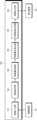
映像表示システム10は、1台の撮像装置20により撮像されて情報処理装置100に入力される映像(以下、入力映像と称する。)に対象物の位置や動作などに応じて情報処理装置100が処理を施して、入力映像中の所定の領域を表示装置30に表示させるものである。入力映像は表示装置30に表示すべき被写体を全て含んだ映像である必要がある。図1に示すように本実施の形態においては、表示装置30に3つの筆記板である第1筆記板1、第2筆記板2、第3筆記板3を表示させるため、撮像装置20は第1筆記板1、第2筆記板2、第3筆記板3の全てを画角(撮像領域)内に収めるように設けられている。そして、筆記板を用いて講義を行う人物Tを特許請求の範囲における対象物として、その人物Tの位置、動きに合わせて3つの筆記板のうちのいずれかを表示装置30に表示させる。
The
第1の実施の形態においては、映像表示システム10は、対象物としての人物Tが第1筆記板1の前に立っている場合、表示装置30には第1筆記板1を表示させる。また、人物Tが移動して第2筆記板2の前に立っている場合、表示装置30には第2筆記板2を表示させる。さらに、人物Tが第3筆記板3の前に立っている場合、表示装置30には第3筆記板3を表示させる。なお、筆記板とは例えば、黒板、ホワイトボードなど文字、図表、絵などを描くことができる板状部材である。本実施の形態はこのように筆記板と筆記板の前の立つ講師などの人物を例にして説明を行うが、本技術はそのような利用態様に限られるものではない。
In the first embodiment, the
撮像装置20は動画撮影可能なデジタルビデオカメラまたは、動画撮影可能な機能を備えるパーソナルコンピュータ、タブレット端末、スマートフォンなどの電子機器である。撮像装置20は、パンチルト動作はせずに、図1に示すように画角内に表示装置30に表示させる被写体としての3つの筆記板、第1筆記板1、第2筆記板2、第3筆記板3を収めることができるように設けられている。撮像装置20は、ユーザの映像表示システム10の利用時においては、撮像した入力映像のデータを常に情報処理装置100に供給し続ける。
The
表示装置30は、例えば、LCD(Liquid Crystal Display)、PDP(Plasma Display Panel)、有機EL(Electro Luminescence)パネルなどにより構成された表示デバイスである。表示装置30には、撮像装置20で撮像された入力映像中における所定の領域が対象物の位置や動作などに応じて表示される。
The
情報処理装置100は、撮像装置20が撮像した入力映像に対して本技術に係る映像処理を施して、入力映像中の所定の領域を表示する領域として決定して表示装置30に表示させるものである。情報処理装置100は、撮像装置20により撮像された入力映像をリアルタイムに処理することも可能であるし、撮像完了後に映像コンテンツに対して処理を行うことも可能である。
The
情報処理装置100は、例えば、パーソナルコンピュータ、タブレット端末、スマートフォンなどの電子機器で構成されている。情報処理装置100はプログラムで構成され、そのプログラムは、予め電子機器内にインストールされていてもよいし、ダウンロード、記憶媒体などで配布されて、ユーザが自らインストールするようにしてもよい。また、情報処理装置100は、プログラムによって実現されるのみでなく、その機能を有するハードウェアによる専用の装置、回路などを組み合わせて実現されてもよい。なお、撮像装置20が情報処理装置100としての機能を備え、または、表示装置30が情報処理装置100としての機能を備え、撮像装置20と表示装置30とが直接接続されていてもよい。
The
[1-2.情報処理装置の構成]
次に図2のブロック図を参照して情報処理装置100の構成について説明する。情報処理装置100は、映像入力部110、領域設定部120、特徴量取得部130、特徴量比算出部140、注視領域合成部150、映像出力部160とから構成されている。[1-2. Configuration of information processing device]
Next, the configuration of the
映像入力部110には撮像装置20から供給された入力映像のデータが入力され、映像入力部110から領域設定部120に入力映像のデータが供給される。なお、映像入力部110から領域設定部120には入力映像を構成する連続する一連のフレーム画像が再生順序に従って順に供給される。領域設定部120以降における一連の処理は、入力映像を構成する連続する一連のフレーム画像にそれぞれに対して行われる。フレーム画像のそれぞれに対して処理を施し、処理が施されたフレーム画像(以下、合成フレーム画像と称する)を順次表示装置30に供給する。連続する一連の合成フレーム画像が再生順序に従って表示されることにより、表示装置30では情報処理装置100により処理が施された映像が表示されることになる。
The
領域設定部120は、予めユーザからの入力により決定されている注視領域と検出領域とを入力映像を構成するフレーム画像のそれぞれに対して設定するものである。ユーザは、映像表示システム10を利用する前に注視領域と検出領域とを情報処理装置100に入力しておく必要がある。注視領域と検出領域の入力方法と入力用ユーザインターフェースについては後述する。
The
注視領域とは、入力映像中から切り出して表示装置30に表示させる領域であり、注視領域の位置、形状、サイズおよび数はユーザが任意に決定することができる。本実施の形態においては、図1に示すように、3つの筆記板のそれぞれに対して、第1筆記板1を含むように注視領域A、第2筆記板2を含むように注視領域B、第3筆記板3を含むように注視領域Cが予めユーザにより決定されているとする。
A gaze area is an area cut out from the input image and displayed on the
また、それら注視領域のそれぞれに対応するようにフレーム画像に対して検出領域が設定される。図1に示すように、注視領域Aに対しては検出領域a、注視領域Bに対しては検出領域b、注視領域Cに対しては検出領域cが予めユーザにより決定されて、それが領域設定部120によりフレーム画像に設定される。検出領域とは、それぞれの注視領域と対応させるように注視領域ごとに設定され、どの注視領域を表示装置30に表示させるかの判断となる特徴量を検出するための領域である。この特徴量により把握される検出領域内の状態が特許請求の範囲における「状態」に相当するものである。なお、検出領域は注視領域に重なっている必要はなく、一つの注視領域に一つの検出領域が対応さえしていれば、検出領域の位置、形状およびサイズはユーザが自由に決定することができる。
Also, a detection area is set for the frame image so as to correspond to each of these gaze areas. As shown in FIG. 1, the user predetermines a detection area a for the gaze area A, a detection area b for the gaze area B, and a detection area c for the gaze area C. The frame image is set by the
第1の実施の形態においては、どの注視領域を表示装置30に表示させる領域として決定するかは人物Tの位置に対応させるため、図1に示すように、検出領域は対応する注視領域の横方向の一端から他端までに及ぶ領域として予めユーザにより決定されているとする。なぜなら人物Tは筆記板の前において横方向に移動するからである。横方向とは、人物Tが歩くことにより移動可能な方向、筆記板の幅方向と同方向である。
In the first embodiment, which gaze area is determined as the area to be displayed on the
本実施の形態においては、人物Tが第1筆記板1の前、すなわち検出領域aの前に立っている場合は入力映像から注視領域Aを切り出して表示装置30に表示させる。人物Tが第2筆記板2の前、すなわち検出領域bの前に立っている場合は入力映像から注視領域Bを切り出して表示装置30に表示させる。人物Tが第3筆記板3の前、すなわち検出領域cの前に立っている場合は入力映像から注視領域Cを切り出して表示装置30に表示させる。
In this embodiment, when the person T stands in front of the
領域設定部120により設定された注視領域と検出領域を示す情報は入力映像データと共に特徴量取得部130に供給される。
Information indicating the region of interest and the detection region set by the
図2の説明に戻る。特徴量取得部130は、検出領域から特徴量を取得するものである。特徴量とは、どの注視領域を表示装置30に表示させる領域として決定するかの判断に用いるものである。特徴量の第1の例は、各検出領域内における人物Tの存在領域を構成する画素の数である。特徴量取得部130は、まず、公知の被写体検出技術などを用いて処理対象のフレーム画像から人物Tの存在領域を検出する。被写体検出方法としては、テンプレートマッチングによる物体検出技術、被写体の輝度分布情報に基づくマッチング方法、画像に含まれる肌色の部分や人間の顔の特徴量等に基づく方法などを用いてもよい。また、これらの手法を組み合わせて認識精度を高めるようにしてもよい。
Returning to the description of FIG. The feature
そして、各検出領域内における人物Tの存在領域を構成する画素数を計測することにより特徴量を取得する。特徴量取得部130により取得された特徴量は入力映像データと共に特徴量比算出部140に供給される。
Then, the feature amount is acquired by measuring the number of pixels forming the presence area of the person T in each detection area. The feature amount acquired by the feature
特徴量比算出部140は、検出領域ごとに取得された特徴量を用いて、全ての検出領域を合わせた全検出領域に対する各検出領域における人物Tの特徴量の割合を算出する。この割合は、例えば、全検出領域における人物Tの全画素数の割合を1.0として算出するものである。特徴量比算出部140により算出された特徴量の割合は入力映像データ、注視領域および検出領域情報と共に注視領域合成部150に供給される。
The feature amount
例えば、図3Aに示すように、人物Tが第1筆記板1の前に立っており、検出領域aにのみ人物Tの特徴量が存在する場合、検出領域全体に対する検出領域aに占める特徴量の割合は1.0となり、検出領域bと検出領域cの特徴量の割合はともに0となる。また、図3Bに示すように、人物Tが第2筆記板2の前に立っており、検出領域bにのみ人物Tの特徴量が存在する場合、検出領域全体に対する検出領域bに占める特徴量の割合は1.0となり、検出領域aと検出領域cの特徴量の割合はともに0となる。さらに、人物Tが第3筆記板3の前に立っており、検出領域cにのみ人物Tの特徴量が存在する場合、検出領域全体に対する検出領域cに占める特徴量の割合は1.0となり、検出領域aと検出領域bの特徴量の割合はともに0となる。
For example, as shown in FIG. 3A, when a person T is standing in front of the
また、図4Aに示すように、人物Tが第1筆記板1と第2筆記板2とにまたがって存在している場合、図4Bに示すように人物Tは注視領域Aと注視領域Bの両方、さらに検出領域aと検出領域bの両方にまたがって存在することになる。図4Bは注視領域Aと注視領域B、検出領域aと検出領域bとを分離させて示したものである。この場合、検出領域aにも検出領域bにも特徴量が存在することになり、全検出領域内に存在する人物Tの全画素数の割合を1.0として、検出領域a内の人物Tの画素数が2500であり、検出領域b内の人物Tの画素数が7500だとすると、図4Cに示すように、特徴量の割合は「検出領域a:0.25」、「検出領域b:0.75」となる。このように画素数の割合から特徴量の割合を算出する。なお、人物Tが存在していない検出領域cの特徴量の割合は0である。このようにして特徴量比算出部140は各検出領域における特徴量の割合を算出する。
Also, as shown in FIG. 4A, when the person T exists across the
注視領域合成部150は、入力映像を構成するフレーム画像中に存在する全ての注視領域を切り出して、特徴量比算出部140で算出された各検出領域における特徴量の割合に基づいて全ての注視領域を合成するものである。注視領域合成部150の合成処理により作成された合成フレーム画像が再生順序に従って表示装置30に供給されて表示されることにより、情報処理装置100により処理が施された映像が表示されることになる。
The gaze
図1の例をもとに注視領域の合成について説明する。注視領域の合成は各注視領域を構成する全ての画素ごとに、特徴量の割合に基づいて注視領域A、注視領域B、注視領域Cを合成することにより行われる。まず、注視領域合成部150はフレーム画像中から注視領域A、注視領域B、注視領域Cを切り出す。
Synthesis of gaze areas will be described based on the example in FIG. The gazing area synthesis is performed by synthesizing the gazing area A, the gazing area B, and the gazing area C on the basis of the ratio of the feature amounts for all the pixels constituting each gazing area. First, the gaze
次に、各注視領域に対応する検出領域における特徴量の割合から注視領域の合成を行う。ここで、注視領域Aに対応する検出領域aにおける特徴量の割合をL、注視領域Bに対応する検出領域bにおける特徴量の割合をM、注視領域Cに対応する検出領域cにおける特徴量の割合をNとする。 Next, a region of interest is synthesized from the ratio of the feature amount in the detection region corresponding to each region of interest. Here, L is the ratio of the feature amount in the detection area a corresponding to the gaze area A, M is the ratio of the feature amount in the detection area b corresponding to the gaze area B, and M is the ratio of the feature amount in the detection area c corresponding to the gaze area C. Let N be the ratio.
また、図5に示すように、注視領域A内における点(x,y)における画素値をIA(x,y)とし、注視領域B内における同一の点(x,y)における画素値をIB(x,y)とし、注視領域C内における同一の点(x,y)における画素値をIC(x,y)とする。そうすると、最終的に表示装置30に出力する合成フレーム画像における同一の点(x,y)における画素値I(A+B+C)(x,y)は下記の式1で表すことができる。Also, as shown in FIG. 5, let the pixel value at a point (x, y) in the region of interest A be I A (x, y), and let the pixel value at the same point (x, y) in the region of interest B be I A (x, y). Let I B (x, y) be the pixel value at the same point (x, y) in the region of interest C, and let I C (x, y) be the pixel value. Then, the pixel value I (A+B+C) ( x, y) at the same point (x, y) in the synthesized frame image that is finally output to the
[式1]
I(A+B+C)(x,y)
=L・IA(x,y)+M・IB(x,y) +N・IC(x,y)[Formula 1]
I (A+B+C) (x,y)
=L · I A (x, y) + M · I B (x, y) + N · I C (x, y)
この処理により、点(x,y)における画素について、特徴量の割合に応じて全ての注視領域が合成された状態を得ることができる。これを注視領域を構成する全ての画素について行うことにより、注視領域A、注視領域B、注視領域Cを特徴量の割合に応じて合成した合成フレーム画像を得ることができる。 By this processing, it is possible to obtain a state in which all the gaze areas are combined according to the ratio of the feature amount for the pixel at the point (x, y). By performing this for all the pixels forming the gaze area, it is possible to obtain a synthesized frame image in which the gaze area A, the gaze area B, and the gaze area C are synthesized according to the ratio of the feature amount.
例えば図1に示すように、人物Tが第1筆記板1の前、すなわち検出領域aの前にいる場合、全検出領域に対する各検出領域における特徴量の割合は、
検出領域a:特徴量の割合L=1.0
検出領域b:特徴量の割合M=0.0
検出領域c:特徴量の割合N=0.0
となる。この特徴量の割合を式1に代入すると、合成フレーム画像における点(x,y)における画素値I(A+B+C)(x,y)は下記の式2のようになる。For example, as shown in FIG. 1, when a person T is in front of the
Detection area a: feature amount ratio L = 1.0
Detection region b: feature amount ratio M=0.0
Detection area c: feature amount ratio N=0.0
becomes. Substituting this feature amount ratio into
[式2]
I(A+B+C)(x,y)
=1・IA(x,y)+0・IB(x,y)+0・IC(x,y)
=IA(x,y)[Formula 2]
I (A+B+C) (x,y)
= 1 · I A (x, y) + 0 · I B (x, y) + 0 · I C (x, y)
=I A (x, y)
検出領域a以外の検出領域は特徴量の割合が0であるため、注視領域A、注視領域B、注視領域Cにおける同一の点(x,y)の合成結果は注視領域Aにおける点(x,y)と同一となる。これを各注視領域を構成する全てに画素に対して行うことにより、注視領域A、注視領域B、注視領域Cを合成した合成フレーム画像を得ることができる。この例の場合、注視領域A、注視領域B、注視領域Cの合成結果は注視領域Aと同一のもの、すなわち、合成フレーム画像は注視領域Aと同一となる。この合成フレーム画像が表示装置30に送信される。これにより、人物Tが検出領域aの前に立っている場合、注視領域Aのみが表示装置30に表示されることになる。同様にして、人物Tが検出領域bの前に立っている場合は注視領域Bのみが表示装置30に表示され、人物Tが検出領域cの前に立っている場合は注視領域Cのみが表示装置30に表示されることになる。
Since the ratio of the feature amount is 0 in the detection areas other than the detection area a, the synthesis result of the same point (x, y) in the gaze area A, the gaze area B, and the gaze area C is the point (x, y) in the gaze area A. y). By performing this on all the pixels constituting each attention area, a composite frame image in which the attention areas A, B, and C are synthesized can be obtained. In this example, the result of synthesizing the gaze area A, the gaze area B, and the gaze area C is the same as the gaze area A, that is, the synthesized frame image is the same as the gaze area A. This synthesized frame image is transmitted to the
次に、人物Tが2つの検出領域にまたがって存在している場合について説明する。人物Tが一の注視領域から他の注視領域へ移動する場合、例えば、注視領域Aから注視領域Bへ移動している場合を考える。この場合、人物Tは注視領域Bへの移動が完了するまでは図4Aに示すように、検出領域aと検出領域bの両方にまたがって存在していることとなる。 Next, a case where a person T exists across two detection areas will be described. Let us consider a case where a person T moves from one gaze area to another gaze area, for example, from the gaze area A to the gaze area B. FIG. In this case, as shown in FIG. 4A, the person T exists across both the detection area a and the detection area b until the movement to the gaze area B is completed.
図4Bに示すように、人物Tが検出領域aと検出領域bの両方にまたがって存在している場合で、図4Cに示すように検出領域全体に対する各検出領域における特徴量の割合が、
検出領域a:特徴量の割合L=0.25
検出領域b:特徴量の割合M=0.75
検出領域c:特徴量の割合N=0.0
となっているとする。なお、検出領域cには人物Tは存在していないので、検出領域cの特徴量の割合は0となる。そして、注視領域Aにおける点(x,y)の画素値をIA(x,y)とし、注視領域Bにおける同一の点(x,y)の画素値をIB(x,y)とし、注視領域Cの同一の点(x,y)における画素値をIC(x,y)し、この特徴量の割合を式1に代入すると、合成フレーム画像における同一の点(x,y)における画素値I(A+B+C)(x,y)は下記の式3のようになる。As shown in FIG. 4B, when the person T exists across both the detection area a and the detection area b, the ratio of the feature amount in each detection area to the entire detection area as shown in FIG. 4C is
Detection area a: feature amount ratio L = 0.25
Detection area b: feature amount ratio M=0.75
Detection area c: feature amount ratio N=0.0
Suppose that In addition, since the person T does not exist in the detection area c, the ratio of the feature amount of the detection area c is zero. Let I A (x, y) be the pixel value of the point (x, y) in the region of interest A, and I B (x, y) be the pixel value of the same point (x, y) in the region of interest B, If the pixel value at the same point (x, y) in the gaze area C is I C (x, y) and the ratio of this feature amount is substituted into
[式3]
I(A+B+C)(x,y)
=0.25・IA(x,y)+0.75・IB(x,y)+0・IC(x,y)
=0.25・IA(x,y)+0.75・IB(x,y)[Formula 3]
I (A+B+C) (x,y)
= 0.25 I A (x, y) + 0.75 I B (x, y) + 0 I C (x, y)
= 0.25 · I A (x, y) + 0.75 · I B (x, y)
これは、合成フレーム画像における点(x,y)は、注視領域Aの点(x,y)の画素と注視領域Bの点(x,y)の画素とが特徴量の割合である「0.25:0.75」の割合で合成されたものであることを意味する。検出領域cは特徴量の割合が0であるため、注視領域Cの画素は合成されていない。 This is because the point (x, y) in the synthesized frame image is the ratio of the feature amount between the pixel of the point (x, y) in the region of interest A and the pixel of the point (x, y) in the region of interest B, which is "0 .25:0.75". Since the detection area c has a feature amount ratio of 0, the pixels of the attention area C are not synthesized.
これを各注視領域を構成する全てに画素に対して行うことにより、注視領域A、注視領域B、注視領域Cの合成結果である合成フレーム画像を得ることができる。この例の場合、図6に示すように、注視領域A、注視領域B、注視領域Cの合成結果は人物Tが存在している注視領域Aと注視領域Bとを特徴量の割合である「0.25:0.75」で合成したものとなる。よって、合成フレーム画像では注視領域A内の人物Tの一部と注視領域B内に人物Tの一部が共に存在しており、特徴量の割合に対応して人物Tの濃淡が異なっている。検出領域bに対応する注視領域B内の人物Tと、検出領域aに対応する注視領域A内の人物Tは共に入力映像よりも薄く表示され、さらに、特徴量の割合が大きい検出領域bに対応する注視領域B内の人物Tが特徴量の割合が小さい検出領域aに対応する注視領域A内の人物Tよりも濃く表示される。 By performing this on all the pixels forming each attention area, a synthesized frame image as a result of synthesizing the attention area A, attention area B, and attention area C can be obtained. In this example, as shown in FIG. 6, the combination result of the gaze area A, the gaze area B, and the gaze area C is the ratio of the feature amount between the gaze area A and the gaze area B in which the person T exists. 0.25:0.75". Therefore, in the synthesized frame image, both a part of the person T in the gaze area A and a part of the person T in the gaze area B are present, and the shading of the person T differs according to the ratio of the feature amount. . Both the person T in the gaze area B corresponding to the detection area b and the person T in the gaze area A corresponding to the detection area a are displayed lighter than the input image. The person T in the corresponding gaze area B is displayed darker than the person T in the gaze area A corresponding to the detection area a having a smaller feature amount ratio.
このように生成された合成フレーム画像が表示装置30に送信され、これにより、人物Tが検出領域aと検出領域bの前にまたがって存在している場合、注視領域Aと注視領域Bが合成された映像が表示装置30に表示されることになる。
The synthesized frame image generated in this way is transmitted to the
人物Tが検出領域aから検出領域bに移動していくと、人物Tの位置の変化に伴い、図7A乃至図7Eに示すように検出領域aの特徴量の割合は徐々に減っていき、検出領域bの特徴量の割合は徐々に増えていく。そして、図7Eに示すように人物Tの検出領域bへの移動が完了すると、検出領域bの特徴量の割合は1.0となり、検出領域aの特徴量の割合は0.0となる。検出領域bの特徴量の割合が1.0となり、検出領域aの特徴量の割合が0.0となると、合成フレーム画像の点(x,y)における画素値I(A+B+C)(x,y)は、式1を用いて下記の式4のようになる。As the person T moves from the detection area a to the detection area b, the ratio of the feature amount of the detection area a gradually decreases as shown in FIGS. The ratio of the feature amount of the detection region b gradually increases. Then, as shown in FIG. 7E, when the movement of the person T to the detection area b is completed, the ratio of the feature amount of the detection area b becomes 1.0, and the ratio of the feature amount of the detection area a becomes 0.0. When the ratio of the feature amount of the detection area b is 1.0 and the ratio of the feature amount of the detection area a is 0.0, the pixel value I (A+B+C) at the point (x, y) of the synthesized frame image is Using
[式4]
I(A+B+C)(x,y)=0+1・IB(x,y)+0=IB(x,y)[Formula 4]
I (A+B+C) (x, y) = 0 + 1 · I B (x, y) + 0 = I B (x, y)
このように、注視領域A、注視領域B、注視領域Cにおける同一点(x,y)の合成結果は注視領域Bにおける点(x,y)と同一となり、合成フレーム画像は注視領域Bと同一になる。よって、表示装置30には注視領域Bのみが表示されることになる。なお、図7では、人物Tの注視領域Aから注視領域Bへの移動を5つの図で表しているが、特徴量の取得と特徴量の割合の算出はこのように飛び飛び間隔で行っているのではなく、連続するフレーム画像の全てにおいて行っている。
In this way, the synthesis result of the same point (x, y) in the gaze area A, the gaze area B, and the gaze area C is the same as the point (x, y) in the gaze area B, and the synthesized frame image is the same as the gaze area B. become. Therefore, only the gaze area B is displayed on the
この合成処理を、映像を構成する一連のフレーム画像全てに対して行うことにより、注視領域Aから注視領域Bへの人物Tの移動、すなわち検出領域aと検出領域bにおける特徴量の変化に対応して、注視領域Aから注視領域Bに徐々に滑らかに変化していく映像を得ることができる。 By performing this synthesizing process on all the series of frame images that make up the video, it is possible to cope with the movement of the person T from the gaze area A to the gaze area B, that is, the change in the feature amount in the detection area a and the detection area b. As a result, an image that gradually and smoothly changes from the gaze area A to the gaze area B can be obtained.
人物Tが注視領域Aから注視領域Bへ素早く動けば検出領域aと検出領域bにおける特徴量の割合の変化も早くなるため、表示装置30における注視領域Aから注視領域Bへ表示の切り替わりも早く行われることになる。一方、人物Tが注視領域Aから注視領域Bへゆっくりと動けば検出領域aと検出領域bにおける特徴量の割合の変化もゆっくりになるため、表示装置30における注視領域Aから注視領域Bへ表示の切り替わりもゆっくり行われることになる。 If the person T quickly moves from the gaze area A to the gaze area B, the change in the ratio of the feature amount between the detection area a and the detection area b becomes quicker. will be done. On the other hand, if the person T moves slowly from the gaze area A to the gaze area B, the change in the ratio of the feature amount between the detection area a and the detection area b becomes slow. switching is also performed slowly.
これは、人物Tの注視領域Bから注視領域Cへの移動、注視領域Cから注視領域Bへの移動、注視領域Bから注視領域Aへの移動においても同様である。 This is the same when the person T moves from the gaze area B to the gaze area C, moves from the gaze area C to the gaze area B, and moves from the gaze area B to the gaze area A.
なお、人物Tがいずれか1つの注視領域から他の注視領域に移動しない限り、全ての検出領域における特徴量は変わらないため、表示装置30に表示される注視領域は切り替わらない。人物Tが注視領域Aに存在し続ける場合、表示装置30には注視領域Aが表示され続ける。
As long as the person T does not move from any one gaze area to another gaze area, the feature amounts in all the detection areas do not change, so the gaze area displayed on the
図2の説明に戻る。映像出力部160は、上述の処理が施されて生成された合成フレーム画像を表示順序に従って順次表示装置30に送信する。これにより情報処理装置100で処理が施された映像が表示装置30において表示される。なお、映像出力部160は、処理を施した合成フレーム画像単位で表示装置30に送信してもよいし、複数の合成フレーム画像をある程度の長さの映像データとして表示装置30に送信してもよい。
Returning to the description of FIG. The
以上のようにして情報処理装置100が構成されている。
The
[1-3.情報処理装置による処理]
次に図8のフローチャートを参照して、情報処理装置100により行われる処理の流れを説明する。まずステップS11で、映像表示システム10を利用するユーザにより入力された注視領域および検出領域の情報を保持する。[1-3. Processing by information processing device]
Next, the flow of processing performed by the
ユーザからの処理開始を指示する入力があると、次にステップS12で映像処理が開始される。これ以降の処理は撮像装置20から供給される入力映像を構成するフレーム画像ごとに行われる。
When the user inputs an instruction to start processing, next step S12 starts video processing. Subsequent processing is performed for each frame image forming the input video supplied from the
次にステップS13で特徴量取得部130が各検出領域における特徴量を取得し、その特徴量を特徴量比算出部140に供給する。次にステップS14で、特徴量比算出部140が特徴量の検出領域ごとの特徴量の割合を算出し、その特徴量割合を示す情報を注視領域合成部150に供給する。
Next, in step S<b>13 , the feature
次にステップS15で、注視領域合成部150が検出領域における特徴量の割合に応じて注視領域の合成処理を行って合成フレーム画像を作成する。そしてステップS16で映像出力部160が合成フレーム画像を表示装置30に送信する。表示装置30において合成フレーム画像が映像を構成する一連のフレーム画像として表示されることにより、表示装置30に映像が表示される。
Next, in step S15, the attention
次にステップS17で、ユーザから処理終了を指示する入力があったか否かが判定され、終了を指示する入力がない限りステップS13乃至ステップS17が繰り返されて表示装置30に映像が表示され続ける。ステップS17でユーザから処理終了を指示する入力があった場合、処理は終了となり、表示装置30における映像の表示が終了する。
Next, in step S17, it is determined whether or not there is an input from the user to instruct the end of processing. If the user inputs an instruction to end the process in step S17, the process ends and the image display on the
本技術の第1の実施の形態は以上のようにして処理を行う。第1の実施の形態によれば、一台の撮像装置20で撮像した映像を用いて、まるで複数台の撮像装置で撮像したかのような映像を表示装置30に表示させることができる。その際、検出領域における特徴量を用いることで、表示装置30に表示させる映像中の領域の切り替えを自動で行うことができる。
The first embodiment of the present technology performs processing as described above. According to the first embodiment, by using an image captured by one
また、検出領域と特徴量を用いて表示装置30に表示させる映像中の領域の切り替えを行うことにより、表示領域の切り替えを滑らかに行うことができる。本技術を用いることにより、あらゆる映像制作現場での撮像装置などの機材コスト削減や、映像切り替えに伴う編集コストの削減を図ることができる。なお、情報処理装置100による処理は、撮像装置20からリアルタイムに供給される入力映像に対して行うだけでなく、撮像終了後に映像コンテンツに対しても行うことができ、その処理が施された映像をアーカイブとして映像配信することも可能である。
In addition, by switching the area in the image displayed on the
なお、検出領域は必ずしも図1のように設定する必要はない。これはあくまで人物Tの動きに合わせた注視領域の表示を実現するための設定である。例えば常に3つの筆記板のうち追記されたり、消されたりした筆記板を自動選択して切り替えたい場合は、検出領域をそれぞれの筆記板の大きさに合わせて設定し、それぞれの検出領域内の板面内容の変化を特徴量とすればよい。 Note that it is not always necessary to set the detection area as shown in FIG. This is a setting for realizing the display of the gaze area in accordance with the movement of the person T to the last. For example, if you always want to automatically select and switch between the three writing boards that have been added or erased, set the detection area according to the size of each writing board, and A change in the content of the board surface may be used as a feature amount.
なお、注視領域と検出領域とは必ずしも重なるように設定される必要もない。注視領域とそれに対応する検出領域とは、離れた状態で設定されてもよい。さらに、図1に示したように、注視領域は必ずしも入力映像中の特定の領域を切り出すように設定する必要はなく、入力映像全体を注視領域として設定してもよい。例えば図9に示すように、入力映像に対して注視領域A、注視領域Cを設定し、さらに入力映像の画角と同サイズの注視領域Bを設定し、それぞれの注視領域と重ならないように検出領域a、検出領域b、検出領域cを設定してもよい。このように注視領域と検出領域を設定した場合、第2ディスプレイ前に人物Tが存在する場合には検出領域bにのみ特徴量が存在し、注視領域Bの範囲の映像、すなわち入力映像と同じ映像が表示装置30に表示させることができる。このような例は、メディア放送用映像の撮像において有用である。
Note that the gaze area and the detection area do not necessarily have to be set so as to overlap. The gaze area and the corresponding detection area may be set apart. Furthermore, as shown in FIG. 1, the region of interest need not necessarily be set by cutting out a specific region in the input video, and the entire input video may be set as the region of interest. For example, as shown in FIG. 9, a gaze area A and a gaze area C are set for the input image, and a gaze area B having the same size as the angle of view of the input image is set so as not to overlap the respective gaze areas. A detection area a, a detection area b, and a detection area c may be set. When the gaze area and the detection area are set in this way, when the person T is present in front of the second display, the feature amount exists only in the detection area b, and the image in the range of the gaze area B, that is, the input image, is the same as the input image. An image can be displayed on the
<2.第2の実施の形態>
次に本技術の第2の実施の形態について説明する。図10は第2の実施の形態に係る情報処理装置200の構成を示すブロック図である。第2の実施の形態は、情報処理装置200が特徴量時間変化検出部210および注視領域連結部220を備える点で第1の実施の形態と相違する。それら以外の構成は第1の実施の形態と同様であるため、その説明を省略する。また、本実施の形態も図1と同様の具体例を用いて説明を行う。<2. Second Embodiment>
Next, a second embodiment of the present technology will be described. FIG. 10 is a block diagram showing the configuration of an
図11に示すように、人物Tが第1筆記板1と第2筆記板2の間に立ったままその場からしばらく移動しないような場合、すなわち、人物Tが2つの検出領域にまたがって存在している状態が継続し、特徴量の割合が変化しない場合を考える。
As shown in FIG. 11, when a person T stands between the
特徴量時間変化検出部210は特徴量比算出部140から特徴量の割合情報を随時受信しており、特徴量の割合の変化が所定時間以上ないことを検出するものである。この所定時間はユーザが任意に決定して情報処理装置100に設定できるものである。特徴量時間変化検出部210は、特徴量の割合の変化が所定時間以上ないことが検出した場合、それを注視領域連結部220に通知する。注視領域連結部220には入力映像データも供給される。
The feature amount time
注視領域連結部220は、人物Tが複数の検出領域にまたがっている状態が継続しており特徴量の割合が所定時間以上変化をしない場合、その複数の検出領域を連結して新たな注視領域(以下、連結注視領域と称する。)を作成するものである。注視領域連結部220による処理は、第1の実施の形態における注視領域合成部150の合成処理と同様に、入力映像を構成する連続する一連のフレーム画像に対して行われる。ここでは、図11に示すように、図1と同様の例において、人物Tが注視領域Aと注視領域Bの両方にまたがる位置に留まっている場合を例にして説明を行う。
If the state in which the person T is straddling a plurality of detection areas continues and the ratio of the feature amount does not change for a predetermined time or longer, the gaze
図12Aに示すように注視領域Aと注視領域Bの両方に重なるように人物Tが立っており、その状態が続くと、第1の実施の形態では注視領域A全体と注視領域B全体とが合成された状態が表示装置30に表示されることになる。そこで、第2の実施の形態においては、注視領域Aと注視領域Bに重なるように人物Tが存在し続けている場合、図12Bに示すようにその注視領域Aと注視領域Bの境界を略中心とした注視領域Aと注視領域Bを連結した連結注視領域Rを作成し、この連結注視領域Rを入力映像から切り出したフレーム画像を表示装置30に送信する。これにより、注視領域Aの一部と注視領域Bの一部を含む映像が表示装置30に表示されることになり、人物Tが立っている位置を略中心とした見やすい映像を表示装置30に表示させることができる。
As shown in FIG. 12A, a person T stands so as to overlap both the gaze area A and the gaze area B. If this state continues, in the first embodiment, the entire gaze area A and the entire gaze area B will overlap. The synthesized state is displayed on the
表示装置30における表示が注視領域Bが表示されている状態から即座に図12Bに示す連結注視領域Rが表示される状態に切り替わると視聴者に見づらさを感じさせたり、違和感を与えるおそれがある。よって、少しずつ注視領域の境界が中心にするような遷移過程をたどるようにするのが望ましい。図12の例では、人物Tが第2筆記板2側、すなわち注視領域B側に寄っており、検出領域aと検出領域bとでは検出領域bのほうが特徴量の割合が大きいので注視領域B側から注視領域A側へ少しずつ表示が遷移していくようにする。
If the display on the
その際の表示装置30に表示される範囲である連結注視領域Rの遷移は図13に示すようになる。図13Aから図13Fに示すように、特徴量の割合が大きい検出領域bに対応する注視領域B側から注視領域A側に向かって連結注視領域Rが徐々に遷移していく。そして、最終的に図13Fに示すように、注視領域Aと注視領域Bの境界(連結部分)が連結注視領域Rの中央に位置するまで遷移する。
The transition of the connected gaze region R, which is the range displayed on the
なお、このとき、注視領域Aと注視領域Bの境界が連結注視領域Rの略中央に位置するまでの連結注視領域Rの遷移する速度は1フレーム画像ごとにどの程度連結注視領域Rが移動するかによって決定されるものである。1フレーム画像ごとの連結注視領域Rの移動距離が大きければ遷移速度は速くなり、1フレーム画像ごとの連結注視領域Rの移動距離が小さければ遷移速度は遅くなる。この遷移速度はユーザが任意で決めることができる。 At this time, the transition speed of the connected gaze region R until the boundary between the gaze region A and the gaze region B is positioned substantially at the center of the connected gaze region R is how much the connected gaze region R moves for each frame image. It is determined by whether If the moving distance of the connected region of interest R for each frame image is large, the transition speed will be fast, and if the moving distance of the connected region of interest R for each frame image is small, the transition speed will be low. This transition speed can be arbitrarily determined by the user.
この第2の実施の形態によれば、特徴量の検出対象である対象物が2以上の検出領域にまたがっており、かつ、特徴量が変化しない場合、その対象物を含んだ状態で2以上の注視領域を見やすい状態で表示装置30に表示させることができる。
According to the second embodiment, when an object whose feature amount is to be detected straddles two or more detection areas and the feature amount does not change, two or more can be displayed on the
なお、特徴量時間変化検出部210は特徴量の割合の変化が所定時間以上ないことを検出するだけでなく、特徴量の割合の変化が所定の上限と下限の閾値内であるかを検出するようにしてもよい。これにより、人物Tがわずかに動いてはいるが、複数の検出領域にまたがって存在し続けている場合も上記と同様に処理を行うことができる。
Note that the feature amount time
なお、特徴量が何れの検出領域においても一定時間以上検出されなかった場合には、その際に遷移すべき注視領域を予め設定しておき、その注視領域を表示装置30に表示させるか、入力映像全体を注視領域として表示装置30に表示させる、などの方法がある。
If the feature amount is not detected in any of the detection areas for a certain period of time or more, the gaze area to which the transition should be made is set in advance, and the gaze area is displayed on the
特徴量が何れの検出領域においても一定時間以上検出されなかった場合とは、一定時間以上対象物がどの検出領域にも存在していないということである。このような場合、その対象物(人物)や映像表示システム10の利用者に対して、音声メッセージ、メッセージ表示などで検出領域に入るように促す通知を行ってもよい。
A case where the feature amount has not been detected in any detection area for a certain period of time or longer means that the object has not been present in any detection area for a certain period of time or longer. In such a case, the object (person) or the user of the
<3.第3の実施の形態>
次に本技術の第3の実施の形態について説明する。図14は第3の実施の形態に係る情報処理装置300の構成を示すブロック図である。第3の実施の形態は、情報処理装置300が射影変換部310を備える点で第1の実施の形態と相違する。それ以外の構成は第1の実施の形態と同様であるため、その説明を省略する。<3. Third Embodiment>
Next, a third embodiment of the present technology will be described. FIG. 14 is a block diagram showing the configuration of an
射影変換部310は、撮像装置20のレンズに対する入射方向に正対していない注視領域に対して射影変換処理を施すものである。例えば、図15に示すように、長方形状の注視領域Bと、略平行四辺形状に設定された注視領域Aと注視領域Cがある場合、このまま注視領域合成部150により合成処理を行おうとすると、注視領域の形状が一致していないため、適切に合成処理を行うことができないおそれがある。そこで、第3の実施の形態では、注視領域が撮像装置20に正対しておらず正方形または長方形状ではない場合、射影変換部310により、その正対していない注視領域に対して射影変換処理を施す。図15の注視領域Cに対して射影変換処理を施すことにより、図16に示すように、注視領域Bと形状に合った長方形状の注視領域Cを得ることができる。これにより、第1の実施の形態と同様に注視領域合成処理を行うことができる。図示は省略するが、図15における注視領域Aについても射影変換処理を施すのが望ましい。
The
射影変換部310により注視領域に射影変換処理を施すか否かは、例えば、領域設定部120により設定された複数の注視領域のうち、注視領域を構成する4つの角のうち90度ではない角を有するか否かなどにより判断することができる。また、ユーザが射影変換処理を施す注視領域を具体的に状態で表示装置30への入力で指定してもよい。
Whether or not the
なお、情報処理装置300は、処理対象である映像を構成するフレーム画像が領域設定部120から特徴量取得部130および射影変換部310に供給されるように構成されている。よって、射影変換部310により注視領域に射影変換を施すのと並行して第1の実施の形態で説明したように特徴量取得部130および特徴量比算出部140による処理が行われる。そして、特徴量比算出部140による比較結果に基づいた注視領域合成処理が、射影変換が施された注視領域に対して行われる。
The
なお、射影変換部310による処理の後に複数の注視領域を注視領域合成部150で合成するため、射影変換部310で、出力映像の仕様に合わせて縦幅や横幅を拡大または縮小し、それぞれの注視領域を均一に調整する処理をさらに行ってもよい。
Note that since a plurality of gaze areas are combined by the gaze
この第3の実施の形態によれば、注視領域同士の形状が異なっていた場合でも射影変換処理により形状を一致させるので、注視領域同士の形状が異なっていたとしても注視領域合成処理を行って表示装置30に適切な状態で注視領域を表示させることができる。
According to the third embodiment, even if the shapes of the gaze areas are different from each other, the shapes are matched by the projective transformation process. The attention area can be displayed in an appropriate state on the
なお、上述の第1乃至第3の実施の形態において、検出領域内における対象物の状態は、検出領域内における対象物を構成する画素の存在率(特徴量の割合)に基づいて求めることもでき、また、対象物の移動の状況に基づいて求めることもできる。検出領域内における対象物を構成する画素の存在率は図4乃至図7などを参照して説明した通りである。検出領域内における対象物を構成する画素の数を計測し、全ての検出領域を合わせた全検出領域に対する各検出領域における対象物の画素の割合を算出することにより求めることができる。この画素の存在率(特徴量の割合)に基づいて注視領域の切り替え、遷移を行うことができる。 In the above-described first to third embodiments, the state of the object within the detection area can also be obtained based on the existence ratio (ratio of feature amount) of the pixels forming the object within the detection area. It can also be determined based on the movement of the object. The existence ratio of the pixels forming the object within the detection area is as described with reference to FIGS. 4 to 7 and the like. It can be obtained by measuring the number of pixels forming the object in the detection area and calculating the ratio of the pixels of the object in each detection area to the total detection area including all the detection areas. The region of interest can be switched and transitioned based on the existence ratio of pixels (proportion of feature amount).
対象物の移動の状況に基づく場合、公知の速度検出技術を用いて対象物の移動速度を求め、その移動速度に応じて表示させる注視領域の切り替え、合成、遷移を行うようにする。対象物の移動速度を検出すれば対象物の移動速度から図7に示したのと同様に対象物の検出領域における位置と対象物の存在率(特徴量の割合)を得ることができ、それに基づいて注視領域の切り替え、合成、遷移を行うことができる。 When based on the moving state of the object, the moving speed of the object is obtained using a known speed detection technique, and switching, synthesizing, and transitioning of the gazing area to be displayed are performed according to the moving speed. If the moving speed of the object is detected, the position of the object in the detection area of the object and the presence ratio of the object (ratio of feature quantity) can be obtained from the moving speed of the object in the same way as shown in FIG. Based on this, it is possible to switch, synthesize, and transition the region of interest.
対象物の移動速度は例えば、入力映像を構成する一のフレーム画像とその次のフレーム画像とにおける対象物の位置の差とフレームレートから求めることができる。また、撮像装置が備えるまたは撮像装置以外の装置としての速度センサにより対象物の速度を求めるようにしてもよい。速度センサとしては、レーザ光、マイクロ波、超音波などを測定対象(対象物)に当て、その反射波の周波数変化から速度を測定するものなどがある。 The moving speed of the object can be obtained, for example, from the difference in the position of the object between one frame image and the next frame image forming the input video and the frame rate. Alternatively, the speed of the object may be obtained by a speed sensor provided in the imaging device or as a device other than the imaging device. As a velocity sensor, there is a sensor that irradiates a measurement object (object) with laser light, microwaves, ultrasonic waves, etc., and measures the velocity from the frequency change of the reflected wave.
また、表示装置30への表示については、検出領域における上述した対象物の状態に応じて入力映像中に設定された複数の注視領域から表示させる注視領域を選択して切り替えるようにしてもよいし、対象物の状態に応じて注視領域を滑らかに遷移させるようにしてもよい。さらに、対象物の状態に応じて注視領域として入力映像から切り出す位置および範囲を変更して表示装置30に表示させてもよい。
Further, regarding the display on the
<4.ユーザインターフェースの例>
次に本技術を利用する際におけるユーザインターフェースの例について説明する。このユーザインターフェースは、情報処理装置100が備える表示部(図示せず。)または表示装置30などに表示されるものであり、ユーザが注視領域および検出領域を入力するためのものである。図17に示す注視領域および検出領域入力用ユーザインターフェースは注視領域入力ボタン402、検出領域入力ボタン403を備えている。ユーザから注視領域入力ボタン402に入力がなされるとユーザインターフェースは図17Aに示す注視領域入力モードに遷移する。また、ユーザから検出領域入力ボタン403に入力がなされるとユーザインターフェースは図17Bに示す検出領域入力モードに遷移する。<4. Example of user interface>
Next, an example of a user interface when using this technology will be described. This user interface is displayed on a display unit (not shown) provided in the
図17Aに示す注視領域入力モードは、撮像領域表示領域401、注視領域入力ボタン402、検出領域入力ボタン403、領域追加ボタン404、領域削除ボタン405を備えている。
The gaze area input mode shown in FIG. 17A includes an imaging
注視領域入力モードに遷移後、ユーザはマウスカーソル、スタイラスペン、自らの指などで撮像領域表示領域401内を指定することで4点を指定して注視領域を示す注視領域アイコン410を表示させることができる。注視領域アイコン410は矩形の枠と、枠の4つの角にそれぞれ設けられた点とから構成されている。注視領域アイコン410を示す構成する点をクリックして移動させることにより注視領域の形状、サイズを変更することができ、注視領域アイコン410内部をクリックして移動させることにより注視領域の位置を変更することができる。
After transitioning to the gaze area input mode, the user designates four points within the imaging
注視領域の形状、サイズおよび位置が決定するとユーザは領域追加ボタン404に対して入力を行う。これにより、注視領域情報が情報処理装置100内に保存されることになる。一度決定した、またはサイズおよび位置の調整中の注視領域を削除する場合、ユーザは領域削除ボタン405に対して入力を行う。
After determining the shape, size and position of the gaze area, the user makes an input to the
検出領域入力モードに遷移後、ユーザがマウスカーソルなどで撮像領域表示領域401内を指定することで4点を指定して検出領域を示す検出領域アイコン420を表示させることができる。検出領域アイコン420は矩形の枠と枠の4つの角にそれぞれ設けられた点とから構成されている。検出領域アイコン420を示す構成する点をクリックして移動させることにより検出領域の形状、サイズを変更することができ、検出領域アイコン420内部をクリックして移動させることにより検出領域の位置を変更することができる。
After transitioning to the detection area input mode, the user can specify four points within the imaging
注視領域の形状、サイズおよび位置が決定するとユーザは領域追加ボタン404に対して入力を行う。これにより、検出領域情報が情報処理装置100内に保存されることになる。一度決定した、またはサイズおよび位置の調整中の検出領域を削除する場合、ユーザは領域削除ボタン405に対して入力を行う。
After determining the shape, size and position of the gaze area, the user makes an input to the
また、検出領域入力モードにおいては、特徴量がどの検出領域においても検出されなかった場合の情報処理装置100の動作を選択する動作項目406が表示される。オーバービューは撮像装置20による撮像領域全体、すなわち情報処理装置100に入力される映像全体を表示させるものである。プリセットは、ユーザの任意により決定されたように、または情報処理装置100において予め設定されたように情報処理装置100を動作させるものである。
Also, in the detection area input mode, an
また、検出領域入力モードにおいては、特徴量の検出対象である対象物を選択するための被写体選択ボタン407が設けられている。
In addition, in the detection area input mode, a
なお、図17に示したユーザインターフェースはあくまで一例であり、ユーザインターフェースはこれに限られるものではない。また、注視領域および検出領域は四角形状に限られるものではなく、三角形状や五角形以上の多角形状、円状でもよい。 Note that the user interface shown in FIG. 17 is merely an example, and the user interface is not limited to this. Moreover, the gaze area and the detection area are not limited to a quadrilateral shape, and may be a triangular shape, a polygonal shape having a pentagon or more, or a circular shape.
<5.本技術の利用態様の具体例>
[5-1.第1の利用態様]
次に本技術の利用態様の具体例について説明する。本技術は、図18に示すような広い教室や会議室などにおける講演や講義(以下、講演とする)において有用である。本技術利用のために、外部表示装置501に表示するホワイトボード502全体を撮像装置503で撮像する必要がある。情報処理装置100は教壇などに設置しておき、事前に撮像装置503と外部表示装置501と接続しておく。講師は講演の前に事前に注視領域と検出領域を決定して情報処理装置100に入力しておく。<5. Concrete examples of usage modes of the present technology>
[5-1. First usage mode]
Next, a specific example of a usage mode of the present technology will be described. This technology is useful in lectures and lectures (hereinafter referred to as lectures) in large classrooms and conference rooms as shown in FIG. In order to use this technology, it is necessary to image the
講演を開始する際に教壇などにあるシステム起動スイッチ504をオンにすることにより、本技術に係る情報処理装置100による処理が開始される。撮像装置503によって撮影された講演の入力映像に対して情報処理装置100による処理が行われ、処理が施された映像がリアルタイムに外部表示装置501に表示される。図のように大きな会場において講師から離れた位置にいる受講者にとっては、外部表示装置501に映し出された映像が補助映像として機能し、講演が見やすくなる。また、遠隔地へのリアルタイムの映像配信にも本技術を利用することができる。さらに情報処理装置100で作成された映像を記録して講演終了後にはアーカイブとして映像配信することも可能である。講演終了時には、システム起動スイッチをオフにすることにより処理および収録を終了する。
When starting a lecture, the processing by the
[5-2.第2の利用態様]
第1の実施形態では、筆記板の前に特徴量の検出対象である対象物としての1人の人物Tが立っている例を用いて説明を行った。しかし、本技術はそのような例以外にも利用可能である。例えば、図19に示すように、講演や講義において複数の聴講者を撮像する場合にも利用することができる。[5-2. Second usage mode]
In the first embodiment, an example has been described in which a single person T is standing in front of a writing board as an object for which feature amounts are to be detected. However, the present technology can be used beyond such examples. For example, as shown in FIG. 19, it can also be used to capture images of a plurality of listeners in a lecture.
図19の例では、聴衆者全体を撮像装置20で撮像し、聴衆者が座っている位置などに基づいて、複数の聴衆者を囲う範囲を注視領域A、注視領域B、注視領域Cとして設定する。さらにそれら注視領域に対応するように、各注視領域内の聴衆者全員が含まれるように検出領域a、検出領域b、検出領域cを設定する。そして、聴講者の立ち上がり具合を特徴量して、第1乃至第3の実施の形態と同様の処理を行う。この聴衆者の立ち上がり具合が特許請求の範囲における「変化の度合い」の一例である。なお、聴衆者の立ち上がり具合は、公知の姿勢検出技術により得ることができるし、公知の顔検出技術により検出した顔の位置の変化などによっても得ることができる。
In the example of FIG. 19, an image of the entire audience is captured by the
表示装置30において表示される映像の遷移は図20に示すようになる。聴衆者全員が座っている場合、特徴量は検出されないため、図20Aに示すように表示装置30には入力映像を表示する。注視領域Cの聴衆者Sが立ち上がると、その立ち上がり具合が特徴量として検出され、その特徴量に応じて全体領域と注視領域Cとが合成されて合成フレーム画像が作成される。そして合成フレーム画像が表示装置30に送信されて、一連の合成フレーム画像が映像として表示される。
The transition of the video displayed on the
いずれの検出領域にも特徴量が検出されない場合を図20Aの初期状態としており、その際には入力映像と同じ入力映像が表示されるようにしている。注視領域Cの聴衆者Sが立ち上がると、立ち上がり具合を特徴量としてその特徴量の変化に応じて、図20Bから図20Dに示すように入力映像と注視領域Cとが合成されて、最終的に図20Eに示すように注視領域Cのみが表示装置30に表示される。この後、例えば注視領域Aに存在する聴衆者が立ち上がった場合、表示装置30における表示は注視領域Cから注視領域Aに切り替わることになる。
The initial state in FIG. 20A is the case where no feature amount is detected in any of the detection areas, and the same input video as the input video is displayed in this case. When the listener S in the gaze area C stands up, the input image and the gaze area C are synthesized as shown in FIGS. Only the gaze area C is displayed on the
この利用態様により、例えば、公演での質疑等において聴講者が発言する際のその聴講者がいる注視領域を切り出して表示装置30に表示することができる。これにより、聴衆者の中の誰が発言するかわからない状態であっても発言する聴衆者を自動的に表示装置30に表示させることができる。
With this usage mode, for example, when an audience member speaks during a question-and-answer session at a performance, it is possible to cut out and display on the
<6.変形例>
以上、本技術の実施の形態について具体的に説明したが、本技術は上述の実施の形態に限定されるものではなく、本技術の技術的思想に基づく各種の変形が可能である。<6. Variation>
Although the embodiments of the present technology have been specifically described above, the present technology is not limited to the above-described embodiments, and various modifications based on the technical idea of the present technology are possible.
特徴量の検出対象である対象物は、公知の被写体検出技術により入力映像中から検出されたものでもよいし、予めユーザが指定したものでもよい。ユーザが予め対象物を指定する方法としては、例えば、公知の被写体認識技術により認識した被写体を表示装置30などに表示してユーザに提示し、その中からユーザが対象物を選択して決定する入力を行う方法がある。また、ユーザが入力映像中の領域を枠アイコンなどで指定して、その枠アイコン内に存在する被写体を特徴量の検出対象である対象物にするという方法もある。また、対象物は、人物に限らず、動物、乗り物、ロボットなど動くものであればどのようなものであってもよい。
The target object for which the feature amount is to be detected may be detected from the input image by a known subject detection technique, or may be specified by the user in advance. As a method for the user to designate an object in advance, for example, an object recognized by a known object recognition technology is displayed on the
図21に示すように、情報処理装置は、第1、第2、第3の実施の形態を組み合わせて、特徴量時間変化検出部210、注視領域連結部220および射影変換部310を備える情報処理装置400のように構成してもよい。
As shown in FIG. 21, the information processing apparatus combines the first, second, and third embodiments, and includes an
また、本技術では表示装置30に入力映像中に設定された複数の注視領域のうちのいずれかが表示されるが、どの注視領域が現在表示されているのかを視聴者が把握したい場合がある。そこで図22に示すように、補助機能として複数の注視領域のうちのどの注視領域を現在表示しているのかを示すアイコン600を表示装置30に表示するようにしてもよい。
In addition, in the present technology, one of a plurality of gaze areas set in the input video is displayed on the
アイコン600は、設定されている注視領域の数および注視領域の配列を示すように、各注視領域の位置関係が維持された状態で等分割された矩形状の四角形により構成されている。図22の例では、アイコンは3つの四角形で構成され、3つの注視領域が横並びに並んでいることを表している。図22Aに示すように、3つの注視領域のうち中央の注視領域が表示装置30に表示されている場合、アイコン600の中央の四角形が色付きで表示するとよい。これにより、視聴者は今現在表示装置30に表示されているのがどの注視領域であるかを把握することができる。また、図22Bに示すようにアイコン600と検出領域とを対応させて、それぞれの検出領域で検出される特徴量の割合をアイコン600の表示態様(色の濃淡など)の変化に反映させるようにしてもよい。これにより、視聴者は、特徴量の対象となる被写体が今現在どこにいるかを把握することができる。さらに、表示装置30に注視領域を示すアイコンおよび検出領域を示すアイコンの両方を表示するようにしてもよい。なお、アイコン600は四角形上に限られず、丸形状、三角形状などどのような形状でもよいし、文字により現在表示している注視領域をユーザに示すものでもよい。
The
第1乃至第3の実施の形態は撮像装置が1台である場合を例にして説明を行ったが、撮像装置の数は1つに限られるものではない。複数台の撮像装置を用いて映像表示システム10を構成してもよい。例えば図23に示すように、第1撮像装置701で注視領域Aを撮像し、第2撮像装置702で注視領域Bを撮像し、第3撮像装置703で注視領域Cを撮像し、第4撮像装置704で全ての注視領域を含む入力映像を撮像し、全ての撮像装置の映像データを情報処理装置100に供給する。情報処理装置100は、第4撮像装置704により撮像された入力映像から検出領域における特徴量を検出し、その特徴量に基づいていずれかの注視領域を表示装置30に表示させるようにする。
Although the first to third embodiments have been described using one imaging device as an example, the number of imaging devices is not limited to one. The
なお、本技術はリアルタイムで映像を処理する以外にも利用が可能である。例えば、録画済みの映像コンテンツを表示装置に表示させる際に本技術の処理を施すようにしてもよい。また、リアルタイムで映像に対して本技術の処理を施し、録画済み映像コンテンツのメタデータとして注視領域、検出領域、特徴量、注視領域の切り替え情報などを記録し、後からそのメタデータを用いることにより注視領域の位置や範囲、注視領域の切り替え速度などの編集を行えるようにしてもよい。その際、リアルタイムでの映像に対する処理はユーザの入力に従って行われてもよいし、情報処理装置100が被写体認識技術、テンプレートなどを用いて自動で行うようにしてもよい。さらに、映像を視聴する人物が表示装置に表示すべき被写体を全て含んだ入力映像から見たい任意の領域を注視領域として指定して視聴できるようにしてもよい。これは撮像装置をパンチルトさせる手法とは異なり、本技術における入力映像が表示すべき被写体を全て含んだ映像であるから可能となっている。
Note that this technology can be used for purposes other than processing video in real time. For example, the processing of the present technology may be performed when displaying recorded video content on a display device. In addition, this technology can be applied to video in real time, and the gaze area, detection area, feature amount, gaze area switching information, etc. can be recorded as metadata of the recorded video content, and the metadata can be used later. , the position and range of the gaze area, the switching speed of the gaze area, and the like may be edited. At this time, the processing of the video in real time may be performed according to the user's input, or may be automatically performed by the
<7.応用例>
本開示に係る技術は、様々な製品へ応用することができる。例えば、本開示に係る技術は、自動車、電気自動車、ハイブリッド電気自動車、自動二輪車、自転車、パーソナルモビリティ、飛行機、ドローン、船舶、ロボット、建設機械、農業機械(トラクター)などのいずれかの種類の移動体に搭載される装置として実現されてもよい。<7. Application example>
The technology according to the present disclosure can be applied to various products. For example, the technology according to the present disclosure can be applied to any type of movement such as automobiles, electric vehicles, hybrid electric vehicles, motorcycles, bicycles, personal mobility, airplanes, drones, ships, robots, construction machinery, agricultural machinery (tractors), etc. It may also be implemented as a body-mounted device.
図24は、本開示に係る技術が適用され得る移動体制御システムの一例である車両制御システム7000の概略的な構成例を示すブロック図である。車両制御システム7000は、通信ネットワーク7010を介して接続された複数の電子制御ユニットを備える。図24に示した例では、車両制御システム7000は、駆動系制御ユニット7100、ボディ系制御ユニット7200、バッテリ制御ユニット7300、車外情報検出ユニット7400、車内情報検出ユニット7500、及び統合制御ユニット7600を備える。これらの複数の制御ユニットを接続する通信ネットワーク7010は、例えば、CAN(Controller Area Network)、LIN(Local Interconnect Network)、LAN(Local Area Network)又はFlexRay(登録商標)等の任意の規格に準拠した車載通信ネットワークであってよい。
FIG. 24 is a block diagram showing a schematic configuration example of a
各制御ユニットは、各種プログラムにしたがって演算処理を行うマイクロコンピュータと、マイクロコンピュータにより実行されるプログラム又は各種演算に用いられるパラメータ等を記憶する記憶部と、各種制御対象の装置を駆動する駆動回路とを備える。各制御ユニットは、通信ネットワーク7010を介して他の制御ユニットとの間で通信を行うためのネットワークI/Fを備えるとともに、車内外の装置又はセンサ等との間で、有線通信又は無線通信により通信を行うための通信I/Fを備える。図24では、統合制御ユニット7600の機能構成として、マイクロコンピュータ7610、汎用通信I/F7620、専用通信I/F7630、測位部7640、ビーコン受信部7650、車内機器I/F7660、音声画像出力部7670、車載ネットワークI/F7680及び記憶部7690が図示されている。他の制御ユニットも同様に、マイクロコンピュータ、通信I/F及び記憶部等を備える。
Each control unit includes a microcomputer that performs arithmetic processing according to various programs, a storage unit that stores programs executed by the microcomputer or parameters used in various calculations, and a drive circuit that drives various devices to be controlled. Prepare. Each control unit has a network I/F for communicating with other control units via a
駆動系制御ユニット7100は、各種プログラムにしたがって車両の駆動系に関連する装置の動作を制御する。例えば、駆動系制御ユニット7100は、内燃機関又は駆動用モータ等の車両の駆動力を発生させるための駆動力発生装置、駆動力を車輪に伝達するための駆動力伝達機構、車両の舵角を調節するステアリング機構、及び、車両の制動力を発生させる制動装置等の制御装置として機能する。駆動系制御ユニット7100は、ABS(Antilock Brake System)又はESC(Electronic Stability Control)等の制御装置としての機能を有してもよい。
Drive
駆動系制御ユニット7100には、車両状態検出部7110が接続される。車両状態検出部7110には、例えば、車体の軸回転運動の角速度を検出するジャイロセンサ、車両の加速度を検出する加速度センサ、あるいは、アクセルペダルの操作量、ブレーキペダルの操作量、ステアリングホイールの操舵角、エンジン回転数又は車輪の回転速度等を検出するためのセンサのうちの少なくとも一つが含まれる。駆動系制御ユニット7100は、車両状態検出部7110から入力される信号を用いて演算処理を行い、内燃機関、駆動用モータ、電動パワーステアリング装置又はブレーキ装置等を制御する。
A vehicle
ボディ系制御ユニット7200は、各種プログラムにしたがって車体に装備された各種装置の動作を制御する。例えば、ボディ系制御ユニット7200は、キーレスエントリシステム、スマートキーシステム、パワーウィンドウ装置、あるいは、ヘッドランプ、バックランプ、ブレーキランプ、ウィンカー又はフォグランプ等の各種ランプの制御装置として機能する。この場合、ボディ系制御ユニット7200には、鍵を代替する携帯機から発信される電波又は各種スイッチの信号が入力され得る。ボディ系制御ユニット7200は、これらの電波又は信号の入力を受け付け、車両のドアロック装置、パワーウィンドウ装置、ランプ等を制御する。
Body
バッテリ制御ユニット7300は、各種プログラムにしたがって駆動用モータの電力供給源である二次電池7310を制御する。例えば、バッテリ制御ユニット7300には、二次電池7310を備えたバッテリ装置から、バッテリ温度、バッテリ出力電圧又はバッテリの残存容量等の情報が入力される。バッテリ制御ユニット7300は、これらの信号を用いて演算処理を行い、二次電池7310の温度調節制御又はバッテリ装置に備えられた冷却装置等の制御を行う。
A
車外情報検出ユニット7400は、車両制御システム7000を搭載した車両の外部の情報を検出する。例えば、車外情報検出ユニット7400には、撮像部7410及び車外情報検出部7420のうちの少なくとも一方が接続される。撮像部7410には、ToF(Time Of Flight)カメラ、ステレオカメラ、単眼カメラ、赤外線カメラ及びその他のカメラのうちの少なくとも一つが含まれる。車外情報検出部7420には、例えば、現在の天候又は気象を検出するための環境センサ、あるいは、車両制御システム7000を搭載した車両の周囲の他の車両、障害物又は歩行者等を検出するための周囲情報検出センサのうちの少なくとも一つが含まれる。
External
環境センサは、例えば、雨天を検出する雨滴センサ、霧を検出する霧センサ、日照度合いを検出する日照センサ、及び降雪を検出する雪センサのうちの少なくとも一つであってよい。周囲情報検出センサは、超音波センサ、レーダ装置及びLIDAR(Light Detection and Ranging、Laser Imaging Detection and Ranging)装置のうちの少なくとも一つであってよい。これらの撮像部7410及び車外情報検出部7420は、それぞれ独立したセンサないし装置として備えられてもよいし、複数のセンサないし装置が統合された装置として備えられてもよい。
The environment sensor may be, for example, at least one of a raindrop sensor that detects rainy weather, a fog sensor that detects fog, a sunshine sensor that detects the degree of sunshine, and a snow sensor that detects snowfall. The ambient information detection sensor may be at least one of an ultrasonic sensor, a radar device, and a LIDAR (Light Detection and Ranging, Laser Imaging Detection and Ranging) device. These
ここで、図25は、撮像部7410及び車外情報検出部7420の設置位置の例を示す。撮像部7910,7912,7914,7916,7918は、例えば、車両7900のフロントノーズ、サイドミラー、リアバンパ、バックドア及び車室内のフロントガラスの上部のうちの少なくとも一つの位置に設けられる。フロントノーズに備えられる撮像部7910及び車室内のフロントガラスの上部に備えられる撮像部7918は、主として車両7900の前方の画像を取得する。サイドミラーに備えられる撮像部7912,7914は、主として車両7900の側方の画像を取得する。リアバンパ又はバックドアに備えられる撮像部7916は、主として車両7900の後方の画像を取得する。車室内のフロントガラスの上部に備えられる撮像部7918は、主として先行車両又は、歩行者、障害物、信号機、交通標識又は車線等の検出に用いられる。
Here, FIG. 25 shows an example of installation positions of the
なお、図25には、それぞれの撮像部7910,7912,7914,7916の撮影範囲の一例が示されている。撮像範囲aは、フロントノーズに設けられた撮像部7910の撮像範囲を示し、撮像範囲b,cは、それぞれサイドミラーに設けられた撮像部7912,7914の撮像範囲を示し、撮像範囲dは、リアバンパ又はバックドアに設けられた撮像部7916の撮像範囲を示す。例えば、撮像部7910,7912,7914,7916で撮像された画像データが重ね合わせられることにより、車両7900を上方から見た俯瞰画像が得られる。
Note that FIG. 25 shows an example of the imaging range of each of the
車両7900のフロント、リア、サイド、コーナ及び車室内のフロントガラスの上部に設けられる車外情報検出部7920,7922,7924,7926,7928,7930は、例えば超音波センサ又はレーダ装置であってよい。車両7900のフロントノーズ、リアバンパ、バックドア及び車室内のフロントガラスの上部に設けられる車外情報検出部7920,7926,7930は、例えばLIDAR装置であってよい。これらの車外情報検出部7920~7930は、主として先行車両、歩行者又は障害物等の検出に用いられる。
The vehicle
図24に戻って説明を続ける。車外情報検出ユニット7400は、撮像部7410に車外の画像を撮像させるとともに、撮像された画像データを受信する。また、車外情報検出ユニット7400は、接続されている車外情報検出部7420から検出情報を受信する。車外情報検出部7420が超音波センサ、レーダ装置又はLIDAR装置である場合には、車外情報検出ユニット7400は、超音波又は電磁波等を発信させるとともに、受信された反射波の情報を受信する。車外情報検出ユニット7400は、受信した情報に基づいて、人、車、障害物、標識又は路面上の文字等の物体検出処理又は距離検出処理を行ってもよい。車外情報検出ユニット7400は、受信した情報に基づいて、降雨、霧又は路面状況等を認識する環境認識処理を行ってもよい。車外情報検出ユニット7400は、受信した情報に基づいて、車外の物体までの距離を算出してもよい。
Returning to FIG. 24, the description continues. The vehicle exterior
また、車外情報検出ユニット7400は、受信した画像データに基づいて、人、車、障害物、標識又は路面上の文字等を認識する画像認識処理又は距離検出処理を行ってもよい。車外情報検出ユニット7400は、受信した画像データに対して歪補正又は位置合わせ等の処理を行うとともに、異なる撮像部7410により撮像された画像データを合成して、俯瞰画像又はパノラマ画像を生成してもよい。車外情報検出ユニット7400は、異なる撮像部7410により撮像された画像データを用いて、視点変換処理を行ってもよい。
Further, the vehicle exterior
車内情報検出ユニット7500は、車内の情報を検出する。車内情報検出ユニット7500には、例えば、運転者の状態を検出する運転者状態検出部7510が接続される。運転者状態検出部7510は、運転者を撮像するカメラ、運転者の生体情報を検出する生体センサ又は車室内の音声を集音するマイク等を含んでもよい。生体センサは、例えば、座面又はステアリングホイール等に設けられ、座席に座った搭乗者又はステアリングホイールを握る運転者の生体情報を検出する。車内情報検出ユニット7500は、運転者状態検出部7510から入力される検出情報に基づいて、運転者の疲労度合い又は集中度合いを算出してもよいし、運転者が居眠りをしていないかを判別してもよい。車内情報検出ユニット7500は、集音された音声信号に対してノイズキャンセリング処理等の処理を行ってもよい。
The vehicle interior
統合制御ユニット7600は、各種プログラムにしたがって車両制御システム7000内の動作全般を制御する。統合制御ユニット7600には、入力部7800が接続されている。入力部7800は、例えば、タッチパネル、ボタン、マイクロフォン、スイッチ又はレバー等、搭乗者によって入力操作され得る装置によって実現される。統合制御ユニット7600には、マイクロフォンにより入力される音声を音声認識することにより得たデータが入力されてもよい。入力部7800は、例えば、赤外線又はその他の電波を利用したリモートコントロール装置であってもよいし、車両制御システム7000の操作に対応した携帯電話又はPDA(Personal Digital Assistant)等の外部接続機器であってもよい。入力部7800は、例えばカメラであってもよく、その場合搭乗者はジェスチャにより情報を入力することができる。あるいは、搭乗者が装着したウェアラブル装置の動きを検出することで得られたデータが入力されてもよい。さらに、入力部7800は、例えば、上記の入力部7800を用いて搭乗者等により入力された情報に基づいて入力信号を生成し、統合制御ユニット7600に出力する入力制御回路などを含んでもよい。搭乗者等は、この入力部7800を操作することにより、車両制御システム7000に対して各種のデータを入力したり処理動作を指示したりする。
The
記憶部7690は、マイクロコンピュータにより実行される各種プログラムを記憶するROM(Read Only Memory)、及び各種パラメータ、演算結果又はセンサ値等を記憶するRAM(Random Access Memory)を含んでいてもよい。また、記憶部7690は、HDD(Hard Disc Drive)等の磁気記憶デバイス、半導体記憶デバイス、光記憶デバイス又は光磁気記憶デバイス等によって実現してもよい。
The
汎用通信I/F7620は、外部環境7750に存在する様々な機器との間の通信を仲介する汎用的な通信I/Fである。汎用通信I/F7620は、GSM(登録商標)(Global System of Mobile communications)、WiMAX(登録商標)、LTE(登録商標)(Long Term Evolution)若しくはLTE-A(LTE-Advanced)などのセルラー通信プロトコル、又は無線LAN(Wi-Fi(登録商標)ともいう)、Bluetooth(登録商標)などのその他の無線通信プロトコルを実装してよい。汎用通信I/F7620は、例えば、基地局又はアクセスポイントを介して、外部ネットワーク(例えば、インターネット、クラウドネットワーク又は事業者固有のネットワーク)上に存在する機器(例えば、アプリケーションサーバ又は制御サーバ)へ接続してもよい。また、汎用通信I/F7620は、例えばP2P(Peer To Peer)技術を用いて、車両の近傍に存在する端末(例えば、運転者、歩行者若しくは店舗の端末、又はMTC(Machine Type Communication)端末)と接続してもよい。
General-purpose communication I/
専用通信I/F7630は、車両における使用を目的として策定された通信プロトコルをサポートする通信I/Fである。専用通信I/F7630は、例えば、下位レイヤのIEEE802.11pと上位レイヤのIEEE1609との組合せであるWAVE(Wireless Access in Vehicle Environment)、DSRC(Dedicated Short Range Communications)、又はセルラー通信プロトコルといった標準プロトコルを実装してよい。専用通信I/F7630は、典型的には、車車間(Vehicle to Vehicle)通信、路車間(Vehicle to Infrastructure)通信、車両と家との間(Vehicle to Home)の通信及び歩車間(Vehicle to Pedestrian)通信のうちの1つ以上を含む概念であるV2X通信を遂行する。
Dedicated communication I/
測位部7640は、例えば、GNSS(Global Navigation Satellite System)衛星からのGNSS信号(例えば、GPS(Global Positioning System)衛星からのGPS信号)を受信して測位を実行し、車両の緯度、経度及び高度を含む位置情報を生成する。なお、測位部7640は、無線アクセスポイントとの信号の交換により現在位置を特定してもよく、又は測位機能を有する携帯電話、PHS若しくはスマートフォンといった端末から位置情報を取得してもよい。
The
ビーコン受信部7650は、例えば、道路上に設置された無線局等から発信される電波あるいは電磁波を受信し、現在位置、渋滞、通行止め又は所要時間等の情報を取得する。なお、ビーコン受信部7650の機能は、上述した専用通信I/F7630に含まれてもよい。
The
車内機器I/F7660は、マイクロコンピュータ7610と車内に存在する様々な車内機器7760との間の接続を仲介する通信インタフェースである。車内機器I/F7660は、無線LAN、Bluetooth(登録商標)、NFC(Near Field Communication)又はWUSB(Wireless USB)といった無線通信プロトコルを用いて無線接続を確立してもよい。また、車内機器I/F7660は、図示しない接続端子(及び、必要であればケーブル)を介して、USB(Universal Serial Bus)、HDMI(登録商標)(High-Definition Multimedia Interface、又はMHL(Mobile High-definition Link)等の有線接続を確立してもよい。車内機器7760は、例えば、搭乗者が有するモバイル機器若しくはウェアラブル機器、又は車両に搬入され若しくは取り付けられる情報機器のうちの少なくとも1つを含んでいてもよい。また、車内機器7760は、任意の目的地までの経路探索を行うナビゲーション装置を含んでいてもよい。車内機器I/F7660は、これらの車内機器7760との間で、制御信号又はデータ信号を交換する。
In-vehicle equipment I/
車載ネットワークI/F7680は、マイクロコンピュータ7610と通信ネットワーク7010との間の通信を仲介するインタフェースである。車載ネットワークI/F7680は、通信ネットワーク7010によりサポートされる所定のプロトコルに則して、信号等を送受信する。
In-vehicle network I/
統合制御ユニット7600のマイクロコンピュータ7610は、汎用通信I/F7620、専用通信I/F7630、測位部7640、ビーコン受信部7650、車内機器I/F7660及び車載ネットワークI/F7680のうちの少なくとも一つを介して取得される情報に基づき、各種プログラムにしたがって、車両制御システム7000を制御する。例えば、マイクロコンピュータ7610は、取得される車内外の情報に基づいて、駆動力発生装置、ステアリング機構又は制動装置の制御目標値を演算し、駆動系制御ユニット7100に対して制御指令を出力してもよい。例えば、マイクロコンピュータ7610は、車両の衝突回避あるいは衝撃緩和、車間距離に基づく追従走行、車速維持走行、車両の衝突警告、又は車両のレーン逸脱警告等を含むADAS(Advanced Driver Assistance System)の機能実現を目的とした協調制御を行ってもよい。また、マイクロコンピュータ7610は、取得される車両の周囲の情報に基づいて駆動力発生装置、ステアリング機構又は制動装置等を制御することにより、運転者の操作に拠らずに自律的に走行する自動運転等を目的とした協調制御を行ってもよい。
The
マイクロコンピュータ7610は、汎用通信I/F7620、専用通信I/F7630、測位部7640、ビーコン受信部7650、車内機器I/F7660及び車載ネットワークI/F7680のうちの少なくとも一つを介して取得される情報に基づき、車両と周辺の構造物や人物等の物体との間の3次元距離情報を生成し、車両の現在位置の周辺情報を含むローカル地図情報を作成してもよい。また、マイクロコンピュータ7610は、取得される情報に基づき、車両の衝突、歩行者等の近接又は通行止めの道路への進入等の危険を予測し、警告用信号を生成してもよい。警告用信号は、例えば、警告音を発生させたり、警告ランプを点灯させたりするための信号であってよい。
音声画像出力部7670は、車両の搭乗者又は車外に対して、視覚的又は聴覚的に情報を通知することが可能な出力装置へ音声及び画像のうちの少なくとも一方の出力信号を送信する。図24の例では、出力装置として、オーディオスピーカ7710、表示部7720及びインストルメントパネル7730が例示されている。表示部7720は、例えば、オンボードディスプレイ及びヘッドアップディスプレイの少なくとも一つを含んでいてもよい。表示部7720は、AR(Augmented Reality)表示機能を有していてもよい。出力装置は、これらの装置以外の、ヘッドホン、搭乗者が装着する眼鏡型ディスプレイ等のウェアラブルデバイス、プロジェクタ又はランプ等の他の装置であってもよい。出力装置が表示装置の場合、表示装置は、マイクロコンピュータ7610が行った各種処理により得られた結果又は他の制御ユニットから受信された情報を、テキスト、イメージ、表、グラフ等、様々な形式で視覚的に表示する。また、出力装置が音声出力装置の場合、音声出力装置は、再生された音声データ又は音響データ等からなるオーディオ信号をアナログ信号に変換して聴覚的に出力する。
The audio/
なお、図24に示した例において、通信ネットワーク7010を介して接続された少なくとも二つの制御ユニットが一つの制御ユニットとして一体化されてもよい。あるいは、個々の制御ユニットが、複数の制御ユニットにより構成されてもよい。さらに、車両制御システム7000が、図示されていない別の制御ユニットを備えてもよい。また、上記の説明において、いずれかの制御ユニットが担う機能の一部又は全部を、他の制御ユニットに持たせてもよい。つまり、通信ネットワーク7010を介して情報の送受信がされるようになっていれば、所定の演算処理が、いずれかの制御ユニットで行われるようになってもよい。同様に、いずれかの制御ユニットに接続されているセンサ又は装置が、他の制御ユニットに接続されるとともに、複数の制御ユニットが、通信ネットワーク7010を介して相互に検出情報を送受信してもよい。
In the example shown in FIG. 24, at least two control units connected via the
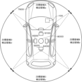
図26は、本技術を上述した車両7900に適用した第1の例を示す図である。車両7900の屋根に360度方向の撮像が可能な魚眼レンズ8000が設けられている。魚眼レンズ8000が撮像した映像は車両7900内に設けられた情報処理装置100を介してモニターや電子ミラー(以下、モニター等と称する)に表示されるように構成されている。
FIG. 26 is a diagram showing a first example in which the present technology is applied to
魚眼レンズ8000で撮像した360度全方向の映像を入力映像とし、例えば、フロント方向の90度幅を注視領域A、サイドR方向の90度幅を注視領域B、リア方向の90度幅を注視領域C、Lサイド方向の90度幅を注視領域Dとする。さらに、フロント方向の90度幅を検出領域a、Rサイド方向の90度幅を検出領域b、リア方向の90度幅を検出領域c、サイドL方向の90度幅を検出領域dとする。このように各注視領域および検出領域を設定し、魚眼レンズ8000の映像を情報処理装置100で処理して車両7900内のモニター等に表示する。
A 360-degree omnidirectional image captured by the
これにより、例えば、車両7900の近傍で動く人物を特徴量の検出対象である対象物として、第1乃至第3の実施の形態と同様の映像処理を行えば、車両7900のフロント方向にその人物がいる場合には車両7900のフロント方向の映像をモニター等に表示することができる。車両7900のRサイド方向にその人物がいる場合には車両7900のRサイド方向の映像を自動でモニター等に表示させることができる。車両7900のリア方向にその人物がいる場合には車両7900のリア方向の映像を自動でモニター等に表示させることができる。車両7900のLサイド方向にその人物がいる場合には車両7900のLサイド方向の映像をモニター等に表示させることができる。これにより、車両7900運転時または停車時の周囲の状況をより詳細に把握することができ、安全性を向上させることができる。
As a result, for example, if a person moving in the vicinity of the
また、車両7900の一方向を撮像する撮像装置からの入力映像を利用することも可能である。図27に示す本技術の適用の第2の例のように、車両7900のリア方向に向けた撮像装置9000の撮像映像を入力映像として、注視領域A、注視領域B、注視領域C、注視領域Dを車両7900内のモニター等に表示させることもできる。このような利用態様は、フロント方向、Rサイド方向、Lサイド方向についても可能である。
It is also possible to use input video from an imaging device that captures one direction of the
このような本技術の車両への適用においては、撮像装置は1台に限られず複数台であってもよい。例えば、図28に示す車両への適用の第3の例のように、車両7900の周囲360度方向の撮像が可能な魚眼レンズ8000と、フロント方向を撮像する第1撮像装置9100、リア方向を撮像する第2撮像装置9200、Lサイド方向を撮像する第3撮像装置9300、Rサイド方向を撮像する第4撮像装置9400を設けてもよい。この場合、魚眼レンズ8000の360度全方向映像から対象物の特徴量を検出し、その特徴量に応じて第1撮像装置9100、第2撮像装置9200、第3撮像装置9300、第4撮像装置9400の撮像映像を選択、合成等してモニター等に表示させる。
In such application of the present technology to a vehicle, the number of imaging devices is not limited to one, and a plurality of imaging devices may be used. For example, like the third example of application to a vehicle shown in FIG. A
撮像装置を複数台用いる場合、360度方向の撮像が可能な魚眼レンズ以外の撮像装置は4つ限られず、Lサイド方向用撮像装置およびRサイド方向用撮像装置の組み合わせでもよい。また、魚眼レンズと、リア方向用撮像装置、Lサイド方向用撮像装置およびRサイド方向用撮像装置という組み合わせでもよい。 When a plurality of imaging devices are used, the number of imaging devices other than the fisheye lens capable of imaging in the 360-degree direction is not limited to four, and a combination of the L side direction imaging device and the R side direction imaging device may be used. Alternatively, a combination of a fisheye lens, a rear image pickup device, an L side image pickup device, and an R side image pickup device may be used.
また、自動車に限られず、自転車、パーソナルモビリティ、飛行機、ドローン、船舶、ロボット、建設機械、農業機械(トラクターなど移動体においても同様に本技術を適用可能である。 In addition, the present technology is applicable not only to automobiles, but also to moving bodies such as bicycles, personal mobility vehicles, airplanes, drones, ships, robots, construction machinery, agricultural machinery (tractors, etc.).
本技術は以下のような構成も取ることができる。
(1)
撮像領域における注視領域を設定し、
対象物の状態に応じて前記注視領域から表示する領域を決定する
情報処理装置。
(2)
前記注視領域に対応する検出領域を設定し、
前記対象物の前記検出領域における特徴量に基づいて複数の前記注視領域を合成して表示する領域とする(1)に記載の情報処理装置。
(3)
前記特徴量は、前記検出領域内における前記対象物を構成する画素数に基づく値である(2)に記載の情報処理装置。
(4)
前記対象物が複数の前記検出領域のうちのいずれか1つの検出領域に存在している状態では、前記対象物が存在する前記1つの検出領域に対応した1つの前記注視領域を表示する領域とする(2)に記載の情報処理装置。
(5)
前記対象物が複数の前記検出領域のうちの2以上の検出領域に存在している状態では、前記対象物が存在する前記2以上の検出領域のそれぞれに対応した2以上の前記注視領域を合成して表示する領域とする(2)に記載の情報処理装置。
(6)
前記特徴量は、前記対象物が前記検出領域において一の状態から他の状態に変化する場合における該変化の度合いである(2)に記載の情報処理装置。
(7)
前記特徴量に応じて、表示されている前記注視領域と、前記被写体の状態が変化した前記検出領域に対応した前記注視領域とを合成して表示する領域とする(6)に記載の情報処理装置。
(8)
前記対象物が前記複数の検出領域のうちの2以上の検出領域に存在している状態で所定時間が経過した場合、前記2以上の検出領域に対応した2以上の前記注視領域を表示する領域とする(2)に記載の情報処理装置。
(9)
前記対象物が2つの前記検出領域に存在している状態で所定時間が経過した場合、2つの前記検出領域に対応した2つの前記注視領域の境界が表示装置の表示領域の略中央に位置するように表示させる(8)に記載の情報処理装置。
(10)
前記撮像領域を撮像する撮像装置のレンズに対する入射方向に正対していない前記注視領域に射影変換処理を施す(1)から(9)のいずれかに記載の情報処理装置。
(11)
前記合成は、前記撮像領域を撮像した映像を構成するフレーム画像ごとに行われる(2)から(10)のいずれかに記載の情報処理装置。
(12)
前記撮像領域は、1台の撮像装置により撮像される(1)から(11)のいずれかに記載の情報処理装置。
(13)
前記撮像領域は、前記1台の撮像装置により全ての前記注視領域を画角内に収めるよう領域である(12)に記載の情報処理装置。
(14)
前記撮像領域は、複数台の撮像装置により撮像される(1)から(13)のいずれかに記載の情報処理装置。
(15)
前記対象物は、前記撮像領域中において検出された被写体である(1)から(14)のいずれかに記載の情報処理装置。
(16)
前記対象物は、前記撮像領域中において予め指定された被写体である(1)から(14)のいずれかに記載の情報処理装置。
(17)
表示装置に前記注視領域を示すアイコンを表示させる(1)から(16)に記載の情報処理装置。
(18)
撮像領域における注視領域を設定し、
対象物の状態に応じて前記注視領域から表示する領域を決定する
情報処理方法。
(19)
撮像領域における注視領域を設定し、
対象物の状態に応じて前記注視領域から表示する領域を決定する
情報処理方法をコンピュータに実行させる情報処理プログラム。The present technology can also take the following configurations.
(1)
Set the gaze area in the imaging area,
An information processing apparatus that determines an area to be displayed from the gaze area according to the state of an object.
(2)
setting a detection area corresponding to the gaze area;
The information processing apparatus according to (1), wherein a plurality of gaze areas are synthesized and displayed based on the feature amount in the detection area of the object.
(3)
The information processing apparatus according to (2), wherein the feature amount is a value based on the number of pixels forming the object within the detection area.
(4)
an area displaying one gaze area corresponding to the one detection area in which the object exists in a state where the object exists in one of the plurality of detection areas; The information processing apparatus according to (2).
(5)
In a state where the object exists in two or more detection areas among the plurality of detection areas, two or more of the gaze areas corresponding to each of the two or more detection areas in which the object exists are synthesized. The information processing apparatus according to (2), which is defined as an area to be displayed.
(6)
The information processing apparatus according to (2), wherein the feature amount is a degree of change when the object changes from one state to another state in the detection area.
(7)
The information processing according to (6), wherein the displayed gaze area and the gaze area corresponding to the detection area in which the state of the subject has changed are synthesized and displayed according to the feature amount. Device.
(8)
When a predetermined period of time elapses while the object is present in two or more of the plurality of detection areas, two or more of the gaze areas corresponding to the two or more detection areas are displayed. The information processing apparatus according to (2).
(9)
When a predetermined time elapses while the object exists in the two detection areas, the boundary between the two gaze areas corresponding to the two detection areas is positioned substantially in the center of the display area of the display device. The information processing device according to (8) is displayed as follows.
(10)
The information processing apparatus according to any one of (1) to (9), wherein projective transformation processing is performed on the region of interest that is not facing the incident direction with respect to the lens of the imaging device that captures the image of the imaging region.
(11)
The information processing apparatus according to any one of (2) to (10), wherein the combining is performed for each frame image forming a video obtained by imaging the imaging area.
(12)
The information processing apparatus according to any one of (1) to (11), wherein the imaging region is imaged by one imaging device.
(13)
The information processing apparatus according to (12), wherein the imaging area is an area such that all the gaze areas are contained within an angle of view by the single imaging device.
(14)
The information processing apparatus according to any one of (1) to (13), wherein the imaging region is imaged by a plurality of imaging devices.
(15)
The information processing apparatus according to any one of (1) to (14), wherein the object is a subject detected in the imaging area.
(16)
The information processing apparatus according to any one of (1) to (14), wherein the object is a subject specified in advance in the imaging area.
(17)
The information processing apparatus according to any one of (1) to (16), wherein an icon indicating the gaze area is displayed on a display device.
(18)
Set the gaze area in the imaging area,
An information processing method for determining an area to be displayed from the gaze area according to the state of an object.
(19)
Set the gaze area in the imaging area,
An information processing program that causes a computer to execute an information processing method of determining an area to be displayed from the gaze area according to the state of an object.
20・・・・撮像装置
30・・・・表示装置
100・・・情報処理装置20...
Claims (19)
複数の前記注視領域のそれぞれに対応する検出領域を前記注視領域単位で設定し、
前記撮像領域に存在する対象物が複数の前記検出領域のうちの2以上の検出領域に存在している場合、前記対象物が存在する前記2以上の検出領域に対応した2以上の前記注視領域を連結して連結注視領域を作成し、前記連結注視領域を表示する領域とする
情報処理装置。 setting a plurality of gaze areas in the imaging area,
setting a detection area corresponding to each of the plurality of gaze areas in units of the gaze area;
When an object existing in the imaging area exists in two or more detection areas among the plurality of detection areas, two or more gazing areas corresponding to the two or more detection areas in which the object exists are connected to create a connected gaze area, and the connected gaze area is used as a display area.
請求項1に記載の情報処理装置。 When a predetermined time elapses while the object is present in two or more of the plurality of detection areas, two or more of the gaze areas corresponding to the two or more detection areas are connected. 2. The information processing apparatus according to claim 1, wherein a connected gaze area is created and used as a display area.
請求項2に記載の情報処理装置。 When a predetermined time elapses while the object exists in the two detection areas, the boundary between the two gaze areas corresponding to the two detection areas is positioned substantially in the center of the display area of the display device. 3. The information processing apparatus according to claim 2, wherein the information is displayed as follows.
請求項1に記載の情報処理装置。 When determining the area to be displayed based on the feature amount in the detection area of the object, the two or more gaze areas corresponding to the two or more detection areas in which the object exists are not connected, and a plurality of 2. The information processing apparatus according to claim 1, wherein the gaze area is an area synthesized and displayed by adding pixel values based on the ratio of the feature amount.
請求項4に記載の情報処理装置。 5. The information processing apparatus according to claim 4, wherein the feature amount is a value based on the number of pixels forming the object within the detection area.
請求項4または5に記載の情報処理装置。 In a state in which the object exists in two or more detection areas among the plurality of detection areas, two or more of the gaze areas corresponding to the two or more detection areas in which the object exists are set to the 6. The information processing apparatus according to claim 4, wherein the area is displayed by combining pixel values based on the ratio of the feature amount .
請求項4から6のいずれかに記載の情報処理装置。 7. The information processing apparatus according to any one of claims 4 to 6, wherein the feature amount is the degree of change when the object changes from one state to another state in the detection area.
請求項4から7のいずれかに記載の情報処理装置。 8. A region according to any one of claims 4 to 7, wherein the displayed gaze region and the gaze region corresponding to the detection region in which the state of the object has changed are synthesized and displayed according to the feature amount. 1. The information processing device according to claim 1.
請求項4から8のいずれかに記載の情報処理装置。 9. The information processing apparatus according to any one of claims 4 to 8, wherein said synthesizing is performed for each frame image forming a video obtained by imaging said imaging area.
請求項1から9のいずれかに記載の情報処理装置。 an area displaying one gaze area corresponding to the one detection area in which the object exists in a state where the object exists in one of the plurality of detection areas; The information processing apparatus according to any one of claims 1 to 9.
請求項1から10のいずれかに記載の情報処理装置。 11. Any one of claims 1 to 10, wherein the non-rectangular gazing area that does not directly face the incident direction with respect to a lens of an imaging device that images the imaging area is transformed into the rectangular gazing area by performing a projective transformation process. The information processing device described.
請求項1から11のいずれかに記載の情報処理装置。 12. The information processing apparatus according to any one of claims 1 to 11, wherein the imaging area is imaged by one imaging device.
請求項12に記載の情報処理装置。 13. The information processing apparatus according to claim 12, wherein the imaging area is an area in which all the gaze areas are contained within an angle of view by the single imaging device.
請求項1から13のいずれかに記載の情報処理装置。 14. The information processing apparatus according to any one of claims 1 to 13, wherein the imaging area is imaged by a plurality of imaging devices.
請求項1から14のいずれかに記載の情報処理装置。 15. The information processing apparatus according to any one of claims 1 to 14, wherein the object is a subject detected in the imaging area.
請求項1から14のいずれかに記載の情報処理装置。 15. The information processing apparatus according to any one of claims 1 to 14, wherein the target object is a subject specified in advance in the imaging area.
請求項1から16のいずれかに記載の情報処理装置。 17. The information processing apparatus according to any one of claims 1 to 16, wherein an icon indicating the gaze area is displayed on a display device.
複数の前記注視領域のそれぞれに対応する検出領域を前記注視領域単位で設定し、
前記撮像領域に存在する対象物が複数の前記検出領域のうちの2以上の検出領域に存在している場合、前記対象物が存在する前記2以上の検出領域に対応した2以上の前記注視領域を連結して連結注視領域を作成し、前記連結注視領域を表示する領域とする
情報処理方法。 setting a plurality of gaze areas in the imaging area,
setting a detection area corresponding to each of the plurality of gaze areas in units of the gaze area;
When an object existing in the imaging area exists in two or more detection areas among the plurality of detection areas, two or more gazing areas corresponding to the two or more detection areas in which the object exists are connected to create a connected gaze area, and the connected gaze area is used as a display area.
複数の前記注視領域のそれぞれに対応する検出領域を前記注視領域単位で設定し、
前記撮像領域に存在する対象物が複数の前記検出領域のうちの2以上の検出領域に存在している場合、前記対象物が存在する前記2以上の検出領域に対応した2以上の前記注視領域を連結して連結注視領域を作成し、前記連結注視領域を表示する領域とする
情報処理方法をコンピュータに実行させる情報処理プログラム。 setting a plurality of gaze areas in the imaging area,
setting a detection area corresponding to each of the plurality of gaze areas in units of the gaze area;
When an object existing in the imaging area exists in two or more detection areas among the plurality of detection areas, two or more gazing areas corresponding to the two or more detection areas in which the object exists An information processing program for causing a computer to execute an information processing method for creating a connected gaze area by connecting .
Applications Claiming Priority (3)
| Application Number | Priority Date | Filing Date | Title |
|---|---|---|---|
| JP2017211117 | 2017-10-31 | ||
| JP2017211117 | 2017-10-31 | ||
| PCT/JP2018/033645 WO2019087577A1 (en) | 2017-10-31 | 2018-09-11 | Information processing device, information processing method, and information processing program |
Publications (2)
| Publication Number | Publication Date |
|---|---|
| JPWO2019087577A1 JPWO2019087577A1 (en) | 2020-12-17 |
| JP7302477B2 true JP7302477B2 (en) | 2023-07-04 |
Family
ID=66332974
Family Applications (1)
| Application Number | Title | Priority Date | Filing Date |
|---|---|---|---|
| JP2019549921A Active JP7302477B2 (en) | 2017-10-31 | 2018-09-11 | Information processing device, information processing method and information processing program |
Country Status (5)
| Country | Link |
|---|---|
| US (1) | US11403057B2 (en) |
| EP (1) | EP3706413B1 (en) |
| JP (1) | JP7302477B2 (en) |
| CN (1) | CN111345035B (en) |
| WO (1) | WO2019087577A1 (en) |
Families Citing this family (1)
| Publication number | Priority date | Publication date | Assignee | Title |
|---|---|---|---|---|
| JP2022181708A (en) | 2021-05-26 | 2022-12-08 | 株式会社日立製作所 | Automatic display system for watch area and remote state monitoring system using the same |
Citations (8)
| Publication number | Priority date | Publication date | Assignee | Title |
|---|---|---|---|---|
| JP2003143596A (en) | 2001-10-30 | 2003-05-16 | Fujitsu Ten Ltd | Monitor device for vehicle |
| JP2005033570A (en) | 2003-07-04 | 2005-02-03 | Chuo Electronics Co Ltd | Method and system for providing mobile body image |
| JP2006162692A (en) | 2004-12-02 | 2006-06-22 | Hosei Univ | Automatic lecture content creating system |
| JP2006186939A (en) | 2004-12-28 | 2006-07-13 | Canon Marketing Japan Inc | Monitoring system, server, and method, and program thereof |
| JP2007025425A (en) | 2005-07-20 | 2007-02-01 | Tac Kk | Lecture collecting/delivering system |
| JP2007081553A (en) | 2005-09-12 | 2007-03-29 | Hitachi Kokusai Electric Inc | Camera system and display method thereof |
| JP2010206475A (en) | 2009-03-03 | 2010-09-16 | Fujitsu Ltd | Monitoring support device, method thereof, and program |
| JP2012185555A (en) | 2011-03-03 | 2012-09-27 | Panasonic Corp | Object detecting device and method, and program |
Family Cites Families (13)
| Publication number | Priority date | Publication date | Assignee | Title |
|---|---|---|---|---|
| EP1504276B1 (en) * | 2002-05-03 | 2012-08-08 | Donnelly Corporation | Object detection system for vehicle |
| US8427538B2 (en) | 2004-04-30 | 2013-04-23 | Oncam Grandeye | Multiple view and multiple object processing in wide-angle video camera |
| EP1872724B1 (en) * | 2006-01-10 | 2019-08-28 | Toshiba Medical Systems Corporation | Ultrasonograph and ultrasonogram creating method |
| JP5603839B2 (en) | 2011-07-05 | 2014-10-08 | 日本電信電話株式会社 | Image manipulation experience control method |
| WO2013086739A1 (en) * | 2011-12-16 | 2013-06-20 | Thomson Licensing | Method and apparatus for generating 3d free viewpoint video |
| KR101501515B1 (en) * | 2012-01-04 | 2015-03-11 | 삼성메디슨 주식회사 | Diagnosis image apparatus and operating method thereof |
| CN103248855B (en) * | 2012-02-07 | 2016-12-14 | 北京同步科技有限公司 | Course recording system based on fixing seat in the plane, video process apparatus and record class method |
| JP6147740B2 (en) * | 2012-06-07 | 2017-06-14 | 株式会社日立製作所 | Method of operating ultrasonic diagnostic apparatus and ultrasonic diagnostic apparatus |
| EP2813959A3 (en) * | 2013-06-12 | 2015-08-26 | Samsung Electronics Co., Ltd | Apparatus and method for providing medical information |
| KR101643286B1 (en) * | 2014-09-04 | 2016-07-29 | 삼성전자주식회사 | Medical imaging apparatus and controlling method thereof |
| KR20170091913A (en) * | 2016-02-02 | 2017-08-10 | 삼성전자주식회사 | Method and apparatus for providing video service |
| CN108139799B (en) * | 2016-04-22 | 2022-01-14 | 深圳市大疆创新科技有限公司 | System and method for processing image data based on a region of interest (ROI) of a user |
| EP3780629A4 (en) * | 2018-04-05 | 2021-02-17 | Sony Semiconductor Solutions Corporation | Transmission device, reception device, and communication system |
-
2018
- 2018-09-11 JP JP2019549921A patent/JP7302477B2/en active Active
- 2018-09-11 WO PCT/JP2018/033645 patent/WO2019087577A1/en unknown
- 2018-09-11 US US16/757,942 patent/US11403057B2/en active Active
- 2018-09-11 CN CN201880068987.7A patent/CN111345035B/en active Active
- 2018-09-11 EP EP18872302.7A patent/EP3706413B1/en active Active
Patent Citations (8)
| Publication number | Priority date | Publication date | Assignee | Title |
|---|---|---|---|---|
| JP2003143596A (en) | 2001-10-30 | 2003-05-16 | Fujitsu Ten Ltd | Monitor device for vehicle |
| JP2005033570A (en) | 2003-07-04 | 2005-02-03 | Chuo Electronics Co Ltd | Method and system for providing mobile body image |
| JP2006162692A (en) | 2004-12-02 | 2006-06-22 | Hosei Univ | Automatic lecture content creating system |
| JP2006186939A (en) | 2004-12-28 | 2006-07-13 | Canon Marketing Japan Inc | Monitoring system, server, and method, and program thereof |
| JP2007025425A (en) | 2005-07-20 | 2007-02-01 | Tac Kk | Lecture collecting/delivering system |
| JP2007081553A (en) | 2005-09-12 | 2007-03-29 | Hitachi Kokusai Electric Inc | Camera system and display method thereof |
| JP2010206475A (en) | 2009-03-03 | 2010-09-16 | Fujitsu Ltd | Monitoring support device, method thereof, and program |
| JP2012185555A (en) | 2011-03-03 | 2012-09-27 | Panasonic Corp | Object detecting device and method, and program |
Also Published As
| Publication number | Publication date |
|---|---|
| EP3706413B1 (en) | 2024-04-03 |
| CN111345035B (en) | 2022-10-14 |
| US20200326897A1 (en) | 2020-10-15 |
| EP3706413A1 (en) | 2020-09-09 |
| JPWO2019087577A1 (en) | 2020-12-17 |
| CN111345035A (en) | 2020-06-26 |
| WO2019087577A1 (en) | 2019-05-09 |
| US11403057B2 (en) | 2022-08-02 |
| EP3706413A4 (en) | 2020-09-09 |
Similar Documents
| Publication | Publication Date | Title |
|---|---|---|
| JP6977720B2 (en) | Generation device and generation method, and playback device and playback method | |
| JP6988815B2 (en) | Image processing device and image processing method | |
| JP7192772B2 (en) | Image processing device and image processing method | |
| US10508911B2 (en) | Apparatus and method for measurement, and program | |
| US11272115B2 (en) | Control apparatus for controlling multiple camera, and associated control method | |
| JP6813027B2 (en) | Image processing device and image processing method | |
| JPWO2018021071A1 (en) | Image processing apparatus and image processing method | |
| JPWO2018079260A1 (en) | Image processing apparatus and image processing method | |
| US10748264B2 (en) | Image processing apparatus and image processing method | |
| JPWO2019188390A1 (en) | Exposure control device, exposure control method, program, imaging device, and moving object | |
| US11443520B2 (en) | Image processing apparatus, image processing method, and image processing system | |
| JPWO2019142660A1 (en) | Image processing device, image processing method, and program | |
| WO2018034171A1 (en) | Image processing device and image processing method | |
| JP7302477B2 (en) | Information processing device, information processing method and information processing program | |
| WO2020085101A1 (en) | Image processing device, image processing method, and program | |
| US20190394405A1 (en) | Information processing apparatus, information processing method, and information processing program | |
| JP7363890B2 (en) | Information processing device, information processing method and program | |
| WO2021256483A1 (en) | Control device, projection system, control method, and program | |
| WO2020255589A1 (en) | Information processing device, information processing method, and program |
Legal Events
| Date | Code | Title | Description |
|---|---|---|---|
| A621 | Written request for application examination |
Free format text: JAPANESE INTERMEDIATE CODE: A621 Effective date: 20210805 |
|
| A131 | Notification of reasons for refusal |
Free format text: JAPANESE INTERMEDIATE CODE: A131 Effective date: 20220809 |
|
| A521 | Request for written amendment filed |
Free format text: JAPANESE INTERMEDIATE CODE: A523 Effective date: 20221003 |
|
| A131 | Notification of reasons for refusal |
Free format text: JAPANESE INTERMEDIATE CODE: A131 Effective date: 20221122 |
|
| A521 | Request for written amendment filed |
Free format text: JAPANESE INTERMEDIATE CODE: A523 Effective date: 20230118 |
|
| TRDD | Decision of grant or rejection written | ||
| A01 | Written decision to grant a patent or to grant a registration (utility model) |
Free format text: JAPANESE INTERMEDIATE CODE: A01 Effective date: 20230523 |
|
| A61 | First payment of annual fees (during grant procedure) |
Free format text: JAPANESE INTERMEDIATE CODE: A61 Effective date: 20230605 |
|
| R151 | Written notification of patent or utility model registration |
Ref document number: 7302477 Country of ref document: JP Free format text: JAPANESE INTERMEDIATE CODE: R151 |