JP7300915B2 - surveying equipment - Google Patents
surveying equipment Download PDFInfo
- Publication number
- JP7300915B2 JP7300915B2 JP2019130996A JP2019130996A JP7300915B2 JP 7300915 B2 JP7300915 B2 JP 7300915B2 JP 2019130996 A JP2019130996 A JP 2019130996A JP 2019130996 A JP2019130996 A JP 2019130996A JP 7300915 B2 JP7300915 B2 JP 7300915B2
- Authority
- JP
- Japan
- Prior art keywords
- point cloud
- laser
- cloud data
- unit
- light
- Prior art date
- Legal status (The legal status is an assumption and is not a legal conclusion. Google has not performed a legal analysis and makes no representation as to the accuracy of the status listed.)
- Active
Links
Images


Classifications
-
- G—PHYSICS
- G01—MEASURING; TESTING
- G01C—MEASURING DISTANCES, LEVELS OR BEARINGS; SURVEYING; NAVIGATION; GYROSCOPIC INSTRUMENTS; PHOTOGRAMMETRY OR VIDEOGRAMMETRY
- G01C15/00—Surveying instruments or accessories not provided for in groups G01C1/00 - G01C13/00
- G01C15/002—Active optical surveying means
-
- G—PHYSICS
- G02—OPTICS
- G02B—OPTICAL ELEMENTS, SYSTEMS OR APPARATUS
- G02B23/00—Telescopes, e.g. binoculars; Periscopes; Instruments for viewing the inside of hollow bodies; Viewfinders; Optical aiming or sighting devices
- G02B23/12—Telescopes, e.g. binoculars; Periscopes; Instruments for viewing the inside of hollow bodies; Viewfinders; Optical aiming or sighting devices with means for image conversion or intensification
-
- G—PHYSICS
- G02—OPTICS
- G02B—OPTICAL ELEMENTS, SYSTEMS OR APPARATUS
- G02B26/00—Optical devices or arrangements for the control of light using movable or deformable optical elements
- G02B26/08—Optical devices or arrangements for the control of light using movable or deformable optical elements for controlling the direction of light
- G02B26/10—Scanning systems
-
- G—PHYSICS
- G01—MEASURING; TESTING
- G01C—MEASURING DISTANCES, LEVELS OR BEARINGS; SURVEYING; NAVIGATION; GYROSCOPIC INSTRUMENTS; PHOTOGRAMMETRY OR VIDEOGRAMMETRY
- G01C15/00—Surveying instruments or accessories not provided for in groups G01C1/00 - G01C13/00
- G01C15/02—Means for marking measuring points
Description
本発明は、対象物の変状を検出する技術に関する。 The present invention relates to technology for detecting deformation of an object.
橋の橋脚やコンクリートで補強された法面等では、変状の有無を定期的に検査する必要がある。ここで、変状とは、変形、欠損、ひび、脆化等が発生した状態のことをいう。例えば、特許文献1には、レーザースキャナを用いた3D計測により、地盤の変形を検出する技術が記載されている。
Bridge piers and slopes reinforced with concrete must be periodically inspected for deformation. Here, the term "deformation" refers to a state in which deformation, chipping, cracking, embrittlement, or the like occurs. For example,
通常は、レーザースキャナにより対象物の変状を検出した後、検査員による当該箇所の目視確認、あるいは当該箇所を撮影し、画像を用いての精密な検査が行なわれる。この際、変状部分を確認する作業の効率化が求められる。 Usually, after detecting a deformation of an object with a laser scanner, an inspector visually confirms the relevant portion, or photographs the relevant portion and performs a precise inspection using an image. At this time, it is required to improve the efficiency of the work for confirming the deformed portion.
このような背景において、本発明は、レーザースキャンを用いた対象物の変状箇所の検出に係る作業の効率化を目的とする。 In view of such a background, the present invention aims to improve the efficiency of work related to detection of a deformed portion of an object using laser scanning.
本発明は、外部標定要素の関係が既知なトータルステーションとレーザースキャナを複合化した構成を備え、検査対象に対して時間差をおいて前記レーザースキャナによるレーザースキャンを行うことで得た第1の点群データと第2の点群データを取得する点群データ取得部と、前記第1の点群データと前記第2の点群データの差分を算出し、前記検査対象における位置情報に変化があった部分を詳細検査対象部分として検出する検出部と、前記詳細検査対象部分の位置を取得する位置取得部と、前記詳細検査対象部分の位置に基づき、前記詳細検査対象部分への前記トータルステーションの視準制御を行う視準制御部とを備える測量装置である。 The present invention comprises a combined configuration of a total station and a laser scanner with a known relationship between exterior orientation elements, and a first point cloud obtained by performing laser scanning with the laser scanner on an inspection object with a time lag. A point cloud data acquisition unit that acquires data and second point cloud data, and calculates a difference between the first point cloud data and the second point cloud data, and detects a change in position information in the inspection object. a detection unit for detecting a portion as a detailed inspection target portion; a position acquisition unit for acquiring the position of the detailed inspection target portion; A surveying instrument including a collimation control unit that performs control.
本発明において、前記トータルステーションは、望遠鏡および該望遠鏡が捉えた画像を撮像する撮像手段を備え、前記視準制御により、前記望遠鏡の前記詳細検査対象部分への視準が行なわれ、前記撮像手段により、前記詳細検査対象部分の拡大画像の撮像が行なわれる態様は好ましい。また本発明において、前記トータルステーションは、マーキング光の照射を行う機能を有し、前記視準処理の後に、前記詳細検査対象部分への前記マーキング光の照射が行なわれる態様は好ましい。また本発明において、前記視準処理の後に、前記トータルステーションは、前記詳細検査対象部分の複数の点の測位を行う態様は好ましい。また本発明において、前記第1の点群データと前記第2の点群データの差分に基づき、変状の類型パターンの判定が行われる態様は好ましい。またこの態様において、前記判定された変状の類型パターンに応じて、その後の処理が決定される態様は好ましい。
In the present invention, the total station comprises a telescope and imaging means for imaging an image captured by the telescope. Preferably, an enlarged image of the portion to be inspected in detail is picked up. Further, in the present invention, it is preferable that the total station has a function of irradiating the marking light, and the marking light is radiated to the detailed inspection target portion after the collimation process. Further, in the present invention, it is preferable that the total station performs positioning of a plurality of points on the detailed inspection target portion after the collimation process. Further, in the present invention, it is preferable that the deformation type pattern is determined based on the difference between the first point cloud data and the second point cloud data. Moreover, in this aspect, it is preferable that the subsequent processing is determined according to the determined type pattern of deformation.
本発明によれば、レーザースキャンを用いた対象物の変状箇所の検出に係る作業が効率化される。 According to the present invention, work related to detection of a deformed portion of an object using laser scanning is made efficient.
1.第1の実施形態
(概要)
図1には、実施形態の概要が示されている。符号150は、検査対象物であり、例えばコンクリートの壁面である。検査対象物としては、壁、建物、トンネル内壁、橋脚、コンクリート等で補強された法面や崖や土手、路面、ダム、その他の各種の壁面や天井面が挙げられるが特に限定されない。検査対象物の材質は特に限定されないが、コンクリート、モルタル、金属、木材、樹脂、各種のセラミック材料、これらの複合材料が挙げられる。検査対象物は塗装されていてもよい。また、土や岩等を検査の対象とすることもできる。例えば、落石や崩落につながる地盤の動き(変形)や石の動きをレーザースキャンによって監視することも可能である。
1. First embodiment (outline)
FIG. 1 shows an overview of the embodiment.
図1(A)には、レーザースキャナ付トータルステーション(TS)のレーザースキャナ機能を用いてコンクリートの壁面150のレーザースキャンを行う状態が示されている。このレーザースキャンは、1年に一回や2年に一回という頻度で定期的に繰り返し行う。勿論、スキャンの間隔は適宜選択でき、また等間隔で行う場合に限定されない。
FIG. 1A shows a state in which a
図6~図8に変状の具体的な例を示す。図6~図8は、国土交通省国土技術政策総合研究所の国土技術政策総合研究所資料(国土総研資料)748号(http://www.nilim.go.jp/lab/bcg/siryou/tnn/tnn0748.htm)から引用したものである。図6(A)には、コンクリートの表面が剥離し、浮きが生じている場合が示されている。図6(B)および図7(A) には、鉄骨に変形が生じた場合が示されている。図7(B)には、コンクリートの構造体に生じたひび割れの例が示されている。図8(A)には、鉄板で被覆されたコンクリートの構造体に欠損が生じた場合が示されている。図8(B)には、鉄筋で補強されたコンクリートの表面が欠落し、鉄筋が露出した状態が示されている。 6 to 8 show specific examples of deformation. Figures 6 to 8 are from the National Institute for Land and Infrastructure Management, National Institute for Land and Infrastructure Management, Ministry of Land, Infrastructure, Transport and Tourism (NILIM) No. 748 (http://www.nilim.go.jp/lab/bcg/siryou/) tnn/tnn0748.htm). FIG. 6(A) shows a case where the surface of the concrete is peeled off and floating occurs. FIGS. 6(B) and 7(A) show the case where the steel frame is deformed. FIG. 7B shows an example of cracks occurring in a concrete structure. FIG. 8(A) shows a case where a concrete structure coated with an iron plate is damaged. FIG. 8(B) shows a state in which the surface of concrete reinforced with reinforcing bars is missing and the reinforcing bars are exposed.
図1(B)には、変状部分の一例として、コンクリートの壁面150の表面に腐食等により欠損部分151が発生した場合が示されている。ここでは、欠損部分151において、コンクリートの一部が欠落し、凹型に窪んでいるとする。
FIG. 1B shows, as an example of a deformed portion, a case where a defective portion 151 is generated on the surface of a
窪みがあると、窪みがない場合に比較して、その部分におけるレーザースキャナ点(レーザースキャナ光の反射点)の三次元位置データが異なるものとなる。このレーザースキャン光の反射点の位置データの変化を検出することで、欠損部分151の発生の有無を検出する。 If there is a dent, the three-dimensional position data of the laser scanner point (reflection point of the laser scanner light) in that portion will be different from the case where there is no dent. By detecting the change in the position data of the reflection point of the laser scanning light, the presence or absence of the missing portion 151 is detected.
具体的には、N-1回目のレーザースキャンで得られた点群データとN回目のレーザースキャンで得られた点群データとを比較し、その差分を計算する。時間差をおいて行われたレーザースキャンの間に変状が生じていれば、2つの点群データにおいて、その部分の点群データに差異が生じる。そこで、閾値を用いて上記差異が生じた部分を変状が生じている可能性がある部分(要詳細検査対象部分)として検出する。なお、Nは、2以上の自然数である。 Specifically, the point cloud data obtained by the (N−1)th laser scan and the point cloud data obtained by the Nth laser scan are compared, and the difference between them is calculated. If deformation occurs between the laser scans performed with a time lag, there will be a difference in the point cloud data of that portion between the two point cloud data. Therefore, the threshold is used to detect the portion where the above difference occurs as a portion where there is a possibility that deformation has occurred (a detailed inspection target portion). Note that N is a natural number of 2 or more.
レーザースキャンで得られる点群データには、各レーザースキャン点の三次元座標と各点の反射光の強度が含まれる。レーザースキャンで得られる点の位置は、利用するレーザースキャナの光学原点を原点とするローカル座標系で得られる。ここで、利用するレーザースキャナの絶対座標系における外部標定要素(位置と姿勢)が既知であれば、絶対座標系における点の座標が取得できる。絶対座標系というのは、GNSSや地図で用いられる座標系であり、例えば(緯度、経度、標高)によって位置の情報が記述される座標系である。 The point cloud data obtained by laser scanning includes the three-dimensional coordinates of each laser scanning point and the intensity of the reflected light at each point. The position of a point obtained by laser scanning is obtained in a local coordinate system whose origin is the optical origin of the laser scanner to be used. Here, if the exterior orientation elements (position and orientation) in the absolute coordinate system of the laser scanner to be used are known, the coordinates of the point in the absolute coordinate system can be obtained. The absolute coordinate system is a coordinate system used in GNSS and maps, and is a coordinate system in which position information is described by (latitude, longitude, altitude), for example.
レーザースキャンによって得られる点群データには、スキャン光一つ一つの反射点の座標が含まれるので、上記の方法で得られる変状部分のTS100に対する位置を知ることができる。すなわち、N-1回目のレーザースキャンで得られた点群データとN回目のレーザースキャンで得られた点群データの差分データから、N-1回目とN回目のレーザースキャンの間に生じた欠損部分151の位置(TS100に対する位置)を知ることができる。
Since the point cloud data obtained by laser scanning includes the coordinates of the reflection point of each scanning light, the position of the deformed portion obtained by the above method with respect to the
具体的には、点群データに含まれる点の位置情報(3次元座標)を2つのレーザースキャンデータ(点群データ)で比較し、その差分を得る。前回(N-1回目)のレーザースキャン時と今回(N回目)のレーザースキャン時の間に欠損が生じた場合、その部分の点群位置データに差が生じ、それが上記の差分として表れる。この差分の程度を閾値で判定することで、この差分が出た点群の部分を欠損部分151として検出する。 Specifically, the position information (three-dimensional coordinates) of points included in the point cloud data is compared between the two laser scan data (point cloud data) to obtain the difference. If a defect occurs between the previous (N-1th) laser scan and the current (Nth) laser scan, a difference occurs in the point cloud position data of that portion, which appears as the above difference. By determining the degree of this difference with a threshold value, the portion of the point cloud where this difference is found is detected as the missing portion 151 .
TS100は、レーザースキャナ付トータルステーションの一例である。TS100は、トータルステーションとしての機能に加えて、望遠鏡による観察および撮像機能、更にレーザーマーキングを行う機能を有している。望遠鏡の光軸とレーザーマーキング光の光軸は一致しており、TSの視準した位置の望遠画像の取得と当該位置のレーザーマーキングが行なえる。
TS100 is an example of a total station with a laser scanner. In addition to the function as a total station, the
この例では、レーザースキャンにより位置を特定した欠損部分151を対象に望遠鏡の視準を行い、更にその場所にレーザーマーキングを行う。これにより、欠損部分151の画像観察、更にレーザーマーキング光を目印とした検査員による欠損部分151の目視検査やUAV等を利用した欠損部分の拡大画像の撮影が行なわれる。 In this example, a telescope is collimated to the defective portion 151 whose position is specified by laser scanning, and laser marking is performed on that location. As a result, image observation of the defective portion 151, visual inspection of the defective portion 151 by an inspector using the laser marking light as a mark, and photographing of an enlarged image of the defective portion using a UAV or the like are performed.
(レーザースキャナ付きトータルステーション)
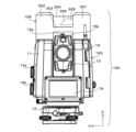
図2には、発明を利用したレーザースキャナ付きTS(トータルステーション)100の斜視図が示されている。図3には、TS100の正面図が示されている。TS100は、後述するレーザースキャナ109とTSを複合化した構造を有している。TSの機能は、通常のTSと同じである。TSの詳細な構造については、例えば特開2009-229192号公報、特開2012―202821号公報に記載されている。
(Total station with laser scanner)
FIG. 2 shows a perspective view of a TS (total station) 100 with a laser scanner utilizing the invention. A front view of the
TS100は、TS本体150とレーザースキャナ109を結合(複合化)した構造を有している。TS100は、本体部11を有している。本体部11は、台座12上に水平回転が可能な状態で保持されている。台座12は図示しない三脚の上部に固定される。本体部11は、Y軸の方向から見て上方に向かって延在する2つの延在部を有する略コの字形状を有し、この2つの延在部の間に可動部13が鉛直角(仰角および俯角)の制御が可能な状態で保持されている。
The
本体部11は、台座12に対して電動で水平回転する。すなわち、本体部11は、本体部11に内蔵された水平角制御用のモータにより駆動され、台座12に対して水平回転する。可動部13は、本体部11に内蔵された鉛直角制御用のモータにより本体部11に対して鉛直回転する。これら水平回転と鉛直回転の制御は、本体部11に内蔵された鉛直・水平回転駆動部106(図4のブロック図を参照)により行われる。
The
本体部11には、水平回転角制御ダイヤル14aと鉛直角制御ダイヤル14bが配置されている。水平回転角制御ダイヤル14aを操作することで、本体部11(可動部13)の水平回転角の調整が行なわれ、鉛直角制御ダイヤル14bを操作することで、可動部13の鉛直角の調整が行なわれる。位置データを入力し、TS100の光軸をその方向に自動で指向させる動作も可能である。
A horizontal rotation
可動部13の上部には、大凡の照準を付ける角筒状の照準器15aが配置されている。また、可動部13には、照準器15aよりも視野が狭い光学式の照準器15bと、より精密な視準が可能な望遠鏡16が配置されている。
At the upper part of the
照準器15bと望遠鏡16が捉えた像は、接眼部17を覗くことで視認できる。望遠鏡16は、測距用の赤外帯域のレーザー光(レーザー測位部103からの測距光)、測距対象(例えばターゲットとなる専用の反射プリズム)を追尾および捕捉するための追尾光、およびレーザーマーキングを行う可視帯域のマーキング用レーザー光の光学系を兼ねている。測距光、追尾光およびマーキング用レーザー光の光軸は、望遠鏡16の光軸と一致するように光学系の設計が行なわれている。
The image captured by the
測距用のレーザー光とマーキング用のレーザー光を一つのレーザー光で兼ねることも可能である。この場合、可視帯域のレーザー光を測距用のレーザー光兼マーカ用レーザー光として利用する。可動部13の光学系とレーザースキャナ109の外部標定要素の関係は、設計データとして予め取得されており既知である。
It is also possible to use a single laser beam as both the laser beam for distance measurement and the laser beam for marking. In this case, the laser light in the visible band is used as both the laser light for distance measurement and the laser light for the marker. The relationship between the optical system of the
本体部11には、ディスプレイ18と19が取り付けられている。ディスプレイ18は、操作部101と一体化されている。操作部101には、テンキーや十字操作ボタン等が配され、TS100に係る各種の操作やデータの入力が行なわれる。ディスプレイ18と19には、TS100の操作に必要な各種の情報や測量データ等が表示される。前後に2つディスプレイがあるのは、本体部11を回転させなくても前後のいずれの側からでもディスプレイを視認できるようにするためである。
本体部11の上部には、レーザースキャナ109が固定されている。レーザースキャナ109は、第1の塔部301と第2の塔部302を有している。第1の塔部301と第2の塔部302は、結合部303で結合され、結合部の上方の空間(第1の塔部301と第2の塔部302の間の空間)は、スキャンレーザー光を透過する部材で構成された保護ケース304で覆われている。保護ケース304の内側には、第1の塔部301からX軸方向に突出した回転部305が配置されている。回転部305の先端は、斜めに切り落とされた形状を有し、その先端部には、斜めミラー306が固定されている。
A
回転部305は、第1の塔部301に納められたモータにより駆動され、X軸を回転軸として回転する。第1の塔部301には、上記のモータに加え、このモータを駆動する駆動回路と、その制御回路、回転部305の回転角を検出するセンサ、該センサの周辺回路が納められている。
The
第2の塔部302の内部には、レーザースキャン光を発光するための発光部、対象物から反射してきたスキャン光を受光する受光部、発光部と受光部に関係する光学系、スキャン点(スキャン光の反射点)までの距離を算出する距離算出部が納められている。また、レーザースキャナ109は、回転部305の回転角度位置(鉛直回転角)、本体部11の水平回転角およびスキャン点までの距離に基づきスキャン点の三次元座標を算出するスキャン点位置算出部を有している。
Inside the
レーザースキャナ109の光学系の外部標定要素と可動部13内部の光学系(レーザー測位部103の光学系)の外部標定要素の関係は設計データとして既知である。すなわち、レーザースキャナ109の光学原点とレーザー測位部103の光学原点の位置関係は既知であり、レーザースキャナ109の姿勢とレーザー測位部103の姿勢の関係も既知である。
The relationship between the exterior orientation elements of the optical system of the
レーザースキャン光は、第2の塔部302の内部から斜めミラー306に向けて照射され、そこで反射され、透明なケース304を介して外部に照射される。また、対象物から反射したスキャン光は、照射光と逆の経路を辿り、第1の塔部302内部の受光部で受光される。
The laser scanning light is irradiated from the inside of the
スキャン光の発光タイミングと受光タイミング、さらにその際の回転部305の鉛直回転角と本体部11の水平回転角により、スキャン点(スキャンレーザー光の反射点)の測位が行なわれる。この測位の原理は、通常のレーザー測距の原理と同じである。
The scanning point (reflecting point of the scanning laser light) is positioned based on the timing of light emission and light reception of the scanning light, and the vertical rotation angle of the
以下、レーザースキャナ109におけるレーザー測距の原理を簡単に説明する。まず、光速度は不変なので、測距光の飛翔時間とその方向が判れば、光学系の光学原点を起点としたベクトルが設定でき、光学原点に対する測距光の反射点の位置が計算できる。この原理は、レーザー測位部103におけるレーザー測位も同じである。
The principle of laser ranging in the
測距光の飛翔時間は、発光と受光のタイミング差や、距離が既知の基準光路を伝搬した基準光の受光タイミングと測距光の受光タイミングの差(位相差)から知ることができる。 The flight time of the distance measurement light can be known from the timing difference between light emission and light reception, and the difference (phase difference) between the light reception timing of the reference light and the light reception timing of the distance measurement light propagating through a reference optical path whose distance is known.
測距光の照射方向は、発光時における回転部材305の鉛直回転角と本体部11の水平回転角から知ることができる。ここで、回転部材305の鉛直回転角と本体部11の水平回転角は、鉛直・水平回転角度検出部107により検出される。
The irradiation direction of the distance measuring light can be known from the vertical rotation angle of the rotating
レーザースキャン用のパルスレーザー光は、パルス発光され、斜めミラー306で反射され、保護ケース304から外部に向かって間欠的に出射される。この際、回転部305が回転しながらレーザースキャン光の照射が行われる。これにより、鉛直面(Y―Z面(X軸回り))におけるレーザースキャン、つまり鉛直面に沿ったレーザースキャンが行なわれる。また、同時に本体部11を水平回転(Z軸回りに回転)させることで、水平方向のレーザースキャンも行われ、結果として周囲全体(あるいは必要とする範囲)のレーザースキャンが行なわれる。レーザースキャン光は、1条の形態も可能であるし、同時に複数条を照射する形態も可能である。
A pulsed laser beam for laser scanning is emitted as a pulse, reflected by an
なお、レーザースキャナに係る技術については、特開2010-151682号公報、特開2008-268004号公報、米国特許第8767190号公報、US7969558号公報、US2017-0269197号公報等に記載されている。また、レーザースキャナとして、米国公開公報US2015/0293224号公報に記載されているような、スキャンを電子式に行う形態も採用可能である。 Techniques related to laser scanners are described in JP-A-2010-151682, JP-A-2008-268004, US Pat. Also, as the laser scanner, it is possible to employ a form in which scanning is performed electronically, as described in US Publication No. US 2015/0293224.
(ブロック図)
図4には、TS(トータルステーション)100のブロック図が示されている。TS100のトータルステーションとしての基本的な機能は、従来のものと同じである。TS100が従来のトータルステーションと異なるのは、レーザースキャナ109と複合化されている点、レーザースキャンによって変状部分を検出できる点、更にマーキング用のレーザー光を照射できる点である。
(Block Diagram)
FIG. 4 shows a block diagram of a TS (total station) 100. As shown in FIG. The basic functions of the TS100 as a total station are the same as the conventional one. The
TS100は、操作部101、撮像部(カメラ)102、ディスプレイ18,19、レーザー測位部103、鉛直・水平回転駆動部106、鉛直・水平回転角検出部107、視準制御部(マーキング光照射位置制御部)108、レーザースキャナ109、点群データ取得部110、点群データマッチング部111、マーキング光発光部112、変状部分検出部113、変状部分位置取得部114、変状部分の方向算出部115、動作制御部121、記憶部122、光学系201(望遠鏡16)を備える。
The
レーザー測位部103は、TSの基本機能であるレーザー光を用いた三次元測位を行う。測位の原理は、レーザースキャナ109と同じである。光学系201は、照準器15b(図3参照)、望遠鏡16(図3参照)、レーザー測位部200の光学系、撮像部102の光学系、図示省略した追尾光の光路を構成する光学系、およびマーキング光発光部112から発光されるマーキング光(マーキング光)の光路を構成する光学系を含んでいる。レーザー測位部103からの測距光と、マーキング光発光部112からのマーキング光は、望遠鏡16の対物レンズから望遠鏡16の光軸上で出射される。
The
光学系201は、各種のレンズ、ミラー、光路の分離や合成のためのダイクロイックミラー、ハーフミラー、偏光ミラー等を有している。光学系201により、測距用のレーザー光が望遠鏡16を介して測位対象に照射され、測位対象から反射された測距用レーザー光が望遠鏡16を介して受光される。また、光学系201により望遠鏡16が捉えた像が接眼部17に導かれると共に撮像部102に導かれる。また、光学系201を介して、マーキング光発光部112から発光されたマーキング光がマーキングの対象となる位置に照射される。
The
また、TS100は、ターゲット(例えば反射プリズム)を追尾するための追尾光を発光する追尾光発光部、ターゲットで反射した追尾光を受光する追尾光受光部、追尾光が望遠鏡16の視野の視準位置にくるように鉛直・水平回転駆動部106に制御信号を出力する追尾制御部を備える。このあたりの構成は、現在市場に供給されている製品と同じであるので、詳細な説明は省略する。TSの追尾光に係る構成については、例えば日本国特許第5124319号公報に記載されている。
The
操作部101は、オペレータによるTS100の操作の内容を受け付ける。この操作には、レーザースキャナ109を用いたレーザースキャンに係る操作、レーザースキャナ109を用いた検査対象の変状部分の検出、この検出した変状部分へのマーキング光の照射に係る操作が含まれる。TS100の操作は、TS100が備えるボタンスイッチ等により行われる。タブレットやスマートフォンを操作部として利用する形態も可能である。この場合、専用のアプリケーションソフトウェアをタブレットやスマートフォンにインストールすることで、タブレットやスマートフォンをTS100の操作手段として機能させる。
The
撮像部102は、望遠鏡16が捉えた画像を撮像する。撮像は、例えばCCDイメージセンサやCMOSイメージセンサにより行われる。ディスプレイ18,19は、撮像部102が撮像した画像、TS100の操作に必要な情報、TS100の動作に係る情報(測距データやターゲットの方位等)等が表示される。ディスプレイ18,19としては、液晶ディスプレイやELディスプレイ等が用いられる。
The
鉛直・水平回転駆動部106は、本体部11の水平回転の駆動および可動部13の鉛直回転の駆動を行う。鉛直・水平回転駆動部106は、上記駆動のためのモータ、ギア機構および駆動回路を備えている。
The vertical/horizontal rotation drive unit 106 drives the horizontal rotation of the
鉛直・水平回転角度検出部107は、本体部11の水平回転角の検出、可動部13の鉛直角(仰角および俯角)の値を検出する。角度の検出は、ロータリーエンコーダによって行われる。水平回転角は、例えば北を基準(0°)として、上方から見た時計回り方向の角度で測られる。鉛直角(仰角および俯角)は、水平方向を基準(0°)として仰角方向を+、俯角方向を-として測角する。
The vertical/horizontal rotation
視準制御部(マーキング光照射位置制御部)108は、変状部分位置取得部114が取得した変状部分の位置(TS100に対する位置)に基づき、望遠鏡16の光軸を当該変状部分に指向させる制御(視準制御)を行う。望遠鏡16の光軸は、レーザー測位部103からの測距用レーザー光の光軸およびマーキング光発光部112からのマーキング光の光軸と一致している。よって、望遠鏡16の視準を行うことで、レーザー測位部103からの測距用レーザー光の照射方向(照射位置)の調整、およびマーキング光発光部112からのマーキング光の照射方向(照射位置)の調整が同時に行なわれる。
A collimation control unit (marking light irradiation position control unit) 108 directs the optical axis of the
具体的には、望遠鏡16の光軸の向きを決める制御信号が、マーキング光照射位置制御部108で生成され、それが鉛直・水平回転駆動部106に送られ、本体部11の水平角度位置の調整と、可動部13の鉛直回転角の調整が行なわれる。
Specifically, a control signal for determining the direction of the optical axis of the
レーザースキャナ109は、レーザースキャンを行いレーザースキャンにより得られた点群データ(レーザースキャン点群))の取得を行う。レーザースキャンの範囲は、希望する範囲で設定可能である。
The
スキャンデータ取得部110は、レーザースキャナ109が得た点群データを取得する。この例では、レーザースキャナ109が取得した点群データは、記憶部122に記憶される。そして、変状部分を検出する処理に際して、記憶部122から読み出され、点群データ取得部110で取得される。適当な記憶媒体や記憶装置にスキャンデータ(レ―ザースキャナで得た点群データ)を記憶し、そこから取得する形態も可能である。
A scan
点群データマッチング部111は、2つの点群データの対応関係を求める。例えば、特定の対象物に対するTS100を用いたレーザースキャナが時間差をおいて複数回行われる場合を考える。この場合、例えばN-1回目とN回目の点群データの対応関係の特定(マッチング)が行なわれる。マッチングの手法としては、例えばテンプレートマッチングが利用される。点群データのマッチングを行うためのアルゴリズムは各種のものが開発されている。点群データのマッチングについては、例えば、国際公開番号WO2012/141235号公報、特開2014-35702号公報、特開2015-46128号公報、特開2017-15598号公報等に記載されている。なお、比較する点群データの時間軸上における間隔は限定されない。また、N回目とN+3回目の点群データの対応関係を求めるようなことも可能である。 The point cloud data matching unit 111 obtains a correspondence relationship between two point cloud data. For example, consider a case where laser scanning using the TS100 for a specific object is performed multiple times with a time lag. In this case, for example, identification (matching) of the correspondence relationship between the (N−1)-th point cloud data and the N-th point cloud data is performed. As a matching technique, for example, template matching is used. Various algorithms have been developed for matching point cloud data. Matching of point cloud data is described, for example, in International Publication No. WO2012/141235, JP-A-2014-35702, JP-A-2015-46128, JP-A-2017-15598, and the like. In addition, the interval on the time axis of the point cloud data to be compared is not limited. It is also possible to find the correspondence between the N-th and N+3-th point cloud data.
マーキング光発光部112は、レーザーマーキングを行うためのレーザー光(レーザーマーキング光)を発光する。レーザーマーキング光は、可視光であり、照射点の輝点を利用したマーキングを行う。 The marking light emitting unit 112 emits laser light (laser marking light) for laser marking. The laser marking light is visible light, and marking is performed using the bright spot of the irradiation point.
変状部分検出部113は、時間差をもって取得された同一対象物を対象としたレーザースキャンデータ(レ―ザースキャン点群)の比較に基づき、当該対象物の変状部分を検出する。具体的には、比較するレーザースキャンデータの位置情報を比較し、その差分を算出する。欠損や変形が生じると、その部分の点群位置情報に変化が生じる。この変化は上記2つのレーザースキャン点群の差分データとして得られる。そして、予め定めた閾値を超える差分が検出された場合に、その点で変状が生じたものと推認する判定を行う。この処理が変状部分検出部113で行われる。
The deformed
変状部分位置取得部114は、変状部分検出部113が検出した変状部分の位置を取得する。変状部分は、2つの点群データの位置データの差分を計算することで得られる。よって、この差分に関係する点群データの位置を調べることで、変状部分の位置を知ることができる。
The deformed portion
変状部分の方向算出部115は、変状部分位置取得部114が取得した位置の情報に基づき、TS100から見た変状部分の方向を算出する。TS100に対する変状部分の位置が判れば、TS100から見た変状部分の方向が判る。この処理が変状部分の方向算出部115で行われる。
The deformed portion direction calculation unit 115 calculates the direction of the deformed portion viewed from the
動作制御部121は、TS100の動作の制御を統括する。例えば、図5に係る処理の制御は、動作制御部121で行なわれる。記憶部122は、TS100の動作に必要なデータやプログラム、TS100の動作の結果得られた測量データを記憶する。
The operation control unit 121 integrates control of the operation of the
(処理の一例)
図5は、TS100を用いて行なわれる検査対象物の変状部分の検出に係る処理の手順の一例を示すフローチャートである。図5の処理を実行するプログラムは、記憶部122や適当な記憶媒体に記憶される。この処理の手順は、動作制御部121により制御されて実行される。このプログラムを適当な記憶媒体や通信回線を介してアクセス可能な記憶装置(データサーバ等)に記憶させ、そこからダウンロードする形態も可能である。また、図5の処理をPC(パーソナルコンピュータ)やサーバ等で行う形態も可能である。
(Example of processing)
FIG. 5 is a flow chart showing an example of a procedure for detecting a deformed portion of an object to be inspected using the
ここでは、検査対象物としてコンクリートで補強された崖や斜面を想定する。また、レーザースキャナ時において、使用するTS100の絶対座標系における外部標定要素は取得され、既知であるとする。
Here, cliffs and slopes reinforced with concrete are assumed as inspection objects. Also, it is assumed that the exterior orientation elements in the absolute coordinate system of the
まず、時間差をおいて検査対象物に対するレーザースキャンを、TS100を用いて行う。例えば、三か月毎や半年毎にTS100を用いた検査対象物に対するレーザースキャンを行い、定期的に点群データを得る。なお、各レーザースキャン時におけるレーザースキャナの位置は同じであってもよいし、同じでなくてもよい。 First, the TS100 is used to perform laser scanning on the inspection target with a time lag. For example, every three months or half a year, the object to be inspected is scanned with a laser using the TS100 to periodically obtain point cloud data. Note that the position of the laser scanner may or may not be the same during each laser scan.
以下、時期T1において行われたN-1回目のレーザースキャンで得た点群データ1と、T1の後の時期T2において行われたN回目のレーザースキャンで得た点群デー2とに基づく、時期T1とT2の間に生じた変状部分の検出、および変状部分への誘導に係る処理を説明する。なお、Nは、2以上の自然数である。
Hereinafter,
まず、点群データ1と点群データ2を取得する(ステップS101)。この処理は、点群データ取得部110で行われる。次に、点群データ1と点群データ2の対応関係の特定(マッチング)を行う(ステップS102)。この処理は、点群データマッチング部111で行われる。
First,
次に、点群データ1と点群データ2を比較し、各点の位置データの差分を計算し(ステップS103)、更にステップ103で得た差分データに基づき、変状部分(正確には、変状の発生が疑われる部分)を検出する(ステップS104)。ステップS103とS104の処理は、変状部分検出部113で行われる。なお、変状部分が無ければ処理を終了する。
Next, the
変状部分を検出したら、その部分の位置を取得する(ステップS105)。この処理では、変状部分の点群データから変状部分の位置を取得する。この処理は、変状部分位置取得部114で行われる。変状部分の位置を取得したら、TS100から見たその方向を算出する(ステップS106)。この処理は、変状部分の方向算出部115で行なわれる。
When the deformed portion is detected, the position of that portion is obtained (step S105). In this process, the position of the deformed portion is acquired from the point cloud data of the deformed portion. This processing is performed by the deformed portion
変状部分の方向を算出したら、その方向に望遠鏡16の狙いを付ける自動視準処理を行う(ステップS107)。この処理では、自動視準制御部(マーキング光照射位置制御部)108で制御信号が生成され、この制御信号により鉛直・水平回転駆動部106による可動部13の上下方向における角度位置の調整、更に本体部11の水平方向における角度位置の調整が行なわれる。望遠鏡16の視準を行なったら、撮像部102により変状部分の撮影を行う(ステップS108)。
After the direction of the deformed portion is calculated, automatic collimation processing is performed to aim the
次に、マーキング光発光部112からマーキング光の発光を行う(ステップS109)。この処理により、レーザースキャンにより検出した変状部分にマーキング光の照射が行なわれる。このマーキング光によるマーキングを利用して変状部分の目視での確認やUAVを用いた変状部分の撮影が行なわれる。自動視準による撮影およびマーキングを行うことで、レーザースキャンを用いた対象物の変状箇所の検出に係る作業が効率化される。 Next, marking light is emitted from the marking light emitting unit 112 (step S109). Through this process, the deformed portion detected by laser scanning is irradiated with marking light. Marking with this marking light is used to visually confirm the deformed portion and to photograph the deformed portion using a UAV. By performing photographing and marking by automatic collimation, work related to detection of deformed portions of an object using laser scanning is made more efficient.
(その他)
比較する点群データの取得時期の組み合わせは任意である。例えば、半年ごとにレーザースキャンを行うとする。その場合に、1年前と現在の点群データ(レーザースキャンにより得た点群データ)を比較する、2年前と現在の点群データを比較する、といった処理が可能である。
(others)
Any combination of acquisition times of the point cloud data to be compared can be used. For example, suppose you do a laser scan every six months. In that case, it is possible to perform processing such as comparing point cloud data (point cloud data obtained by laser scanning) between one year ago and present, and comparing point cloud data two years ago and present.
また、対象とする点群の取得時期の差は、どのような対象を検査するかによって自由に決めることができる。例えば、上記の例のようなコンクリートの壁面における変状を検査する場合は、数カ月単位や年単位のスパンであるが、対象によっては、数時間の間隔で変状を監視する場合も有り得る。 Also, the difference in acquisition timing of target point clouds can be freely determined depending on what kind of target is to be inspected. For example, when inspecting the deformation of a concrete wall surface as in the above example, the span is several months or years, but depending on the object, the deformation may be monitored at intervals of several hours.
マーキング光の発光部を望遠鏡16と同軸の構造とせず、可動部13の望遠鏡16とは別の場所に配置する構成も可能である。この場合、望遠鏡16の視準点とマーキング光のマーキング一は少しずれが生じる。
A configuration is also possible in which the marking light emitting section is not coaxial with the
2.第2の実施形態
レーザースキャンの間隔に比較して、変状の進行が緩やかである場合が有り得る。この場合、N-1回目とN回目のレーザースキャンデータの比較では、検出できないが、N-2回目とN回目のレーザースキャンデータの比較では、変状が検出できる可能性がある。このような場合に対応する方法として、N-1回目とN回目のレーザースキャンデータの比較、N-2回目とN回目のレーザースキャンデータの比較、N-3回目とN回目のレーザースキャンデータの比較、・・・を行い、変状の進行を検出する形態も可能である。
2. Second Embodiment There may be cases where the progress of deformation is slow compared to the interval of laser scanning. In this case, the deformation cannot be detected by comparing the (N-1)th and Nth laser scanning data, but it is possible to detect the deformation by comparing the (N-2)th and Nth laser scanning data. As a method to cope with such a case, comparison of N-1th and N-th laser scan data, comparison of N-2nd and N-th laser scan data, comparison of N-3rd and N-th laser scan data It is also possible to perform comparison, . . . to detect the progress of deformation.
3.第3の実施形態
本実施形態では、ステップS104で検出された変状部分の再検査のためのデータを、トータルステーション100が備える本来のTSとしての測位機能を用いて取得する。以下、一例を説明する。まず、図5のステップS105において、変状が疑われる部分が検出されたとする。この場合、当該部分を中心に9点×9点や15点×15点といったマトリクス点を設定し、これらマトリクス点に対するレーザー測位部103の機能を利用した測位を行う。
3. Third Embodiment In this embodiment, the data for re-examination of the deformed portion detected in step S104 is acquired using the positioning function as the original TS of the
点の間隔は、複数のパターンを用意しておき、その中から選択する。例えば、点群密度として、メッシュ間隔5cm、メッシュ間隔10cm、メッシュ間隔20cmといったマトリクスパターンを予め用意しておき、その中から選択される。 The interval between points is selected from a plurality of patterns prepared. For example, as point cloud densities, matrix patterns such as a mesh interval of 5 cm, a mesh interval of 10 cm, and a mesh interval of 20 cm are prepared in advance, and selected from among them.
レーザー測位部103による点群データの取得は、一つの計測点に対して、(1)本体部11の水平回転と可動部13の鉛直回転による望遠鏡16の光軸の設定、(2)当該計測点に対する複数回のレーザー測位、によって行われる。この方法は、計測に必要な時間が、レーザースキャナ109を用いた場合よりも長くなるが、測位の精度は高くなる。
Acquisition of point cloud data by the
レーザー測位部103を用いて点群データを得たら、当該点群データを解析し、変状の状態を判定する。例えば、設計データや事前に取得しておいた三次元モデルデータとレーザー測位部103を用いて取得した点群データとを比較することで、対象物の僅かな変形を評価することができる。
After obtaining the point cloud data using the
TS(トータルステーション)とレーザースキャナは、レーザー測位という点で共通する。しかしながら、測位精度がTSの方が上である。これは、以下の理由による。 A TS (total station) and a laser scanner are common in terms of laser positioning. However, TS has higher positioning accuracy. This is for the following reasons.
まず、TS100のレーザー測位部103を用いた点群データの取得では、本体部11と可動部13を静止させ、その上でレーザー測位が行なわれる。更にレーザー測位部103を用いた測位では、1点に測位レーザー光を複数回(例えば、3回~15回)照射し、複数回の測位を行い、その平均値が測位データとして採用される。
First, in acquisition of point group data using the
これに対して、レーザースキャナ109を用いたレーザースキャンでは、測位レーザー光を走査しながら照射する関係で、照射方向の揺らぎがあり、またそれ故に1点に複数回の測位レーザーの照射を行うことができない。このため、点群データを構成する各点の測位精度はレーザー測位部103を用いた場合より劣るものとなる。
On the other hand, in the laser scanning using the
本実施形態によれば、レーザースキャンによって変状の発生が予見された(疑われた)部分の精密測位が行なわれる。この方法は、目視による確認が難しい場所における変状の検出や、視認や画像観察からでは判断し難い変状の検出に有効である。レーザースキャナのレーザースキャン機能とTSの精密な測位機能を組み合わせることで、レーザースキャンを用いた対象物の変状箇所の検出に係る作業が効率化される。 According to the present embodiment, precise positioning of a portion where the occurrence of deformation is predicted (suspected) by laser scanning is performed. This method is effective for detecting deformation in places where visual confirmation is difficult, and for detecting deformation that is difficult to determine visually or from image observation. By combining the laser scanning function of the laser scanner and the precise positioning function of the TS, work related to detection of deformed parts of the object using laser scanning is made more efficient.
4.第4の実施形態
変状部分の点群データの類型パターンを機械学習により予め学習しておき、取得した変状部分の点群が何れの類型パターンに相当するのか判定する態様も可能である。この場合、時間差をおいて取得された第1の点群データと第2の点群データの差分から類型パターンを判定する。
4. Fourth Embodiment It is also possible to learn in advance the type patterns of the point cloud data of the deformed portion by machine learning, and determine which type pattern the obtained point cloud of the deformed portion corresponds to. In this case, the type pattern is determined from the difference between the first point cloud data and the second point cloud data acquired with a time difference.
例えば、機械学習技術を用いて、変状部分の類型パターンとして、ひび割れを特徴づける点群データの変化を予め調べておく。そして、その特徴が見いだせる点群データの変化が検出された場合に、この変化が生じた部分をひび割れが発生した部分として抽出する。同様な方法で、欠落や鉄筋の露出といった変状の類型パターンの判定が行われる。 For example, using machine learning technology, changes in point cloud data that characterize cracks are investigated in advance as the type pattern of the deformed portion. Then, when a change in the point cloud data from which the feature can be found is detected, the portion where the change occurs is extracted as a portion where the crack occurs. Determination of type patterns of deformation such as missing or exposed reinforcing bars is performed in a similar manner.
判定された類型パターンはユーザに提示される。また、判定の結果が当該変状部分に係る点群データ、写真画像、その他の関連情報と共に関連付けされてデータとして記憶される。勿論、データの内容は修正可能である。 The determined typological pattern is presented to the user. Also, the determination result is stored as data in association with the point cloud data, the photographic image, and other relevant information relating to the deformed portion. Of course, the content of the data can be modified.
変状の類型パターンとしては、コンクリートの浮き、欠損や欠落、ひび割れ、脆化、膨張、鉄筋の露出、鉄骨の座屈等の変形等が挙げられる。この態様によれば、参考情報として疑いのある類型パターンが判定され、それがユーザに提示され、また記憶される。なお、複数の類型の複合パターンを判定することもできる。例えば、変形とひび割れが複合した状態を判定することもできる。 Typical patterns of deformation include deformation such as lifting of concrete, loss or chipping, cracking, embrittlement, expansion, exposure of reinforcing bars, buckling of steel frames, and the like. According to this aspect, the suspected typological pattern is determined as reference information, presented to the user, and stored. It is also possible to determine multiple types of composite patterns. For example, it is possible to determine a state in which deformation and cracking are combined.
また、判定された変状の類型パターンに応じて、その後の処理を決める態様も可能である。この場合、例えば、剥離変状の場合はマーキング光の照射、ひび割れの場合は拡大画像撮影、変形の場合は密度を上げた再度のレーザースキャン点群の取得あるいはトータルステーションを用いた高精度のレーザースキャンデータの取得といった処理が行なわれる。 Further, it is also possible to adopt a mode in which subsequent processing is determined according to the determined type pattern of deformation. In this case, for example, in the case of peeling deformation, irradiation with marking light, in the case of cracks, enlarged image photography, and in the case of deformation, acquisition of laser scanning point cloud with increased density or high-precision laser scanning using a total station Processing such as acquisition of data is performed.
100…レーザースキャナ付TS(トータルステーション)、109…レーザースキャナ、150…TS本体、11…本体部、12…台座、13…可動部、14a…水平回転角制御ダイヤル、14b…鉛直角制御ダイヤル、15a…照準器、15b…光学式の照準器、16…望遠鏡、17…接眼部、18,19…ディスプレイ、301…第1の塔部、302…第2の塔部、303…結合部、304…保護ケース、305…回転部、306…斜めミラー、111…変状部分、150…検査対象物、
DESCRIPTION OF
Claims (6)
検査対象に対して時間差をおいて前記レーザースキャナによるレーザースキャンを行うことで得た第1の点群データと第2の点群データを取得する点群データ取得部と、
前記第1の点群データと前記第2の点群データの差分を算出し、前記検査対象における位置情報に変化があった部分を詳細検査対象部分として検出する検出部と、
前記詳細検査対象部分の位置を取得する位置取得部と、
前記詳細検査対象部分の位置に基づき、前記詳細検査対象部分への前記トータルステーションの視準制御を行う視準制御部と
を備える測量装置。 Equipped with a combined configuration of a total station and a laser scanner with a known relationship between external orientation elements,
A point cloud data acquisition unit that acquires first point cloud data and second point cloud data obtained by performing laser scanning with the laser scanner with a time lag on the inspection object;
a detection unit that calculates a difference between the first point cloud data and the second point cloud data, and detects a portion of the inspection target where position information has changed as a detailed inspection target portion;
a position acquisition unit that acquires the position of the detailed inspection target portion;
and a collimation control unit that performs collimation control of the total station to the detailed inspection target portion based on the position of the detailed inspection target portion.
前記視準制御により、前記望遠鏡の前記詳細検査対象部分への視準が行なわれ、前記撮像手段により、前記詳細検査対象部分の拡大画像の撮像が行なわれる請求項1に記載の測量装置。 The total station comprises a telescope and imaging means for capturing an image captured by the telescope,
2. The surveying instrument according to claim 1, wherein the sighting control causes the telescope to collimate the portion to be inspected in detail, and the imaging means images an enlarged image of the portion to be inspected in detail.
前記視準処理の後に、前記詳細検査対象部分への前記マーキング光の照射が行なわれる請求項1または2に記載の測量装置。 The total station has a function of irradiating marking light,
3. The surveying instrument according to claim 1, wherein the marking light is applied to the detailed inspection target portion after the collimation process.
Priority Applications (3)
| Application Number | Priority Date | Filing Date | Title |
|---|---|---|---|
| JP2019130996A JP7300915B2 (en) | 2019-07-16 | 2019-07-16 | surveying equipment |
| US16/916,183 US11629957B2 (en) | 2019-07-16 | 2020-06-30 | Surveying apparatus |
| EP20184246.5A EP3767231A1 (en) | 2019-07-16 | 2020-07-06 | Surveying apparatus |
Applications Claiming Priority (1)
| Application Number | Priority Date | Filing Date | Title |
|---|---|---|---|
| JP2019130996A JP7300915B2 (en) | 2019-07-16 | 2019-07-16 | surveying equipment |
Publications (2)
| Publication Number | Publication Date |
|---|---|
| JP2021015081A JP2021015081A (en) | 2021-02-12 |
| JP7300915B2 true JP7300915B2 (en) | 2023-06-30 |
Family
ID=71515081
Family Applications (1)
| Application Number | Title | Priority Date | Filing Date |
|---|---|---|---|
| JP2019130996A Active JP7300915B2 (en) | 2019-07-16 | 2019-07-16 | surveying equipment |
Country Status (3)
| Country | Link |
|---|---|
| US (1) | US11629957B2 (en) |
| EP (1) | EP3767231A1 (en) |
| JP (1) | JP7300915B2 (en) |
Families Citing this family (7)
| Publication number | Priority date | Publication date | Assignee | Title |
|---|---|---|---|---|
| CN110547766B (en) * | 2019-08-22 | 2023-04-28 | 苏州佳世达光电有限公司 | Operation method of mouth sweeping machine |
| CN113491532B (en) * | 2020-03-20 | 2024-03-22 | 苏州佳世达光电有限公司 | Mouth sweeper system and operation method of mouth sweeper |
| CN113567963B (en) * | 2021-06-25 | 2024-04-12 | 北京四维远见信息技术有限公司 | Method for precisely detecting laser radar measurement error |
| CN113567966B (en) * | 2021-08-10 | 2024-04-02 | 中交第二公路勘察设计研究院有限公司 | Monte Carlo simulation-based airborne/vehicular laser point cloud precision prediction method |
| CN113884075A (en) * | 2021-09-10 | 2022-01-04 | 中国十七冶集团有限公司 | Intelligent tunnel under-excavation display projector and operation method |
| CN114755666B (en) * | 2022-06-01 | 2022-09-13 | 苏州一径科技有限公司 | Point cloud expansion evaluation method, device and equipment |
| CN115289981A (en) * | 2022-08-30 | 2022-11-04 | 武汉新朗光电科技有限公司 | Multipoint laser displacement monitoring device, system and method |
Citations (2)
| Publication number | Priority date | Publication date | Assignee | Title |
|---|---|---|---|---|
| JP2017223540A (en) | 2016-06-15 | 2017-12-21 | 株式会社トプコン | Measuring system |
| CN108362216A (en) | 2018-01-26 | 2018-08-03 | 林海剑 | A kind of measurement data acquisition and processing method |
Family Cites Families (26)
| Publication number | Priority date | Publication date | Assignee | Title |
|---|---|---|---|---|
| JPS5124319B2 (en) | 1972-11-11 | 1976-07-23 | ||
| EP2041515A4 (en) | 2006-07-13 | 2009-11-11 | Velodyne Acoustics Inc | High definition lidar system |
| JP4966616B2 (en) * | 2006-09-19 | 2012-07-04 | 大成建設株式会社 | Shape variation monitoring method and shape variation monitoring system |
| JP4256890B2 (en) | 2006-10-25 | 2009-04-22 | 地球観測株式会社 | Ground deformation monitoring method |
| JP5263804B2 (en) * | 2007-04-20 | 2013-08-14 | 株式会社トプコン | Multipoint measuring method and surveying device |
| DE102008014274B4 (en) * | 2008-02-01 | 2020-07-09 | Faro Technologies, Inc. | Method and device for determining a distance to an object |
| JP5124319B2 (en) | 2008-03-21 | 2013-01-23 | 株式会社トプコン | Surveying instrument, surveying system, measuring object detection method, and measuring object detection program |
| JP5688876B2 (en) | 2008-12-25 | 2015-03-25 | 株式会社トプコン | Calibration method for laser scanner measurement system |
| EP2388615B1 (en) | 2010-05-17 | 2020-03-18 | Velodyne LiDAR, Inc. | High definition lidar system |
| JP5725922B2 (en) * | 2011-03-25 | 2015-05-27 | 株式会社トプコン | Surveying system, surveying pole used in this surveying system, and portable wireless transceiver used in this surveying system |
| WO2012141235A1 (en) | 2011-04-13 | 2012-10-18 | 株式会社トプコン | Three-dimensional point group position data processing device, three-dimensional point group position data processing system, three-dimensional point group position data processing method and program |
| JP5963353B2 (en) * | 2012-08-09 | 2016-08-03 | 株式会社トプコン | Optical data processing apparatus, optical data processing system, optical data processing method, and optical data processing program |
| DE112013004369T5 (en) * | 2012-09-06 | 2015-06-11 | Faro Technologies, Inc. | Laser scanner with additional detection device |
| JP2014169947A (en) * | 2013-03-05 | 2014-09-18 | Hitachi Ltd | Shape inspection method and device thereof |
| US10132928B2 (en) | 2013-05-09 | 2018-11-20 | Quanergy Systems, Inc. | Solid state optical phased array lidar and method of using same |
| JP6237002B2 (en) | 2013-08-29 | 2017-11-29 | 富士通株式会社 | Model measurement apparatus, model measurement method, and program |
| JP6543520B2 (en) | 2015-07-02 | 2019-07-10 | 株式会社トプコン | Survey data processing apparatus, survey data processing method and program for survey data processing |
| CA3017819C (en) | 2016-03-21 | 2023-03-14 | Velodyne Lidar, Inc. | Lidar based 3-d imaging with varying illumination intensity |
| EP3264034B1 (en) * | 2016-06-30 | 2020-02-26 | Leica Geosystems AG | Measuring device with height measurement system and method for measuring a height |
| US10546373B2 (en) * | 2016-08-03 | 2020-01-28 | Sightline Innovation Inc. | System and method for integrated laser scanning and signal processing |
| JP6786325B2 (en) * | 2016-09-21 | 2020-11-18 | 株式会社トプコン | Surveying equipment and measuring method |
| WO2018216629A1 (en) | 2017-05-22 | 2018-11-29 | キヤノン株式会社 | Information processing device, information processing method, and program |
| JP2019090653A (en) * | 2017-11-13 | 2019-06-13 | 株式会社トプコン | Surveying device, calibration confirmation method for surveying device, and program for surveying device calibration confirmation |
| JP7007167B2 (en) * | 2017-12-05 | 2022-01-24 | 株式会社トプコン | Surveying equipment, surveying equipment calibration method and surveying equipment calibration program |
| CN108974044A (en) | 2018-08-09 | 2018-12-11 | 铁路愿景欧洲有限公司 | Railroad track assets survey system |
| JP7313955B2 (en) * | 2019-07-30 | 2023-07-25 | 株式会社トプコン | Surveying instrument, surveying method and surveying program |
-
2019
- 2019-07-16 JP JP2019130996A patent/JP7300915B2/en active Active
-
2020
- 2020-06-30 US US16/916,183 patent/US11629957B2/en active Active
- 2020-07-06 EP EP20184246.5A patent/EP3767231A1/en active Pending
Patent Citations (2)
| Publication number | Priority date | Publication date | Assignee | Title |
|---|---|---|---|---|
| JP2017223540A (en) | 2016-06-15 | 2017-12-21 | 株式会社トプコン | Measuring system |
| CN108362216A (en) | 2018-01-26 | 2018-08-03 | 林海剑 | A kind of measurement data acquisition and processing method |
Also Published As
| Publication number | Publication date |
|---|---|
| US11629957B2 (en) | 2023-04-18 |
| JP2021015081A (en) | 2021-02-12 |
| US20210018318A1 (en) | 2021-01-21 |
| EP3767231A1 (en) | 2021-01-20 |
Similar Documents
| Publication | Publication Date | Title |
|---|---|---|
| JP7300915B2 (en) | surveying equipment | |
| US11592291B2 (en) | Method, device, and program for surveying | |
| JP7313955B2 (en) | Surveying instrument, surveying method and surveying program | |
| JP7022601B2 (en) | Surveying equipment and surveying method | |
| JP2022153541A (en) | Surveying device, surveying method, and program | |
| JP7257326B2 (en) | Surveying instrument, surveying system, surveying method and surveying program | |
| JP2019100915A (en) | Measurement device, measurement device calibration method, and measurement device calibration-purpose program | |
| JP7007137B2 (en) | Information processing equipment, information processing methods and programs for information processing | |
| US10591290B2 (en) | Survey system | |
| JP7378545B2 (en) | Target equipment and surveying method | |
| EP3353492B1 (en) | Device and method to locate a measurement point with an image capture device | |
| JP2019086332A (en) | Reflection prism, measurement object equipped with reflection prism, surveying instrument, coordinate comparison unit, surveying method, and program for survey processing | |
| JP2018048866A (en) | Surveying device and measurement method | |
| JPH06186036A (en) | Three-dimensional location measuring system | |
| JP2019168406A (en) | Target device and surveying system | |
| JP2001289620A (en) | Method for detecting construction state in tunnel | |
| JP4403546B2 (en) | Automatic survey system | |
| JPH06186035A (en) | Three-dimenisonal position measuring system | |
| US20220120563A1 (en) | Electronic surveying instrument | |
| JP6954830B2 (en) | Target device, surveying method, surveying device and surveying program | |
| JP2023100945A (en) | Measurement device, measurement method, and measurement program | |
| JP2022156016A (en) | Measurement system, information processing device, and information processing method | |
| Lavelle et al. | A Handheld, Wireless 3D Laser Scanner for Shuttle Tile Inspection | |
| JPH06137069A (en) | Automatic measuring method of shielding machine |
Legal Events
| Date | Code | Title | Description |
|---|---|---|---|
| A621 | Written request for application examination |
Free format text: JAPANESE INTERMEDIATE CODE: A621 Effective date: 20220629 |
|
| A977 | Report on retrieval |
Free format text: JAPANESE INTERMEDIATE CODE: A971007 Effective date: 20230227 |
|
| A131 | Notification of reasons for refusal |
Free format text: JAPANESE INTERMEDIATE CODE: A131 Effective date: 20230306 |
|
| A521 | Request for written amendment filed |
Free format text: JAPANESE INTERMEDIATE CODE: A523 Effective date: 20230414 |
|
| TRDD | Decision of grant or rejection written | ||
| A01 | Written decision to grant a patent or to grant a registration (utility model) |
Free format text: JAPANESE INTERMEDIATE CODE: A01 Effective date: 20230601 |
|
| A61 | First payment of annual fees (during grant procedure) |
Free format text: JAPANESE INTERMEDIATE CODE: A61 Effective date: 20230620 |
|
| R150 | Certificate of patent or registration of utility model |
Ref document number: 7300915 Country of ref document: JP Free format text: JAPANESE INTERMEDIATE CODE: R150 |