JP2014169947A - Shape inspection method and device thereof - Google Patents
Shape inspection method and device thereof Download PDFInfo
- Publication number
- JP2014169947A JP2014169947A JP2013042494A JP2013042494A JP2014169947A JP 2014169947 A JP2014169947 A JP 2014169947A JP 2013042494 A JP2013042494 A JP 2013042494A JP 2013042494 A JP2013042494 A JP 2013042494A JP 2014169947 A JP2014169947 A JP 2014169947A
- Authority
- JP
- Japan
- Prior art keywords
- shape
- inspection
- sensor
- dimensional
- measurement
- Prior art date
- Legal status (The legal status is an assumption and is not a legal conclusion. Google has not performed a legal analysis and makes no representation as to the accuracy of the status listed.)
- Pending
Links
Images


Classifications
-
- G—PHYSICS
- G01—MEASURING; TESTING
- G01B—MEASURING LENGTH, THICKNESS OR SIMILAR LINEAR DIMENSIONS; MEASURING ANGLES; MEASURING AREAS; MEASURING IRREGULARITIES OF SURFACES OR CONTOURS
- G01B21/00—Measuring arrangements or details thereof, where the measuring technique is not covered by the other groups of this subclass, unspecified or not relevant
- G01B21/02—Measuring arrangements or details thereof, where the measuring technique is not covered by the other groups of this subclass, unspecified or not relevant for measuring length, width, or thickness
- G01B21/04—Measuring arrangements or details thereof, where the measuring technique is not covered by the other groups of this subclass, unspecified or not relevant for measuring length, width, or thickness by measuring coordinates of points
- G01B21/047—Accessories, e.g. for positioning, for tool-setting, for measuring probes
-
- G—PHYSICS
- G01—MEASURING; TESTING
- G01B—MEASURING LENGTH, THICKNESS OR SIMILAR LINEAR DIMENSIONS; MEASURING ANGLES; MEASURING AREAS; MEASURING IRREGULARITIES OF SURFACES OR CONTOURS
- G01B11/00—Measuring arrangements characterised by the use of optical techniques
- G01B11/24—Measuring arrangements characterised by the use of optical techniques for measuring contours or curvatures
-
- G—PHYSICS
- G01—MEASURING; TESTING
- G01B—MEASURING LENGTH, THICKNESS OR SIMILAR LINEAR DIMENSIONS; MEASURING ANGLES; MEASURING AREAS; MEASURING IRREGULARITIES OF SURFACES OR CONTOURS
- G01B5/00—Measuring arrangements characterised by the use of mechanical techniques
- G01B5/0002—Arrangements for supporting, fixing or guiding the measuring instrument or the object to be measured
- G01B5/0004—Supports
-
- G—PHYSICS
- G05—CONTROLLING; REGULATING
- G05B—CONTROL OR REGULATING SYSTEMS IN GENERAL; FUNCTIONAL ELEMENTS OF SUCH SYSTEMS; MONITORING OR TESTING ARRANGEMENTS FOR SUCH SYSTEMS OR ELEMENTS
- G05B19/00—Programme-control systems
- G05B19/02—Programme-control systems electric
- G05B19/18—Numerical control [NC], i.e. automatically operating machines, in particular machine tools, e.g. in a manufacturing environment, so as to execute positioning, movement or co-ordinated operations by means of programme data in numerical form
- G05B19/401—Numerical control [NC], i.e. automatically operating machines, in particular machine tools, e.g. in a manufacturing environment, so as to execute positioning, movement or co-ordinated operations by means of programme data in numerical form characterised by control arrangements for measuring, e.g. calibration and initialisation, measuring workpiece for machining purposes
-
- H—ELECTRICITY
- H04—ELECTRIC COMMUNICATION TECHNIQUE
- H04N—PICTORIAL COMMUNICATION, e.g. TELEVISION
- H04N23/00—Cameras or camera modules comprising electronic image sensors; Control thereof
- H04N23/80—Camera processing pipelines; Components thereof
Abstract
Description
本発明は、形状検査方法および検査装置に関する。 The present invention relates to a shape inspection method and an inspection apparatus.
ものづくりにおける加工・組み立て中の製品の品質確保を目的に、目視検査員の技量に左右されない定量的・製造プロセスへのフィードバックが可能な加工工具、製品の形状・表面状態検査技術が求められている。しかしながら、被検物には複雑な形状を持つものも多く自動検査が困難なこともある。 For the purpose of ensuring the quality of products during processing and assembly in manufacturing, there is a need for processing tools that can be quantitatively fed back to the manufacturing process regardless of the skill of visual inspectors, and for product shape and surface condition inspection technology. . However, many test objects have complicated shapes, and automatic inspection may be difficult.
特許文献1にはレーザ光を走査し、光切断法に基づき、広範に3次元形状測定を行うことができる3次元形状測定において、3次元形状に色彩や陰影を付しても、反射光量が一定となるようにレーザ光量を調整することで精度が良好な3次元形状測定を実施する方法が提案されている。
In
特許文献2には、被検物が載置される支持装置と、支持装置上に載置された被検物を照明し被検物からの光を受光して被検物を撮像する撮像装置と、撮像装置により撮像された被検物の画像に基づき被検物測定する測定処理部と、支持装置および撮像装置を互いに直交する3軸回りの相対回転移動と3軸方向の相対平進移動とのうちの少なくとも3つの相対移動を可能に支持する移動機構と、支持装置および撮像装置を相対移動させる制御を行う作動制御装置とを有して構成される三次元形状測定装置であって、作動制御装置は、撮像装置による被検物上の撮像部位を走査するために撮像装置および支持装置の相対移動制御を行う第1の作動制御モードと、撮像装置が撮像部位を撮像可能な状態を維持して撮像装置および支持装置の相対移動制御を行う第2の作動制御モードとを有している3次元形状測定装置が記述されている。
特許文献1では、被検物と照射レーザ光の相対位置の制御について考慮されていなかった。そのため、光切断法の計測精度は照射レーザ光と、被検物の面傾きおよび表面の反射特性により異なることから、複雑な形状を安定して計測することができなかった。
In
また、特許文献2では、計測精度を確保するために、被検物の支持装置と撮像装置との相対位置を制御可能な機構を持っているが、支持装置と撮像装置との相対位置を撮像装置の計測特性に応じて、安定して高い精度で計測できるように制御するのは困難であり、制御方法のティーチングに時間がかかり、ティーチングを実施する作業者により計測精度にバラつきが生じていた。
Further, in
そこで、本発明は、上記問題点に鑑み、複雑な3次元形状を安定して高い精度で計測することができる形状検査方法および装置を提供することを目的とする。 In view of the above problems, an object of the present invention is to provide a shape inspection method and apparatus capable of stably measuring a complicated three-dimensional shape with high accuracy.
上記課題を解決するため、本発明は、検査対象の形状データを取得する3次元形状センサと、前記検査対象の形状データを表す参照データを用いて、前記検査対象に対する前記3次元形状センサの相対位置が検査時に通る経路を設定する経路設定部と、前記検査対象に対する前記3次元形状センサの相対位置を制御する駆動部とを備える形状検査装置を提供する。 In order to solve the above-described problems, the present invention relates to a three-dimensional shape sensor that acquires shape data of an inspection object and reference data that represents the shape data of the inspection object, and relative to the inspection object. There is provided a shape inspection apparatus including a route setting unit that sets a route through which a position passes during inspection, and a drive unit that controls a relative position of the three-dimensional shape sensor with respect to the inspection target.
また、他の観点における本発明は、検査対象の形状データを表す参照データを用いて、3次元形状センサの前記検査対象に対する相対位置が検査時に通る経路を設定し、設定した前記経路を通るように前記検査対象に対する前記3次元形状センサの相対位置を制御し、前記3次元形状センサで前記検査対象の形状データを取得することを特徴とする形状検査方法を提供する。 According to another aspect of the present invention, a path through which a relative position of the three-dimensional shape sensor with respect to the inspection target passes during the inspection is set using reference data representing the shape data of the inspection target, and the set path is passed. The shape inspection method is characterized in that the relative position of the three-dimensional shape sensor with respect to the inspection object is controlled and the shape data of the inspection object is acquired by the three-dimensional shape sensor.
本発明によれば、複雑な3次元形状を安定して高い精度で計測することができる形状検査方法および装置を提供することができる。 According to the present invention, it is possible to provide a shape inspection method and apparatus capable of stably measuring a complicated three-dimensional shape with high accuracy.
本発明の実施例1を図1〜図10を用いて説明する。 A first embodiment of the present invention will be described with reference to FIGS.
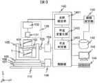
図1に3次元計測装置の構成を示す。検査対象である被検物1は、保持機構101および102によって保持されている。ここで、被検物1と保持機構101および102の全体がサーボモータ103に接続されており、xz平面上でy軸を中心とした回転機構を有する。ここで、保持機構101および102は、サーボモータ103の回転量と被検物1の回転量にずれが生じない適度な保持力を持つ。ここで、被検物1と距離計測部130との相対位置は、検査カバー率(=検査可能面積/全体面積被検物)が大きくなるように、つまり検査領域がより広くなるように、距離計測部130の特性を顧みて配置されなければいけない。詳細は後述するが、本実施例では、被検物1に対する距離計測部130の相対位置が検査時に通る検査経路を経路設定部150にて設定する。なお、被検物1は3次元形状計測により品質確保が必要な加工品や、加工精度管理のために形状計測が必要な加工工具などである。
FIG. 1 shows the configuration of the three-dimensional measuring apparatus. A
また、被検物1、保持機構101および102、サーボモータ103の全体はベース105により保持されており、ベース105はxステージ106、yステージ107、ゴニオステージ108に搭載されている。ゴニオステージ108の回転方向はyz平面内であり、回転軸はx軸方向である。xステージ106、yステージ107、ゴニオステージ108およびベース105は、防振定盤110に搭載されている。サーボモータ103はモータコントローラ104を、xステージ106、yステージ107、ゴニオステージ108の3つは3軸のステージコントローラ109を介し、制御用PC140にて動作が制御される。
Further, the
図1に示す3次元計測装置では、被検物1の3次元形状(表面状態)を、3次元形状センサとしての距離計測部130にて計測し、3次元形状データを取得する。距離計測部130は、非接触距離計測センサ131とセンサコントローラ132からなり、制御用PC140にて被検物1に対する距離計測部130の相対位置を制御する駆動部としての各ステージと同期制御され、計測結果はモニタ141に出力される。非接触距離計測センサ131は、例えば、レーザーの照射により、被検物1の点群を計測する距離計測センサであり、物体表面との距離を計測する。xステージ106とゴニオステージ108にて被検物1と距離計測センサ131の姿勢を定め、yステージ107とサーボモータ103を走査しながら距離計測センサ131と被検物1との距離を計測し、ステージ座標系を考慮することで、3次元座標系における点群を得る。非接触式の距離計測センサ131は、多くの手法が提案されており、いずれの方法も本実施例に適用可能である。例えば、三角測量に基づく光切断法、物体へ光を当て、その光が戻ってくる時間によって距離を計測するTOF(Time Of Flight)法、白色干渉を用いた干渉法、偏光干渉を応用したコノスコピックホログラフィーなどがある。また、周波数空間において等間隔に並ぶ多数の光周波数モードを持つ光周波数コムを用いた距離計測法や、周波数帰還型レーザを用いた距離計測法も適用可能である。これらの手法から、被検物1の大きさ、形状、表面状態(反射率、粗さ)に適した計測方法を選択する。
In the three-dimensional measuring apparatus shown in FIG. 1, the three-dimensional shape (surface state) of the
制御部140では、各ステージと距離計測部130の同期制御を行い点群を計測し、点群統合部1401にて多数の点群を1つの形状データとし、不良定量化部1402にてCAD(Computer Aided Design)データなどの設計形状もしくは理想形状を表す参照形状データ142との差分を算出しその差異を定量化し、不良判定部1403にてしきい値処理を施し不良か否かを判定する。
The
以下、本実施例における被検物と距離センサとの相対位置最適化機能を持つ3次元形状計測/検査方法について詳細に説明する。 Hereinafter, the three-dimensional shape measurement / inspection method having the function of optimizing the relative position between the test object and the distance sensor in this embodiment will be described in detail.
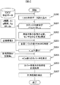
検査フローを図2に示す。適用する距離計測部130の性能に応じて経路設定部150にて計測領域を決定し(S100)、S100にて決定した計測領域に対し被検物1をステージ制御しながら距離計測部130にて3D空間中の座標を表す点群を取得し(S101)、計測した点群に含まれる距離計測部130の計測誤差に起因する例外値を除去する(S102)。S102にて取得した計測形状データとCADデータ、もしくは良品をS100〜S102と同様の過程にて計測した良品形状データとを比較し、計測形状データの形状不良を定量化し(S103)、しきい値を設けOK/NG判定を行う(S104)。
The inspection flow is shown in FIG. The
以下、各ステップを詳細に説明する。 Hereinafter, each step will be described in detail.
(S100)
距離計測部130は、使用する距離計測センサ131によって、その特性が異なる。一般に光を用いた非接触方式では、被検物1からの反射、拡散光を利用するため、被検物1測定箇所と距離センサ131より発するレーザ光の傾き具合によって計測精度が変化する。経路設定部150では、CADデータ等の測定対象の形状情報に基づき、距離センサ131の計測精度に応じて、被検物1との相対位置制御の最適値を導出する。経路設定部150の詳細は後述する。
(S100)
The
(S101)
距離計測部130と被検物1の相対位置は、サーボモータ103、xステージ106、yステージ107、ゴニオステージ108にて制御される。各ステージを、被検物1の計測領域をカバーするよう制御し、3D空間中の座標を表す点群を取得する。xステージ106とゴニオステージ108にて姿勢を決定し、サーボモータ103とyステージ107を走査する。距離計測部130にて計測されるのは、被検物1表面との距離であるため、各ステージの位置情報を用いて3D空間座標に変換する。
(S101)
The relative positions of the
(S102)
距離計測部130にて計測された点群には、距離計測部130の計測誤差により例外値が生じる。この例外値は、一般に計測点群の統計的な性質より除去される。例えば、ある着目範囲内にて密集している点群の位置の違いを標準偏差で表し、標準偏差のN倍距離が離れている点は例外値とするなどの処理が考えられる。
(S102)
An exceptional value is generated in the point group measured by the
(S103)
点群とCADデータと比較し、形状不良を定量化する。また、CADデータがない場合には、良品をS100〜S103の手順にてデジタル化した良品形状データと比較し、形状不良を定量化することもできる。また、S102にて取得した点群を、CADデータ等と比較する際、点群から法線情報を持つメッシュデータに変換してもよい。変換方法としては、Ball−Pivoting法、Power Crust法等を利用することができる。
(S103)
Compare the point cloud and CAD data to quantify the shape defect. In addition, when there is no CAD data, the defective product can be quantified by comparing the non-defective product with the non-defective product shape data digitized by the procedures of S100 to S103. Further, when the point group acquired in S102 is compared with CAD data or the like, the point group may be converted into mesh data having normal information. As a conversion method, a Ball-Pivoting method, a Power Crush method, or the like can be used.
(S104)
S103にて定量化した形状不良値に対し、しきい値をあらかじめ設定し、しきい値以下をOK、以上をNGとするOK/NG判定を自動的に行う。しきい値は被検物1の理想値や設計値からのずれを表しており、ユーザが用途に応じて任意に設定する。
(S104)
A threshold is set in advance for the shape defect value quantified in S103, and OK / NG determination is automatically performed with OK below the threshold and NG above. The threshold value represents a deviation from the ideal value or design value of the
以下、経路設定部150の詳細を説明する。経路設定部ではあらかじめ用意してあるCADデータや事前に取得された形状データなど、被検物1の形状を表す参照データ、および距離センサ131の計測精度特性を用いて、距離センサ131と被検物1の相対位置の適切な設定値を導出する。計測精度特性は、例えば距離センサ131から発せられるレーザと被検物1の計測面とのなす角の精度依存性、被検物1に反射し距離センサ131に戻ってくる光量の精度依存性、被検物1の面粗さとの精度依存性等、被検物1と距離センサ131との距離に応じた精度依存性などを指す。本実施例では、距離センサ131から発せられるレーザと被検物1の計測面とのなす角の精度依存性を例に取った場合の計算手順を図3に示す。
Details of the
(S200)
CADデータもしくは、別途計測した被検物1の形状データを読み込む。形式はCAD形式、メッシュ形式、点群形式などがある。
(S200)
The CAD data or the shape data of the
(S201)
図1に示す形状計測装置は可動部としてサーボモータ103、xステージ106、yステージ107、ゴニオステージ108を備える。xステージ106とゴニオステージ108において、被検物1と距離センサ131の初期位置を決定し、サーボモータ103の回転角θとyステージ107の位置yを可変しながら、被検物1と距離センサ131から発せられるレーザとの距離を算出する。
(S201)
The shape measuring apparatus shown in FIG. 1 includes a
このとき、条件設定時のxステージ106の可動範囲と間隔Δx、ゴニオステージ108の可動範囲と間隔Δgを入力する。これらの値は、S200にて入力した形状データの大きさを考慮し、全体計測が可能となるようxステージとゴニオステージの可動範囲を、実際の装置に搭載されているステージ性能に依存して間隔Δx、Δgを自動的に設定してもよい。また、間隔が細かいほど、計算条件が増え、計算時間が膨大にかかるため、計算時間を顧みて間隔Δx、Δgを決めることもできる。また、計算時のθとyの分解能Δθ、Δyも入力する。ただし、S200にて入力した形状データの空間分解能と同程度、もしくはある係数をかけて算出するなど、自動的に決定してもよい。なお、計測時に得られる点群数はθとyの分解能に依存して決まる。被検物1の全体形状を適切に計測可能なxステージ106とゴニオステージ108の組み合わせ数および、その組み合わせを決定する。最適な組み合わせを求めるため、xステージ106とゴニオステージ108に可動範囲、間隔を与え、それぞれの位置にて以下S202の計算を施す。
At this time, the movable range and interval Δx of the
(S202)
次にS200にて読み込んだ形状データの局所領域ごとに距離計測センサから発せられるレーザとのなす角を導出する。光学式の距離センサ131の性能は一般に被検物1と距離センサ131から発せられるレーザとのなす角αに大きく依存する。ここでは、測定精度を表す指標としてなす角αを用いる。被検物1と距離センサ131から発せられるレーザとのなす角αは、各ステージの位置が決まれば、機械的に算出できる。あるステージ位置が設定された場合、図4に示すように距離センサ131から発せられる照射レーザ1301が被検物1にあたる個所が計測点11であり、計測点11と照射レーザ1301のなす角αを算出することができる。実際のαの算出方法はS200にて入力したデータの形式により異なる。CADデータの場合、S201にて設定した分解能で各ステージを走査、被検物1にレーザが当たる個所において周囲の面方向を推定し、αを算出する。面方向は、レーザのあたる個所付近で分解能以下の領域を選択し、主成分分析等を用いて主な面方向を求める。メッシュデータの場合、各メッシュが法線情報を保持しているため、メッシュごとにαを算出することができる。ステージの分解能もメッシュの分解能を基準に設定する。メッシュが必要以上に高分解能の場合は、複数メッシュで1つのαを算出することもできる。点群データの場合は、各点群においてαを算出することができる。ある点に着目すると、その周囲の点群より主成分分析等を用いて面の方向を導出し、αを算出する。最小空間分解能は点群間隔で決まる。
(S202)
Next, for each local region of the shape data read in S200, an angle formed with the laser emitted from the distance measuring sensor is derived. In general, the performance of the
(S203)
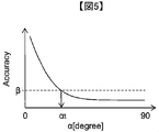
S202にて算出した各面ごとのαに対し、しきい値αtを設け、しきい値以上はOK,以下をNGとする判定を行う。しきい値αtは距離センサ131の特性にて決まるもので、面の傾きと計測に必要な精度の関係から導出する。図5に計測に必要な精度と面の傾きαとの関係を示す。図5に示すとおり、面の傾きαが小さくなるほど計測に必要な精度βは高くなる。計測に必要な精度βを与えると、計測時に必要とされる面の傾きのしきい値αtが一意に決定され、面の傾きαがしきい値αt以上で計測に必要な精度βを満たすことになる。しきい値αtによる判定を、形状データに含まれる全ての面に対して実施する。これにより、計測に必要な所定の精度β以上のしきい値αtによる判定を行うことができる。
(S203)
A threshold value αt is set for α for each surface calculated in S202, and a determination is made that OK is given above the threshold value, and NG is given below. The threshold value αt is determined by the characteristics of the
(S204)
S202,S203にてxステージ106、ゴニオステージ108のある設定の場合において、被検物1を表す形状データを構成する各面と距離計測センサ131とのなす角、およびしきい値処理によるOK/NG判定が出ている。想定しているxステージ106、ゴニオステージ108のそれぞれの位置X,gの組み合わせ数NだけS202、S203の計算を繰り返す。
(S204)
In the case where the
(S205)
測定回数Mを指定し、N通りの計測条件の中から適切なM回の組み合わせを選択する。形状データがメッシュデータの場合にて説明する。図6に示すように、対象としているメッシュ12には、S204にて考慮したxステージ106とゴニオステージ108の組み合わせで決まるN通りの方向から距離計測センサ131のレーザが照射される。例えば、ある条件では照射レーザ1301aとなり面とのなす角はαaとなる。同様に照射レーザ1301bではなす角αb、照射レーザ1301cではなす角αcであり、αa<αb<αc<90°である。ここでしきい値がαb<αt<αcだと、照射ビーム1301cの場合のみOKと判定される。ここで、組み合わせの選択の指標としてカバー率を用いる。カバー率はメッシュ数をA、OK判定のメッシュ数をBとしたとき、B/Aにて定義する。算出フローを図7に示す。N通りの計測条件からM個を選択し、(S300)A個のメッシュより1つを選択、(S301)M通りのαの中で1つでもしきい値以上となるものがあれば、そのメッシュは計測可能メッシュとしてカウントし、(S302)Bに1を加える(Bの初期値は0とする)。(S303)S302をメッシュ数Aだけ繰り返し、(S304)B/Aを算出する。
(S205)
The number of times of measurement M is designated, and an appropriate combination of M times is selected from N kinds of measurement conditions. The case where the shape data is mesh data will be described. As shown in FIG. 6, the
(S206)
S205をNCMの全ての組み合わせに対して実行し、最もカバー率の高い計測条件を最適値として選択する。なお、最もカバー率が高い計測条件ではなく、所定のカバー率を超える計測条件の1つを選択してもよい。
(S206)
S205 is executed for all combinations of NCMs, and the measurement condition with the highest coverage is selected as the optimum value. In addition, you may select one of the measurement conditions exceeding predetermined | prescribed coverage rather than the measurement conditions with the highest coverage.
(S207)
S206にて決定されたのは計測条件であり、実測する場合には計測する順序も定め、計測経路とする必要がある。M通りの計測を適切な順序とするため、計測時間を最短にする、計測経路(被検物1に対する距離計測部130の相対位置の移動量)を最短にする等の最適化を行う。なお、M通り全てについて計測せずに所定の個数の経路について計測時間を計算し、その中で最短となるようにして計測時間が短くなるようにしてもよい。
(S207)
What is determined in S206 is the measurement condition, and in the case of actual measurement, it is necessary to determine the order of measurement and to set the measurement path. In order to set M kinds of measurements in an appropriate order, optimization such as minimizing the measurement time and minimizing the measurement path (the amount of movement of the relative position of the
以下、計測時間を最短にする際の実施例を示す。M通りの計測位置に関してxステージ106の位置をxi、ゴニオステージの位置をgi、i=1, 2, 3, …Mとする。計測時間が最短となるようなiの順序を決定する。状態iからi+1へxステージ106が移動するときの移動量をSxi(=|xi-xi+1|)、加速度をax、減速度をax’, 速度をvxとすると、移動にかかる時間Txi=Sxi/vx+0.5vx(1/ax+1/ax’)と表すことができる。同様にゴニオステージの移動量をSgi(=|gi-gi+1|)、加速度をag, 減速度をgx’, 速度をvgとすると、移動にかかる時間Tgi=Sgi/vg+0.5vg(1/ag+1/ag’)となる。E=Σ(Txi+Tgi)が最小となるiの順序を最適化計算にて導出することで、最短経路が導出される。以上の計算は、定速で移動する箇所があると仮定し、加減速の速度の小さい方をaとし|v2/a|>Sが成り立つとした。これにより、距離計測部130による被検物1の計測時間を短縮することができる。
Hereinafter, an example in which the measurement time is minimized will be described. For the M measurement positions, the position of the
以上のように計測された点群は、CAD等の設計形状もしくは理想形状と比較される。本実施例においては、xステージ106とゴニオステージ108それぞれの位置をパラメータとし複数回計測を行う。CAD等と比較する際、複数回データを個別に比較する、もしくは統合して比較するという2通りが考えられる。1回の計測にて大まかな形状が把握できる場合には個々のデータと比較するとよい。一方、被検物1が複雑な形状のため1回に計測できる領域が少ない場合には統合してから比較するとよい。
The point group measured as described above is compared with a design shape such as CAD or an ideal shape. In this embodiment, measurement is performed a plurality of times using the positions of the
ここで、経路設定150で設定された経路で距離センサ131にて取得した複数の計測データを点群統合部1401にて統合する方法について説明する。xステージ106とゴニオステージ108の動作が測定精度に影響を与えないほど正確に補正されている場合、各データの統合はステージにて移動した座標系の変換を行えばよい。この補正が不十分な場合には、計測後の点群データ同士を位置合わせし、統合する必要がある。点群同士の統合にはICP(Iterative Closest Point)法を基本とした手法が広く用いられている。この手法では、複数点群の重複部分が最も整合性の取れるように点群同士の配置を最適化する。そのため、各点群には重複する部分が必須である。図8に複数回計測において重複部分も考慮した検査経路設定フローについて説明する。図3と同様の部分は説明を割愛し、S405からS409までを説明する。データ統合時に必要となる重複率εは形状データによって異なるためユーザが適したものを設定する。形状の複雑さを表す面方向を指標に自動的に設定してもよい。なお、重複率は入力データがメッシュデータの場合、重複しているメッシュ/全メッシュにて定義する。
Here, a method of integrating a plurality of measurement data acquired by the
複数の計測データを統合することで、検査領域全体について高い精度での計測結果を得ることができる。 By integrating a plurality of measurement data, a measurement result with high accuracy can be obtained for the entire inspection region.
(S405)
N通りのxステージ106とゴニオステージ108の組み合わせから計測回数として指定したM通りを選択する。
(S405)
From the combinations of N types of x stages 106 and
(S406)
M通りの計測条件から2通りを選択し、重複率を算出する。これをすべての条件の組み合わせMC2通り分計算する。
(S406)
Two methods are selected from the M measurement conditions, and the duplication rate is calculated. This is calculated for all combinations of conditions MC2.
(S407)
S406にて計算したMC2通りの重複率の中で最低値を算出しεと比較する。ε以上
であれば以降の計算を継続し、以下であればS405にて選択した組み合わせは計測条件に適さないとしこれ以上の計算を行わない。
(S407)
The lowest value of the MC2 overlap rates calculated in S406 is calculated and compared with ε. If it is equal to or greater than ε, the subsequent calculation is continued, and if it is equal to or less than that, the combination selected in S405 is not suitable for the measurement condition, and no further calculation is performed.
(S408)
S407にて重複率の最低値がε以上と判定された組み合わせに対してカバー率を算出する。
(S408)
In S407, the cover ratio is calculated for the combination determined that the minimum value of the overlap ratio is ε or more.
(S409)
S405からS408をNCM通りの組み合わせ分実施する。
ここまでは計測回数Mを固定し、カバー率を算出する方法を示したが、カバー率にしきい値を設け、それを満たす計測回数Mを求めることもできる。その場合は、カバー率がしきい値以上となるまで、Mを増やしながら図8に示す経路導出フローの計算を繰り返し行えばよい。
(S409)
S405 to S408 are performed for NCM combinations.
Up to this point, the method of calculating the cover ratio while fixing the number of measurements M has been described. However, it is also possible to provide a threshold value for the cover ratio and obtain the number of measurements M that satisfies the threshold. In that case, the calculation of the route derivation flow shown in FIG. 8 may be repeated while increasing M until the coverage becomes equal to or greater than the threshold value.
これまで説明してきた計測経路設定部を操作するGUI(Graphical User Interface)の例を図9に示す。GUI300を開き、始めに形状データボタン301にて形状データを読み込み、表示ウィンドウ302に表示する。また、使用するセンサ特性(面の傾きと精度の情報)をセンサ特性ボタン303にて読み込む。次に、経路設定に必要なパラメータを入力する。経路を探索するxステージ106の可動範囲をx最小値ボックス304、x最大値ボックス305に入力する。ゴニオステージ108に関しても同様に、g最小値ボックス306、g最大値ボックス307に入力する。また、x、y、ゴニオステージ、サーボモータの分解能を分解能ボックス308−311に入力する。測定精度βを精度入力ボックス312に、重複率εを重複率入力ボックス313、計測回数Mを計測回数入力ボックス314にそれぞれ入力する。なお、ステージに関連するパラメータには事前情報から推定値を導出することができ、これらをAUTOボタン315にて自動入力できる。パラメータを設定した後、経路算出ボタン316にて経路を算出し、ウィンドウに計測経路を表示する。
FIG. 9 shows an example of a GUI (Graphical User Interface) for operating the measurement path setting unit described so far. The
以上より、本実施例によれば、被検物1に対する距離計測部130の相対位置が検査時に通る検査経路を経路設定部150にて設定することで、作業者により計測精度のばらつきが生じず、複雑な3次元形状を安定して計測することができる。
As described above, according to the present embodiment, by setting the inspection path through which the relative position of the
本発明の実施例2を図10〜図13を用いて説明する。 A second embodiment of the present invention will be described with reference to FIGS.
図10に構成を示す。図1と比較し、画像撮像部120が追加されている。本実施例では距離計測部130と画像撮像部120の2種の特性の異なるセンサを用いた形状計測装置を用いた場合の計測経路最適化に関して説明する。図10に示す3次元計測装置では、被検物1の表面状態および形状を、画像撮像部120および距離計測部130にて計測する。画像撮像部120では、照明部121により被検物1を任意の方向より照明し、その反射光、散乱光、回折光、拡散光をレンズ122により2次元カメラ123にて撮像し、3次元形状を2次元の画像データとして取得する。照明部121にはランプ、LED(Light Emitting Diode)等を使用でき、図10は単一方向からの照明を示しているが、照明方向は複数方向でもよいし、リング状照明を用いてもよい。また、単一方向から照明する場合においても、照明方向を自由に設定できる機構を持ち、被検物1の表面状態、形状に応じて、表面凹凸や形状を顕在化する方向から照明光を照射することができる。2次元カメラ123にはCCD(Charge Coupled Device)イメージセンサやCMOS(Complementary Metal Oxide Semiconductor)イメージセンサなどが使用できる。2次元カメラ123はカメラコントローラ124を介し、制御用PC140にて制御され、計測結果はモニタ141に出力される。なお、2次元カメラ123の画像歪等を表す内部パラメータ、2次元カメラ123と距離計測部130との座標関係はあらかじめ較正しておくこととする。
FIG. 10 shows the configuration. Compared to FIG. 1, an
2次元カメラ123にて撮像された画像より、形状を求める手法に、3角測量に基づくステレオ法、レンズの焦点を動かしピントを合わせることで距離を計測するレンズ焦点法、物体に格子パターンを投影し物体表面の形状に応じて変形したパターン模様から形状計測するモアレ法などがある。また、表面凹凸を検出する手法として、照明方向による陰影の違いを利用し、対象物体の面の法線ベクトル方向を推定する照度差ステレオ等がある。
The stereo method based on triangulation, the lens focus method that measures the distance by moving the focus of the lens, and the method of obtaining the shape from the image captured by the two-
以後、距離計測センサ131と複数画像の視点の違いを利用し立体形状を復元するステレオ法を用いた場合に関して詳細に説明する。ステレオ法は、画像の中で周囲と明暗の変化が大きく表れるエッジ部の形状計測に適している。そのため、エッジ部は画像撮像部120にて計測し、滑らかな面は距離計測部130にて計測することで、安定した計測/検査が実現する。図11に計測フローを示す。
Hereinafter, the case of using the stereo method that restores the three-dimensional shape using the difference between the viewpoints of the
(S500)
CADデータもしくは、別途計測した被検物1の形状データを読み込む。形式はCAD形式、メッシュ形式、点群形式がある。
(S500)
The CAD data or the shape data of the
(S501)
S500にて読み込んだ形状データからエッジ部を認識する。エッジ部の認識方法の詳細は後述する。
(S501)
The edge portion is recognized from the shape data read in S500. Details of the edge recognition method will be described later.
(S502)
計測部がエッジ部か否かにより、撮像部120もしくは距離計測部130にて、計測を実施することとする。
(S502)
Depending on whether or not the measurement unit is an edge portion, the
(S503)
計測部がエッジではない場合、距離計測部130にて計測を実施する。図3もしくは図8に示した方法にて経路設定部150にてエッジ部を除いた非エッジ部について計測経路を決定した後、計測する。
(S503)
If the measurement unit is not an edge, the
(S504)
エッジ部に関しては撮像部120にてステレオ計測を行う。この時、カメラは測定対象位置の焦点が合うように設定し固定しておき、サーボモータ103による被検物1の回転により生じる視差を利用する。
(S504)
For the edge portion, stereo measurement is performed by the
(S505)
S503およびS504にて計測された点群を、座標系の変換にて統合する。距離計測部130と撮像部120では、その特性の違いから、計測される箇所に重複部分が少なく、ICP等の手法で統合することは困難である。
(S505)
The point groups measured in S503 and S504 are integrated by coordinate system conversion. In the
(S506)
距離計測部130および画像撮像部120にて計測された点群には、それぞれの計測誤差により例外値が含まれている。この例外値は、一般に計測点群の統計的な性質より除去される。例えば、ある着目範囲内にて密集している点群の位置の違いを標準偏差で表し、標準偏差のN倍距離が離れている点は例外値とするなどの処理が考えられる。
(S506)
The point group measured by the
(S507)
点群とCADデータと比較し、形状不良を定量化する。また、CADデータがない場合には、良品をS500〜S506の手順にてデジタル化した良品形状データと比較し、形状不良を定量化することもできる。また、S102にて取得した点群を、CADデータ等と比較する際、点群から法線情報を持つメッシュデータに変換してもよい。変換方法としては、Ball−Pivoting、Power Crust等を利用することができる。
(S507)
Compare the point cloud and CAD data to quantify the shape defect. Further, when there is no CAD data, the defective product can be quantified by comparing the non-defective product with the non-defective product shape data digitized by the procedure of S500 to S506. Further, when the point group acquired in S102 is compared with CAD data or the like, the point group may be converted into mesh data having normal information. As a conversion method, Ball-Pivoting, Power Crush, or the like can be used.
(S508)
S103にて定量化した形状不良値に対し、しきい値をあらかじめ設定し、しきい値以下をOK、以上をNGとするOK/NG判定を自動的に行う。しきい値は被検物1の理想値や設計値からのずれを表しており、ユーザが用途に応じて任意に設定する。
(S508)
A threshold is set in advance for the shape defect value quantified in S103, and OK / NG determination is automatically performed with OK below the threshold and NG above. The threshold value represents a deviation from the ideal value or design value of the
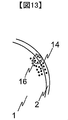
次にエッジ部の認識方法を説明する。図12にフローを示した。 Next, a method for recognizing the edge portion will be described. FIG. 12 shows the flow.
(S600)
図13にエッジ部2が含まれる被検物1を示す。計測点群14にて構成されている。領域A16を設定しその中に含まれる点群に球面をフィッティングし曲率を算出する。点群が存在する領域すべてにおいて同様の作業を繰り返し実施する。
(S600)
FIG. 13 shows the
(S601)
しきい値を設け曲率がγ以上、以下を判定する。
(S601)
A threshold is provided to determine whether the curvature is greater than or equal to γ.
(S602)
曲率がγ以上の箇所をエッジ部と認識する。
(S602)
A portion having a curvature of γ or more is recognized as an edge portion.
(S603)
曲率がγ未満の箇所を非エッジ部と認識する。
(S603)
A portion having a curvature less than γ is recognized as a non-edge portion.
以上より、本実施例によれば、非エッジ部を距離計測部130にて計測し、エッジ部を画像撮像部120にて計測することにより、被検物1の形状に対応して、精度の高い計測を行うことができる。
As described above, according to the present embodiment, the non-edge portion is measured by the
これまで説明してきた実施例は、何れも本発明を実施するにあたっての具体化の一例を示したものに過ぎず、これらによって本発明の技術的範囲が限定的に解釈されない。すなわち、本発明はその技術思想、又はその主要な特徴から逸脱することなく、様々な形で実施することができる。 The embodiments described so far are merely examples of implementation in carrying out the present invention, and the technical scope of the present invention is not limitedly interpreted by these. That is, the present invention can be implemented in various forms without departing from the technical idea or the main features thereof.
1・・・被検物
2・・・エッジ部
11・・・計測点
14・・・計測点群
16・・・領域A
101、102・・・保持機構
103・・・サーボモータ
104・・・モータコントローラ
105・・・ベース
106・・・xステージ
107・・・yステージ
108・・・ゴニオステージ
109・・・ステージコントローラ
110・・・防振定盤
120・・・画像撮像部
121・・・照明部
122・・・レンズ
123・・・2次元カメラ
124・・・カメラコントローラ
130・・・距離計測部
131・・・非接触距離計測センサ
132・・・センサコントローラ
140・・・制御用PC
141・・・モニタ
142・・・参照形状データ
143・・・データベース
144・・・入力装置
150・・・経路設定部
300・・・GUI
301・・・形状データボタン
302・・・表示ウィンドウ
303・・・センサ特性ボタン
304・・・x最小値ボックス
305・・・x最大値ボックス
306・・・g最小値ボックス
307・・・g最大値ボックス
308,309,310,311・・・分解能ボックス
312・・・精度入力ボックス
313・・・重複率入力ボックス
314・・・測定回数入力ボックス
315・・・AUTOボタン
316・・・経路算出ボタン
1301、1301a、1301b、1301c・・・照射レーザ
1401・・・点群統合部
1402・・・不良定量部
1402・・・不良判定部
DESCRIPTION OF
101, 102 ...
141 ...
301 ...
Claims (14)
前記検査対象の形状データを表す参照データを用いて、前記検査対象に対する前記3次元形状センサの相対位置が検査時に通る経路を設定する経路設定部と、
前記検査対象に対する前記3次元形状センサの相対位置を制御する駆動部とを備える形状検査装置。 A three-dimensional shape sensor for acquiring shape data of an inspection object;
A path setting unit that sets a path through which a relative position of the three-dimensional shape sensor with respect to the inspection target passes during the inspection, using reference data representing the shape data of the inspection target;
A shape inspection apparatus comprising: a drive unit that controls a relative position of the three-dimensional shape sensor with respect to the inspection object.
前記経路設定部は、前記距離計測センサから照射されるレーザと前記検査対象の被検査面とのなす角度が所定のしきい値以上の場合、必要な精度以上とみなすことを特徴とする請求項2に記載の形状検査装置。 The three-dimensional shape sensor is a distance measurement sensor that measures a point cloud of the inspection object by irradiating the inspection object with a laser,
The path setting unit, when an angle formed between a laser irradiated from the distance measurement sensor and the surface to be inspected is equal to or greater than a predetermined threshold value, is regarded as greater than a required accuracy. 2. The shape inspection apparatus according to 2.
前記検査対象のうち、エッジ部を前記2次元カメラにより取得し、前記エッジ部を除いた非エッジ部を前記3次元形状センサにより取得し、前記経路設定部はエッジ部を除いた部分の経路を設定することを特徴とする請求項1に記載の形状検査装置。 A two-dimensional camera for acquiring the shape data of the inspection object;
Among the inspection objects, an edge part is acquired by the two-dimensional camera, a non-edge part excluding the edge part is acquired by the three-dimensional shape sensor, and the path setting unit extracts a path of a part excluding the edge part. The shape inspection apparatus according to claim 1, wherein the shape inspection apparatus is set.
設定した前記経路を通るように前記検査対象に対する前記3次元形状センサの相対位置を制御し、
前記3次元形状センサで前記検査対象の形状データを取得することを特徴とする形状検査方法。 Using reference data representing the shape data of the inspection target, a path through which the relative position of the three-dimensional shape sensor with respect to the inspection target passes during the inspection is set.
Control the relative position of the three-dimensional shape sensor with respect to the inspection object so as to pass through the set path,
A shape inspection method, wherein the shape data of the inspection object is acquired by the three-dimensional shape sensor.
前記検査対象のエッジ部を除いた非エッジ部について前記経路を設定し、3次元形状センサで形状データを取得し、
前記2次元カメラにより取得した形状データと前記3時原形乗船差で取得した形状データとを統合することを特徴とする請求項8に記載の形状検査方法。 The shape data of the edge part to be inspected is acquired by a two-dimensional camera,
The path is set for the non-edge portion excluding the edge portion to be inspected, and the shape data is acquired by a three-dimensional shape sensor,
9. The shape inspection method according to claim 8, wherein the shape data acquired by the two-dimensional camera and the shape data acquired by the 3 o'clock original boarding difference are integrated.
Priority Applications (4)
| Application Number | Priority Date | Filing Date | Title |
|---|---|---|---|
| JP2013042494A JP2014169947A (en) | 2013-03-05 | 2013-03-05 | Shape inspection method and device thereof |
| EP14760754.3A EP2966401A4 (en) | 2013-03-05 | 2014-01-24 | Shape examination method and device therefor |
| US14/761,377 US20150362310A1 (en) | 2013-03-05 | 2014-01-24 | Shape examination method and device therefor |
| PCT/JP2014/051441 WO2014136490A1 (en) | 2013-03-05 | 2014-01-24 | Shape examination method and device therefor |
Applications Claiming Priority (1)
| Application Number | Priority Date | Filing Date | Title |
|---|---|---|---|
| JP2013042494A JP2014169947A (en) | 2013-03-05 | 2013-03-05 | Shape inspection method and device thereof |
Publications (2)
| Publication Number | Publication Date |
|---|---|
| JP2014169947A true JP2014169947A (en) | 2014-09-18 |
| JP2014169947A5 JP2014169947A5 (en) | 2015-07-30 |
Family
ID=51491016
Family Applications (1)
| Application Number | Title | Priority Date | Filing Date |
|---|---|---|---|
| JP2013042494A Pending JP2014169947A (en) | 2013-03-05 | 2013-03-05 | Shape inspection method and device thereof |
Country Status (4)
| Country | Link |
|---|---|
| US (1) | US20150362310A1 (en) |
| EP (1) | EP2966401A4 (en) |
| JP (1) | JP2014169947A (en) |
| WO (1) | WO2014136490A1 (en) |
Cited By (3)
| Publication number | Priority date | Publication date | Assignee | Title |
|---|---|---|---|---|
| JP2017204222A (en) * | 2016-05-13 | 2017-11-16 | 株式会社トプコン | Management device, management method, and program for management |
| WO2021131990A1 (en) * | 2019-12-23 | 2021-07-01 | ソニーグループ株式会社 | Information processing device, information processing method, and program |
| JP2021170305A (en) * | 2020-02-17 | 2021-10-28 | クリスタルメソッド株式会社 | Information processor and information processing method |
Families Citing this family (8)
| Publication number | Priority date | Publication date | Assignee | Title |
|---|---|---|---|---|
| US9607370B2 (en) * | 2014-01-15 | 2017-03-28 | The Boeing Company | System and methods of inspecting an object |
| JP6452508B2 (en) * | 2015-03-17 | 2019-01-16 | オリンパス株式会社 | 3D shape measuring device |
| JP6519265B2 (en) * | 2015-03-27 | 2019-05-29 | 株式会社Ihi | Image processing method |
| JP6691837B2 (en) * | 2016-06-27 | 2020-05-13 | 株式会社キーエンス | measuring device |
| US20170084085A1 (en) * | 2016-11-30 | 2017-03-23 | Caterpillar Inc. | System and method for object recognition |
| CN112368568A (en) * | 2018-06-29 | 2021-02-12 | 株式会社高迎科技 | Turning device and object inspection method using same |
| JP7300915B2 (en) * | 2019-07-16 | 2023-06-30 | 株式会社トプコン | surveying equipment |
| JP7339069B2 (en) * | 2019-08-27 | 2023-09-05 | ファナック株式会社 | Machining program generation support device |
Citations (7)
| Publication number | Priority date | Publication date | Assignee | Title |
|---|---|---|---|---|
| JPH11298837A (en) * | 1998-04-13 | 1999-10-29 | Ricoh Co Ltd | Image input device and image input method |
| JP2004163347A (en) * | 2002-11-15 | 2004-06-10 | Kanto Auto Works Ltd | Off-line teaching method of noncontact three-dimensional shape measuring device |
| JP2005215917A (en) * | 2004-01-29 | 2005-08-11 | Hitachi Plant Eng & Constr Co Ltd | Working drawing creation support method and replacement model creation method |
| JP2007225434A (en) * | 2006-02-23 | 2007-09-06 | Yaskawa Electric Corp | Three-dimensional measuring device |
| JP2007292474A (en) * | 2006-04-21 | 2007-11-08 | Hitachi Plant Technologies Ltd | Three-dimensional shape measuring device |
| JP2008262555A (en) * | 2007-03-20 | 2008-10-30 | National Univ Corp Shizuoka Univ | Shape information processing method, device, and program |
| JP2011047863A (en) * | 2009-08-28 | 2011-03-10 | Konica Minolta Sensing Inc | Three-dimensional shape data processing apparatus, three-dimensional shape data processing system, and three-dimensional shape measurement system |
Family Cites Families (7)
| Publication number | Priority date | Publication date | Assignee | Title |
|---|---|---|---|---|
| GB2202659B (en) * | 1987-02-23 | 1991-07-17 | Mitutoyo Corp | Coordinate measuring instrument and method of generating pattern data concerning shape of work to be measured |
| GB0210990D0 (en) * | 2002-05-14 | 2002-06-19 | Rolls Royce Plc | Method of generating an inspection program and method of generating a visual display |
| DE102007032609A1 (en) * | 2007-07-11 | 2009-03-05 | Corpus.E Ag | Cost-effective detection of the inner spatial form of footwear and bodies |
| JP4872948B2 (en) | 2008-02-27 | 2012-02-08 | パルステック工業株式会社 | Three-dimensional shape measuring apparatus and three-dimensional shape measuring method |
| FR2940449A1 (en) * | 2008-12-24 | 2010-06-25 | Snecma | METHOD FOR NON-DESTRUCTIVE CONTROL OF A MECHANICAL PART |
| JP5278808B2 (en) | 2009-03-16 | 2013-09-04 | 株式会社ニコン | 3D shape measuring device |
| CN105486251B (en) * | 2014-10-02 | 2019-12-10 | 株式会社三丰 | Shape measuring device, shape measuring method, and positioning unit of point sensor |
-
2013
- 2013-03-05 JP JP2013042494A patent/JP2014169947A/en active Pending
-
2014
- 2014-01-24 EP EP14760754.3A patent/EP2966401A4/en not_active Withdrawn
- 2014-01-24 US US14/761,377 patent/US20150362310A1/en not_active Abandoned
- 2014-01-24 WO PCT/JP2014/051441 patent/WO2014136490A1/en active Application Filing
Patent Citations (7)
| Publication number | Priority date | Publication date | Assignee | Title |
|---|---|---|---|---|
| JPH11298837A (en) * | 1998-04-13 | 1999-10-29 | Ricoh Co Ltd | Image input device and image input method |
| JP2004163347A (en) * | 2002-11-15 | 2004-06-10 | Kanto Auto Works Ltd | Off-line teaching method of noncontact three-dimensional shape measuring device |
| JP2005215917A (en) * | 2004-01-29 | 2005-08-11 | Hitachi Plant Eng & Constr Co Ltd | Working drawing creation support method and replacement model creation method |
| JP2007225434A (en) * | 2006-02-23 | 2007-09-06 | Yaskawa Electric Corp | Three-dimensional measuring device |
| JP2007292474A (en) * | 2006-04-21 | 2007-11-08 | Hitachi Plant Technologies Ltd | Three-dimensional shape measuring device |
| JP2008262555A (en) * | 2007-03-20 | 2008-10-30 | National Univ Corp Shizuoka Univ | Shape information processing method, device, and program |
| JP2011047863A (en) * | 2009-08-28 | 2011-03-10 | Konica Minolta Sensing Inc | Three-dimensional shape data processing apparatus, three-dimensional shape data processing system, and three-dimensional shape measurement system |
Non-Patent Citations (1)
| Title |
|---|
| F. A. R. MARTINS ET AL.: "Automated 3D surface scanning based on CAD model", MECHATRONICS, vol. Volume 15, Issue 7, JPN6014008811, September 2005 (2005-09-01), pages 837 - 857, ISSN: 0003259420 * |
Cited By (3)
| Publication number | Priority date | Publication date | Assignee | Title |
|---|---|---|---|---|
| JP2017204222A (en) * | 2016-05-13 | 2017-11-16 | 株式会社トプコン | Management device, management method, and program for management |
| WO2021131990A1 (en) * | 2019-12-23 | 2021-07-01 | ソニーグループ株式会社 | Information processing device, information processing method, and program |
| JP2021170305A (en) * | 2020-02-17 | 2021-10-28 | クリスタルメソッド株式会社 | Information processor and information processing method |
Also Published As
| Publication number | Publication date |
|---|---|
| WO2014136490A1 (en) | 2014-09-12 |
| EP2966401A4 (en) | 2016-11-09 |
| EP2966401A1 (en) | 2016-01-13 |
| US20150362310A1 (en) | 2015-12-17 |
Similar Documents
| Publication | Publication Date | Title |
|---|---|---|
| WO2014136490A1 (en) | Shape examination method and device therefor | |
| CN114041168A (en) | Automated 360-degree dense point object inspection | |
| KR101604037B1 (en) | method of making three dimension model and defect analysis using camera and laser scanning | |
| JP2013186100A (en) | Shape inspection method and device | |
| JP5943547B2 (en) | Apparatus and method for non-contact measurement | |
| JP5911904B2 (en) | Accurate image acquisition on structured light systems for optical measurement of shape and position | |
| WO2013061976A1 (en) | Shape inspection method and device | |
| JP2016061687A (en) | Contour line measurement device and robot system | |
| JP6520451B2 (en) | Appearance photographing apparatus and appearance photographing method | |
| US11426876B2 (en) | Information processing apparatus, information processing method, and program | |
| Bernal et al. | Performance evaluation of optical scanner based on blue LED structured light | |
| TW201544788A (en) | Methods and system for inspecting a 3D object using 2D image processing | |
| JP5913903B2 (en) | Shape inspection method and apparatus | |
| JP7273185B2 (en) | COORDINATE SYSTEM ALIGNMENT METHOD, ALIGNMENT SYSTEM AND ALIGNMENT APPARATUS FOR ROBOT | |
| JP6285037B2 (en) | Manufacturing method of parts, manufacturing apparatus using the same, volume measuring method, shape measuring method | |
| JP2021193400A (en) | Method for measuring artefact | |
| EP3491333B1 (en) | Non-contact probe and method of operation | |
| US20230016639A1 (en) | System and method for controlling automatic inspection of articles | |
| JP2017198470A (en) | Measurement device, measurement method, system, and goods manufacturing method | |
| JP2020034484A (en) | Image inspection device | |
| JP6043974B2 (en) | Three-dimensional position measuring device, three-dimensional measuring device, and three-dimensional position measuring program | |
| JP6884077B2 (en) | Surface inspection equipment and surface inspection method | |
| Bernal et al. | Accuracy analysis of fringe projection systems based on blue light technology | |
| JP2016095243A (en) | Measuring device, measuring method, and article manufacturing method | |
| JP7442752B1 (en) | Shape inspection method of inspected object |
Legal Events
| Date | Code | Title | Description |
|---|---|---|---|
| A521 | Request for written amendment filed |
Free format text: JAPANESE INTERMEDIATE CODE: A523 Effective date: 20150612 |
|
| A621 | Written request for application examination |
Free format text: JAPANESE INTERMEDIATE CODE: A621 Effective date: 20150612 |
|
| A131 | Notification of reasons for refusal |
Free format text: JAPANESE INTERMEDIATE CODE: A131 Effective date: 20160223 |
|
| A521 | Request for written amendment filed |
Free format text: JAPANESE INTERMEDIATE CODE: A523 Effective date: 20160407 |
|
| A131 | Notification of reasons for refusal |
Free format text: JAPANESE INTERMEDIATE CODE: A131 Effective date: 20160906 |
|
| RD04 | Notification of resignation of power of attorney |
Free format text: JAPANESE INTERMEDIATE CODE: A7424 Effective date: 20170110 |
|
| RD04 | Notification of resignation of power of attorney |
Free format text: JAPANESE INTERMEDIATE CODE: A7424 Effective date: 20170112 |
|
| A02 | Decision of refusal |
Free format text: JAPANESE INTERMEDIATE CODE: A02 Effective date: 20170321 |