JP7298699B2 - Vehicle remote control method and vehicle remote control device - Google Patents
Vehicle remote control method and vehicle remote control device Download PDFInfo
- Publication number
- JP7298699B2 JP7298699B2 JP2021544947A JP2021544947A JP7298699B2 JP 7298699 B2 JP7298699 B2 JP 7298699B2 JP 2021544947 A JP2021544947 A JP 2021544947A JP 2021544947 A JP2021544947 A JP 2021544947A JP 7298699 B2 JP7298699 B2 JP 7298699B2
- Authority
- JP
- Japan
- Prior art keywords
- gesture
- vehicle
- determination area
- input
- remote control
- Prior art date
- Legal status (The legal status is an assumption and is not a legal conclusion. Google has not performed a legal analysis and makes no representation as to the accuracy of the status listed.)
- Active
Links
- 238000000034 method Methods 0.000 title claims description 64
- 238000001514 detection method Methods 0.000 description 35
- 238000004891 communication Methods 0.000 description 18
- 238000010586 diagram Methods 0.000 description 11
- 230000005540 biological transmission Effects 0.000 description 4
- 238000013459 approach Methods 0.000 description 2
- 238000005516 engineering process Methods 0.000 description 2
- 230000003213 activating effect Effects 0.000 description 1
- 230000004913 activation Effects 0.000 description 1
- 238000002485 combustion reaction Methods 0.000 description 1
- 230000001568 sexual effect Effects 0.000 description 1
- 239000000725 suspension Substances 0.000 description 1
- 230000001755 vocal effect Effects 0.000 description 1
Images


Classifications
-
- G—PHYSICS
- G08—SIGNALLING
- G08C—TRANSMISSION SYSTEMS FOR MEASURED VALUES, CONTROL OR SIMILAR SIGNALS
- G08C17/00—Arrangements for transmitting signals characterised by the use of a wireless electrical link
- G08C17/02—Arrangements for transmitting signals characterised by the use of a wireless electrical link using a radio link
-
- G—PHYSICS
- G05—CONTROLLING; REGULATING
- G05D—SYSTEMS FOR CONTROLLING OR REGULATING NON-ELECTRIC VARIABLES
- G05D1/00—Control of position, course, altitude or attitude of land, water, air or space vehicles, e.g. using automatic pilots
- G05D1/0011—Control of position, course, altitude or attitude of land, water, air or space vehicles, e.g. using automatic pilots associated with a remote control arrangement
- G05D1/0016—Control of position, course, altitude or attitude of land, water, air or space vehicles, e.g. using automatic pilots associated with a remote control arrangement characterised by the operator's input device
-
- B—PERFORMING OPERATIONS; TRANSPORTING
- B60—VEHICLES IN GENERAL
- B60W—CONJOINT CONTROL OF VEHICLE SUB-UNITS OF DIFFERENT TYPE OR DIFFERENT FUNCTION; CONTROL SYSTEMS SPECIALLY ADAPTED FOR HYBRID VEHICLES; ROAD VEHICLE DRIVE CONTROL SYSTEMS FOR PURPOSES NOT RELATED TO THE CONTROL OF A PARTICULAR SUB-UNIT
- B60W30/00—Purposes of road vehicle drive control systems not related to the control of a particular sub-unit, e.g. of systems using conjoint control of vehicle sub-units
- B60W30/06—Automatic manoeuvring for parking
-
- B—PERFORMING OPERATIONS; TRANSPORTING
- B60—VEHICLES IN GENERAL
- B60W—CONJOINT CONTROL OF VEHICLE SUB-UNITS OF DIFFERENT TYPE OR DIFFERENT FUNCTION; CONTROL SYSTEMS SPECIALLY ADAPTED FOR HYBRID VEHICLES; ROAD VEHICLE DRIVE CONTROL SYSTEMS FOR PURPOSES NOT RELATED TO THE CONTROL OF A PARTICULAR SUB-UNIT
- B60W40/00—Estimation or calculation of non-directly measurable driving parameters for road vehicle drive control systems not related to the control of a particular sub unit, e.g. by using mathematical models
- B60W40/08—Estimation or calculation of non-directly measurable driving parameters for road vehicle drive control systems not related to the control of a particular sub unit, e.g. by using mathematical models related to drivers or passengers
-
- B—PERFORMING OPERATIONS; TRANSPORTING
- B60—VEHICLES IN GENERAL
- B60W—CONJOINT CONTROL OF VEHICLE SUB-UNITS OF DIFFERENT TYPE OR DIFFERENT FUNCTION; CONTROL SYSTEMS SPECIALLY ADAPTED FOR HYBRID VEHICLES; ROAD VEHICLE DRIVE CONTROL SYSTEMS FOR PURPOSES NOT RELATED TO THE CONTROL OF A PARTICULAR SUB-UNIT
- B60W60/00—Drive control systems specially adapted for autonomous road vehicles
- B60W60/001—Planning or execution of driving tasks
-
- G—PHYSICS
- G05—CONTROLLING; REGULATING
- G05D—SYSTEMS FOR CONTROLLING OR REGULATING NON-ELECTRIC VARIABLES
- G05D1/00—Control of position, course, altitude or attitude of land, water, air or space vehicles, e.g. using automatic pilots
- G05D1/20—Control system inputs
- G05D1/22—Command input arrangements
- G05D1/221—Remote-control arrangements
- G05D1/222—Remote-control arrangements operated by humans
- G05D1/223—Command input arrangements on the remote controller, e.g. joysticks or touch screens
-
- G—PHYSICS
- G06—COMPUTING; CALCULATING OR COUNTING
- G06F—ELECTRIC DIGITAL DATA PROCESSING
- G06F3/00—Input arrangements for transferring data to be processed into a form capable of being handled by the computer; Output arrangements for transferring data from processing unit to output unit, e.g. interface arrangements
- G06F3/01—Input arrangements or combined input and output arrangements for interaction between user and computer
- G06F3/048—Interaction techniques based on graphical user interfaces [GUI]
- G06F3/0484—Interaction techniques based on graphical user interfaces [GUI] for the control of specific functions or operations, e.g. selecting or manipulating an object, an image or a displayed text element, setting a parameter value or selecting a range
-
- G—PHYSICS
- G06—COMPUTING; CALCULATING OR COUNTING
- G06F—ELECTRIC DIGITAL DATA PROCESSING
- G06F3/00—Input arrangements for transferring data to be processed into a form capable of being handled by the computer; Output arrangements for transferring data from processing unit to output unit, e.g. interface arrangements
- G06F3/01—Input arrangements or combined input and output arrangements for interaction between user and computer
- G06F3/048—Interaction techniques based on graphical user interfaces [GUI]
- G06F3/0487—Interaction techniques based on graphical user interfaces [GUI] using specific features provided by the input device, e.g. functions controlled by the rotation of a mouse with dual sensing arrangements, or of the nature of the input device, e.g. tap gestures based on pressure sensed by a digitiser
- G06F3/0488—Interaction techniques based on graphical user interfaces [GUI] using specific features provided by the input device, e.g. functions controlled by the rotation of a mouse with dual sensing arrangements, or of the nature of the input device, e.g. tap gestures based on pressure sensed by a digitiser using a touch-screen or digitiser, e.g. input of commands through traced gestures
- G06F3/04883—Interaction techniques based on graphical user interfaces [GUI] using specific features provided by the input device, e.g. functions controlled by the rotation of a mouse with dual sensing arrangements, or of the nature of the input device, e.g. tap gestures based on pressure sensed by a digitiser using a touch-screen or digitiser, e.g. input of commands through traced gestures for inputting data by handwriting, e.g. gesture or text
Landscapes
- Engineering & Computer Science (AREA)
- Physics & Mathematics (AREA)
- Theoretical Computer Science (AREA)
- Automation & Control Theory (AREA)
- General Physics & Mathematics (AREA)
- General Engineering & Computer Science (AREA)
- Human Computer Interaction (AREA)
- Mechanical Engineering (AREA)
- Transportation (AREA)
- Mathematical Physics (AREA)
- Aviation & Aerospace Engineering (AREA)
- Radar, Positioning & Navigation (AREA)
- Remote Sensing (AREA)
- Computing Systems (AREA)
- Computer Networks & Wireless Communication (AREA)
- Control Of Position, Course, Altitude, Or Attitude Of Moving Bodies (AREA)
Description
本発明は、自律走行制御機能を備えた車両を遠隔操作により自律走行させる車両遠隔制御方法及び車両遠隔制御装置に関するものである。 TECHNICAL FIELD The present invention relates to a vehicle remote control method and a vehicle remote control apparatus for autonomously driving a vehicle having an autonomous driving control function by remote control.
車両の遠隔操作装置のタッチパネルにジェスチャを入力し、入力されたジェスチャが予め決められたジェスチャと一致した場合に、当該ジェスチャに割り当てられた所定の機能を車両に実行させる車両の遠隔制御方法が知られている(特許文献1参照)。 A vehicle remote control method is known in which a gesture is input to a touch panel of a remote control device of a vehicle, and when the input gesture matches a predetermined gesture, the vehicle is caused to execute a predetermined function assigned to the gesture. (see Patent Document 1).
上記従来技術では、タッチパネルに対するジェスチャの入力位置が予め規定されている。そのため、ジェスチャの入力位置が規定の入力位置に対してずれてしまうと、正規のジェスチャとして判定されず、車両に所定の機能を実行させることができなかった。 In the conventional technology described above, the gesture input position on the touch panel is defined in advance. Therefore, if the input position of the gesture deviates from the specified input position, the gesture is not determined as a normal gesture, and the vehicle cannot perform a predetermined function.
本発明が解決しようとする課題は、タッチパネルの任意の位置にジェスチャを入力することができる車両の遠隔制御方法及び遠隔制御装置を提供することである。 The problem to be solved by the present invention is to provide a remote control method and a remote control device for a vehicle that can input a gesture at an arbitrary position on a touch panel.
本発明は、遠隔操作器のタッチパネルに対するタッチ操作の入力位置を検出し、入力位置に応じて、ジェスチャを受け付けるジェスチャ判定エリアを可変にする場合に、自律走行制御が開始される前において、予め設定された位置に第1の前記ジェスチャ判定エリアを設定し、自律走行制御が開始された後において、入力位置に応じて、新たな前記ジェスチャ判定エリアを設定する、又は自律走行制御が開始される前において、入力位置に応じて、ジェスチャ判定エリアを可変に設定し、自律走行制御が開始された後において、予め設定された位置にジェスチャ判定エリアを設定することによって上記課題を解決する。 The present invention detects an input position of a touch operation on a touch panel of a remote controller, and when varying a gesture determination area for accepting gestures according to the input position, a preset area is set before autonomous driving control is started. After the first gesture determination area is set at the position specified and the autonomous driving control is started, the new gesture determination area is set according to the input position, or before the autonomous driving control is started , the above problem is solved by setting the gesture determination area variably according to the input position, and setting the gesture determination area at a preset position after the autonomous driving control is started.
本発明によれば、タッチパネルの任意の位置にジェスチャを入力することができるので、ジェスチャの入力位置に関わらず、車両に所定の機能を実行させることができる。 According to the present invention, a gesture can be input to any position on the touch panel, so the vehicle can be caused to execute a predetermined function regardless of the input position of the gesture.
《第1実施形態》
以下、本発明の実施形態を図面に基づいて説明する。図1は、本発明の車両の遠隔制御方法及び遠隔制御装置を適用したリモート駐車システム1を示すブロック図である。本明細書において「自律走行制御」とは、ドライバの運転操作に依ることなく、車載された走行制御装置の自動制御により、車両を走行させることをいう。「自律駐車制御」とは、自律走行制御の一種であって、ドライバの運転操作に依ることなく、車載された走行制御装置の自動制御により、車両を駐車(入庫又は出庫)させることをいう。また、「駐車」とは、駐車スペースへ車両を継続的に止めておくことをいうが、「走行経路」という場合には、駐車スペースへ車庫入れする場合の駐車経路のみならず、駐車スペースからの車庫出し経路をも含むものとする。その意味で、「駐車時の車両走行制御方法及び車両走行制御装置」は、駐車スペースへの車庫入れ時の車両の走行制御と、駐車スペースからの車庫出し時の車両走行制御との両方が含まれる。なお、車庫入れを入庫とも言い、車庫出しを出庫とも言う。以下の実施形態においては、本発明に係る遠隔制御方法及び遠隔制御装置を、遠隔制御された車両を自律走行制御により駐車するリモート駐車システムに適用した一例を挙げて、本発明の具体例を説明する。本実施形態のリモート駐車システム1は、ドライバなどの操作者が車両に乗車して当該操作者の介入操作が可能なアシストモードにより自律走行制御を行う。その後、操作者が車両から降車し、車両の外部から遠隔操作器を用いたリモートコントロールモードにより自律走行制御を行う。<<1st Embodiment>>
BEST MODE FOR CARRYING OUT THE INVENTION An embodiment of the present invention will be described below with reference to the drawings. FIG. 1 is a block diagram showing a
本実施形態のリモート駐車システム1は、駐車スペースへの車庫入れ又は駐車スペースからの車庫出しをする場合に、自律走行制御により車庫入れ又は車庫出しを行うシステムである。より具体的には、車庫入れの途中でドライバが降車し、安全を確認しながら、遠隔操作器により実行指令信号を車両に送信し続けることで、車両は自律駐車制御を継続する。そして、車両が障害物と衝突するおそれがある場合には、遠隔操作器による実行指令信号の送信を中止することで、自律駐車制御を停止するものである。以下、ドライバなどの操作者が乗車して当該操作者の介入操作が可能な自律走行制御モードをアシストモード、操作者が降車して遠隔操作を併用した車庫入れ又は車庫出しを行う自律走行制御モードをリモートコントロールモードという。 The
たとえば、幅狭の車庫や両隣に他車両が駐車している駐車場など、サイドドアが充分に開くほど余裕がない幅狭の駐車スペースでは、ドライバの乗降が困難となる。このような場合でも駐車を可能とするため、遠隔操作を併用したリモートコントロールモードを利用することができる。リモートコントロールモードで車庫入れを行う場合には、リモートコントロールモードを起動し、選択した駐車スペースへの入庫経路を演算して自律駐車制御が開始されたら、ドライバは遠隔操作器を所持して降車する。降車したドライバは、遠隔操作器により車両に実行指令信号を送信し続けることで車庫入れを完了する。また、当該駐車スペースからの車庫出しする場合には、ドライバは所持した遠隔操作器を用いて車両の内燃機関又は駆動用モータをONし、さらにリモート出庫モードを起動し、選択した車庫出し位置への出庫経路を演算して自律出庫制御が開始されたら、ドライバは遠隔操作器により実行指令を送信し続けることで車庫出しを完了し、その後に乗車する。本実施形態のリモート駐車システム1は、このような遠隔操作を併用したリモートコントロールモードを備えるシステムである。なお、自律駐車制御の一例として、図2に示す後退自律駐車制御を例示するが、車庫出し、縦列自律駐車その他の自律駐車にも本発明を適用することができる。 For example, it is difficult for a driver to get in and out of a narrow parking space, such as a narrow garage or a parking lot with other vehicles parked on both sides, where the side door cannot be opened sufficiently. In order to enable parking even in such a case, a remote control mode can be used in combination with remote control. When parking in the remote control mode, the remote control mode is activated, the entry route to the selected parking space is calculated, and when autonomous parking control is started, the driver gets off with the remote controller in hand. . After getting off the vehicle, the driver continues to send an execution command signal to the vehicle using the remote controller to complete parking. When exiting the garage from the parking space, the driver turns on the internal combustion engine or drive motor of the vehicle using the remote controller, activates the remote exit mode, and moves to the selected garage exit position. After the autonomous garage exit control is started, the driver completes the garage exit by continuing to send an execution command from the remote controller, and then gets on the vehicle. The
本実施形態のリモート駐車システム1は、目標駐車スペース設定器11、車両位置検出器12、物体検出器13、駐車経路生成部14、物体減速演算部15、経路追従制御部16、目標車速生成部17、操舵角制御部18、車速制御部19、親機20、遠隔操作器21及び子機22を備える。目標駐車スペース設定器11、車両位置検出器12、物体検出器13、駐車経路生成部14、物体減速演算部15、経路追従制御部16、目標車速生成部17、操舵角制御部18、車速制御部19及び親機20は、車両に搭載されている。遠隔操作器21及び子機22は、ドライバなどの操作者により所持される。以下、各構成を説明する。 The
目標駐車スペース設定器11は、リモートコントロールモードにおいて、自車両の周辺に存在する駐車スペースを探索し、駐車可能な駐車スペースの中から操作者に所望の駐車スペースを選択させる。また、目標駐車スペース設定器11は、選択された駐車スペースの位置情報(自車両の現在位置からの相対的位置座標や、緯度・経度など)を駐車経路生成部14に出力する。 In the remote control mode, the target parking space setter 11 searches for parking spaces existing around the vehicle and allows the operator to select a desired parking space from available parking spaces. The target
目標駐車スペース設定器11は、上述した機能を発揮するために、入力スイッチ、複数のカメラ、駐車スペース検出部及びタッチパネル型ディスプレイ(いずれも図示せず)を備える。入力スイッチは、リモートコントロールモードと、アシストモードを択一的に選択する。複数のカメラは、車両の周囲を撮影する。なお、目標駐車スペース設定器11のカメラは、後述する物体検出器13のカメラと兼用してもよい。駐車スペース検出部は、複数のカメラで撮影された画像データから駐車可能な駐車スペースを検出するソフトウェアプログラムがインストールされたコンピュータである。タッチパネル型ディスプレイは、検出された駐車スペースの表示と、駐車スペースの選択に用いる。 The target
目標駐車スペース設定器11は、ドライバなどの操作者が、入力スイッチによりリモートコントロールモードを選択すると、複数のカメラにより自車両の周囲の画像データを取得し、画像データを解析して駐車可能な駐車スペースを検出する。また、目標駐車スペース設定器11は、駐車可能な駐車スペースを含む画像をタッチパネル型ディスプレイに表示し、操作者に車両を駐車したい駐車スペースの選択を促す。操作者が、表示された駐車スペースから所望の駐車スペースを選択すると、目標駐車スペース設定器11は、この駐車スペースの位置情報を駐車経路生成部14に出力する。なお、駐車可能な駐車スペースを探索する場合に、ナビゲーション装置の地図情報に詳細な位置情報を有する駐車場情報が含まれるときは、当該駐車場情報を用いてもよい。 When an operator such as a driver selects a remote control mode with an input switch, the target
車両位置検出器12は、GPSユニット、ジャイロセンサ、および車速センサなどから構成されている。GPSユニットは、複数の衛星通信から送信される電波を検出し、自車両の位置情報を周期的に取得する。車両位置検出器12は、GPSユニットにより取得した自車両の位置情報と、ジャイロセンサから取得した角度変化情報と、車速センサから取得した車速とに基づいて、自車両の現在位置を検出する。車両位置検出器12により検出された自車両の位置情報は、所定時間間隔で駐車経路生成部14及び経路追従制御部16に出力される。 The
物体検出器13は、自車両の周辺に、障害物などの物体が存在するか否かを探索するものであり、カメラ、レーダー(ミリ波レーダー、レーザーレーダー、超音波レーダーなど)若しくはソナーなど、又はこれらを組み合わせたものを備える。これらのカメラ、レーダー若しくはソナー又はこれらを組み合わせたものは、自車両の周囲の外板部に装着されている。物体検出器13の装着位置としては、特に限定はされないが、たとえば、フロントバンパの中央及び両サイド、リヤバンパの中央及び両サイド、左右のセンターピラー下部のシルアウタなどの全箇所又はこれらの一部箇所に装着することができる。 The
また、物体検出器13は、カメラやレーダーなどで検出された物体の位置を特定するためのソフトウェアプログラムがインストールされたコンピュータを備える。このコンピュータは、特定された物体情報(物標情報)とその位置情報(自車両の現在位置からの相対的位置座標や、緯度・経度など)を、駐車経路生成部14と、物体減速演算部15へ出力する。これらの物体情報及び位置情報は、自律駐車制御の開始前においては、駐車経路生成部14による駐車経路の生成に利用される。また、物体減速演算部15は、自律駐車制御中に不意な障害物などの物体を検出すると、物体情報及び位置情報を、自車両を減速又は停車させる制御に利用する。 Also, the
駐車経路生成部14は、自車両の現在位置から目標駐車位置に向かう駐車経路(リモートコントロールモードの場合は入庫経路をいう。以下同じ。)であって、物体に衝突又は干渉しない駐車経路を演算する。駐車経路の演算には、予め記憶している自車両の大きさ(車幅、車長及び最小回転半径など)と、目標駐車スペース設定器11からの目標駐車位置(リモートコントロールモードの場合は駐車スペースの位置情報をいう。以下同じ)と、車両位置検出器12からの自車両の現在位置情報と、物体検出器13からの物体(障害物)の位置情報とを用いる。 The parking
図2は、リモートコントロールモードの一例を示す平面図である。図2に示す自車両Vの現在位置P1において、ドライバなどの操作者Uが車内の入力スイッチを操作してリモートコントロールモードを選択すると、目標駐車スペース設定器11は1つの駐車可能な駐車スペースTPSを探索してこれを含む画像をディスプレイに表示する。これに対して操作者Uが駐車スペースTPSを選択すると、駐車経路生成部14は、現在位置P1から切り返し位置P3に至る駐車経路R1と、切り返し位置P3から目標とする駐車スペースTPSに至る駐車経路R2とを演算する。そして、この一連の駐車経路R1、R2を経路追従制御部16及び目標車速生成部17に出力する。 FIG. 2 is a plan view showing an example of the remote control mode. At the current position P1 of the own vehicle V shown in FIG. 2, when an operator U such as a driver operates an input switch inside the vehicle to select the remote control mode, the target
物体減速演算部15は、物体検出器13からの障害物その他の物体の位置情報を入力し、物体との距離と、車速とに基づいて、物体と衝突するまでの時間(TTC:Time to Collision)を演算し、自車両の減速開始タイミングを演算する。たとえば、図2に示すリモートコントロールモードでは、切り返し位置P3における道路の右側の壁W、目標とする駐車スペースTPSに至る駐車経路R2の左右両側の家屋H1、H2及び植木WDなどが障害物としての物体となる。物体減速演算部15は、これらの障害物との距離が所定以上であると判定した場合は、車速を初期設定値とし、自車両Vが障害物に衝突するまでの時間TTCが所定値以下になるタイミングで、自車両Vの車速を減速する。また、図2に示す一連の自律駐車制御を実行中に、駐車経路R1、R2の中に不意な障害物を検出した場合も同様に、自車両Vがその障害物に衝突するまでの時間TTCが所定値以下になるタイミングで、自車両Vの車速を減速又は停車させる。この減速開始タイミングは、目標車速生成部17に出力する。 The object
経路追従制御部16は、駐車経路生成部14からの駐車経路と、車両位置検出器12からの自車両の現在位置とに基づいて、所定時間間隔で自車両を駐車経路に沿って追従するための目標操舵角を演算する。図2の駐車経路R1、R2についていえば、経路追従制御部16は、現在位置P1から切り返し位置P3まで直進及び右旋回する駐車経路R1の目標操舵角を、自車両Vの現在位置ごとに所定時間間隔で演算する。同様に、経路追従制御部16は、切り返し位置P3から目標とする駐車スペースTPSまで左旋回及び直進する駐車経路R2の目標操舵角を、自車両Vの現在位置ごとに所定時間間隔で演算する。経路追従制御部16は、算出した目標操舵角を操舵角制御部18に出力する。 Based on the parking route from the parking
目標車速生成部17は、駐車経路生成部14からの駐車経路と、物体減速演算部15からの減速開始タイミングとに基づいて、所定時間間隔で自車両を駐車経路に沿って追従する際の目標車速を演算する。図2の駐車経路R1、R2についていえば、現在位置P1から発進し、直進及び右旋回して切り返し位置P3で停止する際の目標車速を、自車両Vの現在位置ごとに所定時間間隔で演算し、車速制御部19に出力する。同様に、目標車速生成部17は、切り返し位置P3から再度発進(後退)し、目標とする駐車スペースTPSの途中まで左旋回する際の目標車速と、目標とする駐車スペースTPSに接近して停車する際の目標車速とを、自車両Vの現在位置ごとに所定時間間隔で演算し、車速制御部19に出力する。また、目標車速生成部17は、図2に示す一連の自律駐車制御を実行中に、駐車経路R1、R2の中に不意な障害物を検出した場合は、物体減速演算部15から減速又は停車タイミングが出力されるので、これに応じた目標車速を車速制御部19に出力する。 Based on the parking path from the parking
操舵角制御部18は、経路追従制御部16からの目標操舵角に基づいて、自車両Vの操舵系システムに設けられた操舵アクチュエータを動作する制御信号を生成する。また、車速制御部19は、目標車速生成部17からの目標車速に基づいて、自車両Vの駆動系システムに設けられたアクセルアクチュエータを動作する制御信号を生成する。これら操舵角制御部18と車速制御部19とを同時に制御することで、自律駐車制御が実行される。 The steering
次に、子機22と、親機20について説明する。車両の自律走行制御に関する国際規格では、車両の遠隔操作を許容する条件として、車両と操作者との距離が所定の遠隔操作距離以内(たとえば、6m以内)であることが規定されている。そのため、本実施形態のリモート駐車システム1では、操作者Uが所持する子機22と、自車両Vに搭載した親機20とを利用して、自車両Vに対する子機22の相対位置、すなわち、子機22を所持している操作者Uの自車両Vに対する相対位置を検出する。子機22及び親機20は、いわゆるキーレスエントリシステムを構成する。キーレスエントリシステムは、ドライバなどの操作者Uが子機22を所持した状態で自車両Vの所定距離以内に接近すると、自車両Vに設置した親機20と子機22との間で無線通信を行い、ドアロックの自動解除などを行うシステムである。 Next, the
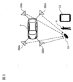
本実施形態では、たとえば、図3に示すように、自車両Vの周囲の所定箇所に、親機20に接続されたアンテナ202a~202dを設置している。親機20は、アンテナ202a~202dから子機探索信号を送信する。子機22は、自車両Vの所定距離内に接近すると、各アンテナ202a~202dから送信されている子機探索信号を受信し、各アンテナ202a~202dの子機探索信号の電波強度を測定する。子機探索信号の電波強度は、子機22と、各アンテナ202a~202dとの距離によって変化する。すなわち、子機22がフロントバンパの左サイド近傍のアンテナ202bの近傍に存在する場合、アンテナ202bから受信した子機探索信号の電波強度が最も強くなるが、リヤバンパの右サイド近傍のアンテナ202cから受信した子機探索信号の電波強度は最も弱くなる。 In this embodiment, for example, as shown in FIG. 3,
子機22は、測定した各アンテナ202a~202dの子機探索信号の電波強度を親機20に送信する。親機20の位置検出器201は、たとえば、子機22から受信した各アンテナ202a~202dの電波強度から、三角測量法などを用いて子機22の位置を演算するソフトウェアプログラムがインストールされたコンピユータである。位置検出器201は、子機22から受信した各アンテナ202a~202dの電波強度に基づいて、自車両Vに対する子機22の相対位置、すなわち、子機22を所持している操作者Uの自車両Vに対する相対位置を検出する。位置検出器201は、検出した子機22の相対位置を、経路追従制御部16及び目標車速生成部17(又はこれに代えて、操舵角制御部18及び車速制御部19でもよい)に出力し、遠隔操作器21に送信する。
遠隔操作器21は、目標駐車スペース設定器11にて設定した自律駐車制御の実行を継続するか又は停止するかを、操作者Uが車外から指令するための装置である。そのため、遠隔操作器21は、経路追従制御部16及び目標車速生成部17(又はこれに代えて、操舵角制御部18及び車速制御部19でもよい)に実行指令信号を送信するための無線通信機能を備え、自車両Vに設けられた無線通信機能との間で通信を行う。 The
遠隔操作器21は、たとえば、リモートコントロール用のアプリケーションソフトウェア(以下、アプリケーションという。)がインストールされたスマートフォンなどの携帯情報端末からなる。アプリケーションがインストールされたスマートフォンは、当該アプリケーションを起動することにより、リモート駐車システム1の遠隔操作器21として機能する。 The
車両の自律走行制御に関する国際規格では、操作者が遠隔操作器の操作を連続して行っている間だけ、車両に自律走行制御を実行させることが規定されている。そのため、本実施形態のリモート駐車システム1では、遠隔操作器21のタッチパネル211に所定の指令ジェスチャが連続して入力されている間だけ、遠隔操作器21から自車両Vに実行指令信号を送信し続ける。また、自車両Vは、遠隔操作器21から送信された実行指令信号を受信している間のみ、自律駐車制御を実行する。すなわち、遠隔操作器21への指令ジェスチャの入力を中止すると、遠隔操作器21から車両に実行指令信号が送信されなくなり、車両の自律駐車制御の実行が中断又は中止する。また、遠隔操作器21は、狭い駐車スペースに駐車されている車両を車両の外部からの遠隔操作で出庫するために、車両のエンジン又はモータなどの駆動源を遠隔操作によって起動させる機能を備えている。 International standards for autonomous driving control of vehicles stipulate that autonomous driving control is to be executed by the vehicle only while the operator is continuously operating the remote controller. Therefore, in the
遠隔操作器21は、図4に示すように、タッチパネル211、ジェスチャ判定部212、記憶部213、指令部214及び通信部215を備える。タッチパネル211は、操作者Uのタッチ操作を検出する。ジェスチャ判定部212は、タッチパネル211にジェスチャの入力を受け付けるジェスチャ判定エリアを設定する。また、ジェスチャ判定部212は、ジェスチャ判定エリアによりジェスチャを検出し、検出したジェスチャが予め設定された指令ジェスチャであるか否かと、ジェスチャの入力速度が所定範囲内であるか否かを判定する。記憶部213は、ジェスチャ判定部212によるジェスチャの判定に関連する各種情報を記憶する。指令部214は、検出したジェスチャが指令ジェスチャであり、ジェスチャの入力速度が所定範囲内であると判定した場合に、自車両Vに自律走行制御機能による自律駐車制御を実行させる実行指令信号を生成する。通信部215は、指令部214で生成された実行指令信号を自車両Vに送信する。 The
以下、遠隔操作器21の各部について説明する。タッチパネル211には、遠隔操作器21として機能するスマートフォンのタッチパネルディスプレイが用いられる。リモートコントロールモードにおいて入力されるジェスチャは、予め決められた規定の指令ジェスチャである。規定の指令ジェスチャの形態とサイズは、アプリケーションと関連付けて遠隔操作器21の記憶部213に記憶されている。指令ジェスチャは、たとえば、タッチパネル211の横方向をX軸、縦方向をY軸としたときに、タッチ操作による入力位置の座標がX軸とY軸との少なくとも一方において連続的に変化するようなタッチ操作をいう。図5Aの(A)、(B)及び(C)に示す例では、タッチパネル211上で指を上下方向にスライドさせるジェスチャG1、指を左右方向にスライドさせるジェスチャG2、あるいは指を斜め方向にスライドさせるジェスチャG3を指令ジェスチャとしてもよい。 Each part of the
なお、指を直線的にスライドさせる単調なジェスチャでは、指令ジェスチャ以外の入力操作であると誤判定される可能性がある。また、何らかの物体がタッチパネル211に接触して動いた場合に、指令ジェスチャであると判定される可能性もある。このような指令ジェスチャの誤判定を防ぐため、たとえば、ジェスチャの1回の入力が開始される始端と、ジェスチャの1回の入力が終わる終端とが重なって閉じられた図形の軌跡をタッチパネルに描くタッチ操作を、指令ジェスチャとしてもよい。このような閉じられた図形としては、図5Bの(A)に示すように、円環形状の図形からなるジェスチャG4を用いてもよいし、同図(B)、(C)に示すように、三角形又は四角形、その他の多角形からなるジェスチャG5、G6を用いてもよい。さらには、同図(D)に示すように、数字の8の字状などの図形などからなるジェスチャG7を用いてもよい。図5Bにおいて、ハッチングを施している部分は、ジェスチャの始端及び終端を一例として示している。なお、本実施形態では、図5Bの(A)に示す、円環形状の図形からなるジェスチャG4を規定の指令ジェスチャとしている。 A monotonous gesture of sliding a finger linearly may be erroneously determined to be an input operation other than a command gesture. Further, when some object touches the
ジェスチャ判定部212は、遠隔操作器21として機能するスマートフォンのCPU(Central Processing Unit)が、アプリケーションにしたがって動作することで機能する。ジェスチャ判定部212は、タッチパネル211に対し操作者Uが行ったタッチ操作の入力位置に応じて、ジェスチャ判定エリアを設定する。また、ジェスチャ判定部212は、タッチパネル211に対するジェスチャ判定エリアのサイズを可変にする。すなわち、タッチパネル211に設定されるジェスチャ判定エリアの位置とサイズは、タッチ操作の入力位置に応じて可変となっているため、タッチパネル211の任意の位置に、任意のサイズで規定の指令ジェスチャを入力することができる。これにより、ジェスチャの入力位置や、入力サイズが常に固定されていた従来技術に比べ、指令ジェスチャの入力ミスによって自車両Vの自律駐車制御が中止されるのを抑制することができる。 The gesture determination unit 212 functions when a CPU (Central Processing Unit) of the smartphone functioning as the
ジェスチャ判定部212は、ジェスチャの入力開始時に、図6Aに示すように、タッチパネル211の予め設定された位置、たとえば、中心位置Ip0(座標x0、y0)を基準にして、規定サイズの指令ジェスチャG4の形状を示す入力ガイド212aを表示する。入力ガイド212aの近傍には、「表示されている入力ガイドを矢印の方向に沿ってタッチ操作して下さい」などのメッセージを表示する。 At the start of gesture input, as shown in FIG. 6A, gesture determination unit 212 performs command gesture G4 of a prescribed size based on a preset position of
また、ジェスチャ判定部212は、ジェスチャの入力開始時には、タッチパネル211に対するタッチ操作の入力位置に関わらず、タッチパネル211の予め設定された位置に第1のジェスチャ判定エリアGa0を設定する。具体的には、図6Bに示すように、入力ガイド212aの中心位置Ip0を基準にして、入力ガイド212aに対応した第1のジェスチャ判定エリアGa0を設定する。この第1のジェスチャ判定エリアGa0は、タッチパネル211の幅方向をX軸、縦方向をY軸としたとき、所定の中心位置Ip0の中心座標(x0、y0)と、半径Rとによって規定される。半径Rは、図6B中に破線で示すように、規定サイズの指令ジェスチャG4の半径rを所定の割合(たとえば、30%)で縮小した最小入力サイズrminと、同じく半径rを所定の割合(たとえば、150%)で拡大した最大入力サイズrmaxの範囲を有している。指令ジェスチャG4の規定サイズは、タッチパネル211のサイズや解像度に応じた値が記憶部213に予め記憶されている。ジェスチャ判定部212は、アプリケーションがインストールされたスマートフォンのタッチパネル211のサイズや解像度に基づいて、指令ジェスチャG4の規定サイズと、最小入力サイズ及び最大入力サイズを設定する。 Moreover, the gesture determination unit 212 sets the first gesture determination area Ga<b>0 at a preset position on the
このように、ジェスチャの入力開始時に、入力ガイド212aを表示して第1のジェスチャ判定エリアGa0を一時的に固定化するのは、指令ジェスチャG4の形態を操作者Uに報知し、入力開始直後のジェスチャの判定率を高めるためである。また、自車両Vの遠隔操作の開始時には、操作者Uは遠隔操作器21を操作するために、遠隔操作器21に目を向ける可能性が高い。そのため、予め設定された位置に入力ガイド212aを表示して第1のジェスチャ判定エリアGa0を設定することで、操作者Uに必要な操作を示唆することができるので、操作者Uの違和感を抑制することができる。これとは逆に、自車両Vの自律駐車制御が開始された後には、操作者Uは遠隔操作器21から目を離して自車両Vを監視する可能性が高い。そのため、タッチ操作が第1のジェスチャ判定エリアGa0からずれてしまう可能性が高くなるので、タッチ操作の入力位置に応じて新たなジェスチャ判定エリアを設定することで、自車両Vの自律走行制御を継続させることが可能となる。また、第1のジェスチャ判定エリアGa0を、最小入力サイズrminと最大入力サイズrmaxとによって規定しているのは、入力されたジェスチャが規定サイズの指令ジェスチャG4と同一サイズである場合だけでなく、所定の範囲内のサイズ、すなわち規定サイズよりも小さい場合あるいは大きい場合にも指令ジェスチャであると判定するためである。 Thus, the reason why the
ジェスチャ判定部212は、入力されたジェスチャが、規定の指令ジェスチャG4のような円環形状のジェスチャであるか否かと、第1のジェスチャ判定エリアGa0内に収まるサイズであるか否かを判定する。また、ジェスチャ判定部212は、ジェスチャの入力速度が、予め設定した所定範囲内であるか否かを判定する。ジェスチャ判定部212は、入力されたジェスチャが、指令ジェスチャG4のような円環形状のジェスチャで、かつ、第1のジェスチャ判定エリアGa0内に収まるサイズであり、入力速度が所定範囲内であるときに、指令ジェスチャG4が入力されたと判定する。したがって、ジェスチャ判定部212は、図6Cに示すように、入力されたジェスチャG4aが第1のジェスチャ判定エリアGa0内で蛇行し、変形した楕円形のような形状である場合でも、指令ジェスチャG4であると判定する。なお、ジェスチャの入力速度を指令ジェスチャの判定に用いるのは、何らかの物体がタッチパネル211に接触して入力されたジェスチャを、操作者Uのジェスチャと区別するためである。 The gesture determination unit 212 determines whether the input gesture is an annular gesture such as the prescribed command gesture G4, and whether the size is within the first gesture determination area Ga0. . Also, the gesture determination unit 212 determines whether or not the gesture input speed is within a preset range. The gesture determination unit 212 determines when the input gesture is an annular gesture such as the command gesture G4, has a size that fits within the first gesture determination area Ga0, and the input speed is within a predetermined range. , it is determined that the command gesture G4 has been input. Therefore, as shown in FIG. 6C, the gesture determination unit 212 performs the command gesture G4 even when the input gesture G4a meanders in the first gesture determination area Ga0 and has a deformed elliptical shape. Determine that there is. Note that the reason why the input speed of the gesture is used to determine the command gesture is to distinguish a gesture input by some object contacting the
ジェスチャ判定部212は、入力されたジェスチャが指令ジェスチャG4であると判定された時点、あるいはジェスチャの入力位置の変化に応じて新たなジェスチャ判定エリアが設定された時点で、入力ガイド212aを非表示にする。なお、ジェスチャ判定部212は、指令ジェスチャが入力ガイド212aに沿って入力され続けているのを検出した場合には、入力ガイド212aの表示を継続してもよい。また、ジェスチャ判定部212は、新たなジェスチャ判定エリアが設定された場合には、その新たなジェスチャ判定エリアの位置に入力ガイド212aを表示してもよい。 The gesture determination unit 212 hides the
タッチパネル211に対するジェスチャの入力は、操作者Uのタッチ操作によって行われるため、ジェスチャの入力位置は必ず移動する。そのため、ジェスチャ判定部212は、タッチパネル211に対するジェスチャの入力位置の移動に応じて、新たなジェスチャ判定エリアを設定する。また、ジェスチャの入力位置及び入力サイズが可変であることを予め理解している操作者Uが、入力ガイド212aを無視してジェスチャを入力した場合にも、その入力位置に応じて新たなジェスチャ判定エリアを設定する。新たなジェスチャ判定エリアの設定には、タッチパネル211により検出したタッチ操作の検出値xraw、yrawと、この検出値の移動平均値xmean、ymeanとを用いる。 Since a gesture input to the
図7に示すグラフは、操作者Uがタッチパネル211にジェスチャを入力したときに、タッチパネル211で検出されるタッチ操作の検出値の一例を示している。同図(A)のグラフは、横軸が時間、縦軸がX軸方向におけるタッチ操作の検出値xrawと、この検出値xrawの移動平均値xmeanとを示す。(A)のグラフの縦軸のプラス側は、タッチパネル211のX軸の中心線より右側を示し、マイナス側は、X軸の中心線より左側を示す。また、同図の(B)のグラフは、横軸が時間、縦軸がY軸方向におけるタッチ操作の検出値yrawと、この検出値yrawの移動平均値ymeanとを示す。(B)のグラフの縦軸のプラス側は、タッチパネル211のY軸の中心線より上側を示し、マイナス側は、Y軸の中心線より下側を示す。タッチパネル211の検出値xraw、yrawは、記憶部213に随時記憶される。また、移動平均値xmean、ymeanは、ジェスチャ判定部212で演算されて記憶部213に記憶される。 The graph illustrated in FIG. 7 illustrates an example of a touch operation detection value detected on the
たとえば、図8に示すように、操作者Uのタッチ操作によってタッチパネル211にジェスチャG4bが入力された場合、ジェスチャ判定部212は、タッチパネル211に対する操作者Uの現在のタッチ位置Tp1の座標(xb、yb)を記憶部213から取得する。また、ジェスチャ判定部212は、タッチ位置がTp1に至るまでの過去数秒間(以下、半径判定時間Tと言う。)の移動平均値(xmean、ymean)を記憶部213から取得する。ジェスチャ判定部212は、下記の数式1、2を用いて、タッチ位置がTp1に移動するまでのジェスチャG4bの半径rbと、タッチ位置Tp1とタッチパネル211のX軸との角度θとを演算する。そして、ジェスチャ判定部212は、半径rbと角度θとに基づいて、ジェスチャG4bの中心位置Ip1の座標(x1、Y1)を演算し、この中心位置Ip1に基づいて新たなジェスチャ判定エリアGa1を設定する。このように、ジェスチャ判定部212は、ジェスチャの入力位置の移動に応じて、常に新たなジェスチャ判定エリアを設定する。 For example, as shown in FIG. 8, when a gesture G4b is input to the


ところで、タッチパネル211へのジェスチャの入力中に、ジェスチャ判定部212でジェスチャが一時的に検出できなくなることがある。ジェスチャ判定部212でジェスチャが検出できなくなるのは、タッチパネル211から操作者Uの指が離れた場合、入力されたジェスチャが指令ジェスチャであると判定されなかった場合、あるいは操作者Uがジェスチャの入力を途中で終了した場合などがある。また、タッチパネル211から操作者Uの指が離れる場合には、操作者Uの指がタッチパネル211からはみ出すような場合も含まれる。ジェスチャ判定部212は、タッチパネル211へのジェスチャの入力中に、ジェスチャが検出できなくなったときに、ジェスチャが検出できなくなった時間(非検出時間)と、上述した半径判定時間Tとに基づいて、ジェスチャ判定エリアの設定処理を切り替える。 By the way, while a gesture is being input to the
たとえば、ジェスチャの入力中に操作者Uの指がタッチパネル211から一時的に離れてジェスチャ判定部212がジェスチャを検出できなった場合、あるいは操作者Uの指がタッチパネル211からはみ出してジェスチャ判定部212がジェスチャを検出できなった場合には、非検出時間は比較的短いと考えられる。そこで、ジェスチャ判定部212は、非検出時間と半径判定時間Tとを比較し、非検出時間が半径判定時間T未満であると判定したときには、ジェスチャが検出できなくなる直前に検出したタッチ位置の座標を利用して移動平均値を演算し、この演算結果を利用して新たなジェスチャ判定エリアを設定する。すなわち、非検出時間内のタッチ位置を利用せずに新たなジェスチャ判定エリアを設定する。たとえば、図9に示す例であれば、ジェスチャの入力中に操作者Uの指がタッチパネル211一時的にはみ出したことを検出した場合に、ジェスチャ判定部212は、タッチパネル211からはみ出す直前に検出したタッチ位置の座標を利用して移動平均値を演算し、この演算結果を利用して新たなジェスチャ判定エリアGa2を設定する。ジェスチャの非検出時間が半径判定時間T未満であるときには、非検出時間内のタッチ位置を利用せずに新たなジェスチャ判定エリアを設定しても、ジェスチャ判定エリアの設定位置に大きなずれは生じない。したがって、ジェスチャの判定結果にも大きな影響は生じない。 For example, when the finger of the operator U is temporarily separated from the
また、操作者Uの入力ミスにより、ジェスチャ判定部212によって、入力されたジェスチャが指令ジェスチャであると判定されなかった場合には、指がタッチパネル211から離れる場合と比べて、ジェスチャの非検出時間は比較的長くなると考えられる。そのため、ジェスチャ判定部212は、ジェスチャの非検出時間が半径判定時間T以上であると判定したときには、ジェスチャが検出できなくなる直前に設定したジェスチャ判定エリアを、第2のジェスチャ判定エリアとして記憶部213に記憶する。そして、ジェスチャ判定部212がジェスチャの入力を再び検出した場合には、第2のジェスチャ判定エリアを記憶部213から読み出してジェスチャの判定を行う。たとえば、図9に示す例であれば、ジェスチャ判定部212は、ジェスチャG4cが非検出となる直前に設定したジェスチャ判定エリアGa2を、第2のジェスチャ判定エリアとして記憶部213に記憶する。そして、ジェスチャ判定部212がジェスチャの入力を再び検出した場合には、記憶部213からジェスチャ判定エリアGa2を読み出してジェスチャの判定を行う。操作者Uは、ジェスチャを連続して入力する場合、同じ入力位置に対して入力を続ける可能性が高い。そのため、入力ミスによってジェスチャが検出できなくなった場合には、そのる直前に設定したジェスチャ判定エリアを利用することで、ジェスチャの判定率を高めることができる。 Further, when the gesture determination unit 212 does not determine that the input gesture is the command gesture due to an input error by the operator U, the gesture non-detection time is longer than when the finger leaves the
また、操作者Uがジェスチャの入力を途中で終了した場合には、指がタッチパネル211から離れた場合や、入力中のジェスチャが指令ジェスチャであると判定されなかった場合と比べて、ジェスチャの非検出時間がさらに長くなると考えられる。そこで、ジェスチャ判定部212は、ジェスチャの非検出時間が予め設定した入力再開待機時間以上であると判定した場合には、タッチパネル211に入力ガイド212aを表示し、予め設定した中心位置Ip0に基づいて第1のジェスチャ判定エリアGa0を設定する。なお、入力再開待機時間は、半径判定時間Tよりも長く、たとえば、数秒間の時間に設定することが好ましい。ジェスチャの非検出時間がある程度長くなった場合に、入力ガイド212aを表示して第1のジェスチャ判定エリアGa0を設定することで、再開されたジェスチャの判定率を高めることができる。 In addition, when the operator U finishes inputting a gesture midway, the non-operation of the gesture is more likely than when the finger is removed from the
次に、遠隔操作器21の指令部214及び通信部215について説明する。指令部214は、タッチパネル211で検出されたジェスチャが、ジェスチャ判定部212で指令ジェスチャG4であると判定された場合に、自車両Vに自律走行制御機能による自律駐車制御を実行させるための実行指令信号を生成する。指令部214は、生成した実行指令信号を通信部215に入力する。指令部214は、遠隔操作器21として機能するスマートフォンのCPUが、アプリケーションにしたがって動作することで機能する。 Next, the
通信部215には、遠隔操作器21として機能するスマートフォンが予め備えている通信機能を利用する。通信部215は、たとえば、Bluetooth(登録商標)などの無線通信部であり、リモートコントロールモードにおいて、自車両Vに搭載された無線通信部(図示せず)と接続し、自車両Vに実行指令信号を送信する。なお、通信部215として、Wi-Fi(登録商標)などの無線LAN(Local Area Network)や、携帯電話回線などを用いてもよい。 For the
図1に示すように、自車両Vに送信された実行指令信号は、経路追従制御部16と、目標車速生成部17とに入力される。また、上述したように、自車両Vと子機22との相対位置は、位置検出器201から、経路追従制御部16と目標車速生成部17とに入力されている。経路追従制御部16は、自車両Vと子機22との距離が遠隔操作距離以内であって、かつ、遠隔操作器21からの実行指令信号が入力された場合に、操舵角制御部18に目標操舵角を出力する。同様に、目標車速生成部17は、自車両Vと子機22との距離が遠隔操作距離以内であって、かつ、遠隔操作器21からの実行指令信号が入力された場合に、車速制御部19に目標車速を出力する。操舵角制御部18は、経路追従制御部16からの目標操舵角に基づいて、自車両Vの操舵系システムに設けられた操舵アクチュエータを動作する制御信号を生成する。また、車速制御部19は、目標車速生成部17からの目標車速に基づいて、自車両Vの駆動系システムに設けられたアクセルアクチュエータを動作する制御信号を生成する。 As shown in FIG. 1 , the execution command signal sent to the host vehicle V is input to the route following
また、経路追従制御部16は、自車両Vと子機22との距離が遠隔操作距離よりも離れている場合には、遠隔操作器21からの実行指令信号が入力されている場合であっても、操舵角制御部18に目標操舵角を出力しない。同様に、目標車速生成部17は、自車両Vと子機22との距離が遠隔操作距離よりも離れている場合には、遠隔操作器21からの実行指令信号が入力されている場であっても、車速制御部19に目標車速を出力しない。すなわち、自車両Vと子機22との距離が遠隔操作距離よりも離れている場合には、遠隔操作器21から指令ジェスチャが入力されていても自律駐車制御は実行されない。 Further, when the distance between the own vehicle V and the
次に図10、図11及び図12を参照して、本実施形態のリモート駐車システム1の制御フローを説明する。ここでは、図2に示す後退駐車を自律駐車制御により実行するシーンを説明する。図10は、本実施形態のリモート駐車システム1で実行される制御手順を示すフローチャートである。図11は、遠隔操作器21におけるジェスチャの検出、判定及び実行指令信号の送信までの手順を示すフローチャートである。図12は、ジェスチャが一時的に検出されなくなった後、ジェスチャの入力を検出した場合に、ジェスチャ判定エリアを設定する手順を示すフローチャートである。 Next, the control flow of the
まず、自車両Vが目標とする駐車スペースTPSの近傍の位置P1に到着すると、図10に示すステップS1において、ドライバなどの操作者Uは、車載された目標駐車スペース設定器11のリモート駐車の開始スイッチをONしてリモート入庫モードを選択する。目標駐車スペース設定器11は、ステップS2にて、車載された複数のカメラなどを用いて自車両Vが駐車可能な駐車スペースを探索し、ステップS3にて駐車可能な駐車スペースがあるか否かを判定する。駐車可能な駐車スペースがある場合はステップS4へ進み、駐車可能な駐車スペースがない場合はステップS1へ戻る。ステップS2により駐車可能な駐車スペースが検出されない場合は、「駐車スペースがありません」といった言語表示または音声にて操作者に報知し、本処理を終了してもよい。 First, when the own vehicle V arrives at the position P1 near the target parking space TPS, in step S1 shown in FIG. Turn on the start switch to select the remote warehousing mode. In step S2, the target parking
目標駐車スペース設定器11は、ステップS4にて、駐車可能な駐車スペースを車載のディスプレイに表示し、操作者Uに希望する駐車スペースの選択を促し、操作者Uが特定の駐車スペースTPSを選択したら、その目標駐車位置情報を駐車経路生成部14へ出力する。駐車経路生成部14は、ステップS5において、自車両Vの現在位置P1と目標駐車位置である駐車スペースTPSとから、図2に示す駐車経路R1,R2を生成する。物体減速演算部15は、物体検出器13により検出された物体情報に基づいて、自律駐車制御時の減速開始タイミングを演算する。駐車経路生成部14により生成された駐車経路R1,R2は経路追従制御部16へ出力され、物体減速演算部15により演算された減速開始タイミングは、目標車速生成部17へ出力される。 In step S4, the target parking
以上により自律駐車制御がスタンバイ状態となるので、ステップS6にて、操作者に自律駐車制御の開始の承諾を促し、操作者が開始を承諾すると、アシストモードによる自律走行制御が開始される。図2に示す後退駐車においては、図2に示す現在位置P1から一旦右旋回で前進し、切り返し位置P3に到着したら、左旋回で中間停車位置P4まで後退する。 Since the autonomous parking control is in the standby state as described above, the operator is urged to approve the start of the autonomous parking control in step S6, and when the operator approves the start, the autonomous driving control in the assist mode is started. In reverse parking shown in FIG. 2, the vehicle moves forward by turning right from the current position P1 shown in FIG.
ステップS7では、自車両Vの位置が中間停車位置P4に到達したので、自車両Vを停車し、操作者Uに降車を促す。ステップS7にて降車が促され、操作者が遠隔操作器21を持って降車すると、ステップS8にて、操作者Uは遠隔操作器21を起動する。これにより遠隔操作が開始される。なお、遠隔操作器21による遠隔操作の開始入力は、遠隔操作器21にインストールされたアプリケーションの起動のほか、ドアの開錠操作、ドアの施錠及び開錠操作、これらとアプリケーションの起動の組み合わせなどを例示することができる。なお、ステップS7からステップS9までの間は、自車両Vは停車状態とされる。 In step S7, the position of the own vehicle V reaches the intermediate stop position P4, so the own vehicle V is stopped and the operator U is urged to get off. When the operator is prompted to get off the vehicle in step S7 and gets off the vehicle holding the
ステップS9においては、遠隔操作器21と自車両Vとのペアリング処理が行われる。ステップS9のペアリング処理により、自車両Vが遠隔操作器21を認証して指令の受け付けが可能になると、ステップS10にてリモート操作が開始される。 In step S9, pairing processing between the
遠隔操作器21によるリモート操作が開始されると、ジェスチャ判定部212は、図11に示すように、ステップS101において初期設定を行う。この初期設定では、図6Aに示すように、タッチパネル211に入力ガイド212aと、「表示されている入力ガイドを矢印の方向に沿ってタッチ操作して下さい」というメッセージとを表示する。また、ジェスチャ判定部212は、図6Bに示すように、入力ガイド212aの中心位置Ip0に基づいて、第1のジェスチャ判定エリアGa0を設定する。 When remote operation by the
操作者Uは、入力ガイド212aに沿うようにタッチ操作を行い、円環形状のジェスチャをタッチパネル211に入力する。また、本実施形態のリモート駐車システム1では、ジェスチャ判定エリアの位置及びサイズが可変になっているため、操作者Uは入力ガイド212aを無視して、タッチパネル211の任意の位置に、任意のサイズでジェスチャを入力することができる。タッチパネル211により検出されたタッチ操作の検出値xraw、yrawは、記憶部213に随時記憶される。また、移動平均値xmean、ymeanは、ジェスチャ判定部212で演算されて記憶部213に記憶される。 The operator U performs a touch operation along the
ステップS102において、タッチパネル211は、操作者Uのタッチ操作により入力されたジェスチャを検出する。タッチパネル211でジェスチャが検出されると、ジェスチャ判定部212は、ステップS103において、検出したジェスチャが第1のジェスチャ判定エリアGa0に入力されたか否かを判定する。検出したジェスチャが第1のジェスチャ判定エリアGa0に入力されていた場合、ジェスチャ判定部212は、ステップS104において、検出したジェスチャが指令ジェスチャG4のような円環形状のジェスチャであるか、予め設定した所定範囲内の入力速度で入力されているかを判定する。 In step S102, the
検出したジェスチャが指令ジェスチャG4ではない場合、あるいは入力速度が所定範囲外である場合には、ステップS106に進んで次のジェスチャを検出する。これとは逆に、検出したジェスチャが指令ジェスチャG4であり、かつ、入力速度が所定範囲内である場合には、ステップS105に進み、指令部214で実行指令信号を生成して、通信部215から自車両Vへ実行指令信号を送信する。次のステップS106において、ジェスチャの検出が継続している場合には、ステップ103に戻ってジェスチャの判定と、実行指令信号の送信とを繰り返す。 If the detected gesture is not the command gesture G4, or if the input speed is outside the predetermined range, the process proceeds to step S106 to detect the next gesture. Conversely, if the detected gesture is the command gesture G4 and the input speed is within the predetermined range, the process proceeds to step S105, the
ステップ103に戻り、検出したジェスチャが第1のジェスチャ判定エリアGa0に入力されていなかった場合には、ジェスチャ判定部212は、ステップS107に進み、現在のジェスチャの入力位置に基づいて新たなジェスチャ判定エリアを設定する。ジェスチャ判定部212は、上述したように、タッチパネル211に対する操作者Uの現在のタッチ位置の座標と、タッチ位置が現在のタッチ位置に至るまでの移動平均値とに基づいて、新たなジェスチャ判定エリアを設定する。 Returning to step S103, if the detected gesture has not been input to the first gesture determination area Ga0, the gesture determination unit 212 proceeds to step S107 to perform new gesture determination based on the current gesture input position. Set area. As described above, the gesture determination unit 212 creates a new gesture determination area based on the coordinates of the current touch position of the operator U on the
次のステップS108では、ジェスチャ判定部212は、新たに設定したジェスチャ判定エリアを利用して、検出したジェスチャが指令ジェスチャG4のような円環形状のジェスチャであるか、予め設定した所定範囲内の入力速度で入力されているかを判定する。検出したジェスチャが指令ジェスチャG4ではない場合、あるいは入力速度が所定範囲外である場合には、ステップS110に進んで次のジェスチャを検出する。これとは逆に、検出したジェスチャが指令ジェスチャG4であり、かつ、入力速度が所定範囲内である場合には、ステップS109に進み、指令部214で実行指令信号を生成して、通信部215から自車両Vへ実行指令信号を送信する。次のステップS110において、ジェスチャの検出が継続している場合にはステップ107に戻り、新たなジェスチャ判定エリアの設定と、ジェスチャの判定と、実行指令信号の送信とを繰り返す。 In the next step S108, the gesture determination unit 212 uses the newly set gesture determination area to determine whether the detected gesture is an annular gesture such as the command gesture G4, or whether the detected gesture is an annular gesture within a predetermined range set in advance. Determines whether input is made at the input speed. If the detected gesture is not the command gesture G4, or if the input speed is outside the predetermined range, the process proceeds to step S110 to detect the next gesture. Conversely, if the detected gesture is the command gesture G4 and the input speed is within the predetermined range, the process proceeds to step S109, the
図10に戻り、ステップS11では、子機22と親機20とを利用して、自車両Vに対する子機22の相対位置、すなわち、子機22を所持した操作者Uと自車両Vとの相対位置を検出する。親機20は、検出した相対位置を経路追従制御部16と、目標車速生成部17とに出力する。経路追従制御部16は、自車両Vと子機22との距離が遠隔操作距離以内であって、かつ、遠隔操作器21からの実行指令信号が入力されている場合に、操舵角制御部18に目標操舵角を出力する。同様に、目標車速生成部17は、自車両Vと子機22との距離が遠隔操作距離以内であって、かつ、遠隔操作器21からの実行指令信号が入力されている場合に、車速制御部19に目標車速を出力する。操舵角制御部18は、経路追従制御部16からの目標操舵角に基づいて、自車両Vの操舵系システムに設けられた操舵アクチュエータを動作する制御信号を生成する。また、車速制御部19は、目標車速生成部17からの目標車速に基づいて、自車両Vの駆動系システムに設けられたアクセルアクチュエータを動作する制御信号を生成する。これにより、次のステップS12で自律駐車制御が実行される。 Returning to FIG. 10, in step S11, using the
なお、ステップS10から後述するステップS13までの処理は、ステップS13にて自車両Vが目標とする駐車スペースTPSに到着するまでの間、所定時間間隔で実行される。ステップS13にて、自車両Vが目標とする駐車スペースTPSに到着したか否かを判断し、到着していない場合はステップS10へ戻り、自車両Vが目標とする駐車スペースTPSに到着した場合は、自車両Vを停車して処理を終了する。以上により、自車両Vの現在位置P1から中間停車位置P4までの走行経路は、アシストモードによる自律走行制御を実行し、中間停車位置P4から目標とする駐車スペースTPSまでの走行経路はリモートコントロールモードによる自律走行制御を実行する。 The processing from step S10 to step S13, which will be described later, is executed at predetermined time intervals until the host vehicle V reaches the target parking space TPS in step S13. In step S13, it is determined whether or not the vehicle V has arrived at the target parking space TPS. If not, the process returns to step S10. stops the own vehicle V and terminates the process. As described above, the travel route from the current position P1 of the own vehicle V to the intermediate stop position P4 is controlled in the assist mode, and the travel route from the intermediate stop position P4 to the target parking space TPS is controlled in the remote control mode. Execute autonomous driving control by
ステップS10にて、遠隔操作器21によるリモート操作を行っている際に、ジェスチャが一時的に検出されなくなることがある。ジェスチャ判定部212は、図12に示すステップS20にて、ジェスチャの入力が一時的に検出できなくなったときに非検出時間を測定し、次のステップS21において、ジェスチャの入力位置の検出に用いる半径判定時間Tと比較する。非検出時間が半径判定時間T未満であるときには、操作者Uの指がタッチパネル211から一時的に離れた場合、あるいは操作者Uの指がタッチパネル211から一時的にはみ出した場合などが考えられる。そのため、ジェスチャ判定部212は、次のステップS22に進み、ジェスチャが検出できなくなる直前に検出したタッチ位置の座標を利用して移動平均値を演算し、この演算結果を利用して新たなジェスチャ判定エリアを設定する。ジェスチャの非検出時間が半径判定時間T未満であるときには、非検出時間内のタッチ位置を利用せずに新たなジェスチャ判定エリアを設定しても、ジェスチャ判定エリアの設定位置に大きなずれは生じない。したがって、ジェスチャの判定結果にも大きな影響は生じない。 In step S<b>10 , the gesture may be temporarily undetected while the
また、ステップS21にて、ジェスチャの非検出時間が半径判定時間T以上である場合には、ステップS23に進み、ジェスチャの非検出時間と、予め設定した入力再開待機時間とを比較する。非検出時間が入力再開待機時間未満である場合には、入力したジェスチャが指令ジェスチャであると判定されなかった場合などが考えられる。そのため、指令ジェスチャと判定されなかったジェスチャに基づいてジェスチャ判定エリアを設定すると、ジェスチャ判定エリアの設定位置にずれが生じる可能性がある。このような場合、ジェスチャ判定部212は、次のステップS24に進み、ジェスチャが検出できなくなる直前に設定したジェスチャ判定エリアを第2のジェスチャ判定エリアとして記憶部213に記憶する。そして、ジェスチャの入力を検出した場合には、第2のジェスチャ判定エリアを記憶部213から読み出してジェスチャの判定を行う。 Also, in step S21, if the gesture non-detection time is equal to or longer than the radius determination time T, the process proceeds to step S23, where the gesture non-detection time is compared with a preset input restart waiting time. If the non-detection time is less than the input restart waiting time, it is conceivable that the input gesture was not determined to be the command gesture. Therefore, if a gesture determination area is set based on a gesture that has not been determined to be a command gesture, there is a possibility that the set position of the gesture determination area will be misaligned. In such a case, the gesture determination unit 212 proceeds to the next step S24, and stores the gesture determination area set immediately before the gesture becomes undetectable in the
ステップS23に戻り、ジェスチャの非検出時間が入力待機時間以上である場合には、ステップS25に進む。ジェスチャの非検出時間が入力待機時間以上であるときには、操作者Uがジェスチャの入力を途中で終了した場合などが考えられる。そのため、ジェスチャ判定部212は、タッチパネル211に入力ガイド212aを表示し、予め設定された中心位置Ip0に基づいて第1のジェスチャ判定エリアGa0を設定する。これにより、再開されたジェスチャの判定率を高めることができる。 Returning to step S23, if the gesture non-detection time is equal to or longer than the input standby time, the process proceeds to step S25. When the gesture non-detection time is equal to or longer than the input waiting time, it is conceivable that the operator U has finished inputting the gesture in the middle. Therefore, the gesture determination unit 212 displays an
以上のとおり、本発明の車両の遠隔制御方法及び遠隔制御装置を適用したリモート駐車システム1によれば、遠隔操作器21のタッチパネル211において、操作者Uのタッチ操作が行われた入力位置を検出し、入力位置に応じて、ジェスチャ判定部212で設定されるジェスチャ判定エリアの位置を可変としている。また、ジェスチャ判定エリアによりジェスチャを検出し、検出したジェスチャが予め設定した指令ジェスチャであるか否かをジェスチャ判定部212により判定する。そして、ジェスチャが指令ジェスチャである場合には、自律走行制御機能を備えた自車両Vに、自律走行制御として自律駐車制御を実行させている。これにより、タッチパネル211の任意の位置にジェスチャを入力することができるので、ジェスチャの入力位置に関わらず、自車両Vに自律駐車制御を実行させることができる。また、入力位置を気にせずにジェスチャを入力することができるので、遠隔操作器21の操作性が向上する。さらに、タッチパネル211全体をジェスチャ判定エリアとして利用する場合に比べ、小さなジェスチャ判定エリアでジェスチャの判定を行うことができる。これにより、ジェスチャ判定に必要な処理負荷を低減することができる。 As described above, according to the
また、タッチパネル211に対するジェスチャ判定エリアのサイズを可変にしている。これにより、タッチパネル211に任意のサイズのジェスチャを入力することができ、ジェスチャのサイズに関わらず、自車両Vに自律駐車制御を実行させることができる。さらに、ジェスチャ判定エリアのサイズは、予め設定した最小入力サイズと、最大入力サイズとの間で可変としたので、極端にサイズが異なるジェスチャの入力を抑制することができる。 Also, the size of the gesture determination area for the
また、予め設定された位置に第1のジェスチャ判定エリアGa0を設定し、タッチパネル211に対するタッチ操作の入力位置に応じて、新たなジェスチャ判定エリアを設定するようにしたので、入力開始時のジェスチャの判定率を高めることができ、自車両Vに自律駐車制御を迅速に開始させることができる。さらに、タッチ操作の入力位置の変化に応じて、新たなジェスチャ判定エリアを設定するので、ジェスチャの入力位置が第1のジェスチャ判定エリアからずれた場合でも、自車両Vに自律駐車制御を継続させることができる。特に、自車両Vの遠隔操作の開始時には、操作者Uは遠隔操作器21に目を向ける可能性が高い。そのため、予め設定された位置に入力ガイド212aを表示して第1のジェスチャ判定エリアGa0を設定することで、操作者Uに必要な操作を示唆することができるので、操作者Uの違和感を抑制することができる。これとは逆に、自車両Vの自律駐車制御が開始された後には、操作者Uは遠隔操作器21から目を離して自車両Vを監視する可能性が高い。そのため、タッチ操作が第1のジェスチャ判定エリアGa0からずれてしまう可能性が高くなるので、タッチ操作の入力位置に応じて新たなジェスチャ判定エリアを設定することで、自車両Vの自律走行制御を継続させることが可能となる。 Also, the first gesture determination area Ga0 is set at a preset position, and a new gesture determination area is set according to the input position of the touch operation on the
また、ジェスチャが一時的に検出できなくなった場合には、検出できなくなる直前に設定したジェスチャ判定エリアを第2のジェスチャ判定エリアとして記憶し、ジェスチャの入力を検出した場合に、第2のジェスチャ判定エリアによりジェスチャの判定を行うようにしている。ジェスチャの入力が一時的に中止されて再開される場合、中止前の入力位置に対してジェスチャの入力が再開される可能性が高い。そのため、ジェスチャの入力再開時の判定に、第2のジェスチャ判定エリアを利用することで、ジェスチャの判定率を高めることができる。 Further, when the gesture becomes temporarily undetectable, the gesture determination area set immediately before it becomes undetectable is stored as the second gesture determination area, and when the input of the gesture is detected, the second gesture determination is performed. Gestures are determined by area. When gesture input is temporarily suspended and resumed, there is a high possibility that gesture input will be resumed at the input position before suspension. Therefore, by using the second gesture determination area to determine when gesture input is resumed, the gesture determination rate can be increased.
また、ジェスチャが検出できなくなった後で、ジェスチャの入力を再び検出した場合に、第1のジェスチャ判定エリアによりジェスチャの判定を行うこともできる。たとえば、ジェスチャの入力が一時的に中止されてから、比較的長い時間をおいて再開されるような場合には、第1のジェスチャ判定エリアを設定することでジェスチャの判定率を高めることができる。 Further, when gesture input is detected again after the gesture cannot be detected, the gesture can be judged using the first gesture judgment area. For example, when gesture input is temporarily stopped and then resumed after a relatively long period of time, the gesture determination rate can be increased by setting the first gesture determination area. .
なお、ジェスチャが検出できなくなる場合とは、タッチパネル211から操作者Uの指が離れた場合、ジェスチャが指令ジェスチャであると判定されなかった場合、あるいは操作者Uがジェスチャの入力を途中で終了した場合などである。したがって、本実施形態によれば、タッチパネル211から操作者Uの指が離れた場合、ジェスチャが指令ジェスチャであると判定されなかった場合、あるいは操作者Uがジェスチャの入力を途中で終了した場合のいずれの場合であっても、直前に設定したジェスチャ判定エリアを記憶して利用してもよいし、第1のジェスチャ判定エリアを利用してもよい。 Note that the gesture cannot be detected when the finger of the operator U is removed from the
また、本実施形態における指令ジェスチャは、タッチパネル211の横方向をX軸、縦方向をY軸としたときに、操作者のタッチ操作による入力位置の座標が、X軸とY軸の少なくとも一方において連続的に変化するタッチ操作としている。したがって、タッチパネル211に対するタッチ操作が不慣れな操作者であっても、簡単に指令ジェスチャを入力することができる。 Further, the command gesture in the present embodiment is such that when the horizontal direction of the
また、指令ジェスチャとして、ジェスチャの1回の入力が開始される始端と、ジェスチャの1回の入力が終わる終端とが重なるような図形の軌跡を、タッチパネル211に描くタッチ操作とすることができる。このような指令ジェスチャとして、円環形状の図形の軌跡をタッチパネル211に描くタッチ操作を適用することができる。これにより、指令ジェスチャを、単調で簡単な他のジェスチャと区別して入力することができるので、ジェスチャの誤判定を抑制することができる。 As the command gesture, a touch operation for drawing a locus of a figure on the
また、指令ジェスチャが、円環形状の図形の軌跡をタッチパネル211に描くタッチ操作である場合には、円環形状の図形の中心座標と、半径とによってジェスチャ判定エリアを規定することができるので、複雑な図形からなるジェスチャに比べて、比較的簡単な処理でジェスチャ判定エリアを設定することができる。 Further, when the command gesture is a touch operation that draws the trajectory of an annular figure on the
また、本実施形態では、ジェスチャが検出されなくなった場合に、自車両Vに自律駐車制御を中止させている。そのため、自車両Vに自律駐車制御を中止させるための操作は不要となるので、自車両Vの遠隔操作が容易になる。 Further, in the present embodiment, the autonomous parking control is stopped by the own vehicle V when the gesture is no longer detected. This eliminates the need for the vehicle V to stop the autonomous parking control, thus facilitating the remote control of the vehicle V. FIG.
また、本実施形態では、自律走行制御として、自車両Vを駐車させる自律駐車制御を実行させるので、自車両Vを離れた位置から遠隔操作して駐車させることができる。 In addition, in the present embodiment, autonomous parking control for parking the own vehicle V is executed as the autonomous driving control, so that the own vehicle V can be remotely operated and parked from a distant position.
《第2実施形態》
次に、本発明の車両遠隔制御方法及び車両遠隔制御装置を適用したリモート駐車システムの第2実施形態について説明する。なお、第1実施形態と同様の構成については、第1実施形態と同符号を用いて詳しい説明は省略する。<<Second embodiment>>
Next, a second embodiment of a remote parking system to which the vehicle remote control method and vehicle remote control device of the present invention are applied will be described. In addition, about the structure similar to 1st Embodiment, detailed description is abbreviate|omitted using the same code|symbol as 1st Embodiment.
第1実施形態では、ジェスチャの入力開始時には、タッチパネル211に対するタッチ操作の入力位置に関わらず、タッチパネル211の予め設定された位置に第1のジェスチャ判定エリアGa0を設定する。そして、タッチ操作の入力位置が第1のジェスチャ判定エリアGa0内でない場合には、入力位置に応じて新たなジェスチャ判定エリアを設定している。これに対し、本実施形態では、自車両Vの自律走行制御が開始される前には、タッチパネル211の予め設定された位置に第1のジェスチャ判定エリアGa0を設定する。そして、自車両Vの自律走行制御が開始された後には、タッチ操作の入力位置に応じて新たなジェスチャ判定エリアを設定している。すなわち、本実施形態は、自車両Vの自律走行制御の開始前後において、ジェスチャ判定エリアの設定を切り替える。 In the first embodiment, the first gesture determination area Ga<b>0 is set at a preset position on the
図13のフローチャートに示すように、本実施形態のリモート操作に関するステップS10では、自車両Vの自律走行制御が開始される前のステップS101aにおいて、ジェスチャ判定部212は、タッチパネル211に対するタッチ操作の入力位置に関わらず、タッチパネル211の予め設定された位置に第1のジェスチャ判定エリアGa0を設定する。なお、第1のジェスチャ判定エリアGa0に対応して、入力ガイド212aをタッチパネル211に表示してもよい。ジェスチャ判定部212は、次のステップS102aで、第1のジェスチャ判定エリアGa0によりジェスチャが検出された場合には、次のステップS103aにて、検出したジェスチャが指令ジェスチャG4であるか、及び予め設定した所定範囲内の入力速度で入力されているかを判定する。 As shown in the flowchart of FIG. 13, in step S10 relating to the remote operation of the present embodiment, in step S101a before the autonomous driving control of the own vehicle V is started, the gesture determination unit 212 inputs a touch operation to the
検出したジェスチャが指令ジェスチャG4ではない場合、あるいは入力速度が所定範囲外である場合には、ジェスチャ判定部212は、ステップS102aに戻って次のジェスチャを検出する。これとは逆に、検出したジェスチャが指令ジェスチャG4であり、かつ、入力速度が所定範囲内である場合には、ステップS104aに進み、指令部214で実行指令信号を生成して、通信部215から自車両Vへ実行指令信号を送信する。これにより、自車両Vでは、自律走行制御が開始される。次のステップS105aにおいて、ジェスチャの検出が継続している場合には、ステップS106aに進み、ジェスチャ判定部212は、タッチパネル211へのタッチ操作の入力位置に応じて、新たなジェスチャ判定エリアを設定する。新たなジェスチャ判定エリアの設定後、ステップS103aに戻ってジェスチャの判定を繰り返す。 If the detected gesture is not the command gesture G4, or if the input speed is outside the predetermined range, the gesture determination unit 212 returns to step S102a to detect the next gesture. Conversely, if the detected gesture is the command gesture G4 and the input speed is within the predetermined range, the process proceeds to step S104a, the
自車両Vの遠隔操作の開始時に、自車両Vが自律走行制御を開始していないときには、操作者Uは遠隔操作器21の操作を開始するために、遠隔操作器21に目を向ける可能性が高い。そのため、タッチパネル211の予め設定された位置に入力ガイド212aを表示して第1のジェスチャ判定エリアGa0を設定することにより、操作者Uに必要な操作を示唆することができるので、操作者Uの違和感を抑制することができる。これとは逆に、自車両Vの自律駐車制御が開始された後には、操作者Uは遠隔操作器21から目を離して自車両Vを監視する可能性が高い。そのため、タッチ操作が第1のジェスチャ判定エリアGa0からずれてしまうことが多くなるので、タッチ操作の入力位置に応じて新たなジェスチャ判定エリアを設定することで、自車両Vの自律走行制御を継続させることが可能となる。 At the start of remote control of own vehicle V, when own vehicle V has not started autonomous driving control, operator U may turn to
《第3実施形態》
次に、本発明の車両遠隔制御方法及び車両遠隔制御装置を適用したリモート駐車システムの第3実施形態について説明する。なお、第1実施形態と同様の構成については、第1実施形態と同符号を用いて詳しい説明は省略する。<<Third Embodiment>>
Next, a third embodiment of a remote parking system to which the vehicle remote control method and vehicle remote control device of the present invention are applied will be described. In addition, about the structure similar to 1st Embodiment, detailed description is abbreviate|omitted using the same code|symbol as 1st Embodiment.
第2実施形態では、自車両Vの自律走行制御が開始される前には、タッチパネル211の予め設定された位置に第1のジェスチャ判定エリアGa0を設定する。そして、自車両Vの自律走行制御が開始された後には、タッチ操作の入力位置に応じて新たなジェスチャ判定エリアを設定している。これに対し、本実施形態では、自車両Vの自律走行制御が開始される前には、タッチ操作の入力位置に応じて新たなジェスチャ判定エリアを設定する。そして、自車両Vの自律走行制御が開始された後には、タッチパネル211の予め設定された位置に第1のジェスチャ判定エリアGa0を設定する。すなわち、本実施形態は、自車両Vの自律走行制御の開始前後において、第2実施形態とはジェスチャ判定エリアの切り替えを逆にしている。 In the second embodiment, the first gesture determination area Ga0 is set at a preset position on the
図14のフローチャートに示すように、本実施形態のリモート操作に関するステップS10では、自車両Vの自律走行制御が開始される前のステップS101bにおいて、ジェスチャ判定部212は、タッチパネル211へのタッチ操作の入力位置に応じて、新たなジェスチャ判定エリアを設定する。次のステップS102bで、タッチパネル211に入力されたジェスチャが検出された場合には、ジェスチャ判定部212は、次のステップS103bにて、検出したジェスチャが指令ジェスチャG4であるか、及び予め設定した所定範囲内の入力速度で入力されているかを判定する。 As shown in the flowchart of FIG. 14 , in step S10 relating to the remote operation of the present embodiment, in step S101b before the autonomous driving control of the own vehicle V is started, the gesture determination unit 212 determines whether the touch operation to the
検出したジェスチャが指令ジェスチャG4ではない場合、あるいは入力速度が所定範囲外である場合には、ステップS102bに戻って次のジェスチャを検出する。これとは逆に、検出したジェスチャが指令ジェスチャG4であり、かつ、入力速度が所定範囲内である場合には、ステップS104bに進み、指令部214で実行指令信号を生成して、通信部215から自車両Vへ実行指令信号を送信する。これにより、自車両Vでは、自律走行制御が開始される。次のステップS105bにおいて、ジェスチャの検出が継続している場合には、ステップS106bに進む。ステップS106bでは、ジェスチャ判定部212は、タッチパネル211に対するタッチ操作の入力位置に関わらず、タッチパネル211の予め設定された位置に第1のジェスチャ判定エリアGa0を設定する。なお、第1のジェスチャ判定エリアGa0に対応して、入力ガイド212aをタッチパネル211に表示してもよい。第1のジェスチャ判定エリアGa0の設定後、ステップS103bに戻ってジェスチャの判定を繰り返す。 If the detected gesture is not the command gesture G4, or if the input speed is outside the predetermined range, the process returns to step S102b to detect the next gesture. Conversely, if the detected gesture is the command gesture G4 and the input speed is within the predetermined range, the process proceeds to step S104b, the
自車両Vの遠隔操作の開始時に、自車両Vが自律走行制御を開始していないときには、操作者Uは、自車両Vが自律走行制御を開始するのを確認するために、自車両Vに目を向ける場合がある。そのため、タッチ操作の入力位置に応じて新たなジェスチャ判定エリアを設定することで、自車両Vの自律走行制御を開始しやすくすることができる。また、自車両Vの自律駐車制御が開始された後には、操作者Uは、遠隔操作器21を正確に操作するために遠隔操作器21に目を向ける場合がある。そのため、予め設定された位置に入力ガイド212aを表示して第1のジェスチャ判定エリアGa0を設定することで、操作者Uに遠隔操作器21の正確な操作を促すことができる。 At the start of remote control of own vehicle V, when own vehicle V has not started autonomous running control, operator U asks own vehicle V to confirm that own vehicle V starts autonomous running control. You may turn your attention. Therefore, by setting a new gesture determination area according to the input position of the touch operation, it is possible to easily start the autonomous driving control of the own vehicle V. Further, after the autonomous parking control of the own vehicle V is started, the operator U may look at the
《第4実施形態》
次に、本発明の車両遠隔制御方法及び車両遠隔制御装置を適用したリモート駐車システムの第4実施形態について説明する。なお、第1実施形態と同様の構成については、第1実施形態と同符号を用いて詳しい説明は省略する。<<Fourth Embodiment>>
Next, a fourth embodiment of a remote parking system to which the vehicle remote control method and vehicle remote control device of the present invention are applied will be described. In addition, about the structure similar to 1st Embodiment, detailed description is abbreviate|omitted using the same code|symbol as 1st Embodiment.
第1実施形態~第3実施形態では、タッチ操作の入力位置の変化や、自車両Vの自律走行制御の開始前後をトリガーとして、ジェスチャ判定エリアの切り替えを行っている。これに対し、本実施形態では、自車両Vの自律走行制御が実行されている場合において、自律走行制御により自車両Vが直進しているか否かを判定し、直進している場合には、タッチパネル211への入力位置に応じて新たなジェスチャ判定エリアを設定し、直進していない場合には、予め設定された位置に第1のジェスチャ判定エリアGa0を設定する。 In the first to third embodiments, the gesture determination area is switched using a change in the input position of the touch operation or before and after the start of the autonomous driving control of the own vehicle V as a trigger. On the other hand, in this embodiment, when the autonomous driving control of the own vehicle V is being executed, it is determined whether the own vehicle V is going straight by the autonomous driving control, and if it is going straight, A new gesture determination area is set according to the input position on the
図15のフローチャートに示すように、本実施形態のリモート操作に関するステップS10では、ジェスチャ判定部212は、ステップS101cにおいて、自車両Vが自律走行制御を実行中であるか否かを判定する。自車両Vが自律走行制御を実行中である場合には、ジェスチャ判定部212は、ステップS102cにて、自車両Vが直進しているか否かを判定する。ジェスチャ判定部212は、自車両Vが直進している場合には、次のステップS103cに進み、タッチパネル211へのタッチ操作の入力位置に応じて、新たなジェスチャ判定エリアを設定する。また、ステップS102cにて、自車両Vが直進していなかった場合には、次のステップS104cに進み、ジェスチャ判定部212は、タッチパネル211に対するタッチ操作の入力位置に関わらず、タッチパネル211の予め設定された位置に第1のジェスチャ判定エリアGa0を設定する。なお、第1のジェスチャ判定エリアGa0に対応して、入力ガイド212aをタッチパネル211に表示してもよい。 As shown in the flowchart of FIG. 15, in step S10 relating to the remote operation of the present embodiment, the gesture determination unit 212 determines in step S101c whether or not the host vehicle V is executing autonomous travel control. When the host vehicle V is executing autonomous travel control, the gesture determination unit 212 determines in step S102c whether the host vehicle V is traveling straight. If the host vehicle V is traveling straight ahead, the gesture determination unit 212 proceeds to the next step S103c and sets a new gesture determination area according to the input position of the touch operation on the
自車両Vが自律走行制御により直進する場合、特に自車両Vが操作者Uから離れる方向に直進する場合には、操作者Uは、自車両Vが障害物等と衝突しないように、自車両Vに目を向ける可能性がある。そのため、タッチ操作の入力位置に応じて新たなジェスチャ判定エリアを設定することで、自車両Vの自律走行制御を実行しやすくすることができる。また、自車両Vが直進せずに旋回などを行っている場合には、操作者Uの比較的近くで自車両Vの自律走行制御が行われることがある。このような場合、操作者Uは、遠隔操作器21を正確に操作するために遠隔操作器21に目を向ける可能性がある。そのため、予め設定された位置に入力ガイド212aを表示して第1のジェスチャ判定エリアGa0を設定することで、操作者Uに遠隔操作器21の正確な操作を促すことができる。 When the own vehicle V runs straight under the autonomous driving control, particularly when the own vehicle V runs straight in a direction away from the operator U, the operator U must control the own vehicle V so that the own vehicle V does not collide with an obstacle or the like. You can look to V. Therefore, by setting a new gesture determination area according to the input position of the touch operation, it is possible to facilitate execution of the autonomous travel control of the own vehicle V. FIG. Further, when the own vehicle V does not go straight but makes a turn or the like, the autonomous travel control of the own vehicle V may be performed relatively close to the operator U. In such cases, the operator U may turn to the
《第5実施形態》
次に、本発明の車両遠隔制御方法及び車両遠隔制御装置を適用したリモート駐車システムの第5実施形態について説明する。なお、第1実施形態と同様の構成については、第1実施形態と同符号を用いて詳しい説明は省略する。<<Fifth Embodiment>>
Next, a fifth embodiment of a remote parking system to which the vehicle remote control method and vehicle remote control device of the present invention are applied will be described. In addition, about the structure similar to 1st Embodiment, detailed description is abbreviate|omitted using the same code|symbol as 1st Embodiment.
第4実施形態では、自車両Vが自律走行制御により直進している場合は、タッチパネル211への入力位置に応じてジェスチャ判定エリアを設定し、直進していない場合は、予め設定された位置に第1のジェスチャ判定エリアGa0を設定する。これに対し、本実施形態では、第4実施形態とは逆に、自車両Vが直進している場合には、予め設定された位置に第1のジェスチャ判定エリアGa0を設定し、自車両Vが直進していない場合には、タッチパネル211への入力位置に応じてジェスチャ判定エリアを設定する。 In the fourth embodiment, when the host vehicle V is traveling straight under autonomous driving control, the gesture determination area is set according to the input position on the
図16のフローチャートに示すように、本実施形態のリモート操作に関するステップS10では、ジェスチャ判定部212は、ステップS101dにおいて、自車両Vが自律走行制御を実行中であるか否かを判定する。自車両Vが自律走行制御を実行中である場合には、ジェスチャ判定部212は、ステップS102dにて、自車両Vが直進しているか否かを判定する。ジェスチャ判定部212は、自車両Vが直進している場合には、次のステップS103dに進み、タッチパネル211に対するタッチ操作の入力位置に関わらず、タッチパネル211の予め設定された位置に第1のジェスチャ判定エリアGa0を設定する。なお、第1のジェスチャ判定エリアGa0に対応して、入力ガイド212aをタッチパネル211に表示してもよい。また、ステップS102dにて、自車両Vが直進していなかった場合には、ジェスチャ判定部212は、次のステップS104dにて、タッチパネル211への入力位置に応じて新たなジェスチャ判定エリアを設定する。 As shown in the flowchart of FIG. 16, in step S10 relating to the remote operation of the present embodiment, the gesture determination unit 212 determines in step S101d whether or not the host vehicle V is executing autonomous travel control. When the host vehicle V is executing autonomous travel control, the gesture determination unit 212 determines whether the host vehicle V is traveling straight in step S102d. If the host vehicle V is traveling straight ahead, the gesture determination unit 212 proceeds to the next step S103d, and performs the first gesture on the preset position of the
自車両Vが自律走行制御により直進する場合、操作者Uは、予め自車両Vの進行方向を確認してから遠隔操作器21の操作を開始することから、遠隔操作器21に目を向ける可能性が高い。そのため、タッチパネル211の予め設定された位置に入力ガイド212aを表示して第1のジェスチャ判定エリアGa0を設定することにより、操作者Uに必要な操作を示唆することができるので、操作者Uの違和感を抑制することができる。これとは逆に、自車両Vが直進せずに旋回などを行う場合には、操作者Uは、周囲に障害物がないかを確認するために自車両Vに目を向ける可能性が高い。そのため、タッチ操作の入力位置に応じて新たなジェスチャ判定エリアを設定することで、自車両Vの自律走行制御を実行しやすくすることができる。 When the own vehicle V is driven straight by the autonomous driving control, the operator U starts operating the
なお、上記実施形態では、遠隔操作器21にジェスチャ判定部212と、指令部214とが設けられている例について説明したが、この構成に代えて、自車両Vにジェスチャ判定部212と、指令部214とを設けてもよい。この場合、遠隔操作器21からは、自車両Vに対してタッチパネル211の検出値を送信し、自車両Vのジェスチャ判定部212で入力されたジェスチャが指令ジェスチャであるか否かを判定し、自車両Vの指令部214から経路追従制御部16及び目標車速生成部17に、実行指令信号を出力すればよい。 In the above embodiment, an example in which the
1…リモート駐車システム
11…目標駐車スペース設定器
12…車両位置検出器
13…物体検出器
14…駐車経路生成部
15…物体減速演算部
16…経路追従制御部
17…目標車速生成部
18…操舵角制御部
19…車速制御部
20…親機
22…子機
21…遠隔操作器
211…タッチパネル
212…ジェスチャ判定部
212a…入力ガイド
213…記憶部
214…指令部
215…通信部
G1~G7…指令ジェスチャ
Ip0…中心位置
Ga0、Ga1、Ga2…ジェスチャ判定エリア
V…自車両
TPS…目標とする駐車スペース
R1,R2…駐車経路
W…壁(障害物)
H1,H2…家屋(障害物)
WD…植木(障害物)DESCRIPTION OF
H1, H2... Houses (obstacles)
WD...Plants (obstacle)
Claims (17)
前記遠隔操作器は、
前記遠隔操作器のタッチパネルにおいて、操作者のタッチ操作が行われた入力位置を検出し、
前記入力位置に応じて、車両を遠隔制御するためのジェスチャを受け付けるジェスチャ判定エリアを可変とし、
前記ジェスチャ判定エリアにより、前記ジェスチャを検出し、
検出した前記ジェスチャが、予め設定した指令ジェスチャであるか否かを判定し、
前記ジェスチャが前記指令ジェスチャである場合、自律走行制御機能を備えた前記車両に自律走行制御を実行させ、
前記自律走行制御が開始される前において、予め設定された位置に第1の前記ジェスチャ判定エリアを設定し、
前記自律走行制御が開始された後において、前記入力位置に応じて、新たな前記ジェスチャ判定エリアを設定する、車両遠隔制御方法。 In a vehicle remote control method executed by a remote controller,
The remote controller is
Detecting an input position where an operator's touch operation is performed on the touch panel of the remote controller,
A gesture determination area for receiving gestures for remotely controlling a vehicle is variable according to the input position;
detecting the gesture by the gesture determination area;
determining whether the detected gesture is a preset command gesture;
if the gesture is the command gesture, causing the vehicle equipped with an autonomous cruise control function to perform autonomous cruise control ;
setting the first gesture determination area at a preset position before the autonomous driving control is started;
A vehicle remote control method, wherein the new gesture determination area is set according to the input position after the autonomous travel control is started.
前記ジェスチャが非検出となった場合、非検出となる直前に設定したジェスチャ判定エリアを第2の前記ジェスチャ判定エリアとして記憶し、
前記ジェスチャの入力が再開された場合には、第2の前記ジェスチャ判定エリアにより、前記ジェスチャが前記指令ジェスチャであるか否かを判定する、請求項1に記載の車両遠隔制御方法。 The remote controller is
when the gesture is not detected, storing a gesture determination area set immediately before the gesture is not detected as a second gesture determination area;
2. The vehicle remote control method according to claim 1, wherein when input of said gesture is resumed, whether said gesture is said command gesture is determined by said second gesture determination area.
前記ジェスチャが非検出となった後、前記ジェスチャの入力が再開された場合には、第1の前記ジェスチャ判定エリアにより、前記ジェスチャが前記指令ジェスチャであるか否かを判定する、請求項1に記載の車両遠隔制御方法。 The remote controller is
2. The method according to claim 1, wherein when input of said gesture is resumed after said gesture is no longer detected, it is determined whether said gesture is said command gesture by said first gesture determination area. The vehicle remote control method described.
前記遠隔操作器は、
前記遠隔操作器のタッチパネルにおいて、操作者のタッチ操作が行われた入力位置を検出し、
前記入力位置に応じて、車両を遠隔制御するためのジェスチャを受け付けるジェスチャ判定エリアを可変とし、
前記ジェスチャ判定エリアにより、前記ジェスチャを検出し、
検出した前記ジェスチャが、予め設定した指令ジェスチャであるか否かを判定し、
前記ジェスチャが前記指令ジェスチャである場合、自律走行制御機能を備えた前記車両に自律走行制御を実行させ、
前記自律走行制御が開始される前において、前記入力位置に応じて、前記ジェスチャ判定エリアを可変に設定し、
前記自律走行制御が開始された後において、予め設定された位置に前記ジェスチャ判定エリアを設定する、車両遠隔制御方法。 In a vehicle remote control method executed by a remote controller,
The remote controller is
Detecting an input position where an operator's touch operation is performed on the touch panel of the remote controller,
A gesture determination area for receiving gestures for remotely controlling a vehicle is variable according to the input position;
detecting the gesture by the gesture determination area;
determining whether the detected gesture is a preset command gesture;
if the gesture is the command gesture, causing the vehicle equipped with an autonomous cruise control function to perform autonomous cruise control ;
before the autonomous driving control is started, variably setting the gesture determination area according to the input position;
A vehicle remote control method, wherein the gesture determination area is set at a preset position after the autonomous driving control is started.
前記タッチパネルに対する前記ジェスチャ判定エリアのサイズを可変とする、請求項1~5のいずれか一項に記載の車両遠隔制御方法。 The remote controller is
The vehicle remote control method according to any one of claims 1 to 5, wherein the size of said gesture determination area with respect to said touch panel is variable .
前記ジェスチャ判定エリアのサイズを、予め設定した最小入力サイズと、最大入力サイズとの間で可変とする、請求項6に記載の車両遠隔制御方法。 The remote controller is
7. The vehicle remote control method according to claim 6, wherein the size of said gesture determination area is variable between a preset minimum input size and a preset maximum input size.
前記自律走行制御が実行されている場合において、前記自律走行制御により前記車両が直進しているか否かを判定し、
直進している場合は、前記入力位置に応じて前記ジェスチャ判定エリアを設定し、
直進していない場合は、予め設定された位置に前記ジェスチャ判定エリアを設定する、請求項1~7のいずれか一項に記載の車両遠隔制御方法。 The remote controller is
determining whether the vehicle is traveling straight under the autonomous driving control when the autonomous driving control is being executed;
if the robot is traveling straight, setting the gesture determination area according to the input position;
The vehicle remote control method according to any one of claims 1 to 7, wherein the gesture determination area is set at a preset position when the vehicle is not traveling straight.
前記ジェスチャ判定エリアを、前記円環形状の図形の中心座標と、半径とによって規定する、請求項11に記載の車両遠隔制御方法。 The remote controller is
12. The vehicle remote control method according to claim 11, wherein said gesture determination area is defined by center coordinates and a radius of said annular figure.
前記ジェスチャが検出されなくなった場合、前記車両に自律走行制御を中止させる、請求項1~12のいずれか一項に記載の車両遠隔制御方法。 The remote controller is
The vehicle remote control method according to any one of claims 1 to 12, wherein the vehicle is caused to stop autonomous driving control when the gesture is no longer detected.
前記ジェスチャの形状を示す入力ガイドを前記タッチパネルに表示し、前記ジェスチャ判定エリアを、前記入力ガイドに対応した位置に設定する、請求項1~14のいずれか一項に記載の車両遠隔制御方法。 The remote controller is
The vehicle remote control method according to any one of claims 1 to 14, wherein an input guide indicating the shape of said gesture is displayed on said touch panel, and said gesture determination area is set at a position corresponding to said input guide.
前記入力位置に応じて、前記車両を遠隔制御するためのジェスチャを受け付けるジェスチャ判定エリアを可変とし、前記ジェスチャ判定エリアにより検出した前記ジェスチャが、予め設定した指令ジェスチャであるか否かを判定するジェスチャ判定部と、
前記ジェスチャが前記指令ジェスチャである場合、自律走行制御機能を備えた前記車両に自律走行制御を実行させる指令部と、を備える車両遠隔制御装置において、
前記ジェスチャ判定部は、
前記自律走行制御が開始される前において、予め設定された位置に第1の前記ジェスチャ判定エリアを設定し、
前記自律走行制御が開始された後において、前記入力位置に応じて、新たな前記ジェスチャ判定エリアを設定する、車両遠隔制御装置。 A vehicle remote controller equipped with a touch panel for detecting an input position of a touch operation by an operator;
A gesture determination area for receiving a gesture for remote control of the vehicle is variable according to the input position, and a gesture for determining whether or not the gesture detected by the gesture determination area is a preset command gesture. a determination unit;
A vehicle remote control device comprising a command unit that causes the vehicle having an autonomous cruise control function to perform autonomous cruise control when the gesture is the command gesture,
The gesture determination unit
setting the first gesture determination area at a preset position before the autonomous driving control is started;
A vehicle remote control device that sets the new gesture determination area according to the input position after the autonomous travel control is started.
前記入力位置に応じて、前記車両を遠隔制御するためのジェスチャを受け付けるジェスチャ判定エリアを可変とし、前記ジェスチャ判定エリアにより検出した前記ジェスチャが、予め設定した指令ジェスチャであるか否かを判定するジェスチャ判定部と、
前記ジェスチャが前記指令ジェスチャである場合、自律走行制御機能を備えた前記車両に自律走行制御を実行させる指令部と、を備える車両遠隔制御装置において、
前記ジェスチャ判定部は、
前記自律走行制御が開始される前において、前記入力位置に応じて、前記ジェスチャ判定エリアを可変に設定し、
前記自律走行制御が開始された後において、予め設定された位置に前記ジェスチャ判定エリアを設定する、車両遠隔制御装置。
A vehicle remote controller equipped with a touch panel for detecting an input position of a touch operation by an operator;
A gesture determination area for receiving a gesture for remote control of the vehicle is variable according to the input position, and a gesture for determining whether or not the gesture detected by the gesture determination area is a preset command gesture. a determination unit;
A vehicle remote control device comprising a command unit that causes the vehicle having an autonomous cruise control function to perform autonomous cruise control when the gesture is the command gesture,
The gesture determination unit
before the autonomous driving control is started, variably setting the gesture determination area according to the input position;
A vehicle remote control device that sets the gesture determination area at a preset position after the autonomous travel control is started.
Applications Claiming Priority (1)
| Application Number | Priority Date | Filing Date | Title |
|---|---|---|---|
| PCT/IB2019/001097 WO2021048582A1 (en) | 2019-09-09 | 2019-09-09 | Vehicle remote control method and vehicle remote control device |
Publications (3)
| Publication Number | Publication Date |
|---|---|
| JPWO2021048582A1 JPWO2021048582A1 (en) | 2021-03-18 |
| JPWO2021048582A5 JPWO2021048582A5 (en) | 2022-07-07 |
| JP7298699B2 true JP7298699B2 (en) | 2023-06-27 |
Family
ID=74865676
Family Applications (1)
| Application Number | Title | Priority Date | Filing Date |
|---|---|---|---|
| JP2021544947A Active JP7298699B2 (en) | 2019-09-09 | 2019-09-09 | Vehicle remote control method and vehicle remote control device |
Country Status (5)
| Country | Link |
|---|---|
| US (1) | US12093033B2 (en) |
| EP (1) | EP4030773B1 (en) |
| JP (1) | JP7298699B2 (en) |
| CN (1) | CN114616835A (en) |
| WO (1) | WO2021048582A1 (en) |
Families Citing this family (4)
| Publication number | Priority date | Publication date | Assignee | Title |
|---|---|---|---|---|
| EP4029748B1 (en) * | 2019-09-09 | 2024-01-10 | NISSAN MOTOR Co., Ltd. | Vehicle remote control method and vehicle remote control device |
| US20220258965A1 (en) * | 2021-02-17 | 2022-08-18 | Oshkosh Corporation | Large cab innovations |
| JP7360483B2 (en) | 2022-01-24 | 2023-10-12 | 本田技研工業株式会社 | Information terminal, control system, and control method |
| CN118466266A (en) * | 2023-02-09 | 2024-08-09 | 比亚迪股份有限公司 | Vehicle control method and device and terminal equipment |
Citations (4)
| Publication number | Priority date | Publication date | Assignee | Title |
|---|---|---|---|---|
| JP2013012021A (en) | 2011-06-29 | 2013-01-17 | Sony Corp | Information processing apparatus, information processing method, program and remote operation system |
| WO2013171898A1 (en) | 2012-05-18 | 2013-11-21 | トヨタ自動車株式会社 | Vehicle information display device |
| JP2014006883A (en) | 2012-05-31 | 2014-01-16 | Canon Inc | Electronic equipment, and information processing apparatus and control method of the same |
| WO2019163165A1 (en) | 2018-02-23 | 2019-08-29 | アルプスアルパイン株式会社 | Onboard device, mobile device, and vehicle remote control system |
Family Cites Families (7)
| Publication number | Priority date | Publication date | Assignee | Title |
|---|---|---|---|---|
| DE102013012394A1 (en) * | 2013-07-26 | 2015-01-29 | Daimler Ag | Method and device for remote control of a function of a vehicle |
| US9731714B2 (en) * | 2014-06-25 | 2017-08-15 | Fujitsu Ten Limited | Vehicle apparatus |
| US9809231B2 (en) * | 2015-10-28 | 2017-11-07 | Honda Motor Co., Ltd. | System and method for executing gesture based control of a vehicle system |
| RU2736960C1 (en) * | 2017-08-10 | 2020-11-23 | Ниссан Мотор Ко., Лтд. | Parking control method and parking control device |
| KR102201757B1 (en) * | 2017-10-12 | 2021-01-12 | 엘지전자 주식회사 | Autonomous vehicle and method of controlling the same |
| KR102037324B1 (en) * | 2017-11-30 | 2019-10-28 | 엘지전자 주식회사 | Autonomous vehicle and method of controlling the same |
| DE102019210383A1 (en) * | 2019-07-15 | 2021-01-21 | Audi Ag | Method for operating a mobile terminal by means of a gesture recognition and control device, gesture recognition and control device, motor vehicle, and output device that can be worn on the head |
-
2019
- 2019-09-09 JP JP2021544947A patent/JP7298699B2/en active Active
- 2019-09-09 CN CN201980100173.1A patent/CN114616835A/en active Pending
- 2019-09-09 WO PCT/IB2019/001097 patent/WO2021048582A1/en active Application Filing
- 2019-09-09 EP EP19944794.7A patent/EP4030773B1/en active Active
- 2019-09-09 US US17/640,990 patent/US12093033B2/en active Active
Patent Citations (4)
| Publication number | Priority date | Publication date | Assignee | Title |
|---|---|---|---|---|
| JP2013012021A (en) | 2011-06-29 | 2013-01-17 | Sony Corp | Information processing apparatus, information processing method, program and remote operation system |
| WO2013171898A1 (en) | 2012-05-18 | 2013-11-21 | トヨタ自動車株式会社 | Vehicle information display device |
| JP2014006883A (en) | 2012-05-31 | 2014-01-16 | Canon Inc | Electronic equipment, and information processing apparatus and control method of the same |
| WO2019163165A1 (en) | 2018-02-23 | 2019-08-29 | アルプスアルパイン株式会社 | Onboard device, mobile device, and vehicle remote control system |
Also Published As
| Publication number | Publication date |
|---|---|
| US20220342415A1 (en) | 2022-10-27 |
| EP4030773A4 (en) | 2022-10-19 |
| JPWO2021048582A1 (en) | 2021-03-18 |
| EP4030773B1 (en) | 2023-11-01 |
| EP4030773A1 (en) | 2022-07-20 |
| WO2021048582A1 (en) | 2021-03-18 |
| CN114616835A (en) | 2022-06-10 |
| US12093033B2 (en) | 2024-09-17 |
Similar Documents
| Publication | Publication Date | Title |
|---|---|---|
| JP7298699B2 (en) | Vehicle remote control method and vehicle remote control device | |
| CN111479726B (en) | Parking control method and parking control device | |
| CN114630774B (en) | Vehicle remote control method and vehicle remote control device | |
| US20200324816A1 (en) | Method for Controlling a Parking Operation of a Motor Vehicle | |
| WO2019123586A1 (en) | Parking control method and parking control device | |
| WO2019123587A1 (en) | Parking control method and parking control device | |
| JP7032568B2 (en) | Vehicle driving control method and vehicle driving control device | |
| JP6359233B1 (en) | Vehicle guidance device and vehicle guidance method | |
| JP7250941B2 (en) | Vehicle remote control method and vehicle remote control device | |
| JP7271571B2 (en) | Vehicle travel control method and vehicle travel control device during parking | |
| JPH05127747A (en) | Method and device for operating with collision prevention for unmanned self-running body | |
| RU2795911C1 (en) | Vehicle remote control method and vehicle remote control device | |
| JP7206103B2 (en) | VEHICLE DRIVING CONTROL METHOD AND VEHICLE DRIVING CONTROL DEVICE | |
| JP7278760B2 (en) | Vehicle travel control method and vehicle travel control device during parking | |
| WO2021186529A1 (en) | Parking assistance method and parking assistance system | |
| RU2795181C1 (en) | Vehicle remote control method and vehicle remote control device | |
| WO2021048891A1 (en) | Mobile body and control method for mobile body | |
| RU2795171C1 (en) | Method and device for remote control of vehicle |
Legal Events
| Date | Code | Title | Description |
|---|---|---|---|
| A521 | Request for written amendment filed |
Free format text: JAPANESE INTERMEDIATE CODE: A523 Effective date: 20220302 |
|
| A621 | Written request for application examination |
Free format text: JAPANESE INTERMEDIATE CODE: A621 Effective date: 20220302 |
|
| A131 | Notification of reasons for refusal |
Free format text: JAPANESE INTERMEDIATE CODE: A131 Effective date: 20230117 |
|
| A521 | Request for written amendment filed |
Free format text: JAPANESE INTERMEDIATE CODE: A523 Effective date: 20230309 |
|
| TRDD | Decision of grant or rejection written | ||
| A01 | Written decision to grant a patent or to grant a registration (utility model) |
Free format text: JAPANESE INTERMEDIATE CODE: A01 Effective date: 20230516 |
|
| A61 | First payment of annual fees (during grant procedure) |
Free format text: JAPANESE INTERMEDIATE CODE: A61 Effective date: 20230529 |
|
| R151 | Written notification of patent or utility model registration |
Ref document number: 7298699 Country of ref document: JP Free format text: JAPANESE INTERMEDIATE CODE: R151 |