JP7297281B2 - game machine - Google Patents
game machine Download PDFInfo
- Publication number
- JP7297281B2 JP7297281B2 JP2018178388A JP2018178388A JP7297281B2 JP 7297281 B2 JP7297281 B2 JP 7297281B2 JP 2018178388 A JP2018178388 A JP 2018178388A JP 2018178388 A JP2018178388 A JP 2018178388A JP 7297281 B2 JP7297281 B2 JP 7297281B2
- Authority
- JP
- Japan
- Prior art keywords
- game
- unit
- button
- ball
- base
- Prior art date
- Legal status (The legal status is an assumption and is not a legal conclusion. Google has not performed a legal analysis and makes no representation as to the accuracy of the status listed.)
- Active
Links
Images


Classifications
-
- Y—GENERAL TAGGING OF NEW TECHNOLOGICAL DEVELOPMENTS; GENERAL TAGGING OF CROSS-SECTIONAL TECHNOLOGIES SPANNING OVER SEVERAL SECTIONS OF THE IPC; TECHNICAL SUBJECTS COVERED BY FORMER USPC CROSS-REFERENCE ART COLLECTIONS [XRACs] AND DIGESTS
- Y02—TECHNOLOGIES OR APPLICATIONS FOR MITIGATION OR ADAPTATION AGAINST CLIMATE CHANGE
- Y02E—REDUCTION OF GREENHOUSE GAS [GHG] EMISSIONS, RELATED TO ENERGY GENERATION, TRANSMISSION OR DISTRIBUTION
- Y02E60/00—Enabling technologies; Technologies with a potential or indirect contribution to GHG emissions mitigation
- Y02E60/10—Energy storage using batteries
Description
本発明は、遊技機に関する。 The present invention relates to gaming machines.
従来の遊技機において、遊技盤の下部に一般入賞口等の入賞口と他の部材を寄せ集めて一体化したユニットが配置されている遊技機が知られている(例えば、特許文献1参照)。 Among conventional gaming machines, there is known a gaming machine in which a unit integrated with a winning opening such as a general winning opening and other members is arranged at the bottom of a game board (see, for example, Patent Document 1). .
ところで、遊技者がユニットを注視することがなかった。By the way, the player never looked at the unit.
本発明は、遊技者に注視させることができるユニットを備えた遊技機を提供することを目的とする。SUMMARY OF THE INVENTION An object of the present invention is to provide a gaming machine having a unit that can be watched by a player.
本発明の代表的な一形態では、装飾部を有するユニットを備え、ゲームの結果が特別結果となった場合に特別遊技状態を発生させる遊技機において、前記特別遊技状態の種類を複数の発光部の点灯や消灯の組合せで表示する表示部を備え、前記装飾部には、前記組合せを示す点灯態様図と、前記組合せに対応する前記特別遊技状態のラウンド数を表す情報と、が対になった対応図が表示され、前記対応図には、異なる前記組合せを示す複数の前記点灯態様図に対して同一のラウンド数を表す情報が表示されることを含む。 According to a representative aspect of the present invention, in a gaming machine that includes a unit having a decorative portion and generates a special game state when a game results in a special result, the type of the special game state is determined by a plurality of light emitting units. and a display unit that displays a combination of lighting and extinguishing of the lights, and the decoration unit includes a lighting state diagram showing the combination and information representing the number of rounds of the special game state corresponding to the combination. A corresponding diagram is displayed, and in the correspondence diagram, information indicating the same number of rounds is displayed for a plurality of the lighting state diagrams showing the different combinations.
本発明の一形態によれば、遊技者にユニットを注視させることができる。 According to one aspect of the present invention, a player can be made to look at a unit.
[第1実施形態]
以下、本発明の好適な実施の形態を図面に基づいて説明する。なお、遊技機の説明にお
ける前後左右とは、遊技中の遊技者から見た方向を指すものとする。
[First embodiment]
Preferred embodiments of the present invention will be described below with reference to the drawings. Note that front, back, left, and right in the description of the gaming machine refer to directions seen by the player during the game.
〔遊技機全体図〕
図1、図2、及び、図3は、遊技機を説明する図である。図1、図2、及び、図3は遊
技機の斜視図、正面図、左側面図である。
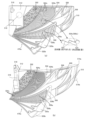
[General view of game machine]
1, 2, and 3 are diagrams for explaining the gaming machine. 1, 2 and 3 are a perspective view, a front view and a left side view of the gaming machine.
遊技機10は島設備に固定される枠11に、ヒンジ16a、16bを介して開閉回動自
在に取り付けられる開閉枠を備える。開閉枠は、前面枠12(本体枠)及びガラス枠15
(前枠ユニット)によって構成されている。なお、枠11と前面枠12は、外枠ユニット
17を構成する。
The
(front frame unit). Note that the
前面枠12には、遊技盤30(図35参照)が配設されるとともに、遊技盤30の前面
を覆うカバーガラス14を有するガラス枠15が取り付けられる。カバーガラス14は、
遊技盤30に形成される遊技領域32(図35参照)を視認可能とする遊技視認領域とし
て機能する。なお、カバーガラス14は、透明部材の一例として示すものであり、カバー
ガラス14の代わりにプラスチック製のカバーを使用してよい。ガラス枠15は、透明部
材を保持する透明部材保持枠として機能する。
A game board 30 (see FIG. 35) is arranged on the
It functions as a game viewing area that makes the game area 32 (see FIG. 35) formed on the
前面枠12及びガラス枠15は、それぞれ個別に開放することが可能となっている。例
えば、ガラス枠15のみをヒンジ12a、12b(図4)を介して回動して開放すること
で、遊技盤30の遊技領域32にアクセスすることができる。また、ガラス枠15が開放
されていない状態で前面枠12をヒンジ16a、16bを介して回動して開放することで
、遊技盤30の裏面側に配設された遊技制御装置100(主基板)(図79参照)等にア
クセスすることができる。ガラス枠15及び/又は前面枠12は、鍵部446によって施
錠されたり開放される。
The
ガラス枠15(前枠ユニット)の前枠ベースユニット480(図7)には、カバーガラ
ス14の縁の前方において、前方から見て全体的に凹形状をとる前枠内側部材482が配
置されている。前枠内側部材482は、左右方向に延在する底板482aと、底板482
aの両端部から各々上下方向に延在する右側と左側の2つの垂直板482b、482cと
を、備える。垂直板482b、482cは、下側では前方(遊技者側)に対面しているが
、中央部で捩じれており、上側では遊技機10の中央側に対面している(図33(a)も
参照)。
A front frame
two right and left
前枠内側部材482は、明度や彩度の低い色としての黒色を有する。このため、遊技者
がカバーガラス14(透明部材)を介して、表示装置41(後述)や遊技盤30の各種入
賞口(後述)に注目する際の視野内に黒色の部分が一部あるため、遊技者への圧迫感が少
なくなる。なお、前枠内側部材482は、仮に、赤色等の彩度や明度の高い色であると、
目立つためにくどい印象を遊技者に与えてしまう。また、前枠内側部材482の外側の周
囲には、装飾装置18b、18cや演出ボタン25などの発光装置があるが、これら発光
装置は、見え方として黒色の前枠内側部材482とは明確に区画されるため、その発光が
目立つことになる。なお、前枠内側部材482は、その材料自体が黒色であってもよいし
、前面が黒色に塗られたものでもよい。
The front frame
Because it stands out, it gives a verbose impression to the player. In addition, around the outside of the front frame
また、ガラス枠15のカバーガラス14周囲の縁部分には、種々の枠構成部材が配設さ
れている。
In addition, various frame-constituting members are arranged on the edge portion of the
ガラス枠15の上部中央及び右側部と左側部には、遊技状態に応じて発光演出可能な装
飾装置18a,18b,18cが配設されている。装飾装置18a,18b,18cは、
内部にLED等の照明部材を収容しており、遊技状態に応じた発光演出を行う演出装置で
ある。これら装飾装置18a,18b,18cの内部に配設される照明部材は、枠装飾装
置18(図80参照)の一部を構成している。
It is a production device that accommodates lighting members such as LEDs inside and performs light emission production according to the game state. The lighting members arranged inside these
装飾装置18aは、ガラス枠15の上部で、遊技機10の左右方向に延設されるととも
に、前方に向かって突出するトップユニットである。装飾装置18aは、本実施形態では
固定され動作しないが、遊技者への圧迫感を低減するように、引っ込んだ初期位置(通常
位置)から必要な場合のみ前方に突出動作したり、上下方向に移動動作してもよい。
The
装飾装置18bは、ガラス枠15の右側で上下方向に延設されるとともに、前方に向か
って突出する突出演出ユニット(前枠発光ユニット)である。装飾装置18cは、ガラス
枠15の左側で、上下方向に延設されるとともに、前方に向かって突出する突出演出ユニ
ット(前枠発光ユニット)である。装飾装置18b,18cは、遊技機10の中央側(内
側)へ遊技者に向けて光を照射するとともに、サイドカバー795の複数の開口795a
からインナーレンズ794(インナーカバー)を介して遊技機10の外側に光が漏れる。
なお、装飾装置18b、18cの詳細な構成は、図33と図34に基づいて後述される。
The
light leaks to the outside of the
The detailed configuration of the
ガラス枠15の右上角部分及び左上角部分には、上スピーカ19a,19bがそれぞれ
配設される。これら上スピーカ19a,19bとは別に遊技機10の下部には、2つの下
スピーカ19c,19dが設けられている。下スピーカ19c,19dは、ガラス枠15
の左下角部分及び前面枠12の右下角部分に配設されている。これら上スピーカ19a,
19b及び下スピーカ19c,19dは、効果音や警報音、報知音等を発するものである
。なお、上スピーカ19a,19bは、各々、右側のスピーカ飾り部材470aと左側の
スピーカ飾り部材470bで覆われているが、スピーカ飾り部材470a,470bの詳
細な機能と構成は、図7から図11に基づいて後述される。
and the lower right corner of the
The 19b and the
ガラス枠15の下部には、遊技球を貯留可能な上皿21を有する上皿ユニット20が取
り付けられている。上皿21は、上部で開口した箱状に形成されている。上皿21も、前
枠内側部材482と同じく、明度や彩度の低い色としての黒色を有する。上皿21に貯留
されている遊技球は、一球ずつ球発射装置530(後述)に供給される。なお、上皿ユニ
ット20の詳細な構成は、図18から図27に基づいて後述される。
An
上皿ユニット20は、遊技者からの入力操作を受け付ける演出操作装置と、遊技者から
の入力操作を受け付ける球貸操作装置と、遊技状態に応じて発光演出等を行う装飾装置2
2と、をさらに備える。
The
2 and .
演出操作装置は、演出ボタン25、音量調整用ボタン690d,690e、及び、十字
キー690fを含む操作装置であり、遊技者が操作しやすいように上皿ユニット20の上
部中央とその左側に設けられている。演出ボタン25は、操作パネル690に包囲される
ように、操作パネル690の開口内に配置される。操作パネル690は、表面への金属メ
ッキや全体を金属製にすることなどによって光を反射可能であり、例えばシルバー(銀色
)の金属光沢を有する。演出ボタン25が発光すると、周囲の操作パネル690で演出ボ
タン25からの光が反射され、演出ボタン25の発光演出が効果的になる。
The effect operation device is an operation device including the
後述のように、演出ボタン25は、最上面のボタンレンズ754が透明で、ボタンレン
ズ754の下に配置されるボタンレンズ飾り756の文字「PUSH」が視認できる(図
18)。また、演出ボタン25は、駆動手段としてのモータ771によって振動するよう
なバイブレーション機能を有する(図18)。なお、演出ボタン25は上方に向かって飛
び出すように動作してもよく、その場合、前方の正面から見ると前枠ベースユニット48
0の黒色の前枠内側部材482(底板482a)と一部と重なり、遊技者が黒色に見えた
部分に変化があったと気づき、演出ボタン25の変化(動作)を見逃すことがない。なお
、演出ボタン25は、前枠内側部材482(底板482a)と異なる色(例えばシルバー
)を有したり飛び出すときに発光すると、さらに演出ボタン25の変化(動作)を見逃す
ことがなくなる。
As will be described later, the
0 black front frame inner member 482 (
音量調整用ボタン690d,690eは、上皿ユニット20の操作パネル690の上部
左側に設けられ、スピーカの音量を増減(+-)して調整する。十字キー690fは、上
皿ユニット20の操作パネル690の上部左側で音量調整用ボタン690d,690eに
隣接して設けられ、例えば、LEDの輝度を調整する。
球貸操作装置は、遊技者が遊技球を借りる場合に操作する操作装置であって、上皿ユニ
ット20の操作パネル690の上部右側に設けられている。球貸操作装置は、残高表示部
690aと、球貸ボタン690bと、返却ボタン690cと、を備えている。残高表示部
690aは、プリペイドカード等の残高が表示される表示領域である。球貸ボタン690
bは遊技球を借りる場合に遊技者が操作するボタンであり、返却ボタン690cは遊技機
10に隣接するように配置されるカードユニット(図示省略)からプリペイドカード等を
排出させる場合に遊技者が操作するボタンである。
The ball rental operation device is an operation device operated when a player borrows game balls, and is provided on the upper right side of the
b is a button operated by the player when borrowing a game ball, and a
装飾装置22は、内部にLED等の照明部材を収容しており、遊技状態に応じて発光演
出等を行う装置であって、上皿ユニット20に設けられている。装飾装置22の内部に配
設される照明部材は、枠装飾装置18(図80参照)の一部を構成している。
The
上記した上皿ユニット20等を備えるガラス枠15の下方であって、前面枠12の下部
には、球発射装置530の動作を制御するための操作ハンドル24と、遊技球を貯留可能
な下皿23等を備える下皿ユニット29とが設けられている。下皿ユニット29と上皿ユ
ニット20は、形状的に適合しており上下方向に重ねて並べて配置される。上皿ユニット
20の上皿操作部735を操作することによって、上皿21の遊技球は下皿23へと流下
させることができる。なお、下皿ユニット29の詳細な構成は、図5と図6に基づいて後
述される。
Below the
操作ハンドル24は、前面枠12の右下部であって、右側の下スピーカ19cの下方に
配置されている。遊技者が操作ハンドル24を回動操作することによって、球発射装置5
30は上皿21から供給された遊技球を遊技盤30の遊技領域32に発射する。球発射装
置530から発射される遊技球の発射速度は、操作ハンドル24の回動操作量が大きくな
るほど速くなるように設定されている。即ち、球発射装置530は、遊技領域32に遊技
球を発射する勢(速度)である発射勢を、遊技者による操作ハンドル24の操作に対応し
て変更でき、発射勢の異なる種々の発射態様で遊技球を発射できる。発射態様には、遊技
領域32の左側において遊技球を流下させる左打ち(通常打ち)と、遊技領域32の右側
において遊技球を流下させる右打ちが含まれる。
The operation handle 24 is arranged in the lower right portion of the
30 shoots the game balls supplied from the
下皿ユニット29の下皿23は、上皿ユニット20に対して所定の間隔をあけて、上皿
ユニット20の下方に配置されている。下皿23は、当該下皿23の底面を上下方向に貫
通する開口部455a(後述)と、開口部455aを開閉するための開閉操作部467と
、を有している。遊技者が開閉操作部467を操作して、開口部455aを開くことによ
って、下皿23に貯留されていた遊技球を開口部455aを通じて外部に排出することが
できる。
The
また、前面枠12の裏側には、各種装置に電力を供給する電源装置400、島設備に設
置された補給装置(図示省略)から補給される遊技球を貯留する上部タンク448、上部
タンク448から流下してきた遊技球を上皿21に払い出す払出ユニット780などが配
置される(図3)。
In addition, on the back side of the
図3のように、本実施形態では、装飾装置18a(トップユニット)は、上皿ユニット
20やよりも若干大きく前方へ突出し、目立つように装飾装置18b,18c(突出演出
ユニット)や下皿ユニット29よりもかなり大きく前方へ突出している(一点鎖線参照)
。即ち、装飾装置18aの前方への突出量は、上皿ユニット20やよりも若干大きく、装
飾装置18b,18cや下皿ユニット29よりもかなり大きい。ここで、突出量は、ガラ
ス枠15の後部(例えばカバーガラス14)から前後方向における最先端432a(頂点
)までの距離である。しかし、図3に限られず、装飾装置18aの前方への突出量は適宜
変更可能である。例えば、遊技者の頭が装飾装置18a(トップユニット)に衝突しない
ように、装飾装置18aの突出量を上皿ユニット20よりも少なくして(装飾装置18b
,18cよりは大きくして)、装飾装置18aの最先端432a(頂点)を上皿ユニット
20の最先端20a(頂点)よりも後側に配置してもよい。
As shown in FIG. 3, in this embodiment, the
. That is, the amount of forward projection of the
, 18c), and the
図4は、遊技機の分解図である。なお、見えやすくするため遊技盤30の一部は省略さ
れている。
FIG. 4 is an exploded view of the gaming machine. A part of the
装飾装置18a(トップユニット)は、本体部432、本体部432の前方に位置する
透明カバー434、本体部432の前部から左右に突出する飾り部436、飾り部436
の後方に位置する左右の発光部440(発光手段)、本体部432の後方に位置する取付
部438、442、を備える。装飾装置18aは、遊技者に大きく且つ広く見せるために
、前方に向かって上下左右に広がっていくような末広がりの形状を有している。装飾装置
18aは、前枠ベースユニット480の受部444に接続される取付部442などによっ
て前枠ベースユニット480に取り付けられる。
The
left and right light-emitting portions 440 (light-emitting means) located behind the
本体部432の前面432bと透明カバー434の間には遊技機10の機種名が表示さ
れたシートが挟まれて配置される。シートのみを交換することで、装飾装置18a全体を
交換せずに異なる機種でも装飾装置18aを使用可能であり、コストが削減できる。
Between the
前面枠12の下部には、遊技球を発射するための球発射装置530やファール球(後述
)を捕獲するためのファール球キャッチユニット560(ファール球捕獲部材)が配置さ
れている。球発射装置530の詳細については、図12と図13に基づいて、後述される
。ファール球キャッチユニット560については、図12、図14から図17に基づいて
後述される。
A
前面枠12の左端部には、遊技盤30の被係止部30d(図35参照)を係止する複数
の遊技盤係止部材12cが設けられる。遊技盤30は、被係止部30dと遊技盤係止部材
12cを介して前面枠4に取り付けられる。また、前面枠12の右端部には、下皿ユニッ
ト29の係合部452と接続する受部451が設けられている。
A plurality of game
前面枠12の左下側には、払出ユニット780から払い出される賞球を上皿21の賞球
入口484へ通過させる賞球払出口443が設けられる。
A prize
〔下皿ユニット〕
図5と図6を参照して、下皿ユニット29の詳細な構成を説明する。図5は、下皿ユニ
ット29を右斜め上から見た斜視図(a)と、左斜め上から見た斜視図(b)を示す。図
6は、下皿ユニット29の上面図(a)、断面図(b)、拡大断面図(c)(d)を示す
。
[Lower plate unit]
A detailed configuration of the
下皿ユニット29は、背面側の下皿ベース453と、下皿ベース453に前方から接続
する左側ケース部456、中央ケース部458、及び右側ケース部460と、を備える。
また、下皿ユニット29は、左側ケース部456よりも下側で、下皿ベース453に前方
から接続する下側ケース部459を備える。
The
The
また、下皿ユニット29は、左側ケース部456の前方に、遊技場(遊技店)の係員を
呼び出すための呼出しボタン454を備える。呼出しボタン454のオン信号は、遊技制
御装置100(図79)に入力されて、外部情報として外部情報端子71からデータラン
プに送られて、遊技情報等の表示装置であるデータランプが発光する。
The
中央ケース部458の前方には、下皿ユニット29の右前側を装飾する右飾り部466
aが設けられる。下皿23の前方には、下皿ユニット29の左前側を装飾する左飾り部4
66aが設けられる。
A right decorative portion 466 for decorating the right front side of the
a is provided. In front of the
66a is provided.
中央ケース部458は、略上下方向に延在する縦部分458aと略左右方向に延在する
横部分458bを有する。中央ケース部458の縦部分458aと右側ケース部460の
間には、下スピーカ19cと操作ハンドル24の軸部24aが配置される。
The
下皿ユニット29は、大きく分けて、左右方向に延在する平坦部29aと、平坦部29
aの右側で上方に突出する右側突出部29bからなる。平坦部29aは、下皿23、左側
ケース部456、及び、中央ケース部458の横部分458bを含む。平坦部29aの上
方には、上皿ユニット20の底板部701(後述)が対面して配置される。右側突出部2
9bは、中央ケース部458の縦部分458a、右側ケース部460、下スピーカ19c
、及び、操作ハンドル24を含む。ガラス枠15を前面枠12に対して閉じ得るように、
右側突出部29bは、上皿ユニット20の右端の部分と前枠ベースユニット480(図7
)の右下隅の部分に後方から嵌まる形状を有している。
The
It consists of a
9b is the
, and an
The
) is fitted from behind in the lower right corner.
左側ケース部456と中央ケース部458の間には、遊技球の通路462(溝)が形成
される。通路462の上端には、通路462を上方から覆う透明な部材であるカバー46
4が設けられる。カバー464が透明であることから、ガラス枠15を前面枠12に対し
て開放した場合に通路462内を視認可能となる。
A game ball passage 462 (groove) is formed between the
4 is provided. Since the
下皿ユニット29の下皿ベース453の背面には、遊技球の第1入口461と第2入口
465が設けられる。第1入口461には、球発射装置530から打ち出されたが遊技領
域32に到達せずに戻ってきたようなファール球(落下球)がファール球キャッチユニッ
ト560から流入するとともに、上皿21が満タン(満杯)になった際に払出ユニット7
80からの遊技球(賞球)が流入してよい。第2入口465には、上皿操作部735の操
作によって上皿21から抜かれた遊技球が流入してよい。遊技球は、第1入口461と第
2入口465から通路462を通って、通路462の出口463から下皿23に流入する
。なお、下皿23が満タンとなった場合に、通路462に遊技球が貯留される。通路46
2は、第1入口461と第2入口465に連通するために、一部が、左側ケース部456
と中央ケース部458の内部又は下側を通過してよい。
A
Gaming balls (prize balls) from 80 may flow in. A game ball ejected from the
2 is partly connected to the
and may pass through or under the
ファール球は第1入口461から通路462を通るため、不正(ゴト行為)の一環とし
て糸の一端が付けられたファール球(糸の他端は遊技領域32内の遊技球に付けられてい
る)を使用する場合に、通路462の透明なカバー464が糸で擦れて傷ついて白くなり
透明でなくなるので、不正を簡単に発見できる。また、透明なカバー464は、不正によ
って傷ついても交換可能であり、下皿ユニット29全体を交換する必要はない。
Since the foul ball passes through the
左側ケース部456の前方、且つ、下側ケース部459の上方には、下皿23の底部と
前部を構成する皿部455が配置される。図6(b)のように、皿部455は、上下方向
且つ前後方向内にL字状の断面を有する。なお、左側ケース部456は、一体的に形成さ
れた上板456aと前板456bを有し、前板456bが下皿23の背板を構成する。図
6(b)のように、左側ケース部456の前板456b(下皿23の背板)が下側に行く
ほど奥側に位置するような傾斜を有することによって、遊技者が斜め上の前方から下皿2
3の遊技球を手で掻き出し易くなる。
A
It becomes easy to rake out the game ball of 3 by hand.
下皿23の底部(即ち皿部455の底部)には、円環状の開口部455aと、開口部4
55aから4方に放射状に延びる谷部455bが設けられる。通路462の出口463か
ら下皿23に流入した遊技球は、通り易い谷部455bを通って開口部455aに落ちる
。開口部455aは、開閉部材457によって通常は閉じられているが、開閉操作部46
7の操作によって開閉部材457が開く。開閉部材457が開くと、遊技球は、開口部4
55aを通過して、下側ケース部459に突設された円環状の排出口459aから遊技機
10の外部に排出される。
The bottom of the lower plate 23 (that is, the bottom of the plate portion 455) has an
7 opens the opening/closing
55 a and is discharged to the outside of the
図6(c)のように、下皿23の窪み(凹み)の深さD1は、遊技球の直径よりも短い
。このため、遊技球を手でつかみ易くなる。なお、深さD1は、開口部455aの下端(
閉じられた開閉部材457の上面)から通路462の出口463の下端までの高さに相当
する。また、円環状の排出口459aの深さD2は、遊技球の直径よりも長い。このため
、開口部455aを通過した遊技球は、真下に落ち易くなる。
As shown in FIG. 6(c), the depth D1 of the recess (recess) of the
It corresponds to the height from the upper surface of the closed opening/closing
また、図6(d)のように、排出口459aと開口部455aからなる排出部(排出穴
)の深さD3は、遊技球の直径よりも長いが、遊技球の直径の2倍よりも短い。このため
、遊技球の下半分側が排出部の開閉部材457(扉)に挟まった場合(挟まって下側に戻
る場合)、下側に戻しやすく、遊技球の上半分側が排出部の開閉部材457に挟まった場
合(挟まって遊技機外に排出される場合)、遊技球が箱(自動計数用の回収箱やいわゆる
ドル箱)にまっすぐ誘導されるため、箱からこぼれない。なお、深さD3は、排出口45
9aの下端から開口部455aの上端までの高さに相当する。
Also, as shown in FIG. 6(d), the depth D3 of the discharge portion (discharge hole) consisting of the
It corresponds to the height from the lower end of 9a to the upper end of
〔音出力部〕
図7から図9を参照して、音を出力するための音出力部473の構成を説明する。音出
力部473は、音発生手段として上スピーカ19a,19bと、上スピーカ19a,19
bの周辺部材としてスピーカ飾り部材470a,470bと、を備える。図7は、装飾装
置18a(トップユニット)を除いたガラス枠15の分解図である。図8は、装飾装置1
8aを除いたガラス枠15の正面図(a)、断面図(b)、さらにスピーカ飾り部材47
0a,470bを除いた正面図(c)、裏面図(d)である。図9は、音出力部の拡大断
面図(a)と、上スピーカ19a,19bから出力された音の伝わり方を示す図(b)で
ある。
[Sound output part]
The configuration of the
Front view (a) and cross-sectional view (b) of
It is a front view (c) and a rear view (d) excluding 0a and 470b. FIG. 9 is an enlarged cross-sectional view (a) of the sound output section, and a view (b) showing how the sounds output from the
図7と図8のように、ガラス枠15(前枠ユニット)の前枠ベースユニット480は、
上スピーカ19a,19bを備える。上スピーカ19a,19bは、遊技機10の下側及
び内側(中央側)に音が向かって出力されるように傾いている。前枠ベースユニット48
0には、上皿ユニット20とスピーカ飾り部材470a,470bが取り付けられる。右
側のスピーカ飾り部材470aは、右側の上スピーカ19aを覆うように前枠ベースユニ
ット480に取り付けられる。左側のスピーカ飾り部材470bは、左側の上スピーカ1
9bを覆うように前枠ベースユニット480に取り付けられる。
As shown in FIGS. 7 and 8, the front
0, the
It is attached to the front
スピーカ飾り部材470a,470bは、上スピーカ19a,19bからの音が遊技者
に直接伝わらないようにする。上スピーカ19a,19bの前部から出た音は、それぞれ
、スピーカ飾り部材470a,470bの裏面で反射して、カバーガラス14に当たりそ
こで再度反射して遊技者に伝わる(図9(b)の実線)。なお、下スピーカ19c、19
dからの音は、遊技者に直接伝わる。スピーカ飾り部材470a,470bは第1音反射
手段を構成し、カバーガラス14は、第2音反射手段を構成する。
The
Sound from d is transmitted directly to the player. The
上スピーカ19a(或は上スピーカ19b)は、スピーカ本体490、スピーカ本体4
90の後方の第1スピーカ収納部材491a、スピーカ本体490の周囲に位置して第1
スピーカ収納部材491aに接続する第2スピーカ収納部材491b、及び、第2スピー
カ収納部材491bの周囲に配置されるスピーカ外枠部材491cを備えたスピーカユニ
ットである。
The
A first
The speaker unit includes a second
第1スピーカ収納部材491aと第2スピーカ収納部材491bは、組み合わされて、
スピーカ本体490の前部を除いてスピーカ本体490を包囲して収納する。スピーカ本
体490の後部と第1スピーカ収納部材491aとの間には空間492(隙間)が形成さ
れる。上スピーカ19a,19b(スピーカユニット)の裏面を構成する第1スピーカ収
納部材491aの下部とカバーガラス14の間には、ボックス状の空間493(隙間)が
形成される。空間493の前後方向の長さL1、即ち、第1スピーカ収納部材491aの
下部とカバーガラス14との距離は、上スピーカ19a,19bの後部(スピーカユニッ
ト裏面)から出る音をカバーガラス14で遊技者に向けて反射できるように(図9(b)
の点線)、適切な値に設定されている。
The first
The speaker
dotted line), set to an appropriate value.
図9(b)の実線と点線で示すように、上スピーカ19a,19bの前部と後部から出
た音は、カバーガラス14で反射して遊技者に向かうため種々の効果が生じる。例えば、
高音である場合、遊技者に直接音が当ると耳が痛いが、カバーガラス14(壁)を介する
ことで緩和させられる。また、音(特に低音)がカバーガラス14にぶつかることでカバ
ーガラス14全体から音が出ているように聞こえるため、好適である。また、音が外に漏
れ難くなり、遊技者は音を聞き取り易くなる。
As shown by the solid and dotted lines in FIG. 9B, the sounds emitted from the front and rear portions of the
If the sound is high-pitched, the sound directly hitting the player hurts the player's ears, but the cover glass 14 (wall) can alleviate the pain. In addition, when the sound (particularly low-pitched sound) collides with the
図8(d)のように、前枠ベースユニット480は、その裏面において、上スピーカ1
9a,19bの各々の後方(裏側)に対応する位置で、右側の裏側カバー部材488aと
左側の裏側カバー部材488bを備えている。裏側カバー部材488a,488bは、ボ
ックス状の形状を有する。右側の裏側カバー部材488aは、上スピーカ19aから前枠
ベースユニット480を介して後方(裏側)に伝わる音(振動)を、内部の空間に閉じ込
めて減衰させることができる。同様に、左側の裏側カバー部材488bは、上スピーカ1
9bから前枠ベースユニット480を介して後方(裏側)に伝わる音(振動)を、内部の
空間に閉じ込めて減衰させることができる。従って、裏側カバー部材488a,488b
は、騒音防止の効果があるとともに、上スピーカ19a,19b周辺の各種電子回路基板
を振動から保護できる。
As shown in FIG. 8(d), the front
A right
The sound (vibration) transmitted from 9b to the rear (rear side) via the front
has the effect of preventing noise and can protect various electronic circuit boards around the
また、裏側カバー部材488a,488bは、外側(カバーガラス14と反対側)で電
気配線を配置することによって、カバーガラス14から電気配線を遠ざけることができ、
カバーガラス14(フレーム14a含む)を前枠ベースユニット480の取付部480a
から外し易くする。また、裏側カバー部材488a,488bの少なくとも一方において
、カバーガラス14に沿った部分が遊技盤30の部材(例えばガイドレール31)に形状
的に適合して、ガラス枠15を前面枠12に対して閉じる際にガイドとして機能する。さ
らに、裏側カバー部材488a,488bは、前後方向の厚みを大きくしてスペーサとし
て機能させ、遊技盤30がカバーガラス14に接触することを防止してよい。この場合、
遊技盤30は、裏側カバー部材488a,488bに当接する部分を有してよい。
In addition, the back
The cover glass 14 (including the
make it easier to remove from In at least one of the back
The
なお、以下に、前枠ベースユニット480についてさらに説明しておくと、前枠ベース
ユニット480は、カバーガラス14のフレーム14aと、フレーム14aの前方に配置
される前述の前枠内側部材482と、を備える。また、前枠ベースユニット480は、払
出ユニット780から払い出される賞球を上皿21へ流入させる賞球入口484と、上皿
21からの遊技球を球発射装置530に供給する発射球供給路486と、を備える。また
、ガラス枠15が前面枠12に対して閉じられるように、前枠ベースユニット480は、
下皿ユニット29の右側突出部29bに形状的に適合したカーブ状の湾入端部480cを
右下側に備えている。
The front
A curved recessed
賞球入口484(図7)には、前枠ベースユニット480の背面側の賞球通路487(
図8(d))が連通している。賞球通路487は前面枠12の賞球払出口443(図4)
と接続する。このため、払出ユニット780からの賞球が、賞球払出口443(図4)、
賞球通路487(図8(d))、賞球入口484(図7)を通って、上皿21に流入する
。
The prize ball entrance 484 (FIG. 7) has a prize ball passage 487 (
FIG. 8(d)) are in communication. The
Connect with Therefore, the prize balls from the
It flows into the
上皿操作部735の操作がない通常の場合に、開閉部材734(図18、図19)が閉
状態であり、遊技球は上皿21から発射球供給路486に供給される。一方、上皿操作部
735の操作によって開閉部材734が開状態となった場合に、遊技球は、発射球供給路
486ではなく下方へ向かう通路485に流れ、通路485に連通する第2入口465に
達する。これにより、上皿21から下皿23に遊技球が抜かれることになる。
In the normal case where the upper
また、前枠ベースユニット480は、図8(d)のように、球止めユニット489を有
する。球止めユニット489は、ガラス枠15が前面枠12から開放されたときに、発射
球供給路486から遊技球が前枠ベースユニット480の後方へ流下するのを止めるため
のものである。球止めユニット489では、発射球供給路486を開閉可能な略L字形状
の球止め部材483を前枠ベースユニット480に対して回動可能に軸着している。なお
、球止めユニット489は、従来のもの(例えば特開2012-232200参照)と同
じでよい。
Further, the front
この球止め部材483は、コイルばね等の付勢部材(図示せず)により、発射球供給路
486が閉状態となるように付勢されている。そして、ガラス枠15が前面枠12に対し
て閉じた際に、球止め部材483が球発射装置530の前面に突設された球止め部材変換
部536(図4及び図13参照)と係合することによって、発射球供給路486は開状態
となる。なお、球止め部材変換部536の前端面は、当接した球止め部材483を摺動さ
せる台形状のカム面となるように傾斜している。
The
〔スピーカ飾り部材〕
図10、図11A、及び、図11Bを参照して、スピーカ飾り部材470a,470b
の構成について説明する。なお、図10、図11A、及び、図11Bにおいて、スピーカ
飾り部材470aのみを図示するが、スピーカ飾り部材470aとスピーカ飾り部材47
0bは、左右を入れ替えれば同じ構成を有する。
[Speaker decoration]
10, 11A, and 11B,
will be described. 10, 11A, and 11B show only the
0b has the same configuration if left and right are interchanged.
図10は、右斜めから見た遊技機10の斜視図である。図11Aは、遊技機10に取り
付けられた状態でのスピーカ飾り部材470aの側面図(a)と、スピーカ飾り部材47
0aを左斜め上から見た斜視図(b)である。図11Bは、スピーカ飾り部材470aの
正面図(a)と、スピーカ飾り部材470aを右斜めから見た斜視図(b)である。
FIG. 10 is a perspective view of the
It is the perspective view (b) which looked at 0a from the diagonal upper left. FIG. 11B is a front view (a) of the
スピーカ飾り部材470a(470b)は、前枠ベースユニット480の側部にネジ止
めされる外側取付部514a、514bを有するとともに、内側取付板512において前
枠ベースユニット480にネジ止めされる内側取付部516を有する。また、スピーカ飾
り部材470a(470b)は、装飾装置18a(トップユニット)の取付部438が貫
通する開口518を備える。
The
スピーカ飾り部材470a(470b)は、光を拡散する光拡散手段として拡散部50
2を備え、光を反射する光反射手段として上反射部504と下反射部506を備える。拡
散部502は、遊技機10の内側(中央側)に配置される内側取付板512に隣接して配
置される。上反射部504は、拡散部502の右下側で拡散部502に接して配置される
。上反射部504と拡散部502は、略同一平面内にあってよい。下反射部506は、上
反射部504の下側に配置される。拡散部502、上反射部504、下反射部506は、
表面(特に前面)に金属メッキがされているか、又は、金属製の表面部(表面板)を有す
る。
The
2, and includes an
The surface (especially the front surface) is plated with metal, or has a surface portion (surface plate) made of metal.
拡散部502は、スピーカ飾り部材470a(470b)と装飾装置18a(トップユ
ニット)が遊技機10(前枠ベースユニット480)に取り付けられた状態で、装飾装置
18aの発光部440の後方に配置される。拡散部502は、発光部440の透明なケー
スの背面(後部)に接して配置されてよい。また、拡散部502は、ランダムに種々の大
きさの凸凹が配置された磨りガラス状の表面部に有し、発光部440から後方に照射され
た光を乱反射して拡散する。これにより、発光部440の内部に点光源状にLEDが配置
されていても発光部440を全体的に光らせることができる。拡散部502で乱反射され
た光は、前方に向かったり、上反射部504や下反射部506の方に向かったりする。な
お、装飾装置18aの発光部440が発光することで、遊技機10の側面側(遊技島の入
口方向)から見る遊技者に対してアピールすることができる。
The
上反射部504と下反射部506は、発光部440からの光を反射可能であり、全体的
に羽根状の形状を有する。上反射部504は、前面504aと側面504bを有する。下
反射部506は、前面506aと側面506bを有する。上反射部504と下反射部50
6は、遊技機10の外側に向けて厚みが大きくなってよい。図11B(a)のように、上
反射部504の前面504aは、洗濯板状になっており、前方に突出した複数の突条50
4cが並べて配置されている。同様に、下反射部506の前面506aも、洗濯板状にな
っており、前方に突出した複数の突条506cが並べて配置されている。個々の突条50
4c、506cは、略上下方向に延在している。
The
6 may increase in thickness toward the outside of the
4c are arranged side by side. Similarly, the
4c and 506c extend substantially vertically.
前面504a、506aの上下方向又は左右方向に対する全体的な傾き(角度)は、適
宜調整可能である。例えば、図11A(a)の側面図のように、上反射部504の前面5
04aは上下方向及び左右方向と略平行にして前方を向くように配置する一方、下反射部
506の前面506aを上下方向から大きく傾けてよい。下反射部506は発光部440
からの距離が上反射部504よりも遠いため、このようにすれば、前面506aからの反
射光の向きが下側になり過ぎないようでき、下反射部506と上反射部504の両方で反
射する発光部440からの光を所定の位置(例えば遊技者の頭部)に集中させることがで
きる。また、拡散部502、及び、発光部440のケースの前面440aは、上反射部5
04の前面504aに向きを揃えて前方を向いているため、拡散部502と発光部440
と上反射部504の発光演出に協調性があり、興趣が向上する。
The overall inclination (angle) of the
04a may be arranged so as to be substantially parallel to the vertical direction and the horizontal direction and facing forward, while the
is farther from the
04 facing forward, the diffusing
and the light emitting effect of the upper reflecting
図11B(a)のように、複数の突条504c、506cの断面(長手方向に垂直)は
、鋸の歯のようになっている。個々の突条504c、506cは、前方に突出した3角状
(又はL字状)の断面を有し、装飾装置18aの発光部440からの光が当たる反射面5
22と、発光部440からの光が当らない非反射面524(影になる部分)を前方に有す
る。反射面522と非反射面524があることにより、前面504a、506aは、反射
面522だけが光って前方からは縞模様に見え、演出効果が高まり興趣が向上する。
As shown in FIG. 11B(a), the cross section (perpendicular to the longitudinal direction) of the plurality of
22 and a non-reflecting surface 524 (shaded portion) on which the light from the
また、反射面522の幅を調整することによって、上反射部504の前面504a又は
下反射部506の前面506aからの反射光の光量を調整できる。例えば、下反射部50
6は発光部440からの距離が上反射部504よりも遠いため、反射光の光量を上反射部
504と下反射部506で揃えるように、突条506cは、突条504cよりも大きい幅
の反射面522を有してよい。
Further, by adjusting the width of the reflecting
6 is farther from the
また、反射面522は遊技機10の中央側(内側)に下り傾斜しているが、反射面52
2の左右方向からの傾き(角度)を調整することによっても、上反射部504の前面50
4a又は下反射部506の前面506aからの反射光の光量を調整できる。例えば、下反
射部506は発光部440からの距離が上反射部504よりも遠いため、反射光の光量を
上反射部504と下反射部506で揃えるように、突条506cの反射面522は、突条
504cの反射面522よりも左右方向からの傾き(角度)を小さくしてもよい。なお、
突条506cの反射面522の傾きを小さくする(即ち、前方への高さを低くする)と、
非反射面524(影になる部分)の面積が減少するため、前面506aの反射光の光量が
増加する。
In addition, the reflecting
2 from the horizontal direction, the
4a or the amount of reflected light from the
Reducing the inclination of the
Since the area of the non-reflecting surface 524 (shadowed portion) is reduced, the amount of reflected light from the
さらに、図10、図11A、及び、図11Bを参照して説明すると、スピーカ飾り部材
470a(470b)は、上反射部504の外側後方で上反射部504に対峙する第1装
飾部508と、上反射部504と下反射部506の間に配置される第2装飾部509と、
下反射部506の横側後方で下反射部506に対峙する第3装飾部510と、第3装飾部
510の下側で第3装飾部510に対峙する第4装飾部511(図11Bでは省略)と、
を備える。さらに、スピーカ飾り部材470a(470b)には、下反射部506の下側
で、羽根状の薄い2枚の下部装飾部520a、520bが段になるように配置されている
。なお、装飾装置18aの発光部440からの光は、下反射部506と上反射部504に
遮られて、装飾部508~511、520a、520bにほとんど届かず、上反射部50
4の前面504a又は下反射部506の前面506aからの反射光が目立つようになる。
10, 11A, and 11B, the
A third
Prepare. Further, on the
4 or the
第1装飾部508と第3装飾部510は、表面への金属メッキや金属製の表面部(表面
板)とすることなどによって金属光沢を有するが、第2装飾部509と第4装飾部511
は黒色(明度や彩度の低い色)を有する樹脂製であり光を反射せず金属光沢を有さない。
このため、第1装飾部508と第3装飾部510の金属光沢が目立つようになり装飾性が
向上する。
The first
is made of black resin (a color with low brightness and saturation), does not reflect light, and does not have metallic luster.
Therefore, the metallic luster of the first
〔球発射装置〕
図12と図13を参照して、球発射装置530(発射ユニット、球発射手段)の詳細に
ついて説明する。図12は、球発射装置530を有する前面枠12の一部拡大正面図であ
る。図13は、球発射装置530の正面図(a)と斜視図(b)、及び、切断刃550の
斜視図(c)である。
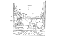
[Ball Launcher]
Details of the ball launching device 530 (shooting unit, ball launching means) will be described with reference to FIGS. 12 and 13 . FIG. 12 is a partially enlarged front view of the
球発射装置530の発射杵532によって弾発された遊技球は、通常、前面枠12の下
部に右下方から左上方に上り傾斜するように形成された発射レール533からファール球
キャッチユニット560(ファール球捕獲部材)を飛び越えて遊技盤30の発射球案内通
路33に流入し、発射球案内通路33を通って遊技領域32(図35参照)に導かれる。
A game ball shot by a
なお、図12の右下向きの実線の矢印と点線の矢印のように、発射勢(発射速度)が少
ない遊技球(発射球)は、発射球案内通路33から遊技領域32に到達せずに戻ってきて
ファール球(落下球)となり、ファール球キャッチユニット560に流入する。特に、フ
ァール球(落下球)は、ファール球キャッチユニット560の球ストッパーである突起部
585に衝突して、ファール球キャッチユニット560に流入する。また、発射勢(発射
速度)がさらに少ない遊技球(発射球)は、発射球案内通路33に達することなく直接的
にファール球キャッチユニット560に飛び込むファール球(直接球)となる。このよう
に、ファール球キャッチユニット560は、発射されたが遊技領域32に入らないファー
ル球を捕獲する捕獲手段を構成する。なお、ファール球キャッチユニット560の構成の
詳細については、後述される。
12, a game ball (launched ball) with a low launching force (launching speed) returns from the launching
図13(a)(b)のように、遊技球を発射するための球発射装置530は、上皿21
に貯留された遊技球を供給する発射球供給路486に連通する誘導路542と、糸部材が
取り付けられた不正球が発射された場合に不正球の糸部材を切断する切断機構544と、
を備える。
As shown in FIGS. 13(a) and 13(b), a
a guiding
Prepare.
なお、釣り糸等の糸部材を取り付けた遊技球(不正球)を球発射装置530で発射して
、遊技球が遊技領域32(図35参照)に入ったら糸部材を上皿21から操作して入賞口
に入賞させるような不正(ゴト行為)が行われる場合があり、切断機構544で不正球の
糸部材を切断する。切断機構544は、第1不正対策手段(第1不正対策部)を構成する
。
A game ball (illegal ball) to which a string member such as fishing line is attached is shot by the
なお、ガラス枠15の閉状態で、前面枠12側の誘導路542とガラス枠15側の発射
球供給路486とが接続して連通し、供給流路540の一部となる。供給流路540は、
上皿21に貯留された遊技球を左右方向右側に導いた後に前後方向後側に導き、球発射装
置530の発射位置に供給するように構成されている。
In the closed state of the
The game balls stored in the
球発射装置530は、前面枠12の前面右下部に設置されるベース板531と、ベース
板531の前面に回動自在に配設される発射杵532と、を有する。また、ベース板53
1の前面には、右側から左側に上り傾斜する発射レール533(発射通路)が固定されて
いる。
The
1 is fixed with a firing rail 533 (firing path) that slopes upward from the right side to the left side.
発射杵532は、操作ハンドル24の回動操作に基づいて回動し、発射レール533上
の発射位置にある遊技球を弾発するように構成されている。発射杵532によって弾発さ
れた遊技球は、発射レール533によって左右方向左側に導かれ、発射レール533から
遊技盤30の発射球案内通路33に流入し、発射球案内通路33を通って遊技領域32に
導かれる。
The
なお、球発射装置530から発射される遊技球の発射速度は、操作ハンドル24の回動
操作量が大きくなるほど速くなるように設定されている。
The shooting speed of the game ball shot from the
誘導路542の入口部542aは、球発射装置530のベース板531の前方をカバー
するように当該ベース板531に取り付けられたカバー部材534に設けられる。入口部
542aは、カバー部材534を前後方向に貫通する開口として形成されている。
An
また、誘導路542には、不正球の糸部材を切断するための切断機構544が設けられ
ている。
Further, the
切断機構544は、誘導路542の入口部542aと繋がるようにカバー部材534に
形成された糸誘導部546と、刃先部分が糸誘導部546内に位置するようにカバー部材
534に取り付けられる切断刃550と、切断刃550をカバー部材534に固定する固
定板548と、を備える。
The
糸誘導部546は、カバー部材534を前後方向に貫通する開口であって、誘導路54
2の入口部542aの左側部の上側部分に繋がるように切り欠かれている。これら糸誘導
部546と入口部542aは左右方向に並設されている。糸誘導部546は、不正球発射
時に不正球の糸部材が切断刃550の刃先部分(所定位置)に向かって移動することを可
能とする誘導通路として構成されている。
The
2 is cut out so as to be connected to the upper portion of the left side of the
図13(c)のように、切断刃550は、平板状の基端部553と、基端部553に連
接され当該基端部553と同一平面内に延在する平板状の第1先端部551と、基端部5
53に連接され当該基端部553から後方に屈曲される平板状の第2先端部552と、を
備える。第1先端部551と第2先端部552は上下に並設されており、これら先端部5
51,552の間(境界)に形成される隙間部554が不正球の糸部材を切断する切断部
分となる。第1先端部551の先端面551a(右側面)及び第2先端部552の先端面
552a(右側面)は、不正球の糸部材を隙間部554にガイドするよう、隙間部554
に向かって下り傾斜する傾斜面として形成されている。
As shown in FIG. 13C, the
53 and a flat second
A
is formed as an inclined surface that slopes downward toward
切断刃550は、カバー部材534の裏面に形成された収容凹部534aに収容された
状態で、固定板548を介してカバー部材534に固定される。切断刃550は、カバー
部材534に係合する固定板548によって、収容凹部534a内に固定される。固定板
548は、収容凹部534aに嵌め込まれた切断刃550の後側に配設される。
The
収容凹部534aは、切断刃550が嵌めこまれるような形状としてカバー部材534
に窪んで形成されている。収容凹部534aは切断刃550の外形をかたどるように形成
された凹部であり、切断刃550が収容凹部534aに嵌め込まれた状態では、切断刃5
50の左右方向及び上下方向への移動が規制される。また、切断刃550が収容凹部53
4a内に設置されている場合、当該切断刃550の隙間部554等の刃先部分は、糸誘導
部546の奥まった位置(左寄りの位置)に位置している。
The
is formed with a recess in the
Movement of 50 in the left-right direction and the up-down direction is restricted. Also, the
4a, the cutting edge portion of the
このように、切断刃550は、その刃先部分が右側に向けられるとともに糸誘導部54
6に露出するように配設されている(図13(a)参照)。
In this way, the
6 (see FIG. 13(a)).
上記のように構成される切断機構544では、糸部材が取り付けられた不正球が球発射
装置530により発射された際に、当該不正球の糸部材は、糸誘導部546を介して切断
刃550に導かれ、切断刃550の隙間部554に食い込む。隙間部554に食い込んだ
糸部材は、不正球の発射勢によって引っ張られて切断される。切断機構544の糸誘導部
546は供給流路540の誘導路542の入口部542aに繋がるように当該入口部54
2aの側部に切り欠かれており、切断刃550は糸誘導部546の奥まった位置に配設さ
れるので、遊技球の流下を妨げることなく、不正球の糸部材を切断することが可能となる
。
In the
2a is notched, and the
供給流路540は上皿21に貯留された遊技球を右側方に導いた後に後方に導き、球発
射装置530の発射位置に供給するように構成されており、発射レール533は発射位置
から発射された遊技球を左側方に導くように構成されている。そして、糸誘導部546は
誘導路542の入口部542aの左側部に繋がるように形成されており、切断刃550は
その刃先部分が右側を向くように配設されている。このように、糸誘導部546を入口部
542aの遊技球発射方向側の側部に設け、切断刃550の刃先部分を遊技球発射方向と
逆向きに設けることで、不正球の糸部材をより確実に切断することが可能となる。
The
〔ファール球キャッチユニット〕
図14から図17を参照して、ファール球を捕獲可能なファール球キャッチユニット5
60の詳細について説明する。ファール球は、球発射装置530によって発射されたが遊
技領域32に入らない遊技球である。図14Aは、ファール球キャッチユニット560の
正面図(a)と分解図(b)である。図14Bは、ファール球キャッチユニット560の
裏面図(a)と裏側の斜視図(b)である。図15は、ファール球キャッチユニット56
0の水平方向の断面図(a)とパーツ部材560bの水平方向の断面図(b)である。な
お、図15(a)の上図は、図14B(a)と同様である。図16は、ファール球キャッ
チユニット560を斜め上から見た斜視図である。図17は、ファール球キャッチユニッ
ト560を外した前面枠12の一部拡大正面図である。
[Foul ball catch unit]
14 to 17, foul ball catching unit 5 capable of catching foul balls.
60 will be described in detail. A foul ball is a game ball that is launched by
0 (a) and a horizontal cross-sectional view (b) of the
ファール球キャッチユニット560は、ベース部材560aと、ベース部材560aの
背面側に後方から接続するパーツ部材560bを組み合わせたものである。ベース部材5
60aは、前面枠12に設置されることにより、前面枠12の設置面598(図17)に
接して種々の遊技球流路590(590a-590d)を形成する。さらに、ベース部材
560aとパーツ部材560bの間にはベースパーツ間流路591が形成される。なお、
ファール球キャッチユニット560は、正面から見て略三角形状の本体部569と、本体
部569の左側に位置する落下払出球回収部570と、を備える。落下払出球回収部57
0は、ガラス枠15が開状態である場合に、賞球払出口443(図4、図12)から流出
して下方に落ちる遊技球を回収する。
The foul
By being installed on the
The foul
0 collects game balls that flow out from the prize ball payout port 443 (FIGS. 4 and 12) and fall downward when the
まず、ベース部材560aについて説明する。ベース部材560aは、平板状の前面部
561(前板)と、前面部561の上部において後方で垂直に設けた平板状の転動部56
4(転動板)と、前面部561の中央下部において後方に設けたベース側ボックス部56
5と、を備える。前面部561には、後方を視認するための3つの窓部561aが設けら
れる。窓部561aは、静電気の滞留を防止する機能も果たす。ベース側ボックス部56
5は、前方が前面部561において開口になっている。ベース側ボックス部565の上端
面594は、遊技球が左側に転動可能な傾斜面になっている。
First, the
4 (rolling plate) and a base-
5 and . The
5 has an opening in the
また、ベース部材560aは、ベース側ボックス部565の開口の右隣で、前面部56
1の右下部において前方で垂直に設けた環状の囲いであるベース側補強リブ566と、前
面部561に関してベース側補強リブ566とは反対側の位置に配置されるパーツ支持部
567及び右側流路形成部568と、を備える。パーツ支持部567及び右側流路形成部
568は、前面部561の右下部において後方で垂直に設けられている。
In addition, the
1, a base
パーツ支持部567は、後方から見て90度回転させた「F」の字状の形状をしており
(図14B(a))、パーツ部材560bを下から支持する長板部567aと短板部56
7bを有する。長板部567aと短板部567bは、両方とも、前後方向に同一の幅を有
して前面部561から延在するが、上下方向の長さ(高さ)は、長板部567aの方が短
板部567bよりも長い。また、長板部567aは、短板部567bと並列的に配置され
、短板部567bよりも右に配置される。
The
7b. Both the
前面部561は、前面部561に対して垂直に後方へ延出する上縁部562を有する。
平板状の転動部564は、長手方向において右下に下り傾斜して遊技球が右下側に転動可
能である。転動部564は、上縁部562と略平行に延在するが、上縁部562の前後方
向の幅は、転動部564の前後方向(短方向)の幅よりも短い。このため、転動部564
にファール球が流入できる。
The
The
A foul ball can flow into the
ベース側補強リブ566は、パーツ支持部567と右側流路形成部568に、前面部5
61を挟んで対峙するため、パーツ支持部567と右側流路形成部568の間に形成され
る右側流路590cの流路壁を補強する。また、ベース側補強リブ566は、成型時のヒ
ケ(成形収縮によって生じる窪み等の不良)を防止する。
The base-
61, the channel wall of the
さらに、ベース部材560aは、左側に位置する左側底面部571aと、左側底面部5
71aよりも右側の低い位置にある右側底面部571bを有する段状の底面部571を備
える。底面部571は、前面部561の下端部において垂直方向に延設される。なお、左
側底面部571a上に形成される案内流路590aと、案内流路590a(左側底面部5
71a)の前方に前面部561から延出する受皿部572は、落下払出球回収部570を
構成する。受皿部572は、前後方向の断面がL字状であり、賞球払出口443(図4、
図12)からこぼれ落ちてきた遊技球を受け入れて、後方の案内流路590aへと流下さ
せる。受皿部572の底部は、案内流路590aへ遊技球を流下させるように後方へ下り
傾斜してよい。
Further, the
A stepped
A
12) are received and flowed down to the
また、ベース部材560aは、前面部561から垂直に後方へ延在する中央流路形成部
589を有する。中央流路形成部589は、前面枠12の設置面598(図17)や前面
部561とともに中央流路590bを形成する。また、中央流路形成部589は、案内流
路590aと中央流路590bを仕切る仕切板として機能する。
The
その他、ベース部材560aは、前面枠12の設置面598(図17)に設けられる2
つの被係合部598a、598bに押し込んで取り付けられる2つの係合用フック575
a、575bを有する。
In addition, the
Two engaging hooks 575 attached by pushing into two engaged
a, 575b.
次に、パーツ部材560bについて説明する。パーツ部材560bは、ベース部材56
0aの平板状の前面部561に平行に配置される平板状のパーツ本体部576と、パーツ
本体部576の上部に配置され前面部561に取り付けられる取付部578と、を備える
。パーツ本体部576は、転動部564(転動板)の後端の段部564aに当接する上端
576aを有する。取付部578は、パーツ本体部576よりも前方に凸状に盛り上げて
形成されるとともに、前面部561の円柱状のネジ受部561b(図14B(b))に後
方からネジ止めによって取り付けられる。なお、取付部578は、ネジが通過する貫通孔
578aを有する。
Next, the
A flat plate-shaped
また、パーツ部材560bは、パーツ本体部576の下部において前方で設けられるパ
ーツ側ボックス部579を有する。パーツ側ボックス部579の上端面580は、遊技球
が左側に転動可能な傾斜面になっている。パーツ側ボックス部579の側端面581は、
ベース側ボックス部565の側端面(図示せず)に対向して右側で接している。パーツ側
ボックス部579の側端面581は、左側に行くほど後方に位置するように、左側で傾斜
しているが、ベース側ボックス部565の側端面は傾斜していない。このため、ベース側
ボックス部565とパーツ側ボックス部579の間には、左側で、細いスリット状の隙間
592が存在している(図15(a))。なお、パーツ側ボックス部579の上端面58
0の前後方向の幅は、上端面580の先端580a(左端)に行くほど若干狭く(短く)
なっているが、ベース側ボックス部565の上端面594の幅は一定である。
Further, the
It faces and contacts the side end surface (not shown) of the base-
The width of 0 in the front-rear direction is slightly narrower (shorter) toward the
However, the width of the
パーツ側ボックス部579の側端面581には、パーツ側ボックス部579をベース側
ボックス部565にネジ止めするための開口581aと、上部で右側に張り出した角状(
つのじょう)の鋭部581bと、ベース側ボックス部565の側端面と係合する細長い突
状の係合部584が設けられる。係合部584は、パーツ部材560bの位置決めをする
機能を有してよい。鋭部581bの付け根は、パーツ支持部567の短板部567bによ
って下から支持され、鋭部581bの突先は、パーツ支持部567の長板部567aに当
接する(図14B(a))。
The
A
さらに、パーツ部材560bは、平板状のパーツ本体部576の右端部において前方で
設けられる突起部585と、突起部585の下に設けられて突起部585を支持且つ補強
する補強リブ586と、を備える。
Further, the
補強リブ586は、突起部585の右下部と左下部を各々支持する右側板状部材586
aと左側板状部材586bを有する。突起部585の前後方向の幅は、補強リブ586(
2枚の板状部材586a、586b)の前後方向の幅よりも短い。そして、2枚の板状部
材586a、586bの上端において突起部585に繋がらない前側は、ベース部材56
0aの上縁部562に当接する。2枚の板状部材586a、586bは、両方とも、前後
方向に同一の幅を有してベース部材560aの前面部561に当接する(図15(a))
。右側板状部材586aと左側板状部材586bは、上下方向に沿って略平行に配置され
るが、上下方向の長さ(高さ)は、右側板状部材586aが低く、左側板状部材586b
が長い。なお、パーツ支持部567の長板部567aは、右側板状部材586aに右方で
接して並列的に配置されるとともに(図15(a))、右側板状部材586aとともに突
起部585の右下部を下から支持する。
The reinforcing
a and a
It is shorter than the width of the two plate-
It abuts on the
. The right plate-
is long. The
突起部585(球ストッパー)は、ベース部材560a(前面部561)の上縁部56
2よりも上方に突出している障壁となる(図14A(a)、図14B(a))。図12で
前述したように、ファール球キャッチユニット560の左上の発射球案内通路33から戻
ってきたファール球(落下球)は、突起部585に衝突して、突起部585を右側に超え
て進むことが難しく、ファール球キャッチユニット560に流入する。なお、発射球案内
通路33から戻ってきたファール球は、障壁としての補強リブ586の左側板状部材58
6bに衝突して、ファール球キャッチユニット560に流入する場合もある。
The projecting portion 585 (ball stopper) is attached to the
2 (FIGS. 14A(a) and 14B(a)). As described above with reference to FIG. 12, a foul ball (falling ball) returning from the upper left shot
6b and flow into the foul
また、突起部585は、全体として一枚の板を3箇所で折ったような中空の山型形状(
前方から見て左下で閉じない略「C」の字の形状)であり、中空であるためファール球と
突起部585の衝突音の発生を軽減できたり、衝突音の高低を適宜調整できる。また、補
強リブ586の2枚の板状部材586a、586bと突起部585で画定される空間は、
ファール球と突起部585の衝突音を閉じ込めて減衰させることができる。
In addition, the projecting
It has a substantially "C" shape that does not close at the bottom left when viewed from the front), and because it is hollow, it is possible to reduce the collision noise between the foul ball and the
The collision sound between the foul ball and the
〔遊技球の流れと流路(ファール球キャッチユニット内)〕
次に、図14から図17(特に、図14B(a))を参照して、ファール球キャッチユ
ニット560における遊技球(ファール球)の流れと流路を説明する。
[Game ball flow and flow path (inside foul ball catch unit)]
Next, referring to FIGS. 14 to 17 (particularly, FIG. 14B(a)), the flow and flow paths of game balls (foul balls) in the foul
ファール球は、転動部564に流入して転動できる。ここでのファール球として、発射
球案内通路33から戻ってきて突起部585に衝突して跳ね返ったファール球(落下球)
、発射球案内通路33から戻ってきたが突起部585まで到達しなかったファール球(落
下球)、又は、発射速度が遅くファール球キャッチユニット560を超えられなかったフ
ァール球(発射球、直接球)がある。転動部564を転がり落ちた遊技球は、転動部56
4と突起部585の間の大開口部595aに流入する。なお、突起部585に衝突して跳
ね返ったファール球や発射速度が遅いファール球(発射球、直接球)などが、直接、大開
口部595aに流入することもある。
A foul ball can flow into the rolling
, a foul ball (falling ball) that returned from the shot
4 and the
大開口部595aを通過した遊技球(ファール球)は、パーツ側ボックス部579の上
端面580及びベース側ボックス部565の上端面594の上に位置するベースパーツ間
流路591に流入する。ベースパーツ間流路591は、上端面580、594、ベース部
材560aの前面部561、及び、パーツ部材560bのパーツ本体部576によって形
成される。ベースパーツ間流路591は、遊技球が左方向に転動可能となるように、左側
に下り傾斜している。
A game ball (foul ball) that has passed through the
上端面594の前後方向の幅、即ち、ベース側ボックス部565の後方への突出量は、
上縁部562の前後方向の幅よりも長いため、遊技球がベース側ボックス部565の上端
面594に落下可能である。また、ベースパーツ間流路591の幅(ここでは、上端面5
80と上端面594の前後方向の幅の合計に略等しい)は、転動部564の前後方向(短
方向)の幅に略等しい。なお、パーツ側ボックス部579及びベース側ボックス部565
の一方(即ち上端面580と上端面594の一方)を省略する構成も可能であるが、その
場合には、上端面580と上端面594の他方の幅を転動部564の前後方向(短方向)
の幅に略等しくしてよい。また、上端面580と上端面594の前後方向の幅の合計は、
遊技球の直径より小さな量(遊技球が落下しない量)であれば、転動部564の前後方向
(短方向)の幅より短くできる。
The width of the
Since it is longer than the width of the
80 and the sum of the widths of the
(that is, one of the
may be approximately equal to the width of In addition, the total width of the
If the amount is smaller than the diameter of the game ball (the amount at which the game ball does not fall), it can be shorter than the width of the rolling
ベースパーツ間流路591を通過した遊技球は、中央流路形成部589の右にある中央
流路590bに流入する。中央流路590bは、前面枠12の設置面598とベース部材
560aの前面部561の間で、ベース側ボックス部565とパーツ側ボックス部579
の左端面、及び、中央流路形成部589によって形成される。中央流路590bは、略上
下方向に延在している。
The game ball that has passed through the inter-base parts channel 591 flows into the
and a central flow
中央流路590bを通過した遊技球は、右側底面部571b上に形成される底部流路5
90dに流入する。なお、前述のように、賞球払出口443(図4、図12)からこぼれ
落ちてきて受皿部572に入った遊技球も、左側底面部571a上に形成される案内流路
590aを通過し、その後、案内流路590aよりも低い位置にある底部流路590dに
流入する。
The game ball that has passed through the
Flow into 90d. In addition, as described above, the game balls falling from the prize ball payout port 443 (FIGS. 4 and 12) and entering the
底部流路590dを通過した遊技球は、排出口593を通過して、下皿ユニット29の
第1入口461(図6(a))に流れ、第1入口461から下皿23に流入する。
The game ball that has passed through the
また、発射速度が非常に遅い右側からのファール球(発射球、直接球)、又は、稀に突
起部585を左側から超えたファール球(落下球)は、パーツ支持部567と右側流路形
成部568の間の小開口部595bに流入可能である。小開口部595bは、大開口部5
95aよりも小さい。
In addition, a foul ball (launched ball, direct ball) from the right side with a very slow firing speed, or a foul ball (falling ball) that rarely crosses the
smaller than 95a.
小開口部595bを通過した遊技球は、右側流路形成部568とパーツ支持部567の
長板部567aの間に形成される右側流路590cに流入する。右側流路590cを通過
した遊技球は、排出口593を通過して、下皿ユニット29の第1入口461(図6(a
))に流れ、第1入口461から下皿23に流入する。なお、小開口部595b及び右側
流路590cは、省略可能であり、存在しない構成とすることもできる。
The game ball that has passed through the
)) and flows into the
なお、ベース部材560aの前述の3つの窓部561aからは、それぞれ、案内流路5
90a、ベースパーツ間流路591、底部流路590dを視認可能であり、案内流路59
0a、ベースパーツ間流路591、底部流路590dに遊技球が詰まったときには窓部5
61aから細い棒などを挿入して、遊技球の詰まりを解消することもできる。
From the three
90a, the
0a, the
A thin stick or the like can be inserted from 61a to clear the clogging of game balls.
なお、本実施形態において、転動部564、パーツ支持部567、右側流路形成部56
8、中央流路形成部589、補強リブ586(2枚の板状部材586a、586b)の前
後方向の幅は、略同一であるが、遊技球の直径未満の範囲であれば適宜変更可能である。
In addition, in this embodiment, the rolling
8. The widths of the central flow
〔不正対策〕
次に、図14から図17(特に、図15と図16)を参照して、ファール球キャッチユ
ニット560における不正対策(ゴト対策)について説明する。
[Countermeasures against fraud]
Next, with reference to FIGS. 14 to 17 (in particular, FIGS. 15 and 16), fraud countermeasures (goto countermeasures) in foul
前述のように、球発射装置530(発射ユニット)において、第1不正対策手段(第1
不正対策部)として不正球の糸部材を切断する切断機構544を設けたが、ファール球キ
ャッチユニット560において、不正対策を行う第2から第4の不正対策手段(不正対策
部)が設けられる。
As described above, in the ball launching device 530 (launching unit), the first fraud countermeasure means (first
Although the
なお、ファール球キャッチユニット560において、以下の手順で実行される不正(ゴ
ト行為)に対する不正対策が行われる。まず、2つの遊技球に糸部材(釣り糸など)を取
り付けて対になるようにして、対の一方の遊技球を球発射装置530で遅い速度で発射し
、ファール球キャッチユニット560にファール球として落とす。続いて、対の他方の遊
技球を通常の速度で発射して遊技領域32に入れる。そして、ファール球キャッチユニッ
ト560から下皿23に入ったファール球に取り付けてある糸部材を下皿23から操作し
て、遊技領域32の遊技球を入賞口に不正に入賞させる。この不正では、糸部材を操作す
る手の動作が、下皿23によって見えにくいし遊技球を上皿21に持っていく動作をして
いるように見える。
In addition, in the foul
なお、切断機構544(第1不正対策手段)は、遊技球を遊技領域32に入れてから糸
部材を操作した場合に糸部材を切断できる場合も多いため(発射時に糸部材を切断できな
い場合もある)、ファール球に取り付けられた糸部材を切断できないこともある。
It should be noted that the cutting mechanism 544 (first fraud countermeasure means) can often cut the string member when the string member is operated after the game ball is put into the game area 32 (even if the string member cannot be cut at the time of shooting) some), it may not be possible to cut the thread member attached to the foul ball.
前述したように、ベース側ボックス部565とパーツ側ボックス部579と間には、左
側で、切れ目状(裂け目状)の隙間592が設けられているが、この隙間592が、第2
不正対策手段(第2不正対策部)となる。
As described above, between the base-
Acts as an anti-fraud measure (second anti-fraud section).
ファール球キャッチユニット560の大開口部595aを通って下皿23に入ったファ
ール球に取り付けた糸部材は、パーツ側ボックス部579の上端面580及びベース側ボ
ックス部565の上端面594の上に位置するベースパーツ間流路591を右から左へ通
過して、中央流路形成部589の右にある中央流路590bを上から下に通過している。
前述の不正において、ファール球に取り付けてある糸部材を下皿23から手で引いたりす
ると、この糸部材は、切れ目状の隙間592に挟み込まれて、操作して動かすことが困難
になる。
The string member attached to the foul ball that has entered the
In the above fraud, if the string member attached to the foul ball is pulled out of the
なお、前述のように、切れ目状の隙間592を設けるために、パーツ側ボックス部57
9の側端面581は左側に行くほど後方に位置するように傾斜しているが、傾斜は右側か
ら左側にかけて急になっている。従って、隙間592の入口592aは広くなり、糸部材
は隙間592に入り込み易くなるとともに、ファール球に取り付けてある糸部材を下皿2
3から手で引いたり離したりして何度も操作すると、糸部材は切れ目状の隙間592に徐
々に挟み込まれて、最終的には隙間592の狭い右側で動かなくなり、それ以上の操作が
できなくなる。
In addition, as described above, in order to provide the cut-
The
3, the thread member is gradually caught in the cut-
なお、上端面580、594に上下方向の凹凸を多数設けてざらついた面とすることに
よって、糸部材との摩擦を増やして、糸部材を隙間592に絡め易くしてよい。また、パ
ーツ側ボックス部579の側端面581ではなく、ベース側ボックス部565の側端面に
傾斜を設けて、切れ目状の隙間592を形成することも可能である。
The upper end surfaces 580 and 594 may be roughened by providing a large number of unevenness in the vertical direction to increase the friction with the thread member and make it easier to entwine the thread member in the
次に、右側流路形成部568の上部に形成したスリット状の切れ込み596a(図16
)が、第3不正対策手段(第3不正対策部)となる。
Next, a slit-shaped
) becomes the third anti-fraud measure (third anti-fraud section).
発射速度が非常に遅い発射球(ファール球)は、小開口部595bから右側流路590
cを通過して、下皿ユニット29の下皿23に流入する。この際に、このファール球に取
り付けた糸部材は、切れ込み596aに入って挟み込まれて、その後操作して動かすこと
が困難になる可能性がある。また、ファール球に取り付けてある糸部材を下皿23から手
で引いたりして操作すると、糸部材は、切れ込み596aに入って挟み込まれる可能性が
ある。
A ball with a very slow firing speed (foul ball) is discharged from the
C and flows into the
次に、排出口593の周囲に形成したスリット状の切れ込み597a、597b(図1
6)が、第4不正対策手段(第4不正対策部)となる。本実施形態において、切れ込み5
97aは、右側底面部571bの右端部に設けられる。切れ込み597bは、右側流路形
成部568の下端部とその周辺部材に設けられる。
Next, slit-
6) serves as a fourth anti-fraud measure (fourth anti-fraud section). In this embodiment, the notch 5
97a is provided at the right end of the right
ファール球は、最終的にファール球キャッチユニット560の排出口593を通って下
皿ユニット29へ排出されるが、この際に、このファール球に取り付けた糸部材は、切れ
込み597a、597bに入って挟み込まれて、その後操作して動かすことが困難になる
可能性がある。また、ファール球に取り付けてある糸部材を下皿23から手で引いたりし
て操作すると、糸部材は、切れ込み597a、597bに入って挟み込まれる可能性があ
る。
The foul ball is finally discharged to the
なお、ファール球キャッチユニット560において、ファール球に取り付けてある糸部
材が通る他の箇所の周囲でも、部材に切れ込み等を設けて、不正対策手段とすることがで
きる。
In addition, in the foul
〔上皿ユニット〕
図18と図19を参照して、上皿ユニット20について説明する。
[Upper plate unit]
The
図18は、演出ボタンユニット750を上皿ユニット本体680から外した状況の上皿
ユニット20の斜視図(a)と、上皿ユニット20の上面図である。図19は、上皿ユニ
ット20(上皿ユニット本体680)の分解図である。なお、演出ボタンユニット750
(演出ボタン25)の詳細については、図20,図21及び図22等に基づいて、後述す
る。
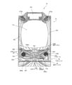
FIG. 18 is a perspective view (a) of the
Details of the (effect button 25) will be described later with reference to FIGS.
上皿ユニット20(上皿ユニット本体680)は、右レンズ部材681と、左レンズ部
材682と、操作パネル690と、上皿フレーム700と、中間部材720と、ボタンベ
ース730と、後部材740と、を備える(図19)。
The upper tray unit 20 (upper tray unit main body 680) includes a
上皿フレーム700には、前方に右レンズ部材681と左レンズ部材682が配置され
、上方に操作パネル690が配置される。また、上皿フレーム700には、右側の後方に
中間部材720が配置されるとともに、左側の後方にLED基板726が配置される。さ
らに、上皿フレーム700には、略下側の後方にボタンベース730が配置され、さらに
後方に後部材740が配置される。上皿フレーム700は、中間部材720とLED基板
726とボタンベース730とを収容し、上方から操作パネル690で後方から後部材7
40で蓋がされたものである。なお、LED基板726も、中間部材720の範疇に含め
てよい。
A
40 is capped. Note that the
右レンズ部材681と左レンズ部材682は、各々、透明で後方からの光を拡散する前
側の上皿レンズと、上皿レンズの後方に配置されるレンズフレームを有する。
The
操作パネル690は、右のボタン設置部691において、前述した残高表示部690a
、球貸ボタン690b、及び、返却ボタン690cを備え、左のボタン設置部692にお
いて、前述した音量調整用ボタン690d、690e、及び、十字キー690f、を備え
ている。
The
, a
また、操作パネル690は、演出ボタンユニット750を収容する環状の演出ボタン収
容部694を有する。演出ボタン収容部694は、段状に鱗状の装飾が表面に付けられて
いる。演出ボタン収容部694の開口部694aには、演出ボタンユニット750が挿入
されて収容される。演出ボタン収容部694の前部を構成する前板部696は、中央にお
いて前方に尖った中央先鋭部696aを有する。前板部696は、右板696bと左板6
96cから構成され、右板696bと左板696cの接続する箇所が中央先鋭部696a
となる。
Further, the
96c, and the point where the
becomes.
上皿フレーム700は、図19に示すように、底板部701と、底板部701から略上
方に延在する前面部702と、前面部702の後方から前面部702に接続する上板部7
03と、前面部702と上板部703の間でこれらに接続する略Cの字状の操作パネル収
容部704と、を備える。
As shown in FIG. 19, the
03, and a substantially C-shaped operation
上皿フレーム700の前面部702には、左の下スピーカ19dが挿入されるスピーカ
開口702aが設けられる。また、前面部702には、右レンズ部材681が前方から取
り付けられる右側レンズベース706と、左レンズ部材682が前方から取り付けられる
左側レンズベース707が接続される。
A
右側レンズベース706は、後方のLED基板721の各LEDの光を通過させる開口
706aを有し、後部に取付部708を有する。左側レンズベース707は、後方のLE
D基板726の各LEDの光を通過させる開口707a(図19には図示されていない)
を有し、後部に取付部709を有する。取付部709は、前枠ベースユニット480(図
7)に取り付けられる。
The
and has a mounting
また、前面部702の中央上部には、前後方向且つ上下方向内の断面(左右方向に垂直
な断面)に関して略Lの字状の断面となる下段部710と上段部712が設けられる(図
23(c)及び図24(a)も参照)。上段部712は、下段部710の上端に形成され
ており、上段部712は、受皿状の形状を有し、前方から見た場合には凹状になっている
(図24(a)も参照)。上段部712の左右方向の幅は、下段部710の左右方向の幅
よりも狭い。なお、下段部710と上段部712は、操作パネル690の前板部696の
後に配置されることにより、操作パネル690の前板部696に覆われ遮蔽される。この
ため、前板部696が透明でない限り、遊技者は、前方から下段部710と上段部712
を視認できない。なお、演出効果を狙って、前板部696を透明にする構成も可能である
。下段部710及び上段部712についての詳細は、後述する。
In addition, a
cannot be seen. It should be noted that it is also possible to configure the
上皿フレーム700の上板部703は、右側に、上皿操作部735が下方から挿入され
て配置される開口703aと、後部材740の板状の通信端末置き場743(スマートフ
ォン置き場)が当接する受部703b(右端部)と、を備える。
On the right side of the
上皿ユニット20(上皿ユニット本体680)の中間部材720は、右側に、上皿フレ
ーム700の右側レンズベース706の後方に配置されるLED基板721と、LED基
板721を保持して略上方と後方で覆うLED基板カバー723と、を有する。LED基
板721に設けられた複数のLEDの各々は、右側レンズベース706の開口706aに
対応した位置に配置される。また、中間部材720は、LED基板カバー723の後方に
取付部722を有する。取付部722は、前枠ベースユニット480(図7)に取り付け
られる。さらに、中間部材720は、上皿操作部735の保持部736に形状適合して受
け入れる受部724を有する。
The intermediate member 720 of the upper tray unit 20 (upper tray unit main body 680) has an
上皿ユニット20(上皿ユニット本体680)のボタンベース730は、本体部731
に対して上方から開閉機構732や中継基板737や左右の補強プレート739a、73
9b(補強部材、補強手段)が設置されたものである。
The
, the opening/
9b (reinforcing member, reinforcing means) is installed.
本体部731は、上皿ユニット20において演出ボタンユニット750(演出ボタン2
5)が載置される底部731aと、底部731aの右側に設けられる右側部731bと、
を備える。底部731aの中央には、壁で仕切られた3つの部屋(空間)を有するボック
ス部731cが設けられる。また、底部731aの右端部と左端部には、それぞれ、右側
補強プレート739aがネジ止めによって取り付けられる右側補強プレート取付部731
dと、左側補強プレート739bがネジ止めによって取り付けられる左側補強プレート取
付部731eが配置される。
The
5) is placed on a
Prepare. A
d and a left reinforcing
本体部731において、演出ボタンユニット750(演出ボタン25)が取り付けられ
る底部731a,右側補強プレート取付部731d及び左側補強プレート取付部731e
は前側に下り傾斜しており、演出ボタンユニット750も全体的に前側に下り傾斜して、
演出ボタンユニット750の前部が後部よりも低く配置されるように形成されている(図
23(b)も参照)。
In the
is inclined downward to the front side, and the
The front part of the
開閉機構732は、本体部731の右側部731b上に設置され、遊技者に操作される
ことによって上皿21の遊技球を下皿23へと流下させる上皿操作部735と、上皿操作
部735を保持する保持部736と、上皿操作部735の操作に応じて開閉部材734を
移動(動作)させる開閉レバー733と、開閉レバー733に対して上皿操作部735と
は反対側に取り付けられる開閉部材734と、備える。開閉部材734が開状態となった
場合に、通路485(図8(d))と第2入口465(図5(b)、図6(a))を介し
て、上皿21から下皿23に遊技球が流下する。
The opening/
中継基板737は、遊技者の演出ボタンユニット750(演出ボタン25)への操作に
関する検出信号を演出制御装置300(後述)へと中継したり、演出ボタンユニット75
0(演出ボタン25)のLEDに電力を供給したりしてよい。
The
Power may be supplied to the LED of 0 (effect button 25).
本実施形態では、中継基板737は、LED基板721、十字キー690f、音量調整
用ボタン690d、690e、及び後述するボタンユニットベース770の光センサ77
2等のそれぞれと電気的に接続されている。
In this embodiment, the
2, etc. are electrically connected to each other.
LED基板721、十字キー690f、音量調整用ボタン690d、690e、及びボ
タンユニットベース770の光センサ772等のように、演出に関連する構成は、中継基
板737を介して、演出制御装置300(サブ基板)に接続される。中継基板737を介
して演出制御装置300(サブ基板)と接続する構成とすることにより、LED基板72
1、十字キー690f、音量調整用ボタン690d、690e、及びボタンユニットベー
ス770の光センサ772等のそれぞれを演出制御装置300(サブ基板)に接続するた
めの配線処理を容易にすることができる。また、こららの構成のそれぞれを演出制御装置
300(サブ基板)に接続するための配線のための空間を省スペース化できる。
Like the
1. Wiring processing for connecting each of the cross key 690f,
なお、本実施形態においては、中継基板737は、残高表示部690aと、球貸ボタン
690bと、返却ボタン690cのように演出制御装置300(サブ基板)と接続されな
い構成(演出に関連しない構成)とは電気的に接続されていない。しかし、演出制御装置
300(サブ基板)と直接接続されない構成であっても、中継基板737に電気的に接続
することで中継基板737上に、一旦、集約させて、演出制御装置300(サブ基板)と
は別の基板に向けて配線を引き出す構成とすることもできる。このような構成とすること
により、配線処理を簡素化できるとともに、配線のための空間を省スペース化できる。
In addition, in the present embodiment, the
補強プレート739a、739b(補強部材、補強手段)は、操作パネル690を下か
ら支持することによって操作パネル690を補強する。補強プレート739a、739b
は、演出ボタンユニット750(演出ボタン25)の操作時などにおいて、操作パネル6
90の沈み込みを防止できる。
Reinforcing
, when operating the effect button unit 750 (effect button 25), etc., the operation panel 6
90 can be prevented from sinking.
上皿ユニット20(上皿ユニット本体680)の後部材740は、背板742と、背板
742の左部で前方から取り付けられる下スピーカ19dと、背板742の上方に設けら
れる上皿21と、背板742の上方且つ上皿21の右方に板状の通信端末置き場743と
、を備える。背板742には、開閉部材734が左右に移動可能に貫通する開閉部材用開
口742aが左右方向に延在して設けられる。上皿21は、上皿底部21aと、上皿底部
21aから略垂直に延在する上皿壁部21bと、を備える。
The
通信端末置き場743は、3つの突条部743a、743b、743cと、隆起部74
3dと、を有し、突条部743a、743bの間の溝部と、突条部743b、743cの
間の溝部と、突条部743cと隆起部743dの間の溝部に挟んで、スマートフォン等の
通信端末を置くことができる。各溝の左右方向における長さが異なるため、機種(通信端
末の幅)に応じて通信端末を置き易くなっている。また、溝を形成する突条部743a,
743b,743cの上下方向における長さがそれぞれ異なって形成されていてもよい。
上下方向における長さが異なることにより、通信端末を置き易くなっている。通信端末置
き場743は、操作パネル690の右のボタン設置部691の後方で、上皿フレーム70
0の上板部303と右側レンズベース706の間に嵌め込まれて配置される。
The communication
3d, and sandwiched between the grooves between the ridges 743a and 743b, the grooves between the
The lengths in the vertical direction of 743b and 743c may be different.
The different lengths in the vertical direction make it easier to place the communication terminal. The communication
0 and the
〔演出ボタンユニット(演出ボタン)〕
図20,図21及び図22を参照して(必要に応じて図25(b)も参照)、演出ボタ
ンユニット750(演出ボタン25)の詳細について説明する。図20は、演出ボタンユ
ニット750(演出ボタン25)の分解図である。図21は、演出ボタンユニット750
(演出ボタン25)の正面図(a)と斜視図(b)である。図22は、演出ボタンユニッ
ト750(演出ボタン25)を上方から見た平面図(a)と、操作パネル690において
、演出ボタンユニット750及び右側のボタン設置部691を取り外して示す斜視図(b
)である。
[Production button unit (production button)]
With reference to FIGS. 20, 21 and 22 (see also FIG. 25(b) if necessary), details of the effect button unit 750 (effect button 25) will be described. FIG. 20 is an exploded view of the effect button unit 750 (the effect button 25). FIG. 21 shows the
It is the front view (a) and perspective view (b) of (production button 25). FIG. 22 is a plan view (a) of the production button unit 750 (production button 25) viewed from above, and a perspective view (b) showing the
).
演出ボタンユニット750(演出ボタン25)は、重ねて組み合わされる、ボタンフレ
ーム752と、ボタンレンズ754と、ボタンレンズ飾り756と、ボタン内レンズ上部
758と、ボタン内レンズ下部760と、リフレクタ762と、リフレクタベース764
と、ボタン下ベース766と、ボタンユニットベース770と、を備える(図20参照)
。ボタンレンズ754とボタン下ベース766との間に、ボタンレンズ飾り756と、ボ
タン内レンズ上部758と、ボタン内レンズ下部760と、リフレクタ762と、リフレ
クタベース764が、演出ボタンユニット750(演出ボタン25)の中心軸方向に重ね
て配置されている(図20参照)。
The production button unit 750 (production button 25) includes a
, a button
. Between the
ボタンレンズ754とボタン下ベース766、及び、これらの間のボタンレンズ飾り7
56は、図20には図示されていないコイルばね(弾性部材)を介してボタンユニットベ
ース770によって支持されている。また、後述するように、ボタンフレーム752と、
ボタン内レンズ上部758と、ボタン内レンズ下部760と、リフレクタ762と、リフ
レクタベース764は、ボタンユニットベース770に関して固定される固定部材であり
、遊技者の操作では動かない。従って、可動部材は、ボタンレンズ754、ボタンレンズ
飾り756、ボタン下ベース766となる。これら可動部材は、遊技者のボタンレンズ7
54を押す操作によって、初期位置から中心軸方向(略上下方向内)に沿って移動して下
方に沈み、遊技者の操作がないと、コイルばね(図示せず)で付勢されて中心軸方向に沿
って上方に移動して初期位置に戻る。
56 is supported by the
The button-inside lens
By pressing 54, it moves along the central axis direction (substantially in the vertical direction) from the initial position and sinks downward. Move up along the direction and return to the initial position.
ボタンフレーム752は、前側に配置される前装飾部752aと、ボタンレンズ754
が挿入され配置される開口部752bと、ボタンユニットベース770の外側の受部77
0fに挿入されて係合する複数の脚部752cと、を備える。ボタンフレーム752は、
中央部を除去して開口部752bとしたような笠のような形状であり外周面(傾斜面75
1c)が半径方向外側に下り傾斜しているが、全体的には円環状の形状を有する。
The
, and a receiving
and a plurality of
The central portion is removed to form an
1c) is sloping radially outward, but has an overall toric shape.
開口部752bの半径方向内側の内周端部751aは、半径方向外側の外周端部751
bよりも中心軸方向に関して高い位置に形成されており、内周端部751aは、傾斜した
外周面(傾斜面751c)から下方に折り曲げられて形成されている。そして、下方に折
り曲げられた先端部分は、後述するボタンレンズ本体754aに形成されたフランジ部7
54bと当接するように構成されている。
A radially inner inner
The inner
54b.
開口部752bの半径方向内側の内周端部751aから半径方向外側の外周端部751
bに向かう傾斜面751cは、後述する凸形状に形成されたボタンレンズ754の傾斜面
となだらかに連続するような斜度に形成されており、遊技者に、ボタンレンズ754とボ
タンフレーム752との境界部分を違和感無く見せる意匠とされている。
From the radially inner inner
The
また、前装飾部752aは、操作パネル690の中央先鋭部696aの上方に配置され
る。なお、ボタンフレーム752は、複数の脚部752cによってボタンユニットベース
770に対して固定されており、遊技者のボタンレンズ754への操作では動かない。
Also, the front
ボタンレンズ754は、鍋状(桶状)のボタン下ベース766の円環部766b(壁部
)に係合される。ボタンレンズ754は、山型に中央で盛り上がった円状のボタンレンズ
本体754aと、ボタンレンズ本体754aの裾部分においてボタンレンズ754の半径
方向における断面がLの字状に形成されたフランジ部754bと、を備える。ボタンレン
ズ本体754aの外周面754dとフランジ部754bの間には、外周溝754cが形成
される。ボタンレンズ本体754aは、ボタンフレーム752に形成された開口部752
bの内側に配置された際に、フランジ部754bの一部(外周溝754cの外側の壁部)
がボタンフレーム752の内周端部751aの下方に位置するように構成されている。こ
のため、ボタンレンズ754は、コイルばねで付勢されても、フランジ部754bの一部
が開口部752bの内周端部751aに当接することにより、ボタンレンズ754がボタ
ンフレーム752の上方に飛び出すことがない。
The
part of the
is located below the inner
図21(b)及び図22(a)に示すように、ボタンレンズ本体754aの左右方向両
側の一部において、フランジ部754bには、外周溝754cが半径方向外側に開放され
るように切り欠かれた側方切欠き部754f(後述)が形成されている。側方切欠き部7
54fの位置には、ネジ受部754e(後述)が形成されている。また、ボタンレンズ本
体754aの前方において、フランジ部754bには、外周溝754cが半径方向外側に
開放されるように切り欠かれた前方切欠き部754g(後述)が形成されている。側方切
欠き部754fと前方切欠き部754gは、各々、ボタン下ベース766に形成された横
誘導口766iと前誘導口766gに、円周方向の位置を合わせて形成される(図21も
参照)。
As shown in FIGS. 21(b) and 22(a), the
A
また、ボタンレンズ本体754aにおいて、ネジ受部754eが形成された側方切欠き
部754fの位置と前方切欠き部754gの位置との間には、フランジ部754bが半径
方向内側に向けて凹んだフランジ凹部754hが形成されている。また、フランジ凹部7
54hは、左右方向に形成された側方切欠き部754fを結ぶ直線に対して線対称となる
位置にも形成される。これらフランジ凹部754hは、ボタンフレーム752からボタン
ユニットベース770における受部770fに向けて下方に延びる脚部752cを避ける
避け部を構成する。なお、図22(a)には、説明の便宜上、ボタンユニットベース77
0における受部770fも示されている。
In addition, in the
54h is also formed at a line-symmetrical position with respect to a straight line connecting the
ボタンレンズ本体754aにおいて、外周溝754c、フランジ部754b、ネジ受部
754e及びフランジ凹部754h等のボタンレンズ本体754aの周縁部分は、遊技者
からは視認できないように、上述したボタンフレーム752によって遮蔽されている。し
たがって、後述するように、演出ボタンユニット750に流動物が滴下され流動した場合
、ボタンフレーム752は、演出ボタンユニット750の周囲を流動する流動物を遊技者
から遮蔽する遮蔽手段を構成する。
In the
ボタンレンズ飾り756は、図20に示すように、全体として腕時計のような形状を有
し、文字「PUSH」を示す文字部756aと、円状のボタンレンズ飾り本体756bと
、左右のバンド部756cと、左右のバンド端部756dと、左右のボタンレンズ係合部
756eと、を有する。ボタンレンズ754が透明であるため、ボタンレンズ754の下
に配置される文字部756aの文字「PUSH」が視認できる。左右のボタンレンズ係合
部756eは、鍋状のボタン下ベース766の円環部766b(壁部)に係合される。
As shown in FIG. 20, the
ボタン内レンズ上部758とボタン内レンズ下部760とリフレクタ762は、組み合
わされて組立体を構成する(図25(b)参照)。円盤状の形状を有するボタン内レンズ
上部758は、外周面に、半径方向外側に突出する複数(8個)の突起部758aを有す
る。角度45度の等間隔に配置された突起部758aは一つおきに係止部758bを下側
に有し、合計4つの係止部758bが存在する。各係止部758bは、ボタン内レンズ下
部760の対応する溝状の受部760bに挿入されて、光を透過可能な上側のボタン内レ
ンズ上部758と光を透過可能な下側のボタン内レンズ下部760が組み合わされる。
The button-inside lens
また、ボタン内レンズ上部758には、リフレクタ762がネジ止めによって下方から
取り付けられる。リフレクタ762は、金属製であるか又は表面が金属メッキされていて
光を反射可能である。略円筒状の形状を有するボタン内レンズ下部760は、内部にリフ
レクタ762を収容する。ボタン内レンズ下部760は、角度180度の間隔で配置され
た2つの庇部760aと、各庇部760aの下方に延在する脚部760cとを備える。
In addition, a
リフレクタベース764は、底部に開口764eを有し、底が抜けたすり鉢状の形状で
、内側表面が略円錐面となっている。リフレクタベース764は、金属製であるか又は内
側表面が金属メッキされている。リフレクタベース764は、乱反射加工が施され、半径
方向に放射状に並べた凹凸764aを有し光を乱反射する。
The
リフレクタベース764は、ボタン内レンズ下部760の各脚部760cが係合する係
合受部764bを備える。これにより、リフレクタベース764にボタン内レンズ下部7
60が載置される。ここで、ボタン内レンズ下部760の下端部は、リフレクタベース7
64の内周端(開口764eを画定する)の上側に当接するとともに、リフレクタ762
の下端部が開口764eに挿入されている(図23(b)、図25(b)参照)。
The
60 is placed. Here, the lower end portion of the button inner lens
64 (defining
is inserted into the
また、リフレクタベース764は、ボタンレンズ飾り756の各バンド端部756dが
摺動可能に嵌合する嵌合部764cを外周端に備える。これにより、リフレクタベース7
64は、ボタンレンズ飾り756の2つのバンド端部756dに挟まれることになる。そ
して、遊技者のボタンレンズ754を押す操作によって、各バンド端部756dが溝とし
ての嵌合部764cを中心軸方向(略上下方向)に摺動する。
In addition, the
64 will be sandwiched between two band ends 756 d of
さらに、リフレクタベース764は、ボタン下ベース766を貫通してボタンユニット
ベース770に係合する脚部764dを有する。これにより、リフレクタベース764ひ
いては、ボタン内レンズ上部758と、ボタン内レンズ下部760と、リフレクタ762
とがボタンユニットベース770に対して固定される。
Further, the
are fixed to the
ボタン下ベース766は、鍋状(桶状)の形状を有しており、円盤状の形状を有する底
部766aと、底部766aから垂直に上方に向けて延在する円環部766bと、円環部
766bの上端部から半径方向外側に延在する鍔部766c(フランジ部)と、を備える
。ボタン下ベース766は、円環部766bの半径方向内側に形成される収容部766d
の底部766aに、LED基板767を収容する。ボタン下ベース766の鍔部766c
(フランジ部)は、ボタンレンズ754のフランジ部754bに当接する。
The button
The
(flange portion) contacts the
円盤状のLED基板767は、中心に配置された1つの中心LED767aと、その周
りで円環状に配置された8個の周辺LED767bとを有する。LED基板767には、
リフレクタ762の下端部とリフレクタベース764の下端部(開口764eの周り)が
当接する。中心LED767aは、リフレクタ762の下端部に囲まれるように配置され
、8個の周辺LED767bは、リフレクタ762の下端部を囲むように配置される。即
ち、中心LED767aは、リフレクタ762の下端部よりも半径方向内側に配置され、
周辺LED767bは、リフレクタ762の下端部よりも半径方向外側に、リフレクタベ
ース764の下端部よりも半径方向内側に配置される(図25(b)参照)。
The disk-shaped
The lower end of the
The
中心LED767aからの直接光、及び、直接光がリフレクタ762で反射した間接光
は、主に、略透明なボタン内レンズ上部758とボタンレンズ飾り756とボタンレンズ
754を通過して、演出ボタンユニット750の外部に出ていく。周辺LED767bか
らの直接光、及び、直接光がリフレクタベース764で反射した間接光は、主に、ボタン
内レンズ下部760とボタンレンズ飾り756とボタンレンズ754を通過して、演出ボ
タンユニット750の外部に出ていく。
The direct light from the
ボタン下ベース766の円環部766bは、左右方向の両側に、ボタンレンズ飾り75
6の各ボタンレンズ係合部756eが当接して配置される係合受部766eと、ネジ受部
754eが当接してネジによってネジ受部754eをネジ止めするためのネジ穴部766
f(雌ネジ)と、係合受部766e及びネジ穴部766fと半径方向外側で対峙して配置
される凹状の横誘導口766iと、を備える。
The
6, and a
f (female screw), and a concave
ボタンレンズ本体754aに形成されたネジ受部754eがネジ穴部766fにネジ止
めされることにより、ボタンレンズ754のフランジ部754bがボタン下ベース766
の鍔部766c(フランジ部)に押し付けられる。また、ボタンレンズ飾り756に形成
されたボタンレンズ係合部756eが、該ボタンレンズ係合部756eの下方に位置する
係合受部766eと、該ボタンレンズ係合部756eの上方に位置するネジ受部754e
とに挟まれて固定される(図21(b)参照)。
A
is pressed against the
and fixed (see FIG. 21(b)).
ネジ穴部766fは、係合受部766eと横誘導口766iの底部に跨って配置され、
ネジ穴の開口部分は、僅かに上方に凸状になるように形成されている。また、ネジ穴部7
66fは、上から見てボタンレンズ本体754aに形成されたネジ受部754eに収まる
ような外径サイズに形成されている。凹状の横誘導口766iに挿入されるため、ネジ受
部754eは、ボタンレンズ754がボタン下ベース766に取り付けられる際に、円周
方向に位置決めする機能も有する。
The
The opening of the screw hole is formed to be slightly convex upward. Also, the
66f is formed to have an outer diameter size that can be accommodated in the
後述のように、横誘導口766iは、演出ボタンユニット750に滴下された流動可能
な流動物(液体等)を、ボタンレンズ754の外周溝754cから上皿ユニット本体68
0の内部に演出ボタンユニット750内を通過させずに誘導する。
As will be described later, the
0 is guided without passing through the
なお、ボタンレンズ754上に落ちた流動物(液体等)は、ボタンレンズ本体754a
の表面を外周面754dに向けて下って、外周溝754cに入る。また、操作パネル69
0上に落ちた流動物(液体等)も、量が多ければ、演出ボタン収容部694の表面を下っ
て、ボタンフレーム752を超えて外周溝754cに入ることがある。前側へ下り傾斜し
たボタンベース730の底部731aに載置された演出ボタンユニット750は前側に下
り傾斜しているため、図22(a)のように横誘導口766iよりも後方(点線よりも後
方)の外周溝754cに入った流動物(液体等)は、ネジ受部754eの上を通って横誘
導口766iへと流れる。なお、横誘導口766iからの流動物は、ボタンフレーム75
2が載置されるボタンフレーム載置部694cに設けたパネル側凹部694b(図22(
b))に流入する。また、フランジ凹部754hにおいて、外周溝754cは流動物が通
る隙間が狭い(広くすることも可能である)。しかし、流動物は、フランジ凹部754h
の上を越えて、ボタンフレーム752の内周端部751aとボタンレンズ本体754aの
外周面754dの間に形成される流路を流れることができる。
Note that any fluid (liquid, etc.) that has fallen onto the
surface toward the outer
Fluid (liquid, etc.) falling on 0 may descend the surface of the effect
2 is placed in the panel-side
b)). In addition, in the flange
over the top of the
また、ボタン下ベース766の円環部766bには、外周面における前方位置に、凹状
の形状を有し、円環部766bの外周面よりも円環部766bの半径方向外側に向けて突
出した前誘導口766gが形成されている(図21参照)。本実施形態においては、前誘
導口766gは、外周面の最前部に形成されている。前誘導口766gに対応する位置に
おいて、鍔部766c(フランジ部)は切り欠かれている。このため、前誘導口766g
の上方は開放されている。
In addition, the
is open above.
また、前誘導口766gを形成する凹状の突出部分に囲まれた円環部766bの外周面
には、3つのリブ776が設けられる。リブ776の各々は、略等間隔に、縦方向(上方
から下方)に延在して形成されており、リブ776の各々は、上方から下方に向けて、円
環部766bの外周面からの高さが高くなるように形成されている。
Further, three
この構造により、前誘導口766gは、後述のように液体等の流動物を、ボタンレンズ
754の外周溝754cから上皿ユニット本体680の内部に演出ボタンユニット750
内を通過させずに誘導する。この際、3つのリブ776の各々は、ボタン下ベース766
の鍔部766c(フランジ部)の切欠きを通じて、ボタンレンズ754の前方切欠き部7
54gから前誘導口766g内へと流動物(液体等)を流れやすくする。なお、演出ボタ
ンユニット750は前側に下り傾斜しているため、図22(a)のように横誘導口766
iよりも前方(点線よりも前方)に位置する外周溝754cに入った流動物(液体等)は
、前方切欠き部754gから前誘導口766gへと流れる。
With this structure, the
Guide without passing through the inside. At this time, each of the three
The
It facilitates the flow of fluids (such as liquids) from 54g into the
A fluid (liquid or the like) that has entered the outer
また、図20と図21に示すように、ボタン下ベース766は、底部766aから下方
に延在する遮光板768及び4つのばね軸766hを備える。遮光板768は、遊技者の
ボタンレンズ754を押す操作によってボタン下ベース766とともに下方に移動して、
ボタンユニットベース770の光センサ772(演出ボタンスイッチ25a)で検出され
る。ばね軸766hは、コイルばね(図示せず)が通されて取り付けられた状態で、ボタ
ンユニットベース770のばね室770d内にコイルばねとともに収容される。
Also, as shown in FIGS. 20 and 21, the button
It is detected by the
ボタンユニットベース770は、モータ771を収納する収納フレーム770aと、収
納フレーム770aから中心軸方向(略上下方向)に沿ってそれぞれ下方又は上方に延在
する下外壁部770bと上外壁部770cと、を備える。収納フレーム770aは、ボタ
ンベース730の底部731a上に取り付けられる。下外壁部770bは、ボタンベース
730に接続する。上外壁部770cは、ボタン下ベース766の円環部766bの周り
で、円環部766bに対面して配置される(図25(b))。
The
また、ボタンユニットベース770は、コイルばねが取り付けられたばね軸766hを
収容する4つのばね室770dと、リフレクタベース764の各脚部764dが挿入され
る縦孔770eと、ボタンフレーム752の各脚部752cが取り付けられる受部770
fと、を有する。これにより、ボタンフレーム752とリフレクタベース764は、ボタ
ンユニットベース770に固定され、ボタン下ベース766はボタンユニットベース77
0に対して可動に支持される。
In addition, the
and f. Thereby, the
0 is movably supported.
また、ボタンユニットベース770は、遊技者のボタンレンズ754を押す操作によっ
て沈んだボタン下ベース766がボタンユニットベース770に衝突する場合に、衝突を
緩和する複数の緩和部材773を有する。ボタンユニットベース770は、ボタン下ベー
ス766が遊技者のボタンレンズ754を押す操作によって沈んだ場合に、ボタン下ベー
ス766の遮光板768(前述)を検出する光センサ772を有する。光センサ772は
、遮光板768が光照射部から発生させた光を遮断して受光部が光を受信できない場合に
オン状態となる後述の演出ボタンスイッチ25aとして機能する。
Further, the
収納フレーム770aに収納されたモータ771が動作することにより演出ボタンユニ
ット750(演出ボタン25)の全体が振動し、遊技者に演出ボタンユニット750(演
出ボタン25)を操作することを促す操作促進報知演出を実行できる。ボタンベース73
0のボックス部731cは、モータ771の下方に配置されて、モータ771の騒音を吸
収可能である。
The operation of the
The 0
〔第1貯留部(貯水部)〕
図23と図24を参照して、上皿ユニット20の第1貯留部713(貯水部)について
説明する。図23は、上皿ユニット20の正面図(a)と、正面図(a)のA-A線にお
ける断面を左側方からみた断面図(b)と、断面図(b)の要部を拡大した要部拡大図(
c)である。また、図24は、上皿ユニット20の上面図(図18(b)と同様)のA-
A線における断面を裏側からみた断面図(a)と、上皿ユニット20を構成する部材の一
部を取り外した状態の正面図(b)である。
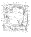
[First reservoir (water reservoir)]
The first reservoir 713 (water reservoir) of the
c). 24 is a top view of the upper tray unit 20 (similar to FIG. 18(b)).
FIG. 4A is a cross-sectional view of the cross section taken along line A seen from the back side, and FIG.
図23(a)から図23(c)に示すように、上皿ユニット20では、ボタンレンズ本
体754に形成された前方切欠き部754gと、ボタン下ベース766に形成された前誘
導口766gとが、ボタンフレーム752における前装飾部752aと対向するように組
み付けられる。また、操作パネル690の前板部696に形成された中央先鋭部696a
と、上皿フレーム700に形成される下段部710及び上段部712が対向するように組
み付けられる。なお、ボタンフレーム752の前装飾部752aを大きくして、下段部7
10及び上段部712に対向させたり、操作パネル690の中央先鋭部696aを長くし
て、前誘導口766gに対向させたりするような構成も可能である。
As shown in FIGS. 23(a) to 23(c), the
Then, the
10 and the
また、図23(b)に示すように、ボタンベース730(本体部731)において、演
出ボタンユニット750(演出ボタン25)が取り付けられる底部731aの上端,右側
補強プレート取付部731d及び左側補強プレート取付部731eは、底板部701に対
して前側に下り傾斜しており、演出ボタンユニット750の前部が後部よりも低く配置さ
れるような傾斜角が付与されている。すなわち、演出ボタンユニット750は、盤面側の
端部よりも遊技者側の端部の方が低くなるように傾斜されている。
Further, as shown in FIG. 23(b), in the button base 730 (body portion 731), the upper end of the
図19,図23(a)及び図24(a)に示すように、上皿フレーム700に形成され
た下段部710は、上皿フレーム700の右側レンズベース706と左側レンズベース7
07の間、すなわち、遊技機の略正面中央であって、上皿フレーム700において遊技者
側に突出した部分に形成されている。下段部710は、上皿フレーム700の遊技者側か
ら遊技機奥側に向かって延びる底面710a,710bと遊技機上方に延びる背面710
cとを有する。
As shown in FIGS. 19, 23(a), and 24(a), the
07, that is, approximately in the front center of the gaming machine, and formed in the portion of the
c.
操作パネル690の前板部696の中央先鋭部696aが透明な場合に、下段部710
の底面710a,710bは、遊技者に視認可能である。この場合に、下段部710にお
いて、底面710a,710bは遊技者側からみて略V字形状に形成されており、上皿フ
レーム700の右方向に延びる右側レンズベース706と、左方向に延びる左側レンズベ
ース707とに連なる意匠とされている。
When the central
are visible to the player. In this case,
また、下段部710の略V字形状の頂点近傍である先端部分710dは、最も前方(遊
技者側)に突出して形成されており、上述のように、先端部分710dにおける左右方向
に垂直な断面が、略Lの字状を呈する。
In addition, the
上段部712は、下段部710の背面部710cの上端710uから連なって形成され
ており、遊技者側から遊技機奥側に延びる底面712aと、遊技機上方に延びる背面71
2bとを有する。また、上段部712は、左右方向に仕切部分712c,712dを備え
る。上段部712は、底面712aと、背面712bと、仕切部分712c,712dに
より、受皿状の形状を有し、前方から見た場合には凹状に形成されている(図21(a)
及び図24(a)も参照)。なお、上段部712の左右方向の幅(仕切部分712cと仕
切部分712dの間隔)は、V字形状に形成された下段部710の左右方向において最も
幅広に形成された部分の幅よりも狭い。
The
2b. Moreover, the
and also FIG. 24(a)). The width of the
また、図23(c)に示すように、上皿ユニット20の各部が組み立てられた状態の演
出ボタンユニット750の前方部分において、ボタンレンズ本体754の外周面754d
の外側と、ボタン下ベース766の円環部766bに形成された前誘導口766gの外側
と、両者を遮蔽するように組み付けられるボタンフレーム752の内側と間に連通空間S
1が形成される。なお、図24(c)の点線より後側に水は侵入しない。演出ボタンユニ
ット750の可動部材(ボタンレンズ754、ボタン下ベース766)と固定部材(ボタ
ンフレーム752)の間の連通空間S1は、流動物の流路(図23(c)の矢印)の一部
を構成する。連通空間S1は、遊技者のボタンレンズ754を押す操作によって、初期位
置から下方への可動部材の移動に応じて流路幅が広がり、流動物が流れ易くなる。
Further, as shown in FIG. 23(c), in the front portion of the
, the outside of the
1 is formed. In addition, water does not enter behind the dotted line in FIG. 24(c). The communication space S1 between the movable members (the
また、ボタンベース730及び演出ボタンユニット750(ボタンユニットベース77
0)が収容される上皿フレーム700の最前部に位置する下段部710及び上段部712
の外側と、操作パネル690の中央先鋭部696aの内側との間に連通空間S2が形成さ
れる。連通空間S2は、上皿フレーム700と操作パネル690の間に形成されるもので
、固定されており、可動部材の移動に応じて流路幅が広がることはない。
Also, the
0) are located at the forefront of the
and the inside of the
ここで、連通空間S1は、流動物の流動を遅延させる遅延手段を構成する。連通空間S
2は、流動物の流動を遅延させる第1貯留部713(遅延手段)を構成する。なお、流動
物の遅延には、上皿ユニット本体680の構成部材の隙間(例えば第1貯留部713への
流路)から、第1貯留部713に溜まった流動物が蒸発することも含めてもよい。
Here, the communication space S1 constitutes delay means for delaying the flow of the fluid. Communication space S
2 constitutes a first reservoir 713 (delay means) that delays the flow of the fluid. Note that the delay of the fluid includes evaporation of the fluid accumulated in the
また、図23(c)に示すように、ボタンフレーム752の前装飾部752aの下縁部
753と中央先鋭部696aの上縁部698aとは当接されており、操作パネル690に
おける中央先鋭部696aの下縁部698bと上皿フレーム700の先端部分710dは
当接されている。したがって、連通空間S1及び連通空間S2は、遊技機の外部と遮断さ
れており、流動物が遊技機の外部へと流出することがない。
23(c), the
演出ボタンユニット750は、図20及び図21を用いて説明したように、ボタンレン
ズ本体754aに外周溝754cを有し、外周溝754cの前方側には、前方切欠き部7
54gが形成されている。前方切欠き部754gは、ボタン下ベース766に形成された
前誘導口766gと位置を合わせて組み付けられている。また、上述したように、図23
(b),(c)に示すように、上皿ユニット20の前方側(遊技者側)において、前方切
欠き部754g、前誘導口766g、及び、上皿フレーム700に形成された下段部71
0及び上段部712が、ボタンフレーム752における前装飾部752a、操作パネル6
90の前板部696に形成された中央先鋭部696aに対峙するように組み付けられる。
20 and 21, the
54 g are formed. The
As shown in (b) and (c), on the front side (player side) of the
0 and the
90 is assembled so as to face the central sharpened
このような構造によれば、演出ボタンユニット750の前方部分において、ボタンレン
ズ754における外周溝754cの前方切欠き部754gと、ボタン下ベース766に形
成された前誘導口766gとが、操作手段としてのボタンレンズ754の周囲を流動する
流動物を遊技機の内部に流動可能な流動手段を構成することができる。
According to such a structure, in the front portion of the
また、前誘導口766gの外側とボタンフレーム752の内側と間に形成された連通空
間S1、及び/又は、下段部710及び上段部712の外側と中央先鋭部696aの内側
との間に形成された連通空間S2が、上述の流動手段によって流動した流動物の流動を遅
延させる遅延手段を構成することができる。
In addition, the communicating space S1 formed between the outside of the
したがって、以上の構成を有する遊技機によれば、演出ボタン25に滴下した流動物が
あれば、前方(遊技者側)に傾斜して配置されたボタンレンズ754の表面を前方側に向
けて流動し、ボタンレンズ754の外周溝754cに流入する。外周溝754cに流入し
た流動物は、前方側に向けて流動し、前方切欠き部754gから前誘導口766gを通過
して、連通空間S1に流入する。これにより、流動物の遊技機内部(上皿ユニット20の
内部)への流入が遅延される。さらに、図24(b)に示すように、連通空間S2(第1
貯留部713)に流入し、ここに貯留される。連通空間S2(第1貯留部713)におい
て、流動物は、最も下部の下段部710の上から溜まっていき、次に上段部712の上に
溜まる。流動物の容量が多い場合には、連通空間S2が流動物で満たされた後に、流動物
は、さらに、上段部712を越え、上段部712の裏側を伝って、上皿フレーム700に
おける底板部701上であって前面部702とボタンベース730との間の空間に溜まる
ことができる。すなわち、この空間が流動物の流動を遅延させる遅延手段としての第3貯
留部を構成する。
Therefore, according to the gaming machine having the above configuration, if there is a fluid dropped onto the
It flows into the storage section 713) and is stored therein. In the communicating space S<b>2 (first reservoir 713 ), the fluid accumulates from the top of the
〔第2貯留部(貯水部)〕
図25と図26を参照して、上皿ユニット20の第2貯留部777a,777b(貯水
部)について説明する。図25は、上皿ユニット20の上面図(図18(b)と同様)の
A-A線における断面を正面からみた断面図(a)と、断面図(a)の要部を拡大した要
部拡大図(b)である。また、図26は、演出ボタンユニット750及びその周辺部位を
直径方向に沿って切断した断面の右側を拡大して示す右側要部拡大図(a)と、左側を拡
大して示す左側要部拡大図(b)と、ボタンベース730の要部を示す上面図(c)及び
(d)である。
[Second Reservoir (Water Reservoir)]
The
図20、図21、及び、図23を用いて説明したように、上皿ユニット20は、ボタン
レンズ本体754に形成された前方切欠き部754gと、ボタン下ベース766に形成さ
れた前誘導口766gと、ボタンフレーム752の前装飾部752aとが、位置的に対応
し、操作パネル690の中央先鋭部696aと、上皿フレーム700に形成される下段部
710及び上段部712とが位置的に対応するように組み付けられている。そして、ボタ
ンレンズ754の外周溝754cの左右方向に形成された側方切欠き754fと、ボタン
下ベース766の横誘導口766iもまた位置的に対応するように形成されている。
20, 21, and 23, the
図22(b)に示すように、操作パネル690の演出ボタン収容部694に形成された
開口部694aを画定する開口壁695には、ボタンフレーム752の外周端部751b
を支持するためのボタンフレーム載置部694cが設けられている。ボタンフレーム載置
部694cは、略円状の開口部694aの中心に向けて半径方向に突出して形成されてい
る。また、ボタンフレーム載置部694cには、開口部694aに嵌め込まれる演出ボタ
ンユニット750に形成された側方切欠き部754f及び横誘導口766iに対応(対向
)する位置に、半径方向外側(左右方向外側)に向けて凹んだパネル側凹部694bが形
成されている。本実施形態では、パネル側凹部694bは、横誘導口766iの一部を収
容するが、流体物の流路を広げるようにパネル側凹部694bから横誘導口766iを半
径方向に離して収容しないようにしてもよい。
As shown in FIG. 22(b), an opening
A button
また、図25(b)及び図26(a)に示すように(図19も参照する)、ボタンベー
ス730の底部731aは、側壁に囲まれた凹状に形成されている。また、底部731a
の中央領域には、演出ボタンユニット750を支持すると共に、底部731aを仕切る仕
切部732a,732bが前側から奥側に延設されている。また、仕切部732a,73
2bの間の空間を仕切るように左右方向に延在する仕切部732c,732dが形成され
ている。前述のボックス部731cは、仕切部732a,732b,仕切部732c,7
32dによって形成されることになる。
Further, as shown in FIGS. 25(b) and 26(a) (also refer to FIG. 19), the
In the central area of ,
32d.
これにより、底部731aには、仕切部732aと底部側壁732eとの間に、底部囲
み部分730aが形成される。また、仕切部732bと底部側壁732fとの間に、底部
囲み部分730bが形成される。
As a result, a
また、底部731aにおいて、底部囲み部分730a及び底部囲み部分730bのそれ
ぞれには、演出ボタンユニット750におけるボタンユニットベース770のばね室77
0dを支持するばね室受け部732gが底部731aの底面から上方に向けて立設されて
いる。
In addition, in the
A spring
右側の底部側壁732eの外側には、底部側壁732eの上端部よりも下方であって底
部731aの底面よりも高い位置に台部730cが形成されている。台部730cには、
側壁に囲まれた台部囲み部分730eが形成されている。台部囲み部分730eには、右
側補強プレート739aの下端部が取り付けられる右側補強プレート取付部731dが底
部囲み部分730eの底面から上方に向けて立設されている。
Outside the
A
また、左側の底部側壁732fの外側にも同様に、台部730dが形成されており、台
部730dには、台部囲み部分730fが形成されている。台部囲み部分730fには、
補強プレート取付部731eが台部囲み部分730fの底面から上方に向けて立設されて
いる。
Similarly, a
A reinforcing
図25(b)及び図26(a)に示すように、演出ボタンユニット750の右側におい
て、ボタンフレーム752の開口部752bの半径方向内側の内周端部751aは、下方
に折り曲げられており、その先端部分がボタンレンズ本体754aに形成されたフランジ
部754bと当接する。また、半径方向外側の外周端部751bは、操作パネル690の
開口部694aに形成されたボタンフレーム載置部694cと当接する。
As shown in FIGS. 25(b) and 26(a), on the right side of the
このため、ボタンレンズ本体754aの外周溝754cに形成された側方切欠き754
f及びボタン下ベース766の円環部766bに形成された横誘導口766iの外側と、
ボタンレンズ本体754aの外周面754dを覆うように取り付けられたボタンフレーム
752の内側との間には、連通空間S3が形成される。即ち、連通空間S3が、ボタンフ
レーム752と、ボタンフレーム752に対峙して設置される部分(横誘導口766i等
)との間に設けられる。
Therefore, the
f and the outside of the
A communicating space S3 is formed between the inner side of the
このように、演出ボタンユニット750の可動部材(ボタンレンズ754)と固定部材
(ボタンフレーム752)の間の連通空間S3は、流動物の流路(図26(a)の矢印)
の一部を構成する。連通空間S3は、遊技者のボタンレンズ754を押す操作によって、
初期位置から下方への可動部材の移動に応じて流路幅が広がり、流動物が流れ易くなる。
In this way, the communication space S3 between the movable member (button lens 754) and the fixed member (button frame 752) of the
form part of The communication space S3 can be opened by pressing the
As the movable member moves downward from the initial position, the width of the flow path widens, making it easier for the fluid to flow.
また、ボタン下ベース766の半径方向外側と、操作パネル690に形成されたパネル
側凹部694bや開口壁695との間を通って、ボタンユニットベース770の半径方向
外側と右側補強プレート739a(及び開口壁695)との間に繋がる連通空間S4が形
成される。即ち、連通空間S4が、操作パネル690と、操作パネル690に対峙して設
置される部分(ボタン下ベース766等)との間に設けられるとともに、操作パネル69
0に当接する右側補強プレート739aと、右側補強プレート739aに対峙して設置さ
れる部分(ボタンユニットベース770等)との間に設けられる。
In addition, the radially outer side of the
0 and a portion (
連通空間S4も、流動物の流路(図26(a)の矢印)の一部を構成する。連通空間S
4は更に、右側補強プレート取付部731dが形成された台部囲み部分730eに繋がっ
ている。
The communication space S4 also constitutes a part of the fluid flow path (arrow in FIG. 26(a)). Communication space S
4 is further connected to a
演出ボタンユニット750の可動部材(ボタン下ベース766)と固定部材(操作パネ
ル690)の間の連通空間S4は、遊技者のボタンレンズ754を押す操作によって、初
期位置から下方への可動部材の移動に応じて流路幅が狭くなるが、流動物が存在する場合
には、流動物は可動部材(ボタン下ベース766)に押されるか引き込まれて流れ易くな
る。ボタンユニットベース770と、右側補強プレート739a又は操作パネル690と
の間の連通空間S4は、固定されており、可動部材の移動に応じて変化することはない。
The communication space S4 between the movable member (lower button base 766) and the fixed member (operation panel 690) of the
また、演出ボタンユニット750の左側においても同様、ボタンレンズ本体754aの
外周溝754cに形成された側方切欠き754f及びボタン下ベース766の円環部76
6bに形成された横誘導口766iの外側と、ボタンレンズ本体754aの外周面754
dを覆うように取り付けられたボタンフレーム752の内側との間には、連通空間S5が
形成される。演出ボタンユニット750の可動部材(ボタンレンズ754)と固定部材(
ボタンフレーム752)の間の連通空間S5は、流動物の流路(図26(b)の矢印)の
一部を構成する。連通空間S5は、遊技者のボタンレンズ754を押す操作によって、初
期位置から下方への可動部材の移動に応じて流路幅が広がり、流動物が流れ易くなる。
Similarly, on the left side of the
6b and the outer
A communication space S5 is formed between the inner side of the
The communication space S5 between the button frames 752) constitutes part of the fluid flow path (arrow in FIG. 26(b)). In the communication space S5, the width of the channel is widened according to the downward movement of the movable member from the initial position by the player's operation of pressing the
また、ボタン下ベース766の半径方向外側と、操作パネル690の開口部694aに
形成されたパネル側凹部694bや開口壁695との間を通って、ボタンユニットベース
770の半径方向外側と左側補強プレート739bとの間に繋がる連通空間S6が形成さ
れる。連通空間S6は更に、左側補強プレート取付部731eが形成された台部囲み部分
730fに繋がっている。
In addition, it passes between the radially outer side of the button
演出ボタンユニット750の可動部材(ボタン下ベース766)と固定部材(操作パネ
ル690)の間の連通空間S6は、遊技者のボタンレンズ754を押す操作によって、初
期位置から下方への可動部材の移動に応じて流路幅が狭くなるが、流動物が存在する場合
には、流動物は可動部材(ボタン下ベース766)に押されるか引き込まれて流れ易くな
る。ボタンユニットベース770と左側補強プレート739bとの間の連通空間S6は、
固定されており、可動部材の移動に応じて変化することはない。
The communication space S6 between the movable member (lower button base 766) and the fixed member (operation panel 690) of the
It is fixed and does not change as the movable member moves.
このような構造によれば、演出ボタンユニット750の左右方向の側面部分において、
ボタンレンズ754の側方切欠き部754fと、ボタン下ベース766に形成された横誘
導口766iとが、操作手段としてのボタンレンズ754の周囲を流動する流動物を遊技
機の内部に流動可能な流動手段を構成することができる。
According to such a structure, in the lateral side portion of the
A
また、横誘導口766iの外側とボタンフレーム752の内側と間に形成された連通空
間S3,S5、操作パネル690と演出ボタンユニット750の外側との間に形成される
連通空間S4,S6、及び/又は、台部囲み部分730e,底部囲み部分730fが、上
述の流動手段によって流動した流動物の流動を遅延させる遅延手段を構成することができ
る。
Communication spaces S3 and S5 formed between the outside of the
したがって、以上の構成を有する遊技機によれば、演出ボタン25の表面において広が
りながら流動する流動物(液体等)があれば、ボタンレンズ754の外周面754dから
ボタンレンズ754の外周溝754cに流入することができる。また、操作パネル690
の演出ボタン収容部694の表面を下って流動する流動物(液体等)も、量が多ければ、
ボタンフレーム752を超えて外周溝754cに入ることがある。横誘導口766iより
も奥側(図22(a)の点線よりも後方)の外周溝754cに流入した流動物は、外周溝
754cに形成された側方切欠き754f及びボタン下ベース766の円環部766bに
形成された横誘導口766iを通過して、連通空間S3,S5に流入する。さらに、図2
6(a)及び図26(b)に示すように、流動物は、連通空間S4,S6に流入し、図2
6(d)の斜線部ように、台部囲み部分730e及び台部囲み部分730fに貯留される
。そして、図26(c)の斜線部に示すように、流れ込む流動物の容量が台部囲み部分7
30e及び台部囲み部分730fの容量を超える場合には、流動物を底部囲み部分730
a及び底部囲み部分730bに流入させることができる。なお、仕切部732a,732
b等で形成されるボックス部731cに、流動物は流入しない。
Therefore, according to the gaming machine having the above configuration, if there is a fluid (such as a liquid) that spreads and flows on the surface of the
If the amount of fluid (liquid etc.) flowing down the surface of the effect
It may go over the
As shown in 6(a) and 26(b), the fluid flows into the communication spaces S4 and S6,
As shown in the shaded area of 6(d), it is stored in the base
30e and the capacity of the
a and
A fluid does not flow into the
このように、台部囲み部分730e及び台部囲み部分730fは、流動物の流動を遅延
させる第2貯留部777a,777b(遅延手段)を構成することができる。また、底部
囲み部分730a及び底部囲み部分730bは、第2貯留部777a,777bのバッフ
ァとしての付加的な貯留部778a,778b(流動物の流動を遅延させる遅延手段)を
構成することができる。
In this way, the base
なお、流動物の容量が多い場合には、底部囲み部分730a及び底部囲み部分730b
(貯留部778a,778b)が流動物で満たされた後に、流動物は、底部囲み部分73
0a及び底部囲み部分730bの前方の壁上端部分を越え、底部囲み部分730a及び底
部囲み部分730bの前方の壁の表側を伝って、上述の第3貯留部(上皿フレーム700
における底板部701上であって前面部702とボタンベース730との間の空間)に溜
まることができる。すなわち、第3貯留部は、上述した連通空間S2と、底部囲み部分7
30a及び底部囲み部分730bの共通のバッファ用の貯水部を構成することができる。
なお、台部囲み部分730e及び台部囲み部分730f(第2貯留部777a,777b
)の先端部(補強プレート739a、739bに覆われていない低い側の部分)からボタ
ンベース730の表面を伝って、第3貯留部に流動物が落下(流下)してもよい。
In addition, when the volume of the fluid is large, the
After (
0a and the upper end portion of the wall in front of the
can accumulate in the space between the
A common buffer reservoir for 30a and
Note that the base
) (the lower portion not covered by the reinforcing
〔流体物排出口(液体排出口)〕
図27を参照して、流体物排出口(液体排出口)について説明する。図27は、排出口
779を説明する正面図である。上述したように、連通空間S1に流入し、連通空間S2
(第1貯留部713)に貯留された流動物、連通空間S3,S5を通過し、連通空間S4
,S6を通過して、台部囲み部分730e及び台部囲み部分730f(第2貯留部777
a,777b)に貯留された流動物、或いは、底部囲み部分730a及び底部囲み部分7
30b(予備貯留部778a,778b)に貯留された流動物を遊技機の外部に排出する
ための排出口779が備えられていてもよい。本実施形態においては、「流動物を遊技機
内部に貯留し、貯留された流動物を遊技機の外部に排出する」ことは、「流動物の流動を
遅延させる」ことに含まれる。なお、特別に排出口779を設けずに、上皿ユニット20
の構成部材間の微細な隙間(例えば、操作パネル690と上皿フレーム700の公差によ
って生じる隙間)から流動物を遊技機の外部に徐々に排出する構成としてもよい。
[Fluid discharge port (liquid discharge port)]
The fluid discharge port (liquid discharge port) will be described with reference to FIG. FIG. 27 is a front view illustrating the
The fluid stored in (the first storage part 713) passes through the communication spaces S3 and S5, and passes through the communication space S4.
, S6, the base
a, 777b) or the
30b (
The fluid may be gradually discharged to the outside of the game machine through a minute gap between the constituent members (for example, a gap caused by the tolerance between the
排出口779は、図27に示すように、上皿フレーム700の前面部702の下部にお
いて、操作ハンドル24寄りの位置(右側の位置)に形成されている。排出口779は、
下皿ユニット29の右側で突出する右側突出部29b付近で右側突出部29bに対向して
設けられている。排出口779は、連通空間S2(第1貯留部713)、台部囲み部分7
30e及び台部囲み部分730f(第2貯留部777a,777b)、底部囲み部分73
0a及び底部囲み部分730b(予備貯留部778a,778b)とは、遊技機内部の遊
技者から視認不可能に形成された流路によって連通されている。例えば、連通空間S2(
第1貯留部713)から排出口779への流路(溝)は、上皿フレーム700の前面部7
02の裏側に視認不可能に形成されてよい(図27の点線)。
As shown in FIG. 27, the
It is provided in the vicinity of the
30e and a base
0a and the
A flow path (groove) from the first storage portion 713 ) to the
02 (dotted line in FIG. 27).
本実施形態において、排出口779を上皿フレーム700の前面部702の操作ハンド
ル24寄りの位置に形成しているのは、遊技球が貯留される下皿23や、操作パネル69
0におけるスイッチ類に排出された流動物が及ぶことを避けるためである。遊技球が濡れ
た状態で遊技領域に流入すると、釘等の部材や遊技球の循環構造の劣化を早める要因にも
なる。このため、排出口779は、排出された流動物が遊技球、遊技機の操作パネル及び
島設備等に干渉しない位置であればよく、上述した位置に限定されない。
In this embodiment, the
This is to avoid the discharged fluid from reaching the switches at 0. If the game balls enter the game area in a wet state, it may accelerate the deterioration of members such as nails and the circulation structure of the game balls. Therefore, the
また、排出口779には、密封可能な封止材が設けられており、必要に応じて排出口を
開放可能な構成とされていてもよい。また、排出口779は、管理者によってのみ、必要
に応じて開放可能な機構とされていてもよい。
Further, the
〔球流路ユニット〕
続いて、図28から図31を参照して、前面枠12の裏側に配置される配置される球流
路ユニット783について説明する。図28は、外枠ユニット17(或は前面枠12)の
裏面図(a)と断面上面図(b)である。図29は、外枠ユニット17(或は前面枠12
)の分解図である。図30は、球流路ユニット783の分解図である。図31は、球流路
ユニットベース786の裏面図(a)と透視正面図(b)である。
[Spherical channel unit]
Next, with reference to FIGS. 28 to 31, the spherical
) is an exploded view of FIG. FIG. 30 is an exploded view of the spherical
前面枠12は、裏側に、遊技機10に関する情報を外部装置(ホールコンピュータなど
の遊技場内部管理装置)に出力可能な外部情報端子71と、島設備に設置された補給装置
から補給される遊技球を貯留する上部タンク448と、上部タンク448から流下してき
た遊技球を上皿21に払い出す払出ユニット780と、払出ユニット780を制御する払
出制御装置200と、各種装置に電力を供給する電源装置400と、を備える(図28(
a))。
The
a)).
また、前面枠12は、裏側に、演出制御中継基板781や台間中継基板782なども備
える。演出制御中継基板781は、演出制御装置300からの電気配線と接続する演出用
接続部などを有する。台間中継基板782は、遊技機10に隣接して配置される台間装置
に対して電気的に接続される基板である。なお、台間装置は、例えば、遊技機10に隣接
して配設されるカードサンドや現金サンドである。なお、払出制御装置200、電源装置
400、演出制御中継基板781、及び、台間中継基板782を一つのユニットとして構
成してよい(図29)。
In addition, the
なお、前述のように、前面枠12は、前側に、球発射装置530とファール球キャッチ
ユニット560を有する(図28(b))。
As described above, the
前面枠12は、電源装置400とファール球キャッチユニット560の間に、球流路ユ
ニット783を備え、払出制御装置200と球発射装置530の間に、球発射装置530
を制御する発射制御装置784(発射制御基板)を備える。球流路ユニット783と発射
制御装置784は、左右方向に並べて配置される(図28(b)、図29)。
The
It has a launch control device 784 (launch control board) that controls the . The
後述のように、球流路ユニット783は、遊技盤30のアウト口30bから流下した遊
技球を受け入れてアウトタンクに流す。また、球流路ユニット783は、払出ユニット7
80からの遊技球(賞球)を賞球払出口443を介して上皿21に供給したり、上皿21
が満タンになった際には、払出ユニット780からの遊技球を下皿ユニット29の第1入
口461を介して下皿23に供給する。
As will be described later, the ball
The game ball (prize ball) from 80 is supplied to the
becomes full, the game balls from the
図30のように、球流路ユニット783は、前蓋部材785と、前蓋部材785に後方
から当接する球流路ユニットベース786と、球流路ユニットベース786に後方から当
接する後蓋部材787と、を備える。球流路ユニットベース786は、前蓋部材785と
後蓋部材787に前後から挟まれて、内部に種々の遊技球流路が形成される。
As shown in FIG. 30, the spherical
前蓋部材785は、球流路ユニットベース786の賞球払出口443が嵌合する凹状の
受部785aを有する。また、後述するように、前蓋部材785は、背面に延在する流路
壁によってアウト球流路785b、785cが形成される(図31(b))。
The
図30のように、球流路ユニットベース786は、払出ユニット780の下部に接続し
て払出ユニット780から遊技球(賞球)が供給される左上側の接続通路786aを有す
る。また、球流路ユニットベース786は、前後方向の略中間に配置される中間板786
bを有する。中間板786bよりも前方の前面側で、球流路ユニットベース786は、接
続通路786aからの遊技球が流入する賞球払出口443と、上方に開口して遊技盤30
のアウト口30bから流下した遊技球を受け入れるアウト球受け口786gと、アウト球
を検出するアウトセンサ786hと、を備える。賞球払出口443は、正面視で長方形状
の開口であり、前方と中間板786bにおいて開口する。アウトセンサ786hは、後述
のアウト球検出スイッチ74として使用されてよい。
As shown in FIG. 30, the ball
b. On the front side forward of the
Out
図31(a)のように、中間板786bよりも後方の裏面側で、球流路ユニットベース
786は、接続通路786aからの遊技球(賞球)を受け入れる棚部786cと、棚部7
86cが遊技球で溢れた場合に接続通路786aからの遊技球が流入するオーバーフロー
流路786dと、を備える。棚部786cに入った遊技球は、賞球払出口443に流入す
る。賞球払出口443からの遊技球は、さらに上皿21の賞球入口484に供給される。
上皿21が満タン(満杯)の場合に、棚部786cまで遊技球が溢れるため(オーバーフ
ロー)、接続通路786aからの遊技球は、棚部786cに入ることができずに、オーバ
ーフロー流路786dに流入する(図31(a)の矢印)。オーバーフロー流路786d
は、中間板786bの裏側に延在する流路壁によって形成される。なお、オーバーフロー
流路786dを通過した遊技球は、下皿ユニット29の第1入口461を介して下皿23
に供給される。
As shown in FIG. 31(a), on the rear surface side behind the
An
When the
is formed by the channel wall extending behind the
supplied to
さらに、中間板786bよりも後方の裏面側で、球流路ユニットベース786は、オー
バーフロー流路786d内の遊技球(オーバーフロー球)の衝突圧力(球圧)を検出する
オーバーフローセンサ786eと、オーバーフローセンサ786eの左側に重ねて配置さ
れる球圧受部材786fと、を備える。球圧受部材786fは、オーバーフロー流路78
6dの右端の切欠部に上端の支軸により揺動可能な状態で臨ませる。オーバーフローセン
サ786eは、球圧受部材786fが球圧で右側に向けて押圧された場合に信号を遊技制
御装置100に送出する。
Furthermore, on the rear surface side behind the
The notch on the right end of 6d is faced in a swingable state by the support shaft at the upper end. The
また、球流路ユニットベース786は、中間板786bよりも後方の裏面側で、オーバ
ーフロー流路786dと略平行に形成される特別流路786iを備える。例えば、特別流
路786iは、上部タンク448の弁を開いて上部タンク448からの遊技球を流下させ
て遊技機10の外部へ回収する回収流路として使用してよい。特別流路786iも、中間
板786bの裏側に延在する流路壁によって形成される。
In addition, the spherical flow
図31(b)のように、前蓋部材785は、背面に延在する流路壁によって上側アウト
球流路785bと下側アウト球流路785cが形成される。上側アウト球流路785bに
は、アウト球受け口786gからの遊技球(アウト球)が流入する。上側アウト球流路7
85bに連通する下側アウト球流路785cには、上側アウト球流路785bを通過した
遊技球が流入し、その後アウトタンクへ回収される。上側アウト球流路785bと下側ア
ウト球流路785cの接続部には、球流路ユニットベース786に設けられる前述のアウ
トセンサ786h(アウト球検出スイッチ74)が配置される。
As shown in FIG. 31(b), the
A game ball that has passed through the upper out ball flow
〔視認窓部〕
次に、図32を参照して、ガラス枠15(前枠ユニット)において右下側に設けられる
視認窓部789について説明する。図32は、ガラス枠15の右側面図(a)とその一部
拡大図(b)、及び、ガラス枠15の下斜めから見た斜視図(c)とその一部拡大図(d
)である。
[Viewing window]
Next, with reference to FIG. 32, the visual
).
視認窓部789は、ガラス枠15の前枠ベースユニット480(或は、上皿ユニット2
0の後部材740の背板742(図19))と、上皿ユニット20の前面部702(図1
9)の後端部702cの間に形成される。視認窓部789は、上皿ユニット20(上皿ユ
ニット本体680)の取付部722の下方に位置する。
The
0 back plate 742 (FIG. 19) of the
9) between the
視認窓部789は、ガラス枠15が前面枠12に対して開いた場合に、ガラス枠15に
取り付けられた上皿ユニット20の内部を右方などから視認するためのものである。視認
窓部789には、上皿ユニット20の内部を保護するための透明なカバーが嵌め込まれて
よい。ガラス枠15が前面枠12に対して閉じた場合に、視認窓部789は、下皿ユニッ
ト29の右側突出部29b(図5)によって塞がれる。
The
視認窓部789を通して、上皿ユニット20内の前述の開閉レバー733(図19)及
びその動作を右方から視認できる。開閉レバー733は、上皿操作部735の操作に応じ
て開閉部材734を移動させるものである。開閉部材734が開くと上皿21の遊技球が
下皿23へと流下する。開閉レバー733は上皿ユニット20内にあっても、右レンズ部
材681からの外光やLED基板721から漏れた光によって、視認窓部789を通して
目視することができ、開閉部材734の動作確認することができる。
Through the
また、視認窓部789を通して、上皿ユニット20内の前述のLED基板721(図1
9)及びそ発光動作を後方の斜め下側から視認できる。なお、上皿ユニット20の前面部
702と右レンズ部材681は、前枠ベースユニット480において右下側に位置するカ
ーブ状の湾入端部480c、及び、上皿ユニット20の背板742において右側に位置す
るカーブ状の湾入端部742cよりも、外側に膨らんでいる。このため、視認窓部789
を通して、右レンズ部材681に光を照射するLED基板721を視認できる。
Also, through the
9) and its light emitting operation can be visually recognized from the obliquely lower rear side. Note that the
The
〔突出演出ユニット(装飾装置)〕
続いて、図33と図34を参照して、ガラス枠15(前枠ユニット)の両側部において
設けられる突出演出ユニット、即ち、装飾装置18b、18cについて説明する。図33
は、ガラス枠15から装飾装置18b、18cを分離した分解図(a)と、一方の突出演
出ユニット(装飾装置18b)の分解図(b)である。図34は、一方の突出演出ユニッ
ト(装飾装置18b)の正面図である。
[Protruding production unit (decoration device)]
Next, with reference to FIGS. 33 and 34, the protruding production units provided on both sides of the glass frame 15 (front frame unit), that is, the
12A is an exploded view (a) in which the
図33(a)のように、装飾装置18b、18cは、各々、前枠ベースユニット480
の左右方向の両側部における取付部790a、790bに取り付けられる。装飾装置18
b、18cは、各々、前枠内側部材482の垂直板482b、482cの外側に設けられ
る。
As shown in FIG. 33(a), the
are attached to
b, 18c are provided outside the
図33(b)のように、突出演出ユニット(装飾装置18b)は、重ねて組み合わされ
る、LED基板791と、裏カバー792と、リフレクタ793と、インナーレンズ79
4と、サイドカバー795と、アウターレンズ796と、を備える。
As shown in FIG. 33(b), the protruding production unit (
4, a
LED基板791は、左列の複数(10個)のLED791aと右列の複数(16個)
のLED791bを有し、前枠ベースユニット480の右側部における取付部790aに
取り付けられる。透明な裏カバー792は、LED基板791の前方に配置されるととも
に、リフレクタ793とインナーレンズ794に止着される。また、裏カバー792は、
ギザギザ状の左端における複数の凹部792aが左列の複数のLED791aに対応する
。このため、裏カバー792は、右列の複数のLED791bのうちの一部を覆うが、左
列の複数のLED791aを覆わない。リフレクタ793は、全体が金属製または金属メ
ッキされ光を反射するものであり、裏カバー792に止着される。リフレクタ793は、
左列の複数のLED791aに対向する位置で複数(10個)の開口793aを有する。
The
A plurality of
It has a plurality of (10)
インナーレンズ794は、裏カバー792に止着されて、裏カバー792とともにリフ
レクタ793を挟み込むように配置される。インナーレンズ794の左面は、リフレクタ
793に形状的に適合している。また、インナーレンズ794は、乳白色に着色された樹
脂製のものであり若干光を透過する。サイドカバー795には、インナーレンズ794と
アウターレンズ796が同じ箇所で止着される。また、サイドカバー795は、飾りとし
て複数の開口795aを有する。透明なアウターレンズ796は、インナーレンズ794
を覆うとともに、リフレクタ793と係合する。アウターレンズ796は、リフレクタ7
93の複数の係合部793bとそれぞれ係合する複数の係合受部796aを有する。
The
and engage
It has a plurality of
図34のように、LED基板791における左列のLED791aは、リフレクタ79
3の開口793aに位置して露出しているため、透明なアウターレンズ796を介して視
認可能である。左列のLED791aからの直接光と、左列のLED791aからリフレ
クタ793で反射した反射光(間接光)とが、透明なアウターレンズ796を介して、遊
技機10の中央側(内側)に向けて遊技者へと届くため、効果的な発光演出が可能となる
。また、裏カバー792は左列のLED791aを覆わないため、LED791aからの
光は裏カバー792で屈折することなく、真っ直ぐにリフレクタ793の開口793aを
通過できる。
As shown in FIG. 34, the
3 opening 793 a , it is visible through a transparent
一方、LED基板791における右列のLED791bは、乳白色に着色されたインナ
ーレンズ794(図34の点線)に覆われて露出しておらず、視認不可である。右列のL
ED791bは、インナーレンズ794を通して遊技機10の外側に柔らかな照明を行う
ため、左列のLED791aとは異なる照明態様となり、左列のLED791aの演出に
加えて効果的な発光演出を可能とする。
On the other hand, the
Since the
[第1実施形態の作用・効果]
第1実施形態によると、所定の演出を実行可能な表示装置(例えば表示装置41)を備
えた遊技機10は、遊技者が操作可能な操作手段(演出ボタンユニット750、操作パネ
ル690等)と、操作手段の周囲を流動する流動物を当該遊技機の内部に流動可能な流動
手段(例えば、外周溝754c、前誘導口766g、横誘導口766i)と、流動手段に
よって流動した流動物の流動を遅延させる遅延手段(例えば、連通空間S2(貯留部71
3)、台部囲み部分730e,730f(貯留部777a,777b)、底部囲み部分7
30a,730b(貯留部778a,778b)や、連通空間S1、連通空間S3,S4
,S5,S6)と、を備える。操作手段は、回路基板(例えば、LED基板767、中継
基板737)を備えてよく、回路基板を例えば内蔵してもよい。
[Actions and effects of the first embodiment]
According to the first embodiment, the
3), base
30a, 730b (
, S5, S6). The operating means may include a circuit board (eg,
このような、遊技機10では、流動手段によって流動物が当該遊技機の内部に流動可能
とされており、また、遅延手段によって、該流動手段によって当該遊技機の内部に流動さ
れた流動物の流動を遅延させる。したがって、遊技者の遊技中に、流動物が遊技機10の
表面(上皿ユニット20などの表面)を伝って遊技者側に流れることにより、遊技者が流
動物に気を取られて遊技の興趣が低下するような事態を減少させることが可能である。
In the
また、このような遊技機10では、操作手段(演出ボタンユニット750等)に水等の
流動物が侵入しないため、漏水などによって生じる操作手段内の回路基板(電子部品)の
不具合(故障)や遊技に関する操作演出が実行できない不具合がなく、遊技者の興趣を継
続させることができる。また、このような遊技機10では、水等の流動物を遊技機外に排
出したことにより、流動物に触れて汚れた遊技球が遊技機内(遊技領域32)に侵入する
ことによって生じる遊技領域32内の部材等の劣化も防止できる。さらにまた、このよう
な遊技機10によれば、遊技機から排出された流動物を清掃する手間を低減することがで
きる。
In addition, in such a
また、第1実施形態によると、遊技機10は、操作手段の周囲を流動する流動物を遊技
者から遮蔽する遮蔽手段(例えばボタンフレーム752)を備える。
Further, according to the first embodiment, the
このような、遊技機10では、遊技者の遊技中に、流動物が操作手段に滴下された場合
であっても、遮蔽手段によって、操作手段(演出ボタンユニット750)の周囲を流動す
る流動物が遊技者から遮蔽されるため、遊技者が流動物に気を取られて興趣を低下させる
ことがない。
In the
また、第1実施形態によると、遅延手段は、流動物の少なくとも一部を貯留する貯留部
(例えば、連通空間S2(貯留部713)、台部囲み部分730e,730f(貯留部7
77a,777b)、底部囲み部分730a,730b(貯留部778a,778b))
を有する。
In addition, according to the first embodiment, the delay means includes a storage portion that stores at least part of the fluid (for example, the communication space S2 (storage portion 713), the base
77a, 777b),
have
このような、遊技機10では、遅延手段が貯留部を備えることにより、流動物の少なく
とも一部を貯留部に貯留することができる。これにより、流動物の容量が多い場合であっ
ても、流動物の流動を大きく遅延することができ、遊技者が流動物に気を取られて興趣を
低下させることがない。
In the
また、第1実施形態によると、回路基板(例えば、演出ボタンユニット750内のLE
D基板767や、操作パネル690に配置された残高表示部690a、球貸ボタン690
b、及び、返却ボタン690c用の電子回路基板697a(図25参照)と、音量調整用
ボタン690d、690e、及び、十字キー690f用の電子回路基板697b(図25
参照))が遅延手段(例えば、貯留部713、貯留部777a,777b、貯留部778
a,778b)よりも高い位置に配置されている。
Also, according to the first embodiment, the circuit board (for example, the LE in the
The
and an
)) delay means (for example,
a, 778b).
このような、遊技機10では、流動物は、演出ボタンユニット750内のLED基板7
67や、操作パネル690に配置された電子回路基板697a(図25参照)や電子回路
基板697b(図25参照)等の回路基板よりも低い位置にある遅延手段に向けて流動す
るため、回路基板が流動物に接触することを防止できる。
In such a
67, and the
また、第1実施形態に係る遊技機10では、演出ボタンユニット750は、盤面側の端
部よりも遊技者側の端部の方が低くなるように前方に下り傾斜されている。このため、演
出ボタンユニット750に滴下した流動物を、遊技者側(前方)に向けて流動させて、遅
延手段(連通空間S1、S2)に繋がる流動手段(前誘導口766g)に、速やかに誘導
することができる。
In addition, in the
また、第1実施形態に係る遊技機10では、ボタン下ベース766において、前誘導口
766gを形成する凹状の突出部分に囲まれた円環部766bの外周面には、3つのリブ
776が設けられる。リブ776の各々は、略等間隔に、縦方向(上方から下方)に延在
して形成されており、リブ776の各々は、上方から下方に向けて、円環部766bの外
周面からの高さが高くなるように形成されている。このため、流動物がリブ776を伝っ
て、前誘導口766gに流れこみやすい。
In addition, in the
また、第1実施形態に係る遊技機10では、上皿ユニット20の各部が組み立てられた
状態の演出ボタンユニット750の前方部分において、ボタンレンズ本体754の外周面
754dの外側と、ボタン下ベース766の円環部766bに形成された前誘導口766
gの外側と、両者を遮蔽するように組み付けられるボタンフレーム752の内側と間に形
成された連通空間S1に流動物が流入する。その後、ボタンベース730及び演出ボタン
ユニット750(ボタンユニットベース770)が収容される上皿フレーム700の前部
に位置する下段部710及び上段部712の外側と、操作パネル690の中央先鋭部69
6aの内側との間に形成された連通空間S2に流動物が流入する。
In addition, in the
The fluid flows into the communication space S1 formed between the outside of g and the inside of the
The fluid flows into the communication space S2 formed between the inside of 6a.
連通空間S1,S2は、遊技機の内部であって外部とは遮断されており、流動物が連通
空間S1,S2の途中から外部に流出することがないため、遊技者の遊技中に、遊技者が
流動物に気を取られて興趣を低下させることがない。
The communication spaces S1 and S2 are inside the gaming machine and are isolated from the outside. The user will not be distracted by the fluid and lose interest.
また、第1実施形態に係る遊技機10では、第1貯留部713を構成する下段部710
は、底面710a,710bが遊技者側からみて略V字形状に形成されている。このため
、下段部710の下側に流動物を貯留しやすい。また、操作パネル690の前板部696
の中央先鋭部696aが透明な場合に、下段部710の底面710a,710bは、遊技
者に視認可能である。この場合に、遊技者に視認可能な位置にある下段部710の底面7
10a,710bは、上皿フレーム700の右方向に延びる右側レンズベース706と、
左方向に延びる左側レンズベース707とに連なる意匠とされている。このため、流動物
を貯留する機能を有しながらも遊技機の美観を損なわない構成とされている。
Further, in the
,
When the central
10a and 710b are a
The design continues with the
また、第1実施形態に係る遊技機10では、上段部712の左右方向の幅(仕切部分7
12cと仕切部分712dの間隔)は、V字形状に形成された下段部710の左右方向に
おいて最も幅広に形成された部分の幅よりも狭い。このため、上段部712から流下した
流動物は、幅広とされた下段部710に速やかに流入させることができる。
Further, in the
12c and the
また、第1実施形態に係る遊技機10では、ボタンレンズ754の外周溝754cの左
右方向に形成された側方切欠き754fと、ボタン下ベース766の横誘導口766iが
位置的に対応するように形成されている。これにより、演出ボタンユニット750の前方
向だけでなく、側方(左右方向)にも流動物を流動させることができる。
In addition, in the
また、第1実施形態に係る遊技機10では、演出ボタンユニット750の右側において
、ボタンレンズ本体754aの側方切欠き754f及びボタン下ベース766の横誘導口
766iの外側と、ボタンフレーム752の内側との間に形成された連通空間S3を備え
る。また、ボタン下ベース766の半径方向外側と、操作パネル690のパネル側凹部6
94bとの間を通って、ボタンユニットベース770の半径方向外側と右側補強プレート
739aとの間に繋がる連通空間S4を備える。また、連通空間S4が繋がる台部囲み部
分730eを備える。
In addition, in the
94b to connect between the radially outer side of the
連通空間S3,S4及び台部囲み部分730eは、遊技者からは遮蔽された領域であっ
て外部とは遮断されており、流動物が連通空間S3,S4の途中から外部に流出すること
がないため、遊技者の遊技中に、遊技者が流動物に気を取られて興趣を低下させることが
ない。
The communication spaces S3 and S4 and the
また、このような遊技機10では、流動物の容量が台部囲み部分730eの容量を超え
る場合には、底部囲み部分730aに流入させることができる。したがって、流動物の容
量が多い場合であっても、遊技機の外部に流出することがないか流出が遅延するため、遊
技者の遊技中に、遊技者が流動物に気を取られて興趣を低下させることがない。
In addition, in such a
また、上述した台部囲み部分730eが形成された台部730cは、右側補強プレート
取付部731dを設けるための構成であり、漏水による損傷や劣化が及び難い部分である
。また、底部囲み部分730eは、ボタンユニットベース770を支持するための構成で
ある。このような位置に流動物を貯留する機能を持たせることにより、遊技機10の内部
に流動物を留めても、遊技球を汚したり、遊技機の回路基板に触れたり、遊技領域内の部
材が劣化したりする不具合を回避できる。
Further, the
また、遊技機10では、上述のように、流動手段によって流動物が当該遊技機の内部に
流動可能とされており、また、遅延手段によって、該流動手段によって当該遊技機の内部
に流動された流動物の流動を遅延させる。これにより、遊技機10では、遊技機内部(上
皿ユニット20の内部)に流動物が流入するスピードが遅くなるため、水等の流動物が回
路基板(例えば、LED基板767、中継基板737)等の重要な部分に到達する前に、
流動物を蒸発若しくは分散させることができる。したがって、遊技機内部において重要な
部分を流動物から保護することができ、遊技機の故障等による遊技者の興趣の低下を防ぐ
ことができる。
In addition, in the
Fluids can be evaporated or dispersed. Therefore, it is possible to protect important parts inside the game machine from fluids, and to prevent the loss of interest of the player due to the failure of the game machine or the like.
なお、上述した効果は、上皿ユニット20(演出ボタンユニット750)の左側におい
ても同様に奏するものである。
Note that the above-described effects are similarly produced on the left side of the upper tray unit 20 (the production button unit 750).
[第2実施形態]
図35から図50を参照して第2実施形態の遊技機10について説明する。なお、以下
で述べる以外の構成は、第1実施形態と同様でよい。また、以下の実施形態では、第1実
と同じ機能を果たす構成には同一の符号を用い、重複する記載を適宜省略して説明する。
[Second embodiment]
The
〔遊技盤〕
図35から図37を参照して、遊技機10の遊技盤30について説明する。図35は、
第2実施形態の遊技機10の遊技盤30の正面図(通常遊技状態)である。図36は、第
2実施形態の遊技機10の遊技盤30の正面図(特定のモードを示唆する状態)である。
図37は、第2実施形態の遊技機10の遊技盤30の正面図(特定遊技状態)である。
[Game board]
The
FIG. 11 is a front view (normal game state) of the
FIG. 37 is a front view (specific game state) of the
図35に示すように、遊技盤30は、各種部材の取付ベースとなる平板状の遊技盤本体
30aを備える。遊技盤本体30aは木製又は合成樹脂製であって、当該遊技盤本体30
aの前面にはガイドレール31で囲まれた遊技領域32が設けられている。
As shown in FIG. 35, the
A
遊技領域32の略中央には、変動表示ゲームの表示領域となる窓部を形成するセンター
ケース(前面構成体)40が取り付けられている。センターケース40に形成された窓部
の後方には、複数の識別情報を変動表示(可変表示)する演出表示装置(変動表示装置)
としての表示装置41が配置されている。また、センターケース40の窓部の後方、且つ
、表示装置41の前方には、正面から見て表示装置41の周囲に可動役物820、落下役
物810等が配置される。
At approximately the center of the
A
表示装置41は、例えば、液晶ディスプレイを備え、センターケース40の窓部を介し
て遊技盤30の前面側から表示内容が視認可能となるように配置される。なお、表示装置
41は、液晶ディスプレイを備えるものに限らず、ELやCRT等のディスプレイを備え
るものであってもよい。
The
表示装置41の表示画面(表示部)には、複数の変動表示領域(変動表示領域610、
615)が設けられており、各変動表示領域に識別情報(特別図柄)や変動表示ゲームを
演出するキャラクタ(例えば、キャラクタ826a(図40))が表示される。その他、
表示画面には遊技の進行に基づく画像(大当り表示やファンファーレ表示、エンディング
表示等)が表示される。
The display screen (display unit) of the
615) are provided, and identification information (special symbols) and a character (for example, a
The display screen displays images (big win display, fanfare display, ending display, etc.) based on the progress of the game.
例えば、表示装置41の中央部には、識別情報として飾り特別図柄(大図柄)の変動(
↓↓↓)を表示する変動表示領域610が表示される。表示装置41の右側には、上から
順に、特図1の第4図柄671、特図2の第4図柄672、特図2保留数表示部660、
特図2保留数表示部660、変動表示領域615が表示される。
For example, in the central part of the
↓↓↓) is displayed. On the right side of the
Special figure 2 reservation
特図1の第4図柄671は、特図1変動表示ゲームが実行中か否かを表示するものであ
り、「○」であれば実行中であり、「×」であれば非実行中(保留なし又は中断中)であ
ることを示す。また、特図2の第4図柄672は、特図2変動表示ゲームが実行中か否か
を表示するものであり、「○」であれば実行中であり、「×」であれば非実行中(保留な
し)であることを示す。
The
特図1保留数表示部650は、後述の特図1変動表示ゲームの保留数(最大保留数は4
)を表示するものである。特図2保留数表示部660は、後述の特図2変動表示ゲームの
保留数(最大保留数は4)を表示するものである。変動表示領域615は、識別情報とし
て飾り縮小図柄(小図柄)の変動(↓↓↓)を表示するものである。
The special figure 1 reservation
) is displayed. Special figure 2 reservation
表示装置41の下部には、後述の特図1変動表示ゲームの保留(第1始動記憶)、又は
後述の特図2変動表示ゲームの保留(第2始動記憶)を保留表示633として表示する保
留表示部630aと、実行中の変動表示ゲーム(特図1変動表示ゲーム、特図2変動表示
ゲーム)に係る保留を示す変動保留表示633aを表示する保留消化領域640が表示さ
れる。なお、保留表示633及び変動保留表示633aは大当りの期待度に応じて、色、
形状、模様等を変更して表示する予告演出が可能となっている。
At the bottom of the
It is possible to display a notice effect by changing the shape, pattern, etc.
また、表示装置41の左側上部には演出モード(ステージ)を文字情報により表示する
モード表示部674(第1示唆情報)が表示される。演出モードの表示としては、遊技状
態に応じて任意の文言が適用され、例えば、通常遊技状態(遊技者にとって何ら有利な遊
技状態になっていない状態)では「普通モード」と表示し(図35)、時短状態等の特定
遊技状態では、「??モード」と表示し(図36)、特別遊技状態(大当り、小当り)で
は「虎モード」と表示する(図37)。
In addition, a mode display portion 674 (first suggestive information) for displaying the production mode (stage) by character information is displayed on the upper left portion of the
なお、遊技者が演出操作装置(前記の演出ボタン25)を操作することによって、表示
装置41(図2参照)に表示される特図変動表示ゲーム等において遊技者の操作を介入さ
せた演出を行うことができる。例えば、演出パターン(演出態様)を選択したり、始動記
憶に対応する変動表示ゲームの結果を事前に予告する予告演出を実行したりすることがで
きる。なお、変動表示ゲームには特図変動表示ゲームが含まれ、単に変動表示ゲームとし
た場合には、本明細書では特図変動表示ゲームを指すものとする。
By operating the effect operation device (the above-mentioned effect button 25) by the player, the effect in which the player's operation is intervened in the special figure fluctuation display game etc. displayed on the display device 41 (see FIG. 2) is performed. It can be carried out. For example, it is possible to select an effect pattern (effect mode), or execute an advance notice effect that gives advance notice of the result of the variable display game corresponding to the starting memory. Note that the variable display game includes a special figure variable display game, and when simply referred to as a variable display game, this specification refers to a special figure variable display game.
また、変動表示ゲームの実行中だけでなく、非実行中に遊技者が演出操作装置(演出ボ
タン25)を操作することによっても演出パターンを変更するようにしてもよい。
Also, the effect pattern may be changed not only during execution of the variable display game but also by the player operating the effect operation device (effect button 25) during non-execution.
なお、変動表示ゲームが実行される際の遊技状態は、複数の遊技状態からなる。通常遊
技状態(通常状態)とは、特別な遊技状態が発生していない遊技状態である。また、特別
な遊技状態とは、例えば、特定遊技状態としての時短状態や変動表示ゲームにおいて特別
結果(例えば大当り)の発生確率が高い状態(確変状態、確率変動状態)、大当り状態(
特別遊技状態)、小当り遊技状態(小当り状態)である。
The game state when the variable display game is executed consists of a plurality of game states. The normal game state (normal state) is a game state in which no special game state occurs. In addition, the special game state is, for example, a state with a high probability of occurrence of a special result (for example, a big hit) in a time-saving state or a variable display game as a specific game state (variable state, probability variable state), a big hit state (
Special game state), small hit game state (small hit state).
ここで、確変状態(特定遊技状態)は、次の大当りが発生するまで継続するもの(ルー
プタイプ)、所定回数の変動表示ゲームが実行されるまで継続するもの(回数切りタイプ
、ST)、及び所定の確率転落抽選に当選するまで継続するもの(転落抽選タイプ)等が
ある。
Here, the probability variable state (specific game state) continues until the next big hit occurs (loop type), continues until a predetermined number of variable display games are executed (number cut type, ST), and There is one that continues until a predetermined probability fall lottery is won (fall lottery type).
本実施形態では、後述のように、特定領域86を備える入賞装置等を設け、特定領域8
6を遊技球が通過した場合に確変状態を発生させるようにしている。大当り図柄乱数によ
って特定種類の大当り(確変大当りなど)に当選すれば特定領域86は長時間開放され確
実に遊技球が通過し、大当り終了後に確変状態に移行できる。なお、本実施形態では、簡
単のため、確変状態(高確率状態)は次の大当りが発生するまで継続するものとする。
In this embodiment, as will be described later, a winning device or the like having a
A variable probability state is generated when a game ball passes through 6. If a specific kind of jackpot (probability variable jackpot or the like) is won by the jackpot pattern random number, the
遊技機10は、ガイドレール31で囲まれた遊技領域32内に球発射装置530から遊
技球を発射して遊技を行うように構成されている。遊技領域32には遊技球の流下方向を
変換する部材として風車や障害釘等が配設されており、発射された遊技球はこれら部材に
より転動方向を変えながら遊技領域32を流下する。
The
遊技領域32の入口(発射球案内通路33の出口)には、戻り弁814と弁センサ81
4aが配置されている。戻り弁814は、下端が固定端で上端が自由端となって回動可能
となるように配置されており、また遊技領域32の入口を塞ぐ方向に付勢する付勢手段(
不図示)が取り付けられている。
A
4a is placed. The
(not shown) is attached.
戻り弁814は、球発射装置530から発射された遊技球が当接することで遊技領域3
2の入口を開放する方向に回動し遊技球を遊技領域32に導入する。その後、戻り弁81
4は、遊技球が戻り弁814から離間すると付勢力により逆方向に回動して遊技領域32
の入口を塞ぐようになっている。これにより、遊技領域32に導入された遊技球が球発射
装置側に戻ることを回避している。
The
2 is rotated in a direction to open the entrance, and a game ball is introduced into the
4, when the game ball is separated from the
It is designed to block the entrance of This prevents the game ball introduced into the
弁センサ814aは、戻り弁814が遊技領域32の入口を開放する方向に回動する毎
に(又は遊技領域32の入口を塞ぐ方向に回動する毎に)検知信号を遊技制御装置100
に送信する。当該検知信号は遊技球の発射球数(又はアウト球数)をカウントするために
用いられる。なお当該検知信号を演出制御装置300(後述)に送信して演出制御に用い
てもよい。
The
Send to The detection signal is used to count the number of shot balls (or the number of out balls). In addition, you may transmit the said detection signal to the production|presentation control apparatus 300 (after-mentioned), and may use it for production|presentation control.
センターケース40の上部及び右側部には、それぞれ上部演出ユニット40c及び側部
演出ユニット40dが設けられる。上部演出ユニット40c及び側部演出ユニット40d
は、盤装飾装置46(図4参照)及び盤演出装置44(図4参照)の一部を構成している
。
An
constitutes a part of the board decoration device 46 (see FIG. 4) and the board rendering device 44 (see FIG. 4).
また、センターケース40には、遊技領域32を流下する遊技球をセンターケース40
の内側に導くためのワープ通路40eへの流入口40aと、ワープ通路40eを通過した
遊技球が転動可能なステージ部40bとが設けられている。
In addition, the
An
センターケース40の下方の遊技領域32であってステージ部40bの下方となる位置
には、特図変動表示ゲームの開始条件を付与する始動入賞口(始動口1、第1始動入賞領
域)36が設けられている。このため、ステージ部40b上で転動した遊技球は始動入賞
口36に入賞しやすくなっている。遊技球が始動入賞口36に入賞した場合には、特図1
変動表示ゲームが実行されるが、特図1変動表示ゲームが実行中であれば保留扱い(最大
保留数は4)となる。また、始動入賞口36の真下には、入賞口に入賞しなかった遊技球
を回収するアウト口30bが設けられている。
At a position below the
The variable display game is executed, but if the special figure 1 variable display game is being executed, it is treated as pending (the maximum number of pending is 4). In addition, directly below the
センターケース40の左下方の遊技領域32には、複数の一般入賞口35、一括表示装
置50を備えた一般入賞口ユニット808が配置されている。また、一般入賞口ユニット
808にもアウト口30bが設けられている。ここで、一般入賞口35への遊技球の入賞
は、一般入賞口35に設けられた入賞口スイッチ(SW)35a~35n(図79参照)
によって検出される。なお、一般入賞口ユニット808には、これを装飾するシール81
5が貼り付けられている。シール815については後述する。
In the lower
detected by In addition, the seal 81 that decorates the general
5 is attached.
一括表示装置50(図39(b)参照)は、横に並んだ8個のLEDランプが縦に4段
に並び、総数が32個のLEDランプで構成された表示用装置となっている。一括表示装
置50は、例えば最上段の8個のLEDランプにより構成され特図1変動表示ゲームを表
示する第1特図変動表示部(特図1表示器51)と、上から二段目の8個のLEDランプ
により構成された特図2変動表示ゲームを表示する第2特図変動表示部(特図2表示器5
2)と、を有している。
The collective display device 50 (see FIG. 39(b)) is a display device composed of 32 LED lamps in total, with eight horizontally arranged LED lamps arranged vertically in four stages. The
2) and
また、一括表示装置50は、最下段の左から5番目から7番目までのLEDランプによ
り構成され普図変動表示ゲームを表示する変動表示部(普図表示器53)と、下から二段
目の左から1番目と2番目のLEDランプにより構成され特図1変動表示ゲームの始動(
保留)記憶数を報知する特図1保留表示部54と、下から二段目の左から3番目と4番目
のLEDランプにより構成され特図2変動表示ゲームの始動(保留)記憶数を報知する特
図2保留表示部55と、を有している。
In addition, the
Suspended) Consisting of a special figure 1
さらに、一括表示装置50は、下から二段目の左から7番目のLEDランプにより構成
され右打ち時(右打ちすべき時)又は左打ち時(通常打ち時)であることを報知する第1
遊技状態表示部57(第1遊技状態表示器)と、下から二段目の一番右のLEDランプに
より構成され時短状態が発生すると点灯して時短状態発生を報知する第2遊技状態表示部
58(第2遊技状態表示器)と、最下段で一番右に配置されたLEDランプにより構成さ
れ遊技機10の電源投入時に大当りの確率状態が高確率状態となっていることを表示する
第3遊技状態表示部59(第3遊技状態表示器、確率状態表示部)と、最下段の左から1
番目から4番目のLEDランプにより構成され大当り時のラウンド数(特別変動入賞装置
38、39の開閉回数、ラウンド数上限値)を表示するラウンド表示部60と、を有して
いる。
Furthermore, the
A second game state display unit composed of a game state display unit 57 (first game state display unit) and the rightmost LED lamp in the second row from the bottom, and lights up when the time saving state occurs to notify the occurrence of the time saving state. 58 (second game state display) and an LED lamp arranged on the rightmost side of the lowest stage for displaying that the probability state of a big hit is a high probability state when the
It has a
特図1表示器51と特図2表示器52において、変動表示ゲームは、識別情報(例えば
、中央のセグメント)の点灯消灯(点滅)を繰り返す変動表示によって実行される。なお
、特図1表示器51、特図2表示器52は、このように複数のLEDの集合体により構成
する場合に限らず7セグメント型の表示器により構成してもよい。
In the special figure 1
また、変動表示を実行する場合に、すべてのLEDランプにより全点灯全消灯(全LE
Dの同時点滅)や、循環点灯(いずれか1のLEDランプから所定時間毎に所定の順序で
点灯し、消灯する)、又は複数のLEDランプのうちの所定数のLEDランプによる点灯
消灯(点滅)や循環点灯によって行ってもよい。
In addition, when executing variable display, all LED lamps are all lit and all extinguished (all LE
Simultaneous blinking of D), cyclic lighting (lighting from any one LED lamp in a predetermined order at predetermined time intervals and then turning off), or lighting and extinguishing by a predetermined number of LED lamps out of a plurality of LED lamps (blinking ) or cyclic lighting.
普図表示器53においても、変動表示ゲームは、普図表示器53を構成する全てのLE
Dランプの点灯消灯を繰り返す変動表示(点滅)によって実行される。また、普図表示器
53も特図1表示器51、特図2表示器52と同様に適宜構成することが可能である。
Also in the normal
It is executed by a variable display (blinking) in which the D lamp is repeatedly turned on and off. In addition, the
センターケース40の右側の遊技領域32に配置されたランプ表示装置80は、図柄(
後述の第四特別図柄)として点灯表示と消灯表示を繰り返す変動表示(点滅)を実行する
ランプ表示部1、2(LED)と、各特図変動表示ゲームの始動(保留)記憶数報知用の
ランプ表示部3-6(LED)を有する。なお、ランプ表示装置80は、演出制御装置3
00(後述)で制御される。
The
00 (described later).
ランプ表示部1(一番上のLED)、ランプ表示部2(上から2番目のLED)は、変
動表示として所定の点滅周期(例えば200msec(ミリ秒))で点滅する。一括表示
装置50の特図1表示器51、特図2表示器52、普図表示器53における変動表示の変
動時間が遊技制御装置100で計測されるのに対して、ランプ表示装置80のランプ表示
部1、2の変動時間は演出制御装置300(後述)で計測される。
Lamp display section 1 (top LED) and lamp display section 2 (second LED from the top) blink at a predetermined blinking cycle (for example, 200 msec (milliseconds)) as variable display. While the fluctuation time of the fluctuation display in the special figure 1
ランプ表示部3(上から3番目の特図1保留LED1)、ランプ表示部4(上から4番
目の特図1保留LED2)は、消灯状態、点灯状態、点滅状態の組合せによって、特図1
保留数(第1始動記憶数)を表示する。同様に、ランプ表示部5(上から5番目の特図2
保留LED1)、ランプ表示部6(一番下の特図2保留LED2)は、消灯状態、点灯状
態、点滅状態の組合せによって、特図2保留数(第2始動記憶数)を表示する。ランプ表
示部3-6は、大当り発生により保留数の表示を終了するが、大当り状態中以外の場合(
表示装置41で後述のリーチが発生している場合も含む)では、保留数の表示を行う。
Lamp display unit 3 (3rd special figure 1 reserved LED1 from the top), lamp display unit 4 (4th special figure 1 reserved LED2 from the top) is a special figure 1
Display the number of pending (first starting memory number). Similarly, the lamp display unit 5 (the fifth special figure 2 from the top
Suspension LED1), lamp display unit 6 (lowest special figure 2 suspension LED2) displays the special figure 2 suspension number (second start memory number) by a combination of off state, lighting state, and blinking state. The lamp display unit 3-6 terminates the display of the pending number due to the occurrence of the big hit, but if it is not in the big hit state (
(Including the case where a reach, which will be described later, occurs on the display device 41) displays the number of reservations.
センターケース40の右側の遊技領域32には、上から順に、流路ユニット802、大
入賞口ユニット800、普電ユニット804、大入賞口ユニット806が設けられている
。
In the
流路ユニット802は、普図始動ゲート34を包含する流路を形成するものであり、遊
技球の普図始動ゲート34の通過の有無に関わらず、遊技球を大入賞口ユニット800に
流下させる。ここで、普図始動ゲート34の内部には、当該普図始動ゲート34を通過し
た遊技球を検出するためのゲートスイッチ(SW)34a(図79参照)が設けられてい
る。そして、遊技球が普図始動ゲート34を通過すると普図変動表示ゲームが実行される
。
The
大入賞口ユニット800は、一般入賞口35と、特別変動入賞装置39(大入賞口ソレ
ノイド39b,開閉扉39c(図72の羽根部材914a))、特定領域86等が一体と
なったものである。大入賞口ユニット800において、流路ユニット802から流下した
遊技球は一般入賞口35に入賞するか、又は特別変動入賞装置39に通じる流路を流下す
る。ここで、特別変動入賞装置39は通常閉じており、当該流路を流下した遊技球を普電
ユニット804に流下させる。しかし、上記の特図1変動表示ゲームの結果態様が特別遊
技状態(大当り)となると、又は後述の特図2変動表示ゲームの結果態様が特別遊技状態
(大当り、小当り)となると、所定の時間開放され遊技球が特別変動入賞装置39に入賞
可能な状態となり、さらに所定の確率で特定領域86に入賞可能な構成を有している。大
入賞口ユニット800の詳細については第4実施形態において説明する。
The special winning
なお、遊技制御装置100は、特定領域86への遊技球の通過(V入賞)をセンサ(特
定領域スイッチ72(Vスイッチ、図72))等を介して検知でき、V入賞を検知すると
大当り終了後に確変状態に移行することを確定するとともに、後述の演出制御装置300
にV入賞があったことを示す情報(特定領域通過コマンド等)を送信する。そして、演出
制御装置300は、V入賞を表示装置41などにおいて報知できる。
The
to send information (specified area passing command, etc.) indicating that there was a V prize. Then, the
普電ユニット804は、普通変動入賞装置37(始動口2、第2始動入賞領域)を包含
する流路を形成するものであり、普通変動入賞装置37に入賞しなかった遊技球を大入賞
口ユニット806に流下させる。ここで、普通変動入賞装置37は、上記の普図変動表示
ゲームの結果が当りの場合に可動部材37bを所定時間(例えば0.3秒)開放して遊技
球が入賞可能となっている。そして、普通変動入賞装置37に遊技球が入賞すると特図2
変動表示ゲームが実行されるが、特図2変動表示ゲームが実行中であれば保留扱い(最大
保留数は4)となる。
The general
The variable display game is executed, but if the special figure 2 variable display game is being executed, it is treated as pending (the maximum number of pending is 4).
大入賞口ユニット806は、特別変動入賞装置38(大入賞口ソレノイド38b、スラ
イド式の開閉扉38c)を包含する流路を形成するものであり、特別変動入賞装置38に
入賞しなかった遊技球を始動入賞口36の真下にあるアウト口30bに流下させるもので
ある。ここで、特別変動入賞装置38は通常閉じており遊技球は入賞しない。しかし、上
記の特図1変動表示ゲームの結果態様が特別遊技状態(大当り)となると(又は上記の特
図2変動表示ゲームの結果態様が特別遊技状態(大当り、小当り)となると)所定の時間
開放され遊技球が特別変動入賞装置38に入賞可能な状態となる。
The special winning
RUSHランプ812(第2点灯手段)は、大入賞口ユニット806の上方、且つ普電
ユニット804の左側となる位置に配置されている。RUSHランプ812は、例えばフ
ルカラー点灯可能なものが適用される。またRUSHランプ812は、演出制御装置30
0により制御され、遊技状態に基づいて点灯状態(色変化も含む)が変化する。特に、R
USHランプ812は、確変状態(後述の小当りラッシュ(小当りRUSH)が発生可能
な状態)が発生したときに、例えば「RUSH」の文字が浮かぶように点灯(点滅)する
(図37)。ここで、RUSHランプ812の「↓RUSH↓」(又は「RUSH」)の
文字は、RUSHランプ812の表面に印字してもよい。またRUSHランプ812は、
「↓RUSH↓」(又は「RUSH」)の文字を形成するように配列した複数の発光体(
LED等)により構成してもよい。「RUSH」の横に「↓」を表示することにより、小
当りラッシュが発生している大入賞口ユニット806に確実に注目させることができる。
The RUSH lamp 812 (second lighting means) is arranged above the big winning
0, and the lighting state (including color change) changes based on the game state. In particular, R
The
A plurality of light emitters (
LED, etc.). By displaying "↓" next to "RUSH", it is possible to draw attention to the big winning
可動役物820は、全体として円弧状の形状を有するとともに役物ランプ820a(第
1発光手段)を備え、遊技状態に応じて演出制御装置300により制御されて可動する役
物である。可動役物820は、初期状態(通常遊技状態)において、例えば、図35に示
すように、表示装置41の左側を覆う位置に配置されている。このとき、役物ランプ82
0aはワープ通路40eの裏側に配置され、ワープ通路40eを裏側から装飾する発光態
様を備えている。
The
0a is arranged on the back side of the
可動役物820は、図36、図37に示すように、可動役物820の左側に配置された
上ガイド部材954(図41)、及び可動役物820の下方に配置された下ガイド部材9
56(図41)に沿ってスライドすることで円弧を描くように移動する。可動役物820
の構造については後述する。
36 and 37, the
Sliding along 56 (Fig. 41) moves in an arc.
The structure of is described later.
前記のように、役物ランプ820aは、図35の配置のときは、ワープ通路40eの裏
側となる位置に配置されワープ通路40eを装飾する演出の表示に用いられる。一方、役
物ランプ820aは、可動役物820の移動に従って移動する。例えば、図36に示すよ
うに可動役物820が中間位置まで移動すると、役物ランプ820aは後述のように表示
装置41の下部に配置され演出ボタン25を用いた演出の表示に用いられる。また例えば
、図37に示すように可動役物820が最終位置まで移動すると、役物ランプ820aは
後述のように表示装置41の右下部に配置され変動表示ゲームの変動表示、及び、変動表
示ゲームの結果表示(はずれ、小当り又は大当り)に用いられる。即ち、役物ランプ82
0aは、遊技状態に応じて位置を移動するとともに、互いに異なる発光態様を用いて目的
の異なる演出を行うようになっている。なお、役物ランプ820a(可動役物820)が
図37に示す配置のときに、RUSHランプ812が点灯するので、RUSHランプ81
2の点灯のみならず役物ランプ820a(可動役物820)の位置により確変状態を示唆
することもできる。
As described above, the
0a moves its position according to the game state, and uses different lighting modes to perform effects with different purposes. In addition, since the
Not only the lighting of 2 but also the position of the
落下役物810は、初期状態で左右方向に長手方向を有する役物であり、その右側部分
が軸支されてモータとギアにより回動可能となっている。よって、落下役物810は右側
を固定端、左側を自由端としてモータの駆動により回動可能であり、モータが正方向に駆
動することで落下役物810の左側部分が表示装置41に重なる位置まで回動し、モータ
が逆方向に駆動することで逆方向に回動して初期状態に戻ることができる。モータは演出
制御装置300により制御される。なお、落下役物810の左側部分には開口部810a
が形成され、開口部810aには種々の装飾物(図40参照)が取り付け可能となってい
る。
The falling
is formed, and various decorations (see FIG. 40) can be attached to the
次に、遊技機10における遊技の流れ、普図変動表示ゲーム及び特図変動表示ゲームの
詳細について説明する。
Next, details of the flow of the game in the
遊技機10では、球発射装置530から発射球案内通路33を通って遊技領域32に向
けて遊技球が打ち出されることによって遊技が行われる。打ち出された遊技球は、遊技領
域32内の各所に配置された障害釘や風車等によって転動方向を変えながら遊技領域32
を流下し、普図始動ゲート34、一般入賞口35、始動入賞口36、普通変動入賞装置3
7、又は特別変動入賞装置38、39に入賞するか、遊技領域32の最下部に設けられた
アウト口30bへ流入し、遊技領域32から排出される。そして、一般入賞口35、始動
入賞口36、普通変動入賞装置37、又は特別変動入賞装置38、39に遊技球が入賞す
ると、入賞した入賞口の種類に応じた数の賞球が払出装置を介して上皿21に排出される
。
In the
flow down, normal
7 or special variable winning
普図始動ゲート34には、当該普図始動ゲート34を通過した遊技球を検出するゲート
スイッチ34a(図79参照)が設けられている。遊技球が普図始動ゲート34を通過す
ると、ゲートスイッチ34aによって検出され、このときに抽出された当り判定用乱数値
の判定結果に基づき普図変動表示ゲームが実行される。
The normal
普図変動表示ゲームを開始できない状態、例えば、既に普図変動表示ゲームが行われて
おり当該普図変動表示ゲームが終了していない場合や、普図変動表示ゲームの結果が当り
となって普通変動入賞装置37が開放状態に変換されている場合に、遊技球が普図始動ゲ
ート34を通過すると、普図始動記憶数が上限数未満ならば当該記憶数が加算(+1)さ
れる。
A state where the normal pattern fluctuation display game cannot be started, for example, when the normal pattern fluctuation display game has already been played and the normal pattern fluctuation display game has not ended, or the result of the normal pattern fluctuation display game is a hit. When the variable
普図始動記憶には普図変動表示ゲームの当りはずれを決定するための当り判定用乱数値
が記憶されており、この当り判定用乱数値が判定値と一致した場合に、当該普図変動表示
ゲームが当りとなって特定の結果態様(特定結果)が導出される。
The normal pattern start memory stores a hit judgment random value for determining the hit or miss of the normal pattern fluctuation display game, and when this hit judgment random value matches the judgment value, the normal pattern fluctuation display A game wins and a specific result mode (specific result) is derived.
普図変動表示ゲームは、一括表示装置50に設けられた普図表示器53で実行されるよ
うになっている。普図表示器53は、普通識別情報(普図)として点灯状態の場合に当り
を示し、消灯状態の場合にはずれを示すLEDから構成され、このLEDを点滅表示する
ことで普通識別情報の変動表示を行い、所定の変動表示時間の経過後、LEDを点灯又は
消灯することで結果を表示するようになっている。
The normal pattern fluctuation display game is executed by the normal
普図始動ゲート34通過時に抽出された普図乱数値が当り値である場合には、普図表示
器53に表示される普通図柄が当り状態で停止し、当り状態となる。このとき、普電ソレ
ノイド37c(図79参照)が駆動されることにより、可動部材37bが所定の時間(例
えば0.3秒間)だけ開状態に変換され、普通変動入賞装置37への遊技球の入賞が許容
される。
When the normal pattern random number value extracted when passing the normal
遊技球の始動入賞口36への入賞及び普通変動入賞装置37への入賞は、始動口1スイ
ッチ36a(図79参照)及び始動口2スイッチ37a(図79参照)によって検出され
る。始動入賞口36に入賞した遊技球は特図1変動表示ゲームの始動入賞球として検出さ
れ、所定の上限数を限度に記憶されるとともに、普通変動入賞装置37に入賞した遊技球
は特図2変動表示ゲームの始動入賞球として検出され、所定の上限数を限度に記憶される
。
Winning of the game ball to the
特図変動表示ゲームの始動入賞球の検出時には、大当り乱数値や大当り図柄乱数値、各
変動パターン乱数値等が抽出される。これら乱数値は、遊技制御装置100の特図保留記
憶領域(RAMの一部)に特図始動入賞記憶として各々所定回数分(例えば最大で8回分
)を限度に記憶される。特図始動入賞記憶の記憶数は、一括表示装置50の始動入賞数報
知用の特図1保留表示部54や特図2保留表示部55に表示されるとともに、表示装置4
1の表示画面にも表示される。
At the time of detection of the starting prize ball of the special figure variation display game, a big hit random number value, a big hit pattern random number value, each variation pattern random number value, etc. are extracted. These random numbers are stored in the special figure reservation storage area (a part of the RAM) of the
1 is also displayed on the display screen.
遊技制御装置100は、始動入賞口36への入賞若しくは第1始動記憶に基づいて、特
図1表示器51で特図1変動表示ゲームを実行する。また、遊技制御装置100は、普通
変動入賞装置37への入賞若しくは第2始動記憶に基づいて、特図2表示器52で特図2
変動表示ゲームを実行する。
The
Run the floating display game.
特図1変動表示ゲーム(第1特図変動表示ゲーム)及び特図2変動表示ゲーム(第2特
図変動表示ゲーム)は、特図1表示器51及び特図2表示器52において識別情報(特別
図柄、特図)を変動表示した後に所定の結果態様を停止表示することで行われる。
The special figure 1 variation display game (first special figure variation display game) and special figure 2 variation display game (second special figure variation display game) are identified by the special figure 1
なお、本実施形態において、遊技機10は、いわゆる同時変動機であり、特図1変動表
示ゲーム及び特図2変動表示ゲームは互いに独立して、同時に(共に)実行状態にするこ
とができる。特図1変動表示ゲームで大当り(本実施形態で特図1変動表示ゲームに小当
りはない)が発生する場合には、実行中の特図2変動表示ゲームは、強制的にはずれ結果
で停止する。特図2変動表示ゲームで大当りが発生する場合には、実行中の特図1変動表
示ゲームは、強制的にはずれ結果で停止する。
In addition, in the present embodiment, the
特図2変動表示ゲームで小当りが発生する場合には、実行中の特図1変動表示ゲームは
中断する。この場合、特図1ゲーム処理タイマによる変動時間の計測を中断して、特図1
変動表示ゲームの結果の導出(停止図柄番号に対応する停止図柄の表示)を延期し、特図
2変動表示ゲームに関する小当り動作の終了後に、中断していた特図1変動表示ゲームを
再開できる。
When a small hit occurs in the special figure 2 variation display game, the special figure 1 variation display game being executed is interrupted. In this case, the measurement of the fluctuation time by the special figure 1 game processing timer is interrupted, and the special figure 1
Derivation of the result of the variable display game (display of the stop pattern corresponding to the stop pattern number) is postponed, and after the small hit operation regarding the special figure 2 variable display game is completed, the interrupted special figure 1 variable display game can be resumed. .
また、通常遊技状態において右打ちによって普通変動入賞装置37に遊技球が入賞した
場合には、特図2変動表示ゲームは変動開始するが、基本的に長時間変動(長変動、例え
ば10分)が行われるため、この間に特図1変動表示ゲームにて大当りが発生すると強制
的にはずれ停止されることになる。
In addition, when the game ball wins in the normal
また、表示装置41では、各特図変動表示ゲームに対応して複数種類の識別情報(例え
ば、数字、記号、キャラクタ図柄など)を変動表示させる飾り特図変動表示ゲームが実行
される。
Also, in the
表示装置41における飾り特図変動表示ゲームは、例えば、前述した数字等で構成され
る飾り特別図柄(識別情報)が左(第一特別図柄)、右(第二特別図柄)、中(第三特別
図柄)の順に変動表示(スクロール表示)を開始して、所定時間後に変動している図柄を
順次停止させて、特図変動表示ゲームの結果を表示することで行われる。また、表示装置
41では、興趣向上のためにキャラクタの出現等の多様な演出表示が行われる。さらに、
飾り特図変動表示ゲームでは、他の飾り特別図柄(識別情報)として、ランプ表示装置8
0のランプ表示部1、2において、点灯表示と消灯表示の繰り返し(点滅)によって第四
特別図柄(第4図柄)が変動する。ランプ表示部1、2の変動表示は、開始から所定時間
後に、はずれの場合は「消灯」、大当りもしくは小当りの場合は「点灯」で停止する。な
お、表示装置41において、第四特別図柄(第4図柄)が、特図1の第4図柄671及び
特図2の第4図柄672として表示される。
The decoration special symbol variation display game in the
In the decorative special figure fluctuation display game, as other decorative special symbols (identification information), the lamp display device 8
In the
表示装置41における飾り特図変動表示ゲームについては、特図1変動表示ゲームと特
図2変動表示ゲームとを別々の表示装置や別々の表示領域で実行するようにしてもよいし
、同一の表示装置や表示領域で実行するようにしてもよい。また、特図1変動表示ゲーム
及び特図2変動表示ゲームに対応する飾り特図変動表示ゲームは共に同時に実行状態(実
行されている状態)をとってよい。
Regarding the decorative special figure variation display game on the
始動入賞口36又は普通変動入賞装置37への遊技球の入賞が所定のタイミングでなさ
れた場合(入賞検出時の大当り乱数値が大当り値である場合)には、特図変動表示ゲーム
の結果として表示図柄により特定の結果態様(特別結果態様)が導出され、大当り状態(
特別遊技状態)となる。これに対応して、表示装置41の表示態様は特別結果態様(例え
ば「7,7,7」等の数字が揃った状態)となる。
When the winning of the game ball to the start winning
special game state). In response to this, the display mode of the
このとき、特別変動入賞装置38,39は、大入賞口ソレノイド38b,39b(図7
9参照)への通電によって、大入賞口が所定の時間(例えば30秒)だけ閉状態から開状
態に変換される。すなわち、特別変動入賞装置38、39に備えられた大入賞口が所定の
時間又は所定数の遊技球が入賞するまで大きく開き、この間遊技者は多くの遊技球を獲得
することができるという特典が付与される。
At this time, the special variable winning
9), the large winning opening is changed from the closed state to the open state for a predetermined time (for example, 30 seconds). In other words, the special variable winning
始動入賞口36又は普通変動入賞装置37への遊技球の入賞が所定のタイミングでなさ
れた場合(入賞検出時の大当り乱数値が小当り値である場合)には、特図変動表示ゲーム
の結果として表示図柄により特定結果態様(小当り結果態様)が導出され、小当り状態と
なる。これに対応して、表示装置41の表示態様は小当り結果態様となる。なお、本実施
形態では、小当りの判定にも大当り乱数値が使用されるが、小当り値(小当り判定値)は
、大当り値(大当り判定値)と異なる。
When the winning of the game ball to the
このとき、特別変動入賞装置38、特別変動入賞装置39は、大入賞口ソレノイド38
b、大入賞口ソレノイド39b(図79参照)への通電によって、大入賞口が所定の短時
間だけ閉状態から開状態に変換される。なお、大入賞口の全開放時間は、小当り状態(小
当り遊技状態)の方が大当り状態(特別遊技状態)よりも短いため、小当り状態では大当
り状態よりも遊技者が獲得可能な遊技価値(獲得球数)が少ない。なお、小当り状態と大
当り状態では両方とも大入賞口が開放状態となるが、大当り状態を第1特別遊技状態と呼
び、小当り状態を第2特別遊技状態と呼んでもよい。
At this time, the special variable winning
b. By energizing the large winning
なお、本実施形態では、小当り状態では、特別変動入賞装置38のみが作動して下大入
賞口だけが開放される構成とするが、小当り状態で特別変動入賞装置38、39の両方が
作動して下大入賞口と上大入賞口の両方が開放される構成としてもよい。
In this embodiment, only the special variable winning
また、本実施形態において、確変状態では、特図2変動表示ゲームにより小当りが頻繁
に発生する小当りRUSH(ラッシュ)状態となる。そして、小当りラッシュでは、特別
変動入賞装置38が高い頻度で開放されることになる。なお、時短状態でも、小当りRU
SH(ラッシュ)状態になる構成も可能である。
In addition, in the present embodiment, in the variable probability state, it becomes a small hit RUSH (rush) state in which a small hit frequently occurs due to the special figure 2 fluctuation display game. In the small winning rush, the special variable winning
An SH (rush) state configuration is also possible.
ここで、大当りと小当りとの違いについて説明する。 Here, the difference between the big win and the small win will be explained.
大当りとは条件装置の作動を伴う特別結果であり、小当りとは条件装置の作動を伴わな
い特定結果である。条件装置とは、特図変動表示ゲームで大当りが発生(大当り図柄の停
止表示)した場合に作動するもので、条件装置が作動するとは、例えば大当り状態が発生
して特別電動役物としての特別変動入賞装置38,39を連続して作動させるための特定
のフラグがセットされることを意味する。条件装置が作動しないとは、例えば小当り抽選
に当選した場合のように上記の特定のフラグがセットされないことを意味する。なお、「
条件装置」は、上記のようなソフトウェア的にオンオフされるフラグのようなソフトウェ
ア手段であっても良いし、電気的にオンオフされるスイッチのようなハードウェア手段で
あっても良い。また、「条件装置」は、その作動が電動役物の連続作動に必要条件とされ
る装置として、パチンコ遊技機の分野においては一般的に使用されている用語であり、本
明細書においても同様の意味を有する用語として使用している。
A big win is a special result that involves the operation of a conditional device, and a small win is a specific result that does not involve the operation of a conditional device. The condition device operates when a big hit occurs in the special figure fluctuation display game (stop display of the big hit pattern). It means that a specific flag is set for continuously operating the variable winning
The condition device may be software means such as a flag that is turned on and off by software as described above, or hardware means such as a switch that is electrically turned on and off. In addition, "conditional device" is a term commonly used in the field of pachinko machines as a device whose operation is a necessary condition for continuous operation of electric accessories, and the same applies in this specification. It is used as a term having the meaning of
具体的には、大当りの場合は、大当りフラグが設定されることにより特別変動入賞装置
38,39が開放されるのに対して、小当りの場合は、小当りフラグが設定されることに
より特別変動入賞装置38,39が開放される。
Specifically, in the case of a big hit, the special variable winning
なお、大当り状態の終了後は、大当り状態中にV入賞があれば確変状態に移行し、V入
賞がなければ通常遊技状態に移行する。一方、小当り状態(大当り状態に比較して短時間
)の終了後は、小当り状態の開始前の元の遊技状態に戻る。なお、大当り状態中において
大当り確率は低確率となるが、小当り状態中において、小当り状態の開始前の大当り確率
が維持される(小当りでは確率状態は変化しない)。従って、小当りが頻発する小当りラ
ッシュ状態は、確変状態の開始から大当り状態の発生まで(特図変動表示ゲームの結果が
大当り結果になるまで)継続し、小当りラッシュ状態の全体を通して大当り確率が高確率
(確率変動状態)に維持される。
After the end of the big win state, if there is a V prize during the big win state, the state shifts to the probability variable state, and if there is no V prize, the state shifts to the normal game state. On the other hand, after the end of the small win state (for a short time compared to the big win state), the game returns to the original game state before the start of the small win state. The probability of a big win is low during the state of a big win, but during the state of a small win, the probability of a big win before the start of the state of a small win is maintained (the probability state does not change in the state of a small win). Therefore, the small hit rush state in which small hits occur frequently continues from the start of the variable probability state to the occurrence of the big hit state (until the result of the special figure variation display game becomes a big hit result), and the probability of big hits throughout the small hit rush state. is maintained at a high probability (probability fluctuation state).
なお、特図1表示器51及び特図2表示器52は、別々の表示器として構成してもよい
し同一の表示器として構成してもよいが、各特図変動表示ゲームが同時に実行されないよ
うに設定される。
In addition, the special figure 1
なお、以下の説明において、特図1変動表示ゲームと特図2変動表示ゲームを区別しな
い場合は、単に特図変動表示ゲームと称する。
In the following description, when the special figure 1 variation display game and the special figure 2 variation display game are not distinguished, they are simply referred to as the special figure variation display game.
また、特に限定されるわけではないが、上記始動入賞口36内の始動口1スイッチ36
a、普通変動入賞装置37内の始動口2スイッチ37a、ゲートスイッチ34a、入賞口
スイッチ35a、大入賞口スイッチ43(下大入賞口スイッチ38a、上大入賞口スイッ
チ39a、図79)、特定領域スイッチ72(Vスイッチ、図72、図79)には、磁気
検出用のコイルを備え該コイルに金属が近接すると磁界が変化する現象を利用して遊技球
を検出する非接触型の磁気近接センサ(以下、近接スイッチと称する)が使用されている
(図79)。また、遊技機10のガラス枠15等に設けられたガラス枠開放検出スイッチ
63や前面枠(遊技枠)12等に設けられた前面枠開放検出スイッチ64(本体枠開放検
出スイッチ)には、機械的な接点を有するマイクロスイッチを用いることができる(図7
9)。
Also, although not particularly limited, the starting
a,
9).
なお、遊技(変動表示ゲーム等)に関する遊技制御と演出に関する演出制御、及び、遊
技制御を実行する遊技制御装置100と演出制御を実行する演出制御装置300の詳細に
ついては、ブロック図とフローチャートに基づいて第5実施形態において後述する。
Details of the game control for the game (variable display game, etc.), the effect control for the effect, and the
〔役物ランプの配置、役物ランプ及びRUSHランプの点灯態様〕
図35から図37に示すように、本実施形態では、表示装置41に表示されたモード表
示部674、RUSHランプ812、大入賞口ユニット806が、遊技盤30の略対角線
(左上から右下に向かう線)をなす仮想線822(図37の破線)上に並ぶように配置さ
れている。特に、特別変動入賞装置38において、大入賞口を開閉するスライド式の開閉
扉38cが、仮想線822(図37)上に配置される。なお、戻り弁814は、回動する
ことにより、少なくとのその先端が仮想線822に重なるように配置されている。
[Arrangement of role lamps, lighting mode of role lamps and RUSH lamps]
As shown in FIGS. 35 to 37, in this embodiment, the
役物ランプ820aは、通常遊技状態(図35)及び特定遊技状態(確変状態を除く)
(図36)において仮想線822から離間した位置に配置される。このとき、RUSHラ
ンプ812は基本的に消灯している。なお、通常遊技状態及び特定遊技状態(確変状態を
除く)において、役物ランプ820aは、図36のように演出のために点灯してもよい。
( FIG. 36 ) is arranged at a position spaced apart from the
図35に示すように、役物ランプ820aは、通常遊技状態において、演出制御装置3
00の制御に基づいて点灯してワープ通路40eを装飾するが、例えば始動入賞口36又
は普通変動入賞装置37に遊技球が入賞すると後述の変動表示ゲームを表示する。
As shown in FIG. 35, the
The
図36に示すように、時短状態等の特定遊技状態(確変状態を除く)が発生すると、表
示装置41の左上部分には「??モード」とのモード表示部674が表示され、可動役物
820は役物ランプ820aが表示装置41の下部のほぼ中央となる位置に配置されるよ
うに中間位置に移動する。また、役物ランプ820a及び表示装置41は、演出制御装置
300により演出の用に供される。
As shown in FIG. 36, when a specific game state (excluding the variable probability state) such as a time saving state occurs, a
例えば、表示装置41の中央部には「ボタン操作で消灯させろ」という表示と、その下
の表示された「PUSH」の文字を楕円で囲った表示からなり、演出ボタン25の操作を
促す操作促進情報618aが表示される。このとき、役物ランプ820aは、操作促進情
報618aの真下となる位置に配置され、初期状態として役物ランプ820aを構成する
全てのLEDランプ(7個)が点灯する。また、表示装置41の操作促進情報618aと
役物ランプ820aの間となる位置には「あと7個」というように消灯すべきLEDラン
プの残存数を表示する残存数情報618bが表示される。
For example, in the central part of the
上記の状態で遊技者が演出ボタン25を押下する毎に、役物ランプ820aを構成する
LEDランプが一つずつ消灯し、残存数情報618bが示す残数も1つずつ減少する表示
が行われる。そして、全てのLEDランプが消灯すると表示装置41、役物ランプ820
a、上部演出ユニット40c、側部演出ユニット40d、落下役物810等を用いた任意
の演出を行うようになっている。
Each time the player presses the
a, an
図37に示すように、確変状態(小当りラッシュが発生可能な状態)となると、役物ラ
ンプ820aは仮想線822上に並ぶように配置される。このとき、RUSHランプ81
2は確変状態(小当りラッシュ発生可能な状態)であることを示唆するために発光(示唆
発光)する。このとき、役物ランプ820a(可動役物820)は、その動作位置により
確変状態を示唆することになるが、RUSHランプ812と同様の発光態様により確変状
態(小当りラッシュ発生可能な状態)を示唆してもよい。
As shown in FIG. 37, when the variable probability state (state in which a small hit rush can occur) is reached, the
2 emits light (suggestive light) to suggest that it is in a probability variable state (a state in which a small hit rush can occur). At this time, the
また、遊技球が普通変動入賞装置37に入賞すると役物ランプ820aを用いた変動表
示ゲームが開始される(図38)。そして変動表示ゲームの結果が小当りとなると、役物
ランプ820aは停止表示されるが、例えば、小当り状態中にRUSHランプ812は点
滅する。また、大当りとなると、役物ランプ820aは停止表示され、例えば、大当り状
態中にRUSHランプ812は確変状態の場合とは異なる色で発光する。RUSHランプ
812は、例えば、確変状態では青色で発光し、大当り状態では黄色で発光、または赤、
橙、黄、緑、青、藍、紫の7色(虹色)の発光色で順に発光する。
Also, when the game ball wins the normal
It emits light in 7 colors (rainbow colors) of orange, yellow, green, blue, indigo, and violet in order.
なお、RUSHランプ812及び役物ランプ820aは、確変状態を維持する限り(互
いに同じ発光色、互いに同系統(類似)の発光色、互いに全く異なる発光色のいずれかで
)常時点灯させてもよいし、所定の時間間隔(例えば弁センサ814aから送信される検
知信号を演出制御装置300が受信するタイミング)に合わせて点滅させ、また発光色を
変化させてもよい。
In addition, the
確変状態では、少なくとも、役物ランプ820a、RUSHランプ812、大入賞口ユ
ニット806が仮想線822上に並ぶ形となり、小当り(又は大当り)で入賞可能となる
大入賞口ユニット806に遊技者の視線が向きやすくなっている。
In the variable probability state, at least the
このとき、表示装置41では、上記のモード表示部674「虎モード」のほか、RUS
Hランプ812及び役物ランプ820aの確変状態に関する示唆発光が仮想線822上に
表示される。これにより遊技者は、モード表示部674、役物ランプ820a、RUSH
ランプ812により仮想線822の存在を認識し、当該仮想線822上に配置された大入
賞口ユニット806に視線が向きやすくなる。
At this time, in the
Suggestive light emission relating to the probability changing state of the
The existence of the
さらに、小当り状態となって大入賞口38が開放されると、エフェクト画像617(特
定画像)が仮想線822上に表示される。エフェクト画像617は、例えば、仮想線82
2上に沿った方向に火花が激しく散る動きを示す動画(静止画でもよい)等が適用され、
例えば大入賞口38の開放時間に連動して表示される。これにより遊技者は、モード表示
部674、エフェクト画像617、役物ランプ820a、RUSHランプ812により仮
想線822の存在を認識し、当該仮想線822上に配置された大入賞口ユニット806に
視線がさらに向きやすくなる。
Furthermore, when the small winning state is reached and the big winning
2 A video (still image is also acceptable) that shows the movement of sparks violently scattering in the direction along the top is applied,
For example, it is displayed in conjunction with the opening time of the big winning
さらに、表示装置41においては、エフェクト画像617の表示に連動して大入賞口ユ
ニット806が配置された方向を示す矢印画像619(第2示唆情報)が仮想線822上
に表示される。矢印画像619は静止画でもよいが、仮想線822に沿って大入賞口ユニ
ット806に向けて移動する動画として表示してもよい。これにより、遊技者の視線を大
入賞口ユニット806に確実に向けさせることもできる。
Further, on the
また、RUSHランプ812を、役物ランプ820aの大入賞口ユニット806を挟ん
だ反対側に配置してもよい。すなわち、RUSHランプ812を大入賞口ユニット806
よりも右下の仮想線822上に配置して、大入賞口ユニット806を役物ランプ820a
とRUSHランプ812で挟むような配置としてもよい。これにより、役物ランプ820
aとRUSHランプ812が点灯することで、その間に挟まれた大入賞口ユニット806
に注目させることができる。また、大入賞口ユニット806とRUSHランプ812を一
体化させてもよく、これによりRUSHランプ812が点灯することで大入賞口ユニット
806に注目させることができる。
Also, the
Placed on the lower right
and the
a and the
can draw attention to. Also, the large winning
〔役物ランプの変動表示態様〕
図38は、役物ランプ820aの点灯態様を表す模式図であり、図38(a)は変動時
に点灯部分が周回する点灯態様を、図38(b)は変動時に2つの点灯状態を交互に繰り
返す点灯態様を、図38(c)は変動時に点灯部分が8の字を描くように変化する点灯態
様をそれぞれ示す。
[Variable display mode of role lamp]
38A and 38B are schematic diagrams showing the lighting mode of the
図38に示すように、役物ランプ820aは、中心に配置されたLEDランプ823a
とLEDランプ823aの周囲に配置された複数(本実施形態では6個)のLEDランプ
823bにより構成されている。LEDランプ823a及びLEDランプ823bはフル
カラー点灯が可能なものが好適である。
As shown in FIG. 38, the
and a plurality of (six in this embodiment)
変動表示ゲームの表示パターンとしては、例えば、図38(a)に示すように、複数あ
るLEDランプ823bのうちの一つが最初に点灯し、当該LEDランプ823bが消灯
するとともに時計回り方向で(又は反時計回りで)隣接するLEDランプ823bが点灯
し、これを繰り返すことで、LEDランプ823aの周囲を点灯が循環する循環点灯によ
り表示する。このとき、循環回数は1回でも複数回でもよい。そして、変動表示ゲームの
結果態様がはずれ(小当りでもよい)の場合は、LEDランプ823aのみが点灯してL
EDランプ823bは全て消灯する。一方、変動表示ゲームの結果態様が小当り(はずれ
でもよい)となった場合は、LEDランプ823aは消灯してLEDランプ823bは全
て点灯する。さらに、変動表示ゲームの結果態様が大当りとなった場合は、LEDランプ
823a及びLEDランプ823bは全て点灯、若しくは全て同期して点滅点灯する。
As a display pattern of the variable display game, for example, as shown in FIG. The
All the
また、図38(b)に示すように、LEDランプ823aとLEDランプ823bを交
互に点灯させる交互点灯により変動表示ゲームを表示してもよい。なお、結果態様は図3
8(a)の場合と同様である。そして、次の変動表示ゲームを行う場合は、所定の短時間
、LEDランプ823a及びLEDランプ823bを全て消灯させ、変動表示ゲームの開
始と終了が明確になるようにしてもよい。
Alternatively, as shown in FIG. 38(b), the variable display game may be displayed by alternately lighting the
8(a). Then, when the next variable display game is to be played, the
さらに、図38(c)に示すように、LEDランプ823aを中心として横に8の字を
描くように点灯位置を移動させる循環点灯により変動表示ゲームを表示してもよい。なお
、結果態様は図38(a)の場合と同様である。
Furthermore, as shown in FIG. 38(c), a variable display game may be displayed by cyclic lighting in which the lighting positions are moved horizontally so as to draw a figure of eight with the
なお、LEDランプ823a及びLEDランプ823bはフルカラーのLEDが適用で
き、この場合、上記循環点灯はLEDランプ823a及びLEDランプ823bの点灯・
消灯ではなく、LEDランプ823a及びLEDランプ823bが全て点灯した状態で特
定の発光色が循環する点灯態様としてもよい。例えば、一つのLEDランプを黄色の発光
色で点灯させ、残り全てのLEDランプを青色の発光色で点灯させ、当該黄色の点灯が隣
のLEDに移動するようにLEDランプ823a及びLEDランプ823bの間で循環点
灯する点灯態様としてもよい。
Full-color LEDs can be applied to the
Instead of turning off the light, a lighting mode may be adopted in which a specific emission color circulates while all of the
また上記交互点灯の場合は2つの互いに異なる発光色をLEDランプ823aとLED
ランプ823bで交互に発光させる点灯態様としてもよい。例えば、LEDランプ823
aが青色の発光色で点灯する状態と、LEDランプ823bが全て黄色の発光色で点灯す
る状態とを交互に切り替える点灯態様としてもよい。
In the case of the above alternate lighting, the
A lighting mode in which the
A lighting mode may alternately switch between a state in which the
さらに、結果態様も、LEDランプ823a及びLEDランプ823bが全て点灯した
状態で、はずれであればLEDランプ823aが特定の発光色で点灯してLEDランプ8
23bが当該特定の発光色以外の発光色で点灯し、小当りであればLEDランプ823b
が特定の発光色で点灯してLEDランプ823aが当該特定の発光色以外の発光色で点灯
する点灯態様を適用すればよい。例えば、はずれの場合は、LEDランプ823aが黄色
の発光色で点灯してLEDランプ823bが青色の発光色で点灯し、小当りの場合はLE
Dランプ823aが青の発光色で点灯してLEDランプ823bが黄色の発光色で点灯す
る点灯態様としてもよい。
Furthermore, the result mode is also a state in which all the
23b lights up in a luminescent color other than the specific luminescent color, and if it is a small hit, the
is lit in a specific luminescent color and the
A lighting mode may be adopted in which the
また、変動表示ゲームは図37に示す確変状態のみならず、図35に示す通常遊技状態
及び図36に示す時短状態(特定のモード状態)においても行われてもよいが、少なくと
も確変状態における変動表示ゲームの実行時間(変動時間)は、通常遊技状態における実
行時間よりも短く設定されている。これにより、例えば小当りラッシュが発生している場
合に変動表示ゲームを迅速に行わせラッシュ感を高めることで遊技の興趣を向上させるこ
とができる。
In addition, the variable display game may be performed not only in the probability variable state shown in FIG. 37, but also in the normal game state shown in FIG. 35 and the time saving state (specific mode state) shown in FIG. The execution time (fluctuation time) of the display game is set shorter than the execution time in the normal game state. As a result, for example, when a small winning rush is occurring, the variation display game is quickly performed to enhance the feeling of rush, thereby improving the interest of the game.
なお、実行時間(最短変動時間、最長変動時間、平均変動時間)としては、例えば、通
常遊技状態では(1.2秒、2秒、1.6秒)、時短状態では(0.5秒、1秒、0.7
5秒)、確変状態(小当りラッシュ状態)では(0.5秒、1秒、0.75秒)とするこ
とができる。通常遊技状態での最長変動時間は、特図2変動表示ゲームの長変動(後述)
の場合に、例えば10分としてよい。また、リーチの場合、最長変動時間は数十秒などに
長くしてもよい。
The execution time (shortest variation time, longest variation time, average variation time) is, for example, (1.2 seconds, 2 seconds, 1.6 seconds) in the normal game state, (0.5 seconds, 1 second, 0.7
5 seconds), and (0.5 seconds, 1 second, 0.75 seconds) in the variable probability state (small hit rush state). The longest fluctuation time in the normal game state is the long fluctuation of the special figure 2 fluctuation display game (described later)
, for example, 10 minutes. Also, in the case of reach, the maximum fluctuation time may be increased to several tens of seconds.
〔一般入賞口ユニットを装飾するシール〕
図39(a)は一般入賞口ユニット808と一括表示装置50の模式図であり、図39
(b)は一括表示装置50の詳細図であり、図39(c)は一般入賞口ユニット808を
装飾するシール815の模式図を、図39(d)はシール815に表示される位置情報8
19a,819b及び関連情報817の模式図をそれぞれ示す。
[Seal that decorates the general winning entrance unit]
FIG. 39(a) is a schematic diagram of the general
39(b) is a detailed view of the
19a, 819b and
図39(a)に示すように、一般入賞口ユニット808(ユニット)は、複数の一般入
賞口35(入賞口)と、アウト口30bと、一括表示装置50とを備え、遊技領域32の
左下の位置(始動入賞口36の左)に配置されている。なお、本実施形態ではユニットに
一般入賞口35を組み込んでいるが、始動入賞口36、特別変動入賞装置38,39等を
組み込んでもよい。
As shown in FIG. 39( a ), the general winning slot unit 808 (unit) includes a plurality of general winning slots 35 (winning slots), an
また、一般入賞口ユニット808は、その前面壁808aが一般入賞口35及びアウト
口30bを覆い、かつ下部が遊技領域32の境界に倣った形状を有している。
In addition, the general prize winning
前面壁808aは、透明であっても不透明であってもよいが、不透明の場合は一括表示
装置50に重なる部分を透明にして一括表示装置50を視認可能としている。また前面壁
808aには一般入賞口ユニット808を装飾するシール815(装飾部)が貼り付けら
れている。
The
図39(c)に示すように、シール815は、その外形が前面壁808aの形状に倣っ
て形成されている。シール815は、透明であっても不透明であってもよいが、不透明で
ある場合は、一括表示装置50と重なる位置に透明部815a(開口部でもよい)が設け
られる。なお、シール815が透明である場合であっても、一括表示装置50と重なる部
分に開口部を設けることが好適である。これにより、シール815表面の光の反射で一括
表示装置50が視認しにくくなる状況を回避できる。また、シール815(粘着部分)と
一括表示装置50の間にゴミが付着することを回避できる。
As shown in FIG. 39(c), the
また、シール815には一般入賞口35の位置を示す位置情報819a,819b(一
般入賞口位置情報)と、アウト口30bの位置を示す位置情報818a(アウト口位置情
報)が表示されている。
図39(d)に示すように、位置情報819a,819bは、例えば長方形の枠とその
内部に「IN」の文字を配置した形態を有し、「IN」の文字が配置された位置が一般入
賞口35であることを示している。また、位置情報818aも、例えば矩形の枠とその内
部に「OUT」の文字を配置した形態を有し、「OUT」の文字が配置された位置がアウ
ト口30bであることを示している。位置情報818a,819a,819bの枠内の領
域は文字を除いて透明であっても不透明であってもよい。
As shown in FIG. 39(d), the
シール815には、ラウンド表示部60が表示する大当りのラウンド数(大当りの継続
時間、ラウンド数上限値)の表示態様を列挙した関連情報817(ラウンド情報)が表示
されている。関連情報817は矩形の枠に左から16ラウンド(確変)、16ラウンド(
通常)、8ラウンド、2ラウンドの点灯態様を横一列に並べたものを表示している。
On the
Normal), 8 rounds, and 2 rounds of lighting modes are displayed in a horizontal row.
これに対応して、図39(b)に示すように、シール815の透明部815aであって
ラウンド表示部60に対応する位置にはラウンド表示部60であることを強調(示唆)す
る強調情報815bが表示されている。強調情報815bは、図39(b)に示すように
ラウンド表示部60を囲む矩形の枠形状としてもよく、またラウンド表示部60の下に引
かれたアンダーライン形状としてもよい。さらに、シール815には、強調情報815b
と関連情報817とを結ぶ矢印815cが表示され、強調情報815bと関連情報817
とが対応することを示唆している。よって、遊技者は強調情報815bの枠内で表示され
る点灯情報と関連情報817とを比較して今回はどのラウンドになっているかを明確に判
断することができる。
Correspondingly, as shown in FIG. 39(b), emphasis information for emphasizing (suggesting) that the
and the
This suggests that the Therefore, the player can clearly determine which round the current round is by comparing the lighting information displayed within the frame of the emphasized
また、シール815には、シール815全体を装飾する模様816a,816b,81
6cが表示されている。模様816a,816b,816cは、例えば星型の枠形状を有
している。各模様は一括表示装置50及び関連情報817等の視認性を確保できる範囲で
任意に表示することができる。たとえば、関連情報817に重なる模様816aは、その
一部が参照情報817に覆われる態様で表示されている。また透明部815aに重なる模
様816aは、透明部815a(一括表示装置50)に重なる部分が消失するように表示
されている。模様816bは、位置情報818a上であって「OUT」の文字とは重なら
ない位置に表示されている。模様816cは、位置情報819a,819b上であって「
IN」の文字を内側に配置する位置に表示されている。
Moreover, the
6c is displayed. The
"IN" is displayed at the position where the characters are arranged inside.
本実施形態のシール815は、入賞口位置情報(位置情報819a,819b)と関連
情報817を表示するので、遊技者に注視させることができる。またシール815に関連
情報817が表示されるので、特別遊技状態の内容を容易に理解することができる。
The
また、本実施形態のシール815は、一般入賞口ユニット808を装飾するシール81
5にラウンド表示部60の点灯態様を示唆する関連情報817が表示されている。これに
より、関連情報817の異なる他の機種に対しても当該関連情報817を反映させたシー
ル815を適用することで一般入賞口ユニット808を他の機種に適用することができ、
一般入賞口ユニット808の汎用性を高めることができる。
In addition, the
5,
The versatility of the general prize winning
ところで、一般入賞口ユニット808は遊技領域32内に配置されるため、機種が変わ
ること(スペックや機種のモチーフが変わること)で、一般入賞口ユニット808を装飾
するシールも変更が必須となり、役物や盤面デザインに合わせたシールに変更することが
必須となる。一方、本実施形態において、一般入賞口ユニット808を装飾するシール8
15には、関連情報817として一括表示装置50のラウンド数の点灯態様を表示させて
いる。これにより、シール815の変更によって、ラウンド数の表示とモチーフにあった
装飾(模様816a,816b,816cが、星型(☆)ではない別の装飾)との両方を
一緒に変更でき、その結果、一般入賞口ユニット808の構造はそのままにして、シール
815のみを変更するだけで再利用でき、コスト削減を図ることができる。なお、一括表
示装置50は、一般入賞口ユニット808に搭載されていなくてもよく、この場合であっ
ても関連情報817をシール815に表示することで遊技者にシール815を注視させる
ことができる。
By the way, since the general
15, the lighting mode of the number of rounds of the
より詳細には、例えば、(1)機種のモチーフが同じで、スペックが異なる(ラウンド
数が少なく、例えば2つしかない等)機種に利用する際に、このまま同じ一括表示装置5
0を包含する一般入賞口ユニット808を用いる:この場合、ラウンド数を示すLEDラ
ンプは4つも必要がないため、例えば左2つを視認不能(視認困難)にするようなシール
(不図示、例えば黒色のシール)を上から貼り付けて再利用してもよい。これにより、共
通で一般入賞口ユニット808が使用できるので、コスト削減につながる。また、視認不
能(視認困難)としてLEDランプ2個は電源投入時のみ発光するようにして、通電して
いるかを確認するLEDランプとして機能させてもよい。その際に、シール(不図示)に
より視認困難になったLEDランプを少なくとも赤色の発光は多少見えるようにする。
More specifically, for example, (1) when using a model with the same motif but different specs (the number of rounds is small, for example, there are only two), the same batch display device 5 can be used as it is.
0. Use a general winning mouth unit 808: In this case, since there is no need for four LED lamps that indicate the number of rounds, for example, a seal (not shown, such as You may reuse it by sticking a black sticker from above. As a result, the general prize winning
また、例えば、(2)(1)のように2つのLEDランプを見えなくした場合、ラウン
ド数を強調する強調情報815b(例えば形状が矩形の枠形状(□)の場合)にも黒色の
シール(不図示)を貼り付けて、強調するLEDランプが右2つのLEDランプであるこ
とが分かるようにする:これにより強調情報815bは、その左半分が欠損した状態に見
えるので、その左半分を強調することなく、残りの右半分を強調できるようになる。
In addition, for example, when the two LED lamps are hidden as in (2) and (1), a black sticker is also placed on the
〔各モードにおける可動役物と落下役物の配置〕
図40は、役物ユニットと落下役物ユニットの動作、及び表示装置における表示態様等
を説明する図であり、図40(a-1)は通常遊技状態の場合の例を、図40(a-2)
は図40(a-1)の状態のときに落下役物ユニットが動作する場合の例を、図40(b
-1)は特定のモードを示唆するときの場合の例を、図40(b-2)は図40(b-1
)の状態のときに落下役物ユニットが動作する場合の例を、図40(c-1)は確変状態
の場合の例を、図40(c-2)は図40(c-1)の状態のときに落下役物ユニットが
動作する場合の例をそれぞれ示す。
[Arrangement of movable accessories and falling accessories in each mode]
40A and 40B are diagrams for explaining the operation of the accessory unit and the falling accessory unit, the display mode on the display device, etc. FIG. -2)
is an example in which the falling accessory unit operates in the state of FIG. 40(a-1), and FIG. 40(b
-1) is an example when suggesting a specific mode, and FIG. 40(b-2) is FIG.
), FIG. 40(c-1) shows an example of the variable probability state, and FIG. 40(c-2) shows FIG. 40(c-1). An example of the case where the falling accessory unit operates in the state is shown respectively.
図40(a-1)に示すように、通常遊技状態(初期状態)において、可動役物820
は初期位置として表示装置41の左側を覆うように配置され、落下役物810は表示装置
41の上側の一部を覆うように配置され、表示装置41の左上の位置には「普通モード」
との文字からなるモード表示部674が表示されている。また、例えば、特図1及び特図
2には保留はなく、特図1の第4図柄671及び特図2の第4図柄672は「×」(変動
表示ゲーム不実行)と表示され、特図2保留数表示部660及び特図2保留数表示部66
0は「0」であり、変動表示領域615には停止図柄「123」が表示されている。なお
、通常遊技状態において、モード表示部674を表示しない構成も可能である。
As shown in FIG. 40(a-1), in the normal game state (initial state), the
is arranged to cover the left side of the
A
0 is “0”, and the stop symbol “123” is displayed in the
その後、図40(a-2)に示すように、例えば特図1の変動表示ゲーム(変動表示領
域610を省略)が開始されると、特図1の第4図柄671は「○」(特図1の変動表示
ゲーム実行中)と表示され特図2の第4図柄672は「×」(特図2の変動表示ゲーム不
実行)と表示され、特図2保留数表示部660は「1」と表示され、特図2保留数表示部
660は「0」と表示され、変動表示領域615では識別情報が変動表示されている。
After that, as shown in FIG. 40 (a-2), for example, when the variation display game of special figure 1 (
このとき、変動表示ゲームの実行とともに(またはリーチ発生とともに)落下役物81
0が落下(所定角度回動)する。しかし、落下役物810が可動役物820に干渉(衝突
)することはない。また、落下役物810は表示装置41に表示されたキャラクタ826
aを覆う。しかし、落下役物810には開口部810aが形成され、開口部810aから
キャラクタ826aを視認できるようになっている。なお、例えば変動表示ゲームの結果
がはずれになると、落下役物810は初期位置に戻る。
At this time, with the execution of the variable display game (or with the occurrence of the reach), the falling accessory 81
0 falls (rotates at a predetermined angle). However, the falling
cover a. However, an
図40(b-1)に示すように、モード表示部674が「??モード」という文言を表
示するように時短状態等の特定遊技状態である場合、役物ランプ820aが表示装置41
の下部中央の前方の配置されるように可動役物820が初期位置から中間位置まで移動す
る。このように可動役物820が移動する際に可動役物820が落下役物810と干渉(
衝突)することはない。また表示装置41の上側中央には「??モード」に対する注目を
高める等の目的で、例えば「熱」の文言からなる特定表示826bが表示される。また、
落下役物810の開口部810aにはレンズ810b(凸レンズ、又はフレネルレンズ)
が嵌め込まれている。
As shown in FIG. 40(b-1), when the
The
collision). Further, in the upper center of the
is embedded.
その後、図40(b-2)に示すように、前記同様に落下役物810が落下する。この
とき、レンズ810bは特定表示826bに重なり「熱」の文字を拡大する。なお、例え
ば、特定遊技状態が終了すると可動役物820及び落下役物810は、それぞれ初期位置
に戻る。なお、特定表示826bの代わり操作促進情報618a(図36)も適用可能で
あり、レンズ810bが操作促進情報618aを拡大表示することでボタン操作を促す表
示態様にするようにしてもよい。
After that, as shown in FIG. 40(b-2), the falling
図40(c-1)に示すように、確変状態である場合に、モード表示部674が「虎モ
ード」という文言を表示し、RUSHランプ812が点灯するとともに、「右打ち」を指
示する右打ち指示表示620が表示装置41の右側の位置に表示される。また、役物ラン
プ820aが表示装置41の下部右側であってRUSHランプ812に隣接する位置に配
置されるように可動役物820が前記の中間位置(又は初期位置)から最終位置まで移動
している。最終位置は、可動役物820が初期位置から最も遠くに移動できる最大位置で
あってよい。このように可動役物820が可動する際に可動役物820が落下役物810
と干渉(衝突)することはない。また、可動役物820の最終位置において、役物ランプ
820aが、モード表示部674、RUSHランプ812、大入賞口ユニット806が配
置される仮想線822(図37の破線)上に並ぶように配置されている。
As shown in FIG. 40 (c-1), in the case of the variable probability state, the
There is no interference (collision) with Also, at the final position of the
また表示装置41の上側中央には「虎モード」に対する注目を高める等の目的で、キャ
ラクタ826a(図40(a-1)のキャラクタ826aと異なってもよい。)が表示さ
れる。また、落下役物810の開口部810aには導光板810cが嵌め込まれ、導光板
801aには導光板810cの光源からの光を反射することで視認できるサングラス(他
のものでもよい)形状の図形827を有している。ここで、前記のようにモード表示部6
74、役物ランプ820a、及びRUSHランプ812は、同一直線(図37の仮想線8
22)上に配置される。
A
74, the
22) placed above.
その後、例えば、図40(c-2)に示すように、大当りの期待度の高い演出として前
記同様に落下役物810が落下する。このとき、導光板810cはキャラクタ826aに
重なり、さらに図形827がキャラクタ826aの「目」に重なることで、キャラクタ8
26aがサングラスをかけたような表示態様を形成する。即ち、表示装置41に表示され
ている表示内容と、落下役物810に表示されている表示内容とを合体させて一つの表示
内容(キャラクタ)を形成している。なお、例えば、大当りの期待度の高い演出が終了す
ると可動役物820及び落下役物810は、それぞれ初期位置に戻るが、可動役物820
は最終位置に維持される。
After that, for example, as shown in FIG. 40(c-2), a falling
26a forms a display mode as if wearing sunglasses. That is, the display content displayed on the
is maintained in its final position.
確変状態が終了して通常遊技状態になると可動役物820は初期位置に戻る。一方、確
変状態中に特図変動表示ゲームが小当りとなって小当り状態に移行しても、小当り状態は
短時間で終了するため、可動役物820は最終位置に維持されることが好適である。また
、確変状態中に特図変動表示ゲームが大当りとなって、確変状態が終了して大当り状態(
特別遊技状態)に移行した場合には、可動役物820は大当りのラウンド数(ラウンド数
上限値)が大きいなら初期位置に戻ってもよいし、大当りのラウンド数が小さいなら最終
位置に維持されてもよい。
When the variable probability state ends and the normal game state is entered, the
special game state), the
また、上記に限られず、変動表示ゲームの大当りの期待度の高い場合において(即ち、
所定条件下において)、可動役物820を振動させるなどして、役物ランプ820aが、
確変状態であっても、モード表示部674、RUSHランプ812、及び、大入賞口ユニ
ット806が配置される同一直線(図37の仮想線822)上から外れてもよい。また、
落下役物810を長くして、落下役物810が落下した場合に導光板810c及びキャラ
クタ826aが図37の仮想線822上に配置されるようにしてもよい。
In addition, not limited to the above, in the case where the expectation of a big hit in a variable display game is high (that is,
under predetermined conditions), by vibrating the
Even in the variable probability state, the
The falling
上記いずれのモードであっても、可動役物820と落下役物810が干渉することはな
く、また、右打ち指示表示620、特図1の第4図柄671、特図2の第4図柄672、
特図2保留数表示部660、特図2保留数表示部660、変動表示領域615が可動役物
820又は落下役物810により隠されることはなく、これらは視認可能である。ただし
、モード表示部674は、遊技状態や可動役物820及び落下役物810の状態によって
表示位置を変更可能であり、また可動役物820又は落下役物810と重なってもよい。
なお、表示装置41に特定表示826b及びキャラクタ826aが表示されてから落下役
物810が落下する演出態様としていたが、逆に落下役物810が落下した後に表示装置
41に特定表示826b及びキャラクタ826aが表示される演出態様としてもよい。
In any of the above modes, the
The special figure 2 reserved
In addition, the
〔可動役物の構造〕
図41は、可動役物820の分解斜視図である。本実施形態の可動役物820(役物ユ
ニット)は、可動役物本体950と、可動役物820を遊技盤30(図41では不図示)
に取り付けるためのベース部材952と、可動役物本体950(飾り部材960)の上部
をガイドする上ガイド部材954と、可動役物本体950(飾り部材960)の下部をガ
イドする下ガイド部材956により構成されている。
[Structure of movable accessories]
41 is an exploded perspective view of the
A
可動役物本体950は、上下方向に可動する上可動部970と、左右方向に可動する下
可動部982と、を有する。また、可動役物本体950は、上可動部970の可動範囲を
規定する上スライドガイド部材976と、下可動部982の可動範囲を規定する下スライ
ドガイドベース部材978(下スライドガイド部材979)を備え、正面から見て上スラ
イドガイド部材976と下スライドガイドベース部材978によりL字型の外形を有する
(図42参照)。
The movable accessory
可動役物本体950は、上可動部970及び下可動部982に対してそれぞれ回転自在
に取り付けられることで上可動部970と下可動部982との間でリンク機構として動作
する飾り部材960を有する。また飾り部材960には、上ガイド部材954に接触する
ガイド部材964a(ピン)と、下ガイド部材956に接触するガイド部材964b(ピ
ン)と、を備える。
The movable accessory
ベース部材952は、上下方向に延び上スライドガイド部材976等が接続される垂直
部952aと、左右方向に延び下スライドガイドベース部材978が取り付けられる水平
部952bとが一体となったものであり、正面からみてL字型の外形を有する。
The
上ガイド部材954は、ガイド部材964aが接触する上下方向に延びたガイド面95
4aを有する部材である。下ガイド部材956は、ガイド部材964b接触する左右方向
に延びたガイド面956aを備える部材である。ガイド面954a及びガイド面956a
は、遊技機10の前後方向で同じ位置となるように配置され、後述のようにガイド面95
4a及びガイド面956aが一つの曲面を形成するような曲面形状をそれぞれ有している
(図45等参照)。
The
4a. The
are arranged at the same position in the front-rear direction of the
4a and the
下スライドガイドベース部材978にはボス形状のネジ穴978a(2箇所)が配置さ
れ、下ガイド部材956の当該ネジ穴に対向する位置(図中、破線で結び付けられている
。以下の構成要素についても同様に表示する)には挿通孔956b(2箇所)が配置され
、挿通孔956bにネジ(不図示)を挿通してネジ穴978aに螺合させることにより可
動役物本体950と下ガイド部材956とが接続される。また、上ガイド部材954の下
部にはボス形状のネジ穴954bが配置され、下ガイド部材956の当該ネジ穴954b
に対応する位置には挿通孔(不図示)が配置され、当該挿通孔にネジ(不図示)を挿通し
てネジ穴954bに螺合させることにより上ガイド部材954と下ガイド部材956が接
続される。
Boss-shaped screw holes 978a (two places) are arranged in the lower slide
An insertion hole (not shown) is arranged at a position corresponding to the
ここで、飾り部材960は、後述のように下スライドガイド部材979の長手方向に沿
ってスライドしながら、その傾斜角度を変化させるものである。しかし、飾り部材960
は、ガイド面954a及びガイド面956aとは前後方向で異なる位置に配置されており
、飾り部材960が動いてもガイド面954a及びガイド面956aに干渉することはな
い。
Here, the
are arranged at different positions in the front-rear direction from the
図42は、可動役物820の詳細な分解斜視図である。図42に示すように可動役物本
体950は、飾り部材960、上可動部970、下可動部982等により構成されている
。
42 is a detailed exploded perspective view of the
飾り部材960は、飾りベース部材961、LED基板962、飾り前板963を備え
ている。飾り部材960は、飾りベース部材961の開口部からLED基板962を収容
して飾りベース部材961の開口部を飾り前板963で閉止した形態を有しており、飾り
ベース部材961及び飾り前板963が飾り部材960の外形を形成している。
The
飾りベース部材961は、LED基板962を収容可能な収容部961aを有している
。また収容部961aの裏面の上側には後述の軸受け部970bに回転自在に軸支される
回転軸961bが配置され、下側には後述の軸受け部982aに回転自在に軸支される回
転軸961cが配置されている。
The
また、飾りベース部材961の上部には、ガイド部材964aを支持する支持部961
d(ダボ穴)が配置され、下部にもガイド部材964bを支持する支持部961e(ダボ
穴)が配置されている。
In addition, a
d (dowel hole) is arranged, and a
ガイド部材964aは、その基端が支持部961dにはめ込まれるピン形状を有し、ピ
ンの側面がガイド面954aに接触しガイド面954aに対してスライド可能となってい
る(図41)。同様に、ガイド部材964bは、その基端が支持部961eにはめ込まれ
るピン形状を有し、ピンの側面がガイド面956aに接触しガイド面956aに対してス
ライド可能となっている(図41)。
The
また、他の形態として、ガイド部材964aは、支持部961dにはめ込まれる軸部(
ダボ)と、軸部(ダボ)に回転自在に支持されるローラ部とを有し、ローラ部がガイド面
954aに点接してガイド面954aに対して転動(スライド)可能となっている(図4
1)。同様に、ガイド部材964bは、支持部961eにはめ込まれる軸部(ダボ)と、
軸部(ダボ)に回転自在に支持されるローラ部とを有し、ローラ部がガイド面956aに
点接してガイド面956aに対して転動(スライド)可能となっている(図41)。
As another form, the
and a roller portion rotatably supported by the shaft portion (dowel). Figure 4
1). Similarly, the
A roller portion is rotatably supported by a shaft portion (dowel), and the roller portion is in point contact with the
LED基板962は、飾り前板963側の面全体に多数のLEDランプ962aが配置
されたものであり、当該LEDランプ962aの一部が役物ランプ820aのLEDラン
プ823a(図38)及びLEDランプ823b(図38)となっている。
The
飾り前板963は、例えば、全体として半透明な材料で形成されており、LED基板9
62に配置されたLEDランプからの光を有る程度透過できるようになっている。また、
飾り前板963の役物ランプ820a(LEDランプ823a及びLEDランプ823b
)に対向する位置には窓部963a(開口部、若しくは透明部)が形成され、当該窓部9
63aから役物ランプ820aの光を確実に視認することができる。
The decorative
The light from the LED lamps located at 62 can be transmitted to some extent. again,
) is formed with a
The light of the
上可動部970は、ベース部材952に固定される部材として、上スライドガイド部材
976、ラックギア部材967、ベースガイド部材966を有する。また、上可動部97
0は、上下方向に可動する部材として、駆動源968、上可動部本体970a、中継可動
基板972、配線ガード部材974、中継可動基板押さえ部材971等を備える。
The upper
0 includes a driving
上スライドガイド976は、上下方向に延びるレール976aと、レール976aの長
手方向に沿ってスライドするスライダ976bと、を備える。レール976aには、垂直
部952aに形成された複数のネジ穴952cにそれぞれ連通する複数の挿通孔976c
を備え、各挿通孔976cにネジ(不図示)を挿通し、当該ネジをネジ穴952cに螺合
させることでレール976aが垂直部952aに固定される。
The
The
ラックギア部材967は、上下方向に延びる部材であって、線形のギア967aが後述
のピニオンギア968aに向くように配置されている。ラックギア部材967は、その長
手方向の互いに異なる複数の位置(4箇所)において、ネジ(不図示)を挿通する挿通孔
967bが形成されている。一方、垂直部952aにおいて、挿通孔976cとは左右方
向で異なる位置に形成されたボス形状のネジ穴952dが複数配置されている。ネジ穴9
52dは挿通孔967bと一対一で互いに連通する。よって、ラックギア部材967は、
挿通孔967bとネジ穴952dを連通させた状態で挿通孔967bにネジ(不図示)を
挿通させ、ネジ穴952dにネジ(不図示)を螺合させることで垂直部952aに固定さ
れる。
The
52d communicates with the
A screw (not shown) is inserted into the through
ベースガイド部材966は、上下方向に延びる部材であって、上可動部本体970a(
摺動部970d)が当接してスライドするものである。また、ベースガイド部材966は
、その長手方向の両端にネジ(不図示)を挿通させる挿通孔966aを備えている。一方
、垂直部952aのベースガイド部材966の取り付け位置(上スライドガイド976及
びラックギア部材967の取り付け位置とは異なる位置)にはボス形状のネジ穴952e
が一対(下方にあるネジ穴は不図示)配置されている。よって、ベースガイド部材966
は、挿通孔966aとネジ穴952eを連通させた状態で挿通孔966aにネジ(不図示
)を挿通させ、ネジ穴952eにネジ(不図示)を螺合させることで垂直部952aに固
定される。
The
The sliding
are arranged (the lower screw holes are not shown). Therefore, the
is fixed to the
上可動部本体970aは、軸受け部970b及び取り付け部970cと一体となったも
のである。軸受け部970bは飾りベース部材961に取り付けられた回転軸961bを
回転自在に軸支するものである。取り付け部970cは、上スライドガイド部材976の
スライダ976bに取り付けられる。これにより、上可動部本体970aはスライダ97
6bのスライド動作に従って上下方向に移動する。また、摺動部970dは、ベースガイ
ド部材966の遊技機10の前面側の面に当接しベースガイド部材966に対して上下方
向にスライド可能となっている。
The upper movable portion
It moves up and down according to the slide motion of 6b. The sliding
上可動部本体970にはピニオンギア968aを備えた駆動源968(モータ)が取り
付けられている。駆動源968は、上可動部本体970に対してネジ留め(2箇所)され
ることで上可動部本体970に固定される。
A driving source 968 (motor) having a
駆動源968は、円形のピニオンギア968aを回転駆動させるものであり、ピニオン
ギア968aは、ラックギア部材967のギア967aに係合する(噛み合う)ものであ
る。よって駆動源968を駆動させると、ピニオンギア968aが回転してラックギア部
材967の長手方向(上下方向)に沿って滑ることなく移動することで、上可動部本体9
70は上下方向に移動する。
The
70 moves vertically.
このとき、上可動部本体970に取り付けられたスライダ976bがレール976aの
長手方向に従って上下方向にスライドし、上可動部本体970の摺動部970dがベース
ガイド部材966に当接して上下方向にスライドする。よって、上可動部本体970は互
いに異なる位置にあるレール976aとベースガイド部材966により2点支持状態とな
るので上下方向以外の変位が制限され、水平方向(前後方向、左右方向)にブレることな
く(ピニオンギア968aがギア967aから脱落することなく)上下方向に移動するこ
とができる。なお、例えば、駆動源968が正転で駆動すると上可動部本体970は下降
し、駆動源968が逆転で駆動すると上可動部本体970は上昇する。
At this time, the
また、上可動部本体970には、中継可動基板972(配線ガード部材974、中継可
動基板押さえ部材971)が取り付けられる。中継可動基板972は、例えば、演出制御
装置300、駆動源968、LED基板962(役物ランプ820a)に電気的に接続さ
れ、演出制御装置300から送信された信号に基づいて駆動信号を駆動源968に送信し
、LEDランプの点灯パターンを表す信号をLED基板962(役物ランプ820a)に
送信するものである。
A movable relay substrate 972 (a
中継可動基板972の取り付け部材として、配線ガード部材974、中継可動基板押さ
え部材971が用いられる。中継可動基板押さえ部材971は、配線ガード部材974と
ともに中継可動基板972の幅方向から中継可動基板972を挟み込むものであり、中継
可動基板972を挟み込んだ状態で配線ガード部材974にネジ留め(2箇所)される。
配線ガード部材974は、中継可動基板972に接続された配線(不図示)等が上可動部
本体970の移動により他の部分に接触して断線することを回避するための部材である。
また、配線ガード部材974は、中継可動基板押さえ部材971がネジ留めされた状態(
中継可動基板972を挟み込んだ状態)で上可動部本体970にネジ留め(2箇所)され
る。
As mounting members for the
The
Also, the
It is screwed (at two places) to the upper movable section
下スライドガイドベース部材978は、ベース部材952の水平部952bに取り付け
られるものであり、水平部952bに対向する側面にネジ穴(不図示)が複数配置されて
いる。一方、水平部952bには当該ネジ穴に連通する挿通孔952fが配置されている
。よって、ネジ(不図示)を挿通孔952fに挿通して前記ネジ穴に螺合させることによ
り、下スライドガイドベース部材978は水平部952bに固定される。
The lower slide
下スライドガイドベース部材978は、その基端がベース部材952の垂直部952a
に近い側となっているが、当該基端には後述の付勢部材ユニット981が取り付けられて
いる。
The base end of the lower slide
, and an urging
また、下スライドガイドベース部材978は、その先端が垂直部952aから遠い側と
なるが、取り付け時に下スライドガイドベース部材978の基端側から先端側に向けて緩
く傾斜する傾斜面978bを備える。
In addition, the lower slide
傾斜面978bには、下スライドガイド部材979(レール)が取り付けられる。下ス
ライドガイド部材979の底面には長手方向に沿って複数の挿通孔979aが形成され、
傾斜面978bの挿通孔979aに対向する位置にはネジ穴978cが形成され、ネジ(
不図示)を挿通孔979aに挿通した状態でネジ穴978cに螺合させることにより下ス
ライドガイド部材979が下スライドガイドベース部材978(傾斜面978b)に固定
される。
A lower slide guide member 979 (rail) is attached to the
A
(not shown) is inserted into the
下スライドガイドベース部材978には、前記の下可動部982が取り付けられる。下
可動部982は、飾りベース部材961に配置された回転軸961cを回転自在に軸支す
る軸受け部982aと、軸受け部982aを支持するとともに軸受け部982aを下スラ
イドガイド部材979の長手方向であって斜め上下方向にスライド可能(案内可能)なス
ライド部982bと、スライド部982bの土台であって下スライドガイド部材979に
取り付けられ、下スライドガイド部材979の長手方向に沿ってスライド可能なスライダ
982cと、を備える。
The lower
上記構成において、駆動源968が正転で駆動して上可動部本体970に下降する力を
印加すると、上可動部本体970は回転軸961bを介して飾りベース部材961に当該
力を伝達する。ところで、飾りベース部材961は、上可動部本体970及び下可動部9
82に回転自在に取り付けられ、上可動部本体970と下可動部982との間で力を伝達
するリンク機構として機能する。従って、飾りベース部材961が駆動源968からの力
を受けると、上可動部本体970(軸受け部970b)及び下可動部982(軸受け部9
82a)に対して回動し、上可動部本体970は上下方向の下方に移動し、下可動部98
2は下スライドガイド部材979の先端側に向けて移動する。このとき、飾りベース部材
961(飾り部材960)は、上部を上下方向下方に移動させ且つ下部を下スライドガイ
ド部材979の先端側に向けて移動させることで直立した状態から傾斜していく。逆に駆
動源968が逆転で駆動して上可動部本体970に上昇する力を印加すると、上可動部本
体970、下可動部982及び飾りベース部材961は上記と逆の動作を行う。
In the above configuration, when the driving
82 and functions as a link mechanism that transmits force between the upper movable portion
82a), the upper movable portion
2 moves toward the tip side of the lower
上記の動作を確実に行うため、初期状態(通常遊技状態)において、回転軸961cが
回転軸961bの垂直下方(リンク機構の下死点)となる位置よりも下スライドガイド部
材979の先端側に変位した位置に配置されるように飾りベース部材961を設計する必
要がある。
In order to reliably perform the above operation, in the initial state (normal game state), the
図43は、可動役物本体950を構成する付勢部材ユニット981の分解図である。図
43に示すように、付勢部材ユニット981は、バネ形状の付勢部材981bと、付勢部
材981bが巻回される態様で付勢部材981bを支持する前カバー部材981cと、前
カバー部材981cの後部に配置され、前カバー部材981cとともに付勢部材981b
を挟み込む後カバー部材981gと、前カバー部材981cと付勢部材981bと後カバ
ー部材981gからなる一体物981aを収容するとともに下スライドガイドベース部材
978に取り付けられる付勢ベース部材981iと、一体物981a及び付勢ベース部材
981iを貫通することで、一体物981aを回転自在に付勢ベース部材981iに軸支
するピン981mと、を含む。
FIG. 43 is an exploded view of the biasing
and an urging
付勢部材981bは、例えばコンストンバネが適用され、その繰り出し方向が下スライ
ドガイド部材979の長手方向に一致する。また、付勢部材981bはその繰り出し量に
関わらず復元力(付勢力)が略一定であるものが好適であり、巻き数も任意に適用できる
。なお、付勢部材981bの先端は下可動部982(図44参照)に接続されている。
The urging
前カバー部材981cは、付勢部材981bが巻回される円筒部981dと、円筒部9
81dの側面(遊技機10の前面側)に同軸で取り付けられ、円筒部981dよりも直径
の大きなフランジ部981eと、を有する。円筒部981dには付勢部材981bの基端
が接続される。後カバー部材981gは、フランジ部981eと同様の形状を有しており
、円筒部981dに同軸で接続される。また、フランジ部981e、後カバー部材981
gのそれぞれの中心には、ピン981mを挿通する挿通孔981f、挿通孔981hがそ
れぞれ形成されている。
The
81d (on the front side of the game machine 10) coaxially attached to the side surface of the
A through
ピン981mの先端は雄ネジ981nとなっており、当該雄ネジ981nが雌ネジ98
1pに螺合するようになっている。また、付勢ベース部材981iにはピン981mを挿
通する挿通孔981j、挿通孔981kが形成されている。よって、一体物981aを付
勢ベース部材981iに収容し、挿通孔981j、挿通孔981f、挿通孔981h、挿
通孔981kにピン981mを挿通し、雄ネジ981nを雌ネジ981pに螺合させるこ
とで付勢部材ユニット981が構築される。
The tip of the
1p. Further, an
この状態で付勢部材981bを引張ると付勢部材981bが一体物981aから繰り出
されるとともに一体物981aが回転する。そして、この状態で付勢部材981bを自由
にすると付勢部材981bは自身の復元力により一体物981aに巻き回され、このとき
一体物981aが当該復元力により逆方向に回転する。
When the urging
図44は、可動役物本体950の移動をガイドする下可動部982の動作を示す斜視図
であり、図44(a)は付勢部材981bが初期状態の場合を、図44(b)は付勢部材
981bが伸張したときの場合をそれぞれ示す。
44A and 44B are perspective views showing the operation of the lower
図44(a)に示すように、下可動部982は、初期状態(通常遊技状態)において、
下スライドガイド部材979の基端側に配置されている。そして、図44(b)に示すよ
うに、下可動部982は下スライドガイド部材979の先端側に移動させることができる
。この場合、下可動部982は、スライド部982bが軸受け部982a及び飾り部材9
60を介して駆動源968からの力(及び飾り部材960と上可動部970の荷重)を受
けることで下スライドガイド部材979の先端側に移動させることができる。また、付勢
部材981bには、一体物981aから繰り出されることで復元力が発生している。
As shown in FIG. 44(a), the lower
It is arranged on the base end side of the lower
It can be moved to the tip side of the lower
一方、駆動源968を停止させると、下可動部982は付勢部材981bの復元力によ
り基端側に戻ることが可能である。しかし、下可動部982には飾り部材960(及び上
可動部970)から先端方向にスライドさせる荷重が掛る。また、下スライドガイド部材
979は先端方向に向かって傾斜しており、下可動部982は自重により先端側にスライ
ドする力が掛かる。
On the other hand, when the driving
したがって、付勢部材981bの復元力は、前記先端方向にスライドする力と一致する
ように設計することが好適である。これにより、駆動源968が停止しても下可動部98
2は駆動源968の停止時の位置に留まることが可能である。そして、駆動源968を逆
回転させることで下可動部982及び飾り部材960(及び上可動部970)を初期位置
にまで戻すことが可能であり、その際の駆動源968に対する負担も軽減することができ
る。従って、駆動源968の正転の駆動、逆転の駆動により下可動部982を下スライド
ガイド部材979上で滑らかにスライドさせることができる。
Therefore, it is preferable to design the restoring force of the biasing
2 can remain in the position when the
ところで、下可動部982を中間位置(図47、図48)と最大位置(図49、図50
)との間を往復するような演出を実行する場合がある。当該演出としては、例えば小当り
ラッシュ(確変状態)が終了すると見せかけるため、可動役物820を故意に小当りラッ
シュ(確変状態)に対応する最大位置(最終位置、図37参照)から中間位置(図36参
照)に移動させるが、実際には小当りラッシュはまだ終了しないのですぐに最大位置に戻
す「ガセ演出」が挙げられる。このような演出の際に、可動役物820(下可動部982
)の動きが滑らかでないと(通常のバネであると可動役物820の位置によってその復元
力が一定ではないため)、その動きにより「ガセ演出」であることが見破られてしまう。
しかし、上記のような滑らかな動きであれば動作が完全に終了するまで結果がわからない
ようにでき、当該演出に対して最後まで注視させることができる。
By the way, the lower
) may be executed to make a round trip between. As the effect, for example, in order to make it appear that the small hit rush (variable probability state) ends, the
) is not smooth (because the restoring force is not constant depending on the position of the
However, if the movement is smooth as described above, the result can be hidden until the movement is completely completed, and the effect can be watched until the end.
なお、付勢部材981bの復元力(付勢部材981bを基端側に戻す力)を、飾り部材
960(及び上可動部970)の荷重と下可動部982の自重により先端方向にスライド
させる力(付勢部材981bを先端側に引っ張る力)よりも大きくなるように設計するこ
とも好適である。これにより、駆動源968を停止させると付勢部材981bの付勢力に
より下可動部982及び飾り部材960(及び上可動部970)を初期位置にまでスムー
ズに戻すことが可能となる。
The restoring force of the biasing
〔可動役物本体の動作〕
図45は、可動役物本体950の正面図(初期位置)である。図46は、図45の裏面
図である。図47は、可動役物本体950の正面図(中間位置)である。図48、図47
の裏面図である。図49は、可動役物本体950の正面図(最大位置、最終位置)である
。図50は、図49の裏面図である。
[Operation of the main body of the movable accessory]
45 is a front view (initial position) of the movable
It is a back view of. 49 is a front view (maximum position, final position) of the movable
可動役物本体950の動作について説明する。まず、図45、図46に示す初期位置(
通常遊技状態、図35参照)において、上可動部970は最も高い位置に配置され、下可
動部982は下スライドガイド部材979の基端側に配置され、飾り部材960は長手方
向が立ち上がった状態(傾斜角度が最も大きい状態)で配置されている。
The operation of the movable accessory
In the normal game state (see FIG. 35), the upper
ここで、ガイド面954aは全体として垂直に立った面を有しているが下部において下
スライドガイド部材979の先端側に向けて湾曲した形状を有している。また、ガイド面
956aは、ガイド面954aに隣接する領域においてガイド面954aと略同一曲面を
形成する形状を有し、中間領域において下スライドガイド部材979と同様に傾斜する傾
斜面(曲面)を有し、先端領域において先端に進むにつれて傾斜が大きくなるように立ち
上がる曲面を有している。そして、ガイド部材964aはガイド面954aに接触(また
は点接)し、ガイド部材964bはガイド面956aに接触(または点接)している。
Here, the
上記配置において、駆動源968が正転で駆動することで、上可動部970(上可動部
本体970a)は下降し、下可動部982は飾り部材960(リンク機構)を介して上可
動部970(上可動部本体970a)から力を受けて下スライドガイド部材979の先端
側に移動する。その際、ガイド部材964aがガイド面954aにおいて下方にスライド
(または転動)し、ガイド部材964bがガイド面956aにおいて下スライドガイド部
材979の先端側にスライド(または転動)することで飾り部材960の傾斜角度が減少
していく。
In the above arrangement, when the
また、回転軸961bは前記傾斜角度の変化に基づいて上可動部970に対して回動し
、回転軸961cも前記傾斜角度の変化に基づいて下可動部982に対して回動する。さ
らに、付勢部材981bは下可動部982が下スライドガイド部材979の先端側に移動
した分だけ付勢部材ユニット981から繰り出される。
Further, the
次に、図47、図48に示す中間位置(例えば時短状態、図36参照)において、ガイ
ド部材964bは、ガイド面956aの中間領域に接触(または点接)している。一方、
ガイド部材964aはガイド面954aから離間している。なお、この状態において役物
ランプ820aは表示装置41の下部中央の前に配置される(図36参照)。
Next, at the intermediate position shown in FIGS. 47 and 48 (for example, time-saving state, see FIG. 36), the
The
そして、図49、図50に示す最大位置(確変状態、図37参照)において、ガイド部
材964bは、ガイド面956aの先端領域に接触(または点接)している。これに伴い
、回転軸961c(軸受け部982a)はスライド部982b内を上昇する。この動作を
確実に行うため、スライド部982bは、その長手方向が下スライドガイド部材979の
法線よりも下スライドガイド部材979の先端側に傾斜するように形成する必要がある。
なお、この状態において役物ランプ820aは表示装置41の下部右端の前に配置される
(図37参照)。
At the maximum position shown in FIGS. 49 and 50 (variable state, see FIG. 37), the
In this state, the
なお、図47-図50の配置において、駆動源968が停止すると上可動部970、下
可動部982、及び飾り部材960の移動が停止するが、上記のように、それぞれ駆動源
968の停止時の位置において留まることができる。また、駆動源968を逆転で駆動さ
せると上可動部970、下可動部982、及び飾り部材960をそれぞれ初期位置まで戻
すことができる。
47 to 50, when the
[第2実施形態の作用・効果]
第2実施形態の遊技機10によれば、ゲーム(変動表示ゲーム)の結果が特別結果とな
った場合に特別遊技状態(大当り、小当り)を発生させる遊技機10において、特別遊技
状態において動作可能な変動入賞装置(大入賞口ユニット806)と、特別遊技状態とな
ることに対応して発光可能な第1発光手段(役物ランプ820a)と、特別遊技状態と異
なる特定遊技状態(確変状態(小当りラッシュ発生可能状態))であることを示唆する示
唆発光を行う第2発光手段(RUSHランプ812)と、を備え、第1発光手段(役物ラ
ンプ820a)は、第2発光手段(RUSHランプ812)が示唆発光を行う場合におい
て、変動入賞装置(大入賞口ユニット806)と第2発光手段(RUSHランプ812)
とを結ぶ線を包含する仮想線822上に配置されることを特徴とする。
[Actions and effects of the second embodiment]
According to the
is arranged on a
これにより、遊技状態の変化とその際に注視すべき場所(特別変動入賞装置38)を、
役物ランプ820a、RUSHランプ812、及び大入賞口ユニット806により(遊技
者が想起できる仮想線822を通じて)遊技者が容易に把握できるようになる。
As a result, the change in the game state and the place to watch at that time (special variable winning device 38) are
第2実施形態において、第2発光手段(RUSHランプ812)が示唆発光する場合の
ゲーム(変動表示ゲーム)の実行時間は、特別遊技状態と異なる通常遊技状態におけるゲ
ーム(変動表示ゲーム)の実行時間よりも短いことを特徴とする。これにより、例えば小
当りラッシュが発生している場合に変動表示ゲームを迅速に行わせラッシュ感を高めるこ
とで遊技の興趣を向上させることができる。
In the second embodiment, the execution time of the game (variation display game) when the second light emitting means (RUSH lamp 812) emits suggestive light is the execution time of the game (variation display game) in the normal game state different from the special game state. characterized by being shorter than As a result, for example, when a small winning rush is occurring, the variation display game is quickly performed to enhance the feeling of rush, thereby improving the interest of the game.
第2実施形態において、所定の演出を表示可能な表示装置41を備え、表示装置41は
、特別遊技状態に応じて特定画像(エフェクト画像617)を表示可能とされ、特定画像
(エフェクト画像617)は、仮想線822上に表示されることを特徴とする。これによ
り、遊技者は、エフェクト画像617、役物ランプ820a、RUSHランプ812、(
オプションでモード表示部674)、により仮想線822の存在を認識し、当該仮想線8
22上に配置された大入賞口ユニット806(特別変動入賞装置38)に視線が向きやす
くなる。
In the second embodiment, the
Optionally, the mode display unit 674) recognizes the presence of the
It becomes easier to turn the line of sight to the large winning opening unit 806 (special variable winning device 38) arranged on 22.
第2実施形態において、表示装置41は、示唆発光(確変状態の示唆発光)に連動して
特別遊技状態となる確率が高いことを示唆する第1示唆情報(モード表示部674)を表
示可能とされ、第1示唆情報(モード表示部674)は、仮想線822上に表示されるこ
とを特徴とする。これにより、遊技者は、モード表示部674、役物ランプ820a、R
USHランプ812、(オプションでエフェクト画像617)、により仮想線822の存
在を認識し、当該仮想線822上に配置された大入賞口ユニット806(特別変動入賞装
置38)に視線が向きやすくなる。
In the second embodiment, the
The existence of the
第2実施形態において、表示装置41は、示唆発光(小当り時の示唆発光)に連動して
変動入賞装置(大入賞口ユニット806)の配置された方向を示唆する第2示唆情報(矢
印画像619)を表示可能とされ、第2示唆情報(矢印画像619)は、仮想線822上
に表示されることを特徴とする。これにより、遊技者の視線を大入賞口ユニット806(
特別変動入賞装置38)に確実に向けさせることができる。
In the second embodiment, the
It can be reliably directed to the special variable winning device 38).
第2実施形態において、第1発光手段(役物ランプ820a)は、第2発光手段(RU
SHランプ812)の発光態様に関連した発光態様により発光することを特徴とする。こ
れにより、役物ランプ820aがRUSHランプ812による小当りラッシュの示唆をサ
ポート可能となり、大入賞口ユニット806(特別変動入賞装置38)に視線が向きやす
くなる。
In the second embodiment, the first light emitting means (
It is characterized by emitting light in a light emission mode related to the light emission mode of the SH lamp 812). This makes it possible for the
第2実施形態において、第2発光手段(RUSHランプ812)は、特別遊技状態(大
当り)のときに示唆発光とは異なる発光態様により発光することを特徴とする。これによ
り、小当りラッシュの示唆と大当りの示唆を区別することができる。
In the second embodiment, the second light emitting means (RUSH lamp 812) is characterized in that it emits light in a light emission mode different from suggestive light emission in the special game state (jackpot). This makes it possible to distinguish between the suggestion of a small win rush and the suggestion of a big win.
第2実施形態において、第2発光手段(RUSHランプ812)は、第1発光手段(役
物ランプ820a)の変動入賞装置(大入賞口ユニット806)を挟んだ反対側に配置さ
れていることを特徴とする。これにより、役物ランプ820aとRUSHランプ812が
点灯することで、その間に挟まれた大入賞口ユニット806(特別変動入賞装置)に注目
させることができる。
In the second embodiment, the second light emitting means (RUSH lamp 812) is arranged on the opposite side of the first light emitting means (
また、第2実施形態の遊技機10は、入賞口(一般入賞口35)を有するユニット(一
般入賞口ユニット808)を備え、ゲーム(変動表示ゲーム)の結果が特別結果となった
場合に特別遊技状態を発生させる遊技機10において、ユニット(一般入賞口ユニット8
08)の前面にはユニット(一般入賞口ユニット808)を装飾する装飾部(シール81
5)を備え、シール815には、入賞口(一般入賞口35)の位置を示す一般入賞口位置
情報(位置情報819a,819b)と、特別遊技状態に関連する関連情報817と、が
表示されていることを特徴とする。
In addition, the
08) on the front is a decorative part (sticker 81
5), the
これにより、シール815は、入賞口位置情報(位置情報819a,819b)と関連
情報817を表示するので、遊技者に注視させることができる。またシール815に関連
情報817が表示されるので、特別遊技状態の内容を容易に理解することができる。
As a result, the
また、関連情報817の異なる他の機種に対しても当該関連情報817を反映させたシ
ール815を適用することで一般入賞口ユニット808を他の機種に適用することができ
、一般入賞口ユニット808の汎用性を高めることができる。
In addition, by applying the
第2実施形態において、ユニット(一般入賞口ユニット808)は、当該ユニット(一
般入賞口ユニット808)の前面から視認可能となるように遊技機10の遊技状態を表示
する一括表示装置50を備え、関連情報817は、一括表示装置50の表示態様に関する
情報であることを特徴とする。これにより、一括表示装置50で表示される遊技状態を関
連情報817から把握することができる。
In the second embodiment, the unit (general prize winning unit 808) has a
第2実施形態において、関連情報817は、特別遊技状態の継続時間(ラウンド)に関
する情報であることを特徴とする。これにより、一括表示装置50で表示されるラウンド
情報を関連情報817から把握することができる。
The second embodiment is characterized in that the
第2実施形態において、シール815は、ユニット(一般入賞口ユニット808)を前
面から見たときに一括表示装置50と重なる領域が開口していることを特徴とする。これ
により、一括表示装置50の視認性を害することなくシール815をユニット(一般入賞
口ユニット808)の前面に貼り付けることができる。また、シール815が透明である
場合であっても、一括表示装置50と重なる部分を開口させることが好適である。これに
より、シール815表面の光の反射で一括表示装置50が視認しにくくなる状況を回避で
きる。また、シール815(粘着部分)と一括表示装置50の間にゴミが付着することを
回避できる。
In the second embodiment, the
第2実施形態において、シール815は、ユニット(一般入賞口ユニット808)を前
面から見たときに一括表示装置50と重なる領域が透明になっていることを特徴とする。
これにより一括表示装置50の視認性を害することなくシール815をユニット(一般入
賞口ユニット808)の前面に貼り付けることができる。
In the second embodiment, the
As a result, the
第2実施形態において、シール815には、一括表示装置50において関連情報817
に係る点灯表示を行う位置を強調する強調情報815bが表示されていることを特徴とす
る。これにより、一括表示装置50において関連情報817に対応する点灯表示部分(ラ
ウンド表示部60)を確実に把握することができる。
In the second embodiment, the
The feature is that highlighting
第2実施形態において、ユニット(一般入賞口ユニット808)は、アウト球が流入す
るアウト口30bを備え、シール815には、アウト口30bの位置を示すアウト口位置
情報(位置情報818a)が表示されていることを特徴とする。これにより、ユニット(
一般入賞口ユニット808)におけるアウト口30bの位置を把握することができる。
In the second embodiment, the unit (general prize-winning unit 808) has an out-
It is possible to grasp the position of the
第2実施形態において、シール815は、ユニット(一般入賞口ユニット808)の前
面の外形に倣った形状を備えることを特徴とする。これによりシール815のユニット(
一般入賞口ユニット808)に対する貼り付け前の位置決めを容易に行うことができる。
In the second embodiment, the
It is possible to easily perform positioning before sticking to the general winning hole unit 808).
[第3実施形態]
図51から図70を参照して、第3実施形態について説明する。なお、以下で述べる以
外の構成は、第1実施形態又は第2実施形態と同様でよい。また、以下の実施形態では、
第1実施形態又は第2実施形態と同じ機能を果たす構成には同一の符号を用い、重複する
記載を適宜省略して説明する。
[Third embodiment]
A third embodiment will be described with reference to FIGS. 51 to 70. FIG. Configurations other than those described below may be the same as those of the first embodiment or the second embodiment. Also, in the following embodiments,
The same reference numerals are used for configurations that perform the same functions as those of the first embodiment or the second embodiment, and redundant descriptions are omitted as appropriate.
〔遊技制御装置及び演出制御装置〕
図51は、第3実施形態の遊技機10の背面図である。図51に示すように、遊技機1
0の背面の下部には遊技制御装置100(主基板)が配置されている。遊技制御装置10
0は、透明なケース100aに覆われており、ケース100a外部から視認できるように
なっている。
[Game control device and performance control device]
FIG. 51 is a rear view of the
A game control device 100 (main board) is arranged at the lower part of the back surface of 0.
0 is covered with a
また、遊技機10の背面には、遊技制御装置100(主基板)上に又は遊技制御装置1
00に隣接して設定キースイッチ93とRAM初期化スイッチ112が配置されている。
設定キースイッチ93は蓋部93aを開けることで操作可能となっている。
In addition, on the back of the
00, a setting
The setting
遊技機10において、設定キースイッチ93及びRAM初期化スイッチ112をオンに
した状態で電源を投入することにより設定可変状態となり、例えば遊技制御装置100に
搭載された性能表示装置152(図79)に現在の確率設定値が表示され、設定値変更ス
イッチとしても使用されるRAM初期化スイッチ112を押下することで確率設定値を変
更することができる。そして、設定キースイッチ93をオフにすることにより設定可変状
態は終了し、性能表示装置152(図79)も消灯する。また、設定キースイッチ93を
オンにしRAM初期化スイッチ112をオフにした状態で電源を投入することにより設定
確認状態となり、性能表示装置152に現在の確率設定値が表示され、設定キースイッチ
93をオフにすることにより設定確認状態は終了し、性能表示装置152も消灯する。
In the
遊技機10の背面の上部に演出制御装置300が配置されている。演出制御装置300
は、透明なサブ基板ボックス841に収容され、サブ基板ボックス841が遊技機10の
背面に取り付けられる。
A
is accommodated in a transparent
〔サブ基板ボックスの構成〕
図52は、演出制御装置300を収容するサブ基板ボックス841の分解斜視図である
。図52に示すように、サブ基板ボックス841は演出制御装置300及びROM基板8
40を収容するものである。ROM基板840は、演出制御装置300の演出内容に関す
る情報を記憶したものであり、遊技機10の機種毎の固有の情報が記憶される。
[Structure of sub-board box]
FIG. 52 is an exploded perspective view of a
40. The
サブ基板ボックス841は、遊技機10の背面に取り付けられるボックス下部材842
と、ボックス下部材842に係合するとともに演出制御装置300及びROM基板840
を収容する内部空間841aをボックス下部材842(第2ケース部材)とともに形成す
るボックス上部材843(第1ケース部材)と、ボックス下部材842とボックス上部材
843とを締結する締結ネジ858と、ボックス上部材843に取り付けられ締結ネジ8
58を隠蔽するカバー部材859(カシメ部材)と、を備える。
The
And, while engaging with the box
a box upper member 843 (first case member) that forms an
and a cover member 859 (crimping member) that conceals 58 .
演出制御装置300の外縁には複数の挿通孔844aが形成され、挿通孔844aにネ
ジ844bが挿通される。ROM基板840にも複数の挿通孔844aが形成され、挿通
孔844aにネジ844bが挿通される。
A plurality of
また、演出制御装置300にはソケット844cが配置され、ROM基板840にはソ
ケット844cに嵌め込むコネクタ840aが配置されている。そして、コネクタ840
aをソケット844cに嵌め込み、演出制御装置300とROM基板840との一体物を
ボックス下部材842に取り付ける。なお、ソケット844cとコネクタ840aはその
取り付け位置を相互に入れ替えてもよい。
A
a is fitted into the
ボックス下部材842は、ボックス上部材843に対向する側が開口したトレー形状の
部材であって、内側に演出制御装置300及びROM基板840が取り付けられる部材で
ある。ボックス下部材842は、演出制御装置300及びROM基板840に配置された
挿通孔844aに対向する位置にネジ穴842aを備えている。
The box
よって、挿通孔844aとネジ穴842aを連通させた状態で、ネジ844bを挿通孔
844aに挿通し、ネジ穴842aに螺合させることで演出制御装置300及びROM基
板840がボックス下部材842に取り付けられる。
Therefore, in a state in which the
ボックス下部材842は、演出制御装置300及びROM基板840に当接する複数の
リブ842b(凸部)が配置されている。リブ842bは演出制御装置300に配置され
たデバイス、及びROM基板840に配置されたデバイスとの干渉を回避して基板に直接
当接する(図55参照)。これにより、取り付け後の演出制御装置300及びROM基板
840の撓みを低減することができる。
The box
ボックス上部材843は、ボックス下部材842とほぼ同様の外形を有し、ボックス下
部材842に対向する側が開口したトレー形状の部材である。ボックス上部材843には
、多数の通気孔843aが形成され演出制御装置300から発生する熱を外部に放出する
。また、ボックス上部材843のROM基板840の外周に対応する位置には切り込み8
43bが形成されている。ボックス上部材843は、切り込み843bに倣ってニッパ等
を用いて切断することによりROM基板840を取り出し可能となっている。遊技機10
の開発段階では、ROM基板840の取り出しが頻繁に行われる場合があるため、作業効
率を考慮して切り込み843bが設けられている。もちろん通常の使用時は通気孔843
aと同様の役割を果たす。
The box
43b are formed. The box
In the development stage of , the
Plays the same role as a.
ボックス上部材843の表面には表示領域843cが設けられ、表示領域843cには
、遊技機10の仕様等が記載されたシールや情報表示板が配置される。
A
ボックス下部材842及びボックス上部材843は、互いに係合するための構成を備え
ている。ボックス下部材842の上部には2つの第1被係合部845を備え、ボックス上
部材843の上部には2つの第1係合部846を備えている。第1被係合部845はボッ
クス下部材842から上方向に延びるとともに途中位置からボックス上部材843から離
間する方向に折れ曲がった爪形状を有している。第1係合部846は、ボックス上部材8
43の上部から、ボックス下部材842側に延びるとともに第1被係合部845が挿通し
て係合する係合孔846aを備えている。
The
43, an engaging
また、ボックス下部材842の下部には第2被係合部847を備え、ボックス上部材8
43の下部にも第2係合部848を備えている。第2係合部848は第2被係合部847
に着脱自在に嵌め込み可能となるように変形可能である。また第2被係合部847も第2
係合部848との係合を解除するために第2係合部848を変形させるためのスペースを
備えている。
In addition, a second
43 also has a
It can be deformed so that it can be detachably fitted into the housing. Further, the second
A space is provided for deforming the second
ボックス上部材843とボックス下部材842との係合は、ボックス上部材843をボ
ックス下部材842に対して傾斜させた状態で第1係合部846の係合孔846aに第1
被係合部845を挿通(係合)させ、その状態でボックス上部材843を第1係合部84
6を中心として回動させてボックス下部材842に対向させるとともに第2係合部848
を第2被係合部847に係合させればよい。逆に係合を解除する場合は、第2係合部84
8を変形させて第2被係合部847との係合を解除した状態でボックス上部材843を第
1係合部846を中心として逆方向に回動(めくり上げる)させればよい。
The engagement between the box
The engaged
6 to face the box
is engaged with the second
8 is deformed to release the engagement with the second
なお、ボックス下部材842は、遊技機10の背面に係合する背面係合部842cを複
数備える(図55、図56)。
The box
図53は、カバー部材859が取り付けられるボックス上部材843の正面図である。
図54は、図53の部分詳細図(図53において矩形の一点鎖線で囲んだ部分の拡大図)
であって、図54(a)はカバー部材859がない場合の図、図54(b)はカバー部材
859を取り付けた場合の図である。図55は、図53のA-A線断面図及びその部分詳
細図である。図56は、図53のB-B断面図であってカバー部材859を取り付けた場
合の図、及びその部分詳細図である。
FIG. 53 is a front view of the box
FIG. 54 is a partial detailed view of FIG. 53 (enlarged view of the part surrounded by the rectangular dashed line in FIG. 53)
54(a) is a diagram without the
ボックス下部材842及びボックス上部材843は、係合後のボックス下部材842及
びボックス上部材843を互いに締結させる構成を備えている。ボックス下部材842は
、ボックス下部材842の下部から下方に延出し、ボックス上部材843に対向する側が
開口した下締結部849(図53)を備える。ボックス上部材843は、ボックス上部材
843の下部から下方に延出し、ボックス下部材842に対向する側の反対側に後述のカ
バー部材859が収容される収容部853を備えた上締結部852(図52)を備える。
そして、下締結部849と上締結部852は、締結ネジ858(締結手段)(図53、図
54(a))により互いに締結される。
The box
The
下締結部849及び上締結部852は、ボックス下部材842及びボックス上部材84
3が互いに係合したときに互いに重なり、ボックス下部材842及びボックス上部材84
3が形成する内部空間841aとは異なる仕切り空間851(図55)を形成する。この
仕切り空間851には締結ネジ858を収容可能である。
The
3 overlap each other when they engage each other, box
A partitioned space 851 (FIG. 55) different from the
下締結部849には、ネジ穴850(締結手段)(図55、図56)を備え、上締結部
852には挿通孔854(締結手段)(図55、図56)を備える。また、ネジ穴850
及び挿通孔854は、下締結部849及び上締結部852が重なると互いに連通する。よ
って、締結ネジ858を上締結部852の収容部853側から導入して挿通孔854に挿
通し、さらにネジ穴850に螺合させることで下締結部849と上締結部852が互いに
締結される(図55、図56)。
The
and the
上締結部852には、締結ネジ858の締結を解除する道具(ドライバー等)のアクセ
スを禁止するために締結ネジ858を覆うカバー部材859(図54)が取り付けられる
。
A cover member 859 ( FIG. 54 ) is attached to the
なお、図53等に示すように、本実施形態において下締結部849は(第1下締結部及
び第2下締結部として)一対配置され、これに対応して上締結部852も(第1上締結部
及び第2下締結部として)一対配置されるが、正面から見てそれぞれ互いに左右が反転し
た形状を有している。これに対応して上締結部852の一方(第1上締結部)に取り付け
られるカバー部材859と上締結部852の他方(第2上締結部)に取り付けられるカバ
ー部材859では正面から見て左右が反転した形状を有している。また、上締結部852
の一方(第1上締結部)とこれに対向する下締結部849の一方(第1下連結部)が重な
ることで仕切り空間851(第1仕切り空間)が形成され、上締結部852の他方(第2
上締結部)とこれに対向する下締結部849の他方(第2下締結部)が重なることで仕切
り空間851(第2仕切り空間)が形成される(図53、図55参照)。
In addition, as shown in FIG. 53 and the like, in this embodiment, a pair of lower fastening portions 849 (as a first lower fastening portion and a second lower fastening portion) are arranged, and correspondingly, an upper fastening portion 852 (first lower fastening portion) is also arranged. As a top fastening portion and a second bottom fastening portion), they are arranged in pairs, and have shapes that are left-right reversed to each other when viewed from the front. Correspondingly, the
A partition space 851 (first partition space) is formed by overlapping one (first upper fastening portion) and one (first lower connection portion) of the
A partitioned space 851 (second partitioned space) is formed by overlapping the other (second lower fastening portion) of the lower fastening portion 849 (see FIGS. 53 and 55).
なお、一対の下締結部849及び上締結部852のうちの一方のみを締結ネジ858に
より締結し、他方は締結しなくてもボックス上部材843とボックス下部材842との締
結を実現することができる。その際、一対の下締結部849及び上締結部852のうちの
他方に形成された仕切り空間851に締結ネジ858を収容しておいてもよい(図55参
照)。
It should be noted that it is possible to achieve fastening between the box
図54(a)に示すように、収容部853は、後述のようにカバー部材859の外形に
倣った形状を有している。収容部853の底部には、挿通孔854が形成された固定部8
54aを備える。締結ネジ858を挿通孔854に挿通させた状態でネジ穴850(図5
2)に螺合させて固定部854aを下締結部849に対して固定することで収容部853
(上締結部852)を下締結部849に締結させることができる。
As shown in FIG. 54(a), the
54a. With the
2) is screwed to fix the fixing
(Upper fastening portion 852 ) can be fastened to the
また、収容部853の底部の固定部854aの上と下となる部分には貫通孔855が形
成されている。また収容部853の上部の内壁及び下部の内壁からは、正面から見て貫通
孔855の一部を覆うように第3被係合部856がそれぞれ延出し、第3被係合部856
は収容部853の底部に向けて延出している(図55)。
Further, through
extends toward the bottom of the housing 853 (Fig. 55).
〔カバー部材の構成〕
カバー部材859は、正面から見て矩形形状の蓋部860と、当該蓋部860の一辺に
おいて外部に突出したノッチ861(図54(b))を備えた外形を有し、蓋部860の
中心に円形の開口部862を有している。これに対応して、前記のように収容部853は
、カバー部材859の外形(蓋部860及びノッチ861)及び凹凸形状に倣った形状の
内壁を備えている。そして、蓋部860(及びノッチ861)の周縁は、カバー部材85
9を収容部853に収容すると、収容部853の周縁に当接する。これにより、収容部8
53に収容されたカバー部材859のがたつきを低減できる。また、カバー部材859(
蓋部860)にノッチ861をつけることにより、カバー部材859の収容部853との
取り付けの向きを確定させることができる(図54(b))。
[Structure of cover member]
The
When 9 is housed in the
53 can be reduced. Also, the cover member 859 (
By forming a
図57は、カバー部材859の斜視図である。図58は、カバー部材859の実装面を
示す裏面図である。図59は、カバー部材859の正面図である。図60は、カバー部材
859の左側面図である。図61は、図58及び図59のA-A線断面図である。図62
は、図58及び図59のB-B線断面図である。
57 is a perspective view of the
59 is a cross-sectional view taken along the line BB of FIGS. 58 and 59. FIG.
カバー部材859(蓋部860)の実装面(収容部853に対向する面)には収容部8
53側に係合する第3係合部863(係合部)が一対配置されている(図57、図58、
図60)。第3係合部863は、開口部862を上下方向(左右方向でもよい)から挟ん
で線対称(背中合わせ)となるように一対で配置されている。第3係合部863は、実装
面の法線方向に延びる部材であるとともに、その先端には第3係合部863の他の部分よ
りも突出し側面が矢印形状となる楔部863aを備えている(図60)。
The housing portion 8 is mounted on the mounting surface (the surface facing the housing portion 853) of the cover member 859 (lid portion 860).
A pair of third engaging portions 863 (engaging portions) are arranged to engage on the 53 side (FIGS. 57, 58,
Figure 60). The third
これに対応して、収容部853は、前記のように第3被係合部856を備えている(図
55)。第3被係合部856は、第3係合部863に対して外側から係合するように一対
で配置され、カバー部材859の取付時に第3係合部863の楔部863aに当接する傾
斜面856aを備えている。
Correspondingly, the receiving
なお、第3係合部863及び第3被係合部856は、それぞれ変形可能となっている(
図68)。そして、固定部854aの幅は、一方の第3係合部863と他方の第3係合部
863との間隔よりも短くすることが好適である。これにより、第3係合部863を第3
被係合部856に当接(押圧)させることで、一対の第3係合部863を互いに接近させ
る方向(固定部854aに近接する方向)に容易に変形させることができ、第3係合部8
63と第3被係合部856との係合を容易に行うことができる。
The third
Figure 68). The width of the fixing
By abutting (pressing) the engaged
63 and the third
逆に一対の第3被係合部856の先端部分が互いに離間する方向に第3被係合部856
を変形させる、及び/若しくは、一対の第3係合部863の楔部863aが互いに接近す
るように第3係合部863を変形させることにより、第3係合部863(楔部863a)
と第3被係合部856との係合を解除することができる。従って、第3係合部863は、
第3被係合部856と着脱自在に係合している。
Conversely, the distal end portions of the pair of third
and/or by deforming the third
and the third
It is detachably engaged with the third
カバー部材859(蓋部860)の実装面には、収容部853側にはめ込む嵌め込み部
864A,864B,864C,864D(図57、図58)が配置されている。これに
対応して、収容部853は、嵌め込み部864A-864Dがはめ込まれる被嵌め込み部
857A,857B,857C,857Dを備えている(図54(a))。嵌め込み部8
64A-864Dが被嵌め込み部857A-857Dにそれぞれはめ込まれることで、第
3係合部863が第3被係合部856に係合した後のカバー部材859のがたつきを低減
できる。なお、嵌め込み部864Aは他の嵌め込み部864B-864Dよりも幅広に設
計され、これに対応して被嵌め込み部857Aも他の嵌め込み部857B-857Dより
も幅広に設計されている。これによりノッチ861と同様にカバー部材859の収容部8
53に対する取り付けの向きを確定させることができる。
Fitting
By fitting 64A to 864D into the
The orientation of attachment relative to 53 can be determined.
また、蓋部860の実装面には、嵌め込み部864Aと嵌め込み部964Bを連結して
両者の剛性を補強する補強部865Aと、嵌め込み部864Cと嵌め込み部864Dとを
連結して両者の剛性を補強する補強部865Bが設けられている(図57、図58)。
Further, on the mounting surface of the
開口部862は、締結ネジ858よりも大きな直径を有し、カバー部材859を収容部
853に収容した状態で正面から見ると、締結ネジ858を内側に収容する配置となるよ
うに形成されている。そして、図58、図59に示すように、開口部862には、少なく
とも開口部862の一部を覆うように切断部(第1切断部866、第2切断部867)が
配置されている。切断部は、自身が切断されることにより開口部862を開放するもので
ある。
The
切断部は、例えば、開口部862の中心を通過するとともに上下方向(傾斜していても
よい)に伸び、開口部862の内壁の上端と下端に接続する第1切断部866(図57、
図58、図59、図61)と、開口部862を正面から臨む方向から見て第1切断部86
6と直交(交差)する配置で第1切断部866に接続された第2切断部867(図57、
図58、図59、図62)とを備え、第1切断部866と第2切断部867により開口部
862を十字形状(図57、図58)で覆っている。第2切断部867は、蓋部860の
正面側(第3係合部863が配置される側とは反対側)に突出するように配置され(図6
0、図62)、開口部862の外周となる位置で蓋部860に接続している(図59、図
62)。
For example, the cutting portion passes through the center of the
58, 59, and 61) and the
A second cut 867 (Fig. 57,
58, 59 and 62), and the
0, FIG. 62), and is connected to the
切断部(第1切断部866、第2切断部867)は、不正防止のためドライバー等が締
結ネジ858にアクセスできないように締結ネジ858の前を覆うものである。しかし、
演出制御装置300又はROM基板840を修理・交換する際は、切断部を切断して開口
部862を開放し締結ネジ858を外す必要がある。切断部はニッパ等の切断手段により
切断する。
The cut portion (
When repairing or replacing the
そこで、第1切断部866は、図61に示すように、その厚みを蓋部860の厚みより
も薄く形成することが好適である。これにより、第1切断部866の切断を容易に行うこ
とができる。また、図62に示すように、第2切断部867には、実装面(裏面)側から
溝867bを形成することも好適である。これにより、溝867bが形成された部分を切
断することで第2切断部867の切断を容易に行うことができる。ここで、溝867bの
形状は任意であり、図57、図58に示すように、開口部862と同心円を形成してもよ
い。なお、ニッパ等の切断手段の切断強度が十分であれば、第1切断部866の厚みは蓋
部860の厚みと同じにしてもよく、また第2切断部867の溝867bも省略してよい
。
Therefore, as shown in FIG. 61, the thickness of the
図63は、カバー部材859の第1切断部866の切断領域866aを表す図であって
、図63(a)は正面図、図63(b)は裏面(実装面)図である。図64は、カバー部
材859の第2切断部867(及び第1切断部866)の切断領域867aを表す図であ
って、図64(a)は正面図、図64(b)は裏面(実装面)図である。
63A and 63B are diagrams showing a
切断部を切断する際は、例えば、まず、図63に示すように、ニッパ等の切断手段を用
いて第1切断部866の切断領域866aを切断することが好適であり、次に、図64に
示すように、第2切断部867の切断領域867a(溝867b)を切断することが好適
である。又は、逆に第2切断部867の切断領域867aを切断し、その後第1切断部の
切断領域を切断してもよい。いずれの場合においても、第1切断部866及び第2切断部
867を切断して分離される切断片868(図67(a))は、第2切断部867の成分
により蓋部860の正面側に大きなウエイト(重み)があるので、切断片868は蓋部8
60の正面側に落下し、実装面側に落下することを回避できる。これにより、切断片86
8が仕切り空間851(図55)に入り込み、これを取り出す煩雑性を回避することがで
きる。もちろん切断片868となる部分を作業者が予め支持した状態で切断片868を切
り出すことで、切断片868が収容部853の奥に入り込むことをより確実に回避できる
。
When cutting the cut portion, for example, as shown in FIG. 63, it is preferable to cut the
Dropping on the front side of 60 and dropping on the mounting surface side can be avoided. Thereby, the
8 enters into the partition space 851 (FIG. 55), and the trouble of taking it out can be avoided. Of course, by cutting out the
〔カバー部材の取り付け工程〕
図65は、カバー部材859の取り付け工程を示す図であり、図65(a)は締結ネジ
858を取り付ける工程、図65(b)はカバー部材859を取り付ける前の状態をそれ
ぞれ示す。図66は、カバー部材859の取り付け工程を示す図であり、図66(c)は
カバー部材859をボックス上部材843に取り付け途中の状態を、図66(d)はカバ
ー部材859をボックス上部材843に取り付けた状態をそれぞれ示す。
[Mounting process of cover member]
65A and 65B show a process of attaching the
カバー部材859の取り付け工程について説明する。まず、図65(a)に示すように
、下締結部849(ボックス下部材842)と上締結部852(ボックス上部材843)
を重ね、上締結部852の挿通孔854に締結ネジ858を挿通してネジ穴850に螺合
させることで、下締結部849と上締結部852とを互いに締結させる。そして、図65
(b)に示すように、収容部853にカバー部材859を収容する。
A process of attaching the
, and by inserting the
As shown in (b), the
図66(c)に示すように、収容部853にカバー部材859を収容すると、カバー部
材859を構成する第3係合部863の楔部863aが第3被係合部856の傾斜面85
6aに当接(押圧)し、所謂楔効果により第3係合部863が第3被係合部856に応力
を印加し、一対の第3被係合部856が互いに離間する方向に変形する。一方、第3係合
部863は第3被係合部856から抗力(応力)を受けて、一対の第3係合部863が互
いに接近する方向に変形する。このような変形を行いながら第3係合部863(楔部86
3a)は貫通孔855に向けて進行する。
As shown in FIG. 66(c), when the
6a, the third
3a) proceeds towards the through
図66(d)に示すように、楔部863aが貫通孔855に進入し、楔部893aが第
3被係合部856を通過すると第3係合部863及び第3被係合部856に印加されてい
た応力が解除され、楔部863aが第3被係合部856の先端部分に係合する。これによ
り、カバー部材859が収容部853に収容される態様で上締結部852に取り付けられ
る。また、このとき、嵌め込み部864A-864Dは被嵌め込み部857A-857D
に嵌め込まれ、蓋部860(及びノッチ861)の周縁は、収容部853の周縁に当接す
る(図54(a)、図58参照)。
As shown in FIG. 66(d), when the
54(a) and 58).
〔カバー部材の取り外し工程〕
図67は、カバー部材859の取り外し工程を示す図であり、図67(a)は切断部を
切断する工程を、図67(b)は、締結ネジ858を取り外す工程をそれぞれ示す。図6
8は、カバー部材859の取り外し工程を示す図であり、図68(c)はカバー部材85
9をボックス上部材843から取り外す途中の状態を、図68(d)はカバー部材859
をボックス上部材843から取り外した状態をそれぞれ示す。
[Removing process of cover member]
67A and 67B show the process of removing the
8 is a diagram showing a process of removing the
9 from the
are removed from the box
図67(a)に示すように、第1切断部866及び第2切断部867を切断して切断片
868を取り出し、開口部862を開放する。
As shown in FIG. 67(a), the
図67(b)に示すように、ドライバー等を開口部862から導入して締結ネジ858
の締結を解除し、下締結部849(ボックス下部材842)と上締結部852(ボックス
上部材843)とを分離する。
As shown in FIG. 67(b), a screwdriver or the like is introduced from the
are released, and the lower fastening portion 849 (the box lower member 842) and the upper fastening portion 852 (the box upper member 843) are separated.
図68(c)に示すように、第3係合部863及び第3被係合部856を変形させて楔
部863aを貫通孔855から取り出す。このとき、例えば一対の第3係合部863の楔
部863aを互いに近づくように変形させ、及び/若しくは、一対の第3被係合部856
の先端を互いに離間させるように変形させることで楔部863aと第3被係合部856の
先端部分との係合を解除し、その状態で楔部863aを蓋部860側に押し込めばよい。
これにより楔部863aが第3被係合部856の傾斜面856aに接触する。そして、楔
部863aを蓋部860側にさらに押し込んでいくと第3被係合部856の変形が小さく
なる。
As shown in FIG. 68( c ), the third
are separated from each other to release the engagement between the
As a result, the
図68(d)に示すように、楔部863aの押し込みを継続させると第3係合部863
及び第3被係合部856が元の形状に戻り、楔部863aが第3被係合部856から離間
することで、使用後のカバー部材859が収容部853(上締結部852)から分離する
。そして、再び締結する場合は、新たにカバー部材859を用意するとともにボックス下
部材842及びボックス上部材843を再利用して、図65、図66に示す工程を行えば
よい。
As shown in FIG. 68(d), when the
And the third
〔カバー部材の第1変形例〕
図69は、カバー部材859の第1変形例の断面図である。第1変形例のカバー部材8
59aは、前記のカバー部材859と外形は共通しているが(図62参照)、カバー部材
859aの第2切断部867に対応する部分が延出部869となっている。延出部869
は、第2切断867部と同様に第1切断部866と直交(交差)した状態で接続している
。しかし、第2切断部867とは異なり開口部862の外周となる位置で蓋部860と非
接続(接続していない)状態で蓋部860と接触している、若しくは所定の間隔で蓋部8
60から離間している。
[First modification of cover member]
69 is a cross-sectional view of a first modified example of the
59a has the same outer shape as the cover member 859 (see FIG. 62), but the portion corresponding to the
is connected to the
away from 60.
これにより、第1切断部866を切断するのみで第1切断部866の一部と延出部86
9による切断片870が形成されて蓋部860から分離するので作業効率が向上する。さ
らに、切断片870を構成する延出部869の長さが開口部862の直径よりも長いため
、切断片870がカバー部材859aの内部に入り込むことも回避できる。
As a result, a portion of the
9 is formed and separated from the
〔カバー部材の第2変形例〕
図70は、カバー部材859の第2変形例であり、図70(a)は正面図、図70(b
)は裏面図である。第2変形例のカバー部材859bは、第1切断部866及び第2切断
部867cが開口部862内で接続された構成となっている。第2切断部877cは、第
1切断部866と直交(交差)するとともに開口部862の左右の内壁に両端が接続して
おり、第1切断部866及び第2切断部867cにより十字形状で開口部862を覆って
いる。この変形例では切断領域866a及び切断領域867dを切断することで、切断片
871がカバー部材859bの内部に入り込む可能性があるが、カバー部材859bの取
り外しの際に切断片871が邪魔にならない場合は、第2変形例も適用することができる
。
[Second modification of cover member]
FIG. 70 shows a second modification of the
) is a back view. The
第2変形例では、十字形状で開口部862を覆っているが、十字形状以外でも、開口部
862にニッパ等の切断手段の先端が入り込める隙間を残す形状であれば、他の形状でも
よい。たとえば、3つの第1切断部866(又は第2切断部867c)が互いに120度
で交差した状態で開口部862に接続された構成でもよい。また、例えば1つの第1切断
部866と2つの第2切断部867が互いに120度で交差した状態で開口部862に接
続された構成でもよい。
In the second modification, the
[第3実施形態の作用・効果]
第3実施形態の遊技機10によれば、第1ケース部材(ボックス上部材843)と第2
ケース部材(ボックス下部材842)とで形成された(サブ基板ボックス841)内部空
間841aに収容される基板(演出制御装置300)を有する遊技機10において、第1
ケース部材(ボックス上部材843)と第2ケース部材(ボックス下部材842)とを締
結する締結手段(挿通孔854、ネジ穴850、締結ネジ858)と、第1ケース部材(
ボックス上部材843)に係合するとともに締結手段(挿通孔854、ネジ穴850、締
結ネジ858)を覆うように配置されたカバー部材859と、を備え、カバー部材859
は、第1ケース部材(ボックス上部材843)に対して着脱自在に係合していることを特
徴とする。
[Action and effect of the third embodiment]
According to the
In the
Fastening means (
a
is detachably engaged with the first case member (box upper member 843).
従来、カバー部材(カバー部材859)を再度基板ボックス(サブ基板ボックス841
)に装着する場合(カバー部材によって締結手段(締結ネジ858等)を再度覆う場合)
、切断(開封)後のカバー部材が取り付けられた基板ボックス全体を交換することになる
ためコストがかかるという問題あった。また、開封した基板ボックスを再度締結手段によ
り締結する場合、カバー部材が切断(開封)された状態であるので、セキュリティ的に脆
弱であり、不正される虞があった。
Conventionally, the cover member (cover member 859) is replaced with the board box (sub-board box 841).
) (when the fastening means (
There is also the problem that the entire board box to which the cover member is attached after cutting (opening) must be replaced, which is costly. In addition, when the circuit board box that has been opened is refastened by the fastening means, the cover member is cut (opened), so security is vulnerable and there is a risk of fraud.
しかし、上記構成により、カバー部材859を取り外すことで第1ケース部材(ボック
ス上部材843)及び第2ケース部材(ボックス下部材842)を再利用することができ
るのでコストを抑制することができる。また、第1ケース部材(ボックス上部材843)
及び第2ケース部材(ボックス下部材842)を再び締結手段で締結する場合、その後に
新たなカバー部材859により締結手段を覆うことができるので、基板(演出制御装置3
00)に対する不正な操作を防止するとともに、コストを抑制することができる。
However, by removing the
And when the second case member (box lower member 842) is fastened again with the fastening means, the fastening means can be covered with a
00) can be prevented, and costs can be reduced.
第3実施形態において、カバー部材859は、締結手段(挿通孔854、ネジ穴850
、締結ネジ858)に対向する位置に開口部862を備え、開口部862には、開口部8
62の少なくとも一部を覆うように配置され、切断されることで開口部862を開放する
切断部(第1切断部866、第2切断部867,867c)を備えることを特徴とする。
これにより、切断部が締結手段(締結ネジ858)の締結を解除する手段(ドライバー等
)のアクセスを禁止する。また、切断部を切断する手段(ニッパ等)の先端が入り込む隙
間を残して切断部(第1切断部866、第2切断部867,867c)が開口部862を
覆っているので、切断部の切断を容易に行うことができる。
In the third embodiment, the
, fastening screws 858 ), and
62, and cut to open the opening 862 (
This prohibits the access of means (such as a screwdriver) for releasing the fastening of the fastening means (fastening screw 858) from the cut portion. In addition, since the cutting portions (the
第3実施形態において、切断部は、開口部862の内壁に両端が取り付けられた第1切
断部866と、開口部862を正面から臨む方向から見て第1切断部866と交差するよ
うに配置されカバー部材859(蓋部860)及び第1切断部866に接続された第2切
断部867と、を備え、第2切断部867は、カバー部材859の締結手段(挿通孔85
4、ネジ穴850、締結ネジ858)に対向する面(実装面)の反対面(正面)に接続さ
れていることを特徴とする。
In the third embodiment, the cutting portion is arranged so as to intersect with the
4, screw holes 850 and fastening screws 858) are connected to the opposite surface (front surface) of the surface (mounting surface).
従来、カバー部材を切断する際に、カバー部材の一部(切断されて除去される部分)が
基板ボックス内又は基板ボックス外に落下してしまい、切断作業の効率が悪かった。
Conventionally, when the cover member is cut, part of the cover member (the part that is cut and removed) falls into or out of the board box, resulting in poor cutting efficiency.
しかし、上記構成により、簡易な構成で切断部を実現できるとともに、第1切断部86
6及び第2切断部867を切断して分離する切断片868は第2切断部867のウエイト
により正面側に落下する。従って、カバー部材559の内側に切断片868が落ちること
なく切断片868を取り出す必要はなく、また落下する方向も予測できるので作業の煩雑
性を低減することができる。
However, with the above configuration, the cutting portion can be realized with a simple configuration, and the
6 and the
第3実施形態において、第2切断部867の切断位置には溝867bが形成されている
ことを特徴とする。これにより、第2切断部867の切断を容易に行うことができる。
A feature of the third embodiment is that a
第3実施形態において、切断部は、開口部862の内壁に両端が接続された第1切断部
866と、第1切断部866と交差するように第1切断部866から延出して両端が前記
内壁に接続された第2切断部867cと、を備えることを特徴とする。これにより、簡易
な構成で切断部を実現できる。
In the third embodiment, the cut portion includes a
第3実施形態において、切断部は、開口部862の内壁に両端が接続された第1切断部
866と、開口部862を正面から臨む方向から見て第1切断部866と交差するように
配置されるとともに第1切断部866に接続され、且つカバー部材859(蓋部860)
と非接続状態となっている延出部869と、を備え、延出部869は、カバー部材859
(蓋部860)の締結手段(挿通孔854、ネジ穴850、締結ネジ858)に対向する
面(実装面)の反対面(正面)に配置されていることを特徴とする。
In the third embodiment, the cut section is arranged so as to intersect the
and an
It is characterized by being arranged on the opposite surface (front surface) of the surface (mounting surface) facing the fastening means (
これにより、第1切断部866を切断するのみで第1切断部866の一部と延出部86
9による切断片870が形成されて蓋部860から分離するので作業効率が向上する。さ
らに、切断片870を構成する延出部869の長さが開口部862の直径よりも長いため
、切断片870がカバー部材859aの内部に入り込むことも回避できる。
As a result, a portion of the
9 is formed and separated from the
第3実施形態において、カバー部材859は、係合部(第3係合部863)を備え、第
1ケース部材(ボックス上部材843、上締結部852)は、被係合部(第3被係合部8
56)を備え、係合部(第3係合部863)が被係合部(第3被係合部856)に係合す
ることでカバー部材859が第1ケース部材(ボックス上部材843、上締結部852)
に係合され、係合部(第3係合部863)及び被係合部(第3被係合部856)は、係合
時において互いに当該係合を解除する方向に変形可能であることを特徴とする。
これにより、簡易な構成で着脱自在なカバー部材859を実現できる。
In the third embodiment, the
56), and when the engaging portion (third engaging portion 863) engages with the engaged portion (third engaged portion 856), the
and the engaging portion (third engaging portion 863) and the engaged portion (third engaged portion 856) are deformable in the direction of disengaging each other at the time of engagement. characterized by
As a result, the
第3実施形態において、カバー部材859は、嵌め込み部864A-864Dを備え、
第1ケース部材(上締結部852)は、被嵌め込み部857A-857Dを備え、嵌め込
み部864A-864Dは、係合時に被嵌め込み部857A-857Dにはめ込まれるこ
とを特徴とする。これにより、第3係合部863が第3被係合部856に係合した後のカ
バー部材859のがたつきを低減できる。
In the third embodiment,
The first case member (upper fastening portion 852) is characterized by having fitted
第3実施形態において、第1ケース部材(上締結部852)は、係合時にカバー部材8
59を収容可能な収容部853を備え、カバー部材859(蓋部860)の周縁は、係合
時に収容部853の周縁に当接していることを特徴とする。これにより、収容部853に
収容されたカバー部材859のがたつきを低減できる。
In the third embodiment, the first case member (upper fastening portion 852) is attached to the cover member 8 when engaged.
59, and the peripheral edge of the cover member 859 (lid portion 860) is in contact with the peripheral edge of the
第3実施形態において、カバー部材859(蓋部860)の周縁にはノッチ861が形
成され、収容部853は、ノッチ861を包含するカバー部材859(蓋部860)の周
縁の外形に倣って形成されていることを特徴とする。これにより、カバー部材859の収
容部853との取り付けの向きを確定させることができる。
In the third embodiment, a
第3実施形態において、第1ケース部材(上締結部852)と第2ケース部材(下締結
部849)の間には内部空間841aとは異なる仕切り空間851を備え、締結手段は、
第1ケース部材(上締結部852)と第2ケース部材(下締結部849)とを締結するネ
ジ(締結ネジ858)を備え、ネジ(締結ネジ858)は、仕切り空間851に収容可能
であることを特徴とする。これにより、締結ネジ858を締結に用いない場合であっても
仕切り空間851に収容することで締結ネジ858の紛失を回避することができる。
In the third embodiment, a
A screw (fastening screw 858) for fastening the first case member (upper fastening portion 852) and the second case member (lower fastening portion 849) is provided, and the screw (fastening screw 858) can be accommodated in the
第3実施形態において、第1ケース部材(ボックス上部材843)は、第1上締結部(
上締結部852)と、第1上締結部(上締結部852)とは異なる位置に配置された第2
上締結部(上締結部852)と、を含む。第2ケース部材(ボックス下部材842)は、
第1下締結部(下締結部849)と、第1下締結部(下締結部849)とは異なる位置に
配置された第2下締結部(下締結部849)と、を含む。第1ケース部材(ボックス上部
材843)と第2ケース部材(ボックス下部材842)が係合することで第1上締結部(
上締結部852)と第1下締結部(下締結部849)が互いに対向するとともに、第2上
締結部と第2下締結部が互いに対向する。ネジは、第1上締結部(上締結部852)と第
1下締結部(下締結部849)とを締結する第1ネジ(締結ネジ858)と、第2上締結
部(上締結部852)と第2下締結部(下締結部849)とを締結する第2ネジ(締結ネ
ジ858)と、を含む。仕切り空間851は、第1上締結部(上締結部852)と第1下
締結部(下締結部849)が重なることで形成される第1仕切り空間(仕切り空間851
)と、第2上締結部(上締結部852)と第2下締結部(下締結部849)が重なること
で形成される第2仕切り空間(仕切り空間851)と、を含む。そして、第1ネジ(締結
ネジ858)を第1仕切り空間(仕切り空間851)に収容した状態で第2ネジ(締結ネ
ジ858)により第2上締結部(上締結部852)と第2下締結部(下締結部849)と
を締結可能とされ、または第2ネジ(締結ネジ858)を第2仕切り空間(仕切り空間8
51)に収容した状態で第1ネジ(締結ネジ858)により第1上締結部(上締結部85
2)と第1下締結部(下締結部849)とを締結可能である。
In the third embodiment, the first case member (box upper member 843) includes the first upper fastening portion (
Upper fastening portion 852) and a second upper fastening portion (upper fastening portion 852) arranged at a position different from that of the first upper fastening portion (upper fastening portion 852).
and an upper fastening portion (upper fastening portion 852). The second case member (box lower member 842) is
A first lower fastening portion (lower fastening portion 849) and a second lower fastening portion (lower fastening portion 849) arranged at a position different from the first lower fastening portion (lower fastening portion 849) are included. By engaging the first case member (box upper member 843) and the second case member (box lower member 842), the first upper fastening portion (
The upper fastening portion 852) and the first lower fastening portion (lower fastening portion 849) face each other, and the second upper fastening portion and the second lower fastening portion face each other. The screws are a first screw (fastening screw 858) for fastening the first upper fastening portion (upper fastening portion 852) and the first lower fastening portion (lower fastening portion 849), and a second upper fastening portion (
), and a second partition space (partition space 851) formed by overlapping the second upper fastening portion (upper fastening portion 852) and the second lower fastening portion (lower fastening portion 849). Then, with the first screw (fastening screw 858) housed in the first partition space (partition space 851), the second upper fastening portion (upper fastening portion 852) and the second lower fastening portion are fastened together by the second screw (fastening screw 858). (lower fastening portion 849), or the second screw (fastening screw 858) can be fastened to the second partition space (partition space 8
51), the first upper fastening portion (upper fastening portion 85) is tightened by the first screw (fastening screw 858).
2) and the first lower fastening portion (lower fastening portion 849) can be fastened.
上記構成により、一方の仕切り空間851に締結ネジ858を収納した状態で双方の上
締結部852にカバー部材859を取り付けることができる。そして、基板(演出制御装
置300)を検査等の理由で取り出す場合は、他方の上締結部852に取り付けられたカ
バー部材859を開封して締結に用いた締結ネジ858を取り外すことで基板(演出制御
装置300)と、一方の仕切り空間851に収容された締結ネジ858と、を取り出すこ
とができる。その後、再締結する際は、一方の上締結部852に取り付けられた未開封の
カバー部材859を当該上締結部852から一旦取り外し、双方の上締結部852及び下
締結部849を締結ネジ858によりそれぞれ締結するとともに一方の上締結部852に
未開封のカバー部材859を取り付けることができる。すなわち、一方の仕切り空間85
1に締結ネジ858を収納しておくことで、1回開封しても、もう1回締結できるので、
カバー部材859を両方交換することなく、1回の点検から再締結までを行うことができ
、コスト削減を図ることができる。
With the above configuration, the
By storing the
A single inspection and refastening can be performed without replacing both of the
[第4実施形態]
図71から図78を参照して、第4実施形態について説明する。第4実施形態は、上側
の大入賞口ユニット800(Vアタッカ、大入ユニット)の構成の詳細に関するものであ
る。なお、以下で述べる以外の構成は、第1実施形態から第3実施形態までの実施形態と
同様でよい。また、以下の実施形態では、第1実施形態から第3実施形態までの実施形態
と同じ機能を果たす構成には同一の符号を用い、重複する記載を適宜省略して説明する。
[Fourth embodiment]
A fourth embodiment will be described with reference to FIGS. 71 to 78. FIG. 4th Embodiment is related with the detail of a structure of the upper big prize-winning opening unit 800 (V attacker, big winning unit). Configurations other than those described below may be the same as those of the first to third embodiments. In addition, in the following embodiments, the same reference numerals are used for configurations that perform the same functions as those of the first to third embodiments, and overlapping descriptions are omitted as appropriate.
図71は、遊技盤30、及び、制御ベースユニット813等の分解図である。
FIG. 71 is an exploded view of the
遊技盤30の構成は前述した通りであるが(図35等参照)、遊技盤30は、収容部3
0fに収容される大入賞口ユニット800に加えて、大入賞口ユニット800の遊技盤中
央側(ここでは左側)に配置される装飾部材831も有している。装飾部材831は、キ
ャラクタ等が描かれた不透明な部材であり、大入賞口ユニット800の筐体が遊技盤中央
側(ここでは左側)で透明であっても、遊技盤中央側から遊技者が大入賞口ユニット80
0の内部を視認できないようにする。なお、装飾部材831の上下方向の中央に位置する
中央部831aは、大入賞口ユニット800に対峙して遊技盤中央側から覆うように配置
される。装飾部材831の上下方向に関する上部831bと下部831cは、各々、流路
ユニット802と普電ユニット804に対峙して遊技盤中央側から覆うように配置されて
よい。
The configuration of the
In addition to the big winning
Make the inside of 0 invisible. A
制御ベースユニット813は、遊技盤30の背面に取り付けられる。制御ベースユニッ
ト813は、落下役物810(前述)と、可動役物820(前述)と、制御ユニット83
0と、ロゴ部材832と、を備える。制御ユニット830は、略箱状の形状であって前後
方向に所定の深さを有し、落下役物810(前述)、可動役物820(前述)、及び、ロ
ゴ部材832等を収容する。制御ユニット830は、底となる背面板830aと、壁とな
る上板830b、右板830c、左板830d、下板830eとを一体的に備えている。
背面板830aには、表示装置41(図35)の表示画面を視認可能とするための開口8
30fが形成され、開口830fの背面に表示装置41(図35)が取り付けられる。さ
らに、制御ユニット830の後側には、遊技制御装置100と演出制御装置300が配置
される(図51)。
A
0 and a
The
30f is formed and a display device 41 (FIG. 35) is attached to the back of the opening 830f. Furthermore, behind the
落下役物810は、上板830bに対向する位置において制御ユニット830に取り付
けられる。可動役物820は、左板830dと下板830eに対向する位置において制御
ユニット830に取り付けられる。ロゴ部材832は、可動役物820よりも後方の奥側
で下板830eに対向する位置において制御ユニット830に取り付けられる。ロゴ部材
832には、遊技機10の機種名などのロゴ(文字)が表示されており、ロゴはセンター
ケース40の透明な下部(ステージ部40bの上)を通して遊技者から視認可能である(
図35参照)。
The falling
See Figure 35).
図72は、大入賞口ユニット800(Vアタッカ、大入ユニット)の分解図である。 FIG. 72 is an exploded view of the big winning opening unit 800 (V attacker, big winning unit).
大入賞口ユニット800は、大入ユニットベース902と、大入ユニットベース902
の左下部の後方に配置される中間部材904と、大入ユニットベース902の右下部の後
方において一部が中間部材904の右側に隣接して配置される可動部駆動機構906と、
大入ユニットベース902の右中央部の後方且つ可動部駆動機構906の略上方に配置さ
れる一般入賞口排出ユニット908と、中間部材904の略後方に配置される大入ハネ部
駆動機構910と、大入ユニットベース902の前方に配置される透明な前飾り部材91
2と、大入ハネ部駆動機構910に駆動されて羽根部材914aが開閉する大入賞口ハネ
部914(羽部材)と、を備える。
The big
An
A general prize winning
2, and a large winning opening splash portion 914 (feather member) driven by a large winning splash
また、大入賞口ユニット800は、一般入賞口35を通過した遊技球を検出する入賞口
スイッチ35aと、大入賞口902hを通過した遊技球を検出する大入賞口スイッチ43
(上大入賞口スイッチ39a、大入カウントスイッチ)と、特定領域86(V入賞口)を
通過した遊技球を検出する特定領域スイッチ72(Vスイッチ)と、大入賞口902hを
通過したが特定領域86を通過しなかった遊技球を残存球として検出する残存球排出口ス
イッチ73(検出手段、残存球スイッチ)と、を備える。なお、大入賞口902hは、後
述の第1流入経路917(図75、図77)の羽根部材914aによって開閉される入口
部分(図72、図74)と定義してもよく、また大入賞口スイッチ43(39a)の開口
部(図72、図75)と定義してもよい。
Also, the big winning
(Upper large winning
大入賞口ユニット800は、大入ユニットベース902、中間部材904、一般入賞口
排出ユニット908が合体することで、特定領域スイッチ72(特定領域86)、残存球
排出口スイッチ73、後述の第1流入経路917(及び第2流入経路918)を包含する
筐体を構成し、当該筐体は一般入賞口35と一般入賞口35に入賞した遊技球の流通経路
を備えている。これにより、ユニット全体を小型化して遊技領域32に対する占有面積(
体積)を小さくすることができる。
The special winning
volume) can be reduced.
大入ユニットベース902は、流路形成部材であり、前飾り部材912が前方から覆う
ように取り付けられることによって、遊技球の各種流路(図74、図76で後述する左上
流路902a、右上流路902b、右下流路902d等)を形成する。このため、大入ユ
ニットベース902は、板状の背面部902fと、種々の箇所に設けられて背面部902
fから前後方向に延在する流路壁902gと、を有する。また、中間部材904の流路構
成部904cが後方から取り付けられることによって、左下奥流路902cを形成する。
The main
and a
大入ユニットベース902は、特定領域86を通過する又は通過した遊技球の通路を形
成する通路枠902k(流路壁902gの一部)を有する。通路枠902kは、前後方向
に垂直な断面が長方形状であり、正面視で長方形状である。通路枠902k内には特定領
域スイッチ72が介挿されて取り付けられており、特定領域スイッチ72の開口部(特定
領域86に対応)が、通路枠902k内に配置される。大入ユニットベース902の背面
部902fには、入賞口スイッチ35aと、大入賞口スイッチ43と、残存球排出口スイ
ッチ73とが後方から対峙して配置される。大入ユニットベース902は上部に一般入賞
口35を有し、入賞口スイッチ35aは、一般入賞口35の後方に配置される。
The big
大入ユニットベース902の上部から、入賞口スイッチ35a、大入賞口スイッチ43
、特定領域スイッチ72、残存球排出口スイッチ73が順に設けられる。なお、大入賞口
スイッチ43の遊技球が通過する開口部は、特定領域スイッチ72の後部と残存球排出口
スイッチ73の前部に上下方向に重ねて配置される(図75、図77参照)。
From the upper part of the winning
, a
大入ユニットベース902は、一般入賞口排出ユニット908の棒状の磁気センサ90
8aが挿入される挿入孔902eを有するとともに、大入賞口ハネ部914の軸部914
bが前後方向に貫通する貫通孔902iと、大入賞口ハネ部914のガイド914cが摺
動可能に案内される案内孔902jとを有する。また、大入ユニットベース902は、背
面部902f上に、複数のLEDを有するLED基板902mが取り付けられる。LED
基板902mのLEDは、特定領域スイッチ72の検出(V入賞)があった場合などに、
発光してよい。なお、大入ユニットベース902の特定領域86の前面の開口部に対応す
る位置に、前飾り部材912とは色や模様が異なる半透明な前飾り911(図74、図7
6)を取り付けてもよい。
The winning
8a is inserted into the
b has a through
When the
May emit light. A translucent front decoration 911 (FIGS. 74 and 7) having a different color and pattern from the
6) may be attached.
中間部材904は、上部に複数のLEDを有するLED基板904aと、大入賞口ハネ
部914の軸部914bが前後方向に貫通する貫通穴904bと、LED基板904aの
前方に設けられる流路構成部904cと、を備える。流路構成部904cは、その内部が
左下奥流路902cとなり、流路構成部904cの下方に大入賞口スイッチ43が配置さ
れる。中間部材904の下部には、開口部を後方に配して、残存球排出口スイッチ73が
取り付けられる。LED基板904aのLEDは、左下奥流路902cに光を照射可能で
あり、大入賞口スイッチ43で検出があった場合に発光してよい。
The
後述するように、大入賞口ハネ部914の羽根部材914aが開放状態となった場合に
、大入賞口ハネ部914及び大入賞口902hよりも上方にある左上流路902a又は右
上流路902b(図74参照)を流下して、大入賞口902hを通過した遊技球は、左下
奥流路902cを通過して大入賞口スイッチ43で検出される。その後、大入賞口スイッ
チ43で検出された遊技球は、可動部駆動機構906の可動部材906aの位置に応じて
、特定領域スイッチ72又は残存球排出口スイッチ73(検出手段)で検出される(図7
4-図77参照)。大入賞口ハネ部914の羽根部材914aが閉状態となった場合に、
左上流路902a又は右上流路902bを流下した遊技球は、右下流路902dに入る。
As will be described later, when the
4-see FIG. 77). When the
A game ball that has flowed down the upper
可動部駆動機構906は、可動部材906aと、可動部材906aを駆動する駆動源と
なるレバーソレノイド906b(86b)(第1駆動手段)と、レバーソレノイド906
bの軸部の前後方向の力を左右方向の力に変換して可動部材906aに伝達するレバー9
06c(第1リンク機構)と、を備える。また、可動部駆動機構906は、レバー906
cの左に配置される仕切部906dと、仕切部906dのさらに左に配置される分岐部9
06eと、分岐部906eの下方に配置される支持部906fと、備える。分岐部906
eと支持部906fの間には隙間部906gが形成され、隙間部906gには、前方から
特定領域スイッチ72が介挿され、後方から残存球排出口スイッチ73が介挿されている
(図75、図77参照)。
The movable
Lever 9 that converts the force in the longitudinal direction of the shaft portion b into the force in the lateral direction and transmits it to the
06c (first link mechanism). In addition, the movable
The
06e, and a
A
後述のように、分岐部906eは、前方に傾斜する傾斜面915(前上端面)を有して
おり、大入賞口スイッチ43を通過した遊技球を前方の特定領域86へと送ることができ
る(図75と図77参照)。大入賞口スイッチ43の開口部から傾斜面915の上の流路
にかけて、特定領域86に遊技球を流入させる第1流入経路917(図75、図77)が
形成される。また、分岐部906eは、傾斜面915の後側に、後方にやや傾斜する後上
端面916を有している。後上端面916の上には、残存球排出口スイッチ73(検出手
段)に遊技球を流入させる第2流入経路918(図75、図77)が形成される。
As will be described later, the
可動部材906aは、通常位置(初期位置)で分岐部906eの上方に配置され、仕切
部906dの右側に引っ込んで動作位置に移動すると分岐部906eの上方には存在しな
い。可動部材906aが分岐部906eの上方の通常位置にある場合に、遊技球は、可動
部材906aに邪魔されて、傾斜面915上の第1流入経路917に入ることができず、
第2流入経路918に入る(図75参照)。一方、可動部材906aが分岐部906eの
上方でない動作位置にある場合に、遊技球は、可動部材906aに邪魔されることはなく
、傾斜面915上の第1流入経路917に入ることができる(図77参照)。このように
、可動部材906aは、第1流入経路917内で第2流入経路918との分岐位置に配置
される。本実施形態において、分岐位置、即ち、通常位置における可動部材906aの先
端部分(又はその近傍)の位置は、大入賞口スイッチ43の開口部の下方にあるが、これ
に限られるものではない。
The
Enter the second inflow path 918 (see FIG. 75). On the other hand, when the
一般入賞口排出ユニット908には、不正検出用の複数の磁気センサスイッチ61(図
79)の一部として磁気センサ908aが設けられている。磁気センサスイッチ61は、
大入ユニットベース902の挿入孔902eを貫通しており、大入ユニットベース902
の大入賞口902hなどへの磁石による不正を検出できる。
The general winning
The
It is possible to detect fraudulent use of a magnet to the big winning
また、一般入賞口排出ユニット908は、入賞口スイッチ35aが取り付けられる入賞
口スイッチ取付部908cを有し、前板908dの上部に入賞口スイッチ35aが設けら
れる。一般入賞口排出ユニット908は、遊技球を排出する一般入賞口排出通路908b
を有し、入賞口スイッチ35aを通過した遊技球は、前板908dに沿って流下して、入
口908eから一般入賞口排出通路908bを通過する。なお、大入ユニットベース90
2の背面部902fの後側の流路形成部材と一般入賞口排出ユニット908の前板908
dによって、遊技球の流路が形成されている。
In addition, the general winning
, and the game ball that has passed through the winning
2 and the
d forms the flow path of the game ball.
なお、一般入賞口排出ユニット908の前板908dは、中間部材904のLED基板
904aの略右方に設けられる。一般入賞口排出ユニット908の一般入賞口排出通路9
08bは、可動部駆動機構906のレバーソレノイド906b(86b)の略上方に設け
られる。
In addition, the
08 b is provided substantially above the
大入ハネ部駆動機構910は、大入賞口ハネ部914(羽部材)の軸部914bが取り
付けられる軸穴部910aと、駆動源であるハネ部駆動ソレノイド910b(第2駆動手
段、大入賞口ソレノイド39b)と、中間部材904のLED基板904aの後方に対峙
して配置される板状の前面部910cと、ハネ部駆動ソレノイド910bの上下方向の力
を遊技盤30の盤面方向の回転力に変換するカム機構910d(第2リンク機構)と、を
備える。
The large winning splash
前飾り部材912は、大入賞口ハネ部914の略前方に配置されるメンテナンス用の円
弧状開口912aを有する。円弧状開口912aには、棒状の物を挿入でき、大入賞口ハ
ネ部914の羽根部材914aによる球詰まり(球噛み)なども解消できる。前飾り部材
912は、特定領域スイッチ72の開口部(特定領域86に対応)の遊技球の通過を遊技
者が視認できるように、大入ユニットベース902の通路枠902kの長方体状の内部に
対応する部分が少なくとも透明であるが、当該部分だけが透明であっても、全体的に透明
であってもよい。また、前飾り部材912は、通路枠902kの長方体状の内部に対応す
る部分に、前述のように半透明な前飾り911(図74、図76)を取り付けてもよい。
The
大入賞口ハネ部914は、大入賞口902hを開閉する羽根部材914aと、大入ハネ
部駆動機構910の軸穴部910aに接続する軸部914bと、大入ユニットベース90
2の案内孔902jに沿って移動するガイド914cと、を備える。前述のように、軸部
914bは、大入ユニットベース902の貫通孔902i及び中間部材904の貫通穴9
04bを通って軸穴部910aに接続する。また、羽根部材914aは、前後方向に延び
る軸部914bを回転軸として遊技盤30の盤面方向に回動する。
The big winning prize opening
and a
04b to connect to the
〔大入ハネ部駆動機構の動作〕
図73Aは、大入賞口ユニット800の大入ハネ部駆動機構910の動作を示す斜視図
であり、図73A(a)は初期状態を、図73A(b)はVスイッチ又は残存球スイッチ
への入球可能状態(大入賞口スイッチ43(39a)への入賞可能状態)をそれぞれ示す
。
[Operation of large entry spring part drive mechanism]
Figure 73A is a perspective view showing the operation of the large winning splash
図73Aに示すように、大入ハネ部駆動機構910を構成するハネ部駆動ソレノイド9
10bは、上下方向を駆動方向とし上下方向に延びるロッド910eを上下に移動させる
ものである。ハネ部駆動ソレノイド910bは、図73A(a)に示す非駆動時にロッド
910eを下方に繰り出した状態を維持し、図73A(b)に示す駆動時に上方に引き上
げる。ハネ部駆動ソレノイド910bは、内部に付勢バネ(不図示)を備え、ハネ部駆動
ソレノイド910bの駆動を停止させると付勢バネ(不図示)による付勢力によりロッド
910eを下方に繰り出すが、駆動すると当該付勢力よりも強い駆動力によりロッド91
0eを上方に引き上げる。
As shown in FIG. 73A , the spring portion drive solenoid 9 that constitutes the large entry spring
Reference numeral 10b vertically moves a
Pull 0e upwards.
カム機構910dは、軸穴部910aを軸部914bと同軸で回動させるカム910f
と、ロッド910eの先端に接続されるとともにカム910fに対向する位置に左右方向
に延びるスライド穴910iを備える接続部910hと、カム910fから接続部910
hに向けて延出してスライド穴910iに入り込んだロッド910gとを有する。ロッド
910gは、スライド穴910iの上側の内壁と下側に内壁に転接し且つスライド穴91
0iに対して左右方向に移動可能となっている。
The
a connecting
h and a
It is movable in the horizontal direction with respect to 0i.
カム910fは、図73A(a)において、その長手方向(軸部914bの半径方向)
が下方向に傾斜した角度(例えば45度)に配置され、図73A(b)において、その長
手方向が上方向に傾斜した角度(例えば45度)に配置されている。よって、ハネ部駆動
ソレノイド910bを駆動させると、カム910fは、ロッド910gを介して接続部9
10hにより引き上げられるとともに下方向に傾斜した角度から上方向に傾斜した角度ま
で所定の回動角度(例えば90度)回動する。このとき、カム910fと同じ回転角度で
羽根部材914aも回動する。
The
is arranged at an angle (for example, 45 degrees) inclined downward, and in FIG. 73A(b), its longitudinal direction is arranged at an angle (for example, 45 degrees) inclined upward. Therefore, when the fly
10h and is rotated by a predetermined rotation angle (for example, 90 degrees) from a downwardly inclined angle to an upwardly inclined angle. At this time, the
このとき、ロッド910gは、カム910fの回動に従って回動しつつスライド穴91
0iに対して左右方向に移動する。より詳細には、図73A(a)に示す初期位置からカ
ム910fが回動し始めるとロッド910gはカム910fの左右方向の変位(コサイン
成分)に従ってスライド穴910iに対して左右方向に変位し、カム910fの長手方向
が水平になったときにロッド910gの変位が最大となる。そして、そのままカム910
fが回動を継続するとロッド910gの変位は減少し、図73A(b)に示す最大回動位
置になるとロッド910gは元の位置に戻る。
At this time, the
Move left and right with respect to 0i. More specifically, when the
As f continues to rotate, the displacement of
前記のように、ハネ部駆動ソレノイド910bは、上下方向を駆動方向としている。こ
れにより、正面方向からの振動や衝撃等によりハネ部駆動ソレノイド910b(ロッド9
10e)が変位して羽根部材914aを回動させることはなく、振動や衝撃に強い大入ハ
ネ部駆動機構910となる。
As described above, the
10e) is not displaced to rotate the
なお、カム910fの回動の際のロッド910gの左右方向の変位が小さく、ハネ部駆
動ソレノイド910bが当該変位を許容できる場合は、ロッド910g及びスライド穴9
10iを省略してカム910fを接続部910hにピン結合してもよい。
If the lateral displacement of the
10i may be omitted and the
〔可動部駆動機構の動作〕
図73Bは、大入賞口ユニット800の可動部駆動機構906の平面図であって、図7
3B(a)は残存球スイッチ入球可能状態(初期状態)を、図73B(b)はVスイッチ
入球可能状態(入賞可能状態)をそれぞれ示す。
[Operation of movable part drive mechanism]
FIG. 73B is a plan view of the movable
FIG. 73B(a) shows the remaining ball switch entry possible state (initial state), and FIG. 73B(b) shows the V switch entry possible state (winning possible state).
図73Bに示すように、可動部駆動機構906を構成するレバーソレノイド906b(
86b)は、前後方向を駆動方向とし前後方向に延びるロッド906kを前後に移動させ
るものである。レバーソレノイド906bは、図73B(a)に示す非駆動時にロッド9
06kを前方に繰り出した状態を維持し、図73B(b)に示す駆動時に後方に引き戻す
。レバーソレノイド906bは、内部に付勢バネ(不図示)を備え、レバーソレノイド9
06bの駆動を停止させると付勢バネ(不図示)による付勢力によりロッド906kを前
方に繰り出すが、駆動すると当該付勢力よりも強い駆動力によりロッド906kを後方に
引き戻す。
As shown in FIG. 73B, a
86b) moves a
06k is maintained in a state of being extended forward, and is pulled backward during the driving shown in FIG. 73B(b). The
When the driving of 06b is stopped, the
このように、可動部駆動機構906を構成するレバーソレノイド906b(86b)の
駆動方向を前後方向とすることで、大入ユニットベース902の前面における遊技球の視
認可能エリアを確保することができる。なお、ロッド906kの先端には接続部906m
が配置されている。
In this way, by setting the driving direction of the
are placed.
可動部材906aは、その断面形状の外形に倣った挿通孔906n(図75、図77)
を備えた仕切部906dに挿通し、その長手方向が左右方向に移動可能なものである。こ
れにより、正面方向からの振動や衝撃等により可動部材906aが変位することはなく、
振動や衝撃に強い可動部材906aとなる。また、可動部材906aは、図73B(a)
に示す初期状態(通常位置、初期位置)において、その先端部分が挿通孔906nから繰
り出されて分岐部906eの上方に配置されるが、図73B(b)に示す駆動状態(動作
位置)において、先端部分が挿通孔906n内に入りこむようになっている。
The
is inserted into the
The
In the initial state (normal position, initial position) shown in FIG. The tip portion is designed to be inserted into the
レバー906cは、可動部駆動機構906の本体に上下方向を軸としてピン結合された
ピン結合部906hを備える。レバー906cは、ピン結合部906hから可動部材90
6aに向けて延びる第1アーム906iと、ピン結合部906hから接続部906mに向
けて延びる第2アーム906jとを備え、第1アーム906iと第2アーム906jが略
直交したL字型の形状を有している。
The
6a, and a
図示は省略するが、可動部材906aの第1アーム906iの上下方向から重なる位置
には前後方向に延びた開口部を備えたスライド穴(スライド穴910iと同様のもの)を
備え、第1アーム906iの当該スライド穴に対向する位置には当該スライド穴に入り込
むロッド(ロッド910gと同様のもの)を備える。同様に、接続部906mの第2アー
ム906jの上下方向から重なる位置には左右方向に延びた開口部を備えたスライド穴(
スライド穴910iと同様のもの)を備え、第2アーム906jの当該スライド穴に対向
する位置には当該スライド穴に入り込むロッド(ロッド910gと同様のもの)を備える
。
Although not shown, a slide hole (similar to the
The
よって、図73B(a)の状態でレバーソレノイド906b(86b)を駆動させると
、ロッド906k及び接続部906mがレバーソレノイド906b(86b)側(後方)
に引き寄せられる。
Therefore, when the
attracted to.
このとき、第2アーム906jは第2アーム906jに接続されたロッド(不図示)を
介して接続部906mから後方に引っ張られる力を受けるが、当該ロッド(不図示)は、
接続部906mのスライド穴(不図示)により左右方向に移動可能となっている。よって
、第2アーム906jは、ピン結合部906hを中心として回動可能であり、当該回動に
伴う回動力を第1アーム906iに伝達することができる。
At this time, the
A slide hole (not shown) of the connecting
可動部材906aのスライド穴(不図示)に入り込んだ第1アーム906iのロッド(
不図示)は、第2アーム906jから受けた回転力を可動部材906aに伝達可能である
が、当該ロッド(不図示)は、当該スライド穴(不図示)により前後方向に移動可能とな
っている。よって、第1アーム906iは、第2アーム906jから受けた回転力の左右
方向の成分をほとんど抵抗のない状態で可動部材906aに伝達させることができる。
The rod (
(not shown) can transmit the rotational force received from the
従って、図73B(a)の状態でレバーソレノイド906b(86b)を駆動させると
、レバー906cはピン結合部906hを中心として回動し、図73B(b)に示すよう
に、可動部材906aを挿通孔906n内に引っ込ませる方向に移動させることができる
。また、この状態で、レバーソレノイド906b(86b)の駆動を停止させると、レバ
ーソレノイド906b(86b)が備える付勢バネ(不図示)の付勢力により、ロッド9
06k及び接続部906mは前面方向に繰り出されてレバー906cが逆方向に回動し、
可動部材906aを挿通孔906nから分岐部906eに繰り出す方向に移動させること
ができる。
Therefore, when the
06k and the connecting
The
なお、レバー906cの回動の際に、第1アーム906iの前後方向の変位が小さく、
可動部材906aが当該変位を許容できる場合は、第1アーム906iを可動部材にピン
結合させてもよい。同様に、第2アーム906jの左右方向の変位が小さく、レバーソレ
ノイド906b(86)が当該変位を許容できる場合は、第2アーム906jを接続部9
06mにピン結合させてもよい。
Note that when the
If the
06m may be pinned.
このように、本実施形態では、可動部駆動機構906(レバーソレノイド906b(8
6b))を駆動させることで可動部材906aが第1流入経路917外の動作位置に移動
している。これにより、可動部駆動機構906の駆動が停止すれば必ず可動部材906a
が第1流入経路917内の通常位置に配置されるので、特定領域スイッチ72に不意に遊
技球が入賞することを回避できる。
Thus, in the present embodiment, the movable part drive mechanism 906 (
6b)) moves the
is arranged at the normal position in the
ここで、分岐部906e(特定領域86)は、遊技球の直径程度であって遊技球が通過
可能な幅(左右方向の幅)を有している(図74参照)。よって、レバーソレノイド90
6bの駆動時(図73B(b))において、可動部材906aは、少なくとも挿通孔90
6nから右側にほとんど収容された状態(第1流入経路917から外れた状態)となる必
要がある。
Here, the
6b (FIG. 73B(b)), the
It is necessary to be in a state of being almost accommodated to the right of 6n (a state of being removed from the first inflow path 917).
一方、レバーソレノイド906bの停止時(図73B(a))において、可動部材90
6aの左側(分岐部906e側)の先端と、分岐部906eの左側の端部との距離(特定
領域86へのボトルネック幅になる)が、少なくとも遊技球の直径よりも小さくなれば、
遊技球の特定領域86(第1流入経路917)への流入を阻止できる。
On the other hand, when the
If the distance between the tip of the left side (
It is possible to block the inflow of the game ball into the specific area 86 (the first inflow path 917).
そこで、可動部材906aの繰り出し量は、遊技球の直径よりも小さく、例えば遊技球
の半径程度とすることが好適である(図74参照)。これにより、レバーソレノイド90
6bの繰り出し量を短くできるので、レバーソレノイド906bの消費電力を低減するこ
とができる。
Therefore, it is preferable that the moving amount of the
6b can be shortened, power consumption of the
なお、可動部材906aを含む大入賞口ユニット800の形状は、正面方向から見て左
右反転させた形状であってもよい。この場合、大入ハネ部駆動機構910を駆動させると
可動部材906aが左方向に移動して第1流入経路外に配置され、大入ハネ部駆動機構9
10の駆動を停止させると可動部材906aが右方向に移動して第1流入経路917内に
配置される。
It should be noted that the shape of the large winning
10 is stopped, the
〔大入賞口ユニット中の遊技球の流入経路〕
図74は、大入賞口ユニット800の正面図であってVスイッチ入球禁止状態を示す図
である。図75は、図74のA-A線断面図である。図76は、大入賞口ユニット800
の正面図であってVスイッチ入球可能状態を示す図である。図77は、図76のA-A線
断面図である。
[Inflow route of game balls in the big prize opening unit]
FIG. 74 is a front view of the big winning
It is a front view of , showing a state in which a V-switch can be entered. 77 is a cross-sectional view taken along the line AA of FIG. 76. FIG.
図74、図76に示すように、大入ユニットベース902は、遊技球が流入する流路と
して左上流路902a、右上流路902b、一般入賞口35を備えている。前記のように
一般入賞口35に入賞した遊技球は、入賞口スイッチ35aを通過して一般入賞口排出通
路908bから外部に排出される(図72、図75)。
As shown in FIGS. 74 and 76, the big winning
大入ユニットベース902の左上流路902a及び右上流路902bの合流位置には、
羽根部材914aが配置されている。羽根部材914a(破線)は初期状態(例えば通常
遊技状態)において大入賞口902hを閉止している。よって、左上流路902a又は右
上流路902bに流入した遊技球は大入賞口902hに入賞することなく、右下流路90
2dに流れて外部に排出される。
At the confluence position of the upper
A
2d and discharged to the outside.
一方、前記のように、特図1変動表示ゲームの結果態様が特別結果(大当り)となると
、又は特図2変動表示ゲームの結果態様が特別結果(大当り、小当り)となると、羽根部
材914a(実線)が回動して大入賞口902hが所定の時間開放され、遊技球が大入賞
口902hに入賞可能な状態になる。
On the other hand, as described above, when the result mode of the special figure 1 variation display game is a special result (big hit), or when the result mode of the special figure 2 variation display game is a special result (big hit, small hit), the
図75、図77に示すように、大入賞口902hに入賞した遊技球の経路としては、羽
根部材914aの傾斜面に従って流下して大入賞口スイッチ43(39a)に流入し、大
入賞口スイッチ43(39a)を通過して落下することで分岐部906eに到達し、分岐
部906eの前方に傾斜した傾斜面915に従って流下して特定領域スイッチ72(特定
領域86)に流入し、特定領域スイッチ72を通過して外部に排出する第1流入経路91
7がある。
As shown in FIGS. 75 and 77, the path of the game ball that has won the
There are 7.
また、他の経路としては、大入賞口スイッチ43(39a)と分岐部906eの間に配
置された可動部材906aにより第1流入経路917から分岐し、可動部材906aの後
方に傾斜した傾斜面906p及び後上端面916に従って流下して残存球排出口スイッチ
73に流入し、残存球排出口スイッチ73を通過して外部に排出する第2流入経路918
がある。
In addition, as another route, a
There is
第1流入経路917は、第2流入経路918との分岐点から前面に向かうように配置さ
れ、当該前面に向かった位置に特定領域スイッチ72(特定領域86)が配置されている
。これにより特定領域スイッチ72(Vスイッチ)の視認性を確保することができる。
The
図74、図75に示す初期状態では、可動部材906aが分岐部906e上に繰り出さ
れている。このとき、大入賞口スイッチ43(39a)の遊技球が通過する開口部は上か
ら見て可動部材906aの傾斜面906pに対向している。従って、大入賞口スイッチ4
3(39a)を通過した遊技球は、可動部材906aに当接して第2流入経路918に導
入され、可動部材906aの傾斜面906pに従って後上端面916に流下して残存球排
出口スイッチ73を通過することになる。
In the initial state shown in FIGS. 74 and 75, the
3 (39a), the game ball comes into contact with the
図76、図77に示す駆動状態では、可動部材906aは、分岐部906e上に配置さ
れていない。このとき、大入賞口スイッチ43(39a)の遊技球が通過する開口部の大
部分が分岐部906eの傾斜面915に対向している。従って、大入賞口スイッチ43(
39a)を通過した遊技球は、分岐部906eに当接して引き続き第1流入経路917内
に留まり、分岐部906eの傾斜面915に従って流下して特定領域スイッチ72を通過
することになる。
In the driving state shown in FIGS. 76 and 77, the
39a), the game ball that has passed through the
ここで、図75、図77に示すように、可動部材906aは、その断面形状(左右方向
から見た形状)が山形形状(若しくは三角形状)であって、その一辺が後方に傾斜する傾
斜面906pを備えている。これにより簡易な形状で可動部材906aを形成することが
できる。また挿通孔906nは、可動部材906aの断面形状の外形に倣った形状で開口
している。これにより、可動部材906aの動作時のがたつきを低減できる。
Here, as shown in FIGS. 75 and 77, the
ところで、可動部材906aを駆動させる可動部駆動機構906(レバーソレノイド9
06b(86b))、及び大入賞口ハネ部914を駆動させる大入ハネ部駆動機構910
(ハネ部駆動ソレノイド910b(39b))は、それぞれ遊技制御装置100により制
御される(図79参照)。そして、遊技制御装置100は、可動部駆動機構906の駆動
を大入ハネ部駆動機構910の駆動に同期させている。具体的には、所定の確率で特定種
類の大当り(確変大当りなど)に当選した場合に、所定回目(例えば、第1回目)の大当
りラウンドにおいて、大入ハネ部駆動機構910が駆動するとともに可動部駆動機構90
6を駆動させる(第5実施形態参照)。この場合、大入ハネ部駆動機構910の駆動と同
時に可動部駆動機構906駆動させる、又は大入ハネ部駆動機構910の駆動する直前に
可動部駆動機構906を駆動させる。
By the way, the movable part driving mechanism 906 (lever solenoid 9
06b (86b)), and a large-entry splash
(The splash
6 is driven (see the fifth embodiment). In this case, the movable
これにより、大入ハネ部駆動機構910の駆動した後に可動部駆動機構906が駆動す
ることはないので、大入賞口902hを通過した遊技球が可動部材906aを通過するタ
イミングで可動部材906aが駆動して可動部材906aが遊技球を噛み込むような不具
合を回避できる。
As a result, since the movable
なお、図74、図76に示すように、LED基板902mは、大入賞口ユニット800
の前面に配置されるが、特定領域86よりも右側となる位置に配置されている。これによ
り、LED基板902mが特定領域86に対する視認性を害することはない。またLED
基板902mが特定領域スイッチ72の裏面(後方)に配置される態様でもないので、L
ED基板902mが特定領域スイッチ72への遊技球の通過を妨げることもない。
Incidentally, as shown in FIGS. 74 and 76, the
, but is positioned on the right side of the
Since the
The
なお、大入賞口ユニット800において、特定領域スイッチ72(特定領域86)の取
り付け位置(第1流入経路917)と残存球排出口スイッチ73の取り付け位置(第2流
入経路918)を取り替えてもよい。この場合、可動部駆動機構906を駆動させると可
動部材906aが第1流入経路917内に配置されて遊技球が特定領域スイッチ72に流
入し、可動部駆動機構906の駆動を停止させると可動部材906aが第1流入経路91
7外に配置されて遊技球が残存球排出口スイッチ73に流入する。これにより、遊技機1
0の遊技形態を容易に変更することができる。
In addition, in the special winning
7 and the game balls flow into the remaining ball
0 can be easily changed.
[第4実施形態の作用・効果]
第4実施形態の遊技機10によれば、ゲーム(変動表示ゲーム)の結果が特別結果とな
った場合に発生する特別遊技状態において遊技球が流入可能な特定領域86を備える遊技
機10において、特別遊技状態において流入可能な領域であって特定領域86(特定領域
スイッチ72)とは異なる領域に遊技球が通過したことを検出可能な検出手段(残存球排
出口スイッチ73)と、遊技機10の左右方向に動作可能であり、特定領域86(特定領
域スイッチ72)及び検出手段(残存球排出口スイッチ73)よりも上流に配置された可
動部材906aと、を備え、可動部材906aが左右方向の一方向に動作することで特定
領域86(特定領域スイッチ72)に遊技球が流入可能であり、可動部材906aが左右
方向の他方向に動作することで検出手段(残存球排出口スイッチ73)に遊技球が流入可
能であることを特徴とする。
[Functions and effects of the fourth embodiment]
According to the
従来の遊技機において、特定領域(特定領域86)に遊技球を流入させるために動作す
る可動部材であって前後方向に動作する可動部材がある。この可動部材に対して遊技機の
前方から振動や衝撃が加わると、意図しないタイミングで可動部材が変位して特定領域に
遊技球が流入してしまう虞があった。これに対して、遊技機前方からの振動や衝撃等(不
正行為)を検出するために検出手段を設けることも考えられるがコストがかかる。さらに
、可動部材を前後方向に動作させることで特定領域(Vスイッチ)を通過したことを視認
しやすくなるが遊技機前方からの振動や衝撃に対しては弱くなり、不正に対して脆弱な遊
技機となる。
In a conventional gaming machine, there is a movable member that operates in the front-rear direction to cause game balls to flow into a specific area (specific area 86). When vibration or impact is applied to the movable member from the front of the game machine, the movable member may be displaced at an unintended timing, causing game balls to flow into a specific area. On the other hand, it is conceivable to provide detection means for detecting vibrations, impacts, etc. (fraud) from the front of the game machine, but this is costly. Furthermore, by moving the movable member in the forward and backward direction, it becomes easier to visually recognize that it has passed through a specific area (V switch), but it becomes weak against vibrations and shocks from the front of the game machine, making it vulnerable to cheating. machine.
しかし、上記構成により、可動部材906aの移動方向が左右方向であるので、正面方
向からの振動や衝撃等により可動部材906aが変位することはなく、振動や衝撃に強く
なる。したがって、可動部材906aの意図しない変位を回避することで可動部材906
aに対する不正行為に強い遊技機10となる。
However, since the moving direction of the
The
第4実施形態において、遊技球を特定領域86(特定領域スイッチ72)に流入させる
第1流入経路917を備え、可動部材906aは、一方向に動作して第1流入経路917
外に配置されることで特定領域86(特定領域スイッチ72)に遊技球を流入可能であり
、他方向に動作して第1流入経路917内に配置されることで検出手段(残存球排出口ス
イッチ73)に遊技球を流入可能であることを特徴とする。これにより可動部材906a
の簡易な動作により遊技球の流入先を変更することができる。
In the fourth embodiment, a
By being placed outside, the game ball can flow into the specific area 86 (specific area switch 72), and by operating in the other direction and being placed in the
It is possible to change the inflow destination of the game ball by a simple operation.
第4実施形態において、第1流入経路917の途中から分岐して遊技球を検出手段(残
存球排出口スイッチ73)に流入させる第2流入経路918を備え、可動部材906aは
、第1流入経路917内の第2流入経路918との分岐位置に配置され、一方向に動作し
て第1流入経路917外に配置されることで遊技球を第1流入経路917に流入可能であ
り、他方向に動作して第1流入経路917内に配置されることで遊技球を第1流入経路9
17から第2流入経路918に流入させる経路(可動部材906aの傾斜面906pによ
り形成される経路)を形成することを特徴とする。これにより、可動部材906aの簡易
な動作により遊技球の流入先を確実に変更することができる。
In the fourth embodiment, a
17 to the second inflow path 918 (path formed by the
第4実施形態において、第1流入経路917は、(第2流入経路918との)分岐位置
から遊技機10の前面方向に向かうように配置されていることを特徴とする。これにより
特定領域スイッチ72(Vスイッチ)の視認性を確保することができる。
The fourth embodiment is characterized in that the
第4実施形態において、可動部材906aの上面には、第2流入経路918に向けて傾
斜する傾斜面906pを備えることを特徴とする。これにより簡易な構成で可動部材90
6aから第2流入経路918へ遊技球を流入させることができる。
The fourth embodiment is characterized in that the upper surface of the
A game ball can be made to flow into the
第4実施形態において、可動部材906aの断面形状は、三角形状又は山形形状であっ
て、傾斜面906pに係る辺を備えることを特徴とする。これにより、簡易な形状で可動
部材906aを構築できる。
In the fourth embodiment, the cross-sectional shape of the
第4実施形態において、可動部材906aを動作(駆動)させる第1駆動手段(可動部
駆動機構906)を備え、第1駆動手段(可動部駆動機構906)は、駆動することで可
動部材906aを第1流入経路917外に移動させることを特徴とする。これにより、遊
技球が不意に特定領域86(特定領域スイッチ72)に流入することを回避できる。
In the fourth embodiment, a first driving means (movable part driving mechanism 906) for operating (driving) the
第4実施形態において、第1駆動手段(可動部駆動機構906)の駆動方向は、遊技機
10の前後方向であり、第1駆動手段(可動部駆動機構906)は、前後方向の力を左右
方向の力に変換する第1リンク機構(レバー906c)を介して可動部材906aに接続
されていることを特徴とする。これにより、例えば、第1駆動手段(可動部駆動機構90
6)の前(大入賞口ユニット800の前面)に配置された遊技球の視認可能エリアを確保
することができる。
In the fourth embodiment, the driving direction of the first driving means (movable part driving mechanism 906) is the longitudinal direction of the
6) It is possible to secure a visible area for the game balls placed in front of (the front of the big winning opening unit 800).
第4実施形態において、第1流入経路917の幅は遊技球の直径と略同一であって遊技
球が流通可能な大きさであり、可動部材906aの移動する長さは、遊技球の直径よりも
短いことを特徴とする。これにより、第1駆動手段(可動部駆動機構906)の駆動する
長さ(ストローク長)を短くすることで消費電力と駆動時間(可動部材906aの移動時
間)を削減できる。
In the fourth embodiment, the width of the
第4実施形態において、(特定領域86(特定領域スイッチ72)と検出手段(残存球
排出口スイッチ73)の取り付け位置が交換された場合において、)遊技球を検出手段(
残存球排出口スイッチ73)に流入させる第1流入経路917を備え、可動部材906a
は、一方向に動作して第1流入経路917外に配置されることで検出手段(残存球排出口
スイッチ73)に遊技球が流入可能であり、他方向に動作して第1流入経路917内に配
置されることで特定領域86(特定領域スイッチ72)に遊技球が流入可能であることを
特徴とする。これにより、遊技機10の遊技形態を容易に変更することができる。
In the fourth embodiment, (when the mounting positions of the specific area 86 (specific area switch 72) and the detection means (remaining ball discharge port switch 73) are exchanged), the game ball is detected by the detection means (
It has a
operates in one direction and is arranged outside the
第4実施形態において、特別遊技状態において、遊技球を第1流入経路917に導入す
るように遊技機10の盤面方向に回動する羽部材(大入賞口ハネ部914)と、羽部材(
大入賞口ハネ部914)を回動させる第2駆動手段(大入ハネ部駆動機構910)と、を
備え、第2駆動手段(大入ハネ部駆動機構910)の駆動方向は、遊技機10の上下方向
であり、第2駆動手段(大入ハネ部駆動機構910)は、上下方向の力を盤面方向の回転
力に変換する第2リンク機構(カム機構910d)を介して羽部材(大入賞口ハネ部91
4)に接続されていることを特徴とする。これにより、第2駆動手段(大入ハネ部駆動機
構910)及び羽部材(大入賞口ハネ部914)は前面からの振動や衝撃等に対して変位
することがないので、外部からの不正を回避できる。
In the fourth embodiment, in the special game state, a feather member (large winning opening splash portion 914) that rotates in the board surface direction of the
A second driving means (large winning splash portion driving mechanism 910) for rotating the big winning opening splash portion 914), and the driving direction of the second driving means (large winning splash portion driving mechanism 910) , and the second drive means (large-entry spring portion drive mechanism 910) converts the force in the vertical direction into rotational force in the direction of the board surface via the second link mechanism (
4). As a result, the second drive means (large-entry splash section drive mechanism 910) and the blade member (large-scale winning opening splash section 914) do not displace due to vibrations or impacts from the front surface, preventing fraud from the outside. can be avoided.
第4実施形態において、特別遊技状態において、遊技球を第1流入経路917に導入す
るように遊技機10の盤面方向に回動する羽部材(大入賞口ハネ部914)と、羽部材(
大入賞口ハネ部914)を回動させる第2駆動手段(大入ハネ部駆動機構910)と、第
1駆動手段(可動部駆動機構906)及び第2駆動手段(大入ハネ部駆動機構910)を
駆動させる遊技制御手段(遊技制御装置100)と、を備え、遊技制御手段(遊技制御装
置100)は、第1駆動手段(可動部駆動機構906)の駆動を第2駆動手段(大入ハネ
部駆動機構910)の駆動に同期させることを特徴とする。
In the fourth embodiment, in the special game state, a feather member (large winning opening splash portion 914) that rotates in the board surface direction of the
Second driving means (large winning opening splash portion 914) to rotate (large winning splash portion driving mechanism 910), first driving means (movable portion driving mechanism 906) and second driving means (large winning splash portion driving mechanism 910 ), and the game control means (game control device 100) drives the first drive means (movable part drive mechanism 906) to the second drive means (large entry It is characterized by synchronizing with the driving of the fly portion driving mechanism 910).
これにより、大入ハネ部駆動機構910の駆動した後に可動部駆動機構906が駆動し
ないようにすることが可能であり、大入賞口902hを通過した遊技球が可動部材906
aを通過するタイミングで可動部材906aが駆動して可動部材906aが遊技球を噛み
込むような不具合を回避できる。
As a result, it is possible to prevent the movable
It is possible to avoid the problem that the
第4実施形態において、特定領域86(特定領域スイッチ72)、検出手段(残存球排
出口スイッチ73)、及び第1流入経路917を包含する筐体(大入ユニットベース90
2、中間部材904、一般入賞口排出ユニット908が合体したもの)を備え、筐体は、
一般入賞口35と一般入賞口35に入賞した遊技球の流通経路(一般入賞口排出通路90
8b)を備えることを特徴とする。これにより、ユニット全体を小型化して遊技領域32
に対する占有面積(体積)を小さくすることができる。
In the fourth embodiment, the specific area 86 (specific area switch 72), the detection means (remaining ball discharge port switch 73), and the housing (large entry unit base 90
2, an
General winning
8b). As a result, the whole unit is downsized and the
can reduce the occupied area (volume) for
第4実施形態において、大入賞口ユニット800と第2実施形態で説明した演出を関連
付けてもよい。図78は、第4実施形態に係る遊技機の遊技盤の正面図であって、図37
に示す状態から特別遊技状態に移行する際の図である。図78に示すように、確変状態(
小当りラッシュが発生可能な状態)から大当り(特別遊技状態)が発生すると、図78に
示すように、矢印画像619及びエフェクト画像617に替わって、仮想線822に交差
(直交)する矢印画像619aを表示することができる。矢印画像619aは、例えば、
仮想線822に重なる位置を基端として大入賞口ユニット800(Vアタッカ)に向けて
延び、先端が大入賞口ユニット800(Vアタッカ)を指す矢印形状を有する。また矢印
画像619aの表示に連動して、例えば「狙え」の文言からなる促進情報619bを表示
することができる。促進情報619bは、例えばエフェクト画像617と略同じ位置に表
示する。このように表示することにより、確変状態から特別遊技状態に移行する際に遊技
者が注視すべき対象物を大入賞口ユニット806から大入賞口ユニット800に切り替え
るとともに、確変状態において遊技者が注視していた部分に大入賞口ユニット800(V
アタッカ)に関する表示を行うので、遊技者がこれらの表示を見逃すことはなく、「大入
賞口ユニット800(Vアタッカ)を狙え」と指示されたことを容易に認識できる。
In the fourth embodiment, the special winning
It is a diagram when transitioning from the state shown in 1 to the special game state. As shown in FIG. 78, the variable probability state (
When a big win (special game state) occurs from a state where a small win rush can occur), as shown in FIG. can be displayed.
It has an arrow shape extending toward the large winning opening unit 800 (V-attacker) with the position overlapping the
Attacker) is displayed, so that the player does not miss these displays and can easily recognize that the instruction "Aim for the big winning unit 800 (V attacker)" is given.
図78において、特定種類の大当り(確変大当りなど)が発生しており特別遊技状態終
了後も確変状態(小当りラッシュが発生可能な状態)となるため、モード表示部674(
第1示唆情報)は、特別遊技状態終了後の確変状態(小当りラッシュ)を報知するように
「虎モード」のままにしている。即ち、図78では、モード表示部674(第1示唆情報
)は、確変状態から特別遊技状態に移行しても「虎モード」に係る演出モードを表示した
ままにしている。なお、特別遊技状態終了後に確変状態とならない場合、又は、特別遊技
状態終了後の遊技状態にかかわらず、当該移行時に、「虎モード」の表示を消去し、「虎
モード」を表示していた位置に、例えば「虎ボーナス」等、特別遊技状態であることを報
知する任意の文言を表示するようにしてもよい。
In FIG. 78, a specific type of jackpot (such as a variable probability jackpot) has occurred, and even after the special game state ends, the variable probability state (a state in which a small hit rush can occur) is entered, so the mode display unit 674 (
The first suggestion information) is left in the "tiger mode" so as to inform the variable probability state (small hit rush) after the end of the special game state. That is, in FIG. 78, the mode display section 674 (first suggestive information) continues to display the effect mode related to the "tiger mode" even after shifting from the variable probability state to the special game state. In addition, if the variable probability state does not occur after the end of the special game state, or regardless of the game state after the end of the special game state, the display of "tiger mode" is erased and "tiger mode" is displayed at the time of the transition. Arbitrary words, such as "Tiger Bonus", may be displayed at the position to notify that the game is in the special game state.
なお、図78の矢印画像619aと促進情報619bによる演出は、特別遊技状態の開
始直後にV入賞が発生すると効果的であるため、第1回目の大当りラウンドにおいて、V
入賞が可能となるように可動部材906aを駆動させることが好適である。しかし、これ
に限られず、第1回目の大当りラウンド以外のラウンドで可動部材906aを駆動させて
もよい。
It should be noted that the effect by the
It is preferable to drive the
[第5実施形態]
図79から図111を参照して、第5実施形態について説明する。第5実施形態は、遊
技制御装置100の構成とその遊技制御の詳細、及び、演出制御装置300の構成とその
演出制御の詳細に関するものである。なお、以下で述べる以外の構成は、第1実施形態か
ら第4実施形態までの実施形態と同様でよい。また、以下の実施形態では、第1実施形態
から第4実施形態までの実施形態と同じ機能を果たす構成には同一の符号を用い、重複す
る記載を適宜省略して説明する。
[Fifth embodiment]
A fifth embodiment will be described with reference to FIGS. 79 to 111. FIG. 5th Embodiment is related with the structure of the
〔遊技制御装置〕
図79は、遊技機10の遊技制御系のブロック図である。遊技機10は遊技制御装置1
00(主基板)を備え、遊技制御装置100は、遊技を統括的に制御する主制御装置(主
基板)であって、遊技用マイクロコンピュータ(以下、遊技用マイコンと称する)111
を有するCPU部110と、入力ポートを有する入力部120と、出力ポートやドライバ
などを有する出力部130、CPU部110と入力部120と出力部130との間を接続
するデータバス140などからなる。
[Game control device]
FIG. 79 is a block diagram of the game control system of the
00 (main board), the
, an
CPU部110は、アミューズメントチップ(IC)と呼ばれる遊技用マイコン(CP
U)111と、水晶振動子のような発振子を備え、CPUの動作クロックやタイマ割込み
、乱数生成回路の基準となるクロックを生成する発振回路(水晶発振器)113などを有
する。遊技制御装置100及び該遊技制御装置100によって駆動されるソレノイドやモ
ータなどの電子部品には、電源装置400で生成されたDC32V,DC12V,DC5
Vなど所定のレベルの直流電圧が供給されて動作可能にされる。
The CPU unit 110 is a gaming microcomputer (CP) called an amusement chip (IC).
U) 111, and an oscillator circuit (crystal oscillator) 113 for generating an operating clock for the CPU, a timer interrupt, a reference clock for the random number generation circuit, and the like. The
A DC voltage of a predetermined level, such as V, is supplied and enabled.
電源装置400は、24Vの交流電源からDC32Vの直流電圧を生成するACDCコ
ンバータやDC32Vの電圧からDC12V,DC5Vなどのより低いレベルの直流電圧
を生成するDC-DCコンバータなどを有する通常電源部410と、遊技用マイコン11
1の内部のRAMに対して停電時に電源電圧を供給するバックアップ電源部420と、停
電監視回路を有し、遊技制御装置100に停電の発生、回復を知らせる停電監視信号やリ
セット信号などの制御信号を生成して出力する制御信号生成部430などを備える。
The
It has a backup
本実施形態では、電源装置400は、遊技制御装置100と別個に構成されているが、
バックアップ電源部420及び制御信号生成部430は、別個の基板上あるいは遊技制御
装置100と一体、すなわち、主基板上に設けるように構成してもよい。遊技盤30及び
遊技制御装置100は機種変更の際に交換の対象となるので、実施例のように、電源装置
400若しくは主基板とは別の基板にバックアップ電源部420及び制御信号生成部43
0を設けることにより、交換の対象から外しコストダウンを図ることができる。
In this embodiment, the
The backup
By providing 0, the cost can be reduced by excluding it from the object of replacement.
バックアップ電源部420は、電解コンデンサのような大容量のコンデンサ1つで構成
することができる。バックアップ電源は、遊技制御装置100の遊技用マイコン111(
特に内蔵RAM)に供給され、停電中あるいは電源遮断後もRAMに記憶されたデータが
保持されるようになっている。制御信号生成部430は、例えば通常電源部410で生成
された32Vの電圧を監視してそれが例えば17V以下に下がると停電発生を検出して停
電監視信号を変化させるとともに、所定時間後にリセット信号を出力する。また、電源投
入時や停電回復時にもその時点から所定時間経過後にリセット信号を出力する。
The backup
In particular, the data is supplied to the built-in RAM), and the data stored in the RAM is retained even during a power failure or after the power is turned off. The control
また、遊技制御装置100にはRAM初期化スイッチ112が設けられている。RAM
初期化スイッチ112が押下げられてオン操作されると初期化スイッチ信号が生成され、
これに基づき遊技用マイコン111内のRAM111c及び払出制御装置200内のRA
Mに記憶されている情報を強制的に初期化する処理が行われる。特に限定されるわけでは
ないが初期化スイッチ信号は電源投入時に読み込まれ、停電監視信号は遊技用マイコン1
11が実行するメインプログラムのメインループの中で繰り返し読み込まれる。リセット
信号は強制割込み信号の一種であり、制御システム全体をリセットさせる。
Also, the
When the
Based on this, the
A process of forcibly initializing the information stored in M is performed. Although not particularly limited, the initialization switch signal is read when the power is turned on, and the power failure monitoring signal is the
It is read repeatedly in the main loop of the main program executed by 11. A reset signal is a kind of forced interrupt signal and resets the entire control system.
また、遊技制御装置100(主基板)は、設定キースイッチ93を備える。設定キース
イッチ93は、操作者の回転操作等によってオンすることによって遊技条件(遊技)に関
する設定に応じた確率設定値(設定値)を変更可能な状態にする。なお、RAM初期化ス
イッチ112は、操作者の操作に応じて確率設定値を変更可能な設定値変更スイッチとし
ても使用可能である。本実施形態では、確率設定値は、大当り確率や小当り確率などの当
選確率を設定するための設定値であるが、確率以外の他の遊技条件(演出など)も確率設
定値に応じて変更可能である。設定キースイッチ93とRAM初期化スイッチ112は、
遊技条件に関する設定(確率設定値)を変更可能な設定変更手段(設定変更装置42)を
構成する。なお、RAM初期化スイッチ112ではなく、他のスイッチが、設定値変更ス
イッチを兼用してもよいし、専用に独自の設定値変更スイッチを設けてもよい。
Also, the game control device 100 (main board) is provided with a setting
A setting change means (setting change device 42) capable of changing settings (probability setting values) relating to game conditions is configured. Instead of the
設定キースイッチ93とRAM初期化スイッチ112は、遊技機10内部の遊技制御装
置100上に又は遊技制御装置100に隣接して設けられることによって、前面枠12(
本体枠)が開放されなければ操作できない位置(アクセスできない位置)に配置される。
即ち、一般の遊技者は、設定キースイッチ93とRAM初期化スイッチ112にアクセス
して操作することができない。
The setting
It is placed in a position (inaccessible position) that cannot be operated unless the main body frame is opened.
That is, general players cannot access and operate the setting
後述するように、遊技機10の電源投入(停電復旧、復電)の際に、遊技機10は、設
定キースイッチ93とRAM初期化スイッチ112のオン/オフ状態に応じて、確率設定
値を変更可能な設定可変状態(設定変更状態、設定変更モード)、確率設定値を確認可能
な設定確認状態(設定確認モード)などの各種状態に、移行することができる。
As will be described later, when the
本実施形態において、確率設定値は、例えば6段階で規定され、確率設定値1(設定1
)、確率設定値2(設定2)、確率設定値3(設定3)、確率設定値4(設定4)、確率
設定値5(設定5)、確率設定値6(設定6)がある。一般的に、設定1が遊技者に最も
不利な設定であり、設定6が遊技者に最も有利な設定である。設定1、2が低設定であり
、設定3、4が中間の設定(中間設定)であり、設定5、6が高設定である。
In the present embodiment, the probability setting value is defined, for example, in six stages, and probability setting value 1 (setting 1
), probability setting value 2 (setting 2), probability setting value 3 (setting 3), probability setting value 4 (setting 4), probability setting value 5 (setting 5), and probability setting value 6 (setting 6). In general, setting 1 is the most unfavorable setting for the player and setting 6 is the most favorable setting for the player.
確率設定変更処理では、操作者によってRAM初期化スイッチ112が押下操作される
度に、作業用設定値領域の作業用設定値(設定)が、設定値0(設定1、確率設定値1)
→設定値1(設定2、確率設定値2)→設定値2(設定3、確率設定値3)→設定値3(
設定4、確率設定値4)→設定値4(設定5、確率設定値5)→設定値5(設定6、確率
設定値6)→設定値0(設定1)→設定値1(設定2)→・・・のように変更される。こ
のように、RAM初期化スイッチ112は、設定値変更スイッチとしても機能する。なお
、説明の都合上、設定変更状態(設定変更モード)中に、作業用設定値0~5をそれぞれ
確率設定値1~6に対応して設けるが、作業用設定値と確率設定値は同じ数値範囲(即ち
0~5又は1~6)に揃えて同じものとして取り扱ってもよい(作業用設定値と確率設定
値を同じ数値にする)。
In the probability setting change process, each time the operator presses the
→ setting value 1 (setting 2, probability setting value 2) → setting value 2 (setting 3, probability setting value 3) → setting value 3 (
Setting 4, probability setting value 4) → setting value 4 (setting 5, probability setting value 5) → setting value 5 (setting 6, probability setting value 6) → setting value 0 (setting 1) → setting value 1 (setting 2) → It is changed as follows. Thus, the
なお、RAM初期化スイッチ112(設定値変更スイッチ)の操作ではなく、設定キー
スイッチ93を所定の位置に回転操作して確率設定値を変更する構成としてもよい。また
、確率設定値は6段階に限られない。そして、選択されている0~5の作業用設定値に対
応する表示用確率設定値が、例えば4桁の7セグメント型(ドットDpを含めると8セグ
メント型)の表示器である性能表示装置152等に表示される。
Instead of operating the RAM initialization switch 112 (setting value change switch), the setting
遊技用マイコン111は、CPU(中央処理ユニット:マイクロプロセッサ)111a
、読出し専用のROM(リードオンリメモリ)111b及び随時読出し書込み可能なRA
M(ランダムアクセスメモリ)111cを備える。
The
, a read-only ROM (read-only memory) 111b and an RA that can be read and written at any time
M (random access memory) 111c.
ROM111bは、遊技制御のための不変の情報(プログラム、固定データ、各種乱数
の判定値等)を不揮発的に記憶する。RAM111cは、遊技制御時にCPU111aの
作業領域や各種信号や乱数値の記憶領域として利用されるもので、遊技に関する情報(遊
技情報)が記憶され、停電が発生しても記憶された情報の記憶保持が可能な保持記憶手段
となる。ROM111b又はRAM111cとして、EEPROMのような電気的に書換
え可能な不揮発性メモリを用いてもよい。
The
また、ROM111bは、例えば、特図変動表示ゲームの実行時間、演出内容、リーチ
状態の発生の有無などを規定する変動パターン(変動態様)を決定するための変動パター
ンテーブルを記憶している。変動パターンテーブルとは、始動記憶として記憶されている
変動パターン乱数1~3をCPU111aが参照して変動パターンを決定するためのテー
ブルである。また、変動パターンテーブルには、結果がはずれとなる場合に選択されるは
ずれ変動パターンテーブル、結果が大当りとなる場合に選択される大当り変動パターンテ
ーブル等が含まれる。さらに、これらのパターンテーブルには、リーチ状態となった後の
変動パターンである後半変動パターンを決定するためのテーブル(後半変動グループテー
ブルや後半変動パターン選択テーブル等)、リーチ状態となる前の変動パターンである前
半変動パターンを決定するためのテーブル(前半変動グループテーブルや前半変動パター
ン選択テーブル等)が含まれている。
Further, the
ここでリーチ(リーチ状態)とは、表示状態が変化可能な表示装置を有し、該表示装置
が時期を異ならせて複数の表示結果を導出表示し、該複数の表示結果が予め定められた特
別結果態様となった場合に、遊技状態が遊技者にとって有利な遊技状態(特別遊技状態)
となる遊技機10において、複数の表示結果の一部がまだ導出表示されていない段階で、
既に導出表示されている表示結果が特別結果態様となる条件を満たしている表示状態をい
う。また、別の表現をすれば、リーチ状態とは、表示装置の変動表示制御が進行して表示
結果が導出表示される前段階にまで達した時点でも、特別結果態様となる表示条件からは
ずれていない表示態様をいう。そして、例えば、特別結果態様が揃った状態を維持しなが
ら複数の変動表示領域による変動表示を行う状態(いわゆる全回転リーチ)もリーチ状態
に含まれる。また、リーチ状態とは、表示装置の表示制御が進行して表示結果が導出表示
される前段階にまで達した時点での表示状態であって、表示結果が導出表示される以前に
決定されている複数の変動表示領域の表示結果の少なくとも一部が特別結果態様となる条
件を満たしている場合の表示状態をいう。
Here, reach (reach state) means that the display device has a display device whose display state can be changed, the display device derives and displays a plurality of display results at different times, and the plurality of display results are determined in advance. A game state (special game state) in which the game state is advantageous to the player when the special result mode is reached.
In the
A display state in which a display result that has already been derived and displayed satisfies the conditions for becoming a special result mode. In other words, the ready-to-reach state means that even when the variable display control of the display device progresses and reaches the stage before the display result is derived and displayed, the display conditions for the special result mode are not met. It refers to a display mode that does not exist. And, for example, a state in which variable display is performed using a plurality of variable display areas while maintaining a state in which the special result modes are uniform (so-called full rotation reach) is also included in the reach state. In addition, the reach state is a display state at the time when the display control of the display device progresses and reaches the stage before the display result is derived and displayed, and is determined before the display result is derived and displayed. It means a display state when at least some of the display results of a plurality of variable display areas that are present satisfy the conditions for the special result mode.
よって、例えば、特図変動表示ゲームに対応して表示装置に表示される飾り特図変動表
示ゲームが、表示装置における左、中、右の変動表示領域の各々で所定時間複数の識別情
報を変動表示した後、左、右、中の順で変動表示を停止して結果態様を表示するものであ
る場合、左、右の変動表示領域で、特別結果態様となる条件を満たした状態(例えば、同
一の識別情報)で変動表示が停止した状態がリーチ状態となる。他に、すべての変動表示
領域の変動表示を一旦停止した時点で、左、中、右のうちいずれか二つの変動表示領域で
特別結果態様となる条件を満たした状態(例えば、同一の識別情報となった状態、ただし
特別結果態様は除く)をリーチ状態とし、リーチ状態から残りの一つの変動表示領域を変
動表示するようにしてもよい。
Therefore, for example, the decoration special figure variation display game displayed on the display device corresponding to the special figure variation display game changes the plurality of identification information for a predetermined time in each of the left, middle, and right variation display areas on the display device. After displaying, when the variable display is stopped in the order of left, right, and middle to display the result mode, the condition for the special result mode is satisfied in the left and right variable display areas (for example, The state in which the variable display is stopped with the same identification information) is the reach state. In addition, when the variable display of all the variable display areas is temporarily stopped, any two of the left, middle, and right variable display areas satisfy the condition for the special result mode (for example, the same identification information This state (excluding the special result mode) may be set as the ready-to-win state, and the remaining one variable display area may be variably displayed from the ready-to-win state.
そして、リーチ状態には複数のリーチ演出が含まれ、特別結果態様(大当り態様)が導
出される可能性が異なる(期待度が異なる)リーチ演出の系統(種類)として、ノーマル
リーチ(Nリーチ)、スペシャル1リーチ(SP1リーチ)、スペシャル2リーチ(SP
2リーチ)、スペシャル3リーチ(SP3リーチ)、プレミアリーチが設定されている。
なお、大当りの期待度(期待値)は、リーチなし<ノーマルリーチ<スペシャル1リーチ
<スペシャル2リーチ<スペシャル3リーチ<プレミアリーチの順に高くなるようになっ
ている。また、リーチ状態は、少なくとも特図変動表示ゲームで特別結果態様が導出され
る場合(大当りとなる場合)における変動表示態様に含まれるようになっている。すなわ
ち、特図変動表示ゲームで特別結果態様が導出されないと判定する場合(はずれとなる場
合)における変動表示態様に含まれることもある。よって、リーチ状態が発生した状態は
、リーチ状態が発生しない場合と比較して大当りとなる可能性の高い状態である。
The ready-to-win state includes a plurality of ready-to-win effects, and normal reach (N reach), normal reach (N reach),
2 reach), special 3 reach (SP3 reach), and premier reach.
The degree of expectation (expected value) of the big hit increases in the order of no reach<normal reach<special 1 reach<special 2 reach<special 3 reach<premier reach. Also, the ready-to-win state is included in the variable display mode at least when the special result mode is derived in the special figure variable display game (when the game becomes a big hit). That is, it may be included in the variation display mode when it is determined that the special result mode is not derived in the special figure variation display game (when it is lost). Therefore, the state in which the ready-to-win state has occurred is a state with a high possibility of winning a big hit compared to the case in which the ready-to-win state has not occurred.
CPU111aは、ROM111b内の遊技制御用プログラムを実行して、払出制御装
置200や演出制御装置300に対する制御信号(コマンド)を生成したりソレノイドや
表示装置の駆動信号を生成して出力して遊技機10全体の制御を行う。また、図示しない
が、遊技用マイコン111は、特図変動表示ゲームの大当りを判定するための大当り乱数
や大当りの図柄を決定するための大当り図柄乱数、小当りの図柄を決定するための小当り
図柄乱数、特図変動表示ゲームでの変動パターン(各種リーチやリーチなしの変動表示に
おける変動表示ゲームの実行時間等を含む)を決定するための変動パターン乱数等を生成
するための乱数生成回路と、発振回路113からの発振信号(原クロック信号)に基づい
てCPU111aに対する所定周期(例えば、4msec(ミリ秒))のタイマ割込み信
号や乱数生成回路の更新タイミングを与えるクロックを生成するクロックジェネレータを
備えている。
The CPU 111a executes a game control program in the
また、CPU111aは、特図変動表示ゲームに関する処理において、ROM111b
に記憶されている複数の変動パターンテーブルの中から、いずれか一の変動パターンテー
ブルを取得する。具体的には、CPU111aは、特図変動表示ゲームの遊技結果(大当
りあるいははずれ)や、現在の遊技状態としての特図変動表示ゲームの確率状態(通常確
率状態あるいは高確率状態)、始動記憶数などに基づいて、複数の変動パターンテーブル
の中から、いずれか一の変動パターンテーブルを選択して取得する。ここで、CPU11
1aは、特図変動表示ゲームを実行する場合に、ROM111bに記憶された複数の変動
パターンテーブルのうち、いずれか一の変動パターンテーブルを取得する変動振り分け情
報取得手段をなす。
In addition, the CPU 111a uses the
Any one variation pattern table is acquired from among a plurality of variation pattern tables stored in the . Specifically, the CPU 111a, the game result of the special figure fluctuation display game (big hit or lose), the probability state of the special figure fluctuation display game as the current game state (normal probability state or high probability state), the number of starting memories Any one variation pattern table is selected and acquired from among a plurality of variation pattern tables based on the above. Here, the
1a constitutes variation distribution information acquiring means for acquiring any one variation pattern table among a plurality of variation pattern tables stored in
払出制御装置200は、CPU、ROM、RAM、入力インタフェース、出力インタフ
ェース等を備え、遊技制御装置100からの賞球払出し指令(コマンドやデータ)に従っ
て、払出ユニットの払出モータ91を駆動させ、賞球を払い出させるための制御を行う。
また、払出制御装置200は、カードユニット600からの貸球要求信号に基づいて払出
ユニットの払出モータ91を駆動させ、貸球を払い出させるための制御を行う。
The
Further, the
遊技用マイコン111の入力部120には、遊技機に対する電波の発射を検出する電波
センサ62(盤電波センサ)、普図始動ゲート34のゲートスイッチ34a、第1始動入
賞口36内の始動口1スイッチ36a、第2始動入賞口37(普通変動入賞装置)内の始
動口2スイッチ37a、一般入賞口35の入賞口スイッチ35a、特別変動入賞装置38
、39の大入賞口スイッチ43(下大入賞口スイッチ38a、上大入賞口スイッチ39a
)に接続され、これらのスイッチから供給されるハイレベルが11Vでロウレベルが7V
のような負論理の信号が入力され、0V-5Vの正論理の信号に変換するインタフェース
チップ(近接I/F)121が設けられている。
The
, 39 big winning opening switch 43 (lower big winning opening switch 38a, upper big winning
), and the high level supplied from these switches is 11V and the low level is 7V.
, and is provided with an interface chip (proximity I/F) 121 that converts it into a positive logic signal of 0V-5V.
さらに、インタフェースチップ(近接I/F)121は、特定領域スイッチ72、残存
球排出口スイッチ73、アウト球検出スイッチ74に接続される。特定領域スイッチ72
は、特定領域86(V入賞口)への遊技球の通過(V入賞)を検出する。残存球排出口ス
イッチ73は、特別変動入賞装置38、39からの遊技球を排出する残存球排出口を通過
した遊技球を検出する。アウト球検出スイッチ74は、アウト口30bを通過する遊技球
のみを検出してもよいし、遊技領域に発射されて遊技を終えた全ての遊技球を検出しても
よい。
Further, the interface chip (proximity I/F) 121 is connected to the
detects the passage of the game ball (V winning) to the specific area 86 (V winning opening). The remaining ball
近接I/F121の出力は、第2入力ポート123、第3入力ポート124、又は、第
4入力ポート126に供給されデータバス140を介して遊技用マイコン111に読み込
まれる。なお、近接I/F121の出力のうち、ゲートスイッチ34a、始動口1スイッ
チ36a、始動口2スイッチ37a、入賞口スイッチ35a、大入賞口スイッチ43の検
出信号は第3入力ポート124に入力される。
The output of the proximity I/
また、近接I/F121の出力のうち、電波センサ62の検出信号及びセンサやスイッ
チの異常を検出した際に出力される異常検知信号は第2入力ポート123に入力される。
Among the outputs of the proximity I/
また、近接I/F121の出力のうち、特定領域スイッチ72、残存球排出口スイッチ
73、又は、アウト球検出スイッチ74の検出信号は第4入力ポート126に入力される
。
Among the outputs of the proximity I/
また、第2入力ポート123には、遊技機10の前面枠12等に設けられた不正検出用
の磁気センサスイッチ61の検出信号、遊技機10のガラス枠15等に設けられたガラス
枠開放検出スイッチ63、前面枠12(本体枠)等に設けられた前面枠開放検出スイッチ
64(本体枠開放検出スイッチ)からの信号、遊技機10の振動を検出する振動センサ6
5からの信号が入力される。
Further, the
5 is input.
また、第2入力ポート123は、設定キースイッチ93からの設定キースイッチ信号を
取り込んでデータバス140を介して遊技用マイコン111に供給する。
Also, the
また、近接I/F121の出力のうち、第3入力ポート124への出力は、遊技制御装
置100から中継基板70を介して図示しない試射試験装置へも供給されるようになって
いる。さらに、近接I/F121の出力のうち始動口1スイッチ36aと始動口2スイッ
チ37aの検出信号は、第3入力ポート124の他、遊技用マイコン111に入力される
ように構成されている。
Further, among the outputs of the proximity I/
前述のように近接I/F121は、信号のレベル変換機能を有する。このようなレベル
変換機能を可能にするため、近接I/F121には、電源装置400から通常のICの動
作に必要な例えば5Vのような電圧の他に、12Vの電圧が供給されるようになっている
。
As described above, the proximity I/
第3入力ポート124が保持しているデータは、遊技用マイコン111が第3入力ポー
ト124に割り当てられているアドレスをデコードすることによってイネーブル信号CE
2をアサート(有効レベルに変化)することよって、読み出すことができる。第2入力ポ
ート123、第4入力ポート126や後述の第1入力ポート122も同様である。
The data held by the
It can be read by asserting 2 (changed to valid level). The same applies to the
また、入力部120には、払出制御装置200から出力される枠電波不正信号、払出ビ
ジー信号、払出異常を示すステータス信号、払出前の遊技球の不足を示すシュート球切れ
スイッチ信号、オーバーフローを示すオーバーフロースイッチ信号、操作ハンドル24に
設けられたタッチスイッチの入力に基づくタッチスイッチ信号、RAM初期化スイッチ1
12からの信号を取り込んでデータバス140を介して遊技用マイコン111に供給する
第1入力ポート122が設けられている。オーバーフロースイッチ信号は、下皿23に遊
技球が所定量以上貯留されていること(満杯になったこと)を検出したときに出力される
信号である。枠電波不正信号は前面枠12(本体枠)に設けられた枠電波センサが電波を
検出することに基づき出力される信号であり、払出ビジー信号は払出制御装置200がコ
マンドを受付可能な状態か否かを示す信号である。
In addition, the
A
また、入力部120には、電源装置400からの停電監視信号やリセット信号などの信
号を遊技用マイコン111等に入力するためのシュミットバッファ125が設けられてお
り、シュミットバッファ125はこれらの入力信号からノイズを除去する機能を有する。
電源装置400からの停電監視信号は、一旦第1入力ポート122に入力され、データバ
ス140を介して遊技用マイコン111に取り込まれる。つまり、前述の各種スイッチか
らの信号と同等の信号として扱われる。遊技用マイコン111に設けられている外部から
の信号を受ける端子の数には制約があるためである。
Further, the
A power failure monitoring signal from the
一方、シュミットバッファ125によりノイズ除去されたリセット信号RSTは、遊技
用マイコン111に設けられているリセット端子に直接入力されるとともに、出力部13
0の各ポートに供給される。また、リセット信号RSTは出力部130を介さずに直接中
継基板70に出力することで、試射試験装置に出力するために中継基板70のポート(図
示省略)に保持される試射試験信号をオフするように構成されている。
On the other hand, the reset signal RST noise-removed by the
0 to each port. In addition, by outputting the reset signal RST directly to the
また、リセット信号RSTを中継基板70を介して試射試験装置に出力可能に構成する
ようにしてもよい。なお、リセット信号RSTは入力部120の各ポート122,123
,124には供給されない。リセット信号RSTが入る直前に遊技用マイコン111によ
って出力部130の各ポートに設定されたデータはシステムの誤動作を防止するためリセ
ットする必要があるが、リセット信号RSTが入る直前に入力部120の各ポートから遊
技用マイコン111が読み込んだデータは、遊技用マイコン111のリセットによって廃
棄されるためである。
Also, the reset signal RST may be configured to be output to the test-firing test apparatus via the
, 124. The data set to each port of the
出力部130には、遊技用マイコン111から演出制御装置300への通信経路及び遊
技用マイコン111から払出制御装置200への通信経路に配されるシュミットバッファ
132が設けられている。遊技制御装置100から演出制御装置300及び払出制御装置
200へは、シリアル通信でデータが送信される。なお、演出制御装置300の側から遊
技制御装置100へ信号を入力できないようにした片方向通信とされている。
The
さらに、出力部130には、データバス140に接続され図示しない認定機関の試射試
験装置へ変動表示ゲームの特図図柄情報を知らせるデータや大当りの確率状態を示す信号
などを中継基板70を介して出力するバッファ133が実装可能に構成されている。バッ
ファ133は遊技店に設置される実機(量産販売品)としてのパチンコ遊技機の遊技制御
装置(主基板)には実装されない部品である。なお、前記近接I/F121から出力され
る始動口スイッチなど加工の必要のないスイッチの検出信号は、バッファ133を通さず
に中継基板70を介して試射試験装置に供給される。
Further, the
一方、磁気センサスイッチ61や電波センサ62のようにそのままでは試射試験装置に
供給できない検出信号は、一旦遊技用マイコン111に取り込まれて他の信号若しくは情
報に加工されて、例えば遊技機が遊技制御できない状態であることを示すエラー信号とし
てデータバス140からバッファ133、中継基板70を介して試射試験装置に供給され
る。
On the other hand, detection signals such as those from the
なお、中継基板70には、バッファ133から出力された信号を取り込んで試射試験装
置に供給するポートや、バッファを介さないスイッチの検出信号の信号線を中継して伝達
するコネクタなどが設けられている。中継基板70上のポートには、遊技用マイコン11
1から出力されるチップイネーブル信号CEも供給され、該信号CEにより選択制御され
たポートの信号が試射試験装置に供給されるようになっている。
The
A chip enable signal CE output from 1 is also supplied, and signals of ports selectively controlled by the signal CE are supplied to the test-firing apparatus.
また、出力部130には、データバス140に接続され普通変動入賞装置37を開放さ
せるソレノイド(普電ソレノイド)37c、第1特別変動入賞装置38を開放させる下大
入賞口ソレノイド38b(大入賞口ソレノイド1)、第2特別変動入賞装置39を開放さ
せる上大入賞口ソレノイド39b(大入賞口ソレノイド2)、レバーを動作させ特定領域
86を開放させるレバーソレノイド86bの開閉データを出力するための第2出力ポート
134が設けられている。
In addition, the
また、出力部130には、一括表示装置50に表示する内容に応じてLEDのアノード
端子が接続されているセグメント線のオン/オフデータを出力するための第3出力ポート
135、一括表示装置50のLEDのカソード端子が接続されているデジット線のオン/
オフデータを出力するための第4出力ポート136が設けられている。
The
A fourth output port 136 is provided for outputting OFF data.
また、出力部130には、大当り情報など遊技機10に関する情報を外部情報端子71
に出力するための第5出力ポート137が設けられている。外部情報端子71にはフォト
リレーが備えられ、例えば遊技店に設置された外部装置(情報収集端末や遊技場内部管理
装置(ホールコンピュータ)など)に接続可能であり、遊技機10に関する情報を外部装
置に供給することができるようになっている。また、第5出力ポート137からはシュミ
ットバッファ132を介して払出制御装置200に発射許可信号も出力される。
Also, the
A
さらに、出力部130には、第2出力ポート134から出力される普電ソレノイド37
cや大入賞口ソレノイド38b、39bなどの開閉データ信号を受けてソレノイド駆動信
号を生成し出力する第1ドライバ(駆動回路)138a、第3出力ポート135から出力
される一括表示装置50の電流供給側のセグメント線のオン/オフ駆動信号を出力する第
2ドライバ138b、第4出力ポート136から出力される一括表示装置50の電流引き
込み側のデジット線のオン/オフ駆動信号を出力する第3ドライバ138c、第5出力ポ
ート137から管理装置等の外部装置に供給する外部情報信号を外部情報端子71に出力
する第4ドライバ138dが設けられている。
Further, the
A first driver (driving circuit) 138a that receives an opening/closing data signal for the big winning
第1ドライバ138aには、32Vで動作するソレノイドを駆動できるようにするため
、電源電圧としてDC32Vが電源装置400から供給される。また、一括表示装置50
のセグメント線を駆動する第2ドライバ138bには、DC12Vが供給される。デジッ
ト線を駆動する第3ドライバ138cは、表示データに応じたデジット線を電流で引き抜
くためのものであるため、電源電圧は12V又は5Vのいずれであってもよい。
12Vを出力する第2ドライバ138bによりセグメント線を介してLEDのアノード
端子に電流を流し込み、接地電位を出力する第3ドライバ138cによりカソード端子よ
りセグメント線を介して電流を引き抜くことで、ダイナミック駆動方式で順次選択された
LEDに電源電圧が流れて点灯される。外部情報信号を外部情報端子71に出力する第4
ドライバ138dは、外部情報信号に12Vのレベルを与えるため、DC12Vが供給さ
れる。なお、バッファ133や第2出力ポート134、第1ドライバ138a等は、遊技
制御装置100の出力部130、すなわち、主基板ではなく、中継基板70側に設けるよ
うにしてもよい。
A
さらに、出力部130には、外部の検査装置500へ各遊技機の識別コードやプログラ
ムなどの情報を送信するためのフォトカプラ139が設けられている。フォトカプラ13
9は、遊技用マイコン111が検査装置500との間でシリアル通信によってデータの送
受信を行えるように双方通信可能に構成されている。なお、かかるデータの送受信は、通
常の汎用マイクロプロセッサと同様に遊技用マイコン111が有するシリアル通信端子を
利用して行われるため、入力ポート122,123,124のようなポートは設けられて
いない。
Further, the
9 is configured to allow two-way communication so that the
さらに、出力部130には、第2出力ポート134から出力されるシリアルデータ(制
御用データ、点灯パターンデータ、キャラクタコード(文字コード)など)を受けて、性
能表示装置152(状態表示装置)を駆動するドライバ150が設けられている。本実施
形態では、性能表示装置152は、複数(4つ)の7セグメント型(ドットDpを含める
と8セグメント型)の表示器(LEDランプ)からなり、ドライバ150はLEDドライ
バであるが、これに限られるものではない。
Furthermore, the
性能表示装置152は、遊技制御装置100(主基板)上に設けられるものであるが、
他の場所に設けられてもよい。例えば、性能表示装置152は、表示用確率設定値や役物
比率や出玉率や排出球数を表示可能である。
The
It may be provided in other places. For example, the
ここで、排出球数は、遊技領域32から排出された遊技球の数(アウト球数とも呼ぶ)
であり、入賞口を通過した遊技球の数(入賞数)とアウト口30bを通過した遊技球の数
との合計である。排出球数は、アウト球検出スイッチ74の信号などをカウント(計数)
することにより取得できる。本実施形態では、入賞口には、一般入賞口35、始動入賞口
36(第1始動入賞口、始動口1)、普通変動入賞装置37(第2始動入賞口、始動口2
)、及び、特別変動入賞装置38、39(大入賞口)が含まれる。
Here, the number of discharged balls is the number of game balls discharged from the game area 32 (also called the number of out balls).
is the sum of the number of game balls that have passed through the winning hole (the number of winning prizes) and the number of game balls that have passed through the
can be obtained by In this embodiment, the winning openings include a general winning
), and special variable winning
出玉率は、排出球数(或は発射球数)に対する賞球数の合計の比率(割合)であり、(
獲得球数÷排出球数)×100(%)で計算される。即ち、出玉率は、排出球数100個
当りの獲得球数(賞球数の合計)となる。
The ball output rate is the ratio (percentage) of the total number of prize balls to the number of discharged balls (or the number of fired balls),
Number of acquired balls / number of discharged balls) x 100 (%). That is, the ball output rate is the number of winning balls (total number of prize balls) per 100 discharged balls.
例えば、役物比率は、所定期間(例えば、遊技機10の電源投入から現在まで)に入賞
口に入賞したことで得られた全賞球数(賞球の合計数)のうち、大当り状態中に大入賞口
に入賞したことで得られた賞球数(役物別獲得球数)の割合(%)(=いわゆる連続役物
比率)である。なお、役物比率は、全賞球数のうち、大入賞口に入賞したことで得られた
賞球数(大当り状態中と小当り状態中)の割合(=大入賞口比率)でもよいし、或は、大
入賞口及び普通変動入賞装置37(第2始動入賞口)に入賞したことで得られた賞球数の
割合(=一般的に使用されるいわゆる役物比率(全役物比率))でもよい。
For example, the role ratio is the total number of prize balls (total number of prize balls) obtained by entering a prize slot for a predetermined period (for example, from the power-on of the
〔演出制御装置〕
次に、図80を用いて、演出制御装置300(サブ基板)の構成について説明する。図
80は、遊技機10の演出制御系のブロック図である。
[Production control device]
Next, the configuration of the effect control device 300 (sub board) will be described using FIG. FIG. 80 is a block diagram of the effect control system of the
演出制御装置300は、遊技用マイコン111と同様にアミューズメントチップ(IC
)からなる主制御用マイコン(CPU)311と、主制御用マイコン311からのコマン
ドやデータに従って表示装置41への映像表示のための画像処理を行うグラフィックプロ
セッサとしてのVDP(Video Display Processor)312と、各種のメロディや効果音
などをスピーカ19から再生させるため音の出力を制御する音源LSI314を備えてい
る。
The
), and a VDP (Video Display Processor) 312 as a graphic processor that performs image processing for video display on the
主制御用マイコン311には、CPUが実行するプログラムや各種データを格納したP
ROM(プログラマブルリードオンリメモリ)からなるプログラムROM321、作業領
域を提供するRAM322、停電時に電力が供給されなくとも記憶内容を保持可能なFe
RAM323、現在の日時(年月日や曜日、時刻など)を示す情報を生成する計時手段を
なすRTC(リアルタイムクロック)338が接続されている。なお、主制御用マイコン
311の内部にも作業領域を提供するRAMが設けられている。
The
A
A
また、主制御用マイコン311にはWDT(ウォッチドッグ・タイマ)回路324が接
続されている。主制御用マイコン311は、遊技用マイコン111からのコマンドを解析
し、演出内容を決定してVDP312に出力映像の内容を指示したり、音源LSI314
への再生音の指示、装飾ランプの点灯、モータやソレノイドの駆動制御、演出時間の管理
などの処理を実行する。
A WDT (watchdog timer)
It performs processing such as instructing playback sound to, lighting decorative lamps, driving control of motors and solenoids, and managing performance time.
VDP312には、作業領域を提供するRAM312aや、画像を拡大、縮小処理する
ためのスケーラ312bが設けられている。また、VDP312にはキャラクタ画像や映
像データが記憶された画像ROM325や、画像ROM325から読み出されたキャラク
タなどの画像データを展開したり加工したりするのに使用される超高速なVRAM(ビデ
オRAM)326が接続されている。
The
特に限定されるわけではないが、主制御用マイコン311とVDP312との間は、パ
ラレル方式でデータの送受信が行われるように構成されている。パラレル方式でデータを
送受信することで、シリアルの場合よりも短時間にコマンドやデータを送信することがで
きる。
Although not particularly limited, the
VDP312から主制御用マイコン311へは、表示装置41の映像とガラス枠15や
遊技盤30に設けられている装飾ランプの点灯を同期させるための垂直同期信号VSYN
C、データの送信タイミングを与える同期信号STSが入力される。なお、VDP312
から主制御用マイコン311へは、VRAMへの描画の終了等処理状況を知らせるため割
込み信号INT0~n及び主制御用マイコン311からのコマンドやデータの受信待ちの
状態にあることを知らせるためのウェイト信号WAITなども入力される。
From
C. Synchronization signal STS that provides data transmission timing is input. Note that VDP312
to the
演出制御装置300には、LVDS(小振幅信号伝送)方式で表示装置41に送信する
映像信号を生成する信号変換回路313が設けられている。VDP312から信号変換回
路313へは、映像データ、水平同期信号HSYNC及び垂直同期信号VSYNCが入力
されるようになっており、VDP312で生成された映像は、信号変換回路313を介し
て表示装置41に表示される。
The
音源LSI314には音声データが記憶された音ROM327が接続されている。主制
御用マイコン311と音源LSI314は、アドレス/データバス340を介して接続さ
れている。また、音源LSI314から主制御用マイコン311へは割込み信号INTが
入力されるようになっている。演出制御装置に300には、ガラス枠15に設けられた上
スピーカ19a,19b及び前面枠12に設けられた下スピーカ19c,19dを駆動す
るオーディオパワーアンプなどからなるアンプ回路337が設けられており、音源LSI
314で生成された音声はアンプ回路337を介して上スピーカ19a,19b及び下ス
ピーカ19c,19dから出力される。
A
The sound generated in 314 is output from the
また、演出制御装置300には、遊技制御装置100から送信されるコマンドを受信す
るインタフェースチップ(コマンドI/F)331が設けられている。コマンドI/F3
31を介して、遊技制御装置100から演出制御装置300に送信された飾り特図保留数
コマンド、飾り特図コマンド、変動コマンド、停止情報コマンド等を、演出制御指令信号
(演出コマンド)として受信する。遊技制御装置100の遊技用マイコン111はDC5
Vで動作し、演出制御装置300の主制御用マイコン311はDC3.3Vで動作するた
め、コマンドI/F331には信号のレベル変換の機能が設けられている。
Also, the
Via 31, received decoration special figure pending number command, decoration special figure command, variation command, stop information command, etc. transmitted from
Since the
また、演出制御装置300には、遊技盤30(センターケース40を含む)に設けられ
ているLED(発光ダイオード)を有する盤装飾装置46を駆動制御する盤装飾LED制
御回路332、ガラス枠15に設けられているLED(発光ダイオード)を有する枠装飾
装置(例えば枠装飾装置18等)を駆動制御する枠装飾LED制御回路333、遊技盤3
0(センターケース40を含む)に設けられている盤演出装置44(例えば表示装置41
における演出表示と協働して演出効果を高める可動役物等)を駆動制御する盤演出可動体
制御回路334が設けられている。なお、盤装飾装置46には、前述のランプ表示装置8
0が含まれてよい。
In addition, the
0 (including the center case 40).
A board production movable
0 may be included.
ランプやモータ及びソレノイドなどを駆動制御するこれらの制御回路332~334は
、アドレス/データバス340を介して主制御用マイコン311と接続されている。なお
、ガラス枠15に設けられているモータ等の枠演出装置を駆動制御する枠演出可動体制御
回路を備えていてもよい。
These
さらに、演出制御装置300には、ガラス枠15に設けられた演出ボタン25に内蔵さ
れている演出ボタンスイッチ25a、演出ボタン25の表面に設けられている十字キー6
90f、盤演出装置44内のモータの初期位置等を検出する演出役物スイッチ47(演出
モータスイッチ)のオン/オフ状態を検出して主制御用マイコン311に検出信号を入力
する機能や、演出制御装置300に設けられた音量調節スイッチ335の状態を検出して
主制御用マイコン311に検出信号を入力するスイッチ入力回路336が設けられている
。
Furthermore, the
90f, the function of detecting the on/off state of the production accessory switch 47 (production motor switch) that detects the initial position of the motor in the
電源装置400の通常電源部410は、前述のような構成を有する演出制御装置300
やそれによって制御される電子部品に対して所望のレベルの直流電圧を供給するため、モ
ータやソレノイドを駆動するためのDC32V、液晶パネルからなる表示装置41、モー
タやLEDを駆動するためのDC12V、コマンドI/F331の電源電圧となるDC5
Vの他に、モータやLED、スピーカを駆動するためのDC15Vの電圧を生成するよう
に構成されている。
The normal
32 VDC for driving motors and solenoids, 12 VDC for driving motors and LEDs, 32 VDC for driving motors and solenoids, and 12 VDC for driving motors and LEDs. DC5, which is the power supply voltage of the command I/
In addition to V, it is configured to generate a voltage of DC 15V for driving motors, LEDs, and speakers.
さらに、主制御用マイコン311として、3.3Vあるいは1.2Vのような低電圧で
動作するLSIを使用する場合には、DC5Vに基づいてDC3.3VやDC1.2Vを
生成するためのDC-DCコンバータが演出制御装置300に設けられる。なお、DC-
DCコンバータは通常電源部410に設けるようにしてもよい。
Furthermore, when using an LSI that operates at a low voltage such as 3.3V or 1.2V as the
A DC converter may be provided in the normal
電源装置400の制御信号生成部430により生成されたリセット信号は、主制御用マ
イコン311に供給され、当該デバイスをリセット状態にする。また、主制御用マイコン
311から出力される形で、VDP312(VDPRESET信号)、音源LSI314
、スピーカを駆動するアンプ回路337(SNDRESET信号)、ランプやモータなど
を駆動制御する制御回路332~334(IORESET信号)に供給され、これらをリ
セット状態にする。また、演出制御装置300には遊技機10の各所を冷却する冷却FA
N45が接続され、演出制御装置300の電源が投入された状態では冷却FAN45が駆
動するようにされている。
The reset signal generated by the
, an amplifier circuit 337 (SNDRESET signal) for driving a speaker, and control
N45 is connected, and cooling FAN45 drives in the state where the power supply of
次に、これらの制御回路において行われる遊技制御について説明する。遊技制御装置1
00の遊技用マイコン111のCPU111aでは、普図始動ゲート34に備えられたゲ
ートスイッチ34aからの遊技球の検出信号の入力に基づき、普図の当り判定用乱数値を
抽出してROM111bに記憶されている判定値と比較し、普図変動表示ゲームの当り外
れを判定する。
Next, game control performed in these control circuits will be described.
In the CPU 111a of the
そして、普図表示器に、識別図柄を所定時間変動表示した後、停止表示する普図変動表
示ゲームを表示する。普図変動表示ゲームの結果が当りの場合は、普図表示器に特別の結
果態様を表示するとともに、普電ソレノイド37cを動作させ、普通変動入賞装置37の
可動部材37bを所定時間(例えば、0.3秒間)前述のように開放する制御を行う。す
なわち、遊技制御装置100が、変換部材(可動部材37b)の変換制御を行う変換制御
実行手段をなす。なお、普図変動表示ゲームの結果がはずれの場合は、普図表示器にはず
れの結果態様を表示する制御を行う。
Then, after the identification symbols are variably displayed for a predetermined time on the normal pattern display device, the normal pattern variability display game that is stopped and displayed is displayed. If the result of the normal pattern fluctuation display game is a hit, a special result mode is displayed on the normal pattern display, the general
また、始動入賞口36に備えられた始動口1スイッチ36aからの遊技球の検出信号の
入力に基づき始動入賞(始動記憶)を記憶し、始動記憶に基づき、特図1変動表示ゲーム
の大当り判定用乱数値を抽出してROM111bに記憶されている判定値と比較し、特図
1変動表示ゲームの当り外れを判定する。
In addition, based on the input of the detection signal of the game ball from the starting
また、普通変動入賞装置37に備えられた始動口2スイッチ37aからの遊技球の検出
信号の入力に基づき始動記憶を記憶し、始動記憶に基づき、特図2変動表示ゲームの大当
り判定用乱数値を抽出してROM111bに記憶されている判定値と比較し、特図2変動
表示ゲームの当り外れを判定する。
In addition, based on the input of the game ball detection signal from the
そして、遊技制御装置100のCPU111aは、特図1変動表示ゲームや特図2変動
表示ゲームの判定結果を含む制御信号(演出制御コマンド)を、演出制御装置300に出
力する。そして、特図1表示器51や特図2表示器52に、識別図柄を所定時間変動表示
した後、停止表示する特図変動表示ゲームを表示する。すなわち、遊技制御装置100が
、遊技領域32を流下する遊技球の始動入賞領域(第1始動入賞口36、普通変動入賞装
置37)への入賞に基づき変動表示ゲームの進行制御を行う遊技制御手段をなす。
And CPU111a of the
また、演出制御装置300では、遊技制御装置100からの制御信号に基づき、表示装
置41で特図変動表示ゲームに対応した飾り特図変動表示ゲームを表示する。さらに、演
出制御装置300では、遊技制御装置100からの制御信号に基づき、演出状態の設定や
、スピーカ19a-19dからの音の出力、各種LEDの発光を制御する処理等を行う。
すなわち、演出制御装置300が、遊技(変動表示ゲーム等)に関する演出を制御する演
出制御手段をなす。
Also, in the
That is, the
そして、遊技制御装置100のCPU111aは、特図変動表示ゲームの結果が当りの
場合は、特図1表示器51や特図2表示器52に特別結果態様を表示するとともに、特別
遊技状態を発生させる。特別遊技状態を発生させる処理においては、CPU111aは、
例えば、大入賞口ソレノイド39bにより特別変動入賞装置39の開閉扉39cを開放さ
せ、大入賞口内への遊技球の流入を可能とする制御を行う。
Then, when the result of the special figure variation display game is hit, the CPU 111a of the
For example, the opening/
そして、大入賞口に所定個数(例えば、10個)の遊技球が入賞するか、大入賞口の開
放から所定の開放可能時間(例えば、27秒又は0.05秒)が経過するかのいずれかの
条件が達成されるまで大入賞口を開放することを1ラウンド(R)とし、これを所定ラウ
ンド回数(例えば、15回、11回又は2回)継続する(繰り返す)制御(サイクル遊技
)を行う。すなわち、遊技制御装置100が、停止結果態様が特別結果態様となった場合
に、大入賞口を開閉する制御を行う大入賞口開閉制御手段をなす。また、特図変動表示ゲ
ームの結果がはずれの場合は、特図1表示器51や特図2表示器52にはずれの結果態様
を表示する制御を行う。
Then, either a predetermined number (for example, 10) of game balls enter the big winning opening, or a predetermined openable time (for example, 27 seconds or 0.05 seconds) elapses after the opening of the big winning opening. 1 round (R) is to open the big winning opening until the condition is achieved, and this is continued (repeated) control (cycle game) for a predetermined number of rounds (for example, 15 times, 11 times or 2 times). I do. That is, the
また、遊技制御装置100は、特図変動表示ゲームの結果態様に基づき、特別遊技状態
の終了後に、遊技状態として高確率状態を発生可能となっている。高確率状態(確変状態
)は、特図変動表示ゲームにて当り結果となる確率が、通常確率状態と比較して高い状態
である。また、特図1変動表示ゲーム及び特図2変動表示ゲームのどちらの特図変動表示
ゲームの結果態様に基づき高確率状態となっても、特図1変動表示ゲーム及び特図2変動
表示ゲームの両方が高確率状態となる。
Further, the
また、遊技制御装置100は、特図変動表示ゲームの結果態様に基づき、特別遊技状態
の終了後に、遊技状態として時短状態(特定遊技状態)を発生可能となっている。時短状
態においては、普図変動表示ゲーム及び普通変動入賞装置37を時短動作状態とする制御
を行い、普通変動入賞装置37が通常動作状態である場合よりも、単位時間当りの普通変
動入賞装置37の開放時間が実質的に多くなるように制御するため、普電サポート状態と
なる。なお、潜伏確変状態を除く高確率状態(通常の確変状態)でも、重複して時短状態
にして普電サポート(電サポ)を実行する。
In addition, the
例えば、時短状態においては、前述の普図変動表示ゲームの実行時間(普図変動時間)
を通常の第1変動表示時間よりも短い第2変動表示時間にする時間短縮変動が可能である
(例えば、10000msecが1000msec)。なお、時短状態においては、特図
変動表示ゲームの実行時間(特図変動時間)も通常より短縮され、特図変動表示ゲームの
時間短縮変動も実行する。
For example, in the time saving state, the execution time of the above-mentioned normal pattern fluctuation display game (normal pattern fluctuation time)
to a second variable display time that is shorter than the normal first variable display time (eg, 10000 msec becomes 1000 msec). In addition, in the time saving state, the execution time of the special figure variation display game (special figure variation time) is also shortened than usual, and the time shortening variation of the special figure variation display game is also performed.
また、時短状態においては、普図変動表示ゲームの結果を表示する普図停止時間を第1
停止時間(例えば1604msec)よりも短い第2停止時間(例えば704msec)
となるように制御することが可能である。
In addition, in the time-saving state, the normal pattern stop time to display the results of the normal pattern fluctuation display game is the first
A second stop time (eg 704 msec) shorter than the stop time (eg 1604 msec)
It is possible to control so that
また、時短状態においては、普図変動表示ゲームが当り結果となって普通変動入賞装置
37が開放される場合に、開放時間(普電開放時間)が通常状態の第1開放時間(例えば
100msec)よりも長い第2開放時間(例えば1352msec)となるように制御
することが可能である。
In addition, in the time saving state, when the normal fluctuation display game results in a win and the normal
また、時短状態においては、普図変動表示ゲームの1回の当り結果に対して、普通変動
入賞装置37の開放回数(普電開放回数)を第1開放回数(例えば2回)よりも多い回数
(例えば、4回)の第2開放回数に設定することが可能である。また、時短状態において
は、普図変動表示ゲームの当り結果となる確率(普図確率)を通常動作状態である場合の
通常確率(低確率)よりも高い高確率とすることが可能である。
In addition, in the time saving state, the number of openings of the normal fluctuation prize winning device 37 (the number of openings of the general electric power) is greater than the first number of openings (for example, 2 times) for one hit result of the normal figure fluctuation display game. It is possible to set the second number of openings to (eg, 4 times). In addition, in the time-saving state, it is possible to make the probability of a winning result in the normal pattern variation display game (normal pattern probability) higher than the normal probability (low probability) in the normal operation state.
時短状態においては、普図変動時間、普図停止時間、普電開放回数、普電開放時間、普
図確率のいずれか一つ又は複数を変化させることで普通変動入賞装置37を開状態に状態
変換する時間を通常よりも延長するようにする。これにより、時短状態では、通常遊技状
態よりも普通変動入賞装置37への入賞が容易化して、単位時間当たりの特図変動表示ゲ
ームの実行回数が通常遊技状態よりも増加可能である。また、変化させるものが異なる複
数種類の時短状態を設定することも可能である。また、通常動作状態において可動部材3
7bを開放しないように設定(普図確率が0)してもよい。また、当りとなった場合に第
1開放態様と第2開放態様のいずれかを選択するようにしてもよい。この場合、第1開放
態様と第2開放態様の選択確率を異ならせてもよい。また、高確率状態と時短状態は、そ
れぞれ独立して発生可能であり、両方を同時に発生することも可能であるし一方のみを発
生させることも可能である。
In the time saving state, the normal
It may be set so as not to open 7b (normal pattern probability is 0). Alternatively, either the first opening mode or the second opening mode may be selected when a win is achieved. In this case, the selection probabilities of the first open mode and the second open mode may be different. Also, the high probability state and the time saving state can be generated independently of each other, both can be generated at the same time, or only one of them can be generated.
〔電源投入時の移行状態〕
図81は、遊技機10の電源投入(電源復旧)時の移行状態を説明する図である。前述
のように、電源投入時のRAM初期化スイッチ112及び設定キースイッチ93のオンオ
フ状態によって、図81に示すように4つの状態(モード)へ移行する。
[Transitional state at power-on]
FIG. 81 is a diagram for explaining the transition state when the
まず、電源投入時に、RAM初期化スイッチ112と設定キースイッチ93とがオンに
されている場合には、確率設定値(設定値)を変更可能な設定可変状態(設定変更状態、
設定変更モード)に移行する(図82BのA1027-A1036と図84参照)。
First, when the power is turned on, if the
setting change mode) (see A1027-A1036 in FIG. 82B and FIG. 84).
次に、電源投入時に、設定キースイッチ93がオンにされているがRAM初期化スイッ
チ112がオフの場合には、確率設定値を確認可能な設定確認状態(設定確認モード)に
移行する(図82BのA1031-A1036と図84参照)。
Next, when the power is turned on, if the setting
また、電源投入時に、設定キースイッチ93がオフであるがRAM初期化スイッチ11
2がオンにされている場合には、RAM初期化状態(RAMクリアモード)に移行し、R
AM初期化処理(RAMクリア処理)が実行されて、RAM111cが初期化される(図
82BのA1042-1044参照)。
When the power is turned on, although the setting
2 is turned on, transition to the RAM initialization state (RAM clear mode);
AM initialization processing (RAM clearing processing) is executed to initialize the
電源投入時に、設定キースイッチ93とRAM初期化スイッチ112とがオフである場
合には、通常復電状態(通常復電モード)に移行し、単に復電されるだけの状態になる。
If the setting
[遊技制御装置の制御]
以下、このような遊技を行う遊技機の制御について説明する。まず、上記遊技制御装置
100の遊技用マイクロコンピュータ(遊技用マイコン)111によって実行される制御
について説明する。遊技用マイコン111による制御処理は、主に図82A及び図82B
に示すメイン処理と、所定時間周期(本実施形態では4msec(ミリ秒))で行われる
図83に示すタイマ割込み処理とからなる。即ち、遊技用マイコン111の制御処理に対
応する遊技制御用プログラムは、メイン処理に対応するメインプログラム(呼出元ルーチ
ン)と、タイマ割込み処理に対応する割込み処理プログラム(割込み処理ルーチン)から
構成される。
[Control of game control device]
The control of the gaming machine that performs such games will be described below. First, the control executed by the game microcomputer (game microcomputer) 111 of the
and a timer interrupt process shown in FIG. That is, the game control program corresponding to the control processing of the
〔メイン処理(遊技制御装置)〕
まず、メイン処理について説明する。図82A及び図82Bは、遊技制御装置100に
よるメイン処理の手順を示すフローチャートである。メイン処理は、電源が投入されるこ
とで開始される。なお、遊技制御装置100が実行する処理のフローチャートにおいて、
ステップの符号(番号)は「A****」と表されている。
[Main processing (game control device)]
First, the main processing will be explained. 82A and 82B are flowcharts showing the procedure of main processing by the
The sign (number) of the step is expressed as "A****".
図82Aに示すように、遊技制御装置100は、メイン処理を開始すると、まず、割込
みを禁止する処理を実行する(A1001)。さらに、割込み発生時にレジスタ等の値を
退避する領域の先頭アドレスであるスタックポインタを設定するスタックポインタ設定処
理を実行する(A1002)。
As shown in FIG. 82A, when starting the main process, the
続いて、使用するレジスタバンクとしてレジスタバンク0を指定し(A1003)、所
定のレジスタにRAM先頭アドレスの上位アドレスをセットする(A1004)。例えば
、RAMのアドレスが0000h~01FFhの範囲である場合に、上位アドレスとして
00hをセットする。
Subsequently, the
次に、遊技制御装置100は、発射禁止の信号を出力して発射許可信号を禁止状態に設
定する(A1005)。発射許可信号は遊技制御装置100と払出制御装置200の少な
くとも一方が発射禁止の信号を出力している場合に禁止状態に設定され、遊技球の発射が
禁止されるようになっている。その後、遊技制御装置100は、設定キースイッチ93と
RAM初期化スイッチ112の状態を読み込む(A1006)。即ち、設定キースイッチ
93とRAM初期化スイッチ112からの信号を読み込む。
Next, the
さらに、遊技制御装置100は、電源ディレイタイマを設定する(A1007)。電源
ディレイタイマに所定の初期値を設定することにより、主制御手段をなす遊技制御装置1
00からの指示に従い種々の制御を行う従制御手段(例えば、払出制御装置200や演出
制御装置300)のプログラムが正常に起動するまで待機するための待機時間(例えば3
秒)が設定される。これにより、電源投入の際に仮に遊技制御装置100が先に立ち上が
って従制御装置(例えば払出制御装置200や演出制御装置300)が立ち上がる前にコ
マンドを従制御装置に送ってしまい、従制御装置がコマンドを取りこぼすことを回避する
ことができる。すなわち、遊技制御装置100が、電源投入時において、主制御手段(遊
技制御装置100)の起動を遅らせて従制御装置(払出制御装置200、演出制御装置3
00等)の起動を待つための所定の待機時間を設定する待機手段をなす。
Furthermore, the
00 to perform various controls according to the instructions from the sub-control means (e.g.,
seconds) is set. As a result, when the power is turned on, if the
00 etc.) for setting a predetermined waiting time for waiting for activation.
また、電源ディレイタイマの計時は、RAMの正当性判定(チェックサム算出)の対象
とならない記憶領域(正当性判定対象外のRAM領域又はレジスタ等)を用いて行われる
。これにより、RAM領域のチェックサム等のチェックデータを算出する際に、一部のR
AM領域を除外して算出する必要がないため電源投入時の制御が複雑になることを防止す
ることができる。
In addition, the power supply delay timer clocks time using a storage area that is not subject to RAM validity determination (checksum calculation) (RAM area not subject to validity determination, registers, or the like). As a result, when calculating check data such as the checksum of the RAM area,
Since it is not necessary to perform calculation while excluding the AM region, it is possible to prevent the control from becoming complicated when the power is turned on.
なお、待機時間の開始前に設定キースイッチ93とRAM初期化スイッチ112の状態
を読み込むことで、設定キースイッチ93とRAM初期化スイッチ112の操作を確実に
検出できる。すなわち、待機時間の経過後に設定キースイッチ93とRAM初期化スイッ
チ112の状態を読み込むようにすると、待機時間の経過を待ってから設定キースイッチ
93とRAM初期化スイッチ112を操作したり、電源投入から待機時間の経過まで設定
キースイッチ93とRAM初期化スイッチ112を操作し続けたりする必要がある。しか
し、待機時間の開始前に状態を読み込むことで、このような煩わしい操作を行わなくても
、電源投入時に行った設定キースイッチ93とRAM初期化スイッチ112の操作が受け
付けられないような事態を防止できる。
By reading the states of the setting
電源ディレイタイマを設定すると(A1007)、遊技制御装置100は、待機時間の
計時と、待機時間中における停電の発生を監視する処理とを実行する(A1008からA
1010)。
When the power delay timer is set (A1007), the
1010).
停電監視処理が開始されると、遊技制御装置100は、まず、電源装置400から入力
されている停電監視信号をポート及びデータバスを介して読み込むなどして、停電が発生
しているか否か判定する(A1008)。停電が発生している場合に(A1008の結果
が「Y」)、遊技機の電源が遮断されるまで待機する。
When the power failure monitoring process is started, the
遊技制御装置100は、停電が発生していない場合には(A1008の結果が「N」)
、電源投入ディレイタイマを-1更新し(A1009)、タイマの値が0であるか否かを
判定する(A1010)。タイマの値が0でない場合(A1010の結果が「N」)、す
なわち、待機時間が終了していない場合には、ステップA1008の処理に戻る。
If the
, the power-on delay timer is updated by -1 (A1009), and it is determined whether or not the value of the timer is 0 (A1010). If the timer value is not 0 (the result of A1010 is "N"), that is, if the standby time has not expired, the process returns to step A1008.
すなわち、遊技制御装置100が、所定の待機時間において停電の発生を監視する停電
監視手段をなす。これにより、主制御手段をなす遊技制御装置100の起動を遅らせてい
る期間において発生した停電に対応することが可能となり、電源投入時における不具合に
適切に対処することができる。なお、待機時間の終了まではRAMへのアクセスが許可さ
れておらず、前回の電源遮断時の記憶内容が保持されたままとなっているため、ここでの
停電発生時にはバックアップの処理等は行う必要がない。したがって、待機時間中に停電
が発生してもRAMのバックアップを取る必要がなく、制御の負担を軽減することができ
る。
That is, the
一方、遊技制御装置100は、タイマの値が0である場合(A1010の結果が「Y」
)、すなわち、待機時間が終了した場合には、RAMやEEPROM等の読出し書込み可
能なRWM(リードライトメモリ)のアクセスを許可し(A1011)、全出力ポートに
オフデータを出力(出力が無い状態に設定)する(A1012)。
On the other hand, if the value of the timer is 0 (the result of A1010 is "Y"), the
), that is, when the standby time is over, access to a readable and writable RWM (read/write memory) such as RAM or EEPROM is permitted (A1011), and off data is output to all output ports (no output state). (A1012).
次に、遊技制御装置100は、シリアルポート(遊技用マイコン111に予め搭載され
ているポートで、本実施形態では、演出制御装置300や払出制御装置200との通信に
使用)を設定する(A1013)。
Next, the
さらに、ここで、性能表示装置152(状態表示装置)を駆動するドライバ150を初
期設定してもよい。遊技制御装置100は、初期設定の内容に対応する制御用データを含
むコマンドを、第2出力ポート134(シリアル通信回路)の送信バッファに書き込んで
ドライバ150に送信する。例えば、遊技制御装置100は、初期設定においてデューテ
ィ比を設定する。デューティ比は、性能表示装置152の各LED(各セグメント)の明
るさに対応する。遊技制御装置100は、初期設定において、性能表示装置152の使用
桁数を設定する。本実施形態では、使用桁数は4である。
Further, the
次に、遊技制御装置100は、遊技用マイコン111(クロックジェネレータ)内のタ
イマ割込み信号及び乱数更新トリガ信号(CTC)を発生するCTC(Counter/Timer C
ircuit)回路を起動する(A1014)。なお、CTC回路は、遊技用マイコン111内
のクロックジェネレータに設けられている。クロックジェネレータは、発振回路113か
らの発振信号(原クロック信号)を分周する分周回路と、分周された信号に基づいてCP
U111aに対して所定周期(例えば、4ミリ秒)のタイマ割込み信号及び乱数生成回路
に供給する乱数更新のトリガを与える信号CTCを発生するCTC回路とを備えている。
Next, the
ircuit) Activate the circuit (A1014). Incidentally, the CTC circuit is provided in the clock generator in the
For U111a, there is provided a CTC circuit that generates a signal CTC that provides a timer interrupt signal with a predetermined period (for example, 4 milliseconds) and a random number update trigger that is supplied to the random number generation circuit.
続いて、遊技制御装置100は、RAM(ここではRAM111c)の異常を示すRA
M異常フラグをセットする(A1015)。ここでは、一旦、異常前提のフラグを所定の
レジスタにセットしておく。
Then, the
The M abnormality flag is set (A1015). Here, a flag indicating an anomaly is temporarily set in a predetermined register.
次に、遊技制御装置100は、RWM内の停電検査領域1の値が正常な停電検査領域チ
ェックデータであるか否かを判定する(A1016)。そして、正常であれば(A101
6の結果が「Y」)、RWM内の停電検査領域2の値が正常な停電検査領域チェックデー
タであるか否かを判定する(A1017)。
Next, the
6 is "Y"), it is determined whether or not the value of power
さらに、遊技制御装置100は、停電検査領域2の値が正常であれば(A1017の結
果が「Y」)、RWM内の所定領域(例えば遊技制御用作業領域)のチェックサムを算出
するチェックサム算出処理を実行し(A1018)、算出されたチェックサムと電源断時
のチェックサムが一致するか否かを判定する(A1019)。チェックサムが一致する場
合には(A1019の結果が「Y」)、RAMは正常であり、RAMの異常を示すRAM
異常フラグをクリアする(A1020)。その後、ステップA1021の処理に移行する
。
Furthermore, the
Clear the abnormal flag (A1020). After that, the process proceeds to step A1021.
また、遊技制御装置100は、停電検査領域のチェックデータが正常なデータでないと
判定された場合(A1016の結果が「N」、又は、A1017の結果が「N」)、チェ
ックサムが一致しない場合には(A1019の結果が「N」)、RAM異常フラグをクリ
アすることなく、ステップA1021の処理に移行する。
In addition, the
次に、遊技制御装置100は、設定キースイッチ93及びRAM初期化スイッチ112
の両スイッチがオンであるか否かを判定する(A1021)。遊技制御装置100は、両
スイッチがオンである場合に(A1021の結果が「Y」)、設定可変状態(設定変更モ
ード)に移行し、ステップA1027-A1037の確率設定変更中の処理を実行する。
Next, the
are on (A1021). When both switches are on (the result of A1021 is "Y"), the
遊技制御装置100は、設定キースイッチ93及びRAM初期化スイッチ112の少な
くとも一方がオフである場合に(A1021の結果が「N」)、RAM(ここではRAM
111c)の異常を示すRAM異常フラグがセットされているか否か判定する(A102
2)。RAM異常フラグがセットされていない場合に(A1022の結果が「N」)、確
率設定変更中フラグがセットされているか否かを判定する(A1023)。確率設定変更
中フラグがセットされていない場合に(A1023の結果が「N」)、ステップA103
1-A1037の確率設定確認中(設定確認状態中、設定確認モード中)の処理、ステッ
プA1041-1044のRAM初期化処理(RAMクリア処理)、又は、ステップA1
041、A1045、A1046の通常の電源投入時(電源復旧時)の処理を実行する。
When at least one of the
111c) is determined whether or not the RAM abnormality flag indicating the abnormality is set (A102).
2). If the RAM abnormality flag is not set (the result of A1022 is "N"), it is determined whether or not the probability setting changing flag is set (A1023). If the probability setting changing flag is not set (result of A1023 is "N"), step A103
1-Probability setting confirmation process in A1037 (setting confirmation state, setting confirmation mode), RAM initialization process (RAM clear process) in steps A1041-1044, or step A1
041, A1045, and A1046 are executed when the power is turned on (when the power is restored).
遊技制御装置100は、確率設定変更中フラグがセットされている場合に(A1023
の結果が「Y」)、遊技制御装置100(主基板、メイン基板)に異常があったことを報
知するメイン異常エラー報知のコマンドを演出制御装置300に送信する(A1024)
。メイン異常エラー報知のコマンドを受信した演出制御装置300は、遊技制御装置10
0の異常があったことを報知する。
result is "Y"), a command of main abnormality error notification for notifying that there is an abnormality in the game control device 100 (main board, main board) is transmitted to the effect control device 300 (A1024)
. The
0 anomaly is reported.
続いて、遊技制御装置100は、遊技停止時の7セグ表示データ(「E1」のエラー表
示のデータ)を性能表示装置152で表示するために性能表示装置152のドライバ15
0に出力する(A1025)。そして、外部装置(遊技場内部管理装置(ホールコンピュ
ータ)や情報収集端末など)に異常を知らせるためのセキュリティ信号のオンデータを外
部情報端子71に出力する(A1026)。なお、ここで、大当りに関する情報がRAM
111cに残っている場合でも、大当り信号など外部情報端子71への他の信号はオフ状
態に維持される。その後、ステップA1025とA1026の処理を繰り返して待機し、
再度、設定変更の操作(設定キースイッチ93及びRAM初期化スイッチ112の両方の
オン操作)をして電源が投入されるのを待つ。なお、ステップA1025とA1026の
処理を繰り返して待機して待機している間、割込みは禁止されたままであり(A1001
)、特図1、2ゲーム処理や普図ゲーム処理を実行可能なタイマ割込み処理(図83)が
実行できないため、遊技(特図変動表示ゲーム、普図変動表示ゲーム)は実行できない。
Subsequently, the
0 is output (A1025). Then, ON data of a security signal for notifying the abnormality to an external device (playground internal management device (hall computer), information collection terminal, etc.) is output to the external information terminal 71 (A1026). In addition, here, the information about the jackpot is stored in the RAM
111c, other signals to the
Once again, the setting change operation (turning on both the
), the timer interrupt processing (FIG. 83) capable of executing the special figure 1 and 2 game processing and the general figure game processing cannot be executed, so the game (special figure variation display game, general figure variation display game) cannot be performed.
このように、設定変更の操作(設定キースイッチ93及びRAM初期化スイッチ112
の両方のオン操作)を実行していないのに、確率設定変更中フラグがセットされている場
合に異常があったとして、A1024-A1026の処理を実行する。例えば、確率設定
変更中(設定変更が完了する前)に電源がオフして再起動した場合などに、設定変更の操
作を実行していないのに、確率設定変更中フラグがセットされることがある。
In this way, setting change operations (setting
If the probability setting changing flag is set even though the two ON operations are not executed, it is assumed that there is an abnormality, and the processing of A1024 to A1026 is executed. For example, if the power is turned off and restarted while the probability setting is being changed (before the setting change is completed), the probability setting changing flag may be set even though the setting change operation is not performed. be.
一方、遊技制御装置100は、RAM異常フラグがセットされている場合も(A102
2の結果が「Y」)、遊技制御装置100(メイン基板)に異常があったことを報知する
メイン異常エラー報知のコマンドを演出制御装置300に送信し(A1024)、遊技停
止時の7セグ表示データ(「E1」のエラー表示のデータ)を性能表示装置152のドラ
イバ150に出力し(A1025)、外部装置にRAM異常を知らせるために、セキュリ
ティ信号のオンデータを外部情報端子71に出力する(A1026)。なお、前述と同様
に、大当りに関する情報がRAM111cに残っている場合でも、大当り信号など外部情
報端子71への他の信号はオフ状態に維持される。その後、ステップA1025とA10
26の処理を繰り返して待機する。
On the other hand, the
The result of 2 is "Y"), the main abnormality error notification command for notifying that there is an abnormality in the game control device 100 (main board) is transmitted to the effect control device 300 (A1024), and the 7 segments when the game is stopped. Display data ("E1" error display data) is output to the
26 is repeated and waited.
遊技制御装置100は、設定キースイッチ93及びRAM初期化スイッチ112の両ス
イッチがオンである場合に(A1021の結果が「Y」)、確率設定変更中(設定可変状
態中)の処理を開始して、まず、RAM異常フラグがセットされているか否かを判定する
(A1027)。RAM異常フラグがセットされている場合に(A1027の結果が「Y
」)、確率設定値が正しいものであるか不明であるため、RAM111cの確率設定値領
域に記憶されている確率設定値をクリアし初期値(例えば最低設定値「1」)にしてから
(A1028)、確率設定変更中であることを示す確率設定変更中フラグをセットする(
A1029)。RAM異常フラグがセットされていない場合に(A1027の結果が「N
」)、確率設定値をクリアせずに、確率設定変更中フラグをセットする(A1029)。
次に、確率設定変更中のコマンドを演出制御装置300(演出制御基板)に送信し(A1
030)、ステップA1034の処理に移行する。なお、確率設定変更中のコマンドを受
信した演出制御装置300は、確率設定変更中であることを表示装置41などにおいて報
知する。
When both the
”), since it is unclear whether the probability setting value is correct, the probability setting value stored in the probability setting value area of the
A1029). If the RAM error flag is not set (the result of A1027 is "N
'), the probability setting change flag is set without clearing the probability setting value (A1029).
Next, a command during probability setting change is transmitted to the production control device 300 (production control board) (A1
030), the process proceeds to step A1034. In addition, the
遊技制御装置100は、設定キースイッチ93及びRAM初期化スイッチ112の少な
くとも一方がオフであり(A1021の結果が「N」)、RAM異常フラグがセットされ
ておらず(A1022の結果が「N」)、且つ、確率設定変更中フラグがセットされてい
ない場合に(A1023の結果が「N」)、設定キースイッチ93がオンであるか否かを
判定する(A1031)。設定キースイッチ93がオンである場合に(A1031の結果
が「Y」)、RAM初期化スイッチ112はオフということになり、確率設定確認中(設
定確認状態中)の処理が開始して、確率設定確認中であることを示す確率設定確認中フラ
グをセットする(A1032)。そして、確率設定確認中のコマンドを演出制御装置30
0(演出制御基板)に送信し(A1033)、ステップA1034の処理に移行する。な
お、確率設定変更中のコマンドを受信した演出制御装置300は、確率設定確認中である
ことを表示装置41などにおいて報知する。
In the
0 (effect control board) (A1033), and the process proceeds to step A1034. In addition, the
ステップA1030又はステップA1033の後に、遊技制御装置100は、確率設定
変更中と確率設定確認中の共通の処理として、ステップA1034からA1040の処理
を実行する。
After step A1030 or step A1033, the
遊技制御装置100は、まず、確率設定変更中と確率設定確認中においてセキュリティ
信号を出力するために、セキュリティ信号制御タイマ領域に128ms(所定時間)をセ
ーブする(A1034)。なお、セキュリティ信号制御タイマのカウントとセキュリティ
信号の出力は、後述の確率設定変更/確認処理(図84)において実行されるが、確率設
定変更又は確率設定確認が早期に終了した場合には、残りのセキュリティ信号制御タイマ
のカウントとセキュリティ信号の出力は、外部情報編集処理(A1321)で実行される
。確率設定変更中と確率設定確認中において、少なくとも50msは、セキュリティ信号
は出力される。
The
次に、遊技制御装置100は、割込みを許可する(A1035)。これにより、タイマ
割込み処理(図83)が実行可能となる。そして、設定キースイッチ93がオフであるか
否かを判定する(A1036)。設定キースイッチ93がオンである場合に(A1036
の結果が「N」)、停電が発生しているか否かを判定する(A1037)。停電が発生し
ていない場合に(A1037の結果が「N」)、ステップA1036の処理に戻る。一方
、停電が発生している場合に(A1037の結果が「Y」)、ステップA1055-A1
061の停電発生時の処理を実行する。
Next, the
(A1037). If no power failure has occurred (the result of A1037 is "N"), the process returns to step A1036. On the other hand, if a power failure has occurred (the result of A1037 is "Y"), step A1055-A1
061 is executed when a power failure occurs.
このように、設定キースイッチ93がオンであり、停電が発生していない限り、確率設
定値を変更可能な設定可変状態(設定変更状態、設定変更モード)、又は、確率設定値を
確認可能な設定確認状態(設定確認モード)が継続される。
In this way, as long as the setting
一方、遊技制御装置100は、設定キースイッチ93がオフである場合に(A1036
の結果が「Y」)、割込みを禁止し(A1038)、報知終了のコマンドを演出制御装置
300(演出制御基板)に送信する(A1039)。なお、報知終了のコマンドを受信し
た演出制御装置300は、確率設定確認中であることの報知又は確率設定変更中であるこ
との報知を終了する。
On the other hand, the
The result is "Y"), prohibits the interruption (A1038), and transmits a command to end the notification to the effect control device 300 (effect control board) (A1039). In addition, the effect|
次に、遊技制御装置100は、確率設定変更中フラグがセットされているか否か、即ち
、これまで確率設定変更中であったか否かを判定する(A1040)。確率設定変更中フ
ラグがセットされている場合に(A1040の結果が「Y」)、即ち、これまで確率設定
変更中であった場合に、ステップA1042-A1044のRAM初期化処理(後述)を
実行する。一方、確率設定変更中フラグがセットされていない場合に(A1040の結果
が「N」)、即ち、これまで確率設定確認中であった場合に、ステップA1045以降の
電源投入時(電源復旧時)の通常の処理を実行する。
Next, the
遊技制御装置100は、設定キースイッチ93がオフである場合に(A1031の結果
が「N」)、RAM初期化スイッチ112がオンであるか否かを判定する(A1041)
。RAM初期化スイッチ112がオンである場合に(A1041の結果が「Y」)、RA
M111cにおいて、確率設定値を記憶するための確率設定値領域以外のRAM領域を0
クリアする(A1042)。即ち、確率設定値領域で記憶されている確率設定値を除いて
、RAM111cに記憶された遊技情報は0クリアされる。さらに、前述の確率設定変更
中フラグもここでクリアされる。また、ここで、確率設定値領域の他に、スタック領域や
未使用領域をクリアしない構成や、性能情報やその表示(性能表示)に関連するワークエ
リア、スタック領域をクリアしない構成も可能である。なお、性能情報は、入賞により得
られた賞球数に基づいて導出されるもので、例えば、出玉率、ベース値(通常遊技状態に
おける出玉率)、役物比率、排出球数などである。
When the setting
. When the
In M111c, the RAM area other than the probability setting value area for storing the probability setting value is set to 0.
Clear (A1042). That is, the game information stored in the
次に、遊技制御装置100は、初期化すべき領域にRAM初期化時の初期値をセーブす
る(A1043)。そして、RAM初期化時のコマンドを演出制御装置300(演出制御
基板)に送信し(A1044)、ステップA1047の処理に移行する。
Next, the
一方、遊技制御装置100は、RAM初期化スイッチ112がオフである場合に(A1
041の結果が「N」)、設定キースイッチ93とRAM初期化スイッチ112が両方と
もオフであるため、通常の電源投入時(電源復旧時)の処理を開始し、停電復旧処理を実
行する(A1045)。例えば、初期化すべき領域に停電復旧時(復電時)の初期値をセ
ーブする。また、前述の確率設定確認中フラグもここでクリアされる。次に、後述の特図
ゲーム処理を合理的に実行するために用意されている処理番号に対応する停電復旧時のコ
マンドを演出制御装置300(演出制御基板)に送信し(A1046)、ステップA10
47の処理に移行する。
On the other hand, the
041 result is "N"), the setting
47 is processed.
なお、ステップA1044の処理で送信されるRAM初期化時のコマンド及びステップ
A1046の処理で送信される停電復旧時のコマンドには、遊技機の種類を示す機種指定
コマンド、特図1、2の保留数を示す飾り特図1保留数コマンド及び飾り特図2保留数コ
マンド、確率の状態(高確率状態又は低確率状態)や時短状態の有無を示す確率情報コマ
ンド、所定の演出モードで特図変動表示ゲームが実行された回数を示す演出回数情報コマ
ンド、電源投入されたこと示す停電復旧コマンドが含まれる。
In addition, the command for RAM initialization transmitted in the process of step A1044 and the command for power failure recovery transmitted in the process of step A1046 include a model designation command indicating the type of game machine, special figures 1 and 2 pending Decoration special figure 1 reservation number command and decoration special figure 2 reservation number command indicating the number, probability information command indicating the presence or absence of probability state (high probability state or low probability state) and time saving state, special figure fluctuation in predetermined production mode It includes a number-of-effects information command indicating the number of times the display game has been executed, and a power failure recovery command indicating that the power has been turned on.
さらに、RAM初期化時のコマンド及び停電復旧時のコマンドには、遊技機10の確率
設定値(設定値)の情報である設定値情報を示す設定値情報コマンド(確率設定値情報コ
マンド)が含まれる。遊技制御装置100は、電源の復旧(投入)時に、一度だけ設定値
情報コマンドを演出制御装置300に送信するだけでよく、以降、演出制御装置300は
自身が記憶した設定値情報を参照して演出制御を行える。
Further, the RAM initialization command and the power failure recovery command include a set value information command (probability set value information command) indicating set value information that is information on the probability set value (set value) of the
なお、RAM初期化時のコマンドには、RAM初期化のコマンド(RAMクリアのコマ
ンド)も含まれる。RAM初期化のコマンドを受信した演出制御装置300は、例えば、
表示装置41に客待ちデモを表示し、盤装飾装置46等のLEDとスピーカの音でRAM
初期化(RAMクリア)の報知を30秒間行う。また、停電復旧時のコマンドには、表示
装置41の画面の表示内容を指定する画面指定のコマンドが含まれる。なお、画面指定の
コマンドは、特図1、2について共に普段処理中では(変動中でも当り中でもないとき)
、客待ちデモコマンドであり、それ以外なら復旧画面コマンドである。
The command for RAM initialization includes a RAM initialization command (RAM clear command). The
A customer waiting demonstration is displayed on the
Notification of initialization (RAM clearing) is performed for 30 seconds. Further, the command for restoration from power failure includes a screen designation command for designating the display contents of the screen of the
, is a customer waiting demo command, otherwise it is a recovery screen command.
ステップA1044又はステップA1046の後に、遊技制御装置100は、乱数生成
回路を起動設定する(A1047)。具体的には、乱数生成回路内の所定のレジスタ(C
TC更新許可レジスタ)に乱数生成回路を起動させるためのコード(指定値)の設定など
がCPU111aによって行われる。また、乱数生成回路のハードウェアで生成されるハ
ード乱数(ここでは大当り乱数)のビット転置パターンの設定も行われる。
After step A1044 or step A1046, the
The CPU 111a sets a code (designated value) for activating the random number generation circuit in the TC update permission register). Also, the bit permutation pattern of the hard random number (here, the jackpot random number) generated by the hardware of the random number generation circuit is set.
ビット転置パターンとは、抽出した乱数のビット配置(上段のビット転置前の配置)を
、予め定められた順で入れ替えて異なるビット配置(下段のビット転置後の配置)として
格納する際の入れ替え方を定めるパターンである。
The bit permutation pattern is a method of permuting the bit arrangement of the extracted random numbers (arrangement before bit transposition in the upper row) in a predetermined order and storing it as a different bit arrangement (arrangement after bit transposition in the lower row). is a pattern that defines
本実施形態では、ビット転置パターンに従い乱数のビットを入れ替えることで、乱数の
規則性を崩すことができるとともに、乱数の秘匿性を高めることができる。なお、ビット
転置パターンは、固定された単一のパターンであってもよいし、予め用意された複数のパ
ターンから選択するようにしてもよい。また、ユーザーが任意に設定できるようにしても
よい。
In this embodiment, by replacing the bits of the random number according to the bit permutation pattern, the regularity of the random number can be broken and the secrecy of the random number can be enhanced. The bit transposition pattern may be a single fixed pattern, or may be selected from a plurality of prepared patterns. In addition, the user may be able to set them arbitrarily.
その後、遊技制御装置100は、電源投入時の乱数生成回路内の所定のレジスタ(ソフ
ト乱数レジスタ1~n)の値を抽出し、対応する各種初期値乱数(大当り図柄を決定する
大当り図柄乱数の初期値(大当り図柄初期値乱数)、小当り図柄を決定する小当り図柄乱
数の初期値(小当り図柄初期値乱数)、普図の当りを決定する当り乱数の初期値(当り初
期値乱数)、転落抽選で使用する転落抽選乱数の初期値(転落抽選初期値乱数)等)のス
タート値としてRWMの所定領域にセーブし(A1048)、割込みを許可する(A10
49)。本実施形態で使用するCPU111a内の乱数生成回路においては、電源投入ご
とにソフト乱数レジスタの初期値が変わるように構成されているため、この値を各種初期
値乱数のスタート値(初期値)とすることで、ソフトウェアで生成される乱数の規則性を
崩すことができ、遊技者による不正な乱数の取得を困難にすることができる。
After that, the
49). The random number generation circuit in the CPU 111a used in this embodiment is configured so that the initial value of the soft random number register changes each time power is turned on. By doing so, the regularity of the random numbers generated by the software can be broken, making it difficult for the player to acquire illegal random numbers.
続いて、遊技制御装置100は、各種初期値乱数の値を更新して乱数の規則性を崩すた
めの初期値乱数更新処理を実行する(A1050)。なお、特に限定されるわけではない
が、本実施形態においては、大当り乱数、大当り図柄乱数、当り乱数、転落抽選乱数は乱
数生成回路において生成される乱数を使用して生成するように構成されている。ただし、
大当り乱数はCPUの動作クロックと同等以上の速度のクロックを基にして更新される所
謂「高速カウンタ」であり、大当り図柄乱数、当り乱数、転落抽選乱数はプログラムの処
理単位であるタイマ割込み処理と同周期となるCTC出力(タイマ割込み処理のCTC(
CTC0)とは別のCTC(CTC2))を基にして更新される「低速カウンタ」である
。
Subsequently, the
The jackpot random number is a so-called "high-speed counter" that is updated based on a clock with a speed equal to or higher than the operating clock of the CPU. CTC output with the same period (CTC of timer interrupt processing (
It is a "slow counter" that is updated based on a CTC (CTC2)) that is different from CTC0).
また、大当り図柄乱数、当り図柄乱数、転落抽選乱数においては、乱数が一巡するごと
に各々の初期値乱数(ソフトウェアで生成)を用いてスタート値を変更する所謂「初期値
変更方式」を採用している。なお、前記各乱数は、+1あるいは1によるカウンタ式更新
でもよいし、一巡するまで範囲内のすべての値が重複なくバラバラに出現するランダム式
更新でもよい。つまり、大当り乱数はハードウェアのみで更新される乱数であり、大当り
図柄乱数、当り乱数、転落抽選乱数はハードウェア及びソフトウェアで更新される乱数で
ある。
In addition, in the jackpot pattern random number, the winning pattern random number, and the falling lottery random number, the so-called "initial value change method" is used to change the start value using each initial value random number (generated by software) each time the random number goes around. ing. Note that each random number may be updated by a counter with +1 or 1, or may be updated by a random method in which all values within the range appear separately without duplication until one round is completed. In other words, the jackpot random numbers are random numbers updated only by hardware, and the jackpot pattern random numbers, winning random numbers, and falling lottery random numbers are random numbers updated by hardware and software.
続いて、遊技制御装置100は、割込みを禁止し(A1051)、性能情報やその表示
(性能表示)を編集する性能表示編集処理を実行する(A1052)。ここで、性能情報
(役物比率や出玉率など)を計算してよい。また、RAM異常フラグがレジスタにセット
されていた場合に、性能情報やその表示(性能表示)に関連するワークエリア、スタック
領域をクリアしてもよい(ステップA1042でクリアされていないなら)。その後、割
込みを許可する(A1053)。これにより、タイマ割込み処理(図83)が実行可能と
なる。
Subsequently, the
次に、遊技制御装置100は、停電が発生しているか否かを判定する(A1054)。
停電が発生していない場合に(A1054の結果が「N」)、ステップA1050の処理
に戻る。これにより、停電が発生するまで、ステップA1050-A1054の処理が繰
り返される。
Next, the
If no power failure has occurred (the result of A1054 is "N"), the process returns to step A1050. As a result, the processing of steps A1050 to A1054 is repeated until a power failure occurs.
停電が発生した場合に(A1054の結果が「Y」)、遊技制御装置100は、停電発
生時の処理を開始し、一旦割込みを禁止し(A1055)、全出力ポートにオフデータを
出力する(1056)。その後、停電検査領域1に停電検査領域チェックデータ1をセー
ブし(A1057)、停電検査領域2に停電検査領域チェックデータ2をセーブする(A
1058)。さらに、RWMの電源遮断時のチェックサムを算出するチェックサム算出処
理を実行し(A1059)、さらに、算出したチェックサムをセーブする(A1060)
。最後に、RWMへのアクセスを禁止する処理を実行し(A1061)、遊技機の電源が
遮断されるまで待機する。
When a power failure occurs (the result of A1054 is "Y"), the
1058). Further, checksum calculation processing is executed to calculate the checksum when the RWM is powered off (A1059), and the calculated checksum is saved (A1060).
. Finally, a process of prohibiting access to the RWM is executed (A1061), and the game machine waits until the power is cut off.
このように、停電検査領域にチェックデータをセーブするとともに、電源遮断時のチェ
ックサムを算出することで、電源の遮断の前にRWMに記憶されていた情報が正しくバッ
クアップされているか否かを電源再投入時に判断することができる。
In this way, by saving the check data in the power failure inspection area and calculating the checksum when the power is shut off, it is possible to check whether the information stored in the RWM before the power shutoff has been correctly backed up. A decision can be made at the time of re-insertion.
〔タイマ割込み処理〕
次に、タイマ割込み処理について説明する。図83は、タイマ割込み処理(割込み処理
プログラム)の手順を示すフローチャートである。タイマ割込み処理は、クロックジェネ
レータ内のCTC回路で生成される周期的なタイマ割込み信号がCPU111aに入力さ
れることで開始される。遊技用マイコン111においてタイマ割込みが発生すると、タイ
マ割込み処理が開始される。
[Timer interrupt processing]
Next, timer interrupt processing will be described. FIG. 83 is a flow chart showing the procedure of timer interrupt processing (interrupt processing program). Timer interrupt processing is started when a periodic timer interrupt signal generated by the CTC circuit in the clock generator is input to the CPU 111a. When a timer interrupt occurs in the
タイマ割込み処理が開始されると、遊技制御装置100は、まず、使用するレジスタバ
ンクとしてレジスタバンク1を指定し(A1301)、所定のレジスタにRAM先頭アド
レスの上位アドレスをセットする(A1302)。タイマ割込み処理の開始時にメイン処
理で使用するレジスタバンク0からレジスタバンク1に切り替えることで、メイン処理で
使っているレジスタを退避したのと同等になる。なお、タイマ割込み処理が開始されると
、自動的に割込み禁止状態になる。
When the timer interrupt process is started, the
次に、遊技制御装置100は、各種センサやスイッチからの入力や、信号の取り込み、
すなわち、各入力ポートの状態を読み込む入力処理を実行する(A1303)。次に、確
率設定変更中フラグと確率設定確認中フラグに基づいて、確率設定変更中又は確率設定確
認中であるか否かを判定する(A1304)。確率設定変更中又は確率設定確認中である
場合に(A1304の結果が「Y」)、確率設定値を変更又は確認するための確率設定変
更/確認処理を実行する(A1305)。
Next, the
That is, an input process for reading the state of each input port is executed (A1303). Next, based on the probability setting changing flag and the probability setting checking flag, it is determined whether the probability setting is being changed or the probability setting is being checked (A1304). If the probability setting is being changed or the probability setting is being confirmed (result of A1304 is "Y"), probability setting change/confirmation processing for changing or confirming the probability setting value is executed (A1305).
遊技制御装置100は、確率設定変更中でも確率設定確認中でもない場合に(A130
4の結果が「N」)、各種処理でセットされた出力データに基づき、ソレノイド(大入賞
口ソレノイド38b,39b)等のアクチュエータの駆動制御などを行うための出力処理
を実行する(A1306)。なお、メイン処理におけるステップA1005の処理で発射
禁止の信号を出力した場合は、この出力処理が行われることで発射許可の信号が出力され
、発射許可信号を許可状態に設定可能な状態とする。
If the
4 is "N"), and based on the output data set in various processes, output processing for driving control of actuators such as solenoids (large winning
次に、遊技制御装置100は、各種処理で送信バッファにセットされたコマンドを払出
制御装置200に出力する払出コマンド送信処理を実行し(A1307)、さらに、乱数
更新処理1(A1308)、乱数更新処理2(A1309)を実行する。その後、始動口
1スイッチ36a、始動口2スイッチ37a、入賞口スイッチ35a、下大入賞口スイッ
チ38a、上大入賞口スイッチ39aから正常な信号の入力があるか否かの監視や、エラ
ーの監視(前面枠やガラス枠が開放されていないかなど)を行う入賞口スイッチ/状態監
視処理を実行する(A1310)。
Next, the
次に、遊技制御装置100は、大入賞口で遊技球の異常排出が発生中であるか否かを判
定する(A1311)。後述の異常排出監視処理(A1320)によって異常排出発生中
フラグが設定された場合に、異常排出が発生中であると判定できる。異常排出が発生中で
ある場合に(A1311の結果が「Y」)、ステップA1317以降の処理を実行する。
Next, the
遊技制御装置100は、異常排出が発生中でない場合に(A1311の結果が「N」)
、始動口1スイッチ36a及び始動口2スイッチ37aにより始動口への入賞を監視する
始動口スイッチ監視処理を実行する(A1312)。続いて、特図1変動表示ゲームに関
する処理を行う特図1ゲーム処理を実行し(A1313)、次に、特図2変動表示ゲーム
に関する処理を行う特図2ゲーム処理を実行する(A1314)。なお、特図1ゲーム処
理と特図2ゲーム処理の詳細については後述する。
The
, a starting opening switch monitoring process for monitoring the winning of the starting opening by the starting
次に、遊技制御装置100は、普図変動表示ゲームに関する処理を行う普図ゲーム処理
を実行する(A1315)。遊技機10に設けられ、特図変動ゲームの表示や遊技に関す
る各種情報を表示するセグメントLEDを所望の内容を表示するように駆動するセグメン
トLED編集処理を実行する(A1316)。
Next, the
さらに、遊技制御装置100は、磁気センサスイッチ61からの検出信号をチェックし
て異常がないか否かを判定する磁石不正監視処理を実行する(A1317)。さらに、遊
技盤の電波センサ62からの検出信号をチェックして異常がないか否かを判定する電波不
正監視処理(盤電波不正監視処理)を実行する(A1318)。
Furthermore, the
その後、遊技制御装置100は、振動センサ65からの入力に基づいて振動による不正
を監視する振動不正監視処理を実行する(A1319)。次に、大入賞口からの異常排出
を監視する異常排出監視処理を実行する(A1320)。異常排出監視処理では、特別変
動入賞装置38、39における大入賞口スイッチ43(下大入賞口スイッチ38a、上大
入賞口スイッチ39a)、特定領域スイッチ72(V入賞口スイッチ、Vスイッチ)、残
存球排出口スイッチ73からの入力に基づいて、特別変動入賞装置38、39の異常排出
を監視し、異常排出が発生した場合に異常排出発生中フラグが設定される。なお、特別変
動入賞装置38、39の大入賞口スイッチ43を通過した遊技球は、特定領域スイッチ7
2(V入賞口スイッチ、Vスイッチ)又は残存球排出口スイッチ73を通過して排出され
る。
Thereafter, the
2 (V winning port switch, V switch) or the remaining ball
次に、遊技制御装置100は、各種外部装置に出力する信号を出力バッファにセットす
る外部情報編集処理を実行する(A1321)。そして、性能表示装置152の表示を制
御する性能表示モニタ制御処理を実行する(A1322)。その後、タイマ割込み処理を
終了する。
Next, the
なお、タイマ割込み処理のリターンの際、割込み禁止状態の復元やレジスタバンクの指
定の復元は、自動的に行われる構成とするが、使用するCPUによっては、外部情報編集
処理の後に、割込みを許可する処理やレジスタバンクの指定をレジスタバンク0に戻す処
理を行ってもよい。
When the timer interrupt processing returns, the restoration of the interrupt disabled state and the restoration of the register bank designation are automatically performed. Alternatively, a process of returning the designation of the register bank to the
〔確率設定変更/確認処理〕
次に、タイマ割込み処理における確率設定変更/確認処理(A1305)の詳細につい
て説明する。図84は、確率設定変更/確認処理の手順を示すフローチャートである。確
率設定変更/確認処理では、確率設定値が変更又は確認できる。
[Probability setting change/confirmation process]
Next, the details of the probability setting change/confirmation process (A1305) in the timer interrupt process will be described. FIG. 84 is a flowchart showing the procedure of probability setting change/confirmation processing. In the probability setting change/confirm process, the probability setting value can be changed or confirmed.
遊技制御装置100は、まず、確率設定値が正常範囲内であるか否かを判定する(A2
401)。ここでの確率設定値は、RAM111cの確率設定値領域に記憶されている。
The
401). The probability setting value here is stored in the probability setting value area of the
遊技制御装置100は、確率設定値が正常範囲内である場合に(A2401の結果が「
Y」)、確率設定値に対応する確率設定値表示データを設定して(A2402)、性能表
示装置152にドライバ150を介して出力する(A2404)。確率設定値が正常範囲
内でない場合に(A2401の結果が「N」)、確率設定値表示データとして消灯データ
を設定して(A2403)、性能表示装置152にドライバ150を介して出力する(A
2404)。
Y"), set the probability set value display data corresponding to the probability set value (A2402), and output it to the
2404).
ここで、確率設定値表示データは、性能表示装置152で表示される表示用確率設定値
のデータであり、確率設定値表示データ領域に記憶されている。なお、ホール関係者等の
混乱を防止するため、確率設定値が異なっても同じ大当り確率(及び小当たり確率)であ
れば、表示用確率設定値を大当り確率(及び小当たり確率)に対応付けて同じにしてよい
。即ち、同じ表示用確率設定値は、同じ大当り確率(及び小当たり確率)を意味してよい
。
Here, the probability setting value display data is data of probability setting values for display displayed on the
次に、遊技制御装置100は、セキュリティ信号制御タイマが0でなければ-1更新す
る(A2405)。セキュリティ信号制御タイマは、ステップA1034で設定された1
28ms(所定時間)である。続いて、外部装置(遊技場内部管理装置(ホールコンピュ
ータ)など)に異常を知らせるためのセキュリティ信号のオンデータを外部情報端子71
に出力する(A1026)。なお、ここで、大当り信号など外部情報端子71への他の信
号はオフ状態に維持される。
Next, the
28 ms (predetermined time). Subsequently, the
(A1026). Here, other signals to the
その後、遊技制御装置100は、確率設定変更中フラグがセットされているか否かを判
定する(A2407)。確率設定変更中フラグがセットされていない場合に(A2407
の結果が「N」)、即ち、確率設定確認中である場合に、何もせずに確率設定変更/確認
処理を終了する。
After that, the
result is "N"), that is, when the probability setting is being confirmed, the probability setting change/confirmation process is terminated without doing anything.
遊技制御装置100は、確率設定変更中フラグがセットされている場合に(A2407
の結果が「Y」)、即ち、確率設定変更中である場合に、電源投入後の最初のタイマ割込
み処理であるか否かを判定する(A2408)。電源投入後の最初のタイマ割込み処理で
ある場合に(A2408の結果が「Y」)、確率設定変更/確認処理を終了する。これは
、RAM初期化スイッチ112を押しっぱなしだった場合に、意図せずに確率設定値の更
新がされる事態を防止するためである。
result is "Y"), that is, if the probability setting is being changed, it is determined whether or not it is the first timer interrupt process after power-on (A2408). If it is the first timer interrupt process after power-on (the result of A2408 is "Y"), the probability setting change/confirmation process is terminated. This is to prevent the probability setting value from being unintentionally updated when the
遊技制御装置100は、電源投入後の最初のタイマ割込み処理でない場合に(A240
8の結果が「N」)、RAM初期化スイッチ112の入力があるか否かを判定する(A2
409)。RAM初期化スイッチの入力がない場合に(A2409の結果が「N」)、確
率設定変更/確認処理を終了する。
If the
8 is "N"), it is determined whether or not there is an input from the RAM initialization switch 112 (A2
409). If there is no input from the RAM initialization switch (the result of A2409 is "N"), the probability setting change/confirmation process is terminated.
遊技制御装置100は、RAM初期化スイッチ112の入力がある場合に(A2409
の結果が「Y」)、作業用設定値領域(RAM111c内又はレジスタ)の作業用設定値
を0~5の範囲で+1更新するとともに、作業用設定値に対応して確率設定値領域の確率
設定値1~6を+1更新する(A2410)。これにより、RAM初期化スイッチ112
が操作される度に、確率設定値領域の確率設定値が1ずつ更新される。その後、確率設定
変更/確認処理を終了する。なお、設定変更モードに入ったときに作業用設定値を格納す
る作業用設定値領域(RAM111c内又はレジスタ)に、確率設定値領域から読み出し
た確率設定値に対応する値(確率設定値から1減算した値)が格納されてよい。
When there is an input from the
result is "Y"), the work set value in the work set value area (in the
Each time is operated, the probability setting value in the probability setting value area is updated by one. After that, the probability setting change/confirmation process is terminated. When entering the setting change mode, a value corresponding to the probability setting value read out from the probability setting value area (1 subtracted value) may be stored.
なお、上記では、RAM初期化スイッチ112が操作される度に、作業用設定値の更新
に対応して確率設定値領域の確率設定値を直接更新するようにしたが、RAM111cの
作業用設定値領域に設定変更中の確率設定値(作業用設定値)を記憶するようにし、設定
キースイッチ93がオフになり設定変更作業が完了したときに(A1036の結果が「Y
」)、作業用設定値領域の作業用設定値に対応する値をはじめて確率設定値領域に格納す
るようにしてもよい。このようにすれば、設定変更中に停電が発生した場合(A1037
の結果が「Y」)に、遊技制御や演出制御等に使用される確率設定値(確率設定値領域に
記憶される確率設定値)が意図しない値で変更される事態を防止できる。
In the above description, each time the
”), a value corresponding to the work set value in the work set value area may be stored in the probability set value area for the first time. In this way, if a power failure occurs while changing settings (A1037
result is "Y"), the probability setting value (probability setting value stored in the probability setting value area) used for game control, performance control, etc. can be prevented from being changed by an unintended value.
〔始動口スイッチ監視処理〕
次に、前述のタイマ割込み処理における始動口スイッチ監視処理(A1312)の詳細
について説明する。図85は、始動口スイッチ監視処理の手順を示すフローチャートであ
る。
[Starting port switch monitoring process]
Next, the details of the starting port switch monitoring process (A1312) in the timer interrupt process described above will be described. FIG. 85 is a flow chart showing the procedure of the starting port switch monitoring process.
遊技制御装置100は、まず、第1始動入賞口36(始動口1)への入賞を監視する始
動口1入賞監視テーブルを準備し(A2701)、大当り乱数としてハード乱数を取得す
るハード乱数取得処理を実行する(A2702)。次に、第1始動入賞口36への始動口
入賞があったか否かを判定する(A2703)。そして、始動口入賞がなかった場合(A
2703の結果が「N」)、ステップA2709の処理に移行する。
The
If the result of 2703 is "N"), the processing moves to step A2709.
遊技制御装置100は、第1始動入賞口36への始動口入賞があった場合(A2703
の結果が「Y」)、大当りの発生確率が低確率状態であり且つ時短なしの状態(普電サポ
ートなしの状態)であるか否か、即ち、特図低確率&時短なし中(通常遊技状態中)であ
るか否かを判定する(A2704)。特図ゲームモードフラグ領域に特図低確率&時短な
しフラグが設定されていれば、特図低確率&時短なし中(通常遊技状態中)であると判定
できる。そして、低確率状態且つ時短なしの状態である場合(A2704の結果が「Y」
)、即ち通常遊技状態である場合、ステップA2707の処理に移行する。
The
The result is "Y"), whether the probability of occurrence of the jackpot is low probability and no time saving (no state support), that is, special low probability & no time saving (normal game state) (A2704). If the special figure low probability & no time saving flag is set in the special figure game mode flag area, it can be determined that it is during the special figure low probability & no time saving (normal game state). And if it is in a low probability state and no time saving state (the result of A2704 is "Y"
), that is, in the normal game state, the process proceeds to step A2707.
遊技制御装置100は、大当りの発生確率が低確率状態でない場合(高確率状態である
場合)又は時短ありの状態(普電サポートありの状態)である場合(A2704の結果が
「N」)、演出コマンドとして右打ち指示報知コマンドを準備し(A2705)、演出コ
マンド設定処理を実行する(A2706)。これにより、演出制御装置300は、特図高
確率状態又は時短状態で第1始動入賞口36への始動口入賞があった場合に、右打ちを指
示する右打ち指示表示を警告として表示装置41に表示することができる。なお、演出コ
マンド設定処理では、シリアル送信バッファに演出コマンドを書き込み、演出コマンドが
演出制御装置300に送信される。
The
次に、遊技制御装置100は、第1始動入賞口36(始動口1)への入賞による保留の
情報を設定するテーブルを準備し(A2707)、特図始動口スイッチ共通処理を実行す
る(A2708)。
Next, the
続いて、遊技制御装置100は、普通変動入賞装置37(第2始動入賞口、始動口2)
への入賞を監視する始動口2入賞監視テーブルを準備し(A2709)、大当り乱数とし
てハード乱数を取得するハード乱数取得処理を実行する(A2710)。次に、普通変動
入賞装置37への始動口入賞があったか否かを判定する(A2711)。始動口入賞がな
かった場合(A2711の結果が「N」)、始動口スイッチ監視処理を終了する。
Subsequently, the
A starting
遊技制御装置100は、普通変動入賞装置37への始動口入賞があった場合(A271
1の結果が「Y」)、普通変動入賞装置37が作動中(普電作動中)であるか否かを判定
する(A2712)。普通変動入賞装置37が作動中でない場合(A2712の結果が「
N」)、普通変動入賞装置37に対する不正(普電不正)が発生中であるか否かを判定す
る(A2713)。普通変動入賞装置37への不正入賞数が不正発生判定個数以上(例え
ば5個以上)ある場合に、普電不正が発生中であると判定できる。普通変動入賞装置37
に対する不正が発生中である場合(A2713の結果が「Y」)、始動口スイッチ監視処
理を終了する。
The
If the result of 1 is "Y"), it is determined whether or not the normal
N"), and it is determined whether or not fraud (general and electrical fraud) is occurring with respect to the normal variable winning device 37 (A2713). When the number of fraudulent winnings to the normal variable
is occurring (result of A2713 is "Y"), the starting port switch monitoring process is terminated.
遊技制御装置100は、普通変動入賞装置37に対する不正が発生中でない場合(A2
713の結果が「N」)、普通変動入賞装置37(始動口2)への入賞による保留の情報
を設定するテーブルを準備し(A2714)、特図始動口スイッチ共通処理を実行し(A
2715)、始動口スイッチ監視処理を終了する。
If the
The result of 713 is "N"), prepare a table for setting information on hold due to winning to normal variable winning device 37 (starting port 2) (A2714), execute special figure starting port switch common processing (A
2715), the starting port switch monitoring process is terminated.
遊技制御装置100は、普通変動入賞装置37に対する不正が発生中である場合(A2
712の結果が「Y」)、ステップA2713の処理を実行せず、ステップA2714と
A2715の処理を実行する。
The
712 is "Y"), the processing of steps A2714 and A2715 is executed without executing the processing of step A2713.
〔特図始動口スイッチ共通処理〕
次に、前述の始動口スイッチ監視処理における特図始動口スイッチ共通処理(A270
8、A2715)の詳細について説明する。図86は、特図始動口スイッチ共通処理の手
順を示すフローチャートである。特図始動口スイッチ共通処理は、始動口1スイッチ36
aや始動口2スイッチ37aの入力があった場合に、各々の入力について共通して行われ
る処理である。
[Common process for special figure start switch]
Next, the special figure start switch common processing (A270
8, A2715) will be described in detail. FIG. 86 is a flow chart showing the procedure of the special figure start opening switch common processing. The special figure starting port switch common processing is the starting
This processing is performed in common for each input when there is an input from a or the
遊技制御装置100は、まず、始動口1スイッチ36a及び始動口2スイッチ37aの
うち、監視対象の始動口スイッチへの入賞の回数に関する情報を遊技機10の外部の管理
装置に対して出力する回数である始動口信号出力回数をロードし(A2901)、ロード
した値を+1更新して(A2902)、出力回数がオーバーフローするか否かを判定する
(A2903)。出力回数がオーバーフローしない場合(A2903の結果が「N」)、
更新後の値をRWMの始動口信号出力回数領域にセーブして(A2904)、ステップA
2905の処理に移行する。一方、出力回数がオーバーフローする場合(A2903の結
果が「Y」)、ステップA2905の処理に移行する。本実施形態では、始動口信号出力
回数領域に「0」から「255」までの値を記憶することができる。そして、ロードした
値が「255」である場合には+1更新によって更新後の値は「0」になり、出力回数が
オーバーフローすると判定するよう構成されている。
First, the
Save the updated value in the starting signal output count area of RWM (A2904), step A
2905 processing is performed. On the other hand, if the output count overflows (result of A2903 is "Y"), the process proceeds to step A2905. In this embodiment, a value from "0" to "255" can be stored in the starting signal output count area. Then, when the loaded value is "255", the updated value becomes "0" by +1 update, and it is determined that the number of outputs overflows.
次に、遊技制御装置100は、始動口1スイッチ36a及び始動口2スイッチ37aの
うち、監視対象の始動口スイッチに対応する更新対象の特図保留数(始動記憶数)が上限
値未満か否かを判定する(A2905)。更新対象の特図保留数が上限値未満でない場合
(A2905の結果が「N」)は、特図始動口スイッチ共通処理を終了する。また、更新
対象の特図保留数が上限値未満である場合(A2905の結果が「Y」)は、更新対象の
特図保留数(特図1保留数又は特図2保留数)を+1更新して(A2906)、対象の始
動口入賞フラグをセーブする(A2907)。
Next, the
次に、遊技制御装置100は、監視対象の始動口スイッチ及び特図保留数に対応する乱
数格納領域のアドレスを算出して(A2908)、ステップA2702にて準備した大当
り乱数をRWMの大当り乱数格納領域にセーブする(A2909)。次に、監視対象の始
動口スイッチの大当り図柄乱数を抽出し、準備して(A2910)、RWMの大当り図柄
乱数格納領域にセーブする(A2911)。
Next, the
その後、遊技制御装置100は、特図の大当り確率の高確率状態から低確率状態への転
落を抽選するための転落抽選乱数を抽出し、準備し(A2912)、転落抽選乱数を転落
抽選乱数格納領域にセーブする(A2913)。
After that, the
次に、遊技制御装置100は、普通変動入賞装置37(始動口2)への入賞であるか否
かを判定する(A2914)。普通変動入賞装置37への入賞でない場合(A2914の
結果が「N」)には、ステップA2917の処理に移行する。一方、始動入賞口36への
入賞である場合(A2914の結果が「Y」)、小当り図柄乱数を抽出し、準備して(A
2915)、RWMの小当り図柄乱数格納領域にセーブする(A2916)。
Next, the
2915), and save in the RWM's small winning symbol random number storage area (A2916).
次に、遊技制御装置100は、変動パターン乱数1から3を対応するRWMの変動パタ
ーン乱数格納領域にセーブして(A2917)、特図保留情報判定処理を実行する(A2
918)。そして、監視対象の始動口スイッチ及び特図保留数に対応する飾り特図保留数
コマンドを演出コマンドとして準備し(A2919)、演出コマンド設定処理(A292
0)を実行して、特図始動口スイッチ共通処理を終了する。飾り特図保留数コマンドは、
始動口1スイッチ36aでは飾り特図1保留数コマンドであり、始動口2スイッチ37a
では飾り特図2保留数コマンドである。
Next, the
918). Then, prepare a decoration special figure reservation number command corresponding to the start opening switch to be monitored and the number of special figure reservations as a production command (A2919), production command setting processing (A292
0) is executed to end the special figure start opening switch common processing. The decoration special figure reservation number command is
In the starting
Then, it is a decoration special figure 2 reservation number command.
特図保留情報判定処理(A2918)は、第1始動入賞口36と普通変動入賞装置37
への遊技球の入賞に基づき発生した特図1、2始動記憶に対して実行される。特図保留情
報判定処理では、特図1、2始動記憶に基づく特図変動表示ゲームが実行されるよりも前
に当該特図変動表示ゲームの実行情報(停止図柄情報を含む)を判定する先読み処理(事
前判定処理)が実行される。また、特図保留情報判定処理では、対象の始動口スイッチ及
び判定された停止図柄情報に対応する低確率用の先読み停止図柄コマンド(低確率)及び
/又は高確率用の先読み停止図柄コマンド(高確率)を演出コマンドとして準備し、特図
変動表示ゲームの変動態様を示す変動パターン番号(判定されたもの)に対応する先読み
変動パターンコマンドを演出コマンドとして準備し、演出コマンド設定処理を実行する。
なお、通常遊技状態では、後述のように特図2変動表示ゲームは長時間変動(長変動)に
なってはずれ結果で強制終了することも多いため、無駄にならないよう特図2変動表示ゲ
ームに対する先読み処理(事前判定処理)を実行しなくてよい。
Special figure reservation information determination processing (A2918) is the first
It is executed for the special figures 1 and 2 start memory generated based on the winning of the game ball to. In the special figure reservation information determination process, the execution information (including the stop symbol information) of the special figure variation display game is determined before the special figure variation display game based on the special figure 1 and 2 start memory is executed. Processing (preliminary determination processing) is executed. In addition, in the special figure reservation information determination process, the target start switch and the low probability corresponding to the determined stop design information prefetching stop design command (low probability) and / or high probability for prefetching stop design command (high probability) is prepared as a performance command, a read-ahead variation pattern command corresponding to a variation pattern number (determined one) indicating a variation mode of a special figure variation display game is prepared as a performance command, and performance command setting processing is executed.
In addition, in the normal game state, as will be described later, the special figure 2 fluctuation display game becomes a long fluctuation (long fluctuation) and is often forced to end due to the result of losing, so as not to waste the special figure 2 fluctuation display game It is not necessary to execute pre-reading processing (pre-determination processing).
なお、演出制御装置300は、先読み停止図柄コマンド(低確率)と先読み停止図柄コ
マンド(高確率)の両方を受信する場合には、受信した時の大当り確率が低確率状態であ
れば先読み停止図柄コマンド(低確率)を使用して先読み図柄系コマンド処理を実行し、
受信した時の大当り確率が高確率状態であれば先読み停止図柄コマンド(高確率)を使用
して先読み図柄系コマンド処理を実行してよい。
In addition, when the
If the jackpot probability at the time of reception is in a high probability state, the prefetching stop symbol command (high probability) may be used to execute the prefetching symbol system command processing.
ここで、遊技制御装置100(RAM111c)は、始動入賞口36や普通変動入賞装
置37の始動入賞領域への遊技球の流入に基づき、所定の乱数を抽出し前記変動表示ゲー
ムの実行権利となる始動記憶として所定数を上限に記憶する始動記憶手段をなす。また、
始動記憶手段(遊技制御装置100)は、第1始動入賞口(始動入賞口36)への遊技球
の入賞に基づき抽出した各種の乱数値を、所定数を上限に第1始動記憶として記憶し、第
2始動入賞口(普通変動入賞装置37)への遊技球の入賞に基づき抽出した各種の乱数値
を、所定数を上限に第2始動記憶として記憶する。
Here, the game control device 100 (
The starting memory means (game control device 100) stores various random values extracted based on the winning of the game ball into the first starting winning port (starting winning port 36) as the first starting memory up to a predetermined number as the upper limit. , Various random numbers extracted based on the winning of the game ball to the second starting winning port (normal variable winning device 37) are stored as the second starting memory up to a predetermined number as the upper limit.
〔特図1ゲーム処理〕
次に、タイマ割込み処理における特図1ゲーム処理(A1313)の詳細について説明
する。図87は、特図1ゲーム処理の手順を示すフローチャートである。
[Special figure 1 game processing]
Next, the details of the special figure 1 game process (A1313) in the timer interrupt process will be described. FIG. 87 is a flow chart showing the procedure of special figure 1 game processing.
遊技制御装置100は、まず、特図1変動表示ゲームが中断中であることを示す特図1
ゲーム中断フラグが設定されているか否かを判定する(A3201)。
The
It is determined whether or not the game interruption flag is set (A3201).
遊技制御装置100は、特図1変動表示ゲームが中断中であることを示す特図1ゲーム
中断フラグが設定されていない場合(A3201の結果が「N」)、特図2変動表示ゲー
ムの大当り状態中又は小当り状態中であるか否かを判定する(A3202)。特図2変動
表示ゲームの大当り状態でも小当り状態中でもない場合(A3202の結果が「N」)、
大入賞口スイッチ監視処理を実行する(A3203)。大入賞口スイッチ監視処理では、
第1特別変動入賞装置38内に設けられた下大入賞口スイッチ38aや第2特別変動入賞
装置39内に設けられた上大入賞口スイッチ39aでの遊技球の検出を監視する。そして
、特定領域スイッチ72からの入力を監視する特定領域スイッチ特定領域スイッチ監視処
理を実行する(A3204)。
When the special figure 1 game interruption flag indicating that the special figure 1 fluctuation display game is being interrupted is not set (the result of A3201 is "N"), the
A big winning opening switch monitoring process is executed (A3203). In the big winning opening switch monitoring process,
The detection of game balls by the lower large winning opening switch 38a provided in the first special variable winning
次に、遊技制御装置100は、特図1ゲーム処理タイマが0でなければ-1更新する(
1だけ減算する)(A3205)。特図1ゲーム処理タイマは、-1更新によって、タイ
マ割込み処理の割込み周期(4msec)の分だけ計時されることになる。なお、特図ゲ
ーム処理タイマの最小値は0に設定されている。特図2変動表示ゲームの大当り中状態又
は小当り状態中である場合(A3202の結果が「Y」)、ステップA3203、A32
04の処理を行わずに、ステップA3205の処理を行う。次に、特図1ゲーム処理タイ
マが0であるか否かを判定する(A3206)。特図1ゲーム処理タイマが0でない場合
(A3206の結果が「N」)、ステップA3217の処理に移行する。
Next, the
subtract 1) (A3205). The special figure 1 game processing timer is clocked by the interrupt cycle (4 msec) of the timer interrupt processing by -1 update. In addition, the minimum value of the special figure game processing timer is set to 0. If the special figure 2 fluctuation display game is in the big hit state or the small hit state (the result of A3202 is "Y"), steps A3203 and A32
04 is skipped, and step A3205 is processed. Next, it is determined whether or not the special figure 1 game processing timer is 0 (A3206). If the special figure 1 game processing timer is not 0 (the result of A3206 is "N"), the process proceeds to step A3217.
遊技制御装置100は、特図1ゲーム処理タイマが0である場合(A3206の結果が
「Y」)、すなわち、タイムアップした又は既にタイムアップしていた場合には、特図1
ゲーム処理番号に対応する処理に分岐させるために参照する特図1ゲームシーケンス分岐
テーブルをレジスタに設定する(A3207)。さらに、特図1ゲームシーケンス分岐テ
ーブルを用いて特図1ゲーム処理番号に対応する処理の分岐先アドレスを取得する(A3
208)。続いて、特図1ゲーム処理番号によるサブルーチンコールを行って、特図1ゲ
ーム処理番号に応じたゲーム分岐処理を実行する(A3209)。
When the special figure 1 game processing timer is 0 (the result of A3206 is "Y"), that is, when the time is up or has already been up, the
The special figure 1 game sequence branch table referred to for branching to the process corresponding to the game process number is set in the register (A3207). Furthermore, the special figure 1 game sequence branch table is used to acquire the branch destination address of the process corresponding to the special figure 1 game process number (A3
208). Subsequently, a subroutine call is performed by the special figure 1 game processing number, and the game branch processing is executed according to the special figure 1 game processing number (A3209).
遊技制御装置100は、ステップA3209にてゲーム処理番号が「0」の場合には、
特図1変動表示ゲームの変動開始を監視し、特図1変動表示ゲームの変動開始の設定、演
出の設定や、特図1変動中処理を行うために必要な情報の設定等を行う特図1普段処理を
実行する(A3210)。なお、特図1普段処理の詳細については、図89にて後述する
。
If the game processing number is "0" at step A3209, the
Monitor the start of fluctuation of the special figure 1 fluctuation display game, set the start of fluctuation of the special figure 1 fluctuation display game, set the effect, and set the information necessary for processing during the special figure 1 fluctuation Special figure 1 Normal processing is executed (A3210). In addition, the details of the special figure 1 usual processing will be described later with reference to FIG.
遊技制御装置100は、ステップA3209にてゲーム処理番号が「1」の場合には、
特図1の停止表示時間の設定や、特図1表示中処理を行うために必要な情報の設定等を行
う特図1変動中処理を実行する(A3211)。なお、特図1変動中処理の詳細について
は、図102にて後述する。
If the game processing number is "1" at step A3209, the
The setting of the stop display time of the special figure 1 and the processing during the special figure 1 fluctuation which performs the setting of the information necessary for performing the processing during the special figure 1 display are executed (A3211). In addition, the details of the special figure 1 fluctuating process will be described later with reference to FIG.
遊技制御装置100は、ステップA3209にてゲーム処理番号が「2」の場合には、
特図1変動表示ゲームの遊技結果が大当りであれば、大当りの種類に応じた大当りファン
ファーレコマンドの設定や、各大当りの大入賞口開放パターンに応じたファンファーレ時
間の設定、ファンファーレ/インターバル中処理を行うために必要な情報の設定等を行う
特図1表示中処理を実行する(A3212)。
If the game processing number is "2" at step A3209, the
If the game result of the special figure 1 variable display game is a jackpot, the jackpot fanfare command is set according to the jackpot type, the fanfare time is set according to the jackpot opening pattern of each jackpot, and the fanfare/interval processing is performed. To perform the setting of the information necessary for performing special figure 1 display during processing is executed (A3212).
なお、特図1表示中処理では、特図1変動表示ゲームの結果が大当りである場合に、当
り図柄コマンド領域から大当り図柄に対応する当り図柄コマンドをロードして演出コマン
ドとして準備し、大当りファンファーレコマンドを演出コマンドとして準備し、演出コマ
ンド設定処理を実行する。続いて、大入賞口開放情報に対応する大当りファンファーレ時
間を設定し、大当りファンファーレ時間を特図1ゲーム処理タイマ領域にセーブする。そ
して、ファンファーレ/インターバル中処理に移行するために処理番号として「3」を設
定し、特図ゲームモードフラグ領域に特図低確率&時短なしフラグをセーブし、普図ゲー
ムモードフラグ領域に普図時短なしフラグをセーブする。特図1変動表示ゲームの結果が
はずれである場合に、特図1普段処理に移行するために特図1普段処理の処理番号として
「0」を設定し、特図1ゲーム処理番号領域に処理番号をセーブする。
In the special figure 1 display process, when the result of the special figure 1 variable display game is a big hit, a winning pattern command corresponding to the big winning pattern is loaded from the winning pattern command area and prepared as a production command, and a big winning fanfare is performed. A command is prepared as an effect command, and effect command setting processing is executed. Subsequently, the big win fanfare time corresponding to the big winning hole opening information is set, and the big win fanfare time is saved in the special figure 1 game processing timer area. Then, set "3" as the processing number to shift to fanfare / interval processing, save the special low probability & no time saving flag in the special game mode flag area, and normal game mode in the normal game mode flag area Save no time saving flag. If the result of the special figure 1 variable display game is a loss, set "0" as the processing number of the special figure 1 normal process to shift to the special figure 1 normal process, and process it in the special figure 1 game processing number area save the number.
遊技制御装置100は、ステップA3209にてゲーム処理番号が「3」の場合には、
大入賞口の開放時間の設定や開放回数の更新、大入賞口開放中処理を行うために必要な情
報の設定等を行うファンファーレ/インターバル中処理を実行する(A3213)。なお
、ファンファーレ/インターバル中処理の詳細については、図39にて後述する。
If the game processing number is "3" at step A3209, the
A fanfare/interval process for setting the opening time of the big winning opening, updating the number of times of opening, and setting information necessary for performing the processing during the opening of the big winning opening is executed (A3213). Details of the fanfare/during interval processing will be described later with reference to FIG.
遊技制御装置100は、ステップA3209にてゲーム処理番号が「4」の場合には、
大当りラウンドが最終ラウンドでなければインターバルコマンドを設定する一方で最終ラ
ウンドであればエンディングコマンドを設定する処理や、大入賞口残存球処理を行うため
に必要な情報の設定等を行う大入賞口開放中処理を実行する(A3214)。
If the game processing number is "4" at step A3209, the
If the jackpot round is not the final round, the interval command is set, while if it is the final round, the processing of setting the ending command, and the processing of setting the information necessary for the processing of the remaining balls of the big winning gate, etc. Open the big winning gate. Intermediate processing is executed (A3214).
遊技制御装置100は、ステップA3209にてゲーム処理番号が「5」の場合には、
インターバル時間やエンディング時間を設定する処理や、大当り終了処理を行うために必
要な情報の設定等を行う大入賞口残存球処理を実行する(A3215)。
If the game processing number is "5" at step A3209, the
A process of setting the interval time and the ending time, and a big winning hole remaining ball process for setting information necessary for performing the big hit end process are executed (A3215).
遊技制御装置100は、ステップA3209にてゲーム処理番号が「6」の場合には、
特図2ゲームウェイト時間値(後述)を設定したり、特図1普段処理を実行するために必
要な情報の設定等を行う特図1大当り終了処理を実行する(A3216)。
If the game processing number is "6" at step A3209, the
A special figure 2 game wait time value (described later) is set, and special figure 1 jackpot end processing for setting information necessary for executing special figure 1 normal processing is executed (A3216).
なお、特図1大当り終了処理では、特図1変動表示ゲームの開始の際に設定した時間短
縮判定データ(後述)が時短なしのデータの場合に、大当り終了後に通常遊技状態に移行
するために大当り終了設定処理1を実行し、時間短縮判定データが時短ありのデータの場
合に、大当り終了後に時短状態に移行するために大当り終了設定処理2を実行する。しか
し、特定領域86(V入賞口)を遊技球が通過したことを示す特定領域通過情報がある場
合には、大当り終了後に確変状態(確率変動状態)に移行するために、大当り終了設定処
理3を実行する。さらに、特図1大当り終了処理では、特図1普段処理に戻るために処理
番号として「0」を設定し、特図1ゲーム処理番号領域に処理番号をセーブする。
In addition, in the special figure 1 jackpot end processing, if the time reduction determination data (described later) set at the start of the special figure 1 fluctuation display game is data without time saving, after the jackpot ends, in order to shift to the normal game state A jackpot
なお、大当り終了後に確変状態となる確変大当りの場合に、所定回目(例えば、第1回
目)の大当りラウンドにおいて、特定領域86は長時間開放され、特定領域スイッチ72
は特定領域86への遊技球の通過(V入賞)を確実に検出する。
In addition, in the case of a variable probability big hit that becomes a variable probability state after the end of the big win, the
reliably detects the passage of the game ball to the specific area 86 (V winning).
大当り終了設定処理1では、普図ゲームモードフラグ領域に普図時短なしフラグをセー
ブして、特図ゲームモードフラグ領域に特図低確率&時短なしフラグをセーブする。普図
時短なしフラグは、普図変動表示ゲームの時間短縮変動状態(時短状態、普電サポート状
態)でないことを示す。特図低確率&時短なしフラグは、大当りの確率が低確率で且つ時
短状態(普電サポート状態)でないことを示す。その後、遊技制御装置100は、時間短
縮変動回数領域を0クリアする。
In the jackpot
大当り終了設定処理2では、普図ゲームモードフラグ領域に普図時短ありフラグをセー
ブして、特図ゲームモードフラグ領域に特図低確率&時短ありフラグをセーブする。普図
時短ありフラグは、普図変動表示ゲームの時間短縮変動状態(時短状態、普電サポート状
態)であることを示す。特図低確率&時短ありフラグは、大当りの確率が低確率で且つ時
短状態(普電サポート状態)であることを示す。さらに、遊技制御装置100は、時間短
縮変動回数を記憶する時間短縮変動回数領域に初期値(例えば100)をセーブする。
In the jackpot
大当り終了設定処理3では、特図ゲームモードフラグ領域に特図高確率&時短ありフラ
グをセーブする。特図高確率&時短ありフラグは、大当りの確率が高確率で且つ時短状態
(ここでは特図変動表示ゲームの時間短縮変動が実行される状態)であることを示す。
In the jackpot
特図1ゲーム処理番号に基づく処理が終了すると、遊技制御装置100は、特図1表示
器51の変動を制御するための特図1変動制御テーブルを準備した後(A3217)、特
図1表示器51に係る図柄変動制御処理を実行し(A3218)、レバーソレノイド86
bを制御するレバーソレノイド制御処理を実行し(A3219)、特図1ゲーム処理を終
了する。
When the processing based on the special figure 1 game processing number is completed, the
Executes lever solenoid control processing for controlling b (A3219), and ends the special figure 1 game processing.
一方、特図1変動表示ゲームが中断中であることを示す特図1ゲーム中断フラグが設定
されている場合(A3201の結果が「Y」)、遊技制御装置100は、ステップA32
02からA3216の処理を行わずに、特図1表示器51の変動を制御するための特図1
変動制御テーブルを準備した後(A3217)、特図1表示器51に係る図柄変動制御処
理を実行し(A3218)、レバーソレノイド86bを制御するレバーソレノイド制御処
理を実行し(A3219)、特図1ゲーム処理を終了する。このようにして、特図1変動
表示ゲームが中断中である場合には、変動時間を計時する変動時間タイマ(特図1ゲーム
処理タイマ)の計時(更新)が停止する。なお、図柄変動制御処理によって、特図1表示
器51において、特別図柄の変動自体は見かけ上継続してもよい。
On the other hand, when the special figure 1 game interruption flag indicating that the special figure 1 fluctuation display game is being interrupted is set (the result of A3201 is "Y"), the
Special figure 1 for controlling the variation of the special figure 1
After preparing the variation control table (A3217), the symbol variation control process related to the special figure 1
〔特図2ゲーム処理〕
次に、タイマ割込み処理における特図2ゲーム処理(A1314)の詳細について説明
する。図88Aと図88Bは、特図2ゲーム処理の前半と後半の手順を示すフローチャー
トである。
[
Next, the details of the special figure 2 game process (A1314) in the timer interrupt process will be described. 88A and 88B are flowcharts showing the first half and second half of the special figure 2 game process.
遊技制御装置100は、まず、特図1変動表示ゲームの大当り状態中であるか否かを判
定する(A3301)。特図1変動表示ゲームの大当り状態中でない場合(A3301の
結果が「N」)、大入賞口スイッチ監視処理を実行する(A3302)。大入賞口スイッ
チ監視処理では、第1特別変動入賞装置38内に設けられた下大入賞口スイッチ38aや
第2特別変動入賞装置39内に設けられた上大入賞口スイッチ39aでの遊技球の検出を
監視する。そして、特定領域スイッチ72からの入力を監視する特定領域スイッチ監視処
理を実行する(A3303)。
The
次に、遊技制御装置100は、特図2ゲーム処理タイマが0でなければ-1更新する(
1だけ減算する)(A3304)。特図2ゲーム処理タイマは、-1更新によって、タイ
マ割込み処理の割込み周期(4msec)の分だけ計時されることになる。なお、特図ゲ
ーム処理タイマの最小値は0に設定されている。
Next, the
subtract 1) (A3304). The special figure 2 game processing timer is clocked by the interrupt period (4 msec) of the timer interrupt processing by -1 update. In addition, the minimum value of the special figure game processing timer is set to 0.
遊技制御装置100は、特図1変動表示ゲームの大当り状態中である場合(A3301
の結果が「Y」)、ステップA3302、A3303の処理を行わずに、ステップA33
04の処理を行う。
When the
result is "Y"), step A33 without performing steps A3302 and A3303
04 is performed.
次に、特図2ゲーム処理タイマが0であるか否かを判定する(A3305)。特図2ゲ
ーム処理タイマが0でない場合(A3305の結果が「N」)、ステップA3323の処
理に移行する。
Next, it is determined whether or not the special figure 2 game processing timer is 0 (A3305). If the special figure 2 game processing timer is not 0 (the result of A3305 is "N"), the process proceeds to step A3323.
遊技制御装置100は、特図2ゲーム処理タイマが0である場合(A3305の結果が
「Y」)、すなわち、タイムアップした又は既にタイムアップしていた場合には、特図2
ゲーム処理タイマの繰り返し回数が0であるか否かを判定する(A3306)。特図2ゲ
ーム処理タイマの繰り返し回数が0になっていない場合(A3306の結果が「N」)、
特図2ゲーム処理タイマの繰り返し回数を-1更新し(A3307)、特図2ゲーム処理
タイマ領域に長変動用タイマ値(例えば60000msec(60秒))をセーブする(
A3308)。なお、後述のように、特図2変動表示ゲームが長変動であり、変動時間が
長時間(例えば10分)である場合に、2バイトでは変動時間のタイマの設定できないた
め、ステップA3306-A3308の処理によって長変動用タイマ値のカウントを繰り
返し回数分だけ繰り返して、特図2変動表示ゲーム用の長い変動時間のタイマを用意して
いる。
The
It is determined whether or not the number of repetitions of the game processing timer is 0 (A3306). If the number of repetitions of the special figure 2 game processing timer is not 0 (the result of A3306 is "N"),
The number of repetitions of the special figure 2 game processing timer is updated by -1 (A3307), and the timer value for long fluctuations (for example, 60000 msec (60 seconds)) is saved in the special figure 2 game processing timer area (
A3308). It should be noted that, as will be described later, the special figure 2 variable display game is a long variation, and when the variation time is long (eg, 10 minutes), the timer for the variation time cannot be set with 2 bytes, so steps A3306-A3308 By repeating the count of the timer value for long fluctuation by the processing of , a timer with a long fluctuation time for the special figure 2 fluctuation display game is prepared.
遊技制御装置100は、特図2ゲーム処理タイマが0である場合(A3305の結果が
「Y」)且つ特図2ゲーム処理タイマの繰り返し回数が0である場合(A3306の結果
が「Y」)、特図2ゲーム処理番号に対応する処理に分岐させるために参照する特図2ゲ
ームシーケンス分岐テーブルをレジスタに設定する(A3309)。さらに、特図2ゲー
ムシーケンス分岐テーブルを用いて特図2ゲーム処理番号に対応する処理の分岐先アドレ
スを取得する(A3310)。続いて、特図2ゲーム処理番号によるサブルーチンコール
を行って、特図2ゲーム処理番号に応じたゲーム分岐処理を実行する(A3311)。
The
遊技制御装置100は、ステップA3311にてゲーム処理番号が「0」の場合には、
特図2変動表示ゲームの変動開始を監視し、特図2変動表示ゲームの変動開始の設定、演
出の設定や、特図2変動中処理を行うために必要な情報の設定等を行う特図2普段処理を
実行する(A3312)。なお、特図2普段処理の詳細については、図90にて後述する
。
If the game processing number is "0" at step A3311, the
Monitor the start of fluctuation of the special figure 2 fluctuation display game, set the start of fluctuation of the special figure 2 fluctuation display game, set the effect, and set the information necessary for processing during the special figure 2 fluctuation Special figure 2 Normal processing is executed (A3312). In addition, the details of the special figure 2 usual processing will be described later with reference to FIG.
遊技制御装置100は、ステップA3311にてゲーム処理番号が「1」の場合には、
特図2の停止表示時間の設定や、特図2表示中処理を行うために必要な情報の設定等を行
う特図2変動中処理を実行する(A3313)。なお、特図2変動中処理の詳細について
は、図103にて後述する。
If the game processing number is "1" at step A3311, the
And the setting of the stop display time of the special figure 2, to perform the special figure 2 fluctuation during processing such as the setting of the information necessary for performing the processing during the special figure 2 display (A3313). In addition, the details of the special figure 2 fluctuating process will be described later with reference to FIG.
遊技制御装置100は、ステップA3311にてゲーム処理番号が「2」の場合には、
特図2変動表示ゲームの遊技結果が大当りであれば、大当りの種類に応じた大当りファン
ファーレコマンドの設定や、各大当りの大入賞口開放パターンに応じたファンファーレ時
間の設定、ファンファーレ/インターバル中処理を行うために必要な情報の設定等を行う
特図2表示中処理を実行する(A3314)。
If the game processing number is "2" at step A3311, the
If the game result of the special figure 2 variable display game is a jackpot, the jackpot fanfare command is set according to the jackpot type, the fanfare time is set according to the jackpot opening pattern of each jackpot, and the fanfare/interval processing is performed. To perform special figure 2 display during processing to set the necessary information, etc. (A3314).
なお、特図2表示中処理では、特図2変動表示ゲームの結果は大当りである場合に、当
り図柄コマンド領域から大当り図柄に対応する当り図柄コマンドをロードして演出コマン
ドとして準備し、大当りファンファーレコマンドを演出コマンドとして準備し、演出コマ
ンド設定処理を実行する。続いて、大入賞口開放情報に対応する大当りファンファーレ時
間を設定し、大当りファンファーレ時間を特図2ゲーム処理タイマ領域にセーブする。そ
して、ファンファーレ/インターバル中処理に移行するために処理番号として「3」を設
定する。
In the special figure 2 display process, when the result of the special figure 2 variable display game is a big hit, a winning pattern command corresponding to the big winning pattern is loaded from the winning pattern command area and prepared as a performance command, and a big winning fanfare is performed. A command is prepared as an effect command, and effect command setting processing is executed. Subsequently, the big win fanfare time corresponding to the big winning hole opening information is set, and the big win fanfare time is saved in the special figure 2 game processing timer area. Then, "3" is set as the processing number in order to shift to the fanfare/interval processing.
また、特図2表示中処理では、特図2変動表示ゲームの結果は小当りである場合に、当
り図柄コマンド領域から小当り図柄に対応する当り図柄コマンドをロードして演出コマン
ドとして準備し、小当りファンファーレコマンドを演出コマンドとして準備し、演出コマ
ンド設定処理を実行する。そして、小当りファンファーレ中処理に移行するために処理番
号として「7」を設定し、特図2ゲーム処理番号領域に処理番号をセーブし、小当りファ
ンファーレ時間を特図2ゲーム処理タイマ領域にセーブする。
In addition, in the special figure 2 display process, when the result of the special figure 2 fluctuation display game is a small win, the winning pattern command corresponding to the small winning pattern is loaded from the winning pattern command area and prepared as a production command, A small win fanfare command is prepared as a performance command, and performance command setting processing is executed. Then, "7" is set as the processing number in order to shift to the small winning fanfare middle processing, the processing number is saved in the special figure 2 game processing number area, and the small winning fanfare time is saved in the special figure 2 game processing timer area. do.
また、特図2表示中処理では、特図2変動表示ゲームの結果がはずれである場合に、特
図2普段処理に移行するために特図2普段処理の処理番号として「0」を設定し、特図2
ゲーム処理番号領域に処理番号をセーブする。
Also, in the special figure 2 display process, if the result of the special figure 2 fluctuation display game is a loss, set "0" as the processing number of the special figure 2 normal process in order to shift to the special figure 2 normal process , special figure 2
Save the transaction number in the game transaction number area.
遊技制御装置100は、ステップA3311にてゲーム処理番号が「3」の場合には、
大入賞口の開放時間の設定や開放回数の更新、大入賞口開放中処理を行うために必要な情
報の設定等を行うファンファーレ/インターバル中処理を実行する(A3315)。なお
、ファンファーレ/インターバル中処理は、特図1ゲーム処理内で実行するものと共通し
ており、詳細については、図39にて後述する。
If the game processing number is "3" at step A3311, the
Fanfare/interval processing for setting the opening time of the big winning opening, updating the number of openings, and setting information necessary for performing the processing during the opening of the big winning opening is executed (A3315). It should be noted that the fanfare/during-interval processing is common to that executed within the special-figure 1 game processing, and the details will be described later with reference to FIG.
遊技制御装置100は、ステップA3311にてゲーム処理番号が「4」の場合には、
大当りラウンドが最終ラウンドでなければインターバルコマンドを設定する一方で最終ラ
ウンドであればエンディングコマンドを設定する処理や、大入賞口残存球処理を行うため
に必要な情報の設定等を行う大入賞口開放中処理を実行する(A3316)。
If the game processing number is "4" at step A3311, the
If the jackpot round is not the final round, the interval command is set, while if it is the final round, the processing of setting the ending command, and the processing of setting the information necessary for the processing of the remaining balls of the big winning gate, etc. Open the big winning gate. Intermediate processing is executed (A3316).
遊技制御装置100は、ステップA3311にてゲーム処理番号が「5」の場合には、
インターバル時間やエンディング時間を設定する処理や、大当り終了処理を行うために必
要な情報の設定等を行う大入賞口残存球処理を実行する(A3317)。
If the game processing number is "5" at step A3311, the
A processing for setting the interval time and the ending time, and a big winning hole remaining ball processing for setting information necessary for performing the jackpot end processing are executed (A3317).
遊技制御装置100は、ステップA3311にてゲーム処理番号が「6」の場合には、
特図2普段処理を実行するために必要な情報の設定等を行う特図2大当り終了処理を実行
する(A3318)。なお、特図2大当り終了処理は、特図1大当り終了処理の「特図1
」に対する処理を「特図2」に置き換えたものである。
If the game processing number is "6" at step A3311, the
Special figure 2 jackpot end processing for performing setting of information necessary for executing special figure 2 usual processing is executed (A3318). In addition, the special figure 2 jackpot end processing is the special figure 1 jackpot end processing "special figure 1
” is replaced with “Special Figure 2”.
遊技制御装置100は、ステップA3311にてゲーム処理番号が「7」の場合には、
大入賞口の開放時間の設定や開放回数の更新、小当り中処理を行うために必要な情報の設
定等を行う小当りファンファーレ中処理を実行する(A3319)。なお、小当りファン
ファーレ中処理では、特図2ゲーム処理番号領域に処理番号「8」をセーブし、下大入賞
口の開放時間として小当り開放時間(例えば1600msec)を特図2ゲーム処理タイ
マ領域にセーブする。
If the game processing number is "7" at step A3311, the
Small win fanfare mid-process for setting the opening time of the big winning opening, updating the number of times of opening, and setting information necessary for performing the small-win mid-process is executed (A3319). In addition, in the process during the small hit fanfare, the process number "8" is saved in the special figure 2 game processing number area, and the small hit opening time (for example, 1600 msec) is set as the opening time of the lower big winning opening in the special figure 2 game process timer area. save to .
遊技制御装置100は、ステップA3311にてゲーム処理番号が「8」の場合には、
小当り終了コマンドを設定する処理や、小当り残存球処理を行うために必要な情報の設定
等を行う小当り中処理を実行する(A3320)。
If the game processing number is "8" at step A3311, the
A process of setting a small hit end command and a process of setting information necessary for performing a small hit remaining ball process are executed (A3320).
遊技制御装置100は、ステップA3311にてゲーム処理番号が「9」の場合には、
エンディング時間を設定する処理や、特図2小当り終了処理を行うために必要な情報の設
定等を行う小当り残存球処理を実行する(A3321)。
If the game processing number is "9" at step A3311, the
Processing for setting the ending time and small hit remaining ball processing for setting information necessary for performing the special figure 2 small hit end processing are executed (A3321).
遊技制御装置100は、ステップA3311にてゲーム処理番号が「10」の場合には
、特図2普段処理を実行するために必要な情報の設定等を行う特図2小当り終了処理を実
行する(A3322)。なお、特図2小当り終了処理では、特図2普段処理に戻るために
処理番号として「0」を設定する他、特図1変動表示ゲームが中断中である場合、飾り特
図1再開コマンドを演出コマンドとして準備し、演出コマンド設定処理を実行する。なお
、特図2小当り終了処理では、普図ゲームモードフラグ領域と特図ゲームモードフラグ領
域のフラグは維持されており、小当りの発生によって確率状態などは変化しない。
When the game processing number is "10" at step A3311, the
特図2ゲーム処理番号に基づく処理が終了すると、遊技制御装置100は、特図2表示
器52の変動を制御するための特図2変動制御テーブルを準備した後(A3323)、特
図2表示器52に係る図柄変動制御処理を実行し(A3324)、レバーソレノイド86
bを制御するレバーソレノイド制御処理を実行し(A3325)、特図2ゲーム処理を終
了する。
When the processing based on the special figure 2 game processing number is completed, the
Execute the lever solenoid control process for controlling b (A3325), and end the special figure 2 game process.
〔特図1普段処理〕
次に、特図1ゲーム処理における特図1普段処理(A3210)の詳細について説明す
る。図89は、特図1普段処理の手順を示すフローチャートである。
[Special figure 1 normal processing]
Next, the details of the special figure 1 normal process (A3210) in the special figure 1 game process will be described. FIG. 89 is a flow chart showing the procedure of special figure 1 normal processing.
遊技制御装置100は、まず、特図1変動表示ゲームが変動開始可能であるか否か判定
する(A3401)。特図1変動表示ゲームが変動開始可能でない場合(変動開始不可で
ある場合)(A3401の結果が「N」)、特図1ゲーム処理番号として特図1普段処理
の番号「0」を設定し(A3416)、RWMの特図1ゲーム処理番号領域にセーブする
(A3417)。なお、ここで、特図2変動表示ゲームの大当りの変動の終了(特図2表
示中処理中)から大当り動作の終了(特図2大当り終了処理)まで、及び、特図2変動表
示ゲームの小当りの変動の終了(特図2表示中処理中)から小当り動作の終了(特図2小
当り終了処理)までは、特図1変動表示ゲームは、変動開始可能でないとされる。
The
遊技制御装置100は、特図1変動表示ゲームが変動開始可能である場合(A3401
の結果が「Y」)、左打ち指示報知済みであるか否か判定する(A3402)。既に、左
打ち指示報知コマンドを演出コマンドとして準備して、演出制御装置300に送信してい
れば、左打ち指示報知済みであると判断できる。左打ち指示報知済みである場合(A34
02の結果が「Y」)、ステップA3406の処理に移行する。
The
(A3402). If the left-handed instruction notification command is already prepared as a production command and transmitted to the
02 result is "Y"), the process proceeds to step A3406.
遊技制御装置100は、左打ち指示報知フラグに基づいて左打ち指示報知済みでない場
合(A3402の結果が「N」)、左打ち指示報知コマンドを演出コマンドとして準備し
(A3403)、演出コマンド設定処理を実行し(A3404)、表示装置41等で左打
ち指示の報知(表示)がされることを示す左打ち指示報知フラグをセットする(A340
5)。
If the
5).
次に、遊技制御装置100は、特図1保留数が0であるか否か判定する(A3406)
。特図1保留数が0である場合(A3406の結果が「Y」)、RWMの特図1ゲーム処
理番号領域に特図1普段処理番号「0」をセーブする(A3402)。これにより、特図
1保留数が1以上になるまで、特図1普段処理が繰り返される。
Next, the
. If the special figure 1 pending number is 0 (the result of A3406 is "Y"), save the special figure 1 normal processing number "0" in the special figure 1 game processing number area of RWM (A3402). Thereby, the special figure 1 normal processing is repeated until the number of special figure 1 reservations becomes 1 or more.
遊技制御装置100は、特図1保留数が0でない場合(A3406の結果が「N」)、
現在の確率状態(低確率状態又は高確率状態)や時短状態の有無に対応する変動開始確率
情報コマンドを演出コマンドとして準備し(A3407)、演出コマンド設定処理を実行
する(A3408)。続いて、特図1変動表示ゲームを開始するための特図1変動開始処
理を実行する(A3409)。その後、特図1保留数に対応する飾り特図保留数コマンド
(飾り特図1保留数コマンド)を演出コマンドとして準備し(A3410)、演出コマン
ド設定処理を実行する(A3411)。
A variation start probability information command corresponding to the presence or absence of the current probability state (low probability state or high probability state) and the time saving state is prepared as an effect command (A3407), and effect command setting processing is executed (A3408). Subsequently, a special figure 1 variation start process for starting the special figure 1 variation display game is executed (A3409). After that, the decoration special figure reservation number command (decorative special figure 1 reservation number command) corresponding to the special figure 1 reservation number is prepared as a production command (A3410), and the production command setting process is executed (A3411).
その後、遊技制御装置100は、時短状態での残りの特図変動表示ゲームの回数である
時間短縮変動回数に対応する残り遊技回数コマンドを演出コマンドとして準備し(A34
12)、演出コマンド設定処理を実行する(A3413)。残り遊技回数コマンドを受信
した演出制御装置300は、時間短縮変動回数を把握することができる。
After that, the
12), the effect command setting process is executed (A3413). The
次に、遊技制御装置100は、RWM内の特図ステータス領域に特図1変動中の情報を
セットする(情報加算)(A3414)。ここで、特図ステータス領域には、特図1変動
中、又は、(特図1変動中+特図2変動中)の情報がセットされることになる。次に、特
図1変動中処理に移行するための処理である特図1変動中処理移行設定処理を実行する(
A3415)。特図1変動中処理移行設定処理では、例えば、特図1ゲーム処理番号領域
に処理番号「1」をセーブする。
Next, the
A3415). In the special figure 1 variable process transition setting process, for example, the process number "1" is saved in the special figure 1 game process number area.
〔特図2普段処理〕
次に、特図2ゲーム処理における特図2普段処理(A3312)の詳細について説明す
る。図90は、特図2普段処理の手順を示すフローチャートである。
[Special figure 2 normal processing]
Next, the details of the special figure 2 normal process (A3312) in the special figure 2 game process will be described. FIG. 90 is a flow chart showing the procedure of special figure 2 normal processing.
遊技制御装置100は、まず、特図2変動表示ゲームが変動開始可能であるか否か判定
する(A3501)。特図2変動表示ゲームが変動開始可能でない場合(変動開始不可で
ある場合)(A3501の結果が「N」)、特図2ゲーム処理番号として特図2普段処理
の番号「0」を設定し(A3518)、RWMの特図2ゲーム処理番号領域にセーブする
(A3519)。なお、ここで、特図1変動表示ゲームの大当りの変動の終了(特図1表
示中処理中)から大当り動作の終了(特図1大当り終了処理)まで、特図2変動表示ゲー
ムは、変動開始可能でないとされる。
The
遊技制御装置100は、特図2変動表示ゲームが変動開始可能である場合(A3501
の結果が「Y」)、特図2保留数が0であるか否か判定する(A3502)。特図2保留
数が0でない場合(A3502の結果が「N」)、現在の確率状態(低確率状態又は高確
率状態)や時短状態の有無に対応する変動開始確率情報コマンドを演出コマンドとして準
備し(A3503)、演出コマンド設定処理を実行する(A3504)。続いて、特図2
変動表示ゲームを開始するための特図2変動開始処理を実行する(A3505)。
The
(A3502). If the number of special figures 2 pending is not 0 (the result of A3502 is "N"), prepare the fluctuation start probability information command corresponding to the current probability state (low probability state or high probability state) and the presence or absence of the time saving state as a production command (A3503), and effect command setting processing is executed (A3504). Next, special figure 2
Special figure 2 fluctuation start processing for starting the fluctuation display game is executed (A3505).
続いて、遊技制御装置100は、特図2保留数に対応する飾り特図保留数コマンド(飾
り特図2保留数コマンド)を演出コマンドとして準備し(A3506)、演出コマンド設
定処理を実行する(A3507)。その後、遊技制御装置100は、時短状態での残りの
特図変動表示ゲームの回数である時間短縮変動回数に対応する残り遊技回数コマンドを演
出コマンドとして準備し(A3508)、演出コマンド設定処理を実行する(A3509
)。残り遊技回数コマンドを受信した演出制御装置300は、時間短縮変動回数を把握す
ることができる。
Subsequently, the
). The
次に、遊技制御装置100は、RWM内の特図ステータス領域に特図2変動中の情報を
セットする(情報加算)(A3510)。ここで、特図ステータス領域には、特図2変動
中、又は、(特図1変動中+特図2変動中)の情報がセットされることになる。次に、特
図2変動中処理に移行するための処理である特図2変動中処理移行設定処理を実行する(
A3511)。特図2変動中処理移行設定処理では、例えば、特図2ゲーム処理番号領域
に処理番号「1」をセーブする。
Next, the
A3511). In the special figure 2 fluctuation processing transition setting process, for example, the processing number "1" is saved in the special figure 2 game processing number area.
遊技制御装置100は、特図2保留数が0である場合(A3502の結果が「Y」)、
特図1保留数が0であるか否か判定する(A3512)。特図1保留数が0である場合(
A3512の結果が「Y」)、特図1が変動中(特図1変動表示ゲームが実行中)である
か否か判定する(A3513)。特図1が変動中でない場合(A3513の結果が「N」
)、客待ちデモ開始済みであるか否か判定する(A3514)。客待ちデモ開始済みでな
い場合(A3514の結果が「N」)、客待ちデモ中フラグをセットする(A3515)
。
It is determined whether or not the special figure 1 pending number is 0 (A3512). If the number of special figures 1 pending is 0 (
The result of A3512 is "Y"), it is determined whether or not the special figure 1 is fluctuating (the special figure 1 variation display game is being executed) (A3513). If the special figure 1 is not fluctuating (the result of A3513 is "N"
), it is determined whether or not the customer waiting demonstration has been started (A3514). If the customer waiting demonstration has not started (the result of A3514 is "N"), the customer waiting demonstration flag is set (A3515).
.
次に、遊技制御装置100は、現在の確率状態に対応する客待ちデモコマンドを演出コ
マンドとして準備し(A3516)、演出コマンド設定処理を実行する(A3517)。
客待ちデモコマンドを受信した演出制御装置300は、表示装置41で客待ちデモを実行
できる。その後、特図2ゲーム処理番号として特図2普段処理の番号「0」を設定し(A
3518)、RWMの特図2ゲーム処理番号領域にセーブする(A3519)。これによ
り、特図2保留数が1になるまで、特図2普段処理が繰り返される。
Next, the
The
3518), and save in the special figure 2 game processing number area of RWM (A3519). Thereby, the special figure 2 normal processing is repeated until the number of special figure 2 reservations becomes 1.
一方、特図1保留数が0でない場合(A3512の結果が「N」)、特図1変動表示ゲ
ームが実行されることになるため、客待ちデモコマンドを準備等せずに、特図2ゲーム処
理番号として特図2普段処理の番号「0」を設定し(A3518)、RWMの特図2ゲー
ム処理番号領域にセーブする(A3519)。また、特図1が変動中である場合(A35
13の結果が「Y」)、又は、客待ちデモ開始済みである場合(A3514の結果が「Y
」)にも、客待ちデモコマンドを準備等せずに、特図2ゲーム処理番号として特図2普段
処理の番号「0」を設定し(A3518)、RWMの特図2ゲーム処理番号領域にセーブ
する(A3519)。
On the other hand, if the special figure 1 pending number is not 0 (the result of A3512 is "N"), the special figure 1 fluctuation display game will be executed, so without preparing the customer waiting demo command, the special figure 2 Set the special figure 2 normal processing number "0" as the game processing number (A3518) and save it in the special figure 2 game processing number area of RWM (A3519). Also, if Toku-
13 is "Y"), or if the customer waiting demonstration has already started (the result of A3514 is "Y")
”), without preparing a customer waiting demo command, etc., set the special figure 2 normal processing number “0” as the special figure 2 game processing number (A3518), and enter the special figure 2 game processing number area of RWM Save (A3519).
〔特図1変動開始処理〕
次に、特図1普段処理における特図1変動開始処理(A3409)の詳細について説明
する。図91は、特図1変動開始処理の手順を示すフローチャートである。
[Special figure 1 fluctuation start process]
Next, the details of the special figure 1 fluctuation start processing (A3409) in special figure 1 normal processing will be described. FIG. 91 is a flow chart showing the procedure of the special figure 1 fluctuation start process.
遊技制御装置100は、まず、特図1情報設定フラグをセットする(A3601a)。
なお、特図1情報設定フラグは、変動情報の設定用(先読み変動パターンの振り分けを含
む)などに使用される。次に、特図1転落抽選乱数格納領域(保留数1用)から乱数をロ
ードし、準備し(A3602a)、特図1転落抽選乱数格納領域(保留数1用)を0クリ
アし(A3603a)、後述の転落抽選処理を実行する(A3604a)。なお、保留数
1用とは、消化順序が最先(ここでは特図1のうちで最先)の特図始動記憶についての情
報(乱数等)を格納する領域である。
The
In addition, the special figure 1 information setting flag is used for setting the variation information (including the distribution of the prefetch variation pattern). Next, load a random number from the special figure 1 falling lottery random number storage area (for the number of reservations 1), prepare (A3602a), and clear the special figure 1 falling lottery random number storage area (for the
続いて、遊技制御装置100は、特図1変動表示ゲームが大当りであるか否かを判別す
るための大当りフラグ1にはずれ情報や大当り情報を設定する大当りフラグ1設定処理(
A3605a)、特図1停止図柄(図柄情報)の設定に係る特図1停止図柄設定処理(A
3606a)、特図1変動表示ゲームの変動パターンを設定するためのパラメータである
特図情報を設定する特図1情報設定処理(A3607a)を実行する。
Subsequently, the
A3605a), special figure 1 stop design setting process (A
3606a), the special figure 1 information setting process (A3607a) for setting the special figure information which is the parameter for setting the variation pattern of the special figure 1 variation display game is executed.
特図1停止図柄設定処理(A3606a)では、大当りフラグ1は大当りである場合に
、大当り図柄乱数に対応する停止図柄番号を取得して、停止図柄番号に対応する停止図柄
パターン、時間短縮判定データ、ラウンド数上限値情報、及び、大入賞口開放情報を取得
してセーブする一方、大当りフラグ1は大当りでない場合に、はずれ停止図柄パターンを
停止図柄パターン領域にセーブする。その後、停止図柄パターンに対応する飾り特図1コ
マンドを演出コマンドとして準備し、演出コマンド設定処理を実行する。なお、大当り停
止図柄番号に対応する大当りの種類は、例えば、16R確変大当り、2R確変大当り、1
6R通常大当り(時短回数100回)がある。
In the special figure 1 stop design setting process (A3606a), when the
There is a 6R normal jackpot (100 times of time reduction).
停止図柄パターンとは、特図表示器(ここでは特図1表示器51)での停止図柄や表示
装置41での停止図柄を設定するためのものである。時間短縮判定データは、大当り終了
後の時短状態の有無(時短あり又は時短なし)の情報を含み、特図1大当り終了処理と特
図2大当り終了処理で使用される。ラウンド数上限値情報、及び、大入賞口開放情報は、
特別遊技状態の実行態様を設定するためのものである。
The stop design pattern is for setting the stop design in the special figure display device (here special figure 1 display device 51) and the stop design in the
It is for setting the execution mode of the special game state.
次に、遊技制御装置100は、特図1変動表示ゲームの変動パターンの設定に関する種
々の情報を参照するための情報が設定されたテーブルである特図1変動パターン設定情報
テーブルを準備する(A3608a)。続いて、特図1変動表示ゲームにおける変動態様
である変動パターンを設定する特図1変動パターン設定処理(A3609a)、特図1変
動表示ゲームの変動開始の情報を設定する変動開始情報設定処理(A3610a)を実行
する。そして、時間短縮変動回数を更新する時間短縮変動回数更新処理を実行する(A3
611a)。
Next, the
611a).
特図1変動パターン設定処理では、変動振分情報2に対応する後半変動グループテーブ
ルを利用して、特図1の変動パターン乱数1格納領域(保留数1用)からロードした変動
パターン乱数1に基づく振り分け処理を実行し、後半変動選択テーブルを準備する。続い
て、後半変動選択テーブルを利用して、特図1の変動パターン乱数2格納領域(保留数1
用)からロードした変動パターン乱数2に基づく振り分け処理を実行して、後半変動番号
を取得し後半変動番号領域にセーブする。また、変動振分情報1と後半変動番号を基に算
出したテーブル選択ポインタに対応する前半変動選択テーブルを準備する。さらに、特図
1の変動パターン乱数3格納領域(保留数1用)からロードした変動パターン乱数3に基
づく振り分け処理を実行して、前半変動番号を取得し前半変動番号領域にセーブする。
In the special figure 1 variation pattern setting process, using the second half variation group table corresponding to the
Execute the sorting process based on the variation pattern
時間短縮変動回数更新処理では、特図ゲームモードフラグ領域に特図低確率&時短あり
フラグが設定されて特図時短中(特図低確率で普電サポートありの状態)である場合、時
間短縮変動回数を-1更新する(1だけ減算する)。なお、時間短縮変動回数の初期値は
、大当り終了後に時短状態が維持される変動回数であり、例えば100回に設定されてい
る。また、特図1変動表示ゲーム又は特図2変動表示ゲームのいずれが変動開始する場合
でも、時間短縮変動回数を-1更新する。そして、時間短縮変動回数が0となった場合に
、特図ゲームモードフラグ領域に特図低確率&時短なしフラグをセーブし、普図ゲームモ
ードフラグ領域に普図時短なしフラグをセーブし、時間短縮変動回数が0とならない場合
、何もしない。
In the time reduction fluctuation count update process, if the special low probability & time saving flag is set in the special game mode flag area and it is in a special time saving (with a special low probability and general electricity support), time reduction The number of fluctuations is updated by -1 (subtracted by 1). In addition, the initial value of the number of time reduction fluctuations is the number of fluctuations in which the time reduction state is maintained after the end of the big hit, and is set to 100 times, for example. Also, even if any of the special figure 1 variation display game or the special figure 2 variation display game starts to fluctuate, the time reduction variation frequency is updated by -1. Then, when the number of time reduction fluctuations becomes 0, save the special low probability & no time saving flag in the special game mode flag area, save the normal figure time saving no flag in the general game mode flag area, time If the number of shortened fluctuations does not become 0, nothing is done.
次に、遊技制御装置100は、特図1変動中処理に移行するために処理番号として「1
」を設定し(A3612a)、特図1ゲーム処理番号領域に処理番号をセーブする(A3
613a)。続いて、客待ちデモフラグ領域をクリアし(A3614a)、特図1の変動
開始に関する信号(特別図柄1変動中信号のオンデータ)を試験信号出力データ領域にセ
ーブする(A3615a)。
Next, the
” (A3612a), and save the processing number in the special figure 1 game processing number area (A3
613a). Subsequently, the customer waiting demonstration flag area is cleared (A3614a), and the signal related to the start of fluctuation of special symbol 1 (ON data of signal during
次に、遊技制御装置100は、特図1変動制御フラグ領域に変動中フラグをセーブする
(A3616a)。続いて、特図1点滅制御タイマ領域に点滅制御タイマ(特図1表示器
51の点滅の周期のタイマ)の初期値(例えば100msec)をセーブし(A3617
a)、特図1変動中図柄番号領域に変動中図柄番号の初期値(例えば、非点灯図柄を示す
0)をセーブし(A3618a)、特図1変動開始処理を終了する。
Next, the
a), save the initial value of the pattern number during fluctuation (for example, 0 indicating a non-lighting pattern) in the special figure 1 fluctuation pattern number area (A3618a), and finish the special figure 1 fluctuation start process.
〔特図2変動開始処理〕
次に、特図2普段処理における特図2変動開始処理(A3505)の詳細について説明
する。図92は、特図2変動開始処理の手順を示すフローチャートである。
[Special figure 2 fluctuation start process]
Next, the details of the special figure 2 fluctuation start processing (A3505) in the special figure 2 normal processing will be described. Figure 92 is the flowchart which shows the procedure of special figure 2 fluctuation start processing.
特図2変動開始処理は、特図1変動開始処理(図91)における「大当りフラグ1」を
「大当りフラグ2」に、「特図1」を「特図2」に置き換えたものであり、特図1変動開
始処理と同様の処理が行われるため、詳細な説明は省略する。なお、特図2変動開始処理
におけるステップA3601b-A3618bは、それぞれ、特図1変動開始処理におけ
るステップA3601a-A3618aに対応する。
The special figure 2 fluctuation start process is the special figure 1 fluctuation start process (Fig. 91) in which the "
なお、特図2停止図柄設定処理(A3606b)では、大当りフラグ2は大当りである
場合に、大当り図柄乱数に対応する停止図柄番号を取得して、停止図柄番号に対応する停
止図柄パターン、時間短縮判定データ、ラウンド数上限値情報、及び、大入賞口開放情報
を取得してセーブする一方、大当りフラグ2は小当りである場合に、停止図柄番号に対応
する停止図柄パターンを取得してセーブし、大当りフラグ2ははずれである場合に、はず
れ停止図柄パターンを停止図柄パターン領域にセーブする。その後、停止図柄パターンに
対応する飾り特図2コマンドを演出コマンドとして準備し、演出コマンド設定処理を実行
する。
In addition, in the special figure 2 stop design setting process (A3606b), when the
〔転落抽選処理〕
次に、特図1変動開始処理及び特図2変動開始処理における転落抽選処理(A3604
a、A3604b)の詳細について説明する。図93は、転落抽選処理の手順を示すフロ
ーチャートである。
[Fall lottery process]
Next, the fall lottery process (A3604
a, A3604b) will be described in detail. FIG. 93 is a flow chart showing the procedure of the falling lottery process.
遊技制御装置100は、まず、大当りの発生確率が高確率状態(確変状態)であるか否
か、即ち特図高確率中であるか否かを判定する(A3701)。特図高確率中でない場合
に(A3701の結果が「N」)、転落抽選処理を終了する。
The
遊技制御装置100は、特図高確率中である場合に(A3701の結果が「Y」)、対
象(特図1又は特図2)の転落抽選乱数の値が転落抽選下限判定値未満であるか否かを判
定する(A3702)。転落抽選下限判定値未満である場合に(A3702の結果が「Y
」)、転落抽選処理を終了する。転落抽選下限判定値以上である場合に(A3702の結
果が「N」)、対象の転落抽選乱数の値が転落抽選上限判定値より大きいか否かを判定す
る(A3703)。転落抽選上限判定値より大きい場合に(A3703の結果が「Y」)
、転落抽選処理を終了する。
When the
”), and the drop lottery process ends. If it is equal to or greater than the drop lottery lower limit judgment value (the result of A3702 is "N"), it is determined whether or not the target drop lottery random number value is larger than the drop lottery upper limit judgment value (A3703). When it is larger than the fall lottery upper limit judgment value (result of A3703 is "Y")
, ends the drop lottery process.
遊技制御装置100は、転落抽選上限判定値以下の場合に(A3703の結果が「N」
)、対象の転落抽選乱数の値が転落抽選上限判定値と転落抽選下限判定値の間の値になる
ため、転落抽選の当選時の処理を開始し、まず、高確率終了に関する信号をRWMの外部
情報出力データ領域にセーブする(A3704)。ここで、高確率終了に関する信号は、
大当り2信号のオフデータ(オフ信号)と大当り4信号のオフデータ(オフ信号)である
。これにより、高確率終了に関する信号が外部情報として外部情報端子71ひいては外部
装置(ホールコンピュータなど)に出力される。
If the
), the target drop lottery random number is between the drop lottery upper limit judgment value and the drop lottery lower limit judgment value, so the process when winning the drop lottery is started. Save in the external information output data area (A3704). where the signal for high-probability termination is
They are OFF data (OFF signal) of 2 jackpot signals and OFF data (OFF signal) of 4 jackpot signals. As a result, a signal relating to high-probability termination is output as external information to the
次に、遊技制御装置100は、高確率&時短の終了に関する信号を試験信号出力データ
領域にセーブする(A3705)。高確率&時短の終了に関する信号は、例えば、特別図
柄1高確率状態信号のオフデータ、特別図柄2高確率状態信号のオフデータ、特別図柄1
変動時間短縮状態信号のオフデータ、特別図柄2変動時間短縮状態信号のオフデータであ
る。
Next, the
They are the OFF data of the fluctuation time reduction state signal and the OFF data of the
続いて、遊技制御装置100は、左打ち指示に関する信号を試験信号出力データ領域に
セーブする(A3706)。そして、RWMの遊技状態表示番号領域に時短なしの番号を
セーブする(A3707)。RWMの特図ゲームモードフラグ領域に特図低確率&時短な
しフラグをセーブし(A3708)、転落抽選処理を終了する。特図低確率&時短なしフ
ラグは、大当りの確率が低確率で且つ時短状態がないこと(通常遊技状態)を示す。
Subsequently, the
以上のように、確変状態(特図高確率中)では、各特図変動表示ゲームの開始時に転落
抽選が実行され、転落抽選の当選時に、確変状態(高確率状態)から通常遊技状態(低確
率状態)へ転落する転落処理(A3704-A3708)が実行される。
As described above, in the variable state (high probability of special figure), the drop lottery is executed at the start of each special variable display game, and when the drop lottery is won, the variable state (high probability state) is changed to the normal game state (low Falling process (A3704-A3708) for falling to probability state) is executed.
〔大当りフラグ1設定処理〕
次に、特図1変動開始処理における大当りフラグ1設定処理(A3605a)の詳細に
ついて説明する。図94は、大当りフラグ1設定処理の手順を示すフローチャートである
。
[Big hit
Next, the details of the
遊技制御装置100は、まず、RWMの大当りフラグ1領域にはずれ情報をセーブする
(A3801)。続いて、RWMの特図1大当り乱数格納領域(保留数1用)から大当り
乱数をロードし、準備する(A3802)。なお、保留数1用とは、消化順序が最先(こ
こでは特図1のうちで最先)の特図始動記憶についての情報(乱数等)を格納する領域で
ある。その後、特図1大当り乱数格納領域(保留数1用)を0クリアする(A3803)
。
The
.
次に、遊技制御装置100は、大当りフラグ2は大当りであるか否か、即ち、大当りフ
ラグ2領域に大当り情報がセーブされているか判定する(A3804)。大当りフラグ2
は大当りでない場合(A3804の結果が「N」)、取得した大当り乱数値に基づいて、
特図1変動表示ゲームが大当りであるか否かを判定する大当り判定処理を実行し(A38
05)、判定の結果が大当りであるか否か判断する(A3806)。判定の結果が大当り
である場合(A3806の結果が「Y」)、ステップA3801にてはずれ情報をセーブ
した大当りフラグ1領域に大当り情報を上書きしてセーブし(A3807)、大当りフラ
グ1設定処理を終了する。なお、大当りフラグ2が大当りでない場合にのみ、大当りフラ
グ1が大当りとなり得る(大当りフラグ1領域に大当り情報がセーブされる)ので、大当
りフラグ1と大当りフラグ2が同時に大当りとなることが避けられる。
Next, the
is not a big hit (the result of A3804 is "N"), based on the obtained big hit random value,
A big hit determination process for determining whether or not the special figure 1 variation display game is a big hit is executed (A38
05), it is determined whether or not the result of determination is a big hit (A3806). If the result of determination is a big hit (the result of A3806 is "Y"), the big hit information is overwritten and saved in the
遊技制御装置100は、大当りフラグ2は大当りである場合(A3804の結果が「Y
」)、又は、特図1変動表示ゲームの判定結果が大当りでない場合(A3806の結果が
「N」)、大当りフラグ1設定処理を終了する。
If the
”), or if the determination result of the special figure 1 variation display game is not a big hit (the result of A3806 is “N”), the
〔大当りフラグ2設定処理〕
次に、特図2変動開始処理における大当りフラグ2設定処理(A3605b)の詳細に
ついて説明する。図95は、大当りフラグ2設定処理の手順を示すフローチャートである
。
[Big hit
Next, the details of the
遊技制御装置100は、まず、RWMの小当りフラグ2領域にはずれ情報をセーブし(
A3901)、RWMの大当りフラグ2領域にはずれ情報をセーブする(A3902)。
続いて、RWMの特図2大当り乱数格納領域(保留数1用)から大当り乱数をロードし、
準備する(A3903)。なお、保留数1用とは、消化順序が最先(ここでは特図2のう
ちで最先)の特図始動記憶についての情報(乱数等)を格納する領域である。その後、特
図2大当り乱数格納領域(保留数1用)を0クリアする(A3904)。
The
A3901), save information in the
Subsequently, load the jackpot random number from the RWM special figure 2 jackpot random number storage area (for the number of reservations 1),
Prepare (A3903). It should be noted that the
次に、遊技制御装置100は、大当りフラグ1は大当りであるか否か、即ち、大当りフ
ラグ1領域に大当り情報がセーブされているか判定する(A3905)。大当りフラグ1
は大当りでない場合(A3905の結果が「N」)、取得した大当り乱数値に基づいて、
特図2変動表示ゲームが大当りであるか否かを判定する大当り判定処理を実行し(A39
06)、判定の結果が大当りであるか否か判断する(A3907)。判定の結果が大当り
である場合(A3907の結果が「Y」)、ステップA3902にてはずれ情報をセーブ
した大当りフラグ2領域に大当り情報を上書きしてセーブし(A3908)、大当りフラ
グ2設定処理を終了する。なお、大当りフラグ1が大当りでない場合にのみ、大当りフラ
グ2が大当りとなり得る(大当りフラグ2領域に大当り情報がセーブされる)ので、大当
りフラグ1と大当りフラグ2が同時に大当りとなることが避けられる。
Next, the
is not a big hit (the result of A3905 is "N"), based on the obtained big hit random value,
A big hit determination process for determining whether or not the special figure 2 fluctuation display game is a big hit is executed (A39
06), it is determined whether or not the result of determination is a big hit (A3907). If the result of the determination is a big hit (the result of A3907 is "Y"), the big hit information is overwritten and saved in the
遊技制御装置100は、大当りフラグ1は大当りである場合(A3905の結果が「Y
」)、又は、特図2変動表示ゲームの判定結果が大当りでない場合(A3907の結果が
「N」)、取得した大当り乱数値に基づいて、特図2変動表示ゲームが小当りであるか否
かを判定する小当り判定処理を実行し(A3909)、判定の結果は小当りであるか否か
判断する(A3910)。なお、本実施形態では、小当りの判定にも大当り乱数値が使用
される(別の言い方では、小当り判定と大当り判定に同じ乱数値が使用される)。特図2
変動表示ゲームが小当りである場合(A3910の結果が「Y」)、ステップA3901
にてはずれ情報をセーブした小当りフラグ2領域に小当り情報を上書きしてセーブし(A
3911)、大当りフラグ2設定処理を終了する。特図2変動表示ゲームが小当りでない
場合(A3910の結果が「N」)、小当りフラグ2領域に小当り情報をセーブすること
なく、大当りフラグ2設定処理を終了する。
If the
”), or if the determination result of the special figure 2 variation display game is not a big hit (the result of A3907 is “N”), based on the acquired big hit random number, whether the special figure 2 variation display game is a small hit A small hit determination process for determining whether or not is executed (A3909), and it is determined whether or not the result of the determination is a small hit (A3910). In addition, in this embodiment, the big hit random number value is also used for the determination of the small hit (in other words, the same random number value is used for the small hit determination and the big hit determination). special figure 2
If the variable display game is a small hit (result of A3910 is "Y"), step A3901
Overwrite the small hit information in the small hit
3911), the
〔大当り判定処理〕
次に、大当りフラグ1設定処理と大当りフラグ2設定処理等における大当り判定処理(
A3805、A3906)の詳細について説明する。図96は、大当り判定処理の手順を
示すフローチャートである。なお、大当り判定処理は、タイマ割込み処理中に実行される
他の処理における大当り判定処理に共通する処理である。
[Jackpot determination process]
Next, the big hit determination process in the
A3805, A3906) will be described in detail. FIG. 96 is a flow chart showing the procedure of the big hit determination process. Incidentally, the big hit determination process is a process common to the big hit determination process in other processes executed during the timer interrupt process.
遊技制御装置100は、まず、大当り判定値の下限判定値を設定し(A4001)、対
象の大当り乱数の値が下限判定値未満であるか否かを判定する(A4002)。なお、大
当りであるとは大当り乱数が大当り判定値と一致することである。大当り判定値は連続す
る複数の値であり、大当り乱数が、大当り判定値の下限の値である下限判定値以上で、か
つ、大当り判定値の上限の値である上限判定値以下である場合に、大当りであると判定さ
れる。
The
遊技制御装置100は、対象の大当り乱数の値が下限判定値未満である場合(A400
2の結果が「Y」)、判定結果としてはずれ(大当り以外)を設定し(A4007)、大
当り判定処理を終了する。
The result of 2 is "Y"), set a failure (other than a big hit) as the judgment result (A4007), and finish the big hit judgment process.
また、遊技制御装置100は、大当り乱数の値が下限判定値未満でない場合には(A4
002の結果が「N」)、特図高確率中であるか否かを判定する(A4003)。そして
、特図高確率中である場合には(A4003の結果が「Y」)、確率設定値に対応する高
確率中の上限判定値を設定する(A4004)。一方、特図高確率中でない場合には(A
4003の結果が「N」)、確率設定値に対応する低確率中の上限判定値を設定する(A
4005)。
In addition, the
The result of 002 is "N"), it is determined whether it is in the special figure high probability (A4003). And, when it is in the special figure high probability (the result of A4003 is "Y"), the upper limit judgment value in the high probability corresponding to the probability setting value is set (A4004). On the other hand, if it is not in the special high probability (A
The result of 4003 is "N"), and the upper limit judgment value in the low probability corresponding to the probability setting value is set (A
4005).
遊技制御装置100は、大当り乱数の値の上限判定値を設定すると、対象の大当り乱数
の値が上限判定値より大きいか否かを判定する(A4006)。大当り乱数の値が上限判
定値より大きい場合(A4006の結果が「Y」)、判定結果としてはずれ(大当り以外
)を設定する(A4007)。一方、大当り乱数の値が上限判定値より大きくない場合(
A4006の結果が「N」)、判定結果として大当りを設定する(A4008)。判定結
果を設定すると、大当り判定処理を終了する。
After setting the upper limit judgment value of the value of the jackpot random number, the
The result of A4006 is "N"), and a big hit is set as the determination result (A4008). When the determination result is set, the big hit determination process is terminated.
〔小当り判定処理〕
次に、大当りフラグ2設定処理等における小当り判定処理(A3909)の詳細につい
て説明する。図97は、小当り判定処理の手順を示すフローチャートである。なお、小当
り判定処理は、タイマ割込み処理中に実行される他の処理における小当り判定処理に共通
する処理である。
[Small hit determination process]
Next, the details of the small hit determination process (A3909) in the
遊技制御装置100は、まず、対象の大当り乱数の値が小当り下限判定値未満であるか
否かを判定する(A4101)。なお、小当りであるとは大当り乱数が小当り判定値と一
致することである。小当り判定値は連続する複数の値であり、大当り乱数が、小当り判定
値の下限の値である小当り下限判定値以上で、かつ、小当り判定値の上限の値である小当
り上限判定値以下である場合に、小当りであると判定される。
The
当然ながら、同じ特図変動表示ゲームの結果が小当り且つ大当りとなることを避けるべ
く、小当り判定値の範囲(小当り下限判定値と小当り上限判定値の間)は、前述の大当り
判定値の範囲(下限判定値と上限判定値の間)とは重ならない。なお、本実施形態では、
独自に小当り乱数を設けることはせず、小当りの判定にも大当り乱数を利用するが、独自
の小当り乱数を設ける構成も可能である。
Of course, in order to avoid that the result of the same special figure fluctuation display game becomes a small hit and a big hit, the range of the small hit judgment value (between the small hit lower limit judgment value and the small hit upper limit judgment value) is the above-mentioned big hit judgment It does not overlap with the value range (between the lower limit judgment value and the upper limit judgment value). In addition, in this embodiment,
Although the small hit random number is not provided uniquely and the big hit random number is used for the determination of the small hit, it is also possible to provide the unique small hit random number.
遊技制御装置100は、対象の大当り乱数の値が小当り下限判定値未満である場合(A
4101の結果が「Y」)、判定結果としてはずれを設定し(A4103)、小当り判定
処理を終了する。
The result of 4101 is "Y"), the deviation is set as the determination result (A4103), and the small hit determination process is terminated.
また、遊技制御装置100は、大当り乱数の値が小当り下限判定値未満でない場合には
(A4101の結果が「N」)、対象の大当り乱数の値が小当り上限判定値より大きいか
否かを判定する(A4102)。大当り乱数の値が小当り上限判定値より大きい場合(A
4102の結果が「Y」)、判定結果としてはずれを設定する(A4103)。一方、大
当り乱数の値が小当り上限判定値より大きくない場合(A4102の結果が「N」)、判
定結果として小当りを設定する(A4104)。判定結果を設定すると、小当り判定処理
を終了する。
In addition, when the value of the jackpot random number is not less than the small hit lower limit judgment value (the result of A4101 is "N"), the
If the result of 4102 is "Y"), deviation is set as the determination result (A4103). On the other hand, when the value of the big hit random number is not greater than the small hit upper limit judgment value (the result of A4102 is "N"), a small hit is set as the judgment result (A4104). When the determination result is set, the small hit determination process is terminated.
〔大当り確率、小当り確率、転落確率〕
図98(a)(b)(c)は、上述の大当り判定処理(図96)と小当り判定処理(図
97)と転落抽選処理(図93)の結果として決定される特図変動表示ゲームの大当り確
率と小当り確率と転落確率を例示するテーブルである。
[Big hit probability, small hit probability, fall probability]
Figure 98 (a) (b) (c) is a special figure variation display game determined as a result of the above-described big hit determination process (Figure 96), small hit determination process (Figure 97) and fall lottery process (Figure 93) is a table exemplifying the big hit probability, the small hit probability, and the fall probability.
図98(a)の例では、高確率状態での大当り確率(高確率状態)は、確率設定値1~
6(設定1~6)によらず同じである。一方、低確率状態での大当り確率(低確率状態)
は、確率設定値が大きくなる(高い設定になる)とともに高くなる傾向になり、確率設定
値が大きいほど大当りが発生し易くなり遊技者に有利となる。このように低確率状態の大
当り確率と高確率状態の大当り確率のうち一方だけを、確率設定値が大きくなるとともに
高くするように構成してもよい。大当り確率は、図96の上限判定値と下限判定値の差分
を大当り乱数の値の範囲で割ったものである。大当り確率は、上限判定値の他に、下限判
定値又は大当り乱数の値の範囲を確率設定値に対応して変更することによって、確率設定
値に応じて変更できる。
In the example of FIG. 98(a), the jackpot probability in the high probability state (high probability state) is the
6 (
tends to increase as the probability set value increases (higher setting). In this manner, only one of the jackpot probability in the low-probability state and the jackpot probability in the high-probability state may be increased as the probability set value increases. The jackpot probability is obtained by dividing the difference between the upper limit judgment value and the lower limit judgment value in FIG. 96 by the value range of the jackpot random number. The jackpot probability can be changed according to the probability setting value by changing the lower limit decision value or the value range of the jackpot random number in addition to the upper limit decision value.
また、設定1と設定2で、設定3と設定4で、又は、設定5と設定6で、大当り確率(
高確率状態)と大当り確率(低確率状態)は同じである。なお、全ての設定で互いに大当
り確率を異ならせてもよい。また、大当り確率が同じでも、演出制御装置300は、各確
率設定値に応じた演出を実行可能である(後述の変動演出設定処理)。
Also, with
High probability state) and jackpot probability (low probability state) are the same. It should be noted that the jackpot probabilities may be different for all settings. Moreover, even if the jackpot probabilities are the same, the
図98(b)の例では、高確率状態であるか低確率状態であるかによらず、又、確率設
定値(設定)によらず、小当り確率は一定である。小当り確率は、図97の小当り上限判
定値と小当り下限判定値の差分を大当り乱数の値の範囲で割ったものである。図87のよ
うに、特図1変動表示ゲームでは、小当りは発生しない(小当り確率はゼロ)。なお、特
図1変動表示ゲームで小当りが発生する構成も可能である。また、低確率状態では、小当
り確率を高確率状態よりも低くしてよい。
In the example of FIG. 98(b), the small hit probability is constant regardless of whether it is in a high probability state or a low probability state, and regardless of the probability set value (setting). The small hit probability is obtained by dividing the difference between the small hit upper limit judgment value and the small hit lower limit judgment value in FIG. 97 by the value range of the big hit random number. As shown in FIG. 87, in the special figure 1 variation display game, a small hit does not occur (the small hit probability is zero). In addition, it is also possible to have a configuration in which a small hit occurs in the special figure 1 fluctuation display game. Moreover, in a low probability state, you may make small hit probability lower than a high probability state.
図98(c)の例では、転落抽選の当選確率としての転落確率は、確率設定値(設定)
によらず、高確率状態であるか低確率状態であるかによらず、又、特図1変動表示ゲーム
であるか特図2変動表示ゲームであるかによらず一定(1/237)である。転落確率は
、図93の転落抽選上限判定値と転落抽選下限判定値の差分を転落抽選乱数の値の範囲で
割ったものである。
In the example of FIG. 98(c), the falling probability as the winning probability of the falling lottery is the probability set value (setting)
Regardless of whether it is a high probability state or a low probability state, and regardless of whether it is a special figure 1 fluctuation display game or a special figure 2 fluctuation display game, it is constant (1/237) be. The fall probability is obtained by dividing the difference between the fall lottery upper limit judgment value and the fall lottery lower limit judgment value in FIG. 93 by the fall lottery random number value range.
〔特図1情報設定処理〕
次に、特図1変動開始処理における特図1情報設定処理(A3607a)の詳細につい
て説明する。図99は、特図1情報設定処理の手順を示すフローチャートである。
[Special figure 1 information setting process]
Next, the details of the special figure 1 information setting process (A3607a) in the special figure 1 fluctuation start process will be described. FIG. 99 is a flow chart showing the procedure of the special figure 1 information setting process.
遊技制御装置100は、まず、変動パターン選択情報テーブルを設定する(A4401
)。そして、特図1の停止図柄パターンに対応する前半オフセットデータと後半オフセッ
トデータを取得する(A4402)。
The
). Then, the first half offset data and second half offset data corresponding to the stop symbol pattern of special figure 1 are acquired (A4402).
ここで、前半オフセットデータ(変動振分情報1)は、前半変動を振り分けるためのテ
ーブルポインタであり、後半オフセットデータ(変動振分情報2)は、後半変動を振り分
けるためのテーブルポインタである。前半変動は、リーチ開始前までの変動態様であり、
後半変動は、リーチ状態となった後の変動態様でありリーチの種類(ノーマルリーチやス
ペシャルリーチ等でありリーチなしを含む)に対応する。
Here, the first half offset data (fluctuation distribution information 1) is a table pointer for distributing the first half fluctuation, and the second half offset data (fluctuation distribution information 2) is a table pointer for distributing the latter half fluctuation. The first half fluctuation is a fluctuation mode before the start of reach,
The second half variation is a variation mode after reaching the reach state, and corresponds to the type of reach (normal reach, special reach, etc., including no reach).
続いて、遊技制御装置100は、特図1変動表示ゲームの結果が大当りであるか否か判
定し(A4403)、特図1変動表示ゲームの結果が大当りでない場合(A4403の結
果が「N」)、特図1保留数に応じて前半変動を振り分けるために前半オフセットデータ
に特図1保留数を加算して値を変換する(A4404)。そして、ステップA4405の
処理に移行する。
Subsequently, the
遊技制御装置100は、特図1変動表示ゲームの結果が大当りである場合(A4403
の結果が「Y」)、ステップA4404の処理を行わず、ステップA4402で取得した
前半オフセットデータを更新、変換せずに、ステップA4405の処理に移行する。
When the result of the special figure 1 variation display game is a big hit, the game control device 100 (A4403
is "Y"), the process of step A4404 is not performed, and the first half offset data acquired in step A4402 is not updated or converted, and the process proceeds to step A4405.
そして、遊技制御装置100は、前半オフセットデータ(変動振分情報1)をRWMの
変動振分情報1領域にセーブし(A4405)、後半オフセットデータ(変動振分情報2
)をRWMの変動振分情報2領域にセーブし(A4406)、特図1情報設定処理を終了
する。
Then, the
) is saved in the RWM
〔特図2情報設定処理〕
次に、特図2変動開始処理における特図2情報設定処理(A3607b)の詳細につい
て説明する。図100は、特図2情報設定処理の手順を示すフローチャートである。
[
Next, the details of the special figure 2 information setting process (A3607b) in the special figure 2 fluctuation start process will be described. Figure 100 is a flowchart showing the procedure of the special figure 2 information setting process.
遊技制御装置100は、まず、大当りの発生確率が低確率状態であり且つ時短なしの状
態(普電サポートなしの状態)であるか否か、即ち、特図低確率&時短なし中(通常遊技
状態中)であるか否か判定する(A4501)。特図低確率&時短なし中である場合(A
4501の結果が「Y」)、ステップA4505の処理に移行する。
The
If the result of 4501 is "Y"), the process proceeds to step A4505.
遊技制御装置100は、特図低確率&時短なし中でない場合(A4501の結果が「N
」)、即ち、時短状態又は確変状態である場合に、これから開始する特図変動表示ゲーム
が時間短縮最終変動であるか否かを判定する(A4502)。時間短縮最終変動とは、時
短状態での最終(例えば100回目)の特図変動表示ゲームである。これから開始する特
図変動表示ゲームが時間短縮最終変動である場合に(A4502の結果が「Y」)、ステ
ップA4506の処理に移行する。
If the
”), that is, when it is in the time saving state or the definite variable state, it is determined whether or not the special figure variation display game to be started from now is the time shortening final variation (A4502). The time reduction final variation is the final (for example, 100th) special figure variation display game in the time saving state. When the special figure variation display game to be started from now on is the time shortening final variation (the result of A4502 is "Y"), the process proceeds to step A4506.
遊技制御装置100は、これから開始する特図変動表示ゲームが時間短縮最終変動でな
い場合に(A4502の結果が「N」)、変動パターン選択情報テーブルを設定する(A
4503)。そして、特図2の停止図柄パターンに対応する前半オフセットデータと後半
オフセットデータを取得する(A4504)。前述のように、前半オフセットデータ(変
動振分情報1)は、前半変動を振り分けるためのテーブルポインタであり、後半オフセッ
トデータ(変動振分情報2)は、後半変動を振り分けるためのテーブルポインタである。
The
4503). Then, the first half offset data and second half offset data corresponding to the stop symbol pattern of special figure 2 are acquired (A4504). As described above, the first half offset data (fluctuation distribution information 1) is a table pointer for distributing the first half fluctuation, and the second half offset data (fluctuation distribution information 2) is a table pointer for distributing the latter half fluctuation. .
一方、遊技制御装置100は、特図低確率&時短なし中である場合(A4501の結果
が「Y」)、これから開始する特図変動表示ゲームが高確率最終変動であるか否かを判定
する(A4505)。ここで、高確率最終変動は、転落抽選(図93)に当選して確変状
態(高確率状態)から通常遊技状態(低確率状態)に転落した際の特図変動表示ゲームで
ある。
On the other hand, the
遊技制御装置100は、これから開始する特図変動表示ゲームが高確率最終変動である
場合に(A4505の結果が「Y」)、又は、時間短縮最終変動である場合に(A450
2の結果が「Y」)、最終変動であることを報知するための時間を確保するため、最終変
動用の前半オフセットデータと後半オフセットデータを設定し(A4506)、ステップ
A4511の処理に移行する。
The
2 result is "Y"), in order to secure the time for notifying that it is the final variation, set the first half offset data and second half offset data for the final variation (A4506), and shift to the processing of step A4511. .
遊技制御装置100は、これから開始する特図変動表示ゲームが高確率最終変動でない
場合に(A4505の結果が「N」)、特図2変動表示ゲームの結果が大当りであるか否
か判定する(A4507)。特図2変動表示ゲームの結果が大当りでない場合(A450
7の結果が「N」)、低確率時の特図2のはずれ・小当り用の前半オフセットデータを設
定し(A4508)、ステップA4510の処理に移行する。特図2変動表示ゲームの結
果が大当りである場合(A4507の結果が「Y」)、低確率時の特図2の大当り用の前
半オフセットデータを設定する(A4509)。続いて、特図2変動表示ゲームの長時間
変動用の後半オフセットデータを設定する(A4510)。これにより、通常遊技状態で
は、特図2変動表示ゲームは長時間変動(長変動)になる。
The
The result of 7 is "N"), the first half offset data for the special figure 2 at the time of low probability is set (A4508), and the process moves to step A4510. When the result of the special figure 2 fluctuation display game is a big hit (the result of A4507 is "Y"), the first half offset data for the special figure 2 big hit at the time of low probability is set (A4509). Subsequently, the second half offset data for long-term fluctuation of the special figure 2 fluctuation display game is set (A4510). Thereby, in the normal game state, the special figure 2 fluctuation display game becomes a long fluctuation (long fluctuation).
なお、確変状態(特図高確率状態)では、特図2変動表示ゲームの長時間変動用の後半
オフセットデータを設定しないため、特図2変動表示ゲームは通常の変動時間の変動(長
変動に比較して短変動)になる。これにより、確変状態(特図高確率状態)では、特図2
変動表示ゲームにより小当りが頻繁に発生する小当りラッシュ(RUSH)の状態が発生
する。小当りでは確率状態は変化しないため、小当りが頻発する小当りラッシュ状態は、
確変状態の開始から大当り状態の発生まで(特図変動表示ゲームの結果が大当り結果にな
るまで)継続する。なお、時短状態でも小当りラッシュの状態を可能にする構成も可能で
ある。
In addition, in the probability variable state (special figure high probability state), the second half offset data for the long-term variation of the special figure 2 variation display game is not set, so the special figure 2 variation display game is normal variation time variation (long variation relatively short fluctuations). As a result, in the variable state (special figure high probability state), special figure 2
A small win rush (RUSH) state in which small wins occur frequently occurs due to the variable display game. Since the probability state does not change in the small hit, the small hit rush state where the small hit occurs frequently is
It continues from the start of the variable probability state to the occurrence of the big hit state (until the result of the special figure variation display game becomes the big hit result). It should be noted that it is also possible to have a configuration that enables the state of a small hit rush even in the time saving state.
遊技制御装置100は、ステップA4504、A4506又はA4510の後、前半オ
フセットデータ(変動振分情報1)をRWMの変動振分情報1領域にセーブし(A451
1)、後半オフセットデータ(変動振分情報2)をRWMの変動振分情報2領域にセーブ
し(A4512)、特図2情報設定処理を終了する。
After step A4504, A4506 or A4510, the
1) Save the second half offset data (fluctuation distribution information 2) in the RWM
〔変動開始情報設定処理〕
次に、特図1変動開始処理と特図2変動開始処理における変動開始情報設定処理(A3
610a、A3610b)の詳細について説明する。図101は、変動開始情報設定処理
の手順を示すフローチャートである。
[Variation start information setting process]
Next, the fluctuation start information setting process (A3
610a, A3610b) will be described in detail. FIG. 101 is a flow chart showing the procedure of the change start information setting process.
遊技制御装置100は、まず、使用した特図1の変動パターン乱数1~3の乱数格納領
域(保留球1用)をクリアする(A5001)。
The
次に、遊技制御装置100は、前半変動時間値テーブルを設定し(A5002)、前半
変動番号に対応する前半変動時間値を取得する(A5003)。さらに、後半変動時間値
テーブルを設定し(A5004)、後半変動番号に対応する後半変動時間値を取得する(
A5005)。
Next, the
A5005).
そして、遊技制御装置100は、前半変動時間値と後半変動時間値を加算し(A500
6)、加算値を対象の特図ゲーム処理タイマ領域にセーブする(A5007)。続いて、
特図1変動表示ゲームに関して情報設定中であるか否かを判定する(A5008)。特図
1変動表示ゲームに関して情報設定中でない場合(A5008の結果が「N」)、特図2
変動表示ゲームに関して情報設定中であるため、特図2変動表示ゲームの長変動(長時間
変動)を開始するか否かを判定する(A5009)。
Then, the
6), save the added value in the target special game processing timer area (A5007). continue,
It is determined whether or not information is being set regarding the special figure 1 fluctuation display game (A5008). If the information is not set for the special figure 1 fluctuation display game (result of A5008 is "N"), special figure 2
Since the information is being set for the variable display game, it is determined whether or not to start the long variation (long-term variation) of the special figure 2 variable display game (A5009).
遊技制御装置100は、特図2変動表示ゲームの長変動を開始しない場合(A5009
の結果が「N」)、特図2ゲーム処理タイマの繰り返し回数領域に0をセーブし(A50
10)、特図2変動表示ゲームの長変動を開始する場合(A5009の結果が「Y」)、
特図2ゲーム処理タイマの繰り返し回数領域に9をセーブする(A5011)。特図2変
動表示ゲームの長変動では、2バイトのタイマでは足らない変動時間(例えば10分)の
変動をさせるため、特図2ゲーム処理タイマの所定の繰り返し回数(ここでは9)が繰り
返し回数領域に設定される。なお、割込み周期4msec(ミリ秒)のタイマ割込み処理
において、2バイトのタイマでは、約262秒まで設定できる。特図2変動表示ゲームの
長変動は、通常遊技状態において実行される。
If the
result is "N"), save 0 in the repetition count area of the special figure 2 game processing timer (A50
10), when starting the long variation of the special figure 2 variation display game (the result of A5009 is "Y"),
9 is saved in the repetition number area of the special figure 2 game processing timer (A5011). In the long variation of the special figure 2 variable display game, in order to change the variation time (for example, 10 minutes) that is not enough with a 2-byte timer, the predetermined number of repetitions (here, 9) of the special figure 2 game processing timer is set to the number of repetitions. set in the area. In timer interrupt processing with an interrupt period of 4 msec (milliseconds), a 2-byte timer can be set up to about 262 seconds. The long variation of the special figure 2 variation display game is executed in the normal game state.
例えば、特図ゲーム処理タイマ領域への上記の加算値のセーブによって60000ms
ec(60秒)のタイマが設定され、さらに9回の繰り返し回数がセーブされる場合に、
タイマ割込み処理(特に、特図2ゲーム処理(図88))でタイマを減算していき(A3
304)、タイムアップした時に(A3305の結果が「Y」)、繰り返し回数を1減算
し(A3307)、ゲーム処理タイマに長変動用タイマ値である60000ms(60秒
)が再度セットされる(A3308)。結果として、長変動の特図2変動表示ゲームを、
60000msec+(60000msec×9)=10分の長い変動時間とすることが
できる。
For example, 60000 ms by saving the above additional value to the special game processing timer area
If a timer of ec (60 seconds) is set and 9 more iterations are saved,
Timer interrupt processing (particularly, special figure 2 game processing (Fig. 88)) continues to subtract the timer (A3
304), when the time is up (the result of A3305 is "Y"), the number of repetitions is decremented by 1 (A3307), and 60000 ms (60 seconds), which is the long fluctuation timer value, is set again in the game processing timer (A3308). ). As a result, the special figure 2 variable display game of long variation,
60000 msec + (60000 msec x 9) = 10 minutes long variation time.
なお、特図1変動表示ゲームの変動時間と、長変動でない場合(繰り返し回数=0)の
特図2変動表示ゲームの変動時間は、ステップA5007で特図ゲーム処理タイマ領域に
セーブされた前半変動時間値と後半変動時間値の加算値となる。
In addition, the fluctuation time of the special figure 1 fluctuation display game and the fluctuation time of the special figure 2 fluctuation display game when it is not a long fluctuation (number of repetitions = 0) are the first half fluctuation saved in the special figure game processing timer area in step A5007 It is the sum of the time value and the second half fluctuation time value.
遊技制御装置100は、特図1変動表示ゲームに関して情報設定中である場合(A50
08の結果が「Y」)、タイマの繰り返し回数を設定することなく、ステップA5012
に移行する。
When the
08 result is "Y"), step A5012 without setting the number of repetitions of the timer
transition to
遊技制御装置100は、ステップA5008、A5010、A5011の後、前半変動
番号に対応する変動コマンド(MODE)を準備し(A5012)、後半変動番号に対応
する変動コマンド(ACTION)を準備する(A5013)。そして、変動コマンドを
演出コマンドとして送信するための演出コマンド設定処理を実行する(A5014)。
After steps A5008, A5010 and A5011, the
次に、遊技制御装置100は、開始する特図変動表示ゲームの対象の特図保留数(特図
1保留数又は特図2保留数)を-1更新し(A5015)、対象の特図変動表示ゲームに
係る乱数格納領域の内容をシフトし(A5016)、シフト後の空き領域をクリアする(
A5017)。そして、変動開始情報設定処理を終了する。
Next, the
A5017). Then, the fluctuation start information setting process is terminated.
以上の処理により、特図変動表示ゲームの開始に関する情報が設定される。すなわち、
遊技制御装置100が、始動記憶手段(遊技制御装置100)に記憶された各種の乱数値
の判定を行う判定手段をなす。また、遊技制御装置100が、始動記憶の判定情報に基づ
いて、変動表示ゲームで実行する識別情報の変動パターンを決定することが可能な変動パ
ターン決定手段をなす。
Information about the start of the special figure variation display game is set by the above processing. i.e.
The
そして、これらの特図変動表示ゲームの開始に関する情報は後に演出制御装置300に
送信され、演出制御装置300では、特図変動表示ゲームの開始に関する情報の受信に基
づき、決定された変動パターンに応じて飾り特図変動表示ゲームでの詳細な演出内容を設
定する。これらの特図変動表示ゲームの開始に関する情報としては、始動記憶数(保留数
)に関する情報を含む飾り特図保留数コマンド、停止図柄に関する情報を含む飾り特図コ
マンド、特図変動表示ゲームの変動パターンに関する情報を含む変動コマンドが挙げられ
、これらコマンドが演出制御装置300に送信される。特に、飾り特図コマンドを変動コ
マンドよりも先に送信することで、演出制御装置300での処理を効率よく進めることが
できる。
Then, the information on the start of these special figure fluctuation display games is later transmitted to the
〔特図1変動中処理〕
次に、特図1ゲーム処理における特図1変動中処理(A3211)の詳細について説明
する。図102は、特図1変動中処理の手順を示すフローチャートである。
[Special figure 1 processing during fluctuation]
Next, the details of the special figure 1 fluctuating process (A3211) in the special figure 1 game process will be described. FIG. 102 is a flow chart showing the procedure of special figure 1 during fluctuation processing.
遊技制御装置100は、まず、図柄確定回数出力回数を+1更新する(A5301)。
図柄確定回数出力回数は、特図変動表示ゲームの停止図柄が確定する際に生成される図柄
確定回数信号を外部装置に出力する図柄確定回数信号編集処理(外部情報編集処理の一部
)において利用される。次に、飾り特図1コマンド領域から飾り特図1コマンドをロード
して演出コマンドとして準備し(A5302)、演出コマンド設定処理を実行する(A5
303)。その後、飾り特図1変動表示ゲームを停止させるための飾り特図1停止コマン
ドを演出コマンドとして準備し(A5304)、演出コマンド設定処理を実行する(A5
305)。
The
The output count of the number of design confirmations is used in the design confirmation number signal editing process (a part of the external information editing process) that outputs the pattern confirmation number signal generated when the stop pattern of the special symbol variation display game is decided to the external device. be done. Next, the decoration special figure 1 command is loaded from the decoration special figure 1 command area and prepared as a production command (A5302), and the production command setting process is executed (A5
303). After that, a decoration special figure 1 stop command for stopping the decoration special figure 1 variable display game is prepared as an effect command (A5304), and an effect command setting process is executed (A5
305).
次に、遊技制御装置100は、特図1の停止図柄の表示時間(停止表示時間)として、
特図1の停止図柄パターンに対応する表示時間を設定する(A5306)。例えば、停止
図柄パターンに対応する表示時間は、停止図柄パターンが特図1のはずれ図柄であれば6
00msec、特図1の大当り図柄であれば2000msecである。
Next, the
The display time corresponding to the stop symbol pattern of special figure 1 is set (A5306). For example, the display time corresponding to the stop symbol pattern is 6 if the stop symbol pattern is the missing symbol of special figure 1.
00msec, if it is a big hit pattern of special figure 1, it is 2000msec.
次に、遊技制御装置100は、特図1変動表示ゲームの結果がはずれであるか否かを判
定する(A5307)。特図1変動表示ゲームの結果がはずれである場合(A5307の
結果が「Y」)、前述の特図1停止図柄設定処理でセーブした情報(はずれ時の停止図柄
番号)を特図1停止図柄退避領域からロードして特図1停止図柄領域にセーブする(A5
322)。
Next, the
322).
遊技制御装置100は、特図1変動表示ゲームの結果がはずれでない場合(大当りの場
合)(A5307の結果が「N」)、特図2も変動中(特図2変動表示ゲームも実行中)
であるか否かを判定する(A5308)。特図2は変動中でない場合(A5308の結果
が「N」)、ステップA5319の処理に移行する。特図2も変動中である場合(A53
08の結果が「Y」)、後述の特図2表示中処理が実行中であるか否かを判定する(A5
309)。
When the result of the special figure 1 variation display game is not a win (in the case of a big hit) (the result of A5307 is "N"), the
(A5308). If special figure 2 is not fluctuating (the result of A5308 is "N"), the process proceeds to step A5319. If special figure 2 is also changing (A53
(A5
309).
遊技制御装置100は、特図2表示中処理が実行中である場合(A5309の結果が「
Y」)、ステップA5311の処理に移行する。特図2表示中処理が実行中でない場合(
A5309の結果が「N」)、図柄確定回数出力回数を+1更新する(A5310)。続
いて、特図2の表示時間として特図1の表示時間に4msecを加算した値(特図1の表
示時間+4msec)の表示時間を設定し(A5311)、特図2ゲーム処理タイマ領域
に表示時間をセーブする(A5312)。ここで、4msecは、タイマ割込み処理の割
込み周期(所定時間周期)である。4msecを加算したのは、次の特図2ゲーム処理で
特図2ゲーム処理タイマが-1更新(割込み周期に相当する4msecだけ減算)される
ため(A3304)、余分に付加したものである。これにより、実際の特図1の停止図柄
の表示時間と特図2の停止図柄の表示時間を同じに揃えることができる。なお、既に特図
2の停止表示を開始していたら、ここでは表示時間が再設定されることになる(基本は表
示時間の延長となるが、場合によっては短縮になる可能性もある)。
The
Y"), and the process proceeds to step A5311. If the special figure 2 display process is not running (
The result of A5309 is "N"), and the design determination number output number is updated by +1 (A5310). Subsequently, the display time of the special figure 1 plus 4msec to the special figure 1 display time (special figure 1 display time + 4msec) is set (A5311), and the special figure 2 is displayed in the game processing timer area. Save time (A5312). Here, 4 msec is the interrupt cycle (predetermined time cycle) of timer interrupt processing. The reason for adding 4msec is that the special figure 2 game processing timer is updated by -1 in the next special figure 2 game process (subtraction of 4msec corresponding to the interrupt cycle) (A3304), which is an extra addition. Thereby, the actual display time of the stop pattern of the special figure 1 and the display time of the stop pattern of the special figure 2 can be made the same. In addition, if you have already started the stop display of special figure 2, the display time will be reset here (basically the display time will be extended, but in some cases it may be shortened).
次に、遊技制御装置100は、飾り特図2のはずれ図柄コマンドを演出コマンドとして
設定、準備し(A5313)、飾り特図2コマンド領域にセーブし(A5314)、演出
コマンド設定処理を実行する(A5315)。続いて、飾り特図2変動表示ゲームを停止
させるための飾り特図2停止コマンドを演出コマンドとして準備し(A5316)、演出
コマンド設定処理を実行する(A5317)。その後、特図2表示中処理を実行するため
の設定をする特図2表示中処理移行設定処理2を実行する(A5318)。特図2表示中
処理移行設定処理2では、特図2ゲーム処理番号領域に処理番号「2」をセーブしたり、
特図2変動表示ゲームをはずれ結果で停止する処理を実行する。
Next, the
Execute processing to stop the special figure 2 fluctuation display game with the result of losing.
ステップA5311からA5318の処理により、特図1変動表示ゲームに係る制御で
ある特図1変動中処理において、特図2変動表示ゲーム(飾り特図2変動表示ゲームも含
む)のはずれ結果が設定され、特図2表示中処理の実行(特図2変動表示ゲームの終了)
が設定される。このように、特図2変動表示ゲームが実行中(特図2の変動中)であって
も、特図1変動表示ゲームが当り結果(大当り)になると、特図2変動表示ゲームは、は
ずれ結果で強制的に変動終了(強制終了)することになる。
Through the processing of steps A5311 to A5318, in the special figure 1 varying process which is the control related to the special figure 1 variation display game, the result of the special figure 2 variation display game (including the decorative special figure 2 variation display game) is set. , Execution of special figure 2 display processing (end of special figure 2 fluctuation display game)
is set. In this way, even if the special figure 2 variation display game is being executed (during the special figure 2 variation), if the special figure 1 variation display game becomes a hit result (jackpot), the special figure 2 variation display game is lost. As a result, the process is forcibly terminated (forced termination).
なお、特図1変動中処理は、変動時間の終了の際、即ち、特図1ゲーム処理タイマ(ス
テップA5007で設定された特図1ゲーム処理タイマ領域の値)がタイムアップする際
(A3206の結果が「Y」)に実行されるため、当り結果の特図1変動表示ゲームが変
動停止する際に、特図2変動表示ゲームは強制的に変動終了(強制終了)することになる
。
It should be noted that the special figure 1 variable processing, at the end of the fluctuation time, that is, when the special figure 1 game processing timer (the value of the special figure 1 game processing timer area set in step A5007) times up (of A3206 Since the result is "Y"), when the special figure 1 variation display game of the winning result stops variation, the special figure 2 variation display game is forcibly terminated (forced termination).
次に、遊技制御装置100は、飾り特図1コマンド領域から飾り特図1コマンドをロー
ドし、当り図柄コマンド領域にセーブする(A5319)。次に、前述の特図1ラウンド
数上限値情報領域からラウンド数上限値情報をロードし、ラウンド数上限値情報領域にセ
ーブし(A5320)、前述の特図1大入賞口開放情報領域から大入賞口開放情報をロー
ドし、大入賞口開放情報領域にセーブする(A5321)。その後、前述の特図1停止図
柄設定処理でセーブした情報(大当り時の停止図柄番号)を特図1停止図柄退避領域から
ロードし、特図1停止図柄領域にセーブする(A5322)。次に、特図1表示中処理を
実行するための設定をする特図1表示中処理移行設定処理1を実行し(A5323)、特
図1変動中処理を終了する。特図1表示中処理移行設定処理1では、特図1ゲーム処理番
号領域に処理番号「2」をセーブしたり、特図1変動表示ゲームを停止する処理を実行す
るなど、特図1表示中処理に移行するために必要な処理を行う。
Next, the
以上のように、本実施形態では、遊技制御装置100が、変動表示ゲームの停止結果態
様を表示する停止時間(表示時間)を設定する停止時間設定手段(表示時間設定手段)を
なす。また、遊技制御装置100が、特図2変動表示ゲームが実行中(特図2の変動中)
であっても、特図1変動表示ゲームが当り結果になると、特図2変動表示ゲームをはずれ
結果で強制的に終了させる強制終了手段をなす。
As described above, in the present embodiment, the
Even so, when the special figure 1 variation display game becomes a winning result, the special figure 2 variation display game is forcibly terminated with a losing result.
〔特図2変動中処理〕
次に、特図2ゲーム処理における特図2変動中処理(A3313)の詳細について説明
する。図103は、特図2変動中処理の手順を示すフローチャートである。
[Special Figure 2 Fluctuation Processing]
Next, the details of the special figure 2 changing process (A3313) in the special figure 2 game process will be described. Figure 103 is the flowchart which shows the procedure of processing during special figure 2 change.
遊技制御装置100は、まず、図柄確定回数出力回数を+1更新する(A5401)。
図柄確定回数出力回数は、変動表示ゲームの停止図柄が確定する際に生成される図柄確定
回数信号を外部装置に出力する図柄確定回数信号編集処理(外部情報編集処理の一部)に
おいて利用される。次に、飾り特図2コマンド領域から飾り特図2コマンドをロードして
演出コマンドとして準備し(A5402)、演出コマンド設定処理を実行する(A540
3)。その後、飾り特図2変動表示ゲームを停止させるための飾り特図2停止コマンドを
演出コマンドとして準備し(A5404)、演出コマンド設定処理を実行する(A540
5)。
The
The output count of the number of times of design determination is used in the design determination number signal editing process (a part of the external information editing process) for outputting to an external device the pattern determination number signal generated when the stop symbol of the variable display game is determined. . Next, the decoration special figure 2 command is loaded from the decoration special figure 2 command area and prepared as a production command (A5402), and the production command setting process is executed (A540
3). After that, a decoration special figure 2 stop command for stopping the decoration special figure 2 variable display game is prepared as an effect command (A5404), and an effect command setting process is executed (A540
5).
次に、遊技制御装置100は、特図2の停止図柄の表示時間(停止表示時間)として、
特図2の停止図柄パターンに対応する表示時間を設定する(A5406)。例えば、停止
図柄パターンに対応する表示時間は、停止図柄パターンが特図2のはずれ図柄であれば6
00msec、特図2の大当り図柄であれば600msec、特図2の小当り図柄であれ
ば136msecである。なお、特図2のはずれ図柄と大当り図柄の表示時間は、同じに
なっているが、特図2の小当り図柄の表示時間よりも長い。
Next, the
Set the display time corresponding to the stop symbol pattern of special figure 2 (A5406). For example, the display time corresponding to the stop symbol pattern is 6 if the stop symbol pattern is a missing symbol of the special figure 2.
00 msec, 600 msec if the special figure 2 big hit pattern, 136 msec if the special figure 2 small hit pattern. In addition, the display time of the winning pattern and the big hit pattern of the special figure 2 is the same, but is longer than the display time of the small hit pattern of the special figure 2. - 特許庁
次に、遊技制御装置100は、特図2変動表示ゲームの結果がはずれであるか否かを判
定する(A5407)。特図2変動表示ゲームの結果がはずれである場合(A5407の
結果が「Y」)、前述の特図2停止図柄設定処理でセーブした情報(はずれ時の停止図柄
番号)を特図2停止図柄退避領域からロードして特図2停止図柄領域にセーブする(A5
427)。
Next, the
427).
遊技制御装置100は、特図2変動表示ゲームの結果がはずれでない場合(A5407
の結果が「N」)、特図1も変動中(特図1変動表示ゲームも実行中)であるか否かを判
定する(A5408)。特図1は変動中でない場合(A5408の結果が「N」)、ステ
ップA5423の処理に移行する。特図1も変動中である場合(A5408の結果が「Y
」)、特図2変動表示ゲームの結果が大当りであるか否かを判定する(A5409)。
If the
The result is "N"), it is determined whether the special figure 1 is also fluctuating (the special figure 1 fluctuation display game is also being executed) (A5408). If special figure 1 is not fluctuating (the result of A5408 is "N"), the process proceeds to step A5423. If Toku-
”), it is determined whether or not the result of the special figure 2 variation display game is a big hit (A5409).
遊技制御装置100は、特図2変動表示ゲームの結果が大当りでない場合に(A540
9の結果が「N」)、即ち、小当りである場合に、特図1ゲーム中断フラグをセットし(
A5412)、飾り特図1中断コマンドを演出コマンドとして準備し(A5413)、演
出コマンド設定処理を実行する(A5414)。その後、ステップA5423の処理に移
行する。このように、特図1変動表示ゲームが実行中(特図1の変動中)であっても、特
図2変動表示ゲームが小当りになると、特図1変動表示ゲームは、特図1ゲーム処理タイ
マによる変動時間の計測を中断することによって、中断することになる。この場合、特図
1変動表示ゲームの結果の導出(停止図柄番号に対応する停止図柄の表示)を延期し、特
図2変動表示ゲームに関する小当り動作の終了後に、中断していた特図1変動表示ゲーム
を再開できる。
When the result of the special figure 2 variation display game is not a big hit, the game control device 100 (A540
If the result of 9 is "N"), that is, if it is a small hit, set the special figure 1 game interruption flag (
A5412), prepares the decoration special figure 1 interruption command as an effect command (A5413), and executes the effect command setting process (A5414). Thereafter, the process proceeds to step A5423. In this way, even if the special figure 1 variation display game is running (during the special figure 1 variation), when the special figure 2 variation display game becomes a small hit, the special figure 1 variation display game becomes the special figure 1 game. Interruption is achieved by interrupting the measurement of the variable time by the processing timer. In this case, the derivation of the result of the special figure 1 fluctuation display game (display of the stop pattern corresponding to the stop pattern number) is postponed, and after the small hit operation related to the special figure 2 fluctuation display game is completed, the special figure 1 that was interrupted You can restart the variable display game.
遊技制御装置100は、特図2変動表示ゲームの結果が大当りである場合に(A540
9の結果が「Y」)、後述の特図1表示中処理が実行中であるか否かを判定する(A54
10)。特図1表示中処理が実行中である場合(A5410の結果が「Y」)、ステップ
A5415の処理に移行する。特図1表示中処理が実行中でない場合(A5410の結果
が「N」)、図柄確定回数出力回数を+1更新する(A5411)。続いて、特図1の表
示時間として特図2の表示時間に4msecを加算した値(特図2の表示時間+4mse
c)の表示時間を設定し(A5415)、特図1ゲーム処理タイマ領域に表示時間をセー
ブする(A5416)。ここで、4msecは、タイマ割込み処理の割込み周期(所定時
間周期)である。4msecを加算したのは、次の特図1ゲーム処理で特図1ゲーム処理
タイマが-1更新(割込み周期に相当する4msecだけ減算)されるため(A3205
)、余分に付加したものである。これにより、実際の特図2の停止図柄の表示時間と特図
1の停止図柄の表示時間を同じに揃えることができる。なお、既に特図1の停止表示を開
始していたら、ここでは表示時間が再設定されることになる(基本は表示時間の延長とな
るが、場合によっては短縮になる可能性もある)。
The game control device 100 (A540
The result of 9 is "Y"), and it is determined whether the special figure 1 display process described later is being executed (A54
10). If the special figure 1 displaying process is in progress (result of A5410 is "Y"), the process proceeds to step A5415. If the special figure 1 displaying process is not being executed (the result of A5410 is "N"), +1 is updated to the design fixed number of times output number (A5411). Subsequently, the value obtained by adding 4 msec to the display time of special figure 2 as the display time of special figure 1 (display time of special figure 2 + 4 msec
Set the display time of c) (A5415), and save the display time in the special figure 1 game processing timer area (A5416). Here, 4 msec is the interrupt cycle (predetermined time cycle) of timer interrupt processing. The reason for adding 4 msec is that the special figure 1 game processing timer is updated by -1 in the next special figure 1 game process (subtracts only 4 msec corresponding to the interrupt cycle) (A3205
), which is an extra addition. Thereby, the display time of the stop design of the actual special figure 2 and the display time of the stop design of the special figure 1 can be made the same. In addition, if you have already started the stop display of special figure 1, the display time will be reset here (basically the display time will be extended, but in some cases it may be shortened).
次に、遊技制御装置100は、飾り特図1のはずれ図柄コマンドを演出コマンドとして
設定、準備し(A5417)、飾り特図1コマンド領域にセーブし(A5418)、演出
コマンド設定処理を実行する(A5419)。続いて、飾り特図1変動表示ゲームを停止
させるための飾り特図1停止コマンドを演出コマンドとして準備し(A5420)、演出
コマンド設定処理を実行する(A5421)。その後、特図1表示中処理を実行するため
の設定をする特図1表示中処理移行設定処理2を実行する(A5422)。特図1表示中
処理移行設定処理2では、特図1ゲーム処理番号領域に処理番号「2」をセーブしたり、
特図1変動表示ゲームをはずれ結果で停止する処理を実行する。
Next, the
A process of stopping the special figure 1 fluctuation display game with the result of losing is executed.
ステップA5415からA5422の処理により、特図2変動表示ゲームに係る制御で
ある特図2変動中処理において、特図1変動表示ゲーム(飾り特図1変動表示ゲームも含
む)のはずれ結果が設定され、特図1表示中処理の実行(特図1変動表示ゲームの終了)
が設定される。このように、特図1変動表示ゲームが実行中(特図1の変動中)であって
も、特図2変動表示ゲームが大当りになると、特図1変動表示ゲームは、はずれ結果で強
制的に変動終了(実行終了)することになる。
By the processing of steps A5415 to A5422, in the special figure 2 fluctuation processing which is the control related to the special figure 2 fluctuation display game, the result of the special figure 1 fluctuation display game (including the decorative special figure 1 fluctuation display game) is set. , Execution of special figure 1 display processing (end of special figure 1 fluctuation display game)
is set. In this way, even if the special figure 1 variation display game is being executed (the special figure 1 is changing), if the special figure 2 variation display game becomes a big hit, the special figure 1 variation display game will be forced as a result of losing. will end (execution ends).
なお、特図2変動中処理は、変動時間の終了の際、即ち、特図2ゲーム処理タイマの繰
り返し回数が0であり且つ特図2ゲーム処理タイマがタイムアップする際(A3305と
A3306の結果が「Y」)に実行されるため、当り結果の特図2変動表示ゲームが変動
停止する際に、特図1変動表示ゲームは強制的に変動終了(実行終了)することになる。
It should be noted that the special figure 2 fluctuation process, when the fluctuation time ends, that is, when the number of repetitions of the special figure 2 game processing timer is 0 and the special figure 2 game processing timer times up (results of A3305 and A3306 is executed in "Y"), when the special figure 2 variation display game of the hit result stops variation, the special figure 1 variation display game is forcibly ended in variation (execution end).
次に、遊技制御装置100は、飾り特図2コマンド領域から飾り特図2コマンドをロー
ドし、当り図柄コマンド領域にセーブする(A5423)。次に、特図2変動表示ゲーム
の結果が小当りであるか否か判定する(A5424)。特図2変動表示ゲームの結果が小
当りである場合(A5424の結果が「Y」)、前述の特図2停止図柄設定処理でセーブ
した情報(小当り時の停止図柄番号)を特図2停止図柄退避領域からロードして特図2停
止図柄領域にセーブする(A5427)。
Next, the
遊技制御装置100は、特図2変動表示ゲームの結果が小当りでない場合(大当りであ
る場合)(A5424の結果が「N」)、前述の特図2ラウンド数上限値情報領域からラ
ウンド数上限値情報をロードし、ラウンド数上限値情報領域にセーブし(A5425)、
前述の特図2大入賞口開放情報領域から大入賞口開放情報をロードし、大入賞口開放情報
領域にセーブする(A5426)。その後、前述の特図2停止図柄設定処理でセーブした
情報(大当り時の停止図柄番号)を特図2停止図柄退避領域からロードし、特図2停止図
柄領域にセーブする(A5427)。次に、特図2表示中処理を実行するための設定をす
る特図2表示中処理移行設定処理1を実行し(A5428)、特図2変動中処理を終了す
る。特図2表示中処理移行設定処理1では、特図2ゲーム処理番号領域に処理番号「2」
をセーブしたり、特図2変動表示ゲームを停止する処理を実行するなど、特図2表示中処
理に移行するために必要な処理を行う。
When the result of the special figure 2 variation display game is not a small hit (when the result of A5424 is "N"), the
The special prize opening opening information is loaded from the special figure 2 special winning opening opening information area and saved in the special winning opening opening information area (A5426). After that, the information saved in the special figure 2 stop symbol setting process (stop symbol number at the time of the big hit) is loaded from the special figure 2 stop symbol save area and saved in the special figure 2 stop symbol area (A5427). Next, the special figure 2 displaying process
Or save, such as executing the processing to stop the special figure 2 fluctuation display game, perform the necessary processing to shift to the special figure 2 display processing.
以上のように、本実施形態では、遊技制御装置100が、変動表示ゲームの停止結果態
様を表示する停止時間(表示時間)を設定する停止時間設定手段(表示時間設定手段)を
なす。また、遊技制御装置100が、特図1変動表示ゲームが実行中(特図1の変動中)
であっても、特図2変動表示ゲームが当り結果になると、特図1変動表示ゲームをはずれ
結果で強制的に終了させる強制終了手段をなす。
As described above, in the present embodiment, the
Even so, when the special figure 2 variation display game becomes a hit result, the special figure 1 variation display game is forcibly terminated with a losing result.
〔ファンファーレ/インターバル中処理〕
次に、特図1ゲーム処理と特図2ゲーム処理におけるファンファーレ/インターバル中
処理(A3213、A3315)の詳細について説明する。図104Aと図104Bは、
ファンファーレ/インターバル中処理の手順を示すフローチャートである。
[Fanfare/interval processing]
Next, the details of the fanfare/interval process (A3213, A3315) in the special figure 1 game process and the special figure 2 game process will be described. Figures 104A and 104B show
FIG. 10 is a flow chart showing a procedure of fanfare/during interval processing; FIG.
遊技制御装置100は、まず、特別変動入賞装置38、39の残存球をカウントする残
存球カウンタが0であるか否かを判定する(A6001)。残存球カウンタが0でない場
合に(A6001の結果が「N」)、ファンファーレ/インターバル中処理を終了する。
残存球カウンタが0である場合に(A6001の結果が「Y」)。初回の大当りラウンド
であるか否かを判定する(A6002)。初回の大当りラウンドでない場合に(A600
2の結果が「N」)、ステップA6010の処理に移行する。
The
When the remaining ball counter is 0 (the result of A6001 is "Y"). It is determined whether or not it is the first big hit round (A6002). If it is not the first jackpot round (A600
2 is "N"), the process proceeds to step A6010.
遊技制御装置100は、初回の大当りラウンドである場合に(A6002の結果が「Y
」)、普図始動ゲート34で遊技球の通過があったか否かを判定する(A6003)。普
図始動ゲート34で遊技球の通過がない場合に(A6003の結果が「N」)、ファンフ
ァーレ/インターバル中処理を終了する。即ち、右打ちが開始されて普図始動ゲート34
に遊技球が通過するまで、大当りに関する処理(大入賞口開放中処理など)に移行しない
。
If the
”), it is determined whether or not a game ball has passed through the normal pattern starting gate 34 (A6003). When there is no passage of the game ball at the normal pattern starting gate 34 (the result of A6003 is "N"), the fanfare/interval processing is terminated. That is, the right-hand shot is started and the normal
Until the game ball passes through the game ball, it does not shift to the processing related to the big hit (such as processing during the opening of the big winning opening).
遊技制御装置100は、普図始動ゲート34で遊技球の通過があった場合に(A600
3の結果が「Y」)、即ち、右打ちが開始された場合に、大当りの開始に関する情報の設
定を実行する(A6004-A6009)。まず、ラウンド数上限値テーブルを設定し(
A6004)、ラウンド数上限値情報領域のラウンド数上限値情報に対応するラウンド数
上限値をラウンド数上限値テーブルから取得し、RWMのラウンド数上限値領域にセーブ
する(A6005)。なお、本実施形態において、ラウンド数上限値は、16R、8R,
2Rである。
The game control device 100 (A600
If the result of 3 is "Y"), that is, when the right hand is started, the setting of information regarding the start of the big win is executed (A6004-A6009). First, set the round number limit table (
A6004), the round number upper limit value corresponding to the round number upper limit information in the round number upper limit information area is obtained from the round number upper limit table and saved in the round number upper limit area of the RWM (A6005). In addition, in this embodiment, the upper limit of the number of rounds is 16R, 8R,
2R.
続いて、遊技制御装置100は、ラウンド数上限値情報領域のラウンド数上限値情報に
対応するラウンドLEDポインタをラウンド数上限値テーブルから取得し、RWMのラウ
ンドLEDポインタ領域にセーブする(A6006)。そして、本実施形態では大当りで
上大入賞口が開放されるため、上大入賞口不正入賞数領域をクリアし(A6007)、R
WMの上大入賞口不正監視期間フラグ領域に不正監視期間外フラグをセーブし(A600
8)、役物連続作動装置作動中信号のオン出力データを試験信号出力データ領域にセーブ
する(A6009)。
Subsequently, the
Save the flag outside the fraud monitoring period in the upper grand prize opening fraud monitoring period flag area of WM (A600
8), save the ON output data of the continuous operation device operating signal in the test signal output data area (A6009).
次に、遊技制御装置100は、ラウンド数領域のラウンド数を+1更新する(A601
0)。なお、ラウンド数領域のラウンド数は、ファンファーレ/インターバル中処理移行
設定処理において0クリアされているため、今回の大当り動作開始前に0となっている。
その後、大入賞口開放情報とラウンド数に対応するラウンドコマンドを演出コマンドとし
て準備し(A6011)、演出コマンド設定処理を実行する(A6012)。
Next, the
0). In addition, the number of rounds in the number of rounds area is cleared to 0 in the fanfare/interval process transition setting process, so it is set to 0 before the start of this big hit operation.
Thereafter, a round command corresponding to the big winning opening opening information and the number of rounds is prepared as an effect command (A6011), and effect command setting processing is executed (A6012).
次に、遊技制御装置100は、大入賞口開放情報とラウンド数に対応する大当り中処理
制御ポインタ初期値を設定し(A6013)、RWMの大当り中処理制御ポインタ領域に
セーブする(A6014)。ここで、一のラウンド中に大入賞口の開閉を繰り返すパター
ンの場合は、初期値として0を設定、一のラウンド中に大入賞口を1回だけ開くパターン
の場合は、初期値としていきなり上限値(=21)を設定する。なお、開閉を繰り返すパ
ターンの場合は初期値として0でなくても、0より大きく上限値未満の値でよい(即ち、
途中の値から始める)。次に、大入賞口開放情報とラウンド数に対応する大入賞口開放時
間を設定する(A6015)。
Next, the
start with a value in the middle). Next, the big winning opening opening time corresponding to the big winning opening opening information and the number of rounds is set (A6015).
続いて、遊技制御装置100は、特定領域86(V入賞口)を開放させるレバーソレノ
イド86bを動作させるレバーソレノイド動作ラウンドであるか否かを判定する(A60
16)。本実施形態では、レバーソレノイド動作ラウンドは、大当りラウンド1(第1回
目の大当りラウンド)である。
Subsequently, the
16). In this embodiment, the lever solenoid actuation round is jackpot round 1 (first jackpot round).
遊技制御装置100は、レバーソレノイド動作ラウンドである場合に(A6016の結
果が「Y」)、レバーソレノイド86bの動作データを設定する(A6017)。ここで
は、確変大当り(例えば16R、8R又は2R確変大当り)の場合に長時間で、通常大当
り(例えば16R通常大当り)の場合に短時間(非常に短い時間)で、特定領域86を開
放するように、レバーソレノイド86bの動作データを設定する。具体的には、レバーソ
レノイド制御ポインタ領域にデータを設定するとともに、レバーソレノイド制御タイマを
0クリアする。一方、レバーソレノイド動作ラウンドでない場合に(A6016の結果が
「N」)、レバーソレノイドの停止データを設定する(A6018)。
The
次に、遊技制御装置100は、大入賞口開放中処理に移行するために処理番号として「
4」を設定し(A6019)、特図1変動表示ゲームの大当りであるか否かを判定する(
A6020)。特図1変動表示ゲームの大当りである場合(A6020の結果が「Y」)
、この処理番号を特図1ゲーム処理番号領域にセーブし(A6021)、大入賞口開放時
間を特図1ゲーム処理タイマ領域にセーブする(A6022)。特図1変動表示ゲームの
大当りでない場合(A6020の結果が「N」)、この処理番号を特図2ゲーム処理番号
領域にセーブし(A6023)、大入賞口開放時間を特図2ゲーム処理タイマ領域にセー
ブする(A6024)。
Next, the
4” is set (A6019), and it is determined whether or not the special figure 1 fluctuation display game is a big hit (
A6020). If it is a big hit in the special figure 1 fluctuation display game (the result of A6020 is "Y")
, This process number is saved in the special figure 1 game process number area (A6021), and the big winning opening opening time is saved in the special figure 1 game process timer area (A6022). If the special figure 1 variable display game is not a big hit (the result of A6020 is "N"), save this processing number in the special figure 2 game processing number area (A6023), and the special figure 2 game processing timer for the special figure 2 game processing time Save to area (A6024).
次に、遊技制御装置100は、上大入賞口開放開始に関する信号(特別電動役物1作動
中信号のオンデータ)を試験信号出力データ領域にセーブし(A6025)、RWMの大
入賞口ソレノイド出力データ領域に、上大入賞口ソレノイド39b(大入賞口ソレノイド
2)をオンする上大入賞口オンデータをセーブし(A6026)、大入賞口カウント数を
クリアし(A6027)、ファンファーレ/インターバル中処理を終了する。
Next, the
なお、本実施形態では、上大入賞口だけを開放する大当りのみ存在するが、上大入賞口
だけを開放する大当りと下大入賞口だけを開放する大当りの2タイプを設けてもよいし、
上大入賞口と下大入賞口の両方を開放する大当りを設ける構成も可能である。
In the present embodiment, there is only a big win that opens only the upper big prize opening, but two types of big wins that open only the upper big prize opening and big wins that only open the lower big prize opening may be provided.
A configuration is also possible in which a big win is provided in which both the upper big prize opening and the lower big prize opening are opened.
[演出制御装置の制御]
以下に、演出制御装置300が演出制御用プログラムによって実行する制御(処理)を
説明する。
[Control of production control device]
Below, the control (process) which the production|
〔メイン処理(演出制御装置)〕
最初に、演出制御装置300によって実行されるメイン処理の詳細を説明する。図10
5は、演出制御装置300によって実行されるメイン処理(メインプログラム)の手順を
示すフローチャートである。メイン処理は、遊技機10に電源が投入されると主制御用マ
イコン311(演出用マイコン)によって実行される。なお、演出制御装置300が実行
する処理のフローチャートにおいて、ステップの符号(番号)は「B****」と表され
ている。
[Main processing (production control device)]
First, the details of the main process executed by the
5 is a flowchart showing the procedure of the main process (main program) executed by the
演出制御装置300は、メイン処理の実行が開始されると、まず、割込みを禁止する(
B0001)。次にCPU311及びVDP312の初期設定を実行し(B0002、B
0003)、割込みを許可する(B0004)。割込みが許可されると、遊技制御装置1
00から送信されたコマンドを受信するコマンド受信割込み処理を実行可能な状態となる
。
When the execution of the main process is started, the
B0001). Next, the
0003), and allow interrupts (B0004). When the interruption is permitted, the
00, it becomes possible to execute the command reception interrupt process for receiving the command sent from 00.
次に、演出制御装置300は、表示装置41等に表示する表示用データの生成を許可し
(B0005)、乱数生成に用いる乱数シードを設定する(B0006)。そして、初期
化すべき領域に電源投入時の初期値をセーブする(B0007)。
Next, the
続いて、演出制御装置300は、WDT(ウォッチドックタイマ)をクリアする(B0
008)。WDTは、上述したCPU初期設定(B0002)で起動され、CPU311
が正常に動作しているかどうかを監視する。WDTが一定周期を経過してもクリアされな
い場合は、WDTがタイムアップしてCPU311がリセットされる。
Subsequently, the
008). The WDT is activated by the CPU initial setting (B0002) described above, and the
to see if it's working properly. If the WDT is not cleared after a certain period, the WDT times out and the
その後、演出制御装置300は、計時手段としてのRTC(リアルタイムクロック)3
38から時刻の情報を読み込むRTC読込処理を実行する(B0009)。
After that, the
38 is executed to read time information (B0009).
RTC読込処理では、所定の周期(例えば1分おき)でRTC338から時刻の情報を
読み込む構成としてもよく、ステップB0009へ処理が移行する度に時刻の情報を読み
込む必要はない。また、演出制御装置300への電源投入(即ち遊技機10への電源投入
)の際に、一度だけ、RTC読込処理を実行する構成としてもよい(RTC読込処理の位
置を変えて、例えばステップB0003とB0004の間で実行してもよい)。演出制御
装置300は、RAM内のタイマ領域に時刻を計時する時刻用タイマ(計時手段)を設定
し、所定の周期でRTC338から時刻の情報を読み込んだ際又は電源投入時に一度だけ
RTC338から時刻の情報を読み込んだ際に、時刻用タイマをRTC338の時刻に合
わせるよう調整してよい。そして、演出制御装置300は、RTC338に代えて、時刻
用タイマを使用して各種処理を実行してもよい。このようにすれば、RTC338から時
刻を読み込む処理の回数を低減でき、CPU311の負荷が減少する。
In the RTC reading process, time information may be read from the
なお、RTC読込処理において、読み込んだ時刻が複数の所定時刻(第1所定時刻、第
2所定時刻、・・・)のいずれかに合致する場合に、所定の演出を実行してよいが、複数
の所定時刻の時間間隔を設定値に応じた確率で抽選することによって、遊技者はこの時間
間隔から設定値を推定することができる。例えば、長い時間間隔の選択率が、設定値が大
きいほど小さくなるように抽選されてよい。また、所定の演出を実行する実行期間を設定
値に応じた確率で抽選することによって、遊技者は所定の演出の実行期間から設定値を推
定することができる。例えば、長い実行期間の選択率が、設定値が大きいほど大きくなる
ように抽選されてよい。
In the RTC reading process, when the read time matches any one of a plurality of predetermined times (first predetermined time, second predetermined time, . . . ), a predetermined effect may be executed. The player can estimate the set value from this time interval by drawing a lottery for the time interval of the predetermined time in accordance with the set value. For example, a lottery may be made so that the selection rate for a long time interval decreases as the set value increases. In addition, the player can estimate the set value from the execution period of the predetermined effect by drawing lots for the execution period for executing the predetermined effect with a probability corresponding to the set value. For example, a lottery may be made so that the selection rate for a long execution period increases as the set value increases.
次に、演出制御装置300は、遊技者による演出ボタン25の操作信号(演出ボタンス
イッチ25a又は十字キー690fの信号)を検出したり、検出した信号に応じて演出内
容(設定)を変更したりする演出ボタン入力処理を実行する(B0010)。続いて、遊
技場(遊技店)の責任者や遊技者等によるLEDや液晶の輝度、音量の変更などの操作を
受け付けるホール・遊技者設定モード処理を実行する(B0011)。ホール・遊技者設
定モード処理において、後述の演出ポイントに応じて、遊技者は演出をカスタマイズする
ことができる。
Next, the
次に、演出制御装置300は、演出ポイントの加算やクリアを実行する演出ポイント制
御処理を実行する(B0012)。演出ポイント制御処理では、演出ポイントの加算対象
となる演出や操作が実行されることで演出ポイントが加算される処理がされ、また、演出
ポイントを次回の遊技に繰り越せるよう遊技終了時などに、例えば、演出ポイントの情報
等を含む情報がQRコード(登録商標)として表示装置41に表示される。例えば、演出
制御装置300は、ホール・遊技者設定モード処理において、QRコード(登録商標)を
表示装置41に表示できる。なお、演出ポイントに加算する値(加算値)を設定値に応じ
た確率で抽選することによって、遊技者は加算値から設定値を推定することができる。例
えば、大きな加算値の選択率が、設定値が大きいほど大きくなるように抽選してよい。
Next, the
次に、演出制御装置300は、演出乱数などの乱数を更新するための乱数更新処理を実
行し(B0013)、遊技制御装置100から受信した受信コマンドを解析して対応する
受信コマンドチェック処理を実行する(B0014)。なお、受信コマンドチェック処理
の詳細については、図106にて後述する。
Next, the
次に、演出制御装置300は、表示装置41等の表示装置(表示手段)に表示する内容
に合わせて各種データの更新を行ったり、表示装置41に表示する描画を表示フレームバ
ッファに設定したりする演出表示編集処理を実行する(B0015)。このとき設定され
る描画データは、フレーム周期1/30秒(約33.3msec)以内にVDP312が
描画を完了することができるものであれば問題なく表示装置41の画像を更新することが
できる。そして、表示フレームバッファへの描画準備を完了させて描画コマンド準備終了
設定を実行する(B0016)。
Next, the
続いて、演出制御装置300は、フレーム切替タイミングであるか否かを判定する(B
0017)。フレーム切替タイミングでない場合は(B0017の結果が「N」)、フレ
ーム切替タイミングになるまでB0017の処理を繰り返し、フレーム切替タイミングで
ある場合は(B0017の結果が「Y」)、表示装置41への画面描画を指示する(B0
018)。本実施形態のフレーム周期は1/30秒なので、例えば1/60秒(フレーム
周期の1/2)毎の周期的なVブランク(画像更新)が2回実行されるとフレームの切り
替えが行われる。なお、1/60秒で画像を更新せず、さらに間隔を大きくしてもよい。
Subsequently, the
0017). If it is not the frame switching timing (the result of B0017 is "N"), the process of B0017 is repeated until the frame switching timing. Instruct screen drawing (B0
018). Since the frame period of this embodiment is 1/30 second, for example, when periodic V blanking (image update) is performed twice every 1/60 second (1/2 of the frame period), the frame is switched. . Note that the image may not be updated every 1/60th of a second, and the interval may be increased.
また、演出制御装置300は、スピーカ19から出力される音を制御するサウンド制御
処理を実行する(B0019)。
In addition, the
また、演出制御装置300は、LED等からなる装飾装置(盤装飾装置46、枠装飾装
置18)を制御する装飾制御処理を実行する(B0020)。装飾制御処理では、例えば
、LED等の装飾装置の発光制御を実行する。
In addition, the
さらに、演出制御装置300は、モータ及びソレノイドで駆動される電動役物などの演
出装置(盤演出装置44、枠演出装置)を制御する可動体制御処理を実行する(B002
1)。可動体制御処理では、例えば、モータを駆動する役物動作演出を設定する。
Furthermore, the
1). In the movable body control process, for example, a performance for driving a motor is set.
そして、演出制御装置300は、前述のB0021の処理を終えると、B0008の処
理に戻る。以降、B0008からB0021までの処理を繰り返す。
And the production|
〔受信コマンドチェック処理〕
次に、図106を参照して、上述したメイン処理(図105)における受信コマンドチ
ェック処理(B0014)の詳細について説明する。図106は、演出制御装置300に
よって実行される受信コマンドチェック処理の手順を示すフローチャートである。
[Receive command check processing]
Next, details of the received command check process (B0014) in the above-described main process (FIG. 105) will be described with reference to FIG. FIG. 106 is a flow chart showing the procedure of the received command check process executed by the
演出制御装置300は、まず、遊技制御装置100から受信したコマンド数をチェック
するためにRAMのコマンド受信カウンタ領域のコマンド受信カウンタの値をコマンド受
信数としてロードする(B1101)。そして、コマンド受信数が0でないか否かを判定
する(B1102)。コマンド受信数が0である場合、すなわち、遊技制御装置100か
ら受信したコマンドがない場合には(B1102の結果が「N」)、解析するコマンドが
ないので、受信コマンドチェック処理を終了する。
The
一方、演出制御装置300は、コマンド受信数が0でない場合、すなわち、遊技制御装
置100からコマンドを受信している場合には(B1102の結果が「Y」)、コマンド
受信カウンタ領域のコマンド受信カウンタ値をコマンド受信数分減算した後(B1103
)、RAMの受信コマンドバッファの内容を解析用のコマンド領域にコピーする(B11
04)。ここで、受信コマンドバッファはリングバッファなので、バッファ内の内容をコ
マンド領域にコピーする前にコマンド受信数を減算しても問題ない。また、コピー中に新
たにコマンドを受信してもデータが上書きされることはない。
On the other hand, the
), and copy the contents of the receive command buffer in the RAM to the command area for analysis (B11
04). Here, since the received command buffer is a ring buffer, there is no problem even if the number of received commands is subtracted before copying the contents in the buffer to the command area. Also, even if a new command is received during copying, the data will not be overwritten.
そして、演出制御装置300は、コマンド読出インデックスを0~31の範囲で+1更
新(1だけ加算)する(B1105)。受信コマンドバッファは受信したコマンドを32
個まで保存できるよう構成されている。受信したコマンドは、コマンド読出インデックス
0~31の順に受信コマンドバッファに格納されており、ここではインデックス順に受信
したコマンドを読み出して、解析用のコマンド領域にコピーする。なお、解析用のコマン
ド領域へのコピーが完了したタイミングで、読みだしたコマンド読出インデックスに対応
する受信コマンドバッファの格納領域内はクリアされる。
Then, the
It is configured to store up to Received commands are stored in the received command buffer in the order of command read
演出制御装置300は、ステップB1101の処理にてロードしたコマンド受信数分の
コマンドのコピーが完了したか否かを判定し(B1106)、コピーが完了していない場
合は(B1106の結果が「N」)、ステップB1104からB1106の処理を繰り返
す。
The
遊技制御装置100から送信されたコマンドを演出制御装置300が受信すると、受信
コマンドバッファに受信したコマンドの内容が保存されると同時にコマンド受信カウンタ
領域のコマンド受信カウンタ値が加算更新される。受信コマンドバッファには32個分の
コマンドを保存することができるが、受信したコマンドの解析は、別途、解析用のコマン
ド領域で行われる。そして、解析用のコマンド領域に受信したコマンドの内容がコピーさ
れると、受信コマンドバッファ及びコマンド受信カウンタ値はクリアされる。このように
、受信コマンドバッファ内で直接解析を行わずに常に空き領域を確保しておくことで、コ
マンドの大量受信に備えることができる。
When the command transmitted from the
続いて、演出制御装置300は、コピーが完了した場合には(B1106の結果が「Y
])、解析用のコマンド領域の受信したコマンド内容をロードし(B1107)、内容を
解析する受信コマンド解析処理を実行する(B1108)。なお、受信コマンド解析処理
の詳細については、次の図107にて後述する。また、解析用のコマンド領域のアドレス
を更新する(B1109)。その後、ステップB1101の処理にてロードしたコマンド
受信数分のコマンドの解析が完了したか否かを判定し(B1110)、解析が完了してい
ない場合は(B1110の結果が「N」)、ステップB1107からB1110の処理を
繰り返す。解析が完了した場合には(B1110の結果が「Y])、受信コマンドチェッ
ク処理を終了する。
Subsequently, when the copy is completed, the effect control device 300 (the result of B1106 is "Y
]), loads the contents of the received command in the command area for analysis (B1107), and executes received command analysis processing for analyzing the contents (B1108). The details of the received command analysis processing will be described later with reference to FIG. 107 below. Also, the address of the command area for analysis is updated (B1109). After that, it is determined whether or not the analysis of the commands corresponding to the number of received commands loaded in the processing of step B1101 has been completed (B1110). The processing from B1107 to B1110 is repeated. When the analysis is completed (the result of B1110 is "Y"), the received command check process is terminated.
〔受信コマンド解析処理〕
次に、図107を参照して、前述した受信コマンドチェック処理(図106)における
受信コマンド解析処理(B1108)の詳細について説明する。図107は、演出制御装
置300によって実行される受信コマンド解析処理の手順を示すフローチャートである。
[Receive command analysis processing]
Next, with reference to FIG. 107, details of the received command analysis process (B1108) in the received command check process (FIG. 106) described above will be described. FIG. 107 is a flow chart showing the procedure of the received command analysis process executed by the
演出制御装置300は、まず、受信したコマンドの上位バイトをMODE部、下位バイ
トをACTION部(ACT部)として分離する(B1201)。遊技制御装置100か
ら演出制御装置300に送信されるコマンドは、MODE部(MODEコマンド)及びA
CTION部(ACTIONコマンド)によって構成されており、通常、コマンドの種類
を示すMODE部から連続して送信される。従って、受信したコマンドの上位、下位はM
ODE部、ACTION部の順に構成される。
The
It consists of a CTION section (ACTION command), and is normally transmitted continuously from a MODE section indicating the type of command. Therefore, the upper and lower order of the received command are M
It consists of an ODE section and an ACTION section in that order.
次に、演出制御装置300は、MODE部が正常範囲であるか否かを判定する(B12
02)。すなわち、コマンドの種類を示すMODE部が取り得る値(種類を示すコマンド
仕様として割り当てられた値)であるか否かを判定する。そして、MODE部が正常範囲
である場合には(B1202の結果が「Y」)、同様にACTION部が正常範囲である
か否かを判定する(B1203)。すなわち、コマンドの内容(具体的な演出指示等)を
示すACTION部が取り得る値(内容を示すコマンド仕様として割り当てられた値)で
あるか否かを判定する。そして、ACTION部が正常範囲である場合には(B1203
の結果が「Y」)、さらに、MODE部に対するACTION部は正しい組み合せか否か
を判定する(B1204)。すなわち、ACTION部の値が、MODE部によって特定
される種類のコマンドが取り得る値であるのか否かを判定する。そして、正しい組み合せ
である場合には(B1204の結果が「Y」)、B1205以降の処理でコマンドの系統
に応じたコマンド処理を実行する。
Next, the
02). That is, it is determined whether or not the MODE portion indicating the type of command is a value that can be taken (a value assigned as a command specification indicating the type). Then, if the MODE part is within the normal range (the result of B1202 is "Y"), it is similarly determined whether or not the ACTION part is within the normal range (B1203). That is, it is determined whether or not it is a value (a value assigned as a command specification indicating the content) that can be taken by the ACTION section indicating the content of the command (specific effect instruction, etc.). Then, when the ACTION part is within the normal range (B1203
(B1204). That is, it is determined whether or not the value of the ACTION section is a value that can be taken by the type of command specified by the MODE section. Then, if the combination is correct (the result of B1204 is "Y"), the command processing corresponding to the command system is executed in the processing after B1205.
演出制御装置300は、まず、MODE部の値が変動系コマンドの範囲か否かを判定す
る(B1205)。なお、変動系コマンドは、飾り特別図柄の変動パターンを指令するコ
マンドであり、変動コマンド(変動開始情報設定処理で設定)がある。そして、MODE
部が変動系コマンドを表す場合には(B1205の結果が「Y」)、変動系コマンド処理
を実行し(B1206)、受信コマンド解析処理を終了する。
The
If the part represents a variable command (the result of B1205 is "Y"), the variable command process is executed (B1206), and the received command analysis process ends.
演出制御装置300は、MODE部が変動系コマンドを表していない場合には(B12
05の結果が「N」)、次に、MODE部が当り系コマンドの範囲か否かを判定する(B
1207)。なお、当り系コマンドは、当り中の演出に関する動作(ファンファーレ画面
やラウンド画面の表示など)を指令するコマンドであり、例えば、大当りファンファーレ
コマンド(特図表示中処理で設定)、ラウンドコマンド(ファンファーレ/インターバル
中処理で設定)、インターバルコマンド(大入賞口開放中処理で設定)、エンディングコ
マンド(大入賞口開放中処理で設定)、小当りファンファーレコマンド、小当り開放中コ
マンド(小当りラウンドコマンド)、小当り終了画面コマンド(小当りエンディングコマ
ンド)などである。そして、MODE部が当り系コマンドを表す場合には(B1207の
結果が「Y」)、当り系コマンド処理を実行し(B1208)、受信コマンド解析処理を
終了する。
(B
1207). In addition, the hit system command is a command to command the operation related to the performance during the hit (display of the fanfare screen and the round screen, etc.). (Set during interval processing), Interval command (Set during processing during opening of large winning mouth), Ending command (Set during processing during opening of large winning mouth), Small win fanfare command, Small winning open command (Small winning round command), Small hit end screen command (small hit ending command) and the like. If the MODE part indicates a winning command (the result in B1207 is "Y"), the winning command processing is executed (B1208), and the received command analysis processing ends.
演出制御装置300は、MODE部が当り系コマンドを表していない場合には(B12
07の結果が「N」)、次に、MODE部が図柄系コマンドの範囲か否かを判定する(B
1209)。なお、図柄系コマンドには、停止図柄パターンに対応する飾り特図1コマン
ド、飾り特図2コマンドがある。そして、MODE部が図柄系コマンドを表す場合には(
B1209の結果が「Y」)、図柄系コマンド処理を実行し(B1210)、受信コマン
ド解析処理を終了する。
(B
1209). It should be noted that the symbol-based commands include a decoration special figure 1 command and a decoration special figure 2 command corresponding to the stop symbol pattern. And when the MODE part represents a pattern-based command (
The result of B1209 is "Y"), the pattern-based command processing is executed (B1210), and the received command analysis processing ends.
演出制御装置300は、MODE部が図柄系コマンドを表していない場合には(B12
09の結果が「N」)、次に、MODE部が単発系コマンドの範囲か否かを判定する(B
1211)。そして、MODE部が単発系コマンドを表す場合には(B1211の結果が
「Y」)、単発系コマンド処理を実行し(B1212)、受信コマンド解析処理を終了す
る。
09 result is "N"), then it is determined whether or not the MODE part is within the range of single-shot commands (B
1211). If the MODE part indicates a single-shot command (the result of B1211 is "Y"), single-shot command processing is executed (B1212), and the received command analysis processing ends.
演出制御装置300は、MODE部が単発系コマンドを表していない場合には(B12
11の結果が「N」)、次に、MODE部が先読み図柄系コマンドの範囲か否かを判定す
る(B1213)。先読み図柄系コマンドには、先読み停止図柄コマンドがある。そして
、MODE部が先読み図柄系コマンドを表す場合には(B1213の結果が「Y」)、先
読み図柄系コマンド処理を実行し(B1214)、受信コマンド解析処理を終了する。先
読み図柄系コマンド処理では、最新で受信した飾り特図保留数コマンドが飾り特図1保留
数コマンドである場合、先読み図柄系コマンド(先読み停止図柄コマンド)を特図1保留
数に対応する特図1先読み図柄コマンド領域にセーブし、最新で受信した飾り特図保留数
コマンドが飾り特図2保留数コマンドである場合、先読み図柄系コマンド(先読み停止図
柄コマンド)を特図2保留数に対応する特図2先読み図柄コマンド領域にセーブする。な
お、受信した時の大当り確率が低確率状態であれば先読み停止図柄コマンド(低確率)を
使用して先読み図柄系コマンド処理を実行し、受信した時の大当り確率が高確率状態であ
れば先読み停止図柄コマンド(低確率)を使用して先読み図柄系コマンド処理を実行して
よい。
If the MODE part does not represent a single-shot command, the effect control device 300 (B12
11 result is "N"), then it is determined whether or not the MODE part is within the range of the look-ahead symbol system command (B1213). The look-ahead symbol system command includes a look-ahead stop symbol command. Then, when the MODE part indicates a look-ahead symbol system command (the result of B1213 is "Y"), a look-ahead symbol system command process is executed (B1214), and the received command analysis process ends. In the look-ahead design system command processing, if the latest received decoration special figure reservation number command is the decoration special figure 1 reservation number command, the look-ahead design system command (look-ahead stop design command) special figure corresponding to the special figure 1
演出制御装置300は、MODE部が先読み図柄系コマンドを表していない場合には(
B1213の結果が「N」)、次に、MODE部が先読み変動系コマンドの範囲か否かを
判定する(B1215)。先読み変動系コマンドには、先読み変動パターンコマンドがあ
る。そして、MODE部が先読み変動系コマンドを表す場合には(B1215の結果が「
Y」)、先読み変動系コマンド処理を実行し(B1216)、受信コマンド解析処理を終
了する。先読み変動系コマンド処理では、先読み変動パターンコマンドや先読み図柄系コ
マンド(先読み停止図柄コマンド)に基づいて、先読み演出に関する先読み抽選処理を実
行する。先読み演出としては、例えば、連続予告演出(チャンス目演出を含む)、先読み
ゾーン演出、保留変化予告などがある。
The result of B1213 is "N"), then it is determined whether or not the MODE part is within the range of the prefetch variation command (B1215). A look-ahead variation command includes a look-ahead variation pattern command. Then, if the MODE part indicates a read-ahead variation command (the result of B1215 is "
Y"), execute the prefetch variation command process (B1216), and terminate the received command analysis process. In the look-ahead variation command process, look-ahead lottery processing related to look-ahead effect is executed based on a look-ahead variation pattern command and a look-ahead symbol system command (look-ahead stop symbol command). As the look-ahead effect, for example, there are a continuous notice effect (including chance eye effect), a look-ahead zone effect, and a pending change notice.
一方、演出制御装置300は、MODE部が先読み変動系コマンドを表していない場合
には(B1215の結果が「N」)、予期しないコマンド(例えば、テストモード中のみ
使用するコマンド)を受信した可能性があるので、受信コマンド解析処理を終了する。ま
た、MODE部が正常範囲でない場合(B1202の結果が「N」)、ACTION部が
正常範囲でない場合(B1203の結果が「N」)、もしくは、MODE部に対するAC
TION部が正しい組合せでない場合も(B1204の結果が「N」)、受信コマンド解
析処理を終了する。
On the other hand, the
Even if the TION part is not a correct combination (the result of B1204 is "N"), the received command analysis process is terminated.
〔単発系コマンド処理〕
次に、図108を参照して、前述した受信コマンド解析処理(図107)における単発
系コマンド処理(B1212)の詳細について説明する。図108は、演出制御装置30
0によって実行される単発系コマンド処理の手順を示すフローチャートである。
[Single-shot command processing]
Next, with reference to FIG. 108, details of the one-shot command processing (B1212) in the received command analysis processing (FIG. 107) described above will be described. FIG. 108 shows the
10 is a flowchart showing the procedure of single-shot command processing executed by .0.
演出制御装置300は、まず、MODE部が遊技機の種類を示す機種指定コマンドを表
すか否かを判定する(B1301)。そして、MODE部が機種指定コマンドを表す場合
には(B1301の結果が「Y」)、遊技機の種類を設定する機種設定処理を実行し(B
1302)、単発系コマンド処理を終了する。
The
1302), the one-shot command processing ends.
演出制御装置300は、MODE部が機種指定コマンドを表していない場合には(B1
301の結果が「N」)、次に、MODE部がRAM初期化のコマンドを表すか否かを判
定する(B1303)。そして、MODE部がRAM初期化のコマンドを表す場合には(
B1303の結果が「Y」)、RAM初期化の報知等を行うRAM初期化設定処理を実行
し(B1304)、単発系コマンド処理を終了する。
If the MODE part does not represent the model designation command, the effect control device 300 (B1
The result of 301 is "N"), then it is determined whether or not the MODE part represents a command for RAM initialization (B1303). And if the MODE part represents a command for RAM initialization (
If the result of B1303 is "Y"), RAM initialization setting processing for notifying RAM initialization is executed (B1304), and the one-shot command processing ends.
演出制御装置300は、MODE部がRAM初期化のコマンドを表していない場合には
(B1303の結果が「N」)、次に、MODE部が停電復旧コマンドを表すか否かを判
定する(B1305)。そして、MODE部が停電復旧コマンドを表す場合には(B13
05の結果が「Y」)、停電復旧設定処理を実行し(B1306)、単発系コマンド処理
を終了する。
05 result is "Y"), the power failure restoration setting process is executed (B1306), and the one-shot system command process ends.
演出制御装置300は、MODE部が停電復旧コマンドを表していない場合には(B1
305の結果が「N」)、次に、MODE部が客待ちデモコマンドを表すか否かを判定す
る(B1307)。そして、MODE部が客待ちデモコマンドを表す場合には(B130
7の結果が「Y」)、客待ちデモ設定処理を実行し(B1308)、単発系コマンド処理
を終了する。
If the MODE part does not represent the power failure recovery command, the effect control device 300 (B1
If the result of 305 is "N"), then it is determined whether or not the MODE part indicates a customer waiting demo command (B1307). Then, if the MODE part indicates a customer waiting demo command (B130
7 is "Y"), the customer waiting demonstration setting process is executed (B1308), and the single command process is terminated.
演出制御装置300は、MODE部が客待ちデモコマンドを表していない場合には(B
1307の結果が「N」)、次に、MODE部が飾り特図1保留数コマンドを表すか否か
を判定する(B1309)。そして、MODE部が飾り特図1保留数コマンドを表す場合
には(B1309の結果が「Y」)、特図1保留情報設定処理を実行し(B1310)、
単発系コマンド処理を終了する。
If the MODE part does not indicate the customer waiting demo command, the effect control device 300 (B
The result of 1307 is "N"), then it is determined whether the MODE part represents the decoration special figure 1 reserved number command (B1309). Then, if the MODE part represents the decoration special figure 1 reservation number command (the result of B1309 is "Y"), execute the special figure 1 reservation information setting process (B1310),
Ends single-shot command processing.
演出制御装置300は、MODE部が飾り特図1保留数コマンドを表していない場合に
は(B1309の結果が「N」)、次に、MODE部が飾り特図2保留数コマンドを表す
か否かを判定する(B1311)。そして、MODE部が飾り特図2保留数コマンドを表
す場合には(B1311の結果が「Y」)、特図2保留情報設定処理を実行し(B131
2)、単発系コマンド処理を終了する。
2) End the one-shot command processing.
演出制御装置300は、MODE部が飾り特図2保留数コマンドを表していない場合に
は(B1311の結果が「N」)、次に、MODE部が確率情報コマンドを表すか否かを
判定する(B1313)。そして、MODE部が確率情報コマンドを表す場合には(B1
313の結果が「Y」)、確率情報設定処理を実行し(B1314)、単発系コマンド処
理を終了する。
The result of 313 is "Y"), the probability information setting process is executed (B1314), and the single command process ends.
演出制御装置300は、MODE部が確率情報コマンドを表していない場合には(B1
313の結果が「N」)、次に、MODE部がエラー/不正系のコマンドを表すか否かを
判定する(B1315)。なお、エラー/不正系のコマンドとして、例えば、不正発生コ
マンド、不正解除コマンド、状態オフコマンド、状態オンコマンドがある。状態オンコマ
ンドとして、ガラス枠開放検出スイッチ63からの信号の発生(ガラス枠開放エラー)や
、前面枠開放検出スイッチ64(本体枠開放検出スイッチ)からの信号の発生(本体枠開
放エラー、前面枠開放エラー)を示すコマンドがある。また、状態オフコマンドは、エラ
ーの不発生を示す。
If the MODE part does not represent the probability information command, the effect control device 300 (B1
The result of 313 is "N"), then it is determined whether or not the MODE part indicates an error/illegal command (B1315). Error/illegal commands include, for example, a fraud occurrence command, a fraud cancellation command, a state off command, and a state on command. As a state ON command, the generation of a signal from the glass frame open detection switch 63 (glass frame open error) and the generation of a signal from the front frame open detection switch 64 (body frame open detection switch) (body frame open error, front frame There is a command that indicates an open error). A state off command also indicates that no error has occurred.
そして、MODE部がエラー/不正系のコマンドを表す場合には(B1315の結果が
「Y」)、エラーや不正の報知や報知解除をするためのエラー/不正設定処理を実行し(
B1316)、単発系コマンド処理を終了する。
Then, if the MODE part indicates an error/illegal command (result of B1315 is "Y"), error/illegal setting processing for reporting or canceling the notification of error or illegality is executed (
B1316), the one-shot command processing is terminated.
演出制御装置300は、MODE部がエラー/不正系のコマンドを表していない場合に
は(B1315の結果が「N」)、次に、MODE部が演出モード切替用のコマンド(特
図表示中処理等で設定)を表すか否かを判定する(B1317)。そして、MODE部が
演出モード切替用のコマンドを表す場合には(B1317の結果が「Y」)、演出モード
切替設定処理を実行し(B1318)、単発系コマンド処理を終了する。
演出制御装置300は、MODE部が演出モード切替用のコマンドを表していない場合
には(B1317の結果が「N」)、次に、MODE部がアウト球数を示すアウト球数コ
マンドを表すか否かを判定する(B1319)。そして、MODE部がアウト球数コマン
ドを表す場合には(B1319の結果が「Y」)、アウト球数受信時処理を実行し(B1
320)、単発系コマンド処理を終了する。
320), ending the one-shot command processing.
演出制御装置300は、MODE部がアウト球数コマンドを表していない場合には(B
1319の結果が「N」)、次に、MODE部がカウントのコマンド(大入賞口カウント
コマンド)を表すか否かを判定する(B1321)。そして、MODE部が大入賞口スイ
ッチのカウントのコマンドを表す場合には(B1321の結果が「Y」)、カウント情報
設定処理を実行し(B1322)、単発系コマンド処理を終了する。
If the result of 1319 is "N"), then it is determined whether or not the MODE part indicates a count command (large winning opening count command) (B1321). Then, when the MODE part indicates a command for counting the big winning opening switch (the result of B1321 is "Y"), the count information setting process is executed (B1322), and the one-shot system command process ends.
演出制御装置300は、MODE部がカウントのコマンドを表していない場合には(B
1321の結果が「N」)、MODE部が設定値情報コマンド(確率設定値情報コマンド
)を表すか否かを判定する(B1323)。設定値情報コマンドは、図82Bのステップ
A1046の停電復旧時のコマンド及びステップA1044の処理で送信されるRAM初
期化時のコマンドに含まれる。そして、MODE部が設定値情報コマンドを表す場合には
(B1323の結果が「Y」)、設定値受信時処理を実行し(B1324)、単発系コマ
ンド処理を終了する。設定値受信時処理では、設定値(確率設定値)をRAM等の記憶部
に記憶するとともに必要な処理を実行する。
If the MODE section does not indicate a count command, the effect control device 300 (B
If the result of 1321 is "N"), it is determined whether or not the MODE part represents a setting value information command (probability setting value information command) (B1323). The set value information command is included in the command for restoration from power failure in step A1046 of FIG. 82B and the command for RAM initialization transmitted in the process of step A1044. Then, if the MODE part indicates a setting value information command (the result of B1323 is "Y"), the setting value reception processing is executed (B1324), and the one-shot command processing ends. In the setting value reception processing, the setting value (probability setting value) is stored in a storage unit such as a RAM, and necessary processing is executed.
演出制御装置300は、MODE部が設定値情報コマンドを表していない場合には(B
1323の結果が「N」)、MODE部が設定変更系のコマンドを表すか否かを判定する
(B1325)。設定変更系のコマンドとして、例えば、確率設定変更中のコマンド(A
1030)がある。そして、MODE部が設定変更系のコマンドを表す場合には(B13
25の結果が「Y」)、設定変更系情報設定処理を実行し(B1326)、単発系コマン
ド処理を終了する。設定変更系情報設定処理では、設定変更系のコマンドの内容を記憶し
、コマンドに対応する処理を実行する。例えば、確率設定変更中のコマンドを受信した場
合に、設定変更系情報設定処理では、遊技者に設定変更中であること報知する設定変更中
表示を表示装置41に表示する。
If the MODE section does not represent the set value information command, the effect control device 300 (B
If the result of 1323 is "N"), it is determined whether or not the MODE part indicates a setting change command (B1325). As a setting change command, for example, a probability setting change command (A
1030). Then, when the MODE part indicates a setting change command (B13
25 is "Y"), the setting change information setting process is executed (B1326), and the one-shot command process ends. In the setting change system information setting process, the contents of the setting change system command are stored, and the process corresponding to the command is executed. For example, when a command indicating that the probability setting is being changed is received, in the setting change information setting process, a setting change indication is displayed on the
演出制御装置300は、MODE部が設定変更系のコマンドを表していない場合には(
B1325の結果が「N」)、MODE部が設定確認系のコマンドを表すか否かを判定す
る(B1327)。設定確認系のコマンドとして、例えば、確率設定確認中のコマンド(
A1033)がある。そして、MODE部が設定確認系のコマンドを表す場合には(B1
327の結果が「Y」)、設定確認系情報設定処理を実行し(B1328)、単発系コマ
ンド処理を終了する。設定確認系情報設定処理では、設定確認系のコマンドの内容を記憶
し、コマンドに対応する処理を実行する。例えば、確率設定確認中のコマンドを受信した
場合に、設定確認系情報設定処理では、遊技者に設定確認中であること報知する設定確認
中表示を表示装置41に表示する。
If the MODE section does not represent a setting change command, the effect control device 300 (
If the result of B1325 is "N"), it is determined whether or not the MODE part indicates a setting confirmation type command (B1327). As a setting confirmation command, for example, a command during probability setting confirmation (
A1033). When the MODE part indicates a setting confirmation command (B1
The result of 327 is "Y"), the setting confirmation system information setting process is executed (B1328), and the one-shot system command process is terminated. In the setting confirmation system information setting process, the contents of the setting confirmation system command are stored, and the process corresponding to the command is executed. For example, when the probability setting confirming command is received, in the setting confirmation system information setting process, a setting confirming display is displayed on the
次に、MODE部が図柄停止のコマンドを表すか否かを判定する(B1329)。なお
、図柄停止のコマンドには、例えば、特図1の図柄停止コマンド(飾り特図1停止コマン
ド)と特図2の図柄停止コマンド(飾り特図2停止コマンド)がある。そして、MODE
部が図柄停止のコマンドを表す場合には(B1329の結果が「Y」)、演出制御装置3
00は、次に、MODE部のコマンドが正常なコマンドであるか否かを判定する(B13
30)。
Next, it is determined whether or not the MODE portion indicates a symbol stop command (B1329). It should be noted that the symbol stop command, for example, there is a special figure 1 symbol stop command (decoration special figure 1 stop command) and a special figure 2 symbol stop command (decoration special figure 2 stop command). and MODE
If the part represents a command to stop the pattern (the result of B1329 is "Y"), the
00 then determines whether or not the command in the MODE section is a normal command (B13
30).
MODE部のコマンドが正常なコマンドである場合には(B1330の結果が「Y」)
、演出制御装置300は、対応する特図の停止態様を設定し(B1331)、全図柄が停
止した後に遊技状態フラグを通常状態に設定して(B1332)、単発系コマンド処理を
終了する。B1332の処理では、一例として、遊技状態フラグを通常状態に設定してい
るが、本処理が実行されるタイミングによって、遊技状態フラグは、「変動中」「大当り
中」「小当り中」のフラグが設定される。
If the command in the MODE section is a normal command (result of B1330 is "Y")
, The
一方、MODE部が図柄停止のコマンドを表していない場合(B1329の結果が「N
」)、または、MODE部のコマンドが正常ではない場合(B1330の結果が「N」)
には、演出制御装置300は、単発系コマンド処理を終了する。
On the other hand, if the MODE section does not indicate a symbol stop command (the result of B1329 is "N
”), or if the command in the MODE part is not normal (result of B1330 is “N”)
, the
その他、図108には記載されていないが、MODE部が飾り特図1中断コマンド(A
5413)や飾り特図1再開コマンド(A7311)を表す場合には、演出制御装置30
0は、飾り特図1変動表示ゲームを中断したり再開したりする処理を実行してよい。MO
DE部がV入賞があったことを示す情報(特定領域通過コマンド等)を表す場合には、演
出制御装置300は、V入賞を表示装置41などにおいて報知してよい。
In addition, although not shown in FIG. 108, the MODE part is decorated with a special figure 1 interruption command (A
5413) and the decoration special figure 1 resume command (A7311), the
0 may execute a process of interrupting or restarting the decoration special figure 1 variable display game. MO
When the DE part represents information indicating that a V prize has been won (such as a specific area passing command), the
〔図柄系コマンド処理〕
次に、図109を参照して、前述した受信コマンド解析処理(図107)における図柄
系コマンド処理(B1210)の詳細について説明する。図109は、演出制御装置30
0によって実行される図柄系コマンド処理の手順を示すフローチャートである。
[Processing of pattern-based commands]
Next, with reference to FIG. 109, details of the pattern-based command processing (B1210) in the received command analysis processing (FIG. 107) described above will be described. FIG. 109 shows the
0 is a flow chart showing the procedure of pattern-based command processing executed by .0.
演出制御装置300は、受信した図柄系コマンド(飾り特図1コマンド又は飾り特図2
コマンド)のMODE部に対応する特図種別を設定する(B1801)。特図種別は、特
図1又は特図2である。そして、図柄系コマンドのMODE部とACTION部(ACT
部)の組合せに対応する図柄種別を設定し、RAM等の所定領域にセーブする(B180
2)。ここで、特図1と特図2では、図柄の振分け割合が変わるので、MODE毎にテー
ブルを使用して、図柄種別を設定する。なお、本実施形態において、図柄種別は、はずれ
図柄や、16R確変大当り図柄、2R確変大当り図柄、16R通常大当り図柄などである
。
The
command) to set the special figure type corresponding to the MODE part (B1801). The special figure classification is special figure 1 or special figure 2. Then, the MODE part and the ACTION part (ACT
part), and save it in a predetermined area such as RAM (B180
2). Here, in the special figure 1 and the special figure 2, since the distribution ratio of the design changes, the table is used for each MODE, and the design type is set. Incidentally, in the present embodiment, the symbol types are a winning symbol, a 16R probability variation big hit symbol, a 2R probability variation big hit symbol, a 16R normal jackpot symbol, and the like.
〔変動系コマンド処理〕
次に、図110を参照して、前述した受信コマンド解析処理(図107)における変動
系コマンド処理(B1206)の詳細について説明する。図110は、演出制御装置30
0によって実行される変動系コマンド処理の手順を示すフローチャートである。
[Processing of variable commands]
Next, with reference to FIG. 110, details of the variable command processing (B1206) in the received command analysis processing (FIG. 107) described above will be described. FIG. 110 shows the
10 is a flowchart showing the procedure of variable command processing executed by .0.
演出制御装置300は、受信した変動系コマンド(変動コマンド)の特図種別(特図1
又は特図2)が未確定であるか否かを判定する(B1901)。特図種別が未確定である
場合(B1901の結果が「Y」)、変動系コマンド処理を終了する。特図種別が未確定
でない場合(B1901の結果が「N」)、受信した変動系コマンドと図柄系コマンドの
組合せをチェックし(B1902)、変動系コマンドと図柄種別が不整合であるか否かを
判定する(B1903)。ここで、不整合とは、はずれの変動系コマンドを受信したのに
大当り図柄の図柄系コマンドを受信していた場合など、演出を行う上で矛盾してしまうこ
とである。変動系コマンドと図柄種別が不整合である場合(B1903の結果が「Y」)
、変動系コマンド処理を終了する。
Or special figure 2) determines whether it is undetermined (B1901). If the special figure type is undetermined (the result of B1901 is "Y"), end the variation system command processing. If the special figure type is not undetermined (the result of B1901 is "N"), check the combination of the received variation system command and symbol system command (B1902), whether the variation system command and symbol type are inconsistent is determined (B1903). Here, the inconsistency means a contradiction in effecting, for example, when a winning variation command is received but a jackpot symbol symbol command is received. When the fluctuation system command and the symbol type are inconsistent (the result of B1903 is "Y")
, to terminate the variable command processing.
演出制御装置300は、変動系コマンドと図柄種別が不整合でない場合(B1903の
結果が「N」)、変動系コマンド(変動コマンド)から変動パターン種別を判別し(B1
904)、変動中の演出である変動演出を設定する変動演出設定処理を実行する(B19
05)。なお、同じ変動系コマンドに対して、複数の演出が存在する。続いて、遊技状態
(P機状態)を示す遊技状態フラグに特図変動中を設定し(B1906)、連続予告演出
の先読み演出回数(連続予告演出の残り回数)が0でなければ-1更新する(B1907
)。
904), a variable effect setting process for setting a variable effect that is a variable effect is executed (B19
05). It should be noted that there are multiple effects for the same variable command. Subsequently, the game state flag indicating the game state (P machine state) is set to be during special figure fluctuation (B1906), and the number of times of the read-ahead effect of the continuous notice effect (remaining number of times of the continuous notice effect) is not 0 -1 updated (B1907
).
〔変動演出設定処理〕
次に、図111を参照して、前述した変動系コマンド処理(図110)における変動演
出設定処理(B1905)の詳細について説明する。図111は、演出制御装置300に
よって実行される変動演出設定処理の手順を示すフローチャートである。
[Variation effect setting process]
Next, with reference to FIG. 111, details of the variable effect setting process (B1905) in the variable command process (FIG. 110) described above will be described. FIG. 111 is a flow chart showing the procedure of the variable effect setting process executed by the
演出制御装置300は、まず、変動パターン種別が、リーチなし変動(リーチ状態にな
らない変動)であるか否かを判定する(B2001)。変動パターン種別がリーチなし変
動である場合(B2001の結果が「Y」)、演出ポイントのポイント数、機種コード、
特図種別、演出モード、設定値(確率設定値)に対応する前半予告振分グループアドレス
テーブルを設定し(B2002)、変動系コマンド(変動コマンド)のMODE部と特図
種別の保留数に対応する前半予告振分グループテーブルのアドレスを取得する(B200
3)。リーチなし変動の場合、保留数が多いほど変動時間が短縮されるため、保留数に対
応するテーブルのアドレスを取得している。
The
Set the first half notice distribution group address table corresponding to the special figure type, production mode, setting value (probability setting value) (B2002), and correspond to the MODE part of the variation command (variation command) and the number of reservations of the special figure type (B200
3). In the case of non-reach fluctuation, the higher the number of reservations, the shorter the fluctuation time, so the address of the table corresponding to the number of reservations is acquired.
演出制御装置300は、変動パターン種別がリーチなし変動でない場合(B2001の
結果が「N」)、即ち、リーチあり変動である場合、演出ポイントのポイント数、機種コ
ード、特図種別、演出モード、図柄種別、設定値(確率設定値)に対応する前半予告振分
グループアドレステーブルを設定し(B2004)、変動系コマンド(変動コマンド)の
MODE部と変動パターン種別に対応する前半予告振分グループテーブルのアドレスを取
得する(B2005)。
演出制御装置300は、ステップB2003、B2005の後、前半変動中(リーチ前
)に出現する予告の抽選を行う(B2006)。なお、予告の抽選確率は、設定値に依存
することになる。続いて、演出ポイントのポイント数、機種コード、特図種別、演出モー
ド、図柄種別、設定値(確率設定値)に対応する後半予告振分グループアドレステーブル
を設定し(B2007)、変動系コマンドのACT部に対応する後半予告振分グループテ
ーブルのアドレスを取得し(B2008)、後半変動中(リーチ中)に出現する予告の抽
選を行う(B2009)。なお、予告の抽選確率は、設定値に依存することになる。その
後、変動系コマンド(変動コマンド)のMODE部、ACT部に対応する変動演出の内容
を決定する(B2010)。なお、変動系コマンドから変動時間や主なリーチ内容などが
わかる。
次に、演出制御装置300は、予告の抽選結果に対応する演出(予告演出)の内容を決
定する(B2011)。そして、設定値(確率設定値、設定)を示唆するための設定示唆
演出の内容を決定する(B2012)。その後、例えばリーチ演出等の変動演出や予告演
出の内容に応じて、飾り特図変動表示ゲームの停止図柄を決定する停止図柄設定処理を実
行する(B2013)。ここで、はずれ図柄の場合にばらけ目を決定するなど、飾り停止
図柄を具体的に決定する。
Next, the
次に、演出制御装置300は、設定示唆演出の表示設定を行う(B2014)。リーチ
演出等の変動演出の表示設定を行い(B2015)、予告演出の表示設定を行う(B20
16)。続いて、特図種別に対応する保留減少(保留シフト)の表示設定を行い、例えば
、今回変動する飾り特図に対応する保留表示が減る表示が設定される他、保留シフト時の
先読み演出に対応する表示情報(B1717)等が読み出される(B2017)。続いて
、スピーカの音声による演出態様(音出力態様)を定める音声番号、装飾装置の発光によ
る演出態様を定める装飾番号を設定する(B2018)。装飾装置(盤装飾装置46、枠
装飾装置18)は、複数の装飾用発光部(装飾LED等)を有し、装飾番号で定められる
発光態様(各LEDの色や発光タイミング等)で発光する。
Next, the
16). Subsequently, the display setting of the hold reduction (hold shift) corresponding to the special figure type is set, for example, the display that the hold display corresponding to the decorative special figure that fluctuates this time is reduced, and the look-ahead effect at the time of the hold shift Corresponding display information (B1717) and the like are read out (B2017). Subsequently, a sound number that determines the mode of presentation (sound output mode) by the sound of the speaker and a decoration number that determines the mode of presentation by the light emission of the decoration device are set (B2018). The decoration device (
なお、音声番号や装飾番号を、演出内容に基づいて設定するだけでなく、設定値(確率
設定値)に応じた抽選確率で抽選して設定することも可能である。このようにすると、遊
技者は、装飾装置の発光態様、即ち、装飾用発光部(LED)の発光態様から遊技機10
の設定値(確率設定値)を推測することを楽しめる。
It should be noted that the voice number and decoration number can be set not only based on the content of the effect, but also by lottery with a lottery probability corresponding to a set value (probability set value). In this way, the player can select from the lighting mode of the decoration device, that is, the lighting mode of the decoration light-emitting portion (LED).
You can enjoy guessing the set value (probability set value) of .
次に、演出制御装置300は、特図種別に対応する飾り特図変動の表示設定を行い(B
2019)、第一から第三の特別図柄以外に第四特別図柄(第4図柄、識別情報)に関す
る第4図柄変動の表示設定を行う(B2020)。なお、第4図柄変動は、表示装置41
以外に設けた前述のランプ表示装置80のランプ表示部1、2(LED)、及び/又は、
表示装置41で表示される。
Next, the
2019), the display setting of the 4th design variation related to the 4th special design (4th design, identification information) is performed in addition to the 1st to 3rd special designs (B2020). In addition, the fourth pattern variation is the
The
It is displayed on the
[第5実施形態の作用・効果]
第5実施形態によると、遊技機10をいわゆる同時変動機として制御でき、特図1変動
表示ゲーム及び特図2変動表示ゲームは互いに独立して同時に(共に)実行中の状態にす
ることができる。特図1変動表示ゲームと特図2変動表示ゲームのうち一方が実行中であ
っても他方が大当りになると、一方の変動表示ゲームをはずれ結果で強制的に終了するこ
とができる。また、確変状態において、特図2変動表示ゲームによる小当りが多く発生す
る小当りRUSH(ラッシュ)状態が可能となる。さらに、確率設定値に応じた遊技制御
と演出制御を実現できる。
[Functions and Effects of the Fifth Embodiment]
According to the fifth embodiment, the
なお、本発明は、以上説明した実施形態に限定されることなく、その技術的思想の範囲
内において種々の変形や変更が可能であり、それらも本発明の技術的範囲に含まれること
が明白である。例えば、複数の実施形態を組合せることも可能である。また、例えば、本
発明を他の種類の遊技機(スロットマシンなど)に適用することもできる。本発明の範囲
は特許請求の範囲によって示され、特許請求の範囲と均等の意味及び内容の範囲でのすべ
ての変更が含まれることが意図される。
It should be noted that the present invention is not limited to the embodiments described above, and various modifications and changes are possible within the scope of the technical idea, and it is clear that these are also included in the technical scope of the present invention. is. For example, it is possible to combine multiple embodiments. Also, for example, the present invention can be applied to other types of gaming machines (slot machines, etc.). The scope of the present invention is indicated by the claims, and is intended to include all changes within the scope of the claims and equivalent meanings and contents.
10 遊技機
12 前面枠(遊技枠)
25 演出ボタン
30 遊技盤
32 遊技領域
36 第1始動入賞口(第1始動入賞領域)
37 普通変動入賞装置
38 第1特別変動入賞装置
39 第2特別変動入賞装置
40 センターケース
41 表示装置
44 盤演出装置
46 盤装飾装置
50 一括表示装置(LED)
93 設定キースイッチ
100 遊技制御装置(主基板)
200 払出制御装置
300 演出制御装置(サブ基板)
400 電源装置
806 大入賞口ユニット
808 一般入賞口ユニット
812 RUSHランプ
815 シール
817 関連情報
819a 位置情報
819b 位置情報
820a 役物ランプ
822 仮想線
841 サブ基板ボックス841
841a 内部空間
842 ボックス下部材
843 ボックス上部材
858 締結ネジ
859 カバー部材
906a 可動部材
10
25
37 normal
93 setting
200
400
841a
Claims (1)
前記特別遊技状態の種類を複数の発光部の点灯や消灯の組合せで表示する表示部を備え、
前記装飾部には、前記組合せを示す点灯態様図と、前記組合せに対応する前記特別遊技状態のラウンド数を表す情報と、が対になった対応図が表示され、
前記対応図には、異なる前記組合せを示す複数の前記点灯態様図に対して同一のラウンド数を表す情報が表示されることを含む遊技機。 A gaming machine that includes a unit having a decorative part and generates a special game state when a game results in a special result,
A display unit that displays the type of the special game state by a combination of lighting and extinguishing of a plurality of light emitting units,
The decoration portion displays a correspondence diagram in which a lighting state diagram indicating the combination and information indicating the number of rounds of the special game state corresponding to the combination are paired ,
In the gaming machine, the correspondence diagram displays information representing the same number of rounds for a plurality of the lighting state diagrams showing the different combinations.
Priority Applications (1)
| Application Number | Priority Date | Filing Date | Title |
|---|---|---|---|
| JP2018178388A JP7297281B2 (en) | 2018-09-25 | 2018-09-25 | game machine |
Applications Claiming Priority (1)
| Application Number | Priority Date | Filing Date | Title |
|---|---|---|---|
| JP2018178388A JP7297281B2 (en) | 2018-09-25 | 2018-09-25 | game machine |
Publications (3)
| Publication Number | Publication Date |
|---|---|
| JP2020048648A JP2020048648A (en) | 2020-04-02 |
| JP2020048648A5 JP2020048648A5 (en) | 2021-09-09 |
| JP7297281B2 true JP7297281B2 (en) | 2023-06-26 |
Family
ID=69994339
Family Applications (1)
| Application Number | Title | Priority Date | Filing Date |
|---|---|---|---|
| JP2018178388A Active JP7297281B2 (en) | 2018-09-25 | 2018-09-25 | game machine |
Country Status (1)
| Country | Link |
|---|---|
| JP (1) | JP7297281B2 (en) |
Citations (8)
| Publication number | Priority date | Publication date | Assignee | Title |
|---|---|---|---|---|
| JP2006101946A (en) | 2004-09-30 | 2006-04-20 | Aruze Corp | Game machine and simulation game program |
| JP2007000240A (en) | 2005-06-22 | 2007-01-11 | Samii Kk | Pachinko game machine |
| JP2007111175A (en) | 2005-10-19 | 2007-05-10 | Taiyo Elec Co Ltd | Game machine |
| JP2010075574A (en) | 2008-09-29 | 2010-04-08 | Kyoraku Sangyo Kk | Game machine |
| JP2014061031A (en) | 2012-09-19 | 2014-04-10 | Newgin Co Ltd | Game machine |
| JP2014083174A (en) | 2012-10-23 | 2014-05-12 | Sophia Co Ltd | Game machine |
| JP2016120342A (en) | 2016-03-31 | 2016-07-07 | 京楽産業.株式会社 | Game machine |
| JP2018033665A (en) | 2016-08-31 | 2018-03-08 | 京楽産業.株式会社 | Game machine |
-
2018
- 2018-09-25 JP JP2018178388A patent/JP7297281B2/en active Active
Patent Citations (8)
| Publication number | Priority date | Publication date | Assignee | Title |
|---|---|---|---|---|
| JP2006101946A (en) | 2004-09-30 | 2006-04-20 | Aruze Corp | Game machine and simulation game program |
| JP2007000240A (en) | 2005-06-22 | 2007-01-11 | Samii Kk | Pachinko game machine |
| JP2007111175A (en) | 2005-10-19 | 2007-05-10 | Taiyo Elec Co Ltd | Game machine |
| JP2010075574A (en) | 2008-09-29 | 2010-04-08 | Kyoraku Sangyo Kk | Game machine |
| JP2014061031A (en) | 2012-09-19 | 2014-04-10 | Newgin Co Ltd | Game machine |
| JP2014083174A (en) | 2012-10-23 | 2014-05-12 | Sophia Co Ltd | Game machine |
| JP2016120342A (en) | 2016-03-31 | 2016-07-07 | 京楽産業.株式会社 | Game machine |
| JP2018033665A (en) | 2016-08-31 | 2018-03-08 | 京楽産業.株式会社 | Game machine |
Also Published As
| Publication number | Publication date |
|---|---|
| JP2020048648A (en) | 2020-04-02 |
Similar Documents
| Publication | Publication Date | Title |
|---|---|---|
| JP7044257B2 (en) | Pachinko machine | |
| JP6321975B2 (en) | Game machine | |
| JP2015136510A (en) | Game machine | |
| JP2021003150A (en) | Game machine | |
| JP2014151088A (en) | Game machine | |
| JP2023066784A (en) | game machine | |
| JP2014151093A (en) | Game machine | |
| JP6881769B2 (en) | Pachinko machine | |
| JP6982317B2 (en) | Pachinko machine | |
| JP6152542B2 (en) | Game machine | |
| JP2014151090A (en) | Game machine | |
| JP7100355B2 (en) | Pachinko machine | |
| JP7048971B2 (en) | Pachinko machine | |
| JP6912818B2 (en) | Pachinko machine | |
| JP7297281B2 (en) | game machine | |
| JP7301325B2 (en) | game machine | |
| JP7222521B2 (en) | game machine | |
| JP7272618B2 (en) | game machine | |
| JP7216399B2 (en) | game machine | |
| JP7436064B2 (en) | gaming machine | |
| JP6894636B2 (en) | Pachinko machine | |
| JP7262780B2 (en) | game machine | |
| JP2020048647A (en) | Game machine | |
| JP7289486B2 (en) | game machine | |
| JP2020130388A (en) | Game machine |
Legal Events
| Date | Code | Title | Description |
|---|---|---|---|
| A521 | Request for written amendment filed |
Free format text: JAPANESE INTERMEDIATE CODE: A523 Effective date: 20210802 |
|
| A621 | Written request for application examination |
Free format text: JAPANESE INTERMEDIATE CODE: A621 Effective date: 20210802 |
|
| A977 | Report on retrieval |
Free format text: JAPANESE INTERMEDIATE CODE: A971007 Effective date: 20220728 |
|
| A131 | Notification of reasons for refusal |
Free format text: JAPANESE INTERMEDIATE CODE: A131 Effective date: 20220809 |
|
| RD02 | Notification of acceptance of power of attorney |
Free format text: JAPANESE INTERMEDIATE CODE: A7422 Effective date: 20220829 |
|
| A521 | Request for written amendment filed |
Free format text: JAPANESE INTERMEDIATE CODE: A523 Effective date: 20221004 |
|
| A131 | Notification of reasons for refusal |
Free format text: JAPANESE INTERMEDIATE CODE: A131 Effective date: 20230124 |
|
| A521 | Request for written amendment filed |
Free format text: JAPANESE INTERMEDIATE CODE: A523 Effective date: 20230303 |
|
| TRDD | Decision of grant or rejection written | ||
| A01 | Written decision to grant a patent or to grant a registration (utility model) |
Free format text: JAPANESE INTERMEDIATE CODE: A01 Effective date: 20230606 |
|
| A61 | First payment of annual fees (during grant procedure) |
Free format text: JAPANESE INTERMEDIATE CODE: A61 Effective date: 20230607 |
|
| R150 | Certificate of patent or registration of utility model |
Ref document number: 7297281 Country of ref document: JP Free format text: JAPANESE INTERMEDIATE CODE: R150 |