JP7296260B2 - absorbent article - Google Patents
absorbent article Download PDFInfo
- Publication number
- JP7296260B2 JP7296260B2 JP2019115024A JP2019115024A JP7296260B2 JP 7296260 B2 JP7296260 B2 JP 7296260B2 JP 2019115024 A JP2019115024 A JP 2019115024A JP 2019115024 A JP2019115024 A JP 2019115024A JP 7296260 B2 JP7296260 B2 JP 7296260B2
- Authority
- JP
- Japan
- Prior art keywords
- sheet
- width direction
- absorbent article
- continuous
- region
- Prior art date
- Legal status (The legal status is an assumption and is not a legal conclusion. Google has not performed a legal analysis and makes no representation as to the accuracy of the status listed.)
- Active
Links
Images


Classifications
-
- A—HUMAN NECESSITIES
- A61—MEDICAL OR VETERINARY SCIENCE; HYGIENE
- A61F—FILTERS IMPLANTABLE INTO BLOOD VESSELS; PROSTHESES; DEVICES PROVIDING PATENCY TO, OR PREVENTING COLLAPSING OF, TUBULAR STRUCTURES OF THE BODY, e.g. STENTS; ORTHOPAEDIC, NURSING OR CONTRACEPTIVE DEVICES; FOMENTATION; TREATMENT OR PROTECTION OF EYES OR EARS; BANDAGES, DRESSINGS OR ABSORBENT PADS; FIRST-AID KITS
- A61F13/00—Bandages or dressings; Absorbent pads
- A61F13/15—Absorbent pads, e.g. sanitary towels, swabs or tampons for external or internal application to the body; Supporting or fastening means therefor; Tampon applicators
- A61F13/45—Absorbent pads, e.g. sanitary towels, swabs or tampons for external or internal application to the body; Supporting or fastening means therefor; Tampon applicators characterised by the shape
- A61F13/49—Absorbent articles specially adapted to be worn around the waist, e.g. diapers
- A61F13/496—Absorbent articles specially adapted to be worn around the waist, e.g. diapers in the form of pants or briefs
-
- A—HUMAN NECESSITIES
- A61—MEDICAL OR VETERINARY SCIENCE; HYGIENE
- A61F—FILTERS IMPLANTABLE INTO BLOOD VESSELS; PROSTHESES; DEVICES PROVIDING PATENCY TO, OR PREVENTING COLLAPSING OF, TUBULAR STRUCTURES OF THE BODY, e.g. STENTS; ORTHOPAEDIC, NURSING OR CONTRACEPTIVE DEVICES; FOMENTATION; TREATMENT OR PROTECTION OF EYES OR EARS; BANDAGES, DRESSINGS OR ABSORBENT PADS; FIRST-AID KITS
- A61F13/00—Bandages or dressings; Absorbent pads
- A61F13/15—Absorbent pads, e.g. sanitary towels, swabs or tampons for external or internal application to the body; Supporting or fastening means therefor; Tampon applicators
- A61F13/15577—Apparatus or processes for manufacturing
- A61F13/15756—Applying tabs, strips, tapes, loops; Knotting the ends of pads
-
- A—HUMAN NECESSITIES
- A61—MEDICAL OR VETERINARY SCIENCE; HYGIENE
- A61F—FILTERS IMPLANTABLE INTO BLOOD VESSELS; PROSTHESES; DEVICES PROVIDING PATENCY TO, OR PREVENTING COLLAPSING OF, TUBULAR STRUCTURES OF THE BODY, e.g. STENTS; ORTHOPAEDIC, NURSING OR CONTRACEPTIVE DEVICES; FOMENTATION; TREATMENT OR PROTECTION OF EYES OR EARS; BANDAGES, DRESSINGS OR ABSORBENT PADS; FIRST-AID KITS
- A61F13/00—Bandages or dressings; Absorbent pads
- A61F13/15—Absorbent pads, e.g. sanitary towels, swabs or tampons for external or internal application to the body; Supporting or fastening means therefor; Tampon applicators
- A61F13/15577—Apparatus or processes for manufacturing
- A61F13/15764—Transferring, feeding or handling devices; Drives
-
- A—HUMAN NECESSITIES
- A61—MEDICAL OR VETERINARY SCIENCE; HYGIENE
- A61F—FILTERS IMPLANTABLE INTO BLOOD VESSELS; PROSTHESES; DEVICES PROVIDING PATENCY TO, OR PREVENTING COLLAPSING OF, TUBULAR STRUCTURES OF THE BODY, e.g. STENTS; ORTHOPAEDIC, NURSING OR CONTRACEPTIVE DEVICES; FOMENTATION; TREATMENT OR PROTECTION OF EYES OR EARS; BANDAGES, DRESSINGS OR ABSORBENT PADS; FIRST-AID KITS
- A61F13/00—Bandages or dressings; Absorbent pads
- A61F13/15—Absorbent pads, e.g. sanitary towels, swabs or tampons for external or internal application to the body; Supporting or fastening means therefor; Tampon applicators
- A61F13/15577—Apparatus or processes for manufacturing
- A61F13/15804—Plant, e.g. involving several steps
-
- A—HUMAN NECESSITIES
- A61—MEDICAL OR VETERINARY SCIENCE; HYGIENE
- A61F—FILTERS IMPLANTABLE INTO BLOOD VESSELS; PROSTHESES; DEVICES PROVIDING PATENCY TO, OR PREVENTING COLLAPSING OF, TUBULAR STRUCTURES OF THE BODY, e.g. STENTS; ORTHOPAEDIC, NURSING OR CONTRACEPTIVE DEVICES; FOMENTATION; TREATMENT OR PROTECTION OF EYES OR EARS; BANDAGES, DRESSINGS OR ABSORBENT PADS; FIRST-AID KITS
- A61F13/00—Bandages or dressings; Absorbent pads
- A61F13/15—Absorbent pads, e.g. sanitary towels, swabs or tampons for external or internal application to the body; Supporting or fastening means therefor; Tampon applicators
- A61F13/45—Absorbent pads, e.g. sanitary towels, swabs or tampons for external or internal application to the body; Supporting or fastening means therefor; Tampon applicators characterised by the shape
- A61F13/49—Absorbent articles specially adapted to be worn around the waist, e.g. diapers
- A61F13/494—Absorbent articles specially adapted to be worn around the waist, e.g. diapers characterised by edge leakage prevention means
- A61F13/49406—Absorbent articles specially adapted to be worn around the waist, e.g. diapers characterised by edge leakage prevention means the edge leakage prevention means being at the crotch region
- A61F13/49413—Absorbent articles specially adapted to be worn around the waist, e.g. diapers characterised by edge leakage prevention means the edge leakage prevention means being at the crotch region the edge leakage prevention means being an upstanding barrier
-
- A—HUMAN NECESSITIES
- A61—MEDICAL OR VETERINARY SCIENCE; HYGIENE
- A61F—FILTERS IMPLANTABLE INTO BLOOD VESSELS; PROSTHESES; DEVICES PROVIDING PATENCY TO, OR PREVENTING COLLAPSING OF, TUBULAR STRUCTURES OF THE BODY, e.g. STENTS; ORTHOPAEDIC, NURSING OR CONTRACEPTIVE DEVICES; FOMENTATION; TREATMENT OR PROTECTION OF EYES OR EARS; BANDAGES, DRESSINGS OR ABSORBENT PADS; FIRST-AID KITS
- A61F13/00—Bandages or dressings; Absorbent pads
- A61F13/15—Absorbent pads, e.g. sanitary towels, swabs or tampons for external or internal application to the body; Supporting or fastening means therefor; Tampon applicators
- A61F13/15577—Apparatus or processes for manufacturing
- A61F2013/15821—Apparatus or processes for manufacturing characterized by the apparatus for manufacturing
-
- A—HUMAN NECESSITIES
- A61—MEDICAL OR VETERINARY SCIENCE; HYGIENE
- A61F—FILTERS IMPLANTABLE INTO BLOOD VESSELS; PROSTHESES; DEVICES PROVIDING PATENCY TO, OR PREVENTING COLLAPSING OF, TUBULAR STRUCTURES OF THE BODY, e.g. STENTS; ORTHOPAEDIC, NURSING OR CONTRACEPTIVE DEVICES; FOMENTATION; TREATMENT OR PROTECTION OF EYES OR EARS; BANDAGES, DRESSINGS OR ABSORBENT PADS; FIRST-AID KITS
- A61F13/00—Bandages or dressings; Absorbent pads
- A61F13/15—Absorbent pads, e.g. sanitary towels, swabs or tampons for external or internal application to the body; Supporting or fastening means therefor; Tampon applicators
- A61F13/45—Absorbent pads, e.g. sanitary towels, swabs or tampons for external or internal application to the body; Supporting or fastening means therefor; Tampon applicators characterised by the shape
- A61F13/49—Absorbent articles specially adapted to be worn around the waist, e.g. diapers
- A61F13/494—Absorbent articles specially adapted to be worn around the waist, e.g. diapers characterised by edge leakage prevention means
- A61F2013/4948—Absorbent articles specially adapted to be worn around the waist, e.g. diapers characterised by edge leakage prevention means the edge leakage prevention means being elastic
Description
本発明は、吸収性物品、及び吸収性物品の製造方法に関する。 TECHNICAL FIELD The present invention relates to absorbent articles and methods for manufacturing absorbent articles.
特許文献1の図4には、吸収性物品の前記幅方向の中心よりも前記幅方向の外側に配置される1のサイドシートと、肌面側に起立可能である立体ギャザーと、立体ギャザーよりも幅方向の外側に配置されているレッグギャザーと、を有する吸収性物品が開示されている。サイドシートは、前後方向に延びる2つの折り目を基点に折り返されている。
In FIG. 4 of
レッグギャザーは、一方の折り目(幅方向において外側の折り目)を基点にサイドシートを折り返すことによって構成されている。レッグギャザーは、所定の幅で前後方向に収縮する収縮領域を有するため、レッグギャザーの平面性を維持し易い。これにより、レッグギャザーが着用者の肌に面でフィットし易くなり、着用者の脚回りを局所的に圧迫することを抑制できる。 The leg gathers are formed by folding back the side sheets with one fold line (outer fold line in the width direction) as a base point. Since the leg gathers have contraction regions that contract in the front-rear direction with a predetermined width, it is easy to maintain the flatness of the leg gathers. This makes it easier for the leg gathers to fit the wearer's skin, and suppresses local pressure around the wearer's legs.
立体ギャザーは、他方の折り目(幅方向において内側の折り目)を基点にサイドシートを折り返すことによって構成されている。立体ギャザーは、前後方向に伸縮性を有する立体弾性部材によって起立可能である起立部と、起立部の起立支点となる起立端縁と、を有する。起立部は、内側の折り目を基点に折り返された折り返し部と、内側の折り目から起立端縁まで延びる非折り返し部とによって構成されている。内側の折り目から遠い折り返し部の端部は、非折り返し部へ接合されている。 The three-dimensional gather is formed by folding back the side sheet with the other crease (inner crease in the width direction) as a base point. The three-dimensional gathers have a standing portion that can be raised by a three-dimensional elastic member having stretchability in the front-rear direction, and a standing edge serving as a standing fulcrum of the standing portion. The standing portion is composed of a folded portion folded back from the inner fold line and a non-folded portion extending from the inner fold line to the standing edge. The ends of the folded portion remote from the inner fold line are joined to the non-folded portion.
折り返し部の端部は、起立端縁まで延びていないため、起立端縁付近において、吸収性物品の表面を流れて幅方向の外側へ移動した排泄物が、非折り返し部にすぐに接触して、非折り返し部に染み込み易い。その結果、排泄物が、立体ギャザーの幅方向の外側へ染み出し易く、排泄物の漏れが発生する虞がある。 Since the ends of the folded portions do not extend to the standing edges, excrement that has flowed on the surface of the absorbent article and moved outward in the width direction near the standing edges immediately contacts the non-folded portions. , easy to soak into the non-folded portion. As a result, the excrement tends to seep outward in the width direction of the three-dimensional gathers, and there is a risk of leakage of the excrement.
折り返し部の端部から起立端縁までの領域を低減するために、折り返し部が内側の折り目から起立端縁まで延びるように、すなわち、折り返し部の長さと非折り返し部の長さとが等しくなるように、サイドシートを折り返すことが考えられる。 To reduce the area from the end of the folded portion to the raised edge, the folded portion extends from the inner fold to the raised edge, i.e., the length of the folded portion equals the length of the unfolded portion. In addition, it is conceivable to fold the side seats.
しかしながら、サイドシートを正確に折り返すことは難しいため、折り返し部の端部と起立端縁との間に隙間が発生することがある。従って、当該隙間を通った排泄物は、非折り返し部にすぐに接触するため、立体ギャザーから排泄物が染み出す虞が依然としてあった。 However, since it is difficult to fold the side sheet back accurately, a gap may occur between the end of the folded portion and the upright edge. Therefore, since the excrement passing through the gap immediately contacts the non-folded portion, there is still a possibility that the excrement seeps out from the three-dimensional gathers.
そこで、レッグギャザーの平面性を維持し易くしつつも、排泄物の漏れを低減できる吸収性物品が望まれる。 Therefore, an absorbent article that can reduce the leakage of excrement while facilitating maintenance of the flatness of the leg gathers is desired.
一態様に係る吸収性物品は、前後方向、前記前後方向に直交する幅方向、及び厚さ方向と、前胴回り域と、後胴回り域と、前記前胴回り域及び前記後胴回り域に挟まれている股下域と、吸収性物品の前記幅方向の中心よりも前記幅方向の外側に配置される1のサイドシートと、立体ギャザーとレッグギャザーと、を有する。前記立体ギャザーは、前記前後方向に伸縮性を有する1以上の立体弾性部材によって起立可能である起立部と、前記起立部の起立支点となる起立端縁と、を有する。前記レッグギャザーは、前記前後方向に伸縮性を有する1以上のレッグ弾性部材によって所定の幅で前記前後方向に収縮する収縮領域を有し、かつ前記起立端縁よりも前記幅方向の外側に配置されている。前記立体ギャザーと前記レッグギャザーとは、前記1のサイドシートを前記前後方向に延びる1つの折り目を基点に折り返すことによって互いに対向する一対のシート層によって構成されている。前記幅方向において、前記一対のシート層は、前記立体ギャザーの起立時に最も肌面側に位置する立体弾性部材と接する位置から、前記幅方向において最も外側に配置されているレッグ弾性部材と接する位置まで、連続的に延びている。 An absorbent article according to one aspect is sandwiched between a front-rear direction, a width direction orthogonal to the front-rear direction, a thickness direction, a front waist region, a rear waist region, and the front waist region and the rear waist region. a crotch region, one side sheet arranged outside the center of the absorbent article in the width direction, three-dimensional gathers, and leg gathers. The three-dimensional gathers have an erecting portion that can be erected by one or more stereoelastic members having stretchability in the front-rear direction, and an erecting edge serving as an erecting fulcrum of the erecting portion. The leg gather has a contraction region that contracts in the longitudinal direction by a predetermined width by one or more leg elastic members having stretchability in the longitudinal direction, and is arranged outside the standing edges in the width direction. It is The three-dimensional gathers and the leg gathers are formed by a pair of sheet layers facing each other by folding back the one side sheet about one fold line extending in the front-rear direction. In the width direction, the pair of sheet layers are positioned from the position in contact with the three-dimensional elastic member positioned closest to the skin surface when the three-dimensional gathers are erected to the position in contact with the leg elastic member positioned on the outermost side in the width direction. It extends continuously until
一態様に係る吸収性物品の製造方法は、吸収性物品の幅方向の中心よりも幅方向の外側に配置される1のサイドシートと、立体ギャザーと、レッグギャザーと、を有し、前記立体ギャザーは、前後方向に伸縮性を有する1以上の立体弾性部材によって起立可能である起立部と、前記起立部の起立支点となる起立端縁と、を有し、前記レッグギャザーは、前記前後方向に伸縮性を有する1以上のレッグ弾性部材によって所定の幅で前記前後方向に収縮する収縮領域を有し、かつ前記起立端縁よりも前記幅方向の外側に配置されており、前記立体ギャザーと前記レッグギャザーとは、前記1のサイドシートを前記前後方向に延びる1つの折り目を基点に折り返すことによって互いに対向する一対のシート層によって構成されている吸収性物品を製造する吸収性物品の製造方法である。前記製造方法は、前記一対のシート層を有しかつ伸縮性を有する複合伸縮シートが前記前後方向に連続したシート連続体を形成する形成工程を有する。前記形成工程は、前記1以上の立体弾性部材を構成する第1連続弾性部材及び前記1以上のレッグ弾性部材を構成する第2連続弾性部材からなる複数の連続弾性部材を、前記1のサイドシートが前記前後方向に連続したサイドシート連続体に配置する工程と、前記複数の連続弾性部材の全てが前記サイドシート連続体に挟まれるように、前記サイドシート連続体を1回折り返す折り工程と、を有する。 A method for manufacturing an absorbent article according to one aspect includes one side sheet arranged outside the center in the width direction of the absorbent article, three-dimensional gathers, and leg gathers, and the three-dimensional The gather has a standing portion that can be raised by one or more stereoelastic members having stretchability in the front-rear direction, and a standing edge serving as a standing fulcrum of the standing portion. The three-dimensional gather has a contraction region that contracts in the front-rear direction with a predetermined width by one or more leg elastic members having elasticity, and is arranged outside the standing edge in the width direction. The leg gathers refer to a method of manufacturing an absorbent article in which an absorbent article is constructed of a pair of sheet layers facing each other by folding back the one side sheet about one fold line extending in the front-rear direction. is. The manufacturing method has a forming step of forming a sheet continuous body in which the composite elastic sheet having the pair of sheet layers and having elasticity continues in the front-rear direction. In the forming step, a plurality of continuous elastic members including a first continuous elastic member constituting the one or more three-dimensional elastic members and a second continuous elastic member constituting the one or more leg elastic members are formed on the one side sheet. is arranged in the side sheet continuum that is continuous in the front-rear direction; a folding step of folding the side sheet continuum once so that all of the plurality of continuous elastic members are sandwiched between the side sheet continuum; have
(1)実施形態の概要
本明細書及び添付図面の記載により、少なくとも以下の事項が明らかとなる。
(1) Overview of Embodiments At least the following matters will become clear from the description of this specification and the accompanying drawings.
一態様に係る吸収性物品は、前後方向、前記前後方向に直交する幅方向、及び厚さ方向と、前胴回り域と、後胴回り域と、前記前胴回り域及び前記後胴回り域に挟まれている股下域と、吸収性物品の前記幅方向の中心よりも前記幅方向の外側に配置される1のサイドシートと、立体ギャザーとレッグギャザーと、を有する。前記立体ギャザーは、前記前後方向に伸縮性を有する1以上の立体弾性部材によって起立可能である起立部と、前記起立部の起立支点となる起立端縁と、を有する。前記レッグギャザーは、前記前後方向に伸縮性を有する1以上のレッグ弾性部材によって所定の幅で前記前後方向に収縮する収縮領域を有し、かつ前記起立端縁よりも前記幅方向の外側に配置されている。前記立体ギャザーと前記レッグギャザーとは、前記1のサイドシートを前記前後方向に延びる1つの折り目を基点に折り返すことによって互いに対向する一対のシート層によって構成されている。前記幅方向において、前記一対のシート層は、前記立体ギャザーの起立時に最も肌面側に位置する立体弾性部材と接する位置から、前記幅方向において最も外側に配置されているレッグ弾性部材と接する位置まで、連続的に延びている。 An absorbent article according to one aspect is sandwiched between a front-rear direction, a width direction orthogonal to the front-rear direction, a thickness direction, a front waist region, a rear waist region, and the front waist region and the rear waist region. a crotch region, one side sheet arranged outside the center of the absorbent article in the width direction, three-dimensional gathers, and leg gathers. The three-dimensional gathers have an erecting portion that can be erected by one or more stereoelastic members having stretchability in the front-rear direction, and an erecting edge serving as an erecting fulcrum of the erecting portion. The leg gather has a contraction region that contracts in the longitudinal direction by a predetermined width by one or more leg elastic members having stretchability in the longitudinal direction, and is arranged outside the standing edges in the width direction. It is The three-dimensional gathers and the leg gathers are formed by a pair of sheet layers facing each other by folding back the one side sheet about one fold line extending in the front-rear direction. In the width direction, the pair of sheet layers are positioned from the position in contact with the three-dimensional elastic member positioned closest to the skin surface when the three-dimensional gathers are erected to the position in contact with the leg elastic member positioned on the outermost side in the width direction. It extends continuously until
立体ギャザーの起立時に最も肌面側に位置する立体弾性部材から、幅方向において最も外側に配置されているレッグ弾性部材までの間に、起立端縁が存在するため、起立端縁付近において一対のシート層が存在する。従って、吸収性物品の表面を流れて幅方向の外側へ移動する排泄物が、一方のシート層(幅方向の内側のシート層)から幅方向の外側へ染み出しとしても、他方のシート層(幅方向の外側のシート層)によって幅方向の外側へ染み出すことを抑制できる。これにより、立体ギャザーの幅方向の外側へ滲み出すことで発生する排泄物の漏れを抑制できる。 Since the standing edge exists between the three-dimensional elastic member located closest to the skin surface when the three-dimensional gathers are raised and the leg elastic member located on the outermost side in the width direction, a pair of standing edges is formed near the standing edge. There is a sheet layer. Therefore, even if the excrement flowing on the surface of the absorbent article and moving outward in the width direction seeps out from one sheet layer (inner sheet layer in the width direction) to the outer side in the width direction, the other sheet layer ( The outer sheet layer in the width direction can suppress the seepage to the outer side in the width direction. As a result, it is possible to suppress leakage of excrement caused by oozing out of the three-dimensional gathers in the width direction.
加えて、一対のシート層の両方が、全てのレッグ弾性部材と厚さ方向Tに重なっているため、レッグギャザーの平面性を維持し易く、レッグギャザーが着用者の肌に面でフィットし易くなる。 In addition, since both of the pair of sheet layers overlap all the leg elastic members in the thickness direction T, it is easy to maintain the flatness of the leg gathers, and the leg gathers can easily fit the wearer's skin. Become.
好ましい一態様によれば、前記1つの折り目が前記立体ギャザーに配置されるように、前記1のサイドシートが折り返されてよい。前記1以上の立体弾性部材と前記1以上のレッグ弾性部材とが、前記一対のシート層に挟まれてよい。 According to a preferred aspect, the one side sheet may be folded back so that the one fold line is arranged in the three-dimensional gathers. The one or more stereo elastic members and the one or more leg elastic members may be sandwiched between the pair of sheet layers.
サイドシートの折り目は、サイドシートの端縁(切断面を有するエッジ)と比較して、肌触りがよい。従って、立体ギャザーの起立時に、肌触りの良いサイドシートの折り目が着用者の肌に当たるため、立体ギャザーの起立に起因した着け心地の悪化を抑制できる。 The creases of the side sheets are more pleasant to the touch than the edges of the side sheets (edges having cut surfaces). Therefore, when the three-dimensional gathers are erected, the creases of the side sheets, which are pleasant to the touch, come into contact with the wearer's skin, so it is possible to suppress the wearer's comfort from deteriorating due to the three-dimensional gathers being erected.
好ましい一態様によれば、前記吸収性物品は、前記1のサイドシートよりも非肌面側に配置され、かつ前記1のサイドシートと直接的又は間接的に接合される構成部材を有してよい。前記構成部材は、前記起立端縁よりも前記幅方向の外側へ延びてよい。 According to a preferred aspect, the absorbent article has a component that is arranged on the non-skin surface side of the one side sheet and is directly or indirectly joined to the one side sheet. good. The component member may extend outward in the width direction beyond the upright edge.
構成部材により、レッグギャザーの剛性を高くすることができるため、レッグギャザーの平面性を維持し易くなる。 Since the structural members can increase the rigidity of the leg gathers, the flatness of the leg gathers can be easily maintained.
好ましい一態様によれば、前記吸収性物品は、前記1のサイドシートよりも非肌面側に配置され、かつ液不透過性を有する液不透過シートを有してよい。前記液不透過シートは、前記起立端縁よりも前記幅方向の外側へ延びてよい。 According to a preferred aspect, the absorbent article may have a liquid-impermeable sheet that is disposed on the non-skin surface side of the one side sheet and has liquid-impermeability. The liquid-impermeable sheet may extend outward in the width direction beyond the upright edges.
これにより、排泄物が起立端縁よりも幅方向の外側へ移動したとしても、液不透過シートによって排泄物が、液不透過シートよりも非肌面側へ染み出すことを抑制できる。 Thus, even if the excrement moves outward in the width direction from the upright edge, the liquid-impermeable sheet can prevent the excrement from seeping to the non-skin surface side of the liquid-impermeable sheet.
好ましい一態様によれば、前記一対のシート層のそれぞれは、前記1のサイドシートの前記幅方向における端縁を有してよい。前記一対のシート層の一方のシート層が有する前記端縁と他方のシート層が有する前記端縁とは、前記厚さ方向に重なっていない。 According to a preferred aspect, each of the pair of sheet layers may have an edge in the width direction of the one side sheet. The edge of one sheet layer of the pair of sheet layers and the edge of the other sheet layer do not overlap in the thickness direction.
これにより、一方のシート層の端縁と他方のシート層の端縁とが着用者の肌に一緒に当たり難くなり、肌触りの悪化を抑制することができる。 This makes it difficult for the edge of one sheet layer and the edge of the other sheet layer to come into contact with the wearer's skin together, thereby suppressing deterioration of the touch.
好ましい一態様によれば、前記1以上のレッグ弾性部材の数は、前記1以上の立体弾性部材の数よりも多くてよい。 According to a preferred aspect, the number of the one or more leg elastic members may be greater than the number of the one or more stereoelastic members.
これにより、レッグギャザーの剛性を高くすることができ、レッグギャザーの平面性を維持し易くなる。 This makes it possible to increase the rigidity of the leg gathers, making it easier to maintain the flatness of the leg gathers.
好ましい一態様によれば、前記1以上のレッグ弾性部材の数及び前記1以上の立体弾性部材の数は、2以上であってよい。前記幅方向において、前記レッグ弾性部材どうしの間隔は、前記立体弾性部材どうしの間隔よりも狭くてよい。 According to a preferred aspect, the number of the one or more leg elastic members and the number of the one or more stereoelastic members may be two or more. In the width direction, the interval between the leg elastic members may be narrower than the interval between the three-dimensional elastic members.
これにより、レッグギャザーの剛性を高くすることができ、レッグギャザーの平面性を維持し易くなる。 This makes it possible to increase the rigidity of the leg gathers, making it easier to maintain the flatness of the leg gathers.
好ましい一態様によれば、前記吸収性物品は、前記立体ギャザーの起立時に最も非肌面側に位置する立体弾性部材と前記起立端縁との間において、接着剤により前記一対のシート層どうしを接合するシート内接合部を有してよい。 According to a preferred aspect of the absorbent article, the pair of sheet layers are held together by an adhesive between the upright edge and the stereoelastic member positioned closest to the non-skin surface when the three-dimensional gathers are upright. It may have an intra-sheet joint that joins.
排泄物が、接合部によって幅方向の外側のシート層へ到達し難くなり、立体ギャザーの幅方向の外側へ滲み出すことで発生する排泄物の漏れを抑制できる。 The joint makes it difficult for excrement to reach the sheet layer on the outer side in the width direction, thereby suppressing leakage of excrement caused by oozing out to the outer side in the width direction of the three-dimensional gather.
好ましい一態様によれば、前記立体ギャザーの起立時に最も非肌面側に位置する立体弾性部材と前記起立端縁との間の領域は、接着剤により前記一対のシート層どうしが接合されていない内側非接合領域であってよい。 According to a preferred aspect, the pair of sheet layers are not bonded to each other with an adhesive in a region between the upright edge and the stereoelastic member positioned closest to the non-skin surface when the three-dimensional gather is upright. It may be an inner non-bonded region.
一対のシート層の間に空間が発生するため、排泄物が、幅方向の内側のシート層から外側のシート層へ連続的に染み込むことを抑制できる。 Since a space is generated between the pair of sheet layers, it is possible to prevent excrement from continuously permeating from the inner sheet layer in the width direction to the outer sheet layer.
好ましい一態様によれば、前記幅方向において最も外側に配置されている前記レッグ弾性部材よりも前記幅方向の外側の領域は、前記一対のシート層どうしが接合されていない外側非接合領域であってよい。 According to a preferred aspect, the region outside the leg elastic member arranged on the outermost side in the width direction in the width direction is an outer non-bonded region where the pair of sheet layers are not bonded together. you can
幅方向において最も外側に配置されているレッグ弾性部材よりも幅方向の外側の領域は、着用者の肌に当たり易い。従って、当該領域では、一対のシート層どうしが接合されていないため、当該領域の剛性が高くならず、肌触りの悪化を抑制できる。 Regions on the outer side in the width direction of the leg elastic members arranged on the outermost side in the width direction are likely to come into contact with the skin of the wearer. Therefore, since the pair of sheet layers are not joined in the area, the rigidity of the area does not increase, and the deterioration of the touch can be suppressed.
好ましい一態様によれば、前記吸収性物品の平面視において、前記1のサイドシートは、少なくとも前記吸収性物品の前記前後方向の中心よりも後側において、前記幅方向の外側へ向かうように湾曲しながら後方へ延びている部分を有してよい。 According to a preferred aspect, in a plan view of the absorbent article, the one side sheet is curved outward in the width direction at least rearward of the center of the absorbent article in the front-rear direction. It may have a portion extending rearwardly.
これにより、サイドシートが着用者の身体の形状(具体的には、臀部と脚との境界線(肉割れ線))に沿って配置され易くなり、サイドシートによる違和感を着用者に与えにくくなる。加えて、排泄物(大便)の収容空間を確保できるため、排泄物の漏れを抑制できる。
一態様に係る吸収性物品の製造方法は、吸収性物品の幅方向の中心よりも幅方向の外側に配置される1のサイドシートと、立体ギャザーと、レッグギャザーと、を有し、前記立体ギャザーは、前後方向に伸縮性を有する1以上の立体弾性部材によって起立可能である起立部と、前記起立部の起立支点となる起立端縁と、を有し、前記レッグギャザーは、前記前後方向に伸縮性を有する1以上のレッグ弾性部材によって所定の幅で前記前後方向に収縮する収縮領域を有し、かつ前記起立端縁よりも前記幅方向の外側に配置されており、前記立体ギャザーと前記レッグギャザーとは、前記1のサイドシートを前記前後方向に延びる1つの折り目を基点に折り返すことによって互いに対向する一対のシート層によって構成されている吸収性物品を製造する吸収性物品の製造方法である。前記一対のシート層を有しかつ伸縮性を有する複合伸縮シートが前記前後方向に連続したシート連続体を形成する形成工程を有する。前記形成工程は、前記1以上の立体弾性部材を構成する第1連続弾性部材及び前記1以上のレッグ弾性部材を構成する第2連続弾性部材からなる複数の連続弾性部材を、前記1のサイドシートが前記前後方向に連続したサイドシート連続体に配置する工程と、前記複数の連続弾性部材の全てが前記サイドシート連続体に挟まれるように、前記サイドシート連続体を1回折り返す折り工程と、を有する。
This makes it easier for the side sheets to be arranged along the shape of the wearer's body (specifically, the boundary line between the buttocks and the leg (skin crack line)), and makes it difficult for the wearer to feel discomfort due to the side sheets. . In addition, since a storage space for excrement (stool) can be secured, leakage of excrement can be suppressed.
A method for manufacturing an absorbent article according to one aspect includes one side sheet arranged outside the center in the width direction of the absorbent article, three-dimensional gathers, and leg gathers, and the three-dimensional The gather has a standing portion that can be raised by one or more stereoelastic members having stretchability in the front-rear direction, and a standing edge serving as a standing fulcrum of the standing portion. The three-dimensional gather has a contraction region that contracts in the front-rear direction with a predetermined width by one or more leg elastic members having elasticity, and is arranged outside the standing edge in the width direction. The leg gathers refer to a method of manufacturing an absorbent article in which an absorbent article is constructed of a pair of sheet layers facing each other by folding back the one side sheet about one fold line extending in the front-rear direction. is. A forming step of forming a sheet continuous body in which the composite stretchable sheet having the pair of sheet layers and having stretchability is continuous in the front-rear direction. In the forming step, a plurality of continuous elastic members including a first continuous elastic member constituting the one or more three-dimensional elastic members and a second continuous elastic member constituting the one or more leg elastic members are formed on the one side sheet. is arranged in the side sheet continuum that is continuous in the front-rear direction; a folding step of folding the side sheet continuum once so that all of the plurality of continuous elastic members are sandwiched between the side sheet continuum; have
複数の連続弾性部材の全てがサイドシート連続体に挟まれるため、製造された吸収性物品では、1のサイドシートを折り返すことによって互いに対向する一対のシート層が、立体ギャザーの起立時に最も肌面側に位置する立体弾性部材と接する位置から、幅方向において最も外側に配置されているレッグ弾性部材と接する位置まで、幅方向に連続的に延びている。加えて、一対のシート層の両方が、全てのレッグ弾性部材と重なっているため、レッグギャザーの平面性を維持し易く、レッグギャザーが着用者の肌に面でフィットし易くなる。従って、レッグギャザーの平面性を維持し易くしつつも、排泄物の漏れを低減できる吸収性物品を製造することができる。 Since all of the plurality of continuous elastic members are sandwiched by the side sheet continuum, in the manufactured absorbent article, the pair of sheet layers facing each other by folding back one side sheet is the most skin surface when the three-dimensional gathers are raised. It extends continuously in the width direction from a position in contact with the three-dimensional elastic member located on the side to a position in contact with the leg elastic member arranged on the outermost side in the width direction. In addition, since both of the pair of sheet layers are overlapped with all the leg elastic members, the flatness of the leg gathers can be easily maintained, and the leg gathers can easily fit the wearer's skin. Therefore, it is possible to manufacture an absorbent article that can reduce the leakage of excrement while facilitating the maintenance of the flatness of the leg gathers.
また、サイドシート連続体を複数回折り返してシート連続体を形成する必要がないため、製造工程の増加を抑制できる。 Moreover, since it is not necessary to fold the side sheet continuous body a plurality of times to form a sheet continuous body, an increase in the number of manufacturing processes can be suppressed.
好ましい一態様によれば、前記形成工程は、前記第1連続弾性部材が配置される第1弾性領域と前記第2連続弾性部材が配置される第2弾性領域との間の中間領域に、前記サイドシート連続体どうしを接合する接着剤を塗布する工程をさらに有してよい。 According to a preferred aspect, the forming step includes forming the elastic member in an intermediate region between a first elastic region in which the first continuous elastic member is arranged and a second elastic region in which the second continuous elastic member is arranged. It may further include a step of applying an adhesive that joins the side sheet continuum.
中間領域は、連続弾性部材が配置されていないため、第1弾性領域及び第2弾性領域よりも剛性が低い。そこで、中間領域において接着剤を塗布して、サイドシート連続体どうしを接合することにより、中間領域の剛性を高めることができる。これにより、シート連続体を別部材に接合する際にシート連続体に皺が発生し難くなり、シート連続体を別部材に適切に接合することができる。 The intermediate region has lower rigidity than the first elastic region and the second elastic region because the continuous elastic member is not arranged. Therefore, the rigidity of the intermediate region can be increased by applying an adhesive to the intermediate region and joining the side sheet continuous bodies to each other. As a result, wrinkles are less likely to occur in the continuous sheet when the continuous sheet is joined to another member, and the continuous sheet can be appropriately joined to the separate member.
好ましい一態様によれば、前記複合伸縮シートは、前記複合伸縮シートの前記前後方向の端部において、前記複合伸縮シートの前記前後方向の中央部よりも伸縮力が低い低伸縮領域を有してよい。前記製造方法は、前記シート連続体に、前記低伸縮領域を形成する工程と、前記シート連続体を、少なくとも前記低伸縮領域と重なる領域において、前記1のサイドシートよりも非肌面側に配置される構成部材が連続した連続体と接合する工程と、を有してよい。 According to a preferred aspect, the composite stretch sheet has a low-stretch region having a lower stretch force than the central portion of the composite stretch sheet in the front-rear direction at the ends of the composite stretch sheet in the front-rear direction. good. The manufacturing method includes a step of forming the low-stretch region in the sheet continuum, and arranging the sheet continuum on the non-skin surface side of the one side sheet in at least a region overlapping with the low-stretch region. joining the component to be formed with the continuous body.
これにより、低伸縮領域ではシート連続体が縮み難くなるため、シート連続体を連続体に接合し易くすることができる。 This makes it difficult for the sheet continuum to shrink in the low-stretch region, so that the sheet continuum can be easily joined to the continuum.
好ましい一態様によれば、前記低伸縮領域を形成する工程では、前記シート連続体を圧搾して前記連続弾性部材を切断することにより、前記低伸縮領域を形成してよい。 According to a preferred aspect, in the step of forming the low-stretch region, the low-stretch region may be formed by compressing the sheet continuous body to cut the continuous elastic member.
連続弾性部材を切断することで、低伸縮領域を形成すると共に圧搾によってシート連続体の剛性を高めることができる。これにより、シート連続体がさらに縮み難くなるため、シート連続体を連続体に接合し易くすることができる。 By cutting the continuous elastic member, it is possible to form a low-stretch region and increase the rigidity of the sheet continuous body by pressing. This makes it more difficult for the continuous sheet to shrink, so that the continuous sheet can be easily joined to the continuous body.
好ましい一態様によれば、前記製造方法は、前記吸収性物品の平面視において、前記1のサイドシートが、少なくとも前記吸収性物品の前記前後方向の中心よりも後側において、前記幅方向の外側へ向かうように湾曲しながら後方へ延びている部分を有するように、前記シート連続体を湾曲する工程と、湾曲した前記シート連続体を、前記1のサイドシートよりも非肌面側に配置される構成部材が連続した連続体と接合する工程と、を有してよい。 According to a preferred aspect, in the manufacturing method, in a plan view of the absorbent article, the one side sheet is located at least on the outer side in the width direction at a rear side of the center of the absorbent article in the front-rear direction. a step of curving the continuous sheet body so as to have a portion extending rearward while curving toward the front; joining the component with the continuous body.
これにより、サイドシートが着用者の身体の形状(具体的には、臀部と脚との境界線(肉割れ線))に沿って配置され易くなり、サイドシートによる違和感を着用者に与えにくくなる吸収性物品を製造することができる。加えて、シート連続体を湾曲させることで、シート連続体を湾曲させた後に、連続弾性部材を湾曲させながら配置する場合と比較して、連続弾性部材の位置を調整し易い。 This makes it easier for the side sheets to be arranged along the shape of the wearer's body (specifically, the boundary line between the buttocks and the leg (skin crack line)), and makes it difficult for the wearer to feel discomfort due to the side sheets. Absorbent articles can be manufactured. In addition, by bending the continuous sheet, it is easier to adjust the position of the continuous elastic member than when the continuous elastic member is arranged while being curved after the continuous sheet is curved.
好ましい一態様によれば、前記製造方法は、前記1のサイドシートよりも非肌面側に配置される構成部材が連続した連続体に前記シート連続体を接合するための本体接着剤を、前記シート連続体に塗布する工程を有してよい。前記シート連続体を湾曲する工程では、前記本体接着剤が塗布された前記シート連続体を湾曲してよい。 According to a preferred aspect, the manufacturing method includes applying the main body adhesive for joining the sheet continuum to the continuum in which the constituent members arranged on the non-skin surface side of the side sheet are continuous. You may have the process of apply|coating to a sheet|seat continuous body. In the step of curving the continuous sheet, the continuous sheet coated with the main body adhesive may be curved.
これにより、シート連続体の湾曲に沿って本体接着剤を塗布するための高度な制御が必要なくなり、本体接着剤を狙い通りの位置に塗布しやすくなる。 This eliminates the need for advanced control for applying the main body adhesive along the curve of the continuous sheet, making it easier to apply the main body adhesive to the intended position.
好ましい一態様によれば、前記製造方法は、前記シート連続体を切断することによって前記伸縮シートを形成する工程と、前記吸収性物品の平面視において、前記1のサイドシートが、少なくとも前記吸収性物品の前記前後方向の中心よりも後側において、前記幅方向の外側へ向かうように湾曲しながら後方へ延びている部分を有するように、前記伸縮シートを湾曲する工程と、前記伸縮シートを、前記1のサイドシートよりも非肌面側に配置される構成部材が連続した連続体と接合する工程と、を有してよい。 According to a preferred aspect, the manufacturing method includes a step of forming the stretchable sheet by cutting the sheet continuous body; a step of curving the stretchable sheet so as to have a portion extending rearward while curving outward in the width direction on the rear side of the center of the article in the front-rear direction; and a step of joining the constituent member arranged on the non-skin surface side of the side sheet to a continuous continuous body.
シート連続体を湾曲させた場合、シート連続体には、幅方向の内側にかかる力と、幅方向の外側にかかる力とが交互に繰り返しかかるため、シート連続体を狙い通りに湾曲できない虞がある。そこで、複合伸縮シートを個別に湾曲させることで、複合伸縮シートを狙い通りに湾曲させることができる。 When the continuous sheet is curved, the continuous sheet may not be curved as intended because a force applied to the inner side in the width direction and a force applied to the outer side in the width direction are alternately applied to the continuous sheet. be. Therefore, by bending the composite stretchable sheet individually, the composite stretchable sheet can be curved as intended.
(2)吸収性物品の全体概略構成
以下、図面を参照して、実施形態に係る吸収性物品について説明する。なお、以下の図面の記載において、同一又は類似の部分には、同一又は類似の符号を付している。ただし、図面は模式的なものであり、各寸法の比率等は現実のものとは異なることに留意すべきである。したがって、具体的な寸法等は、以下の説明を参酌して判断すべきである。また、図面相互間においても互いの寸法の関係や比率が異なる部分が含まれ得る。
(2) Overall Schematic Configuration of Absorbent Article Hereinafter, an absorbent article according to an embodiment will be described with reference to the drawings. In addition, in the following description of the drawings, the same or similar reference numerals are given to the same or similar parts. However, it should be noted that the drawings are schematic, and the ratio of each dimension is different from the actual one. Therefore, specific dimensions and the like should be determined with reference to the following description. In addition, portions having different dimensional relationships and ratios may also be included between the drawings.
吸収性物品は、例えば、パンツ型の使い捨ておむつ、テープ型の使い捨ておむつ、又はショーツ型の生理用ナプキンなどである。実施形態の吸収性物品は、パンツ型の使い捨ておむつである。 The absorbent article is, for example, a pants-type disposable diaper, a tape-type disposable diaper, or a shorts-type sanitary napkin. The absorbent article of the embodiment is a pants-type disposable diaper.
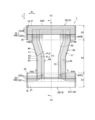
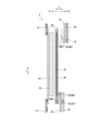
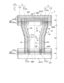
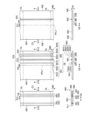
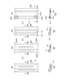
図1は、本実施形態に係る吸収性物品1の模式正面図である。図2は、本実施形態に係る吸収性物品1の模式平面図である。図2に示す模式平面図は、後述するサイド接合部18を展開した状態において吸収性物品1を皺が形成されない状態まで伸長させた伸長状態を示している。図3は、図2に示すF3-F3断面に沿った模式断面図である。
図4は、図2に示す吸収性物品の模式断面図である。図4Aは、前側の胴回り域における吸収性物品の模式断面図であり、図2に示すF4A-F4A断面に沿った模式断面図である。図4Bは、後側の胴回り域における吸収性物品の模式断面図であり、図2に示すF4B-F4B断面に沿った模式断面図である。図5は、本実施形態に係る吸収性物品1の模式平面図である。図6は、立体ギャザーを説明するための図である。図6は、図5に示すF6-F6断面において立体ギャザーが起立した状態を示す図である。なお、説明の便宜上、各部材が厚さ方向において離間していたとしても、実際の製品では厚さ方向に接していることに留意すべきである。
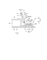
FIG. 1 is a schematic front view of an
4 is a schematic cross-sectional view of the absorbent article shown in FIG. 2. FIG. 4A is a schematic cross-sectional view of the absorbent article in the front waist region, and is a schematic cross-sectional view along the F4A-F4A cross section shown in FIG. 4B is a schematic cross-sectional view of the absorbent article in the back waist region, and is a schematic cross-sectional view along the F4B-F4B cross section shown in FIG. FIG. 5 is a schematic plan view of the
吸収性物品1は、互いに直交する前後方向L及び幅方向Wを有する。前後方向Lは、身体前側と身体後側とに延びる方向によって規定される。言い換えると、前後方向Lは、展開された吸収性物品1において前後に延びる方向である。また、吸収性物品1は、前後方向Lと幅方向Wの両方の直交する厚さ方向Tを有する。厚さ方向Tは、着用者側に向かう肌面側T1と、肌面側と反対側の非肌面側T2と、に延びる。
The
吸収性物品1は、前胴回り域S1と、後胴回り域S2と、股下域S3と、を有する。前胴回り域S1は、着用者の前胴回り(腹部)に対向する領域である。後胴回り域S2は、着用者の後胴回り(背部)に対向する領域であり、装着時に身体(臀部)が載せられる領域を含む。股下域S3は、着用者の股下に位置し、前胴回り域S1と後胴回り域S2との間に挟まれた領域である。なお、請求の範囲に記載の「第1胴回り域」が前胴回り域S1であり、請求の範囲に記載の「第2胴回り域」が後胴回り域S2であってよいし、その逆であってもよい。
The
図1に示すように、幅方向Wにおける前胴回り域S1の端部と、幅方向Wにおける後胴回り域S2の端部と、を接合したサイド接合部18が設けられていてよい。サイド接合部18は、前胴回り域S1の外側部と、後胴回り域S2の外側部とを互いに係止した部分によって規定される。図1に示すように、サイド接合部18が形成された状態で、吸収性物品1には、着用者の胴が通されるウエスト開口部16と、着用者の脚がそれぞれ挿入される一対の脚回り開口部17と、が形成される。ウエスト開口部16は、前胴回り域S1の前端縁S1Fと、後胴回り域S2の後端縁S2Rとによって規定されていてよい。
As shown in FIG. 1 , side joints 18 may be provided that join an end of the front waist region S1 in the width direction W and an end of the rear waist region S2 in the width direction W. The side
ここで、図2は、サイド接合部18における接合を解除し、吸収性物品1を展開した状態を示している。サイド接合部18は、前側外装体20及び後側外装体30のそれぞれにおいて、前後方向Lに沿って延びていてよい。パンツ型の吸収性物品においては、前胴回り域S1と股下域S3との境界は、前側外装体20に設けられたサイド接合部18の後端縁によって規定されていてよい。同様に、後胴回り域S2と股下域S3との境界は、後側外装体30に設けられたサイド接合部18の前端縁によって規定されていてよい。なお、股下域S3は、脚回り開口部17が設けられた領域であってもよい。
Here, FIG. 2 shows a state in which the side joints 18 are unjoined and the
なお、本発明における外側部とは、幅方向Wにおける外縁を含む幅方向Wに一定の範囲を占める部分であり、外側縁とは、幅方向Wにおける外縁である。本発明における内側部とは、幅方向Wにおける内縁を含む幅方向Wに一定の範囲を占める部分であり、内側縁とは、幅方向Wにおける内縁である。また、本発明における前端部及び後端部は、前後方向Lにおける縁を含む前後方向Lに一定の範囲を占める部分であり、前端縁及び後端縁は、前後方向Lにおける縁である。外端部は、前端部及び後端部を含んでおり、外端縁は、前端縁及び後端縁を含んでいる。 In addition, the outer portion in the present invention is a portion occupying a certain range in the width direction W including the outer edge in the width direction W, and the outer edge is the outer edge in the width direction W. The inner portion in the present invention is a portion occupying a certain range in the width direction W including the inner edge in the width direction W, and the inner edge is the inner edge in the width direction W. Further, the front end portion and the rear end portion in the present invention are portions occupying a certain range in the front-rear direction L including edges in the front-rear direction L, and the front end edge and the rear end edge are edges in the front-rear direction L. The outer edge includes a leading edge and a trailing edge, and the outer edge includes a leading edge and a trailing edge.
本実施形態では、吸収性物品1は、外装体15と、本体部40と、を有していてよい。外装体15は、本体部40と厚さ方向Tに重なっている。外装体15は、前胴回り域S1に配置された前側外装体20と、後胴回り域S2に配置された後側外装体30と、を有してよい。前側外装体20は、前胴回り域S1において本体部40よりも非肌面側T2に配置されている外装体である。後側外装体30は、前側外装体20と前後方向Lに離間し、かつ後胴回り域S2において本体部40よりも非肌面側T2に配置されている外装体である。
In this embodiment, the
図3に示すように、外装体15は、本体部40の肌面側T1に配置されたカバーシートを有してよい。カバーシートは、前胴回り域S1の本体部40の肌面側T1に設けられた前側カバーシート27と、後胴回り域S2の本体部40の肌面側T1に設けられた後側カバーシート37と、を有してよい。前側カバーシート27及び後側カバーシート37は、例えば不織布のようなシートから構成されていてよい。前側カバーシート27は、前側外装体20を構成するシートが肌面側T1に折り返された部分によって構成されてもよいし、前側外装体20を構成するシートとは別体のシートによって構成されてもよい。同様に、後側カバーシート37は、後側外装体30を構成するシートが肌面側T1に折り返された部分によって構成されてもよいし、後側外装体30を構成するシートとは別体のシートによって構成されてもよい。
As shown in FIG. 3 , the
前側外装体20及び後側外装体30は、例えば不織布のようなシートから構成されていてよい。前側外装体20は、第1前側シート25と、第1前側シート25の非肌面側T2に位置する第2前側シート26と、を有してよい。前側外装体20は、第1前側シート25、第2前側シート26以外のシートを更に備えていてよい。また、後側外装体30は、複数のシートを有してよい。前側外装体20は、第1後側シート35と、第1後側シート35の非肌面側T2に位置する第2後側シート36と、を有してよい。後側外装体30は、第1後側シート35、第2後側シート36以外のシートを更に備えていてよい。
The front
外装体15は、幅方向Wに伸縮性を有するウエスト弾性部材WEを有してよい。具体的には、前胴回り域S1には、幅方向Wに伸縮性を有するウエスト弾性部材WEである前ウエスト弾性部材22が配置されてよい。後胴回り域S2には、幅方向Wに伸縮性を有するウエスト弾性部材WEである後ウエスト弾性部材32が配置されてよい。前ウエスト弾性部材22は、第1前側シート25と第2前側シート26の間に配置されてよく、後ウエスト弾性部材32は、第1後側シート35と第2後側シート36の間に配置されてよい。ウエスト弾性部材WEは、例えば、幅方向Wに伸縮可能な糸ゴム、又は幅方向Wに伸縮可能な弾性シートによって構成されていてよい。ウエスト弾性部材WEは、例えば伸縮可能なシートにより構成された外装体15自体によって構成されていてもよい。本実施の形態のウエスト弾性部材WEは、糸ゴムによって構成されている。
The
本体部40は、少なくとも股下域S3に配置されている。本体部40は、前胴回り域S1、後胴回り域S2及び股下域S3にわたって配置されてよい。本体部40は、前側外装体20及び後側外装体30とは別体として構成され、前胴回り域S1及び後胴回り域S2において、それぞれ前側外装体20及び後側外装体30と接合されていてよい。
The
本体部40は、吸収性本体41と、吸収性本体41よりも肌面側T1に配置される一対の複合伸縮シート60と、を有してよい。
The
吸収性本体41は、少なくとも吸収コア50を有する。吸収コア50は、吸収材料を含む。吸収コア50は、例えば粉砕パルプもしくは高吸収性ポリマー(SAP)、又はこれらの混合物を含んでいてよい。吸収コア50は、少なくとも股下域S3に配置されている。吸収コア50は、前胴回り域S1に配置されてよく、後胴回り域S2に配置されてよい。吸収コア50は、前後方向Lにおいて、前胴回り域S1から後胴回り域S2にわたって延びていてよい。吸収コア50は、コアラップによって覆われていてよい。
The absorbent
図3に示すように、吸収性本体41は、吸収コア50の肌面側T1に位置するセンターシート43と、吸収コア50の非肌面側T2に位置する液不透過シート46と、液不透過シート46よりも非肌面側T2に配置された非肌面シート47と、を有してよい。本実施の形態の吸収性本体41は、吸収コア50よりも前側の領域において、肌面側T1から非肌面側T2に向かって、センターシート43、液不透過シート46、非肌面シート47の順で配置されている。また、吸収コア50と重なった領域では、肌面側T1から非肌面側T2に向かって、センターシート43、吸収コア50、液不透過シート46、非肌面シート47の順で配置されている。センターシート43と液不透過シート46は、厚さ方向Tにおいて吸収コア50を挟んで配置されてよい。
As shown in FIG. 3, the absorbent
センターシート43は、液透過性を有していればよく、例えば不織布によって構成されていてよい。センターシート43は、吸収コア50の幅方向Wの中央を覆う。センターシート43は、後述するサイドシート62と肌面シートを構成してよい。液不透過シート46は、液不透過性を有していればよく、例えば、フィルムによって構成されてよい。図4に示すように、液不透過シート46は、サイドシート62よりも非肌面側T2に配置されてよい。非肌面シート47は、例えば不織布によって構成されていてよい。
The
図4に示すように、吸収性本体41は、吸収コア50よりも幅方向Wの外側に配置される非肌側サイドシート48を有してよい。非肌側サイドシート48は、サイドシート62よりも非肌面側T2に配置されてよい。非肌側サイドシート48は、例えば不織布によって構成されてよい。なお、吸収性本体41は、非肌側サイドシート48を有さなくてもよい。
As shown in FIG. 4 , the absorbent
図3に示すように、吸収性本体41は、本体接合部MBを介して外装体15と接合されている。実施形態では、吸収性本体41は、前本体接合部28を介して前側外装体20と接合されており、後本体接合部38を介して後側外装体30と接合されている。一方で、図3及び図5に示すように、吸収性物品1には、吸収性本体41と外装体15とが接合されていない非接合領域NBRが設けられてよい。
As shown in FIG. 3, the absorbent
図2及び図4に示すように、後側の股下域S3の吸収性本体41の幅方向Wの長さは、前側の股下域S3の吸収性本体41の幅方向Wの長さよりも長くてよい。吸収性本体41の外側縁は、複合伸縮シート60に沿って前後方向Lに延びてよい。
As shown in FIGS. 2 and 4, the length in the width direction W of the absorbent
一対の複合伸縮シート60は、吸収性本体41の両側部において前後方向Lに延びており、吸収性本体41と接合されている。複合伸縮シート60は、前後方向Lに伸縮性を有する。複合伸縮シート60は、後述するように、一対のシート層62pを有する。
A pair of composite
一対の複合伸縮シート60は、一対のサイドシート62、立体弾性部材75、レッグ弾性部材85を有してよい。
A pair of composite
サイドシート62は、吸収性物品1の幅方向Wの中心Cよりも幅方向Wの外側に配置されている。サイドシート62は、センターシート43よりも肌面側T1においてセンターシート43の外側部を覆っている。サイドシート62は、1枚のシートにより構成されている。サイドシートを構成する1枚のシートは、単一のシートであってよいし、厚さ方向Tにシートが積層された1枚の積層シートであってよい。
The
吸収性物品1の平面視において、1のサイドシート62は、少なくとも吸収性物品1の前後方向Lの中心Lcよりも後側において、幅方向Wの外側へ向かうように湾曲しながら後方へ延びている部分を有してよい。後側の股下域S3における一対のサイドシート62間の最大幅は、前側の股下域S3における一対のサイドシート62間の最大幅よりも大きい。
In a plan view of the
サイドシート62は、湾曲しながら前後方向Lに延びている。従って、前側の股下域S3では、サイドシート62は、センターシート43と非肌側サイドシート48とに接合されてよい。後側の股下域S3では、サイドシート62は、非肌側サイドシート48と非肌面シート47と接合されてよい。
The
サイドシート62は、1のサイドシート62を前後方向Lに延びる1つの折り目である第1折り目FL1を基点に折り返されている。サイドシート62は、第1折り目FL1が後述する立体ギャザー70に配置されるように、1のサイドシート62が折り返されてよい。従って、第1折り目FL1は、サイドシート62の幅方向Wの内側に配置されている。一方で、サイドシート62の幅方向Wにおける端縁62Eは、サイドシート62の幅方向Wの外側、すなわち、脚回り開口部17側に配置されている。サイドシート62の端縁62Eは、サイドシート62自体の端縁(切断面を有するエッジ)である。
The
1のサイドシート62を、第1折り目FL1を基点に折り返すことによって互いに対向する一対のシート層62pが形成されている。一対のシート層62pは、第1シート層621と第2シート層622とを有する。第1シート層621は、少なくとも幅方向Wの外側で肌面側T1に配置されており、第2シート層622は、少なくとも幅方向Wの外側で非肌面側T2に配置されている。第1折り目FL1は、第1シート層621と第2シート層622との境界を規定してよい。
A pair of
なお、図4に示されるように、サイドシート62の幅方向Wの内側において、前後方向Lに延びる折り目である第2折り目FL2を基点に一対のシート層62p自体がさらに折り返されていてもよい。一対のシート層62pの折り返されている部分では、第1シート層621が非肌面側T2に配置され、第2シート層622が肌面側T1に配置されてよい。
As shown in FIG. 4, the pair of
一対のシート層62pのそれぞれ、すなわち、第1シート層621と第2シート層622とは、1のサイドシート62の端縁62Eを有してよい。実施形態では、第1シート層621が有する端縁62Eと第2シート層622が有する端縁62Eとが厚さ方向Tに重なっている。
Each of the pair of
図4に示すように、サイドシート62の端縁62Eは、吸収性本体41の幅方向Wにおける側端縁よりも、幅方向Wの内側に配置されてよい。これにより、サイドシート62の端縁62Eが着用者の肌に当たり難くなり、肌触りの悪化を抑制することができる。
As shown in FIG. 4 , the
立体弾性部材75は、前後方向Lに伸縮性を有する弾性部材である。立体弾性部材75の収縮によって、立体ギャザー70が肌面側T1に起立可能である。立体弾性部材75は、例えば、糸ゴム又は弾性シートによって構成されていてよい。
The three-dimensional
立体弾性部材75は、1以上の弾性部材によって構成される。立体弾性部材75の数が2以上である場合、立体弾性部材75は、幅方向Wに間隔を空けて配置されてよい。本実施形態では、立体弾性部材75は、第1立体弾性部材751と第2立体弾性部材752によって構成されている。図6に示すように、第1立体弾性部材751は、立体ギャザー70の起立時に最も肌面側T1に位置する。従って、第1立体弾性部材751は、立体ギャザー70の頂点Apに最も近い位置に配置されている。一方、第2立体弾性部材752は、立体ギャザー70の起立時に最も非肌面側T2に位置する。従って、第2立体弾性部材752は、サイドシート62に沿った方向において立体ギャザー70の頂点Ap(第1折り目FL)から最も遠い位置に配置されている。
The three-dimensional
なお、本実施形態では、サイドシート62(一対のシート層62p)は、第2折り目FL2を基点にさらに折り返されているため、図4では、第1立体弾性部材751は、第2立体弾性部材752よりも幅方向Wの外側に配置されている。
In the present embodiment, the side sheets 62 (the pair of
図4に示すように、吸収性物品1は、第2立体弾性部材752(立体ギャザー70の起立時に最も非肌面側T2に位置する弾性部材)と後述する起立端縁73との間において、接着剤により一対のシート層62pどうしを接合する接合部(シート内接合部)63を有してよい。シート内接合部63は、例えば、HMA(ホットメルト接着剤)であってよい。
As shown in FIG. 4 , in the
レッグ弾性部材85は、前後方向Lに伸縮性を有する弾性部材である。レッグ弾性部材85は、後述する起立部72の起立支点である起立端縁73よりも幅方向Wの外側に配置されている。レッグ弾性部材85は、例えば、糸ゴム又は弾性シートによって構成されていてよい。
The leg
レッグ弾性部材85は、1以上の弾性部材によって構成される。レッグ弾性部材85の数が2以上である場合、レッグ弾性部材85は、幅方向Wに間隔を空けて配置されてよい。また、レッグ弾性部材85の数及び立体弾性部材75の数が2以上である場合、幅方向Wにおいて、レッグ弾性部材85どうしの間隔は、立体弾性部材75どうしの間隔よりも狭くてよい。また、レッグ弾性部材85の数は、立体弾性部材75の数よりも多くてよい。
The leg
本実施形態では、レッグ弾性部材85は、第1レッグ弾性部材851、第2レッグ弾性部材852、第3レッグ弾性部材853、第4レッグ弾性部材854によって構成されている。1以上のレッグ弾性部材85のうち、第1レッグ弾性部材851は、幅方向Wにおいて最も内側に配置されており、第4レッグ弾性部材854は、幅方向Wにおいて最も外側に配置されている。レッグ弾性部材85の収縮によって所定の幅で前後方向Lに収縮する収縮領域85Rが設けられる。収縮領域85Rの幅は、幅方向Wにおいて、少なくとも、最も内側のレッグ弾性部材85(すなわち、第1レッグ弾性部材851)から最も外側のレッグ弾性部材85(すなわち、第4レッグ弾性部材854)までの長さである。図4に示すように、収縮領域85Rの長さは、最も内側のレッグ弾性部材85から最も外側のレッグ弾性部材85までの長さよりも長くてよい。
In this embodiment, the leg
本実施形態では、立体弾性部材75とレッグ弾性部材85とは、一対のシート層62pに挟まれている。これにより、立体弾性部材75とレッグ弾性部材85とは、シート層62pに接している。
In this embodiment, the three-dimensional
幅方向Wにおいて最も外側に配置されている第4レッグ弾性部材854よりも幅方向Wの外側の領域は、一対のシート層62pどうしが接合されていない外側非接合領域であってよい。
A region outside in the width direction W of the outermost fourth leg
吸収性物品1は、立体ギャザー70とレッグギャザー80とを有する。立体ギャザー70は、肌面側T1に起立可能である。立体ギャザー70は、防漏カフと称されてもよい。立体ギャザー70は、防漏接合部71と、起立部72と、起立端縁73と、を有してよい。防漏接合部71は、は、サイドシート62(複合伸縮シート60)を吸収性本体41と接合する部分である。防漏接合部71は、接着剤により構成されてよい。
The
図4及び図5に示すように、防漏接合部71は、起立端縁73よりも前後方向Lの外側に配置される前後接合部711と、起立端縁73よりも幅方向Wの外側に配置される幅接合部712と、を有してよい。前後接合部711は、前胴回り域S1に配置される前接合部711Fと、後胴回り域S2に配置される後接合部711Rと、を有してよい。
As shown in FIGS. 4 and 5 , the leak-
起立部72は、1以上の立体弾性部材75によって起立可能である。起立部72は、立体弾性部材75の収縮によって起立する。
The standing
起立端縁73は、起立部72の起立支点となる。起立端縁73は、前後接合部711の内端縁(前接合部711Fの後端縁及び後接合部711Rの前端縁)及び幅接合部712の内側縁により構成される。
The
レッグギャザー80は、収縮領域85Rを有している。収縮領域85Rは、股下域S3において、起立端縁73よりも幅方向Wの外側に配置されているレッグ弾性部材85の収縮によって前後方向Lに収縮する。また、レッグギャザー80は、起立端縁73よりも幅方向Wの外側に配置されている。
Leg gathers 80 have
立体ギャザー70とレッグギャザー80とは、一対のシート層62pによって構成されている。図6に示すように、一対のシート層62pは、立体ギャザー70の起立時に最も肌面側に位置する第1立体弾性部材751と接する位置P1から、幅方向Wにおいて最も外側に配置されている第4レッグ弾性部材854と接する位置P2まで、連続的に延びている。従って、一対のシート層62pの両方が、全てのレッグ弾性部材85と厚さ方向Tに重なっている。
The three-dimensional gathers 70 and the leg gathers 80 are composed of a pair of
本実施形態では、第1折り目FL1がする立体ギャザー70に配置されているため、一対のシート層62pは、第1立体弾性部材751を超えて、第1折り目FL1、すなわち、立体ギャザー70の頂点Apまで連続的に延びている。また、一対のシート層62pは、第4レッグ弾性部材854を超えて幅方向Wの外側まで延びている。
In the present embodiment, the pair of
また、図4及び図6に示すように、1のサイドシート62よりも非肌面側T2に配置され、かつ1のサイドシート62と直接的又は間接的に接合される構成部材は、起立端縁73よりも幅方向Wの外側へ延びてよい。構成部材は、厚さ方向Tにおいて、1以上のレッグ弾性部材85と重なってよく、全てのレッグ弾性部材85と重なっていることが好ましい。
Further, as shown in FIGS. 4 and 6, the constituent member which is arranged on the non-skin surface side T2 of the
なお、本実施形態では、構成部材は、センターシート43、液不透過シート46、非肌面シート47、非肌側サイドシート48の少なくともいずれかである。従って、例えば、液不透過シート46は、起立端縁73よりも幅方向Wの外側へ延びてよい。図4A及び図4Bに示すように、センターシート43及び非肌側サイドシート48は、サイドシート62と直接的に接合されている。液不透過シート46は、非肌側サイドシート48を介してサイドシート62と間接的に接合されている。非肌面シート47は、サイドシート62と直接的に接合されており(図4A参照)、液不透過シート46及び/又は非肌側サイドシート48を介してサイドシート62と間接的に接合されている。
In this embodiment, the constituent member is at least one of the
上述したように、本実施形態の吸収性物品1では、立体ギャザー70の起立時に最も肌面側T1に位置する第1立体弾性部材751から、幅方向Wにおいて最も外側に配置されている第4レッグ弾性部材854までの間に、起立端縁73が存在するため、起立端縁73付近において一対のシート層62pが存在する。従って、図6に示すように、吸収性物品1の表面を流れて幅方向Wの外側へ移動する排泄物Eが、第2シート層622から幅方向Wの外側へ染み出しとしても、第1シート層621によって幅方向Wの外側へ染み出すことを抑制できる。これにより、立体ギャザーの幅方向Wの外側へ滲み出すことで発生する排泄物の漏れを抑制できる。
As described above, in the
加えて、一対のシート層の両方が、全てのレッグ弾性部材85と厚さ方向Tに重なっているため、レッグギャザー80の平面性を維持し易く、レッグギャザー80が着用者の肌に面でフィットし易くなる。
In addition, since both of the pair of sheet layers overlap all the leg
また、サイドシート62の第1折り目FL1は、サイドシート62の端縁62Eと比較して、肌触りがよい。従って、立体弾性部材75とレッグ弾性部材85とが、一対のシート層62pに挟まれているため、立体ギャザー70の起立時に、肌触りの良いサイドシート62の第1折り目FL1が着用者の肌に当たるため、立体ギャザー70の起立に起因した吸収性物品1の着け心地の悪化を抑制できる。
Also, the first fold line FL1 of the
また、センターシート43、液不透過シート46、非肌面シート47、非肌側サイドシート48などの構成部材が、起立端縁73よりも幅方向Wの外側へ延びているため、レッグギャザー80の剛性を高くすることができ、レッグギャザー80の平面性を維持し易くできる。
In addition, since the constituent members such as the
特に、液不透過シート46が、起立端縁73よりも幅方向Wの外側へ延びていることにより、排泄物が起立端縁73よりも幅方向Wの外側へ移動したとしても、液不透過シート46によって排泄物が、液不透過シート46よりも非肌面側へ染み出すことを抑制できる。
In particular, since the liquid-
また、レッグ弾性部材85の数は、立体弾性部材75の数よりも多い。レッグ弾性部材85を多く配置することで、レッグギャザー80の剛性を高くすることができ、レッグギャザー80の平面性を維持し易くなる。
Also, the number of leg
また、レッグ弾性部材85どうしの間隔は、立体弾性部材75どうしの間隔よりも狭い。これにより、単位面積当たりに、レッグ弾性部材85を多く配置することで、レッグギャザー80の剛性を高くすることができ、レッグギャザー80の平面性を維持し易くなる。
Also, the interval between the leg
また、第2立体弾性部材752と起立端縁73との間において、シート内接合部63が設けられているため、排泄物が、シート内接合部63によって幅方向Wの外側の第1シート層621へ到達し難くなる(図6参照)。これにより、排泄物が、立体ギャザー70の幅方向Wの外側へ染み出すことで発生する排泄物の漏れを抑制できる。
In addition, since the in-sheet
また、第4レッグ弾性部材854よりも幅方向Wの外側の領域は、外側非接合領域である。当該領域は、着用者の肌に当たり易いため、当該領域において一対のシート層62pどうしを接合しないことで、当該領域の剛性が高くならず、肌触りの悪化を抑制できる。
In addition, the area outside the fourth leg
また、サイドシート62は、前後方向Lの中心Lcよりも後側において、幅方向Wの外側へ湾曲しながら後方へ延びている部分(湾曲部分)を有している。これにより、サイドシート62が着用者の身体の形状(具体的には、臀部と脚との境界線(肉割れ線))に沿って配置され易くなり、サイドシート62による違和感を着用者に与え難くなる。加えて、排泄物(大便)の収容空間を確保できるため、排泄物の漏れを抑制できる。
In addition, the
(3)吸収性物品の製造方法
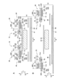
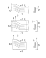
次に、吸収性物品1の製造方法を、図7から図9を用いて説明する。図7から図9は、吸収性物品1の製造方法を説明するための図である。製造過程における構成部品を搬送する方向を搬送方向MDとして示し、当該搬送方向と交差する方向を交差方向CDとして示し、搬送方向MD及び交差方向CDに直交する方向を横断方向TDとして示す。図7から図9において、左図は、横断方向TD(上側)から見た部材を示し、右図は、搬送方向MDから見た部材を示している。具体的には、図7の工程S11の右図は左図のC11-C11断面に沿った模式断面図を示し、図7の工程S12の右図は左図のC12-C12断面に沿った模式断面図を示し、図7の工程S13の右図は左図のC13-C13断面に沿った模式断面図を示し、図8の工程S20の右図は左図のC20-C20断面に沿った模式断面図を示し、図8の工程S30の右図は左図のC30-C30断面に沿った模式断面図を示し、図8の工程S40の右図は左図のC40-C40断面に沿った模式断面図を示し、図8の工程S50の右図は左図のC50-C50断面に沿った模式断面図を示し、図9の工程S60の右図は左図のC60-C60断面に沿った模式断面図を示し、図9の工程S70の右図は左図のC70-C70断面に沿った模式断面図を示し、図9の工程S80の右図は左図のC80-C80断面に沿った模式断面図を示す。
なお、説明の便宜上、製造装置の構成は、図示していない。
(3) Manufacturing Method of Absorbent Article Next, a manufacturing method of the
For convenience of explanation, the configuration of the manufacturing apparatus is not shown.
なお、CLは、後述するシート連続体60Cが切断される切断線を示す。PFL1は、サイドシート連続体62Cの折り目を示す仮想線を示す。サイドシート連続体62CがPFL1の位置で折られることにより、第1折り目FL1が設けられる。
Note that CL indicates a cutting line along which the
以下において、説明の便宜のために、吸収性物品1の幅方向Wの一方側の製造を主に説明するが、吸収性物品1の幅方向Wの他方側も同様に製造されることは勿論である。
In the following, for convenience of explanation, manufacturing of one side of the
図7から図9に示すように、本実施形態に係る吸収性物品の製造工程は、工程S10から工程S80を有する。 As shown in FIGS. 7 to 9, the manufacturing process of the absorbent article according to this embodiment has steps S10 to S80.
工程S10は、複合伸縮シート60が前後方向Lに連続したシート連続体60Cを形成する工程である。工程S10は、工程S11と、工程S12と、工程S13と、を有してよい。
Step S10 is a step of forming a sheet
工程S11は、搬送されているサイドシート連続体62Cに接着剤63Cを塗布する工程である。サイドシート連続体62Cは、1のサイドシート62が前後方向Lに連続したものである。接着剤63Cは、シート内接合部63に対応する接着剤である。接着剤63Cは、サイドシート連続体62Cどうしを接合するものである。
Step S11 is a step of applying an adhesive 63C to the conveyed side sheet
接着剤63Cは、搬送方向MDに沿って塗布されている。接着剤63Cは、中間領域MRに配置してよい。中間領域MRは、第1弾性領域ER1と第2弾性領域ER2との間の領域である。第1弾性領域ER1は、後述する第1連続弾性部材75Cが配置される領域である。第2弾性領域ER2は、後述する第2連続弾性部材85Cが配置される領域である。中間領域MRは、搬送方向MDにおいて、第1弾性領域ER1と第2弾性領域ER2とに挟まれている。
The adhesive 63C is applied along the transport direction MD. The adhesive 63C may be arranged in the middle region MR. The middle region MR is a region between the first elastic region ER1 and the second elastic region ER2. The first elastic region ER1 is a region in which a first continuous
工程S12は、複数の連続弾性部材CEをサイドシート連続体62Cに配置する工程である。複数の連続弾性部材CEは、1以上の立体弾性部材75を構成する第1連続弾性部材75Cと1以上のレッグ弾性部材85を構成する第2連続弾性部材85Cとからなる。連続弾性部材CEは、立体弾性部材75が前後方向Lに連続したものを含んでおり、レッグ弾性部材85が前後方向Lに連続したものを含んでいる。
Step S12 is a step of arranging a plurality of continuous elastic members CE on the side sheet
第1連続弾性部材75Cは、交差方向CDにおいて、第1折り目FL1となる位置(PFL1)と接着剤63Cとの間に配置されてよい。第2連続弾性部材85Cは、交差方向CDにおいて、接着剤63Cと、サイドシート連続体62Cの交差方向CDにおいて接着剤63Cに近い一方の端縁62Eとの間に配置されてよい。
The first continuous
実施形態では、第1連続弾性部材75Cは、第1連続弾性部材751Cと第1連続弾性部材752Cとにより構成される。従って、第1弾性領域ER1は、第1連続弾性部材751Cから第1連続弾性部材752Cまでの間の領域である。同様に、第2連続弾性部材85Cは、第2連続弾性部材851Cから第2連続弾性部材854Cにより構成される。従って、第2弾性領域ER2は、第2連続弾性部材851Cから第2連続弾性部材854Cまでの間の領域である。
In the embodiment, the first continuous
連続弾性部材CEには、接着剤が塗布されており、連続弾性部材CEをサイドシート連続体62Cに配置することにより、連続弾性部材CEがサイドシート連続体62Cに固定される。なお、サイドシート連続体62Cに連続弾性部材CEを固定するための接着剤を塗布してもよい。
An adhesive is applied to the continuous elastic member CE, and the continuous elastic member CE is fixed to the side sheet
工程S13は、複数の連続弾性部材CEの全てがサイドシート連続体62Cに挟まれるように、サイドシート連続体62Cを1回折り返す工程である。第1折り目FL1となる位置PFL1を境界として、複数の連続弾性部材CEが配置されていない一方側のサイドシート連続体62Cを折り返すことによって、一方側のサイドシート連続体62Cを複数の連続弾性部材CEが配置されている他方側のサイドシート連続体62Cと、横断方向TDに重ねる。
Step S13 is a step of folding back the
なお、複数の連続弾性部材CEの全てをサイドシート連続体62Cに挟むためには、交差方向CDにおいて、位置PFL1から、サイドシート連続体62Cの接着剤63Cに遠い他方の端縁62Eまでの距離が、位置PFL1から第2連続弾性部材854Cまでの距離以上であることが必要である。
In order to sandwich all of the plurality of continuous elastic members CE between the
接着剤63Cは、折り返しによって形成された一対のシート層62p(第1シート層621と第2シート層622)を接合する。なお、工程S13以降では、接着剤63Cの図示が省略されている。
The adhesive 63C joins the pair of
以上の工程により、一対のシート層62pを有するシート連続体60Cを形成することができる。なお、特許文献1(特表2018-511385号公報)の図4に記載の吸収性物品を製造しようとした場合、1回目の折り返しによって、全ての第1連続弾性部材75Cをサイドシート連続体62Cに挟んで、2回目の折り返しによって、全ての第2連続弾性部材85Cをサイドシート連続体62Cに挟むことができる。従って、シート連続体60Cを形成するために、サイドシート連続体62Cを少なくとも2回以上折り返す必要がある。特許文献1の図4の吸収性物品と比較して、シート連続体60Cを形成する工程数を少なくすることができる。
Through the above steps, the sheet
工程S20は、低伸縮領域LER(第1低伸縮領域LER1)を形成する工程である。低伸縮領域LERは、複合伸縮シート60の前後方向Lの端部において、複合伸縮シート60の前後方向Lの中央部よりも伸縮力が低い領域である。
Step S20 is a step of forming a low-stretch region LER (first low-stretch region LER1). The low-stretch region LER is a region in which the stretch force is lower at the ends of the
図8に示すように、接着剤が横断方向TDにおいて連続弾性部材CE(第1連続弾性部材75C)と重なるように塗布する。接着剤は、切断線CLに跨がるように塗布されている。一方で、複合伸縮シート60の前後方向Lの中央部の伸縮力が低下しないように、搬送方向MDにおいて間隔を空けて接着剤が塗布されている。接着剤の剛性によって、接着剤が塗布された領域では、第1連続弾性部材75Cの弾性力が、接着剤が塗布されていない領域(接着剤の搬送方向MDの前後の領域)における第1連続弾性部材75Cの弾性力と比較して弱くなる。従って、接着剤が塗布された領域は、低伸縮領域LERである第1低伸縮領域LER1を構成する。
As shown in FIG. 8, the adhesive is applied so as to overlap the continuous elastic member CE (first continuous
工程S30は、シート連続体60Cを折り返す工程である。第1折り目FL1側のシート連続体60Cを折り返す事によって、工程S20で塗布された接着剤を介してシート連続体60Cどうしを接合する。
Step S30 is a step of folding back the
工程S40は、低伸縮領域LER(第2低伸縮領域LER2)を形成する工程である。具体的には、搬送方向MDにおいて切断線CLの前後の領域において、シート連続体60Cを圧搾する。これにより、連続弾性部材CEが切断される。切断された連続弾性部材CEは収縮によって搬送方向MDに収縮し、立体弾性部材75及びレッグ弾性部材85が設けられる。収縮によって立体弾性部材75及びレッグ弾性部材85が存在しなくなった領域は、伸縮力が低下した領域であり第2低伸縮領域LER2を構成する。
Step S40 is a step of forming a low-stretch region LER (second low-stretch region LER2). Specifically, the
工程S50は、本体接着剤71Cをシート連続体60Cに塗布する工程である。本体接着剤71Cは、1のサイドシート62よりも非肌面側T2に配置される構成部材が連続した吸収性本体連続体41Cにシート連続体60Cを接合するための接着剤である。また、本体接着剤71Cは、防漏接合部71を構成する接着剤である。防漏接合部71が配置される領域に本体接着剤71Cを塗布する。
Step S50 is a step of applying the main body adhesive 71C to the sheet
本体接着剤71Cは、低伸縮領域LERと重なる領域に配置されてよい。 The main body adhesive 71C may be arranged in a region that overlaps the low-stretch region LER.
工程S60は、シート連続体60Cを湾曲する工程である。吸収性物品1の平面視において、1のサイドシート62が湾曲部分を有するように、シート連続体60Cを湾曲する。搬送方向MDにおける切断線CLと切断線CLとの間の領域で、搬送方向MDにおけるシート連続体60Cの一方側をシート連続体60Cの他方側に対して交差方向CDにズラすことで、シート連続体60Cを湾曲させることができる。
Step S60 is a step of curving the
なお、例えば、シート連続体60Cの後側を交差方向CDの一方側(例えば、右側)にズラした場合、次の切断線CLと切断線CLとの間の領域では、シート連続体60Cの前側が交差方向CDの一方側にズレているため、シート連続体60Cの後側を交差方向CDの他方側(例えば、左側)へズラしてよい。これにより、交差方向CDにおけるスペースが大きくならず、製造装置の巨大化を抑えることができる。
Note that, for example, when the rear side of the
工程S60は、工程S40の後に行われるため、弾性部材が幅方向Wに連続していない。これにより、弾性部材によって交差方向CDにかかる力を低減することができ、シート連続体60Cを狙い通りに湾曲させることができる。
Since step S60 is performed after step S40, the elastic member is not continuous in the width direction W. As a result, the force applied in the cross direction CD can be reduced by the elastic member, and the
なお、工程S60は、工程S50の後に行われるため、本体接着剤71Cが塗布されたシート連続体60Cを湾曲している。
Since step S60 is performed after step S50, the sheet
工程S70では、湾曲したシート連続体60Cを吸収性本体連続体41Cと接合する工程である。シート連続体60Cを吸収性本体連続体41C上に配置することで、シート連続体60Cを本体接着剤71Cを介して吸収性本体連続体41Cと接合できる。
Step S70 is a step of joining the curved sheet
本体接着剤71Cは、低伸縮領域LERと重なる領域に配置されている場合、少なくとも低伸縮領域LERと重なる位置で、湾曲したシート連続体60Cを吸収性本体連続体41Cと接合できる。
When the main body adhesive 71C is arranged in the region overlapping the low-stretch region LER, it can join the curved sheet
なお、吸収性本体連続体41Cは、吸収性本体41が前後方向Lに連続したものであってもよいし、複合伸縮シート60と直接接合される部材が連続したものであってもよい。例えば、シート連続体60Cと、非肌面シート47が前後方向Lに連続したものを含まない吸収性本体連続体41Cとが接合された後に、非肌面シート47が前後方向Lに連続したものが接合されてよい。
The absorbent
湾曲したシート連続体60Cを吸収性本体連続体41Cと接合することで、本体部40が連続した本体連続体40Cを形成することができる。
By joining the
工程S80では、本体連続体40Cを切断する工程である。本体連続体40Cを切断線CLに沿って切断する。また、交差方向CDにおける本体連続体40Cの側端部を切断してよい。具体的には、交差方向CDにおける吸収性本体連続体41Cの側端部41CEを、搬送方向MDに延びるシート連続体60Cに沿って、切断してよい。これにより、後側の幅が、前側の幅よりも広い本体部40を製造することができる。
Step S80 is a step of cutting the main body continuum 40C. The body continuum 40C is cut along the cutting line CL. Also, the side end portion of the main body continuum 40C in the cross direction CD may be cut. Specifically, the side end portion 41CE of the continuous
以後、本体部40に外装体15を接合することで、吸収性物品1を製造することができる。
Thereafter, the
以上のように、実施形態の製造方法によれば、レッグギャザー80の平面性を維持し易くしつつも、排泄物の漏れを低減できる吸収性物品1を製造することができる。また、サイドシート連続体62Cを複数回折り返して、シート連続体60Cを形成する必要がないため、製造工程の増加を抑制できる。
As described above, according to the manufacturing method of the embodiment, it is possible to manufacture the
また、工程S11では、中間領域MRに、サイドシート連続体62Cどうしを接合する接着剤63Cを塗布する。中間領域MRは、連続弾性部材CEが配置されていないため、第1弾性領域ER1及び第2弾性領域ER2よりも剛性が低い。そこで、中間領域MRにおいて接着剤63Cを塗布して、サイドシート連続体62Cどうしを接合することにより、中間領域MRの剛性を高めることができる。これにより、シート連続体60Cを別部材(吸収性本体連続体41C)に接合する際にシート連続体60C(サイドシート連続体62C)に皺が発生し難くなり、シート連続体60Cを別部材に適切に接合することができる。
Further, in step S11, the intermediate region MR is coated with an adhesive 63C for joining the side sheet
また、工程S70では、低伸縮領域LERと重なる領域において、シート連続体60Cを吸収性本体連続体41Cと接合している。これにより、低伸縮領域LERでは、シート連続体60Cが縮み難くなるため、シート連続体60Cを吸収性本体連続体41Cに接合し易くすることができる。
Further, in step S70, the
また、工程S40では、シート連続体60Cを圧搾して連続弾性部材CEを切断することにより、第2低伸縮領域LER2を形成している。連続弾性部材CEを切断することで、第2低伸縮領域LER2を形成すると共に圧搾によってシート連続体60Cの剛性を高めることができる。これにより、シート連続体60Cがさらに縮み難くなるため、シート連続体60Cを吸収性本体連続体41Cに接合し易くすることができる。
Further, in step S40, the continuous elastic member CE is cut by squeezing the sheet
また、工程S70では、湾曲したシート連続体60Cを吸収性本体連続体41Cと接合している。これにより、サイドシート62が着用者の身体の形状(具体的には、臀部と脚との境界線(肉割れ線))に沿って配置され易くなり、サイドシート62による違和感を着用者に与えにくくなる吸収性物品1を製造することができる。
Further, in step S70, the curved sheet
加えて、シート連続体60Cを湾曲させることで、シート連続体60Cを湾曲させた後に、連続弾性部材CEを湾曲させながら配置する場合と比較して、連続弾性部材CEの位置を調整し易い。従って、狙い通りに連続弾性部材CEを湾曲させることができる。
In addition, by bending the
また、シート連続体60Cを湾曲した後に本体接着剤71Cを塗布するケースでは、湾曲具合に合わせて本体接着剤71Cを塗布するには、高度な制御が必要である。工程S60では、本体接着剤71Cが塗布されたシート連続体60Cを湾曲している。従って、シート連続体60Cの湾曲に沿って本体接着剤71Cを塗布するための高度な制御が必要なくなり、本体接着剤を狙い通りの位置に塗布しやすくなる。
Further, in the case where the main body adhesive 71C is applied after the sheet
(4)変更例
次に、各変更例について、図10を用いて説明する。図10は、変更例に係る吸収性物品の模式断面図である。図10Aは、変更例1に係る吸収性物品1の模式断面図であり、図10Bは、変更例2に係る吸収性物品1の模式断面図である。図10における断面は、F4A-F4A断面に対応する。なお、実施形態と同様の説明は省略する。
(4) Modifications Next, each modification will be described with reference to FIG. FIG. 10 is a schematic cross-sectional view of an absorbent article according to a modification. 10A is a schematic cross-sectional view of an
変更例1について、図10Aを用いて説明する。図10Aに示すように、サイドシート62の端縁62Eは、立体ギャザー70に配置されている。この場合、サイドシート62の端縁62Eは、後述の立体ギャザー70の頂点Apを構成してよい。
また、第2立体弾性部材752と起立端縁73との間の領域には、シート内接合部63が設けられていなくてもよい。すなわち、第2立体弾性部材752と起立端縁73との間の領域は、一対のシート層62pどうしが接合されていない内側非接合領域であってよい。これにより、一対のシート層62pの間に空間が発生するため、排泄物が、第2シート層622から第1シート層621へ連続的に染み込むことを抑制できる。
Also, the in-
変更例2について、図10Bを用いて説明する。図10Bに示すように、第1シート層621が有する端縁62Eと第2シート層622が有する端縁62Eとが厚さ方向Tに重ならなくてよい。従って、第1シート層621が有する端縁62Eと第2シート層622が有する端縁62Eとが幅方向Wにずれていてよい。第1シート層621の端縁62Eと第2シート層622の端縁62Eとが、着用者の肌に一緒に当たり難くなり、肌触りの悪化を抑制することができる。第1シート層621の端縁62Eが、第2シート層622の端縁62Eよりも幅方向Wの外側に配置されていてもよく、第2シート層622の端縁62Eよりも幅方向Wの内側に配置されていてもよい。
Modification 2 will be described with reference to FIG. 10B. As shown in FIG. 10B, the
変更例3について説明する。吸収性物品の製造方法は、工程S50の後に、シート連続体60Cを切断する工程を有してよい。シート連続体60Cを切断線CLに沿って切断することができる。
Modification 3 will be described. The method for manufacturing an absorbent article may have a step of cutting the sheet
次に、シート連続体60Cを切断した後に、切断によって製造された複合伸縮シート60を湾曲させる工程を行う。湾曲方法は、工程S60と同様である。
Next, after cutting the sheet
ここで、シート連続体60Cを湾曲させた場合、シート連続体60Cは搬送方向MDに連続しているため、シート連続体60Cには、交差方向CDの内側にかかる力と、交差方向CDの外側にかかる力とが交互に繰り返しかかり、シート連続体60Cを狙い通りに湾曲できない虞がある。そこで、複合伸縮シート60を個別に湾曲させることで、複合伸縮シート60を狙い通りに湾曲させることができる。
Here, when the
次に、湾曲した複合伸縮シート60を、工程S70と同様に、吸収性本体連続体41Cに接合する。これにより、狙い通りに湾曲させた複合伸縮シート60を吸収性本体連続体41Cに接合することができ、サイドシート62が着用者の身体の形状(具体的には、臀部と脚との境界線(肉割れ線))に沿ってさらに配置され易くなる。
Next, the curved composite
(6)その他実施形態
以上、上述の実施形態を用いて本発明について詳細に説明したが、当業者にとっては、本発明が本明細書中に説明した実施形態に限定されるものではないということは明らかである。本発明は、特許請求の範囲の記載により定まる本発明の趣旨及び範囲を逸脱することなく修正及び変更態様として実施することができる。したがって、本明細書の記載は、例示説明を目的とするものであり、本発明に対して何ら制限的な意味を有するものではない。
(6) Other Embodiments Although the present invention has been described in detail using the above-described embodiments, those skilled in the art will understand that the present invention is not limited to the embodiments described herein. is clear. The present invention can be implemented with modifications and variations without departing from the spirit and scope of the invention defined by the claims. Accordingly, the descriptions herein are for the purpose of illustration and description, and are not intended to have any limiting meaning with respect to the present invention.
上述において製造方法の工程の順番は、変更されてよい。例えば、工程S11は、工程S12の後に実行されてよい。 The order of the steps of the manufacturing method described above may be changed. For example, step S11 may be performed after step S12.
また、上述において製造方法の一部の工程は省略されてよい。例えば、第1低伸縮領域LER1と第2低伸縮領域LER2を形成する工程の一方の工程は省略されてもよく、両方の工程が省略されてもよい。また、工程S20は省略されてもよい。 Also, in the above description, some steps of the manufacturing method may be omitted. For example, one of the steps of forming the first low-stretch region LER1 and the second low-stretch region LER2 may be omitted, or both steps may be omitted. Also, step S20 may be omitted.
上述の実施形態、各変更例及びその他実施形態に係る吸収性物品1に係る構成は、適宜組み合わせることが可能である。
The configurations of the
1 :吸収性物品
15 :外装体
16 :ウエスト開口部
17 :脚回り開口部
18 :サイド接合部
20 :前側外装体
30 :後側外装体
40 :本体部
41 :吸収性本体
43 :センターシート
46 :液不透過シート
47 :非肌面シート
48 :非肌側サイドシート
50 :吸収コア
60 :複合伸縮シート
62 :サイドシート
62p :シート層
63 :シート内接合部
70 :立体ギャザー
71 :接合部
72 :起立部
73 :起立端縁
75 :立体弾性部材
80 :レッグギャザー
85 :レッグ弾性部材
621 :第1シート層
622 :第2シート層
S1 :前胴回り域
S2 :後胴回り域
S3 :股下域
1: Absorbent article 15 : Exterior body 16 : Waist opening 17 : Leg opening 18 : Side joint 20 : Front exterior body 30 : Rear exterior body 40 : Body part 41 : Absorbent body 43 : Center seat 46 : liquid impermeable sheet 47 : non-skin sheet 48 : non-skin side side sheet 50 : absorbent core 60 : composite elastic sheet 62 :
Claims (8)
前胴回り域と、後胴回り域と、前記前胴回り域及び前記後胴回り域に挟まれている股下域と、
吸収性物品の前記幅方向の中心よりも前記幅方向の外側に配置される1のサイドシートと、
立体ギャザーとレッグギャザーと、を有し、
前記立体ギャザーは、
前記前後方向に伸縮性を有する1以上の立体弾性部材によって起立可能である起立部と、
前記起立部の起立支点となる起立端縁と、を有し、
前記レッグギャザーは、前記前後方向に伸縮性を有する1以上のレッグ弾性部材によって所定の幅で前記前後方向に収縮する収縮領域を有し、かつ前記起立端縁よりも前記幅方向の外側に配置されている、吸収性物品であって、
前記立体ギャザーと前記レッグギャザーとは、前記1のサイドシートを前記前後方向に延びる1つの折り目を基点に折り返すことによって互いに対向する一対のシート層によって構成されており、
前記幅方向において、前記一対のシート層は、前記立体ギャザーの起立時に最も肌面側に位置する前記立体弾性部材と接する位置から、前記幅方向において最も外側に配置されている前記レッグ弾性部材と接する位置まで、連続的に延びており、
前記立体ギャザーの起立時に最も非肌面側に位置する前記立体弾性部材と前記起立端縁との間において、接着剤により前記一対のシート層どうしを接合するシート内接合部を有し、
前記幅方向において最も外側に配置されている前記レッグ弾性部材よりも前記幅方向の外側の領域は、前記一対のシート層どうしが接合されていない外側非接合領域である、吸収性物品。 a front-rear direction, a width direction orthogonal to the front-rear direction, and a thickness direction;
a front waist region, a back waist region, and a crotch region sandwiched between the front waist region and the back waist region;
one side sheet arranged outside the center in the width direction of the absorbent article in the width direction;
having three-dimensional gathers and leg gathers,
The three-dimensional gathers are
a standing portion that can be erected by the one or more stereoelastic members having stretchability in the front-rear direction;
a standing edge serving as a standing fulcrum of the standing portion;
The leg gathers have contraction regions that contract in the longitudinal direction to a predetermined width by one or more leg elastic members having stretchability in the longitudinal direction, and are arranged outside the standing edges in the width direction. An absorbent article comprising:
The three-dimensional gathers and the leg gathers are composed of a pair of sheet layers facing each other by folding back the one side sheet about one fold line extending in the front-rear direction,
In the width direction, the pair of sheet layers are arranged with the leg elastic member arranged on the outermost side in the width direction from a position in contact with the three-dimensional elastic member positioned closest to the skin surface when the three-dimensional gathers are erected. It extends continuously until it touches,
an in-sheet joining portion for joining the pair of sheet layers with an adhesive between the stereoelastic member positioned closest to the non-skin surface side when the three-dimensional gathers are erected and the standing edge ,
The absorbent article according to claim 1, wherein a region outside in the width direction of the leg elastic member arranged on the outermost side in the width direction is an outer non-bonded region in which the pair of sheet layers are not bonded together.
前記1以上の立体弾性部材と前記1以上のレッグ弾性部材とが、前記一対のシート層に挟まれている請求項1に記載の吸収性物品。 The one side sheet is folded back so that the one fold line is arranged in the three-dimensional gathers,
2. The absorbent article according to claim 1, wherein said one or more stereoelastic members and said one or more leg elastic members are sandwiched between said pair of sheet layers.
前記構成部材は、前記起立端縁よりも前記幅方向の外側へ延びている請求項1又は2に記載の吸収性物品。 Having a component disposed on the non-skin surface side of the one side sheet and directly or indirectly joined to the one side sheet,
3. The absorbent article according to claim 1, wherein the constituent member extends outward in the width direction from the upright edges.
前記液不透過シートは、前記起立端縁よりも前記幅方向の外側へ延びている請求項1から3のいずれか1項に記載の吸収性物品。 Having a liquid-impermeable sheet disposed on the non-skin side of the side sheet of 1 and having liquid-impermeability,
The absorbent article according to any one of claims 1 to 3, wherein the liquid-impermeable sheet extends outward in the width direction beyond the upright edges.
前記一対のシート層の一方のシート層が有する前記端縁と他方のシート層が有する前記端縁とは、前記厚さ方向に重なっていない、請求項1から4のいずれか1項に記載の吸収性物品。 Each of the pair of sheet layers has an edge in the width direction of the one side sheet,
The edge of one of the pair of sheet layers and the edge of the other sheet layer according to any one of claims 1 to 4, wherein the edge does not overlap in the thickness direction. absorbent article.
前記幅方向において、前記レッグ弾性部材どうしの間隔は、前記立体弾性部材どうしの間隔よりも狭い、請求項6に記載の吸収性物品。 the number of the one or more leg elastic members and the number of the one or more stereoelastic members are two or more;
7. The absorbent article according to claim 6, wherein the interval between the leg elastic members is narrower than the interval between the three-dimensional elastic members in the width direction.
Priority Applications (3)
| Application Number | Priority Date | Filing Date | Title |
|---|---|---|---|
| JP2019115024A JP7296260B2 (en) | 2019-06-20 | 2019-06-20 | absorbent article |
| PCT/JP2020/024138 WO2020256103A1 (en) | 2019-06-20 | 2020-06-19 | Absorbent article and method for manufacturing absorbent article |
| CN202080045098.6A CN114080206B (en) | 2019-06-20 | 2020-06-19 | Absorbent article and method for producing absorbent article |
Applications Claiming Priority (1)
| Application Number | Priority Date | Filing Date | Title |
|---|---|---|---|
| JP2019115024A JP7296260B2 (en) | 2019-06-20 | 2019-06-20 | absorbent article |
Publications (3)
| Publication Number | Publication Date |
|---|---|
| JP2021000237A JP2021000237A (en) | 2021-01-07 |
| JP2021000237A5 JP2021000237A5 (en) | 2021-09-30 |
| JP7296260B2 true JP7296260B2 (en) | 2023-06-22 |
Family
ID=73994461
Family Applications (1)
| Application Number | Title | Priority Date | Filing Date |
|---|---|---|---|
| JP2019115024A Active JP7296260B2 (en) | 2019-06-20 | 2019-06-20 | absorbent article |
Country Status (3)
| Country | Link |
|---|---|
| JP (1) | JP7296260B2 (en) |
| CN (1) | CN114080206B (en) |
| WO (1) | WO2020256103A1 (en) |
Families Citing this family (1)
| Publication number | Priority date | Publication date | Assignee | Title |
|---|---|---|---|---|
| CN115281939B (en) * | 2022-09-06 | 2023-05-12 | 智邦(天津)卫生用品科技有限公司 | Sanitary towel preparation method |
Citations (5)
| Publication number | Priority date | Publication date | Assignee | Title |
|---|---|---|---|---|
| JP2010088570A (en) | 2008-10-06 | 2010-04-22 | Kao Corp | Method for attaching strip material and method for manufacturing absorbent article |
| JP2011523887A (en) | 2008-06-13 | 2011-08-25 | ザ プロクター アンド ギャンブル カンパニー | Disposable absorbent articles with elastically shrinkable cuffs to improve containment of liquid effluent |
| JP2015510838A (en) | 2012-03-30 | 2015-04-13 | ザ プロクター アンド ギャンブルカンパニー | Method and apparatus for manufacturing leg cuff for absorbent article |
| JP2018511385A (en) | 2015-03-18 | 2018-04-26 | ザ プロクター アンド ギャンブル カンパニー | Absorbent article with leg cuff |
| JP2020195421A (en) | 2019-05-30 | 2020-12-10 | 大王製紙株式会社 | Disposable wearing article |
Family Cites Families (3)
| Publication number | Priority date | Publication date | Assignee | Title |
|---|---|---|---|---|
| EP3058918B1 (en) * | 2015-02-17 | 2019-04-17 | The Procter and Gamble Company | Absorbent articles forming a three-dimensional basin |
| JP6495765B2 (en) * | 2015-06-30 | 2019-04-03 | ユニ・チャーム株式会社 | Disposable diapers |
| JP6454658B2 (en) * | 2016-03-30 | 2019-01-16 | 大王製紙株式会社 | Disposable diapers |
-
2019
- 2019-06-20 JP JP2019115024A patent/JP7296260B2/en active Active
-
2020
- 2020-06-19 CN CN202080045098.6A patent/CN114080206B/en active Active
- 2020-06-19 WO PCT/JP2020/024138 patent/WO2020256103A1/en active Application Filing
Patent Citations (5)
| Publication number | Priority date | Publication date | Assignee | Title |
|---|---|---|---|---|
| JP2011523887A (en) | 2008-06-13 | 2011-08-25 | ザ プロクター アンド ギャンブル カンパニー | Disposable absorbent articles with elastically shrinkable cuffs to improve containment of liquid effluent |
| JP2010088570A (en) | 2008-10-06 | 2010-04-22 | Kao Corp | Method for attaching strip material and method for manufacturing absorbent article |
| JP2015510838A (en) | 2012-03-30 | 2015-04-13 | ザ プロクター アンド ギャンブルカンパニー | Method and apparatus for manufacturing leg cuff for absorbent article |
| JP2018511385A (en) | 2015-03-18 | 2018-04-26 | ザ プロクター アンド ギャンブル カンパニー | Absorbent article with leg cuff |
| JP2020195421A (en) | 2019-05-30 | 2020-12-10 | 大王製紙株式会社 | Disposable wearing article |
Also Published As
| Publication number | Publication date |
|---|---|
| WO2020256103A1 (en) | 2020-12-24 |
| CN114080206B (en) | 2023-08-08 |
| JP2021000237A (en) | 2021-01-07 |
| CN114080206A (en) | 2022-02-22 |
Similar Documents
| Publication | Publication Date | Title |
|---|---|---|
| JP6752085B2 (en) | Absorbent article | |
| JP5995870B2 (en) | Disposable wearing article and manufacturing method thereof | |
| CN109906066B (en) | Disposable wearing article and method of manufacturing | |
| JP5977590B2 (en) | Absorbent article and method for manufacturing absorbent article | |
| JP2019162372A (en) | Pant-type absorbent article and method for manufacturing the same | |
| JP5250407B2 (en) | Disposable pants-type diaper and method for manufacturing the same | |
| JP7296260B2 (en) | absorbent article | |
| JP6412834B2 (en) | Absorbent articles | |
| WO2019131111A1 (en) | Underpants type absorbent article | |
| CN210330913U (en) | Pants-type absorbent article | |
| JP7037428B2 (en) | Pants-type absorbent article and method for manufacturing pants-type absorbent article | |
| WO2019131110A1 (en) | Absorbent article | |
| WO2019131109A1 (en) | Underpants type absorbent article | |
| WO2023127549A1 (en) | Pants-type absorbent article, absorbent article packaging, and method for manufacturing pants-type absorbent article | |
| JP7149070B2 (en) | absorbent article | |
| JP7285073B2 (en) | Composite sheet, absorbent article, and method for producing composite sheet | |
| JP7217203B2 (en) | absorbent article | |
| JP7305861B1 (en) | Elastic sheet used for absorbent article, and pants-type absorbent article | |
| EP3482730B1 (en) | Absorbent article and method for manufacturing pull-up absorbent article | |
| WO2022071604A1 (en) | Wearable article manufacturing method and wearable article manufactured therewith | |
| JPWO2019116982A1 (en) | Disposable diapers and manufacturing methods for disposable diapers | |
| JP7145756B2 (en) | absorbent article | |
| JP7179457B2 (en) | absorbent article | |
| JP7137928B2 (en) | absorbent article | |
| JP7071146B2 (en) | Manufacturing method of disposable absorbent article and disposable absorbent article |
Legal Events
| Date | Code | Title | Description |
|---|---|---|---|
| RD01 | Notification of change of attorney |
Free format text: JAPANESE INTERMEDIATE CODE: A7421 Effective date: 20200716 |
|
| A521 | Request for written amendment filed |
Free format text: JAPANESE INTERMEDIATE CODE: A523 Effective date: 20210820 |
|
| A621 | Written request for application examination |
Free format text: JAPANESE INTERMEDIATE CODE: A621 Effective date: 20210820 |
|
| A131 | Notification of reasons for refusal |
Free format text: JAPANESE INTERMEDIATE CODE: A131 Effective date: 20220628 |
|
| A521 | Request for written amendment filed |
Free format text: JAPANESE INTERMEDIATE CODE: A523 Effective date: 20220829 |
|
| A131 | Notification of reasons for refusal |
Free format text: JAPANESE INTERMEDIATE CODE: A131 Effective date: 20221129 |
|
| A521 | Request for written amendment filed |
Free format text: JAPANESE INTERMEDIATE CODE: A523 Effective date: 20230130 |
|
| TRDD | Decision of grant or rejection written | ||
| A01 | Written decision to grant a patent or to grant a registration (utility model) |
Free format text: JAPANESE INTERMEDIATE CODE: A01 Effective date: 20230516 |
|
| A61 | First payment of annual fees (during grant procedure) |
Free format text: JAPANESE INTERMEDIATE CODE: A61 Effective date: 20230612 |
|
| R150 | Certificate of patent or registration of utility model |
Ref document number: 7296260 Country of ref document: JP Free format text: JAPANESE INTERMEDIATE CODE: R150 |