JP7294882B2 - Molded article containing recycled carbon fiber and method for producing molded article - Google Patents
Molded article containing recycled carbon fiber and method for producing molded article Download PDFInfo
- Publication number
- JP7294882B2 JP7294882B2 JP2019095502A JP2019095502A JP7294882B2 JP 7294882 B2 JP7294882 B2 JP 7294882B2 JP 2019095502 A JP2019095502 A JP 2019095502A JP 2019095502 A JP2019095502 A JP 2019095502A JP 7294882 B2 JP7294882 B2 JP 7294882B2
- Authority
- JP
- Japan
- Prior art keywords
- carbon fiber
- composite material
- molded article
- raw material
- fiber composite
- Prior art date
- Legal status (The legal status is an assumption and is not a legal conclusion. Google has not performed a legal analysis and makes no representation as to the accuracy of the status listed.)
- Active
Links
Images


Classifications
-
- B—PERFORMING OPERATIONS; TRANSPORTING
- B29—WORKING OF PLASTICS; WORKING OF SUBSTANCES IN A PLASTIC STATE IN GENERAL
- B29C—SHAPING OR JOINING OF PLASTICS; SHAPING OF MATERIAL IN A PLASTIC STATE, NOT OTHERWISE PROVIDED FOR; AFTER-TREATMENT OF THE SHAPED PRODUCTS, e.g. REPAIRING
- B29C48/00—Extrusion moulding, i.e. expressing the moulding material through a die or nozzle which imparts the desired form; Apparatus therefor
- B29C48/25—Component parts, details or accessories; Auxiliary operations
- B29C48/36—Means for plasticising or homogenising the moulding material or forcing it through the nozzle or die
- B29C48/375—Plasticisers, homogenisers or feeders comprising two or more stages
- B29C48/385—Plasticisers, homogenisers or feeders comprising two or more stages using two or more serially arranged screws in separate barrels
-
- B—PERFORMING OPERATIONS; TRANSPORTING
- B29—WORKING OF PLASTICS; WORKING OF SUBSTANCES IN A PLASTIC STATE IN GENERAL
- B29B—PREPARATION OR PRETREATMENT OF THE MATERIAL TO BE SHAPED; MAKING GRANULES OR PREFORMS; RECOVERY OF PLASTICS OR OTHER CONSTITUENTS OF WASTE MATERIAL CONTAINING PLASTICS
- B29B7/00—Mixing; Kneading
- B29B7/30—Mixing; Kneading continuous, with mechanical mixing or kneading devices
- B29B7/34—Mixing; Kneading continuous, with mechanical mixing or kneading devices with movable mixing or kneading devices
- B29B7/38—Mixing; Kneading continuous, with mechanical mixing or kneading devices with movable mixing or kneading devices rotary
- B29B7/40—Mixing; Kneading continuous, with mechanical mixing or kneading devices with movable mixing or kneading devices rotary with single shaft
- B29B7/42—Mixing; Kneading continuous, with mechanical mixing or kneading devices with movable mixing or kneading devices rotary with single shaft with screw or helix
- B29B7/426—Mixing; Kneading continuous, with mechanical mixing or kneading devices with movable mixing or kneading devices rotary with single shaft with screw or helix with consecutive casings or screws, e.g. for charging, discharging, mixing
-
- B—PERFORMING OPERATIONS; TRANSPORTING
- B29—WORKING OF PLASTICS; WORKING OF SUBSTANCES IN A PLASTIC STATE IN GENERAL
- B29B—PREPARATION OR PRETREATMENT OF THE MATERIAL TO BE SHAPED; MAKING GRANULES OR PREFORMS; RECOVERY OF PLASTICS OR OTHER CONSTITUENTS OF WASTE MATERIAL CONTAINING PLASTICS
- B29B7/00—Mixing; Kneading
- B29B7/30—Mixing; Kneading continuous, with mechanical mixing or kneading devices
- B29B7/34—Mixing; Kneading continuous, with mechanical mixing or kneading devices with movable mixing or kneading devices
- B29B7/38—Mixing; Kneading continuous, with mechanical mixing or kneading devices with movable mixing or kneading devices rotary
- B29B7/46—Mixing; Kneading continuous, with mechanical mixing or kneading devices with movable mixing or kneading devices rotary with more than one shaft
- B29B7/48—Mixing; Kneading continuous, with mechanical mixing or kneading devices with movable mixing or kneading devices rotary with more than one shaft with intermeshing devices, e.g. screws
- B29B7/482—Mixing; Kneading continuous, with mechanical mixing or kneading devices with movable mixing or kneading devices rotary with more than one shaft with intermeshing devices, e.g. screws provided with screw parts in addition to other mixing parts, e.g. paddles, gears, discs
- B29B7/483—Mixing; Kneading continuous, with mechanical mixing or kneading devices with movable mixing or kneading devices rotary with more than one shaft with intermeshing devices, e.g. screws provided with screw parts in addition to other mixing parts, e.g. paddles, gears, discs the other mixing parts being discs perpendicular to the screw axis
-
- B—PERFORMING OPERATIONS; TRANSPORTING
- B29—WORKING OF PLASTICS; WORKING OF SUBSTANCES IN A PLASTIC STATE IN GENERAL
- B29B—PREPARATION OR PRETREATMENT OF THE MATERIAL TO BE SHAPED; MAKING GRANULES OR PREFORMS; RECOVERY OF PLASTICS OR OTHER CONSTITUENTS OF WASTE MATERIAL CONTAINING PLASTICS
- B29B7/00—Mixing; Kneading
- B29B7/30—Mixing; Kneading continuous, with mechanical mixing or kneading devices
- B29B7/34—Mixing; Kneading continuous, with mechanical mixing or kneading devices with movable mixing or kneading devices
- B29B7/38—Mixing; Kneading continuous, with mechanical mixing or kneading devices with movable mixing or kneading devices rotary
- B29B7/46—Mixing; Kneading continuous, with mechanical mixing or kneading devices with movable mixing or kneading devices rotary with more than one shaft
- B29B7/48—Mixing; Kneading continuous, with mechanical mixing or kneading devices with movable mixing or kneading devices rotary with more than one shaft with intermeshing devices, e.g. screws
- B29B7/487—Mixing; Kneading continuous, with mechanical mixing or kneading devices with movable mixing or kneading devices rotary with more than one shaft with intermeshing devices, e.g. screws with consecutive casings or screws, e.g. for feeding, discharging, mixing
-
- B—PERFORMING OPERATIONS; TRANSPORTING
- B29—WORKING OF PLASTICS; WORKING OF SUBSTANCES IN A PLASTIC STATE IN GENERAL
- B29B—PREPARATION OR PRETREATMENT OF THE MATERIAL TO BE SHAPED; MAKING GRANULES OR PREFORMS; RECOVERY OF PLASTICS OR OTHER CONSTITUENTS OF WASTE MATERIAL CONTAINING PLASTICS
- B29B7/00—Mixing; Kneading
- B29B7/30—Mixing; Kneading continuous, with mechanical mixing or kneading devices
- B29B7/34—Mixing; Kneading continuous, with mechanical mixing or kneading devices with movable mixing or kneading devices
- B29B7/38—Mixing; Kneading continuous, with mechanical mixing or kneading devices with movable mixing or kneading devices rotary
- B29B7/46—Mixing; Kneading continuous, with mechanical mixing or kneading devices with movable mixing or kneading devices rotary with more than one shaft
- B29B7/48—Mixing; Kneading continuous, with mechanical mixing or kneading devices with movable mixing or kneading devices rotary with more than one shaft with intermeshing devices, e.g. screws
- B29B7/488—Parts, e.g. casings, sealings; Accessories, e.g. flow controlling or throttling devices
- B29B7/489—Screws
-
- B—PERFORMING OPERATIONS; TRANSPORTING
- B29—WORKING OF PLASTICS; WORKING OF SUBSTANCES IN A PLASTIC STATE IN GENERAL
- B29B—PREPARATION OR PRETREATMENT OF THE MATERIAL TO BE SHAPED; MAKING GRANULES OR PREFORMS; RECOVERY OF PLASTICS OR OTHER CONSTITUENTS OF WASTE MATERIAL CONTAINING PLASTICS
- B29B7/00—Mixing; Kneading
- B29B7/30—Mixing; Kneading continuous, with mechanical mixing or kneading devices
- B29B7/58—Component parts, details or accessories; Auxiliary operations
- B29B7/72—Measuring, controlling or regulating
- B29B7/726—Measuring properties of mixture, e.g. temperature or density
-
- B—PERFORMING OPERATIONS; TRANSPORTING
- B29—WORKING OF PLASTICS; WORKING OF SUBSTANCES IN A PLASTIC STATE IN GENERAL
- B29B—PREPARATION OR PRETREATMENT OF THE MATERIAL TO BE SHAPED; MAKING GRANULES OR PREFORMS; RECOVERY OF PLASTICS OR OTHER CONSTITUENTS OF WASTE MATERIAL CONTAINING PLASTICS
- B29B7/00—Mixing; Kneading
- B29B7/80—Component parts, details or accessories; Auxiliary operations
- B29B7/84—Venting or degassing ; Removing liquids, e.g. by evaporating components
- B29B7/845—Venting, degassing or removing evaporated components in devices with rotary stirrers
-
- B—PERFORMING OPERATIONS; TRANSPORTING
- B29—WORKING OF PLASTICS; WORKING OF SUBSTANCES IN A PLASTIC STATE IN GENERAL
- B29B—PREPARATION OR PRETREATMENT OF THE MATERIAL TO BE SHAPED; MAKING GRANULES OR PREFORMS; RECOVERY OF PLASTICS OR OTHER CONSTITUENTS OF WASTE MATERIAL CONTAINING PLASTICS
- B29B7/00—Mixing; Kneading
- B29B7/80—Component parts, details or accessories; Auxiliary operations
- B29B7/88—Adding charges, i.e. additives
- B29B7/90—Fillers or reinforcements, e.g. fibres
-
- B—PERFORMING OPERATIONS; TRANSPORTING
- B29—WORKING OF PLASTICS; WORKING OF SUBSTANCES IN A PLASTIC STATE IN GENERAL
- B29C—SHAPING OR JOINING OF PLASTICS; SHAPING OF MATERIAL IN A PLASTIC STATE, NOT OTHERWISE PROVIDED FOR; AFTER-TREATMENT OF THE SHAPED PRODUCTS, e.g. REPAIRING
- B29C45/00—Injection moulding, i.e. forcing the required volume of moulding material through a nozzle into a closed mould; Apparatus therefor
- B29C45/17—Component parts, details or accessories; Auxiliary operations
- B29C45/46—Means for plasticising or homogenising the moulding material or forcing it into the mould
- B29C45/58—Details
- B29C45/60—Screws
-
- B—PERFORMING OPERATIONS; TRANSPORTING
- B29—WORKING OF PLASTICS; WORKING OF SUBSTANCES IN A PLASTIC STATE IN GENERAL
- B29C—SHAPING OR JOINING OF PLASTICS; SHAPING OF MATERIAL IN A PLASTIC STATE, NOT OTHERWISE PROVIDED FOR; AFTER-TREATMENT OF THE SHAPED PRODUCTS, e.g. REPAIRING
- B29C48/00—Extrusion moulding, i.e. expressing the moulding material through a die or nozzle which imparts the desired form; Apparatus therefor
- B29C48/022—Extrusion moulding, i.e. expressing the moulding material through a die or nozzle which imparts the desired form; Apparatus therefor characterised by the choice of material
-
- B—PERFORMING OPERATIONS; TRANSPORTING
- B29—WORKING OF PLASTICS; WORKING OF SUBSTANCES IN A PLASTIC STATE IN GENERAL
- B29C—SHAPING OR JOINING OF PLASTICS; SHAPING OF MATERIAL IN A PLASTIC STATE, NOT OTHERWISE PROVIDED FOR; AFTER-TREATMENT OF THE SHAPED PRODUCTS, e.g. REPAIRING
- B29C48/00—Extrusion moulding, i.e. expressing the moulding material through a die or nozzle which imparts the desired form; Apparatus therefor
- B29C48/25—Component parts, details or accessories; Auxiliary operations
- B29C48/36—Means for plasticising or homogenising the moulding material or forcing it through the nozzle or die
- B29C48/50—Details of extruders
- B29C48/505—Screws
- B29C48/51—Screws with internal flow passages, e.g. for molten material
-
- B—PERFORMING OPERATIONS; TRANSPORTING
- B29—WORKING OF PLASTICS; WORKING OF SUBSTANCES IN A PLASTIC STATE IN GENERAL
- B29C—SHAPING OR JOINING OF PLASTICS; SHAPING OF MATERIAL IN A PLASTIC STATE, NOT OTHERWISE PROVIDED FOR; AFTER-TREATMENT OF THE SHAPED PRODUCTS, e.g. REPAIRING
- B29C48/00—Extrusion moulding, i.e. expressing the moulding material through a die or nozzle which imparts the desired form; Apparatus therefor
- B29C48/25—Component parts, details or accessories; Auxiliary operations
- B29C48/36—Means for plasticising or homogenising the moulding material or forcing it through the nozzle or die
- B29C48/50—Details of extruders
- B29C48/68—Barrels or cylinders
-
- B—PERFORMING OPERATIONS; TRANSPORTING
- B29—WORKING OF PLASTICS; WORKING OF SUBSTANCES IN A PLASTIC STATE IN GENERAL
- B29C—SHAPING OR JOINING OF PLASTICS; SHAPING OF MATERIAL IN A PLASTIC STATE, NOT OTHERWISE PROVIDED FOR; AFTER-TREATMENT OF THE SHAPED PRODUCTS, e.g. REPAIRING
- B29C48/00—Extrusion moulding, i.e. expressing the moulding material through a die or nozzle which imparts the desired form; Apparatus therefor
- B29C48/25—Component parts, details or accessories; Auxiliary operations
- B29C48/36—Means for plasticising or homogenising the moulding material or forcing it through the nozzle or die
- B29C48/50—Details of extruders
- B29C48/74—Bypassing means, i.e. part of the molten material being diverted into downstream stages of the extruder
-
- B—PERFORMING OPERATIONS; TRANSPORTING
- B29—WORKING OF PLASTICS; WORKING OF SUBSTANCES IN A PLASTIC STATE IN GENERAL
- B29C—SHAPING OR JOINING OF PLASTICS; SHAPING OF MATERIAL IN A PLASTIC STATE, NOT OTHERWISE PROVIDED FOR; AFTER-TREATMENT OF THE SHAPED PRODUCTS, e.g. REPAIRING
- B29C48/00—Extrusion moulding, i.e. expressing the moulding material through a die or nozzle which imparts the desired form; Apparatus therefor
- B29C48/25—Component parts, details or accessories; Auxiliary operations
- B29C48/36—Means for plasticising or homogenising the moulding material or forcing it through the nozzle or die
- B29C48/50—Details of extruders
- B29C48/76—Venting, drying means; Degassing means
-
- B—PERFORMING OPERATIONS; TRANSPORTING
- B29—WORKING OF PLASTICS; WORKING OF SUBSTANCES IN A PLASTIC STATE IN GENERAL
- B29C—SHAPING OR JOINING OF PLASTICS; SHAPING OF MATERIAL IN A PLASTIC STATE, NOT OTHERWISE PROVIDED FOR; AFTER-TREATMENT OF THE SHAPED PRODUCTS, e.g. REPAIRING
- B29C48/00—Extrusion moulding, i.e. expressing the moulding material through a die or nozzle which imparts the desired form; Apparatus therefor
- B29C48/25—Component parts, details or accessories; Auxiliary operations
- B29C48/92—Measuring, controlling or regulating
-
- B—PERFORMING OPERATIONS; TRANSPORTING
- B29—WORKING OF PLASTICS; WORKING OF SUBSTANCES IN A PLASTIC STATE IN GENERAL
- B29C—SHAPING OR JOINING OF PLASTICS; SHAPING OF MATERIAL IN A PLASTIC STATE, NOT OTHERWISE PROVIDED FOR; AFTER-TREATMENT OF THE SHAPED PRODUCTS, e.g. REPAIRING
- B29C70/00—Shaping composites, i.e. plastics material comprising reinforcements, fillers or preformed parts, e.g. inserts
- B29C70/04—Shaping composites, i.e. plastics material comprising reinforcements, fillers or preformed parts, e.g. inserts comprising reinforcements only, e.g. self-reinforcing plastics
- B29C70/06—Fibrous reinforcements only
-
- C—CHEMISTRY; METALLURGY
- C08—ORGANIC MACROMOLECULAR COMPOUNDS; THEIR PREPARATION OR CHEMICAL WORKING-UP; COMPOSITIONS BASED THEREON
- C08J—WORKING-UP; GENERAL PROCESSES OF COMPOUNDING; AFTER-TREATMENT NOT COVERED BY SUBCLASSES C08B, C08C, C08F, C08G or C08H
- C08J5/00—Manufacture of articles or shaped materials containing macromolecular substances
- C08J5/04—Reinforcing macromolecular compounds with loose or coherent fibrous material
- C08J5/0405—Reinforcing macromolecular compounds with loose or coherent fibrous material with inorganic fibres
- C08J5/042—Reinforcing macromolecular compounds with loose or coherent fibrous material with inorganic fibres with carbon fibres
-
- C—CHEMISTRY; METALLURGY
- C08—ORGANIC MACROMOLECULAR COMPOUNDS; THEIR PREPARATION OR CHEMICAL WORKING-UP; COMPOSITIONS BASED THEREON
- C08J—WORKING-UP; GENERAL PROCESSES OF COMPOUNDING; AFTER-TREATMENT NOT COVERED BY SUBCLASSES C08B, C08C, C08F, C08G or C08H
- C08J7/00—Chemical treatment or coating of shaped articles made of macromolecular substances
- C08J7/04—Coating
- C08J7/042—Coating with two or more layers, where at least one layer of a composition contains a polymer binder
-
- C—CHEMISTRY; METALLURGY
- C08—ORGANIC MACROMOLECULAR COMPOUNDS; THEIR PREPARATION OR CHEMICAL WORKING-UP; COMPOSITIONS BASED THEREON
- C08K—Use of inorganic or non-macromolecular organic substances as compounding ingredients
- C08K3/00—Use of inorganic substances as compounding ingredients
- C08K3/02—Elements
- C08K3/04—Carbon
-
- C—CHEMISTRY; METALLURGY
- C08—ORGANIC MACROMOLECULAR COMPOUNDS; THEIR PREPARATION OR CHEMICAL WORKING-UP; COMPOSITIONS BASED THEREON
- C08K—Use of inorganic or non-macromolecular organic substances as compounding ingredients
- C08K7/00—Use of ingredients characterised by shape
- C08K7/02—Fibres or whiskers
- C08K7/04—Fibres or whiskers inorganic
- C08K7/06—Elements
-
- C—CHEMISTRY; METALLURGY
- C08—ORGANIC MACROMOLECULAR COMPOUNDS; THEIR PREPARATION OR CHEMICAL WORKING-UP; COMPOSITIONS BASED THEREON
- C08L—COMPOSITIONS OF MACROMOLECULAR COMPOUNDS
- C08L101/00—Compositions of unspecified macromolecular compounds
-
- B—PERFORMING OPERATIONS; TRANSPORTING
- B29—WORKING OF PLASTICS; WORKING OF SUBSTANCES IN A PLASTIC STATE IN GENERAL
- B29C—SHAPING OR JOINING OF PLASTICS; SHAPING OF MATERIAL IN A PLASTIC STATE, NOT OTHERWISE PROVIDED FOR; AFTER-TREATMENT OF THE SHAPED PRODUCTS, e.g. REPAIRING
- B29C2948/00—Indexing scheme relating to extrusion moulding
- B29C2948/92—Measuring, controlling or regulating
- B29C2948/92504—Controlled parameter
- B29C2948/9258—Velocity
- B29C2948/9259—Angular velocity
-
- B—PERFORMING OPERATIONS; TRANSPORTING
- B29—WORKING OF PLASTICS; WORKING OF SUBSTANCES IN A PLASTIC STATE IN GENERAL
- B29C—SHAPING OR JOINING OF PLASTICS; SHAPING OF MATERIAL IN A PLASTIC STATE, NOT OTHERWISE PROVIDED FOR; AFTER-TREATMENT OF THE SHAPED PRODUCTS, e.g. REPAIRING
- B29C45/00—Injection moulding, i.e. forcing the required volume of moulding material through a nozzle into a closed mould; Apparatus therefor
- B29C45/0001—Injection moulding, i.e. forcing the required volume of moulding material through a nozzle into a closed mould; Apparatus therefor characterised by the choice of material
-
- B—PERFORMING OPERATIONS; TRANSPORTING
- B29—WORKING OF PLASTICS; WORKING OF SUBSTANCES IN A PLASTIC STATE IN GENERAL
- B29C—SHAPING OR JOINING OF PLASTICS; SHAPING OF MATERIAL IN A PLASTIC STATE, NOT OTHERWISE PROVIDED FOR; AFTER-TREATMENT OF THE SHAPED PRODUCTS, e.g. REPAIRING
- B29C45/00—Injection moulding, i.e. forcing the required volume of moulding material through a nozzle into a closed mould; Apparatus therefor
- B29C45/0005—Injection moulding, i.e. forcing the required volume of moulding material through a nozzle into a closed mould; Apparatus therefor using fibre reinforcements
-
- B—PERFORMING OPERATIONS; TRANSPORTING
- B29—WORKING OF PLASTICS; WORKING OF SUBSTANCES IN A PLASTIC STATE IN GENERAL
- B29K—INDEXING SCHEME ASSOCIATED WITH SUBCLASSES B29B, B29C OR B29D, RELATING TO MOULDING MATERIALS OR TO MATERIALS FOR MOULDS, REINFORCEMENTS, FILLERS OR PREFORMED PARTS, e.g. INSERTS
- B29K2077/00—Use of PA, i.e. polyamides, e.g. polyesteramides or derivatives thereof, as moulding material
-
- B—PERFORMING OPERATIONS; TRANSPORTING
- B29—WORKING OF PLASTICS; WORKING OF SUBSTANCES IN A PLASTIC STATE IN GENERAL
- B29K—INDEXING SCHEME ASSOCIATED WITH SUBCLASSES B29B, B29C OR B29D, RELATING TO MOULDING MATERIALS OR TO MATERIALS FOR MOULDS, REINFORCEMENTS, FILLERS OR PREFORMED PARTS, e.g. INSERTS
- B29K2105/00—Condition, form or state of moulded material or of the material to be shaped
- B29K2105/26—Scrap or recycled material
-
- B—PERFORMING OPERATIONS; TRANSPORTING
- B29—WORKING OF PLASTICS; WORKING OF SUBSTANCES IN A PLASTIC STATE IN GENERAL
- B29K—INDEXING SCHEME ASSOCIATED WITH SUBCLASSES B29B, B29C OR B29D, RELATING TO MOULDING MATERIALS OR TO MATERIALS FOR MOULDS, REINFORCEMENTS, FILLERS OR PREFORMED PARTS, e.g. INSERTS
- B29K2307/00—Use of elements other than metals as reinforcement
- B29K2307/04—Carbon
-
- B—PERFORMING OPERATIONS; TRANSPORTING
- B29—WORKING OF PLASTICS; WORKING OF SUBSTANCES IN A PLASTIC STATE IN GENERAL
- B29K—INDEXING SCHEME ASSOCIATED WITH SUBCLASSES B29B, B29C OR B29D, RELATING TO MOULDING MATERIALS OR TO MATERIALS FOR MOULDS, REINFORCEMENTS, FILLERS OR PREFORMED PARTS, e.g. INSERTS
- B29K2995/00—Properties of moulding materials, reinforcements, fillers, preformed parts or moulds
- B29K2995/0037—Other properties
- B29K2995/0094—Geometrical properties
-
- C—CHEMISTRY; METALLURGY
- C08—ORGANIC MACROMOLECULAR COMPOUNDS; THEIR PREPARATION OR CHEMICAL WORKING-UP; COMPOSITIONS BASED THEREON
- C08J—WORKING-UP; GENERAL PROCESSES OF COMPOUNDING; AFTER-TREATMENT NOT COVERED BY SUBCLASSES C08B, C08C, C08F, C08G or C08H
- C08J2377/00—Characterised by the use of polyamides obtained by reactions forming a carboxylic amide link in the main chain; Derivatives of such polymers
- C08J2377/02—Polyamides derived from omega-amino carboxylic acids or from lactams thereof
-
- C—CHEMISTRY; METALLURGY
- C08—ORGANIC MACROMOLECULAR COMPOUNDS; THEIR PREPARATION OR CHEMICAL WORKING-UP; COMPOSITIONS BASED THEREON
- C08K—Use of inorganic or non-macromolecular organic substances as compounding ingredients
- C08K2201/00—Specific properties of additives
- C08K2201/016—Additives defined by their aspect ratio
-
- Y—GENERAL TAGGING OF NEW TECHNOLOGICAL DEVELOPMENTS; GENERAL TAGGING OF CROSS-SECTIONAL TECHNOLOGIES SPANNING OVER SEVERAL SECTIONS OF THE IPC; TECHNICAL SUBJECTS COVERED BY FORMER USPC CROSS-REFERENCE ART COLLECTIONS [XRACs] AND DIGESTS
- Y02—TECHNOLOGIES OR APPLICATIONS FOR MITIGATION OR ADAPTATION AGAINST CLIMATE CHANGE
- Y02W—CLIMATE CHANGE MITIGATION TECHNOLOGIES RELATED TO WASTEWATER TREATMENT OR WASTE MANAGEMENT
- Y02W30/00—Technologies for solid waste management
- Y02W30/50—Reuse, recycling or recovery technologies
- Y02W30/62—Plastics recycling; Rubber recycling
Description
本発明は、航空機や自動車の廃棄物等から取り出した再生炭素繊維を含有する導電性を備えた炭素繊維複合材料の成形体および当該成形体の製造方法に関する。 TECHNICAL FIELD The present invention relates to a conductive carbon fiber composite material molded article containing recycled carbon fibers taken out from aircraft or automobile waste, and a method for producing the molded article .
炭素繊維を含有する炭素繊維強化材料(CFRP)は、高強度、高剛性であり軽量化に有利であることから、航空機や自動車等の部品として利用されている。炭素繊維強化材料に含まれる炭素繊維は高価であるため、使用済みのCFRPに含まれる炭素繊維を取り出し、再生炭素繊維を製造する方法が提案されている(例えば、特許文献1)。 BACKGROUND ART Carbon fiber reinforced materials (CFRP) containing carbon fibers are used as parts for aircraft, automobiles, etc., because they have high strength, high rigidity, and are advantageous for weight reduction. Since the carbon fiber contained in the carbon fiber reinforced material is expensive, a method of extracting the carbon fiber contained in the used CFRP and producing recycled carbon fiber has been proposed (for example, Patent Document 1).
高価な未使用炭素繊維(以下、適宜「炭素繊維」という)の代わりに、安価な再生炭素繊維を用いて、高い強度および弾性を有する炭素繊維複合材料を製造できれば、経済性および環境への負担軽減の観点から好ましい。しかし、使用済みのCFRPから製造された再生炭素繊維は、製造工程の影響により、一般に、未使用炭素繊維と比較して機械的な特性が低い。このため、未使用炭素繊維の代わりに再生炭素繊維を用いて、強度および弾性に優れる樹脂複合材料を製造することは困難であった。また、再生炭素繊維は複合材料中における分散性が悪いため、従来、50重量%を超える高濃度の再生炭素繊維を配合することが困難であった。高濃度に配合された再生炭素繊維の分散性が悪いと、再生炭素繊維が凝集した部分から初期破壊を誘発し、複合材料の強度および弾性が低下する原因になるという問題があった。
そこで、本発明は、高い強度および弾性を備えた再生炭素繊維を含有する炭素繊維複合材料およびその製造方法を提供することを目的とする。
If inexpensive recycled carbon fiber can be used instead of expensive virgin carbon fiber (hereinafter referred to as "carbon fiber") to produce a carbon fiber composite material with high strength and elasticity, it will be economical and environmentally friendly. It is preferable from the viewpoint of reduction. However, recycled carbon fibers made from used CFRP generally have lower mechanical properties than virgin carbon fibers due to the effects of the manufacturing process. Therefore, it has been difficult to produce a resin composite material having excellent strength and elasticity by using recycled carbon fibers instead of virgin carbon fibers. Moreover, since recycled carbon fibers have poor dispersibility in composite materials, it has conventionally been difficult to blend recycled carbon fibers at a high concentration exceeding 50% by weight. Poor dispersibility of the recycled carbon fiber blended at a high concentration causes initial failure from the aggregated portion of the recycled carbon fiber, which causes a decrease in the strength and elasticity of the composite material.
Accordingly, an object of the present invention is to provide a carbon fiber composite material containing recycled carbon fibers with high strength and elasticity, and a method for producing the same.
本発明は、せん断力と伸長力と加える方法により、50重量%を超える高濃度の再生炭素繊維を分散性良く炭素繊維複合材料に配合することが可能になるという知見に基づいており、以下の構成を備えている。
本発明の成形体は、樹脂および再生炭素繊維を含有する炭素繊維複合材料を射出成形することにより成形されたものであり、前記炭素繊維複合材料における前記再生炭素繊維の含有量が58~70重量%であり、射出成形時における流れ方向をMD、前記流れ方向に対する直角方向をTDとしたとき、引張強度の比(TD/MD)が0.75以上、および/または引張弾性の比(TD/MD)が0.85以上であることを特徴としている。
The present invention is based on the knowledge that it is possible to blend a high concentration of recycled carbon fiber exceeding 50% by weight into a carbon fiber composite material with good dispersibility by a method of applying shear force and elongation force. It has configuration.
The molded article of the present invention is molded by injection molding a carbon fiber composite material containing a resin and recycled carbon fibers, and the content of the recycled carbon fibers in the carbon fiber composite material is 58 to 70% by weight. %, and the tensile strength ratio (TD/MD) is 0.75 or more and/or the tensile elasticity ratio (TD/ MD) is 0.85 or more .
本発明の成形体の製造方法は、内部に通路を備えたスクリュ本体の外周面に沿って再生炭素繊維を58~70重量%含有する原料を搬送する際、前記外周面に設けられた障壁部により前記原料の搬送を制限して、前記スクリュ本体により前記原料にせん断力を加えるとともに、前記外周面に設けられた前記通路の入口から前記通路の出口へ通過させて前記原料に伸長力を加えて炭素繊維複合材料とし、前記炭素繊維複合材料を射出成形して成形体とすることを特徴としている。
In the method for producing a molded body of the present invention , when conveying a raw material containing 58 to 70% by weight of recycled carbon fiber along the outer peripheral surface of a screw body having a passage inside, the barrier provided on the outer peripheral surface The feed of the raw material is restricted by the portion, the raw material is applied with a shearing force by the screw body, and the raw material is passed from the inlet of the passage provided on the outer peripheral surface to the outlet of the passage to apply an elongation force to the raw material. In addition, a carbon fiber composite material is used, and the carbon fiber composite material is injection-molded to form a molding .
樹脂と再生炭素繊維とを溶融混練する際、せん断力とともに伸長力を加えることにより、高濃度の再生炭素繊維を樹脂中に分散させることが可能になる。このため、高い分散性を維持したままで、炭素繊維複合材料における再生炭素繊維の含有量を高くすることができる。再生炭素繊維の含有量を高くすることで、強度および弾性が高い炭素繊維複合材料となる。また、高濃度の再生炭素繊維を含有する炭素繊維複合材料を射出成形することにより、機械的特性の異方性が抑制された、等方性に優れる成形品を提供することが可能である。 When the resin and the recycled carbon fibers are melt-kneaded, it is possible to disperse the recycled carbon fibers at a high concentration in the resin by applying an elongation force together with a shearing force. Therefore, the content of recycled carbon fibers in the carbon fiber composite material can be increased while maintaining high dispersibility. By increasing the content of recycled carbon fiber, a carbon fiber composite material having high strength and elasticity can be obtained. In addition, by injection molding a carbon fiber composite material containing a high concentration of recycled carbon fiber, it is possible to provide a molded product with excellent isotropy in which anisotropy in mechanical properties is suppressed.
[炭素繊維複合材料]
本発明の炭素繊維複合材料は、樹脂および50~70重量%の再生炭素繊維を含有している。連続式高せん断加工装置を用いる本発明の製造方法により、50~70重量%の高濃度の再生炭素繊維が良好な状態で分散された炭素繊維複合材料を製造することが可能になる。再生炭素繊維を高濃度で含有することにより、強度および弾性などの機械的特性が良好な炭素繊維複合材料となる。本発明において、数値範囲「A~B」は「A以上B以下」を意味する。
[Carbon fiber composite material]
The carbon fiber composite material of the present invention contains resin and 50-70% by weight of recycled carbon fiber. The production method of the present invention using a continuous high-shear processing apparatus makes it possible to produce a carbon fiber composite material in which a high concentration of 50 to 70% by weight of recycled carbon fibers is dispersed in a good state. By containing recycled carbon fibers at a high concentration, a carbon fiber composite material having good mechanical properties such as strength and elasticity can be obtained. In the present invention, the numerical range "A to B" means "above A and below B".
炭素繊維複合材料における再生炭素繊維の含有量は、複合材料の強度および弾性を高くする観点から、53重量%以上が好ましく、58重量%以上がより好ましい。また、連続加工性に優れた炭素繊維複合材料とする観点から、再生炭素繊維の含有量は、68重量%以下が好ましく、63重量%以下がより好ましい。 The content of the recycled carbon fiber in the carbon fiber composite material is preferably 53% by weight or more, more preferably 58% by weight or more, from the viewpoint of increasing the strength and elasticity of the composite material. In addition, from the viewpoint of making a carbon fiber composite material excellent in continuous workability, the content of recycled carbon fibers is preferably 68% by weight or less, more preferably 63% by weight or less.
再生炭素繊維とは、航空機の部品などに用いられた炭素繊維強化材料(CFRP)から回収された炭素繊維を含むものをいう。炭素繊維を回収(再生)する際に、炭素繊維強化材料中に含まれる炭素繊維から樹脂を分離する方法は限定されないが、例えば、熱分解法や化学溶解法等が挙げられる。なお、再生炭素繊維は、炭素繊維強化材料(CFRP)から回収されたものに加えて、製造工程において生じた未使用炭素繊維の端材(織物材やノンクリンプ織物など)を含んでいてもよい。 Recycled carbon fibers include carbon fibers recovered from carbon fiber reinforced materials (CFRP) used in aircraft parts and the like. When recovering (regenerating) the carbon fibers, the method for separating the resin from the carbon fibers contained in the carbon fiber reinforced material is not limited, but examples thereof include a thermal decomposition method and a chemical dissolution method. The recycled carbon fiber may contain unused carbon fiber offcuts (fabric material, non-crimped fabric, etc.) generated in the manufacturing process in addition to those recovered from the carbon fiber reinforced material (CFRP).
炭素繊維複合材料の引張強度を高くする観点から、再生炭素繊維のアスペクト比は3.4~4.0が好ましく、3.5~3.9がより好ましい。同様の観点から、再生炭素繊維の繊維長(D50)は、100μm以上が好ましく、105μm以上がより好ましい。また、炭素繊維複合材料を射出成形した成形体の機械的特性の異方性を小さくする観点から、再生炭素繊維の繊維長(D50)は、150μm以下が好ましく、120μm以下がより好ましい。 From the viewpoint of increasing the tensile strength of the carbon fiber composite material, the aspect ratio of the recycled carbon fiber is preferably 3.4 to 4.0, more preferably 3.5 to 3.9. From the same point of view, the fiber length (D50) of the recycled carbon fiber is preferably 100 μm or longer, more preferably 105 μm or longer. Moreover, from the viewpoint of reducing the anisotropy of mechanical properties of a molded article obtained by injection molding a carbon fiber composite material, the fiber length (D50) of the recycled carbon fiber is preferably 150 μm or less, more preferably 120 μm or less.
炭素繊維複合材料に含まれる樹脂は、特に限定されないが、加熱条件下において再生炭素繊維と容易に混練できることから、熱可塑性樹脂が好ましい。熱可塑性樹脂としては、ポリプロピレン(PP)、ポリスルホン(PS)、ポリエチレンテレフタレート(PET)、ポリブチレンテレフタレート(PBT)、ポリエーテルスルホン(PES)、ポリフェニレンサルファイド(PPS)、ポリエーテルケトン(PEK)、ポリエーテルエーテルケトン(PEEK)、芳香族ポリアミド(PA)、芳香族ポリエステル、芳香族ポリカーボネート(PC)、ポリエーテルイミド(PEI)、ポリアリーレンオキシド、熱可塑性ポリイミド、ポリアミドイミドである。これらの樹脂は、1種類を用いても、2種以上併用しても良い。 The resin contained in the carbon fiber composite material is not particularly limited, but a thermoplastic resin is preferable because it can be easily kneaded with the recycled carbon fiber under heating conditions. Thermoplastic resins include polypropylene (PP), polysulfone (PS), polyethylene terephthalate (PET), polybutylene terephthalate (PBT), polyethersulfone (PES), polyphenylene sulfide (PPS), polyetherketone (PEK), poly ether ether ketone (PEEK), aromatic polyamide (PA), aromatic polyester, aromatic polycarbonate (PC), polyetherimide (PEI), polyarylene oxide, thermoplastic polyimide, polyamideimide. These resins may be used singly or in combination of two or more.
炭素繊維複合材料は、上述した樹脂および再生炭素繊維以外の成分を含有してもよい。含有してもよい成分としては、例えば、酸化防止剤(硫黄系、リン系)、無水カルボン酸、マレイン酸、可塑剤、UV吸収剤、難燃剤、結晶核剤などの添加剤や各種フィラー(カーボンブラック、タルク、金属粉、CNT、シリカ粒子、マイカ)等が挙げられ、配合量は、炭素繊維複合材料が用途に応じた強度および弾性を維持することができる範囲とする。 The carbon fiber composite material may contain components other than the resin and recycled carbon fiber described above. Components that may be contained include, for example, antioxidants (sulfur-based, phosphorus-based), carboxylic anhydrides, maleic acid, plasticizers, UV absorbers, flame retardants, crystal nucleating agents and other additives and various fillers ( carbon black, talc, metal powder, CNT, silica particles, mica), etc., and the blending amount is within a range where the carbon fiber composite material can maintain strength and elasticity according to the application.
[成形体]
再生炭素繊維を高濃度で含有する炭素繊維複合材料は、一般的に固く、溶融粘度が高いため、射出成形に向いていない。しかし、本実施形態の炭素繊維複合材料には、高濃度の再生炭素繊維が分散性良く配合されているから、適度な流動性を備えている。このため、射出成形により成形体を形成することが可能である。
[Molded body]
A carbon fiber composite material containing a high concentration of recycled carbon fiber is generally hard and has a high melt viscosity, so it is not suitable for injection molding. However, since the carbon fiber composite material of the present embodiment contains high-concentration recycled carbon fibers with good dispersibility, it has appropriate fluidity. Therefore, it is possible to form a molded body by injection molding.
本発明の炭素繊維複合材料は、原料にせん断力および伸長力を加える本発明の製造方法によって、樹脂と再生炭素繊維との分散状態が良好なまま、再生炭素繊維を50~70重量%という高い濃度で配合することができる。再生炭素繊維が高濃度で配合された複合材料を成形することにより、強度および弾性率の高い成形体を得ることができる。 The carbon fiber composite material of the present invention is produced by the production method of the present invention, which applies a shearing force and an elongation force to the raw material. Can be blended in concentrations. By molding a composite material containing a high concentration of recycled carbon fibers, it is possible to obtain a molded article having high strength and elastic modulus.
本発明の炭素繊維複合材料を射出成形して形成された成形体の機械的特性は、未使用炭素繊維を含有するCFRPと比較して、異方性が抑制された(等方性に優れた)ものとなる。これは、本発明の製造方法によって樹脂と混練する際、再生炭素繊維の繊維長が短くなることに関係していると考えられる。すなわち、繊維長が比較的短い再生炭素繊維を50重量%以上の高濃度で含有していることにより、射出成形時における再生炭素繊維の流れ方向への配向性が低下し、ランダムに近い配向となったためと考えられる。成形体の異方性を小さくする観点から、再生炭素繊維の繊維長(D50)は、150μm以下が好ましく、120μm以下がより好ましい。 The mechanical properties of the molded body formed by injection molding the carbon fiber composite material of the present invention have suppressed anisotropy (excellent isotropy) compared to CFRP containing virgin carbon fiber ) becomes a thing. This is thought to be related to the shortening of the fiber length of the recycled carbon fiber when kneading with the resin by the production method of the present invention. That is, by containing recycled carbon fibers with a relatively short fiber length at a high concentration of 50% by weight or more, the orientation of the recycled carbon fibers in the flow direction during injection molding is reduced, and the orientation is almost random. This is thought to be due to From the viewpoint of reducing the anisotropy of the molded article, the fiber length (D50) of the recycled carbon fiber is preferably 150 μm or less, more preferably 120 μm or less.
本発明の炭素繊維複合材料により、射出成形時における流れ方向(MD、機械的特性が高い方向)に対する直角方向(TD、機械的特性が低い方向)の機械的特性の比(TD/MD)が大きい(異方性の小さい)成形体が得られる。成形体の機械的特性としては、引張強度や引張弾性が挙げられる。本発明の炭素繊維複合材料を射出成形することにより、引張強度の比(TD/MD)が0.75以上であり、引張弾性の比(TD/MD)が0.85以上である、異方性が抑制された成形体が得られる。機械的特性の比は、実施例に記載の測定方法により得られる値をいい、機械的特性の比(TD/MD)が1.0に近い程、成形体の異方性が低い(等方性が高い)。 With the carbon fiber composite material of the present invention, the ratio (TD/MD) of the mechanical properties in the direction perpendicular to the flow direction (MD, the direction in which the mechanical properties are high) during injection molding (TD, the direction in which the mechanical properties are low) is A large (small anisotropic) molded body is obtained. The mechanical properties of the molded body include tensile strength and tensile elasticity. By injection molding the carbon fiber composite material of the present invention, an anisotropic A molded article with suppressed properties is obtained. The ratio of mechanical properties refers to a value obtained by the measurement method described in Examples. high quality).
[炭素繊維複合材料の製造方法]
上述した本発明の炭素繊維複合材料は、樹脂および再生炭素繊維を含む原料を溶融混練して連続的に吐出する連続式高せん断加工装置を用いて、内部に通路を備えたスクリュ本体の外周面に沿って、再生炭素繊維を50~70重量%含有する原料を搬送する際、外周面に設けられた障壁部により原料の搬送を制限して、スクリュ本体により原料にせん断力を加えるとともに、外周面に設けられた通路の入口から通路の出口へ通過させて原料に伸長力を加えることによって製造できる。
[Method for producing carbon fiber composite material]
The above-described carbon fiber composite material of the present invention is produced by using a continuous high shear processing device that melts and kneads raw materials containing resin and recycled carbon fiber and continuously discharges them. When conveying a raw material containing 50 to 70% by weight of recycled carbon fiber along, the conveyance of the raw material is restricted by the barrier provided on the outer peripheral surface, and the screw body applies a shearing force to the raw material, and the outer periphery It can be manufactured by applying an elongation force to the raw material passing from the entrance of the passage provided in the surface to the exit of the passage.
本発明の製造方法について、連続式高せん断加工装置を参照しつつ、以下に説明する。
図1には、第1の実施形態に係る連続式高せん断加工装置(混練装置)1の構成が概略的に示されている。高せん断加工装置1は、第1の押出機(処理機)2、第2の押出機3および第3の押出機(脱泡機)4を備えている。第1の押出機2、第2の押出機3および第3の押出機4は、互いに直列に接続されている。
The manufacturing method of the present invention will be described below with reference to a continuous high shear processing apparatus.
FIG. 1 schematically shows the configuration of a continuous high shear processing device (kneading device) 1 according to the first embodiment. The high shear processing device 1 comprises a first extruder (processing machine) 2 , a second extruder 3 and a third extruder (defoamer) 4 . The first extruder 2, the second extruder 3 and the third extruder 4 are connected in series with each other.
第1の押出機2は、樹脂および再生炭素繊維を含む原料を、予備的に混練し、溶融するための処理機である。これら原料は、樹脂なら例えばペレットや粉末などの状態で、再生炭素繊維なら3~10mmに切断された短繊維チョップなどの状態で、第1の押出機2に供給される。 The first extruder 2 is a processor for preliminarily kneading and melting raw materials containing resin and recycled carbon fibers. These raw materials are supplied to the first extruder 2 in the form of pellets or powder in the case of resin, or in the form of short fiber chops cut into 3 to 10 mm pieces in the case of recycled carbon fiber.
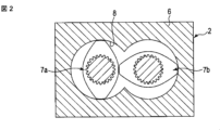
本実施形態では、原料の混練・溶融の度合いを強化するため、第1の押出機2として同方向回転型の二軸混練機を用いている。図2および図3は、二軸混練機の一例を開示している。二軸混練機は、バレル6と、バレル6の内部に収容された二本のスクリュ7a,7bと、を備えている。バレル6は、二つの円筒を組み合わせた形状を有するシリンダ部8を含んでいる。前記樹脂は、バレル6の一端部に設けた供給口9からシリンダ部8に連続的に供給される。さらに、バレル6は、樹脂を溶融するためのヒータを内蔵している。
In this embodiment, a co-rotating twin-screw kneader is used as the first extruder 2 in order to enhance the degree of kneading and melting of the raw materials. 2 and 3 disclose an example of a twin-screw kneader. The twin-screw kneader has a barrel 6 and two
スクリュ7a,7bは、互いに噛み合った状態でシリンダ部8に収容されている。スクリュ7a,7bは、図示しないモータから伝わるトルクを受けて互いに同方向に回転される。図3に示すように、スクリュ7a,7bは、それぞれ、フィード部11、混練部12およびポンピング部13を備えている。フィード部11、混練部12およびポンピング部13は、スクリュ7a,7bの軸方向に沿って一列に並んでいる。
The
フィード部11は、螺旋状に捩じれたフライト14を有している。スクリュ7a,7bのフライト14は、互いに噛み合った状態で回転するとともに、供給口9から供給された再生炭素繊維と樹脂を含む材料を混練部12に向けて搬送する。
The
混練部12は、スクリュ7a,7bの軸方向に並んだ複数のディスク15を有している。スクリュ7a,7bのディスク15は、互いに向かい合った状態で回転するとともに、フィード部11から送られた再生炭素繊維と樹脂を含む材料を予備的に混練する。混練された材料は、スクリュ7a,7bの回転によりポンピング部13に送り込まれる。
The kneading
ポンピング部13は、螺旋状に捩じれたフライト16を有している。スクリュ7a,7bのフライト16は、互いに噛み合った状態で回転するとともに、予備的に混練された材料をバレル6の吐出端から押し出す。
The
このような二軸混練機によると、スクリュ7a,7bのフィード部11に供給された材料中の樹脂は、スクリュ7a,7bの回転に伴うせん断発熱およびヒータの熱を受けて溶融する。二軸混練機での予備的な混練により溶融された樹脂と再生炭素繊維は、ブレンドされた原料を構成する。原料は、図1に矢印Aで示すように、バレル6の吐出端から第2の押出機3に連続的に供給される。
According to such a twin-screw kneader, the resin in the material supplied to the
さらに、第1の押出機2を二軸混練機として構成することで、樹脂を溶融させるだけでなく、樹脂および再生炭素繊維にせん断作用を付与することができる。このため、原料が第2の押出機3に供給される時点で、当該原料は、第1の押出機2での予備的な混練により溶融されて最適な粘度に保たれる。また、第1の押出機2を二軸混練機として構成することで、第2の押出機3に連続して原料を供給する際、単位時間当たりに、所定量の原料を安定して供給することができる。したがって、原料を本格的に混練する第2の押出機3の負担を軽減することができる。 Further, by configuring the first extruder 2 as a twin-screw kneader, it is possible not only to melt the resin but also to apply a shearing action to the resin and the recycled carbon fibers. Therefore, when the raw material is supplied to the second extruder 3, the raw material is melted by preliminary kneading in the first extruder 2 and kept at an optimum viscosity. Further, by configuring the first extruder 2 as a twin-screw kneader, when continuously supplying the raw material to the second extruder 3, a predetermined amount of raw material is stably supplied per unit time. be able to. Therefore, the load on the second extruder 3 that kneads the raw materials in earnest can be reduced.
第2の押出機3は、原料の樹脂成分中に再生炭素繊維が高分散した混練物を生成するための要素である。本実施形態では、第2の押出機3として単軸押出機を用いている。単軸押出機は、バレル20と、一本のスクリュ21と、を備えている。スクリュ21は、溶融された原料にせん断作用および伸長作用を繰り返し付与する機能を有している。スクリュ21を含む第2の押出機3の構成に関しては、後で詳細に説明する。
The second extruder 3 is an element for producing a kneaded material in which recycled carbon fibers are highly dispersed in the resin component of the raw material. In this embodiment, a single screw extruder is used as the second extruder 3 . A single screw extruder has a
第3の押出機4は、第2の押出機3から吐出された混練物に含まれるガス成分を吸引・除去するための要素である。本実施形態では、第3の押出機4として単軸押出機を用いている。図4に示すように、単軸押出機は、バレル22と、バレル22に収容された一本のベントスクリュ23と、を備えている。バレル22は、真っ直ぐな円筒状のシリンダ部24を含んでいる。第2の押出機3から押し出された混練物は、シリンダ部24の軸方向に沿う一端部からシリンダ部24に連続的に供給される。
The third extruder 4 is an element for sucking and removing gas components contained in the kneaded material discharged from the second extruder 3 . In this embodiment, a single screw extruder is used as the third extruder 4 . As shown in FIG. 4, the single-screw extruder has a
バレル22は、ベント口25を有している。ベント口25は、シリンダ部24の軸方向に沿う中間部に開口されているとともに、真空ポンプ26に接続されている。さらに、バレル22のシリンダ部24の他端部は、ヘッド部27で閉塞されている。ヘッド部27は、混練物を吐出させる吐出口28を有している。
ベントスクリュ23は、シリンダ部24に収容されている。ベントスクリュ23は、図示しないモータから伝わるトルクを受けて一方向に回転される。ベントスクリュ23は、螺旋状に捩じれたフライト29を有している。フライト29は、ベントスクリュ23と一体的に回転するとともに、シリンダ部24に供給された混練物をヘッド部27に向けて連続的に搬送する。混練物は、ベント口25に対応する位置に搬送された時に、真空ポンプ26のバキューム圧を受ける。すなわち、真空ポンプによってシリンダ部24内を負圧に引くことで、混練物に含まれるガス状物質やその他の揮発成分が混練物から連続的に吸引・除去される。ガス状物質やその他の揮発成分が取り除かれた混練物は、ヘッド部27の吐出口28から高せん断加工装置1の外に炭素繊維複合材料として連続的に吐出される。
The
次に、第2の押出機3について説明する。
図5、図6に示すように、第2の押出機3のバレル20は、真っ直ぐな筒状であって、水平に配置されている。バレル20は、複数のバレルエレメント31に分割されている。
Next, the second extruder 3 will be explained.
As shown in FIGS. 5 and 6, the
各バレルエレメント31は、円筒状の貫通孔32を有している。バレルエレメント31は、それぞれの貫通孔32が同軸状に連続するようにボルト締結により一体的に結合されている。バレルエレメント31の貫通孔32は、互いに協働してバレル20の内部に円筒状のシリンダ部33を規定している。シリンダ部33は、バレル20の軸方向に延びている。
Each
バレル20の軸方向に沿う一端部に供給口34が形成されている。供給口34は、シリンダ部33に連通するとともに、当該供給口34に第1の押出機2でブレンドされた原料が連続的に供給される。
A
バレル20は、図示しないヒータを備えている。ヒータは、バレル20の温度が原料の混練に最適な値となるようにバレル20の温度を調整する。さらに、バレル20は、例えば水あるいは油のような冷媒が流れる冷媒通路35を備えている。冷媒通路35は、シリンダ部33を取り囲むように配置されている。冷媒は、バレル20の温度が予め決められた上限値を超えた時に冷媒通路35に沿って流れ、バレル20を強制的に冷却する。
The
バレル20の軸方向に沿う他端部は、ヘッド部36で閉塞されている。ヘッド部36は、吐出口36aを有している。吐出口36aは、供給口34に対しバレル20の軸方向に沿う反対側に位置されるとともに、第3の押出機4に接続されている。
The other axial end of the
スクリュ21は、スクリュ本体37を備えている。本実施形態のスクリュ本体37は、一本の回転軸38と、複数の円筒状の筒体39と、で構成されている。
The
回転軸38は、第1の軸部40および第2の軸部41を備えている。第1の軸部40は、バレル20の一端部の側である回転軸38の基端に位置されている。第1の軸部40は、継手部42およびストッパ部43を含んでいる。継手部42は、図示しないカップリングを介してモータのような駆動源に連結される。ストッパ部43は、継手部42に同軸状に設けられている。ストッパ部43は、継手部42よりも径が大きい。
The rotating
第2の軸部41は、第1の軸部40のストッパ部43の端面から同軸状に延びている。第2の軸部41は、バレル20の略全長に亘る長さを有するとともに、ヘッド部36と向かい合う先端を有している。第1の軸部40および第2の軸部41を同軸状に貫通する真っ直ぐな軸線O1は、回転軸38の軸方向に水平に延びている。
The
第2の軸部41は、ストッパ部43よりも径が小さいソリッドな円柱状である。図7に示すように、第2の軸部41の外周面に一対のキー45a,45bが取り付けられている。キー45a,45bは、第2の軸部41の周方向に180°ずれた位置で第2の軸部41の軸方向に延びている。
The
図7、図8に示すように、各筒体39は、第2の軸部41が同軸状に貫通するように構成されている。筒体39の内周面に一対のキー溝49a,49bが形成されている。キー溝49a,49bは、筒体39の周方向に180°ずれた位置で筒体39の軸方向に延びている。
As shown in FIGS. 7 and 8, each
筒体39は、キー溝49a,49bを第2の軸部41のキー45a,45bに合わせた状態で第2の軸部41の先端の方向から第2の軸部41の上に挿入される。本実施形態では、第2の軸部41の上に最初に挿入された筒体39と第1の軸部40のストッパ部43の端面との間に第1のカラー44が介在されている。さらに、全ての筒体39を第2の軸部41の上に挿入した後、第2の軸部41の先端面に第2のカラー51を介して固定ねじ52がねじ込まれている。
The
このねじ込みにより、全ての筒体39が、第1のカラー44と第2のカラー51との間で第2の軸部41の軸方向に締め付けられ、隣り合う筒体39の端面が隙間なく密着されている。
By this screwing, all the
スクリュ本体37は、原料を搬送するための複数の搬送部81と、原料の流動を制限するための複数の障壁部82と、を有している。すなわち、バレル20の一端部に対応するスクリュ本体37の基端に複数の搬送部81が配置され、バレル20の他端部に対応するスクリュ本体37の先端に複数の搬送部81が配置されている。さらに、これら搬送部81の間において、スクリュ本体37の基端から先端に向かって、搬送部81と障壁部82とが軸方向に交互に並べて配置されている。搬送部81と障壁部82とを一組として配置する数により、樹脂と再生炭素繊維との混練工程を繰り返す回数が決定される。
なお、バレル20の供給口34は、スクリュ本体37の基端の側に配置された搬送部81に向けて開口している。
The screw
In addition, the
回転軸38は、第1の軸部40および第2の軸部41を備えている。第1の軸部40は、バレル20の一端部の側である回転軸38の基端に位置されている。第1の軸部40は、継手部42およびストッパ部43を含んでいる。継手部42は、図示しないカップリングを介してモータのような駆動源に連結される。ストッパ部43は、継手部42に同軸状に設けられている。ストッパ部43は、継手部42よりも径が大きい。
The rotating
各搬送部81は、螺旋状に捩じれたフライト84を有している。フライト84は、筒体39の周方向に沿う外周面から搬送路53に向けて張り出している。フライト84は、スクリュ本体37の基端から見てスクリュ21が逆時計回りに左回転した時に、当該スクリュ本体37の基端から先端に向けて原料を搬送するように捩じれている。すなわち、フライト84は、当該フライト84の捩じれ方向が右ねじと同じように右に捩じれている。
Each
各障壁部82は、螺旋状に捩じれたフライト86を有している。フライト86は、筒体39の周方向に沿う外周面から搬送路53に向けて張り出している。フライト86は、スクリュ本体37の基端から見てスクリュ21が逆時計回りに左回転した時に、スクリュ本体37の先端から基端に向けて原料を搬送するように捩じれている。すなわち、フライト86は、当該フライト86の捩じれ方向が左ねじと同じように左に捩じれている。
Each
各障壁部82のフライト86の捩じれピッチは、搬送部81のフライト84の捩じれピッチと同じか、それよりも小さく設定されている。さらに、フライト84、86の頂部とバレル20のシリンダ部33の内周面との間には、僅かなクリアランスが確保されている。
The twist pitch of the
図5、図6、図9に示すように、スクリュ本体37は、スクリュ本体37の軸方向に延びる複数の通路88を有している。通路88は、一つの障壁部82と、当該障壁部82を挟んだ二つの搬送部81とを一つのユニットとすると、双方の搬送部81の筒体39に各ユニットの障壁部82を跨いで形成されている。この場合、通路88は、スクリュ本体37の軸方向に沿った同一の直線上において、所定の間隔(例えば、等間隔)で一列に整列されている。
As shown in FIGS. 5, 6, and 9, the
さらに、通路88は、筒体39の内部において、回転軸38の軸線O1から偏心した位置に設けられている。言い換えると、通路88は、軸線O1から外れており、スクリュ本体37が回転した時に、軸線O1の回りを公転するようになっている。
Further, the
図7に示すように、通路88は、例えば円形の断面形状を有する孔である。通路88は、原料の流通のみを許容する中空の空間として構成されている。通路88の壁面89は、スクリュ本体37が回転した時に、軸線O1を中心に自転することなく軸線O1の回りを公転する。
As shown in FIG. 7,
通路88を円形の断面形状を有する孔とする場合、円の直径は、例えば2~6mm程度に設定すればよい。また、通路88の距離(長さ)は、例えば15~90mm程度に設定すればよい。再生炭素繊維を円滑に通過させると共に、通過させる際に十分なせん断力を付与し再生炭素繊維を分散させる観点から、通路88断面の円の直径は3~5mmが好ましく、通路88の距離は20~40mmが好ましい。
When the
図10に示すように、各通路88は、入口91、出口92、入口91と出口92との間を連通する通路本体93を有している。入口91および出口92は、一つの障壁部82の両側に接近して設けられている。別の捉え方をすると、隣り合う二つの障壁部82の間に隣接した一つの搬送部81において、入口91は、当該搬送部81の下流端の付近の外周面に開口されているとともに、出口92は、当該搬送部81の上流端の付近の外周面に開口されている。一つの搬送部81の外周面において開口されている入口91と出口92とは、通路本体93によって連通されていない。入口91は障壁部82を介して隣り合う下流側の搬送部81の出口92と連通されており、出口92は障壁部82を介して隣り合う上流側の搬送部81の入口91と連通されている。
As shown in FIG. 10, each
図10には、搬送部81のうちスクリュ本体37の搬送部81に対応した箇所の原料の充満率がグラデーションで表されている。すなわち、当該搬送部81において、色調が濃くなる程に原料の充満率が高くなっている。図10から明らかなように、搬送部81において、障壁部82に近づくに従い原料の充満率が高まっており、障壁部82の直前で、原料の充満率が100%となっている。
In FIG. 10 , the filling rate of the raw material at a portion of the conveying
このため、障壁部82の直前で、原料の充満率が100%となる「原料溜まりR」が形成される。原料溜まりRでは、原料の流動が堰き止められたことで、当該原料の圧力が上昇している。圧力が上昇した原料は、図10に破線の矢印で示すように、搬送部81の外周面に開口された入口91から通路88に連続的に流入し、当該通路88内を連続的に流通する。
Therefore, immediately before the
通路88の口径によって規定される通路断面積は、シリンダ部33の径方向に沿う搬送部81の円環断面積よりも遥かに小さい。別の捉え方をすると、通路88の口径に基づく広がり領域は、円環形状の搬送路53の広がり領域よりも遥かに小さい。このため、入口91から通路88に流入する際に、原料が急激に絞られることで、当該原料に伸長作用が付与される。
The passage cross-sectional area defined by the diameter of the
図11に示すように、スクリュ本体37の内部に複数の通路88が並行して設けられた構成としてもよい。複数の通路88を設ける場合、スクリュ本体37に均等に配置することが好ましい。複数の通路88を均等に配置することにより、混練される樹脂及び再生炭素繊維に加わる圧力およびせん断力を均一化し、局所的な温度上昇により樹脂が劣化することを抑制できる。複数の通路88を均等に設ける場合、通路88の入口91および出口92(図8参照)もそれぞれ、スクリュ本体37の外周面に均等に設けられる。
As shown in FIG. 11, a configuration in which a plurality of
図11には、スクリュ本体37の内部に4つの通路88a,88b,88c,88dが並行して、設けられた例を示している。同図に示すように、複数の通路88が均等に配置されるとは、スクリュ本体37の断面の軸線(中心点)O1と隣り合う通路88を結ぶ線の角度が等しいことをいう。O1と隣り合う通路88を結ぶ線の角度は、通路88が4つの場合90°であり、通路88が2つの場合180°である。なお、D1はスクリュ本体37の外径を示している。
FIG. 11 shows an example in which four
第2の押出機3に供給された原料は、図9に矢印Cで示すように、スクリュ本体37の基端の側に位置された搬送部81の外周面に投入される。このとき、スクリュ本体37の基端から見てスクリュ21が逆時計回りに左回転すると、搬送部81のフライト84は、当該原料を、図9に実線の矢印で示すように、スクリュ本体37の先端に向けて連続的に搬送する。
The raw material supplied to the second extruder 3 is introduced into the outer peripheral surface of the conveying
本実施形態では、複数の搬送部81および複数の障壁部82がスクリュ本体37の軸方向に交互に並んでいるとともに、複数の通路88がスクリュ本体37の軸方向に間隔を存して並んでいる。このため、供給口34からスクリュ本体37に投入された原料は、図9および図10に矢印で示すように、せん断作用および伸長作用を交互に繰り返し受けながらスクリュ本体37の基端から先端の方向に連続的に搬送される。よって、原料の混練の度合いが強化され、原料における樹脂と再生炭素繊維の分散化が促進される。
In this embodiment, a plurality of conveying
樹脂と再生炭素繊維との分散化を促進する際に、再生炭素繊維の繊維長が短くなりすぎると、複合材料の引張強度が低くなることがある。そこで、引張強度の高い複合材料とする観点から、再生炭素繊維のアスペクト比が3.4~4.0、好ましくは3.5~3.9となるように、再生炭素繊維の繊維長(D50)が、100μm以上、好ましくは105μm以上となるように、分散化を促進する際の条件を調整する。 If the fiber length of the recycled carbon fibers is too short when promoting dispersion of the resin and the recycled carbon fibers, the composite material may have a low tensile strength. Therefore, from the viewpoint of making a composite material with high tensile strength, the fiber length of the recycled carbon fiber (D50 ) is 100 μm or more, preferably 105 μm or more, the conditions for promoting dispersion are adjusted.
当該条件として、通路88の内径、距離、せん断作用および伸長作用を交互に繰り返す回数などが挙げられる。例えば、内径4mm、距離30mmの通路を4つ備えたスクリュ本体37を用いて、回転数200~500(回転/分間)、搬送を制限する回数(繰り返し回数)2回~4回とすれば、高い強度および弾性を備えた炭素繊維複合材料を製造することができる。本発明において、搬送を制限する回数は、第2の押出機3に設けられている障壁部82の数と同じである。
Such conditions include the inner diameter of the
スクリュ21は、駆動源からのトルクを受けて回転する。機械的特性の良好な炭素繊維複合材料を製造するために好適なスクリュ21の回転数は、スクリュ21の外径によって異なる。一般に、スクリュ21の外径が小さくなるにしたがって、好適な回転数が大きくなる傾向にある。外径が30mm以上50mm以下のスクリュ21を用いる場合、スクリュ21の回転数は、100rpmから1000rpmが好ましく、150rpmから600rpmがより好ましく、200rpmから400rpmがさらに好ましい。
The
本実施形態では、図9に示すように、実線の矢印で示した搬送部81における原料の搬送方向と、破線の矢印で示した通路88内における原料の流通方向とが同じである。また、通路88の入口91が搬送部81における下流側(先端側、図9に向かって左側)の端部近傍に設けられ、出口92は障壁部82を介して隣り合う下流側の搬送部81の上流側の端部近傍に設けられている。このように、障壁部82を跨ぐ通路88の長さL2が短く構成されているから、原料が通路88を通過する際の流動抵抗が低くなる。したがって、本実施形態の製造方法は、粘度の高い原料を用いた樹脂の製造に適しており、再生炭素繊維を高濃度で含有する炭素繊維複合材料の製造方法として好適である。また、再生炭素繊維に代えて、未使用炭素繊維、ガラスファイバー(GF)等の繊維材料を高濃度で含有する炭素繊維複合材料を製造することもできる。
In the present embodiment, as shown in FIG. 9, the material transport direction in the
通路88の長さL2は、当該通路88が跨ぐ障壁部82の長さL1よりも大きい必要があるが、原料が通路88を通過する際の流動抵抗を低くする観点から、当該通路88が跨いでいる障壁部82の長さL1の2倍以下が好ましく、1.5倍以下がより好ましく、1.3倍以下がさらに好ましい。
The length L2 of the
そして、スクリュ本体37の先端に達した原料は、十分に混練された混練物となって、吐出口36aから第3の押出機4に連続的に供給され、当該混練物に含まれるガス状物質やその他の揮発成分が混練物から連続的に除去される。
Then, the raw material reaching the tip of the
[実施例1~14、比較例1]
図1~図11を参照して実施の形態で説明した連続式高せん断加工装置を用いて、再生炭素繊維(適宜、RCFという)と熱可塑性樹脂原料を混練して炭素繊維複合材料を製造した。表1に示すように、再生炭素繊維には市販品(カーボンリサイクル工業(株)製、東レT800相当のグレード-1次加熱品)を使用して、熱可塑性樹脂として、ポリアミド6樹脂(PA6、商品名:アミランCM1017、東レ(株)製)またはポリフェニレンサルファイド樹脂(PPS、商品名:トレリナA900B1、東レ(株)製)を用いた。
[Examples 1 to 14, Comparative Example 1]
A carbon fiber composite material was produced by kneading recycled carbon fiber (hereinafter referred to as RCF) and a thermoplastic resin raw material using the continuous high-shear processing apparatus described in the embodiment with reference to FIGS. 1 to 11. . As shown in Table 1, a commercially available product (manufactured by Carbon Recycle Industry Co., Ltd., grade equivalent to Toray T800-first heated product) is used as the recycled carbon fiber, and polyamide 6 resin (PA6, Trade name: Amilan CM1017, manufactured by Toray Industries, Inc.) or polyphenylene sulfide resin (PPS, trade name: Torelina A900B1, manufactured by Toray Industries, Inc.) was used.
炭素繊維複合材料の製造においては、スクリュ有効長(スクリュ長/スクリュ径)48に対する混練部12のスクリュ有効長を8に設定した第1の押出機2に供給し、予備的に混練することで溶融状態の材料を生成した。そして、その溶融状態の材料を、第2の押出機3の原料として、第1の押出機2から第2の押出機3に連続的に供給し、炭素繊維複合材料を製造した。
In the production of the carbon fiber composite material, it is supplied to the first extruder 2 in which the effective screw length of the kneading
炭素繊維複合材料の製造には、以下の仕様のスクリュ21を備えた第2の押出機3を用い、RCFの含有量(wt%)、通路長(mm)、並列に設けられている通路数、処理回数(回)および回転速度(回転/分間)を表1および表2に記載の設定とした。
スクリュ径(外径):48mm
スクリュ有効長(L/D):6.25~18.75
原料供給量:10kg/時間
バレル設定温度:250℃
入口、出口および通路本体の断面形状:直径4mmの円形
For the production of the carbon fiber composite material, a second extruder 3 equipped with a
Screw diameter (outer diameter): 48 mm
Effective screw length (L/D): 6.25 to 18.75
Raw material supply rate: 10 kg/hour Barrel set temperature: 250°C
Cross-sectional shape of inlet, outlet and passage body: circular with a diameter of 4 mm
上述した条件で製造した炭素繊維複合材料により試験片を作製し、以下の方法により、引張強度、引張弾性率、曲げ強度、曲げ弾性率、複合材料中のRCFの平均繊維長(D50)およびアスペクト比を測定した。結果を表1および表2に示す。
<引張強度>
JIS K 7161に準拠して測定した。
試験片は射出成形により、中央幅が10mm、長さが175mm、厚み4mmのダンベル形状の試験片を作製した。試験片の形状はダンベル状1A号形とした。引張試験は、卓上形精密万能試験機(島津製作所(株)製オートグラフAG-50kN型)を用い、クロスヘッド速度を5mm/分とし、試験片の破断まで荷重を負荷した。引張強度について以下の計算式から算出した。
F=P/W×D
F:強度(MPa)
P:破壊荷重(MPa)
W:試験片の幅(mm)
D:試験片の厚さ(mm)
A test piece was prepared from the carbon fiber composite material produced under the conditions described above, and the tensile strength, tensile modulus, flexural strength, flexural modulus, average fiber length (D50) and aspect of RCF in the composite material were measured by the following methods. ratio was measured. Results are shown in Tables 1 and 2.
<Tensile strength>
Measured according to JIS K 7161.
A dumbbell-shaped specimen having a central width of 10 mm, a length of 175 mm, and a thickness of 4 mm was prepared by injection molding. The shape of the test piece was dumbbell-shaped No. 1A. For the tensile test, a tabletop precision universal testing machine (Autograph AG-50kN, manufactured by Shimadzu Corporation) was used at a crosshead speed of 5 mm/min, and a load was applied until the test piece broke. The tensile strength was calculated from the following formula.
F=P/W×D
F: Strength (MPa)
P: breaking load (MPa)
W: Width of test piece (mm)
D: Thickness of test piece (mm)
<引張弾性率>
引張試験は,JIS K 7161に準拠して実施した。引張弾性率は、試験で得られた応力-歪の関係から、ε1及びε2の歪み2点間に対応する応力/歪み曲線の傾きから求めた。尚、歪は測定前に校正した伸び計(イプシロン社製)にて計測した。
E=((σ2-σ1)/(ε2-ε1))/1000
E:弾性率(GPa)
ε1:歪み0.1%(0.001)
ε2:歪み0.3%(0.003)
σ1:ε1における応力(MPa)
σ2:ε2における応力(MPa)
<Tensile modulus>
The tensile test was performed according to JIS K7161. The tensile modulus was obtained from the slope of the stress/strain curve corresponding to the two strain points of ε1 and ε2 from the stress-strain relationship obtained in the test. The strain was measured with an extensometer (manufactured by Epsilon) calibrated before measurement.
E = ((σ2-σ1)/(ε2-ε1))/1000
E: elastic modulus (GPa)
ε1: strain 0.1% (0.001)
ε2: strain 0.3% (0.003)
σ1: Stress at ε1 (MPa)
σ2: Stress at ε2 (MPa)
<曲げ強度>
JIS K 7171に準拠して測定した。
試験片は射出成形により、幅が10mm、長さが80mm、厚み4mmのダンベル形状の試験片を作製した。曲げ試験は3点曲げとし、卓上形精密万能試験機(島津製作所(株)製オートグラフAG-50kN型)を用いて試験した。クロスヘッド速度を2mm/分とし、試験片の破断まで荷重を負荷した。曲げ強度について以下の計算式から算出した。
F=3×P×L/2×W×D2
F:強度(MPa)
P:破壊荷重(MPa)
L:支点間距離 64mm
W:試験片の幅(mm)
D:試験片の厚さ(mm)
<Bending strength>
Measured according to JIS K 7171.
A dumbbell-shaped test piece having a width of 10 mm, a length of 80 mm, and a thickness of 4 mm was prepared by injection molding. A three-point bending test was performed using a desktop precision universal testing machine (Autograph AG-50kN, manufactured by Shimadzu Corporation). The crosshead speed was set to 2 mm/min, and the load was applied until the test piece broke. The bending strength was calculated from the following formula.
F=3×P×L/2×W×D 2
F: Strength (MPa)
P: breaking load (MPa)
L: Distance between fulcrums 64 mm
W: Width of test piece (mm)
D: Thickness of test piece (mm)
<曲げ弾性率>
曲げ試験は,JIS K 7171に準拠して実施した。曲げ弾性率は、試験で得られた応力-歪み(伸び)の関係から、ε1及びε2の歪み2点間に対応する応力/歪み曲線の傾きから求めた。
E=((σ2-σ1)/(ε2-ε1))/1000
E:弾性率(GPa)
ε1:歪み0.05%(0.0005)
ε2:歪み0.25%(0.0025)
σ1:ε1における応力(MPa)
σ2:ε2における応力(MPa)
<Flexural modulus>
A bending test was performed in accordance with JIS K7171. The flexural modulus was determined from the slope of the stress/strain curve corresponding to the two strain points of ε1 and ε2 from the stress-strain (elongation) relationship obtained in the test.
E = ((σ2-σ1)/(ε2-ε1))/1000
E: elastic modulus (GPa)
ε1: strain 0.05% (0.0005)
ε2: strain 0.25% (0.0025)
σ1: Stress at ε1 (MPa)
σ2: Stress at ε2 (MPa)
<平均繊維長(D50)・アスペクト比>
各条件で得られた混練物を500℃以上の不活性雰囲気下で樹脂を飛ばし、炭素繊維を採取した。得られた炭素繊維をレーザ回折・散乱式粒子径分布測定装置(マイクロトラックベル社製MT3300II)に投入して、繊維分布を測定しメジアン径(D50)を求め、画像解析して、円相当径と長径を測定しアスペクト比を求めた。
<Average fiber length (D50)/aspect ratio>
The kneaded material obtained under each condition was placed in an inert atmosphere at 500° C. or higher to remove the resin and collect carbon fibers. The resulting carbon fiber is put into a laser diffraction/scattering particle size distribution analyzer (MT3300II manufactured by Microtrack Bell Co.) to measure the fiber distribution to determine the median diameter (D50). The aspect ratio was obtained by measuring the major axis and the length.


連続式高せん断加工装置の代わりに、TEM二軸混練押出機(東芝機械(株)製)を用いて、表1の実施例1~3と同じ原料および配合量として、再生炭素繊維(RCF)と熱可塑性樹脂原料を混練した。しかし、炭素繊維複合材料を安定的に連続製造することができなかったため、これらの結果(比較例2~4)は、表1および表2に記載していない。
実施例1(RCF:50重量%)と同じ原料を用いた場合、炭素繊維複合材料(比較例2)を調製することができ、引張強度が265(MPa)、引張弾性率が31(GPa)であったが、試験中はタブ部での破壊が多かった。また、製造中も吐出した炭素繊維複合材料が途中で切れてしまうなど、安定した連続製造はできなかった。結果、一般的なTEM二軸混練押出機では、実施例1~3(RCF:50~65重量%)と同じ原料を用いた炭素繊維複合材料は、連続して製造することができなかった(比較例2~4)。このように、本発明の炭素繊維複合材料は、一般的なTEM二軸混練押出機を用いて製造することは困難であった。
A TEM twin-screw kneading extruder (manufactured by Toshiba Machine Co., Ltd.) was used instead of the continuous high-shear processing device, and the raw materials and blending amounts were the same as in Examples 1 to 3 in Table 1. Recycled carbon fiber (RCF) and thermoplastic resin raw materials were kneaded. However, these results (Comparative Examples 2 to 4) are not shown in Tables 1 and 2 because the carbon fiber composite material could not be produced stably and continuously.
When the same raw material as in Example 1 (RCF: 50% by weight) is used, a carbon fiber composite material (Comparative Example 2) can be prepared, which has a tensile strength of 265 (MPa) and a tensile modulus of 31 (GPa). However, there were many breakages at the tab portion during the test. In addition, stable continuous production was not possible because the carbon fiber composite material discharged was broken during production. As a result, with a general TEM twin-screw kneading extruder, carbon fiber composite materials using the same raw materials as in Examples 1 to 3 (RCF: 50 to 65% by weight) could not be continuously produced ( Comparative Examples 2-4). Thus, it was difficult to produce the carbon fiber composite material of the present invention using a general TEM twin-screw kneading extruder.
表1の実施例1~14に示したように、連続式高せん断加工装置を用いることにより、再生炭素繊維の含有量が50~65重量%の炭素繊維複合材料を連続して製造することができた。同じ原料について、連続式高せん断加工装置を用いて調製した実施例1と、TEM二軸混練押出機との比較から、連続式高せん断加工装置を用いて得られた炭素繊維複合材料は、TEM二軸混練押出機を用いて製造した炭素繊維複合材料よりも引張強度が低下する傾向があった(実施例1:197MPa、比較例2:265MPa)。これは、樹脂と再生炭素繊維を高分散する工程において、再生炭素繊維の繊維長が短くなったためと考えられる。ただし、再生炭素繊維の含有量を大きくすることによって、炭素繊維複合材料の引張弾性率を向上させることができた。 As shown in Examples 1 to 14 in Table 1, a carbon fiber composite material containing 50 to 65% by weight of recycled carbon fiber can be continuously produced by using a continuous high shear processing device. did it. For the same raw material, a comparison between Example 1 prepared using a continuous high shear processing device and a TEM twin-screw kneading extruder shows that the carbon fiber composite material obtained using the continuous high shear processing device is TEM Tensile strength tended to be lower than that of carbon fiber composite materials produced using a twin-screw kneading extruder (Example 1: 197 MPa, Comparative Example 2: 265 MPa). This is probably because the fiber length of the recycled carbon fibers was shortened in the step of highly dispersing the resin and the recycled carbon fibers. However, by increasing the content of recycled carbon fibers, the tensile modulus of the carbon fiber composite material could be improved.
炭素繊維複合材料の引張強度は、繰り返し数や、回転速度等の製造条件に影響される。製造条件のなかでは、回転速度の影響が大きかった。
原料にせん断力を付与するための通路の数を増やすことにより、炭素繊維複合材料の引張強度が向上する傾向が認められた。引張強度が高い炭素繊維複合材料を製造するためには、通路を複数設けて、高せん断加工時の回転数を低くすることが好ましい。
The tensile strength of a carbon fiber composite material is affected by manufacturing conditions such as the number of repetitions and rotation speed. Among the manufacturing conditions, the rotational speed had a large effect.
It was found that the tensile strength of the carbon fiber composite material tends to be improved by increasing the number of passages for applying shear force to the raw material. In order to produce a carbon fiber composite material with high tensile strength, it is preferable to provide a plurality of passages and reduce the rotational speed during high shear processing.
炭素繊維複合材料中に含まれるRCFのアスペクト比および繊維長(D50)は、炭素繊維複合材料の引張強度を評価する指標となる。高せん断加工により、RCFの繊維長が短くなりすぎないようにすることが、炭素繊維複合材料の引張強度を高くするために有効であった。
引張強度および引張弾性率が良好な炭素繊維複合材料は、曲げ強度および曲げ弾性率も良好であった。
The aspect ratio and fiber length (D50) of the RCF contained in the carbon fiber composite material are indices for evaluating the tensile strength of the carbon fiber composite material. It was effective in increasing the tensile strength of the carbon fiber composite material to prevent the fiber length of the RCF from being excessively shortened by high shear processing.
Carbon fiber composite materials with good tensile strength and tensile modulus also had good flexural strength and flexural modulus.
実施例12の炭素繊維複合化材料を用いて作製した成形体について、以下の方法により異方性を測定した。測定結果を表3に示す。 The anisotropy of the molded article produced using the carbon fiber composite material of Example 12 was measured by the following method. Table 3 shows the measurement results.
<異方性評価>
射出成形により、200mm×200mmの厚み4mmの平板を作製し、金型内を溶融樹脂が流れる方向(MD)および、その直角方法(TD)に、中央部分から引張試験に用いたダンベル形状の試験片を機械加工にて切出し、上述した方法により引張強度(JIS K 7161)および引張弾性率(JIS K 7161)を測定した。
<Anisotropy evaluation>
A flat plate with a thickness of 200 mm × 200 mm and a thickness of 4 mm is produced by injection molding, and the direction (MD) in which the molten resin flows in the mold and the direction (TD) at right angles to it are measured from the center part. A piece was cut out by machining, and the tensile strength (JIS K 7161) and tensile elastic modulus (JIS K 7161) were measured by the method described above.
[比較例5]
実施例12の炭素繊維複合材料の代わりに、市販の炭素繊維複合材料(製品名:PYLOFIL、三菱ケミカル(株)製、未使用炭素繊維が30%、PA6が70%)を用いて射出成形により同じ形状の平板を作製し、実施例12と同様の条件・方法により異方性を測定した。測定結果を表4に示す。
[Comparative Example 5]
Instead of the carbon fiber composite material of Example 12, injection molding using a commercially available carbon fiber composite material (product name: PYLOFIL, manufactured by Mitsubishi Chemical Corporation, 30% unused carbon fiber, 70% PA6) A flat plate having the same shape was produced, and the anisotropy was measured under the same conditions and method as in Example 12. Table 4 shows the measurement results.

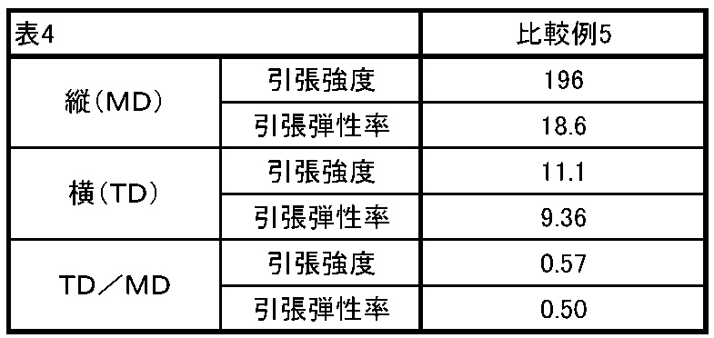
成形体の異方性は、異なる方向に切り出した成形体の特性の違いで評価することができ、縦(MD)と横(TD)の特性の比(TD/MD)が1.0に近い程、成形品の異方性が小さい。表3および表4に示すように、実施例12の成形体は、比較例5の成形体よりも、引張強度および引張弾性の異方性が小さかった。連続式高せん断加工装置を用いることで、RCFを高濃度で配合しても高分散し、炭素繊維複合化材料の異方性が抑制されたものといえる。 The anisotropy of the molded body can be evaluated by the difference in the properties of the molded body cut in different directions, and the ratio of the longitudinal (MD) to the transverse (TD) properties (TD/MD) is close to 1.0. The smaller the anisotropy of the molded product. As shown in Tables 3 and 4, the molded article of Example 12 had smaller anisotropy of tensile strength and tensile elasticity than the molded article of Comparative Example 5. It can be said that the use of the continuous high-shear processing device enabled the RCF to be highly dispersed even when blended at a high concentration, thereby suppressing the anisotropy of the carbon fiber composite material.
(実施例12、14および比較例5~9)
上述した実施例12、14の成形品の曲げ弾性率、引張強度、比剛性および比強度を測定した。また、未使用炭素繊維:30%とPA6:70%との炭素繊維複合材料(比較例5)、ガラス繊維とPPSとの複合材料(比較例6)、PPSの成形品(比較例7)、アルミダイキャスト(比較例8、Al-DC)およびマグネシウムダイキャスト(比較例9、Mg-DC)それぞれの成形品についても同様にして、曲げ弾性率、引張強度、比剛性および比強度を測定した。これらの曲げ弾性率、引張強度、比剛性および比強度とあわせて、表5、図12(a)および図12(b)に示す。比剛性は、曲げ弾性率の3乗根を比重で割って規格化した値であり、比強度は引張強度を比重で割って規格化した値である。
(Examples 12, 14 and Comparative Examples 5-9)
The flexural modulus, tensile strength, specific stiffness and specific strength of the molded articles of Examples 12 and 14 described above were measured. In addition, a carbon fiber composite material of unused carbon fiber: 30% and PA6: 70% (Comparative Example 5), a composite material of glass fiber and PPS (Comparative Example 6), a PPS molded product (Comparative Example 7), The flexural modulus, tensile strength, specific stiffness and specific strength were measured in the same manner for aluminum die-cast (Comparative Example 8, Al-DC) and magnesium die-cast (Comparative Example 9, Mg-DC) molded products. . These flexural modulus, tensile strength, specific stiffness and specific strength are shown in Table 5, Figures 12(a) and 12(b). The specific stiffness is a normalized value obtained by dividing the cube root of the flexural modulus by the specific gravity, and the specific strength is a normalized value obtained by dividing the tensile strength by the specific gravity.
<導電性の評価>
実施例12および比較例5の炭素繊維複合材料の導電率をJIS K 7194に準拠して測定した。結果を表5に示す。
導電率測定では、測定用の試験片として、射出成形により平板を作製した。導電率は、低抵抗抵抗率計を用いて各試験片について5点測定した。1個の試験片から5個の抵抗率が算出されるので、15個の抵抗率が算出される。この15個の抵抗率を平均した値を導電率とした。
作製条件:温度260℃、
試験片 :長さ60mm、幅60mm、厚み4mm
<Evaluation of conductivity>
The electrical conductivity of the carbon fiber composite materials of Example 12 and Comparative Example 5 was measured according to JIS K 7194. Table 5 shows the results.
In the conductivity measurement, a flat plate was prepared by injection molding as a test piece for measurement. Conductivity was measured at 5 points for each test piece using a low resistance resistivity meter. Since five resistivities are calculated from one test piece, 15 resistivities are calculated. A value obtained by averaging these 15 resistivities was defined as conductivity.
Production conditions: temperature 260°C,
Test piece:

表5、図12(a)および図12(b)に示すように、実施例12、14の炭素繊維複合材料は、再生炭素繊維の含有量を60重量%とすることにより、200(MPa)を超える高い引張強度を実現できた。また、実施例12の炭素繊維複合材料の比強度および比剛性は、アルミニウムダイキャスト(Al-DC)およびマグネシウムダイキャスト(Mg-DC)と同等以上であった。 As shown in Table 5, FIG. 12(a) and FIG. 12(b), the carbon fiber composite materials of Examples 12 and 14 had 200 (MPa) It was possible to achieve a high tensile strength exceeding In addition, the specific strength and specific rigidity of the carbon fiber composite material of Example 12 were equal to or higher than those of aluminum die-cast (Al-DC) and magnesium die-cast (Mg-DC).
また、実施例12の炭素繊維複合材料は、非常に高い導電率を有していた。これは、実施例12の炭素繊維複合材料が60重量%という高濃度の再生炭素繊維を含有することによると考えられる。すなわち、上述したように再生炭素繊維(RCF)は、未使用炭素繊維(CF)よりも樹脂との親和性が低く、その表面が樹脂の層で覆われていない。このため、再生炭素繊維を用いることにより、導電性を有する再生炭素繊維同士が直接的に接触する面積が広くなる。したがって、再生炭素繊維(RCF)を60重量%含有する実施例1の炭素繊維複合材料が、未使用炭素繊維(CF)を30重量%含有する比較例5の炭素
繊維複合材料の約40倍という極めて高い導電性を実現できたといえる。
Also, the carbon fiber composite material of Example 12 had a very high electrical conductivity. This is probably because the carbon fiber composite material of Example 12 contains a high concentration of recycled carbon fibers of 60% by weight. That is, as described above, recycled carbon fiber (RCF) has a lower affinity for resin than virgin carbon fiber (CF), and its surface is not covered with a layer of resin. Therefore, by using recycled carbon fibers, the area where conductive recycled carbon fibers are in direct contact with each other is increased. Therefore, the carbon fiber composite material of Example 1 containing 60% by weight of recycled carbon fiber (RCF) is about 40 times the carbon fiber composite material of Comparative Example 5 containing 30% by weight of virgin carbon fiber (CF). It can be said that extremely high conductivity was achieved.
以上のように本発明の炭素繊維複合材料は、従来の未使用炭素繊維(CF)を用いた材料と比べて非常に高い導電性を有している。このため、例えば、静電気防止、電磁波シールド性、あるいは放熱性が要求される成形品の材料として有用である。 As described above, the carbon fiber composite material of the present invention has a very high electrical conductivity compared to conventional materials using virgin carbon fibers (CF). Therefore, it is useful, for example, as a material for molded articles that require antistatic properties, electromagnetic wave shielding properties, or heat dissipation properties.
1:高せん断加工装置 2:第1の押出機 3:第2の押出機 4:第3の押出機
6:バレル 7a,7b:スクリュ 8:シリンダ部 9:供給口 11:フィード部
12:混練部 13:ポンピング部 14:フライト 15:ディスク 16:フライト
20:バレル 21:スクリュ 22:バレル 23:ベントスクリュ
24:シリンダ部 25:ベント口 26:真空ポンプ 27:ヘッド部 28:吐出口
29:フライト 31:バレルエレメント 32:貫通孔 33:シリンダ部
34:供給口 35:冷媒通路 36:ヘッド部 36a:吐出口 37:スクリュ本体
38:回転軸 39:筒体 40:第1の軸部 41:第2の軸部 42:継手部
43:ストッパ部 44:第1のカラー 45a,45b:キー
49a,49b:キー溝 51:第2のカラー 52:固定ねじ 53:搬送路
81:搬送部 82:障壁部 84,86:フライト
88,88a,88b,88c,88d:通路 89:壁面 91:入口 92:出口
93:通路本体 O1:軸線
1: high shear processing device 2: first extruder 3: second extruder 4: third extruder
6:
12: Kneading part 13: Pumping part 14: Flight 15: Disk 16: Flight 20: Barrel 21: Screw 22: Barrel 23: Bent screw
24: Cylinder part 25: Vent port 26: Vacuum pump 27: Head part 28: Discharge port 29: Flight 31: Barrel element 32: Through hole 33: Cylinder part
34: Supply port 35: Refrigerant passage 36:
49a, 49b: keyway 51: second collar 52: fixing screw 53: transport path
81: Conveyor 82:
88, 88a, 88b, 88c, 88d: Passage 89: Wall surface 91: Inlet 92: Outlet 93: Passage body O1: Axis
Claims (7)
前記炭素繊維複合材料における前記再生炭素繊維の含有量が58~70重量%であり、
射出成形時における流れ方向をMD、前記流れ方向に対する直角方向をTDとしたとき、引張強度の比(TD/MD)が0.75以上、および/または引張弾性の比(TD/MD)が0.85以上であることを特徴とする成形体。 A molded article molded by injection molding a carbon fiber composite material containing resin and recycled carbon fiber,
The content of the recycled carbon fiber in the carbon fiber composite material is 58 to 70% by weight ,
A tensile strength ratio (TD/MD) of 0.75 or more and/or a tensile elasticity ratio (TD/MD) of 0, where MD is the flow direction during injection molding and TD is the direction perpendicular to the flow direction. .85 or more .
請求項1に記載の成形体。 2. The molded article according to claim 1, wherein the recycled carbon fibers have an average aspect ratio of 3.4 to 4.0.
請求項2に記載の成形体。 The molded article according to claim 2, wherein the recycled carbon fiber has a fiber length (D50) of 100 to 150 µm.
請求項3に記載の成形体。 The molded article according to claim 3, wherein the resin is a thermoplastic resin.
前記外周面に設けられた障壁部により前記原料の搬送を制限して、前記スクリュ本体により前記原料にせん断力を加えるとともに、前記外周面に設けられた前記通路の入口から前記通路の出口へ通過させて前記原料に伸長力を加えて炭素繊維複合材料とし、
前記炭素繊維複合材料を射出成形して請求項1に記載の成形体とする、成形体の製造方法。 When conveying a raw material containing 58 to 70% by weight of recycled carbon fiber along the outer peripheral surface of the screw body having a passage inside ,
The feed of the raw material is restricted by the barrier portion provided on the outer peripheral surface, the raw material is applied with a shearing force by the screw body, and the raw material passes from the inlet of the passage provided on the outer peripheral surface to the outlet of the passage. and applying an elongation force to the raw material to form a carbon fiber composite material,
A method for producing a molded article, comprising injection-molding the carbon fiber composite material to obtain the molded article according to claim 1 .
請求項5に記載の成形体の製造方法。 A plurality of passages are provided in parallel inside the screw body.
The method for producing a molded article according to claim 5 .
請求項5に記載の成形体の製造方法。 The number of revolutions of the screw body is 200 to 500 (rotations/minute), and the number of times of limiting the transportation of the raw material is 2 to 4 times.
The method for producing a molded article according to claim 5 .
Priority Applications (6)
| Application Number | Priority Date | Filing Date | Title |
|---|---|---|---|
| JP2019095502A JP7294882B2 (en) | 2019-05-21 | 2019-05-21 | Molded article containing recycled carbon fiber and method for producing molded article |
| PCT/JP2020/019673 WO2020235533A1 (en) | 2019-05-21 | 2020-05-18 | Carbon fiber composite material containing recycled carbon fibers, molded body, and method for producing carbon fiber composite material |
| US17/612,559 US20220305704A1 (en) | 2019-05-21 | 2020-05-18 | Carbon fiber composite material containing recycled carbon fibers, molded body, and method for producing carbon fiber composite material |
| CN202080036449.7A CN113840711B (en) | 2019-05-21 | 2020-05-18 | Molded article and method for producing same |
| TW109116445A TWI754935B (en) | 2019-05-21 | 2020-05-18 | Carbon fiber composite material containing recycled carbon fiber, formed body, and manufacturing method of carbon fiber composite material |
| KR1020217040993A KR20220010521A (en) | 2019-05-21 | 2020-05-18 | Carbon fiber composite material containing recycled carbon fiber, molded article and method for producing carbon fiber composite material |
Applications Claiming Priority (1)
| Application Number | Priority Date | Filing Date | Title |
|---|---|---|---|
| JP2019095502A JP7294882B2 (en) | 2019-05-21 | 2019-05-21 | Molded article containing recycled carbon fiber and method for producing molded article |
Publications (2)
| Publication Number | Publication Date |
|---|---|
| JP2020189916A JP2020189916A (en) | 2020-11-26 |
| JP7294882B2 true JP7294882B2 (en) | 2023-06-20 |
Family
ID=73453389
Family Applications (1)
| Application Number | Title | Priority Date | Filing Date |
|---|---|---|---|
| JP2019095502A Active JP7294882B2 (en) | 2019-05-21 | 2019-05-21 | Molded article containing recycled carbon fiber and method for producing molded article |
Country Status (6)
| Country | Link |
|---|---|
| US (1) | US20220305704A1 (en) |
| JP (1) | JP7294882B2 (en) |
| KR (1) | KR20220010521A (en) |
| CN (1) | CN113840711B (en) |
| TW (1) | TWI754935B (en) |
| WO (1) | WO2020235533A1 (en) |
Families Citing this family (4)
| Publication number | Priority date | Publication date | Assignee | Title |
|---|---|---|---|---|
| JP6639798B2 (en) * | 2014-05-08 | 2020-02-05 | 東芝機械株式会社 | Screw for extruder, extruder and extrusion method |
| JP6639800B2 (en) * | 2014-05-08 | 2020-02-05 | 東芝機械株式会社 | Screw for extruder, extruder and extrusion method |
| JP6446234B2 (en) * | 2014-10-27 | 2018-12-26 | 東芝機械株式会社 | Screw for extruder, screw element, extruder and extrusion method |
| US20240033974A1 (en) | 2021-08-31 | 2024-02-01 | Shibaura Machine Co., Ltd. | Method for producing fiber-reinforced composite material |
Citations (7)
| Publication number | Priority date | Publication date | Assignee | Title |
|---|---|---|---|---|
| JP2000318004A (en) | 1999-05-10 | 2000-11-21 | Mitsubishi Heavy Ind Ltd | Injection device for injection molding machine |
| JP2012533503A (en) | 2009-07-17 | 2012-12-27 | カーボン ファイバー プリフォームズ リミテッド | Fiber matrix and method for producing fiber matrix |
| JP2015007212A (en) | 2013-05-30 | 2015-01-15 | エフテックス有限会社 | Manufacturing method of polyester-carbon fiber copolymer |
| JP2015214143A (en) | 2014-04-24 | 2015-12-03 | 東芝機械株式会社 | Extruder screw, and extruder and extrusion method |
| JP2015227051A (en) | 2014-05-08 | 2015-12-17 | 東芝機械株式会社 | Screw for extruder, extruder and extrusion method |
| JP2016521295A (en) | 2013-03-28 | 2016-07-21 | イーエルジー カーボン ファイバー インターナショナル ゲーエムベーハー | Pyrolysis system and method for recovering carbon fiber from carbon fiber-containing resin |
| JP2020143228A (en) | 2019-03-07 | 2020-09-10 | 住友ベークライト株式会社 | Molding for screwing |
Family Cites Families (8)
| Publication number | Priority date | Publication date | Assignee | Title |
|---|---|---|---|---|
| US8685537B2 (en) * | 2009-03-16 | 2014-04-01 | Toray Industries, Inc. | Fiber reinforced resin composition, molding material, and method for producing fiber reinforced resin composition |
| WO2013013070A2 (en) * | 2011-07-21 | 2013-01-24 | Entegris, Inc. | Nanotube and finely milled carbon fiber polymer composite compositions and methods of making |
| CN103709703A (en) * | 2013-12-11 | 2014-04-09 | 上海交通大学 | Recycled carbon fiber reinforced thermoplastic resin composite material and preparation method thereof |
| CN104861563A (en) * | 2014-10-17 | 2015-08-26 | 青岛欣展塑胶有限公司 | Modified PTT/carbon fiber composite material and preparation method therefor |
| JP6764225B2 (en) | 2015-10-23 | 2020-09-30 | カーボンファイバーリサイクル工業株式会社 | Manufacturing method of recycled carbon fiber |
| CN105199379B (en) * | 2015-10-27 | 2017-12-19 | 北京纳盛通新材料科技有限公司 | A kind of continuous long carbon fiber enhancing nanocomposite and its preparation method and application |
| CN109476910B (en) * | 2016-07-13 | 2022-06-24 | Ems 专利股份公司 | Conductive thermoplastic polyamide molding materials |
| CN108807786B (en) * | 2017-05-04 | 2020-05-15 | 宁波昌祺微滤膜科技有限公司 | Reinforcing film for battery isolation and preparation method thereof |
-
2019
- 2019-05-21 JP JP2019095502A patent/JP7294882B2/en active Active
-
2020
- 2020-05-18 CN CN202080036449.7A patent/CN113840711B/en active Active
- 2020-05-18 US US17/612,559 patent/US20220305704A1/en active Pending
- 2020-05-18 TW TW109116445A patent/TWI754935B/en active
- 2020-05-18 KR KR1020217040993A patent/KR20220010521A/en not_active Application Discontinuation
- 2020-05-18 WO PCT/JP2020/019673 patent/WO2020235533A1/en active Application Filing
Patent Citations (7)
| Publication number | Priority date | Publication date | Assignee | Title |
|---|---|---|---|---|
| JP2000318004A (en) | 1999-05-10 | 2000-11-21 | Mitsubishi Heavy Ind Ltd | Injection device for injection molding machine |
| JP2012533503A (en) | 2009-07-17 | 2012-12-27 | カーボン ファイバー プリフォームズ リミテッド | Fiber matrix and method for producing fiber matrix |
| JP2016521295A (en) | 2013-03-28 | 2016-07-21 | イーエルジー カーボン ファイバー インターナショナル ゲーエムベーハー | Pyrolysis system and method for recovering carbon fiber from carbon fiber-containing resin |
| JP2015007212A (en) | 2013-05-30 | 2015-01-15 | エフテックス有限会社 | Manufacturing method of polyester-carbon fiber copolymer |
| JP2015214143A (en) | 2014-04-24 | 2015-12-03 | 東芝機械株式会社 | Extruder screw, and extruder and extrusion method |
| JP2015227051A (en) | 2014-05-08 | 2015-12-17 | 東芝機械株式会社 | Screw for extruder, extruder and extrusion method |
| JP2020143228A (en) | 2019-03-07 | 2020-09-10 | 住友ベークライト株式会社 | Molding for screwing |
Also Published As
| Publication number | Publication date |
|---|---|
| JP2020189916A (en) | 2020-11-26 |
| US20220305704A1 (en) | 2022-09-29 |
| KR20220010521A (en) | 2022-01-25 |
| CN113840711B (en) | 2023-09-22 |
| TWI754935B (en) | 2022-02-11 |
| CN113840711A (en) | 2021-12-24 |
| WO2020235533A1 (en) | 2020-11-26 |
| TW202043003A (en) | 2020-12-01 |
Similar Documents
| Publication | Publication Date | Title |
|---|---|---|
| JP7294882B2 (en) | Molded article containing recycled carbon fiber and method for producing molded article | |
| TWI818021B (en) | Kneading method for conductive composite material | |
| JP7093681B2 (en) | Kneading method and kneaded product | |
| JP4786648B2 (en) | Manufacturing method of resin composition with high concentration of fibrous filler and resin composition pellet | |
| KR20070092625A (en) | Kneading extruder | |
| JP5781533B2 (en) | Screw elements for extrusion of viscoelastic composites | |
| Zander et al. | Rubber toughened recycled polyethylene terephthalate for material extrusion additive manufacturing | |
| WO2017203943A1 (en) | Fiber-containing particulate resin structure, method for producing fiber-containing particulate resin structure, cured fiber-reinforced resin product, and fiber-reinforced resin molded article | |
| US20050063246A1 (en) | Mixing and kneading device for polymer compositions | |
| WO2019198479A1 (en) | Kneading method and kneaded material | |
| TWI496675B (en) | Glass fiber reinforced thermoplastic synthetic resin composites for the production of compressed products | |
| JP7382047B2 (en) | Manufacturing method of fiber reinforced composite material | |
| WO2023234220A1 (en) | Method for producing thermoplastic resin composition | |
| JP5032244B2 (en) | Apparatus for producing fiber-reinforced thermoplastic resin composition and method for producing the same | |
| JPH09235382A (en) | Raw material for electromagnetic wave-shielding material and its production | |
| US9533432B2 (en) | Just-in-time compounding in an injection molding machine | |
| JP2024030243A (en) | Fibrous filler stirring supply device, supply method, manufacturing method, and manufacturing method of thermoplastic resin composition | |
| JP2023138391A (en) | Carbon fiber reinforced thermoplastic resin molded product | |
| TW202404785A (en) | Method for producing thermoplastic resin composition | |
| CN113286689A (en) | Single extruder barrel designed to accommodate compounding, chemical reactions and immiscible polymer blends with solids coated with one polymer |
Legal Events
| Date | Code | Title | Description |
|---|---|---|---|
| A621 | Written request for application examination |
Free format text: JAPANESE INTERMEDIATE CODE: A621 Effective date: 20220405 |
|
| A131 | Notification of reasons for refusal |
Free format text: JAPANESE INTERMEDIATE CODE: A131 Effective date: 20230110 |
|
| A521 | Request for written amendment filed |
Free format text: JAPANESE INTERMEDIATE CODE: A523 Effective date: 20230217 |
|
| TRDD | Decision of grant or rejection written | ||
| A01 | Written decision to grant a patent or to grant a registration (utility model) |
Free format text: JAPANESE INTERMEDIATE CODE: A01 Effective date: 20230523 |
|
| A61 | First payment of annual fees (during grant procedure) |
Free format text: JAPANESE INTERMEDIATE CODE: A61 Effective date: 20230608 |
|
| R150 | Certificate of patent or registration of utility model |
Ref document number: 7294882 Country of ref document: JP Free format text: JAPANESE INTERMEDIATE CODE: R150 |