JP7294550B2 - Adhesive film, electricity storage device, and method for producing electricity storage device - Google Patents
Adhesive film, electricity storage device, and method for producing electricity storage device Download PDFInfo
- Publication number
- JP7294550B2 JP7294550B2 JP2022576553A JP2022576553A JP7294550B2 JP 7294550 B2 JP7294550 B2 JP 7294550B2 JP 2022576553 A JP2022576553 A JP 2022576553A JP 2022576553 A JP2022576553 A JP 2022576553A JP 7294550 B2 JP7294550 B2 JP 7294550B2
- Authority
- JP
- Japan
- Prior art keywords
- storage device
- layer
- heat
- electricity storage
- adhesive film
- Prior art date
- Legal status (The legal status is an assumption and is not a legal conclusion. Google has not performed a legal analysis and makes no representation as to the accuracy of the status listed.)
- Active
Links
- 238000003860 storage Methods 0.000 title claims description 278
- 239000002313 adhesive film Substances 0.000 title claims description 179
- 230000005611 electricity Effects 0.000 title claims description 170
- 238000004519 manufacturing process Methods 0.000 title claims description 13
- 229920005989 resin Polymers 0.000 claims description 271
- 239000011347 resin Substances 0.000 claims description 271
- 239000000463 material Substances 0.000 claims description 151
- -1 polyethylene Polymers 0.000 claims description 115
- 238000002844 melting Methods 0.000 claims description 99
- 230000008018 melting Effects 0.000 claims description 98
- 229920000098 polyolefin Polymers 0.000 claims description 45
- 230000004888 barrier function Effects 0.000 claims description 39
- 239000004698 Polyethylene Substances 0.000 claims description 27
- 238000007789 sealing Methods 0.000 claims description 26
- 238000000034 method Methods 0.000 claims description 23
- 229920000573 polyethylene Polymers 0.000 claims description 22
- 239000000758 substrate Substances 0.000 claims description 19
- 229920001225 polyester resin Polymers 0.000 claims description 5
- 239000004645 polyester resin Substances 0.000 claims description 5
- 239000010410 layer Substances 0.000 description 493
- 239000010408 film Substances 0.000 description 42
- 239000004743 Polypropylene Substances 0.000 description 34
- 229920001155 polypropylene Polymers 0.000 description 30
- 229920001707 polybutylene terephthalate Polymers 0.000 description 29
- 229920001971 elastomer Polymers 0.000 description 28
- 239000000806 elastomer Substances 0.000 description 26
- 239000012790 adhesive layer Substances 0.000 description 25
- 239000000853 adhesive Substances 0.000 description 23
- 230000001070 adhesive effect Effects 0.000 description 23
- 229920000728 polyester Polymers 0.000 description 22
- 229920001577 copolymer Polymers 0.000 description 21
- 229910052751 metal Inorganic materials 0.000 description 21
- 239000002184 metal Substances 0.000 description 21
- 239000007789 gas Substances 0.000 description 18
- 125000004122 cyclic group Chemical group 0.000 description 15
- 229920005672 polyolefin resin Polymers 0.000 description 14
- 238000012360 testing method Methods 0.000 description 14
- 229920002647 polyamide Polymers 0.000 description 13
- 239000004952 Polyamide Substances 0.000 description 12
- PPBRXRYQALVLMV-UHFFFAOYSA-N Styrene Chemical compound C=CC1=CC=CC=C1 PPBRXRYQALVLMV-UHFFFAOYSA-N 0.000 description 12
- 150000001408 amides Chemical class 0.000 description 11
- 230000000694 effects Effects 0.000 description 11
- 238000005259 measurement Methods 0.000 description 11
- 239000000203 mixture Substances 0.000 description 11
- 229920000139 polyethylene terephthalate Polymers 0.000 description 11
- OKTJSMMVPCPJKN-UHFFFAOYSA-N Carbon Chemical compound [C] OKTJSMMVPCPJKN-UHFFFAOYSA-N 0.000 description 10
- 239000000178 monomer Substances 0.000 description 10
- 239000000945 filler Substances 0.000 description 9
- 229920000642 polymer Polymers 0.000 description 9
- LYCAIKOWRPUZTN-UHFFFAOYSA-N Ethylene glycol Chemical compound OCCO LYCAIKOWRPUZTN-UHFFFAOYSA-N 0.000 description 8
- PXHVJJICTQNCMI-UHFFFAOYSA-N Nickel Chemical compound [Ni] PXHVJJICTQNCMI-UHFFFAOYSA-N 0.000 description 8
- 230000001747 exhibiting effect Effects 0.000 description 8
- 230000002093 peripheral effect Effects 0.000 description 8
- 239000000049 pigment Substances 0.000 description 8
- 239000004677 Nylon Substances 0.000 description 7
- VYPSYNLAJGMNEJ-UHFFFAOYSA-N Silicium dioxide Chemical compound O=[Si]=O VYPSYNLAJGMNEJ-UHFFFAOYSA-N 0.000 description 7
- 229910052799 carbon Inorganic materials 0.000 description 7
- 239000000314 lubricant Substances 0.000 description 7
- 229920001778 nylon Polymers 0.000 description 7
- KAKZBPTYRLMSJV-UHFFFAOYSA-N Butadiene Chemical compound C=CC=C KAKZBPTYRLMSJV-UHFFFAOYSA-N 0.000 description 6
- VGGSQFUCUMXWEO-UHFFFAOYSA-N Ethene Chemical compound C=C VGGSQFUCUMXWEO-UHFFFAOYSA-N 0.000 description 6
- 239000005977 Ethylene Substances 0.000 description 6
- RRHGJUQNOFWUDK-UHFFFAOYSA-N Isoprene Chemical compound CC(=C)C=C RRHGJUQNOFWUDK-UHFFFAOYSA-N 0.000 description 6
- KKEYFWRCBNTPAC-UHFFFAOYSA-N Terephthalic acid Chemical compound OC(=O)C1=CC=C(C(O)=O)C=C1 KKEYFWRCBNTPAC-UHFFFAOYSA-N 0.000 description 6
- 238000010438 heat treatment Methods 0.000 description 6
- QQVIHTHCMHWDBS-UHFFFAOYSA-N isophthalic acid Chemical compound OC(=O)C1=CC=CC(C(O)=O)=C1 QQVIHTHCMHWDBS-UHFFFAOYSA-N 0.000 description 6
- 150000001336 alkenes Chemical class 0.000 description 5
- 229920001400 block copolymer Polymers 0.000 description 5
- 230000001965 increasing effect Effects 0.000 description 5
- 229910052757 nitrogen Inorganic materials 0.000 description 5
- JFNLZVQOOSMTJK-KNVOCYPGSA-N norbornene Chemical compound C1[C@@H]2CC[C@H]1C=C2 JFNLZVQOOSMTJK-KNVOCYPGSA-N 0.000 description 5
- HBBGRARXTFLTSG-UHFFFAOYSA-N Lithium ion Chemical compound [Li+] HBBGRARXTFLTSG-UHFFFAOYSA-N 0.000 description 4
- 229910052782 aluminium Inorganic materials 0.000 description 4
- XAGFODPZIPBFFR-UHFFFAOYSA-N aluminium Chemical compound [Al] XAGFODPZIPBFFR-UHFFFAOYSA-N 0.000 description 4
- 150000008064 anhydrides Chemical class 0.000 description 4
- 239000003990 capacitor Substances 0.000 description 4
- 239000000470 constituent Substances 0.000 description 4
- MGNZXYYWBUKAII-UHFFFAOYSA-N cyclohexa-1,3-diene Chemical compound C1CC=CC=C1 MGNZXYYWBUKAII-UHFFFAOYSA-N 0.000 description 4
- ZSWFCLXCOIISFI-UHFFFAOYSA-N cyclopentadiene Chemical compound C1C=CC=C1 ZSWFCLXCOIISFI-UHFFFAOYSA-N 0.000 description 4
- 238000004512 die casting Methods 0.000 description 4
- 229910001416 lithium ion Inorganic materials 0.000 description 4
- FPYJFEHAWHCUMM-UHFFFAOYSA-N maleic anhydride Chemical compound O=C1OC(=O)C=C1 FPYJFEHAWHCUMM-UHFFFAOYSA-N 0.000 description 4
- 229910052759 nickel Inorganic materials 0.000 description 4
- 239000004814 polyurethane Substances 0.000 description 4
- QQONPFPTGQHPMA-UHFFFAOYSA-N propylene Natural products CC=C QQONPFPTGQHPMA-UHFFFAOYSA-N 0.000 description 4
- 125000004805 propylene group Chemical group [H]C([H])([H])C([H])([*:1])C([H])([H])[*:2] 0.000 description 4
- 229920005604 random copolymer Polymers 0.000 description 4
- 150000004671 saturated fatty acids Chemical class 0.000 description 4
- 239000007787 solid Substances 0.000 description 4
- 150000004670 unsaturated fatty acids Chemical class 0.000 description 4
- 235000021122 unsaturated fatty acids Nutrition 0.000 description 4
- 238000007740 vapor deposition Methods 0.000 description 4
- HECLRDQVFMWTQS-RGOKHQFPSA-N 1755-01-7 Chemical compound C1[C@H]2[C@@H]3CC=C[C@@H]3[C@@H]1C=C2 HECLRDQVFMWTQS-RGOKHQFPSA-N 0.000 description 3
- WSQZNZLOZXSBHA-UHFFFAOYSA-N 3,8-dioxabicyclo[8.2.2]tetradeca-1(12),10,13-triene-2,9-dione Chemical group O=C1OCCCCOC(=O)C2=CC=C1C=C2 WSQZNZLOZXSBHA-UHFFFAOYSA-N 0.000 description 3
- LLLVZDVNHNWSDS-UHFFFAOYSA-N 4-methylidene-3,5-dioxabicyclo[5.2.2]undeca-1(9),7,10-triene-2,6-dione Chemical group C1(C2=CC=C(C(=O)OC(=C)O1)C=C2)=O LLLVZDVNHNWSDS-UHFFFAOYSA-N 0.000 description 3
- 229920000178 Acrylic resin Polymers 0.000 description 3
- 239000004925 Acrylic resin Substances 0.000 description 3
- 238000004566 IR spectroscopy Methods 0.000 description 3
- 229920000459 Nitrile rubber Polymers 0.000 description 3
- 239000004840 adhesive resin Substances 0.000 description 3
- 229920006223 adhesive resin Polymers 0.000 description 3
- 125000003118 aryl group Chemical group 0.000 description 3
- 125000004432 carbon atom Chemical group C* 0.000 description 3
- 230000000052 comparative effect Effects 0.000 description 3
- 150000001875 compounds Chemical class 0.000 description 3
- 238000013461 design Methods 0.000 description 3
- 238000010586 diagram Methods 0.000 description 3
- 239000003792 electrolyte Substances 0.000 description 3
- 239000008151 electrolyte solution Substances 0.000 description 3
- 238000011156 evaluation Methods 0.000 description 3
- 239000011888 foil Substances 0.000 description 3
- 229910002804 graphite Inorganic materials 0.000 description 3
- 239000010439 graphite Substances 0.000 description 3
- QQVIHTHCMHWDBS-UHFFFAOYSA-L isophthalate(2-) Chemical compound [O-]C(=O)C1=CC=CC(C([O-])=O)=C1 QQVIHTHCMHWDBS-UHFFFAOYSA-L 0.000 description 3
- 238000010030 laminating Methods 0.000 description 3
- 238000003475 lamination Methods 0.000 description 3
- 238000002156 mixing Methods 0.000 description 3
- 239000004745 nonwoven fabric Substances 0.000 description 3
- TWNQGVIAIRXVLR-UHFFFAOYSA-N oxo(oxoalumanyloxy)alumane Chemical compound O=[Al]O[Al]=O TWNQGVIAIRXVLR-UHFFFAOYSA-N 0.000 description 3
- 229920000058 polyacrylate Polymers 0.000 description 3
- 239000005020 polyethylene terephthalate Substances 0.000 description 3
- 229920006124 polyolefin elastomer Polymers 0.000 description 3
- 229920002635 polyurethane Polymers 0.000 description 3
- 239000000377 silicon dioxide Substances 0.000 description 3
- 238000010998 test method Methods 0.000 description 3
- 229920002725 thermoplastic elastomer Polymers 0.000 description 3
- LIKMAJRDDDTEIG-UHFFFAOYSA-N 1-hexene Chemical compound CCCCC=C LIKMAJRDDDTEIG-UHFFFAOYSA-N 0.000 description 2
- NIXOWILDQLNWCW-UHFFFAOYSA-N 2-Propenoic acid Natural products OC(=O)C=C NIXOWILDQLNWCW-UHFFFAOYSA-N 0.000 description 2
- WSSSPWUEQFSQQG-UHFFFAOYSA-N 4-methyl-1-pentene Chemical compound CC(C)CC=C WSSSPWUEQFSQQG-UHFFFAOYSA-N 0.000 description 2
- IJGRMHOSHXDMSA-UHFFFAOYSA-N Atomic nitrogen Chemical compound N#N IJGRMHOSHXDMSA-UHFFFAOYSA-N 0.000 description 2
- VTYYLEPIZMXCLO-UHFFFAOYSA-L Calcium carbonate Chemical compound [Ca+2].[O-]C([O-])=O VTYYLEPIZMXCLO-UHFFFAOYSA-L 0.000 description 2
- RTZKZFJDLAIYFH-UHFFFAOYSA-N Diethyl ether Chemical compound CCOCC RTZKZFJDLAIYFH-UHFFFAOYSA-N 0.000 description 2
- YCKRFDGAMUMZLT-UHFFFAOYSA-N Fluorine atom Chemical compound [F] YCKRFDGAMUMZLT-UHFFFAOYSA-N 0.000 description 2
- XEEYBQQBJWHFJM-UHFFFAOYSA-N Iron Chemical compound [Fe] XEEYBQQBJWHFJM-UHFFFAOYSA-N 0.000 description 2
- UQSXHKLRYXJYBZ-UHFFFAOYSA-N Iron oxide Chemical compound [Fe]=O UQSXHKLRYXJYBZ-UHFFFAOYSA-N 0.000 description 2
- 229920002292 Nylon 6 Polymers 0.000 description 2
- 229920002302 Nylon 6,6 Polymers 0.000 description 2
- 239000005062 Polybutadiene Substances 0.000 description 2
- 239000004642 Polyimide Substances 0.000 description 2
- 239000004721 Polyphenylene oxide Substances 0.000 description 2
- OFOBLEOULBTSOW-UHFFFAOYSA-N Propanedioic acid Natural products OC(=O)CC(O)=O OFOBLEOULBTSOW-UHFFFAOYSA-N 0.000 description 2
- 239000002253 acid Substances 0.000 description 2
- 229920000800 acrylic rubber Polymers 0.000 description 2
- 230000009471 action Effects 0.000 description 2
- 239000000654 additive Substances 0.000 description 2
- 230000000996 additive effect Effects 0.000 description 2
- WNLRTRBMVRJNCN-UHFFFAOYSA-L adipate(2-) Chemical compound [O-]C(=O)CCCCC([O-])=O WNLRTRBMVRJNCN-UHFFFAOYSA-L 0.000 description 2
- WNLRTRBMVRJNCN-UHFFFAOYSA-N adipic acid Chemical compound OC(=O)CCCCC(O)=O WNLRTRBMVRJNCN-UHFFFAOYSA-N 0.000 description 2
- 230000008901 benefit Effects 0.000 description 2
- IISBACLAFKSPIT-UHFFFAOYSA-N bisphenol A Chemical compound C=1C=C(O)C=CC=1C(C)(C)C1=CC=C(O)C=C1 IISBACLAFKSPIT-UHFFFAOYSA-N 0.000 description 2
- PXKLMJQFEQBVLD-UHFFFAOYSA-N bisphenol F Chemical compound C1=CC(O)=CC=C1CC1=CC=C(O)C=C1 PXKLMJQFEQBVLD-UHFFFAOYSA-N 0.000 description 2
- NTXGQCSETZTARF-UHFFFAOYSA-N buta-1,3-diene;prop-2-enenitrile Chemical compound C=CC=C.C=CC#N NTXGQCSETZTARF-UHFFFAOYSA-N 0.000 description 2
- WERYXYBDKMZEQL-UHFFFAOYSA-N butane-1,4-diol Chemical compound OCCCCO WERYXYBDKMZEQL-UHFFFAOYSA-N 0.000 description 2
- 238000004040 coloring Methods 0.000 description 2
- 230000007797 corrosion Effects 0.000 description 2
- 238000005260 corrosion Methods 0.000 description 2
- 230000006866 deterioration Effects 0.000 description 2
- 235000014113 dietary fatty acids Nutrition 0.000 description 2
- 229910001873 dinitrogen Inorganic materials 0.000 description 2
- 238000004146 energy storage Methods 0.000 description 2
- 230000002708 enhancing effect Effects 0.000 description 2
- 239000003822 epoxy resin Substances 0.000 description 2
- 239000000194 fatty acid Substances 0.000 description 2
- 229930195729 fatty acid Natural products 0.000 description 2
- 239000011737 fluorine Substances 0.000 description 2
- 229910052731 fluorine Inorganic materials 0.000 description 2
- MSYLJRIXVZCQHW-UHFFFAOYSA-N formaldehyde;6-phenyl-1,3,5-triazine-2,4-diamine Chemical compound O=C.NC1=NC(N)=NC(C=2C=CC=CC=2)=N1 MSYLJRIXVZCQHW-UHFFFAOYSA-N 0.000 description 2
- LNEPOXFFQSENCJ-UHFFFAOYSA-N haloperidol Chemical compound C1CC(O)(C=2C=CC(Cl)=CC=2)CCN1CCCC(=O)C1=CC=C(F)C=C1 LNEPOXFFQSENCJ-UHFFFAOYSA-N 0.000 description 2
- 229920001903 high density polyethylene Polymers 0.000 description 2
- 239000004700 high-density polyethylene Substances 0.000 description 2
- 230000006872 improvement Effects 0.000 description 2
- 239000011256 inorganic filler Substances 0.000 description 2
- 229910052809 inorganic oxide Inorganic materials 0.000 description 2
- 239000012948 isocyanate Substances 0.000 description 2
- 229920000092 linear low density polyethylene Polymers 0.000 description 2
- 239000004707 linear low-density polyethylene Substances 0.000 description 2
- 229920001684 low density polyethylene Polymers 0.000 description 2
- 239000004702 low-density polyethylene Substances 0.000 description 2
- 229920001179 medium density polyethylene Polymers 0.000 description 2
- 239000004701 medium-density polyethylene Substances 0.000 description 2
- XMYQHJDBLRZMLW-UHFFFAOYSA-N methanolamine Chemical class NCO XMYQHJDBLRZMLW-UHFFFAOYSA-N 0.000 description 2
- 238000000465 moulding Methods 0.000 description 2
- SJYNFBVQFBRSIB-UHFFFAOYSA-N norbornadiene Chemical compound C1=CC2C=CC1C2 SJYNFBVQFBRSIB-UHFFFAOYSA-N 0.000 description 2
- JRZJOMJEPLMPRA-UHFFFAOYSA-N olefin Natural products CCCCCCCC=C JRZJOMJEPLMPRA-UHFFFAOYSA-N 0.000 description 2
- 239000012766 organic filler Substances 0.000 description 2
- 239000002245 particle Substances 0.000 description 2
- 229920001568 phenolic resin Polymers 0.000 description 2
- 239000005011 phenolic resin Substances 0.000 description 2
- 229920003023 plastic Polymers 0.000 description 2
- 239000004033 plastic Substances 0.000 description 2
- 229920003207 poly(ethylene-2,6-naphthalate) Polymers 0.000 description 2
- 229920006122 polyamide resin Polymers 0.000 description 2
- 229920002857 polybutadiene Polymers 0.000 description 2
- 239000004417 polycarbonate Substances 0.000 description 2
- 229920000515 polycarbonate Polymers 0.000 description 2
- 229920000647 polyepoxide Polymers 0.000 description 2
- 229920000570 polyether Polymers 0.000 description 2
- 229920001601 polyetherimide Polymers 0.000 description 2
- 239000011112 polyethylene naphthalate Substances 0.000 description 2
- 229920001721 polyimide Polymers 0.000 description 2
- 229920005629 polypropylene homopolymer Polymers 0.000 description 2
- 229920001296 polysiloxane Polymers 0.000 description 2
- 239000000047 product Substances 0.000 description 2
- 230000009467 reduction Effects 0.000 description 2
- GHMLBKRAJCXXBS-UHFFFAOYSA-N resorcinol Chemical compound OC1=CC=CC(O)=C1 GHMLBKRAJCXXBS-UHFFFAOYSA-N 0.000 description 2
- 239000005060 rubber Substances 0.000 description 2
- CXMXRPHRNRROMY-UHFFFAOYSA-N sebacic acid Chemical compound OC(=O)CCCCCCCCC(O)=O CXMXRPHRNRROMY-UHFFFAOYSA-N 0.000 description 2
- 229920002379 silicone rubber Polymers 0.000 description 2
- 229920006132 styrene block copolymer Polymers 0.000 description 2
- 239000000126 substance Substances 0.000 description 2
- 239000013589 supplement Substances 0.000 description 2
- 229920001897 terpolymer Polymers 0.000 description 2
- 238000009823 thermal lamination Methods 0.000 description 2
- 230000007704 transition Effects 0.000 description 2
- XLYOFNOQVPJJNP-UHFFFAOYSA-N water Chemical compound O XLYOFNOQVPJJNP-UHFFFAOYSA-N 0.000 description 2
- 239000013585 weight reducing agent Substances 0.000 description 2
- 230000002087 whitening effect Effects 0.000 description 2
- 150000007934 α,β-unsaturated carboxylic acids Chemical class 0.000 description 2
- 239000004711 α-olefin Substances 0.000 description 2
- DNIAPMSPPWPWGF-VKHMYHEASA-N (+)-propylene glycol Chemical compound C[C@H](O)CO DNIAPMSPPWPWGF-VKHMYHEASA-N 0.000 description 1
- OYUBNQOGHWGLJB-WRBBJXAJSA-N (13z,33z)-hexatetraconta-13,33-dienediamide Chemical compound NC(=O)CCCCCCCCCCC\C=C/CCCCCCCCCCCCCCCCCC\C=C/CCCCCCCCCCCC(N)=O OYUBNQOGHWGLJB-WRBBJXAJSA-N 0.000 description 1
- RRKODOZNUZCUBN-CCAGOZQPSA-N (1z,3z)-cycloocta-1,3-diene Chemical compound C1CC\C=C/C=C\C1 RRKODOZNUZCUBN-CCAGOZQPSA-N 0.000 description 1
- PRBHEGAFLDMLAL-GQCTYLIASA-N (4e)-hexa-1,4-diene Chemical compound C\C=C\CC=C PRBHEGAFLDMLAL-GQCTYLIASA-N 0.000 description 1
- OJOWICOBYCXEKR-KRXBUXKQSA-N (5e)-5-ethylidenebicyclo[2.2.1]hept-2-ene Chemical compound C1C2C(=C/C)/CC1C=C2 OJOWICOBYCXEKR-KRXBUXKQSA-N 0.000 description 1
- MXJJJAKXVVAHKI-WRBBJXAJSA-N (9z,29z)-octatriaconta-9,29-dienediamide Chemical compound NC(=O)CCCCCCC\C=C/CCCCCCCCCCCCCCCCCC\C=C/CCCCCCCC(N)=O MXJJJAKXVVAHKI-WRBBJXAJSA-N 0.000 description 1
- CPUBMKFFRRFXIP-YPAXQUSRSA-N (9z,33z)-dotetraconta-9,33-dienediamide Chemical compound NC(=O)CCCCCCC\C=C/CCCCCCCCCCCCCCCCCCCCCC\C=C/CCCCCCCC(N)=O CPUBMKFFRRFXIP-YPAXQUSRSA-N 0.000 description 1
- VZGOTNLOZGRSJA-ZZEZOPTASA-N (z)-n-octadecyloctadec-9-enamide Chemical compound CCCCCCCCCCCCCCCCCCNC(=O)CCCCCCC\C=C/CCCCCCCC VZGOTNLOZGRSJA-ZZEZOPTASA-N 0.000 description 1
- ZTNJGMFHJYGMDR-UHFFFAOYSA-N 1,2-diisocyanatoethane Chemical compound O=C=NCCN=C=O ZTNJGMFHJYGMDR-UHFFFAOYSA-N 0.000 description 1
- YPFDHNVEDLHUCE-UHFFFAOYSA-N 1,3-propanediol Substances OCCCO YPFDHNVEDLHUCE-UHFFFAOYSA-N 0.000 description 1
- RDYWHMBYTHVOKZ-UHFFFAOYSA-N 18-hydroxyoctadecanamide Chemical compound NC(=O)CCCCCCCCCCCCCCCCCO RDYWHMBYTHVOKZ-UHFFFAOYSA-N 0.000 description 1
- XHSVWKJCURCWFU-UHFFFAOYSA-N 19-[3-(19-amino-19-oxononadecyl)phenyl]nonadecanamide Chemical compound NC(=O)CCCCCCCCCCCCCCCCCCC1=CC=CC(CCCCCCCCCCCCCCCCCCC(N)=O)=C1 XHSVWKJCURCWFU-UHFFFAOYSA-N 0.000 description 1
- STMDPCBYJCIZOD-UHFFFAOYSA-N 2-(2,4-dinitroanilino)-4-methylpentanoic acid Chemical compound CC(C)CC(C(O)=O)NC1=CC=C([N+]([O-])=O)C=C1[N+]([O-])=O STMDPCBYJCIZOD-UHFFFAOYSA-N 0.000 description 1
- SMZOUWXMTYCWNB-UHFFFAOYSA-N 2-(2-methoxy-5-methylphenyl)ethanamine Chemical compound COC1=CC=C(C)C=C1CCN SMZOUWXMTYCWNB-UHFFFAOYSA-N 0.000 description 1
- JAHNSTQSQJOJLO-UHFFFAOYSA-N 2-(3-fluorophenyl)-1h-imidazole Chemical compound FC1=CC=CC(C=2NC=CN=2)=C1 JAHNSTQSQJOJLO-UHFFFAOYSA-N 0.000 description 1
- FWWXYLGCHHIKNY-UHFFFAOYSA-N 2-ethoxyethyl prop-2-enoate Chemical compound CCOCCOC(=O)C=C FWWXYLGCHHIKNY-UHFFFAOYSA-N 0.000 description 1
- HFCUBKYHMMPGBY-UHFFFAOYSA-N 2-methoxyethyl prop-2-enoate Chemical compound COCCOC(=O)C=C HFCUBKYHMMPGBY-UHFFFAOYSA-N 0.000 description 1
- WMRCTEPOPAZMMN-UHFFFAOYSA-N 2-undecylpropanedioic acid Chemical compound CCCCCCCCCCCC(C(O)=O)C(O)=O WMRCTEPOPAZMMN-UHFFFAOYSA-N 0.000 description 1
- YMTYZTXUZLQUSF-UHFFFAOYSA-N 3,3'-Dimethylbisphenol A Chemical compound C1=C(O)C(C)=CC(C(C)(C)C=2C=C(C)C(O)=CC=2)=C1 YMTYZTXUZLQUSF-UHFFFAOYSA-N 0.000 description 1
- LZFNKJKBRGFWDU-UHFFFAOYSA-N 3,6-dioxabicyclo[6.3.1]dodeca-1(12),8,10-triene-2,7-dione Chemical compound O=C1OCCOC(=O)C2=CC=CC1=C2 LZFNKJKBRGFWDU-UHFFFAOYSA-N 0.000 description 1
- ZVSXNPBSZYQDKJ-UHFFFAOYSA-N 3,8-dioxabicyclo[8.3.1]tetradeca-1(14),10,12-triene-2,9-dione Chemical compound O=C1OCCCCOC(=O)C2=CC=CC1=C2 ZVSXNPBSZYQDKJ-UHFFFAOYSA-N 0.000 description 1
- FVUKYCZRWSQGAS-UHFFFAOYSA-N 3-carbamoylbenzoic acid Chemical compound NC(=O)C1=CC=CC(C(O)=O)=C1 FVUKYCZRWSQGAS-UHFFFAOYSA-N 0.000 description 1
- OFNISBHGPNMTMS-UHFFFAOYSA-N 3-methylideneoxolane-2,5-dione Chemical compound C=C1CC(=O)OC1=O OFNISBHGPNMTMS-UHFFFAOYSA-N 0.000 description 1
- UPMLOUAZCHDJJD-UHFFFAOYSA-N 4,4'-Diphenylmethane Diisocyanate Chemical compound C1=CC(N=C=O)=CC=C1CC1=CC=C(N=C=O)C=C1 UPMLOUAZCHDJJD-UHFFFAOYSA-N 0.000 description 1
- WTQBISBWKRKLIJ-UHFFFAOYSA-N 5-methylidenebicyclo[2.2.1]hept-2-ene Chemical compound C1C2C(=C)CC1C=C2 WTQBISBWKRKLIJ-UHFFFAOYSA-N 0.000 description 1
- NLHHRLWOUZZQLW-UHFFFAOYSA-N Acrylonitrile Chemical compound C=CC#N NLHHRLWOUZZQLW-UHFFFAOYSA-N 0.000 description 1
- GVNWZKBFMFUVNX-UHFFFAOYSA-N Adipamide Chemical compound NC(=O)CCCCC(N)=O GVNWZKBFMFUVNX-UHFFFAOYSA-N 0.000 description 1
- 229910000838 Al alloy Inorganic materials 0.000 description 1
- 239000004953 Aliphatic polyamide Substances 0.000 description 1
- 229920001634 Copolyester Polymers 0.000 description 1
- ORAWFNKFUWGRJG-UHFFFAOYSA-N Docosanamide Chemical compound CCCCCCCCCCCCCCCCCCCCCC(N)=O ORAWFNKFUWGRJG-UHFFFAOYSA-N 0.000 description 1
- 239000004593 Epoxy Substances 0.000 description 1
- JIGUQPWFLRLWPJ-UHFFFAOYSA-N Ethyl acrylate Chemical compound CCOC(=O)C=C JIGUQPWFLRLWPJ-UHFFFAOYSA-N 0.000 description 1
- JOYRKODLDBILNP-UHFFFAOYSA-N Ethyl urethane Chemical compound CCOC(N)=O JOYRKODLDBILNP-UHFFFAOYSA-N 0.000 description 1
- 101000576320 Homo sapiens Max-binding protein MNT Proteins 0.000 description 1
- UFHFLCQGNIYNRP-UHFFFAOYSA-N Hydrogen Chemical compound [H][H] UFHFLCQGNIYNRP-UHFFFAOYSA-N 0.000 description 1
- JHWNWJKBPDFINM-UHFFFAOYSA-N Laurolactam Chemical compound O=C1CCCCCCCCCCCN1 JHWNWJKBPDFINM-UHFFFAOYSA-N 0.000 description 1
- 239000004594 Masterbatch (MB) Substances 0.000 description 1
- 229920000877 Melamine resin Polymers 0.000 description 1
- CERQOIWHTDAKMF-UHFFFAOYSA-N Methacrylic acid Chemical compound CC(=C)C(O)=O CERQOIWHTDAKMF-UHFFFAOYSA-N 0.000 description 1
- 238000005481 NMR spectroscopy Methods 0.000 description 1
- 229920000299 Nylon 12 Polymers 0.000 description 1
- 229920003189 Nylon 4,6 Polymers 0.000 description 1
- 229920000305 Nylon 6,10 Polymers 0.000 description 1
- CBENFWSGALASAD-UHFFFAOYSA-N Ozone Chemical compound [O-][O+]=O CBENFWSGALASAD-UHFFFAOYSA-N 0.000 description 1
- ISWSIDIOOBJBQZ-UHFFFAOYSA-N Phenol Chemical compound OC1=CC=CC=C1 ISWSIDIOOBJBQZ-UHFFFAOYSA-N 0.000 description 1
- 229920000616 Poly(1,4-butylene adipate) Polymers 0.000 description 1
- 239000004697 Polyetherimide Substances 0.000 description 1
- 229920002367 Polyisobutene Polymers 0.000 description 1
- 239000004793 Polystyrene Substances 0.000 description 1
- 229920006121 Polyxylylene adipamide Polymers 0.000 description 1
- XUIMIQQOPSSXEZ-UHFFFAOYSA-N Silicon Chemical compound [Si] XUIMIQQOPSSXEZ-UHFFFAOYSA-N 0.000 description 1
- GWEVSGVZZGPLCZ-UHFFFAOYSA-N Titan oxide Chemical compound O=[Ti]=O GWEVSGVZZGPLCZ-UHFFFAOYSA-N 0.000 description 1
- RTAQQCXQSZGOHL-UHFFFAOYSA-N Titanium Chemical compound [Ti] RTAQQCXQSZGOHL-UHFFFAOYSA-N 0.000 description 1
- 229920001807 Urea-formaldehyde Polymers 0.000 description 1
- 229920006311 Urethane elastomer Polymers 0.000 description 1
- HCHKCACWOHOZIP-UHFFFAOYSA-N Zinc Chemical compound [Zn] HCHKCACWOHOZIP-UHFFFAOYSA-N 0.000 description 1
- DUCFBDUJLLKKPR-UHFFFAOYSA-N [O--].[Zn++].[Ag+] Chemical compound [O--].[Zn++].[Ag+] DUCFBDUJLLKKPR-UHFFFAOYSA-N 0.000 description 1
- 125000005396 acrylic acid ester group Chemical group 0.000 description 1
- 230000010062 adhesion mechanism Effects 0.000 description 1
- 239000001361 adipic acid Substances 0.000 description 1
- 235000011037 adipic acid Nutrition 0.000 description 1
- 125000002723 alicyclic group Chemical group 0.000 description 1
- 229920003231 aliphatic polyamide Polymers 0.000 description 1
- WNROFYMDJYEPJX-UHFFFAOYSA-K aluminium hydroxide Chemical compound [OH-].[OH-].[OH-].[Al+3] WNROFYMDJYEPJX-UHFFFAOYSA-K 0.000 description 1
- QVGXLLKOCUKJST-UHFFFAOYSA-N atomic oxygen Chemical compound [O] QVGXLLKOCUKJST-UHFFFAOYSA-N 0.000 description 1
- 229910002113 barium titanate Inorganic materials 0.000 description 1
- JRPBQTZRNDNNOP-UHFFFAOYSA-N barium titanate Chemical compound [Ba+2].[Ba+2].[O-][Ti]([O-])([O-])[O-] JRPBQTZRNDNNOP-UHFFFAOYSA-N 0.000 description 1
- 230000015572 biosynthetic process Effects 0.000 description 1
- CQEYYJKEWSMYFG-UHFFFAOYSA-N butyl acrylate Chemical compound CCCCOC(=O)C=C CQEYYJKEWSMYFG-UHFFFAOYSA-N 0.000 description 1
- 229910052793 cadmium Inorganic materials 0.000 description 1
- RDVQTQJAUFDLFA-UHFFFAOYSA-N cadmium Chemical compound [Cd][Cd][Cd][Cd][Cd][Cd][Cd][Cd][Cd] RDVQTQJAUFDLFA-UHFFFAOYSA-N 0.000 description 1
- 229910000019 calcium carbonate Inorganic materials 0.000 description 1
- AXCZMVOFGPJBDE-UHFFFAOYSA-L calcium dihydroxide Chemical compound [OH-].[OH-].[Ca+2] AXCZMVOFGPJBDE-UHFFFAOYSA-L 0.000 description 1
- 239000000920 calcium hydroxide Substances 0.000 description 1
- 229910001861 calcium hydroxide Inorganic materials 0.000 description 1
- XFWJKVMFIVXPKK-UHFFFAOYSA-N calcium;oxido(oxo)alumane Chemical compound [Ca+2].[O-][Al]=O.[O-][Al]=O XFWJKVMFIVXPKK-UHFFFAOYSA-N 0.000 description 1
- 239000006229 carbon black Substances 0.000 description 1
- 150000001732 carboxylic acid derivatives Chemical class 0.000 description 1
- 150000001735 carboxylic acids Chemical class 0.000 description 1
- 150000001768 cations Chemical class 0.000 description 1
- 238000006243 chemical reaction Methods 0.000 description 1
- 238000006757 chemical reactions by type Methods 0.000 description 1
- PMMYEEVYMWASQN-IMJSIDKUSA-N cis-4-Hydroxy-L-proline Chemical compound O[C@@H]1CN[C@H](C(O)=O)C1 PMMYEEVYMWASQN-IMJSIDKUSA-N 0.000 description 1
- 239000003086 colorant Substances 0.000 description 1
- 238000004891 communication Methods 0.000 description 1
- 238000003851 corona treatment Methods 0.000 description 1
- 238000005336 cracking Methods 0.000 description 1
- 238000004132 cross linking Methods 0.000 description 1
- LDHQCZJRKDOVOX-NSCUHMNNSA-N crotonic acid Chemical compound C\C=C\C(O)=O LDHQCZJRKDOVOX-NSCUHMNNSA-N 0.000 description 1
- 238000002425 crystallisation Methods 0.000 description 1
- 230000008025 crystallization Effects 0.000 description 1
- 238000005520 cutting process Methods 0.000 description 1
- QYQADNCHXSEGJT-UHFFFAOYSA-N cyclohexane-1,1-dicarboxylate;hydron Chemical compound OC(=O)C1(C(O)=O)CCCCC1 QYQADNCHXSEGJT-UHFFFAOYSA-N 0.000 description 1
- FOTKYAAJKYLFFN-UHFFFAOYSA-N decane-1,10-diol Chemical compound OCCCCCCCCCCO FOTKYAAJKYLFFN-UHFFFAOYSA-N 0.000 description 1
- 230000032798 delamination Effects 0.000 description 1
- 238000004925 denaturation Methods 0.000 description 1
- 230000036425 denaturation Effects 0.000 description 1
- 150000001991 dicarboxylic acids Chemical class 0.000 description 1
- 150000001993 dienes Chemical class 0.000 description 1
- 125000005442 diisocyanate group Chemical group 0.000 description 1
- 239000004205 dimethyl polysiloxane Substances 0.000 description 1
- 150000002009 diols Chemical class 0.000 description 1
- 208000028659 discharge Diseases 0.000 description 1
- VVTXSHLLIKXMPY-UHFFFAOYSA-L disodium;2-sulfobenzene-1,3-dicarboxylate Chemical compound [Na+].[Na+].OS(=O)(=O)C1=C(C([O-])=O)C=CC=C1C([O-])=O VVTXSHLLIKXMPY-UHFFFAOYSA-L 0.000 description 1
- GZCKIUIIYCBICZ-UHFFFAOYSA-L disodium;benzene-1,3-dicarboxylate Chemical compound [Na+].[Na+].[O-]C(=O)C1=CC=CC(C([O-])=O)=C1 GZCKIUIIYCBICZ-UHFFFAOYSA-L 0.000 description 1
- 238000004090 dissolution Methods 0.000 description 1
- ILRSCQWREDREME-UHFFFAOYSA-N dodecanamide Chemical compound CCCCCCCCCCCC(N)=O ILRSCQWREDREME-UHFFFAOYSA-N 0.000 description 1
- 238000004049 embossing Methods 0.000 description 1
- UAUDZVJPLUQNMU-KTKRTIGZSA-N erucamide Chemical compound CCCCCCCC\C=C/CCCCCCCCCCCC(N)=O UAUDZVJPLUQNMU-KTKRTIGZSA-N 0.000 description 1
- 125000001495 ethyl group Chemical group [H]C([H])([H])C([H])([H])* 0.000 description 1
- JXZAVFLAOZYIOR-UHFFFAOYSA-N ethyl octadecanoate;octadecanamide Chemical compound CCCCCCCCCCCCCCCCCC(N)=O.CCCCCCCCCCCCCCCCCC(=O)OCC JXZAVFLAOZYIOR-UHFFFAOYSA-N 0.000 description 1
- 238000004880 explosion Methods 0.000 description 1
- 238000001125 extrusion Methods 0.000 description 1
- IVJISJACKSSFGE-UHFFFAOYSA-N formaldehyde;1,3,5-triazine-2,4,6-triamine Chemical compound O=C.NC1=NC(N)=NC(N)=N1 IVJISJACKSSFGE-UHFFFAOYSA-N 0.000 description 1
- VOZRXNHHFUQHIL-UHFFFAOYSA-N glycidyl methacrylate Chemical compound CC(=C)C(=O)OCC1CO1 VOZRXNHHFUQHIL-UHFFFAOYSA-N 0.000 description 1
- 238000010559 graft polymerization reaction Methods 0.000 description 1
- FEEPBTVZSYQUDP-UHFFFAOYSA-N heptatriacontanediamide Chemical compound NC(=O)CCCCCCCCCCCCCCCCCCCCCCCCCCCCCCCCCCCC(N)=O FEEPBTVZSYQUDP-UHFFFAOYSA-N 0.000 description 1
- RKVQXYMNVZNJHZ-UHFFFAOYSA-N hexacosanediamide Chemical compound NC(=O)CCCCCCCCCCCCCCCCCCCCCCCCC(N)=O RKVQXYMNVZNJHZ-UHFFFAOYSA-N 0.000 description 1
- HSEMFIZWXHQJAE-UHFFFAOYSA-N hexadecanamide Chemical compound CCCCCCCCCCCCCCCC(N)=O HSEMFIZWXHQJAE-UHFFFAOYSA-N 0.000 description 1
- XXMIOPMDWAUFGU-UHFFFAOYSA-N hexane-1,6-diol Chemical compound OCCCCCCO XXMIOPMDWAUFGU-UHFFFAOYSA-N 0.000 description 1
- BHIXMQGGBKDGTH-UHFFFAOYSA-N hexatetracontanediamide Chemical compound NC(=O)CCCCCCCCCCCCCCCCCCCCCCCCCCCCCCCCCCCCCCCCCCCCC(N)=O BHIXMQGGBKDGTH-UHFFFAOYSA-N 0.000 description 1
- 239000001257 hydrogen Substances 0.000 description 1
- 229910052739 hydrogen Inorganic materials 0.000 description 1
- 125000004435 hydrogen atom Chemical group [H]* 0.000 description 1
- WGCNASOHLSPBMP-UHFFFAOYSA-N hydroxyacetaldehyde Natural products OCC=O WGCNASOHLSPBMP-UHFFFAOYSA-N 0.000 description 1
- 229910003475 inorganic filler Inorganic materials 0.000 description 1
- 239000001023 inorganic pigment Substances 0.000 description 1
- 229910052742 iron Inorganic materials 0.000 description 1
- 150000002513 isocyanates Chemical class 0.000 description 1
- 150000003951 lactams Chemical class 0.000 description 1
- VTHJTEIRLNZDEV-UHFFFAOYSA-L magnesium dihydroxide Chemical compound [OH-].[OH-].[Mg+2] VTHJTEIRLNZDEV-UHFFFAOYSA-L 0.000 description 1
- 239000000347 magnesium hydroxide Substances 0.000 description 1
- 229910001862 magnesium hydroxide Inorganic materials 0.000 description 1
- 239000000395 magnesium oxide Substances 0.000 description 1
- CPLXHLVBOLITMK-UHFFFAOYSA-N magnesium oxide Inorganic materials [Mg]=O CPLXHLVBOLITMK-UHFFFAOYSA-N 0.000 description 1
- AXZKOIWUVFPNLO-UHFFFAOYSA-N magnesium;oxygen(2-) Chemical compound [O-2].[Mg+2] AXZKOIWUVFPNLO-UHFFFAOYSA-N 0.000 description 1
- VZCYOOQTPOCHFL-UPHRSURJSA-N maleic acid Chemical compound OC(=O)\C=C/C(O)=O VZCYOOQTPOCHFL-UPHRSURJSA-N 0.000 description 1
- 239000011976 maleic acid Substances 0.000 description 1
- 125000002496 methyl group Chemical group [H]C([H])([H])* 0.000 description 1
- LVHBHZANLOWSRM-UHFFFAOYSA-N methylenebutanedioic acid Natural products OC(=O)CC(=C)C(O)=O LVHBHZANLOWSRM-UHFFFAOYSA-N 0.000 description 1
- 230000004048 modification Effects 0.000 description 1
- 238000012986 modification Methods 0.000 description 1
- JHOKTNSTUVKGJC-UHFFFAOYSA-N n-(hydroxymethyl)octadecanamide Chemical compound CCCCCCCCCCCCCCCCCC(=O)NCO JHOKTNSTUVKGJC-UHFFFAOYSA-N 0.000 description 1
- FTQWRYSLUYAIRQ-UHFFFAOYSA-N n-[(octadecanoylamino)methyl]octadecanamide Chemical compound CCCCCCCCCCCCCCCCCC(=O)NCNC(=O)CCCCCCCCCCCCCCCCC FTQWRYSLUYAIRQ-UHFFFAOYSA-N 0.000 description 1
- VMRGZRVLZQSNHC-ZCXUNETKSA-N n-[(z)-octadec-9-enyl]hexadecanamide Chemical compound CCCCCCCCCCCCCCCC(=O)NCCCCCCCC\C=C/CCCCCCCC VMRGZRVLZQSNHC-ZCXUNETKSA-N 0.000 description 1
- PECBPCUKEFYARY-ZPHPHTNESA-N n-[(z)-octadec-9-enyl]octadecanamide Chemical compound CCCCCCCCCCCCCCCCCC(=O)NCCCCCCCC\C=C/CCCCCCCC PECBPCUKEFYARY-ZPHPHTNESA-N 0.000 description 1
- KYMPOPAPQCIHEG-UHFFFAOYSA-N n-[2-(decanoylamino)ethyl]decanamide Chemical compound CCCCCCCCCC(=O)NCCNC(=O)CCCCCCCCC KYMPOPAPQCIHEG-UHFFFAOYSA-N 0.000 description 1
- DJWFNQUDPJTSAD-UHFFFAOYSA-N n-octadecyloctadecanamide Chemical compound CCCCCCCCCCCCCCCCCCNC(=O)CCCCCCCCCCCCCCCCC DJWFNQUDPJTSAD-UHFFFAOYSA-N 0.000 description 1
- KYTZHLUVELPASH-UHFFFAOYSA-N naphthalene-1,2-dicarboxylic acid Chemical compound C1=CC=CC2=C(C(O)=O)C(C(=O)O)=CC=C21 KYTZHLUVELPASH-UHFFFAOYSA-N 0.000 description 1
- 229920006284 nylon film Polymers 0.000 description 1
- LYRFLYHAGKPMFH-UHFFFAOYSA-N octadecanamide Chemical compound CCCCCCCCCCCCCCCCCC(N)=O LYRFLYHAGKPMFH-UHFFFAOYSA-N 0.000 description 1
- WGOROJDSDNILMB-UHFFFAOYSA-N octatriacontanediamide Chemical compound NC(=O)CCCCCCCCCCCCCCCCCCCCCCCCCCCCCCCCCCCCC(N)=O WGOROJDSDNILMB-UHFFFAOYSA-N 0.000 description 1
- FATBGEAMYMYZAF-KTKRTIGZSA-N oleamide Chemical compound CCCCCCCC\C=C/CCCCCCCC(N)=O FATBGEAMYMYZAF-KTKRTIGZSA-N 0.000 description 1
- 229920006285 olefinic elastomer Polymers 0.000 description 1
- 239000001301 oxygen Substances 0.000 description 1
- 229910052760 oxygen Inorganic materials 0.000 description 1
- RVTZCBVAJQQJTK-UHFFFAOYSA-N oxygen(2-);zirconium(4+) Chemical compound [O-2].[O-2].[Zr+4] RVTZCBVAJQQJTK-UHFFFAOYSA-N 0.000 description 1
- 238000004806 packaging method and process Methods 0.000 description 1
- WOQDVIVTFCTQCE-UHFFFAOYSA-N pentacontanediamide Chemical compound NC(=O)CCCCCCCCCCCCCCCCCCCCCCCCCCCCCCCCCCCCCCCCCCCCCCCCC(N)=O WOQDVIVTFCTQCE-UHFFFAOYSA-N 0.000 description 1
- PNJWIWWMYCMZRO-UHFFFAOYSA-N pent‐4‐en‐2‐one Natural products CC(=O)CC=C PNJWIWWMYCMZRO-UHFFFAOYSA-N 0.000 description 1
- 125000001997 phenyl group Chemical group [H]C1=C([H])C([H])=C(*)C([H])=C1[H] 0.000 description 1
- 238000009832 plasma treatment Methods 0.000 description 1
- 229920000435 poly(dimethylsiloxane) Polymers 0.000 description 1
- 229920006111 poly(hexamethylene terephthalamide) Polymers 0.000 description 1
- 229920003229 poly(methyl methacrylate) Polymers 0.000 description 1
- 229920001921 poly-methyl-phenyl-siloxane Polymers 0.000 description 1
- 229920001281 polyalkylene Polymers 0.000 description 1
- 229920001610 polycaprolactone Polymers 0.000 description 1
- 239000004632 polycaprolactone Substances 0.000 description 1
- 229920006267 polyester film Polymers 0.000 description 1
- 229920005906 polyester polyol Polymers 0.000 description 1
- 229920006149 polyester-amide block copolymer Polymers 0.000 description 1
- 229920006146 polyetheresteramide block copolymer Polymers 0.000 description 1
- 229920000921 polyethylene adipate Polymers 0.000 description 1
- 229920006290 polyethylene naphthalate film Polymers 0.000 description 1
- 229920001195 polyisoprene Polymers 0.000 description 1
- 238000006116 polymerization reaction Methods 0.000 description 1
- 229920000193 polymethacrylate Polymers 0.000 description 1
- 239000004926 polymethyl methacrylate Substances 0.000 description 1
- 229920002223 polystyrene Polymers 0.000 description 1
- 229920000346 polystyrene-polyisoprene block-polystyrene Polymers 0.000 description 1
- 229920000166 polytrimethylene carbonate Polymers 0.000 description 1
- 229920003225 polyurethane elastomer Polymers 0.000 description 1
- 239000004576 sand Substances 0.000 description 1
- 229940116351 sebacate Drugs 0.000 description 1
- CXMXRPHRNRROMY-UHFFFAOYSA-L sebacate(2-) Chemical compound [O-]C(=O)CCCCCCCCC([O-])=O CXMXRPHRNRROMY-UHFFFAOYSA-L 0.000 description 1
- 239000010703 silicon Substances 0.000 description 1
- 229910052710 silicon Inorganic materials 0.000 description 1
- HBMJWWWQQXIZIP-UHFFFAOYSA-N silicon carbide Chemical compound [Si+]#[C-] HBMJWWWQQXIZIP-UHFFFAOYSA-N 0.000 description 1
- 229910010271 silicon carbide Inorganic materials 0.000 description 1
- 229920002050 silicone resin Polymers 0.000 description 1
- 239000004945 silicone rubber Substances 0.000 description 1
- 239000002356 single layer Substances 0.000 description 1
- 239000012748 slip agent Substances 0.000 description 1
- 239000002904 solvent Substances 0.000 description 1
- 239000010935 stainless steel Substances 0.000 description 1
- 229910001220 stainless steel Inorganic materials 0.000 description 1
- 229920003048 styrene butadiene rubber Polymers 0.000 description 1
- 229920000468 styrene butadiene styrene block copolymer Polymers 0.000 description 1
- 229920005992 thermoplastic resin Polymers 0.000 description 1
- 239000010409 thin film Substances 0.000 description 1
- 239000010936 titanium Substances 0.000 description 1
- 229910052719 titanium Inorganic materials 0.000 description 1
- OGIDPMRJRNCKJF-UHFFFAOYSA-N titanium oxide Inorganic materials [Ti]=O OGIDPMRJRNCKJF-UHFFFAOYSA-N 0.000 description 1
- VZCYOOQTPOCHFL-UHFFFAOYSA-N trans-butenedioic acid Natural products OC(=O)C=CC(O)=O VZCYOOQTPOCHFL-UHFFFAOYSA-N 0.000 description 1
- LDHQCZJRKDOVOX-UHFFFAOYSA-N trans-crotonic acid Natural products CC=CC(O)=O LDHQCZJRKDOVOX-UHFFFAOYSA-N 0.000 description 1
- 230000005612 types of electricity Effects 0.000 description 1
- 230000037303 wrinkles Effects 0.000 description 1
- 238000004383 yellowing Methods 0.000 description 1
- 229910052725 zinc Inorganic materials 0.000 description 1
- 239000011701 zinc Substances 0.000 description 1
- 229910001928 zirconium oxide Inorganic materials 0.000 description 1
- GFQYVLUOOAAOGM-UHFFFAOYSA-N zirconium(iv) silicate Chemical compound [Zr+4].[O-][Si]([O-])([O-])[O-] GFQYVLUOOAAOGM-UHFFFAOYSA-N 0.000 description 1
Images


Classifications
-
- H—ELECTRICITY
- H01—ELECTRIC ELEMENTS
- H01G—CAPACITORS; CAPACITORS, RECTIFIERS, DETECTORS, SWITCHING DEVICES, LIGHT-SENSITIVE OR TEMPERATURE-SENSITIVE DEVICES OF THE ELECTROLYTIC TYPE
- H01G11/00—Hybrid capacitors, i.e. capacitors having different positive and negative electrodes; Electric double-layer [EDL] capacitors; Processes for the manufacture thereof or of parts thereof
- H01G11/78—Cases; Housings; Encapsulations; Mountings
- H01G11/80—Gaskets; Sealings
-
- H—ELECTRICITY
- H01—ELECTRIC ELEMENTS
- H01G—CAPACITORS; CAPACITORS, RECTIFIERS, DETECTORS, SWITCHING DEVICES, LIGHT-SENSITIVE OR TEMPERATURE-SENSITIVE DEVICES OF THE ELECTROLYTIC TYPE
- H01G11/00—Hybrid capacitors, i.e. capacitors having different positive and negative electrodes; Electric double-layer [EDL] capacitors; Processes for the manufacture thereof or of parts thereof
- H01G11/84—Processes for the manufacture of hybrid or EDL capacitors, or components thereof
-
- H—ELECTRICITY
- H01—ELECTRIC ELEMENTS
- H01M—PROCESSES OR MEANS, e.g. BATTERIES, FOR THE DIRECT CONVERSION OF CHEMICAL ENERGY INTO ELECTRICAL ENERGY
- H01M50/00—Constructional details or processes of manufacture of the non-active parts of electrochemical cells other than fuel cells, e.g. hybrid cells
- H01M50/10—Primary casings; Jackets or wrappings
- H01M50/102—Primary casings; Jackets or wrappings characterised by their shape or physical structure
- H01M50/105—Pouches or flexible bags
-
- H—ELECTRICITY
- H01—ELECTRIC ELEMENTS
- H01M—PROCESSES OR MEANS, e.g. BATTERIES, FOR THE DIRECT CONVERSION OF CHEMICAL ENERGY INTO ELECTRICAL ENERGY
- H01M50/00—Constructional details or processes of manufacture of the non-active parts of electrochemical cells other than fuel cells, e.g. hybrid cells
- H01M50/10—Primary casings; Jackets or wrappings
- H01M50/116—Primary casings; Jackets or wrappings characterised by the material
- H01M50/121—Organic material
-
- H—ELECTRICITY
- H01—ELECTRIC ELEMENTS
- H01M—PROCESSES OR MEANS, e.g. BATTERIES, FOR THE DIRECT CONVERSION OF CHEMICAL ENERGY INTO ELECTRICAL ENERGY
- H01M50/00—Constructional details or processes of manufacture of the non-active parts of electrochemical cells other than fuel cells, e.g. hybrid cells
- H01M50/10—Primary casings; Jackets or wrappings
- H01M50/116—Primary casings; Jackets or wrappings characterised by the material
- H01M50/124—Primary casings; Jackets or wrappings characterised by the material having a layered structure
- H01M50/126—Primary casings; Jackets or wrappings characterised by the material having a layered structure comprising three or more layers
-
- H—ELECTRICITY
- H01—ELECTRIC ELEMENTS
- H01M—PROCESSES OR MEANS, e.g. BATTERIES, FOR THE DIRECT CONVERSION OF CHEMICAL ENERGY INTO ELECTRICAL ENERGY
- H01M50/00—Constructional details or processes of manufacture of the non-active parts of electrochemical cells other than fuel cells, e.g. hybrid cells
- H01M50/10—Primary casings; Jackets or wrappings
- H01M50/131—Primary casings; Jackets or wrappings characterised by physical properties, e.g. gas permeability, size or heat resistance
-
- H—ELECTRICITY
- H01—ELECTRIC ELEMENTS
- H01M—PROCESSES OR MEANS, e.g. BATTERIES, FOR THE DIRECT CONVERSION OF CHEMICAL ENERGY INTO ELECTRICAL ENERGY
- H01M50/00—Constructional details or processes of manufacture of the non-active parts of electrochemical cells other than fuel cells, e.g. hybrid cells
- H01M50/10—Primary casings; Jackets or wrappings
- H01M50/183—Sealing members
- H01M50/184—Sealing members characterised by their shape or structure
-
- H—ELECTRICITY
- H01—ELECTRIC ELEMENTS
- H01M—PROCESSES OR MEANS, e.g. BATTERIES, FOR THE DIRECT CONVERSION OF CHEMICAL ENERGY INTO ELECTRICAL ENERGY
- H01M50/00—Constructional details or processes of manufacture of the non-active parts of electrochemical cells other than fuel cells, e.g. hybrid cells
- H01M50/10—Primary casings; Jackets or wrappings
- H01M50/183—Sealing members
- H01M50/19—Sealing members characterised by the material
- H01M50/193—Organic material
-
- H—ELECTRICITY
- H01—ELECTRIC ELEMENTS
- H01M—PROCESSES OR MEANS, e.g. BATTERIES, FOR THE DIRECT CONVERSION OF CHEMICAL ENERGY INTO ELECTRICAL ENERGY
- H01M50/00—Constructional details or processes of manufacture of the non-active parts of electrochemical cells other than fuel cells, e.g. hybrid cells
- H01M50/10—Primary casings; Jackets or wrappings
- H01M50/183—Sealing members
- H01M50/19—Sealing members characterised by the material
- H01M50/197—Sealing members characterised by the material having a layered structure
-
- H—ELECTRICITY
- H01—ELECTRIC ELEMENTS
- H01M—PROCESSES OR MEANS, e.g. BATTERIES, FOR THE DIRECT CONVERSION OF CHEMICAL ENERGY INTO ELECTRICAL ENERGY
- H01M50/00—Constructional details or processes of manufacture of the non-active parts of electrochemical cells other than fuel cells, e.g. hybrid cells
- H01M50/10—Primary casings; Jackets or wrappings
- H01M50/183—Sealing members
- H01M50/19—Sealing members characterised by the material
- H01M50/198—Sealing members characterised by the material characterised by physical properties, e.g. adhesiveness or hardness
-
- H—ELECTRICITY
- H01—ELECTRIC ELEMENTS
- H01M—PROCESSES OR MEANS, e.g. BATTERIES, FOR THE DIRECT CONVERSION OF CHEMICAL ENERGY INTO ELECTRICAL ENERGY
- H01M50/00—Constructional details or processes of manufacture of the non-active parts of electrochemical cells other than fuel cells, e.g. hybrid cells
- H01M50/30—Arrangements for facilitating escape of gases
- H01M50/342—Non-re-sealable arrangements
-
- Y—GENERAL TAGGING OF NEW TECHNOLOGICAL DEVELOPMENTS; GENERAL TAGGING OF CROSS-SECTIONAL TECHNOLOGIES SPANNING OVER SEVERAL SECTIONS OF THE IPC; TECHNICAL SUBJECTS COVERED BY FORMER USPC CROSS-REFERENCE ART COLLECTIONS [XRACs] AND DIGESTS
- Y02—TECHNOLOGIES OR APPLICATIONS FOR MITIGATION OR ADAPTATION AGAINST CLIMATE CHANGE
- Y02E—REDUCTION OF GREENHOUSE GAS [GHG] EMISSIONS, RELATED TO ENERGY GENERATION, TRANSMISSION OR DISTRIBUTION
- Y02E60/00—Enabling technologies; Technologies with a potential or indirect contribution to GHG emissions mitigation
- Y02E60/10—Energy storage using batteries
Landscapes
- Chemical & Material Sciences (AREA)
- Chemical Kinetics & Catalysis (AREA)
- Electrochemistry (AREA)
- General Chemical & Material Sciences (AREA)
- Engineering & Computer Science (AREA)
- Power Engineering (AREA)
- Microelectronics & Electronic Packaging (AREA)
- Manufacturing & Machinery (AREA)
- Laminated Bodies (AREA)
- Sealing Battery Cases Or Jackets (AREA)
Description
本開示は、接着性フィルム、蓄電デバイス、及び蓄電デバイスの製造方法に関する。 TECHNICAL FIELD The present disclosure relates to an adhesive film, an electricity storage device, and a method of manufacturing an electricity storage device.
従来、様々なタイプの蓄電デバイスが開発されているが、あらゆる蓄電デバイスにおいて電極や電解質等の蓄電デバイス素子を封止するために蓄電デバイス用外装材が不可欠な部材になっている。従来、蓄電デバイス用外装材として金属製の蓄電デバイス用外装材が多用されていたが、近年、電気自動車、ハイブリッド電気自動車、パソコン、カメラ、携帯電話等の高性能化に伴い、蓄電デバイスには、多様な形状が要求されると共に、薄型化や軽量化が求められている。しかしながら、従来多用されていた金属製の蓄電デバイス用外装材では、形状の多様化に追従することが困難であり、しかも軽量化にも限界があるという欠点がある。 Conventionally, various types of electricity storage devices have been developed, and in all electricity storage devices, exterior materials for electricity storage devices have become essential members for sealing electricity storage device elements such as electrodes and electrolytes. Conventionally, metal exterior materials for energy storage devices have been widely used as exterior materials for energy storage devices. , various shapes are required, and thinness and weight reduction are required. However, conventionally widely used metallic exterior materials for electric storage devices have the drawback that it is difficult to follow the diversification of shapes and that there is a limit to weight reduction.
そこで、近年、多様な形状に加工が容易で、薄型化や軽量化を実現し得る蓄電デバイス用外装材として、基材層/接着層/バリア層/熱融着性樹脂層が順次積層された積層シートが提案されている。このような積層フィルム状の蓄電デバイス用外装材を用いる場合、蓄電デバイス用外装材の最内層に位置する熱融着性樹脂層同士を対向させた状態で、蓄電デバイス用外装材の周縁部をヒートシールにて熱融着させることにより、蓄電デバイス用外装材によって蓄電デバイス素子が封止される。 Therefore, in recent years, a base material layer/adhesive layer/barrier layer/heat-fusible resin layer has been sequentially laminated as an exterior material for an electricity storage device that can be easily processed into various shapes and can be made thinner and lighter. Laminated sheets have been proposed. When such a laminated film-like exterior material for an electricity storage device is used, the peripheral edge portion of the exterior material for an electricity storage device is pressed while the heat-fusible resin layers located in the innermost layer of the exterior material for an electricity storage device face each other. The electrical storage device element is sealed with the electrical storage device exterior material by heat-sealing.
例えば、近年、スマートフォンの高速大容量データ通信化に伴い、消費する電気量も増大し、蓄電デバイスの高容量化が検討されている。しかしながら、バッテリーの高容量化は、容器サイズの増大や反応性物質の増加を伴い、蓄電デバイスが熱暴走した時(すなわち、蓄電デバイスの高温化時)に発生するガス量も増加し、蓄電デバイスの内圧上昇に伴う爆発リスクが増大する。金属製の外装材を用いた蓄電デバイス(例えば金属缶電池など)では、安全弁を取り付けることでガス発生時の安全性を確保している(特許文献2参照)。 For example, in recent years, along with high-speed, large-capacity data communication of smartphones, the amount of electricity consumed has also increased, and increasing the capacity of power storage devices is being considered. However, increasing the capacity of the battery is accompanied by an increase in the size of the container and an increase in the amount of reactive substances. The explosion risk increases due to the increase in internal pressure. In an electric storage device using a metal exterior material (for example, a metal can battery), a safety valve is attached to ensure safety when gas is generated (see Patent Document 2).
しかしながら、積層フィルム状の外装材を用いた蓄電デバイスでは、このような安全弁を取り付けることは難しく、高温になった蓄電デバイス内部で発生したガスによる、蓄電デバイスの膨張回避が課題となる。 However, it is difficult to attach such a safety valve to an electricity storage device using a laminated film-like exterior material, and the problem is how to avoid expansion of the electricity storage device due to the gas generated inside the electricity storage device that has reached a high temperature.
このような状況下、本開示は、蓄電デバイスの外装材の熱融着部において、熱融着性樹脂層の間に介在される接着性フィルムであって、蓄電デバイスが高温(例えば100℃から120℃程度)になるまでは、蓄電デバイスを密封し、蓄電デバイスが当該高温(例えば100℃から125℃程度)になった場合に、熱融着性樹脂層の間の接着性フィルムの位置で蓄電デバイスが開封して、蓄電デバイス内部で発生したガスを外部に放出することができる、接着性フィルムを提供することを主な目的とする。さらに、本開示は、当該接着性フィルムを利用した、蓄電デバイス及び当該蓄電デバイスの製造方法を提供することも目的とする。 Under such circumstances, the present disclosure provides an adhesive film interposed between heat-sealable resin layers in a heat-sealed portion of an exterior material of an electric storage device, wherein the electric storage device is heated to a high temperature (for example, from 100 ° C. Until the temperature reaches about 120 ° C.), the power storage device is sealed. A main object of the present invention is to provide an adhesive film that allows an electricity storage device to be unsealed to release gas generated inside the electricity storage device to the outside. Another object of the present disclosure is to provide an electricity storage device and a method for manufacturing the electricity storage device using the adhesive film.
本開示の発明者等は、上記の課題を解決すべく鋭意検討を行った。その結果、蓄電デバイス用外装材の熱融着部において、所定の融解ピーク温度を有する接着性フィルムを、蓄電デバイス用外装材の熱融着性樹脂層の間に介在させることにより、蓄電デバイスが高温(例えば100℃から125℃程度)になるまでは、蓄電デバイスを密封し、蓄電デバイスが当該高温(例えば100℃から125℃程度)になった場合に、熱融着性樹脂層の間の接着性フィルムの位置で蓄電デバイスが開封して、蓄電デバイス内部で発生したガスを外部に放出できることを見出した。本開示は、かかる知見に基づいて更に検討を重ねることにより完成したものである。 The inventors of the present disclosure conducted extensive studies to solve the above problems. As a result, by interposing an adhesive film having a predetermined melting peak temperature between the heat-sealable resin layers of the electrical storage device exterior material in the heat-sealed portion of the electrical storage device exterior material, the electrical storage device is Until the temperature reaches a high temperature (for example, about 100° C. to 125° C.), the electricity storage device is sealed, and when the electricity storage device reaches the high temperature (for example, about 100° C. to 125° C.), the gap between the heat-sealable resin layers is closed. It has been found that the electric storage device can be unsealed at the position of the adhesive film, and the gas generated inside the electric storage device can be released to the outside. The present disclosure has been completed through further studies based on such findings.
即ち、本開示は、下記に掲げる態様の発明を提供する。
蓄電デバイスに用いられる接着性フィルムであって、
前記蓄電デバイスは、蓄電デバイス素子が、蓄電デバイス用外装材により形成された包装体中に収容された構造を備えており、
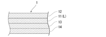
蓄電デバイス用外装材は、少なくとも、外側から、基材層、バリア層、及び熱融着性樹脂層をこの順に備える積層体から構成されており、
前記蓄電デバイス用外装材の前記熱融着性樹脂層同士を熱融着させることによって、前記蓄電デバイス素子が、前記包装体中に収容され、
前記接着性フィルムは、前記熱融着性樹脂層同士が熱融着される位置において、前記熱融着性樹脂層の間に介在するように用いられ、
前記接着性フィルムは、多層構造を有しており、
前記接着性フィルムは、融解ピーク温度が100℃以上135℃以下である樹脂層Lを少なくとも1層含んでいる、接着性フィルム。That is, the present disclosure provides inventions in the following aspects.
An adhesive film used in an electricity storage device,
The electricity storage device has a structure in which an electricity storage device element is housed in a package formed of an electricity storage device exterior material,
The exterior material for an electricity storage device is composed of a laminate including at least a substrate layer, a barrier layer, and a heat-fusible resin layer in this order from the outside,
The power storage device element is accommodated in the package by heat-sealing the heat-sealable resin layers of the power storage device exterior material,
The adhesive film is used so as to be interposed between the heat-fusible resin layers at positions where the heat-fusible resin layers are heat-sealed,
The adhesive film has a multilayer structure,
The adhesive film includes at least one resin layer L having a melting peak temperature of 100° C. or higher and 135° C. or lower.
本開示によれば、蓄電デバイスの外装材の熱融着部において、熱融着性樹脂層の間に介在される接着性フィルムであって、蓄電デバイスが高温(例えば100℃から125℃程度)になるまでは、蓄電デバイスを密封し、蓄電デバイスが当該高温(例えば100℃から125℃程度)になった場合に、熱融着性樹脂層の間の接着性フィルムの位置で蓄電デバイスが開封して、蓄電デバイス内部で発生したガスを外部に放出することができる、接着性フィルムを提供することができる。さらに、本開示は、当該接着性フィルムを利用した、蓄電デバイス及び当該蓄電デバイスの製造方法を提供することもできる。 According to the present disclosure, the adhesive film interposed between the heat-sealable resin layers in the heat-sealed portion of the exterior material of the electric storage device, and the electric storage device is heated to a high temperature (for example, about 100°C to 125°C). until the power storage device is sealed, and when the power storage device reaches the high temperature (for example, about 100 ° C. to 125 ° C.), the power storage device is unsealed at the position of the adhesive film between the heat-fusible resin layers. As a result, it is possible to provide an adhesive film that can release gas generated inside the electricity storage device to the outside. Furthermore, the present disclosure can also provide an electricity storage device and a method for manufacturing the electricity storage device using the adhesive film.
本開示の接着性フィルムは、蓄電デバイスに用いられる接着性フィルムであって、蓄電デバイスは、蓄電デバイス素子が、蓄電デバイス用外装材により形成された包装体中に収容された構造を備えており、蓄電デバイス用外装材は、少なくとも、外側から、基材層、バリア層、及び熱融着性樹脂層をこの順に備える積層体から構成されており、蓄電デバイス用外装材の熱融着性樹脂層同士を熱融着させることによって、蓄電デバイス素子が、包装体中に収容され、接着性フィルムは、熱融着性樹脂層同士が熱融着される位置において、熱融着性樹脂層の間に介在するように用いられ、接着性フィルムは、多層構造を有しており、接着性フィルムは、融解ピーク温度が100℃以上135℃以下である樹脂層Lを少なくとも1層含んでいることを特徴とする。 The adhesive film of the present disclosure is an adhesive film used in an electricity storage device, and the electricity storage device has a structure in which an electricity storage device element is accommodated in a package formed by an exterior material for an electricity storage device. , the power storage device exterior material is composed of a laminate having at least a substrate layer, a barrier layer, and a heat-fusible resin layer in this order from the outside, and the heat-fusible resin of the power storage device exterior material By heat-sealing the layers together, the electricity storage device element is accommodated in the packaging body, and the adhesive film is positioned between the heat-sealable resin layers at the positions where the heat-sealable resin layers are heat-sealed. The adhesive film has a multi-layered structure, and the adhesive film contains at least one resin layer L having a melting peak temperature of 100° C. or more and 135° C. or less. characterized by
本開示の接着性フィルムは、このような特徴を備えていることから、蓄電デバイスが高温(例えば100℃から125℃程度)になるまでは、蓄電デバイスが密封され、蓄電デバイスが当該高温(例えば100℃から125℃程度)になった場合に、熱融着性樹脂層の間の接着性フィルムの位置で蓄電デバイスが開封して、蓄電デバイス内部で発生したガスを外部に放出することができる。 Since the adhesive film of the present disclosure has such characteristics, the electricity storage device is sealed until the electricity storage device reaches a high temperature (for example, about 100 ° C. to 125 ° C.), and the electricity storage device is kept at the high temperature (for example, 100° C. to 125° C.), the electricity storage device is unsealed at the position of the adhesive film between the heat-sealable resin layers, and the gas generated inside the electricity storage device can be released to the outside. .
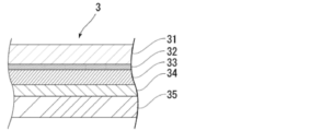
また、本開示の蓄電デバイスは、蓄電デバイス素子が、蓄電デバイス用外装材により形成された包装体中に収容された構造を備える蓄電デバイスであって、蓄電デバイス用外装材は、少なくとも、外側から、基材層、バリア層、及び熱融着性樹脂層をこの順に備える積層体から構成されており、蓄電デバイス用外装材の熱融着性樹脂層同士を熱融着させることによって、蓄電デバイス素子が、包装体中に収容されており、熱融着性樹脂層同士が熱融着される位置において、熱融着性樹脂層の間に介在するようにして、接着性フィルムが配置されており、接着性フィルムは、多層構造を有しており、接着性フィルムは、融解ピーク温度が100℃以上135℃以下である樹脂層Lを少なくとも1層含んでいることを特徴とする。 Further, the electricity storage device of the present disclosure is an electricity storage device having a structure in which an electricity storage device element is housed in a package formed by an electricity storage device exterior material, and the electricity storage device exterior material is at least externally , a substrate layer, a barrier layer, and a heat-fusible resin layer in this order. The element is accommodated in the package, and the adhesive film is arranged so as to be interposed between the heat-fusible resin layers at positions where the heat-fusible resin layers are heat-sealed. The adhesive film has a multi-layered structure and is characterized by including at least one resin layer L having a melting peak temperature of 100° C. or higher and 135° C. or lower.
すなわち、本開示の蓄電デバイスは、本開示の接着性フィルムが利用されており、蓄電デバイスが高温(例えば100℃から125℃程度)になるまでは、蓄電デバイスが密封され、蓄電デバイスが当該高温(例えば100℃から125℃程度)になった場合に、熱融着性樹脂層の間の接着性フィルムの位置で蓄電デバイスが開封して、蓄電デバイス内部で発生したガスを外部に放出することができる。 That is, the power storage device of the present disclosure uses the adhesive film of the present disclosure, and until the power storage device reaches a high temperature (for example, about 100 ° C. to 125 ° C.), the power storage device is sealed and the power storage device is kept at the high temperature. (for example, about 100° C. to 125° C.), the electricity storage device is unsealed at the position of the adhesive film between the heat-fusible resin layers, and the gas generated inside the electricity storage device is released to the outside. can be done.
以下、本開示の接着性フィルム及びその製造方法、蓄電デバイス及びその製造方法について詳述する。 The adhesive film of the present disclosure and its manufacturing method, and the electricity storage device and its manufacturing method are described in detail below.
なお、本明細書において、数値範囲については、「~」で示される数値範囲は「以上」、「以下」を意味する。例えば、2~15mmとの表記は、2mm以上15mm以下を意味する。 In this specification, regarding numerical ranges, the numerical range indicated by "-" means "more than" and "less than". For example, the notation of 2 to 15 mm means 2 mm or more and 15 mm or less.
1.接着性フィルム
本開示の接着性フィルムは、蓄電デバイスに用いられる接着性フィルムである。本開示の接着性フィルムは、蓄電デバイス用外装材の熱融着性樹脂層同士が熱融着される位置において、熱融着性樹脂層の間に介在するように用いられる。例えば図1及び図2に示されるように、本開示の蓄電デバイス10において、本開示の接着性フィルム1は、蓄電デバイス素子4を封止するために熱融着性樹脂層同士が熱融着された、蓄電デバイス用外装材3の周縁部3aの位置において、互いに対向する熱融着性樹脂層の間に介在されている。接着性フィルムと、その両側の熱融着性樹脂層とは、蓄電デバイス用外装材3で蓄電デバイス素子4を封止する際に、熱融着される。すなわち、接着性フィルムの両面は、それぞれ、熱融着性樹脂層と熱融着可能である。 1. Adhesive Film The adhesive film of the present disclosure is an adhesive film used in electrical storage devices. The adhesive film of the present disclosure is used so as to be interposed between the heat-fusible resin layers at positions where the heat-fusible resin layers of the exterior material for an electricity storage device are heat-sealed. For example, as shown in FIGS. 1 and 2 , in the
本開示の接着性フィルム1は、蓄電デバイス10が高温(例えば100℃から125℃程度)になるまでは、蓄電デバイス10を密封し、蓄電デバイスが当該高温(例えば100℃から125℃程度)になった場合に、熱融着性樹脂層の間の接着性フィルムの位置で蓄電デバイスが開封して、蓄電デバイス内部で発生したガスを外部に放出できる。接着性フィルム1は、蓄電デバイス用外装材の熱融着性樹脂層同士が熱融着される位置の一部に配置することにより、接着性フィルム1を配置した特定の位置から選択的にガスを外部に排出することができる。すなわち、ガスを排出する位置を、熱融着性樹脂層同士の熱融着部の任意の位置に設定することができる。
The
本開示の接着性フィルムを配置する位置としては、蓄電デバイス用外装材の熱融着性樹脂層同士が熱融着される位置であれば特に制限されず、例えば、蓄電デバイスが平面視長方形状であれば、熱融着された蓄電デバイス用外装材3の周縁部3aのうち、長辺及び短辺のいずれに配置することもできる。また、本開示の接着性フィルムは、蓄電デバイス用外装材の熱融着性樹脂層同士が熱融着される位置のうち、少なくとも1箇所に配置すればよいが、2箇所以上に配置してもよい。
The position at which the adhesive film of the present disclosure is arranged is not particularly limited as long as the heat-sealable resin layers of the exterior material for an electricity storage device are heat-sealed to each other. If so, it can be arranged on either the long side or the short side of the
接着性フィルムのサイズとしては、開封時にガスが適切に排出されれば、特に制限されない。例えば、図1に示されるように、蓄電デバイスが平面視矩形状であり、矩形状の1辺に沿って接着性フィルムを配置する場合(図1の例であれば、z方向に沿って接着性フィルムを配置する場合)、当該一辺の長さに対する接着性フィルムの長さの割合は、3~98%程度とすることができる。また、接着性フィルムの幅方向(長さ方向及び厚み方向に垂直な方向であり、図1の例であれば、x方向に沿った方向)のサイズについては、接着性フィルムの長さ方向のサイズを基準100%として、20~300%程度とすることができる。 The size of the adhesive film is not particularly limited as long as the gas is properly discharged when the package is opened. For example, as shown in FIG. 1, when the electricity storage device has a rectangular shape in plan view and the adhesive film is arranged along one side of the rectangular shape (in the example of FIG. When an adhesive film is arranged), the ratio of the length of the adhesive film to the length of the one side can be about 3 to 98%. In addition, regarding the size in the width direction of the adhesive film (the direction perpendicular to the length direction and the thickness direction, and in the example of FIG. 1, the direction along the x direction), the length direction of the adhesive film Taking the size as a standard of 100%, it can be about 20 to 300%.
なお、蓄電デバイス10において、金属端子2は、蓄電デバイス素子4に電気的に接続されており、蓄電デバイス用外装材3の外側に突出している。本開示の接着性フィルムは、金属端子2と蓄電デバイス用外装材3(熱融着性樹脂層)との間に位置しないようにして配置されることが好ましい。さらに、本開示の接着性フィルム1は、金属端子2と接触しないことが好ましい。
In the
本開示の接着性フィルム1は、図3から図7に示すように、多層構造を有しており、融解ピーク温度が100℃以上135℃以下である樹脂層Lを少なくとも1層含んでいる。図3から図7の模式図では、少なくとも第1層11が、樹脂層Lに対応する層であるが、接着性フィルム1において、樹脂層Lに対応する層は、2層以上含まれていてもよい。樹脂層Lは、融解ピーク温度が前記所定範囲にあることから、蓄電デバイスの外装材の熱融着部において、熱融着性樹脂層の間に接着性フィルムを介在させることにより、蓄電デバイスが高温(例えば100℃から125℃程度)になるまでは、蓄電デバイスが密封され、蓄電デバイスが当該高温(例えば100℃から125℃程度)になった場合に、熱融着性樹脂層の間の接着性フィルム1の位置(特に、樹脂層Lの位置)で蓄電デバイスが開封させて、蓄電デバイス内部で発生したガスを外部に放出することができる。
As shown in FIGS. 3 to 7, the
本開示の接着性フィルム1においては、少なくとも第1層11が、樹脂層Lに対応する層である。本開示の接着性フィルム1の積層構成としては、例えば第1層11と第2層12とがこの順に積層された2層構成(図3を参照);第2層12と第1層11と第3層13とがこの順に積層された3層構成(図4を参照);第1層11と第2層12と第3層13とがこの順に積層された3層構成(図5を参照);第1層11と第2層12と第3層13と第4層14とがこの順に積層された4層構成(図6を参照);第2層12と第1層11と第3層13と第4層14とがこの順に積層された4層構成(図7を参照)などが挙げられる。
At least the
本開示の接着性フィルム1において、第1層11以外の層(後述の他の層)のうち少なくとも1層についても、樹脂層Lに対応する層としてもよい。例えば、図3から図7の第2層12、第3層13、第4層14のうち、少なくとも1層についても樹脂層Lに対応する層であってもよい。ただし、本開示の接着性フィルム1において、樹脂層Lよりも融解ピーク温度の高い層(例えば、融解ピーク温度が樹脂層Lの融解ピーク温度の上限135℃を超える層)を設けることによって、樹脂層Lの厚みを薄く設計することが容易となる。樹脂層Lの厚みを薄くすれば、蓄電デバイスの開封時において、ガスの排出が穏やかになるという利点がある。このように、本開示の接着性フィルム1は、融解ピーク温度が所定範囲に設定された樹脂層Lと、他の層の多層構造とすることで、様々な機能設計が可能となっている。
In the
なお、後述の通り、本開示の効果をより一層好適に発揮させる観点から、樹脂層L以外の層については、融解ピーク温度が樹脂層Lの融解ピーク温度の下限100℃以上であることが望ましい。また、同様の観点から、本開示の接着性フィルムを適用する蓄電デバイス10において、蓄電デバイス用外装材3の熱融着性樹脂層35の融解ピーク温度は、樹脂層Lの融解ピーク温度の下限100℃以上であることが望ましく、樹脂層Lの融解ピーク温度の下限100℃超であることがより望ましい。
As will be described later, from the viewpoint of more preferably exhibiting the effects of the present disclosure, it is desirable that the melting peak temperature of the layers other than the resin layer L is 100° C. or more, which is the lower limit of the melting peak temperature of the resin layer L. . From a similar point of view, in the
本開示の接着性フィルム1の総厚みとしては、本開示の効果を好適に発揮させる観点から、例えば約5μm以上、好ましくは約20μm以上、さらに好ましくは約30μm以上である。また、本開示の接着性フィルム1の総厚みは、例えば約500μm以下、好ましくは約200μm以下、より好ましくは180μm以下である。本開示の接着性フィルム1の総厚みの好ましい範囲としては、5~500μm程度、5~200μm程度、5~180μm程度、20~500μm程度、20~200μm程度、20~180μm程度、30~500μm程度、30~200μm程度、30~180μm程度が挙げられる。より具体的な例としては、例えば、本開示の接着性フィルム1を民生用蓄電デバイスに使用する場合には、総厚みは60~100μm程度とすることが好ましく、車載用蓄電デバイスに使用する場合には、総厚みは100~200μm程度とすることが好ましい。
The total thickness of the
以下、本開示の接着性フィルム1に含まれる樹脂層L(第1層11)及び他の層(例えば、第2層12、第3層13、第4層14など)を構成する材料、厚みなどについて詳述する。
Hereinafter, materials and thicknesses constituting the resin layer L (first layer 11) and other layers (e.g.,
[第1層11(樹脂層L)]
本開示の接着性フィルム1において、第1層11は、融解ピーク温度が100℃以上135℃以下である樹脂層Lに対応する層である。[First layer 11 (resin layer L)]
In the
樹脂層Lを構成する材料については、融解ピーク温度が前記所定範囲にあれば、特に制限されない。樹脂層Lは、好ましくはポリオレフィン系樹脂を含む層(すなわち、ポリオレフィン骨格を有する)であり、より好ましくはポリオレフィン系樹脂により形成された層である。ポリオレフィン系樹脂としては、ポリエチレン、ポリプロピレンなどのポリオレフィンが挙げられる。また、ポリオレフィン系樹脂は、ポリオレフィンが酸変性された樹脂(酸変性ポリオレフィン)ものであってもよい。酸変性ポリオレフィンとしては、酸変性されたポリオレフィンであれば特に制限されないが、好ましくは不飽和カルボン酸またはその無水物でグラフト変性されたポリオレフィンが挙げられ、酸変性ポリエチレン、酸変性ポリプロピレンなどが挙げられる。 The material constituting the resin layer L is not particularly limited as long as the melting peak temperature is within the predetermined range. The resin layer L is preferably a layer containing a polyolefin resin (that is, having a polyolefin skeleton), and more preferably a layer formed of a polyolefin resin. Examples of polyolefin resins include polyolefins such as polyethylene and polypropylene. Further, the polyolefin-based resin may be a resin (acid-modified polyolefin) in which polyolefin is acid-modified. The acid-modified polyolefin is not particularly limited as long as it is an acid-modified polyolefin, but preferably includes a polyolefin graft-modified with an unsaturated carboxylic acid or its anhydride, such as acid-modified polyethylene and acid-modified polypropylene. .
ポリオレフィンとしては、それぞれ、低密度ポリエチレン、中密度ポリエチレン、高密度ポリエチレン、線状低密度ポリエチレン等のポリエチレン;ホモポリプロピレン、ポリプロピレンのブロックコポリマー(例えば、プロピレンとエチレンのブロックコポリマー)、ポリプロピレンのランダムコポリマー(例えば、プロピレンとエチレンのランダムコポリマー)等の結晶性又は非晶性のポリプロピレン;エチレン-ブテン-プロピレンのターポリマー等が挙げられる。これらのポリオレフィンの中でも、好ましくはポリエチレン及びポリプロピレンが挙げられる。 Polyolefins include polyethylenes such as low density polyethylene, medium density polyethylene, high density polyethylene and linear low density polyethylene, respectively; homopolypropylene, block copolymers of polypropylene (e.g. block copolymers of propylene and ethylene), random copolymers of polypropylene ( Examples include crystalline or amorphous polypropylene such as random copolymer of propylene and ethylene; terpolymer of ethylene-butene-propylene. Among these polyolefins, polyethylene and polypropylene are preferred.
また、ポリオレフィンは、環状ポリオレフィンであってもよい。環状ポリオレフィンは、オレフィンと環状モノマーとの共重合体であり、環状ポリオレフィンの構成モノマーであるオレフィンとしては、例えば、エチレン、プロピレン、4-メチル-1-ペンテン、ブタジエン、イソプレン等が挙げられる。また、前記環状ポリオレフィンの構成モノマーである環状モノマーとしては、例えば、ノルボルネン等の環状アルケン;具体的には、シクロペンタジエン、ジシクロペンタジエン、シクロヘキサジエン、ノルボルナジエン等の環状ジエン等が挙げられる。これらのポリオレフィンの中でも、好ましくは環状アルケン、さらに好ましくはノルボルネンが挙げられる。構成モノマーとしては、スチレンも挙げられる。 Also, the polyolefin may be a cyclic polyolefin. Cyclic polyolefins are copolymers of olefins and cyclic monomers. Examples of olefins that are constituent monomers of cyclic polyolefins include ethylene, propylene, 4-methyl-1-pentene, butadiene, and isoprene. Examples of cyclic monomers constituting the cyclic polyolefin include cyclic alkenes such as norbornene; specific examples thereof include cyclic dienes such as cyclopentadiene, dicyclopentadiene, cyclohexadiene and norbornadiene. Among these polyolefins, cyclic alkenes are preferred, and norbornene is more preferred. Constituent monomers also include styrene.
酸変性ポリオレフィンにおいて、酸変性されるポリオレフィンについても、前記のポリオレフィンが好ましい。なお、例えば、カルボン酸変性環状ポリオレフィンとは、環状ポリオレフィンを構成するモノマーの一部を、α,β-不飽和カルボン酸又はその無水物に代えて共重合することにより、或いは環状ポリオレフィンに対してα,β-不飽和カルボン酸又はその無水物をブロック重合又はグラフト重合することにより得られるポリマーである。 Among the acid-modified polyolefins, the polyolefins described above are also preferred for acid-modified polyolefins. Incidentally, for example, the carboxylic acid-modified cyclic polyolefin is obtained by copolymerizing a part of the monomers constituting the cyclic polyolefin with α,β-unsaturated carboxylic acid or its anhydride, or by copolymerizing the cyclic polyolefin. It is a polymer obtained by block polymerization or graft polymerization of α,β-unsaturated carboxylic acid or its anhydride.
酸変性に使用されるカルボン酸またはその無水物としては、例えば、マレイン酸、アクリル酸、イタコン酸、クロトン酸、無水マレイン酸、無水イタコン酸等が挙げられる。ポリオレフィン系樹脂は、赤外分光法で分析すると、無水マレイン酸に由来するピークが検出されることが好ましい。例えば、赤外分光法にて無水マレイン酸変性ポリオレフィンを測定すると、波数1760cm-1付近と波数1780cm-1付近に無水マレイン酸由来のピークが検出される。すなわち、この場合、ポリオレフィン系樹脂を赤外分光法にて測定すると、無水マレイン酸由来のピークが検出される。ただし、酸変性度が低いとピークが小さくなり検出されない場合がある。その場合は核磁気共鳴分光法にて分析可能である。Carboxylic acids or anhydrides thereof used for acid modification include, for example, maleic acid, acrylic acid, itaconic acid, crotonic acid, maleic anhydride, and itaconic anhydride. When the polyolefin resin is analyzed by infrared spectroscopy, it is preferable that a peak derived from maleic anhydride is detected. For example, when maleic anhydride-modified polyolefin is measured by infrared spectroscopy, peaks derived from maleic anhydride are detected near wavenumbers of 1760 cm −1 and 1780 cm −1 . That is, in this case, when the polyolefin resin is measured by infrared spectroscopy, a peak derived from maleic anhydride is detected. However, if the degree of acid denaturation is low, the peak may be too small to be detected. In that case, it can be analyzed by nuclear magnetic resonance spectroscopy.
樹脂層Lは、1種の樹脂成分単独で形成してもよく、また2種以上の樹脂成分を組み合わせたブレンドポリマーにより形成してもよい。樹脂層Lの製膜性の観点からは、2種以上の樹脂成分を組み合わせたブレンドポリマーにより形成することが好ましい。ブレンドポリマーとする場合、樹脂層Lは、酸変性ポリプロピレンを主成分(50質量%以上の成分)とし、50質量%以下を他の樹脂(柔軟性を向上させる観点からは、好ましくはポリエチレン)とすることが好ましい。一方、樹脂層Lの耐電解液性を高める観点からは、樹脂層Lは、樹脂としてポリプロピレン又は酸変性ポリプロピレンを単独で含むことが好ましい。 The resin layer L may be formed of one resin component alone, or may be formed of a blend polymer in which two or more resin components are combined. From the viewpoint of the film formability of the resin layer L, it is preferable to form the resin layer L with a blend polymer in which two or more resin components are combined. In the case of a blended polymer, the resin layer L is mainly composed of acid-modified polypropylene (50% by mass or more), and 50% by mass or less is another resin (preferably polyethylene from the viewpoint of improving flexibility). preferably. On the other hand, from the viewpoint of enhancing the electrolyte resistance of the resin layer L, the resin layer L preferably contains polypropylene or acid-modified polypropylene alone as the resin.
また、樹脂層Lには、粘着成分が含まれていてもよい。粘着成分としては、エラストマーなどが挙げられる。 Moreover, the resin layer L may contain an adhesive component. An elastomer etc. are mentioned as an adhesive component.
エラストマーとしては、ポリオレフィンと共に配合されて、粘着性を発揮するものであれば、特に制限されず、例えば、熱可塑性樹脂により構成されたエラストマー(熱可塑性エラストマー)が好ましい。 The elastomer is not particularly limited as long as it is compounded with polyolefin and exhibits adhesiveness. For example, an elastomer composed of a thermoplastic resin (thermoplastic elastomer) is preferable.
エラストマーとしては、好ましくはスチレン系エラストマー、オレフィン系エラストマー、アクリル系エラストマー、シリコーン系エラストマー、ウレタン系エラストマー、ポリエステル系エラストマー、ポリアミド系エラストマー、ゴム系エラストマーなどが挙げられる。エラストマーは、1種類単独で使用してもよいし、2種類以上を組み合わせて使用してもよい。 Preferred elastomers include styrene elastomers, olefin elastomers, acrylic elastomers, silicone elastomers, urethane elastomers, polyester elastomers, polyamide elastomers, rubber elastomers, and the like. One type of elastomer may be used alone, or two or more types may be used in combination.
スチレン系エラストマーの種類としては、特に制限されないが、具体例としては、スチレン-ブタジエン-スチレンブロックコポリマー、スチレン-イソプレン-スチレンブロックコポリマー、スチレン-エチレン-ブチレン-スチレンブロックコポリマー、及びスチレン-エチレン-プロピレン-スチレンブロックコポリマーなどが挙げられる。 The type of styrene-based elastomer is not particularly limited, but specific examples include styrene-butadiene-styrene block copolymer, styrene-isoprene-styrene block copolymer, styrene-ethylene-butylene-styrene block copolymer, and styrene-ethylene-propylene. - Styrene block copolymers and the like.
オレフィン系エラストマーとしては、エチレン、プロピレン、1-ブテン、1-ヘキセン、4-メチル-ペンテン等の炭素数2~20のα-オレフィンの共重合体が挙げられ、例えば、エチレン-プロピレン共重合体(EPR)、エチレン-プロピレン-ジエン共重合体(EPDM)等が好適に挙げられる。また、ジシクロペンタジエン、1,4-ヘキサジエン、シクロオクタジエン、メチレンノルボルネン、エチリデンノルボルネン、ブタジエン、イソプレン等の炭素数2~20の非共役ジエンとα-オレフィンとの共重合体が挙げられる。さらには、ブタジエン-アクリロニトリル共重合体にメタクリル酸を共重合したカルボキシ変性ニトリルゴムなどが挙げられる。 Examples of olefinic elastomers include copolymers of α-olefins having 2 to 20 carbon atoms such as ethylene, propylene, 1-butene, 1-hexene and 4-methyl-pentene. (EPR), ethylene-propylene-diene copolymer (EPDM), and the like. Copolymers of non-conjugated dienes having 2 to 20 carbon atoms such as dicyclopentadiene, 1,4-hexadiene, cyclooctadiene, methylenenorbornene, ethylidenenorbornene, butadiene and isoprene with α-olefins are also included. Furthermore, a carboxy-modified nitrile rubber obtained by copolymerizing a butadiene-acrylonitrile copolymer with methacrylic acid may be mentioned.
アクリル系エラストマーは、アクリル酸エステルを主成分とするもので、具体的には、エチルアクリレート、ブチルアクリレート、メトキシエチルアクリレート、エトキシエチルアクリレート等が好適に用いられる。また、架橋点モノマーとして、グリシジルメタクリレート、アリルグリシジルエーテル等が用いられる。さらに、アクリロニトリルやエチレンを共重合することもできる。具体的には、アクリロニトリル-ブチルアクリレート共重合体、アクリロニトリル-ブチルアクリレート-エチルアクリレート共重合体、アクリロニトリル-ブチルアクリレート-グリシジルメタクリレート共重合体等が挙げられる。 The acrylic elastomer is mainly composed of acrylic acid ester, and specifically, ethyl acrylate, butyl acrylate, methoxyethyl acrylate, ethoxyethyl acrylate, etc. are preferably used. Moreover, glycidyl methacrylate, allyl glycidyl ether, etc. are used as a cross-linking monomer. Furthermore, acrylonitrile and ethylene can also be copolymerized. Specific examples include acrylonitrile-butyl acrylate copolymer, acrylonitrile-butyl acrylate-ethyl acrylate copolymer, acrylonitrile-butyl acrylate-glycidyl methacrylate copolymer and the like.
シリコーン系エラストマーとしては、オルガノポリシロキサンを主成分したものであり、ポリジメチルシロキサン系、ポリメチルフェニルシロキサン系、ポリジフェニルシロキサン系の各エラストマーが挙げられる。 Examples of silicone-based elastomers include organopolysiloxane-based elastomers, including polydimethylsiloxane-based, polymethylphenylsiloxane-based, and polydiphenylsiloxane-based elastomers.
ウレタン系エラストマーは、低分子のエチレングリコールとジイソシアネートからなるハードセグメントと、高分子(長鎖)ジオールとジイソシアネートからなるソフトセグメントとの構造単位からなり、高分子(長鎖)ジオールとして、ポリプロピレングリコール、ポリテトラメチレンオキサイド、ポリ(1,4-ブチレンアジペート)、ポリ(エチレン-1,4-ブチレンアジペート)、ポリカプロラクトン、ポリ(1,6-ヘキシレンカーボネート)、ポリ(1,6-へキシレン・ネオペンチレンアジペート)等が挙げられる。 Urethane-based elastomers are composed of structural units of hard segments composed of low-molecular-weight ethylene glycol and diisocyanate, and soft segments composed of high-molecular-weight (long-chain) diols and diisocyanate. Polytetramethylene oxide, poly(1,4-butylene adipate), poly(ethylene-1,4-butylene adipate), polycaprolactone, poly(1,6-hexylene carbonate), poly(1,6-hexylene neopentylene adipate) and the like.
ポリエステル系エラストマーは、ジカルボン酸又はその誘導体とジオール化合物又はその誘導体を重縮合して得られる。ジカルボン酸の具体例としては、テレフタル酸、イソフタル酸、ナフタレンジカルボン酸等の芳香族ジカルボン酸及びこれらの芳香核の水素原子がメチル基、エチル基、フェニル基等で置換された芳香族ジカルボン酸、アジピン酸、セバシン酸、ドデカンジカルボン酸等の炭素数2~20の脂肪族ジカルボン酸、及びシクロヘキサンジカルボン酸等の脂環式ジカルボン酸などが挙げられる。これらの化合物は1種を単独で、又は2種以上を混合して用いることができる。 A polyester-based elastomer is obtained by polycondensing a dicarboxylic acid or its derivative and a diol compound or its derivative. Specific examples of dicarboxylic acids include aromatic dicarboxylic acids such as terephthalic acid, isophthalic acid and naphthalene dicarboxylic acid, and aromatic dicarboxylic acids in which the hydrogen atoms of these aromatic nuclei are substituted with methyl groups, ethyl groups, phenyl groups, etc. Aliphatic dicarboxylic acids having 2 to 20 carbon atoms such as adipic acid, sebacic acid and dodecanedicarboxylic acid, and alicyclic dicarboxylic acids such as cyclohexanedicarboxylic acid and the like are included. These compounds can be used individually by 1 type or in mixture of 2 or more types.
ジオール化合物の具体例としては、エチレングリコール、1,3-プロパンジオール、1,4-ブタンジオール、1,6-ヘキサンジオール、1,10-デカンジオール、1,4-シクロヘキサンジオール等の脂肪族ジオール及び脂環式ジオールが挙げられ、さらに、ビスフェノールA、ビス-(4-ヒドロキシフェニル)-メタン、ビス-(4-ヒドロキシ-3-メチルフェニル)-プロパン、レゾルシン等が挙げられる。これらの化合物は1種を単独で、又は2種以上を混合して用いることができる。 Specific examples of diol compounds include aliphatic diols such as ethylene glycol, 1,3-propanediol, 1,4-butanediol, 1,6-hexanediol, 1,10-decanediol, and 1,4-cyclohexanediol. and alicyclic diols, and further bisphenol A, bis-(4-hydroxyphenyl)-methane, bis-(4-hydroxy-3-methylphenyl)-propane, resorcinol, and the like. These compounds can be used individually by 1 type or in mixture of 2 or more types.
ポリアミド系エラストマーとしては、ポリアミドをハードセグメント成分、ポリブタジエン、ブタジエン-アクリロニトリル共重合体、スチレン-ブタジエン共重合体、ポリイソプレン、エチレン-プロピレン共重合体、ポリエーテル、ポリエステル、ポリブタジエン、ポリカーボネート、ポリアクリレート、ポリメタクリレート、ポリウレタン又はシリコーンゴム等をソフトセグメント成分としたブロック共重合体が挙げられる。 Polyamide-based elastomers include polyamide as a hard segment component, polybutadiene, butadiene-acrylonitrile copolymer, styrene-butadiene copolymer, polyisoprene, ethylene-propylene copolymer, polyether, polyester, polybutadiene, polycarbonate, polyacrylate, Examples thereof include block copolymers having soft segment components such as polymethacrylate, polyurethane or silicone rubber.
ゴム系エラストマーとしては、例えば、ポリイソブチレンなどが挙げられる。 Examples of rubber-based elastomers include polyisobutylene.
エラストマーの中でも、スチレン系エラストマー及びオレフィン系エラストマーが好ましく、スチレン系エラストマーが特に好ましい。 Among elastomers, styrene-based elastomers and olefin-based elastomers are preferred, and styrene-based elastomers are particularly preferred.
樹脂層Lに含まれるエラストマーの割合としては、特に制限されないが、好ましくは約50質量%以下、より好ましくは10~50質量%程度、さらに好ましくは10~40質量%程度が挙げられる。 The proportion of the elastomer contained in the resin layer L is not particularly limited, but is preferably about 50% by mass or less, more preferably about 10 to 50% by mass, still more preferably about 10 to 40% by mass.
樹脂層Lの融解ピーク温度は、100℃以上135℃以下の範囲にあればよいが、本開示の効果をより一層好適に発揮する観点から、好ましくは約105℃以上、より好ましくは約110℃以上であり、また、好ましくは約130℃以下であり、好ましい範囲としては、100~135℃程度、100~130℃程度、105~135℃程度、105~130℃程度、110~135℃程度、110~130℃程度などが挙げられる。 The melting peak temperature of the resin layer L may be in the range of 100°C or higher and 135°C or lower, but from the viewpoint of more preferably exhibiting the effects of the present disclosure, it is preferably about 105°C or higher, more preferably about 110°C. above, and preferably about 130° C. or less. About 110 to 130° C. can be mentioned.
また、本開示の効果をより一層好適に発揮する観点から、樹脂層Lの融解ピーク温度は、蓄電デバイス用外装材3の熱融着性樹脂層35の融解ピーク温度よりも、5℃以上低い値であることが好ましく、10℃以上低い値であることがより好ましく、15℃以上低い値であることがさらに好ましい。
In addition, from the viewpoint of more preferably exhibiting the effects of the present disclosure, the melting peak temperature of the resin layer L is lower than the melting peak temperature of the heat-fusible resin layer 35 of the power storage
本開示において、融解ピーク温度の測定方法は、以下の通りである。 In the present disclosure, the method for measuring the melting peak temperature is as follows.
<融解ピーク温度の測定>
各樹脂について、JIS K7121:2012(プラスチックの転移温度測定方法(JIS K7121:1987の追補1))の規定に準拠して融解ピーク温度を測定する。測定は、示差走査熱量計(例えば、DSC、ティー・エイ・インスツルメント製の示差走査熱量計Q200)を用いて行う。測定サンプルを、-50℃で15分間保持した後、10℃/分の昇温速度で-50℃から210℃まで昇温させて、1回目の融解ピーク温度P(℃)を測定した後、210℃にて10分間保持する。次に、10℃/分の降温速度で210℃から-50℃まで降温させて15分間保持する。さらに、10℃/分の昇温速度で-50℃から210℃まで昇温させて2回目の融解ピーク温度Q(℃)を測定する。なお、窒素ガスの流量は50ml/分とする。以上の手順によって、1回目に測定される融解ピーク温度P(℃)と、2回目に測定される融解ピーク温度Q(℃)を求め、1回目に測定された融解ピーク温度を融解ピーク温度とする。サンプルの融解ピーク温度が高いものを測定する場合、同じ昇温速度で-50℃から500℃の範囲を測定してもよい。<Measurement of melting peak temperature>
For each resin, the melting peak temperature is measured in accordance with JIS K7121:2012 (Method for measuring transition temperature of plastics (JIS K7121:1987 Supplement 1)). The measurement is performed using a differential scanning calorimeter (for example, DSC, Differential Scanning Calorimeter Q200 manufactured by TA Instruments). After holding the measurement sample at −50° C. for 15 minutes, the temperature was raised from −50° C. to 210° C. at a heating rate of 10° C./min, and the first melting peak temperature P (° C.) was measured. Hold at 210° C. for 10 minutes. Next, the temperature is lowered from 210° C. to −50° C. at a rate of 10° C./min and held for 15 minutes. Further, the temperature is raised from −50° C. to 210° C. at a heating rate of 10° C./min, and the second melting peak temperature Q (° C.) is measured. Note that the flow rate of nitrogen gas is 50 ml/min. By the above procedure, the melting peak temperature P (° C.) measured for the first time and the melting peak temperature Q (° C.) measured for the second time are obtained, and the melting peak temperature measured for the first time is the melting peak temperature. do. When measuring a sample with a high melting peak temperature, the temperature may be measured in the range of -50°C to 500°C at the same heating rate.
また、本開示の効果をより好適に奏する観点から、第1層11の厚さは、好ましくは約0.1μm以上、より好ましくは約1μm以上、さらに好ましくは約3μm以上であり、また、好ましくは約500μm以下、より好ましくは約200μm以下、さらに好ましくは100μm以下である。第1層11の厚さの好ましい範囲としては、0.1~500μm程度、0.1~200μm程度、0.1~100μm程度、1~500μm程度、1~200μm程度、1~100μm程度が挙げられる。
In addition, from the viewpoint of achieving the effects of the present disclosure more preferably, the thickness of the
第1層11に加えて、さらに樹脂層Lに相当する層(すなわち、融解ピーク温度は、100℃以上135℃以下の層)が存在する場合(例えば、後述の第2層12、第3層13、及び第4層14のうち、少なくとも1層が樹脂層Lに対応する場合)、接着性フィルム1に含まれる樹脂層Lの合計厚みとしては、好ましくは約0.1μm以上、より好ましくは約3μm以上、さらに好ましくは約5μm以上であり、また、好ましくは約500μm以下、より好ましくは約200μm以下、さらに好ましくは約100μm以下である。樹脂層Lの合計厚みの好ましい範囲としては、0.1~500μm程度、0.1~200μm程度、0.1~100μm程度、3~500μm程度、3~200μm程度、3~100μm程度、5~500μm程度、5~200μm程度、5~100μm程度が挙げられる。
In addition to the
本開示において、本開示の効果をより好適に発揮する観点から、接着性フィルム1の総厚(100%)に対する、第1層11の厚みの割合としては、好ましくは約5%以上、より好ましくは約10%以上、さらに好ましくは約15%以上であり、また、好ましくは約95%以下、より好ましくは約90%以下、さらに好ましくは約85%以下であり、好ましい範囲としては、5~95%程度、5~90%程度、5~85%程度、10~95%程度、10~90%程度、10~85%程度、15~95%程度、15~90%程度、15~85%程度である。
In the present disclosure, from the viewpoint of more preferably exhibiting the effects of the present disclosure, the ratio of the thickness of the
また、第1層11に加えて、さらに樹脂層Lに相当する層(すなわち、融解ピーク温度は、100℃以上135℃以下の層)が存在する場合(例えば、後述の第2層12、第3層13、及び第4層14のうち、少なくとも1層が樹脂層Lに対応する場合)、接着性フィルム1の総厚(100%)に対する、樹脂層Lの合計厚みの割合としては、好ましくは約5%以上、より好ましくは約10%以上、さらに好ましくは約15%以上であり、また、好ましくは約95%以下、より好ましくは約90%以下、さらに好ましくは約85%以下であり、好ましい範囲としては、5~95%程度、5~90%程度、5~85%程度、10~95%程度、10~90%程度、10~85%程度、15~95%程度、15~90%程度、15~85%程度である。
Further, in addition to the
[他の層(第2層12、第3層13、第4層14など)]
本開示の接着性フィルム1は、多層構造であり、前記の第1層11に加えて、他の層として少なくとも第2層12を含んでいる。本開示の接着性フィルム1が2層構造である場合には、第1層11と第2層12との積層体であり、3層構造である場合には、第1層11と第2層12と第3層13との積層体であり、4層構造である場合には、第1層11と第2層12と第3層13と第4層14との積層体であり、5層構造である場合には、第1層11と第2層12と第3層13と第4層14と第5層15との積層体である。なお、第1層11と他の層の積層順については、特に制限されない。また、接着性フィルム1の層の数としては、特に制限はないが、好ましくは2~5層、2~4層などである。[Other layers (
The
前記の通り、本開示の接着性フィルム1において、樹脂層Lに対応する層を他の層に含めてよい。例えば、図3から図7の第2層12、第3層13、第4層14のうち、少なくとも1層についても樹脂層Lに対応する層であってもよい。また、他の層のうち、少なくとも1層は、融解ピーク温度が樹脂層Lの融解ピーク温度の上限135℃を超える層としてもよい。例えば、本開示の接着性フィルム1において、樹脂層Lよりも融解ピーク温度の高い層(例えば、融解ピーク温度が135℃を超える層であって、樹脂層Lに対応しない層(以下、樹脂層Mと表記することがある))を設けることによって、樹脂層Lの厚みを薄く設計することが容易となる。
As described above, in the
他の層においても、樹脂層Lを構成する材料については、前記の第1層11と同様、融解ピーク温度が前記所定範囲にあれば、特に制限されず、好ましくはポリオレフィン系樹脂を含む層(すなわち、ポリオレフィン骨格を有する)であり、より好ましくはポリオレフィン系樹脂により形成された層である。ポリオレフィン系樹脂の具体例については、第1層11で例示した通りである。
In the other layers as well, the material constituting the resin layer L is not particularly limited as long as the melting peak temperature is within the predetermined range as in the
他の層を形成する素材については、特に制限されるものではない。他の層を形成する素材としては、例えば、ポリオレフィン系樹脂、ポリアミド系樹脂、ポリエステル系樹脂、エポキシ樹脂、アクリル樹脂、フッ素樹脂、珪素樹脂、フェノール樹脂、ポリエーテルイミド、ポリイミド、ポリカーボネート及びこれらの混合物や共重合物等が挙げられ、これらの中でも、特にポリオレフィン系樹脂を含むことが好ましく、ポリオレフィン系樹脂により形成された層を含むことがより好ましい。なお、他の層を形成する素材がポリオレフィン系樹脂であっても、他の層は、樹脂層Lよりも融解ピーク温度の高い層(樹脂層M)とすることができる。 Materials forming other layers are not particularly limited. Examples of materials for forming other layers include polyolefin resins, polyamide resins, polyester resins, epoxy resins, acrylic resins, fluororesins, silicone resins, phenolic resins, polyetherimides, polyimides, polycarbonates, and mixtures thereof. Among these, it is particularly preferable to contain a polyolefin resin, and it is more preferable to contain a layer formed of a polyolefin resin. Even if the material forming the other layer is a polyolefin resin, the other layer can be a layer (resin layer M) having a melting peak temperature higher than that of the resin layer L.
ポリアミドとしては、具体的には、ナイロン6、ナイロン66、ナイロン610、ナイロン12、ナイロン46、ナイロン6とナイロン66との共重合体等の脂肪族系ポリアミド;テレフタル酸及び/又はイソフタル酸に由来する構成単位を含むナイロン6I、ナイロン6T、ナイロン6IT、ナイロン6I6T(Iはイソフタル酸、Tはテレフタル酸を表す)等のヘキサメチレンジアミン-イソフタル酸-テレフタル酸共重合ポリアミド、ポリメタキシリレンアジパミド(MXD6)等の芳香族を含むポリアミド;ポリアミノメチルシクロヘキシルアジパミド(PACM6)等の脂環系ポリアミド;さらにラクタム成分や、4,4’-ジフェニルメタン-ジイソシアネート等のイソシアネート成分を共重合させたポリアミド、共重合ポリアミドとポリエステルやポリアルキレンエーテルグリコールとの共重合体であるポリエステルアミド共重合体やポリエーテルエステルアミド共重合体;これらの共重合体等が挙げられる。これらのポリアミドは、1種単独で使用してもよく、また2種以上を組み合わせて使用してもよい。
Specific examples of polyamides include aliphatic polyamides such as nylon 6, nylon 66, nylon 610,
ポリエステルとしては、具体的には、ポリエチレンテレフタレート、ポリブチレンテレフタレート、ポリエチレンナフタレート、ポリブチレンナフタレート、ポリエチレンイソフタレート、エチレンテレフタレートを繰り返し単位の主体とした共重合ポリエステル、ブチレンテレフタレートを繰り返し単位の主体とした共重合ポリエステル等が挙げられる。また、エチレンテレフタレートを繰り返し単位の主体とした共重合ポリエステルとしては、具体的には、エチレンテレフタレートを繰り返し単位の主体としてエチレンイソフタレートと重合する共重合体ポリエステル(以下、ポリエチレン(テレフタレート/イソフタレート)にならって略す)、ポリエチレン(テレフタレート/イソフタレート)、ポリエチレン(テレフタレート/アジペート)、ポリエチレン(テレフタレート/ナトリウムスルホイソフタレート)、ポリエチレン(テレフタレート/ナトリウムイソフタレート)、ポリエチレン(テレフタレート/フェニル-ジカルボキシレート)、ポリエチレン(テレフタレート/デカンジカルボキシレート)等が挙げられる。また、ブチレンテレフタレートを繰り返し単位の主体とした共重合ポリエステルとしては、具体的には、ブチレンテレフタレートを繰り返し単位の主体としてブチレンイソフタレートと重合する共重合体ポリエステル(以下、ポリブチレン(テレフタレート/イソフタレート)にならって略す)、ポリブチレン(テレフタレート/アジペート)、ポリブチレン(テレフタレート/セバケート)、ポリブチレン(テレフタレート/デカンジカルボキシレート)、ポリブチレンナフタレート等が挙げられる。これらのポリエステルは、1種単独で使用してもよく、また2種以上を組み合わせて使用してもよい。 Specific examples of polyesters include polyethylene terephthalate, polybutylene terephthalate, polyethylene naphthalate, polybutylene naphthalate, polyethylene isophthalate, copolymer polyester mainly composed of repeating units of ethylene terephthalate, and butylene terephthalate mainly composed of repeating units. and copolymerized polyester. Further, as the copolymer polyester having ethylene terephthalate as the main repeating unit, specifically, a copolymer polyester polymerized with ethylene isophthalate having ethylene terephthalate as the main repeating unit (hereinafter referred to as polyethylene (terephthalate/isophthalate) ), polyethylene (terephthalate/isophthalate), polyethylene (terephthalate/adipate), polyethylene (terephthalate/sodium sulfoisophthalate), polyethylene (terephthalate/sodium isophthalate), polyethylene (terephthalate/phenyl-dicarboxylate) , polyethylene (terephthalate/decanedicarboxylate), and the like. Further, as the copolymer polyester having butylene terephthalate as the main repeating unit, specifically, a copolymer polyester polymerized with butylene isophthalate having butylene terephthalate as the main repeating unit (hereinafter referred to as polybutylene (terephthalate/isophthalate) ), polybutylene (terephthalate/adipate), polybutylene (terephthalate/sebacate), polybutylene (terephthalate/decanedicarboxylate), polybutylene naphthalate, and the like. These polyesters may be used singly or in combination of two or more.
また、他の層のうち少なくとも1層は、上記の樹脂で形成された不織布により形成されていてもよい。不織布により形成する場合、不織布は、前述のポリオレフィン系樹脂、ポリアミド樹脂等で構成されていることが好ましい。 At least one of the other layers may be made of a nonwoven fabric made of the above resin. When formed from a nonwoven fabric, the nonwoven fabric is preferably composed of the aforementioned polyolefin resin, polyamide resin, or the like.
他の層に含まれる層のうち、融解ピーク温度が135℃を超える層であり、樹脂層Lに対応しない層(樹脂層M)の融解ピーク温度は、好ましくは約140℃以上、より好ましくは約160℃以上、さらに好ましくは約180℃以上であり、また、好ましくは約500℃以下、より好ましくは約450℃以下、さらに好ましくは約350℃以下であり、好ましい範囲としては、135℃超500℃以下、135℃超450℃以下、135℃超350℃以下、140~500℃程度、140~450℃程度、140~350℃程度、160~500℃程度、160~450℃程度、160~350℃程度、180~500℃程度、180~450℃程度、180~350℃程度などが挙げられる。 Among the layers contained in the other layers, the melting peak temperature of the layer (resin layer M), which is a layer having a melting peak temperature exceeding 135° C. and does not correspond to the resin layer L, is preferably about 140° C. or higher, more preferably It is about 160°C or higher, more preferably about 180°C or higher, preferably about 500°C or lower, more preferably about 450°C or lower, further preferably about 350°C or lower, and a preferable range is higher than 135°C. 500°C or less, 135°C to 450°C, 135°C to 350°C, about 140 to 500°C, about 140 to 450°C, about 140 to 350°C, about 160 to 500°C, about 160 to 450°C, 160 to About 350° C., about 180 to 500° C., about 180 to 450° C., and about 180 to 350° C. can be mentioned.
また、本開示の効果をより好適に奏する観点から、他の層の合計厚さは、好ましくは約0.1μm以上、より好ましくは約1μm以上、さらに好ましくは約5μm以上であり、また、好ましくは約500μm以下、より好ましくは約300μm以下、さらに好ましくは約200μm以下である。他の層の合計厚さの好ましい範囲としては、0.1~500μm程度、0.1~300μm程度、0.1~200μm程度、1~500μm程度、1~300μm程度、1~200μm程度、5~500μm程度、5~300μm程度、5~200μm程度が挙げられる。 In addition, from the viewpoint of more preferably exhibiting the effects of the present disclosure, the total thickness of the other layers is preferably about 0.1 μm or more, more preferably about 1 μm or more, and still more preferably about 5 μm or more. is about 500 μm or less, more preferably about 300 μm or less, and even more preferably about 200 μm or less. Preferred ranges for the total thickness of the other layers are about 0.1 to 500 μm, about 0.1 to 300 μm, about 0.1 to 200 μm, about 1 to 500 μm, about 1 to 300 μm, about 1 to 200 μm, 5 about 500 μm, about 5 to 300 μm, and about 5 to 200 μm.
他の層に樹脂層Mに相当する層が存在する場合(例えば、後述の第2層12、第3層13、及び第4層14のうち、少なくとも1層が樹脂層Mに対応する場合)、接着性フィルム1に含まれる樹脂層Mの合計厚みとしては、好ましくは約5%以上、より好ましくは約10%以上、さらに好ましくは約15%以上であり、また、好ましくは約95%以下、より好ましくは約90%以下、さらに好ましくは約85%以下であり、好ましい範囲としては、5~95%、10~90%である。
When a layer corresponding to the resin layer M exists in another layer (for example, when at least one of the
本開示において、本開示の効果をより好適に発揮する観点から、接着性フィルム1の総厚(100%)に対する、他の層の合計厚みの割合としては、好ましくは約5%以上、より好ましくは約10%以上、さらに好ましくは約15%以上であり、また、好ましくは約95%以下、より好ましくは約90%以下、さらに好ましくは約85%以下であり、好ましい範囲としては、5~95%程度、5~90%程度、5~85%程度、10~95%程度、10~90%程度、10~85%程度、15~95%程度、15~90%程度、15~85%程度である。
In the present disclosure, from the viewpoint of more preferably exhibiting the effects of the present disclosure, the ratio of the total thickness of the other layers to the total thickness (100%) of the
また、他の層に樹脂層Mに相当する層が存在する場合(例えば、後述の第2層12、第3層13、及び第4層14のうち、少なくとも1層が樹脂層Mに対応する場合)、接着性フィルム1の総厚(100%)に対する、樹脂層Mの合計厚みの割合としては、好ましくは約5%以上、より好ましくは約10%以上、さらに好ましくは約15%以上であり、また、好ましくは約95%以下、より好ましくは約90%以下、さらに好ましくは約85%以下であり、好ましい範囲としては、5~95%程度、5~90%程度、5~85%程度、10~95%程度、10~90%程度、10~85%程度、15~95%程度、15~90%程度、15~85%程度である。
Further, when a layer corresponding to the resin layer M exists in another layer (for example, at least one of the
(添加剤)
また、第1層11及び他の層のうち、少なくとも1層には、それぞれ、樹脂に加えて、顔料などの着色剤、充填剤、滑剤などの添加剤が含まれていてもよい。(Additive)
At least one of the
顔料としては、無機系の各種顔料を用いることができる。顔料の具体例としては、後述する充填剤で例示した炭素(カーボン、グラファイト)が好ましく例示できる。なお、炭素(カーボン、グラファイト)は、一般に蓄電デバイスの内部に使用されている材料であり、電解液に対する溶出の虞がないことから、好適に配合することができる。また、着色効果が大きく接着性を阻害しない程度の添加量で充分な着色効果を得られると共に、熱で溶融することがなく、添加した樹脂の見かけの溶融粘度を高くすることができる。さらに、熱接着時(ヒートシール時)に加圧部が薄肉となることを防止して、蓄電デバイス用外装材と金属端子の間における優れた密封性を付与できる。 Various inorganic pigments can be used as the pigment. As a specific example of the pigment, carbon (carbon, graphite) exemplified in the later-described filler can be preferably exemplified. Carbon (carbon, graphite) is a material generally used in the interior of an electric storage device, and is not likely to be eluted into the electrolytic solution, so it can be suitably blended. In addition, a sufficient coloring effect can be obtained with a large coloring effect and an addition amount that does not impede adhesion, and the apparent melt viscosity of the added resin can be increased without being melted by heat. Furthermore, it is possible to prevent the thickness of the pressurized portion from becoming thin during thermal adhesion (during heat sealing), and to provide excellent sealing between the electrical storage device exterior material and the metal terminal.
第1層11及び他の層のうち、少なくとも1層に顔料を添加する場合、その添加量としては、たとえば、粒径が約0.03μmのカーボンブラックを使用した場合、接着性フィルム1の各層の樹脂成分100質量部に対して、それぞれ、0.05~0.3質量部程度、好ましくは0.1~0.2質量部程度が挙げられる。なお、接着性フィルム1に顔料と充填剤の両方を添加する場合、同一の層に充填剤の顔料の両者を添加してもよいが、接着性フィルム1の熱融着性を阻害しない観点からは、充填剤及び顔料は、異なる層に分けて添加することが好ましい。
When a pigment is added to at least one layer of the
充填剤の粒径としては、0.1~35μm程度、好ましくは5.0~30μm程度、さらに好ましくは10~25μm程度の範囲が挙げられる。また、充填剤の含有量としては、接着性フィルム1の各層を形成する樹脂成分100質量部に対して、それぞれ、5~30質量部程度、より好ましくは10~20質量部程度が挙げられる。
The particle size of the filler is about 0.1 to 35 μm, preferably about 5.0 to 30 μm, more preferably about 10 to 25 μm. The content of the filler is about 5 to 30 parts by mass, more preferably about 10 to 20 parts by mass, per 100 parts by mass of the resin component forming each layer of the
充填剤としては、無機系、有機系のいずれも用いることができる。無機系充填剤としては、例えば、炭素(カーボン、グラファイト)、シリカ、酸化アルミニウム、チタン酸バリウム、酸化鉄、シリコンカーバイド、酸化ジルコニウム、珪酸ジルコニウム、酸化マグネシウム、酸化チタン、アルミ酸カルシウム、水酸化カルシウム、水酸化アルミニウム、水酸化マグネシウム、炭酸カルシウム等が挙げられる。また、有機系充填剤としては、例えば、フッ素樹脂、フェノール樹脂、ユリア樹脂、エポキシ樹脂、アクリル樹脂、ベンゾグアナミン・ホルムアルデヒド縮合物、メラミン・ホルムアルデヒド縮合物、ポリメタクル酸メチル架橋物、ポリエチレン架橋物等が挙げられる。形状の安定性、剛性、内容物耐性の点から、酸化アルミニウム、シリカ、フッ素樹脂、アクリル樹脂、ベンゾグアナミン・ホルムアルデヒド縮合物が好ましく、特にこの中でも球状の酸化アルミニウム、シリカがより好ましい。接着性フィルム1の各層を形成する樹脂成分への充填剤の混合方法としては、予めバンバリーミキサー等で両者をメルトブレンドし、マスターバッチ化したものを所定の混合比にする方法、樹脂成分との直接混合方法などを採用することができる。
Both inorganic and organic fillers can be used. Examples of inorganic fillers include carbon (carbon, graphite), silica, aluminum oxide, barium titanate, iron oxide, silicon carbide, zirconium oxide, zirconium silicate, magnesium oxide, titanium oxide, calcium aluminate, and calcium hydroxide. , aluminum hydroxide, magnesium hydroxide, calcium carbonate, and the like. Examples of organic fillers include fluorine resins, phenolic resins, urea resins, epoxy resins, acrylic resins, benzoguanamine-formaldehyde condensates, melamine-formaldehyde condensates, polymethyl methacrylate crosslinked products, polyethylene crosslinked products, and the like. be done. Aluminum oxide, silica, fluororesin, acrylic resin, and benzoguanamine-formaldehyde condensate are preferable from the viewpoint of shape stability, rigidity, and content resistance, and spherical aluminum oxide and silica are more preferable among these. As a method for mixing the filler with the resin component forming each layer of the
本開示の蓄電デバイスの密封性を高める観点から、接着性フィルム1の表面を構成する層には、それぞれ、滑剤を含ませてもよい。滑剤の濃度は、好ましくは2000ppm以下、より好ましくは1500ppm以下、さらに好ましくは1000ppm以下であり、また、好ましくは200ppm以上、より好ましくは500ppm以上であり、好ましい範囲としては、200~2000ppm程度、200~1500ppm程度、200~1000ppm程度、500~2000ppm程度、500~1500ppm程度、500~1000ppm程度である。
From the viewpoint of improving the sealing performance of the power storage device of the present disclosure, each of the layers forming the surface of the
滑剤としては、特に制限されないが、好ましくはアミド系滑剤が挙げられる。アミド系滑剤の具体例としては、例えば、飽和脂肪酸アミド、不飽和脂肪酸アミド、置換アミド、メチロールアミド、飽和脂肪酸ビスアミド、不飽和脂肪酸ビスアミド、脂肪酸エステルアミド、芳香族ビスアミドなどが挙げられる。飽和脂肪酸アミドの具体例としては、ラウリン酸アミド、パルミチン酸アミド、ステアリン酸アミド、ベヘン酸アミド、ヒドロキシステアリン酸アミドなどが挙げられる。不飽和脂肪酸アミドの具体例としては、オレイン酸アミド、エルカ酸アミドなどが挙げられる。置換アミドの具体例としては、N-オレイルパルミチン酸アミド、N-ステアリルステアリン酸アミド、N-ステアリルオレイン酸アド、N-オレイルステアリン酸アミド、N-ステアリルエルカ酸アミドなどが挙げられる。また、メチロールアミドの具体例としては、メチロールステアリン酸アミドなどが挙げられる。飽和脂肪酸ビスアミドの具体例としては、メチレンビスステアリン酸アミド、エチレンビスカプリン酸アミド、エチレンビスラウリン酸アミド、エチレンビスステアリン酸アミド、エチレンビスヒドロキシステアリン酸アミド、エチレンビスベヘン酸アミド、ヘキサメチレンビスステアリン酸アミド、ヘキサメチレンビスベヘン酸アミド、ヘキサメチレンヒドロキシステアリン酸アミド、N,N’-ジステアリルアジピン酸アミド、N,N’-ジステアリルセバシン酸アミドなどが挙げられる。不飽和脂肪酸ビスアミドの具体例としては、エチレンビスオレイン酸アミド、エチレンビスエルカ酸アミド、ヘキサメチレンビスオレイン酸アミド、N,N’-ジオレイルアジピン酸アミド、N,N’-ジオレイルセバシン酸アミドなどが挙げられる。脂肪酸エステルアミドの具体例としては、ステアロアミドエチルステアレートなどが挙げられる。また、芳香族ビスアミドの具体例としては、m-キシリレンビスステアリン酸アミド、m-キシリレンビスヒドロキシステアリン酸アミド、N,N’-ジステアリルイソフタル酸アミドなどが挙げられる。滑剤は、1種類単独で使用してもよいし、2種類以上を組み合わせて使用してもよい。 The lubricant is not particularly limited, but preferably includes an amide-based lubricant. Specific examples of amide lubricants include saturated fatty acid amides, unsaturated fatty acid amides, substituted amides, methylolamides, saturated fatty acid bisamides, unsaturated fatty acid bisamides, fatty acid ester amides, and aromatic bisamides. Specific examples of saturated fatty acid amides include lauric acid amide, palmitic acid amide, stearic acid amide, behenic acid amide, and hydroxystearic acid amide. Specific examples of unsaturated fatty acid amides include oleic acid amide and erucic acid amide. Specific examples of substituted amides include N-oleyl palmitic acid amide, N-stearyl stearic acid amide, N-stearyl oleic acid amide, N-oleyl stearic acid amide, N-stearyl erucic acid amide and the like. Further, specific examples of methylolamide include methylol stearamide. Specific examples of saturated fatty acid bisamides include methylenebisstearic acid amide, ethylenebiscapric acid amide, ethylenebislauric acid amide, ethylenebisstearic acid amide, ethylenebishydroxystearic acid amide, ethylenebisbehenic acid amide, hexamethylenebisstearin. acid amide, hexamethylenebisbehenamide, hexamethylenehydroxystearic acid amide, N,N'-distearyladipic acid amide, N,N'-distearylsebacic acid amide and the like. Specific examples of unsaturated fatty acid bisamides include ethylenebisoleic acid amide, ethylenebiserucic acid amide, hexamethylenebisoleic acid amide, N,N'-dioleyladipic acid amide, and N,N'-dioleylsebacic acid amide. etc. Specific examples of fatty acid ester amides include stearamide ethyl stearate. Further, specific examples of the aromatic bisamide include m-xylylenebisstearic acid amide, m-xylylenebishydroxystearic acid amide, N,N'-distearyl isophthalic acid amide and the like. Lubricants may be used singly or in combination of two or more.
接着性フィルム1を構成する層が、樹脂フィルムにより構成されている場合、これらの層の表面には、必要に応じて、コロナ放電処理、オゾン処理、プラズマ処理等の公知の易接着手段が施されていてもよい。
When the layers constituting the
本開示の接着性フィルム1の製造において、各層の積層は、押出ラミネート法、Tダイ法、インフレーション法、サーマルラミネート法などの公知の方法により行うことができる。
In manufacturing the
[蓄電デバイス用外装材3]
蓄電デバイス用外装材3としては、少なくとも、基材層31、バリア層33、及び熱融着性樹脂層35をこの順に有する積層体からなる積層構造を有するものが挙げられる。図8に、蓄電デバイス用外装材3の断面構造の一例として、基材層31、必要に応じて設けられる接着剤層32、バリア層33、必要に応じて設けられる接着層34、及び熱融着性樹脂層35がこの順に積層されている態様について示す。蓄電デバイス用外装材3においては、基材層31が外層側になり、熱融着性樹脂層35が最内層になる。蓄電デバイスの組み立て時に、蓄電デバイス素子4の周縁に位置する熱融着性樹脂層35同士を接面させて熱融着することにより蓄電デバイス素子4が密封され、蓄電デバイス素子4が封止される。なお、図1及び図2には、エンボス成形などによって成形されたエンボスタイプの蓄電デバイス用外装材3を用いた場合の蓄電デバイス10を図示しているが、蓄電デバイス用外装材3は成形されていないパウチタイプであってもよい。なお、パウチタイプには、三方シール、四方シール、ピロータイプなどが存在するが、何れのタイプであってもよい。[
Examples of the power storage
蓄電デバイス用外装材3を構成する積層体の厚みとしては、特に制限されないが、上限については、コスト削減、エネルギー密度向上等の観点からは、好ましくは約180μm以下、約160μm以下、約155μm以下、約140μm以下、約130μm以下、約120μm以下が挙げられ、下限については、蓄電デバイス素子4を保護するという蓄電デバイス用外装材3の機能を維持する観点からは、好ましくは約35μm以上、約45μm以上、約60μm以上、約80μm以上が挙げられ、好ましい範囲については、例えば、35~180μm程度、35~160μm程度、35~155μm程度、35~140μm程度、35~130μm程度、35~120μm程度、45~180μm程度、45~160μm程度、45~155μm程度、45~140μm程度、45~130μm程度、45~120μm程度、60~180μm程度、60~160μm程度、60~155μm程度、60~140μm程度、60~130μm程度、60~120μm程度、80~180μm程度、80~160μm程度、80~155μm程度、80~140μm程度、80~130μm程度、80~120μm程度が挙げられる。
The thickness of the laminate constituting the power storage
また、本開示の接着性フィルム1は、全固体電池用外装材に対して好適に適用することができ、全固体電池用外装材を構成する積層体の厚みとしては、特に制限されないが、コスト削減、エネルギー密度向上等の観点からは、好ましくは約10000μm以下、約8000μm以下、約5000μm以下が挙げられ、電池素子を保護するという全固体電池用外装材の機能を維持する観点からは、好ましくは約100μm以上、約150μm以上、約200μm以上が挙げられ、好ましい範囲については、例えば、100~10000μm程度、100~8000μm程度、100~5000μm程度、150~10000μm程度、150~8000μm程度、150~5000μm程度、200~10000μm程度、200~8000μm程度、200~5000μm程度が挙げられ、特に100~500μm程度が好ましい。
In addition, the
(基材層31)
蓄電デバイス用外装材3において、基材層31は、蓄電デバイス用外装材の基材として機能する層であり、最外層側を形成する層である。(Base material layer 31)
In the power storage
基材層31を形成する素材については、絶縁性を備えるものであることを限度として特に制限されるものではない。基材層31を形成する素材としては、例えば、ポリエステル、ポリアミド、エポキシ、アクリル、フッ素樹脂、ポリウレタン、珪素樹脂、フェノール、ポリエーテルイミド、ポリイミド、及びこれらの混合物や共重合物等が挙げられる。ポリエチレンテレフタレート、ポリブチレンテレフタレートなどのポリエステルは、耐電解液性に優れ、電解液の付着に対して白化等が発生し難いという利点があり、基材層31の形成素材として好適に使用される。また、ポリアミドフィルムは延伸性に優れており、成形時の基材層31の樹脂割れによる白化の発生を防ぐことができ、基材層31の形成素材として好適に使用される。 The material forming the base layer 31 is not particularly limited as long as it has insulating properties. Materials for forming the base material layer 31 include, for example, polyester, polyamide, epoxy, acrylic, fluorine resin, polyurethane, silicon resin, phenol, polyetherimide, polyimide, and mixtures and copolymers thereof. Polyester, such as polyethylene terephthalate and polybutylene terephthalate, has the advantage of being excellent in resistance to electrolytic solution and less likely to cause whitening or the like due to adhesion of the electrolytic solution. In addition, the polyamide film is excellent in stretchability, and can prevent occurrence of whitening due to cracking of the resin in the base layer 31 during molding.
基材層31は、1軸又は2軸延伸された樹脂フィルムで形成されていてもよく、また未延伸の樹脂フィルムで形成してもよい。中でも、1軸又は2軸延伸された樹脂フィルム、とりわけ2軸延伸された樹脂フィルムは、配向結晶化することにより耐熱性が向上しているので、基材層31として好適に使用される。 The base material layer 31 may be formed of a uniaxially or biaxially stretched resin film, or may be formed of an unstretched resin film. Among them, a uniaxially or biaxially stretched resin film, particularly a biaxially stretched resin film, is preferably used as the substrate layer 31 because its heat resistance is improved by oriented crystallization.
これらの中でも、基材層31を形成する樹脂フィルムとして、好ましくはナイロン、ポリエステル、更に好ましくは2軸延伸ナイロン、2軸延伸ポリエステルが挙げられる。また、全固体電池は150℃以上の耐用温度にする為、200℃以上の高温でシールする場合が多く、2軸延伸ポリエステルが最も適している。 Among these, the resin film forming the substrate layer 31 is preferably nylon or polyester, more preferably biaxially oriented nylon or biaxially oriented polyester. In addition, since the all-solid-state battery has a temperature resistance of 150° C. or higher, it is often sealed at a high temperature of 200° C. or higher, and biaxially stretched polyester is most suitable.
基材層31は、耐ピンホール性及び蓄電デバイスの包装体とした時の絶縁性を向上させるために、異なる素材の樹脂フィルムを積層化することも可能である。具体的には、ポリエステルフィルムとナイロンフィルムとを積層させた多層構造や、2軸延伸ポリエステルと2軸延伸ナイロンとを積層させた多層構造等が挙げられる。基材層31を多層構造にする場合、各樹脂フィルムは接着剤を介して接着してもよく、また接着剤を介さず直接積層させてもよい。接着剤を介さず接着させる場合には、例えば、共押出し法、サンドラミネート法、サーマルラミネート法等の熱溶融状態で接着させる方法が挙げられる。上記、高温シールの為、少なくとも最外層は2軸延伸ポリエステルであることが望ましい。 The base material layer 31 can be formed by laminating resin films made of different materials in order to improve the pinhole resistance and the insulating properties when the electric storage device is packaged. Specific examples include a multilayer structure in which a polyester film and a nylon film are laminated, a multilayer structure in which a biaxially stretched polyester and a biaxially stretched nylon are laminated, and the like. When the substrate layer 31 has a multi-layer structure, each resin film may be adhered via an adhesive, or may be directly laminated without an adhesive. In the case of bonding without using an adhesive, for example, a method of bonding in a heat-melted state such as a coextrusion method, a sand lamination method, a thermal lamination method, or the like can be used. At least the outermost layer is desirably made of biaxially oriented polyester for high temperature sealing.
また、基材層31は、成形性を向上させるために低摩擦化させておいてもよい。基材層31を低摩擦化させる場合、その表面の摩擦係数については特に制限されないが、例えば1.0以下が挙げられる。基材層31を低摩擦化するには、例えば、マット処理、スリップ剤の薄膜層の形成、これらの組み合わせ等が挙げられる。 Further, the base material layer 31 may be made to have low friction in order to improve moldability. When the friction coefficient of the base material layer 31 is reduced, the coefficient of friction of the surface thereof is not particularly limited, but may be, for example, 1.0 or less. In order to reduce the friction of the base material layer 31, for example, matte treatment, formation of a thin film layer of a slip agent, combination thereof, and the like can be mentioned.
基材層31の厚さについては、例えば、10~50μm程度、好ましくは15~30μm程度が挙げられる。 The thickness of the base material layer 31 is, for example, approximately 10 to 50 μm, preferably approximately 15 to 30 μm.
(接着剤層32)
蓄電デバイス用外装材3において、接着剤層32は、基材層31に密着性を付与させるために、必要に応じて、基材層31上に配置される層である。即ち、接着剤層32は、基材層31とバリア層33の間に設けられる。(Adhesive layer 32)
In the electrical storage
接着剤層32は、基材層31とバリア層33とを接着可能である接着剤によって形成される。接着剤層32の形成に使用される接着剤は、2液硬化型接着剤であってもよく、また1液硬化型接着剤であってもよい。また、接着剤層32の形成に使用される接着剤の接着機構についても、特に制限されず、化学反応型、溶剤揮発型、熱溶融型、熱圧型等のいずれであってもよい。 The adhesive layer 32 is made of an adhesive capable of bonding the base layer 31 and the barrier layer 33 together. The adhesive used to form the adhesive layer 32 may be a two-component curing adhesive or a one-component curing adhesive. Also, the adhesion mechanism of the adhesive used to form the adhesive layer 32 is not particularly limited, and may be any of a chemical reaction type, a solvent volatilization type, a heat melting type, a heat pressure type, and the like.
接着剤層32の形成に使用できる接着剤の樹脂成分としては、展延性、高湿度条件下における耐久性や黄変抑制作用、ヒートシール時の熱劣化抑制作用等が優れ、基材層31とバリア層33との間のラミネート強度の低下を抑えてデラミネーションの発生を効果的に抑制するという観点から、好ましくはポリウレタン系2液硬化型接着剤;ポリアミド、ポリエステル、又はこれらと変性ポリオレフィンとのブレンド樹脂が挙げられる。 The resin component of the adhesive that can be used to form the adhesive layer 32 is excellent in extensibility, durability under high humidity conditions, yellowing suppressing action, heat deterioration suppressing action during heat sealing, and the like. From the viewpoint of suppressing the deterioration of the laminate strength between the barrier layer 33 and effectively suppressing the occurrence of delamination, it is preferable to use a polyurethane-based two-component curing adhesive; polyamide, polyester, or a combination thereof with modified polyolefin. A blended resin is mentioned.
また、接着剤層32は異なる接着剤成分で多層化してもよい。接着剤層32を異なる接着剤成分で多層化する場合、基材層31とバリア層33とのラミネート強度を向上させるという観点から、基材層31側に配される接着剤成分として基材層31との接着性に優れる樹脂を選択し、バリア層33側に配される接着剤成分としてバリア層33との接着性に優れる接着剤成分を選択することが好ましい。接着剤層32は異なる接着剤成分で多層化する場合、具体的には、バリア層33側に配置される接着剤成分としては、好ましくは、酸変性ポリオレフィン、金属変性ポリオレフィン、ポリエステルと酸変性ポリオレフィンとの混合樹脂、共重合ポリエステルを含む樹脂等が挙げられる。 Adhesive layer 32 may also be multi-layered with different adhesive components. When the adhesive layer 32 is multilayered with different adhesive components, from the viewpoint of improving the lamination strength between the base layer 31 and the barrier layer 33, the base layer 32 is used as the adhesive component on the base layer 31 side. It is preferable to select a resin having excellent adhesion to the barrier layer 31 and to select an adhesive component having excellent adhesion to the barrier layer 33 as the adhesive component disposed on the barrier layer 33 side. When the adhesive layer 32 is multilayered with different adhesive components, specifically, the adhesive components arranged on the barrier layer 33 side are preferably acid-modified polyolefin, metal-modified polyolefin, polyester and acid-modified polyolefin. and a resin containing a copolyester.
接着剤層32の厚さについては、例えば、2~50μm程度、好ましくは3~25μm程度が挙げられる。 The thickness of the adhesive layer 32 is, for example, approximately 2 to 50 μm, preferably approximately 3 to 25 μm.
(バリア層33)
蓄電デバイス用外装材において、バリア層33は、蓄電デバイス用外装材の強度向上の他、蓄電デバイス内部に水蒸気、酸素、光などが侵入することを防止する機能を有する層である。バリア層33は、金属層、すなわち、金属で形成されている層であることが好ましい。バリア層33を構成する金属としては、具体的には、アルミニウム、ステンレス、チタンなどが挙げられ、好ましくはアルミニウムが挙げられる。バリア層33は、例えば、金属箔や金属蒸着膜、無機酸化物蒸着膜、炭素含有無機酸化物蒸着膜、これらの蒸着膜を設けたフィルムなどにより形成することができ、金属箔により形成することが好ましく、アルミニウム箔により形成することがさらに好ましい。蓄電デバイス用外装材の製造時に、バリア層33にしわやピンホールが発生することを防止する観点からは、バリア層は、例えば、焼きなまし処理済みのアルミニウム(JIS H4160:1994 A8021H-O、JIS H4160:1994 A8079H-O、JIS H4000:2014 A8021P-O、JIS H4000:2014 A8079P-O)など軟質アルミニウム箔により形成することがより好ましい。(Barrier layer 33)
In the electrical storage device exterior material, the barrier layer 33 is a layer that has a function of improving the strength of the electrical storage device exterior material and preventing water vapor, oxygen, light, and the like from entering the interior of the electrical storage device. The barrier layer 33 is preferably a metal layer, that is, a layer made of metal. Specific examples of the metal forming the barrier layer 33 include aluminum, stainless steel, titanium, and the like, preferably aluminum. The barrier layer 33 can be formed of, for example, a metal foil, a metal vapor deposition film, an inorganic oxide vapor deposition film, a carbon-containing inorganic oxide vapor deposition film, a film provided with these vapor deposition films, or the like. is preferred, and forming with aluminum foil is more preferred. From the viewpoint of preventing the occurrence of wrinkles and pinholes in the barrier layer 33 during the production of the exterior material for an electric storage device, the barrier layer is made of, for example, annealed aluminum (JIS H4160: 1994 A8021H-O, JIS H4160 : 1994 A8079H-O, JIS H4000:2014 A8021P-O, JIS H4000:2014 A8079P-O).
バリア層33の厚さについては、蓄電デバイス用外装材を薄型化しつつ、成形によってもピンホールの発生し難いものとする観点から、好ましくは10~200μm程度、より好ましくは20~100μm程度、20~45μm程度、45~65μm程度、65~85μm程度が挙げられる。 The thickness of the barrier layer 33 is preferably about 10 to 200 μm, more preferably about 20 to 100 μm, more preferably about 20 to 100 μm, from the viewpoint of reducing the thickness of the power storage device exterior material and making it difficult for pinholes to occur during molding. about 45 μm, about 45 to 65 μm, and about 65 to 85 μm.
また、バリア層33は、接着の安定化、溶解や腐食の防止などのために、少なくとも一方の面、好ましくは両面が化成処理されていることが好ましい。ここで、化成処理とは、バリア層の表面に耐食性皮膜を形成する処理をいう。 At least one surface, preferably both surfaces, of the barrier layer 33 is preferably chemically treated in order to stabilize adhesion and prevent dissolution and corrosion. Here, chemical conversion treatment refers to treatment for forming a corrosion-resistant film on the surface of the barrier layer.
(接着層34)
蓄電デバイス用外装材3において、接着層34は、熱融着性樹脂層35を強固に接着させるために、バリア層33と熱融着性樹脂層35の間に、必要に応じて設けられる層である。(Adhesion layer 34)
In the power storage
接着層34は、バリア層33と熱融着性樹脂層35を接着可能である接着剤によって形成される。接着層の形成に使用される接着剤の組成については、特に制限されないが、例えば、ポリエステルポリオール化合物と脂環式イソシアネート化合物からなる接着剤が挙げられる。 The adhesive layer 34 is made of an adhesive capable of bonding the barrier layer 33 and the heat-fusible resin layer 35 together. The composition of the adhesive used to form the adhesive layer is not particularly limited, but examples include adhesives comprising a polyester polyol compound and an alicyclic isocyanate compound.
接着層34の厚さについては、例えば、1~40μm程度、好ましくは2~30μm程度が挙げられる。 The thickness of the adhesive layer 34 is, for example, approximately 1 to 40 μm, preferably approximately 2 to 30 μm.
(熱融着性樹脂層35)
蓄電デバイス用外装材3において、熱融着性樹脂層35は、最内層に該当し、蓄電デバイスの組み立て時に熱融着性樹脂層同士が熱融着して蓄電デバイス素子を密封する層である。(Heat-fusible resin layer 35)
In the power storage
熱融着性樹脂層35に使用される樹脂成分については、熱融着可能であることを限度として特に制限されないが、例えば、蓄電デバイス用外装材においては、一般には、ポリオレフィン、環状ポリオレフィンが挙げられる。 The resin component used for the heat-sealable resin layer 35 is not particularly limited as long as it is heat-sealable. be done.
前記ポリオレフィンとしては、具体的には、低密度ポリエチレン、中密度ポリエチレン、高密度ポリエチレン、線状低密度ポリエチレン等のポリエチレン;ホモポリプロピレン、ポリプロピレンのブロックコポリマー(例えば、プロピレンとエチレンのブロックコポリマー)、ポリプロピレンのランダムコポリマー(例えば、プロピレンとエチレンのランダムコポリマー)等の結晶性又は非晶性のポリプロピレン;エチレン-ブテン-プロピレンのターポリマー等が挙げられる。これらのポリオレフィンの中でも、好ましくはポリエチレン及びポリプロピレンが挙げられる。 Specific examples of the polyolefin include polyethylenes such as low-density polyethylene, medium-density polyethylene, high-density polyethylene, and linear low-density polyethylene; homopolypropylene, block copolymers of polypropylene (for example, block copolymers of propylene and ethylene), and polypropylene. crystalline or amorphous polypropylene such as random copolymers of (eg, random copolymers of propylene and ethylene); terpolymers of ethylene-butene-propylene; Among these polyolefins, polyethylene and polypropylene are preferred.
前記環状ポリオレフィンは、オレフィンと環状モノマーとの共重合体であり、前記環状ポリオレフィンの構成モノマーであるオレフィンとしては、例えば、エチレン、プロピレン、4-メチル-1-ペンテン、ブタジエン、イソプレン、等が挙げられる。また、前記環状ポリオレフィンの構成モノマーである環状モノマーとしては、例えば、ノルボルネン等の環状アルケン;具体的には、シクロペンタジエン、ジシクロペンタジエン、シクロヘキサジエン、ノルボルナジエン等の環状ジエン等が挙げられる。これらのポリオレフィンの中でも、好ましくは環状アルケン、さらに好ましくはノルボルネンが挙げられる。構成モノマーとしては、スチレンも挙げられる。 The cyclic polyolefin is a copolymer of an olefin and a cyclic monomer. Examples of olefins that are constituent monomers of the cyclic polyolefin include ethylene, propylene, 4-methyl-1-pentene, butadiene, and isoprene. be done. Examples of cyclic monomers constituting the cyclic polyolefin include cyclic alkenes such as norbornene; specific examples thereof include cyclic dienes such as cyclopentadiene, dicyclopentadiene, cyclohexadiene and norbornadiene. Among these polyolefins, cyclic alkenes are preferred, and norbornene is more preferred. Constituent monomers also include styrene.
これらの樹脂成分の中でも、好ましくは結晶性又は非晶性のポリオレフィン、環状ポリオレフィン、及びこれらのブレンドポリマー;さらに好ましくはポリエチレン、ポリプロピレン、エチレンとノルボルネンの共重合体、及びこれらの中の2種以上のブレンドポリマーが挙げられる。 Among these resin components, preferably crystalline or amorphous polyolefins, cyclic polyolefins, and blend polymers thereof; more preferably polyethylene, polypropylene, copolymers of ethylene and norbornene, and two or more of these of blend polymers.
熱融着性樹脂層35は、1種の樹脂成分単独で形成してもよく、また2種以上の樹脂成分を組み合わせたブレンドポリマーにより形成してもよい。さらに、熱融着性樹脂層35は、1層のみで形成されていてもよいが、同一又は異なる樹脂成分によって2層以上形成されていてもよい。 The heat-fusible resin layer 35 may be formed of one type of resin component alone, or may be formed of a blend polymer in which two or more types of resin components are combined. Furthermore, the heat-fusible resin layer 35 may be formed of only one layer, but may be formed of two or more layers of the same or different resin components.
また、熱融着性樹脂層35の厚さとしては、特に制限されないが、2~2000μm程度、好ましくは5~1000μm程度、さらに好ましくは10~500μm程度が挙げられる。 The thickness of the heat-fusible resin layer 35 is not particularly limited, but is about 2-2000 μm, preferably about 5-1000 μm, more preferably about 10-500 μm.
前記の通り、蓄電デバイス用外装材3の熱融着性樹脂層35の融解ピーク温度は、樹脂層Lの融解ピーク温度の下限100℃超であることがより望ましい。熱融着性樹脂層35の融解ピーク温度は、好ましくは150~250℃であり、より好ましくは180~270℃、さらに好ましくは200~270℃、さらに好ましくは200~250℃である。前記の通り、本開示の効果をより一層好適に発揮する観点から、樹脂層Lの融解ピーク温度は、蓄電デバイス用外装材3の熱融着性樹脂層35の融解ピーク温度よりも、5℃以上低い値であることが好ましく、10℃以上低い値であることがより好ましく、15℃以上低い値であることがさらに好ましい。
As described above, the melting peak temperature of the heat-fusible resin layer 35 of the power storage
また、全固体電池用外装材の熱融着性樹脂層35に含まれる樹脂としては、例えば、ポリプロピレン、ポリエチレン等のポリオレフィンや、酸変性ポリプロピレン、酸変性ポリエチレンなどの酸変性ポリオレフィン、ポリブチレンテレフタレートなどが挙げられる。これらの中でも、ポリブチレンテレフタレートは耐熱性に優れているため、全固体電池用外装材において、熱融着性樹脂層35は、好ましくはポリブチレンテレフタレートフィルムにより形成されている。また、熱融着性樹脂層35がポリブチレンテレフタレートフィルムにより形成されることにより、本開示の接着性フィルムの樹脂層Lとの密着性も優れている。なお、熱融着性樹脂層35を形成するポリブチレンテレフタレートフィルムは、予め用意したポリブチレンテレフタレートフィルムを接着層34と積層して熱融着性樹脂層35としてもよいし、ポリブチレンテレフタレートフィルムを形成する樹脂を溶融押出しするなどしてフィルムとすると共に、接着層34と積層してもよい。 Examples of the resin contained in the heat-sealable resin layer 35 of the exterior material for an all-solid-state battery include polyolefins such as polypropylene and polyethylene, acid-modified polyolefins such as acid-modified polypropylene and acid-modified polyethylene, and polybutylene terephthalate. is mentioned. Among these materials, polybutylene terephthalate has excellent heat resistance. Therefore, in the exterior material for an all-solid-state battery, the heat-fusible resin layer 35 is preferably formed of a polybutylene terephthalate film. In addition, since the heat-fusible resin layer 35 is formed of the polybutylene terephthalate film, the adhesiveness of the adhesive film of the present disclosure to the resin layer L is also excellent. As for the polybutylene terephthalate film forming the heat-fusible resin layer 35, a previously prepared polybutylene terephthalate film may be laminated with the adhesive layer 34 to form the heat-fusible resin layer 35, or the polybutylene terephthalate film may be used. The resin to be formed may be melt-extruded to form a film and laminated with the adhesive layer 34 .
ポリブチレンテレフタレートフィルムは、延伸ポリブチレンテレフタレートフィルムであってもよいし、未延伸ポリブチレンテレフタレートフィルムであってもよく、未延伸ポリブチレンテレフタレートフィルムであることが好ましい。 The polybutylene terephthalate film may be a stretched polybutylene terephthalate film or an unstretched polybutylene terephthalate film, preferably an unstretched polybutylene terephthalate film.
ポリブチレンテレフタレートフィルムは、ポリブチレンテレフタレートに加えて、さらに、エラストマーを含むことが好ましい。エラストマーは、ポリブチレンテレフタレートフィルムの高温環境における耐久性を担保しつつ、その柔軟性を高める役割を果たすものである。好ましいエラストマーとしては、ポリエステル系、ポリアミド系、ポリウレタン系、ポリオレフィン系、ポリスチレン系、ポリエーテル系から選ばれる少なくとも1種以上の熱可塑性エラストマー、または、これらの共重合体である熱可塑性エラストマーなどが挙げられる。ポリブチレンテレフタレートフィルムにおいて、エラストマーの含有量としては、ポリブチレンテレフタレートフィルムの高温環境における耐久性を担保しつつ、その柔軟性を高められる程度であれば、特に制限はなく、例えば約0.1質量%以上、好ましくは約0.5質量%以上、より好ましくは約1.0質量%以上、さらに好ましくは約3.0質量%以上である。また、当該含有量は、例えば約10.0質量%以下、約8.0質量%以下、約5.0質量%以下などである。当該含有量の好ましい範囲としては、0.1~10.0質量%程度、0.1~8.0質量%程度、0.1~5.0質量%程度、0.5~10.0質量%程度、0.5~8.0質量%程度、0.5~5.0質量%程度、1.0~10.0質量%程度、1.0~8.0質量%程度、1.0~5.0質量%程度、3.0~10.0質量%程度、3.0~8.0質量%程度、3.0~5.0質量%程度などが挙げられる。 The polybutylene terephthalate film preferably contains an elastomer in addition to polybutylene terephthalate. The elastomer plays a role of enhancing the flexibility of the polybutylene terephthalate film while ensuring durability in a high-temperature environment. Preferred elastomers include at least one thermoplastic elastomer selected from polyester, polyamide, polyurethane, polyolefin, polystyrene, and polyether, or a thermoplastic elastomer that is a copolymer thereof. be done. In the polybutylene terephthalate film, the content of the elastomer is not particularly limited as long as the flexibility of the polybutylene terephthalate film can be increased while ensuring the durability of the polybutylene terephthalate film in a high-temperature environment. % or more, preferably about 0.5 mass % or more, more preferably about 1.0 mass % or more, and even more preferably about 3.0 mass % or more. Also, the content is, for example, about 10.0% by mass or less, about 8.0% by mass or less, or about 5.0% by mass or less. The preferable range of the content is about 0.1 to 10.0% by mass, about 0.1 to 8.0% by mass, about 0.1 to 5.0% by mass, and 0.5 to 10.0% by mass. %, about 0.5 to 8.0% by mass, about 0.5 to 5.0% by mass, about 1.0 to 10.0% by mass, about 1.0 to 8.0% by mass, 1.0 about 5.0% by mass, about 3.0 to 10.0% by mass, about 3.0 to 8.0% by mass, about 3.0 to 5.0% by mass, and the like.
熱融着性樹脂層35は、1層のみで形成されていてもよいが、同一又は異なる樹脂によって2層以上で形成されていてもよい。熱融着性樹脂層35が2層以上で形成されている場合、少なくとも1層が、ポリブチレンテレフタレートフィルムにより形成されており、ポリブチレンテレフタレートフィルムは、全固体電池用外装材の最内層であることが好ましい。また、接着層34と接着する層は、ポリブチレンテレフタレートフィルムであることが好ましい。熱融着性樹脂層35が2層以上で形成されている場合、ポリブチレンテレフタレートフィルムにより形成されていない層については、例えば、ポリプロピレン、ポリエチレン等のポリオレフィンや、酸変性ポリプロピレン、酸変性ポリエチレンなどの酸変性ポリオレフィンなどにより形成された層であってもよい。ただし、ポリオレフィンや酸変性ポリオレフィンは、ポリブチレンテレフタレートと比較すると、高温環境下における耐久性が低いため、熱融着性樹脂層35は、ポリブチレンテレフタレートフィルムのみによって構成されていることが好ましい。 The heat-fusible resin layer 35 may be formed of only one layer, or may be formed of two or more layers of the same or different resins. When the heat-sealable resin layer 35 is formed of two or more layers, at least one layer is formed of a polybutylene terephthalate film, and the polybutylene terephthalate film is the innermost layer of the exterior material for an all-solid-state battery. is preferred. Also, the layer that adheres to the adhesive layer 34 is preferably a polybutylene terephthalate film. When the heat-sealable resin layer 35 is formed of two or more layers, the layer not formed of the polybutylene terephthalate film is, for example, a polyolefin such as polypropylene or polyethylene, or an acid-modified polypropylene or acid-modified polyethylene. A layer formed of acid-modified polyolefin or the like may also be used. However, since polyolefins and acid-modified polyolefins have lower durability in high-temperature environments than polybutylene terephthalate, it is preferable that the heat-sealable resin layer 35 is composed only of a polybutylene terephthalate film.
2.蓄電デバイス
本開示の蓄電デバイス10は、蓄電デバイス素子4が、蓄電デバイス用外装材3により形成された包装体中に収容された構造を備える蓄電デバイスである。蓄電デバイス用外装材3は、少なくとも、外側から、基材層31、バリア層33、及び熱融着性樹脂層35をこの順に備える積層体から構成されており、蓄電デバイス用外装材3の熱融着性樹脂層35同士を熱融着させることによって、蓄電デバイス素子4が、包装体中に収容されている。熱融着性樹脂層35同士が熱融着される位置において、熱融着性樹脂層35の間に介在するようにして、接着性フィルム1が配置されている。前記の通り、接着性フィルム1は、多層構造を有しており、融解ピーク温度が100℃以上135℃以下である樹脂層Lを少なくとも1層含んでいる。すなわち、本開示の蓄電デバイス10は、蓄電デバイス用外装材3の熱融着性樹脂層35同士を熱融着させる位置において、熱融着性樹脂層35の間に介在するようにして、接着性フィルム1を配置して、接着性フィルム1を介して熱融着性樹脂層35同士を熱融着させることにより、蓄電デバイス素子4を、包装体中に収容する収容工程を備える方法により製造することができる。 2. Electricity Storage Device The
具体的には、少なくとも正極、負極、及び電解質を備えた蓄電デバイス素子4を、蓄電デバイス用外装材3で、正極及び負極の各々に接続された金属端子2を外側に突出させた状態で、蓄電デバイス素子4の周縁に蓄電デバイス用外装材のフランジ部(熱融着性樹脂層35同士が接触する領域であり、蓄電デバイス用外装材の周縁部3a)が形成できるようにして被覆し、フランジ部の熱融着性樹脂層35同士をヒートシールして密封させる。このとき、ヒートシールする位置の一部において、熱融着性樹脂層35の間に、接着性フィルム1を配置してヒートシールすることによって、接着性フィルム1を利用した蓄電デバイス10が提供される。なお、蓄電デバイス用外装材3を用いて蓄電デバイス素子4を収容する場合、蓄電デバイス用外装材3の熱融着性樹脂層35が内側(蓄電デバイス素子4と接する面)になるようにして用いられる。
Specifically, an electric
本開示の蓄電デバイス10に用いられる、本開示の接着性フィルム1の詳細については、前述の通りである。
The details of the
前記の通り、蓄電デバイス10において、接着性フィルム1は、蓄電デバイス用外装材3の熱融着性樹脂層35同士が熱融着される位置において、熱融着性樹脂層35の間に介在するように配置されている。例えば図1及び図2に示されるように、本開示の蓄電デバイス10において、本開示の接着性フィルム1は、蓄電デバイス素子4を封止するために熱融着性樹脂層35同士が熱融着された、蓄電デバイス用外装材3の周縁部3aの位置において、互いに対向する熱融着性樹脂層の間に介在されている。接着性フィルム1と、その両側の熱融着性樹脂層35とは、蓄電デバイス用外装材3で蓄電デバイス素子4を封止する際に、熱融着されている。
As described above, in the
本開示の蓄電デバイス10は、高温(例えば100℃から125℃程度)になるまでは密封されており、蓄電デバイス10が当該高温(例えば100℃から125℃程度)になった場合に、熱融着性樹脂層35の間の接着性フィルム1の位置で蓄電デバイス10が開封して、蓄電デバイス10内部で発生したガスが外部に放出される。接着性フィルム1が、蓄電デバイス用外装材3の熱融着性樹脂層35同士が熱融着される位置の一部に配置されていることにより、接着性フィルム1を配置した特定の位置から選択的にガスを外部に排出することができる。すなわち、本開示の蓄電デバイス10においては、開封によってガスを排出する位置を、熱融着性樹脂層35同士の熱融着部の任意の位置に設定することができる。
The
前記の通り、接着性フィルム1が配置された位置としては、蓄電デバイス用外装材3の熱融着性樹脂層35同士が熱融着された位置であれば特に制限されず、例えば、蓄電デバイス10が平面視長方形状であれば、熱融着された蓄電デバイス用外装材3の周縁部3aのうち、長辺及び短辺のいずれに配置されていてもよい。また、接着性フィルム1は、好ましくは蓄電デバイス用外装材3の内側に接着性フィルム1が露出した状態(蓄電デバイス用外装材3の熱融着性樹脂層35同士が熱融着された部分で接着性フィルム1が完全に埋没しないようにして)で配置されていることが好ましい。また、蓄電デバイス用外装材3の熱融着性樹脂層35同士が熱融着された位置のうち、少なくとも1箇所に接着性フィルム1が配置されていればよいが、2箇所以上に配置されていてもよい。
As described above, the position where the
また、前記のとおり、本開示の蓄電デバイス10において、接着性フィルム1のサイズとしては、開封時にガスが適切に排出されれば、特に制限されない。例えば、図1に示されるように、蓄電デバイス10が平面視矩形状であり、矩形状の1辺に沿って接着性フィルム1が配置されている場合(図1の例であれば、z方向に沿って接着性フィルムが配置されている場合)、当該一辺の長さに対する接着性フィルム1の長さの割合は、3~98%程度とすることができる。また、接着性フィルム1の幅方向(長さ方向及び厚み方向に垂直な方向であり、図1の例であれば、x方向に沿った方向)のサイズについては、接着性フィルムの長さ方向のサイズを基準100%として、20~300%程度とすることができる。
Moreover, as described above, in the
なお、蓄電デバイス10において、金属端子2は、蓄電デバイス素子4に電気的に接続されており、蓄電デバイス用外装材3の外側に突出している。本開示の接着性フィルムは、金属端子2と蓄電デバイス用外装材3(熱融着性樹脂層35)との間に位置しないようにして配置されていることが好ましい。さらに、本開示の接着性フィルム1は、金属端子2と接触していないことが好ましい。
In the
本開示の蓄電デバイスは、電池(コンデンサー、キャパシター等を含む)などの蓄電デバイスとすることができる。また、本開示の蓄電デバイスは、一次電池、二次電池のいずれであってもよいが、好ましくは二次電池である。二次電池の種類については、特に制限されず、例えば、リチウムイオン電池、リチウムイオンポリマー電池、全固体電池、鉛蓄電池、ニッケル・水素蓄電池、ニッケル・カドミウム蓄電池、ニッケル・鉄蓄電池、ニッケル・亜鉛蓄電池、酸化銀・亜鉛蓄電池、金属空気電池、多価カチオン電池、コンデンサー、キャパシター等が挙げられる。これらの二次電池の中でも、リチウムイオン電池及びリチウムイオンポリマー電池が好適である。 The power storage device of the present disclosure can be a power storage device such as a battery (including capacitors, capacitors, etc.). Also, the power storage device of the present disclosure may be either a primary battery or a secondary battery, preferably a secondary battery. The type of secondary battery is not particularly limited, and examples include lithium ion batteries, lithium ion polymer batteries, all-solid batteries, lead storage batteries, nickel/hydrogen storage batteries, nickel/cadmium storage batteries, nickel/iron storage batteries, and nickel/zinc storage batteries. , silver-zinc oxide batteries, metal-air batteries, polyvalent cation batteries, capacitors, capacitors, and the like. Among these secondary batteries, lithium ion batteries and lithium ion polymer batteries are preferred.
以下に実施例及び比較例を示して本開示を詳細に説明する。但し、本開示は実施例に限定されるものではない。 EXAMPLES The present disclosure will be described in detail below with reference to examples and comparative examples. However, the present disclosure is not limited to the examples.
<接着性フィルムの製造>
実施例1
押出機及びTダイキャスティング装置を用いて、第1層(樹脂層L)としてのポリオレフィン系エラストマー(添加量10質量%)を含む酸変性ポリエチレン(融解ピーク温度122.7℃)と、第2層(樹脂層L)としての酸変性ポリエチレン(融解ピーク温度120℃)、を、それぞれ厚み25μmで押出し、第1層(樹脂層L PEa層 融解ピーク温度122.7℃、厚み25μm)/第2層(樹脂層L PEa層 融解ピーク温度120℃、厚み25μm)が順に積層された接着性フィルム(総厚み50μm)を得た。<Production of adhesive film>
Example 1
Using an extruder and a T-die casting device, acid-modified polyethylene (melting peak temperature 122.7° C.) containing a polyolefin elastomer (
実施例2
押出機及びTダイキャスティング装置を用いて、第1層(樹脂層L)としてのポリエチレンフィルム(融解ピーク温度120℃、厚み15μm)の一方面に、第2層としてポリプロピレン(融解ピーク温度140℃)、他方面に、第3層としてポリプロピレン(融解ピーク温度140℃)を、それぞれ厚み7.5μmで押出し、第2層(PP層 融解ピーク温度140℃、厚み7.5μm)/第1層(樹脂層L PE層 融解ピーク温度120℃、厚み15μm)/第3層(PP層 融解ピーク温度140℃、厚み7.5μm)が順に積層された接着性フィルム(総厚み30μm)を得た。 Example 2
Using an extruder and a T-die casting device, a polyethylene film (melting peak temperature: 120°C, thickness: 15 µm) as the first layer (resin layer L) was coated on one side with polypropylene (melting peak temperature: 140°C) as the second layer. , On the other side, polypropylene (melting peak temperature 140 ° C.) was extruded as a third layer with a thickness of 7.5 µm, and the second layer (PP layer melting peak temperature 140 ° C., thickness 7.5 µm) / first layer (resin An adhesive film (total thickness: 30 μm) was obtained by laminating Layer L: PE layer (peak melting temperature: 120° C., thickness: 15 μm)/third layer (PP layer: peak melting temperature: 140° C., thickness: 7.5 μm).
実施例3
押出機及びTダイキャスティング装置を用いて、第1層(樹脂層L)としてのポリエチレンフィルム(融解ピーク温度110℃、厚み15μm)の一方面に、第2層としてポリプロピレン(融解ピーク温度140℃)、他方面に、第3層としてポリプロピレン(融解ピーク温度140℃)を、それぞれ厚み7.5μmで押出し、第2層(PP層 融解ピーク温度140℃、厚み7.5μm)/第1層(樹脂層L PE層 融解ピーク温度110℃、厚み15μm)/第3層(PP層 融解ピーク温度140℃、厚み7.5μm)が順に積層された接着性フィルム(総厚み30μm)を得た。 Example 3
Using an extruder and a T-die casting device, a polyethylene film (melting peak temperature: 110°C, thickness: 15 µm) as the first layer (resin layer L) was coated on one side with polypropylene (melting peak temperature: 140°C) as the second layer. , On the other side, polypropylene (melting peak temperature 140 ° C.) was extruded as a third layer with a thickness of 7.5 µm, and the second layer (PP layer melting peak temperature 140 ° C., thickness 7.5 µm) / first layer (resin An adhesive film (total thickness: 30 μm) was obtained by laminating Layer L: PE layer (peak melting temperature: 110° C., thickness: 15 μm)/third layer (PP layer: peak melting temperature: 140° C., thickness: 7.5 μm).
実施例4
押出機及びTダイキャスティング装置を用いて、第3層としてポリエチレンナフタレートフィルム(融解ピーク温度265℃、厚み12μm)の一方面に、第2層として無水マレイン酸変性ポリプロピレン(融解ピーク温度140℃)、他方面に、第4層として無水マレイン酸変性ポリプロピレン(融解ピーク温度140℃)を、それぞれ、厚み30μmで押出し、さらに、第2層の表面に第1層(樹脂層L)としてポリオレフィン系エラストマー(添加量10質量%)を含む酸変性ポリエチレン(融解ピーク温度122.7℃)を、厚み33μmで押出し、第1層(樹脂層L PEa層 融解ピーク温度122.7℃、厚み33μm)/第2層(PPa層 融解ピーク温度140℃、厚み30μm)/第3層(PEN層 融解ピーク温度265℃、厚み12μm)/第4層(PPa層 融解ピーク温度140℃、厚み30μm)/が順に積層された接着性フィルム(総厚み100μm)を得た。 Example 4
Using an extruder and a T-die casting device, a polyethylene naphthalate film (melting peak temperature: 265°C, thickness: 12 µm) was used as the third layer on one side, and maleic anhydride-modified polypropylene (melting peak temperature: 140°C) was used as the second layer. On the other side, a maleic anhydride-modified polypropylene (melting peak temperature: 140° C.) is extruded as a fourth layer to a thickness of 30 μm, and a polyolefin elastomer is applied as a first layer (resin layer L) on the surface of the second layer. Acid-modified polyethylene (melting peak temperature 122.7 ° C.) containing (
比較例1
ポリエチレンフィルム(融解ピーク温度125℃、厚み50μm)の単層を接着性フィルム(総厚み50μm)とした。 Comparative example 1
A single layer of polyethylene film (melting peak temperature 125° C., thickness 50 μm) was used as the adhesive film (total thickness 50 μm).
比較例2
3層共押出の未延伸ポリプロピレンフィルム(CPP層 ポリプロピレン(融解ピーク温度140℃、厚み10μm)/ポリプロピレン(融解ピーク温度140℃、厚み20μm)/ポリプロピレン(融解ピーク温度140℃、厚み10μm))を接着性フィルム(総厚み40μm)とした。 Comparative example 2
Three-layer co-extruded unstretched polypropylene film (CPP layer polypropylene (peak melting temperature 140°C,
<融解ピーク温度の測定>
各樹脂について、JIS K7121:2012(プラスチックの転移温度測定方法(JIS K7121:1987の追補1))の規定に準拠して融解ピーク温度を測定した。測定は、示差走査熱量計(DSC、ティー・エイ・インスツルメント製の示差走査熱量計Q200)を用いて行った。測定サンプルを、-50℃で15分間保持した後、10℃/分の昇温速度で-50℃から210℃まで昇温させて、1回目の融解ピーク温度P(℃)を測定した後、210℃にて10分間保持した。次に、10℃/分の降温速度で210℃から-50℃まで降温させて15分間保持した。さらに、10℃/分の昇温速度で-50℃から210℃まで昇温させて2回目の融解ピーク温度Q(℃)を測定した。なお、窒素ガスの流量は50ml/分とした。以上の手順によって、1回目に測定される融解ピーク温度P(℃)と、2回目に測定される融解ピーク温度Q(℃)を求め、1回目に測定された融解ピーク温度を融解ピーク温度とした。<Measurement of melting peak temperature>
For each resin, the melting peak temperature was measured in accordance with JIS K7121:2012 (Method for measuring transition temperature of plastics (JIS K7121:1987 Supplement 1)). The measurement was performed using a differential scanning calorimeter (DSC, differential scanning calorimeter Q200 manufactured by TA Instruments). After holding the measurement sample at −50° C. for 15 minutes, the temperature was raised from −50° C. to 210° C. at a heating rate of 10° C./min, and the first melting peak temperature P (° C.) was measured. It was held at 210° C. for 10 minutes. Next, the temperature was lowered from 210° C. to −50° C. at a rate of 10° C./min and held for 15 minutes. Further, the temperature was raised from −50° C. to 210° C. at a heating rate of 10° C./min, and the second melting peak temperature Q (° C.) was measured. The nitrogen gas flow rate was set to 50 ml/min. By the above procedure, the melting peak temperature P (° C.) measured for the first time and the melting peak temperature Q (° C.) measured for the second time are obtained, and the melting peak temperature measured for the first time is the melting peak temperature. bottom.
<開封試験方法>
基材層(PET(厚み12μm)/接着剤(厚み2μm)/ナイロン(厚み15μm))/接着剤層(厚み2μm)/バリア層(アルミニウム合金箔 厚み40μm)/接着層(無水マレイン酸変性ポリプロピレン 厚み25μm)/熱融着性樹脂層(ポリプロピレン 融解ピーク温度140℃、厚み25μm)がこの順に積層された、総厚121μmの蓄電デバイス用外装材を用意し、横(z方向)8cm×縦(x方向)19cmのサイズに裁断した試験片を2枚準備した。次に、これらの2枚の試験片の熱融着性樹脂層同士が対向するように重ね、横(z方向)8cmの短辺を構成し、縦(x方向)19cmの長辺を構成する重ねられた状態の一対の試験片を準備した。図1及び図2の模式図に示すように、蓄電デバイス用外装材の熱融着性樹脂層同士が熱融着される周縁部3aの短辺側の位置において、熱融着性樹脂層の間に接着性フィルムを配置した。接着性フィルムのサイズは、横(z方向)3cm×縦(x方向)1.5cmとした。なお、図1の模式図では金属端子を描いているが、開封試験方法では金属端子は用いなかった。さらに、試験片に対し接着性フィルムの横(z方向)と縦(x方向)が一致するように配置し、より詳細には、横(z方向)においては、試験片と接着性フィルムの中心位置が一致するように配置し、縦(x方向)においては、試験片の縦(x方向)の下端になる8cmの短辺に対し、接着性フィルムの縦(x方向)の下端が揃うように配置した。次に、圧力0.5MPa、温度190℃、シール幅3mmの条件で、試験片である蓄電デバイス用外装材の接着性フィルムを配置した短辺と、これに対向する短辺をヒートシールした。このとき、接着性フィルムの両面が、熱融着性樹脂層と熱融着されている。接着性フィルムの両側に蓄電デバイス用外装材で熱融着されていない余白が0.8cm存在している。さらに、試験片である蓄電デバイス用外装材の一方の長辺側を同様にしてヒートシールし、対向する短辺と一方の長辺がヒートシールされ、ヒートシールされていない他方の長辺が開口部となった袋状のサンプルに水1gを入れた後、開口辺(長辺側)を同様にヒートシールして、水を密封した試験サンプルとした。試験サンプルに熱電対を取付け、オーブン内に設置し、室温(25℃)から昇温速度6℃/分で試験サンプル温度を140℃になるまで加熱した。開封温度評価を以下の基準で行った。結果を表1に示す。
A:100℃以上125℃以下の間で開封した。
B:100℃未満で開封した。
C:125℃超開封した。<Opening test method>
Base layer (PET (
A: Opened at 100°C or higher and 125°C or lower.
B: Unsealed at less than 100°C.
C: Opened over 125°C.
[シール強度(25℃、60℃、100℃、及び120℃の各測定温度)の測定]
前記の<開封試験方法>で使用した蓄電デバイス用外装材を横(Z方向)60mm×縦(X方向)150mmのサイズにカットした後、熱融着性樹脂層を内側にして二つ折りにし、その間に接着性フィルム(Z方向60mm、X方向15mm)を(二つ折りの折り曲げ部)挟んだ。この状態で、7mm幅の上下金属ヘッドのシール機で240℃×1.0MPa×5秒の条件でヒートシールして試験片とした。得られた積層体を裁断し、接着性フィルムが熱融着性樹脂層で挟まれた位置の中央部分から、15mmの短冊状の試験片(接着性フィルムの両面全体が熱融着性樹脂層と熱融着されている)を取得した。得られた試験片について、JIS K7127:1999の規定に準拠し、それぞれ、25℃環境、60℃環境、100℃環境、及び120℃環境の各測定温度におけるシール強度を次のようにして測定した。恒温槽付きの引張試験機で、25℃、60℃、100℃、又は120℃の各測定環境において、300mm/minの速度で片方の外装材と対面の外装材をチャックして引っ張り(チャック間距離は50mm)、各温度におけるシール強度(N/15mm)を測定した。結果を表1に示す。また、60℃の測定温度におけるシール強度(四捨五入値)に基づいて、60℃におけるシール強度評価を以下の基準で評価した。結果を表1に示す。
A+:51N/15mm以上
A :11N/15mm以上50N/15mm以下
B :10N/15mm以下[Measurement of seal strength (measurement temperatures of 25°C, 60°C, 100°C, and 120°C)]
After cutting the exterior material for an electricity storage device used in the <opening test method> to a size of 60 mm in width (Z direction) x 150 mm in length (X direction), fold it in half with the heat-fusible resin layer inside, An adhesive film (60 mm in the Z direction, 15 mm in the X direction) was sandwiched between them (folded portion of the two folds). In this state, a test piece was obtained by heat-sealing under the conditions of 240° C.×1.0 MPa×5 seconds using a sealing machine with upper and lower metal heads of 7 mm width. The resulting laminate was cut, and a 15 mm strip-shaped test piece was cut from the center of the position where the adhesive film was sandwiched between the heat-fusible resin layers (both sides of the adhesive film were the heat-fusible resin layers and heat-sealed). Regarding the obtained test pieces, the seal strength was measured in accordance with the provisions of JIS K7127: 1999 at each measurement temperature of 25 ° C. environment, 60 ° C. environment, 100 ° C. environment, and 120 ° C. environment as follows. . In a tensile tester with a constant temperature bath, chuck and pull one exterior material and the facing exterior material at a speed of 300 mm / min in each measurement environment of 25 ° C, 60 ° C, 100 ° C, or 120 ° C (between chucks The distance was 50 mm), and the seal strength (N/15 mm) at each temperature was measured. Table 1 shows the results. Based on the seal strength (rounded value) at the measurement temperature of 60°C, the seal strength evaluation at 60°C was evaluated according to the following criteria. Table 1 shows the results.
A+: 51 N/15 mm or more A: 11 N/15 mm or more and 50 N/15 mm or less B: 10 N/15 mm or less

実施例1~4の接着性フィルムは、多層構造であって、融解ピーク温度が100℃以上135℃以下である樹脂層Lに対応する層(実施例1は第1層(PEa層)及び第2層(PEa層)、実施例2は第1層(PE層)、実施例3は第1層(PE層)、実施例4は第1層(PEa層)を含んでいる。表1に示される開封温度評価の結果から明らかなとおり、実施例1~4の接着性フィルムは、蓄電デバイスが高温(例えば100℃から125℃程度)になるまでは、蓄電デバイスを密封し、蓄電デバイスが当該高温(例えば100℃から125℃程度)になった場合に、熱融着性樹脂層の間の接着性フィルムの位置で蓄電デバイスが開封して、蓄電デバイス内部で発生したガスを外部に放出することができる。 The adhesive films of Examples 1 to 4 have a multilayer structure and have a melting peak temperature of 100° C. or higher and 135° C. or lower corresponding to the resin layer L (Example 1 includes the first layer (PEa layer) and the Two layers (PEa layer), Example 2 contains the first layer (PE layer), Example 3 contains the first layer (PE layer), and Example 4 contains the first layer (PEa layer). As is clear from the results of the opening temperature evaluation shown, the adhesive films of Examples 1 to 4 sealed the electricity storage device until the electricity storage device reached a high temperature (for example, about 100°C to 125°C). When the temperature reaches such a high temperature (for example, about 100° C. to 125° C.), the electricity storage device is unsealed at the position of the adhesive film between the heat-sealable resin layers, and the gas generated inside the electricity storage device is released to the outside. can do.
なお、開封試験において、実施例1~4の接着性フィルムを用いた場合には、全て接着性フィルムの位置で開封が生じていた。 In the opening test, when the adhesive films of Examples 1 to 4 were used, opening occurred at the position of the adhesive film.
以上のとおり、本開示は、下記に掲げる態様の発明を提供する。
項1. 蓄電デバイスに用いられる接着性フィルムであって、
前記蓄電デバイスは、蓄電デバイス素子が、蓄電デバイス用外装材により形成された包装体中に収容された構造を備えており、
蓄電デバイス用外装材は、少なくとも、外側から、基材層、バリア層、及び熱融着性樹脂層をこの順に備える積層体から構成されており、
前記蓄電デバイス用外装材の前記熱融着性樹脂層同士を熱融着させることによって、前記蓄電デバイス素子が、前記包装体中に収容され、
前記接着性フィルムは、前記熱融着性樹脂層同士が熱融着される位置において、前記熱
融着性樹脂層の間に介在するように用いられ、
前記接着性フィルムは、多層構造を有しており、
前記接着性フィルムは、融解ピーク温度が100℃以上135℃以下である樹脂層Lを少なくとも1層含んでいる、接着性フィルム。
項2. 前記樹脂層Lの融解ピーク温度は、前記蓄電デバイス用外装材の前記熱融着性樹脂層の融解ピーク温度よりも、5℃以上低い値である、項1に記載の接着性フィルム。
項3. 前記樹脂層Lは、ポリオレフィン骨格を含む、項1又は2に記載の接着性フィルム。
項4. 前記樹脂層Lの厚みが、0.1μm以上である、項1~3のいずれか1項に記載の接着性フィルム。
項5. 前記接着性フィルムの厚みが、5μm以上500μm以下である、項1~4のいずれか1項に記載の接着性フィルム。
項6. 蓄電デバイス素子が、蓄電デバイス用外装材により形成された包装体中に収容された構造を備える蓄電デバイスであって、
蓄電デバイス用外装材は、少なくとも、外側から、基材層、バリア層、及び熱融着性樹脂層をこの順に備える積層体から構成されており、
前記蓄電デバイス用外装材の前記熱融着性樹脂層同士を熱融着させることによって、前記蓄電デバイス素子が、前記包装体中に収容されており、
前記熱融着性樹脂層同士が熱融着される位置において、前記熱融着性樹脂層の間に介在するようにして、接着性フィルムが配置されており、
前記接着性フィルムは、多層構造を有しており、
前記接着性フィルムは、融解ピーク温度が100℃以上135℃以下である樹脂層Lを少なくとも1層含んでいる、蓄電デバイス。
項7. 蓄電デバイス素子が、蓄電デバイス用外装材により形成された包装体中に収容された構造を備える蓄電デバイスであって、
蓄電デバイス用外装材は、少なくとも、外側から、基材層、バリア層、及び熱融着性樹脂層をこの順に備える積層体から構成されており、
前記蓄電デバイス用外装材の前記熱融着性樹脂層同士を熱融着させることによって、前記蓄電デバイス素子が、前記包装体中に収容されており、
前記熱融着性樹脂層同士が熱融着される位置において、前記熱融着性樹脂層の間に介在するようにして、接着性フィルムが配置されており、
前記接着性フィルムは、多層構造を有しており、
100℃以上120℃以下において前記包装体が開封する、蓄電デバイス。
項8. 蓄電デバイス素子が、蓄電デバイス用外装材により形成された包装体中に収容された構造を備える蓄電デバイスの製造方法であって、
蓄電デバイス用外装材は、少なくとも、外側から、基材層、バリア層、及び熱融着性樹脂層をこの順に備える積層体から構成されており、
前記蓄電デバイス用外装材の前記熱融着性樹脂層同士を熱融着させる位置において、前記熱融着性樹脂層の間に介在するようにして、接着性フィルムを配置して、前記接着性フィルムを介して前記熱融着性樹脂層同士を熱融着させることにより、前記蓄電デバイス素子を、前記包装体中に収容する収容工程を備えており、
前記接着性フィルムは、多層構造を有しており、
前記接着性フィルムは、融解ピーク温度が100℃以上135℃以下である樹脂層Lを少なくとも1層含んでいる、蓄電デバイスの製造方法。
項9. 蓄電デバイスに用いるための蓄電デバイス用外装材と、項1~5のいずれか1項に記載の接着性フィルムとを含む、キットであって、
前記蓄電デバイスは、蓄電デバイス素子が、蓄電デバイス用外装材により形成された包装体中に収容された構造を備えており、
蓄電デバイス用外装材は、少なくとも、外側から、基材層、バリア層、及び熱融着性樹脂層をこの順に備える積層体から構成されており、
前記蓄電デバイス用外装材の前記熱融着性樹脂層同士を熱融着させることによって、前記蓄電デバイス素子が、前記包装体中に収容され、
用時に、前記熱融着性樹脂層同士が熱融着される位置において、前記熱融着性樹脂層の間に前記接着性フィルムを介在させるように用いられる、キット。As described above, the present disclosure provides inventions in the following aspects.
The electricity storage device has a structure in which an electricity storage device element is housed in a package formed of an electricity storage device exterior material,
The exterior material for an electricity storage device is composed of a laminate including at least a substrate layer, a barrier layer, and a heat-fusible resin layer in this order from the outside,
The power storage device element is accommodated in the package by heat-sealing the heat-sealable resin layers of the power storage device exterior material,
The adhesive film is used so as to be interposed between the heat-fusible resin layers at positions where the heat-fusible resin layers are heat-sealed,
The adhesive film has a multilayer structure,
The adhesive film includes at least one resin layer L having a melting peak temperature of 100° C. or higher and 135° C. or lower.
Item 6. An electricity storage device having a structure in which an electricity storage device element is housed in a package formed by an exterior material for an electricity storage device,
The exterior material for an electricity storage device is composed of a laminate including at least a substrate layer, a barrier layer, and a heat-fusible resin layer in this order from the outside,
The power storage device element is accommodated in the package by heat-sealing the heat-sealable resin layers of the power storage device exterior material,
An adhesive film is arranged so as to be interposed between the heat-fusible resin layers at positions where the heat-fusible resin layers are heat-fused together,
The adhesive film has a multilayer structure,
The electric storage device, wherein the adhesive film includes at least one resin layer L having a melting peak temperature of 100° C. or higher and 135° C. or lower.
Item 7. An electricity storage device having a structure in which an electricity storage device element is housed in a package formed by an exterior material for an electricity storage device,
The exterior material for an electricity storage device is composed of a laminate including at least a substrate layer, a barrier layer, and a heat-fusible resin layer in this order from the outside,
The power storage device element is accommodated in the package by heat-sealing the heat-sealable resin layers of the power storage device exterior material,
An adhesive film is arranged so as to be interposed between the heat-fusible resin layers at positions where the heat-fusible resin layers are heat-fused together,
The adhesive film has a multilayer structure,
An electricity storage device, wherein the package is unsealed at 100°C or higher and 120°C or lower.
Item 8. A method for manufacturing an electricity storage device having a structure in which an electricity storage device element is housed in a package formed of an exterior material for an electricity storage device,
The exterior material for an electricity storage device is composed of a laminate including at least a substrate layer, a barrier layer, and a heat-fusible resin layer in this order from the outside,
An adhesive film is arranged so as to be interposed between the heat-fusible resin layers at a position where the heat-fusible resin layers of the exterior material for an electricity storage device are heat-sealed to each other, and the adhesiveness A housing step of housing the electricity storage device element in the package by heat-sealing the heat-fusible resin layers with each other via a film,
The adhesive film has a multilayer structure,
The method for producing an electricity storage device, wherein the adhesive film includes at least one resin layer L having a melting peak temperature of 100°C or higher and 135°C or lower.
Item 9. A kit comprising an electricity storage device exterior material for use in an electricity storage device and the adhesive film according to any one of
The electricity storage device has a structure in which an electricity storage device element is housed in a package formed of an electricity storage device exterior material,
The exterior material for an electricity storage device is composed of a laminate including at least a substrate layer, a barrier layer, and a heat-fusible resin layer in this order from the outside,
The power storage device element is accommodated in the package by heat-sealing the heat-sealable resin layers of the power storage device exterior material,
When used, the kit is used such that the adhesive film is interposed between the heat-fusible resin layers at positions where the heat-fusible resin layers are heat-fused together.
1 接着性フィルム
2 金属端子
3 蓄電デバイス用外装材
3a 蓄電デバイス用外装材の周縁部
4 蓄電デバイス素子
5 金属端子用接着性フィルム
10 蓄電デバイス
11 第1層(樹脂層L)
12 第2層
13 第3層
14 第4層
31 基材層
32 接着剤層
33 バリア層
34 接着層
35 熱融着性樹脂層
12
Claims (9)
前記蓄電デバイスは、蓄電デバイス素子が、蓄電デバイス用外装材により形成された包装体中に収容された構造を備えており、
蓄電デバイス用外装材は、少なくとも、外側から、基材層、バリア層、及び熱融着性樹脂層をこの順に備える積層体から構成されており、
前記蓄電デバイス用外装材の前記熱融着性樹脂層同士を熱融着させることによって、前記蓄電デバイス素子が、前記包装体中に収容され、
前記接着性フィルムは、前記熱融着性樹脂層同士が熱融着される位置において、前記熱融着性樹脂層の間に介在するように用いられ、
前記接着性フィルムは、多層構造を有しており、
前記接着性フィルムは、融解ピーク温度が105℃以上135℃以下である樹脂層Lを少なくとも1層と、融解ピーク温度が135℃を超える樹脂層Mを少なくとも1層含んでおり、
前記樹脂層Lは、ポリエチレンにより形成されており、前記樹脂層Mはポリエステル系樹脂により形成されている、接着性フィルム。 An adhesive film used in an electricity storage device,
The electricity storage device has a structure in which an electricity storage device element is housed in a package formed of an electricity storage device exterior material,
The exterior material for an electricity storage device is composed of a laminate including at least a substrate layer, a barrier layer, and a heat-fusible resin layer in this order from the outside,
The power storage device element is accommodated in the package by heat-sealing the heat-sealable resin layers of the power storage device exterior material,
The adhesive film is used so as to be interposed between the heat-fusible resin layers at positions where the heat-fusible resin layers are heat-sealed,
The adhesive film has a multilayer structure,
The adhesive film includes at least one resin layer L having a melting peak temperature of 105° C. or higher and 135° C. or lower and at least one resin layer M having a melting peak temperature exceeding 135° C.,
The adhesive film, wherein the resin layer L is made of polyethylene, and the resin layer M is made of polyester resin.
蓄電デバイス用外装材は、少なくとも、外側から、基材層、バリア層、及び熱融着性樹脂層をこの順に備える積層体から構成されており、
前記蓄電デバイス用外装材の前記熱融着性樹脂層同士を熱融着させることによって、前記蓄電デバイス素子が、前記包装体中に収容されており、
前記熱融着性樹脂層同士が熱融着される位置において、前記熱融着性樹脂層の間に介在するようにして、接着性フィルムが配置されており、
前記接着性フィルムは、多層構造を有しており、
前記接着性フィルムは、融解ピーク温度が105℃以上135℃以下である樹脂層Lを少なくとも1層と、融解ピーク温度が135℃を超える樹脂層Mを少なくとも1層を含んでおり、
前記樹脂層Lは、ポリエチレンにより形成されており、前記樹脂層Mはポリエステル系樹脂により形成されている、蓄電デバイス。 An electricity storage device having a structure in which an electricity storage device element is housed in a package formed by an exterior material for an electricity storage device,
The exterior material for an electricity storage device is composed of a laminate including at least a substrate layer, a barrier layer, and a heat-fusible resin layer in this order from the outside,
The power storage device element is accommodated in the package by heat-sealing the heat-sealable resin layers of the power storage device exterior material,
An adhesive film is arranged so as to be interposed between the heat-fusible resin layers at positions where the heat-fusible resin layers are heat-fused together,
The adhesive film has a multilayer structure,
The adhesive film includes at least one resin layer L having a melting peak temperature of 105° C. or higher and 135° C. or lower and at least one resin layer M having a melting peak temperature exceeding 135° C.,
The electric storage device, wherein the resin layer L is made of polyethylene, and the resin layer M is made of polyester resin.
蓄電デバイス用外装材は、少なくとも、外側から、基材層、バリア層、及び熱融着性樹脂層をこの順に備える積層体から構成されており、
前記蓄電デバイス用外装材の前記熱融着性樹脂層同士を熱融着させることによって、前記蓄電デバイス素子が、前記包装体中に収容されており、
前記熱融着性樹脂層同士が熱融着される位置において、前記熱融着性樹脂層の間に介在するようにして、接着性フィルムが配置されており、
前記接着性フィルムは、多層構造を有しており、
前記接着性フィルムは、ポリエチレンにより形成された樹脂層Lを少なくとも1層と、ポリエステル系樹脂により形成された樹脂層Mを少なくとも1層含んでおり、
100℃以上120℃以下において前記包装体が開封する、蓄電デバイス。 An electricity storage device having a structure in which an electricity storage device element is housed in a package formed by an exterior material for an electricity storage device,
The exterior material for an electricity storage device is composed of a laminate including at least a substrate layer, a barrier layer, and a heat-fusible resin layer in this order from the outside,
The power storage device element is accommodated in the package by heat-sealing the heat-sealable resin layers of the power storage device exterior material,
An adhesive film is arranged so as to be interposed between the heat-fusible resin layers at positions where the heat-fusible resin layers are heat-fused together,
The adhesive film has a multilayer structure,
The adhesive film includes at least one resin layer L made of polyethylene and at least one resin layer M made of polyester resin,
An electricity storage device, wherein the package is unsealed at 100°C or higher and 120°C or lower.
蓄電デバイス用外装材は、少なくとも、外側から、基材層、バリア層、及び熱融着性樹脂層をこの順に備える積層体から構成されており、
前記蓄電デバイス用外装材の前記熱融着性樹脂層同士を熱融着させる位置において、前記熱融着性樹脂層の間に介在するようにして、接着性フィルムを配置して、前記接着性フィルムを介して前記熱融着性樹脂層同士を熱融着させることにより、前記蓄電デバイス素子を、前記包装体中に収容する収容工程を備えており、
前記接着性フィルムは、多層構造を有しており、
前記接着性フィルムは、融解ピーク温度が105℃以上135℃以下である樹脂層Lを少なくとも1層と、融解ピーク温度が135℃を超える樹脂層Mを少なくとも1層含んでおり、
前記樹脂層Lは、ポリエチレンにより形成されており、前記樹脂層Mはポリエステル系樹脂により形成されている、蓄電デバイスの製造方法。 A method for manufacturing an electricity storage device having a structure in which an electricity storage device element is housed in a package formed of an exterior material for an electricity storage device,
The exterior material for an electricity storage device is composed of a laminate including at least a substrate layer, a barrier layer, and a heat-fusible resin layer in this order from the outside,
An adhesive film is arranged so as to be interposed between the heat-fusible resin layers at a position where the heat-fusible resin layers of the exterior material for an electricity storage device are heat-sealed to each other, and the adhesiveness A housing step of housing the electricity storage device element in the package by heat-sealing the heat-fusible resin layers with each other via a film,
The adhesive film has a multilayer structure,
The adhesive film includes at least one resin layer L having a melting peak temperature of 105° C. or higher and 135° C. or lower and at least one resin layer M having a melting peak temperature exceeding 135° C.,
The method for manufacturing an electricity storage device, wherein the resin layer L is made of polyethylene, and the resin layer M is made of polyester resin.
前記蓄電デバイスは、蓄電デバイス素子が、蓄電デバイス用外装材により形成された包装体中に収容された構造を備えており、
蓄電デバイス用外装材は、少なくとも、外側から、基材層、バリア層、及び熱融着性樹脂層をこの順に備える積層体から構成されており、
前記蓄電デバイス用外装材の前記熱融着性樹脂層同士を熱融着させることによって、前記蓄電デバイス素子が、前記包装体中に収容され、
用時に、前記熱融着性樹脂層同士が熱融着される位置において、前記熱融着性樹脂層の間に前記接着性フィルムを介在させるように用いられる、キット。
A kit comprising an electricity storage device exterior material for use in an electricity storage device and the adhesive film according to claim 1 or 2 ,
The electricity storage device has a structure in which an electricity storage device element is housed in a package formed of an electricity storage device exterior material,
The exterior material for an electricity storage device is composed of a laminate including at least a substrate layer, a barrier layer, and a heat-fusible resin layer in this order from the outside,
The power storage device element is accommodated in the package by heat-sealing the heat-sealable resin layers of the power storage device exterior material,
When used, the kit is used so that the adhesive film is interposed between the heat-fusible resin layers at positions where the heat-fusible resin layers are heat-fused together.
Priority Applications (1)
| Application Number | Priority Date | Filing Date | Title |
|---|---|---|---|
| JP2023082668A JP2023113709A (en) | 2021-04-27 | 2023-05-19 | Adhesive film, power storage device, and method for manufacturing power storage device |
Applications Claiming Priority (3)
| Application Number | Priority Date | Filing Date | Title |
|---|---|---|---|
| JP2021075440 | 2021-04-27 | ||
| JP2021075440 | 2021-04-27 | ||
| PCT/JP2022/019133 WO2022230950A1 (en) | 2021-04-27 | 2022-04-27 | Adhesive film, power storage device, and method for manufacturing power storage device |
Related Child Applications (1)
| Application Number | Title | Priority Date | Filing Date |
|---|---|---|---|
| JP2023082668A Division JP2023113709A (en) | 2021-04-27 | 2023-05-19 | Adhesive film, power storage device, and method for manufacturing power storage device |
Publications (3)
| Publication Number | Publication Date |
|---|---|
| JPWO2022230950A1 JPWO2022230950A1 (en) | 2022-11-03 |
| JPWO2022230950A5 JPWO2022230950A5 (en) | 2023-03-29 |
| JP7294550B2 true JP7294550B2 (en) | 2023-06-20 |
Family
ID=83848530
Family Applications (2)
| Application Number | Title | Priority Date | Filing Date |
|---|---|---|---|
| JP2022576553A Active JP7294550B2 (en) | 2021-04-27 | 2022-04-27 | Adhesive film, electricity storage device, and method for producing electricity storage device |
| JP2023082668A Pending JP2023113709A (en) | 2021-04-27 | 2023-05-19 | Adhesive film, power storage device, and method for manufacturing power storage device |
Family Applications After (1)
| Application Number | Title | Priority Date | Filing Date |
|---|---|---|---|
| JP2023082668A Pending JP2023113709A (en) | 2021-04-27 | 2023-05-19 | Adhesive film, power storage device, and method for manufacturing power storage device |
Country Status (5)
| Country | Link |
|---|---|
| EP (1) | EP4333006A1 (en) |
| JP (2) | JP7294550B2 (en) |
| KR (1) | KR20240001123A (en) |
| CN (1) | CN117223155A (en) |
| WO (1) | WO2022230950A1 (en) |
Citations (4)
| Publication number | Priority date | Publication date | Assignee | Title |
|---|---|---|---|---|
| JP2001283800A (en) | 2000-03-31 | 2001-10-12 | Sanyo Electric Co Ltd | Thin battery |
| JP2003242952A (en) | 2002-02-05 | 2003-08-29 | Samsung Sdi Co Ltd | Secondary battery |
| JP2017062872A (en) | 2015-09-23 | 2017-03-30 | 株式会社デンソー | Nonaqueous electrolyte secondary battery |
| JP2019029300A (en) | 2017-08-03 | 2019-02-21 | 大日本印刷株式会社 | Battery-packaging material, method for manufacturing the same, and battery |
Family Cites Families (2)
| Publication number | Priority date | Publication date | Assignee | Title |
|---|---|---|---|---|
| JP4486223B2 (en) | 2000-06-16 | 2010-06-23 | 三菱重工業株式会社 | Method for forming safety valve of non-aqueous electrolyte secondary battery and non-aqueous electrolyte secondary battery |
| JP2015079638A (en) | 2013-10-17 | 2015-04-23 | 大倉工業株式会社 | Terminal with adhesive tape, method of manufacturing terminal with adhesive tape, and thin battery |
-
2022
- 2022-04-27 KR KR1020237034060A patent/KR20240001123A/en unknown
- 2022-04-27 EP EP22795863.4A patent/EP4333006A1/en active Pending
- 2022-04-27 JP JP2022576553A patent/JP7294550B2/en active Active
- 2022-04-27 WO PCT/JP2022/019133 patent/WO2022230950A1/en active Application Filing
- 2022-04-27 CN CN202280031731.5A patent/CN117223155A/en active Pending
-
2023
- 2023-05-19 JP JP2023082668A patent/JP2023113709A/en active Pending
Patent Citations (4)
| Publication number | Priority date | Publication date | Assignee | Title |
|---|---|---|---|---|
| JP2001283800A (en) | 2000-03-31 | 2001-10-12 | Sanyo Electric Co Ltd | Thin battery |
| JP2003242952A (en) | 2002-02-05 | 2003-08-29 | Samsung Sdi Co Ltd | Secondary battery |
| JP2017062872A (en) | 2015-09-23 | 2017-03-30 | 株式会社デンソー | Nonaqueous electrolyte secondary battery |
| JP2019029300A (en) | 2017-08-03 | 2019-02-21 | 大日本印刷株式会社 | Battery-packaging material, method for manufacturing the same, and battery |
Also Published As
| Publication number | Publication date |
|---|---|
| EP4333006A1 (en) | 2024-03-06 |
| KR20240001123A (en) | 2024-01-03 |
| JP2023113709A (en) | 2023-08-16 |
| WO2022230950A1 (en) | 2022-11-03 |
| JPWO2022230950A1 (en) | 2022-11-03 |
| CN117223155A (en) | 2023-12-12 |
Similar Documents
| Publication | Publication Date | Title |
|---|---|---|
| JP7120491B2 (en) | Adhesive film for metal terminals, method for producing adhesive film for metal terminals, metal terminal with adhesive film for metal terminals, power storage device, and method for producing power storage device | |
| JP6882617B1 (en) | Adhesive film for metal terminals, method for manufacturing adhesive film for metal terminals, metal terminal with adhesive film for metal terminals, power storage device using the adhesive film for metal terminals, and method for manufacturing power storage device | |
| JP6892025B1 (en) | Adhesive film for metal terminals, method for manufacturing adhesive film for metal terminals, metal terminal with adhesive film for metal terminals, power storage device using the adhesive film for metal terminals, and method for manufacturing power storage device | |
| JP6950857B2 (en) | Adhesive film for metal terminals, metal terminals with adhesive film for metal terminals, power storage devices using the adhesive film for metal terminals, and methods for manufacturing power storage devices | |
| JP7294550B2 (en) | Adhesive film, electricity storage device, and method for producing electricity storage device | |
| JP7255763B2 (en) | Adhesive film, electricity storage device, and method for producing electricity storage device | |
| JP6954437B2 (en) | Adhesive film for metal terminals, method for manufacturing adhesive film for metal terminals, metal terminal with adhesive film for metal terminals, power storage device using the adhesive film for metal terminals, and method for manufacturing power storage device | |
| US20230163388A1 (en) | Adhesive film for metal terminal, method for producing adhesive film for metal terminal, metal terminal with adhesive film for metal terminal attached thereto, power storage device, and method for producing power storage device | |
| JP7276642B1 (en) | Adhesive film, method for producing adhesive film, power storage device, and method for producing power storage device | |
| JP2022175137A (en) | Metal terminal adhesive film, method of manufacturing the same, metal terminal with metal terminal adhesive film, power storage device, and method of manufacturing the power storage device | |
| JP7460852B2 (en) | Adhesive film, adhesive film manufacturing method, power storage device, and power storage device manufacturing method | |
| JPWO2016159233A1 (en) | Battery packaging material, manufacturing method thereof, and battery | |
| WO2023058735A1 (en) | Adhesive film for metal terminals, method for producing adhesive film for metal terminals, metal terminal provided with adhesive film for metal terminals, power storage device, and method for producing power storage device | |
| WO2022244853A1 (en) | Water-impermeable degassing film for power storage device | |
| JP7334877B2 (en) | Adhesive film for metal terminals, method for producing adhesive film for metal terminals, metal terminal with adhesive film for metal terminals, power storage device, and method for producing power storage device | |
| JP7311076B1 (en) | An adhesive film for a metal terminal and a method for producing the same, a metal terminal with an adhesive film for a metal terminal, an electricity storage device using the adhesive film for a metal terminal, a kit including an adhesive film for a metal terminal and an exterior material for an electricity storage device, and method for manufacturing power storage device | |
| KR20240076787A (en) | Adhesive film, method for producing adhesive film, power storage device, and method for producing power storage device | |
| JP2022175134A (en) | Metal terminal adhesive film, method of manufacturing the same, metal terminal with metal terminal adhesive film, power storage device including the metal terminal adhesive film, and method of manufacturing the power storage device |
Legal Events
| Date | Code | Title | Description |
|---|---|---|---|
| A521 | Request for written amendment filed |
Free format text: JAPANESE INTERMEDIATE CODE: A523 Effective date: 20221212 |
|
| A621 | Written request for application examination |
Free format text: JAPANESE INTERMEDIATE CODE: A621 Effective date: 20221212 |
|
| A871 | Explanation of circumstances concerning accelerated examination |
Free format text: JAPANESE INTERMEDIATE CODE: A871 Effective date: 20221212 |
|
| A131 | Notification of reasons for refusal |
Free format text: JAPANESE INTERMEDIATE CODE: A131 Effective date: 20230117 |
|
| A521 | Request for written amendment filed |
Free format text: JAPANESE INTERMEDIATE CODE: A523 Effective date: 20230213 |
|
| A131 | Notification of reasons for refusal |
Free format text: JAPANESE INTERMEDIATE CODE: A131 Effective date: 20230307 |
|
| A521 | Request for written amendment filed |
Free format text: JAPANESE INTERMEDIATE CODE: A523 Effective date: 20230404 |
|
| A131 | Notification of reasons for refusal |
Free format text: JAPANESE INTERMEDIATE CODE: A131 Effective date: 20230418 |
|
| A521 | Request for written amendment filed |
Free format text: JAPANESE INTERMEDIATE CODE: A523 Effective date: 20230421 |
|
| TRDD | Decision of grant or rejection written | ||
| A01 | Written decision to grant a patent or to grant a registration (utility model) |
Free format text: JAPANESE INTERMEDIATE CODE: A01 Effective date: 20230509 |
|
| A61 | First payment of annual fees (during grant procedure) |
Free format text: JAPANESE INTERMEDIATE CODE: A61 Effective date: 20230522 |
|
| R150 | Certificate of patent or registration of utility model |
Ref document number: 7294550 Country of ref document: JP Free format text: JAPANESE INTERMEDIATE CODE: R150 |