JP7293100B2 - camera system - Google Patents
camera system Download PDFInfo
- Publication number
- JP7293100B2 JP7293100B2 JP2019227407A JP2019227407A JP7293100B2 JP 7293100 B2 JP7293100 B2 JP 7293100B2 JP 2019227407 A JP2019227407 A JP 2019227407A JP 2019227407 A JP2019227407 A JP 2019227407A JP 7293100 B2 JP7293100 B2 JP 7293100B2
- Authority
- JP
- Japan
- Prior art keywords
- distance
- image
- unit
- camera system
- road surface
- Prior art date
- Legal status (The legal status is an assumption and is not a legal conclusion. Google has not performed a legal analysis and makes no representation as to the accuracy of the status listed.)
- Active
Links
Images


Classifications
-
- G—PHYSICS
- G01—MEASURING; TESTING
- G01B—MEASURING LENGTH, THICKNESS OR SIMILAR LINEAR DIMENSIONS; MEASURING ANGLES; MEASURING AREAS; MEASURING IRREGULARITIES OF SURFACES OR CONTOURS
- G01B11/00—Measuring arrangements characterised by the use of optical techniques
-
- G—PHYSICS
- G06—COMPUTING OR CALCULATING; COUNTING
- G06T—IMAGE DATA PROCESSING OR GENERATION, IN GENERAL
- G06T7/00—Image analysis
-
- G—PHYSICS
- G08—SIGNALLING
- G08G—TRAFFIC CONTROL SYSTEMS
- G08G1/00—Traffic control systems for road vehicles
-
- G—PHYSICS
- G08—SIGNALLING
- G08G—TRAFFIC CONTROL SYSTEMS
- G08G1/00—Traffic control systems for road vehicles
- G08G1/01—Detecting movement of traffic to be counted or controlled
- G08G1/04—Detecting movement of traffic to be counted or controlled using optical or ultrasonic detectors
-
- H—ELECTRICITY
- H04—ELECTRIC COMMUNICATION TECHNIQUE
- H04N—PICTORIAL COMMUNICATION, e.g. TELEVISION
- H04N7/00—Television systems
- H04N7/18—Closed-circuit television [CCTV] systems, i.e. systems in which the video signal is not broadcast
Landscapes
- Physics & Mathematics (AREA)
- General Physics & Mathematics (AREA)
- Engineering & Computer Science (AREA)
- Multimedia (AREA)
- Signal Processing (AREA)
- Computer Vision & Pattern Recognition (AREA)
- Theoretical Computer Science (AREA)
- Image Analysis (AREA)
- Measurement Of Optical Distance (AREA)
- Length Measuring Devices By Optical Means (AREA)
- Closed-Circuit Television Systems (AREA)
- Traffic Control Systems (AREA)
Description
本発明はカメラシステムに関する。 The present invention relates to camera systems.
カメラによって撮像された画像等に基づき、画像中で移動する物体を検知するための様々な技術が公知である。このような技術の例は、特許文献1および2に記載される。特許文献1に記載された技術では、「背景差分法と顕著性算出法を使い分ける要因として画像内の距離に注目し、画像内に撮像された近距離の物体を検出するためには背景差分法を用い、また、画素値の変化が少なく背景差分法では検出されにくい遠距離の物体を検出するためには顕著性算出法を用いている。なお、画像内に物体が撮像され得ない(歩行者が出現し得ない)画像の消失点より上の領域については、物体検出を行う領域からあらかじめ除外する。」と記載されている。 Various techniques are known for detecting a moving object in an image, such as an image captured by a camera. Examples of such techniques are described in US Pat. The technique described in Patent Document 1 focuses on the distance in the image as a factor for selectively using the background subtraction method and the saliency calculation method. In addition, the saliency calculation method is used to detect distant objects that are difficult to detect by the background subtraction method due to small changes in pixel values. The area above the vanishing point of the image (where an object cannot appear) is excluded in advance from the area for object detection."
また、特許文献2には、「視差画像より推定される距離情報(距離マップ)を参照し、テンプレート画像および探索画像を最適なサイズに設定することで、正しい被写体領域を決定する確率を向上している。決定された1つの被写体領域の情報が被写体追跡部161の出力となる。」ことが記載されている。 In addition, Japanese Patent Application Laid-Open No. 2002-200000 describes, "Referring to distance information (distance map) estimated from a parallax image and setting the template image and the search image to optimal sizes, thereby improving the probability of determining the correct subject area. Information on one determined subject area is output from the subject tracking unit 161."
車載のカメラシステムの場合、従来の技術では、視差が出ない領域で、且遠方の領域の物体検知をするために、テンプレートマッチング処理や顕著性算出法を用いて検知しようとすると、テンプレートや顕著性を抽出すべき大きさを特定することができず、処理負荷が大きいという課題があった。 In the case of an in-vehicle camera system, in the conventional technology, in order to detect an object in an area where parallax does not occur and in a distant area, when trying to detect using a template matching process or a saliency calculation method, template and saliency calculation methods are used. However, there is a problem that the size of the data to be extracted cannot be specified, resulting in a large processing load.
たとえば、特許文献1の技術では、遠方の領域や消失点より下の領域に絞って顕著性算出法を用いるとしているが、車両の上下動によりカメラの光軸が上下に動くことを考慮すると領域の絞り込みが不十分で処理負荷が高くなる。 For example, in the technique of Patent Document 1, the saliency calculation method is used by focusing on a distant area or an area below the vanishing point. The narrowing down is insufficient, and the processing load increases.
また、特許文献2の技術では、視差の出ていない領域のテンプレートサイズを決定する方法がなく、全領域で視差を出せないと検知が難しい。 Further, in the technique of Patent Document 2, there is no method for determining the template size of an area where parallax is not generated, and detection is difficult unless parallax is generated in the entire area.
本発明は、上記のような課題に鑑みてなされたものであり、カメラの光軸が上下に変化しても、物体を適切に検知できる画像処理システムおよびカメラシステムを提供することを目的とする。 SUMMARY OF THE INVENTION It is an object of the present invention to provide an image processing system and a camera system that can appropriately detect an object even if the optical axis of the camera changes vertically. .
本発明に係るカメラシステムの一例は、
距離取得領域について距離を取得する距離取得部と、
前記距離取得領域と少なくとも一部が重複する画像取得領域について画像を取得するカメラと、
前記画像について、テンプレートを用いてテンプレートマッチング処理を行うことにより対象物を検知する、テンプレートマッチング検知部と、
前記距離取得部で算出された距離に基づき、路面の位置を推定する路面推定部と、
前記路面の位置に基づき、前記画像における探索線を算出する、探索線算出部と
を備え、
前記探索線は、前記画像中の路面において距離が所定の値となる位置に沿った線であり、
前記テンプレートマッチング処理は、前記探索線に沿って行われる、
ことを特徴とする。
An example of a camera system according to the present invention includes:
a distance acquisition unit that acquires a distance for the distance acquisition area;
a camera that acquires an image of an image acquisition area that at least partially overlaps with the distance acquisition area;
a template matching detection unit that detects an object by performing template matching processing on the image using a template;
a road surface estimation unit that estimates the position of the road surface based on the distance calculated by the distance acquisition unit;
a search line calculation unit that calculates a search line in the image based on the position of the road surface;
The search line is a line along a position where the distance is a predetermined value on the road surface in the image,
the template matching process is performed along the search line;
It is characterized by
本発明に係る画像処理システムおよびカメラシステムによれば、カメラの向きが上下に変化する車載システムにおいても、低処理負荷で、特定の物体を検知することができる。 According to the image processing system and the camera system according to the present invention, it is possible to detect a specific object with a low processing load even in an in-vehicle system in which the direction of the camera changes up and down.
以下、この発明の実施例を添付図面に基づいて説明する。
[実施例1]
本発明の実施例1に係る画像処理システムは、画像(たとえばカメラで撮像されたシャッタ画像)中において、対象となる物体検知を行うものであり、たとえば移動体や立体物、特定の物体を検知することができる。この「移動体」とは、背景に対して動いているものを指す。ただし、「背景」とは、画像中で変化しない画素からなる領域に限らない。例えば前方センシングを行う車載カメラの場合には、路面が背景の例であり、路面に対して移動を行う歩行者や車両が移動体の例である。また例えば固定された監視カメラであれば、カメラ画像内で動く人物や動物、動かされる物、等が移動体の例である。
Embodiments of the present invention will be described below with reference to the accompanying drawings.
[Example 1]
The image processing system according to the first embodiment of the present invention detects a target object in an image (for example, a shutter image captured by a camera). can do. This "moving object" refers to an object that is moving relative to the background. However, the "background" is not limited to an area made up of pixels that do not change in the image. For example, in the case of an in-vehicle camera that performs forward sensing, the road surface is an example of the background, and pedestrians and vehicles that move on the road surface are examples of moving objects. For example, in the case of a fixed surveillance camera, examples of moving objects include people, animals, and objects that move within the camera image.
「立体物」は、たとえば、路面に対して高さのある物体を意味し、車両や歩行者、二輪車、電柱などをいう。「特定の物体」は、たとえば、意図的に検知したい特定の物体を意味し、たとえば、車両や歩行者、二輪車などをいう。前記特定の物体は、テンプレートやパターンや機械学習の辞書などを予め用意して、該テンプレートやパターンや機械学習の辞書との類似度が高いか否かに基づいて検知することができる。 A "three-dimensional object" means, for example, an object that is taller than the road surface, such as a vehicle, a pedestrian, a two-wheeled vehicle, and a utility pole. A "specific object" means, for example, a specific object that is intentionally desired to be detected, such as a vehicle, a pedestrian, or a two-wheeled vehicle. Templates, patterns, machine learning dictionaries, etc. are prepared in advance, and the specific object can be detected based on whether or not it has a high degree of similarity with the templates, patterns, or machine learning dictionaries.
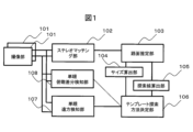
図1は、本実施例に係るカメラシステムの構成の例を示すブロック図である。カメラシステムは、複数の撮像部101と、ステレオマッチング部102と、路面推定部103と、サイズ算出部104と、探索線算出部105と、テンプレート探索方法決定部106と、単眼遠方検知部107と、単眼俯瞰差分検知部108とを備える。
FIG. 1 is a block diagram showing an example of the configuration of a camera system according to this embodiment. The camera system includes a plurality of
撮像部101は撮像センサを含み、たとえば公知のカメラとして構成される。撮像センサにはレンズが取り付けられ、装置の外界を撮像する。撮像センサは、例えばCMOS(Complementary Metal Oxide Semiconductor)を備える撮像センサであり、光を電気信号に変換するものである。
The
撮像部101の撮像センサで電気信号に変換された情報は、さらに撮像部101内で、画像を表す画像データに変換される。画像データは画素の輝度値を含む。輝度値は、たとえばデジタル値として表現することができ、色毎の輝度値や、モノクロの輝度値として表される。色毎の輝度値としては、たとえばRGB(Red Green Blue)またはRC(Red Clear)が利用可能である。
The information converted into an electric signal by the imaging sensor of the
撮像部101は、画像データを、ステレオマッチング部102と単眼遠方検知部107と単眼俯瞰差分検知部108とに送信する。
The
撮像部101は、撮像センサの露光条件を変更する機能を備える。たとえば、撮像センサにグローバルシャッタまたはローリングシャッタ等の電子シャッタが備わっており、露光時間を任意の時間に設定して撮影することができる。受光素子として、受光すると電荷が蓄積されるフォトダイオードを用いる場合には、露光時間は、フォトダイオードの蓄積電荷をリセットしてから、輝度値に係る情報を読み出すために電荷を取り出すまでの時間を指す。
The
露光時間を長くすると電荷が多く蓄積されるので、読み出される輝度値が高くなる。一方で露光時間を短くすると蓄えられる電荷が少なくなるので、読み出される輝度が低くなる。そのため、露光時間に相関して、撮像センサから得られる画像の明るさが変化する。 If the exposure time is lengthened, a large amount of electric charge is accumulated, so that the read luminance value is increased. On the other hand, if the exposure time is shortened, less charge is stored, so the readout brightness is lower. Therefore, the brightness of the image obtained from the imaging sensor changes in correlation with the exposure time.
撮像部101では、フォトダイオードから取り出される電荷量を電圧に変換し、A/D(Analog Digital)変換を行ってデジタル値を取得する。撮像部101はA/D変換に用いる増幅器を備えており、露光条件の一部として増幅器のゲインが変更できるように構成される場合がある。その場合には、増幅器のゲイン設定に応じて読み出される輝度値が変化する。ゲインを高くすれば輝度値は高く、ゲインを低くすれば輝度値は低くなる。
The
ここで、一般的に、露光条件(上記の例では露光時間およびゲイン)の変化により輝度値が低くなると、暗い対象物の輝度値が0になったり、コントラスト比が低い対象物の輝度値が一様になったりし、輪郭や濃淡等が判別できなくなる場合がある。この問題は輝度値をデジタル値として表現する場合に顕著であるが、アナログ値として表現する場合にも同質の問題が発生し得る。同様に、露光条件の変化により輝度値が高くなると、明るい対象物の輝度値が最大値となり、対象物の輪郭や対象物の濃淡が判別できなくなる場合がある。従って、撮影する対象物の明るさに応じて露光条件を設定すると好適である。 Here, in general, when the luminance value decreases due to changes in exposure conditions (exposure time and gain in the above example), the luminance value of a dark object becomes 0, or the luminance value of an object with a low contrast ratio becomes 0. It may become uniform, and it may not be possible to distinguish outlines and shading. This problem is conspicuous when the brightness value is expressed as a digital value, but the same problem can occur when it is expressed as an analog value. Similarly, when the luminance value increases due to a change in exposure conditions, the luminance value of a bright object becomes the maximum value, and the outline of the object and the shading of the object cannot be determined in some cases. Therefore, it is preferable to set the exposure condition according to the brightness of the object to be photographed.
撮像部101は、時系列的に繰り返し電子シャッタを切り、シャッタ毎の画像データを取得することにより動画を撮影することができる。単位時間あたりの電子シャッタを切り画像データを出力する回数をフレームレートと呼び、1秒あたりのフレームレートをFPS(Frame Per Second)の単位で表す。
The
ステレオマッチング部102は、複数の撮像部101から画像データを含むデータを受信し、これを処理することにより、画像データ間の視差を演算する。視差は、基準となる撮像部101からの画像データに対する、該基準となる撮像部101以外の撮像部101からの画像データの、視差である。前記視差とは、複数の撮像部の位置の違いから生じる、同一物体の写る画像座標の差を示す。視差は、近距離のものは大きく、遠距離のものは小さくなり、視差から距離を算出することが可能である。
The
撮像部101は、たとえば2つ備わり、それぞれの撮像部の視野は、一部重なり、一部重ならない。図2に、図1の画像処理システムの視野画角の具体例を示す。2つの撮像部101を車の前方向きに取り付ける例である。本実施例のカメラシステムは、車両201に取り付けられる。
For example, two
カメラシステムは、2つの撮像部101を備えるステレオカメラ202を備える。右視野を撮像する撮像部101を、図2ではとくに撮像部203として示す。左視野を撮像する撮像部101を、図2ではとくに撮像部204として示す。撮像部203および204は、車両201の前方中央視野において、重なった視野を持つ。
The camera system has a
撮像部203は、視野205を有する。撮像部204は、視野206を有する。撮像部203は、車両201の右側に、撮像部204の視野206よりも外側となる右視野を持つ。撮像部204は、車両201の左側に、撮像部204の視野205より外側となる左視野を持つ。
The
図3に、図2のステレオカメラ202で撮像される画像の具体例を示す。図3(a)は撮像部203によって取得される画像301を示し、図3(b)は撮像部204によって取得される画像302を示し、図3(c)はこれら2つの画像の合成画像303を示す。
FIG. 3 shows a specific example of an image captured by the
画像301は右向きの撮像部203の画像であり、前方の中央近傍および右側が撮像されている。画像302は左向きの撮像部204の画像であり、前方の中央近傍および左側が撮像されている。
An
合成画像303は、撮像部203と撮像部204とがそれぞれ撮像した画像を合成した、左右撮像部合成画像である。合成画像303は、領域304と、領域305と、領域306とを含む。領域304は、画像302の内、画像301には写っていない視野領域に該当する部分であり、左単眼視視野である。領域305は、画像301の内、画像302には写っていない視野領域に該当する部分であり、右単眼視視野である。
A combined
領域304および305は、一つのカメラで撮像された単眼領域である。領域306は、画像301および302の両方に写っている部分であり、ステレオ視視野(距離取得領域)である。このように、撮像部203および204は、ステレオ視視野(距離取得領域)と少なくとも一部が重複する領域(画像取得領域)について、画像を取得する。
ステレオマッチング部102は、画像データの歪みを補正してもよい。たとえば、中心射影モデルや透視投影モデルを用い、同一の高さで同一の奥行距離の物体が、画像中で水平に並ぶ様に、画像データの歪を補正する。前記補正された左右双方の画像に対して(たとえば2つの撮像部101それぞれの画像に対して)ステレオマッチング処理を行う際は、1つの撮像部101の画像データ(基準画像データ)を基準として、これともう一方の撮像部101の画像データ(比較画像データ)とを比較することにより、視差を求める。
The
このように、本実施例では、ステレオマッチング部102が距離取得部として機能し、ステレオ視視野について、視野中に現れる対象物(たとえば路面)の距離を取得する。とくに、本実施例では、ステレオマッチング部102は複数のカメラ(撮像部203および204)を備え、ステレオマッチングを行うことにより距離を算出する。このような構成により、高価な測距手段が不要となり、コストを低減できる。
Thus, in this embodiment, the
なお、本明細書において、「距離」の定義および測定方法は当業者が適切に決定可能である。たとえば、「路面の距離」とは、路面と、カメラシステムに対して特定される基準点との間の距離をいう。また、距離の起点(たとえば特定の基準点)は、撮像部203と撮像部204との中点であってもよく、車両201の特定部位(たとえば車両の前端中央)であってもよく、他の装置(測距装置等)の位置であってもよい。また、距離の測定は、たとえば算出された視差に基づいて公知の方法により実施することができる。
In addition, in this specification, a person skilled in the art can appropriately determine the definition of "distance" and the measurement method. For example, "road surface distance" refers to the distance between the road surface and the reference point identified to the camera system. Further, the starting point of the distance (for example, a specific reference point) may be a midpoint between the
本実施例では、領域304および305において特定の物体を検知する。或いは、本実施例では、領域304、305および306において特定の物体を検知する。
In this example, specific objects are detected in
尚、前記では中心射影モデルや透視投影モデルを用いたが、投影モデルはこれに限らない。たとえば画角が広い場合は、画像データのサイズを抑制するために、たとえば円筒や球面に射影してもよい。マッチング処理は、たとえば投影面上に同一距離の物体が並ぶ探索線に沿って行われる。 Although the central projection model and the perspective projection model are used above, the projection model is not limited to this. For example, when the angle of view is wide, projection may be performed on a cylindrical or spherical surface in order to reduce the size of the image data. The matching process is performed, for example, along a search line along which objects at the same distance are aligned on the projection plane.
視差を求める際は、前記基準画像データと、前記比較画像データの消失点の垂直座標を合わせて、前記基準画像データの各座標に対して、前記比較画像データの同一垂直座標のどの水平座標が同一物体を映しているのかを、たとえばSSD(Sum of Squared Difference)やSAD(Sum of Absolute Difference)といった手法で検査する。 When obtaining the parallax, the vertical coordinates of the vanishing points of the reference image data and the comparison image data are combined, and which horizontal coordinate of the same vertical coordinates of the comparison image data corresponds to each coordinate of the reference image data. A method such as SSD (Sum of Squared Difference) or SAD (Sum of Absolute Difference) is used to check whether the same object is projected.
尚、前記ではSSDやSADとしたが、そのほかの手法でもよい。たとえばコーナー特徴点抽出を行い、同一特徴点かを検査する、FAST(Features from Accelerated Segment Test)や、BRIEF(Binary Robust Independent Elementary Features)などの手法を組み合わせて、同一物体のマッチング処理を行ってもよい。 In the above description, SSD and SAD are used, but other methods may be used. For example, it is possible to perform matching processing of the same object by combining methods such as FAST (Features from Accelerated Segment Test) and BRIEF (Binary Robust Independent Elementary Features), which extract corner feature points and check whether they are the same feature points. good.
路面推定部103は、ステレオマッチング部102で算出された距離に基づき、路面の位置を推定する。路面の位置の推定では、たとえばステレオマッチング部102から受け取った視差データをもとに、路面に対応する特定の視差を有する部分、点または領域が路面であると推定する。
A road
路面推定部103は、予め撮像部101の路面からの高さや撮像部101の取り付け角度などの情報を有してもよく、路面の写る前記画像データ上の座標と距離との関係を求めて、その関係に適合する視差を生じる点が路面を表す点であると特定してもよい。
The road
本実施例の路面推定部103では、視差を用いるとしたが、視差を用いない構成も可能である。たとえば測距結果を用いてもよく、例えばLiDAR(Light Detection and Ranging)またはミリ波レーダで測距した結果を、カメラ画像の座標とマッピングしたものを用いてもよい。
Although parallax is used in the road
LiDARを用いる場合は、カメラとLiDARとの設置位置および向きの関係に基づき幾何変換してマッピングを行うことができる。路面推定を行う処理は、前記幾何変換の後に行われてもよく、前記幾何変換の前に行われてもよい。探索線算出部105による探索線の決定処理で用いることができるタイミングで路面を特定しておき、且前記幾何変換を施せば、テンプレートマッチング処理などで探索することが可能である。
When using LiDAR, mapping can be performed by geometrically transforming based on the relationship between the installation positions and orientations of the camera and LiDAR. The process of estimating the road surface may be performed after the geometric transformation, or may be performed before the geometric transformation. If the road surface is specified at a timing that can be used in the search line determination processing by the search
サイズ算出部104は、テンプレートマッチング処理などの実行時に画像を切り出す枠(単眼遠方検知部107が用いる)の大きさを算出する。サイズ算出部104では、同一奥行距離の探索線において、該奥行距離に応じてサイズを算出する。すなわち、サイズ算出部104は、テンプレートサイズ決定部として機能する。
The
探索線算出部105は、同一の奥行距離を有する路面を表す点に基づいて、単眼遠方検知部107がテンプレートマッチング処理において用いる探索線を算出する。探索線は、画像またはその領域において、同一奥行距離となる位置に沿って延びる線である。本実施例では、画像中の路面において、カメラシステムを起点とした距離が所定の値(所定の許容度を考慮した範囲内の値である場合を含む)となる位置に沿った線である。
The search
テンプレート探索方法決定部106は、路面の位置と、サイズ算出部104が決定した枠の大きさとに基づき、テンプレートマッチング処理(単眼遠方検知部107で実行される)の探索方法を決定する。
A template search
このようにテンプレートサイズが決定されることにより、テンプレートマッチング処理の精度が向上し、または処理負荷が低減される。 By determining the template size in this way, the accuracy of the template matching process is improved or the processing load is reduced.
単眼遠方検知部107は、撮像部203および204が取得した画像について、テンプレートを用いてテンプレートマッチング処理を行うことにより、対象物(たとえば特定の物体)を検知するテンプレートマッチング検知部である。
The monocular
単眼遠方検知部107は、テンプレートマッチング処理により、検知したい特定の物体の特徴に当てはまるものがないかを探す。テンプレートマッチング処理は、パターンマッチング処理を含んでもよく、機械学習の辞書によるマッチング処理を含んでもよい。機械学習の辞書は、たとえばHaar Like特徴量を用いて、Adaboostにて、前記特定の物体の様々なバリエーションを学習させることにより生成することができる。この際に、単眼遠方検知部107は、テンプレート探索方法決定部106が決定した大きさの枠を用い、画像データからテンプレートマッチング処理の対象領域を切り出す。このようにして単眼遠方検知部107は該特定の物体を検出する。たとえば、対象領域の画像が前記特定の物体の画像と類似しているか否かを判定し、これによって、その対象領域に該特定の物体が写っているか否かを判定する。
The monocular long-
前記特定の物体の探索処理では、画像上の特定の領域を切り出し、該切り出した領域の画像と、テンプレートやパターンや機械学習の辞書で表現されたモデル(またはモデル画像)とに基づき、これらの類似度を検査する。この前記切り出しでは、前記モデルを、特定の画像の大きさや角度に応じ、たとえば正規化処理等により、適切な大きさおよび角度(たとえば実際の画像に近い大きさおよび角度)に揃えると好適である。ただし、車両や歩行者や二輪車は、路面に対して大きく傾いてカメラに写ることは少ないので、角度は合っていると考えることもでき、その場合には角度を揃える処理は省略可能である。 In the process of searching for a specific object, a specific region is cut out from the image, and based on the image of the cut-out region and a model (or model image) represented by a template, pattern, or machine learning dictionary, these Check for similarity. In this cutting, it is preferable to align the model to an appropriate size and angle (for example, a size and angle close to the actual image) by normalization processing, for example, according to the size and angle of a specific image. . However, since vehicles, pedestrians, and two-wheeled vehicles are rarely photographed with a large tilt with respect to the road surface, it is possible to consider that the angles are correct, and in that case, the process of aligning the angles can be omitted.
モデルを前記適切な大きさに合わせるには、前記モデルの実際の大きさと、写っている特定の物体と撮像部101との距離と、撮像部の焦点距離および画素ピッチとが分かっていればよい。
To adjust the model to the appropriate size, it is sufficient to know the actual size of the model, the distance between the specific object being photographed and the
たとえば路面において、カメラシステムからの距離が同一となる位置が水平に並んでいる場合を考える。車両、歩行者、二輪車等は、路面に接して立っているので、これらがカメラシステムから等距離にあれば、これらの下端は水平に揃う(すなわちY座標が一致する)と考えられる。また、この場合には、カメラシステムからこれらの特定の物体までの距離は、その下端に位置する路面までの距離と等しいと考えられる(なお、ここでは、鉛直線上における上下位置の差による距離の差は無視できるものと考えているが、そうでない場合には適宜変換または補正が可能である)。 Consider, for example, a case where positions on a road surface at the same distance from the camera system are arranged horizontally. Vehicles, pedestrians, two-wheeled vehicles, etc. stand against the road surface, so if they are equidistant from the camera system, their bottom edges are considered to be horizontally aligned (ie, have the same Y coordinate). Also, in this case, the distance from the camera system to these specific objects is considered to be equal to the distance to the road surface located at the lower end of the object (here, the difference in distance due to the difference in vertical position) It is assumed that the difference is negligible, otherwise it can be transformed or corrected as appropriate).
前記では路面において同一の距離となる位置が水平に並んでいると想定した。このような場合には、探索線は水平の直線となる。しかしながら、路面が斜めである場合、撮像部101が傾いているような場合、画像の周辺に歪みが発生する場合、等では、同一の距離となる位置が、水平ではなく斜めに並んだり、曲線上に並んだりする場合もある。
In the above description, it was assumed that the positions having the same distance on the road surface were lined up horizontally. In such a case, the search line will be a horizontal straight line. However, when the road surface is slanted, when the
このような場合には、路面において同一の距離となる位置を結ぶ線(探索線)を、1以上のパラメータを有するモデル関数で表される線として定義しておき、最小二乗法などでパラメータを特定して、数式またはテーブル等に基づき、具体的に探索線を決定してもよい。 In such a case, a line (search line) that connects positions with the same distance on the road surface is defined as a line represented by a model function having one or more parameters, and the parameters are determined by the least squares method. Specifically, the search line may be specifically determined based on a formula, a table, or the like.
このようにして、視差が得られない領域(たとえば領域304および305)についても路面の推定および探索線の決定が可能である。単眼遠方検知部107は、決定された探索線に沿って、テンプレートマッチングなどで特定の物体を探索する。たとえば、探索線を下端として枠を設定し、枠内の領域を切り抜き、該特定の物体が写っていないかを確認する。
In this way, estimation of the road surface and determination of search lines are possible even for areas where parallax is not available (for example,
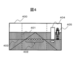
図4に、単眼遠方検知部107による探索処理の例を示す。合成画像400は、左右の撮像部101の画像を合成したものであり、図3の合成画像303に対応する。合成画像400には路面部401が現れている。同一距離点402は、視差が互いに等しい点を表し、すなわち距離が等しい点を表す。
FIG. 4 shows an example of search processing by the monocular far-
探索線算出部105は、画像における探索線403を、同一距離点402に基づいて特定する。探索線403の算出は、たとえば、路面の位置(または距離)に基づいて行うことができる。探索線403は、たとえば画像中の路面において距離が所定の値(所定の許容度を考慮した範囲内の値である場合を含む)となる位置に沿った線である。
The search
枠404は、単眼遠方検知部107のテンプレートマッチング処理により特定の物体と比較するために、切り抜く画像領域の枠である。特定の物体405が、探索線403と整合する位置に現れている。
A
本実施例では、路面上に探索線403を作成し、探索線403上に特定の大きさの枠404を配置し、枠404の下端が探索線403に一致した状態で枠404を左右に移動させる。このように、単眼遠方検知部107によるテンプレートマッチング処理は、探索線403に沿って行われる。単眼遠方検知部107は、枠404を左右に移動させながら、異なる位置において枠404から切り抜いた画像についてテンプレートマッチング処理を行い、特定の物体と類似しているか否かを判定する。
In this embodiment, a
本実施例では、テンプレートマッチング処理は、単眼領域(たとえば図3の領域304および305)において行われ、ステレオ視視野(たとえば図3の領域306)では行われない。このようにすると、テンプレートマッチング処理の回数を減らし、処理負荷を低減することができる。ただし、変形例として、ステレオ視視野の全体または一部においてテンプレートマッチング処理を行ってもよい。
In this example, the template matching process is performed in the monocular field (eg,
いずれかの位置において、切り抜いた画像が特定の物体と類似している場合は、その位置に特定の物体が写っていると検知する。検知された特定の物体までの距離は、探索線403までの距離と等しいものと判断される。
If the clipped image resembles a specific object at any position, it is detected that the specific object is captured at that position. The distance to the particular detected object is determined to be equal to the distance to search
ここで、撮像部101の向きが上下に変化する場合を考える。撮像部101の向きが上下に変化すると、路面が画像中で上下するので、所定距離にある路面の画像中での上下位置が一定せず、想定される上下動の範囲内でテンプレートマッチングを行う必要がある。
Here, consider a case where the orientation of the
このため、従来技術では、ある大きさの枠を、上下左右に2次元的に広がる範囲内の各位置に移動させてテンプレートマッチング処理を行う必要があり、処理負荷が高くなる。 For this reason, in the conventional technique, it is necessary to perform template matching processing by moving a frame of a certain size to each position within a range that extends two-dimensionally up, down, left, and right, increasing the processing load.
これに対し、本発明の実施例1に係る画像処理システムおよびカメラシステムによれば、路面が画像中で上下しても、路面に合わせた探索線403を設定するので、枠の移動範囲は左右方向(または探索線403に沿った1次元範囲)のみに限定され、処理負荷が低くなる。このように、カメラの向きが上下に変化する車載システムにおいても、低処理負荷で、特定の物体を検知することができる。
On the other hand, according to the image processing system and the camera system according to the first embodiment of the present invention, even if the road surface rises and falls in the image, the
探索線403は複数生成してもよい。たとえば、異なる距離についてそれぞれ個別の探索線403を生成してもよく、単眼遠方検知部107は、各探索線403についてテンプレートマッチング処理を行ってもよい。このようにすると、様々な距離において、テンプレートマッチング処理により特定の物体を探索することができる。特定の物体を検知したい距離範囲が予め定まっている場合は、該距離範囲内において複数の探索線を作り、探索を行う。そうすることで、距離範囲外の不要な探索を抑制して、処理時間を短くすることができる。
A plurality of
複数の探索線403を設定する場合において、隣接する探索線403間の間隔は任意に設計可能である。たとえば、各探索線403は、画像上で一定の画素間隔をおいて設定されてもよいし、路面上で一定の距離間隔をおいて設定されてもよい。
When setting a plurality of
ここで、ある程度の距離ずれがあってもテンプレートマッチング処理が可能である場合には、テンプレートマッチング処理の頑強度に応じて探索線403間の間隔を決定することができる。たとえば、テンプレートマッチング処理が頑強であり、探索線403の距離と特定の物体との距離とが大きく相違していても特定の物体を検出することができる場合には、隣接する探索線403間の間隔を大きく設計することができる。このようにすることで、探索線403の数を低減し、処理時間を短くすることができる。
Here, if the template matching process can be performed even if there is some degree of distance deviation, the interval between the
一本の探索線403上において、テンプレートマッチング処理を行う位置の間隔(たとえば左右方向の間隔)も、同様に設計可能である。たとえば、テンプレートマッチング処理が頑強であり、枠404と特定の物体とが大きく隔たっていても特定の物体を検出することができる場合には、テンプレートマッチング処理の間隔を大きく設計することができる。このようにすることで、テンプレートマッチング処理の回数を低減し、処理時間を短くすることができる。
On one
図5に枠404の寸法を求める方法について示す。図5は、特定の物体501と、撮像部101のレンズ502と、撮像部101の撮像センサ503(撮像素子)と、路面504とを、光軸と直交する水平方向から見た概念的な位置関係を示す。
FIG. 5 shows how to determine the dimensions of the
撮像部101の焦点距離505をfとする。特定の物体501と撮像部101(より厳密にはレンズ502)との奥行距離506(距離)をZとする。画像中の高さ507(撮像センサ503上に写る特定の物体501の高さ)が求めるべき値である。特定の物体501の高さ508をhとする。
Let f be the
数式509は、これらのパラメータの関係を示す。数式509から、画像における枠404の高さを求めることができる。前記においては、高さについて示したが、同様に幅についても求めることができる。その場合には、高さhを幅に置き換え、画像中の高さ507を画像中の幅に置き換える。
単眼俯瞰差分検知部108は、撮像部101から画像データを含むデータを受信し、これを処理することにより画像中の物体を検知する。物体の検知は俯瞰差分方式で行われ、これによって対象物(たとえば移動体)を検知することが可能である。
The monocular bird's-eye view
俯瞰差分方式は、画像の一部(第1領域)について、異なる時刻の俯瞰画像を比較する方式である。俯瞰差分方式では、俯瞰画像の背景差分を取得してもよいし、俯瞰画像の時間差分を取得してもよい。 The bird's-eye view difference method is a method of comparing bird's-eye view images at different times for part of the image (first region). In the bird's-eye view difference method, the background difference of the bird's-eye view image may be acquired, or the time difference of the bird's-eye view image may be acquired.
このような場合には、単眼遠方検知部107は、画像の一部(第2領域)においてテンプレートマッチング処理を行ってもよい。この第2領域は、第1領域とは異なる領域であってもよく、とくに、第1領域と重ならない領域であってもよい。このようにすると、単眼遠方検知部107によるテンプレートマッチング処理を一部省略することができ、処理負荷が低減される。
In such a case, the monocular
なお、単眼俯瞰差分検知部108は省略してもよい。
Note that the monocular overhead view
[実施例2]
本発明の実施例2について説明する。実施例2は実施例1と基本的には同じであるが、以下の点において異なる。実施例2では、車両の四面に撮像部を設置し、全周囲の検知を行える様にする。そのため撮像部の水平画角は広くとる。
[Example 2]
A second embodiment of the present invention will be described. Example 2 is basically the same as Example 1, but differs in the following points. In the second embodiment, imaging units are installed on the four sides of the vehicle so that the entire surroundings can be detected. Therefore, the horizontal angle of view of the imaging unit is widened.
図6は、実施例2に係るカメラシステムの構成の例を示すブロック図である。実施例2に係るカメラシステムは、180度を超える水平画角を撮像可能な撮像部601を備える。また、カメラシステムはステレオマッチング部602を備え、ステレオマッチング部602は、複数の撮像部601から画像を受け取り、複数の撮像部が重なる領域においてステレオマッチング処理を行う。これによって路面の距離が推定され、テンプレートマッチング処理が可能となる。
FIG. 6 is a block diagram illustrating an example configuration of a camera system according to the second embodiment. The camera system according to Example 2 includes an
図7は、実施例2のカメラシステムが車両に取り付けられた際の、撮像部601の画角の例を示す図である。第1撮像部601は水平画角701を有する。第2撮像部601は水平画角702を有する。第3撮像部601は水平画角703を有する。第4撮像部601は水平画角704を有する。
FIG. 7 is a diagram illustrating an example of the angle of view of the
水平画角701の左端の領域は、水平画角702の前端の領域と重なる。水平画角701の右端の領域は、水平画角703の前端の領域と重なる。水平画角704の左端の領域は、水平画角702の後端の領域と重なる。水平画角704の右端の領域は、水平画角703の後端の領域と重なる。
The left end region of the horizontal angle of
複数の画角が重なる領域において、実施例2のカメラシステムは、ステレオマッチング処理を行い、ステレオマッチングを行った領域において路面推定を行い、結果に基づいて同一距離に対応する視差を有する点を結んだ探索線を作成し、テンプレートマッチング処理を行う。 In an area where multiple angles of view overlap, the camera system of Example 2 performs stereo matching processing, performs road surface estimation in the area where stereo matching is performed, and connects points having parallax corresponding to the same distance based on the result. Create a search line and perform template matching processing.
[実施例3]
本発明の実施例3について説明する。実施例3は実施例1と基本的には同じであるが、以下の点において異なる。実施例3では、測距センサ部を設け、測距センサ部の距離情報に基づいて路面推定を行い、探索線を決定してテンプレートマッチング処理を行う。
[Example 3]
A third embodiment of the present invention will be described. Example 3 is basically the same as Example 1, but differs in the following points. In the third embodiment, a distance measuring sensor is provided, road surface estimation is performed based on distance information from the distance measuring sensor, a search line is determined, and template matching processing is performed.
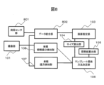
図8は、実施例3に係るカメラシステムの構成の例を示すブロック図である。カメラシステムは測距センサ部801を備え、測距センサ部801は周囲の三次元の距離情報を取得することができる。測距センサ部801は、例えばLiDar(Laser Imaging Detection and Ranging)である。本実施例では、測距センサ部801が距離の測定を行う。
FIG. 8 is a block diagram illustrating an example configuration of a camera system according to the third embodiment. The camera system includes a
カメラシステムはデータ統合部802を備え、データ統合部802は、測距センサ部801から三次元距離情報を受信し、撮像部101からカメラ画像を受信して、該カメラ画像に対して座標変換された距離情報を重畳する。この重畳の処理では、三次元距離情報を、撮像部101の三次元位置を視点としたカメラ画像座標に変換して重畳する。これによって路面の距離が推定され、テンプレートマッチング処理が可能となる。
The camera system includes a
図9に、実施例3のカメラシステムを車両に取り付けた際の、測距センサ部801および撮像部101の画角の例を示す。測距センサ部801は画角901(距離取得領域)を有する。測距センサ部801は、例えば車両のフロントバンパに取り付けられる。撮像部101は画角902を有する。撮像部101は、例えば車両のフロントガラスに取り付けられる。
FIG. 9 shows an example of the angles of view of the distance
実施例3のカメラシステムは、テンプレートマッチング処理を、測距センサ部801の画角901の外部において行う。すなわち、撮像部101の画角902のうち、測距センサ部801の画角901と重なっていない部分のみについてテンプレートマッチング処理を行う。このようにするとテンプレートマッチング処理を行う範囲が限定され、処理負荷が低減される。
The camera system of Example 3 performs template matching processing outside the angle of
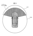
また、実施例3の変形例として、カメラシステムは、図10に示すような視野角の測距センサ部801を用いてもよい。撮像部101は画角1001を有する。測距センサ部801は画角1002(距離取得領域)を有する。
Also, as a modification of the third embodiment, the camera system may use a distance
測距センサ部801の画角1002は全周囲360度に及ぶ。このため、物体の検知は測距センサ部801のみで全て行える。しかしながら、物体の種別を識別するためには距離情報だけでは不十分な場合がある。
The angle of
本変形例のカメラシステムは、物体の種別(たとえば、その物体が特定の物体であるか否か)を識別するために、テンプレートマッチング処理を、測距センサ部801は画角1002内において行う。たとえば、測距センサ部801の画角1002を利用した全周囲画角の路面推定結果に基づき、撮像部101の画角1001内で探索線を決定し、探索線に沿ってテンプレートマッチング処理を行う。そうすることで、物体の種別の識別を効率的に行うことができる。
In the camera system of this modified example, the distance
なお、本発明は上記した実施例および変形例に限定されるものではなく、これら以外にも様々な変形例が含まれる。例えば、上記した実施例は本発明を分かりやすく説明するために詳細に説明したものであり、本発明は必ずしも説明した全ての構成を備えるものに限定されるものではない。 It should be noted that the present invention is not limited to the above-described examples and modifications, and includes various modifications in addition to these. For example, the above-described embodiments have been described in detail in order to explain the present invention in an easy-to-understand manner, and the present invention is not necessarily limited to those having all the described configurations.
また、ある実施例の構成の一部を他の実施例の構成に置き換えることが可能であり、また、ある実施例の構成に他の実施例の構成を加えることも可能である。また、各実施例の構成の一部について、他の構成の追加・削除・置換をすることが可能である。 In addition, it is possible to replace part of the configuration of one embodiment with the configuration of another embodiment, and it is also possible to add the configuration of another embodiment to the configuration of one embodiment. Moreover, it is possible to add, delete, or replace a part of the configuration of each embodiment with another configuration.
また、上記の各構成、機能、処理部、処理手段等は、それらの一部又は全部を、例えば集積回路で設計する等によりハードウェアで実現してもよい。また、上記の各構成、機能等は、プロセッサがそれぞれの機能を実現するプログラムを解釈し、実行することによりソフトウェアで実現してもよい。各機能を実現するプログラム、テーブル、ファイル等の情報は、メモリや、ハードディスク、SSD(Solid State Drive)等の記録装置、または、ICカード、SDカード等の記録媒体に置くことができる。 Further, each of the above configurations, functions, processing units, processing means, and the like may be realized by hardware, for example, by designing them in an integrated circuit. Moreover, each of the above configurations, functions, etc. may be realized by software by a processor interpreting and executing a program for realizing each function. Information such as programs, tables, and files that implement each function can be stored in a recording device such as a memory, a hard disk, an SSD (Solid State Drive), or a recording medium such as an IC card or SD card.
また、制御線や情報線は説明上必要と考えられるものを示しており、製品上必ずしも全ての制御線や情報線を示しているとは限らない。実際には殆ど全ての構成が相互に接続されていると考えてもよい。 Further, the control lines and information lines indicate those considered necessary for explanation, and not all control lines and information lines are necessarily indicated on the product. In practice, it may be considered that almost all configurations are interconnected.
101,203,204,601…撮像部
102…ステレオマッチング部(距離取得部)
103…路面推定部
104…サイズ算出部(テンプレートサイズ決定部)
105…探索線算出部
106…テンプレート探索方法決定部
107…単眼遠方検知部
108…単眼俯瞰差分検知部
201…車両
202…ステレオカメラ
301,302…画像
303,400…合成画像
401…路面部
402…同一距離点
403…探索線
404…枠
405,501…物体
502…レンズ
503…撮像センサ
504…路面
505…焦点距離
506…奥行距離
507,508…高さ
601…撮像部
602…ステレオマッチング部(距離取得部)
801…測距センサ部
802…データ統合部
101, 203, 204, 601...
103... Road
105 Search
801 ... Ranging
Claims (7)
前記カメラシステムは、
距離取得領域について距離を取得する距離取得部と、
前記距離取得領域と少なくとも一部が重複する画像取得領域について画像を取得するカメラと、
前記画像について、テンプレートを用いてテンプレートマッチング処理を行うことにより対象物を検知する、テンプレートマッチング検知部と、
前記距離取得部で算出された距離に基づき、路面の位置を推定する路面推定部と、
前記路面の位置に基づき、前記画像における探索線を算出する、探索線算出部と
を備え、
前記探索線は、前記画像中の路面において距離が所定の値となる位置に沿った線であり、
前記テンプレートマッチング処理は、一つのカメラで撮像された単眼領域において、前記探索線に沿って行われる、
ことを特徴とするカメラシステム。 a camera system,
The camera system is
a distance acquisition unit that acquires a distance for the distance acquisition area;
a camera that acquires an image of an image acquisition area that at least partially overlaps with the distance acquisition area;
a template matching detection unit that detects an object by performing template matching processing on the image using a template;
a road surface estimation unit that estimates the position of the road surface based on the distance calculated by the distance acquisition unit;
a search line calculation unit that calculates a search line in the image based on the position of the road surface;
The search line is a line along a position where the distance is a predetermined value on the road surface in the image,
The template matching process is performed along the search line in a monocular region captured by one camera .
A camera system characterized by:
前記画像のうち第1領域について、異なる時刻の俯瞰画像を比較する俯瞰差分方式により対象物を検知する、俯瞰差分検知部をさらに備え、
前記テンプレートマッチング検知部は、前記画像のうち、前記第1領域とは異なる第2領域において前記テンプレートマッチング処理を行う、
ことを特徴とするカメラシステム。 3. The camera system of claim 2, wherein
Further comprising a bird's-eye difference detection unit that detects an object by a bird's-eye difference method that compares bird's-eye images at different times in the first region of the image,
wherein the template matching detection unit performs the template matching process on a second region of the image that is different from the first region;
A camera system characterized by:
Priority Applications (3)
| Application Number | Priority Date | Filing Date | Title |
|---|---|---|---|
| JP2019227407A JP7293100B2 (en) | 2019-12-17 | 2019-12-17 | camera system |
| PCT/JP2020/038395 WO2021124657A1 (en) | 2019-12-17 | 2020-10-09 | Camera system |
| CN202080082086.0A CN114762019A (en) | 2019-12-17 | 2020-10-09 | Camera system |
Applications Claiming Priority (1)
| Application Number | Priority Date | Filing Date | Title |
|---|---|---|---|
| JP2019227407A JP7293100B2 (en) | 2019-12-17 | 2019-12-17 | camera system |
Publications (2)
| Publication Number | Publication Date |
|---|---|
| JP2021096638A JP2021096638A (en) | 2021-06-24 |
| JP7293100B2 true JP7293100B2 (en) | 2023-06-19 |
Family
ID=76431396
Family Applications (1)
| Application Number | Title | Priority Date | Filing Date |
|---|---|---|---|
| JP2019227407A Active JP7293100B2 (en) | 2019-12-17 | 2019-12-17 | camera system |
Country Status (3)
| Country | Link |
|---|---|
| JP (1) | JP7293100B2 (en) |
| CN (1) | CN114762019A (en) |
| WO (1) | WO2021124657A1 (en) |
Families Citing this family (1)
| Publication number | Priority date | Publication date | Assignee | Title |
|---|---|---|---|---|
| JP7727502B2 (en) * | 2021-11-22 | 2025-08-21 | Astemo株式会社 | Image processing device |
Citations (5)
| Publication number | Priority date | Publication date | Assignee | Title |
|---|---|---|---|---|
| JP2002099997A (en) | 2000-09-26 | 2002-04-05 | Mitsubishi Motors Corp | Moving object detection device |
| JP2004120585A (en) | 2002-09-27 | 2004-04-15 | Mitsubishi Electric Corp | On-vehicle travel lane recognition device |
| JP2007064894A (en) | 2005-09-01 | 2007-03-15 | Fujitsu Ten Ltd | Object detector, object detecting method, and object detection program |
| WO2011090053A1 (en) | 2010-01-21 | 2011-07-28 | クラリオン株式会社 | Obstacle detection warning device |
| WO2016092925A1 (en) | 2014-12-09 | 2016-06-16 | クラリオン株式会社 | Approaching vehicle detection device |
Family Cites Families (18)
| Publication number | Priority date | Publication date | Assignee | Title |
|---|---|---|---|---|
| JP4171282B2 (en) * | 2002-10-25 | 2008-10-22 | 富士重工業株式会社 | Terrain recognition device and terrain recognition method |
| JP2006318061A (en) * | 2005-05-10 | 2006-11-24 | Olympus Corp | Apparatus, method, and program for image processing |
| WO2006121088A1 (en) * | 2005-05-10 | 2006-11-16 | Olympus Corporation | Image processing device, image processing method, and image processing program |
| JP4804202B2 (en) * | 2006-04-10 | 2011-11-02 | 富士重工業株式会社 | Stereo monitoring device |
| JP2010020710A (en) * | 2008-07-14 | 2010-01-28 | Mazda Motor Corp | Device for detecting road side fixed object |
| JP2013140515A (en) * | 2012-01-05 | 2013-07-18 | Toyota Central R&D Labs Inc | Solid object detection device and program |
| JP2013161241A (en) * | 2012-02-03 | 2013-08-19 | Toyota Motor Corp | Object recognition device and object recognition method |
| JP6035774B2 (en) * | 2012-02-24 | 2016-11-30 | 株式会社リコー | Image processing apparatus, image processing method, and vehicle |
| JP2014021017A (en) * | 2012-07-20 | 2014-02-03 | Sanyo Electric Co Ltd | Information acquisition device and object detection device |
| JP2014052307A (en) * | 2012-09-07 | 2014-03-20 | Sanyo Electric Co Ltd | Information acquisition device and object detection device |
| JP2014067320A (en) * | 2012-09-27 | 2014-04-17 | Hitachi Automotive Systems Ltd | Stereo camera device |
| JP6550881B2 (en) * | 2014-07-14 | 2019-07-31 | 株式会社リコー | Three-dimensional object detection device, three-dimensional object detection method, three-dimensional object detection program, and mobile device control system |
| CN104881661B (en) * | 2015-06-23 | 2018-02-13 | 河北工业大学 | Vehicle checking method based on structural similarity |
| JP6548518B2 (en) * | 2015-08-26 | 2019-07-24 | 株式会社ソニー・インタラクティブエンタテインメント | INFORMATION PROCESSING APPARATUS AND INFORMATION PROCESSING METHOD |
| JP6623044B2 (en) * | 2015-11-25 | 2019-12-18 | 日立オートモティブシステムズ株式会社 | Stereo camera device |
| JP2017167970A (en) * | 2016-03-17 | 2017-09-21 | 株式会社リコー | Image processing apparatus, object recognition apparatus, device control system, image processing method, and program |
| CN106228110B (en) * | 2016-07-07 | 2019-09-20 | 浙江零跑科技有限公司 | A kind of barrier and drivable region detection method based on vehicle-mounted binocular camera |
| CN109631829B (en) * | 2018-12-17 | 2022-05-27 | 南京理工大学 | Self-adaptive fast-matching binocular ranging method |
-
2019
- 2019-12-17 JP JP2019227407A patent/JP7293100B2/en active Active
-
2020
- 2020-10-09 WO PCT/JP2020/038395 patent/WO2021124657A1/en not_active Ceased
- 2020-10-09 CN CN202080082086.0A patent/CN114762019A/en active Pending
Patent Citations (5)
| Publication number | Priority date | Publication date | Assignee | Title |
|---|---|---|---|---|
| JP2002099997A (en) | 2000-09-26 | 2002-04-05 | Mitsubishi Motors Corp | Moving object detection device |
| JP2004120585A (en) | 2002-09-27 | 2004-04-15 | Mitsubishi Electric Corp | On-vehicle travel lane recognition device |
| JP2007064894A (en) | 2005-09-01 | 2007-03-15 | Fujitsu Ten Ltd | Object detector, object detecting method, and object detection program |
| WO2011090053A1 (en) | 2010-01-21 | 2011-07-28 | クラリオン株式会社 | Obstacle detection warning device |
| WO2016092925A1 (en) | 2014-12-09 | 2016-06-16 | クラリオン株式会社 | Approaching vehicle detection device |
Also Published As
| Publication number | Publication date |
|---|---|
| WO2021124657A1 (en) | 2021-06-24 |
| CN114762019A (en) | 2022-07-15 |
| JP2021096638A (en) | 2021-06-24 |
Similar Documents
| Publication | Publication Date | Title |
|---|---|---|
| US10909395B2 (en) | Object detection apparatus | |
| US6956469B2 (en) | Method and apparatus for pedestrian detection | |
| JP4406381B2 (en) | Obstacle detection apparatus and method | |
| US8102427B2 (en) | Camera egomotion estimation from an infra-red image sequence for night vision | |
| US8867790B2 (en) | Object detection device, object detection method, and program | |
| US7899211B2 (en) | Object detecting system and object detecting method | |
| KR101758684B1 (en) | Apparatus and method for tracking object | |
| US20050232463A1 (en) | Method and apparatus for detecting a presence prior to collision | |
| US10659762B2 (en) | Stereo camera | |
| KR101551026B1 (en) | Method of tracking vehicle | |
| WO2017138245A1 (en) | Image processing device, object recognition device, device control system, and image processing method and program | |
| CN108369739B (en) | Object detection device and object detection method | |
| JP2016152027A (en) | Image processing device, image processing method and program | |
| CN111382722A (en) | License plate image optimization method, image processing device and device with storage function | |
| JP6410231B2 (en) | Alignment apparatus, alignment method, and computer program for alignment | |
| JP2018503195A (en) | Object detection method and object detection apparatus | |
| JP7293100B2 (en) | camera system | |
| US20180268228A1 (en) | Obstacle detection device | |
| JP2022014673A (en) | Image processing apparatus | |
| KR20170119167A (en) | System and method for detecting object | |
| WO2022270183A1 (en) | Computation device and speed calculation method | |
| JP4696925B2 (en) | Image processing device | |
| JP4788399B2 (en) | Pedestrian detection method, apparatus, and program | |
| Garg et al. | High-Precision Positioning of Known Objects Using a Static Monocular Camera | |
| KR20240115442A (en) | Device and Method for Omni-directional Visual Odometry based on Multicamera Robust to Challenging Conditions |
Legal Events
| Date | Code | Title | Description |
|---|---|---|---|
| A621 | Written request for application examination |
Free format text: JAPANESE INTERMEDIATE CODE: A621 Effective date: 20220413 |
|
| A131 | Notification of reasons for refusal |
Free format text: JAPANESE INTERMEDIATE CODE: A131 Effective date: 20230110 |
|
| A521 | Request for written amendment filed |
Free format text: JAPANESE INTERMEDIATE CODE: A523 Effective date: 20230310 |
|
| TRDD | Decision of grant or rejection written | ||
| A01 | Written decision to grant a patent or to grant a registration (utility model) |
Free format text: JAPANESE INTERMEDIATE CODE: A01 Effective date: 20230509 |
|
| A61 | First payment of annual fees (during grant procedure) |
Free format text: JAPANESE INTERMEDIATE CODE: A61 Effective date: 20230607 |
|
| R150 | Certificate of patent or registration of utility model |
Ref document number: 7293100 Country of ref document: JP Free format text: JAPANESE INTERMEDIATE CODE: R150 |