JP7288552B2 - CONTROL DEVICE FOR INTERNAL COMBUSTION ENGINE AND CONTROL METHOD FOR INTERNAL COMBUSTION ENGINE - Google Patents

CONTROL DEVICE FOR INTERNAL COMBUSTION ENGINE AND CONTROL METHOD FOR INTERNAL COMBUSTION ENGINE Download PDF

Info

Publication number
JP7288552B2
JP7288552B2 JP2022534931A JP2022534931A JP7288552B2 JP 7288552 B2 JP7288552 B2 JP 7288552B2 JP 2022534931 A JP2022534931 A JP 2022534931A JP 2022534931 A JP2022534931 A JP 2022534931A JP 7288552 B2 JP7288552 B2 JP 7288552B2
Authority
JP
Japan
Prior art keywords
angle
valve
internal combustion
combustion engine
control device
Prior art date
Legal status (The legal status is an assumption and is not a legal conclusion. Google has not performed a legal analysis and makes no representation as to the accuracy of the status listed.)
Active
Application number
JP2022534931A
Other languages
Japanese (ja)
Other versions
JPWO2022009532A1 (en
Inventor
英一郎 大畠
Current Assignee (The listed assignees may be inaccurate. Google has not performed a legal analysis and makes no representation or warranty as to the accuracy of the list.)
Hitachi Astemo Ltd
Original Assignee
Hitachi Astemo Ltd
Priority date (The priority date is an assumption and is not a legal conclusion. Google has not performed a legal analysis and makes no representation as to the accuracy of the date listed.)
Filing date
Publication date
Application filed by Hitachi Astemo Ltd filed Critical Hitachi Astemo Ltd
Publication of JPWO2022009532A1 publication Critical patent/JPWO2022009532A1/ja
Application granted granted Critical
Publication of JP7288552B2 publication Critical patent/JP7288552B2/en
Active legal-status Critical Current
Anticipated expiration legal-status Critical

Links

Images

Classifications

    • FMECHANICAL ENGINEERING; LIGHTING; HEATING; WEAPONS; BLASTING
    • F01MACHINES OR ENGINES IN GENERAL; ENGINE PLANTS IN GENERAL; STEAM ENGINES
    • F01LCYCLICALLY OPERATING VALVES FOR MACHINES OR ENGINES
    • F01L1/00Valve-gear or valve arrangements, e.g. lift-valve gear
    • F01L1/34Valve-gear or valve arrangements, e.g. lift-valve gear characterised by the provision of means for changing the timing of the valves without changing the duration of opening and without affecting the magnitude of the valve lift
    • F01L1/344Valve-gear or valve arrangements, e.g. lift-valve gear characterised by the provision of means for changing the timing of the valves without changing the duration of opening and without affecting the magnitude of the valve lift changing the angular relationship between crankshaft and camshaft, e.g. using helicoidal gear
    • F01L1/352Valve-gear or valve arrangements, e.g. lift-valve gear characterised by the provision of means for changing the timing of the valves without changing the duration of opening and without affecting the magnitude of the valve lift changing the angular relationship between crankshaft and camshaft, e.g. using helicoidal gear using bevel or epicyclic gear
    • FMECHANICAL ENGINEERING; LIGHTING; HEATING; WEAPONS; BLASTING
    • F01MACHINES OR ENGINES IN GENERAL; ENGINE PLANTS IN GENERAL; STEAM ENGINES
    • F01LCYCLICALLY OPERATING VALVES FOR MACHINES OR ENGINES
    • F01L13/00Modifications of valve-gear to facilitate reversing, braking, starting, changing compression ratio, or other specific operations
    • FMECHANICAL ENGINEERING; LIGHTING; HEATING; WEAPONS; BLASTING
    • F02COMBUSTION ENGINES; HOT-GAS OR COMBUSTION-PRODUCT ENGINE PLANTS
    • F02DCONTROLLING COMBUSTION ENGINES
    • F02D13/00Controlling the engine output power by varying inlet or exhaust valve operating characteristics, e.g. timing
    • F02D13/02Controlling the engine output power by varying inlet or exhaust valve operating characteristics, e.g. timing during engine operation
    • YGENERAL TAGGING OF NEW TECHNOLOGICAL DEVELOPMENTS; GENERAL TAGGING OF CROSS-SECTIONAL TECHNOLOGIES SPANNING OVER SEVERAL SECTIONS OF THE IPC; TECHNICAL SUBJECTS COVERED BY FORMER USPC CROSS-REFERENCE ART COLLECTIONS [XRACs] AND DIGESTS
    • Y02TECHNOLOGIES OR APPLICATIONS FOR MITIGATION OR ADAPTATION AGAINST CLIMATE CHANGE
    • Y02TCLIMATE CHANGE MITIGATION TECHNOLOGIES RELATED TO TRANSPORTATION
    • Y02T10/00Road transport of goods or passengers
    • Y02T10/10Internal combustion engine [ICE] based vehicles
    • Y02T10/12Improving ICE efficiencies

Landscapes

  • Engineering & Computer Science (AREA)
  • Mechanical Engineering (AREA)
  • General Engineering & Computer Science (AREA)
  • Chemical & Material Sciences (AREA)
  • Combustion & Propulsion (AREA)
  • Output Control And Ontrol Of Special Type Engine (AREA)
  • Valve Device For Special Equipments (AREA)
  • Combined Controls Of Internal Combustion Engines (AREA)

Description

本発明は、例えば、吸気弁や排気弁の開閉タイミングを制御する内燃機関の制御装置及び内燃機関の制御方法に関する。 The present invention relates to, for example, an internal combustion engine control apparatus and an internal combustion engine control method for controlling opening/closing timings of an intake valve and an exhaust valve.

自動車の内燃機関(エンジン)は、燃費や排気低減に対応するために、電動化技術が進められている。例えば、アイドルストップ後のエンジンの再始動には、従来のセルスタータに代えて、フルハイブリッド用の主機モータや、マイルドハイブリッド用のISG(Integrated Starter Generator,モータ機能付発電機)などを用いて、エンジンの初期駆動を行う。 BACKGROUND ART Electrification technology for internal combustion engines (engines) of automobiles is progressing in order to cope with fuel consumption and exhaust emission reduction. For example, to restart the engine after an idle stop, instead of the conventional self-starter, a main motor for a full hybrid or an ISG (Integrated Starter Generator, generator with motor function) for a mild hybrid is used. Initial drive of the engine is performed.

エンジンの初期駆動においては、エンジンをモータで回すため、筒内における圧縮圧力の変化に伴う振動が生じる。この振動を抑制するためには、筒内における圧縮圧力の変化を小さくする必要がある。ここで、バルブタイミング制御装置により、吸気弁の閉じる時期を下死点から離すことで、筒内へ吸入される空気量(圧縮対象の空気量)を減らす方法が知られている。なお、従来のバルブタイミング制御装置としては、例えば、特許文献1に記載されている。 In the initial drive of the engine, since the engine is rotated by the motor, vibration occurs due to changes in the compression pressure in the cylinder. In order to suppress this vibration, it is necessary to reduce the change in compression pressure in the cylinder. Here, there is known a method of reducing the amount of air taken into the cylinder (the amount of air to be compressed) by moving the closing timing of the intake valve away from the bottom dead center using a valve timing control device. A conventional valve timing control device is disclosed, for example, in Japanese Unexamined Patent Application Publication No. 2002-200012.

図17は、圧縮対象の空気量を減らしたことによるエンジン回転速度の変化への影響を示した測定例である。図17に示すように、吸気弁を開閉するカムシャフトの作動角を遅角したことで、エンジン回転速度の変化が小さくなっている。このことから、圧縮対象の空気量を減らすことは、振動抑制に効果があると考えられる。 FIG. 17 is a measurement example showing the effect of reducing the amount of air to be compressed on changes in engine speed. As shown in FIG. 17, by retarding the operating angle of the camshaft that opens and closes the intake valve, the change in the engine speed is reduced. From this, it is considered that reducing the amount of air to be compressed is effective in suppressing vibration.

特表2016-205195号公報Japanese Patent Publication No. 2016-205195

図18は、特許文献1に記載されたバルブタイミング制御装置を用いた制御方法を示すタイミングチャートである。図18に示すように、エンジンの再始動要求が行われた時点であるt5において、吸気バルブタイミングは遅角最大、且つ吸入空気流量はゼロである。そして、エンジン再始動要求と同時に吸気バルブの開弁タイミングが進角し、吸入空気量が増加する。このとき、エンジン再始動の開始直後における吸入空気流量は少ない。そのため、着火に必要な流動が得られず、失火が生じるという問題がある。 FIG. 18 is a timing chart showing a control method using the valve timing control device described in Patent Document 1. FIG. As shown in FIG. 18, at time t5 when the engine restart request is issued, the intake valve timing is at its maximum retardation and the intake air flow rate is zero. Simultaneously with the engine restart request, the opening timing of the intake valve is advanced, and the amount of intake air increases. At this time, the intake air flow rate is small immediately after the start of engine restart. Therefore, there is a problem that a flow necessary for ignition cannot be obtained and misfire occurs.

本発明の目的は、上記の問題点を考慮し、内燃機関(エンジン)の始動時における振動を抑制し、且つ、失火を抑制することができる内燃機関の制御装置を提供することにある。 SUMMARY OF THE INVENTION An object of the present invention is to provide a control apparatus for an internal combustion engine that can suppress vibrations at the time of starting the internal combustion engine (engine) and suppress misfires.

上記課題を解決し、本発明の目的を達成するため、本発明の内燃機関の制御装置は、クランクシャフトの回転とカムシャフトの回転の相対回転位相を変更して、カムシャフトにより開閉される吸気弁のリフト量を可変するバルブタイミング制御装置と、クランクシャフトの回転角度であるクランク角度を検出するクランク角センサとを備える内燃機関を制御する。ここで、吸気弁が開弁を開始するクランク角度を開弁開始角度、吸気弁が閉弁を完了するクランク角度を閉弁完了角度、開弁開始角度と閉弁完了角度との中間を中間角度、開弁開始角度と中間角度との中間を第1中間角度と定義する。内燃機関の制御装置は、バルブタイミング制御装置を制御し、吸気弁が開弁を開始した後、第1中間角度を超えるまで吸気弁のリフト量を抑制し、その後、中間角度に至るタイミングで吸気弁を最大リフト位置に変化させるバルブタイミング制御部を有する。 In order to solve the above problems and achieve the object of the present invention, a control apparatus for an internal combustion engine of the present invention changes the relative rotational phases of the rotation of a crankshaft and the rotation of a camshaft to open and close intake air by the camshaft. An internal combustion engine is controlled that includes a valve timing control device that varies the lift amount of a valve and a crank angle sensor that detects a crank angle, which is the rotation angle of a crankshaft. Here, the crank angle at which the intake valve starts to open is the valve opening start angle, the crank angle at which the intake valve completes closing is the valve closing angle, and the intermediate angle between the valve opening start angle and the valve closing angle is the intermediate angle. , an intermediate angle between the valve opening start angle and the intermediate angle is defined as a first intermediate angle. The control device for the internal combustion engine controls the valve timing control device, after the intake valve starts to open, suppresses the lift amount of the intake valve until it exceeds a first intermediate angle, and then at the timing reaching the intermediate angle. It has a valve timing control that changes the valve to the maximum lift position.

上記構成の内燃機関の制御装置によれば、内燃機関の始動時における振動を抑制し、且つ、失火を抑制することができる。
なお、上述した以外の課題、構成および効果は、以下の実施形態の説明により明らかにされる。
According to the control device for an internal combustion engine configured as described above, it is possible to suppress vibration and misfire at the time of starting the internal combustion engine.
Problems, configurations, and effects other than those described above will be clarified by the following description of the embodiments.

本発明の一実施形態に係る内燃機関の基本構成例を示す全体構成図である。1 is an overall configuration diagram showing a basic configuration example of an internal combustion engine according to an embodiment of the present invention; FIG. 本発明の一実施形態に係る内燃機関の制御装置の機能構成を説明する機能ブロック図である。1 is a functional block diagram illustrating the functional configuration of an internal combustion engine control device according to an embodiment of the present invention; FIG. 本発明の一実施形態に係る内燃機関の要部構成を説明する模式図である。1 is a schematic diagram for explaining the main configuration of an internal combustion engine according to one embodiment of the present invention; FIG. 本発明の一実施形態に係る内燃機関の各気筒の配列を説明する平面図である。1 is a plan view illustrating the arrangement of cylinders of an internal combustion engine according to one embodiment of the present invention; FIG. 本発明の一実施形態におけるバルブタイミング制御装置の一部縦断面図である1 is a partial vertical cross-sectional view of a valve timing control device according to an embodiment of the present invention; FIG. 本発明の一実施形態に係るバルブタイミング制御装置の分解斜視図である。1 is an exploded perspective view of a valve timing control device according to one embodiment of the present invention; FIG. 本発明の一実施形態に係るバルブタイミング制御装置の要部拡大図である。1 is an enlarged view of a main portion of a valve timing control device according to an embodiment of the invention; FIG. 図5に示すA-A線断面図である。FIG. 6 is a cross-sectional view taken along the line AA shown in FIG. 5; 図5に示すB矢視図である。It is a B arrow view shown in FIG. 本発明の一実施形態に係るバルブタイミング制御装置の電動モータの正面図である。1 is a front view of an electric motor of a valve timing control device according to an embodiment of the invention; FIG. 本発明の一実施形態に係るバルブタイミング制御装置の電動モータの斜視図である。1 is a perspective view of an electric motor of a valve timing control device according to an embodiment of the invention; FIG. 図5に示すC-C線断面図である。6 is a cross-sectional view taken along the line CC shown in FIG. 5; FIG. 従来のバルブタイミング制御におけるバルブリフト量の変化について示した図である。FIG. 5 is a diagram showing changes in valve lift amount in conventional valve timing control; 本発明の一実施形態に係るバルブタイミング制御におけるバルブリフト量の変化について示した図である。FIG. 4 is a diagram showing changes in valve lift amount in valve timing control according to one embodiment of the present invention; 従来と本発明の一実施形態に係るバルブタイミング制御における筒内の乱流エネルギーの変化について示した図である。FIG. 5 is a diagram showing changes in turbulent flow energy in a cylinder in conventional valve timing control and valve timing control according to an embodiment of the present invention; 本発明の一実施形態に係る制御方法を示すタイミングチャートである。4 is a timing chart showing a control method according to one embodiment of the present invention; バルブタイミング制御装置により、空気量を減らしたことによるエンジン回転速度の変化への影響を示した測定例を示す図である。FIG. 10 is a diagram showing a measurement example showing the influence on changes in engine rotation speed caused by reducing the amount of air by a valve timing control device; バルブタイミング制御装置を用いた従来の制御方法を示すタイミングチャートである。4 is a timing chart showing a conventional control method using a valve timing control device;

1.実施形態
以下、本発明の一実施形態に係る内燃機関の制御装置について説明する。なお、各図において共通の部材には、同一の符号を付している。
1. Embodiment Hereinafter, an internal combustion engine control apparatus according to an embodiment of the present invention will be described. In addition, the same code|symbol is attached|subjected to the member which is common in each figure.

[内燃機関システム]
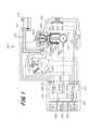
まず、本実施形態によるバルブタイミング制御装置を搭載する内燃機関システムの構成について説明する。図1は、本発明の一実施形態に係る内燃機関の基本構成例を示す全体構成図である。
[Internal combustion engine system]
First, the configuration of an internal combustion engine system equipped with a valve timing control device according to this embodiment will be described. FIG. 1 is an overall configuration diagram showing a basic configuration example of an internal combustion engine according to an embodiment of the present invention.

図1に示す内燃機関100は、単気筒でも複数気筒を有するものでもよいが、実施形態では、4気筒を有する内燃機関100を例示して説明する。図1に示すように、内燃機関100では、外部から吸引した空気はエアクリーナ110、吸気管111、吸気マニホールド112を通流し、各気筒150に流入する。各気筒150に流入する空気量は、スロットル弁113により調整される。スロットル弁113で調整された空気量は、流量センサ114により測定される。 The internal combustion engine 100 shown in FIG. 1 may have a single cylinder or a plurality of cylinders, but in the embodiment, the internal combustion engine 100 having four cylinders will be described as an example. As shown in FIG. 1 , in the internal combustion engine 100 , air sucked from the outside flows through an air cleaner 110 , an intake pipe 111 and an intake manifold 112 and flows into each cylinder 150 . The amount of air flowing into each cylinder 150 is adjusted by the throttle valve 113 . The amount of air adjusted by the throttle valve 113 is measured by the flow rate sensor 114 .

スロットル弁113には、スロットルの開度を検出するスロットル開度センサ113aが設けられている。スロットル開度センサ113aで検出されたスロットル弁113の開度情報は、制御装置(Electronic Control Unit:ECU)101に出力される。 The throttle valve 113 is provided with a throttle opening sensor 113a for detecting the opening of the throttle. The opening degree information of the throttle valve 113 detected by the throttle opening degree sensor 113 a is output to a control device (Electronic Control Unit: ECU) 101 .

本実施形態では、スロットル弁113として、電動機で駆動される電子スロットル弁を適用する。しかし、本発明に係るスロットル弁としては、空気の流量を適切に調整できるものであれば、その他の方式によるものを適用してもよい。 In this embodiment, an electronic throttle valve driven by an electric motor is applied as the throttle valve 113 . However, as the throttle valve according to the present invention, any other method may be applied as long as it can appropriately adjust the air flow rate.

各気筒150に流入したガスの温度は、吸気温センサ115で検出される。 The temperature of gas flowing into each cylinder 150 is detected by an intake air temperature sensor 115 .

クランクシャフト123に取り付けられたリングギア120の径方向外側には、クランク角センサ121が設けられている。クランク角センサ121は、クランクシャフト123の回転角度を検出する。本実施形態では、クランク角センサ121は、10°毎及び燃焼周期毎のクランクシャフト123の回転角度を検出する。 A crank angle sensor 121 is provided radially outside the ring gear 120 attached to the crankshaft 123 . Crank angle sensor 121 detects the rotation angle of crankshaft 123 . In this embodiment, the crank angle sensor 121 detects the rotation angle of the crankshaft 123 every 10 degrees and every combustion cycle.

シリンダヘッドのウォータジャケット(図示せず)には、水温センサ122が設けられている。水温センサ122は、内燃機関100の冷却水の温度を検出する。 A water temperature sensor 122 is provided in the water jacket (not shown) of the cylinder head. A water temperature sensor 122 detects the temperature of the cooling water of the internal combustion engine 100 .

また、車両には、アクセルペダル125の変位量(踏み込み量)を検出するアクセルポジションセンサ(Accelerator Position Sensor:APS)126が設けられている。アクセルポジションセンサ126は、運転者の要求トルクを検出する。アクセルポジションセンサ126で検出された運転者の要求トルクは、後述する制御装置101に出力される。制御装置101は、この要求トルクに基づいて、スロットル弁113を制御する。 The vehicle is also provided with an accelerator position sensor (APS) 126 that detects the amount of displacement (depression amount) of an accelerator pedal 125 . An accelerator position sensor 126 detects the torque requested by the driver. The driver's requested torque detected by the accelerator position sensor 126 is output to the control device 101, which will be described later. The control device 101 controls the throttle valve 113 based on this required torque.

燃料タンク130に貯留された燃料は、燃料ポンプ131によって吸引及び加圧される。燃料ポンプ131によって吸引及び加圧された燃料は、燃料配管133に設けられたプレッシャレギュレータ132で所定の圧力に調整される。そして、所定の圧力に調整された燃料は、燃料噴射装置(インジェクタ)400から各気筒150内に噴射される。 Fuel stored in the fuel tank 130 is sucked and pressurized by the fuel pump 131 . Fuel sucked and pressurized by the fuel pump 131 is adjusted to a predetermined pressure by a pressure regulator 132 provided in the fuel pipe 133 . Fuel adjusted to a predetermined pressure is injected into each cylinder 150 from a fuel injection device (injector) 400 .

燃料噴射装置400の制御は、後述する制御装置101の燃料噴射制御部382の燃料噴射パルス(制御信号)に基づいて行われる。 Control of the fuel injection device 400 is performed based on a fuel injection pulse (control signal) of a fuel injection control section 382 of the control device 101, which will be described later.

プレッシャレギュレータ132で圧力調整された後の余分な燃料は、戻り配管(図示せず)を介して燃料タンク130に戻される。 Excess fuel after pressure regulation by the pressure regulator 132 is returned to the fuel tank 130 via a return pipe (not shown).

各気筒150には、燃焼後のガス(排気ガス)を、気筒150の外側に排出する排気マニホールド160が取り付けられている。この排気マニホールド160の排気側には、三元触媒161が設けられている。三元触媒161は、排気ガスを浄化する。三元触媒161により浄化された排気ガスは、大気に排出される。 Each cylinder 150 is provided with an exhaust manifold 160 that discharges gas (exhaust gas) after combustion to the outside of the cylinder 150 . A three-way catalyst 161 is provided on the exhaust side of the exhaust manifold 160 . The three-way catalyst 161 purifies exhaust gas. The exhaust gas purified by the three-way catalyst 161 is discharged to the atmosphere.

三元触媒161の上流側には、上流側空燃比センサ162が設けられている。上流側空燃比センサ162は、各気筒150から排出された排気ガスの空燃比を連続的に検出する。 An upstream air-fuel ratio sensor 162 is provided upstream of the three-way catalyst 161 . The upstream air-fuel ratio sensor 162 continuously detects the air-fuel ratio of exhaust gas discharged from each cylinder 150 .

また、三元触媒161の下流側には、下流側空燃比センサ163が設けられている。下流側空燃比センサ163は、理論空燃比近傍でスイッチ的な検出信号を出力する。本実施形態の下流側空燃比センサ163は、O2センサである。 A downstream side air-fuel ratio sensor 163 is provided downstream of the three-way catalyst 161 . The downstream air-fuel ratio sensor 163 outputs a switch-like detection signal near the stoichiometric air-fuel ratio. The downstream air-fuel ratio sensor 163 of this embodiment is an O2 sensor.

各気筒150の上部には、点火プラグ200が各々設けられている。点火プラグ200は、放電(点火)により火花を発生させ、その火花が、気筒150内の空気と燃料との混合気に着火する。これにより、気筒150内で爆発が起こり、ピストン170が押し下げられる。ピストン170が押し下げられることにより、クランクシャフト123が回転する。 A spark plug 200 is provided at the top of each cylinder 150 . The spark plug 200 generates a spark by electric discharge (ignition), and the spark ignites the air-fuel mixture in the cylinder 150 . This causes an explosion in cylinder 150 and pushes down piston 170 . As the piston 170 is pushed down, the crankshaft 123 rotates.

前述したスロットル開度センサ113a、流量センサ114、クランク角センサ121、アクセルポジションセンサ126、水温センサ122、筒内圧センサ140等の各種センサからの出力信号は、制御装置101に出力される。制御装置101は、これら各種センサからの出力信号に基づいて、内燃機関100の運転状態を検出する。そして、制御装置101は、気筒150内に送出する空気量、燃料噴射装置400からの燃料噴射量、点火プラグ200の点火タイミング等の制御を行う。 Output signals from various sensors such as the throttle opening sensor 113 a , the flow rate sensor 114 , the crank angle sensor 121 , the accelerator position sensor 126 , the water temperature sensor 122 , the in-cylinder pressure sensor 140 and the like are output to the control device 101 . The control device 101 detects the operating state of the internal combustion engine 100 based on output signals from these various sensors. The control device 101 controls the amount of air sent into the cylinder 150, the amount of fuel injected from the fuel injection device 400, the ignition timing of the spark plug 200, and the like.

[制御装置のハードウェア構成]
次に、制御装置101のハードウェアの全体構成を説明する。
[Hardware configuration of control device]
Next, the overall hardware configuration of the control device 101 will be described.

図1に示すように、制御装置101は、アナログ入力部310と、デジタル入力部320と、A/D(Analog/Digita)変換部330と、RAM(Random Access Memory)340と、MPU(Micro-Processing Unit)350と、ROM(Read Only Memory)360と、I/O(Input/Output)ポート370と、出力回路380と、を有する。 As shown in FIG. 1, the control device 101 includes an analog input section 310, a digital input section 320, an A/D (Analog/Digital) conversion section 330, a RAM (Random Access Memory) 340, and an MPU (Micro- Processing Unit) 350 , ROM (Read Only Memory) 360 , I/O (Input/Output) port 370 , and output circuit 380 .

アナログ入力部310には、スロットル開度センサ113a、流量センサ114、アクセルポジションセンサ126、上流側空燃比センサ162、下流側空燃比センサ163、筒内圧センサ140、水温センサ122等の各種センサからのアナログ出力信号が入力される。 Analog input unit 310 receives signals from various sensors such as throttle opening sensor 113a, flow rate sensor 114, accelerator position sensor 126, upstream side air-fuel ratio sensor 162, downstream side air-fuel ratio sensor 163, in-cylinder pressure sensor 140, and water temperature sensor 122. An analog output signal is input.

アナログ入力部310には、A/D変換部330が接続されている。アナログ入力部310に入力された各種センサからのアナログ出力信号は、ノイズ除去等の信号処理が行われた後、A/D変換部330でデジタル信号に変換される。そして、A/D変換部330により変換されたデジタル信号は、RAM340に記憶される。 An A/D conversion section 330 is connected to the analog input section 310 . Analog output signals from various sensors input to the analog input unit 310 are subjected to signal processing such as noise removal, and then converted to digital signals by the A/D conversion unit 330 . The digital signal converted by the A/D converter 330 is stored in the RAM 340 .

デジタル入力部320には、クランク角センサ121からのデジタル出力信号が入力される。 A digital output signal from the crank angle sensor 121 is input to the digital input section 320 .

デジタル入力部320には、I/Oポート370が接続されている。デジタル入力部320に入力されたデジタル出力信号は、I/Oポート370を介してRAM340に記憶される。 An I/O port 370 is connected to the digital input section 320 . A digital output signal input to the digital input section 320 is stored in the RAM 340 via the I/O port 370 .

RAM340に記憶された各出力信号は、MPU350で演算処理される。 Each output signal stored in the RAM 340 is arithmetically processed by the MPU 350 .

MPU350は、ROM360に記憶された制御プログラム(図示せず)を実行することで、RAM340に記憶された出力信号を、制御プログラムに従って演算処理する。MPU350は、制御プログラムに従って、内燃機関100を駆動する各アクチュエータ(例えば、スロットル弁113、プレッシャレギュレータ132、点火プラグ200等)の作動量を規定する制御値を算出し、その制御値をRAM340に一時的に記憶する。 The MPU 350 executes a control program (not shown) stored in the ROM 360 to process output signals stored in the RAM 340 according to the control program. The MPU 350 calculates a control value that defines the operation amount of each actuator (for example, the throttle valve 113, the pressure regulator 132, the spark plug 200, etc.) that drives the internal combustion engine 100 according to the control program, and temporarily stores the control value in the RAM 340. memorize.

RAM340に記憶されたアクチュエータの作動量を規定する制御値は、I/Oポート370を介して出力回路380に出力される。 A control value that defines the actuation amount of the actuator stored in RAM 340 is output to output circuit 380 via I/O port 370 .

出力回路380には、各種センサ(例えば、筒内圧センサ140)からの出力信号に基づいて内燃機関の全体制御を行う全体制御部381(図2参照)と、燃料噴射装置400のプランジャロッド(不図示)の駆動を制御する燃料噴射制御部382(図2参照)と、点火プラグ200に印加する電圧を制御する点火制御部383(図3参照)の機能などが設けられている。 The output circuit 380 includes an overall control unit 381 (see FIG. 2) that performs overall control of the internal combustion engine based on output signals from various sensors (for example, the in-cylinder pressure sensor 140), and a plunger rod (unused 2) and an ignition control unit 383 (see FIG. 3) for controlling the voltage applied to the ignition plug 200 are provided.

[制御装置の機能ブロック]
次に、制御装置101の機能構成を説明する。
[Functional block of control device]
Next, the functional configuration of the control device 101 will be described.

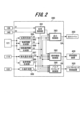
図2は、制御装置101の機能構成を説明する機能ブロック図である。 FIG. 2 is a functional block diagram for explaining the functional configuration of the control device 101. As shown in FIG.

制御装置101の各機能は、MPU350がROM360記憶された制御プログラムを実行することにより、出力回路380における各種機能として実現される。出力回路380における各種機能は、例えば、燃料噴射制御部382による燃料噴射装置400の制御や、点火制御部383による点火プラグ200の放電制御がある。 Each function of the control device 101 is implemented as various functions in the output circuit 380 by the MPU 350 executing a control program stored in the ROM 360 . Various functions of the output circuit 380 include, for example, control of the fuel injection device 400 by the fuel injection control section 382 and discharge control of the spark plug 200 by the ignition control section 383 .

図4に示すように、制御装置101の出力回路380は、全体制御部381と、燃料噴射制御部382と、点火制御部383と、バルブタイミング制御部390とを有する。 As shown in FIG. 4 , the output circuit 380 of the control device 101 has a general control section 381 , a fuel injection control section 382 , an ignition control section 383 and a valve timing control section 390 .

[全体制御部]
全体制御部381は、アクセルポジションセンサ126と、筒内圧センサ140(CPS)に接続されており、アクセルポジションセンサ126からの要求トルク(加速信号S1)と、筒内圧センサ140からの出力信号S2とを受け付ける。全体制御部381は、筒内圧センサ140からの出力信号S2の所定の補正期間に応じて補正を行う。
[Overall control part]
The overall control unit 381 is connected to the accelerator position sensor 126 and the in-cylinder pressure sensor 140 (CPS). accept. General control unit 381 performs correction according to a predetermined correction period of output signal S2 from in-cylinder pressure sensor 140 .

全体制御部381は、アクセルポジションセンサ126からの要求トルク(加速信号S1)と、筒内圧センサ140からの出力信号S2とに基づいて、燃料噴射制御部382と、点火制御部383と、バルブタイミング制御部390の全体的な制御を行う。 Based on the required torque (acceleration signal S1) from the accelerator position sensor 126 and the output signal S2 from the in-cylinder pressure sensor 140, the general control unit 381 controls the fuel injection control unit 382, the ignition control unit 383, and the valve timing control unit 382. It performs overall control of the control unit 390 .

[点火制御部]
点火制御部383は、全体制御部381のほか、気筒判別部384と、角度情報生成部385と、回転数情報生成部386と、負荷情報生成部388と、水温計測部389とに接続されており、これらからの各情報を受け付ける。
[Ignition control part]
The ignition control unit 383 is connected to the overall control unit 381, as well as the cylinder discrimination unit 384, the angle information generation unit 385, the rotation speed information generation unit 386, the load information generation unit 388, and the water temperature measurement unit 389. and accept each information from them.

点火制御部383は、受け付けた各情報に基づいて、点火コイル300の1次側コイルに通電する電流量(通電角)と、通電開始時間と、1次側コイルに通電した電流を遮断する時間(点火時間)を算出する。 Based on the received information, the ignition control unit 383 determines the amount of current (energization angle) to be energized to the primary side coil of the ignition coil 300, the energization start time, and the time to cut off the current energized to the primary side coil. (ignition time) is calculated.

点火制御部383は、算出した通電量と、通電開始時間と、点火時間とに基づいて、点火コイル300の1次側コイルに点火信号SAを出力することで、点火プラグ200による放電制御を行う。 The ignition control unit 383 outputs an ignition signal SA to the primary coil of the ignition coil 300 based on the calculated energization amount, energization start time, and ignition time, thereby performing discharge control by the spark plug 200. .

[燃料噴射制御部]
燃料噴射制御部382は、内燃機関100の各気筒150を判別する気筒判別部384と、クランクシャフト123のクランク角を計測する角度情報生成部385と、エンジン回転数を計測する回転数情報生成部386と、に接続されている。燃料噴射制御部382は、気筒判別部384からの気筒判別情報S3と、角度情報生成部385からのクランク角度情報S4と、回転数情報生成部386からのエンジン回転数情報S5と、を受け付ける。
[Fuel injection controller]
The fuel injection control unit 382 includes a cylinder discrimination unit 384 that discriminates each cylinder 150 of the internal combustion engine 100, an angle information generation unit 385 that measures the crank angle of the crankshaft 123, and a rotation speed information generation unit that measures the engine speed. 386 and are connected to. Fuel injection control section 382 receives cylinder discrimination information S3 from cylinder discrimination section 384, crank angle information S4 from angle information generation section 385, and engine speed information S5 from revolution information generation section 386.

また、燃料噴射制御部382は、気筒150内に吸気される空気の吸気量を計測する吸気量計測部387と、エンジン負荷を計測する負荷情報生成部388と、エンジン冷却水の温度を計測する水温計測部389と、に接続されている。燃料噴射制御部382は、吸気量計測部387からの吸気量情報S6と、負荷情報生成部388からのエンジン負荷情報S7と、水温計測部389からの冷却水温度情報S8と、を受け付ける。 The fuel injection control unit 382 also includes an intake air amount measuring unit 387 that measures the amount of air taken into the cylinder 150, a load information generating unit 388 that measures the engine load, and a temperature of the engine cooling water. It is connected to the water temperature measurement unit 389 and . Fuel injection control unit 382 receives intake air amount information S6 from intake air amount measuring unit 387, engine load information S7 from load information generating unit 388, and cooling water temperature information S8 from water temperature measuring unit 389.

燃料噴射制御部382は、受け付けた各情報に基づいて、燃料噴射装置400から噴射される燃料の噴射量と噴射時間を算出する。そして、燃料噴射制御部382は、算出した燃料の噴射量と噴射時間とに基づいて生成した燃料噴射パルスS9を燃料噴射装置400に送信する。 Fuel injection control unit 382 calculates the injection amount and injection time of fuel injected from fuel injection device 400 based on the received information. Then, the fuel injection control unit 382 transmits a fuel injection pulse S9 generated based on the calculated fuel injection amount and injection time to the fuel injection device 400 .

[バルブタイミング制御部]
バルブタイミング制御部390は、内燃機関100の各気筒150を判別する気筒判別部384と、クランクシャフト123のクランク角を計測する角度情報生成部385と、エンジン回転数を計測する回転数情報生成部386と、に接続されている。バルブタイミング制御部390は、気筒判別部384からの気筒判別情報S3と、角度情報生成部385からのクランク角度情報S4と、回転数情報生成部386からのエンジン回転数情報S5と、を受け付ける。
[Valve timing controller]
The valve timing control unit 390 includes a cylinder discrimination unit 384 that discriminates each cylinder 150 of the internal combustion engine 100, an angle information generation unit 385 that measures the crank angle of the crankshaft 123, and a rotation speed information generation unit that measures the engine speed. 386 and are connected to. Valve timing control unit 390 receives cylinder identification information S3 from cylinder identification unit 384, crank angle information S4 from angle information generation unit 385, and engine speed information S5 from rotation speed information generation unit 386.

また、バルブタイミング制御部390は、気筒150内に吸気される空気の吸気量を計測する吸気量計測部387と、エンジン負荷を計測する負荷情報生成部388と、エンジン冷却水の温度を計測する水温計測部389と、に接続されている。バルブタイミング制御部390は、吸気量計測部387からの吸気量情報S6と、負荷情報生成部388からのエンジン負荷情報S7と、水温計測部389からの冷却水温度情報S8と、を受け付ける。 The valve timing control unit 390 also includes an intake air amount measurement unit 387 that measures the amount of air taken into the cylinder 150, a load information generation unit 388 that measures the engine load, and a temperature of the engine cooling water. It is connected to the water temperature measurement unit 389 and . Valve timing control unit 390 receives intake air amount information S6 from intake air amount measuring unit 387, engine load information S7 from load information generating unit 388, and cooling water temperature information S8 from water temperature measuring unit 389.

バルブタイミング制御部390は、受け付けた各情報に基づいて、後述する吸気カムシャフト2の作動角を遅角にするタイミング(遅角タイミング)と進角にするタイミング(進角タイミング)を決定する。そして、燃料噴射制御部382は、決定した遅角タイミングや進角タイミングに基づいて生成したモータ駆動電流(制御電流)S10を後述するバルブタイミング制御装置500の電動モータ12(図5参照)に供給する。 The valve timing control unit 390 determines the timing (retarded timing) and the timing (advanced timing) for retarding the operating angle of the intake camshaft 2, which will be described later, based on the received information. Then, the fuel injection control unit 382 supplies a motor drive current (control current) S10 generated based on the determined retard timing and advance timing to the electric motor 12 (see FIG. 5) of the valve timing control device 500, which will be described later. do.

[内燃機関の要部構成]
次に、本実施形態に係る制御装置101を適用した内燃機関100(車両用筒内噴射式4気筒ガソリンエンジン)の要部構成を説明する。
[Main Configuration of Internal Combustion Engine]
Next, the main configuration of an internal combustion engine 100 (vehicle in-cylinder injection four-cylinder gasoline engine) to which the control device 101 according to the present embodiment is applied will be described.

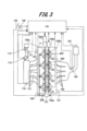
図3は、制御装置101を適用した内燃機関100(車両用筒内噴射式4気筒ガソリンエンジン)の要部構成を説明する模式図である。
図4は、各気筒150の配列を説明する平面図である。
FIG. 3 is a schematic diagram illustrating a configuration of a main part of an internal combustion engine 100 (vehicle in-cylinder injection four-cylinder gasoline engine) to which the control device 101 is applied.
FIG. 4 is a plan view for explaining the arrangement of cylinders 150. As shown in FIG.

図3に示すように、本実施形態の内燃機関100は、火花点火式燃焼を実施する車両用の直列4気筒ガソリンエンジンである場合を例示して説明する。 As shown in FIG. 3, the internal combustion engine 100 of the present embodiment will be described by exemplifying a case where the internal combustion engine 100 is an in-line four-cylinder gasoline engine for a vehicle that performs spark ignition combustion.

内燃機関100では、第1気筒151、第2気筒152、第3気筒153、第4気筒154が、シリンダブロック(図示せず)に直列に設けられている。以下、これら第1気筒151~第4気筒154を特に区別しない場合、単に気筒150と言う。 In the internal combustion engine 100, a first cylinder 151, a second cylinder 152, a third cylinder 153, and a fourth cylinder 154 are provided in series in a cylinder block (not shown). Hereinafter, these first to fourth cylinders 151 to 154 are simply referred to as cylinders 150 when not specifically distinguished.

各気筒150の燃焼室150a内には、点火プラグ200と、筒内圧センサ140と、燃料噴射装置400とが取り付けられている(図4参照)。内燃機関100が、直列4気筒の場合、各気筒150の燃焼室150aでは、クランクシャフト123の回転角度が180度周期で、点火プラグ200による点火と燃焼が行われる。各気筒150における燃焼は、第1気筒151、第3気筒153、第4気筒154、第2気筒152の順番で行われる。 A spark plug 200, an in-cylinder pressure sensor 140, and a fuel injection device 400 are mounted in the combustion chamber 150a of each cylinder 150 (see FIG. 4). When the internal combustion engine 100 is an in-line four-cylinder engine, in the combustion chamber 150a of each cylinder 150, the rotation angle of the crankshaft 123 is 180 degrees, and ignition and combustion are performed by the spark plug 200. FIG. Combustion in each cylinder 150 is performed in the order of the first cylinder 151 , the third cylinder 153 , the fourth cylinder 154 and the second cylinder 152 .

各気筒150に流入する空気の圧力は、吸気マニホールド112に設けられた吸気圧センサ116により測定される。 The pressure of air flowing into each cylinder 150 is measured by an intake pressure sensor 116 provided in intake manifold 112 .

各気筒150の上方には、シリンダヘッド180が設けられている。シリンダヘッド180には、吸気カムシャフト2と、排気カムシャフト105とが設けられている。吸気カムシャフト2は、気筒150内への混合気(空気と燃料との混合気)の吸入量を調整する吸気弁106aを稼働させる。排気カムシャフト105は、気筒150内から排出する排気ガスの排出量を調整する排気弁106bを稼働させる。 A cylinder head 180 is provided above each cylinder 150 . The cylinder head 180 is provided with an intake camshaft 2 and an exhaust camshaft 105 . The intake camshaft 2 operates an intake valve 106 a that adjusts the intake amount of air-fuel mixture (a mixture of air and fuel) into the cylinder 150 . The exhaust camshaft 105 operates an exhaust valve 106 b that adjusts the amount of exhaust gas discharged from the cylinder 150 .

図3に示すように、吸気カムシャフト2には、バルブタイミング制御装置500が接続されている。また、バルブタイミング制御装置500は、制御装置101と電気的に接続されている。 As shown in FIG. 3 , a valve timing control device 500 is connected to the intake camshaft 2 . Also, the valve timing control device 500 is electrically connected to the control device 101 .

図4に示すように、内燃機関100では、第1気筒151~第4気筒154に、筒内圧センサ140A~140Dと、対応する燃料噴射装置400A~400Dとが設けられている。筒内圧センサ140A~140Dと、対応する燃料噴射装置400A~400Dとは、それぞれ近距離に配置されている。 As shown in FIG. 4, in internal combustion engine 100, first cylinder 151 to fourth cylinder 154 are provided with cylinder internal pressure sensors 140A to 140D and corresponding fuel injection devices 400A to 400D. The in-cylinder pressure sensors 140A-140D and the corresponding fuel injection devices 400A-400D are arranged at short distances, respectively.

以下、筒内圧センサ140A~140Dを特に区別しない場合、単に筒内圧センサ140と表記する。また、燃料噴射装置400A~400Dを特に区別しない場合、単に燃料噴射装置400と表記する。 In the following description, the in-cylinder pressure sensors 140A to 140D are simply referred to as the in-cylinder pressure sensor 140 unless otherwise distinguished. Further, when the fuel injection devices 400A to 400D are not particularly distinguished, they are simply referred to as fuel injection device 400. FIG.

内燃機関100では、燃料噴射装置400A~400Dのプランジャロッドの駆動に伴う振動や歪がシリンダヘッド180などの内燃機関100の構成部品を伝播して筒内圧センサ140A~140Dに伝達される恐れがある。この場合、筒内圧センサ140A~140Dは、プランジャロッド410の振動や歪の影響を受け、筒内圧センサ140A~140Dによる振動の検出誤差が大きくなってしまう。 In internal combustion engine 100, there is a risk that vibrations and strains associated with the driving of the plunger rods of fuel injection devices 400A-400D will propagate through components of internal combustion engine 100 such as cylinder head 180 and be transmitted to in-cylinder pressure sensors 140A-140D. . In this case, the in-cylinder pressure sensors 140A to 140D are affected by the vibration and distortion of the plunger rod 410, and the vibration detection errors of the in-cylinder pressure sensors 140A to 140D become large.

さらに、内燃機関100では、筒内圧センサ140A~140Dの信号線140a~140d(図6の実線)と、燃料噴射装置400A~400Dの電力線400a~400d(図6の破線)と、が共に制御装置101に接続されている。このため、電力線400a~400dの電流変化により電磁誘導が発生し、筒内圧センサ140A~140Dの信号線140a~140dの出力信号S2に影響を与える。よって、この電力線400a~400dの電磁誘導もまた、筒内圧センサ140A~140Dによる振動の検出誤差の要因となる。 Further, in the internal combustion engine 100, the signal lines 140a to 140d (solid lines in FIG. 6) of the in-cylinder pressure sensors 140A to 140D and the power lines 400a to 400d (broken lines in FIG. 6) of the fuel injection devices 400A to 400D are both controlled by the control device. 101. Therefore, electromagnetic induction occurs due to changes in current in power lines 400a-400d, which affects output signals S2 of signal lines 140a-140d of in-cylinder pressure sensors 140A-140D. Therefore, the electromagnetic induction of these power lines 400a-400d also causes vibration detection errors by the in-cylinder pressure sensors 140A-140D.

[バルブタイミング制御装置]
次に、バルブタイミング制御装置500の構成について説明する。本実施形態では、バルブタイミング制御装置500を吸気側に適用したものを示している。すなわち、バルブタイミング制御装置500は、クランクシャフト123の回転と吸気カムシャフト2の回転の相対回転位相を変更して、吸気カムシャフト2により開閉される吸気弁106aのリフト量を可変する。しかし、本発明に係るバルブタイミング制御装置としては、排気側に適用することも可能である。
[Valve timing controller]
Next, the configuration of valve timing control device 500 will be described. In this embodiment, the valve timing control device 500 is applied to the intake side. That is, the valve timing control device 500 changes the relative rotational phase between the rotation of the crankshaft 123 and the rotation of the intake camshaft 2 to vary the lift amount of the intake valve 106a that is opened and closed by the intake camshaft 2 . However, the valve timing control device according to the present invention can also be applied to the exhaust side.

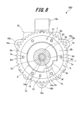
図5は、本実施形態に係るバルブタイミング制御装置を示す一部縦断面図である。図6は、本実施形態に供される主要な構成部材を示す分解図である。図7は、図5に示すバルブタイミング制御装置の要部拡大図である。図8は、図5に示すA-A線断面図である。 FIG. 5 is a partial longitudinal sectional view showing the valve timing control device according to this embodiment. FIG. 6 is an exploded view showing main constituent members provided for this embodiment. 7 is an enlarged view of a main part of the valve timing control device shown in FIG. 5. FIG. 8 is a cross-sectional view taken along the line AA shown in FIG. 5. FIG.

図1及び図2に示すように、バルブタイミング制御装置500は、駆動回転体であるタイミングスプロケット1(以下、スプロケット1という。)と、吸気カムシャフト2(以下、カムシャフト2という。)と、スプロケット1とカムシャフト2との間に配置された位相変更機構3と、を備えている。カムシャフト2は、シリンダヘッド180上に軸受181を介して回転自在に支持されている。位相変更機構3は、内燃機関100の運転状態に応じて両者1,2の相対回転位相を変更する。 As shown in FIGS. 1 and 2, the valve timing control device 500 includes a timing sprocket 1 (hereinafter referred to as sprocket 1) which is a driving rotating body, an intake camshaft 2 (hereinafter referred to as camshaft 2), and a phase change mechanism 3 arranged between the sprocket 1 and the camshaft 2 . Camshaft 2 is rotatably supported on cylinder head 180 via bearing 181 . A phase change mechanism 3 changes the relative rotational phases of both 1 and 2 according to the operating state of the internal combustion engine 100 .

スプロケット1は、全体が金属材である鉄系金属によって環状一体に形成されている。スプロケット1は、円環状のスプロケット本体1aと、該スプロケット本体1aの外周に一体に設けられた歯車部1bとを備えている。歯車部1bには、不図示のタイミングチェーンが巻回されている。歯車部1bは、タイミングチェーンを介して、内燃機関100のクランクシャフト123(図1参照)からの回転力を受ける。 The sprocket 1 is integrally annularly formed of a ferrous metal that is entirely metallic. The sprocket 1 includes an annular sprocket body 1a and a gear portion 1b integrally provided on the outer circumference of the sprocket body 1a. A timing chain (not shown) is wound around the gear portion 1b. Gear portion 1b receives rotational force from crankshaft 123 (see FIG. 1) of internal combustion engine 100 via a timing chain.

なお、スプロケット1の外周には、内燃機関100のシリンダブロック(不図示)とシリンダヘッド180に結合された不図示のチェーンケースが設けられている。 A chain case (not shown) coupled to a cylinder block (not shown) and a cylinder head 180 of the internal combustion engine 100 is provided on the outer circumference of the sprocket 1 .

スプロケット本体1aの前端側には、後述する減速機構13の一部を構成する円環状の内歯構成部5が一体に設けられている。この内歯構成部5は、スプロケット本体1aに回転軸方向から一体に結合されている。内歯構成部5の内周には、波形状の複数の内歯5aが形成されている。 An annular internal tooth forming portion 5 forming part of a speed reduction mechanism 13, which will be described later, is integrally provided on the front end side of the sprocket main body 1a. The internal tooth forming portion 5 is integrally coupled to the sprocket main body 1a from the rotation axis direction. A plurality of corrugated internal teeth 5 a are formed on the inner periphery of the internal tooth forming portion 5 .

スプロケット本体1aの内周面と従動回転体である後述する従動部材9の外周面との間には、滑り軸受機構6が設けられている。従動部材9は、カムシャフト2の回転軸方向の一端部2aに固定されている。滑り軸受機構6は、従動部材9(カムシャフト2)の外周でスプロケット1を相対回転自在に軸受けしている。 A sliding bearing mechanism 6 is provided between the inner peripheral surface of the sprocket body 1a and the outer peripheral surface of a driven member 9, which is a driven rotating body and will be described later. The driven member 9 is fixed to one end portion 2a of the camshaft 2 in the rotation axis direction. The sliding bearing mechanism 6 bears the sprocket 1 relatively rotatably on the outer periphery of the driven member 9 (camshaft 2).

さらに、スプロケット本体1aの内歯構成部5と反対側の後端面には、保持プレート8が固定されている。この保持プレート8は、図5、図6及び図8に示すように、金属材である鉄系金属の板材によって円環状に形成されている。保持プレート8の外径は、スプロケット本体1aの外径とほぼ同一に設定されている。また、保持プレート8は、中央に形成された中央孔8a側の内周部8bが滑り軸受機構6の後述する軸受凹部10のカムシャフト2側の一端開口を覆うように配置されている。この内周部8bは、中央孔8aの孔縁となる部位が、内歯構成部5の内歯5aの歯底面よりも内側に位置している。 Further, a holding plate 8 is fixed to the rear end surface of the sprocket body 1a on the side opposite to the internal tooth forming portion 5. As shown in FIG. As shown in FIGS. 5, 6 and 8, the holding plate 8 is formed in an annular shape by a plate material made of iron-based metal. The outer diameter of the holding plate 8 is set substantially equal to the outer diameter of the sprocket body 1a. Further, the holding plate 8 is arranged so that the inner peripheral portion 8b on the side of the central hole 8a formed in the center covers one end opening on the side of the camshaft 2 of the bearing concave portion 10 of the slide bearing mechanism 6, which will be described later. A portion of the inner peripheral portion 8b, which serves as a hole rim of the central hole 8a, is located inside the tooth bottom surfaces of the internal teeth 5a of the internal tooth forming portion 5. As shown in FIG.

また、保持プレート8は、中央孔8aの内周縁の所定位置に、径方向内側、つまり中心軸方向に向かって突出したストッパ凸部8cが一体に設けられている。このストッパ凸部8cは、ほぼ逆台形状に形成されて、先端面が従動部材9の後述する固定端部9bのストッパ凹溝9fの円弧状内周面に沿った円弧状に形成されている。 Further, the holding plate 8 is integrally provided with a stopper convex portion 8c protruding radially inward, that is, in the central axis direction, at a predetermined position on the inner peripheral edge of the central hole 8a. The stopper convex portion 8c is formed in a substantially inverted trapezoidal shape, and the tip surface thereof is formed in an arcuate shape along the arcuate inner peripheral surface of the stopper concave groove 9f of the fixed end portion 9b of the driven member 9, which will be described later. .

図9は、図5に示すB矢視図である。 9 is a view in the direction of arrow B shown in FIG. 5. FIG.

また、スプロケット1の内歯構成部5側の前端面には、フロントプレート15が設けられている。このフロントプレート15は、図5、図6及び図9に示すように、例えば鉄系金属板を円環状にプレス成形で打ち抜き形成されたものである。フロントプレート15の肉厚tは、保持プレート8の肉厚t1よりも小さく設定されている。フロントプレート15は、中央に挿入孔15aが貫通形成されている。フロントプレート15の挿入孔15aには、後述する偏心軸21が挿入される。 A front plate 15 is provided on the front end face of the sprocket 1 on the side of the internal tooth forming portion 5 . As shown in FIGS. 5, 6 and 9, the front plate 15 is formed by punching, for example, an iron-based metal plate into an annular shape by press forming. The thickness t of the front plate 15 is set smaller than the thickness t1 of the holding plate 8 . The front plate 15 has an insertion hole 15a penetrating through its center. An eccentric shaft 21 , which will be described later, is inserted into the insertion hole 15 a of the front plate 15 .

内歯構成部5を含むスプロケット本体1aとフロントプレート15の各外周部には、6つのボルト挿通孔1c、15bが周方向のほぼ等間隔位置にそれぞれ貫通形成されている。各ボルト挿通孔1c、15bには、ボルト7が挿通する。また、保持プレート8における各ボルト挿通孔1c、15bに対応する位置には、6つの雌ねじ孔8dが形成されている。6つの雌ねじ孔8dには、各ボルト7の先端部に設けられた雄ねじ部7aが螺着する。 Six bolt insertion holes 1c and 15b are formed through the outer peripheral portions of the sprocket body 1a including the internal tooth forming portion 5 and the front plate 15 at substantially equal intervals in the circumferential direction. A bolt 7 is inserted through each of the bolt insertion holes 1c and 15b. Six female screw holes 8d are formed in the holding plate 8 at positions corresponding to the bolt insertion holes 1c and 15b. A male threaded portion 7a provided at the tip of each bolt 7 is screwed into the six female threaded holes 8d.

図6に示すように、スプロケット本体1aの2つのボルト挿通孔1cと保持プレート8の対応する2つの雌ねじ孔8dの各側部には、位置決め用の小孔1d、8eがそれぞれ設けられている。位置決め用の小孔1d、8eには、2つの位置決め用のピン28a、28bが挿入される。これにより、保持プレート8は、スプロケット1に対して周方向及び軸方向で位置決めされる。 As shown in FIG. 6, small positioning holes 1d and 8e are provided on each side of the two bolt insertion holes 1c of the sprocket body 1a and the corresponding two female screw holes 8d of the holding plate 8. . Two positioning pins 28a and 28b are inserted into the small positioning holes 1d and 8e. Thereby, the holding plate 8 is circumferentially and axially positioned with respect to the sprocket 1 .

カムシャフト2は、外周に吸気弁106a(図3参照)を開作動させる一気筒当たり2つの駆動カムを有している。また、カムシャフト2において、回転軸方向の位相変更機構3側の一端部2aには、フランジ部2bが一体に設けられている。フランジ部2bは、軸受181を介してカムシャフト2の軸方向の位置決めを行う。また、カムシャフト2の一端部2aにおける内部軸心方向には、雌ねじ部2cが形成されている。雌ねじ部2cには、後述のカムボルト14が螺着する。カムボルト14は、カムシャフト2に従動部材9を軸方向から締結固定する。さらに、カムシャフト2の一端部2aの前端には、従動部材9との回転方向の位置決めを行う位置決め用のピン2dが圧入固定されている。 The camshaft 2 has two drive cams per cylinder for opening the intake valves 106a (see FIG. 3) on the outer circumference. A flange portion 2b is integrally provided at one end portion 2a of the camshaft 2 on the side of the phase change mechanism 3 in the rotation axis direction. The flange portion 2 b positions the camshaft 2 in the axial direction via the bearing 181 . A female screw portion 2c is formed in one end portion 2a of the camshaft 2 in the inner axial direction. A cam bolt 14, which will be described later, is screwed into the female threaded portion 2c. The cam bolt 14 axially fastens and fixes the driven member 9 to the camshaft 2 . Further, a positioning pin 2d for positioning with respect to the driven member 9 in the rotational direction is press-fitted and fixed to the front end of the one end portion 2a of the camshaft 2. As shown in FIG.

従動部材9は、鉄系金属によって一体に形成されている。図5、図6及び図8に示すように、従動部材9は、円盤状本体9aと、該円盤状本体9aの後端側(カムシャフト2側)に有する円環状の固定端部9bと、から主として構成されている。 The driven member 9 is integrally formed of ferrous metal. As shown in FIGS. 5, 6 and 8, the driven member 9 includes a disk-shaped main body 9a, an annular fixed end portion 9b provided on the rear end side (camshaft 2 side) of the disk-shaped main body 9a, is mainly composed of

円盤状本体9aは、外周面に滑り軸受機構6の一部を構成するジャーナル部11が一体に設けられている。また、円盤状本体9aは、固定端部9bを含む内部軸心方向にカムボルト14の軸部14bが挿通するボルト挿通孔9cが貫通形成されている。このボルト挿通孔9cは、内径がカムシャフト2の雌ねじ部2cの内径よりも大きく形成されている。 A journal portion 11 that constitutes a part of the slide bearing mechanism 6 is integrally provided on the outer peripheral surface of the disk-shaped main body 9a. A bolt insertion hole 9c through which the shaft portion 14b of the cam bolt 14 is inserted is formed through the disk-shaped main body 9a in the axial direction including the fixed end portion 9b. The bolt insertion hole 9 c is formed to have an inner diameter larger than the inner diameter of the female threaded portion 2 c of the camshaft 2 .

固定端部9bは、一定の肉厚を有しており、円盤状本体9aからカムシャフト2方向へ突出している。また、固定端部9bにおけるカムシャフト2側の外側面のほぼ中央(ボルト挿通孔9cの外周側)には、円環状の嵌合溝9dが形成されている。固定端部9bの嵌合溝9dには、カムシャフト2の一端部2aにおける先端部が嵌合する。嵌合溝9dの底面には、位置決め用の孔9eが形成されている。位置決め用の孔9eには、前述したカムシャフト2の位置決め用のピン2dが軸方向から挿入される。 The fixed end portion 9b has a constant thickness and protrudes from the disk-shaped main body 9a toward the camshaft 2. As shown in FIG. In addition, an annular fitting groove 9d is formed substantially in the center of the outer surface of the fixed end portion 9b on the side of the camshaft 2 (on the outer peripheral side of the bolt insertion hole 9c). The tip of one end 2a of the camshaft 2 is fitted into the fitting groove 9d of the fixed end 9b. A positioning hole 9e is formed in the bottom surface of the fitting groove 9d. The aforementioned positioning pin 2d for the camshaft 2 is axially inserted into the positioning hole 9e.

また、固定端部9bの外周面には、ストッパ凹溝9fが円周方向に沿って形成されている。ストッパ凹溝9fは、円周方向へ延びる所定長さの円弧状に形成されている。ストッパ凹溝9fには、保持プレート8のストッパ凸部8cが入り込む。ストッパ凸部8cは、ストッパ凹溝9fの範囲内で円周方向へ回動する。ストッパ凸部8cの2つの側面が、ストッパ凹溝9fの対向面にそれぞれ当接することにより、ストッパ凸部8cの回動が規制される。このように、本実施形態では、スプロケット1に対するカムシャフト2の最大進角側、あるいは最大遅角側の相対回転位置を機械的に規制するようになっている。 A stopper groove 9f is formed along the circumferential direction on the outer peripheral surface of the fixed end portion 9b. The stopper groove 9f is formed in an arc shape of a predetermined length extending in the circumferential direction. A stopper projection 8c of the holding plate 8 enters the stopper groove 9f. The stopper projection 8c rotates in the circumferential direction within the range of the stopper groove 9f. The rotation of the stopper projection 8c is restricted by the two side surfaces of the stopper projection 8c coming into contact with the facing surfaces of the stopper groove 9f. Thus, in this embodiment, the relative rotational position of the camshaft 2 on the maximum advance side or the maximum retardation side with respect to the sprocket 1 is mechanically restricted.

従動部材9は、嵌合溝9dにカムシャフト2の一端部2aの先端部が軸方向から嵌合した状態で、カムボルト14によってカムシャフト2の一端部2aに軸方向から固定される。 The driven member 9 is axially fixed to the one end 2a of the camshaft 2 by a cam bolt 14 with the tip of the one end 2a of the camshaft 2 axially fitted into the fitting groove 9d.

滑り軸受機構6は、図5及び図6に示すように、スプロケット本体1aの内周面に形成された円環状の軸受凹部10と、円盤状本体9aの外周面に設けられ、軸受凹部10の内部に配置されたジャーナル部11と、軸受凹部10の一端開口を覆う保持プレート8と、を有している。 As shown in FIGS. 5 and 6, the slide bearing mechanism 6 includes an annular bearing recess 10 formed on the inner peripheral surface of the sprocket main body 1a and a bearing recess 10 provided on the outer peripheral surface of the disk-shaped main body 9a. It has a journal portion 11 arranged inside and a holding plate 8 covering one end opening of the bearing recess portion 10 .

軸受凹部10は、スプロケット本体1aの保持プレート8側の一方側面から内歯構成部5まで延びることなく、カムシャフト2側に寄ったスプロケット本体1aの内周面側のみに配置形成されている。また、軸受凹部10は、図5に示すように、スプロケット1の回転軸心から径方向に沿った断面形状がほぼ矩形状に形成されている。そして、軸受凹部10は、その一部が各歯車部1bの形成位置と軸方向でオーバーラップするように配置されている。 The bearing recess 10 does not extend from one side surface of the sprocket body 1a on the holding plate 8 side to the internal tooth forming portion 5, and is formed only on the inner peripheral surface side of the sprocket body 1a closer to the camshaft 2 side. Further, as shown in FIG. 5, the bearing recess 10 has a substantially rectangular cross-sectional shape along the radial direction from the rotation axis of the sprocket 1 . The bearing recessed portion 10 is arranged so that a portion thereof overlaps the forming position of each gear portion 1b in the axial direction.

さらに、軸受凹部10の円環状の底面には、滑り軸受面10aが形成されている。また、軸受凹部10は、軸方向で保持プレート8と反対側の他端側に有する内側面10bが滑り軸受面10aから径方向へほぼ直角に切欠されている。また、軸受凹部10は、前述したように、カムシャフト2側の他端部が開口されて外部に解放され、この解放された他端開口が保持プレート8の内周部8bの内側面8fによって覆われている。 Furthermore, a slide bearing surface 10a is formed on the annular bottom surface of the bearing recess 10 . Further, the bearing recess 10 has an inner surface 10b on the other end side opposite to the holding plate 8 in the axial direction, and is notched substantially at a right angle in the radial direction from the sliding bearing surface 10a. As described above, the bearing recess 10 is opened at the other end on the side of the camshaft 2 and released to the outside. covered.

ジャーナル部11は、円盤状本体9aの外周面から径方向外側へ突出している。ジャーナル部11の断面形状は、軸受凹部10の断面形状とほぼ相似形の矩形状に形成されている。また、ジャーナル部11は、軸受凹部10が各歯車部1bと軸方向でオーバーラップしていることから、同じく一部がスプロケット1の各歯車部1bと軸方向でオーバーラップ配置されている。 The journal portion 11 protrudes radially outward from the outer peripheral surface of the disk-shaped main body 9a. The cross-sectional shape of the journal portion 11 is formed in a rectangular shape that is substantially similar to the cross-sectional shape of the bearing recess 10 . Also, since the bearing recesses 10 axially overlap the gear portions 1b, the journal portion 11 is also partially overlapped with the gear portions 1b of the sprocket 1 in the axial direction.

さらに、ジャーナル部11の基部11aにおける軸方向両側には、それぞれ円環溝が形成されている。また、ジャーナル部11の環状の外周面は、軸受凹部10の滑り軸受面10a全体に摺動可能になっている。各円環溝は、従動部材9の回転時においてジャーナル部が、保持プレート8の内側面8fと軸受凹部10の内側面10bと接触するのを回避するようになっている。 Further, annular grooves are formed on both sides in the axial direction of the base portion 11a of the journal portion 11, respectively. Further, the annular outer peripheral surface of the journal portion 11 is slidable on the entire slide bearing surface 10a of the bearing recess portion 10. As shown in FIG. Each annular groove prevents the journal portion from coming into contact with the inner surface 8f of the holding plate 8 and the inner surface 10b of the bearing recess 10 when the driven member 9 rotates.

ジャーナル部11は、軸方向のフロントプレート15側の一端面が軸受凹部10の内側面10bに摺動可能になっている。この軸受凹部10の内側面10bが、スプロケット1の傾動時においてジャーナル部11の一端面に当接して一方のスラスト移動を規制するようになっている。 One end surface of the journal portion 11 on the side of the front plate 15 in the axial direction is slidable on the inner surface 10 b of the bearing recess 10 . When the sprocket 1 tilts, the inner side surface 10b of the bearing recessed portion 10 abuts against one end surface of the journal portion 11 to restrict the thrust movement of the one side.

また、ジャーナル部11は、軸方向の保持プレート8側の他端面が保持プレート8の内周部8bの内側面8fに摺動可能になっている。この保持プレート8の内側面8fが、スプロケット1の傾動時においてジャーナル部11の他端面に当接して他方のスラスト移動を規制するようになっている。 Further, the other end surface of the journal portion 11 on the side of the holding plate 8 in the axial direction is slidable on the inner surface 8f of the inner peripheral portion 8b of the holding plate 8. As shown in FIG. When the sprocket 1 tilts, the inner side surface 8f of the holding plate 8 contacts the other end surface of the journal portion 11 to restrict the thrust movement of the other side.

カムボルト14は、図5及び図7に示すように、ほぼ円柱状の頭部14aと、該頭部14aに一体に固定された軸部14bと、を有している。 As shown in FIGS. 5 and 7, the cam bolt 14 has a substantially cylindrical head portion 14a and a shaft portion 14b integrally fixed to the head portion 14a.

頭部14aの先端部には、六角レンチなどの工具が挿入される六角形の工具穴14cが形成されている。また、頭部14aの外周面には、ニードルベアリング25の各ニードルローラ25aが転動可能に保持されている。 A hexagonal tool hole 14c into which a tool such as a hexagonal wrench is inserted is formed at the tip of the head 14a. Each needle roller 25a of a needle bearing 25 is rotatably held on the outer peripheral surface of the head 14a.

軸部14bは、頭部14aとの結合部に一体に設けられた大径部14dを有する。また、大径部14dよりも先端部側の小径部の外周には、カムシャフト2の雌ねじ部2cに螺着する雄ねじ部14eが形成されている。 The shaft portion 14b has a large-diameter portion 14d integrally provided at a joint portion with the head portion 14a. A male threaded portion 14e that is screwed into the female threaded portion 2c of the camshaft 2 is formed on the outer periphery of the small diameter portion closer to the tip than the large diameter portion 14d.

大径部14dは、従動部材9のボルト挿通孔9cに挿入される。大径部14dの軸方向の長さは、ボルト挿通孔9cの軸方向の長さとほぼ同一に設定されている。また、大径部14dは、外径がボルト挿通孔9cの内径より僅かに小さく設定されている。これにより、大径部14dは、ボルト挿通孔9cに微小クリアランスをもって挿入される。 The large diameter portion 14 d is inserted into the bolt insertion hole 9 c of the driven member 9 . The axial length of the large diameter portion 14d is set substantially equal to the axial length of the bolt insertion hole 9c. The large diameter portion 14d has an outer diameter slightly smaller than the inner diameter of the bolt insertion hole 9c. As a result, the large diameter portion 14d is inserted into the bolt insertion hole 9c with a minute clearance.

位相変更機構3は、図5及び図6示すように、従動部材9の固定端部9bにおける前端側に配置された電動モータ12と、この電動モータ12の回転速度を減速してカムシャフト2に伝達する減速機構13と、から主として構成されている。 As shown in FIGS. 5 and 6, the phase change mechanism 3 includes an electric motor 12 arranged on the front end side of the fixed end portion 9b of the driven member 9, and a cam shaft 2 by reducing the rotational speed of the electric motor 12. and a deceleration mechanism 13 for transmission.

図10は、電動モータ12の正面図である。図11は、電動モータ12の斜視図である。 10 is a front view of the electric motor 12. FIG. 11 is a perspective view of the electric motor 12. FIG.

電動モータ12は、いわゆるブラシレスの直流型モータである。電動モータ12は、チェーンケースに固定される有底円筒状のモータハウジング16と、モータハウジング16の後端部に設けられて、内部にステータコイルなどが収容されたモータステータと、ステータコイルの内周側に配置されたモータ出力軸17と、モータ出力軸17の外周に固定された円筒状の永久磁石と、モータハウジング16のスプロケット1と反対側の前端部に設けられた給電機構18と、を有している。 The electric motor 12 is a so-called brushless DC motor. The electric motor 12 includes a bottomed cylindrical motor housing 16 that is fixed to the chain case, a motor stator that is provided at the rear end of the motor housing 16 and accommodates stator coils and the like, and a motor stator that accommodates stator coils and the like. A motor output shaft 17 arranged on the circumferential side, a cylindrical permanent magnet fixed to the outer circumference of the motor output shaft 17, a power supply mechanism 18 provided at the front end of the motor housing 16 opposite to the sprocket 1, have.

モータハウジング16は、ほぼカップ状に形成されている。モータハウジング16の前端部(底壁)におけるほぼ中央には、モータ出力軸17が挿通する貫通孔(不図示)が形成されている。一方、モータハウジング16の後端部における外周には、径方向外側に突出したフランジ部16aが一体に設けられている。フランジ部16aは、円周方向の約120°位置に3つのブラケット片16bが一体に設けられている。また、この3つのブラケット片16bには、ボルト挿通孔16cが貫通形成されている。ボルト挿通孔16cには、不図示のチェーンケースに結合されるボルトが挿通される。 The motor housing 16 is generally cup-shaped. A through hole (not shown) through which the motor output shaft 17 is inserted is formed substantially in the center of the front end (bottom wall) of the motor housing 16 . On the other hand, the rear end portion of the motor housing 16 is integrally provided with a flange portion 16a protruding radially outward on the outer periphery thereof. The flange portion 16a is integrally provided with three bracket pieces 16b at approximately 120° positions in the circumferential direction. Bolt insertion holes 16c are formed through the three bracket pieces 16b. A bolt coupled to a chain case (not shown) is inserted through the bolt insertion hole 16c.

さらに、フランジ部16aの円周方向の各ブラケット片16bの間には、3つのボルト29が挿通する3つのボルト挿通孔が形成されている。各ボルト29は、モータハウジング16に給電機構18を結合する。 Furthermore, three bolt insertion holes through which three bolts 29 are inserted are formed between the bracket pieces 16b in the circumferential direction of the flange portion 16a. Each bolt 29 couples the power supply mechanism 18 to the motor housing 16 .

なお、ボルト挿通孔16cやボルト29などは、さらに増加することも可能である。 It should be noted that the number of bolt insertion holes 16c, bolts 29, and the like can be further increased.

モータステータは、主として合成樹脂材の樹脂部によって一体に形成されている。モータステータの内部には、ステータコイルがモールド固定されている。 The motor stator is integrally formed mainly by a resin portion made of a synthetic resin material. A stator coil is molded and fixed inside the motor stator.

給電機構18は、合成樹脂材によってボックス状に形成されている。この給電機構18の内部には、電動モータ12へ給電するバスバーなどの通電回路やモータ出力軸17の回転位置を検出する回転センサなどが収容されている。また、給電機構18の外周部には、通電回路に電気的に接続される給電用コネクタ18aと、不図示の信号用コネクタが設けられている。 The power feeding mechanism 18 is formed in a box shape from a synthetic resin material. Inside the power feeding mechanism 18, an energizing circuit such as a bus bar for feeding power to the electric motor 12, a rotation sensor for detecting the rotational position of the motor output shaft 17, and the like are accommodated. In addition, a power supply connector 18a electrically connected to the current-carrying circuit and a signal connector (not shown) are provided on the outer periphery of the power supply mechanism 18 .

給電用コネクタ18aの端子は、雌端子を介して電源であるバッテリーに接続されている。一方、信号用コネクタの端子は、雌端子を介して制御装置101(図3参照)に接続されている。上述の回転センサで検出した回転角信号は、信号用コネクタから制御装置101へ出力される。 A terminal of the power supply connector 18a is connected to a battery as a power supply via a female terminal. On the other hand, terminals of the signal connector are connected to the control device 101 (see FIG. 3) via female terminals. A rotation angle signal detected by the rotation sensor described above is output to the control device 101 from the signal connector.

モータ出力軸17は、金属材によって円柱状に形成されている。モータ出力軸17における減速機構13側の先端部17aの外面には、接線方向に沿って形成された二面幅部17b、17cが設けられている。また、先端部17aの先端側には、図10に示すように、二面幅部17b、17cに対して直交する方向から切り欠かれた一対の嵌着溝17d、17eが形成されている。嵌着溝17d、17eには、ストッパ部材19が径方向から嵌着固定されている。ストッパ部材19は、後述する中間部材30のカムボルト14方向の移動を規制する規制部である。 The motor output shaft 17 is formed in a columnar shape from a metal material. Width across flats 17b and 17c formed along the tangential direction are provided on the outer surface of the tip portion 17a of the motor output shaft 17 on the speed reduction mechanism 13 side. Further, as shown in FIG. 10, a pair of fitting grooves 17d and 17e are formed on the tip side of the tip portion 17a by notching in a direction orthogonal to the width across flats portions 17b and 17c. A stopper member 19 is radially fitted and fixed to the fitting grooves 17d and 17e. The stopper member 19 is a restricting portion that restricts the movement of an intermediate member 30 (to be described later) in the direction of the cam bolt 14 .

図7に示すように、モータ出力軸17は、カムボルト14に近接配置されている。これにより、モータ出力軸17の先端部17aとカムボルト14の頭部14aとの間には、僅かな隙間Cが形成されている。また、先端部17aは、ストッパ部材19を含めた全体が工具穴14cの内部に軸方向から挿入可能になっている。 As shown in FIG. 7, the motor output shaft 17 is arranged close to the cam bolt 14 . As a result, a slight gap C is formed between the tip portion 17a of the motor output shaft 17 and the head portion 14a of the cam bolt 14. As shown in FIG. Further, the entire tip portion 17a including the stopper member 19 can be inserted into the tool hole 14c from the axial direction.

つまり、先端部17aは、回転軸の直角断面が工具穴14cの直角断面の大きさよりも小さく形成されている。換言すれば、先端部17aの回転軸の直角断面の回転軸を中心とする径方向距離の最大が、工具穴14cの直角断面の回転軸を中心とする径方向距離の最小よりも小さくなっている。また、隙間Cは、内燃機関100の振動などによってモータ出力軸17やカムシャフト2(従動部材9)などが回転軸方向へ移動した際に、モータ出力軸17の先端部17aが工具穴14c内に入ることが可能な大きさになっている。 That is, the tip portion 17a is formed so that the cross section perpendicular to the rotating shaft is smaller than the size of the cross section perpendicular to the tool hole 14c. In other words, the maximum radial distance around the rotation axis of the right-angled cross section of the tip portion 17a is smaller than the minimum radial distance around the rotation axis of the right-angled cross section of the tool hole 14c. there is Further, the gap C is such that when the motor output shaft 17, the camshaft 2 (driven member 9), etc. are moved in the rotation axis direction due to vibration of the internal combustion engine 100 or the like, the tip portion 17a of the motor output shaft 17 does not move into the tool hole 14c. It is large enough to fit inside.

ストッパ部材19は、Cリング状に形成されている。ストッパ部材19は、拡径方向及び縮径方向へ弾性変形可能になっている。 The stopper member 19 is formed in a C-ring shape. The stopper member 19 is elastically deformable in the radially expanding direction and the radially contracting direction.

また、モータ出力軸17の先端部17aには、中間部材30が設けられている。中間部材30は、減速機構13に接続される継手機構であるオルダム継手20の一部を構成する。図10及び図11に示すように、中間部材30は、モータ出力軸17の先端部17aに固定される筒状基部31を有している。筒状基部31は、円形状の外面の両側、つまり円周方向の180°位置に二面幅状の一対の平面部31a、31bを有している。これにより、筒状基部31の外形は、ほぼ長円状に形成されている。 An intermediate member 30 is provided at the tip portion 17 a of the motor output shaft 17 . The intermediate member 30 constitutes a part of the Oldham's coupling 20 which is a joint mechanism connected to the speed reduction mechanism 13 . As shown in FIGS. 10 and 11, the intermediate member 30 has a cylindrical base portion 31 fixed to the tip portion 17a of the motor output shaft 17. As shown in FIGS. The cylindrical base portion 31 has a pair of flat portions 31a and 31b on both sides of the circular outer surface, that is, at 180° positions in the circumferential direction. Thereby, the outer shape of the tubular base 31 is formed in a substantially oval shape.

また、筒状基部31の中央には、モータ出力軸17の先端部17aが挿通される貫通孔32が形成されている。 A through hole 32 is formed in the center of the cylindrical base portion 31, through which the tip portion 17a of the motor output shaft 17 is inserted.

筒状基部31の貫通孔32は、円孤状の一対の内周面と、二面幅状の一対の対向面32a、32bとを有している。これにより、貫通孔32は、筒状基部31の外形と相似形の径方向に長い長円形状に形成されている。したがって、中間部材30は、長円状の貫通孔32を介してモータ出力軸17の先端部17aに対して径方向へ移動可能になっている。 The through-hole 32 of the cylindrical base 31 has a pair of arc-shaped inner peripheral surfaces and a pair of opposing surfaces 32a and 32b having a width across flats. Thereby, the through hole 32 is formed in an oval shape that is long in the radial direction and similar to the outer shape of the cylindrical base portion 31 . Therefore, the intermediate member 30 is radially movable with respect to the distal end portion 17 a of the motor output shaft 17 via the oblong through hole 32 .

筒状基部31は、一対の平面部31a、31bの長手方向(図10の上下方向)のほぼ中央位置に一対の突出部である2つの伝達キー33a、33bが設けられている。各伝達キー33a、33bは、ほぼ矩形板状に形成されている。各伝達キー33a、33bは、筒状基部31の2つの平面部31a、31bから径方向外側に向かって突出している。 The cylindrical base portion 31 is provided with two transmission keys 33a and 33b, which are a pair of projecting portions, at substantially central positions in the longitudinal direction (vertical direction in FIG. 10) of the pair of flat portions 31a and 31b. Each transmission key 33a, 33b is formed in a substantially rectangular plate shape. Each of the transmission keys 33a, 33b protrudes radially outward from the two flat portions 31a, 31b of the cylindrical base portion 31. As shown in FIG.

制御装置101(図3参照)は、クランク角センサ121や流量センサ114、水温センサ122、スロットル開度センサ113aなど各種のセンサ類からの情報信号に基づいて現在の内燃機関100の運転状態を検出する。そして、制御装置101は、検出した運転状態に基づいて内燃機関100の制御を行っている。また、制御装置101は、各情報信号や回転位置検出機構に基づいて、コイル部に通電してモータ出力軸17の回転制御を行う。これにより、制御装置101は、減速機構13によってカムシャフト2のスプロケット1に対する相対回転位相を制御する。 A control device 101 (see FIG. 3) detects the current operating state of the internal combustion engine 100 based on information signals from various sensors such as a crank angle sensor 121, a flow rate sensor 114, a water temperature sensor 122, and a throttle opening sensor 113a. do. The control device 101 controls the internal combustion engine 100 based on the detected operating state. The control device 101 controls the rotation of the motor output shaft 17 by energizing the coil portion based on each information signal and the rotation position detection mechanism. Thereby, the control device 101 controls the relative rotation phase of the camshaft 2 with respect to the sprocket 1 by the speed reduction mechanism 13 .

減速機構13は、図5に示すように、電動モータ12とは軸方向から分離独立して設けられている。減速機構13の各構成部材は、保持プレート8とフロントプレート15との間のスプロケット1の内部に収容配置されている。 As shown in FIG. 5, the speed reduction mechanism 13 is provided separately from the electric motor 12 in the axial direction. Each component of the reduction mechanism 13 is housed inside the sprocket 1 between the holding plate 8 and the front plate 15 .

図12は、図1に示すC-C線断面図である。 FIG. 12 is a sectional view taken along line CC shown in FIG.

減速機構13は、図5~図7及び図12に示すように、スプロケット本体1aの内部に一部が配置された入力部材である円筒状の偏心軸21と、偏心軸21の外周に設けられたボールベアリング22と、ボールベアリング22の外周に設けられ、内歯構成部5の各内歯5a内に転動自在に保持された伝達部材であるローラ23と、ローラ23を転動方向に保持しつつ径方向の移動を許容する伝達部(突出部)である保持器24と、保持器24と一体の前述した従動部材9と、から主として構成されている。 As shown in FIGS. 5 to 7 and 12, the speed reduction mechanism 13 includes a cylindrical eccentric shaft 21, which is an input member partly arranged inside the sprocket body 1a, and a cylindrical eccentric shaft 21 provided on the outer periphery of the eccentric shaft 21. a ball bearing 22, a roller 23 which is a transmission member provided on the outer periphery of the ball bearing 22 and held in each internal tooth 5a of the internal tooth forming portion 5 so as to be free to roll, and the roller 23 is held in the rolling direction. It is mainly composed of the retainer 24 which is a transmitting portion (protruding portion) that allows radial movement while allowing movement in the radial direction, and the above-described driven member 9 integrated with the retainer 24 .

偏心軸21は、ニードルベアリング25の外周に配置された偏心軸部21aと、偏心軸部21aの電動モータ12側に設けられた大径円筒部21bと、を有している。ニードルベアリング25は、カムボルト14の頭部14aの外周に設けられた軸受である。 The eccentric shaft 21 has an eccentric shaft portion 21a arranged on the outer periphery of the needle bearing 25, and a large-diameter cylindrical portion 21b provided on the electric motor 12 side of the eccentric shaft portion 21a. The needle bearing 25 is a bearing provided on the outer periphery of the head portion 14a of the cam bolt 14. As shown in FIG.

偏心軸部21aは、周方向の肉厚が厚薄変化している。これにより、偏心軸部21aの軸心Xは、カムボルト14の軸心Yに対して僅かに偏心している。 The thickness of the eccentric shaft portion 21a varies in the circumferential direction. As a result, the axis X of the eccentric shaft portion 21 a is slightly eccentric with respect to the axis Y of the cam bolt 14 .

大径円筒部21bは、偏心軸部21aよりも肉厚に形成されている。大径円筒部21bは、中間部材30と共にオルダム継手20を構成している。この大径円筒部21bは、スプロケット本体1aの内部からフロントプレート15の挿入孔15aを介して電動モータ12方向へ突出している。また、大径円筒部21bは、図9に示すように、二面幅状の嵌合孔21cが形成されている。嵌合孔21cには、中間部材30の二面幅状の筒状基部31が軸方向から嵌合可能である。また、大径円筒部21bは、電動モータ12側の先端面の円周方向の約180°の位置に、一対のキー溝21d、21eが形成されている。一対のキー溝21d、21eには、2つの伝達キー33a、33bが回転軸方向から嵌合可能である。 The large-diameter cylindrical portion 21b is formed thicker than the eccentric shaft portion 21a. The large-diameter cylindrical portion 21 b constitutes the Oldham coupling 20 together with the intermediate member 30 . The large-diameter cylindrical portion 21b protrudes toward the electric motor 12 from the inside of the sprocket body 1a through the insertion hole 15a of the front plate 15. As shown in FIG. As shown in FIG. 9, the large-diameter cylindrical portion 21b is formed with a fitting hole 21c having a width across flats. A cylindrical base portion 31 having a width across flats of the intermediate member 30 can be fitted into the fitting hole 21c from the axial direction. The large-diameter cylindrical portion 21b has a pair of key grooves 21d and 21e formed at approximately 180° in the circumferential direction of the tip surface on the electric motor 12 side. Two transmission keys 33a and 33b can be fitted into the pair of key grooves 21d and 21e from the rotation axis direction.

ニードルベアリング25は、複数のニードルローラ25aと、円筒状のシェル25bと、を有している。複数のニードルローラ25aは、カムボルト14の頭部14aの外周面を転動する。シェル25bは、偏心軸部21aの内周面に形成された段差面に固定されている。シェル25bは、内周面にニードルローラ25aを転動可能に保持する複数の溝部を有する。 The needle bearing 25 has a plurality of needle rollers 25a and a cylindrical shell 25b. A plurality of needle rollers 25 a roll on the outer peripheral surface of the head 14 a of the cam bolt 14 . The shell 25b is fixed to a step surface formed on the inner peripheral surface of the eccentric shaft portion 21a. The shell 25b has a plurality of grooves that hold the needle roller 25a rollably on its inner peripheral surface.

ボールベアリング22は、図5に示すように、ニードルベアリング25の径方向位置で全体がほぼオーバーラップする状態に配置されている。また、ボールベアリング22は、内輪22aと、外輪22b、これら両輪22a、22bとの間に介装されたボール22cと、ボール22cを保持するケージ22dと、から構成されている。 As shown in FIG. 5, the ball bearings 22 are arranged so as to substantially overlap the needle bearings 25 in the radial direction. The ball bearing 22 is composed of an inner ring 22a, an outer ring 22b, balls 22c interposed between the two rings 22a and 22b, and a cage 22d for holding the balls 22c.

内輪22aは、偏心軸部21aの外周面に圧入固定されている。外輪22bは、軸方向で固定されることなくフリーな状態になっている。つまり、外輪22bは、軸方向の電動モータ12側の一端面がフロントプレート15の内側面に微小クリアランスを介して非接触状態になっている。また、外輪22bの軸方向の他端面は、これに対向する従動部材9の円盤状本体9aの背面に微小なクリアランスを介して非接触状態になっている。 The inner ring 22a is press-fitted and fixed to the outer peripheral surface of the eccentric shaft portion 21a. The outer ring 22b is in a free state without being fixed in the axial direction. That is, one end surface of the outer ring 22b on the electric motor 12 side in the axial direction is in a non-contact state with the inner surface of the front plate 15 via a small clearance. Further, the other end surface of the outer ring 22b in the axial direction is in a non-contact state with the rear surface of the disk-shaped main body 9a of the driven member 9 facing thereto through a small clearance.

外輪22bは、外周面に各ローラ23の外周面が転動可能に当接している。また、外輪22bの外周面と保持器24の内面との間には、円環状のクリアランスが形成されている。したがって、ボールベアリング22は、クリアランスを介して全体が偏心軸部21aの偏心回転に伴って径方向へ偏心動可能になっている。 The outer ring 22b is in contact with the outer peripheral surface so that the outer peripheral surface of each roller 23 can roll. An annular clearance is formed between the outer peripheral surface of the outer ring 22b and the inner surface of the retainer 24. As shown in FIG. Therefore, the ball bearing 22 as a whole can eccentrically move in the radial direction along with the eccentric rotation of the eccentric shaft portion 21a through the clearance.

保持器24は、円環板状に形成されている。保持器24は、円盤状本体9aの外周部に一体に設けられている。つまり、保持器24は、円盤状本体9aのジャーナル部11の基部11aからフロントプレート15方向へ直線状に突出している。保持器24の先端面24aとフロントプレート15の内側面15cとの間には、所定のクリアランスが形成されている。 The retainer 24 is formed in an annular plate shape. The retainer 24 is provided integrally with the outer peripheral portion of the disk-shaped main body 9a. That is, the retainer 24 linearly protrudes toward the front plate 15 from the base portion 11a of the journal portion 11 of the disk-shaped main body 9a. A predetermined clearance is formed between the tip surface 24a of the retainer 24 and the inner surface 15c of the front plate 15 .

また、保持器24は、複数のローラ保持孔24bを有している。複数のローラ保持孔24bは、複数のローラ23をそれぞれ転動自在に保持する。このローラ保持孔24bは、保持器24の円周方向の等間隔位置に設けられ、先端部側が閉塞されて前後方向に細長い長方形状に形成されている。また、ローラ保持孔24bは、その全体の数(ローラ23の数)が内歯構成部5の内歯5aの全体の歯数よりも少なくなっている。これにより、所定の減速比を得ることができる。 Further, the retainer 24 has a plurality of roller retaining holes 24b. The plurality of roller holding holes 24b hold the plurality of rollers 23 rollably. The roller retaining holes 24b are provided at equal intervals in the circumferential direction of the retainer 24, and are formed in a rectangular shape elongated in the front-rear direction and closed at the tip side. The total number of roller holding holes 24b (the number of rollers 23) is smaller than the total number of internal teeth 5a of the internal tooth forming portion 5. As shown in FIG. Thereby, a predetermined speed reduction ratio can be obtained.

各ローラ23は、鉄系金属によって形成されている。各ローラ23は、ボールベアリング22の偏心動に伴って径方向へ移動しつつ内歯構成部5の内歯5aに嵌入している。また各ローラ23は、保持器24のローラ保持孔24bの両側縁によって周方向にガイドされつつ径方向へ揺動運動する。 Each roller 23 is made of iron-based metal. Each roller 23 is engaged with the internal teeth 5a of the internal tooth forming portion 5 while moving in the radial direction as the ball bearing 22 moves eccentrically. Further, each roller 23 is guided in the circumferential direction by both side edges of the roller holding hole 24b of the retainer 24 and oscillates in the radial direction.

また、減速機構13は、図3に示すように、潤滑油供給通路を介して内部に潤滑油が供給されるようになっている。潤滑油供給通路は、内燃機関100のメインオイルギャラリーから分岐されてシリンダヘッド180内からカムシャフト2の内部に形成された油通路26と、従動部材9の円盤状本体9aをカムシャフト2の軸方向に沿って貫通形成された油孔27と、を有している。 As shown in FIG. 3, the speed reduction mechanism 13 is supplied with lubricating oil through a lubricating oil supply passage. The lubricating oil supply passage includes an oil passage 26 branched from the main oil gallery of the internal combustion engine 100 and formed inside the camshaft 2 from the inside of the cylinder head 180 , and the disk-shaped main body 9 a of the driven member 9 extending along the axis of the camshaft 2 . and an oil hole 27 penetrating along the direction.

油孔27は、上流側の大径な一端部27aと、下流側の小径な他端部27bを有している。油孔27の一端部27aは、油通路26と連通している。油孔27の他端部27bは、ニードルベアリング25のシェル25bにおける側部付近に開口している。 The oil hole 27 has an upstream large-diameter end 27a and a downstream small-diameter other end 27b. One end 27 a of the oil hole 27 communicates with the oil passage 26 . The other end 27b of the oil hole 27 opens near the side of the shell 25b of the needle bearing 25. As shown in FIG.

また、油孔27から減速機構13の内部に流入した潤滑油は、ボールベアリング22の内部や外周側の保持器24内などを通り、軸受凹部10とジャーナル部11との間に流入する。つまり、潤滑油は、ジャーナル部11の両端面や外周面と軸受凹部10の内側面10bや滑り軸受面10aとの間を通って潤滑に供される。そして、潤滑油は、フロントプレート15の挿入孔15aから外部に排出される。 The lubricating oil that has flowed into the speed reduction mechanism 13 from the oil hole 27 passes through the inside of the ball bearing 22 and the retainer 24 on the outer peripheral side, and flows between the bearing concave portion 10 and the journal portion 11 . In other words, the lubricating oil passes between both end surfaces and the outer peripheral surface of the journal portion 11 and the inner surface 10b and the slide bearing surface 10a of the bearing recess 10 to provide lubrication. Then, the lubricating oil is discharged to the outside through the insertion hole 15a of the front plate 15. As shown in FIG.

なお、メインオイルギャラリーには、不図示のオイルポンプの吐出通路から潤滑油が圧送されるようになっている。 Lubricating oil is pumped to the main oil gallery from a discharge passage of an oil pump (not shown).

[バルブタイミング制御装置の作用]
以下、本実施形態におけるバルブタイミング制御装置500の作用について説明する。
[Action of valve timing control device]
The operation of the valve timing control device 500 according to this embodiment will be described below.

まず、内燃機関100のクランクシャフト123が回転駆動すると、その回転力がタイミングチェーンを介してスプロケット1に伝達される。これにより、スプロケット1が回転し、この回転力が内歯構成部5に伝達される。内歯構成部5の回転力は、各ローラ23から保持器24及び従動部材9を経由してカムシャフト2に伝達される。その結果、カムシャフト2の駆動カムが各吸気弁106a(図3参照)を開閉作動させる。 First, when the crankshaft 123 of the internal combustion engine 100 is rotationally driven, its rotational force is transmitted to the sprocket 1 via the timing chain. As a result, the sprocket 1 rotates, and this rotational force is transmitted to the internal tooth forming portion 5 . The rotational force of the internal tooth forming portion 5 is transmitted from each roller 23 to the camshaft 2 via the retainer 24 and the driven member 9 . As a result, the drive cams of the camshaft 2 open and close the intake valves 106a (see FIG. 3).

内燃機関100の始動後の所定の機関運転時には、制御装置101からの制御電流が電動モータ12のコイル部に通電される。これにより、モータ出力軸17が正逆回転駆動される。このモータ出力軸17の回転力は、偏心軸21に伝達されて、減速機構13の作動により減速された回転力がカムシャフト2に伝達される。 During a predetermined engine operation after the internal combustion engine 100 is started, a control current from the control device 101 is applied to the coil portion of the electric motor 12 . As a result, the motor output shaft 17 is driven to rotate forward and backward. The rotational force of the motor output shaft 17 is transmitted to the eccentric shaft 21 , and the rotational force reduced by the operation of the deceleration mechanism 13 is transmitted to the camshaft 2 .

これによって、カムシャフト2が、スプロケット1に対して正逆相対回転して相対回転位相が変換される。したがって、各吸気弁106aは、開閉タイミングを進角側あるいは遅角側に変換制御される。 As a result, the camshaft 2 rotates forward and backward relative to the sprocket 1 to change the relative rotation phase. Therefore, the opening/closing timing of each intake valve 106a is controlled to advance or retard.

このように、吸気弁106aの開閉タイミングが進角側あるいは遅角側へ連続的に変換されることによって、内燃機関100の燃費や出力などの性能の向上を図ることができる。 As described above, the opening/closing timing of the intake valve 106a is continuously changed to the advanced side or the retarded side, so that performance of the internal combustion engine 100, such as fuel consumption and output, can be improved.

[バルブタイミング制御]
次に、バルブタイミング制御について説明する。本実施形態では、制御装置101のバルブタイミング制御部390がバルブタイミング制御装置500の駆動を制御して、吸気弁106aのリフト量を可変する。
[Valve timing control]
Next, valve timing control will be described. In this embodiment, the valve timing control unit 390 of the control device 101 controls driving of the valve timing control device 500 to vary the lift amount of the intake valve 106a.

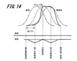
図13は、従来のバルブタイミング制御におけるバルブリフト量の変化について示した図である。図14は、本実施形態に係るバルブタイミング制御におけるバルブリフト量の変化について示した図である。 FIG. 13 is a diagram showing changes in valve lift amount in conventional valve timing control. FIG. 14 is a diagram showing changes in the valve lift amount in the valve timing control according to this embodiment.

図13に示すように、従来のバルブタイミング制御では、気筒150(図1参照)内への吸入空気量を減じるために、カムシャフト2の作動角を遅角とする。この時、カムシャフト2の作動角の変化速度は一定である。このため、吸気弁106aのリフト量が少ない(低リフト)期間は、開弁開始初期の短期間に限られる。 As shown in FIG. 13, in the conventional valve timing control, the operating angle of camshaft 2 is retarded in order to reduce the amount of intake air into cylinder 150 (see FIG. 1). At this time, the change speed of the operating angle of the camshaft 2 is constant. Therefore, the period in which the amount of lift of the intake valve 106a is small (low lift) is limited to a short period of time at the beginning of the opening of the valve.

図14に示すように、本実施形態に係るバルブタイミング制御では、吸気量を減じるようにカムシャフト2の作動角を遅角させる。また、吸気弁106aの開弁中に、クランクシャフト123に対するカムシャフト2の位相角を変化させる。カムシャフト2の作動角は、遅角、進角の順に動作し、吸気弁106aの1度の開弁中に遅角と進角の動作を2回繰り返す。また、1回目の遅角と進角の動作が行われる期間と、2回目の遅角と進角の動作が行われる期間が同じである。 As shown in FIG. 14, in the valve timing control according to this embodiment, the operating angle of the camshaft 2 is retarded so as to reduce the intake air amount. Also, the phase angle of the camshaft 2 with respect to the crankshaft 123 is changed while the intake valve 106a is open. The operating angle of the camshaft 2 is retarded and advanced in this order, and the retarded and advanced operations are repeated twice during one opening of the intake valve 106a. Also, the period during which the first retarding and advancing operations are performed is the same as the period during which the second retarding and advancing operations are performed.

ここで、吸気弁106aが開弁を開始するクランク角度を開弁開始角度とする。また、吸気弁106aが閉弁を完了するクランク角度を閉弁完了角度とする。また、開弁開始角度と閉弁完了角度との中間を中間角度とする。さらに、開弁開始角度と中間角度との中間を第1中間角度とする。そして、中間角度と閉弁完了角度との中間を第2中間角度とする。 Here, the crank angle at which the intake valve 106a starts to open is defined as the opening start angle. Also, the crank angle at which the intake valve 106a completes closing is defined as the valve closing completion angle. An intermediate angle between the valve-opening start angle and the valve-closing completion angle is defined as an intermediate angle. Further, the intermediate angle between the valve opening start angle and the intermediate angle is defined as the first intermediate angle. Then, the intermediate angle between the intermediate angle and the valve closing completion angle is defined as the second intermediate angle.

図14に示すように、制御装置101は、吸気弁が開弁を開始する開弁開始角度から第1中間角度を超えるまで、カムシャフト2の作動角を遅角に動作させて、吸気弁106aのリフト量を抑制する。すなわち、カムシャフト2の作動角を遅角に動作させて、吸気弁106aを低リフト位置に維持する。これにより、本実施形態に係るバルブタイミング制御では、吸気弁106aのリフト量が少ない(低リフト)期間が従来のバルブタイミング制御よりも長くなる。開弁開始角度から第1中間角度を超えるまで、カムシャフト2の作動角を遅角に動作させる制御は、本発明に係る第1制御に対応する。 As shown in FIG. 14, the control device 101 retards the operating angle of the camshaft 2 from the valve opening start angle at which the intake valve starts to open until it exceeds the first intermediate angle. to suppress the lift amount of That is, the operating angle of the camshaft 2 is retarded to maintain the intake valve 106a at the low lift position. Accordingly, in the valve timing control according to the present embodiment, the period during which the lift amount of the intake valve 106a is small (low lift) is longer than in the conventional valve timing control. The control for retarding the operating angle of the camshaft 2 from the valve-opening start angle until it exceeds the first intermediate angle corresponds to the first control according to the present invention.

次に、制御装置101は、第1中間角度を超えてから中間角度に至るタイミングでカムシャフト2の作動角を進角に動作させて、吸気弁106aを最大リフト位置に変化させる。開弁開始角度から中間角度まで、カムシャフト2の作動角を遅角と進角の順に動作させる制御は、本発明に係る第1作動角制御に対応する。 Next, the control device 101 advances the operating angle of the camshaft 2 at the timing of reaching the intermediate angle after exceeding the first intermediate angle, thereby changing the intake valve 106a to the maximum lift position. The control for sequentially retarding and advancing the operating angle of the camshaft 2 from the valve opening start angle to the intermediate angle corresponds to the first operating angle control according to the present invention.

次に、制御装置101は、吸気弁106aが最大リフト位置に到達した中間角度から第2中間角度を超えるまで、カムシャフト2の作動角を遅角に動作させて、吸気弁106aを最大リフト位置に維持させる。これにより、吸気弁106aの閉弁が完了するまでに気筒150内へ適切な量の空気を吸入することができる。その結果、吸入空気量が不足しないようにすることができる。中間角度から第2中間角度を超えるまで、カムシャフト2の作動角を遅角に動作させる制御は、本発明に係る第2制御に対応する。 Next, the control device 101 retards the operating angle of the camshaft 2 from the intermediate angle at which the intake valve 106a reaches the maximum lift position until it exceeds the second intermediate angle, thereby moving the intake valve 106a to the maximum lift position. to maintain As a result, an appropriate amount of air can be drawn into the cylinder 150 before the intake valve 106a is completely closed. As a result, the amount of intake air can be prevented from becoming insufficient. Control for retarding the operating angle of the camshaft 2 from the intermediate angle to beyond the second intermediate angle corresponds to the second control according to the present invention.

次に、制御装置101は、第2中間角度から閉弁完了角度までカムシャフト2の作動角を進角に動作させる。なお、中間角度から閉弁完了角度まで、カムシャフト2の作動角を遅角と進角の順に動作させる制御は、本発明に係る第2作動角制御に対応する。第1作動角制御を実行する期間と、第2作動角制御を実行する期間は等しい。 Next, the control device 101 advances the operating angle of the camshaft 2 from the second intermediate angle to the valve closing completion angle. It should be noted that the control for operating the operating angle of the camshaft 2 in order of retardation and advance from the intermediate angle to the valve closing completion angle corresponds to the second operating angle control according to the present invention. The period during which the first operating angle control is performed is equal to the period during which the second operating angle control is performed.

図15は、従来のバルブタイミング制御と本実施形態に係るバルブタイミング制御における筒内の乱流エネルギーの変化について示した図である。なお、乱流エネルギーの算出には、CFD(computational fluid dynamics)を用いた。また、開弁時期は、上死点で統一した。 FIG. 15 is a diagram showing changes in turbulent energy in the cylinder in conventional valve timing control and valve timing control according to the present embodiment. CFD (computational fluid dynamics) was used to calculate the turbulence energy. In addition, the valve opening timing was unified at the top dead center.

図15に示すように、クランクシャフト123(カムシャフト2)の回転に伴って生じる気筒150内の負圧に対して、吸気弁106aのリフト量が少ない(低リフト)期間が長くなると、乱流エネルギーが大きくなる。したがって、本実施形態に係るバルブタイミング制御における乱流エネルギーは、従来のバルブタイミング制御における乱流エネルギーよりも大きい。 As shown in FIG. 15, with respect to the negative pressure in the cylinder 150 caused by the rotation of the crankshaft 123 (camshaft 2), if the period during which the lift amount of the intake valve 106a is small (low lift) becomes longer, turbulent flow will occur. energy increases. Therefore, the turbulence energy in the valve timing control according to this embodiment is greater than the turbulence energy in the conventional valve timing control.

乱流エネルギーが増大すると、気筒150内の空気と燃料が撹拌され易くなる。これにより、混合ガスが均質化されるため、点火プラグ200の電極周りのガスが最適となる。その結果、混合ガスの着火性が改善し、失火を防止することができる。 When the turbulence energy increases, the air and fuel in cylinder 150 are easily agitated. As a result, the mixed gas is homogenized, and the gas around the electrodes of the spark plug 200 is optimized. As a result, the ignitability of the mixed gas is improved, and misfiring can be prevented.

図16は、本実施形態に係る制御方法を示すタイミングチャートである。 FIG. 16 is a timing chart showing the control method according to this embodiment.

図16に示すように、エンジン(内燃機関100)の再始動要求が行われた時点であるt5において、吸気弁106a(吸気バルブ)の開弁タイミングは、遅角が最大である。そして、t5において、気筒150内への吸入空気量はゼロである。エンジンの再始動要求と同時に吸気弁106aの開弁タイミングが進角し、吸入空気量が増加する。 As shown in FIG. 16, at time t5 when a request to restart the engine (internal combustion engine 100) is made, the opening timing of the intake valve 106a (intake valve) is maximally retarded. Then, at t5, the amount of intake air into cylinder 150 is zero. Simultaneously with the request to restart the engine, the opening timing of the intake valve 106a is advanced to increase the amount of intake air.

エンジンの再始動の開始直後における吸入空気流量は少ない。しかし、本実施形態に係るバルブタイミング制御を実施することにより、カムシャフト2の作動角の変化速度を可変する。これにより、吸気弁106aのリフト量が少ない(低リフト)期間を従来のバルブタイミング制御よりも長くすることができる。その結果、気筒150内の乱流エネルギーを従来のバルブタイミング制御よりも大きくして、着火に必要な流動を得ることができる。 The intake air flow rate is small immediately after the start of restarting the engine. However, by performing the valve timing control according to this embodiment, the change speed of the operating angle of the camshaft 2 can be varied. As a result, the period during which the lift amount of the intake valve 106a is small (low lift) can be made longer than in conventional valve timing control. As a result, the turbulence energy in the cylinder 150 can be made greater than that in conventional valve timing control to obtain the necessary flow for ignition.

2.まとめ
以上説明したように、上述した実施形態に係る内燃機関(内燃機関100)の制御装置(制御装置101)は、クランクシャフト(クランクシャフト123)の回転とカムシャフト(カムシャフト2)の回転の相対回転位相を変更して、カムシャフトにより開閉される吸気弁(吸気弁106a)のリフト量を可変するバルブタイミング制御装置(バルブタイミング制御装置500)と、クランクシャフトの回転角度であるクランク角度を検出するクランク角センサ(クランク角センサ121)とを備える内燃機関を制御する。ここで、吸気弁が開弁を開始するクランク角度を開弁開始角度、吸気弁が閉弁を完了するクランク角度を閉弁完了角度、開弁開始角度と閉弁完了角度との中間を中間角度、開弁開始角度と中間角度との中間を第1中間角度と定義する。内燃機関の制御装置は、バルブタイミング制御装置を制御し、吸気弁が開弁を開始した後、第1中間角度を超えるまで吸気弁のリフト量を抑制し、その後、中間角度に至るタイミングで吸気弁を最大リフト位置に変化させるバルブタイミング制御部(バルブタイミング制御部390)を有する。
2. Summary As described above, the control device (control device 101) for the internal combustion engine (internal combustion engine 100) according to the above-described embodiment controls the rotation of the crankshaft (crankshaft 123) and the rotation of the camshaft (camshaft 2). A valve timing control device (valve timing control device 500) that changes the relative rotation phase of rotation to vary the lift amount of the intake valve (intake valve 106a) that is opened and closed by the camshaft, and the crank that is the rotation angle of the crankshaft. It controls an internal combustion engine provided with a crank angle sensor (crank angle sensor 121) that detects an angle. Here, the crank angle at which the intake valve starts to open is the valve opening start angle, the crank angle at which the intake valve completes closing is the valve closing angle, and the intermediate angle between the valve opening start angle and the valve closing angle is the intermediate angle. , an intermediate angle between the valve opening start angle and the intermediate angle is defined as a first intermediate angle. The control device for the internal combustion engine controls the valve timing control device, after the intake valve starts to open, suppresses the lift amount of the intake valve until it exceeds a first intermediate angle, and then at the timing reaching the intermediate angle. It has a valve timing control section (valve timing control section 390) that changes the valve to the maximum lift position.

これにより、吸気弁のリフト量が少ない(低リフト)期間を、従来のバルブタイミング制御よりも長くすることができる。その結果、従来のバルブタイミング制御によりも乱流エネルギーを大きくすることができる。したがって、気筒(気筒150)内の空気と燃料が撹拌され易くなり、混合ガスが均質化される。そのため、混合ガスの着火性が改善し、失火を防止することができる。 As a result, the period during which the lift amount of the intake valve is small (low lift) can be made longer than in conventional valve timing control. As a result, turbulence energy can be increased more than conventional valve timing control. Therefore, the air and fuel in the cylinder (cylinder 150) are easily agitated, and the mixed gas is homogenized. Therefore, the ignitability of the mixed gas is improved, and misfiring can be prevented.

また、上述した実施形態に係る内燃機関(内燃機関100)の制御装置(制御装置101)において、中間角度と閉弁完了角度との中間を第2中間角度と定義する。バルブタイミング制御部(バルブタイミング制御部390)は、吸気弁(吸気弁106a)が最大リフト位置に到達した後、第2中間角度を超えるまで吸気弁を最大リフト位置に維持させる。これにより、吸気弁の閉弁が完了するまでに気筒(気筒150)内へ適切な量の空気を吸入することができる。その結果、吸入空気量が不足しないようにすることができる。 Further, in the control device (control device 101) for the internal combustion engine (internal combustion engine 100) according to the embodiment described above, the intermediate angle between the intermediate angle and the valve closing angle is defined as the second intermediate angle. After the intake valve (intake valve 106a) reaches the maximum lift position, the valve timing control section (valve timing control section 390) maintains the intake valve at the maximum lift position until the second intermediate angle is exceeded. As a result, an appropriate amount of air can be drawn into the cylinder (cylinder 150) before the intake valve is completely closed. As a result, the amount of intake air can be prevented from becoming insufficient.

また、上述した実施形態に係る内燃機関(内燃機関100)の制御装置(制御装置101)におけるバルブタイミング制御部(バルブタイミング制御部390)は、吸気弁(吸気弁106a)の開弁開始から閉弁完了するまでの期間に、(カムシャフト2)を遅角側に制御する第1制御を実施することにより、吸気弁が開弁開始した後、吸気弁のリフト量を抑制する。これにより、吸気弁のリフト量が少ない(低リフト)期間を、従来のバルブタイミング制御よりも長くすることができる。 Further, the valve timing control unit (valve timing control unit 390) in the control device (control device 101) for the internal combustion engine (internal combustion engine 100) according to the above-described embodiment controls the opening of the intake valve (intake valve 106a) to close it. By performing the first control that controls (camshaft 2) to the retard side during the period until the valve is completed, the lift amount of the intake valve is suppressed after the intake valve starts to open. As a result, the period during which the lift amount of the intake valve is small (low lift) can be made longer than in conventional valve timing control.

また、上述した実施形態に係る内燃機関(内燃機関100)の制御装置(制御装置101)におけるバルブタイミング制御部(バルブタイミング制御部390)は、第1制御を実施してから、カムシャフト(カムシャフト2)を進角側に戻す制御を行った後、吸気弁(吸気弁106a)が最大リフト位置に到達するタイミングで、カムシャフトを遅角側に制御する第2制御を実施することにより、吸気弁を最大リフト位置に維持させる。これにより、吸入空気量が不足しないようにすることができる。 Further, the valve timing control unit (valve timing control unit 390) in the control device (control device 101) for the internal combustion engine (internal combustion engine 100) according to the above-described embodiment performs the first control, and then the camshaft (cam After performing control to return the shaft 2) to the advance side, at the timing when the intake valve (intake valve 106a) reaches the maximum lift position, a second control is performed to control the camshaft to the retard side, Keep the intake valve in the maximum lift position. As a result, it is possible to prevent the intake air amount from becoming insufficient.

また、上述した実施形態に係る内燃機関(内燃機関100)の制御装置(制御装置101)は、クランクシャフト(クランクシャフト123)の回転とカムシャフト(カムシャフト2)の回転の相対回転位相を変更して、カムシャフトにより開閉される吸気弁(吸気弁106a)のリフト量を可変するバルブタイミング制御装置(バルブタイミング制御装置500)と、クランクシャフトの回転角度であるクランク角度を検出するクランク角センサ(クランク角センサ121)とを備える内燃機関を制御する。内燃機関の制御装置は、バルブタイミング制御装置を制御し、吸気弁が開弁を開始してから閉弁を完了するまでの間に、カムシャフトの作動角を遅角と進角の順に制御する第1作動角制御を実施するバルブタイミング制御部(バルブタイミング制御部390)を有する。これにより、従来のバルブタイミング制御によりも乱流エネルギーを大きくすることができる。その結果、混合ガスの着火性を改善して、失火を防止することができる。 Further, the control device (control device 101) for the internal combustion engine (internal combustion engine 100) according to the above-described embodiment changes the relative rotation phase between the rotation of the crankshaft (crankshaft 123) and the rotation of the camshaft (camshaft 2). A valve timing control device (valve timing control device 500) that varies the lift amount of the intake valve (intake valve 106a) that is opened and closed by the camshaft, and a crank angle sensor that detects the crank angle, which is the rotation angle of the crankshaft. (crank angle sensor 121) to control an internal combustion engine. A control device for an internal combustion engine controls a valve timing control device, and sequentially controls the operating angle of a camshaft from the start of opening of an intake valve to the completion of closing of the valve. It has a valve timing control section (valve timing control section 390) that performs the first operating angle control. As a result, the turbulence energy can be increased more than the conventional valve timing control. As a result, it is possible to improve the ignitability of the mixed gas and prevent misfiring.

また、上述した実施形態に係る内燃機関(内燃機関100)の制御装置(制御装置101)におけるバルブタイミング制御部(バルブタイミング制御部390)は、第1作動角制御の後に、カムシャフト(カムシャフト2)の作動角を遅角と進角の順に制御する第2作動角制御を実施する。これにより、吸気弁の閉弁が完了するまでに気筒(気筒150)内へ適切な量の空気を吸入することができる。その結果、吸入空気量が不足しないようにすることができる。 Further, the valve timing control unit (valve timing control unit 390) in the control device (control device 101) for the internal combustion engine (internal combustion engine 100) according to the above-described embodiment controls the camshaft (camshaft The second operating angle control of 2) is performed to control the operating angle in the order of retardation and advance. As a result, an appropriate amount of air can be drawn into the cylinder (cylinder 150) before the intake valve is completely closed. As a result, the amount of intake air can be prevented from becoming insufficient.

また、上述した実施形態に係る内燃機関(内燃機関100)の制御装置(制御装置101)において、第1作動角制御と第2作動角制御の実施期間は等しい。これにより、乱流エネルギーを大きくすることと、吸入空気量が不足しないようにすることの両立を図ることができる。 In addition, in the control device (control device 101) for the internal combustion engine (internal combustion engine 100) according to the above-described embodiment, the execution periods of the first operating angle control and the second operating angle control are the same. As a result, it is possible to both increase the turbulence energy and prevent the intake air amount from becoming insufficient.

また、上述した実施形態に係る内燃機関(内燃機関100)の制御装置(制御装置101)において、吸気弁が開弁を開始するクランク角度を開弁開始角度、吸気弁が閉弁を完了するクランク角度を閉弁完了角度、開弁開始角度と閉弁完了角度との中間を中間角度、開弁開始角度と中間角度との中間を第1中間角度と定義する。第1作動角制御は、開弁開始角度から中間角度となる期間に実施する。第2作動角制御は、中間角度から閉弁完了角度となる期間に実施する。これにより、第1作動角制御と第2作動角制御の実施期間を等しくすることができる。 Further, in the control device (control device 101) of the internal combustion engine (internal combustion engine 100) according to the above-described embodiment, the crank angle at which the intake valve starts to open, the valve opening start angle, and the crank angle at which the intake valve closes An angle is defined as a valve closing completion angle, an intermediate angle between the valve opening start angle and the valve closing completion angle, and an intermediate angle between the valve opening start angle and the intermediate angle as a first intermediate angle. The first operating angle control is performed during a period of an intermediate angle from the valve opening start angle. The second operating angle control is performed during the period from the intermediate angle to the valve closing completion angle. This makes it possible to equalize the implementation periods of the first operating angle control and the second operating angle control.

また、上述した実施形態に係る内燃機関(内燃機関100)の制御装置(制御装置101)において、吸気弁(吸気弁106a)の開弁は、内燃機関の始動時におけるクランクシャフト(クランクシャフト123)の回転開始から最初の開弁である。これにより、内燃機関の始動時における気筒(気筒150)内の圧縮圧力の変化を小さくすることができる。その結果、内燃機関の始動時における振動を抑制することができる。また、混合ガスの着火性が改善し、失火を防止することができる。 Further, in the control device (control device 101) for the internal combustion engine (internal combustion engine 100) according to the above-described embodiment, the opening of the intake valve (intake valve 106a) is controlled by the crankshaft (crankshaft 123) at the time of starting the internal combustion engine. It is the first valve opening from the start of rotation. As a result, changes in the compression pressure in the cylinder (cylinder 150) can be reduced when the internal combustion engine is started. As a result, it is possible to suppress vibrations at the start of the internal combustion engine. In addition, the ignitability of the mixed gas is improved, and misfiring can be prevented.

また、上述した実施形態に係る内燃機関(内燃機関100)の制御方法は、クランクシャフト(クランクシャフト123)の回転とカムシャフト(カムシャフト2)の回転の相対回転位相を変更して、カムシャフトにより開閉される吸気弁(吸気弁106a)のリフト量を可変するバルブタイミング制御装置(バルブタイミング制御装置500)と、クランクシャフトの回転角度であるクランク角度を検出するクランク角センサ(クランク角センサ121)と、を備える内燃機関の制御方法である。ここで、吸気弁が開弁を開始するクランク角度を開弁開始角度、吸気弁が閉弁を完了するクランク角度を閉弁完了角度、開弁開始角度と閉弁完了角度との中間を中間角度、開弁開始角度と中間角度との中間を第1中間角度と定義する。内燃機関の制御方法は、吸気弁が開弁を開始した後、第1中間角度を超えるまで吸気弁のリフト量を抑制し、その後、中間角度に至るタイミングで吸気弁を最大リフト位置に変化させる。これにより、従来のバルブタイミング制御によりも乱流エネルギーを大きくすることができる。その結果、混合ガスの着火性を改善して、失火を防止することができる。 Further, the control method of the internal combustion engine (internal combustion engine 100) according to the above-described embodiment changes the relative rotation phase between the rotation of the crankshaft (crankshaft 123) and the rotation of the camshaft (camshaft 2), A valve timing control device (valve timing control device 500) that varies the lift amount of the intake valve (intake valve 106a) that is opened and closed by the engine, and a crank angle sensor (crank angle sensor 121) that detects the crank angle, which is the rotation angle of the crankshaft. ) and a control method for an internal combustion engine. Here, the crank angle at which the intake valve starts to open is the valve opening start angle, the crank angle at which the intake valve completes closing is the valve closing angle, and the intermediate angle between the valve opening start angle and the valve closing angle is the intermediate angle. , an intermediate angle between the valve opening start angle and the intermediate angle is defined as a first intermediate angle. A control method for an internal combustion engine is to suppress the lift amount of the intake valve until it exceeds a first intermediate angle after the intake valve starts to open, and then change the intake valve to the maximum lift position at the timing when the intermediate angle is reached. . As a result, the turbulence energy can be increased more than the conventional valve timing control. As a result, it is possible to improve the ignitability of the mixed gas and prevent misfiring.

また、上述した実施形態に係る内燃機関(内燃機関100)の制御方法は、クランクシャフト(クランクシャフト123)の回転とカムシャフト(カムシャフト2)の回転の相対回転位相を変更して、カムシャフトにより開閉される吸気弁(吸気弁106a)のリフト量を可変するバルブタイミング制御装置(バルブタイミング制御装置500)と、クランクシャフトの回転角度であるクランク角度を検出するクランク角センサ(クランク角センサ121)と、を備える内燃機関の制御方法である。この内燃機関の制御方法は、吸気弁が開弁を開始してから閉弁を完了するまでの間に、カムシャフトの作動角を遅角と進角の順に制御する第1作動角制御を実施する。これにより、従来のバルブタイミング制御によりも乱流エネルギーを大きくすることができる。その結果、混合ガスの着火性を改善して、失火を防止することができる。 Further, the control method of the internal combustion engine (internal combustion engine 100) according to the above-described embodiment changes the relative rotation phase between the rotation of the crankshaft (crankshaft 123) and the rotation of the camshaft (camshaft 2), A valve timing control device (valve timing control device 500) that varies the lift amount of the intake valve (intake valve 106a) that is opened and closed by the engine, and a crank angle sensor (crank angle sensor 121) that detects the crank angle, which is the rotation angle of the crankshaft. ) and a control method for an internal combustion engine. This method of controlling an internal combustion engine implements first operating angle control in which the operating angle of the camshaft is controlled in order of retardation and advance from the time the intake valve starts to open until the valve closes. do. As a result, the turbulence energy can be increased more than the conventional valve timing control. As a result, it is possible to improve the ignitability of the mixed gas and prevent misfiring.

以上、本発明の内燃機関の制御装置、及び内燃機関の制御方法の実施形態について、その作用効果も含めて説明した。しかしながら、本発明の内燃機関の制御装置、及び内燃機関の制御方法は、上述の実施形態に限定されるものではなく、請求の範囲に記載した発明の要旨を逸脱しない範囲内で種々の変形実施が可能である。 The embodiments of the internal combustion engine control device and the internal combustion engine control method of the present invention have been described above, including their effects. However, the internal combustion engine control device and the internal combustion engine control method of the present invention are not limited to the above-described embodiments, and various modifications can be made without departing from the scope of the invention described in the claims. is possible.

また、上述した実施形態は、本発明を分かりやすく説明するために詳細に説明したものであり、必ずしも説明した全ての構成を備えるものに限定されるものではない。また、ある実施形態の構成の一部を他の実施形態の構成に置き換えることが可能であり、また、ある実施形態の構成に他の実施形態の構成を加えることも可能である。また、各実施形態の構成の一部について、他の構成の追加・削除・置換をすることが可能である。 Also, the above-described embodiments have been described in detail in order to explain the present invention in an easy-to-understand manner, and are not necessarily limited to those having all the described configurations. Also, part of the configuration of one embodiment can be replaced with the configuration of another embodiment, and the configuration of another embodiment can be added to the configuration of one embodiment. Moreover, it is possible to add, delete, or replace a part of the configuration of each embodiment with another configuration.

例えば、上述した実施形態では、開弁開始角度から第1中間角度を超えるまで、カムシャフト2の作動角を遅角に動作させる第1制御と、中間角度から第2中間角度を超えるまで、カムシャフト2の作動角を遅角に動作させる第2制御を実施する。しかし、本発明に係るバルブタイミング制御としては、少なくとも第1制御を実施すればよい。第1制御を実施することにより、吸気弁のリフト量が少ない(低リフト)期間を、従来のバルブタイミング制御よりも長くすることができる。その結果、従来のバルブタイミング制御によりも乱流エネルギーを大きくすることができため、混合ガスの着火性が改善し、失火を防止することができる。 For example, in the above-described embodiment, the first control for retarding the operating angle of the camshaft 2 from the valve-opening start angle until it exceeds the first intermediate angle, and the cam A second control is performed to retard the operating angle of the shaft 2 . However, at least the first control should be performed as the valve timing control according to the present invention. By performing the first control, the period during which the intake valve lift amount is small (low lift) can be made longer than in conventional valve timing control. As a result, the turbulence energy can be increased more than the conventional valve timing control, so that the ignitability of the mixed gas is improved and misfiring can be prevented.

また、上述した実施形態では、吸気弁106aの1度の開弁中に遅角と進角の動作を2回繰り返すようにした。しかし、本発明に係るバルブタイミング制御としては、吸気弁の1度の開弁中に遅角と進角の動作を3回以上繰り返すようにしてもよい。 Further, in the above-described embodiment, the operation of retarding and advancing the angle is repeated twice during one opening of the intake valve 106a. However, as the valve timing control according to the present invention, the operation of retarding and advancing the intake valve may be repeated three times or more during one opening of the intake valve.

1…タイミングスプロケット(スプロケット)、 2…吸気カムシャフト(カムシャフト)、 3…位相変更機構、 5…内歯構成部、 6…滑り軸受機構、 8…保持プレート、 9…従動部材、 10…軸受凹部、 11…ジャーナル部、 12…電動モータ、 13…減速機構、 14…カムボルト、 15…フロントプレート、 16…モータハウジング、 17…モータ出力軸、 18…給電機構、 19…ストッパ部材、 20…オルダム継手、 21…偏心軸、 22…ボールベアリング、 23…ローラ、 24…保持器、 25…ニードルベアリング、 30…中間部材、 31…筒状基部、 33a…伝達キー、 100…内燃機関、 101…制御装置、 105…排気カムシャフト、 106a…吸気弁、 106b…排気弁、 111…吸気管、 112…吸気マニホールド、 113…スロットル弁、 113a…スロットル開度センサ、 114…流量センサ、 115…吸気温センサ、 116…吸気圧センサ、 121…クランク角センサ、 122…水温センサ、 123…クランクシャフト、 126…アクセルポジションセンサ、 140…筒内圧センサ、 150…気筒、 160…排気マニホールド、 161…三元触媒、 162…上流側空燃比センサ、 163…下流側空燃比センサ、 170…ピストン、 180…シリンダヘッド、 181…軸受、 200…点火プラグ、 310…アナログ入力部、 320…デジタル入力部、 330…A/D変換部、 340…RAM、 350…MPU、 360…ROM、 370…I/Oポート、 380…出力回路、 381…全体制御部、 382…燃料噴射制御部、 383…点火制御部、 390…バルブタイミング制御部、 400…燃料噴射装置、 410…プランジャロッド、 500…バルブタイミング制御装置 DESCRIPTION OF SYMBOLS 1... Timing sprocket (sprocket), 2... Intake camshaft (camshaft), 3... Phase change mechanism, 5... Internal tooth structure part, 6... Slide bearing mechanism, 8... Holding plate, 9... Driven member, 10... Bearing Recess 11 Journal portion 12 Electric motor 13 Reduction mechanism 14 Cam bolt 15 Front plate 16 Motor housing 17 Motor output shaft 18 Power supply mechanism 19 Stopper member 20 Oldham Joint 21 Eccentric shaft 22 Ball bearing 23 Roller 24 Cage 25 Needle bearing 30 Intermediate member 31 Cylindrical base 33a Transmission key 100 Internal combustion engine 101 Control Device 105 Exhaust camshaft 106a Intake valve 106b Exhaust valve 111 Intake pipe 112 Intake manifold 113 Throttle valve 113a Throttle opening sensor 114 Flow rate sensor 115 Intake air temperature sensor , 116... Intake pressure sensor 121... Crank angle sensor 122... Water temperature sensor 123... Crankshaft 126... Accelerator position sensor 140... In-cylinder pressure sensor 150... Cylinder 160... Exhaust manifold 161... Three-way catalyst 162...Upstream air-fuel ratio sensor 163...Downstream air-fuel ratio sensor 170...Piston 180...Cylinder head 181...Bearing 200...Ignition plug 310...Analog input section 320...Digital input section 330...A/ D converter 340 RAM 350 MPU 360 ROM 370 I/O port 380 output circuit 381 overall control unit 382 fuel injection control unit 383 ignition control unit 390 valve Timing control unit 400 Fuel injection device 410 Plunger rod 500 Valve timing control device

Claims (11)

クランクシャフトの回転とカムシャフトの回転の相対回転位相を変更して、前記カムシャフトにより開閉される吸気弁のリフト量を可変するバルブタイミング制御装置と、
前記クランクシャフトの回転角度であるクランク角度を検出するクランク角センサと、を備える内燃機関を制御する内燃機関の制御装置において、
前記吸気弁が開弁を開始するクランク角度を開弁開始角度、前記吸気弁が閉弁を完了するクランク角度を閉弁完了角度、前記開弁開始角度と前記閉弁完了角度との中間を中間角度、前記開弁開始角度と前記中間角度との中間を第1中間角度と定義した場合に、
前記バルブタイミング制御装置を制御し、前記吸気弁が開弁を開始した後、前記第1中間角度を超えるまで前記吸気弁のリフト量を抑制し、その後、前記中間角度に至るタイミングで前記吸気弁を最大リフト位置に変化させるバルブタイミング制御部を有する
内燃機関の制御装置。
a valve timing control device that changes the relative rotational phases of the rotation of the crankshaft and the rotation of the camshaft to vary the lift amount of the intake valves that are opened and closed by the camshaft;
A control device for an internal combustion engine that controls an internal combustion engine, comprising: a crank angle sensor that detects a crank angle that is a rotation angle of the crankshaft;
A crank angle at which the intake valve starts opening, a valve opening start angle, a crank angle at which the intake valve completes closing, a valve closing angle, and an intermediate between the valve opening start angle and the valve closing completion angle. angle, when the intermediate angle between the valve opening start angle and the intermediate angle is defined as a first intermediate angle,
After the intake valve starts to open, the valve timing control device is controlled to suppress the lift amount of the intake valve until the first intermediate angle is exceeded, and then, at the timing when the intermediate angle is reached, the intake valve is controlled. to a maximum lift position.
前記中間角度と前記閉弁完了角度との中間を第2中間角度と定義した場合に、
前記バルブタイミング制御部は、前記吸気弁が最大リフト位置に到達した後、前記第2中間角度を超えるまで前記吸気弁を最大リフト位置に維持させる
請求項1に記載の内燃機関の制御装置。
When the intermediate angle between the intermediate angle and the valve closing angle is defined as a second intermediate angle,
2. The control device for an internal combustion engine according to claim 1, wherein said valve timing control unit maintains said intake valve at said maximum lift position until said second intermediate angle is exceeded after said intake valve reaches said maximum lift position.
前記バルブタイミング制御部は、前記吸気弁の開弁開始から閉弁完了するまでの期間に、前記カムシャフトを遅角側に制御する第1制御を実施することにより、前記吸気弁が開弁開始した後、前記吸気弁のリフト量を抑制する
請求項1に記載の内燃機関の制御装置。
The valve timing control unit performs a first control for controlling the camshaft to the retard side during a period from the start of opening of the intake valve to the completion of closing of the intake valve, thereby causing the intake valve to start opening. 2. The control device for an internal combustion engine according to claim 1, wherein the lift amount of the intake valve is suppressed after the intake valve is lifted.
前記バルブタイミング制御部は、前記第1制御を実施してから、前記カムシャフトを進角側に戻す制御を行った後、前記吸気弁が最大リフト位置に到達するタイミングで、前記カムシャフトを遅角側に制御する第2制御を実施することにより、前記吸気弁を最大リフト位置に維持させる
請求項3に記載の内燃機関の制御装置。
After executing the first control, the valve timing control unit performs control to return the camshaft to the advance side, and then retards the camshaft at the timing when the intake valve reaches the maximum lift position. 4. The control device for an internal combustion engine according to claim 3, wherein the intake valve is maintained at the maximum lift position by executing a second control that controls to the corner side.
クランクシャフトの回転とカムシャフトの回転の相対回転位相を変更して、前記カムシャフトにより開閉される吸気弁のリフト量を可変するバルブタイミング制御装置と、
前記クランクシャフトの回転角度であるクランク角度を検出するクランク角センサと、を備える内燃機関を制御する内燃機関の制御装置において、
前記バルブタイミング制御装置を制御し、前記吸気弁が開弁を開始してから閉弁を完了するまでの間に、前記カムシャフトの作動角を遅角と進角の順に制御する第1作動角制御を実施するバルブタイミング制御部を有する
内燃機関の制御装置。
a valve timing control device that changes the relative rotational phases of the rotation of the crankshaft and the rotation of the camshaft to vary the lift amount of the intake valves that are opened and closed by the camshaft;
A control device for an internal combustion engine that controls an internal combustion engine, comprising: a crank angle sensor that detects a crank angle that is a rotation angle of the crankshaft;
A first operating angle that controls the valve timing control device and controls the operating angle of the camshaft in order of retardation and advance from the start of opening of the intake valve to the completion of closing of the intake valve. A control device for an internal combustion engine having a valve timing control section that performs control.
前記バルブタイミング制御部は、前記第1作動角制御の後に、前記カムシャフトの作動角を遅角と進角の順に制御する第2作動角制御を実施する
請求項5に記載の内燃機関の制御装置。
6. The control of the internal combustion engine according to claim 5, wherein the valve timing control unit performs second operation angle control for controlling the operation angle of the camshaft in order of retardation and advance after the first operation angle control. Device.
前記第1作動角制御と前記第2作動角制御の実施期間は等しい
請求項6に記載の内燃機関の制御装置。
7. The control device for an internal combustion engine according to claim 6, wherein said first operating angle control and said second operating angle control are performed for the same period.
前記吸気弁が開弁するクランク角度を開弁開始角度、前記吸気弁が閉弁するクランク角度を閉弁完了角度、前記開弁開始角度と前記閉弁完了角度との中間を中間角度、前記開弁開始角度と前記中間角度との中間を第1中間角度と定義した場合に、
前記第1作動角制御は、前記開弁開始角度から前記中間角度となる期間に実施し、
前記第2作動角制御は、前記中間角度から前記閉弁完了角度となる期間に実施する
請求項7に記載の内燃機関の制御装置。
A crank angle at which the intake valve opens a valve opening start angle, a crank angle at which the intake valve closes is a valve closing angle, an intermediate angle between the valve opening start angle and the valve closing completion angle is an intermediate angle, and the opening When the intermediate angle between the valve opening angle and the intermediate angle is defined as the first intermediate angle,
The first operating angle control is performed during a period from the valve opening start angle to the intermediate angle,
The control device for an internal combustion engine according to claim 7, wherein the second operating angle control is performed during a period from the intermediate angle to the valve closing completion angle.
前記吸気弁の開弁は、内燃機関の始動時における前記クランクシャフトの回転開始から最初の開弁である
請求項1乃至8の何れかに記載の内燃機関の制御装置。
9. The control device for an internal combustion engine according to any one of claims 1 to 8, wherein the opening of the intake valve is the first valve opening after the start of rotation of the crankshaft when the internal combustion engine is started.
クランクシャフトの回転とカムシャフトの回転の相対回転位相を変更して、前記カムシャフトにより開閉される吸気弁のリフト量を可変するバルブタイミング制御装置と、
前記クランクシャフトの回転角度であるクランク角度を検出するクランク角センサと、を備える内燃機関の制御方法において、
前記吸気弁が開弁を開始するクランク角度を開弁開始角度、前記吸気弁が閉弁を完了するクランク角度を閉弁完了角度、前記開弁開始角度と前記閉弁完了角度との中間を中間角度、前記開弁開始角度と前記中間角度との中間を第1中間角度と定義した場合に、
前記吸気弁が開弁を開始した後、前記第1中間角度を超えるまで前記吸気弁のリフト量を抑制し、その後、前記中間角度に至るタイミングで前記吸気弁を最大リフト位置に変化させる
内燃機関の制御方法。
a valve timing control device that changes the relative rotational phases of the rotation of the crankshaft and the rotation of the camshaft to vary the lift amount of the intake valves that are opened and closed by the camshaft;
A control method for an internal combustion engine comprising a crank angle sensor that detects a crank angle, which is the rotation angle of the crankshaft,
A crank angle at which the intake valve starts opening, a valve opening start angle, a crank angle at which the intake valve completes closing, a valve closing angle, and an intermediate between the valve opening start angle and the valve closing completion angle. angle, when the intermediate angle between the valve opening start angle and the intermediate angle is defined as a first intermediate angle,
After the intake valve starts to open, the lift amount of the intake valve is suppressed until the first intermediate angle is exceeded, and then the intake valve is changed to the maximum lift position at the timing when the intermediate angle is reached. Internal combustion engine control method.
クランクシャフトの回転とカムシャフトの回転の相対回転位相を変更して、前記カムシャフトにより開閉される吸気弁のリフト量を可変するバルブタイミング制御装置と、
前記クランクシャフトの回転角度であるクランク角度を検出するクランク角センサと、を備える内燃機関の制御方法において、
前記吸気弁が開弁を開始してから閉弁を完了するまでの間に、前記カムシャフトの作動角を遅角と進角の順に制御する第1作動角制御を実施する
内燃機関の制御方法。
a valve timing control device that changes the relative rotational phases of the rotation of the crankshaft and the rotation of the camshaft to vary the lift amount of the intake valves that are opened and closed by the camshaft;
A control method for an internal combustion engine comprising a crank angle sensor that detects a crank angle, which is the rotation angle of the crankshaft,
performing a first operation angle control in which the operation angle of the camshaft is controlled in order of retardation and advance in the period from when the intake valve starts to open until it completes closing; Method of controlling an internal combustion engine .
JP2022534931A 2020-07-07 2021-05-19 CONTROL DEVICE FOR INTERNAL COMBUSTION ENGINE AND CONTROL METHOD FOR INTERNAL COMBUSTION ENGINE Active JP7288552B2 (en)

Applications Claiming Priority (3)

Application Number Priority Date Filing Date Title
JP2020116924 2020-07-07
PCT/JP2021/019019 WO2022009532A1 (en) 2020-07-07 2021-05-19 Control device for internal combustion engine, and control method for internal combustion engine

Publications (2)

Publication Number Publication Date
JPWO2022009532A1 JPWO2022009532A1 (en) 2022-01-13
JP7288552B2 true JP7288552B2 (en) 2023-06-07

Family

ID=79552888

Family Applications (1)

Application Number Title Priority Date Filing Date
JP2022534931A Active JP7288552B2 (en) 2020-07-07 2021-05-19 CONTROL DEVICE FOR INTERNAL COMBUSTION ENGINE AND CONTROL METHOD FOR INTERNAL COMBUSTION ENGINE

Country Status (2)

Country Link
JP (1) JP7288552B2 (en)
WO (1) WO2022009532A1 (en)

Citations (4)

* Cited by examiner, † Cited by third party
Publication number Priority date Publication date Assignee Title
JP2003254100A (en) 2002-03-05 2003-09-10 Hitachi Unisia Automotive Ltd Variable valve train for internal combustion engines
US20060027208A1 (en) 2004-08-03 2006-02-09 Bruce Pinkston Internal combustion engine control
JP2007077841A (en) 2005-09-13 2007-03-29 Nissan Motor Co Ltd Internal combustion engine
JP2007298047A (en) 2007-08-22 2007-11-15 Hitachi Ltd Variable valve operating apparatus for internal combustion engine and controller for variable valve operating apparatus for internal combustion engine

Patent Citations (4)

* Cited by examiner, † Cited by third party
Publication number Priority date Publication date Assignee Title
JP2003254100A (en) 2002-03-05 2003-09-10 Hitachi Unisia Automotive Ltd Variable valve train for internal combustion engines
US20060027208A1 (en) 2004-08-03 2006-02-09 Bruce Pinkston Internal combustion engine control
JP2007077841A (en) 2005-09-13 2007-03-29 Nissan Motor Co Ltd Internal combustion engine
JP2007298047A (en) 2007-08-22 2007-11-15 Hitachi Ltd Variable valve operating apparatus for internal combustion engine and controller for variable valve operating apparatus for internal combustion engine

Also Published As

Publication number Publication date
WO2022009532A1 (en) 2022-01-13
JPWO2022009532A1 (en) 2022-01-13

Similar Documents

Publication Publication Date Title
US10316765B2 (en) Control device and control method for internal combustion engine
JP4767096B2 (en) Variable valve timing device
JP2000356143A (en) Combustion control device for internal combustion engine
US20120037105A1 (en) Variably operated valve apparatus for internal combustion engine, start system for internal combustion engine, and start control apparatus for internal combustion engine
CN101438032B (en) Variable valve timing system and method for controlling the same
JP4267635B2 (en) Variable valve timing device
KR20080033323A (en) Valve timing control device and control method for internal combustion engines
JP7288552B2 (en) CONTROL DEVICE FOR INTERNAL COMBUSTION ENGINE AND CONTROL METHOD FOR INTERNAL COMBUSTION ENGINE
JP2014031727A (en) Start control device of internal combustion engine
US6769401B2 (en) Power output control system for internal combustion engine
JP2007270754A (en) Variable valve timing device
JP2013130092A (en) Method for discriminating cylinder in start for internal combustion engine
JP2004036428A (en) Control device for internal combustion engine
US12012906B2 (en) Stop control device for internal combustion engine
JP4267636B2 (en) Variable valve timing device
CN106050440B (en) Control device and control method for internal combustion engine
JP3584476B2 (en) Valve timing control device for internal combustion engine
JP3175243B2 (en) Valve timing control device for internal combustion engine
WO2014076531A1 (en) Control apparatus and control method for internal combustion engine
JP5348074B2 (en) Internal combustion engine start control system
JP4737158B2 (en) Engine with variable valve mechanism
JP4532399B2 (en) Control device for internal combustion engine
US10233848B2 (en) Control apparatus for internal combustion engine
JP2008274798A (en) Torque detection device and abnormality diagnostic device for internal combustion engine
JPH06213020A (en) Valve timing control device for internal combustion engine

Legal Events

Date Code Title Description
A621 Written request for application examination

Free format text: JAPANESE INTERMEDIATE CODE: A621

Effective date: 20221114

TRDD Decision of grant or rejection written
A01 Written decision to grant a patent or to grant a registration (utility model)

Free format text: JAPANESE INTERMEDIATE CODE: A01

Effective date: 20230516

A61 First payment of annual fees (during grant procedure)

Free format text: JAPANESE INTERMEDIATE CODE: A61

Effective date: 20230526

R150 Certificate of patent or registration of utility model

Ref document number: 7288552

Country of ref document: JP

Free format text: JAPANESE INTERMEDIATE CODE: R150