JP7286260B2 - transfer press machine - Google Patents
transfer press machine Download PDFInfo
- Publication number
- JP7286260B2 JP7286260B2 JP2021011643A JP2021011643A JP7286260B2 JP 7286260 B2 JP7286260 B2 JP 7286260B2 JP 2021011643 A JP2021011643 A JP 2021011643A JP 2021011643 A JP2021011643 A JP 2021011643A JP 7286260 B2 JP7286260 B2 JP 7286260B2
- Authority
- JP
- Japan
- Prior art keywords
- pair
- support
- split
- transfer
- slide
- Prior art date
- Legal status (The legal status is an assumption and is not a legal conclusion. Google has not performed a legal analysis and makes no representation as to the accuracy of the status listed.)
- Active
Links
Images


Landscapes
- Shaping Metal By Deep-Drawing, Or The Like (AREA)
- Mounting, Exchange, And Manufacturing Of Dies (AREA)
- Press Drives And Press Lines (AREA)
Description
本開示は、横一列に並ぶ複数のワークをトランスファ装置にて間欠的に横方向に搬送しながらプレス加工を行うトランスファプレス機に関する。 TECHNICAL FIELD The present disclosure relates to a transfer press machine that presses a plurality of workpieces arranged in a horizontal row while intermittently conveying them in the horizontal direction by a transfer device.
従来、この種のトランスファプレス機は、別々に取り外し可能な複数のダイ支持分割ブロックを横並びにして備え、それらダイ支持分割ブロックにダイが支持された構造になっている(例えば、特許文献1参照)。 Conventionally, this type of transfer press has a structure in which a plurality of separately removable die-supporting split blocks are arranged side by side, and the die is supported by these die-supporting split blocks (see, for example, Patent Document 1). ).
しかしながら、上記した従来のトランスファプレス機では、ワークの形状変更を行う際には、狭い作業空間で複数のダイ支持分割ブロックを1つずつ引き抜いてダイを交換するという困難な作業を強いられていた。このため、ダイを容易に交換可能なトランスファプレス機の開発が求められている。 However, in the above-described conventional transfer press, when changing the shape of a work, the difficult work of pulling out a plurality of die supporting divided blocks one by one in a narrow work space and replacing the die was forced. . Therefore, development of a transfer press machine that can easily replace dies is required.
上記課題を解決するためになされた請求項1の発明は、複数の筒形のワークを、横一列に並ぶ複数のパンチで一度に複数のダイの成形孔に押し込んでプレス加工してから複数のノックアウトピンで前記複数のダイの上方に押し出してトランスファ装置により各隣のダイの上方へと移動する動作を繰り返すトランスファプレス機であって、横方向に延びる支持梁と、前記支持梁の上方で昇降するラムと、前記支持梁を上下に貫通すると共に前記ラムに同期して昇降し、前記複数のノックアウトピンを押し上げる複数の押上ロッドと、を有するプレス機プラットフォームと、前記ラムに支持され、前記複数のパンチを横一列に並べて保持するパンチホルダと、前記支持梁に支持され、複数の上下貫通孔を有して、それらの内側に前記複数のダイと前記複数のノックアウトピンとを収容する支持ブロックと、を備えるトランスファプレス機において、前記支持ブロックの一部又は全体を分割してなり、前記複数のダイ及び前記複数のノックアウトピンをそれぞれが収容する複数のベースブロックと、前記支持梁上で横一列に並べられて、前記複数のベースブロックを下方から支持し、それぞれ別々に前後方向の第1位置と第2位置との間をスライド移動可能な複数のスライドベースと、前記スライドベースを上下に貫通し、前記ノックアウトピンが内側を昇降する複数の上下貫通孔と、前記複数のスライドベースをそれぞれ前記第1位置に固定する複数のベース固定部と、を備えるトランスファプレス機である。 The invention of claim 1, which has been made to solve the above problems, presses a plurality of cylindrical workpieces into the forming holes of a plurality of dies at once with a plurality of punches arranged in a horizontal row, and then presses them into a plurality of workpieces. A transfer press machine that repeats the operation of pushing out the plurality of dies above with knockout pins and moving above each adjacent die with a transfer device, comprising a laterally extending support beam and a lift above the support beam. a press machine platform having a ram that vertically penetrates the support beam, a plurality of push-up rods that move up and down in synchronism with the ram, and push up the plurality of knockout pins; and a support block supported by the support beam and having a plurality of upper and lower through holes for accommodating the plurality of dies and the plurality of knockout pins therein. , a plurality of base blocks obtained by dividing a part or the whole of the support block, each accommodating the plurality of dies and the plurality of knockout pins; and a horizontal row on the support beam. a plurality of slide bases arranged side by side to support the plurality of base blocks from below, and each of which is slidably movable between a first position and a second position in the front-rear direction; a plurality of vertical through-holes in which the knockout pins move up and down; and a plurality of base fixing portions for fixing the plurality of slide bases to the first positions.
請求項2の発明は、前記パンチホルダを、前記複数のベースブロックに対応させて、横方向で分割してなり、前記パンチをそれぞれが支持すると共に前記ラムに着脱可能に取り付けられる複数の分割パンチホルダと、各前記スライドベースから起立して各前記分割パンチホルダを昇降可能に支持する支柱と、を有する請求項1に記載のトランスファプレス機である。
In the invention of
請求項3の発明は、前記スライドベース毎別々に、前記プレス機プラットフォームから取り外し可能である請求項1又は2に記載のトランスファプレス機である。
The invention of claim 3 is the transfer press machine of
請求項4の発明は、前記トランスファ装置は、前記支持ブロック上で横方向に延びて前後方向で対向する1対のフィンガー支持レールで複数対のフィンガーを開閉可能に支持する把持機構を有して、前記把持機構を横方向で往復移動し、複数のワークを前記複数対のフィンガーで把持して間欠的に搬送するように構成され、前記把持機構は、前記複数のベースブロックに対応させて、横方向で複数の分割把持機構に分割され、各前記分割把持機構には、前記1対のフィンガー支持レールから分割される1対ずつの分割レールと、複数対ずつの前記フィンガーと、前記支持ブロックに取り付けられ、前記1対の分割レールを横方向にスライド可能に支持する1対のスライド係合部材と、が備えられている請求項1から3の何れか1の請求項に記載のトランスファプレス機である。 According to a fourth aspect of the present invention, the transfer device has a gripping mechanism that supports a plurality of pairs of fingers to be opened and closed by a pair of finger support rails that extend laterally on the support block and face each other in the front-rear direction. , the gripping mechanism is configured to reciprocate in a horizontal direction to grip and intermittently convey a plurality of works by the plurality of pairs of fingers, wherein the gripping mechanism corresponds to the plurality of base blocks, It is divided in a lateral direction into a plurality of divided gripping mechanisms, and each divided gripping mechanism includes a pair of divided rails divided from the pair of finger support rails, a plurality of pairs of the fingers, and the support block. 4. The transfer press according to any one of claims 1 to 3, further comprising a pair of slide engaging members attached to and laterally slidably supporting the pair of split rails. machine.
請求項5の発明は、前記分割把持機構毎に、前記支持ブロックに取り付けられ、搬送用駆動源から動力を受けて前記1対の分割レールを横方向に往復移動する搬送駆動機構が備えられている請求項4に記載のトランスファプレス機である。 According to a fifth aspect of the present invention, each of the split gripping mechanisms is provided with a transport drive mechanism that is attached to the support block and reciprocates laterally on the pair of split rails by receiving power from a transport drive source. The transfer press machine according to claim 4.
請求項6の発明は、前記複数の分割把持機構には、前記フィンガーの横方向のスライドストロークが互い相違する複数種類の分割把持機構に含まれている請求項5に記載のトランスファプレス機である。 The invention of claim 6 is the transfer press machine according to claim 5, wherein the plurality of divided gripping mechanisms include a plurality of types of divided gripping mechanisms having mutually different lateral sliding strokes of the fingers. .
請求項7の発明は、横方向で隣合う前記分割レール同士を連結する複数のレール連結部と、前記複数対の分割レールを共通の搬送用駆動源にて横方向に往復移動する搬送駆動機構とを備える請求項4に記載のトランスファプレス機である。 According to a seventh aspect of the present invention, there are provided a plurality of rail connecting portions for connecting the split rails adjacent to each other in the lateral direction, and a transport drive mechanism for horizontally reciprocating the plurality of pairs of split rails by a common transport drive source. The transfer press machine according to claim 4, comprising:
請求項8の発明は、一部又は全部の前記分割把持機構の前記1対の分割レールは、前記1対のスライド係合部材に横方向にスライド可能に係合する1対の横スライド係合部材と、前記1対の横スライド係合部材に対して前後方向にスライド可能に係合し、前記複数対のフィンガーを支持する1対の前後スライド係合レールとを含んでなり、開閉用駆動源から動力を受けて、前記1対の前後スライド係合レールを互いに接近及び離間させる開閉駆動機構が備えられている請求項4から7の何れか1の請求項に記載のトランスファプレス機である。 According to the eighth aspect of the invention, the pair of split rails of part or all of the split gripping mechanism is a pair of lateral slide engagements that engage the pair of slide engagement members so as to be slidable in the lateral direction. and a pair of front-rear slide engagement rails that engage with the pair of lateral slide-engagement members so as to be slidable in the front-rear direction and support the plurality of pairs of fingers. 8. The transfer press according to any one of claims 4 to 7, further comprising an opening/closing drive mechanism that receives power from a source and moves the pair of front and rear slide engagement rails toward and away from each other. .
請求項9の発明は、前記複数のうちの一部又は全部の分割把持機構には、前記1対のスライド係合部材を前記1対の分割レールと共に前後方向に移動可能に支持する前後スライド支持部と、開閉用駆動源から動力を受けて、前記1対のスライド係合部材を互いに接近及び離間させる開閉駆動機構が備えられている請求項4から7の何れか1の請求項に記載のトランスファプレス機である。 According to a ninth aspect of the present invention, a part or all of the plurality of divided gripping mechanisms has a front-rear slide support that supports the pair of slide engaging members so as to be movable in the front-rear direction together with the pair of divided rails. and an opening/closing drive mechanism that receives power from an opening/closing drive source and moves the pair of slide engagement members toward and away from each other. It is a transfer press machine.
請求項10の発明は、各対の前記フィンガーを互いに接近するように付勢する複数のばね部材を有し、前記各対のフィンガーが、前記パンチに嵌合したワークその他の部材に摺接して開閉させる請求項4から7の何れか1の請求項に記載のトランスファプレス機である。 The invention according to claim 10 has a plurality of spring members for urging each pair of said fingers to approach each other, and said each pair of fingers slidably contacts a workpiece or other member fitted to said punch. The transfer press machine according to any one of claims 4 to 7, which is opened and closed.
請求項11の発明は、前記ベースブロックから一部を取り外し可能に分割してなり、前記分割把持機構を支持するトランスファ支持分割ブロックを備える請求項4から10の何れか1の請求項に記載のトランスファプレス機である。
The invention of
請求項12の発明は、前記ベースブロックを横方向で分割してなり、それぞれ別々に取り外し可能でかつ、それぞれに1つずつの前記ダイ及び前記ノックアウトピンを収容する複数のダイ支持分割ブロックを備え、前記トランスファ支持分割ブロックは、前記複数のダイ支持分割ブロックとは別個に設けられ、前記トランスファ支持分割ブロックの上方には、前記ラムに支持されて昇降し、前記ワークを前記トランスファ支持分割ブロックの上面に押しつけて前記1対のフィンガーから受け取り、一時的に保持してから前記1対のフィンガーに受け渡すダミーパンチが備えられている請求項11に記載のトランスファプレス機である。
The invention of
請求項13の発明は、前記ベースブロックを横方向で分割してなり、それぞれ別々に取り外し可能でかつ、それぞれに1つずつの前記ダイ及び前記ノックアウトピンを収容する複数のダイ支持分割ブロックを備え前記複数のダイ支持分割ブロックの一部が前記トランスファ支持分割ブロックを兼ねている請求項11に記載のトランスファプレス機である。
A thirteenth aspect of the invention comprises a plurality of die support division blocks which are formed by dividing the base block in the horizontal direction, each of which can be separately removed, and each of which accommodates one of the die and one of the knockout pins. 12. The transfer press according to
請求項14の発明は、前記ベースブロックを横方向で分割してなり、それぞれ別々に取り外し可能でかつ、それぞれに1つずつの前記ダイ及び前記ノックアウトピンを収容する複数のダイ支持分割ブロックを備える請求項1から4の何れか1の請求項に記載のトランスファプレス機である。
The invention according to
請求項1のトランスファプレス機では、支持ブロックの一部又は全部が、複数のダイ及び複数のノックアウトピンをそれぞれが収容する複数のベースブロックに分割されて、前後にスライド移動可能な複数のスライドベースに支持されているので、ダイを交換する際には、スライドベースと共にブースブロックをプレス機プラットフォームから前後方向の外側に引き出して、従来より広い作業空間でダイの交換作業を行うことができる。これにより、従来よりダイの交換作業を容易に行うことができる。 In the transfer press machine of claim 1, part or all of the support block is divided into a plurality of base blocks each accommodating a plurality of dies and a plurality of knockout pins, and a plurality of slide bases capable of sliding back and forth. Therefore, when exchanging the die, the booth block can be pulled out from the press machine platform along with the slide base in the front-rear direction, and the die exchange work can be performed in a wider working space than before. As a result, the replacement work of the die can be performed more easily than before.
請求項2の構成によれば、複数のダイを収容するベースブロックと共にパンチを保持する分割パンチホルダをプレス機プラットフォームから引き出すことができるので、ダイの交換と併せてパンチの交換も容易に行うことができる。
According to the configuration of
請求項3の構成によれば、複数のダイを収容するベースブロックを、スライドベース毎、新たなものに交換することができる。 According to the structure of claim 3, the base block accommodating a plurality of dies can be replaced with a new one for each slide base.
請求項4のトランスファプレス機では、1対のフィンガー支持レールで複数対のフィンガーを開閉可能に支持するトランスファ装置の把持機構が、横方向で複数の分割把持機構に分割されているので、分割把持機構毎に分けて着脱することができる。これにより、トランスファ装置の着脱作業を含むダイの交換作業が容易になる。 In the transfer press machine of claim 4, the gripping mechanism of the transfer device, which supports a plurality of pairs of fingers in a pair of finger support rails so as to be able to open and close, is laterally divided into a plurality of divided gripping mechanisms. It can be attached and detached separately for each mechanism. This facilitates the die replacement work including the attachment and detachment work of the transfer device.
ここで、複数の分割レールは、請求項7の構造のように、レール連結部で連結して共通の搬送用駆動源で動作させてもよいし、請求項5の構成のように、分割把持機構毎に分割レールを動作させる搬送駆動機構を備えてもよい。また、請求項5の構成とした場合、請求項6の構成のように、複数の分割把持機構に、フィンガーの横方向のスライドストロークが互い相違する複数種類の分割把持機構に含まれていてもよい。具体的には、下流側に向かうに従ってワークが絞られて徐々にスリムになっていく場合には、下流側のフィンガーの横方向のスライドストロークを、上流側のフィンガーの横方向のスライドストロークより小さくし、それに応じて、隣合うフィンガー間、隣合うパンチ間、隣合うダイ間を狭めてトランスファプレス機全体をコンパクトにすることができる。 Here, the plurality of divided rails may be connected by a rail connecting portion as in the structure of claim 7 and operated by a common driving source for transportation, or as in the structure of claim 5, the divided rails may be divided and gripped. A transport drive mechanism may be provided for operating the split rail for each mechanism. Further, in the case of the configuration of claim 5, as in the configuration of claim 6, even if a plurality of divided grasping mechanisms are included in a plurality of types of divided grasping mechanisms in which the lateral slide strokes of the fingers are different from each other. good. Specifically, when the workpiece is narrowed toward the downstream side and gradually becomes slim, the lateral slide stroke of the downstream finger is made smaller than the lateral slide stroke of the upstream finger. Accordingly, the space between adjacent fingers, between adjacent punches, and between adjacent dies can be narrowed to make the entire transfer press compact.
なお、請求項5の構成では、一端部の分割把持機構の搬送用駆動源が、ラムを駆動するラム昇降用駆動源で兼用されていてもよい。 In addition, in the structure of Claim 5, the drive source for conveyance of the division|segmentation holding mechanism of one end part may be combined with the drive source for ram raising/lowering which drives a ram.
また、複数対のフィンガーを開閉するためには、例えば、請求項10の構成のように、各対のフィンガーを互いに接近するように付勢する複数のバネ部材を備えて、各対のフィンガーの摺接ガイド部が、パンチ又はパンチに嵌合した嵌合部材に横方向から摺接して各対のフィンガーが開き、パンチ又は嵌合部材から各対のフィンガーが離れて閉じる構成としてもよいし、請求項8及び9の構成のように、複数対のフィンガーを開閉するための開閉用駆動源を備えてもよい。 In order to open and close a plurality of pairs of fingers, for example, a plurality of spring members for urging each pair of fingers to approach each other are provided as in the configuration of claim 10. The slidable contact guide portion may slide laterally on the punch or the fitting member fitted to the punch to open each pair of fingers, and separate the pair of fingers from the punch or the fitting member to close. As in the configurations of claims 8 and 9, an opening/closing drive source for opening/closing the plurality of pairs of fingers may be provided.
請求項11のトランスファプレス機では、支持ブロックから分割支持機構を支持するトランスファ支持分割ブロックとして取り外し可能であるから、分割把持機構をトランスファ支持分割ブロック毎、トランスファプレス機から取り外すことができる。
In the transfer press of
請求項12及び14のトランスファプレス機では、支持ブロックが、1つずつのダイ及びノックアウトピンを収容する複数のダイ支持分割ブロックに分割されているので、ダイ支持分割ブロック毎、新たなものに交換することができる。また、請求項12のように、トランスファ支持分割ブロックとダイ支持分割ブロックとが別個に設けられている場合には、トランスファ支持分割ブロックの上方には、ラムに支持されて昇降し、ワークをトランスファ支持分割ブロックの上面に押しつけて1対のフィンガーから受け取りるダミーパンチを備えておけばよい。また、請求項13のトランスファプレス機のように、複数のダイ支持分割ブロックの一部がトランスファ支持分割ブロックを兼ねていてもよい。
In the transfer presses of
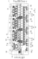
以下、図1~図14を参照して、本開示の一実施形態のトランスファプレス機10Aについて説明する。図1には、本実施形態のトランスファプレス機10Aを前方から見た正面図が示されている。以下、図1におけるトランスファプレス機10Aの横方向を単に「横方向H1」といい、トランスファプレス機10Aを前方から見たときの右側(図1の右側)を単に「右側」、その反対側を単に「左側」ということとする。また、図1の紙面と直交する方向を、単に「前後方向H2」ということとする。
A
トランスファプレス機10Aは、プレス機プラットフォーム11に、複数のダイセット21,22等の部品を組み付けてなる。そのプレス機プラットフォーム11は、支持フレーム12にラム20を昇降可能に備えた構造をなしている。支持フレーム12は、ベースプレート12Aから起立して横方向H1で対向する1対の側壁12Bと、それら1対の側壁12Bの上端間に差し渡されてベースプレート12Aと平行になった天井壁12Cと、1対の側壁12Bの上下方向における中間部より上側で、1対の側壁12Bの互いの対向面における後端縁の間に差し渡されたラム支持壁12Dと、1対の側壁12Bの下端寄り位置の間に差し渡された支持梁13とを有する。なお、1対の側壁12Bには、例えば、ラム支持壁12Dと支持梁13とに上下方向から挟まる位置に横方向H1に貫通する貫通窓12Wが形成されている。
The
ラム20は、ラム支持壁12Dの前面に重ねて配置され、図示しないスライド支持機構により昇降可能に支持されている。また、1対の側壁12Bの上端寄り位置の間には、ラム20を昇降させるためのカムシャフト15が差し渡されて回転可能に支持されている。そして、カムシャフト15に一体回転可能に設けられた1対のカム15Aが、ラム20に支持された1対のカムフォロア15Bに上下方向から挟まれている。
The
カムシャフト15は、支持フレーム12の右上部に取り付けられたラム昇降用駆動源14であるサーボモータによって回転駆動される。具体的には、カムシャフト15のうち支持フレーム12の右側方に突出する端部と、ラム昇降用駆動源14であるサーボモータの出力回転軸とが、プーリ、ベルト等を介して接続され、ラム昇降用駆動源14によりカムシャフト15が回転駆動されるようになっている。そして、カムシャフト15の回転によりラム20が昇降する。
The
支持フレーム12の左側方には、上下方向に延びる中継シャフト16が設けられて回転可能に支持されている。また、支持梁13の下方には、1対の側壁12Bの間にボトムカムシャフト17が差し渡されて回転可能に支持されている。そして、カムシャフト15と中継シャフト16とが傘歯車16Gを介して連結されると共に、ボトムカムシャフト17と中継シャフト16とが図示しない傘歯車を介して連結されている。また、ボトムカムシャフト17には、複数のカム17Aが一体回転可能に備えられている。これらにより、カムシャフト15の1対のカム15Aとボトムカムシャフト17の複数のカム17Aとが同期して回転する。
A vertically extending
図2に示すように、支持梁13には、前後方向H2の中間部分に、上下方向に貫通する貫通孔13Aが形成されている。なお、貫通孔13Aは、横方向H1の長い長孔状又はスリット状になっていてもよいし、横方向H1に複数形成されていてもよい。
As shown in FIG. 2, the
図1に示すように、支持梁13の上面には、台座プレート18が敷設されている。図3に示すように、台座プレート18は、例えば、複数のダイセット21,22に対応して分割され、それぞれが図2に示すように支持梁13にボルトにて着脱可能に固定されている。台座プレート18のうち支持梁13の貫通孔13Aの上方には、台座プレート18を上下方向に貫通する複数の貫通孔18Aが横一列に等間隔に並んでいる(図14参照)。また、複数の貫通孔18Aには、一部を除き、押上ロッド19が昇降可能に支持されている。そして、それら複数の押上ロッド19の下端部が、図1に示すように、ボトムカムシャフト17の各カム17Aに当接している。これにより、複数の押上ロッド19がラム20に同期して昇降する。また、押上ロッド19は、例えば上死点に位置したときに上面が台座プレート18の上面と略面一になるように設定されている。
As shown in FIG. 1, a
以上がプレス機プラットフォーム11の構造に関する説明である。なお、本実施形態のトランスファプレス機10Aでは、押上ロッド19の駆動源は、ラム20の駆動源であるラム昇降用駆動源14で兼用されているが、それとは別に設けられていてもよい。具体的には、各押上ロッド19に1つずつ駆動源としてのサーボモータを設け、それらサーボモータの回転出力をボールネジ機構、ラックアンドピニオン機構等によって押上ロッド19の直線移動に変換する構成としてもよい。
The above is the description of the structure of the
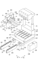
次に、複数のダイセット21,22について説明する。図2及び図3に示すように、各ダイセット21,22は、台座プレート18上に着脱可能に固定されるスライドベース24と、スライドベース24から起立して伸縮する1対の支柱25と、1対の支柱25に支持されて、ラム20に着脱可能に固定される分割パンチホルダ26とを有する。また、図3に示すように、複数のダイセット21,22は、横一列に並べられ、左側端部の1つのみがブランク加工用のダイセット21で、それ以外の複数(例えば、3つ)は、絞り・しごき加工用のダイセット22になっている。
Next, a plurality of die sets 21 and 22 will be explained. As shown in FIGS. 2 and 3, each of the die sets 21 and 22 includes a
以下、絞り・しごき加工用のダイセット22及びそれに組み付けられる機構について詳説してから、ブランク加工用のダイセット21及びそれに組み付けられる機構について、絞り・しごき加工用のダイセット22と異なる構成についてのみ説明することとする。 The drawing and ironing die set 22 and the mechanism assembled therewith will be described in detail below, and then the blanking die set 21 and the mechanism assembled therewith will only differ in configuration from the drawing and ironing die set 22. I will explain.
図6に示すように、絞り・しごき加工用のダイセット22のスライドベース24は、台座プレート18の上面に重ねられる厚板状のベッド部24Zの後部から土手部24Yが上方に突出した構造をなし、横方向H1から見た形状が略L形になっている。また、スライドベース24の前面及び後面の下端寄り位置には、横長の係合孔24Aが穿孔されている。そして、図2に示すように、複数の固定ブロック29の突起29Aが係合孔24Aに凹凸係合した状態で固定ブロック29が台座プレート18にボルトB1で固定されている。より具体的には、固定ブロック29の下面のうち突起29Aから離れた側の下面縁部から図示しない突条が突出していて、固定ブロック29をボルトB1で締め付けることで、スライドベース24が突起29Aにより下方に押される。そして、スライドベース24が台座プレート18との間の摩擦と固定ブロック29との当接とによって台座プレート18に固定される。
As shown in FIG. 6, the
また、ベッド部24Zの前後方向H2の中間部には、台座プレート18の貫通孔18Aの同軸上に、複数の上下貫通孔24Bが設けられている。上下貫通孔24Bは、貫通孔18Aの内径と同一かそれより僅かに小さくなっている。また、本実施形態のトランスファプレス機10Aでは、例えば、5つの上下貫通孔24Bが横一列に設けられ、それらのうち左端部の上下貫通孔24Bは使用されず、それ以外の複数の上下貫通孔24Bがノックアウトピン35のガイド孔として使用されている。
Further, a plurality of upper and lower through
図2に示すように、ノックアウトピン35は、下部ロッド33と上部ロッド34とに分割されていて、上記上下貫通孔24Bには、下部ロッド33が主として収容され、押上ロッド19に下方から支持されている。また、下部ロッド33と上下貫通孔24Bとは、軸長が同一になっていて、押上ロッド19が上死点に位置したときには、下部ロッド33の上面と下面とがベッド部24Zの上面及び下面と面一に配置される(このときの下部ロッド33の配置を「下部ロッド33の上死点」という)。
As shown in FIG. 2, the
下部ロッド33の軸方向の中間位置には、係合溝33Mが形成され、上下貫通孔24Bの内面には、下部ロッド33が上死点で係合溝33Mと対向する位置にシャフト挿入孔24Sが開口している。シャフト挿入孔24Sは、ベッド部24Zの前面と係合溝33Mとの間を連絡するように延び、その内部には、係合シャフト24Rが挿入されている。また、ベッド部24Zの前面のうちシャフト挿入孔24Sの開口縁には、ナット24Nが固定されていて、係合シャフト24Rの基端部に形成された螺子部をナット24Nに螺合して係合シャフト24Rの先端を係合溝33Mに係合させることで、下部ロッド33を上死点に固定することができる。
An
そして、トランスファプレス機10Aを稼働する際には、係合シャフト24Rと係合溝33Mとの係合が解除されるように係合シャフト24Rの螺合が緩められるか、シャフト挿入孔24Sから係合シャフト24Rが引き抜かれ、後述するようにダイセット22を台座プレート18から前方にスライドさせるときに、係合シャフト24Rが係合溝33Mに係合されて下部ロッド33が上下貫通孔24B内に固定される。
Then, when the
なお、本実施形態では、押上ロッド19を下方に備えない左端の上下貫通孔24Bの下部ロッド33は、トランスファプレス機10Aの稼働中も下部ロッド33が係合シャフト24Rによって上下貫通孔24B内に固定されている。また、本実施形態では、押上ロッド19の使用を要しない上下貫通孔24Bの下方には、押上ロッド19が備えられていないが、押上ロッド19を備えて、下部ロッド33を上下貫通孔24B内で昇降可能にしておいてもよい。また、不使用の上下貫通孔24Bから下部ロッド33を抜き取っておいてもよい。
In this embodiment, the
図6に示すように、ベッド部24Zの上面には、複数のレール突部24Tが形成されている。それらレール突部24Tは、断面が横長の矩形状をなして前後方向H2の延び、横方向H1に等間隔に配置されている。そして、隣合うレール突部24Tの間には、角溝24L1が形成され、両端のレール突部24Tの更なる両端には、角溝24L1を幅方向で半分にした段付き凹部24L2が形成されている。また、各レール突部24Tの上面の幅方向の中央には、前述の上下貫通孔24Bが開口している。
As shown in FIG. 6, a plurality of
図5に示すように、ベッド部24Zの上面には、左端のレール突部24Tの上に、トランスファ支持分割ブロック31が取り付けられ、それ以外の複数のレール突部24Tの上にダイ支持分割ブロック32が取り付けられる。図6に示すように、ダイ支持分割ブロック32は、直方体の後側上端角部を切除し、下面にレール突部24Tが丁度係合する係合溝32Mを備えた構造をなし、その横幅は、ベッド部24Zの上面を横方向H1で5等分した大きさと略同一で、前後長はベッド部24Zの上面の前後長と略同一になっている。また、トランスファ支持分割ブロック31は、ダイ支持分割ブロック32と同様に、全体が略直方体状をなして下面に係合溝31Mを有する。
As shown in FIG. 5, on the upper surface of the
そして、図5に示すように、トランスファ支持分割ブロック31及びダイ支持分割ブロック32は、係合溝31M,32Mにレール突部24Tが係合され、後端をスライドベース24の土手部24Yに押し付けられてスライドベース24上で位置決めされている。そして、トランスファ支持分割ブロック31及びダイ支持分割ブロック32は、図2に示すように、それらを上下に貫通するボルトB2や、それらの外面に宛がわれる複数の止め板36等によってスライドベース24に固定されている。
As shown in FIG. 5, the transfer support split
以下、トランスファ支持分割ブロック31及びダイ支持分割ブロック32のそれぞれの構造について、上述の如く固定された状態を前提にして説明する。
The structures of the transfer
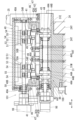
図2に示すように、ダイ支持分割ブロック32には、上下貫通孔24Bの同軸上に上下貫通孔32Bが形成され、そこにダイ92とノックアウトピン35の一部を構成する上部ロッド34が収容されるようになっている。つまり、ダイ支持分割ブロック32は、ダイホルダとして機能する。ダイ92は、筒状をなして内側に成形孔92Aを有する。上部ロッド34は、下部ロッド33を介して押上ロッド19によって下方から支持され、成形孔92A内を昇降する。また、上部ロッド34は、下端にフランジ34Fを備えて抜け止めされている。
As shown in FIG. 2, the die support split
図6に示すように、トランスファ支持分割ブロック31の上面には、架台40が固定されている。架台40は、前後方向H2で対向する1対の対向壁40Aの上端間を天井壁40Bで連絡した構造をなしている。1対の対向壁40Aの対向面の下端部には、横方向H1に延びる溝形のスライド係合部材41がそれぞれ固定され、それら各スライド係合部材41に横スライド係合部材42がスライド可能に支持され、例えば、トランスファ支持分割ブロック31の横幅分だけスライドする。具体的には、1対のスライド係合部材41は、互いに対向する側に溝開口を有する溝形構造をなしている。横スライド係合部材42は、スライド係合部材41にスライド可能に係合する角材状のスライダ42Aと、そのスライダ42Aが固定された支持部材42Bとからなる。支持部材42Bは、横方向H1に延びかつ幅方向が前後方向H2を向いた帯板部42Cを有する。
As shown in FIG. 6 , a
また、図6に示すように、横スライド係合部材42の横方向H1の全長は、スライドベース24の横幅より僅かに短くなっている。そして、1対の横スライド係合部材42は、横方向H1のスライドストロークの右端部に位置した場合には、トランスファ支持分割ブロック31の上面とその右側の4つのダイ支持分割ブロック32の上面とに重なる。また、1対の横スライド係合部材42は、横方向H1のスライドストロークの左端部に位置した場合には、トランスファ支持分割ブロック31の上面とその右側の3つのダイ支持分割ブロック32の上面と左隣の1つのダイ支持分割ブロック32の上面とに重なる。
Further, as shown in FIG. 6, the total length of the horizontal
図8及び図9に示すように、1対の横スライド係合部材42の上(詳細には、帯板部42Cの上)には、1対の帯板状の前後スライド係合レール46が重ねられ、それら横スライド係合部材42と前後スライド係合レール46とから本開示に係る分割レール47が形成されている。また、前後スライド係合レール46と横スライド係合部材42の長手方向の2箇所が1対のスライド結合ユニット48にて連結されて、前後スライド係合レール46が横スライド係合部材42に対して前後方向H2にスライドするようになっている。
As shown in FIGS. 8 and 9, a pair of strip-like front and rear slide engagement rails 46 are provided on the pair of lateral slide engagement members 42 (more specifically, on the
1対の前後スライド係合レール46には、前後方向H2の延びる複数のフィンガー支持凹部46A(図7参照)が、長手方向に等間隔に並べて形成され、それらフィンガー支持凹部46Aに複数のフィンガー49が組み付けられている。そして、図8に示すように、複数対(例えば、5対)のフィンガー49が、横方向H1に等間隔に並んで1対の前後スライド係合レール46から互いに接近する側に張り出した構造をなし、それら対向するフィンガー49の間の空間の下方にダイ92の成形孔92Aの開口が位置する。
A plurality of finger support recesses 46A (see FIG. 7) extending in the front-rear direction H2 are formed in the pair of front-rear slide engagement rails 46 and are arranged at regular intervals in the longitudinal direction. is assembled. Further, as shown in FIG. 8, a plurality of pairs (for example, five pairs) of
複数対のフィンガー49は、図7に示した搬送用駆動源98であるサーボモータによって横方向H1にスライド駆動され、同図に示した開閉用駆動源99であるサーボモータによって前後方向H2に開閉駆動される。
The plurality of pairs of
搬送用駆動源98によって複数対のフィンガー49を横方向H1にスライド駆動するための搬送駆動機構100は、以下のようになっている。即ち、トランスファ支持分割ブロック31の上部には、前後方向に貫通する丸孔31Eが形成され、その内側中心部に配置された搬送駆動シャフト44Sが、丸孔31E内に嵌合されたスリーブ44Tによって回転可能に支持されている。そして、トランスファ支持分割ブロック31の前面に取り付けられた搬送用駆動源98としてのサーボモータの回転出力部に搬送駆動シャフト44Sの一端部が連結されている。また、搬送駆動シャフト44Sのうち1対の横スライド係合部材42の下方となる2箇所には、1対のピニオン44が一体回転可能に備えられている。ピニオン44は、搬送駆動シャフト44Sと一体回転する1対の円板44Aの間に複数のピン44Bを差し渡した構造をなしている。複数のピン44Bは、円板44Aの回転中心回りの架空の円を複数等分する位置に配置されてピニオン44の複数の歯として機能する。そして、横スライド係合部材42に固定された1対のラック43が、トランスファ支持分割ブロック31に形成されたスリットを介して丸孔31E内に突入して、ピニオン44の複数の歯としてのピン44Bと噛合している。これにより、搬送用駆動源98から動力を受けて1対の横スライド係合部材42が横方向H1にスライドする。また、そのスライドストロークは、ダイ92の中心軸同士の間隔と同じになっている。これにより、搬送用駆動源98によって1対の横スライド係合部材42と共に複数対のフィンガー49の間が横方向H1にスライド駆動される。
A
一方、開閉用駆動源99によって複数対のフィンガー49を前後方向H2に開閉するための開閉駆動機構101は、以下のようになっている。即ち、架台40の1対の対向壁40Aの間に、前後方向に延びるボール螺子50が差し渡されて回転可能に支持されている。そして、トランスファ支持分割ブロック31の前面に取り付けられた開閉用駆動源99としてのサーボモータの回転出力部にボール螺子50の一端部が連結されている。ボール螺子50には、長手方向の途中位置の前後で螺旋の向き逆向きとなった1対の螺子部50A,50Bが備えられ、それらに1対の螺子部50A,50Bに1対のボールナット51が螺合している。また、架台40の天井壁40Bの下面には、1対の横スライド係合部材42の真上となる位置に横方向H1に延びる1対の支持レール53が固定され、それら1対の支持レール53にスライド可能に支持された1対のレール係合部材52に、1対のボールナット51が固定されている。
On the other hand, the opening/
また、1対のレール係合部材52には、1対のカムフォロア54が取り付けられている。カムフォロア54は、上下方向に延びる回転軸を中心として回転するローラ54Rを有し、1対のカムフォロア54の1対のローラ54Rが、各レール係合部材52の下方に突出した状態で前後方向H2で対向している。また、前後スライド係合レール46の上面からは、断面角形をなして横方向H1に延びる係合突条55が突出している。係合突条55は、所謂、キー材を前後スライド係合レール46に固定してなる。そして、各前後スライド係合レール46の係合突条55が、各レール係合部材52の1対のローラ54Rに前後方向H2から挟まれている。これにより、開閉用駆動源99によって1対の前後スライド係合レール46と共に複数対のフィンガー49の間が開閉される。
A pair of
また、搬送用駆動源98及び開閉用駆動源99は、ラム昇降用駆動源14と同期して動作することで、以下のように複数対のフィンガー49によって複数のワークWが間欠的に左から右へと搬送される。複数対のフィンガー49の開いた状態で横方向H1のスライドストロークの左端部に移動してから複数対のフィンガー49が閉じられる。このとき、複数対のフィンガー49の間には複数のワークWが配置されていて、それらワークWが複数対のフィンガー49によって把持される。そして、その状態で複数対のフィンガー49が横方向H1のスライドストロークの右端部に移動してから複数対のフィンガー49が開かれて最初の状態に戻る。以下、この動作が繰り返されて、複数のワークWが間欠的に左から右へと搬送される。
Further, the driving
次に、絞り・しごき加工用のダイセット22の分割パンチホルダ26について説明する。分割パンチホルダ26は、トランスファプレス機10Aの全体のパンチホルダ115(図3参照)を横方向H1で分割したものである。また、分割パンチホルダ26は、パンチ91を保持するための一般的な機構を備え、複数のパンチ91を、一定の間隔で横方向H1に並べて複数のダイ支持分割ブロック32のダイ92の同軸上に保持する。そして、図2に示すように、分割パンチホルダ26は、ラム20の下端部にボルト止めされ、ラム20の昇降動作に伴って複数のパンチ91が複数のダイ92の成形孔92Aに進退する。また、図3に示すように、分割パンチホルダ26の左側面には、ダミーパンチ93が備えられている。ダミーパンチ93は、パンチ91同士の間隔と同じ間隔で左端にパンチ91から左に離れた位置に配置されている。また、架台40の天井壁40Bには、ダミーパンチ93が通過するための切り欠き40C(図6参照)が形成されている。さらに、ダミーパンチ93は、図示しない弾性部材で下方に付勢されていて、パンチ91が成形孔92Aに突入している間に、トランスファ支持分割ブロック31の上面にワークWを押圧し続け、パンチ91がワークWから離脱するときにダミーパンチ93もワークWから離脱する。また、図3に示すように、右端部の絞り・しごき加工用のダイセット22の分割パンチホルダ26における右側面には、払い落としパンチ93Xが備えられている。そして、プレス加工を終えたワークWが、払い落としパンチ93Xにより図1に示すようにフィンガー49から払い落とされ、その下方にシュート93Gに案内されて図示しない回収箱に回収される。
Next, the
以上が、絞り・しごき加工用のダイセット22及びそれに組み付けられる部品に関する説明である。次に、ブランク加工用のダイセット21及びそれに組み付けられる部品の構造を図10~図12を参照して説明する。図10及び図11に示すように、ブランク加工用のダイセット21のスライドベース24は、絞り・しごき加工用のダイセット22のトランスファ支持分割ブロック31及びダイ支持分割ブロック32の上面と略面一の上面を有し、そのスライドベース24の右側端部は段付き状に陥没していて、そこにダミーブロック32Dが組み付けられている。また、図10に示すように、スライドベース24の上面にはダイ支持テーブル85が取り付けられている。ダイ支持テーブル85は、前後方向で対向する図示しない1対の脚部85Aの上端部間に支持盤85Bを差し渡して備える。支持盤85Bの上下方向の中間位置には、スリット85Sが形成され、そのスリット85Sに帯状の板金Vが通されている。そして、ラム20の昇降動作に同期して板金V(図12参照)が間欠的に送給される。また、支持盤85Bのうちスリット85Sの下には、図12に示した打ち抜きダイ83と絞りダイ84とが上下に重ねて設けられている。上側の打ち抜きダイ83には、円形又は楕円形の打ち抜き孔83Aが備えられ、下側の絞りダイ84には、打ち抜き孔83Aより一回り小さい絞り孔84Aが備えられている。また、分割パンチホルダ26には、筒状の打ち抜きパンチ81とその内側に嵌合された絞りパンチ82とが保持されている。そして、ラム20の降下時に打ち抜きパンチ81が板金Vの一部を打ち抜きダイ83の打ち抜き孔83Aに押し込んで打ち抜き、ブランク材を生成し、そのブランク材を絞りパンチ82が絞りダイ84の絞り孔84Aに押し込んで通過させることで筒形のワークWを成形する。
The above is the description of the die set 22 for drawing and ironing and the parts assembled therewith. Next, the structure of the die set 21 for blanking and the parts assembled therewith will be described with reference to FIGS. 10 to 12. FIG. As shown in FIGS. 10 and 11, the
なお、絞りパンチ82を打ち抜きパンチ81に対して上下に移動する構成としては、例えば、ラム20に、図示しない駆動源によって駆動されるボールネジ機構やクランク機構等を設けてその出力部分を絞りパンチ82に連結する構成や、図1に示した支持フレーム12の側壁12Bにシーソー形の図示しないレバーを設けると共に、中継シャフト16の中間部に円筒形カムを一体回転可能に設けて、その円筒形カムの外周面に形成されたカム溝にレバーの一端部を係合させた構成が考えられる。
As a configuration for moving the drawing
図10に示すように、ダイセット21のスライドベース24には、左上端部から左側方に張出部24Hが張り出され、その上に搬送駆動機構102の搬送用駆動源97であるサーボモータが配置されている。また、図11に示すように、搬送用駆動源97の回転出力部には駆動シャフト97Sが連結され、その駆動シャフト97Sに1対のピニオン44が一体回転可能に固定されている。また、ダイ支持テーブル85の支持盤85Bの下方には、図12に示すように、1対の分割レール86が横方向H1にスライド可能に支持され、それら分割レール86に固定された図示しないラックと1対のピニオン44とが噛合している。また、分割レール86に1対のフィンガー79が対向状態に支持されている。そして、搬送用駆動源97によって1対のフィンガー79が、横方向H1にスライド駆動される。
As shown in FIG. 10, the
また、ブランク加工用のダイセット21に備えられた1対のフィンガー79の横方向H1のスライドストロークは、絞り・しごき加工用のダイセット22に備えられた複数対のフィンガー49の横方向H1のスライドストロークより長くなっていて、そのスライドストロークの一端では、1対のフィンガー79は、絞りパンチ82の真下の領域を挟んで対向し、スライドストロークで他端では、隣のダイセット22におけるダミーパンチ93の下方の領域を挟んで対向する。
In addition, the slide stroke in the horizontal direction H1 of the pair of
さらには、ブランク加工用のダイセット21は、前述の開閉駆動機構101は有さず、1対のフィンガー79は、分割レール86に対して前後に移動可能に支持されると共に分割レール86に内蔵された1対のばね部材87にて互いに接近する方向に付勢されている。そして、絞りパンチ82によってワークWが1対のフィンガー79の間に押し込まれ、1対のフィンガー79の対向面に形成されている段差部79DにワークWの上端が係止して絞りパンチ82からワークWが抜け取られて1対のフィンガー79に保持される。そして、1対のフィンガー79は、ワークWを保持した状態で隣の絞り・しごき加工用のダイセット22のトランスファ支持分割ブロック31上までワークWを搬送し、ダミーパンチ93によってワークWがトランスファ支持分割ブロック31上に押圧されたところで、絞りパンチ82の下方に戻る。このようにして、板金Vから生成されたワークWが間欠的に搬送され、そのワークWが絞り・しごき加工用の複数のダイセット22のパンチ91とダイ92とによって絞り加工又はしごき加工される。即ち、1対のフィンガー79は、ワークWとの摺接によって開閉する。
Furthermore, the die set 21 for blank processing does not have the opening/
なお、図3に示すように、ワークWが絞り・しごき加工用の複数のダイセット22の一部のパンチ91には、ワークWを離脱させるための筒状のストリッパー91Sが嵌合されている。そして、例えば、スライドベース24の後面に備えた駆動機構によってストリッパー91Sがパンチ91に対して上下に移動してワークWがパンチ91から払い落とされる。また、ストリッパー91Sを備えないパンチ91に関しては、ブランク加工用のダイセット21の前述したフィンガー79の段差部79Dと同様に、フィンガー49に設けられた段差部によってワークWがパンチ91から離脱される。なお、複数対のフィンガー49を、フィンガー79と同様に、開閉駆動機構を備えず、ばね部材で付勢し、ストリッパー91Sに摺接させることで開閉してもよい。
As shown in FIG. 3, a
上述の説明では、絞り・しごき加工用のダイセット22とブランク加工用のダイセット21とに分けて説明したがトランスファプレス機10Aの全体で見れば、図4に示すように、複数対の分割レール47と1対の分割レール86とが直線状に並んで1対のフィンガー支持レール105になり、それらフィンガー支持レール105にて複数対のフィンガー49,79を支持した把持機構111が形成される。そして、その把持機構111を有するトランスファ装置110がトランスファプレス機10Aの横方向H1全体に延びた構造になり、複数のワークWが把持機構111によって一度に把持されて横方向H1の右側に間欠的に搬送されて複数回に亘ってプレス加工される。
In the above description, the die set 22 for drawing and ironing and the die set 21 for blanking are separately described. The
また、上記した構造は、図5に示すように、ダイセット22のベッド部24Zの上面全体の上に配置されるベースブロック94を、横方向H1でトランスファ支持分割ブロック31と複数のダイ支持分割ブロック32とに複数等分した構造ということもできる。また、図3に示すように、台座プレート18の上に配置されて横方向H1に延びる支持ブロック95の一部を、複数のベースブロック94とダミーブロック32Dと分割したと捉えることもできるし、支持ブロック95を、複数のスライドベース24と複数のベースブロック94とダミーブロック32Dとに分割したと捉えることもできる。
5, the
そして、本実施形態では、支持ブロック95が分割されると共に、把持機構111が、ブランク加工用のダイセット21の分割把持機構112と、絞り・しごき加工用の複数のダイセット22の分割把持機構113とに分割されているので、ダイセット21,22毎にトランスファ装置110を分割して着脱することができ、パンチ91、ダイ92等の交換作業を容易に行うことができる。そのパンチ91、ダイ92等の交換作業をより容易に行うために、本実施形態のトランスファプレス機10Aでは、ダイセット21,22をプレス機プラットフォーム11から前方に引き出せるようになっている。
In this embodiment, the
即ち、図4に示すように、台座プレート18の前面には、ダイセット21,22毎に、1対ずつのコンベア支持ブロック27が取り付けられ、それらコンベア支持ブロック27にローラーコンベア28を装着することができる。図6に示すように、ローラーコンベア28は、板金を溝形に折り曲げてなりかつ前後方向H2に延びる支持ボディ28Hを有し、その支持ボディ28Hの上部開口縁には複数のローラ28Rが回転可能に支持されて前後方向H2に並び、支持ボディ28Hの上面前端からはストッパ28Fが突出している。また、支持ボディ28Hの後端部の上部からは、後方に後方突部28Tが突出していて、その後方突部28Tの両側面からは係止突部28Kが突出している。これに対し、コンベア支持ブロック27は、上面が開放した箱体の前面中央を、上端から上下方向の途中位置まで切り欠いて前面開口27Wを備えた構造をなしている。そして、ローラーコンベア28の後方突部28Tが上方からコンベア支持ブロック27の前面開口27Wに挿入され、前面開口27Wの両側の開口縁27Kに1対の係止突部28Kが内側から係合し、さらには、支持ボディ28Hのうち後方突部28Tの下方の当接面28Mがコンベア支持ブロック27の前面下部に当接する。これにより、図13に示すように、ローラーコンベア28がコンベア支持ブロック27によって片持ち梁状に支持され、ローラーコンベア28の複数のローラ28Rの上端が台座プレート18の上面と同じ高さに配置される。
That is, as shown in FIG. 4, a pair of conveyor support blocks 27 are attached to the front surface of the
また、図14に示すように、台座プレート18の上面のうちダイセット21,22に覆われる部分には、複数のエアー噴出口18Bが開口していて、図示しないバルブが開かれると、台座プレート18内に形成された流路を通してエアー噴出口18Bから圧縮空気が噴出されるようになっている。これにより、ダイセット21,22と台座プレート18との間に空気層が形成されて、ダイセット21,22をスムーズに前後方向H2にスライドさせることができる。また、図3に示すように、台座プレート18の上面のうち各ダイセット21,22の両横には、それらダイセット21,22の横方向H1への移動を規制し、前後方向H2に案内するガイド突条18が備えられている。以上の構成により、固定ブロック29を外してエアー噴出口18Bから圧縮空気を噴出させれば、図13及び図14に示すように、任意のダイセット21,22を台座プレート18の前方にして引き出すことができる。
Further, as shown in FIG. 14, a plurality of
本実施形態のトランスファプレス機10Aの構成に関する説明は以上である。次に、このトランスファプレス機10Aの作用効果について説明する。本実施形態のトランスファプレス機10Aでは、複数の筒形のワークWを、横一列に並ぶ複数のパンチ91で一度に複数のダイ92の成形孔92Aに押し込んでプレス加工してから複数のノックアウトピン35で複数のダイ92の上方に押し出し、複数対のフィンガー49で把持して各隣のダイ92の上方へと搬送する動作を繰り返す。
The description of the configuration of the
ここで、筒形のワークWの最終形状は、円筒状でも、楕円筒状で、角筒状であってもよく、パンチ91とダイ92とを交換することでワークWの形状を変更することができる。その際、トランスファ装置110を外す必要がある。これに対し、本実施形態のトランスファプレス機10Aが有するトランスファ装置110の把持機構111は、図4に示すように横方向H1で複数の分割把持機構112,113に分割されているので、分割把持機構112,113毎に着脱して把持機構111全体の着脱作業を行うことができる。これにより、ダイ92の交換作業を従来より容易に行うことができる。
Here, the final shape of the cylindrical work W may be a cylindrical shape, an elliptical cylindrical shape, or a square cylindrical shape. can be done. At that time, it is necessary to remove the
また、トランスファ装置110の下方の支持ブロック95の一部が、複数のダイ92及び複数のノックアウトピン35をそれぞれが収容する複数のベースブロック94に分割されて、前後にスライド移動可能な複数のダイセット22に支持されているので、ダイ92を交換する際には、ダイセット22をプレス機プラットフォーム11から前後方向の外側に引き出して、従来より広い作業空間でダイ92及びパンチ91の交換作業を行うことができる。これにより、従来よりダイ92及びパンチ91の交換作業を容易に行うことができる。
Further, a part of the
しかも、ベースブロック94は、分割把持機構113を支持するトランスファ支持分割ブロック31と、ダイ92を支持する複数のダイ支持分割ブロック32とに分割されているので、分割把持機構113の着脱作業も、1つずつのダイ92の交換作業も容易に行うことができる。また、ダイ支持分割ブロック32毎、或いは、トランスファ支持分割ブロック31毎、新たなものに交換することができる。さらには、ダイセット22毎新たなものに交換することもできる。
Moreover, since the
また、本実施形態のトランスファプレス機10Aでは、分割把持機構112,113毎に分割レール47,86を動作させる搬送駆動機構100,102を備えているので、分割把持機構112,113同士のフィンガー49,79の横方向H1のスライドストロークを相違させることができる。また、上記した構成例では、絞り・しごき用のダイセット22の分割把持機構113同士のフィンガー49の横方向H1のスライドストロークは同じであったが、相違させてもよい。具体的には、例えば、下流側に向かうに従ってワークWが絞られて徐々にスリムになるので、下流側のフィンガー49の横方向H1のスライドストロークを、上流側のフィンガー49の横方向H1のスライドストロークより小さくし、それに応じて、横方向H1で隣合うフィンガー49間、パンチ91間、ダイ92間を狭めてもよい。そうすることで、トランスファプレス機10A全体をコンパクトにすることもできる。
Further, since the
[他の実施形態]
(1)前記実施形態のトランスファプレス機10Aでは、分割把持機構112,113の搬送方向の上流側に搬送駆動機構100,102が設けられていたが、分割把持機構の搬送方向の下流側に搬送駆動機構が配置されていてもよいし、分割把持機構の搬送方向の中間部に配置されていてもよい。
[Other embodiments]
(1) In the
(2)前記実施形態のトランスファプレス機10Aは、板金VからワークWを生成するワーク生成機構(打ち抜きパンチ81,絞りパンチ82、打ち抜きダイ83,絞りダイ84)を備えているが、トランスファプレス機の前工程にワーク生成機構を有する専用のプレス機を配備して、トランスファプレス機がワーク生成機構を有さず前工程からワークを取得する構成としてもよい。また、トランスファプレス機が、前工程からブランク材を取得して筒形のワークを生成する工程からプレス加工を行ってもよい。
(2) The
(3)前記実施形態のトランスファプレス機10Aでは、全ての分割把持機構112,113に搬送用駆動源が備えられていたが、例えば、ブランク加工用のダイセット21の分割把持機構112の搬送用駆動源をラム昇降用駆動源14で兼用してもよい。
(3) In the
(4)また、分割把持機構112,113毎の搬送用駆動源を設けず、例えば、複数の分割レール47,86をレール連結部で着脱可能に連結して共通の搬送用駆動源で動作させてもよい。
(4) In addition, a driving source for transportation is not provided for each of the divided
(5)開閉駆動機構101は、ボールネジ機構であったが、例えば、1対のタイミングベルトを前後方向H2の延ばした状態にしてそれらに1対の前後スライド係合レール46に固定し、1対のモータにて1対のタイミングベルトを相互に逆向きに回転させる機構や、エアーシリンダの直動ロッドを1対の前後スライド係合レール46に連結し、圧縮エアーによって前後スライド係合レール46を前後方向に動かす構成であってもよい。
(5) The opening/
(6)搬送駆動機構100,102も、ラックアンドピニオン機構に替えて、ボールネジ機構やタイミングベルト機構としてもよい。
(6) The
(7)前記実施形態のトランスファプレス機10Aにおいて、トランスファ支持分割ブロック31にもダイ92とノックアウトピン35とを収容して、トランスファ支持分割ブロック31がダイ支持分割ブロック32毎を兼ねた構成としてもよい。
(7) In the
(8)また、前記実施形態のトランスファプレス機10Aにおいて、搬送駆動シャフト44Sとピニオン44とにスプラインを形成して回転軸方向にスライド可能にしておき、分割レール47を横スライド係合部材42と前後スライド係合レール46とに分割せずに、分割レール47全体を横方向H1に移動する構成としてもよい。
(8) In the
なお、本明細書及び図面には、特許請求の範囲に含まれる技術の具体例が開示されているが、特許請求の範囲に記載の技術は、これら具体例に限定されるものではなく、具体例を様々に変形、変更したものも含み、また、具体例から一部を単独で取り出したものも含む。 Although specific examples of the technology included in the scope of claims are disclosed in the specification and drawings, the technology described in the scope of claims is not limited to these specific examples. Various modifications and changes of the examples are included, and a part of specific examples is also included.
10A トランスファプレス機
11 プレス機プラットフォーム
13 支持梁
19 押上ロッド
20 ラム
21,22 ダイセット
24 スライドベース
24B 上下貫通孔
26 分割パンチホルダ
31 トランスファ支持分割ブロック
32 ダイ支持分割ブロック
35 ノックアウトピン
41 スライド係合部材
42 横スライド係合部材
43 ラック
44 ピニオン
46 前後スライド係合レール
47,86 分割レール
48 スライド結合ユニット
49,79 フィンガー
50 ボール螺子
50A,50B 螺子部
51 ボールナット
52 レール係合部材
53 支持レール
55 係合突条
87 ばね部材
81,82,91 パンチ
83,84,92 ダイ
92A 成形孔
93 ダミーパンチ
94 ベースブロック
95 支持ブロック
97,98 搬送用駆動源
99 開閉用駆動源
100,102 搬送駆動機構
101 開閉駆動機構
105 フィンガー支持レール
110 トランスファ装置
111 把持機構
112,113 分割把持機構
115 パンチホルダ
H1 横方向
H2 前後方向
W ワーク
REFERENCE SIGNS LIST
Claims (14)
横方向に延びる支持梁と、前記支持梁の上方で昇降するラムと、前記支持梁を上下に貫通すると共に前記ラムに同期して昇降し、前記複数のノックアウトピンを押し上げる複数の押上ロッドと、を有するプレス機プラットフォームと、
前記ラムに支持され、前記複数のパンチを横一列に並べて保持するパンチホルダと、
前記支持梁に支持され、複数の上下貫通孔を有して、それらの内側に前記複数のダイと前記複数のノックアウトピンとを収容する支持ブロックと、を備えるトランスファプレス機において、
前記支持ブロックの一部又は全体を分割してなり、前記複数のダイ及び前記複数のノックアウトピンをそれぞれが収容する複数のベースブロックと、
前記支持梁上で横一列に並べられて、前記複数のベースブロックを下方から支持し、それぞれ別々に前後方向の第1位置と第2位置との間をスライド移動可能な複数のスライドベースと、
前記スライドベースを上下に貫通し、前記ノックアウトピンが内側を昇降する複数の上下貫通孔と、
前記複数のスライドベースをそれぞれ前記第1位置に固定する複数のベース固定部と、を備えるトランスファプレス機。 A plurality of cylindrical workpieces are pressed into the forming holes of a plurality of dies at once by a plurality of punches arranged in a horizontal row, and then pushed out above the plurality of dies by a plurality of knockout pins, and each of them is pressed by a transfer device. A transfer press machine that repeats the movement upward of the adjacent die,
a laterally extending support beam, a ram that rises and falls above the support beam, a plurality of push-up rods that vertically penetrate the support beam and rise and fall in synchronization with the ram to push up the plurality of knockout pins; a press platform having
a punch holder supported by the ram and holding the plurality of punches arranged in a horizontal row;
A transfer press comprising a support block supported by the support beam, having a plurality of upper and lower through holes, and accommodating the plurality of dies and the plurality of knockout pins inside the holes,
a plurality of base blocks obtained by dividing a part or the whole of the support block and each accommodating the plurality of dies and the plurality of knockout pins;
a plurality of slide bases arranged in a horizontal row on the support beam, supporting the plurality of base blocks from below, and capable of sliding independently between a first position and a second position in the front-rear direction;
a plurality of vertical through-holes vertically penetrating the slide base and in which the knockout pins move up and down;
A transfer press machine comprising: a plurality of base fixing parts for fixing the plurality of slide bases to the first positions.
各前記スライドベースから起立して各前記分割パンチホルダを昇降可能に支持する支柱と、を有する請求項1に記載のトランスファプレス機。 a plurality of divided punch holders, each of which is formed by dividing the punch holder in the horizontal direction corresponding to the plurality of base blocks, each of which supports the punch and is detachably attached to the ram;
2. The transfer press machine according to claim 1, further comprising a pillar that rises from each of said slide bases and supports each of said divided punch holders so that they can move up and down.
前記把持機構は、前記複数のベースブロックに対応させて、横方向で複数の分割把持機構に分割され、
各前記分割把持機構には、前記1対のフィンガー支持レールから分割される1対ずつの分割レールと、複数対ずつの前記フィンガーと、前記支持ブロックに取り付けられ、前記1対の分割レールを横方向にスライド可能に支持する1対のスライド係合部材と、が備えられている請求項1から3の何れか1の請求項に記載のトランスファプレス機。 The transfer device has a gripping mechanism that supports a plurality of pairs of fingers openable and closable on a pair of finger support rails that extend laterally on the support block and face each other in the front-rear direction. and intermittently convey a plurality of workpieces by gripping them with the plurality of pairs of fingers,
the gripping mechanism is laterally divided into a plurality of divided gripping mechanisms corresponding to the plurality of base blocks;
Each of the split gripping mechanisms includes a pair of split rails split from the pair of finger support rails, a plurality of pairs of the fingers, and a pair of split rails attached to the support block. 4. The transfer press machine according to any one of claims 1 to 3, further comprising a pair of sliding engagement members that are slidably supported in a direction.
開閉用駆動源から動力を受けて、前記1対の前後スライド係合レールを互いに接近及び離間させる開閉駆動機構が備えられている請求項4から7の何れか1の請求項に記載のトランスファプレス機。 The pair of split rails of part or all of the split gripping mechanism includes a pair of lateral slide engagement members that engage the pair of slide engagement members in a laterally slidable manner; a pair of front-rear slide engagement rails that engage with the lateral slide-engagement member so as to be slidable in the front-rear direction and support the plurality of pairs of fingers;
8. The transfer press according to any one of claims 4 to 7, further comprising an opening/closing drive mechanism for receiving power from an opening/closing drive source to move the pair of front/rear slide engagement rails toward and away from each other. machine.
前記1対のスライド係合部材を前記1対の分割レールと共に前後方向に移動可能に支持する前後スライド支持部と、
開閉用駆動源から動力を受けて、前記1対のスライド係合部材を互いに接近及び離間させる開閉駆動機構が備えられている請求項4から7の何れか1の請求項に記載のトランスファプレス機。 Some or all of the plurality of divided gripping mechanisms include:
a front-rear slide support portion that supports the pair of slide engagement members together with the pair of split rails so as to be movable in the front-rear direction;
8. The transfer press machine according to any one of claims 4 to 7, further comprising an opening/closing drive mechanism for receiving power from an opening/closing drive source to move the pair of slide engagement members toward and away from each other. .
前記各対のフィンガーが、前記パンチに嵌合したワークその他の部材に摺接して開閉させる請求項4から7の何れか1の請求項に記載のトランスファプレス機。 a plurality of spring members biasing each pair of said fingers toward each other;
8. A transfer press according to any one of claims 4 to 7, wherein each pair of fingers slides and opens and closes the workpiece and other members fitted to the punch.
前記トランスファ支持分割ブロックは、前記複数のダイ支持分割ブロックとは別個に設けられ、
前記トランスファ支持分割ブロックの上方には、前記ラムに支持されて昇降し、前記ワークを前記トランスファ支持分割ブロックの上面に押しつけて前記1対のフィンガーから受け取り、一時的に保持してから前記1対のフィンガーに受け渡すダミーパンチが備えられている請求項11に記載のトランスファプレス機。 a plurality of die support division blocks formed by dividing the base block in the lateral direction, each of which is separately removable and which accommodates one of each of the dies and the knockout pins;
The transfer support division block is provided separately from the plurality of die support division blocks,
Above the transfer support split block, the workpiece is supported by the ram and moved up and down. 12. The transfer press machine according to claim 11, further comprising dummy punches that are transferred to the fingers of the transfer press.
前記複数のダイ支持分割ブロックの一部が前記トランスファ支持分割ブロックを兼ねている請求項11に記載のトランスファプレス機。 a plurality of die support division blocks formed by dividing the base block in the horizontal direction, each of which is separately removable and which accommodates one of each of the dies and the knockout pins; and the plurality of die support division blocks. 12. The transfer press machine according to claim 11, wherein a part of also serves as the transfer support division block.
Priority Applications (1)
| Application Number | Priority Date | Filing Date | Title |
|---|---|---|---|
| JP2021011643A JP7286260B2 (en) | 2021-01-28 | 2021-01-28 | transfer press machine |
Applications Claiming Priority (1)
| Application Number | Priority Date | Filing Date | Title |
|---|---|---|---|
| JP2021011643A JP7286260B2 (en) | 2021-01-28 | 2021-01-28 | transfer press machine |
Publications (2)
| Publication Number | Publication Date |
|---|---|
| JP2022115158A JP2022115158A (en) | 2022-08-09 |
| JP7286260B2 true JP7286260B2 (en) | 2023-06-05 |
Family
ID=82747921
Family Applications (1)
| Application Number | Title | Priority Date | Filing Date |
|---|---|---|---|
| JP2021011643A Active JP7286260B2 (en) | 2021-01-28 | 2021-01-28 | transfer press machine |
Country Status (1)
| Country | Link |
|---|---|
| JP (1) | JP7286260B2 (en) |
Citations (3)
| Publication number | Priority date | Publication date | Assignee | Title |
|---|---|---|---|---|
| JP2003039198A (en) | 2001-07-30 | 2003-02-12 | Asahi-Seiki Mfg Co Ltd | Operating method and mechanism therefor for punch of transfer press |
| JP2004230424A (en) | 2003-01-30 | 2004-08-19 | Asahi-Seiki Mfg Co Ltd | Transfer device with different kind of pitch |
| JP2016203212A (en) | 2015-04-23 | 2016-12-08 | 旭精機工業株式会社 | Transfer press machin |
Family Cites Families (6)
| Publication number | Priority date | Publication date | Assignee | Title |
|---|---|---|---|---|
| US4160372A (en) * | 1977-11-28 | 1979-07-10 | The Minster Machine Company | Transfer press having quick change die sets |
| US4614265A (en) * | 1985-07-22 | 1986-09-30 | Danly Machine Corporation | Apparatus for automatically splitting transfer feed rails in a transfer feed press |
| US4655071A (en) * | 1985-11-26 | 1987-04-07 | The U.S. Baird Corporation | Transfer press with quick change die set arrangement |
| JPH0716736B2 (en) * | 1989-07-24 | 1995-03-01 | 株式会社ヨシツカ精機 | Linear feeder for press machine |
| US5054306A (en) * | 1990-02-21 | 1991-10-08 | Verson, A Division Of Allied Products Corporation | Transfer finger shift apparatus for transfer presses |
| JP3193252B2 (en) * | 1994-11-30 | 2001-07-30 | 旭精機工業株式会社 | Cam type small transfer press machine |
-
2021
- 2021-01-28 JP JP2021011643A patent/JP7286260B2/en active Active
Patent Citations (3)
| Publication number | Priority date | Publication date | Assignee | Title |
|---|---|---|---|---|
| JP2003039198A (en) | 2001-07-30 | 2003-02-12 | Asahi-Seiki Mfg Co Ltd | Operating method and mechanism therefor for punch of transfer press |
| JP2004230424A (en) | 2003-01-30 | 2004-08-19 | Asahi-Seiki Mfg Co Ltd | Transfer device with different kind of pitch |
| JP2016203212A (en) | 2015-04-23 | 2016-12-08 | 旭精機工業株式会社 | Transfer press machin |
Also Published As
| Publication number | Publication date |
|---|---|
| JP2022115158A (en) | 2022-08-09 |
Similar Documents
| Publication | Publication Date | Title |
|---|---|---|
| KR101590589B1 (en) | Transfer press machine | |
| US4160372A (en) | Transfer press having quick change die sets | |
| JP6626234B1 (en) | Work removal device and transfer press machine | |
| JP7322079B2 (en) | transfer press machine | |
| EP3771504B1 (en) | Press apparatus | |
| JP7286260B2 (en) | transfer press machine | |
| US3369387A (en) | Double strand feed press | |
| DE102005057658B4 (en) | Device for multiple processing | |
| CN210966570U (en) | Multi-punch mounting equipment for repeated stamping forming of hardware | |
| JPS6235880B2 (en) | ||
| JP4140707B2 (en) | Transfer device with different pitch feed | |
| KR100832739B1 (en) | Lead Bending and Cutting Device of ABS Sensor Element | |
| ITTO950609A1 (en) | EQUIPMENT FOR THE SUPPLY OF MATERIAL | |
| CN210045848U (en) | Punch press with multistation mould | |
| JP3704033B2 (en) | Work feed amount adjustment device for transfer slide | |
| CN214639551U (en) | Punching device of vegetable cutter hopper plate | |
| JPWO2004067203A1 (en) | Slender body forming device | |
| KR20140129233A (en) | Heading machine | |
| GB803556A (en) | Strip feed press | |
| US4577486A (en) | Retracting mechanism and jaw assembly for a power press | |
| US7021111B2 (en) | Forging machine with a guiding roller mechanism for guiding movement of a sliding plate unit | |
| CN220635975U (en) | Press forming device | |
| SU430926A1 (en) | MULTI-POSITIONAL STAMPING AUTOMATIC MACHINE | |
| JP4664522B2 (en) | Transfer device with finger opening / closing mechanism | |
| RU2167730C2 (en) | Apparatus for double side bending of diagonal portions of flange of gasoline tank |
Legal Events
| Date | Code | Title | Description |
|---|---|---|---|
| A621 | Written request for application examination |
Free format text: JAPANESE INTERMEDIATE CODE: A621 Effective date: 20220825 |
|
| A977 | Report on retrieval |
Free format text: JAPANESE INTERMEDIATE CODE: A971007 Effective date: 20230510 |
|
| TRDD | Decision of grant or rejection written | ||
| A01 | Written decision to grant a patent or to grant a registration (utility model) |
Free format text: JAPANESE INTERMEDIATE CODE: A01 Effective date: 20230523 |
|
| A61 | First payment of annual fees (during grant procedure) |
Free format text: JAPANESE INTERMEDIATE CODE: A61 Effective date: 20230523 |
|
| R150 | Certificate of patent or registration of utility model |
Ref document number: 7286260 Country of ref document: JP Free format text: JAPANESE INTERMEDIATE CODE: R150 |