JP7283841B2 - Gaze measurement device - Google Patents
Gaze measurement device Download PDFInfo
- Publication number
- JP7283841B2 JP7283841B2 JP2019064828A JP2019064828A JP7283841B2 JP 7283841 B2 JP7283841 B2 JP 7283841B2 JP 2019064828 A JP2019064828 A JP 2019064828A JP 2019064828 A JP2019064828 A JP 2019064828A JP 7283841 B2 JP7283841 B2 JP 7283841B2
- Authority
- JP
- Japan
- Prior art keywords
- center
- coordinate system
- camera coordinate
- eyeball
- dimensional coordinates
- Prior art date
- Legal status (The legal status is an assumption and is not a legal conclusion. Google has not performed a legal analysis and makes no representation as to the accuracy of the status listed.)
- Active
Links
Images


Classifications
-
- A—HUMAN NECESSITIES
- A61—MEDICAL OR VETERINARY SCIENCE; HYGIENE
- A61B—DIAGNOSIS; SURGERY; IDENTIFICATION
- A61B3/00—Apparatus for testing the eyes; Instruments for examining the eyes
- A61B3/10—Objective types, i.e. instruments for examining the eyes independent of the patients' perceptions or reactions
- A61B3/113—Objective types, i.e. instruments for examining the eyes independent of the patients' perceptions or reactions for determining or recording eye movement
-
- A—HUMAN NECESSITIES
- A61—MEDICAL OR VETERINARY SCIENCE; HYGIENE
- A61B—DIAGNOSIS; SURGERY; IDENTIFICATION
- A61B3/00—Apparatus for testing the eyes; Instruments for examining the eyes
- A61B3/0008—Apparatus for testing the eyes; Instruments for examining the eyes provided with illuminating means
-
- G—PHYSICS
- G06—COMPUTING; CALCULATING OR COUNTING
- G06V—IMAGE OR VIDEO RECOGNITION OR UNDERSTANDING
- G06V40/00—Recognition of biometric, human-related or animal-related patterns in image or video data
- G06V40/10—Human or animal bodies, e.g. vehicle occupants or pedestrians; Body parts, e.g. hands
- G06V40/18—Eye characteristics, e.g. of the iris
- G06V40/19—Sensors therefor
-
- A—HUMAN NECESSITIES
- A61—MEDICAL OR VETERINARY SCIENCE; HYGIENE
- A61B—DIAGNOSIS; SURGERY; IDENTIFICATION
- A61B3/00—Apparatus for testing the eyes; Instruments for examining the eyes
- A61B3/10—Objective types, i.e. instruments for examining the eyes independent of the patients' perceptions or reactions
- A61B3/14—Arrangements specially adapted for eye photography
- A61B3/15—Arrangements specially adapted for eye photography with means for aligning, spacing or blocking spurious reflection ; with means for relaxing
- A61B3/156—Arrangements specially adapted for eye photography with means for aligning, spacing or blocking spurious reflection ; with means for relaxing for blocking
- A61B3/158—Arrangements specially adapted for eye photography with means for aligning, spacing or blocking spurious reflection ; with means for relaxing for blocking of corneal reflection
Description
本発明は、視線計測装置に係り、特に、顔を撮像した画像から、視線を計測する視線計測装置に関する。 The present invention relates to a line-of-sight measurement device, and more particularly to a line-of-sight measurement device for measuring a line of sight from an image of a face.
従来より、角膜の曲率中心と眼球の回転中心とが異なるので、眼球運動に伴ってプルキンエ像が平行移動するのをビデオカメラあるいはCCDカメラで撮影し、眼球運動を計算する方法が知られている(非特許文献1)。角膜前面からの反射によって得られる像を利用する方法が角膜反射法である。 Conventionally, since the center of curvature of the cornea and the center of rotation of the eyeball are different, a method of calculating the eyeball movement by photographing the parallel movement of the Purkinje image accompanying the eyeball movement with a video camera or CCD camera has been known. (Non-Patent Document 1). The corneal reflection method is a method that utilizes an image obtained by reflection from the anterior surface of the cornea.
角膜反射像に関して複数光源を用いたり、投光パターンを時間変化させることで眼鏡映り込みと区別して検出できるようにする技術が知られている(例えば、特許文献1、2)。 Techniques are known that use multiple light sources for the corneal reflection image or change the light projection pattern over time so that the reflection can be distinguished from the spectacles and can be detected (for example, Patent Documents 1 and 2).
特許文献1では、赤外光パターンを使用し、特許文献2では、複数光源を使用している。 US Pat. No. 6,200,008 uses an infrared light pattern, and US Pat.
上記非特許文献1に記載の技術のように、単一光源を用いる方法では、眼鏡への外乱光の映り込みと角膜反射像の区別が難しい。 In the method using a single light source, such as the technique described in Non-Patent Document 1, it is difficult to distinguish between the reflection of ambient light on the spectacles and the corneal reflection image.
また、上記特許文献1、2に記載の技術では、角膜反射像を得るために、複数の光源や投光パターンを用いるための装置が必要となるため、装置コストがかかってしまう。 Moreover, the techniques described in Patent Documents 1 and 2 above require an apparatus for using a plurality of light sources and light projection patterns in order to obtain a corneal reflection image, which increases the apparatus cost.
本発明は、上記の問題点を解決するためになされたもので、簡易な構成で、視線計測のために、顔画像上の角膜反射像の画像座標又は瞳孔中心の画像座標を精度良く求めることができる視線計測装置を提供することを目的とする。 SUMMARY OF THE INVENTION The present invention has been made to solve the above-mentioned problems, and it is possible to accurately obtain the image coordinates of the corneal reflection image on the face image or the image coordinates of the center of the pupil for sight line measurement with a simple configuration. It is an object of the present invention to provide a line-of-sight measuring device capable of
上記の目的を達成するために第1の発明に係る視線計測装置は、被観察者の顔を撮像する撮像部と、前記被観察者の目に対して光を照射する光照射部と、前記撮像部によって撮像された前記顔を表す顔画像から、カメラ座標系における眼球中心の3次元座標を推定するカメラ座標系眼球中心座標計算部と、前記顔画像上の目の瞳孔中心位置から、カメラ座標系における見かけの瞳孔中心の3次元座標を推定する瞳孔中心計算部と、前記カメラ座標系における眼球中心の3次元座標と、前記カメラ座標系における見かけの瞳孔中心の3次元座標とに基づいて、前記カメラ座標系において、前記眼球中心の3次元位置から瞳孔中心の3次元位置へ向かう3次元の光軸ベクトルを計算する眼球位置姿勢推定部と、前記カメラ座標系における眼球中心の3次元座標と、前記光軸ベクトルと、予め定められた3次元眼球モデルとに基づいて、カメラ座標系における角膜反射像の3次元座標を求める角膜反射像計算部と、前記カメラ座標系における角膜反射像の3次元座標から、前記顔画像上の角膜反射像の画像座標を推定する画像座標計算部と、を含んで構成されている。 In order to achieve the above object, a sight line measuring device according to a first aspect of the present invention includes an imaging unit for capturing an image of a face of a person to be observed, a light irradiation unit for irradiating the eyes of the person to be observed with light, and a camera coordinate system eyeball center coordinate calculator for estimating three-dimensional coordinates of eyeball centers in a camera coordinate system from a face image representing the face captured by an imaging unit; Based on a pupil center calculation unit for estimating the apparent three-dimensional coordinates of the pupil center in the coordinate system, the three-dimensional coordinates of the eyeball center in the camera coordinate system, and the apparent three-dimensional coordinates of the pupil center in the camera coordinate system an eyeball position/orientation estimator that calculates a three-dimensional optical axis vector from the three-dimensional position of the center of the eyeball to the three-dimensional position of the center of the pupil in the camera coordinate system; and a three-dimensional coordinate of the center of the eyeball in the camera coordinate system. a corneal reflection image calculation unit for obtaining three-dimensional coordinates of the corneal reflection image in the camera coordinate system based on the optical axis vector and the predetermined three-dimensional eyeball model; an image coordinate calculator for estimating the image coordinates of the corneal reflection image on the face image from the three-dimensional coordinates.
第1の発明によれば、簡易な構成で、顔画像上の目の瞳孔中心位置から、視線計測のために顔画像上の角膜反射像の画像座標を精度良く求めることができる。 According to the first invention, with a simple configuration, the image coordinates of the corneal reflection image on the face image can be obtained with high accuracy for line-of-sight measurement from the pupil center position of the eye on the face image.
上記第1の発明に係る視線計測装置において、前記撮像部と前記光照射部との位置関係、前記撮像部と前記目との位置関係、及び前記撮像部に関するパラメータが、前記撮像部の撮像方向と前記光照射部の光照射方向とが同軸であるとみなすための予め定められた制約条件を満たすようにすることができる。 In the line-of-sight measurement device according to the first aspect, the positional relationship between the imaging unit and the light irradiation unit, the positional relationship between the imaging unit and the eye, and the parameters related to the imaging unit are the imaging direction of the imaging unit. and the light irradiation direction of the light irradiation unit are coaxial with each other, and satisfy a predetermined constraint condition.
また、上記第1の発明に係る視線計測装置において、前記眼球位置姿勢推定部は、前記カメラ座標系における見かけの瞳孔中心の3次元座標と前記カメラ座標系における眼球中心の3次元座標とを結んだ線分と、前記カメラ座標系における眼球中心の3次元座標と前記撮像部の3次元座標とを結んだ線分とのなす角を算出し、前記なす角に対応して予め定められた角度補正量を取得し、前記カメラ座標系における眼球中心の3次元座標と前記カメラ座標系における見かけの瞳孔中心の3次元座標とを結んだベクトルと、前記取得した前記角度補正量と、前記算出した前記なす角と、前記カメラ座標系における眼球中心の3次元座標とに基づいて、前記カメラ座標系において、前記眼球中心の3次元位置から瞳孔中心の3次元位置へ向かう3次元の光軸ベクトルを計算するようにすることができる。 In the sight line measuring device according to the first invention, the eyeball position/orientation estimating unit connects the apparent three-dimensional coordinates of the center of the pupil in the camera coordinate system and the three-dimensional coordinates of the center of the eyeball in the camera coordinate system. calculating an angle formed by a line segment and a line segment connecting the three-dimensional coordinates of the eyeball center in the camera coordinate system and the three-dimensional coordinates of the imaging unit, and determining a predetermined angle corresponding to the formed angle; A vector connecting the three-dimensional coordinates of the center of the eyeball in the camera coordinate system and the three-dimensional coordinates of the apparent center of the pupil in the camera coordinate system, the obtained angle correction amount, and the calculated angle correction amount. A three-dimensional optical axis vector directed from the three-dimensional position of the center of the eyeball to the three-dimensional position of the center of the pupil in the camera coordinate system based on the formed angle and the three-dimensional coordinates of the center of the eyeball in the camera coordinate system. can be calculated.
第2の発明に係る視線計測装置は、被観察者の顔を撮像する撮像部と、前記被観察者の目に対して光を照射する光照射部と、前記撮像部によって撮像された前記顔を表す顔画像から、カメラ座標系における眼球中心の3次元座標を推定するカメラ座標系眼球中心座標計算部と、前記顔画像上の目の角膜反射像の位置から、カメラ座標系における角膜反射像の3次元座標を推定する角膜反射像計算部と、前記カメラ座標系における眼球中心の3次元座標と、前記カメラ座標系における角膜反射像の3次元座標とに基づいて、前記カメラ座標系において、前記眼球中心の3次元位置から角膜曲率中心の3次元位置へ向かう3次元の光軸ベクトルを計算する眼球位置姿勢推定部と、前記カメラ座標系における眼球中心の3次元座標と、前記光軸ベクトルと、予め定められた3次元眼球モデルとに基づいて、カメラ座標系における見かけの瞳孔中心の3次元座標を求める瞳孔中心計算部と、前記カメラ座標系における見かけの瞳孔中心の3次元座標から、前記顔画像上の瞳孔中心の画像座標を推定する画像座標計算部と、を含んで構成されている。 A line-of-sight measurement apparatus according to a second aspect of the present invention includes an imaging unit that images the face of an observed person, a light irradiation unit that irradiates the eyes of the observed person with light, and the face imaged by the imaging unit. A camera coordinate system eyeball center coordinate calculation unit for estimating the three-dimensional coordinates of the eyeball center in the camera coordinate system from the face image representing the In the camera coordinate system, based on the corneal reflection image calculation unit for estimating the three-dimensional coordinates of, the three-dimensional coordinates of the center of the eyeball in the camera coordinate system, and the three-dimensional coordinates of the corneal reflection image in the camera coordinate system, an eyeball position/orientation estimation unit that calculates a three-dimensional optical axis vector from the three-dimensional position of the center of the eyeball to the three-dimensional position of the center of corneal curvature; the three-dimensional coordinates of the center of the eyeball in the camera coordinate system; and the optical axis vector. and a predetermined three-dimensional eyeball model, a pupil center calculation unit that obtains the three-dimensional coordinates of the apparent center of the pupil in the camera coordinate system, and from the three-dimensional coordinates of the apparent center of the pupil in the camera coordinate system, and an image coordinate calculator for estimating the image coordinates of the center of the pupil on the face image.
第2の発明によれば、簡易な構成で、顔画像上の目の角膜反射像の位置から、視線計測のために顔画像上の瞳孔中心の画像座標を精度良く求めることができる。 According to the second invention, with a simple configuration, the image coordinates of the center of the pupil on the face image can be obtained with high accuracy from the positions of the corneal reflection images of the eyes on the face image for eye gaze measurement.
上記第2の発明に係る視線計測装置において、前記撮像部と前記光照射部との位置関係、前記撮像部と前記目との位置関係、及び前記撮像部に関するパラメータが、前記撮像部の撮像方向と前記光照射部の光照射方向とが同軸であるとみなすための予め定められた制約条件を満たすようにすることができる。 In the line-of-sight measurement device according to the second aspect, the positional relationship between the imaging unit and the light irradiation unit, the positional relationship between the imaging unit and the eye, and the parameters related to the imaging unit are the imaging direction of the imaging unit. and the light irradiation direction of the light irradiation unit are coaxial with each other, and satisfy a predetermined constraint condition.
また、上記第2の発明に係る視線計測装置において、前記瞳孔中心計算部は、前記光軸ベクトルと、前記カメラ座標系における眼球中心の3次元座標とに基づいて、前記カメラ座標系における眼球中心の3次元座標と前記カメラ座標系の角膜曲率中心の3次元座標とを結んだ線分と、前記カメラ座標系における眼球中心の3次元座標と前記撮像部の3次元座標とを結んだ線分とのなす角を算出し、前記算出された前記なす角に対応して予め定められた角度補正量を取得し、前記カメラ座標系における眼球中心の3次元座標と、前記光軸ベクトルと、前記角度補正量とに基づいて、前記カメラ座標系における眼球中心の3次元座標と前記カメラ座標系における見かけの瞳孔中心の3次元座標とを結んだベクトルを算出し、前記算出されたベクトルと、前記カメラ座標系における眼球中心の3次元座標と、予め定められた3次元眼球モデルとに基づいて、カメラ座標系における見かけの瞳孔中心の3次元座標を求めるようにすることができる。 Further, in the sight line measuring device according to the second invention, the pupil center calculator calculates the center of the eyeball in the camera coordinate system based on the optical axis vector and the three-dimensional coordinates of the center of the eyeball in the camera coordinate system. and a line segment connecting the three-dimensional coordinates of the corneal curvature center in the camera coordinate system and a line segment connecting the three-dimensional coordinates of the eyeball center in the camera coordinate system and the three-dimensional coordinates of the imaging unit and acquires a predetermined angle correction amount corresponding to the calculated angle, the three-dimensional coordinates of the center of the eyeball in the camera coordinate system, the optical axis vector, and the a vector connecting the three-dimensional coordinates of the center of the eyeball in the camera coordinate system and the three-dimensional coordinates of the apparent center of the pupil in the camera coordinate system, based on the angle correction amount; Based on the three-dimensional coordinates of the eyeball center in the camera coordinate system and a predetermined three-dimensional eyeball model, the apparent three-dimensional coordinates of the pupil center in the camera coordinate system can be obtained.
以上説明したように、本発明の視線計測装置によれば、簡易な構成で、視線計測のために、顔画像上の角膜反射像の画像座標又は瞳孔中心の画像座標を精度良く求めることができる、という効果が得られる。 As described above, according to the sight line measurement device of the present invention, the image coordinates of the corneal reflection image on the face image or the image coordinates of the center of the pupil can be obtained with high accuracy for sight line measurement with a simple configuration. , an effect is obtained.
以下、図面を参照して本発明の実施の形態を詳細に説明する。なお、本実施の形態では、撮像された顔画像から、視線ベクトルを推定する視線計測装置に本発明を適用した場合を例に説明する。 BEST MODE FOR CARRYING OUT THE INVENTION Hereinafter, embodiments of the present invention will be described in detail with reference to the drawings. In this embodiment, an example will be described in which the present invention is applied to a line-of-sight measuring apparatus that estimates a line-of-sight vector from a captured face image.
<本発明の実施の形態の概要>
本発明の実施の形態で主に取り扱うのは角膜反射法による視線検出技術であるが、後の説明のため眼球モデルフィッティング法についても概要を述べておく。
<Overview of Embodiments of the Present Invention>
The embodiment of the present invention mainly deals with the line-of-sight detection technique based on the corneal reflection method, but for the sake of later explanation, the eyeball model fitting method will also be outlined.
角膜反射法は、図11に示すようにカメラと近赤外LEDを用い、角膜に映り込んだ近赤外LED(角膜反射像)と瞳孔の位置関係から視線ベクトルを求める手法である。 The corneal reflection method uses a camera and a near-infrared LED as shown in FIG. 11, and obtains a line-of-sight vector from the positional relationship between the near-infrared LED (corneal reflection image) reflected on the cornea and the pupil.
眼球モデルフィッティング法は、図12に示すように目尻・目頭の特徴点に対し三次元眼球モデルを当てはめることで眼球中心位置を推定し、眼球中心と瞳孔中心を結ぶベクトルを視線ベクトルとする手法である。必ずしも目尻・目頭の特徴点を用いる必要はなく、何らかの手段で眼球中心を推定する手法を用いれば良い。 The eyeball model fitting method estimates the eyeball center position by fitting a three-dimensional eyeball model to the feature points of the outer and inner corners of the eye, as shown in FIG. be. It is not always necessary to use the feature points of the outer and inner corners of the eyes, and a method of estimating the center of the eyeball by some means may be used.
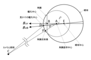
図13は2種類の視線検出法で求める視線の詳細な説明図である。角膜反射法で求める視線ベクトルをgcrとし、眼球モデルフィッティング法で求める視線ベクトルをgebとする。角膜反射法では、角膜曲率中心座標を計算で求めることができるため、角膜に関連した情報として角膜反射像と角膜曲率中心および角膜表面上で観測される瞳孔中心(以後、見かけの瞳孔中心と呼ぶ)の3つが得られる。そのため、角膜での光の屈折を計算に組み込むことができ、正しい瞳孔中心と角膜曲率中心を結ぶベクトルとして視線ベクトルを計算できる。それに対して、眼球モデルフィッティング法では、角膜と関連した情報が見かけの瞳孔中心しか得られないために角膜屈折を扱うことができず、視線ベクトルは見かけの瞳孔中心と眼球中心を結ぶベクトルとして計算される。図13に示すように視線ベクトルgcrとgebは厳密には一致しない。また、二つの視線ベクトルの角度差(以後、視線誤差と呼ぶ)ρは一定ではなく、眼球の位置と向きによって変化する。角膜反射法で求める視線ベクトルgcrが正しいとすると、この視線誤差ρが大きいことは眼球モデルフィッティング法の視線推定精度の劣化を意味する。 FIG. 13 is a detailed explanatory diagram of the line of sight obtained by two types of line of sight detection methods. Let g cr be the line-of-sight vector obtained by the corneal reflection method, and g eb be the line-of-sight vector obtained by the eyeball model fitting method. In the corneal reflection method, the coordinates of the center of curvature of the cornea can be obtained by calculation. Therefore, the corneal reflection image, the center of curvature of the cornea, and the center of the pupil observed on the corneal surface (hereinafter referred to as the apparent center of the pupil) are used as information related to the cornea. ) are obtained. Therefore, the refraction of light on the cornea can be incorporated into the calculation, and the line-of-sight vector can be calculated as a vector connecting the correct pupil center and corneal curvature center. On the other hand, the eyeball model fitting method cannot handle corneal refraction because the information related to the cornea is only the apparent center of the pupil. be done. As shown in FIG. 13, the line-of-sight vectors g cr and g eb do not exactly match. Also, the angle difference ρ between the two line-of-sight vectors (hereinafter referred to as the line-of-sight error) is not constant, but varies depending on the position and orientation of the eyeball. Assuming that the line-of-sight vector g cr obtained by the corneal reflection method is correct, a large line-of-sight error ρ means deterioration of the line-of-sight estimation accuracy of the eyeball model fitting method.
そこで、本発明の実施の形態では、カメラと照明が同軸とみなせる画像撮像部と、眼球中心推定技術と、3次元眼球モデルと、光軸ベクトルの補正技術を用いることで、瞳孔中心の観測結果から角膜反射像座標を推定する。また、角膜反射像の観測結果から瞳孔中心座標を推定する。ソフトウェアによる実装であるため、ハードウェアの追加は不要である。 Therefore, in the embodiment of the present invention, by using an image capturing unit in which the camera and illumination can be considered coaxial, an eyeball center estimation technique, a three-dimensional eyeball model, and an optical axis vector correction technique, the pupil center observation result Estimate the corneal reflection image coordinates from Also, the coordinates of the center of the pupil are estimated from the observation result of the corneal reflection image. Since it is a software implementation, no additional hardware is required.
<視線計測装置の構成>
図1に示すように、本発明の実施の形態に係る視線計測装置10は、対象とする被験者の顔を含む画像を撮像するCCDカメラ等からなる画像撮像部12と、被験者の目に対して光を照射する照射部13と、画像処理を行うコンピュータ14と、CRT等で構成された出力部16とを備えている。
<Configuration of line-of-sight measurement device>
As shown in FIG. 1, a visual
画像撮像部12は、1つのカメラであり、照射部13は、例えば、1つの近赤外LEDである。本実施の形態では、画像撮像部12の撮像方向と照射部13の照射方向とが同軸ではないが、同軸とみなされるように配置されている(図2)。具体的には、以下の(1)式に示す制約条件を満たす配置となっている(図3)。なお、(1)式を満たした上で、2つの近赤外LEDをカメラの左右両側に配置してもよい。
The

(1)
(1)
ただし、Lは、画像撮像部12から角膜曲率中心へ向かう直線と角膜との交点と、画像撮像部12との間の距離であり、rは、角膜曲率半径であり、fは、画像撮像部12のピクセル単位の焦点距離である。
where L is the distance between the
コンピュータ14は、CPU、後述する視線計測処理ルーチンのプログラムを記憶したROM、データ等を記憶するRAM、及びこれらを接続するバスを含んで構成されている。このコンピュータ14をハードウェアとソフトウェアとに基づいて定まる機能実現手段毎に分割した機能ブロックで説明すると、図1に示すように、コンピュータ14は、画像撮像部12から出力される濃淡画像である顔画像を入力する画像入力部20と、画像入力部20の出力である顔画像の時系列から、角膜反射像の画像座標の時系列を推定する角膜反射像推定部22と、画像入力部20の出力である顔画像の時系列から、瞳孔中心の画像座標の時系列を推定する瞳孔推定部24と、角膜反射像の画像座標の時系列と、瞳孔中心の画像座標の時系列とから、角膜反射法(図11参照)を用いて、カメラ座標系における視線ベクトルを計算する角膜反射法視線検出部28とを備えている。
The
画像入力部20は、例えば、A/Dコンバータや1画面の画像データを記憶する画像メモリ等で構成される。
The
角膜反射像推定部22は、図4に示すように、カメラ座標系眼球中心座標計算部30と、見かけの瞳孔中心計算部32と、眼球モデル記憶部34と、眼球位置姿勢推定部36と、カメラ座標系角膜反射像計算部40と、角膜反射像画像座標計算部42とを備えている。
As shown in FIG. 4, the corneal reflection
カメラ座標系眼球中心座標計算部30は、以下のように、顔画像から、図5に示すカメラ座標系における眼球中心の3次元座標を推定する。
The camera coordinate system eyeball center coordinate
まず、予め、図5に示す顔モデル座標系における眼球中心(点E)の3次元座標

を求めておく(図6参照)。
First, three-dimensional coordinates of the eyeball center (point E) in the face model coordinate system shown in FIG.
(see Figure 6).
例えば、顔画像の角膜反射像から計算した角膜曲率中心と瞳孔中心を使って視線を計算し、計算した視線を用いて、眼球モデル座標系における眼球中心の3次元座標を推定する。 For example, the corneal curvature center and the pupil center calculated from the corneal reflection image of the face image are used to calculate the line of sight, and the calculated line of sight is used to estimate the three-dimensional coordinates of the eyeball center in the eyeball model coordinate system.
そして、カメラ座標系における顔モデル座標系の位置姿勢(回転並進ベクトル)を求める。 Then, the position and orientation (rotational translation vector) of the face model coordinate system in the camera coordinate system are obtained.
例えば、現在の顔画像に顔モデルをフィッティングさせることで、カメラ座標系に対する顔モデル座標系の現在の回転行列Rと並進ベクトルtを求める。 For example, by fitting a face model to the current face image, the current rotation matrix R and translation vector t of the face model coordinate system with respect to the camera coordinate system are obtained.
そして、求めた回転並進ベクトルにより、顔モデル座標系における眼球中心の3次元座標をカメラ座標系における眼球中心の3次元座標に変換する。 Then, the three-dimensional coordinates of the center of the eyeball in the face model coordinate system are transformed into the three-dimensional coordinates of the center of the eyeball in the camera coordinate system using the obtained rotational translation vector.
具体的には、カメラ座標系における現在の眼球中心の3次元座標eを、以下の式に従って計算する。 Specifically, the three-dimensional coordinate e of the current eyeball center in the camera coordinate system is calculated according to the following formula.

(2)
(2)
見かけの瞳孔中心計算部32は、以下に説明するように、顔画像上の目の瞳孔中心位置から、カメラ座標系における見かけの瞳孔中心の3次元座標を推定する。
The apparent
まず、顔画像から、瞳孔中心を検出し、図5に示す画像座標系における瞳孔中心座標を求める。 First, the pupil center is detected from the face image, and the pupil center coordinates in the image coordinate system shown in FIG. 5 are obtained.
具体的には、従来既知の技術を用いて、瞳孔中心の検出を行い、画像座標系における瞳孔中心座標

を求める。
Specifically, using a conventionally known technique, the pupil center is detected, and the pupil center coordinates in the image coordinate system
Ask for
そして、瞳孔中心の画像座標からカメラ座標系における3次元座標を推定する。 Then, the three-dimensional coordinates in the camera coordinate system are estimated from the image coordinates of the center of the pupil.
具体的には、カメラ座標系における瞳孔中心のZ座標を何等かの測距手段で求め、dzとする。画像中心の座標を(xc,yc)とする。カメラ座標系における瞳孔中心の3次元座標

は、ピクセル単位で表される焦点距離をfとすると以下になる。
Specifically, the Z coordinate of the center of the pupil in the camera coordinate system is obtained by some distance measuring means and is set to dz . Let the coordinates of the center of the image be (x c , y c ). 3D coordinates of pupil center in camera coordinate system
is as follows, where f is the focal length expressed in pixels.

(3)
(3)
眼球モデル記憶部34には、2つの球からなる眼球モデルおよびそのパラメータが記憶されている。具体的には、眼球モデル記憶部34には、角膜曲率半径r、眼球中心Eと角膜曲率中心Aとの距離u、角膜曲率中心Aと真の瞳孔中心Bとの距離s、及び大気の屈折率n1と房水の屈折率n2の比(n1/n2)が記憶されている。なお、角膜曲率中心Aと真の瞳孔中心Bとの距離s、及び大気の屈折率n1と房水の屈折率n2の比(n1/n2)は、角膜反射法視線検出部28で角膜反射法を用いてカメラ座標系における視線ベクトルを計算する際に用いられるパラメータである。
The eyeball
眼球位置姿勢推定部36は、以下に説明するように、カメラ座標系における眼球中心の3次元座標と、カメラ座標系における見かけの瞳孔中心の3次元座標とに基づいて、カメラ座標系において、眼球中心の3次元位置から瞳孔中心の3次元位置へ向かう3次元の光軸ベクトルを計算する。
As will be described below, the eyeball position/
まず、画像撮像部12の撮像方向と照射部13の照射方向とが同軸とみなされるように配置されていること、図6に示す角CEDから、角度補正量を推定する。 First, the angle correction amount is estimated from the angle CED shown in FIG.
具体的には、眼球中心Eから見かけの瞳孔中心までのベクトルを Specifically, the vector from the eyeball center E to the apparent pupil center is

とすると、以下の式で表される。 Then, it is represented by the following formula.

(4)
(Four)
カメラ座標系における見かけの瞳孔中心の3次元座標と前記カメラ座標系における眼球中心の3次元座標とを結んだ線分と、カメラ座標系における眼球中心の3次元座標と前記撮像部の3次元座標とを結んだ線分とのなす角CEDについて

とすると、角CEDの角度ωを、以下の式に従って計算する。
A line segment connecting the apparent three-dimensional coordinates of the pupil center in the camera coordinate system and the three-dimensional coordinates of the eyeball center in the camera coordinate system, and the three-dimensional coordinates of the eyeball center in the camera coordinate system and the three-dimensional coordinates of the imaging unit About the angle CED made with the line segment connecting
, the angle ω of the angle CED is calculated according to the following equation.

(5)
(Five)
そして、角CEDの角度と、角膜反射法で求める視線ベクトルgcrと眼球モデルフィッティング法で求める視線ベクトルgebとの角度差ρとの関係を予め求めておき、当該関係を用いて、角CEDの角度に対応する角度差ρを、補正量ρとして求める。 Then, the relationship between the angle of the angle CED and the angle difference ρ between the line-of-sight vector g cr obtained by the corneal reflection method and the line-of-sight vector g eb obtained by the eyeball model fitting method is obtained in advance. The angle difference ρ corresponding to the angle of is obtained as the correction amount ρ.
そして、カメラ座標系における眼球中心の3次元座標eと、眼球中心Eから見かけの瞳孔中心までのベクトルgebと、角度補正量ρとに基づいて、カメラ座標系において、眼球中心の3次元座標から瞳孔中心の3次元座標へ向かう3次元の光軸ベクトルgを、以下の式で計算する。
![]()
![]()
このように、補正量と眼球中心の3次元座標から光軸ベクトルが定まり、眼球中心の3次元座標と合わせれば、眼球モデルの位置姿勢が推定できる。 Thus, the optical axis vector is determined from the correction amount and the three-dimensional coordinates of the center of the eyeball, and the position and orientation of the eyeball model can be estimated by combining the three-dimensional coordinates of the center of the eyeball.
カメラ座標系角膜反射像計算部40は、以下に説明するように、カメラ座標系における眼球中心の3次元座標と、光軸ベクトルと、予め定められた3次元眼球モデルとに基づいて、カメラ座標系における角膜反射像の3次元座標を求める。
As described below, the camera coordinate system corneal reflection
まず、カメラ座標系における眼球中心の3次元座標eと、光軸ベクトルgと、眼球モデル記憶部34に記憶されている眼球中心Eと角膜曲率中心Aとの距離uとを用いて、以下の式に従って、カメラ座標系における角膜曲率中心Aの3次元座標aを推定する。
First, using the three-dimensional coordinate e of the eyeball center in the camera coordinate system, the optical axis vector g, and the distance u between the eyeball center E and the corneal curvature center A stored in the eyeball

(7)
(7)
そして、ベクトルCA上で、角膜曲率中心Aからの距離がrとなる点を求める。 Then, on the vector CA, a point whose distance from the corneal curvature center A is r is determined.
具体的には、角膜反射像Pの3次元ベクトルを

とすると、点Pは直線CA上で点Aから長さrだけC側の点になるので、pは以下の式(8)で求められる。
Specifically, the three-dimensional vector of the corneal reflection image P is
Then, since the point P is located on the straight line CA from the point A by the length r on the C side, p is obtained by the following equation (8).

(8)
(8)
角膜反射像画像座標計算部42は、以下の説明するように、カメラ座標系における角膜反射像の3次元座標から、顔画像上の角膜反射像の画像座標を推定する。
The corneal reflection image coordinate
まず、カメラパラメータを用いて、カメラ座標系における角膜反射像の3次元座標を、2次元投影する。 First, the camera parameters are used to two-dimensionally project the three-dimensional coordinates of the corneal reflection image in the camera coordinate system.
具体的には、ピクセル単位で表される焦点距離をf、 画像中心の座標を(xc,yc)とすると、角膜反射像の画像座標(Px,Py)は以下になる。 Specifically, assuming that the focal length expressed in pixels is f and the coordinates of the center of the image are ( xc , yc ), the image coordinates ( Px , Py ) of the corneal reflection image are as follows.

(9)
(9)

(10)
(Ten)
以上の各部の処理により、瞳孔中心の観測値から角膜反射像の画像座標を推定することができる。 The image coordinates of the corneal reflection image can be estimated from the observed value at the center of the pupil by the processing of each part described above.
瞳孔推定部24は、図7に示すように、カメラ座標系眼球中心座標計算部50と、カメラ座標系角膜反射像計算部52と、眼球モデル記憶部54と、眼球位置姿勢推定部56と、見かけの瞳孔中心計算部60と、瞳孔中心画像座標計算部62とを備えている。
As shown in FIG. 7, the
カメラ座標系眼球中心座標計算部50は、カメラ座標系眼球中心座標計算部30と同様に、顔画像から、カメラ座標系における眼球中心の3次元座標を推定する。
Like the camera coordinate system eyeball center coordinate
カメラ座標系角膜反射像計算部52は、前記顔画像上の目の角膜反射像の位置から、カメラ座標系における角膜反射像の3次元座標を推定する。
A camera coordinate system corneal
まず、従来既知の技術を用いて、顔画像から角膜反射像を検出し、画像座標における角膜反射像の座標

を求める。
First, using a conventionally known technique, the corneal reflection image is detected from the face image, and the coordinates of the corneal reflection image in the image coordinates are calculated.
Ask for
そして、角膜反射像の画像座標からカメラ座標系における角膜反射像の3次元座標を推定する。 Then, the three-dimensional coordinates of the corneal reflection image in the camera coordinate system are estimated from the image coordinates of the corneal reflection image.
具体的には、カメラ座標系における角膜反射像座標のZ座標を何等かの測距手段で求め、pzとする。画像中心の座標を(xc,yc)とする。カメラ座標系における角膜反射像の3次元座標
![]()
はピクセル単位で表される焦点距離をfとすると以下になる。
Specifically, the Z coordinate of the corneal reflection image coordinates in the camera coordinate system is obtained by some distance measuring means and is defined as p z . Let the coordinates of the center of the image be (x c , y c ). 3D coordinates of the corneal reflection image in the camera coordinate system
![]()
is as follows, where f is the focal length expressed in pixels.

(11)
(11)
眼球モデル記憶部54には、眼球モデル記憶部34と同様に、角膜曲率半径r、眼球中心Eと角膜曲率中心Aとの距離u、角膜曲率中心Aと真の瞳孔中心Bとの距離s、及び大気の屈折率n1と房水の屈折率n2の比(n1/n2)が記憶されている。なお、角膜曲率中心Aと真の瞳孔中心Bとの距離s、及び大気の屈折率n1と房水の屈折率n2の比(n1/n2)は、角膜反射法視線検出部28で角膜反射法を用いてカメラ座標系における視線ベクトルを計算する際に用いられるパラメータである。
In the eyeball
眼球位置姿勢推定部56は、以下に説明するように、カメラ座標系における眼球中心の3次元座標と、カメラ座標系における角膜反射像の3次元座標とに基づいて、カメラ座標系において、眼球中心の3次元位置から角膜曲率中心の3次元位置へ向かう3次元の光軸ベクトルを計算する。
As will be described below, the eyeball position/
まず、画像撮像部12の撮像方向と照射部13の照射方向とが同軸とみなされるように配置されていること、カメラ座標系における角膜反射像の3次元座標p、及び角膜曲率半径rを用いて、カメラ座標系における角膜曲率中心Aの3次元座標を推定する。
First, the imaging direction of the
具体的には、角膜曲率中心Aの3次元ベクトルをaとすると、aは直線CPを長さrだけP側に伸ばしたものなので、以下の式で表される。 Specifically, assuming that the three-dimensional vector of the corneal curvature center A is a, a is obtained by extending the straight line CP by the length r toward the P side, and is represented by the following equation.

(12)
(12)
そして、カメラ座標系における角膜曲率中心Aの3次元座標と、カメラ座標系における眼球中心の3次元座標とから光軸ベクトルを求める。 Then, an optical axis vector is obtained from the three-dimensional coordinates of the corneal curvature center A in the camera coordinate system and the three-dimensional coordinates of the eyeball center in the camera coordinate system.
具体的には、光軸ベクトルgは、カメラ座標系における眼球中心Eからカメラ座標系における角膜曲率中心Aに向かうベクトルなので、以下の式に従って計算される。 Specifically, since the optical axis vector g is a vector directed from the eyeball center E in the camera coordinate system to the corneal curvature center A in the camera coordinate system, it is calculated according to the following equation.

(13)
(13)
以上のように、光軸ベクトルが定まり、眼球中心座標の推定値と合わせれば、眼球モデルの位置姿勢が推定できる。 As described above, the position and orientation of the eyeball model can be estimated by determining the optical axis vector and combining it with the estimated eyeball center coordinates.
見かけの瞳孔中心計算部60は、以下に説明するように、カメラ座標系における眼球中心の3次元座標と、光軸ベクトルと、予め定められた3次元眼球モデルとに基づいて、カメラ座標系における見かけの瞳孔中心の3次元座標を求める。
As will be described below, the apparent pupil
まず、光軸ベクトルgと、カメラ座標系における眼球中心の3次元座標eとに基づいて、カメラ座標系における眼球中心の3次元座標Eとカメラ座標系の角膜曲率中心の3次元座標Aとを結んだ線分EAと、カメラ座標系における眼球中心の3次元座標Eと画像撮像部12の3次元座標Cとを結んだ線分ECとのなす角CEAを算出する。
First, based on the optical axis vector g and the three-dimensional coordinate e of the eyeball center in the camera coordinate system, the three-dimensional coordinate E of the eyeball center in the camera coordinate system and the three-dimensional coordinate A of the corneal curvature center in the camera coordinate system are determined. An angle CEA formed between a connecting line segment EA and a line segment EC connecting a three-dimensional coordinate E of the eyeball center in the camera coordinate system and a three-dimensional coordinate C of the
具体的には、角CEDの角度をωとし、角DEAの角度をρとし、角CEAの角度を

とすると、以下の式で表される。
Specifically, let the angle CED be ω, the angle DEA be ρ, and the angle CEA be
Then, it is represented by the following formula.

(14)
(14)
従って、内積計算により、

は以下の式で求められる。
Therefore, by calculating the inner product,
is calculated by the following formula.

(15)
(15)
そして、算出された角CEAの角度に対応して予め定められた角度補正量を取得する。 Then, a predetermined angle correction amount corresponding to the calculated angle CEA is acquired.
具体的には、角CEAの角度と、角膜反射法で求める視線ベクトルgcrと眼球モデルフィッティング法で求める視線ベクトルgebとの角度差ρとの関係を予め求めておき、当該関係を用いて、角CEAの角度に対応する角度差ρを、補正量ρとして求める。 Specifically, the relationship between the angle of the angle CEA and the angle difference ρ between the line-of-sight vector g cr obtained by the corneal reflection method and the line-of-sight vector g eb obtained by the eyeball model fitting method is obtained in advance, and using the relationship , the angle difference ρ corresponding to the angle CEA is obtained as the correction amount ρ.
そして、カメラ座標系における眼球中心の3次元座標eと、光軸ベクトルgと、角度補正量ρと、に基づいて、カメラ座標系における眼球中心の3次元座標Eとカメラ座標系における角膜曲率中心の3次元座標Aとを結んだベクトルgebを以下の式で計算する。

そして、カメラ座標系における眼球中心の3次元座標Eとカメラ座標系における角膜曲率中心の3次元座標Aとを結んだベクトルgeb上で、角膜曲率中心Aからの距離がrとなる点を求める。 Then, a point whose distance from the corneal curvature center A is r on the vector geb connecting the three-dimensional coordinate E of the eyeball center in the camera coordinate system and the three-dimensional coordinate A of the corneal curvature center in the camera coordinate system is obtained. .
具体的には、EとDの距離をxとおく。三角形EDAにおいて、AE=u、AD=r、角DEAの角度=ρなので、余弦定理により以下の式(17)が成り立つ。xの二次方程式である式(17)をxについて解き、大きい方の解をEとDの距離xとする。 Specifically, let the distance between E and D be x. In the triangle EDA, AE=u, AD=r, and the angle of the angle DEA=ρ. Equation (17), which is a quadratic equation of x, is solved for x, and the larger solution is taken as the distance x between E and D.

(17)
(17)
また、瞳孔中心Dの3次元ベクトルを

とすると、Dはベクトルgeb上でEから距離xにある点なので、dは以下の式(18)で求められる。
Also, the three-dimensional vector of the pupil center D is
Then, D is a point on the vector g eb at a distance x from E, so d is obtained by the following equation (18).

(18)
(18)
瞳孔中心画像座標計算部62は、カメラ座標系における見かけの瞳孔中心の3次元座標から、顔画像上の瞳孔中心の画像座標を推定する。
The pupil center image coordinate
具体的には、カメラパラメータを用いて、カメラ座標系における見かけの瞳孔中心の3次元座標を、2次元投影する。 Specifically, the camera parameters are used to two-dimensionally project the apparent three-dimensional coordinates of the center of the pupil in the camera coordinate system.
例えば、fをピクセル単位で表される焦点距離、画像中心座標を(xc,yc)とすると、瞳孔中心の画像座標(Dx,Dy)は以下になる。 For example, if f is the focal length expressed in pixels and the image center coordinates are ( xc , yc ), the image coordinates ( Dx , Dy ) of the pupil center are as follows.

(19)

(20)
(19)
(20)
以上説明した各部の処理により、角膜反射像の観測値から瞳孔中心の画像座標を推定することができる。 The image coordinates of the center of the pupil can be estimated from the observed value of the corneal reflection image by the processing of each unit described above.
角膜反射法視線検出部28は、角膜反射像の画像座標と、瞳孔中心の画像座標とに基づいて、角膜反射法により、視線ベクトルを求めて、出力部16により出力する。
The corneal reflection method line-of-
この際、角膜反射像の推定値と検出された角膜反射像の観測値とを比較して、角膜反射像の観測値が正しいかどうか判断すると共に、瞳孔中心の推定値と検出された瞳孔中心の観測値とを比較して、瞳孔中心の観測値が正しいかどうか判断する。そして、正しいと判断された角膜反射像の観測値と瞳孔中心の観測値を用いて、角膜反射法により、視線ベクトルを求める。 At this time, the estimated value of the corneal reflection image and the observed value of the detected corneal reflection image are compared to determine whether the observed value of the corneal reflection image is correct. to determine if the observed value for the center of the pupil is correct. Then, using the observed value of the corneal reflection image determined to be correct and the observed value of the center of the pupil, the line-of-sight vector is obtained by the corneal reflection method.
<視線計測装置の動作>
次に、視線計測装置10の動作について説明する。まず、照射部13により近赤外の光を被験者の目に照射しているときに、画像撮像部12で被験者の顔画像を連続的に撮像する。
<Operation of line-of-sight measurement device>
Next, the operation of the line-of-
そして、コンピュータ14において、撮像された顔画像毎に、図8に示す視線計測処理ルーチンを実行する。
Then, the
まず、ステップS100において、画像撮像部12で撮像された顔画像を取得する。
First, in step S100, a face image captured by the
そして、ステップS102において、顔画像から、角膜反射像の画像座標を推定する。 Then, in step S102, the image coordinates of the corneal reflection image are estimated from the face image.
ステップS104では、顔画像から、瞳孔中心の画像座標を推定する。 In step S104, the image coordinates of the center of the pupil are estimated from the face image.
ステップS106では、角膜反射像の画像座標と、瞳孔中心の画像座標とに基づいて、角膜反射法により、視線ベクトルを求めて、出力部16により出力して、視線計測処理ルーチンを終了する。
In step S106, the line-of-sight vector is obtained by the corneal reflection method based on the image coordinates of the corneal reflection image and the image coordinates of the center of the pupil, and is output by the
上記ステップS102は、図9に示す角膜反射像推定処理ルーチンにより実現される。 The step S102 is realized by the corneal reflection image estimation processing routine shown in FIG.
まず、ステップS110において、現在の顔画像に顔モデルをフィッティングさせることで、カメラ座標系に対する顔モデル座標系の現在の回転行列Rと並進ベクトルtを求める。 First, in step S110, the current rotation matrix R and the translation vector t of the face model coordinate system with respect to the camera coordinate system are obtained by fitting the face model to the current face image.
そして、ステップS112において、求めた回転並進ベクトルにより、顔モデル座標系における眼球中心の3次元座標をカメラ座標系における眼球中心の3次元座標に変換する。 Then, in step S112, the three-dimensional coordinates of the center of the eyeball in the face model coordinate system are transformed into the three-dimensional coordinates of the center of the eyeball in the camera coordinate system using the obtained rotational translation vector.
ステップS114では、顔画像から、瞳孔中心を検出し、画像座標系における瞳孔中心座標を求める。 In step S114, the pupil center is detected from the face image, and the pupil center coordinates in the image coordinate system are obtained.
ステップS116では、瞳孔中心の画像座標からカメラ座標系における3次元座標を推定する。 In step S116, three-dimensional coordinates in the camera coordinate system are estimated from the image coordinates of the center of the pupil.
ステップS118では、画像撮像部12の撮像方向と照射部13の照射方向とが同軸とみなされるように配置されていること、カメラ座標系における見かけの瞳孔中心の3次元座標と前記カメラ座標系における眼球中心の3次元座標とを結んだ線分と、前記カメラ座標系における眼球中心の3次元座標と前記撮像部の3次元座標とを結んだ線分とのなす角CEDの角度から、角度補正量を推定する。
In step S118, the imaging direction of the
ステップS120では、角CEDの角度ωと、カメラ座標系における眼球中心の3次元座標eと、角度補正量とに基づいて、カメラ座標系において、眼球中心の3次元位置から瞳孔中心の3次元位置へ向かう3次元の光軸ベクトルgを計算する。 In step S120, based on the angle ω of the angle CED, the three-dimensional coordinate e of the center of the eyeball in the camera coordinate system, and the angle correction amount, the three-dimensional position of the center of the pupil is calculated from the three-dimensional position of the center of the eyeball in the camera coordinate system. Calculate the three-dimensional optical axis vector g pointing to .
ステップS122では、カメラ座標系における眼球中心の3次元座標eと、光軸ベクトルgと、眼球モデル記憶部34に記憶されている眼球中心Eと角膜曲率中心Aとの距離uとを用いて、カメラ座標系における角膜曲率中心Aの3次元座標aを推定する。
In step S122, using the three-dimensional coordinate e of the eyeball center in the camera coordinate system, the optical axis vector g, and the distance u between the eyeball center E and the corneal curvature center A stored in the eyeball
そして、ステップS124では、ベクトルCA上で、角膜曲率中心Aからの距離がrとなる点を求め、角膜反射像Pの3次元ベクトルを推定する。 Then, in step S124, a point on the vector CA whose distance is r from the corneal curvature center A is obtained, and the three-dimensional vector of the corneal reflection image P is estimated.
ステップS126では、カメラ座標系における角膜反射像の3次元座標から、顔画像上の角膜反射像の画像座標を推定する。 In step S126, the image coordinates of the corneal reflection image on the face image are estimated from the three-dimensional coordinates of the corneal reflection image in the camera coordinate system.
上記ステップS104は、図10に示す瞳孔中心推定処理ルーチンにより実現される。 The step S104 is realized by the pupil center estimation processing routine shown in FIG.
まず、ステップS130では、現在の顔画像に顔モデルをフィッティングさせることで、カメラ座標系に対する顔モデル座標系の現在の回転行列Rと並進ベクトルtを求める。 First, in step S130, the current rotation matrix R and translation vector t of the face model coordinate system with respect to the camera coordinate system are obtained by fitting the face model to the current face image.
そして、ステップS132において、求めた回転並進ベクトルにより、顔モデル座標系における眼球中心の3次元座標をカメラ座標系における眼球中心の3次元座標に変換する。 Then, in step S132, the three-dimensional coordinates of the center of the eyeball in the face model coordinate system are transformed into the three-dimensional coordinates of the center of the eyeball in the camera coordinate system using the obtained rotational translation vector.
ステップS134では、顔画像から角膜反射像を検出し、画像座標における角膜反射像の座標を求める。 In step S134, the corneal reflection image is detected from the face image, and the coordinates of the corneal reflection image in the image coordinates are obtained.
そして、ステップS136では、角膜反射像の画像座標からカメラ座標系における角膜反射像の3次元座標を推定する。 Then, in step S136, the three-dimensional coordinates of the corneal reflection image in the camera coordinate system are estimated from the image coordinates of the corneal reflection image.
ステップS138では、画像撮像部12の撮像方向と照射部13の照射方向とが同軸とみなされるように配置されていること、カメラ座標系における角膜反射像の3次元座標p、及び角膜曲率半径rを用いて、カメラ座標系における角膜曲率中心Aの3次元座標を推定する。
In step S138, the imaging direction of the
そして、ステップS140において、カメラ座標系における角膜曲率中心Aの3次元座標と、カメラ座標系における眼球中心の3次元座標とから光軸ベクトルを求める。 Then, in step S140, an optical axis vector is obtained from the three-dimensional coordinates of the corneal curvature center A in the camera coordinate system and the three-dimensional coordinates of the eyeball center in the camera coordinate system.
ステップS142では、光軸ベクトルgと、カメラ座標系における眼球中心の3次元座標eとに基づいて、カメラ座標系における眼球中心の3次元座標Eとカメラ座標系の角膜曲率中心の3次元座標Aとを結んだ線分EAと、カメラ座標系における眼球中心の3次元座標Eと画像撮像部12の3次元座標Cとを結んだ線分ECとのなす角CEAを算出し、算出された角CEAの角度に対応して予め定められた角度補正量を取得する。
In step S142, the three-dimensional coordinate E of the eyeball center in the camera coordinate system and the three-dimensional coordinate A of the corneal curvature center in the camera coordinate system are calculated based on the optical axis vector g and the three-dimensional coordinate e of the center of the eyeball in the camera coordinate system. and a line segment EC connecting the three-dimensional coordinates E of the eyeball center in the camera coordinate system and the three-dimensional coordinates C of the
ステップS144では、カメラ座標系における眼球中心の3次元座標eと、光軸ベクトルgと、角度補正量ρと、に基づいて、カメラ座標系における眼球中心の3次元座標Eとカメラ座標系における角膜曲率中心の3次元座標Aとを結んだベクトルgebを計算する。 In step S144, based on the three-dimensional coordinate e of the eyeball center in the camera coordinate system, the optical axis vector g, and the angle correction amount ρ, the three-dimensional coordinate E of the eyeball center in the camera coordinate system and the cornea in the camera coordinate system are calculated. A vector g eb connecting the three-dimensional coordinates A of the center of curvature is calculated.
そして、ステップS146において、カメラ座標系における眼球中心の3次元座標Eとカメラ座標系における角膜曲率中心の3次元座標Aとを結んだベクトルgeb上で、角膜曲率中心Aからの距離がrとなる点を求め、カメラ座標系における見かけの瞳孔中心の3次元座標とする。 Then, in step S146, the distance from the corneal curvature center A on the vector geb connecting the three-dimensional coordinate E of the eyeball center in the camera coordinate system and the three-dimensional coordinate A of the corneal curvature center in the camera coordinate system is r. , and set it as the three-dimensional coordinates of the apparent center of the pupil in the camera coordinate system.
ステップS148では、カメラ座標系における見かけの瞳孔中心の3次元座標から、顔画像上の瞳孔中心の画像座標を推定する。 In step S148, the image coordinates of the pupil center on the face image are estimated from the apparent three-dimensional coordinates of the pupil center in the camera coordinate system.
以上説明したように、本発明の実施の形態に係る視線計測装置によれば、簡易な構成で、顔画像上の目の瞳孔中心位置から、視線計測のために顔画像上の角膜反射像の画像座標を精度良く求めることができる。また、簡易な構成で、顔画像上の目の角膜反射像の位置から、視線計測のために顔画像上の瞳孔中心の画像座標を精度良く求めることができる。 INDUSTRIAL APPLICABILITY As described above, according to the sight line measurement device according to the embodiment of the present invention, a corneal reflection image on a face image is obtained for sight line measurement from the pupil center position of the eye on the face image with a simple configuration. Image coordinates can be obtained with high accuracy. In addition, with a simple configuration, the image coordinates of the center of the pupil on the face image can be obtained with high accuracy from the positions of the corneal reflection images of the eyes on the face image for the purpose of line-of-sight measurement.
また、カメラと照明が同軸とみなせる画像撮像部と、眼球中心推定技術と、3次元眼球モデルと、光軸ベクトルの補正技術を用いることで、角膜反射法で用いる2つの観測値(瞳孔中心と角膜反射像)の一方の観測結果から他方の画像座標のモデルベース推定が可能となる。これにより、観測値と推定値との比較で観測結果が正しいかどうか判断可能になり、低コストに観測の信頼性を上げることができる。 In addition, by using an image capturing unit in which the camera and lighting can be regarded as coaxial, an eyeball center estimation technology, a 3D eyeball model, and an optical axis vector correction technology, the two observation values used in the corneal reflection method (pupil center and Observation of one image (corneal reflection image) enables model-based estimation of the image coordinates of the other. As a result, it becomes possible to judge whether the observation result is correct by comparing the observed value and the estimated value, and the reliability of the observation can be improved at low cost.
10 視線計測装置
12 画像撮像部
13 照射部
14 コンピュータ
16 出力部
20 画像入力部
22 角膜反射像推定部
24 瞳孔推定部
28 角膜反射法視線検出部
30 カメラ座標系眼球中心座標計算部
32 見かけの瞳孔中心計算部
34、54 眼球モデル記憶部
36、56 眼球位置姿勢推定部
40 カメラ座標系角膜反射像計算部
42 角膜反射像画像座標計算部
50 カメラ座標系眼球中心座標計算部
52 カメラ座標系角膜反射像計算部
60 見かけの瞳孔中心計算部
62 瞳孔中心画像座標計算部
10 Visual
Claims (4)
前記被観察者の目に対して光を照射する光照射部と、
前記撮像部によって撮像された前記顔を表す顔画像から、カメラ座標系における眼球中心の3次元座標を推定するカメラ座標系眼球中心座標計算部と、
前記顔画像上の目の瞳孔中心位置から、カメラ座標系における見かけの瞳孔中心の3次元座標を推定する第1瞳孔中心計算部と、
前記カメラ座標系における眼球中心の3次元座標と、前記カメラ座標系における見かけの瞳孔中心の3次元座標とに基づいて、前記カメラ座標系において、前記眼球中心の3次元位置から瞳孔中心の3次元位置へ向かう3次元の光軸ベクトルを計算する第1眼球位置姿勢推定部と、
前記カメラ座標系における眼球中心の3次元座標と、前記光軸ベクトルと、予め定められた3次元眼球モデルとに基づいて、カメラ座標系における角膜反射像の3次元座標を求める角膜反射像計算部と、
前記カメラ座標系における角膜反射像の3次元座標から、前記顔画像上の角膜反射像の画像座標を推定する第1画像座標計算部と、
前記顔画像上の目の角膜反射像の位置から、カメラ座標系における角膜反射像の3次元座標を推定する角膜反射像計算部と、
前記カメラ座標系における眼球中心の3次元座標と、前記カメラ座標系における角膜反射像の3次元座標とに基づいて、前記カメラ座標系において、前記眼球中心の3次元位置から角膜曲率中心の3次元位置へ向かう3次元の光軸ベクトルを計算する第2眼球位置姿勢推定部と、
前記カメラ座標系における眼球中心の3次元座標と、前記光軸ベクトルと、予め定められた3次元眼球モデルとに基づいて、カメラ座標系における見かけの瞳孔中心の3次元座標を求める第2瞳孔中心計算部と、
前記カメラ座標系における見かけの瞳孔中心の3次元座標から、前記顔画像上の瞳孔中心の画像座標を推定する第2画像座標計算部と、
前記角膜反射像の画像座標と、前記瞳孔中心の画像座標とに基づいて、角膜反射法により、視線ベクトルを求める視線検出部と、
を含む視線計測装置。 an imaging unit that captures an image of the observed person's face;
a light irradiation unit that irradiates the eyes of the observed person with light;
a camera coordinate system eyeball center coordinate calculation unit for estimating three-dimensional coordinates of an eyeball center in a camera coordinate system from a face image representing the face captured by the imaging unit;
a first pupil center calculator for estimating three-dimensional coordinates of the apparent pupil center in a camera coordinate system from the position of the pupil center of the eye on the face image;
Based on the three-dimensional coordinates of the center of the eyeball in the camera coordinate system and the three-dimensional coordinates of the apparent center of the pupil in the camera coordinate system, in the camera coordinate system, from the three-dimensional position of the center of the eyeball to the three-dimensional center of the pupil a first eyeball position/orientation estimator that calculates a three-dimensional optical axis vector toward a position;
A corneal reflection image calculation unit that obtains the three-dimensional coordinates of the corneal reflection image in the camera coordinate system based on the three-dimensional coordinates of the center of the eyeball in the camera coordinate system, the optical axis vector, and a predetermined three-dimensional eyeball model. and,
a first image coordinate calculator for estimating the image coordinates of the corneal reflection image on the face image from the three-dimensional coordinates of the corneal reflection image in the camera coordinate system;
a corneal reflection image calculation unit for estimating the three-dimensional coordinates of the corneal reflection image in the camera coordinate system from the position of the corneal reflection image of the eye on the face image;
Based on the three-dimensional coordinates of the center of the eyeball in the camera coordinate system and the three-dimensional coordinates of the corneal reflection image in the camera coordinate system, the three-dimensional coordinates of the center of corneal curvature from the three-dimensional position of the center of the eyeball in the camera coordinate system. a second eye position/orientation estimator that calculates a three-dimensional optical axis vector toward a position;
A second pupil center that obtains the apparent three-dimensional coordinates of the pupil center in the camera coordinate system based on the three-dimensional coordinates of the eyeball center in the camera coordinate system, the optical axis vector, and a predetermined three-dimensional eyeball model. a calculation unit;
a second image coordinate calculator for estimating the image coordinates of the pupil center on the face image from the apparent three-dimensional coordinates of the pupil center in the camera coordinate system;
a line-of-sight detection unit that obtains a line-of-sight vector by a corneal reflection method based on the image coordinates of the corneal reflection image and the image coordinates of the center of the pupil;
A line-of-sight measurement device including.
請求項1記載の視線計測装置。 The positional relationship between the imaging unit and the light irradiation unit, the positional relationship between the imaging unit and the eye, and parameters related to the imaging unit are such that the imaging direction of the imaging unit and the light irradiation direction of the light irradiation unit are coaxial. 2. The line-of-sight measurement device according to claim 1, which satisfies a predetermined constraint condition for assuming that .
前記カメラ座標系における見かけの瞳孔中心の3次元座標と前記カメラ座標系における眼球中心の3次元座標とを結んだ線分と、前記カメラ座標系における眼球中心の3次元座標と前記撮像部の3次元座標とを結んだ線分とのなす角を算出し、
前記なす角に対応して予め定められた角度補正量を取得し、
前記カメラ座標系における眼球中心の3次元座標と前記カメラ座標系における見かけの瞳孔中心の3次元座標とを結んだベクトルと、前記取得した前記角度補正量と、前記算出した前記なす角と、前記カメラ座標系における眼球中心の3次元座標とに基づいて、前記カメラ座標系において、前記眼球中心の3次元位置から瞳孔中心の3次元位置へ向かう3次元の光軸ベクトルを計算する請求項2記載の視線計測装置。 The first eyeball position/orientation estimator,
a line segment connecting the apparent three-dimensional coordinates of the center of the pupil in the camera coordinate system and the three-dimensional coordinates of the center of the eyeball in the camera coordinate system; Calculate the angle with the line segment connecting the dimensional coordinates,
Acquiring a predetermined angle correction amount corresponding to the formed angle,
A vector connecting the three-dimensional coordinates of the eyeball center in the camera coordinate system and the three-dimensional coordinates of the apparent pupil center in the camera coordinate system, the obtained angle correction amount, the calculated angle, and the 3. The three-dimensional optical axis vector directed from the three-dimensional position of the center of the eyeball to the three-dimensional position of the center of the pupil in the camera coordinate system is calculated based on the three-dimensional coordinates of the center of the eyeball in the camera coordinate system. line of sight measurement device.
前記光軸ベクトルと、前記カメラ座標系における眼球中心の3次元座標とに基づいて、前記カメラ座標系における眼球中心の3次元座標と前記カメラ座標系の角膜曲率中心の3次元座標とを結んだ線分と、前記カメラ座標系における眼球中心の3次元座標と前記撮像部の3次元座標とを結んだ線分とのなす角を算出し、
前記算出された前記なす角に対応して予め定められた角度補正量を取得し、
前記カメラ座標系における眼球中心の3次元座標と、前記光軸ベクトルと、前記角度補正量とに基づいて、前記カメラ座標系における眼球中心の3次元座標と前記カメラ座標系における見かけの瞳孔中心の3次元座標とを結んだベクトルを算出し、
前記算出されたベクトルと、前記カメラ座標系における眼球中心の3次元座標と、予め定められた3次元眼球モデルとに基づいて、カメラ座標系における見かけの瞳孔中心の3次元座標を求める請求項2記載の視線計測装置。 The second pupil center calculator,
Based on the optical axis vector and the three-dimensional coordinates of the eyeball center in the camera coordinate system, the three-dimensional coordinates of the eyeball center in the camera coordinate system and the three-dimensional coordinates of the corneal curvature center in the camera coordinate system are connected. calculating an angle formed by a line segment and a line segment connecting the three-dimensional coordinates of the eyeball center in the camera coordinate system and the three-dimensional coordinates of the imaging unit;
Acquiring a predetermined angle correction amount corresponding to the calculated angle,
Based on the three-dimensional coordinates of the eyeball center in the camera coordinate system, the optical axis vector, and the angle correction amount, the three-dimensional coordinates of the eyeball center in the camera coordinate system and the apparent pupil center in the camera coordinate system Calculate a vector connecting the three-dimensional coordinates,
3. Obtaining the apparent three-dimensional coordinates of the center of the pupil in the camera coordinate system based on the calculated vector, the three-dimensional coordinates of the eyeball center in the camera coordinate system, and a predetermined three-dimensional eyeball model. A line-of-sight measuring device as described.
Priority Applications (3)
| Application Number | Priority Date | Filing Date | Title |
|---|---|---|---|
| JP2019064828A JP7283841B2 (en) | 2019-03-28 | 2019-03-28 | Gaze measurement device |
| US16/787,332 US11571125B2 (en) | 2019-03-28 | 2020-02-11 | Line-of-sight measurement device |
| EP20157854.9A EP3725211A3 (en) | 2019-03-28 | 2020-02-18 | Line-of-sight measurement device |
Applications Claiming Priority (1)
| Application Number | Priority Date | Filing Date | Title |
|---|---|---|---|
| JP2019064828A JP7283841B2 (en) | 2019-03-28 | 2019-03-28 | Gaze measurement device |
Publications (2)
| Publication Number | Publication Date |
|---|---|
| JP2020162759A JP2020162759A (en) | 2020-10-08 |
| JP7283841B2 true JP7283841B2 (en) | 2023-05-30 |
Family
ID=69699760
Family Applications (1)
| Application Number | Title | Priority Date | Filing Date |
|---|---|---|---|
| JP2019064828A Active JP7283841B2 (en) | 2019-03-28 | 2019-03-28 | Gaze measurement device |
Country Status (3)
| Country | Link |
|---|---|
| US (1) | US11571125B2 (en) |
| EP (1) | EP3725211A3 (en) |
| JP (1) | JP7283841B2 (en) |
Families Citing this family (2)
| Publication number | Priority date | Publication date | Assignee | Title |
|---|---|---|---|---|
| KR20210136623A (en) * | 2020-05-08 | 2021-11-17 | 한국전자통신연구원 | A device tracking gaze and method threrefor |
| CN115588052A (en) * | 2022-10-24 | 2023-01-10 | 浙江极氪智能科技有限公司 | Sight direction data acquisition method, device, equipment and storage medium |
Citations (5)
| Publication number | Priority date | Publication date | Assignee | Title |
|---|---|---|---|---|
| JP2008136789A (en) | 2006-12-05 | 2008-06-19 | Nec Corp | Eyeball parameter estimating instrument and method |
| WO2011021936A1 (en) | 2009-08-20 | 2011-02-24 | Technische Universiteit Delft | Apparatus and method for automatically determining a strabismus angle |
| JP2019000136A (en) | 2017-06-09 | 2019-01-10 | 株式会社豊田中央研究所 | Visual line measurement device and program |
| JP2019000135A (en) | 2017-06-09 | 2019-01-10 | 株式会社豊田中央研究所 | Visual line measurement device |
| JP2019025195A (en) | 2017-08-02 | 2019-02-21 | 株式会社Jvcケンウッド | Visual line detection device and visual line detection method |
Family Cites Families (7)
| Publication number | Priority date | Publication date | Assignee | Title |
|---|---|---|---|---|
| US5471542A (en) * | 1993-09-27 | 1995-11-28 | Ragland; Richard R. | Point-of-gaze tracker |
| US6659611B2 (en) * | 2001-12-28 | 2003-12-09 | International Business Machines Corporation | System and method for eye gaze tracking using corneal image mapping |
| US7963652B2 (en) * | 2003-11-14 | 2011-06-21 | Queen's University At Kingston | Method and apparatus for calibration-free eye tracking |
| US8885882B1 (en) * | 2011-07-14 | 2014-11-11 | The Research Foundation For The State University Of New York | Real time eye tracking for human computer interaction |
| JP5949319B2 (en) * | 2012-08-21 | 2016-07-06 | 富士通株式会社 | Gaze detection apparatus and gaze detection method |
| JP2014188322A (en) | 2013-03-28 | 2014-10-06 | Panasonic Corp | Visual line detection device, visual line detection method and program |
| JP6631951B2 (en) | 2015-12-18 | 2020-01-15 | 国立大学法人静岡大学 | Eye gaze detection device and eye gaze detection method |
-
2019
- 2019-03-28 JP JP2019064828A patent/JP7283841B2/en active Active
-
2020
- 2020-02-11 US US16/787,332 patent/US11571125B2/en active Active
- 2020-02-18 EP EP20157854.9A patent/EP3725211A3/en active Pending
Patent Citations (5)
| Publication number | Priority date | Publication date | Assignee | Title |
|---|---|---|---|---|
| JP2008136789A (en) | 2006-12-05 | 2008-06-19 | Nec Corp | Eyeball parameter estimating instrument and method |
| WO2011021936A1 (en) | 2009-08-20 | 2011-02-24 | Technische Universiteit Delft | Apparatus and method for automatically determining a strabismus angle |
| JP2019000136A (en) | 2017-06-09 | 2019-01-10 | 株式会社豊田中央研究所 | Visual line measurement device and program |
| JP2019000135A (en) | 2017-06-09 | 2019-01-10 | 株式会社豊田中央研究所 | Visual line measurement device |
| JP2019025195A (en) | 2017-08-02 | 2019-02-21 | 株式会社Jvcケンウッド | Visual line detection device and visual line detection method |
Also Published As
| Publication number | Publication date |
|---|---|
| JP2020162759A (en) | 2020-10-08 |
| US11571125B2 (en) | 2023-02-07 |
| EP3725211A2 (en) | 2020-10-21 |
| EP3725211A3 (en) | 2020-12-30 |
| US20200305712A1 (en) | 2020-10-01 |
Similar Documents
| Publication | Publication Date | Title |
|---|---|---|
| JP6800091B2 (en) | Line-of-sight measuring device and program | |
| JP6507046B2 (en) | Three-dimensional object detection device and three-dimensional object authentication device | |
| JP5137833B2 (en) | Gaze direction detection device and gaze direction detection method | |
| JP6840697B2 (en) | Line-of-sight direction estimation device, line-of-sight direction estimation method, and line-of-sight direction estimation program | |
| US20190172222A1 (en) | Line-of-sight detection device | |
| JP5070435B1 (en) | Three-dimensional relative coordinate measuring apparatus and method | |
| JP2008136789A (en) | Eyeball parameter estimating instrument and method | |
| JP6677522B2 (en) | Information processing apparatus, control method for information processing apparatus, and program | |
| JP7030317B2 (en) | Pupil detection device and pupil detection method | |
| JP2014052758A (en) | Sight line measurement method | |
| JP7283841B2 (en) | Gaze measurement device | |
| JP2021531601A (en) | Neural network training, line-of-sight detection methods and devices, and electronic devices | |
| JP6785723B2 (en) | Line-of-sight measuring device | |
| JP4837538B2 (en) | End position measuring method and dimension measuring method | |
| JP2018128749A (en) | Sight line measurement device, sight line measurement method and sight line measurement program | |
| JP7255436B2 (en) | Eyeball structure estimation device | |
| JP6288770B2 (en) | Face detection method, face detection system, and face detection program | |
| CN113902652A (en) | Speckle image correction method, depth calculation method, device, medium, and apparatus | |
| JP5648159B2 (en) | Three-dimensional relative coordinate measuring apparatus and method | |
| CN112419399A (en) | Image ranging method, device, equipment and storage medium | |
| JP2003079577A (en) | Visual axis measuring apparatus and method, visual axis measuring program, and recording medium recording the same | |
| KR100628921B1 (en) | Method For Torsional Eye Movement Measurement Compensation | |
| JP2011118767A (en) | Facial expression monitoring method and facial expression monitoring apparatus | |
| US20190357767A1 (en) | Measuring a posterior corneal surface of an eye | |
| JP6597467B2 (en) | Face orientation measuring device |
Legal Events
| Date | Code | Title | Description |
|---|---|---|---|
| A621 | Written request for application examination |
Free format text: JAPANESE INTERMEDIATE CODE: A621 Effective date: 20220325 |
|
| A711 | Notification of change in applicant |
Free format text: JAPANESE INTERMEDIATE CODE: A711 Effective date: 20220325 |
|
| A521 | Request for written amendment filed |
Free format text: JAPANESE INTERMEDIATE CODE: A523 Effective date: 20220406 |
|
| A521 | Request for written amendment filed |
Free format text: JAPANESE INTERMEDIATE CODE: A821 Effective date: 20220406 Free format text: JAPANESE INTERMEDIATE CODE: A523 Effective date: 20220406 |
|
| A131 | Notification of reasons for refusal |
Free format text: JAPANESE INTERMEDIATE CODE: A131 Effective date: 20230131 |
|
| A521 | Request for written amendment filed |
Free format text: JAPANESE INTERMEDIATE CODE: A523 Effective date: 20230320 |
|
| TRDD | Decision of grant or rejection written | ||
| A01 | Written decision to grant a patent or to grant a registration (utility model) |
Free format text: JAPANESE INTERMEDIATE CODE: A01 Effective date: 20230418 |
|
| A61 | First payment of annual fees (during grant procedure) |
Free format text: JAPANESE INTERMEDIATE CODE: A61 Effective date: 20230515 |
|
| R150 | Certificate of patent or registration of utility model |
Ref document number: 7283841 Country of ref document: JP Free format text: JAPANESE INTERMEDIATE CODE: R150 |