JP7283302B2 - Boiler chemical cleaning method - Google Patents
Boiler chemical cleaning method Download PDFInfo
- Publication number
- JP7283302B2 JP7283302B2 JP2019151331A JP2019151331A JP7283302B2 JP 7283302 B2 JP7283302 B2 JP 7283302B2 JP 2019151331 A JP2019151331 A JP 2019151331A JP 2019151331 A JP2019151331 A JP 2019151331A JP 7283302 B2 JP7283302 B2 JP 7283302B2
- Authority
- JP
- Japan
- Prior art keywords
- chemical
- cleaning
- water
- pipe
- heat exchanger
- Prior art date
- Legal status (The legal status is an assumption and is not a legal conclusion. Google has not performed a legal analysis and makes no representation as to the accuracy of the status listed.)
- Active
Links
Images

Description
本発明はボイラの化学洗浄方法に係り、特に汽水分離器及びそれよりも火炉側を化学洗浄する方法に関する。 The present invention relates to a method of chemically cleaning a boiler, and more particularly to a method of chemically cleaning a steam separator and a furnace side thereof.
火力発電ボイラの蒸気系の一例を図2に示す。ボイラ給水は、給水ポンプ1、給水弁2及び給水管3を介して火炉10の節炭器4に供給されて加熱される。加熱された給水は、配管5及び管寄せ6を介して火炉10の管壁に供給される。バーナ11により燃料を燃焼させることにより発生した蒸気は、管寄せ12、汽水分離器13、飽和蒸気管14、過熱器15、主蒸気管16、主蒸気止弁16aを通って高圧タービン17に供給される。高圧タービン17で仕事をした蒸気は、低温再熱蒸気管18を通って再熱器19に送られて加熱され、高温再熱蒸気管20を通って中圧タービン21及び低圧タービン22に順次に供給されて仕事を行う。また、低圧タービン22で仕事をした蒸気は復水器23で復水された後、ポンプ24、復水配管25を通って節炭器4に戻される。
An example of a steam system of a thermal power boiler is shown in FIG. Boiler feedwater is supplied to the
汽水分離器13で分離された水は、ドレンタンク26に導入され、バルブ27及びポンプ28を有する配管29を介して節炭器4に戻される。
The water separated by the steam separator 13 is introduced into a drain tank 26 and returned to the
このような火力発電ボイラの蒸気系において、蒸発管、蒸気ドラム、降水管、集合管寄せなどに洗浄薬液を循環させて化学洗浄する方法が知られている(特許文献1)。 In the steam system of such a thermal power boiler, there is known a method of chemically cleaning the evaporator tubes, the steam drum, the downcomer tubes, the manifold, and the like by circulating a cleaning chemical solution (Patent Document 1).
特許文献1には、ボイラの汽水分離器及びそれよりも火炉側を化学洗浄する方法として、バルブ27及びポンプ28を迂回する仮設配管を設けると共に、この仮設配管に仮設ポンプを設け、汽水分離器に洗浄薬液を供給する方法が記載されている。
In
ボイラの化学洗浄では、あらかじめ純水を循環させると共に該純水中に蒸気を吹き込んで昇温させる予熱工程を行い、その後洗浄薬品を該純水に注入する。これは、洗浄薬品は常温であり、特に冬季は低温となり、この洗浄薬品を注入すると洗浄液は所定の温度よりも低下するためである。そのため、無機酸による洗浄の場合は50~60℃、有機酸およびキレート洗浄の場合は80~90℃程度に純水を予熱しておく。この予熱を行うために、上記の通り前記純水に蒸気を注入して所定温度まで加温、温度保持を行う。 In chemical cleaning of a boiler, pure water is circulated in advance, and a preheating step is performed in which steam is blown into the pure water to raise the temperature, and then cleaning chemicals are injected into the pure water. This is because the cleaning chemicals are at room temperature, especially in winter, and the temperature is low. Therefore, pure water is preheated to about 50 to 60° C. for cleaning with inorganic acid, and to about 80 to 90° C. for cleaning with organic acid and chelate. In order to perform this preheating, as described above, steam is injected into the pure water, heated to a predetermined temperature, and the temperature is maintained.
従来は、このように純水を予め加熱しておく予熱工程を行ってから薬液を注入し、その後温度調整した後、洗浄工程を行うことから、総洗浄時間が長くなっていた。 Conventionally, the preheating step for preheating the pure water is performed, the chemical solution is injected, and then the temperature is adjusted, and then the cleaning step is performed, resulting in a long total cleaning time.
また、純水が所定温度まで上昇した後、洗浄薬液の注入を開始すると、循環している水の温度が低下するので、薬品注入工程では、薬液を注入しながら、または薬液注入終了後に再度蒸気を注入し水温を上げる必要があり、所定の洗浄温度になるまでに再度蒸気注入による温度調整が必要になり、洗浄時間が長くなる。なお、薬液注入による洗浄液の温度低下は、洗浄薬品の量や環境にもよるが、10℃以上低下することもある。 In addition, when the injection of the cleaning chemical is started after the pure water has risen to a predetermined temperature, the temperature of the circulating water drops. It is necessary to inject steam to raise the water temperature, and it is necessary to adjust the temperature by injecting steam again until the predetermined cleaning temperature is reached, which increases the cleaning time. It should be noted that the temperature drop of the cleaning liquid due to chemical injection may drop by 10° C. or more, depending on the amount of cleaning chemicals and the environment.
また、洗浄中の温度保持のために蒸気を注入すると、蒸気が凝縮して生じた水の分だけ洗浄液が希釈されるため、あらかじめ希釈される分の薬品量を上乗せして注入する必要がある。例えば、200m3の洗浄液量で0.5%分の薬品を上乗せする場合、1,000kgの薬品を上乗せする必要がある。また、この蒸気の凝縮水の体積分だけ洗浄液量が増加するので、増加分の水をブローする必要がある。このブロー水には注入した薬品が含まれているため、ブロー水中の薬品は洗浄に供されることなく無駄に廃棄されることになる。このようなことから、従来の洗浄方法では、薬品コストが高くなっていた。 In addition, when steam is injected to maintain the temperature during cleaning, the cleaning liquid is diluted by the amount of water generated by condensation of the steam. . For example, if 0.5% of chemicals are added to the amount of cleaning liquid of 200 m 3 , 1,000 kg of chemicals must be added. In addition, since the amount of cleaning liquid increases by the volume of the condensed water of this steam, it is necessary to blow off the increased amount of water. Since this blow water contains the injected chemicals, the chemicals in the blow water are wasted without being used for cleaning. For this reason, the conventional cleaning method requires a high chemical cost.
本発明は、総洗浄時間を短縮することができ、また薬品コストを低減することができるボイラの化学洗浄方法を提供することを目的とする。 SUMMARY OF THE INVENTION It is an object of the present invention to provide a chemical boiler cleaning method capable of shortening the total cleaning time and reducing the cost of chemicals.
本発明のボイラの化学洗浄方法は、
給水管によって給水が導入される節炭器と、該節炭器からの水が導入される壁管を有する火炉と、該壁管が連なる汽水分離器と、該汽水分離器からの水を受け入れるドレンタンクと、該ドレンタンク内の水を前記給水管に循環させるポンプ及び配管とを有するボイラを化学洗浄する方法において、
該ドレンタンクと節炭器とを連通させる仮設ラインを設け、
該仮設ラインにポンプ及び仮設ライン用熱交換器を設け、
該汽水分離器及びそれよりも火炉側に純水を循環させると共に、
この循環を行っている間に、前記仮設ライン用熱交換器によって該純水を加熱し、且つこの加熱された純水を熱源とする薬液加熱用熱交換器によって薬液を加熱しておき、
純水が所定温度以上にまで加熱された後、この加熱された薬液を純水に注入して化学洗浄工程を行うことを特徴とするボイラの化学洗浄方法、
を要旨とする。
The boiler chemical cleaning method of the present invention comprises:
An economizer to which water is introduced by a water supply pipe, a furnace having wall pipes to which water is introduced from the economizer, a steam separator connected to the wall pipes, and receiving water from the steam separator. In a method for chemically cleaning a boiler having a drain tank and a pump and piping for circulating water in the drain tank to the water supply pipe,
providing a temporary line for communication between the drain tank and the economizer;
The temporary line is provided with a pump and a temporary line heat exchanger,
While circulating pure water to the steam separator and to the furnace side,
During this circulation, the pure water is heated by the temporary line heat exchanger, and the chemical is heated by the chemical solution heating heat exchanger using the heated pure water as a heat source,
A method of chemically cleaning a boiler, comprising heating pure water to a predetermined temperature or higher and then injecting the heated chemical solution into the pure water to carry out a chemical cleaning process;
is the gist.
本発明の一態様では、前記薬液の注入途中又はその後の化学洗浄工程において、前記仮設ライン用熱交換器によって洗浄液を加熱する。 In one aspect of the present invention, the cleaning liquid is heated by the temporary line heat exchanger during or after the injection of the chemical liquid in the chemical cleaning step.
本発明の一態様では、前記仮設ライン用熱交換器は、蒸気が熱源流体側に供給される熱交換器である。 In one aspect of the present invention, the temporary line heat exchanger is a heat exchanger in which steam is supplied to the heat source fluid side.
本発明によると、あらかじめ薬液を熱交換器で加温しておくので、薬液注入時の洗浄液温度低下を抑制することができる。 According to the present invention, since the chemical solution is heated in advance by the heat exchanger, it is possible to suppress the temperature drop of the cleaning solution when the chemical solution is injected.
本発明の一態様では、薬液注入時および洗浄中の昇温、温度保持を熱交換器で行うので、蒸気注入による昇温が行われない。このため、薬品の希釈が防止される。また蒸気凝縮水の体積分だけ洗浄液を排出するブローが行われないので、ブローに伴う薬品の流失が防止され、薬品コストが低減される。 In one aspect of the present invention, since the heat exchanger is used to raise the temperature and maintain the temperature during chemical injection and cleaning, the temperature is not raised by injecting steam. Therefore, dilution of the chemical is prevented. In addition, since the blowing for discharging the cleaning liquid by the volume of the steam condensed water is not performed, the outflow of the chemicals due to the blowing is prevented, and the cost of the chemicals is reduced.
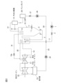
以下、図1を参照して実施の形態について説明する。図1は、前記図2の火力発電ボイラの蒸気系に洗浄系を設けた場合の火炉及び洗浄系のフロー図である。 An embodiment will be described below with reference to FIG. FIG. 1 is a flow diagram of a furnace and a cleaning system when a cleaning system is provided in the steam system of the thermal power boiler shown in FIG.
この実施の形態では、ドレンタンク26とバルブ27との間の配管29に仮設配管30の一端が接続されている。仮設配管30の他端側は、蒸気を熱源とする第1熱交換器31、配管32、ポンプ33、配管34、スラッジキャッチャー35、配管36、濾過ユニット37、配管38、蒸気を熱源とする第2熱交換器39及び配管40を介して給水管3に連なっている。配管40からは排水用配管41が分岐し、該配管41にバルブ42が設けられている。
In this embodiment, one end of
この仮設ライン(配管30から配管40までのライン)に注入される薬液(洗浄薬品の液)を収容した薬液タンク50が設置されている。薬液タンク50内の薬液は、ポンプ51、配管52、バルブ53、第3熱交換器54及び配管55を介して循環され、この循環途中で該熱交換器54によって加熱可能とされている。また、配管52から分岐した配管56は、バルブ57を介して配管32に接続され、薬注可能とされている。
A chemical liquid tank 50 containing a chemical liquid (cleaning chemical liquid) to be injected into this temporary line (the line from the
第3熱交換器54の熱源流体の入口には、配管34から分岐した配管60がバルブ61を介して接続されている。第3熱交換器54の熱源流体の出口は、配管62を介して配管30に接続されている。
A
汽水分離器13よりも火炉10側の化学洗浄を行うには、主蒸気止弁16aを閉とした後、配管30から配管40までの仮設ラインを純水で満たす。(例えば、バルブ27を閉め、給水ポンプ1を作動させて純水よりなるボイラ給水を、給水管3を介して供給する。)その後、バルブ2を閉じ、循環ポンプ33を作動させると共に、第1及び第2熱交換器31,39の熱源流体側(1次側)に蒸気を供給し、循環する純水を加熱する。仮設ラインを循環する純水は、給水管3、節炭器4、管寄せ6、火炉10の管壁、管寄せ12、汽水分離器13、ドレンタンク26の順に流れ、配管30から配管40までの仮設ラインを流れて給水管3に戻って循環する。
To chemically clean the
蒸気を第1及び第3熱交換器31,39の1次側に供給することにより、循環純水の温度が次第に上昇してくる。この温度が約50~95℃程度にまで上昇した段階で、バルブ53,61を開とし、ポンプ51を作動させる。これにより、薬液タンク50内の薬液がポンプ51、配管52、第3熱交換器54、配管55を循環し、該第3熱交換器54によって加熱される。薬液温度が所定温度(例えば約50℃)まで上昇したならば、バルブ53,61を閉とし、ポンプ51を停止する。なお、その後も、必要に応じて薬液タンク50内の薬液を第3熱交換器54に通すとともに、第3熱交換器54の1次側に配管34から高温水を通水し、薬液温度を上記範囲に維持する。
By supplying steam to the primary sides of the first and
配管30から配管40までの仮設ラインを流れる純水の温度が80~90℃まで上昇した後、バルブ57を開とし、ポンプ51を作動させ、循環純水に対し薬液を供給する。この薬品注入工程を所定時間行い、循環水を化学洗浄液とする。薬品注入後は、ポンプ51を停止すると共にバルブ57を閉とし、化学洗浄液を配管30から配管40までの仮設ラインと、節炭器4、火炉10の管壁、汽水分離器13及びドレンタンク26とに循環流通させて化学洗浄を行う。所定時間この化学洗浄工程を行うことにより、汽水分離器13、ドレンタンク26、給水管3、節炭器4、火炉10の壁管、及び管寄せ6,12等が化学洗浄される。
After the temperature of the pure water flowing through the temporary line from the
この化学洗浄を継続している間に化学洗浄液の温度が低下してきた場合には、第1及び第2熱交換器31,39の少なくとも一方の1次側に蒸気を供給し、化学洗浄液を加温する。
When the temperature of the chemical cleaning liquid drops while this chemical cleaning is continued, steam is supplied to the primary side of at least one of the first and
洗浄工程が終了した後は、バルブ42を開とし、化学洗浄液を排出し、給水管3から純水を供給して節炭器4、壁管、管寄せ12、汽水分離器13、ドレンタンク26内の残留洗浄液を押し出す。その後、防錆及びブローを行った後、仮設配管30~40を撤去し、通常の水洗及び起動操作を行ってボイラの運転を再開する。
After the cleaning process is completed, the
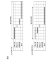
この洗浄方法によると、図3(b)の通り、純水の予熱工程を行っている途中で、薬液タンク50内の薬液を第3熱交換器54に循環させて加熱しておくので、予熱工程の終了時又はその前から薬液を循環純水に注入し、この注入終了後直ちに化学洗浄を開始することができる。
According to this cleaning method, as shown in FIG. 3B, the chemical solution in the chemical solution tank 50 is circulated and heated in the
また、このように、あらかじめ薬液を第3熱交換器54で加温しておくので、薬液注入に伴う洗浄液温度低下を小さくすることができる。
In addition, since the chemical solution is heated in advance by the
また、薬液注入時および化学洗浄中の昇温、温度保持を熱交換器31,39,54で行うので、薬品の希釈が防止される。これにより、ブローに伴う薬品の流失が防止されるので、薬品コストが低減される。
In addition, since the
例えば、洗浄液量を175m3、薬品量を35m3として、90℃の予熱水に20℃の洗浄薬液を注入した場合、洗浄液温は77℃まで低下することになる(放熱は無視する。以下同様)。 For example, if the amount of cleaning liquid is 175 m 3 and the amount of chemical is 35 m 3 , and the cleaning chemical of 20° C. is injected into the preheated water of 90° C., the temperature of the cleaning liquid drops to 77° C. ).
これに対し、薬液をあらかじめ50℃まで昇温しておいた場合、同様の計算で薬液注入後の洗浄液温は83℃となる。更に、薬液注入時も間接熱交換器31,39で加熱することで、洗浄液を希釈せずに昇温、温度保持を行うことが可能である。
On the other hand, when the temperature of the chemical solution is raised to 50° C. in advance, the temperature of the cleaning solution after injection of the chemical solution is 83° C. by the same calculation. Furthermore, by heating with the
[実施例1]
図1に示すボイラの化学洗浄を図3(b)の本発明方法の手順に従って行った。
[Example 1]
Chemical cleaning of the boiler shown in FIG. 1 was performed according to the procedure of the method of the present invention shown in FIG. 3(b).
<予熱工程>
洗浄系統内に純水を循環させながら、第1及び第2熱交換器31,39に蒸気を供給し、循環純水を90℃まで予熱した。
<Preheating process>
While circulating pure water in the cleaning system, steam was supplied to the first and
予熱の過程で、循環している加熱された純水の一部を第3熱交換器54に通水し、薬液タンク50内の薬液を50℃まで昇温させると共に、薬液の温度を50℃に保持した。
In the preheating process, part of the circulating heated deionized water is passed through the
<薬液注入>
90℃、175m3の予熱循環水に対して、50℃、35m3の薬液を約2サイクル(450m3/h、1サイクル約23分)で注入し、並行して第1,第3熱交換器31,39で循環水の温度保持を行った。
<Chemical solution injection>
50°C, 35m 3 chemical solution is injected into 90°C, 175m 3 preheated circulating water in about 2 cycles (450m 3 /h, 1 cycle about 23 minutes), and the first and third heat exchanges are performed in parallel. The temperature of the circulating water was maintained by the
その結果、注入終了時の液温を90℃で保持することが可能であった。また、総洗浄時間は、次に説明する比較例1に比べて2時間短縮された。 As a result, it was possible to keep the liquid temperature at 90° C. at the end of injection. Also, the total cleaning time was shortened by 2 hours compared to Comparative Example 1 described below.
また、洗浄中も第1,第3熱交換器31,35を使用して温度を保持することで、通常であれば希釈されることを見込んで上乗せする0.5%分(洗浄液量175m3で875kg)の薬品を節約することができた。
In addition, by maintaining the temperature using the first and
[比較例1]
図3(a)の従来方法の手順に従って化学洗浄を行った。この方法では、予熱工程で蒸気を循環純水に注入し、予熱終了後に薬液を注入し、薬液注入終了後、蒸気注入により液温度を90℃とした。この方法では、洗浄時間が上記本発明方法より2時間長く要すると共に、薬品使用量も多かった。
[Comparative Example 1]
Chemical cleaning was performed according to the procedure of the conventional method shown in FIG. 3(a). In this method, steam is injected into the circulating pure water in the preheating step, the chemical solution is injected after the preheating is finished, and the liquid temperature is set to 90° C. by the steam injection after the chemical solution injection is finished. In this method, the cleaning time was two hours longer than in the method of the present invention, and the amount of chemicals used was large.
3 給水管
4 節炭器
10 火炉
13 汽水分離器
15 過熱器
19 再熱器
26 ドレンタンク
31,39,54 熱交換器
3
Claims (3)
該ドレンタンクと節炭器とを連通させる仮設ラインを設け、
該仮設ラインにポンプ及び仮設ライン用熱交換器を設け、
該汽水分離器及びそれよりも火炉側に純水を循環させると共に、
この循環を行っている間に、前記仮設ライン用熱交換器によって該純水を加熱し、且つこの加熱された純水を熱源とする薬液加熱用熱交換器によって薬液を加熱しておき、
純水が所定温度以上にまで加熱された後、この加熱された薬液を純水に注入して化学洗浄工程を行うことを特徴とするボイラの化学洗浄方法。 An economizer to which water is introduced by a water supply pipe, a furnace having wall pipes to which water is introduced from the economizer, a steam separator connected to the wall pipes, and receiving water from the steam separator. In a method for chemically cleaning a boiler having a drain tank and a pump and piping for circulating water in the drain tank to the water supply pipe,
providing a temporary line for communication between the drain tank and the economizer;
The temporary line is provided with a pump and a temporary line heat exchanger,
While circulating pure water to the steam separator and to the furnace side,
During this circulation, the pure water is heated by the temporary line heat exchanger, and the chemical is heated by the chemical solution heating heat exchanger using the heated pure water as a heat source,
A chemical cleaning method for a boiler, comprising heating pure water to a predetermined temperature or higher and then injecting the heated chemical solution into the pure water to perform a chemical cleaning step.
Priority Applications (1)
| Application Number | Priority Date | Filing Date | Title |
|---|---|---|---|
| JP2019151331A JP7283302B2 (en) | 2019-08-21 | 2019-08-21 | Boiler chemical cleaning method |
Applications Claiming Priority (1)
| Application Number | Priority Date | Filing Date | Title |
|---|---|---|---|
| JP2019151331A JP7283302B2 (en) | 2019-08-21 | 2019-08-21 | Boiler chemical cleaning method |
Publications (2)
| Publication Number | Publication Date |
|---|---|
| JP2021032447A JP2021032447A (en) | 2021-03-01 |
| JP7283302B2 true JP7283302B2 (en) | 2023-05-30 |
Family
ID=74675590
Family Applications (1)
| Application Number | Title | Priority Date | Filing Date |
|---|---|---|---|
| JP2019151331A Active JP7283302B2 (en) | 2019-08-21 | 2019-08-21 | Boiler chemical cleaning method |
Country Status (1)
| Country | Link |
|---|---|
| JP (1) | JP7283302B2 (en) |
Citations (6)
| Publication number | Priority date | Publication date | Assignee | Title |
|---|---|---|---|---|
| US20130139855A1 (en) | 2010-08-13 | 2013-06-06 | Klaus-Dieter Kuhnke | Method for completing a chemical power plant cleaning |
| JP2015114064A (en) | 2013-12-12 | 2015-06-22 | 三菱日立パワーシステムズ株式会社 | Boiler tube chemical cleaning method |
| JP2017150001A (en) | 2016-02-22 | 2017-08-31 | 三菱日立パワーシステムズ株式会社 | Chemical cleaning method and chemical cleaning apparatus |
| JP2018021684A (en) | 2016-08-01 | 2018-02-08 | 栗田エンジニアリング株式会社 | Chemical cleaning method of boiler |
| JP2018071906A (en) | 2016-10-31 | 2018-05-10 | 株式会社片山化学工業研究所 | Liquid chemical warming device and liquid chemical warming method |
| JP2019082314A (en) | 2017-10-27 | 2019-05-30 | 東北電力株式会社 | Chemical cleaning method for boiler |
-
2019
- 2019-08-21 JP JP2019151331A patent/JP7283302B2/en active Active
Patent Citations (6)
| Publication number | Priority date | Publication date | Assignee | Title |
|---|---|---|---|---|
| US20130139855A1 (en) | 2010-08-13 | 2013-06-06 | Klaus-Dieter Kuhnke | Method for completing a chemical power plant cleaning |
| JP2015114064A (en) | 2013-12-12 | 2015-06-22 | 三菱日立パワーシステムズ株式会社 | Boiler tube chemical cleaning method |
| JP2017150001A (en) | 2016-02-22 | 2017-08-31 | 三菱日立パワーシステムズ株式会社 | Chemical cleaning method and chemical cleaning apparatus |
| JP2018021684A (en) | 2016-08-01 | 2018-02-08 | 栗田エンジニアリング株式会社 | Chemical cleaning method of boiler |
| JP2018071906A (en) | 2016-10-31 | 2018-05-10 | 株式会社片山化学工業研究所 | Liquid chemical warming device and liquid chemical warming method |
| JP2019082314A (en) | 2017-10-27 | 2019-05-30 | 東北電力株式会社 | Chemical cleaning method for boiler |
Also Published As
| Publication number | Publication date |
|---|---|
| JP2021032447A (en) | 2021-03-01 |
Similar Documents
| Publication | Publication Date | Title |
|---|---|---|
| JP6303836B2 (en) | Chemical cleaning method for boiler | |
| JP7183639B2 (en) | Boiler chemical cleaning method | |
| CN202188481U (en) | Pumpless direct-current furnace startup system capable of recycling work media and part of heat | |
| JP7283302B2 (en) | Boiler chemical cleaning method | |
| CN102425778B (en) | Process of carrying out low-temperature chemical cleaning passivation on thermal power plant boiler by utilizing EDTA (Ethylene Diamine Tetraacetic Acid) | |
| US6155054A (en) | Steam power plant and method of and cleaning its steam/water cycle | |
| JP7119898B2 (en) | Boiler chemical cleaning method | |
| CN201748408U (en) | Supercritical heat supply network heater full-backheating drain water system in concurrent boiler thermal power plant | |
| JP6328916B2 (en) | Waste heat recovery boiler and cleaning method | |
| JP2012207852A (en) | Boiler | |
| JP7363695B2 (en) | Boiler chemical cleaning method | |
| CN211875989U (en) | Purification system for high-temperature gas cooled reactor nuclear power unit during starting period of thermal equipment | |
| CN109442372B (en) | Waste heat boiler water circulation system with auxiliary steam | |
| JP2013148234A (en) | Blow method of boiler | |
| JP6743558B2 (en) | Boiler chemical cleaning method | |
| JP7380309B2 (en) | Boiler chemical cleaning method | |
| JP7472622B2 (en) | Chemical cleaning method for boilers | |
| KR20200109568A (en) | Water heating system using exhaust vapor of condensate tank | |
| JP2021173440A (en) | Chemical cleaning method for boiler | |
| JP2021063593A (en) | Chemical cleaning method for boiler | |
| CN220018316U (en) | Chemical cleaning system for fused salt heat storage unit heat storage island system | |
| CN208687709U (en) | A kind of multi-stage boilers water supply device with purification function | |
| JP6766090B2 (en) | Exhaust heat recovery boiler and cleaning method | |
| KR20020051105A (en) | Preventing method of dust corrosion in water preheater for in coke dryer quenching system | |
| JP2020134091A (en) | Chemical cleaning method of boiler |
Legal Events
| Date | Code | Title | Description |
|---|---|---|---|
| A711 | Notification of change in applicant |
Free format text: JAPANESE INTERMEDIATE CODE: A712 Effective date: 20210512 |
|
| A621 | Written request for application examination |
Free format text: JAPANESE INTERMEDIATE CODE: A621 Effective date: 20220712 |
|
| TRDD | Decision of grant or rejection written | ||
| A977 | Report on retrieval |
Free format text: JAPANESE INTERMEDIATE CODE: A971007 Effective date: 20230413 |
|
| A01 | Written decision to grant a patent or to grant a registration (utility model) |
Free format text: JAPANESE INTERMEDIATE CODE: A01 Effective date: 20230418 |
|
| A61 | First payment of annual fees (during grant procedure) |
Free format text: JAPANESE INTERMEDIATE CODE: A61 Effective date: 20230501 |
|
| R150 | Certificate of patent or registration of utility model |
Ref document number: 7283302 Country of ref document: JP Free format text: JAPANESE INTERMEDIATE CODE: R150 |