JP7282801B2 - Analysis apparatus having multiple liquid chromatographs and analysis method thereof - Google Patents
Analysis apparatus having multiple liquid chromatographs and analysis method thereof Download PDFInfo
- Publication number
- JP7282801B2 JP7282801B2 JP2020558419A JP2020558419A JP7282801B2 JP 7282801 B2 JP7282801 B2 JP 7282801B2 JP 2020558419 A JP2020558419 A JP 2020558419A JP 2020558419 A JP2020558419 A JP 2020558419A JP 7282801 B2 JP7282801 B2 JP 7282801B2
- Authority
- JP
- Japan
- Prior art keywords
- sample
- detector
- liquid chromatographs
- peak separation
- liquid
- Prior art date
- Legal status (The legal status is an assumption and is not a legal conclusion. Google has not performed a legal analysis and makes no representation as to the accuracy of the status listed.)
- Active
Links
Images


Classifications
-
- G—PHYSICS
- G01—MEASURING; TESTING
- G01N—INVESTIGATING OR ANALYSING MATERIALS BY DETERMINING THEIR CHEMICAL OR PHYSICAL PROPERTIES
- G01N30/00—Investigating or analysing materials by separation into components using adsorption, absorption or similar phenomena or using ion-exchange, e.g. chromatography or field flow fractionation
- G01N30/02—Column chromatography
- G01N30/26—Conditioning of the fluid carrier; Flow patterns
- G01N30/38—Flow patterns
- G01N30/46—Flow patterns using more than one column
- G01N30/466—Flow patterns using more than one column with separation columns in parallel
-
- G—PHYSICS
- G01—MEASURING; TESTING
- G01N—INVESTIGATING OR ANALYSING MATERIALS BY DETERMINING THEIR CHEMICAL OR PHYSICAL PROPERTIES
- G01N30/00—Investigating or analysing materials by separation into components using adsorption, absorption or similar phenomena or using ion-exchange, e.g. chromatography or field flow fractionation
- G01N30/02—Column chromatography
- G01N30/62—Detectors specially adapted therefor
- G01N30/72—Mass spectrometers
- G01N30/7233—Mass spectrometers interfaced to liquid or supercritical fluid chromatograph
-
- G—PHYSICS
- G01—MEASURING; TESTING
- G01N—INVESTIGATING OR ANALYSING MATERIALS BY DETERMINING THEIR CHEMICAL OR PHYSICAL PROPERTIES
- G01N30/00—Investigating or analysing materials by separation into components using adsorption, absorption or similar phenomena or using ion-exchange, e.g. chromatography or field flow fractionation
- G01N30/02—Column chromatography
- G01N30/86—Signal analysis
-
- G—PHYSICS
- G01—MEASURING; TESTING
- G01N—INVESTIGATING OR ANALYSING MATERIALS BY DETERMINING THEIR CHEMICAL OR PHYSICAL PROPERTIES
- G01N30/00—Investigating or analysing materials by separation into components using adsorption, absorption or similar phenomena or using ion-exchange, e.g. chromatography or field flow fractionation
- G01N30/02—Column chromatography
- G01N2030/022—Column chromatography characterised by the kind of separation mechanism
- G01N2030/027—Liquid chromatography
-
- G—PHYSICS
- G01—MEASURING; TESTING
- G01N—INVESTIGATING OR ANALYSING MATERIALS BY DETERMINING THEIR CHEMICAL OR PHYSICAL PROPERTIES
- G01N30/00—Investigating or analysing materials by separation into components using adsorption, absorption or similar phenomena or using ion-exchange, e.g. chromatography or field flow fractionation
- G01N30/02—Column chromatography
- G01N30/62—Detectors specially adapted therefor
- G01N2030/628—Multiplexing, i.e. several columns sharing a single detector
-
- G—PHYSICS
- G01—MEASURING; TESTING
- G01N—INVESTIGATING OR ANALYSING MATERIALS BY DETERMINING THEIR CHEMICAL OR PHYSICAL PROPERTIES
- G01N30/00—Investigating or analysing materials by separation into components using adsorption, absorption or similar phenomena or using ion-exchange, e.g. chromatography or field flow fractionation
- G01N30/02—Column chromatography
- G01N30/04—Preparation or injection of sample to be analysed
- G01N30/24—Automatic injection systems
-
- G—PHYSICS
- G01—MEASURING; TESTING
- G01N—INVESTIGATING OR ANALYSING MATERIALS BY DETERMINING THEIR CHEMICAL OR PHYSICAL PROPERTIES
- G01N30/00—Investigating or analysing materials by separation into components using adsorption, absorption or similar phenomena or using ion-exchange, e.g. chromatography or field flow fractionation
- G01N30/02—Column chromatography
- G01N30/26—Conditioning of the fluid carrier; Flow patterns
- G01N30/28—Control of physical parameters of the fluid carrier
- G01N30/34—Control of physical parameters of the fluid carrier of fluid composition, e.g. gradient
Description
本発明は、複数の液体クロマトグラフを有する分析装置およびその分析方法に関する。 The present invention relates to an analyzer having a plurality of liquid chromatographs and an analysis method thereof.
液体クロマトグラフ(LC、Liquid Chromatograph:LC)は、試料を分離する分離カラムに送出される移動相に液体を用いたクロマトグラフであり、測定対象を含む液体試料は移動相によって分離カラムまで送液され、分離カラムに充填された固定相と移動相との親和性の差を用いて試料に含まれる各成分に分離し、分離された各成分を、紫外・可視吸光光度計、蛍光光度計、質量分析計などの検出器を用いて検出する分析装置である。 Liquid chromatograph (LC, Liquid Chromatograph: LC) is a chromatograph that uses a liquid as a mobile phase that is sent to a separation column that separates the sample, and the liquid sample containing the measurement target is sent to the separation column by the mobile phase. and separated into each component contained in the sample using the difference in affinity between the stationary phase and the mobile phase packed in the separation column, and each separated component was analyzed with an ultraviolet/visible absorption photometer, a fluorophotometer, It is an analyzer that detects using a detector such as a mass spectrometer.
液体クロマトグラフの測定データは、試料の分離時間(保持時間)と、検出器の検出信号強度の関係を示すピークで表示され、保持時間はピークトップの時間であり、分析条件が同一であれば試料成分毎にほぼ同一の値を示すため、分離成分を同定するための情報として使用される。 Liquid chromatograph measurement data is displayed as a peak that shows the relationship between the separation time (retention time) of the sample and the detection signal intensity of the detector. Since each sample component shows almost the same value, it is used as information for identifying the separated component.
一方で検出信号強度は試料濃度と相関関係があり、分離成分の濃度を算出するための情報として使用され、液体クロマトグラフでは、分離された成分のピークの保持時間と信号強度で分離成分の同定と濃度を決定することを可能にする。 On the other hand, the detected signal intensity correlates with the sample concentration and is used as information to calculate the concentration of the separated components. and concentration can be determined.
高性能液体クロマトグラフ(High Performance Liquid Chromatograph: HPLC)と呼ばれる液体クロマトグラフは、分析時間の短縮や分離性能の向上を目的として、分離カラムの充填材の粒子径を小さくし、送液装置により高圧圧縮された溶媒を用いて分析を行うことを特長とし、HPLCの分析性能の向上と分析時間の短縮化を目的として、粒子径2μm以下の充填材を使用した分離カラムを用いた超高性能液体クロマトグラフ(UHPLC、 Ultra High Performance Liquid Chromatograph)と呼ばれる液体クロマトグラフもある。 A liquid chromatograph, called High Performance Liquid Chromatograph (HPLC), is designed to reduce the analysis time and improve the separation performance by reducing the particle size of the packing material of the separation column and applying a high pressure with a liquid transfer device. Ultra-high-performance liquid that uses a separation column that uses a packing material with a particle size of 2 μm or less for the purpose of improving the analytical performance of HPLC and shortening the analysis time, characterized by using a compressed solvent for analysis. There is also a liquid chromatograph called a chromatograph (UHPLC, Ultra High Performance Liquid Chromatograph).
近年、HPLCやUHPLCに検出器として質量分析計(Mass Spectrometry: MS)を接続した液体クロマトグラフ質量分析計(Liquid Chromatograph-Mass Spectrometry: LC-MS)が生体試料中の薬剤成分や代謝物の測定などの臨床検査分野に使用される機会が増えている。このような測定目的とした分析では、より高い感度、再現性、スループット性能などが求められており、例えば特許文献1に記載されているような質量分析計を検出器とし、複数の液体クロマトグラフを並列接続させることでスループット向上を実現するシステムが提案されている。 In recent years, liquid chromatograph-mass spectrometry (LC-MS) in which a mass spectrometer (MS) is connected to HPLC or UHPLC as a detector has been used to measure drug components and metabolites in biological samples. Opportunities for use in the field of clinical testing such as In the analysis for such measurement purposes, higher sensitivity, reproducibility, throughput performance, etc. are required, for example, a mass spectrometer as described in Patent Document 1 is used as a detector, and a plurality of liquid chromatographs are used. A system has been proposed that improves throughput by connecting in parallel.
しかしながら、LC-MSシステムに求められるような送液流量が小さい送液条件で分析する場合には、同一構成の異なる分析装置間で目的試料の分離性能の差が機差として確認されることがあり、これら機差の主な原因は送液装置から検出器までの配管公差による容量のばらつきや、送液装置の送液性能の機差、高耐圧部品の消耗以外に、カラム間の性能差、分析装置の周囲環境の影響などが考えられている。 However, when analysis is performed under the condition of a low liquid flow rate, which is required for an LC-MS system, the difference in the separation performance of the target sample between different analyzers with the same configuration can be confirmed as an instrumental difference. The main causes of these instrumental differences are variations in capacity due to piping tolerances from the liquid transfer device to the detector, differences in the liquid transfer performance of the liquid transfer device, wear of high-pressure parts, and performance differences between columns. , the influence of the surrounding environment of the analyzer, and the like.
前述したように、液体クロマトグラフにおいて保持時間などの分離性能は、分離成分を同定・定量するための情報として用いられるため、装置やカラム間の機差は存在しないことが望ましく、装置を安定して運用するために多くの場合、測定目的に応じて許容される機差または分離性能の差を設定し、その性能を達成できるように装置メンテナンスを実施、必要に応じて補正パラメータ等を設け、また分析結果からカラム交換タイミングを判断している。 As mentioned above, separation performance such as retention time is used as information for identifying and quantifying separated components in liquid chromatographs. In many cases, the permissible instrumental difference or difference in separation performance is set according to the purpose of measurement, equipment maintenance is performed so that the performance can be achieved, correction parameters are set as necessary, Also, the column exchange timing is determined from the analysis results.
例えば、特許文献2には、装置間の保持時間のばらつきを補正する手段が提示されている。 For example, Patent Literature 2 presents means for correcting variations in retention time between apparatuses.
しかしながら、特許文献2に記載の技術では、保持時間の機差を解決するひとつの手段として、分析条件に流路体積の差分や測定結果から算出される分離成分の保持時間の差分を入力し分析開始タイミングを調整しているが、この方法では流路体積の差分や測定結果からばらつきの原因を考慮せずに補正してしまうため、例えば高耐圧部品のシール消耗やカラムの性能変化等の改善すべきシステムの不具合を補正値に取り込んでしまう可能性を含んでいる。 However, in the technique described in Patent Document 2, as one means of solving the instrumental difference in retention time, analysis is performed by inputting the difference in channel volume and the difference in retention time of separated components calculated from the measurement results into the analysis conditions. Although the start timing is adjusted, this method makes corrections without considering the difference in channel volume and the cause of variation from the measurement results. It includes the possibility of incorporating system failures that should be corrected into the correction values.
また、仮に装置が健全な状態で補正値を取得した場合でも、液体クロマトグラフシステムを使用する中で分離カラムの性能変化や装置の部品消耗により機差が発生するだけではなく、分離カラムの変更や装置の保守作業によって補正値が不適切になる場合も考えられる。 In addition, even if the correction value is obtained with the device in a healthy state, not only will there be instrumental differences due to changes in the performance of the separation column and wear and tear of the device parts during the use of the liquid chromatographic system, but also changes in the separation column It is conceivable that the correction value may become inappropriate due to maintenance work of the device.
そのため、機差を適切に管理し装置を運用するためには、補正値を適切な方法とタイミングで取得するだけではなく、分離カラム性能や装置状態を正確に把握し適切な状態を維持することが求められる。よって、使用者は分離カラムの分離性能の変化を継続的に監視し、分析結果の信頼性が失われるような分離性能変化が発生する前に適切なタイミングでカラムや消耗部品の交換を行い、必要に応じて補正値を更新することが望ましい。 Therefore, in order to properly manage the instrumental difference and operate the equipment, it is necessary to not only obtain correction values in an appropriate manner and timing, but also to accurately grasp the separation column performance and equipment conditions and maintain appropriate conditions. is required. Therefore, the user should continuously monitor the change in the separation performance of the separation column, and replace the column and consumable parts at an appropriate timing before the separation performance change that causes the reliability of the analysis result to be lost. It is desirable to update the correction value as needed.
特に複数の液体クロマトグラフまたは液体クロマトグラフの分離部を並列に接続させたLCシステムでは、並列に接続された液体クロマトグラフ間の機差が存在すると、1つの測定装置内で異なる分析結果が出力される可能性がある。 In particular, in an LC system in which a plurality of liquid chromatographs or separation units of liquid chromatographs are connected in parallel, if there is an instrumental difference between the liquid chromatographs connected in parallel, different analysis results will be output within one measuring device. may be
本発明の目的は、適切なタイミングで、分離性能等を判定して早期に分析性能を向上可能な複数の液体クロマトグラフを有する分析装置およびその分析方法を実現することである。 SUMMARY OF THE INVENTION An object of the present invention is to realize an analyzer having a plurality of liquid chromatographs capable of judging separation performance and the like at an appropriate timing and improving analytical performance at an early stage, and an analysis method thereof.
上記目的を達成するため、本発明は、次のように構成される。 In order to achieve the above object, the present invention is configured as follows.
試料が導入され、導入された試料を各成分に分離する分離カラムを有する複数の液体クロマトグラフと、前記液体クロマトグラフから送液された試料の成分を検出する検出器と、前記検出器により検出された検出データを処理するデータ処理部と、前記液体クロマトグラフ及び前記検出器を制御する装置制御部とを備える複数の液体クロマトグラフを有する分析装置において、前記装置制御部は、前記複数の液体クロマトグラフのいずれかに導入された前記分離カラムに保持されない非保持成分試料が前記検出器によって検出され、前記データ処理部によって処理されたデータに従って前記複数の液体クロマトグラフの装置状態を判定する。 A plurality of liquid chromatographs into which a sample is introduced and having a separation column that separates the introduced sample into components, a detector that detects the components of the sample sent from the liquid chromatograph, and detection by the detector and a device controller for controlling the liquid chromatograph and the detector, wherein the device controller controls the plurality of liquids A non-retained component sample introduced into any of the chromatographs and not retained in the separation column is detected by the detector, and device states of the plurality of liquid chromatographs are determined according to the data processed by the data processing unit.
試料が導入され、導入された試料を各成分に分離する分離カラムを有する複数の液体クロマトグラフと、前記液体クロマトグラフから送液された試料の成分を検出する検出器と、前記検出器により検出された検出データを処理するデータ処理部と、前記液体クロマトグラフ及び前記検出器を制御する装置制御部とを備える複数の液体クロマトグラフを有する分析装置において、前記装置制御部は、前記複数の液体クロマトグラフのいずれかに導入された前記分離カラムに保持されない非保持成分試料と測定対象試料とが前記検出器によって検出され、前記データ処理部によって処理されたデータに従って、前記測定対象試料のピーク分離性能と、前記非保持成分試料の保持時間の変動に基づいて前記複数の液体クロマトグラフの装置状態を判定するものであって、出力部を備え、前記装置制御部は、前記測定対象試料のピーク分離性能がピーク分離許容範囲内か否かを判定し、前記ピーク分離性能がピーク分離許容範囲内ではない場合は、前記非保持成分試料の保持時間の変動量が変動量許容範囲内であれば、分離カラム交換指示を前記出力部に出力し、前記ピーク分離性能がピーク分離許容範囲内ではなく、前記非保持成分試料の保持時間の変動量が変動量許容範囲内でない場合は、装置メンテナンス指示を前記出力部に出力する。 A plurality of liquid chromatographs into which a sample is introduced and having a separation column that separates the introduced sample into components, a detector that detects the components of the sample sent from the liquid chromatograph, and detection by the detector and a device controller for controlling the liquid chromatograph and the detector, wherein the device controller controls the plurality of liquids A non-retained component sample that is not retained in the separation column introduced into any of the chromatographs and a sample to be measured are detected by the detector, and the peaks of the sample to be measured are separated according to the data processed by the data processing unit. The device state of the plurality of liquid chromatographs is determined based on the performance and the fluctuation of the retention time of the non-retained component sample, and the device control unit includes an output unit, wherein the device control unit detects the peak of the sample to be measured. Determine whether the separation performance is within the peak separation permissible range, and if the peak separation performance is not within the peak separation permissible range, if the fluctuation amount of the retention time of the non-retained component sample is within the fluctuation amount permissible range , a separation column replacement instruction is output to the output unit, and if the peak separation performance is not within the peak separation allowable range and the fluctuation amount of the retention time of the non-retained component sample is not within the fluctuation amount allowable range, an apparatus maintenance instruction is output to the output unit .
また、試料が導入され、導入された試料を各成分に分離する分離カラムを有する複数の液体クロマトグラフと、前記液体クロマトグラフから送液された試料の成分を検出する検出器と、前記検出器により検出された検出データを処理するデータ処理部と、前記液体クロマトグラフ及び前記検出器を制御する装置制御部とを備える複数の液体クロマトグラフの分析方法において、前記複数の液体クロマトグラフのいずれかに導入された前記分離カラムに保持されない非保持成分試料と測定対象試料とを前記検出器によって検出し、検出したデータに従って前記複数の液体クロマトグラフの装置状態を判定する分析方法であって、前記測定対象試料のピーク分離性能がピーク分離許容範囲内か否かを判定し、前記ピーク分離性能がピーク分離許容範囲内ではない場合は、前記非保持成分試料の保持時間の変動量が変動量許容範囲内であれば、分離カラム交換指示を出力部に出力し、前記ピーク分離性能がピーク分離許容範囲内ではなく、前記非保持成分試料の保持時間の変動量が変動量許容範囲内でない場合は、装置メンテナンス指示を前記出力部に出力する。
Further, a plurality of liquid chromatographs having a separation column into which a sample is introduced and separating the introduced sample into each component, a detector for detecting components of the sample sent from the liquid chromatograph, and the detector A plurality of liquid chromatograph analysis methods comprising a data processing unit that processes detection data detected by and a device control unit that controls the liquid chromatograph and the detector, wherein any of the plurality of liquid chromatographs An analysis method in which a non-retained component sample that is not retained in the separation column and a sample to be measured introduced into the separation column are detected by the detector, and the apparatus state of the plurality of liquid chromatographs is determined according to the detected data, It is determined whether or not the peak separation performance of the sample to be measured is within the peak separation permissible range, and if the peak separation performance is not within the peak separation permissible range, the fluctuation amount of the retention time of the non-retained component sample is within the permissible fluctuation amount. If it is within the range, a separation column replacement instruction is output to the output unit, and if the peak separation performance is not within the peak separation permissible range and the fluctuation amount of the retention time of the non-retained component sample is not within the fluctuation amount permissible range , to output an apparatus maintenance instruction to the output unit .
以下、本発明に係る複数の液体クロマトグラフを有する分析装置およびその分析方法の実施形態として前処理機能を有するLCシステムについて説明する。 An LC system having a pretreatment function will be described below as an embodiment of an analyzer having a plurality of liquid chromatographs and an analysis method thereof according to the present invention.
なお、本発明の実施形態は実施例に限定されるものではなく、例えば検出器として可視・紫外吸光度検出器やフォトダイオードアレイ検出器、蛍光検出器、質量分析計等を使用するなど、その技術思想の範囲において応用が可能である。 In addition, the embodiments of the present invention are not limited to the examples. Applications are possible within the scope of the idea.
(実施例1)
図1は、本発明の実施例1が適用されるLCシステムの全体概略構成図である。(Example 1)
FIG. 1 is an overall schematic configuration diagram of an LC system to which Embodiment 1 of the present invention is applied.
図1において、LCシステムは、移動相を高圧送液する送液装置107、108、及び109と、試料導入部110、111及び112と、試料を各成分に分離する分離カラム113、114及び115から構成される複数のLCユニット(液体クロマトグラフ)101、102及び103を備える。また、LCシステムは、各LCユニット101、102、103の試料導入部110、111、112に試料を導入する試料分注機構104と、LCユニット101、102、103と流路で接続された切換バルブ105と、切換バルブ105の下流側に流路で接続された検出器である検出器106とを備える。検出器106は、LCユニット101、102、103から送液された試料の成分を検出する。
In FIG. 1, the LC system includes
また、LCシステムは、各LCユニット101、102、103、試料分注機構104、切換バルブ105、検出器106を制御する装置制御部116と、検出器106から出力された測定結果(検出データ)を処理するデータ処理部121とを備える。
The LC system includes the
LCユニット101、102及び103と、検出器106とを接続する流路は設計上の配管容量が等しくなるように接続されている。試料分注機構104は、分離カラム113、114、115に対して非保持成分(保持されない成分)である非保持成分試料を測定対象試料に添加し調整した混合試料を試料導入部110、111、112から、LCユニット(液体クロマトグラフ)101、102、103の分析流路に導入し、導入された混合試料は分離カラム113、114、115にて化学的特性によって各成分に分離される。このとき、分離カラム113、114、115はカラム内温度を一定に保つためにカラムオーブンに収容されることがある。
The channels connecting the
また、装置制御部116は、システム容量算出部117と、注入タイミング調整部118と、グラジエントタイミング調整部119と、保守タイミング判定部120とを備える。また、データ処理部121は、ピーク情報取得部122を備え、出力部123が接続されている。
The
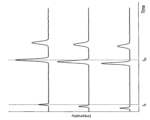
図2は、分離カラム113、114、115に対して非保持成分の有無によるクロマトグラムの概略図であり、縦軸は信号強度を示し、横軸は時間を示す。図2の(a)は、非保持成分を添加しない場合のクロマトグラムを示し、測定対象試料が分離カラムとの相互作用により分離した成分ごとの保持時間tR1及びtR2が検出器106にて検出される。FIG. 2 is a schematic diagram of chromatograms with and without unretained components for
これに対し、図2の(b)は非保持成分を添加した場合のクロマトグラムを示し、添加されたカラム非保持成分は分離カラムとの相互作用がないため流路及び分離カラムのデッドボリュームの体積を通過する時間(t0)で検出される。On the other hand, (b) of FIG. 2 shows a chromatogram when a non-retained component is added. It is detected at the time of passage through the volume (t 0 ).
このように、非保持成分は分離カラムと相互作用しないため、配管や分離カラムのデッドボリュームや溶媒の送液流量が変わらない限りは時間t0や非保持成分のピーク形状は変化しないため、液体クロマトグラフの装置状態を判定するパラメータとして用いることができる。In this way, since the non-retained components do not interact with the separation column, the time t0 and the peak shape of the non-retained components do not change unless the dead volume of the piping or the separation column or the flow rate of the solvent is changed. It can be used as a parameter for determining the device state of the chromatograph.
図3A及び図3Bは、クロマトグラムの各ピークの保持時間について装置状態を判定するパラメータとして仮定した場合の概略図である。図3Aは、使用時間の経過が異なり、経過時間ごとに測定した3つのクロマトグラムを示す。3つのクロマトグラムが示す測定結果は、測定対象試料の分離成分tRの保持時間tR1が変動し、それぞれ異なっているが、非保持成分の分離カラムの通過時間t0は3つのクロマトグラフで変動していない。これは、送液流量の変化や配管からの液漏れなどの装置側に問題があるわけではなく、分離カラムの性能が変化している可能性を示唆している。3A and 3B are schematic diagrams when the retention time of each peak in the chromatogram is assumed as a parameter for determining the device state. FIG. 3A shows three chromatograms measured over different time periods of use. The measurement results shown by the three chromatograms are different because the retention time tR1 of the separated component tR of the sample to be measured varies, but the passage time t0 of the non-retained component through the separation column is not changed. This suggests the possibility that the performance of the separation column has changed, rather than that there is a problem on the device side such as a change in the flow rate of the liquid sent or a liquid leak from the pipe.
図3Aに対して、図3Bに示した例では、測定対象試料の分離成分tRの保持時間tR1と非保持成分の通過時間t0の全てが互いに変動しているため、送液流量の変化や配管からの液漏れなどの可能性があり装置のメンテナンスが必要であることが判断できる。なお、本願明細書においては、非保持成分の通過時間t0は非保持成分の保持時間t0とも表現する。In contrast to FIG. 3A, in the example shown in FIG. 3B, both the retention time tR1 of the separated component tR and the passage time t0 of the non-retained component of the sample to be measured fluctuate with each other. It can be determined that maintenance of the equipment is necessary due to the possibility of change or liquid leakage from piping. In the specification of the present application, the passage time t0 of the non-retained component is also expressed as the retention time t0 of the non-retained component.
図3A及び図3Bでは各ピークの保持時間及び通過時間を、装置状態を判断するための指標と仮定したが、それ以外のピークの分離情報、たとえばピーク面積や高さ、シンメトリー係数や理論段数など、を用いることでより正確な判定を実現することができる。 In FIGS. 3A and 3B, the retention time and transit time of each peak were assumed to be indicators for judging the state of the apparatus, but other peak separation information, such as peak area and height, symmetry coefficient, theoretical plate number, etc. , a more accurate determination can be realized.
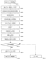
図4は、分離カラム113、114、115への非保持成分(例えばウラシル)を測定対象試料に添加し、複数のLCユニット(液体クロマトグラフ)101、102、103のいずれかに導入し、取得したクロマトグラムから液体クロマトグラフの装置状態を判定するプロセスの一例におけるフローチャートである。
FIG. 4 shows that components not retained in
図4において、分析開始の信号が、装置制御部116に入力される(ステップS401)。試料分注機構104は、分離カラム113、114、115に導入する測定対象試料に非保持成分を添加し混合試料を調整する(ステップS402)。このとき、混合試料の調整作業は、測定試料が収められた容器に非保持成分を添加し混合する方式や、測定試料と非保持成分を異なる容器に分注し混合する方法でも良い。非保持成分は、測定対象試料に対して、例えば10~20%でよい。
In FIG. 4, an analysis start signal is input to the apparatus control section 116 (step S401). The
混合試料の調整が終了した後に、混合試料は試料分注機構104により分析に必要な容量が計量され(ステップS403)、試料導入部110、111、112から分析流路へ導入される(ステップS404)。分離カラム113、114、115により各成分に分離された後に、検出器106にてクロマトグラムデータとしてデータ処理部121に出力され(ステップS405)、分析が終了する(ステップS406)。
After the mixed sample is adjusted, the volume of the mixed sample required for analysis is measured by the sample dispensing mechanism 104 (step S403), and is introduced into the analysis channel from the
データ処理部121のピーク情報取得部122は、検出器106から出力されたクロマトグラムから保持時間を始めとする各成分のピーク情報を取得し(ステップS407)、装置制御部116は、それらの測定結果が設定されたピーク分離許容範囲内であるか(分離した成分ごとの保持時間tR1とtR2との分離時間が許容範囲内か否か等)を判定し(ステップS408)、許容範囲内であれば装置制御部116により次の分析へ移行される(ステップS409)。The peak
許容範囲の判定作業(ステップS408)においてピークの分離性能が許容範囲外であった場合は、装置制御部116は、添加した非保持成分の通過時間t0が設定された許容値からのシフト量を確認する(ステップS410)。If the peak separation performance is outside the allowable range in the allowable range determination operation (step S408), the
ステップS410において、装置制御部116は、通過時間(保持時間)t0の変動量が、変動量許容範囲内であればLCユニット101、102、103の装置状態は正常と判断し分離カラム交換の指示を出力部123に出力(表示等)する(ステップS411)。In step S410, the
ステップS410において、装置制御部116は、通過時間t0の変動量が許容範囲外であった場合は、装置のメンテナンスの指示を出力部123に出力(表示等)する(ステップS412)。In step S410, if the fluctuation amount of the passage time t0 is outside the allowable range, the
図4に示したプロセスでは、装置状態を監視する目的で非保持成分を添加する必要があり分析コストを増大させる要因の1つになる可能性がある。このため、通常の分析プロセスにおいては不要な試料であるカラム非保持成分は必要なタイミングでのみ添加されることが望ましい。 In the process shown in FIG. 4, it is necessary to add non-retained components for the purpose of monitoring the state of the apparatus, which may be one of the factors that increase analysis costs. For this reason, it is desirable that the column non-retained component, which is an unnecessary sample in the normal analysis process, is added only at the necessary timing.
図5は、図4に示したフローとは異なるフローによる装置状態を判定するプロセスのフローチャートである。 FIG. 5 is a flowchart of a process for determining device status according to a flow different from that shown in FIG.
図5に示した例は、測定対象試料のピーク分離性能が許容範囲外と判定された場合にのみ、カラム非保持成分を添加剤として用いた性能確認モードへ移行するプロセスである。このプロセスでは装置が正常状態であるとき、例えば、装置導入時や装置メンテナンスを実施した後に基準となる通過時間t0を取得しておく必要がある。The example shown in FIG. 5 is a process of shifting to the performance confirmation mode using the column non-retained component as an additive only when the peak separation performance of the sample to be measured is determined to be out of the allowable range. In this process, when the device is in a normal state, for example, when the device is installed or after the device is maintained, it is necessary to obtain the reference passing time t0 .
図5において、通常の分析プロセスでは非保持成分を添加しないため、装置制御部116から入力される分析開始信号が装置の各部に入力される(ステップS501)。試料分注機構104は分析に必要な容量の測定対象試料を計量する(ステップS502)。計量された試料は試料導入部110、111、112から分析流路へ導入されて分析が開始され(ステップS503)、分離カラム113、114、115により各成分に分離された後に検出器106にてクロマトグラムデータとしてデータ処理部121に出力され(ステップS504)、分析が終了する(ステップS505)。
In FIG. 5, since non-retained components are not added in a normal analysis process, an analysis start signal input from the
データ処理部121のピーク情報取得部122は、検出器106から出力されたクロマトグラムから保持時間を始めとする各成分のピーク情報を取得し(ステップS506)、装置制御部116は、それらの測定結果(ピーク分離性能)が設定された許容範囲内であるかを判定し(ステップS507)、許容範囲内であれば装置制御部116により次の分析へ移行される(ステップS508)。
The peak
ステップS507において、ピーク分離性能が許容範囲外と判定された場合、LCシステムは、性能確認モードへ移行し(ステップS509)、試料分注機構104はカラム非保持成分を測定対象試料に添加し混合試料を調整する(ステップS510)。
In step S507, when the peak separation performance is determined to be out of the allowable range, the LC system shifts to the performance confirmation mode (step S509), and the
図5に示したプロセスでは非保持成分は必要に応じて添加するため、測定試料と非保持成分を異なる容器に分注し混合する方式が望ましい。試料分注機構104は調整された混合試料については分析に必要な容量を計量し(ステップS511)、試料導入部110、111、112から分析流路に導入されて分析を開始する(ステップS512)。
In the process shown in FIG. 5, the non-retained component is added as required, so a method of dispensing and mixing the measurement sample and the non-retained component into different containers is desirable. The
そして、検出器106にてクロマトグラムデータとしてデータ処理部121に出力され(ステップS513)、データ処理部121のピーク情報取得部122においてピーク情報が取得される(ステップS514)。装置制御部116は、算出されたピーク情報から得られた通過時間t0とあらかじめ取得し記憶しておいた基準となる通過時間t0とを比較し変動量が許容範囲内か否かを判定する(ステップS515)。測定値となる通過時間t0の変動量が許容範囲内である場合は、装置状態は正常であると判定しカラム交換の指示を出力部123に出力する(ステップS516)。Then, the
ステップS515において、基準値の通過時時間t0に対して測定値となる通過時間t0の変動量が許容範囲外である場合は、装置状態が適切ではないと判断し装置メンテナンス指示を出力部123に出力する(ステップS517)。In step S515, if the amount of variation in the passing time t0, which is the measured value, relative to the passing time t0 of the reference value is outside the allowable range, it is determined that the device state is not appropriate, and the device maintenance instruction is output by the unit. 123 (step S517).
以上のように、本発明の実施例1によれば、測定対象試料のピーク分離性能と、非保持成分の通過時間の変動量とを判定して、分離カラムの交換指示、LCシステムの装置メンテナンスの指示を早期に適切に行うことができる。 As described above, according to Example 1 of the present invention, the peak separation performance of the sample to be measured and the fluctuation amount of the passage time of the non-retained component are determined, and the replacement of the separation column and the equipment maintenance of the LC system are determined. instructions can be given early and appropriately.
よって、適切なタイミングで、分離性能等の劣化を判定して早期に分析性能を向上可能な複数の液体クロマトグラフを有する分析装置およびその分析方法を実現することができる。 Therefore, it is possible to realize an analyzer having a plurality of liquid chromatographs capable of judging deterioration of separation performance or the like at an appropriate timing and improving analytical performance at an early stage, and an analysis method thereof.
(実施例2)
次に、本発明の実施例2について説明する。(Example 2)
Next, Example 2 of the present invention will be described.
LCシステムは、実施例1と実施例2は同様な構成となっているので、図示及び詳細な説明は省略する。 Since the LC system has the same configuration in the first embodiment and the second embodiment, illustration and detailed description thereof are omitted.
実施例2は、図1に示す複数のLCが接続されたLCシステムにおいて、LCシステムを構成する装置が正常であり、同じ種類の分離カラムにより分析を実施しているにもかかわらず発生する装置間の保持時間の機差を分離カラムの非保持成分の保持時間である通過時間t0から補正する例である。In Example 2, in the LC system in which a plurality of LCs are connected as shown in FIG. This is an example in which the instrumental difference in the retention time between the two is corrected from the passage time t0 , which is the retention time of the non-retained components in the separation column.
補正パラメータは、装置が正常状態で取得する必要があるため、LCシステムの装置導入時またはメンテナンス実施後に取得するのが望ましい。 Since the correction parameters must be obtained when the apparatus is in a normal state, it is desirable to obtain the correction parameters when the LC system is installed or after performing maintenance.
図6は、実施例2において、装置間機差を補正する補正パラメータの取得プロセスのフローチャートである。 FIG. 6 is a flowchart of a correction parameter acquisition process for correcting the machine difference between devices in the second embodiment.
図6において、補正パラメータ取得プロセスが開始されると(ステップS601)、装置制御部116は、補正パラメータ算出モードへ移行し(ステップS602)、試料導入部104は測定対象試料に非保持成分を添加し混合試料を調整する(ステップS603)。
In FIG. 6, when the correction parameter acquisition process is started (step S601), the
ステップS603にて調整された混合試料は補正パラメータ取得に必要な容量分を計量され(ステップS604)、試料導入部110、111、112から分析流路へ導入される(ステップS605)。そして、分離カラム113、114、115にて各成分に分離され、検出器106にてクロマトグラムデータとして検出されて(ステップS606)、分析が終了する(ステップS607)。
The mixed sample adjusted in step S603 is weighed by the volume necessary for acquiring the correction parameters (step S604), and is introduced from the
データ処理部121は取得したクロマトグラムデータからカラム非保持成分の保持時間(通過時間)t0を算出し(ステップS608)、分析に用いた送液流量Qを算出条件とした次式(1)を用いることで試料導入部110、111、112から検出部(検出器)である検出器106までの容量(VRS)を算出する(ステップS609)。容量VRSは、接続されたLCユニット101、102、103の機差を補正する必要があるため、各LCユニット101、102、103についてクロマトグラムを取得し算出する。補正パラメータVCは、次式(2)を用いてあらかじめ装置構成と使用する分離カラムによって定められた容量の基準値VSと算出されたVRSとの差分から算出される(ステップS610)。
VRS=t0[min]×Q[mL/min] ・・・ (1)
VC=VS[mL]-VRS[mL] ・・・ (2)The
VRS = t0 [min] x Q [mL/min] (1)
VC = VS [mL] -VRS [mL] (2)
装置制御部116により、算出された補正パラメータVCは、あらかじめ設定された許容値と比較され許容範囲内か否か判定され(ステップS611)、許容範囲内の場合にのみ、パラメータ取得時に使用した分離カラムを用いた際の装置容量の補正値(補正パラメータ)として記憶され(ステップS612)、補正パラメータ取得プロセスを終了する(ステップS613)。The
ステップS611において、算出された補正パラメータVCが許容値範囲外の値となった場合は、装置または分離カラムが不適切な状態にあると判断し、エラーが出力部123から出力される(ステップS614)。装置または分離カラムが不適切な状態の例としては、流路配管の接続ミスがある。In step S611, when the calculated correction parameter V C is out of the allowable value range, it is determined that the device or separation column is in an inappropriate state, and an error is output from the output unit 123 (step S614). An example of improper condition of a device or separation column is a misconnected flow line plumbing.
図7は、図6に示したフローチャートにより算出された装置容量の補正値VCを用いて試料注入タイミング(試料導入タイミング)を装置制御部116により自動調整(制御)するプロセスについてのフローチャートである。FIG. 7 is a flow chart of a process for automatically adjusting (controlling) the sample injection timing (sample introduction timing) by the
図7において、分析開始の信号が入力されると、装置制御部116は分析開始準備として(ステップS701)、記憶された各LCユニット101、102、103の補正値VCの読み込みを開始し、補正値VCがあらかじめ設定されている仕様範囲内にあるかどうかを判定する(ステップS702)。In FIG. 7, when an analysis start signal is input, the
ステップS702において、補正値VCが仕様範囲内にあると判定した場合は、試料導入タイミング補正の必要なしと判断し(ステップS703)、試料導入及びデータ収集を開始し分析を開始する(ステップS704)。If it is determined in step S702 that the correction value VC is within the specification range, it is determined that sample introduction timing correction is not necessary (step S703), sample introduction and data collection are started, and analysis is started (step S704). ).
ステップS702において、補正値VCが設定された仕様範囲外にあると判定した場合は、試料導入タイミングの補正が必要と判定し試料導入タイミングの補正プロセスを開始させる(ステップS707)。試料導入タイミングの補正プロセスでは、最初に補正値VCについて正負の判定を行い(ステップS708)、補正値VCが0より大の値である場合は、容量VRSは基準となるシステム容量よりも小さく保持時間t0が早い時間帯に検出されていることを示しているため、試料導入タイミングを遅くし(ステップS709)、設定されたデータ収集の開始(ステップS710)した後に試料を導入する(ステップS711)。これにより、調整を実施する。If it is determined in step S702 that the correction value V C is outside the set specification range, it is determined that the sample introduction timing needs to be corrected, and the process of correcting the sample introduction timing is started (step S707). In the process of correcting the sample introduction timing, first, the positive or negative of the correction value VC is determined (step S708 ). is small, indicating that the retention time t0 is detected in an early time zone, the sample introduction timing is delayed (step S709), and the sample is introduced after the start of the set data collection (step S710). (Step S711). Adjustments are made accordingly.
ステップS708において、補正値VCが0以下の値である場合は、容量VRSは基準となるシステム容量よりも大きく保持時間t0が遅い時間帯に検出されていることを示しているため、試料導入タイミングを早くして(ステップS712)、設定されたデータ収集が開始(ステップS714)される前に試料を導入する(ステップS713)。これにより、保持時間の調整を実施する。In step S708, if the correction value V C is a value of 0 or less, it indicates that the capacity V RS is larger than the reference system capacity and the retention time t0 is detected in a later time zone. The sample introduction timing is advanced (step S712), and the sample is introduced (step S713) before the set data collection is started (step S714). Thereby, adjustment of retention time is implemented.
そして、ステップS704、S711、S714の終了後にクロマトグラムデータの取得が行われ(ステップS705)、分析が終了される(ステップS706)。 After steps S704, S711, and S714 are completed, chromatogram data is obtained (step S705), and the analysis is completed (step S706).
本実施例2では試料注入タイミングを調整することで保持時間の機差調整を行っているが、送液装置107、108、109が送液溶媒の濃度比を変更しながら送液するグラジエント送液で動作する場合、グラジエント送液開始点(濃度比変更の開始点)を調整することで同じように保持時間の機差調整を実現することができる。 In the second embodiment, the sample injection timing is adjusted to adjust the retention time. In the case of operation with , it is possible to similarly adjust the retention time by adjusting the starting point of the gradient liquid transfer (the starting point of changing the concentration ratio).
図8は、図7に示した自動調整プロセスをクロマトグラム上の概略として示した図である。 FIG. 8 is a chromatographic schematic of the automatic adjustment process shown in FIG.
図8において、図8の(a)は、補正値VCが0を超える場合であり、図8の(b)は、補正値VCが0以下の場合を示す。In FIG. 8, (a) of FIG. 8 shows the case where the correction value V C exceeds 0, and (b) of FIG. 8 shows the case where the correction value V C is 0 or less.
あらかじめ設定された分析開始点801と分析終了点802と分析区間803に対し、補正値VCが0を超える場合は、試料導入タイミング804が分析開始点801よりも後に設定される。また、補正値VCが0以下の場合は、試料導入タイミング805が分析開始点801よりも前に設定されることで、保持時間の機差調整が実現される。If the correction value V C exceeds 0 for the preset
本発明の実施例2によれば、非保持成分の通過時間t0から、複数のLCユニット101、102、103間の保持時間の機差を補正するように構成したので、分析性能を向上することができる。According to the second embodiment of the present invention, since the passage time t0 of the non-retained component is configured to correct the instrumental difference in the retention time among the plurality of
よって、実施例1と同様に、適切なタイミングで、分離性能等の劣化を判定して早期に分析性能を向上可能な複数の液体クロマトグラフを有する分析装置およびその分析方法を実現することができる。 Therefore, as in Example 1, it is possible to realize an analysis apparatus having a plurality of liquid chromatographs and an analysis method thereof that can determine deterioration of separation performance or the like at an appropriate timing and improve analysis performance at an early stage. .
なお、上述した実施例1と実施例2とを組み合わせることが可能である。つまり、実施例2に基いて、保持時間の機差を補正し、記載が補正されたLCユニットについて、実施例1のように、測定対象試料のピーク分離性能と、非保持成分の通過時間の変動量とを判定して、分離カラムの交換指示、LCシステムの装置メンテナンスの指示を行うことも可能である。 In addition, it is possible to combine the first and second embodiments described above. That is, based on Example 2, for the LC unit in which the instrumental difference in retention time was corrected and the description was corrected, as in Example 1, the peak separation performance of the sample to be measured and the passage time of the non-retained component It is also possible to determine the amount of fluctuation and issue an instruction for replacement of the separation column or an instruction for equipment maintenance of the LC system.
また、本実施例2では分離カラム113、114、115を接続した状態で取得したカラム非保持成分の保持時間を補正値(補正パラメータ)VCとして用いているため、補正値VCには分離カラム113、114、115のデッドボリュームが考慮されているが、分離カラム113、114、115を接続しない状態で保持時間を取得することで分離カラム113、114、115のデッドボリュームを排除した装置固有の補正パラメータを算出することも可能である。In addition, in Example 2, the retention time of the column non-retained component obtained with the
(実施例3)
次に、本発明の実施例3について説明する。(Example 3)
Next, Example 3 of the present invention will be described.
図9は、実施例3の概略構成図であり、互に離れた場所に位置する複数のLCシステム(液体クロマトグラフ)910、923、928がクライアントPC及びサーバーPCによって互いに接続される例を示す図である。 FIG. 9 is a schematic configuration diagram of Example 3, and shows an example in which a plurality of LC systems (liquid chromatographs) 910, 923, and 928 located at distant locations are connected to each other by a client PC and a server PC. It is a diagram.
つまり、従来独立していたLCシステムに対してサーバーPC901と、複数のクライアントPC902、915を介在して、複数のLCシステム910、923、928を制御することで、実施例1によるLCシステムの状態確認および実施例2による機差の補正値を算出することが可能になる。
In other words, by controlling a plurality of
本実施例3によるシステムでは、データを保管・共有するためのサーバーPC901に、独立したLCシステム910、923、928を操作するためのクライアントPC902、915が接続されており、クライアントPC902、915は複数のLCシステムを接続することも可能である。
In the system according to the third embodiment,
LCシステム910は、このLCシステム910を操作するための装置制御部903に接続され、LCシステム923及び928は、それぞれを操作するための装置制御部916に接続されている。
The
また、クライアントPC902はデータ処理部908を有し、クライアントPC915はデータ処理部921を有する。LCシステム910は、移動相を送液するための送液装置911、測定試料を分析流路に導入するための導入部を有する試料分注機構912、測定試料を化学的特性に応じて各成分に分離する分離カラム913、分離した成分を検出する検出器914で構成されている。
Also, the
また、LCシステム923は、移動相を送液するための送液装置924、測定試料を分析流路に導入するための導入部を有する試料分注機構925、測定試料を化学的特性に応じて各成分に分離する分離カラム926、分離した成分を検出する検出器927で構成されている。
In addition, the
また、LCシステム928は、移動相を送液するための送液装置929、測定試料を分析流路に導入するための導入部を有する試料分注機構930、測定試料を化学的特性に応じて各成分に分離する分離カラム931、分離した成分を検出する検出器932で構成されている。
In addition, the
分離カラム913、926、931はカラム内温度を一定に保つためにカラムオーブンに収容されることがあり、検出器914、927、932は可視・紫外吸光度検出器やフォトダイオードアレイ検出器、蛍光検出器、質量分析計等を選択することができる。
装置制御部903は、システム容量算出部904、注入タイミング調整部905、グラジエントタイミング調整部906、保守タイミング判定部907を有し、データ処理部908はピーク情報取得部909を有する。
装置制御部916は、システム容量算出部917、注入タイミング調整部918、グラジエントタイミング調整部919、保守タイミング判定部920を有し、データ処理部921はピーク情報取得部922を有する。
The
本実施例3によるシステム構成では、クライアントPC902、915が、実施例1と同様にカラム非保持成分を使用したシステム状態の確認プロセスや実施例2と同様に機差を補正するための補正値の取得プロセスと試料導入タイミングの調整プロセスを行う。また、サーバーPC901は、異なるクライアントPC902、915間で制御されるLCシステム910、932、928の測定データを保管すると共に、クライアントPC902、915がカラム交換や装置メンテナンスのタイミングを判定するのに必要な判定基準値、ピーク分離性能の許容範囲、通過時間t0の変動量の許容範囲や、補正値を算出する際に必要な基準値VSを保管する。In the system configuration according to the third embodiment, the
クライアントPC902、915は、分離カラム913、926、931の保持時間の機差を補正する補正値を算出する際に、サーバーPC901から基準値VSを取得し、補正値の算出を行い、試料分注機構912、925、930による試料導入タイミングや送液装置911、924、929によるグラジエント送液の開始タイミングを調整することで保持時間の調整を実施する。The
また、クライアントPC902、915は、サーバーPC901から、カラム交換や装置メンテナンスのタイミングを判定するのに必要な判定基準値、ピーク分離性能の許容範囲、通過時間t0の変動量の許容範囲を取得し、カラム交換や装置メンテナンスの指示を行う。カラム交換や装置メンテナンスの指示は、データ処理部908、921に接続された出力部により行う。図9には図示していないが、図1に示した出力部123と同様な出力部がデータ処理部908、921に接続されている。In addition, the
以上のように、本発明の実施例3によれば、互に離れた場所に位置する複数のLCシステム910、923、928のクライアントPC902、915が、サーバーPC901に接続され、サーバーPC901に保管されたカラム交換や装置メンテナンスのタイミングを判定するのに必要な判定基準値、ピーク分離性能の許容範囲、通過時間t0の変動量の許容範囲や、補正値を算出する際に必要な基準値VSを用いて、保持時間の調整等を行うように構成されている。As described above, according to the third embodiment of the present invention, the
したがって、互に離れた場所に位置する複数のLCシステム910、923、928で統一した許容範囲等により、分離カラムの交換指示等を行うことができ、互に離れた場所に位置する複数のLCシステム910、923、928において、適切なタイミングで、分離性能等の劣化を判定して早期に分析性能を向上可能となる。
Therefore, it is possible to instruct the replacement of the separation column, etc., according to the uniform tolerance range etc. for the plurality of
なお、複数のLCシステム910、923、928のそれぞれが、別箇のクライアントPCに接続されていてもよいし、任意の複数のLCシステムが一つのクライアントPCに接続されていてもよい。
Each of the plurality of
101、102、103・・・LCユニット、104・・・試料分注機構、105・・・切換バルブ、106・・・検出器、107、108、109、911、924、929・・・送液装置、110、111、112・・・試料導入部、113、114、115、913、926、931・・・分離カラム、116、903、916・・・装置制御部、117、904、917・・・システム容量算出部、118、905、918・・・注入タイミング調整部、119、906、919・・・グラジエントタイミング調整部、120、907、920・・・保守タイミング判定部、121、908、921・・・データ処理部、122、909、922・・・ピーク情報取得部、123・・・出力部、901・・・サーバーPC、902、915・・・クライアントPC、910、923、928・・・LCシステム
101, 102, 103... LC unit, 104... Sample dispensing mechanism, 105... Switching valve, 106... Detector, 107, 108, 109, 911, 924, 929... Liquid sending
Claims (11)
前記装置制御部は、前記複数の液体クロマトグラフのいずれかに導入された前記分離カラムに保持されない非保持成分試料と測定対象試料とが前記検出器によって検出され、前記データ処理部によって処理されたデータに従って、前記測定対象試料のピーク分離性能と、前記非保持成分試料の保持時間の変動に基づいて前記複数の液体クロマトグラフの装置状態を判定するものであって、
出力部を備え、前記装置制御部は、前記測定対象試料のピーク分離性能がピーク分離許容範囲内か否かを判定し、前記ピーク分離性能がピーク分離許容範囲内ではない場合は、前記非保持成分試料の保持時間の変動量が変動量許容範囲内であれば、分離カラム交換指示を前記出力部に出力し、前記ピーク分離性能がピーク分離許容範囲内ではなく、前記非保持成分試料の保持時間の変動量が変動量許容範囲内でない場合は、装置メンテナンス指示を前記出力部に出力することを特徴とする複数の液体クロマトグラフを有する分析装置。 A plurality of liquid chromatographs into which a sample is introduced and having a separation column that separates the introduced sample into components, a detector that detects the components of the sample sent from the liquid chromatograph, and detection by the detector In an analyzer having a plurality of liquid chromatographs, comprising a data processing unit that processes the detected data obtained and a device control unit that controls the liquid chromatograph and the detector,
The device control unit detects a non-retained component sample and a measurement target sample that are not retained in the separation column introduced into one of the plurality of liquid chromatographs by the detector and processes them by the data processing unit. According to the data, the device state of the plurality of liquid chromatographs is determined based on the peak separation performance of the measurement target sample and the retention time fluctuation of the non-retained component sample ,
An output unit is provided, and the apparatus control unit determines whether the peak separation performance of the measurement target sample is within the peak separation allowable range, and if the peak separation performance is not within the peak separation allowable range, the non-holding If the fluctuation amount of the retention time of the component sample is within the fluctuation amount allowable range, a separation column replacement instruction is output to the output unit, and if the peak separation performance is not within the peak separation allowable range, the non-retained component sample is retained. An analysis apparatus having a plurality of liquid chromatographs, wherein an instruction for apparatus maintenance is output to the output unit when the amount of variation in time is not within the allowable range of variation.
前記装置制御部は、前記複数の液体クロマトグラフのいずれかに導入された前記分離カラムに保持されない非保持成分試料が前記検出器によって検出され、前記データ処理部によって処理されたデータに従って、前記複数の液体クロマトグラフの装置状態を判定するものであって、
前記データ処理部は、前記非保持成分試料の保持時間に基づいて、前記非保持成分試料が前記複数の液体クロマトグラフのいずれかに導入されてから前記検出器までの容量を算出し、算出した前記容量と基準容量値との差分から補正値を算出し、前記装置制御部は、前記補正値に基づいて、前記非保持成分試料及び測定対象試料の前記複数の液体クロマトグラフへの導入タイミング及び前記データ処理部のデータ収集タイミングを調整し、
出力部を備え、前記装置制御部は、測定対象試料のピーク分離性能がピーク分離許容範囲内か否かを判定し、前記ピーク分離性能がピーク分離許容範囲内ではない場合は、前記非保持成分試料の保持時間の変動量が変動量許容範囲内であれば、分離カラム交換指示を前記出力部に出力し、前記ピーク分離性能がピーク分離許容範囲内ではなく、前記非保持成分試料の保持時間の変動量が変動量許容範囲内でない場合は、装置メンテナンス指示を前記出力部に出力することを特徴とする複数の液体クロマトグラフを有する分析装置。 A plurality of liquid chromatographs into which a sample is introduced and having a separation column that separates the introduced sample into components, a detector that detects the components of the sample sent from the liquid chromatograph, and detection by the detector In an analyzer having a plurality of liquid chromatographs, comprising a data processing unit that processes the detected data obtained and a device control unit that controls the liquid chromatograph and the detector,
The device control unit detects a non-retained component sample that is not retained in the separation column introduced into one of the plurality of liquid chromatographs by the detector, and controls the plurality of liquid chromatographs according to the data processed by the data processing unit. to determine the device state of the liquid chromatograph of
Based on the retention time of the non-retained component sample, the data processing unit calculates the capacity from the time when the non-retained component sample is introduced into any of the plurality of liquid chromatographs to the detector. A correction value is calculated from the difference between the volume and the reference volume value, and the device control unit controls the introduction timing and Adjusting the data collection timing of the data processing unit,
An output unit is provided, and the device control unit determines whether the peak separation performance of the sample to be measured is within the peak separation allowable range, and if the peak separation performance is not within the peak separation allowable range, the non-retained component If the fluctuation amount of the retention time of the sample is within the fluctuation amount allowable range, a separation column replacement instruction is output to the output unit, and if the peak separation performance is not within the peak separation allowable range, the retention time of the non-retained component sample is changed. is not within the allowable range of variation, an analyzer having a plurality of liquid chromatographs is output to the output section .
前記装置制御部は、前記複数の液体クロマトグラフのいずれかに導入された前記分離カラムに保持されない非保持成分試料と測定対象試料とが前記検出器によって検出され、前記データ処理部によって処理されたデータに従って、前記測定対象試料のピーク分離性能と、前記非保持成分試料の保持時間の変動に基づいて前記複数の液体クロマトグラフの装置状態を判定するものであって、
出力部を備え、前記装置制御部は、前記測定対象試料を前記複数の液体クロマトグラフのいずれかに導入し、前記測定対象試料のピーク分離性能がピーク分離許容範囲内か否かを判定し、前記ピーク分離性能がピーク分離許容範囲内ではない場合は、前記非保持成分試料及び前記測定対象試料を前記複数の液体クロマトグラフのいずれかに導入し、前記非保持成分試料の保持時間の変動量が変動量許容範囲内であれば、分離カラム交換指示を前記出力部に出力し、前記ピーク分離性能がピーク分離許容範囲内ではなく、前記非保持成分試料の保持時間の変動量が変動量許容範囲内でない場合は、装置メンテナンス指示を前記出力部に出力することを特徴とする複数の液体クロマトグラフを有する分析装置。 A plurality of liquid chromatographs into which a sample is introduced and having a separation column that separates the introduced sample into components, a detector that detects the components of the sample sent from the liquid chromatograph, and detection by the detector In an analyzer having a plurality of liquid chromatographs, comprising a data processing unit that processes the detected data obtained and a device control unit that controls the liquid chromatograph and the detector,
The device control unit detects a non-retained component sample and a measurement target sample that are not retained in the separation column introduced into one of the plurality of liquid chromatographs by the detector and processes them by the data processing unit. According to the data, the device state of the plurality of liquid chromatographs is determined based on the peak separation performance of the measurement target sample and the retention time fluctuation of the non-retained component sample,
An output unit is provided, the apparatus control unit introduces the measurement target sample into one of the plurality of liquid chromatographs, determines whether the peak separation performance of the measurement target sample is within the peak separation allowable range, When the peak separation performance is not within the peak separation permissible range, the non-retained component sample and the measurement target sample are introduced into one of the plurality of liquid chromatographs, and the amount of change in the retention time of the non-retained component sample is determined. is within the permissible fluctuation range, a separation column replacement instruction is output to the output unit, the peak separation performance is not within the permissible peak separation range, and the fluctuation amount of the retention time of the non-retained component sample is within the permissible fluctuation amount An analysis apparatus having a plurality of liquid chromatographs , wherein an apparatus maintenance instruction is output to the output unit when the range is not within the range .
前記装置制御部は、前記複数の液体クロマトグラフのいずれかに導入された前記分離カラムに保持されない非保持成分試料が前記検出器によって検出され、前記データ処理部によって処理されたデータに従って、前記複数の液体クロマトグラフの装置状態を判定するものであって、
前記データ処理部は、前記非保持成分試料の保持時間に基づいて、前記非保持成分試料が前記複数の液体クロマトグラフのいずれかに導入されてから前記検出器までの容量を算出し、算出した前記容量と基準容量値との差分から補正値を算出し、前記装置制御部は、前記補正値に基づいて、前記非保持成分試料及び測定対象試料の前記複数の液体クロマトグラフへの導入タイミング及び前記データ処理部のデータ収集タイミングを調整し、
出力部を備え、前記装置制御部は、前記測定対象試料を前記複数の液体クロマトグラフのいずれかに導入し、前記測定対象試料のピーク分離性能がピーク分離許容範囲内か否かを判定し、前記ピーク分離性能がピーク分離許容範囲内ではない場合は、前記非保持成分試料及び前記測定対象試料を前記複数の液体クロマトグラフのいずれかに導入し、前記非保持成分試料の保持時間の変動量が変動量許容範囲内であれば、分離カラム交換指示を前記出力部に出力し、前記ピーク分離性能がピーク分離許容範囲内ではなく、前記非保持成分試料の保持時間の変動量が変動量許容範囲内でない場合は、装置メンテナンス指示を前記出力部に出力することを特徴とする複数の液体クロマトグラフを有する分析装置。 A plurality of liquid chromatographs into which a sample is introduced and having a separation column that separates the introduced sample into components, a detector that detects the components of the sample sent from the liquid chromatograph, and detection by the detector In an analyzer having a plurality of liquid chromatographs, comprising a data processing unit that processes the detected data obtained and a device control unit that controls the liquid chromatograph and the detector,
The device control unit detects a non-retained component sample that is not retained in the separation column introduced into one of the plurality of liquid chromatographs by the detector, and controls the plurality of liquid chromatographs according to the data processed by the data processing unit. to determine the device state of the liquid chromatograph of
Based on the retention time of the non-retained component sample, the data processing unit calculates the capacity from the time when the non-retained component sample is introduced into any of the plurality of liquid chromatographs to the detector. A correction value is calculated from the difference between the volume and the reference volume value, and the device control unit controls the introduction timing and Adjusting the data collection timing of the data processing unit,
An output unit is provided, the apparatus control unit introduces the measurement target sample into one of the plurality of liquid chromatographs, determines whether the peak separation performance of the measurement target sample is within the peak separation allowable range, When the peak separation performance is not within the peak separation permissible range, the non-retained component sample and the measurement target sample are introduced into one of the plurality of liquid chromatographs, and the amount of change in the retention time of the non-retained component sample is determined. is within the permissible fluctuation range, a separation column replacement instruction is output to the output unit, the peak separation performance is not within the permissible peak separation range, and the fluctuation amount of the retention time of the non-retained component sample is within the permissible fluctuation amount An analysis apparatus having a plurality of liquid chromatographs , wherein an apparatus maintenance instruction is output to the output unit when the range is not within the range .
前記複数の液体クロマトグラフの1又は複数が接続される複数のクライアントPCと、前記複数のクライアントPCが接続されるサーバーPCとを備えることを特徴とする複数の液体クロマトグラフを有する分析装置。 In an analyzer having a plurality of liquid chromatographs according to any one of claims 1 to 4 ,
An analyzer having a plurality of liquid chromatographs, comprising: a plurality of client PCs to which one or more of the plurality of liquid chromatographs are connected; and a server PC to which the plurality of client PCs are connected.
前記検出器は、質量分析計であることを特徴とする複数の液体クロマトグラフを有する分析装置。 In an analyzer having a plurality of liquid chromatographs according to any one of claims 1 to 4 ,
An analyzer having a plurality of liquid chromatographs, wherein the detector is a mass spectrometer.
前記複数の液体クロマトグラフのいずれかに導入された前記分離カラムに保持されない非保持成分試料と測定対象試料とを前記検出器によって検出し、検出したデータに従って前記複数の液体クロマトグラフの装置状態を判定する分析方法であって、
前記測定対象試料のピーク分離性能がピーク分離許容範囲内か否かを判定し、前記ピーク分離性能がピーク分離許容範囲内ではない場合は、前記非保持成分試料の保持時間の変動量が変動量許容範囲内であれば、分離カラム交換指示を出力部に出力し、前記ピーク分離性能がピーク分離許容範囲内ではなく、前記非保持成分試料の保持時間の変動量が変動量許容範囲内でない場合は、装置メンテナンス指示を前記出力部に出力することを特徴とする複数の液体クロマトグラフの分析方法。 A plurality of liquid chromatographs into which a sample is introduced and having a separation column that separates the introduced sample into components, a detector that detects the components of the sample sent from the liquid chromatograph, and detection by the detector In a plurality of liquid chromatograph analysis methods comprising a data processing unit that processes the detected data obtained and a device control unit that controls the liquid chromatograph and the detector,
The detector detects a non-retained component sample that is not retained in the separation column introduced into any one of the plurality of liquid chromatographs and the sample to be measured, and the device states of the plurality of liquid chromatographs are determined according to the detected data. An analysis method for determining,
It is determined whether the peak separation performance of the measurement target sample is within the peak separation permissible range, and if the peak separation performance is not within the peak separation permissible range, the amount of change in the retention time of the non-retained component sample is the amount of change. If it is within the permissible range, a separation column replacement instruction is output to the output unit, and if the peak separation performance is not within the peak separation permissible range and the fluctuation amount of the retention time of the non-retained component sample is not within the fluctuation amount permissible range A method for analyzing a plurality of liquid chromatographs , characterized in that an apparatus maintenance instruction is output to the output unit .
前記複数の液体クロマトグラフのいずれかに導入された前記分離カラムに保持されない非保持成分試料を前記検出器によって検出し、検出したデータに従って前記複数の液体クロマトグラフの装置状態を判定する分析方法であって、
前記非保持成分試料の保持時間に基づいて、前記非保持成分試料が前記複数の液体クロマトグラフのいずれかに導入されてから前記検出器までの容量を算出し、算出した前記容量と基準容量値との差分から補正値を算出し、前記装置制御部は、前記補正値に基づいて、前記非保持成分試料及び測定対象試料の前記複数の液体クロマトグラフへの導入タイミング及びデータ収集タイミングを調整し、
前記測定対象試料のピーク分離性能がピーク分離許容範囲内か否かを判定し、前記ピーク分離性能がピーク分離許容範囲内ではない場合は、前記非保持成分試料の保持時間の変動量が変動量許容範囲内であれば、分離カラム交換指示を出力部に出力し、前記ピーク分離性能がピーク分離許容範囲内ではなく、前記非保持成分試料の保持時間の変動量が変動量許容範囲内でない場合は、装置メンテナンス指示を前記出力部に出力することを特徴とする複数の液体クロマトグラフの分析方法。 A plurality of liquid chromatographs into which a sample is introduced and having a separation column that separates the introduced sample into components, a detector that detects the components of the sample sent from the liquid chromatograph, and detection by the detector In a plurality of liquid chromatograph analysis methods comprising a data processing unit that processes the detected data obtained and a device control unit that controls the liquid chromatograph and the detector,
An analysis method in which a non-retained component sample that is not retained in the separation column introduced into any of the plurality of liquid chromatographs is detected by the detector, and the apparatus state of the plurality of liquid chromatographs is determined according to the detected data. There is
Based on the retention time of the non-retained component sample, the volume from the introduction of the non-retained component sample into any one of the plurality of liquid chromatographs to the detector is calculated, and the calculated volume and the reference volume value Based on the correction value, the device control unit adjusts the timing of introducing the non-retained component sample and the sample to be measured into the plurality of liquid chromatographs and the timing of data acquisition. ,
It is determined whether the peak separation performance of the measurement target sample is within the peak separation permissible range, and if the peak separation performance is not within the peak separation permissible range, the amount of change in the retention time of the non-retained component sample is the amount of change. If it is within the permissible range, a separation column replacement instruction is output to the output unit, and if the peak separation performance is not within the peak separation permissible range and the fluctuation amount of the retention time of the non-retained component sample is not within the fluctuation amount permissible range A method for analyzing a plurality of liquid chromatographs , characterized in that an apparatus maintenance instruction is output to the output section .
前記複数の液体クロマトグラフのいずれかに導入された前記分離カラムに保持されない非保持成分試料と測定対象試料とを前記検出器によって検出し、検出したデータに従って前記複数の液体クロマトグラフの装置状態を判定する分析方法であって、
前記測定対象試料を前記複数の液体クロマトグラフのいずれかに導入し、前記測定対象試料のピーク分離性能がピーク分離許容範囲内か否かを判定し、前記ピーク分離性能がピーク分離許容範囲内ではない場合は、前記非保持成分試料及び前記測定対象試料を前記複数の液体クロマトグラフのいずれかに導入し、前記非保持成分試料の保持時間の変動量が変動量許容範囲内であれば、分離カラム交換指示を出力部に出力し、前記ピーク分離性能がピーク分離許容範囲内ではなく、前記非保持成分試料の保持時間の変動量が変動量許容範囲内でない場合は、装置メンテナンス指示を前記出力部に出力することを特徴とする複数の液体クロマトグラフの分析方法。 A plurality of liquid chromatographs into which a sample is introduced and having a separation column that separates the introduced sample into components, a detector that detects the components of the sample sent from the liquid chromatograph, and detection by the detector In a plurality of liquid chromatograph analysis methods comprising a data processing unit that processes the detected data obtained and a device control unit that controls the liquid chromatograph and the detector,
The detector detects a non-retained component sample that is not retained in the separation column introduced into any one of the plurality of liquid chromatographs and the sample to be measured, and the device states of the plurality of liquid chromatographs are determined according to the detected data. An analysis method for determining,
introducing the measurement target sample into any one of the plurality of liquid chromatographs, determining whether the peak separation performance of the measurement target sample is within the peak separation permissible range, and determining whether the peak separation performance is within the peak separation permissible range If not, the non-retained component sample and the sample to be measured are introduced into one of the plurality of liquid chromatographs, and if the amount of variation in the retention time of the non-retained component sample is within the permissible range of variation, separation A column replacement instruction is output to the output unit, and if the peak separation performance is not within the peak separation permissible range and the fluctuation amount of the retention time of the non-retained component sample is not within the fluctuation amount permissible range, the apparatus maintenance instruction is output. A method for analyzing a plurality of liquid chromatographs, characterized by outputting to a part .
前記複数の液体クロマトグラフのいずれかに導入された前記分離カラムに保持されない非保持成分試料を前記検出器によって検出し、検出したデータに従って前記複数の液体クロマトグラフの装置状態を判定する分析方法であって、
前記非保持成分試料の保持時間に基づいて、前記非保持成分試料が前記複数の液体クロマトグラフのいずれかに導入されてから前記検出器までの容量を算出し、算出した前記容量と基準容量値との差分から補正値を算出し、前記装置制御部は、前記補正値に基づいて、前記非保持成分試料及び測定対象試料の前記複数の液体クロマトグラフへの導入タイミング及びデータ収集タイミングを調整し、
前記測定対象試料を前記複数の液体クロマトグラフのいずれかに導入し、前記測定対象試料のピーク分離性能がピーク分離許容範囲内か否かを判定し、前記ピーク分離性能がピーク分離許容範囲内ではない場合は、前記非保持成分試料及び前記測定対象試料を前記複数の液体クロマトグラフのいずれかに導入し、前記非保持成分試料の保持時間の変動量が変動量許容範囲内であれば、分離カラム交換指示を出力部に出力し、前記ピーク分離性能がピーク分離許容範囲内ではなく、前記非保持成分試料の保持時間の変動量が変動量許容範囲内でない場合は、装置メンテナンス指示を前記出力部に出力することを特徴とする複数の液体クロマトグラフの分析方法。 A plurality of liquid chromatographs into which a sample is introduced and having a separation column that separates the introduced sample into components, a detector that detects the components of the sample sent from the liquid chromatograph, and detection by the detector In a plurality of liquid chromatograph analysis methods comprising a data processing unit that processes the detected data obtained and a device control unit that controls the liquid chromatograph and the detector,
An analysis method in which a non-retained component sample that is not retained in the separation column introduced into any of the plurality of liquid chromatographs is detected by the detector, and the apparatus state of the plurality of liquid chromatographs is determined according to the detected data. There is
Based on the retention time of the non-retained component sample, the volume from the introduction of the non-retained component sample into any one of the plurality of liquid chromatographs to the detector is calculated, and the calculated volume and the reference volume value Based on the correction value, the device control unit adjusts the timing of introducing the non-retained component sample and the sample to be measured into the plurality of liquid chromatographs and the timing of data acquisition. ,
introducing the measurement target sample into any one of the plurality of liquid chromatographs, determining whether the peak separation performance of the measurement target sample is within the peak separation permissible range, and determining whether the peak separation performance is within the peak separation permissible range If not, the non-retained component sample and the sample to be measured are introduced into one of the plurality of liquid chromatographs, and if the amount of variation in the retention time of the non-retained component sample is within the permissible range of variation, separation A column replacement instruction is output to the output unit, and if the peak separation performance is not within the peak separation permissible range and the fluctuation amount of the retention time of the non-retained component sample is not within the fluctuation amount permissible range, the apparatus maintenance instruction is output. A method for analyzing a plurality of liquid chromatographs, characterized by outputting to a part .
前記複数の液体クロマトグラフの1又は複数を複数のクライアントPCに接続し、前記複数のクライアントPCをサーバーPCに接続することを特徴とする複数の液体クロマトグラフの分析方法。 In the multiple liquid chromatograph analysis method according to any one of claims 7 to 10 ,
A method of analyzing a plurality of liquid chromatographs, comprising connecting one or more of the plurality of liquid chromatographs to a plurality of client PCs, and connecting the plurality of client PCs to a server PC.
Applications Claiming Priority (3)
| Application Number | Priority Date | Filing Date | Title |
|---|---|---|---|
| JP2018217157 | 2018-11-20 | ||
| JP2018217157 | 2018-11-20 | ||
| PCT/JP2019/045240 WO2020105624A1 (en) | 2018-11-20 | 2019-11-19 | Analysis apparatus having plurality of liquid chromatographs, and analysis method for same |
Publications (3)
| Publication Number | Publication Date |
|---|---|
| JPWO2020105624A1 JPWO2020105624A1 (en) | 2021-10-07 |
| JPWO2020105624A5 JPWO2020105624A5 (en) | 2022-02-16 |
| JP7282801B2 true JP7282801B2 (en) | 2023-05-29 |
Family
ID=70774025
Family Applications (1)
| Application Number | Title | Priority Date | Filing Date |
|---|---|---|---|
| JP2020558419A Active JP7282801B2 (en) | 2018-11-20 | 2019-11-19 | Analysis apparatus having multiple liquid chromatographs and analysis method thereof |
Country Status (5)
| Country | Link |
|---|---|
| US (1) | US20210389287A1 (en) |
| EP (1) | EP3885763A4 (en) |
| JP (1) | JP7282801B2 (en) |
| CN (1) | CN113167771B (en) |
| WO (1) | WO2020105624A1 (en) |
Families Citing this family (1)
| Publication number | Priority date | Publication date | Assignee | Title |
|---|---|---|---|---|
| EP3992627A1 (en) * | 2020-10-28 | 2022-05-04 | Roche Diagnostics GmbH | Liquid chromatography - stream equivalence by single stream calibration |
Citations (7)
| Publication number | Priority date | Publication date | Assignee | Title |
|---|---|---|---|---|
| JP2004515770A (en) | 2000-12-05 | 2004-05-27 | ウォーターズ・インヴェストメンツ・リミテッド | Automated test protocol |
| JP2004524518A (en) | 2000-12-28 | 2004-08-12 | コヒーシブ・テクノロジーズ・インコーポレイテッド | Multi-column chromatograph |
| JP2006084308A (en) | 2004-09-15 | 2006-03-30 | Shimadzu Corp | Analyzer and analyzing system |
| JP2008224559A (en) | 2007-03-15 | 2008-09-25 | Hitachi High-Technologies Corp | Liquid chromatograph |
| US20140033793A1 (en) | 2012-08-02 | 2014-02-06 | Waters Technologies Corporation | Chromatographic system quality control reference materials |
| JP2017138248A (en) | 2016-02-05 | 2017-08-10 | 株式会社島津製作所 | Liquid chromatograph device |
| WO2017216934A1 (en) | 2016-06-16 | 2017-12-21 | 株式会社日立ハイテクノロジーズ | Chromatographic mass analysis device and control method |
Family Cites Families (9)
| Publication number | Priority date | Publication date | Assignee | Title |
|---|---|---|---|---|
| JP3391862B2 (en) * | 1993-10-05 | 2003-03-31 | 株式会社日立製作所 | Chromatogram analysis method |
| JP3583771B2 (en) * | 2002-10-10 | 2004-11-04 | 株式会社日立製作所 | Chromatogram analysis method |
| WO2005079263A2 (en) * | 2004-02-13 | 2005-09-01 | Waters Investments Limited | Apparatus and method for identifying peaks in liquid chromatography/mass spectrometry data and for forming spectra and chromatograms |
| WO2009062538A1 (en) * | 2007-11-12 | 2009-05-22 | Agilent Technologies, Inc. | Hplc-system with variable flow rate |
| JP2014048210A (en) * | 2012-08-31 | 2014-03-17 | Horiba Ltd | Data processing device for gas chromatograph, data processing program, data processing method |
| US9829470B2 (en) * | 2013-06-17 | 2017-11-28 | Waters Technologies Corporation | Systems and methods of compensation for chromatography column volume variations |
| JP2015141141A (en) * | 2014-01-30 | 2015-08-03 | 株式会社日立ハイテクノロジーズ | Liquid chromatograph apparatus |
| WO2017093861A1 (en) * | 2015-12-01 | 2017-06-08 | Dh Technologies Development Pte. Ltd. | Sentinel signal for adaptive retention time in targeted ms methods |
| DE102017112612A1 (en) * | 2016-06-10 | 2017-12-14 | Hitachi High-Tech Science Corporation | A liquid chromatograph and method for correcting variations in a detector output of the liquid chromatograph |
-
2019
- 2019-11-19 JP JP2020558419A patent/JP7282801B2/en active Active
- 2019-11-19 CN CN201980076368.7A patent/CN113167771B/en active Active
- 2019-11-19 EP EP19886510.7A patent/EP3885763A4/en active Pending
- 2019-11-19 WO PCT/JP2019/045240 patent/WO2020105624A1/en unknown
- 2019-11-19 US US17/295,345 patent/US20210389287A1/en active Pending
Patent Citations (7)
| Publication number | Priority date | Publication date | Assignee | Title |
|---|---|---|---|---|
| JP2004515770A (en) | 2000-12-05 | 2004-05-27 | ウォーターズ・インヴェストメンツ・リミテッド | Automated test protocol |
| JP2004524518A (en) | 2000-12-28 | 2004-08-12 | コヒーシブ・テクノロジーズ・インコーポレイテッド | Multi-column chromatograph |
| JP2006084308A (en) | 2004-09-15 | 2006-03-30 | Shimadzu Corp | Analyzer and analyzing system |
| JP2008224559A (en) | 2007-03-15 | 2008-09-25 | Hitachi High-Technologies Corp | Liquid chromatograph |
| US20140033793A1 (en) | 2012-08-02 | 2014-02-06 | Waters Technologies Corporation | Chromatographic system quality control reference materials |
| JP2017138248A (en) | 2016-02-05 | 2017-08-10 | 株式会社島津製作所 | Liquid chromatograph device |
| WO2017216934A1 (en) | 2016-06-16 | 2017-12-21 | 株式会社日立ハイテクノロジーズ | Chromatographic mass analysis device and control method |
Non-Patent Citations (3)
| Title |
|---|
| 液クロ犬の巻 誰にも聞けなかったHPLC Q&A,筑波出版会,2004年12月10日,第145頁,Question 74 |
| 液クロ虎の巻 誰にも聞けなかったHPLC Q&A,筑波出版会,2001年11月22日,第8頁,Question 5 |
| 液クロ龍の巻 誰にも聞けなかったHPLC Q&A,筑波出版会,2002年11月30日,第42-43頁,Question 23 |
Also Published As
| Publication number | Publication date |
|---|---|
| EP3885763A4 (en) | 2022-07-27 |
| US20210389287A1 (en) | 2021-12-16 |
| CN113167771A (en) | 2021-07-23 |
| EP3885763A1 (en) | 2021-09-29 |
| WO2020105624A1 (en) | 2020-05-28 |
| JPWO2020105624A1 (en) | 2021-10-07 |
| CN113167771B (en) | 2023-09-29 |
Similar Documents
| Publication | Publication Date | Title |
|---|---|---|
| EP3355054A1 (en) | Simulated internal standard method, device and application for mass spectrometry quantitative analysis | |
| EP2449372B1 (en) | Liquid chromatography adjustment for method-conformally compensating deviations from ideal behavior | |
| JP2007101538A (en) | System and method for controlling flow of fluid | |
| US8343258B2 (en) | Apparatus and method for controlling constant mass flow to gas chromatography column | |
| US10434440B2 (en) | Mobile phase controller for supercritical fluid chromatography systems | |
| JP7282801B2 (en) | Analysis apparatus having multiple liquid chromatographs and analysis method thereof | |
| JP2012530918A (en) | Functional inspection and variation compensation in mass spectrometry | |
| EP0840116B1 (en) | Calibration method for a chromatography column | |
| CN107407663B (en) | Artifact compensation due to different characteristics of fluid containment volumes in a sample separation device | |
| US20210063361A1 (en) | Techniques for checking state of analyzers | |
| US20130041611A1 (en) | Method of and system for calibrating gas flow dilutors | |
| CN111868517B (en) | Analytical device with a plurality of chromatographs | |
| EP2581741B1 (en) | Method transfer by freezing an initially non-controlled parameter | |
| EP3014262B1 (en) | Compensation for chromatography column volume variations | |
| GB2495777A (en) | Flow sensor stabilisation by adjusting temperature gradient | |
| US20240019407A1 (en) | Method of controlling liquid chromatograph and liquid chromatograph | |
| US20220128531A1 (en) | Liquid chromatography - stream equivalence by single stream calibration | |
| JP7262472B2 (en) | Analysis apparatus having liquid chromatograph and liquid chromatograph analysis method | |
| JP2011033556A (en) | Liquid chromatography apparatus | |
| RU2480744C2 (en) | Universal chemical analysis system for gas chromatography, sampling valve and gas density detector | |
| EP4067898A1 (en) | Using multi-component test sample for determining real parameter value of sample separation | |
| EP4156228A1 (en) | Analytical system and method | |
| US20240102974A1 (en) | Gas chromatograph and carrier gas usage amount display method | |
| WO2020084737A1 (en) | Gas chromatograph device and method for calibrating gas chromatograph | |
| CN109564251B (en) | Analysis control system |
Legal Events
| Date | Code | Title | Description |
|---|---|---|---|
| A521 | Request for written amendment filed |
Free format text: JAPANESE INTERMEDIATE CODE: A523 Effective date: 20220207 |
|
| A621 | Written request for application examination |
Free format text: JAPANESE INTERMEDIATE CODE: A621 Effective date: 20220207 |
|
| A131 | Notification of reasons for refusal |
Free format text: JAPANESE INTERMEDIATE CODE: A131 Effective date: 20230110 |
|
| A521 | Request for written amendment filed |
Free format text: JAPANESE INTERMEDIATE CODE: A523 Effective date: 20230220 |
|
| TRDD | Decision of grant or rejection written | ||
| A01 | Written decision to grant a patent or to grant a registration (utility model) |
Free format text: JAPANESE INTERMEDIATE CODE: A01 Effective date: 20230509 |
|
| A61 | First payment of annual fees (during grant procedure) |
Free format text: JAPANESE INTERMEDIATE CODE: A61 Effective date: 20230517 |
|
| R150 | Certificate of patent or registration of utility model |
Ref document number: 7282801 Country of ref document: JP Free format text: JAPANESE INTERMEDIATE CODE: R150 |