JP7282525B2 - Heating device, fixing device and image forming device - Google Patents
Heating device, fixing device and image forming device Download PDFInfo
- Publication number
- JP7282525B2 JP7282525B2 JP2019006465A JP2019006465A JP7282525B2 JP 7282525 B2 JP7282525 B2 JP 7282525B2 JP 2019006465 A JP2019006465 A JP 2019006465A JP 2019006465 A JP2019006465 A JP 2019006465A JP 7282525 B2 JP7282525 B2 JP 7282525B2
- Authority
- JP
- Japan
- Prior art keywords
- heating element
- contact
- heating
- power supply
- switching means
- Prior art date
- Legal status (The legal status is an assumption and is not a legal conclusion. Google has not performed a legal analysis and makes no representation as to the accuracy of the status listed.)
- Active
Links
- 238000010438 heat treatment Methods 0.000 title claims description 342
- 239000000758 substrate Substances 0.000 claims description 30
- 239000000463 material Substances 0.000 claims description 8
- 238000010891 electric arc Methods 0.000 description 16
- 238000010586 diagram Methods 0.000 description 12
- 230000006870 function Effects 0.000 description 10
- 230000009467 reduction Effects 0.000 description 8
- 239000000919 ceramic Substances 0.000 description 6
- 238000009826 distribution Methods 0.000 description 5
- 230000005855 radiation Effects 0.000 description 5
- 230000032258 transport Effects 0.000 description 5
- 238000000034 method Methods 0.000 description 4
- 230000008569 process Effects 0.000 description 4
- 230000007704 transition Effects 0.000 description 4
- 230000015572 biosynthetic process Effects 0.000 description 3
- 238000004140 cleaning Methods 0.000 description 3
- 239000011521 glass Substances 0.000 description 3
- 230000002457 bidirectional effect Effects 0.000 description 2
- 238000001514 detection method Methods 0.000 description 2
- 239000002184 metal Substances 0.000 description 2
- 230000002093 peripheral effect Effects 0.000 description 2
- 230000001681 protective effect Effects 0.000 description 2
- 238000011144 upstream manufacturing Methods 0.000 description 2
- 229920000106 Liquid crystal polymer Polymers 0.000 description 1
- 239000004977 Liquid-crystal polymers (LCPs) Substances 0.000 description 1
- 239000004642 Polyimide Substances 0.000 description 1
- 230000008901 benefit Effects 0.000 description 1
- 230000008859 change Effects 0.000 description 1
- 239000003086 colorant Substances 0.000 description 1
- 238000005520 cutting process Methods 0.000 description 1
- 230000000694 effects Effects 0.000 description 1
- 239000004519 grease Substances 0.000 description 1
- 238000009413 insulation Methods 0.000 description 1
- 238000010030 laminating Methods 0.000 description 1
- 230000007257 malfunction Effects 0.000 description 1
- 239000011368 organic material Substances 0.000 description 1
- 229920001721 polyimide Polymers 0.000 description 1
- 238000003825 pressing Methods 0.000 description 1
- 238000004904 shortening Methods 0.000 description 1
- 229920002379 silicone rubber Polymers 0.000 description 1
- 239000004945 silicone rubber Substances 0.000 description 1
- 239000007787 solid Substances 0.000 description 1
- 230000006641 stabilisation Effects 0.000 description 1
- 238000011105 stabilization Methods 0.000 description 1
- 230000001629 suppression Effects 0.000 description 1
Images


Classifications
-
- G—PHYSICS
- G03—PHOTOGRAPHY; CINEMATOGRAPHY; ANALOGOUS TECHNIQUES USING WAVES OTHER THAN OPTICAL WAVES; ELECTROGRAPHY; HOLOGRAPHY
- G03G—ELECTROGRAPHY; ELECTROPHOTOGRAPHY; MAGNETOGRAPHY
- G03G15/00—Apparatus for electrographic processes using a charge pattern
- G03G15/20—Apparatus for electrographic processes using a charge pattern for fixing, e.g. by using heat
- G03G15/2003—Apparatus for electrographic processes using a charge pattern for fixing, e.g. by using heat using heat
- G03G15/2014—Apparatus for electrographic processes using a charge pattern for fixing, e.g. by using heat using heat using contact heat
- G03G15/2039—Apparatus for electrographic processes using a charge pattern for fixing, e.g. by using heat using heat using contact heat with means for controlling the fixing temperature
- G03G15/2042—Apparatus for electrographic processes using a charge pattern for fixing, e.g. by using heat using heat using contact heat with means for controlling the fixing temperature specially for the axial heat partition
-
- G—PHYSICS
- G03—PHOTOGRAPHY; CINEMATOGRAPHY; ANALOGOUS TECHNIQUES USING WAVES OTHER THAN OPTICAL WAVES; ELECTROGRAPHY; HOLOGRAPHY
- G03G—ELECTROGRAPHY; ELECTROPHOTOGRAPHY; MAGNETOGRAPHY
- G03G15/00—Apparatus for electrographic processes using a charge pattern
- G03G15/20—Apparatus for electrographic processes using a charge pattern for fixing, e.g. by using heat
- G03G15/2003—Apparatus for electrographic processes using a charge pattern for fixing, e.g. by using heat using heat
- G03G15/2014—Apparatus for electrographic processes using a charge pattern for fixing, e.g. by using heat using heat using contact heat
- G03G15/2053—Structural details of heat elements, e.g. structure of roller or belt, eddy current, induction heating
- G03G15/2057—Structural details of heat elements, e.g. structure of roller or belt, eddy current, induction heating relating to the chemical composition of the heat element and layers thereof
-
- G—PHYSICS
- G03—PHOTOGRAPHY; CINEMATOGRAPHY; ANALOGOUS TECHNIQUES USING WAVES OTHER THAN OPTICAL WAVES; ELECTROGRAPHY; HOLOGRAPHY
- G03G—ELECTROGRAPHY; ELECTROPHOTOGRAPHY; MAGNETOGRAPHY
- G03G15/00—Apparatus for electrographic processes using a charge pattern
- G03G15/20—Apparatus for electrographic processes using a charge pattern for fixing, e.g. by using heat
- G03G15/2003—Apparatus for electrographic processes using a charge pattern for fixing, e.g. by using heat using heat
- G03G15/2014—Apparatus for electrographic processes using a charge pattern for fixing, e.g. by using heat using heat using contact heat
- G03G15/2039—Apparatus for electrographic processes using a charge pattern for fixing, e.g. by using heat using heat using contact heat with means for controlling the fixing temperature
-
- G—PHYSICS
- G03—PHOTOGRAPHY; CINEMATOGRAPHY; ANALOGOUS TECHNIQUES USING WAVES OTHER THAN OPTICAL WAVES; ELECTROGRAPHY; HOLOGRAPHY
- G03G—ELECTROGRAPHY; ELECTROPHOTOGRAPHY; MAGNETOGRAPHY
- G03G15/00—Apparatus for electrographic processes using a charge pattern
- G03G15/20—Apparatus for electrographic processes using a charge pattern for fixing, e.g. by using heat
- G03G15/2003—Apparatus for electrographic processes using a charge pattern for fixing, e.g. by using heat using heat
- G03G15/2014—Apparatus for electrographic processes using a charge pattern for fixing, e.g. by using heat using heat using contact heat
- G03G15/2053—Structural details of heat elements, e.g. structure of roller or belt, eddy current, induction heating
-
- G—PHYSICS
- G03—PHOTOGRAPHY; CINEMATOGRAPHY; ANALOGOUS TECHNIQUES USING WAVES OTHER THAN OPTICAL WAVES; ELECTROGRAPHY; HOLOGRAPHY
- G03G—ELECTROGRAPHY; ELECTROPHOTOGRAPHY; MAGNETOGRAPHY
- G03G15/00—Apparatus for electrographic processes using a charge pattern
- G03G15/20—Apparatus for electrographic processes using a charge pattern for fixing, e.g. by using heat
- G03G15/2003—Apparatus for electrographic processes using a charge pattern for fixing, e.g. by using heat using heat
- G03G15/2014—Apparatus for electrographic processes using a charge pattern for fixing, e.g. by using heat using heat using contact heat
- G03G15/2064—Apparatus for electrographic processes using a charge pattern for fixing, e.g. by using heat using heat using contact heat combined with pressure
-
- G—PHYSICS
- G03—PHOTOGRAPHY; CINEMATOGRAPHY; ANALOGOUS TECHNIQUES USING WAVES OTHER THAN OPTICAL WAVES; ELECTROGRAPHY; HOLOGRAPHY
- G03G—ELECTROGRAPHY; ELECTROPHOTOGRAPHY; MAGNETOGRAPHY
- G03G15/00—Apparatus for electrographic processes using a charge pattern
- G03G15/50—Machine control of apparatus for electrographic processes using a charge pattern, e.g. regulating differents parts of the machine, multimode copiers, microprocessor control
- G03G15/5004—Power supply control, e.g. power-saving mode, automatic power turn-off
-
- G—PHYSICS
- G03—PHOTOGRAPHY; CINEMATOGRAPHY; ANALOGOUS TECHNIQUES USING WAVES OTHER THAN OPTICAL WAVES; ELECTROGRAPHY; HOLOGRAPHY
- G03G—ELECTROGRAPHY; ELECTROPHOTOGRAPHY; MAGNETOGRAPHY
- G03G15/00—Apparatus for electrographic processes using a charge pattern
- G03G15/80—Details relating to power supplies, circuits boards, electrical connections
-
- H—ELECTRICITY
- H05—ELECTRIC TECHNIQUES NOT OTHERWISE PROVIDED FOR
- H05B—ELECTRIC HEATING; ELECTRIC LIGHT SOURCES NOT OTHERWISE PROVIDED FOR; CIRCUIT ARRANGEMENTS FOR ELECTRIC LIGHT SOURCES, IN GENERAL
- H05B3/00—Ohmic-resistance heating
- H05B3/02—Details
- H05B3/06—Heater elements structurally combined with coupling elements or holders
-
- G—PHYSICS
- G03—PHOTOGRAPHY; CINEMATOGRAPHY; ANALOGOUS TECHNIQUES USING WAVES OTHER THAN OPTICAL WAVES; ELECTROGRAPHY; HOLOGRAPHY
- G03G—ELECTROGRAPHY; ELECTROPHOTOGRAPHY; MAGNETOGRAPHY
- G03G2215/00—Apparatus for electrophotographic processes
- G03G2215/20—Details of the fixing device or porcess
- G03G2215/2003—Structural features of the fixing device
- G03G2215/2009—Pressure belt
-
- G—PHYSICS
- G03—PHOTOGRAPHY; CINEMATOGRAPHY; ANALOGOUS TECHNIQUES USING WAVES OTHER THAN OPTICAL WAVES; ELECTROGRAPHY; HOLOGRAPHY
- G03G—ELECTROGRAPHY; ELECTROPHOTOGRAPHY; MAGNETOGRAPHY
- G03G2215/00—Apparatus for electrophotographic processes
- G03G2215/20—Details of the fixing device or porcess
- G03G2215/2003—Structural features of the fixing device
- G03G2215/2016—Heating belt
- G03G2215/2022—Heating belt the fixing nip having both a stationary and a rotating belt support member opposing a pressure member
Description
本発明は、加熱装置、定着装置及び画像形成装置に関し、画像形成装置に用いる定着ヒータと、その定着ヒータを制御する制御回路に関する。 The present invention relates to a heating device, a fixing device, and an image forming apparatus, and more particularly to a fixing heater used in the image forming apparatus and a control circuit for controlling the fixing heater.
発熱源にセラミックヒータを用いた加熱装置において、発熱体の長さよりも短い幅を有する記録紙(以下、小サイズ紙という)を搬送した際、次のような現象が発生することが知られている。すなわち、発熱体の発熱領域かつ非通紙領域において、通紙領域に比べて温度が高くなってしまう現象(以下、非通紙部昇温という)が発生することが知られている。発熱領域とは発熱体が発熱する領域をいう。非通紙領域とは、発熱領域のうち小サイズ紙と接しない領域をいう。通紙領域とは、発熱領域のうち小サイズ紙と接する領域をいう。非通紙部昇温は、端部昇温ともいわれる。非通紙部昇温による温度上昇が大きくなりすぎると、セラミックヒータを支持する部材等、周囲の部材にダメージを与えてしまうおそれがある。そこで、異なる長さの発熱体を複数備え、記録紙の幅に応じた長さの発熱体を選択的に用いて非通紙部昇温を軽減することを可能にした加熱装置及び画像形成装置の提案が数多くなされている。例えば、特許文献1では、絶縁基板上に設けられ、独立して駆動することが可能な複数の発熱体の少なくとも一部の電極を共通化することによって、基板の有効利用を図ることが開示されている。また、基板両端部に設けられる電極の数を同じにして、端部に接続されるコネクタの共通化やセラミックヒータの長手方向における熱分布の均一化を図る提案がなされている。 In a heating device using a ceramic heater as a heat source, it is known that the following phenomenon occurs when a recording paper having a width shorter than the length of the heating element (hereinafter referred to as small size paper) is conveyed. there is That is, it is known that a phenomenon occurs in which the temperature in the heat generating region of the heating element and the non-paper-passing region becomes higher than that in the paper-passing region (hereinafter referred to as temperature rise in the non-paper-passing portion). A heating area means an area where a heating element generates heat. The non-paper-passing area is a heat-generating area that does not come into contact with small-size paper. The paper-passing area is the area of the heat-generating area that is in contact with the small-size paper. The non-sheet passing portion temperature rise is also called edge portion temperature rise. If the temperature rise due to the temperature rise in the non-sheet-passing portion becomes too large, there is a risk of damaging peripheral members such as members supporting the ceramic heater. Therefore, a heating device and an image forming apparatus which are provided with a plurality of heat generating elements having different lengths and selectively use the heat generating elements having lengths corresponding to the width of the recording paper to reduce the temperature rise in the non-paper-passing portion. A number of proposals have been made. For example, Japanese Patent Laid-Open No. 2004-100001 discloses that the substrate is effectively used by sharing the electrodes of at least a portion of a plurality of independently drivable heating elements provided on an insulating substrate. ing. In addition, proposals have been made to make the number of electrodes provided on both ends of the substrate the same, to share connectors connected to the ends, and to make the heat distribution uniform in the longitudinal direction of the ceramic heater.
従来例では、有接点スイッチ(c接点構成の電磁リレー)によって給電する発熱体の切り替えを行う構成が記載されている。従来例の構成においてc接点構成の電磁リレーを動作させると、リレーの接点間でアーク放電が生じる。通常電磁リレーを動作させる際は、発熱体への給電を停止して(トライアックを非導通状態にして)行われる。従来例の構成では、この状態で電磁リレーの接点間に電位差があるため、トライアック両端の容量成分(配線パターンの浮遊容量やトライアック両端に配置するノイズ対策部品など)など介してアーク電流が流れるからである。電磁リレーの接点間でアーク放電が生じると、電磁ノイズを放射してEMIの課題を引き起こす、電磁リレー周辺回路を誤動作させる、などの恐れがある。また、電磁リレーの接点間でアーク放電が生じると、接点摩耗が生じ、電磁リレーの寿命ひいては装置の寿命が短くなってしまう。 A conventional example describes a configuration in which a contact switch (electromagnetic relay having a c-contact configuration) is used to switch a heating element to which power is supplied. When an electromagnetic relay having a c-contact configuration is operated in the configuration of the conventional example, arc discharge occurs between the contacts of the relay. Normally, when operating an electromagnetic relay, power supply to the heating element is stopped (triac is made non-conducting). In the configuration of the conventional example, since there is a potential difference between the contacts of the electromagnetic relay in this state, an arc current flows through capacitive components at both ends of the triac (stray capacitance of the wiring pattern, noise suppression components placed at both ends of the triac, etc.). is. If an arc discharge occurs between the contacts of the electromagnetic relay, it may radiate electromagnetic noise, cause an EMI problem, or malfunction the peripheral circuits of the electromagnetic relay. Also, if arc discharge occurs between the contacts of the electromagnetic relay, the contact wears, shortening the life of the electromagnetic relay and thus the life of the device.
本発明はこのような状況のもとでなされたもので、有接点スイッチを用いて給電する発熱体を切り替える場合であっても、有接点スイッチ動作時にアーク放電による電磁ノイズが放射されず、接点摩耗による寿命低下が生じない装置を提供することを目的とする。 The present invention has been made under such circumstances, and even when switching the heating element to be supplied with a contact switch, electromagnetic noise due to arc discharge is not radiated when the contact switch is operated, and the contact It is an object of the present invention to provide a device whose life is not shortened due to wear.
上述した課題を解決するために、本発明は、以下の構成を備える。 In order to solve the above problems, the present invention has the following configurations.
(1)複数の発熱体と、複数の接点と、前記複数の発熱体と前記複数の接点とが配置される基板と、第1の切替手段と、を有する加熱装置であって、前記複数の発熱体は、第1の発熱体と、前記第1の発熱体よりも長手方向における長さが短い第2の発熱体及び第3の発熱体と、を含み、前記複数の接点は、前記第1の発熱体の一端が接続された第1の接点と、前記第2の発熱体の一端及び前記第3の発熱体の一端が接続された第2の接点と、前記第3の発熱体の他端が接続された第3の接点と、前記第1の発熱体の他端及び前記第2の発熱体の他端が接続された第4の接点と、を含み、前記第1の切替手段は、前記第2の接点と前記第4の接点との電気的な経路を接続状態又は開放状態に切り替えることが可能であり、前記基板の長手方向において、前記第1の接点、前記第2の接点、前記第3の接点、及び前記第4の接点は、前記第1の発熱体、前記第2の発熱体、及び前記第3の発熱体よりも、前記基板の端部側に配置されることを特徴とする加熱装置。
(2)複数の発熱体と、複数の接点と、前記複数の発熱体と前記複数の接点とが配置される基板と、第2の切替手段と、を有する加熱装置であって、前記複数の発熱体は、第1の発熱体と、前記第1の発熱体よりも長手方向における長さが短い第2の発熱体及び第3の発熱体と、を含み、前記複数の接点は、前記第1の発熱体の一端が接続された第1の接点と、前記第2の発熱体の一端及び前記第3の発熱体の一端が接続された第2の接点と、前記第3の発熱体の他端が接続された第3の接点と、前記第1の発熱体の他端及び前記第2の発熱体の他端が接続された第4の接点と、を含み、前記第2の切替手段は、前記第3の接点と前記第4の接点との電気的な経路を接続状態又は開放状態に切り替えることが可能であり、前記基板の長手方向において、前記第1の接点、前記第2の接点、前記第3の接点、及び前記第4の接点は、前記第1の発熱体、前記第2の発熱体、及び前記第3の発熱体よりも、前記基板の端部側に配置されることを特徴とする加熱装置。
(3)前記(1)又は前記(2)に記載の加熱装置により、記録材上のトナー像を定着することを特徴とする定着装置。
(4)記録材にトナー画像を形成する画像形成手段と、前記(3)に記載の定着装置と、を備えることを特徴とする画像形成装置。
(1) A heating device comprising: a plurality of heating elements; a plurality of contacts; a substrate on which the plurality of heating elements and the plurality of contacts are arranged ; The heat generating elements include a first heat generating element, and a second heat generating element and a third heat generating element each having a length in the longitudinal direction shorter than that of the first heat generating element. A first contact to which one end of one heating element is connected, a second contact to which one end of the second heating element and one end of the third heating element are connected, and the third heating element a third contact to which the other end is connected; and a fourth contact to which the other end of the first heating element and the other end of the second heating element are connected , the first switching means is capable of switching the electrical path between the second contact and the fourth contact between a connected state and an open state, and in the longitudinal direction of the substrate, the first contact and the second contact The contact, the third contact, and the fourth contact are arranged closer to the edge of the substrate than the first heating element, the second heating element, and the third heating element. A heating device characterized by:
(2) A heating device comprising: a plurality of heating elements; a plurality of contacts; a substrate on which the plurality of heating elements and the plurality of contacts are arranged; The heat generating elements include a first heat generating element, and a second heat generating element and a third heat generating element each having a length in the longitudinal direction shorter than that of the first heat generating element. A first contact to which one end of one heating element is connected, a second contact to which one end of the second heating element and one end of the third heating element are connected, and the third heating element a third contact to which the other end is connected; and a fourth contact to which the other end of the first heating element and the other end of the second heating element are connected, the second switching means is capable of switching the electrical path between the third contact and the fourth contact between a connected state and an open state, and in the longitudinal direction of the substrate, the first contact and the second contact The contact, the third contact, and the fourth contact are arranged closer to the edge of the substrate than the first heating element, the second heating element, and the third heating element. A heating device characterized by:
(3) A fixing device that fixes a toner image on a recording material by the heating device according to (1) or (2).
(4) An image forming apparatus comprising: image forming means for forming a toner image on a recording material; and the fixing device described in (3) above.
本発明によれば、有接点スイッチを用いて給電する発熱体を切り替える場合であっても、有接点スイッチ動作時にアーク放電による電磁ノイズが放射されず、接点摩耗による寿命低下が生じない装置を提供することができる。 According to the present invention, there is provided a device that does not emit electromagnetic noise due to arc discharge during operation of the contact switch and does not reduce the service life due to wear of the contacts even when switching the heating element to which power is supplied using the contact switch. can do.
本発明の実施例について、図面を参照しながら説明する。 An embodiment of the present invention will be described with reference to the drawings.
以下の実施例では、3系統の発熱体を有し3通りの電力供給経路を切り替える際、1通りの電力供給経路の切替えにおいて、有接点スイッチを用いる。有接点スイッチを用いて電力給電経路の切替えを行う場合でも有接点スイッチ動作時にアーク放電による電磁ノイズが放射されず、接点摩耗による寿命低下が生じない構成を説明する。
また、3系統以上の発熱体を有する加熱装置において、基板の両端部に設けられる電極(以下の、第1の接点~第4の接点)の数を同じにする。これにより、基板の両端部に接続されるコネクタの共通化やセラミックヒータの長手方向での熱分布の均一化を図る。
In the following examples, when switching between three power supply paths having three heating elements, a contact switch is used for switching one power supply path. A configuration will be described in which electromagnetic noise due to arc discharge is not radiated when the contact switch is operated even when the power supply path is switched using the contact switch, and the service life is not reduced due to wear of the contacts.
Also, in a heating device having three or more systems of heating elements, the number of electrodes (first to fourth contacts, hereinafter) provided on both ends of the substrate is made the same. As a result, the connectors connected to both ends of the substrate can be used in common, and the heat distribution in the longitudinal direction of the ceramic heater can be made uniform.
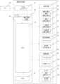
[全体構成]
図1は実施例1の定着装置を搭載した一例の画像形成装置である、インライン方式のカラー画像形成装置を示す構成図である。図1を用いて電子写真方式のカラー画像形成装置の動作を説明する。なお、第1ステーションをイエロー(Y)色のトナー画像形成用のステーション、第2ステーションをマゼンタ(M)色のトナー画像形成用のステーションとしている。また、第3ステーションをシアン(C)色のトナー画像形成用のステーション、第4ステーションをブラック(K)色のトナー画像形成用のステーションとしている。
[overall structure]
FIG. 1 is a configuration diagram showing an in-line color image forming apparatus, which is an example of an image forming apparatus equipped with the fixing device of the first embodiment. The operation of the electrophotographic color image forming apparatus will be described with reference to FIG. The first station is a yellow (Y) toner image forming station, and the second station is a magenta (M) toner image forming station. The third station is for forming a cyan (C) toner image, and the fourth station is for forming a black (K) toner image.
第1ステーションで、像担持体である感光ドラム1aは、OPC感光ドラムである。感光ドラム1aは金属円筒上に感光して電荷を生成するキャリア生成層、発生した電荷を輸送する電荷輸送層等からなる機能性有機材料が複数層積層されたものであり、最外層は電気的導電性が低くほぼ絶縁である。帯電手段である帯電ローラ2aが感光ドラム1aに当接され、感光ドラム1aの回転に伴い、従動回転しなから感光ドラム1a表面を均一に帯電する。帯電ローラ2aには直流電圧又は交流電圧を重畳した電圧が印加され、帯電ローラ2aと感光ドラム1a表面とのニップ部から、回転方向の上流側及び下流側の微小な空気ギャップにおいて放電が発生することにより感光ドラム1aが帯電される。クリーニングユニット3aは、後述する転写後に感光ドラム1a上に残ったトナーをクリーニングするユニットである。現像手段である現像ユニット8aは、現像ローラ4a、非磁性一成分トナー5a、現像剤塗布ブレード7aからなる。感光ドラム1a、帯電ローラ2a、クリーニングユニット3a、現像ユニット8aは、画像形成装置に対して着脱自在な一体型のプロセスカートリッジ9aとなっている。
At the first station, the
露光手段である露光装置11aは、レーザー光を多面鏡によって走査させるスキャナユニット又はLED(発光ダイオード)アレイから構成され、画像信号に基づいて変調された走査ビーム12aを感光ドラム1a上に照射する。また、帯電ローラ2aは、帯電ローラ2aへの電圧供給手段である帯電高電圧電源20aに接続されている。現像ローラ4aは、現像ローラ4aへの電圧供給手段である現像高電圧電源21aに接続されている。1次転写ローラ10aは、1次転写ローラ10aへの電圧供給手段である1次転写高電圧電源22aに接続されている。以上が第1ステーションの構成であり、第2、第3、第4ステーションも同様の構成をしている。他のステーションについて、第1ステーションと同一の機能を有する部品は同一の符号を付し、符号の添え字にステーションごとにb、c、dを付している。なお、以下の説明において、特定のステーションについて説明する場合を除き、添え字a、b、c、dを省略する。
An
中間転写ベルト13は、その張架部材として2次転写対向ローラ15、テンションローラ14、補助ローラ19の3本のローラにより支持されている。テンションローラ14のみバネで中間転写ベルト13を張る方向の力が加えられており、中間転写ベルト13に適当なテンション力が維持されるようになっている。2次転写対向ローラ15はメインモータ(不図示)からの回転駆動を受けて回転し、外周に巻かれた中間転写ベルト13が回動する。中間転写ベルト13は感光ドラム1a~1d(例えば、図1では反時計回り方向に回転)に対して順方向(例えば、図1では時計回り方向)に略同速度で移動する。また、中間転写ベルト13は、矢印方向(時計回り方向)に回転し、1次転写ローラ10は中間転写ベルト13をはさんで感光ドラム1と反対側に配置されて、中間転写ベルト13の移動に伴い従動回転する。中間転写ベルト13をはさんで感光ドラム1と1次転写ローラ10とが当接している位置を1次転写位置という。補助ローラ19、テンションローラ14及び2次転写対向ローラ15は電気的に接地されている。なお、第2~第4ステーションも1次転写ローラ10b~10dは第1ステーションの1次転写ローラ10aと同様の構成としているので説明を省略する。
The
次に実施例1の画像形成装置の画像形成動作を説明する。画像形成装置は待機状態時に印刷指令を受信すると、画像形成動作をスタートする。感光ドラム1や中間転写ベルト13等はメインモータ(不図示)によって所定のプロセススピードで矢印方向に回転を始める。感光ドラム1aは、帯電高電圧電源20aにより電圧が印加された帯電ローラ2aによって一様に帯電され、続いて露光装置11aから照射された走査ビーム12aによって画像情報に従った静電潜像が形成される。現像ユニット8a内のトナー5aは、現像剤塗布ブレード7aによって負極性に帯電されて現像ローラ4aに塗布される。そして、現像ローラ4aには、現像高電圧電源21aより所定の現像電圧が供給される。感光ドラム1aが回転して感光ドラム1a上に形成された静電潜像が現像ローラ4aに到達すると、静電潜像は負極性のトナーが付着することによって可視化され、感光ドラム1a上には第1色目(例えば、Y(イエロー))のトナー像が形成される。他の色M(マゼンタ)、C(シアン)、K(ブラック)の各ステーション(プロセスカートリッジ9b~9d)も同様に動作する。各色の1次転写位置間の距離に応じて、一定のタイミングでコントローラ(不図示)からの書き出し信号を遅らせながら、露光による静電潜像が各感光ドラム1a~1d上に形成される。それぞれの1次転写ローラ10a~10dにはトナーと逆極性の直流高電圧が印加される。以上の工程により、順に中間転写ベルト13にトナー像が転写されていき(以下、1次転写という)、中間転写ベルト13上に多重トナー像が形成される。
Next, the image forming operation of the image forming apparatus according to the first embodiment will be described. When the image forming apparatus receives a print command in a standby state, it starts an image forming operation. The photosensitive drum 1, the
その後、トナー像の作像に合わせて、カセット16に積載されている記録材である用紙Pは、給紙ソレノイド(不図示)によって回転駆動される給紙ローラ17により給送(ピックアップ)される。給送された用紙Pは搬送ローラによりレジストレーションローラ(以下、レジストローラという)18に搬送される。用紙Pは、中間転写ベルト13上のトナー像に同期して、レジストローラ18によって中間転写ベルト13と2次転写ローラ25との当接部である転写ニップ部へ搬送される。2次転写ローラ25には2次転写高電圧電源26により、トナーと逆極性の電圧が印加され、中間転写ベルト13上に担持された4色の多重トナー像が一括して用紙P上(記録材上)に転写される(以下、2次転写という)。用紙P上に未定着のトナー像が形成されるまでに寄与した部材(例えば、感光ドラム1等)は画像形成手段として機能する。一方、2次転写を終えた後、中間転写ベルト13上に残留したトナーは、クリーニングユニット27によって清掃される。2次転写が終了した後の用紙Pは、定着手段である定着装置50へと搬送され、トナー像の定着を受けて画像形成物(プリント、コピー)として排出トレー30へと排出される。定着装置50は本発明の加熱装置に相当する。定着装置50のフィルム51、ニップ形成部材52、加圧ローラ53、ヒータ54については後述する。
After that, in accordance with the formation of the toner image, the paper P loaded in the
[画像形成装置のブロック図]
図2は画像形成装置の動作を説明するブロック図であり、この図を参照しながら画像形成装置の印刷動作について説明する。ホストコンピュータであるPC110は、画像形成装置の内部にあるビデオコントローラ91に対して印刷指令を出力し、印刷画像の画像データをビデオコントローラ91に転送する役割を担う。
[Block Diagram of Image Forming Apparatus]
FIG. 2 is a block diagram for explaining the operation of the image forming apparatus, and the printing operation of the image forming apparatus will be explained with reference to this diagram. The
ビデオコントローラ91はPC110からの画像データを露光データに変換し、エンジンコントローラ92内にある露光制御装置93に転送する。露光制御装置93はCPU94から制御され、露光データのオンオフ、露光装置11の制御を行う。制御手段であるCPU94は印刷指令を受信すると画像形成シーケンスをスタートさせる。
The
エンジンコントローラ92にはCPU94、メモリ95等が搭載されており、予めプログラムされた動作を行う。高電圧電源96は上述の帯電高電圧電源20、現像高電圧電源21、1次転写高電圧電源22、2次転写高電圧電源26から構成される。また、電力制御部97は双方向サイリスタ(以下、トライアックという)56、電力を供給する発熱体を切り替える発熱体切り替え器57等から構成される。電力制御部97は、定着装置50において発熱する発熱体を選択し、供給する電力量を決定する。また、駆動装置98はメインモータ99、定着モータ100等から構成される。またセンサ101は定着装置50の温度を検知する定着温度センサ59、フラグを有し用紙Pの有無を検知する紙有無センサ102等からなり、センサ101の検知結果はCPU94に送信される。CPU94は画像形成装置内のセンサ101の検知結果を取得し、露光装置11、高電圧電源96、電力制御部97、駆動装置98を制御する。これにより、CPU94は、静電潜像の形成、現像されたトナー像の転写、用紙Pへのトナー像の定着等を行い、露光データがトナー像として用紙P上に印刷される画像形成工程の制御を行う。なお、本発明が適用される画像形成装置は、図1で説明した構成の画像形成装置に限定されるものではなく、異なる幅の用紙Pを印刷することが可能で、後述するヒータ54を有する定着装置50を備える画像形成装置であればよい。
The
[定着装置]
次に、実施例1における定着装置50の構成について図3を用いて説明する。ここで、長手方向とは、後述する用紙Pの搬送方向と略直交する加圧ローラ53の回転軸方向のことである。また、搬送方向に略直交する方向(長手方向)の用紙Pの長さを幅という。図3は、定着装置50の断面模式図である。
[Fixing device]
Next, the configuration of the fixing
図3左側から未定着のトナー像Tnを保持した用紙Pが、定着ニップ部Nにおいて図中左から右に向けて搬送されながら加熱されることにより、トナー像Tnが用紙Pに定着される。実施例1における定着装置50は、円筒状のフィルム51と、フィルム51を保持するニップ形成部材52と、フィルム51と共に定着ニップ部Nを形成する加圧ローラ53と、用紙Pを加熱するためのヒータ54とにより構成されている。
The toner image Tn is fixed on the paper P by heating the paper P holding the unfixed toner image Tn from the left side of FIG. The fixing
第1の回転体であるフィルム51は加熱回転体としての定着フィルムである。実施例1では、基層として、例えばポリイミドを用いている。基層の上に、シリコーンゴムからなる弾性層、PFAからなる離型層を用いている。フィルム51の回転によるニップ形成部材52及びヒータ54とフィルム51との間に生じる摩擦力を低減するために、フィルム51の内面には、グリスが塗布されている。
The
ニップ形成部材52はフィルム51を内側からガイドするとともに、フィルム51を介して加圧ローラ53との間で定着ニップ部Nを形成する役割を果たす。ニップ形成部材52は剛性・耐熱性・断熱性を有する部材であり、液晶ポリマー等により形成されている。フィルム51はこのニップ形成部材52に対して外嵌されている。第2の回転体である加圧ローラ53は加圧回転体としてのローラである。加圧ローラ53は、芯金53a、弾性層53b、離型層53cからなる。加圧ローラ53は、両端を回転可能に保持されており、定着モータ100(図2参照)によって回転駆動される。また、加圧ローラ53の回転により、フィルム51は従動回転する。加熱部材であるヒータ54は、ニップ形成部材52に保持され、フィルム51の内面と接している。定着温度センサ59はヒータ54の温度を検知する。ヒータ54については後述する。
The
[ヒータ及びヒータ制御回路]
実施例1の加熱装置に用いられるヒータ及びヒータ制御回路である電力制御部97を図4に示す。図4(a)に実施例1で用いられるヒータ54及び電力制御部97を示し、図4(b)にヒータ54のp-p’断面を示す。ヒータ54は主としてセラミック等で形成された基板54aの上(基板上)に実装された発熱体54b1~54b3、接点54d1~54d4、絶縁ガラス等の保護ガラス層54eで構成される。発熱体54b1~54b3は、商用交流電源等の交流電源55からの電力供給により発熱する抵抗体である。接点54d1及び接点54d2は、基板54aの長手方向における一方の端部に設けられ、接点54d3及び接点54d4は、基板54aの長手方向における他方の端部に設けられる。このように、基板54aの両端部に設けられる接点(電極)の数を、例えば2ずつと同じにする。保護ガラス層54eは、交流電源55にほぼ同電位である発熱体54b1~54b3からユーザーを絶縁するために設けられる。
[Heater and heater control circuit]
FIG. 4 shows a heater and a
第1の発熱体である発熱体54b1は、加熱装置において搬送することが可能な用紙Pのうち最大の幅を有する用紙Pにトナーを定着する際に主として用いられる発熱体である。ここで、幅とは、用紙Pの搬送方向に略直交する方向であり、ヒータ54の長手方向でもある。そのため、発熱体54b1の長手方向の長さ(寸法)はレターサイズの幅215.9mmより数mm程度長く設定される。発熱体54b1は、図4に示すように用紙Pの搬送方向(図4(a)の上下方向)の上流側及び下流側に、発熱体54b2、54b3を挟むように基板54aの両側に2本配置されている。基板54aの長手方向において、発熱体54b1の領域内に発熱体54b2及び発熱体54b3が配置されている。また発熱体54b1は、加熱装置が起動されるとき(すなわち、加熱装置が冷めた状態(室温と略同じ温度である状態)から所定の温度まで温度を立ち上げるとき)においても主として用いられる発熱体である。このため、発熱体54b1は、加熱装置の起動時に必要な電力が供給できるように設計される。発熱体54b1は、第1の接点である接点54d1と第4の接点である接点54d4に接続される。
The heating element 54b1, which is the first heating element, is a heating element that is mainly used when fixing toner on the sheet P having the largest width among the sheets P that can be conveyed in the heating device. Here, the width is a direction substantially orthogonal to the transport direction of the paper P, and is also the longitudinal direction of the
第2の発熱体である発熱体54b2はB5サイズの幅に対応した発熱体であり、発熱体54b2の長手方向の長さはB5サイズの幅182mmより数mm程度長く設定される。発熱体54b2は、第2の接点である接点54d2と接点54d4に接続される。第3の発熱体である発熱体54b3はA5サイズの幅に対応した発熱体であり、発熱体54b3の長手方向の長さはA5サイズの幅148mmより数mm程度長く設定される。発熱体54b3は、接点54d2と第3の接点である接点54d3に接続される。 The heating element 54b2, which is the second heating element, corresponds to the width of the B5 size, and the longitudinal length of the heating element 54b2 is set several mm longer than the B5 size width of 182 mm. The heating element 54b2 is connected to the second contacts 54d2 and 54d4. The heating element 54b3, which is the third heating element, corresponds to the width of the A5 size, and the longitudinal length of the heating element 54b3 is set several mm longer than the A5 size width of 148 mm. The heating element 54b3 is connected to the contact 54d2 and the third contact 54d3.
発熱体54b2と発熱体54b3は加熱装置がある程度温まった状態で使用されることを想定しており、発熱体54b2と発熱体54b3の定格電力は発熱体54b1の定格電力より低く設定される。つまり、発熱体54b1がメインヒータ、発熱体54b2、54b3がサブヒータという位置付けになる。したがって、起動時や負荷変動時を中心に、メインヒータ(発熱体54b1)とサブヒータ(発熱体54b2、54b3)とが切り替えられながら使用される。また、ヒータ54は用紙Pの幅方向に長さの異なる3系統の発熱体54b1~54b3を備えている。これにより、非通紙部昇温を抑制し、レターサイズやA4サイズ未満の幅の用紙P(以下、小サイズ紙という)が印刷される場合においても高い生産性を出すことを目的としている。したがって、この観点でもメインヒータ(発熱体54b1)とサブヒータ(発熱体54b2、54b3)が頻繁に切り替えられることでヒータ54の性能が発揮される。
It is assumed that the heating element 54b2 and the heating element 54b3 are used in a state where the heating device is warmed to some extent, and the rated power of the heating element 54b2 and the heating element 54b3 is set lower than the rated power of the heating element 54b1. That is, the heating element 54b1 is positioned as a main heater, and the heating elements 54b2 and 54b3 are positioned as sub-heaters. Therefore, the main heater (heating element 54b1) and the sub-heaters (heating elements 54b2, 54b3) are used while being switched, mainly at the time of start-up or load fluctuation. The
接点54d1は、第1のスイッチ手段である双方向サイリスタ(以下、トライアックという)56aを介して交流電源55の第1の極に接続される。接点54d2は、第2のスイッチ手段であるトライアック56bを介して交流電源55の第1の極に接続される。接点54d3は、第3のスイッチ手段であるトライアック56cを介して交流電源55の第1の極に接続される。接点54d4はトライアック等を介することなく交流電源55の第2の極に接続される。接点54d2と接点54d4とは、第1の切替手段であるa接点構成の電磁リレー57aを介して接続される。電磁リレー57aは、接点54d2と接点54d4との電気的な経路(電力供給経路)を接続状態(以下、短絡状態ともいう)又は開放状態にする。電磁リレー57aは、a接点構成の電磁リレーに限らず、b接点構成の電磁リレー、c接点構成の電磁リレー等、有接点スイッチを用いても構わない。更に、電磁リレー57aは、ソリッドステートリレー(SSR)、フォトモスリレー、トライアック等の無接点スイッチを用いても構わない。
The contact 54d1 is connected to the first pole of the
[電力供給経路]
図5に、実施例1のヒータ54と電力制御部97を用いる場合の、発熱体54b1~54b3への3通りの電流経路(電気的な経路であり電力供給経路でもある)を示す。
[Power supply path]
FIG. 5 shows three current paths (both electrical paths and power supply paths) to the heating elements 54b1 to 54b3 when the
(発熱体54b1への電力供給)
交流電源55から発熱体54b1に電力供給する場合の電流は、図5(a)の太線で示すルートで流れる。ヒータ54の温度をサーミスタ等の温度検知素子(不図示)で検知し、その温度情報に基づいてマイクロコンピュータ(不図示)からの指示に基づきトライアック56aが動作することで発熱体54b1が所定温度になるように制御される。発熱体54b1への電力供給はトライアック56b、56c及びa接点構成の電磁リレー57aに依らない。すなわち、発熱体54b1に電力供給する場合には、電磁リレー57aは開放状態であっても短絡状態であってもよい。なお、図5(a)では、一例として電磁リレー57aは開放状態となっている。
(Power supply to heating element 54b1)
When power is supplied from the
(発熱体54b2への電力供給)
交流電源55から発熱体54b2に電力供給する場合の電流は、図5(b)の太線で示すルートで流れる。発熱体54b2に電力供給を行う場合には、a接点構成の電磁リレー57aの接点を開放状態に設定する。開放状態のa接点構成の電磁リレー57aの接点インピーダンスは発熱体54b2より十分に大きいため、a接点構成の電磁リレー57aにはほぼ電流が流れず発熱体54b2のみを発熱させることができる。発熱体54b2に供給される電力はトライアック56bにより制御される。
(Power supply to heating element 54b2)
When power is supplied from the
(発熱体54b3への電力供給)
交流電源55から発熱体54b3に電力供給する場合の電流は、図5(c)の太線で示すルートで流れる。発熱体54b3に電力供給を行う場合には、a接点構成の電磁リレー57aの接点を短絡状態に設定することで、電流はほぼ全て発熱体54b3に流れる。短絡状態のa接点構成の電磁リレー57aの接点インピーダンスは発熱体54b2より十分に小さいため、発熱体54b2に電流がほぼ流れず発熱体54b3のみを発熱させることができる。発熱体54b3に供給される電力はトライアック56cにより制御される。
(Power supply to heating element 54b3)
When power is supplied from the
[電力供給経路の切り替え]
発熱体54b1への電力供給経路(図5(a))と発熱体54b2への電力供給経路(図5(b))との切り替えは、予めa接点構成の電磁リレー57aの接点を開放状態にしておく。電力供給経路(図5(a))と発熱体54b2への電力供給経路(図5(b))との切り替えは、トライアック56aとトライアック56bの無接点スイッチのみによって独立して制御することができる。無接点スイッチ(=トライアック)の動作だけで状態遷移できるため、電力供給経路(図5(a))と電力供給経路(図5(b))との間を高頻度で遷移したり、電力供給経路(図5(a))と電力供給経路(図5(b))を併用することができる。
[Switching the power supply path]
Switching between the power supply path to the heating element 54b1 (FIG. 5(a)) and the power supply path to the heating element 54b2 (FIG. 5(b)) is performed by opening the contact of the
発熱体54b1への電力供給経路(図5(a))と発熱体54b3への電力供給経路(図5(c))も同様である。予めa接点構成の電磁リレー57aの接点を短絡状態にし、トライアック56aとトライアック56bの制御によって経路を切り替える。無接点スイッチ(=トライアック)の動作だけで状態遷移できるため、電力供給経路(図5(a))と電力供給経路(図5(c))との間を高頻度で遷移したり、電力供給経路(図5(a))と電力供給経路(図5(c))を併用することができる。
The same applies to the power supply path (FIG. 5(a)) to the heating element 54b1 and the power supply path (FIG. 5(c)) to the heating element 54b3. The contacts of the
一方、発熱体54b2の電力供給経路(図5(b))と発熱体54b3の電力供給経路(図5(c))を切り替える際にはa接点構成の電磁リレー57aの状態を切り替える必要がある。ここで、a接点構成の電磁リレー57aの両端は発熱体54b2の両端に接続されている。これによりトライアック56bが非導通の時、a接点構成の電磁リレー57aが開放状態か短絡状態かに関わらずa接点構成の電磁リレー57aの両端は同電位になる。その為、a接点構成の電磁リレー57a動作時(電磁リレー57aはトライアック56bが非導通の時に動作させる)にa接点構成の電磁リレー57aの接点間でアーク放電が発生しない。したがって電磁ノイズが放射されず、アーク放電起因の接点摩耗(=寿命低下)も生じない。これにより、電力供給経路(図5(b))と電力供給経路(図5(c))は排他的であるものの、自由度高く切り替えることができる。
On the other hand, when switching between the power supply path for the heating element 54b2 (FIG. 5(b)) and the power supply path for the heating element 54b3 (FIG. 5(c)), it is necessary to switch the state of the
なお、実施例1のヒータ54及び電力制御部97を用いることで、電磁リレー動作時の電磁ノイズ放射や接点摩耗の解消のみならず、次のような効果も得ることができる。第一に、基板54aの両端部に設けられる電極(接点)の数を同じにできるので、基板54aの両端部に接続されるコネクタの共通化やセラミックヒータの長手方向での熱分布の均一化を図ることができる。第二に、3通りの状態遷移のうち2通りを無接点スイッチのみの制御で行うことができる。このため、有接点スイッチの動作待ち(リレーの接点バウンスによる接点安定待ち)の影響を受ける状態遷移を最小化し、ヒータ54の性能を最大化できるため、小サイズ紙の生産性を高めることができる。
なお、説明の便宜上、ノイズフィルタや省エネルギーのためにノイズフィルタ等を交流電源55から遮断する省エネルギー機能等は図示していないが、これら実機能上必要な回路を付与しても本発明の効果が変わるものではない。
By using the
For convenience of explanation, a noise filter and an energy saving function for cutting off the noise filter from the
このように、有接点スイッチを用いて電力供給経路を切り替える構成において、有接点スイッチからの電磁ノイズ放射や接点摩耗による寿命低下を解消することができる。以上、実施例1によれば、有接点スイッチを用いて給電する発熱体を切り替える場合であっても、有接点スイッチ動作時にアーク放電による電磁ノイズが放射されず、接点摩耗による寿命低下が生じない装置を提供することができる。 In this manner, in the configuration in which the contact switch is used to switch the power supply path, it is possible to eliminate the reduction in life due to electromagnetic noise radiation from the contact switch and wear of the contacts. As described above, according to the first embodiment, even when the heating element to be supplied with power is switched using the contact switch, electromagnetic noise due to arc discharge is not radiated when the contact switch is operated, and the service life is not shortened due to wear of the contacts. Equipment can be provided.
[ヒータ及び電力制御部]
実施例2の加熱装置に用いるヒータ54及び電力制御部97を図6に示す。実施例2に用いるヒータ54は実施例1のものと共通であるので説明を省略する。実施例2の電力制御部97は、図4のトライアック56bとトライアック56cを兼用して1つのトライアック56bを用い、代わりに第2の切替手段であるc接点構成の電磁リレー57bを付与した構成になっている。本実施例は、トライアック56bをどの発熱体に接続するかを選択する役割と、図4のa接点構成の電磁リレー57bの役割を、c接点構成の電磁リレー57bが兼ねていることが特徴である。
[Heater and power controller]
FIG. 6 shows the
具体的には、第2の切替手段であるc接点構成の電磁リレー57cは、接点54d2に接続された接点57c1、トライアック56b及び接点54d3に接続された接点57c2、交流電源55及び接点54d4に接続された接点57c3を有する。電磁リレー57cは、接点57c1と接点57c2とが接続された状態であるとき、発熱体54b2に電力が供給される状態となっている。電磁リレー57cは、接点57c1と接点57c3とが接続された状態であるとき、発熱体54b3に電力が供給される状態となっている。電磁リレー57cにおいて、接点57c1と接点57c3とが接続された状態であるとき、接点54d2と接点54d4とが接続された状態となる。このため、電磁リレー57cは、第1の切替手段としても機能する。
Specifically, the
[電流供給経路]
図7に、実施例2のヒータ54と電力制御部97を用いる場合の、発熱体54b1~54b3への3通りの電流供給経路を示す。交流電源55から発熱体54b1に電力供給する場合の電流は、図7(a)の太線で示すルートで流れる。交流電源55から発熱体54b1への電力供給はトライアック56aにより制御される。発熱体54b1への電力供給時、電磁リレー57cは接点57c1と接点57c2とが接続された状態であっても接点57c1と接点57c3とが接続された状態であってもよい。
[Current supply path]
FIG. 7 shows three current supply paths to the heating elements 54b1 to 54b3 when the
交流電源55から発熱体54b2に電力供給する場合の電流は、図7(b)の太線で示すルートで流れる。このとき、c接点構成の電磁リレー57cは接点57c1と接点57c2とが接続されてトライアック56b及び接点54d4側に接続され、トライアック56bにより交流電源55から発熱体54b2への電力供給が制御される。c接点構成の電磁リレー57cの接点インピーダンスは発熱体54b3より十分に小さいため、発熱体54b3にはほぼ電流が流れず発熱体54b2のみを発熱させることができる。
When power is supplied from the
交流電源55から発熱体54b3に電力供給する場合の電流は、図7(c)の太線で示すルートで流れる。このとき、c接点構成の電磁リレー57cは接点57c1と接点57c3とが接続されて接点54d3側に接続され、トライアック56bにより交流電源55から発熱体54b3への電力供給が制御される。c接点構成の電磁リレー57cの接点インピーダンスは発熱体54b2より十分に小さいため、発熱体54b2にはほぼ電流が流れず発熱体54b3のみを発熱させることができる。
When power is supplied from the
c接点構成の電磁リレー57cは、接点54d2と接点54d4との短絡(図7(b))及び開放(図7(c))により、発熱体54b2を短絡(図7(b))及び開放(図7(c))を行う第1の機能を有している。また、c接点構成の電磁リレー57cは、発熱体54b3を短絡(図7(c))及び開放(図7(b))する第2の機能を有している。すなわち、c接点構成の電磁リレー57cは、第1の機能と第2の機能とを兼ねている点が特徴である。
The
ここで、c接点構成の電磁リレー57cの接点57c1と接点57c2は発熱体54b3の両端に接続されている。これによりトライアック56bが非導通の時、接点57c1と接点57c2は、開放状態か短絡状態かに関わらず同電位になる。さらに、c接点構成の電磁リレー57cの接点57c1と57c3は発熱体54b2の両端に接続されている。これによりトライアック56bが非導通の時、接点57c1と接点57c3は、開放状態か短絡状態かに関わらず同電位になる。即ち、トライアック56bが非導通の時、接点57c1、57c2、57c3は全て同電位となる。これにより、c接点構成の電磁リレー57c動作時(電磁リレー57cはトライアック56bが非導通の時に動作させる)にc接点構成の電磁リレー57cの何れの接点間でもアーク放電が発生しない。したがってc接点構成の電磁リレー57c動作時に電磁ノイズが放射されず、アーク放電起因の接点摩耗(寿命低下)も生じない。
Here, the contacts 57c1 and 57c2 of the
実施例2の構成は、実施例1の図4に示すa接点構成の電磁リレー57aとトライアック56cの機能を、c接点構成の電磁リレー57cだけで担っていることと同義である。したがって、実施例2の構成を選択することで、回路部品の点数を更に抑えつつ、実施例1と同様の機能を確保できる。
In the configuration of the second embodiment, the functions of the
なお、実施例1の構成ではトライアック56bが導通状態、かつa接点構成の電磁リレー57aの接点が短絡状態という、正常でない状態になると交流電源55の出力端が短絡状態になる。この場合、電流ヒューズ(不図示)の溶断を招くおそれがないとは言えず、装置の破壊を招くおそれもある。それに対し、実施例2の構成では交流電源55の出力端が短絡されることはなく、より信頼性の高い構成であると言える。
In the configuration of the first embodiment, when the
このように、有接点スイッチを用いて電力供給経路を切り替える構成において、有接点スイッチからの電磁ノイズ放射や接点摩耗による寿命低下を解消することができる。加えて、実施例1よりも安価かつ省スペースで信頼性の高い装置を提供できる。以上、実施例2によれば、有接点スイッチを用いて給電する発熱体を切り替える場合であっても、有接点スイッチ動作時にアーク放電による電磁ノイズが放射されず、接点摩耗による寿命低下が生じない装置を提供することができる。 In this manner, in the configuration in which the contact switch is used to switch the power supply path, it is possible to eliminate the reduction in life due to electromagnetic noise radiation from the contact switch and wear of the contacts. In addition, it is possible to provide a device that is less expensive, space-saving, and highly reliable than the first embodiment. As described above, according to the second embodiment, even when the heating element to be supplied with power is switched using the contact switch, electromagnetic noise due to arc discharge is not radiated when the contact switch is operated, and the service life is not shortened due to wear of the contacts. Equipment can be provided.
[ヒータ及び電力制御部]
実施例3の加熱装置に用いるヒータ54及び電力制御部97を図8に示す。ヒータ54の発熱体54b1、54b3は実施例1~3と同じである。第2の発熱体である発熱体54b4の長手方向の長さは、実施例1~3のヒータ54の発熱体54b2と発熱体54b3との差分の長さである。発熱体54b4は、長手方向に直交する方向において発熱体54b3の両側に2本配置されている。すなわち、発熱体54b4の長手方向の長さと発熱体54b3の長手方向の長さの合計がヒータ54の発熱体54b2の長手方向の長さと同じになるように設定されている。後述するが、発熱体54b3と発熱体54b4とを1つの発熱体とみなして使用する場合がある。このため、発熱体54b3と発熱体54b4の長手方向の単位長さ辺りの抵抗値は等しく設定されている必要がある。
[Heater and power controller]
FIG. 8 shows the
[電流供給経路]
図9に、実施例3のヒータ54と電力制御部97を用いる場合の、発熱体への3通りの電流経路を示す。交流電源55から発熱体54b1に電力供給する場合の電流は、図9(a)の太線で示すルートで流れる。交流電源55から発熱体54b1への電力供給はトライアック56aにより制御される。発熱体54b1に電力供給する場合には、電磁リレー57aは開放状態であっても短絡状態であってもよい。
[Current supply path]
FIG. 9 shows three current paths to the heating element when using the
交流電源55から発熱体54b3と発熱体54b4とに電力供給する場合の電流は、図9(b)の太線で示すルートで流れる。このとき、a接点構成の電磁リレー57aの接点は開放状態に設定され、電流は発熱体54b3と発熱体54b4とを直列に流れる。以下、直列に接続された発熱体54b3、54b4を直列発熱体ということもある。これにより発熱体54b3と発熱体54b4とは共に発熱し、ヒータ54の長手方向では実施例1~3の発熱体54b2と同様の範囲に熱を与えることができ、例えばB5サイズの用紙幅に対応した1つの発熱体とみなすことができる。交流電源55から発熱体54b3と発熱体54b4との直列発熱体への電力供給は、トライアック56bにより制御される。開放状態のa接点構成の電磁リレー57aの接点インピーダンスは発熱体54b4より十分に大きいため、ほぼa接点構成の電磁リレー57aには電流が流れず発熱体54b3と発熱体54b4のみを発熱させることができる。
When power is supplied from the
交流電源55から発熱体54b3に電力供給する場合の電流は図9(c)の太線で示すルートで流れる。このとき、a接点構成の電磁リレー57aの接点は短絡状態に設定され、トライアック56bにより交流電源55から発熱体54b3への電力供給が制御される。短絡状態のa接点構成の電磁リレー57aの接点インピーダンスは発熱体54b4より十分に小さいため、発熱体54b4にはほぼ電流が流れず発熱体54b3のみを発熱させることができる。ここで、a接点構成の電磁リレー57aの両端は発熱体54b4の両端に接続されている。その為、実施例1と同じくa接点構成の電磁リレー57a動作時に電磁ノイズが放射されず、アーク放電起因の接点摩耗(=寿命低下)も生じない。
実施例3の構成は、電磁リレー57aとして、実施例2で用いたc接点構成の電磁リレー57cよりも安価で小型なa接点構成の電磁リレーを用いることができるので、電力制御部97を安価かつ小型にできるメリットがある。
When power is supplied from the
In the configuration of the third embodiment, the
実施例3のヒータ54は、長手方向における発熱体54b3と発熱体54b4との2ヶ所の境界部で熱の分布に段差(熱の分布の不連続性)が生じないように設計する必要がある。実際には、2ヶ所の境界部において各発熱体54b3、54b4を例えばテーパー形状にする等の工夫を施すのが望ましい。
The
また、発熱体54b3と発熱体54b4の抵抗値に関して制約が生じる点にも留意しなければならない。発熱体54b3の抵抗値をR103、発熱体54b4の抵抗値をR114とする。R103とR114の直列抵抗体の抵抗値Rsは、Rs=R103+R114という関係を有するため、必ずRs>R103である必要がある。しかし、発熱体54b3よりも広い幅の用紙Pを加熱する直列発熱体(抵抗値Rs)の方が発熱体54b3よりも必要とされる電力が大きく、抵抗値としてはR103よりRsの方が低い抵抗値であることを求められる。したがって、初めに直列発熱体の抵抗値Rsが決定され、次に発熱体54b3の抵抗値R103は抵抗値Rsより低い値が設定される。つまり、発熱体54b3の抵抗値R103は必要とされる電力から算出される抵抗値より低い抵抗値に設定することが求められ、発熱体54b3はスペックオーバーな設定とならざるを得ない。実施例3の構成を用いる場合にはこの点を考慮し、発熱体54b3に対して十分な保護システム等を確立する等が必要になる。 It should also be noted that there are restrictions on the resistance values of the heating elements 54b3 and 54b4. Let R103 be the resistance value of the heating element 54b3, and R114 be the resistance value of the heating element 54b4. Since the resistance value Rs of the series resistors R103 and R114 has a relationship of Rs=R103+R114, it is necessary that Rs>R103. However, the series heating element (resistance value Rs) that heats the paper P having a wider width than the heating element 54b3 requires more electric power than the heating element 54b3, and the resistance value of Rs is lower than that of R103. It is required to be a resistance value. Therefore, the resistance value Rs of the series heating element is determined first, and then the resistance value R103 of the heating element 54b3 is set to a value lower than the resistance value Rs. In other words, the resistance value R103 of the heating element 54b3 is required to be set to a resistance value lower than the resistance value calculated from the required electric power, and the heating element 54b3 must be set beyond the specifications. When using the configuration of the third embodiment, it is necessary to consider this point and establish a sufficient protection system for the heating element 54b3.
このように、有接点スイッチを用いて電力供給経路を切り替える構成において、有接点スイッチからの電磁ノイズ放射や接点摩耗による寿命低下を解消することができる。加えて、実施例2よりも電力制御部97を安価かつ小型にできる。以上、実施例3によれば、有接点スイッチを用いて給電する発熱体を切り替える場合であっても、有接点スイッチ動作時にアーク放電による電磁ノイズが放射されず、接点摩耗による寿命低下が生じない装置を提供することができる。
In this manner, in the configuration in which the contact switch is used to switch the power supply path, it is possible to eliminate the reduction in life due to electromagnetic noise radiation from the contact switch and wear of the contacts. In addition, the
[ヒータ及び電力供給部]
実施例4の加熱装置に用いるヒータ54及び電力供給部を図10に示す。ヒータ54上に形成される、第2の発熱体である発熱体54b5の長手方向の長さは、実施例1~4で用いたヒータ54の発熱体54b3と同じである。しかし、発熱体54b5が接続される接点が、接点54d2と接点54d4である点が異なる。また、第3の発熱体である発熱体54b6の長手方向の長さや形状(2つに分離されている形状)も実施例3で用いたヒータ54の発熱体54b4と同じであるが、接続される接点が、接点54d2及び接点54d3である点が異なる。また、第3の切替手段である電磁リレー57dは、a接点構成の電磁リレーであり、一端が接点54d3に接続され、他端が交流電源55の第2の極及び接点54d4に接続されている。
[Heater and power supply]
FIG. 10 shows the
[電流供給経路]
図11に、実施例4のヒータ54と電力制御部97を用いる場合の、発熱体への3通りの電流経路を示す。交流電源55から発熱体54b1に電力供給する場合の電流は、図11(a)の太線で示すルートで流れる。交流電源55から発熱体54b1への電力供給はトライアック56aにより制御される。発熱体54b1に電力供給する場合には、電磁リレー57dは開放状態であっても短絡状態であってもよい。
[Current supply path]
FIG. 11 shows three current paths to the heating element when using the
交流電源55から発熱体54b5と発熱体54b6に電力供給する場合の電流は、図11(b)の太線で示すルートで流れる。このとき、a接点構成の電磁リレー57dの接点は短絡状態に設定され、電流は発熱体54b5と発熱体54b6とを並列に流れる。以下、並列に接続された発熱体54b5、54b6を並列発熱体ということもある。これにより発熱体54b5と発熱体54b6とは共に発熱し、ヒータ54の長手方向では例えばB5サイズの用紙幅に対応した1つの発熱体とみなすことができる。交流電源55から発熱体54b5と発熱体54b6の並列発熱体への電力供給は、トライアック56bにより制御される。
When power is supplied from the
交流電源55から発熱体54b5に電力供給する場合の電流は、図11(c)の太線で示すルートで流れる。このとき、a接点構成の電磁リレー57dの接点は開放状態に設定され、トライアック56bにより交流電源55から発熱体54b5への電力供給が制御される。開放状態のa接点構成の電磁リレー57dの接点インピーダンスは発熱体54b5より十分に大きいため、発熱体54b6にはほぼ電流が流れず発熱体54b5のみを発熱させることができる。ここで、a接点構成の電磁リレー57dの両端は発熱体54b5と発熱体54b6の直列接続発熱体の両端に接続されている。その為、実施例1と同じくa接点構成の電磁リレー57a動作時に電磁ノイズが放射されず、アーク放電起因の接点摩耗(=寿命低下)も生じない。
When power is supplied from the
実施例4の構成も実施例3と同様に、発熱体54b5と発熱体54b6の抵抗値に関して制約が生じる。発熱体54b5の抵抗値をR116、発熱体54b6の抵抗値をR117とする。発熱体54b5、54b6の並列発熱体の抵抗値Rpは、1/Rp=(1/R116)+(1/R117)という関係になる。仮に発熱体54b5の抵抗値R116を110Ω、並列発熱体の抵抗値Rpを90Ωに設定する場合、発熱体54b6の抵抗値R117を495Ωにする必要がある。発熱体54b6には発熱体54b5よりも抵抗率の高い(具体的には2倍程度)の抵抗材をする必要がある。このように、実施例3及び実施例4で用いたヒータ54にはそれぞれ発熱体の抵抗値の設定に課せられる制約が異なる。このため、設計条件に合致した手段を選択することが望ましい。
In the configuration of the fourth embodiment, as in the third embodiment, there are restrictions on the resistance values of the heating elements 54b5 and 54b6. Let R116 be the resistance value of the heating element 54b5, and R117 be the resistance value of the heating element 54b6. The resistance value Rp of the parallel heating elements of the heating elements 54b5 and 54b6 has a relationship of 1/Rp=(1/R116)+(1/R117). If the resistance value R116 of the heating element 54b5 is set to 110Ω and the resistance value Rp of the parallel heating element is set to 90Ω, it is necessary to set the resistance value R117 of the heating element 54b6 to 495Ω. The heating element 54b6 needs to be made of a resistance material having a higher resistivity (specifically, about twice as high) as that of the heating element 54b5. As described above, the
このように、有接点スイッチを用いて電力供給経路を切り替える構成において、有接点スイッチからの電磁ノイズ放射や接点摩耗による寿命低下を解消することができる。以上、実施例4によれば、有接点スイッチを用いて給電する発熱体を切り替える場合であっても、有接点スイッチ動作時にアーク放電による電磁ノイズが放射されず、接点摩耗による寿命低下が生じない装置を提供することができる。 In this manner, in the configuration in which the contact switch is used to switch the power supply path, it is possible to eliminate the reduction in life due to electromagnetic noise radiation from the contact switch and wear of the contacts. As described above, according to the fourth embodiment, even when the heating element to be supplied with power is switched using the contact switch, electromagnetic noise due to arc discharge is not emitted when the contact switch is operated, and the service life is not shortened due to wear of the contacts. Equipment can be provided.
54b1~54b3 発熱体
54d1~54d4 接点
56a~56c 双方向サイリスタ
57a 電磁リレー
54b1 to 54b3 heating elements 54d1 to 54d4
Claims (27)
複数の接点と、
前記複数の発熱体と前記複数の接点とが配置される基板と、
第1の切替手段と、
を有する加熱装置であって、
前記複数の発熱体は、第1の発熱体と、前記第1の発熱体よりも長手方向における長さが短い第2の発熱体及び第3の発熱体と、を含み、
前記複数の接点は、前記第1の発熱体の一端が接続された第1の接点と、前記第2の発熱体の一端及び前記第3の発熱体の一端が接続された第2の接点と、前記第3の発熱体の他端が接続された第3の接点と、前記第1の発熱体の他端及び前記第2の発熱体の他端が接続された第4の接点と、を含み、
前記第1の切替手段は、前記第2の接点と前記第4の接点との電気的な経路を接続状態又は開放状態に切り替えることが可能であり、
前記基板の長手方向において、前記第1の接点、前記第2の接点、前記第3の接点、及び前記第4の接点は、前記第1の発熱体、前記第2の発熱体、及び前記第3の発熱体よりも、前記基板の端部側に配置されることを特徴とする加熱装置。 a plurality of heating elements;
a plurality of contacts;
a substrate on which the plurality of heating elements and the plurality of contacts are arranged;
a first switching means;
A heating device comprising
The plurality of heat generating elements includes a first heat generating element, and a second heat generating element and a third heat generating element each having a length in the longitudinal direction shorter than that of the first heat generating element,
The plurality of contacts include a first contact to which one end of the first heating element is connected, and a second contact to which one end of the second heating element and one end of the third heating element are connected. , a third contact to which the other end of the third heating element is connected, and a fourth contact to which the other end of the first heating element and the other end of the second heating element are connected, including
The first switching means is capable of switching an electrical path between the second contact and the fourth contact between a connected state and an open state,
In the longitudinal direction of the substrate, the first contact, the second contact, the third contact, and the fourth contact are aligned with the first heating element, the second heating element, and the fourth heating element. 3. A heating device characterized in that it is arranged closer to the edge of the substrate than the heating element of 3.
2本の前記第1の発熱体は、一端が前記第1の接点に接続され、他端が前記第4の接点に接続されていることを特徴とする請求項1に記載の加熱装置。 Two of the first heating elements are arranged on both sides of the substrate in a direction orthogonal to the longitudinal direction,
2. The heating device according to claim 1, wherein the two first heating elements have one end connected to the first contact and the other end connected to the fourth contact.
一端が前記第2の接点に接続され、他端が前記第1の極に接続され、前記第2の発熱体への電力の供給を制御するための第2のスイッチ手段と、
一端が前記第3の接点に接続され、他端が前記第1の極に接続され、前記第3の発熱体への電力の供給を制御するための第3のスイッチ手段と、
を備えることを特徴とする請求項1から請求項3のいずれか1項に記載の加熱装置。 a first switch means, one end of which is connected to the first contact and the other end of which is connected to a first pole of an AC power supply, for controlling power supply to the first heating element;
a second switch means having one end connected to the second contact and the other end connected to the first pole for controlling power supply to the second heating element;
third switch means, one end of which is connected to the third contact and the other end of which is connected to the first pole, for controlling power supply to the third heating element;
The heating device according to any one of claims 1 to 3, comprising:
前記第2の発熱体は、前記第1の切替手段を前記開放状態とし、前記第2のスイッチ手段、前記第2の接点及び前記第4の接点を介した電力供給経路で電力を供給され、
前記第3の発熱体は、前記第1の切替手段を前記接続状態とし、前記第3のスイッチ手段、前記第2の接点及び前記第3の接点を介した電力供給経路で電力を供給されることを特徴とする請求項4に記載の加熱装置。 the first heating element is supplied with power through a power supply path via the first switch means, the first contact, and the fourth contact regardless of the state of the first switching means;
the second heating element is supplied with power through a power supply path through the second switch means, the second contact, and the fourth contact, with the first switching means being in the open state;
The third heating element is supplied with power through a power supply path via the third switch means, the second contact, and the third contact while the first switching means is in the connected state. 5. The heating device according to claim 4, characterized in that:
前記第2の発熱体又は前記第3の発熱体への電力の供給を制御するための第2のスイッチ手段と、
を有し、
前記第1の切替手段は、一端が前記第2の接点に接続され、他端が前記第2のスイッチ手段に接続された状態と前記交流電源の第2の極に接続された状態とを切り替えることが可能であり、
前記第2のスイッチ手段は、前記第1の切替手段の他端が前記第2のスイッチ手段に接続された状態では前記第2の発熱体への電力の供給を制御し、前記第1の切替手段の他端が前記第2の極に接続された状態では前記第3の発熱体への電力の供給を制御することを特徴とする請求項1から請求項3のいずれか1項に記載の加熱装置。 a first switch means, one end of which is connected to the first contact and the other end of which is connected to a first pole of an AC power supply, for controlling power supply to the first heating element;
a second switch means for controlling power supply to the second heating element or the third heating element;
has
The first switching means switches between a state in which one end is connected to the second contact and the other end is connected to the second switch means and a state in which it is connected to the second pole of the AC power supply. is possible and
The second switch means controls power supply to the second heating element in a state where the other end of the first switch means is connected to the second switch means. 4. The device according to any one of claims 1 to 3, wherein the power supply to the third heating element is controlled in a state where the other end of the means is connected to the second pole. heating device.
前記第2の発熱体は、前記第1の切替手段の他端を前記第2のスイッチ手段に接続した状態とし、前記第2のスイッチ手段、前記第2の接点及び前記第4の接点を介した電力供給経路で電力を供給され、
前記第3の発熱体は、前記第1の切替手段の他端を前記交流電源の前記第2の極に接続した状態とし、前記第2のスイッチ手段、前記第2の接点及び前記第3の接点を介した電力供給経路で電力を供給されることを特徴とする請求項6に記載の加熱装置。 the first heating element is supplied with power through a power supply path via the first switch means, the first contact, and the fourth contact regardless of the state of the first switching means;
The second heating element connects the other end of the first switching means to the second switching means, and the second heating element is connected to the second switching means, the second contact and the fourth contact. powered by a power supply path that
The third heating element connects the other end of the first switching means to the second pole of the AC power supply, and the second switching means, the second contact, and the third 7. The heating device according to claim 6, wherein power is supplied through a power supply path through contacts.
一端が前記第3の接点に接続され、他端が前記第1の極に接続され、前記第2の発熱体及び前記第3の発熱体への電力の供給を制御する、又は前記第3の発熱体への電力の供給を制御するための第2のスイッチ手段と、
を備え、
前記第2のスイッチ手段は、前記第1の切替手段が前記開放状態では前記第2の発熱体と前記第3の発熱体とが直列に接続された発熱体への電力の供給を制御し、前記第1の切替手段が前記接続状態では前記第3の発熱体への電力の供給を制御することを特徴とする請求項1から請求項3のいずれか1項に記載の加熱装置。 a first switch means, one end of which is connected to the first contact and the other end of which is connected to a first pole of an AC power supply, for controlling power supply to the first heating element;
One end is connected to the third contact and the other end is connected to the first pole to control power supply to the second heating element and the third heating element , or a second switch means for controlling the supply of power to the heating element of 3 ;
with
the second switch means controls power supply to a heat generating element in which the second heat generating element and the third heat generating element are connected in series when the first switching means is in the open state; 4. The heating device according to claim 1, wherein said first switching means controls power supply to said third heating element in said connected state.
前記第2の発熱体及び前記第3の発熱体は、前記第1の切替手段を前記開放状態とし、前記第2のスイッチ手段、前記第3の接点及び前記第4の接点を介した電力供給経路で電力を供給され、
前記第3の発熱体は、前記第1の切替手段を前記接続状態とし、前記第2のスイッチ手段、前記第2の接点及び前記第3の接点を介した電力供給経路で電力を供給されることを特徴とする請求項10に記載の加熱装置。 the first heating element is supplied with power through a power supply path via the first switch means, the first contact, and the fourth contact regardless of the state of the first switching means;
The second heating element and the third heating element set the first switching means to the open state, and supply power through the second switching means, the third contact, and the fourth contact. powered by the path,
The third heating element is supplied with power through a power supply path via the second switch means, the second contact, and the third contact while the first switching means is in the connected state. 11. The heating device according to claim 10, characterized in that:
前記第1の切替手段が前記開放状態であるときの前記第1の切替手段のインピーダンスは、前記第2の発熱体のインピーダンスより大きいことを特徴とする請求項4、請求項5、請求項9から請求項11のいずれか1項に記載の加熱装置。 the impedance of the first switching means when the first switching means is in the connected state is smaller than the impedance of the second heating element;
Claims 4, 5 and 9, wherein the impedance of said first switching means when said first switching means is in said open state is greater than the impedance of said second heating element. 12. A heating device according to any one of claims 11 to 11.
前記第1の切替手段の他端が前記第2の極に接続されているときの前記第1の切替手段のインピーダンスは、前記第2の発熱体のインピーダンスよりも小さいことを特徴とする請求項6又は請求項7に記載の加熱装置。 the impedance of the first switching means when the other end of the first switching means is connected to the second switching means is smaller than the impedance of the third heating element;
3. The impedance of said first switching means when the other end of said first switching means is connected to said second pole is smaller than the impedance of said second heating element. The heating device according to claim 6 or claim 7.
複数の接点と、
前記複数の発熱体と前記複数の接点とが配置される基板と、
第2の切替手段と、
を有する加熱装置であって、
前記複数の発熱体は、第1の発熱体と、前記第1の発熱体よりも長手方向における長さが短い第2の発熱体及び第3の発熱体と、を含み、
前記複数の接点は、前記第1の発熱体の一端が接続された第1の接点と、前記第2の発熱体の一端及び前記第3の発熱体の一端が接続された第2の接点と、前記第3の発熱体の他端が接続された第3の接点と、前記第1の発熱体の他端及び前記第2の発熱体の他端が接続された第4の接点と、を含み、
前記第2の切替手段は、前記第3の接点と前記第4の接点との電気的な経路を接続状態又は開放状態に切り替えることが可能であり、
前記基板の長手方向において、前記第1の接点、前記第2の接点、前記第3の接点、及び前記第4の接点は、前記第1の発熱体、前記第2の発熱体、及び前記第3の発熱体よりも、前記基板の端部側に配置されることを特徴とする加熱装置。 a plurality of heating elements;
a plurality of contacts;
a substrate on which the plurality of heating elements and the plurality of contacts are arranged;
a second switching means;
A heating device comprising
The plurality of heat generating elements includes a first heat generating element, and a second heat generating element and a third heat generating element each having a length in the longitudinal direction shorter than that of the first heat generating element,
The plurality of contacts include a first contact to which one end of the first heating element is connected, and a second contact to which one end of the second heating element and one end of the third heating element are connected. , a third contact to which the other end of the third heating element is connected, and a fourth contact to which the other end of the first heating element and the other end of the second heating element are connected, including
The second switching means is capable of switching an electrical path between the third contact and the fourth contact between a connected state and an open state,
In the longitudinal direction of the substrate, the first contact, the second contact, the third contact, and the fourth contact are aligned with the first heating element, the second heating element, and the fourth heating element. 3. A heating device characterized in that it is arranged closer to the edge of the substrate than the heating element of 3.
2本の前記第1の発熱体は、一端が前記第1の接点に接続され、他端が前記第4の接点に接続されていることを特徴とする請求項15に記載の加熱装置。 Two of the first heating elements are arranged on both sides of the substrate in a direction orthogonal to the longitudinal direction,
16. The heating device according to claim 15, wherein the two first heating elements have one end connected to the first contact and the other end connected to the fourth contact.
一端が前記第2の接点に接続され、他端が前記第1の極に接続され、前記第2の発熱体及び前記第3の発熱体への電力の供給を制御する、又は前記第2の発熱体への電力の供給を制御するための第2のスイッチ手段と、
を備え、
前記第2のスイッチ手段は、前記第2の切替手段が前記接続状態では前記第2の発熱体と前記第3の発熱体とが並列に接続された発熱体への電力の供給を制御し、前記第2の切替手段が前記開放状態では前記第2の発熱体への電力の供給を制御することを特徴とする請求項15から請求項17のいずれか1項に記載の加熱装置。 a first switch means, one end of which is connected to the first contact and the other end of which is connected to a first pole of an AC power supply, for controlling power supply to the first heating element;
One end is connected to the second contact and the other end is connected to the first pole to control power supply to the second heating element and the third heating element , or a second switch means for controlling the supply of power to the two heating elements ;
with
The second switch means controls power supply to a heating element in which the second heating element and the third heating element are connected in parallel when the second switching means is in the connected state, 18. The heating device according to any one of claims 15 to 17, wherein said second switching means controls power supply to said second heating element in said open state.
前記第2の発熱体及び前記第3の発熱体は、前記第2の切替手段を前記接続状態とし、前記第2のスイッチ手段、前記第2の接点、前記第3の接点及び前記第4の接点を介した電力供給経路で電力を供給され、
前記第2の発熱体は、前記第2の切替手段を前記開放状態とし、前記第2のスイッチ手段、前記第2の接点及び前記第4の接点を介した電力供給経路で電力を供給されることを特徴とする請求項19に記載の加熱装置。 the first heating element is supplied with power through a power supply path via the first switch means, the first contact, and the fourth contact regardless of the state of the second switching means;
The second heat generating element and the third heat generating element set the second switching means to the connected state, and switch the second switch means, the second contact, the third contact and the fourth contact. Powered by the power supply path through the contacts,
The second heating element is supplied with power through a power supply path via the second switch means, the second contact, and the fourth contact, with the second switching means in the open state. 20. The heating device according to claim 19, characterized by:
前記第2の切替手段が前記開放状態であるときの前記第2の切替手段のインピーダンスは、前記第2の発熱体のインピーダンスより大きいことを特徴とする請求項21に記載の加熱装置。 the impedance of the second switching means when the second switching means is in the connected state is smaller than the impedance of the second heating element;
22. The heating device according to claim 21, wherein the impedance of said second switching means when said second switching means is in said open state is higher than the impedance of said second heating element.
前記第1の回転体とともにニップ部を形成する第2の回転体と、
を備えることを特徴とする請求項23に記載の定着装置。 a first rotating body heated by the plurality of heating elements;
a second rotating body forming a nip with the first rotating body;
24. The fixing device of claim 23, comprising:
前記ヒータは、前記フィルムの内部空間に配置されており、前記ヒータと前記第2の回転体により前記フィルムを挟持しており、
記録材上の画像は、前記フィルムと前記第2の回転体との間に形成されたニップ部で前記フィルムを介して加熱されることを特徴とする請求項25に記載の定着装置。 A heater having the substrate,
The heater is arranged in an internal space of the film, and the film is sandwiched between the heater and the second rotating body,
26. A fixing device according to claim 25, wherein the image on the recording material is heated through the film at a nip portion formed between the film and the second rotating body.
請求項23から請求項26のいずれか1項に記載の定着装置と、
を備えることを特徴とする画像形成装置。 an image forming means for forming a toner image on a recording material;
a fixing device according to any one of claims 23 to 26;
An image forming apparatus comprising:
Priority Applications (11)
| Application Number | Priority Date | Filing Date | Title |
|---|---|---|---|
| JP2019006465A JP7282525B2 (en) | 2019-01-18 | 2019-01-18 | Heating device, fixing device and image forming device |
| EP20151917.0A EP3683632A1 (en) | 2019-01-18 | 2020-01-15 | Heating apparatus including a plurality of heat generation members, fixing apparatus, and image forming apparatus |
| US16/744,609 US11156945B2 (en) | 2019-01-18 | 2020-01-16 | Heating apparatus including a plurality of heat generation members, fixing apparatus, and image forming apparatus |
| CN202010051985.6A CN111459001B (en) | 2019-01-18 | 2020-01-17 | Heating apparatus including a plurality of heat generating members, fixing apparatus, and image forming apparatus |
| CN202310659599.9A CN116679539A (en) | 2019-01-18 | 2020-01-17 | Heating apparatus and image forming apparatus |
| KR1020200006375A KR20200090129A (en) | 2019-01-18 | 2020-01-17 | Heating apparatus including a plurality of heat generation members, fixing apparatus, and image forming apparatus |
| CN202310662958.6A CN116610016A (en) | 2019-01-18 | 2020-01-17 | Heating apparatus and image forming apparatus |
| US17/227,588 US11520263B2 (en) | 2019-01-18 | 2021-04-12 | Heating apparatus including a plurality of heat generation members, fixing apparatus, and image forming apparatus |
| US17/979,222 US11774888B2 (en) | 2019-01-18 | 2022-11-02 | Heating apparatus including a plurality of heat generation members, fixing apparatus, and image forming apparatus |
| JP2023079884A JP2023099642A (en) | 2019-01-18 | 2023-05-15 | Heating device and image forming apparatus |
| US18/454,969 US20230393502A1 (en) | 2019-01-18 | 2023-08-24 | Heating apparatus including a plurality of heat generation members, fixing apparatus, and image forming apparatus |
Applications Claiming Priority (1)
| Application Number | Priority Date | Filing Date | Title |
|---|---|---|---|
| JP2019006465A JP7282525B2 (en) | 2019-01-18 | 2019-01-18 | Heating device, fixing device and image forming device |
Related Child Applications (1)
| Application Number | Title | Priority Date | Filing Date |
|---|---|---|---|
| JP2023079884A Division JP2023099642A (en) | 2019-01-18 | 2023-05-15 | Heating device and image forming apparatus |
Publications (3)
| Publication Number | Publication Date |
|---|---|
| JP2020115185A JP2020115185A (en) | 2020-07-30 |
| JP2020115185A5 JP2020115185A5 (en) | 2022-01-25 |
| JP7282525B2 true JP7282525B2 (en) | 2023-05-29 |
Family
ID=69172660
Family Applications (2)
| Application Number | Title | Priority Date | Filing Date |
|---|---|---|---|
| JP2019006465A Active JP7282525B2 (en) | 2019-01-18 | 2019-01-18 | Heating device, fixing device and image forming device |
| JP2023079884A Pending JP2023099642A (en) | 2019-01-18 | 2023-05-15 | Heating device and image forming apparatus |
Family Applications After (1)
| Application Number | Title | Priority Date | Filing Date |
|---|---|---|---|
| JP2023079884A Pending JP2023099642A (en) | 2019-01-18 | 2023-05-15 | Heating device and image forming apparatus |
Country Status (5)
| Country | Link |
|---|---|
| US (4) | US11156945B2 (en) |
| EP (1) | EP3683632A1 (en) |
| JP (2) | JP7282525B2 (en) |
| KR (1) | KR20200090129A (en) |
| CN (3) | CN116679539A (en) |
Families Citing this family (6)
| Publication number | Priority date | Publication date | Assignee | Title |
|---|---|---|---|---|
| US11334009B2 (en) * | 2020-01-21 | 2022-05-17 | Oki Electric Industry Co., Ltd. | Load controller and image forming apparatus |
| JP7408439B2 (en) | 2020-03-06 | 2024-01-05 | キヤノン株式会社 | Heating device and image forming device |
| JP7471869B2 (en) | 2020-03-06 | 2024-04-22 | キヤノン株式会社 | Heating device and image forming apparatus |
| JP2022176686A (en) | 2021-05-17 | 2022-11-30 | キヤノン株式会社 | Image forming apparatus and fixing device |
| JP2023031969A (en) | 2021-08-26 | 2023-03-09 | キヤノン株式会社 | Fixing device and image forming apparatus |
| JP2023033771A (en) | 2021-08-30 | 2023-03-13 | キヤノン株式会社 | Image forming apparatus |
Citations (4)
| Publication number | Priority date | Publication date | Assignee | Title |
|---|---|---|---|---|
| JP2001100558A (en) | 1999-09-28 | 2001-04-13 | Canon Inc | Heating device and image forming device |
| JP2006004860A (en) | 2004-06-21 | 2006-01-05 | Canon Inc | Heating body and heating arrangement |
| JP2012037613A (en) | 2010-08-04 | 2012-02-23 | Sharp Corp | Fixing device and image forming device |
| JP2013235181A (en) | 2012-05-10 | 2013-11-21 | Canon Inc | Image heating device and image forming device including the same |
Family Cites Families (12)
| Publication number | Priority date | Publication date | Assignee | Title |
|---|---|---|---|---|
| JP3647290B2 (en) * | 1998-11-30 | 2005-05-11 | キヤノン株式会社 | Image heating apparatus and image forming apparatus |
| JP2000250337A (en) * | 1999-02-25 | 2000-09-14 | Canon Inc | Heating body, image heating device and image forming device |
| JP2006004891A (en) | 2004-06-21 | 2006-01-05 | Olympus Corp | Push button device |
| US7283145B2 (en) * | 2004-06-21 | 2007-10-16 | Canon Kabushiki Kaisha | Image heating apparatus and heater therefor |
| JP5464190B2 (en) * | 2011-09-20 | 2014-04-09 | コニカミノルタ株式会社 | Power control method, power control apparatus, and image forming apparatus |
| JP2013235191A (en) | 2012-05-10 | 2013-11-21 | Funai Electric Co Ltd | Display device and display system |
| JP6188313B2 (en) * | 2012-11-21 | 2017-08-30 | キヤノン株式会社 | Image heating apparatus and heater used in the image heating apparatus |
| JP6594038B2 (en) * | 2014-05-26 | 2019-10-23 | キヤノン株式会社 | Heater and image heating apparatus provided with the same |
| JP6376868B2 (en) * | 2014-07-09 | 2018-08-22 | キヤノン株式会社 | Image heating apparatus and heater |
| CN107526271A (en) * | 2016-06-20 | 2017-12-29 | 东芝泰格有限公司 | Heater and image processing system |
| JP7237600B2 (en) * | 2019-01-18 | 2023-03-13 | キヤノン株式会社 | Heating device and image forming device |
| JP7309531B2 (en) * | 2019-09-06 | 2023-07-18 | キヤノン株式会社 | image forming device |
-
2019
- 2019-01-18 JP JP2019006465A patent/JP7282525B2/en active Active
-
2020
- 2020-01-15 EP EP20151917.0A patent/EP3683632A1/en active Pending
- 2020-01-16 US US16/744,609 patent/US11156945B2/en active Active
- 2020-01-17 CN CN202310659599.9A patent/CN116679539A/en active Pending
- 2020-01-17 KR KR1020200006375A patent/KR20200090129A/en not_active Application Discontinuation
- 2020-01-17 CN CN202010051985.6A patent/CN111459001B/en active Active
- 2020-01-17 CN CN202310662958.6A patent/CN116610016A/en active Pending
-
2021
- 2021-04-12 US US17/227,588 patent/US11520263B2/en active Active
-
2022
- 2022-11-02 US US17/979,222 patent/US11774888B2/en active Active
-
2023
- 2023-05-15 JP JP2023079884A patent/JP2023099642A/en active Pending
- 2023-08-24 US US18/454,969 patent/US20230393502A1/en active Pending
Patent Citations (4)
| Publication number | Priority date | Publication date | Assignee | Title |
|---|---|---|---|---|
| JP2001100558A (en) | 1999-09-28 | 2001-04-13 | Canon Inc | Heating device and image forming device |
| JP2006004860A (en) | 2004-06-21 | 2006-01-05 | Canon Inc | Heating body and heating arrangement |
| JP2012037613A (en) | 2010-08-04 | 2012-02-23 | Sharp Corp | Fixing device and image forming device |
| JP2013235181A (en) | 2012-05-10 | 2013-11-21 | Canon Inc | Image heating device and image forming device including the same |
Also Published As
| Publication number | Publication date |
|---|---|
| CN116610016A (en) | 2023-08-18 |
| CN116679539A (en) | 2023-09-01 |
| EP3683632A1 (en) | 2020-07-22 |
| US20210232072A1 (en) | 2021-07-29 |
| KR20200090129A (en) | 2020-07-28 |
| JP2023099642A (en) | 2023-07-13 |
| US20230393502A1 (en) | 2023-12-07 |
| US11774888B2 (en) | 2023-10-03 |
| CN111459001B (en) | 2023-06-13 |
| US20230045815A1 (en) | 2023-02-16 |
| US20200233348A1 (en) | 2020-07-23 |
| JP2020115185A (en) | 2020-07-30 |
| CN111459001A (en) | 2020-07-28 |
| US11156945B2 (en) | 2021-10-26 |
| US11520263B2 (en) | 2022-12-06 |
Similar Documents
| Publication | Publication Date | Title |
|---|---|---|
| JP7282525B2 (en) | Heating device, fixing device and image forming device | |
| JP7305357B2 (en) | Fixing device and image forming device | |
| US11774891B2 (en) | Heater including a plurality of heat generation members, fixing apparatus, and image forming apparatus | |
| JP7309531B2 (en) | image forming device | |
| JP7313835B2 (en) | Fixing device and image forming device | |
| JP7277191B2 (en) | Fixing device and image forming device | |
| JP2021089330A (en) | Fixing device and image forming apparatus | |
| JP7408439B2 (en) | Heating device and image forming device | |
| US10884361B2 (en) | Image forming apparatus that switches power supply to plurality of heating elements | |
| JP7383428B2 (en) | Fixing device and image forming device | |
| JP7267751B2 (en) | image forming device | |
| JP7353759B2 (en) | Fixing device and image forming device | |
| JP7263022B2 (en) | Heating device, fixing device and image forming device | |
| JP2023031969A (en) | Fixing device and image forming apparatus | |
| JP2021096469A (en) | Image forming apparatus |
Legal Events
| Date | Code | Title | Description |
|---|---|---|---|
| A521 | Request for written amendment filed |
Free format text: JAPANESE INTERMEDIATE CODE: A523 Effective date: 20220117 |
|
| A621 | Written request for application examination |
Free format text: JAPANESE INTERMEDIATE CODE: A621 Effective date: 20220117 |
|
| A977 | Report on retrieval |
Free format text: JAPANESE INTERMEDIATE CODE: A971007 Effective date: 20221116 |
|
| A131 | Notification of reasons for refusal |
Free format text: JAPANESE INTERMEDIATE CODE: A131 Effective date: 20221129 |
|
| A521 | Request for written amendment filed |
Free format text: JAPANESE INTERMEDIATE CODE: A523 Effective date: 20230124 |
|
| TRDD | Decision of grant or rejection written | ||
| A01 | Written decision to grant a patent or to grant a registration (utility model) |
Free format text: JAPANESE INTERMEDIATE CODE: A01 Effective date: 20230418 |
|
| A61 | First payment of annual fees (during grant procedure) |
Free format text: JAPANESE INTERMEDIATE CODE: A61 Effective date: 20230517 |
|
| R151 | Written notification of patent or utility model registration |
Ref document number: 7282525 Country of ref document: JP Free format text: JAPANESE INTERMEDIATE CODE: R151 |