JP7282206B2 - Internal fixed member set and internal fixed member - Google Patents

Internal fixed member set and internal fixed member Download PDF

Info

Publication number
JP7282206B2
JP7282206B2 JP2021561436A JP2021561436A JP7282206B2 JP 7282206 B2 JP7282206 B2 JP 7282206B2 JP 2021561436 A JP2021561436 A JP 2021561436A JP 2021561436 A JP2021561436 A JP 2021561436A JP 7282206 B2 JP7282206 B2 JP 7282206B2
Authority
JP
Japan
Prior art keywords
head
screw
outer member
opening
interference
Prior art date
Legal status (The legal status is an assumption and is not a legal conclusion. Google has not performed a legal analysis and makes no representation as to the accuracy of the status listed.)
Active
Application number
JP2021561436A
Other languages
Japanese (ja)
Other versions
JPWO2021106900A1 (en
JPWO2021106900A5 (en
Inventor
文也 中田
一弘 長井
Current Assignee (The listed assignees may be inaccurate. Google has not performed a legal analysis and makes no representation or warranty as to the accuracy of the list.)
Kyocera Corp
Original Assignee
Kyocera Corp
Priority date (The priority date is an assumption and is not a legal conclusion. Google has not performed a legal analysis and makes no representation as to the accuracy of the date listed.)
Filing date
Publication date
Application filed by Kyocera Corp filed Critical Kyocera Corp
Publication of JPWO2021106900A1 publication Critical patent/JPWO2021106900A1/ja
Publication of JPWO2021106900A5 publication Critical patent/JPWO2021106900A5/ja
Application granted granted Critical
Publication of JP7282206B2 publication Critical patent/JP7282206B2/en
Active legal-status Critical Current
Anticipated expiration legal-status Critical

Links

Images

Classifications

    • AHUMAN NECESSITIES
    • A61MEDICAL OR VETERINARY SCIENCE; HYGIENE
    • A61BDIAGNOSIS; SURGERY; IDENTIFICATION
    • A61B17/00Surgical instruments, devices or methods, e.g. tourniquets
    • A61B17/56Surgical instruments or methods for treatment of bones or joints; Devices specially adapted therefor
    • A61B17/58Surgical instruments or methods for treatment of bones or joints; Devices specially adapted therefor for osteosynthesis, e.g. bone plates, screws, setting implements or the like
    • A61B17/68Internal fixation devices, including fasteners and spinal fixators, even if a part thereof projects from the skin
    • A61B17/70Spinal positioners or stabilisers ; Bone stabilisers comprising fluid filler in an implant
    • A61B17/7001Screws or hooks combined with longitudinal elements which do not contact vertebrae
    • A61B17/7035Screws or hooks, wherein a rod-clamping part and a bone-anchoring part can pivot relative to each other
    • A61B17/7037Screws or hooks, wherein a rod-clamping part and a bone-anchoring part can pivot relative to each other wherein pivoting is blocked when the rod is clamped
    • AHUMAN NECESSITIES
    • A61MEDICAL OR VETERINARY SCIENCE; HYGIENE
    • A61BDIAGNOSIS; SURGERY; IDENTIFICATION
    • A61B17/00Surgical instruments, devices or methods, e.g. tourniquets
    • A61B17/56Surgical instruments or methods for treatment of bones or joints; Devices specially adapted therefor
    • A61B17/58Surgical instruments or methods for treatment of bones or joints; Devices specially adapted therefor for osteosynthesis, e.g. bone plates, screws, setting implements or the like
    • A61B17/68Internal fixation devices, including fasteners and spinal fixators, even if a part thereof projects from the skin
    • A61B17/70Spinal positioners or stabilisers ; Bone stabilisers comprising fluid filler in an implant
    • A61B17/7001Screws or hooks combined with longitudinal elements which do not contact vertebrae
    • A61B17/7032Screws or hooks with U-shaped head or back through which longitudinal rods pass

Description

本開示は、内固定部材セットおよび内固定部材に関する。 The present disclosure relates to internal fixation member sets and internal fixation members.

整形外科の分野において、椎間結合装置が知られている。椎間結合装置は、可動要素と、中間要素と、固定要素と、抜け防止用のねじとを含んでいる。中間要素は可動要素の内部に回転可能に収納される。固定要素は椎骨に結合されるスクリューであり、そのヘッドが中間要素の内部に回転可能に収納される。抜け防止用のねじは可動要素の外側において固定要素に着脱可能に取り付けられ、固定要素が中間要素から抜けることを防止する。 Intervertebral fusion devices are known in the field of orthopedics. The intervertebral fusion device includes a movable element, an intermediate element, a fixed element, and a screw to prevent withdrawal. The intermediate element is rotatably housed inside the movable element. The fixation element is a screw coupled to the vertebrae, the head of which is rotatably housed inside the intermediate element. The pull-out prevention screw is detachably attached to the fixed element outside the movable element, and prevents the fixed element from slipping out of the intermediate element.

内固定部材セットおよび内固定部材が開示される。一実施の形態においては、内固定部材セットは内固定部材とアウター部材とインナー部材とを含む。内固定部材は、骨に設置可能な内固定部材本体、および、内固定部材本体の一端に配された球状のヘッドを含む。アウター部材は、第1開口および第2開口を有する筒状形状を有し、ヘッドを回転可能に保持する。インナー部材は、アウター部材の内部において、ヘッドよりも第1開口側に位置し、ヘッドから離れた第1位置と、第1位置よりも第2開口側の第2位置との間で移動可能に配される。インナー部材は、ヘッドに干渉可能な第1干渉部を有している。ヘッドは、インナー部材の第1干渉部に干渉可能な第2干渉部を有している。インナー部材が第2位置に位置する状態のヘッドの第2回転範囲は、第1干渉部および第2干渉部の干渉により、インナー部材が第1位置に位置する状態のヘッドの第1回転範囲よりも小さい。ヘッドがアウター部材に対して抜き差し可能である基準回転位置は、第1回転範囲内に含まれており、第2回転範囲内には含まれていない。 An internal fixation member set and an internal fixation member are disclosed. In one embodiment, the internal fixation member set includes an internal fixation member, an outer member and an inner member. The internal fixation member includes an internal fixation member body locatable in bone and a spherical head disposed at one end of the internal fixation member body. The outer member has a tubular shape with a first opening and a second opening, and rotatably holds the head. The inner member is positioned closer to the first opening than the head inside the outer member and is movable between a first position away from the head and a second position closer to the second opening than the first position. distributed. The inner member has a first interference portion that can interfere with the head. The head has a second interference portion that can interfere with the first interference portion of the inner member. The second rotation range of the head with the inner member positioned at the second position is greater than the first rotation range of the head with the inner member positioned at the first position due to interference between the first interference portion and the second interference portion. is also small. A reference rotational position at which the head can be inserted into and removed from the outer member is included in the first rotation range, and is not included in the second rotation range.

一実施の形態において、内固定部材は、第1開口および第2開口を有する筒状形状を有するアウター部材と、アウター部材の内部において第1位置と第2位置との間で移動可能なインナー部材によって保持される。内固定部材は、内固定部材本体と、ヘッドとを備える。内固定部材本体は、骨に設置可能な内固定部材本体と、骨内固定部材本体の一端に連結され、アウター部材の内部においてインナー部材よりも第2開口側で保持される球状のヘッドとを備える。インナー部材は、ヘッドに干渉可能な第1干渉部を有している。ヘッドは、インナー部材の第1干渉部に干渉可能な第2干渉部を有している。第1干渉部および第2干渉部の干渉により、インナー部材が第2位置に位置する状態のヘッドの第2回転範囲は、インナー部材が第1位置に位置する状態のヘッドの第1回転範囲よりも小さい。第1回転範囲には基準回転位置が含まれており、第2回転範囲には基準回転位置が含まれていない。 In one embodiment, the internal fixing member includes an outer member having a tubular shape having a first opening and a second opening, and an inner member movable between a first position and a second position inside the outer member. held by The internal fixing member includes an internal fixing member main body and a head. The internal fixation member main body includes an internal fixation member main body that can be installed in the bone, and a spherical head that is connected to one end of the intrabone fixation member main body and held inside the outer member on the second opening side of the inner member. Prepare. The inner member has a first interference portion that can interfere with the head. The head has a second interference portion that can interfere with the first interference portion of the inner member. Due to interference between the first interference portion and the second interference portion, the second rotation range of the head with the inner member positioned at the second position is larger than the first rotation range of the head with the inner member positioned at the first position. is also small. The first rotation range includes the reference rotation position, and the second rotation range does not include the reference rotation position.

生体用のインプラントの構成の一例を概略的に示す図である。It is a figure which shows roughly an example of a structure of the implant for living bodies. スクリューアセンブリの構成の一例を概略的に示す断面図である。It is a sectional view showing an example of composition of a screw assembly roughly. スクリューアセンブリの構成の一例を概略的に示す分解断面図である。FIG. 4 is an exploded cross-sectional view schematically showing an example of the configuration of a screw assembly; スクリューアセンブリの構成の一例を概略的に示す分解斜視図である。It is an exploded perspective view showing an example of composition of a screw assembly roughly. インナー部材の構成の一例を概略的に示す斜視図である。It is a perspective view which shows an example of a structure of an inner member roughly. インナー部材の構成の一例におけるI-I線に沿った仮想的な切断面を概略的に示す図である。FIG. 4 is a diagram schematically showing a virtual cut plane along line I-I in one example of the configuration of the inner member; インナー部材の構成の一例におけるII-II線に沿った仮想的な切断面を概略的に示す図である。FIG. 4 is a diagram schematically showing a virtual cut plane along line II-II in an example of the configuration of the inner member; インナー部材の構成の一例におけるIII-III線に沿った仮想的な切断面を概略的に示す断面図である。FIG. 4 is a cross-sectional view schematically showing a virtual cross-section along line III-III in an example of the configuration of the inner member; インナー部材の構成の一例におけるIV-IV線に沿った仮想的な切断面を概略的に示す図である。FIG. 4 is a diagram schematically showing a virtual cut plane along line IV-IV in one example of the configuration of the inner member; スクリューアセンブリを組み立てる途中の様子の一例を概略的に示す断面図である。It is a sectional view showing roughly an example of a state in the middle of assembling a screw assembly. スクリューアセンブリを組み立てる途中の様子の一例を概略的に示す断面図である。It is a sectional view showing roughly an example of a state in the middle of assembling a screw assembly. スクリューのヘッドが結合部材に対して回転する様子の一例を概略的に示す図である。FIG. 4 schematically shows an example of how the head of the screw rotates with respect to the coupling member; スクリューアセンブリを組み立てる途中の様子の一例を概略的に示す断面図である。It is a sectional view showing roughly an example of a state in the middle of assembling a screw assembly. スクリューアセンブリを組み立てる途中の様子の一例を概略的に示す断面図である。It is a sectional view showing roughly an example of a state in the middle of assembling a screw assembly. スクリューのヘッドが結合部材に対して回転する様子の一例を概略的に示す図である。FIG. 4 schematically shows an example of how the head of the screw rotates with respect to the coupling member; スクリューのヘッドを結合部材に挿入する様子の一例を概略的に示す図である。FIG. 4 schematically shows an example of how the head of the screw is inserted into the coupling member; スクリューのヘッドが結合部材に対して回転する様子の一例を概略的に示す図である。FIG. 4 schematically shows an example of how the head of the screw rotates with respect to the coupling member; アウター部材の他の一例の構成の一例を概略的に示す図である。FIG. 5 is a diagram schematically showing an example of the configuration of another example of the outer member; スクリューのヘッドを結合部材に挿入する様子の一例を概略的に示す図である。FIG. 4 schematically shows an example of how the head of the screw is inserted into the coupling member; スクリューのヘッドを結合部材に挿入する様子の一例を概略的に示す図である。FIG. 4 schematically shows an example of how the head of the screw is inserted into the coupling member; 内固定部材本体がスクリューである一例を概略的に示す図である。FIG. 4 is a diagram schematically showing an example in which the internal fixing member main body is a screw; 内固定部材本体がフックである一例を概略的に示す図である。FIG. 4 is a diagram schematically showing an example in which the main body of the internal fixing member is a hook; スクリューアセンブリの構成の一例を概略的に示す図である。FIG. 2 schematically illustrates an example configuration of a screw assembly; アウター部材の下端部のうちスクリュー本体と当接可能な部分を模式的に示す図である。It is a figure which shows typically the part which can contact|abut a screw main body among the lower end parts of an outer member. アウター部材の下端部のうちスクリュー本体と当接可能な部分を模式的に示す図である。It is a figure which shows typically the part which can contact|abut a screw main body among the lower end parts of an outer member. アウター部材の下端部のうちスクリュー本体と当接可能な部分を模式的に示す図である。It is a figure which shows typically the part which can contact|abut a screw main body among the lower end parts of an outer member.

本開示は、簡便な操作で骨の内固定部材セットの各要素を組付け、それらの分離を困難にすることができる内固定部材セットおよび内固定部材を提供する。 The present disclosure provides an internal fixation member set and an internal fixation member that can assemble each element of the bone internal fixation member set with a simple operation and make it difficult to separate them.

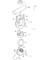
以下では、内固定部材本体がスクリューである場合について、説明する。図1は、生体用のインプラント100の構成の一例を概略的に示す図である。図1の例では、インプラント100は人の脊椎用のインプラントである。インプラント100は体内の複数の腰椎210、仙骨220および腸骨230を相互に固定する。 A case where the main body of the internal fixing member is a screw will be described below. FIG. 1 is a diagram schematically showing an example of the configuration of a biological implant 100. As shown in FIG. In the example of FIG. 1, the implant 100 is a human spinal implant. Implant 100 secures a plurality of lumbar vertebrae 210, sacrum 220 and ilium 230 in the body to each other.

インプラント100はスクリューアセンブリ110とスクリューアセンブリ1とロッド130とを含んでいる。これらは、生体適合性を有する材料によって構成される。当該材料は、例えば、チタン、チタン合金、コバルトクロム合金およびステンレス鋼の少なくともいずれか一つを含む。 Implant 100 includes screw assembly 110 , screw assembly 1 and rod 130 . They are composed of biocompatible materials. The material includes, for example, at least one of titanium, titanium alloys, cobalt-chromium alloys, and stainless steel.

図1の例では、各腰椎210の右側および左側に、それぞれスクリューアセンブリ110が埋入され、仙骨220の右側および左側に、それぞれスクリューアセンブリ1が埋入されている。図1の例では、各スクリューアセンブリ1は、仙骨220の第2仙椎の仙骨翼を入口として、仙腸関節を貫通し、大座骨切痕の直上の腸骨230内に埋入される。 In the example of FIG. 1, screw assemblies 110 are implanted on the right and left sides of each lumbar vertebrae 210, respectively, and screw assemblies 1 are implanted on the right and left sides of the sacrum 220, respectively. In the example of FIG. 1, each screw assembly 1 is implanted in the iliac bone 230 just above the greater sciatic notch through the sacral wing of the second sacral vertebra of the sacrum 220, through the sacroiliac joint.

図1の例では、右側に位置するスクリューアセンブリ110およびスクリューアセンブリ1は、1本のロッド130によって相互に連結される。ロッド130は円柱形状を有している。左側に位置するスクリューアセンブリ110およびスクリューアセンブリ1は、別の1本のロッド130によって相互に連結される。 In the example of FIG. 1 , the screw assembly 110 and the screw assembly 1 located on the right side are interconnected by one rod 130 . Rod 130 has a cylindrical shape. The left screw assembly 110 and screw assembly 1 are interconnected by another rod 130 .

各スクリューアセンブリ110はスクリュー111と結合部材112と締結部材113とを含んでいる。結合部材112は筒状形状を有しており、その内部にスクリュー111のヘッドが配置される。スクリュー111は結合部材112から外側に延在しており、腰椎210に埋入される。スクリュー111のヘッドは結合部材112に対して回転可能である。よって、スクリュー111を腰椎210に埋入した状態で、結合部材112の姿勢を調整することができる。 Each screw assembly 110 includes a screw 111 , a coupling member 112 and a fastening member 113 . The coupling member 112 has a cylindrical shape, inside which the head of the screw 111 is arranged. Screw 111 extends outwardly from connecting member 112 and is implanted in lumbar vertebrae 210 . The head of screw 111 is rotatable with respect to coupling member 112 . Therefore, the posture of the connecting member 112 can be adjusted with the screw 111 embedded in the lumbar vertebrae 210 .

結合部材112はロッド130の長手方向の一部を挿入可能であり、挿入状態でロッド130の長手方向の当該一部を横から挟む。結合部材112の姿勢は、スクリュー111を腰椎210に埋入した状態で、ロッド130を挿入できるように調整される。締結部材113は例えばボルトであり、結合部材112に締結される。この締結により、ロッド130が結合部材112内で固定される。 A part of the rod 130 in the longitudinal direction can be inserted into the connecting member 112 , and in the inserted state, the part of the rod 130 in the longitudinal direction is sandwiched from the side. The posture of the connecting member 112 is adjusted so that the rod 130 can be inserted with the screw 111 embedded in the lumbar vertebrae 210 . The fastening member 113 is, for example, a bolt, and is fastened to the coupling member 112 . This fastening secures the rod 130 within the coupling member 112 .

スクリューアセンブリ1も、スクリューアセンブリ110と同様に、スクリュー2と結合部材3と締結部材7とを含んでいる。結合部材3は筒状形状を有しており、その内部にスクリュー2のヘッド22が回転可能に配置される。スクリュー2は結合部材3から外側に延在している。スクリュー2は仙骨220および腸骨230に埋入される。以下では、仙骨220および腸骨230を纏めて対象骨とも呼ぶ。スクリュー2のヘッド22は結合部材3に対して回転可能であるので、スクリュー2が対象骨に埋入された状態で、結合部材3の姿勢を調整することができる。 The screw assembly 1 also includes a screw 2, a coupling member 3 and a fastening member 7, similar to the screw assembly 110. As shown in FIG. The coupling member 3 has a cylindrical shape in which the head 22 of the screw 2 is rotatably arranged. A screw 2 extends outwardly from the coupling member 3 . Screw 2 is embedded in sacrum 220 and ilium 230 . Hereinafter, the sacrum 220 and the ilium 230 are also collectively referred to as target bones. Since the head 22 of the screw 2 is rotatable with respect to the connecting member 3, the posture of the connecting member 3 can be adjusted while the screw 2 is embedded in the target bone.

結合部材3はロッド130の長手方向の一部を挿入可能であり、挿入状態においてロッド130の長手方向の当該一部を横から挟む。結合部材3の姿勢は、スクリュー2が対象骨に埋入された状態で、結合部材3にロッド130が挿入できるように調整される。締結部材7は例えばボルトであり、結合部材3に締結されてロッド130を固定する。 A part of the rod 130 in the longitudinal direction can be inserted into the coupling member 3 , and in the inserted state, the part of the rod 130 in the longitudinal direction is sandwiched from the side. The posture of the connecting member 3 is adjusted so that the rod 130 can be inserted into the connecting member 3 with the screw 2 embedded in the target bone. The fastening member 7 is, for example, a bolt, and is fastened to the coupling member 3 to fix the rod 130 .

このようなインプラント100において、スクリューアセンブリ110は腰椎210に埋入されており、スクリューアセンブリ1は仙骨220および腸骨230に埋入されている。そして、スクリューアセンブリ110およびスクリューアセンブリ1はロッド130によって相互に連結される。よって、腰椎210、仙骨220および腸骨230を相互に固定することができる。 In such an implant 100, the screw assembly 110 is implanted in the lumbar vertebrae 210, and the screw assembly 1 is implanted in the sacrum 220 and the ilium 230. And screw assembly 110 and screw assembly 1 are interconnected by rod 130 . Thus, the lumbar vertebrae 210, the sacrum 220 and the ilium 230 can be fixed together.

ところで、腸骨230は仙骨220に対して横方向に位置しているので、スクリュー2は横方向に延在する。例えば、右側に位置するスクリューアセンブリ1のスクリュー2は右側に延在し、左側に位置するスクリューアセンブリ1のスクリュー2は左側に延在する。つまり、スクリュー2の結合部材3に対する回転範囲は、スクリューアセンブリ110とは異なって、等方的である必要がなく、結合部材3に対して片側に広ければよい。 By the way, since the ilium 230 is located laterally with respect to the sacrum 220, the screw 2 extends laterally. For example, the screw 2 of the screw assembly 1 located on the right extends to the right and the screw 2 of the screw assembly 1 located on the left extends to the left. In other words, unlike the screw assembly 110, the rotation range of the screw 2 with respect to the coupling member 3 does not need to be isotropic, and may be widened to one side with respect to the coupling member 3.

以下、このようなスクリューアセンブリ1の一例について詳述する。図2は、スクリューアセンブリ1の構成の一例を概略的に示す断面図であり、図3は、スクリューアセンブリ1の構成の一例を概略的に示す分解断面図であり、図4は、スクリューアセンブリ1の構成の一例を概略的に示す分解斜視図である。 An example of such a screw assembly 1 will be described in detail below. 2 is a cross-sectional view schematically showing an example of the configuration of the screw assembly 1, FIG. 3 is an exploded cross-sectional view schematically showing an example of the configuration of the screw assembly 1, and FIG. 1 is an exploded perspective view schematically showing an example of the configuration of FIG.

スクリューアセンブリ1は内固定部材の一例たるスクリュー2と結合部材3と締結部材7とを含んでいる。スクリュー2は対象骨に埋入される部材である。結合部材3はスクリュー2とロッド130とを結合する部材であり、インナー部材4およびアウター部材5を含む。スクリューアセンブリ1は、スクリュー2、インナー部材4、アウター部材5および締結部材7を部品として含んでおり、これらを組み立てることで構成される。これらの組立前の状態をスクリューセット1A(内固定部材セット)とも呼ぶ。図3および図4では、これらが分離されているので、スクリューセット1Aを示している、と把握することもできる。以下では、まず各構成を概説した後に詳述する。 A screw assembly 1 includes a screw 2 , which is an example of an internal fixing member, a connecting member 3 and a fastening member 7 . The screw 2 is a member embedded in the target bone. The connecting member 3 is a member that connects the screw 2 and the rod 130 and includes an inner member 4 and an outer member 5 . The screw assembly 1 includes a screw 2, an inner member 4, an outer member 5, and a fastening member 7 as parts, and is constructed by assembling these parts. These pre-assembled states are also referred to as a screw set 1A (internal fixing member set). In FIGS. 3 and 4, since these are separated, it can also be understood that the screw set 1A is shown. In the following, each configuration will be outlined and then detailed.

スクリュー2は、内固定部材本体の一例たるスクリュー本体21と、ヘッド22とを含んでいる。スクリュー本体21は長尺状の形状を有している。スクリュー本体21は先端側から対象骨に埋入される。ヘッド22は略球形状を有しており、スクリュー本体21の他の一端(基端ともいう)に連結されている。 The screw 2 includes a screw body 21 , which is an example of an internal fixing member body, and a head 22 . The screw body 21 has an elongated shape. The screw body 21 is embedded in the target bone from the tip side. The head 22 has a substantially spherical shape and is connected to the other end (also referred to as the proximal end) of the screw body 21 .

アウター部材5は、第1開口5aおよび第2開口5bを有する略筒状形状を有している。具体的には、アウター部材5は仮想中心軸Q1を中心とした略円筒形状を有している。このアウター部材5はスクリュー2のヘッド22を回転可能に保持する。アウター部材5の内周面には、ヘッド22の仮想球面B1に沿う球状凹面51cが形成されており、ヘッド22はこの球状凹面51cに嵌まる。ヘッド22は後述のように締結部材7によってアウター部材5の内部で固定されるものの、少なくとも締結前においては、ヘッド22はアウター部材5の内部で回転可能である。なお、アウター部材5の材料としては、高強度のコバルトクロム合金を用いることができる。 The outer member 5 has a substantially cylindrical shape with a first opening 5a and a second opening 5b. Specifically, the outer member 5 has a substantially cylindrical shape centered on the virtual central axis Q1. This outer member 5 rotatably holds the head 22 of the screw 2 . A spherical concave surface 51c along the phantom spherical surface B1 of the head 22 is formed on the inner peripheral surface of the outer member 5, and the head 22 fits into this spherical concave surface 51c. Although the head 22 is fixed inside the outer member 5 by the fastening member 7 as described later, the head 22 is rotatable inside the outer member 5 at least before fastening. As the material of the outer member 5, a high-strength cobalt-chromium alloy can be used.

以下では、各構成の位置関係を説明すべく、第2開口5b側を下側と呼び、第1開口5a側を上側と呼ぶ。ここでいう上側および下側は鉛直方向とは関係がなく、アウター部材5の形状に対して設定される。また、以下では、第2開口5bを下側開口5bとも呼び、第1開口5aを上側開口5aとも呼ぶ。 Below, the second opening 5b side is referred to as the lower side, and the first opening 5a side is referred to as the upper side in order to describe the positional relationship of each configuration. The upper side and the lower side referred to here have nothing to do with the vertical direction, and are set with respect to the shape of the outer member 5 . Moreover, below, the 2nd opening 5b is also called the lower opening 5b, and the 1st opening 5a is also called the upper opening 5a.

スクリュー2のスクリュー本体21はアウター部材5よりも下側においてヘッド22からアウター部材5の外側を延在している。ヘッド22がアウター部材5に対して回転可能であるので、スクリュー2はヘッド22を中心として結合部材3に対して振り運動することが可能である。ここでいう振り運動とは、ヘッド22を中心としてスクリュー本体21の先端が仮想球面に沿って移動することをいう。つまり、スクリュー本体21のアウター部材5に対する傾斜角は可変である。 A screw body 21 of the screw 2 extends from the head 22 to the outside of the outer member 5 below the outer member 5 . Since the head 22 is rotatable with respect to the outer member 5 , the screw 2 can swing about the head 22 with respect to the coupling member 3 . The swing motion here means that the tip of the screw body 21 moves along the phantom spherical surface with the head 22 as the center. That is, the inclination angle of the screw body 21 with respect to the outer member 5 is variable.

インナー部材4はアウター部材5の内部に収納されており、ヘッド22よりも上側に位置している。インナー部材4は後述のように締結部材7によってヘッド22を下側に押圧する。この押圧により、ヘッド22はインナー部材4および球状凹面51cの下側部分によって挟持される。これにより、ヘッド22の回転位置が固定される。また、インナー部材4はヘッド22の干渉部26(後述)と当接してヘッド22の回転範囲を制限する。この点は後に詳述する。 The inner member 4 is housed inside the outer member 5 and positioned above the head 22 . The inner member 4 presses the head 22 downward with the fastening member 7 as will be described later. By this pressing, the head 22 is sandwiched between the inner member 4 and the lower portion of the spherical concave surface 51c. Thereby, the rotational position of the head 22 is fixed. Further, the inner member 4 abuts on an interference portion 26 (described later) of the head 22 to limit the rotation range of the head 22 . This point will be detailed later.

アウター部材5の内部には、その上側開口5aから、ロッド130の長手方向の一部が挿入される。締結部材7はアウター部材5の上側開口5aに挿入される。締結部材7は例えば六角穴つきボルトなどのボルトであって、アウター部材5の上端部の内周面に螺合する。締結部材7の先端はロッド130に当接してロッド130を下側に押圧する。この押圧により、ロッド130はインナー部材4を下側に押圧し、インナー部材4がヘッド22を下側に押圧する。これにより、ロッド130およびヘッド22がアウター部材5の内部で固定される。 A portion of the rod 130 in the longitudinal direction is inserted into the outer member 5 through the upper opening 5a. The fastening member 7 is inserted into the upper opening 5 a of the outer member 5 . The fastening member 7 is, for example, a bolt such as a hexagon socket head bolt, and is screwed onto the inner peripheral surface of the upper end portion of the outer member 5 . The tip of the fastening member 7 contacts the rod 130 and presses the rod 130 downward. By this pressing, the rod 130 presses the inner member 4 downward, and the inner member 4 presses the head 22 downward. Thereby, the rod 130 and the head 22 are fixed inside the outer member 5 .

以下、上述の各構成の一例について、より詳しく説明する。 An example of each configuration described above will be described in more detail below.

図示の例では、スクリュー本体21は、仮想中心軸Q3を中心とした略円柱形状を有しており、その外周面にねじ山(不図示)が形成される。ねじ山は、スクリュー本体21の先端から他の一端に向かって螺旋状に形成される。このスクリュー本体21は上述のように対象骨に埋入される。仙骨220および腸骨230に埋入されるスクリュー2は、S2AIスクリューとも呼ばれる。スクリュー本体21は、スクリュー2の軸部とも呼ばれる。 In the illustrated example, the screw body 21 has a substantially cylindrical shape centered on the virtual central axis Q3, and a thread (not shown) is formed on the outer peripheral surface thereof. The screw thread is spirally formed from the tip of the screw body 21 toward the other end. This screw body 21 is embedded in the target bone as described above. The screw 2 implanted in the sacrum 220 and ilium 230 is also called the S2AI screw. The screw body 21 is also called the shank of the screw 2 .

ヘッド22はスクリュー本体21の一端に連結されている。スクリュー本体21およびヘッド22は同一材料で互いに一体に構成されてもよい。ヘッド22は略球形状を有している。ヘッド22は仮想中心軸Q3上に位置しており、より具体的な一例として、ヘッド22の中心が仮想中心軸Q3の上に位置するとよい。 The head 22 is connected to one end of the screw body 21 . The screw body 21 and the head 22 may be integrally constructed of the same material. The head 22 has a substantially spherical shape. The head 22 is positioned on the virtual central axis Q3, and as a more specific example, the center of the head 22 may be positioned on the virtual central axis Q3.

図3を参照して、ヘッド22は一対の部分球面部23,24と平坦帯部25と干渉部26とを含んでいる。一対の部分球面部23,24は仮想球面B1に沿う形状を有している。図示の例では、仮想球面B1の直径はスクリュー本体21の直径よりも大きい。部分球面部23はスクリュー本体21の一端に連結されている。 Referring to FIG. 3, head 22 includes a pair of partial spherical portions 23 and 24, a flat strip portion 25 and an interference portion 26. As shown in FIG. The pair of partial spherical portions 23 and 24 has a shape along the phantom spherical surface B1. In the illustrated example, the diameter of the phantom spherical surface B1 is larger than the diameter of the screw body 21 . The partial spherical portion 23 is connected to one end of the screw body 21 .

平坦帯部25は、ヘッド22の大円の全周に沿って形成された帯状の平坦面である。ここでいう大円とは、仮想球面B1がその中心を通る平面と交わる円である。平坦帯部25は、仮想球面B1の中心を通る仮想中心軸Q4を中心とした略円柱形状を有している。図示の例では、仮想中心軸Q4は仮想中心軸Q3に対して交差している。つまり、平坦帯部25は、スクリュー本体21が延在する仮想中心軸Q3に対して傾斜している。平坦帯部25は部分球面部23,24の間に位置しており、これらに連結されている。平坦帯部25の直径は、部分球面部23,24が沿う仮想球面B1の直径よりも小さい。この平坦帯部25は後に説明するように、ヘッド22をアウター部材5の下側開口5bから内部に挿入する際に利用される。 The flat strip portion 25 is a strip-shaped flat surface formed along the entire circumference of the great circle of the head 22 . The great circle referred to here is a circle in which the phantom spherical surface B1 intersects with a plane passing through its center. The flat belt portion 25 has a substantially cylindrical shape centered on a virtual central axis Q4 that passes through the center of the virtual spherical surface B1. In the illustrated example, the virtual central axis Q4 crosses the virtual central axis Q3. That is, the flat belt portion 25 is inclined with respect to the virtual central axis Q3 along which the screw body 21 extends. The flat strip 25 is located between and connected to the partial spherical portions 23,24. The diameter of the flat belt portion 25 is smaller than the diameter of the phantom spherical surface B1 along which the partial spherical surface portions 23 and 24 extend. This flat belt portion 25 is used when the head 22 is inserted into the outer member 5 from the lower opening 5b, as will be described later.

干渉部26は、部分球面部23,24が沿う仮想球面B1から逸脱した形状を有している。図示の例では、干渉部26は部分球面部24から径方向外側に突出している。図示の例では、干渉部26は仮想球面B1よりも径方向外側に突出している。図示の例では、干渉部26はスクリュー本体21とは反対側のヘッド22の端部に位置しており、仮想中心軸Q3に沿って、スクリュー本体21とは反対側に突出している。 The interference portion 26 has a shape that deviates from the phantom spherical surface B1 along which the partial spherical portions 23 and 24 are aligned. In the illustrated example, the interference portion 26 protrudes radially outward from the partial spherical portion 24 . In the illustrated example, the interference portion 26 protrudes radially outward from the phantom spherical surface B1. In the illustrated example, the interference portion 26 is located at the end of the head 22 opposite to the screw body 21 and protrudes to the side opposite to the screw body 21 along the virtual central axis Q3.

干渉部26の頭頂面の外周縁は略円形状を有する(図4も参照)。具体的な一例として、干渉部26は、仮想中心軸Q3を中心とした略円柱形状を有する。この干渉部26は、アウター部材5の内部においてインナー部材4の内周面41a(より具体的には、後述の干渉面41c)と当接し、ヘッド22の結合部材3に対する回転範囲を制限する。この点は後に詳述する。 The outer peripheral edge of the top surface of the interference portion 26 has a substantially circular shape (see also FIG. 4). As a specific example, the interference portion 26 has a substantially cylindrical shape centered on the virtual central axis Q3. The interference portion 26 abuts on the inner peripheral surface 41 a (more specifically, the interference surface 41 c described later) of the inner member 4 inside the outer member 5 to limit the rotation range of the head 22 with respect to the coupling member 3 . This point will be detailed later.

図4の例では、干渉部26は、仮想中心軸Q3のまわりでスクリュー2を回転させるための工具(不図示)と嵌合可能な形状を有している。より具体的な一例として、干渉部26の頭部面には、嵌合穴27が形成されている。嵌合穴27は、仮想中心軸Q3に沿って見て、工具の断面に応じた形状を有しており、図4の例では、滑らかな星形形状を有している。図4では、嵌合穴27の頂点は6つであるものの、その個数は適宜変更し得る。嵌合穴27には、これと略同形状の断面を有する工具が挿入される。医療従事者は当該工具を用いてスクリュー2を仮想中心軸Q3のまわりで回転させることにより、スクリュー2を対象骨に埋入することができる。なお、嵌合穴27は、星形形状に限らず、すりわり、十字穴、H型、六角穴、四角穴などの他の形状を有していてもよい。 In the example of FIG. 4, the interference portion 26 has a shape that can be fitted with a tool (not shown) for rotating the screw 2 around the virtual central axis Q3. As a more specific example, a fitting hole 27 is formed in the head surface of the interference portion 26 . The fitting hole 27 has a shape corresponding to the cross section of the tool when viewed along the virtual central axis Q3, and has a smooth star shape in the example of FIG. In FIG. 4, the fitting hole 27 has six vertexes, but the number can be changed as appropriate. A tool having a cross section of approximately the same shape is inserted into the fitting hole 27 . A medical worker can embed the screw 2 in the target bone by rotating the screw 2 around the virtual central axis Q3 using the tool. The fitting hole 27 is not limited to the star shape, and may have other shapes such as a slot, a cross hole, an H shape, a hexagonal hole, and a square hole.

アウター部材5は、仮想中心軸Q1を中心とした略筒状形状を有している。より具体的な一例として、アウター部材5は筒状部材51と一対の側壁52とを含んでいる。筒状部材51は筒状形状を有しており、図示の例では、仮想中心軸Q1を中心とした略円筒形状を有している。 The outer member 5 has a substantially tubular shape centered on the virtual central axis Q1. As a more specific example, the outer member 5 includes a tubular member 51 and a pair of side walls 52 . The tubular member 51 has a tubular shape, and in the illustrated example, has a substantially cylindrical shape centered on the virtual central axis Q1.

図示の例では、筒状部材51の内周面51aは円柱面51b、球状凹面51cおよび円柱面51dによって形成される。円柱面51b、球状凹面51cおよび円柱面51dは上側から下側に向かってこの順で位置しており、互いに連続する。円柱面51dの下端周縁はアウター部材5の下側開口5bを形成する。 In the illustrated example, the inner peripheral surface 51a of the tubular member 51 is formed by a cylindrical surface 51b, a spherical concave surface 51c and a cylindrical surface 51d. The cylindrical surface 51b, the spherical concave surface 51c, and the cylindrical surface 51d are positioned in this order from top to bottom and are continuous with each other. A lower edge of the cylindrical surface 51d forms a lower opening 5b of the outer member 5. As shown in FIG.

円柱面51bは、仮想中心軸Q1を中心とした略円柱形状を有している。この円柱面51bの直径は、ヘッド22の部分球面部23,24が沿う仮想球面B1の直径よりも小さい。 The cylindrical surface 51b has a substantially cylindrical shape centered on the virtual central axis Q1. The diameter of this cylindrical surface 51b is smaller than the diameter of the phantom spherical surface B1 along which the partial spherical surface portions 23 and 24 of the head 22 extend.

球状凹面51cは、筒状部材51の内周面51aの全周に亘って形成された凹形状を有している。球状凹面51cの凹形状は仮想球面B1に沿う形状を有しており、その直径は仮想球面B1の直径と同一、または、仮想球面B1の直径よりも若干大きい。仮想中心軸Q1は例えば球状凹面51cの中心を通る。球状凹面51cの上端周縁は円柱面51bの下端周縁と連続する。 The spherical concave surface 51 c has a concave shape formed over the entire circumference of the inner peripheral surface 51 a of the cylindrical member 51 . The concave shape of the spherical concave surface 51c has a shape along the phantom spherical surface B1, and its diameter is the same as the diameter of the phantom spherical surface B1 or slightly larger than the diameter of the phantom spherical surface B1. The virtual central axis Q1 passes through the center of the spherical concave surface 51c, for example. The upper peripheral edge of the spherical concave surface 51c is continuous with the lower peripheral edge of the cylindrical surface 51b.

円柱面51dは、仮想中心軸Q2(図3参照)を中心とした略円柱形状を有している。図示の例では、仮想中心軸Q2は仮想中心軸Q1と交差している。円柱面51dの直径は仮想球面B1の直径よりも小さく、ヘッド22の平坦帯部25の直径と同一、または、平坦帯部25の直径よりも若干大きい。円柱面51dの上端周縁は球状凹面51cの下端周縁と連続する。円柱面51dの上端周縁および球状凹面51cの下端周縁は、仮想中心軸Q1に対して傾斜している。円柱面51dの下端周縁はアウター部材5の下側開口5bを形成する。図示の例では、円柱面51dの下端周縁は、仮想中心軸Q1に対して略直交する面上に位置している。つまり、円柱面51dの上端周縁および下端周縁は互いに傾斜しており、その幅(つまり、仮想中心軸Q2に沿う長さ)は周方向の位置に応じて相違する。図3で言えば、円柱面51dの幅は左側において狭く、右側において広い。この技術的な意義については後に述べる。 The cylindrical surface 51d has a substantially cylindrical shape centered on the virtual central axis Q2 (see FIG. 3). In the illustrated example, the virtual central axis Q2 intersects the virtual central axis Q1. The diameter of the cylindrical surface 51d is smaller than the diameter of the phantom spherical surface B1 and is the same as the diameter of the flat belt portion 25 of the head 22 or slightly larger than the diameter of the flat belt portion 25 . The upper peripheral edge of the cylindrical surface 51d is continuous with the lower peripheral edge of the spherical concave surface 51c. The upper peripheral edge of the cylindrical surface 51d and the lower peripheral edge of the spherical concave surface 51c are inclined with respect to the virtual central axis Q1. A lower edge of the cylindrical surface 51d forms a lower opening 5b of the outer member 5. As shown in FIG. In the illustrated example, the lower peripheral edge of the cylindrical surface 51d is positioned on a plane substantially perpendicular to the virtual central axis Q1. That is, the upper edge and the lower edge of the cylindrical surface 51d are inclined with respect to each other, and the width (that is, the length along the imaginary central axis Q2) differs depending on the position in the circumferential direction. Referring to FIG. 3, the width of the cylindrical surface 51d is narrow on the left side and wide on the right side. The technical significance of this will be described later.

スクリュー2のヘッド22は後に詳述するように、アウター部材5の下側開口5bを介してアウター部材5の内部へと挿入されて、球状凹面51cに回転可能に嵌まる。 The head 22 of the screw 2 is inserted into the outer member 5 through the lower opening 5b of the outer member 5 and rotatably fitted in the spherical concave surface 51c, as will be described in detail later.

筒状部材51の上端部には、一対の側壁52が立設されている。一対の側壁52および筒状部材51は同じ材料で互いに一体に構成されてもよい。一対の側壁52は仮想中心軸Q1に対して互いに反対側に位置し、仮想中心軸Q1に沿って上側に延在する。一対の側壁52の互いに向かい合う内周面52aは、仮想中心軸Q1を中心とした仮想円柱面に沿った湾曲形状を有しており、当該内周面52aには、不図示のねじ溝が形成される。一対の側壁52は間隔を空けて互いに対向するので、一対の側壁52の間の空間は上側に開口しつつ、仮想中心軸Q1に交差する交差方向にアウター部材5を貫通する。 A pair of side walls 52 are erected at the upper end of the tubular member 51 . The pair of side walls 52 and tubular member 51 may be made of the same material and integrally formed with each other. The pair of side walls 52 are positioned opposite to each other with respect to the virtual central axis Q1 and extend upward along the virtual central axis Q1. The inner peripheral surfaces 52a of the pair of side walls 52 facing each other have a curved shape along an imaginary cylindrical surface centered on the imaginary central axis Q1, and thread grooves (not shown) are formed in the inner peripheral surfaces 52a. be done. Since the pair of side walls 52 are opposed to each other with a space therebetween, the space between the pair of side walls 52 is opened upward and penetrates the outer member 5 in the cross direction crossing the imaginary central axis Q1.

ロッド130は、その長手方向が交差方向に沿う姿勢で、一対の側壁52の内部に挿入される。このとき、ロッド130の長手方向の一部が一対の側壁52の間に挿入され、その他の部分がアウター部材5の両側から突出する。 The rod 130 is inserted inside the pair of side walls 52 with its longitudinal direction extending along the intersecting direction. At this time, a part of the rod 130 in the longitudinal direction is inserted between the pair of side walls 52 and the other parts protrude from both sides of the outer member 5 .

一対の側壁52の仮想中心軸Q1に沿う長さはロッド130の直径よりも長い。したがって、ロッド130が一対の側壁52の間に挿入された状態で、一対の側壁52はロッド130よりも上側に突出している。 The length of the pair of side walls 52 along the imaginary center axis Q1 is longer than the diameter of the rod 130. As shown in FIG. Therefore, the pair of side walls 52 protrude above the rod 130 while the rod 130 is inserted between the pair of side walls 52 .

締結部材7は例えばボルトであって、一対の側壁52の内周面52aに螺合する。締結部材7の先端はロッド130に当接し、ロッド130を下側に押圧する。これにより、ロッド130が結合部材3に結合される。 The fastening member 7 is, for example, a bolt and is screwed onto the inner peripheral surfaces 52a of the pair of side walls 52 . The tip of the fastening member 7 contacts the rod 130 and presses the rod 130 downward. The rod 130 is thereby coupled to the coupling member 3 .

インナー部材4はアウター部材5の内部において、ロッド130とスクリュー2のヘッド22との間に位置している。インナー部材4は、締結部材7が取り付けられていない状態で、仮想中心軸Q1に沿って移動可能である。つまり、この状態では、インナー部材4は、ヘッド22から離れた第1位置(以下、上位置と呼ぶ)と、当該上位置よりも下側開口5b側の第2位置(以下、下位置と呼ぶ)との間で移動可能である。インナー部材4は下位置においてヘッド22に当接してもよい。この場合、締結部材7が取り付けられることにより、インナー部材4はロッド130によって下側に押圧される。これにより、インナー部材4は下位置に移動してヘッド22に当接し、ヘッド22を下側に押圧する。ヘッド22はアウター部材5の球状凹面51cの下側部分と、インナー部材4とによって挟持される。 The inner member 4 is located inside the outer member 5 between the rod 130 and the head 22 of the screw 2 . The inner member 4 is movable along the virtual central axis Q1 in a state in which the fastening member 7 is not attached. That is, in this state, the inner member 4 is positioned at a first position (hereinafter referred to as an upper position) away from the head 22 and a second position (hereinafter referred to as a lower position) closer to the lower opening 5b than the upper position. ). The inner member 4 may contact the head 22 at the lower position. In this case, the inner member 4 is pressed downward by the rod 130 by attaching the fastening member 7 . As a result, the inner member 4 moves to the lower position and contacts the head 22 to press the head 22 downward. The head 22 is sandwiched between the lower portion of the spherical concave surface 51 c of the outer member 5 and the inner member 4 .

図示の例では、インナー部材4は下部材41と一対の側壁42とを含んでいる。下部材41は少なくとも下側に開口する形状を有している。図示の例では、インナー部材4には、下部材41を仮想中心軸Q1に沿って貫通する内部空間が形成されている。この内部空間は下部材41の上側にも開口し、下側にも開口する。この内部空間は、下部材41の内周面41aによって形成される。図示の例では、内周面41aは部分球面41bと干渉面41cと天面41dとによって形成される。 In the illustrated example, the inner member 4 includes a lower member 41 and a pair of side walls 42 . The lower member 41 has a shape that opens at least downward. In the illustrated example, the inner member 4 is formed with an internal space penetrating the lower member 41 along the imaginary central axis Q1. This internal space opens to the upper side of the lower member 41 as well as to the lower side. This internal space is formed by the inner peripheral surface 41 a of the lower member 41 . In the illustrated example, the inner peripheral surface 41a is formed by a partial spherical surface 41b, an interference surface 41c, and a top surface 41d.

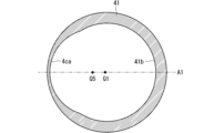
図5は、インナー部材4の構成の一例を示す斜視図であり、図6から図9は、インナー部材4の下部材41の切断面を概略的に示す図である。図5では、インナー部材4を仮想断面A1で切断して得られる2つの部分の一方が示されている。仮想断面A1は、仮想中心軸Q1を含む面である。図6から図9は、仮想中心軸Q1に垂直な断面を下側から上側に順に示している。具体的には、図6から図9は、それぞれ、図5に示すI-I線、II-II線、III-III線およびIV-IV線に沿った仮想的な切断面を概略的に示している。つまり、図6は、最も下側の位置における下部材41の断面を示し、図9は、最も上側の位置における下部材41の断面を示している。 5 is a perspective view showing an example of the configuration of the inner member 4, and FIGS. 6 to 9 are diagrams schematically showing cut surfaces of the lower member 41 of the inner member 4. FIG. FIG. 5 shows one of two portions obtained by cutting the inner member 4 along the imaginary cross section A1. The virtual cross section A1 is a plane that includes the virtual central axis Q1. 6 to 9 show cross sections perpendicular to the virtual central axis Q1 in order from bottom to top. Specifically, FIGS. 6 to 9 schematically show imaginary cross-sections along lines I-I, II-II, III-III and IV-IV shown in FIG. 5, respectively. . 6 shows the cross section of the lower member 41 at the lowest position, and FIG. 9 shows the cross section of the lower member 41 at the uppermost position.

部分球面41bは、ヘッド22の仮想球面B1に沿う湾曲形状を有しており、ヘッド22に当接する。部分球面41bはヘッド22に対して上側から当接するので、部分球面41bはインナー部材4の下面であると把握することもできる。図示の例では、部分球面41bは仮想断面A1に対して略対称となる形状を有している。仮想断面A1は仮想中心軸Q1を含む面であり、図6から図8では二点鎖線で示されている。図6から図8を参照して、部分球面41bは各断面においてインナー部材4の周方向の一部のみに形成されており、部分球面41bの周方向の長さは上側に向かうにつれて短くなっている。また、部分球面41bは上側に向かうにつれて、仮想中心軸Q1に近づく。 The partial spherical surface 41 b has a curved shape along the phantom spherical surface B<b>1 of the head 22 and contacts the head 22 . Since the partial spherical surface 41b abuts against the head 22 from above, the partial spherical surface 41b can also be grasped as the lower surface of the inner member 4. As shown in FIG. In the illustrated example, the partial spherical surface 41b has a shape substantially symmetrical with respect to the virtual cross section A1. The imaginary cross section A1 is a plane including the imaginary center axis Q1, and is indicated by a chain double-dashed line in FIGS. 6 to 8. FIG. 6 to 8, the partial spherical surface 41b is formed only partially in the circumferential direction of the inner member 4 in each cross section, and the length of the partial spherical surface 41b in the circumferential direction becomes shorter toward the upper side. there is Further, the partial spherical surface 41b approaches the virtual central axis Q1 as it goes upward.

図5を参照して、干渉面41cは部分球面41bの上端縁部から上側に延在している。図2および図3も参照して、この干渉面41cは、ヘッド22の干渉部26が移動する移動空間H1を形成する。ヘッド22を中心としてスクリュー2を結合部材3に対して振り運動させると、干渉部26はこの移動空間H1内において、ヘッド22の中心のまわりで移動する。干渉部26が干渉面41cに当接することにより、それ以上のヘッド22の回転が規制される。つまり、干渉面41cはヘッド22の回転範囲を制限する。 Referring to FIG. 5, the interference surface 41c extends upward from the upper edge of the partial spherical surface 41b. 2 and 3, this interference surface 41c forms a movement space H1 in which the interference portion 26 of the head 22 moves. When the screw 2 is swung around the head 22 with respect to the coupling member 3, the interference portion 26 moves around the center of the head 22 within the movement space H1. Further rotation of the head 22 is restricted by the contact of the interference portion 26 with the interference surface 41c. That is, the interference surface 41c limits the rotation range of the head 22. FIG.

図示の例では、干渉面41cも仮想断面A1に対して略対称の形状を有しており、円弧柱面41caおよび円弧柱面41cbによって構成される。円弧柱面41caは、仮想中心軸Q5を中心とした円柱面に沿った形状を有している。ただし、円弧柱面41caはインナー部材4の周方向の一部のみに形成されている。図6から図8に例示するように、部分球面41bを通る断面では、円弧柱面41caの周方向の両端は、それぞれ部分球面41bの周方向の両端と連続しており、当該断面において、円弧柱面41caおよび部分球面41bは全体として環状形状を形成する。仮想中心軸Q5は仮想断面A1上に位置して仮想中心軸Q1からずれた軸であり、仮想中心軸Q1と略平行である。 In the illustrated example, the interference surface 41c also has a substantially symmetrical shape with respect to the virtual cross section A1, and is composed of an arc cylindrical surface 41ca and an arc cylindrical surface 41cb. The arcuate cylindrical surface 41ca has a shape along a cylindrical surface centered on the virtual central axis Q5. However, the arcuate cylindrical surface 41ca is formed only on a part of the inner member 4 in the circumferential direction. As illustrated in FIGS. 6 to 8, in a cross section passing through the partial spherical surface 41b, both circumferential ends of the arc cylindrical surface 41ca are continuous with both circumferential ends of the partial spherical surface 41b. The cylindrical surface 41ca and the partial spherical surface 41b form an annular shape as a whole. The virtual central axis Q5 is an axis located on the virtual cross section A1 and deviated from the virtual central axis Q1, and substantially parallel to the virtual central axis Q1.

円弧柱面41cbは部分球面41bよりも上側に位置している。円弧柱面41cbは、仮想中心軸Q1を中心とした円柱面に沿った形状を有している。ただし、円弧柱面41cbはインナー部材4の周方向に一部のみに形成されている。図9に例示するように、部分球面41bよりも上側の断面では、円弧柱面41cbの周方向の両端はそれぞれ円弧柱面41caの周方向の両端と連続しており、当該断面において円弧柱面41caおよび円弧柱面41cbは全体として環状形状を形成する。 The circular arc cylindrical surface 41cb is located above the partial spherical surface 41b. The arcuate cylindrical surface 41cb has a shape along a cylindrical surface centered on the virtual central axis Q1. However, the arcuate cylindrical surface 41cb is formed only partially in the inner member 4 in the circumferential direction. As illustrated in FIG. 9, in the cross section above the partial spherical surface 41b, both circumferential ends of the circular arc cylindrical surface 41cb are continuous with both circumferential ends of the circular arc cylindrical surface 41ca. 41ca and arc cylindrical surface 41cb form an annular shape as a whole.

円弧柱面41caの上端周縁は、天面41dの外周縁に連結されている。天面41dは仮想中心軸Q1に沿って見て、三日月状の形状を有している(図5も参照)。天面41dの内周縁は、後述の側壁42の内周面の下端周縁と連続しており、円弧柱面41cbの上端周縁も側壁42の内周面の下端周縁と連続する。 The upper peripheral edge of the circular arc column surface 41ca is connected to the outer peripheral edge of the top surface 41d. The top surface 41d has a crescent shape when viewed along the virtual central axis Q1 (see also FIG. 5). The inner peripheral edge of the top surface 41 d is continuous with the lower peripheral edge of the inner peripheral surface of the side wall 42 to be described later, and the upper peripheral edge of the arc columnar surface 41 cb is also continuous with the lower peripheral edge of the inner peripheral surface of the side wall 42 .

下部材41の上端部には、一対の側壁42が立設されている。一対の側壁42および下部材41は同じ材料で互いに一体に構成されてもよい。一対の側壁42は、アウター部材5の一対の側壁52が対向する方向において、互いに向かい合って配置される。図示の例では、側壁42の向かい合う方向は、仮想断面A1に含まれる。 A pair of side walls 42 are erected at the upper end of the lower member 41 . The pair of side walls 42 and lower member 41 may be made of the same material and integrally formed with each other. The pair of side walls 42 are arranged to face each other in the direction in which the pair of side walls 52 of the outer member 5 face each other. In the illustrated example, the facing directions of the sidewalls 42 are included in the imaginary cross section A1.

インナー部材4がアウター部材5の内部に位置する状態で、一対の側壁42はそれぞれアウター部材5の一対の側壁52の間に位置している。一対の側壁42の間にはロッド130が挿入される。このとき、ロッド130の長手方向の一部が一対の側壁42の間に挿入され、他の部分はインナー部材4の両側から突出する。一対の側壁42の上端は、ロッド130が挿入された状態で、ロッド130の上端よりも下側に位置している。 With the inner member 4 positioned inside the outer member 5 , the pair of side walls 42 are positioned between the pair of side walls 52 of the outer member 5 . A rod 130 is inserted between the pair of side walls 42 . At this time, a part of the rod 130 in the longitudinal direction is inserted between the pair of side walls 42 and the other part protrudes from both sides of the inner member 4 . The upper ends of the pair of side walls 42 are located below the upper ends of the rods 130 when the rods 130 are inserted.

図示の例では、一対の側壁42は、下部材41の上端面の外周縁よりも内側に立設されているので、一対の側壁42の外周面と下部材41の上端面とは段差43を形成する。一方、アウター部材5において、一対の側壁52の内周面52aは、筒状部材51の内周面51aよりも内側に位置しており、内周面51a,52aはストッパー面53aを介して互いに連結される。 In the illustrated example, the pair of side walls 42 are erected inside the outer peripheral edge of the upper end surface of the lower member 41 , so that a step 43 is formed between the outer peripheral surface of the pair of side walls 42 and the upper end surface of the lower member 41 . Form. On the other hand, in the outer member 5, the inner peripheral surfaces 52a of the pair of side walls 52 are located inside the inner peripheral surface 51a of the tubular member 51, and the inner peripheral surfaces 51a and 52a are mutually connected via the stopper surface 53a. concatenated.

これによれば、アウター部材5の内部においてインナー部材4を上側に移動させると、下部材41の上端面の外周縁がアウター部材5のストッパー面53aに当接する。よって、インナー部材4がアウター部材5の上側開口5aから抜けることを回避できる。 According to this, when the inner member 4 is moved upward inside the outer member 5 , the outer peripheral edge of the upper end surface of the lower member 41 comes into contact with the stopper surface 53 a of the outer member 5 . Therefore, it is possible to prevent the inner member 4 from slipping out of the upper opening 5 a of the outer member 5 .

図示の例では、スクリューアセンブリ1はC字状部材6も含んでいる。C字状部材6はC字形状を有している。つまり、C字状部材6は、リング形状をその周方向の一部で切断して得られた形状を有している。C字状部材6の内周面は、ヘッド22の平坦帯部25に沿う平坦な円柱形状を有し、外周面は、ヘッド22の仮想球面B1に沿う湾曲形状を有している。C字状部材6の幅はヘッド22の平坦帯部25の幅と略等しい。C字状部材6の内径は平坦帯部25の直径と略同一、または、平坦帯部25の直径よりも若干小さい。 In the illustrated example, screw assembly 1 also includes a C-shaped member 6 . The C-shaped member 6 has a C-shape. That is, the C-shaped member 6 has a shape obtained by cutting a part of the ring shape in the circumferential direction. The inner peripheral surface of the C-shaped member 6 has a flat columnar shape along the flat belt portion 25 of the head 22 , and the outer peripheral surface has a curved shape along the phantom spherical surface B<b>1 of the head 22 . The width of the C-shaped member 6 is substantially equal to the width of the flat strip portion 25 of the head 22 . The inner diameter of the C-shaped member 6 is substantially the same as the diameter of the flat belt portion 25 or slightly smaller than the diameter of the flat belt portion 25 .

C字状部材6は弾性変形可能である。C字状部材6は、その内周面がヘッド22の平坦帯部25と向かい合うように、ヘッド22の平坦帯部25に取り付けられる。これによって、ヘッド22およびC字状部材6からなる構造体を、より球形状に近づけることができる。 The C-shaped member 6 is elastically deformable. The C-shaped member 6 is attached to the flat belt portion 25 of the head 22 so that the inner peripheral surface of the C-shaped member 6 faces the flat belt portion 25 of the head 22 . As a result, the structure composed of the head 22 and the C-shaped member 6 can be brought closer to a spherical shape.

次に、このスクリューアセンブリ1の組立方法について説明する。図10は、スクリューアセンブリ1を組み立てる途中の様子の一例を概略的に示す図である。 Next, a method for assembling this screw assembly 1 will be described. FIG. 10 is a diagram schematically showing an example of how the screw assembly 1 is being assembled.

まず、医療従事者はインナー部材4をアウター部材5の内部に挿入する。具体的には、インナー部材4をアウター部材5の下側開口5bを通って内部に挿入する。この状態では、インナー部材4はアウター部材5に固定されておらず、仮想中心軸Q1に沿って移動可能である。図10の例では、インナー部材4が上位置に位置する状態を示している。 First, a medical worker inserts the inner member 4 inside the outer member 5 . Specifically, the inner member 4 is inserted inside the outer member 5 through the lower opening 5b. In this state, the inner member 4 is not fixed to the outer member 5 and is movable along the virtual central axis Q1. The example of FIG. 10 shows a state in which the inner member 4 is positioned at the upper position.

図10に例示するように、円柱面51dの幅(仮想中心軸Q2に沿う幅)は周方向において相違している。図10で言えば、右側に向かうほど円柱面51dの幅は増加する。一方で、インナー部材4の部分球面41bの長さL1(仮想中心軸Q1を含む断面における長さ:図5も参照)も、周方向において相違している。図10で言えば、右側に向かうほど部分球面41bの長さL1は増加する。言い換えれば、医療従事者は、部分球面41bのうち長さL1の長い部分が、円柱面51dのうち幅の広い部分に近くなる姿勢で、インナー部材4をアウター部材5の内部に挿入する。 As illustrated in FIG. 10, the width of the cylindrical surface 51d (the width along the imaginary central axis Q2) is different in the circumferential direction. In FIG. 10, the width of the cylindrical surface 51d increases toward the right side. On the other hand, the length L1 of the partial spherical surface 41b of the inner member 4 (the length in the cross section including the virtual central axis Q1: see also FIG. 5) is also different in the circumferential direction. In FIG. 10, the length L1 of the partial spherical surface 41b increases toward the right side. In other words, the medical staff inserts the inner member 4 into the outer member 5 in such a posture that the longer part of the partial spherical surface 41b with the length L1 is closer to the wider part of the cylindrical surface 51d.

次に、医療従事者はC字状部材6をアウター部材5の内部に挿入する。具体的には、医療従事者はC字状部材6の両端が互いに近づくようにC字状部材6を弾性変形させる。これにより、C字状部材6の外径をアウター部材5の下側開口5bの直径よりも小さくすることができる。医療従事者は、この縮径させたC字状部材6をアウター部材5の下側開口5bを通って内部に挿入し、球状凹面51cに嵌める。このとき、医療従事者は、C字状部材6の内周面がアウター部材5の円柱面51dと平行となるように、C字状部材6を球状凹面51cに嵌める。これにより、C字状部材6の内周面および円柱面51dが連続した一つの円柱面を構成する。 The medical staff then inserts the C-shaped member 6 inside the outer member 5 . Specifically, the medical staff elastically deforms the C-shaped member 6 so that both ends of the C-shaped member 6 approach each other. Thereby, the outer diameter of the C-shaped member 6 can be made smaller than the diameter of the lower opening 5b of the outer member 5. As shown in FIG. The medical staff inserts the diameter-reduced C-shaped member 6 inside through the lower opening 5b of the outer member 5 and fits it into the spherical concave surface 51c. At this time, the medical staff fits the C-shaped member 6 into the spherical concave surface 51 c so that the inner peripheral surface of the C-shaped member 6 is parallel to the cylindrical surface 51 d of the outer member 5 . Thereby, the inner peripheral surface of the C-shaped member 6 and the cylindrical surface 51d form a continuous cylindrical surface.

次に、医療従事者はスクリュー2のヘッド22をアウター部材5の内部に挿入する。具体的には、まず、医療従事者は、ヘッド22の平坦帯部25がアウター部材5の下側開口5bの周縁に沿うようにスクリュー2をアウター部材5に対して傾斜させる。言い換えれば、医療従事者は、平坦帯部25の仮想中心軸Q4がアウター部材5の円柱面51dの仮想中心軸Q2と略一致するように、スクリュー2を傾斜させる。また、医療従事者は、干渉部26がインナー部材4の部分球面41bと向かい合うように、スクリュー2の傾斜姿勢を調整する。図10の例では、干渉部26は、部分球面41bのうち長さL1の長い部分と向かい合っている。図10で言えば、干渉部26が仮想中心軸Q1に対して右側に位置し、スクリュー本体21が左下に延在するように、スクリュー2を傾斜させる。 The medical practitioner then inserts the head 22 of the screw 2 inside the outer member 5 . Specifically, first, the medical staff inclines the screw 2 with respect to the outer member 5 so that the flat strip portion 25 of the head 22 follows the periphery of the lower opening 5 b of the outer member 5 . In other words, the medical staff inclines the screw 2 so that the virtual central axis Q4 of the flat belt portion 25 substantially coincides with the virtual central axis Q2 of the cylindrical surface 51d of the outer member 5. Further, the medical staff adjusts the tilted posture of the screw 2 so that the interference portion 26 faces the partial spherical surface 41 b of the inner member 4 . In the example of FIG. 10, the interference portion 26 faces the longer portion of the partial spherical surface 41b having the length L1. Referring to FIG. 10, the screw 2 is tilted so that the interference portion 26 is positioned on the right side of the virtual center axis Q1 and the screw body 21 extends to the lower left.

平坦帯部25の直径は円柱面51dの直径以下であるので、この状態で、スクリュー2のヘッド22を、下側開口5bを介してアウター部材5に対して抜き差しすることができる。以下では、この状態でのヘッド22のアウター部材5に対する回転位置を基準回転位置と呼ぶ。 Since the diameter of the flat belt portion 25 is equal to or smaller than the diameter of the cylindrical surface 51d, in this state, the head 22 of the screw 2 can be inserted into and removed from the outer member 5 through the lower opening 5b. Hereinafter, the rotational position of the head 22 with respect to the outer member 5 in this state will be referred to as a reference rotational position.

そして、医療従事者はこの基準回転位置を維持しつつ、ヘッド22をアウター部材5の下側開口5bから内部に挿入する。これにより、C字状部材6がヘッド22の平坦帯部25に取り付けられ、以後、C字状部材6がヘッド22と一体に回転する。 The medical staff then inserts the head 22 into the outer member 5 through the lower opening 5b while maintaining this reference rotational position. As a result, the C-shaped member 6 is attached to the flat belt portion 25 of the head 22 , and thereafter the C-shaped member 6 rotates integrally with the head 22 .

図11は、スクリューアセンブリ1を組み立てる途中の様子の一例を概略的に示す断面図である。図11においては、スクリュー2のヘッド22がアウター部材5の内部に位置しており、その回転位置は基準回転位置である。この状態でも、インナー部材4は上位置に位置している。インナー部材4が上位置に位置するときには、インナー部材4はヘッド22の回転を規制しない。 FIG. 11 is a cross-sectional view schematically showing an example of how the screw assembly 1 is being assembled. In FIG. 11, the head 22 of the screw 2 is positioned inside the outer member 5, and its rotational position is the reference rotational position. Even in this state, the inner member 4 is positioned at the upper position. The inner member 4 does not restrict the rotation of the head 22 when the inner member 4 is positioned at the upper position.

以下では、基準回転位置でヘッド22の干渉部26が占めるアウター部材5の内部の空間を所定空間H2と呼ぶ。インナー部材4が上位置に位置するときには、インナー部材4はこの所定空間H2よりも上側に位置している。 Hereinafter, the space inside the outer member 5 occupied by the interference portion 26 of the head 22 at the reference rotational position is referred to as a predetermined space H2. When the inner member 4 is positioned at the upper position, the inner member 4 is positioned above the predetermined space H2.

図12は、ヘッド22が結合部材3に対して回転する様子の一例を概略的に示す図である。図12では、インナー部材4が上位置に位置している。この状態では、スクリュー2のスクリュー本体21がアウター部材5の下端に当接する、または、ヘッド22の干渉部26がアウター部材5の円柱面51bに当接することで、ヘッド22の結合部材3に対する回転範囲が規定される。図12では、ヘッド22の回転範囲を回転範囲R1で示している。このヘッド22の回転範囲は、アウター部材5に対するスクリュー本体21の傾斜角の角度範囲を示している。 12A and 12B schematically show an example of how the head 22 rotates with respect to the coupling member 3. FIG. In FIG. 12, the inner member 4 is positioned at the upper position. In this state, the screw body 21 of the screw 2 contacts the lower end of the outer member 5, or the interference portion 26 of the head 22 contacts the cylindrical surface 51b of the outer member 5, thereby rotating the head 22 with respect to the coupling member 3. A range is specified. In FIG. 12, the rotation range of the head 22 is indicated by a rotation range R1. The rotation range of the head 22 indicates the angle range of the inclination angle of the screw body 21 with respect to the outer member 5 .

円柱面51bは、仮想中心軸Q1を中心とした円柱形状を有しており、アウター部材5の下端もほとんど仮想中心軸Q1を中心とした円形状を有するので、回転範囲R1は仮想中心軸Q1を中心としてほとんど等方的に設定される。 The cylindrical surface 51b has a cylindrical shape centered on the imaginary center axis Q1, and the lower end of the outer member 5 also has a circular shape centered on the imaginary center axis Q1. is set almost isotropically around .

次に、医療従事者は、ヘッド22の干渉部26が所定空間H2から退避するように、ヘッド22を中心としてスクリュー2をアウター部材5に対して変位させる。言い換えれば、医療従事者は干渉部26が仮想中心軸Q1に平行な方向においてインナー部材4の部分球面41bと対向しない回転位置まで、スクリュー2を変位させる。図13は、スクリューアセンブリ1を組み立てる途中の様子の一例を概略的に示す断面図である。図13の例では、ヘッド22の干渉部26はインナー部材4の部分球面41bと対向しない。言い換えれば、ヘッド22の干渉部26は移動空間H1内に位置している。図13の例では、仮想中心軸Q1,Q3が互いに一致する状態を示しているものの、必ずしもこれに限らない。要するに、干渉部26がインナー部材4の部分球面41bと対向しない位置に、干渉部26を移動させればよい。 Next, the medical staff displaces the screw 2 with respect to the outer member 5 around the head 22 so that the interference portion 26 of the head 22 is withdrawn from the predetermined space H2. In other words, the medical staff displaces the screw 2 to a rotational position where the interference portion 26 does not face the partial spherical surface 41b of the inner member 4 in the direction parallel to the virtual central axis Q1. FIG. 13 is a cross-sectional view schematically showing an example of how the screw assembly 1 is being assembled. In the example of FIG. 13, the interference portion 26 of the head 22 does not face the partial spherical surface 41b of the inner member 4. As shown in FIG. In other words, the interference portion 26 of the head 22 is positioned within the movement space H1. Although the example of FIG. 13 shows a state in which the virtual central axes Q1 and Q3 are aligned with each other, this is not necessarily the case. In short, the interference part 26 should be moved to a position where the interference part 26 does not face the partial spherical surface 41 b of the inner member 4 .

次に、医療従事者は、インナー部材4を下側に移動させる。図14は、スクリューアセンブリ1を組み立てる途中の様子の一例を概略的に示す断面図である。図14の例では、インナー部材4が下位置に位置している。この状態では、インナー部材4の部分球面41bはスクリュー2の部分球面部23、部分球面部24およびC字状部材6の少なくともいずれかに当接する。また、インナー部材4の一部(干渉部411と呼ぶ)は所定空間H2内に位置する。干渉部411の下面は、部分球面41bのうち長さL1の長い部分である。インナー部材4の干渉部411は後に詳述するようにヘッド22の干渉部26と干渉可能である。 Next, the medical staff moves the inner member 4 downward. FIG. 14 is a cross-sectional view schematically showing an example of how the screw assembly 1 is being assembled. In the example of FIG. 14, the inner member 4 is positioned at the lower position. In this state, the partial spherical surface 41 b of the inner member 4 contacts at least one of the partial spherical surface portion 23 , the partial spherical surface portion 24 and the C-shaped member 6 of the screw 2 . A portion of the inner member 4 (referred to as an interference portion 411) is positioned within the predetermined space H2. The lower surface of the interference portion 411 is the longer portion of the partial spherical surface 41b with the length L1. The interference portion 411 of the inner member 4 can interfere with the interference portion 26 of the head 22 as described in detail later.

図15は、ヘッド22が結合部材3に対して回転する様子の一例を概略的に示す図である。図15では、インナー部材4が下位置に位置している。この状態では、スクリュー2の干渉部26はインナー部材4の干渉面41cによって囲まれた移動空間H1内に位置する。インナー部材4はヘッド22の回転範囲を制限することができる。具体的には、スクリュー2の干渉部26がインナー部材4の干渉面41cに当接することにより、ヘッド22の回転範囲が規定される。図15では、この状態でのヘッド22の回転範囲を回転範囲R2で示している。干渉部26は、アウター部材5の円柱面51bよりも内側に位置するインナー部材4の干渉面41cに当接するので、回転範囲R2は回転範囲R1よりも小さくなる。しかも、インナー部材4の干渉部411が所定空間H2内に位置しているので、干渉部26は所定空間H2に移動することできず、ヘッド22は基準回転位置に位置することができない。つまり、回転範囲R1には基準回転位置が含まれるのに対して、回転範囲R2には基準回転位置が含まれない。 15A and 15B schematically show an example of how the head 22 rotates with respect to the coupling member 3. FIG. In FIG. 15, the inner member 4 is positioned at the lower position. In this state, the interference portion 26 of the screw 2 is positioned within the movement space H1 surrounded by the interference surface 41c of the inner member 4. As shown in FIG. The inner member 4 can limit the rotation range of the head 22 . Specifically, the rotation range of the head 22 is defined by the contact of the interference portion 26 of the screw 2 with the interference surface 41c of the inner member 4 . In FIG. 15, the rotational range of the head 22 in this state is indicated by the rotational range R2. Since the interference portion 26 contacts the interference surface 41c of the inner member 4 located inside the cylindrical surface 51b of the outer member 5, the rotation range R2 is smaller than the rotation range R1. Moreover, since the interference portion 411 of the inner member 4 is positioned within the predetermined space H2, the interference portion 26 cannot move into the predetermined space H2, and the head 22 cannot be positioned at the reference rotational position. That is, the rotation range R1 includes the reference rotation position, whereas the rotation range R2 does not include the reference rotation position.

したがって、インナー部材4が下位置に位置する状態では、ヘッド22の回転位置を基準回転位置にすることができず、スクリュー2をアウター部材5の内部から抜くことができない。 Therefore, when the inner member 4 is positioned at the lower position, the rotational position of the head 22 cannot be set to the reference rotational position, and the screw 2 cannot be removed from the outer member 5 .

図15に例示するように、回転範囲R2は仮想中心軸Q1に対して偏って設定される。図15の例では、スクリュー本体21は仮想中心軸Q1に対して右側において、ヘッド22を中心に振り運動可能であるものの、その反対側にはあまり移動できない。しかしながら、図1に例示するインプラント100においては、例えば右側のスクリューアセンブリ1のスクリュー2は結合部材3に対して右側に延在できればよく、左側のスクリューアセンブリ1のスクリュー2は結合部材3に対して左側に延在できればよい。よって、ヘッド22の回転範囲R2が仮想中心軸Q1に対して偏っていても、スクリューアセンブリ1の利用に支障は生じない。図15において、仮想中心軸Q1を零度とし、反時計回り方向を正とすると、回転範囲R2の上限値は例えば35度程度である。 As illustrated in FIG. 15, the rotation range R2 is set biased with respect to the virtual central axis Q1. In the example of FIG. 15, the screw body 21 can swing around the head 22 on the right side of the virtual central axis Q1, but cannot move to the opposite side. However, in the implant 100 illustrated in FIG. 1, for example, the screw 2 of the right screw assembly 1 can extend rightward with respect to the connecting member 3, and the screw 2 of the left screw assembly 1 can extend with respect to the connecting member 3. It should be possible to extend to the left. Therefore, even if the rotation range R2 of the head 22 is deviated from the virtual center axis Q1, the use of the screw assembly 1 is not hindered. In FIG. 15, assuming that the virtual center axis Q1 is zero degrees and the counterclockwise direction is positive, the upper limit of the rotation range R2 is, for example, about 35 degrees.

このスクリューアセンブリ1は次のようにして、人体の骨に埋入される。まず、医療従事者は、仮想中心軸Q3が仮想中心軸Q1に沿うように、ヘッド22を中心としてスクリュー2を結合部材3に対して変位させる(図14参照)。この状態では、干渉部26の頭部面がアウター部材5の上側開口5aから視認可能となる。次に、医療従事者は、不図示の工具をアウター部材5の上側開口5aに挿入し、干渉部26の頭頂面に形成された嵌合穴27に嵌合させる。そして、医療従事者は当該工具を回転させてスクリュー2を仮想中心軸Q1のまわりで回転させて、対象骨にスクリュー本体21を埋入させる。 This screw assembly 1 is embedded in a human bone as follows. First, the medical staff displaces the screw 2 with respect to the coupling member 3 around the head 22 so that the virtual central axis Q3 is along the virtual central axis Q1 (see FIG. 14). In this state, the head surface of the interference portion 26 can be visually recognized from the upper opening 5a of the outer member 5. As shown in FIG. Next, the medical staff inserts a tool (not shown) into the upper opening 5 a of the outer member 5 to fit it into the fitting hole 27 formed on the top surface of the interfering portion 26 . Then, the medical staff rotates the tool to rotate the screw 2 around the virtual central axis Q1, thereby embedding the screw body 21 in the target bone.

次に、医療従事者は結合部材3の姿勢を調整する。具体的には、医療従事者はロッド130の挿入に適した回転位置に結合部材3をスクリュー2のヘッド22に対して回転させる。インナー部材4が下位置に位置する状態では、結合部材3をヘッド22に対して基準回転位置に移動させることはできない。よって、作業中に結合部材3がヘッド22から外れにくい。なお、重力がインナー部材4に対して下側に作用する場合には、インナー部材4は重力によって下位置に維持され得る。あるいは、インナー部材4とアウター部材5との間の摩擦力により、インナー部材4が下位置に維持されてもよい。あるいは、インナー部材4およびアウター部材5が仮係止構造を有してもよい。インナー部材4がアウター部材5に対して仮係止されることで、インナー部材4が下位置に維持されてもよい。 Next, the medical staff adjusts the posture of the connecting member 3 . Specifically, the medical practitioner rotates coupling member 3 relative to head 22 of screw 2 to a rotational position suitable for insertion of rod 130 . When the inner member 4 is positioned at the lower position, the coupling member 3 cannot be moved to the reference rotational position with respect to the head 22 . Therefore, the connecting member 3 is less likely to come off from the head 22 during operation. In addition, when gravity acts on the inner member 4 downward, the inner member 4 can be maintained in the downward position by gravity. Alternatively, the frictional force between the inner member 4 and the outer member 5 may maintain the inner member 4 in the lower position. Alternatively, the inner member 4 and the outer member 5 may have a temporary locking structure. The inner member 4 may be maintained at the lower position by temporarily locking the inner member 4 to the outer member 5 .

次に、医療従事者はロッド130をアウター部材5の上側開口5aから挿入し、所定の工具を用いて締結部材7をアウター部材5の内周面52aに螺合させる。これにより、締結部材7がロッド130、インナー部材4およびヘッド22を下側に押圧し、これらが一体的に締結される。 Next, the medical staff inserts the rod 130 from the upper opening 5a of the outer member 5, and screws the fastening member 7 onto the inner peripheral surface 52a of the outer member 5 using a predetermined tool. As a result, the fastening member 7 presses the rod 130, the inner member 4 and the head 22 downward, and these are fastened together.

以上のようにして、スクリューアセンブリ1を対象骨に移植しつつ、ロッド130をスクリューアセンブリ1に結合することができる。 As described above, the rod 130 can be coupled to the screw assembly 1 while implanting the screw assembly 1 into the target bone.

本スクリューアセンブリ1によれば、インナー部材4は、ヘッド22を押圧してアウター部材5とともにヘッド22を保持する機能と、スクリュー2の結合部材3に対する回転範囲を回転範囲R2に制限して、スクリュー2を抜けにくくする機能とを含む。よって、簡便な操作でスクリューアセンブリ1の各要素の分離を困難にすることができる。また、これらが別部材で構成される場合に比して、部品点数を低減することができ、管理を容易にできる。 According to the screw assembly 1, the inner member 4 has the function of pressing the head 22 to hold the head 22 together with the outer member 5, and limiting the rotation range of the screw 2 with respect to the coupling member 3 to the rotation range R2. 2 and a function that makes it difficult to pull out. Therefore, separation of each element of the screw assembly 1 can be made difficult by a simple operation. In addition, the number of parts can be reduced and the management can be facilitated, as compared with the case where these are composed of separate members.

また、上述の例では、インナー部材4には、仮想中心軸Q1に沿ってインナー部材4を貫通する中空部が形成されている。よって、医療従事者は、アウター部材5の内部にインナー部材4およびスクリュー2のヘッド22を配置した状態で、所定の工具を用いてスクリュー2を回転させることができる(図14参照)。したがって、この状態で、スクリュー2を対象骨に埋入することができる。 Further, in the above example, the inner member 4 is formed with a hollow portion passing through the inner member 4 along the virtual central axis Q1. Therefore, the medical staff can rotate the screw 2 using a predetermined tool while the inner member 4 and the head 22 of the screw 2 are arranged inside the outer member 5 (see FIG. 14). Therefore, the screw 2 can be embedded in the target bone in this state.

また、締結部材7の締結により、ロッド130を結合部材3に結合しつつ、インナー部材4を下側に押圧して下位置に位置させることができる。よって、当該締結により、インナー部材4の回転範囲の制限機能を発揮させつつ、インナー部材4およびヘッド22を固定することができる。なお、インナー部材4の下位置への移動は締結部材7の締結に限らず、種々の手法により、行ってもよい。 Further, by fastening the fastening member 7 , the rod 130 can be coupled to the coupling member 3 and the inner member 4 can be pressed downward to be positioned at the lower position. Therefore, by the fastening, the inner member 4 and the head 22 can be fixed while exhibiting the function of limiting the rotation range of the inner member 4 . In addition, the movement of the inner member 4 to the lower position is not limited to the fastening of the fastening member 7, and may be performed by various methods.

また、上述の例では、インナー部材4の部分球面41bがヘッド22およびC字状部材6に当接する。よって、ヘッド22およびC字状部材6からなる構造体とインナー部材4との接触面積を大きくすることができ、当該構造体の固定力を向上することができる。 Further, in the above example, the partial spherical surface 41 b of the inner member 4 abuts on the head 22 and the C-shaped member 6 . Therefore, the contact area between the structure composed of the head 22 and the C-shaped member 6 and the inner member 4 can be increased, and the fixing force of the structure can be improved.

また、上述の例では、ヘッド22が基準回転位置に位置する状態(図11参照)で、干渉部26はアウター部材5の内部空間のうち、その中央部よりも内周面51aに近い所定空間H2に位置している。より具体的には、基準回転位置において、干渉部26は仮想中心軸Q2と交差しない。言い換えれば、基準回転位置において、干渉部26は仮想中心軸からずれて位置している。移動空間H1は、アウター部材5の内部空間のうち、少なくともこの所定空間H2を含まない空間である。よって、所定空間H2が当該内部空間の中央部、つまり、仮想中心軸Q1側に位置すると、移動空間H1の体積が小さくなり、ひいては、回転範囲R2を狭くする。上述の例では、所定空間H2は仮想中心軸Q1と交差せず、当該空間の端に位置するので、移動空間H1を大きく設定することができ、回転範囲R2を広くすることができる。 In the above example, when the head 22 is positioned at the reference rotational position (see FIG. 11), the interference portion 26 is a predetermined space in the inner space of the outer member 5 that is closer to the inner peripheral surface 51a than the central portion thereof. Located on H2. More specifically, the interference portion 26 does not intersect the virtual central axis Q2 at the reference rotational position. In other words, at the reference rotational position, the interference portion 26 is positioned away from the virtual central axis. The movement space H1 is a space within the inner space of the outer member 5 that does not include at least the predetermined space H2. Therefore, when the predetermined space H2 is located in the central portion of the internal space, that is, on the side of the virtual center axis Q1, the volume of the movement space H1 is reduced, thereby narrowing the rotation range R2. In the above example, the predetermined space H2 does not intersect the virtual central axis Q1 and is positioned at the end of the space, so the movement space H1 can be set large, and the rotation range R2 can be widened.

また、上述の例では、ヘッド22の平坦帯部25は、スクリュー本体21が延在する仮想中心軸Q3に対して傾斜している(図10参照)。言い換えれば、平坦帯部25の仮想中心軸Q4は仮想中心軸Q3と交差している。よって、基準回転位置において、スクリュー本体21は、アウター部材5の円柱面51dの仮想中心軸Q2に対して傾斜した方向に沿って延在する。図12の例では、基準回転位置は、回転範囲R1の左側の端に略一致している。 Further, in the above example, the flat belt portion 25 of the head 22 is inclined with respect to the virtual central axis Q3 along which the screw body 21 extends (see FIG. 10). In other words, the imaginary center axis Q4 of the flat belt portion 25 crosses the imaginary center axis Q3. Therefore, at the reference rotational position, the screw body 21 extends along the direction of the cylindrical surface 51d of the outer member 5 inclined with respect to the virtual central axis Q2. In the example of FIG. 12, the reference rotational position substantially coincides with the left end of the rotational range R1.

上述のように、インナー部材4はヘッド22の回転範囲を、基準回転位置を含まない回転範囲R2に制限する(図15参照)。図12および図15から理解できるように、回転範囲R2の左側の端は回転範囲R1の左側の端(基準回転位置)よりも右側に位置している。これにより、回転範囲R2は回転範囲R1よりも狭くなる。 As described above, the inner member 4 limits the rotation range of the head 22 to the rotation range R2 that does not include the reference rotation position (see FIG. 15). As can be understood from FIGS. 12 and 15, the left end of the rotation range R2 is positioned to the right of the left end (reference rotation position) of the rotation range R1. As a result, the rotation range R2 becomes narrower than the rotation range R1.

さて、平坦帯部25の仮想中心軸Q4をスクリュー本体21の仮想中心軸Q3と一致するように設定する場合も考えられる。図16は、スクリュー2の他の一例であるスクリュー2Aを結合部材3に挿入する様子の一例を概略的に示す図である。スクリュー2Aはスクリュー本体21のヘッド22に対する延在方向という点で、スクリュー2と相違する。スクリュー2Aでは、スクリュー本体21が延在する仮想中心軸Q3は平坦帯部25の仮想中心軸Q4と略一致する。この場合、基準回転位置において、スクリュー本体21はより仮想中心軸Q1に近い方向に延在する。 Now, it is conceivable to set the imaginary center axis Q4 of the flat belt portion 25 so as to coincide with the imaginary center axis Q3 of the screw body 21 . FIG. 16 is a diagram schematically showing an example of how a screw 2A, which is another example of the screw 2, is inserted into the coupling member 3. As shown in FIG. The screw 2A differs from the screw 2 in that the screw body 21 extends in the head 22 direction. In the screw 2</b>A, the virtual center axis Q<b>3 along which the screw body 21 extends substantially coincides with the virtual center axis Q<b>4 of the flat belt portion 25 . In this case, at the reference rotational position, the screw body 21 extends in a direction closer to the virtual central axis Q1.

図17は、スクリュー2Aのヘッド22が結合部材3に対して回転する様子の一例を概略的に示す図である。図17の例では、干渉部26は所定空間H2から移動空間H1に退避され、インナー部材4が下位置に位置している。これにより、ヘッド22の回転範囲が回転範囲R2Aに制限される。図15および図17から理解できるように、回転範囲R2Aは回転範囲R2よりも狭い。逆に言えば、ヘッド22の平坦帯部25を、スクリュー本体21が延在する仮想中心軸Q3に対して傾斜させることにより、回転範囲R2を広く設定することができる。 17A and 17B schematically show an example of how the head 22 of the screw 2A rotates with respect to the coupling member 3. FIG. In the example of FIG. 17, the interference portion 26 is retracted from the predetermined space H2 to the movement space H1, and the inner member 4 is positioned at the lower position. As a result, the rotation range of the head 22 is limited to the rotation range R2A. As can be understood from FIGS. 15 and 17, the rotation range R2A is narrower than the rotation range R2. Conversely, by inclining the flat belt portion 25 of the head 22 with respect to the virtual central axis Q3 along which the screw body 21 extends, the rotation range R2 can be set wider.

また、上述の例では、インナー部材4の干渉面41cは仮想円柱面に沿う湾曲形状を有しており、ヘッド22の干渉部26の頭頂面の外周縁は円形状を有している。これによれば、干渉部26の外周縁を干渉面41cに当接したままヘッド22を回転させたときに、干渉部26は滑らかに干渉面41cに沿って滑ることができる。よって、医療従事者はヘッド22を中心としてスクリュー2をアウター部材5に対して滑らかに変位させることができる。 In the above example, the interference surface 41c of the inner member 4 has a curved shape along the virtual cylindrical surface, and the outer peripheral edge of the top surface of the interference portion 26 of the head 22 has a circular shape. According to this, when the head 22 is rotated while the outer peripheral edge of the interference portion 26 is in contact with the interference surface 41c, the interference portion 26 can smoothly slide along the interference surface 41c. Therefore, the medical staff can smoothly displace the screw 2 with respect to the outer member 5 around the head 22 .

また、上述の例では、アウター部材5の円柱面51dの仮想中心軸Q2は、アウター部材5の仮想中心軸Q1に対して傾斜している。以下、この傾斜に起因する効果について述べる。 Further, in the above example, the virtual center axis Q2 of the cylindrical surface 51d of the outer member 5 is inclined with respect to the virtual center axis Q1 of the outer member 5 . The effect resulting from this inclination will be described below.

図18は、アウター部材5の他の一例であるアウター部材5Aの構成の一例を概略的に示す図である。アウター部材5Aにおいては、円柱面51dの仮想中心軸Q2はアウター部材5Aの仮想中心軸Q1と一致している。 FIG. 18 is a diagram schematically showing an example of the configuration of an outer member 5A, which is another example of the outer member 5. As shown in FIG. In the outer member 5A, the virtual central axis Q2 of the cylindrical surface 51d coincides with the virtual central axis Q1 of the outer member 5A.

図18の例では、干渉部26は移動空間H1と向かい合っているものの、スクリュー2の平坦帯部25の仮想中心軸Q4が円柱面51dの仮想中心軸Q2と一致しているので、この状態でスクリュー2のヘッド22をアウター部材5Aの下側開口5bから内部に挿入することができる。よって、図18の実線で示すヘッド22のアウター部材5Aに対する回転位置も基準回転位置である。しかしながら、図18の例では、干渉部26が移動空間H1と向かい合っている。よって、この状態でヘッド22をアウター部材5Aの内部に挿入すると、インナー部材4を下位置に移動させたとしても、ヘッド22の回転位置を図18の基準回転位置に位置することができる。つまり、インナー部材4は、適切にスクリュー2の回転範囲を制限できない。 In the example of FIG. 18, although the interference portion 26 faces the moving space H1, the imaginary center axis Q4 of the flat belt portion 25 of the screw 2 coincides with the imaginary center axis Q2 of the cylindrical surface 51d. The head 22 of the screw 2 can be inserted inside from the lower opening 5b of the outer member 5A. Therefore, the rotational position of the head 22 with respect to the outer member 5A indicated by the solid line in FIG. 18 is also the reference rotational position. However, in the example of FIG. 18, the interference part 26 faces the moving space H1. Therefore, when the head 22 is inserted into the outer member 5A in this state, the rotational position of the head 22 can be positioned at the reference rotational position in FIG. 18 even if the inner member 4 is moved to the lower position. That is, the inner member 4 cannot appropriately limit the rotation range of the screw 2 .

もちろん、アウター部材5Aであっても、二点鎖線(仮想線)で示す姿勢でスクリュー2のヘッド22をアウター部材5Aの内部に挿入すればよい。つまり、干渉部26が所定空間H2と向かい合う姿勢で、ヘッド22をアウター部材5Aに挿入すればよい。そして、図14に例示するように、干渉部26が移動空間H1内に位置するようにヘッド22を中心としてスクリュー2を変位させ、図15に例示するように、インナー部材4を下位置に移動させれば、スクリュー2の回転範囲を、基準回転位置を含まない回転範囲R2に制限することができる。 Of course, even with the outer member 5A, the head 22 of the screw 2 may be inserted into the outer member 5A in the posture indicated by the two-dot chain line (phantom line). That is, the head 22 may be inserted into the outer member 5A with the interference portion 26 facing the predetermined space H2. Then, as illustrated in FIG. 14, the screw 2 is displaced around the head 22 so that the interference portion 26 is positioned within the movement space H1, and as illustrated in FIG. 15, the inner member 4 is moved to the lower position. By doing so, the rotation range of the screw 2 can be limited to a rotation range R2 that does not include the reference rotation position.

しかしながら、アウター部材5Aでは、インナー部材4の回転範囲の制限機能を発揮できなくする図16の姿勢でも、スクリュー2のヘッド22をアウター部材5Aに挿入可能であるので、医療従事者は組み立てに失敗する可能性がある。つまり、アウター部材5Aを用いれば、作業性はさほど高くない。 However, with the outer member 5A, the head 22 of the screw 2 can be inserted into the outer member 5A even in the posture shown in FIG. there's a possibility that. That is, if the outer member 5A is used, workability is not so high.

これに対して、アウター部材5の円柱面51dの仮想中心軸Q2が、アウター部材5の仮想中心軸Q1に対して傾斜していると、干渉部26が移動空間H1に向かい合う姿勢ではヘッド22をアウター部材5の内部に挿入できない。図19は、スクリュー2のヘッド22をアウター部材5の内部に挿入する様子の一例を概略的に示す図である。図19の例では、スクリュー2の干渉部26は移動空間H1と向かい合っている。また、スクリュー2の平坦帯部25の仮想中心軸Q4は、アウター部材5の円柱面51dの仮想中心軸Q2と一致している。 On the other hand, if the imaginary center axis Q2 of the cylindrical surface 51d of the outer member 5 is inclined with respect to the imaginary center axis Q1 of the outer member 5, the interference portion 26 faces the movement space H1 and the head 22 is moved. It cannot be inserted inside the outer member 5. FIG. 19 is a diagram schematically showing an example of how the head 22 of the screw 2 is inserted into the outer member 5. As shown in FIG. In the example of FIG. 19, the interference portion 26 of the screw 2 faces the movement space H1. Also, the virtual center axis Q4 of the flat belt portion 25 of the screw 2 coincides with the virtual center axis Q2 of the cylindrical surface 51d of the outer member 5 .

この姿勢では、スクリュー本体21は、仮想中心軸Q1に対してアウター部材5の円柱面51dのうち幅(仮想中心軸Q2に沿う幅)の広い方に延在している。図19で言えば、スクリュー本体21は右下に延在している。よって、スクリュー本体21のうち平坦帯部25に最も近い部分211が、円柱面51dのうち幅の広い部分側(図19の右側)に位置する。しかも、スクリュー本体21と平坦帯部25との間の最小距離Δd(仮想中心軸Q2に沿う距離の最小値)は、円柱面51dの幅の最大値Wよりも小さい。 In this posture, the screw body 21 extends to the wider side of the cylindrical surface 51d of the outer member 5 (the width along the virtual central axis Q2) with respect to the virtual central axis Q1. Referring to FIG. 19, the screw body 21 extends to the lower right. Therefore, the portion 211 of the screw body 21 that is closest to the flat belt portion 25 is located on the wide portion side (the right side in FIG. 19) of the cylindrical surface 51d. Moreover, the minimum distance Δd between the screw main body 21 and the flat belt portion 25 (minimum distance along the virtual central axis Q2) is smaller than the maximum width W of the cylindrical surface 51d.

図20は、このスクリュー2をアウター部材5の内部に挿入する様子の一例を概略的に示す図である。ヘッド22をアウター部材5の下側開口5bから内部に挿入すると、図20に例示するように、適切な位置まで挿入する前に、スクリュー本体21の部分211がアウター部材5の下端に当接する。つまり、この姿勢では、ヘッド22をアウター部材5の内部に挿入できない。 FIG. 20 is a diagram schematically showing an example of how the screw 2 is inserted into the outer member 5. As shown in FIG. When the head 22 is inserted through the lower opening 5b of the outer member 5, the portion 211 of the screw body 21 abuts the lower end of the outer member 5 before it is inserted to the proper position, as illustrated in FIG. In other words, the head 22 cannot be inserted inside the outer member 5 in this posture.

医療従事者は、ヘッド22をアウター部材5挿入できるように、仮想中心軸Q2のまわりでヘッド22を回転させる。これにより、図10の姿勢で、ヘッド22がアウター部材5に挿入される。ヘッド22の挿入後には、上述のように、干渉部26が移動空間H1内に位置するように、ヘッド22を中心としてスクリュー2を変位させ、インナー部材4を下側に移動させる。これにより、ヘッド22の回転範囲が、基準回転位置を含まない回転範囲R2に制限される。言い換えれば、スクリュー2のヘッド22をアウター部材5の下側開口5bから抜けにくくすることができる。 The medical staff rotates the head 22 around the virtual central axis Q2 so that the head 22 can be inserted into the outer member 5 . As a result, the head 22 is inserted into the outer member 5 in the posture shown in FIG. After the head 22 is inserted, the screw 2 is displaced around the head 22 to move the inner member 4 downward so that the interference portion 26 is positioned within the movement space H1, as described above. As a result, the rotation range of the head 22 is limited to the rotation range R2 that does not include the reference rotation position. In other words, it is possible to make it difficult for the head 22 of the screw 2 to come off from the lower opening 5b of the outer member 5 .

以上のように、アウター部材5によれば、インナー部材4の機能を発揮できない姿勢ではヘッド22をアウター部材5の内部に挿入できないので、医療従事者はスクリューアセンブリ1を組み立てやすく、作業性を向上することができる。 As described above, according to the outer member 5, the head 22 cannot be inserted into the outer member 5 in a posture in which the function of the inner member 4 cannot be exhibited. can do.

また、上述の例では、スクリューアセンブリ1はC字状部材6を含んでいる。これにより、ヘッド22およびC字状部材6からなる構造体を、より球形状に近づけることができる。よって、インナー部材4の部分球面41bと当該構造体との接触面積を向上することができ、ヘッド22の保持力を向上することができる。 Also in the above example, the screw assembly 1 includes a C-shaped member 6 . As a result, the structure composed of the head 22 and the C-shaped member 6 can be brought closer to a spherical shape. Therefore, the contact area between the partial spherical surface 41b of the inner member 4 and the structure can be improved, and the holding force of the head 22 can be improved.

以上のように、スクリューアセンブリ1は詳細に説明されたが、上記した説明は、全ての局面において例示であって、この開示がそれに限定されるものではない。また、上述した各種変形例は、相互に矛盾しない限り組み合わせて適用可能である。そして、例示されていない多数の変形例が、この開示の範囲から外れることなく想定され得るものと解される。 Although the screw assembly 1 has been described in detail as above, the above description is illustrative in all aspects, and this disclosure is not limited thereto. Moreover, the various modifications described above can be applied in combination as long as they do not contradict each other. And it is understood that many variations not illustrated can be envisioned without departing from the scope of this disclosure.

例えば、干渉部26の外周縁は必ずしも円形である必要はなく、楕円形状を有していてもよい。あるいは、干渉部26の外周縁が滑らかな星形形状を有していてもよい。この星形形状の各頂点は所定の仮想円の上に位置しているとよい。これによっても、干渉部26の外周縁をインナー部材4の干渉面41cの当接させたままで、滑らかにヘッド22を回転させることができる。この場合、干渉部26の外周縁と略同形状の断面を有するナットドライバを用いて、スクリュー2を仮想中心軸Q3のまわりで回転させることができる。 For example, the outer peripheral edge of the interference portion 26 does not necessarily have to be circular, and may have an elliptical shape. Alternatively, the outer peripheral edge of the interference portion 26 may have a smooth star shape. Each vertex of this star shape is preferably positioned on a predetermined virtual circle. This also allows the head 22 to rotate smoothly while keeping the outer peripheral edge of the interference portion 26 in contact with the interference surface 41 c of the inner member 4 . In this case, it is possible to rotate the screw 2 around the virtual central axis Q3 using a nut driver having a cross-section that has substantially the same shape as the outer peripheral edge of the interference portion 26 .

また、上述の例では、干渉部26はヘッド22の径方向外側に突出しているものの、必ずしもこれに限らない。要するに、インナー部材4が下位置に位置するときに、ヘッド22の干渉部26と当接して、ヘッド22の回転範囲を、基準回転位置を含まない回転範囲R2に制限できればよい。例えば、干渉部26はヘッド22の径方向内側に凹む凹部であってもよい。この場合、インナー部材4は、下位置に位置する状態で、当該凹部に遊挿入される干渉部を含んでいてもよい。当該干渉部は、インナー部材4が上位置に位置するときには、凹部よりも外側に位置しており、ヘッド22と当接しない。干渉部は例えば棒状の突起部である。干渉部が凹部に遊挿されると、ヘッド22は干渉部と凹部との間の隙間に応じた回転範囲で回転可能となる。つまり、干渉部が凹部の周縁に当接することにより、ヘッド22の回転範囲が回転範囲R2に制限される。 Also, in the above example, the interference portion 26 protrudes radially outward of the head 22, but this is not necessarily the case. In short, when the inner member 4 is positioned at the lower position, it is sufficient that the inner member 4 comes into contact with the interference portion 26 of the head 22 to limit the rotation range of the head 22 to the rotation range R2 that does not include the reference rotation position. For example, the interference portion 26 may be a concave portion that is concave radially inward of the head 22 . In this case, the inner member 4 may include an interfering portion that is loosely inserted into the recess when positioned at the lower position. When the inner member 4 is positioned at the upper position, the interference portion is positioned outside the recess and does not contact the head 22 . The interfering portion is, for example, a rod-shaped protrusion. When the interference portion is loosely inserted into the recess, the head 22 can rotate within a rotation range corresponding to the gap between the interference portion and the recess. That is, the rotation range of the head 22 is limited to the rotation range R2 by the contact of the interference portion with the peripheral edge of the recess.

図23は、他の実施形態としてのスクリューアセンブリ1の構成の一例を概略的に示す断面図である。図23の例では、インナー部材4は下位置に位置しており、ヘッド22の基準回転位置への回転がインナー部材4と干渉部26との当接によって制限される。図23の例では、回転範囲R21のうち最も左側の位置が、インナー部材4と干渉部26との当接によって規定される。 FIG. 23 is a cross-sectional view schematically showing an example of the configuration of the screw assembly 1 as another embodiment. In the example of FIG. 23 , the inner member 4 is positioned at the lower position, and the rotation of the head 22 to the reference rotational position is restricted by the contact between the inner member 4 and the interference portion 26 . In the example of FIG. 23, the leftmost position in the rotation range R21 is defined by the contact between the inner member 4 and the interference portion 26. In the example of FIG.

図23の例では、スクリュー本体21はヘッド22を中心に回転することにより、アウター部材5の下端部の一部に当接可能である。具体的には、図23の例では、インナー部材4の円弧柱面41caの径がより大きく設定されている。よって、ヘッド22を図23の左側から右側に向かって回転させると、干渉部26がインナー部材4の円弧柱面41caに当接するよりも前に、スクリュー本体21がアウター部材5の下端部に当接する。つまり、本実施形態では、ヘッド22の回転範囲R21はスクリュー本体21とアウター部材5の下端部との当接によっても規定される。図23の例では、回転範囲R21のうち最も右側の位置が、アウター部材5の下端部とスクリュー本体21との当接によって規定されるが、この時インナー部材4と干渉部26は当接しない。 In the example of FIG. 23 , the screw body 21 can come into contact with part of the lower end of the outer member 5 by rotating around the head 22 . Specifically, in the example of FIG. 23, the diameter of the arcuate cylindrical surface 41ca of the inner member 4 is set larger. Therefore, when the head 22 is rotated from left to right in FIG. touch. That is, in this embodiment, the rotation range R21 of the head 22 is also defined by the contact between the screw main body 21 and the lower end portion of the outer member 5 . In the example of FIG. 23, the rightmost position in the rotation range R21 is defined by the contact between the lower end of the outer member 5 and the screw body 21, but the inner member 4 and the interference portion 26 do not contact at this time. .

図24は、アウター部材5の下端部のうちスクリュー本体21と当接可能な部分51eの一例を模式的に示す図である。図24の例では、部分51eは円弧形状を有しており、部分51eが沿う平面は仮想中心軸Q1に略垂直である。スクリュー本体21は部分51eの円弧形状に沿った範囲内で、ヘッド22を中心として回転可能である。図24の例では、アウター部材5の部分51eは仮想中心軸Q1に対して略垂直であるが、必ずしもこれに限らない。 FIG. 24 is a diagram schematically showing an example of a portion 51e of the lower end portion of the outer member 5 that can come into contact with the screw body 21. As shown in FIG. In the example of FIG. 24, the portion 51e has an arc shape, and the plane along which the portion 51e extends is substantially perpendicular to the virtual central axis Q1. The screw body 21 is rotatable around the head 22 within a range along the arc shape of the portion 51e. In the example of FIG. 24, the portion 51e of the outer member 5 is substantially perpendicular to the virtual central axis Q1, but this is not necessarily the case.

図25は、他の実施例としてのアウター部材5の部分51eの他の一例を模式的に示す図である。図25の例では、部分51eは、第1領域51fと、第2領域51gとを有する。第2領域51gは第1領域51fよりもアウター部材5の第1開口5aに近い。図25に即して言えば、第2領域51gは第1領域51fよりも上側に位置する。具体的な一例として、部分51eは、第1開口5a側に凹んだ凹部51iを有し、凹部51iが第2領域51gに相当し、部分51eのうち凹部51iよりも両側の部分が第1領域51fに相当する。 FIG. 25 is a diagram schematically showing another example of the portion 51e of the outer member 5 as another embodiment. In the example of FIG. 25, the portion 51e has a first region 51f and a second region 51g. The second region 51g is closer to the first opening 5a of the outer member 5 than the first region 51f. In line with FIG. 25, the second region 51g is located above the first region 51f. As a specific example, the portion 51e has a recessed portion 51i that is recessed on the side of the first opening 5a, the recessed portion 51i corresponds to the second region 51g, and the portions on both sides of the recessed portion 51i in the portion 51e are the first regions. 51f.

このような構成によれば、アウター部材5の部分51eが規制するスクリュー本体21の回転範囲を、その一部において大きくすることができる。図25の例に即して言えば、第2領域51gにおいてスクリュー本体21の回転範囲を広げることができる。言い換えれば、スクリュー本体21が第2領域51gに当接するときのスクリュー本体21の仮想中心軸Q3と仮想中心軸Q1との間の角度θを、スクリュー本体21が第1領域51fに当接するときの角度θよりも大きくすることができる。 According to such a configuration, the rotation range of the screw body 21 regulated by the portion 51e of the outer member 5 can be partially increased. In line with the example of FIG. 25, the rotation range of the screw body 21 can be widened in the second region 51g. In other words, the angle θ between the virtual center axis Q3 and Q1 of the screw body 21 when the screw body 21 contacts the second region 51g is defined as It can be larger than the angle θ.

図26は、他の実施例としてのアウター部材5の構成の一例を概略的に示す図である。図26に例示するように、部分51eは、アウター部材5の仮想中心軸Q1に垂直な面に対して、傾斜していても良い。より具体的には、部分51eは所定の仮想平面上に沿っており、当該仮想平面が仮想中心軸Q1に垂直な面に対して傾斜していてもよい。図26の例では、部分51eは楕円の一部に沿う形状を有し、その両端から離れるにしたがって、第1開口5a側(図26では仮想中心軸Q1に沿う上側)に向かうように傾斜している。このような構成によると、アウター部材5の下端部が規制するスクリュー本体21の回転範囲の上限を片側において大きくすることができる。図26に即して言えば、スクリュー本体21の回転範囲の上限を右側において大きくすることができる。仮想中心軸Q1に垂直な面に対する仮想平面の傾斜角度は、例えば1~20°である。 FIG. 26 is a diagram schematically showing an example of the configuration of the outer member 5 as another embodiment. As illustrated in FIG. 26, the portion 51e may be inclined with respect to a plane perpendicular to the virtual central axis Q1 of the outer member 5. As shown in FIG. More specifically, the portion 51e is along a predetermined virtual plane, and the virtual plane may be inclined with respect to a plane perpendicular to the virtual central axis Q1. In the example of FIG. 26, the portion 51e has a shape along a part of an ellipse, and is inclined toward the first opening 5a side (upper side along the imaginary central axis Q1 in FIG. 26) as it moves away from both ends thereof. ing. According to such a configuration, the upper limit of the rotation range of the screw body 21 regulated by the lower end portion of the outer member 5 can be increased on one side. 26, the upper limit of the rotation range of the screw body 21 can be increased on the right side. The inclination angle of the virtual plane with respect to the plane perpendicular to the virtual central axis Q1 is, for example, 1 to 20°.

なお、部分51eが仮想中心軸Q1に垂直な面に対して傾斜している場合(図26)、部分51eは当然に第1領域51fおよび第2領域51gを有する。例えば、第1領域51fを部分51eの両端部分とみれば、その両端部分の間の部分を第2領域51gとみることができる。 If the portion 51e is inclined with respect to the plane perpendicular to the virtual central axis Q1 (FIG. 26), the portion 51e naturally has the first region 51f and the second region 51g. For example, if the first region 51f is regarded as both end portions of the portion 51e, the portion between the both end portions can be regarded as the second region 51g.

また、アウター部材5はインナー部材4に対して外側に位置するという点で、「アウター」部材と呼ばれているものの、アウター部材5よりも外側に別の部材が配置されても構わない。 Further, although the outer member 5 is called an “outer” member because it is located outside the inner member 4 , another member may be arranged outside the outer member 5 .

また、上述の例では、内固定部材本体が、図21に示すようなスクリュー本体21である例について説明したが、必ずしもこれに限らない。内固定部材本体は生体の骨に設置固定されればよく、その形状は適宜に変更可能である。例えば、内固定部材本体は、図22に示すような生体の骨に係合するフック21Aであっても良い。フック21Aは湾曲した爪形状を有しており、フック21Aが当該骨の外周面に係合する。または、内固定部材本体は、生体の骨に圧入または打ち込まれるピンであっても良い。ピンは例えば先端が尖った棒状形状を有している。ピンはその先端から骨に圧入または打ち込まれる。なお、図2では、スクリュー本体21のねじ山が図示されていないので、内固定部材本体がピンである内固定部材の形状は、図2においてスクリュー2として図示された形状と同様の形状を有している。ただし、この内固定部材においては、ヘッド22は嵌合穴27を有していなくてもよい。 Also, in the above example, the internal fixing member main body is the screw main body 21 as shown in FIG. 21, but it is not necessarily limited to this. The internal fixing member main body may be installed and fixed to the bone of the living body, and its shape can be changed as appropriate. For example, the internal fixation member main body may be a hook 21A that engages with a living bone as shown in FIG. The hook 21A has a curved claw shape, and the hook 21A engages with the outer peripheral surface of the bone. Alternatively, the internal fixation member main body may be a pin that is press-fitted or driven into the bone of the living body. The pin has, for example, a rod-like shape with a pointed tip. The pin is pressed or driven into the bone from its tip. 2 does not show the thread of the screw body 21, the shape of the internal fixing member whose main body is a pin has the same shape as the shape illustrated as the screw 2 in FIG. are doing. However, in this internal fixing member, the head 22 may not have the fitting hole 27 .

また、上述の例では、内固定部材本体は人体の内部に移植されているものの、必ずしもこれに限らず、人以外の動物に移植してもよい。 Also, in the above example, the internal fixation member main body is implanted inside the human body, but it is not necessarily limited to this, and may be implanted in animals other than humans.

1 スクリューアセンブリ
2 スクリュー
21 スクリュー本体
22 ヘッド
23,24 球面部
25 平坦帯部
26 干渉部
27 嵌合穴
3 結合部材
4 インナー部材
41a インナー部材の内周面
411 干渉部
5 アウター部材
5a 第1開口(上側開口)
5b 第2開口(下側開口)
51a アウター部材の内周面
51c 球状凹面
51d 円柱面
6 C字状部材
7 締結部材
H2 所定空間
1 screw assembly 2 screw 21 screw main body 22 head 23, 24 spherical portion 25 flat belt portion 26 interference portion 27 fitting hole 3 coupling member 4 inner member 41a inner peripheral surface of inner member 411 interference portion 5 outer member 5a first opening ( upper opening)
5b Second opening (lower opening)
51a Inner peripheral surface of outer member 51c Spherical concave surface 51d Cylindrical surface 6 C-shaped member 7 Fastening member H2 Predetermined space

Claims (15)

骨の内固定部材セットであって、
骨に設置可能な内固定部材本体および前記内固定部材本体の一端に配された球状のヘッドを含む内固定部材と、
第1開口および第2開口を有する筒状形状を有し、前記ヘッドを回転可能に保持するアウター部材と、
前記アウター部材の内部において、前記ヘッドよりも前記第1開口側に位置し、前記ヘッドから離れた第1位置と、前記第1位置よりも第2開口側の第2位置との間で移動可能に配されたインナー部材と、を備え
前記インナー部材は、前記ヘッドに干渉可能な第1干渉部を有し、
前記ヘッドは、前記インナー部材の前記第1干渉部に干渉可能な第2干渉部を有しており、
前記インナー部材が前記第2位置に位置する状態の前記ヘッドの第2回転範囲は、前記第1干渉部および前記第2干渉部の干渉により、前記インナー部材が前記第1位置に位置する状態の前記ヘッドの第1回転範囲よりも小さく、
前記ヘッドが前記アウター部材に対して抜き差し可能である基準回転位置は、前記第1回転範囲内に含まれており、前記第2回転範囲内には含まれていない、内固定部材セット。
An internal bone fixation member set comprising:
an internal fixation member including an internal fixation member body that can be placed in a bone and a spherical head disposed at one end of the internal fixation member body;
an outer member having a cylindrical shape with a first opening and a second opening and rotatably holding the head;
Inside the outer member, it is movable between a first position located closer to the first opening than the head and away from the head, and a second position closer to the second opening than the first position. an inner member disposed in the head, the inner member having a first interfering portion capable of interfering with the head;
The head has a second interference portion that can interfere with the first interference portion of the inner member,
The second rotation range of the head in the state where the inner member is positioned at the second position corresponds to the state where the inner member is positioned at the first position due to interference between the first interference portion and the second interference portion. smaller than the first rotation range of the head;
The inner fixed member set, wherein a reference rotational position at which the head can be inserted into and removed from the outer member is included in the first rotation range and is not included in the second rotation range.
請求項1に記載の内固定部材セットであって、
前記第2干渉部は、前記内固定部材本体とは反対側に突出しており、
前記ヘッドが前記基準回転位置に位置する状態において、前記第2干渉部は前記アウター部材の内部の所定空間に位置し、
前記インナー部材は、前記ヘッドが前記アウター部材に対して回転して前記第2干渉部が前記所定空間から退避した状態で、前記第2位置に移動可能であり、
前記インナー部材が前記第2位置に位置する状態において、前記インナー部材の前記第1干渉部が前記所定空間内に位置する、内固定部材セット。
The internal fixing member set according to claim 1,
The second interference portion protrudes to the side opposite to the inner fixing member main body,
When the head is positioned at the reference rotational position, the second interference portion is positioned in a predetermined space inside the outer member,
the inner member is movable to the second position in a state in which the head rotates with respect to the outer member and the second interference portion is retracted from the predetermined space;
The inner fixing member set, wherein the first interfering portion of the inner member is positioned within the predetermined space when the inner member is positioned at the second position.
請求項2に記載の内固定部材セットであって、
前記第2干渉部の頭頂面の外周縁は円形状を有しており、
前記第1干渉部のうち、前記第2干渉部の前記頭頂面の外周縁と当接する干渉面は、仮想円柱面に沿う湾曲形状を有している、内固定部材セット。
The internal fixing member set according to claim 2,
The outer peripheral edge of the top surface of the second interference portion has a circular shape,
The internal fixing member set, wherein an interference surface of the first interference portion that contacts an outer peripheral edge of the parietal surface of the second interference portion has a curved shape along an imaginary cylindrical surface.
請求項2または請求項3に記載の内固定部材セットであって、
前記ヘッドが前記基準回転位置に位置する状態において、前記第2干渉部は前記アウター部材の仮想中心軸と交差しない、内固定部材セット。
The internal fixing member set according to claim 2 or claim 3,
The inner fixed member set, wherein the second interference portion does not intersect the virtual central axis of the outer member when the head is positioned at the reference rotational position.
請求項1から請求項4のいずれか一つに記載の内固定部材セットであって、前記内固定部材本体が、スクリューの軸部、フック、またはピンを含む、内固定部材セット。 5. The internal fixation member set according to any one of claims 1 to 4, wherein the internal fixation member body comprises a screw shank, hook, or pin. 請求項1から請求項5のいずれか一つに記載の内固定部材セットであって、
前記内固定部材本体はスクリューの軸部を含み、
前記第2干渉部は、前記スクリューの軸部を回転させる工具と嵌合可能な嵌合穴を有する、内固定部材セット。
The internal fixing member set according to any one of claims 1 to 5,
The internal fixing member main body includes a shaft portion of a screw,
The internal fixing member set, wherein the second interference portion has a fitting hole that can be fitted with a tool for rotating the shaft portion of the screw.
請求項1から請求項6のいずれか一つに記載の内固定部材セットであって、
前記アウター部材の前記第1開口に挿入可能な締結部材を備え、
前記締結部材による締結によって、前記インナー部材が前記ヘッドに押圧される、内固定部材セット。
The internal fixing member set according to any one of claims 1 to 6,
a fastening member that can be inserted into the first opening of the outer member;
An inner fixing member set, wherein the inner member is pressed against the head by fastening with the fastening member.
請求項7に記載の内固定部材セットであって、
前記インナー部材の内周面は、前記ヘッドの仮想球面に沿う部分球面であり、前記部分球面が前記ヘッドの球面部に当接する、内固定部材セット。
The internal fixing member set according to claim 7,
The inner fixing member set, wherein the inner peripheral surface of the inner member is a partial spherical surface along the phantom spherical surface of the head, and the partial spherical surface abuts the spherical surface portion of the head.
請求項1から請求項8のいずれか一つに記載の内固定部材セットであって、
前記アウター部材の内周面は、
前記ヘッドが嵌まる球状凹面と、
前記球状凹面よりも前記第2開口側に位置する円柱面と
を含み、
前記円柱面の前記第2開口側の周縁が前記アウター部材の前記第2開口を形成し、
前記円柱面の仮想中心軸は、前記アウター部材の仮想中心軸に対して傾斜している、内固定部材セット。
The internal fixing member set according to any one of claims 1 to 8,
The inner peripheral surface of the outer member is
a spherical concave surface in which the head fits;
a cylindrical surface positioned closer to the second opening than the spherical concave surface;
a peripheral edge of the cylindrical surface on the side of the second opening forms the second opening of the outer member;
The inner fixing member set, wherein the virtual central axis of the cylindrical surface is inclined with respect to the virtual central axis of the outer member.
請求項1から請求項9のいずれか一つに記載の内固定部材セットであって、
前記ヘッドは、
仮想球面に沿う第1部分球面部および第2部分球面部と、
前記第1部分球面部と前記第2部分球面部の間に位置し、前記仮想球面に沿って配された平坦帯部と、
をさらに含んでおり、
前記ヘッドは、前記平坦帯部が前記アウター部材の前記第2開口の周縁に沿う前記基準回転位置で、前記第2開口を介して前記アウター部材に対して抜き差し可能である、内固定部材セット。
The internal fixing member set according to any one of claims 1 to 9,
The head is
a first partial spherical portion and a second partial spherical portion along the phantom spherical surface;
a flat belt portion positioned between the first partial spherical portion and the second partial spherical portion and arranged along the phantom spherical surface;
further contains
The inner fixed member set, wherein the flat belt portion of the head can be inserted into and removed from the outer member through the second opening at the reference rotational position along the periphery of the second opening of the outer member.
請求項10に記載の内固定部材セットであって、
前記ヘッドの前記仮想球面に沿う外周面を有し、前記平坦帯部に嵌合するC字状部材をさらに備える、内固定部材セット。
The internal fixed member set according to claim 10,
An internal fixing member set, further comprising a C-shaped member having an outer peripheral surface along the phantom spherical surface of the head and fitted to the flat belt portion.
請求項1から請求項11のいずれか一つに記載の内固定部材セットであって、
前記アウター部材の前記第2開口を形成する端部のうち、前記インナー部材が前記第2位置に位置する状態で前記内固定部材本体と当接可能な部分は、第1領域と、前記第1領域よりも前記第1開口に近い位置にある第2領域とを含む、内固定部材セット。
The internal fixing member set according to any one of claims 1 to 11,
Of the end portion forming the second opening of the outer member, the portion capable of coming into contact with the inner fixing member main body when the inner member is positioned at the second position includes a first region and the first opening. and a second region located closer to the first opening than the region.
請求項12に記載の内固定部材セットであって、
前記アウター部材の前記端部の前記部分は、前記インナー部材の移動方向に垂直な面に対して1から20度の範囲で傾斜している、内固定部材セット。
The internal fixed member set according to claim 12,
The inner fixing member set, wherein the portion of the end portion of the outer member is inclined in a range of 1 to 20 degrees with respect to a plane perpendicular to the moving direction of the inner member.
第1開口および第2開口を有する筒状形状を有するアウター部材と、前記アウター部材の内部において第1位置と第2位置との間で移動可能なインナー部材によって保持される内固定部材であって、
骨に設置可能な内固定部材本体と、
前記内固定部材本体の一端に連結され、前記アウター部材の内部において前記インナー部材よりも前記第2開口側で保持される球状のヘッドと
を備え、
前記ヘッドが前記アウター部材に対して基準回転位置に位置する状態で、前記ヘッドは前記アウター部材に対して抜き差し可能であり、
前記インナー部材は、前記ヘッドに干渉可能な第1干渉部を有し、
前記ヘッドは、前記インナー部材の前記第1干渉部に干渉可能な第2干渉部を有しており、
前記インナー部材が前記第2位置に位置する状態の前記ヘッドの第2回転範囲は、前記第1干渉部および前記第2干渉部の干渉により、前記インナー部材が前記第1位置に位置する状態の前記ヘッドの第1回転範囲よりも小さく、
前記ヘッドが前記アウター部材に対して抜き差し可能である基準回転位置は、前記第1回転範囲内に含まれており、前記第2回転範囲内には含まれていない、内固定部材。
An inner fixed member held by an outer member having a tubular shape having a first opening and a second opening and an inner member movable between a first position and a second position inside the outer member, ,
an internal fixation member main body that can be installed on a bone;
a spherical head connected to one end of the inner fixing member main body and held inside the outer member on the second opening side of the inner member,
wherein the head is insertable/extractable from the outer member in a state in which the head is positioned at the reference rotational position with respect to the outer member;
The inner member has a first interference portion that can interfere with the head,
The head has a second interference portion that can interfere with the first interference portion of the inner member,
The second rotation range of the head in the state where the inner member is positioned at the second position corresponds to the state where the inner member is positioned at the first position due to interference between the first interference portion and the second interference portion. smaller than the first rotation range of the head;
A reference rotational position at which the head can be inserted into and pulled out of the outer member is included in the first rotation range and is not included in the second rotation range.
請求項14に記載の内固定部材であって、前記内固定部材本体が、スクリューの軸部、フック、またはピンを含む、内固定部材。 15. The internal fixation member of claim 14, wherein the internal fixation member body comprises a screw shank, hook, or pin.
JP2021561436A 2019-11-29 2020-11-25 Internal fixed member set and internal fixed member Active JP7282206B2 (en)

Applications Claiming Priority (3)

Application Number Priority Date Filing Date Title
JP2019216768 2019-11-29
PCT/JP2020/043732 WO2021106900A1 (en) 2019-11-29 2020-11-25 Internal fixation member set and internal fixation member

Publications (3)

Publication Number Publication Date
JPWO2021106900A1 JPWO2021106900A1 (en) 2021-06-03
JPWO2021106900A5 JPWO2021106900A5 (en) 2022-07-06
JP7282206B2 true JP7282206B2 (en) 2023-05-26

Family

ID=76130532

Family Applications (1)

Application Number Title Priority Date Filing Date
JP2021561436A Active JP7282206B2 (en) 2019-11-29 2020-11-25 Internal fixed member set and internal fixed member

Country Status (3)

Country Link
US (1) US20220395297A1 (en)
JP (1) JP7282206B2 (en)
WO (1) WO2021106900A1 (en)

Citations (4)

* Cited by examiner, † Cited by third party
Publication number Priority date Publication date Assignee Title
JP2005516721A (en) 2002-02-13 2005-06-09 エンディウス・インコーポレーテッド Device for connecting a longitudinal member to a bone portion
JP2007502677A (en) 2003-08-20 2007-02-15 ウォーソー・オーソペディック・インコーポレーテッド Multi-axis orthopedic devices and systems, eg for spinal surgery
US20080288002A1 (en) 2006-12-29 2008-11-20 Abbott Spine Inc. Spinal Stabilization Systems and Methods
JP2010515552A (en) 2007-01-12 2010-05-13 ランクス インコーポレイテッド Bone anchor assembly

Family Cites Families (4)

* Cited by examiner, † Cited by third party
Publication number Priority date Publication date Assignee Title
EP2117451A1 (en) * 2006-12-29 2009-11-18 Zimmer Spine Austin, Inc. Spinal stabilization systems and methods
US9480501B2 (en) * 2013-10-21 2016-11-01 Blackstone Medical, Inc. Modular pedicle screw
US10575878B2 (en) * 2016-07-21 2020-03-03 Warsaw Orthopedic, Inc. Spinal implant system and methods of use
US11076888B2 (en) * 2017-07-28 2021-08-03 Anza Innovations, Inc. Spinal stabilization system including bottom loading wide angulation polyaxial rod anchor assemblies

Patent Citations (4)

* Cited by examiner, † Cited by third party
Publication number Priority date Publication date Assignee Title
JP2005516721A (en) 2002-02-13 2005-06-09 エンディウス・インコーポレーテッド Device for connecting a longitudinal member to a bone portion
JP2007502677A (en) 2003-08-20 2007-02-15 ウォーソー・オーソペディック・インコーポレーテッド Multi-axis orthopedic devices and systems, eg for spinal surgery
US20080288002A1 (en) 2006-12-29 2008-11-20 Abbott Spine Inc. Spinal Stabilization Systems and Methods
JP2010515552A (en) 2007-01-12 2010-05-13 ランクス インコーポレイテッド Bone anchor assembly

Also Published As

Publication number Publication date
JPWO2021106900A1 (en) 2021-06-03
WO2021106900A1 (en) 2021-06-03
US20220395297A1 (en) 2022-12-15

Similar Documents

Publication Publication Date Title
US11849978B2 (en) Constrained motion bone screw assembly
US10517646B2 (en) Stabilizing bone using spinal fixation devices and systems
JP5760013B2 (en) Locking elements, osteosynthesis plate assemblies, and tools for multiaxial osteosynthesis anchors
US20170340360A1 (en) Bone fixation assembly
US8814909B2 (en) Modular multi-level spine stabilization system and method
US9011497B2 (en) Bone anchoring system
EP2337514B1 (en) Semi-constrained screw and spinal plate assembly
US9005249B2 (en) Spinal rod connector assembly
JP2007516808A (en) Bone anchor assembly
US20080004625A1 (en) Bone anchor assemblies
US20120323276A1 (en) Expandable interspinous device
JP2007530217A (en) Angle adjustable spinal fixation element
KR20020093842A (en) Multi-Axial Bone Anchor System
US20150012042A1 (en) Orthopedic implantation device
EP1161191B1 (en) Spinal osteosynthesis instrumentation
US20120035667A1 (en) Locking mechanisms for pivoting bone anchors
CN108697445B (en) Polyaxial bone fixation element
JP7282206B2 (en) Internal fixed member set and internal fixed member
TWI403305B (en) Spiral rod connection device

Legal Events

Date Code Title Description
A521 Request for written amendment filed

Free format text: JAPANESE INTERMEDIATE CODE: A523

Effective date: 20220502

A621 Written request for application examination

Free format text: JAPANESE INTERMEDIATE CODE: A621

Effective date: 20220502

TRDD Decision of grant or rejection written
A01 Written decision to grant a patent or to grant a registration (utility model)

Free format text: JAPANESE INTERMEDIATE CODE: A01

Effective date: 20230418

A61 First payment of annual fees (during grant procedure)

Free format text: JAPANESE INTERMEDIATE CODE: A61

Effective date: 20230516

R150 Certificate of patent or registration of utility model

Ref document number: 7282206

Country of ref document: JP

Free format text: JAPANESE INTERMEDIATE CODE: R150