JP7281069B2 - belt driving device, image forming device - Google Patents
belt driving device, image forming device Download PDFInfo
- Publication number
- JP7281069B2 JP7281069B2 JP2019001216A JP2019001216A JP7281069B2 JP 7281069 B2 JP7281069 B2 JP 7281069B2 JP 2019001216 A JP2019001216 A JP 2019001216A JP 2019001216 A JP2019001216 A JP 2019001216A JP 7281069 B2 JP7281069 B2 JP 7281069B2
- Authority
- JP
- Japan
- Prior art keywords
- pulley
- belt
- metal belt
- image forming
- motor
- Prior art date
- Legal status (The legal status is an assumption and is not a legal conclusion. Google has not performed a legal analysis and makes no representation as to the accuracy of the status listed.)
- Active
Links
Images


Classifications
-
- G—PHYSICS
- G03—PHOTOGRAPHY; CINEMATOGRAPHY; ANALOGOUS TECHNIQUES USING WAVES OTHER THAN OPTICAL WAVES; ELECTROGRAPHY; HOLOGRAPHY
- G03G—ELECTROGRAPHY; ELECTROPHOTOGRAPHY; MAGNETOGRAPHY
- G03G21/00—Arrangements not provided for by groups G03G13/00 - G03G19/00, e.g. cleaning, elimination of residual charge
- G03G21/16—Mechanical means for facilitating the maintenance of the apparatus, e.g. modular arrangements
- G03G21/1661—Mechanical means for facilitating the maintenance of the apparatus, e.g. modular arrangements means for handling parts of the apparatus in the apparatus
-
- G—PHYSICS
- G03—PHOTOGRAPHY; CINEMATOGRAPHY; ANALOGOUS TECHNIQUES USING WAVES OTHER THAN OPTICAL WAVES; ELECTROGRAPHY; HOLOGRAPHY
- G03G—ELECTROGRAPHY; ELECTROPHOTOGRAPHY; MAGNETOGRAPHY
- G03G15/00—Apparatus for electrographic processes using a charge pattern
- G03G15/14—Apparatus for electrographic processes using a charge pattern for transferring a pattern to a second base
- G03G15/16—Apparatus for electrographic processes using a charge pattern for transferring a pattern to a second base of a toner pattern, e.g. a powder pattern, e.g. magnetic transfer
- G03G15/1605—Apparatus for electrographic processes using a charge pattern for transferring a pattern to a second base of a toner pattern, e.g. a powder pattern, e.g. magnetic transfer using at least one intermediate support
- G03G15/1615—Apparatus for electrographic processes using a charge pattern for transferring a pattern to a second base of a toner pattern, e.g. a powder pattern, e.g. magnetic transfer using at least one intermediate support relating to the driving mechanism for the intermediate support, e.g. gears, couplings, belt tensioning
-
- G—PHYSICS
- G03—PHOTOGRAPHY; CINEMATOGRAPHY; ANALOGOUS TECHNIQUES USING WAVES OTHER THAN OPTICAL WAVES; ELECTROGRAPHY; HOLOGRAPHY
- G03G—ELECTROGRAPHY; ELECTROPHOTOGRAPHY; MAGNETOGRAPHY
- G03G15/00—Apparatus for electrographic processes using a charge pattern
- G03G15/75—Details relating to xerographic drum, band or plate, e.g. replacing, testing
- G03G15/757—Drive mechanisms for photosensitive medium, e.g. gears
-
- F—MECHANICAL ENGINEERING; LIGHTING; HEATING; WEAPONS; BLASTING
- F16—ENGINEERING ELEMENTS AND UNITS; GENERAL MEASURES FOR PRODUCING AND MAINTAINING EFFECTIVE FUNCTIONING OF MACHINES OR INSTALLATIONS; THERMAL INSULATION IN GENERAL
- F16H—GEARING
- F16H55/00—Elements with teeth or friction surfaces for conveying motion; Worms, pulleys or sheaves for gearing mechanisms
- F16H55/32—Friction members
- F16H55/36—Pulleys
-
- F—MECHANICAL ENGINEERING; LIGHTING; HEATING; WEAPONS; BLASTING
- F16—ENGINEERING ELEMENTS AND UNITS; GENERAL MEASURES FOR PRODUCING AND MAINTAINING EFFECTIVE FUNCTIONING OF MACHINES OR INSTALLATIONS; THERMAL INSULATION IN GENERAL
- F16H—GEARING
- F16H7/00—Gearings for conveying rotary motion by endless flexible members
- F16H7/08—Means for varying tension of belts, ropes or chains
- F16H7/10—Means for varying tension of belts, ropes or chains by adjusting the axis of a pulley
- F16H7/12—Means for varying tension of belts, ropes or chains by adjusting the axis of a pulley of an idle pulley
-
- G—PHYSICS
- G03—PHOTOGRAPHY; CINEMATOGRAPHY; ANALOGOUS TECHNIQUES USING WAVES OTHER THAN OPTICAL WAVES; ELECTROGRAPHY; HOLOGRAPHY
- G03G—ELECTROGRAPHY; ELECTROPHOTOGRAPHY; MAGNETOGRAPHY
- G03G15/00—Apparatus for electrographic processes using a charge pattern
- G03G15/50—Machine control of apparatus for electrographic processes using a charge pattern, e.g. regulating differents parts of the machine, multimode copiers, microprocessor control
-
- G—PHYSICS
- G03—PHOTOGRAPHY; CINEMATOGRAPHY; ANALOGOUS TECHNIQUES USING WAVES OTHER THAN OPTICAL WAVES; ELECTROGRAPHY; HOLOGRAPHY
- G03G—ELECTROGRAPHY; ELECTROPHOTOGRAPHY; MAGNETOGRAPHY
- G03G21/00—Arrangements not provided for by groups G03G13/00 - G03G19/00, e.g. cleaning, elimination of residual charge
- G03G21/16—Mechanical means for facilitating the maintenance of the apparatus, e.g. modular arrangements
- G03G21/1604—Arrangement or disposition of the entire apparatus
-
- F—MECHANICAL ENGINEERING; LIGHTING; HEATING; WEAPONS; BLASTING
- F16—ENGINEERING ELEMENTS AND UNITS; GENERAL MEASURES FOR PRODUCING AND MAINTAINING EFFECTIVE FUNCTIONING OF MACHINES OR INSTALLATIONS; THERMAL INSULATION IN GENERAL
- F16H—GEARING
- F16H55/00—Elements with teeth or friction surfaces for conveying motion; Worms, pulleys or sheaves for gearing mechanisms
- F16H55/32—Friction members
- F16H55/36—Pulleys
- F16H2055/363—Pulleys with special means or properties for lateral tracking of the flexible members running on the pulley, e.g. with crowning to keep a belt on track
-
- F—MECHANICAL ENGINEERING; LIGHTING; HEATING; WEAPONS; BLASTING
- F16—ENGINEERING ELEMENTS AND UNITS; GENERAL MEASURES FOR PRODUCING AND MAINTAINING EFFECTIVE FUNCTIONING OF MACHINES OR INSTALLATIONS; THERMAL INSULATION IN GENERAL
- F16H—GEARING
- F16H7/00—Gearings for conveying rotary motion by endless flexible members
- F16H7/02—Gearings for conveying rotary motion by endless flexible members with belts; with V-belts
-
- G—PHYSICS
- G03—PHOTOGRAPHY; CINEMATOGRAPHY; ANALOGOUS TECHNIQUES USING WAVES OTHER THAN OPTICAL WAVES; ELECTROGRAPHY; HOLOGRAPHY
- G03G—ELECTROGRAPHY; ELECTROPHOTOGRAPHY; MAGNETOGRAPHY
- G03G2215/00—Apparatus for electrophotographic processes
- G03G2215/00135—Handling of parts of the apparatus
- G03G2215/00139—Belt
- G03G2215/00143—Meandering prevention
Landscapes
- Engineering & Computer Science (AREA)
- General Engineering & Computer Science (AREA)
- Physics & Mathematics (AREA)
- General Physics & Mathematics (AREA)
- Mechanical Engineering (AREA)
- Microelectronics & Electronic Packaging (AREA)
- Electrophotography Configuration And Component (AREA)
- Devices For Conveying Motion By Means Of Endless Flexible Members (AREA)
- Discharging, Photosensitive Material Shape In Electrophotography (AREA)
- Dry Development In Electrophotography (AREA)
- Electrostatic Charge, Transfer And Separation In Electrography (AREA)
Description
本発明は、ベルト駆動装置、及び画像形成装置に関する。 The present invention relates to belt driving devices and image forming apparatuses.
駆動プーリー及び従動プーリーに金属ベルトが張架されており、前記従動プーリーの外周面に径方向外側へ膨らむ膨出部が形成されているベルト駆動機構が知られている(例えば、特許文献1参照)。 A belt drive mechanism is known in which a metal belt is stretched over a drive pulley and a driven pulley, and a bulging portion that bulges radially outward is formed on the outer peripheral surface of the driven pulley (see, for example, Patent Document 1). ).
しかしながら、前記ベルト駆動機構では、前記従動プーリーに形成されている膨出部によって金属ベルトが塑性変形して湾曲することがある。そうすると、湾曲した金属ベルトが前記駆動プーリーに当接する際に、金属ベルトの幅方向における両端部に中央部よりも大きな力が作用する。その結果、金属ベルトの端部が損傷してしまうことがある。 However, in the belt drive mechanism, the metal belt may be plastically deformed and bent by the bulging portion formed in the driven pulley. As a result, when the curved metal belt abuts against the drive pulley, a larger force acts on both ends in the width direction of the metal belt than on the central portion. As a result, the ends of the metal belt may be damaged.
本発明の目的は、ベルトの損傷を抑制することが可能なベルト駆動装置、及び画像形成装置を提供することにある。 SUMMARY OF THE INVENTION An object of the present invention is to provide a belt driving device and an image forming apparatus capable of suppressing damage to the belt.
本発明の一の局面に係るベルト駆動装置は、第1プーリー及び第2プーリーと、第1膨出部と、ベルトと、押圧部とを備える。前記第1膨出部は、前記第2プーリーの外周部における軸方向の中央部において前記第2プーリーの外周に沿って設けられ、前記第2プーリーの径方向の外側へ膨らむ。前記ベルトは、前記第1プーリー及び前記第1膨出部によって張架される。前記押圧部は、前記ベルトの外周面における前記ベルトの幅方向の中央部を押圧する。 A belt drive device according to one aspect of the present invention includes a first pulley and a second pulley, a first swelling portion, a belt, and a pressing portion. The first bulging portion is provided along the outer circumference of the second pulley at an axial center portion of the outer circumference of the second pulley, and bulges outward in the radial direction of the second pulley. The belt is stretched by the first pulley and the first swelling portion. The pressing portion presses the central portion of the belt in the width direction on the outer peripheral surface of the belt.
本発明の他の局面に係る画像形成装置は、前記ベルト駆動装置と、画像形成部とを備える。前記画像形成部は、前記ベルト駆動装置により駆動される被駆動体を含み、シートに画像を形成する。 An image forming apparatus according to another aspect of the present invention includes the belt driving device and an image forming section. The image forming section includes a driven member driven by the belt driving device and forms an image on a sheet.
本発明によれば、ベルトの損傷を抑制することが可能なベルト駆動装置、及び画像形成装置が実現される。 According to the present invention, a belt driving device and an image forming apparatus capable of suppressing damage to the belt are realized.
以下、添付図面を参照しながら、本発明の実施形態について説明する。なお、以下の実施形態は、本発明を具体化した一例であって、本発明の技術的範囲を限定するものではない。 Hereinafter, embodiments of the present invention will be described with reference to the accompanying drawings. It should be noted that the following embodiment is an example that embodies the present invention, and does not limit the technical scope of the present invention.
[画像形成装置1の構成]
図1に示されるように、本発明の実施形態に係る画像形成装置1は、操作表示部10、ADF(Auto Document Feeder)11、画像読取部12、画像形成部13、通信I/F14、記憶部15、及び制御部16などを備える。具体的に、画像形成装置1は、プリンター機能、スキャナー機能、コピー機能、及びファクシミリ機能などを有する複合機である。画像形成装置1は、本発明のベルト駆動装置の一例である。なお、本発明は、複合機に限らず、コピー機、プリンター、ファクシミリ装置のような画像形成装置に適用可能である。また、本発明は、画像形成装置に限らず、後述のベルト駆動部20のようなベルト駆動機構を備えるベルト駆動装置に適用可能である。
[Configuration of Image Forming Apparatus 1]
As shown in FIG. 1, an
操作表示部10は、情報を表示する液晶ディスプレーなどの表示部と、ユーザー操作を受け付けるタッチパネル及び操作ボタンなどの操作部とを備える。
The
ADF11は、原稿セット部、搬送ローラー、原稿押さえ、及び排紙部を備え、画像読取部12によって読み取られる原稿を搬送する自動原稿搬送装置である。
The ADF 11 is an automatic document feeder that includes a document set portion, a transport roller, a document presser, and a paper discharge portion, and transports the document read by the
画像読取部12は、原稿台、光源、ミラー、光学レンズ、及びCCD(Charge Coupled Device)を備え、原稿の画像を読み取って画像データとして出力することが可能である。
The
画像形成部13は、電子写真方式又はインクジェット方式で画像データに基づく印刷処理を実行することが可能であり、前記画像データに基づいてシートに画像を形成する。例えば、画像形成部13が電子写真方式でシートに画像を形成するものである場合、画像形成部13は感光体ドラム、帯電器、露光装置、現像装置、転写装置、及び定着装置などを備える。前記感光体ドラムは、後述の被駆動体30(図2参照)の一例である。
The
通信I/F14は、電話回線、インターネット、又はLANなどの通信網を介して、外部のファクシミリ装置又はパーソナルコンピューターなどの情報処理装置との間で所定の通信プロトコルに従った通信処理を実行することが可能な通信インターフェイスである。
The communication I/
記憶部15は、ハードディスク又はEEPROM(登録商標)などの不揮発性の記憶装置である。記憶部15には、制御部16によって実行される各種の制御プログラム、及び各種のデータなどが記憶される。
The
制御部16は、CPU、ROM、及びRAMなどの制御機器を備える。前記CPUは、各種の演算処理を実行するプロセッサーである。前記ROMは、前記CPUに各種の処理を実行させるための制御プログラムなどの情報が予め記憶される不揮発性の記憶装置である。前記RAMは、前記CPUが実行する各種の処理の一時記憶メモリー(作業領域)として使用される揮発性又は不揮発性の記憶装置である。
The
[ベルト駆動部20の構成]
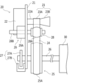
画像形成装置1は、図2及び図3に示されるようなベルト駆動部20を備える。なお、図3は、図2に示されるベルト駆動部20を図2における右側から見た図である。ベルト駆動部20は、モーター22の回転駆動力を、前記感光体ドラムのような被駆動体30に伝達するための機構である。
[Construction of Belt Drive Unit 20]
The
ベルト駆動部20は、支持部21、モーター22、駆動プーリー23、金属ベルト24、従動プーリー25、出力軸26、ロータリーエンコーダー27、押圧プーリー28、及び移動機構29を備える。ロータリーエンコーダー27は、円板形状を有するパルス板27Aとフォトセンサー27Bとを備える。
The
支持部21には、モーター22及びフォトセンサー27Bが固定される。また、支持部21は、モーター22の回転軸22A、出力軸26、及び押圧プーリー28を回転可能に支持する。また、支持部21は、移動機構29の軸受部29Aを支持する。
A
モーター22は、不図示のモーター駆動回路により駆動される。駆動プーリー23は、モーター22の回転軸22Aと連結されており、モーター22により回転される。駆動プーリー23は、本発明の第1プーリーの一例である。なお、本発明の第1プーリーは、モーター22の回転軸22Aと連結された駆動ローラーであってもよい。
The
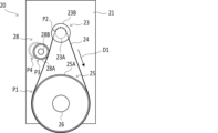
金属ベルト24は、駆動プーリー23及び従動プーリー25に張架され、駆動プーリー23の回転を従動プーリー25に伝達する。金属ベルト24は、例えばステンレス鋼で形成された無端状ベルトである。金属ベルト24は、駆動プーリー23が回転することによって図3に示される移動方向D1へ周回移動する。
The
従動プーリー25は、出力軸26に固定されており、出力軸26と一体的に回転する。従動プーリー25は、本発明の第2プーリーの一例である。出力軸26の一方端部(図2における左側の端部)には、パルス板27Aが固定されており、出力軸26の他方端部には、前記感光体ドラムのような被駆動体30が連結されている。これにより、モーター22の回転駆動力は、駆動プーリー23、金属ベルト24、従動プーリー25、及び出力軸26を介して被駆動体30に伝達される。その結果、モーター22の回転駆動力によって被駆動体30が駆動される。
The driven
ロータリーエンコーダー27は、従動プーリー25の回転速度に応じたパルス信号を出力する。具体的には、ロータリーエンコーダー27のパルス板27Aには、周方向に沿って等間隔に複数のスリットが設けられている。一方、ロータリーエンコーダー27のフォトセンサー27Bには、前記パルス板27Aを挟んで互いに対向する位置に発光部及び受光部が設けられている。そして、パルス板27Aが回転すると、前記発光部からの光が前記スリットを通じて前記受光部に入射される状態と、前記発光部からの光がパルス板27Aで遮光される状態とが繰り返される。その結果、前記受光部に入射する光量が周期的に変化し、従動プーリー25の回転速度に応じた前記パルス信号がロータリーエンコーダー27から出力される。前記パルス信号は、制御部16に入力される。
A
ところで、一般に、軸方向における中央部が膨らんだ、いわゆるクラウン形状の膨出部を有するプーリーにベルトを張架することによって、前記ベルトのずれ(蛇行)が抑制されることが知られている。そこで、金属ベルト24のずれを抑制するために、駆動プーリー23及び従動プーリー25のいずれか一方(例えば、従動プーリー25)に前記膨出部を設けることが考えられる。しかしながら、そのような構成を採用した場合、従動プーリー25に形成されている前記膨出部によって金属ベルト24が塑性変形して湾曲することがある。そうすると、湾曲した金属ベルト24が駆動プーリー23に当接する際に、金属ベルト24の幅方向における両端部に中央部よりも大きな力が作用する。その結果、金属ベルト24の端部が損傷してしまうことがある。これに対して、本実施形態に係る画像形成装置1では、以下で説明するように、金属ベルト24の損傷を抑制することが可能である。
By the way, it is generally known that the deviation (meandering) of the belt is suppressed by stretching the belt over a pulley having a so-called crown-shaped bulging portion that bulges in the center in the axial direction. Therefore, in order to suppress the deviation of the
図4には、金属ベルト24を取り外した状態のベルト駆動部20が示されている。本実施形態では、従動プーリー25に前記膨出部が形成されている。すなわち、図4に示されるように、従動プーリー25には、軸方向における中央部が膨らんだ、いわゆるクラウン形状の第1膨出部25Aが形成されている。第1膨出部25Aは、従動プーリー25の外周に沿って当該外周の全部に設けられており、従動プーリー25の径方向の外側へ膨らんでいる。換言すると、第1膨出部25Aは、従動プーリー25の外周部において、従動プーリー25の外周に沿って連続しており径方向の外側へ湾曲する湾曲面を形成する。
FIG. 4 shows the
金属ベルト24は、駆動プーリー23において円柱状に形成された第1外周部23A及び第1膨出部25Aによって張架される。これにより、金属ベルト24のずれが抑制される。
The
なお、他の実施形態では、駆動プーリー23の第1外周部23Aに前記膨出部が形成されていてもよい。また、第1膨出部25Aは、従動プーリー25の外周に沿って断続的に設けられていてもよい。
In another embodiment, the bulging portion may be formed on the first outer
押圧プーリー28は、金属ベルト24の外周面に接触して設けられ、金属ベルト24の移動によって従動回転する。押圧プーリー28は、本発明の第3プーリーの一例である。図3に示されるように、押圧プーリー28は、金属ベルト24が従動プーリー25から離れる第1位置P1よりも金属ベルト24の移動方向D1の下流側であって、金属ベルト24が駆動プーリー23と接触する第2位置P2よりも移動方向D1の上流側で、金属ベルト24と接触する。
The pressing
図4に示されるように、押圧プーリー28には、軸方向における中央部が膨らんだ、いわゆるクラウン形状の第2膨出部28Aが形成されている。第2膨出部28Aは、本発明の押圧部の一例である。第2膨出部28Aは、押圧プーリー28の外周に沿って当該外周の全部に設けられており、押圧プーリー28の径方向の外側へ膨らんでいる。換言すると、第2膨出部28Aは、押圧プーリー28の外周部において、押圧プーリー28の外周に沿って連続しており径方向の外側へ湾曲する湾曲面を形成する。第2膨出部28Aは、押圧プーリー28の軸方向の曲率が、第1膨出部25Aにおける従動プーリー25の軸方向の曲率よりも大きくなるように形成されている。
As shown in FIG. 4, the pressing
金属ベルト24は、第2膨出部28Aによってその外周面における幅方向の中央部が押圧される。一方、金属ベルト24は、第1膨出部25Aによってその内周面における幅方向の中央部が押圧される。換言すると、金属ベルト24は、第1膨出部25Aから受ける力とは逆方向の力を第2膨出部28Aから受ける。これにより、第1膨出部25Aから受ける力によって金属ベルト24に現れる影響が軽減又は除去される。そのため、第1膨出部25Aから受ける力による金属ベルト24の塑性変形が抑制される。
The second bulging
ところで、金属ベルト24の周長が短く、且つ剛性が高い場合には、モーター22が停止した状態においても、第1膨出部25Aから受ける力によって金属ベルト24に生じる弾性変形が駆動プーリー23側にも現れることがある。即ち、駆動プーリー23側においても、金属ベルト24が湾曲することがある。これに対し、画像形成装置1では、図3に示されるように、第2膨出部28Aが第1位置P1よりも金属ベルト24の移動方向D1の下流側であって第2位置P2よりも移動方向D1の上流側で金属ベルト24を押圧する。また、画像形成装置1では、第2膨出部28Aの表面の曲率は、第1膨出部25Aの表面の曲率よりも大きい。これにより、第1膨出部25Aから受ける力によって金属ベルト24に生じる弾性変形は、金属ベルト24が駆動プーリー23に接触する前に第2膨出部28Aによって除去される。そのため、金属ベルト24が湾曲した状態で駆動プーリー23に接触することが回避される。
By the way, when the
なお、他の実施形態では、第2膨出部28Aが第1位置P1よりも金属ベルト24の移動方向D1の上流側であって第2位置P2よりも移動方向D1の下流側で金属ベルト24を押圧してもよい。また、他の実施形態では、第2膨出部28Aは、押圧プーリー28の外周に沿って断続的に設けられていてもよい。また、他の実施形態では、第2膨出部28Aは、押圧プーリー28の軸方向の曲率が、第1膨出部25Aにおける従動プーリー25の軸方向の曲率以下となるように形成されていてもよい。また、他の実施形態では、押圧プーリー28が第2膨出部28Aを含んでいなくてもよい。また、他の実施形態では、押圧プーリー28に替えて、例えば、延出方向の先端に球面を有する棒状の接触部材が金属ベルト24の外周面に接触して設けられ、当該先端が金属ベルト24の幅方向の中央部を押圧してもよい。
Note that in another embodiment, the second bulging
移動機構29は、押圧プーリー28を、金属ベルト24と接触する第3位置P3(図3参照)と、金属ベルト24から離間する第4位置P4との間で移動させることが可能である。なお、図3には、第4位置P4に配置された状態の押圧プーリー28が破線によって示されている。
The moving
移動機構29は、軸受部29Aと、不図示の駆動部とを備える。軸受部29Aは、押圧プーリー28の回転軸28Bを回転可能に支持する。押圧プーリー28及び軸受部29Aは、支持部21によって第3位置P3と第4位置P4との間を移動可能に支持されている。前記駆動部は、モーター又はソレノイドを含んでおり、軸受部29Aを第3位置P3と第4位置P4との間で移動させる。前記駆動部は、制御部16から入力される制御信号に応じて、軸受部29Aを第3位置P3と第4位置P4との間で移動させる。
The moving
なお、上記のような構成を採用しても、金属ベルト24のずれを完全に防止することは困難であり、金属ベルト24がずれてしまうことがある。そこで、本実施形態に係る画像形成装置1は、金属ベルト24のずれを検知して、必要に応じて金属ベルト24を元の位置に復帰させる機能を備えている。
It should be noted that it is difficult to completely prevent the
具体的に、制御部16は、図1に示されるように、従動プーリー速度検出部161、モーター制御部162、モーター速度検出部163、ずれ検知処理部164、復帰処理部165、及び報知処理部166を含む。なお、制御部16は、前記制御プログラムに従って各種の処理を実行することによりこれらの各処理部として機能する。また、制御部16は、これらの各処理部の一部又は複数の処理機能を実現する電子回路を備えるものであってもよい。
Specifically, as shown in FIG. 1, the
従動プーリー速度検出部161は、従動プーリー25の回転速度を検出する。具体的に、従動プーリー速度検出部161は、ロータリーエンコーダー27から出力される前記パルス信号に基づいて、従動プーリー25の回転速度を検出する。
The driven
モーター制御部162は、従動プーリー速度検出部161により検出される従動プーリー25の回転速度に基づいて、従動プーリー25の回転速度が予め定められた目標速度となるようにモーター22の回転速度をフィードバック制御する。モーター制御部162は、前記モーター駆動回路(不図示)を介して、モーター22の回転速度を制御する。
Based on the rotation speed of the driven
モーター速度検出部163は、モーター22の回転速度を検出する。例えば、モーター速度検出部163は、前記モーター駆動回路(不図示)からモーター22に供給される電流の大きさ、モーター22の回転速度を検出するためのセンサー(例えば、ロータリーエンコーダー、ホールセンサーなど)の出力信号などからモーター22の回転速度を検出する。
A
ずれ検知処理部164は、モーター速度検出部163により検出されるモーター22の回転速度に基づいて、駆動プーリー23の第1外周部23A又は第1膨出部25Aからの金属ベルト24のずれを検知する。以下、ずれ検知処理部164による金属ベルト24のずれの検知方法について説明する。
The displacement
駆動プーリー23には、金属ベルト24の張力により、従動プーリー25に向かう方向の力が作用する。その結果、駆動プーリー23が撓み、駆動プーリー23の先端部(図2における右側の端部)が従動プーリー25に向かう方向に移動する。その結果、金属ベルト24は、駆動プーリー23の第1外周部23Aから駆動プーリー23の先端側にずれ易くなる。金属ベルト24が駆動プーリー23の先端側にずれて、最終的に金属ベルト24が駆動プーリー23から外れてしまうと、画像形成部13による画像の形成が不可能になってしまう。
A force directed toward the driven
本実施形態では、上記のような金属ベルト24のずれを検知するために、図4に示されるように、駆動プーリー23に第2外周部23Bが形成されている。第2外周部23Bは、逆テーパー状に形成されており、第2外周部23Bの径は、軸方向における位置が第1外周部23Aから遠ざかるほど大きくなっている。したがって、金属ベルト24が駆動プーリー23の先端側にずれるほど、金属ベルト24に当接する駆動プーリー23の径が大きくなる。その結果、金属ベルト24との当接位置における駆動プーリー23の周速が速くなり、それに伴って金属ベルト24の移動速度(周回速度)も速くなる。
In this embodiment, a second outer
金属ベルト24の移動速度が速くなると、従動プーリー25の回転速度も速くなるので、モーター制御部162は、従動プーリー25の回転速度が前記目標速度に保たれるように、モーター22の回転速度を遅くする。その結果、金属ベルト24が駆動プーリー23の先端側にずれるほど、モーター22の回転速度は遅くなる。ずれ検知処理部164は、モーター22の回転速度を監視し、モーター22の回転速度が予め定められた閾値を下回った場合に、金属ベルト24がずれたと判定する。
As the moving speed of the
なお、前記閾値は、金属ベルト24が第1外周部23Aに張架されているときのモーター22の回転速度よりも低く、且つ、金属ベルト24が駆動プーリー23の先端部(図2における右側の端部)に張架されているときのモーター22の回転速度よりも高い値に設定される。これにより、ずれ検知処理部164は、金属ベルト24が駆動プーリー23の先端部までずれてしまう前に、金属ベルト24がずれたと判定することができる。
The threshold value is lower than the rotation speed of the
なお、本実施形態では、駆動プーリー23において、第1外周部23Aよりも先端側(すなわち、図4における右側)に第2外周部23Bが設けられているが、他の実施形態では、第1外周部23Aよりも基端側(すなわち、図4における左側)に、基端に近づくほど径が大きくなる逆テーパー状の外周部が設けられてもよい。また、第1外周部23Aの両側に逆テーパー状の外周部が設けられてもよい。
In the present embodiment, the
また、他の実施形態では、従動プーリー25において、第1膨出部25Aの一方側又は両側に逆テーパー状の外周部が設けられてもよい。例えば、図6に示されるように、従動プーリー25において、第1膨出部25Aよりも被駆動体30側に逆テーパー状の外周部25Bが設けられてもよい。この場合、金属ベルト24が従動プーリー25の第1膨出部25Aからずれるほど、金属ベルト24に当接する従動プーリー25の径が大きくなる。その結果、従動プーリー25の回転速度が遅くなるので、モーター制御部162は、従動プーリー25の回転速度が前記目標速度に保たれるように、モーター22の回転速度を速くする。よって、この場合は、ずれ検知処理部164は、モーター22の回転速度が予め定められた閾値を上回った場合に、金属ベルト24がずれたと判定する。
In another embodiment, the driven
復帰処理部165は、ずれ検知処理部164により金属ベルト24のずれが検知された場合に、金属ベルト24を元の位置に復帰させる。具体的に、復帰処理部165は、駆動プーリー23の軸方向の傾きを調整することが可能な傾き調整機構(不図示)を制御して、金属ベルト24を元の位置に復帰させる。また、復帰処理部165は、金属ベルト24を元の位置に復帰させる前に、押圧プーリー28を金属ベルト24から離間させる。具体的に、復帰処理部165は、移動機構29を制御して、押圧プーリー28を第3位置P3から第4位置P4に移動させる。
The
なお、金属ベルト24を元の位置に復帰させる方法としては種々の方法が考えられる。例えば、他の実施形態では、復帰処理部165は、モーター22を逆回転させる(すなわち、画像形成時の回転方向とは逆方向に回転させる)ことによって、金属ベルト24を元の位置に復帰させてもよい。
Various methods are conceivable for returning the
報知処理部166は、ずれ検知処理部164により金属ベルト24のずれが検知された場合に、その旨を報知する。なお、報知処理部166は、ずれ検知処理部164により金属ベルト24のずれが検知された場合に、即座に、その旨を報知してもよい。もしくは、報知処理部166は、ずれ検知処理部164により金属ベルト24のずれが検知された後、復帰処理部165により金属ベルト24を元の位置に復帰できなかった場合に、その旨を報知してもよい。
When the displacement
例えば、報知処理部166は、画像形成装置1のメンテンナンス業務を請け負っている事業者のサーバー(不図示)に、金属ベルト24のずれが検知された旨を示す情報を送信してもよい。もしくは、報知処理部166は、金属ベルト24の点検を促すメッセージを操作表示部10に表示させてもよい。
For example, the
[ずれ検知処理]
次に、図5を参照しつつ、制御部16によって実行されるずれ検知処理の手順の一例について説明する。ここで、ステップS1,S2,・・・は、制御部16により実行される処理手順(ステップ)の番号を表している。なお、前記ずれ検知処理は、例えば、画像形成装置1の電源がオンされたことに応じて開始される。
[Deviation detection processing]
Next, an example of the procedure of deviation detection processing executed by the
<ステップS1>
まず、ステップS1において、制御部16は、モーター22の回転速度を検出する。例えば、制御部16は、前記モーター駆動回路(不図示)からモーター22に供給される電流の大きさ、モーター22の回転速度を検出するためのセンサー(例えば、ロータリーエンコーダー、ホールセンサーなど)の出力信号などからモーター22の回転速度を検出する。ステップS1の処理は、モーター速度検出部163により実行される。
<Step S1>
First, in step S<b>1 , the
<ステップS2>
ステップS2において、制御部16は、ステップS1で検出されたモーター22の回転速度が予め定められた閾値を下回っているか否かを判断する。そして、モーター22の回転速度が前記閾値を下回っていると判断されると(S2:Yes)、処理がステップS3に移行する。一方、モーター22の回転速度が前記閾値を下回っていないと判断されると(S2:No)、処理がステップS1に戻る。ステップS2の処理は、ずれ検知処理部164により実行される。
<Step S2>
In step S2, the
<ステップS3>
ステップS3において、制御部16は、復帰処理を開始する。例えば、制御部16は、金属ベルト24を元の位置に復帰させるべく、前記調整機構(不図示)を制御する。ステップS3の処理は、復帰処理部165により実行される。
<Step S3>
In step S3, the
ここで、制御部16は、金属ベルト24を元の位置に復帰させる前に、押圧プーリー28を金属ベルト24から離間させる。具体的に、制御部16は、移動機構29を制御して、押圧プーリー28を第3位置P3から第4位置P4に移動させる。これにより、金属ベルト24を元の位置に復帰させる際に、押圧プーリー28がその邪魔となることがない。
Here, the
<ステップS4>
ステップS4において、制御部16は、モーター22の回転速度を検出する。ステップS4の処理は、モーター速度検出部163により実行される。
<Step S4>
At step S<b>4 , the
<ステップS5>
ステップS5において、制御部16は、ステップS4で検出されたモーター22の回転速度が前記閾値を下回っているか否かを判断する。そして、モーター22の回転速度が前記閾値を下回っていると判断されると(S5:Yes)、処理がステップS6に移行する。一方、モーター22の回転速度が前記閾値を下回っていないと判断されると(S5:No)、処理がステップS1に戻る。この場合、制御部16は、移動機構29を制御して、押圧プーリー28を第4位置P4から第3位置P3に移動させる。
<Step S5>
In step S5, the
<ステップS6>
ステップS6において、制御部16は、前記復帰処理がタイムアウトしたか否かを判断する。すなわち、制御部16は、ステップS3で前記復帰処理が開始されてから、予め定められた時間が経過したか否かを判断する。そして、前記復帰処理がタイムアウトしたと判断されると(S6:Yes)、処理がステップS7に移行する。一方、前記復帰処理がタイムアウトしていないと判断されると(S6:No)、処理がステップS4に戻る。
<Step S6>
In step S6, the
<ステップS7>
ステップS7において、制御部16は、前記復帰処理を終了する。例えば、制御部16は、モーター22を停止させる。
<Step S7>
In step S7, the
<ステップS8>
ステップS8において、制御部16は、エラー報知を行う。例えば、制御部16は、画像形成装置1のメンテンナンス業務を請け負っている事業者のサーバー(不図示)に、金属ベルト24のずれが検知された旨を示す情報を送信する。そして、前記ずれ検知処理が終了される。ステップS8の処理は、報知処理部166により実行される。
<Step S8>
In step S8, the
以上のように、本実施形態に係る画像形成装置1では、第2膨出部28Aを含む押圧プーリー28が、金属ベルト24の外周面に接触して設けられている。これにより、第1膨出部25Aから受ける力による金属ベルト24の塑性変形が抑制されて、湾曲した状態の金属ベルト24が駆動プーリー23に当接することが抑制される。そのため、金属ベルト24の損傷が抑制される。
As described above, in the
また、本実施形態に係る画像形成装置1では、金属ベルト24が検知された場合に、復帰処理又は報知処理が行われる。よって、駆動プーリー23又は従動プーリー25から金属ベルト24が外れてしまう前に復帰処理又は報知処理が行われるので、突然に画像形成部13による画像の形成が不可能になってしまうことを防止することができる。
Further, in the
また、本実施形態では、モーター22の回転速度に基づいて金属ベルト24のずれが検知されるので、簡単な構成で金属ベルト24のずれを検知することが可能である。
Further, in the present embodiment, since the deviation of the
[変形例]
なお、被駆動体30は、前記感光体ドラムに限らず、前記現像装置に設けられる現像ローラー、前記転写装置に設けられる転写ベルトを周回移動させるための駆動ローラーなどであってもよい。特に、前記感光体ドラム、前記現像ローラー、及び前記転写ベルトにとっては、ギア同士の接触によって発生する振動による画像品質の低下を避けるために、ギア駆動よりもベルト駆動の方が好ましい。
[Modification]
Note that the driven
また、画像形成装置1において、金属ベルト24に替えて、樹脂製のベルトが用いられていてもよい。
Also, in the
また、画像形成装置1において、金属ベルト24は、駆動プーリー23、及び従動プーリー25を含む三つ以上のプーリーによって張架されていてもよい。この場合、本発明における第1プーリー又は第2プーリーは、三つ以上のプーリーのうちのいずれかであればよい。
Moreover, in the
1 画像形成装置
13 画像形成部
16 制御部
161 従動プーリー速度検出部
162 モーター制御部
163 モーター速度検出部
164 ずれ検知処理部
165 復帰処理部
166 報知処理部
20 ベルト駆動部
21 支持部
22 モーター
22A 回転軸
23 駆動プーリー
23A 第1外周部
23B 第2外周部
24 金属ベルト
25 従動プーリー
25A 第1膨出部
25B 外周部
26 出力軸
27 ロータリーエンコーダー
27A パルス板
27B フォトセンサー
28 押圧プーリー
28A 第2膨出部
28B 回転軸
29 移動機構
29A 軸受部
30 被駆動体
1
Claims (4)
前記第2プーリーの外周部における軸方向の中央部において前記第2プーリーの外周に沿って設けられ、前記第2プーリーの径方向の外側へ膨らむ第1膨出部と、
前記第1プーリー及び前記第1膨出部によって張架され、前記第1膨出部により塑性変形するベルトと、
前記ベルトの外周面における前記ベルトの幅方向の中央部を押圧する押圧部と、
前記ベルトの外周面に接触して設けられる第3プーリーと、
を備え、
前記押圧部は、前記ベルトが前記第2プーリーから離れる第1位置よりも前記ベルトの移動方向の下流側であって前記ベルトが前記第1プーリーと接触する第2位置よりも前記移動方向の上流側で前記ベルトを押圧し、
前記押圧部は、前記第3プーリーの外周部における軸方向の中央部において前記第3プーリーの外周に沿って設けられ、前記第3プーリーの径方向の外側へ膨らむ第2膨出部であって、
前記第2膨出部における前記第3プーリーの軸方向の曲率は、前記第1膨出部における前記第2プーリーの軸方向の曲率よりも大きい、ベルト駆動装置。 a first pulley and a second pulley;
a first bulging portion provided along the outer periphery of the second pulley at an axial center portion of the outer peripheral portion of the second pulley and bulging outward in the radial direction of the second pulley;
a belt stretched by the first pulley and the first bulging portion and plastically deformed by the first bulging portion ;
a pressing portion that presses a center portion in the width direction of the belt on the outer peripheral surface of the belt;
a third pulley provided in contact with the outer peripheral surface of the belt;
with
The pressing portion is downstream in the moving direction of the belt from a first position where the belt separates from the second pulley and upstream in the moving direction from a second position at which the belt contacts the first pulley. pressing the belt on the side,
The pressing portion is provided along the outer periphery of the third pulley at an axial center portion of the outer peripheral portion of the third pulley, and is a second bulging portion that bulges outward in the radial direction of the third pulley. ,
The belt driving device, wherein the axial curvature of the third pulley at the second bulging portion is larger than the axial curvature of the second pulley at the first bulging portion.
請求項1に記載のベルト駆動装置。 A moving mechanism capable of moving the pressing portion between a third position in contact with the belt and a fourth position away from the belt,
2. A belt drive device according to claim 1 .
前記ベルト駆動装置により駆動される被駆動体を含み、シートに画像を形成する画像形成部と、
を備える画像形成装置。 A belt drive device according to claim 1 or 2 ;
an image forming unit including a driven body driven by the belt driving device and forming an image on a sheet;
An image forming apparatus comprising:
請求項3に記載の画像形成装置。
The driven body includes at least one of a photosensitive drum, a developing roller, and a driving roller that circulates the transfer belt.
The image forming apparatus according to claim 3 .
Priority Applications (4)
| Application Number | Priority Date | Filing Date | Title |
|---|---|---|---|
| JP2019001216A JP7281069B2 (en) | 2019-01-08 | 2019-01-08 | belt driving device, image forming device |
| CN201911299920.7A CN111413855B (en) | 2019-01-08 | 2019-12-17 | Belt drive device, image forming device |
| EP19217108.0A EP3683630B1 (en) | 2019-01-08 | 2019-12-17 | Belt drive device capable of restricting damage of belt, image forming apparatus |
| US16/736,293 US10895830B2 (en) | 2019-01-08 | 2020-01-07 | Belt drive device capable of restricting damage of belt, image forming apparatus |
Applications Claiming Priority (1)
| Application Number | Priority Date | Filing Date | Title |
|---|---|---|---|
| JP2019001216A JP7281069B2 (en) | 2019-01-08 | 2019-01-08 | belt driving device, image forming device |
Publications (2)
| Publication Number | Publication Date |
|---|---|
| JP2020112171A JP2020112171A (en) | 2020-07-27 |
| JP7281069B2 true JP7281069B2 (en) | 2023-05-25 |
Family
ID=68944289
Family Applications (1)
| Application Number | Title | Priority Date | Filing Date |
|---|---|---|---|
| JP2019001216A Active JP7281069B2 (en) | 2019-01-08 | 2019-01-08 | belt driving device, image forming device |
Country Status (4)
| Country | Link |
|---|---|
| US (1) | US10895830B2 (en) |
| EP (1) | EP3683630B1 (en) |
| JP (1) | JP7281069B2 (en) |
| CN (1) | CN111413855B (en) |
Families Citing this family (2)
| Publication number | Priority date | Publication date | Assignee | Title |
|---|---|---|---|---|
| JP2022154798A (en) * | 2021-03-30 | 2022-10-13 | 京セラドキュメントソリューションズ株式会社 | Image forming apparatus |
| US20240401687A1 (en) * | 2023-01-31 | 2024-12-05 | Belt Technologies, Inc. | Belt Pulley Assembly |
Citations (2)
| Publication number | Priority date | Publication date | Assignee | Title |
|---|---|---|---|---|
| JP2004190712A (en) | 2002-12-09 | 2004-07-08 | Ricoh Co Ltd | Power transmission device, unit, and image forming device |
| JP2012145179A (en) | 2011-01-13 | 2012-08-02 | Konica Minolta Business Technologies Inc | Rotation transmitting mechanism and image forming device with the same |
Family Cites Families (14)
| Publication number | Priority date | Publication date | Assignee | Title |
|---|---|---|---|---|
| US3387758A (en) * | 1965-11-12 | 1968-06-11 | Rca Corp | Low jitter web and tape drive |
| JPS6152753U (en) * | 1984-09-11 | 1986-04-09 | ||
| EP0603776A1 (en) * | 1992-12-22 | 1994-06-29 | Minnesota Mining And Manufacturing Company | Free span coater with backside support |
| JP3083684B2 (en) * | 1993-06-29 | 2000-09-04 | 富士写真フイルム株式会社 | Belt transmission mechanism |
| JP2001080780A (en) * | 1999-09-10 | 2001-03-27 | Toshiba Corp | Paper processing equipment |
| JP2004324801A (en) * | 2003-04-25 | 2004-11-18 | Ricoh Co Ltd | Power transmission device |
| JP4871716B2 (en) * | 2006-12-14 | 2012-02-08 | キヤノン株式会社 | Drive transmission device |
| JP5487833B2 (en) * | 2009-09-16 | 2014-05-14 | 富士ゼロックス株式会社 | Fixing apparatus and image forming apparatus |
| JP5392053B2 (en) * | 2009-12-16 | 2014-01-22 | トヨタ自動車株式会社 | Manufacturing method of laminated ring |
| JP5813602B2 (en) * | 2012-08-31 | 2015-11-17 | 京セラドキュメントソリューションズ株式会社 | Driving device and image forming apparatus provided with the same |
| JP2014159867A (en) * | 2013-02-21 | 2014-09-04 | Kyocera Document Solutions Inc | Belt drive mechanism, belt drive device, and pulley |
| JP5819869B2 (en) * | 2013-02-21 | 2015-11-24 | 京セラドキュメントソリューションズ株式会社 | Belt drive mechanism, belt drive device, and pulley |
| JP2014159866A (en) * | 2013-02-21 | 2014-09-04 | Kyocera Document Solutions Inc | Belt drive mechanism and belt drive device |
| JP5903412B2 (en) * | 2013-08-08 | 2016-04-13 | 京セラドキュメントソリューションズ株式会社 | Drive device |
-
2019
- 2019-01-08 JP JP2019001216A patent/JP7281069B2/en active Active
- 2019-12-17 EP EP19217108.0A patent/EP3683630B1/en not_active Not-in-force
- 2019-12-17 CN CN201911299920.7A patent/CN111413855B/en not_active Expired - Fee Related
-
2020
- 2020-01-07 US US16/736,293 patent/US10895830B2/en not_active Expired - Fee Related
Patent Citations (2)
| Publication number | Priority date | Publication date | Assignee | Title |
|---|---|---|---|---|
| JP2004190712A (en) | 2002-12-09 | 2004-07-08 | Ricoh Co Ltd | Power transmission device, unit, and image forming device |
| JP2012145179A (en) | 2011-01-13 | 2012-08-02 | Konica Minolta Business Technologies Inc | Rotation transmitting mechanism and image forming device with the same |
Also Published As
| Publication number | Publication date |
|---|---|
| CN111413855A (en) | 2020-07-14 |
| US20200218177A1 (en) | 2020-07-09 |
| EP3683630A1 (en) | 2020-07-22 |
| EP3683630B1 (en) | 2022-06-15 |
| JP2020112171A (en) | 2020-07-27 |
| CN111413855B (en) | 2023-03-14 |
| US10895830B2 (en) | 2021-01-19 |
Similar Documents
| Publication | Publication Date | Title |
|---|---|---|
| JP2005035710A (en) | Sheet conveying apparatus, image forming apparatus, and image reading apparatus | |
| JP5506994B2 (en) | Image forming apparatus | |
| JP5865872B2 (en) | Image forming apparatus | |
| US11204570B2 (en) | Contact-separation mechanism, fixing device, and image forming apparatus | |
| JP7281069B2 (en) | belt driving device, image forming device | |
| CN119610910A (en) | Sheet detecting device and image forming apparatus | |
| JP3893961B2 (en) | Sheet sensor and sheet conveying apparatus | |
| JP2013077953A (en) | Image reader | |
| WO2019116846A1 (en) | Belt drive device and image forming device | |
| JP4687284B2 (en) | Paper feeding device and image forming apparatus | |
| JP5624968B2 (en) | Image forming apparatus | |
| JP2016179868A (en) | Paper feeding device and control program of paper feeding device | |
| JP7596764B2 (en) | SHEET CONVEYING APPARATUS, IMAGE READING APPARATUS, AND SHEET CONVEYING METHOD | |
| JP5859084B2 (en) | Image forming apparatus | |
| JP5919350B2 (en) | Image reading apparatus and image forming apparatus | |
| JP5826352B2 (en) | Image forming apparatus | |
| JP4189589B2 (en) | Paper feeder | |
| JP7655400B2 (en) | Image forming device | |
| WO2019069586A1 (en) | Belt drive device and image formation device | |
| JP2024164675A (en) | Image forming device | |
| JP7484269B2 (en) | Sheet conveying device | |
| JP2008030888A (en) | Paper feeding device, image forming apparatus, and paper feeding device control method | |
| JP2025109313A (en) | Sheet feeding device and image forming apparatus | |
| JP5818503B2 (en) | End position detection apparatus and image forming apparatus | |
| JP6204433B2 (en) | Image reading apparatus and image forming apparatus |
Legal Events
| Date | Code | Title | Description |
|---|---|---|---|
| A621 | Written request for application examination |
Free format text: JAPANESE INTERMEDIATE CODE: A621 Effective date: 20211228 |
|
| A977 | Report on retrieval |
Free format text: JAPANESE INTERMEDIATE CODE: A971007 Effective date: 20221128 |
|
| A131 | Notification of reasons for refusal |
Free format text: JAPANESE INTERMEDIATE CODE: A131 Effective date: 20221206 |
|
| A521 | Request for written amendment filed |
Free format text: JAPANESE INTERMEDIATE CODE: A523 Effective date: 20230202 |
|
| TRDD | Decision of grant or rejection written | ||
| A01 | Written decision to grant a patent or to grant a registration (utility model) |
Free format text: JAPANESE INTERMEDIATE CODE: A01 Effective date: 20230411 |
|
| A61 | First payment of annual fees (during grant procedure) |
Free format text: JAPANESE INTERMEDIATE CODE: A61 Effective date: 20230424 |
|
| R150 | Certificate of patent or registration of utility model |
Ref document number: 7281069 Country of ref document: JP Free format text: JAPANESE INTERMEDIATE CODE: R150 |