JP7280732B2 - Watch parts, watch movements and watches - Google Patents
Watch parts, watch movements and watches Download PDFInfo
- Publication number
- JP7280732B2 JP7280732B2 JP2019060521A JP2019060521A JP7280732B2 JP 7280732 B2 JP7280732 B2 JP 7280732B2 JP 2019060521 A JP2019060521 A JP 2019060521A JP 2019060521 A JP2019060521 A JP 2019060521A JP 7280732 B2 JP7280732 B2 JP 7280732B2
- Authority
- JP
- Japan
- Prior art keywords
- hairspring
- restricting
- watch
- central axis
- wheel
- Prior art date
- Legal status (The legal status is an assumption and is not a legal conclusion. Google has not performed a legal analysis and makes no representation as to the accuracy of the status listed.)
- Active
Links
Images


Description
本発明は、時計用部品、時計用ムーブメントおよび時計に関する。 The present invention relates to watch components, watch movements and timepieces.
機械式時計は、表輪列を構成する香箱車、二番車、三番車および四番車の回転を制御するための脱進・調速機構を備えている。一般的な脱進・調速機構は、がんぎ車と、てんぷとを備えている。てんぷは、てん輪と、てん真と、ひげぜんまいと、ひげ玉とを備えている。てん真は、てん輪の回転中心となる。ひげ玉は、ひげぜんまいをてん真に固定する。ひげぜんまいは、渦巻状に形成され、拡縮によりてん輪を往復回転させる。ひげぜんまいは、カシメ固定、溶接等によりひげ玉に固定される(特許文献1,2参照)。 A mechanical watch has an escapement/governing mechanism for controlling the rotation of a barrel wheel, second wheel, third wheel and fourth wheel that constitute a front wheel train. A typical escapement/governing mechanism has an escape wheel and a balance. The balance has a balance wheel, a balance, a hairspring, and a hairball. The balance shaft is the center of rotation of the balance wheel. The hairball secures the hairspring to the spring. A hairspring is formed in a spiral shape, and expands and contracts to reciprocate the balance wheel. The hairspring is fixed to the hairball by caulking, welding, or the like (see Patent Documents 1 and 2).
しかしながら、ひげぜんまいをカシメ固定によりひげ玉に固定する場合には、ひげぜんまいの形状のばらつきに対応してひげ玉を選択使用することが必要となるため、製造に手間がかかる場合があった。一方、ひげぜんまいを溶接等によりひげ玉に固定する場合には、ひげぜんまいがひげ玉に対して傾斜して固定され、脱進・調速機構の機械的特性に影響が及ぶ可能性があった。 However, when the hairspring is fixed to the hairspring by crimping, it is necessary to select and use the hairspring according to variations in the shape of the hairspring. On the other hand, when the hairspring is fixed to the hairball by welding or the like, the hairspring is fixed at an angle to the hairball, which may affect the mechanical properties of the escapement/speed control mechanism. .
本発明の一態様は、製造が容易であり、かつ、ひげぜんまいを正しい姿勢でひげ玉に固定することができる時計用部品、時計用ムーブメントおよび時計を提供することを目的とする。 An object of one aspect of the present invention is to provide a timepiece component, a timepiece movement, and a timepiece that are easy to manufacture and that can fix a hairspring to a hairspring in a correct posture.
(1)本発明の一態様は、てん真に外嵌固定されるひげ玉と、前記ひげ玉に固定されたひげぜんまいと、を備え、前記ひげ玉は、前記ひげぜんまいの中心軸が傾く方向の前記ひげぜんまいの姿勢変化を規制する規制凸部を有する、時計用部品を提供する。 (1) One aspect of the present invention includes a hairspring externally fixed to a spring and a hairspring fixed to the hairspring, wherein the hairball is tilted in a direction in which the central axis of the hairspring tilts. A timepiece component having a regulating convex portion for regulating a change in posture of the balance spring.
前記構成によれば、ひげ玉が規制凸部を有するため、ひげぜんまいをひげ玉に接合する際に、中心軸が傾く方向のひげぜんまいの姿勢変化が規制凸部によって規制される。よって、ひげぜんまいを正しい姿勢でひげ玉に固定することができる。
前記構成によれば、ひげぜんまいをカシメ固定する場合と異なり、ひげぜんまいの形状にばらつきが生じた場合でも、ひげぜんまいをひげ玉に固定することができる。よって、ひげぜんまいの形状に応じて複数のひげ玉を選択使用する必要はなく、製造が容易である。
According to the above configuration, since the hairspring has the regulating projection, when the hairspring is joined to the hairball, the regulating projection regulates the change in posture of the hairspring in the direction in which the central axis is tilted. Therefore, the hairspring can be fixed to the hairball in a correct posture.
According to the above configuration, unlike the case where the hairspring is crimped and fixed, the hairspring can be fixed to the hairball even when the shape of the hairspring varies. Therefore, it is not necessary to select and use a plurality of hairsprings according to the shape of the hairspring, which facilitates manufacturing.
(2)前記規制凸部は、複数設けられ、前記複数の規制凸部は、第1規制凸部と、前記中心軸に沿う軸方向から見て前記第1規制凸部より前記ひげぜんまいの内端側に位置する第2規制凸部とを含むことが好ましい。 (2) A plurality of the restricting protrusions are provided, and the plurality of restricting protrusions are located within the balance spring from the first restricting protrusions and the first restricting protrusions when viewed in the axial direction along the central axis. It is preferable to include a second restricting convex portion positioned on the end side.
前記構成によれば、中心軸周り方向の広い範囲でひげぜんまいの傾動を規制できる。よって、ひげぜんまいを正しい姿勢でひげ玉に固定することができる。 According to the above configuration, tilting of the balance spring can be restricted over a wide range in the direction around the central axis. Therefore, the hairspring can be fixed to the hairball in a correct posture.
(3)前記規制凸部には、前記ひげぜんまいが前記ひげ玉の径方向外方に移動するのを規制する係止部が形成されていることが好ましい。 (3) It is preferable that the restricting convex portion is formed with an engaging portion that restricts the hairspring from moving outward in the radial direction of the hairball.
前記構成によれば、前記係止部によってひげぜんまいの傾動を規制できる。よって、ひげぜんまいを正しい姿勢でひげ玉に固定することができる。 According to the above configuration, tilting of the balance spring can be restricted by the locking portion. Therefore, the hairspring can be fixed to the hairball in a correct posture.
(4)前記規制凸部は、複数設けられ、前記複数の規制凸部のうち少なくとも1つは、前記ひげぜんまいに対して前記ひげ玉の軸方向の一端側に形成され、この規制凸部以外の規制凸部のうち少なくとも1つは、前記ひげぜんまいに対して前記ひげ玉の軸方向の他端側に形成されていてもよい。 (4) A plurality of the restricting protrusions are provided, and at least one of the plurality of restricting protrusions is formed on one end side of the hairspring in the axial direction of the hairspring. may be formed on the other end side of the hair ball in the axial direction with respect to the hair spring.
前記構成によれば、ひげぜんまいの両端側に規制凸部を有するため、ひげぜんまいの傾動を防ぐ効果の点で優れている。 According to the above configuration, since the hairspring has the regulating projections on both end sides of the hairspring, it is excellent in terms of the effect of preventing the hairspring from tilting.
(5)前記複数の規制凸部は、軸方向から見て位置を違えて設けられていることが好ましい。 (5) It is preferable that the plurality of restricting protrusions are provided at different positions when viewed from the axial direction.
前記構成によれば、規制凸部を電鋳法などの成型法により形成するのが容易となる。 According to the above configuration, it becomes easy to form the restricting convex portion by a molding method such as an electroforming method.
(6)本発明の他の態様は、前記時計用部品が組み込まれた時計用ムーブメントを提供する。 (6) Another aspect of the present invention provides a timepiece movement incorporating the timepiece component.
(7)本発明のさらに他の態様は、前記時計用ムーブメントを備えた時計を提供する。 (7) Still another aspect of the present invention provides a timepiece including the timepiece movement.
本発明の一態様によれば、製造が容易であり、かつ、ひげぜんまいを正しい姿勢でひげ玉に固定することができる。 According to one aspect of the present invention, manufacturing is easy, and the hairspring can be fixed to the hairball in a correct posture.
本発明の実施形態について、図面を用いて説明する。
以下では、まず実施形態に係る機械式の腕時計(請求項の「時計」に相当。)およびこの腕時計に組み込まれたムーブメント(請求項の「時計用ムーブメント」に相当。)について説明したあと、時計用部品の詳細について説明する。
An embodiment of the present invention will be described with reference to the drawings.
In the following, first, a mechanical wristwatch (corresponding to the "clock" in the claims) according to the embodiment and a movement incorporated in this wristwatch (corresponding to the "clock movement" in the claims) will be described. The details of the parts for
[時計]
一般に、時計の駆動部分を含む機械体を「ムーブメント」と称する。このムーブメントに文字板、針を取り付けて、時計ケースの中に入れて完成品にした状態を時計の「コンプリート」と称する。時計の基板を構成する地板の両側のうち、時計ケースのガラスのある方の側、すなわち文字板のある方の側をムーブメントの「裏側」と称する。また、地板の両側のうち、時計ケースのケース裏蓋のある方の側、すなわち文字板と反対の側をムーブメントの「表側」と称する。
[clock]
In general, the mechanical body including the driving part of the watch is called "movement". A dial and hands are attached to this movement, and it is called a "complete" watch when it is placed in a watch case. Of the two sides of the main plate that constitutes the substrate of the watch, the side with the glass of the watch case, that is, the side with the dial is referred to as the "back side" of the movement. Of the two sides of the main plate, the side on which the case back of the watch case is located, that is, the side opposite to the dial is referred to as the "front side" of the movement.
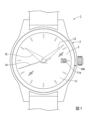
図1は、実施形態に係る時計1の外観図である。図1に示すように、本実施形態の時計1のコンプリートは、図示しないケース裏蓋、およびガラス2からなる時計ケース3内に、ムーブメント100と、時に関する情報を示す目盛り等を有する文字板11と、時を示す時針12、分を示す分針13および秒を示す秒針14を含む指針と、を備えている。文字板11には、日付を表す数字を明示させる日窓11aが開口している。これにより、時計1は、時刻に加え、日付を確認することが可能とされている。
FIG. 1 is an external view of a timepiece 1 according to an embodiment. As shown in FIG. 1, the complete watch 1 of this embodiment has a
図2は、ムーブメント表側の平面図である。図2では、図面を見やすくするため、ムーブメント100を構成する時計部品のうち一部の図示を省略している。
図2に示すように、機械式時計のムーブメント100は、基板を構成する地板102を有している。地板102の巻真案内穴102aには、巻真110が回転可能に組み込まれている。この巻真110は、おしどり190、かんぬき192、かんぬきばね194および裏押さえ196を含む切換装置によって、軸線方向の位置が決められている。
巻真110を回転させると、つづみ車(不図示)の回転を介してきち車112が回転する。きち車112の回転により丸穴車114および角穴車116が順に回転し、香箱車120に収容されたぜんまい(不図示)が巻き上げられる。
FIG. 2 is a plan view of the front side of the movement. In FIG. 2, some of the timepiece components that make up the
As shown in FIG. 2, a
When the
香箱車120は、地板102と香箱受160との間で回転可能に支持されている。二番車124、三番車126、四番車128およびがんぎ車130は、地板102と輪列受162との間で回転可能に支持されている。
ぜんまいの復元力により香箱車120が回転すると、香箱車120の回転により二番車124、三番車126、四番車128およびがんぎ車130が順に回転する。これら香箱車120、二番車124、三番車126および四番車128は、表輪列を構成する。
The
When the
二番車124が回転すると、その回転に基づいて筒かな(不図示)が同時に回転し、この筒かなに取り付けられた分針13(図1参照)が「分」を表示する。また、筒かなの回転に基づいて日の裏車(不図示)の回転を介して筒車(不図示)が回転し、この筒車に取り付けられた時針12(図1参照)が「時」を表示する。
When the center wheel &
表輪列の回転を制御するための脱進・調速装置は、がんぎ車130、アンクル142およびてんぷ10で構成されている。
がんぎ車130の外周には歯130aが形成されている。アンクル142は、地板102とアンクル受164との間で回転可能に支持されており、一対のつめ石142a,142bを備えている。アンクル142の一方のつめ石142aが、がんぎ車130の歯130aに係合した状態で、がんぎ車130は一時的に停止している。
てんぷ10は、一定周期で往復回転することにより、がんぎ車130の歯130aに、アンクル142の一方のつめ石142aおよび他方のつめ石142bを、交互に係合および解除させている。これにより、がんぎ車130を一定速度で脱進させている。
An escapement/governing device for controlling the rotation of the front train wheel is composed of an
The
[てんぷ]
図3は、第1実施形態に係る時計用部品15を備えたてんぷ10の平面図である。図3に示すように、てんぷ10は、主にてん輪20と、てん真30と、時計用部品15と、を備えている。
[attachment]
FIG. 3 is a plan view of the
[てん輪]
てん輪20は、例えば真鍮等の金属により形成されており、略円環状に形成されたてん輪本体部21を備えている。てん輪本体部21の中心軸は、てんぷ10の回転中心である中心軸Oと一致している。中心軸Oに沿う方向を「軸方向」という。
てん輪本体部21の内周面21aからは、中心軸Oに向かって径方向に沿うように四本のアーム部23(23a~23d)が延設されている。四本のアーム部23a~23dは、てん輪本体部21の周方向に90°ピッチとなるように、略等間隔に形成されている。四本のアーム部23a~23dは、中心軸O近傍で連結されている。四本のアーム部23a~23dの連結部25には、中心軸Oと同軸の嵌合孔(図示略)が形成されている。
[Balance]
The
Four arm portions 23 (23a to 23d) extend radially toward the central axis O from the inner
[てん真]
てんぷ10は、中心軸Oと同軸上に、てん真30を備えている。てん真30は、例えば真鍮等の金属により形成された棒状の部材である。てん真30は、中心軸Oまわりに回転可能となっている。てん輪20とてん真30とは一体的に動作する。
[Tenma]
The
[時計用部品](第1実施形態)
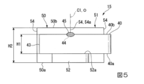
図4は、時計用部品15の一部を示す平面図である。図5は、時計用部品の一部を示す側面図である。図4および図5に示すように、時計用部品15は、ひげぜんまい40と、ひげ玉50とを備える。
以下、図5に即して上下の位置関係を仮に定める。すなわち、図5において上に向かう方向は上方であり、下に向かう方向は下方である。ここで定めた位置関係は時計用部品15の使用時の姿勢を限定しない。上下方向を高さ方向ともいう。中心軸Oは上下方向に平行である。
[Watch parts] (first embodiment)
FIG. 4 is a plan view showing part of the
Hereinafter, the vertical positional relationship is provisionally determined according to FIG. That is, the upward direction in FIG. 5 is upward, and the downward direction is downward. The positional relationship defined here does not limit the attitude of the
(ひげぜんまい)
図3に示すように、ひげぜんまい40は、ひげぜんまい本体41と、円弧部42とを備える。ひげぜんまい本体41は、例えば鉄、ニッケル等の金属で構成された薄板ばねである。ひげぜんまい40は、厚さ方向に湾曲して形成されている。ひげぜんまい本体41は、複数の巻き数をもつ渦巻状に形成されている。円弧部42は、ひげぜんまい本体41の外周側の端部に連設されている。円弧部42の外周側端部42aは、ひげ持106に固定されている。
(hairspring)
As shown in FIG. 3 , the
ひげぜんまい40は、後述するように、ひげ玉50に固定されている。ひげぜんまい40の中心軸C1は中心軸Oと一致する。ひげぜんまい40の下縁40a(第1側縁)および上縁40b(第2側縁)は、軸方向に直交する面に沿う。
The
図5に示すように、ひげぜんまい40の高さH1は、ひげ玉50の高さH2より小である。ひげぜんまい40は、ひげ玉50の下端50aより高く、かつひげ玉50の上端50bより低い位置にある。
As shown in FIG. 5, the height H1 of the
(ひげ玉)
図4に示すように、ひげ玉50は、本体部51と、規制凸部52とを備えている。ひげ玉50は、例えばニッケル、ニッケル合金等により形成されている。本体部51は、外嵌固定部53と、複数の支持部54とを備える。外嵌固定部53は、てん真30に外嵌可能な開口53aを有する。支持部54は、外嵌固定部53の外周面から外嵌固定部53の径方向の外方に突出して形成されている。支持部54は、径方向外方に向かって幅(外嵌固定部53の軸回り方向の寸法)が小さくなる形状とされている。複数の支持部54は、外嵌固定部53の軸周り方向に位置を違えて形成されている。複数の支持部54は、例えば、中心軸O回り方向に等ピッチで形成されている。本実施形態では支持部54の数は4であり、4つの支持部54は、中心軸O周り方向に90°ピッチで形成されている。
(whiskers)
As shown in FIG. 4 , the
支持部54の先端54aには、ひげぜんまい40の内周面40aの接合箇所44が、溶接(例えばレーザ溶接)により接合される。接合箇所44は、ひげぜんまい40の内周側端部43に近い位置であって、内周側端部43より外周側端部42a(図3参照)寄りの位置である。詳しくは、ひげぜんまい40は、接合箇所44が支持部54の先端54aに当接した状態で、上縁40bの一部(すなわち、軸方向の一端部)に形成された溶接部45を介して先端54aに接合される。
A
図4および図5に示すように、規制凸部52は、本体部51の外周面から本体部51の径方向外方(中心軸Oから離れる方向)に突出形成されている。規制凸部52は、例えば、軸方向から見て少なくとも一部が接合箇所44に重なる位置に形成されている。図5に示すように、規制凸部52は、中心軸Oに直交する板状に形成されている。規制凸部52は、ひげぜんまい40より低い位置に形成されている。すなわち、規制凸部52は、ひげぜんまい40に対して、ひげ玉50の下端側(軸方向の他端側)に形成されている。規制凸部52の対向面52a(上面)は、中心軸Oに直交する面であり、ひげぜんまい40の下縁40aに対面する。対向面52aは、ひげぜんまい40の下縁40aに当接または近接する。
As shown in FIGS. 4 and 5 , the restricting
第1実施形態の時計用部品15では、ひげ玉50が規制凸部52を有するため、ひげぜんまい40を溶接によりひげ玉50に接合する際に、中心軸C1が傾く方向のひげぜんまい40の姿勢変化が規制凸部52によって規制される。そのため、ひげぜんまい40を正しい姿勢(軸方向に垂直な姿勢)でひげ玉50に固定することができる。よって、脱進・調速機構の機械的特性に悪影響が及ぶのを回避できる。
In the
時計用部品15では、ひげぜんまいをカシメ固定する場合と異なり、ひげぜんまい40の形状にばらつきが生じた場合でも、ひげぜんまい40をひげ玉50に固定することができる。よって、ひげぜんまい40の形状に応じて複数のひげ玉50を選択使用する必要はなく、製造が容易である。
In the
図5に示す第1実施形態の時計用部品15の作用効果を明確にするため、図6に示すように、比較形態に係る時計用部品415を作製した。比較形態の時計用部品415は、規制凸部52がない点で、図5に示す第1実施形態の時計用部品15と異なる。図6に示すように、比較形態の時計用部品415では、ひげぜんまい40を溶接によりひげ玉450に接合する際に、中心軸が傾く方向のひげぜんまい40の姿勢変化が生じることがある。そのため、ひげぜんまい40が傾斜姿勢でひげ玉450に固定されることがある。
In order to clarify the effects of the
[時計用部品](第2実施形態)
図7は、第2実施形態の時計用部品115の一部を示す平面図である。図8は、時計用部品115の一部を示す側面図である。既出の構成については、同じ符号を付して説明を省略する。
[Watch parts] (Second embodiment)
FIG. 7 is a plan view showing part of the
図7および図8に示すように、時計用部品115は、ひげぜんまい40と、ひげ玉150とを備える。ひげ玉150は、本体部51と、複数の規制凸部152とを備える。複数の規制凸部152は、第1規制凸部152Aと、第2規制凸部152Bとを含む。時計用部品115は、複数の規制凸部152を備えている点で、図4および図5に示す第1実施形態の時計用部品15と異なる。
図7に示すように、中心軸Oの周り方向のうち、ひげぜんまい40の内周側端部43に近づく方向を「内周り方向D1」という。中心軸Oの周り方向のうち、内周り方向D1とは反対の方向を「外周り方向D2」という。
As shown in FIGS. 7 and 8,
As shown in FIG. 7, of the directions around the central axis O, the direction toward the inner peripheral
図7に示すように、第1規制凸部152Aは、軸方向から見て少なくとも一部が接合箇所44に重なる位置に形成されている。図8に示すように、第1規制凸部152Aは、中心軸Oに直交する板状に形成されている。第1規制凸部152Aは、ひげぜんまい40より低い位置に形成されている。第1規制凸部152Aの対向面152Aa(上面)は、中心軸Oに直交する面であり、ひげぜんまい40の下縁40aに対面する。対向面152Aaは、ひげぜんまい40の下縁40aに当接または近接する。
As shown in FIG. 7, the first restricting
図7に示すように、第2規制凸部152Bは、軸方向から見て、第1規制凸部152Aよりひげぜんまい40の内端側に位置する。すなわち、第2規制凸部152Bは、第1規制凸部152Aよりも内周り方向D1寄りに位置する。
図8に示すように、第2規制凸部152Bは、中心軸Oに直交する板状に形成されている。第2規制凸部152Bは、ひげぜんまい40より低い位置に形成されている。第2規制凸部152Bの対向面152Ba(上面)は、中心軸Oに直交する面であり、ひげぜんまい40の下縁40aに対面する。対向面152Baは、ひげぜんまい40の下縁40aに当接または近接する。
なお、規制凸部の数は1または2に限らず、3以上の任意の数であってもよい。
As shown in FIG. 7, the second restricting
As shown in FIG. 8, the second restricting
Note that the number of restricting protrusions is not limited to 1 or 2, and may be any number of 3 or more.
第2規制凸部152Bの内周り方向D1の端部(内周り端部152Bb)の、中心軸O周り方向の位置は、ひげぜんまい40の内周側端部43の中心軸O周り方向の位置と一致させることができる。これによって、ひげ玉150に対するひげぜんまい40の位置合わせが容易となる。
The position of the end of the second restricting
第2実施形態の時計用部品115では、第1実施形態の時計用部品15と同様に、ひげぜんまい40を溶接によりひげ玉150に接合する際に、ひげぜんまい40の姿勢変化が規制凸部152(152A,152B)によって規制される。よって、ひげぜんまい40を正しい姿勢(軸方向に垂直な姿勢)でひげ玉150に固定することができる。
時計用部品115では、ひげぜんまい40の形状にばらつきが生じた場合でもひげぜんまい40をひげ玉150に固定することができるため、製造が容易である。
In the
The
時計用部品115では、複数の規制凸部152(152A,152B)を備えるため、中心軸O周り方向の広い範囲でひげぜんまい40の傾動を規制できる。よって、ひげぜんまい40を正しい姿勢(軸方向に垂直な姿勢)でひげ玉150に固定することができる。
Since the
[時計用部品](第3実施形態)
図9は、第3実施形態の時計用部品215の一部を示す平面図である。図10は、時計用部品215の一部を示す側面図である。図11は、時計用部品215の一部を示す断面図である。既出の構成については、同じ符号を付して説明を省略する。
[Watch parts] (Third embodiment)
FIG. 9 is a plan view showing part of the
図9~図11に示すように、時計用部品215は、ひげぜんまい40と、ひげ玉250とを備える。ひげ玉250は、本体部51と、複数の規制凸部252とを備える。複数の規制凸部252は、第1規制凸部252Aと、第2規制凸部252Bとを含む。
As shown in FIGS. 9 to 11, the
図11に示すように、第1規制凸部252Aは、先端部に、対向面252Aa(上面)から上方に突出する係止部253(第1係止部253A)が形成されている点で、第2実施形態における第1規制凸部152A(図7および図8参照)と異なる。第2規制凸部252Bは、先端部に、対向面252Ba(上面)から上方に突出する係止部253(第2係止部253B)が形成されている点で、第2実施形態における第2規制凸部152B(図7および図8参照)と異なる。係止部253(253A,253B)は、ひげぜんまい40の下部(下縁40aを含む部分)が係止可能な高さを有する。そのため、ひげぜんまい40が径方向外方(中心軸Oから離れる方向)に移動するのを阻止することができる。
As shown in FIG. 11, the first restricting
第3実施形態の時計用部品215では、第1実施形態の時計用部品15と同様に、ひげぜんまい40を正しい姿勢(軸方向に垂直な姿勢)でひげ玉250に固定することができる。時計用部品215では、ひげぜんまい40の形状にばらつきが生じた場合でもひげぜんまい40をひげ玉250に固定することができるため、製造が容易である。
時計用部品215では、複数の規制凸部252(252A,252B)を備えるため、中心軸O周り方向の広い範囲でひげぜんまい40の傾動を規制できる。よって、ひげぜんまい40を正しい姿勢(軸方向に垂直な姿勢)でひげ玉250に固定することができる。
In the
Since the
時計用部品215では、規制凸部252(252A,252B)が係止部253(253A,253B)を有するため、図11に仮想線で示すようなひげぜんまい40の傾動を規制できる。よって、ひげぜんまい40を正しい姿勢(軸方向に垂直な姿勢)でひげ玉250に固定することができる。
In the
[時計用部品](第4実施形態)
図12は、第4実施形態の時計用部品315の一部を示す平面図である。図13は、時計用部品315の一部を示す側面図である。図14は、時計用部品315の一部を示す断面図である。既出の構成については、同じ符号を付して説明を省略する。
[Watch parts] (Fourth embodiment)
FIG. 12 is a plan view showing part of the
図12~図14に示すように、時計用部品315は、ひげぜんまい40と、ひげ玉350とを備える。ひげ玉350は、本体部51と、第1規制凸部152A(図7および図8参照)と、第2規制凸部152B(図7および図8参照)と、第3規制凸部352とを備える。
時計用部品315は、第3規制凸部352を有する点で、図7および図8に示す第2実施形態の時計用部品115と異なる。
As shown in FIGS. 12 to 14, the
The
第3規制凸部352は、ひげぜんまい40より高い位置に形成されている。すなわち、第3規制凸部352は、ひげぜんまい40に対して、ひげ玉350の上端側(一端側)に形成されている。第3規制凸部352の対向面352a(下面)は、中心軸Oに直交する面であり、ひげぜんまい40の上縁40bに対面する。対向面352aは、ひげぜんまい40の上縁40bに当接または近接する。
The third restricting
第3規制凸部352は、中心軸Oの周り方向の位置が第1規制凸部152Aおよび第2規制凸部152Bの中心軸Oの周り方向とは異なると、第1および第2規制凸部152、および第3規制凸部352を電鋳法などの成型法により形成するのが容易となる。
If the position of the third restricting
第4実施形態の時計用部品315では、第1実施形態の時計用部品15と同様に、ひげぜんまい40を正しい姿勢(軸方向に垂直な姿勢)でひげ玉350に固定することができる。時計用部品315では、ひげぜんまい40の形状にばらつきが生じた場合でもひげぜんまい40をひげ玉350に固定することができるため、製造が容易である。
時計用部品315では、複数の規制凸部352(352A,352B)を備えるため、中心軸O周り方向の広い範囲でひげぜんまい40の傾動を規制できる。よって、ひげぜんまい40を正しい姿勢(軸方向に垂直な姿勢)でひげ玉350に固定することができる。
In the
Since the
時計用部品315では、ひげぜんまい40の下側の規制凸部152と、ひげぜんまい40の上側に第3規制凸部352とを有するため、ひげぜんまい40の傾動を防ぐ効果の点で優れている。
Since the
なお、この発明の技術範囲は上記実施の形態に限られるものではなく、本発明の趣旨を逸脱しない範囲において種々の変更を加えることが可能である。ひげ玉は電鋳法に限らず、機械加工により形成してもよい。規制凸部はひげ玉と一体でなくてもよい。規制凸部はひげ玉とは別成形し、ひげ玉の外面に接合してもよい。
規制凸部の外形形状は特に限定されず、例えば、軸方向から見て矩形状、半円状、半楕円状、多角形状などとすることができる。
実施形態では、ひげ玉50にひげぜんまい40を溶接する方法として、レーザ溶接を例示したが、溶接方法はレーザ溶接に限られることはない。例えば、アーク溶接や、抵抗溶接、摩擦攪拌接合等により、ひげ玉50にひげぜんまい40を溶接してもよい。
図12に示す時計用部品315の第3規制凸部352の数は1つであるが、第3規制凸部の数は2以上の任意の数でもよい。
The technical scope of the present invention is not limited to the above embodiments, and various modifications can be made without departing from the scope of the present invention. The whiskers may be formed not only by electroforming but also by machining. The restricting convex portion does not have to be integrated with the whiskers. The restricting protrusion may be formed separately from the whisker and joined to the outer surface of the whisker.
The outer shape of the restricting protrusion is not particularly limited, and may be, for example, rectangular, semicircular, semielliptical, or polygonal when viewed from the axial direction.
In the embodiment, laser welding is exemplified as a method of welding the
Although the
1…時計 15…時計用部品 30…てん真 40…ひげぜんまい 43…内周側端部 50…ひげ玉 52,152,252,352…規制凸部、100…ムーブメント、152A…第1規制凸部、152B…第2規制凸部、253…係止部
REFERENCE SIGNS LIST 1
Claims (6)
前記ひげ玉は、前記ひげぜんまいの中心軸が傾く方向の前記ひげぜんまいの姿勢変化を規制する規制凸部を有し、
前記規制凸部は、複数設けられ、
複数の前記規制凸部のうち少なくとも1つは、前記ひげぜんまいに対して前記ひげ玉の軸方向の一端側に形成され、
この規制凸部以外の規制凸部のうち少なくとも1つは、前記ひげぜんまいに対して前記ひげ玉の軸方向の他端側に形成されている、
時計用部品。 A hairball externally fixed to a spring, and a hairspring fixed to the hairball by welding,
the hair ball has a restricting convex portion that restricts a change in posture of the hair spring in a direction in which the central axis of the hair spring is tilted;
A plurality of the regulating protrusions are provided,
at least one of the plurality of restricting protrusions is formed on one end side of the hairspring in the axial direction of the hairspring;
At least one of the restricting protrusions other than the restricting protrusion is formed on the other end side of the hairspring in the axial direction of the hairspring.
clock parts.
Priority Applications (1)
| Application Number | Priority Date | Filing Date | Title |
|---|---|---|---|
| JP2019060521A JP7280732B2 (en) | 2019-03-27 | 2019-03-27 | Watch parts, watch movements and watches |
Applications Claiming Priority (1)
| Application Number | Priority Date | Filing Date | Title |
|---|---|---|---|
| JP2019060521A JP7280732B2 (en) | 2019-03-27 | 2019-03-27 | Watch parts, watch movements and watches |
Publications (2)
| Publication Number | Publication Date |
|---|---|
| JP2020159912A JP2020159912A (en) | 2020-10-01 |
| JP7280732B2 true JP7280732B2 (en) | 2023-05-24 |
Family
ID=72642949
Family Applications (1)
| Application Number | Title | Priority Date | Filing Date |
|---|---|---|---|
| JP2019060521A Active JP7280732B2 (en) | 2019-03-27 | 2019-03-27 | Watch parts, watch movements and watches |
Country Status (1)
| Country | Link |
|---|---|
| JP (1) | JP7280732B2 (en) |
Citations (4)
| Publication number | Priority date | Publication date | Assignee | Title |
|---|---|---|---|---|
| JP4721663B2 (en) | 2003-06-27 | 2011-07-13 | マイクロソフト コーポレーション | Method and apparatus for viewing and managing collaboration data from within the context of a shared document |
| JP5116960B2 (en) | 2005-09-27 | 2013-01-09 | 古河電気工業株式会社 | Surface emitting laser element and laser array |
| JP5212567B2 (en) | 2012-09-28 | 2013-06-19 | セイコーエプソン株式会社 | Electrostatic actuator and droplet discharge head |
| JP2015137896A (en) | 2014-01-21 | 2015-07-30 | 盛岡セイコー工業株式会社 | Adhesive for clock component, movement, and clock |
Family Cites Families (3)
| Publication number | Priority date | Publication date | Assignee | Title |
|---|---|---|---|---|
| JPS4721663U (en) * | 1971-02-19 | 1972-11-10 | ||
| CH871474A4 (en) * | 1974-06-25 | 1977-02-28 | ||
| JPS5212567U (en) * | 1975-07-14 | 1977-01-28 |
-
2019
- 2019-03-27 JP JP2019060521A patent/JP7280732B2/en active Active
Patent Citations (4)
| Publication number | Priority date | Publication date | Assignee | Title |
|---|---|---|---|---|
| JP4721663B2 (en) | 2003-06-27 | 2011-07-13 | マイクロソフト コーポレーション | Method and apparatus for viewing and managing collaboration data from within the context of a shared document |
| JP5116960B2 (en) | 2005-09-27 | 2013-01-09 | 古河電気工業株式会社 | Surface emitting laser element and laser array |
| JP5212567B2 (en) | 2012-09-28 | 2013-06-19 | セイコーエプソン株式会社 | Electrostatic actuator and droplet discharge head |
| JP2015137896A (en) | 2014-01-21 | 2015-07-30 | 盛岡セイコー工業株式会社 | Adhesive for clock component, movement, and clock |
Also Published As
| Publication number | Publication date |
|---|---|
| JP2020159912A (en) | 2020-10-01 |
Similar Documents
| Publication | Publication Date | Title |
|---|---|---|
| US8491183B2 (en) | Detent escapement for timepiece and mechanical timepiece | |
| US8801268B2 (en) | Detent escapement for timepiece and mechanical timepiece | |
| CN110083044B (en) | Movement and timepiece | |
| JP7280732B2 (en) | Watch parts, watch movements and watches | |
| JP2006214822A (en) | Mechanical timepiece including regulatable hairspring | |
| JP6492928B2 (en) | Timepiece and timepiece manufacturing method | |
| US11022940B2 (en) | Timepiece movement and timepiece | |
| JP6004857B2 (en) | Display mechanism, watch movement, and mechanical watch | |
| JP7299115B2 (en) | Gear train setting, watch movement and timepiece | |
| JP2019211404A (en) | Constant torque mechanism, timepiece movement and timepiece | |
| US10908556B2 (en) | Timepiece movement and timepiece | |
| JP7246200B2 (en) | Balance springs, balances, watch movements and timepieces | |
| JP2011039007A (en) | Day turning wheel structure and clock equipped with the same | |
| JP7476768B2 (en) | Balance, movement, mechanical watch and balance manufacturing method | |
| JP7407626B2 (en) | Watch gears, movements and watches | |
| JP7263871B2 (en) | Balances, movements and mechanical watches | |
| CN106970514B (en) | Positioning lever mechanism, movement, and timepiece | |
| CN110275419B (en) | Temperature compensation type balance wheel hairspring mechanism, movement and clock | |
| JP2015007583A (en) | Display mechanism, movement and timepiece | |
| JP6239390B2 (en) | Adhesives, movements and watches for watch parts | |
| JP6222726B2 (en) | Watch gear, escapement mechanism, watch movement and mechanical watch | |
| JP6591883B2 (en) | Constant force spring adjustment mechanism, constant force device, and mechanical watch | |
| JP2023140585A (en) | Balance with hairspring, watch, and method for manufacturing balance with hairspring | |
| JP6153254B2 (en) | Watch ankle, escapement mechanism, watch movement and mechanical watch | |
| JP2013170840A (en) | Escapement and mechanical timepiece |
Legal Events
| Date | Code | Title | Description |
|---|---|---|---|
| A621 | Written request for application examination |
Free format text: JAPANESE INTERMEDIATE CODE: A621 Effective date: 20220111 |
|
| A977 | Report on retrieval |
Free format text: JAPANESE INTERMEDIATE CODE: A971007 Effective date: 20221019 |
|
| A131 | Notification of reasons for refusal |
Free format text: JAPANESE INTERMEDIATE CODE: A131 Effective date: 20221101 |
|
| A521 | Request for written amendment filed |
Free format text: JAPANESE INTERMEDIATE CODE: A523 Effective date: 20221215 |
|
| A131 | Notification of reasons for refusal |
Free format text: JAPANESE INTERMEDIATE CODE: A131 Effective date: 20230207 |
|
| A521 | Request for written amendment filed |
Free format text: JAPANESE INTERMEDIATE CODE: A523 Effective date: 20230313 |
|
| TRDD | Decision of grant or rejection written | ||
| A01 | Written decision to grant a patent or to grant a registration (utility model) |
Free format text: JAPANESE INTERMEDIATE CODE: A01 Effective date: 20230425 |
|
| A61 | First payment of annual fees (during grant procedure) |
Free format text: JAPANESE INTERMEDIATE CODE: A61 Effective date: 20230512 |
|
| R150 | Certificate of patent or registration of utility model |
Ref document number: 7280732 Country of ref document: JP Free format text: JAPANESE INTERMEDIATE CODE: R150 |