JP7279353B2 - Display device control method, display device and display system - Google Patents
Display device control method, display device and display system Download PDFInfo
- Publication number
- JP7279353B2 JP7279353B2 JP2018234119A JP2018234119A JP7279353B2 JP 7279353 B2 JP7279353 B2 JP 7279353B2 JP 2018234119 A JP2018234119 A JP 2018234119A JP 2018234119 A JP2018234119 A JP 2018234119A JP 7279353 B2 JP7279353 B2 JP 7279353B2
- Authority
- JP
- Japan
- Prior art keywords
- access point
- display device
- communication
- situation
- projector
- Prior art date
- Legal status (The legal status is an assumption and is not a legal conclusion. Google has not performed a legal analysis and makes no representation as to the accuracy of the status listed.)
- Active
Links
Images


Classifications
-
- H—ELECTRICITY
- H04—ELECTRIC COMMUNICATION TECHNIQUE
- H04W—WIRELESS COMMUNICATION NETWORKS
- H04W48/00—Access restriction; Network selection; Access point selection
- H04W48/16—Discovering, processing access restriction or access information
-
- H—ELECTRICITY
- H04—ELECTRIC COMMUNICATION TECHNIQUE
- H04L—TRANSMISSION OF DIGITAL INFORMATION, e.g. TELEGRAPHIC COMMUNICATION
- H04L67/00—Network arrangements or protocols for supporting network services or applications
- H04L67/50—Network services
- H04L67/75—Indicating network or usage conditions on the user display
-
- H—ELECTRICITY
- H04—ELECTRIC COMMUNICATION TECHNIQUE
- H04W—WIRELESS COMMUNICATION NETWORKS
- H04W4/00—Services specially adapted for wireless communication networks; Facilities therefor
- H04W4/80—Services using short range communication, e.g. near-field communication [NFC], radio-frequency identification [RFID] or low energy communication
-
- H—ELECTRICITY
- H04—ELECTRIC COMMUNICATION TECHNIQUE
- H04W—WIRELESS COMMUNICATION NETWORKS
- H04W72/00—Local resource management
- H04W72/20—Control channels or signalling for resource management
- H04W72/21—Control channels or signalling for resource management in the uplink direction of a wireless link, i.e. towards the network
-
- H—ELECTRICITY
- H04—ELECTRIC COMMUNICATION TECHNIQUE
- H04W—WIRELESS COMMUNICATION NETWORKS
- H04W76/00—Connection management
- H04W76/10—Connection setup
- H04W76/11—Allocation or use of connection identifiers
-
- H—ELECTRICITY
- H04—ELECTRIC COMMUNICATION TECHNIQUE
- H04W—WIRELESS COMMUNICATION NETWORKS
- H04W8/00—Network data management
- H04W8/005—Discovery of network devices, e.g. terminals
-
- H—ELECTRICITY
- H04—ELECTRIC COMMUNICATION TECHNIQUE
- H04W—WIRELESS COMMUNICATION NETWORKS
- H04W84/00—Network topologies
- H04W84/02—Hierarchically pre-organised networks, e.g. paging networks, cellular networks, WLAN [Wireless Local Area Network] or WLL [Wireless Local Loop]
- H04W84/10—Small scale networks; Flat hierarchical networks
- H04W84/12—WLAN [Wireless Local Area Networks]
-
- H—ELECTRICITY
- H04—ELECTRIC COMMUNICATION TECHNIQUE
- H04W—WIRELESS COMMUNICATION NETWORKS
- H04W88/00—Devices specially adapted for wireless communication networks, e.g. terminals, base stations or access point devices
- H04W88/02—Terminal devices
- H04W88/06—Terminal devices adapted for operation in multiple networks or having at least two operational modes, e.g. multi-mode terminals
Description
本発明は、表示装置の制御方法、表示装置および表示システムに関する。 The present invention relates to a display device control method, a display device, and a display system.
特許文献1には、Bluetooth通信と無線LAN(Local Area Network)通信の両方を行える機器同士が通信する技術が記載されている。Bluetoothは登録商標である。この技術では、一方の機器は、Bluetooth通信で、他方の機器から無線LAN通信の各種設定情報を入手し、当該設定情報を用いて他方の機器と無線LAN通信を実行する。 Japanese Patent Laid-Open No. 2002-200002 describes a technique for communicating between devices capable of both Bluetooth communication and wireless LAN (Local Area Network) communication. Bluetooth is a registered trademark. In this technique, one device obtains various setting information for wireless LAN communication from the other device through Bluetooth communication, and uses the setting information to perform wireless LAN communication with the other device.
特許文献1に記載の技術は、機器同士で無線LAN通信の各種設定をやりとりするための技術である。このため、この技術では、機器が、好ましいアクセスポイントに接続できない可能性があり、この可能性を低減できる技術が望まれる。
The technique described in
本発明に係る表示装置の制御方法の一態様は、前記表示装置がアクセスポイントと接続していない第1状況において、前記第1状況を示す第1状況情報を送信することと、前記第1状況情報が電子機器によって受信されており且つ前記電子機器がアクセスポイントと接続していない状況において、アクセスポイントとして動作することを指示する指示を、前記電子機器から受信することと、前記指示の受信に応じて、第1アクセスポイントとして動作することと、前記第1アクセスポイントとして動作する場合、前記第1アクセスポイントに接続するための第1接続情報を、前記電子機器に送信することと、を含む。 One aspect of the display device control method according to the present invention includes, in a first situation in which the display device is not connected to an access point, transmitting first situation information indicating the first situation; receiving an instruction from the electronic device to operate as an access point in a situation where information is being received by the electronic device and the electronic device is not connected to the access point; and receiving the instruction. accordingly, operating as a first access point; and, when operating as the first access point, transmitting to the electronic device first connection information for connecting to the first access point. .
本発明に係る表示装置の一態様は、電子機器と通信する第1通信部と、第1アクセスポイントとして動作可能な第2通信部と、前記第1通信部と前記第2通信部とを制御する制御部と、を含み、前記制御部は、前記表示装置がアクセスポイントと接続していない第1状況において、前記第1通信部に、前記第1状況を示す第1状況情報を送信させ、前記第1状況情報が前記電子機器によって受信されており且つ前記電子機器がアクセスポイントと接続していない状況において、アクセスポイントとして動作することを指示する指示を、前記第1通信部が前記電子機器から受信すると、前記第2通信部を前記第1アクセスポイントとして動作させ、前記第2通信部が前記第1アクセスポイントとして動作する場合、前記第1通信部に、前記第1アクセスポイントに接続するための第1接続情報を、前記電子機器へ送信させる。 One aspect of the display device according to the present invention controls a first communication unit that communicates with an electronic device, a second communication unit that can operate as a first access point, and controls the first communication unit and the second communication unit. and a control unit, wherein the control unit causes the first communication unit to transmit first situation information indicating the first situation in a first situation where the display device is not connected to an access point; wherein the first communication unit instructs the electronic device to operate as an access point in a state in which the first status information has been received by the electronic device and the electronic device is not connected to the access point; when receiving from, causes the second communication unit to operate as the first access point, and when the second communication unit operates as the first access point, causes the first communication unit to connect to the first access point to the electronic device.
本発明に係る表示システムの一態様は、表示装置と、電子機器と、を含み、前記表示装置は、前記表示装置がアクセスポイントと接続していない第1状況において、前記第1状況を示す第1状況情報を送信し、前記電子機器は、前記第1状況情報を受信しており、且つ、アクセスポイントと接続していない状況において、アクセスポイントとして動作することを指示する指示を、前記表示装置に送信し、前記表示装置は、前記指示の受信に応じて第1アクセスポイントとして動作し、前記表示装置は、前記第1アクセスポイントとして動作する場合、前記第1アクセスポイントに接続するための第1接続情報を、前記電子機器に送信する。 One aspect of the display system according to the present invention includes a display device and an electronic device, wherein the display device displays the first situation in a first situation in which the display device is not connected to an access point. 1 status information is transmitted, and the electronic device receives the first status information and is not connected to the access point, the display device provides an instruction to operate as an access point. and the display device operates as a first access point in response to receiving the instruction, and the display device, when operating as the first access point, sends a first request for connecting to the first access point. 1. Send connection information to the electronic device.
本発明に係る表示装置の制御方法の一態様は、第1の無線LANアクセスポイントに接続するための接続情報を前記第1の無線LANアクセスポイントとは異なる第2の無線LANアクセスポイントと接続している状況で受信する場合に接続先の無線LANアクセスポイントを前記第2の無線LANアクセスポイントから前記第1の無線LANアクセスポイントに切り替える電子機器と、通信する表示装置の制御方法であって、前記表示装置が前記第1の無線LANアクセスポイントと接続している状況において、前記接続情報を送信すること、を含む。 In one aspect of the display device control method according to the present invention, connection information for connecting to a first wireless LAN access point is connected to a second wireless LAN access point different from the first wireless LAN access point. A control method for a display device that communicates with an electronic device that switches a connection destination wireless LAN access point from the second wireless LAN access point to the first wireless LAN access point when receiving in a state where the transmitting the connection information when the display device is connected to the first wireless LAN access point.
<A:第1実施形態>
<A1:表示システムAの概要>
図1は、第1実施形態に係る表示システムAの一例を示す図である。表示システムAは、プロジェクター1と、通信端末2と、を含む。
プロジェクター1と通信端末2は、Bluetooth通信、さらに言えば、BLE(Bluetooth Low Energy)通信で相互に通信できる。具体的には、通信端末2がプロジェクター1のBLE通信の通信圏Rに位置する場合、プロジェクター1と通信端末2は、相互にBLE通信を実行できる。Bluetoothは、登録商標である。BLE通信は、近距離無線通信の一例である。なお、近距離無線通信は、Bluetooth通信、さらに言えばBLE通信に限らず、例えば、赤外線通信、超音波通信、またはNFC(Near Field Communication)通信等でもよい。本願では、近距離無線通信には、WiFi通信等の無線LAN通信は含まれないとする。また、プロジェクター1と通信端末2は、無線LAN(Local Area Network)通信で相互に通信可能である。
<A: First Embodiment>
<A1: Overview of Display System A>
FIG. 1 is a diagram showing an example of a display system A according to the first embodiment. A display system A includes a
The
プロジェクター1は、種々の画像を投射面3に投射する。投射面3は、表示面の一例である。プロジェクター1は、表示装置の一例である。
The
通信端末2は、例えばスマートフォンまたはタブレット端末等の携帯通信端末である。通信端末2は、利用者に携帯される。通信端末2は、電子機器および電子通信機器の一例である。
The
<A2:プロジェクター1の一例>
図2は、プロジェクター1の一例を示す図である。プロジェクター1は、第1操作部11と、投射部12と、第1通信部13と、第2通信部14と、第1記憶部15と、第1制御部16と、を含む。
<A2: An example of the
FIG. 2 is a diagram showing an example of the
第1操作部11は、例えば、各種の操作ボタン、操作キーまたはタッチパネルである。第1操作部11は、使用者の入力操作を受け取る。第1操作部11は、使用者による入力操作に応じた情報を無線または有線で送信するリモートコントローラー等であってもよい。この場合、プロジェクター1は、リモートコントローラーが送信する情報を受信する受信部を備える。リモートコントローラーは、使用者による入力操作を受け取る各種の操作ボタン、操作キーまたはタッチパネルを備える。
The
投射部12は、種々の画像を投射面3に投射することによって、当該画像を投射面3に表示する。投射部12が投射する画像は、例えば、通信端末2または不図示の画像供給装置から供給される画像情報に基づく画像である。不図示の画像供給装置は、例えば、PC(Personal Computer)またはDVD(Digital Versatile Disc)プレーヤーである。画像情報は、例えば、第2通信部14を介して入力される。
The
第1通信部13は、BLE通信を実行する。例えば、第1通信部13は、BLE通信で通信端末2と直接に通信する。
The
第2通信部14は、無線LAN通信、さらに言えば、WiFi(Wireless Fidelity)通信を実行する。WiFiは、登録商標である。第2通信部14は、WiFi Direct機能を有する。このため、第2通信部14は、アクセスポイントとして動作可能である。アクセスポイントは、無線LANアクセスポイントを意味する。以下、第2通信部14が動作可能なアクセスポイントを「第1アクセスポイント」と称する。WiFi Directは、登録商標である。
The
第1記憶部15は、例えば、フラッシュメモリーと、ROM(Read Only Memory)と、RAM(Random Access Memory)と、を含む。第1記憶部15は、コンピューターが読み取り可能な記録媒体の一例である。第1記憶部15は、種々の情報と、第1制御部16の動作を規定するプログラムと、を記憶する。
The
第1制御部16は、CPU(Central Processing Unit)等のコンピューターである。第1制御部16は、1または複数の処理装置で構成されてもよい。第1制御部16は、制御部の一例である。第1制御部16は、第1記憶部15に記憶されているプログラムを読み取り実行することにより投射部12と第1通信部13と第2通信部14を制御する。
The
<A3:通信端末2の一例>
図3は、通信端末2の一例を示す図である。通信端末2は、第2操作部21と、表示部22と、第3通信部23と、第4通信部24と、第2記憶部25と、第2制御部26と、を含む。
<A3: An example of
FIG. 3 is a diagram showing an example of the
第2操作部21は、例えば、各種の操作ボタン、操作キーまたはタッチパネルである。第2操作部21は、使用者の入力操作を受け取る。
The
表示部22は、液晶表示パネルである。なお、表示部22は、液晶表示パネルに限らず、例えば、有機EL表示パネルでもよい。
The
第3通信部23は、プロジェクター1の第1通信部13が用いる通信と同じ種類の通信を実行する。本実施形態では、第3通信部23は、第1通信部13と同様に、BLE通信を実行する。
The
第4通信部24は、プロジェクター1の第2通信部14と通信できる。本実施形態では、第4通信部24は、WiFi通信を実行する。
The
第2記憶部25は、例えば、フラッシュメモリー、ROMおよびRAMを含む。第2記憶部25は、コンピューターが読み取り可能な記録媒体の一例である。第2記憶部25は、種々の情報と、第2制御部26の動作を規定するプログラムと、を記憶する。
The
第2制御部26は、例えばCPU等のコンピューターである。第2制御部26は、1または複数の処理装置で構成されてもよい。第2制御部26は、第2記憶部25に記憶されているプログラムを読み取り実行することにより、表示部22と第3通信部23と第4通信部24とを制御する。
The
<A4:投射部12の一例>
図4は、プロジェクター1の投射部12の一例を示す図である。投射部12は、画像処理部121と、ライトバルブ駆動部122と、光源123と、赤色用液晶ライトバルブ124Rと、緑色用液晶ライトバルブ124Gと、青色用液晶ライトバルブ124Bと、投射光学系125と、を含む。以下、赤色用液晶ライトバルブ124Rと、緑色用液晶ライトバルブ124Gと、青色用液晶ライトバルブ124Bとを相互に区別する必要がない場合、これらを「液晶ライトバルブ124」と称する。
<A4: An example of the
FIG. 4 is a diagram showing an example of the
画像処理部121は、例えばCPU等のコンピューターである。画像処理部121は、1または複数の処理装置で構成されてもよい。画像処理部121は、例えば、通信端末2から提供される画像情報に対して画像処理を施すことによって画像信号を生成する。
The
画像処理部121が実行する画像処理は、例えば、解像度変換処理を包含する。解像度変換処理では、画像処理部121は、画像情報の解像度を、例えば液晶ライトバルブ124の解像度に変換する。画像処理部121は、解像度変換処理に加えて、または、解像度変換処理の代わりに、他の画像処理、例えばガンマ補正処理を実行してもよい。
The image processing executed by the
ライトバルブ駆動部122は、画像処理部121から入力される画像信号に基づいて液晶ライトバルブ124を駆動する。
The light
光源123は、例えば、LED(Light Emitting Diode)である。なお、光源123は、LEDに限らず、例えば、キセノンランプ、超高圧水銀ランプ、またはレーザー光源等でもよい。光源123から射出される光は、不図示のインテグレーター光学系によって輝度分布のばらつきが低減され、その後、不図示の色分離光学系によって光の3原色である赤色、緑色、青色の色光成分に分離される。赤色の色光成分は赤色用液晶ライトバルブ124Rに入射する。緑色の色光成分は緑色用液晶ライトバルブ124Gに入射する。青色の色光成分は青色用液晶ライトバルブ124Bに入射する。
The
液晶ライトバルブ124は、一対の透明基板間に液晶が存在する液晶パネル等によって構成される。液晶ライトバルブ124は、マトリクス状に位置する複数の画素124pを含む矩形の画素領域124aを有する。液晶ライトバルブ124では、液晶に対して画素124pごとに駆動電圧が印加される。ライトバルブ駆動部122が、画像信号に基づく駆動電圧を各画素124pに印加すると、各画素124pは、駆動電圧に基づく光透過率に設定される。光源123から射出される光は、画素領域124aを通ることで変調され画像信号に基づく画像が色光ごとに形成される。液晶ライトバルブ124は、光変調装置の一例である。
The liquid crystal
各色の画像は、図示しない色合成光学系によって画素124pごとに合成され、カラー画像が生成される。カラー画像は、投射光学系125によって投射面3に投射される。
Images of respective colors are synthesized for each
<A5:動作の説明>
<A5-1:プロジェクター1と通信端末2の両方がアクセスポイントに未接続>
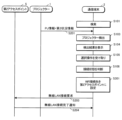
図5は、プロジェクター1と通信端末2との両方がアクセスポイントに未接続である状況での表示システムAの動作を説明するためのシーケンス図である。
<A5: Description of operation>
<A5-1: Both
FIG. 5 is a sequence diagram for explaining the operation of the display system A when neither the
ステップS101において通信端末2の第2制御部26は、第3通信部23を用いてプロジェクター1を探索する。具体的にはステップS101において第2制御部26は、ステップS102においてプロジェクター1が第1通信部13からBLE通信で無線送信するアドバタイズ情報を、第1通信部13に受信させようとする。
In step S<b>101 , the
プロジェクター1がいずれのアクセスポイントとも接続していない第1状況においては、第1制御部16は、第1通信部13に、プロジェクター1の情報と、第1状況を示す第1状況情報と、を含むアドバタイズ情報を、BLE通信によりブロードキャストで送信させる。図5では、プロジェクター1の情報を「PJ情報」と示している。
In a first situation in which the
ここで、プロジェクター1の情報は、プロジェクター1がアクセスポイントに接続しているか否かにかかわらず、プロジェクター1の名称を含む。
また、プロジェクター1の情報は、プロジェクター1がアクセスポイントに接続している場合、プロジェクター1と接続しているアクセスポイントのSSID(Service Set Identifier)と、プロジェクター1と接続しているアクセスポイントと接続するために必要なパスワードと、を含む。アクセスポイントのSSIDは、アクセスポイントの識別情報の一例である。
Here, the information of the
Further, when the
第1状況、すなわち、プロジェクター1がいずれのアクセスポイントとも接続していない状況において、プロジェクター1のBLE通信の通信圏Rに、通信端末2を携帯する利用者が位置せずに、第3通信部23がプロジェクター1からブロードキャストで無線送信されるアドバタイズ情報を受信しない場合、第2制御部26はステップS101を終了する。
In the first situation, that is, in a situation in which the
一方、第1状況において、プロジェクター1のBLE通信の通信圏Rに、通信端末2を携帯する利用者が位置すると、プロジェクター1からブロードキャストで無線送信されるアドバタイズ情報が、通信端末2に到達する。通信端末2の第3通信部23が、プロジェクター1が送信するアドバタイズ情報を受信すると、ステップS103において第2制御部26は、プロジェクター1を検出したと判断する。
On the other hand, in the first situation, when the user carrying the
プロジェクター1が検出されると、ステップS104において第2制御部26は、アドバタイズ情報に含まれるプロジェクター1の情報を表示部22に表示させる。
When the
表示部22におけるプロジェクター1の情報の表示例G1を図6に示す。図6は、プロジェクター1の名称が「EB01」である場合の表示例を示す。表示部22には、プロジェクター1の名称である「EB01」と共に、プロジェクター1が接続しているアクセスポイントのSSIDも表示される。なお、図5に示す動作では、プロジェクター1はアクセスポイントに接続されておらず、通信端末2によって第1状況情報が受信されるため、図6に示す例では、プロジェクター1が接続しているアクセスポイントのSSIDとして「接続なし」が表示される。
A display example G1 of the information of the
続いて、通信端末2を携帯する利用者が、表示部22に表示された「EB01」つまりプロジェクター1を選択する選択操作を第2操作部21に対して行うと、ステップS105において第2操作部21は選択操作を受け取る。
Subsequently, when the user carrying the
第2操作部21が選択操作を受け取ると、ステップS106において第2制御部26は、選択操作で選択されるプロジェクター1と、通信端末2と、の各々について、アクセスポイントとの接続状態を判断する。
When the
ステップS106では、第2制御部26は、プロジェクター1から受信したアドバタイズ情報に第1状況情報が含まれる場合、換言すると、第1状況情報が通信端末2によって受信されている場合、第2制御部26は、プロジェクター1がアクセスポイントと接続していないと判断する。
さらに、ステップS106では、第2制御部26は、第4通信部24とアクセスポイントとの接続状態に基づいて、通信端末2がアクセスポイントと接続されているか否かを判断する。
In step S<b>106 , if the advertised information received from the
Furthermore, in step S106, the
図5に示す例では、上述の通り、第1状況情報が通信端末2によって受信されており、且つ、通信端末2がアクセスポイントと接続していない。この場合、第2制御部26は、プロジェクター1とのBLE通信のための接続処理を行い、その後、ステップS107において第3通信部23にBLE通信の接続要求をプロジェクター1へ送信させることによって、ステップS108において通信端末2とプロジェクター1とのBLE通信を確立する。
In the example shown in FIG. 5, as described above, the first status information is received by the
続いて、ステップS109において第2制御部26は、第3通信部23に、アクセスポイントとして動作することを指示するアクセスポイント動作指示をBLE通信でプロジェクター1へ送信させる。アクセスポイント動作指示は、指示の一例である。
Subsequently, in step S109, the
プロジェクター1の第1通信部13が、アクセスポイント動作指示を受信すると、ステップS110において第1制御部16は、第2通信部14を第1アクセスポイントとして動作させる。
なお、プロジェクター1は、第2通信部14を第1アクセスポイントとして動作させるか否かを動作モードで区別してもよい。例えば、プロジェクター1において、第2通信部14を第1アクセスポイントとして動作させる動作モードとして第1モードが設けられ、第2通信部14を第1アクセスポイントとして動作させない動作モードとして第2モードが設けられてもよい。この場合、第1制御部16は、ステップS110において動作モードを第2モードから第1モードに切り替える。
When the
Note that the
続いて、ステップS111において第1制御部16は、第1通信部13に、第1アクセスポイントに接続するための第1アクセスポイント接続情報を、通信端末2へ送信させる。第1アクセスポイント接続情報は、第1アクセスポイントのSSIDと、第1アクセスポイントと接続するために必要なパスワードと、を含む。第1アクセスポイント接続情報は、第1接続情報の一例である。
Subsequently, in step S<b>111 , the
通信端末2の第3通信部23が、第1アクセスポイント接続情報を受信すると、ステップS112において第2制御部26は、第1アクセスポイント接続情報を用いて、第4通信部24の接続先、換言するとWiFi通信の接続先を、第1アクセスポイントに設定する。
When the
続いて、ステップS113において第2制御部26は、第4通信部24に、第1アクセスポイント接続情報を含む無線LAN通信の接続要求を、プロジェクター1へ送信させる。
Subsequently, in step S<b>113 , the
プロジェクター1の第2通信部14、すなわち、第1アクセスポイントが、無線LAN通信の接続要求を受信すると、第1制御部16は、無線LAN通信の接続要求に従って、第1アクセスポイントと第4通信部24との無線LAN通信の接続処理を実行する。
When the
第1制御部16による無線LAN通信の接続処理が完了すると、ステップS114において第1制御部16は、第2通信部14つまり第1アクセスポイントに、無線LAN接続完了通知を通信端末2へ送信させ、通信端末2の第4通信部24が、無線LAN接続完了通知を受信し、無線LAN通信が確立する。図7は、プロジェクター1さらに言えば第2通信部14が第1アクセスポイントになってプロジェクター1と通信端末2との無線LAN通信が確立した状態を示す図である。
When the wireless LAN communication connection processing by the
本実施形態に係るプロジェクター1およびプロジェクター1の制御方法によれば、第1制御部16は、第1状況において、第1通信部13に、第1状況情報を含むアドバタイズ情報を送信させる。
第1状況情報が通信端末2によって受信されており且つ通信端末2がアクセスポイントと接続していない状況において通信端末2から送信されるアクセスポイント動作指示を、第1通信部13が受信すると、第1制御部16は、第2通信部14を第1アクセスポイントとして動作させる。
第1制御部16は、第2通信部14を第1アクセスポイントとして動作させる場合、第1通信部13に、第1アクセスポイント接続情報を、通信端末2へ送信させる。
According to the
When the
When operating the
このため、プロジェクター1と通信端末2の両方がアクセスポイントと接続されていない状況で、プロジェクター1と通信端末2とを無線LAN接続する場合、通信端末2を、プロジェクター1の第1アクセスポイントに接続させることが可能になる。この場合、通信端末2は、利用者から第1アクセスポイント接続情報を入力されなくても、第1アクセスポイントと接続できるため、プロジェクター1の第1アクセスポイントは、通信端末2の接続先として、好ましいアクセスポイントとなる。したがって、プロジェクター1と通信端末2の両方がアクセスポイントと接続されていない状況において、通信端末2を、好ましいアクセスポイントに接続させることが可能になる。
Therefore, in a situation where neither the
第1状況情報と、アクセスポイント動作指示と、第1アクセスポイント接続情報とは、近距離無線通信で通信される。このため、近距離無線通信を使うことによって、アクセスポイントを介する無線LAN通信を実現可能になる。 The first status information, the access point operation instruction, and the first access point connection information are communicated by short-range wireless communication. Therefore, by using short-range wireless communication, it becomes possible to realize wireless LAN communication via an access point.
通信端末2は、第1アクセスポイント接続情報の受信に応じて、第1アクセスポイント接続情報を用いて第1アクセスポイントに接続する。このため、プロジェクター1と通信端末2の両方がアクセスポイントと接続されていない状況において、通信端末2を、好ましいアクセスポイントに接続できる。
Upon receiving the first access point connection information, the
第1アクセスポイント接続情報は、第1アクセスポイントのSSIDと、第1アクセスポイントと接続するために必要なパスワードと、を含む。このため、パスワード設定がなされている第1アクセスポイントに対して、通信端末2を接続可能になる。
The first access point connection information includes the SSID of the first access point and the password required to connect with the first access point. Therefore, the
<A5-2:プロジェクター1と通信端末2の両方がアクセスポイントに接続済み>
図8は、プロジェクター1と通信端末2が別々のアクセスポイントにそれぞれ接続している状況での表示システムAの動作を説明するためのシーケンス図である。図8において、図5に示した処理と同一の処理には同一符号を付してある。
<A5-2: Both
FIG. 8 is a sequence diagram for explaining the operation of the display system A when the
以下では、図9に例示されるように、プロジェクター1が第2アクセスポイント5と接続しており、且つ、通信端末2が第3アクセスポイント6と接続しているとする。第2アクセスポイント5のSSIDが「APX」であり、第3アクセスポイント6のSSIDが「APY」であるとする。なお、第2アクセスポイント5は、第1アクセスポイントとは異なり、第3アクセスポイント6は、第1アクセスポイントと第2アクセスポイント5とのいずれとも異なる。以下、図8に示す動作のうち、図5に示した処理と異なる処理を中心に説明する。
It is assumed below that the
プロジェクター1が第2アクセスポイント5と接続している第2状況では、ステップS201において第1制御部16は、第1通信部13に、プロジェクター1の情報と、第2状況を示す第2状況情報と、を含むアドバタイズ情報を、BLE通信によりブロードキャストで送信させる。以下、ステップS103~ステップS106が実行される。
In the second situation where the
ここで、プロジェクター1が第2アクセスポイント5と接続していため、ステップS201で送信されるプロジェクター1の情報は、第2アクセスポイント5のSSIDと、第2アクセスポイント5と接続するために必要なパスワードと、を含む。第2アクセスポイント5のSSIDと、第2アクセスポイント5と接続するために必要なパスワードとは、第2アクセスポイント5に接続するための第2接続情報の一例である。
Here, since the
ステップS104では、例えば図10に例示される画面が表示部22に表示される。ステップS105では、第2操作部21は、プロジェクター1を選択する選択操作を受け取るとする。ステップS106では、第2制御部26は、第2状況情報が通信端末2によって受信されており、通信端末2が第3アクセスポイント6と接続しているため、プロジェクター1が第2アクセスポイント5と接続しており且つ通信端末2が第3アクセスポイント6と接続されていると判断する。
In step S104, for example, the screen illustrated in FIG. 10 is displayed on the
続いて、第2状況情報が通信端末2によって受信されており、通信端末2が第3アクセスポイント6と接続しているため、ステップS202において第2制御部26は、第4通信部24のWiFi通信の接続先の設定を、第3アクセスポイント6から第2アクセスポイント5に切り替える。
Subsequently, since the second status information has been received by the
続いて、ステップS203において第2制御部26は、第4通信部24に、第2アクセスポイント5のSSIDと、第2アクセスポイント5と接続するために必要なパスワードと、を含む無線LAN通信の接続要求を、第2アクセスポイント5へ送信させる。
Subsequently, in step S<b>203 , the
第2アクセスポイント5は、通信端末2から無線LAN通信の接続要求を受信すると、通信端末2からの無線LAN通信の接続要求に従って、第2アクセスポイント5と第4通信部24との無線LAN通信の接続処理を実行する。
When the
第2アクセスポイント5は、通信端末2との無線LAN通信の接続処理を完了すると、ステップS204において、無線LAN接続完了通知を通信端末2に送信し、通信端末2の第4通信部24が、無線LAN接続完了通知を受信し、無線LAN通信が確立する。図11は、プロジェクター1と通信端末2の両方が第2アクセスポイント5と無線LAN通信を確立した状態を示す図である。
After completing the wireless LAN communication connection process with the
上述の通り、第1制御部16は、第2状況において、第1通信部13に、第2アクセスポイント5に接続するための情報を含むアドバタイズ情報を送信させる。
このため、通信端末2は、第1通信部13が送信するアドバタイズ情報を受信すれば、接続先となるアクセスポイントを、第3アクセスポイント6から、プロジェクター1が接続している第2アクセスポイント5に切り替えることが可能になる。この場合、通信端末2は、利用者から第2アクセスポイント5に接続するための情報を入力されなくても、第2アクセスポイント5と接続できるため、第2アクセスポイント5は、通信端末2の接続先として、好ましいアクセスポイントとなる。したがって、プロジェクター1と通信端末2が別々のアクセスポイントと接続されている状況において、通信端末2を、好ましいアクセスポイントに接続させることが可能になる。なお、第2アクセスポイント5は、第1の無線LANアクセスポイントの一例でもあり、第3アクセスポイント6は、第2の無線LANアクセスポイントの一例でもある。
As described above, the
Therefore, when the
第2アクセスポイント5に接続するための情報は、近距離無線通信で通信される。このため、近距離無線通信を使うことによって、アクセスポイントを介する無線LAN通信を実現可能になる。
Information for connecting to the
通信端末2は、第3アクセスポイント6と接続している第3状況において、第2アクセスポイント5に接続するための情報を受信する場合、第2アクセスポイント5に接続するための情報を用いて、接続先のアクセスポイントを第3アクセスポイント6から第2アクセスポイント5に切り替える。
このため、プロジェクター1と通信端末2が別々のアクセスポイントと接続されている状況において、通信端末2を、好ましいアクセスポイントに接続できる。
In the third situation where the
Therefore, in a situation where the
第2アクセスポイント5に接続するための情報は、第2アクセスポイント5のSSIDと、第2アクセスポイント5と接続するために必要となるパスワードと、を含む。このため、パスワード設定がなされている第2アクセスポイント5に対して、通信端末2を接続可能になる。
Information for connecting to the
<A5-3:プロジェクター1と通信端末2のうちプロジェクター1のみがアクセスポイントに接続済み>
図12は、プロジェクター1と通信端末2のうちプロジェクター1のみがアクセスポイントに接続している状況での表示システムAの動作を説明するためのシーケンス図である。図12において、図8に示した処理と同一の処理には同一符号を付してある。
<A5-3: Of
FIG. 12 is a sequence diagram for explaining the operation of the display system A when only the
以下では、図13に例示されるように、プロジェクター1が第2アクセスポイント5と接続しており、且つ、通信端末2がいずれのアクセスポイントにも接続していないとする。以下、図12に示す動作のうち、図8に示した処理と異なる処理を中心に説明する。
Below, as illustrated in FIG. 13, it is assumed that the
ステップS106では、第2制御部26は、第2状況情報が通信端末2によって受信されており、第4通信部24がいずれのアクセスポイントにも接続していないため、プロジェクター1が第2アクセスポイント5と接続しており且つ通信端末2がいずれのアクセスポイントにも接続されていないと判断する。
In step S106, the second status information is received by the
続いて、第2状況情報が通信端末2によって受信されており、通信端末2がいずれのアクセスポイントとも接続していないため、ステップS301において第2制御部26は、第4通信部24の接続先を、第2アクセスポイント5に設定する。以下、ステップS203およびステップS204が実行される。図14は、プロジェクター1と通信端末2の両方が第2アクセスポイント5と無線LAN通信を確立した状態を示す図である。
Subsequently, since the second status information has been received by the
上述の通り、通信端末2は、利用者から第2アクセスポイント5に接続するための情報を入力されなくても、第2アクセスポイント5と接続できるため、第2アクセスポイント5は、通信端末2の接続先として、好ましいアクセスポイントとなる。したがって、プロジェクター1と通信端末2のうちプロジェクター1のみがアクセスポイントと接続されている状況において、通信端末2を、好ましいアクセスポイントに接続させることが可能になる。
As described above, the
<A5-4:プロジェクター1と通信端末2のうち通信端末2のみがアクセスポイントに接続済み>
図15に示すように、プロジェクター1と通信端末2のうち通信端末2のみがアクセスポイントと接続済みである場合には、プロジェクター1が接続可能なアクセスポイントは、通信端末2が接続しているアクセスポイントとなる。
このため、通信端末2が接続している第3アクセスポイント6と接続するために必要なパスワードを、利用者が、プロジェクター1に入力することによって、プロジェクター1を第3アクセスポイント6に接続する。図16は、プロジェクター1と通信端末2の両方が第3アクセスポイント6と無線LAN通信を確立した状態を示す図である。
<A5-4: Out of
As shown in FIG. 15, when only the
Therefore, the user connects the
<B:変形例>
第1実施形態において、例えば以下に例示する構成が採用されてもよい。
<B: Modification>
In the first embodiment, for example, a configuration exemplified below may be adopted.
<B1:変形例1>
第1実施形態において、プロジェクター1は、BLE通信で送信する情報を示すQRコードを生成し、当該QRコードを不図示のディスプレイに表示してもよい。QRコードは登録商標である。この場合、通信端末2は、プロジェクター1に表示されるQRコードを読み取ることで、第1実施形態においてプロジェクター1からBLE通信で送信されていた情報を受信してもよい。また、通信端末2は、BLE通信で送信する情報を示すQRコードを生成し、当該QRコードを表示部22に表示してもよい。この場合、プロジェクター1は、通信端末2に表示されるQRコードを読み取ることで、第1実施形態において通信端末2からBLE通信で送信されていた情報を受信してもよい。なお、QRコードを表示することは、QRコードを表す可視光が送信されることを意味する。
<B1:
In the first embodiment, the
<B2:変形例2>
第1実施形態および変形例1において、光変調装置の一例として液晶ライトバルブ124が用いられたが、光変調装置は液晶ライトバルブに限らず適宜変更可能である。例えば、光変調装置は、3枚の反射型の液晶パネルを用いた構成であってもよい。また、光変調装置は、1枚の液晶パネルを用いた方式、3枚のデジタルミラーデバイス(DMD)を用いた方式、1枚のデジタルミラーデバイスを用いた方式等の構成であってもよい。光変調装置として1枚のみの液晶パネルまたはDMDが用いられる場合、色分離光学系および色合成光学系に相当する部材は不要である。また、液晶パネルおよびDMD以外にも、光源123が発した光を変調可能な構成は、光変調装置として採用できる。
<B2:
In the first embodiment and
<B3:変形例3>
第1実施形態および変形例1~2のいずれかにおいて、第1制御部16と第2制御部26と画像処理部121の各々は、例えばFPGA(field programmable gate array)またはASIC(Application Specific IC)等の電子回路によりハードウェアで実現されてもよい。
<B3:
In the first embodiment and any of
<B4:変形例4>
第1実施形態および変形例1~3のいずれかにおいて、表示装置として、プロジェクター1が用いられるが、表示装置は、液晶表示装置またはEL表示装置のような、直視型の表示装置でもよい。
<B4: Modification 4>
Although the
<B5:変形例5>
第1実施形態および変形例1~4のいずれかにおいて、通信端末2は、第3アクセスポイント6と接続している第3状況において、第2アクセスポイント5に接続するための第2接続情報を受信する場合、第2アクセスポイント5と第3アクセスポイント6のうち転送速度が速い方のアクセスポイントに接続してもよい。
<B5:
In the first embodiment and any one of
例えば、通信端末2は、第3アクセスポイント6との接続時に第3アクセスポイント6から第3アクセスポイント6の転送速度を示す情報を受信する。
また、第2アクセスポイント5に接続するための第2接続情報は、第2アクセスポイント5のSSIDと、第2アクセスポイント5と接続するために必要なパスワードと、第2アクセスポイント5の転送速度を示す情報とを含む。
通信端末2は、第3アクセスポイント6の転送速度を示す情報と、第2アクセスポイント5の転送速度を示す情報と、を用いて、第2アクセスポイント5と第3アクセスポイント6のうち転送速度が速い方のアクセスポイントを特定する。
続いて、通信端末2は、第2アクセスポイント5と第3アクセスポイント6のうち転送速度が速い方のアクセスポイントと接続する。
For example, the
The second connection information for connecting to the
Subsequently, the
A…表示システム、1…プロジェクター、2…通信端末、3…投射面、5…第2アクセスポイント、6…第3アクセスポイント、11…第1操作部、12…投射部、13…第1通信部、14…第2通信部、15…第1記憶部、16…第1制御部、21…第2操作部、22…表示部、23…第3通信部、24…第4通信部、25…第2記憶部、26…第2制御部。
A...
Claims (10)
前記表示装置がアクセスポイントと接続していない第1状況において、前記第1状況を示す第1状況情報を送信することと、
前記第1状況情報が電子機器によって受信されており且つ前記電子機器がアクセスポイントと接続していない状況において、アクセスポイントとして動作することを指示する指示を、前記電子機器から受信することと、
前記指示の受信に応じて、第1アクセスポイントとして動作することと、
前記第1アクセスポイントとして動作する場合、前記第1アクセスポイントに接続するための第1接続情報を、前記電子機器に送信することと、
前記表示装置が前記第1アクセスポイントとは異なる第2アクセスポイントと接続している第2状況において、前記第2アクセスポイントに接続するための第2接続情報を送信すること、
とを含む表示装置の制御方法。 A display device control method comprising:
transmitting first situation information indicating the first situation in a first situation where the display device is not connected to an access point;
receiving an instruction from the electronic device to operate as an access point in a situation where the first status information has been received by the electronic device and the electronic device is not connected to the access point;
operating as a first access point in response to receiving the indication;
When operating as the first access point, transmitting first connection information for connecting to the first access point to the electronic device;
transmitting second connection information for connecting to the second access point in a second situation where the display device is connected to a second access point different from the first access point;
and a control method of a display device.
請求項1に記載の表示装置の制御方法。 wherein the first status information, the instruction, and the first connection information are communicated by short-range wireless communication;
The method of controlling the display device according to claim 1 .
請求項1または2に記載の表示装置の制御方法。 The display device, in response to receiving the first connection information to the electronic device, causes the electronic device to connect to the first access point using the first connection information.
3. The method of controlling a display device according to claim 1.
請求項1から3のいずれか1項に記載の表示装置の制御方法。 The first connection information includes identification information of the first access point and a password required to connect to the first access point.
The method of controlling a display device according to any one of claims 1 to 3.
請求項4に記載の表示装置の制御方法。 wherein the second connection information is communicated by short-range wireless communication;
5. The control method of the display device according to claim 4 .
請求項4または5に記載の表示装置の制御方法。 When the display device receives the second connection information in a third situation in which the electronic device is connected to a third access point that is different from the first access point and the second access point, the causing the electronic device to switch the connection destination access point from the third access point to the second access point using the second connection information;
6. The method of controlling a display device according to claim 4 or 5 .
請求項4または5に記載の表示装置の制御方法。 When the display device receives the second connection information in a third situation in which the electronic device is connected to a third access point that is different from the first access point and the second access point, the connecting the electronic device to the second access point or the third access point, whichever has a faster transfer speed;
6. The method of controlling a display device according to claim 4 or 5 .
請求項4から7のいずれか1項に記載の表示装置の制御方法。 The second connection information includes identification information of the second access point and a password required to connect to the second access point.
The method of controlling a display device according to any one of claims 4 to 7 .
電子機器と通信する第1通信部と、
第1アクセスポイントとして動作可能な第2通信部と、
前記第1通信部と前記第2通信部とを制御する制御部と、を含み、
前記制御部は、
前記表示装置がアクセスポイントと接続していない第1状況において、前記第1通信部に、前記第1状況を示す第1状況情報を送信させ、
前記第1状況情報が前記電子機器によって受信されており且つ前記電子機器がアクセスポイントと接続していない状況において、アクセスポイントとして動作することを指示する指示を、前記第1通信部が前記電子機器から受信すると、前記第2通信部を前記第1アクセスポイントとして動作させ、
前記第2通信部が前記第1アクセスポイントとして動作する場合、前記第1通信部に、前記第1アクセスポイントに接続するための第1接続情報を、前記電子機器へ送信させ、
前記表示装置が前記第1アクセスポイントとは異なる第2アクセスポイントと接続している第2状況において、前記第2アクセスポイントに接続するための第2接続情報を送信させる、
表示装置。 A display device,
a first communication unit that communicates with the electronic device;
a second communication unit operable as a first access point;
a control unit that controls the first communication unit and the second communication unit,
The control unit
causing the first communication unit to transmit first situation information indicating the first situation in a first situation where the display device is not connected to an access point;
wherein the first communication unit instructs the electronic device to operate as an access point in a state in which the first status information has been received by the electronic device and the electronic device is not connected to the access point; When receiving from, operating the second communication unit as the first access point,
causing the first communication unit to transmit first connection information for connecting to the first access point to the electronic device when the second communication unit operates as the first access point ;
transmitting second connection information for connecting to the second access point in a second situation where the display device is connected to a second access point different from the first access point;
display device.
前記表示装置は、前記表示装置がアクセスポイントと接続していない第1状況において、前記第1状況を示す第1状況情報を送信し、
前記電子機器は、前記第1状況情報を受信しており、且つ、アクセスポイントと接続していない状況において、アクセスポイントとして動作することを指示する指示を、前記表示装置に送信し、
前記表示装置は、前記指示の受信に応じて第1アクセスポイントとして動作し、
前記表示装置は、前記第1アクセスポイントとして動作する場合、前記第1アクセスポイントに接続するための第1接続情報を、前記電子機器に送信し、
前記表示装置が前記第1アクセスポイントとは異なる第2アクセスポイントと接続している第2状況において、前記第2アクセスポイントに接続するための第2接続情報を送信する、
表示システム。
including a display device and an electronic device,
wherein the display device transmits first situation information indicating the first situation in a first situation in which the display device is not connected to an access point;
When the electronic device has received the first status information and is not connected to an access point, it transmits an instruction to the display device to instruct it to operate as an access point;
the display device operates as a first access point in response to receiving the instruction;
When the display device operates as the first access point, the display device transmits first connection information for connecting to the first access point to the electronic device;
transmitting second connection information for connecting to the second access point in a second situation where the display device is connected to a second access point different from the first access point;
display system.
Priority Applications (2)
| Application Number | Priority Date | Filing Date | Title |
|---|---|---|---|
| JP2018234119A JP7279353B2 (en) | 2018-12-14 | 2018-12-14 | Display device control method, display device and display system |
| US16/713,082 US11240741B2 (en) | 2018-12-14 | 2019-12-13 | Method for controlling display device, display device, and display system |
Applications Claiming Priority (1)
| Application Number | Priority Date | Filing Date | Title |
|---|---|---|---|
| JP2018234119A JP7279353B2 (en) | 2018-12-14 | 2018-12-14 | Display device control method, display device and display system |
Publications (3)
| Publication Number | Publication Date |
|---|---|
| JP2020096305A JP2020096305A (en) | 2020-06-18 |
| JP2020096305A5 JP2020096305A5 (en) | 2021-12-09 |
| JP7279353B2 true JP7279353B2 (en) | 2023-05-23 |
Family
ID=71071443
Family Applications (1)
| Application Number | Title | Priority Date | Filing Date |
|---|---|---|---|
| JP2018234119A Active JP7279353B2 (en) | 2018-12-14 | 2018-12-14 | Display device control method, display device and display system |
Country Status (2)
| Country | Link |
|---|---|
| US (1) | US11240741B2 (en) |
| JP (1) | JP7279353B2 (en) |
Families Citing this family (1)
| Publication number | Priority date | Publication date | Assignee | Title |
|---|---|---|---|---|
| JP2023067096A (en) * | 2021-10-29 | 2023-05-16 | キヤノン株式会社 | Wireless communication device and control method for the same |
Citations (6)
| Publication number | Priority date | Publication date | Assignee | Title |
|---|---|---|---|---|
| JP2013214802A (en) | 2012-03-30 | 2013-10-17 | Brother Ind Ltd | Communication device |
| JP2014027538A (en) | 2012-07-27 | 2014-02-06 | Brother Ind Ltd | Communication device |
| US20160127938A1 (en) | 2014-10-31 | 2016-05-05 | Samsung Electronics Co., Ltd. | User terminal apparatus, electronic apparatus, system and controlling method thereof |
| JP2017073018A (en) | 2015-10-08 | 2017-04-13 | コニカミノルタ株式会社 | Image formation system and program |
| JP2017188869A (en) | 2016-01-29 | 2017-10-12 | キヤノン株式会社 | Information processing apparatus, control method, and program |
| JP2018195888A (en) | 2017-05-12 | 2018-12-06 | キヤノン株式会社 | Information processing unit, control method of information processing unit, and program |
Family Cites Families (13)
| Publication number | Priority date | Publication date | Assignee | Title |
|---|---|---|---|---|
| JP2004112225A (en) | 2002-09-17 | 2004-04-08 | Ricoh Co Ltd | Information communication system |
| TW200729892A (en) * | 2005-11-16 | 2007-08-01 | Nokia Corp | System and method for establishing bearer-independent and secure connections |
| US8850052B2 (en) * | 2008-09-30 | 2014-09-30 | Apple Inc. | System and method for simplified resource sharing |
| WO2013014763A1 (en) * | 2011-07-27 | 2013-01-31 | 株式会社ビジョナリスト | Easily operated wireless data transmission/reception system and easily operated wireless data transmission/reception program |
| US9253589B2 (en) * | 2012-03-12 | 2016-02-02 | Blackberry Limited | Wireless local area network hotspot registration using near field communications |
| ES2659773T3 (en) * | 2013-03-15 | 2018-03-19 | Vivint, Inc | Using a control panel as a wireless access point |
| US9654960B2 (en) * | 2013-05-31 | 2017-05-16 | Qualcomm Incorporated | Server-assisted device-to-device discovery and connection |
| KR102186547B1 (en) * | 2014-02-06 | 2020-12-04 | 삼성전자주식회사 | Communication Method and Apparatus Supporting Selective Communication Services |
| US10681591B2 (en) * | 2014-07-31 | 2020-06-09 | Lg Electronics Inc. | Method and apparatus for controlling electronic device in wireless communication system supporting Bluetooth communication |
| JP6571997B2 (en) * | 2015-06-08 | 2019-09-04 | キヤノン株式会社 | COMMUNICATION DEVICE, COMMUNICATION DEVICE CONTROL METHOD, AND PROGRAM |
| JP2017163489A (en) | 2016-03-11 | 2017-09-14 | 株式会社リコー | Communication equipment, method, system, and program |
| KR102566247B1 (en) * | 2017-01-17 | 2023-08-14 | 삼성전자주식회사 | Method for controlling service set for wireless local area network and apparatus thereof |
| JP7155537B2 (en) * | 2018-02-27 | 2022-10-19 | セイコーエプソン株式会社 | Terminal device, communication system, program and communication control method |
-
2018
- 2018-12-14 JP JP2018234119A patent/JP7279353B2/en active Active
-
2019
- 2019-12-13 US US16/713,082 patent/US11240741B2/en active Active
Patent Citations (6)
| Publication number | Priority date | Publication date | Assignee | Title |
|---|---|---|---|---|
| JP2013214802A (en) | 2012-03-30 | 2013-10-17 | Brother Ind Ltd | Communication device |
| JP2014027538A (en) | 2012-07-27 | 2014-02-06 | Brother Ind Ltd | Communication device |
| US20160127938A1 (en) | 2014-10-31 | 2016-05-05 | Samsung Electronics Co., Ltd. | User terminal apparatus, electronic apparatus, system and controlling method thereof |
| JP2017073018A (en) | 2015-10-08 | 2017-04-13 | コニカミノルタ株式会社 | Image formation system and program |
| JP2017188869A (en) | 2016-01-29 | 2017-10-12 | キヤノン株式会社 | Information processing apparatus, control method, and program |
| JP2018195888A (en) | 2017-05-12 | 2018-12-06 | キヤノン株式会社 | Information processing unit, control method of information processing unit, and program |
Non-Patent Citations (1)
| Title |
|---|
| 森田 賢太 他,Wi-FiとBluetoothを組み合わせたMANETの一提案,電気学会研究会資料,一般社団法人電気学会,2017年01月26日,CMN-17-018,pp.87-90 |
Also Published As
| Publication number | Publication date |
|---|---|
| US20200196224A1 (en) | 2020-06-18 |
| JP2020096305A (en) | 2020-06-18 |
| US11240741B2 (en) | 2022-02-01 |
Similar Documents
| Publication | Publication Date | Title |
|---|---|---|
| CN107408371B (en) | Display device, terminal device, and display system | |
| JP6601032B2 (en) | Display device, display system, display device control method, and electronic device control method | |
| JP2019015834A (en) | Display and method for controlling display | |
| JP6992265B2 (en) | Display device and control method of display device | |
| CN110032265B (en) | Control method of image display device, image display system and image display device | |
| JP7279353B2 (en) | Display device control method, display device and display system | |
| JP6015354B2 (en) | Image display system and method for controlling image display system | |
| JP6194681B2 (en) | Image display device | |
| JP2009253718A (en) | Electronic device, projector, control method of electronic device and electronic device system | |
| US10847120B2 (en) | Control method and system for display apparatus connected to multiple external apparatus | |
| JP5617575B2 (en) | Image display device and control method thereof | |
| US10942698B2 (en) | Control method of display system, display system, and display device | |
| US20200201619A1 (en) | Method for controlling display device, display device, and display system | |
| US11422378B2 (en) | Control method for display device and control device | |
| US20220197586A1 (en) | Method for operating communication apparatus, and communication apparatus | |
| JP2021190752A (en) | Image transmission system, image receiving device, and method for controlling image receiving device | |
| JP2020064131A (en) | Image display unit and method for controlling image display unit | |
| JP2020057128A (en) | Display device and display device control method | |
| JP2013160978A (en) | Projector and control method of projector | |
| JP2023062803A (en) | Image display method, image display device, image supply device, and program | |
| JP2022099487A (en) | Image display system, method for controlling image display system, and method for controlling display unit | |
| JP2010186036A (en) | Image display device | |
| JP2014066854A (en) | Projector and method of controlling projector | |
| JP2021087203A (en) | Display device and program | |
| JP2019201375A (en) | Image display system, image display device, and method for controlling image display system |
Legal Events
| Date | Code | Title | Description |
|---|---|---|---|
| A521 | Request for written amendment filed |
Free format text: JAPANESE INTERMEDIATE CODE: A523 Effective date: 20211027 |
|
| A621 | Written request for application examination |
Free format text: JAPANESE INTERMEDIATE CODE: A621 Effective date: 20211027 |
|
| A977 | Report on retrieval |
Free format text: JAPANESE INTERMEDIATE CODE: A971007 Effective date: 20220921 |
|
| A131 | Notification of reasons for refusal |
Free format text: JAPANESE INTERMEDIATE CODE: A131 Effective date: 20221025 |
|
| A521 | Request for written amendment filed |
Free format text: JAPANESE INTERMEDIATE CODE: A523 Effective date: 20221219 |
|
| TRDD | Decision of grant or rejection written | ||
| A01 | Written decision to grant a patent or to grant a registration (utility model) |
Free format text: JAPANESE INTERMEDIATE CODE: A01 Effective date: 20230411 |
|
| A61 | First payment of annual fees (during grant procedure) |
Free format text: JAPANESE INTERMEDIATE CODE: A61 Effective date: 20230424 |
|
| R150 | Certificate of patent or registration of utility model |
Ref document number: 7279353 Country of ref document: JP Free format text: JAPANESE INTERMEDIATE CODE: R150 |