JP7278849B2 - Shake correction device, lens device and camera system - Google Patents
Shake correction device, lens device and camera system Download PDFInfo
- Publication number
- JP7278849B2 JP7278849B2 JP2019080606A JP2019080606A JP7278849B2 JP 7278849 B2 JP7278849 B2 JP 7278849B2 JP 2019080606 A JP2019080606 A JP 2019080606A JP 2019080606 A JP2019080606 A JP 2019080606A JP 7278849 B2 JP7278849 B2 JP 7278849B2
- Authority
- JP
- Japan
- Prior art keywords
- shake correction
- movable
- lens frame
- lock
- optical axis
- Prior art date
- Legal status (The legal status is an assumption and is not a legal conclusion. Google has not performed a legal analysis and makes no representation as to the accuracy of the status listed.)
- Active
Links
Images


Classifications
-
- G—PHYSICS
- G02—OPTICS
- G02B—OPTICAL ELEMENTS, SYSTEMS OR APPARATUS
- G02B27/00—Optical systems or apparatus not provided for by any of the groups G02B1/00 - G02B26/00, G02B30/00
- G02B27/64—Imaging systems using optical elements for stabilisation of the lateral and angular position of the image
- G02B27/646—Imaging systems using optical elements for stabilisation of the lateral and angular position of the image compensating for small deviations, e.g. due to vibration or shake
-
- G—PHYSICS
- G02—OPTICS
- G02B—OPTICAL ELEMENTS, SYSTEMS OR APPARATUS
- G02B7/00—Mountings, adjusting means, or light-tight connections, for optical elements
- G02B7/02—Mountings, adjusting means, or light-tight connections, for optical elements for lenses
- G02B7/023—Mountings, adjusting means, or light-tight connections, for optical elements for lenses permitting adjustment
-
- G—PHYSICS
- G03—PHOTOGRAPHY; CINEMATOGRAPHY; ANALOGOUS TECHNIQUES USING WAVES OTHER THAN OPTICAL WAVES; ELECTROGRAPHY; HOLOGRAPHY
- G03B—APPARATUS OR ARRANGEMENTS FOR TAKING PHOTOGRAPHS OR FOR PROJECTING OR VIEWING THEM; APPARATUS OR ARRANGEMENTS EMPLOYING ANALOGOUS TECHNIQUES USING WAVES OTHER THAN OPTICAL WAVES; ACCESSORIES THEREFOR
- G03B5/00—Adjustment of optical system relative to image or object surface other than for focusing
- G03B5/02—Lateral adjustment of lens
-
- H—ELECTRICITY
- H04—ELECTRIC COMMUNICATION TECHNIQUE
- H04N—PICTORIAL COMMUNICATION, e.g. TELEVISION
- H04N23/00—Cameras or camera modules comprising electronic image sensors; Control thereof
- H04N23/50—Constructional details
-
- H—ELECTRICITY
- H04—ELECTRIC COMMUNICATION TECHNIQUE
- H04N—PICTORIAL COMMUNICATION, e.g. TELEVISION
- H04N23/00—Cameras or camera modules comprising electronic image sensors; Control thereof
- H04N23/50—Constructional details
- H04N23/54—Mounting of pick-up tubes, electronic image sensors, deviation or focusing coils
-
- H—ELECTRICITY
- H04—ELECTRIC COMMUNICATION TECHNIQUE
- H04N—PICTORIAL COMMUNICATION, e.g. TELEVISION
- H04N23/00—Cameras or camera modules comprising electronic image sensors; Control thereof
- H04N23/50—Constructional details
- H04N23/55—Optical parts specially adapted for electronic image sensors; Mounting thereof
-
- H—ELECTRICITY
- H04—ELECTRIC COMMUNICATION TECHNIQUE
- H04N—PICTORIAL COMMUNICATION, e.g. TELEVISION
- H04N23/00—Cameras or camera modules comprising electronic image sensors; Control thereof
- H04N23/60—Control of cameras or camera modules
- H04N23/68—Control of cameras or camera modules for stable pick-up of the scene, e.g. compensating for camera body vibrations
- H04N23/682—Vibration or motion blur correction
- H04N23/685—Vibration or motion blur correction performed by mechanical compensation
- H04N23/687—Vibration or motion blur correction performed by mechanical compensation by shifting the lens or sensor position
-
- G—PHYSICS
- G03—PHOTOGRAPHY; CINEMATOGRAPHY; ANALOGOUS TECHNIQUES USING WAVES OTHER THAN OPTICAL WAVES; ELECTROGRAPHY; HOLOGRAPHY
- G03B—APPARATUS OR ARRANGEMENTS FOR TAKING PHOTOGRAPHS OR FOR PROJECTING OR VIEWING THEM; APPARATUS OR ARRANGEMENTS EMPLOYING ANALOGOUS TECHNIQUES USING WAVES OTHER THAN OPTICAL WAVES; ACCESSORIES THEREFOR
- G03B2205/00—Adjustment of optical system relative to image or object surface other than for focusing
- G03B2205/0007—Movement of one or more optical elements for control of motion blur
Landscapes
- Physics & Mathematics (AREA)
- Engineering & Computer Science (AREA)
- Multimedia (AREA)
- Signal Processing (AREA)
- General Physics & Mathematics (AREA)
- Optics & Photonics (AREA)
- Adjustment Of Camera Lenses (AREA)
- Studio Devices (AREA)
Description
本発明は、振れ補正装置、レンズ装置およびカメラシステムに関する。 The present invention relates to a shake correction device, a lens device, and a camera system.
従来、撮像装置の光軸に垂直な平面内において、レンズ群の一部を並進移動させることで、画像の振れを抑制する振れ補正装置が知られている。振れ補正装置において、振れ補正を行わない場合、並進移動を行う可動レンズ群の移動を規制する保持機構が提案されている。保持機構により可動レンズ群の移動を規制することで、外部から衝撃が加わった際に可動レンズ群に加わる衝撃を緩和することや、振れ補正装置を備える製品を持ち運ぶ際の品位を向上することができる。 Conventionally, there has been known a shake correction device that suppresses image shake by translating a part of a lens group in a plane perpendicular to the optical axis of an imaging device. In a shake correction device, a holding mechanism has been proposed that restricts movement of a movable lens group that moves in translation when shake correction is not performed. By regulating the movement of the movable lens group with a holding mechanism, it is possible to reduce the impact on the movable lens group when an external impact is applied, and to improve the quality when carrying a product equipped with a shake correction device. can.
特許文献1では、光軸回りで回転するリング形状の保持機構を備える光学防振装置が開示されている。特許文献2では、可動レンズ枠の光軸回りの3か所以上に設けられ、バネで付勢されたレバー形状の保持部材で可動レンズ枠の移動を規制する光軸ロック機構が開示されている。 Japanese Patent Application Laid-Open No. 2002-200002 discloses an optical vibration isolator that includes a ring-shaped holding mechanism that rotates around an optical axis. Patent Document 2 discloses an optical axis lock mechanism that is provided at three or more locations around the optical axis of the movable lens frame and regulates the movement of the movable lens frame with lever-shaped holding members that are biased by springs. .
しかしながら、特許文献1の光学防振装置では、可動レンズ枠にリング形状の保持部材を係合させるための突起形状が必要となる。可動レンズ枠の移動を規制していない状態では、可動レンズ枠の突起形状と固定側のレンズ枠との接触を避ける必要があるため、固定レンズ枠側にも対応する逃げ形状が必要となり、装置の小型化を妨げる。
However, the optical vibration isolator of
また、特許文献2の光軸ロック機構では、可動レンズ枠を駆動させるマグネットやヨーク等の駆動装置を避けて等間隔に少なくとも3つの保持部材を配置することは困難であり、装置の小型化を妨げる。 In addition, in the optical axis locking mechanism of Patent Document 2, it is difficult to arrange at least three holding members at equal intervals while avoiding driving devices such as magnets and yokes for driving the movable lens frame, and miniaturization of the device is required. hinder
本発明は、小型化可能な振れ補正装置、レンズ装置およびカメラシステムを提供することを目的とする。 An object of the present invention is to provide a shake correction device, a lens device, and a camera system that can be miniaturized.
本発明の一側面としての振れ補正装置は、固定部材と、振れ補正レンズを保持するとともに、振れ補正レンズの光軸に垂直な平面内において固定部材に対して移動可能である可動部材と、可動部材の移動を制限するロック位置と、可動部材の固定部材に対する移動の制限を解除するアンロック位置に移動可能な規制部材を有し、規制部材は、アンロック位置からロック位置への切り換えに際して、可動部材が固定部材に接触するように、可動部材を偏心させることを特徴とする。
A shake correction device as one aspect of the present invention includes a fixed member, a movable member that holds a shake correction lens and is movable with respect to the fixed member in a plane perpendicular to the optical axis of the shake correction lens , It has a restricting member that can move to a locked position that restricts the movement of the movable member and an unlocked position that releases the restriction on the movement of the movable member with respect to the fixed member, and the restricting member is moved from the unlocked position to the locked position when switching from the unlocked position to the locked position. , the movable member is eccentric so that the movable member is in contact with the fixed member ;
本発明によれば、小型化可能な振れ補正装置、レンズ装置およびカメラシステムを提供することができる。 According to the present invention, it is possible to provide a shake correction device, a lens device, and a camera system that can be miniaturized.
以下、本発明の実施例について、図面を参照しながら詳細に説明する。各図において、同一の部材については同一の参照番号を付し、重複する説明は省略する。 BEST MODE FOR CARRYING OUT THE INVENTION Hereinafter, embodiments of the present invention will be described in detail with reference to the drawings. In each figure, the same reference numerals are given to the same members, and overlapping descriptions are omitted.
図1は、本発明の実施形態に係るカメラシステム1の一例であるデジタルスチルカメラの構成を示している。カメラシステム1は、撮像装置101およびレンズ鏡筒(レンズ装置)201を有する。レンズ鏡筒201は、撮像装置101と一体的に構成されていてもよいし、撮像装置101に着脱可能に取り付けられるように構成されていてもよい。
FIG. 1 shows the configuration of a digital still camera as an example of a
撮像装置101は、レンズ鏡筒201を介して形成された被写体像を光電変換する撮像素子102を有する。撮像素子102として、主にCCDイメージセンサーやCMOSイメージセンサーなどが用いられる。
The
レンズ鏡筒201は、補正レンズ202aを備える振れ補正ユニット(振れ補正装置)202、光軸αに沿って移動可能な可動レンズ203、および演算部204aを備える駆動制御部204を有する。振れ補正ユニット202は、補正レンズ202aを光軸αに垂直な平面内を移動させることで像振れの補正を行う。図1では、補正レンズ202aは、光軸αの中心位置(基準位置)に位置している。可動レンズ203は、ズームレンズおよびフォーカスレンズの少なくとも一方を含んでいる。駆動制御部204は、演算部204aにより算出された補正レンズ202aの駆動量に基づいて補正レンズ202aを駆動制御する。また、レンズ鏡筒201は、補正レンズ202aや可動レンズ203の他に、撮像光学系を形成する不図示のレンズ群を有する。
The
以下、図2および図3を参照して、振れ補正ユニット202の駆動原理および構成について説明する。図2は、振れ補正ユニット202を撮像素子102の撮像面側から見た分解斜視図である。図3は、振れ補正ユニット202を被写体側から見た分解斜視図である。
The drive principle and configuration of the
可動レンズ枠(可動部材)220は、補正レンズ202aを保持可能な枠部材である。固定レンズ枠(固定部材)210は、レンズ鏡筒201に対して、光軸αに垂直な方向(光軸垂直方向)に固定される。駆動手段(駆動部)は、第1のヨーク310、第2のヨーク320、シフトコイル330およびシフトマグネット340によって構成される。第1のヨーク310および第2のヨーク320は、固定レンズ枠210に対して固定配置される。第2のヨーク320は、可動レンズ枠220に対して第1のヨーク310が配置される側の反対側に配置される。シフトコイル330は、可動レンズ枠220に2つ固定されている。2つのシフトコイル330は、光軸中心から見て、同じ量だけ離れた位置であって、互いに90°ずれた位置に配置される。シフトマグネット340は、第1のヨーク310上に配置されている。シフトマグネット340は、光軸方向から見て、シフトコイル330と重なる2つの位置に2個ずつ配置される。2つの位置は、光軸中心から同じ量だけ離れた位置である。シフトマグネット340は、第2のヨーク320上にも配置される。シフトマグネット340は、光軸方向から見て、シフトコイル330と重なる2つの位置に2個ずつ配置される。2つの位置は、光軸中心から同じ量だけ離れた位置である
第1のヨーク310、第2のヨークおよびシフトマグネット340によって閉じた磁気回路が形成され、磁気吸引力によって第1のヨーク310と第2のヨーク320が引き合う。シャフト350は、第1のヨーク310と第2のヨーク320との間に配置され、磁気吸引力によって各ヨークや固定レンズ枠210が変形することを防止する。磁気回路内でシフトコイル330に通電することで、コイルとマグネットの電磁気的な相互作用によって、可動レンズ枠220がX方向およびY方向へ移動する。したがって、可動レンズ枠220は、固定レンズ枠210に対して光軸αに垂直な平面内のX方向およびY方向へ移動可能である。
A movable lens frame (movable member) 220 is a frame member capable of holding the
位置検出部250および位置被検出部251は、固定レンズ枠210に対する可動レンズ枠220の相対的な移動量を検出する。検出方法として、例えば、ホール効果を利用してホール素子とマグネットとの相対位置を検出する方法が知られている。本実施例では、ホールセンサーである位置検出部250は固定レンズ枠210に一体に取り付けられたセンサー保持枠240に設けられており、マグネットである位置被検出部251は可動レンズ枠220に設けられている。位置検出部250および位置被検出部251は、光軸中心から見て、同じ量だけ離れた位置であって、互いに90°ずれた位置に配置される。
The
第1のヨーク310、第1のアンチロールプレート410、第2のアンチロールプレート420、および6個の転動ボール430は、可動レンズ枠220が固定レンズ枠210に対して光軸α回りに回転することを防止する回転防止機構を構成する。第2のアンチロールプレート420は、可動レンズ枠220に対して固定される。
The
第1のヨーク310と第1のアンチロールプレート410にはそれぞれ、光軸αに垂直な互いに同じ方向の2つのガイド溝が形成されている。2つの転動ボール430は第1のヨーク310と第1のアンチロールプレート410のガイド溝の間で挟持される。また、1つの転動ボール430は、固定レンズ枠210と第1のアンチロールプレート410との間で溝に規制されない状態で挟持される。このような構成により、第1のアンチロールプレート410は、第1のヨーク310に対して、光軸αに垂直な所定の一方向にのみ移動可能である。
The
第1のアンチロールプレート410と第2のアンチロールプレート420にはそれぞれ、光軸αに垂直な互いに同じ方向の2つのガイド溝が形成されている。2つの転動ボール430は、第1のアンチロールプレート410と第2のアンチロールプレート420との間で挟持される。このような構成により、第2のアンチロールプレート420は、第1のアンチロールプレート410に対して、光軸αに垂直な所定の一方向にのみ移動可能である。第2のアンチロールプレート420が第1のアンチロールプレート410に対して移動する方向は、第1のアンチロールプレート410が第1のヨーク310に対して移動する方向とは異なる。
Each of the first
1つの転動ボール430は、可動レンズ枠220と第1のヨーク310との間で溝に規制されない状態で挟持される。このような構成により、可動レンズ枠220は、固定レンズ枠210に対して回転することなく光軸垂直方向へ移動可能である。また、固定レンズ枠210と可動レンズ枠220は、コイルばね440によって、互いに近づくように付勢されている。このように固定レンズ枠210と可動レンズ枠220の相対的な回転を抑制することで、位置検出部250と位置被検出部251による位置の誤検出を防止することができる。
One
以下、図4を参照して、アンチロールプレートと転動ボールの構成について説明する。図4は、第1のアンチロールプレート410と第2のアンチロールプレート420との間で挟持されている転動ボール430の中心位置をガイド溝の長手方向に垂直な面で切断した断面図である。
The configuration of the anti-roll plate and rolling balls will be described below with reference to FIG. FIG. 4 is a cross-sectional view of the central position of the rolling
第1のアンチロールプレート410と第2のアンチロールプレート420は、転動ボール430と光軸αに垂直な平面と45°をなす平面で接している。コイルばね440によって第1のアンチロールプレート410と第2のアンチロールプレート420が互いに近づくように付勢されることで、転動ボール430の浮き上がりを抑制可能である。ガイド溝によって挟まれる他の転動ボールも同様の構成により、ガタつきなく転動可能である。したがって、可動レンズ枠220は、光軸αに垂直な平面内において回転することなく、光軸αに垂直な平面内を移動可能である。
The first
以下、図5から図9を参照して、可動レンズ枠220の移動を制限するロック機構について説明する。図5は、可動レンズ枠220の光軸垂直方向への移動の制限が解除されるアンロック状態であるロック機構を示す図である。図6は、可動レンズ枠220の光軸垂直方向への移動が制限されるロック状態であるロック機構を示す図である。図7は、ロック機構の構造を示す分解斜視図である。
A lock mechanism for restricting the movement of the
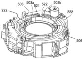
ロック機構は、ロックリング(切替部材、ロック部材)500、2つのロックレバー(規制部材、保持部材、第1保持部材)510およびロックモーター(第2の駆動手段)520によって構成される。ロックリング500は径嵌合部501を有し、固定レンズ枠210は径嵌合部212を有する。径嵌合部501と径嵌合部212が径嵌合することで、ロックリング500は光軸回りにアンロック位置とロック位置との間を回転可能に保持される。また、固定レンズ枠210はバヨネット部213を3位相に備え、ロックリング500はバヨネット部213に対応するバヨネット部502を3位相に備える。バヨネット部213とバヨネット部502が係合することで、組立位相以外でロックリング500が固定レンズ枠210から外れることを防止する。また、ロックリング500はロックリング側メカ端(規制部)503a、503bを有し、モーター板金(第2保持部材)521は固定側メカ端(接触部、第2接触部)522を有する。ロックリング側メカ端503a、503bと固定側メカ端522が接触することで、固定レンズ枠210に対するロックリング500の回転範囲を規制する。また、ロックリング500はギア部505を有し、ロックモーター520にはギア部505に係合するモーターピニオン523が取り付けられている。そのため、ロックモーター520が回転することで、ロックリング500が回転する。
The lock mechanism includes a lock ring ( switching member, lock member) 500 , two lock levers ( regulating member, holding member, first holding member) 510 and a lock motor (second driving means) 520 . The
前述したように、ロックリング500は、固定レンズ枠210と径嵌合することで光軸回りに回転可能に保持される。ロックレバー510は、可動レンズ枠220の外周に回転軸を有するレバー部材であり、可動レンズ枠220の外周の互いに異なる位相に複数配置されている。ロックレバー510は嵌合穴512を有し、固定レンズ枠210は嵌合軸214を有する。嵌合軸214が嵌合穴512に径嵌合することで、ロックレバー510は嵌合軸214回りに回転可能に保持される。
As described above, the
また、固定レンズ枠210は、回転検出部530を備える。回転検出部530は、本実施例では、フォトインタラプタであり、ロックリング500の形状の一部(本実施例では、回転被検出部514)が通過することで、ロックリング500の状態を検出する。
The fixed
図8および図9は、ロックリング500とロックレバー510を撮像面側から見た図であり、ロックリング500とロックレバー510との関係を示している。ロックレバー510は、係合部511を有する。ロックリング500は、係合部511に係合する係合部504を有する。ロックレバー510は、嵌合軸214回りに回転するため、ロックリング500が回転すると、係合部511に係合する係合部504から力を受けて回転する。
8 and 9 are diagrams of the
ロックリング500が図5に示されるようにアンロック位置に位置する場合、ロックレバー510は可動レンズ枠220に接触していない。すなわち、ロック機構は、可動レンズ枠220の光軸垂直方向への移動の制限が解除されるアンロック状態である。ロックリング500がアンロック位置から図6に示されるロック位置に回転すると、ロックレバー510は可動レンズ枠220の可動範囲方向へ飛び出し、可動レンズ枠220に接触する。可動レンズ枠220は、図6の矢印で示される偏芯方向へ移動し、固定レンズ枠210の内径にある固定側メカ端211および2本のロックレバー510によって、光軸中心から偏芯した状態で保持され、可動範囲を規制される。すなわち、ロック機構は、可動レンズ枠220の光軸垂直方向への移動が制限されるロック状態である。本実施例では、可動レンズ枠220を偏芯させた状態で可動レンズ枠220の移動を制限するため、従来3つ必要であったレバー部材を2つで構成でき、振れ補正ユニット202をより小型化可能である。
When the
本実施例では、図8および図9に示されるように、係合部504は突起形状(凸部)であり、係合部511は光軸に垂直な方向へ延びた溝形状である。しかしながら、図10に示されるように、係合部504を溝形状、係合部511を突起形状としてもよい。すなわち、ロックリング500およびロックレバー510の一方が突起形状(係合部)を有し、他方が溝形状(被係合部)を有すればよい。機能、部品強度および成型金型の要件から適切な係合部の形状を選択することが望ましい。
In this embodiment, as shown in FIGS. 8 and 9, the engaging
図11は、固定レンズ枠210とロックレバー510の撮像面側の拡大図である。図12は、固定レンズ枠210とロックレバー510の断面図である。ロックレバー510はロックレバー側対向面(接触部、第1接触部)513を有し、固定レンズ枠210は固定側対向面215を有する。ロックレバー510がロック位置に位置する場合、ロックレバー側対向面513と固定側対向面215は互いに近接し、接触可能に配置される。このような構成により、可動レンズ枠220に衝撃が加わり、ロックレバー510で受けた際、変形したロックレバー510を固定レンズ枠210で受けることができる。そのため、ロックレバー510自体の破損や、嵌合軸214の破損等を防止することができる。また、このような構成を設けない場合に比べて、ロックレバー510や嵌合軸214を細く構成しても破損しづらくなるため、振れ補正ユニット202の小型化やレイアウトの自由度を向上させることができる。なお、ロックレバー510は、弾性変形可能な樹脂で構成されていることが望ましい。
FIG. 11 is an enlarged view of the fixed
図13は、ロックレバー510の配置位相の説明図である。図13の直線Aは、光軸αを通り、可動レンズ枠220の外周を2つの領域に分ける直線である。ロックレバー510は、直線Aで分けられた領域のうち、シフトコイル330やシフトマグネット340で構成される可動レンズ枠220を移動させるための駆動手段が配置されている側(マグネット配置側)とは反対側(マグネット配置反対側)に配置される。マグネット配置側には、ヨーク部材(本実施例では、第1のヨーク310)が配置されるため、固定レンズ枠210に嵌合軸214を設けることが困難である。ヨークの上に嵌合軸214を設ける場合、振れ補正ユニット202が光軸方向へ大型化してしまう。本実施例では、上記構成により、振れ補正ユニット202をより小型化可能である。
13A and 13B are explanatory diagrams of the arrangement phase of the
本実施例では、図7に示されるように、ロックレバー510は、光軸方向において、固定レンズ枠210とロックリング500との間に配置される。ロックレバー510をこのように配置することで、第1のヨーク310の厚みで生まれたスペースを有効に活用できる。また、本実施例では、ロックレバー510の上からロックリング500を被せる構成としているため、ロックリング500にロックレバー510の抜け止めの役割を持たすことができる。このような構成は、部品点数の削減や、振れ補正ユニット202の小型化に寄与する。
In this embodiment, as shown in FIG. 7, the
本実施例では、ロックリング500はロックリング側メカ端503a、503bを有し、ロックモーター520は固定側メカ端522を有する。ロック機構がアンロック状態において、固定側メカ端522はロックリング側メカ端503aに接触する。ロック機構がロック状態において、固定側メカ端522はロックリング側メカ端503bに接触する。このような構成により、ロックリング500が必要以上に回転することを防止することができる。また、振れ補正ユニット202に衝撃等が加わった際、ロックリング500およびロックレバー510の固定レンズ枠210等他の部品に対する影響を抑制し、動作不良等を防止することができる。
In this embodiment, the
本実施例の振れ補正ユニット202では、ロック機構により可動レンズ枠220の移動が制限される場合、可動レンズ枠220は光軸中心ではなく、光軸αから偏芯した位置に保持される。これは、レンズ鏡筒201の電源がOFFになっている場合、可動レンズ枠220が偏芯してしまうことを意味する。したがって、本実施例の振れ補正ユニット202は、例えば、光学ファインダーを備えないカメラシステム(ミラーレス一眼カメラなど)に適している。
In the
本実施例では、ロックリング500にロックレバー510の役割を持たせる場合について説明する。図14は、可動レンズ枠220の光軸垂直方向への移動の制限が解除されるアンロック状態であるロック機構を示す図である。図15は、可動レンズ枠220の光軸垂直方向への移動が制限されるロック状態であるロック機構を示す図である。図16は、ロック機構の構造を示す斜視図である。本実施例では、実施例1と異なる構成について説明する。
In this embodiment, a case where the
可動レンズ枠220はロック受け部222を有し、ロックリング500は当接部(保持部材)506を有する。ロック機構がアンロック状態である場合、ロック受け部222は当接部506に接触しておらず、可動レンズ枠220の可動範囲は規制されていない。一方、ロック機構がロック状態である場合、ロック受け部222と当接部506が接触し、可動レンズ枠220の可動範囲は規制される。このとき、実施例1と同様に、可動レンズ枠220は、可動範囲の中で片寄せされる。このような構成により、従来3つ必要であった規制部材を2つで構成でき、振れ補正ユニット202をより小型化可能である。
The
図17から図22を用いて実施例3の振れ補正ユニットについて説明する。本実施例の振れ補正ユニットでは前述の実施例1および実施例2の振れ補正ユニットと同様に、ある部材が回転することでロック状態とアンロック状態が切り替わるが、回転する部材が異なる。以下では主に前述の実施例1および実施例2の振れ補正ユニットと本実施例の振れ補正ユニットの違いを説明する。 A shake correction unit according to the third embodiment will be described with reference to FIGS. 17 to 22. FIG. In the shake correction unit of this embodiment, similar to the shake correction units of the first and second embodiments described above, the locked state and the unlocked state are switched by rotating a certain member, but the member that rotates is different. Differences between the shake correction units of the first and second embodiments and the shake correction unit of the present embodiment will be mainly described below.
図17は本実施例の振れ補正ユニットを撮像面側から見た分解斜視図であり、図18は本実施例の振れ補正ユニットを被写体側から見た分解斜視図である。 FIG. 17 is an exploded perspective view of the shake correction unit of this embodiment as seen from the imaging surface side, and FIG. 18 is an exploded perspective view of the shake correction unit of this embodiment as seen from the object side.
図2および図3に示した実施例1の振れ補正ユニットと、図17および図18に示す本実施例の振れ補正ユニットとの主な違いは、ロック部材としてロックリング500の代わりに回転ロック円筒部材600を備える点と、ロックレバー510を備えない代わりに回転ロック円筒部材600が半円筒部603を備える点である。つまり、ロック部材と保持部材は一体的に構成されていてもよい。これらの点以外にも、可動レンズ枠、固定レンズ枠、第1のアンチロールプレート、センサー保持枠、モーター板金の形状等が異なる。図17および図18中の2200が可動レンズ枠、2100が固定レンズ枠、4100が第1のアンチロールプレート、2400がセンサー保持枠、5210がモーター板金である。
The main difference between the shake correction unit of the first embodiment shown in FIGS. 2 and 3 and the shake correction unit of the present embodiment shown in FIGS. 2, the rotation lock
図19は前述の回転ロック円筒部材600の構成を示す図である。図19(a)はアンロック状態における回転ロック円筒部材600を示しており、図19(b)はロック状態における回転ロック円筒部材600を示している。図19に示すように回転ロック円筒部材600は、ギア601、回転軸部602、半円筒部603を備えている。
FIG. 19 is a diagram showing the configuration of the rotation lock
620は回転ロック円筒部材600がアンロック状態かロック状態であるかを検出するためのフォトリフレクタである。フォトリフレクタ620は発光部と受光部を備えている。図19(a)に示すように、アンロック状態では、フォトリフレクタ620と半円筒部603が重なり、フォトリフレクタ620の発光部からの光が半円筒部603の軸方向端面で反射されて受光部に入射する。逆に、図19(b)に示すように、ロック状態では、フォトリフレクタ620と半円筒部603は重ならず、フォトリフレクタ620の発光部からの光は受光部に入射しない。以上の発光部からの光が受光部に入射するかどうかを基準にアンロック状態かロック状態かを判断することができる。
620 is a photoreflector for detecting whether the rotation lock
ギア601、回転軸部602、半円筒部603は一体的に構成されているため、ギア610がロックモーター520によって回転するとギア601、回転軸部602、半円筒部603が一体的に回転する。以上の構成で回転ロック円筒部材600のアンロック状態とロック状態を切り替えることができる。なお、フォトリフレクタ620は図18に示す穴部2402に嵌った状態でセンサー保持枠2400に保持されている。
Since the
図20(a)はアンロック状態にある振れ補正ユニットを示しており、図20(b)はロック状態にある振れ補正ユニットを示している。図20(b)に示すように、本実施例においても前述の実施例1および実施例2と同様にロック状態では振れ補正レンズ202aはその他のレンズの光軸に対して偏心した状態で保持される。ロック状態では可動レンズ枠2200は固定側メカ端211に接触している。
FIG. 20(a) shows the shake correction unit in the unlocked state, and FIG. 20(b) shows the shake correction unit in the locked state. As shown in FIG. 20(b), in this embodiment as well, the
図21は図20(a)の一点鎖線で示す線で切断したときの振れ補正ユニットの断面図である。図21に示すように、回転軸部602はセンサー保持枠2400に設けられた穴部2401と固定レンズ枠2100に設けられた穴部2101に軸支されている。
FIG. 21 is a cross-sectional view of the shake correction unit taken along the dashed line in FIG. 20(a). As shown in FIG. 21, the
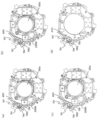
図22を用いて本実施例においてアンロック状態からロック状態に至るまでの各工程における振れ補正ユニットの状態について説明する。図22(a)はアンロック状態の振れ補正ユニットを示している。なお、図22(a)(b)(c)においては説明のためにセンサー保持枠2400などが不図示となっており、図22(d)においては説明のためにさらに可動レンズ枠2200および第2のアンチロールプレート420が不図示となっている。図22(a)に示すように半円筒部603は可動レンズ枠2200の方を向いておらず、可動レンズ枠2200が備える凹部2201とは接触していない。
With reference to FIG. 22, the state of the shake correction unit in each step from the unlocked state to the locked state in this embodiment will be described. FIG. 22(a) shows the shake correction unit in an unlocked state. 22(a), 22(b), and 22(c) do not show the
アンロック状態からロック状態に移行する際には駆動制御部204から振れ補正ユニットへ、可動レンズ枠2200を図22(a)に示す状態から図22(b)に示す状態へするように指示が出される。図22(b)は図22(a)に示す状態から可動レンズ枠2200を紙面右方向へ移動させ、可動レンズ枠2200が右側のメカ端に接触した状態である。図22(b)では図22(a)よりもギア601が露出していることから、可動レンズ枠2200が紙面右方向へ移動したことがわかる。可動レンズ枠2200を紙面右方向へ移動させる際には通常の振れ補正時に可動レンズ枠2200を移動させる方法と同じ方法を用いればよい。
When shifting from the unlocked state to the locked state, the
可動レンズ枠2200が図22(b)に示す状態になると、ロックモーター520はギア610を回転させる。その結果、半円筒部603は図22(a)および(b)に示す位置から図22(c)に示す位置へ回転する。図22(c)に示す状態で振れ補正ユニットへの電源供給が行われなくなると、可動レンズ枠2200はコイルバネ440によって図22(a)に示す状態、つまり、振れ補正レンズ202aが偏心していない状態へ戻ろうとする。しかしながら、このとき半円筒部603の凹部2201との接触で可動レンズ枠2200の上下左右の動きは制限され、振れ補正ユニットへの電源供給が行われなくなっても図22(c)に示す状態、つまり、振れ補正レンズ202aが偏心している状態が維持されてロックが完了する。
When the
図22(d)は図22(c)から可動レンズ枠2200および第2のアンチロールプレート420を取り除いた図である。図22(d)に示すように第1のアンチロールプレート4100には前述の可動レンズ枠2200が備える凹部2201と同様の凹部4101が設けられている。凹部2201および凹部4101は図22(c)および(d)に示すように、半円筒部603と同様の形状を有しており、ロック状態において半円筒部603が凹部2201および凹部4101に接触することで、可動レンズ枠2200の紙面上下方向への移動が規制される。また、ロック状態では可動レンズ枠2200が回転ロック円筒部材600および固定側メカ端211に接触することで紙面左右方向への移動が規制される。
FIG. 22(d) is a diagram in which the
以上説明したように、本実施例では前述の実施例1と比較して、ロックリング500を設ける必要がなく、振れ補正ユニットの厚みの範囲に回転ロック円筒部材600を設けているために、振れ補正ユニットを光軸方向により薄くすることができる。また、ロックリング500とロックレバー510の両方が必要な実施例1と比較して少ない部品で可動レンズ枠のロック機構を実現することができる。さらに、回転軸部602は細い軸部であるために、回転軸部602を回転させる際の負荷トルクが小さく、ガタが少ないために、ロックモーター520が回転する際の安定性が良い、動作音が小さいといった利点もある。なお、ロックモーター520はSTMであるが、ロックモーター520の構成は、回転ロック円筒部材600を回転させることができれば、STM以外のものであってもよい。
As described above, in this embodiment, unlike the first embodiment described above, the
また、ロック状態において、回転ロック円筒部材600は可動レンズ枠2200に接触してもよいし、可動レンズ枠2200ではなく、可動レンズ枠2200に固定されている部材(第2のアンチロールプレート420)に接触してもよい。さらに、ロック状態において、回転ロック円筒部材600は可動レンズ枠2200と第2のアンチロールプレート420の両方に接触してもよい。
In the locked state, the rotation lock
図23から図28を用いて実施例4の振れ補正ユニットについて説明する。前述の各実施例の振れ補正ユニットでは、ある部材が回転することでアンロック状態とロック状態が切り替えられていた。しかしながら、本実施例の振れ補正ユニットでは、ある部材を光軸方向へ移動させることでアンロック状態とロック状態を切り替える。以下では主に前述の実施例1の振れ補正ユニットと本実施例の振れ補正ユニットの違いを説明する。 A shake correction unit according to the fourth embodiment will be described with reference to FIGS. 23 to 28. FIG. In the shake correction unit of each of the embodiments described above, the unlocked state and the locked state are switched by rotating a certain member. However, in the shake correction unit of this embodiment, the unlocked state and the locked state are switched by moving a certain member in the optical axis direction. Differences between the shake correction unit of the first embodiment and the shake correction unit of the present embodiment will be mainly described below.
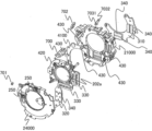
図23は本実施例の振れ補正ユニットを撮像面側から見た分解斜視図であり、図24は本実施例の振れ補正ユニットを被写体側から見た分解斜視図である。図2および図3に示した実施例1の振れ補正ユニットと、図23および図24に示す本実施例の振れ補正ユニットとの主な違いは、ロック部材としてロックリング500の代わりに移動ロック円筒部材700を備える点と、ロックレバー510を備えない代わりに移動ロック円筒部材700が半円筒部707を備える点である。つまり、ロック部材と保持部材は一体的に構成されていてもよい。これらの点以外にも、可動レンズ枠、固定レンズ枠、第1のアンチロールプレート、センサー保持枠の形状等が異なる。図23および図24中の22000が可動レンズ枠、21000が固定レンズ枠、4100が第1のアンチロールプレート、24000がセンサー保持枠である。
FIG. 23 is an exploded perspective view of the shake correction unit of this embodiment as seen from the imaging surface side, and FIG. 24 is an exploded perspective view of the shake correction unit of this embodiment as seen from the object side. The main difference between the shake correction unit of the first embodiment shown in FIGS. 2 and 3 and the shake correction unit of the present embodiment shown in FIGS. 2. The moving lock
図25は前述の移動ロック円筒部材700の構成を示す図である。図25(a)はアンロック状態における移動ロック円筒部材700を示しており、図25(b)はロック状態における移動ロック円筒部材700を示している。図25(c)は移動ロック円筒部材700を後述の支持軸706の軸方向と直交する方向から見た図であり、図25(d)は移動ロック円筒部材700を支持軸706の軸方向から見た図である。
FIG. 25 is a diagram showing the configuration of the movement lock
図25(a)および(b)に示すように、移動ロック円筒部材700は遮光部704、半円筒部707、第1のクリック溝7051、第2のクリック溝7052を備えている。移動ロック円筒部材700は支持軸706に支持されている。支持軸706の両端部はそれぞれ後述の図27(a)および(b)に示すように、固定レンズ枠21000が有する凹部21001と、センサー保持枠24000が有する凹部24001に嵌っている。
As shown in FIGS. 25(a) and 25(b), the moving lock
移動ロック円筒部材700には、第1のマグネット部7081(N極)および第2のマグネット部7082(S極)が設けられている。第1のマグネット部7081および第2のマグネット部7082の上方向にはコイル702が設けられている。コイル702は後述の図27(a)および(b)に示すように固定レンズ枠21000に保持されている。第1のマグネット部7081、第2のマグネット部7082、コイル702によって移動ロック円筒部材700を支持軸706の軸方向に移動させるための駆動部が構成されている。
The movement lock
アンロック状態においてはクリック板バネ7032が第2のクリック溝7052に嵌り、ロック状態においてはクリック板バネ7032が第1のクリック溝7051に嵌るようになっている。クリック板バネ7032が第1のクリック溝7051あるいは第2のクリック溝7052に嵌ることで、前述の駆動部が駆動していない状態では移動ロック円筒部材700の支持軸706の軸方向の位置が固定される。クリック板バネ7032はネジ7031によって固定レンズ枠21000に固定されている。
The
701はフォトインタラプタである。フォトインタラプタ701には発光部と受光部があり、図25(b)に示すロック状態では遮光部704によって発光部からの光は受光部に入らない。逆に、図25(a)に示すアンロック状態では遮光部704は発光部からの光を遮光しないので、発光部からの光は受光部に入る。以上の発光部からの光が受光部に入射するかどうかを基準にアンロック状態かロック状態かを判断することができる。
701 is a photointerrupter. The
図26(a)はアンロック状態にある振れ補正ユニットを示しており、図26(b)はロック状態にある振れ補正ユニットを示している。図26(b)に示すように、本実施例においても前述の実施例1および実施例2と同様にロック状態では振れ補正レンズ202aはその他のレンズの光軸に対して偏心した状態で保持される。ロック状態では可動レンズ枠22000は固定側メカ端211に接触している。
FIG. 26(a) shows the shake correction unit in the unlocked state, and FIG. 26(b) shows the shake correction unit in the locked state. As shown in FIG. 26(b), in this embodiment as well, the
図27は図26(a)の一点鎖線で示す線で切断したときの振れ補正ユニットの断面図である。図27(a)はアンロック状態における振れ補正ユニットの断面図であり、図27(b)はロック状態における振れ補正ユニットの断面図である。 FIG. 27 is a cross-sectional view of the shake correction unit taken along the dashed line in FIG. 26(a). FIG. 27(a) is a sectional view of the shake correction unit in the unlocked state, and FIG. 27(b) is a sectional view of the shake correction unit in the locked state.
図27(a)に示すようにアンロック状態では、振れ補正レンズ202aの光軸方向において、移動ロック円筒部材700は可動レンズ枠22000、第1のアンチロールプレート4100、第2のアンチロールプレート420から離れた位置に位置している。言い換えれば、アンロック状態では、光軸直交方向視において、半円筒部707は可動レンズ枠22000、第1のアンチロールプレート4100、第2のアンチロールプレート420の少なくとも一つと重ならない位置に移動ロック円筒部材700は位置している。
As shown in FIG. 27(a), in the unlocked state, the movement lock
図27(b)に示すようにロック状態では、振れ補正レンズ202aの光軸方向において、移動ロック円筒部材700は可動レンズ枠22000、第1のアンチロールプレート4100、第2のアンチロールプレート420に近い位置に位置している。言い換えれば、ロック状態では、光軸直交方向視において、半円筒部707は可動レンズ枠22000、第1のアンチロールプレート4100、第2のアンチロールプレート420の少なくとも一つと重なる位置に移動ロック円筒部材700は位置している。
As shown in FIG. 27(b), in the locked state, the movable lock
図28を用いて本実施例においてアンロック状態からロック状態に至るまでの各工程における振れ補正ユニットの状態について説明する。図28(a)はアンロック状態の振れ補正ユニットを示している。なお、図28(a)(b)(c)においては説明のためにセンサー保持枠24000などが不図示となっており、図28(d)においては説明のためにさらに可動レンズ枠22000および第2のアンチロールプレート420が不図示となっている。
With reference to FIG. 28, the state of the shake correction unit in each step from the unlocked state to the locked state in this embodiment will be described. FIG. 28(a) shows the shake correction unit in an unlocked state. 28(a), 28(b) and 28(c), the
アンロック状態からロック状態に移行する際には駆動制御部204から振れ補正ユニットへ、可動レンズ枠22000を図28(a)に示す状態から図28(b)に示す状態へするように指示が出される。図28(b)は図28(a)に示す状態から可動レンズ枠22000を紙面右方向へ移動させ、可動レンズ枠22000が右側のメカ端に接触した状態である。図28(b)では図28(a)よりも半円筒部707が露出していることから、可動レンズ枠22000が紙面右方向へ移動したことがわかる。可動レンズ枠22000を紙面右方向へ移動させる際には通常の振れ補正時に可動レンズ枠22000を移動させる方法と同じ方法を用いればよい。
When shifting from the unlocked state to the locked state, the
可動レンズ枠22000が図28(b)に示す状態になると、駆動制御部204から前述の第1のマグネット部7081、第2のマグネット部7082、コイル702から構成される駆動部へ、移動ロック円筒部材700を支持軸706の軸方向へ移動させるように指示が出させる。その結果、駆動部が移動ロック円筒部材700を前述の図27(a)に示す位置から図27(b)に示す位置に移動させる。図28(c)に示す状態で振れ補正ユニットへの電源供給が行われなくなると、可動レンズ枠22000はコイルバネ440によって図28(a)に示す状態、つまり、振れ補正レンズ202aが偏心していない状態へ戻ろうとする。しかしながら、このとき半円筒部707が第2のアンチロールプレート420が有する凹部4201と接触しているために、振れ補正ユニットへの電源供給が行われなくなっても図28(c)に示す状態、つまり、振れ補正レンズ202aが偏心している状態が維持されてロックが完了する。
When the
図28(d)は図28(c)から可動レンズ枠22000および第2のアンチロールプレート420を取り除いた図である。図28(d)に示すように第1のアンチロールプレート4100には前述の第2のアンチロールプレート420が備える凹部4201と同様の凹部4101が設けられている。凹部4201および凹部4101は図28(c)および(d)に示すように、半円筒部707と同様の形状を有しており、ロック状態において半円筒部707が凹部2201および凹部4101に接触することで、可動レンズ枠2200の紙面上下方向への移動が規制される。また、ロック状態では可動レンズ枠2200が固定側メカ端211に接触することで紙面左右方向への移動が規制される。
FIG. 28(d) is a diagram in which the
以上説明したように、本実施例では前述の実施例1と比較して、ロックリング500を設ける必要がなく、振れ補正ユニットの厚みの範囲に移動ロック円筒部材700を設けているために、振れ補正ユニットを光軸方向により薄くすることができる。また、本実施例では、アンロック状態とロック状態の切り替えを、移動ロック円筒部材700をわずかに移動させることで実現できているので、アンロック状態とロック状態を素早く切り替えることができる。
As described above, in this embodiment, unlike the first embodiment described above, there is no need to provide the
なお、本実施例ではVCMを用いて移動ロック円筒部材700を移動させていたが、移動ロック円筒部材700を支持軸706の軸方向に移動させることができるものであれば、VCM以外の送りねじ付きのSTMとラックの組み合わせ等を用いてもよい。
In this embodiment, the VCM is used to move the movable lock
以上、本発明の好ましい実施形態について説明したが、本発明はこれらの実施形態に限定されず、その要旨の範囲内で種々の変形および変更が可能である。 Although preferred embodiments of the present invention have been described above, the present invention is not limited to these embodiments, and various modifications and changes are possible within the scope of the gist.
202 振れ補正ユニット(振れ補正装置)
202a 振れ補正レンズ
210 固定レンズ枠(固定部材)
220 可動レンズ枠(可動部材)
500 ロックリング(ロック部材)
506 当接部(保持部材)
510 ロックレバー(保持部材)
202 shake correction unit (shake correction device)
202a
220 movable lens frame (movable member)
500 lock ring (lock member)
506 contact portion (holding member)
510 lock lever (holding member)
Claims (19)
振れ補正レンズを保持するとともに、前記振れ補正レンズの光軸に垂直な平面内において前記固定部材に対して移動可能である可動部材と、
前記可動部材の移動を制限するロック位置と、前記可動部材の前記固定部材に対する移動の制限を解除するアンロック位置に移動可能な規制部材を有し、
前記規制部材は、前記アンロック位置から前記ロック位置への切り換えに際して、前記可動部材が前記固定部材に接触するように、前記可動部材を偏心させることを特徴とする振れ補正装置。 a fixing member;
a movable member that holds the shake correction lens and is movable with respect to the fixed member in a plane perpendicular to the optical axis of the shake correction lens;
a restricting member movable between a lock position for restricting the movement of the movable member and an unlock position for releasing the restriction on the movement of the movable member with respect to the fixed member ;
The shake correction device, wherein the regulating member eccentrically moves the movable member so that the movable member comes into contact with the fixed member when switching from the unlocked position to the locked position.
前記規制部材および前記切替部材の一方は、係合部を備え、
前記規制部材および前記切替部材の他方は、前記係合部に係合する被係合部を備えることを特徴とする請求項2に記載の振れ補正装置。 the regulating member is a lever member having a rotating shaft on the outer periphery of the movable member;
one of the regulating member and the switching member includes an engaging portion;
3. The image stabilization device according to claim 2, wherein the other of the regulating member and the switching member has an engaged portion that engages with the engaging portion.
前記被係合部は、溝であることを特徴とする請求項3に記載の振れ補正装置。 The engaging portion is a convex portion,
4. The shake correction device according to claim 3, wherein the engaged portion is a groove.
前記規制部材は、前記可動部材の外周を、光軸を通る直線で2つの領域に分けた場合、前記マグネットが配置されている側の領域とは反対側の領域に配置されていることを特徴とする請求項1から8のいずれか1項に記載の振れ補正装置。 further comprising a driving means comprising a magnet and driving the movable member with respect to the fixed member;
When the outer periphery of the movable member is divided into two regions by a straight line passing through the optical axis, the regulating member is arranged in a region opposite to the region where the magnet is arranged. 9. The shake correction device according to any one of claims 1 to 8.
前記第2駆動手段を保持する第2保持部材と、を更に有し、
前記第2保持部材は、前記規制部材が前記ロック位置および前記アンロック位置に位置する場合に、前記規制部に接触する接触部を有することを特徴とする請求項11に記載の振れ補正装置。 a second driving means for rotating the switching member;
a second holding member that holds the second driving means;
12. The shake correcting device according to claim 11, wherein the second holding member has a contact portion that contacts the restricting portion when the restricting member is positioned at the locked position and the unlocked position.
前記光軸に沿って移動可能な可動レンズと、を有することを特徴とするレンズ装置。 a shake correction device according to any one of claims 1 to 16;
and a movable lens movable along the optical axis.
前記レンズ装置を介して形成された被写体像を光電変換する撮像素子を備える撮像装置と、を有することを特徴とするカメラシステム。 a lens device according to claim 17;
and an imaging device that photoelectrically converts a subject image formed through the lens device.
Applications Claiming Priority (2)
| Application Number | Priority Date | Filing Date | Title |
|---|---|---|---|
| JP2018084728 | 2018-04-26 | ||
| JP2018084728 | 2018-04-26 |
Publications (3)
| Publication Number | Publication Date |
|---|---|
| JP2019194691A JP2019194691A (en) | 2019-11-07 |
| JP2019194691A5 JP2019194691A5 (en) | 2022-04-25 |
| JP7278849B2 true JP7278849B2 (en) | 2023-05-22 |
Family
ID=66251586
Family Applications (1)
| Application Number | Title | Priority Date | Filing Date |
|---|---|---|---|
| JP2019080606A Active JP7278849B2 (en) | 2018-04-26 | 2019-04-22 | Shake correction device, lens device and camera system |
Country Status (4)
| Country | Link |
|---|---|
| US (1) | US10735657B2 (en) |
| EP (1) | EP3561589B1 (en) |
| JP (1) | JP7278849B2 (en) |
| CN (1) | CN110418034B (en) |
Families Citing this family (4)
| Publication number | Priority date | Publication date | Assignee | Title |
|---|---|---|---|---|
| JP7486975B2 (en) | 2020-02-28 | 2024-05-20 | キヤノン株式会社 | Lens device and imaging device |
| US20240248370A1 (en) * | 2021-05-12 | 2024-07-25 | Nikon Corporation | Blur correction device, lens barrel, and imaging apparatus |
| US11618862B2 (en) | 2021-06-16 | 2023-04-04 | Comstock Ip Holdings Llc | Organic monolignol biopolymer impregnated wood particle briquettes/pellets and method of making |
| CN117678228A (en) * | 2022-03-10 | 2024-03-08 | 深圳市大疆创新科技有限公司 | Camera and cradle head |
Citations (4)
| Publication number | Priority date | Publication date | Assignee | Title |
|---|---|---|---|---|
| JP2005070113A (en) | 2003-08-26 | 2005-03-17 | Nikon Corp | Blur correction device |
| JP2005227568A (en) | 2004-02-13 | 2005-08-25 | Nikon Corp | Lens barrel and photographing device |
| JP2006081118A (en) | 2004-09-13 | 2006-03-23 | Konica Minolta Photo Imaging Inc | Imaging apparatus |
| JP2015004769A (en) | 2013-06-20 | 2015-01-08 | リコーイメージング株式会社 | Lock mechanism and optical device including the same |
Family Cites Families (29)
| Publication number | Priority date | Publication date | Assignee | Title |
|---|---|---|---|---|
| JP3192414B2 (en) * | 1990-05-31 | 2001-07-30 | キヤノン株式会社 | Image blur prevention device and camera |
| US5181056A (en) * | 1990-05-31 | 1993-01-19 | Canon Kabushiki Kaisha | Image stabilizing apparatus |
| JP3044106B2 (en) * | 1991-10-09 | 2000-05-22 | キヤノン株式会社 | Camera with image blur prevention function |
| US5774266A (en) * | 1992-04-06 | 1998-06-30 | Canon Kabushiki Kaisha | Image stabilizing device |
| JP3253168B2 (en) * | 1993-04-01 | 2002-02-04 | キヤノン株式会社 | Lens barrel |
| JPH07199258A (en) | 1993-12-28 | 1995-08-04 | Sony Corp | Lens driving mechanism for correcting optical axis |
| JP3618798B2 (en) * | 1994-09-19 | 2005-02-09 | キヤノン株式会社 | Image blur correction device |
| JPH1090587A (en) | 1996-09-10 | 1998-04-10 | Canon Inc | Lens barrel, camera and image shake preventing device |
| US6208810B1 (en) * | 1997-01-28 | 2001-03-27 | Canon Kabushiki Kaisha | Image blur preventing device |
| JPH11337995A (en) * | 1998-05-28 | 1999-12-10 | Minolta Co Ltd | Image blurring correcting optical device |
| JP4050082B2 (en) | 2002-04-09 | 2008-02-20 | 株式会社シグマ | Optical axis locking mechanism of image shake prevention device |
| US7025512B2 (en) * | 2002-08-27 | 2006-04-11 | Pentax Corporation | Retracting mechanism of a retractable lens |
| JP2004145188A (en) * | 2002-10-28 | 2004-05-20 | Nikon Corp | Lens barrel |
| ATE393920T1 (en) * | 2004-05-31 | 2008-05-15 | Fujinon Corp | LENS DRIVE APPARATUS AND IMAGING APPARATUS |
| JP4744939B2 (en) * | 2005-06-01 | 2011-08-10 | Hoya株式会社 | Lens barrel |
| US7782533B2 (en) * | 2006-02-10 | 2010-08-24 | Panasonic Corporation | Image stabilizing apparatus |
| US8139291B2 (en) * | 2007-05-21 | 2012-03-20 | Tamron Co., Ltd. | Image blur prevention actuator and lens unit and camera equipped therewith |
| JP5611578B2 (en) * | 2009-12-08 | 2014-10-22 | Hoya株式会社 | Optical element position control device |
| JP2011154310A (en) * | 2010-01-28 | 2011-08-11 | Nikon Corp | Optical device and optical apparatus |
| JP5495860B2 (en) | 2010-03-03 | 2014-05-21 | キヤノン株式会社 | Optical image stabilizer and optical apparatus |
| KR102441779B1 (en) * | 2014-12-26 | 2022-09-08 | 미쓰미덴기가부시기가이샤 | Lens-driving device, camera module, and camera mount device |
| JP6617007B2 (en) * | 2015-01-28 | 2019-12-04 | 三星電子株式会社 | Lens barrel |
| WO2016122177A1 (en) * | 2015-01-28 | 2016-08-04 | Samsung Electronics Co., Ltd. | Lens barrel and camera |
| CN105022204B (en) * | 2015-08-07 | 2017-10-31 | 深圳市世尊科技有限公司 | A kind of mobile terminal camera module and mobile terminal |
| DE102015116414A1 (en) * | 2015-09-28 | 2017-03-30 | Airbus Operations Gmbh | Passenger seating system with sliding seats for a means of transport and an aircraft cabin with such a passenger seat system |
| CN206611500U (en) * | 2016-11-29 | 2017-11-03 | 宁波舜宇光电信息有限公司 | Optical anti-vibration camera module and electronic equipment based on long cross direction |
| CN110036326B (en) * | 2016-12-05 | 2021-12-10 | 富士胶片株式会社 | Lens guide device and lens moving device |
| JP6800911B2 (en) | 2018-04-17 | 2020-12-16 | キヤノン株式会社 | Shake correction device and lens device and camera system equipped with this |
| CN208605865U (en) * | 2018-07-09 | 2019-03-15 | 单景华 | A kind of switching adaptive device and camera shooting stabilizer |
-
2019
- 2019-04-22 JP JP2019080606A patent/JP7278849B2/en active Active
- 2019-04-23 CN CN201910329567.6A patent/CN110418034B/en active Active
- 2019-04-23 EP EP19170667.0A patent/EP3561589B1/en active Active
- 2019-04-26 US US16/396,107 patent/US10735657B2/en active Active
Patent Citations (4)
| Publication number | Priority date | Publication date | Assignee | Title |
|---|---|---|---|---|
| JP2005070113A (en) | 2003-08-26 | 2005-03-17 | Nikon Corp | Blur correction device |
| JP2005227568A (en) | 2004-02-13 | 2005-08-25 | Nikon Corp | Lens barrel and photographing device |
| JP2006081118A (en) | 2004-09-13 | 2006-03-23 | Konica Minolta Photo Imaging Inc | Imaging apparatus |
| JP2015004769A (en) | 2013-06-20 | 2015-01-08 | リコーイメージング株式会社 | Lock mechanism and optical device including the same |
Also Published As
| Publication number | Publication date |
|---|---|
| JP2019194691A (en) | 2019-11-07 |
| US20190335105A1 (en) | 2019-10-31 |
| US10735657B2 (en) | 2020-08-04 |
| EP3561589A1 (en) | 2019-10-30 |
| CN110418034A (en) | 2019-11-05 |
| CN110418034B (en) | 2021-08-10 |
| EP3561589B1 (en) | 2022-07-13 |
Similar Documents
| Publication | Publication Date | Title |
|---|---|---|
| JP7278849B2 (en) | Shake correction device, lens device and camera system | |
| US7899312B2 (en) | Lens barrel and imaging device | |
| US7414802B2 (en) | Lens apparatus and camera | |
| JP3044106B2 (en) | Camera with image blur prevention function | |
| JP2008197388A (en) | Image shake correction device, lens barrel, and optical apparatus | |
| JP5495860B2 (en) | Optical image stabilizer and optical apparatus | |
| US11073674B2 (en) | Lens apparatus and imaging apparatus | |
| JP2019194691A5 (en) | ||
| US9798158B2 (en) | Optical apparatus capable of retracting optical element from optical path | |
| JP2011128621A (en) | Zoom lens | |
| JP2006337957A (en) | Lens barrel | |
| JP2008020488A (en) | Lens barrel and imaging apparatus | |
| JP2013045068A (en) | Vibration-proof actuator, lens unit with the same, and camera | |
| JP2010266574A (en) | Shift and tilt lens barrel | |
| JP2014089264A (en) | Optical vibration-proof device and optical apparatus | |
| US9958637B2 (en) | Optical device having improved impact resistance | |
| JP2016122079A (en) | Lens barrel with shake correction function | |
| JP2023150362A (en) | Lens device and imaging apparatus | |
| JP2020187291A (en) | Image shake correction device, and imaging apparatus | |
| JP2005077683A (en) | Lens driving mechanism | |
| CN118474507A (en) | Image pickup apparatus performing pan/tilt control | |
| JP2023046735A (en) | Lens barrel and imaging apparatus | |
| JP2019179052A (en) | Image blur correcting device and optical apparatus | |
| JP2010262142A (en) | Lens device and imaging apparatus | |
| JP2016138978A (en) | Lens barrel and imaging device |
Legal Events
| Date | Code | Title | Description |
|---|---|---|---|
| A521 | Request for written amendment filed |
Free format text: JAPANESE INTERMEDIATE CODE: A523 Effective date: 20220415 |
|
| A621 | Written request for application examination |
Free format text: JAPANESE INTERMEDIATE CODE: A621 Effective date: 20220415 |
|
| A977 | Report on retrieval |
Free format text: JAPANESE INTERMEDIATE CODE: A971007 Effective date: 20230117 |
|
| A131 | Notification of reasons for refusal |
Free format text: JAPANESE INTERMEDIATE CODE: A131 Effective date: 20230131 |
|
| A521 | Request for written amendment filed |
Free format text: JAPANESE INTERMEDIATE CODE: A523 Effective date: 20230328 |
|
| TRDD | Decision of grant or rejection written | ||
| A01 | Written decision to grant a patent or to grant a registration (utility model) |
Free format text: JAPANESE INTERMEDIATE CODE: A01 Effective date: 20230411 |
|
| A61 | First payment of annual fees (during grant procedure) |
Free format text: JAPANESE INTERMEDIATE CODE: A61 Effective date: 20230510 |
|
| R151 | Written notification of patent or utility model registration |
Ref document number: 7278849 Country of ref document: JP Free format text: JAPANESE INTERMEDIATE CODE: R151 |