JP7278087B2 - COMMUNICATION DEVICE, CONTROL METHOD THEREOF, AND PROGRAM - Google Patents
COMMUNICATION DEVICE, CONTROL METHOD THEREOF, AND PROGRAM Download PDFInfo
- Publication number
- JP7278087B2 JP7278087B2 JP2019015981A JP2019015981A JP7278087B2 JP 7278087 B2 JP7278087 B2 JP 7278087B2 JP 2019015981 A JP2019015981 A JP 2019015981A JP 2019015981 A JP2019015981 A JP 2019015981A JP 7278087 B2 JP7278087 B2 JP 7278087B2
- Authority
- JP
- Japan
- Prior art keywords
- communication
- aux
- communication device
- scan
- wireless lan
- Prior art date
- Legal status (The legal status is an assumption and is not a legal conclusion. Google has not performed a legal analysis and makes no representation as to the accuracy of the status listed.)
- Active
Links
Images


Classifications
-
- H—ELECTRICITY
- H04—ELECTRIC COMMUNICATION TECHNIQUE
- H04W—WIRELESS COMMUNICATION NETWORKS
- H04W76/00—Connection management
- H04W76/10—Connection setup
- H04W76/15—Setup of multiple wireless link connections
-
- H—ELECTRICITY
- H04—ELECTRIC COMMUNICATION TECHNIQUE
- H04W—WIRELESS COMMUNICATION NETWORKS
- H04W12/00—Security arrangements; Authentication; Protecting privacy or anonymity
- H04W12/06—Authentication
-
- H—ELECTRICITY
- H04—ELECTRIC COMMUNICATION TECHNIQUE
- H04W—WIRELESS COMMUNICATION NETWORKS
- H04W4/00—Services specially adapted for wireless communication networks; Facilities therefor
- H04W4/80—Services using short range communication, e.g. near-field communication [NFC], radio-frequency identification [RFID] or low energy communication
-
- H—ELECTRICITY
- H04—ELECTRIC COMMUNICATION TECHNIQUE
- H04W—WIRELESS COMMUNICATION NETWORKS
- H04W12/00—Security arrangements; Authentication; Protecting privacy or anonymity
- H04W12/50—Secure pairing of devices
-
- H—ELECTRICITY
- H04—ELECTRIC COMMUNICATION TECHNIQUE
- H04W—WIRELESS COMMUNICATION NETWORKS
- H04W48/00—Access restriction; Network selection; Access point selection
- H04W48/16—Discovering, processing access restriction or access information
-
- H—ELECTRICITY
- H04—ELECTRIC COMMUNICATION TECHNIQUE
- H04W—WIRELESS COMMUNICATION NETWORKS
- H04W48/00—Access restriction; Network selection; Access point selection
- H04W48/18—Selecting a network or a communication service
-
- H—ELECTRICITY
- H04—ELECTRIC COMMUNICATION TECHNIQUE
- H04W—WIRELESS COMMUNICATION NETWORKS
- H04W52/00—Power management, e.g. TPC [Transmission Power Control], power saving or power classes
- H04W52/02—Power saving arrangements
- H04W52/0209—Power saving arrangements in terminal devices
- H04W52/0212—Power saving arrangements in terminal devices managed by the network, e.g. network or access point is master and terminal is slave
-
- H—ELECTRICITY
- H04—ELECTRIC COMMUNICATION TECHNIQUE
- H04W—WIRELESS COMMUNICATION NETWORKS
- H04W52/00—Power management, e.g. TPC [Transmission Power Control], power saving or power classes
- H04W52/02—Power saving arrangements
- H04W52/0209—Power saving arrangements in terminal devices
- H04W52/0225—Power saving arrangements in terminal devices using monitoring of external events, e.g. the presence of a signal
- H04W52/0229—Power saving arrangements in terminal devices using monitoring of external events, e.g. the presence of a signal where the received signal is a wanted signal
-
- H—ELECTRICITY
- H04—ELECTRIC COMMUNICATION TECHNIQUE
- H04W—WIRELESS COMMUNICATION NETWORKS
- H04W76/00—Connection management
- H04W76/10—Connection setup
-
- H—ELECTRICITY
- H04—ELECTRIC COMMUNICATION TECHNIQUE
- H04W—WIRELESS COMMUNICATION NETWORKS
- H04W84/00—Network topologies
- H04W84/02—Hierarchically pre-organised networks, e.g. paging networks, cellular networks, WLAN [Wireless Local Area Network] or WLL [Wireless Local Loop]
- H04W84/10—Small scale networks; Flat hierarchical networks
- H04W84/12—WLAN [Wireless Local Area Networks]
-
- H—ELECTRICITY
- H04—ELECTRIC COMMUNICATION TECHNIQUE
- H04W—WIRELESS COMMUNICATION NETWORKS
- H04W88/00—Devices specially adapted for wireless communication networks, e.g. terminals, base stations or access point devices
- H04W88/02—Terminal devices
- H04W88/06—Terminal devices adapted for operation in multiple networks or having at least two operational modes, e.g. multi-mode terminals
-
- H—ELECTRICITY
- H04—ELECTRIC COMMUNICATION TECHNIQUE
- H04W—WIRELESS COMMUNICATION NETWORKS
- H04W4/00—Services specially adapted for wireless communication networks; Facilities therefor
- H04W4/50—Service provisioning or reconfiguring
-
- H—ELECTRICITY
- H04—ELECTRIC COMMUNICATION TECHNIQUE
- H04W—WIRELESS COMMUNICATION NETWORKS
- H04W80/00—Wireless network protocols or protocol adaptations to wireless operation
- H04W80/02—Data link layer protocols
-
- Y—GENERAL TAGGING OF NEW TECHNOLOGICAL DEVELOPMENTS; GENERAL TAGGING OF CROSS-SECTIONAL TECHNOLOGIES SPANNING OVER SEVERAL SECTIONS OF THE IPC; TECHNICAL SUBJECTS COVERED BY FORMER USPC CROSS-REFERENCE ART COLLECTIONS [XRACs] AND DIGESTS
- Y02—TECHNOLOGIES OR APPLICATIONS FOR MITIGATION OR ADAPTATION AGAINST CLIMATE CHANGE
- Y02D—CLIMATE CHANGE MITIGATION TECHNOLOGIES IN INFORMATION AND COMMUNICATION TECHNOLOGIES [ICT], I.E. INFORMATION AND COMMUNICATION TECHNOLOGIES AIMING AT THE REDUCTION OF THEIR OWN ENERGY USE
- Y02D30/00—Reducing energy consumption in communication networks
- Y02D30/70—Reducing energy consumption in communication networks in wireless communication networks
Landscapes
- Engineering & Computer Science (AREA)
- Computer Networks & Wireless Communication (AREA)
- Signal Processing (AREA)
- Computer Security & Cryptography (AREA)
- Mobile Radio Communication Systems (AREA)
- Telephone Function (AREA)
Description
本発明は、無線通信を行う通信装置及びその制御方法、プログラムに関する。 The present invention relates to a communication device that performs wireless communication, a control method therefor, and a program.
近年、デジタルカメラ、プリンタ、携帯電話、スマートフォンなどの電子機器に無線通信機能を搭載し、これらの電子機器をWi-Fi等の無線LANに接続して使用するケースが増えている。電子機器を無線LANに接続するには、暗号方式、暗号鍵、認証方式、認証鍵等のさまざまな通信パラメータを設定する必要がある。これらの通信パラメータの設定を容易にする技術として、通信パラメータの設定プロトコル(Wi-Fi Device Provisioning Protocol、以下DPPと称する)が策定されている。特許文献1には、DPPを利用して通信パラメータを設定することが開示されている。 2. Description of the Related Art In recent years, electronic devices such as digital cameras, printers, mobile phones, and smart phones are equipped with wireless communication functions, and the number of cases where these electronic devices are connected to a wireless LAN such as Wi-Fi for use is increasing. In order to connect an electronic device to a wireless LAN, it is necessary to set various communication parameters such as an encryption method, an encryption key, an authentication method, and an authentication key. As a technique for facilitating setting of these communication parameters, a communication parameter setting protocol (Wi-Fi Device Provisioning Protocol, hereinafter referred to as DPP) has been established. Patent Literature 1 discloses setting communication parameters using DPP.
DPPでは、Bluetooth Low Energy(BLE)等でやり取りされる公開鍵暗号を用いたセキュアな通信パラメータの設定及び無線接続処理を行うための仕組みが規定されている。DPPでは、通信パラメータを提供するコンフィギュレータが、アクセスポイントに接続するために必要な情報であるコネクタという情報を、通信パラメータを受信するエンローリに提供する。また、エンローリは、コンフィギュレータから提供されたコネクタを用いて、アクセスポイントとの認証や通信に用いる鍵の生成を行うための接続処理を行う。 DPP defines a mechanism for performing secure communication parameter setting and wireless connection processing using public key encryption exchanged by Bluetooth Low Energy (BLE) or the like. In DPP, a configurator that provides communication parameters provides an enrollee that receives communication parameters with connector information, which is information necessary for connecting to an access point. The enrollee also uses the connector provided by the configurator to perform connection processing for authentication with the access point and generation of keys used for communication.
BLEを用いてエンローリとコンフィギュレータとの間で通信パラメータの設定を行い、無線LAN(WLAN)への接続処理を行う場合、エンローリはBLEおよびWLANを用いた通信のためのファームウェア(FW)を起動させる必要がある。例えば、装置の電源ONとともにWLAN通信のためのFWを起動させ、そのFWの動作時間が長くなると、FWによる消費電力が大きくなる。その結果、特に電源として電池を使用している場合は、電池残量の低下が問題となることがあった。 When communication parameters are set between the enrollee and the configurator using BLE and connection processing to a wireless LAN (WLAN) is performed, the enrollee activates firmware (FW) for communication using BLE and WLAN. There is a need. For example, when the FW for WLAN communication is activated when the power of the device is turned on, and the operating time of the FW becomes longer, the power consumption by the FW increases. As a result, especially when a battery is used as a power supply, a decrease in the remaining battery capacity may become a problem.
本発明は、無線LAN通信のためのFWの動作時間を減少させることで通信装置の消費電力を低減することを目的とする。 SUMMARY OF THE INVENTION An object of the present invention is to reduce the power consumption of a communication device by reducing the operating time of a FW for wireless LAN communication.
本発明の一態様による通信装置は以下の構成を有する。すなわち、
無線LANの通信を行う第1の通信手段と、前記無線LANの通信とは異なる他の通信を行う第2の通信手段とを有する通信装置であって、
無線LANのアクセスポイントと前記第1の通信手段を用いた通信を行うために必要な通信パラメータを無線LANの通信によって他の通信装置が前記通信装置へ提供する提供処理に用いる情報を要求するAUX_SCAN_REQを、前記第2の通信手段を用いて前記他の通信装置から受信する受信手段と、
前記受信手段による前記AUX_SCAN_REQの受信に応じて、前記要求された情報を含むAUX_SCAN_RSPを、前記第2の通信手段を用いて前記他の通信装置へ送信する送信手段と、
前記受信手段による前記要求の受信の後、前記提供処理における認証処理を実行するための通信が前記第1の通信手段により行われるように、前記第1の通信手段を起動する起動手段と、を有する。
A communication device according to one aspect of the present invention has the following configuration. i.e.
A communication device having first communication means for performing wireless LAN communication and second communication means for performing communication different from the wireless LAN communication,
AUX_SCAN_REQ for requesting information to be used in providing processing in which another communication device provides communication parameters necessary for communication using a wireless LAN access point and the first communication means to the communication device through wireless LAN communication from the other communication device using the second communication means;
transmitting means for transmitting AUX_SCAN_RSP including the requested information to the other communication device using the second communication means in response to the reception of the AUX_SCAN_REQ by the receiving means;
an activation means for activating the first communication means so that communication for executing authentication processing in the provision processing is performed by the first communication means after receiving the request by the reception means; have.
本発明によれば、無線LAN通信のためのFWの起動時間が減少し、通信装置の消費電力を低減することができる。 According to the present invention, the activation time of the FW for wireless LAN communication can be reduced, and the power consumption of the communication device can be reduced.
以下、添付図面を参照して実施形態を詳しく説明する。尚、以下の実施形態は特許請求の範囲に係る発明を限定するものでするものでない。実施形態には複数の特徴が記載されているが、これらの複数の特徴の全てが発明に必須のものとは限らず、また、複数の特徴は任意に組み合わせられてもよい。さらに、添付図面においては、同一若しくは同様の構成に同一の参照番号を付し、重複した説明は省略する。 Hereinafter, embodiments will be described in detail with reference to the accompanying drawings. In addition, the following embodiments are not intended to limit the invention according to the claims. Although multiple features are described in the embodiments, not all of these multiple features are essential to the invention, and multiple features may be combined arbitrarily. Furthermore, in the accompanying drawings, the same or similar configurations are denoted by the same reference numerals, and redundant description is omitted.
<第1実施形態>
第1実施形態の通信システムは、コンフィギュレータ機器を介し、BLE規格を用いたDPP(Device Provisioning Protocol)に対応したプロトコルにより、エンローリ機器とアクセスポイントの間でWLAN規格による通信を確立する。本実施形態では、WLAN規格としてIEEE802.11シリーズ規格に準拠した無線LANを用いたシステムの例を説明する。IEEEは、「The Institute of Electrical and Electronics Engineers,Inc.」の略である。
<First Embodiment>
The communication system of the first embodiment establishes WLAN standard communication between an enrollee device and an access point via a configurator device using a protocol compatible with DPP (Device Provisioning Protocol) using the BLE standard. In this embodiment, an example of a system using a wireless LAN conforming to the IEEE802.11 series standard as the WLAN standard will be described. IEEE is an abbreviation for "The Institute of Electrical and Electronics Engineers, Inc."
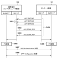
図1は第1実施形態における、通信システムの構成の概要を示す図である。エンローリ機器101とアクセスポイント103の間でWi-Fi規格による通信を確立するために、ユーザ107が持つコンフィギュレータ機器102を介して、BLE規格を用いたDPPが利用される。なお、コンフィギュレータ機器102は過去にアクセスポイント103とWi-Fiによる通信104の確立を行ったことがあり、アクセスポイント103との通信に必要な設定情報をすでに有していることが前提である。エンローリ機器101は、DPPにより、コンフィギュレータ機器102を介して、アクセスポイント103とWLAN規格の通信を確立する通信装置である。エンローリ機器101として動作可能な通信装置としては、例えば、プリンタ、デジタルカメラ、デジタル家電などがあげられる。また、コンフィギュレータ機器102は、DPPにより、エンローリ機器にアクセスポイントとのWLAN規格の通信を確立させる通信装置である。コンフィギュレータ機器102として動作可能な通信装置としては、例えば、スマートフォン等の携帯端末などがあげられる。
FIG. 1 is a diagram showing an overview of the configuration of a communication system according to the first embodiment. DPP using the BLE standard is used via the
ユーザ107がコンフィギュレータ機器102のアプリケーションを操作し、DPP処理の開始を指示すると、DPP処理が開始する。コンフィギュレータ機器102はBLE規格を用いてエンローリ機器101との通信105を行い、Wi-Fi規格によるDPP処理を行うために必要な認証情報を得る。その後、コンフィギュレータ機器102とエンローリ機器101との間でWi-Fi規格によるDPP処理が行われる。このDPP処理により、エンローリ機器101はコンフィギュレータ機器102から、アクセスポイント103とWi-Fi規格による通信を確立するために必要な設定情報を得る。この設定情報を基に、エンローリ機器101はアクセスポイント103と接続処理を行い、Wi-Fi規格による通信106を確立する。
When the
図2は、第1実施形態における通信システムを構成する通信装置のハードウェア構成例を示すブロック図である。エンローリ機器101としての通信装置とコンフィギュレータ機器102としての通信装置の構成は同様のブロック図にて示すことができる。よって、以下では、エンローリ機器101とコンフィギュレータ機器102の構成を、図2、図3に示される通信装置の構成を参照して説明する。
FIG. 2 is a block diagram showing a hardware configuration example of a communication device that configures the communication system according to the first embodiment. The configurations of the communication device as the
通信装置は、CPU(Central processing unit)211、RAM(Random access memory)212、フラッシュメモリ213、入力部214、出力部215、無線通信部216、内部バス217を有する。
The communication device has a CPU (Central Processing Unit) 211 , a RAM (Random Access Memory) 212 , a
CPU211は、後述のRAM212やフラッシュメモリ213に記憶されたプログラムを実行することにより通信装置の全体を制御する。なお、CPU211は、RAM212やフラッシュメモリ213に記憶されたプログラムとOS(Operating System)との協働により通信装置の全体を制御するようにしてもよい。また、CPU211に代えて、またはそれに加えて、MPU等のプロセッサが通信装置の全体を制御するようにしてもよいし、マルチコア等の複数のプロセッサが通信装置(コンフィギュレータ機器102、エンローリ機器101)の全体を制御するようにしてもよい。なお、MPUは「Micro Processing Unit」の略である。
The
RAM212は、CPU211が各種プログラムを実行する際にワークエリア等として使用される揮発性のメモリである。また、各種動作を行うためのプログラム(コンピュータプログラム)や、通信パラメータ等の各種情報がRAM212に記憶されてもよい。フラッシュメモリ213は、通信装置が各種動作を行うためのプログラム(コンピュータプログラム)や、通信パラメータ等の各種情報を記憶する不揮発性のメモリである。
A
なお、RAM212および/またはフラッシュメモリ213に代えて、あるいはそれに加えて、ROM(Read only memory)等のメモリ、フレキシブルディスク、ハードディスク、光ディスク、光磁気ディスク、CD-ROM、CD-R、磁気テープ、不揮発性のメモリカード、DVDなどの記憶媒体が用いられてもよい。また、複数の記憶媒体が用いられてもよい。
In place of or in addition to the
入力部214は、ユーザ107からの各種操作の受付を行う。出力部215は、モニタ画面やスピーカーなどを介してユーザに対して各種出力を行う。ここで、出力部215による出力とは、画面上への表示の他、スピーカーによる音声出力や、振動出力などであってもよい。なお、入力部214と出力部215の両方を1つのモジュールで実現するようにしてもよい。本実施形態において、入力部214および出力部215は、例えばタッチパネルと表示器で構成される。
The
無線通信部216は、図3により後述するように、WLAN規格の通信を行う通信部と、WLAN規格の通信とは異なる他の通信(本実施形態ではBLE規格の通信)を行う通信部とを有している。すなわち、無線通信部216は、BLE規格に準拠した無線通信およびWLAN規格に準拠した無線通信を行うためのインタフェイスである。なお、本実施形態では、WLAN規格に準拠した無線通信として、例えば、IEEE802.11シリーズ規格(Wi-Fi)に準拠した無線通信が用いられる。無線通信部216は、例えば、WLAN通信またはBLE通信を用いた、アクセスポイント103との無線通信および他の通信装置との無線通信を制御する。内部バス217は、CPU211と上述の各部とを接続し、データや制御信号等を伝達する。
As will be described later with reference to FIG. 3, the
図3は、通信装置における無線通信部216のハードウェア構成例を示すブロック図である。無線通信部216は、インタフェイス321、CPU322、ROM323、RAM324、BLE送受信回路325、WLAN送受信回路326、スイッチ327、アンテナ328を有する。
FIG. 3 is a block diagram showing a hardware configuration example of the
インタフェイス321は、図2に示した通信装置の内部バス217と接続する。無線通信部216は、インタフェイス321を介して、通信装置の各部と、データおよび制御信号等の入出力を行う。CPU322は、通信装置のCPU211からの制御信号に基づいて無線通信部216の全体の動作を制御する。CPU322は後述のROM323に記憶されたプログラムを実行することにより、無線通信部216を制御し、データの送受信等を制御する。ROM323は、CPU322が各種動作を行うためのプログラム(コンピュータプログラム)、通信パラメータ等の各種情報を記憶する。RAM324は、CPU322が各種プログラムを実行する際にワークエリア等として使用される揮発性のメモリである。
The
BLE送受信回路325は、アンテナ328を介して受信したBLE高周波信号を復調し、低周波数化してデータに変換する。また、BLE送受信回路325は、インタフェイス321を介して入力されたデータを変調および増幅して、BLE高周波信号に変換し、アンテナ328を介して送信する。WLAN送受信回路326は、アンテナ328を介して受信したWLAN高周波信号を復調し、低周波数化してデータに変換する。また、WLAN送受信回路326はインタフェイス321を介して入力されたデータを変調および増幅して、WLAN高周波信号に変換し、アンテナ328を介して送信する。スイッチ327は、アンテナ328と接続する回路の切り替えを行う。具体的には、スイッチ327は、BLE高周波信号の送受信を行う場合にはBLE送受信回路325とアンテナ328とを接続し、WLAN高周波信号の送受信を行う場合にはWLAN送受信回路326とアンテナ328とを接続する。
The BLE transmission/
以上のような構成を備えた通信装置としてのエンローリ機器101とコンフィギュレータ機器102を有する通信システムにおいて、DPPを用いてエンローリ機器101をアクセスポイント103に接続するための処理を説明する。なお、上述した通信装置の構成を、エンローリ機器101とコンフィギュレータ機器102とで区別する必要がある場合には、参照番号に末尾にEまたはCを付す。例えば、エンローリ機器101の無線通信部は無線通信部216Eと記載し、コンフィギュレータ機器であるコンフィギュレータ機器102の無線通信部は無線通信部216Cと記載する。
A process for connecting the
次に本実施形態の通信システムにおいて、エンローリ機器101とアクセスポイント103の間のWLAN規格による通信が、コンフィギュレータ機器102を介して確立する際の処理の流れについて、添付のシーケンス図およびフローチャートを用いて説明する。図4、図5は、DPP規格に対応したプロトコルにより、コンフィギュレータ機器102を介してエンローリ機器101とアクセスポイント103の間のWLAN規格による通信が確立する際の処理のシーケンス図である。図4は全体の処理の流れを、図5はブートストラップ処理の詳細な流れを示している。また、図5のシーケンス図に対応するエンローリ機器101の処理とコンフィギュレータ機器102の処理のフローチャートをそれぞれ図6、図7に示す。
Next, in the communication system of this embodiment, the flow of processing when WLAN standard communication between the
まず図4を用いて、全体の処理の流れを説明する。なお前述の通り、コンフィギュレータ機器102は過去にアクセスポイント103とWLANによる通信の確立を行ったことがあり、アクセスポイント103との通信に必要な設定情報をすでに有していることが前提である。コンフィギュレータ機器102は、エンローリ機器101がアクセスポイント103と接続するための設定情報を、DPPによりエンローリ機器101に設定する。
First, referring to FIG. 4, the overall processing flow will be described. As described above, it is assumed that the
ユーザ107がコンフィギュレータ機器102の出力部215に表示されたアプリケーションのユーザインタフェイス(UI)を操作し、DPP処理を開始させる。この場合のUIの例を図8に示す。図8に示されているUI801において、「YES」ボタンを選択すると、CPU211Cは、接続処理の開始指示を無線通信部216C(BLE送受信回路325C)に通知する(S401)。開始指示を受信した無線通信部216Cは、DPP処理を開始する。
The
DPP処理を開始した無線通信部216Cは、BLE通信のためのファームウェア(FW)を起動する(S403)。一方、エンローリ機器101では、例えば電源の投入とともにBLE通信のためのファームウエア(FW)を起動する(S402)。エンローリ機器101とコンフィギュレータ機器102は、BLE規格を用いて通信し、Bootstrapping処理を行い、WLAN規格によるDPP処理を行うために必要な認証情報を得る(S404)。
216 C of wireless communication parts which started the DPP process start the firmware (FW) for BLE communication (S403). On the other hand, in the
その後、コンフィギュレータ機器102の無線通信部216Cとエンローリ機器の無線通信部216Eは、WLAN通信に必要なファームウェア(FW)を起動する(S405、S406)。そして、コンフィギュレータ機器102およびエンローリ機器101は、WLANを用いた通信によりDPP Authentication処理(S407)、DPP Configuration処理(S408)を行う。こうして、エンローリ機器101は、コンフィギュレータ機器102から、アクセスポイント103とWLAN規格による通信を確立するために必要な設定情報を得る。エンローリ機器101は、この設定情報を基にアクセスポイント103との間でDPP Connect処理を行い(S409)、アクセスポイント103との通信確立を完了する。コンフィギュレータ機器102は、エンローリ機器101への設定(アクセスポイント103へ接続するための情報の、エンローリ機器101への登録)を完了する(S410)。
Thereafter, the wireless communication unit 216C of the
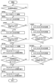
次にBootstrapping処理(S404)からDPP Configuration処理(S408)までの詳細を、図5のシーケンス図を用いて説明する。 Next, details from the Bootstrapping process (S404) to the DPP Configuration process (S408) will be described with reference to the sequence diagram of FIG.
まずエンローリ機器101は、アドバタイズ信号(アドバタイズパケット)であるADV_EXT_IND信号(ADV_EXT_INDパケット)を繰り返し送信する(S501)。このADV_EXT_IND信号には、WLAN規格によるDPP処理を行うために必要な、エンローリ機器101の認証情報の受け渡し処理を行うチャネル情報が含まれている。コンフィギュレータ機器102は、ADV_EXT_IND信号に含まれているチャネルにおいて、AUX_SCAN_REQ信号をエンローリ機器101に対して送信する(S502)。このAUX_SCAN_REQ信号は、エンローリ機器101の認証情報を要求する信号である。なお、DPP規格では、エンローリ機器101は、ADV_EXT_IND信号を送信した後に、エンローリ機器101の認証情報を含むAUX_ADV_IND信号を送信するように規定している。これに対して、本実施形態のエンローリ機器101はAUX_ADV_IND信号を送信しない。これにより、エンローリ機器101とコンフィギュレータ機器102の間でAUX_SCAN_REQ、AUX_SCAN_RSPによるやり取りが発生することになる。
First, the
AUX_SCAN_REQ信号を受信したエンローリ機器101はコンフィギュレータ機器102に対し、エンローリ機器101の認証情報を含むAUX_SCAN_RSP信号を送信する(S503)。すなわち、エンローリ機器101は、コンフィギュレータ機器102からの要求(AUX_SCAN_REQ)に応じて、WLAN規格で通信するための情報をコンフィギュレータ機器102に提供する(AUX_SCAN_RSP)。そして、エンローリ機器101は、このAUX_SCAN_RSP信号の送信後に、WLAN通信のためのファームウェアを起動する(S406)。すなわち、本実施形態のエンローリ機器101は、コンフィギュレータ機器102とWLAN規格で通信するための情報をコンフィギュレータ機器102に提供(S503)した後に、WLAN通信のためのファームウェアを起動する。また、コンフィギュレータ機器102は、AUX_ACAN_RSP信号を受信した後にWLAN通信のためのファームウェアを起動する(S405)。その後、図4で説明したように、コンフィギュレータ機器102とエンローリ機器101は、WLAN規格の通信を開始し、DPP Authentication処理(S407)、およびDPP Configuration処理(S408)を実行する。
Upon receiving the AUX_SCAN_REQ signal, the
図6は、エンローリ機器101における処理を示すフローチャートである。以下に説明される処理は、エンローリ機器101のCPU211Eおよび/または無線通信部216EにおけるCPU322Eが主体となる処理であるが、以下では、エンローリ機器101を処理の主体として記載する。
FIG. 6 is a flow chart showing processing in the
まず、エンローリ機器101は、BLE送受信回路325によるBLE通信のためのファームウエア(FW)をロード/起動する(S601)。エンローリ機器101は、ADV_EXT_IND信号を繰り返し送信し(S602)、コンフィギュレータ機器からのAUX_SCAN_REQ信号を受信するのを待つ(S603)。AUX_SCAN_REQ信号が受信されると、エンローリ機器101は、コンフィギュレータ機器に対してAUX_SCAN_RSP信号を送信し(S604)、WLAN送受信回路326によるWLAN通信のためのファームウェア(FW)をロード/起動する。
First, the
その後、エンローリ機器101は、WLAN通信を用いて、DPP Authentication処理(S606)、DPP Configuration処理(S607)を実行する。そして、エンローリ機器101は、これらの処理で得られたWLAN規格による通信を確立するために必要な設定情報を用いてDPP Connect処理を実行し、アクセスポイント103との接続を確立する(S608)。
Thereafter, the
以上のように、エンローリ機器101は、コンフィギュレータ機器102からのAUX_SCAN_REQ信号の受信に応じてエンローリ機器101の認証情報を含むAUX_SCAN_RSP信号を送信した後、WLAN通信のためのファームウェアを起動する。このようにエンローリ機器101は、コンフィギュレータ機器102とのWLAN通信が必要となる直前までWLANのためのファームウェアを起動しないため、消費電力を低減することができる。
As described above, the
図7にコンフィギュレータ機器102の処理のフローチャートを示す。以下に説明される処理は、コンフィギュレータ機器としてのコンフィギュレータ機器102のCPU211Cおよび/または無線通信部216CにおけるCPU322Cが主体となる処理であるが、コンフィギュレータ機器102を主体として記載する。
FIG. 7 shows a flowchart of processing of the
アプリケーションより接続処理の開始が指示されると、コンフィギュレータ機器102は、BLE通信のためのファームウェア(FW)をロード/起動する(S701、S702)。その後、コンフィギュレータ機器102は、BLE通信を介してエンローリ機器101から送信されるADV_EXT_IND信号を受信する(S703)。ADV_EXT_IND信号が受信されると(S704)、コンフィギュレータ機器102は、コンフィギュレータ機器102からAUX_ADV_IND信号を受信する(S705)。コンフィギュレータ機器102は、コンフィギュレータ機器102からAUX_ADV_IND信号を受信することができたか否かを判断する(S706)。AUX_ADV_IND信号を受信できなかったと判断された場合は、コンフィギュレータ機器102は、AUX_SCAN_REQ信号をコンフィギュレータ機器102へ送信し(S707)、AUX_SCAN_RSP信号の受信を待つ(S708、S709)。
When the application instructs to start connection processing, the
AUX_SCAN_RSP信号が受信されると、コンフィギュレータ機器102は、WLAN通信のためのファームウェアをロード/起動する(S710)。その後、コンフィギュレータ機器102は、WLAN通信を用いて、DPP Authentication処理(S711)、DPP Configuration処理(S712)を実行する。これらの処理により、コンフィギュレータ機器102は、WLAN規格によるアクセスポイント103との通信を確立するために必要な設定情報をエンローリ機器101に設定し、エンローリ機器101がアクセスポイント103と接続を確立できるようにする。
When the AUX_SCAN_RSP signal is received, the
以上の、コンフィギュレータ機器102側の処理は、DPP規格において規定されている処理と同様である。なお、第1実施形態においては、エンローリ機器101がAUX_ADV_IND信号を送信しないため、S704においては常にNOと判定され、S707~S709の処理が実行されることになる。このように、第1実施形態によれば、コンフィギュレータ機器からWLANによる通信のための情報をエンローリ機器に要求し、エンローリ機器がこの要求に応じてその情報を提供する、という動作が必ず実行される。これにより、WLANによる通信が必要となるタイミングでファームウェアを起動することができ、ファームウェアの動作時間を短縮することができる。
The processing on the
<第2実施形態>
第1実施形態では、エンローリ機器がAUX_ADV_IND信号を送信しないことで、AUX_SCAN_REQ信号とAUX_SCAN_RSP信号による情報の提供が必ず実行されるようにした。第2実施形態では、コンフィギュレータ機器がAUX_ADV_IND信号の受信の有無にかかわらずAUX_SCAN_REQ信号を送信し、AUX_SCAN_RSP信号による情報の提供を受けるようにする。
<Second embodiment>
In the first embodiment, the enrollee device does not transmit the AUX_ADV_IND signal so that information is always provided by the AUX_SCAN_REQ signal and the AUX_SCAN_RSP signal. In a second embodiment, the configurator device transmits the AUX_SCAN_REQ signal regardless of whether or not the AUX_ADV_IND signal is received, to receive information provided by the AUX_SCAN_RSP signal.
第2実施形態は第1実施形態と同様に、コンフィギュレータ機器を介し、BLE規格を用いたDPPにより、エンローリ機器とアクセスポイントの間でWLAN規格による通信を確立するシステムである。コンフィギュレータ機器として携帯端末を用い、WLAN規格としては、IEEE802.11シリーズに準拠した無線LAN(Wi-Fi)システムを用いた例について説明する。なお、通信システムの構成、コンフィギュレータ機器102のハードウェア構成、およびエンローリ機器101のハードウェア構成は第1実施形態と同様である。また、第1実施形態と同様に、コンフィギュレータ機器102は過去にアクセスポイント103とWLANによる通信の確立を行ったことがあり、アクセスポイントとの通信に必要な設定情報をすでに有していることが前提である。
As in the first embodiment, the second embodiment is a system that establishes WLAN standard communication between an enrollee device and an access point by DPP using the BLE standard via a configurator device. An example will be described in which a mobile terminal is used as the configurator device and a wireless LAN (Wi-Fi) system conforming to the IEEE802.11 series is used as the WLAN standard. The configuration of the communication system, the hardware configuration of the
次に第2実施形態の通信システムにおける、携帯端末を介してエンローリ機器とアクセスポイントの間でWLAN規格による通信を確立する処理の流れについて、シーケンス図およびフローチャートを用いて説明する。なお、コンフィギュレータ機器102を介してエンローリ機器101とアクセスポイント103の間でWLAN規格による通信を確立する処理の全体の流れについては第1実施形態(図6)と同様であるため、説明を省略する。
Next, the flow of processing for establishing WLAN standard communication between the enrollee device and the access point via the mobile terminal in the communication system of the second embodiment will be described with reference to a sequence diagram and a flowchart. Note that the overall flow of processing for establishing communication according to the WLAN standard between the
図9は、第2実施形態による、DPP規格に対応したプロトコルによる、Bootstrapping処理(S404)からDPP Configuration処理(S408)までの処理の詳細を示すシーケンス図である。第1実施形態(図5)と同様の処理には同一のステップ番号を付してある。また、図9のシーケンス図に対応する、エンローリ機器101の処理、コンフィギュレータ機器102の処理のフローチャートをそれぞれ、図12、図13に示す。
FIG. 9 is a sequence diagram showing the details of the process from the Bootstrapping process (S404) to the DPP Configuration process (S408) according to the protocol compatible with the DPP standard according to the second embodiment. The same step numbers are assigned to the same processes as in the first embodiment (FIG. 5). 12 and 13 respectively show flowcharts of the processing of the
エンローリ機器101は、アドバタイズ信号であるADV_EXT_IND信号を送信する(S501)。この信号には、WLAN規格によるDPP処理を行うために必要な、エンローリ機器の認証情報の受け渡し処理を行うチャネル情報が含まれている。続いて、エンローリ機器101はADV_EXT_IND信号に含まれているチャネルにおいて、AUX_ADV_IND信号をコンフィギュレータ機器102に対して送信する(S901)。コンフィギュレータ機器102は、ADV_EXT_IND信号に含まれているチャネルにおいて、AUX_SCAN_REQ信号をエンローリ機器101に対して送信する(S502)。この信号は、エンローリ機器101の認証情報を要求する信号である。
The
なお、DPP規格では、コンフィギュレータ機器102はエンローリ機器101からのAUX_ADV_IND信号を受信しなかった場合に、AUX_SCAN_REQ信号をエンローリ機器101に対して送信すると規定されている。しかし第2実施形態のコンフィギュレータ機器102では、S901にてAUX_ADV_IND信号を受信したか否かに関わらず、AUX_SCAN_REQ信号をエンローリ機器101に対して送信する(S502)。すなわち、第2実施形態のコンフィギュレータ機器102は、BLE規格の通信を用いて、エンローリ機器101とWLAN規格の通信を行うための情報の要求をエンローリ機器101に対して必ず行う。なお、AUX_SCAN_REQ信号は、ADV_EXT_IND信号に含まれているチャネルにおいて送信される。
Note that the DPP standard stipulates that the
AUX_SCAN_REQ信号を受信したエンローリ機器101はコンフィギュレータ機器102に対し、エンローリ機器101の認証情報を含むAUX_SCAN_RSP信号を送信する(S503)。そしてこの送信の後に、エンローリ機器101はWLAN通信のためのファームウェアを起動する(S406)。また、コンフィギュレータ機器102は、AUX_ACAN_RSP信号を受信した後にWLAN通信に必要なファームウェアを起動する(S405)。その後、第1実施形態と同様に、コンフィギュレータ機器102とエンローリ機器101との間でWLAN通信によるDPP Authentication処理(S407)、およびDPP Configuration処理(S408)を実行する。
Upon receiving the AUX_SCAN_REQ signal, the
図10にエンローリ機器101側の処理のフローチャートを示す。図10において第1実施形態(図6)と同様の処理には同一のステップ番号を付してある。エンローリ機器101は、S603においてAUX_SCAN_REQ信号の受信が確認されるまで、ADV_EXT_IND信号の送信(S602)とAUX_ADV_IND信号の送信(S1001)を繰り返す。第1実施形態と同様に、エンローリ機器101は、コンフィギュレータ機器102から送信されたAUX_SCAN_REQ信号の受信に応じて、エンローリ機器101の認証情報を含むAUX_SCAN_RSP信号をコンフィギュレータ機器102に送信する(S604)。そして、エンローリ機器101は、AUX_SCAN_RSP信号を送信した後、WLAN通信のためのファームウェアを起動する(S605)。
FIG. 10 shows a flowchart of processing on the
このようにエンローリ機器101は、コンフィギュレータ機器102とのWLAN通信が必要となる直前までWLAN通信のためのファームウェアを起動しないため、消費電力を低減することができる。
As described above, the
図11に第2実施形態によるコンフィギュレータ機器102の処理のフローチャートを示す。第1実施形態(図7)と同様の処理には同一のステップ番号が付してある。図11の処理では、第1実施形態で行っていたAUX_ADV_IND信号の受信の有無に応じた処理の分岐が省略されている。すなわち、コンフィギュレータ機器102は、エンローリ機器101よりADV_EXT_IND信号を受信した後に、AUX_ADV_IND信号の受信の有無にかかわらず、AUX_SCAN_REQ信号をエンローリ機器101に送信する(S707)。その後、エンローリ機器101からのAUX_SCAN_RSP信号を受信できたら、WLAN通信のためのファームウェアを起動する(F708~S710)。
FIG. 11 shows a flowchart of processing of the
<第3実施形態>
第3実施形態は第1実施形態と同様に、コンフィギュレータ機器を介し、BLE規格を用いてDPPにより、エンローリ機器とアクセスポイントの間でWLAN規格による通信を確立するシステムである。コンフィギュレータ機器として携帯端末を用い、WLAN規格としては、IEEE802.11シリーズに準拠した無線LAN(Wi-Fi)システムを用いた例について説明する。なお、通信システムの構成、携帯端末のハードウェア構成、およびエンローリ機器のハードウェア構成は第1、第2実施形態(図1~図3)と同様である。また、第3実施形態においても、コンフィギュレータ機器102は過去にアクセスポイント103とWLANによる通信の確立を行ったことがあり、アクセスポイントとの通信に必要な設定情報をすでに有していることが前提である。
<Third Embodiment>
As in the first embodiment, the third embodiment is a system that establishes communication according to the WLAN standard between an enrollee device and an access point by DPP using the BLE standard via a configurator device. An example will be described in which a mobile terminal is used as the configurator device and a wireless LAN (Wi-Fi) system conforming to the IEEE802.11 series is used as the WLAN standard. The configuration of the communication system, the hardware configuration of the mobile terminal, and the hardware configuration of the enrollee device are the same as those of the first and second embodiments (FIGS. 1 to 3). Also in the third embodiment, it is assumed that the
次に第3実施形態の通信システムにおける、携帯端末を介してエンローリ機器とアクセスポイントの間でWLAN規格による通信を確立する処理の流れについて、図12、図13に示されるシーケンス図およびフローチャートを用いて説明する。なお、コンフィギュレータ機器102を介してエンローリ機器101とアクセスポイント103の間でWLAN規格による通信を確立する処理の全体の流れについては第1、第2実施形態(図4)と同様であるため、図示および説明を省略する。
Next, in the communication system of the third embodiment, the flow of processing for establishing communication according to the WLAN standard between the enrollee device and the access point via the mobile terminal will be described with reference to the sequence diagrams and flowcharts shown in FIGS. to explain. Note that the overall flow of processing for establishing WLAN standard communication between the
図12は、DPP規格に対応したプロトコルにより、コンフィギュレータ機器102を介してエンローリ機器101とアクセスポイント103の間でWLAN規格による通信を確立する処理における、Bootstrapping処理からDPP Configuration処理までの詳細の流れを示すシーケンス図である。図12のシーケンス図に対応する、コンフィギュレータ機器102の処理のフローチャートを図12A~図12Bに示す。なお、エンローリ機器101の処理は第1実施形態(図6)または第2実施形態(図10)と同様である。
FIG. 12 shows a detailed flow from the bootstrapping process to the DPP configuration process in the process of establishing communication according to the WLAN standard between the
図12において、エンローリ機器101は、アドバタイズ信号であるADV_EXT_IND信号を送信する(S501)。この信号には、WLAN規格によるDPP処理を行うために必要な、エンローリ機器の認証情報の受け渡し処理を行うチャネル情報が含まれている。続いて、エンローリ機器101はADV_EXT_IND信号に含まれているチャネルにおいて、AUX_ADV_IND信号をコンフィギュレータ機器102に対して送信する(S901)。
In FIG. 12, the
コンフィギュレータ機器102は、AUX_ADV_IND信号を受信した後、WLAN通信のためのファームウェアを起動する(S405)。そしてコンフィギュレータ機器102はエンローリ機器101に対してWLAN通信によるDPP Authentication信号を送信する(S1201)。この後、一定時間1210が経過してもエンローリ機器101からWLAN通信による応答がない場合、コンフィギュレータ機器102は、BLE通信によってAUX_SCAN_REQ信号をエンローリ機器101に対して送信する(S502)。上述したように、AUX_SCAN_REQ信号は、ADV_EXT_IND信号に含まれていたチャネルにおいて送信される。AUX_SCAN_REQ信号は、エンローリ機器101の認証情報を要求する信号である。
After receiving the AUX_ADV_IND signal, the
AUX_SCAN_REQ信号を受信したエンローリ機器101はコンフィギュレータ機器102に対し、エンローリ機器101の認証情報を含むAUX_SCAN_RSP信号を送信する(S503)。そしてこの送信の後に、エンローリ機器101はWLAN通信のためのファームウェアをロード/起動する(S406)。その後、コンフィギュレータ機器102とエンローリ機器101との間でWLAN通信によるDPP Authentication処理(S407)、およびDPP Configuration処理(S408)を実行する。なお、S1203におけるDPP Authenticationの開始要求に応じて一定時間1210内にエンローリ機器101が応答した場合は、DPP Authentication、DPP Configurationが実行される。
Upon receiving the AUX_SCAN_REQ signal, the
第3実施形態によるエンローリ機器101の処理は、第2実施形態(図10)と同様である。第2実施形態で説明したとおり、エンローリ機器101は、コンフィギュレータ機器102から送信されたAUX_SCAN_REQ信号を受信(S603)した後に、コンフィギュレータ機器102に対してAUX_SCAN_RSP信号を送信する(S604)。その後、エンローリ機器101は、WLAN通信のためのファームウェアをロード/起動する(S605)。このようにエンローリ機器101は、コンフィギュレータ機器102とのWLAN通信の実行直前までWLAN通信のためのファームウェアを起動しないことにより、消費電力を低減することができる。
The processing of the
図13に第3実施形態によるコンフィギュレータ機器102の処理のフローチャートを示す。なお、図13において、第1実施形態(図7)と同様の処理には同一のステップ番号を付してある。
FIG. 13 shows a flowchart of processing of the
コンフィギュレータ機器102は、エンローリ機器101から送信されたAUX_ADV_IND信号を受信できた場合に、WLAN通信のためのファームウェアを起動する(S706でYES、S710)。そして、コンフィギュレータ機器102は、WLAN通信によるDPP Authentication処理を開始する(S1301)。しかしながら、コンフィギュレータ機器102からエンローリ機器101へAUX_SCAN_REQを送信していないため、エンローリ機器101はまだWLAN通信のためのファームウェアを起動していない状態である。よって、コンフィギュレータ機器102において、一定時間内にエンローリ機器101からの応答が得られない(S1302でNO)。この場合、コンフィギュレータ機器102は、BLE通信によってAUX_SCAN_REQ信号を送信する(S1303)。そして、コンフィギュレータ機器102は、エンローリ機器101からAUX_SCAN_RSP信号を受信すると(S1304、S1305でYES)、再度、WLAN通信によるDPP Authentication処理を開始する(S711)。続いて、コンフィギュレータ機器102は、DPP Configuration処理を実行する(S712)。
When the
一方、S706で、コンフィギュレータ機器102がエンローリ機器101からAUX_ADV_INDを受信できなかった場合は、第1、第2実施形態と同様にS707~S710が実行され、WLAN通信のためのファームウェアが起動される。すなわち、コンフィギュレータ機器102は、AUX_SCAN_REQ信号をエンローリ機器101へ送信し(S707)、AUX_SCAN_RSP信号を受信すると(S708、S709)、WLAN通信のためのファームウェアを起動する(S710)。その後、WLAN通信によるDPP Authentication処理を開始する(S711)。
On the other hand, if the
この場合、エンローリ機器101へAUX_SCAN_REQ信号がすでに送信されているため、エンローリ機器101ではWLAN通信のためのファームウェアが起動されている。よって、コンフィギュレータ機器102は、一定時間内にエンローリ機器101からDPP Authenticationに対する応答を得ることができ(S1302でYES)、そのまま、エンローリ機器101とのDPP Authentication処理が実行される(S711)。その後、コンフィギュレータ機器102は、WLAN通信によるエンローリ機器101とのDPP Configuration処理を実行する(S712)。
In this case, since the AUX_SCAN_REQ signal has already been sent to the
以上のように、第3実施形態によれば、何らかの要因ですでにWLAN通信のためのファームウェアが起動している場合に、AUX_ADV_IND信号の情報を活用して迅速にDPP Authentication以降の処理を実行できる。結果、迅速にDPPを行えるとともに、エンローリ機器におけるファームウェアの余分な動作時間を低減できる。 As described above, according to the third embodiment, when the firmware for WLAN communication has already started for some reason, the information of the AUX_ADV_IND signal can be used to quickly execute the processing after DPP Authentication. . As a result, the DPP can be performed quickly, and the extra operating time of the firmware in the enrollee device can be reduced.
以上説明したように、上記各実施形態によれば、コンフィギュレータ機器からWLANによる通信のための情報をエンローリ機器に要求し、エンローリ機器がこの要求に応じてその情報を提供する、という動作が必ず実行される。そして、エンローリ機器は、要求に応じて情報を提供した後に、WLANのためのファームウェアを起動する。結果、WLANによる通信が必要なとなるタイミングでファームウェアを起動することをより確実に達成でき、ファームウェアの動作時間が短縮される。 As described above, according to the above embodiments, the configurator device requests the enrollee device for information for WLAN communication, and the enrollee device provides the information in response to this request without fail. be done. The enrollee device then launches the firmware for the WLAN after providing the information as requested. As a result, the firmware can be more reliably activated at the timing when WLAN communication becomes necessary, and the operating time of the firmware can be shortened.
(他の実施形態)
本発明は、上述の実施形態の1以上の機能を実現するプログラムを、ネットワーク又は記憶媒体を介してシステム又は装置に供給し、そのシステム又は装置のコンピュータにおける1つ以上のプロセッサがプログラムを読出し実行する処理でも実現可能である。また、1以上の機能を実現する回路(例えば、ASIC)によっても実現可能である。
(Other embodiments)
The present invention supplies a program that implements one or more functions of the above-described embodiments to a system or apparatus via a network or a storage medium, and one or more processors in the computer of the system or apparatus reads and executes the program. It can also be realized by processing to It can also be implemented by a circuit (for example, ASIC) that implements one or more functions.
発明は上記実施形態に制限されるものではなく、発明の精神及び範囲から離脱することなく、様々な変更及び変形が可能である。従って、発明の範囲を公にするために請求項を添付する。 The invention is not limited to the embodiments described above, and various modifications and variations are possible without departing from the spirit and scope of the invention. Accordingly, the claims are appended to make public the scope of the invention.
101:エンローリ機器、102:携帯端末、103:アクセスポイント、211:CPU、212:RAM、213:フラッシュメモリ、214:入力部、215:出力部、216:無線通信部 101: enrollee device, 102: mobile terminal, 103: access point, 211: CPU, 212: RAM, 213: flash memory, 214: input unit, 215: output unit, 216: wireless communication unit
Claims (17)
無線LANのアクセスポイントと前記第1の通信手段を用いた通信を行うために必要な通信パラメータを無線LANの通信によって他の通信装置が前記通信装置へ提供する提供処理に用いる情報を要求するAUX_SCAN_REQを、前記第2の通信手段を用いて前記他の通信装置から受信する受信手段と、
前記受信手段による前記AUX_SCAN_REQの受信に応じて、前記要求された情報を含むAUX_SCAN_RSPを、前記第2の通信手段を用いて前記他の通信装置へ送信する送信手段と、
前記受信手段による前記要求の受信の後、前記提供処理における認証処理を実行するための通信が前記第1の通信手段により行われるように、前記第1の通信手段を起動する起動手段と、
を有すること特徴とする通信装置。 A communication device having first communication means for performing wireless LAN communication and second communication means for performing communication different from the wireless LAN communication,
AUX_SCAN_REQ for requesting information to be used in providing processing in which another communication device provides communication parameters necessary for communication using a wireless LAN access point and the first communication means to the communication device through wireless LAN communication from the other communication device using the second communication means;
transmitting means for transmitting AUX_SCAN_RSP including the requested information to the other communication device using the second communication means in response to the reception of the AUX_SCAN_REQ by the receiving means;
activation means for activating the first communication means so that communication for executing authentication processing in the provision processing is performed by the first communication means after receiving the request by the reception means;
A communication device characterized by comprising:
前記指示手段による指示に応じて、前記第1の通信手段は起動していない状態で、前記第2の通信手段を用いて、ADV_EXT_IND信号を送信する送信手段と、
を更に有し、
前記受信手段は、前記AUX_SCAN_REQを、前記ADV_EXT_IND信号を受信した前記他の通信装置から受信することを特徴とする請求項1又は2に記載の通信装置。 an instruction means for instructing the start of processing for acquiring communication parameters necessary for performing communication using a wireless LAN access point and the first communication means;
transmission means for transmitting an ADV_EXT_IND signal using the second communication means in a state in which the first communication means is not activated in response to an instruction from the instruction means;
further having
3. The communication device according to claim 1, wherein said receiving means receives said AUX_SCAN_REQ from said another communication device that has received said ADV_EXT_IND signal.
前記受信手段は、前記チャネルにおいて前記他の通信装置から前記AUX_SCAN_REQを受信することを特徴とする請求項3に記載の通信装置。 The ADV_EXT_IND signal includes information indicating a channel used when transmitting the AUX_SCAN_REQ ,
4. The communication device according to claim 3, wherein said receiving means receives said AUX_SCAN_REQ from said other communication device on said channel.
前記送信手段によって送信された情報に基づくconfiguration processを行う実行手段と、
を更に有することを特徴とする請求項1乃至4のいずれか一項に記載の通信装置。 authentication means for performing an authentication process based on the information transmitted by the transmission means;
execution means for performing a configuration process based on the information transmitted by the transmission means;
5. A communication device according to any one of claims 1 to 4, further comprising:
前記第2の通信手段は、BLE(Bluetooth Low Energy)規格に準拠した通信を行うことを特徴とする請求項1乃至5のいずれか一項に記載の通信装置。 The first communication means performs communication conforming to IEEE (The Institute of Electrical and Electronics Engineers, Inc.) 802.11 series standards,
The communication device according to any one of claims 1 to 5, wherein the second communication means performs communication conforming to the BLE (Bluetooth Low Energy) standard.
前記実行手段は、DPPに準拠したconfiguration processを行うことを特徴とする請求項5に記載の通信装置。 The authentication means performs an authentication process conforming to DPP (Device Provisioning Protocol),
6. The communication device according to claim 5, wherein said execution means performs a configuration process conforming to DPP.
無線LANのアクセスポイントと通信を行うために必要な通信パラメータを無線LANの通信によって他の通信装置へ提供する提供処理に用いる情報を要求するAUX_SCAN_REQを、前記第2の通信手段を用いて前記他の通信装置へ送信する送信手段と、 AUX_SCAN_REQ for requesting information used in providing processing for providing communication parameters necessary for communicating with a wireless LAN access point to another communication device through wireless LAN communication is sent to the other communication device using the second communication means. a transmission means for transmitting to the communication device of
前記AUX_SCAN_REQの応答であって、前記要求された情報を含むAUX_SCAN_RSPを、前記第2の通信手段を用いて前記他の通信装置から受信する受信手段と、 receiving means for receiving AUX_SCAN_RSP, which is a response to said AUX_SCAN_REQ and includes said requested information, from said other communication device using said second communication means;
前記受信手段によって前記AUX_SCAN_RSPを受信すると、前記提供処理における認証処理を実行するための通信が前記第1の通信手段により行われるように、前記第1の通信手段を起動する起動手段と、 activation means for activating the first communication means such that when the reception means receives the AUX_SCAN_RSP, the first communication means performs communication for executing authentication processing in the provision processing;
を有することを特徴とする通信装置。 A communication device comprising:
前記受信手段によって受信された情報に基づくconfiguration processを行う実行手段と、
を更に有することを特徴とする請求項10に記載の通信装置。 authentication means for performing an authentication process based on the information received by the receiving means;
execution means for performing a configuration process based on information received by said receiving means;
11. The communication device of claim 10 , further comprising:
前記実行手段は、DPPに準拠したconfiguration processを行うことを特徴とする請求項11に記載の通信装置。 The authentication means performs an authentication process conforming to DPP (Device Provisioning Protocol),
12. The communication apparatus according to claim 11 , wherein said execution means performs a configuration process conforming to DPP.
無線LANのアクセスポイントと前記第1の通信手段を用いた通信を行うために必要な通信パラメータを無線LANの通信によって他の通信装置が前記通信装置へ提供する提供処理に用いる情報を要求するAUX_SCAN_REQを、前記第2の通信手段を用いて前記他の通信装置から受信する受信ステップと、
前記受信ステップにおける前記AUX_SCAN_REQの受信に応じて、前記要求された情報を含むAUX_SCAN_RSPを、前記第2の通信手段を用いて前記他の通信装置へ送信する送信ステップと、
前記受信ステップにおける前記要求の受信の後、前記提供処理における認証処理を実行するための通信が前記第1の通信手段により行われるように、前記第1の通信手段を起動する起動ステップと、
を有すること特徴とする制御方法。 A control method executed by a communication device having first communication means for performing wireless LAN communication and second communication means for performing communication different from the wireless LAN communication,
AUX_SCAN_REQ for requesting information to be used in providing processing in which another communication device provides communication parameters necessary for communication using a wireless LAN access point and the first communication means to the communication device through wireless LAN communication from the other communication device using the second communication means;
a transmitting step of transmitting AUX_SCAN_RSP including the requested information to the other communication device using the second communication means in response to receiving the AUX_SCAN_REQ in the receiving step;
an activation step of activating the first communication means so that communication for executing authentication processing in the provision processing is performed by the first communication device after receiving the request in the reception step;
A control method characterized by comprising:
無線LANのアクセスポイントと通信を行うために必要な通信パラメータを無線LANの通信によって他の通信装置へ提供する提供処理に用いる情報を要求するAUX_SCAN_REQを、前記第2の通信手段を用いて前記他の通信装置へ送信する送信工程と、 AUX_SCAN_REQ for requesting information used in providing processing for providing communication parameters necessary for communicating with a wireless LAN access point to another communication device through wireless LAN communication is sent to the other communication device using the second communication means. a transmission step of transmitting to the communication device of
前記AUX_SCAN_REQの応答であって、前記要求された情報を含むAUX_SCAN_RSPを、前記第2の通信手段を用いて前記他の通信装置から受信する受信工程と、 a receiving step of receiving an AUX_SCAN_RSP, which is a response to the AUX_SCAN_REQ and includes the requested information, from the other communication device using the second communication means;
前記受信工程で前記AUX_SCAN_RSPを受信すると、前記提供処理における認証処理を実行するための通信が前記第1の通信手段により行われるように、前記第1の通信手段を起動する起動工程と、 an activation step of activating the first communication means such that, when the AUX_SCAN_RSP is received in the receiving step, communication for executing authentication processing in the provision processing is performed by the first communication means;
を有することを特徴とする制御方法。 A control method characterized by having
Priority Applications (5)
| Application Number | Priority Date | Filing Date | Title |
|---|---|---|---|
| JP2019015981A JP7278087B2 (en) | 2019-01-31 | 2019-01-31 | COMMUNICATION DEVICE, CONTROL METHOD THEREOF, AND PROGRAM |
| EP20151628.3A EP3691310A1 (en) | 2019-01-31 | 2020-01-14 | Communication apparatus and control method thereof |
| US16/745,754 US11166332B2 (en) | 2019-01-31 | 2020-01-17 | Communication apparatus and control method thereof |
| KR1020200007174A KR102550512B1 (en) | 2019-01-31 | 2020-01-20 | Communication apparatus and control method thereof |
| CN202010075749.8A CN111510921B (en) | 2019-01-31 | 2020-01-22 | Communication apparatus, control method thereof, and computer-readable storage medium |
Applications Claiming Priority (1)
| Application Number | Priority Date | Filing Date | Title |
|---|---|---|---|
| JP2019015981A JP7278087B2 (en) | 2019-01-31 | 2019-01-31 | COMMUNICATION DEVICE, CONTROL METHOD THEREOF, AND PROGRAM |
Publications (3)
| Publication Number | Publication Date |
|---|---|
| JP2020123908A JP2020123908A (en) | 2020-08-13 |
| JP2020123908A5 JP2020123908A5 (en) | 2022-01-18 |
| JP7278087B2 true JP7278087B2 (en) | 2023-05-19 |
Family
ID=69167671
Family Applications (1)
| Application Number | Title | Priority Date | Filing Date |
|---|---|---|---|
| JP2019015981A Active JP7278087B2 (en) | 2019-01-31 | 2019-01-31 | COMMUNICATION DEVICE, CONTROL METHOD THEREOF, AND PROGRAM |
Country Status (5)
| Country | Link |
|---|---|
| US (1) | US11166332B2 (en) |
| EP (1) | EP3691310A1 (en) |
| JP (1) | JP7278087B2 (en) |
| KR (1) | KR102550512B1 (en) |
| CN (1) | CN111510921B (en) |
Citations (4)
| Publication number | Priority date | Publication date | Assignee | Title |
|---|---|---|---|---|
| JP2016225949A (en) | 2015-06-03 | 2016-12-28 | キヤノン株式会社 | Communication device, method of controlling the same, and program |
| JP2017050714A (en) | 2015-09-02 | 2017-03-09 | 株式会社Nttドコモ | Terminal device and program |
| JP2018107619A (en) | 2016-12-26 | 2018-07-05 | キヤノン株式会社 | Communication device, control method, and program |
| JP2019009609A (en) | 2017-06-23 | 2019-01-17 | カシオ計算機株式会社 | Radio communication device, communication system, radio communication method, and radio communication program |
Family Cites Families (31)
| Publication number | Priority date | Publication date | Assignee | Title |
|---|---|---|---|---|
| US6169906B1 (en) * | 1998-03-24 | 2001-01-02 | Motorola, Inc. | Method of transmitting messages in a dispatch call |
| US8843995B2 (en) * | 2004-11-02 | 2014-09-23 | Blackberry Limited | Generic access network (GAN) controller selection in PLMN environment |
| US7937109B2 (en) * | 2008-01-24 | 2011-05-03 | Hewlett-Packard Development Company, L.P. | Current source driver for common ground signal interface |
| JP4743239B2 (en) * | 2008-08-22 | 2011-08-10 | ソニー株式会社 | Wireless communication apparatus, communication system, communication control method, and program |
| US8195251B2 (en) * | 2010-02-26 | 2012-06-05 | Research In Motion Limited | Reducing WLAN power consumption on a mobile device utilizing a cellular radio interface |
| US8818276B2 (en) * | 2012-05-16 | 2014-08-26 | Nokia Corporation | Method, apparatus, and computer program product for controlling network access to guest apparatus based on presence of hosting apparatus |
| US9258712B2 (en) * | 2012-09-04 | 2016-02-09 | Nokia Technologies Oy | Method, apparatus, and computer program product for sharing wireless network configurations |
| US20140075523A1 (en) * | 2012-09-10 | 2014-03-13 | Nokia Corporation | Method, apparatus, and computer program product for sharing wireless network credentials |
| US9706383B2 (en) * | 2013-01-04 | 2017-07-11 | Nokia Technologies Oy | Method, apparatus, and computer program product for configuring a mobile wireless hotspot |
| US9066197B2 (en) * | 2013-01-22 | 2015-06-23 | Nokia Corporation | Method, apparatus, and computer program product for power save control for tethering connections |
| US9386004B2 (en) * | 2013-10-23 | 2016-07-05 | Qualcomm Incorporated | Peer based authentication |
| WO2015068472A1 (en) * | 2013-11-06 | 2015-05-14 | ソニー株式会社 | Terminal device, information processing device, and information provision device |
| RU2016117323A (en) * | 2013-11-11 | 2017-11-13 | Сони Корпорейшн | TERMINAL AND INFORMATION PROCESSING DEVICE |
| US10051671B2 (en) * | 2013-12-25 | 2018-08-14 | Sony Corporation | Terminal device and information processing device |
| JP2015180043A (en) * | 2014-02-25 | 2015-10-08 | キヤノン株式会社 | Communication device, control method therefor and program |
| US9955515B2 (en) * | 2014-05-01 | 2018-04-24 | Sony Corporation | Wireless communication apparatus |
| JP6665782B2 (en) * | 2014-08-29 | 2020-03-13 | ソニー株式会社 | Wireless communication device, wireless communication system, wireless communication method, and program |
| US20160066254A1 (en) * | 2014-09-02 | 2016-03-03 | Intel Corporation | Method and system for smart door directionality detection |
| JP6665791B2 (en) * | 2015-02-06 | 2020-03-13 | ソニー株式会社 | Wireless communication device, wireless communication method, and program |
| JP6472259B2 (en) * | 2015-02-10 | 2019-02-20 | キヤノン株式会社 | COMMUNICATION DEVICE, COMMUNICATION DEVICE CONTROL METHOD, PROGRAM |
| KR102358130B1 (en) * | 2015-03-25 | 2022-02-04 | 삼성전자 주식회사 | Method and apparatus for swapping terminals in a wireless communication system |
| WO2016176962A1 (en) * | 2015-05-04 | 2016-11-10 | 北京合智源科技开发有限责任公司 | Wireless communication device and wireless communication method |
| JP6570355B2 (en) * | 2015-07-21 | 2019-09-04 | キヤノン株式会社 | COMMUNICATION DEVICE, COMMUNICATION METHOD, AND PROGRAM |
| CN106464690B (en) * | 2015-08-24 | 2020-04-10 | 华为技术有限公司 | Security authentication method, configuration method and related equipment |
| US10609581B2 (en) * | 2016-06-03 | 2020-03-31 | Samsung Electronics Co., Ltd | Method and apparatus for setup of wireless communication |
| JP6716399B2 (en) | 2016-09-06 | 2020-07-01 | キヤノン株式会社 | COMMUNICATION DEVICE, COMMUNICATION DEVICE CONTROL METHOD, AND PROGRAM |
| US20180109418A1 (en) * | 2016-10-19 | 2018-04-19 | Qualcomm Incorporated | Device provisioning protocol (dpp) using assisted bootstrapping |
| CN110301143B (en) * | 2016-12-30 | 2022-04-22 | 英特尔公司 | Method and apparatus for radio communication |
| KR102343301B1 (en) * | 2017-04-28 | 2021-12-24 | 삼성전자주식회사 | Method for wireless connection and electronic device thereof |
| WO2019006728A1 (en) * | 2017-07-06 | 2019-01-10 | 北京小米移动软件有限公司 | Method and apparatus for establishing quick connection between internet of things devices, and device |
| US10778530B2 (en) * | 2018-12-27 | 2020-09-15 | Intel Corporation | Device discovery using heartbeat signals |
-
2019
- 2019-01-31 JP JP2019015981A patent/JP7278087B2/en active Active
-
2020
- 2020-01-14 EP EP20151628.3A patent/EP3691310A1/en active Pending
- 2020-01-17 US US16/745,754 patent/US11166332B2/en active Active
- 2020-01-20 KR KR1020200007174A patent/KR102550512B1/en active IP Right Grant
- 2020-01-22 CN CN202010075749.8A patent/CN111510921B/en active Active
Patent Citations (4)
| Publication number | Priority date | Publication date | Assignee | Title |
|---|---|---|---|---|
| JP2016225949A (en) | 2015-06-03 | 2016-12-28 | キヤノン株式会社 | Communication device, method of controlling the same, and program |
| JP2017050714A (en) | 2015-09-02 | 2017-03-09 | 株式会社Nttドコモ | Terminal device and program |
| JP2018107619A (en) | 2016-12-26 | 2018-07-05 | キヤノン株式会社 | Communication device, control method, and program |
| JP2019009609A (en) | 2017-06-23 | 2019-01-17 | カシオ計算機株式会社 | Radio communication device, communication system, radio communication method, and radio communication program |
Non-Patent Citations (1)
| Title |
|---|
| Device Provisioning Protocol Specification Version 1.1 [online],Wi-Fi Alliance,2018年12月03日,[検索日2022.12.20],インターネット <URL:https://www.wi-fi.org/download.php?file=/sites/default/files/private/Device_Provisioning_Protocol_Specification_v1.1_1.pdf>,特に20~22、38~39ページ |
Also Published As
| Publication number | Publication date |
|---|---|
| US20200252986A1 (en) | 2020-08-06 |
| KR102550512B1 (en) | 2023-07-03 |
| KR20200095375A (en) | 2020-08-10 |
| CN111510921B (en) | 2024-08-27 |
| EP3691310A1 (en) | 2020-08-05 |
| US11166332B2 (en) | 2021-11-02 |
| CN111510921A (en) | 2020-08-07 |
| JP2020123908A (en) | 2020-08-13 |
Similar Documents
| Publication | Publication Date | Title |
|---|---|---|
| EP3893109B1 (en) | Method and device for connecting bluetooth devices | |
| US11297666B2 (en) | Electronic device and method for forming Wi-Fi direct group thereof | |
| US9998880B2 (en) | Method and apparatus for forming Wi-Fi P2P group using Wi-Fi direct | |
| EP3193518B1 (en) | Wireless communication terminal, wireless communication system, and wireless communication program | |
| KR101742985B1 (en) | The method of determining group owner in peer to peer network and the device thereof | |
| AU2017428472B2 (en) | Wi-Fi hotspot connection method and terminal | |
| JP4988918B2 (en) | Method and system for communication between accessory device and portable device | |
| JP6421673B2 (en) | Communication equipment | |
| US9420462B2 (en) | Wireless communication apparatus, communication device, wireless communication method, and wireless communication control program | |
| US11419014B2 (en) | Device for wireless communication handover | |
| CN110870353B (en) | WiFi connection method and terminal | |
| WO2020195809A1 (en) | Communication device, communication method, program, and storage medium | |
| JP7278087B2 (en) | COMMUNICATION DEVICE, CONTROL METHOD THEREOF, AND PROGRAM | |
| CN113114798B (en) | Method for acquiring Internet protocol IP address and electronic equipment | |
| JP6245908B2 (en) | COMMUNICATION DEVICE, COMMUNICATION SYSTEM, AND PROGRAM | |
| JP7303913B2 (en) | Communication device, control method, and program | |
| JP6927255B2 (en) | Communication equipment | |
| JP6573018B2 (en) | Communication equipment | |
| JP2017112432A (en) | Communication device, control method and program |
Legal Events
| Date | Code | Title | Description |
|---|---|---|---|
| RD01 | Notification of change of attorney |
Free format text: JAPANESE INTERMEDIATE CODE: A7421 Effective date: 20210103 |
|
| A521 | Request for written amendment filed |
Free format text: JAPANESE INTERMEDIATE CODE: A523 Effective date: 20210113 |
|
| A521 | Request for written amendment filed |
Free format text: JAPANESE INTERMEDIATE CODE: A523 Effective date: 20220107 |
|
| A621 | Written request for application examination |
Free format text: JAPANESE INTERMEDIATE CODE: A621 Effective date: 20220107 |
|
| A131 | Notification of reasons for refusal |
Free format text: JAPANESE INTERMEDIATE CODE: A131 Effective date: 20221223 |
|
| A977 | Report on retrieval |
Free format text: JAPANESE INTERMEDIATE CODE: A971007 Effective date: 20221228 |
|
| A521 | Request for written amendment filed |
Free format text: JAPANESE INTERMEDIATE CODE: A523 Effective date: 20230221 |
|
| TRDD | Decision of grant or rejection written | ||
| A01 | Written decision to grant a patent or to grant a registration (utility model) |
Free format text: JAPANESE INTERMEDIATE CODE: A01 Effective date: 20230410 |
|
| A61 | First payment of annual fees (during grant procedure) |
Free format text: JAPANESE INTERMEDIATE CODE: A61 Effective date: 20230509 |
|
| R151 | Written notification of patent or utility model registration |
Ref document number: 7278087 Country of ref document: JP Free format text: JAPANESE INTERMEDIATE CODE: R151 |