JP7276253B2 - Electric vertical take-off and landing aircraft and control device for electric vertical take-off and landing aircraft - Google Patents

Electric vertical take-off and landing aircraft and control device for electric vertical take-off and landing aircraft Download PDF

Info

Publication number
JP7276253B2
JP7276253B2 JP2020099899A JP2020099899A JP7276253B2 JP 7276253 B2 JP7276253 B2 JP 7276253B2 JP 2020099899 A JP2020099899 A JP 2020099899A JP 2020099899 A JP2020099899 A JP 2020099899A JP 7276253 B2 JP7276253 B2 JP 7276253B2
Authority
JP
Japan
Prior art keywords
drive
information
maintenance
eds
driving
Prior art date
Legal status (The legal status is an assumption and is not a legal conclusion. Google has not performed a legal analysis and makes no representation as to the accuracy of the status listed.)
Active
Application number
JP2020099899A
Other languages
Japanese (ja)
Other versions
JP2021037935A5 (en
JP2021037935A (en
Inventor
俊 杉田
輝 岩川
真梨子 橋本
優一 竹村
Current Assignee (The listed assignees may be inaccurate. Google has not performed a legal analysis and makes no representation or warranty as to the accuracy of the list.)
Denso Corp
Original Assignee
Denso Corp
Priority date (The priority date is an assumption and is not a legal conclusion. Google has not performed a legal analysis and makes no representation as to the accuracy of the date listed.)
Filing date
Publication date
Application filed by Denso Corp filed Critical Denso Corp
Priority to PCT/JP2020/030598 priority Critical patent/WO2021039381A1/en
Priority to EP20857314.7A priority patent/EP4023550A4/en
Priority to CN202080060286.6A priority patent/CN114286784A/en
Publication of JP2021037935A publication Critical patent/JP2021037935A/en
Publication of JP2021037935A5 publication Critical patent/JP2021037935A5/ja
Priority to US17/678,156 priority patent/US20220180670A1/en
Application granted granted Critical
Publication of JP7276253B2 publication Critical patent/JP7276253B2/en
Active legal-status Critical Current
Anticipated expiration legal-status Critical

Links

Images

Classifications

    • YGENERAL TAGGING OF NEW TECHNOLOGICAL DEVELOPMENTS; GENERAL TAGGING OF CROSS-SECTIONAL TECHNOLOGIES SPANNING OVER SEVERAL SECTIONS OF THE IPC; TECHNICAL SUBJECTS COVERED BY FORMER USPC CROSS-REFERENCE ART COLLECTIONS [XRACs] AND DIGESTS
    • Y02TECHNOLOGIES OR APPLICATIONS FOR MITIGATION OR ADAPTATION AGAINST CLIMATE CHANGE
    • Y02TCLIMATE CHANGE MITIGATION TECHNOLOGIES RELATED TO TRANSPORTATION
    • Y02T50/00Aeronautics or air transport
    • Y02T50/60Efficient propulsion technologies, e.g. for aircraft

Description

本開示は、電動垂直離着陸機の制御に関する。 The present disclosure relates to control of an electric vertical take-off and landing vehicle.

近年、ガスタービンエンジンを有する飛行機とは異なる種類の航空機として、電動垂直離着陸機(eVTOL:electric Vertical Take-Off and Landing aircraft)と呼ばれる有人または無人の航空機の開発が活発化している。電動垂直離着陸機は、モータを有する電駆動システム(EDS:Electric Drive System)を複数備え、複数のモータによって複数の回転翼が回転駆動されることで、機体の揚力や推力を得ている。電駆動システムは、安全性を確保するために、必要に応じて交換や点検がなされることが望ましい。特許文献1には、飛行機のエンジンの排気温度が所定値を超えた場合に、かかるエンジンを交換すべき点が記載されている。 In recent years, development of manned or unmanned aircraft called electric Vertical Take-Off and Landing aircraft (eVTOL) has been active as a type of aircraft different from airplanes having gas turbine engines. An electric vertical take-off and landing aircraft includes a plurality of electric drive systems (EDS) having motors, and a plurality of rotor blades are rotationally driven by a plurality of motors to obtain lift and thrust of the aircraft. In order to ensure safety, the electric drive system should be replaced and inspected as necessary. Patent Literature 1 describes that when the exhaust temperature of an aircraft engine exceeds a predetermined value, such an engine should be replaced.

特開2017-159891号公報JP 2017-159891 A

電動垂直離着陸機は、飛行機が備えるエンジンおよびプロペラの数と比較して、より多くのモータおよび回転翼が搭載されることがある。また、電動垂直離着陸機には、主に機体の揚力を得るためのリフト用の回転翼や、主に機体の推力を得るためのクルーズ用の回転翼等、互いに異なる役割を持つ複数の回転翼が組み合わせて搭載されることがある。本願発明者らは、このような電動垂直離着陸機において、複数の電駆動システムのそれぞれに対して保守を実施すべき時期が互いに異なり得ることを見出した。このため、複数の電駆動システムのそれぞれに対する保守時期を適切に判断できる技術が望まれる。 Electric vertical take-off and landing aircraft may have more motors and rotor blades compared to the number of engines and propellers that an airplane has. In addition, electric vertical take-off and landing aircraft have multiple rotors with different roles, such as lift rotors that mainly obtain the lift of the aircraft and cruise rotors that mainly obtain the thrust of the aircraft. are sometimes installed in combination. The inventors of the present application have found that in such an electric vertical take-off and landing aircraft, the timing at which maintenance should be performed on each of the plurality of electric drive systems may differ from each other. Therefore, there is a demand for a technique that can appropriately determine maintenance timing for each of a plurality of electric drive systems.

本開示は、以下の形態として実現することが可能である。 The present disclosure can be implemented as the following forms.

本開示の一形態によれば、電動垂直離着陸機(100、100a~d)が提供される。この電動垂直離着陸機は、回転翼(30)を回転駆動させる駆動用モータ(12)と前記駆動用モータを駆動させる駆動部(11)とを有する複数の電駆動システム(10、10a~d)を備える電動垂直離着陸機であって、離陸動作と、飛行動作と、着陸動作のうちの少なくとも1つを含む前記電動垂直離着陸機の動作中に、前記駆動用モータの劣化状態の指標となるモータ情報と、前記駆動部の劣化状態の指標となる駆動部情報と、のうちの少なくとも一方を含む駆動情報を、前記複数の電駆動システムのそれぞれに対して検出する駆動情報検出部(55)と、検出された前記駆動情報に基づいて、前記複数の電駆動システムのそれぞれに対する保守要否を検出する保守要否検出部(57)と、前記駆動情報の履歴に関する駆動履歴情報を記憶させる記憶制御部(56)と、前記駆動履歴情報を記憶する記憶装置(17a、17b、18b、62)と、を備え、前記保守要否検出部は、記憶された前記駆動履歴情報を用いて判定された前記保守要否を検出する。 According to one aspect of the present disclosure, an electric vertical take-off and landing vehicle (100, 100a-d) is provided. This electric vertical take-off and landing aircraft has a plurality of electric drive systems (10, 10a-d) each having a drive motor (12) for rotationally driving a rotor (30) and a drive section (11) for driving the drive motor. a motor that is indicative of the state of deterioration of the drive motor during operations of the electric vertical take-off and landing vehicle including at least one of a takeoff operation, a flight operation, and a landing operation. a drive information detection unit (55) for detecting drive information including at least one of information and drive unit information as an index of a deterioration state of the drive unit for each of the plurality of electric drive systems; a maintenance necessity detection unit (57) for detecting whether or not maintenance is necessary for each of the plurality of electric drive systems based on the detected drive information; and storage control for storing drive history information relating to the history of the drive information. and a storage device (17a, 17b, 18b, 62) for storing the driving history information, and the maintenance necessity detection unit detects the necessity of maintenance using the stored driving history information. The need for maintenance is detected.

この形態の電動垂直離着陸機によれば、駆動用モータの劣化状態の指標となるモータ情報と駆動部の劣化状態の指標となる駆動部情報とのうちの少なくとも一方を含む駆動情報を、複数の電駆動システムのそれぞれに対して検出する駆動情報検出部と、検出された駆動情報に基づいて複数の電駆動システムのそれぞれに対する保守要否を検出する保守要否検出部とを備えるので、保守を実施すべき時期が互いに異なり得る複数の電駆動システムのそれぞれに対する保守時期を適切に判断できる。 According to the electric vertical take-off and landing aircraft of this aspect, the driving information including at least one of the motor information indicating the deterioration state of the driving motor and the driving unit information indicating the deterioration state of the driving unit is stored in a plurality of units. A drive information detection unit that detects each of the electric drive systems, and a maintenance necessity detection unit that detects whether or not maintenance is required for each of the plurality of electric drive systems based on the detected drive information. It is possible to appropriately determine maintenance timing for each of a plurality of electric drive systems that may be performed at different times.

本開示は、種々の形態で実現することも可能である。例えば、電動垂直離着陸機の制御装置、電動垂直離着陸機の制御方法等の形態で実現することができる。 The present disclosure may also be embodied in various forms. For example, it can be realized in the form of a control device for an electric vertical take-off and landing, a control method for an electric vertical take-off and landing, and the like.

電動垂直離着陸機の外観構成を模式的に示す上面図である。1 is a top view schematically showing the external configuration of an electric vertical take-off and landing aircraft; FIG. 電動垂直離着陸機の外観構成を模式的に示す側面図である。1 is a side view schematically showing the external configuration of an electric vertical take-off and landing aircraft; FIG. 電動垂直離着陸機の概略構成を示すブロック図である。1 is a block diagram showing a schematic configuration of an electric vertical take-off and landing aircraft; FIG. 保守要否検出処理の手順を示すフローチャートである。7 is a flowchart showing a procedure of maintenance necessity detection processing; 駆動履歴情報の更新処理の手順を示すフローチャートである。7 is a flow chart showing a procedure of update processing of drive history information; 第2実施形態における保守要否検出処理の手順を示すフローチャートである。9 is a flow chart showing the procedure of maintenance necessity detection processing in the second embodiment. 第3実施形態における保守要否検出処理の手順を示すフローチャートである。FIG. 11 is a flow chart showing a procedure of maintenance necessity detection processing in the third embodiment; FIG. 第4実施形態における保守要否検出処理の手順を示すフローチャートである。FIG. 14 is a flowchart showing a procedure of maintenance necessity detection processing in the fourth embodiment; FIG. 異常点検要否の検出処理の手順を示すフローチャートである。4 is a flow chart showing a procedure of detecting whether or not an abnormality check is necessary; 第5実施形態における保守要否検出処理の手順を示すフローチャートである。FIG. 14 is a flowchart showing a procedure of maintenance necessity detection processing in the fifth embodiment; FIG. 第5実施形態において設定されている閾値を説明するための説明図である。It is an explanatory view for explaining a threshold set up in a 5th embodiment. 第6実施形態の電動垂直離着陸機の概略構成を示すブロック図である。FIG. 12 is a block diagram showing a schematic configuration of an electric vertical take-off and landing aircraft of a sixth embodiment; 第7実施形態の電動垂直離着陸機の概略構成を示すブロック図である。FIG. 11 is a block diagram showing a schematic configuration of an electric vertical take-off and landing aircraft of a seventh embodiment; 第8実施形態の電動垂直離着陸機の概略構成を示すブロック図である。FIG. 12 is a block diagram showing a schematic configuration of an electric vertical take-off and landing aircraft according to an eighth embodiment; 第9実施形態の電動垂直離着陸機の概略構成を示すブロック図である。FIG. 20 is a block diagram showing a schematic configuration of an electric vertical take-off and landing aircraft of a ninth embodiment; 第10実施形態において、ベアリングのメンテナンス要否の検出処理の手順を示すフローチャートである。FIG. 20 is a flow chart showing a procedure of a process for detecting whether or not maintenance of a bearing is necessary in the tenth embodiment; FIG. 第10実施形態において設定されている閾値を説明するための説明図である。FIG. 20 is an explanatory diagram for explaining threshold values set in the tenth embodiment;

A.第1実施形態:
A-1.装置構成:
図1および図2に示す電動垂直離着陸機100(以下、「eVTOL(electric Vertical Take-Off and Landing aircraft)100」とも呼ぶ)は、電気により駆動され、鉛直方向に離着陸可能な有人航空機として構成されている。eVTOL100は、機体20と、複数の回転翼30と、各回転翼30をそれぞれ回転駆動させるための複数の電駆動システム10(以下、「EDS(Electric Drive System)10とも呼ぶ」とを備えている。本実施形態のeVTOL100は、回転翼30とEDS10とをそれぞれ9つずつ備えている。
A. First embodiment:
A-1. Device configuration:
An electric vertical take-off and landing aircraft 100 (hereinafter also referred to as "eVTOL (electric Vertical Take-Off and Landing aircraft) 100") shown in FIGS. ing. The eVTOL 100 includes a fuselage 20, a plurality of rotor blades 30, and a plurality of electric drive systems 10 (hereinafter also referred to as "EDS (Electric Drive System) 10") for rotating and driving each rotor blade 30. The eVTOL 100 of this embodiment includes nine rotor blades 30 and nine EDSs 10, respectively.

機体20は、eVTOL100において9つの回転翼30およびEDS10を除いた部分に相当する。機体20は、機体本体部21と、支柱部22と、6つの第1支持部23と、6つの第2支持部24と、主翼25と、尾翼28とを備える。 The fuselage 20 corresponds to the portion of the eVTOL 100 excluding the nine rotor blades 30 and the EDS 10 . The fuselage 20 includes a fuselage body portion 21 , a strut portion 22 , six first support portions 23 , six second support portions 24 , a main wing 25 and a tail 28 .

機体本体部21は、eVTOL100の胴体部分を構成する。機体本体部21は、機体軸AXを対称軸として左右対称の構成を有する。本実施形態において、「機体軸AX」とは、機体重心位置CMを通り、eVTOL100の前後方向に沿った軸を意味している。また、「機体重心位置CM」とは、乗員が搭乗していない空虚重量時におけるeVTOL100の重心位置を意味している。機体本体部21の内部には、図示しない乗員室が形成されている。 The fuselage main body 21 constitutes the fuselage portion of the eVTOL 100 . The fuselage main body 21 has a symmetrical configuration with the fuselage axis AX as an axis of symmetry. In the present embodiment, the “fuselage axis AX” means an axis passing through the center of gravity position CM of the fuselage and along the longitudinal direction of the eVTOL 100 . Further, the "aircraft center of gravity position CM" means the position of the center of gravity of the eVTOL 100 at the time of empty weight with no crew on board. A passenger compartment (not shown) is formed inside the fuselage main body 21 .

支柱部22は、鉛直方向に延びる略柱状の外観形状を有し、機体本体部21の上部に固定されている。本実施形態において、支柱部22は、鉛直方向に見てeVTOL100の機体重心位置CMと重なる位置に配置されている。支柱部22の上端部には、6つの第1支持部23の一方の端部がそれぞれ固定されている。6つの第1支持部23は、それぞれ略棒状の外観形状を有し、鉛直方向に垂直な面に沿って延びるように、互いに等角度間隔で放射状に配置されている。各第1支持部23の他方の端部、すなわち支柱部22から遠ざかる位置にある端部には、それぞれ回転翼30とEDS10とが配置されている。6つの第2支持部24は、それぞれ略棒状の外観形状を有し、互いに隣り合う第1支持部23他方の端部(支柱部22と接続されていない側の端部)同士を接続している。 The strut portion 22 has a substantially columnar external shape extending in the vertical direction, and is fixed to the upper portion of the airframe main body portion 21 . In this embodiment, the strut part 22 is arranged at a position overlapping the center-of-gravity position CM of the eVTOL 100 when viewed in the vertical direction. One ends of the six first support portions 23 are fixed to the upper end portion of the strut portion 22 . The six first support portions 23 each have a substantially rod-like external shape, and are radially arranged at equal angular intervals so as to extend along a plane perpendicular to the vertical direction. A rotary blade 30 and an EDS 10 are arranged at the other end of each first support portion 23 , that is, at the end located away from the strut portion 22 . Each of the six second support portions 24 has a substantially rod-like external shape, and connects the other ends of the mutually adjacent first support portions 23 (the ends on the side not connected to the strut portion 22). there is

主翼25は、右翼26と左翼27とにより構成されている。右翼26は、機体本体部21から右方向に延びて形成されている。左翼27は、機体本体部21から左方向に延びて形成されている。尾翼28は、機体本体部21の後端部に形成されている。右翼26と左翼27と尾翼28とには、それぞれ回転翼30とEDS10とが1つずつ配置されている。 The main wing 25 is composed of a right wing 26 and a left wing 27 . The right wing 26 is formed so as to extend rightward from the fuselage main body 21 . The left wing 27 is formed extending leftward from the airframe main body 21 . The tail 28 is formed at the rear end of the fuselage main body 21 . One rotary wing 30 and one EDS 10 are arranged on the right wing 26, the left wing 27 and the tail wing 28, respectively.

9つの回転翼30のうちの6つは、各第2支持部24の端部に配置され、主に機体20の揚力を得るためのリフト用回転翼31として構成されている。9つの回転翼30のうちの3つは、右翼26と左翼27と尾翼28とにそれぞれ配置され、主に機体20の推力を得るためのクルーズ用回転翼32として構成されている。各回転翼30は、それぞれの回転軸を中心として、互いに独立して回転駆動される。各回転翼30は、互いに等角度間隔で配置された3つのブレード33をそれぞれ有する。 Six of the nine rotor blades 30 are arranged at the end of each second support portion 24 and are mainly configured as lift rotor blades 31 for obtaining lift of the fuselage 20 . Three of the nine rotor blades 30 are arranged on the right wing 26 , the left wing 27 and the tail wing 28 , and are mainly configured as cruise rotor blades 32 for obtaining thrust from the airframe 20 . Each rotor blade 30 is rotationally driven independently of each other around its respective rotation axis. Each rotor blade 30 has three blades 33 arranged at equal angular intervals.

9つのEDS10は、各回転翼30をそれぞれ回転駆動させるための駆動装置として構成されている。9つのEDS10のうちの6つは、それぞれリフト用回転翼31を回転駆動させる。9つのEDS10のうちの3つは、それぞれクルーズ用回転翼32を回転駆動させる。 The nine EDSs 10 are configured as driving devices for rotating the respective rotor blades 30 . Six of the nine EDSs 10 rotate the lifting rotor blades 31, respectively. Three of the nine EDSs 10 rotate cruise rotors 32, respectively.

図3に示すように、各EDS10は、駆動部11と、駆動用モータ12と、ギアボックス13と、回転数センサ14と、電流センサ15と、電圧センサ16とを有する。また、eVTOL100は、さらに、バッテリ40と、コンバータ42と、分配器44と、制御装置50と、記憶装置62と、機体通信部64と、報知部66とを備えている。なお、図3では、図示の便宜上、eVTOL100が備える9つの回転翼30およびEDS10のうち、2つの回転翼30およびEDS10を代表して示している。 As shown in FIG. 3 , each EDS 10 has a drive section 11 , drive motor 12 , gearbox 13 , rotation speed sensor 14 , current sensor 15 and voltage sensor 16 . The eVTOL 100 further includes a battery 40 , a converter 42 , a distributor 44 , a control device 50 , a storage device 62 , a body communication section 64 and a notification section 66 . For convenience of illustration, FIG. 3 representatively shows two rotor blades 30 and EDS 10 out of the nine rotor blades 30 and EDS 10 included in the eVTOL 100 .

駆動部11は、図示しないインバータ回路と、かかるインバータ回路を制御する図示しないコントローラとを含む電子機器として構成されている。インバータ回路は、IGBT(Insulated Gate Bipolar Transistor)やMOSFET(Metal-Oxide-Semiconductor Field-Effect Transistor)等のパワー素子により構成され、コントローラから供給される制御信号に応じたデューティ比により駆動用モータ12に駆動電圧を供給する。コントローラは、制御装置50と電気的に接続されており、制御装置50からの指令に応じてインバータ回路に制御信号を供給する。 The drive unit 11 is configured as an electronic device including an inverter circuit (not shown) and a controller (not shown) for controlling the inverter circuit. The inverter circuit is composed of power elements such as IGBTs (Insulated Gate Bipolar Transistors) and MOSFETs (Metal-Oxide-Semiconductor Field-Effect Transistors). Provides drive voltage. The controller is electrically connected to the control device 50 and supplies control signals to the inverter circuit according to commands from the control device 50 .

駆動用モータ12は、本実施形態ではブラシ付きモータにより構成され、駆動部11のインバータ回路から供給される電圧および電流に応じた回転運動を出力する。なお、ブラシ付きモータに代えて、誘導モータやリラクタンスモータ等の任意のモータにより構成されていてもよい。 The drive motor 12 is configured by a motor with brushes in this embodiment, and outputs rotational motion corresponding to the voltage and current supplied from the inverter circuit of the drive section 11 . Any motor such as an induction motor or a reluctance motor may be used instead of the brushed motor.

ギアボックス13は、駆動用モータ12と回転翼30とを物理的に接続している。ギアボックス13は、図示しない複数のギアを有し、駆動用モータ12の回転を減速して回転翼30へと伝達する。なお、ギアボックス13が省略されて駆動用モータ12に回転翼30の回転軸が直接的に接続されていてもよい。 The gearbox 13 physically connects the drive motor 12 and the rotor blades 30 . The gear box 13 has a plurality of gears (not shown), reduces the speed of the rotation of the drive motor 12 and transmits the speed to the rotor blades 30 . Alternatively, the gear box 13 may be omitted and the rotating shaft of the rotor blade 30 may be directly connected to the drive motor 12 .

回転数センサ14は、駆動用モータ12に設けられており、駆動用モータ12の回転数を測定する。電流センサ15と電圧センサ16とは、それぞれ駆動部11と駆動用モータ12との間に設けられており、駆動電流と駆動電圧とをそれぞれ測定する。各センサ14~16による測定結果は、駆動部11を介して、後述する制御装置50の駆動情報検出部55へと出力される。 A rotational speed sensor 14 is provided on the driving motor 12 and measures the rotational speed of the driving motor 12 . A current sensor 15 and a voltage sensor 16 are provided between the drive unit 11 and the drive motor 12, respectively, and measure the drive current and the drive voltage, respectively. The measurement results obtained by the sensors 14 to 16 are output to the drive information detection section 55 of the control device 50, which will be described later, via the drive section 11. FIG.

バッテリ40は、リチウムイオン電池により構成され、eVTOL100における電力供給源として機能する。バッテリ40は、主に、各EDS10がそれぞれ有する駆動部11へと電力を供給して各駆動用モータ12を駆動させる。なお、リチウムイオン電池に代えて、ニッケル水素電池等の任意の二次電池により構成されていてもよく、バッテリ40に代えて、またはバッテリ40に加えて、燃料電池や発電機等の任意の電力供給源が搭載されていてもよい。 The battery 40 is composed of a lithium ion battery and functions as a power supply source for the eVTOL 100 . The battery 40 mainly supplies power to the drive unit 11 of each EDS 10 to drive each drive motor 12 . In place of the lithium-ion battery, any secondary battery such as a nickel-metal hydride battery may be used. A supply may be on board.

コンバータ42は、バッテリ40と接続されており、バッテリ40の電圧を降圧してeVTOL100が備える図示しない補機類や制御装置50へと供給する。分配器44は、バッテリ40の電圧を各EDS10が備える駆動部11へと分配する。 The converter 42 is connected to the battery 40 , steps down the voltage of the battery 40 , and supplies it to auxiliary equipment (not shown) provided in the eVTOL 100 and the control device 50 . The distributor 44 distributes the voltage of the battery 40 to the driving section 11 provided in each EDS 10 .

制御装置50は、記憶部51とCPU(Central Processing Unit)とを備えるマイクロコンピュータであり、ECU(Electronic Control Unit)として構成されている。記憶部51は、ROM(Read Only Memory)とRAM(Random Access Memory)とを有する。CPUは、記憶部51に予め記憶されている制御プログラムを実行することにより、eVTOL100の全体動作を制御する制御部52として機能するとともに、駆動情報検出部55、記憶制御部56、および保守要否検出部57として機能する。 The control device 50 is a microcomputer including a storage section 51 and a CPU (Central Processing Unit), and is configured as an ECU (Electronic Control Unit). The storage unit 51 has a ROM (Read Only Memory) and a RAM (Random Access Memory). The CPU functions as a control unit 52 that controls the overall operation of the eVTOL 100 by executing a control program stored in advance in the storage unit 51, and also functions as a drive information detection unit 55, a storage control unit 56, and a maintenance necessity control unit. It functions as a detector 57 .

eVTOL100の全体動作としては、例えば、垂直離着陸動作や飛行動作等が該当する。垂直離着陸動作および飛行動作は、設定された航空経路情報に基づいて実行されてもよく、乗員の操縦により実行されてもよく、後述する外部装置500が備える外部制御部510からの指令に基づいて実行されてもよい。制御部52は、eVTOL100の動作において、各EDS10が有する駆動用モータ12の回転数および回転方向等を制御する。 The overall motion of the eVTOL 100 includes, for example, vertical takeoff and landing motion, flight motion, and the like. Vertical take-off and landing operations and flight operations may be performed based on the set air route information, may be performed by the crew's control, and may be performed based on commands from an external control unit 510 provided in the external device 500 described later. may be executed. In the operation of the eVTOL 100, the control unit 52 controls the rotation speed, rotation direction, etc. of the driving motor 12 of each EDS 10. FIG.

駆動情報検出部55は、各EDS10のそれぞれに対する駆動情報を検出する。駆動情報には、駆動用モータ12の劣化状態の指標となるモータ情報と、駆動部11の劣化状態の指標となる駆動部情報とのうちの少なくとも一方が含まれている。モータ情報には、例えば、各EDS10がそれぞれ有する回転数センサ14により測定された情報(駆動用モータ12の回転数)や、駆動用モータ12の駆動時間等が該当し、駆動用モータ12のハードウエアの劣化状態の指標となる。駆動部情報には、例えば、各EDS10がそれぞれ有する電流センサ15および電圧センサ16により測定された情報(駆動電流値、駆動電圧値)等の直接的な情報や、駆動電流値や駆動電圧値から算出される駆動用モータ12の回転数の指令値等の間接的な情報や、駆動部11の駆動時間等が該当し、インバータ回路およびコントローラの劣化状態の指標となる。なお、駆動情報は、これらの情報に限らず、図示しないトルクセンサ、温度センサ、振動センサ等により測定された情報が含まれていてもよく、これらの情報のうちの一部の情報であってもよい。これらの情報は、各EDS10の駆動部11を介して駆動情報検出部55に送信される。 The drive information detector 55 detects drive information for each EDS 10 . The drive information includes at least one of motor information as an index of the deterioration state of the drive motor 12 and drive unit information as an index of the deterioration state of the drive unit 11 . The motor information includes, for example, information measured by the rotation speed sensor 14 of each EDS 10 (the rotation speed of the drive motor 12), the drive time of the drive motor 12, and the like. It is an indicator of the state of wear deterioration. The drive unit information includes, for example, direct information such as information (drive current value, drive voltage value) measured by the current sensor 15 and voltage sensor 16 respectively possessed by each EDS 10, and information derived from the drive current value and drive voltage value. Indirect information such as the calculated command value for the number of revolutions of the driving motor 12 and the driving time of the driving unit 11 correspond to the index of deterioration of the inverter circuit and the controller. The drive information is not limited to these information, and may include information measured by a torque sensor, temperature sensor, vibration sensor, etc. (not shown). good too. These pieces of information are transmitted to the drive information detection section 55 via the drive section 11 of each EDS 10 .

記憶制御部56は、後述するように、各EDS10のそれぞれにおける駆動情報の履歴に関する駆動履歴情報の更新処理を実行する。本実施形態の記憶制御部56は、eVTOL100が備える記憶装置62に、更新された駆動履歴情報を記憶させる。駆動履歴情報は、EDS10の劣化の度合いと相関がある情報であり、例えば、EDS10の累積駆動時間、駆動用モータ12の累積回転数、駆動用モータ12の累積駆動電流等の累積負荷値等が該当する。EDS10の累積駆動時間は、例えば、所定以上の駆動電流値が計測された時間であってもよい。 As will be described later, the storage control unit 56 executes update processing of drive history information regarding the history of drive information in each EDS 10 . The storage control unit 56 of the present embodiment causes the storage device 62 included in the eVTOL 100 to store the updated driving history information. The driving history information is information that correlates with the degree of deterioration of the EDS 10. For example, the cumulative drive time of the EDS 10, the cumulative number of revolutions of the drive motor 12, the cumulative load value such as the cumulative drive current of the drive motor 12, and the like. Applicable. The cumulative drive time of the EDS 10 may be, for example, the time during which the drive current value equal to or greater than a predetermined value is measured.

保守要否検出部57は、各EDS10のそれぞれに対する保守要否を検出する処理(以下、「保守要否検出処理」と呼ぶ)を実行する。保守要否は、駆動情報検出部55により検出された駆動情報に基づいて検出される。本実施形態において、保守要否検出部57は、記憶装置62に記憶された各EDS10の駆動履歴情報を用いて保守要否を判定して検出する。また、本実施形態において、EDS10に対する保守には、EDS10の構成部品の交換が含まれる。 The maintenance necessity detection unit 57 executes a process for detecting maintenance necessity for each EDS 10 (hereinafter referred to as "maintenance necessity detection process"). The necessity of maintenance is detected based on the drive information detected by the drive information detection unit 55 . In this embodiment, the maintenance necessity detection unit 57 determines and detects maintenance necessity using the drive history information of each EDS 10 stored in the storage device 62 . Further, in this embodiment, maintenance of the EDS 10 includes replacement of components of the EDS 10 .

記憶装置62は、ROMとRAMとを有するメモリとして構成され、記憶制御部56の指示に応じて駆動履歴情報を記憶する。 The storage device 62 is configured as a memory having a ROM and a RAM, and stores drive history information according to instructions from the storage control section 56 .

機体通信部64は、無線通信を行なう機能を有し、外部装置500が備える外部通信部520とeVTOL100との間で情報の送受信を行なうとともに、制御装置50と通信可能に構成されている。無線通信としては、例えば、民間用VHF(Very High Frequency)無線通信や、4G(第4世代移動体通信システム)や5G(第5世代移動体通信システム)等の電気通信事業者が提供する無線通信や、IEEE802.11規格に従った無線LAN通信等が該当する。また、例えば、USB(Universal Serial Bus)や、IEEE802.3規格に従った有線通信であってもよい。 Machine body communication unit 64 has a function of performing wireless communication, transmits and receives information between external communication unit 520 provided in external device 500 and eVTOL 100 , and is configured to be capable of communicating with control device 50 . As wireless communication, for example, VHF (Very High Frequency) wireless communication for private use, 4G (fourth generation mobile communication system), 5G (fifth generation mobile communication system), etc. Communication, wireless LAN communication according to the IEEE802.11 standard, and the like correspond to this. Alternatively, for example, USB (Universal Serial Bus) or wired communication conforming to the IEEE802.3 standard may be used.

報知部66は、制御装置50からの指示に従って報知を行う。本実施形態において、報知部66は、乗員室に搭載されて文字や画像等を表示する表示装置や、音声や警告音等を出力するスピーカ等により構成され、視覚情報や聴覚情報によって乗員に各種情報を報知する。 The notification unit 66 performs notification according to instructions from the control device 50 . In this embodiment, the notification unit 66 is configured by a display device mounted in the passenger compartment to display characters, images, etc., a speaker for outputting voices, warning sounds, etc., and the like. inform information.

外部装置500は、eVTOL100とは異なる装置であり、例えば、各EDS10の保守の記録等を行うサーバ装置等の管理および制御用のコンピュータとして構成されている。外部装置500は、例えば、航空管制室に配置されているサーバ装置であってもよく、また、各EDS10の保守を行う保守作業員がeVTOL100の運用場所に持ち込んだパーソナルコンピュータ等であってもよい。外部装置500は、外部制御部510と、外部通信部520と、外部記憶装置530とを備える。外部通信部520は、無線通信を行なう機能を有し、eVTOL100が備える機体通信部64との間で情報の送受信を行なう。外部記憶装置530は、ROMとRAMとを有するメモリとして構成されている。 The external device 500 is a device different from the eVTOL 100, and is configured as a computer for management and control such as a server device that records maintenance of each EDS 10, for example. The external device 500 may be, for example, a server device located in an air traffic control room, or may be a personal computer or the like brought into the operation site of the eVTOL 100 by a maintenance worker who maintains each EDS 10. . The external device 500 includes an external control section 510 , an external communication section 520 and an external storage device 530 . The external communication unit 520 has a function of performing wireless communication, and transmits and receives information to and from the machine body communication unit 64 included in the eVTOL 100 . The external storage device 530 is configured as a memory having ROM and RAM.

A-2.保守要否検出処理:
図4に示す保守要否検出処理は、eVTOL100の起動スイッチがオンされると、制御装置50において繰り返し実行される。保守要否検出処理は、eVTOL100が備える複数のEDS10のそれぞれに対して実行される。
A-2. Maintenance necessity detection processing:
The maintenance necessity detection process shown in FIG. 4 is repeatedly executed in the control device 50 when the activation switch of the eVTOL 100 is turned on. The maintenance necessity detection process is executed for each of the multiple EDSs 10 provided in the eVTOL 100 .

駆動情報検出部55は、EDS10の駆動情報を検出する(ステップS110)。記憶制御部56は、EDS10の駆動履歴情報の更新処理を実行する(ステップS120)。 The drive information detector 55 detects the drive information of the EDS 10 (step S110). The storage control unit 56 executes update processing of the drive history information of the EDS 10 (step S120).

図5に示すように、本実施形態における駆動履歴情報の更新処理において、記憶制御部56は、駆動情報検出部55により検出された駆動情報を、駆動履歴情報用の値に変換する(ステップS122)。本実施形態では、駆動履歴情報用の値として、回転数センサ14により測定された駆動用モータ12の回転数と、電流センサ15により測定された駆動電流値とが統合された値(以下、「統合値」と呼ぶ)を用いる。かかる統合値は、例えば、駆動用モータ12の回転数と駆動電流値とを所定の演算式に代入することにより算出されてもよい。かかる演算式は、例えば、駆動用モータ12の回転数よりも駆動電流値の方が劣化の度合いをより反映させるように重み付けされる式であってもよい。また、駆動用モータ12の巻き線抵抗値をさらに検出可能な構成においては、巻き線抵抗値に基づいて巻き線の温度情報を推測し、駆動用モータ12の回転数と駆動電流値とに加えて、かかる温度情報を示す値を所定の演算式に代入することにより統合値が算出されてもよい。巻き線温度は、巻き線の絶縁皮膜等の寿命に影響を及ぼすため、駆動用モータ12の劣化状態の指標となるモータ情報に該当する。一般に、巻き線温度が高いほど駆動用モータ12が劣化するため、巻き線の温度情報が考慮されることにより、駆動用モータ12の劣化の度合いを精度良く推定できる。なお、駆動履歴情報用の値は、これらに限らず、任意の複数種類の駆動情報が統合された値であってもよく、EDS10の劣化速度に対応するように変換された変換値であってもよい。複数の駆動情報が統合された値を用いることにより、記憶装置62のメモリを節約できる。また、変換値を用いることにより、駆動情報とEDS10の劣化速度が線形関係でない場合等においても、EDS10の劣化の度合いをより適切に示すことができる。また、駆動履歴情報用の値として、検出された駆動情報がそのまま用いられてもよい。換言すると、ステップS122が省略されてもよい。 As shown in FIG. 5, in the driving history information updating process in this embodiment, the storage control unit 56 converts the driving information detected by the driving information detecting unit 55 into a value for driving history information (step S122). ). In this embodiment, as a value for drive history information, a value obtained by integrating the rotation speed of the drive motor 12 measured by the rotation speed sensor 14 and the drive current value measured by the current sensor 15 (hereinafter referred to as " (referred to as "integrated value"). Such an integrated value may be calculated, for example, by substituting the number of revolutions of the drive motor 12 and the drive current value into a predetermined arithmetic expression. Such an arithmetic expression may be, for example, an expression in which the drive current value is weighted so as to reflect the degree of deterioration more than the rotation speed of the drive motor 12 . In addition, in a configuration in which the winding resistance value of the driving motor 12 can be further detected, the temperature information of the winding is estimated based on the winding resistance value, and in addition to the rotation speed and the driving current value of the driving motor 12, Alternatively, the integrated value may be calculated by substituting a value indicating such temperature information into a predetermined arithmetic expression. The winding temperature affects the life of the insulation coating of the windings, so it corresponds to motor information that serves as an index of the deterioration state of the drive motor 12 . In general, the higher the winding temperature, the more the driving motor 12 deteriorates. Therefore, the degree of deterioration of the driving motor 12 can be accurately estimated by considering the temperature information of the windings. Note that the values for the drive history information are not limited to these, and may be a value obtained by integrating a plurality of arbitrary types of drive information. good too. The memory of the storage device 62 can be saved by using a value in which a plurality of pieces of drive information are integrated. In addition, by using the conversion value, the degree of deterioration of the EDS 10 can be indicated more appropriately even when the drive information and the deterioration speed of the EDS 10 are not in a linear relationship. Further, the detected driving information may be used as it is as the value for the driving history information. In other words, step S122 may be omitted.

記憶制御部56は、記憶装置62に記憶されている駆動履歴情報の値に、今回の駆動履歴情報の値、すなわち今回算出された統合値を加算する(ステップS128)。ステップS128が実行されることにより、記憶装置62に記憶されている駆動履歴情報が更新され、記憶される。本実施形態では、駆動用モータ12の累積回転数と累積駆動電流との情報が統合された駆動履歴情報としての累積負荷値が更新され、記憶される。なお、モータ情報と駆動部情報とが、統合されずに互いに異なる駆動履歴情報としてそれぞれ加算されて記憶されてもよい。以上により、各EDS10のそれぞれにおける駆動履歴情報の更新処理は完了する。 The storage control unit 56 adds the value of the current drive history information, that is, the integrated value calculated this time, to the value of the drive history information stored in the storage device 62 (step S128). By executing step S128, the driving history information stored in the storage device 62 is updated and stored. In this embodiment, the cumulative load value is updated and stored as drive history information in which the information on the cumulative number of revolutions of the drive motor 12 and the cumulative drive current are integrated. Note that the motor information and the drive unit information may be added and stored as different drive history information without being integrated. As described above, the update process of the drive history information in each EDS 10 is completed.

図4に示すように、保守要否検出部57は、ステップS120において更新されて記憶された駆動履歴情報が、部品交換条件を満たすか否かを特定する(ステップS130)。部品交換条件は、EDS10の構成部品の交換が推奨される程度にEDS10が劣化していると推定され得る条件として、予め設定されて記憶装置62に記憶されている。本実施形態における部品交換条件は、「駆動履歴情報としての累積負荷値が予め定められた部品交換閾値以上である」との条件である。 As shown in FIG. 4, the maintenance necessity detector 57 determines whether or not the drive history information updated and stored in step S120 satisfies the parts replacement condition (step S130). The parts replacement condition is set in advance and stored in the storage device 62 as a condition under which it can be estimated that the EDS 10 has deteriorated to the extent that replacement of the components of the EDS 10 is recommended. The part replacement condition in the present embodiment is that "the cumulative load value as drive history information is equal to or greater than a predetermined part replacement threshold".

駆動履歴情報が部品交換条件を満たすと特定された場合(ステップS130:YES)、保守要否検出部57は、EDS10に対して部品交換「要」を検出する(ステップS140)。制御部52は、かかるEDS10に対して部品交換が必要であるとして、部品交換要請の通知を行なう(ステップS150)。 If it is determined that the drive history information satisfies the parts replacement condition (step S130: YES), the maintenance necessity detector 57 detects that the EDS 10 needs to replace parts (step S140). The control unit 52 notifies the EDS 10 of the need for part replacement (step S150).

部品交換要請の通知は、報知部66を介してeVTOL100の乗員に対して発信される通知であってもよい。より具体的には、例えば、乗員室に搭載された表示装置に複数のEDS10の搭載位置が示されている場合に、部品交換対象のEDS10が赤色のランプで示されてもよい。また、部品交換要請の通知は、機体通信部64を介して外部装置500に対して発信される通知であってもよい。部品交換要請の通知により、eVTOL100dの乗員や保守作業員等により、部品交換が必要であると検出されたEDS10に対する部品交換が実施されることが期待される。ステップS150の実行により、保守要否検出処理は完了する。 The part replacement request notification may be a notification sent to the occupant of the eVTOL 100 via the notification unit 66 . More specifically, for example, when the mounting positions of a plurality of EDSs 10 are indicated on the display device mounted in the passenger compartment, the EDS 10 to be replaced may be indicated by a red lamp. Also, the notification of the parts replacement request may be a notification sent to the external device 500 via the body communication unit 64 . It is expected that the eVTOL 100d occupant, maintenance personnel, and the like will replace the EDS 10 detected to require replacement of the part by the notification of the parts replacement request. The execution of step S150 completes the maintenance necessity detection process.

駆動履歴情報が部品交換条件を満たさないと特定された場合(ステップS130:NO)、保守要否検出部57は、EDS10に対する保守「不要」を検出する(ステップS190)。制御部52は、ステップS190の実行後、ステップS150と同様な方法により、かかるEDS10に対して部品交換が不要である旨の通知を行なってもよい。ステップS190の実行により、保守要否検出処理は完了する。 When it is specified that the drive history information does not satisfy the parts replacement condition (step S130: NO), the maintenance necessity detection unit 57 detects that the maintenance of the EDS 10 is "unnecessary" (step S190). After executing step S190, the control unit 52 may notify the EDS 10 that the part replacement is unnecessary by a method similar to that of step S150. The execution of step S190 completes the maintenance necessity detection process.

以上説明した第1実施形態のeVTOL100によれば、記憶制御部56が複数のEDS10のそれぞれにおける駆動履歴情報の更新処理を実行するので、複数のEDS10のそれぞれにおける駆動履歴情報を個別に管理できる。また、保守要否検出部57が保守要否検出処理を実行して、記憶された駆動履歴情報を用いて複数のEDS10のそれぞれに対する部品交換要否を検出するので、複数のEDS10のそれぞれにおける駆動履歴情報を用いて、複数のEDS10のそれぞれに対する部品交換の時期を適切に判断できる。 According to the eVTOL 100 of the first embodiment described above, the storage control unit 56 executes the update process of the drive history information in each of the multiple EDSs 10, so the drive history information in each of the multiple EDSs 10 can be managed individually. In addition, since the maintenance necessity detection unit 57 executes the maintenance necessity detection process and detects the necessity of component replacement for each of the plurality of EDS 10 using the stored drive history information, the operation of each of the plurality of EDS 10 is Using the history information, it is possible to appropriately determine when to replace parts for each of the plurality of EDSs 10 .

本実施形態のeVTOL100には、主に機体の揚力を得るためのリフト用回転翼31や、主に機体の推力を得るためのクルーズ用回転翼32等、互いに異なる役割を持つ複数の回転翼30が組み合わせて搭載されている。このようなeVTOL100において、各回転翼30を回転駆動する各EDS10の劣化の度合いは、互いに異なり得る。例えば、リフト用回転翼31を回転駆動するEDS10の累積負荷値と、クルーズ用回転翼32を回転駆動するEDS10の累積負荷値とは、互いに異なり得る。また、例えば、機体20の右側に位置するリフト用回転翼31を回転駆動するEDS10の累積負荷値と、機体20の左側に位置するリフト用回転翼31を回転駆動するEDS10の累積負荷値とは、飛行経路や風向きなどの要因により、互いに異なり得る。したがって、複数のEDS10のそれぞれに対して保守を実施すべき時期は、互いに異なり得る。 The eVTOL 100 of this embodiment includes a plurality of rotor blades 30 having different roles from each other, such as a lift rotor blade 31 that mainly obtains the lift of the airframe and a cruise rotor blade 32 that mainly obtains the thrust of the airframe. are installed in combination. In such an eVTOL 100, the degree of deterioration of each EDS 10 that rotationally drives each rotor blade 30 may differ from each other. For example, the cumulative load value of the EDS 10 that rotationally drives the lift rotor 31 and the cumulative load value of the EDS 10 that rotationally drives the cruise rotor 32 may differ from each other. Further, for example, the cumulative load value of the EDS 10 that rotationally drives the lift rotor 31 located on the right side of the fuselage 20 and the cumulative load value of the EDS 10 that rotationally drives the lift rotor 31 located on the left side of the fuselage 20 are: , may differ from each other due to factors such as flight path and wind direction. Therefore, the timing at which maintenance should be performed on each of the plurality of EDSs 10 may differ from each other.

しかしながら、本実施形態のeVTOL100によれば、複数のEDS10のそれぞれにおける駆動履歴情報を用いて複数のEDS10のそれぞれに対する部品交換要否を検出するので、保守を実施すべき時期が互いに異なり得る複数のEDS10のそれぞれに対して部品交換を実施すべき時期を適切に判断できる。このため、例えば、全てのEDS10の保守を同時に実施する構成と比較して、部品交換の実施が推奨される程度に特定のEDS10が劣化している状態が看過されて、かかるEDS10に対する部品交換の実施が遅れることを抑制でき、また、特定のEDS10の劣化の度合いが小さいにも関わらず過度に早い段階で、かかるEDS10に対する部品交換が実施されることを抑制できる。 However, according to the eVTOL 100 of the present embodiment, the driving history information of each of the plurality of EDSs 10 is used to detect whether or not parts need to be replaced for each of the plurality of EDSs 10. Therefore, the timing of performing maintenance may be different from each other. It is possible to appropriately determine when each of the EDSs 10 should be replaced. For this reason, for example, compared to a configuration in which maintenance is performed on all EDSs 10 at the same time, a state in which a specific EDS 10 is degraded to the extent that it is recommended to replace parts is overlooked, and parts replacement for such EDSs 10 is not performed. Implementation can be prevented from being delayed, and even though the degree of deterioration of a specific EDS 10 is small, it is possible to prevent the EDS 10 from being replaced at an excessively early stage.

また、保守要否検出部57は、駆動履歴情報を用いて部品交換要否を検出するので、EDS10の累積負荷値等の劣化の度合いに応じて部品交換要否を検出できる。このため、各EDS10に対する部品交換要否を精度良く検出できる。また、保守要否検出部57は、駆動履歴情報としての累積負荷値が予め定められた閾値以上であるEDS10に対して部品交換が必要であると検出するので、部品交換要否を精度良く検出できる。 Further, since the maintenance necessity detection unit 57 detects necessity of part replacement using the drive history information, it can detect necessity of part replacement according to the degree of deterioration such as the accumulated load value of the EDS 10 . Therefore, it is possible to accurately detect whether or not each EDS 10 needs to be replaced. In addition, since the maintenance necessity detection unit 57 detects that the EDS 10 whose accumulated load value as the driving history information is equal to or greater than the predetermined threshold value needs to be replaced, the necessity of part replacement is accurately detected. can.

また、eVTOL100が記憶装置62を備え、複数のEDS10のそれぞれにおける駆動履歴情報を記憶制御部56が記憶装置62に記憶させるので、駆動履歴情報の更新処理の実行中における外部装置500との通信を省略でき、通信障害等に起因して駆動履歴情報の更新処理の中断等が発生することを抑制できる。 In addition, since the eVTOL 100 includes a storage device 62 and the storage control unit 56 stores the driving history information of each of the plurality of EDSs 10 in the storage device 62, communication with the external device 500 during execution of the driving history information update process is suppressed. It is possible to omit it, and it is possible to suppress the occurrence of interruption of the update process of the driving history information due to a communication failure or the like.

また、各EDS10の駆動履歴情報が、少なくとも2種類の駆動情報が統合された統合値として構成されているので、記憶装置62のメモリを節約でき、また、各EDS10の劣化の度合いをより適切に示すことができる。 In addition, since the drive history information of each EDS 10 is configured as an integrated value obtained by integrating at least two types of drive information, the memory of the storage device 62 can be saved, and the degree of deterioration of each EDS 10 can be more appropriately determined. can be shown.

また、記憶装置62と機体通信部64とがそれぞれ制御装置50に接続されているので、保守要否検出処理を実現するための構成が複雑化することを抑制でき、また、制御装置50とは異なる他の部材をさらに介して記憶装置62と機体通信部64とが搭載される構成と比較して、処理負荷の増加を抑制できる。 In addition, since the storage device 62 and the machine body communication unit 64 are connected to the control device 50 respectively, it is possible to suppress the complexity of the configuration for realizing the maintenance necessity detection process. Compared to a configuration in which the storage device 62 and the machine body communication section 64 are mounted via other different members, an increase in processing load can be suppressed.

B.第2実施形態:
図6に示すように、第2実施形態のeVTOL100は、駆動履歴情報の更新処理を含む保守要否検出処理が、eVTOL100の制御装置50と外部装置500とによって共働して実行される点において、第1実施形態のeVTOL100と異なる。装置構成を含めた他の構成は第1実施形態のeVTOL100と同じであるので、同一の構成には同一の符号を付し、それらの詳細な説明を省略する。なお、図6における破線の矢印は、eVTOL100に搭載された制御装置50と外部装置500との間における情報の送受信を示している。
B. Second embodiment:
As shown in FIG. 6, the eVTOL 100 of the second embodiment is characterized in that the maintenance necessity detection process including the update process of the driving history information is executed in cooperation with the control device 50 of the eVTOL 100 and the external device 500. , is different from the eVTOL 100 of the first embodiment. Since other configurations including the device configuration are the same as those of the eVTOL 100 of the first embodiment, the same configurations are denoted by the same reference numerals, and detailed descriptions thereof are omitted. The dashed arrows in FIG. 6 indicate transmission and reception of information between the control device 50 mounted on the eVTOL 100 and the external device 500 .

第2実施形態のeVTOL100が備える記憶制御部56は、各EDS10の駆動履歴情報を、外部装置500の外部記憶装置530に記憶させる。このため、本実施形態では、eVTOL100の記憶装置62が省略されていてもよい。また、第2実施形態の保守要否検出処理では、EDS10に対する保守要否が、外部装置500の外部制御部510によって判定される。本実施形態において、外部装置500は、制御装置50よりも高性能な演算装置を備えている。外部装置500では、電源がオンすると、図6に示す処理が繰り返し実行される。 The storage control unit 56 included in the eVTOL 100 of the second embodiment stores the drive history information of each EDS 10 in the external storage device 530 of the external device 500 . Therefore, in this embodiment, the storage device 62 of the eVTOL 100 may be omitted. Further, in the maintenance necessity detection process of the second embodiment, the necessity of maintenance for the EDS 10 is determined by the external control unit 510 of the external device 500 . In the present embodiment, the external device 500 has an arithmetic device with higher performance than the control device 50 . In the external device 500, when the power is turned on, the processing shown in FIG. 6 is repeatedly executed.

制御装置50の駆動情報検出部55は、各EDS10の駆動情報を検出する(ステップS110)。記憶制御部56は、駆動情報検出部55により検出された駆動情報を、駆動履歴用の値に変換する(ステップS122)。記憶制御部56は、機体通信部64に、駆動履歴用の値を外部装置500の外部通信部520へと送信させる(ステップS124)。 The drive information detector 55 of the control device 50 detects the drive information of each EDS 10 (step S110). The storage control unit 56 converts the drive information detected by the drive information detection unit 55 into values for drive history (step S122). The storage control unit 56 causes the device communication unit 64 to transmit the drive history values to the external communication unit 520 of the external device 500 (step S124).

外部装置500の外部制御部510は、eVTOL100から送信された駆動履歴用の値を受信したか否かを特定する(ステップS126)。駆動履歴用の値を受信していないと特定された場合(ステップS126:NO)、ステップS126を繰り返す。他方、駆動履歴用の値を受信したと特定された場合(ステップS126:YES)、外部制御部510は、外部記憶装置530に記憶されている駆動履歴情報の値に、今回の駆動履歴情報の値を加算する(ステップS128)。 The external control unit 510 of the external device 500 identifies whether or not the drive history value transmitted from the eVTOL 100 has been received (step S126). If it is determined that the drive history value has not been received (step S126: NO), step S126 is repeated. On the other hand, if it is determined that the drive history value has been received (step S126: YES), external control unit 510 stores the current drive history information in the value of the drive history information stored in external storage device 530. A value is added (step S128).

外部制御部510は、ステップS128において更新されて記憶されたEDS10の駆動履歴情報が、部品交換条件を満たすか否かを特定する(ステップS130)。 The external control unit 510 determines whether or not the drive history information of the EDS 10 updated and stored in step S128 satisfies the parts replacement condition (step S130).

外部制御部510は、駆動履歴情報が部品交換条件を満たすと特定された場合(ステップS130:YES)、かかるEDS10に対して部品交換「要」と判定し、外部通信部520を介して判定結果を機体通信部64へと送信させる(ステップS142)。 When it is specified that the driving history information satisfies the part replacement condition (step S130: YES), the external control unit 510 determines that the EDS 10 needs to be replaced with a part, and the determination result is sent via the external communication unit 520. is transmitted to the body communication unit 64 (step S142).

外部制御部510は、駆動履歴情報が部品交換条件を満たさないと特定された場合(ステップS130:NO)、かかるEDS10に対して保守「不要」と判定し、外部通信部520を介して判定結果を機体通信部64へと送信させる(ステップS192)。上述のステップS142およびステップS192の実行により、外部装置500による処理は完了する。 When it is determined that the driving history information does not satisfy the parts replacement condition (step S130: NO), the external control unit 510 determines that maintenance is “unnecessary” for the EDS 10, and transmits the determination result via the external communication unit 520. is transmitted to the body communication unit 64 (step S192). By executing steps S142 and S192 described above, the processing by the external device 500 is completed.

制御装置50の保守要否検出部57は、外部装置500から送信された保守要否判定結果を機体通信部64が受信したか否かを特定する(ステップS144)。保守要否判定結果を受信していないと特定された場合(ステップS144:NO)、保守要否検出処理は完了する。ステップS144において、保守要否検出部57は、予め定められた期間内に保守要否判定結果を機体通信部64が受信したか否かを特定してもよい。すなわち、予め定められた期間内に保守要否判定結果を受信しない場合に、保守要否検出処理を完了してもよい。 The maintenance necessity detection unit 57 of the control device 50 determines whether or not the machine body communication unit 64 has received the maintenance necessity determination result transmitted from the external device 500 (step S144). If it is determined that the maintenance necessity determination result has not been received (step S144: NO), the maintenance necessity detection process is completed. In step S144, the maintenance necessity detection unit 57 may specify whether the body communication unit 64 has received the maintenance necessity determination result within a predetermined period. That is, the maintenance necessity detection process may be completed when the maintenance necessity determination result is not received within a predetermined period.

他方、保守要否判定結果を受信したと特定された場合(ステップS144:YES)、保守要否検出部57は、保守要否を検出する(ステップS146)。外部通信部520から部品交換「要」の判定結果が送信された場合(ステップS142)、保守要否検出部57は、ステップS146において、かかるEDS10に対して部品交換「要」を検出する(ステップS146)。ステップS146の実行後、制御部52は、かかるEDS10に対して部品交換が必要であるとして、部品交換要請の通知を行なう。外部通信部520から保守「不要」の判定結果が送信された場合(ステップS192)、保守要否検出部57は、ステップS146において、かかるEDS10に対して保守「不要」を検出する(ステップS146)。保守「不要」が検出された場合、制御部52は、ステップS146の実行後、かかるEDS10に対して部品交換が不要である旨の通知を行なってもよい。ステップS146の実行により、保守要否検出処理は完了する。 On the other hand, when it is specified that the maintenance necessity determination result has been received (step S144: YES), the maintenance necessity detector 57 detects maintenance necessity (step S146). When the external communication unit 520 has sent the determination result that the part replacement is “required” (step S142), the maintenance necessity detection unit 57 detects that the part replacement is “required” for the EDS 10 in step S146 (step S146). S146). After execution of step S146, the control unit 52 notifies the EDS 10 of a part replacement request, assuming that the part replacement is necessary. When the external communication unit 520 has transmitted the determination result that maintenance is “unnecessary” (step S192), the maintenance necessity detection unit 57 detects in step S146 that maintenance is “unnecessary” for the EDS 10 (step S146). . When maintenance "unnecessary" is detected, the control unit 52 may notify the EDS 10 that the parts replacement is unnecessary after executing step S146. By executing step S146, the maintenance necessity detection process is completed.

以上説明した第2実施形態のeVTOL100によれば、第1実施形態のeVTOL100と同様な効果を奏する。加えて、記憶制御部56が、各EDS10の駆動履歴情報を外部装置500の外部記憶装置530に記憶させるので、eVTOL100が備える記憶装置62のメモリを節約できる。また、保守要否検出部57が、外部装置500の外部制御部510によって判定された各EDS10のそれぞれに対する保守要否を検出するので、制御装置50における演算負荷を低減できる。また、高性能な外部装置500の外部制御部510が保守要否を判定するので、保守要否の判定精度を向上できる。したがって、複数のEDS10のそれぞれに対する保守の時期をより適切に判断できる。 The eVTOL 100 of the second embodiment described above has the same effects as the eVTOL 100 of the first embodiment. In addition, since the storage control unit 56 stores the drive history information of each EDS 10 in the external storage device 530 of the external device 500, the memory of the storage device 62 provided in the eVTOL 100 can be saved. Further, since the maintenance necessity detection unit 57 detects the necessity of maintenance for each EDS 10 determined by the external control unit 510 of the external device 500, the calculation load in the control device 50 can be reduced. In addition, since the external control unit 510 of the high-performance external device 500 determines whether or not maintenance is necessary, the accuracy of determination of whether or not maintenance is necessary can be improved. Therefore, the maintenance timing for each of the plurality of EDSs 10 can be determined more appropriately.

C.第3実施形態:
図7に示すように、第3実施形態のeVTOL100は、保守要否検出処理において、ステップS130の実行後にステップS160~S180がさらに実行されることにより、定期点検要否がさらに検出される点において、第1実施形態のeVTOL100と異なる。装置構成を含めた他の構成は第1実施形態のeVTOL100と同じであるので、同一の構成には同一の符号を付し、それらの詳細な説明を省略する。第3実施形態におけるEDS10の保守には、EDS10の構成部品の交換およびEDS10の定期点検が含まれている。
C. Third embodiment:
As shown in FIG. 7, the eVTOL 100 of the third embodiment further detects the necessity of periodic inspection by further executing steps S160 to S180 after step S130 in the maintenance necessity detection process. , is different from the eVTOL 100 of the first embodiment. Since other configurations including the device configuration are the same as those of the eVTOL 100 of the first embodiment, the same configurations are denoted by the same reference numerals, and detailed descriptions thereof are omitted. Maintenance of the EDS 10 in the third embodiment includes replacement of components of the EDS 10 and periodic inspection of the EDS 10 .

駆動履歴情報が部品交換条件を満たさないと特定された場合(ステップS130:NO)、保守要否検出部57は、EDS10の駆動履歴情報が定期点検条件を満たすか否かを特定する(ステップS160)。定期点検条件は、EDS10の定期点検の実施が推奨される程度にEDS10が劣化していると推定され得る条件として、予め設定されて記憶装置62に記憶されている。本実施形態における定期点検条件は、「駆動履歴情報としての累積負荷値が予め定められた定期点検閾値以上である」との条件である。定期点検閾値は、部品交換閾値よりも小さい値に設定されている。すなわち、本実施形態の各EDS10では、定期点検が実行された後、さらなる駆動を経た後に部品交換が実行されることとなる。 If it is determined that the drive history information does not satisfy the parts replacement condition (step S130: NO), the maintenance necessity detector 57 determines whether the drive history information of the EDS 10 satisfies the periodical inspection condition (step S160). ). The periodic inspection conditions are set in advance and stored in the storage device 62 as conditions under which it can be estimated that the EDS 10 has deteriorated to the extent that implementation of periodic inspection of the EDS 10 is recommended. The periodic inspection condition in the present embodiment is that "the cumulative load value as drive history information is equal to or greater than a predetermined periodic inspection threshold". The periodic inspection threshold is set to a value smaller than the parts replacement threshold. That is, in each EDS 10 of the present embodiment, after the periodical inspection is performed, the parts are replaced after further driving.

駆動履歴情報が定期点検条件を満たすと特定された場合(ステップS160:YES)、保守要否検出部57は、かかるEDS10に対する定期点検「要」を検出する(ステップS170)。制御部52は、かかるEDS10に対して定期点検が必要であるとして、定期点検要請の通知を行なう(ステップS180)。ステップS180の実行により、保守要否検出処理は完了する。 If it is determined that the drive history information satisfies the periodic inspection condition (step S160: YES), the maintenance necessity detection unit 57 detects that the EDS 10 needs periodic inspection (step S170). The control unit 52 determines that the EDS 10 requires periodic inspection, and notifies the EDS 10 of a periodic inspection request (step S180). The execution of step S180 completes the maintenance necessity detection process.

駆動履歴情報が定期点検条件を満たさないと特定された場合(ステップS160:NO)、保守要否検出部57は、かかるEDS10に対する保守「不要」を検出する(ステップS190)。制御部52は、ステップS190の実行後、保守が不要である旨の通知を行なってもよい。ステップS190の実行により、保守要否検出処理は完了する。 If it is determined that the driving history information does not satisfy the periodical inspection condition (step S160: NO), the maintenance necessity detection unit 57 detects that the maintenance of the EDS 10 is "unnecessary" (step S190). After executing step S190, the control unit 52 may notify that maintenance is unnecessary. The execution of step S190 completes the maintenance necessity detection process.

各種の保守要請の通知は、例えば、乗員室に搭載された表示装置に複数のEDS10の搭載位置が示されている場合に、部品交換対象のEDS10が赤色のランプで示され、定期点検対象のEDS10がオレンジ色のランプで示され、保守が不要であるEDS10が緑色のランプで示されてもよい。なお、保守要請の通知は、報知部66を介してeVTOL100の乗員に対して発信される他の種類の通知であってもよく、機体通信部64を介して外部装置500に対して発信される通知であってもよい。 For example, when the display device installed in the passenger compartment shows the mounting positions of a plurality of EDS 10, the EDS 10 to be replaced is indicated by a red lamp, and the notice of various maintenance requests is displayed by a red lamp. An EDS 10 may be indicated with an orange light and an EDS 10 that is maintenance free may be indicated with a green light. Note that the notification of the maintenance request may be another type of notification transmitted to the crew of the eVTOL 100 via the notification unit 66, and transmitted to the external device 500 via the airframe communication unit 64. It may be a notification.

以上説明した第3実施形態のeVTOL100によれば、第1実施形態のeVTOL100と同様な効果を奏する。加えて、各EDS10に対し、部品交換と定期点検とが互いに区別されて保守要否が検出されるので、複数のEDS10のそれぞれに対する部品交換時期と定期点検時期とを適切に判断できる。 According to the eVTOL 100 of the third embodiment described above, effects similar to those of the eVTOL 100 of the first embodiment are obtained. In addition, for each EDS 10, parts replacement and periodic inspection are distinguished from each other, and the need for maintenance is detected.

D.第4実施形態:
図8に示すように、第4実施形態のeVTOL100は、保守要否検出処理において、ステップS110とステップS120との間にステップS500がさらに実行されて、各EDS10のそれぞれに対する異常点検の要否がさらに検出される点において、第1実施形態のeVTOL100と異なる。装置構成を含めた他の構成は第1実施形態のeVTOL100と同じであるので、同一の構成には同一の符号を付し、それらの詳細な説明を省略する。
D. Fourth embodiment:
As shown in FIG. 8, in the eVTOL 100 of the fourth embodiment, in the maintenance necessity detection process, step S500 is further executed between steps S110 and S120, and the necessity of abnormality inspection for each EDS 10 is determined. Furthermore, it differs from the eVTOL 100 of the first embodiment in that it is detected. Since other configurations including the device configuration are the same as those of the eVTOL 100 of the first embodiment, the same configurations are denoted by the same reference numerals, and detailed descriptions thereof are omitted.

駆動情報検出部55は、EDS10の駆動情報を検出する(ステップS110)。保守要否検出部57は、異常点検要否の検出処理を実行する(ステップS500)。ステップS500の実行後、記憶制御部56は、EDS10の駆動履歴情報の更新処理を実行する(ステップS120)。異常点検は、EDS10の駆動情報の値が正常範囲から外れている状態、すなわち、EDS10に異常が発生していると推定され得る状態において、かかるEDS10に対して実施されるべき点検に相当する。異常点検は、第3実施形態の保守要否検出処理において要否が検出された定期点検とは異なり、累積負荷値等の駆動履歴情報に代えて、駆動情報に基づいて保守要否が検出される。 The drive information detector 55 detects the drive information of the EDS 10 (step S110). The maintenance necessity detection unit 57 executes abnormality inspection necessity detection processing (step S500). After executing step S500, the memory control unit 56 executes the process of updating the driving history information of the EDS 10 (step S120). The abnormality inspection corresponds to an inspection that should be performed on the EDS 10 when the value of the drive information of the EDS 10 is out of the normal range, that is, when it can be estimated that the EDS 10 has an abnormality. Unlike the periodic inspection in which the necessity of maintenance is detected in the maintenance necessity detection process of the third embodiment, the abnormality inspection detects the necessity of maintenance based on the driving information instead of the driving history information such as the cumulative load value. be.

図9に示す異常点検要否の検出処理において、保守要否検出部57は、保守要否検出処理のステップS110において検出されたEDS10の駆動情報を読み込む(ステップS510)。保守要否検出部57は、ステップS510において読み込まれたEDS10の駆動情報の値が、正常範囲内であるか否かを特定する(ステップS515)。本実施形態において、「正常範囲内である」とは、EDS10が正常に動作していることが推定されて、点検が不要であると判断すべき値であることを意味している。本実施形態において、駆動情報の値が正常範囲内であるか否かは、駆動情報の値が第1閾値以下であるか否かにより特定される。第1閾値は、予め設定されて記憶装置62に記憶されている。 In the abnormality inspection necessity detection process shown in FIG. 9, the maintenance necessity detection unit 57 reads the driving information of the EDS 10 detected in step S110 of the maintenance necessity detection process (step S510). The maintenance necessity detector 57 determines whether the value of the drive information of the EDS 10 read in step S510 is within the normal range (step S515). In the present embodiment, "within the normal range" means that the EDS 10 is estimated to be operating normally, and it should be determined that inspection is unnecessary. In this embodiment, whether or not the value of the drive information is within the normal range is specified by whether or not the value of the drive information is equal to or less than the first threshold. The first threshold is preset and stored in the storage device 62 .

駆動情報の値が正常範囲内であると特定された場合(ステップS515:YES)、保守要否検出部57は、かかるEDS10に対する異常点検カウンタをリセットする(ステップS520)。ステップS520の実行により、異常点検要否の検出処理は完了する。 If the drive information value is specified to be within the normal range (step S515: YES), the maintenance necessity detector 57 resets the abnormality check counter for the EDS 10 (step S520). The execution of step S520 completes the abnormality inspection necessity detection process.

駆動情報の値が正常範囲内でないと特定された場合(ステップS515:NO)、保守要否検出部57は、かかるEDS10の駆動情報の値が、要点検状態内であるか否かを特定する(ステップS525)。本実施形態において、「要点検状態内である」とは、駆動状態の値が正常範囲から大きく外れている状態ではないものの、正常範囲から外れている状態であることを意味している。本実施形態において、駆動情報の値が要点検状態内であるか否かは、駆動情報の値が第2閾値以下であるか否かにより特定される。第2閾値は、第1閾値よりも駆動情報の値が正常範囲から外れていることを示す値であり、予め設定されて記憶装置62に記憶されている。 When it is determined that the value of the drive information is not within the normal range (step S515: NO), the maintenance necessity detector 57 determines whether the value of the drive information of the EDS 10 is within the inspection required state. (Step S525). In the present embodiment, "in the inspection-required state" means that the value of the driving state does not greatly deviate from the normal range, but it does deviate from the normal range. In this embodiment, whether or not the value of the drive information is within the inspection required state is specified by whether or not the value of the drive information is equal to or less than the second threshold. The second threshold is a value indicating that the value of the drive information is out of the normal range compared to the first threshold, and is preset and stored in the storage device 62 .

駆動情報の値が要点検状態内であると特定された場合(ステップS525:YES)、保守要否検出部57は、かかるEDS10に対する異常点検カウンタをカウントアップする(ステップS530)。保守要否検出部57は、かかるEDS10に対する異常点検カウンタの値が異常点検判定値を超えるか否かを判定する(ステップS535)。異常点検判定値は、例えば2以上の整数であり、予め設定されて記憶装置62に記憶されている。異常点検判定値は、EDS10の駆動情報の値が正常範囲からわずかに外れている状態が続いているために、かかるEDS10の異常点検の実施が推奨される状態であることを判定するための値として設定されている。 If it is determined that the value of the drive information is within the inspection required state (step S525: YES), the maintenance necessity detector 57 counts up the abnormality inspection counter for the EDS 10 (step S530). The maintenance necessity detection unit 57 determines whether or not the value of the abnormality inspection counter for the EDS 10 exceeds the abnormality inspection determination value (step S535). The abnormality inspection determination value is, for example, an integer of 2 or more, and is preset and stored in the storage device 62 . The abnormality inspection determination value is a value for determining that the EDS 10 abnormality inspection is recommended because the drive information value of the EDS 10 continues to be slightly out of the normal range. is set as

異常点検カウンタの値が異常点検判定値を超えないと判定された場合(ステップS535:NO)、異常点検要否の検出処理は完了する。他方、異常点検カウンタの値が異常点検判定値を超えると判定された場合(ステップS535:YES)、保守要否検出部57は、かかるEDS10に対して異常点検「要」を検出する(ステップS540)。制御部52は、かかるEDS10に対して異常点検が必要であるとして、異常点検要請の通知を行なう(ステップS545)。異常点検要請の通知は、報知部66を介してeVTOL100の乗員に対して発信される通知であってもよく、機体通信部64を介して外部装置500に対して発信される通知であってもよい。異常点検要請の通知により、eVTOL100の乗員や保守作業員等により、異常点検が必要であると検出されたEDS10に対して点検が実施されることが期待される。ステップS545の実行により、異常点検要否の検出処理は完了する。 If it is determined that the value of the abnormality inspection counter does not exceed the abnormality inspection determination value (step S535: NO), the abnormality inspection necessity detection processing is completed. On the other hand, if it is determined that the value of the abnormality inspection counter exceeds the abnormality inspection determination value (step S535: YES), the maintenance necessity detector 57 detects that the EDS 10 needs to be inspected for abnormality (step S540). ). The control unit 52 notifies the EDS 10 of the abnormality inspection request (step S545). The notification of the abnormality inspection request may be a notification sent to the occupant of the eVTOL 100 via the notification unit 66, or may be a notification sent to the external device 500 via the aircraft communication unit 64. good. It is expected that the eVTOL 100 occupants, maintenance workers, and the like will inspect the EDS 10 detected as requiring an abnormality inspection by the notification of the abnormality inspection request. By executing step S545, the processing for detecting whether or not an abnormality check is necessary is completed.

駆動情報の値が要点検状態内でないと特定された場合(ステップS525:NO)、保守要否検出部57は、かかるEDS10に対して異常点検「要」を検出する(ステップS540)。駆動情報の値が要点検状態内でない場合には、駆動状態の値が正常範囲から大きく外れるような異常が発生している可能性があるため、EDS10の点検が速やかに実施されることが望ましい。制御部52は、かかるEDS10に対して異常点検が必要であるとして、異常点検要請の通知を行なう(ステップS545)。ステップS545の実行により、異常点検要否の検出処理は完了する。 If it is determined that the value of the drive information is not within the inspection required state (step S525: NO), the maintenance necessity detection unit 57 detects that the EDS 10 needs to be inspected for abnormality (step S540). If the value of the driving information is not within the inspection required state, there is a possibility that an abnormality has occurred in which the value of the driving state deviates greatly from the normal range. . The control unit 52 notifies the EDS 10 of the abnormality inspection request (step S545). By executing step S545, the processing for detecting whether or not an abnormality check is necessary is completed.

以上説明した第4実施形態のeVTOL100によれば、第1実施形態のeVTOL100と同様な効果を奏する。加えて、保守要否検出部57が、駆動情報に基づいて各EDS10に対する異常点検の要否を検出するので、異常が発生していると推定され得るEDS10に対して異常点検を実施すべきことを適切に判断できる。 According to the eVTOL 100 of the fourth embodiment described above, the same effects as the eVTOL 100 of the first embodiment are obtained. In addition, since the maintenance necessity detection unit 57 detects the necessity of abnormality inspection for each EDS 10 based on the drive information, the abnormality inspection should be performed for the EDS 10 that can be estimated to have an abnormality. can be judged appropriately.

また、駆動情報を用いて異常点検の要否を検出するので、駆動情報の更新処理を経ずに異常点検要否の検出処理を実行できる。このため、異常点検の要否を迅速に検出できる。また、保守要否検出部57が、EDS10の駆動情報の値が要点検状態内であるか否かを特定するので、異常点検要否の検出処理の実行中における外部装置500との通信を省略できる、このため、異常点検の要否を迅速に検出でき、また、通信障害等に起因して異常点検要否の検出処理の中断等が発生することを抑制できる。 Further, since the drive information is used to detect whether or not an abnormality check is necessary, the process of detecting whether an abnormality check is necessary can be executed without going through the process of updating the drive information. Therefore, it is possible to quickly detect the necessity of abnormality inspection. Further, since the maintenance necessity detection unit 57 identifies whether or not the value of the drive information of the EDS 10 is within the inspection required state, communication with the external device 500 is omitted during execution of abnormality inspection necessity detection processing. Therefore, it is possible to quickly detect whether or not an abnormality check is necessary, and it is possible to suppress the occurrence of interruption of the process of detecting whether or not an abnormality check is necessary due to a communication failure or the like.

E.第5実施形態:
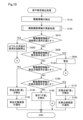
図10に示すように、第5実施形態のeVTOL100は、保守要否検出処理において、ステップS120とステップS130との間にステップS610~S640がさらに実行されることにより、eVTOL100の次回の使用に対する強制停止が実行され得る点において、第3実施形態のeVTOL100と異なる。装置構成を含めた他の構成は第3実施形態のeVTOL100と同じであるので、同一の構成には同一の符号を付し、それらの詳細な説明を省略する。
E. Fifth embodiment:
As shown in FIG. 10, the eVTOL 100 of the fifth embodiment performs steps S610 to S640 between steps S120 and S130 in the maintenance necessity detection process, thereby forcing the next use of the eVTOL 100. It differs from the eVTOL 100 of the third embodiment in that shutdown can be performed. Other configurations including the device configuration are the same as those of the eVTOL 100 of the third embodiment.

保守要否検出部57は、ステップS120において更新されて記憶されたEDS10の駆動履歴情報が、強制停止条件を満たすか否かを特定する(ステップS610)。強制停止条件は、定期点検要請や部品交換要請の通知がなされたにも関わらず保守が実施されずにEDS10の使用が継続された場合に、eVTOL100の次回の使用を強制停止するための条件として、予め設定されて記憶装置62に記憶されている。本実施形態における強制停止条件は、「使用期間が予め定められた期間を超え、駆動履歴情報としての累積負荷値が予め定められた強制停止閾値以上である」との条件である。 The maintenance necessity detection unit 57 determines whether or not the drive history information of the EDS 10 updated and stored in step S120 satisfies the forced stop condition (step S610). The forced stop condition is a condition for forcibly stopping the next use of the eVTOL 100 when the use of the EDS 10 is continued without maintenance being performed despite the notification of a periodic inspection request or parts replacement request. , are preset and stored in the storage device 62 . The forced stop condition in the present embodiment is that "the period of use exceeds a predetermined period and the cumulative load value as drive history information is equal to or greater than a predetermined forced stop threshold".

図11を用いて、EDS10の保守に関わる閾値について説明する。図11において、縦軸は駆動履歴情報を示しており、横軸はEDS10の使用期間を示している。EDS10の使用期間は、EDS10の駆動の有無に関わらず、EDS10が機体20に取り付けられてから現在までの経過時間を意味している。かかる使用期間は、例えば、各EDS10の駆動部11内に、バッテリ40に接続されると自動でカウントアップを開始するタイマーが設けられ、かかるタイマーの情報が制御装置50に送信されることにより特定されてもよい。第5実施形態では、EDS10の保守に関わる閾値として、定期点検閾値、部品交換閾値、警告閾値、強制停止閾値が、この順序で次第に大きくなる値として予め設定されている。なお、定期点検閾値は、図11に示すように、第1定期点検閾値と第2定期点検閾値との2段階に設定されている態様であってもよい。かかる態様においては、1回目の定期点検が実行された後、さらなる駆動を経た後に2回目の定期点検が実行され、さらなる駆動を経た後に部品交換が実行されることとなる。 Thresholds related to maintenance of the EDS 10 will be described with reference to FIG. In FIG. 11 , the vertical axis indicates the drive history information, and the horizontal axis indicates the usage period of the EDS 10 . The usage period of the EDS 10 means the elapsed time from when the EDS 10 was attached to the airframe 20 to the present, regardless of whether the EDS 10 is driven or not. Such a period of use is specified by, for example, providing a timer in the drive unit 11 of each EDS 10 that automatically starts counting up when connected to the battery 40, and transmitting information of the timer to the control device 50. may be In the fifth embodiment, the periodic inspection threshold, the parts replacement threshold, the warning threshold, and the forced stop threshold are set in advance as values that gradually increase in this order as thresholds related to maintenance of the EDS 10 . As shown in FIG. 11, the periodic inspection threshold may be set in two stages, a first periodic inspection threshold and a second periodic inspection threshold. In this aspect, after the first periodical inspection is performed, the second periodical inspection is performed after further driving, and the part replacement is performed after further driving.

図10に示すように、EDS10の駆動履歴情報が強制停止条件を満たすと特定された場合(ステップS610:YES)、すなわち、使用期間または駆動履歴情報が強制停止閾値を超えたと特定された場合、制御部52は、eVTOL100の次回の使用を強制停止する(ステップS620)。ステップS620では、例えば、eVTOL100の次回の離陸動作を禁止する。ステップS620の実行により、保守要否検出処理は完了する。 As shown in FIG. 10, when it is determined that the driving history information of the EDS 10 satisfies the forced stop condition (step S610: YES), that is, when it is determined that the period of use or the driving history information exceeds the forced stop threshold, The control unit 52 forcibly stops the next use of the eVTOL 100 (step S620). In step S620, for example, the next takeoff operation of the eVTOL 100 is prohibited. The execution of step S620 completes the maintenance necessity detection process.

EDS10の駆動履歴情報が強制停止条件を満たさないと特定された場合(ステップS610:NO)、保守要否検出部57は、EDS10の駆動履歴情報が警告条件を満たすか否かを特定する(ステップS630)。警告条件は、定期点検要請や部品交換要請の通知がなされたにも関わらず保守が実行されずにEDS10の使用が継続された場合に、eVTOL100の次回の使用を強制停止することを予告するための条件として、予め設定されて記憶装置62に記憶されている。本実施形態における警告条件は、「使用期間が予め定められた期間を超え、または、駆動履歴情報としての累積負荷値が予め定められた警告閾値以上である」との条件である。 If it is determined that the driving history information of the EDS 10 does not satisfy the forced stop condition (step S610: NO), the maintenance necessity detector 57 determines whether the driving history information of the EDS 10 satisfies the warning condition (step S630). The warning condition is to foreshadow that the next use of the eVTOL 100 will be forcibly stopped if the EDS 10 continues to be used without maintenance being performed despite the notification of a periodic inspection request or parts replacement request. is set in advance and stored in the storage device 62 as a condition of . The warning condition in this embodiment is that "the period of use exceeds a predetermined period, or the accumulated load value as drive history information is equal to or greater than a predetermined warning threshold".

図10に示すように、EDS10の駆動履歴情報が警告条件を満たすと特定された場合(ステップS630:YES)、すなわち、使用期間または駆動履歴情報が警告閾値を超えたと特定された場合、制御部52は、eVTOL100の次回の使用を強制停止する警告を行なう(ステップS640)。かかる警告は、ステップS150等において実行される保守要請の通知と同様な方法により実行されてもよい。ステップS640の実行により、保守要否検出処理は完了する。 As shown in FIG. 10, when it is determined that the driving history information of the EDS 10 satisfies the warning condition (step S630: YES), that is, when it is determined that the period of use or the driving history information exceeds the warning threshold, the control unit 52 issues a warning to forcibly stop the next use of eVTOL 100 (step S640). Such a warning may be performed in a manner similar to the maintenance request notification performed in step S150 or the like. The execution of step S640 completes the maintenance necessity detection process.

EDS10の駆動履歴情報が警告条件を満たさないと特定された場合(ステップS630:NO)。ステップS130に進む。 When it is specified that the drive history information of the EDS 10 does not satisfy the warning condition (step S630: NO). Proceed to step S130.

以上説明した第5実施形態のeVTOL100によれば、第3実施形態のeVTOL100と同様な効果を奏する。加えて、定期点検要請や部品交換要請の通知がなされたにも関わらず保守が実施されずにEDS10の使用が継続された場合に、eVTOL100の次回の使用を強制停止するので、保守が必要であるEDS10に対する保守が実施されないままeVTOL100の使用が継続されることを抑制できる。このため、eVTOL100の安全性の低下を抑制できる。また、強制停止に至る前に警告条件が満たされると警告を行なうので、強制停止前に部品交換が行われることが期待される。 According to the eVTOL 100 of the fifth embodiment described above, effects similar to those of the eVTOL 100 of the third embodiment are obtained. In addition, if the EDS 10 continues to be used without maintenance despite being notified of a periodic inspection request or parts replacement request, the next use of the eVTOL 100 will be forcibly stopped, so maintenance is not required. It is possible to prevent continued use of the eVTOL 100 without performing maintenance on a certain EDS 10 . Therefore, it is possible to suppress deterioration in safety of the eVTOL 100 . In addition, since a warning is issued when the warning condition is satisfied before the forced stop is reached, it is expected that parts will be replaced before the forced stop.

F.第6実施形態:
図12に示すように、第6実施形態のeVTOL100aは、EDS10に代えて、記憶装置17aを有するEDS10aを備える点と、記憶装置62が省略されている点とにおいて、第1実施形態のeVTOL100と異なる。このような構成により、第6実施形態のeVTOL100aにおいて実行される保守要否検出処理では、各EDS10aの記憶装置17aに駆動履歴情報がそれぞれ記憶される。他の構成は第1実施形態のeVTOL100と同じであるので、同一の構成には同一の符号を付し、それらの詳細な説明を省略する。
F. Sixth embodiment:
As shown in FIG. 12, the eVTOL 100a of the sixth embodiment differs from the eVTOL 100 of the first embodiment in that it includes an EDS 10a having a storage device 17a instead of the EDS 10 and that the storage device 62 is omitted. different. With such a configuration, in the maintenance necessity detection process executed in the eVTOL 100a of the sixth embodiment, drive history information is stored in the storage device 17a of each EDS 10a. Since other configurations are the same as those of the eVTOL 100 of the first embodiment, the same configurations are denoted by the same reference numerals, and detailed description thereof will be omitted.

各EDS10aにおいて、記憶装置17aは、ROMとRAMとを有するメモリとして構成され、駆動部11に接続されている。記憶装置17aは、記憶制御部56の指示に応じて、EDS10aの駆動履歴情報としての駆動部情報とモータ情報とをそれぞれ記憶する。換言すると、第6実施形態の記憶制御部56は、各EDS10aの駆動履歴情報を、記憶装置17aにそれぞれ記憶させる。 In each EDS 10 a , the storage device 17 a is configured as a memory having ROM and RAM and is connected to the driving section 11 . The storage device 17a stores drive unit information and motor information as drive history information of the EDS 10a in accordance with instructions from the storage control unit 56. FIG. In other words, the storage controller 56 of the sixth embodiment stores the drive history information of each EDS 10a in the storage device 17a.

以上説明した第6実施形態のeVTOL100aによれば、第1実施形態のeVTOL100と同様な効果を奏する。加えて、各EDS10aに記憶装置17aがそれぞれ搭載されて、各EDS10aの駆動履歴情報が記憶装置17aにそれぞれ記憶されるので、メモリ容量の小さい記憶装置17aを用いることができ、eVTOL100aの製造コストの増加を抑制できる。また、各EDS10aに搭載された記憶装置17aに駆動履歴情報がそれぞれ記憶されるので、EDS10aのローテーションが実行される態様においても、複数のEDS10aの駆動履歴情報を容易に管理できる。より具体的には、各EDS10aの駆動履歴情報とともに識別情報を制御装置50に送信することを省略でき、記憶装置62において各EDS10aの識別情報を記憶することを省略できる。なお、EDS10aのローテーションとは、複数のEDS10aを入れ替えることを意味しており、例えば、複数のEDS10aの搭載位置を物理的に入れ替えることや、EDS10aと回転翼30との組み合わせを複数のEDS10aにおいて電気的に切り替えることを意味している。 According to the eVTOL 100a of the sixth embodiment described above, the same effects as the eVTOL 100 of the first embodiment are obtained. In addition, each EDS 10a is equipped with a storage device 17a, and the drive history information of each EDS 10a is stored in the storage device 17a. You can control the increase. Further, since the drive history information is stored in the storage device 17a mounted on each EDS 10a, the drive history information of a plurality of EDSs 10a can be easily managed even when the EDSs 10a are rotated. More specifically, it is possible to omit transmitting the identification information to the control device 50 together with the driving history information of each EDS 10a, and it is possible to omit storing the identification information of each EDS 10a in the storage device 62. FIG. The rotation of the EDS 10a means to replace the plurality of EDS 10a. It means to switch

G.第7実施形態:
図13に示すように、第7実施形態のeVTOL100bは、EDS10aに代えて、2つの記憶装置17b、18bを有するEDS10bを備える点において、第6実施形態のeVTOL100aと異なる。他の構成は第6実施形態のeVTOL100aと同じであるので、同一の構成には同一の符号を付し、それらの詳細な説明を省略する。
G. Seventh embodiment:
As shown in FIG. 13, the eVTOL 100b of the seventh embodiment differs from the eVTOL 100a of the sixth embodiment in that an EDS 10b having two storage devices 17b and 18b is provided instead of the EDS 10a. Since other configurations are the same as those of the eVTOL 100a of the sixth embodiment, the same configurations are denoted by the same reference numerals, and detailed description thereof will be omitted.

各EDS10bにおいて、記憶装置17bは、駆動部11に接続されており、駆動履歴情報のうち駆動部11の劣化状態の指標となる駆動部情報を記憶する。また、各EDS10bにおいて、記憶装置18bは、駆動用モータ12に接続されており、駆動履歴情報のうち駆動用モータ12の劣化状態の指標となるモータ情報を記憶する。換言すると、第7実施形態の記憶制御部56は、各EDS10bの駆動履歴情報のうち、駆動部情報を記憶装置17bにそれぞれ記憶させ、モータ情報を記憶装置18bにそれぞれ記憶させる。 In each EDS 10b, the storage device 17b is connected to the drive section 11 and stores drive section information that serves as an indicator of the deterioration state of the drive section 11 among the drive history information. In each EDS 10b, the storage device 18b is connected to the driving motor 12 and stores motor information, which is an index of the deterioration state of the driving motor 12, among the driving history information. In other words, the storage control unit 56 of the seventh embodiment causes the storage device 17b to store the drive unit information and the storage device 18b to store the motor information among the drive history information of each EDS 10b.

記憶装置18bは、モータ情報を機械的に測定して記憶してもよい。例えば、駆動用モータ12の回転子の回転を、カウンタで積算して記憶してもよい。また、例えば、ブラシ付きモータの接点摩耗を利用して、接点が削れた長さから駆動用モータ12の累積回転数を推測して記憶してもよい。また、例えば、規定温度に達すると溶解する材料により形成されたインジケータを含むシールを駆動用モータ12に貼り付けること等により、駆動用モータ12の駆動時の温度を機械的に積算して記憶してもよい。なお、記憶装置18bは、例えばROMとRAMとを有するメモリとして構成されて、モータ情報を電子的に記憶してもよい。 The storage device 18b may mechanically measure and store the motor information. For example, the rotation of the rotor of the driving motor 12 may be accumulated by a counter and stored. Further, for example, the accumulated number of revolutions of the drive motor 12 may be estimated from the length of contact scraped by using contact wear of the brushed motor and stored. Further, for example, by attaching a sticker containing an indicator made of a material that melts when reaching a specified temperature to the driving motor 12, the temperature during driving of the driving motor 12 is mechanically accumulated and stored. may Note that the storage device 18b may be configured as a memory having a ROM and a RAM, for example, to electronically store the motor information.

以上説明した第7実施形態のeVTOL100bによれば、第6実施形態のeVTOL100aと同様な効果を奏する。加えて、各EDS10bに、駆動部情報を記憶する記憶装置17bと、モータ情報を記憶する記憶装置18bとがそれぞれ搭載されているので、駆動部11の劣化の度合いと、駆動用モータ12の劣化の度合いとを別々に管理する構成を容易に実現できる。このため、各EDS10bにおいて、駆動部11の交換や駆動用モータ12の交換の時期をそれぞれより容易に判断できる。 The eVTOL 100b of the seventh embodiment described above has the same effect as the eVTOL 100a of the sixth embodiment. In addition, since each EDS 10b is equipped with a storage device 17b for storing drive section information and a storage device 18b for storing motor information, the degree of deterioration of the drive section 11 and the deterioration of the drive motor 12 can be determined. It is possible to easily implement a configuration for separately managing the degree of Therefore, in each EDS 10b, it is possible to more easily determine when to replace the driving unit 11 and when to replace the driving motor 12, respectively.

H.第8実施形態:
図14に示すように、第8実施形態のeVTOL100cは、EDS10aに代えて、通信部19cをさらに有するEDS10cを備える点と、機体通信部64が省略されている点とにおいて、第6実施形態のeVTOL100aと異なる。他の構成は第6実施形態のeVTOL100aと同じであるので、同一の構成には同一の符号を付し、それらの詳細な説明を省略する。
H. Eighth embodiment:
As shown in FIG. 14, the eVTOL 100c of the eighth embodiment differs from the sixth embodiment in that it includes an EDS 10c that further has a communication unit 19c instead of the EDS 10a, and that the body communication unit 64 is omitted. Different from eVTOL 100a. Since other configurations are the same as those of the eVTOL 100a of the sixth embodiment, the same configurations are denoted by the same reference numerals, and detailed description thereof will be omitted.

各EDS10cにおいて、通信部19cは、駆動部11に接続されている。通信部19cは、無線通信を行なう機能を有し、外部装置500が備える外部通信部520とeVTOL100cとの間で情報の送受信を行なうとともに、制御装置50と通信可能に構成されている。 In each EDS 10 c , the communication section 19 c is connected to the drive section 11 . Communication unit 19 c has a function of performing wireless communication, transmits and receives information between external communication unit 520 provided in external device 500 and eVTOL 100 c, and is configured to be capable of communicating with control device 50 .

第8実施形態の保守要否検出処理は、第2実施形態と同様に、制御装置50と外部装置500とによって共働して実行される態様であってもよい。かかる態様において、通信部19cは、本開示における機体通信部に対応する。 The maintenance necessity detection process of the eighth embodiment may be performed by the control device 50 and the external device 500 working together, as in the second embodiment. In this aspect, the communication unit 19c corresponds to the body communication unit in the present disclosure.

以上説明した第8実施形態のeVTOL100cによれば、第2、6実施形態のeVTOL100、100aと同様な効果を奏する。 The eVTOL 100c of the eighth embodiment described above provides the same effects as the eVTOLs 100 and 100a of the second and sixth embodiments.

I.第9実施形態:
図15に示すように、第9実施形態のeVTOL100dは、EDS10bに代えて、第8実施形態と同様の通信部19cをさらに有するEDS10dを備える点と、機体通信部64が省略されている点とにおいて、第7実施形態のeVTOL100bと異なる。他の構成は第7実施形態のeVTOL100bと同じであるので、同一の構成には同一の符号を付し、それらの詳細な説明を省略する。
I. Ninth embodiment:
As shown in FIG. 15, the eVTOL 100d of the ninth embodiment includes an EDS 10d having a communication unit 19c similar to that of the eighth embodiment instead of the EDS 10b, and the body communication unit 64 is omitted. is different from the eVTOL 100b of the seventh embodiment. Since other configurations are the same as those of the eVTOL 100b of the seventh embodiment, the same configurations are denoted by the same reference numerals, and detailed description thereof will be omitted.

第9実施形態の保守要否検出処理は、第2実施形態と同様に、制御装置50と外部装置500とによって共働して実行される態様であってもよい。かかる態様において、通信部19cは、本開示における機体通信部に対応する。 The maintenance necessity detection process of the ninth embodiment may be performed by the control device 50 and the external device 500 working together, as in the second embodiment. In this aspect, the communication unit 19c corresponds to the body communication unit in the present disclosure.

以上説明した第9実施形態のeVTOL100dによれば、第7実施形態のeVTOL100bと同様な効果を奏する。 The eVTOL 100d of the ninth embodiment described above provides the same effects as the eVTOL 100b of the seventh embodiment.

J.第10実施形態:
第10実施形態のeVTOL100は、図16に示すベアリングのメンテナンス要否検出処理が実行される点において、第1実施形態のeVTOL100と異なる。第10実施形態のeVTOL100において、装置構成を含めた他の構成および処理手順は、第1実施形態のeVTOL100と同じであるので、同一の構成および処理手順には同一の符号を付し、それらの詳細な説明を省略する。
J. Tenth embodiment:
The eVTOL 100 of the tenth embodiment differs from the eVTOL 100 of the first embodiment in that the bearing maintenance necessity detection process shown in FIG. 16 is executed. In the eVTOL 100 of the tenth embodiment, other configurations and processing procedures including the device configuration are the same as those of the eVTOL 100 of the first embodiment. Detailed description is omitted.

図1~図3では図示を省略しているが、ギアボックス13と回転翼30との間にはベアリングを備える軸受けが設けられている。図16に示すベアリングのメンテナンス要否検出処理とは、回転翼30の回転によって消耗するベアリングの定期交換の要否を検出するための処理である。ベアリングのメンテナンス要否検出処理は、eVTOL100の起動スイッチがオンにされると、制御装置50において実行される。ベアリングのメンテナンス要否検出処理は、eVTOL100が備える複数のEDS10のそれぞれに対して実行される。 Although not shown in FIGS. 1 to 3, a bearing having bearings is provided between the gearbox 13 and the rotor blades 30 . The bearing maintenance necessity detection process shown in FIG. 16 is a process for detecting the necessity of periodical replacement of the bearing that is worn out by the rotation of the rotor blade 30 . The bearing maintenance necessity detection process is executed in the control device 50 when the start switch of the eVTOL 100 is turned on. The bearing maintenance necessity detection process is executed for each of the plurality of EDSs 10 included in the eVTOL 100 .

駆動情報検出部55は、図示しないトルクセンサからeVTOL100の出力トルクを検出する(ステップS210)。保守要否検出部57は、ベアリング寿命値が、ベアリング寿命時間に到達したか否かを判定する(ステップS220)。ベアリング寿命値は、ベアリングの定期交換が必要となる寿命時間の値を意味する。ベアリング寿命値は、予め設定された初期状態の寿命時間の値から、eVTOL100の使用時間だけ徐々に減算されていき、また後述のように、過負荷状況に応じて減算されていく。そして、ステップS220では、寿命時間が0(ゼロ)に達したか否かが判定され、0(ゼロ)に達した場合に、ベアリング寿命時間に達したと判定される。なお、ベアリングの新品搭載時において、初期状態のベアリングの寿命値は、予め設定された所定の寿命値であり、記憶装置62に予め記憶されている。 The drive information detector 55 detects the output torque of the eVTOL 100 from a torque sensor (not shown) (step S210). The maintenance necessity detector 57 determines whether or not the bearing life value has reached the bearing life time (step S220). A bearing life value means a life time value that requires periodical replacement of the bearing. The bearing life value is gradually subtracted by the usage time of the eVTOL 100 from the preset life time value in the initial state, and is also subtracted according to the overload condition as described later. Then, in step S220, it is determined whether or not the life time has reached 0 (zero), and if it has reached 0 (zero), it is determined that the bearing life time has been reached. When a new bearing is installed, the life value of the bearing in the initial state is a preset predetermined life value, which is stored in advance in the storage device 62 .

ベアリング寿命値が、ベアリング寿命時間に到達したと判定された場合(ステップS220:Yes)、制御部52は、かかるEDS10を対象とするメンテナンスが必要であるとして、メンテナンス要求の通知を行なう(ステップS290)。 If it is determined that the bearing life value has reached the bearing life time (step S220: Yes), the control unit 52 determines that maintenance for the EDS 10 is necessary, and issues a maintenance request (step S290). ).

メンテナンス要求の通知は、報知部66を介してeVTOL100の乗員に対して発信される通知であってもよい。より具体的には、例えば、乗員室に搭載された表示装置に複数のEDS10の搭載位置が示されている場合に、部品交換対象のEDS10が赤色のランプで示されてもよい。また、メンテナンス要求の通知は、機体通信部64を介して外部装置500に対して発信される通知であってもよい。このようにすることにより、eVTOL100の乗員や保守作業員等により、該当のEDS10に対してメンテナンスが実施されることが大いに期待される。ステップS290の実行により、メンテナンス要否検出処理は完了する。 The notification of the maintenance request may be a notification sent to the occupant of the eVTOL 100 via the notification unit 66 . More specifically, for example, when the mounting positions of a plurality of EDSs 10 are indicated on the display device mounted in the passenger compartment, the EDS 10 to be replaced may be indicated by a red lamp. Also, the notification of the maintenance request may be a notification transmitted to the external device 500 via the machine body communication section 64 . By doing so, it is highly expected that the crew of the eVTOL 100, maintenance workers, and the like will perform maintenance on the EDS 10 in question. The execution of step S290 completes the maintenance necessity detection process.

ベアリング寿命時間に到達していないと判定された場合(ステップS220:No)、保守要否検出部57は、ステップS210で検出された出力トルクが閾値Aよりも大きいか否かを判定する(ステップS230)。閾値Aとは、駆動用モータ12が過負荷状態として認められる閾値のトルク値として、予め実験等により求められて設定されている所定値である。 When it is determined that the bearing life time has not been reached (step S220: No), the maintenance necessity detector 57 determines whether or not the output torque detected in step S210 is greater than the threshold value A (step S230). The threshold value A is a predetermined value that is determined and set in advance by experiments or the like as a threshold torque value for recognizing that the drive motor 12 is in an overloaded state.

出力トルクが閾値Aよりも大きくないと判定された場合(ステップS230:No)、処理は、ステップS210に戻る。これに対して、出力トルクが閾値Aよりも大きいと判定された場合(ステップS230:Yes)、保守要否検出部57は、トルク値が閾値Aよりも大きい状態が継続する時間(以下、「過負荷継続時間」と呼ぶ)を、記憶装置62に記憶する(ステップS240)。 If it is determined that the output torque is not greater than the threshold A (step S230: No), the process returns to step S210. On the other hand, if it is determined that the output torque is greater than the threshold A (step S230: Yes), the maintenance necessity detection unit 57 detects the time during which the torque value continues to be greater than the threshold A (hereinafter referred to as " overload continuation time”) is stored in the storage device 62 (step S240).

保守要否検出部57は、ステップS240で記憶装置62に記憶した過負荷継続時間を、ベアリングの寿命計算に反映する(ステップS250)。具体的には、保守要否検出部57は、過負荷継続時間に対して、所定の係数(以下、「寿命減少係数」と呼ぶ)を乗じて得られた値を、現在の寿命時間から差し引く。寿命減少係数は、過負荷状態の継続時間により寿命がどの程度減少するかを予め実験等により求め、得られた実験結果に基づいて設定されている。本実施形態では、より正確な寿命予測を行うために、負荷のレベルに応じて複数の寿命減少係数が設定されている。出力トルクが閾値Aよりも大きく、かつ、後述する閾値B以下の範囲の過負荷状態に対しては、第1の寿命減少係数が設定されている。また、出力トルクが閾値Bよりも大きい過負荷状態に対しては、第2の寿命減少係数が設定されている。なお、第2の寿命減少係数は、第1の寿命減少係数よりも大きい。また、閾値Bは、閾値Aよりも大きな値である。 The maintenance necessity detector 57 reflects the overload continuation time stored in the storage device 62 in step S240 in the bearing life calculation (step S250). Specifically, the maintenance necessity detection unit 57 subtracts a value obtained by multiplying the overload duration time by a predetermined coefficient (hereinafter referred to as a “life reduction coefficient”) from the current life time. . The life reduction coefficient is set based on experimental results obtained by previously obtaining by experiment or the like how much the life is reduced by the duration of the overload state. In this embodiment, in order to perform more accurate life prediction, a plurality of life reduction coefficients are set according to load levels. A first life reduction coefficient is set for an overload state in which the output torque is greater than the threshold A and equal to or less than the threshold B, which will be described later. A second life reduction coefficient is set for an overload condition in which the output torque is greater than the threshold value B. FIG. Note that the second life reduction factor is greater than the first life reduction factor. Threshold B is a value larger than threshold A.

保守要否検出部57は、ステップS210で検出された出力トルクが閾値Bよりも大きいか否かを判定する(ステップS260)。閾値Bとは、駆動用モータ12が過負荷状態として認められ、かつ、ベアリングの故障の可能性が高い閾値のトルク値として、予め実験等により求められて設定されている所定値である。 The maintenance necessity detector 57 determines whether or not the output torque detected in step S210 is greater than the threshold value B (step S260). The threshold value B is a predetermined value obtained and set in advance by experiments or the like as a threshold torque value at which the driving motor 12 is recognized as being in an overloaded state and the possibility of bearing failure is high.

出力トルクが閾値Bよりも大きくないと判定された場合(ステップS260:No)、処理は、ステップS210に戻る。これに対して、出力トルクが閾値Bよりも大きいと判定された場合(ステップS260:Yes)、保守要否検出部57は、出力トルクが閾値Bを超える回数と、出力トルクが閾値Bを超える過負荷継続時間を記憶装置62に記憶する(ステップS270)。出力トルクが閾値Bを超える回数については、具体的には、記憶装置62に記憶されている「閾値Bを超える回数」に1が加えられる。なお、初期状態において、記憶装置62に記憶されている「閾値Bを超える回数」は0(ゼロ)に設定されている。 If it is determined that the output torque is not greater than threshold B (step S260: No), the process returns to step S210. On the other hand, when it is determined that the output torque is greater than the threshold B (step S260: Yes), the maintenance necessity detector 57 determines the number of times the output torque exceeds the threshold B and the number of times the output torque exceeds the threshold B. The overload continuation time is stored in the storage device 62 (step S270). Regarding the number of times the output torque exceeds the threshold B, specifically, 1 is added to the “number of times the threshold B is exceeded” stored in the storage device 62 . In the initial state, the "number of times exceeding the threshold value B" stored in the storage device 62 is set to 0 (zero).

保守要否検出部57は、ステップS270で記憶装置62に記憶した、閾値Bを超える過負荷継続時間を、ベアリングの寿命計算に反映する(ステップS275)。上述したように、閾値Bを超える過負荷状態に対しては、第2の寿命減少係数が設定されている。 The maintenance necessity detector 57 reflects the overload continuation time exceeding the threshold value B stored in the storage device 62 in step S270 in the life calculation of the bearing (step S275). As noted above, for overload conditions above threshold B, a second life reduction factor is set.

保守要否検出部57は、「閾値Bを超える回数」は、予め定められた閾値回数以上であるか否かを判定する(ステップS280)。「閾値Bを超える回数」が、閾値回数より少ないと判定された場合(ステップS280:No)、処理はステップS210へ戻る。保守要否検出部57は、閾値Bを超える回数」は、閾値回数以上であると判定した場合(ステップS280:Yes)、上述のステップS290が実行され、かかるEDS10を対象とするメンテナンスが必要であるとして、メンテナンス要求の通知が行われる。 The maintenance necessity detection unit 57 determines whether or not the "number of times exceeding the threshold value B" is equal to or greater than a predetermined threshold number of times (step S280). If it is determined that "the number of times exceeding the threshold value B" is less than the threshold number of times (step S280: No), the process returns to step S210. When the maintenance necessity detection unit 57 determines that the number of times exceeding the threshold value B is equal to or greater than the threshold number of times (step S280: Yes), the above-described step S290 is executed, and maintenance for the EDS 10 is required. Assuming that there is, a notification of the maintenance request is made.

図17に示すように、駆動用モータ12に一時的に過剰なトルクがかかった場合には出力トルクが一時的に大きくなって過負荷状態となる。図17において、横軸は時間を示し、縦軸は出力トルクを示している。外的作用等によって、出力トルクが予め定められた閾値Aを超えると、過負荷状態となる。さらに、閾値Bよりも出力トルクが大きくなると、ベアリングの故障の可能性が高くなる。 As shown in FIG. 17, when an excessive torque is temporarily applied to the drive motor 12, the output torque is temporarily increased, resulting in an overload state. In FIG. 17, the horizontal axis indicates time, and the vertical axis indicates output torque. When the output torque exceeds a predetermined threshold value A due to an external action or the like, an overload state occurs. Furthermore, when the output torque is greater than threshold B, the possibility of bearing failure increases.

過負荷状態となる時刻t1から時刻t2までの過負荷継続時間tr1に対して、第1の寿命減少係数が乗じられ、得られた値が寿命時間から差し引かれる。同様にして、過負荷状態となる時刻t3から時刻t6までの過負荷継続時間tr2のうち、時刻t3から時刻t4までの時間に対して、第1の寿命減少係数が乗じられ、得られた値が寿命時間から差し引かれる。 The overload continuation time tr1 from time t1 to time t2 at which the overload state occurs is multiplied by the first life reduction coefficient, and the obtained value is subtracted from the life time. Similarly, the value obtained by multiplying the time from time t3 to time t4 of the overload continuation time tr2 from time t3 to time t6 when overloaded by the first life reduction coefficient is subtracted from the life time.

時刻t4から時刻t5までの過負荷継続時間に対しては、第2の寿命減少係数が乗じられ、得られた値が寿命時間から差し引かれる。時刻t5から時刻t6までの過負荷継続時間に対しては、第1の寿命減少係数が乗じられ、得られた値が寿命時間から差し引かれる。また、出力トルクが閾値Bを超える時刻t4から時刻t5までの過負荷状態に対しては、上述したように、「閾値Bを超える回数」が1回増加することとなる。 The overload duration from time t4 to time t5 is multiplied by a second life reduction factor and the resulting value is subtracted from the life time. The overload duration from time t5 to time t6 is multiplied by the first life reduction factor and the resulting value is subtracted from the life time. Further, in the overload state from the time t4 to the time t5 when the output torque exceeds the threshold B, the "number of times the threshold B is exceeded" increases by one, as described above.

以上説明した第10実施形態のeVTOL100によれば、第1実施形態のeVTOL100と同様な効果を奏する。加えて、各EDS10に対し、駆動用モータ12自体のメンテナンスは基本的に不要であっても、出力トルクの過負荷継続時間や、出力トルクが閾値Bを超える回数を用いて、ベアリングに対する定期交換の指針が得られる。これにより、寿命時間に達するまでベアリングを使い切ることができ、EDS10のランニングコストを抑えることができる。また、ベアリングの故障の疑いを適切に検知可能となる。 The eVTOL 100 of the tenth embodiment described above provides the same effects as the eVTOL 100 of the first embodiment. In addition, for each EDS 10, even if the maintenance of the drive motor 12 itself is basically unnecessary, the periodical replacement of the bearing can be performed using the output torque overload duration and the number of times the output torque exceeds the threshold value B. guidance is obtained. As a result, the bearing can be used up until it reaches the end of its service life, and the running cost of the EDS 10 can be suppressed. In addition, it becomes possible to appropriately detect suspicion of bearing failure.

K.他の実施形態:
K-1.他の実施形態1:
上記各実施形態において実行されていた保守要否検出処理は、あくまで一例であり、種々変更可能である。例えば、部品交換と定期点検とが互いに区別されずに各EDS10、10a~dの保守要否が検出されてもよい。より具体的には、例えば、EDS10、10a~dが備える複数の構成部品における劣化の度合いとそれぞれ相関のある駆動履歴情報が用いられて保守要否が検出されてもよく、また、EDS10、10a~dがそれぞれ備える構成部品のうち、保守を実施すべき期間の間隔が最も短い構成部品の劣化の度合いと相関のある駆動履歴情報が用いられて保守要否が検出されてもよい。また、例えば、ステップS130において、部品交換条件に代えてEDS10、10a~d全体を交換する条件が用いられてもよい。また、複数種類の駆動情報に基づく駆動履歴情報を用いて保守要否が検出されてもよく、駆動履歴情報に加えてEDS10の使用期間に関する情報が組み合わされて保守要否が検出されてもよい。また、例えば、部品交換閾値や定期点検閾値等の閾値は、互いに異なる駆動履歴情報の指標により設定されていてもよい。また、例えば、部品交換閾値や定期点検閾値等の閾値として、モータ情報に対する閾値と駆動部情報に対する閾値とが、互いに同じ指標により設定されていてもよく、互いに異なる指標により設定されていてもよい。より具体的には、例えば、モータ情報に対する閾値が駆動用モータ12の累積負荷値としての累積回転数により設定され、駆動部情報に対する閾値が駆動部11の累積負荷値としての累積出力電力量により設定されていてもよく、モータ情報に対する閾値と駆動部情報に対する閾値とが、いずれも累積負荷値としての累積駆動時間により設定されていてもよい。また、例えば、部品交換閾値や定期点検閾値等に代えて、または、部品交換閾値や定期点検閾値等に加えて、所定の種類の駆動履歴情報に基づいて、部品交換条件や定期点検条件等が設定されている態様であってもよい。かかる態様においては、例えば、所定期間における駆動用モータ12の累積駆動電流の増加幅が所定以上であること等、所定期間における駆動情報の変動値が部品交換条件や定期点検条件等として設定されていてもよい。このような構成によっても、上記各実施形態と同様な効果を奏する。
K. Other embodiments:
K-1. Alternative Embodiment 1:
The maintenance necessity detection process executed in each of the above-described embodiments is merely an example, and can be changed in various ways. For example, the need for maintenance of each EDS 10, 10a-d may be detected without distinguishing between parts replacement and periodic inspection. More specifically, for example, the need for maintenance may be detected using drive history information that correlates with the degree of deterioration of each of the components of the EDS 10, 10a to 10d. The need for maintenance may be detected using driving history information that correlates with the degree of deterioration of the component having the shortest maintenance interval among the components provided in each of the components 1 to d. Further, for example, in step S130, a condition for replacing the entire EDS 10, 10a to 10d may be used instead of the part replacement condition. Further, the need for maintenance may be detected using drive history information based on multiple types of drive information, or the need for maintenance may be detected by combining information on the period of use of the EDS 10 in addition to the drive history information. . Further, for example, the thresholds such as the part replacement threshold and the periodic inspection threshold may be set using different indicators of drive history information. Further, for example, as thresholds such as the part replacement threshold and the periodic inspection threshold, the threshold for the motor information and the threshold for the driving unit information may be set using the same index, or may be set using different indexes. . More specifically, for example, the threshold for the motor information is set by the cumulative number of rotations as the cumulative load value of the drive motor 12, and the threshold for the drive unit information is set by the cumulative output power amount as the cumulative load value of the drive unit 11. Alternatively, both the threshold value for the motor information and the threshold value for the drive unit information may be set based on the cumulative driving time as the cumulative load value. Further, for example, instead of or in addition to the part replacement threshold value, the periodic inspection threshold value, etc., the parts replacement condition, the periodic inspection condition, etc., are set based on a predetermined type of drive history information. It may be a set mode. In such a mode, for example, the variation value of the drive information in a predetermined period, such as the increase width of the cumulative drive current of the drive motor 12 in the predetermined period, is set as a part replacement condition, a periodic inspection condition, or the like. may Even with such a configuration, the same effects as those of the above-described embodiments can be obtained.

K-2.他の実施形態2:
上記第2実施形態の保守要否検出処理は、制御装置50と外部装置500とによって共働して実行され、外部記憶装置530に各EDS10の駆動履歴情報が記憶され、外部制御部510が各EDS10のそれぞれに対する保守要否を判定していたが、本開示はこれに限定されるものではない。例えば、各EDS10の駆動履歴情報は、第1、3~9実施形態と同様に、eVTOL100、100a~dが備える記憶装置62、17a、17b、18bに記憶されてもよい。また、例えば、外部制御部510が各EDS10の保守要否の判定を実行することに代えて、保守要否検出部57が各EDS10の保守要否の判定を実行して保守要否を検出してもよい。このように、保守要否検出処理のうちの少なくとも一部が、外部装置500により実行されてもよい。すなわち一般には、eVTOL100、100a~dは、EDS10、10a~dの駆動情報の履歴に関する駆動履歴情報を記憶させる記憶制御部56を備えていてもよく、記憶された駆動履歴情報を用いて判定された保守要否を検出する保守要否検出部57を備えていてもよい。このような構成によっても、上記第2実施形態と同様な効果を奏する。
K-2. Alternative Embodiment 2:
The maintenance necessity detection process of the second embodiment is executed in cooperation with the control device 50 and the external device 500, the drive history information of each EDS 10 is stored in the external storage device 530, and the external control unit 510 Although the necessity of maintenance for each EDS 10 is determined, the present disclosure is not limited to this. For example, the driving history information of each EDS 10 may be stored in the storage devices 62, 17a, 17b, 18b provided in the eVTOLs 100, 100a-d, as in the first, third to ninth embodiments. Further, for example, instead of the external control unit 510 determining whether maintenance is required for each EDS 10, the maintenance necessity detection unit 57 determines whether maintenance is required for each EDS 10 and detects whether maintenance is required. may Thus, at least part of the maintenance necessity detection process may be executed by the external device 500 . That is, in general, the eVTOL 100, 100a-d may include a storage control unit 56 for storing drive history information regarding the history of the drive information of the EDS 10, 10a-d, and determination is made using the stored drive history information. A maintenance necessity detection unit 57 may be provided to detect whether or not maintenance is necessary. Even with such a configuration, the same effects as those of the second embodiment can be obtained.

K-3.他の実施形態3:
上記第4実施形態において実行されていた保守要否検出処理は、あくまで一例であり、種々変更可能である。例えば、異常点検要否の検出処理(ステップS500)の完了により、保守要否検出処理が完了してもよい。換言すると、保守要否検出部57は、各EDS10の保守要否として、部品点検要否等に代えて異常点検要否のみを検出してもよい。すなわち一般には、保守要否検出部57は、検出された駆動情報に基づいて、複数のEDS10のそれぞれに対する保守要否を検出してもよい。このような構成においては、記憶制御部56や記憶装置62が省略されてもよい。また、例えば、異常点検要否の検出処理が、制御装置50と外部装置500とによって共働して実行されてもよい。より具体的には、機体通信部64と外部通信部520とを介して外部装置500へと駆動情報が送信されて、かかる駆動情報の値が正常範囲内であるか否か等の判定が、外部制御部510によって実行される態様であってもよい。かかる態様によれば、外部記憶装置530に記憶されたデータを参照して異常点検の要否を検出できる。より具体的には、例えば、所定の駆動情報の挙動が事故につながるおそれがある等のデータを参照して異常点検の要否を検出できる。このように、eVTOL100が備える記憶装置62よりも容量が大きな外部記憶装置530に蓄積されたデータを参照して異常点検の要否を検出できるので、より高度な判定を実行でき、また、異常点検の要否をより精度良く検出できる。
K-3. Alternative Embodiment 3:
The maintenance necessity detection process executed in the fourth embodiment is merely an example, and various modifications are possible. For example, the maintenance necessity detection process may be completed upon completion of the abnormality inspection necessity detection process (step S500). In other words, the maintenance necessity detection unit 57 may detect only the abnormality inspection necessity as the maintenance necessity of each EDS 10 instead of the parts inspection necessity. That is, in general, the maintenance necessity detector 57 may detect maintenance necessity for each of the plurality of EDSs 10 based on the detected driving information. In such a configuration, the storage controller 56 and storage device 62 may be omitted. Further, for example, the process of detecting whether or not an abnormality check is necessary may be executed in cooperation with the control device 50 and the external device 500 . More specifically, driving information is transmitted to the external device 500 via the body communication unit 64 and the external communication unit 520, and determination such as whether the value of the driving information is within a normal range is performed. A mode executed by the external control unit 510 may be employed. According to this aspect, the data stored in the external storage device 530 can be referenced to detect the necessity of abnormality inspection. More specifically, for example, it is possible to detect whether or not an abnormality check is necessary by referring to data indicating that the behavior of predetermined drive information may lead to an accident. In this way, the data stored in the external storage device 530, which has a larger capacity than the storage device 62 provided in the eVTOL 100, can be referenced to detect whether or not abnormality inspection is necessary. can be detected with higher accuracy.

K-4.他の実施形態4:
上記各実施形態の制御装置50は、eVTOL100、100a~100dに搭載されていたが、外部装置500に搭載されて用いられる態様であってもよい。かかる態様においては、eVTOL100、100a~dに搭載される制御装置(制御装置50とは別の制御装置)に接続された機体通信部64や通信部19cと、外部通信部520との間で制御信号の送受信が行なわれてもよい。すなわち一般には、制御装置50は、eVTOL100、100a~dが備える機体通信部64と通信可能な外部通信部520をさらに備え、eVTOL100、100a~dの外部に存在していてもよい。かかる構成によれば、外部装置500において複数のeVTOL100、100a~dに対する保守要否検出処理を制御できる。
K-4. Alternative Embodiment 4:
Although the control device 50 of each of the above embodiments is mounted on the eVTOL 100, 100a to 100d, it may be mounted on the external device 500 and used. In this aspect, control is performed between the body communication unit 64 and the communication unit 19c connected to the control device (control device different from the control device 50) mounted on the eVTOL 100, 100a to 100d and the external communication unit 520. Signals may be transmitted and received. That is, in general, the control device 50 may further include an external communication unit 520 capable of communicating with the body communication unit 64 included in the eVTOLs 100, 100a-d, and may exist outside the eVTOLs 100, 100a-d. According to such a configuration, the external device 500 can control maintenance necessity detection processing for a plurality of eVTOLs 100, 100a to 100d.

K-5.他の実施形態5:
上記各実施形態におけるeVTOL100、100a~dの構成は、あくまで一例であり、種々変更可能である。例えば、上記各実施形態において、駆動情報検出部55、記憶制御部56、および保守要否検出部57は、制御装置50が備えるCPUによりそれぞれ実現されていたが、駆動情報検出部55、記憶制御部56、および保守要否検出部57のうちの少なくとも1つは、EDS10、10a~dに搭載されていてもよい。また、例えば、第1、3~9実施形態のeVTOL100、100a~dにおいて、機体通信部64や通信部19cが省略されていてもよい。また、例えば、回転翼30とEDS10とは、9つに限らず任意の複数であってもよく、任意の位置に搭載されていてもよい。また、例えば、リフト用回転翼31とクルーズ用回転翼32とに代えてティルトロータにより構成されていてもよい。また、例えば、eVTOL100、100a~dは、有人航空機に代えて無人航空機として構成されていてもよい。
K-5. Alternative Embodiment 5:
The configuration of the eVTOL 100, 100a to 100d in each of the above-described embodiments is merely an example, and various modifications are possible. For example, in each of the above-described embodiments, the drive information detection unit 55, the storage control unit 56, and the maintenance necessity detection unit 57 are each implemented by the CPU provided in the control device 50. At least one of the unit 56 and the maintenance necessity detection unit 57 may be mounted on the EDS 10, 10a-d. Further, for example, in the eVTOLs 100 and 100a to 100d of the first and third to ninth embodiments, the body communication section 64 and the communication section 19c may be omitted. Further, for example, the number of the rotor blades 30 and the EDS 10 is not limited to nine, and may be any number and may be mounted at any position. Further, for example, a tilt rotor may be used instead of the lift rotor 31 and the cruise rotor 32 . Also, for example, the eVTOLs 100, 100a-d may be configured as unmanned aerial vehicles instead of manned aerial vehicles.

K-6.他の実施形態6:
上記第10実施形態において実行されていたベアリングのメンテナンス要否検出処理は、ベアリングを対象としていたが、本開示はこれに限られない。駆動用モータ12の駆動時間や出力トルクの大きさに応じて、消耗度合が変化する任意の種類の消耗品を対象として、メンテナンス要否を検出してもよい。例えば、EDS10の取付けボルトを対象として、メンテナンス要否を検出してもよい。これにより、上記第10実施形態と同様な効果を奏する。
K-6. Alternative Embodiment 6:
Although the bearing maintenance necessity detection process executed in the tenth embodiment is intended for bearings, the present disclosure is not limited to this. The need for maintenance may be detected for any type of consumable item whose degree of consumption changes according to the drive time and the magnitude of the output torque of the drive motor 12 . For example, the need for maintenance may be detected for the mounting bolts of the EDS 10 . This provides the same effect as the tenth embodiment.

本開示は、上述の実施形態に限られるものではなく、その趣旨を逸脱しない範囲において種々の構成で実現することができる。例えば、発明の概要の欄に記載した形態中の技術的特徴に対応する各実施形態中の技術的特徴は、上述の課題の一部又は全部を解決するために、あるいは、上述の効果の一部又は全部を達成するために、適宜、差し替えや、組み合わせを行うことが可能である。また、その技術的特徴が本明細書中に必須なものとして説明されていなければ、適宜、削除することが可能である。 The present disclosure is not limited to the embodiments described above, and can be implemented in various configurations without departing from the scope of the present disclosure. For example, the technical features in each embodiment corresponding to the technical features in the form described in the outline of the invention are used to solve some or all of the above problems, or Substitutions and combinations may be made as appropriate to achieve part or all. Also, if the technical features are not described as essential in this specification, they can be deleted as appropriate.

本開示に記載の制御装置、外部装置及びその手法は、コンピュータプログラムにより具体化された一つ乃至は複数の機能を実行するようにプログラムされたプロセッサ及びメモリを構成することによって提供された専用コンピュータにより、実現されてもよい。あるいは、本開示に記載の制御部及びその手法は、一つ以上の専用ハードウエア論理回路によってプロセッサを構成することによって提供された専用コンピュータにより、実現されてもよい。もしくは、本開示に記載の制御装置、外部装置及びその手法は、一つ乃至は複数の機能を実行するようにプログラムされたプロセッサ及びメモリと一つ以上のハードウエア論理回路によって構成されたプロセッサとの組み合わせにより構成された一つ以上の専用コンピュータにより、実現されてもよい。また、コンピュータプログラムは、コンピュータにより実行されるインストラクションとして、コンピュータ読み取り可能な非遷移有形記録媒体に記憶されていてもよい。 The controllers, external devices, and techniques described in this disclosure are dedicated computers provided by configuring a processor and memory programmed to perform one or more functions embodied by a computer program. It may be realized by Alternatively, the controls and techniques described in this disclosure may be implemented by a dedicated computer provided by configuring the processor with one or more dedicated hardware logic circuits. Alternatively, the controllers, external devices, and techniques described in this disclosure may be processors and memory configured with one or more hardware logic circuits programmed to perform one or more functions. may be implemented by one or more dedicated computers configured by a combination of The computer program may also be stored as computer-executable instructions on a computer-readable non-transitional tangible recording medium.

10、10a~d…EDS(電駆動システム)、11…駆動部、12…駆動用モータ、19c…通信部(機体通信部)、30…回転翼、55…駆動情報検出部、57…保守要否検出部、100、100a~d…eVTOL(電動垂直離着陸機) 10, 10a to d...EDS (electric drive system), 11...drive section, 12...drive motor, 19c...communication section (body communication section), 30...rotor blade, 55...drive information detection section, 57...maintenance required No detection unit, 100, 100a-d ... eVTOL (electric vertical take-off and landing aircraft)

Claims (7)

回転翼(30)を回転駆動させる駆動用モータ(12)と前記駆動用モータを駆動させる駆動部(11)とを有する複数の電駆動システム(10、10a~d)を備える電動垂直離着陸機(100、100a~d)であって、
離陸動作と、飛行動作と、着陸動作のうちの少なくとも1つを含む前記電動垂直離着陸機の動作中に、
前記駆動用モータの劣化状態の指標となるモータ情報と、前記駆動部の劣化状態の指標となる駆動部情報と、のうちの少なくとも一方を含む駆動情報を、前記複数の電駆動システムのそれぞれに対して検出する駆動情報検出部(55)と、
検出された前記駆動情報に基づいて、前記複数の電駆動システムのそれぞれに対する保守要否を検出する保守要否検出部(57)と、
前記駆動情報の履歴に関する駆動履歴情報を記憶させる記憶制御部(56)と、
前記駆動履歴情報を記憶する記憶装置(17a、17b、18b、62)と、
を備え、
前記保守要否検出部は、記憶された前記駆動履歴情報を用いて判定された前記保守要否を検出する、
電動垂直離着陸機。
An electric vertical take-off and landing aircraft ( 100, 100a-d),
during operation of the electric vertical takeoff and landing vehicle including at least one of a takeoff operation, a flight operation, and a landing operation;
Driving information including at least one of motor information as an index of the deterioration state of the driving motor and driving unit information as an index of the deterioration state of the driving unit is supplied to each of the plurality of electric drive systems. a drive information detection unit (55) for detecting against
a maintenance necessity detector (57) for detecting whether or not maintenance is necessary for each of the plurality of electric drive systems based on the detected drive information;
a storage control unit (56) for storing drive history information relating to the history of the drive information;
a storage device (17a, 17b, 18b, 62) for storing the drive history information;
with
The maintenance necessity detection unit detects the necessity of maintenance determined using the stored drive history information.
Electric vertical take-off and landing aircraft.
請求項1に記載の電動垂直離着陸機において、 In the electric vertical take-off and landing aircraft according to claim 1,
前記駆動履歴情報は、累積負荷値を含む、 The drive history information includes a cumulative load value,
電動垂直離着陸機。 Electric vertical take-off and landing aircraft.
請求項2に記載の電動垂直離着陸機において、 In the electric vertical take-off and landing aircraft according to claim 2,
前記累積負荷値は、累積駆動時間と、累積回転数と、累積駆動電流と、のうちでいずれかを含む、The cumulative load value includes any one of cumulative drive time, cumulative rotation speed, and cumulative drive current,
電動垂直離着陸機。 Electric vertical take-off and landing aircraft.
請求項1から請求項3までのいずれか一項に記載の電動垂直離着陸機において、
前記駆動履歴情報は、少なくとも2種類の前記駆動情報が統合された統合値として構成されている、
電動垂直離着陸機。
In the electric vertical take-off and landing aircraft according to any one of claims 1 to 3 ,
The driving history information is configured as an integrated value obtained by integrating at least two types of the driving information.
Electric vertical take-off and landing aircraft.
請求項1から請求項4までのいずれか一項に記載の電動垂直離着陸機において、
前記電動垂直離着陸機とは異なる外部装置(500)が備える外部通信部(520)と通信可能な機体通信部(64、19c)をさらに備え、
前記機体通信部は、検出された前記駆動情報を前記外部通信部へと送信し、送信された前記駆動情報を用いて前記外部装置において判定された前記保守要否を受信し、
前記保守要否検出部は、受信された前記保守要否を検出する、
電動垂直離着陸機。
In the electric vertical take-off and landing aircraft according to any one of claims 1 to 4,
Further comprising a body communication unit (64, 19c) capable of communicating with an external communication unit (520) provided in an external device (500) different from the electric vertical take-off and landing aircraft,
The body communication unit transmits the detected drive information to the external communication unit, receives the maintenance necessity determined by the external device using the transmitted drive information,
The maintenance necessity detection unit detects the received maintenance necessity,
Electric vertical take-off and landing aircraft.
請求項1から請求項5までのいずれか一項に記載の電動垂直離着陸機において、
前記保守要否は、異常点検の要否を含む、
電動垂直離着陸機。
In the electric vertical take-off and landing aircraft according to any one of claims 1 to 5,
The maintenance necessity includes necessity of abnormality inspection,
Electric vertical take-off and landing aircraft.
回転翼を回転駆動させる駆動用モータと前記駆動用モータを駆動させる駆動部とを有する複数の電駆動システムを備える電動垂直離着陸機の制御装置(50)であって、
離陸動作と、飛行動作と、着陸動作のうちの少なくとも1つを含む前記電動垂直離着陸機の動作中に、
前記駆動用モータの劣化状態の指標となるモータ情報と、前記駆動部の劣化状態の指標となる駆動部情報と、のうちの少なくとも一方を含む駆動情報を、前記複数の電駆動システムのそれぞれに対して検出する駆動情報検出部と、
検出された前記駆動情報に基づいて、前記複数の電駆動システムのそれぞれに対する保守要否を検出する保守要否検出部と、
前記駆動情報の履歴に関する駆動履歴情報を記憶させる記憶制御部と、
前記駆動履歴情報を記憶する記憶装置と、
を備え、
前記保守要否検出部は、記憶された前記駆動履歴情報を用いて判定された前記保守要否を検出する、
を備える、電動垂直離着陸機の制御装置。
A control device (50) for an electric vertical take-off and landing aircraft comprising a plurality of electric drive systems each having a drive motor for rotationally driving a rotor blade and a drive unit for driving the drive motor,
during operation of the electric vertical takeoff and landing vehicle including at least one of a takeoff operation, a flight operation, and a landing operation;
Driving information including at least one of motor information as an index of the deterioration state of the driving motor and driving unit information as an index of the deterioration state of the driving unit is supplied to each of the plurality of electric drive systems. a drive information detection unit that detects against
a maintenance necessity detection unit that detects whether maintenance is necessary for each of the plurality of electric drive systems based on the detected drive information;
a storage control unit that stores driving history information related to the history of the driving information;
a storage device that stores the drive history information;
with
The maintenance necessity detection unit detects the necessity of maintenance determined using the stored drive history information.
A control device for an electric vertical take-off and landing aircraft.
JP2020099899A 2019-08-28 2020-06-09 Electric vertical take-off and landing aircraft and control device for electric vertical take-off and landing aircraft Active JP7276253B2 (en)

Priority Applications (4)

Application Number Priority Date Filing Date Title
PCT/JP2020/030598 WO2021039381A1 (en) 2019-08-28 2020-08-11 Electric vertical takeoff and landing aircraft and control device for electric vertical takeoff and landing aircraft
EP20857314.7A EP4023550A4 (en) 2019-08-28 2020-08-11 Electric vertical takeoff and landing aircraft and control device for electric vertical takeoff and landing aircraft
CN202080060286.6A CN114286784A (en) 2019-08-28 2020-08-11 Electric vertical take-off and landing machine and control device thereof
US17/678,156 US20220180670A1 (en) 2019-08-28 2022-02-23 Electric vertical takeoff and landing aircraft and control device for electric vertical takeoff and landing aircraft

Applications Claiming Priority (2)

Application Number Priority Date Filing Date Title
JP2019155209 2019-08-28

Publications (3)

Publication Number Publication Date
JP2021037935A JP2021037935A (en) 2021-03-11
JP2021037935A5 JP2021037935A5 (en) 2021-11-18
JP7276253B2 true JP7276253B2 (en) 2023-05-18

Family

ID=74848113

Family Applications (1)

Application Number Title Priority Date Filing Date
JP2020099899A Active JP7276253B2 (en) 2019-08-28 2020-06-09 Electric vertical take-off and landing aircraft and control device for electric vertical take-off and landing aircraft

Country Status (1)

Country Link
JP (1) JP7276253B2 (en)

Families Citing this family (2)

* Cited by examiner, † Cited by third party
Publication number Priority date Publication date Assignee Title
JP2022154594A (en) * 2021-03-30 2022-10-13 Ntn株式会社 Bearing device and electric vertical taking off/landing device
WO2024004158A1 (en) * 2022-06-30 2024-01-04 株式会社Acsl Unmanned aircraft

Citations (6)

* Cited by examiner, † Cited by third party
Publication number Priority date Publication date Assignee Title
CN105905307A (en) 2016-06-17 2016-08-31 广州极飞电子科技有限公司 Unmanned aerial vehicle, motor control system thereof, and motor failure detection method
US20170069145A1 (en) 2015-07-06 2017-03-09 Liebherr-Aerospace Lindenberg Gmbh Health Monitoring of an Actuator in a Flying Device
JP2017132461A (en) 2016-01-25 2017-08-03 大分県 Unmanned flying body characteristic measurement device and unmanned flying body evaluation system using the same
JP2018516200A (en) 2015-05-29 2018-06-21 ベリティ ストゥディオス アーゲー aircraft
JP2019023069A (en) 2017-06-13 2019-02-14 ゼネラル・エレクトリック・カンパニイ Hybrid-electric propulsion system for aircraft
JP2019055769A (en) 2017-07-17 2019-04-11 オーロラ フライト サイエンシズ コーポレーション System and method for detecting obstacles in aerial systems

Patent Citations (6)

* Cited by examiner, † Cited by third party
Publication number Priority date Publication date Assignee Title
JP2018516200A (en) 2015-05-29 2018-06-21 ベリティ ストゥディオス アーゲー aircraft
US20170069145A1 (en) 2015-07-06 2017-03-09 Liebherr-Aerospace Lindenberg Gmbh Health Monitoring of an Actuator in a Flying Device
JP2017132461A (en) 2016-01-25 2017-08-03 大分県 Unmanned flying body characteristic measurement device and unmanned flying body evaluation system using the same
CN105905307A (en) 2016-06-17 2016-08-31 广州极飞电子科技有限公司 Unmanned aerial vehicle, motor control system thereof, and motor failure detection method
JP2019023069A (en) 2017-06-13 2019-02-14 ゼネラル・エレクトリック・カンパニイ Hybrid-electric propulsion system for aircraft
JP2019055769A (en) 2017-07-17 2019-04-11 オーロラ フライト サイエンシズ コーポレーション System and method for detecting obstacles in aerial systems

Also Published As

Publication number Publication date
JP2021037935A (en) 2021-03-11

Similar Documents

Publication Publication Date Title
JP7276253B2 (en) Electric vertical take-off and landing aircraft and control device for electric vertical take-off and landing aircraft
JP5857326B1 (en) Unmanned flying vehicle and control device therefor
WO2016067489A1 (en) Helicopter
US9944404B1 (en) Prognostic failure detection system
KR102448525B1 (en) Desired departure temperature of the battery in the vehicle
JP6164573B2 (en) Unmanned flying vehicle and control system therefor
KR101667330B1 (en) Vertical take off and landing aircraft using hybrid-electric propulsion system
JP7439666B2 (en) Abnormal alarm system and alarm level setting method
JP2016088110A (en) helicopter
US11872898B2 (en) Abnormality diagnosis system and abnormality diagnosis method
WO2021039381A1 (en) Electric vertical takeoff and landing aircraft and control device for electric vertical takeoff and landing aircraft
US20200039639A1 (en) Peak power use with pilot monitoring
JP7276002B2 (en) Electric vertical take-off and landing aircraft and control device for electric vertical take-off and landing aircraft
CN115515856B (en) Motor wear metric generator
JP7342523B2 (en) Control equipment for electric vertical take-off and landing aircraft and electric vertical take-off and landing aircraft
JP6955421B2 (en) Aircraft control systems, aircraft control methods, aircraft control programs and aircraft
JP2016199153A (en) Cooling system for on-vehicle secondary battery
US10334332B1 (en) System and method for managing battery life in redundant wireless sensors
CN113443167B (en) Unmanned aerial vehicle state evaluation method, unmanned aerial vehicle state evaluation device, server and storage medium
WO2023139969A1 (en) Control device for electric aircraft
JPWO2018042676A1 (en) Unmanned flying vehicle
CN114655449A (en) Aircraft propulsion system
WO2024080060A1 (en) Control device, operation management system, and control program
WO2023119930A1 (en) Control device for electric vertical takeoff and landing aircraft, and computer program
JP6754277B2 (en) Aircraft torque estimation device, aircraft, aircraft torque estimation program and torque estimation method

Legal Events

Date Code Title Description
A521 Request for written amendment filed

Free format text: JAPANESE INTERMEDIATE CODE: A523

Effective date: 20211008

A621 Written request for application examination

Free format text: JAPANESE INTERMEDIATE CODE: A621

Effective date: 20220706

A131 Notification of reasons for refusal

Free format text: JAPANESE INTERMEDIATE CODE: A131

Effective date: 20230117

A521 Request for written amendment filed

Free format text: JAPANESE INTERMEDIATE CODE: A523

Effective date: 20230306

TRDD Decision of grant or rejection written
A01 Written decision to grant a patent or to grant a registration (utility model)

Free format text: JAPANESE INTERMEDIATE CODE: A01

Effective date: 20230404

A61 First payment of annual fees (during grant procedure)

Free format text: JAPANESE INTERMEDIATE CODE: A61

Effective date: 20230417

R151 Written notification of patent or utility model registration

Ref document number: 7276253

Country of ref document: JP

Free format text: JAPANESE INTERMEDIATE CODE: R151