JP7273830B2 - Visualization device for parotid surgery - Google Patents
Visualization device for parotid surgery Download PDFInfo
- Publication number
- JP7273830B2 JP7273830B2 JP2020536682A JP2020536682A JP7273830B2 JP 7273830 B2 JP7273830 B2 JP 7273830B2 JP 2020536682 A JP2020536682 A JP 2020536682A JP 2020536682 A JP2020536682 A JP 2020536682A JP 7273830 B2 JP7273830 B2 JP 7273830B2
- Authority
- JP
- Japan
- Prior art keywords
- sensor
- stylus
- reflector
- light
- target area
- Prior art date
- Legal status (The legal status is an assumption and is not a legal conclusion. Google has not performed a legal analysis and makes no representation as to the accuracy of the status listed.)
- Active
Links
Images


Classifications
-
- A—HUMAN NECESSITIES
- A61—MEDICAL OR VETERINARY SCIENCE; HYGIENE
- A61B—DIAGNOSIS; SURGERY; IDENTIFICATION
- A61B1/00—Instruments for performing medical examinations of the interior of cavities or tubes of the body by visual or photographical inspection, e.g. endoscopes; Illuminating arrangements therefor
- A61B1/227—Instruments for performing medical examinations of the interior of cavities or tubes of the body by visual or photographical inspection, e.g. endoscopes; Illuminating arrangements therefor for ears, i.e. otoscopes
-
- A—HUMAN NECESSITIES
- A61—MEDICAL OR VETERINARY SCIENCE; HYGIENE
- A61B—DIAGNOSIS; SURGERY; IDENTIFICATION
- A61B1/00—Instruments for performing medical examinations of the interior of cavities or tubes of the body by visual or photographical inspection, e.g. endoscopes; Illuminating arrangements therefor
- A61B1/00002—Operational features of endoscopes
- A61B1/00004—Operational features of endoscopes characterised by electronic signal processing
- A61B1/00006—Operational features of endoscopes characterised by electronic signal processing of control signals
-
- A—HUMAN NECESSITIES
- A61—MEDICAL OR VETERINARY SCIENCE; HYGIENE
- A61B—DIAGNOSIS; SURGERY; IDENTIFICATION
- A61B1/00—Instruments for performing medical examinations of the interior of cavities or tubes of the body by visual or photographical inspection, e.g. endoscopes; Illuminating arrangements therefor
- A61B1/00002—Operational features of endoscopes
- A61B1/00004—Operational features of endoscopes characterised by electronic signal processing
- A61B1/00009—Operational features of endoscopes characterised by electronic signal processing of image signals during a use of endoscope
- A61B1/000094—Operational features of endoscopes characterised by electronic signal processing of image signals during a use of endoscope extracting biological structures
-
- A—HUMAN NECESSITIES
- A61—MEDICAL OR VETERINARY SCIENCE; HYGIENE
- A61B—DIAGNOSIS; SURGERY; IDENTIFICATION
- A61B1/00—Instruments for performing medical examinations of the interior of cavities or tubes of the body by visual or photographical inspection, e.g. endoscopes; Illuminating arrangements therefor
- A61B1/00002—Operational features of endoscopes
- A61B1/00043—Operational features of endoscopes provided with output arrangements
- A61B1/00045—Display arrangement
- A61B1/00048—Constructional features of the display
-
- A—HUMAN NECESSITIES
- A61—MEDICAL OR VETERINARY SCIENCE; HYGIENE
- A61B—DIAGNOSIS; SURGERY; IDENTIFICATION
- A61B1/00—Instruments for performing medical examinations of the interior of cavities or tubes of the body by visual or photographical inspection, e.g. endoscopes; Illuminating arrangements therefor
- A61B1/00002—Operational features of endoscopes
- A61B1/00043—Operational features of endoscopes provided with output arrangements
- A61B1/00045—Display arrangement
- A61B1/0005—Display arrangement combining images e.g. side-by-side, superimposed or tiled
-
- A—HUMAN NECESSITIES
- A61—MEDICAL OR VETERINARY SCIENCE; HYGIENE
- A61B—DIAGNOSIS; SURGERY; IDENTIFICATION
- A61B1/00—Instruments for performing medical examinations of the interior of cavities or tubes of the body by visual or photographical inspection, e.g. endoscopes; Illuminating arrangements therefor
- A61B1/00002—Operational features of endoscopes
- A61B1/00043—Operational features of endoscopes provided with output arrangements
- A61B1/00045—Display arrangement
- A61B1/00052—Display arrangement positioned at proximal end of the endoscope body
-
- A—HUMAN NECESSITIES
- A61—MEDICAL OR VETERINARY SCIENCE; HYGIENE
- A61B—DIAGNOSIS; SURGERY; IDENTIFICATION
- A61B1/00—Instruments for performing medical examinations of the interior of cavities or tubes of the body by visual or photographical inspection, e.g. endoscopes; Illuminating arrangements therefor
- A61B1/00064—Constructional details of the endoscope body
- A61B1/00105—Constructional details of the endoscope body characterised by modular construction
-
- A—HUMAN NECESSITIES
- A61—MEDICAL OR VETERINARY SCIENCE; HYGIENE
- A61B—DIAGNOSIS; SURGERY; IDENTIFICATION
- A61B1/00—Instruments for performing medical examinations of the interior of cavities or tubes of the body by visual or photographical inspection, e.g. endoscopes; Illuminating arrangements therefor
- A61B1/00131—Accessories for endoscopes
- A61B1/0014—Fastening element for attaching accessories to the outside of an endoscope, e.g. clips, clamps or bands
-
- A—HUMAN NECESSITIES
- A61—MEDICAL OR VETERINARY SCIENCE; HYGIENE
- A61B—DIAGNOSIS; SURGERY; IDENTIFICATION
- A61B1/00—Instruments for performing medical examinations of the interior of cavities or tubes of the body by visual or photographical inspection, e.g. endoscopes; Illuminating arrangements therefor
- A61B1/00147—Holding or positioning arrangements
- A61B1/00154—Holding or positioning arrangements using guiding arrangements for insertion
-
- A—HUMAN NECESSITIES
- A61—MEDICAL OR VETERINARY SCIENCE; HYGIENE
- A61B—DIAGNOSIS; SURGERY; IDENTIFICATION
- A61B1/00—Instruments for performing medical examinations of the interior of cavities or tubes of the body by visual or photographical inspection, e.g. endoscopes; Illuminating arrangements therefor
- A61B1/012—Instruments for performing medical examinations of the interior of cavities or tubes of the body by visual or photographical inspection, e.g. endoscopes; Illuminating arrangements therefor characterised by internal passages or accessories therefor
- A61B1/018—Instruments for performing medical examinations of the interior of cavities or tubes of the body by visual or photographical inspection, e.g. endoscopes; Illuminating arrangements therefor characterised by internal passages or accessories therefor for receiving instruments
-
- A—HUMAN NECESSITIES
- A61—MEDICAL OR VETERINARY SCIENCE; HYGIENE
- A61B—DIAGNOSIS; SURGERY; IDENTIFICATION
- A61B1/00—Instruments for performing medical examinations of the interior of cavities or tubes of the body by visual or photographical inspection, e.g. endoscopes; Illuminating arrangements therefor
- A61B1/04—Instruments for performing medical examinations of the interior of cavities or tubes of the body by visual or photographical inspection, e.g. endoscopes; Illuminating arrangements therefor combined with photographic or television appliances
- A61B1/042—Instruments for performing medical examinations of the interior of cavities or tubes of the body by visual or photographical inspection, e.g. endoscopes; Illuminating arrangements therefor combined with photographic or television appliances characterised by a proximal camera, e.g. a CCD camera
-
- A—HUMAN NECESSITIES
- A61—MEDICAL OR VETERINARY SCIENCE; HYGIENE
- A61B—DIAGNOSIS; SURGERY; IDENTIFICATION
- A61B1/00—Instruments for performing medical examinations of the interior of cavities or tubes of the body by visual or photographical inspection, e.g. endoscopes; Illuminating arrangements therefor
- A61B1/04—Instruments for performing medical examinations of the interior of cavities or tubes of the body by visual or photographical inspection, e.g. endoscopes; Illuminating arrangements therefor combined with photographic or television appliances
- A61B1/05—Instruments for performing medical examinations of the interior of cavities or tubes of the body by visual or photographical inspection, e.g. endoscopes; Illuminating arrangements therefor combined with photographic or television appliances characterised by the image sensor, e.g. camera, being in the distal end portion
-
- A—HUMAN NECESSITIES
- A61—MEDICAL OR VETERINARY SCIENCE; HYGIENE
- A61B—DIAGNOSIS; SURGERY; IDENTIFICATION
- A61B1/00—Instruments for performing medical examinations of the interior of cavities or tubes of the body by visual or photographical inspection, e.g. endoscopes; Illuminating arrangements therefor
- A61B1/06—Instruments for performing medical examinations of the interior of cavities or tubes of the body by visual or photographical inspection, e.g. endoscopes; Illuminating arrangements therefor with illuminating arrangements
- A61B1/0661—Endoscope light sources
- A61B1/0669—Endoscope light sources at proximal end of an endoscope
-
- A—HUMAN NECESSITIES
- A61—MEDICAL OR VETERINARY SCIENCE; HYGIENE
- A61B—DIAGNOSIS; SURGERY; IDENTIFICATION
- A61B1/00—Instruments for performing medical examinations of the interior of cavities or tubes of the body by visual or photographical inspection, e.g. endoscopes; Illuminating arrangements therefor
- A61B1/06—Instruments for performing medical examinations of the interior of cavities or tubes of the body by visual or photographical inspection, e.g. endoscopes; Illuminating arrangements therefor with illuminating arrangements
- A61B1/0661—Endoscope light sources
- A61B1/0684—Endoscope light sources using light emitting diodes [LED]
-
- A—HUMAN NECESSITIES
- A61—MEDICAL OR VETERINARY SCIENCE; HYGIENE
- A61B—DIAGNOSIS; SURGERY; IDENTIFICATION
- A61B1/00—Instruments for performing medical examinations of the interior of cavities or tubes of the body by visual or photographical inspection, e.g. endoscopes; Illuminating arrangements therefor
- A61B1/06—Instruments for performing medical examinations of the interior of cavities or tubes of the body by visual or photographical inspection, e.g. endoscopes; Illuminating arrangements therefor with illuminating arrangements
- A61B1/07—Instruments for performing medical examinations of the interior of cavities or tubes of the body by visual or photographical inspection, e.g. endoscopes; Illuminating arrangements therefor with illuminating arrangements using light-conductive means, e.g. optical fibres
-
- A—HUMAN NECESSITIES
- A61—MEDICAL OR VETERINARY SCIENCE; HYGIENE
- A61B—DIAGNOSIS; SURGERY; IDENTIFICATION
- A61B1/00—Instruments for performing medical examinations of the interior of cavities or tubes of the body by visual or photographical inspection, e.g. endoscopes; Illuminating arrangements therefor
- A61B1/32—Devices for opening or enlarging the visual field, e.g. of a tube of the body
Description
関連出願の相互参照
本出願は、「VISUALIZATION DEVICES AND METHODS FOR OTOLOGIC PROCEDURES」と題され、2018年1月16日に出願された係属中の米国仮特許出願第62/617,951号において優先権を主張するものであり、その開示は参照により本明細書に組み込まれる。
CROSS-REFERENCE TO RELATED APPLICATIONS This application claims priority from pending U.S. Provisional Patent Application Serial No. 62/617,951, entitled "VISUALIZATION DEVICES AND METHODS FOR OTOLOGIC PROCEDURES," filed January 16, 2018. , the disclosure of which is incorporated herein by reference.
本開示は、一般に、耳下手術中、または耳の手術において対象の耳を可視化するためのシステム、装置、および方法に関する。より詳細は、本開示は、中耳腔換気用チューブ配置手術中の対象の外耳道の内部を可視化するための1つ以上のカメラおよび光を含む可視化デバイスに関する。 The present disclosure relates generally to systems, devices, and methods for visualizing a subject's ear during parotid surgery or ear surgery. More particularly, the present disclosure relates to visualization devices including one or more cameras and lights for visualizing the interior of a subject's ear canal during tympanostomy tube placement surgery.
耳下手術、または耳に関連する手術は、通常、対象の耳への医療器具の挿入を伴う。例えば、中耳炎は、炎症に関連付けられた中耳の一般的な疾患である。中耳炎は、解剖学的構造および免疫機能により、人間の子供に一般的である。重度または未治療の場合、中耳炎は、個人の鼓膜の破裂、難聴、または頭蓋内合併症を引き起こす場合がある。 Parotid surgery, or surgery involving the ear, typically involves the insertion of medical instruments into the subject's ear. For example, otitis media is a common disease of the middle ear associated with inflammation. Otitis media is common in human children due to anatomy and immune function. When severe or untreated, otitis media can lead to ruptured eardrums, hearing loss, or intracranial complications in individuals.
中耳炎の治療は、中耳と外耳との間の流体連通を提供することによって中耳の適切な排液を提供するために、鼓膜を通して均圧チューブまたは中耳腔換気用チューブを配置することを伴い得る。具体的には、かかるチューブは、エウスタキオチューブを介して中耳からの流体の排出を促進する排出路を提供することができ、したがって中耳内の圧力から鼓膜に課される応力を低減させることができる。これは、将来の感染症および鼓膜の圧力誘起による破裂の可能性をさらに低減することができる。 Treatment of otitis media involves placing a pressure equalizing tube or a tympanostomy tube through the eardrum to provide proper drainage of the middle ear by providing fluid communication between the middle and outer ear. can accompany Specifically, such a tube can provide a drainage channel that facilitates the drainage of fluid from the middle ear via the eustachian tube, thus reducing the stress imposed on the tympanic membrane from pressure within the middle ear. can be made This can further reduce the likelihood of future infections and pressure-induced rupture of the eardrum.
均圧チューブの挿入は、鼓膜に到達して鼓膜切開手術を行うことができる送達デバイスを使用して行うことができる。送達デバイスは、鼓膜に開口部または切り口を作成することができる切断要素を含むことができる。その後、均圧チューブを開口部内に配置して、中耳と外耳との間に流体連通を提供することができる。場合によっては、イオン注入は、鼓膜切開手術とチューブ配置を行う前に、局所麻酔薬を鼓膜と周囲の組織に送達するために使用することができる。イオン注入には、荷電薬液に低レベルの電流を流すことを伴う。電流は、溶液中の薬剤の同様の荷電イオンに反発し、皮膚または他の膜を横切って荷電イオンを移動させる。イオン注入は、溶液に電流を流しながら、外耳道内で荷電薬液を封止することができるデバイスを使用して行うことができる。 Insertion of the pressure equalizing tube can be performed using a delivery device that can reach the tympanic membrane and perform a myringotomy. The delivery device can include a cutting element capable of creating an opening or incision in the tympanic membrane. A pressure equalizing tube can then be placed in the opening to provide fluid communication between the middle and outer ear. In some cases, ion implantation can be used to deliver local anesthetic to the tympanic membrane and surrounding tissue prior to performing myringotomy surgery and tube placement. Ion implantation involves passing a low level electrical current through a charged chemical solution. The electric current repels like-charged ions of the drug in solution, causing the charged ions to move across skin or other membranes. Ion implantation can be performed using a device capable of sealing the charged drug solution within the ear canal while passing an electric current through the solution.
イオン注入手術および/またはチューブ配置手術、ならびに他の耳下手術中、医師が耳の内部を視認することは困難であり得る。耳下手術は、従来の方式では、耳の可視化を提供するが、標的治療領域に対して見通し線視野を必要とする外科用顕微鏡を使用して行われる。しかしながら、外耳道内で器具を操作するとき、器具のアクセス経路は、多くの場合、顕微鏡と標的治療領域との間の見通し線に重なるか、または見通し線を遮る。したがって、医師は、器具の操作が制限され得るか、または標的治療領域の不完全な視野で操作しなければならない。視野の妨害を回避するために、医師は、器具の配置を調節する手法を開発したが、これにより、器具の位置決めが最適でなくなり、手術を行う時間が長くなる可能性がある。したがって、標的治療領域の鮮明な視野を提供しながら、標的治療領域への器具のアクセスを可能にする、耳下手術のためのシステムを有することが望ましい。 It can be difficult for a physician to see inside the ear during ion implantation and/or tube placement surgery, as well as other ear surgery. Subarachnoid surgery is conventionally performed using a surgical microscope that provides visualization of the ear but requires a line-of-sight view to the target treatment area. However, when manipulating instruments within the ear canal, the instrument access path often overlaps or blocks the line of sight between the microscope and the target treatment area. Accordingly, the physician may have limited manipulation of the instrument or must operate with an imperfect view of the target treatment area. To avoid obstructing the field of view, physicians have developed techniques to adjust instrument placement, which can result in sub-optimal instrument positioning and lengthen the time to perform surgery. Accordingly, it is desirable to have a system for sub-auricular surgery that allows instrument access to the target treatment area while providing a clear view of the target treatment area.
耳下手術中に、対象の耳内を可視化するためのシステム、装置、および方法が説明される。 Systems, devices, and methods are described for visualization within a subject's ear during parotid surgery.
いくつかの実施形態では、装置は、光源、センサ、プロセッサ、および表示装置を含む。光源は、標的領域に入射光を提供するように構成することができ、センサは、標的領域からの反射光を捕捉して、反射光に基づいて画像データを生成するように構成することができる。プロセッサは、画像データを処理して、標的領域の画像を生成することができ、表示装置は、標的領域の画像を表示することができる。 In some embodiments, the device includes a light source, sensor, processor, and display. The light source can be configured to provide incident light to the target area, and the sensor can be configured to capture reflected light from the target area and generate image data based on the reflected light. . A processor can process the image data to generate an image of the target area, and a display device can display the image of the target area.
いくつかの実施形態では、装置は、反射鏡を含み、センサおよび/または光源は、反射鏡の遠位端に配設されている。いくつかの実施形態では、装置は、センサおよび/または光源を有する別個のスタイラス含む。 In some embodiments, the device includes a reflector and the sensor and/or light source are disposed at the distal end of the reflector. In some embodiments, the device includes a separate stylus with sensors and/or light sources.
前述の概念および以下でより詳細に論じられる追加の概念のすべての組み合わせ(かかる概念が相互に矛盾しない場合)は、本明細書で開示される発明の主題の一部として企図されることを理解されたい。具体的には、本開示の末端に現れる請求項に記載された主題のすべての組み合わせは、本明細書に開示される本発明の主題の一部であると企図される。また、参照により組み込まれる任意の開示にも現れ得る、本明細書で明示的に用いられる用語は、本明細書で開示される特定の概念と最も一致する意味を付与されるべきであることも理解されたい。 It is understood that all combinations of the foregoing concepts and the additional concepts discussed in more detail below (where such concepts are not mutually exclusive) are contemplated as part of the inventive subject matter disclosed herein. want to be In particular, all combinations of claimed subject matter appearing at the end of this disclosure are contemplated as being part of the inventive subject matter disclosed herein. Also, terms expressly used herein, which may appear in any disclosure incorporated by reference, should be given the meaning most consistent with the specific concepts disclosed herein. be understood.
以下の図面および詳細な説明を検討すると、他のシステム、プロセス、および特徴が当業者にとって明らかとなるであろう。かかる追加のシステム、プロセス、および機能はすべて、この説明に含まれ、本発明の範囲内にあり、添付の特許請求の範囲によって保護されることが意図されている。 Other systems, processes and features will become apparent to one with skill in the art upon examination of the following drawings and detailed description. It is intended that all such additional systems, processes, and functions be included within this description, be within the scope of the invention, and be protected by the accompanying claims.
当業者であれば、図面が主に例示的な目的であり、本明細書に記載される本発明の主題の範囲を制限することを意図しないことを理解するであろう。図面は、必ずしも縮尺とおりではなく、場合によっては、本明細書で開示される本発明の主題の様々な態様は、異なる特徴の理解を容易にするために、図面において誇張または拡大して示される場合がある。図面では、同様の参照文字は、一般に、同様の特徴(例えば、機能的に類似した、および/または構造的に類似した要素)を指す。 Those skilled in the art will appreciate that the drawings are primarily for illustrative purposes and are not intended to limit the scope of the inventive subject matter described herein. The drawings are not necessarily to scale and in some cases various aspects of the inventive subject matter disclosed herein are shown exaggerated or enlarged in the drawings to facilitate understanding of the different features. Sometimes. In the drawings, like reference characters generally refer to like features (eg, functionally similar and/or structurally similar elements).
本明細書では、耳下手術中に、対象の耳内を可視化するためのシステム、装置、および方法が説明される。いくつかの実施形態では、本明細書に記載のシステム、装置、および方法を使用して、均圧または中耳腔換気用チューブ配置手術の前、最中、または後に、耳内の可視化を提供することができる。 Described herein are systems, devices, and methods for visualization within a subject's ear during parotid surgery. In some embodiments, the systems, devices, and methods described herein are used to provide intra-ear visualization before, during, or after pressure equalization or tympanostomy tube placement surgery. can do.
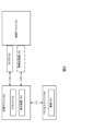
図1に概略的に示されるように、誘導デバイス100を含む例示的な可視化システムは、対象の外耳道EC内に位置決めされ、鼓膜TMなどの標的治療領域の視野を提供することができる。誘導デバイス100は、器具を外耳道ECに誘導するように構成することができる。実施形態では、誘導デバイス100は、反射鏡と同様に成形および機能することができる。誘導デバイス100は、器具を受容するためのチャネルまたは内腔120を画定する本体110を含む。チャネル120は、外耳道EC内に位置決めされている本体110の遠位端の開口部122で終結することができる。チューブ送達デバイスなどの器具は、チャネル120を通して挿入され、開口部122を通して外耳道ECに出ることができる。チャネル120は、本体110の近位端から遠位端までの直径を徐々に減少させる先細形状を有することができるか(例えば、反射鏡において)、または固定直径を有することができる。
As shown schematically in FIG. 1, an exemplary visualization system including a
誘導デバイス100は、外耳道EC内に収まるように解剖学的にサイズ決定され得る。例えば、誘導バイス100は、複数の異なるサイズで利用可能とすることができ、例えば、誘導デバイス100の開口部122は、4ミリメートル(mm)、4.5mm、5mm、6mm、7mm、またはそれらのサイズ内の任意の他のサイズである。誘導デバイス100は、単回使用のために設計されてもよく、または再使用可能とすることができる。
誘導デバイス100は、センサ130および光140を含む。センサ130は、光センサ、圧力センサ、温度センサ、または標的治療領域についての情報を捕捉することができる任意の他のタイプのセンサとすることができる。一実施形態では、センサ130は、相補型金属酸化膜半導体(complementary metal oxide semiconductor、CMOS)センサまたは電荷結合素子(charge-coupled device、CCD)センサなどの画像センサである。センサ130は、本体110の壁内に埋め込まれ得るように寸法決めされ得る。代替的に、センサ130は、本体110の外部表面または内部表面上に配設することができる。一実施形態では、センサ130は、約0.5mm~1mmの幅、および0.5mm~1mmの長さとすることができる。センサ130は、高解像度を提供することができる。例えば、センサ130は、40,000~160,000ピクセルのピクセル解像度を有することができる。センサ130は、弱光状態下で操作することができる。いくつかの実施形態では、センサ130は、90~120度の視界を有することができる。いくつかの実施形態では、センサ130は、5mm~30mmの焦点深度を有することができる。いくつかの実施形態では、センサ130は、例えば、少なくとも毎秒16フレームのフレームレートなど、動画捕捉を可能にするためのフレームレートを有することができる。電池などの低レベルの電源は、センサ130に電力供給するために使用することができる。
センサ130は、アナログ出力を生成することができ、例えば、センサ130は、センサ130によって捕捉される光の量に比例する電荷を生成することができる。センサ130は、このアナログ出力を別個の処理回路または追加的な処理のための計算デバイスに提供することができる。処理回路または計算デバイスは、ワイヤ、カプラなどを介してセンサ130に結合することができる。この構成により、本体110の遠位端に配置される構成要素が少なくなり、それにより、本体110の遠位端に配置され、かつ/または本体110の壁に一体化される必要がある構成要素のサイズを低減させる。サイズのこの低減は、開口部122を通して外耳道ECに挿入される器具に対するより大きな隙間を提供することができる。
Sensor 130 may produce an analog output, eg, sensor 130 may produce a charge proportional to the amount of light captured by sensor 130 . Sensor 130 may provide this analog output to separate processing circuitry or computing devices for additional processing. A processing circuit or computing device can be coupled to sensor 130 via a wire, coupler, or the like. This configuration results in fewer components being placed at the distal end of body 110, thereby requiring components to be placed at the distal end of body 110 and/or integrated into the wall of body 110. reduce the size of This reduction in size can provide greater clearance for instruments inserted into the ear canal EC through
図5に示される実施形態などのいくつかの実施形態では、センサ130は、本体110の近位端に位置決めすることができる。センサ130を本体110の近位端に移動することによって、本体110の遠位端における構成要素のサイズをさらに低減することができる。かかる実施形態では、光ファイバまたは別の伝送要素(例えば、ワイヤまたはケーブル)を使用して、本体110の遠位端からセンサ130へ光または画像データを伝送することができる。複数の光ファイバを一緒に束ねることで、パフォーマンスを向上させることができる。しかし、伝送された画像の解像度は、一緒に束ねることができるファイバの数によって制限されてもよく、これは誘導デバイス100のサイズによって制限することができる。一般に、小さな束内のファイバの数は、4,000~8,000ファイバの範囲とすることができる。光ファイバはまた、適切な画像転送を提供するために、より大量の光を必要とし得る。したがって、センサ130を本体110の遠位端に配設することが有益であり得る。
In some embodiments, such as the embodiment shown in FIG. 5, sensor 130 can be positioned at the proximal end of body 110 . By moving sensor 130 to the proximal end of body 110, the size of components at the distal end of body 110 can be further reduced. In such embodiments, optical fibers or another transmission element (eg, wire or cable) may be used to transmit light or image data from the distal end of body 110 to sensor 130 . Bundling multiple optical fibers together can improve performance. However, the resolution of the transmitted image may be limited by the number of fibers that can be bundled together, which can be limited by the size of the
誘導デバイス100はまた、センサ130によって捕捉された光を集中させるために使用することができるレンズ132も含む。レンズ132は、センサ130と一体化することができる。いくつかの実施形態では、一体化されたレンズ132を備えたセンサ130は、集積回路またはチップ上に装着することができ、これは本体110の遠位端に取り付けることができる。集積回路またはチップは、本体110の遠位端に簡単に装着することができるように可撓性とすることができる。いくつかの実施形態では、レンズ132は、センサ130から別個に組み立てられてて、例えば、より高い解像度、異なる視界または焦点深度などの追加的な可視化パフォーマンスを提供することができる。いくつかの実施形態では、可視化デバイス100は、ユーザがレンズ132の焦点距離を調節してパフォーマンスを変化させることを可能にし得る。いくつかの実施形態では、レンズ132はまた、例えば、敏感な解剖学的領域(例えば、より薄い組織領域)と、薬剤との相互作用によってブランチされた(例えば、エピネフリンの吸収をブランチする)領域とを識別するために望ましい場合など、光の特定の色をフィルタリングするようにも設計することができる。
光140は、外耳道ECおよび鼓膜TMに光を送達することができる。光140は、本体110の遠位端に配設することができ、例えば、光140は、本体110の遠位端に一体化することができる。光140は、小さい、高強度な、発光ダイオード(light-emitting diode、LED)とすることができる。いくつかの実施形態では、複数の光140は、本体110の遠位端に一体化することができる、かつ/または装着することができる。 Light 140 can deliver light to the ear canal EC and tympanic membrane TM. Light 140 can be disposed at the distal end of body 110 , for example, light 140 can be integrated into the distal end of body 110 . Light 140 can be a small, high intensity, light-emitting diode (LED). In some embodiments, multiple lights 140 can be integrated into and/or attached to the distal end of body 110 .
代替的にまたは追加的に、光は、別個の光源(図示せず)、例えば、手術室内の光源、モバイルデバイスまたは他のポータブルデバイスからの光源、もしくはヘッドライトなどの医師が着用する光源によって外耳道ECに提供することができる。光源は、耳の開口部の近くの領域を光で充満させることができ、光は、光ケーブル、光チューブ、または他の伝送要素を介して本体110の遠位端に伝送することができる。いくつかの実施形態では、光源100からの光を伝送要素に向けることができるように、1つ以上のカプラを使用して光源を伝送要素に接続することができる。かかる光の構成の例が図5に図示されており、その例のさらなる詳細を図5を参照して以下に提供する。
Alternatively or additionally, the light is directed into the ear canal by a separate light source (not shown), for example, a light source in the operating room, a light source from a mobile or other portable device, or a light source worn by the physician such as a headlight. Can be provided to EC. The light source can flood the area near the ear opening with light, which can be transmitted to the distal end of body 110 via a light cable, light tube, or other transmission element. In some embodiments, one or more couplers can be used to connect the light source to the transmission element so that the light from the
誘導デバイス100は、必要に応じてコントローラ170に結合することができる。コントローラ170は、必要に応じて表示装置172を含むことができる。コントローラ170は、電池または他のポータブル電源によって電力供給することができる。コントローラ170は、本体110の一部として結合および/または一体的に形成することができる。表示装置172は、鼓膜TMを含む標的治療領域の画像を表示することができる。いくつかの実施形態では、表示装置172は、標的治療領域のリアルタイムの視野を表示することができる。コントローラ170および表示装置172は、表示装置172からの耳内の視野および医師の実際の耳の視野が同じ視界内にあるように、誘導デバイス100に隣接して配設することができる。センサ130からの画像データは、ワイヤ(図示せず)を介して、もしくはBluetooth、WiFi、または他の無線伝送手段を介して無線で、表示装置172上に表示するための画像データを処理することができるコントローラ170に伝送することができる。
いくつかの実施形態では、コントローラ170は、イオン注入デバイス(例えば、図2のイオン注入デバイス180)に電力を供給するように構成することができる。イオン注入デバイスは、可視化システムに一体化することができ、かつ/またはコントローラ170は、コントローラ170がイオン注入デバイスの電極を有効にしてイオン注入溶液に電流を供給することができるように、イオン注入デバイスに結合することができる。例えば、イオント注入デバイス(例えば、電極、イオン注入を制御するための回路)の構成要素は、可視化システムに一体化することができ、コントローラ170を使用して、イオン注入デバイスを制御および電力を供給することができる。代替的に、コントローラ170は、ワイヤまたはケーブルを介してイオン注入デバイスに取り外し可能に結合することができる。コントローラ170は、ボタン、スイッチ、または電極を有効にするために作動することができる他の作動機構を含むことができる。いくつかの実施形態では、表示装置172は、医師が操作して電流の送達を有効にする、かつ制御することができる1つ以上のグラフィカルユーザインターフェース要素(例えば、ボタン、スケール、バー、パネル)を表示することができるタッチ感応表示装置とすることができる。コントローラ170は、イオン注入デバイスを介して送達される電流を監視し、イオン注入プロセスが完了したとき、および/または安全性の問題を検出したときに電流を自動的に停止することができる。例えば、コントローラ170は、センサ130、および/または誘導デバイス100もしくはイオン注入デバイス上に位置する他のセンサ(例えば、光センサ、温度センサ、圧力センサなど)からデータを受信し、異常(例えば、温度上昇、圧力上昇など)のデータを監視することができる。いくつかの実施形態では、コントローラ170は、単回使用のために設計することができる。例えば、コントローラ170は、電池、またはイオン注入手術およびその後のチューブ送達手術の前と最中に、単一のイオン注入手術および表示装置172に電力供給するのに十分な充電を有する他のポータブル電源を装備することができる。
In some embodiments, controller 170 may be configured to power an ion implantation device (eg, ion implantation device 180 of FIG. 2). The ion implantation device can be integrated into the visualization system and/or the controller 170 controls the ion implantation device such that the controller 170 enables the electrodes of the ion implantation device to supply current to the ion implantation solution. Can be attached to a device. For example, components of the ion implantation device (e.g., electrodes, circuitry for controlling ion implantation) can be integrated into the visualization system and controller 170 is used to control and power the ion implantation device. can do. Alternatively, controller 170 can be removably coupled to the ion implantation device via a wire or cable. The controller 170 can include buttons, switches, or other actuation mechanisms that can be actuated to activate the electrodes. In some embodiments, display device 172 includes one or more graphical user interface elements (e.g., buttons, scales, bars, panels) that can be manipulated by a physician to enable and control current delivery. can be a touch-sensitive display device capable of displaying The controller 170 can monitor the current delivered through the ion implantation device and automatically stop the current when the ion implantation process is completed and/or upon detecting a safety issue. For example, the controller 170 may receive data from the sensor 130 and/or other sensors (eg, light sensors, temperature sensors, pressure sensors, etc.) located on the
いくつかの実施形態では、誘導デバイス100は、図2に概略的に示されるように、別個の計算デバイス150に接続することができる。誘導デバイス100は、接続106によって表されるように、コネクタ102(例えば、ワイヤまたはケーブル)を介して計算デバイス150に接続することができる。代替的にまたは追加的に、誘導デバイス100は、接続108によって表されるように、計算デバイス150に情報を無線で通信することができる無線送信機104に結合することができる。誘導デバイス100は、接続106を介して電力供給することができ、または無線構成では、誘導デバイス100は、搭載型電池、または誘導デバイス100に電力を提供するための他のポータブル電源(例えば、コントローラ170のポータブル電源)を有することができる。誘導デバイス100は、接続部106および/または108を介して、センサ130からの画像データ、ならびに誘導デバイス100に結合された任意の他のセンサ(図示せず)からのデータを計算デバイス150に伝送することができる。計算デバイス150は、デスクトップコンピュータ、ラップトップ、タブレット、モバイルデバイスまたはポータブルデバイス、スマートフォン、または計算能力を有する任意の他のタイプのデバイスとすることができる。いくつかの実施形態では、計算デバイス150は、例えば、GoogleGlass(商標)などのウェアラブル表示装置とすることができる。
In some embodiments,
計算デバイス150は、プロセッサ152および表示装置154を含む。プロセッサ152は、センサ130からの画像データを処理して、表示装置154上に表示するための標的治療領域の画像を生成するように構成することができる。表示装置154は、医師が表示装置154と耳とを同じ視界で視認することができるように、耳下手術中に医師の視界内に位置決めすることができる。医師は、(例えば、誘導デバイス100を回転させることおよび/またはセンサ130を移動させることによって)表示装置154からの視野を調節することができ、かつ耳下手術中に標的治療領域の鮮明な視野を把握するために医師の手および/または器具の位置を別個に調節することができる。いくつかの実施形態では、プロセッサ152は、画像データをフィルタリングして、異なる構造および生理学的状態を選択的に視認するように構成することができる。例えば、レンズ132と同様に、プロセッサ152は、敏感な解剖学的領域(例えば、より薄い組織領域)と、薬剤との相互作用によってブランチされた(例えば、エピネフリンの吸収をブランチする)領域とを識別するために、光の波長をデジタル的にフィルタリングするように構成することができる。いくつかの実施形態では、プロセッサ152は、光140および/または他の光源(例えば、画像飽和がある場合の自動調光140)、所望の焦点を選択するための自動焦点調節レンズ132の光強度を変更することと、ノイズをフィルタリングすることと、エッジを強調することと、マージュをシャープにし、回転させることと、などによって標的治療領域の可視化を向上させるように構成することができる。
Computing device 150 includes a processor 152 and a display device 154 . Processor 152 may be configured to process image data from sensor 130 to generate an image of the target treatment area for display on display device 154 . The display 154 can be positioned within the physician's field of view during sub-auricular surgery so that the physician can see the display 154 and the ear in the same field of view. The physician can adjust the field of view from the display 154 (eg, by rotating the
いくつかの実施形態では、センサ130、レンズ132、および光140のうちの1つ以上を誘導デバイス100上で移動可能にすることができる。例えば、センサ130およびレンズ132は、誘導デバイス100上で回転するように設計することができる。センサ130およびレンズ132が回転すると、計算デバイス150は、プロセッサ152を介して、医師に提示された画像の向きが変化しないように標的治療領域の画像を回転させるように構成することができる。ジャイロスコープ、加速度計または他のタイプの移動センサ(図示せず)を、センサ130および/またはレンズ132に結合して、センサ130および/またはレンズ132の回転を感知することができる。ジャイロスコープからのデータは、接続106および/または108を介して計算デバイス150に伝送することができ、プロセッサ152は、データに基づいて、表示装置154上の標的治療領域の画像をいつ自動回転させるかを判定することができる。
In some embodiments, one or more of sensor 130 , lens 132 and light 140 may be movable on
いくつかの実施形態では、計算デバイス150は、画像センサ130を含む複数の画像センサからの画像データを受信することができる。例えば、追加的な画像センサは、誘導デバイス100の本体110、または外耳道EC内に挿入された他のデバイス(例えば、イオン注入デバイス、チューブ送達デバイス、スタイラス)に結合することができ、これらの追加的な画像センサからの画像データは、1つ以上の接続を介して計算デバイス150に送信することができる。計算デバイス150は、画像データを受信すると、標的治療領域の異なる視野を作成する。例えば、計算デバイス150は、表示装置154を介して、両眼視野を作成し、異なるセンサとカメラとの間を切り替え、画像データを使用して外耳道ECのより大きい、またはより鮮明な視野を構築するか、または複数の視野を同時(例えば、並んで、またはピクチャインピクチャ)に表示することができる。
In some embodiments, computing device 150 may receive image data from multiple image sensors, including image sensor 130 . For example, additional image sensors can be coupled to the body 110 of the
いくつかの実施形態では、計算デバイス150は、表示装置154上に表示された画像内の関心対象の領域を視覚的に識別することができる。例えば、計算デバイス150は、プロセッサ152を介して、中耳腔換気用チューブの配置の標的位置を識別することができる。代替的にまたは追加的に、計算デバイス150は、チューブ送達手術などの耳下手術を行うときに、回避する敏感な解剖学的構造の領域(例えば、前方突出部、薄い組織の領域)を強調表示することができる。 In some embodiments, computing device 150 can visually identify regions of interest in images displayed on display device 154 . For example, computing device 150, via processor 152, can identify a target location for placement of a tympanostomy tube. Alternatively or additionally, computing device 150 highlights areas of sensitive anatomy (e.g., anterior protrusions, areas of thin tissue) to avoid when performing parotid surgery, such as tube delivery surgery. can be displayed.
いくつかの実施形態では、計算デバイス150は、標的治療領域の画像および/または動画を保存するように構成することができる。保存された画像および/または動画は、後で医師が見直して問題を評価するか、またはトレーニング環境で使用する場合は教育ツールとして使用することができる。 In some embodiments, computing device 150 can be configured to store images and/or videos of the target treatment area. The stored images and/or videos can be later reviewed by a physician to assess problems or used as an educational tool when used in a training environment.
必要に応じて、計算デバイス150はまた、任意の接続182によって表されるように、イオン注入デバイス180に接続することもできる。イオン注入デバイス180は、可視化システムの一部を形成することができる(すなわち、誘導デバイス100または可視化システムの他の構成要素(単数または複数)に一体化することができる)か、またはイオン注入デバイス180は、計算デバイス150に取り外し可能に結合可能である別個のデバイスとすることができる。イオン注入デバイス180は、イオン注入手術を行うように構成することができる。イオン注入デバイス180、イオン注入溶液に電流を供給するための電極184を含むことができる。イオン注入システムの例は、2013年5月27日に登録された「System and Methods for Anesthetizing Ear Tissue」と題された、米国特許第8,452,392号、2014年9月23日に登録された「System and Methods for Anesthetizing Ear Tissue」と題された、ET.S.特許第8,840,602号、および2017年1月19日に公開された「Earplug Assembly for Iontophoresis System」と題された、ET.S.特許出願公開第2017/0014272号に開示されている。これらの参照の各々の開示は、参照により本明細書に組み込まれる。
If desired, computing device 150 may also be connected to ion implantation device 180 as represented by
計算デバイス150は、電極184を有効にするためにイオン注入デバイス180に電力を供給するように構成することができる。コントローラ170と同様に、計算デバイス150は、ボタン、スイッチ、または電極を有効にするために作動することができる他の作動機構を含むことができる。いくつかの実施形態では、表示装置154は、医師が操作して電流の送達を有効にする、かつ制御することができる1つ以上のグラフィカルユーザインターフェース要素(例えば、ボタン、スケール、バー、パネル)を表示することができるタッチ感応表示装置とすることができる。計算デバイス150は、イオン注入デバイスを介して送達される電流を監視し、イオン注入プロセスが完了した時および/または安全性の問題を検出した時に電流を自動的に停止することができる。例えば、計算デバイス150は、センサ130、および/または誘導デバイス100もしくはイオン注入デバイス上に位置する他のセンサ(例えば、光センサ、温度センサ、圧力センサなど)からデータを受信し、異常(例えば、温度上昇、圧力上昇など)のデータを監視することができる。
Computing device 150 may be configured to power ion implantation device 180 to enable electrode 184 . Similar to controller 170, computing device 150 may include buttons, switches, or other actuation mechanisms that may be actuated to activate the electrodes. In some embodiments, display device 154 includes one or more graphical user interface elements (e.g., buttons, scales, bars, panels) that can be manipulated by a physician to enable and control current delivery. can be a touch-sensitive display device capable of displaying Computing device 150 can monitor the current delivered through the ion implantation device and automatically stop the current when the ion implantation process is completed and/or upon detecting a safety issue. For example, the computing device 150 may receive data from the sensor 130 and/or other sensors (eg, light sensors, temperature sensors, pressure sensors, etc.) located on the
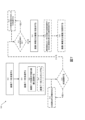
図3は、誘導デバイス200およびスタイラス260を含む可視化システムの別の実施例を概略的に示す。誘導デバイス200は、誘導デバイス100と類似しているが、その遠位端にセンサを含まない。遠位端にセンサがない場合、誘導デバイス200は、光伝送要素(例えば、光ファイバ、光など)のための、より多くの空間を有する。一実施形態では、誘導デバイス200は、反射鏡とすることができる。誘導デバイス200は、チャネル220、および器具を受容し、かつ器具を外耳道ECに誘導するための開口部222を画定する本体210を含む。例えば、器具は、図4に図示されるチューブ送達デバイス290などの中耳腔換気用チューブ送達デバイスとすることができる。
FIG. 3 schematically shows another example of a visualization system including a
誘導デバイス200は、外耳道ECおよび鼓膜TMに光を送達することができる1つ以上の光240を含む。光240は、本体210の遠位端に配設することができ、例えば、光240は、本体210の遠位端に一体化することができる。一実施形態では、光240は、LEDとすることができる。
スタイラス260は、センサ230およびレンズ232を含む。スタイラス260は、チャネル220および開口部222を介して、外耳道ECに挿入される器具に取り外し可能に結合可能とすることができる。例えば、スタイラス260は、チューブ送達デバイス(例えば、チューブ送達デバイス290)のシャフトに結合可能とすることができる。スタイラス260は、接着剤またはテープ、機械的留め具を介して、もしくは磁気的に、チューブ送達デバイスのシャフトに結合することができる。スタイラス260は、外耳道ECへの器具の挿入を妨げないように、小さな外形(例えば、直径約1.5mm~3mm)を有するように設計することができる。代替的に、いくつかの実施形態では、スタイラス260は、誘導デバイス200に結合することができる。
Stylus 260 includes
センサ230は、スタイラス260の遠位端に配設することができる。センサ230は、スタイラス260の壁に埋め込むことができるか、またはセンサ230は、スタイラス260の表面上に配設することができる。センサ130と同様に、センサ230は、CMOSまたはCCDセンサなどの画像センサとすることができる。センサ230は、センサ130と同様に寸法決めすることができ、同様の解像度、視界、焦点深度、およびフレームレートを提供することができる。センサ230は、処理回路または追加的な処理のための計算デバイスを分離するために提供されるアナログ出力(例えば、センサ230によって捕捉される光の量に比例する電荷)を生成することができる。処理回路または計算デバイスは、ワイヤ、カプラなどを介してスタイラス260およびセンサ230に結合することができる。この構成により、スタイラス260の遠位端に配置される構成要素が少なくなり、それにより、スタイラス260の遠位端に配置される必要がある構成要素のサイズを低減させる。
レンズ232は、レンズ132と同様とすることができ、センサ230によって捕捉された光を集中させるために使用することができる。レンズ232は、センサ230と一体化することができるか、またはレンズ232は、センサ230とは別個の構成要素とすることができる。センサ230およびレンズ232の両方を集積回路に装着することができる。いくつかの実施形態では、レンズ232は、関心対象の領域(例えば、敏感な解剖学的領域、ブランチされた組織)を識別するための光の特定の周波数または色をフィルタリングするように構成することができる。
Lens 232 can be similar to lens 132 and can be used to focus the light captured by
図4は、誘導デバイス200とスタイラス260と1つ以上の他のデバイスとの間の接続を概略的に図示する。誘導デバイス100と同様に、誘導デバイス200は、接続206によって表されるように、コネクタ202(例えば、ワイヤまたはケーブル)を介して計算デバイス250に接続することができる。スタイラス260は、接続207によって表されるように、コネクタ203(例えば、ワイヤまたはケーブル)を介して計算デバイス250に接続することができる。代替的にまたは追加的に、スタイラス260は、接続208によって表されるように、計算デバイス250に情報を無線で通信することができる無線送信機204に結合することができる。スタイラス260は、接続207を介して電力供給することができ、または無線構成では、スタイラス260は、搭載型電池、またはスタイラス260に電力供給することができる他のポータブル電源を有することができる。スタイラス260が搭載型電池を介して電力供給される場合、計算デバイス250(または別個のデバイス)は、スタイラス260を再充電するためのドッキングステーションを含むことができる。スタイラス260は、接続207および/または208を介して、センサ230からの画像データを計算デバイス250に伝送することができ、計算デバイス250は、デスクトップコンピュータ、ラップトップ、タブレット、モバイルデバイスまたはポータブルデバイス、スマートフォン、または計算能力を有する任意の他のタイプのデバイスとすることができる。いくつかの実施形態では、スタイラス260は、誘導デバイス100およびスタイラス260が異なる計算デバイスに接続されるように、計算デバイス250とは異なる計算デバイス(図示せず)に接続することができる。
FIG. 4 schematically illustrates connections between
スタイラス260は、結合292(例えば、機械的または磁気的結合)を介してチューブ送達デバイス290に結合することができる。チューブ送達デバイス290は、中耳腔換気用チューブ294を運び、中耳腔換気用チューブ294を鼓膜TMに配置するように構成されている。中耳腔換気用チューブ送達システムの例は、2011年11月8日に登録された「System and Method for the Simultaneous Automated Bilateral Delivery of Pressure Equalization Tubes」と題された、米国特許第8,052,693号、2014年10月21日に登録された「Tympanic Membrane Pressure Equalization Tube Delivery System」と題された、ET.S.特許第8,864,774号、2016年4月26日に登録された「Features to Improve and Sense Tympanic Membrane Apposition by Tympanostomy Tube Delivery Instrument」と題された、ET.S.特許第9,320,652号、2017年6月20日に登録された「Tympanostomy Tube Delivery Device with Cutting Dilator」と題された、米国特許第9,681,891号、2016年2月11日に公開された「Tympanostomy Tube Delivery Device with Rotatable Flexible Shaft」と題された、米国特許出願公開第2016/0038342号、および2017年12月5日に登録された「Tympanostomy Tube Delivery Device with Replaceable Shaft Portion」と題された、米国特許第9,833,360号に開示されている。これらの参照の各々の開示は、参照により本明細書に組み込まれる。 Stylus 260 can be coupled to tube delivery device 290 via coupling 292 (eg, mechanical or magnetic coupling). The tube delivery device 290 is configured to carry a tympanum ventilation tube 294 and place the tympanum ventilation tube 294 into the tympanic membrane TM. An example of a tube delivery system for tympanostomy ventilation is U.S. Pat. No., ET. S. ET. S. U.S. Patent No. 9,681,891, Feb. 11, 2016, entitled "Tympanostomy Tube Delivery Device with Cutting Dilator," issued Jun. 20, 2017; U.S. Patent Application Publication No. 2016/0038342, entitled "Tympanostomy Tube Delivery Device with Rotatable Flexible Shaft," published December 5, 2017, entitled "Tympanostomy Tube Delivery D; device with Replaceable Shaft Portion US Pat. No. 9,833,360 entitled The disclosure of each of these references is incorporated herein by reference.
計算デバイス250は、プロセッサ252および表示装置254を含む。プロセッサ252は、プロセッサ152と同様とすることができる。例えば、プロセッサ262は、センサ230からの画像データを処理して、表示装置254上に表示するための標的治療領域の画像を生成するように構成することができる。いくつかの実施形態では、プロセッサ252は、画像データをフィルタリングし、標的治療領域の可視化を向上させ(例えば、自動調光または自動焦点調節を介して、および/またはデータ処理アルゴリズムを介して)、関心対象の領域(例えば、中耳腔換気用チューブ294を配置するための標的位置、または回避する敏感な解剖学的構造)を視覚的に識別し、画像の保存などをするように構成することができる。
Computing device 250 includes processor 252 and display device 254 . Processor 252 may be similar to processor 152 . For example, processor 262 may be configured to process image data from
いくつかの実施形態では、スタイラス260の遠位端に提供されたセンサ230に加えて、誘導デバイス200の遠位端にセンサ(図示せず)を提供することができる。このような場合には、プロセッサ252は、誘導デバイス200上に位置するセンサによって提供される視野と、センサ230によって提供される視野との間の視野を切り替えるように構成することができる。誘導デバイス200上に位置するセンサによって提供される視野は、標的治療領域の角度を付けた視野とすることができ、センサ230によって提供される視野は、スタイラス260が結合されている器具の長さの下にある軸方向視野(例えば、以下でさらに説明される図13に示される例示的な視野など)とすることができる。
In some embodiments, a sensor (not shown) can be provided at the distal end of
必要に応じて、計算デバイス250は、任意の接続282によって表されるように、イオン注入デバイス280に接続することもできる。イオン注入デバイス280は、イオン注入手術を行うように構成することができる。イオン注入デバイス280、イオン注入溶液に電流を供給するための電極284を含むことができる。計算デバイス250は、電極284を有効にするように構成することができる。
If desired, computing device 250 may also be connected to ion implantation device 280 as represented by
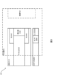
図5は、誘導デバイス300を含む可視化デバイスの別の実施例を概略的に図示する。誘導デバイス100および200と同様に、誘導デバイス300は、チャネル320、および器具を受容し、かつ器具を外耳道ECに誘導するための開口部322を画定する本体310を含む。実施形態では、誘導デバイス300は、反射鏡とすることができる。器具は、例えば、中耳腔換気用チューブ送達デバイスとすることができる。
FIG. 5 schematically illustrates another example of a visualization device that includes a
誘導デバイス300は、本体310の近位端に位置するセンサ330およびレンズ332を必要に応じて含むことができる。センサ130および230と同様に、センサ330は、CMOSまたはCCDセンサなどの画像センサとすることができる。センサ330は、本体310の壁に埋め込むことができるか、またはセンサ330は、本体310の表面上に配設することができる。センサ330は、センサ130および230と同様に寸法決めすることができ、同様の解像度、視界、焦点深度、およびフレームレートを提供することができる。センサ330は、処理回路または追加的な処理のための計算デバイスを分離するために提供されるアナログ出力(例えば、センサ330によって捕捉される光の量に比例する電荷)を生成することができる。処理回路または計算デバイスは、ワイヤ、カプラなどを介してスタイラス260およびセンサ230に結合することができる。この構成により、誘導デバイス300上に配置され、かつ/または誘導デバイス300に一体化される構成要素が少なくなり、それにより、誘導デバイス300の重量および/または誘導デバイス300の寸法を低減させる。
誘導デバイス300は、光ファイバまたは別の伝送手段(例えば、ワイヤまたはケーブル)などの1つ以上の伝送要素334を含み、これは、本体310の遠位端からセンサ320へ光または画像データを伝送するために使用することができる。光ファイバの場合には、複数の光ファイバを一緒に束ねることでパフォーマンスを向上させることができる。光ファイバによって伝送される光はまた、光ファイバの長さにわたって劣化する場合があるため、したがってその遠位端にセンサ330を有する誘導デバイス(例えば、誘導デバイス100)と比較したとき、標的治療領域の鮮明な画像をレンダリングするためにより多くの光が必要とされる場合がある。しかし、光ファイバまたは他の伝送手段は、センサ320よりもサイズが小さく、したがって、誘導デバイス300の遠位端に結合および/または一体化される構成要素のサイズを低減させることができる。これにより、開口部322を通して器具により大きな隙間を提供することができる。
レンズ332は、レンズ132および232と同様とすることができ、センサ330によって捕捉された光を集中させるために使用することができる。レンズ332は、センサ330と一体化することができるか、またはレンズ332は、センサ330とは別個の構成要素とすることができる。センサ330およびレンズ332の両方を集積回路に装着することができる。いくつかの実施形態では、レンズ332は、関心対象の領域(例えば、敏感な解剖学的領域、ブランチされた組織)を識別するための光の特定の周波数または色をフィルタリングするように構成することができる。
誘導デバイス300は、外耳道ECおよび鼓膜TMに光を提供するための光340を必要に応じて含むことができる。光340は、本体310の近位端に配設、および結合ならびに/または一体化することができる。光340は、LEDまたは他のタイプの光源とすることができる。代替的にまたは追加的に、誘導デバイス300から分離された光341を使用して、光を外耳道ECに提供することができる。例えば、光341は、手術室内の光源または医師が着用する光源(例えば、ヘッドライト)とすることができる。光341は、外耳道ECの開口部の近くの領域を光で充満させることができる。光340および/または341からの光は、伝送要素344(例えば、光ケーブル、光チューブ)を介して、本体310の遠位端に伝達することができる。いくつかの実施形態では、1つ以上の連結器(図示せず)を使用して、光341を光伝送要素344に結合し、かつ光を光341から光伝送要素344に向けることができる。
誘導デバイス300は、必要に応じてコントローラ370に結合することができる。コントローラ370は、コントローラ170と同様とすることができ、表示装置372、光373、および/またはカメラ374を必要に応じて含むことができる。コントローラ370は、電池または他のポータブル電源によって電力供給することができる。コントローラ370は、本体310の一部として結合および/または一体的に形成され得る。表示装置372は、鼓膜TMを含む標的治療領域の画像を表示することができる。いくつかの実施形態では、コントローラ370は、コントローラ170と同様に、電力をイオン注入デバイス(例えば、図2のイオン注入デバイス180)に供給するように構成することができる。
一実施形態では、コントローラ370は、モバイルデバイスとすることができる。モバイルデバイスは、専用ケース(図示せず)を介して誘導デバイス300に結合することができる。専用ケースは、画像カプラおよび光伝送要素、例えば、光伝送要素334および344を含むことができる。モバイルデバイスからの光(例えば、光373)は、カプラおよび伝送要素344を介して外耳道ECに伝送することができ、外耳道EC内からの光は、モバイルデバイス上のカメラ(例えば、カメラ374)が外耳道ECの画像を捕捉することができるように、伝送要素334を介してモバイルデバイスに伝送することができる。モバイルデバイスは、カメラによって捕捉された画像を処理し、医師が視認するための画像を表示することができる。この構成では、誘導デバイス300は、受動的要素として機能し、モバイルデバイスからの光を伝送し、かつ外耳道ECからモバイルデバイスまで光を戻すために使用される。モバイルデバイスおよび専用ケースは、医師が、耳下手術の前、最中、または後に、対象の耳の同じ視界においてモバイルデバイス上に表示された画像を視認することを可能にするように、反射鏡に隣接して配設するか、または、例えば、対象の頭または医師の腕に装着するなど、反射鏡の近くに位置決めすることができる。
In one embodiment, controller 370 may be a mobile device. A mobile device can be coupled to
図6は、本明細書に記載される可視化システムのいずれかなど、可視化システムを使用する方法400の流れ図である。方法400は、402において、スタイラス(例えば、スタイラス260)を誘導デバイスまたは器具に取り付けることを必要に応じて含むことができる。例えば、スタイラスは、標的治療領域の画像データを捕捉するために使用することができるセンサまたはカメラを含むことができる。いくつかの実施形態では、スタイラスは、標的治療領域に関連付けられた他のデータを捕捉するために使用することができる、他のセンサ(例えば、温度センサ、圧力センサなど)を含むことができる。
FIG. 6 is a flow diagram of a
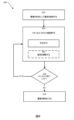
404において、誘導デバイス(例えば、誘導デバイス100、200、または300)およびスタイラスは、誘導デバイスに結合されている場合、対象の外耳道ECに位置決めすることができる。誘導デバイスは、器具を外耳道ECに受容し、かつ誘導するための内腔またはチャネル(例えば、チャネル120、220、または320)を画定することができる。誘導デバイスおよび/またはスタイラスは、1つ以上のカメラまたは光センサ(例えば、センサ130、230、または330)、カメラまたは光センサに関連付けられたレンズ(例えば、レンズ132、232、または332)を有することができる。誘導デバイスおよび/またはスタイラスはまた、1つ以上の光源(例えば、光140、240、または340)も有することができる。代替的にまたは追加的に、別個の光源(例えば、光341)を手術室に提供することができる。光源およびカメラは、406において、外耳道ECの標的治療領域の視野を1つ以上の表示装置(例えば、表示172、154、254、または372)上に提供するために、有効にすることができる。
At 404, the guidance device (eg,
提供される視野に応じて、レンズおよび/またはカメラの位置は、407において、標的治療領域の視野を改善するために必要に応じて調節することができる。この調節は、コントローラまたは計算デバイス(例えば、コントローラ170または370、もしくは計算デバイス150または250)によって自動的に制御することができるか、または調節は、医師が手動で行うことができる。 Depending on the field of view provided, the lens and/or camera position can be adjusted at 407 as needed to improve the field of view of the target treatment area. The adjustment can be automatically controlled by a controller or computing device (eg, controller 170 or 370, or computing device 150 or 250), or the adjustment can be made manually by the physician.
408において、耳下器具(例えば、チューブ送達デバイス290)およびスタイラスは、耳下器具に結合されている場合、外耳道ECに挿入することができる。耳下器具は、誘導デバイスによって画定された内腔またはチャネルを通して外耳道ECに挿入することができる。いくつかの実施形態では、耳下器具は、406において光およびカメラを有効にする前に、または407においてカメラおよび/またはレンズに対して調節が行われる前に、誘導デバイスに挿入することができ、すなわち、ステップ406および407の前にステップ408が発生し得る。
At 408, a parotid appliance (eg, tube delivery device 290) and stylus, if coupled to the parotid appliance, can be inserted into the ear canal EC. A parotid appliance may be inserted into the ear canal EC through a lumen or channel defined by the guiding device. In some embodiments, the parotid appliance can be inserted into the guidance device prior to enabling the light and camera at 406 or before adjustments are made to the camera and/or lens at 407. That is,
耳下器具の位置は、410において確認することができる。例えば、医師は、1つ以上の表示装置上で、標的治療領域および標的治療領域に対する器具の位置を視認し、必要であれば、412において医療手術(例えば、中耳腔換気用チューブの送達)を行うために器具が適切に位置決めされるまで、411において器具の位置を調節することができる。医師は、図1~図5に図示される可視化システムを参照して上述されているように、外耳道EC内のカメラおよびレンズの位置決めを前提として、カメラおよびレンズによって提供される視野を損なうことなく器具の位置を調節することができる。この構成により、医師は、外耳道ECおよび標的治療領域の自身の見通し線に依存することなく、直接的または顕微鏡を介して医療手術を行うことができる。いくつかの実施形態では、医師は、医療手術を行った後に、医療手術(例えば、中耳腔換気用チューブの送達)の正常完了を確認するために表示装置を使用することができる。 The position of the parotid appliance can be confirmed at 410 . For example, a physician may view the target treatment area and the position of the instrument relative to the target treatment area on one or more displays and, if necessary, perform medical surgery (e.g., delivery of a tympanostomy tube) at 412 . The position of the instrument can be adjusted at 411 until the instrument is properly positioned to perform the . Given the positioning of the camera and lens within the ear canal EC as described above with reference to the visualization system illustrated in FIGS. The position of the instrument can be adjusted. This configuration allows the physician to perform medical surgery directly or via a microscope without relying on his line of sight of the ear canal EC and the target treatment area. In some embodiments, a physician can use the display device after performing a medical procedure to confirm successful completion of the medical procedure (eg, delivery of a tympanostomy tube).
図7は、本明細書に記載される可視化システムのいずれかなど、可視化システムによって行われる方法500の流れ図である。可視化システムは、502において画像データを受信することができる。画像データは、外耳道ECに挿入されている誘導デバイス(例えば、誘導デバイス100、200、または300)またはスタイラス(例えば、スタイラス260)上に位置された1つ以上のセンサ(例えば、センサ130、230、または330)から得ることができる。504において、可視化システムは、画像データを処理する。可視化システムは、506において、画像データを外耳道ECおよび標的治療領域の表示可能な画像(単数または複数)に変換することができる。可視化システムはまた、必要に応じて、508において画像データをフィルタリングすることもできる。例えば、可視化システムは、敏感な解剖学的領域(例えば、より薄い組織領域)と、薬剤との相互作用によってブランチされた(例えば、エピネフリンの吸収をブランチする)領域とを識別するために、光の波長をデジタル的にフィルタリングすることができる。
FIG. 7 is a flow diagram of a
510において、可視化システムは、画質を改善するために、光源(例えば、光140、240、340、または341)に対して調節を行う必要があるかどうかを必要に応じて判定することができる。例えば、可視化システムは、外耳道ECへ送達される光を増加または低減させることによって、標的治療領域のより鮮明な視野を提供することができると判定し得る。この判定に基づいて、可視化システムは、511において、光源の増加または調光によって外耳道ECに送達される光の量を自動調節することができる。可視化システムはまた、必要に応じて、画質を改善するために、512においてカメラの感度を調節する必要があり得るかどうかを判定し、その判定に基づいて、513においてカメラの感度を向上または低減させることもできる。 At 510, the visualization system can optionally determine if adjustments need to be made to the light sources (eg, lights 140, 240, 340, or 341) to improve image quality. For example, the visualization system may determine that increasing or decreasing the light delivered to the ear canal EC can provide a clearer view of the target treatment area. Based on this determination, the visualization system can automatically adjust 511 the amount of light delivered to the ear canal EC by increasing or dimming the light source. The visualization system also determines, if necessary, whether the sensitivity of the camera may need to be adjusted at 512 to improve image quality, and increases or decreases the sensitivity of the camera at 513 based on that determination. You can also let
514において、可視化システムは、表示装置(例えば、表示装置172、154、254、または372)上に、外耳道ECおよび標的治療領域の画像(単数または複数)を表示することができる。必要に応じて、可視化システムはまた、516において、中耳腔換気用チューブを配置するための標的位置を識別し、かつ/または回避する敏感な解剖学的構造の領域(例えば、前方突出部、薄い組織の領域)を強調表示するために、外耳道ECおよび標的治療領域の画像(単数または複数)の上に視覚的な重ね合わせ箇所を表示することもできる。必要に応じて、可視化システムは、518において、外耳道ECおよび標的治療領域の画像(単数または複数)を将来の参照用に保存することができる。可視化システムは、局部メモリに画像(単数または複数)を保存するか、またはそれらをネットワークを介して保存用のデバイスまたはサーバに伝送することができる。 At 514, the visualization system can display the image(s) of the ear canal EC and the target treatment region on a display device (eg, display device 172, 154, 254, or 372). Optionally, the visualization system also identifies and/or avoids a target location for placement of the tympanostomy tube at 516, areas of sensitive anatomy (e.g., anterior protrusion, A visual overlay can also be displayed on the image(s) of the ear canal EC and the target treatment area to highlight the thin tissue area). If desired, the visualization system can save the image(s) of the ear canal EC and the target treatment region at 518 for future reference. The visualization system can store the image(s) in local memory or transmit them over a network to a device or server for storage.
図8は、本明細書に記載される可視化システムのいずれかなど、可視化システムを用いてイオン注入を行う方法600の流れ図を図示する。イオン注入デバイス(例えば、イオン注入デバイス180または280)は、対象の耳内に位置決めすることができる。イオン注入デバイスは、例えば、麻酔薬を含む薬液など、イオン注入薬液で耳を充填することができる。可視化システムは、イオン注入システムに結合し、602において、イオン注入溶液に電流を送達するためにイオン注入デバイスの電極(例えば、電極184または284)を有効にすることができる。可視化システムは、ボタン、スイッチ、または電極を有効にするために作動することができる他の作動機構を含むことができる。いくつかの実施形態では、可視化システムは、医師が操作して電流の送達を有効にする、かつ制御することができる1つ以上のグラフィカルユーザインターフェース要素(例えば、ボタン、スケール、バー、パネル)を表示することができる表示装置(例えば、表示装置172、154、254、または372)を含むことができる。
FIG. 8 illustrates a flow diagram of a
電極の有効後、可視化システムを使用して、604において、イオン注入プロセスを監視することができる。イオン注入プロセスの監視には、方法500を含むことができ、それによって外耳道ECおよび標的治療領域の画像(単数または複数)を捕捉し、かつ医師に表示することができる。画像(単数または複数)は、イオン注入手術がいつ完了するのかを識別するためにフィルタリングすることができる。例えば、麻酔薬または他の薬剤の送達は、標的治療領域への血流を低減させ、したがって、その領域(例えば、鼓膜TM)の組織をブランチさせ得る。可視化システムは、外耳道ECの画像(単数または複数)をフィルタリングして、ブランチングを強調表示し、イオン注入プロセスがいつ完了するかを医師が判定するのを支援することができる。いくつかの実施形態では、イオン性染料または他の色収縮成分を使用して、医師による可視化のために組織の色を強調させることもできる。
After enabling the electrodes, the ion implantation process can be monitored at 604 using a visualization system. Monitoring the ion implantation process can include
イオン注入プロセスを監視する間に、可視化システムは、電極によって送達される電流を必要に応じて調節することができる。例えば、可視化システムは、外耳道EC内の温度、圧力、または他の状態の増加などの安全上の問題を検出する場合、電流を停止し得る。可視化システムは、誘導デバイス、スタイラス、またはイオン注入デバイスに位置されている1つ以上のセンサ(例えば、光センサ、温度センサ、圧力センサなど)に接続し、かつセンサから受信したデータに基づいて、電極を無効にして電流を停止することができる。 While monitoring the ion implantation process, the visualization system can adjust the current delivered by the electrodes as needed. For example, the visualization system may stop the current if it detects a safety issue such as an increase in temperature, pressure, or other condition within the ear canal EC. The visualization system connects to one or more sensors (e.g., light sensors, temperature sensors, pressure sensors, etc.) located on the guidance device, stylus, or ion implantation device, and based on data received from the sensors: The current can be stopped by disabling the electrodes.
可視化システムは、606において、例えば、組織がブランチされた時を監視することによって、または医師にイオン注入プロセスが完了したという指示を促し、かつ/または受信することによって、イオン注入プロセスがいつ完了したかを判定することができる。可視化システムは、イオン注入プロセスが完了するまで、604において、イオン注入プロセスを監視し続けることができる。608において、イオン注入プロセスが完了したときに、可視化システムは電極を無効にすることができる。 The visualization system at 606 determines when the ion implantation process is complete, for example, by monitoring when the tissue is branched, or by prompting and/or receiving an indication from the physician that the ion implantation process is complete. It is possible to determine whether The visualization system can continue to monitor the ion implantation process at 604 until the ion implantation process is completed. At 608, the visualization system can disable the electrodes when the ion implantation process is complete.
図9Aおよび図9Bは、本明細書に記載される可視化システムのいずれかなど、可視化システムの一部を形成することができる例示的な誘導デバイス、例えば、反射鏡700の図を図示する。反射鏡700は、反射鏡700の遠位端729にある開口部722で終わる内腔(図示せず)を画定する先細本体710を含む。反射鏡700の遠位端729は、対象の外耳道ECに挿入することができる。反射鏡700は、多種のサイズで提供され、反射鏡700と外耳道ECとの間の解剖学的嵌合を確実にすることができる。内腔および開口部722は、器具(例えば、チューブ送達デバイス)を受容するように、かつそれを外耳道ECに誘導するように構成することができる。
9A and 9B illustrate views of an exemplary guidance device, eg,
反射鏡700は、1つ以上の光および/または光伝送要素740を含む。光740は、図9Bに示されるように、反射鏡700の遠位端729に一体化および/または結合されているLEDとすることができる。反射鏡700が外耳道ECに挿入されると、光740を有効にして外耳道EC内に光を提供することができる。反射鏡700はまた、例えば、CMOSセンサ730などのセンサを含む。CMOSセンサ730は、反射鏡700が外耳道ECに挿入されたときに、標的治療領域の画像データを捕捉することができるカメラとして機能することができる。CMOSセンサ730は、丸い形状であると図示されているが、他の実施形態では、CMOSセンサ730は、他の輪郭形状(例えば、正方形)を取ることができる。
開口部722は、反射鏡700のサイズに応じてサイズが異なってもよい。開口部722は、器具(例えば、チューブ送達デバイス)を受容するように十分にサイズ決めすることができる。一実施形態では、4mmの直径を有する反射鏡700は、CMOSセンサ730が約1mmの直径を有し、光740が約0.5mmの直径を有するとき、少なくとも2.5mmの直径750を有する開口部722を有することができる。
The
反射鏡の遠位端が図10Aおよび図10Bに示されるように斜角で終結される場合、器具の利用可能な開口部を(例えば、4mmの反射鏡で2.5mmよりも大きく)増大させることができる。図10Aおよび図10Bは、本明細書に記載される可視化システムのいずれかなど、可視化システムと共に使用することができる誘導デバイス、例えば、反射鏡800の別の実施例を図示する。反射鏡800は、反射鏡800の遠位端829にある開口部822で終わる内腔(図示せず)を画定する先細本体810を含む。開口部822は、斜角に形成することができる。反射鏡800の先細形状により、開口部822の斜視構成は、反射鏡700の開口部722と比較して、器具に対する追加的な隙間を提供することができる。具体的には、開口部822は、開口部722の直径750よりも大きな外径850および小径852を有することができる。
If the distal end of the reflector is terminated at a bevel as shown in FIGS. 10A and 10B, it increases the available aperture of the instrument (e.g., greater than 2.5 mm with a 4 mm reflector). be able to. 10A and 10B illustrate another example of a guidance device, eg,
反射鏡700と同様に、反射鏡800はまた、CMOSセンサ830および1つ以上の光および/または光伝送要素840も含む。
Similar to
図11は、本明細書に開示される可視化システムのいずれかなど、可視化システムの一部を形成することができる誘導デバイス、例えば、反射鏡900の別の実施例を概略的に図示する。反射鏡900は、外耳道ECに器具を受容し、かつ誘導するための内腔またはチャネル(図示せず)を形成することができる先細本体910を含む。本体910は、コネクタ990を介して、表示装置972を備えたコントローラ970に解放可能に結合することができる。コントローラ970は、コントローラ170または370と同様とすることができ、反射鏡900上に配設された1つ以上のセンサから画像データを受信するように、かつ外耳道EC内の標的治療領域の画像を表示装置972上に表示するように構成することができる。コントローラ970はまた、表示装置972上に表示される要素を変更する(例えば、表示装置の輝度または色設定を調節する)、および/またはコントローラ970に接続することができるイオン注入デバイス(図示せず)を有効にするために作動させることができる、1つ以上のボタン974を含む。
FIG. 11 schematically illustrates another example of a guidance device, eg,
示されるように、表示装置972は、本体910が耳に挿入されたときに、表示装置972が対象の耳と同じ視界内にあることができるように、本体910に隣接している。コネクタ990は、医師が表示装置972の角度を調節して、耳下手術の前、最中、または後に、表示装置972の自身の視野を改善することを可能にするヒンジまたはボールジョイントを含むことができる。コネクタ990はまた、医師がコントローラ970に対して反射鏡900を回転させることを可能にすることができる。いくつかの実施形態では、コネクタ990は、コントローラ970および表示装置972から反射鏡900の結合および/または分離(例えば、迅速な接続および切断)を可能にすることができ、その結果、反射鏡900は、異なるサイズおよび/または異なるセンサおよび光伝送要素を有する異なる反射鏡に置き換えることができる。
As shown, the
図12は、本明細書に開示される可視化システムのいずれかなど、可視化システムの一部を形成することができるスタイラス1060の実施例を図示する。スタイラス1060は、1つ以上の光源を含むことができる、および/または1つ以上の遠隔光源から外耳道ECへ光を伝送することができる反射鏡1010と共に使用することができる。スタイラス1060は、例えば、接着剤、機械的接続、および/または磁気接続を介して、チューブ送達デバイス1090のシャフト1091に取り外し可能に結合可能である。スタイラス1060は、画像データを捕捉することができるセンサ1030と、画像データを計算デバイス(図示せず)に伝送することができる無線送信機1064と、を含むことができる。したがって、スタイラスがチューブ送達デバイス1090に結合され、反射鏡1010によって画定された内腔またはチャネル1020を通して外耳道ECに挿入されると、スタイラス1060は、外耳道ECの画像データを捕捉し、かつその画像データを計算デバイスに無線伝送して、処理および表示することができる。チューブ送達デバイス1090は、ボタン1096を介して有効にされ、鼓膜TMに中耳腔換気用チューブを送達することができる。
FIG. 12 illustrates an
スタイラス1060は、例えば、円筒形状とすることができ、かつ約1.5mmの直径を有することができる。チューブ送達デバイス1090に結合されると、スタイラス1060の遠位端は、シャフト1091の遠位端の前で終結し、その結果、シャフト1091の端部の視野は、図13に示されるようになど、スタイラス1060を介して捕捉された画像で見ることができる。図13は、スタイラス1060を介して捕捉された外耳道ECの例示的な図を図示する。図13に図示される実施形態など、いくつかの実施形態では、チューブ送達デバイス1090のシャフト1091は、シャフト1091の端部を耳の解剖学的構造と識別するのに役立つマーク1092を含むことができる。
図14は、耳下手術中の医師の視点からの視界1100を概略的に示す。視界1100に示されるように、医師は、自身の手1182および1184、外耳1102、および可視化システムによって提供される耳の内側の耳内の視野1151を視認することができる。可視化システムは、耳に挿入することができる反射鏡1110を含む。反射鏡1110は、耳の画像データを捕捉し、かつその画像データを計算デバイス1150に送信して医師に表示することができるセンサまたは撮像デバイス(例えば、カメラ)を含むことができる。患者の近くに計算デバイス1150を位置決めすることによって、医師は、自身の手1182および1184、外耳1102、および可視化システムによって提供される耳内の視野1151を単一の視界1100で視認することができる。医師は、一方の手1184で反射鏡1110を保持することができ、もう片方の手で器具1190を保持することができる。可視化システムは、耳への自身の見通し線によって制限されることなく、医師が器具を操作することを可能にすることができる。
FIG. 14 schematically illustrates a
本明細書において様々な発明の実施形態が記載され、例示されてきたが、当業者は、本明細書に記載される機能を行うため、かつ/または結果および/または1つ以上の利点を取得するための多種の手段および/または構造を容易に展開することができ、かかる変形および/または変更の各々は、本明細書に記載の発明の実施形態の範囲内であると見なされる。より一般的には、当業者は、本明細書に記載されるすべてのパラメータ、寸法、材料、および構成が、例示的であることを意味し、実際のパラメータ、寸法、材料、および/または構成が、本発明の教示が使用される特定の1つまたは複数の用途に依存することを容易に理解するであろう。当業者は、本明細書に記載される特定の発明の実施形態に対する多くの等価物を認識し、または日常的な実験のみを使用して確認することができるであろう。したがって、前述の実施形態は、例としてのみ提示され、添付の特許請求の範囲およびその等価物の範囲内であり、本発明の実施形態は、特に記載および主張されている以外の方法で実施することができることを理解されたい。本開示の発明の実施形態は、本明細書に記載される個々の特徴、システム、物品、材料、キット、および/または方法を対象とする。加えて、かかる機能、システム、記事、材料、キット、および/または方法の2つ以上の任意の組み合わせは、かかる機能、システム、物品、材料、キット、および/または方法が相互に矛盾しない場合、本開示の発明の範囲内に含まれる。 While various inventive embodiments have been described and illustrated herein, it will be apparent to those skilled in the art to perform the functions described herein and/or obtain the results and/or advantages of one or more of the advantages described herein. A wide variety of means and/or structures for doing so may be readily deployed, and each such variation and/or modification is considered within the scope of the inventive embodiments described herein. More generally, those skilled in the art will understand that all parameters, dimensions, materials and configurations described herein are meant to be exemplary, and that actual parameters, dimensions, materials and/or configurations It will be readily appreciated, however, that the teachings of the present invention will depend on the particular application or applications in which they are used. Those skilled in the art will recognize, or be able to ascertain using no more than routine experimentation, many equivalents to the specific inventive embodiments described herein. Thus, the above-described embodiments are presented by way of example only, and within the scope of the appended claims and equivalents thereof, embodiments of the invention may be practiced otherwise than as specifically described and claimed. It should be understood that Inventive embodiments of the present disclosure are directed to each individual feature, system, article, material, kit, and/or method described herein. In addition, any combination of two or more of such features, systems, articles, materials, kits, and/or methods is not mutually exclusive unless such features, systems, articles, materials, kits, and/or methods are mutually exclusive; Included within the scope of the present disclosure.
また、様々な発明の概念が、1つ以上の方法として具現化されてもよく、その例が提供されている。方法の一部として行われる作用は、任意の好適な方法で順序付けられ得る。したがって、実施形態は、例示的な実施形態における連続的な作用として示されているが、作用が、いくつかの作用を同時に行うことを含み得る、示されたものとは異なる順序で行われるものを構築し得る。 Also, various inventive concepts may be embodied in one or more methods, examples of which are provided. Acts performed as part of a method may be ordered in any suitable manner. Thus, although the embodiments are shown as sequential acts in the exemplary embodiment, the acts may include performing some acts simultaneously, which may occur in a different order than that shown. can be constructed.
本明細書で定義および使用されるすべての定義は、辞書定義、参照により組み込まれる文書内の定義、および/または定義された用語の通常の意味を制御すると理解されるべきである。 All definitions and definitions used herein are to be understood to control dictionary definitions, definitions within documents incorporated by reference, and/or the ordinary meaning of the defined terms.
本明細書および特許請求の範囲で使用される場合、不定冠詞「a」および「an」は、それと反対に明確に示されない限り、「少なくとも1つ」を意味すると理解されるべきである。 As used in the specification and claims, the indefinite articles "a" and "an" shall be understood to mean "at least one," unless clearly indicated to the contrary.
本明細書および特許請求の範囲において使用される場合、「および/または」という語句は、そのように結合された要素の「いずれかまたは両方」、すなわち、ある場合には結合的に存在し、他の場合には分離的に存在する要素を意味すると理解されるべきである。「および/または」でリスト化された複数の要素は、同じように、すなわち、そのように結合された要素の「1つ以上」であると解釈されるべきである。「および/または」節によって具体的に識別された要素以外の他の要素は、具体的に識別された要素に関連するかどうかに関係なく、必要に応じて存在してもよい。したがって、非限定的な例として、「comprising(備える)」などの制限のない言語と組み合わせて使用される場合、「Aおよび/またはB」への言及は、一実施形態では、Aのみ(必要に応じてB以外の要素を含む)を指し、別の実施形態では、Bのみ(必要に応じてA以外の要素を含む)を指し、さらに別の実施形態では、AおよびBの両方(必要に応じて他の要素を含む)などを指すことができる。 As used herein and in the claims, the term "and/or" means "either or both" of the elements so conjoined, i.e., in some cases conjointly present In other cases it should be understood to mean separately existing elements. Multiple elements listed with "and/or" should be construed in the same fashion, ie, "one or more" of the elements so conjoined. Other elements other than the elements specifically identified by the "and/or" clause may optionally be present, whether related or unrelated to those elements specifically identified. Thus, as a non-limiting example, when used in conjunction with open-ended language such as "comprising," a reference to "A and/or B" may, in one embodiment, include only A (requires In another embodiment, it refers to only B (including elements other than A as appropriate), in yet another embodiment both A and B (including elements other than A as appropriate). (including other elements depending on the situation), etc.
本明細書および特許請求の範囲で使用される場合、「or(または)」は、上記で定義された「および/または」と同じ意味を有すると理解されるべきである。例えば、リスト内の項目を区切る場合、「または」または「および/または」は、包括的、すなわち、要素の数またはリストの少なくとも1つを含むが、複数、および必要に応じて、リスト化されていない追加の項目も含むものとして解釈されるものとする。「only one of(のうちの1つのみ)」または「exactly one of(のうちの正確に1つ)」などそれと反対に明確に示されている用語のみ、または特許請求の範囲で使用されている場合の「consisting of(からなる)」は、複数の要素または要素のリストのうちの正確に1つを含むことを指す。一般に、本明細書で使用される場合、「または」という用語は、「either(いずれか)」、「one of(のうちの1つ)」、「only one of(のうちの1つのみ)」、または「exactly one of(のうちの正確に1つ)」など、排他性のある用語が先行するとき、排他的な代替案(すなわち、「いずれか一方であるが両方ではない」)を示すものとしてのみ解釈されるものとする。「Consisting essentially(から本質的になる)」は、特許請求の範囲で使用される場合、特許法の分野で使用される通常の意味を有するものとする。 As used in the specification and claims, "or" should be understood to have the same meaning as "and/or" as defined above. For example, when delimiting items in a list, "or" or "and/or" is inclusive, i.e., includes at least one, but more than one, of the number or list of elements and, where appropriate, the listed shall be construed as including any additional items not included in the Only terms specifically indicated to the contrary, such as "only one of" or "exactly one of", or used in a claim "consisting of", if present, refers to containing exactly one of a plurality of elements or lists of elements. In general, as used herein, the term "or" includes the terms "either," "one of," "only one of , or "exactly one of", when preceded by an exclusive term, indicates an exclusive alternative (i.e., "either but not both") shall be construed only as "Consisting essentially" when used in the claims shall have its ordinary meaning as used in the field of patent law.
本明細書および特許請求の範囲で使用される場合、1つ以上の要素のリストに関連する「at least one(少なくとも1つ)」という語句は、要素のリスト内の要素のうちの任意の1つ以上から選択される少なくとも1つの要素を意味するが、必ずしも要素のリスト内に具体的にリストされているすべての要素のうちの少なくとも1つを含む必要はなく、要素のリスト内の要素の組み合わせを除外しないものとすることを理解されたい。また、この定義により、要素は、「at least one(少なくとも1つ)」という語句が、具体的に識別されたそれらの要素に関連するかどうかに関係なく、参照する要素のリスト内で具体的に識別された要素以外に必要に応じて存在し得ることも可能にする。したがって、非限定的な例として、「at least one of A and B(AおよびBの少なくとも1つ)」(または、同等に、「at least one of A or B(AまたはBの少なくとも1つ)」または同等に「at least one of A and/or B(Aおよび/またはBの少なくとも1つ)」)は、一実施形態では、少なくとも1つの、必要に応じて複数のAを含み、Bは存在しない(および必要に応じてB以外の要素を含む)指し、別の実施形態では、少なくとも1つの、必要に応じて複数のBを含み、Aは存在しない(および必要に応じてA以外の要素を含む)を指し、さらに別の実施形態では、少なくとも1つの、必要に応じて複数のAを含み、および少なくとも1つの、必要に応じて複数のBを含む(および必要に応じて他の要素を含む)などを指すことができる。
[付記項1]
装置であって、
近位端および遠位端を有し、かつ内腔を画定する、反射鏡と、
前記反射鏡の前記遠位端に対して遠位に配設された標的領域に入射光を提供するように構成された光源と、
前記標的領域から反射光を捕捉するように、かつ前記反射光に基づいて画像データを生成するように構成されたセンサと、
前記画像データに基づいて前記標的領域の画像を表示するように構成された表示装置であって、前記表示装置は、前記表示装置が前記反射鏡の前記内腔を通して器具を位置決めするユーザの視界内にあり、前記標的領域内に延在する前記器具の遠位端が、前記器具を位置決めしている間、前記ユーザによって視認されることを可能にするように、前記反射鏡の前記近位端に結合されている、表示装置と、を備える、装置。
[付記項2]
前記センサが、相補型金属酸化膜半導体(CMOS)センサである、付記項1に記載の装置。
[付記項3]
前記光源が、1つ以上の光ファイバを介して、前記標的領域に前記入射光を提供するように構成されている、付記項1に記載の装置。
[付記項4]
前記センサと一体化されており、かつ前記標的領域から前記反射光を集中させるように構成されているレンズをさらに備える、付記項1に記載の装置。
[付記項5]
前記反射鏡の前記遠位端から前記センサへ前記反射光を伝送するように構成された光ファイバをさらに備える、付記項1に記載の装置。
[付記項6]
前記光源が、発光ダイオードである、付記項1に記載の装置。
[付記項7]
前記表示装置を前記反射鏡の前記近位端に結合し、かつ少なくとも1つの軸に沿った、または少なくとも1つの軸の周りの前記表示装置の移動を可能にする結合要素をさらに備える、付記項1に記載の装置。
[付記項8]
前記結合要素が、前記反射鏡に対する前記表示装置の角度が調節され得るように、前記表示装置を前記反射鏡の前記近位端に回転可能に結合する、付記項7に記載の装置。
[付記項9]
前記結合要素が、前記表示装置が前記反射鏡の長手方向軸から半径方向にオフセットされるように、前記表示装置を前記反射鏡の前記近位端に結合する、付記項7に記載の装置。
[付記項10]
前記プロセッサが、前記標的領域の物理的状態が前記標的領域の前記画像において視認され得るように、前記画像データをフィルタリングするようにさらに構成されている、付記項1に記載の装置。
[付記項11]
前記プロセッサが、前記画像データ内の光飽和を検出することに応答して、前記光源によって提供される前記入射光を低減させるようにさらに構成されている、付記項1に記載の装置。
[付記項12]
前記プロセッサが、前記表示装置に、前記標的領域の前記画像上に視覚誘導要素を重ね合わせるようにさらに構成され、前記視覚誘導要素が、関心対象の1つ以上の領域を識別する、付記項1に記載の装置。
[付記項13]
前記センサまたは前記光源のうちの少なくとも一方が、前記標的領域の視野を調節するために回転するように構成され、前記プロセッサが、前記表示装置に、前記少なくとも1つのセンサまたは前記光源の回転に基づいて、前記標的領域の前記画像を回転させるようにさらに構成されている、付記項1に記載の装置。
[付記項14]
システムであって、
近位端および遠位端を有し、かつ器具を受容するように構成された内腔を画定する、誘導デバイスと、
入射光を標的領域に提供するように構成された光源と、
反射光を前記標的領域から捕捉するように、かつ前記反射光に基づいて画像データを生成するように構成されたセンサを含むスタイラスであって、前記スタイラスが前記誘導デバイスと解放可能に係合可能である、スタイラスと、
前記画像データを処理して、前記標的領域の画像を生成するように構成されたプロセッサと、
前記画像データに基づいて、前記標的領域の画像を表示するように構成された表示装置と、を備える、システム。
[付記項15]
前記センサが、前記スタイラスの遠位端に配設されている、付記項14に記載の装置。
[付記項16]
前記センサが、前記スタイラスの近位端に配設され、前記スタイラスが、前記スタイラスの遠位端から前記スタイラスの前記近位端に、前記反射光を伝送するように構成された光ファイバをさらに含む、付記項14に記載の装置。
[付記項17]
前記スタイラスが、前記誘導デバイスに機械的に結合されるように構成されている、付記項14に記載の装置。
[付記項18]
前記スタイラスが、約1.5mm~3mmの直径を有する少なくとも遠位端を有する、付記項14に記載の装置。
[付記項19]
方法であって、
誘導デバイスの遠位端を対象の外耳道に位置決めすることであって、前記誘導デバイスが、内腔を画定する、位置決めすることと、
光源を使用して、前記誘導デバイスの前記遠位端に対して遠位の標的領域を照明することと、
前記器具の遠位端を前記内腔を通して前記標的領域へ挿入することと、
前記誘導デバイスに解放可能に結合されたセンサを使用して、前記標的領域から反射光を捕捉することと、
ユーザが、前記誘導デバイスの前記内腔を通して前記器具を挿入している間、画像が前記ユーザの視界内にあるように、前記誘導デバイスの近位端に結合された表示装置を使用して、前記器具の前記遠位先端を含む前記標的領域の前記画像を表示することと、を含む、方法。
[付記項20]
前記器具が前記誘導デバイスの前記内腔を通して挿入されている間、前記センサが前記反射光を捕捉することができるように、前記センサを含むスタイラスを前記誘導デバイスに結合することをさらに含む、付記項19に記載の方法。
As used herein and in the claims, the phrase "at least one" in reference to a list of one or more elements includes any one of the elements in the list of elements. means at least one element selected from one or more, but not necessarily including at least one of all the elements specifically listed in the list of elements; It should be understood that combinations are not to be excluded. Also, by this definition, elements must be specifically identified in the list of elements they refer to, regardless of whether the phrase "at least one" relates to those elements specifically identified. It also allows that elements other than those identified in the can be present as needed. Thus, as a non-limiting example, "at least one of A and B" (or equivalently, "at least one of A or B or equivalently "at least one of A and/or B"), in one embodiment, includes at least one, optionally more than one A, and B is Refers to absent (and optionally including elements other than B), and in another embodiment including at least one, optionally more than one, B and A not present (and optionally including elements other than A) element), and in yet another embodiment includes at least one, optionally multiple A's, and at least one, optionally multiple B's (and optionally other element), etc.
[Appendix 1]
a device,
a reflector having a proximal end and a distal end and defining a lumen;
a light source configured to provide incident light to a target area disposed distal to the distal end of the reflector;
a sensor configured to capture reflected light from the target area and to generate image data based on the reflected light;
A display device configured to display an image of the target area based on the image data, the display device being within the field of view of a user as the display device positions an instrument through the lumen of the reflector. and the proximal end of the reflector to allow a distal end of the instrument extending into the target area to be viewed by the user while positioning the instrument. an apparatus comprising: a display device coupled to a display device;
[Appendix 2]
2. The apparatus of
[Appendix 3]
2. The apparatus of
[Appendix 4]
2. The apparatus of
[Appendix 5]
2. The apparatus of
[Appendix 6]
2. The device of
[Appendix 7]
A claim further comprising a coupling element coupling said display device to said proximal end of said reflector and enabling movement of said display device along or about at least one axis. 1. The device according to
[Appendix 8]
8. The apparatus of clause 7, wherein the coupling element rotatably couples the display device to the proximal end of the reflector such that the angle of the display device relative to the reflector can be adjusted.
[Appendix 9]
8. The apparatus of clause 7, wherein the coupling element couples the display device to the proximal end of the reflector such that the display device is radially offset from the longitudinal axis of the reflector.
[Appendix 10]
2. The apparatus of
[Appendix 11]
2. The apparatus of
[Appendix 12]
[Appendix 13]
At least one of the sensor or the light source is configured to rotate to adjust the field of view of the target area, and the processor instructs the display device based on the rotation of the at least one sensor or the light source. 2. The apparatus of
[Appendix 14]
a system,
a guide device having a proximal end and a distal end and defining a lumen configured to receive an instrument;
a light source configured to provide incident light to a target area;
A stylus including a sensor configured to capture reflected light from the target area and to generate image data based on the reflected light, the stylus releasably engageable with the guidance device. is a stylus and
a processor configured to process the image data to generate an image of the target area;
a display configured to display an image of the target area based on the image data.
[Appendix 15]
15. The device of clause 14, wherein the sensor is disposed at the distal end of the stylus.
[Appendix 16]
The sensor is disposed at a proximal end of the stylus, and the stylus further comprises an optical fiber configured to transmit the reflected light from a distal end of the stylus to the proximal end of the stylus. 15. The apparatus of clause 14, comprising:
[Appendix 17]
15. The apparatus of clause 14, wherein the stylus is configured to be mechanically coupled to the guidance device.
[Appendix 18]
15. The apparatus of clause 14, wherein the stylus has at least a distal end with a diameter of about 1.5mm to 3mm.
[Appendix 19]
a method,
positioning the distal end of the guidance device in the subject's ear canal, the guidance device defining a lumen;
illuminating a target area distal to the distal end of the guidance device using a light source;
inserting a distal end of the instrument through the lumen into the target area;
Capturing reflected light from the target area using a sensor releasably coupled to the guidance device;
using a display coupled to a proximal end of the guiding device such that an image is within the user's field of view while the user inserts the instrument through the lumen of the guiding device; displaying the image of the target area including the distal tip of the instrument.
[Appendix 20]
further comprising coupling a stylus including said sensor to said guiding device such that said sensor can capture said reflected light while said instrument is inserted through said lumen of said guiding device. Item 20. The method according to Item 19.
Claims (16)
前記反射鏡から間隔を開けたスタイラスと、
前記反射鏡の前記遠位端に対して遠位に配設された標的領域に入射光を提供するように構成された光源と、
前記標的領域から反射光を捕捉するように、かつ前記反射光に基づいて画像データを生成するように構成されたセンサと、
前記画像データに基づいて前記標的領域の画像を表示するように構成された表示装置であって、前記表示装置は、前記表示装置が前記反射鏡の前記内腔を通して器具を位置決めするユーザの視界内にあり、前記器具を位置決めしている間、前記標的領域内に延在する前記器具の遠位端が前記ユーザによって視認されることを可能にするように、前記反射鏡の前記近位端に結合されている、表示装置と、
を備え、
前記スタイラスが、前記光源及び/または前記センサを有する、装置。 a reflector having a proximal end and a distal end and defining a lumen;
a stylus spaced from the reflector;
a light source configured to provide incident light to a target area disposed distal to the distal end of the reflector;
a sensor configured to capture reflected light from the target area and to generate image data based on the reflected light;
A display device configured to display an image of the target area based on the image data, the display device being within the field of view of a user as the display device positions an instrument through the lumen of the reflector. at the proximal end of the reflector to allow a distal end of the instrument extending into the target area to be viewed by the user while positioning the instrument. a combined display device;
with
A device, wherein the stylus comprises the light source and/or the sensor.
(a)前記反射鏡に対する前記表示装置の角度が調節可能なように、前記表示装置を前記反射鏡の前記近位端に回転可能に結合する、かつ/または、(a) rotatably coupling the display to the proximal end of the reflector such that the angle of the display relative to the reflector is adjustable; and/or
(b)前記表示装置が前記反射鏡の長手方向軸から半径方向にオフセットされるように、前記表示装置を前記反射鏡の前記近位端に結合する、(b) coupling the display to the proximal end of the reflector such that the display is radially offset from the longitudinal axis of the reflector;
請求項7に記載の装置。8. Apparatus according to claim 7.
(a)前記プロセッサが、前記画像データ内の光飽和を検出することに応答して、前記光源によって提供される前記入射光を低減させるように構成されている、かつ/または、
(b)前記プロセッサが、前記表示装置に、前記標的領域の前記画像上に視覚誘導要素を重ね合わせるように構成され、前記視覚誘導要素が、関心対象の1つ以上の領域を識別する、請求項1から9のいずれか1項に記載の装置。 has a processor
(a) the processor is configured to reduce the incident light provided by the light source in response to detecting light saturation in the image data; and/or
(b) the processor is configured to cause the display device to superimpose visual guidance elements on the image of the target area, the visual guidance elements identifying one or more regions of interest; 10. Apparatus according to any one of claims 1-9 .
前記装置が、
前記画像データを処理して、前記標的領域の画像を生成するように構成されたプロセッサと、
前記画像データに基づいて、前記標的領域の画像を表示するように構成された表示装置と、
を備える、請求項1から11のいずれか1項に記載の装置。 the stylus is releasably engagable with the reflector;
said device comprising:
a processor configured to process the image data to generate an image of the target area;
a display device configured to display an image of the target area based on the image data;
12. The apparatus of any one of claims 1-11 , comprising:
前記スタイラスが、前記スタイラスの遠位端から前記スタイラスの前記近位端に、前記反射光を伝送するように構成された光ファイバをさらに含む、請求項1から12のいずれか1項に記載の装置。 the sensor is disposed at a proximal end of the stylus;
13. The stylus of any one of claims 1-12, wherein the stylus further comprises an optical fiber configured to transmit the reflected light from the distal end of the stylus to the proximal end of the stylus. Device.
Applications Claiming Priority (3)
| Application Number | Priority Date | Filing Date | Title |
|---|---|---|---|
| US201862617951P | 2018-01-16 | 2018-01-16 | |
| US62/617,951 | 2018-01-16 | ||
| PCT/US2019/013568 WO2019143587A1 (en) | 2018-01-16 | 2019-01-15 | Visualization devices and methods for otologic procedures |
Publications (3)
| Publication Number | Publication Date |
|---|---|
| JP2021510560A JP2021510560A (en) | 2021-04-30 |
| JPWO2019143587A5 JPWO2019143587A5 (en) | 2022-01-18 |
| JP7273830B2 true JP7273830B2 (en) | 2023-05-15 |
Family
ID=65279698
Family Applications (1)
| Application Number | Title | Priority Date | Filing Date |
|---|---|---|---|
| JP2020536682A Active JP7273830B2 (en) | 2018-01-16 | 2019-01-15 | Visualization device for parotid surgery |
Country Status (6)
| Country | Link |
|---|---|
| US (1) | US11839362B2 (en) |
| EP (1) | EP3740111A1 (en) |
| JP (1) | JP7273830B2 (en) |
| CN (1) | CN111511265A (en) |
| AU (1) | AU2019209147A1 (en) |
| WO (1) | WO2019143587A1 (en) |
Families Citing this family (3)
| Publication number | Priority date | Publication date | Assignee | Title |
|---|---|---|---|---|
| GB201706497D0 (en) * | 2017-04-25 | 2017-06-07 | Kwong Tsong Yun | New product |
| US11684341B1 (en) * | 2019-02-01 | 2023-06-27 | V.E.I.N., Llc | Point-of-care guidance system for diagnostic and therapeutic medical procedures |
| WO2020160550A1 (en) | 2019-02-01 | 2020-08-06 | Morris Christopher W | Vascular access guidance system and associated computer-based applications for vascular evaluation and training |
Citations (3)
| Publication number | Priority date | Publication date | Assignee | Title |
|---|---|---|---|---|
| WO2001028407A1 (en) | 1999-10-18 | 2001-04-26 | Universal Technologies International, Inc. | Hand-held, portable camera with adaptable lens system |
| WO2002056756A2 (en) | 2001-01-19 | 2002-07-25 | Framtidartaekni Ehf. | Hand-held digital imaging diagnostic and operational instrument with wireless transmission data of image |
| CN102122067A (en) | 2011-03-17 | 2011-07-13 | 天津市圣威科技发展有限公司 | Hand-held endoscope with liquid substance transmission channel and rotatable display |
Family Cites Families (39)
| Publication number | Priority date | Publication date | Assignee | Title |
|---|---|---|---|---|
| GB842965A (en) | 1957-10-15 | 1960-08-04 | George Johnstone Milligan | Improvements in and relating to applicators for liquid medicaments |
| US4034759A (en) | 1975-08-27 | 1977-07-12 | Xomed, Inc. | Moisture-expandable prosthesis |
| US4159719A (en) | 1977-05-09 | 1979-07-03 | Xomed, Inc. | Moisture-expandable ear wick |
| US4706682A (en) | 1985-08-21 | 1987-11-17 | Minnesota Mining And Manufacturing Company | External ear canal electrode to be placed proximate the tympanic membrane |
| US5300018A (en) | 1990-08-24 | 1994-04-05 | Apdyne Medical Company | Applicator means for the application of anesthetizing fluids and the like to the tympanic membrane |
| JPH05220111A (en) * | 1992-02-10 | 1993-08-31 | Machida Endscope Co Ltd | Medical deep part observing device |
| US5489286A (en) | 1992-07-28 | 1996-02-06 | Cinberg; James Z. | Antibiotic impregnated myringotomy ventilation tube |
| US5954682A (en) | 1996-09-25 | 1999-09-21 | Advanced Medical Instruments | Therapeutic applicator apparatus and method |
| US6045528A (en) | 1997-06-13 | 2000-04-04 | Intraear, Inc. | Inner ear fluid transfer and diagnostic system |
| US6358231B1 (en) | 1998-08-24 | 2002-03-19 | Biopolymer, Inc. | Transdermal anesthetizing solution and method and apparatus for anesthetizing the ear canal and tympanic membrane |
| US8197461B1 (en) | 1998-12-04 | 2012-06-12 | Durect Corporation | Controlled release system for delivering therapeutic agents into the inner ear |
| US6120484A (en) | 1999-02-17 | 2000-09-19 | Silverstein; Herbert | Otological implant for delivery of medicament and method of using same |
| US6770080B2 (en) * | 2001-04-26 | 2004-08-03 | Fenestra Medical, Inc. | Mechanically registered videoscopic myringotomy/tympanostomy tube placement system |
| US20120253267A1 (en) * | 2004-05-24 | 2012-10-04 | Reed Don C | Combined otic and medication dispenser and method for treating otic infections |
| US9770344B2 (en) | 2006-03-23 | 2017-09-26 | Imperial Innovations Ltd. | Reconstruction of anterior cruciate ligaments |
| US9387124B2 (en) | 2007-04-19 | 2016-07-12 | Tusker Medical, Inc. | Disposable iontophoresis system and tympanic membrane pain inhibition method |
| FI119531B (en) * | 2007-06-29 | 2008-12-15 | Optomed Oy | Creating an image |
| US8318817B2 (en) | 2008-07-21 | 2012-11-27 | Otonomy, Inc. | Controlled release antimicrobial compositions and methods for the treatment of otic disorders |
| US8840602B2 (en) | 2008-07-31 | 2014-09-23 | Acclarent, Inc. | Systems and methods for anesthetizing ear tissue |
| US8452392B2 (en) | 2008-07-31 | 2013-05-28 | Acclarent, Inc. | Systems and methods for anesthetizing ear tissue |
| EP3649995A1 (en) | 2009-07-15 | 2020-05-13 | Tusker Medical, Inc. | Tympanic membrane pressure equalization tube delivery system |
| US20110208161A1 (en) | 2009-08-13 | 2011-08-25 | Yehuda Ivri | Intracochlear drug delivery to the central nervous system |
| US8747883B2 (en) | 2010-06-02 | 2014-06-10 | Princeton Trade & Technology, Inc. | Medical item for long term drug release |
| TWI403302B (en) * | 2010-06-30 | 2013-08-01 | Three In One Ent Co Ltd | A portable otoscope |
| AU2012335072B2 (en) | 2011-11-09 | 2016-09-08 | Welch Allyn, Inc. | Digital-based medical devices |
| US9370448B2 (en) | 2012-06-15 | 2016-06-21 | Preceptis Medical, Inc. | Insertion system for deploying a ventilation device |
| US9710414B2 (en) | 2012-10-27 | 2017-07-18 | Ping Liang | Interchangeable wireless sensing apparatus for mobile or networked devices |
| US9320652B2 (en) * | 2013-03-14 | 2016-04-26 | Tusker Medical, Inc. | Features to improve and sense tympanic membrane apposition by tympanostomy tube delivery instrument |
| US9681891B2 (en) | 2013-03-14 | 2017-06-20 | Tusker Medical, Inc. | Tympanostomy tube delivery device with cutting dilator |
| WO2015168642A1 (en) | 2014-05-02 | 2015-11-05 | Labib Mohamed E | Drug-releasing device usable in mucosal body cavities |
| WO2015200923A2 (en) | 2014-06-27 | 2015-12-30 | The Trustees Of Columbia University In The City Of New York | Apparatus for perforation and aspiration of inner ear |
| US10195086B2 (en) | 2014-08-11 | 2019-02-05 | Tusker Medical, Inc. | Tympanostomy tube delivery device with rotatable |
| US9833360B2 (en) | 2014-08-12 | 2017-12-05 | Tusker Medical, Inc. | Tympanostomy tube delivery device with replaceable shaft portion |
| US9326668B1 (en) | 2014-08-15 | 2016-05-03 | Wisconsin Alumni Research Foundation | Otoscope providing improved ear canal access |
| US11576567B2 (en) | 2015-06-25 | 2023-02-14 | Wisconsin Alumni Research Foundation | Otoscope providing low obstruction electronic display |
| US10016304B2 (en) | 2015-07-16 | 2018-07-10 | Tusker Medical, Inc. | Earplug assembly for iontophoresis system |
| US20170239091A1 (en) | 2016-02-22 | 2017-08-24 | Altek Corporation | Eardrum incision device |
| CN105725955A (en) | 2016-04-06 | 2016-07-06 | 重庆金创谷医疗科技有限公司 | Gun type endoscope system capable of being connected with intelligent mobile device |
| WO2021011855A1 (en) | 2019-07-17 | 2021-01-21 | Tusker Medical, Inc. | Systems, devices, and methods for visualization during medical procedures |
-
2019
- 2019-01-15 EP EP19703486.1A patent/EP3740111A1/en active Pending
- 2019-01-15 US US16/961,353 patent/US11839362B2/en active Active
- 2019-01-15 WO PCT/US2019/013568 patent/WO2019143587A1/en unknown
- 2019-01-15 CN CN201980006220.6A patent/CN111511265A/en active Pending
- 2019-01-15 AU AU2019209147A patent/AU2019209147A1/en active Pending
- 2019-01-15 JP JP2020536682A patent/JP7273830B2/en active Active
Patent Citations (3)
| Publication number | Priority date | Publication date | Assignee | Title |
|---|---|---|---|---|
| WO2001028407A1 (en) | 1999-10-18 | 2001-04-26 | Universal Technologies International, Inc. | Hand-held, portable camera with adaptable lens system |
| WO2002056756A2 (en) | 2001-01-19 | 2002-07-25 | Framtidartaekni Ehf. | Hand-held digital imaging diagnostic and operational instrument with wireless transmission data of image |
| CN102122067A (en) | 2011-03-17 | 2011-07-13 | 天津市圣威科技发展有限公司 | Hand-held endoscope with liquid substance transmission channel and rotatable display |
Also Published As
| Publication number | Publication date |
|---|---|
| JP2021510560A (en) | 2021-04-30 |
| US20200337544A1 (en) | 2020-10-29 |
| AU2019209147A1 (en) | 2020-06-18 |
| WO2019143587A1 (en) | 2019-07-25 |
| US11839362B2 (en) | 2023-12-12 |
| EP3740111A1 (en) | 2020-11-25 |
| CN111511265A (en) | 2020-08-07 |
Similar Documents
| Publication | Publication Date | Title |
|---|---|---|
| JP6453470B2 (en) | Endoscope that can be deployed and jointed using a single-use port | |
| KR101569781B1 (en) | Disposable endoscopic access device and portable display | |
| EP3723578B1 (en) | Ear examination apparatus | |
| JP7273830B2 (en) | Visualization device for parotid surgery | |
| CN107405066B (en) | Apparatus and method for performing body imaging | |
| US9326668B1 (en) | Otoscope providing improved ear canal access | |
| WO2015191954A1 (en) | Encasement platform for smartdevice for attachment to endoscope | |
| CA2897712A1 (en) | Method for identifying objects in a subject's ear | |
| US20160000514A1 (en) | Surgical vision and sensor system | |
| CA3098271A1 (en) | New product | |
| US20190268574A1 (en) | Communication system for a retractor with a mounted camera | |
| WO2019049997A1 (en) | Endoscope system | |
| US20150223669A1 (en) | Multi-modal medical examining instrument and related method for enabling multiple examination modes | |
| JP2003299675A (en) | Surgial microscope with information system | |
| JP6444506B2 (en) | Image display control device, display device, and image display system | |
| JP4118650B2 (en) | Surgical observation device | |
| US20230072482A1 (en) | Speculum and otoscope | |
| EP2787333B1 (en) | Ear inspection device and method of determining a condition of a subject's ear | |
| JPH05203881A (en) | Image system for stereoscopy and image integration system for stereoscopy | |
| WO2019049998A1 (en) | Endoscope system | |
| KR20170038597A (en) | Multi functional wireless otoscope |
Legal Events
| Date | Code | Title | Description |
|---|---|---|---|
| RD03 | Notification of appointment of power of attorney |
Free format text: JAPANESE INTERMEDIATE CODE: A7423 Effective date: 20200826 |
|
| RD04 | Notification of resignation of power of attorney |
Free format text: JAPANESE INTERMEDIATE CODE: A7424 Effective date: 20200827 |
|
| A521 | Request for written amendment filed |
Free format text: JAPANESE INTERMEDIATE CODE: A523 Effective date: 20220107 |
|
| A621 | Written request for application examination |
Free format text: JAPANESE INTERMEDIATE CODE: A621 Effective date: 20220107 |
|
| A131 | Notification of reasons for refusal |
Free format text: JAPANESE INTERMEDIATE CODE: A131 Effective date: 20230130 |
|
| A521 | Request for written amendment filed |
Free format text: JAPANESE INTERMEDIATE CODE: A523 Effective date: 20230324 |
|
| TRDD | Decision of grant or rejection written | ||
| A01 | Written decision to grant a patent or to grant a registration (utility model) |
Free format text: JAPANESE INTERMEDIATE CODE: A01 Effective date: 20230410 |
|
| A61 | First payment of annual fees (during grant procedure) |
Free format text: JAPANESE INTERMEDIATE CODE: A61 Effective date: 20230428 |
|
| R150 | Certificate of patent or registration of utility model |
Ref document number: 7273830 Country of ref document: JP Free format text: JAPANESE INTERMEDIATE CODE: R150 |