JP7271210B2 - image forming device - Google Patents

image forming device Download PDF

Info

Publication number
JP7271210B2
JP7271210B2 JP2019019911A JP2019019911A JP7271210B2 JP 7271210 B2 JP7271210 B2 JP 7271210B2 JP 2019019911 A JP2019019911 A JP 2019019911A JP 2019019911 A JP2019019911 A JP 2019019911A JP 7271210 B2 JP7271210 B2 JP 7271210B2
Authority
JP
Japan
Prior art keywords
heating element
recording material
recording paper
image forming
length
Prior art date
Legal status (The legal status is an assumption and is not a legal conclusion. Google has not performed a legal analysis and makes no representation as to the accuracy of the status listed.)
Active
Application number
JP2019019911A
Other languages
Japanese (ja)
Other versions
JP2020126204A5 (en
JP2020126204A (en
Inventor
広宣 仁平
Current Assignee (The listed assignees may be inaccurate. Google has not performed a legal analysis and makes no representation or warranty as to the accuracy of the list.)
Canon Inc
Original Assignee
Canon Inc
Priority date (The priority date is an assumption and is not a legal conclusion. Google has not performed a legal analysis and makes no representation as to the accuracy of the date listed.)
Filing date
Publication date
Application filed by Canon Inc filed Critical Canon Inc
Priority to JP2019019911A priority Critical patent/JP7271210B2/en
Publication of JP2020126204A publication Critical patent/JP2020126204A/en
Publication of JP2020126204A5 publication Critical patent/JP2020126204A5/ja
Application granted granted Critical
Publication of JP7271210B2 publication Critical patent/JP7271210B2/en
Active legal-status Critical Current
Anticipated expiration legal-status Critical

Links

Images

Description

本発明は、複写機、レーザプリンタ等の画像形成装置に関し、特に両面印刷を行う場合における発熱体の切替え制御方法に関する。 The present invention relates to an image forming apparatus such as a copying machine and a laser printer, and more particularly to a heating element switching control method for double-sided printing.

従来、電子写真方式を用いた画像形成装置では、定着器が、長さの異なる発熱体を複数有し、かつ、電力を供給する発熱体を排他的に切替え可能に構成されている場合には、次のような発熱体の切替え制御が行われる。すなわち、画像形成装置では、記録材の搬送方向と直交する方向の幅に応じた適切な長さの発熱体に切り替えて電力が供給される。これにより、記録材が通過しない発熱体の非通紙部が昇温することによる発熱体及びその周辺の部材へのダメージを防止しつつ、画像形成装置の生産性低下も抑えて印刷ジョブを実施することができる。例えば、特許文献1では、通紙可能な記録材の最大の幅と、小サイズの記録材の幅とに対応した、複数の発熱体を有する構成の定着手段が開示されている。特許文献1では、記録材の幅と発熱体の長さとの関係から、記録材の幅に適した長さを有する発熱体に切り替えて、定着手段に電力を供給する方法が提案されている。 2. Description of the Related Art Conventionally, in an electrophotographic image forming apparatus, when a fixing device has a plurality of heating elements with different lengths and is configured to be able to exclusively switch the heating elements to which power is supplied, , the following heating element switching control is performed. That is, in the image forming apparatus, electric power is supplied by switching to a heating element having an appropriate length according to the width of the recording material in the direction perpendicular to the conveying direction. As a result, while preventing damage to the heating element and its peripheral members due to temperature rise in the non-paper-passing portion of the heating element through which the recording material does not pass, print jobs can be executed while suppressing a decrease in productivity of the image forming apparatus. can do. For example, Japanese Patent Application Laid-Open No. 2002-200002 discloses a fixing unit having a plurality of heating elements corresponding to the maximum width of a passable recording material and the width of a small size recording material. Japanese Patent Application Laid-Open No. 2002-200001 proposes a method of switching to a heating element having a length suitable for the width of the recording material and supplying electric power to the fixing unit, based on the relationship between the width of the recording material and the length of the heating element.

特開2001-100558号公報Japanese Unexamined Patent Application Publication No. 2001-100558

従来のような、記録材の幅に適した長さを有する発熱体に切り替えて定着手段に電力を供給する方法において、複数の記録材に対して両面印刷を行う場合がある。このような場合に、記録材の幅に応じて発熱体を切り替えようとすると、両面印刷されている複数の記録材の搬送状態によっては、適切に発熱体を切り替えることができない可能性があった。 In the conventional method of supplying electric power to the fixing means by switching to a heating element having a length suitable for the width of the recording material, double-sided printing may be performed on a plurality of recording materials. In such a case, if an attempt is made to switch the heating element according to the width of the recording material, there is a possibility that the heating element cannot be appropriately switched depending on the conveying state of a plurality of recording materials printed on both sides. .

本発明は、このような状況のもとでなされたもので、複数の記録材に対して両面印刷を行う場合に、複数の記録材の搬送状態を鑑みて発熱体を切り替えることを目的とする。 SUMMARY OF THE INVENTION The present invention has been made under such circumstances, and an object of the present invention is to switch a heating element in consideration of the conveying state of a plurality of recording materials when double-sided printing is performed on a plurality of recording materials. .

上述した課題を解決するために、本発明では、以下の構成を備える。 In order to solve the above problems, the present invention has the following configuration.

(1)記録材にトナー像を形成する画像形成手段と、第1の発熱体と、記録材の搬送方向と直交する方向である長手方向における長さが前記第1の発熱体よりも短い第2の発熱体と、を少なくとも有するヒータを備え、前記画像形成手段により記録材上に形成された未定着のトナー像を定着する定着手段と、前記ヒータの前記第1の発熱体又は前記第2の発熱体のいずれか一方に対して電力供給可能となるように電力供給経路を切り替える切替え手段と、前記切替え手段により切り替える前記電力供給経路を制御する制御手段と、を備え、複数の記録材に両面印刷を行う場合に、第1の記録材の第1面に画像を形成し、前記第1の記録材を両面搬送路に待機させ、前記第1の記録材に続く第2の記録材の第1面に画像を形成し、前記第1の記録材の第2面に画像を形成する画像形成装置であって、前記制御手段は、前記第1の記録材の前記長手方向における長さ、及び前記第2の記録材の前記長手方向における長さに基づき、前記第2の記録材の第1面、及び前記第1の記録材の第2面を前記定着手段により定着する場合の前記電力供給経路を制御し、前記定着手段が前記第2の記録材の第1面を定着した後、前記第1の記録材の第2面を定着するまでの間に、前記電力供給経路を切り替えないように制御することを特徴とする画像形成装置。 (1) image forming means for forming a toner image on a recording material; fixing means for fixing an unfixed toner image formed on a recording material by the image forming means; and the first heat generating element or the second heat generating element of the heater. switching means for switching a power supply path so that power can be supplied to any one of the heating elements; and control means for controlling the power supply path switched by the switching means. When double-sided printing is performed, an image is formed on the first surface of a first recording material, the first recording material is made to stand by on a double-sided conveying path, and a second recording material following the first recording material is printed. An image forming apparatus for forming an image on a first surface and forming an image on a second surface of the first recording material, wherein the control means controls the length of the first recording material in the longitudinal direction, and the electric power when fixing the first surface of the second recording material and the second surface of the first recording material by the fixing means based on the length of the second recording material in the longitudinal direction The power supply path is controlled, and the power supply path is not switched after the fixing means fixes the first surface of the second recording material until the second surface of the first recording material is fixed. An image forming apparatus characterized by controlling to :

本発明によれば、複数の記録材に対して両面印刷を行う場合に、複数の記録材の搬送状態を鑑みて発熱体を切り替えることができる。 According to the present invention, when double-sided printing is performed on a plurality of recording materials, the heating element can be switched in consideration of the conveying state of the plurality of recording materials.

実施例1、2の画像形成装置の構成を示す概略断面図Schematic cross-sectional view showing the configuration of the image forming apparatus of Examples 1 and 2. 実施例1、2の定着部の断面を示す模式図Schematic diagram showing a cross section of a fixing portion of Examples 1 and 2 実施例1、2の定着部の電力制御回路の構成を説明する模式図Schematic diagram for explaining the configuration of the power control circuit of the fixing unit of Examples 1 and 2. FIG. 実施例1、2の画像形成装置のシステム構成を示す制御ブロック図FIG. 2 is a control block diagram showing the system configuration of the image forming apparatuses of the first and second embodiments; 実施例1の画像形成装置の画像形成動作を示すタイミングチャート4 is a timing chart showing the image forming operation of the image forming apparatus according to the first embodiment; 実施例1の反転部の記録紙の様子を説明する図4A and 4B are diagrams for explaining the state of the recording paper in the reversing portion of the first embodiment; 実施例1の画像形成装置の画像形成動作を示すタイミングチャート4 is a timing chart showing the image forming operation of the image forming apparatus according to the first embodiment; 実施例1の電力を供給する発熱体を決定する制御シーケンスを示すフローチャート3 is a flow chart showing a control sequence for determining a heating element to which power is to be supplied according to the first embodiment; 実施例2の発熱体と記録紙幅センサの位置関係を説明する図FIG. 10 is a diagram for explaining the positional relationship between the heating element and the recording paper width sensor of the second embodiment; 実施例2の画像形成装置の画像形成動作を示すタイミングチャート6 is a timing chart showing the image forming operation of the image forming apparatus according to the second embodiment; 実施例2の電力を供給する発熱体を決定する制御シーケンスを示すフローチャート3 is a flow chart showing a control sequence for determining a heating element to which power is to be supplied according to the second embodiment; 実施例3の定着部の電力制御回路の構成を説明する模式図Schematic diagram for explaining the configuration of the power control circuit of the fixing unit of the third embodiment. 実施例3の電力を供給する発熱体を決定する制御シーケンスを示すフローチャート10 is a flow chart showing a control sequence for determining a heating element to which power is to be supplied according to the third embodiment;

以下に、図面を参照して本発明の実施の形態について詳細に説明する。 BEST MODE FOR CARRYING OUT THE INVENTION Below, embodiments of the present invention will be described in detail with reference to the drawings.

[画像形成装置の概要]
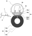
図1では、実施例1の画像形成装置の例として、レーザプリンタの全体構成について説明する。図1に示す画像形成装置は、4つの画像形成ステーション4a、4b、4c、4dを備えており、図中、左側からイエロー(Y)、マゼンタ(M)、シアン(C)、ブラック(K)のトナーを有する画像形成ステーションである。また、図中の符号の末尾のa、b、c、dは、それぞれイエロー(Y)、マゼンタ(M)、シアン(C)、ブラック(K)を意味する。画像形成手段である各画像形成ステーション4a~4dの構成は同じであり、以下の説明では、特に必要がない限り、a~dの符号は付さないこととする。図1に示す画像形成装置は、記録材に対してフルカラー画像又はモノクロ画像を形成することができる。ここで、記録材とは例えば、記録紙、OHPシート、布等が含まれる。以下、本実施例では記録紙に画像を形成する場合について説明する。
[Overview of Image Forming Apparatus]
FIG. 1 illustrates the overall configuration of a laser printer as an example of the image forming apparatus according to the first embodiment. The image forming apparatus shown in FIG. 1 has four image forming stations 4a, 4b, 4c, and 4d, and from the left in the figure, yellow (Y), magenta (M), cyan (C), and black (K). of toner. Also, the letters a, b, c, and d at the end of the symbols in the drawing denote yellow (Y), magenta (M), cyan (C), and black (K), respectively. The image forming stations 4a to 4d, which are image forming means, have the same configuration, and in the following description, the reference numerals a to d will be omitted unless particularly necessary. The image forming apparatus shown in FIG. 1 can form a full-color image or a monochrome image on a recording material. Here, recording materials include, for example, recording paper, OHP sheets, cloth, and the like. In this embodiment, the case of forming an image on recording paper will be described below.

(画像形成部)
画像形成部は、走査光学部材5、感光ドラム8、帯電器9、現像ローラ7、クリーニング装置10から構成される。像担持体である感光ドラム8は、アルミシリンダの外周に有機光導伝層を塗布して構成され、駆動源(不図示)の駆動力によって矢印の方向(反時計回り方向)に回転するように配設されている。感光ドラム8の周囲には、帯電器9、走査光学部材5、現像ローラ7、一次転写ローラ15、クリーニング装置10が配設されている。帯電器9は、感光ドラム8表面を一様に帯電する。走査光学部材5は、画像信号に基づいて生成された光を光路6に導き、感光ドラム8を露光し、静電潜像を形成する。現像ローラ7は、感光ドラム8表面に形成された静電潜像にトナーを付着させて、イエロー(Y)、マゼンタ(M)、シアン(C)、ブラック(K)のトナー像として顕像化する。一次転写ローラ15は、感光ドラム8上(感光ドラム上)のトナー像を中間転写体である中間転写ベルト11に転写する。これを一次転写という。クリーニング装置10は、中間転写ベルト11に転写されず、感光ドラム8表面に残留したトナーを除去する。クリーニング装置10は、上述した感光ドラム8に残留したトナー、又は中間転写ベルト11上(中間転写体上)に形成されたトナーを記録紙に転写した後に、中間転写ベルト11上に残留したトナー像を回収し、クリーナ容器に蓄える。
(Image forming section)
The image forming section comprises a scanning optical member 5 , a photosensitive drum 8 , a charger 9 , a developing roller 7 and a cleaning device 10 . The photosensitive drum 8, which is an image bearing member, is constructed by applying an organic photoconductive layer to the outer periphery of an aluminum cylinder, and is rotated in the direction of the arrow (counterclockwise direction) by the driving force of a driving source (not shown). are arranged. Around the photosensitive drum 8, a charger 9, a scanning optical member 5, a developing roller 7, a primary transfer roller 15, and a cleaning device 10 are arranged. The charger 9 uniformly charges the surface of the photosensitive drum 8 . The scanning optical member 5 guides the light generated based on the image signal to the optical path 6, exposes the photosensitive drum 8, and forms an electrostatic latent image. The developing roller 7 attaches toner to the electrostatic latent image formed on the surface of the photosensitive drum 8 and visualizes it as a yellow (Y), magenta (M), cyan (C), and black (K) toner image. do. A primary transfer roller 15 transfers the toner image on the photosensitive drum 8 (on the photosensitive drum) to an intermediate transfer belt 11 as an intermediate transfer member. This is called primary transcription. The cleaning device 10 removes toner remaining on the surface of the photosensitive drum 8 without being transferred onto the intermediate transfer belt 11 . The cleaning device 10 removes the toner image remaining on the intermediate transfer belt 11 after transferring the toner remaining on the photosensitive drum 8 or the toner formed on the intermediate transfer belt 11 (on the intermediate transfer body) to the recording paper. collected and stored in a cleaner container.

中間転写ベルト11は、支持ローラ11a、11bにより張架され、感光ドラム8に接触するように配設されている。中間転写ベルト11は、駆動源(不図示)によって矢印方向(時計回り方向)に回転し、一次転写ローラ15により感光ドラム8上のトナー像が転写される。二次転写部(転写部ともいう)は、記録紙を狭持搬送しつつ、記録紙に中間転写ベルト11上のトナー像を転写する。これを二次転写という。二次転写部は、転写ローラ11cが中間転写ベルト11に当接するように配設され、また、支持ローラ11bと対向する位置に配設されている。 The intermediate transfer belt 11 is stretched by support rollers 11 a and 11 b and arranged so as to contact the photosensitive drum 8 . The intermediate transfer belt 11 is rotated in the direction of the arrow (clockwise direction) by a drive source (not shown), and the toner image on the photosensitive drum 8 is transferred by the primary transfer roller 15 . A secondary transfer section (also referred to as a transfer section) transfers the toner image on the intermediate transfer belt 11 onto the recording paper while pinching and conveying the recording paper. This is called secondary transfer. The secondary transfer portion is arranged so that the transfer roller 11c contacts the intermediate transfer belt 11, and is arranged at a position facing the support roller 11b.

(給紙部)
給紙部1は、給紙カセット1cに収納された記録紙(記録材ともいう)を送り出す給紙ka、1bを有している。収納部としての給紙カセット1cは画像が形成される記録紙を収納する。給紙部1から送り出された記録紙はレジストセンサ17を経由し、二次転写部に到達する。給紙部2は、給紙部1と同様に、給紙カセット2cに収納された記録紙を送り出す給紙ローラ対2a、2bを有している。収納部としての給紙カセット2cは画像が形成される記録紙を収納する。給紙部1の下部に接続される給紙部2から給紙ローラ対2a、2bにより送り出された記録紙は、給紙部1の搬送路の一部と、レジストセンサ17を経由して二次転写部に到達する。
(Paper feed section)
The paper feed unit 1 has paper feeders ka and 1b for feeding recording paper (also referred to as recording material) stored in a paper feed cassette 1c. A paper feed cassette 1c as a storage unit stores recording paper on which an image is to be formed. The recording paper sent out from the paper feeding unit 1 passes through the registration sensor 17 and reaches the secondary transfer unit. The paper feed section 2, like the paper feed section 1, has a pair of paper feed rollers 2a and 2b for feeding recording paper stored in a paper feed cassette 2c. A paper feed cassette 2c as a storage unit stores recording paper on which an image is to be formed. The recording paper sent out from the paper feeder 2 connected to the lower part of the paper feeder 1 by the pair of paper feed rollers 2a and 2b passes through a part of the transport path of the paper feeder 1 and the registration sensor 17. It reaches the next transfer portion.

(定着部)
定着部50は、記録紙を加熱する定着ローラ51と、記録紙を定着ローラ51に圧接させるための加圧ローラ53とを備え、駆動手段であるモータ25によって矢印方向に回転するように配設されている。定着ローラ51内部にはヒータ54が内蔵されている。トナー像が転写された記録紙は、定着ローラ51と加圧ローラ53により搬送されると共に、熱及び圧力が加えられることにより、溶融したトナー像が記録紙の表面に定着される。排紙ローラ対13a、13b、及び排紙ローラ対18a、18bは、トナー像が定着した後の記録紙を排紙部14に排出する。
(fixing section)
The fixing unit 50 includes a fixing roller 51 that heats the recording paper and a pressure roller 53 that presses the recording paper against the fixing roller 51. The fixing unit 50 is arranged to rotate in the direction of the arrow by the motor 25 as driving means. It is A heater 54 is built inside the fixing roller 51 . The recording paper onto which the toner image has been transferred is conveyed by a fixing roller 51 and a pressure roller 53, and heat and pressure are applied to fix the fused toner image on the surface of the recording paper. A pair of discharge rollers 13a and 13b and a pair of discharge rollers 18a and 18b discharge the recording paper on which the toner image has been fixed to the paper discharge section 14. FIG.

(反転部)
反転手段である反転部は、定着部50よりトナー像が定着された記録紙の搬送方向を反転させる。反転部は、記録紙の搬送経路を変更するフラッパ19と、排紙ローラ対13a、13bによって搬送されてきた記録紙を引き入れる方向、又は反転経路28の方向に搬送するように構成された反転ローラ20a、20bを備えている。フラッパ19と反転ローラ20a、20bは、定着部50と同じ駆動源であるモータ25によって駆動されるように配設されている。フラッパ19、反転ローラ20a、20bと駆動部であるモータ25の間にはソレノイド27が設けられており、ソレノイド27によってフラッパ19の位置と反転ローラ20a、20bの回転方向が切り換えられる。ソレノイド27は、フラッパ19を図1の実線で示した位置と点線で示した位置に切り換えることができる。また、フラッパ19の位置と反転ローラ20a、20bの回転方向とは、連動するように構成されている。フラッパ19の位置が、図1の点線で示す位置にある場合には、反転ローラ20a、20bは反転部に記録紙を引き入れる方向に回転する。一方、フラッパ19の位置が、図1の実線で示す位置にある場合には、反転ローラ20a、20bは、記録紙を反転経路28に搬送する方向に回転する。
(reversal part)
The reversing section, which is reversing means, reverses the conveying direction of the recording paper on which the toner image is fixed by the fixing section 50 . The reversing unit includes a flapper 19 for changing the transport path of the recording paper, and a reversing roller configured to transport the recording paper transported by the pair of discharge rollers 13a and 13b in the direction of pulling in or in the direction of the reversing path 28. 20a and 20b. The flapper 19 and the reversing rollers 20 a and 20 b are arranged so as to be driven by a motor 25 which is the same drive source as the fixing section 50 . A solenoid 27 is provided between the flapper 19, the reversing rollers 20a and 20b, and the motor 25, which is a drive unit, and the solenoid 27 switches the position of the flapper 19 and the rotation direction of the reversing rollers 20a and 20b. A solenoid 27 can switch the flapper 19 between the position indicated by the solid line in FIG. 1 and the position indicated by the dotted line. Further, the position of the flapper 19 and the rotation directions of the reversing rollers 20a and 20b are configured to be interlocked. When the flapper 19 is at the position indicated by the dotted line in FIG. 1, the reversing rollers 20a and 20b rotate in the direction of drawing the recording paper into the reversing portion. On the other hand, when the flapper 19 is positioned at the position indicated by the solid line in FIG.

(再給紙部)
両面搬送路である反転経路28は、搬送ローラ対21a、21bと、搬送ローラ対22a、22bと、搬送ローラ対24a、24bと、各搬送ローラ対への駆動力伝達を制御するクラッチ(不図示)と、再給紙待機センサ23とを備えている。各搬送ローラ対21a/21b、22a/22b、24a/24bは、モータ26と、モータ26の駆動力供給を制御するクラッチと、によって駆動される。また、給紙部1の給紙ローラ対1a、1b、及び給紙部2の給紙ローラ対2a、2bも、搬送ローラ対と同様に、モータ26と、モータ26の駆動力供給を制御するクラッチと、によって駆動される。
(refeed unit)
The reversing path 28, which is a double-sided conveying path, includes conveying roller pairs 21a and 21b, conveying roller pairs 22a and 22b, conveying roller pairs 24a and 24b, and a clutch (not shown) that controls driving force transmission to each conveying roller pair. ) and a paper refeed waiting sensor 23 . Each transport roller pair 21a/21b, 22a/22b, 24a/24b is driven by a motor 26 and a clutch that controls the drive power supply of the motor 26. As shown in FIG. In addition, the pair of paper feed rollers 1a and 1b of the paper feed section 1 and the pair of paper feed rollers 2a and 2b of the paper feed section 2 also control the motor 26 and the supply of the driving force of the motor 26 in the same manner as the transport roller pair. driven by the clutch and

反転部の動作は、記録紙の搬送方向の反転、反転経路28内での所定位置までの搬送、反転経路内からレジストセンサ17への搬送、である。記録紙の搬送方向の反転動作において、反転部は、フラッパ19の位置を変更するソレノイド27を駆動し、定着部50によるトナー像を定着した後の記録紙の搬送方向を変更して、記録紙を反転ローラ20a、20bに導く。そして、反転部は、記録紙をフラッパ19より搬送方向の十分に下流の位置まで搬送した後、ソレノイド27を停止して、反転ローラ20a、20bの回転方向を変更して、記録紙を反転経路28の方向に搬送する。 The operation of the reversing section is reversal of the conveying direction of the recording paper, transportation to a predetermined position within the reversing path 28 , and transportation from the reversing path to the registration sensor 17 . In the reversing operation of the conveying direction of the recording paper, the reversing section drives the solenoid 27 for changing the position of the flapper 19, changes the conveying direction of the recording paper after the toner image is fixed by the fixing section 50, and changes the conveying direction of the recording paper. to the reversing rollers 20a and 20b. After conveying the recording paper to a sufficiently downstream position in the conveying direction from the flapper 19, the reversing section stops the solenoid 27 to change the rotating direction of the reversing rollers 20a and 20b so that the recording paper passes through the reversing path. 28 directions.

反転経路28内での所定位置までの搬送において、反転部は、クラッチ(不図示)を駆動して搬送ローラ対21a、21b、搬送ローラ対22a、22b、搬送ローラ対24a、24bに駆動力を供給して回転させる。そして、反転部は、再給紙待機センサ23が記録紙を検知した時点でクラッチ(不図示)を停止し、各搬送ローラ対への駆動力の供給を停止する。 During transport to a predetermined position in the reversing path 28, the reversing section drives a clutch (not shown) to apply driving force to the transport roller pairs 21a and 21b, the transport roller pairs 22a and 22b, and the transport roller pairs 24a and 24b. Feed and rotate. Then, the reversing section stops the clutch (not shown) when the re-feed waiting sensor 23 detects the recording paper, and stops the supply of driving force to each conveying roller pair.

反転経路28内からレジストセンサ17への搬送において、反転部は、クラッチ(不図示)を駆動して搬送ローラ対21a、21b、搬送ローラ対22a、22b、搬送ローラ対24a、24bに駆動力を供給して回転させる。そして、反転部は、レジストセンサ17が記録紙を検知した後、クラッチの駆動を停止する。 During transport from the reversing path 28 to the registration sensor 17, the reversing section drives a clutch (not shown) to apply driving force to the transport roller pairs 21a and 21b, the transport roller pairs 22a and 22b, and the transport roller pairs 24a and 24b. Feed and rotate. After the registration sensor 17 detects the recording paper, the reversing section stops driving the clutch.

[定着部の構成]
次に、実施例1における定着手段である定着部50の構成について図2を用いて説明する。ここで、長手方向とは、後述する用紙Pの搬送方向と略直交する加圧ローラ53の回転軸方向のことである。また、搬送方向に略直交する方向(長手方向)の用紙Pの長さを幅という。図2は、定着部50の断面模式図である。図2左側から未定着のトナー像Tを保持した用紙Pが、定着ニップ部Nにおいて図中左から右に向けて搬送されながら加熱されることにより、トナー像Tが用紙Pに定着される。実施例1における定着部50は、円筒状のフィルムである定着ローラ51と、定着ローラ51を保持するニップ形成部材52と、定着ローラ51とともに定着ニップ部Nを形成する加圧ローラ53と、用紙Pを加熱するためのヒータ54とにより構成されている。
[Structure of Fixing Section]
Next, the configuration of the fixing section 50, which is the fixing means in the first embodiment, will be described with reference to FIG. Here, the longitudinal direction is the rotation axis direction of the pressure roller 53 which is substantially orthogonal to the sheet P conveying direction, which will be described later. Also, the length of the paper P in the direction (longitudinal direction) substantially perpendicular to the transport direction is called the width. FIG. 2 is a schematic cross-sectional view of the fixing section 50. As shown in FIG. The toner image T is fixed on the paper P by heating the paper P holding the unfixed toner image T from the left side of FIG. The fixing unit 50 in the first embodiment includes a fixing roller 51 that is a cylindrical film, a nip forming member 52 that holds the fixing roller 51, a pressure roller 53 that forms a fixing nip portion N together with the fixing roller 51, and a paper sheet. and a heater 54 for heating P.

定着ローラ51(第1の回転体)は加熱回転体としての定着フィルムである。実施例1では、基層として、例えばポリイミドを用いている。基層の上に、シリコーンゴムからなる弾性層、PFAからなる離型層を用いている。定着ローラ51の回転によるニップ形成部材52及びヒータ54と定着ローラ51との間に生じる摩擦力を低減するために、定着ローラ51の内面には、グリスが塗布されている。 The fixing roller 51 (first rotating body) is a fixing film as a heating rotating body. In Example 1, polyimide, for example, is used as the base layer. An elastic layer made of silicone rubber and a release layer made of PFA are used on the base layer. The inner surface of the fixing roller 51 is coated with grease in order to reduce the frictional force generated between the fixing roller 51 and the nip forming member 52 and the heater 54 due to the rotation of the fixing roller 51 .

ニップ形成部材52は定着ローラ51を内側からガイドするとともに、定着ローラ51を介して加圧ローラ53との間で定着ニップ部Nを形成する役割を果たす。ニップ形成部材52は剛性・耐熱性・断熱性を有する部材であり、液晶ポリマー等により形成されている。定着ローラ51はこのニップ形成部材52に対して外嵌されている。加圧ローラ53(第2の回転体)は加圧回転体としてのローラである。加圧ローラ53は、芯金53a、弾性層53b、離型層53cからなる。加圧ローラ53は、両端を回転可能に保持されており、定着モータでもあるモータ25(図1参照)によって回転駆動される。また、加圧ローラ53の回転により、定着ローラ51は従動回転する。加熱部材であるヒータ54は、ニップ形成部材52に保持され、定着ローラ51の内面と接している。 The nip forming member 52 serves to guide the fixing roller 51 from the inside and form a fixing nip portion N with the pressure roller 53 via the fixing roller 51 . The nip forming member 52 is a member having rigidity, heat resistance, and heat insulation, and is made of liquid crystal polymer or the like. The fixing roller 51 is fitted onto the nip forming member 52 . The pressure roller 53 (second rotating body) is a roller as a pressing rotating body. The pressure roller 53 is composed of a metal core 53a, an elastic layer 53b, and a release layer 53c. The pressure roller 53 is rotatably held at both ends and is rotationally driven by a motor 25 (see FIG. 1) which is also a fixing motor. Further, the fixing roller 51 is driven to rotate by the rotation of the pressure roller 53 . A heater 54 that is a heating member is held by the nip forming member 52 and is in contact with the inner surface of the fixing roller 51 .

ヒータ54は加熱部材である。ヒータ54はニップ形成部材52に保持され、定着ローラ51の内面と接している。また、定着温度センサ59はサーミスタであり、ヒータ54の温度を検知する。定着温度センサ59は、ヒータ54の基板54aに対して保護ガラス層54eと反対側の面に位置し、かつ長手方向の長さの異なる発熱体54b1、54b2の長手方向の中心位置に設置され、基板54aと接している。 A heater 54 is a heating member. The heater 54 is held by the nip forming member 52 and is in contact with the inner surface of the fixing roller 51 . A fixing temperature sensor 59 is a thermistor and detects the temperature of the heater 54 . The fixing temperature sensor 59 is located on the surface of the substrate 54a of the heater 54 opposite to the protective glass layer 54e, and is installed at the longitudinal center position of the heating elements 54b1 and 54b2 having different lengths in the longitudinal direction, It is in contact with the substrate 54a.

[定着部の制御回路]
図3は、定着部50の電力供給を制御する電力制御回路の模式図である。定着部50の電力制御回路は、発熱体54b1、54b2、双方向サイリスタ(以下、トライアックという)56、発熱体切替え器57を有している。ヒータ54は、第1の発熱体である発熱体54b1、及び第2の発熱体である発熱体54b2を有し、長手方向の長さは、発熱体54b1は発熱体54b2よりも長い。本実施例では、発熱体54b1、54b2の長手方向の長さは、それぞれ、A4サイズ、A5サイズの記録紙の幅(長手方向の長さ)とする。スイッチ手段であるトライアック56は、一端を交流電源55に接続され、他端をヒータ54の発熱体54b1及び発熱体54b2と接続された端子に接続され、交流電源55から発熱体54b1、又は発熱体54b2への電力の供給/遮断を行う。切替え手段である発熱体切替え器57は、交流電源55とヒータ54の発熱体54b1、又は発熱体54b2とを接続するリレーであり、本実施例ではC接点リレーを用いている。発熱体切替え器57は、発熱体54b1に接続された端子54d1、又は発熱体54b2に接続された端子54d2を切り替えることによって、交流電源55からの電力供給先を発熱体54b1、54b2のどちら一方を排他的に選択する。トライアック56、及び発熱体切替え器57により、発熱体54b1、又は発熱体54b2へ電力供給可能となるように電力供給経路が形成される。発熱体切替え器57は、初期状態は、発熱体54b1側に交流電源55からの電力が供給可能な状態にあるものとする。なお、C接点リレーである発熱体切替え器57の接点溶着を防止するため、発熱体切替え器57の切替えは、トライアック56による発熱体54b1、54b2への電力供給が確実に遮断されている状態で行われる。
[Control Circuit of Fixing Section]
FIG. 3 is a schematic diagram of a power control circuit that controls power supply to the fixing section 50. As shown in FIG. The power control circuit of the fixing section 50 has heating elements 54 b 1 and 54 b 2 , a bidirectional thyristor (hereinafter referred to as triac) 56 and a heating element switching device 57 . The heater 54 has a heating element 54b1 that is a first heating element and a heating element 54b2 that is a second heating element, and the heating element 54b1 is longer than the heating element 54b2 in the longitudinal direction. In this embodiment, the longitudinal lengths of the heating elements 54b1 and 54b2 are the widths (longitudinal lengths) of A4 size and A5 size recording paper, respectively. One end of the triac 56, which is a switch means, is connected to the AC power supply 55, and the other end is connected to terminals connected to the heating elements 54b1 and 54b2 of the heater 54. It supplies/shuts off power to 54b2. A heating element switching device 57, which is switching means, is a relay that connects the AC power supply 55 and the heating element 54b1 or 54b2 of the heater 54, and in this embodiment, a C-contact relay is used. The heating element switching unit 57 switches the terminal 54d1 connected to the heating element 54b1 or the terminal 54d2 connected to the heating element 54b2 to select either one of the heating elements 54b1 and 54b2 as the power supply destination from the AC power supply 55. Select exclusively. A power supply path is formed by the triac 56 and the heating element switch 57 so that power can be supplied to the heating element 54b1 or the heating element 54b2. It is assumed that the heating element switching device 57 is in a state in which power can be supplied from the AC power supply 55 to the heating element 54b1 side in the initial state. In order to prevent contact welding of the heating element switching device 57, which is a C-contact relay, switching of the heating element switching device 57 is performed in a state in which the power supply to the heating elements 54b1 and 54b2 by the triac 56 is surely cut off. done.

[画像形成装置のシステム構成]
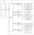
図4は、図1で示した画像形成装置を制御するシステム構成を示す制御ブロック図である。プリンタコントローラ200は、ホストコンピュータ等の外部装置からの画像コードを含む印刷指令を受信し、受信した画像コードを印刷に必要なビットデータに展開する。また、プリンタコントローラ200は、エンジン制御部201とのシリアル通信によってエンジン制御部201の内部情報を読み取り、読み取った内部情報を表示部(不図示)に表示する。制御手段であるエンジン制御部201は、プリンタコントローラ200とのシリアル通信によって制御指示情報を受信し、プリンタコントローラ200から受信した制御指示情報に基づいて、次に説明する各制御部の制御を行う。
[System Configuration of Image Forming Apparatus]
FIG. 4 is a control block diagram showing a system configuration for controlling the image forming apparatus shown in FIG. The printer controller 200 receives a print command including an image code from an external device such as a host computer, and develops the received image code into bit data necessary for printing. The printer controller 200 also reads internal information of the engine control unit 201 through serial communication with the engine control unit 201, and displays the read internal information on a display unit (not shown). The engine control unit 201, which is control means, receives control instruction information through serial communication with the printer controller 200, and controls each control unit described below based on the control instruction information received from the printer controller 200. FIG.

画像形成制御部202は、エンジン制御部201からの指示に基づいて、帯電器9、現像ローラ7、一次転写ローラ15の駆動及び停止、画像形成ステーション4が有する走査光学部材5の駆動及び停止を行う。また、画像形成制御部202は、走査光学部材5がプリンタコントローラ200からの画像信号に応じて、各感光ドラム8を走査するレーザ光の点滅を制御し、中間転写ベルト11上にトナー像を形成させる。 Based on instructions from the engine control unit 201, the image forming control unit 202 drives and stops the charger 9, the developing roller 7, and the primary transfer roller 15, and drives and stops the scanning optical member 5 of the image forming station 4. conduct. Further, the image forming control unit 202 controls flickering of laser light for scanning the photosensitive drums 8 by the scanning optical member 5 according to an image signal from the printer controller 200 to form a toner image on the intermediate transfer belt 11 . Let

転写制御部203は、エンジン制御部201からの指示に基づいて、二次転写部の転写ローラ11c、支持ローラ11bの駆動及び停止を制御し、中間転写ベルト11上に形成されたトナー像を記録紙に転写する。 The transfer control unit 203 controls driving and stopping of the transfer roller 11c and the support roller 11b of the secondary transfer unit based on instructions from the engine control unit 201, and records the toner image formed on the intermediate transfer belt 11. Transfer to paper.

給紙制御部204は、エンジン制御部201からの指示に基づいて、給紙部1及び給紙部2が有するピックアップソレノイド及び給紙モータでもあるモータ26を制御し、給紙部1及び給紙部2内に積載された記録紙をレジストセンサ17に向かって給紙する。 Based on instructions from the engine control unit 201, the paper feed control unit 204 controls the motor 26, which is also a pickup solenoid and a paper feed motor, of the paper feed unit 1 and the paper feed unit 2. The recording paper loaded in the section 2 is fed toward the registration sensor 17 .

定着制御部205は、エンジン制御部201からの指示に基づいて、トライアック56、発熱体切替え器57によるヒータ54の発熱体54b1、54b2の温度調節、定着モータでもあるモータ25の駆動及び停止を行う。これにより、定着部50は、記録紙上(記録材上)に転写されたトナー像を記録紙に定着させる。 Based on instructions from the engine control unit 201, the fixing control unit 205 adjusts the temperature of the heating elements 54b1 and 54b2 of the heater 54 by the triac 56 and the heating element switching unit 57, and drives and stops the motor 25, which is also the fixing motor. . As a result, the fixing unit 50 fixes the toner image transferred onto the recording paper (recording material) onto the recording paper.

反転制御部206は、エンジン制御部201からの指示に基づいて、フラッパ19の位置を変更するソレノイド27の駆動及び停止を行う。また、反転制御部206は、搬送ローラ対21a、21b、搬送ローラ対22a、22b、搬送ローラ対24a、24bの回転を制御するクラッチ(不図示)の駆動及び停止を行う。これにより、反転制御部206は、記録紙の反転及び反転した記録紙の反転経路28の待機位置までの搬送、待機位置で待機する記録紙のレジストセンサ17への搬送を制御する。 The reverse control unit 206 drives and stops the solenoid 27 that changes the position of the flapper 19 based on instructions from the engine control unit 201 . The reverse control unit 206 also drives and stops clutches (not shown) that control the rotation of the transport roller pairs 21a and 21b, the transport roller pairs 22a and 22b, and the transport roller pairs 24a and 24b. Thereby, the reversing control unit 206 controls reversing the recording paper, conveying the reversing recording paper to the standby position on the reversing path 28 , and conveying the recording paper waiting at the standby position to the registration sensor 17 .

[印刷ジョブ実行による各制御部の動作]
次に、上述した発熱体を切替え可能な構成の定着部50を有する画像形成装置において、プリンタコントローラ200からエンジン制御部201に、記録紙サイズ、特に用紙幅の異なる記録紙の両面印刷指示がなされた場合の各制御部の動作について説明する。
[Operation of each control unit by print job execution]
Next, in the image forming apparatus having the fixing section 50 having a configuration in which the heating element can be switched as described above, the printer controller 200 instructs the engine control section 201 to perform double-sided printing on recording paper of different sizes, particularly different widths of recording paper. The operation of each control unit in this case will be described.

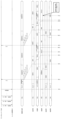
図5は、本実施例における、プリンタコントローラ200からエンジン制御部201に送信された印刷予約命令、及びその印刷予約命令の内容を順次実行するエンジン制御部201の動作を説明するタイミングチャートである。図5において、上部に示すタイミングチャートは、プリンタコントローラ200とエンジン制御部201間の信号(印刷予約命令、印刷開始命令、/TOP信号等)の送受信を示している。下部に示すタイミングチャートは、画像形成部、転写部、定着部、反転部、給紙部1、給紙部2の動作を示している。なお、図5において、横軸は時間を示し、図中のT2001~T2012は動作のタイミングを示す。 FIG. 5 is a timing chart for explaining a print reservation command transmitted from the printer controller 200 to the engine control unit 201 and the operation of the engine control unit 201 that sequentially executes the contents of the print reservation command in this embodiment. In FIG. 5, the timing chart shown at the top shows transmission and reception of signals (print reservation command, print start command, /TOP signal, etc.) between the printer controller 200 and the engine control unit 201 . The timing chart shown at the bottom shows the operations of the image forming section, transfer section, fixing section, reversing section, paper feeding section 1 and paper feeding section 2 . Note that in FIG. 5, the horizontal axis indicates time, and T2001 to T2012 in the figure indicate operation timings.

図5に示す印刷ジョブは、両面2枚交互印刷において、1枚目はA4サイズの記録紙、2枚目はA5サイズの記録紙、3枚目はA5サイズの記録紙、4枚目はA4サイズの記録紙に対する印刷ジョブとする。また、給紙部1にはA4サイズの記録紙、給紙部2にA5サイズの記録紙が予め積載された状態とする。更に、定着部50が有する発熱体54b1、54b2のうち、発熱体54b1は、A4サイズの記録紙を定着可能な幅を有し、発熱体54b2は、A5サイズの記録紙を定着可能な幅を有しているものとする。 The print job shown in FIG. 5 is for double-sided two-sheet alternate printing. The first sheet is A4 size recording paper, the second sheet is A5 size recording paper, the third sheet is A5 size recording paper, and the fourth sheet is A4 size recording paper. The print job is for recording paper of the size. In addition, it is assumed that A4 size recording paper and A5 size recording paper are previously stacked in the paper feeding unit 1 and the paper feeding unit 2, respectively. Further, of the heating elements 54b1 and 54b2 of the fixing unit 50, the heating element 54b1 has a width capable of fixing A4 size recording paper, and the heating element 54b2 has a width capable of fixing A5 size recording paper. shall have.

上述した条件で、プリンタコントローラ200から送信され、エンジン制御部201が取得した印刷予約命令の内容(印刷情報)及びその実行順番は、以下に示すとおりである。
・給紙部1/1面/A4
・給紙部2/1面/A5
・反転部 /2面/A4
・給紙部2/1面/A5
・反転部 /2面/A5
・給紙部1/1面/A4
・反転部 /2面/A5
・給紙部1/2面/A4
なお、印刷予約命令の内容において、スラッシュ(/)で区切られた3つの指定項目のうち、第1番目の指定項目は、印刷する記録紙がどの給紙部(給紙部1、給紙部2、反転部)から搬送されるのかを示している。第2番目の指定項目は、記録紙のどちらの面に画像形成するかを示し、1面の場合は記録紙の表面、2面の場合は記録紙の裏面への画像形成指示であることを意味する。なお、これに限定されるものではなく、1面の場合は記録紙の裏面、2面の場合は記録紙の表面への画像形成指示であることを意味していてもよい。第3番目の指定項目は、記録紙のサイズを示す。
The contents (print information) of the print reservation commands transmitted from the printer controller 200 and acquired by the engine control unit 201 under the conditions described above and the order of execution thereof are as follows.
Paper feed unit 1/1 side/A4
Paper feed unit 2/1 side/A5
・Reversed part / 2 sides / A4
Paper feed unit 2/1 side/A5
・Reversed part / 2 sides / A5
Paper feed unit 1/1 side/A4
・Reversed part / 2 sides / A5
Paper feed unit 1/2 sides/A4
In the content of the print reservation command, among the three specification items separated by slashes (/), the first specification item specifies which paper source (paper source 1, paper source) is used for printing. 2, whether the paper is conveyed from the reversing section). The second specification item indicates which side of the recording paper the image is to be formed on. For the first side, the image is to be formed on the front side of the recording paper, and for the second side, the image is to be formed on the back side of the recording paper. means. It should be noted that the instruction is not limited to this, and 1-sided may mean an instruction to form an image on the back side of the recording paper, and 2-sided may mean an instruction to form an image on the front side of the recording paper. The third specification item indicates the size of the recording paper.

上述した印刷予約命令の実行により、次の順番で、両面印刷が行われる。すなわち、1枚目の記録紙の1面目、2枚目の記録紙の1面目、1枚目の記録紙の2面目、3枚目の記録紙の1面目、2枚目の記録紙の2面目、4枚目の記録紙の1面目、3枚目の記録紙の2面目、4枚目の記録紙の2面目で、両面印刷が行われる。 By executing the print reservation command described above, double-sided printing is performed in the following order. That is, the first side of the first sheet of recording paper, the first side of the second sheet of recording paper, the second side of the first sheet of recording paper, the first side of the third sheet of recording paper, and the second side of the second sheet of recording paper. Duplex printing is performed on the first side, the first side of the fourth recording sheet, the second side of the third recording sheet, and the second side of the fourth recording sheet.

[印刷不良となる画像形成動作の例]
図5は、プリンタコントローラ200からエンジン制御部201に対し、上述した印刷予約命令が送信され、印刷予約命令で指定された記録紙サイズに合わせて、定着部50の発熱体を切り替える場合の画像形成動作を説明するタイミングチャートである。
[Example of image forming operation that causes printing failure]
FIG. 5 shows image formation when the above-described print reservation command is transmitted from the printer controller 200 to the engine control unit 201, and the heating element of the fixing unit 50 is switched according to the recording paper size specified by the print reservation command. It is a timing chart explaining operation.

エンジン制御部201は、プリンタコントローラ200から印刷開始命令を受信すると、図1で説明した画像形成装置の各構成要素の立ち上げ処理を開始する(T2001)。なお、定着部50は、最初の印刷予約命令の記録紙サイズはA4指定であることから、立ち上げ処理においては、A4サイズの記録紙を定着可能な発熱体54b1側に電力を供給し、温度制御を開始する。 Upon receiving the print start command from the printer controller 200, the engine control unit 201 starts startup processing of each component of the image forming apparatus described with reference to FIG. 1 (T2001). Since the recording paper size specified in the first print reservation command is A4, the fixing unit 50 supplies electric power to the heating element 54b1 capable of fixing A4-size recording paper in the start-up process. Start controlling.

定着部50で、定着ローラ51の長手方向全域の温度が、発熱体54b1によりトナー像の定着に必要な温度まで上昇した時点(T2002)で、エンジン制御部201はプリンタコントローラ200に/TOP信号(画像要求信号)を出力する。プリンタコントローラ200は、/TOP信号を受信すると、エンジン制御部201に画像信号の送信を開始する。エンジン制御部201は、プリンタコントローラ200から送信された画像信号を受信すると、画像形成制御部202に、順次Y、M、C、Kのトナー像形成指示を行う。給紙部1は、中間転写ベルト11上に順次形成されたトナー像の二次転写部への到達タイミングに合わせて、A4サイズの1枚目の記録紙(第1の記録材)を給紙し、二次転写部は給紙された記録紙へトナー像の転写を開始する(T2003)。二次転写部を通過した1枚目の記録紙が定着部50を通過し、反転部直前まで到達すると、反転部はソレノイド27を駆動し、フラッパ19の位置を変更し、1枚目の記録紙の反転部への引込み動作を開始する(T2004)。反転部は、記録紙の長さに応じた引込み動作を行った後、ソレノイド27の駆動を停止し、フラッパ19の位置を変更し、1枚目の記録紙の反転動作を開始する(T2006)。反転部は、反転経路28上の再給紙待機センサ23が1枚目の記録紙を検知した時点で、1枚目の記録紙の搬送を停止し、待機状態に遷移する(T2008)。 In the fixing section 50, when the temperature of the fixing roller 51 in the longitudinal direction has risen to the temperature required for fixing the toner image by the heating element 54b1 (T2002), the engine control section 201 sends the printer controller 200 a /TOP signal ( image request signal). Upon receiving the /TOP signal, the printer controller 200 starts transmitting image signals to the engine control unit 201 . Upon receiving the image signal transmitted from the printer controller 200, the engine control unit 201 sequentially instructs the image formation control unit 202 to form Y, M, C, and K toner images. The paper feed unit 1 feeds a first sheet of recording paper (first recording material) of A4 size in synchronization with the arrival timing of the toner images sequentially formed on the intermediate transfer belt 11 to the secondary transfer unit. Then, the secondary transfer unit starts transferring the toner image onto the fed recording paper (T2003). When the first sheet of recording paper that has passed through the secondary transfer section passes through the fixing section 50 and reaches just before the reversing section, the reversing section drives the solenoid 27, changes the position of the flapper 19, and records the first sheet. The operation of drawing the paper to the reversing portion is started (T2004). After performing the pull-in operation according to the length of the recording paper, the reversing section stops driving the solenoid 27, changes the position of the flapper 19, and starts reversing the first recording paper (T2006). . When the re-feed waiting sensor 23 on the reversing path 28 detects the first sheet of recording paper, the reversing section stops conveying the first sheet of recording paper and transitions to a standby state (T2008).

一方、プリンタコントローラ200からの2番目の印刷予約命令の記録紙サイズはA5指定である。そのため、エンジン制御部201は、1枚目の記録紙が定着ローラ51を通過したタイミング(T2005)で、定着部50の電力を供給する発熱体の切替え動作を行う。電力を供給する発熱体の切替え動作は、トライアック56をオフし、発熱体切替え器57で発熱体54b1から発熱体54b2に電力供給先を切り替える。そのため、C接点リレーである発熱体切替え器57が十分なマージンを持って切り替わるのを待った後、トライアック56をオンする。発熱体54b2により定着ローラ51の温度が、トナー像の定着に必要な温度まで上昇した時点(T2007)で、1枚目の記録紙の場合と同様に、エンジン制御部201はプリンタコントローラ200に/TOP信号(画像要求信号)を出力する。プリンタコントローラ200は、/TOP信号を受信すると、エンジン制御部201に画像信号の送信を開始する。エンジン制御部201は、トナー像形成を指示する。 On the other hand, the recording paper size of the second print reservation command from the printer controller 200 is A5. Therefore, the engine control unit 201 performs switching operation of the heating element that supplies power to the fixing unit 50 at the timing when the first recording sheet passes the fixing roller 51 (T2005). In the operation of switching the heating element to which power is supplied, the triac 56 is turned off, and the heating element switching device 57 switches the power supply destination from the heating element 54b1 to the heating element 54b2. Therefore, the triac 56 is turned on after waiting for the heating element switch 57, which is a C-contact relay, to switch with a sufficient margin. When the temperature of the fixing roller 51 rises to the temperature required for fixing the toner image by the heating element 54b2 (T2007), the engine control unit 201 causes the printer controller 200 to A TOP signal (image request signal) is output. Upon receiving the /TOP signal, the printer controller 200 starts transmitting image signals to the engine control unit 201 . The engine control unit 201 instructs toner image formation.

給紙部2は、中間転写ベルト11上に順次形成されたトナー像の二次転写部への到達タイミングに合わせて、A5サイズの2枚目の記録紙(第2の記録材)を給紙し、二次転写部は給紙された2枚目の記録紙へトナー像の転写を開始する(T2009)。二次転写部を通過した2枚目の記録紙が定着部50を通過し、反転部直前まで到達すると、反転部はソレノイド27を駆動し、フラッパ19の位置を変更し、反転部への2枚目の記録紙の引込み動作を開始する(T2010)。反転部は、2枚目の記録紙の長さに応じた引込み動作を行った後、ソレノイド27の駆動を停止し、フラッパ19の位置を変更し、引込み動作が完了する(T2012)。 The paper feeding unit 2 feeds a second sheet of recording paper (second recording material) of A5 size in synchronization with the arrival timing of the toner images sequentially formed on the intermediate transfer belt 11 to the secondary transfer unit. Then, the secondary transfer unit starts transferring the toner image onto the fed second sheet of recording paper (T2009). When the second sheet of recording paper that has passed through the secondary transfer section passes through the fixing section 50 and reaches just before the reversing section, the reversing section drives the solenoid 27, changes the position of the flapper 19, and transfers the second recording sheet to the reversing section. The pull-in operation of the first sheet of recording paper is started (T2010). After performing the pull-in operation corresponding to the length of the second sheet of recording paper, the reversing unit stops driving the solenoid 27, changes the position of the flapper 19, and completes the pull-in operation (T2012).

タイミングT2012における画像形成装置内の2枚の記録紙の様子を図6に示す。図6は、定着部50、反転部、反転経路28の周辺を拡大した模式図である。図中、P1はA4サイズの1枚目の記録紙であり、タイミングT2012の時点では、再給紙待機センサ23の位置で待機している。一方、図中、P2は、A5サイズの2枚目の記録紙であり、T2012の時点で引込み動作が完了し、次に、反転経路28の方向に反転動作を開始する瞬間を示している。上述したように、本実施例では、定着部50と反転部の駆動源はモータ25(図1参照)であり、かつ、ローラ対20a、20bはクラッチなどによりモータ25からの駆動力の伝達を停止(遮断)できない構成である。そのため、ローラ対20a、20bは、それぞれ時計回り方向及び反時計回り方向に回転するか、又はそれぞれ反時計回り方向及び時計回り方向に回転するかのどちらかの状態となる。前者の場合には、反転部は2枚目の記録紙P2の引込み動作を続け、その後、2枚目の記録紙P2は装置外に排出されることになる。一方、後者の場合には、反転部は2枚目の記録紙P2の反転を開始するものの、その後、反転した2枚目の記録紙P2は反転経路28に待機中の1枚目の記録紙P1と衝突してジャムが生じ、双方の記録紙P1、P2が破損するおそれがある。 FIG. 6 shows the state of two sheets of recording paper in the image forming apparatus at timing T2012. FIG. 6 is an enlarged schematic diagram of the fixing section 50, the reversing section, and the reversing path 28 and their surroundings. In the figure, P1 is the first sheet of A4 size recording paper, which is waiting at the position of the paper re-feed waiting sensor 23 at timing T2012. On the other hand, in the figure, P2 is the second sheet of A5 size recording paper, and indicates the moment when the pull-in operation is completed at time T2012 and then the reversing operation in the direction of the reversing path 28 is started. As described above, in this embodiment, the drive source for the fixing section 50 and the reversing section is the motor 25 (see FIG. 1), and the drive force from the motor 25 is transmitted to the pair of rollers 20a and 20b by a clutch or the like. It is a configuration that cannot be stopped (blocked). As a result, the roller pairs 20a and 20b either rotate clockwise and counterclockwise, respectively, or rotate counterclockwise and clockwise, respectively. In the former case, the reversing section continues the operation of pulling in the second sheet of recording paper P2, after which the second sheet of recording paper P2 is discharged outside the apparatus. On the other hand, in the latter case, although the reversing section starts reversing the second sheet of recording paper P2, the reversing second sheet of recording paper P2 is then replaced by the first sheet of recording paper waiting on the reversing path 28. It collides with P1, causing a jam, which may damage both recording papers P1 and P2.

そこで、印刷不良が生じる事態を回避するには、反転経路28に待機している1枚目の記録紙(図中、P1)の2面目用のトナー像形成指示を、発熱体の切替えにより遅延させることなく、行わなければならない。すなわち、図5のT2005の発熱体の切替え動作によって1枚目の記録紙P1の2面目のトナー像形成指示を遅延させるのではなく、先行する2枚目の記録紙P2の1面目と後続の1枚目の記録紙P1の2面目との両方の印刷指示内容を考慮する。そして、後続の1枚目の記録紙P1の2面目の印刷に際して、発熱体を切り替えることがないように発熱体の選択を行う。そのため、上述した印刷予約命令の場合、2番目に形成する画像が定着される2枚目の記録紙の指定サイズであるA5と、3番目に形成する画像が定着される1枚目の記録紙の指定サイズであるA4を考慮し、次のような制御が行われる。すなわち、3番目に形成する画像を定着するための発熱体の切替えが不要となる発熱体54b1に電力を供給したままにする。その際、2番目に形成する画像が定着される2枚目の記録紙の指定サイズであるA5に対して、記録紙幅の大きいA4用の発熱体54b1による定着動作となるが、通常、記録紙1枚程度では定着部50が破損する温度まで上昇することはなく、支障はない。 Therefore, in order to avoid the occurrence of defective printing, the instruction to form the toner image for the second side of the first sheet of recording paper (P1 in the drawing) waiting in the reverse path 28 is delayed by switching the heating element. It must be done without being forced. That is, instead of delaying the toner image formation instruction for the second side of the first recording sheet P1 by the switching operation of the heating element at T2005 in FIG. The contents of the print instruction for both the second side of the first sheet of recording paper P1 and the content of the print instruction are considered. Then, the heating element is selected so as not to switch the heating element when printing on the second side of the subsequent first sheet of recording paper P1. Therefore, in the case of the above-described print reservation command, A5, which is the specified size of the second sheet of recording paper on which the image to be formed second is fixed, and A5, which is the designated size of the second sheet of recording paper on which the image to be formed thirdly is fixed, The following control is performed in consideration of A4, which is the designated size of . In other words, the electric power is kept supplied to the heating element 54b1 which does not need to be switched to fix the third image to be formed. At this time, the heating element 54b1 for A4, which has a wider recording paper width, performs the fixing operation for A5, which is the designated size of the second recording paper on which the second formed image is to be fixed. With about one sheet, the temperature does not rise to the point where the fixing unit 50 is damaged, and there is no problem.

[印刷不良が発生しない画像形成動作の例]
図7は、印刷予約命令での記録紙の指定サイズと両面印刷の状況を考慮して、発熱体を選択する画像形成動作を説明するタイミングチャートである。図7の横軸は時間を示し、T3001~T3013はタイミングを示す。なお、プリンタコントローラ200からエンジン制御部201に送信される印刷予約命令の指示内容は、図5と同一であるため説明を省略する。
[Example of image forming operation that does not cause printing failure]
FIG. 7 is a timing chart for explaining an image forming operation for selecting a heating element in consideration of the size of recording paper designated by the print reservation command and the situation of double-sided printing. The horizontal axis in FIG. 7 indicates time, and T3001 to T3013 indicate timing. Note that the instruction content of the print reservation command transmitted from the printer controller 200 to the engine control unit 201 is the same as that in FIG. 5, so the description is omitted.

エンジン制御部201は、プリンタコントローラ200から印刷開始命令を受信すると、図1で説明した画像形成装置の各構成要素の立ち上げ処理を開始する(T3001)。なお、定着部50は、最初の印刷予約命令の対象となった1枚目の記録紙の記録紙サイズはA4指定であることから、立ち上げ処理においては、A4サイズの記録紙を定着可能な発熱体54b1側に電力を供給し、温度制御を開始する。 Upon receiving the print start command from the printer controller 200, the engine control unit 201 starts startup processing of each component of the image forming apparatus described with reference to FIG. 1 (T3001). Since the recording paper size of the first sheet of recording paper to which the first print reservation instruction is directed is A4, the fixing unit 50 can fix A4 size recording paper in the start-up process. Power is supplied to the heating element 54b1 to start temperature control.

定着部50において、発熱体54b1により定着ローラ51の長手方向全域の温度が上昇し、画像信号の出力許可温度を上回った時点(T3002)で、エンジン制御部201はプリンタコントローラ200に/TOP信号を出力する。プリンタコントローラ200は、/TOP信号を受信すると、エンジン制御部201に画像信号の送信を開始する。エンジン制御部201は、プリンタコントローラ200から送信された画像信号を受けると、画像形成制御部202に、順次Y、M、C、Kのトナー像形成指示を行う。給紙部1は、中間転写ベルト11上に順次形成されたトナー像の二次転写部への到達タイミングに合わせて、A4サイズの1枚目の記録紙を給紙し、二次転写部は給紙された1枚目の記録紙へトナー像の転写を開始する(T3003)。二次転写部を通過した1枚目の記録紙が定着部50を通過し、反転部直前まで到達すると、反転部はソレノイド27を駆動し、フラッパ19の位置を変更し、1枚目の記録紙の反転部への引込み動作を開始する(T3004)。反転部は、1枚目の記録紙の長さに応じた引込み動作を行った後、ソレノイド27の駆動を停止して、フラッパ19の位置を戻し、1枚目の記録紙の反転動作を開始する(T3007)。反転部は、反転経路28上の再給紙待機センサ23が1枚目の記録紙を検知した時点で、1枚目の記録紙の搬送を停止し、待機状態に遷移する(T3009)。 In the fixing unit 50, the temperature of the entire length of the fixing roller 51 rises due to the heating element 54b1, and when the temperature exceeds the output permission temperature of the image signal (T3002), the engine control unit 201 sends the /TOP signal to the printer controller 200. Output. Upon receiving the /TOP signal, the printer controller 200 starts transmitting image signals to the engine control unit 201 . Upon receiving the image signal transmitted from the printer controller 200, the engine control unit 201 sequentially instructs the image formation control unit 202 to form Y, M, C, and K toner images. The paper feeding unit 1 feeds the first sheet of recording paper of A4 size in accordance with the arrival timing of the toner images sequentially formed on the intermediate transfer belt 11 to the secondary transfer unit. Transfer of the toner image to the first sheet of recording paper that has been fed is started (T3003). When the first sheet of recording paper that has passed through the secondary transfer section passes through the fixing section 50 and reaches just before the reversing section, the reversing section drives the solenoid 27, changes the position of the flapper 19, and records the first sheet. The operation of drawing the paper to the reversing portion is started (T3004). After performing the pull-in operation corresponding to the length of the first sheet of recording paper, the reversing unit stops driving the solenoid 27, returns the position of the flapper 19, and starts the reversing operation of the first sheet of recording paper. (T3007). When the re-feed waiting sensor 23 on the reversing path 28 detects the first sheet of recording paper, the reversing section stops conveying the first sheet of recording paper and transitions to a standby state (T3009).

エンジン制御部201は、1枚目の記録紙が定着部50の定着ローラ51を通過したタイミング(T3005)で、プリンタコントローラ200からの2番目の印刷予約命令の指示内容について確認する。そして、エンジン制御部201は、2番目の印刷予約命令が対象となる2枚目の記録紙の記録紙サイズはA5指定でかつ1面目であることから、次に3番目の印刷予約命令の指示内容について確認する。エンジン制御部201は、3番目の印刷予約命令が1枚目の記録紙のA4指定で、かつ2面目であり、2番目の印刷予約命令の2枚目の記録紙の記録紙サイズ(A5)と異なることから、定着部50の発熱体切替え動作を不要と判断する。そのため、エンジン制御部201は、定着部50の発熱体切替え動作を行わない。エンジン制御部201は、1枚目の記録紙に対するトナー像形成開始から両面印刷における所定の間隔を空けて、画像形成制御部202に2枚目の記録紙であるA5サイズの記録紙向けのトナー像形成開始を指示する(T3006)。次いで、エンジン制御部201は、2枚目の記録紙に対するトナー像形成開始から両面印刷における所定の間隔を空けて、3番目の印刷予約命令である、1枚目のA4サイズの記録紙の2面目のトナー像形成開始を指示する(T3008)。 The engine control unit 201 confirms the contents of the second print reservation command from the printer controller 200 at the timing when the first recording sheet passes the fixing roller 51 of the fixing unit 50 (T3005). Since the recording paper size of the second sheet of recording paper targeted by the second print reservation command is A5 and the first side, the engine control unit 201 then instructs the third print reservation command. Check the contents. The engine control unit 201 determines that the third print reservation instruction designates A4 for the first sheet of recording paper and the second side, and the recording paper size (A5) of the second sheet of recording paper for the second print reservation instruction. , it is determined that the heating element switching operation of the fixing unit 50 is unnecessary. Therefore, the engine control unit 201 does not perform the heating element switching operation of the fixing unit 50 . Engine control unit 201 supplies toner for A5 size recording paper, which is the second recording paper, to image formation control unit 202 at a predetermined interval in double-sided printing from the start of toner image formation on the first recording paper. The start of image formation is instructed (T3006). Next, the engine control unit 201 issues a third print reservation command, ie, the third print reservation command, after the start of toner image formation on the second sheet of recording paper. The start of toner image formation for one side is instructed (T3008).

この間の反転部の状態、及び反転部が搬送する記録紙の動きは次のようになる。タイミングT3006において、画像形成制御部202により中間転写ベルト11上に順次、トナー像の形成が開始される。給紙部2は、中間転写ベルト11上に形成されたトナー像の二次転写部到達タイミングに合わせて、2枚目のA5サイズの記録紙を給紙し、二次転写部は給紙されたA5サイズの2枚目の記録紙へトナー像の転写を開始する(T3010)。二次転写部を通過した2枚目の記録紙が定着部50を通過し、反転部直前まで到達すると、反転部は、ソレノイド27を駆動してフラッパ19の位置を変更し、2枚目の記録紙の反転部への引込み動作を開始する(T3011)。一方、タイミングT3008では、画像形成制御部202により中間転写ベルト11上に順次形成されるトナー像の二次転写部への到達タイミング(T3012)に合わせて、反転部は反転経路28に待機しているA4サイズの1枚目の記録紙の搬送を開始する。その後、反転部は、2枚目の記録紙の長さに応じた引込み動作を行った後、ソレノイド27の駆動を停止してフラッパ19の位置を戻し、2枚目の記録紙の反転動作を開始する(T3013)。なお、タイミングT3013では、反転部は、反転経路28に待機している1枚目の記録紙を二次転写部に向けて搬送を開始している。そのため、反転部は、後続の記録紙サイズの異なる2枚目の記録紙の反転動作を開始しても、先行する1枚目の記録紙との衝突は生じず、印刷不良を生じることなく、両面印刷を継続することができる。 The state of the reversing section during this period and the movement of the recording paper conveyed by the reversing section are as follows. At timing T3006, the image formation control unit 202 starts forming toner images on the intermediate transfer belt 11 in sequence. The paper feed unit 2 feeds the second sheet of A5 size recording paper in synchronism with the arrival timing of the toner image formed on the intermediate transfer belt 11 at the secondary transfer unit. Then, the transfer of the toner image to the second sheet of A5 size recording paper is started (T3010). When the second sheet of recording paper that has passed through the secondary transfer section passes through the fixing section 50 and reaches just before the reversing section, the reversing section drives the solenoid 27 to change the position of the flapper 19, thereby transferring the second sheet. The operation of drawing the recording paper into the reversing portion is started (T3011). On the other hand, at timing T3008, the reversing unit waits on the reversing path 28 in synchronization with the arrival timing (T3012) of the toner images sequentially formed on the intermediate transfer belt 11 by the image formation control unit 202 at the secondary transfer unit. Start conveying the first sheet of A4 size recording paper. After that, the reversing section performs a pull-in operation corresponding to the length of the second sheet of recording paper, stops driving the solenoid 27, returns the position of the flapper 19, and reverses the second sheet of recording paper. Start (T3013). At timing T3013, the reversing section starts conveying the first sheet of recording paper waiting in the reversing path 28 toward the secondary transfer section. Therefore, even if the reversing section starts reversing the second sheet of recording paper having a different size, the reversing section does not collide with the preceding first sheet of recording paper and does not cause printing defects. Duplex printing can continue.

[発熱体切り替えの制御シーケンス]
図8は、定着部50の電力を供給する発熱体の切替えの制御シーケンスを示すフローチャートである。図8に示す処理は、印刷ジョブを実行するため、プリンタコントローラ200から印刷予約命令を受信すると起動され、エンジン制御部201により実行される。
[Control sequence for switching heating elements]
FIG. 8 is a flow chart showing a control sequence for switching the heating elements that supply electric power to the fixing section 50 . The processing shown in FIG. 8 is started when a print reservation command is received from the printer controller 200 and executed by the engine control unit 201 in order to execute a print job.

ステップ(以下、Sとする)1001では、エンジン制御部201は、次の処理を行う。すなわち、エンジン制御部201は、プリンタコントローラ200より受信した印刷予約命令のうち、画像形成を行うために、定着部50の電力を供給すべき発熱体が決定されていない印刷予約命令(図中、印刷指示と表記)があるかどうか判断する。エンジン制御部201は、電力を供給すべき発熱体が決定されていない印刷予約命令があると判断した場合には処理をS1002に進め、電力を供給すべき発熱体が決定されていない印刷予約命令がないと判断した場合には処理を終了する。S1002では、エンジン制御部201は、2つ以上の電力を供給すべき発熱体が決定されていない印刷予約命令(図中、印刷指示と表記)があるかどうか判断する。エンジン制御部201は、2つ以上の電力を供給すべき発熱体が決定されていない印刷予約命令があると判断した場合には処理をS1003に進める。一方、エンジン制御部201は、電力を供給すべき発熱体が決定されていない印刷予約命令が2つ未満、すなわち1つと判断した場合には処理をS1006に進める。 At step (hereinafter referred to as S) 1001, the engine control unit 201 performs the following processing. That is, the engine control unit 201 selects a print reservation command for which a heating element to be supplied with electric power to the fixing unit 50 is not determined among the print reservation commands received from the printer controller 200 for image formation. print instructions). If the engine control unit 201 determines that there is a print reservation command for which a heating element to which power is to be supplied has not been determined, the process advances to step S1002. If it is determined that there is no such, the process is terminated. In S1002, the engine control unit 201 determines whether or not there is a print reservation command (denoted as print instruction in the drawing) for which two or more heating elements to which power should be supplied have not been determined. If the engine control unit 201 determines that there is a print reservation command for which two or more heating elements to which power should be supplied has not been determined, the process advances to step S1003. On the other hand, if the engine control unit 201 determines that there are less than two print reservation commands for which the heating element to be supplied with power has not been determined, that is, one print reservation command, the process advances to step S1006.

S1003では、エンジン制御部201は、連続する2枚の記録紙のうち、第1の印刷予約命令は2枚目(後続)の記録紙の1面目に対する印刷指示で、かつ、第2の印刷予約命令は、1枚目(先行)の記録紙の2面目に対する印刷指示かどうか判断する。なお、第1の印刷予約命令(図中、第1の印刷指示と表記)は1番目の印刷予約命令ともいい、第2の印刷予約命令(図中、第2の印刷指示と表記)は2番目の印刷予約命令ともいう。エンジン制御部201は、1番目の印刷予約命令は2枚目の記録紙の1面目で、かつ、2番目の印刷予約命令は1枚目の記録紙の2面目であると判断した場合には処理をS1004に進める。一方、エンジン制御部201は、1番目の印刷予約命令は2枚目の記録紙の1面目で、かつ、2番目の印刷予約命令は1枚目の記録紙の2面目ではないと判断した場合には、処理をS1006に進める。エンジン制御部201が処理をS1006に進める場合は、例えば1番目の印刷予約命令が1枚目の記録紙の2面目の場合や、1番目の印刷予約命令は記録紙(例えば2枚目)の1面目で2番目の印刷予約命令も記録紙(例えば3枚目)の1面目の場合である。 In S1003, the engine control unit 201 determines that the first print reservation command is a print instruction for the first side of the second (subsequent) recording sheet of the two consecutive sheets of recording paper, and the second print reservation It is determined whether the command is a print instruction for the second side of the first (preceding) recording sheet. The first print reservation command (denoted as first print instruction in the figure) is also called the first print reservation command, and the second print reservation command (denoted as second print instruction in the figure) is 2 It is also called the second print reservation command. When the engine control unit 201 determines that the first print reservation command is for the first side of the second sheet of recording paper and the second print reservation command is for the second side of the first sheet of recording paper, The process proceeds to S1004. On the other hand, when the engine control unit 201 determines that the first print reservation command is for the first side of the second sheet of recording paper and the second print reservation command is not for the second side of the first sheet of recording paper. , the process proceeds to S1006. When the engine control unit 201 advances the process to S1006, for example, the first print reservation command is for the second side of the first sheet of recording paper, or the first print reservation command is for the second side of the recording paper (for example, the second sheet). The second print reservation command for the first side is also for the first side of the recording paper (for example, the third sheet).

S1004では、エンジン制御部201は、1番目の印刷予約命令で指示された2枚目の記録紙のサイズと、2番目の印刷予約命令で指示された1枚目の記録紙のサイズが異なるかどうか判断する。エンジン制御部201は、1番目の印刷予約命令と2番目の印刷予約命令で指示された記録紙のサイズが異なると判断した場合には、処理をS1005に進め、指示された記録紙のサイズは同じと判断した場合には、処理をS1006に進める。 In S1004, the engine control unit 201 determines whether the size of the second sheet of recording paper specified by the first print reservation command is different from the size of the first sheet of recording paper specified by the second print reservation command. Please judge. If the engine control unit 201 determines that the recording paper sizes specified by the first print reservation command and the second print reservation command are different, the process advances to step S1005, and the specified recording paper size is If it is determined that they are the same, the process advances to S1006.

S1005では、エンジン制御部201は、1番目の印刷予約命令で指示された2枚目の記録紙と2番目の印刷予約命令で指示された1枚目の記録紙のうちの、大きい方の記録紙サイズに対応する定着部50の発熱体54b1への電力供給を決定する。そして、エンジン制御部201は、定着制御部205を制御して、発熱体切替え器57により発熱体54b1へ電力供給先を切替え、処理をS1001に戻す。 In S1005, the engine control unit 201 selects the larger one of the second sheet of recording paper specified by the first print reservation command and the first sheet of recording paper specified by the second print reservation command. Power supply to the heating element 54b1 of the fixing unit 50 corresponding to the paper size is determined. Then, the engine control unit 201 controls the fixing control unit 205 to switch the power supply destination to the heating element 54b1 by the heating element switching device 57, and the process returns to S1001.

S1006では、エンジン制御部201は、1番目の印刷予約命令で指示された2枚目の記録紙サイズに応じた定着部50の発熱体への電力供給を決定する。なお、記録紙サイズに応じた発熱体とは、ここでは、記録紙サイズがA5以下の場合は発熱体54b2と決定し、記録紙サイズがA5より大きくA4以下の場合は発熱体54b1と決定することとする。そして、エンジン制御部201は、定着制御部205を制御して、発熱体切替え器57により決定された発熱体へ電力供給先を切替え、処理をS1001に戻す。 In S1006, the engine control unit 201 determines power supply to the heating element of the fixing unit 50 according to the size of the second sheet of recording paper specified by the first print reservation command. Here, the heating element corresponding to the recording paper size is determined as the heating element 54b2 when the recording paper size is A5 or less, and is determined as the heating element 54b1 when the recording paper size is larger than A5 and A4 or less. It is assumed that Then, the engine control unit 201 controls the fixing control unit 205 to switch the power supply destination to the heating element determined by the heating element switching unit 57, and returns the process to S1001.

以上、本実施例によれば、定着部と反転部の駆動源が同一の構成において、用紙幅が異なる記録紙が混在した両面印刷ジョブを実行する場合には、電力を供給すべき発熱体の切替えに伴う遅延を生じさせないよう、発熱体を決定する。具体的には、連続する2枚の記録紙の画像形成を行う場合で、先に給紙カセットから給紙された記録紙の1面目、次に反転経路28に待機している記録紙の2面目の画像形成を行う場合には、発熱体の切替えを行わなくてよいように発熱体を決定する。このように、給紙カセットから給紙された記録紙の1面目の印刷を行い、続いて、反転経路28の記録紙の2面目の印刷を行う場合には、発熱体切替えによる遅延を生じさせる発熱体の切替えを行う必要がないように、発熱体を決定する。これにより、ジャム等による印刷不良を発生させることなく、連続する2枚の記録紙の両面印刷を実施することができる。 As described above, according to this embodiment, when the drive source for the fixing unit and the reversing unit are the same, when a double-sided print job including recording sheets of different widths is executed, the heating element to which power is to be supplied is The heating element is determined so as not to introduce delays associated with switching. Specifically, when image formation is performed on two consecutive sheets of recording paper, the first side of the recording paper fed from the paper feed cassette first, and the second side of the recording paper waiting in the reverse path 28 are printed next. When performing image formation on one side, the heating element is determined so that it is not necessary to switch the heating element. In this way, when the first side of the recording paper fed from the paper feed cassette is printed and then the second side of the recording paper in the reverse path 28 is printed, a delay due to the switching of the heating element is caused. The heating element is determined so that switching of the heating element does not have to be performed. As a result, it is possible to perform double-sided printing on two continuous recording sheets without causing printing failures due to jamming or the like.

なお、本実施例では、発熱体の長さは、発熱体54b1はA4記録紙の幅(長手方向の長さ)、発熱体54b2はA5記録紙の幅(長手方向の長さ)で構成される例を示したが、例えば、発熱体54b2はB5記録紙の幅(長手方向の長さ)でもよい。発熱体の長さは、例えばA3幅やはがき幅の構成であってもよく、記録紙の長さに限定されるものではない。更に、本実施例では、フルカラーの画像形成が可能な画像形成装置を例に示したが、モノクロの画像形成装置の構成にも適用することができる。 In this embodiment, the length of the heating element 54b1 is the width of A4 recording paper (longitudinal length), and the heating element 54b2 is the width of A5 recording paper (longitudinal length). However, for example, the width of the B5 recording paper (the length in the longitudinal direction) may be used as the heating element 54b2. The length of the heating element may be, for example, A3 width or postcard width, and is not limited to the length of the recording paper. Furthermore, in this embodiment, an image forming apparatus capable of forming a full-color image is shown as an example, but the present invention can also be applied to a configuration of a monochrome image forming apparatus.

以上説明したように、本実施例によれば、複数の記録材に対して両面印刷を行う場合に、複数の記録材の搬送状態を鑑みて発熱体を切り替えることができる。 As described above, according to this embodiment, when double-sided printing is performed on a plurality of recording materials, the heating element can be switched in consideration of the conveying state of the plurality of recording materials.

実施例1では、プリンタコントローラ200からの予め記録紙のサイズが決定されている印刷予約命令を含む印刷ジョブの実施例について説明した。実施例2では、プリンタコントローラ200から、記録紙幅が未指定、又は不定形幅といった予め画像形成する記録紙の用紙幅の特定がされない印刷予約命令を受信した場合の、定着部50の発熱体の決定方法について説明する。 In the first embodiment, an example of a print job including a print reservation command from the printer controller 200 in which the size of recording paper is determined in advance has been described. In the second embodiment, when a print reservation command is received from the printer controller 200 in which the width of the recording paper on which the image is to be formed is not specified, such as an unspecified width of the recording paper or an irregular width, the heating element of the fixing unit 50 is operated. A determination method will be described.

[記録紙幅センサ]
図9は、定着部50の電力供給を制御する制御回路の模式図である。また、図9は、定着部50の発熱体54b1、54b2の長手方向の長さ(幅)と、定着部50に導入される記録紙の搬送方向と直交する方向の幅を検知する記録紙幅センサの位置関係を説明する図である。なお、定着部50の構成は、実施例1で説明した図3と同様であるため、ここでの説明は省略する。
[Recording paper width sensor]
FIG. 9 is a schematic diagram of a control circuit that controls power supply to the fixing section 50. As shown in FIG. FIG. 9 shows a recording paper width sensor for detecting the length (width) of the heating elements 54b1 and 54b2 of the fixing section 50 in the longitudinal direction and the width of the recording paper introduced into the fixing section 50 in the direction orthogonal to the conveying direction. is a diagram for explaining the positional relationship of . Note that the configuration of the fixing unit 50 is the same as that in FIG. 3 described in the first embodiment, and thus description thereof is omitted here.

検知手段である記録紙幅センサは、図中の一点鎖線Aのそれぞれの位置に配設され、図中矢印の方向に二次転写部より搬送される記録紙Pの通過を検知する構成となっている。本実施例では、記録紙Pの幅(図中、左右方向の長さ)が一点鎖線A-A間の長さより大きいものであれば、記録紙幅センサは、発熱体54b1と同等の長さの用紙幅を有する記録紙として検知する。一方、記録紙Pの幅が一点鎖線A-A間の長さより小さいものであれば、記録紙幅センサは、発熱体54b2と同等の長さの用紙幅を有する記録紙として検知する。なお、本実施例では、記録紙幅センサは、図1において、定着部50と、転写ローラ11cと支持ローラ11bとで構成される二次転写部との間に配置されているものとする。なお、画像形成装置の構成やシステム構成は、実施例1で説明した構成と同様であり、ここでの説明を省略する。 Recording paper width sensors, which are detecting means, are arranged at respective positions indicated by the dashed line A in the figure, and are configured to detect the passage of the recording paper P conveyed from the secondary transfer portion in the direction of the arrow in the figure. there is In this embodiment, if the width of the recording paper P (the length in the left-right direction in the figure) is greater than the length between the dashed-dotted lines AA, the recording paper width sensor has the same length as the heating element 54b1. It is detected as recording paper having a paper width. On the other hand, if the width of the recording paper P is smaller than the length between the dashed-dotted lines AA, the recording paper width sensor detects the recording paper as having a width equal to that of the heating element 54b2. In this embodiment, the recording paper width sensor is arranged between the fixing section 50 and the secondary transfer section composed of the transfer roller 11c and the support roller 11b in FIG. Note that the configuration of the image forming apparatus and the system configuration are the same as those described in the first embodiment, and description thereof will be omitted here.

[印刷ジョブ実行による各制御部の動作]
次に、上述した構成の画像形成装置において、記録紙の用紙幅が未指定の両面印刷ジョブがプリンタコントローラ200からエンジン制御部201に送信された場合の各制御部の動作について説明する。なお、本実施例では、給紙部1にはA5サイズの記録紙、給紙部2にはA4サイズの記録紙が予め積載されているものとする。
[Operation of each control unit by print job execution]
Next, in the image forming apparatus configured as described above, the operation of each control unit when a double-sided print job in which the paper width of the recording paper is not specified is transmitted from the printer controller 200 to the engine control unit 201 will be described. In this embodiment, it is assumed that A5-size recording paper is loaded in the paper feeding unit 1 and A4-size recording paper is loaded in the paper feeding unit 2 in advance.

プリンタコントローラ200から送信され、エンジン制御部201が取得した印刷予約命令の内容(印刷情報)及びその実行順番は、以下に示すとおりである。
・給紙部1/1面/未指定
・給紙部2/1面/未指定
・反転部 /2面/未指定
・給紙部2/1面/未指定
・反転部 /2面/未指定
・給紙部1/1面/未指定
・反転部 /2面/未指定
・給紙部1/2面/未指定
なお、印刷予約命令の内容において、スラッシュ(/)で区切られた3つの指定項目のうち、第1番目の指定項目は、印刷する記録紙がどの給紙部(給紙部1、給紙部2、反転部)から搬送されるのかを示している。第2番目の指定項目は、記録紙のどちらの面に画像形成するかを示し、1面の場合は記録紙の表面、2面の場合は記録紙の裏面への画像形成指示であることを意味する。なお、これに限定されるものではなく、1面の場合は記録紙の裏面、2面の場合は記録紙の表面への画像形成指示であることを意味していてもよい。第3番目の指定項目は、記録紙のサイズを示す。
The contents (printing information) of the print reservation commands transmitted from the printer controller 200 and acquired by the engine control unit 201 and their execution order are as follows.
Paper feed section 1/side 1/unspecified ・Paper feed section 2/side 1/unspecified ・Reversing section/side 2/unspecified ・Paper feed section 2/side 1/unspecified Specified Paper feed unit 1/side 1/Unspecified/Reversed/side 2/Unspecified Paper feed unit 1/2 side/Unspecified Of the three specification items, the first specification item indicates from which paper supply unit (paper supply unit 1, paper supply unit 2, reversing unit) the recording paper to be printed is conveyed. The second specification item indicates which side of the recording paper the image is to be formed on. For the first side, the image is to be formed on the front side of the recording paper, and for the second side, the image is to be formed on the back side of the recording paper. means. It should be noted that the instruction is not limited to this, and 1-sided may mean an instruction to form an image on the back side of the recording paper, and 2-sided may mean an instruction to form an image on the front side of the recording paper. The third specification item indicates the size of the recording paper.

上述した印刷予約命令の実行により、次の順番で、両面印刷が行われる。すなわち、1枚目の用紙の1面目、2枚目の用紙の1面目、1枚目の用紙の2面目、3枚目の用紙の1面目、2枚目の用紙の2面目、4枚目の用紙の1面目、3枚目の用紙の2面目、4枚目の用紙の2面目で、両面印刷が行われる。 By executing the print reservation command described above, double-sided printing is performed in the following order. That is, side 1 of sheet 1, side 1 of sheet 2, side 2 of sheet 1, side 1 of sheet 3, side 2 of sheet 2, sheet 4 Duplex printing is performed on the first side of the first sheet, the second side of the third sheet, and the second side of the fourth sheet.

記録紙のサイズが未指定の場合は用紙幅が不明であるため、画像形成装置は、定着部50の電力を供給する発熱体には幅の広い発熱体54b1を選択して、準備動作を開始する。また、画像形成装置は、定着部50での記録紙にトナー像を定着させる際も発熱体54b1で行う。給紙部1から給紙した1枚目の記録紙が定着部50に到達すると、上述した記録紙幅センサにより、記録紙幅はA5サイズ相当であることが判明する。同じ1枚目の記録紙の2面目の画像形成に対しては、定着部50のA5サイズの記録紙幅に対応した発熱体54b2が適切な長さの発熱体となる。しかしながら、次に印刷を行う給紙部2から給紙した2枚目の記録紙も、記録紙の指定が未指定であり、用紙幅が不明であることから、引き続き、定着部50の発熱体は、発熱体54b1を選択して定着動作を行う。そのため、3番目の印刷である1枚目の記録紙であるA5サイズの記録紙の2面目の印刷に対して、定着部50の発熱体を発熱体54b1から発熱体54b2へ切替え動作を実施すると、実施例1の図6で説明した印刷不良(ジャム)が生じることになる。そこで、本実施例の記録紙の指定が未指定である記録紙幅不定の両面印刷ジョブの場合においても、定着部50の電力を供給する発熱体の切替えが不要となるよう、そのまま発熱体54b1に電力を供給して定着動作を行うようにする。 If the size of the recording paper is not specified, the width of the paper is unknown. Therefore, the image forming apparatus selects the wide heat generating element 54b1 as the heat generating element for supplying power to the fixing unit 50, and starts the preparatory operation. do. Further, in the image forming apparatus, when the toner image is fixed on the recording paper in the fixing section 50, the heating element 54b1 is used. When the first sheet of recording paper fed from the paper feeding unit 1 reaches the fixing unit 50, the width of the recording paper is determined to be equivalent to A5 size by the recording paper width sensor. For image formation on the second side of the same first sheet of recording paper, the heating element 54b2 corresponding to the A5 size recording sheet width of the fixing section 50 has an appropriate length. However, the second sheet of recording paper fed from the paper feeding unit 2 to be printed next is also unspecified, and the width of the paper is unknown. selects the heating element 54b1 to perform the fixing operation. Therefore, when the heating element of the fixing unit 50 is switched from the heating element 54b1 to the heating element 54b2 for the printing on the second side of the A5 size recording paper, which is the first recording paper, which is the third printing, , the printing failure (jam) described in FIG. 6 of the first embodiment occurs. Therefore, even in the case of a double-sided printing job in which the recording paper width is not specified and the recording paper width is not specified in this embodiment, the heating element 54b1 is used as it is so that the switching of the heating element for supplying power to the fixing unit 50 is not required. Power is supplied to perform the fixing operation.

図10は、プリンタコントローラ200からエンジン制御部201に対し、上述した印刷予約命令が送信された場合の画像形成動作を説明するタイミングチャートである。横軸は時間を示し、T4001~T4016はタイミングを示す。なお、基本的な画像形成動作の流れは、実施例1で説明した図7と同様であるため、同様の説明は省略し、記録紙幅の指定が未指定である場合の発熱体の選択、及び記録紙幅センサにより記録紙幅が検知された後の発熱体の選択について説明する。また、図中下部に示す記録紙幅センサは図9で説明した記録紙幅センサの出力を示しており、図9で示したA-A間の幅よりも用紙幅が大きい記録紙が通過した場合にはON信号を出力し、A-A間の幅よりも用紙幅が小さい記録紙の場合はOFF信号を出力する。 FIG. 10 is a timing chart for explaining the image forming operation when the above-described print reservation command is transmitted from the printer controller 200 to the engine control unit 201. As shown in FIG. The horizontal axis indicates time, and T4001 to T4016 indicate timing. Since the flow of the basic image forming operation is the same as that of FIG. 7 described in the first embodiment, the same description will be omitted. Selection of the heating element after the width of the recording paper is detected by the recording paper width sensor will be described. The recording paper width sensor shown in the lower part of the figure indicates the output of the recording paper width sensor explained in FIG. outputs an ON signal, and outputs an OFF signal when the recording paper width is smaller than the width between AA.

エンジン制御部201は、プリンタコントローラ200から印刷開始命令を受信すると、画像形成装置の各構成要素の立ち上げ処理を開始する(T4001)。なお、定着部50は、最初の印刷予約命令の記録紙サイズは未指定であることから、立ち上げ処理においては、いずれの記録紙幅でも定着可能な発熱体54b1側に電力を供給し、温度制御を開始する。定着温度センサ59による定着部50の検知温度が画像信号出力許可温度を上回った時点(T4002)で、エンジン制御部201はプリンタコントローラ200に/TOP信号を出力する。エンジン制御部201は、プリンタコントローラ200から送信された画像信号を受けると、中間転写ベルト11へのトナー像形成、給紙部1によるA5サイズの1枚目の記録紙給紙、二次転写部による1枚目の記録紙へのトナー像転写(T4003)を行う。そして、エンジン制御部201は、定着部50による1枚目の記録紙へのトナー像定着、反転部による1枚目の記録紙の引込み動作(T4005)、反転動作(T4007)、及び再給紙待機センサ23での搬送停止(T4009)を順次実行する。 Upon receiving the print start command from the printer controller 200, the engine control unit 201 starts startup processing of each component of the image forming apparatus (T4001). Since the recording paper size is not specified in the first print reservation command, the fixing unit 50 supplies power to the heating element 54b1, which is capable of fixing any recording paper width, in the start-up process, thereby controlling the temperature. to start. When the temperature of the fixing section 50 detected by the fixing temperature sensor 59 exceeds the image signal output permission temperature (T4002), the engine control section 201 outputs the /TOP signal to the printer controller 200. FIG. When the engine control unit 201 receives an image signal transmitted from the printer controller 200, the engine control unit 201 forms a toner image on the intermediate transfer belt 11, feeds the first sheet of A5 size recording paper by the paper feed unit 1, and performs secondary transfer unit A toner image is transferred to the first sheet of recording paper (T4003). Then, the engine control unit 201 causes the fixing unit 50 to fix the toner image on the first sheet of recording paper, the reversing unit to pull in the first sheet of recording paper (T4005), the reversing operation (T4007), and the refeeding operation. Conveyance stop by standby sensor 23 (T4009) is sequentially executed.

この両面印刷ジョブの実行過程において、1枚目の記録紙が定着部50に到達時(T4004)に、記録紙幅センサからOFF信号が出力されていることから、1枚目の記録紙幅はA5サイズ相当であることが判明する。しかしながら、2番目の印刷予約命令の2枚目の記録紙の記録紙サイズが未指定であることから、1枚目の記録紙が定着部50を通過したタイミング(T4006)では、電力を供給している発熱体を切り替えることなく、発熱体54b1のままで定着動作を行う。次いで、3番目の印刷予約命令の指示内容は、1枚目の記録紙の2面目の印刷に対するものである。タイミングT4004で判明した1枚目の記録紙の記録紙幅(A5サイズ)に適した発熱体は発熱体54b2である。ところが、2枚目の記録紙が定着部50を通過したタイミング(T4015)では、発熱体54b1から発熱体54b2への電力供給先の切替えは行わず、発熱体54b1のまま定着動作を行う。これは、上述したように発熱体54b1から発熱体54b2への切替え動作を行うと、反転経路28において2つの記録紙同士の衝突(ジャム)による印刷不良が発生するためである。 In the process of executing this duplex print job, when the first recording sheet reaches the fixing unit 50 (T4004), the OFF signal is output from the recording sheet width sensor, so the width of the first recording sheet is A5 size. It turns out to be reasonable. However, since the recording paper size of the second recording paper in the second print reservation command is not specified, power is not supplied at the timing (T4006) when the first recording paper passes through the fixing unit 50. The fixing operation is performed with the heating element 54b1 as it is without switching the heating element. Next, the instruction content of the third print reservation instruction is for printing on the second side of the first sheet of recording paper. The heating element 54b2 is suitable for the recording paper width (A5 size) of the first recording sheet found at timing T4004. However, at the timing (T4015) when the second sheet of recording paper passes through the fixing section 50, the power supply destination is not switched from the heating element 54b1 to the heating element 54b2, and the fixing operation is performed with the heating element 54b1. This is because the switching operation from the heating element 54b1 to the heating element 54b2 as described above causes a collision (jam) between the two recording sheets in the reversing path 28, resulting in printing failure.

[発熱体切り替えの制御シーケンス]
図11は、定着部50の電力を供給する発熱体の切替えの制御シーケンスを示すフローチャートである。図11に示す処理は、印刷ジョブを実行するため、プリンタコントローラ200から印刷予約命令を受信すると起動され、エンジン制御部201により実行される。プリンタコントローラ200からの印刷指示の記録紙サイズが未指定の場合に、エンジン制御部201は図11に示す処理を実行する。
[Control sequence for switching heating elements]
FIG. 11 is a flow chart showing a control sequence for switching the heating elements that supply power to the fixing section 50 . The processing shown in FIG. 11 is started when a print reservation command is received from the printer controller 200 and executed by the engine control unit 201 in order to execute a print job. When the print instruction from the printer controller 200 does not specify the recording paper size, the engine control unit 201 executes the processing shown in FIG.

S2001では、エンジン制御部201は、プリンタコントローラ200より受信した印刷予約命令のうち、画像形成を行うために、定着部50の電力を供給すべき発熱体が決定されていない印刷予約命令(図中、印刷指示と表記)があるかどうか判断する。エンジン制御部201は、電力を供給すべき発熱体が決定されていない印刷予約命令があると判断した場合には処理をS2002に進め、電力を供給すべき発熱体が決定されていない印刷予約命令がないと判断した場合には処理を終了する。S2002では、エンジン制御部201は、2つ以上の電力を供給すべき発熱体が決定されていない印刷予約命令(図中、印刷指示と表記)があるかどうか判断する。エンジン制御部201は、2つ以上の電力を供給すべき発熱体が決定されていない印刷予約命令があると判断した場合には処理をS2003に進める。一方、エンジン制御部201は、電力を供給すべき発熱体が決定されていない印刷予約命令が2つ未満、すなわち1つと判断した場合には処理をS2009に進める。 In step S<b>2001 , the engine control unit 201 selects, among the print reservation commands received from the printer controller 200 , a print reservation command for which a heating element to which electric power should be supplied to the fixing unit 50 is not determined for image formation. , print instructions). If the engine control unit 201 determines that there is a print reservation command for which a heating element to which power is to be supplied has not been determined, the process advances to step S2002. If it is determined that there is no such, the process is terminated. In S2002, the engine control unit 201 determines whether or not there is a print reservation command (denoted as print instruction in the figure) for which two or more heating elements to which power should be supplied have not been determined. If the engine control unit 201 determines that there is a print reservation command for which two or more heating elements to which power should be supplied has not been determined, the process advances to step S2003. On the other hand, if the engine control unit 201 determines that there are less than two print reservation commands for which the heating element to be supplied with power has not been determined, that is, one print reservation command, the process advances to step S2009.

S2003では、エンジン制御部201は、連続する2枚の記録紙のうち、1番目の印刷予約命令は2枚目(後続)の記録紙の1面目に対する印刷指示で、かつ、2番目の印刷予約命令は1枚目(先行)の記録紙の2面目に対する印刷指示かどうか判断する。なお、図11では、1番目の印刷予約命令は第1の印刷指示と表記し、2番目の印刷予約命令は第2の印刷指示と表記している。エンジン制御部201は、1番目の印刷予約命令は2枚目の記録紙の1面目で、かつ、2番目の印刷予約命令は1枚目の記録紙の2面目であると判断した場合には処理をS2004に進める。一方、エンジン制御部201は、1番目の印刷予約命令は2枚目の記録紙の1面目で、かつ、2番目の印刷予約命令は1枚目の記録紙の2面目ではないと判断した場合には、処理をS2009に進める。エンジン制御部201が処理をS2009に進める場合は、例えば1番目の印刷予約命令が1枚目の記録紙の2面目の場合や、1番目の印刷予約命令は記録紙(例えば2枚目)の1面目だが、2番目の印刷予約命令も記録紙(例えば3枚目)の1面目の場合である。 In S2003, the engine control unit 201 determines that the first print reservation command of the two consecutive recording sheets is a print instruction for the first side of the second (subsequent) recording sheet, and the second print reservation It is determined whether or not the command is a print instruction for the second side of the first (preceding) recording sheet. In FIG. 11, the first print reservation command is indicated as the first print instruction, and the second print reservation command is indicated as the second print instruction. When the engine control unit 201 determines that the first print reservation command is for the first side of the second sheet of recording paper and the second print reservation command is for the second side of the first sheet of recording paper, The process advances to S2004. On the other hand, when the engine control unit 201 determines that the first print reservation command is for the first side of the second sheet of recording paper and the second print reservation command is not for the second side of the first sheet of recording paper. , the process proceeds to S2009. When the engine control unit 201 advances the process to S2009, for example, the first print reservation command is for the second side of the first sheet of recording paper, or the first print reservation command is for the second side of the recording paper (for example, the second sheet). Regarding the first side, the second print reservation command is also for the first side of the recording paper (for example, the third sheet).

S2004では、エンジン制御部201は、1番目の印刷予約命令で指示された2枚目の記録紙のサイズは判明しているかどうか判断する。エンジン制御部201は、1番目の印刷予約命令で指示された2枚目の記録紙のサイズは、記録紙幅センサにより検知され、判明していると判断した場合には処理をS2005に進める。一方、エンジン制御部201は、1番目の印刷予約命令で指示された2枚目の記録紙のサイズは、判明していないと判断した場合には処理をS2008に進める。 In S2004, the engine control unit 201 determines whether the size of the second sheet of recording paper specified by the first print reservation command is known. If the engine control unit 201 determines that the size of the second sheet of recording paper specified by the first print reservation command is detected by the recording paper width sensor and is known, the process advances to step S2005. On the other hand, if the engine control unit 201 determines that the size of the second sheet of recording paper specified by the first print reservation command is unknown, the process advances to step S2008.

S2005では、エンジン制御部201は、2番目の印刷予約命令で指示された1枚目の記録紙のサイズは判明しているかどうか判断する。エンジン制御部201は、2番目の印刷予約命令で指示された1枚目の記録紙のサイズは、記録紙幅センサにより検知され、判明していると判断した場合には処理をS2006に進める。一方、エンジン制御部201は、2番目の印刷予約命令で指示された1枚目の記録紙のサイズは、判明していないと判断した場合には処理をS2008に進める。 In S2005, the engine control unit 201 determines whether the size of the first sheet of recording paper instructed by the second print reservation command is known. If the engine control unit 201 determines that the size of the first sheet of recording paper instructed by the second print reservation command is detected by the recording paper width sensor and is known, the process advances to step S2006. On the other hand, if the engine control unit 201 determines that the size of the first sheet of recording paper instructed by the second print reservation command is unknown, the process advances to step S2008.

S2006では、エンジン制御部201は、1番目の印刷予約命令で指示された2枚目の記録紙のサイズと、2番目の印刷予約命令で指示された1枚目の記録紙のサイズが同じかどうか判断する。エンジン制御部201は、1番目の印刷予約命令と2番目の印刷予約命令で指示された記録紙のサイズが同じと判断した場合には、処理をS2007に進め、指示された記録紙のサイズは異なる(同じではない)と判断した場合には、処理をS2008に進める。 In S2006, the engine control unit 201 determines whether the size of the second sheet of recording paper specified by the first print reservation command is the same as the size of the first sheet of recording paper specified by the second print reservation command. Please judge. If the engine control unit 201 determines that the recording paper sizes designated by the first print reservation command and the second print reservation command are the same, the process advances to step S2007, and the designated recording paper size is If it is determined that they are different (not the same), the process advances to S2008.

S2007では、エンジン制御部201は、1番目及び2番目の印刷予約命令で指示された記録紙に対応する発熱体を、記録紙サイズが判明している1番目及び2番目の印刷予約命令で指示された記録紙サイズに応じた発熱体に決定する。そして、エンジン制御部201は、定着制御部205を制御して、発熱体切替え器57により決定された発熱体へ電力供給先を切替え、処理をS2001に戻す。 In step S2007, the engine control unit 201 designates the heating element corresponding to the recording paper instructed by the first and second print reservation commands by the first and second print reservation commands whose recording paper sizes are known. The heating element is determined according to the selected recording paper size. Then, the engine control unit 201 controls the fixing control unit 205 to switch the power supply destination to the heating element determined by the heating element switching unit 57, and returns the process to S2001.

S2008では、エンジン制御部201は、1番目及び2番目の印刷予約命令で指示された記録紙に対応する発熱体を、定着部50が有する発熱体のうちの大きい記録紙サイズに対応した発熱体(本実施例では、発熱体54b1)に決定する。そして、エンジン制御部201は、定着制御部205を制御して、発熱体切替え器57により決定された発熱体54b1へ電力供給先を切替え、処理をS2001に戻す。S2008の処理が実行される場合は、1番目の印刷予約命令で指示された記録紙、又は2番目の印刷予約命令で指示された記録紙の記録紙幅が不明、あるいは、1番目及び2番目の印刷予約命令で指示された記録紙の判明した記録紙幅が異なる場合である。そのため、エンジン制御部201は、電力を供給すべき発熱体として、いずれの記録紙幅でも定着可能な発熱体54b1を選択している。 In step S2008, the engine control unit 201 selects a heating element corresponding to the recording paper designated by the first and second print reservation commands as a heating element corresponding to a large recording paper size among the heating elements of the fixing unit 50. (In this embodiment, the heating element 54b1) is determined. Then, the engine control unit 201 controls the fixing control unit 205 to switch the power supply destination to the heating element 54b1 determined by the heating element switching unit 57, and returns the process to S2001. When the process of S2008 is executed, the recording paper width of the recording paper instructed by the first print reservation command or the recording paper width of the recording paper instructed by the second print reservation command is unknown, or This is the case where the known recording paper widths of the recording paper specified by the print reservation command are different. Therefore, the engine control unit 201 selects the heat generating element 54b1 capable of fixing any recording paper width as the heat generating element to which electric power is to be supplied.

S2009では、エンジン制御部201は、1番目の印刷予約命令で指示された2枚目の記録紙のサイズは判明しているかどうか判断する。エンジン制御部201は、1番目の印刷予約命令で指示された2枚目の記録紙のサイズは、記録紙幅センサにより検知され、判明していると判断した場合には処理をS2010に進める。一方、エンジン制御部201は、1番目の印刷予約命令で指示された2枚目の記録紙のサイズは、判明していないと判断した場合には処理をS2011に進める。 In S2009, the engine control unit 201 determines whether the size of the second sheet of recording paper specified by the first print reservation command is known. If the engine control unit 201 determines that the size of the second sheet of recording paper instructed by the first print reservation command is detected by the recording paper width sensor and is known, the process advances to step S2010. On the other hand, if the engine control unit 201 determines that the size of the second sheet of recording paper specified by the first print reservation command is unknown, the process advances to step S2011.

S2010では、エンジン制御部201は、1番目の印刷予約命令で指示された2枚目の記録紙に対応する発熱体を、記録紙サイズが判明している1番目の印刷予約命令で指示された記録紙サイズに応じた発熱体に決定する。そして、エンジン制御部201は、定着制御部205を制御して、発熱体切替え器57により決定された発熱体へ電力供給先を切替え、処理をS2001に戻す。 In S2010, the engine control unit 201 instructs the heating element corresponding to the second sheet of recording paper instructed by the first print reservation command by the first print reservation command whose recording paper size is known. The heating element is determined according to the size of the recording paper. Then, the engine control unit 201 controls the fixing control unit 205 to switch the power supply destination to the heating element determined by the heating element switching unit 57, and returns the process to S2001.

S2011では、エンジン制御部201は、1番目の印刷予約命令で指示された2枚目の記録紙に対応する発熱体を、定着部50が有する発熱体のうちの大きい記録紙サイズに対応した発熱体(本実施例では、発熱体54b1)に決定する。そして、エンジン制御部201は、定着制御部205を制御して、発熱体切替え器57により決定された発熱体54b1へ電力供給先を切替え、処理をS2001に戻す。エンジン制御部201は、1番目の印刷予約命令で指示された2枚目の記録紙サイズが判明していないため、電力を供給すべき発熱体として、いずれの記録紙幅でも定着可能な発熱体54b1を選択している。 In step S2011, the engine control unit 201 selects a heat generating element corresponding to the second sheet of recording paper instructed by the first print reservation command to generate heat corresponding to a large recording paper size among the heat generating elements of the fixing unit 50. The body (the heating element 54b1 in this embodiment) is determined. Then, the engine control unit 201 controls the fixing control unit 205 to switch the power supply destination to the heating element 54b1 determined by the heating element switching unit 57, and returns the process to S2001. Since the engine control unit 201 does not know the size of the second sheet of recording paper instructed by the first print reservation command, the engine control unit 201 selects the heating element 54b1 that can fix any recording sheet width as the heating element to which power should be supplied. are choosing.

以上、本実施例では、定着部と反転部の駆動源が同一の構成において、給紙カセット毎に用紙幅の異なる記録紙が積載されている状況で、プリンタコントローラ200から記録紙幅が未指定で両面ジョブ実行を命令された場合の処理について説明した。上述したように、連続する2枚の記録紙の画像形成を行う場合で、先に給紙カセットから給紙された記録紙の1面目、次に反転経路28に待機している記録紙の2面目の画像形成を行う場合には、発熱体の切替えを行わないように、発熱体を決定する。このように、給紙カセットから給紙された記録紙の1面目の印刷を行い、続いて、反転経路28の記録紙の2面目の印刷を行う場合には、発熱体切替えによる遅延を生じさせる発熱体の切替えを行う必要がないように、発熱体を決定する。これにより、印刷不良を発生させることなく両面印刷を実施することができる。 As described above, in this embodiment, in a configuration in which the drive source for the fixing section and the reversing section are the same, recording sheets of different widths are stacked in each paper feed cassette, and the width of the recording sheet is not specified by the printer controller 200. The processing when a double-sided job execution command is issued has been described. As described above, when image formation is performed on two consecutive sheets of recording paper, the first side of the recording paper first fed from the paper feed cassette and the second side of the recording paper waiting in the reverse path 28 are printed next. When performing image formation on one side, the heating element is determined so as not to switch the heating element. In this way, when the first side of the recording paper fed from the paper feed cassette is printed and then the second side of the recording paper in the reverse path 28 is printed, a delay due to the switching of the heating element is caused. The heating element is determined so that switching of the heating element does not have to be performed. As a result, double-sided printing can be performed without causing printing defects.

なお、本実施例では、発熱体の構成として、発熱体54b1はA4記録紙の幅(長手方向の長さ)、発熱体54b2はA5記録紙の幅(長手方向の長さ)で構成される例を示した。発熱体の長さは、A3幅及びはがき幅の構成であっても良く、記録紙の長さに限定されるものではない。更に、フルカラーの画像形成が可能な装置を例に示したが、モノクロ画像形成装置の構成にも適用できる。 In this embodiment, the heating element 54b1 has the width (length in the longitudinal direction) of A4 recording paper, and the heating element 54b2 has the width (length in the longitudinal direction) of A5 recording paper. I gave an example. The length of the heating element may be A3 width and postcard width, and is not limited to the length of the recording paper. Furthermore, although an apparatus capable of forming a full-color image has been shown as an example, the present invention can also be applied to a configuration of a monochrome image forming apparatus.

以上説明したように、本実施によれば、複数の記録材に対して両面印刷を行う場合に、複数の記録材の搬送状態を鑑みて発熱体を切り替えることができる。 As described above, according to this embodiment, when double-sided printing is performed on a plurality of recording materials, the heating element can be switched in consideration of the conveying state of the plurality of recording materials.

本実施例では、実施例1で示した電力制御回路に比べ、ヒータ54を構成する発熱体の数が多い電力制御回路を用いて画像形成する場合の、発熱体選択について説明する。なお、基本的な構成は実施例1と同様であるため、異なる点について説明する。 In the present embodiment, the selection of heating elements will be described in the case of image formation using a power control circuit having a larger number of heating elements constituting the heater 54 than the power control circuit shown in the first embodiment. Since the basic configuration is the same as that of the first embodiment, different points will be explained.

[定着部の制御回路]
図12は、本実施例で用いる電力制御回路97である。電力制御回路97は、ヒータ54、交流電源55、トライアック56a、56b、発熱体切替え器57からなる。ヒータ54は、発熱体54m1~54m3、接点54n1~54n4で構成される。発熱体54m1~54m3は、商用交流電源等の交流電源55からの電力供給により発熱する抵抗体である。接点54n1及び接点54n2は、基板54aの長手方向における一方の端部側に設けられ、接点54n3及び接点54n4は、基板54aの長手方向における他方の端部側に設けられる。本実施例では、発熱体54m1~54m3の長手方向の長さは、それぞれ、A4サイズ、B5サイズ、A5サイズの記録紙の幅(長手方向の長さ)とする。また、各発熱体は、基板54aの短手方向(図12において上側から下側方向)に、発熱体54m1、発熱体54m2、発熱体54m3、発熱体54m1の順に配置されている。
[Control Circuit of Fixing Section]
FIG. 12 shows the power control circuit 97 used in this embodiment. The power control circuit 97 is composed of the heater 54 , the AC power supply 55 , the triacs 56 a and 56 b and the heating element switch 57 . The heater 54 is composed of heating elements 54m1 to 54m3 and contacts 54n1 to 54n4. The heating elements 54m1 to 54m3 are resistors that generate heat when supplied with power from an AC power supply 55 such as a commercial AC power supply. The contacts 54n1 and 54n2 are provided on one end side in the longitudinal direction of the substrate 54a, and the contacts 54n3 and 54n4 are provided on the other end side in the longitudinal direction of the substrate 54a. In this embodiment, the longitudinal lengths of the heating elements 54m1 to 54m3 are the widths (longitudinal lengths) of A4 size, B5 size, and A5 size recording paper, respectively. The heat generating elements are arranged in the order of heat generating element 54m1, heat generating element 54m2, heat generating element 54m3, and heat generating element 54m1 in the lateral direction of substrate 54a (from the top to the bottom in FIG. 12).

発熱体切替え器57は、接点54n2に接続された接点57a、トライアック56b及び接点54n3に接続された接点57b1、交流電源55及び接点54n4に接続された接点57b2を有する。発熱体切替え器57は、接点57aと接点57b1とが接続された状態であるときには、発熱体54m2に電力が供給可能な状態となっている。一方、発熱体切替え器57は、接点57aと接点57b2とが接続された状態であるとき、発熱体54m3に電力が供給可能な状態となっている。 The heating element switch 57 has a contact 57a connected to the contact 54n2, a contact 57b1 connected to the triac 56b and the contact 54n3, and a contact 57b2 connected to the AC power supply 55 and the contact 54n4. When the contact 57a and the contact 57b1 are connected, the heating element switching device 57 is in a state capable of supplying electric power to the heating element 54m2. On the other hand, when the contact 57a and the contact 57b2 are connected to each other, the heating element switch 57 is ready to supply electric power to the heating element 54m3.

トライアック56aは、一端を接点54n1と接続され、他端を交流電源55及びトライアック56bと接続されており、トライアック56aが導通すると、発熱体54m1(第1の発熱体)に電力が供給される。一方、トライアック56bは、一端を交流電源55及びトライアック56aと接続され、他端を発熱体切替え器57の接点57b1及び接点54n3と接続されている。トライアック56bが導通すると、発熱体切替え器57の接続状態に応じて、発熱体54m2(第2の発熱体)、又は発熱体54m3(第3の発熱体)のどちらか一方に電力が供給される。 The triac 56a has one end connected to the contact 54n1 and the other end connected to the AC power supply 55 and the triac 56b. When the triac 56a is conductive, power is supplied to the heating element 54m1 (first heating element). On the other hand, the triac 56b has one end connected to the AC power supply 55 and the triac 56a, and the other end connected to the contacts 57b1 and 54n3 of the heating element switch 57. FIG. When the triac 56b is turned on, power is supplied to either the heating element 54m2 (second heating element) or the heating element 54m3 (third heating element) according to the connection state of the heating element switch 57. .

[発熱体切替えの制御シーケンス]
図13は、エンジン制御部201の発熱体の決定に関する処理フローを示すものである。なお、フローのS3001からS3004までは、図8で示したフローのS1001からS1004までと同一であるため説明を省略し、発熱体を決定するS3005及びS3006について説明する。S3005において、エンジン制御部201は、1番目の印刷予約命令で指示された2枚目の記録紙と2番目の印刷予約命令で指示された1枚目の記録紙のうちの、大きい方の記録紙のサイズに対応する定着部50の発熱体への電力供給を決定する。なお、図13では、1番目の印刷予約命令は第1の印刷指示と表記し、2番目の印刷予約命令は第2の印刷指示と表記している。S3005では、1番目と2番目の印刷予約命令の記録紙の記録紙サイズがそれぞれA5、B5の場合は、より大きいB5に応じた発熱体である発熱体54m2を、1番目と2番目の印刷予約命令に対する発熱体として決定する。また、1番目と2番目の印刷予約命令の記録紙の記録紙サイズがそれぞれB5、A4の場合は、より大きいA4に応じた発熱体である発熱体54m1を、2つの印刷予約命令に対する発熱体として決定する。更に、1番目と2番目の印刷予約命令の記録紙の記録紙サイズがそれぞれA5、A4の場合は、より大きいA4に応じた発熱体である発熱体54m1を、2つの印刷予約命令に対する発熱体として決定する。S3006において、エンジン制御部201は、1番目の印刷予約命令で指示された2枚目の記録紙のサイズに応じた定着部50の発熱体への電力供給を決定する。ここでは、記録紙サイズに応じた発熱体は、記録紙サイズがA5以下の場合は発熱体54m3と決定し、記録紙サイズがA5より大きくB5以下の場合は発熱体54m2と決定し、記録紙サイズがB5より大きくA4以下の場合は発熱体54m1と決定する。
[Control Sequence for Heating Element Switching]
FIG. 13 shows a processing flow regarding the determination of the heating element of the engine control section 201. As shown in FIG. Since steps S3001 to S3004 of the flow are the same as steps S1001 to S1004 of the flow shown in FIG. 8, description thereof will be omitted, and steps S3005 and S3006 for determining the heating element will be described. In S3005, the engine control unit 201 selects the larger one of the second sheet of recording paper specified by the first print reservation command and the first sheet of recording paper specified by the second print reservation command. The power supply to the heating element of the fixing unit 50 corresponding to the paper size is determined. In FIG. 13, the first print reservation command is indicated as the first print instruction, and the second print reservation command is indicated as the second print instruction. In S3005, if the recording paper sizes of the recording papers of the first and second print reservation commands are A5 and B5, respectively, the heating element 54 m2 corresponding to the larger B5 is used for the first and second printing. Determined as a heating element for a reserved command. If the recording paper sizes for the first and second print reservation instructions are B5 and A4, respectively, the heating element 54m1 corresponding to the larger A4 size is used as the heating element for the two print reservation instructions. Determined as Furthermore, if the recording paper sizes for the first and second print reservation instructions are A5 and A4, respectively, the heating element 54m1 corresponding to the larger A4 size is used as the heating element for the two print reservation instructions. Determined as In S3006, the engine control unit 201 determines power supply to the heating element of the fixing unit 50 according to the size of the second sheet of recording paper instructed by the first print reservation command. Here, the heating element corresponding to the recording paper size is determined to be a 54m3 heating element when the recording paper size is A5 or less, and is determined to be a 54m2 heating element when the recording paper size is larger than A5 and B5 or less. If the size is larger than B5 and equal to or smaller than A4, the heating element is determined to be 54m1.

以上、本実施例によれば、定着部と反転部の駆動源が同一の構成において、プリンタコントローラ200から記録紙幅が未指定で両面印刷ジョブ実行を命令された場合、次のように発熱体を決定する。すなわち、2枚目の記録紙1面目と1枚目の記録紙の2面目のトナー像形成の間に発熱体切替えに伴う遅延を生じさせないように発熱体を決定することで、印刷不良を発生させることなく両面印刷が実施できるようになる。 As described above, according to the present embodiment, when the drive source for the fixing section and the reversing section are configured to be the same, when the printer controller 200 issues a command to execute a double-sided printing job without specifying the width of the recording paper, the heating element is operated as follows. decide. In other words, the heating element is determined so as not to cause a delay due to the switching of the heating element between the formation of the toner image on the first side of the second sheet of recording paper and the formation of the toner image on the second side of the first sheet of recording paper, thereby causing printing defects. Double-sided printing can be performed without

なお、本実施例では、発熱体の長さに係る構成として、発熱体54m1はA4記録紙の幅、発熱体54m2はB5記録紙の幅、発熱体54m3はA5記録紙の幅で構成される例を示した。発熱体の長さは、A3幅及びはがき幅の構成であっても良く、記録紙の長さに限定されるものではない。さらに、フルカラーの画像形成が可能な装置を例に示したが、モノクロ画像形成装置の構成にも適用できる。 In this embodiment, the heating element 54m1 has the width of A4 recording paper, the heating element 54m2 has the width of B5 recording paper, and the heating element 54m3 has the width of A5 recording paper. I gave an example. The length of the heating element may be A3 width and postcard width, and is not limited to the length of the recording paper. Furthermore, although an apparatus capable of forming a full-color image has been shown as an example, the present invention can also be applied to a configuration of a monochrome image forming apparatus.

以上説明したように、本実施によれば、複数の記録材に対して両面印刷を行う場合に、複数の記録材の搬送状態を鑑みて発熱体を切り替えることができる。 As described above, according to this embodiment, when double-sided printing is performed on a plurality of recording materials, the heating element can be switched in consideration of the conveying state of the plurality of recording materials.

4 画像形成ステーション
50 定着部
54b1 発熱体
54b2 発熱体
57 発熱体切替え器
201 エンジン制御部
4 Image Forming Station 50 Fixing Unit 54b1 Heating Element 54b2 Heating Element 57 Heating Element Switch 201 Engine Control Unit

Claims (14)

記録材にトナー像を形成する画像形成手段と、
第1の発熱体と、記録材の搬送方向と直交する方向である長手方向における長さが前記第1の発熱体よりも短い第2の発熱体と、を少なくとも有するヒータを備え、前記画像形成手段により記録材上に形成された未定着のトナー像を定着する定着手段と、
前記ヒータの前記第1の発熱体又は前記第2の発熱体のいずれか一方に対して電力供給可能となるように電力供給経路を切り替える切替え手段と、
前記切替え手段により切り替える前記電力供給経路を制御する制御手段と、を備え、
複数の記録材に両面印刷を行う場合に、第1の記録材の第1面に画像を形成し、前記第1の記録材を両面搬送路に待機させ、前記第1の記録材に続く第2の記録材の第1面に画像を形成し、前記第1の記録材の第2面に画像を形成する画像形成装置であって、
前記制御手段は、前記第1の記録材の前記長手方向における長さ、及び前記第2の記録材の前記長手方向における長さに基づき、前記第2の記録材の第1面、及び前記第1の記録材の第2面を前記定着手段により定着する場合の前記電力供給経路を制御し、前記定着手段が前記第2の記録材の第1面を定着した後、前記第1の記録材の第2面を定着するまでの間に、前記電力供給経路を切り替えないように制御することを特徴とする画像形成装置。
an image forming means for forming a toner image on a recording material;
a heater having at least a first heat generating element and a second heat generating element having a length in a longitudinal direction perpendicular to the conveying direction of the recording material that is shorter than that of the first heat generating element; fixing means for fixing the unfixed toner image formed on the recording material by means;
switching means for switching a power supply path so that power can be supplied to either the first heating element or the second heating element of the heater;
and a control means for controlling the power supply path switched by the switching means,
When double-sided printing is performed on a plurality of recording materials, an image is formed on a first surface of a first recording material, the first recording material is made to wait on a double-sided conveying path, and a second printing material following the first recording material is formed. 2. An image forming apparatus for forming an image on a first surface of a recording material and forming an image on a second surface of the first recording material,
Based on the length of the first recording material in the longitudinal direction and the length of the second recording material in the longitudinal direction, the control means controls the first surface of the second recording material and the second recording material. The power supply path is controlled when the second surface of the recording material of No. 1 is fixed by the fixing means, and after the fixing means has fixed the first surface of the second recording material, the first recording material is fixed. An image forming apparatus , wherein control is performed so as not to switch the power supply path until the second surface of the image forming apparatus is fixed .
前記制御手段は、前記第1の記録材の前記長手方向における長さと前記第2の記録材の前記長手方向における長さとが異なる場合には、前記第1の発熱体が電力供給されるように、前記切替え手段により前記電力供給経路を切り替えることを特徴とする請求項に記載の画像形成装置。 When the length of the first recording material in the longitudinal direction and the length of the second recording material in the longitudinal direction are different, the control means supplies power to the first heating element. 2. The image forming apparatus according to claim 1 , wherein said switching means switches said power supply path. 前記制御手段は、前記第1の記録材の前記長手方向における長さと前記第2の記録材の前記長手方向における長さとが同一の場合には、前記第1の発熱体又は前記第2の発熱体のうち、前記第1の記録材又は前記第2の記録材の前記長手方向の長さに応じた発熱体が電力供給されるように、前記切替え手段により前記電力供給経路を切り替えることを特徴とする請求項に記載の画像形成装置。 When the length of the first recording material in the longitudinal direction and the length of the second recording material in the longitudinal direction are the same, the control means controls the first heating element or the second heating element. The power supply path is switched by the switching means so that power is supplied to a heating element corresponding to the length of the first recording material or the second recording material in the longitudinal direction. The image forming apparatus according to claim 1 , wherein: 記録材の前記長手方向の長さを検知する検知手段を備え、
前記検知手段は、前記画像形成手段と前記定着手段との間に配置されていることを特徴とする請求項に記載の画像形成装置。
A detecting means for detecting the length of the recording material in the longitudinal direction,
2. An image forming apparatus according to claim 1 , wherein said detection means is arranged between said image forming means and said fixing means.
前記制御手段は、前記第1の記録材の前記長手方向の長さが未指定の場合には、前記第1の記録材の画像形成を行う際に、前記第1の発熱体が電力供給されるように、前記切替え手段により前記電力供給経路を切り替えることを特徴とする請求項に記載の画像形成装置。 When the length of the first recording material in the longitudinal direction is not specified, the control means controls whether power is supplied to the first heating element when performing image formation on the first recording material. 5. The image forming apparatus according to claim 4 , wherein the power supply path is switched by the switching means such that the power supply path is switched. 前記制御手段は、前記第2の記録材の前記長手方向の長さが未指定の場合には、前記第1の記録材の画像形成を行う際に、前記第1の発熱体が電力供給されるように、前記切替え手段により前記電力供給経路を切り替えることを特徴とする請求項に記載の画像形成装置。 When the length of the second recording material in the longitudinal direction is not specified, the control means controls whether power is supplied to the first heating element when performing image formation on the first recording material. 5. The image forming apparatus according to claim 4 , wherein the power supply path is switched by the switching means such that the power supply path is switched. 前記ヒータは、前記長手方向における長さが前記第2の発熱体よりも短い第3の発熱体を有することを特徴とする請求項に記載の画像形成装置。 2. The image forming apparatus according to claim 1 , wherein the heater has a third heating element whose length in the longitudinal direction is shorter than that of the second heating element. 前記定着手段は、前記第1の発熱体、前記第2の発熱体、及び前記第3の発熱体が配置される基板を有し、
前記第1の発熱体は、前記基板の短手方向の一方の端部に配置された一方の前記第1の発熱体と、他方の端部に配置された他方の前記第1の発熱体とであり、
前記短手方向において、一方の前記第1の発熱体、前記第2の発熱体、前記第3の発熱体、他方の前記第1の発熱体の順に配置されていることを特徴とする請求項に記載の画像形成装置。
the fixing means has a substrate on which the first heating element, the second heating element, and the third heating element are arranged;
The first heat generating element includes one first heat generating element arranged at one end in the width direction of the substrate and the other first heat generating element arranged at the other end. and
3. The first heating element on one side, the second heating element, the third heating element, and the first heating element on the other side are arranged in this order in the lateral direction. 7. The image forming apparatus according to 7 .
前記制御手段は、前記第1の記録材の前記長手方向における長さと前記第2の記録材の前記長手方向における長さとが異なる場合には、前記第1の発熱体、前記第2の発熱体、前記第3の発熱体のうち、前記第1の記録材又は前記第2の記録材のうちの前記長手方向の長さが長い方の記録材の前記長手方向の長さに応じた発熱体が電力供給されるように、前記切替え手段により前記電力供給経路を切り替え、前記第1の記録材の前記長手方向における長さと前記第2の記録材の前記長手方向における長さとが同一の場合には、前記第1の発熱体、前記第2の発熱体、前記第3の発熱体のうち、前記第1の記録材又は前記第2の記録材の前記長手方向の長さに応じた発熱体が電力供給されるように、前記切替え手段により前記電力供給経路を切り替えることを特徴とする請求項に記載の画像形成装置。 When the length of the first recording material in the longitudinal direction and the length of the second recording material in the longitudinal direction are different, the control means controls the first heating element and the second heating element. , of the third heating elements, the heating element corresponding to the length in the longitudinal direction of the recording material having the longer length in the longitudinal direction, out of the first recording material and the second recording material. When the length of the first recording material in the longitudinal direction and the length of the second recording material in the longitudinal direction are the same, the power supply path is switched by the switching means so that the power is supplied to is the heating element selected from the first heating element, the second heating element, and the third heating element according to the length of the first recording material or the second recording material in the longitudinal direction; 9. The image forming apparatus according to claim 8 , wherein the power supply path is switched by the switching means so that power is supplied to the image forming apparatus. 前記定着手段は、前記ヒータにより加熱される第1の回転体と、
前記第1の回転体とともにニップ部を形成する第2の回転体と、
を有することを特徴とする請求項1から請求項のいずれか1項に記載の画像形成装置。
The fixing means includes a first rotating body heated by the heater;
a second rotating body forming a nip with the first rotating body;
10. The image forming apparatus according to any one of claims 1 to 9 , comprising:
前記第1の回転体はフィルムであることを特徴とする請求項10に記載の画像形成装置。 11. The image forming apparatus according to claim 10 , wherein said first rotating body is a film. 前記ヒータは、前記フィルムの内部空間に配置されており、前記ヒータと前記第2の回転体により前記フィルムを挟持しており、記録材上の画像は、前記フィルムと前記第2の回転体の間に形成されたニップ部で前記フィルムを介して加熱されることを特徴とする請求項1に記載の画像形成装置。 The heater is arranged in the internal space of the film, and the film is sandwiched between the heater and the second rotating body. 12. The image forming apparatus according to claim 11 , wherein the film is heated at a nip formed therebetween. 前記画像形成手段は、画像が形成される複数の感光ドラムと、前記複数の感光ドラムに形成された前記画像が転写される中間転写体と、前記中間転写体上に転写された前記画像を搬送された前記第1の記録材又は前記第2の記録材に転写する転写手段と、を有することを特徴とする請求項1から請求項12のいずれか1項に記載の画像形成装置。 The image forming means transports a plurality of photosensitive drums on which images are formed, an intermediate transfer member to which the images formed on the plurality of photosensitive drums are transferred, and the image transferred on the intermediate transfer member. 13. The image forming apparatus according to any one of claims 1 to 12 , further comprising transfer means for transferring the image onto the first recording material or the second recording material. 前記定着手段により画像が定着された前記第1の記録材又は前記第2の記録材を反転させ、前記両面搬送路へ前記第1の記録材又は前記第2の記録材を搬送する反転手段と、
前記反転手段及び前記定着手段を駆動する駆動手段と、
を備え、
前記駆動手段が前記定着手段を駆動すると、前記駆動手段により前記反転手段も駆動されることを特徴とする請求項1から請求項13のいずれか1項に記載の画像形成装置。
a reversing unit for reversing the first recording material or the second recording material on which the image is fixed by the fixing unit and conveying the first recording material or the second recording material to the double-sided conveying path; ,
driving means for driving the reversing means and the fixing means;
with
14. The image forming apparatus according to claim 1, wherein when said driving means drives said fixing means, said driving means also drives said reversing means.
JP2019019911A 2019-02-06 2019-02-06 image forming device Active JP7271210B2 (en)

Priority Applications (1)

Application Number Priority Date Filing Date Title
JP2019019911A JP7271210B2 (en) 2019-02-06 2019-02-06 image forming device

Applications Claiming Priority (1)

Application Number Priority Date Filing Date Title
JP2019019911A JP7271210B2 (en) 2019-02-06 2019-02-06 image forming device

Publications (3)

Publication Number Publication Date
JP2020126204A JP2020126204A (en) 2020-08-20
JP2020126204A5 JP2020126204A5 (en) 2022-02-14
JP7271210B2 true JP7271210B2 (en) 2023-05-11

Family

ID=72084896

Family Applications (1)

Application Number Title Priority Date Filing Date
JP2019019911A Active JP7271210B2 (en) 2019-02-06 2019-02-06 image forming device

Country Status (1)

Country Link
JP (1) JP7271210B2 (en)

Citations (3)

* Cited by examiner, † Cited by third party
Publication number Priority date Publication date Assignee Title
JP2009075443A (en) 2007-09-21 2009-04-09 Canon Inc Fixing device and image forming device
JP2016021048A (en) 2014-06-16 2016-02-04 キヤノン株式会社 Image forming apparatus
JP2017181833A (en) 2016-03-31 2017-10-05 コニカミノルタ株式会社 Image formation apparatus

Patent Citations (3)

* Cited by examiner, † Cited by third party
Publication number Priority date Publication date Assignee Title
JP2009075443A (en) 2007-09-21 2009-04-09 Canon Inc Fixing device and image forming device
JP2016021048A (en) 2014-06-16 2016-02-04 キヤノン株式会社 Image forming apparatus
JP2017181833A (en) 2016-03-31 2017-10-05 コニカミノルタ株式会社 Image formation apparatus

Also Published As

Publication number Publication date
JP2020126204A (en) 2020-08-20

Similar Documents

Publication Publication Date Title
JP5648263B2 (en) Image forming apparatus
JP6584116B2 (en) Image forming apparatus
US11003118B2 (en) Fixing apparatus and image forming apparatus that control heat generation of heat generation members
US10838336B2 (en) Fixing device and image forming apparatus that control power supply to heat generation members
JP5904176B2 (en) Image forming system and method for controlling image forming system
JP7395292B2 (en) Image forming device
JP7309531B2 (en) image forming device
JP4046976B2 (en) Image forming apparatus
JP4942151B2 (en) Image forming system and image forming apparatus
US9602690B2 (en) Image forming system, image forming apparatus and post processing apparatus
US10928758B2 (en) Image forming apparatus controlling power supply path to heater
JP5975790B2 (en) Image forming apparatus
JP7271210B2 (en) image forming device
JP2005316397A (en) Image forming apparatus
JP2008191453A (en) Image forming apparatus
JP2017207648A (en) Image forming apparatus
JP2005181538A (en) Image forming apparatus
JP5137245B2 (en) Fixing apparatus and image forming apparatus
US20220365469A1 (en) Sheet conveyance apparatus and image forming apparatus
JP4590245B2 (en) Image forming apparatus
US20240012355A1 (en) Image forming apparatus
JP5332154B2 (en) Image forming apparatus
JP2021110792A (en) Image forming apparatus
JP2020003829A (en) Image formation device
JP2018189948A (en) Image heating device

Legal Events

Date Code Title Description
A521 Request for written amendment filed

Free format text: JAPANESE INTERMEDIATE CODE: A523

Effective date: 20220203

A621 Written request for application examination

Free format text: JAPANESE INTERMEDIATE CODE: A621

Effective date: 20220203

A977 Report on retrieval

Free format text: JAPANESE INTERMEDIATE CODE: A971007

Effective date: 20221116

A131 Notification of reasons for refusal

Free format text: JAPANESE INTERMEDIATE CODE: A131

Effective date: 20221122

A521 Request for written amendment filed

Free format text: JAPANESE INTERMEDIATE CODE: A523

Effective date: 20230119

TRDD Decision of grant or rejection written
A01 Written decision to grant a patent or to grant a registration (utility model)

Free format text: JAPANESE INTERMEDIATE CODE: A01

Effective date: 20230328

A61 First payment of annual fees (during grant procedure)

Free format text: JAPANESE INTERMEDIATE CODE: A61

Effective date: 20230426

R151 Written notification of patent or utility model registration

Ref document number: 7271210

Country of ref document: JP

Free format text: JAPANESE INTERMEDIATE CODE: R151